SCOTSMAN EUROPE SERVICE DEPARTMENT
SCOTSMAN EUROPE SERVICE DEPARTMENT
SCOTSMAN EUROPE SERVICE DEPARTMENT

You also want an ePaper? Increase the reach of your titles
YUMPU automatically turns print PDFs into web optimized ePapers that Google loves.
<strong>SCOTSMAN</strong> <strong>EUROPE</strong> <strong>SERVICE</strong> <strong>DEPARTMENT</strong><br />
SP-10.01 – FEBR. ‘10<br />
MF 46 – 56 – 58 - 66<br />
NEW OPTICAL ICE LEVEL CONTROL<br />
Starting from the following serial nbrs.<br />
MF 46 S.N. 16201<br />
MF 56 24026<br />
MF 58 01714<br />
MF 66 05452<br />
the former Optical Ice Level Control P/N 650674 02 has been replaced with a new<br />
wider one (223 mm rather then 180 mm) so to have the two “eyes” at a longer distance<br />
from the vertical ice chute and avoid any possibilty to have drips of water touching<br />
them.<br />
The new wider Optical Ice Level Control is available under Part Nbr 650674 06 and can<br />
be installed in place of the previous one on the above listed models as well as on former<br />
MF 41, MF 51 and MF 61 by drilling two new 2 mm holding holes on the plastic ice<br />
chute.<br />
Unfotunately it’s not possible to install it on model MF 68 (and old MF 62) due to lack<br />
of space inside the machine.<br />
To allow the installation of the new wider Optical Ice Level Control, the model MF 68<br />
will be soon modified in the location of the gear reducers.
<strong>SCOTSMAN</strong> <strong>EUROPE</strong> <strong>SERVICE</strong> <strong>DEPARTMENT</strong><br />
SP-10.02 – MARCH ‘10<br />
MF 46<br />
NEW HIGHER BOTTOM BEARING<br />
Starting from the MF 46 serial nbr 16202, the same modifications, introduced on the<br />
past year on the bigger MF models and detailed in the Service Bulletin SP-09-18 (copy<br />
here below), has been released also for the MF 46.
<strong>SCOTSMAN</strong> <strong>EUROPE</strong> <strong>SERVICE</strong> <strong>DEPARTMENT</strong><br />
SP-10.03 – APRIL ‘10<br />
AF 20-30-100-200<br />
MF 26-36<br />
TC 180<br />
WORM TUBE<br />
Starting right now, the three threaded holes securing the bottom flange of the worm tube<br />
to the aluminum bracket/adaptor are now made of 8 MA in place of the former 5/16”,<br />
exactly the same thread of the three holes used to secure the aluminum adapter to the<br />
upper side of the gear reducer.<br />
To allow the replacement of the former worm tubes only in the machines, the part<br />
numbers of the old worm tube will be cross referenced to new kits, as per below chart,<br />
once we’ll run out of stock:<br />
OLD WORM TUBE<br />
NEW WORM TUBE KIT<br />
The new Worm Tube Kits consists of:<br />
Worm tube<br />
3 x 8MA screws<br />
784260 04 060705 00<br />
784260 06 060705 01<br />
784261 03 060705 02<br />
784483 00 060705 03<br />
The same modification will be done in the next months on worm tube used on AF 80<br />
model.
<strong>SCOTSMAN</strong> <strong>EUROPE</strong> <strong>SERVICE</strong> <strong>DEPARTMENT</strong><br />
SP-10.04 – MAY ‘10<br />
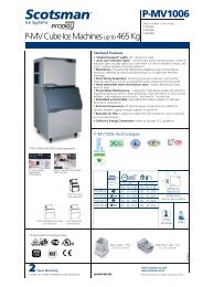
MV 306 - 426<br />
BACK FRONT PANEL ICE<br />
DEFLECTOR<br />
Starting from now, the models MV 306 & MV 426 are equipped with a metal deflector<br />
on the back side of the front panel as shown on the bottom picture.<br />
The main reasonf of this metal deflector is to avoid any possible dripping down of the<br />
water on the upper side of the storage bin metal frame.<br />
In case of need this metal deflector is available as a kit at no charge under part nbr CM<br />
81454477 and consists of:<br />
<br />
<br />
<br />
Metal deflector<br />
Holding S.S. rivets<br />
Installation instructions
<strong>SCOTSMAN</strong> <strong>EUROPE</strong> <strong>SERVICE</strong> <strong>DEPARTMENT</strong><br />
SP-10.05 – JULY ‘10<br />
MF 36<br />
NEW PC BOARD AND SENSORS<br />
FOR FIELD TEST<br />
On the following machines:<br />
MF 36 From s.n. 20342 to s.n. 20366 and from s.n. 20372 to s.n. 20389<br />
has been installed a new version of PC Board working in conjuction with new NTC<br />
Thermal Sensors.<br />
The Part Nbrs of the new components are:<br />
PC Board P/N 620462 13<br />
Condenser sensor 620519 00<br />
Evaporator sesnor 620519 01<br />
Water level sensor 620519 02<br />
ad they are NOT exchangeable with the standard one used on the same model.<br />
The operation of the PC Board and sensors is exactly the same of the current model.<br />
We have been forced to made this change as we are having serious difficulties to find<br />
out in the field the thermistor probe used to make the current Evaporator and Condenser<br />
Sensor.<br />
Ice Level control and Hall effect sensors are the same of the standard version.<br />
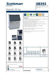
To avoid any mistake in the field, the new PC Boards and Sensors are equipped with<br />
new plugs of different shape compared with the formal ones as on the attached photos.
WATER LEVEL<br />
SENSOR PLUG<br />
ICE LEVEL<br />
SENSOR PLUG<br />
HALL EFFECT<br />
SENSOR PLUG<br />
CONDENSER<br />
SENSOR PLUG<br />
EVAPORATOR<br />
SENSOR PLUG
<strong>SCOTSMAN</strong> <strong>EUROPE</strong> <strong>SERVICE</strong> <strong>DEPARTMENT</strong><br />
SP-10.06 – JULY ‘10<br />
MAR 56-76-106-126<br />
MAR SPLIT 78-108-128<br />
NEW GEAR REDUCER<br />
Starting from the following serial nbrs:<br />
MAR 56 S.N. 1898<br />
MAR 76 1368<br />
MAR 106 2973<br />
MAR 126 1369<br />
MAR 78 S.N. 1614<br />
MAR 108 3457<br />
MAR 128 1690<br />
the Bonfiglioli Gear Reducer P/N 620377 04 used on the past years have been replaced<br />
with a new one manufactured by Hydromec.<br />
As the hi speed shaft of the new gear reducer has a larger diameter and the size is a little<br />
bit different compared to the former one, we have been forced to change the gear<br />
reducer pulley and the V belt as well.<br />
The part nbrs of the new components are:<br />
Gear reducer P/N 620512 00<br />
Gear reducer pulley 650879 11<br />
V belt 650878 04<br />
To allow the replacement of the Bonfiglioli gear reducer with the Hydromec one on the<br />
machines in the field, we have made available a Kit Gear Reducer Part Nbr 060682 00<br />
that will be supplied in place of the Bonfiglioli Gear Reducer P/N 620377 04, once<br />
we’ll run out of stock.
<strong>SCOTSMAN</strong> <strong>EUROPE</strong> <strong>SERVICE</strong> <strong>DEPARTMENT</strong><br />
SP-10.07 – AUG. ‘10<br />
AF SERIES, MF 26-36 &<br />
TC 180<br />
NEW DRIVE MOTOR<br />
CAPACITORS<br />
Starting from the following serial nbrs:<br />
AF 80 S.N. 07847<br />
AF 100 28081<br />
AF 200 03995<br />
AF 20 12674<br />
AF 30 09891<br />
MF 26 05013<br />
MF 36 20470<br />
TC 180 06178<br />
the drive motor capacitor has been replaced with an explosion proof one available under<br />
the following part nbrs:<br />
AF Series – MF 26-36 – TC 180 (230V) – (4 MFD) P/N 620520 03<br />
AF Series – MF 26-36 – TC 180 (115V) – (12,5 MFD) 620520 00<br />
These new explosion proof capacitors have the same electrical features of the former<br />
ones but are equipped with just two spade connetctors rather then four as per photo<br />
attached.<br />
The change of the drive motor capacitor forced us to make some modifications of the<br />
wiring of the drive motor stator that is now equipped with four wires.<br />
Two white ones to be connected to the two spade connectors of the capacitor, and a blue<br />
and a brown one for line and neutral.
The new stators are available under the following part numbers:<br />
AF Series – MF 26-36 – TC 180 (230V) P/N 620521 00<br />
AF Series – MF 26-36 – TC 180 (115V) 620521 01<br />
Once we’ll run out of stock of old capacitors and stators, we’ll supply the new ones.<br />
Attached the new wiring diagrams of AF Sereis – MF 26-36 as well as of TC 180.
<strong>SCOTSMAN</strong> <strong>EUROPE</strong> <strong>SERVICE</strong> <strong>DEPARTMENT</strong><br />
SP-10.08 – AUG. ‘10<br />
AC 206 - 226<br />
NEW PC BOARD AND SENSORS<br />
FOR FIELD TEST<br />
On the following machines:<br />
AC 206 From s.n. 00506 to s.n. 00515<br />
AC 226 From s.n. 54975 to s.n. 55002<br />
has been installed a new version of PC Board working in conjuction with new NTC<br />
Thermal Sensors.<br />
The Part Nbrs of the new components are:<br />
PC Board P/N 620462 11<br />
Condenser sensor 620519 00<br />
Evaporator sensor 620519 01<br />
and they are NOT exchangeable with the standard ones used on the same models.<br />
The operation of the PC Board and sensors is exactly the same of the current models.<br />
We have been forced to made this change as we are having serious difficulties in find<br />
out the thermistor probe used to assembly the current Evaporator and Condenser<br />
Sensors.<br />
Ice Level control used with new PC Board is the same of the one used till now.<br />
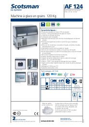
To avoid any mistake in the field, the new PC Boards and Sensors are equipped with<br />
new plugs of different shape compared with the formal ones as per attached photos.
WATER LEVEL<br />
SENSOR PLUG<br />
EC SERIES<br />
ONLY<br />
CONDENSER<br />
SENSOR PLUG<br />
ICE LEVEL<br />
SENSOR PLUG<br />
EVAPORATOR<br />
SENSOR PLUG
START UP DELAY TIME<br />
JUMP IN – 0 MIN.<br />
JUMP OUT – 60 MIN.<br />
AC/EC MODELS<br />
JUMP IN – AC SERIES<br />
JUMP OUT – EC SERIES<br />
PURGE JUMPER<br />
NOT USED ON CUBERS<br />
TEST<br />
WATER SYSTEM CLEANING REMIND<br />
JUMP IN – 6 MONTHS<br />
JUMP OUT – 12 MONTHS<br />
60/70°C CONDENSING TEMP.<br />
NOT USED ON CUBERS
<strong>SCOTSMAN</strong> <strong>EUROPE</strong> <strong>SERVICE</strong> <strong>DEPARTMENT</strong><br />
SP-10.09 – SEPT. ‘10<br />
MF 46-56-58-66-68<br />
NEW DRIVE MOTOR CAPACITOR<br />
As recently done on the AF series, also in the bigger MF series, starting from the<br />
following serial nbrs:<br />
MF 46 16409<br />
MF 56 24373<br />
MF 58 01766<br />
MF 66 05500<br />
MF 68 01726<br />
the previous drive motor capacitor has been replaced with an explosion proof one<br />
available under the part nbr 620520 01.<br />
This new explosion proof capacitor has the same electrical features of the former one<br />
but is equipped with just two spade connetctors rather then four as per here below<br />
photo.<br />
The change of the drive motor capacitor forced us to make some modifications of the<br />
wiring of the drive motor stator that is now equipped with four wires.<br />
Two white ones to be connected to the two spade connectors of the capacitor, and a blue<br />
and a brown one for line and neutral.<br />
The new stator is available under the part number 620522 00.<br />
Once we’ll run out of stock of old capacitor and stator, we’ll supply the new one.<br />
Attached the new wiring diagrams of MF series.
<strong>SCOTSMAN</strong> <strong>EUROPE</strong> <strong>SERVICE</strong> <strong>DEPARTMENT</strong><br />
SP-10.10 – SEPT. ‘10<br />
AC 126 - 176<br />
NEW PC BOARD AND SENSORS<br />
FOR FIELD TEST<br />
Same PC Board and Evaporator and Condenser Sensors as detailed on Service Bulletin<br />
SP-10-08 have been installed also on the following machines:<br />
AC 126 From s.n. 03272 to s.n. 03275<br />
AC 176 From s.n. 04720 to s.n. 04765<br />
The Part Nbrs of the new components are:<br />
PC Board P/N 620462 11<br />
Condenser sensor 620519 00<br />
Evaporator sensor 620519 01<br />
and they are NOT exchangeable with the standard ones used on the same models.<br />
The operation of the PC Board and sensors is exactly the same of the current models.<br />
Ice Level control used with new PC Board is the same of the one used till now.
<strong>SCOTSMAN</strong> <strong>EUROPE</strong> <strong>SERVICE</strong> <strong>DEPARTMENT</strong><br />
SP-10.11 – SEPT. ‘10<br />
MV/MVH 456-606-806-1006<br />
NEW INNER FRONT PANEL<br />
DEFLECTOR KIT<br />
A new inner front panel deflector kit is available to be installed in the field on the 30”<br />
wide models in order to reduce the possible drips of water into the upper frame of the<br />
storage bin as done on the past months with smaller 22” wide models (see below<br />
Service Bulletin SP-10-04).<br />
The new Kit Inner Deflector is available under Part Nbr CM 81454526 and consists of a<br />
metal plate with holding screws so to secure it to the innner side of the front panel
<strong>SCOTSMAN</strong> <strong>EUROPE</strong> <strong>SERVICE</strong> <strong>DEPARTMENT</strong><br />
SP-10.12 – NOV. ‘10<br />
AC 206 ICE SHOT<br />
NEW PCB p/n 620462 10<br />
Starting from AC 206 s.n. 490 ICE SHOT version only a new pcb. p/n 620462 10 has<br />
been installed
This new AC 206 ICE SHOT uses just only one main board instead of former two<br />
Further, ice cubes selection between XL and ICE SHOT type mode, is activated by a<br />
switch available at unit front panel<br />
The same selector/switch is connected to an interface pcb by which two dip switches<br />
blocks are available at its back side, thus to control/adjust ice cube sizes<br />
DS1 (XL cube size) OFF-ON-ON-OFF-ON-OFF<br />
DS2 (ICE shot cube size) ON-ON-ON-ON-ON-ON
At main printing circuit board are available further four dip switches<br />
DIP SWITCHES<br />
ADDITIONAL DEFROST TIME<br />
1 2<br />
ON ON 0<br />
OFF ON 30"<br />
ON OFF 60"<br />
OFF OFF 90"<br />
DIP SWITCHES<br />
WATER PUMP OPERATION<br />
3<br />
OFF 15"<br />
ON 30"<br />
DIP SWITCHES<br />
HI TEMP CUT OFF SETTING<br />
4<br />
OFF<br />
ON<br />
60° W/C<br />
70° A/C
<strong>SCOTSMAN</strong> <strong>EUROPE</strong> <strong>SERVICE</strong> <strong>DEPARTMENT</strong><br />
SP-10.13 – NOV ‘10<br />
AF 80<br />
MF 46-56-58-68<br />
MFN 46-56<br />
NEW WATER TUBE & FITTINGS<br />
As done on the past year with the model MF 26 & MF 36, starting from the following<br />
serial numbers:<br />
AF 80 S.N. 07512<br />
MF 46 16396<br />
MF 56 24160<br />
MF 58 01794<br />
MF 68 01738<br />
MFN 46 00044<br />
MFN 56 00070<br />
the entire water inlet tube/fittings has been redesigned moving from copper tube to John<br />
Guest quick connections and nylon tube.<br />
The new components are available under the following part nbrs:<br />
Water inlet plastic fitting P/N 660956 00<br />
1/4“ male fitting 651206 01<br />
1/4” OD nylon tube (sold per meter) 651206 02<br />
1/4” female – 5/16” female connector 651224 04<br />
1/4” female S.S. nozzle 723107 02<br />
as shown on the attached page.
660956 00<br />
651206 02<br />
651224 04<br />
651206 01<br />
723107 02<br />
651206 02
<strong>SCOTSMAN</strong> <strong>EUROPE</strong> <strong>SERVICE</strong> <strong>DEPARTMENT</strong><br />
SP-10.14 – NOV ‘10<br />
MAR 205<br />
NEW COMPRESSOR<br />
Starting from the serial number 02598 the previous Dorin Compressor (K500CS, no<br />
longer manufactured by Dorin) has been replaced with a new one (Dorin H503CS)<br />
available under the following part nbrs:<br />
230-400/50/3 P/N 670104 00<br />
230-380/60/3 670104 03<br />
As the refrigerant service valves are located in different position, compared with the<br />
former one, the new compressor is not perfectly exchangeable with the previous one<br />
unless of partial modification of the copper tubes.
<strong>SCOTSMAN</strong> <strong>EUROPE</strong> <strong>SERVICE</strong> <strong>DEPARTMENT</strong><br />
SP-10.15 – NOV ‘10<br />
MV/MVH 306-426-456<br />
606-806-1006<br />
CHANGE ON PC BOARD<br />
SOFTWARE<br />
Starting from the following serial numbers:<br />
MV 306 S.N. 00277<br />
MV 426 00217<br />
MV 456 00808<br />
MV 606 00864<br />
MV 806 00071<br />
MV 1006 00229<br />
the software of the PC Board Part Nbr CM 33580250 has been changed in order to<br />
disable the operation of the Ice Thickness Sensor during the first 7 minutes of the<br />
freezing cycle or after 3 minutes from the start up of the water pump during the freezing<br />
cycle (the first reached one)<br />
The disable of the Ice Thickness Sensor during the first part of the freezing cycle is<br />
needed to avoid “wrong” signals transmitted to the PC Board at the beginning of the<br />
freezing cycle when ice is not yet made into the cells and splashed water can reach the<br />
metal plates of the Ice Thickness Sensor moving prematurely the machine in the defrost<br />
cycle.
<strong>SCOTSMAN</strong> <strong>EUROPE</strong> <strong>SERVICE</strong> <strong>DEPARTMENT</strong><br />
SP-10.16 – DEC. ‘10<br />
MF 58 - 68<br />
CHANGE OF GEAR REDUCER<br />
AND FREEZER ASSY<br />
LOCATION<br />
Starting from the following serial numbers:<br />
MF 58 S.N. 01723<br />
MF 68 01701<br />
the location of the gear reducer and freezer assy have been modified for the following<br />
reasons:<br />
Allow the installation of the new wider Optical Ice Level Controls P/N 650674 06<br />
Provide more space for service<br />
All parts, except the Optical Ice Level Control, are the same of the former versions.<br />
The same is for the size of the machine as well as for the location of all water and<br />
refrigerant connections.<br />
Attached the drawing showing the new revised version with new opening for bottom<br />
(through the unit base) and left side ice chutes.
<strong>SCOTSMAN</strong> <strong>EUROPE</strong> <strong>SERVICE</strong> <strong>DEPARTMENT</strong><br />
SP-10.17 – DEC. ‘10<br />
AF & MF SERIES<br />
CHANGE ON PC BAORD AND<br />
THERMAL SENSORS<br />
Starting from the following serial numbers:<br />
AF 80 S.N. 08151<br />
AF 100 28271<br />
AF 200 04051<br />
AF 20 12715<br />
AF 30 09929<br />
MF 26 05128<br />
MF 36 20792<br />
MF 46 16546<br />
MFN 46 00043<br />
MF 56 24628<br />
MFN 56 00070<br />
MF 58 01803<br />
the old PC Board and Sensors has been definitively replaced with a new one that<br />
operate in conjuction with new NTC Thermal Sensors and Water Level Sensor that are<br />
NOT exchangeable with the former ones.<br />
The part nbrs of the new PC Board and Sensors are:<br />
PC Board P/N 620462 13<br />
Evaporator sensor 620519 01<br />
Condenser sensor 620519 00<br />
Water Level Sensor 620519 02<br />
The operation of the PC Board and of the machine as well as all the wiring connections<br />
are exactly the same of the machines equipped with old PC Board and Sensors.<br />
We have been forced to made this change as we are having serious difficulties to find<br />
out in the field the thermistor probe used to make the current Evaporator and Condenser<br />
Sensor.<br />
Ice Level control and Hall effect sensors are the same of the standard version.<br />
To avoid any mistake in the field, the new PC Boards and Sensors are equipped with<br />
new plugs of different shape compared with the formal ones as on the attached photos.
WATER LEVEL<br />
SENSOR PLUG<br />
ICE LEVEL<br />
SENSOR PLUG<br />
HALL EFFECT<br />
SENSOR PLUG<br />
CONDENSER<br />
SENSOR PLUG<br />
EVAPORATOR<br />
SENSOR PLUG
<strong>SCOTSMAN</strong> <strong>EUROPE</strong> <strong>SERVICE</strong> <strong>DEPARTMENT</strong><br />
SP-10.18 – DEC. ‘10<br />
MC SERIES<br />
CHANGE ON PC BAORD AND<br />
THERMAL SENSORS<br />
Starting from the following serial numbers:<br />
MC 16 SHORT S.N. 01054<br />
MC 16 18448<br />
MC 46 28850<br />
MC 1210 03942<br />
the old PC Board and Sensors have been definitively replaced with new ones that<br />
operate in conjuction with new NTC Thermal Sensors, NOT exchangeable with the<br />
former ones.<br />
The part nbrs of the new PC Board and Sensors are:<br />
PC Board P/N 620462 11<br />
Evaporator sensor 620519 01<br />
Condenser sensor 620519 00<br />
As the new PC Board has a six poles green power connector plus two spade connections<br />
for the compressor (same configuration of the PC Board used on current AC Series) a<br />
special adaptor (Part Nbr 630151 00) is used on the following models:<br />
MC 16<br />
MC 46<br />
MC 1210<br />
for the power connection between the new PC Board and the waring of the machine that<br />
remains the same of the units manufactured till now.<br />
Ice Level Control remains the same of the standard version and requires the calibration<br />
with the PC Board (as per AC Series) at time of their replacement.<br />
As on AC models, the new PC Board switches OFF the machine at Bin Full ONLY at<br />
the end of the Harvest Cycle.<br />
To avoid any mistake in the field, the new PC Boards and Sensors are equipped with<br />
new plugs of different shape compared with the formal ones as on the attached photos.<br />
Attached the wiring diagrams showing the use of the adapter for the power connection.
WATER LEVEL<br />
SENSOR PLUG<br />
NOT USED ON<br />
MC SERIES<br />
CONDENSER<br />
SENSOR PLUG<br />
ICE LEVEL<br />
SENSOR PLUG<br />
EVAPORATOR<br />
SENSOR PLUG
START UP DELAY TIME<br />
JUMP IN – 0 MIN.<br />
JUMP OUT – 60 MIN.<br />
MC MODELS<br />
JUMP IN – MC SERIES<br />
JUMP OUT – NOT<br />
USED ON MC SERIES<br />
PURGE JUMPER<br />
NOT USED ON CUBERS<br />
TEST<br />
FACTORY USE ONLY<br />
WATER SYSTEM CLEANING REMIND<br />
JUMP IN – 6 MONTHS<br />
JUMP OUT – 12 MONTHS<br />
USED ONLY ON MC 16 SHORT<br />
60/70°C CONDENSING TEMP.<br />
NOT USED ON CUBERS
<strong>SCOTSMAN</strong> <strong>EUROPE</strong> <strong>SERVICE</strong> <strong>DEPARTMENT</strong><br />
SP-10.19 – DEC. ‘10<br />
AC SERIES<br />
CHANGE ON PC BAORD AND<br />
THERMAL SENSORS<br />
Starting from the following serial numbers:<br />
AC 106 S.N. 04184<br />
AC 126 03468<br />
AC 176 05105<br />
AC 206 00555<br />
AC 226 55171<br />
the old PC Board and Sensors has been definitively replaced with a new one operating<br />
in conjuction with new NTC Thermal Sensors NOT exchangeable with the former ones.<br />
The part nbrs of the new PC Board and Sensors are:<br />
PC Board P/N 620462 11<br />
Evaporator sensor 620519 01<br />
Condenser sensor 620519 00<br />
Ice Level Control remains the same of the standard version.<br />
To avoid any mistake in the field, the new PC Boards and Sensors are equipped with<br />
new plugs of different shape compared with the formal ones as on the attached photos.<br />
Old PC Board P/N 620462 06 will be available for a limited time.<br />
Once no longer available, a new PC Board and Sensors Kit will be supplied as spare<br />
part under the Kit Part Nbr 060711 02
WATER LEVEL<br />
SENSOR PLUG<br />
NOT USED ON<br />
MC SERIES<br />
CONDENSER<br />
SENSOR PLUG<br />
ICE LEVEL<br />
SENSOR PLUG<br />
EVAPORATOR<br />
SENSOR PLUG
START UP DELAY TIME<br />
JUMP IN – 0 MIN.<br />
JUMP OUT – 60 MIN.<br />
MC MODELS<br />
JUMP IN – MC SERIES<br />
JUMP OUT – NOT<br />
USED ON MC SERIES<br />
PURGE JUMPER<br />
NOT USED ON CUBERS<br />
TEST<br />
FACTORY USE ONLY<br />
WATER SYSTEM CLEANING REMIND<br />
JUMP IN – 6 MONTHS<br />
JUMP OUT – 12 MONTHS<br />
USED ONLY ON MC 16 SHORT<br />
60/70°C CONDENSING TEMP.<br />
NOT USED ON CUBERS
<strong>SCOTSMAN</strong> <strong>EUROPE</strong> <strong>SERVICE</strong> <strong>DEPARTMENT</strong><br />
SP-10.20 – DEC. ‘10<br />
MV 306-426-456-606-806-<br />
1006<br />
PC BOARD & SENSORS KIT<br />
FOR VERY SOFT WATER<br />
We would like to remind you that a PC Board & Sensors Kit, suitable to operate with<br />
very soft water, is available as service part under Part Nbr CM 81454417 for New MV<br />
..6 Series machines<br />
This new PC Board & Sensors Kit, that works in the same way of the current standard<br />
one, allows the correct operation of the MV ..6 Series even when water is very soft<br />
and/or demineralized, like the one produced by the Reverse Osmosis water treatment<br />
system.<br />
The major components of the new PC Board & Sensors Kit are:<br />
PC Board P/N CM 33580171<br />
Ice thickness sensor CM 81455066<br />
Ground cable CM 81453902<br />
Water level sensor cable CM 81454416<br />
The PC Board only is the same used on the current MV Series (MV 300 -> MV 1000)<br />
equipped with the Hi Sensitivity Board and is equipped with DIP Switches for the<br />
proper setting according to the model where installed as detailed on the last page of the<br />
attached Pure Water Board installation instructions.
PURE<br />
WATER<br />
BOARD<br />
71503782/0<br />
INSTALLATION KIT<br />
KIT DI INSTALLAZIONE<br />
PURE WATER BOARD<br />
SCHEDA PER ACQUA<br />
DEMINERALIZZATA<br />
WATER LEVEL SENSOR HARNESS<br />
CAVO DI COLLEGAMENTO SENSORE DI<br />
LIVELLO ACQUA ALLA SCHEDA<br />
GROUND CABLE<br />
CAVO DI TERRA<br />
NEW ICE SENSOR WITH HARNESS<br />
SENSORE GHIACCIO CON FILO DI COL-<br />
LEGAMENTO ALLA SCHEDA<br />
11/03/09
PURE<br />
WATER<br />
BOARD<br />
71503782/0<br />
INSTALL THE ICE SENSOR ON ITS<br />
BRACKET AND CONNECT TO THE BOARD<br />
(BOARD CONNECTOR “ICE SENSOR”)<br />
POSIZIONARE IL SENSORE GHACCIO SUL<br />
SUPPORTO E COLLEGARE IL FILO ALLA<br />
SCHEDA (CONNETTORE DELLA SCHEDA<br />
“ICE SENSOR”)<br />
REPLACE THE WATER LEVEL SENSOR<br />
HARNESS AND CONNECT IT TO THE<br />
BOARD (BOARD CONNECTOR “WATER<br />
LEV.”).<br />
SOSTITUIRE IL CAVO DEL SENSORE DI<br />
LIVELLO ACQUA E COLLEGARLO ALLA<br />
SCHEDA, (CONNETTORE DELLA SCHE-<br />
DA “WATER LEV.”).<br />
11/03/09
PURE<br />
WATER<br />
BOARD<br />
71503782/0<br />
REPLACE THE BOARD<br />
NOTE: THE BOARD CONNECTORS ARE<br />
THE SAME (EXCEPT ICE AND WATER<br />
LEVEL SENSOR CONNECTORS)<br />
THEN CONNECT THE GROUND CABLE<br />
TO THE BOARD (BOARD CONNECTOR<br />
“GND”) AND TO THE GROUND TERMINAL<br />
SOSTITUIRE LA SCHEDA<br />
NOTA: I CONNETTORI DELLA SCHEDA<br />
SONO GLI STESSI (ECCETTO I<br />
CONNETTORI DEI SENSORI GHACCIO E<br />
ACQUA)<br />
POI COLLEGARE IL CAVO DI TERRA ALLA<br />
SCHEDA (CONNETTORE DELLA SCHEDA<br />
“GND”) E AL MORSETTO DI TERRA<br />
ICE SENSOR CONNECTOR<br />
CONNETTORE SENSORE GHIACCIO<br />
WATER LEVEL SENSOR CONNECTOR<br />
CONNETTORE SENSORE DI LIVELLO<br />
ACQUA<br />
GROUND CONNECTOR<br />
CONNETTORE DI TERRA<br />
11/03/09