Industrial scale ice machines Evaporator Service ... - Scotsman
Industrial scale ice machines Evaporator Service ... - Scotsman
Industrial scale ice machines Evaporator Service ... - Scotsman

You also want an ePaper? Increase the reach of your titles
YUMPU automatically turns print PDFs into web optimized ePapers that Google loves.
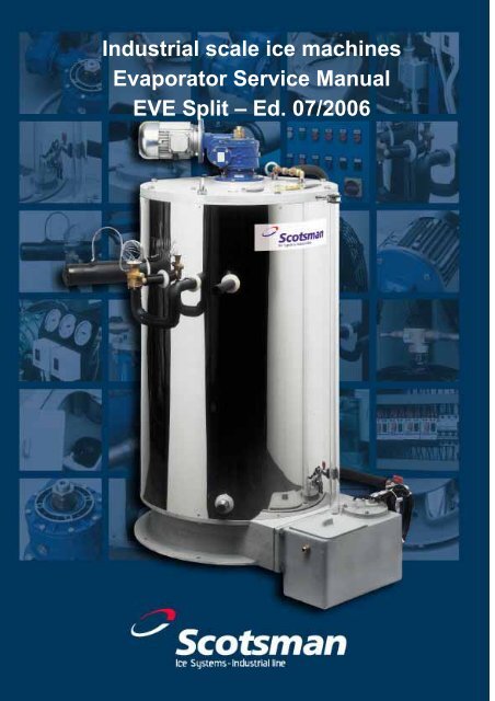
<strong>Industrial</strong> <strong>scale</strong> <strong>ice</strong> <strong>machines</strong><br />
<strong>Evaporator</strong> Serv<strong>ice</strong> Manual<br />
EVE Split – Ed. 07/2006
Serv<strong>ice</strong> Manual<br />
<strong>Evaporator</strong> Manual / EVE Split<br />
I. Introduction page 2<br />
II. Working outline page 3<br />
a) Water system page 4<br />
b) Ice Outlet page 4<br />
c) Refrigeration system page 5<br />
i. Direct expansion with thermostatic valve (TEV)<br />
ii. Direct expansion through FTL<br />
iii. Flooding with pump refrigeration system<br />
d) Working limits of the <strong>Evaporator</strong> cylinder page 6<br />
e) Inlet water page 7<br />
III. Production diagram page 8<br />
IV. Technical Characteristics<br />
page.9<br />
V. Installation<br />
a) Handling, unpacking and disposal of packing materials page13<br />
b) Positioning, levelling and access for maintenance page14<br />
c) Refrigerating system engineering requirements page14<br />
d) Water inlet connection page 17<br />
e) Ice Outlet page 17<br />
f) Electrical connection, start-up and shut down procedure,<br />
electronic level controller (FTL) page 18<br />
g) Electrical circuit diagrams page 22<br />
h) Refrigerant circuit diagram – piston compressor with TEV page 27<br />
i) Refrigerant circuit diagram – piston compressor with FTL page 28<br />
j) Refrigerant circuit diagram – screw compressor page 29<br />
VI. START-UP AND ADJUSTMENT page 30<br />
Start-up and controls<br />
Salt addition page 31<br />
VII. Cleaning, Maintenance and Replacement Procedures page 35<br />
a. Gear Reducer and motor page.36<br />
b. Water pump page 36<br />
c. Ice-breaker bush and scraper page 37<br />
d. Thermostatic expansion valve / FTL page 38<br />
e. Ice deflector page 38<br />
f. Deflector and drip tray page 38<br />
g. Shaft bushing page 39<br />
VIII. Re-start procedure after power supply interruption or emergency stop page 40<br />
IX. Fault Analysis<br />
page.41<br />
X. Exploded views and parts list page 43<br />
1<br />
Rev. 07/2006
Serv<strong>ice</strong> Manual<br />
I. INTRODUCTION<br />
Linea.Net Milano Srl manufacture flake <strong>ice</strong> <strong>machines</strong> in various production capacities and<br />
configurations to suit the numerous market demands.<br />
The agro-food industry (bread making, meat processing, cheese, etc.) and in particular<br />
the fishing industry, have found flake <strong>ice</strong> to offer many advantages over traditional <strong>ice</strong><br />
cubes or crushed <strong>ice</strong>.<br />
In the chemical and cement industry flake <strong>ice</strong> is used during production to avoid<br />
premature drying out or temperature control.<br />
The following is an example of sectors that use <strong>ice</strong>:<br />
- On board installations – Fishing<br />
- Fishing industry - Processing<br />
- Manufacture of fish products<br />
- Fish markets<br />
- Distribution of fresh fish<br />
- Retailers of fish or fish products<br />
- Supermarkets<br />
- Delicatessens<br />
- Meat markets<br />
- Manufacture of poultry and game products<br />
- Production of salamis and sausages<br />
- Oven products and industrial bread-making<br />
- Production of dairy products and cheeses<br />
- Textile industry and paint production<br />
- Chemical-pharmaceutical companies<br />
- Building and construction companies (in compliance with European Standard<br />
EN206-1 : 2000)<br />
Our vast experience (since 1973) allows us to offer <strong>machines</strong> with a high level of<br />
reliability, vouched for by numerous clients who are satisfied with the <strong>machines</strong> they have<br />
used.<br />
These <strong>machines</strong> have been designed to work under stress and offer the following<br />
advantages:<br />
- Reliability- Long-life – Reduced running and maintenance costs<br />
Other than the advantage of reduced production costs when using <strong>ice</strong>, a “dry and subcooled<br />
<strong>ice</strong>” will last longer and therefore provide a longer thermal inertia. Being flat and<br />
free from sharp corners (unlike crushed <strong>ice</strong>) it will not damage the outside of the product<br />
with which it comes into contact which, on defrosting, will lead to a deterioration of the<br />
merchandise.<br />
Example of model designation<br />
EVE201 = Fresh water version – Land Based<br />
EVE201 FW = Fresh water version – On Board<br />
EVE201 LSW = Sea water version - Land Based<br />
EVE201 SW = Sea water version – On Board<br />
2<br />
Rev. 07/2006
Serv<strong>ice</strong> Manual<br />
II.<br />
A working outline<br />
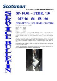
A fixed vertical evaporator (1) is cooled by the refrigerant fluid evaporating on the inside.<br />
Water is evenly distributed from<br />
above onto the internal surface (2), 2<br />
4<br />
where it freezes once it comes into<br />
1<br />
contact with the cold wall. A<br />
helicoidal <strong>ice</strong>-breaker (3) is<br />
positioned parallel to the cylinder<br />
axis, almost in contact with the<br />
internal surface and the gear<br />
reducer (4) causes the central shaft<br />
(5) to turn at a constant speed. The<br />
<strong>ice</strong>-breaker is connected to the<br />
3<br />
central shaft with a satellite<br />
mechanism.<br />
The <strong>ice</strong>-breaker rotates on the<br />
5<br />
surface of <strong>ice</strong>; it removes it by<br />
breaking it into flakes which then<br />
fall by gravity. A flat, vertical blade<br />
(6) follows the <strong>ice</strong>-breaker cleaning<br />
the surface of possible residue.<br />
Un-frozen water is returned to the<br />
reservoir (7).<br />
6<br />
Water pump (8) circulates water<br />
around the system.<br />
7<br />
8<br />
a. WATER SYSTEM<br />
3<br />
Rev. 07/2006
Serv<strong>ice</strong> Manual<br />
At the base of the machine is the water reservoir in<br />
which the stainless steel pump is immersed. Water is<br />
pumped to the distributor from which it falls by gravity;<br />
there is a filter (2) and shut-off valve (1) on the toroidal<br />
distributor which is positioned internally and integral<br />
with the central shaft.<br />
Depending upon the application, there are two different<br />
types of distributor:<br />
a) Peralluman pipe with regular perforations and<br />
supply from above (land version)<br />
b) Stainless steel ring pipe with regular perforations and supply from the axis of the<br />
gear reducer (on board version)<br />
1<br />
3<br />
4<br />
2<br />
In the LAND version, a level sensor (3) allows a check to be carried out on the water<br />
flow. The upper part of the cylinder is rounded at the end in order to channel the water<br />
towards the walls of the cylinder.<br />
In the reservoir there is a float valve which regulates the flow of water from the external<br />
feed circuit in such a way that the level remains constant. The <strong>ice</strong> has to be dry and subcooled,<br />
for this the surface of the evaporator cylinder which is immediately in front of the<br />
scraper roller is not irrigated by the water distribution apparatus.<br />
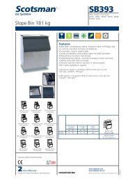
b. ICE OUTLET<br />
The stainless steel shaft, positioned in the centre of the cylinder, is turned on its vertical<br />
axis by a gear reducer. Connected onto the shaft are two ‘V’ arms onto which the <strong>ice</strong>breaker<br />
is fixed on one side and the scraping roller on the other. This collects and cleans<br />
the surface of <strong>ice</strong>. The <strong>ice</strong>-breaker, turning on its<br />
own axis and rotating over the <strong>ice</strong> formed on the<br />
inside, detaches it by breaking it (see photo).<br />
A deflector prevents the <strong>ice</strong> from falling into the water reservoir.<br />
4<br />
Rev. 07/2006
Serv<strong>ice</strong> Manual<br />
Depending on the type of application and position of the machine, there must be<br />
adequate conveyors, containers or storage bins to collect the <strong>ice</strong>.<br />
The rotation speed determines the thickness of the <strong>ice</strong>: a slower speed corresponds to<br />
an increased thickness and sub-cooling of the <strong>ice</strong>.<br />
It is possible to alter the speed by applying a frequency converter (inverter) onto<br />
the electrical supply of the gear reducer.<br />
c. REFRIGERATION SYSTEM<br />
The evaporator cylinder is the main element in the machine. In its<br />
internal chambers the cold refrigerant circulates and absorbs<br />
heat. The walls facing the outside are insulated with foamed<br />
polyurethane. At the base of the cylinder there is a system for the<br />
removal of oil should the machine need to be closed down for<br />
long periods or for use during maintenance visits.<br />
i. DIRECT EXPANSION WITH THERMOSTATIC VALVE<br />
The refrigerant liquid is circulated through a coil on the<br />
inside of the cylinder (acting as heat exchanger), then with<br />
the use of a thermostatic valve is injected into the<br />
evaporator where it absorbs heat and evaporates. The vapour is recovered using<br />
the suction pipe as indicated in the technical diagrams.<br />
ii. DIRECT EXPANSION through<br />
FLOODING with LEVEL CONTROL<br />
The refrigerant liquid flows through the<br />
pipe for sub-cooling with the use of a<br />
solenoid valve and a regulating valve (for<br />
the fall in pressure). It then floods the<br />
evaporator’s internal chambers, where the<br />
expansion phase takes place. If the<br />
machine is not completely flooded, the<br />
level control is carried out with an<br />
electronic controller (FTL) which controls<br />
the solenoid valve. The variation in<br />
pressure between the liquid and suction<br />
must have an ∆P no lower than 12 bar<br />
to guarantee an adequate supply of<br />
refrigerant.<br />
iii. FLOODING WITH PUMP<br />
REFRIGERATION SYSTEM<br />
The refrigerant liquid which comes from<br />
the cold receiver, completely floods the<br />
evaporator. The evaporator is divided into<br />
sections with valves on the inlet.<br />
5<br />
Rev. 07/2006
Serv<strong>ice</strong> Manual<br />
d. Working limits of the <strong>Evaporator</strong> Cylinder<br />
The evaporator cylinders were designed to comply with VSR-95, C.T.I.<br />
Recomendations, ISPESL S & M standards to contain refrigerant fluid up<br />
to the maximum accepted PS pressure conditions, PT test pressure<br />
(junction coeffient Z=0.85, void corrosion stock (expected life: 15 years).<br />
Throughout calculations, impact, heavy loads, earthquakes and wind<br />
were taken into consideration.<br />
Diagram Rev PS PT TS min<br />
(1)<br />
TS max V(lt) refrigerant Cat. Mod. (2)<br />
CE18A 0 17.65 25.24 -35 +40 23 EN378-1:00 Gr.L1 (3) II. A1<br />
CE25A 0 17.65 25.24 -35 +40 27 EN378-1:00 Gr.L1 (3) II. A1<br />
CE40A 0 17.65 25.24 -35 +40 32 EN378-1:00 Gr.L1 (3) II. A1<br />
CE65A 0 17.65 25.24 -35 +40 69 EN378-1:00 Gr.L1 (3) III B+C1<br />
CE85A 0 17.65 25.24 -35 +40 78 EN378-1:00 Gr.L1 (3) III B+C1<br />
CE100B 0 17.65 25.24 -35 +40 282 EN378-1:00 Gr.L1 (3) ; R717 IV B+F<br />
CE125B 0 17.65 25.24 -35 +40 370 EN378-1:00 Gr.L1 (3) ; R717 IV B+F<br />
CE160B 0 17.65 25.24 -35 +40 432 EN378-1:00 Gr.L1 (3) ; R717 IV B+F<br />
CE240B 0 17.65 25.24 -35 +40 602 EN378-1:00 Gr.L1 (3) ; R717 IV B+F<br />
CE100A 0 17.65 25.24 -35 +40 280 EN378-1:00 Gr.L1 (3) ; R717 IV B+F<br />
CE125A 0 17.65 25.24 -35 +40 370 EN378-1:00 Gr.L1 (3) ; R717 IV B+F<br />
CE160A 0 17.65 25.24 -35 +40 430 EN378-1:00 Gr.L1 (3) ; R717 IV B+F<br />
CE240A 0 17.65 25.24 -35 +40 600 EN378-1:00 Gr.L1 (3) ; R717 IV B+F<br />
(1) for the refrigerants with T PS
Serv<strong>ice</strong> Manual<br />
e. INLET WATER<br />
The structural differences between sea and fresh water versions are minimal:<br />
1) the scraping blade is in plexiglass (more rigid) instead of rubber.<br />
2) the surface of the evaporator in contact with the water has a horizontally grooved<br />
surface to improve the thermal exchange.<br />
When using fresh water, the <strong>ice</strong> will vary depending on the hardness of the water, i.e.:<br />
a) Almost pure water such as rain water produces <strong>ice</strong> which is partly<br />
transparent and firmly attached to the cylinder wall<br />
b) Water with a high lime content causes a calcareous sediment to collect on<br />
the cylinder that also causes the <strong>ice</strong> to stick<br />
In both cases, the scraping roller breaks the layer of <strong>ice</strong> which forms on the wall of the<br />
cylinder, but a loss in quality may be experienced.<br />
Our experience has demonstrated that the addition of a small amount of salt (sodium<br />
chloride), eliminates these problems; the <strong>ice</strong> is compact and it breaks up into larger<br />
pieces.<br />
The amount of salt used however so low that it is not possible to taste it in the <strong>ice</strong> and it<br />
will not affect food products.<br />
The salt can be dosed with automatic measuring dev<strong>ice</strong>s, or by a system that<br />
automatically regulates the conductivity of the water (average 1500 uS at +17°C).<br />
When using sea water, after checking that the machine is suitable for this type of use, it<br />
will be necessary to select a lower evaporating temperature than that used for fresh<br />
water, in order to obtain a good quality flake (normally between 4 and 8°C lower). The<br />
salinity of the water used is very important for the correct operation of the machine and<br />
often an adjustment made whilst in the harbour will provide different results when out to<br />
sea, due to different levels of salinity.<br />
Construction<br />
Differences<br />
FRESH<br />
WATER<br />
LAND<br />
FRESH<br />
WATER<br />
ON-BOARD<br />
AISI304<br />
smooth<br />
SEA<br />
WATER<br />
LAND<br />
SEA<br />
WATER<br />
ON-BOARD<br />
<strong>Evaporator</strong> internal<br />
surface<br />
AISI304 smooth<br />
AISI304 rifled AISI304 rifled<br />
Scraper material Rubber Rubber plexiglass plexiglass<br />
Water distributor<br />
Open, made of Closed ring, in Open, made of Closed ring, in<br />
aluminium AISI304 aluminium AISI304<br />
Water sensor level provided Not provided provided Not provided<br />
Through shaft<br />
Through shaft<br />
Supply for water By gravity, from<br />
By gravity, from<br />
and rotating<br />
and rotating<br />
distributor upper cover<br />
upper cover<br />
coupling<br />
coupling<br />
Refrigeration Power 100% 100% 115% 115%<br />
Evaporating<br />
Temperature<br />
-28°C -28°C -35°C -35%<br />
7<br />
Rev. 07/2006
Serv<strong>ice</strong> Manual<br />
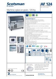
III<br />
PRODUCTION DIAGRAM<br />
24.000<br />
22.000<br />
Diagramma Produzione / Production Diagram<br />
201 301 401<br />
651 801 1001<br />
1301 1501 2401<br />
20.000<br />
18.000<br />
16.000<br />
14.000<br />
Kg/24h<br />
12.000<br />
10.000<br />
8.000<br />
6.000<br />
4.000<br />
2.000<br />
0<br />
10 15 21 25 30 35<br />
T.alim.acqua °C/ Water temp.°C<br />
Models<br />
Ice production<br />
Kg/24h<br />
Th. 1.8-2.2mm<br />
Water temp 21°C,<br />
Ambient Temp.. 25°C<br />
Q (W)<br />
Fresh water<br />
Evap.temp.<br />
-28°C<br />
Q (W)<br />
Sea water<br />
Evap. Temp.<br />
-35°C<br />
EVE201 1.600 10.000 11.500<br />
EVE301 2.300 14.535 16.715<br />
EVE401 3.500 19.770 22.736<br />
EVE651 5.800 33.490 38.514<br />
EVE801 7.500 44.190 50.819<br />
EVE1001 9.000 55.815 64.187<br />
EVE1301 11.000 67.445 77.562<br />
EVE1501 13.500 89.535 102.965<br />
EVE2401 21.000 133.720 153.778<br />
8<br />
Rev. 07/2006
Serv<strong>ice</strong> Manual<br />
IV<br />
TECHNICAL CHARACTERISTICS<br />
The machine is intended to be used at room temperature.<br />
Do not install in refrigerated rooms or in places where the temperature is too low.<br />
If this is unavoidable, provision must be made to protect the electrical parts from possible<br />
dampness and to ensure that the water in the reservoir does not freeze.<br />
The guarantee is no longer valid when there are signs that the machine has been used in<br />
conditions/environments outside the following:<br />
Conditions of use:<br />
Minimum<br />
Maximum<br />
Room temperature 2°C (36°F) 40°C (104°F)<br />
Temperature of inlet water (Fresh). 5°C ( 41°F) # 35°C (95°F)*<br />
Temperature of inlet water (Sea) 2°C (36°F) # 35°C (95°F)*<br />
Electrical voltage -10% +10%<br />
Water pressure 1 bar / 14 psi 5 bar / 70 psi<br />
# for lower temperatures it is advised to use a pre-heating system.<br />
* to obtain a good quality <strong>ice</strong> it will be necessary to reduce the water temperature<br />
to less than 25°C.<br />
Indicative quantity of refrigerant for an evaporator used in a direct expansion system:<br />
Model R404/R507 R22 R717<br />
EVE201 18.5 Kg 18.5 Kg -<br />
EVE301 27.6 Kg 27.6 Kg -<br />
EVE401 30 Kg 30 Kg -<br />
EVE651 45 Kg 45 Kg -<br />
EVE801 55 Kg 55 Kg -<br />
EVE1001 100 Kg 100 Kg 62 Kg<br />
EVE1301 120 Kg 120 Kg 79 Kg<br />
EVE1501 140 Kg 140 Kg 108 Kg<br />
EVE2401 240 Kg 240 Kg 199 Kg<br />
9<br />
Rev. 07/2006
Serv<strong>ice</strong> Manual<br />
EVE201-301-401-651-801<br />
EVE1001-1301-1501<br />
EVE2401<br />
Model<br />
W<br />
mm<br />
.<br />
D<br />
mm<br />
.<br />
H (T/B)<br />
mm<br />
H<br />
mm<br />
M<br />
mm.<br />
N<br />
mm.<br />
P<br />
mm.<br />
Q<br />
mm.<br />
R<br />
mm.<br />
Net<br />
Weight<br />
Kg<br />
Dimensions<br />
WxDxH<br />
EVE201 900 784 1030/1135 1030 625 805 545 110 125 285 1250x1050x1340<br />
EVE301 900 784 1230/1335 1230 625 805 545 110 125 305 1250x1050x1540<br />
EVE401 900 784 1450/1565 1450 625 805 545 110 125 365 1250x1050x1770<br />
EVE651 1140 1080 1530/1710 1510 800 1110 840 235 140 650 1250x1650x1720<br />
EVE801 1140 1080 1730/1910 1710 800 1110 840 235 140 880 1250x1650x1920<br />
EVE1001 1260 1260 1790/1990 1790 975 1240 1005 1075 150 1030 1500x1700x1990<br />
EVE1301 1260 1260 2090/2290 2090 975 1240 1005 1075 150 1230 1500x1700x2290<br />
EVE1501 1260 1260 2290/2490 2290 975 1240 1005 1075 150 1350 1500x1700x2490 (*)<br />
EVE2401 1990 1680 2425/2635 2425 295 1795 745 90 160 2400 2250x2100x2725 (*)<br />
(*) It is possible to reduce height by removing and relocating the water reservoir.<br />
T= Land Based version B = On-Board version<br />
model<br />
K<br />
mm<br />
X<br />
mm<br />
Y<br />
mm<br />
Ice<br />
Outlet<br />
mm.<br />
Inlet<br />
water<br />
Inches<br />
Overflo<br />
w<br />
mm<br />
Liquid<br />
Pipe<br />
Ø mm.<br />
Suction<br />
pipe<br />
Ø mm.<br />
Scraper<br />
motor<br />
KW<br />
Pump<br />
motor<br />
KW<br />
Shaft<br />
rotation<br />
speed<br />
Thickness of <strong>ice</strong>:<br />
1.8-2.2mm<br />
Sec/rev.<br />
EVE201 395 285 285 420 1/2 10 12 42 0.25 0,20 58<br />
EVE301 395 285 285 420 1/2 10 12 42 0.25 0,20 58<br />
EVE401 395 285 285 420 1/2 10 12 42 0.25 0,20 58<br />
EVE651 540 335 275 670 1/2 10 16 60 0.37 0,20 56<br />
EVE801 540 335 275 670 1/2 10 16 60 0.37 0,20 56<br />
EVE1001 630 120 1050 840 3/4 10 28 89 0.55 0,20 59<br />
EVE1301 630 120 1325 840 3/4 10 28 89 0.55 0,20 59<br />
EVE1501 630 120 1430 840 3/4 10 28 114 0.55 0,20 59<br />
EVE2401 854 120 1430 1030 3/4 10 28 114 0,75 0,20 54<br />
Specification and/or dimensions may change without prior notification.<br />
10<br />
Rev. 07/2006
TYPE<br />
A<br />
mm.<br />
Serv<strong>ice</strong> Manual<br />
DIAGRAM OF BASEPLATE<br />
Ice<br />
B Outlet<br />
mm. D<br />
mm.<br />
Hole<br />
radius<br />
mm.<br />
Fixing<br />
hole<br />
Ø mm.<br />
EVE201 130 184 420 340 13<br />
EVE301 130 184 420 340 13<br />
EVE401 130 184 420 340 13<br />
EVE651 190 268 670 495 13<br />
EVE801 190 268 670 495 13<br />
EVE1001 224 316,5 840 585 13<br />
EVE1301 224 316,5 840 585 13<br />
EVE1501 224 316,5 840 585 13<br />
EVE240<br />
1<br />
See<br />
diagram<br />
See<br />
diagram<br />
1030<br />
See<br />
diagram<br />
13<br />
11<br />
Rev. 07/2006
Serv<strong>ice</strong> Manual<br />
EVE2401<br />
12<br />
Rev. 07/2006
Serv<strong>ice</strong> Manual<br />
V. INSTALLATION<br />
a) Handling, unpacking and disposal of packing<br />
Check that the packaging has not been<br />
damaged during transportation.<br />
Proceed carefully with the unpacking. To lift<br />
the equipment, secure the machine equally<br />
on all sides and lift using the rings which are<br />
fixed on the upper cover.<br />
Do not lift equipment in any other way<br />
All damage caused to the machine<br />
during transportation should be<br />
reported immediately to the<br />
deliverer and noted on the delivery<br />
slip.<br />
The crate is made of a recyclable<br />
material (wooden cage +<br />
polyethylene film); dispose of it via<br />
an ecological waste disposal<br />
company dealing in the recovery of<br />
prime materials and waste<br />
disposal.<br />
13<br />
Rev. 07/2006
Serv<strong>ice</strong> Manual<br />
b) Positioning, leveling and access for maintenance<br />
The equipment is factory assembled and ready to be integrated into the refrigerant<br />
system.<br />
Position the evaporator and ensure it is level (front to back and left to right).<br />
Remember to leave adequate space between the other components for<br />
maintenance on parts such as gear reducer, thermostatic valve/FTL, water<br />
reservoir, etc.<br />
The <strong>ice</strong> outlet must be easily disassembled.<br />
Drain the cylinder of any residual oil that may be present from the manufacturing<br />
pressure tests.<br />
Ensure that the air cannot recirculate from the <strong>ice</strong> outlet (ventilation from<br />
evaporators, etc.)<br />
c) Refrigerant system connection<br />
The refrigerator system should be designed and installed by specialised and<br />
qualified personnel. Installation must conform to all relevant standards in the<br />
country of installation.<br />
!<br />
Check that the registration details are compatible with the those<br />
of the system.<br />
Check that the input attachments are not blocked by foreign<br />
objects.<br />
Safety first!<br />
For a correct and secure installation use the right tools and<br />
protection.<br />
The refrigerant fluid can cause suffocation; R717 is toxic and<br />
only qualified personnel can carry out maintenance on this type<br />
of system.<br />
Contact with this can cause burns<br />
For correct operation, the refrigerant circuit should be engineered for an hourly<br />
refrigerant capacity that is no lower than the nominal capacity of the evaporator<br />
selected and as detailed in the technical information. Attention must be given to<br />
the selection of compressor and/or condenser to suit local conditions in respect of<br />
ambient and water temperatures<br />
The most frequently found problems are where <strong>machines</strong> have been installed in<br />
ambient conditions that have not been properly evaluated. This results in<br />
condensing problems; a reduction in evaporator efficiency is experienced.<br />
14<br />
Rev. 07/2006
Serv<strong>ice</strong> Manual<br />
It is important that the refrigerant circuit is equipped with:<br />
‣ oil separator at the compressor outlet<br />
‣ liquid receiver (accumulation bowl for the pump-down)<br />
‣ safety dev<strong>ice</strong>s (valves, taps, etc.)<br />
‣ filter on the liquid and suction lines.<br />
(protection on the compressor from possible brazing/welding residue and other<br />
impurities)<br />
‣ solenoid valve<br />
‣ regulating valve (for <strong>machines</strong> with level control)<br />
‣ evaporator pressure regulating valve (EPR) (for centralised systems)<br />
‣ pressure gauges (suction, discharge and oil)<br />
‣ pressure gauge<br />
To avoid problems if the machine should suddenly stop, it is advisable to install a<br />
liquid separator on the suction line before the compressor to avoid the aspiration<br />
of liquid. The separator is necessary for systems which work on Ammonia (R717).<br />
We suggest that you isolate each of the components by use of valves.<br />
If the pipe work is very long it is advisable to install clamps from the pipes onto the<br />
walls and ceiling.<br />
The suction pipes should be insulated to reduce the effects of heat gain and<br />
condensation.<br />
The evaporator is equipped with a Thermostatic Valve and Level Controller. Other<br />
components such as regulating pressure valves, solenoid valves etc should be<br />
fitted during installation.<br />
Connection of Thermostatic Valve<br />
Before carrying out the brazing/welding of the liquid and suction tube of the<br />
machine, block the pipes and check that the external pressure equalisation tube is<br />
not obstructed. Remember to disconnect the bulb of the thermostatic valve and<br />
then reposition it correctly once this has been completed.<br />
Connection of the level regulator.<br />
Before carrying out the brazing/welding of the liquid and suction tube of the<br />
machine, remove the obstructions from the piping. Connect the liquid line to one<br />
of the sub-cooling circuit lines (indicated in the technical specifications); the other<br />
side of the tube should be connected to the inlet of the evaporator installing the<br />
solenoid valve and then the regulating valve.<br />
15<br />
Rev. 07/2006
Serv<strong>ice</strong> Manual<br />
Notes on plant engineering (piping, oil return siphoning, oil<br />
separators, refrigerant type and volume etc.)<br />
The size of the piping must be adeguate for the refrigerant load in order to<br />
minimise pressure drops and guarantee that the oil returns to the compressor.<br />
The suction pipe must allow a gas speed of 5m/sec.<br />
When the compressor group is a considerable distance from the evaporator, it is<br />
advised that the piping is kept on an incline, towards the compressor, no lower<br />
than 1%.<br />
It is important that on the suction, dev<strong>ice</strong>s are installed to improve the return of the<br />
oil.<br />
When the compressor group is positioned higher than the evaporator cylinder and<br />
the difference is greater than 2 metres, it is advisable to add an intermediary<br />
siphon.<br />
The suction collector must guarantee the sole recovery of vapour, therefore it is<br />
advisable to proceed as shown in the diagram.<br />
The main components of the refrigerant circuit are divided with valves and taps.<br />
The installation of vibration eliminators on the lines of the compressor is advised to<br />
eliminate problems from vibration that can damage pipe work and joints.<br />
The copper pipes must be refrigeration quality and free from imperfections,<br />
porousness etc. The pipes which come unassembled must be provided with plugs<br />
to reduce ingress of damp and dirt.<br />
Steel pipes are advised for systems with a large capacity and when R717<br />
(ammonia) is used. They should be welded with TIG procedure in Argon<br />
atmosphere.<br />
For the brazing of copper-copper tubes, alloy rods must be used. In the case of<br />
copper-steel, it is adviseable to use an alloy with a minimum 20% silver. During<br />
this stage it is very important to pay attention in order to avoid the formation of<br />
oxides and impurities in the inside of the pipes. It is advisable to let some nitrogen<br />
flow through the inside of the pipes. Always avoid brazing/welding pipes which are<br />
full of refrigerant and in environments where there is the possibility that refrigerant<br />
has leaked.<br />
The brazing/welding of taps, valves, filters and liquid indicators, has to be carried<br />
out by disassembling the the parts that can be damaged by the increase in<br />
temperature. The parts which cannot be disassembled can be kept cold using a<br />
water soaked cloth.<br />
16<br />
Rev. 07/2006
Serv<strong>ice</strong> Manual<br />
d) Water inlet connection<br />
The water used for the formation of <strong>ice</strong>, must be connected to the reservoir, an<br />
overflow pipe must also be connected.<br />
If the temperature of the water is close to 0°C, it is advisable to pre-heat to avoid<br />
the formation of <strong>ice</strong> in the pipes and inside the reservoir.<br />
If the water is not completely pure, we advise applying a filter system for the<br />
purification.<br />
DIAGRAM with WATER INLET FILTER<br />
R= regulating tap for<br />
distributor water<br />
F3= mechanical filter<br />
P = pump<br />
F = ballcock<br />
V = water reservoir<br />
S =water outlet<br />
F1 = cartridge filters<br />
F2 = pre-filter<br />
e) Ice outlet<br />
The discharge of the <strong>ice</strong> takes place at the base of the evaporator; dimensions of<br />
the outlet are indicated in the technical tables.<br />
It is possible to aim the outlet of <strong>ice</strong> with a stainless steel conveyor, made to<br />
measure, depending on the specific requirements.<br />
When the machine is positioned on a storage bin, it is possibile to control the filling<br />
with the use of mechanical or optical sensors or a timer that allow the machine to<br />
be stopped on demand.<br />
For safety reasons an <strong>ice</strong> level sensing dev<strong>ice</strong> must be used on the outlet of<br />
the evaporator cylinder to avoid <strong>ice</strong> entering the machine and damaging the<br />
shaft and other rotating elements.<br />
17<br />
Rev. 07/2006
Serv<strong>ice</strong> Manual<br />
f) Electrical connection, start-up and shut-down (re-start-up)<br />
proceedures.<br />
The refrigeration system should be designed and installed by specialised and<br />
qualified personnel. Installation must conform to all local standards of the country<br />
in question.<br />
!<br />
Safety first!<br />
For a correct and secure installation use the right tools and<br />
protection.<br />
Components to be connected:<br />
- Gear reducer of the rotating shaft<br />
Electrical supply: 400/50/3<br />
!<br />
Connect the measuring relay (overcurrent protection)<br />
supplied with the machine, to protect the gear reducer and<br />
shaft.<br />
The control relay (control RM4JA32) measures the current on the power supply to<br />
the motor and controls its operation (see electrical circuit diagram).<br />
1<br />
2<br />
3<br />
4<br />
Dim. 45x78 mm<br />
In order to avoid an excessive formation of <strong>ice</strong><br />
before the restart, the measuring relay has to close down the water inlet and<br />
refrigerant inlet.<br />
The current relay (gear-motor protection), has to be installed as follows:<br />
18<br />
Rev. 07/2006
Serv<strong>ice</strong> Manual<br />
A1-A2 electrical supply 24~240V<br />
C+B1 supply phase drive-motor (EVE201-301-401-651-801)<br />
C+B2 supply phase drive-motor (EVE1001-1301-1501-2401)<br />
15 +18 supply relay with manual restart for plant control<br />
SET UP:<br />
1) Current absorbed in normal working conditions increased by 5%;<br />
2) Hysteresis = calibration 15%<br />
3) Timer = calibration 50%<br />
3) Motor function/delay = calibration to >1 sec<br />
4)<br />
19<br />
Rev. 07/2006
Serv<strong>ice</strong> Manual<br />
- Water pump<br />
Electrical supply: 230/50/1<br />
- Solenoid installed during installation<br />
Not supplied with the machine<br />
- Water level sensor (for the LAND version)<br />
Connect twin cable (2x1) onto the sensor terminal and on<br />
the grounding screw fixed onto the aluminium cover. In<br />
the electrical circuit there must be a level limit switch<br />
connected to the probe.<br />
- Electronic level controller (FTL – when<br />
provided) – connection<br />
The FTL is an electronic level<br />
regulator that when inserted<br />
in a container which is<br />
connected with a system of<br />
communicating containers,<br />
regulates the flow of the liquid<br />
refrigerant to the evaporator.<br />
It must be connected in<br />
succession with the electrical<br />
inlet of the solenoid valve.<br />
The FTL is used in MAXIMUM LEVEL mode,<br />
connecting contacts 1 and 3 (see component<br />
manual).<br />
Start up procedure:<br />
Once the main electrical circuit has been<br />
activated, the following must be energised:<br />
- Refrigerant solenoid valve<br />
- Gear reducer of the rotating shaft<br />
- Water pump<br />
Plus start up of safety control functions:<br />
- Water level regulator control relay<br />
- Current relay<br />
The low water sensor and the overload relay must<br />
immediately stop the refrigerant flow to the machine<br />
(close the inlet solenoid valve), the gear reducer and the water pump.<br />
If there is a single system, all other components must also be shut-down.<br />
It is advisable to include indicator lights to provide a visual indication on the status<br />
of the machine (ON/OFF), including the safety controls and possible reset buttons.<br />
20<br />
Rev. 07/2006
Serv<strong>ice</strong> Manual<br />
Shut-down proceedure:<br />
- Closing the inlet solenoid valve begins the PUMP DOWN phase; the low pressure<br />
switch measureing suction pressure will stop the compressor when the set point is<br />
reached.<br />
- At the end of the PUMP DOWN the rotating shaft and water pump must continue<br />
working to finish cleaning the <strong>ice</strong> residue inside the cylinder; this function is<br />
regulated by a timer which has a standard delay of 5 minutes. When this time has<br />
elapsed the gear reducer and the water pump will stop.<br />
The machine is ready for another working cycle.<br />
Note:<br />
If the evaporator is connected to a central refrigeration system, it may be<br />
necessary to set a longer delay time to ensure that the pump down cycle is<br />
completed before the pump and shaft stop rotating. This time is dependant on the<br />
design of the system and the size of the <strong>ice</strong> machine and should be verified during<br />
the commissioning procedure.<br />
21<br />
Rev. 07/2006
Serv<strong>ice</strong> Manual<br />
g) ELECTRICAL DIAGRAMS “Split Versions” (evaporator only)<br />
22<br />
Rev. 07/2006
Serv<strong>ice</strong> Manual<br />
23<br />
Rev. 07/2006
Serv<strong>ice</strong> Manual<br />
24<br />
Rev. 07/2006
Serv<strong>ice</strong> Manual<br />
25<br />
Rev. 07/2006
Serv<strong>ice</strong> Manual<br />
Key<br />
Pos.<br />
FA<br />
RM4-JA<br />
FU3 -FU4 - FU6<br />
FTL<br />
HL1 - HL2<br />
HL3 - HL4<br />
HL5 - HL6<br />
KA1 - KA2<br />
KA3 - KA4<br />
KA5 - KA6 – KA7<br />
KAL<br />
KM3<br />
KM4<br />
KT1 / KT2<br />
QM3<br />
QM4<br />
QS1<br />
SB1<br />
SB2<br />
SB3<br />
SB1/SP1<br />
SP1<br />
SH1<br />
SH2<br />
T1<br />
YV1<br />
component<br />
Gear reducer current measure relay<br />
Fuse<br />
Level control contacts (specific models only)<br />
Indicator light<br />
Power relay<br />
Level control relay (not included with On Board versions)<br />
Rotating shaft contactor<br />
Water pump contactor<br />
Water level timer / Pump down timer<br />
Auxiliary contact of the overload cutout switch<br />
General disconnect switch<br />
Safety stop button<br />
SB1 – Stop button (for central refrigeration system)<br />
SP1 – Low pressure switch normally open (direct control)<br />
Low pressure switch (direct control)<br />
Illuminated button<br />
Transformer 230V – 110V<br />
Solenoid valve<br />
The selection and sizing of these components must be carried out by qualified<br />
personnel.<br />
26<br />
Rev. 07/2006
Serv<strong>ice</strong> Manual<br />
h) Diagram of the refrigerant circuit with main components<br />
(thermostatic valve version with piston compressor)<br />
Pos. component Pos. component<br />
1 <strong>Evaporator</strong>/<strong>ice</strong> machine 30 rotalock tap<br />
3 F1 = mechanical cartridge filter 31 liquid receiver<br />
4 Vibration eliminator 32 Safety valve<br />
5 reciprocating compressor 33 globe tap<br />
6 high pressure switch 34 Solid cartridge filter<br />
7 low pressure switch 37 Solenoid valve<br />
8 Oil pressure switch 38 Liquid gauge<br />
9 Vibration eliminator 39 Thermostatic Valve<br />
10 oil separator 40 high pressure flexible pipe<br />
25 Non return valve 41 wheel tap<br />
27 Air cooled condenser 45 Lead sealed tap (open)<br />
28 pressure switch<br />
27<br />
Rev. 07/2006
Serv<strong>ice</strong> Manual<br />
i) Diagram of the refrigerant circuit with main components (level<br />
control and piston compressor version)<br />
Pos. component Pos. component<br />
1 <strong>Evaporator</strong>/<strong>ice</strong> machine 28 pressure switch<br />
2 FTL level control 30 rotalock tap<br />
3 Mechanical cartridge filter 31 liquid receiver<br />
4 Vibration eliminator 32 Safety valve<br />
5 reciprocating compressor 33 globe tap<br />
6 high pressure switch 34 Solid cartridge filter<br />
7 low pressure switch 36 Liquid gauge<br />
8 Oil pressure switch 37 solenoid valve<br />
9 Vibration eliminator 38 Globe valve<br />
10 oil separator 41 wheel tap<br />
25 Nonreturn valve 45 Lead sealed tap (open)<br />
27 Air cooled condenser<br />
28<br />
Rev. 07/2006
Serv<strong>ice</strong> Manual<br />
j) Diagram of the refrigerant circuit with main components (level<br />
control and screw compressor version)<br />
Pos. component Pos. component<br />
1 <strong>Evaporator</strong>/<strong>ice</strong> machine 22 Liquid gauge<br />
2 FTL level control 24-41 wheel tap<br />
3 Mechanical cartridge filter 25 Nonreturn valve<br />
5 screw compressor 26-33 globe tap<br />
6 high pressure switch 27 Air cooled condenser<br />
7 low pressure switch 28 pressure switch<br />
9 Vibration eliminator 31 liquid receiver<br />
10 oil separator 32 Safety valve<br />
11 Oil thermostat 34 Solid cartridge filter<br />
12 oil resistance 35 plate exchanger<br />
13 oil level indicator 36 dampness indicator<br />
14-15<br />
23-30<br />
rotalock tap 40 high pressure flexible pipe<br />
16 Oil cooler 42 mechanical filter<br />
17-21<br />
37-43<br />
solenoid valve 44 Thermostatic Valve<br />
18-38 Globe valve 45 Lead sealed tap (open)<br />
19 mechanical cartridge filter 46 mechanical filter<br />
20 Flow meter<br />
29<br />
Rev. 07/2006
Serv<strong>ice</strong> Manual<br />
VI. START-UP and ADJUSTMENT (mechanical, water, electric)<br />
After carrying out the assembly of the refrigerant system, water inlet system and electrical<br />
system, the machine can be started-up after evacuation and charging with refrigerant.<br />
The refrigerant charge should only be introduced after the evacuation process is<br />
completed and the machine has been seen to be in perfect condition. The system will be<br />
filled with the appropriate quantity of refrigerant, calculated from the volume of the<br />
evaporator and the volume of the condensing circuit plus the pipe work.<br />
It is advisable to check that the position of the scraping roller corresponds to the original<br />
position during assembly. Its distance from the wall of the cylinder must be 0,4 mm, at<br />
room temperature of approximately 20°C.<br />
The roller must never touch the surface of the evaporator, contact will damage the<br />
surface.<br />
The adjustment of this distance is achieved by loosening the bolts that keep the box<br />
supports fixed, (positioned on the upper and lower part of the roller holder arm) and by<br />
moving the roller until it reaches the required distance. After carrying out the adjustment,<br />
ensure that the roller does not move whilst retightening the fixings.<br />
Check the scaping blade is in contact with the cylinder to ensure residual <strong>ice</strong> is removed<br />
from the evaporator surface.<br />
Verify that the overload drive-motor protection is connected and the valves of the water<br />
system are opened.<br />
At start-up, check the rotating direction of the shaft (anti-clockwise).<br />
Check that the working suction pressure is as shown in the technical specifications.<br />
In all systems it is necessary to top up the lubricating oil, due to the combination of<br />
oil/refrigerant in the circuit. A few hours after the start-up of the system, it is advised, as a<br />
precaution, to check that the level of oil compressor is normal.<br />
The system could initially have a low quality <strong>ice</strong> production and it will be necessary to<br />
make some adjustments.<br />
a. completely open the downstream tap on the recirculation pump; close the tap<br />
slowly, until there is a constant level of water in the distribution channel without<br />
spillage and excessive return of water into the reservoir (LAND version) and the<br />
vertical distributor sprays the cylinder surface from all holes<br />
30<br />
Rev. 07/2006
Serv<strong>ice</strong> Manual<br />
b. Salt addition – fresh water:<br />
Low salt dosing: <strong>ice</strong> is very dry and breaks in to small pe<strong>ice</strong>s; the machine becomes<br />
noisy and the <strong>ice</strong> breaks before the scraper arrives at the<br />
right position.<br />
Mechanical stress<br />
increases on the<br />
shaft with potential<br />
intervention of gearmotor<br />
overload<br />
protection dev<strong>ice</strong>,<br />
and possible<br />
damage to the<br />
bushes.<br />
High salt dosing: <strong>ice</strong> is very soft and not really subcooled; there are areas where the <strong>ice</strong><br />
did not detach; blocking the shaft.<br />
31<br />
Rev. 07/2006
Serv<strong>ice</strong> Manual<br />
Salt dosing can be done with the manual dispenser or with the feeder pump.<br />
b1. Automatic salt feeder pump: MPS 03 07 PRED (IP65)<br />
Electrical supply 230V/50-60/1 (198-242 VAC) – Do not install directly on<br />
inductive load – provide electrical contactor. The pump should be protected by<br />
a fuse 230VAC/630mA 16W.<br />
The water supply pipe sends<br />
the brine (solution of water<br />
and Sodium Chloride-NaCl)<br />
directly into the water<br />
reservoir through the<br />
injection valve.<br />
Suction pipe should be<br />
placed in the brine tank<br />
together with the level control<br />
probe and the water drain.<br />
Between water tank base<br />
and salt feeder pump the<br />
difference in level should not<br />
be more than 150 cm.<br />
Operation/connections:<br />
connect transparent suction<br />
pipe to suction link (bottom<br />
valve on pump body) taking<br />
care to connect the pipe<br />
before the metal ring and<br />
pipe-stop; then connect the<br />
cone to the end. Check the<br />
valve O-ring and tighten the<br />
metal ring by hand. Place the<br />
suction filter on the water<br />
tank bottom. Suction pipe<br />
has to be short and straight<br />
to avoid bending that can<br />
prevent the pump working<br />
correctly.<br />
32<br />
Rev. 07/2006
Serv<strong>ice</strong> Manual<br />
The pump body has a manual venting valve. To prime the pump<br />
procede as follows:<br />
Place one side of the transparent pipe onto the valve pipe<br />
connector and the other side into the brine tank. Turn the handle<br />
on the pump body anticlockwise to open the valve. Start the<br />
pump and turn the flow to 50%, the air in the pump body will be<br />
pushed by the membrane out through the valve. Once the air is<br />
removed and the brine flows from the valve, close the valve.<br />
To help with the priming if the brine solution is very concentrated,<br />
remove the air from the valve pipe with a 20 cc syringe after<br />
having started the pump and opened the valve.<br />
The feeder pump is provided with a level alarm. When the brine<br />
falls below the minimum level, a red LED will light and the pump<br />
will stop.<br />
The dosage is constant, with the possibility of modifying the flow<br />
rate from zero to 100%. The front panel handle allows<br />
modification of the electronic system. It is advisable not to adjust<br />
the pump flow from 0 to 10% because this may cause an<br />
irregular flow rate.<br />
The bottom part of the filter should be cleaned once a year but if there are crystals<br />
present, it is suggested that cleaning should be carried out more frequentely.<br />
WATER/BRINE TANK<br />
To avoid saturation of brine do not add more than 30% of salt by weight.<br />
As adjustment of the pump regulates the brine flow rate it is possible to meet the majority<br />
of customers requiments in respect of <strong>ice</strong> hardness and temperate.<br />
b2. manual dispenser pipe in plexiglas: compressed salt tablets should be inserted<br />
and the hole at the bottom of the pipe should be gradually enlarged<br />
until the correct dosage is reached, this depends on the water hardness.<br />
NOTE: When the machine is stopped for a long period, the Plexiglas pipe<br />
should be removed to avoid re-starting with increased concentration of salt.<br />
This may lead to a formation of <strong>ice</strong> that is too soft and could block the<br />
<strong>ice</strong>-breaker.<br />
b3. manual dispenser drawer with double basin: add salt to the external basin;<br />
regulate the flow of water until the desired condition is achieved.<br />
With sea water <strong>machines</strong> it is not necessary to use these methods.<br />
If a variation in the quality of the <strong>ice</strong> (temperature) is required, it is not necessary to make<br />
alterations to the refrigerant system, it is enough to close the last holes in the distributor<br />
(closest to the <strong>ice</strong>-breaker) thereby obtaining a greater sub-cooling surface.<br />
However, on all <strong>machines</strong>, the opening of the thermostatic valve or damper can be<br />
regulated to alter the expansion temperature for a greater or lower sub-cooling of the <strong>ice</strong>.<br />
If the <strong>ice</strong> production is too low, proceed as follows:<br />
33<br />
Rev. 07/2006
Serv<strong>ice</strong> Manual<br />
- from the inspection window check the frosting on the evaporator surface if this is<br />
not complete, open the thermostatic valve to increase the quantity of refrigerant<br />
- re-check the level of frosting, proceeding as above until maximum production is<br />
reached.<br />
- if necessary add more refrigerant (sight glass with presence of bubbles)<br />
If you wish to use the <strong>ice</strong> machine to obtain a daily amount which is lower than its<br />
capacity, it is advisable not to alter the refrigerant system but to stop the machine when<br />
the required amount of <strong>ice</strong> has been produced (timer or manual operation by the<br />
operator).<br />
Only in cases when the reduction has to be referred to the hourly production is it<br />
advisable to make alterations to the refrigerant circuit, reducing the refrigerant power of<br />
the compressor (partialisation or variation of a number of turns) and at the same time<br />
reducing the quantity of water which flows over the evaporator surface (it is sufficient to<br />
close some holes of the water distribution channel).<br />
The stopping of the production can be done at any time without experiencing problems,<br />
providing the time is less than 10-15 minutes. If however, the machine needs to be<br />
stopped for over an hour, it is necessary to empty the gas contained in the evaporator<br />
cylinder by using the pump-down facility.<br />
A problem may occur when the machine is off for a long period and the temperature of<br />
the room where the machine is installed drops below 0°C. In such a case, it will be<br />
necessary to empty the water reservoir and all associated piping from the water supply,<br />
alternatively heat the area where the machine is installed.<br />
N.B. After 48 hours of working, it is advised that you substitute/clean the suction<br />
line filter in order to remove any oxidisation from brazing/welding or impurities that<br />
were present in the systems components.<br />
Water quality varies from area to area.<br />
It is recommended that a chemical analysis is carried out to ensure that correct<br />
cleaning/filtering/feeding systems are installed to prolong equipment life.<br />
SALT DOSAGE gr. NaCl in 24h (t.water +15°C)<br />
Model Prod.Kg/24h MIN. MAX.<br />
EVE 200/201 1400 - 1900<br />
90 210<br />
EVE 300/301 2100 - 2900<br />
130 320<br />
EVE 400/401 3400 - 4000 200 430<br />
EVE 650/651 5000 - 6200<br />
EVE 800/801 6500 - 7700<br />
EVE 1000/1001 8500 - 10000<br />
EVE 1300/1301 10000 - 12500<br />
EVE 1500/1501 13500 - 15000<br />
EVE 2400/2401 20500 - 23000<br />
300 700<br />
400 850<br />
500 1.100<br />
600 1.400<br />
800 1.700<br />
1.200 2.600<br />
34<br />
Rev. 07/2006
Serv<strong>ice</strong> Manual<br />
VII. CLEANING, MAINTENANCE and REPLACEMENT PROCEDURES<br />
Maintenance is minimal, but should be carried out regularly, paying attention to any<br />
abnormalities, thereby avoiding small malfunctions becoming major break-downs.<br />
Maintenance is as follows:<br />
1. check the distance of the scraping roller and scraping blade to wall of the evaporator<br />
and check the two bushings, adjust/replace as necessary.<br />
2. cleaning of the filter with compressed air. Normally dirty filters lead to a shut-down of<br />
the machine, caused by an intervention from the control system<br />
3. drain the evaporator of oil. First stop the system and empty the machine of the<br />
refrigerant liquid, wait a few hours, to allow the oil to warm up, and then open the release<br />
tap.<br />
This operation gives excellent results, if repeated several times at hourly intervals.<br />
The accumulation of oil in the evaporator can over time, lead to poor machine<br />
performance (production decrease), leave a deposit on the level regulator (FTL),<br />
thermostatic and other dev<strong>ice</strong>s, with consequent malfunctions.<br />
4. replacement of the <strong>ice</strong>-breaker shaft bushing (advised once a year)<br />
5. Cleaning<br />
It is advisable to clean all parts that come into contact with water, at least once a<br />
year (internal surfaces, water distributor, piping, pump and filter).<br />
If the water is extremely impure and very calcareous, it may be necessary to carry out<br />
cleaning more regularly<br />
Use <strong>Scotsman</strong> CLEANER diluted in warm water (30-35°C), in the following quantity:<br />
1 part water to 3 parts cleaner<br />
Allow only the pump and reducer to work for a minimum of 30 minutes, maximum 2<br />
hours, depending on amount of contamination<br />
Once the cleaning stage has come to an end, circulate water only for 15-20 minutes<br />
to rinse the machine and remove traces of cleaner.<br />
6. Check and unblock obstructed holes in the water distributor<br />
35<br />
Rev. 07/2006
Serv<strong>ice</strong> Manual<br />
a) REPLACEMENT OF GEAR REDUCER and MOTOR<br />
To replace gear reducer proceed as follows:<br />
1) disconnect/switch off the electrical supply for the general circuit<br />
2) disconnect the electrical cables from the gear-reducer<br />
3) remove the nut and locknut from the machine’s rotating shaft<br />
4) remove the four screws from the gear-reducer cover<br />
5) with an extractor remove the gear reducer from the rotating shaft<br />
6) fit the new gear reducer by reversing the procedure<br />
7) when starting the machine check that the shaft is rotating in the direction indicated<br />
by the arrow (anti clockwise)<br />
The oil used in the reducer is "long life" and it is not expected that it will have to be<br />
changed during the life of the reducer; in cases of accidental spillage it is standard<br />
pract<strong>ice</strong> to re-use it. If this is not possible, it is advisable to completely replace it with<br />
another similar type of oil. Each producer of lubricant has a comparison table and any<br />
synthetic oil with 220-320 grade can be used.<br />
AGIP TELIUM OIL SC320<br />
SHELL TIVELA OIL SC320<br />
KLUBER SYNTHESO D 200 EP<br />
FINA GIRAM S320<br />
ESSO GLICOLUBE RANGE 220<br />
b) WATER PUMP REPLACEMENT<br />
Disconnect/switch off electrical supply to pump circuit. Disconnect the electrical cable<br />
from the connector block, disconnect the copper pipe, the filter and coupling that enter<br />
the water reservoir (a); remove the pump cover unscrewing the bolts, (b); remove the<br />
pump from inside the reservoir. Replace the pump with a new one, in reverse order.<br />
b<br />
a<br />
b<br />
36<br />
Rev. 07/2006
Serv<strong>ice</strong> Manual<br />
c) REPLACEMENT of ICE-BREAKER BUSH and SCRAPER<br />
Stop the scraping roller in a position that enables you to access it from the upper<br />
access area.<br />
Fig.1<br />
Slacken the two socket head screws behind the <strong>ice</strong>breaker<br />
support (fig.1).<br />
Slacken the adjusting<br />
screw (fig.2)<br />
Remove the support,<br />
place in a v<strong>ice</strong> and with<br />
a hammer and plastic<br />
cylinder, apply pressure<br />
until the bush is<br />
removed.<br />
Fig.2<br />
Fig.3<br />
Insert the new bush with a wooden cylinder or similar to<br />
distribute the mechanical pressure during the forced insertion.<br />
(fig.3/4).<br />
Re-position the upper support fixing it loosely with the socket<br />
head screws. Before unscrewing the<br />
Fig.4<br />
lower support, the shaft should be<br />
secured with an eyebolt (fig.5) so that it<br />
does not fall.<br />
Fig.5<br />
Repeat the same operation as used for<br />
the upper support, tighten all screws<br />
Check that the roller rotates freely<br />
(without coming into contact with the<br />
evaporator); if it is off-axis, proceed by<br />
loosening the adjustment screws and<br />
adjust as required, (see start-up and<br />
adjustment).<br />
For the replacement of the <strong>ice</strong>-breaker follow the same<br />
procedure. Slacken the screws on the upper support; remove<br />
the roller and the upper and lower supports. The lower support<br />
is accessible from the <strong>ice</strong> outlet.<br />
Lower support registration screw<br />
lower support - socket head fixing screws<br />
37<br />
Rev. 07/2006
Serv<strong>ice</strong> Manual<br />
d) REPLACEMENT OF THERMOSTATIC VALVE / FTL<br />
Before replacing the part, check that there is no refrigerant in the evaporator.<br />
Proceed with the necessary operations in order to bring the valve / FTL to a state of good<br />
working order.<br />
e) REPLACEMENT OF DEFLECTOR<br />
The lower deflector (a) is fixed onto the V support arms of the rotating shaft and the<br />
scraper with two M8 screws (b). The disassembly of the deflector should be carried out<br />
from the lower part of the <strong>ice</strong> outlet by unscrewing the two screws. This will allow removal<br />
of the deflector and fitting of replacement.<br />
b<br />
a<br />
a<br />
f) REPLACEMENT DEFLECTOR and DRIP TRAY (until June 2006)<br />
The deflector is manufactured in two parts fixed together with rivets (a).<br />
The deflector brush (b) is placed in contact with the deflector and fixed with M8 screws to<br />
the V arm of the rotating shaft.<br />
a<br />
b<br />
38<br />
Rev. 07/2006
Serv<strong>ice</strong> Manual<br />
5 mm<br />
The drip tray is placed few millimetres above the deflector to collect water not frozen on<br />
the cylinder surface.<br />
It is very important that this component is draining the water toward the external side of<br />
the machine (water reservoir) .This position must be re-checked every time the drip tray<br />
is removed/replaced.<br />
Dismantling of deflector has to be carried out from the lower part/<strong>ice</strong> chute, by removing<br />
the rivets and the two parts of the deflector.<br />
A small drill or flexible drive will assist with the removal of the rivets, especially for the<br />
small <strong>machines</strong>: EVE201-301-401.<br />
Positioning a new deflector has to be carried out by positioning the two parts, then fix<br />
together with rivets and finally fix on to the base. Leave a 5mm space between base and<br />
deflector.<br />
g. REPLACEMENT SHAFT BUSHING<br />
The lower shaft bush (A) is positioned on the outside of the shaft support base.<br />
The disassembly procedure is carried out from below the machine by unscrewing the 4<br />
fixing screws, to extract the bush from this lower part, use a pipe wrench or similar and<br />
turn the bush in an anti-clockwise direction.<br />
A<br />
39<br />
Rev. 07/2006
Serv<strong>ice</strong> Manual<br />
VIII. RE-START PROCEDURE AFTER SUPPLY INTERUPTION or<br />
EMERGENCY STOP<br />
In the eventuality of the machine experiencing an unexpected loss of power,or the<br />
machine stopping because the gear reducer is blocked with <strong>ice</strong> or it was stopped<br />
unexpectedly for safety reasons, the evaporator will be flooded with refrigerant.<br />
On the re-start of the refrigerant system the presence of liquid in the suction line can<br />
seriously damage the compressor (especially with the ammonia models).<br />
To avoid this problem, we suggest you proceed as follows:<br />
- check that the <strong>ice</strong>-breaker is free from <strong>ice</strong> (possibly by rinsing<br />
with water)<br />
- empty the refrigerant out of the cylinder with a Pump-down procedure, having<br />
firstly partially closed the suction valve.<br />
re-start the machine in normal working mode with all valves returned to their<br />
normal position.<br />
40<br />
Rev. 07/2006
Serv<strong>ice</strong> Manual<br />
IX. FAULT ANALYSIS<br />
Following is a list of the most common faults; for each fault the probable cause is<br />
indicated and the operations to carry out on the system’s components to achieve normal<br />
working.<br />
a. LACK OF ICE:<br />
Ice production will normally only stop whilst the system is operational due a fault<br />
associated with either a reduction in refrigerant at the evaporator or excessive discharge<br />
temperature/pressure. This will be indicated by either a low suction pressure or high<br />
discharge pressure. It is possible however, that the cause may be of a lack of water in<br />
the system as the electronic controls would have stopped the equipment (LAND version).<br />
A reduction in refrigerant can be caused by a faulty FTL (check the electrical supply) or a<br />
fault on the thermostatic valve that controls the flow of liquid.<br />
In either case the repair is simple: i.e. replace the faulty component (solenoid coil,<br />
capillary, FTL).<br />
To check if the FTL is faulty, connect a tester (Ohm resistance meter) onto contacts 1<br />
and 3; immerse the FTL in a bowl of water and see if by changing its position in respect<br />
to the water level, the tester shows a variation in the continuity (ON/OFF).<br />
b. NON UNIFORM FREEZING<br />
There are various possible solutions:<br />
b1. Vertical lines: the water is badly distributed by the distributor (blocked holes, dirty<br />
water filter, etc.).<br />
For this repair these components should be unblocked or cleaned.<br />
b2. Lack of <strong>ice</strong> in the upper part of the cylinder: the flow of refrigerant is insufficient<br />
Adjust the regulation tap or the thermostatic valve and if still insufficient add more<br />
refrigerant.<br />
b3. Discoloured, thinner <strong>ice</strong>: there is oil in the evaporator cylinder<br />
Therefore it is necessary to remove it by using the appropriate release tap (see cleaning<br />
and maintenance)<br />
b4. Excessive thickness of <strong>ice</strong>: results in an irregular movement of the scraping roller and<br />
the rotating shaft. This is caused by too much refrigerant entering the evaporator,<br />
adjust/replace expansion valve or check operation of FTL Another cause is the speed of<br />
the rotating shaft, check operation.<br />
c. REDUCED PRODUCTION<br />
c1. It is mainly caused by a reduction in thermal exchange a dirty FTL or thermostatic<br />
valve usually due to the presence of oil in the evaporator. Remove the oil as<br />
described<br />
in cleaning and maintenance.<br />
c2. Insufficient input of refrigerant liquid.<br />
41<br />
Rev. 07/2006
Serv<strong>ice</strong> Manual<br />
d) ICE WHICH IS DIFFICULT TO BREAK:<br />
Check the distance between the scraping roller and scraping blade and adjust as<br />
required, if the problem persists add some salt to the water, see start-up and<br />
adjustment.<br />
e) LIQUID RETURN TO THE COMPRESSOR:<br />
The evaporator is being overfed, it is necessary to adjust the regulation tap (FTL)<br />
or the thermostatic valve.<br />
This could also occur when the machine has not been shut-down according to the<br />
correct procedure.<br />
42<br />
Rev. 07/2006
Serv<strong>ice</strong> Manual<br />
XI. EXPLODED VIEWS and PARTS LIST<br />
EVE201 – 301 - 401– 651 – 801 - 1001 – 1301 – 1501<br />
Pos. component q.ity Pos. component q.ity<br />
1 Base 1 27 Insulation -<br />
2 <strong>Evaporator</strong> cylinder: 1 28 Internal screw base -<br />
3 Upper cover 1 29 Ice outlet hole -<br />
5 Rotating Shaft 1 30 Water drawer 1<br />
6 Scraping roller – <strong>ice</strong>-breaker 1 31 Upper cover inspection hatch 1<br />
7 scraping blade 1 32 Water and salt reservoir -<br />
9 Deflector kit + drip tray 1 33 Water accumulation reservoir -<br />
11 Small-end bushing rotating Shaft 1 34 Water regulation tap 1<br />
12 Scraping roller support 2 35 Water input rotating coupling 1<br />
13 Scraping roller bushing 2 36 Water filter 1<br />
14 Scraping roller register screws 2 37 Delivery piping to the distributor -<br />
15 Raceway/water distribution ring 1 38 Delivery piping to the salt drawer -<br />
16 Vertical water distributor 1 39 Oil release tap 1/2<br />
17 Water distributor ring support board versions - 40 Salinity regulation tap -<br />
18 Scraping roller / scraping blade door brackets - 41 Overflow piping attachment -<br />
19 Gear reducer - 43 Electrical motor 1<br />
21 Water pump 1 46 Drip pan 1<br />
22 Rotating shaft nut and lock nut tightening<br />
1+1<br />
thermostatic valve or electrical level 1<br />
49<br />
regulator FTL<br />
23 Solenoid valve 1 50 Water level probe 1<br />
24 Salt door tube 1 51 Shaft Drip tray 1<br />
25 Water accumulation reservoir hatch 1 52 Brush deflector 1<br />
43<br />
Rev. 07/2006
Serv<strong>ice</strong> Manual<br />
EVE2401<br />
Pos. component q.ity Pos. component q.ity<br />
1 Base 1 27 Insulation -<br />
2 <strong>Evaporator</strong> cylinder: 1 28 Internal screw base -<br />
3 Upper cover 1 29 Ice outlet hole -<br />
5 Rotating Shaft 1 30 Water drawer 1<br />
6 Scraping roller – <strong>ice</strong>-breaker 1 31 Upper cover inspection hatch 1<br />
7 scraping blade 1 32 Water and salt reservoir -<br />
9 Deflector kit + drip tray 1 33 Water accumulation reservoir -<br />
11 Small-end bushing rotating Shaft 1 34 Water regulation tap 1<br />
12 Scraping roller support 2 35 Water input rotating coupling 1<br />
13 Scraping roller bushing 2 36 Water filter 1<br />
14 Scraping roller register screws 2 37 Delivery piping to the distributor -<br />
15 Raceway/water distribution ring 1 38 Delivery piping to the salt drawer -<br />
16 Vertical water distributor 1 39 Oil release tap 1/2<br />
17 Water distributor ring support board versions - 40 Salinity regulation tap -<br />
18 Scraping roller / scraping blade door brackets - 41 Overflow piping attachment -<br />
19 Gear reducer - 43 Electrical motor 1<br />
21 Water pump 1 46 Drip pan 1<br />
22 Rotating shaft nut and lock nut tightening<br />
1+1<br />
thermostatic valve or electrical level 1<br />
49<br />
regulator FTL<br />
23 Solenoid valve 1 50 Water level probe 1<br />
24 Salt door tube 1<br />
25 Water accumulation reservoir hatch 1<br />
44<br />
Rev. 07/2006
Serv<strong>ice</strong> Manual<br />
MANUFACTURING PLANT AND HEAD OFFICE<br />
Linea.Net Milano Srl<br />
55045 Pietrasanta (LU) Italy<br />
Via 1°maggio 10A<br />
Tel. +39 0584 793938<br />
Fax +39 0584 791462<br />
Email: sales@scotsman-industrial.it<br />
Email: serv<strong>ice</strong>@scotsman-industrial.it<br />
http: www.scotsman-<strong>ice</strong>.it<br />
45<br />
Rev. 07/2006