ISO1000R Service Manual - SciFit
ISO1000R Service Manual - SciFit
ISO1000R Service Manual - SciFit

Create successful ePaper yourself
Turn your PDF publications into a flip-book with our unique Google optimized e-Paper software.
<strong>ISO1000R</strong><br />
<strong>Service</strong> <strong>Manual</strong><br />
SALES: 800-278-3933<br />
CUSTOMER SERVICE: 800-745-1373<br />
Revision: August 1999
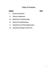
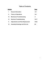
I. Overview<br />
Purpose.<br />
This manual is designed to assist in the servicing of SCIFIT <strong>ISO1000R</strong><br />
exercise machines. This manual uses two systematic troubleshooting tables to<br />
address any problems that may arise with the <strong>ISO1000R</strong>. Besides the standard<br />
<strong>ISO1000R</strong>, there is an optional model that has bi-directional capabilities.<br />
Sections II and III contain some troubleshooting tables and maintenance<br />
procedures for the two models. Figures 1 and 2 show the standard <strong>ISO1000R</strong><br />
while Figures 3 and 4 show the bi-directional <strong>ISO1000R</strong>. Figures 5 and 6 are<br />
universal. References are made to the figures in the troubleshooting tables and<br />
maintenance procedures. A reference given in parentheses, “(See Figure 3)”, is<br />
for the servicing of a bi-directional unit; a non-parenthesized reference, “See<br />
Figure 1”, is for a standard unit. Underlined references such as “See Figure 5”<br />
refer the technician to a figure that corresponds to each model. Be sure to use<br />
the correct reference depending on what type of <strong>ISO1000R</strong> is being serviced.<br />
A parts list for the two model types is located in Section V of this manual.<br />
Item numbers are given that can be used to locate various parts in Figures 1-4.<br />
When troubleshooting, the actions taken to resolve problems should be<br />
performed in the order stated. Deviating from this sequence may cause damage<br />
to the equipment and lead to unnecessary repairs.<br />
Technical Support.<br />
For further assistance in service of SCIFIT products, please call (800)<br />
745-1373, extension 21. The technical support department is staffed from 8 AM<br />
to 5 PM CST Monday through Friday. A voicemail service is available 24 hours<br />
daily for recording messages to request technical support and to order<br />
replacement parts.<br />
Please have the following information prior to calling technical support:<br />
• Model number of equipment<br />
• Serial number of equipment<br />
• Point of contact name and phone number<br />
• Detailed description of symptoms encountered.<br />
2
II. Troubleshooting Tables<br />
Note: A reference given in parenthesis, “(See Figure…)”, is intended for the<br />
servicing of a bi-directional unit. A reference without parenthesis is followed when<br />
servicing a standard unit.<br />
Table 1 – Electrical Troubleshooting<br />
Problem Possible Reasons Solutions<br />
1.1 The machine appears to<br />
be off in spite of being<br />
plugged in and switched<br />
“on”.<br />
Faulty power supply<br />
board.<br />
If buttons on the control display<br />
beep when pressed, replace power<br />
supply board. Otherwise, check<br />
power supply board. See<br />
Procedure 2.<br />
Faulty fuse.<br />
Loose cable connection.<br />
Check and replace fuse if needed.<br />
See Figure 5.<br />
Check wire connections at power<br />
supply and display boards.<br />
1.2 Upper control panel<br />
lights are dim.<br />
1.3 Upper board accepts<br />
commands but pedaling<br />
resistance does not<br />
change.<br />
1.4 LED’s on upper board<br />
blinking off/on, then go<br />
dead.<br />
1.5 Heart rate displays zero<br />
(0) in window<br />
Power display board is<br />
faulty.<br />
Dip switch setting is<br />
incorrect.<br />
Power display board is<br />
faulty.<br />
Ribbon cable<br />
connections are loose.<br />
Faulty power supply<br />
board.<br />
Display board is faulty.<br />
Chest strap and<br />
transmitter improperly<br />
worn.<br />
Loose sensor lead connection<br />
at display board.<br />
Faulty receiver.<br />
Replace power display board. See<br />
Procedure 1.<br />
Set dip switch to 01.<br />
Check and replace power supply<br />
board as needed. See Procedure 2.<br />
Check and replace accordingly.<br />
Unplug and re-plug machine to<br />
reset.<br />
Check and replace power supply<br />
board as needed. See Procedure 2.<br />
Replace display board.<br />
Verify that they are being properly<br />
worn.<br />
Check and adjust as needed.<br />
If there is no audible signal, replace<br />
receiver.<br />
3
1.6 Unit keeps blowing<br />
fuses.<br />
1.7 The upper display resets<br />
after starting a program.<br />
1.8 Program stops, lines of<br />
dots shoot across<br />
screen.<br />
1.9 Machine shuts down in<br />
programs but works in<br />
manual.<br />
1.10 Can’t select program<br />
or enter information and<br />
no beep when buttons<br />
are pressed.<br />
Too many units are<br />
daisy-chained together.<br />
Faulty power supply<br />
board.<br />
Ribbon cable connection<br />
is loose.<br />
Power cord is loose.<br />
Display board is faulty.<br />
Ribbon cable connection<br />
is loose.<br />
Display board is faulty.<br />
Display board is faulty.<br />
Membrane is faulty.<br />
Do not daisy-chain more than 3<br />
units together.<br />
Check and replace power supply<br />
board as needed. See Procedure 2.<br />
Check cable connection at power<br />
supply and display boards.<br />
Check and adjust as needed.<br />
Replace display board.<br />
Check and adjust cable connection<br />
as needed.<br />
Replace display board.<br />
Replace display board.<br />
Replace membrane.<br />
4
Table 2 – Mechanical Troubleshooting<br />
Problem Possible Reasons Solutions<br />
2.1 Pedals lock up while<br />
operating.<br />
Power supply board is<br />
faulty.<br />
Unplug power cord. If rails move,<br />
replace power supply board.<br />
2.2 No resistance on pedals<br />
when in a program.<br />
2.3 Very little resistance at<br />
any level.<br />
Brake is bad.<br />
No speed signal<br />
Wires going to brake are<br />
disconnected.<br />
Power supply board is<br />
faulty.<br />
Speed sensor improperly<br />
adjusted.<br />
Improper speed sensor<br />
connection with power<br />
supply board.<br />
If pedals do not move with power<br />
cord unplugged, replace brake. See<br />
Procedure 4.<br />
Check and adjust the speed sensor<br />
as needed. See Procedure 3.<br />
Check that brake wires are properly<br />
connected.<br />
Check and replace power supply<br />
board as needed. See Procedure 2.<br />
Check and adjust the speed sensor<br />
as needed. See Procedure 3.<br />
Check voltage at power supply<br />
board. See Procedure 2.<br />
2.4 Belt is slipping Not enough tension on<br />
the brake drive belt.<br />
Tighten the belt to ¼” deflection at<br />
10lbs of force.<br />
5
III. Maintenance Procedures<br />
Procedure 1 - Removing the<br />
Power Supply Board<br />
1. Unplug the unit from the power<br />
source.<br />
2. Lay it on its side.<br />
3. Locate the power supply board<br />
access plate under front of unit.<br />
Refer to item 27 in Figure 1<br />
(Refer to item 27 in Figure 3).<br />
4. Remove the four (4) screws. Be<br />
careful when pulling down the<br />
power supply board because of<br />
the plastic ties and brake wires.<br />
5. Cut all the plastic ties.<br />
6. Before disconnecting any of the<br />
wires, make note of the wiring<br />
sequence. Refer to the wiring<br />
diagram, Figure 6.<br />
7. Disconnect the following:<br />
a. The two (2) white (110 V) and<br />
two (2) black (24 V)<br />
transformer wires. These are<br />
all the wires from J4 on Figure<br />
6.<br />
b. The black and white wires<br />
from the power entry module<br />
– total of two (2). These are<br />
the wires at terminals ACIN1<br />
and ACIN2 on the LCB.<br />
c. The two (2) red brake wires.<br />
d. The one (1) speed sensor<br />
plug – J5 on Figure 6.<br />
e. The one (1) ribbon cable.<br />
8. Reinstallation is the reverse of<br />
removal.<br />
9. After reinstalling the power<br />
supply board, perform the<br />
following procedure to test<br />
correct reinstallation.<br />
a. Plug into power source and<br />
turn on.<br />
b. The message “SCIFIT FOR<br />
SCIENTIFIC SOLUTIONS”<br />
should be scrolling across<br />
upper display board. If not,<br />
see troubleshooting table.<br />
c. Press the start button.<br />
d. Turn the crankshaft in a<br />
forward motion.<br />
e. Verify that values are being<br />
displayed in the rpm/Watt<br />
window.<br />
f. Press the up arrow key to<br />
increase the resistance. It<br />
should become more difficult<br />
to turn the crankshaft. In not,<br />
consult the troubleshooting<br />
table.<br />
g. Press the up arrow and hold<br />
until level 22. After 3-5<br />
seconds of turning, the<br />
resistance should be at its<br />
maximum level. If not refer to<br />
the troubleshooting table. If<br />
brake loaded up to maximum<br />
setting, then the job is<br />
complete.<br />
Procedure 2 - Checking voltage at<br />
the Power Supply Board<br />
1. Follow steps 1-4 in Procedure 1.<br />
2. Use a voltmeter to measure the<br />
DC voltage across the speed<br />
sensor pins on the power supply<br />
board. Measure the voltage<br />
across the pin with the red wire<br />
(+) and either one of the center<br />
pins (-). The voltmeter should<br />
measure 4-5 volts DC.<br />
3. If there is no voltage, replace the<br />
power supply board.<br />
Procedure 3 – Checking and<br />
Adjusting the Speed Sensor<br />
1. Turn machine on and press start.<br />
6
2. Turn crank arms at 1 revolution<br />
per second. The RPM window<br />
should display around 60 ±10<br />
rpm.<br />
3. If the RPM window is displaying a<br />
reading outside of the specified<br />
range, proceed to the next step to<br />
adjust the speed sensor.<br />
4. Remove the hood.<br />
5. The air gap between the brake<br />
flywheel and speed sensor<br />
should be 1/8” – 3/16”.<br />
6. The speed sensor must be<br />
pointed directly at the flywheel so<br />
the eyes of the sensor will<br />
intersect the center of the axis of<br />
the brake. Adjust as needed.<br />
7. Rotate the crank arm again at 1<br />
revolution per second. If the RPM<br />
window displays a number<br />
greater than zero (0) but not<br />
within 60 ±10 rpm, repeat steps 1<br />
- 6. If a reading of zero (0) is<br />
displayed, proceed to step 7.<br />
8. Use a voltmeter to measure the<br />
DC voltage across J5 pin 1 (+)<br />
and J5 pin 2<br />
(-) on the power supply board.<br />
Refer to Figure 6. The voltmeter<br />
should read 4-5 VDC.<br />
9. If there is no voltage, replace the<br />
power supply board. If 4-5 volts<br />
are present, replace the speed<br />
sensor.<br />
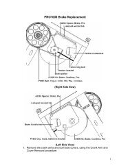
Procedure 4 – Removal and<br />
Replacement of the Brake<br />
Assembly<br />
1. Remove the two screws holding<br />
the bottle cage below the<br />
handlebars. Remove the single<br />
screw located just above the<br />
power entry module.<br />
2. Remove the five screws from<br />
side of the left cover. Position<br />
the left crank arm pointing<br />
backward and parallel to the base<br />
frame. Pull the front edge of the<br />
cover and slide it inward and<br />
backward to clear crank arm.<br />
3. Repeat step 2 for the right side.<br />
4. Disconnect the two red wires on<br />
the right side of brake.<br />
5. Remove the ½” nuts and<br />
lockwashers from both brake<br />
studs.<br />
6. Remove the 10-32 allen-head<br />
screw on the right side of brake.<br />
7. Remove the tensioning screws at<br />
the top center of the brake on<br />
each side of the sheet metal<br />
frame.<br />
8. Remove the V-belt from the<br />
plastic pulley by wedging a<br />
screwdriver blade between the<br />
belt and pulley while rotating the<br />
brake slowly downward to work<br />
the belt off the pulley. Take care<br />
not to damage pulley.<br />
9. Lift the brake upward to clear<br />
frame and pull the speed sensor<br />
bracket off the left brake stud.<br />
Remove the brake from the<br />
machine and set aside to return<br />
to SCIFIT (request a UPS call tag<br />
by phone).<br />
10. Hoist the replacement brake<br />
above the frame mounting slots<br />
and wrap V-belt around brake<br />
hub. Position V-belt hanging<br />
behind the idler pulley.<br />
11. Put the speed sensor bracket on<br />
the left brake stud. Note: If old<br />
brake has a smaller diameter (7”<br />
vs. 9”) a replacement speed<br />
sensor bracket must be used.<br />
Remove the single screw holding<br />
the speed sensor to the old<br />
bracket and attach the sensor,<br />
7
with the same orientation, to the<br />
new bracket. Refer to Procedure<br />
3, if needed.<br />
12. Slide the brake studs and speed<br />
sensor bracket inside and to the<br />
bottom of the frame mounting<br />
slots.<br />
13. Connect the two red wires to the<br />
brake.<br />
14. Loosely attach the lockwashers<br />
and nuts to the brake studs.<br />
15. Rotate the stator of brake to align<br />
the screw hole on the right side of<br />
brake with sheet metal frame.<br />
Loosely attach the 10-32 screw to<br />
this hole.<br />
16. Slip the V-belt over the plastic<br />
pulley while slowly turning the<br />
brake downward to install and<br />
center the belt on the pulley.<br />
17. Insert the left tensioner screw<br />
and finger-tighten. Repeat this<br />
process on the right side.<br />
18. Tighten the left-side tensioner<br />
screw with an allen wrench until<br />
the angle brackets begin to bend<br />
inward. Repeat this process on<br />
the right.<br />
19. Position the speed sensor<br />
bracket vertically.<br />
20. Snugly tighten the brake stud<br />
nuts until the lock washers<br />
compress. Do not over-tighten to<br />
avoid breaking the studs.<br />
21. Tighten the 10-32 screw on the<br />
right side of brake.<br />
22. Rotate the brake assembly to<br />
verify the V-belt is centered in the<br />
idler pulley. If misaligned, wedge<br />
a screwdriver blade between the<br />
face of the brake and the belt<br />
while turning Assembly to align<br />
belt to center of idler pulley.<br />
23. Attach speed sensor tape to the<br />
left edge of the brake armature.<br />
First peel off tape backing on the<br />
end with the wide silver band and<br />
stick on the brake surface<br />
hanging down. Slowly rotate the<br />
brake upward and wrap tape<br />
around the circumference of the<br />
brake.<br />
24. Perform the following steps 25<br />
through 29 and perform the<br />
alignment (Procedure 3), if<br />
indicated results are not<br />
attainable.<br />
25. Plug in and turn on machine but<br />
don’t press any buttons. The<br />
display will be scrolling the<br />
message, “SCIFIT…” Slowly<br />
rotate the crank arm assembly<br />
and the message will change to a<br />
programming prompt. The<br />
following values will be displayed:<br />
[20.00] in TIME, [0] in RPM, and<br />
[4] in LEVEL. If the display<br />
doesn’t default to these values,<br />
perform Procedure 3.<br />
26. Press the START/STOP button<br />
once and press the SCAN/HOLD<br />
button to hold the RPM function.<br />
Press and hold the DOWN<br />
ADJUST arrow until 0.0 is<br />
displayed in the LEVEL window.<br />
27. Rotate the crank arms at one<br />
revolution per second and ensure<br />
display accurately reads about 60<br />
RPM.<br />
28. Press and hold the UP ADJUST<br />
arrow button to the maximum,<br />
level 22. Rotate the crank arms<br />
as rapidly as possible. Brake<br />
resistance should become<br />
increasingly difficult momentarily.<br />
29. Replace the covers and steps 1<br />
through 3 in reverse order.<br />
8
IV. Figures<br />
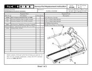
Figure 1 – Standard <strong>ISO1000R</strong> Total Assembly<br />
9
Figure 2 – Standard <strong>ISO1000R</strong> Main Frame<br />
10
Figure 3 – Bi-Directional <strong>ISO1000R</strong> Total Assembly<br />
11
Figure 4 – Bi-Directional <strong>ISO1000R</strong> Main Frame<br />
12
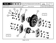
Figure 5 – Electrical Board with Fuse Holder<br />
13
Figure 6 – <strong>ISO1000R</strong> Wiring Diagram<br />
14
V. <strong>ISO1000R</strong> Parts List<br />
Standard <strong>ISO1000R</strong><br />
Item Description Part No. Qty.<br />
1 overlay/switch panel 65112 1<br />
2 Display board 65110S 1<br />
3 standoffs, 1", 6-32 P1051 6<br />
4 heart rate pickup/cable, assy 65160 1<br />
5 Console 65202 1<br />
6 Bracket, mounting, pickup, heart-rate A1124 1<br />
7 screws, 6-32x.250, p.h., cap screw, pltd. 2<br />
8 screws, 8-32 x 3/8 f. h. pltd. 1<br />
9 cable, ribbon, assy 65120 1<br />
10 grommet, hole, 1 1/2 dia. P1105 3<br />
11 lockwashers, 1/4 P1056 10<br />
12 bolts, 1/4-20 x 5/8 pltd. P1054 6<br />
13 lockwashers, 5/16 P1059 34<br />
14 bolts, 5/16 - 18 x 5/8 pltd. P1057 8<br />
15 decal, Scifit P1100 2<br />
16 washer, cover, plastic, black 13<br />
17 screw, 10-32x.5, black, b.h., socket cap P1062 29<br />
18 cover, right P1036 1<br />
19 decal, plate, scuff P1106 2<br />
20 crank, 170mm P1191 1<br />
21 bolt, crank, 8mm P1081 2<br />
22 Pedal, Pro II (pair) 65550 1<br />
23 cord, power, AC 65169 1<br />
24 manual, operator's P1104 1<br />
25 decal, serial number P1103 1<br />
26 PCB, supply, power 65150S 1<br />
27 plate, mounting, electronics, lower A1019 1<br />
28 decal, warning, hi voltage P1102 1<br />
29 screw, 10-32x.5, p.h., pltd. 4<br />
30 washer, star, #8 4<br />
31 nuts, 10-32, pltd. P1073 4<br />
32 lockwasher, #10, P1074 8<br />
33 transformer, supply, power 65180 1<br />
34 washer, star, #10 4<br />
35 standoff, 10-32x3/8 4<br />
36 bracket, PCB, lower A1047 1<br />
37 extrusion, rail, roller, 34" A1222 2<br />
38 nut, pan, 5/16-18 10<br />
39 endcap, 3"dia 70330 4<br />
40 bolt, 5/16-18 x 3, pltd. 10<br />
41 decal, iso 1000r 1<br />
42 screw, p.h., black 20<br />
43 roller, urethane, 1 1/4 dia. X 3/8 P1038 20<br />
44 nut, lock, 5/16-18, pltd. 20<br />
45 rod, lock 1<br />
46 cover, seatpost, iso1000r 1<br />
47 pin, clevis, 1/4 x 1" 2<br />
48 brkt., pos., adj., lever A1115 1<br />
15
16<br />
49 pin, cotter, 3/32 x 3/4" 2<br />
50 brkt., pivot, rod, lock A1147 1<br />
51 handlebar, seat, iso1000r, weldment A1144 1<br />
52 screw, 1/4-20x1.25, black, b.h., socket cap 4<br />
53 lockwasher, 1/4, black 4<br />
54 frame, seat, Iso1000r C1113 2<br />
55 seat pad (back) 71101 1<br />
56 seat pad (bottom) 71100 1<br />
57 knob, ball, 7/16-20, 1.375 dia. P1125 1<br />
58 bolt, 1/4-20x1.25, pltd. 4<br />
59 bracket, spring A1120 1<br />
60 spring 1<br />
61 seat, base, iso1000r, weldment C1143 1<br />
62 track, adjustment, stainless A1149 1<br />
63 sticker, seat adjustment 1<br />
64 bolts, 5/16-18 x 2 1/2, hex, pltd. P1079 8<br />
65 lockwasher, 5/16, black 8<br />
66 cover, left P1035 1<br />
67 grip, 1" dia., 8" long, rubber P1163 1<br />
68 holder, bottle, water P1092 1<br />
69 mount, display, weldment B1139 1<br />
70 idler P1091 1<br />
71 Bracket, sensor, speed A1031 1<br />
72 sensor, speed, cable, assy A1089 1<br />
73 washer, #4, flat, pltd. 1<br />
74 washer, #4, split, pltd. 1<br />
75 belt, poly-V P1090 1<br />
76 screws, 4-40 x 1/2 p.h. pltd. 1<br />
77 bolt, 3/8-16 x 1 1/2 hex, pltd. 1<br />
78 pulley, poly-V, 6" dia P1097 1<br />
79 key, square, 1/4 x 1/4 x 1 P1098 1<br />
80 Tape, pickup, speed, brake 65141 1<br />
81 brake 68000 1<br />
82 plate, side, drivetrain, right C1132 1<br />
83 nut, 5/16-18, pltd. 6<br />
84 housing, bearing, jackshaft A1129 2<br />
85 washer, 5/16, flat 4<br />
86 bolts, 5/16 - 18 x 3/4, pltd. 4<br />
87 bolts, 5/16 - 18 x 1/2, pltd. 22<br />
88 nuts, 3/8-24 1<br />
89 lockwashers, 3/8 2<br />
90 module, outlet, power 65177 1<br />
91 module, power entry 65178 1<br />
92 plate, power entry A1018 1<br />
93 screws, 8-32 x 1/2, pan head, pltd. 4<br />
94 bolt, 3/8-24 x 2 1/2 hex, pltd. 1<br />
95 bracket, wheel, right A1016 1<br />
96 wheel, front P1063 1<br />
97 grommet, hole, 1" dia., P1060 1<br />
98 bracket, wheel, left A1015 1<br />
99 cover, pedal, right A1041 1<br />
100 sprocket, press-fit, 16T A1155 1<br />
101 shaft, jack, forward only A1138 1<br />
102 shaft, spacer A1131 1
103 hub, sprocket, press-fit, 16T, offset A1153 1<br />
104 chain, 1/2 pitch, #40, per ft. P1072 2<br />
105 cover, electronics, lower A1017 1<br />
106 spindle, crank, square taper, 6" long A1151 1<br />
107 flangette, bearing P1095 4<br />
108 bearing, P1096 2<br />
109 nut, jam, 5/16-18, pltd. P1099 8<br />
110 cover, pedal, left A1042 1<br />
111 support, cover A1033 1<br />
112 nut, 3/8-16 1<br />
113 bracket, tension, lower A1117 2<br />
114 bracket, tension, upper A1116 2<br />
115 socket head, 10-32x2.5, flat, d.h., pltd. 2<br />
116 plate, side, drivetrain, left C1133 1<br />
Bi-Directional<br />
Item Description Part No. Qty.<br />
1 overlay/switch panel 65112 1<br />
2 Display board 65110S 1<br />
3 standoffs, 1", 6-32 P1051 6<br />
4 heart rate pickup/cable, assy 65160 1<br />
5 Console 65202 1<br />
6 Bracket, mounting, pickup, heart-rate A1124 1<br />
7 screws, 6-32x.250, p.h., cap screw, pltd. 2<br />
8 screws, 8-32 x 3/8 f. h. pltd. 1<br />
9 cable, ribbon, assy 65120 1<br />
10 grommet, hole, 1 1/2 dia. P1105 3<br />
11 lockwashers, 1/4 P1056 10<br />
12 bolts, 1/4-20 x 5/8 pltd. P1054 6<br />
13 lockwashers, 5/16 P1059 38<br />
14 bolts, 5/16 - 18 x 5/8 pltd. P1057 12<br />
15 decal, Scifit P1100 2<br />
16 washer, cover, plastic, black 13<br />
17 screw, 10-32x.5, black, b.h., socket cap P1062 29<br />
18 cover, right P1036 1<br />
19 decal, plate, scuff P1106 2<br />
20 crank, 170mm P1191 1<br />
21 bolt, crank, 8mm P1081 2<br />
22 Pedal, Pro II (pair) 65550 1<br />
23 cord, power, AC 65169 1<br />
24 manual, operator's P1104 1<br />
25 decal, serial number P1103 1<br />
26 PCB, supply, power 65150S 1<br />
27 plate, mounting, electronics, lower A1019 1<br />
28 decal, warning, hi voltage P1102 1<br />
29 screw, 10-32x.5, p.h., pltd. 4<br />
30 washer, star, #8 4<br />
31 nuts, 10-32, pltd. P1073 4<br />
32 lockwasher, #10, P1074 8<br />
33 transformer, supply, power 65180 1<br />
34 washer, star, #10 4<br />
35 standoff, 3/8", 10-32 4<br />
36 bracket, PCB, lower A1047 1<br />
37 extrusion, rail, roller, 34" A1222 2<br />
17
18<br />
38 nut, pan, 5/16-18 10<br />
39 endcap, 3"dia 70330 4<br />
40 bolt, 5/16-18 x 3, pltd. 10<br />
41 decal, iso 1000r 1<br />
42 screw, 5/16-18, p.h., black 20<br />
43 roller, urethane, 1 1/4 dia. X 3/8 P1038 20<br />
44 nuts, lock, 5/16 -18 pltd. 20<br />
45 rod, lock A1146 1<br />
46 cover, seatpost, iso1000r 1<br />
47 pin, clevis, 1/4 x 1" 2<br />
48 brkt., pos., adj., lever A1115 1<br />
49 pin, carter, 3/32 x 3/4" 2<br />
50 brkt., pivot, rod, lock A1147 1<br />
51 handlebar, seat, iso1000r, weldment A1144 1<br />
52 screw, 1/4-20x1.25, black, b.h., socket cap 4<br />
53 lockwasher, 1/4, black 4<br />
54 frame, seat, Iso1000r C1113 2<br />
55 seat pad (back) 71101 1<br />
56 seat pad (bottom) 71100 1<br />
57 knob, ball, 7/16-20, 1.375 dia. P1125 1<br />
58 bolt, 1/4-20x1.25, pltd. 4<br />
59 bracket, spring A1120 1<br />
60 spring 1<br />
61 seat, base, iso1000r, weldment C1143 1<br />
62 track, adjustment, stainless A1149 1<br />
63 sticker<br />
64 bolts, 5/16-18 x 2 1/2, hex, pltd. P1079 8<br />
65 lockwasher, 5/16, black 8<br />
66 cover, left P1035 1<br />
67 grip, 1" dia., 8" long, rubber P1163 1<br />
68 holder, bottle, water P1092 1<br />
69 mount, display, weldment B1139 1<br />
70 idler P1091 1<br />
71 Bracket, sensor, speed A1031 1<br />
72 sensor, speed, cable, assy A1089 1<br />
73 washer, #4, flat, pltd. 1<br />
74 washer, #4, split, pltd. 1<br />
75 belt, poly-V P1090 1<br />
76 screws, 4-40 x 1/2 p.h. pltd. 1<br />
77 bolt, 3/8-16 x 1 1/2 hex, pltd. 1<br />
78 pulley, poly-V, 6" dia P1097 1<br />
79 key, square, 1/4 x 1/4 x 1 P1098 1<br />
80 Tape, pickup, speed 65141 1<br />
81 brake 68000 1<br />
82 plate, side, drivetrain, right C1132 1<br />
83 nut, 5/16-18, pltd. 6<br />
84 housing, bearing, jackshaft A1129 2<br />
85 washer, 5/16, flat 8<br />
86 bolts, 5/16 - 18 x 3/4, pltd. 4<br />
87 bolts, 5/16 - 18 x 1/2, pltd. 22<br />
88 housing, bearing, bi-direct. Shaft A1130 2<br />
89 nuts, 3/8-24 1<br />
90 lockwashers, 3/8 2<br />
91 module, outlet, power 65177 1<br />
92 module, power entry 65178 1<br />
93 plate, power entry A1018 1
19<br />
94 screws, 8-32 x 1/2, pan head, pltd. 4<br />
95 bolt, 3/8-24 x 2 1/2 hex, pltd. 1<br />
96 bracket, wheel, right A1016 1<br />
97 wheel, front P1063 1<br />
98 grommet, hole, 1" dia., P1060 1<br />
99 bracket, wheel, left A1015 1<br />
100 cover, pedal, right A1041 1<br />
101 hub, sprocket, press-fit, 16T, centered A1154 2<br />
102 shaft, jack A1137 1<br />
103 Shaft, spacer A1131 1<br />
104 shaft, bi-directional A1136 1<br />
105 hub, sprocket, press-fit, 16T, offset A1153 2<br />
106 sprocket, press-fit, 16T A1155 4<br />
107 chain, 1/2 pitch, #40, per ft. P1072 2<br />
108 cover, electronics, lower A1017 1<br />
109 spindle, crank, square taper, 6" long A1151 1<br />
110 flangette, bearing P1095 4<br />
111 bearing, P1096 2<br />
112 nut, jam, 5/16-18, pltd. P1099 8<br />
113 cover, pedal, left A1042 1<br />
114 support, cover A1033 1<br />
115 nut, 3/8-16 1<br />
116 bracket, tension, lower A1117 2<br />
117 bracket, tension, upper A1116 2<br />
118 socket head, 10-32x2.5, flat, d.h., pltd. 2<br />
119 plate, side, drivetrain, left C1133 1