TC1000 Service Manual - SciFit
TC1000 Service Manual - SciFit
TC1000 Service Manual - SciFit

You also want an ePaper? Increase the reach of your titles
YUMPU automatically turns print PDFs into web optimized ePapers that Google loves.
<strong>TC1000</strong><br />
<strong>Service</strong> <strong>Manual</strong><br />
SALES: 800-278-3933<br />
CUSTOMER SERVICE: 800-745-1373
Table of Contents<br />
Section<br />
Page<br />
I. Overview 2<br />
II. Troubleshooting Tables 3<br />
III.<br />
Maintenance Procedures<br />
Procedure 1 – Removal and Reinstallation of<br />
the Power Supply Board 6<br />
Procedure 2 – Checking Voltage at the<br />
Power Supply Board 6<br />
Procedure 3 – Checking and Adjusting the<br />
Speed Sensor 7<br />
Procedure 4 – Removal and Replacement of<br />
the Brake Assembly 7<br />
IV.<br />
Figures<br />
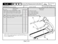
Figure 1 – <strong>TC1000</strong> Total Assembly (Items 1-20) 9<br />
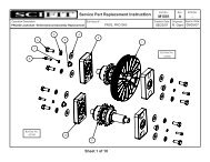
Figure 2 – <strong>TC1000</strong> Main Frame (Items 21-43) 10<br />
Figure 3 – Power Entry Module with<br />
Fuse Holder 11<br />
Figure 4 – <strong>TC1000</strong> Wiring Diagram 12<br />
V. <strong>TC1000</strong> Parts List 13<br />
1
I. Overview<br />
Purpose.<br />
This manual is designed to assist in service of SCIFIT <strong>TC1000</strong> exercise<br />
machines. The manual is divided into sections to diagnose and isolate problems.<br />
Troubleshooting tables and procedures, along with drawings, are provided to aid<br />
technicians in servicing equipment. The Item Numbers given in the parts list in<br />
Section V can be used to determine the location of various parts in Figures 1<br />
and 2.<br />
When troubleshooting, the actions taken to resolve problems should be<br />
performed in the order stated. Deviating from this sequence may cause damage<br />
to the equipment and lead to unnecessary repairs.<br />
Technical Support.<br />
For further assistance in service of SCIFIT products, please call (800)<br />
745-1373, extension 21. The technical support department is staffed from 8 AM<br />
to 5 PM CST Monday through Friday. A voicemail service is available 24 hours<br />
daily for recording messages to request technical support and to order<br />
replacement parts.<br />
Please have the following information prior to calling technical support:<br />
• Model number of equipment<br />
• Serial number of equipment<br />
• Point of contact name and phone number<br />
• Detailed description of symptoms encountered.<br />
2
II. Troubleshooting Tables<br />
Table 1 – Electrical Troubleshooting<br />
Problem Possible Reasons Solutions<br />
1.1 The machine appears to<br />
be off when plugged in<br />
and switched “on”.<br />
Faulty power supply<br />
board (Item 23).<br />
If buttons on the control display<br />
beep when pressed, replace power<br />
supply board. See Procedure 1.<br />
Otherwise, check power supply<br />
board. See Procedure 2.<br />
1.2 Upper control panel<br />
(Item 2) lights are dim.<br />
1.3 Upper board (Item 2)<br />
accepts commands but<br />
rotational resistance<br />
does not change.<br />
1.4 LED’s on upper board<br />
(Item 2) blinking off/on,<br />
then go dead.<br />
1.5 Heart rate displays zero<br />
(0) in window<br />
1.6 Unit keeps blowing<br />
fuses.<br />
Faulty fuse.<br />
Loose cable connection.<br />
Power supply board<br />
(Item 23) is faulty.<br />
Dip switch setting is<br />
incorrect.<br />
Power supply board<br />
(Item 23) is faulty.<br />
Ribbon cable (Item 5)<br />
connections are loose.<br />
Faulty power supply<br />
board (Item 23).<br />
Display board (Item 2) is<br />
faulty.<br />
Chest strap and transmitter<br />
improperly worn.<br />
Loose sensor lead<br />
connection at display<br />
board (Item 2).<br />
Faulty receiver.<br />
Too many units are<br />
daisy-chained together.<br />
Faulty power supply<br />
board (Item 23).<br />
Check and replace fuse if needed.<br />
(See Fig. 3)<br />
Check wire connections at power<br />
supply and display boards.<br />
Replace power supply board. See<br />
Procedure 1.<br />
Set dip switch to 01.<br />
Check and replace power supply<br />
board as needed. See Procedure 2.<br />
Check and replace accordingly.<br />
Unplug and re-plug machine to<br />
reset.<br />
Check and replace power supply<br />
board as needed. See Procedure 2.<br />
Replace display board.<br />
Verify that they are being properly<br />
worn.<br />
Check and adjust as needed.<br />
If there is no audible signal, replace<br />
receiver.<br />
Do not daisy chain more than 3<br />
units together.<br />
Check and replace power supply<br />
board as needed. See Procedure 2.<br />
3
1.7 The upper display (Item<br />
2) resets after starting a<br />
program.<br />
1.8 Program stops, lines of<br />
dots shoot across<br />
screen.<br />
1.9 Machine shuts down in<br />
programs but works in<br />
manual.<br />
1.10 Can’t select program<br />
or enter information and<br />
no beep when buttons<br />
are pressed.<br />
Ribbon cable connection<br />
is loose (Item 5).<br />
Power cord is loose.<br />
Display board is faulty.<br />
Ribbon cable (Item 5)<br />
connection is loose.<br />
Display board (Item 2) is<br />
faulty.<br />
Display board (Item 2) is<br />
faulty.<br />
Overlay/switch panel<br />
(Item 1) is faulty.<br />
Check cable connection at power<br />
supply and display boards (Items 23<br />
and 2, respectively).<br />
Check and adjust as needed.<br />
Replace display board.<br />
Check and adjust cable connection<br />
as needed.<br />
Replace display board.<br />
Replace display board.<br />
Replace overlay/switch panel.<br />
4
Table 2 – Mechanical Troubleshooting<br />
Problem Possible Reasons Solutions<br />
2.1 Pedals lock up while<br />
operating.<br />
Power supply board<br />
(Item 23) is faulty.<br />
Unplug power cord. If pedals now<br />
move freely, replace power supply<br />
board.<br />
2.2 No resistance on pedals<br />
when in a program.<br />
2.3 Very little resistance at<br />
any level.<br />
Brake (Item 30) is faulty.<br />
No speed signal<br />
Wires going to brake<br />
(Item 30) are disconnected.<br />
Power supply board<br />
(Item 23) is faulty.<br />
Speed sensor (Item 37)<br />
improperly adjusted.<br />
Bad speed sensor<br />
connection with power<br />
supply board (Item 23).<br />
If pedals do not move with power<br />
cord unplugged, replace brake. See<br />
Procedure 4.<br />
Check and adjust the speed sensor<br />
(Item 37) as needed. See<br />
Procedure 3.<br />
Check that brake wires are properly<br />
connected.<br />
Check and replace power supply<br />
board as needed. See Procedure 2.<br />
Check and adjust the speed sensor<br />
as needed. See Procedure 3.<br />
Check voltage at power supply<br />
board. See Procedure 2.<br />
5
III. Maintenance Procedures<br />
Procedure 1 - Removal and<br />
Reinstallation of the Power Supply<br />
Board<br />
1. Unplug the unit from the power<br />
source.<br />
2. Remove the screws (Item 17)<br />
that fasten the covers (Items 10<br />
and 16) to the main frame. The<br />
covers can be removed now.<br />
3. Locate the power supply cover<br />
(Item 22) on unit. Remove the<br />
four (4) screws and the power<br />
supply cover. Be careful when<br />
removing the power supply cover<br />
because of the plastic ties and<br />
brake wires.<br />
4. Cut all the plastic ties.<br />
5. Before disconnecting any of the<br />
wires, make note of the wiring<br />
sequence. Refer to the wiring<br />
diagram, Fig. 4.<br />
6. Disconnect the following:<br />
a. The two (2) white (110 V) and<br />
two (2) black (24 V)<br />
transformer wires. These are<br />
all the wires from J4 on Fig. 4.<br />
b. The black and white wires<br />
from the power entry module<br />
– total of two (2). These are<br />
the wires at terminals ACIN1<br />
and ACIN2 on the LCB.<br />
c. The two (2) red brake wires.<br />
d. The one (1) speed sensor<br />
plug – J5 on Fig. 4.<br />
e. The one (1) ribbon cable.<br />
8. The power supply board (Item<br />
23) can now be removed.<br />
Reinstallation is the reverse of<br />
removal.<br />
9. After reinstalling the power<br />
supply board, perform the<br />
following procedure to test<br />
correct reinstallation.<br />
a. Plug into power source and<br />
turn on.<br />
b. The message “SCIFIT FOR<br />
SCIENTIFIC SOLUTIONS”<br />
should be scrolling across<br />
upper display board. If not,<br />
see troubleshooting table.<br />
c. Press the start button.<br />
d. Press SCAN/HOLD so that<br />
the CLIMB RATE indicator<br />
light stays lit.<br />
e. Move the pedals as if<br />
exercising.<br />
f. Verify that the values are<br />
increasing in the CLIMB<br />
RATE window.<br />
g. Press the down arrow key to<br />
slow the pedal speed. It<br />
should be slow and smooth. If<br />
not, consult the troubleshooting<br />
table.<br />
h. Press the up arrow key to<br />
increase pedal speed. The<br />
stepping motion should be<br />
fast and smooth. If not, refer<br />
to the troubleshooting table.<br />
Procedure 2 - Checking voltage at<br />
the Power Supply Board<br />
1. Follow steps 1-3 in Procedure 1.<br />
2. Disconnect the speed sensor<br />
from the lower supply board at<br />
the J5 terminal. See Fig. 4. Use a<br />
voltmeter to measure the DC<br />
voltage across the speed sensor<br />
pins on the power supply board.<br />
Measure the voltage across the<br />
pin with the red wire (+) and<br />
either one of the center pins (-).<br />
The voltmeter should measure 4-<br />
5 volts DC.<br />
6
3. If there is no voltage, replace the<br />
power supply board. See<br />
Procedure 1.<br />
Procedure 3 – Checking and<br />
Adjusting the Speed Sensor<br />
1. Turn machine on and press<br />
START/STOP.<br />
2. Set the LEVEL to 0.0. Stand on<br />
the two pedals until they go down<br />
as far as they will go. The<br />
number in the DISTANCE<br />
window should increase every<br />
time the pedals are pressed<br />
down.<br />
3. If the number in the DISTANCE<br />
window does not increase each<br />
time the pedal is depressed,<br />
proceed to the next step to adjust<br />
the speed sensor.<br />
4. Remove the covers on the<br />
machine (Items 10 and 16).<br />
Locate the speed sensor on the<br />
unit (Item 37).<br />
5. The air gap between the brake<br />
flywheel and speed sensor<br />
should be 1/8”-3/16”.<br />
6. The speed sensor must be<br />
pointed directly at the flywheel so<br />
the eyes of the sensor will<br />
intersect the center of the axis of<br />
the brake. Adjust as needed.<br />
7. Again, stand on the two pedals<br />
until they go down as far as they<br />
will go. If the number in the<br />
DISTANCE window is greater<br />
than zero but does not increase<br />
by one, repeat steps 1-7. If a<br />
reading of zero (0) is displayed,<br />
proceed to step 8.<br />
8. Use a voltmeter to measure the<br />
DC voltage across J5 pin 1 (+)<br />
and J5 pin 2 (-) on the power<br />
supply board. Refer to Fig. 4. The<br />
voltmeter should read 4-5 VDC.<br />
9. If there is no voltage, replace the<br />
power supply board (Item 23). If<br />
4-5 volts are present, replace the<br />
speed sensor.<br />
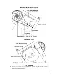
Procedure 4 – Removal and<br />
Replacement of the Brake<br />
Assembly<br />
1. Remove the screws (Item 17)<br />
that fasten the covers (Items 10<br />
and 16) to the main frame. The<br />
covers can be removed now.<br />
2. Tip the entire unit back so that it<br />
is resting horizontally on its two<br />
rectangular shaped feet and the<br />
two pedals. This will allow better<br />
access to the brake from the<br />
underside of the unit.<br />
3. Disconnect the two red wires on<br />
the right side of brake (Item 30).<br />
4. Relieve the tension in the brake<br />
drive belt (Item 42) by loosening<br />
the turnbuckles (Item 29) that are<br />
attached to the brake brackets.<br />
5. Remove the nuts and threaded<br />
bar that hold the brake drive idler<br />
(Item 25) onto the bracket. Also,<br />
loosen the nuts at the lower end<br />
of the brake brackets. With the<br />
idler removed and the brackets<br />
loose, the brake should be loose<br />
enough to remove the belt.<br />
6. Remove the three (3) socket<br />
head screws that hold the brake<br />
assembly to the support bracket.<br />
7. Pull brake away from main frame.<br />
Be careful not to damage the<br />
speed sensor when removing the<br />
brake.<br />
8. Remove the brake from the<br />
machine and set aside to return<br />
7
to SCIFIT (request a UPS call tag<br />
by phone).<br />
9. Reinstallation is the reverse of<br />
removal. Before tightening the<br />
tension in the brake drive belt,<br />
make sure that it is centered<br />
correctly.<br />
10. After brake assembly has been<br />
aligned and tension set, attach<br />
speed sensor tape to the brake<br />
armature. First peel off tape<br />
backing on the end with the wide<br />
silver band and stick on the brake<br />
surface hanging down. The tape<br />
should be on center with the<br />
speed sensor. Slowly rotate the<br />
brake upward and wrap tape<br />
around the circumference of the<br />
brake. It is extremely important<br />
that the speed sensor be<br />
centered over the tape.<br />
11. Stand unit up in its proper<br />
position. Perform steps 12-16. If<br />
the indicated results are not<br />
attainable, see Procedure 3.<br />
12. Plug in and turn on machine but<br />
don’t press any buttons. The<br />
display will be scrolling the<br />
message, “SCIFIT…”<br />
13. Press the START/STOP button.<br />
14. If the LEVEL light is not lit, press<br />
the SCAN/HOLD button until it<br />
becomes lit. Use the down arrow<br />
key to set the LEVEL to 0.0.<br />
15. Stand on the two pedals<br />
simultaneously so that they move<br />
once through their entire range of<br />
motion. The TOTAL CLIMB<br />
window should display 1. If it<br />
does proceed to step 16;<br />
otherwise, check that the air gap<br />
between the speed sensor and<br />
brake flywheel is 1/8”-3/16” then<br />
repeat steps 14 and 15.<br />
16. Use the UP arrow button to set<br />
the LEVEL to 4.0.<br />
17. Stand on the pedals and begin<br />
moving them at a rate typical of a<br />
workout.<br />
18. The resistance on the pedals<br />
should feel smooth and<br />
consistent. If it does, installation<br />
is complete; otherwise, see<br />
Procedure 3.<br />
8
IV. Figures<br />
Figure 1 – <strong>TC1000</strong> Total Assembly (Items 1-20)<br />
Figure 2 – <strong>TC1000</strong> Main Frame (Items 21-43)<br />
9
Figure 3 – Power Entry Module with Fuse Holder<br />
11
Figure 4 – <strong>TC1000</strong> Wiring Diagram<br />
12
V. <strong>TC1000</strong> Parts List<br />
Item Description<br />
Part No. Qty.<br />
1 overlay/switch panel 65112 1<br />
2 Display board 65110 1<br />
3 Console 65202 1<br />
4 Handgrip set, <strong>TC1000</strong> P1368 1<br />
5 cable, ribbon, assy 65120 1<br />
6 Pulley, clutch, roller, assy. P1375 2<br />
7 Ring, retainer 2<br />
8 Arm, pedal, upper P1376 2<br />
9 Cap, base, 3", adjustable 70330 2<br />
10 Cover, right, <strong>TC1000</strong> P1362 1<br />
11 Bolt, M10x1.5x70 2<br />
12 Bearing, roller, 6200-2z P1389 8<br />
13 Spacer, arm, upper P1390 4<br />
14 Cap, base, rectangular P1377 2<br />
15 Pad, foot, rubber P1378 2<br />
16 Cover, left, <strong>TC1000</strong> P1363 1<br />
17 Screw, fastener, hood, <strong>TC1000</strong> P1369 8<br />
18 Belt, pedal, <strong>TC1000</strong> P1366 2<br />
19 Bracket, heartrate A1124 1<br />
20 Board, heartrate, PCB 65160 1<br />
21 Bracket, spring P1379 1<br />
22 Cover, PSB, <strong>TC1000</strong> P1380 1<br />
23 Power supply, (lower), serial 65150S 1<br />
24 Transformer, 24V, 5.4A 65180 1<br />
25 Idler, brake drive, <strong>TC1000</strong> P1381 1<br />
26 Recept, PEM, Daisychain 65177 1<br />
27 Module, power entry, RF/EFI 65178 1<br />
28 Wheel, <strong>TC1000</strong> P1382 2<br />
29 Turnbuckle P1383 2<br />
30 Brake, assy. 68300 1<br />
31 Roller, belt, pedal, <strong>TC1000</strong> P1393 2<br />
32 Spacer, roller, <strong>TC1000</strong> P1394 2<br />
33 Bearing, roller, 608-2SR P1395 4<br />
34 Arm, pedal, lower P1384 2<br />
35 Bearing, roller, 6202-2z P1391 8<br />
36 Spacer, arm, lower P1392 4<br />
37 Sensor, speed, cable, assy. A1089 1<br />
38 Shaft, F0.59x10.718 P1385 1<br />
13
14<br />
39 Stopper, rubber P1386 2<br />
40 Shaft, drive, main, assy. P1387 1<br />
41 Flywheel, <strong>TC1000</strong> P1388 1<br />
42 Belt, drive, brake, <strong>TC1000</strong> P1367 1<br />
43 Spring, return, pedal, <strong>TC1000</strong> P1365 2