PRO1000 Brake Replacement.pdf - SciFit
PRO1000 Brake Replacement.pdf - SciFit
PRO1000 Brake Replacement.pdf - SciFit

Create successful ePaper yourself
Turn your PDF publications into a flip-book with our unique Google optimized e-Paper software.
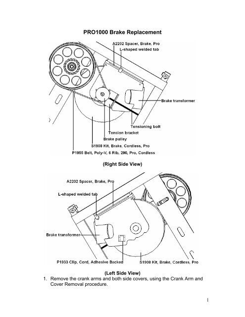
<strong>PRO1000</strong> <strong>Brake</strong> <strong>Replacement</strong><br />
(Right Side View)<br />
(Left Side View)<br />
1. Remove the crank arms and both side covers, using the Crank Arm and<br />
Cover Removal procedure.<br />
1
2. Remove the two (2) nuts holding the tensioning bolt to the tensioning<br />
bracket.<br />
3. Remove tensioning bolt from the frame.<br />
4. Cut the tie wrap mounting the 2-pin brake cable to the frame.<br />
5. Disconnect the 2-pin brake cable affixed to the brake transformer from the<br />
extension cable leading to the lower PCB.<br />
6. Unplug the 3-pin brake cable from the backside of the brake assembly<br />
(S1908) and hook the cable from the cable hook tab.<br />
7. Loosen each brake mounting bolt 3-4 turns.<br />
8. Unhook the poly-v belt (P1955) from around the brake pulley.<br />
9. Remove the two (2) brake mounting bolts on the right side of the frame.<br />
Let the brake flange rest on the L-shaped tab welded to the frame.<br />
10. Remove the brake spacer (A2202) on the right side.<br />
11. Support the brake and remove the two (2) brake mounting bolts on the left<br />
side of the frame.<br />
12. While supporting the brake, remove the brake spacer on the left side.<br />
13. Remove the brake assembly from the unit. Be very careful, as the brake<br />
assembly weighs approximately 32lbs.<br />
14. Rest the new brake assembly on the L-shaped tab welded to the frame on<br />
the right side.<br />
15. Place the brake spacer in place on the right side and start the two (2)<br />
brake mounting bolts. Each brake mounting bolt should have a flat<br />
washer followed by a lock washer. Tighten bolts finger tight<br />
16. While still supporting the brake assembly, insert the brake spacer on the<br />
left side and start the two (2) brake mounting bolts. Each brake mounting<br />
bolt should have a flat washer followed by a lock washer. Tighten bolts<br />
finger tight.<br />
17. Reinstall the poly-v belt on the brake pulley.<br />
18. Insert the tensioning bolt back through the frame and tensioning bracket.<br />
19. Start one (1) of the two (2) nuts on the tensioning bolt.<br />
20. Align the poly-v belt.<br />
21. Turn the nut on the tensioning bolt resting against the tensioning bracket<br />
clockwise until the belt is taut.<br />
22. Tighten all four (4) brake mounting bolts.<br />
23. Install the second nut on the tensioning bolt and tighten.<br />
24. Make sure the poly-v belt is running straight by spinning the brake<br />
assembly.<br />
25. Reconnect the 2-pin brake cable affixed to the brake transformer to the<br />
extension cable from the lower PCB.<br />
26. Reconnect the 3-pin cable to the backside of the brake assembly.<br />
27. Tie-wrap cables to the frame just below the brake transformer.<br />
28. Verify all connections and bolt tightness.<br />
29. Reinstall the covers and crank arms.<br />
30. Test operations of the unit. Make sure the poly-v belt does not slip at high<br />
resistance. If it does, the poly-v belt is not tight enough.<br />
2