SX, SXT Service Manual.pdf - SciFit
SX, SXT Service Manual.pdf - SciFit
SX, SXT Service Manual.pdf - SciFit

You also want an ePaper? Increase the reach of your titles
YUMPU automatically turns print PDFs into web optimized ePapers that Google loves.
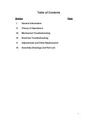
Table of Contents<br />
Section<br />
Page<br />
I. General Information 2-5<br />
II. Theory of Operations 6-8<br />
III. Mechanical Troubleshooting 9<br />
IV. Electrical Troubleshooting 10-17<br />
V. Adjustments and Parts Replacement 18-64<br />
VI. Assembly Drawings and Part List 65-<br />
1
I. General Information<br />
Purpose<br />
This manual provides information for the servicing of SCIFIT <strong>SX</strong>500,<br />
<strong>SX</strong>1000, <strong>SX</strong>7000, and <strong>SX</strong>T7000 cordless ellipticals. It uses systematic<br />
troubleshooting procedures to address problems that may arise with the<br />
cordless elliptical. The actions taken to resolve problems must be<br />
performed in the order stated. Deviating from this sequence may cause<br />
damage to the equipment, lead to unnecessary repairs, and/ or void the<br />
warranty.<br />
Technical Support<br />
For further assistance in the service of SCIFIT products, please call (800)<br />
745-1373 or (918) 359-2000, ext 3. We can also be reached by fax at<br />
(918) 359-2045 or by e-mail at service@scifit.com. The Product Support<br />
department is staffed from 7 AM to 6 PM CST Monday through Friday. A<br />
voicemail service is available 24 hours daily for recording messages to<br />
request technical support and to order replacement parts. Our mailing<br />
address is 5151 S. 110 th E. Avenue, Tulsa, OK 74146.<br />
Please have the following information prior to calling product<br />
support:<br />
• Model number of equipment<br />
• Serial number of equipment<br />
• Point of contact name, address, and phone number<br />
• Detailed description of symptoms encountered<br />
SCIFIT Statement of Warranty<br />
SCIFIT warranties new products against defective workmanship and/ or<br />
materials under normal and proper use subject to the following limitations:<br />
1. SCIFIT’s obligation to the original purchaser shall apply to both<br />
parts and cost of labor required to replace or repair a defective<br />
product for a period of one (1) year from the user purchase date as<br />
documented by the warranty card. If the customer fails to return<br />
the warranty card, the date of shipment from the factory is used.<br />
Thereafter, for a period of two (2) years, such obligation shall<br />
extend only to the supply of replacement parts or products with any<br />
labor costs associated with such replacement or repair to be at the<br />
Buyer’s expense.<br />
2. SCIFIT’s obligation shall be limited to repairing or replacing<br />
defective parts. No allowance shall be granted for repairs made<br />
by Buyer without SCIFIT’s prior written approval. The decision<br />
to replace or repair shall be solely at SCIFIT’s election.<br />
2
3. SCIFIT’s warranty does not apply to parts requiring replacement or<br />
repair due to abnormal wear and tear, improper use, corrosion<br />
(perspiration), improper maintenance, improper rated grounded or<br />
dedicated electrical circuits, or improper storage, nor does it apply<br />
where all or part of the product has been altered from its original<br />
state.<br />
4. THIS WARRANTY IS IN LIEU OF ALL OTHER WARRANTIES,<br />
EXPRESSED OR IMPLIED, ARISING BY LAW OR OTHERWISE<br />
INCLUDING WARRANTY OR MERCHANTABILITY OF FITNESS<br />
FOR PARTICULAR PURPOSE, AND IS IN LIEU OF ALL OTHER<br />
LIABILITIES OF SCIFIT INCLUDING DIRECT, INDIRECT,<br />
SPECIAL AND CONSEQUENTIAL DAMAGES OR PENALTIES<br />
EXPRESSED OR IMPLIED WHETHER ARISING OUT OF<br />
CONTRACT, NEGLIGENCE, OR OTHER TORT.<br />
5. Certain wear items are excluded from warranty coverage unless<br />
determined to be defective. These items include, but are not<br />
limited to:<br />
Rubber Grips<br />
Rail Roller Wheels<br />
Rubber Foot Beds<br />
Bio-Flex Cushions<br />
6. The following items are covered for a period of one (1) year only:<br />
Contact Heart Rate Grips<br />
Heart Rate PCB/ Transmitter<br />
Freight and Shipping<br />
SCIFIT is NOT responsible for the repair or replacement of any unit or part<br />
damaged during transit or installation. Fire, flood, and acts of God are<br />
NOT covered under this warranty. The customer is responsible for<br />
pursuing all freight damage claims with the appropriate transit company.<br />
If the customer signs for freight-damaged goods without noting the<br />
damage on the bill of lading, the customer is solely responsible for<br />
the cost of repair or replacement for such freight damage.<br />
Parts Supply<br />
During the first 30 days, warranty parts will be shipped via next day<br />
overnight delivery, excluding international shipments. Determination must<br />
be made before 2:00 p.m. CST on any given weekday for next day<br />
delivery. After 30 days, parts will be shipped via ground shipment. The<br />
customer is welcome to request overnight or second day parts shipping at<br />
the customer’s expense. If requested, SCIFIT will charge the customer’s<br />
UPS or Federal Express account, or COD the difference in freight cost<br />
between ground shipment and overnight or second day.<br />
3
Return Parts<br />
In order to research problems and ensure they do not reoccur, the<br />
rapid return of defective parts is our biggest help! Thank you in<br />
advance for your assistance.<br />
On electronics orders, a $100.00 core charge is assessed to each printed<br />
circuit board. This amount will be credited once the boards have been<br />
received by SCIFIT. All defective parts must be returned to the SCIFIT<br />
factory within 20 days of receipt of replacement part for invoice credit.<br />
Otherwise, SCIFIT will expect payment on the core charge net 30 days.<br />
Please follow these three (3) easy steps for returning parts:<br />
Step 1: Keep the box and packing material in which the new parts arrived.<br />
Locate the enclosed prepaid UPS return label. The return label is only for<br />
the parts that need to be returned as denoted on the picking ticket.<br />
Step 2: Wrap the defective part and place in the box for a safe return.<br />
Include a copy of the picking ticket that came with the replacement part.<br />
Step 3: When the parts have been packaged, place the prepaid UPS<br />
return label on the outside of the box. Drop the package at any UPS<br />
service center or hand the package to any UPS driver.<br />
When all of the parts are received and inspected at the factory, a credit<br />
will be issued for the original parts invoice. Attention service<br />
companies: Warranty labor invoices will NOT be paid until required<br />
defective parts are returned to the factory.<br />
Installation<br />
SCIFIT is NOT responsible for the repair or replacement of any unit or part<br />
damaged during installation. The customer is responsible for inspection of<br />
each unit and part for damage at the time of installation. The customer is<br />
responsible for pursuing all damage claims with the installer.<br />
<strong>Service</strong> Labor<br />
Where applicable, SCIFIT Product Support will arrange a local field<br />
service technician to provide field support. Every effort will be made to<br />
schedule service during the two (2) working days following notification of a<br />
problem or as soon as repair parts are available to the field service<br />
technician. Where possible, parts will be supplied in advance of the field<br />
service technicians so that the product is repaired with one (1) call. All<br />
jobs to be performed under labor warranty must have SCIFIT’s prior<br />
written approval or they will not be paid.<br />
4
Preventative Maintenance<br />
After training, always wipe down your SCIFIT exercise product.<br />
Perspiration that continuously settles on the frame, upholstery, casings,<br />
and control panels may eventually cause rust or damage. Damage<br />
resulting from lack of maintenance will NOT be covered under warranty.<br />
Preventative maintenance, completed according to the schedule below,<br />
will keep your SCIFIT elliptical functioning properly. We realize your time<br />
is valuable and have kept these maintenance items to a minimum.<br />
This preventative maintenance schedule assumes the equipment is<br />
utilized 6 to 8 hours per day. If the equipment is utilized to a greater<br />
extent, the maintenance schedule must be adjusted accordingly.<br />
Machine Weekly Monthly 6 Months Yearly<br />
Clean exterior Check Bio-Flex<br />
Inspect composite<br />
Cordless<br />
and TeleRails. Cushions, replace<br />
bearings on<br />
Ellipticals<br />
See Note 1 if necessary.<br />
TeleRails for<br />
wear.<br />
Note 1: Clean the console with a damp cloth. Use mild soap and warm<br />
water. Dry with a clean towel. The rest of the machine can be cleaned<br />
using common household cleaners.<br />
5
II.<br />
Theory of Operations<br />
The following is a theory of operation that encompasses all the electrical<br />
components, their functions, and how they interact with each other.<br />
Independent electrical components found in SCIFIT’s Cordless product line:<br />
1. Lower PCB (Power Supply)<br />
2. Upper PCB (Display)<br />
3. Generator/Electromagnetic Brake<br />
4. 12 Volt Battery<br />
5. Wall Pack Receptacle<br />
6. Hand Grip Heart rate PCB (HG HR)<br />
7. Wireless Heart rate PCB (Polar)<br />
Component Functions<br />
1. Lower PCB (Power Supply)<br />
A. Converts the12 to 400 volts AC from the generator into 12 volts DC<br />
using switching power supply technology.<br />
B. Provides 12 volts DC to upper PCB.<br />
C. Accepts 12 volts DC from either the battery or wall pack<br />
transformer if unavailable from the generator<br />
D. Receives Pulse Width Modulation (PWM) signal from the upper<br />
PCB for brake control.<br />
E. Contains Hi-power MOSFET circuitry that controls the brake.<br />
2. Upper PCB (Display)<br />
A. Accepts commands from a user.<br />
B. Displays information to the user.<br />
C. Regulates 12 volts DC from lower PCB down to 8 volts DC and 5<br />
volts DC.<br />
D. Operates the 8 and 5 volt DC serial communications (c-safe and<br />
cardio-key)<br />
E. Provides 5 Volts DC to the contact and wireless heart rate jacks.<br />
F. Receives signals from the contact and wireless heart rate PCB’s.<br />
G. Contains 5 volt DC display (LED) drivers.<br />
H. Contains the 5 volt DC memory and processor components.<br />
I. Provides PWM signal to lower PCB for brake control.<br />
3. Generator/Electromagnetic Brake<br />
Generator:<br />
o A three (3) phase generator that produces 0 to 400 volts AC<br />
depending on the RPM’s.<br />
o Provides AC voltage to the lower PCB.<br />
6
Electromagnetic Brake<br />
o An eddie current transformer that uses rising and collapsing<br />
electromagnetic fields to slow down the generator magnet traveling<br />
through it’s field.<br />
o Controlled by the lower PCB.<br />
4. 12 Volt DC Battery<br />
A. 12 volt sealed lead acid 1.3 Amp Hour Battery.<br />
B. Provides 12 Volts DC to lower PCB during:<br />
o Pause mode<br />
o Between intervals<br />
o Provides power for 15 seconds after generator stops.<br />
5. Wall Pack Receptacle<br />
A. 12 volt DC input receptacle that accepts voltage from a DC wall pack.<br />
B. Provides 12 volts DC to lower PCB when a wall pack is connected to it.<br />
C. Aids in battery charging.<br />
6. Hand Grip (Contact) Heart Rate (HG HR) PCB<br />
A. Outputs a square wave to the upper PCB.<br />
B. Equipped with right and left grip inputs.<br />
C. Power and ground is provided by the upper PCB.<br />
7. Wireless Heart rate PCB<br />
A. Outputs a square wave to the upper PCB.<br />
B. Has a 30” range and position is critical.<br />
C. Power and ground is provided by the upper PCB.<br />
System Functions<br />
Starting the Machine<br />
A. Pedaling the machine rotates the generator, which generates a<br />
current to power the electronics. A minimum of 13 RPM or 10 FPM<br />
must be maintained to keep machine powered up.<br />
B. The generator provides AC voltage to the lower PCB. The lower<br />
PCB then provides DC voltage to the upper PCB.<br />
C. The User controls the resistance by selecting a level on the display.<br />
The display sends a PWM signal which varies, depending on the<br />
level selected. The signal travels through the ribbon cable to the<br />
lower PCB. The lower PCB sends a square wave signal to the<br />
transformer on the brake which is proportionate to the amount of<br />
resistance commanded.<br />
D. The brake LED on the lower PCB, labeled D38 on older units and<br />
D19 on newer units, will illuminate any time braking is applied. The<br />
intensity of the LED is proportional to the level of resistance.<br />
7
E. The battery is charged anytime there is more than 13 RPM’s<br />
present.<br />
Stopping the unit<br />
A. When pedaling is discontinued, the brake continues to spin.<br />
B. The battery will engage once the actual RPM’s dip below 13.<br />
C. The battery remains active for 15 seconds and then a transistor that<br />
connects the battery to the rest of the lower PCB is unlatched. The<br />
transistor will remain unlatched until the unit sees an rpm value<br />
above 13 rpm’s.<br />
Using the Wall Pack<br />
A. Using the wall pack will allow the machine to be powered up<br />
without pedaling. Quick Start or any other program can be selected<br />
without have to pedal first. The machine will be powered up<br />
constantly when the wall pack is in use.<br />
8
III.<br />
Mechanical Troubleshooting<br />
A. Mechanical Troubleshooting Table<br />
Problem Possible Reasons Solutions<br />
TeleRails lock up while Faulty lower PCB. Replace lower PCB. (P. 26-29)<br />
operating.<br />
TeleRails are locked or Drive pulley moved over and is Realign drive pulley. (P. 60-61)<br />
hard to move.<br />
stuck against frame.<br />
Scraping or knocking<br />
noise from inside the<br />
unit.<br />
Drive pulley moved over.<br />
Spindle crank shaft bearings<br />
bad.<br />
Realign drive pulley. (P. 60-61)<br />
Replace bearings. (P. 60-61)<br />
Idler is bad.<br />
Brake pulley is loose.<br />
Brake bearings are bad.<br />
Replace idler. (P. 51)<br />
Fix or replace brake. (P. 49-50)<br />
Replace brake. (P. 49-50)<br />
Scraping noises from<br />
inside the TeleRails.<br />
Metal shavings left at<br />
the rear of the TeleRail<br />
system.<br />
TeleRails hitting side cover.<br />
Interior rollers are bad.<br />
Lateral rollers are bad.<br />
TeleRail is out of alignment.<br />
Realign TeleRails or trim side cover.<br />
(P. 58-59)<br />
Replace interior rollers. (P. 56-57)<br />
Replace lateral rollers. (P. 54-55)<br />
Realign crank arms. (P. 59)<br />
Lateral rollers are bad.<br />
Replace lateral rollers. (P. 54-55)<br />
Belt slipping. Belt too loose. Tension belt. (P. 62-63)<br />
One side TeleRail slips Bolts on the crank arm are Verify Woodruff key is in place and<br />
or clunks when loose.<br />
tighten bolts. (P. 59)<br />
rotated.<br />
Black TeleRail moves<br />
more than 1/8” side to<br />
side on spindle.<br />
Clunking underneath<br />
pedals.<br />
Woodruff key is missing.<br />
Missing snap ring.<br />
Missing IGUS washer.<br />
Cushion under saddle are<br />
damaged or missing.<br />
Replace woodruff key. (P. 59)<br />
Replace snap ring. (P. 58-59)<br />
Replace IGUS washer. (P. 58-59)<br />
Fix or replace cushions. (P. 52)<br />
Loose bolt on Bio-Flex pedal<br />
assembly.<br />
Saddle IGUS bearings worn.<br />
Tighten bolts.<br />
Replace saddle IGUS bearings. (P. 53)<br />
9
IV.<br />
Electrical Troubleshooting<br />
A. Electrical Troubleshooting Table<br />
Problem Possible Reasons Solutions<br />
No lights are showing on<br />
the upper PCB at idle.<br />
No lights on upper PCB<br />
when TeleRails are<br />
rotating.<br />
Unit is not in use.<br />
Brake is shorted to the frame.<br />
Bad Telco or ribbon cable<br />
connection.<br />
Start rotating TeleRails. Unit only stays lit<br />
for 15 seconds after use unless a wall pack<br />
is in use.<br />
See flowchart. (P. 13)<br />
See flowchart. (P. 13)<br />
Faulty lower PCB.<br />
See flowchart. (P. 13)<br />
Lights on the upper PCB<br />
are dim.<br />
Lights on the upper PCB<br />
are frozen.<br />
Lights on the upper PCB<br />
flicker and then go dead.<br />
Faulty upper PCB.<br />
See flowchart. (P.13)<br />
Faulty lower PCB. Replace lower PCB. (P. 26-29)<br />
Faulty upper PCB. Replace upper PCB. (P. 18-25)<br />
Bad Telco or ribbon cable<br />
connection.<br />
Fix connection or replace cable.<br />
Lights on upper PCB go<br />
out as soon as you stop<br />
rotating TeleRails or<br />
change direction.<br />
“PAUSED” is displayed<br />
in top display window.<br />
Display resets after<br />
starting program.<br />
Upper PCB won’t light up<br />
without use of wall pack.<br />
Faulty lower PCB.<br />
Faulty upper PCB.<br />
Battery is weak.<br />
Bad brake to lower PCB<br />
connection.<br />
The PAUSE/CLEAR button has<br />
been pressed during program.<br />
Bad Telco or ribbon connection.<br />
13 RPMs not maintained.<br />
Faulty upper PCB.<br />
Bad brake to lower PCB<br />
connection.<br />
Faulty lower PCB.<br />
Brake shorted to monocoque.<br />
Replace lower PCB. (P. 26-29)<br />
Replace upper PCB. (P. 18-25)<br />
Charge battery with wall pack. If problem<br />
continues, replace battery. (P. 30)<br />
Fix connection.<br />
Press START to resume program or<br />
PAUSE/CLEAR to return to start up screen.<br />
Fix connection or replace cable.<br />
Maintain 13+ RPMs to keep the upper PCB<br />
lit.<br />
Replace upper PCB. (P. 18-25)<br />
Fix connection.<br />
Replace lower PCB. (P. 26-29)<br />
Fix short or replace brake. (P. 49-50)<br />
10
Electrical Troubleshooting Table (cont.)<br />
Problem Possible Reasons Solutions<br />
Upper PCB is lit up but<br />
the values don’t change.<br />
Machine shuts down in<br />
programs but works in<br />
manual mode.<br />
Can’t select program or<br />
enter information and<br />
there is no beep when<br />
buttons are pressed.<br />
Faulty upper PCB.<br />
Replace upper PCB. (P. 18-25)<br />
Overlay and buttons on upper Secure overlay to upper PCB by tightening<br />
PCB not making contact.<br />
standoffs or Philips screws.<br />
Faulty upper PCB. Replace upper PCB. (P. 18-25)<br />
Faulty upper PCB.<br />
Replace upper PCB. (P. 18-25)<br />
Overlay and buttons on upper<br />
PCB not making contact.<br />
Constant resistance. Faulty lower PCB. Replace lower PCB. (P. 26-29)<br />
Intermittent resistance or Bad brake to lower PCB<br />
Fix connection.<br />
spiking.<br />
connection.<br />
Secure overlay to upper PCB by tightening<br />
standoffs or Philips screws.<br />
Resistance is different<br />
than when you received<br />
unit.<br />
No resistance.<br />
No heart rate displayed.<br />
(If using contact grips,<br />
see “No contact heart<br />
rate” below.)<br />
Faulty lower PCB.<br />
Faulty upper PCB.<br />
Defined unit type has been<br />
changed.<br />
Faulty lower PCB.<br />
Bad brake to lower PCB<br />
connection.<br />
Faulty lower PCB.<br />
Faulty upper PCB.<br />
No chest strap worn.<br />
Faulty chest strap.<br />
Wireless heart rate PCB not<br />
plugged in.<br />
Faulty wireless heart rate PCB.<br />
Faulty combo heart rate PCB, if<br />
equipped.<br />
Faulty upper PCB.<br />
Replace lower PCB. (P. 26-29)<br />
Replace upper PCB. (P. 18-25)<br />
Redefine unit type. Call SCIFIT for<br />
procedure.<br />
Replace lower PCB. (P. 26-29)<br />
See flowchart. (P. 14)<br />
See flowchart. (P. 14)<br />
See flowchart. (P. 14)<br />
Must wear chest strap.<br />
Verify chest strap works.<br />
Check and fix wireless heart rate<br />
connection on back of upper PCB.<br />
Replace wireless heart rate PCB. (P. 31-<br />
36)<br />
Replace combo heart rate PCB. (P. 42-43)<br />
Replace upper PCB. (P. 18-25)<br />
11
Electrical Troubleshooting (cont.)<br />
Problem Possible Reasons Solutions<br />
Heart rate displayed is<br />
very high.<br />
Is picking up FM frequency from<br />
radio / transmitter.<br />
Move radio or transmitter.<br />
“---” then “No Heart Rate<br />
Detected” is displayed in<br />
top window while using<br />
Heart Rate Program.<br />
No contact heart rate<br />
displayed.<br />
Is picking up reading from another<br />
person’s chest strap near the unit.<br />
No chest strap is worn.<br />
Faulty wireless heart rate PCB.<br />
Faulty combo heart rate PCB, if<br />
equipped.<br />
Both hands not being used.<br />
Contact heart rate doesn’t work on<br />
all users.<br />
Bad connection from contact heart<br />
rate PCB to upper PCB or to<br />
contact grips. (<strong>SX</strong>T)<br />
Faulty contact heart rate PCB.<br />
Make sure no one with a chest strap is<br />
standing next to your unit.<br />
Heart Rate program requires use of a chest<br />
strap. Contact grips do not work in this<br />
program.<br />
Replace wireless heart rate PCB. (P. 31-36)<br />
Replace combo heart rate PCB. (P. 42-43)<br />
Must hold onto both grips.<br />
Verify w/ multiple users that there is no<br />
contact heart rate.<br />
Fix connection or replace ski pole cable.<br />
(P. 45-48)<br />
Replace contact heart rate PCB. (P. 37-41)<br />
Contact heart rate very<br />
high or very low.<br />
Faulty combo heart rate PCB, if<br />
equipped.<br />
Faulty upper PCB.<br />
Faulty contact heart rate PCB.<br />
Faulty combo heart rate PCB, if<br />
equipped.<br />
Faulty upper PCB.<br />
Replace combo heart rate PCB. (P. 42-43)<br />
Replace upper PCB. (P. 18-25)<br />
Replace contact heart rate PCB. (P. 37-41)<br />
Replace combo heart rate PCB. (P. 42-43)<br />
Replace upper PCB. (P. 18-25)<br />
12
B. Troubleshooting Flowcharts<br />
Although it is impossible to foresee every eventuality, the flowcharts on<br />
the following pages will cover the most common possibilities. If further<br />
assistance is required, please consult SCIFIT SYSTEMS, Inc.<br />
Status Query Action<br />
No Lights<br />
On Display<br />
When<br />
Pedaling<br />
Is there constant<br />
resistance on pedals?<br />
Yes<br />
Brake is shorted to the chassis. Eliminate<br />
short or replace brake.<br />
No<br />
Does display beep<br />
during a button press or when<br />
pedaling is initiated?<br />
Yes<br />
Six (6) pin telco is insecure:<br />
Replace or Secure.<br />
No<br />
Is eight (8) pin telco<br />
cable secure?<br />
No<br />
Secure<br />
Yes<br />
Is three (3) pin<br />
generator cable<br />
secure?<br />
No<br />
Secure<br />
Yes<br />
Replace lower PCB. If<br />
ineffective, replace<br />
upper PCB.<br />
13
Status Query Action<br />
No<br />
Resistance<br />
Lights on display<br />
while exercising?<br />
No<br />
Refer To "No Lights On<br />
Display when Pedaling"<br />
Flowchart<br />
Yes<br />
When in a<br />
program, does display<br />
report RPM's?<br />
No<br />
Is three (3) pin<br />
cable connection<br />
from JP1 to brake<br />
secure?<br />
No<br />
Secure<br />
Yes<br />
Yes<br />
Clear EEPROM. If Ineffective,<br />
replace lower PCB.<br />
Does Brake LED on<br />
lower PCB (D38 or D19)<br />
Illuminate when brake<br />
command is given?<br />
No<br />
Is six (6) pin telco<br />
cable secure?<br />
No<br />
Secure<br />
Yes<br />
Replace upper PCB.<br />
Yes<br />
Is two (2) pin brake<br />
cable secure?<br />
No<br />
Secure<br />
Yes<br />
Is resistance<br />
across two (2) pin<br />
brake header 9 -11<br />
Ohms ?<br />
No<br />
Replace brake.<br />
0 Ohms = Short,<br />
< 1000 Ohms = Open<br />
Yes<br />
Replace lower PCB.<br />
14
C. User Setup (Use this procedure for all <strong>SX</strong>500’s, <strong>SX</strong>1004’s thru serial<br />
number 905-005170, <strong>SX</strong>7000’s thru 911-005227, and <strong>SX</strong>T7000’s thru<br />
970-005361.)<br />
User Setup provides club owners and managers with certain information<br />
about their equipment and enables them to customize certain features.<br />
Provide power to the console by either plugging the wall pack into the<br />
machine and outlet or working out at a low level on the machine. Press<br />
and hold SCAN and ENTER for three (3) seconds to enter User Setup.<br />
Press ENTER to move from one parameter to the next parameter.<br />
1. Language: Toggles between English and German. Use the UP or<br />
DOWN keys to select the appropriate language.<br />
2. Model: Displays the model of the machine that is set in the console. If<br />
the wrong model of machine is defined, the unit will not calculate<br />
resistance, watts, and distance correctly.<br />
3. Version High: Displays the upper console’s software version in the<br />
Time window.<br />
4. Version Low: Displays the lower PCB firmware version in the Time<br />
window. If this version number is zero, no communication has been<br />
established between the upper and lower boards.<br />
5. Unit of Measure: Toggles between metric and U.S. units of measure.<br />
Use the UP or DOWN keys to select the appropriate unit of measure.<br />
6. Communications Mode: Toggles between Cardio Key and Csafe<br />
Comm. Use the UP or DOWN keys to select the appropriate<br />
communications mode.<br />
7. Message: If a message has not been entered or is invalid, the upper<br />
display will show “NO MESSAGE”. The TIME window will display the<br />
message screen number. The screen number range is ct1 through<br />
ct25. Each message screen has 10 characters so the total message<br />
can have up to 250 characters.<br />
To enter a message, use UP and DOWN to select the appropriate<br />
character. Characters available include the entire alphabet, numbers 0<br />
through 9, punctuation, and a few other symbols. Press PAUSE to<br />
move the cursor to the right and START to shift the cursor to the left.<br />
To enter a blank space, press PAUSE without using the UP and<br />
DOWN keys to select a character. Press ENTER to save a message<br />
15
and go to the next of the 25 screens. The only method of accessing<br />
previous screens is to enter the User Setup again and move through<br />
all the parameters. Pressing ENTER for any message that is empty or<br />
invalid will tell the system that message number is the ending message<br />
and the scrolling will stop with the previously set message. Pressing<br />
ENTER on the 25 th screen, the program will advance to the next<br />
parameter (Hour Meter) since that is the end of the available memory.<br />
To edit an existing message, access the appropriate screen by<br />
pressing ENTER. When at the appropriate screen, press PAUSE to<br />
move the cursor to the right and START to shift the cursor to the left.<br />
Use UP and DOWN to change the character. Press ENTER to save a<br />
message and go to the next screen. Pressing SCAN while editing a<br />
message will clear an existing message.<br />
8. Hour Meter: Displays the elapsed run time in days, hours, and minutes.<br />
Days are shown on the upper display. Hours and minutes are shown<br />
in the TIME window.<br />
Press ENTER to exit User Setup.<br />
D. User Setup (Use this procedure for <strong>SX</strong>1004’s with serial numbers 905-<br />
005171 and above, <strong>SX</strong>7000’s with serial numbers 911-005228 and above,<br />
and <strong>SX</strong>T7000’s with serial numbers 970-005362 and above.)<br />
User Setup provides club owners and managers with certain information<br />
about their equipment and enables them to customize certain features.<br />
Provide power to the console by either plugging the wall pack into the<br />
machine and outlet or working out at a low level on the machine. Press<br />
and hold SCAN and ENTER for three (3) seconds to enter User Setup.<br />
Press ENTER to move from one parameter to the next parameter.<br />
1. Language: Toggles between English and German. Use the UP or<br />
DOWN keys to select the appropriate language.<br />
2. Model: Displays the model of the machine that is set in the console. If<br />
the wrong model of machine is defined, the unit will not calculate<br />
resistance, watts, and distance correctly.<br />
3. Version High: Displays the upper console’s software version in the<br />
Time window.<br />
16
4. Unit of Measure: Toggles between US Units and Metric. Use the UP<br />
or DOWN keys to select appropriate measure.<br />
5. Message: If a message has not been entered or is invalid, the upper<br />
display will show “NO MESSAGE”. The TIME window will display the<br />
message screen number. The screen number range is ct1 through<br />
ct25. Each message screen has 10 characters so the total message<br />
can have up to 250 characters.<br />
To enter a message, use UP and DOWN keys to select the appropriate<br />
character. Characters available include the entire alphabet, numbers 0<br />
through 9, punctuation, and a few other symbols. Press PAUSE to<br />
move the cursor to the right and START to shift the cursor to the left.<br />
To enter a blank space, press PAUSE without using the UP and<br />
DOWN keys to select a character. Press ENTER to save a message<br />
and go to the next of the 25 screens. The only method of accessing<br />
previous screens is to enter the User Setup again and move through<br />
all the parameters. Pressing ENTER for any message that is empty or<br />
invalid will tell the system that message number is the ending message<br />
and the scrolling will stop with the previously set message. Pressing<br />
ENTER on the 25 th screen, the program will advance to the next<br />
parameter (Hour Meter) since that is the end of the available memory.<br />
To edit an existing message, access the appropriate screen by<br />
pressing ENTER. When at the appropriate screen, press PAUSE to<br />
move the cursor to the right and START to shift the cursor to the left.<br />
Use UP and DOWN keys to change the next character. Press ENTER<br />
to save a message and go to the next screen. Pressing SCAN while<br />
editing a message will clear an existing message.<br />
6. Hour Meter: Displays the elapsed run time in days, hours, and minutes.<br />
Days are shown on the upper display. Hours and minutes are shown<br />
in the TIME window.<br />
7. Mets: Toggles between Mets On and Mets Off. Use the UP or DOWN<br />
keys to select the appropriate function.<br />
8. Watts Multiplier: Displays the variable at which watts are multiplied.<br />
This is only for certified ergometer calibration.<br />
9. Key: Toggles between Key On and Key Off. With the key turned on,<br />
the machine will only work when a FITKEY is inserted. Use the UP or<br />
DOWN keys to select the appropriate function.<br />
Press ENTER to update and exit User Setup.<br />
17
V. Adjustments and Parts Replacement<br />
A. Upper PCB (Display) Replacement (Use this procedure for all<br />
<strong>SX</strong>500’s, <strong>SX</strong>1004’s thru serial number 905-005170, <strong>SX</strong>7000’s thru 911-<br />
005227, and <strong>SX</strong>T7000’s thru 970-005361.)<br />
1. Using a Philips screwdriver, remove the four (4) display mounting screws<br />
on the back of the display mounting plate.<br />
2. Disconnect all cables running to the upper PCB (P1558) and remove the<br />
upper console assembly from the unit. Make sure the cables do not fall<br />
into the neck of the unit.<br />
3. Remove the two (2) outer countersunk screws in the back of the plastic<br />
console, using a Philips screwdriver. This will free the upper PCB and<br />
overlay from the plastic console. Do not touch any components on the<br />
upper PCB. Touching components could cause static damage. If the<br />
wireless heart rate PCB is still plugged into the upper PCB, unplug it.<br />
4. Remove the six (6) standoffs from the upper PCB. This may require the<br />
use of a 5/16” nut driver or socket. The upper PCB will separate from the<br />
overlay.<br />
5. Install the new upper PCB and replace standoffs. If your unit had two (2)<br />
plastic standoffs, these need to be placed back at the bottom of the new<br />
upper PCB.<br />
18
6. Plug the wireless heart rate PCB back into the upper PCB. It plugs into<br />
the centermost, 3-pin Molex header.<br />
7. Reinsert the upper PCB assembly into the front of the console.<br />
8. Reinstall the two (2) outer countersunk screws in the back of the plastic<br />
console.<br />
9. Reconnect all cables to the upper PCB (as shown at the top of this<br />
procedure).<br />
• The contact heart rate PCB has a cable coming up from the neck of<br />
the unit. This plugs into the outermost, 3-pin Molex header next to<br />
the wireless heart rate header.<br />
• When looking at the back of the upper PCB, the Telco cables plug<br />
in along the left edge. The 6-pin plugs into the top plug and the 8-<br />
pin plugs into the bottom plug.<br />
• If your unit has Cardio Key, the cable plugs into the serial port,<br />
which is the 4-pin Molex header lower right corner.<br />
• If your unit has Broadcast Vision, Cardio Theater, etc., the cable<br />
connects to the 8-pin header located at the bottom center of the<br />
upper PCB.<br />
10. Place the display assembly back onto the mounting plate and install the<br />
four (4) display mounting screws.<br />
11. The model of machine must be defined. (You must rotate the TeleRails or<br />
have the wall pack plugged in to power up the upper display to perform<br />
this next procedure.) When the display lights up, see if “ELLIPTICAL”<br />
appears in the top window. If so, press the ENTER to save. If no unit<br />
type appears in the top window upon power up, the display has probably<br />
been preset at the factory. To verify this, hold the SCAN, SELECT, and<br />
PAUSE for three (3) seconds until a type of machine appears, then<br />
release. Do not continue to hold keys once the type of unit appears.<br />
If “ELLIPTICAL” appears in the top window, press START to save and<br />
exit, unless the unit is equipped with Cardio Key. If “ELLIPTICAL” doesn’t<br />
appear in the top window, press and hold SELECT and the UP or DOWN<br />
arrow until “ELLIPTICAL” does appears. For units with Cardio Key, when<br />
“ELLIPTICAL” appears, press ENTER sixteen times until the top window<br />
shows either “C-SAFE COMM” or “CARDIO KEY”. If “CARDIO KEY” is<br />
displayed, press ENTER three times to exit the mode. If this screen<br />
shows “C-SAFE COMM”, press the UP or DOWN arrow to display<br />
“CARDIO KEY” in the top window, then press ENTER three times to exit<br />
the mode.<br />
12. Verify operations of the unit by using different programs.<br />
19
B. Upper PCB (Display) Replacement (Use this procedure for<br />
<strong>SX</strong>1004’s with serial numbers 905-005171 thru 905-005182, <strong>SX</strong>7000’s<br />
with serial numbers 911-005228 thru 911-005244, and <strong>SX</strong>T7000’s with<br />
serial numbers 970-005362 thru 970-005401.)<br />
1. Using a Philips screwdriver, remove the four (4) display mounting screws<br />
on the back of the display mounting plate.<br />
2. Disconnect all cables running to the upper PCB and remove the upper<br />
console assembly from the unit. Make sure the cables do not fall into<br />
the neck of the unit.<br />
3. Remove the two (2) outer countersunk screws in the back of the plastic<br />
console, using a Philips screwdriver. This will free the upper PCB and<br />
overlay from the plastic console. Do not touch any components on the<br />
upper PCB. Touching components could cause static damage. If the<br />
wireless heart rate PCB is still plugged into the upper PCB, unplug it.<br />
4. Remove the six (6) standoffs from the upper PCB. This may require the<br />
use of a 5/16” nut driver or socket. The upper PCB will separate from the<br />
overlay.<br />
5. Install the new upper PCB and replace standoffs.<br />
6. Reconnect all cables to the upper PCB (as shown above).<br />
20
• Plug the wireless heart rate PCB back into the upper PCB. It plugs<br />
into the bottom 3-pin header on the right side of the upper PCB (as<br />
shown above).<br />
• The contact heart rate PCB has a cable coming up from the neck of<br />
the unit. This plugs into the top, 3-pin header on the right side of<br />
the upper PCB, above the wireless heart rate header.<br />
• The ribbon cable plugs into the bottom ribbon cable header on the<br />
right side of the upper PCB.<br />
• If your unit has Broadcast Vision, Cardio Theater, etc., the cable<br />
connects to the 8-pin, +8VDC power header. When looking at the<br />
upper PCB from the front, this header is located on the lower right<br />
backside corner of the upper PCB (as shown above).<br />
7. Reinsert the upper PCB assembly into the front of the console.<br />
8. Reinstall the two (2) outer countersunk screws in the back of the plastic<br />
console.<br />
9. Place the display assembly back onto the mounting plate and install the<br />
four (4) display mounting screws.<br />
10. The model of machine must be defined. (You must rotate the TeleRails or<br />
have the wall pack plugged in to power up the upper display to perform<br />
this next procedure.) When the display lights up, see if “UNDEFINED”<br />
appears in the top window. If so, use the UP arrow until the correct setting<br />
is displayed for your unit. The correct setting for your unit is<br />
“ELLIPTICAL” for early software versions, “<strong>SX</strong>” or “<strong>SX</strong>1000” for<br />
versions with fixed pedals, “<strong>SX</strong>” or “<strong>SX</strong>7000” for BioFlex pedals, or<br />
“<strong>SX</strong>T” or “<strong>SX</strong>T7000” for all-body ellipticals. If no unit type appears in the<br />
top window upon power up, the display has probably been preset at the<br />
factory. To verify this, hold the SCAN, SELECT, and PAUSE for three<br />
seconds until “FACTORY SETTINGS” appears, then release. Do not<br />
continue to hold keys once this appears. Press ENTER once. If the<br />
correct unit type appears in the top window, press ENTER eight (8) times<br />
until “UPDATING” appears. If the correct unit type doesn’t appear in the<br />
top window, press and hold SELECT and the UP or DOWN arrow<br />
simultaneously until the correct unit type does appears.<br />
11. Verify operations of the unit by using different programs.<br />
21
C. Upper PCB (Display) Replacement (Use this procedure for<br />
<strong>SX</strong>1004’s with serial numbers 905-005183 thru 905-005199, <strong>SX</strong>7000’s<br />
with serial numbers 911-005245 thru 911-005273, and <strong>SX</strong>T7000’s with<br />
serial numbers 970-005402 thru 970-005556.)<br />
1. Remove the five (5) console screws in the console back (P2304), using a<br />
Philips screwdriver.<br />
2. Disconnect all cables running to the upper PCB (P2160) and remove<br />
console face (P2303) from the unit. Make sure the cables do not fall<br />
into the neck of the unit.<br />
22
3. Remove the six (6) screws holding the upper PCB to the console face.<br />
This will free the upper PCB and overlay from the plastic console. Do not<br />
touch any components on the upper PCB. Touching components<br />
could cause static damage.<br />
4. Install the new upper PCB.<br />
5. Reinsert the six (6) screws through the upper PCB and into the console<br />
face. Tighten.<br />
6. Reconnect all cables to the upper PCB (as shown at the top of this<br />
procedure).<br />
• Plug the wireless heart rate PCB back into the upper PCB. It plugs<br />
into the bottom 3-pin header on the right side of the upper PCB (as<br />
shown in the drawing).<br />
• The contact heart rate PCB has a cable coming up from the neck of<br />
the unit. This plugs into the top, 3-pin header on the right side of<br />
the upper PCB, above the wireless heart rate header (as shown in<br />
the drawing).<br />
• The ribbon cable plugs into the bottom ribbon cable header on the<br />
right side of the upper PCB (as shown in the drawing).<br />
• The FITKEY ribbon cable (P2418) plugs into the FITKEY ribbon<br />
cable header on the upper PCB. This header is located just above<br />
the contact heart rate header (as shown in the drawing).<br />
• There are two (2) gray Telco cables. The cable from the 8VDC jack<br />
affixed to the console back connects to the 8-pin, +8VDC power<br />
header on the upper PCB. The other cable from the COMM jack<br />
affixed to the console back connects to the 8-pin, C-Safe<br />
communications header.<br />
7. Verify connections.<br />
8. Match the console and face up to each other and install the five (5)<br />
console screws, using a Philips screwdriver.<br />
9. The model of machine must be defined. (You must rotate the TeleRails or<br />
have the wall pack plugged in to power up the upper display to perform<br />
this next procedure.) When the display lights up, see if “UNDEFINED”<br />
appears in the top window. If so, use the UP arrow until the correct setting<br />
is displayed for your unit. The correct setting for your unit is<br />
“ELLIPTICAL” for early software versions, “<strong>SX</strong>” or “<strong>SX</strong>1000” for<br />
versions with fixed pedals, “<strong>SX</strong>” or “<strong>SX</strong>7000” for BioFlex pedals, or<br />
“<strong>SX</strong>T” or “<strong>SX</strong>T7000” for all-body ellipticals. If no unit type appears in the<br />
top window upon power up, the display has probably been preset at the<br />
factory. To verify this, hold the SCAN, SELECT, and PAUSE for three<br />
seconds until “FACTORY SETTINGS” appears, then release. Do not<br />
continue to hold keys once this appears. Press ENTER once. If the<br />
correct unit type appears in the top window, press ENTER eight (8) times<br />
until “UPDATING” appears. If the correct unit type doesn’t appear in the<br />
top window, press and hold SELECT and the UP or DOWN arrow<br />
simultaneously until the correct unit type does appears.<br />
10. Verify operations of the unit by using different programs.<br />
23
D. Upper PCB (Display) Replacement (Use this procedure for<br />
<strong>SX</strong>1004’s with serial numbers 905-005200 and above, <strong>SX</strong>7000’s with<br />
serial numbers 911-005274 and above, and <strong>SX</strong>T7000’s with serial<br />
numbers 970-005557 and above.)<br />
1. Remove the five (5) console screws in the console back (P2304), using a<br />
Philips screwdriver.<br />
24
2. Disconnect all cables running to the upper PCB (P2160) and remove<br />
console face (P2303) from the unit. Make sure the cables do not fall<br />
into the neck of the unit.<br />
3. Remove the six (6) screws holding the upper PCB to the console face.<br />
This will free the upper PCB and overlay from the plastic console. Do not<br />
touch any components on the upper PCB. Touching components<br />
could cause static damage.<br />
4. Install the new upper PCB.<br />
5. Reinsert the six (6) screws through the upper PCB and into the console<br />
face. Tighten.<br />
6. Reconnect all cables to the upper PCB.<br />
• Plug the combo heart rate PCB back into the upper PCB. It plugs<br />
into the bottom 3-pin header on the right side of the upper PCB (as<br />
shown as wireless heart rate header in the drawing).<br />
• The ribbon cable plugs into the bottom ribbon cable header on the<br />
right side of the upper PCB (as shown in the drawing).<br />
• The FITKEY ribbon cable (P2418) plugs into the FITKEY ribbon<br />
cable header on the upper PCB. This header is located just above<br />
the contact heart rate header (as shown in the drawing).<br />
• There are two (2) gray Telco cables. The cable from the 8VDC jack<br />
affixed to the console back connects to the 8-pin, +8VDC power<br />
header on the upper PCB. The other cable from the COMM jack<br />
affixed to the console back connects to the 8-pin, C-Safe header.<br />
7. Verify connections.<br />
8. Match the console and face up to each other and install the five (5)<br />
console screws, using a Philips screwdriver.<br />
9. The model of machine must be defined. (You must rotate the TeleRails or<br />
have the wall pack plugged in to power up the upper display to perform<br />
this next procedure.) When the display lights up, see if “UNDEFINED”<br />
appears in the top window. If so, use the UP arrow until the correct setting<br />
is displayed for your unit. The correct setting for your unit is<br />
“ELLIPTICAL” for early software versions, “<strong>SX</strong>” or “<strong>SX</strong>1000” for<br />
versions with fixed pedals, “<strong>SX</strong>” or “<strong>SX</strong>7000” for BioFlex pedals, or<br />
“<strong>SX</strong>T” or “<strong>SX</strong>T7000” for all-body ellipticals. If no unit type appears in the<br />
top window upon power up, the display has probably been preset at the<br />
factory. To verify this, hold the SCAN, SELECT, and PAUSE for three<br />
seconds until “FACTORY SETTINGS” appears, then release. Do not<br />
continue to hold keys once this appears. Press ENTER once. If the<br />
correct unit type appears in the top window, press ENTER eight (8) times<br />
until “UPDATING” appears. If the correct unit type doesn’t appear in the<br />
top window, press and hold SELECT and the UP or DOWN arrow<br />
simultaneously until the correct unit type does appears.<br />
10. Verify operations of the unit by using different programs.<br />
25
E. Lower PCB (Power Supply) Replacement (Use this procedure<br />
for all <strong>SX</strong>500’s, <strong>SX</strong>1004’s thru serial number 905-005170, <strong>SX</strong>7000’s thru<br />
911-005227, and <strong>SX</strong>T7000’s thru 970-005361.)<br />
1. Remove the four (4) lower PCB mounting nuts, located on the left side of<br />
the monocoque (silver framework), using a 5/16” socket or wrench. The<br />
covers do not need to be removed from the unit.<br />
2. Lay the unit over on its left side.<br />
3. Lift the lower PCB (P1559) up slightly and pull out the bottom of the unit.<br />
One (1) zip-tie may need to be cut to give the wires enough slack to<br />
remove the lower PCB from the bottom of the unit. Make sure you are<br />
grounded when handling electronics. Do not touch any components<br />
on the lower PCB. Static damage can occur.<br />
4. Disconnect all wires running to the lower PCB.<br />
5. Using a Philips screwdriver, transfer the standoffs from the old lower PCB<br />
to the new lower PCB. To remove a standoff, unscrew the Philips screw<br />
and star washer running through each corner of the lower PCB. One (1)<br />
screw doesn’t have a star washer. When putting the standoffs on the new<br />
lower PCB, it is important to install star washers on the same three (3)<br />
holes as the old PCB. Refer to lower PCB picture on the next page to<br />
confirm. Warning: Installing a star washer on the hole that is not<br />
supposed to get one will short out the lower PCB.<br />
26
6. Reconnect all wires to the lower PCB. Confirm connections with the lower<br />
PCB picture below.<br />
7. Install lower PCB back inside unit. Push the threaded ends of the<br />
standoffs through the mounting holes. Attach mounting nuts to each<br />
standoff and tighten.<br />
8. Verify all connections on the lower PCB are secure.<br />
9. Return unit to the upright position.<br />
10.Rotate TeleRails to see if the upper display lights up. If display lights up,<br />
do an operations test. Use different programs to verify unit is working<br />
correctly.<br />
27
F. Lower PCB (Power Supply) Replacement (Use this procedure<br />
for all <strong>SX</strong>500’s, <strong>SX</strong>1004’s with serial numbers 905-005171 and above,<br />
<strong>SX</strong>7000’s 911-005228 and above, and <strong>SX</strong>T7000’s 970-005362 and<br />
above.)<br />
1. Remove the four (4) lower PCB mounting nuts, located on the left side of<br />
the monocoque (silver framework), using a 5/16” socket or wrench. The<br />
covers do not need to be removed from the unit.<br />
2. Lay the unit over on its left side.<br />
3. Lift the lower PCB (P2161) up slightly and pull out the bottom of the unit.<br />
One (1) zip-tie may need to be cut to give the wires enough slack to<br />
remove the lower PCB from the bottom of the unit. Make sure you are<br />
grounded when handling electronics. Do not touch any components<br />
on the lower PCB. Static damage can occur.<br />
4. Disconnect all wires running to the lower PCB.<br />
5. Using a Philips screwdriver, transfer the standoffs from the old lower PCB<br />
to the new lower PCB. To remove a standoff, unscrew the Philips screw<br />
and star washer running through each corner of the lower PCB.<br />
6. Reconnect all wires to the lower PCB. Confirm connections with the lower<br />
PCB picture on the next page.<br />
28
7. Install lower PCB back inside unit. Push the threaded ends of the<br />
standoffs through the mounting holes. Attach mounting nuts to each<br />
standoff and tighten.<br />
8. Verify all connections on the lower PCB are secure.<br />
9. Return unit to the upright position.<br />
10. Rotate the TeleRails to see if the upper display lights up. If display lights<br />
up, do an operations test. Use different programs to verify unit is working<br />
correctly.<br />
29
G. Battery Replacement<br />
1. Lay the unit on its left side and locate the battery.<br />
2. Remove the bottom Philips screw running through the battery mounting<br />
bracket (A1570), then loosen the top two (2) Philips screws.<br />
3. Pull the battery out the bottom of the unit.<br />
4. Disconnect the two (2) wires connected to the battery.<br />
5. Connect the two (2) wires to the new battery. The red wire connects to<br />
the positive terminal while the black wire connects to the negative<br />
terminal.<br />
6. Install new battery.<br />
7. Install the battery mounting bracket back into place.<br />
8. Insert the three (3) screws through the battery mounting bracket and<br />
tighten down.<br />
9. Verify connections and stand the unit upright.<br />
10. Test unit operations.<br />
30
H. Wireless Heart Rate PCB Replacement (Use this procedure for<br />
all <strong>SX</strong>500’s, <strong>SX</strong>1004’s thru serial number 905-005170, <strong>SX</strong>7000’s thru 911-<br />
005227, and <strong>SX</strong>T7000’s thru 970-005361.)<br />
1. Using a Philips screwdriver, remove the four (4) display mounting screws<br />
on the back of the display mounting plate.<br />
31
2. Disconnect all cables running to the upper PCB and remove the upper<br />
console assembly from the unit. Make sure the cables do not fall into<br />
the neck of the unit.<br />
3. Remove the two (2) outer countersunk screws in the back of the plastic<br />
console using a Philips screwdriver. This will free the upper PCB and<br />
overlay from the plastic console. Do not touch any components on the<br />
PCB. Touching components could cause static damage. If the<br />
wireless heart rate PCB is still plugged into the upper PCB, unplug it.<br />
4. Using a Philips screwdriver, remove the center, countersunk screw that<br />
mounts the heart rate bracket (A1124).<br />
5. Cut the zip-tie holding the wireless heart rate PCB to the bracket.<br />
6. Mount the new wireless heart rate PCB onto the bracket, using a zip-tie<br />
(as shown in the picture at the top of the page).<br />
7. Reinstall the wireless heart rate assembly back into the console but do not<br />
tighten screw all the way down. When looking at the console from the<br />
front, rotate the wireless heart rate PCB clockwise about ten (10) degrees.<br />
When properly installed, the wireless heart rate PCB should be completely<br />
vertical. Tighten the screw to lock in place.<br />
8. Reinstall the upper display assembly. When looking at the console<br />
assembly from the backside, loop the wireless heart rate cable around the<br />
lower right standoff. Plug the wireless heart rate PCB back into the upper<br />
PCB. It plugs into the centermost, 3-pin Molex header.<br />
9. Reinstall the two (2) outer countersunk screws in the back of the plastic<br />
console.<br />
10. Reconnect all cables to the upper PCB (as shown at the top of this<br />
procedure).<br />
• The contact heart rate PCB has a cable coming up from the neck of<br />
the unit. This plugs into the outermost, 3-pin Molex header next to<br />
the wireless heart rate header.<br />
• When looking at the back of the upper PCB, the Telco cables plug<br />
in along the left edge. The 6-pin plugs into the top jack and the 8-<br />
pin plugs into the bottom jack.<br />
• If your unit has Cardio Key, the cable plugs into the serial port,<br />
which is the 4-pin Molex header lower right corner.<br />
• If your unit has Broadcast Vision, Cardio Theater, etc., the cable<br />
connects to the 8-pin header located at the bottom center of the<br />
upper PCB.<br />
11. Place the display assembly back onto the mounting plate and install the<br />
four (4) display mounting screws.<br />
32
I. Wireless Heart Rate PCB Replacement (Use this procedure for<br />
<strong>SX</strong>1004’s with serial numbers 905-005171 thru 905-005182, <strong>SX</strong>7000’s<br />
with serial numbers 911-005228 thru 911-005244, and <strong>SX</strong>T7000’s with<br />
serial numbers 970-005362 thru 970-005401.)<br />
1. Using a Philips screwdriver, remove the four (4) display mounting screws<br />
on the back of the display mounting plate.<br />
33
2. Disconnect all cables running to the upper PCB (P2160) and remove the<br />
upper console assembly from the unit. Make sure the cables do not fall<br />
into the neck of the unit.<br />
3. Remove the two (2) outer countersunk screws in the back of the plastic<br />
console, using a Philips screwdriver. This will free the upper PCB and<br />
overlay (P1560) from the plastic console. Do not touch any<br />
components on the upper PCB. Touching components could cause<br />
static damage. If the wireless heart rate PCB (P2501) is still plugged into<br />
the upper PCB, unplug it.<br />
4. Locate the wireless heart rate PCB mounting location.<br />
5. Peel the old wireless heart rate PCB from the console.<br />
6. Clean the wireless heart rate PCB mounting location.<br />
7. Apply adhesive to the back of the wireless heart rate PCB.<br />
8. Mount the wireless heart rate PCB.<br />
9. Reconnect all cables to the upper PCB (as shown at the top of this<br />
procedure).<br />
• Plug the wireless heart rate PCB back into the upper PCB. It plugs<br />
into the bottom 3-pin header on the right side of the upper PCB (as<br />
shown above).<br />
• The contact heart rate PCB has a cable coming up from the neck of<br />
the unit. This plugs into the top, 3-pin header on the right side of<br />
the upper PCB, above the wireless heart rate header.<br />
• The ribbon cable plugs into the bottom ribbon cable header on the<br />
right side of the upper PCB.<br />
• If your unit has Broadcast Vision, Cardio Theater, etc., the cable<br />
connects to the 8-pin, +8VDC power header. When looking at the<br />
upper PCB from the front, this header is located on the lower right<br />
backside corner of the upper PCB (as shown above).<br />
10. Reinsert the upper PCB assembly into the front of the console.<br />
11. Reinstall the two (2) outer countersunk screws in the back of the plastic<br />
console.<br />
12. Place the display assembly back onto the mounting plate and install the<br />
four (4) display mounting screws.<br />
34
J. Wireless Heart Rate PCB Replacement (Use this procedure for<br />
<strong>SX</strong>1004’s with serial numbers 905-005183 thru 905-005199, <strong>SX</strong>7000’s<br />
with serial numbers 911-005245 thru 911-005273, and <strong>SX</strong>T7000’s with<br />
serial numbers 970-005402 thru 970-005556.)<br />
1. Remove the five (5) console screws in the console back (P2304), using a<br />
Philips screwdriver.<br />
2. Disconnect all cables running to the upper PCB (P2160) and remove<br />
console face (P2303) from the unit. Make sure the cables do not fall<br />
into the neck of the unit.<br />
3. Locate the wireless heart rate mounting location.<br />
4. Peel the old wireless heart rate PCB (P2501) from the console face.<br />
5. Clean the wireless heart rate mounting location.<br />
6. Apply adhesive to the back of the wireless heart rate PCB.<br />
7. Mount the wireless heart rate PCB.<br />
8. Reconnect all cables to the upper PCB (as shown below).<br />
• Plug the wireless heart rate PCB back into the upper PCB. It plugs<br />
into the bottom 3-pin header on the right side of the upper PCB (as<br />
shown in the drawing).<br />
35
• The contact heart rate PCB has a cable coming up from the neck of<br />
the unit. This plugs into the top, 3-pin header on the right side of<br />
the upper PCB, above the wireless heart rate header (as shown in<br />
the drawing).<br />
• The ribbon cable plugs into the bottom ribbon cable header on the<br />
right side of the upper PCB (as shown in the drawing).<br />
• The FITKEY ribbon cable (P2418) plugs into the FITKEY ribbon<br />
cable header on the upper PCB. This header is located just above<br />
the contact heart rate header (as shown in the drawing).<br />
• There are two (2) gray Telco cables. The cable from the 8VDC jack<br />
affixed to the console back connects to the 8-pin, +8VDC power<br />
header on the upper PCB. The other cable from the COMM jack<br />
affixed to the console back connects to the 8-pin, C-Safe header.<br />
9. Verify connections.<br />
10. Match the console and face up to each other and install the five (5)<br />
console screws, using a Philips screwdriver.<br />
11. Test operation of the unit and wireless heart rate.<br />
36
K. Contact Heart Rate PCB Replacement (Use this procedure for all<br />
<strong>SX</strong>500’s, <strong>SX</strong>1004’s thru serial number 905-005171, <strong>SX</strong>7000’s thru 911-<br />
005227, and <strong>SX</strong>T7000’s thru 970-005361.)<br />
1. Using a Philips screwdriver, remove the four (4) display mounting screws<br />
on the back of the display mounting plate.<br />
2. Disconnect all cables running from the neck of the unit to the upper PCB<br />
and remove the upper console assembly from the unit. Make sure the<br />
cables do not fall into the neck of the unit.<br />
3. Pop the grommet out of the hole leading down into the neck of the unit.<br />
4. Pull the small, round, black or gray-jacketed cable that connects to the<br />
contact heart rate PCB (P2222) up through the hole in the neck until you<br />
see two (2) connection points.<br />
5. Disconnect each connection by pressing down on the raised tabs and<br />
pulling cables apart. Do not let the cables fall into the neck of the unit.<br />
6. Install new contact heart rate PCB. Line up the connectors. The hook on<br />
the contact heart rate PCB cable header should line up with the raised tab<br />
on the other cable. Push connections together until they snap in place.<br />
7. Remove the anti-static foam from the old contact heart rate PCB and<br />
install on the new PCB.<br />
8. Reinsert the contact heart rate PCB into the neck of the unit.<br />
9. Run the cables through the center of the grommet. Reinstall the grommet<br />
into the hole of the neck.<br />
10. Reconnect all cables to the upper PCB.<br />
37
• The contact heart rate PCB has a cable coming up from the neck of<br />
the unit. This plugs into the outermost, 3-pin Molex header next to<br />
where the wireless heart rate PCB plugs into.<br />
• When looking at the back of the upper PCB, the Telco cables plug<br />
in along the left edge. The 6-pin plugs into the top plug and the 8-<br />
pin plugs into the bottom plug.<br />
• If your unit has Cardio Key, the cable plugs into the serial port,<br />
which is the 4-pin Molex header lower right corner.<br />
• If your unit has Broadcast Vision, Cardio Theater, etc., the cable<br />
connects to the 8-pin header located at the bottom center of the<br />
upper PCB.<br />
11. Place the console assembly back onto the mounting plate and install the<br />
four (4) display mounting screws.<br />
L. Contact Heart Rate PCB Replacement (Use this procedure for<br />
<strong>SX</strong>1004’s with serial numbers 905-005171 thru 905-005182, <strong>SX</strong>7000’s<br />
with serial numbers 911-005228 thru 911-005244, and <strong>SX</strong>T7000’s with<br />
serial numbers 970-005362 thru 970-005401.)<br />
1. Using a Philips screwdriver, remove the four (4) display mounting screws<br />
on the back of the display mounting plate.<br />
38
2. Remove the two (2) outer countersunk screws in the back of the plastic<br />
console (A1537), using a Philips screwdriver. This will free the upper PCB<br />
(P2160) and overlay (P1560) from the plastic console. Do not touch any<br />
components on the upper PCB. Touching components could cause<br />
static damage.<br />
3. Disconnect all cables running to the upper PCB and remove the upper<br />
console assembly from the unit. Make sure the cables do not fall into<br />
the neck of the unit.<br />
4. Pop the grommet out of the hole leading down into the neck of the unit.<br />
5. Pull the small, round, black or gray-jacketed cable that connects to the<br />
contact heart rate PCB (P2222) up through the hole in the neck until you<br />
see two (2) connection points.<br />
6. Disconnect each connection by pressing down on the raised tabs and<br />
pulling the cables apart. Do not let the cables fall down into the neck<br />
of the unit.<br />
7. Install the new contact heart rate PCB. Line up the connectors. The hook<br />
on the contact heart rate PCB cable header should line up with the raised<br />
tab on the other cable. Push the connections together until they snap in<br />
place.<br />
8. Remove the anti-static foam from the old contact heart rate PCB and<br />
install on the new PCB.<br />
9. Reinsert the contact heart rate PCB into the neck of the unit.<br />
10. Run the cables through the center of the grommet.<br />
11. Reinstall the grommet into the hole of the neck.<br />
12. Reinsert cables through the hole in the back of the console.<br />
13. Reconnect all cables to upper PCB (as shown at top of this procedure).<br />
• Plug the wireless heart rate PCB back into the upper PCB. It plugs<br />
into the bottom 3-pin header on the right side of the upper PCB (as<br />
shown above).<br />
• The contact heart rate PCB has a cable coming up from the neck of<br />
the unit. This plugs into the top, 3-pin header on the right side of<br />
the upper PCB, above the wireless heart rate header.<br />
• The ribbon cable plugs into the bottom ribbon cable header on the<br />
right side of the upper PCB.<br />
• If your unit has Broadcast Vision, Cardio Theater, etc., the cable<br />
connects to the 8-pin, +8VDC power header. When looking at the<br />
upper PCB from the front, this header is located on the lower right<br />
backside corner of the upper PCB (as shown above).<br />
14. Reinsert the upper PCB assembly into the front of the console.<br />
15. Reinstall the two (2) outer countersunk screws in the back of the plastic<br />
console.<br />
16. Place the display assembly back onto the mounting plate and install the<br />
four (4) display mounting screws.<br />
17. Verify operations of the contact heart rate by using different programs<br />
except the Heart Rate Control program. The Heart Rate Control program<br />
requires the use of a wireless chest strap.<br />
39
M. Contact Heart Rate PCB Replacement (Use this procedure for<br />
<strong>SX</strong>1004’s with serial numbers 905-005183 thru 905-005199, <strong>SX</strong>7000’s<br />
with serial numbers 911-005245 thru 911-005273, and <strong>SX</strong>T7000’s with<br />
serial numbers 970-005402 thru 970-005556.)<br />
1. Remove the five (5) console screws in the console back (P2304), using a<br />
Philips screwdriver.<br />
2. Disconnect all cables running to the upper PCB (P2160) and remove<br />
console face (P2303) from the unit. Make sure the cables do not fall<br />
into the neck of the unit.<br />
40
3. Remove the four (4) display mounting screws to remove the console back<br />
from the mounting plate. Make sure the cables do not fall into the neck<br />
of the unit.<br />
4. Pop the grommet out of the hole leading down into the neck of the unit.<br />
5. Pull the small, round, black or gray-jacketed cable that connects to the<br />
contact heart rate PCB (P2222) up through the hole in the neck until you<br />
see two (2) connection points.<br />
6. Disconnect each connection by pressing down on the raised tabs and<br />
pulling the cables apart. Do not let the cables fall down into the neck<br />
of the unit.<br />
7. Install the new contact heart rate PCB. Line up the connectors. The hook<br />
on the contact heart rate PCB cable header should line up with the raised<br />
tab on the other cable. Push the connections together until they snap in<br />
place.<br />
8. Remove the anti-static foam from the old contact heart rate PCB and<br />
install on the new PCB.<br />
9. Reinsert the contact heart rate PCB into the neck of the unit.<br />
10. Run the cables through the center of the grommet. Reinstall the grommet<br />
into the hole of the neck.<br />
11. Run cables through the hole in the console back.<br />
12. Remount the console back by reinstalling the four (4) display mounting<br />
screws.<br />
13. Reconnect all cables to the upper PCB (as shown at the top of procedure).<br />
• Plug the wireless heart rate PCB back into the upper PCB. It plugs<br />
into the bottom 3-pin header on the right side of the upper PCB (as<br />
shown in the drawing).<br />
• The contact heart rate PCB has a cable coming up from the neck of<br />
the unit. This plugs into the top, 3-pin header on the right side of<br />
the upper PCB, above the wireless heart rate header (as shown in<br />
the drawing).<br />
• The ribbon cable plugs into the bottom ribbon cable header on the<br />
right side of the upper PCB (as shown in the drawing).<br />
• The FITKEY ribbon cable (P2418) plugs into the FITKEY ribbon<br />
cable header on the upper PCB. This header is located just above<br />
the contact heart rate header (as shown in the drawing).<br />
• There are two (2) gray Telco cables. The cable from the 8VDC jack<br />
affixed to the console back connects to the 8-pin, +8VDC power<br />
header on the upper PCB. The other cable from the COMM jack<br />
affixed to the console back connects to the 8-pin, C-Safe header.<br />
14. Verify connections.<br />
15. Match the console and face up to each other and install the five (5)<br />
console screws, using a Philips screwdriver.<br />
16. Verify operations of the contact heart rate by using different programs<br />
except the Heart Rate Control program. The Heart Rate Control program<br />
requires the use of a wireless chest strap.<br />
41
N. Combo Heart Rate PCB Replacement (Use this procedure for<br />
<strong>SX</strong>1004’s with serial number 905-005200 and above, <strong>SX</strong>7000’s with serial<br />
number 911-005274 and above, and <strong>SX</strong>T7000’s with serial numbers 970-<br />
005557 and above.)<br />
1. Remove the five (5) console screws in the console back (P2304), using a<br />
Philips screwdriver.<br />
2. Disconnect all cables running to the upper PCB (P2160) and remove<br />
console face (P2303) from the unit. Make sure the cables do not fall<br />
into the neck of the unit.<br />
3. Disconnect the three (3) cables connected to combo heart rate PCB<br />
(P2308). Do not remove cable tie holding the wires in place.<br />
4. Remove old combo heart rate PCB. This is held on by hook-and-loop<br />
tape (Velcro).<br />
42
5. Install new combo heart rate PCB in location shown in the drawing at the<br />
top of this procedure. Note: The placement is very critical. The<br />
antenna will not pick up a wireless transmitter if the placement is off.<br />
6. Plug the hand grip cables (P2745 on <strong>SX</strong>T’s or P2775 on <strong>SX</strong>’s) into the<br />
new combo heart rate PCB. Note: The top pin is not used. The cable<br />
header with the “L” written on it plugs into the next two prongs of the<br />
contact heart rate header. The next pin is not used. The cable<br />
header with the “R” gets plugged into the bottom two prongs.<br />
7. Plug the heart rate cable (P2309) back into the combo heart rate PCB.<br />
Note: This plugs into the top three prongs of the heart rate to upper<br />
PCB header. The bottom four (4) prongs are not used.<br />
8. Plug the other end of the heart rate cable into the wireless heart rate<br />
header on the upper PCB (P2160). See picture below.<br />
9. Reconnect all cables to the upper PCB.<br />
• The ribbon cable plugs into the bottom ribbon cable header on the<br />
right side of the upper PCB (as shown in the drawing).<br />
• The FITKEY ribbon cable (P2418) plugs into the FITKEY ribbon<br />
cable header on the upper PCB. This header is located just above<br />
the contact heart rate header (as shown in the drawing).<br />
• There are two (2) gray Telco cables. The cable from the 8VDC jack<br />
affixed to the console back connects to the 8-pin, +8VDC power<br />
header on the upper PCB. The other cable from the COMM jack<br />
affixed to the console back connects to the 8-pin, C-Safe header.<br />
10. Test operation using the contact grips then a chest strap. Note: Contact<br />
Grips do not work in Heart Rate program.<br />
43
O. Contact Grip Replacement <strong>SX</strong>, <strong>SX</strong>T<br />
1. Insert the head of a small flathead screwdriver between the black plastic<br />
grip and contact grip end cap. Pry the end cap off and set aside.<br />
2. Insert the head of the screwdriver under the corner of each silver plate<br />
and pry away from the black plastic grip. Note: There are cables<br />
connected to each plate.<br />
3. Disconnect the contact grip cable from each silver contact plate on the<br />
<strong>SX</strong>’s. Disconnect the ski pole cable (P1927 or P2773) from the silver<br />
contact plate on the <strong>SX</strong>T’s. Do not let the cables fall inside the<br />
handlebars on the <strong>SX</strong>’s or the ski poles on the <strong>SX</strong>T’s.<br />
4. Using a small Philips screwdriver, remove the two (2) screws that run<br />
through the center of each black plastic grip. Do not lose the nuts that<br />
are on the opposite side of the black plastic grip as the screw heads.<br />
5. Remove the black plastic grips.<br />
6. Position new black plastic grips and reinstall the screws and nuts in each.<br />
Be careful not to over-tighten the screws as this will cause the black<br />
plastic grip to break.<br />
7. Reconnect the contact grip cable or ski pole cable to each silver contact<br />
plate. Note: The cable with the white stripe connects to the silver<br />
plate that makes contact with the palm.<br />
8. Insert silver plate back into the channel in the black plastic grip. Make<br />
sure not to pinch the cables under the silver contact plate.<br />
9. Install the contact grip end cap.<br />
10. Test the unit in different programs to verify operation. Do not use the<br />
Heart Rate program as it requires the use of a wireless chest strap.<br />
44
P. Ski Pole Contact Heart Rate Cable Replacement (Use this<br />
procedure for <strong>SX</strong>T7000’s with serial numbers thru 970-005556.)<br />
1. Remove the grommets in contact heart rate holes in both the upright<br />
bracket and the ski pole.<br />
45
2. Pull the contact heart rate cable out of the upright until you can access the<br />
two (2) connection points on the ski pole cables (P1927).<br />
3. Pull each male-to-female connection apart in the middle of the ski pole<br />
cables.<br />
4. Insert the head of a small flathead screwdriver between the black plastic<br />
grip and contact grip end cap. Pry the end cap off and set aside.<br />
5. Insert the head of the screwdriver under the corner of each silver plate<br />
and pry away from the black plastic grip. Note: There are cables<br />
connected to each plate.<br />
6. Disconnect the ski pole cable (P1927) from the silver contact plate. Do<br />
not let the cables fall inside the ski poles.<br />
7. Using a small Philips screwdriver, remove the two (2) screws that run<br />
through the center of each black plastic grip. Do not lose the nuts that<br />
are on the opposite side of the black plastic grip as the screw heads.<br />
8. Remove the black plastic grips.<br />
9. Tape the two (2) female ends on the new cable, which connect to the<br />
silver contact plate, to the male-to-female connections on the end of the<br />
old ski pole cable.<br />
10. Pull the old cable out the top of the ski pole while guiding the other end<br />
through the contact heart rate cable hole in the ski pole.<br />
11. Remove the tape when the two (2) female connections on the new cable<br />
come out the top of the ski pole.<br />
12. Insert one (1) of the female connections through the top ½” hole on one<br />
(1) side of the top of the ski pole. Insert the other female connection<br />
through the bottom hole on the opposite side of the same ski pole. See<br />
diagram below.<br />
13. Insert each cable through the black plastic grips.<br />
14. Reposition black plastic grips and reinstall the screws and nuts in each.<br />
Be careful not to over-tighten the screws as this will cause the black<br />
plastic grip to break.<br />
15. Reconnect the ski pole cable to each silver contact plate.<br />
16. Insert silver plate back into the channel in the black plastic grip. Make<br />
sure not to pinch the cables under the silver contact plate.<br />
17. Install the contact grip end cap.<br />
18. Test the unit in different programs to verify operation. Do not use the<br />
Heart Rate program as it requires the use of a wireless chest strap.<br />
46
Q. Ski Pole Contact Heart Rate Cable Replacement (Use this<br />
procedure for <strong>SX</strong>T7000’s with serial numbers 970-005557 and above.)<br />
1. Remove the grommets in contact heart rate holes in both the upright<br />
bracket and the ski pole.<br />
47
2. Pull the contact heart rate cable out of the upright until you can access the<br />
two (2) connection points on the ski pole cables (P2773).<br />
3. Pull each male-to-female connection apart in the middle of the ski pole<br />
cables.<br />
4. Insert the head of a small flathead screwdriver between the black plastic<br />
grip and contact grip end cap. Pry the end cap off and set aside.<br />
5. Insert the head of the screwdriver under the corner of each silver plate<br />
and pry away from the black plastic grip. Note: There are cables<br />
connected to each plate.<br />
6. Disconnect the ski pole cable (P2773) from the silver contact plate. Do<br />
not let the cables fall inside the ski poles.<br />
7. Using a small Philips screwdriver, remove the two (2) screws that run<br />
through the center of each black plastic grip. Do not lose the nuts that<br />
are on the opposite side of the black plastic grip as the screw heads.<br />
8. Remove the black plastic grips.<br />
9. Tape the two (2) female ends on the new cable, which connect to the<br />
silver contact plate, to the male-to-female connections on the end of the<br />
old ski pole cable.<br />
10. Pull the old cable out the top of the ski pole while guiding the other end<br />
through the contact heart rate cable hole in the ski pole.<br />
11. Remove the tape when the two (2) female connections on the new cable<br />
come out the top of the ski pole.<br />
12. Insert one (1) of the female connections through the top ½” hole on one<br />
(1) side of the top of the ski pole. Insert the other female connection<br />
through the bottom hole on the opposite side of the same ski pole. See<br />
diagram below.<br />
13. Insert each cable through the black plastic grips.<br />
14. Reposition black plastic grips and reinstall the screws and nuts in each.<br />
Be careful not to over-tighten the screws as this will cause the black<br />
plastic grip to break.<br />
15. Reconnect the ski pole cable to each silver contact plate.<br />
16. Insert silver plate back into the channel in the black plastic grip. Make<br />
sure not to pinch the cables under the silver contact plate.<br />
17. Install the contact grip end cap.<br />
18. Test the unit in different programs to verify operation. Do not use the<br />
Heart Rate program as it requires the use of a wireless chest strap.<br />
48
R. Brake Replacement<br />
Removal<br />
1. Remove covers and water bottle holder (if mounted to the covers). A<br />
Philips screwdriver is used to remove the covers on newer units. For<br />
older units, a 1/8” Allen wrench or socket is required.<br />
2. Remove the cover support (A1546), using a ½” wrench or socket. Four<br />
(4) bolts are located at the top of the support and two (2) at the bottom.<br />
Older machines only had two (2) bolts located at the top.<br />
3. Disconnect both cables connecting to the brake. One (1) cable<br />
connection is located inside the monocoque and connects to the coil on<br />
the bottom of the brake. The other cable runs up the outside of the left<br />
side panel of the monocoque and connects to the brake.<br />
4. Mark the position of the brake on the sides of the monocoque. Four (4)<br />
brake mounting bolts are located on the outside of the monocoque.<br />
5. Loosen the four (4) black 10mm bolts mounting the brake (S1907) to the<br />
monocoque.<br />
6. Back the brake tension bolt off, four (4) to five (5) turns to relieve belt<br />
tension. On newer machines, a 3/8” wrench is used. The older machines<br />
require a 5/32” Allen wrench.<br />
7. Loosen the four (4) bolts that mount the frame spacers (A1131).<br />
8. Loosen the two (2) bolts that mount the tensioning bar for the brake<br />
(A1538) to finger-tight. The tensioning bar will later be used as a handle<br />
to remove the brake.<br />
49
9. Remove the four (4) black 10mm bolts mounting the brake (S1907) to the<br />
monocoque. The brake will be supported by the two (2) tensioning bar<br />
bolts, which should be finger-tight from the previous step.<br />
10. Remove the Poly-V belt from the brake pulley.<br />
11. Remove the top frame spacer (A1131). Warning: Do not remove the<br />
tensioning bar bolts, as the brake will fall, causing harm to the unit<br />
and/or person.<br />
12. Make sure all wires to the brake are disconnected and out of the way.<br />
13. While holding the tensioning bar firmly, remove the tensioning bar bolts.<br />
Warning: The brake weighs approximately 40 lbs.<br />
14. While holding the tensioning bar with one hand, cradle the bottom of the<br />
brake with the other hand. Pull the brake towards you, channeling the<br />
idler pulley through the obstructions on the right side of the brake.<br />
Installation<br />
Installation is reversal of the removal procedure with the following exceptions:<br />
1. Verify the Philips shipping screws have been removed from new brake.<br />
2. Remove tension bolt and bar tensioning bar from the old brake and install<br />
on the new brake.<br />
3. Before installation of the belt, return brake to original position marked on<br />
the sides of the monocoque. This action will preset the brake belt tension<br />
to its original setting. When the brake is at its original position, tighten the<br />
four (4) black 10mm bolts. Make sure all other bolts are tight and the<br />
cover brace is in place before the belt is installed on the brake pulley.<br />
4. Place the belt onto the brake pulley. Loop the belt under the idler<br />
(P1091). Start the belt onto the back of the drive pulley (A1545). Move<br />
the crank arm in a forward motion to rotate the drive pulley, thus feeding<br />
the belt onto the drive pulley. Warning: Keep hands clear of the<br />
underside of the belt. Failure to do so could result in serious injury,<br />
including the loss of a finger. There will be approximately 110 lbs. of<br />
tension on the belt. If necessary, use a blunt object to push the belt<br />
when feeding it onto the drive pulley. Make sure the belt is in all grooves<br />
on the pulleys and is not rubbing on the side of the brake or idler. If it is<br />
rubbing, use a flat-head screwdriver to move the belt over on the drive<br />
pulley while rotating until the belt is centered.<br />
5. Reattach wires to the brake.<br />
50
S. Idler Replacement<br />
1. Remove the brake by following steps 1-14 of the removal section of the<br />
brake replacement procedure.<br />
2. Using a 9/16” socket, remove the nut and lock washer holding the idler to<br />
the monocoque. This is located on the right outer side of the monocoque.<br />
3. Remove the bolt that runs through the center of the idler.<br />
4. Insert the bolt through the new idler and back into mounting hole.<br />
5. Install the lock washer and nut onto the idler mounting bolt. Tighten nut.<br />
6. Reinstall the brake assembly by following steps 1-5 in the installation<br />
section of the brake replacement procedure.<br />
T. Foot Pad Replacement<br />
1. Locate and remove the four (4) bolts and washers under the black foot<br />
pad mounting plate, using a 7/16” socket. (This is the plate the foot pad<br />
(A1489) mounts to.) Only the older units had bolts. Newer units do not.<br />
2. Pull the old foot pad off. It is held on with super glue.<br />
3. Clean the mounting surfaces with isopropyl alcohol.<br />
4. Apply ten (10) beads of quick setting Super Glue to different areas of the<br />
black plate the foot pad mounts to. See the drawing for super glue drop<br />
locations.<br />
5. Set the new foot pad in place.<br />
6. Apply pressure to the top side of the foot pad for approximately 30-45<br />
seconds to let the Super Glue set.<br />
51
U. Front / Rear BioFlex Cushion Replacement<br />
1. Pull each cushion (A1410 and A1409) away from the saddle assembly<br />
(A1415). Each cushion is attached to the saddle assembly with hook-andloop<br />
tape (Velcro).<br />
2. Check the condition of the hook-and-loop tape affixed to the v-shaped<br />
brackets on the bottom of the saddle assembly. If needed, replace tape.<br />
New cushions come with both pieces of hook-and-loop tape.<br />
3. Remount the front cushion which has the hook portion of the hook-andloop<br />
tape affixed to it. Note: The hook portion is the more coarse side<br />
of the hook-and-loop tape.<br />
4. Remount the rear cushion which has the loop portion of the hook-and-loop<br />
tape affixed to it. Note: The loop portion is the softer side of the hoopand-loop<br />
tape.<br />
5. Verify the cushions and mounting surfaces are mated correctly. Between<br />
the two (2) cushions, there is a stop bar (A1413). There should not be a<br />
gap between the bottom of the saddle assembly and the cushions nor<br />
between the cushions and the stop bar.<br />
Note: The easiest way to tell the difference between the front and rear<br />
cushion is to look at the hook-and-loop tape mounting surface on the<br />
cushion itself. The cushion surface the hook-and-loop tape mounts<br />
to is smaller on the front cushion (A1410). The cushion surface the<br />
hook-and-loop tape mounts to is much larger on the rear cushion<br />
(A1409).<br />
52
V. BioFlex Upright Igus Bearing Replacement<br />
1. Remove the two (2) Allen bolts with lock washers that run up into the<br />
bottom of each pivot upright (A1411 and A1412), using a 5/16” Allen<br />
wrench.<br />
2. Remove the two (2) Allen bolts with lock washers that run through the<br />
pivot uprights and into the stop bar (A1413), using a 5/16” Allen wrench.<br />
There is one (1) bolt with lock washer through each pivot upright.<br />
3. Pull each pivot upright vertically away from the mounting pegs on the<br />
saddle assembly.<br />
4. Remove the old Igus bearing from each pivot upright.<br />
5. Press the new Igus bearing into each pivot upright.<br />
6. Start the two (2) Allen bolts with lock washers through the pivot upright<br />
into the bar stop. Do not tighten down.<br />
7. Reinstall the two (2) Allen bolts with lock washers up into the bottom of<br />
each pivot upright. Tighten.<br />
8. Tighten the two (2) Allen bolts with lock washers connecting the pivot<br />
uprights to the bar stop.<br />
9. Make sure all bolts are tight and test operation of the unit.<br />
53
W. TeleRail Roller Replacement (Old) (Use this procedure for all<br />
<strong>SX</strong>500’s, <strong>SX</strong>1004’s with serial number 905-005170 and below, <strong>SX</strong>7000’s<br />
911-005205 and below, and <strong>SX</strong>T7000’s 970-005330 and below.)<br />
Lateral Roller Replacement<br />
1. Remove the acorn nut attached to the bolt running through the lateral<br />
roller (P1557), using a 5/32” Allen wrench and 9/16” wrench.<br />
2. Slide the lateral roller off the bolt and the new roller on in its place.<br />
3. Install and tighten the acorn nut.<br />
Vertical Roller Replacement<br />
1. Remove the acorn nut attached to the bolt running through the track roller<br />
assembly (S1910), using a 9/16” wrench.<br />
2. Remove the nut and lock washer, using a ½” wrench. This nut is located<br />
next to the acorn nut.<br />
3. Grasp the vertical roller and pull the bolt out. There is a flat washer on<br />
each side between the track roller assembly and the angle iron. Do not<br />
lose these flat washers. The vertical roller assembly will not function<br />
properly without them.<br />
4. Install the new vertical roller assembly by inserting the bolt through the<br />
angle iron, flat washer, vertical roller assembly, flat washer, and then<br />
through the other side angle iron.<br />
5. Start the nut onto the bolt. Tighten nut.<br />
6. Install the acorn nut and tighten.<br />
54
X. TeleRail Roller Replacement (Use this procedure for <strong>SX</strong>1004’s<br />
with serial numbers 905-005171 and above, <strong>SX</strong>7000’s 911-005206 and<br />
above, and <strong>SX</strong>T7000’s 970-005330 and above.)<br />
Lateral Roller Replacement<br />
1. Remove the acorn nut attached to the bolt running through the lateral<br />
roller assembly (A2447), using a 3/16” Allen wrench and 9/16” wrench.<br />
2. Slide the lateral roller assembly off the bolt and the new roller on in its<br />
place.<br />
3. Install and tighten the acorn nut.<br />
Vertical Roller Replacement<br />
1. Remove the acorn nut attached to the bolt running through the track roller<br />
assembly (S1910), using a 9/16” wrench.<br />
2. Remove the nut and lock washer, using a ½” wrench. This nut is located<br />
next to the acorn nut.<br />
3. Grasp the track roller and pull the bolt out. There is a flat washer on each<br />
side between the vertical roller assembly and the angle iron. Do not lose<br />
these flat washers. The vertical roller assembly will not function<br />
properly without them.<br />
4. Install the new vertical roller assembly by inserting the bolt through the<br />
angle iron, flat washer, vertical roller assembly, flat washer, and then<br />
through the other side angle iron.<br />
5. Start the nut onto the bolt. Tighten nut.<br />
6. Install the acorn nut and tighten.<br />
55
Y. Interior Roller Replacement (Old) (Use this procedure for all<br />
<strong>SX</strong>500’s, <strong>SX</strong>1004’s with serial number 905-005170 and below, <strong>SX</strong>7000’s<br />
911-005205 and below, and <strong>SX</strong>T7000’s 970-005330 and below.)<br />
1. Remove the acorn nut at the rear of the TeleRail, using a 9/16” wrench.<br />
This nut is located on the bolt that holds the silver TeleRail bar to the black<br />
frame.<br />
2. Using a 3/16” Allen wrench and ½” wrench or socket, remove the bolt, lock<br />
washers, and nut from the rear of the silver TeleRail bar.<br />
3. Lift the rear of the TeleRail bar out of the vertically mounted brackets<br />
welded to the black frame. Do not lose the bushing (A1533) that goes<br />
through the rear of the TeleRail bar.<br />
4. Support the black TeleRail and pull the silver bar out the rear. Do not let<br />
the black TeleRail fall when pulling out the silver bar.<br />
5. Using a 5/32” Allen wrench, remove the bolt running through the middle of<br />
each roller (P1557).<br />
6. Remove each roller and install the new roller in its place.<br />
7. Use a small amount of green loc-tite on the end of each bolt. Insert the<br />
bolts back through the rollers and tighten down.<br />
8. Reinsert the silver bar, roller side up, back into the black TeleRail.<br />
9. Inspect the IGUS bearings (P1561) for damage. Replace, if needed.<br />
10. Slide the bushing through the rear of TeleRail bar.<br />
11. Place the rear of the TeleRail bar into the vertically mounted brackets<br />
welded to the black frame.<br />
12. Line up the holes and insert the bolt from the outside to the inside.<br />
13. Place the lock washer followed by the nut on the bolt. Tighten the nut.<br />
14. Screw an acorn nut on the end of the bolt and tighten.<br />
56
Z. Interior Roller Replacement (Use this procedure for <strong>SX</strong>1004’s with<br />
serial numbers 905-005171 and above, <strong>SX</strong>7000’s 911-005206 and above,<br />
and <strong>SX</strong>T7000’s 970-005330 and above.)<br />
1. Remove the acorn nut at the rear of the TeleRail, using a 9/16” wrench.<br />
This nut is located on the bolt that holds the silver TeleRail bar to the black<br />
frame.<br />
2. Using a 3/16” Allen wrench and ½” wrench or socket, remove the bolt, lock<br />
washer, and nut from the rear of the silver TeleRail bar (A1524).<br />
3. Lift the rear of the TeleRail bar out of the vertically mounted brackets<br />
welded to the black frame. Do not lose the bushing (A1533) that goes<br />
through the rear of the TeleRail bar.<br />
4. Support the black TeleRail and pull the silver bar out the rear. Do not let<br />
the black TeleRail fall when pulling out the silver bar.<br />
5. Using a 3/16” Allen wrench, remove the bolt running through the middle of<br />
the roller assembly (A2448).<br />
6. Remove the roller assembly. Do not lose the flat washer under the<br />
roller assembly.<br />
7. Install the flat washer and then the new roller assembly.<br />
8. Use a small amount of green loc-tite on the end of the bolt. Insert the bolt<br />
back through the roller and tighten down.<br />
9. Reinsert the silver bar, roller side up, back into the black TeleRail.<br />
10. Inspect the IGUS bearings (P1561) for damage. Replace, if needed.<br />
11. Slide the bushing through the rear of TeleRail bar.<br />
12. Place the rear of the TeleRail bar into the vertically mounted brackets<br />
welded to the black frame.<br />
13. Line up the holes and insert the bolt from the outside to the inside.<br />
14. Place the lock washer followed by the nut on the bolt. Tighten the nut.<br />
15. Screw an acorn nut on the end of the bolt and tighten.<br />
57
AA. TeleRail Removal<br />
1. Remove the acorn nut from the rear TeleRail bolt, using a 9/16” wrench.<br />
2. Using a 3/16” Allen wrench and ½” wrench or socket, remove the bolt,<br />
washer, and nut from the rear of the silver TeleRail bar (A1524).<br />
3. Lift the rear of the TeleRail bar out of the vertically mounted brackets<br />
welded to the black frame. Do not lose the bushing (A1533) that goes<br />
through the rear of the TeleRail bar.<br />
4. Support the black TeleRail and pull the silver bar out the rear. Do not let<br />
the black TeleRail fall when pulling out the silver bar.<br />
5. This step is for the <strong>SX</strong>T7000 only. If you don’t have an <strong>SX</strong>T7000, go on to<br />
step 6. Remove the acorn nut on the lower pivot bolt located just below<br />
the foot cushion, using a 9/16” wrench. Using a 3/16” Allen wrench and<br />
½” wrench or socket, remove the bolt, washer, and nut from the lower<br />
58
pivot point just below the foot cushion. Pull the upper body connecting link<br />
(A1848) out of the pivot joint. Do not lose the bushing (A1843, not<br />
shown) that the lower pivot bolt runs through the silver TeleRail bar.<br />
6. Using snap ring pliers, remove the ¾” snap ring holding the black TeleRail<br />
onto the crank arm (A1172).<br />
7. Slide the IGUS thrust bearing (P1179) off the end of the crank arm shaft<br />
followed by the black TeleRail. Do not lose the IGUS thrust bearings.<br />
There is one (1) located on each side of the black TeleRail on the<br />
crank arm shaft.<br />
8. To install, reverse this procedure.<br />
BB. Crank Arm Removal / Replacement<br />
1. Detach TeleRail according to TeleRail Removal Procedure.<br />
2. Remove both crank bolts, using a 7/16” wrench. Older machines had<br />
Allen bolts for crank bolts. These machines require a 3/16” Allen wrench<br />
to remove the crank bolts.<br />
3. Pull the crank arm (A1172) away from the unit and off the end of the<br />
spindle crank assembly (A1542). Do not lose the woodruff key that is<br />
mounted in the slot on the spindle crank assembly shaft.<br />
4. Line up the keyway in the new crank arm with the woodruff key mounted<br />
in the spindle crank shaft.<br />
5. Push the new crank arm onto the spindle crank shaft until the outside of<br />
the crank arm is flush with the outside of the spindle crank shaft.<br />
6. Reinstall crank bolts and tighten to approximately 15 ft/lbs. of torque.<br />
7. Install TeleRail by reversing TeleRail Removal Procedure.<br />
59
CC. Keyed Spindle Crank / Bearing Replacement<br />
1. Remove the TeleRails, using the TeleRail Removal procedure.<br />
2. Remove the crank arms, using the Crank Arm Removal procedure. Do<br />
not lose the keys when removing crank arms.<br />
3. Mark the position of the flangettes (P1095) on the monocoque. Mark<br />
flangettes in at least two (2) positions each.<br />
4. Unhook the poly-v belt from the brake drive pulley (A1545).<br />
5. Loosen the set screws on each bearing collar (P1096), using a 1/8” Allen<br />
wrench. There are two (2) set screws on each bearing collar. On the<br />
older ellipticals, the bearing collars faced toward the inside of the<br />
monocoque. Newer units, the bearing collars faced toward the outside of<br />
the monocoque.<br />
60
6. Move the spindle assembly (A1542) to the left until you can access the<br />
nuts on the backside of the flangettes mounted to right side interior of the<br />
monocoque. This step may require the use of a plastic or rubber mallet.<br />
Do not use a metal hammer. This can flare the end of the shaft so<br />
bearings will not be able to be removed.<br />
7. Using a ½” wrench and socket, remove the nuts, washers, and bolts<br />
mounting the flangettes to the monocoque.<br />
8. Slide the spindle assembly and brake drive pulley out of the machine.<br />
9. Transfer the bearings and flangettes over to the new spindle assembly.<br />
Make sure the bearing collars are facing towards the outsides of the<br />
machine.<br />
10. Install the new spindle assembly into the monocoque. The flangettes<br />
mount on the inside of the monocoque.<br />
11. Run each bolt from the outside in, through the flangette mounting holes in<br />
the monocoque, both flangettes, followed by the lock washer, and hex nut.<br />
Do not tighten down.<br />
12. Line up the marks you made on the flangettes and monocoque, then<br />
tighten the bolts and nuts.<br />
13. Place the belt onto the brake pulley. Loop the belt under the idler<br />
(P1091). Start the belt onto the back of the drive pulley (A1545). Move<br />
the crank arm in a forward motion to rotate the drive pulley, thus feeding<br />
the belt onto the drive pulley. Warning: Keep hands clear of the<br />
underside of the belt. Failure to do so could result in serious injury,<br />
including the loss of a finger. There will be approximately 110 lbs. of<br />
tension on the belt. If necessary, use a blunt object to push the belt<br />
when feeding it onto the drive pulley. Make sure the belt is in all grooves<br />
on the pulleys and is not rubbing on the side of the brake or idler. Rotate<br />
the drive pulley until the pulleys are all lined up and the belt is centered on<br />
both pulleys and the idler.<br />
14. Tighten the set screws on both bearing collars.<br />
15. Reinstall the crank arms by reversing the Crank Arm Removal procedure.<br />
16. Reinstall TeleRails by reversing the TeleRail Removal procedure.<br />
61
DD. Belt Replacement<br />
1. Remove the left TeleRail, using the TeleRail Removal procedure.<br />
2. Remove the left crank arm, using the Crank Arm Removal procedure.<br />
3. Mark the position of the flangettes (P1095) on the left side of the<br />
monocoque. Mark flangettes in at least two (2) places.<br />
4. Unhook the poly-v belt from the brake drive pulley (A1545).<br />
5. Using a ½” wrench or socket, remove the bolts holding the frame spacer<br />
(A1131) to the monocoque. Remove frame spacer from unit.<br />
6. Loosen the set screws on the left bearing collar (P1096), using a 1/8”<br />
Allen wrench. There are two (2) set screws on the bearing collar.<br />
62
7. Using a ½” wrench and socket, remove the nuts, washers, and bolts<br />
mounting the flangettes to the monocoque.<br />
8. Slide the left side flangettes and bearing along the spindle crank assembly<br />
(A1542) toward the flywheel.<br />
9. Remove the old poly-v belt from unit.<br />
10. Loop the new poly-v belt around the left end of the spindle crank<br />
assembly. Slide the belt through the gap between the spindle crank<br />
assembly and the monocoque.<br />
11. Move the left side flangettes and bearing back into place. Reinsert the<br />
bolts, washers, and nuts but do not tighten. Line up the marks you made<br />
on the flangettes and monocoque, then tighten bolts and nuts.<br />
12. Tighten the set screws on the left bearing collar.<br />
13. Place the belt onto the brake pulley. Loop the belt under the idler (P1091)<br />
so that the smooth part of the belt makes contact with the idler. Start the<br />
belt onto the back of the drive pulley (A1545). Move the crank arm in a<br />
forward motion to rotate the drive pulley, thus feeding the belt onto the<br />
drive pulley. Warning: Keep hands clear of the underside of the belt.<br />
Failure to do so could result in serious injury, including the loss of a<br />
finger. There will be approximately 110 lbs. of tension on the belt. If<br />
necessary, use a blunt object to push the belt when feeding it onto the<br />
drive pulley. Make sure the belt is in all grooves on the pulleys and is not<br />
rubbing on the side of the brake or idler. Rotate the drive pulley until the<br />
belt is centered on both pulleys and the idler.<br />
14. Reinstall the crank arms by reversing the Crank Arm Removal procedure.<br />
15. Reinstall TeleRails by reversing the TeleRail Removal procedure.<br />
63
EE. End Cap Replacement / Adjustment<br />
1. Position an object under the frame leg to elevate the end cap (A1890).<br />
2. Pull the rubber end cap off the end of the frame leg. For older versions<br />
with plastic end caps, a plastic or rubber mallet may be needed to tap on<br />
the inner lip of the end cap until it comes off the frame leg.<br />
3. Replace end cap or make necessary adjustment to the existing end cap.<br />
4. The mounting hole in the end cap is offset to allow leveling the machine.<br />
On legs that do not always contact the floor, rotate the end cap so a<br />
thicker section of the cap is next to the floor. Do this until the machine is<br />
level.<br />
64
VI.<br />
Assembly Drawings and Part List<br />
65