USER MANUAL SWAN Cycle III version 40.72A
USER MANUAL SWAN Cycle III version 40.72A USER MANUAL SWAN Cycle III version 40.72A
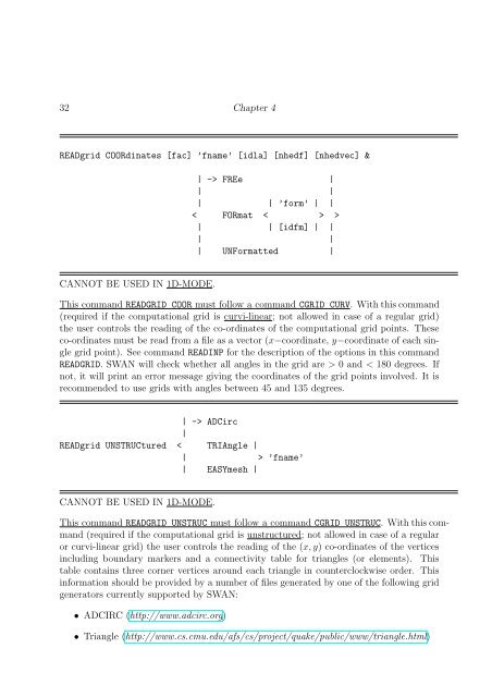
32 Chapter 4 READgrid COORdinates [fac] ’fname’ [idla] [nhedf] [nhedvec] & | -> FREe | | | | | ’form’ | | < FORmat < > > | | [idfm] | | | | | UNFormatted | CANNOT BE USED IN 1D-MODE. This command READGRID COOR must follow a command CGRID CURV. With this command (required if the computational grid is curvi-linear; not allowed in case of a regular grid) the user controls the reading of the co-ordinates of the computational grid points. These co-ordinates must be read from a file as a vector (x−coordinate, y−coordinate of each single grid point). See command READINP for the description of the options in this command READGRID. SWAN will check whether all angles in the grid are > 0 and < 180 degrees. If not, it will print an error message giving the coordinates of the grid points involved. It is recommended to use grids with angles between 45 and 135 degrees. | -> ADCirc | READgrid UNSTRUCtured < TRIAngle | | > ’fname’ | EASYmesh | CANNOT BE USED IN 1D-MODE. This command READGRID UNSTRUC must follow a command CGRID UNSTRUC. With this command (required if the computational grid is unstructured; not allowed in case of a regular or curvi-linear grid) the user controls the reading of the (x,y) co-ordinates of the vertices including boundary markers and a connectivity table for triangles (or elements). This table contains three corner vertices around each triangle in counterclockwise order. This information should be provided by a number of files generated by one of the following grid generators currently supported by SWAN: • ADCIRC (http://www.adcirc.org) • Triangle (http://www.cs.cmu.edu/afs/cs/project/quake/public/www/triangle.html)
Description of commands 33 • Easymesh (http://www-dinma.univ.trieste.it/nirftc/research/easymesh/easymesh.html) After setting up the vertices and the connectivity tables for cells and faces (automatically done in SWAN), SWAN will print some information concerning the used mesh, among others, number of vertices, cells and faces and minimum and maximum gridsizes. Furthermore, SWAN will check at two levels for a possible occurence of badly shaped triangles. Firstly, the number of triangles that meet at each vertex inside the mesh should not be smaller than 4 or larger than 10. Secondly, the angles inside each triangle should not be higher than 143 o . If, at least, one of these two situations occur, SWAN will print an error message. ADCIRC TRIANGLE EASYMESH ’fname’ the necessary grid information is read from file fort.14 as used by ADCIRC. This file also contains the depth information that is read as well. the necessary grid information is read from two files as produced by Triangle. The .node and .ele files are required. The basename of these files must be indicated with parameter ’fname’. the necessary grid information is read from two files as produced by Easymesh. The .n and .e files are required. The basename of these files must be indicated with parameter ’fname’. basename of the required files, i.e. without extension. Only meant for Triangle and Easymesh. 4.5.2 Input grids and data | BOTtom | | | | WLEVel | | | | | CURrent | | < | | | VX | | | VY | | | INPgrid (< >) & | FRiction | | | | | WInd | | < | | | WX | | | WY |
- Page 1: SWAN USER MANUAL SWAN Cycle III ver
- Page 5 and 6: Contents 1 Introduction 1 2 General
- Page 7 and 8: TABLE . . . . . . . . . . . . . . .
- Page 9 and 10: Chapter 1 Introduction The informat
- Page 11 and 12: Chapter 2 General definitions and r
- Page 13 and 14: General definitions and remarks 5 r
- Page 15 and 16: General definitions and remarks 7 I
- Page 17 and 18: which SWAN performs the computation
- Page 19 and 20: General definitions and remarks 11
- Page 21 and 22: General definitions and remarks 13
- Page 23 and 24: General definitions and remarks 15
- Page 25 and 26: General definitions and remarks 17
- Page 27 and 28: Chapter 3 Input and output files 3.
- Page 29 and 30: Chapter 4 Description of commands 4
- Page 31 and 32: (h) Commands to write or plot outpu
- Page 33 and 34: Description of commands 25 ’name
- Page 35 and 36: Description of commands 27 Default:
- Page 37 and 38: Description of commands 29 mesh. Th
- Page 39: ⎛ ∆f = ⎝−1 + Description of
- Page 43 and 44: Description of commands 35 grids ca
- Page 45 and 46: Description of commands 37 y ′
- Page 47 and 48: Description of commands 39 [fac]
- Page 49 and 50: Description of commands 41 ’(10X,
- Page 51 and 52: Description of commands 43 | | East
- Page 53 and 54: Description of commands 45 CONSTANT
- Page 55 and 56: Description of commands 47 points o
- Page 57 and 58: Description of commands 49 CRAY WKS
- Page 59 and 60: Description of commands 51 This com
- Page 61 and 62: Description of commands 53 | JANSse
- Page 63 and 64: Description of commands 55 [Csh3] c
- Page 65 and 66: Description of commands 57 [ursell]
- Page 67 and 68: Description of commands 59 [slope]
- Page 69 and 70: Description of commands 61 [cgmod]
- Page 71 and 72: Description of commands 63 < > [lim
- Page 73 and 74: Description of commands 65 SIGIMPL
- Page 75 and 76: Description of commands 67 ’sname
- Page 77 and 78: Description of commands 69 (see bel
- Page 79 and 80: Description of commands 71 [alpn] d
- Page 81 and 82: Description of commands 73 ‘long
- Page 83 and 84: | HSign | | | | HSWEll | | | | DIR
- Page 85 and 86: Description of commands 77 | WLENgt
- Page 87 and 88: Description of commands 79 QP DEPTH
- Page 89 and 90: Description of commands 81 [tbegblk
32 Chapter 4<br />
READgrid COORdinates [fac] ’fname’ [idla] [nhedf] [nhedvec] &<br />
| -> FREe |<br />
| |<br />
| | ’form’ | |<br />
< FORmat < > ><br />
| | [idfm] | |<br />
| |<br />
| UNFormatted |<br />
CANNOT BE USED IN 1D-MODE.<br />
This command READGRID COOR must follow a command CGRID CURV. With this command<br />
(required if the computational grid is curvi-linear; not allowed in case of a regular grid)<br />
the user controls the reading of the co-ordinates of the computational grid points. These<br />
co-ordinates must be read from a file as a vector (x−coordinate, y−coordinate of each single<br />
grid point). See command READINP for the description of the options in this command<br />
READGRID. <strong>SWAN</strong> will check whether all angles in the grid are > 0 and < 180 degrees. If<br />
not, it will print an error message giving the coordinates of the grid points involved. It is<br />
recommended to use grids with angles between 45 and 135 degrees.<br />
| -> ADCirc<br />
|<br />
READgrid UNSTRUCtured < TRIAngle |<br />
| > ’fname’<br />
| EASYmesh |<br />
CANNOT BE USED IN 1D-MODE.<br />
This command READGRID UNSTRUC must follow a command CGRID UNSTRUC. With this command<br />
(required if the computational grid is unstructured; not allowed in case of a regular<br />
or curvi-linear grid) the user controls the reading of the (x,y) co-ordinates of the vertices<br />
including boundary markers and a connectivity table for triangles (or elements). This<br />
table contains three corner vertices around each triangle in counterclockwise order. This<br />
information should be provided by a number of files generated by one of the following grid<br />
generators currently supported by <strong>SWAN</strong>:<br />
• ADCIRC (http://www.adcirc.org)<br />
• Triangle (http://www.cs.cmu.edu/afs/cs/project/quake/public/www/triangle.html)


