USER MANUAL SWAN Cycle III version 40.72A
USER MANUAL SWAN Cycle III version 40.72A
USER MANUAL SWAN Cycle III version 40.72A

You also want an ePaper? Increase the reach of your titles
YUMPU automatically turns print PDFs into web optimized ePapers that Google loves.
<strong>SWAN</strong><br />
<strong>USER</strong> <strong>MANUAL</strong><br />
<strong>SWAN</strong> <strong>Cycle</strong> <strong>III</strong> <strong>version</strong> <strong>40.72A</strong>
<strong>SWAN</strong> <strong>USER</strong> <strong>MANUAL</strong><br />
by : The <strong>SWAN</strong> team<br />
mail address : Delft University of Technology<br />
Faculty of Civil Engineering and Geosciences<br />
Environmental Fluid Mechanics Section<br />
P.O. Box 5048<br />
2600 GA Delft<br />
The Netherlands<br />
e-mail : swan-info-citg@tudelft.nl<br />
home page : http://www.fluidmechanics.tudelft.nl/swan/index.htm<br />
Copyright (c) 2008 Delft University of Technology.<br />
Permission is granted to copy, distribute and/or modify this document under the terms of<br />
the GNU Free Documentation License, Version 1.2 or any later <strong>version</strong> published by the<br />
Free Software Foundation; with no Invariant Sections, no Front-Cover Texts, and no Back-<br />
Cover Texts. A copy of the license is available at http://www.gnu.org/licenses/fdl.html#TOC1.
Contents<br />
1 Introduction 1<br />
2 General definitions and remarks 3<br />
2.1 Introduction . . . . . . . . . . . . . . . . . . . . . . . . . . . . . . . . . . . 3<br />
2.2 Limitations . . . . . . . . . . . . . . . . . . . . . . . . . . . . . . . . . . . 4<br />
2.3 Internal scenarios, limiters, shortcomings and coding bugs . . . . . . . . . 5<br />
2.4 Relation to WAM, WAVEWATCH <strong>III</strong> and others . . . . . . . . . . . . . . 7<br />
2.5 Units and coordinate systems . . . . . . . . . . . . . . . . . . . . . . . . . 7<br />
2.6 Choice of grids, time windows and boundary / initial / first guess conditions 8<br />
2.6.1 Introduction . . . . . . . . . . . . . . . . . . . . . . . . . . . . . . . 8<br />
2.6.2 Input grid(s) and time window(s) . . . . . . . . . . . . . . . . . . . 10<br />
2.6.3 Computational grids and boundary / initial / first guess conditions 11<br />
2.6.4 Output grids . . . . . . . . . . . . . . . . . . . . . . . . . . . . . . 16<br />
2.7 Activation of physical processes . . . . . . . . . . . . . . . . . . . . . . . . 16<br />
2.8 Time and date notation . . . . . . . . . . . . . . . . . . . . . . . . . . . . 18<br />
3 Input and output files 19<br />
3.1 General . . . . . . . . . . . . . . . . . . . . . . . . . . . . . . . . . . . . . 19<br />
3.2 Input / output facilities . . . . . . . . . . . . . . . . . . . . . . . . . . . . 19<br />
3.3 Print file and error messages . . . . . . . . . . . . . . . . . . . . . . . . . . 20<br />
4 Description of commands 21<br />
4.1 List of available commands . . . . . . . . . . . . . . . . . . . . . . . . . . . 21<br />
4.2 Sequence of commands . . . . . . . . . . . . . . . . . . . . . . . . . . . . . 23<br />
4.3 Command syntax and input / output limitations . . . . . . . . . . . . . . . 24<br />
4.4 Start-up . . . . . . . . . . . . . . . . . . . . . . . . . . . . . . . . . . . . . 24<br />
PROJECT . . . . . . . . . . . . . . . . . . . . . . . . . . . . . . . . 24<br />
SET . . . . . . . . . . . . . . . . . . . . . . . . . . . . . . . . . . . 25<br />
MODE . . . . . . . . . . . . . . . . . . . . . . . . . . . . . . . . . . 27<br />
COORDINATES . . . . . . . . . . . . . . . . . . . . . . . . . . . . 27<br />
4.5 Model description . . . . . . . . . . . . . . . . . . . . . . . . . . . . . . . . 28<br />
4.5.1 Computational grid . . . . . . . . . . . . . . . . . . . . . . . . . . . 28<br />
CGRID . . . . . . . . . . . . . . . . . . . . . . . . . . . . . . . . . 28<br />
v
vi<br />
READGRID COORDINATES . . . . . . . . . . . . . . . . . . . . . 32<br />
READGRID UNSTRUCTURED . . . . . . . . . . . . . . . . . . . 32<br />
4.5.2 Input grids and data . . . . . . . . . . . . . . . . . . . . . . . . . . 33<br />
INPGRID . . . . . . . . . . . . . . . . . . . . . . . . . . . . . . . . 33<br />
READINP . . . . . . . . . . . . . . . . . . . . . . . . . . . . . . . . 37<br />
WIND . . . . . . . . . . . . . . . . . . . . . . . . . . . . . . . . . . 41<br />
4.5.3 Boundary and initial conditions . . . . . . . . . . . . . . . . . . . . 41<br />
BOUND SHAPE . . . . . . . . . . . . . . . . . . . . . . . . . . . . 41<br />
BOUNDSPEC . . . . . . . . . . . . . . . . . . . . . . . . . . . . . . 42<br />
BOUNDNEST1 . . . . . . . . . . . . . . . . . . . . . . . . . . . . . 46<br />
BOUNDNEST2 . . . . . . . . . . . . . . . . . . . . . . . . . . . . . 47<br />
BOUNDNEST3 . . . . . . . . . . . . . . . . . . . . . . . . . . . . . 49<br />
INITIAL . . . . . . . . . . . . . . . . . . . . . . . . . . . . . . . . . 50<br />
4.5.4 Physics . . . . . . . . . . . . . . . . . . . . . . . . . . . . . . . . . . 52<br />
GEN1 . . . . . . . . . . . . . . . . . . . . . . . . . . . . . . . . . . 52<br />
GEN2 . . . . . . . . . . . . . . . . . . . . . . . . . . . . . . . . . . 52<br />
GEN3 . . . . . . . . . . . . . . . . . . . . . . . . . . . . . . . . . . 53<br />
WCAPPING . . . . . . . . . . . . . . . . . . . . . . . . . . . . . . 53<br />
QUADRUPL . . . . . . . . . . . . . . . . . . . . . . . . . . . . . . 54<br />
BREAKING . . . . . . . . . . . . . . . . . . . . . . . . . . . . . . . 55<br />
FRICTION . . . . . . . . . . . . . . . . . . . . . . . . . . . . . . . 55<br />
TRIAD . . . . . . . . . . . . . . . . . . . . . . . . . . . . . . . . . 56<br />
LIMITER . . . . . . . . . . . . . . . . . . . . . . . . . . . . . . . . 56<br />
OBSTACLE . . . . . . . . . . . . . . . . . . . . . . . . . . . . . . . 57<br />
SETUP . . . . . . . . . . . . . . . . . . . . . . . . . . . . . . . . . 59<br />
DIFFRACTION . . . . . . . . . . . . . . . . . . . . . . . . . . . . 60<br />
OFF . . . . . . . . . . . . . . . . . . . . . . . . . . . . . . . . . . . 61<br />
4.5.5 Numerics . . . . . . . . . . . . . . . . . . . . . . . . . . . . . . . . 61<br />
PROP . . . . . . . . . . . . . . . . . . . . . . . . . . . . . . . . . . 61<br />
NUMERIC . . . . . . . . . . . . . . . . . . . . . . . . . . . . . . . 62<br />
4.6 Output . . . . . . . . . . . . . . . . . . . . . . . . . . . . . . . . . . . . . . 65<br />
4.6.1 Output locations . . . . . . . . . . . . . . . . . . . . . . . . . . . . 66<br />
FRAME . . . . . . . . . . . . . . . . . . . . . . . . . . . . . . . . . 66<br />
GROUP . . . . . . . . . . . . . . . . . . . . . . . . . . . . . . . . . 67<br />
CURVE . . . . . . . . . . . . . . . . . . . . . . . . . . . . . . . . . 68<br />
RAY . . . . . . . . . . . . . . . . . . . . . . . . . . . . . . . . . . . 68<br />
ISOLINE . . . . . . . . . . . . . . . . . . . . . . . . . . . . . . . . 69<br />
POINTS . . . . . . . . . . . . . . . . . . . . . . . . . . . . . . . . . 69<br />
NGRID . . . . . . . . . . . . . . . . . . . . . . . . . . . . . . . . . 70<br />
4.6.2 Write or plot computed quantities . . . . . . . . . . . . . . . . . . . 71<br />
QUANTITY . . . . . . . . . . . . . . . . . . . . . . . . . . . . . . . 72<br />
OUTPUT . . . . . . . . . . . . . . . . . . . . . . . . . . . . . . . . 74<br />
BLOCK . . . . . . . . . . . . . . . . . . . . . . . . . . . . . . . . . 74
TABLE . . . . . . . . . . . . . . . . . . . . . . . . . . . . . . . . . 81<br />
SPECOUT . . . . . . . . . . . . . . . . . . . . . . . . . . . . . . . 82<br />
NESTOUT . . . . . . . . . . . . . . . . . . . . . . . . . . . . . . . 83<br />
4.6.3 Write or plot intermediate results . . . . . . . . . . . . . . . . . . . 84<br />
TEST . . . . . . . . . . . . . . . . . . . . . . . . . . . . . . . . . . 84<br />
4.7 Lock-up . . . . . . . . . . . . . . . . . . . . . . . . . . . . . . . . . . . . . 86<br />
COMPUTE . . . . . . . . . . . . . . . . . . . . . . . . . . . . . . . 86<br />
HOTFILE . . . . . . . . . . . . . . . . . . . . . . . . . . . . . . . . 87<br />
STOP . . . . . . . . . . . . . . . . . . . . . . . . . . . . . . . . . . 88<br />
A Definitions of variables 89<br />
B Command syntax 95<br />
B.1 Commands and command schemes . . . . . . . . . . . . . . . . . . . . . . 95<br />
B.2 Command . . . . . . . . . . . . . . . . . . . . . . . . . . . . . . . . . . . . 95<br />
B.2.1 Keywords . . . . . . . . . . . . . . . . . . . . . . . . . . . . . . . . 95<br />
Spelling of keywords . . . . . . . . . . . . . . . . . . . . . . . . . . 96<br />
Required and optional keywords . . . . . . . . . . . . . . . . . . . . 96<br />
Repetitions of keywords and/or other data . . . . . . . . . . . . . . 97<br />
B.2.2 Data . . . . . . . . . . . . . . . . . . . . . . . . . . . . . . . . . . . 97<br />
Character data and numerical data . . . . . . . . . . . . . . . . . . 97<br />
Spelling of data . . . . . . . . . . . . . . . . . . . . . . . . . . . . . 97<br />
Required data and optional data . . . . . . . . . . . . . . . . . . . 99<br />
B.3 Command file and comments . . . . . . . . . . . . . . . . . . . . . . . . . . 99<br />
B.4 End of line or continuation . . . . . . . . . . . . . . . . . . . . . . . . . . . 100<br />
C File swan.edt 101<br />
D Spectrum files, input and output 107<br />
Bibliography 115<br />
Index 116<br />
vii
viii
Chapter 1<br />
Introduction<br />
The information about the <strong>SWAN</strong> package is distributed over five different documents.<br />
This User Manual describes the complete input and usage of the <strong>SWAN</strong> package. The<br />
Implementation Manual explains the installation procedure of <strong>SWAN</strong> on a single- or multiprocessor<br />
machine with shared or distributed memory. The System documentation outlines<br />
the internals of the program and discusses program maintenance. The Programming rules<br />
is meant for programmers who want to develop <strong>SWAN</strong>. The Scientific/Technical documentation<br />
discusses the physical and mathematical details and the discretizations that are used<br />
in the <strong>SWAN</strong> program. The mapping of these numerical techniques in <strong>SWAN</strong> code is also<br />
discussed.<br />
In Chapter 2 some general definitions and remarks concerning the usage of <strong>SWAN</strong>, the<br />
treatment of grids, boundary conditions, etc. is given. It is advised to read these definitions<br />
and remarks before consulting the rest of the manual. Chapter 3 gives some remarks<br />
concerning the input and output files of <strong>SWAN</strong>. Chapter 4 describes the complete set of<br />
commands of the program <strong>SWAN</strong>.<br />
It is strongly advised that users who are not so experienced in the use of <strong>SWAN</strong> first read<br />
Chapters 2 and 3.<br />
This Manual also contains some appendices. In Appendix A definitions of several output<br />
parameters are given. Appendix B outlines the syntax of the command file (or input<br />
file). A complete set of all the commands use in <strong>SWAN</strong> can be found in Appendix C.<br />
Appendix D described the format of the files for spectral input and output by <strong>SWAN</strong>.<br />
1
2 Chapter 1
Chapter 2<br />
General definitions and remarks<br />
2.1 Introduction<br />
The purpose of this chapter is to give some general advice in choosing the basic input for<br />
<strong>SWAN</strong> computations.<br />
<strong>SWAN</strong> is a third-generation wave model for obtaining realistic estimates of wave parameters<br />
in coastal areas, lakes and estuaries from given wind, bottom and current conditions.<br />
However, <strong>SWAN</strong> can be used on any scale relevant for wind-generated surface gravity<br />
waves. The model is based on the wave action balance equation with sources and sinks.<br />
An important question addressed is how to choose various grids in <strong>SWAN</strong> (resolution, orientation,<br />
etc.) including nesting. In general, we consider two types of grids: structured<br />
and unstructured. Structured grids may be recti-linear and uniform or curvi-linear. They<br />
always consist of quadrilaterals in which the number of grid cells that meet each other in<br />
an internal grid point is 4. In unstructured grids, this number can be arbitrarily (usually<br />
between 4 and 10). For this reason, the level of flexibility with respect to the grid<br />
point distribution of unstructured grids is far more optimal compared to structured grids.<br />
Unstructured grids may contain triangles or a combination of triangles and quadrilaterals<br />
(so-called hybrid grids). In the current <strong>version</strong> of <strong>SWAN</strong>, however, only triangular meshes<br />
can be employed.<br />
Often, the characteristic spatial scales of the wind waves propagating from deep to shallow<br />
waters are very diverse and would required to allow local refinement of the mesh near the<br />
coast without incurring overhead associated with grid adaptation at some distance offshore.<br />
Traditionally, this can be achieved by employing a nesting approach.<br />
The idea of nesting is to first compute the waves on a coarse grid for a larger region and<br />
then on a finer grid for a smaller region. The computation on the fine grid uses boundary<br />
conditions that are generated by the computation on the coarse grid. Nesting can be<br />
repeated on ever decreasing scales using the same type of coordinates for the coarse computations<br />
and the nested computations (Cartesian or spherical). Note that curvi-linear grids<br />
3
4 Chapter 2<br />
can be used for nested computations but the boundaries should always be rectangular.<br />
The use of unstructured grids in <strong>SWAN</strong> offers a good alternative to nested models not<br />
only because of the ease of optimal adaption of mesh resolution but also the modest effort<br />
needed to generate grids about complicated geometries, e.g. islands and irregular shorelines.<br />
This type of flexible meshes is particularly useful in coastal regions where the water<br />
depth varies greatly. As a result, this variable spatial meshing gives the highest resolution<br />
where it is most needed. The use of unstructured grids facilitates to resolve the model area<br />
with a relative high accuracy but with a much fewer grid points than with regular grids.<br />
It must be pointed out that the application of <strong>SWAN</strong> on ocean scales is not recommended<br />
from an efficiency point of view. The WAM model and the WAVEWATCH <strong>III</strong> model,<br />
which have been designed specifically for ocean applications, are probably one order of<br />
magnitude more efficient than <strong>SWAN</strong>. <strong>SWAN</strong> can be run on large scales (much larger than<br />
coastal scales) but this option is mainly intended for the transition from ocean scales to<br />
coastal scales (transitions where nonstationarity is an issue and spherical coordinates are<br />
convenient for nesting).<br />
A general suggestion is: start simple. <strong>SWAN</strong> helps in this with default options. Furthermore,<br />
suggestions are given that should help the user to choose among the many options<br />
conditions and in which mode to run <strong>SWAN</strong> (first-, second- or third-generation mode,<br />
stationary or nonstationary and 1D or 2D).<br />
2.2 Limitations<br />
The DIA approximation for the quadruplet wave-wave interactions depends on the<br />
width of the directional distribution of the wave spectrum. It seems to work reasonably<br />
in many cases but it is a poor approximation for long-crested waves (narrow directional<br />
distribution). It also depends on the frequency resolution. It seems to work reasonably in<br />
many cases but it is a poor approximation for frequency resolutions with ratios very different<br />
from 10% (see command CGRID). This is a fundamental problem that <strong>SWAN</strong> shares<br />
with other third-generation wave models such as WAM and WAVEWATCH <strong>III</strong>.<br />
The LTA approximation for the triad wave-wave interactions depends on the width<br />
of the directional distribution of the wave spectrum. The present tuning in <strong>SWAN</strong> (the<br />
default settings, see command TRIAD) seems to work reasonably in many cases but it has<br />
been obtained from observations in a narrow wave flume (long-crested waves).<br />
As an option <strong>SWAN</strong> computes wave-induced set-up. In 1D cases the computations are<br />
based on exact equations. In 2D cases, the computations are based on approximate equations.<br />
This approximation in <strong>SWAN</strong> can only be applied to open coast (unlimited supply<br />
of water from outside the domain, e.g. nearshore coasts and estuaries) in contrast to closed<br />
basin, e.g. lakes, where this option should not be used. The effects of wave-induced cur-
General definitions and remarks 5<br />
rents are always ignored.<br />
<strong>SWAN</strong> does not calculate wave-induced currents. If relevant, such currents should be<br />
provided as input to <strong>SWAN</strong>, e.g. from a circulation model which can be driven by waves<br />
from <strong>SWAN</strong> in an iteration procedure.<br />
In areas where variations in wave height are large within a horizontal scale of a few wave<br />
lengths, diffraction should be used. However, the computation of diffraction in arbitrary<br />
geophysical conditions is rather complicated and requires considerable computing effort.<br />
To avoid this, a phase-decoupled approach is employed in <strong>SWAN</strong> so that same qualitative<br />
behaviour of spatial redistribution and changes in wave direction is obtained. This approach,<br />
however, does not properly handle diffraction in harbours or in front of reflecting<br />
obstacles.<br />
<strong>SWAN</strong> can be used on any scale relevant for wind generated surface gravity waves. However,<br />
<strong>SWAN</strong> is specifically designed for coastal applications that should actually not require<br />
such flexibility in scale. The reasons for providing <strong>SWAN</strong> with such flexibility are:<br />
• to allow <strong>SWAN</strong> to be used from laboratory conditions to shelf seas and<br />
• to nest <strong>SWAN</strong> in the WAM model or the WAVEWATCH <strong>III</strong> model which are formulated<br />
in terms of spherical coordinates.<br />
Nevertheless, these facilities are not meant to support the use of <strong>SWAN</strong> on oceanic scales<br />
because <strong>SWAN</strong> is less efficient on oceanic scales than WAVEWATCH <strong>III</strong> and probably also<br />
less efficient than WAM.<br />
2.3 Internal scenarios, limiters, shortcomings and coding<br />
bugs<br />
Sometimes the user input to <strong>SWAN</strong> is such that <strong>SWAN</strong> produces unreliable and sometimes<br />
even unrealistic results. This may be the case if the bathymetry or the wave field is not well<br />
resolved. Be aware here that the grid on which the computations are performed interpolates<br />
from the grids on which the input is provided; different resolutions for these grids (which<br />
are allowed) can therefore create unexpected interpolation patterns on the computational<br />
grid. In such cases <strong>SWAN</strong> may invoke some internal scenarios or limiters instead of<br />
terminating the computations. The reasons for this model policy is that<br />
• <strong>SWAN</strong> needs to be robust, and<br />
• the problem may be only very local, or<br />
• the problem needs to be fully computed before it can be diagnosed.<br />
Examples are:
6 Chapter 2<br />
• The user can request that refraction over one spatial grid step is limited to about<br />
90 0 (see commandNUMERIC). This may be relevant when the depth varies considerably<br />
over one spatial grid step (e.g. at the edge of oceans or near oceanic islands with<br />
only one or two grid steps to go from oceanic depths to a shallow coast). This implies<br />
inaccurate refraction computations in such grid steps. This may be acceptable when<br />
refraction has only local effects that can be ignored but, depending on the topography,<br />
the inaccurately computed effects may radiate far into the computational area.<br />
• <strong>SWAN</strong> cannot handle wave propagation on super-critical current flow. If such flow is<br />
encountered during <strong>SWAN</strong> computations, the current is locally reduced to sub-critical<br />
flow.<br />
• If the water depth is less than some user-provided limit, the depth is set at that limit<br />
(default is 0.05 m, see command SET).<br />
• The user-imposed wave boundary conditions may not be reproduced by <strong>SWAN</strong> employing<br />
structured grids, as <strong>SWAN</strong> replaces the imposed waves at the boundaries that<br />
propagate into the computational area with the computed waves that move out of<br />
the computational area at the boundaries.<br />
• <strong>SWAN</strong> may have convergence problems.<br />
<strong>SWAN</strong>:<br />
There are three iteration processes in<br />
1. an iteration process for the spatial propagation of the waves,<br />
2. if ambient currents are present, an iteration process for spectral propagation<br />
(current-induced refraction and frequency shift) and<br />
3. if wave-induced set-up is requested by the user, an iteration process for solving<br />
the set-up equation.<br />
ad 1 For spatial propagation the change of the wave field over one iteration is limited<br />
to some realistic value (usually several iterations for stationary conditions or one<br />
iteration or upgrade per time step for nonstationary conditions; see command<br />
NUMERIC). This is a common problem for all third-generation wave models (such<br />
as WAM, WAVEWATCH <strong>III</strong> and also <strong>SWAN</strong>). It does not seem to affect the<br />
result seriously in many cases but sometimes <strong>SWAN</strong> fails to converge properly.<br />
For curvi-linear grids, convergence problems may occur locally where in some<br />
points in the grid, the directions separating the 4 sweeping quadrants coincide<br />
with the given spectral directions.<br />
ad 2 For spectral propagation (but only current-induced refraction and frequency<br />
shift) <strong>SWAN</strong> may also not converge.<br />
ad 3 For the wave-induced set-up <strong>SWAN</strong> may also not converge.
General definitions and remarks 7<br />
Information on the actual convergence of a particular <strong>SWAN</strong> run is provided in the<br />
PRINT file (see <strong>SWAN</strong> Implementation Manual).<br />
Some other problems which the <strong>SWAN</strong> user may encounter are due to more fundamental<br />
shortcomings of <strong>SWAN</strong> (which may or may not be typical for third-generation wave<br />
models) and unintentional coding bugs.<br />
Because of the issues described above, the results may look realistic, but they may (locally)<br />
not be accurate. Any change in these scenarios, limiters or shortcomings, in particular<br />
newly discovered coding bugs and their fixes, are published on the <strong>SWAN</strong> web site and<br />
implemented in new releases of <strong>SWAN</strong>.<br />
2.4 Relation to WAM, WAVEWATCH <strong>III</strong> and others<br />
The basic scientific philosophy of <strong>SWAN</strong> is identical to that of WAM (<strong>Cycle</strong> 3 and 4).<br />
<strong>SWAN</strong> is a third-generation wave model and it uses the same formulations for the source<br />
terms (although <strong>SWAN</strong> uses the adapted code for the DIA technique). On the other hand,<br />
<strong>SWAN</strong> contains some additional formulations primarily for shallow water. Moreover, the<br />
numerical techniques are very different. WAVEWATCH <strong>III</strong> not only uses different numerical<br />
techniques but also different formulations for the wind input and the whitecapping.<br />
This close similarity can be exploited in the sense that<br />
• scientific findings with one model can be shared with the others and<br />
• <strong>SWAN</strong> can be readily nested in WAM and WAVEWATCH <strong>III</strong> (the formulations of<br />
WAVEWATCH <strong>III</strong> have not yet been implemented in <strong>SWAN</strong>).<br />
When <strong>SWAN</strong> is nested in WAM or WAVEWATCH <strong>III</strong>, it must be noted that the boundary<br />
conditions for <strong>SWAN</strong> provided by WAM or WAVEWATCH <strong>III</strong> may not be model consistent<br />
even if the same physics are used. The potential reasons are manifold such as differences<br />
in numerical techniques employed and implementation for the geographic area (spatial and<br />
spectral resolutions, coefficients, etc.). Generally, the deep water boundary of the <strong>SWAN</strong><br />
nest must be located in WAM or WAVEWATCH <strong>III</strong> where shallow water effects do not<br />
dominate (to avoid too large discontinuities between the two models). Also, the spatial and<br />
spectral resolutions should not differ more than a factor two or three. If a finer resolution<br />
is required, a second or third nesting may be needed.<br />
2.5 Units and coordinate systems<br />
<strong>SWAN</strong> expects all quantities that are given by the user to be expressed in S.I. units: m,<br />
kg, s and composites of these with accepted compounds, such as Newton (N) and Watt<br />
(W). Consequently, the wave height and water depth are in m, wave period in s, etc. For<br />
wind and wave direction both the Cartesian and a nautical convention can be used (see
8 Chapter 2<br />
below). Directions and spherical coordinates are in degrees ( 0 ) and not in radians.<br />
For the output of wave energy the user can choose between variance (m 2 ) or energy (spatial)<br />
density (Joule/m 2 , i.e. energy per unit sea surface) and the equivalents in case of<br />
energy transport (m 3 /s or W/m, i.e. energy transport per unit length) and spectral energy<br />
density (m 2 /Hz/Degr or Js/m 2 /rad, i.e. energy per unit frequency and direction per unit<br />
sea surface area). The wave−induced stress components (obtained as spatial derivatives of<br />
wave-induced radiation stress) are always expressed in N/m 2 even if the wave energy is in<br />
terms of variance. Note that the energy density is also in Joule/m 2 in the case of spherical<br />
coordinates.<br />
<strong>SWAN</strong> operates either in a Cartesian coordinate system or in a spherical coordinate system,<br />
i.e. in a flat plane or on a spherical Earth. In the Cartesian system, all geographic<br />
locations and orientations in <strong>SWAN</strong>, e.g. for the bottom grid or for output points, are<br />
defined in one common Cartesian coordinate system with origin (0,0) by definition. This<br />
geographic origin may be chosen totally arbitrarily by the user. In the spherical system,<br />
all geographic locations and orientations in <strong>SWAN</strong>, e.g. for the bottom grid or for output<br />
points, are defined in geographic longitude and latitude. Both coordinate systems are designated<br />
in this manual as the problem coordinate system.<br />
In the input and output of <strong>SWAN</strong> the direction of wind and waves are defined according<br />
to either<br />
• the Cartesian convention, i.e. the direction to where the vector points, measured<br />
counterclockwise from the positive x−axis of this system (in degrees) or<br />
• a nautical convention (there are more such conventions), i.e. the direction where the<br />
wind or the waves come from, measured clockwise from geographic North.<br />
All other directions, such as orientation of grids, are according to the Cartesian convention!<br />
For regular grids, i.e. uniform and rectangular, Figure 4.1 (in Section 4.5) shows how the<br />
locations of the various grids are determined with respect to the problem coordinates. All<br />
grid points of curvi-linear and unstructured grids are relative to the problem coordinate<br />
system.<br />
2.6 Choice of grids, time windows and boundary /<br />
initial / first guess conditions<br />
2.6.1 Introduction<br />
Several types of grids and time window(s) need to be defined: (a) spectral grid, (b) spatial<br />
(geographic) grids and time window(s) in case of nonstationary computations.<br />
The spectral grid that need to be defined by the user is a computational spectral grid on
which <strong>SWAN</strong> performs the computations.<br />
General definitions and remarks 9<br />
<strong>SWAN</strong> has the option to make computations that can be nested in (coarse) <strong>SWAN</strong>, WAM<br />
or WAVEWATCH <strong>III</strong>. In such cases, the spectral grid need not be equal to the spectral<br />
grid in the coarse <strong>SWAN</strong>, WAM or WAVEWATCH <strong>III</strong> run.<br />
The spatial grids that need to be defined by the user are (if required):<br />
• a computational spatial grid on which <strong>SWAN</strong> performs the computations,<br />
• one (or more) spatial input grid(s) for the bottom, current field, water level, bottom<br />
friction and wind (each input grid may differ from the others) and<br />
• one (or more) spatial output grid(s) on which the user requires output of <strong>SWAN</strong>.<br />
The wind and bottom friction do not require a grid if they are uniform over the area of<br />
interest.<br />
For one-dimensional situations, i.e. ∂/∂y ≡ 0, <strong>SWAN</strong> can be run in 1D mode.<br />
If a uniform, rectangular computational spatial grid is chosen in <strong>SWAN</strong>, then all input and<br />
output grids must be uniform and rectangular too, but they may all be different from each<br />
other.<br />
If a curvi-linear computational spatial grid is chosen in <strong>SWAN</strong>, then each input grid should<br />
be either uniform, rectangular or identical to the used curvi-linear grid or staggered with<br />
respect to the curvi-linear computational grid.<br />
If an unstructured computational spatial grid is chosen in <strong>SWAN</strong>, then each input grid<br />
should be either uniform, rectangular or identical to the used unstructured grid.<br />
<strong>SWAN</strong> has the option to make computations that are nested in (coarse) <strong>SWAN</strong>, WAM or<br />
WAVEWATCH <strong>III</strong>. In such runs, <strong>SWAN</strong> interpolates the spatial boundary of the <strong>SWAN</strong>,<br />
WAM or WAVEWATCH <strong>III</strong> grid to the (user provided) grid of <strong>SWAN</strong> (that needs to<br />
(nearly) coincide along the grid lines of WAM or WAVEWATCH <strong>III</strong> or the output nest<br />
grid boundaries of <strong>SWAN</strong>). Since, the computational grids of WAM and WAVEWATCH<br />
<strong>III</strong> are in spherical coordinates, it is recommended to use spherical coordinates in a nested<br />
<strong>SWAN</strong> when nesting in WAM or WAVEWATCH <strong>III</strong>.<br />
<strong>SWAN</strong> using an unstructured mesh may be nested in <strong>SWAN</strong> employing a regular grid and<br />
vice versa. However, <strong>SWAN</strong> using an unstructured grid cannot be nested in WAM or<br />
WAVEWATCH <strong>III</strong>.<br />
Nesting from a 2D model to a 1D model is possible although is should not be done by<br />
using the commands NGRID and NEST. Instead, define the boundary point of the 1D model<br />
as an output point (using command POINTS) and write the spectra for that point using<br />
the command SPECout. In the 1D model, this spectra is used as boundary condition using
10 Chapter 2<br />
the BOUNDSPEC command.<br />
Similarly, the wind fields may be available in different time windows than the current and<br />
water level fields and the computations may need to be carried out at other times than<br />
these input fields. For these reasons <strong>SWAN</strong> operates with different time windows with<br />
different time steps (each may have a different start and end time and time step):<br />
• one computational time window in which <strong>SWAN</strong> performs the computations,<br />
• one (or more) input time window(s) in which the bottom, current field, water level,<br />
bottom friction and wind field (if present) are given by the user (each input window<br />
may differ form the others) and<br />
• one (or more) output time window(s) in which the user requires output of <strong>SWAN</strong>.<br />
In case of nesting, <strong>SWAN</strong> searches the boundary conditions in the relevant output file of<br />
the previous <strong>SWAN</strong>, WAM or WAVEWATCH <strong>III</strong> runs to take the boundary conditions<br />
at the start time of the nested run. It will not take the initial condition (i.e. over the<br />
entire computational grid) for the nested run from the previous <strong>SWAN</strong>, WAM or WAVE-<br />
WATCH <strong>III</strong> run.<br />
During the computation <strong>SWAN</strong> obtains bottom, current, water level, wind and bottom<br />
friction information by tri-linear interpolation from the given input grid(s) and time<br />
window(s). The output is in turn obtained in <strong>SWAN</strong> by bi-linear interpolation in space<br />
from the computational grid; there is no interpolation in time, the output time is shifted<br />
to the nearest computational time level. Interpolation errors can be reduced by taking the<br />
grids and windows as much as equal to one another as possible (preferably identical). It<br />
is recommended to choose output times such that they coincide with computational time<br />
levels.<br />
2.6.2 Input grid(s) and time window(s)<br />
The bathymetry, current, water level, bottom friction and wind (if spatially variable) need<br />
to be provided to <strong>SWAN</strong> on so-called input grids. It is best to make an input grid so large<br />
that it completely covers the computational grid.<br />
In the region outside the input grid <strong>SWAN</strong> assumes that the bottom level, the water level<br />
and bottom friction are identical to those at the nearest boundary of the input grid (lateral<br />
shift of that boundary). In the regions not covered by this lateral shift (i.e. in the outside<br />
quadrants of the corners of the input grid), a constant field equal to the value at the nearest<br />
corner point of the input grid is taken. For the current and wind velocity, <strong>SWAN</strong> takes 0<br />
m/s for points outside the input grid.<br />
In <strong>SWAN</strong>, the bathymetry, current, water level, wind and bottom friction may be time<br />
varying. In that case they need to be provided to <strong>SWAN</strong> in so-called input time windows
General definitions and remarks 11<br />
(they need not be identical with the computational, output or other input windows). It is<br />
best to make an input window larger than the computational time window. <strong>SWAN</strong> assumes<br />
zero values at times before the earliest begin time of the input parameters (which may be<br />
the begin time of any input parameter such as wind). <strong>SWAN</strong> assumes constant values<br />
(the last values) at times after the end time of each input parameter. The input windows<br />
should start early enough so that the initial state of <strong>SWAN</strong> has propagated through the<br />
computational area before reliable output of <strong>SWAN</strong> is expected.<br />
One should choose the spatial resolution for the input grids such that relevant spatial details<br />
in the bathymetry, currents, bottom friction and wind are properly resolved. Special<br />
care is required in cases with sharp and shallow ridges (sand bars, shoals) in the sea bottom<br />
and extremely steep bottom slopes. Very inaccurate bathymetry can result in very<br />
inaccurate refraction computations the results of which can propagate into areas where<br />
refraction as such is not significant (the results may appear to be unstable). For instance,<br />
waves skirting an island that is poorly resolved may propagate beyond the island with<br />
entirely wrong directions. In such a case it may even be better to deactivate the refraction<br />
computations (if refraction is irrelevant for the problem at hand e.g. because the refracted<br />
waves will run into the coast anyway and one is not interested in that part of the coast).<br />
In such cases the ridges are vitally important to obtain good <strong>SWAN</strong> results (at sea the<br />
waves are ’clipped’ by depth-induced breaking over the ridges which must therefore represented<br />
in <strong>SWAN</strong> computation). This requires not only that these ridges should be well<br />
represented on the input grid but also after interpolation on the computational grid. This<br />
can be achieved by choosing the grid lines of the input grid along the ridges (even if this<br />
may require some slight ”shifting” of the ridges) and choosing the computational grid to<br />
be identical to the input grid (otherwise the ridge may be ”lost” in the interpolation from<br />
the bottom input grid to the computational grid).<br />
Finally, one should use a time step that is small enough that time variations in the<br />
bathymetry, current, water level, wind and bottom friction are well resolved.<br />
2.6.3 Computational grids and boundary / initial / first guess<br />
conditions<br />
The computational spatial grid must be defined by the user. The orientation (direction)<br />
can be chosen arbitrarily.<br />
The boundaries of the computational spatial grid in <strong>SWAN</strong> are either land or water. In the<br />
case of land there is no problem: the land does not generate waves and in <strong>SWAN</strong> it absorbs<br />
all incoming wave energy. But in the case of a water boundary there may be a problem.<br />
Often no wave conditions are known along such a boundary and <strong>SWAN</strong> then assumes<br />
that no waves enter the area and that waves can leave the area freely. These assumptions<br />
obviously contain errors which propagate into the model. These boundaries must therefore<br />
be chosen sufficiently far away from the area where reliable computations are needed so
12 Chapter 2<br />
that they do not affect the computational results there. This is best established by varying<br />
the location of these boundaries and inspect the effect on the results. Sometimes the waves<br />
at these boundaries can be estimated with a certain degree of reliability. This is the case if<br />
(a) results of another model run are available (nested computations) or, (b) observations<br />
are available. If model results are available along the boundaries of the computational<br />
spatial grid, they are usually from a coarser resolution than the computational spatial grid<br />
under consideration. This implies that this coarseness of the boundary propagates into<br />
the computational grid. The problem is therefore essentially the same as if no waves are<br />
assumed along the boundary except that now the error may be more acceptable (or the<br />
boundaries are permitted to be closer to the area of interest). If observations are available,<br />
they can be used as input at the boundaries. However, this usually covers only part of the<br />
boundaries so that the rest of the boundaries suffer from the same error as above.<br />
A special case occurs near the coast. Here it is often possible to identify an up-wave<br />
boundary (with proper wave information) and two lateral boundaries (with no or partial<br />
wave information). The affected areas with errors are typically regions with the apex<br />
at the corners of the water boundary with wave information, spreading towards shore at<br />
an angle of 30 o to 45 o for wind sea conditions to either side of the imposed mean wave<br />
direction (less for swell conditions; the angle is essentially the one-sided width of the<br />
directional distribution of wave energy). For propagation of short crested waves (wind sea<br />
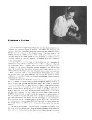
condtions) an example is given in Figure 2.1. For this reason the lateral boundaries should<br />
be sufficiently far away from the area of interest to avoid the propagation of this error<br />
into this area. Such problems do not occur if the lateral boundaries contain proper wave<br />
information over their entire length e.g. obtained from a previous <strong>SWAN</strong> computation or<br />
if the lateral boundaries are coast.<br />
When output is requested along a boundary of the computational grid, it may occur that<br />
this output differs from the boundary conditions that are imposed by the user. The reason<br />
is that <strong>SWAN</strong> accepts only the user-imposed incoming wave components and that it replaces<br />
the user-imposed outgoing wave components with computed outgoing components<br />
(propagating to the boundary from the interior region). This is only the case for structured<br />
grids (both regular and curvi-linear ones). The user is informed by means of<br />
a warning in the output when the computed significant wave height differs more than 10%,<br />
say (10% is default), from the user-imposed significant wave height (command BOUND...).<br />
The actual value of this difference can be set by the user (see the SET command). Note<br />
that this warning will not apply in the case of unstructured grids.<br />
If the computational grid extends outside the input grid, the reader is referred to Section<br />
2.6 to find the assumptions of <strong>SWAN</strong> on depth, current, water level, wind, bottom<br />
friction in the non-overlapping area.<br />
The spatial resolution of the computational grid should be sufficient to resolve relevant<br />
details of the wave field. Usually a good choice is to take the resolution of the computational<br />
grid approximately equal to that of the bottom or current grid. If necessary, an
General definitions and remarks 13<br />
yp − axis<br />
mean wave direction<br />
o<br />
app. 30<br />
yc − axis<br />
00000 11111<br />
00000 11111<br />
00000 11111<br />
00000 11111<br />
00000 11111<br />
00000 11111<br />
00000 11111<br />
00000 11111<br />
00000 11111<br />
computational grid<br />
o<br />
app. 30<br />
0000 1111<br />
0000 1111<br />
0000 1111<br />
0000 1111<br />
0000 1111<br />
0000 1111<br />
0000 1111<br />
mean wave direction<br />
xc − axis<br />
non−zero wave boundary<br />
mean wave direction<br />
xp − axis<br />
Figure 2.1: Disturbed regions in the computational grid due to erroneous boundary conditions<br />
are indicated with shaded areas.<br />
unstructured grid may be used.<br />
<strong>SWAN</strong> may not use the entire user-provided computational grid if the user defines exception<br />
values on the depth grid (see command INPGRID BOTTOM) or on the curvi-linear<br />
computational grid (see command CGRID). It must be noted that for parallel runs using<br />
MPI the user must indicate an exception value when reading the bottom levels (by means<br />
of command INPGRID BOTTOM EXCEPTION), in order to obtain good load balancing.<br />
A computational grid point is either<br />
• wet, i.e. the grid point is included in the computations since it represents water; this<br />
may vary with time-dependent or wave-induced water levels or<br />
• dry, i.e. the grid point is excluded from the computations since it represents land<br />
which may vary with time-dependent or wave-induced water levels or<br />
• exceptional, i.e. the grid point is permanently excluded from the computations since<br />
it is so defined by the user.<br />
If exceptional grid points occur in the computational grid, then <strong>SWAN</strong> filters the entire<br />
computational grid as follows:<br />
• each grid line between two adjacent wet computational grid points (a wet link)<br />
without an adjacent, parallel wet link, is removed,
14 Chapter 2<br />
• each wet computational grid point that is linked to only one other wet computational<br />
grid point, is removed and<br />
• each wet computational grid point that has no wet links is removed.<br />
The effect of this filter is that if exception values are used for the depth grid or the<br />
curvi-linear computational grid, one-dimensional water features are ignored in the <strong>SWAN</strong><br />
computations (results at these locations with a width of about one grid step may be<br />
unrealistic). If no exception values are used, the above described filter will not be applied.<br />
As a consequence, one-dimensional features may appear or disappear due to changing<br />
water levels (flooding may create them, drying may reduce two-dimensional features to<br />
one-dimensional features).<br />
The computational time window must be defined by the user in case of nonstationary<br />
runs. The computational window in time must start at a time that is early enough that<br />
the initial state of <strong>SWAN</strong> has propagated through the computational area before reliable<br />
output of <strong>SWAN</strong> is expected. Before this time the output may not be reliable since usually<br />
the initial state is not known and only either no waves or some very young sea state is<br />
assumed for the initial state. This is very often erroneous and this erroneous initial state<br />
is propagated into the computational area.<br />
The computational time step must be given by the user in case of nonstationary runs. Since,<br />
<strong>SWAN</strong> is based on implicit numerical schemes, it is not limited by the Courant stability<br />
criterion (which couples time and space steps). In this sense, the time step in <strong>SWAN</strong> is<br />
not restricted. However, the accuracy of the results of <strong>SWAN</strong> are obviously affected by<br />
the time step. Generally, the time step in <strong>SWAN</strong> should be small enough to resolve the<br />
time variations of computed wave field itself. Usually, it is enough to consider the time<br />
variations of the driving fields (wind, currents, water depth, wave boundary conditions).<br />
But be careful: relatively(!) small time variations in depth (e.g. by tide) can result in<br />
relatively(!) large variations in the wave field.<br />
As default, the first guess conditions of a stationary run of <strong>SWAN</strong> are determined with the<br />
2 nd generation mode of <strong>SWAN</strong>. The initial condition of a nonstationary run of <strong>SWAN</strong> is<br />
by default a JONSWAP spectrum with a cos 2 (θ) directional distribution centred around<br />
the local wind direction.<br />
A quasi-stationary approach can be employed with stationary <strong>SWAN</strong> computations in a<br />
time-varying sequence of stationary conditions.<br />
The computational spectral grid needs to be provided by the user. In frequency space,<br />
it is simply defined by a minimum and a maximum frequency and the frequency resolution<br />
which is proportional to the frequency itself (i.e. logarithmic, e.g., ∆f = 0.1 f). The<br />
frequency domain may be specified as follows (see command CGRID):<br />
• The lowest frequency, the highest frequency and the number of frequencies can be<br />
chosen.
General definitions and remarks 15<br />
• Only the lowest frequency and the number of frequencies can be chosen. The highest<br />
frequency will be computed by <strong>SWAN</strong> such that ∆f = 0.1 f. This resolution is<br />
required by the DIA method for the approximation of nonlinear 4-wave interactions<br />
(the so-called quadruplets).<br />
• Only the highest frequency and the number of frequencies can be chosen. The lowest<br />
frequency will be computed by <strong>SWAN</strong> such that ∆f = 0.1 f. This resolution is<br />
required by the DIA method for the approximation of nonlinear 4-wave interactions.<br />
• Only the lowest frequency and the highest frequency can be chosen. The number of<br />
frequencies will be computed by <strong>SWAN</strong> such that ∆f = 0.1 f. This resolution is<br />
required by the DIA method for the approximation of nonlinear 4-wave interactions.<br />
The value of lowest frequency must be somewhat smaller than 0.7 times the value of the<br />
lowest peak frequency expected. The value of highest frequency must be at least 2.5 to 3<br />
times the highest peak frequency expected. For the XNL approach, however, this should<br />
be 6 times the highest peak frequency. Usually, it is chosen less than or equal to 1 Hz.<br />
<strong>SWAN</strong> has the option to make computations that can be nested in WAM or WAVE-<br />
WATCH <strong>III</strong>. In such runs <strong>SWAN</strong> interpolates the spectral grid of WAM or WAVEWATCH <strong>III</strong><br />
to the (user provided) spectral grid of <strong>SWAN</strong>. The WAM <strong>Cycle</strong> 4 source term in <strong>SWAN</strong> has<br />
been retuned for a highest prognostic frequency (that is explicitly computed by <strong>SWAN</strong>) of<br />
1 Hz. It is therefore recommended that for cases where wind generation is important and<br />
WAM <strong>Cycle</strong> 4 formulations are chosen, the highest prognostic frequency is about 1 Hz.<br />
In directional space, the directional range is the full 360 o unless the user specifies a limited<br />
directional range. This may be convenient (less computer time and/or memory space), for<br />
example, when waves travel towards a coast within a limited sector of 180 o . The directional<br />
resolution is determined by the number of discrete directions that is provided by the user.<br />
For wind seas with a directional spreading of typically 30 o on either side of the mean wave<br />
direction, a resolution of 10 o seems enough whereas for swell with a directional spreading<br />
of less than 10 o , a resolution of 2 o or less may be required. If the user is confident that no<br />
energy will occur outside a certain directional sector (or is willing to ignore this amount<br />
of energy), then the computations by <strong>SWAN</strong> can be limited to the directional sector that<br />
does contain energy. This may often be the case of waves propagating to shore within a<br />
sector of 180 o around some mean wave direction.<br />
It is recommended to use the following discretization in <strong>SWAN</strong> for applications in coastal<br />
areas:<br />
direction resolution for wind sea<br />
direction resolution for swell<br />
frequency range<br />
spatial resolution<br />
∆θ = 15 o − 10 o<br />
∆θ = 5 o − 2 o<br />
0.04 ≤ f ≤ 1.00 Hz<br />
∆x, ∆y = 50 − 1000 m
16 Chapter 2<br />
The numerical schemes in the <strong>SWAN</strong> model require a minimum number of discrete grid<br />
points in each spatial directions of 2. The minimum number of directional bins is 3 per<br />
directional quadrant and the minimum number of frequencies should be 4.<br />
2.6.4 Output grids<br />
<strong>SWAN</strong> can provide output on uniform, recti-linear spatial grids that are independent from<br />
the input grids and from the computational grid. In the computation with a curvi-linear<br />
computational grid, curvi-linear output grids are available in <strong>SWAN</strong>. This also holds for<br />
triangular meshes. An output grid has to be specified by the user with an arbitrary resolution,<br />
but it is of course wise to choose a resolution that is fine enough to show relevant<br />
spatial details. It must be pointed out that the information on an output grid is obtained<br />
from the computational grid by bi-linear interpolation (output always at computational<br />
time level). This implies that some inaccuracies are introduced by this interpolation. It<br />
also implies that bottom or current information on an output plot has been obtained by<br />
interpolating twice: once from the input grid to the computational grid and once from the<br />
computational grid to the output grid. If the input-, computational- and output grids are<br />
identical, then no interpolation errors occur.<br />
In the regions where the output grid does not cover the computational grid, <strong>SWAN</strong> assumes<br />
output values equal to the corresponding exception value. For example, the default<br />
exception value for the significant wave height is −9. The exception values of output quantities<br />
can be changed by means of the QUANTITY command.<br />
In nonstationary computations, output can be requested at regular intervals starting at a<br />
given time always at computational times.<br />
2.7 Activation of physical processes<br />
<strong>SWAN</strong> contains a number of physical processes (see Scientific/Technical documentation)<br />
that add or withdraw wave energy to or from the wave field. The processes included<br />
are: wind input, whitecapping, bottom friction, depth-induced wave breaking, obstacle<br />
transmission, nonlinear wave-wave interactions (quadruplets and triads) and wave-induced<br />
set-up. <strong>SWAN</strong> can run in several modes, indicating the level of parameterization. <strong>SWAN</strong><br />
can operate in first-, second- and third-generation mode. The first- and second-generation<br />
modes are essentially those of Holthuijsen and De Boer (1988); first-generation with a constant<br />
Phillips ”constant” of 0.0081 and second-generation with a variable Phillips ”constant”.<br />
An overview of the options is given in Table below. The processes are activated as<br />
follows:<br />
• Wind input is activated by commands GEN1, GEN2 or GEN3 1 .<br />
1 active by default, can be deactivated with command OFF.
General definitions and remarks 17<br />
Table 2.1: Overview of physical processes and generation mode in <strong>SWAN</strong>.<br />
process authors generation<br />
mode<br />
1st 2nd 3rd<br />
Linear wind growth Cavaleri and Malanotte-Rizzoli (1981) × ×<br />
(modified)<br />
Cavaleri and Malanotte-Rizzoli (1981) ×<br />
Exponential wind growth Snyder et al. (1981) (modified) × ×<br />
Snyder et al. (1981) ×<br />
Janssen (1989, 1991) ×<br />
Whitecapping Holthuijsen and De Boer (1988) × ×<br />
Komen et al. (1984) ×<br />
Janssen (1991) ×<br />
Quadruplets Hasselmann et al. (1985) ×<br />
Triads Eldeberky (1996) × × ×<br />
Depth-induced breaking Battjes and Janssen (1978) × × ×<br />
Bottom friction JONSWAP (1973) × × ×<br />
Collins (1972) × × ×<br />
Madsen et al. (1988) × × ×<br />
Obstacle transmission Seelig (1979), d’Angremond (1996) × × ×<br />
Wave-induced set-up × × ×<br />
• Whitecapping is activated by commands GEN1, GEN2 or GEN3 2 .<br />
• Quadruplets is activated by command GEN3 3 .<br />
• Triads is activated by command TRIAD.<br />
• Bottom friction is activated by command FRICTION.<br />
• Depth-induced breaking is activated by command BREAKING 4 .<br />
• Obstacle transmission is activated by command OBSTACLE.<br />
• Wave-induced set-up is activated by command SETUP.<br />
For the preliminary <strong>SWAN</strong> runs, it is strongly advised to use the default values of the<br />
model coefficients. First, it should be determined whether or not a certain physical process<br />
is relevant to the result. If this cannot be decided by means of a simple hand computation,<br />
2 active by default, can be deactivated with command OFF.<br />
3 active by default, can be deactivated with command OFF.<br />
4 active by default, can be deactivated with command OFF.
18 Chapter 2<br />
one can perform a <strong>SWAN</strong> computation without and with the physical process included in<br />
the computations, in the latter case using the standard values chosen in <strong>SWAN</strong>.<br />
After it has been established that a certain physical process is important, it may be worthwhile<br />
to modify coefficients. In the case of wind input one may at first try to vary the<br />
wind velocity. Concerning the bottom friction, the best coefficients to vary are the friction<br />
coefficient. Switching off the depth-induced breaking term is usually unwise, since this may<br />
lead to unacceptably high wave heights near beaches (the computed wave heights ’explode’<br />
due to shoaling effects).<br />
2.8 Time and date notation<br />
<strong>SWAN</strong> can run for dates (i.e. nonstationary mode)<br />
• between the years 0 and 9999, if ISO-notation is used in the input (recommended)<br />
or<br />
• between the years 1931 and 2030 if two-digit code for years is used (formats 2-6 in<br />
every command that contains moments in time).<br />
Be careful when nesting <strong>SWAN</strong> in WAM, since WAM does not use ISO-notation.
Chapter 3<br />
Input and output files<br />
3.1 General<br />
<strong>SWAN</strong> is one single computer program. The names of the files provided by the user should<br />
comply with the rules of file identification of the computer system on which <strong>SWAN</strong> is<br />
run. In addition: <strong>SWAN</strong> does not permit file names longer than 36 characters. Moreover,<br />
the maximum length of the lines in the input files for <strong>SWAN</strong> is 120 positions.<br />
The user should provide <strong>SWAN</strong> with a number of files (input files) with the following<br />
information:<br />
• a file containing the instructions of the user to <strong>SWAN</strong> (the command file),<br />
• file(s) containing: grid, bottom, current, friction, and wind (if relevant) and<br />
• file(s) containing the wave field at the model boundaries (if relevant).<br />
3.2 Input / output facilities<br />
To assist in making the command file, an edit file is available to the user (see Appendix C).<br />
In its original form this file consists only of comments; all lines begin with exclamation<br />
mark. In the file, all commands as given in this User Manual (Chapter 4) are reproduced<br />
as mnemonics for making the final command file. Hence, the user does not need to consult<br />
the User Manual every time to check the correct spelling of keywords, order of data, etc.<br />
The user is advised to first copy the edit file (the copy file should have a different name)<br />
and then start typing commands between the comment lines of the edit file.<br />
<strong>SWAN</strong> is fairly flexible with respect to output processing. Output is available for many<br />
different wave parameters and wave related parameters (e.g., wave-induced stresses and<br />
bottom orbital motion). However, the general rule is that output is produced by <strong>SWAN</strong><br />
only at the user’s request. The instructions of the user to control output are separated<br />
into three categories:<br />
19
20 Chapter 3<br />
• Definitions of the geographic location(s) of the output. The output locations may be<br />
either on a geographic grid, or along user specified lines (e.g., a given depth contour<br />
line) or at individual output locations.<br />
• Times for which the output is requested (only in nonstationary runs).<br />
• Type of output quantities (wave parameters, currents or related quantities).<br />
3.3 Print file and error messages<br />
<strong>SWAN</strong> always creates a print file. Usually the name of this file is identical to the name of<br />
the command file of the computations with the extension (.SWN) replaced with (.PRT).<br />
Otherwise, it depends on the batch file that is used by the user. Consult the Implementation<br />
Manual for more information.<br />
The print file contains an echo of the command file and error messages. These messages are<br />
usually self-explanatory (if not, users may address the <strong>SWAN</strong> forum-page on the <strong>SWAN</strong><br />
homepage). The print file also contains computational results if the user so requests (with<br />
command BLOCK or TABLE).
Chapter 4<br />
Description of commands<br />
4.1 List of available commands<br />
The following commands are available to users of <strong>SWAN</strong> (to look for the commands quickly,<br />
see table of contents and index).<br />
Start-up commands<br />
(a) Start-up commands:<br />
PROJECT<br />
SET<br />
MODE<br />
COORD<br />
title of the problem to be computed<br />
sets values of certain general parameters<br />
requests a stationary / nonstationary or<br />
1D-mode / 2D-mode of <strong>SWAN</strong><br />
to choose between Cartesian and spherical coordinates<br />
Commands for model description<br />
(b) Commands for computational grid:<br />
CGRID<br />
READGRID<br />
defines dimensions of computational grid<br />
reads a curvi-linear or unstructured computational grid<br />
(c) Commands for input fields:<br />
INPGRID<br />
READINP<br />
WIND<br />
defines dimensions of bottom, water level, current and friction grids<br />
reads input fields<br />
activates constant wind option<br />
21
22 Chapter 4<br />
(d) Commands for boundary and initial conditions:<br />
BOUND defines the shape of the spectra at the boundary of geographic grid<br />
BOUNDSPEC defines (parametric) spectra at the boundary of geographic grid<br />
BOUNDNEST1 defines boundary conditions obtained from (coarse) <strong>SWAN</strong> run<br />
BOUNDNEST2 defines boundary conditions obtained from WAM run<br />
BOUNDNEST3 defines boundary conditions obtained from WAVEWATCH <strong>III</strong> run<br />
INITIAL specifies an initial wave field<br />
(e) Commands for physics:<br />
GEN1<br />
GEN2<br />
GEN3<br />
WCAPPING<br />
QUAD<br />
BREAKING<br />
FRICTION<br />
TRIAD<br />
LIMITER<br />
OBSTACLE<br />
SETUP<br />
DIFFRAC<br />
OFF<br />
<strong>SWAN</strong> runs in first generation mode<br />
<strong>SWAN</strong> runs in second generation mode<br />
<strong>SWAN</strong> runs in third generation mode<br />
activates cumulative steepness method for whitecapping<br />
controls the computation of quadruplets<br />
activates dissipation by depth-induced wave breaking<br />
activates dissipation by bottom friction<br />
activates three wave-wave interactions<br />
de-actives quadruplets if a certain Ursell number exceeds<br />
defines characteristics of sub-grid obstacles<br />
activates the computation of the wave-induced set-up<br />
activates diffraction<br />
de-activates certain physical processes<br />
(f) Commands for numerics:<br />
PROP<br />
NUMERIC<br />
to choose the numerical propagation scheme<br />
sets some of the numerical properties of <strong>SWAN</strong><br />
Output commands<br />
(g) Commands for output locations:<br />
FRAME<br />
GROUP<br />
CURVE<br />
RAY<br />
ISOLINE<br />
POINTS<br />
NGRID<br />
defines an output frame (a regular grid)<br />
defines an output group (for regular and curvi-linear grids)<br />
defines an output curve<br />
defines a set of straight output lines (rays)<br />
defines a depth- or bottom contour (for output along that contour)<br />
defines a set of individual output points<br />
defines a nested grid
(h) Commands to write or plot output quantities:<br />
Description of commands 23<br />
QUANTITY<br />
OUTPUT<br />
BLOCK<br />
TABLE<br />
SPECOUT<br />
NESTOUT<br />
defines properties of output quantities<br />
influence format of block, table and/or spectral output<br />
requests a block output (geographic distribution)<br />
requests a table output (set of locations)<br />
requests a spectral output<br />
requests a spectral output for subsequent nested computations<br />
(i) Commands to write or plot intermediate results:<br />
TEST<br />
requests an output of intermediate results for testing purposes<br />
Lock-up commands<br />
(j) Commands to lock-up the input file:<br />
COMPUTE<br />
HOTFILE<br />
STOP<br />
starts a computation<br />
stores results for subsequent <strong>SWAN</strong> run<br />
end of user’s input<br />
4.2 Sequence of commands<br />
<strong>SWAN</strong> executes the above command blocks (a,...,j) in the above sequence except (f), (i)<br />
and (j). The commands of the blocks (f) and (i) may appear anywhere before block (j),<br />
except that TEST POINTS must come after READINP BOTTOM. The commands of block (j)<br />
may appear anywhere in the command file (all commands after COMPUTE are ignored by<br />
<strong>SWAN</strong>, except HOTFILE and STOP). A sequence of commands of block (g) is permitted (all<br />
commands will be executed without overriding). Also a sequence of commands of block<br />
(h) is permitted (all commands will be executed without overriding).<br />
Within the blocks the following sequence is to be used:<br />
In block (a)<br />
In block (b)<br />
In block (c)<br />
In block (d)<br />
In block (e)<br />
In block (f)<br />
: no prescribed sequence in block<br />
: READGRID after CGRID<br />
: READINP after INPGRID (repeat both in this sequence for each quantity)<br />
: BOUND SHAPE before BOUNDSPEC, otherwise no prescribed sequence in block<br />
: use only one GEN command; use command OFF only after a GEN command<br />
(note that GEN3 is default)<br />
: no prescribed sequence in block
24 Chapter 4<br />
In block (g)<br />
In block (h)<br />
In block (i)<br />
In block (j)<br />
: ISOLINE after RAY (ISOLINE and RAY can be repeated independently)<br />
: no prescribed sequence in block<br />
: no prescribed sequence in block<br />
: HOTFILE immediately after COMPUTE, STOP after COMPUTE<br />
It must be noted that a repetition of a command may override an earlier occurrence of<br />
that command.<br />
Many commands provide the user with the opportunity to assign values to coefficients of<br />
<strong>SWAN</strong> (e.g. the bottom friction coefficient). If the user does not use such option <strong>SWAN</strong><br />
will use a default value.<br />
Some commands cannot be used in 1D-mode (see individual command descriptions below).<br />
4.3 Command syntax and input / output limitations<br />
The command syntax is given in Appendix B.<br />
Limitations:<br />
• The maximum length of the input lines is 120 characters.<br />
• The maximum length of the file names is 36 characters.<br />
• The maximum length of the plot titles is 36 characters.<br />
• The maximum number of file names is 99. This can be extended (edit the file<br />
swaninit to change highest unit number of 99 to a higher number).<br />
4.4 Start-up<br />
PROJect ’name’ ’nr’<br />
’title1’<br />
’title2’<br />
’title3’<br />
With this required command the user defines a number of strings to identify the <strong>SWAN</strong><br />
run (project name e.g., an engineering project) in the print and plot file.
Description of commands 25<br />
’name’<br />
’nr’<br />
’title1’<br />
’title2’<br />
’title3’<br />
is the name of the project, at most 16 characters long.<br />
Default: blanks.<br />
is the run identification (to be provided as a character string; e.g. the run<br />
number) to distinguish this run among other runs for the same project; it is at<br />
most 4 characters long. It is the only required information in this command.<br />
is a string of at most 72 characters provided by the user to appear in the<br />
output of the program for the user’s convenience.<br />
Default: blanks.<br />
same as ’title1’.<br />
same as ’title1’.<br />
SET [level] [nor] [depmin] [maxmes] [maxerr] [grav] [rho]<br />
&<br />
| NAUTical |<br />
[inrhog] [hsrerr] < > [pwtail] [froudmax] [printf] [prtest]<br />
| -> CARTesian |<br />
With this optional command the user assigns values to various general parameters.<br />
[level]<br />
[nor]<br />
[depmin]<br />
[maxmes]<br />
[maxerr]<br />
increase in water level that is constant in space and time can be given with<br />
this option, [level] is the value of this increase (in m). For a variable water<br />
level reference is made to the commands INPGRID and READINP.<br />
Default: [level]=0.<br />
direction of North with respect to the x−axis (measured counterclockwise);<br />
default [nor]= 90 o , i.e. x−axis of the problem coordinate system<br />
points East.<br />
When spherical coordinates are used (see command COORD) the value<br />
of [nor] may not be modified.<br />
threshold depth (in m). In the computation any positive depth smaller than<br />
[depmin] is made equal to [depmin].<br />
Default: [depmin] = 0.05.<br />
maximum number of error messages (not necessarily the number of errors!)<br />
during the computation at which the computation is terminated. During the<br />
computational process messages are written to the print file.<br />
Default: [maxmes] = 200.<br />
during pre-processing <strong>SWAN</strong> checks input data. Depending on the severity<br />
of the errors encountered during this pre-processing, <strong>SWAN</strong> does not start<br />
computations. The user can influence the error level above which <strong>SWAN</strong> will<br />
not start computations (at the level indicated the computations will continue).<br />
The error level [maxerr] is coded as follows:
26 Chapter 4<br />
1 : warnings,<br />
2 : errors (possibly automatically repaired or repairable by <strong>SWAN</strong>),<br />
3 : severe errors.<br />
Default: [maxerr] = 1.<br />
[grav] is the gravitational acceleration (in m/s 2 ).<br />
Default: [grav] = 9.81.<br />
[rho] is the water density ρ (in kg/m 3 ).<br />
Default: [rho] = 1025.<br />
[inrhog] to indicate whether the user requires output based on variance or based on true<br />
energy (see Section 2.5).<br />
[inrhog] = 0 : output based on variance<br />
[inrhog] = 1 : output based on true energy<br />
Default: [inrhog] = 0.<br />
[hsrerr] the relative difference between the user imposed significant wave height and the<br />
significant wave height computed by <strong>SWAN</strong> (anywhere along the boundary of<br />
structured grid) above which a warning will be given. This relative difference<br />
is the difference normalized with the user provided significant wave height.<br />
This warning will be given for each boundary grid point where the problem occurs<br />
(with its x− and y−index number of the computational grid). The cause of the<br />
difference is explained in Section 2.6.3. To supress these warnings (in particular<br />
for nonstationary computations), set [hsrerr] at a very high value or use<br />
command OFF BNDCHK.<br />
Default: [hsrerr] = 0.10.<br />
NAUTICAL indicates that the Nautical convention for wind and wave direction (<strong>SWAN</strong> input<br />
and output) will be used instead of the default Cartesian convention.<br />
For definition, see Section 2.5 or Appendix A.<br />
CARTESIAN indicates that the Cartesian convention for wind and wave direction (<strong>SWAN</strong> input<br />
[pwtail]<br />
and output) will be used. For definition, see Section 2.5 or Appendix A.<br />
power of high frequency tail; defines the shape of the spectral tail above the<br />
highest prognostic frequency [fhigh] (see command CGRID). The energy density<br />
is assumed to be proportional to frequency to the power [pwtail].<br />
Default values depend on formulations of physics:<br />
command GEN1 : [pwtail] = 5<br />
command GEN2 : [pwtail] = 5<br />
command GEN3 KOMEN : [pwtail] = 4<br />
command GEN3 JANSEN : [pwtail] = 5<br />
If the user wishes to use another value, then this SET command should be<br />
located in the command file after the GEN1, GEN 2 or GEN3 command<br />
(these will override the SET command with respect to [pwtail]).<br />
[froudmax] is the maximum Froude number (U/ √ gd with U the current and d the water<br />
depth). The currents taken from a circulation model may mismatch with given<br />
water depth d in the sense that the Froude number becomes larger than 1.<br />
For this, the current velocities will be maximized by Froude number times √ gd.
Description of commands 27<br />
Default: [froudmax] = 0.8.<br />
[printf] unit reference number of the PRINT file. As default, [printf] is equal to 4. If<br />
it is changed to 6 all print output will be written to the screen. This is useful<br />
if print output is lost due to abnormal end of the program, while information<br />
about the reason is expected to be in the PRINT file.<br />
[prtest] unit reference number of the test output file. As default, [prtest] is equal to 4.<br />
If it is changed to 6 all test output will be written to the screen. This is<br />
useful if test print output is lost due to abnormal end of the program, while<br />
information about the reason is expected to be in the test output file.<br />
|-> STATionary | |-> TWODimensional |<br />
MODE < > < ><br />
| NONSTationary | | ONEDimensional |<br />
With this optional command the user indicates that the run will be either stationary<br />
or nonstationary and one-dimensional (1D-mode) or two-dimensional (2D-mode). Nonstationary<br />
means either (see command COMPUTE):<br />
(a) one nonstationary computations or<br />
(b) a sequence of stationary computations or<br />
(c) a mix of (a) and (b).<br />
The default option is STATIONARY TWODIMENSIONAL.<br />
| -> CARTesian |<br />
COORDINATES < | -> CCM | > REPeating<br />
| SPHErical < > |<br />
| QC |<br />
Command to choose between Cartesian and spherical coordinates (see Section 2.5).<br />
A nested <strong>SWAN</strong> run must use the same coordinate system as the coarse grid <strong>SWAN</strong> run.<br />
CARTESIAN<br />
SPHERICAL<br />
all locations and distances are in m. Coordinates are given with respect<br />
to x− and y−axes chosen by the user in the various commands.<br />
all coordinates of locations and geographical grid sizes are given in degrees;<br />
x is longitude with x = 0 being the Greenwich meridian and x > 0 is East of<br />
this meridian; y is latitude with y > 0 being the Northern hemisphere. Input<br />
and output grids have to be oriented with their x−axis to the East; mesh sizes
28 Chapter 4<br />
CCM<br />
QC<br />
REPEATING<br />
are in degrees. All other distances are in meters.<br />
defines the projection method in case of spherical coordinates. CCM means<br />
central conformal Mercator. The horizontal and vertical scales are uniform<br />
in terms of cm/degree over the area shown. In the centre of the scale is<br />
identical to that of the conventional Mercator projection (but only at that<br />
centre). The area in the projection centre is therefore exactly conformal.<br />
the projection method is quasi-cartesian, i.e. the horizontal and vertical scales<br />
are equal to one another in terms of cm/degree.<br />
this option is only for academic cases. It means that wave energy leaving at one<br />
end of the domain (in computational x−direction) enter at the other side; it is<br />
as if the wave field repeats itself in x−direction with the length of the domain<br />
in x−direction.<br />
This option cannot be used in combination with computation of set-up (see<br />
command SETUP). This option is available only with regular grids.<br />
Note that spherical coordinates can also be used for relatively small areas, say 10 or 20<br />
km horizontal dimension. This may be useful if one obtains the boundary conditions by<br />
nesting in an oceanic model which is naturally formulated in spherical coordinates.<br />
Note that in case of spherical coordinates regular grids must always be oriented E-W, N-S,<br />
i.e. [alpc]=0, [alpinp]=0, [alpfr]=0 (see commands CGRID, INPUT GRID and FRAME,<br />
respectively).<br />
4.5 Model description<br />
4.5.1 Computational grid<br />
| -> REGular [xpc] [ypc] [alpc] [xlenc] [ylenc] [mxc] [myc] |<br />
| |<br />
CGRID < CURVilinear [mxc] [myc] (EXCeption [xexc] [yexc]) > &<br />
| |<br />
| UNSTRUCtured |<br />
| -> CIRcle |<br />
< > [mdc] [flow] [fhigh] [msc]<br />
| SECtor [dir1] [dir2] |<br />
With this required command the user defines the geographic location, size, resolution and<br />
orientation of the computational grid in the problem coordinate system (see Section 2.6.3)<br />
in case of a uniform, recti-linear computational grid, a curvi-linear grid or unstructured
Description of commands 29<br />
mesh. The origin of the regular grid and the direction of the positive x−axis of this grid<br />
can be chosen arbitrary by the user. Must be used for nested runs. Note that in a nested<br />
case, the geographic and spectral range (directional sector inclusive) and resolution may<br />
differ from the previous run (outside these ranges zero’s are used).<br />
REGULAR this option indicates that the computational grid is to be taken as uniform and<br />
rectangular.<br />
CURVILINEAR this option indicates that the computational grid is to be taken as curvi-linear.<br />
The user must provide the coordinates of the grid points with command<br />
READGRID COOR.<br />
UNSTRUCTURE this option indicates that the computational grid is to be taken as unstructured.<br />
The user must provide the coordinates of the vertices and the numbering of<br />
triangles with the associated connectivity table with vertices with command<br />
READGRID UNSTRUC.<br />
[xpc] geographic location of the origin of the computational grid in the problem<br />
coordinate system (x−coordinate, in m). See command COORD.<br />
Default: [xpc] = 0.0 (Cartesian coordinates).<br />
In case of spherical coordinates there is no default, the user must give a value.<br />
[ypc] geographic location of the origin of the computational grid in the problem<br />
coordinate system (y−coordinate, in m). See command COORD.<br />
Default: [ypc] = 0.0 (Cartesian coordinates).<br />
In case of spherical coordinates there is no default, the user must give a value.<br />
[alpc] direction of the positive x−axis of the computational grid (in degrees, Cartesian<br />
convention). In 1D-mode, [alpc] should be equal to the direction [alpinp]<br />
(see command INPGRID).<br />
Default: [alpc] = 0.0.<br />
[xlenc] length of the computational grid in x−direction (in m). In case of spherical<br />
coordinates [xlenc] is in degrees.<br />
[ylenc] length of the computational grid in y−direction (in m). In 1D-mode, [ylenc]<br />
should be 0. In case of spherical coordinates [ylenc] is in degrees.<br />
[mxc] number of meshes in computational grid in x−direction for a uniform, recti-linear<br />
grid or ξ−direction for a curvi-linear grid (this number is one less than the<br />
number of grid points in this domain!).<br />
[myc] number of meshes in computational grid in y−direction for a uniform, recti-linear<br />
grid or η−direction for a curvi-linear grid (this number is one less than the<br />
number of grid points in this domain!). In 1D-mode, [myc] should be 0.<br />
EXCEPTION only available in the case of a curvi-linear grid. If certain grid points are to be<br />
ignored during the computation (e.g. land points that remain dry i.e. no<br />
flooding; saving computer time and memory), then this can be indicated by<br />
identifying these grid points in the file containing the grid point coordinates<br />
(see command READGRID). For an alternative, see command INPGRID BOTTOM.<br />
[xexc] the value which the user uses to indicate that a grid point is to be ignored<br />
in the computations (this value is provided by the user at the location of the
30 Chapter 4<br />
[yexc]<br />
CIRCLE<br />
SECTOR<br />
[dir1]<br />
[dir2]<br />
[mdc]<br />
[flow]<br />
[fhigh]<br />
[msc]<br />
x−coordinate considered in the file of the x−coordinates, see command<br />
READGRID COOR). Required if this option EXCEPTION is used.<br />
Default: [xexc] = 0.0.<br />
the value which the user uses to indicate that a grid point is to be ignored<br />
in the computations (this value is provided by the user at the location of the<br />
y−coordinate considered in the file of the y−coordinates, see command<br />
READGRID COOR). Required if this option EXCEPTION is used.<br />
Default: [yexc] = [xexc].<br />
this option indicates that the spectral directions cover the full circle.<br />
This option is default.<br />
this option means that only spectral wave directions in a limited directional sector<br />
are considered; the range of this sector is given by [dir1] and [dir2].<br />
It must be noted that if the quadruplet interactions are to be computed (see<br />
command GEN3), then the SECTOR should be 30 o wider on each side than the<br />
directional sector occupied by the spectrum (everywhere in the computational grid).<br />
If not, then these computations are inaccurate. If the directional distribution of the<br />
spectrum is symmetric around the centre of the SECTOR, then the computed<br />
quadruplet wave-wave interactions are effectively zero in the 30 o range on<br />
either end of the SECTOR. The problem can be avoided by not activating<br />
the quadruplet wave-wave interactions (use command GEN1 or GEN2) or, if<br />
activated (with command GEN3), by subsequently de-activating them with<br />
command OFF QUAD.<br />
the direction of the right-hand boundary of the sector when looking outward from<br />
the sector (required for option SECTOR) in degrees.<br />
the direction of the left-hand boundary of the sector when looking outward from<br />
the sector (required for option SECTOR) in degrees.<br />
number of meshes in θ−space. In the case of CIRCLE, this is the number of<br />
subdivisions of the 360 degrees of a circle, so ∆θ = [360 o ]/[mdc] is the spectral<br />
directional resolution. In the case of SECTOR, ∆θ = ([dir2] - [dir1])/[mdc].<br />
The minimum number of directional bins is 3 per directional quadrant.<br />
lowest discrete frequency that is used in the calculation (in Hz).<br />
highest discrete frequency that is used in the calculation (in Hz).<br />
one less than the number of frequencies. This defines the grid resolution<br />
in frequency-space between the lowest discrete frequency [flow] and the highest<br />
discrete frequency [fhigh]. This resolution is not constant, since the frequencies<br />
are distributed logarithmical: f i+1 = γf i with γ is a constant. The minimum<br />
number of frequencies is 4.<br />
The value of [msc] depends on the frequency resolution ∆f that the user requires.<br />
Since, the frequency distribution on the frequency axis is logarithmic, the<br />
relationship is:
⎛<br />
∆f = ⎝−1 +<br />
Description of commands 31<br />
[ ] ⎞ [fhigh] 1/[msc]<br />
⎠<br />
[flow]<br />
f<br />
Vice versa, if the user chooses the value of ∆f/f (= γ − 1.), then the value of<br />
[msc] is given by:<br />
[msc] = log([fhigh]/[flow])/ log(1 + ∆f/f)<br />
In this respect, it must be observed that the DIA approximation of the quadruplet<br />
interactions (see command GEN3) is based on a frequency resolution of ∆f/f = 0.1<br />
and hence, γ = 1.1. The actual resolution in the computations should therefore<br />
not deviate too much from this. Alternatively, the user may only specifies one of<br />
the following possibilities:<br />
• [flow] and [msc]; <strong>SWAN</strong> will compute [fhigh], such that γ = 1.1,<br />
and write it to the PRINT file.<br />
• [fhigh] and [msc]; <strong>SWAN</strong> will compute [flow], such that γ = 1.1,<br />
and write it to the PRINT file.<br />
• [flow] and [fhigh]; <strong>SWAN</strong> will compute [msc], such that γ = 1.1,<br />
and write it to the PRINT file.<br />
For illustration of a regular grid with its dimensions, see Figure 4.1.<br />
problem<br />
coordinates<br />
yp−axis<br />
(mxc,myc)<br />
yc−axis<br />
(0,myc)<br />
computational grid<br />
(mxc,0)<br />
xc−axis<br />
ypc<br />
(0,0)<br />
alpc<br />
xpc<br />
problem<br />
coordinates<br />
xp−axis<br />
Figure 4.1: Coordinates of the origin [xpc] and [ypc], the orientation [alpc] and the<br />
grid point numbering of the computational grid with respect to the problem coordinates<br />
system. Note that in case of spherical coordinates the xc− and xp−axes both point East.
32 Chapter 4<br />
READgrid COORdinates [fac] ’fname’ [idla] [nhedf] [nhedvec] &<br />
| -> FREe |<br />
| |<br />
| | ’form’ | |<br />
< FORmat < > ><br />
| | [idfm] | |<br />
| |<br />
| UNFormatted |<br />
CANNOT BE USED IN 1D-MODE.<br />
This command READGRID COOR must follow a command CGRID CURV. With this command<br />
(required if the computational grid is curvi-linear; not allowed in case of a regular grid)<br />
the user controls the reading of the co-ordinates of the computational grid points. These<br />
co-ordinates must be read from a file as a vector (x−coordinate, y−coordinate of each single<br />
grid point). See command READINP for the description of the options in this command<br />
READGRID. <strong>SWAN</strong> will check whether all angles in the grid are > 0 and < 180 degrees. If<br />
not, it will print an error message giving the coordinates of the grid points involved. It is<br />
recommended to use grids with angles between 45 and 135 degrees.<br />
| -> ADCirc<br />
|<br />
READgrid UNSTRUCtured < TRIAngle |<br />
| > ’fname’<br />
| EASYmesh |<br />
CANNOT BE USED IN 1D-MODE.<br />
This command READGRID UNSTRUC must follow a command CGRID UNSTRUC. With this command<br />
(required if the computational grid is unstructured; not allowed in case of a regular<br />
or curvi-linear grid) the user controls the reading of the (x,y) co-ordinates of the vertices<br />
including boundary markers and a connectivity table for triangles (or elements). This<br />
table contains three corner vertices around each triangle in counterclockwise order. This<br />
information should be provided by a number of files generated by one of the following grid<br />
generators currently supported by <strong>SWAN</strong>:<br />
• ADCIRC (http://www.adcirc.org)<br />
• Triangle (http://www.cs.cmu.edu/afs/cs/project/quake/public/www/triangle.html)
Description of commands 33<br />
• Easymesh (http://www-dinma.univ.trieste.it/nirftc/research/easymesh/easymesh.html)<br />
After setting up the vertices and the connectivity tables for cells and faces (automatically<br />
done in <strong>SWAN</strong>), <strong>SWAN</strong> will print some information concerning the used mesh, among<br />
others, number of vertices, cells and faces and minimum and maximum gridsizes. Furthermore,<br />
<strong>SWAN</strong> will check at two levels for a possible occurence of badly shaped triangles.<br />
Firstly, the number of triangles that meet at each vertex inside the mesh should not be<br />
smaller than 4 or larger than 10. Secondly, the angles inside each triangle should not be<br />
higher than 143 o . If, at least, one of these two situations occur, <strong>SWAN</strong> will print an error<br />
message.<br />
ADCIRC<br />
TRIANGLE<br />
EASYMESH<br />
’fname’<br />
the necessary grid information is read from file fort.14 as used by ADCIRC.<br />
This file also contains the depth information that is read as well.<br />
the necessary grid information is read from two files as produced by Triangle.<br />
The .node and .ele files are required. The basename of these files must be<br />
indicated with parameter ’fname’.<br />
the necessary grid information is read from two files as produced by<br />
Easymesh. The .n and .e files are required. The basename of these files<br />
must be indicated with parameter ’fname’.<br />
basename of the required files, i.e. without extension. Only meant for<br />
Triangle and Easymesh.<br />
4.5.2 Input grids and data<br />
| BOTtom |<br />
| |<br />
| WLEVel |<br />
| |<br />
| | CURrent |<br />
| < |<br />
| | VX |<br />
| | VY |<br />
| |<br />
INPgrid (< >) &<br />
| FRiction |<br />
| |<br />
| | WInd |<br />
| < |<br />
| | WX |<br />
| | WY |
34 Chapter 4<br />
| -> REGular [xpinp] [ypinp] [alpinp] [mxinp] [myinp] [dxinp] [dyinp] |<br />
| |<br />
< CURVilinear [stagrx] [stagry] [mxinp] [myinp] > &<br />
| |<br />
| UNSTRUCtured |<br />
(EXCeption [excval])<br />
&<br />
| -> Sec |<br />
(NONSTATionary [tbeginp] [deltinp] < MIn > [tendinp])<br />
| HR |<br />
| DAy |<br />
OPTIONS CURVILINEAR AND UNSTRUCTURED NOT FOR 1D-MODE.<br />
With this required command the user defines the geographic location, size and orientation<br />
of an input grid and also the time characteristics of the variable if it is not stationary.<br />
If this is the case (the variable is not stationary), the variable should be given<br />
in a sequence of fields, one for each time step [deltinp]. The actual reading of values<br />
of bottom levels, currents, etc. from file is controlled by the command READINP.<br />
This command INPGRID must precede the following command READINP.<br />
There can be different grids for bottom level (BOTTOM), flow current (CURRENT), bottom<br />
friction coefficient (FRICTION) and wind velocity (WIND). If the current velocity components<br />
are available on different grids, then option VX, VY can define these different grids for<br />
the x− and y−component of the current, respectively (but the grids must have identical<br />
orientation). Different grids for VX and VY may be useful if the data are generated by a<br />
circulation model using a staggered grid. The same holds for the wind velocity components.<br />
If the command INPGRID is given without any of the keywords BOTTOM, WIND, etc.<br />
it is assumed that all the input grids are the same.<br />
In the case of a regular grid (option REGULAR in the INPGRID command) the current and<br />
wind vectors are defined with the x− and y−component of the current or wind vector with<br />
respect to the x−axis of the input grid. In case of a curvi-linear grid (option CURVILINEAR<br />
in the INPGRID command) the current and wind vectors are defined with the x− and<br />
y−component of the current or wind vector with respect to the x−axis of the problem<br />
coordinate system. For wind velocity and friction coefficient it is also possible to use a<br />
constant value over the computational field (see commands WIND and FRICTION). No grid<br />
definition for wind and friction is then required.<br />
Note that in case of option BOTTOM only stationary input field is allowed.<br />
If the computational grid is unstructured (generated by Triangle or Easymesh), the input
Description of commands 35<br />
grids can be either regular or identical to the used computational grid.<br />
Do not use the commandINP BOTTOM when the unstructured grid of ADCIRC is employed!<br />
The file fort.14 contains the bottom levels and will be read by <strong>SWAN</strong> through the command<br />
READ UNSTRUC ADCIRC.<br />
If land points remain dry during the computation (no flooding!), then these points can be<br />
ignored. In this way, turn-around time and internal memory can be saved. This can be<br />
done by indicating bottom level in these points as exception value. See command INPGRID<br />
BOTTOM EXCEPTION.<br />
For parallel runs using MPI, an exception value for bottom levels should be prescribed in<br />
order to have a good load-balancing!<br />
See Section 2.6 for more information on grids.<br />
BOTTOM defines the input grid of the bottom level. (For the definition of the bottom<br />
level, see command READINP).<br />
WLEV water level relative to datum level, positive upward (in m).<br />
CURRENT defines the input grid of the current field (same grid for x− and y−components).<br />
VX defines the input grid of the x−component of the current field (different grid<br />
than y−component but same orientation).<br />
VY defines input grid of the y−component of the current field (different grid than<br />
x−component but same orientation).<br />
FRICTION defines input grid of the bottom friction coefficient (defined in command<br />
FRICTION, not to be confused with this option FRICTION!).<br />
WIND defines input grid of the wind field (same grid for x− and y−component).<br />
If neither of the commands WIND and READINP WIND is used it is<br />
assumed that there is no wind.<br />
WX defines input grid of the x−component of the wind field (different grid than<br />
x-component but same orientation).<br />
WY defines input grid of the y−component of the wind field (different grid than<br />
y−component but same orientation).<br />
REGULAR means that the input grid is uniform and rectangular.<br />
CURVILINEAR means that the input grid is curvi-linear; this option is available only if the<br />
computational grid is curvi-linear as well. The input grid is identical<br />
(which is default) to the computational grid, or it is staggered in x− and/or<br />
y−direction.<br />
NOT FOR 1D-MODE.<br />
UNSTRUCTURE means that the input grid is unstructured; this option is available only if the<br />
computational grid is unstructured as well. The input grid must be identical<br />
to the computational grid.<br />
NOT FOR 1D-MODE.
36 Chapter 4<br />
For a REGULAR grid:<br />
[xpinp]<br />
[ypinp]<br />
[alpinp]<br />
[mxinp]<br />
[myinp]<br />
[dxinp]<br />
[dyinp]<br />
geographic location (x−coordinate) of the origin of the input grid in<br />
problem coordinates (in m) if Cartesian coordinates are used or in degrees if<br />
spherical coordinates are use (see command COORD).<br />
Default: [xpinp] = 0. In case of spherical coordinates there is no default, the<br />
user must give a value.<br />
geographic location (y−coordinate) of the origin of the input grid in<br />
problem coordinates (in m) if Cartesian coordinates are used or in degrees if<br />
spherical coordinates are use (see command COORD).<br />
Default: [ypinp] = 0. In case of spherical coordinates there is no default, the<br />
user must give a value.<br />
direction of the positive x−axis of the input grid (in degrees, Cartesian convention).<br />
See command COORD.<br />
Default: [alpinp] = 0.<br />
number of meshes in x−direction of the input grid (this number is one less<br />
than the number of grid points in this direction!).<br />
number of meshes in y−direction of the input grid (this number is one less<br />
than the number of grid points in this direction!).<br />
In 1D-mode, [myinp] should be 0.<br />
mesh size in x−direction of the input grid,<br />
in m in case of Cartesian coordinates or<br />
in degrees if spherical coordinates are used, see command COORD.<br />
mesh size in y−direction of the input grid,<br />
in m in case of Cartesian coordinates or<br />
in degrees if spherical coordinates are used, see command COORD.<br />
In 1D-mode, [dyinp] may have any value.<br />
Default: [dyinp] = [dxinp].<br />
For a CURVILINEAR input (not fully tested for spherical coordinates):<br />
[mxinp]<br />
[myinp]<br />
number of meshes in ξ−direction of the input grid (this number is one less<br />
than the number of grid points in this direction!).<br />
Default: [mxinp] = [mxc].<br />
number of meshes in η−direction of the input grid (this number is one less<br />
than the number of grid points in this direction!).<br />
Default: [myinp] = [myc].<br />
[stagrx] staggered x ′ −direction with respect to computational grid; default: 0.<br />
Note: e.g. [stagrx]=0.5 means that the grid points are shifted a half step in<br />
x ′ −direction; in many flow models x−velocities are defined in points shifted<br />
a half step in x ′ −direction.<br />
[stagry] staggered y ′ −direction with respect to computational grid; default: 0.<br />
Note: e.g. [stagry]=0.5 means that the grid points are shifted a half step in
Description of commands 37<br />
y ′ −direction; in many flow models y−velocities are defined in points shifted<br />
a half step in y ′ −direction.<br />
EXCEPTION certain points inside the given grid that are to be ignored during the<br />
computation can be identified by means of an exception value as given in<br />
the corresponding input file as controlled by the command READINP.<br />
NOT FOR 1D-MODE.<br />
[excval] exception value; required if the option EXCEPTION is used.<br />
Note: if [fac] ≠ 1 (see command READINP), [excval] must be given as<br />
[fac] times the exception value.<br />
NONSTATION the variable is nonstationary (given in a time sequence of fields).<br />
NOT FOR 1D-MODE.<br />
[tbeginp] begin time of the first field of the variable, the format is:<br />
1 : ISO-notation 19870530.153000<br />
2 : (as in HP compiler) ’30−May−87 15:30:00’<br />
3 : (as in Lahey compiler) 05/30/87.15:30:00<br />
4 : 15:30:00<br />
5 : 87/05/30 15:30:00’<br />
6 : as in WAM 8705301530<br />
This format is installation dependent. See Implementation Manual or ask the<br />
person who installed <strong>SWAN</strong> on your computer. Default is ISO-notation.<br />
[deltinp] time interval between fields, the unit is indicated in the next option:<br />
SEC unit seconds<br />
MIN unit minutes<br />
HR unit hours<br />
DAY unit days<br />
[tendinp] end time of the last field of the variable, the format is:<br />
1 : ISO-notation 19870530.153000<br />
2 : (as in HP compiler) ’30−May−87 15:30:00’<br />
3 : (as in Lahey compiler) 05/30/87.15:30:00<br />
4 : 15:30:00<br />
5 : 87/05/30 15:30:00’<br />
6 : as in WAM 8705301530<br />
This format is installation dependent. See Implementation Manual or ask the<br />
person who installed <strong>SWAN</strong> on your computer. Default is ISO-notation.<br />
| BOTtom |<br />
| |<br />
| WLEVel |<br />
| |<br />
| CURrent |<br />
| | | ’fname1’ |
38 Chapter 4<br />
READinp < WInd > [fac] < > [idla] &<br />
| | | SERIes ’fname2’ |<br />
| FRiction |<br />
| -> FREe |<br />
| |<br />
| | ’form’ | |<br />
[nhedf] ([nhedt]) ([nhedvec]) < FORmat < > ><br />
| | [idfm] | |<br />
| |<br />
| UNFormatted |<br />
With this required command the user controls the reading of values of the indicated variables<br />
from file. This command READINP must follow a command INPGRID. Note that for<br />
each stationary or nonstationary field, one combination of INPGRID and READINP suffices<br />
if one has more than one COMPUTE command in a run.<br />
If the variables are in one file, then the READINP commands should be given in the same<br />
sequence as the sequence in which the variables appear in the file.<br />
BOTTOM<br />
WLEV<br />
CURRENT<br />
FRICTION<br />
WIND<br />
with this option the user indicates that bottom levels (m) are to be read from<br />
file (bottom level positive downward relative to an arbitrary horizontal datum<br />
level). The sign of the input can be changed with option [fac] = −1. (see below).<br />
with this option the user indicates that water levels (m) are to be read from<br />
file (water level positive upward relative to the same datum level as used in<br />
option BOTTOM). Sign of input can be changed with option [fac] = −1. If the<br />
water level is constant in space and time, the user can use the command SET<br />
to add this water level to the water depth.<br />
recti-linear (curvi-linear) input grid: with this option the user indicates that<br />
the x− and y−component (ξ− and η−component) are to be read from one and<br />
the same file (with one READINP command). With this option <strong>SWAN</strong> reads first all<br />
x−components (ξ−components), and then all y−components (η−components)<br />
(see below). The firs component (x− or ξ−component) is always eastward oriented<br />
and the second one (y− or η−component) is always northwise oriented. The<br />
components ξ and η are taken along the directions of the grid lines<br />
of the curvi-linear grid! If the current velocity is relatively large, i.e.<br />
the Froude number U/ √ gd is larger than 0.8, it will be reduced such that<br />
the Froude number becomes equal to 0.8.<br />
with this option the user indicates that friction coefficient is to be read from<br />
file for Collins: [cfw] and for Madsen: [kn] (no space- or time-variable<br />
coefficient for the Jonswap expression, see command FRICTION). If the<br />
coefficients are constant in space and time: see command FRICTION.<br />
recti-linear (curvi-linear) input grid: with this option the user indicates that
Description of commands 39<br />
[fac]<br />
’fname1’<br />
SERIES<br />
’fname2’<br />
[idla]<br />
the x− and y−component (ξ− and η−component) are to be read from one and<br />
the same file (with one READINP command). With this option <strong>SWAN</strong> reads first<br />
all x−components (ξ−components), and then all y−component (η−components)<br />
(see below). The components ξ and η are taken along the directions of the grid<br />
lines of the curvi-linear grid! If the wind is constant, see command WIND.<br />
<strong>SWAN</strong> multiplies all values that are read from file with [fac]. For instance<br />
if the bottom levels are given in unit decimeter, one should make [fac]=0.1 to<br />
obtain levels in m. To change sign of bottom level use a negative value of [fac].<br />
Note that [fac] = 0 is not allowed!<br />
Default: [fac]=1.<br />
name of the file with the values of the variable.<br />
with this option (only for MODE NONSTATIONARY) the user indicates that the<br />
names of the files containing the nonstationary variable(s) are located in a<br />
separate file with name ’fname2’ (see below).<br />
name of file that contains the names of the files where the variables<br />
are given. These names are to be given in proper time sequence. <strong>SWAN</strong> reads<br />
the next file when the previous file end has been encountered. In these files the<br />
input should be given in the same format as in the above file ’fname1’ (that<br />
implies that a file should start with the start of an input time step).<br />
prescribes the order in which the values of bottom levels and other fields<br />
should be given in the file.<br />
=1: <strong>SWAN</strong> reads the map from left to right starting in the upper-left-hand<br />
corner of the map (it is assumed that the x−axis of the grid is pointing<br />
to the right and the y−axis upwards). A new line in the map should<br />
start on a new line in the file. The lay-out is as follows:<br />
1,myc+1 2,myc+1 ... mxc+1, myc+1<br />
1,myc 2,myc ... mxc+1, myc<br />
... ... ... ...<br />
1,1 2,1 ... mxc+1, 1<br />
=2: as [idla]=1 but a new line in the map need not start on a new line in<br />
the file.<br />
=3: <strong>SWAN</strong> reads the map from left to right starting in the lower-left-hand<br />
corner of the map. A new line in the map should start on a new line in<br />
the file. The lay-out is as follows:<br />
1,1 2,1 ... mxc+1, 1<br />
1,2 2,2 ... mxc+1, 2<br />
... ... ... ...<br />
1,myc+1 2,myc+1 ... mxc+1, myc+1<br />
=4: as [idla]=3 but a new line in the map need not start on a new line
40 Chapter 4<br />
in the file.<br />
=5: <strong>SWAN</strong> reads the map from top to bottom starting in the lower-left-hand<br />
corner of the map. A new column in the map should start on a new line in<br />
the file. The lay-out is as follows:<br />
1,1 1,2 ... 1, myc+1<br />
2,1 2,2 ... 2, myc+1<br />
... ... ... ...<br />
mxc+1,1 mxc+1,2 ... mxc+1, myc+1<br />
[nhedf]<br />
[nhedt]<br />
[nhedvec]<br />
FREE<br />
FORMAT<br />
’form’<br />
=6: as [idla]=5 but a new column in the map need not start on a new line<br />
in the file.<br />
Default: [idla]=1.<br />
is the number of header lines at the start of the file. The text in the header<br />
lines is reproduced in the print file created by <strong>SWAN</strong> (see Section 3.3). The<br />
file may start with more header lines than [nhedf] because the start of the<br />
file is often also the start of a time step and possibly also of a vector<br />
variable (each having header lines, see below, [nhedt] and [nhedvec]).<br />
Default: [nhedf]=0.<br />
only if variable is time dependent: number of header lines in the file at the<br />
start of each time level. A time step may start with more header lines than<br />
[nhedt] because the variable may be a vector variable which has its own header<br />
lines (see below [nhedvec]).<br />
Default: [nhedt]=0.<br />
for each vector variable: number of header lines in the file at the start of<br />
each component (e.g., x− or y−component).<br />
Default: [nhedvec]=0.<br />
With this option the user indicates that the values are to be read with free<br />
format. Free format is a standard of the computer programming language<br />
FORTRAN. The free format conventions in reading from a file are almost the<br />
same as the conventions for the command syntax given elsewhere in this manual;<br />
the most important differences are:<br />
1. There are no continuation marks, reading continues until the required<br />
number of data has been read, or until a slash (/) is encountered.<br />
2. Input lines can be longer than 80 characters (depending on the operating<br />
system of the computer).<br />
3. Comment is not allowed.<br />
With free format empty fields, repetition factors, and closure of a line by a slash,<br />
can be used.<br />
with this option the user indicates that fixed format (FORTRAN convention) is<br />
to be used when reading the values from file. The format can be defined in one<br />
of two ways, by giving the format number [idfm] or the format string ’form’.<br />
a user−specified format string according to Fortran convention, e.g.
Description of commands 41<br />
’(10X,12F5.0)’.<br />
=1: Format according to BODKAR convention (a standard of the Ministry of<br />
Transport and Public Works in the Netherlands).<br />
Format string: (10X,12F5.0).<br />
=5: Format (16F5.0), i.e. an input line consists of 16 fields of 5 places each.<br />
=6: Format (12F6.0), i.e. an input line consists of 12 fields of 6 places each.<br />
=8: Format (10F8.0), i.e. an input line consists of 10 fields of 8 places each.<br />
UNFORMATTED is a form of reading without con<strong>version</strong> (binary files). Not recommended for<br />
ordinary use.<br />
If the file does not contain a sufficient number of data (i.e. less than the number of grid<br />
points of the input grid), <strong>SWAN</strong> will write an error message to the PRINT file, and if<br />
[itest]>0 (see command TEST) it will reproduce the data in the PRINT file, using the<br />
lay-out according to [idla]=1. This echo of the data to print file is also made if the<br />
READINP command is embedded between two TEST commands in the command file as<br />
follows:<br />
TEST 120<br />
READINP ....<br />
TEST 0<br />
WIND [vel] [dir]<br />
With this optional command the user indicates that the wind is constant.<br />
[vel]<br />
[dir]<br />
wind velocity at 10 m elevation (m/s).<br />
wind direction at 10 m elevation (in degrees, Cartesian or Nautical<br />
convention, see command SET).<br />
Both quantities are required if this command is used. Note that <strong>SWAN</strong> converts U 10 to U ∗<br />
(see Scientific/Technical documentation).<br />
4.5.3 Boundary and initial conditions<br />
| -> JONswap [gamma] |<br />
| | | -> PEAK |<br />
BOUNd SHAPespec < PM > < > &<br />
| | | MEAN |<br />
| GAUSs [sigfr] |
42 Chapter 4<br />
| |<br />
| BIN |<br />
| -> POWer |<br />
DSPR < ><br />
| DEGRees |<br />
This command BOUND SHAPESPEC defines the shape of the spectra (both in frequency and<br />
direction) at the boundary of the computational grid in case of parametric spectral input<br />
(see command BOUNDSPEC).<br />
JONSWAP<br />
[gamma]<br />
PM<br />
GAUSS<br />
BIN<br />
[sigfr]<br />
PEAK<br />
MEAN<br />
DSPR<br />
POWER<br />
DEGREES<br />
JONSWAP spectrum will be used. This is default.<br />
peak enhancement parameter of the JONSWAP spectrum.<br />
Default: [gamma]=3.3.<br />
Pierson-Moskowitz spectrum will be used.<br />
a Gaussian-shaped frequency spectrum will be used.<br />
energy is located in one frequency bin (the frequency bin closest to the [per]<br />
value of command BOUNDSPEC).<br />
width of the Gaussian frequency spectrum expressed as a standard deviation in Hz.<br />
Default: the peak period (for definition, see Appendix A) is used as characteristic<br />
wave period. This is default.<br />
T m01 (for definition, see Appendix A) is used as the characteristic wave period.<br />
option for expressing the width of the directional distribution (the distribution<br />
function itself is cos m (θ − θ peak ).<br />
the directional width is expressed with the power m itself, this option is default<br />
(note that the directional resolution should accommodate the directional width,<br />
see command CGRID).<br />
the directional width is expressed in terms of the directional standard deviation<br />
of the cos m (θ − θ peak ) distribution (for definition, see Appendix A).<br />
(Note that the directional resolution should accommodate the directional width,<br />
see command CGRID).<br />
If this command is not used, the JONSWAP option will be used by <strong>SWAN</strong> with [gamma]=3.3<br />
and POWER for the directional width.<br />
| North |<br />
| NW |<br />
| West |<br />
| SW | | -> CCW |<br />
| -> SIDE < South > < > |<br />
| | SE | | CLOCKWise | |
Description of commands 43<br />
| | East | |<br />
| | NE | |<br />
| | | |<br />
BOUNdspec < | [k] | > &<br />
| |<br />
| |<br />
| | -> XY < [x] [y] > | |<br />
| | | |<br />
| SEGMent < | < [i] [j] > | > |<br />
| IJ < > |<br />
| | < [k] > | |<br />
| | PAR [hs] [per] [dir] [dd] |<br />
| CONstant < |<br />
| | FILE ’fname’ [seq] |<br />
< ><br />
| |<br />
| | PAR < [len] [hs] [per] [dir] [dd] > |<br />
|VARiable < |<br />
| | FILE < [len] ’fname’ [seq] > |<br />
This command BOUNDSPEC defines parametric spectra at the boundary. It consists of two<br />
parts, the first part defines the boundary side or segment where the spectra will be given,<br />
the second part defines the spectral parameters of these spectra. Note that in fact only the<br />
incoming wave components of these spectra are used by <strong>SWAN</strong>. The fact that complete<br />
spectra are calculated at the model boundaries from the spectral parameters should not<br />
be misinterpreted. Only the incoming components are effective in the computation.<br />
There are two ways to define the part of the boundary at which the spectra are imposed.<br />
The first (SIDE) is easiest if the boundary is one full side of the computational grid,<br />
although it should not be used for curvi-linear grids. The second (SEGMENT) can be used<br />
if the boundary segment goes around the corner of the grid, or if the segment is only part<br />
of one side of the grid.<br />
This BOUNDSPEC command can be given a number of times, i.e. to define incident wave<br />
fields on various sides or segments of the boundary. One BOUNDSPEC command can be used<br />
for only one side or one contiguous segment.<br />
SIDE the boundary is one full side of the computational grid (in 1D cases either<br />
of the two ends of the 1D-grid).<br />
SHOULD NOT BE USED IN CASE OF CURVI-LINEAR GRIDS!<br />
NORTH, ... indicates on which side the boundary condition is applied. N means the
44 Chapter 4<br />
[k]<br />
CCW,<br />
CLOCKWISE<br />
SEGMENT<br />
XY<br />
[x], [y]<br />
IJ<br />
boundary is the north edge (if present) of the computational area, likewise<br />
for W is west, S is south, E is east, NW is northwest, NE is northeast,<br />
SW is southwest and SE is southeast. The side does not have to face exactly<br />
the given direction (the nearest direction of the normal to the side is taken;<br />
this direction is determined as the normal to the sum of the vectors joining<br />
the grid points on the boundary; there is an interruption in the boundary<br />
(due to the occurrence of exception values) then this interruption is ignored<br />
in the summation).<br />
Note: in case of Cartesian coordinates, the direction of the problem coordinate<br />
system must be defined by the user (see the SET ...[north] command), by<br />
default the positive x−axis points East.<br />
ONLY MEANT FOR REGULAR GRIDS.<br />
indicates on which side of the unstructured grid the boundary condition is<br />
applied. The value of [k] corresponds to the boundary marker as indicated in<br />
file(s) produced by a grid generator (such as in the last column of the Triangle<br />
.node file and the Easymesh .n file or the last part of file fort.14). Boundary<br />
markers are tags to identify which vertices occur on a boundary of the mesh.<br />
ONLY MEANT FOR UNSTRUCTURED MESHES.<br />
see description of [len] below; these option are only effective if the<br />
option VARIABLE is used (see below).<br />
is used if SIDE is not used, i.e. either the boundary segment goes<br />
around a corner of the grid, or the segment is only part of one side of the<br />
grid. The distance along the segment (see [len] below) is measured<br />
from the first point of the segment (see XY or IJ).<br />
the segment is defined by means of a series of points in terms of problem<br />
coordinates; these points do not have to coincide with grid points. The<br />
(straight) line connecting two points must be close to grid lines of the<br />
computational grid (the maximum distance is one hundredth of the length of<br />
the straight line).<br />
This option is default.<br />
problem coordinates of a point of the boundary segment (see command COORD).<br />
the segment is defined by means of a series of computational grid points<br />
given in terms of grid indices (origin at 0,0); not all grid points on the<br />
segment have to be mentioned. If two points are on the same grid line,<br />
intermediate points are assumed to be on the segment as well.<br />
[i], [j] grid indices of a point of the segment. Values of [i] range between 0<br />
and [mxc] (see command CGRID), values of [j] between 0 and [myc]<br />
(inclusive).<br />
ONLY MEANT FOR STRUCTURED GRIDS.<br />
[k]<br />
index of boundary vertex of the segment. This can be obtained in a grid<br />
generator file (fort.14, .node and .n files of ADCIRC, Triangle and<br />
Easymesh, respectively).<br />
ONLY MEANT FOR UNSTRUCTURED MESHES.
Description of commands 45<br />
CONSTANT<br />
VARIABLE<br />
PAR<br />
[hs]<br />
[per]<br />
[dir]<br />
[dd]<br />
[len]<br />
FILE<br />
with this option the wave spectra are constant along the side or segment.<br />
with this option the wave spectra can vary along the side or segment. The<br />
incident wave field is prescribed at a number of points of the side or<br />
segment, these points are characterized by their distance from the begin<br />
point of the side or segment. The wave spectra for grid points on the<br />
boundary of the computational grid are calculated by <strong>SWAN</strong> by the spectral<br />
interpolation technique described in Section 2.6.3.<br />
the wave spectra are defined by means of the following spectral parameters<br />
(see command BOUND SHAPE for spectral shape).<br />
the significant wave height (in m).<br />
the characteristic period of the energy spectrum (relative frequency; which<br />
is equal to absolute frequency in the absence of currents);<br />
[per] is the value of the peak period (in s), if option PEAK is chosen<br />
in command BOUND SHAPE or<br />
[per] is the value of the mean period, if option MEAN was chosen<br />
in command BOUND SHAPE.<br />
the peak wave direction (θ peak , direction in degrees, constant<br />
over frequencies).<br />
coefficient of directional spreading; a cos m (θ) distribution is assumed.<br />
[dd] is interpreted as the directional standard deviation in degrees,<br />
if the option DEGREES is chosen in the command BOUND SHAPE.<br />
Default: [dd]=30.<br />
[dd] is interpreted as the power m, if the option POWER is chosen<br />
in the command BOUND SHAPE.<br />
Default: [dd]=2.<br />
is the distance from the first point of the side or segment to the point along<br />
the side or segment for which the incident wave spectrum is prescribed.<br />
Note: these points do no have to coincide with grid points of the computational<br />
grid. [len] is the distance in m or degrees in the case of spherical<br />
coordinates, not in grid steps. The values of [len] should be given<br />
in ascending order. The length along a SIDE is measured in clockwise or<br />
counterclockwise direction, depending on the options CCW or CLOCKWISE (see<br />
above). The option CCW is default. In case of a SEGMENT the length is<br />
measured from the indicated begin point of the segment.<br />
means that the incoming wave data are read from a file. There are three types<br />
of files:<br />
• TPAR files containing nonstationary wave parameters,<br />
• files containing stationary or nonstationary 1D spectra<br />
(usually from measurements),<br />
• files containing stationary or nonstationary 2D spectra<br />
(from other computer programs or other <strong>SWAN</strong> runs).<br />
A TPAR file is for only one location; it has the string TPAR on the first<br />
line of the file and a number of lines which each contain 5 numbers, i.e.:
46 Chapter 4<br />
Time (ISO-notation), Hs, Period (average or peak period depending on the<br />
choice given in command BOUND SHAPE), Peak Direction (Nautical or Cartesian,<br />
depending on command SET), Directional spread (in degrees or as power of cos<br />
depending on the choice given in command BOUND SHAPE).<br />
Example of a TPAR file:<br />
TPAR<br />
19920516.1300 4.2 12. -110. 22.<br />
19920516.1800 4.2 12. -110. 22.<br />
19920517.0000 1.2 8. -110. 22.<br />
19920517.1200 1.4 8.5 -80. 26<br />
19920517.2000 0.9 6.5 -95. 28<br />
’fname’<br />
[seq]<br />
The structure of the files containing 1D or 2D spectra is described in<br />
Appendix D (there is no relation with the definition of the boundary file<br />
generated by WAM or WAVEWATCH <strong>III</strong>). 1D and 2D files can be used for<br />
stationary and nonstationary boundary conditions, and for one or more than<br />
one location. The spectral frequencies (and directions in the case of a<br />
2D spectrum) do not have to coincide with the frequencies and directions<br />
used in the present <strong>SWAN</strong> run (in a nested run <strong>SWAN</strong> will interpolate to these<br />
frequencies and directions). The coordinates of locations in the 1D and 2D<br />
files are ignored when <strong>SWAN</strong> reads this file (<strong>SWAN</strong> uses the geographical<br />
information in this BOUNDSPEC command instead).<br />
name of the file containing the boundary condition.<br />
sequence number of geographic location in the file (see Appendix D);<br />
useful for files which contain spectra for more than one location.<br />
Default: [seq] = 1 (i.e. first location).<br />
Note: a TPAR file always contains only one location so in this case<br />
[seq] must always be 1.<br />
| -> CLOSed |<br />
BOUNdnest1 NEST ’fname’ < ><br />
| OPEN |<br />
With this optional command a nested <strong>SWAN</strong> run can be carried out with the boundary conditions<br />
obtained from a coarse grid <strong>SWAN</strong> run (generated in that previous <strong>SWAN</strong> run with<br />
command NESTOUT not to be confused with option NEST in this command BOUNDNEST1).<br />
For this nested <strong>SWAN</strong> run the user has to give the CGRID command to define the computational<br />
grid before this BOUNDNEST1 command. The computational grid for <strong>SWAN</strong> in<br />
geographic space is the area bounded by the <strong>SWAN</strong> coarse run nest (<strong>SWAN</strong> boundary
Description of commands 47<br />
points of the nest). This implies that the boundaries of the <strong>SWAN</strong> coarse run nest and<br />
the boundaries of the <strong>SWAN</strong> nested computational area should be (nearly) identical (see<br />
below). The spectral frequencies and directions of the coarse grid run do not have to coincide<br />
with the frequencies and directions used in the nested <strong>SWAN</strong> run (as defined in the<br />
CGRID command); <strong>SWAN</strong> will interpolate to these frequencies and directions in the nested<br />
run (see Section 2.6.3).<br />
To generate the nest boundary in the coarse grid run, use command NGRID. For the nested<br />
run, use the command CGRID with identical geographical information except the number<br />
of meshes (which will be much higher for the nested run).<br />
This BOUNDNEST command is not available for 1D computations; in such cases the commands<br />
SPECOUT and BOUNDSPEC can be used for the same purpose.<br />
A nested <strong>SWAN</strong> run must use the same coordinate system as the coarse grid <strong>SWAN</strong> run.<br />
For a curvi-linear grid, it is advised to use the commands POINTS or CURVE and SPECOUT<br />
instead of NGRID and NESTOUT.<br />
NEST<br />
’fname’<br />
CLOSED<br />
OPEN<br />
with this option the user indicates that the boundary conditions (all four sides<br />
of the computational grid) are to be retrieved from a file created by a previous<br />
<strong>SWAN</strong> run (the present <strong>SWAN</strong> run is a nested run). The spectral frequencies (and<br />
directions in the case of a 2D spectrum) of the previous run do not have to<br />
coincide with the frequencies and directions used in the present <strong>SWAN</strong> run (see<br />
command CGRID); <strong>SWAN</strong> will interpolate the energy densities to these frequencies<br />
and directions (see Section 2.6.3).<br />
name of the file containing the boundary conditions for the present run, created<br />
by the previous <strong>SWAN</strong> coarse grid run. This file is structured according to the<br />
rules given in Appendix D for 2D spectra.<br />
the boundary represented in the file is a closed rectangle; this is always the<br />
case if the NESTOUT command was used to generate the boundary condition file.<br />
the boundary represented in the file is not a closed rectangle.<br />
BOUNdnest2 WAMNest ’fname’ <<br />
|-> CRAY |<br />
| UNFormatted < > |<br />
| | WKstat | |<br />
| |<br />
| |<br />
| FREE |<br />
> [xgc] [ygc]<br />
CANNOT BE USED IN CASE OF UNSTRUCTURED GRIDS.
48 Chapter 4<br />
With this optional command (not fully tested) a nested <strong>SWAN</strong> run can be carried out<br />
with the boundary conditions obtained from a coarse grid WAM run (WAM <strong>Cycle</strong> 4.5,<br />
source code as distributed by the Max Planck Institute in Hamburg). For this nested<br />
<strong>SWAN</strong> run the user has to give the CGRID command to define the computational grid<br />
before this BOUNDNEST2 command. The computational grid for <strong>SWAN</strong> in geographic space<br />
is the area bounded by the WAM coarse run nest (WAM boundary points of the nest).<br />
This implies that the boundaries of the WAM nest and the boundaries of the <strong>SWAN</strong><br />
computational area should be (nearly) identical (see below). The spectral frequencies and<br />
directions of the coarse grid run do not have to coincide with the frequencies and directions<br />
used in the nested <strong>SWAN</strong> run (as defined in the CGRID command); <strong>SWAN</strong> will interpolate<br />
to these frequencies and directions in the nested run (see Section 2.6.3).<br />
Note that <strong>SWAN</strong> will accept output of a WAM output location only if the <strong>SWAN</strong> grid<br />
point on the nest boundary lies within a rectangle between two consecutive WAM output<br />
locations with a width equal to 0.1 times the distance between these output locations on<br />
either side of the line between these WAM output locations.<br />
This BOUNDNEST command is not available for 1D computations.<br />
Only boundary conditions generated by WAM <strong>Cycle</strong> 4.5 can be read properly by <strong>SWAN</strong>.<br />
A nested <strong>SWAN</strong> run may use either Cartesian or spherical coordinates. A curvi-linear<br />
grid may be used in the nested grid but the boundaries of this nest should conform to the<br />
rectangular course grid nest boundaries.<br />
WAM output files are unformatted (binary); this usually implies that WAM and <strong>SWAN</strong><br />
have to run on the same computer. For those cases where WAM and <strong>SWAN</strong> run on different<br />
types of machines (binary files do not transfer properly), the option FREE is available in<br />
this command. The distributed <strong>version</strong> of WAM does not support the required free format<br />
nesting output; WAM users who modify WAM such that it can make formatted output,<br />
must modify WAM such that the files made by WAM can be read in free format, i.e. with<br />
at least a blank or comma between numbers.<br />
Note that the format of time and date that can be accepted by <strong>SWAN</strong> is YYMMDDHHMMSS<br />
(i.e. include seconds).<br />
’fname’ a file name that contains all the names of WAM files containing the nested<br />
boundary conditions in time-sequence (usually one file per day). For example,<br />
the contents of ’fname’ can look like:<br />
CBO9212010000<br />
CBO9212020000<br />
CBO9212030000<br />
....<br />
<strong>SWAN</strong> will read the boundary data from these WAM files one after the other.<br />
UNFORMATTED the user indicates that the WAM files are binary.
Description of commands 49<br />
CRAY<br />
WKSTAT<br />
FREE<br />
[xgc]<br />
[ygc]<br />
input will be read from file created by the CRAY <strong>version</strong> of WAM.<br />
input will be read from file created by the WORKSTATION <strong>version</strong> of WAM.<br />
the user indicates that the WAM files can be read with free format (these files<br />
are not generated standard by WAM!).<br />
if <strong>SWAN</strong> is used with Cartesian coordinates:<br />
longitude of south-west corner of <strong>SWAN</strong> computational grid (in degrees); if the<br />
south-west corner of the nest in the WAM computation is on land this value is<br />
required.<br />
If <strong>SWAN</strong> is used with spherical coordinates then [xgc] is ignored by <strong>SWAN</strong>.<br />
Default: the location of the first spectrum encountered in the nest file.<br />
if <strong>SWAN</strong> is used with Cartesian coordinates:<br />
longitude of south-west corner of <strong>SWAN</strong> computational grid (in degrees); if the<br />
south-west corner of the nest in the WAM computation is on land this value is<br />
required.<br />
If <strong>SWAN</strong> is used with spherical coordinates then [ygc] is ignored by <strong>SWAN</strong>.<br />
Default: the location of the first spectrum encountered in the nest file.<br />
| -> CLOSed |<br />
BOUNdnest3 WW<strong>III</strong> ’fname’ < > [xgc] [ygc]<br />
| OPEN |<br />
CANNOT BE USED IN CASE OF UNSTRUCTURED GRIDS.<br />
With this optional command (not fully tested) a nested <strong>SWAN</strong> run can be carried out<br />
with the boundary conditions obtained from a coarse grid WAVEWATCH <strong>III</strong> run. For this<br />
nested <strong>SWAN</strong> run the user has to give the CGRID command to define the computational<br />
grid before this BOUNDNEST3 command. The computational grid for <strong>SWAN</strong> in geographic<br />
space is the area bounded by the WAVEWATCH <strong>III</strong> nest (WAVEWATCH <strong>III</strong> boundary<br />
points of the nest). This implies that the boundaries of the WAVEWATCH <strong>III</strong> nest and<br />
the boundaries of the <strong>SWAN</strong> computational area should be (nearly) identical (see below).<br />
The spectral frequencies and directions of the coarse grid run do not have to coincide with<br />
the frequencies and directions used in the nested <strong>SWAN</strong> run (as defined in the CGRID<br />
command); <strong>SWAN</strong> will interpolate to these frequencies and directions in the nested run<br />
(see Section 2.6.3).<br />
The output files of WAVEWATCH <strong>III</strong> (<strong>version</strong> 1.18 as distributed by NOAA) have to be<br />
created with the post-processor of WAVEWATCH <strong>III</strong> as output transfer files with<br />
WW_3 OUTP (output type 1 sub type 3)<br />
at the locations along the nest boundary (i.e. computational grid points in WAVE-<br />
WATCH <strong>III</strong>). These locations are equal to the corner points of the <strong>SWAN</strong> nested grid
50 Chapter 4<br />
and optionally also distributed between the corner points of the <strong>SWAN</strong> nested grid (the<br />
boundary of the WAVEWATCH <strong>III</strong> nested grid need not be closed and may cover land).<br />
The locations should be output by WAVEWATCH <strong>III</strong> in sequence (going along the nest<br />
boundary, clockwise or counterclockwise). Note that <strong>SWAN</strong> will accept output of a WAVE-<br />
WATCH <strong>III</strong> output location only if the <strong>SWAN</strong> grid point on the nest boundary lies within a<br />
rectangle between two consecutive WAVEWATCH <strong>III</strong> output locations with a width equal<br />
to 0.1 times the distance between these output locations on either side of the line between<br />
these WAVEWATCH <strong>III</strong> output locations.<br />
This BOUNDNEST command is not available for 1D computations.<br />
A nested <strong>SWAN</strong> run may use either Cartesian or spherical coordinates. A curvi-linear<br />
grid may be used in the nested grid but the boundaries of this nest should conform to the<br />
rectangular course grid nest boundaries.<br />
’fname’<br />
CLOSED<br />
OPEN<br />
[xgc]<br />
[ygc]<br />
the name of the file that contains the spectra computed by WAVEWATCH <strong>III</strong>.<br />
the boundary condition represented in the file is defined on a closed rectangle.<br />
the curve on which the boundary condition is given, is not closed.<br />
if <strong>SWAN</strong> is used with Cartesian coordinates:<br />
longitude of south-west corner of <strong>SWAN</strong> computational grid (in degrees); if the<br />
south-west corner of the nest in the WAM computation is on land this value is<br />
required.<br />
If <strong>SWAN</strong> is used with spherical coordinates then [xgc] is ignored by <strong>SWAN</strong>.<br />
Default: the location of the first spectrum encountered in the nest file.<br />
if <strong>SWAN</strong> is used with Cartesian coordinates:<br />
longitude of south-west corner of <strong>SWAN</strong> computational grid (in degrees); if the<br />
south-west corner of the nest in the WAM computation is on land this value is<br />
required.<br />
If <strong>SWAN</strong> is used with spherical coordinates then [ygc] is ignored by <strong>SWAN</strong>.<br />
Default: the location of the first spectrum encountered in the nest file.<br />
Note that [xgc] and [ygc] are ignored if <strong>SWAN</strong> is used with spherical coordinates; if<br />
<strong>SWAN</strong> is used with Cartesian coordinates the values must be provided by the user.<br />
| -> DEFault<br />
|<br />
INITial < ZERO<br />
|<br />
| PAR [hs] [per] [dir] [dd]<br />
|<br />
| | -> MULTiple |<br />
| HOTStart < > ’fname’<br />
| | SINGle |
Description of commands 51<br />
This command can be used to specify the initial values for a stationary (INITIAL HOTSTART<br />
only) or nonstationary computation. The initial values thus specified override the default<br />
initialization (see Section 2.6.3). Note that it is possible to obtain an initial state by<br />
carrying out a previous stationary or nonstationary computation.<br />
DEFAULT<br />
ZERO<br />
PAR<br />
[hs]<br />
[per]<br />
[dir]<br />
[dd]<br />
HOTSTART<br />
MULTIPLE<br />
SINGLE<br />
’fname’<br />
the initial spectra are computed from the local wind velocities, using the<br />
deep-water growth curve of Kahma and Calkoen (1992), cut off at values of<br />
significant wave height and peak frequency from Pierson and Moskowitz (1964).<br />
The average (over the model area) spatial step size is used as fetch with local<br />
wind. The shape of the spectrum is default JONSWAP with a cos 2 -directional<br />
distribution (options are available: see command BOUND SHAPE).<br />
the initial spectral densities are all 0; note that if waves are generated in the<br />
model only by wind, waves can become non-zero only by the presence of the<br />
”A” term in the growth model; see the keyword AGROW in command GEN3.<br />
the spectra in the entire computational area are generated from integral<br />
parameters [hs] etc. in the same way as done for the boundary using the<br />
command BOUNDSPEC.<br />
the significant wave height.<br />
characteristic wave period of the energy spectrum (either peak or mean period,<br />
as determined by the options PEAK and MEAN in the command BOUND SHAPE).<br />
the peak wave direction (direction in degrees, Nautical or Cartesian convention,<br />
see command SET).<br />
the coefficient of directional spreading; a cos m (θ) distribution is assumed.<br />
See the options DEGREES and POWER in the command BOUND SHAPE.<br />
initial wave field is read from file; this file was generated in a previous <strong>SWAN</strong><br />
run by means of the HOTFILE command. If the previous run was nonstationary,<br />
the time found on the file will be assumed to be the initial time of computation. It<br />
can also be used for stationary computation as first guess. The computational grid<br />
(both in geographical space and in spectral space) must be identical to the one in<br />
the run in which the initial wave field was computed.<br />
input will be read from multiple hotfiles obtained from a previous parallel MPI run.<br />
The number of files equals the number of processors. Hence, for the present run the<br />
same number of processors must be chosen.<br />
input will be read from a single (concatenated) hotfile.<br />
In the case of a previous parallel MPI run, the concatenated hotfile can be created<br />
from a set of multiple hotfiles using the program hcat.exe, see Implementation<br />
Manual.<br />
Note: with this option you may change the number of processors when restart a<br />
parallel MPI run.<br />
name of the file containing the initial wave field.
52 Chapter 4<br />
4.5.4 Physics<br />
GEN1 [cf10] [cf20] [cf30] [cf40] [edmlpm] [cdrag] [umin] [cfpm]<br />
With this command the user indicates that <strong>SWAN</strong> should run in first-generation mode<br />
(see Scientific/Technical documentation).<br />
[cf10]<br />
[cf20]<br />
[cf30]<br />
[cf40]<br />
[edmlpm]<br />
[cdrag]<br />
[umin]<br />
[cfpm]<br />
controls the linear wave growth.<br />
Default: [cf10] = 188.<br />
controls the exponential wave growth.<br />
Default: [cf20] = 0.59<br />
controls the exponential wave growth.<br />
Default: [cf30] = 0.12<br />
controls the dissipation rate, i.e., the time decay scale.<br />
Default: [cf40] = 250.<br />
maximum non-dimensionless energy density of the wind sea part of the spectrum<br />
according to Pierson Moskowitz.<br />
Default: [edmlpm] = 0.0036<br />
drag coefficient.<br />
Default: [cdrag] = 0.0012<br />
minimum wind velocity (relative to current; all wind speeds are taken at 10m above<br />
sea level).<br />
Default: [umin] = 1.<br />
coefficient which determines the Pierson Moskowitz frequency:<br />
σ PM = 2π g [cfpm] /U 10<br />
Default: [cfpm] = 0.13<br />
GEN2 [cf10] [cf20] [cf30] [cf40] [cf50] [cf60] [edmlpm] [cdrag] [umin] [cfpm]<br />
With this command the user indicates that <strong>SWAN</strong> should run in second-generation mode<br />
(see Scientific/Technical documentation). The variables are identical to those in the GEN1<br />
command except that [cf50] and [cf60] are added.<br />
[cf50]<br />
[cf60]<br />
controls the spectral energy scale of the limit spectrum.<br />
Default: [cf50] = 0.0023<br />
controls the spectral energy scale of the limit spectrum.<br />
Default: [cf60] = −0.223
Description of commands 53<br />
| JANSsen [cds1] [delta] |<br />
| |<br />
GEN3 < --> KOMen [cds2] [stpm] > (AGROW [a])<br />
| |<br />
| WESTHuysen |<br />
With this command the user indicates that <strong>SWAN</strong> should run in third-generation mode<br />
for wind input, quadruplet interactions and whitecapping. Triads, bottom friction and<br />
depth-induced breaking are not activated by this command. See the Scientific/Technical<br />
documentation for more information. The option GEN3 KOMEN is default.<br />
JANSSEN linear growth : Cavaleri and Malanotte-Rizzoli (1981), activated only<br />
if the keyword AGROW is present (see below)<br />
exponential growth: Janssen (1989, 1991).<br />
[cds1] coefficient for determining the rate of whitecapping dissipation (=C ds /˜s 4 PM).<br />
[delta]<br />
Default: [cds1] = 4.5.<br />
coefficient which determines the dependency of the whitecapping on wave number<br />
(mix with Komen et al. formulation).<br />
Default: [delta] = 0.5.<br />
KOMEN linear growth : Cavaleri and Malanotte-Rizzoli (1981), activated only<br />
if the keyword AGROW is present (see below)<br />
exponential growth: Komen et al. (1984).<br />
[cds2] coefficient for determining the rate of whitecapping dissipation (=C ds ).<br />
Default: [cds2] = 2.36e-5.<br />
[stpm] value of the wave steepness for a Pierson-Moskowitz spectrum (=˜s 2 PM).<br />
Default: [stpm] = 3.02e-3.<br />
WESTH nonlinear saturation-based whitecapping combined with wind input of Yan (1987).<br />
AGROW<br />
[a]<br />
if this keyword is used, the wave growth term of Cavaleri and Malanotte (1981) is<br />
activated.<br />
if this keyword is NOT used, the wave growth term of Cavaleri and Malanotte (1981)<br />
is NOT activated.<br />
Note that in nonstationary runs <strong>SWAN</strong> start with INIT ZERO (see command INIT),<br />
wave energy remains zero unless wave energy penetrates over the boundary or AGROW<br />
is activated. In case of stationary runs, however, <strong>SWAN</strong> will start with a first guess.<br />
if the wave growth term of Cavaleri and Malanotte (1981) is activated, [a] is<br />
the proportionality coefficient in that term.<br />
Default: [a] = 0.0015.<br />
WCAPping CSM [cst] [pow]
54 Chapter 4<br />
With this command the user wants to choose the Cumulative Steepness Method (CSM)<br />
for approximating whitecapping (see Scientific/Technical documentation) and not the formulation<br />
of Komen et al. (1984) and not Janssen (1991a).<br />
[cst] the tuneable coefficient Cwc<br />
st<br />
Default: [cst] = 4.0.<br />
[pow] power m.<br />
Default: [pow] = 2.0.<br />
Note that the CSM method in <strong>SWAN</strong> is still in its experimental phase. Its results are<br />
promising, but the method still suffers some numerical problems.<br />
QUADrupl [iquad] [lambda] [Cnl4] [Csh1] [Csh2] [Csh3]<br />
With this option the user can influence the computation of nonlinear quadruplet wave<br />
interactions. Default: the quadruplets are included in the computations. Can be deactivated<br />
with command OFF QUAD. Note that the DIA approximation of the quadruplet<br />
interactions is a poor approximation for long-crested waves and frequency resolutions very<br />
different from 10% (see command CGRID).<br />
[iquad]<br />
[lambda]<br />
[Cnl4]<br />
[Csh1]<br />
[Csh2]<br />
the quadruplets can be integrated by four different numerical procedures:<br />
= 1 semi-implicit computation of the nonlinear transfer with DIA per sweep<br />
= 2 fully explicit computation of the nonlinear transfer with DIA per sweep<br />
= 3 fully explicit computation of the nonlinear transfer with DIA per iteration<br />
= 8 fully explicit computation of the nonlinear transfer with DIA per iteration,<br />
but neighbouring interactions are interpolated in piecewise constant manner.<br />
other techniques for the computation of quadruplets are<br />
= 4 Multiple DIA<br />
= 6 FD-RIAM<br />
= 51 XNL (deep water transfer)<br />
= 52 XNL (deep water transfer with WAM depth scaling)<br />
= 53 XNL (finite depth transfer)<br />
Default: [iquad] = 2.<br />
coefficient for quadruplet configuration in case of DIA.<br />
Default: [lambda]=0.25.<br />
proportionality coefficient for quadruplet interactions in case of DIA.<br />
Default: [Cnl4]=3 × 10 7 .<br />
coefficient for shallow water scaling in case of DIA.<br />
Default: [Csh1]=5.5.<br />
coefficient for shallow water scaling in case of DIA.<br />
Default: [Csh2]=6/7.
Description of commands 55<br />
[Csh3]<br />
coefficient for shallow water scaling in case of DIA.<br />
Default: [Csh3]=−1.25.<br />
BREaking CONSTANT [alpha] [gamma]<br />
With this command the user can influence depth-induced wave breaking in shallow water<br />
in the <strong>SWAN</strong> model.<br />
If this command is not used, <strong>SWAN</strong> will account for wave breaking anyhow (with default<br />
options and values). If the user wants to specifically ignore wave breaking, he should use<br />
the command: OFF BREAKING.<br />
CONSTANT<br />
[alpha]<br />
[gamma]<br />
indicates that a constant breaker parameter is to be used.<br />
proportionality coefficient of the rate of dissipation.<br />
Default: [alpha] = 1.0.<br />
the ratio of maximum individual wave height over depth.<br />
Default: [gamma] = 0.73.<br />
| -> JONswap [cfjon]<br />
|<br />
FRICTION < COLLins [cfw]<br />
|<br />
| MADsen [kn]<br />
With this optional command the user can activate bottom friction. If this command is not<br />
used, <strong>SWAN</strong> will not account for bottom friction.<br />
In <strong>SWAN</strong> three different formulations are available, i.e., that of Hasselmann et al. (1973,<br />
JONSWAP), Collins (1972), and Madsen et al. (1988). The default option is: JONSWAP.<br />
JONSWAP<br />
[cfjon]<br />
COLLINS<br />
indicates that the semi-empirical expression derived from the JONSWAP results<br />
for bottom friction dissipation (Hasselmann et al., 1973, JONSWAP) should be<br />
activated. This option is default.<br />
coefficient of the JONSWAP formulation. [cfjon] is equal to 0.038m 2 s −3 for<br />
swell conditions (Hasselmann et al., 1973) and equal to 0.067m 2 s −3 for wind<br />
sea conditions.<br />
Default: [cfjon] = 0.067.<br />
indicates that the expression of Collins (1972) should be activated.
56 Chapter 4<br />
[cfw]<br />
MADSEN<br />
[kn]<br />
Collins bottom friction coefficient.<br />
Default: [cfw] = 0.015.<br />
Note that [cfw] is allowed to vary over the computational region; in that<br />
case use the commands INPGRID FRICTION and READINP FRICTION to define<br />
and read the friction data. The command FRICTION is still required to define<br />
the type of friction expression. The value of [cfw] in this command is then<br />
not required (it will be ignored).<br />
indicates that the expression of Madsen et al. (1988) should be activated.<br />
equivalent roughness length scale of the bottom (in m).<br />
Default: [kn] = 0.05.<br />
Note that [kn] is allowed to vary over the computational region; in that case<br />
use the commands INPGRID FRICTION and READINP FRICTION to define and read<br />
the friction data. This command FRICTION is still required to define the type of<br />
friction expression. The value of [kn] in this command is then not required<br />
(it will be ignored).<br />
TRIad [trfac] [cutfr] [urcrit] [urslim]<br />
With this command the user can activate the triad wave-wave interactions using the LTA<br />
method in the <strong>SWAN</strong> model. If this command is not used, <strong>SWAN</strong> will not account for<br />
triads.<br />
[trfac] the value of the proportionality coefficient α EB .<br />
Default: [trfac] = 0.05.<br />
[cutfr] controls the maximum frequency that is considered in the triad computations. The<br />
value of [cutfr] is the ratio of this maximum frequency over the mean frequency.<br />
Default: [cutfr] = 2.5.<br />
[urcrit] the critical Ursell number appearing in the expression for the biphase.<br />
Default: [urcrit] = 0.2.<br />
[urslim] the lower threshold for Ursell number; if the actual Ursell number is below<br />
[urslim] triad interactions will not be computed.<br />
Default: [urslim] = 0.01.<br />
LIMiter [ursell] [qb]<br />
With this command the user can de-activate permanently the quadruplets when the actual<br />
Ursell number exceeds [ursell]. Moreover, as soon as the actual fraction of breaking<br />
waves exceeds [qb] then the limiter will not be used in case of decreasing action density.
Description of commands 57<br />
[ursell]<br />
[qb]<br />
the upper threshold for Ursell number.<br />
Default: [ursell] = 10.0.<br />
the threshold for fraction of breaking waves.<br />
Default: [qb] = 1.0.<br />
| TRANSm [trcoef] |<br />
OBSTacle < |<br />
| | -> GODA [hgt] [alpha] [beta] > &<br />
| DAM < |<br />
| DANGremond [hgt] [slope] [Bk] |<br />
| -> RSPEC |<br />
(REFL [reflc] < > ) LINe <br />
| RDIFF [pown] |<br />
CANNOT BE USED IN 1D-MODE.<br />
With this optional command the user provides the characteristics of a (line of) sub-grid<br />
obstacle(s) through which waves are transmitted or against which waves are reflected (possibly<br />
both at the same time). The obstacle is sub-grid in the sense that it is narrow<br />
compared to the spatial meshes; its length should be at least one mesh length.<br />
The location of the obstacle is defined by a sequence of corner points of a line. The obstacles<br />
interrupt the propagation of the waves from one grid point to the next wherever this<br />
obstacle line is located between two neighbouring grid points (of the computational grid;<br />
the resolution of the obstacle is therefore equal to the computational grid spacing). This<br />
implies that an obstacle to be effective must be located such that it crosses at least one<br />
grid line. This is always the case when an obstacle is larger than one mesh length.<br />
1. If a straight line is defined with more than two points, then the sum of the reflection<br />
of the parts may differ from the situation when you define it with just two points.<br />
This is due to the way obstacles are handled numerically in <strong>SWAN</strong>. It defines from<br />
computational grid point to its neighbor whether there is a crossing with an obstacle.<br />
In defining which directions of the wave spectrum should be reflected, i.e which<br />
directions are pointed towards the obstacle, it uses the obstacle coordinates as defined<br />
by the user to define the angle of inclusion. This angle will be smaller if more<br />
points are defined, and so the reflected energy will be less for the computational grid<br />
point. This problem becomes smaller if the computational grid points are closer to<br />
the obstacle.<br />
So the advise is to define obstacles with the least amount of points possible.
58 Chapter 4<br />
2. In case of sharp angles in the obstacles, it is very likely that there are more than one<br />
crossing between two computational grid points. In this case <strong>SWAN</strong> does not give<br />
correct reflection results.<br />
• Avoid sharp angles in the obstacle definition.<br />
• If necessary, put corner point of the sharp edge exactly on line between two<br />
computational grid points, but not exactly on the grid point.<br />
3. At the boundaries of the computational area, the reflected spectrum is not taken into<br />
account. This can only be resolved by a different treatment of the boundaries in the<br />
program. Until this time, it is recommended to place obstacles at the inner area of<br />
the computational grid, not at or through the boundaries.<br />
The computation of transmission and reflection is problematic if an obstacle runs exactly<br />
through one or more grid points of the computational structured grid; <strong>SWAN</strong> will move<br />
the obstacle over a small distance (0.01 of the mesh size) if this occurs. Note that this will<br />
not be done in case of unstructured grids.<br />
The reflection results are incorrect if more than one obstacle crosses the same grid line<br />
between two neighbouring grid points. <strong>SWAN</strong> is not able to detect this, so the user must<br />
check if his model fulfills this condition.<br />
TRANSM with this option the user indicates that the transmission coefficient is a constant.<br />
[trcoef] constant transmission coefficient, formulated in terms of wave height, i.e. ratio<br />
of transmitted significant wave height over incoming significant wave height.<br />
Default: [trcoef]=0.0 (no transmission = complete blockage).<br />
DAM with this option the user indicates that the transmission coefficient depends on<br />
the incident wave conditions at the obstacle and on the obstacle height (which<br />
may be submerged).<br />
GODA with this option the user indicates to use the Goda/Seelig formula (1979) for<br />
computing transmission coefficient.<br />
[hgt] the elevation of the top of the obstacle above reference level (same reference<br />
level as for bottom etc.); use a negative value if the top is below that reference<br />
level. If this command is used, this value is required.<br />
[alpha] coefficient determining the transmission coefficient for Goda’s transmission formula.<br />
Default: [alpha]=2.6.<br />
[beta] another coefficient determining the transmission coefficient for Goda’s transmission<br />
formula.<br />
Default: [beta]=0.15.<br />
DANGREMOND with this option the user indicates to use the d’Angremond/Van der Meer formula<br />
(1996) for computing transmission coefficient.<br />
[hgt] the elevation of the top of the obstacle above reference level (same reference<br />
level as for bottom etc.); use a negative value if the top is below that reference<br />
level. If this command is used, this value is required.
Description of commands 59<br />
[slope] the slope of the obstacle (in degrees). If this command is used, this value is required.<br />
[Bk] the crest width of the obstacle. If this command is used, this value is required.<br />
REFL if this keyword is present the obstacle will reflect wave energy (possibly in<br />
combination with transmission). Reflections will be computed only if the spectral<br />
directions cover the full 360 o , i.e. if in the command CGRID the option CIRCLE<br />
is activated.<br />
[reflc] constant reflection coefficient, formulated in terms of wave height, i.e. ratio<br />
of reflected significant wave height over incoming significant wave height.<br />
Restriction: 0 ≤ [reflc] ≤ 1.<br />
Default: [reflc]=1, if the keyword REFL is present.<br />
NOTE: the program checks if the criterion 0 ≤ [reflc] 2 +[trcoef] 2 ≤ 1<br />
is fulfilled.<br />
RSPEC indicates specular reflection which is the default. The angle of reflection<br />
equals the angle of incidence.<br />
RDIFF indicates diffuse reflection, i.e. specular reflection where incident waves<br />
are scattered over reflected direction.<br />
[pown] each incoming direction θ is scattered over reflected direction θ refl<br />
according to cos [pown] (θ − θ refl ). The parameter [pown] indicates the width<br />
of the redistribution function.<br />
Default: [pown] = 1.<br />
LINE with this required keyword the user defines the location of the obstacle(s).<br />
[xp], [yp] coordinates of a corner point of the line that defines the location of the<br />
obstacle(s) (in problem coordinates):<br />
if Cartesian coordinates are used in m or<br />
if spherical coordinates are used in degrees (see command COORD).<br />
At least two corner points must be provided.<br />
SETUP [supcor]<br />
CANNOT BE USED IN CASE OF UNSTRUCTURED GRIDS.<br />
If this optional command is given, the wave-induced set-up is computed and accounted for<br />
in the wave computations (during the computation it is added to the depth that is obtained<br />
from the READ BOTTOM and READ WLEVEL commands). This approximation in <strong>SWAN</strong> can<br />
only be applied to open coast (unlimited supply of water from outside the domain, e.g.<br />
nearshore coasts and estuaries) in contrast to closed basin, e.g. lakes, where this option<br />
should not be used. Note that set-up is not computed correctly with spherical coordinates.<br />
Note that set-up is not supported in case of parallel runs using MPI and also not tested<br />
with OpenMP!<br />
[supcor]<br />
by default the wave-induced set-up is computed with a constant added such that the
60 Chapter 4<br />
set-up is zero in the deepest point in the computational grid. The user can modify<br />
this constant by the value of [supcor]. The user can thus impose a set-up in any<br />
one point (and only one) in the computational grid by first running <strong>SWAN</strong>, then<br />
reading the set-up in that point and adding or subtracting the required value of<br />
[supcor] (in m; positive if the set-up has to rise).<br />
Default: [supcor]=0.<br />
DIFFRACtion [idiffr] [smpar] [smnum] [cgmod]<br />
CANNOT BE USED IN CASE OF UNSTRUCTURED GRIDS.<br />
If this optional command is given, the diffraction is included in the wave computation. But<br />
the diffraction approximation in <strong>SWAN</strong> does not properly handle diffraction in harbours or<br />
in front of reflecting obstacles (see Scientific/Technical documentation). Behind breakwaters<br />
with a down-wave beach, the <strong>SWAN</strong> results seem reasonable. The spatial resolution<br />
near (the tip of) the diffraction obstacle should be 1/5 to 1/10 of the dominant wave length.<br />
Without extra measures, the diffraction computations with <strong>SWAN</strong> often converge poorly<br />
or not at all. Two measures can be taken:<br />
1. (RECOMMENDED) The user can request under-relaxation. See command NUMERIC<br />
parameter [alpha] and Scientific/Technical documentation (Eq. (3.31)). Very limited<br />
experience suggests [alpha] = 0.01.<br />
2. Alternatively, the user can request smoothing of the wave field for the computation<br />
of the diffraction parameter (the wave field remains intact for all other computations<br />
and output). This is done with a repeated convolution filtering. The mother filter is<br />
E n i,j = E n−1<br />
i,j<br />
− a [E i−1,j + E i,j−1 − 4E i,j + E i+1,j + E i,j+1 ] n−1<br />
For a = 0.2 (recommended), the final width of the filter is ε x = 1 2√<br />
3n∆x (in<br />
x−direction and similarly in y−direction) and n is the number of repetitions (see<br />
Scientific/Technical documentation, Eq. (2.100)).<br />
[idiffr]<br />
[smpar]<br />
[smnum]<br />
indicates the use of diffraction. If [idiffr]=0 then no diffraction is taken<br />
into account.<br />
Default: [idiffr]=1.<br />
smoothing parameter for the calculation of ∇ · √E<br />
tot . During every<br />
smoothing step all grid points exchange [smpar] times the energy with their<br />
neighbours. Note that [smpar] is parameter a in the above text.<br />
Default: [smpar] = 0.<br />
number of smoothing steps (n in the above text). For a = 0.2, it should be
Description of commands 61<br />
[cgmod]<br />
approximately equal to ⌊ 4ε2 x<br />
⌋.<br />
3∆x 2<br />
Default: [smnum] = 0.<br />
adaption of propagation velocities in geographic space due to diffraction.<br />
If [cgmod]=0 then no adaption.<br />
Default: [cgmod]=1.<br />
| WINDGrowth |<br />
| |<br />
| QUADrupl |<br />
| |<br />
| WCAPping |<br />
OFF < ><br />
| BREaking |<br />
| |<br />
| REFrac |<br />
| |<br />
| FSHift |<br />
| |<br />
| BNDCHK |<br />
With this optional command the user can change the default inclusion of various physical<br />
processes (e.g. for research purposes). This command is not recommended for operational<br />
use.<br />
WINDGROWTH switches off wind growth (in commands GEN1, GEN2 and GEN3).<br />
QUADRUPL switches off quadruplet wave-wave interactions (in command GEN3).<br />
WCAPPING switches off whitecapping (in command GEN3).<br />
BREAKING switches off depth-induced breaking dissipation. Caution: wave heights may<br />
diverge in very shallow water.<br />
REFRAC switches off refraction (action transport in θ−direction).<br />
FSHIFT switches off frequency shifting in frequency space (action transport in σ−space).<br />
BNDCHK switches off the checking of the difference between imposed and computed<br />
significant wave height at the boundary of the computational grid (see also<br />
command SET).<br />
4.5.5 Numerics
62 Chapter 4<br />
| BSBT<br />
PROP < | Sec |<br />
| GSE [waveage] < MIn ><br />
| | HR |<br />
| | DAy |<br />
Command to choose:<br />
• the BSBT scheme (stationary and nonstationary) instead of the default S&L scheme<br />
(in case of nonstationary cases) or the default SORDUP scheme (in case of stationary<br />
cases) or<br />
• the wave age (for the default nonstationary S&L scheme).<br />
BSBT<br />
GSE<br />
[waveage]<br />
the BSBT scheme will be used in the computations.<br />
garden-sprinkler-effect is to be counteracted in the S&L propagation scheme<br />
(default for nonstationary computations) by adding a diffusion term to the basic<br />
equation. This may affect the numerical stability of <strong>SWAN</strong> (see Scientific/<br />
Technical documentation).<br />
the time interval used to determine the diffusion which counteracts the so-called<br />
garden-sprinkler effect. The default value of [waveage] is zero, i.e. no added<br />
diffusion. The value of [waveage] should correspond to the travel time of<br />
the waves over the computational region.<br />
Notes:<br />
• All schemes (BSBT, SORDUP and S&L) can be used in combination with curvilinear<br />
grids. With the higher order schemes (S&L and SORDUP) it is important to<br />
use a gradually varying grid, otherwise there may be a severe loss of accuracy. If<br />
sharp transitions in the grid cannot be avoided it is safer to use the BSBT scheme.<br />
• In the computation with unstructured meshes, a first order upwind scheme will be<br />
employed. This scheme is very robust but rather diffusive. This may only be significant<br />
for the case when swell waves propagate over relative large distances (in the<br />
order of thousands of kilometers) within the model domain.<br />
| -> ACCUR [drel] [dhoval] [dtoval] [npnts]<br />
NUMeric ( <<br />
| STOPC [dabs] [drel] [curvat] [npnts]<br />
&<br />
| -> STAT [mxitst] [alfa] |
Description of commands 63<br />
< > [limiter] ) &<br />
| NONSTAT [mxitns] |<br />
( DIRimpl [cdd] [cdlim] ) &<br />
( SIGIMpl [css] [eps2] [outp] [niter] ) &<br />
( SETUP [eps2] [outp] [niter] )<br />
With this optional command the user can influence some of the numerical properties of<br />
<strong>SWAN</strong>.<br />
ACCUR<br />
STOPC<br />
[dabs]<br />
With this option the user can influence the criterion for terminating the iterative<br />
procedure in the <strong>SWAN</strong> computations (both stationary and nonstationary mode).<br />
<strong>SWAN</strong> stops the iterations if:<br />
a) the change in the local significant wave height (H s ) from one iteration<br />
to the next is less than<br />
1) fraction [drel] of that height or<br />
2) fraction [dhoval] of the average significant wave height (average<br />
over all wet grid points)<br />
and<br />
b) the change in the local mean wave period (T m01 ) from one iteration to the<br />
next is less than<br />
1) fraction [drel] of that period or<br />
2) fraction [dtoval] of the average mean wave period (average over all wet<br />
grid points)<br />
and<br />
c) conditions a) and b) are fulfilled in more than fraction [npnts]% of all<br />
wet grid points.<br />
DEFAULT IN CASE OF STRUCTURED GRIDS.<br />
With this alternative option the user can influence the criterion for terminating<br />
the iterative procedure in the <strong>SWAN</strong> computations (both stationary and<br />
nonstationary). The criterion make use of the second derivative, or curvature,<br />
of the iteration curve of both the significant wave height and the mean period.<br />
As the solution of a simulation approaches full convergence, the curvature of the<br />
iteration curve will tend to zero. <strong>SWAN</strong> stops the process if the absolute change<br />
in both H s and T m01 from one iteration to the next is less than [dabs] or the<br />
relative change in H s and T m01 from one iteration to the next is less than<br />
[drel] and the curvature of the iteration curve of H s normalized with H s<br />
and that of T m01 normalized with T m01 is less than [curvat].<br />
DEFAULT IN CASE OF UNSTRUCTURED GRIDS.<br />
Default: [dabs] = 0.00 [−] in case of structured grids; [dabs] = 0.005 [−]<br />
in case of unstructured grids.
64 Chapter 4<br />
[drel]<br />
[dhoval]<br />
[dtoval]<br />
[curvat]<br />
[npnts]<br />
STAT<br />
[mxitst]<br />
[alfa]<br />
NONSTAT<br />
[mxitns]<br />
[limiter]<br />
DIRIMPL<br />
[cdd]<br />
[cdlim]<br />
Default: [drel] = 0.02 [−] in case of ACCUR; [drel] = 0.01 [−] in case of STOPC.<br />
Default: [dhoval] = 0.02 [−]<br />
Default: [dtoval] = 0.02 [−]<br />
Default: [curvat] = 0.005 [−]<br />
Default: [npnts] = 98. [−] in case of structured grids; [npnts] = 99.5 [−]<br />
in case of unstructured grids.<br />
indicates the use of parameters in a stationary computation.<br />
the maximum number of iterations for stationary computations.<br />
The computation stops when this number is exceeded.<br />
Default: [mxitst] = 50.<br />
Note that [mxitst] can be set to 0 if one wants to check the input to the<br />
model without making computations.<br />
proportionality constant used in the frequency-dependent under-relaxation technique.<br />
Based on experiences, a suggestion for this parameter is [alfa] = 0.01.<br />
In case of diffraction computations, the use of this parameter is recommended.<br />
Default: [alfa] = 0.00.<br />
NOT MEANINGFUL FOR NONSTATIONARY COMPUTATIONS.<br />
indicates the use of parameters in a nonstationary computation.<br />
the maximum number of iterations per time step for nonstationary computations.<br />
The computation moves to the next time step when this number is exceeded.<br />
Default: [mxitns] = 1.<br />
Note that [mxitns] can be set to 0 if one wants to check the input to the<br />
model without making computations.<br />
determines, in both stationary and nonstationary runs, the maximum change per<br />
iteration of the energy density per spectral (σ,θ)-bin, given in<br />
terms of a fraction of the omni-directional Phillips level (see Scientific/<br />
Technical documentation).<br />
Default: [limiter] = 0.1.<br />
this option is used to influence the numerical scheme for refraction.<br />
A value of [cdd]=0 corresponds to a central scheme and has the largest<br />
accuracy (diffusion ≈ 0) but the computation may more easily generate<br />
spurious fluctuations. A value of [cdd]=1. corresponds to an first order<br />
upwind scheme and it is more diffusive and therefore preferable if (strong)<br />
gradients in depth or current are present.<br />
Default: [cdd] = 0.5.<br />
If the spatial discretization of the bathymetry or the flow currents is too coarse,<br />
the waves may turn too far (more than 90 degrees, say) over one spatial grid step.<br />
The computational results will then be very inaccurate. In such a case <strong>SWAN</strong> can<br />
limit the maximum turning of the waves over one spatial grid to 90 degrees to<br />
obtain robust (but not necessarily correct results).<br />
[cdlim] < 0 then no limiter is used (this is default)<br />
[cdlim] = 0 refraction is off (same effect as command OFF REFRAC)<br />
[cdlim] = 4 waves turning limited to about 90 o over one spatial grid
Description of commands 65<br />
SIGIMPL<br />
SETUP<br />
[css]<br />
[eps2]<br />
[outp]<br />
[niter]<br />
step.<br />
controls the accuracy of computing the frequency shifting and the stopping criterion<br />
and amount of output for the SIP solver (used in the computations in the presence<br />
of currents or time varying depth).<br />
controls the stopping criterion and amount of output for the SOR solver in the<br />
computation of the wave-induced set-up.<br />
A value of [css]=0 corresponds to a central scheme and has the largest<br />
accuracy (diffusion ≈ 0) but the computation may more easily generate<br />
spurious fluctuations. A value of [css]=1. corresponds to an first order upwind<br />
scheme and it is more diffusive and therefore preferable if (strong) gradients in<br />
depth or current are present.<br />
Default: [css] = 0.5.<br />
Relative stopping criterion to terminate the linear solver (SIP or SOR). The<br />
criterion for the SIP solver is based on ‖AN ⃗ k − ⃗ b‖ 2 ≤ [eps2] ‖ ⃗ b‖ 2<br />
where A is a matrix, N ⃗ is the action density vector, ⃗ b is the right hand vector<br />
and k is the iteration number.<br />
The criterion for the SOR solver is based on ‖η k+1 − η k ‖ ∞ ≤ [eps2] where<br />
η is the set-up.<br />
Default: [eps2] = 1.e-4 in case of SIP and [eps2] = 1.e-6 in case of SOR.<br />
output for the iterative solver:<br />
0 = no output<br />
1 = additional information about the iteration process is written to the PRINT file<br />
2 = gives a maximal amount of output concerning the iteration process<br />
3 = summary of the iteration process<br />
Default: [outp] = 0.<br />
maximum number of iterations for the linear solver.<br />
Default: [niter] = 20 in case of SIP and [niter] = 1000 in case of SOR.<br />
4.6 Output<br />
There are two categories of output commands:<br />
1. Locations<br />
commands defining sets of output locations at which the user requires output. Each<br />
set is indicated with a name (’sname’ in this manual) which must be unique and not<br />
more than 8 characters long.<br />
Types of sets of output points:<br />
FRAME<br />
GROUP<br />
CURVE<br />
to define a set of output locations on a regular grid<br />
to define a set of output locations on a regular or curvi-linear grid<br />
to define a set of output locations along a curve
66 Chapter 4<br />
RAY<br />
ISOLINE<br />
POINTS<br />
NGRID<br />
to define a set of output locations along a depth or bottom contour line<br />
(with ISOLINE)<br />
to define a set of output locations along a depth- or bottom contour line<br />
(with RAY)<br />
to define a set of isolated output locations<br />
to define a set of output locations for a nested grid to be used in a<br />
subsequent <strong>SWAN</strong> run<br />
Commands FRAME, GROUP, RAY, ISOLINE and NGRID cannot be used in 1D-MODE<br />
and command GROUP cannot be used in case of unstructured meshes. If one gives one<br />
name for two sets of output locations, the first set is lost (first in the sequence in the<br />
command file). Two special names: BOTTGRID and COMPGRID are reserved for use by<br />
<strong>SWAN</strong> (see below). The user may not define sets with these names.<br />
2. Write / plot<br />
commands defining data file output (write) at the above defined set(s) of output<br />
locations:<br />
BLOCK<br />
TABLE<br />
SPECOUT<br />
NESTOUT<br />
write spatial distributions (only for FRAMEs and GROUPs)<br />
write output for (set of) output location(s)<br />
write to data file the variance / energy (see command SET) density<br />
spectrum for (set of) output location(s)<br />
write to data file two-dimensional action density spectra (relative frequency)<br />
along the boundary of a nested grid (see command NGRID) to be used in a<br />
subsequent <strong>SWAN</strong> run.<br />
Commands BLOCK and NESTOUT cannot be used in 1D-MODE.<br />
4.6.1 Output locations<br />
FRAme ’sname’ [xpfr] [ypfr] [alpfr] [xlenfr] [ylenfr] [mxfr] [myfr])<br />
CANNOT BE USED IN 1D-MODE.<br />
With this optional command the user defines output on a rectangular, uniform grid in a<br />
regular frame.<br />
If the set of output locations is identical to a part of the computational grid, then the user<br />
can use the alternative command GROUP.
Description of commands 67<br />
’sname’<br />
[xpfr]<br />
[ypfr]<br />
[alpfr]<br />
[xlenfr]<br />
[ylenfr]<br />
[mxfr]<br />
[myfr]<br />
name of the frame defined by this command<br />
x−coordinate of the origin of the frame in problem coordinates<br />
if Cartesian coordinates are used in m<br />
if spherical coordinates are used in degrees (see command COORD)<br />
y−coordinate of the origin of the frame in problem coordinates<br />
if Cartesian coordinates are used in m<br />
if spherical coordinates are used in degrees (see command COORD)<br />
direction of the x−axis of the frame (in degrees, Cartesian convention; must be<br />
0 in case of spherical coordinates)<br />
length of the frame in x−direction<br />
if Cartesian coordinates are used in m<br />
if spherical coordinates are used in degrees (see command COORD)<br />
length of the frame in y−direction<br />
if Cartesian coordinates are used in m<br />
if spherical coordinates are used in degrees (see command COORD)<br />
number of meshes in x−direction of the rectangular grid in the frame (one less<br />
than the number of grid points in this direction)<br />
Default: [mxfr]=20<br />
number of meshes in y−direction of the rectangular grid in the frame (one less<br />
than the number of grid points in this direction)<br />
Default: [myfr]=20<br />
Some output may be required on a frame that is identical with the input (bottom/current)<br />
grid or with the computational grid (e.g. for test purposes or to avoid interpolation<br />
errors in the output). These frames need not be defined by the user with this command<br />
FRAME; the frames are always generated automatically by <strong>SWAN</strong> under the names<br />
’sname’ = ’BOTTGRID’ (for the bottom/current grid) and ’sname’ = ’COMPGRID’ (for<br />
the computational grid).<br />
GROUP ’sname’ SUBGrid [ix1] [ix2] [iy1] [iy2]<br />
CANNOT BE USED IN 1D-MODE AND IN CASE OF UNSTRUCTURED GRIDS.<br />
With this optional command the user defines a group of output locations on a rectangular<br />
or curvi-linear grid that is identical with (part of) the computational grid (recti-linear or<br />
curvi-linear). Such a group may be convenient for the user to obtain output that is not<br />
affected by interpolation errors (which would occur when an output grid is used that is<br />
not identical with (part of) the computational grid).<br />
Command CGRID should precede this command GROUP.<br />
The subgrid contains those points (ix,iy) of the computational grid for which:
68 Chapter 4<br />
[ix1] ≤ ix ≤ [ix2] and [iy1] ≤ iy ≤ [iy2]<br />
For convenience the size of the group, the corner coordinates and the angle with the<br />
problem coordinate system are written to PRINT file. The origin of the computational grid<br />
is (ix=0,iy=0)!<br />
’sname’<br />
[ix1]<br />
[iy1]<br />
[ix2]<br />
[iy2]<br />
name of the set of output locations defined by this command<br />
lowest grid index of subgrid in terms of computational grid in ix-direction<br />
lowest grid index of subgrid in terms of computational grid in iy-direction<br />
highest grid index of subgrid in terms of computational grid in ix-direction<br />
highest grid index of subgrid in terms of computational grid in iy-direction<br />
Limitations:<br />
[ix1]≥0, [ix2]≤[mxc], [iy1]≥0, [iy2]≤[myc] ([mxc] and [myc] as defined in the<br />
command CGRID).<br />
CURve ’sname’ [xp1] [yp1] < [int] [xp] [yp] ><br />
With this optional command the user defines output along a curved line. Actually this<br />
curve is a broken line, defined by the user with its corner points. The values of the output<br />
quantities along the curve are interpolated from the computational grid. This command<br />
may be used more than once to define more curves.<br />
’sname’ name of the curve<br />
[xp1],[yp1] problem coordinates of the first point of the curve<br />
if Cartesian coordinates are used in m<br />
if spherical coordinates are used in degrees (see command COORD)<br />
[int] <strong>SWAN</strong> will generate output at [int]−1 equidistant locations between two<br />
subsequent corner points of the curve (including the two corner points of the curve)<br />
[xp],[yp] problem coordinates of a corner point of the curve. Repeat the group<br />
[int] [xp] [yp] in proper order if there are more corner points are on the curve.<br />
RAY ’rname’ [xp1] [yp1] [xq1] [yq1] < [int] [xp] [yp] [xq] [yq] ><br />
CANNOT BE USED IN 1D-MODE.<br />
With this optional command the user provides <strong>SWAN</strong> with information to determine output<br />
locations along the depth contour line(s) defined subsequently in command ISOLINE
Description of commands 69<br />
(see below).<br />
The locations are determined by <strong>SWAN</strong> as the intersections of the depth contour line(s)<br />
and the set of straight rays defined in this command RAY. These rays are characterized by a<br />
set of master rays defined by their start and end positions ([xp],[yp]) and ([xq],[yq]).<br />
Between each pair of sequential master rays thus defined <strong>SWAN</strong> generates [int]−1 intermediate<br />
rays by linear interpolation of the start and end positions.<br />
Note that the rays thus defined have nothing in common with wave rays (e.g. as obtained<br />
from conventional refraction computations).<br />
’rname’ name of the set of rays defined by this command.<br />
[xp1],[yp1],problem coordinates of the begin and end points of the first master ray<br />
[xq1],[yq1] if Cartesian coordinates are used in m<br />
if spherical coordinates are used in degrees (see command COORD)<br />
[int] number of subdivisions between the previous master ray and the<br />
following master ray defined by the following data (number of<br />
subdivisions is one more than the number of interpolated rays)<br />
[xp],[yp], problem coordinates of the begin and end points of each subsequent master ray<br />
[xq],[yq] if Cartesian coordinates are used in m<br />
if spherical coordinates are used in degrees (see command COORD)<br />
| -> DEPth |<br />
ISOline ’sname’ ’rname’ < > [dep]<br />
| BOTtom |<br />
CANNOT BE USED IN 1D-MODE.<br />
With this optional command the user defines a set of output locations along one depth or<br />
bottom level contour line (in combination with command RAY).<br />
’sname’<br />
’rname’<br />
[dep]<br />
name of the set of output locations defined by this command<br />
name of the set of rays (as defined in command RAY)<br />
the depth (in m) of the depth contour line along which output locations are<br />
generated by <strong>SWAN</strong>. If the keyword DEPTH appears in front of the value the<br />
true depth is used, if the keyword BOTTOM appears the water level is ignored,<br />
i.e. the depth with respect to datum level is used.<br />
The set of output locations along the depth contour lines created with this command is of<br />
the type CURVE.
70 Chapter 4<br />
| < [xp] [yp] > |<br />
POINts ’sname’ < ><br />
| FILE ’fname’ |<br />
With this optional command the user defines a set of individual output locations (points).<br />
The coordinates of these points are given in the command itself or read from a file (option<br />
FILE).<br />
’sname’<br />
[xp],[yp]<br />
name of the points<br />
problem coordinates of one output location<br />
if Cartesian coordinates are used in m<br />
if spherical coordinates are used in degrees (see command COORD)<br />
| [xpn] [ypn] [alpn] [xlenn] [ylenn] [mxn] [myn]<br />
|<br />
NGRid ’sname’ < | -> TRIAngle |<br />
| UNSTRUCtured < > ’fname’<br />
| | EASYmesh |<br />
CANNOT BE USED IN 1D-MODE.<br />
If the user wishes to carry out nested <strong>SWAN</strong> run(s), a separate coarse-grid <strong>SWAN</strong> run is<br />
required. With this optional command NGRID, the user defines in the present coarse-grid<br />
run, a set of output locations along the boundary of the subsequent nested computational<br />
grid. The set of output locations thus defined is of the type NGRID.<br />
Command NESTOUT is required after this command NGRID to generate some data for the<br />
(subsequent) nested run (not with command BLOCK because a set of locations of the type<br />
NGRID does represent an outline and not a geographic region).<br />
’sname’<br />
[xpn]<br />
[ypn]<br />
name of the set of output locations along the boundaries of the following nested<br />
computational grid defined by this command<br />
geographic location of the origin of the computational grid of this coarse-grid<br />
run in the problem coordinate system (x−coordinate)<br />
if Cartesian coordinates are used in m<br />
if spherical coordinates are used in degrees (see command COORD)<br />
geographic location of the origin of the computational grid of this coarse-grid<br />
run in the problem coordinate system (y−coordinate)<br />
if Cartesian coordinates are used in m<br />
if spherical coordinates are used in degrees (see command COORD)
Description of commands 71<br />
[alpn] direction of the positive x−axis of the computational grid of this coarse-grid<br />
run (in degrees, Cartesian convention).<br />
[xlenn] length in the x−direction of the nested grid<br />
if Cartesian coordinates are used in m<br />
if spherical coordinates are used in degrees (see command COORD)<br />
[ylenn] length in the y−direction of the nested grid<br />
if Cartesian coordinates are used in m<br />
if spherical coordinates are used in degrees (see command COORD)<br />
[mxn] number of meshes of the output grid in the x−direction of this grid (this number<br />
is one less than the number of grid points in this direction!). [mxn] does not<br />
have to be equal to the number of meshes in the nested computation; <strong>SWAN</strong> will<br />
interpolate the required information.<br />
Default: [mxn] is chosen such that the mesh size of the output grid is<br />
(roughly) equal to the mesh size of the coarse grid, but at least 1.<br />
[myn] number of meshes of the output grid in the y−direction of this grid (this number<br />
is one less than the number of grid points in this direction!). [myn] does not<br />
have to be equal to the number of meshes in the nested computation; <strong>SWAN</strong> will<br />
interpolate the required information.<br />
Default: [myn] is chosen such that the mesh size of the output grid is<br />
(roughly) equal to the mesh size of the coarse grid, but at least 1.<br />
UNSTRUCTURE with this option the user indicates that the subsequent nested grid is an<br />
unstructured one. Only grids generated by Triangle and Easymesh are<br />
supported by <strong>SWAN</strong>.<br />
TRIANGLE the necessary grid information is read from two files as produced by Triangle.<br />
The .node and .ele files are required. The basename of these files must be<br />
indicated with parameter ’fname’.<br />
EASYMESH the necessary grid information is read from two files as produced by<br />
Easymesh. The .n and .e files are required. The basename of these files<br />
must be indicated with parameter ’fname’.<br />
’fname’ basename of the required files, i.e. without extension.<br />
4.6.2 Write or plot computed quantities<br />
For definitions of output parameters, see Appendix A.<br />
WARNING:<br />
When integral parameters are computed by the user from the output spectrum of <strong>SWAN</strong>,<br />
differences with the <strong>SWAN</strong>-computed parameters may occur. The reasons are:<br />
• <strong>SWAN</strong> accepts at the boundaries of the computational grid only the user-imposed<br />
incoming wave components and it replaces the user-imposed outgoing wave components<br />
with computed components (propagating to the boundary from the interior<br />
region). Note that this will not happen in case of triangular meshes.
72 Chapter 4<br />
• during the computation of the parameters, <strong>SWAN</strong> adds an analytical (diagnostic)<br />
high-frequency tail to the discrete spectrum.<br />
• <strong>SWAN</strong> has an option to only compute within a pre-set directional sector (pre-set by<br />
the user). Wave components outside this sector are totally ignored by <strong>SWAN</strong> (no<br />
additions or replacements).<br />
This is particularly relevant along the boundaries of <strong>SWAN</strong> where the user-imposed integral<br />
parameters (boundary conditions) may differ from the <strong>SWAN</strong>-computed parameters. The<br />
user is informed by means of a warning in the output (PRINT file) when the computed<br />
significant wave height differs more than 10%, say, from the user-imposed significant wave<br />
height (command BOUNDSPEC). The actual value of this difference can be set by the user<br />
(see the SET command; Section 4.4).<br />
| ..........|<br />
QUANTity < > ’short’ ’long’ [lexp] [hexp] [excv] &<br />
| ..........|<br />
[power] (For output quantities PER, RPER and WLEN) &<br />
[ref] (For output quantity TSEC) &<br />
[fswell] (For output quantity HSWELL) &<br />
[fmin] [fmax]<br />
(For all integral parameters, like HS, (R)TM01 ...) &<br />
|-> PROBLEMcoord |<br />
< > (For directions (DIR, TDIR, PDIR)<br />
| FRAME | and vectors (FORCE, WIND, VEL, TRANSP))<br />
With this command the user can influence:<br />
• the naming of output quantities,<br />
• the accuracy of writing output quantities,<br />
• the definition of some output quantities and<br />
• reference direction for vectors.<br />
|...|<br />
< > the output parameters are the same as given in command BLOCK.<br />
|...|<br />
‘short’ user preferred short name of the output quantity (e.g. the name appearing in
Description of commands 73<br />
‘long’<br />
[lexp]<br />
[hexp]<br />
[excv]<br />
the heading of a table written by <strong>SWAN</strong>). If this option is not used, <strong>SWAN</strong> will<br />
use a realistic name.<br />
long name of the output quantity (e.g. the name appearing in the heading of a<br />
block output written by <strong>SWAN</strong>). If this option is not used, <strong>SWAN</strong> will use a<br />
realistic name.<br />
lowest expected value of the output quantity.<br />
highest expected value of the output quantity; the highest expected value is<br />
used by <strong>SWAN</strong> to determine the number of decimals in a table with heading. So<br />
the QUANTITY command can be used in case the default number of decimals in<br />
a table is unsatisfactory.<br />
in case there is no valid value (e.g. wave height in a dry point) this<br />
exception value of the output quantity is written in a table or block output.<br />
The following data are accepted only in combination with some specific output quantities.<br />
[power]<br />
[ref]<br />
[fswell]<br />
[fmin]<br />
[fmax]<br />
power p appearing in the definition of PER, RPER and WLEN<br />
(see Appendix A). Note that the value for [power] given for PER<br />
affects also the value of RPER; the power for WLEN is independent of that<br />
of PER or RPER.<br />
Default: [power]=1.<br />
reference time used for the quantity TSEC.<br />
Default value: starting time of the first computation, except in cases where<br />
this is later than the time of the earliest input. In these cases, the time of<br />
the earliest input is used.<br />
upper limit of frequency range used for computing the quantity HSWELL<br />
(see Appendix A).<br />
Default: [fswell] = 0.1 Hz.<br />
lower limit of frequency range used for computing integral parameters.<br />
Default: [fmin] = 0.0 Hz.<br />
upper limit of frequency range used for computing integral parameters.<br />
Default: [fmax] = 1000.0 Hz (acts as infinity).<br />
PROBLEMCOORD− vector components are relative to the x− and y−axes of the problem<br />
coordinate system (see command COORD)<br />
− directions are counterclockwise relative to the positive x−axis of the<br />
problem coordinate system if Cartesian direction convention is used (see<br />
command SET)<br />
− directions are relative to North (clockwise) if Nautical direction<br />
convention is used (see command SET)<br />
FRAME<br />
If output is requested on sets created by command FRAME or automatically<br />
(COMPGRID or BOTTGRID)<br />
− vector components are relative to the x− and y−axes of the frame<br />
coordinate system (see command COORD)
74 Chapter 4<br />
− directions are counterclockwise relative to the positive x−axis of the<br />
frame coordinate system if Cartesian direction convention is used (see<br />
command SET)<br />
− directions are relative to North (clockwise) if Nautical direction<br />
convention is used (see command SET)<br />
Examples:<br />
QUANTITY Xp hexp=100.<br />
for simulations of lab. experiments<br />
QUANTITY HS TM01 RTMM10 excv=-9. to change the exception value for H s ,<br />
T m01 and relative T m−10<br />
QUANTITY HS TM02 FSPR fmin=0.03 fmax=0.5 to compute H s , T m02 and frequency<br />
spreading by means of integration over<br />
f ∈ [0.03, 0.5]<br />
QUANTITY Hswell fswell=0.08<br />
to change the value of [fswell]<br />
QUANTITY Per short=’Tm-1,0’ power=0. to redefine average wave period<br />
QUANTITY Transp Force Frame<br />
to obtain vector components and<br />
direction with respect to the frame<br />
OUTPut OPTIons ’comment’ (TABle [field]) (BLOck [ndec] [len]) (SPEC [ndec])<br />
This command enables the user to influence the format of block, table and spectral output.<br />
comment a comment character; is used in comment lines in the output<br />
Default: comment = %<br />
field length of one data field in a table. Minimum is 8 and maximum is 16.<br />
ndec<br />
Default: field = 12<br />
number of decimals in block (if appearing after keyword BLOCK) or<br />
2D spectral output (if appearing after keyword SPEC). Maximum is 9.<br />
Default: ndec = 4 (in both block and spectral outputs)<br />
len number of data on one line of block output. Maximum is 9999.<br />
Default: len = 6<br />
| -> HEADer |<br />
BLOck ’sname’ < > ’fname’ (LAYout [idla])<br />
| NOHEADer |
| HSign |<br />
| |<br />
| HSWEll |<br />
| |<br />
| DIR |<br />
| |<br />
| PDIR |<br />
| |<br />
| TDIR |<br />
| |<br />
| TM01 |<br />
| |<br />
| RTM01 |<br />
| |<br />
| RTP |<br />
| |<br />
| TPS |<br />
| |<br />
| PER |<br />
| |<br />
| RPER |<br />
| |<br />
| TMM10 |<br />
| |<br />
| RTMM10 |<br />
| |<br />
| TM02 |<br />
| |<br />
| FSPR |<br />
| |<br />
| DSPR |<br />
| |<br />
| QP |<br />
| |<br />
| DEPth |<br />
| |<br />
| WATLev |<br />
| |<br />
| BOTLev |<br />
| |<br />
| VEL |<br />
| |<br />
| FRCoef |<br />
Description of commands 75
76 Chapter 4<br />
| |<br />
| WIND |<br />
| |<br />
| PROPAgat |<br />
| |<br />
| PROPXy |<br />
| |<br />
| PROPTheta |<br />
| |<br />
| PROPSigma |<br />
| |<br />
| GENErat | | -> Sec |<br />
< < > [unit] > (OUTput [tbegblk] [deltblk]) < MIn ><br />
| GENWind | | HR |<br />
| | | DAy |<br />
| REDIst |<br />
| |<br />
| REDQuad |<br />
| |<br />
| REDTriad |<br />
| |<br />
| DISSip |<br />
| |<br />
| DISBot |<br />
| |<br />
| DISSUrf |<br />
| |<br />
| DISWcap |<br />
| |<br />
| RADStr |<br />
| |<br />
| QB |<br />
| |<br />
| TRAnsp |<br />
| |<br />
| FORce |<br />
| |<br />
| UBOT |<br />
| |<br />
| URMS |<br />
| |<br />
| TMBOT |<br />
| |
Description of commands 77<br />
| WLENgth |<br />
| |<br />
| STEEpness |<br />
| |<br />
| BFI |<br />
| |<br />
| DHSign |<br />
| |<br />
| DRTM01 |<br />
| |<br />
| LEAK |<br />
| |<br />
| TIME |<br />
| |<br />
| TSEC |<br />
| |<br />
| XP |<br />
| |<br />
| YP |<br />
| |<br />
| DIST |<br />
| |<br />
| SETUP |<br />
CANNOT BE USED IN 1D-MODE.<br />
With this optional command the user indicates that one or more spatial distributions<br />
should be written to a file.<br />
’sname’<br />
HEADER<br />
NOHEADER<br />
’fname’<br />
name of frame or group (see commands FRAME or GROUP)<br />
with this option the user indicates that the output should be written to a file<br />
with header lines. The text of the header indicates run identification (see<br />
command PROJECT), time, frame name or group name (’sname’), variable and<br />
unit. The number of header lines is 8.<br />
Note: the numerical values in the file are in the units indicated in the header.<br />
with this option the user indicates that the output should be written to a file<br />
without header lines.<br />
name of the data file where the output is to be written to. Default for option<br />
HEADER is the PRINT file. In case of NOHEADER the filename is required. Note<br />
that when the extension is ‘.mat’, a binary MATLAB file will be generated<br />
automatically. This file requires less space on your computer and can be loaded<br />
in MATLAB much faster than the ASCII-file.<br />
Binary MATLAB files are particularly useful for the computation with
78 Chapter 4<br />
LAY-OUT<br />
[idla]<br />
unstructured grids. Some MATLAB scripts are provided with the <strong>SWAN</strong><br />
source code that can be used to plot wave parameters as maps in a<br />
quick manner.<br />
with this option the user can prescribe the lay-out of the output to file with<br />
the value of [idla].<br />
see command READINP (options are: [idla]=1, 3, 4). Option 4 is recommended<br />
for postprocessing by MATLAB, however, in case of a generated binary<br />
MATLAB file option 3 is recommended.<br />
Default: [idla] = 1.<br />
ONLY MEANT FOR STRUCTURED GRIDS.<br />
For definitions of the output quantities, see Appendix A.<br />
Note that the wave parameters in the output of <strong>SWAN</strong> are computed from the wave<br />
spectrum over the prognostic part of the spectrum with the diagnostic tail added. Their<br />
value may therefore deviate slightly from values computed by the user from the output<br />
spectrum of <strong>SWAN</strong> which does not contain the diagnostic tail.<br />
HSIGN<br />
HSWELL<br />
DIR<br />
PDIR<br />
TDIR<br />
TM01<br />
RTM01<br />
RTP<br />
TPS<br />
PER<br />
RPER<br />
TMM10<br />
RTMM10<br />
TM02<br />
FSPR<br />
DSPR<br />
significant wave height (in m).<br />
swell wave height (in m).<br />
mean wave direction (Cartesian or Nautical convention, see command SET).<br />
For Cartesian convention: relative to x−axis of the problem coordinate system<br />
(counterclockwise); possible exception: in the case of output with BLOCK<br />
command in combination with command FRAME, see command QUANTITY.<br />
peak wave direction in degrees.<br />
For Cartesian convention: relative to x−axis of the problem coordinate system<br />
(counterclockwise); possible exception: in the case of output with BLOCK<br />
command in combination with command FRAME, see command QUANTITY.<br />
direction of energy transport in degrees.<br />
For Cartesian convention: relative to x−axis of the problem coordinate system<br />
(counterclockwise); possible exception: in the case of output with BLOCK<br />
command in combination with command FRAME, see command QUANTITY.<br />
mean absolute wave period (in s).<br />
mean relative wave period (in s).<br />
peak period (in s) of the variance density spectrum (relative frequency spectrum).<br />
’smoothed’ peak period (in s).<br />
mean absolute wave period (in s).<br />
mean relative wave period (in s).<br />
mean absolute wave period (in s).<br />
mean relative wave period (in s).<br />
mean absolute zero-crossing period (in s).<br />
the normalized width of the frequency spectrum.<br />
directional spreading of the waves (in degrees).
Description of commands 79<br />
QP<br />
DEPTH<br />
WATLEV<br />
BOTLEV<br />
VEL<br />
FRCOEF<br />
WIND<br />
PROPAGAT<br />
PROPXY<br />
PROPTHETA<br />
PROPSIGMA<br />
GENERAT<br />
GENWIND<br />
REDIST<br />
REDQUAD<br />
REDTRIAD<br />
DISSIP<br />
DISBOT<br />
DISSURF<br />
DISWCAP<br />
RADSTR<br />
QB<br />
TRANSP<br />
peakedness of the wave spectrum (dimensionless).<br />
water depth (in m) (not the bottom level!).<br />
water level (in m).<br />
Output is in both active and non-active points.<br />
Note: exception value for water levels must be given!<br />
(See command INPGRID WLEVEL EXCEPTION).<br />
bottom level (in m).<br />
Output is in both active and non-active points.<br />
Note: exception value for bottom levels must be given!<br />
(See command INPGRID BOTTOM EXCEPTION).<br />
current velocity (vector; in m/s).<br />
friction coefficient (equal to [cfw] or [kn] in command FRICTION).<br />
wind velocity (vector; in m/s).<br />
total energy propagation<br />
(in W/m 2 or m 2 /s, depending on command SET).<br />
energy propagation in geographic space<br />
(in W/m 2 or m 2 /s, depending on command SET).<br />
energy propagation in theta space<br />
(in W/m 2 or m 2 /s, depending on command SET).<br />
energy propagation in sigma space<br />
(in W/m 2 or m 2 /s, depending on command SET).<br />
total energy generation<br />
(in W/m 2 or m 2 /s, depending on command SET).<br />
energy generation due to wind<br />
(in W/m 2 or m 2 /s, depending on command SET).<br />
total energy redistribution<br />
(in W/m 2 or m 2 /s, depending on command SET).<br />
energy redistribution due to quadruplets<br />
(in W/m 2 or m 2 /s, depending on command SET).<br />
energy redistribution due to triads<br />
(in W/m 2 or m 2 /s, depending on command SET).<br />
total energy dissipation<br />
(in W/m 2 or m 2 /s, depending on command SET).<br />
energy dissipation due to bottom friction<br />
(in W/m 2 or m 2 /s, depending on command SET).<br />
energy dissipation due to surf breaking<br />
(in W/m 2 or m 2 /s, depending on command SET).<br />
energy dissipation due to whitecapping<br />
(in W/m 2 or m 2 /s, depending on command SET).<br />
radiation stress<br />
(in W/m 2 or m 2 /s, depending on command SET).<br />
fraction of breaking waves due to depth-induced breaking.<br />
transport of energy (vector; in W/m or m 3 /s, depending on command SET).
80 Chapter 4<br />
FORCE wave-induced force per unit surface area (vector; in N/m 2 ).<br />
UBOT the rms-value of the maxima of the orbital velocity near the bottom (in m/s).<br />
Output only if command FRICTION is used. If one wants to output UBOT but<br />
friction is ignored in the computation, then one should use the command<br />
FRICTION with the value of the friction set to zero (FRICTION COLLINS 0).<br />
URMS the rms-value of the of the orbital velocity near the bottom (in m/s).<br />
If one wants to output URMS but friction is ignored in the computation,<br />
then one should use the command FRICTION with the value of the friction<br />
set to zero (FRICTION COLLINS 0).<br />
TMBOT the bottom wave period (in s).<br />
WLEN average wavelength (in m).<br />
STEEPNESS average wave steepness (dimensionless).<br />
BFI Benjamin-Feir index (dimensionless).<br />
DHSIGN the difference in significant wave height as computed in the last two iterations.<br />
This is not the difference between the computed values and the final limit of<br />
the iteration process, at most an indication of this difference.<br />
DRTM01 the difference in average wave period (RTM01) as computed in the last two<br />
iterations. This is not the difference between the computed values and the<br />
final limit of the iteration process, at most an indication of this difference.<br />
LEAK numerical loss of energy equal to c θ E(ω,θ) across boundaries<br />
θ 1 = [dir1] and θ 2 = [dir2] of a directional sector (see<br />
command CGRID).<br />
TIME Full date-time string as part of line used in TABLE only. Useful only in case of<br />
nonstationary computations.<br />
TSEC Time in seconds with respect to a reference time (see command QUANTITY).<br />
Useful only in case of nonstationary computations.<br />
XP user instructs <strong>SWAN</strong> to write the x−coordinate in the problem coordinate system<br />
of the output location.<br />
YP user instructs <strong>SWAN</strong> to write the y−coordinate in the problem coordinate system<br />
of the output location.<br />
DIST if output has been requested along a curve (see command CURVE) then the distance<br />
along the curve can be obtained with the command TABLE. DIST is the distance<br />
along the curve measured from the first point on the curve to the output location<br />
on the curve in meters (also in the case of spherical coordinates).<br />
SETUP Set-up due to waves (in m).<br />
[unit] this controls the scaling of output. The program divides computed values by [unit]<br />
before writing to file, so the user should multiply the written value by [unit] to<br />
obtain the proper value.<br />
Default: if HEADER is selected, value is written as a 5 position integer.<br />
<strong>SWAN</strong> takes [unit] such that the largest number occurring in the block<br />
can be printed.<br />
If NOHEADER is selected, values are printed in floating-point format, [unit] = 1.<br />
OUTPUT the user requests output at various times. If the user does not use this option, the
Description of commands 81<br />
[tbegblk]<br />
[deltblk]<br />
program will give BLOCK output for the last time step of the computation.<br />
begin time of the first field of the variable, the format is:<br />
1 : ISO-notation 19870530.153000<br />
2 : (as in HP compiler) ’30−May−87 15:30:00’<br />
3 : (as in Lahey compiler) 05/30/87.15:30:00<br />
4 : 15:30:00<br />
5 : 87/05/30 15:30:00’<br />
6 : as in WAM 8705301530<br />
This format is installation dependent. See Implementation Manual or ask the<br />
person who installed <strong>SWAN</strong> on your computer. Default is ISO-notation.<br />
time interval between fields, the unit is indicated in the next option:<br />
SEC unit seconds<br />
MIN unit minutes<br />
HR unit hours<br />
DAY unit days<br />
| -> HEADer |<br />
| |<br />
TABle ’sname’ < NOHEADer > ’fname’ &<br />
| |<br />
| INDexed |<br />
| ... | | -> Sec |<br />
< < > > (OUTput [tbegtbl] [delttbl] < MIn >)<br />
| ... | | HR |<br />
| DAy |<br />
With this optional command the user indicates that for each location of the output location<br />
set ’sname’ (see commands POINTS, CURVE, FRAME or GROUP) one or more variables should<br />
be written to a file. The keywords HEADER and NOHEADER determine the appearance of the<br />
table; the filename determines the destination of the data.<br />
’sname’<br />
HEADer<br />
NOHEADer<br />
name of the set of POINTS, CURVE, FRAME or GROUP<br />
output is written in fixed format to file with headers giving name of variable<br />
and unit per column. A disadvantage of this option is that the data are written<br />
in fixed format; numbers too large to be written will be shown as: ****.<br />
Number of header lines is 4.<br />
output is written in floating point format to file and has no headers; it is<br />
intended primarily for processing by other programs. With some spreadsheet<br />
programs, however, the HEADER option works better.
82 Chapter 4<br />
INDexed<br />
’fname’<br />
a table on file is produced which can be used directly (without editing) as input<br />
to ARCVIEW, ARCINFO, etc. The user should give two TABLE commands, one<br />
to produce one file with XP and YP as output quantities, the other with HS, RTM01<br />
or other output quantities, such as one wishes to process in ARCVIEW<br />
or ARCINFO. The first column of each file produced by <strong>SWAN</strong> with this command<br />
is the sequence number of the output point. The last line of each file is<br />
the word END.<br />
name of the data file where the output is to be written to.<br />
Default for option HEADER is output to the PRINT file. In case of NOHEADER the<br />
filename is required.<br />
|...|<br />
< > the output parameters are the same as given in command BLOCK.<br />
|...|<br />
OUTPUT<br />
[tbegtbl]<br />
[delttbl]<br />
the user requests output at various times. If the user does not use this option,<br />
the program will give TABLE output for the last time step of the computation.<br />
begin time of the first field of the variable, the format is:<br />
1 : ISO-notation 19870530.153000<br />
2 : (as in HP compiler) ’30−May−87 15:30:00’<br />
3 : (as in Lahey compiler) 05/30/87.15:30:00<br />
4 : 15:30:00<br />
5 : 87/05/30 15:30:00’<br />
6 : as in WAM 8705301530<br />
This format is installation dependent. See Implementation Manual or ask the<br />
person who installed <strong>SWAN</strong> on your computer. Default is ISO-notation.<br />
time interval between fields, the unit is indicated in the next option:<br />
SEC unit seconds<br />
MIN unit minutes<br />
HR unit hours<br />
DAY unit days<br />
Otherwise see command BLOCK except that the x− and y−components of the vectorial<br />
quantitiesVEL,FORCE andTRANSPORT are always given with respect to the problem coordinate<br />
system.<br />
The number of decimals in the table varies for the output parameters; it depends on the<br />
value of [hexp], given in the command QUANTITY.<br />
| SPEC1D | | -> ABSolute |<br />
SPECout ’sname’ < > < > ’fname’ &<br />
| -> SPEC2D | | RELative |<br />
| -> Sec |
Description of commands 83<br />
OUTput [tbegspc] [deltspc] < MIn ><br />
| HR |<br />
| DAy |<br />
With this optional command the user indicates that for each location of the output location<br />
set ’sname’ (see commands POINTS, CURVE, FRAME or GROUP) the 1D or 2D variance /<br />
energy (see command SET) density spectrum (either the relative frequency or the absolute<br />
frequency spectrum) is to be written to a data file. The name ’fname’ is required in this<br />
command.<br />
’sname’<br />
SPEC2D<br />
SPEC1D<br />
ABS<br />
REL<br />
’fname’<br />
OUTPUT<br />
[tbegspc]<br />
[deltspc]<br />
name of the set of POINTS, CURVE, FRAME or GROUP<br />
means that 2D (frequency-direction) spectra are written to file according to the<br />
format described in Appendix D. Note that this output file can be used for<br />
defining boundary conditions for subsequent <strong>SWAN</strong> runs (command BOUNDSPEC).<br />
means that 1D (frequency) spectra are written to file according to the format<br />
described in Appendix D. Note that this output file can be used for defining<br />
boundary conditions for subsequent <strong>SWAN</strong> runs (command BOUNDSPEC).<br />
means that spectra are computed as function of absolute frequency (i.e. the<br />
frequency as measured in a fixed point).<br />
means that spectra are computed as function of relative frequency (i.e. the<br />
frequency as measured when moving with the current).<br />
name of the data file where the output is written to.<br />
the user requests output at various times. If the user does not use this option,<br />
the program will give SPECOUT output for the last time step of the computation.<br />
begin time of the first field of the variable, the format is:<br />
1 : ISO-notation 19870530.153000<br />
2 : (as in HP compiler) ’30−May−87 15:30:00’<br />
3 : (as in Lahey compiler) 05/30/87.15:30:00<br />
4 : 15:30:00<br />
5 : 87/05/30 15:30:00’<br />
6 : as in WAM 8705301530<br />
This format is installation dependent. See Implementation Manual or ask the<br />
person who installed <strong>SWAN</strong> on your computer. Default is ISO-notation.<br />
time interval between fields, the unit is indicated in the next option:<br />
SEC unit seconds<br />
MIN unit minutes<br />
HR unit hours<br />
DAY unit days<br />
| -> Sec |
84 Chapter 4<br />
NESTout ’sname’ ’fname’ OUTput [tbegnst] [deltnst] < MIn ><br />
| HR |<br />
| DAy |<br />
CANNOT BE USED IN 1D-MODE<br />
With this optional command the user indicates that the 2D spectra along a nest boundary<br />
’sname’ (see command NGRID) should be written to a data file with name ’fname’. This<br />
name is required in this command.<br />
’sname’<br />
’fname’<br />
OUTPUT<br />
[tbegnst]<br />
[deltnst]<br />
name of the set of output locations, as defined in a command NGRID<br />
name of the data file where the output is written to. The file is structured<br />
according to the description in Appendix D, i.e. also the information about the<br />
location of the boundary are written to this file. <strong>SWAN</strong> will use this as a check<br />
for the subsequent nested run.<br />
the user requests output at various times. If the user does not use this option,<br />
the program will give NESTOUT output for the last time step of the computation.<br />
begin time of the first field of the variable, the format is:<br />
1 : ISO-notation 19870530.153000<br />
2 : (as in HP compiler) ’30−May−87 15:30:00’<br />
3 : (as in Lahey compiler) 05/30/87.15:30:00<br />
4 : 15:30:00<br />
5 : 87/05/30 15:30:00’<br />
6 : as in WAM 8705301530<br />
This format is installation dependent. See Implementation Manual or ask the<br />
person who installed <strong>SWAN</strong> on your computer. Default is ISO-notation.<br />
time interval between fields, the unit is indicated in the next option:<br />
SEC unit seconds<br />
MIN unit minutes<br />
HR unit hours<br />
DAY unit days<br />
4.6.3 Write or plot intermediate results<br />
| | < [i] [j] > | |<br />
| -> IJ < > |<br />
TEST [itest] [itrace] POINTS < | < [k] > | > &<br />
| |<br />
| XY < [x] [y] > |<br />
(PAR ‘fname’) (S1D ‘fname’) (S2D ‘fname’)
Description of commands 85<br />
If <strong>SWAN</strong> produces unexpected results, this optional command can be used to instruct<br />
the program to produce intermediate results during a <strong>SWAN</strong> run (test output). A TEST<br />
command may change between commands in the file to change the level of test output<br />
during a <strong>SWAN</strong> run. This change occurs during the execution of the run. ATEST command<br />
controls the test output until the next TEST command. Such a next TEST command may<br />
have level 0, thus stopping test output.<br />
[itest]<br />
[itrace]<br />
POINTS<br />
IJ<br />
[i], [j]<br />
[k]<br />
XY<br />
[x], [y]<br />
PAR<br />
S1D<br />
the level of test output. For values under 100 the amount is usually reasonable,<br />
for values above 200 it can be very large. For values of [itest] up to 50 the<br />
test output can be interpreted by the user. For higher values of [itest] the<br />
test output can only be interpreted by those who have the program source listing<br />
at their disposal. Note that for sequential or parallel runs, it might be interesting<br />
to print the timings (both wall-clock and CPU times in seconds) in the PRINT file;<br />
for this [itest] should be set to 1.<br />
Default: [itest] = 1.<br />
<strong>SWAN</strong> writes a message (name of subroutine) to the PRINT file at the first<br />
[itrace] entries of each subroutine.<br />
Default: [itrace] = 0.<br />
if this option is used, the user instructs <strong>SWAN</strong> to produce detailed print output<br />
during the computational process for a grid point of the computational grid.<br />
Output at a maximum of 50 grid points is possible. This option can be used<br />
only after the bathymetry has been read (see command READINP BOTTOM).<br />
the test points are defined by means of grid indices.<br />
grid indices of a test point. Values of [i] range between 0 and [mxc]<br />
(see command CGRID), values of [j] between 0 and [myc] (inclusive).<br />
ONLY MEANT FOR STRUCTURED GRIDS.<br />
vertex index of a test point. This can be obtained in a grid generator file<br />
(fort.14, .node and .n files of ADCIRC, Triangle and Easymesh, respectively).<br />
ONLY MEANT FOR UNSTRUCTURED GRIDS.<br />
the test points are defined in terms of problem coordinates; <strong>SWAN</strong> will determine<br />
the nearest grid points. Output will be made for this selected grid point.<br />
coordinates of a test point (problem coordinates in m in case of Cartesian<br />
coordinates, or longitude and latitude in degrees in case of spherical coordinates,<br />
see command COORD).<br />
integral parameters for test points are written: HSIGN, RTM01 (see<br />
Appendix A for definitions) and Swind, Swcap, Ssurf, Sfric, Snl3<br />
and Snl4 which are the integrals over frequency and direction of the respective<br />
source terms (wind input, whitecapping, depth-induced breaking, bottom friction,<br />
absolute value of the triad wave-wave interactions and absolute value of the<br />
quadruplet wave-wave interactions).<br />
if the keyword S1D appears variance densities and 6 source terms (see end of<br />
this list of options) as computed will be printed as 1D spectral (frequency) output.
86 Chapter 4<br />
‘fname’<br />
S2D<br />
‘fname’<br />
The definition of this file is given in Appendix D. This output will be made after<br />
every iteration in the case of MODE STATIONARY, and after every time step<br />
in the case MODE NONSTATIONARY (see command MODE).<br />
name of the file to which the output is written; default filename: SWSRC1D.<br />
if the keyword S2D appears variance densities and 6 source terms (see end of<br />
this list of options) as computed will be printed as 2D (frequency and direction)<br />
spectral output. The format of this file is defined in Appendix D. This output will<br />
be made after every iteration in the case of MODE STATIONARY, and after every<br />
time step in the case MODE NONSTATIONARY (see command MODE).<br />
name of the file to which the output is written; default filename: SWSRC2D.<br />
Note that the keywords PAR, S1D and S2D need to be given in that order.<br />
The source terms written due to the presence of the keyword S1D or S2D are source terms<br />
of variance density. The 6 source terms are: wind input, whitecapping, bottom friction,<br />
breaking, 3-wave interactions and 4-wave interactions.<br />
When a number [maxmes] of error messages, see command SET, have been written to the<br />
PRINT file, the computation will stop. If necessary make [maxmes] larger using command<br />
SET, and rerun the program.<br />
4.7 Lock-up<br />
| STATionary [time] |<br />
COMPute ( < > )<br />
| | -> Sec | |<br />
| -> NONSTat [tbegc] [deltc] < MIn > [tendc] |<br />
| HR |<br />
| DAy |<br />
This command orders <strong>SWAN</strong> to start the computation(s).<br />
If the <strong>SWAN</strong> mode is stationary (see command MODE), then only the command COMPUTE<br />
should be given here (no options!).<br />
If the <strong>SWAN</strong> mode is nonstationary (see command MODE), then the computation can be<br />
• either stationary (at the specified time: option STATIONARY here) or<br />
• nonstationary (over the specified period of time: [tbegc] etc.).<br />
To verify input to <strong>SWAN</strong> (e.g., all input fields such as water depth, wind fields, etc.),<br />
<strong>SWAN</strong> can be run without computations (that is: zero iterations by using command NUM
Description of commands 87<br />
ACCUR MXITST = 0).<br />
In the case MODE NONSTATIONARY several commands COMPUTE can appear, where the wave<br />
state at the end of one computation is used as initial state for the next one, unless a<br />
command INIT appears in between the two COMPUTE commands. This enables the user to<br />
make a stationary computation to obtain the initial state for a nonstationary computation<br />
and/or to change the computational time step during a computation, to change a boundary<br />
condition etc. This also has the advantage of not using a hotfile since, it can be very large<br />
in size.<br />
STATIONARY a stationary computation is to be made.<br />
[time] time level for which the stationary run is to be made, the format is:<br />
1 : ISO-notation 19870530.153000<br />
2 : (as in HP compiler) ’30−May−87 15:30:00’<br />
3 : (as in Lahey compiler) 05/30/87.15:30:00<br />
4 : 15:30:00<br />
5 : 87/05/30 15:30:00’<br />
6 : as in WAM 8705301530<br />
This format is installation dependent. See Implementation Manual or ask the<br />
person who installed <strong>SWAN</strong> on your computer. Default is ISO-notation.<br />
NONSTATION a nonstationary computation is to be made.<br />
[tbegc] the start date and time of the nonstationary computation, format see [time].<br />
Default: the time read from a hotfile (see command INIT HOTSTART), or the<br />
end time [tendc] of the previous nonstationary computation or the [time]<br />
of the previous stationary computation in the same <strong>SWAN</strong> run (if any).<br />
[deltc] the time step of the nonstationary computation, the unit is indicated in the<br />
next option:<br />
SEC unit seconds<br />
MIN unit minutes<br />
HR unit hours<br />
DAY unit days<br />
[tendc] the end time of the nonstationary computation, format see [time].<br />
HOTFile ’fname’<br />
This command can be used to write the entire wave field at the end of a computation to<br />
a so-called hotfile, to be used as initial condition in a subsequent <strong>SWAN</strong> run (see command<br />
INITIAL HOTSTART) This command must be entered immediately after a COMPUTE<br />
command.<br />
The format of the hotfile is identical to the format of the files written by the SPECOUT<br />
command (option SPEC2D).
88 Chapter 4<br />
’fname’<br />
name of the file to which the wave field is written.<br />
Note: for parallel MPI runs, more than one hotfile will be generated depending<br />
on the number of processors (fname-001, fname-002, etc.).<br />
STOP<br />
This required command marks the end of the commands in the command file. Note that<br />
the command STOP may be the last command in the input file; any information in the<br />
input file beyond this command is ignored.
Appendix A<br />
Definitions of variables<br />
In <strong>SWAN</strong> a number of variables are used in input and output. Most of them are related<br />
to waves. The definitions of these variables are mostly conventional.<br />
HSIGN<br />
Significant wave height, denoted as H s in meters, and defined as<br />
H s = 4√ ∫ ∫ E(ω,θ)dωdθ<br />
where E(ω,θ) is the variance density spectrum and ω is the absolute<br />
radian frequency determined by the Doppler shifted dispersion relation.<br />
However, for ease of computation, H s can be determined as follows:<br />
H s = 4√ ∫ ∫ E(σ,θ)dσdθ<br />
HSWELL<br />
Significant wave height associated with the low frequency part of<br />
the spectrum, denoted as H s,swell in meters, and defined as<br />
H s,swell = 4√ ∫ ωswell<br />
0<br />
∫ 2π<br />
0 E(ω,θ)dωdθ<br />
TMM10<br />
with ω swell = 2πf swell and f swell = 0.1 Hz by default (this can be changed<br />
with the command QUANTITY).<br />
Mean absolute wave period (in s) of E(ω,θ), defined as<br />
∫ ∫ ∫ ω<br />
T m−10 = 2π<br />
−1 E(ω,θ)dωdθ<br />
∫ ∫ ω<br />
E(ω,θ)dωdθ<br />
= 2π∫ −1 E(σ,θ)dσdθ<br />
∫ ∫ E(σ,θ)dσdθ<br />
TM01<br />
Mean absolute wave period (in s) of E(ω,θ), defined as<br />
(∫ ∫ ) −1 (∫ ∫ ) −1<br />
ωE(ω,θ)dωdθ<br />
T m01 = 2π ∫ ∫ ωE(σ,θ)dσdθ<br />
E(ω,θ)dωdθ<br />
= 2π ∫ ∫ E(σ,θ)dσdθ<br />
89
90 Appendix A<br />
TM02<br />
Mean absolute wave period (in s) of E(ω,θ), defined as<br />
(∫ ∫ ) ω<br />
T m02 = 2π<br />
2 −1/2 (∫ ∫ )<br />
E(ω,θ)dωdθ<br />
∫ ∫ ω<br />
E(ω,θ)dωdθ<br />
= 2π 2 −1/2<br />
E(σ,θ)dσdθ<br />
∫ ∫ E(σ,θ)dσdθ<br />
DIR<br />
PDIR<br />
TDIR<br />
RTMM10<br />
Mean wave direction (in o , Cartesian or Nautical convention),<br />
as defined by (see Kuik et al. (1988)):<br />
⌊ ∫ ⌋<br />
sin θE(σ,θ)dσdθ<br />
DIR = arctan ∫ cos θE(σ,θ)dσdθ<br />
This direction is the direction normal to the wave crests.<br />
Peak direction of E(θ) = ∫ E(ω,θ)dω = ∫ E(σ,θ)dσ<br />
(in o , Cartesian or Nautical convention).<br />
Direction of energy transport (in o , Cartesian or Nautical convention).<br />
Note that if currents are present, TDIR is different from the mean wave<br />
direction DIR.<br />
Mean relative wave period (in s) of E(σ,θ), defined as<br />
∫ ∫ σ<br />
RT m−10 = 2π<br />
−1 E(σ,θ)dσdθ<br />
∫ ∫ E(σ,θ)dσdθ<br />
RTM01<br />
This is equal to TMM10 in the absence of currents.<br />
Mean relative wave period (in s) of E(σ,θ), defined as<br />
(∫ ∫ ) −1<br />
σE(σ,θ)dσdθ<br />
RT m01 = 2π ∫ ∫ E(σ,θ)dσdθ<br />
RTP<br />
TPS<br />
PER<br />
This is equal to TM01 in the absence of currents.<br />
Relative peak period (in s) of E(σ) (equal to absolute peak period<br />
in the absence of currents).<br />
Note that this peak period is related to the absolute maximum bin of the<br />
discrete wave spectrum and hence, might not be the ’real’ peak period.<br />
Relative peak period (in s) of E(σ).<br />
This value is obtained as the maximum of a parabolic fitting through the<br />
highest bin and two bins on either side the highest one of the discrete<br />
wave spectrum. This ’non-discrete’ or ’smoothed’ value is a better<br />
estimate of the ’real’ peak period compared to the quantity RTP.<br />
Average absolute period (in s) of E(ω,θ), defined as<br />
∫ ∫ ω<br />
T m,p−1,p = 2π<br />
p−1 E(ω,θ)dωdθ<br />
∫ ∫ ω p E(ω,θ)dωdθ<br />
The power p can be chosen by the user by means of the QUANTITY
Definitions of variables 91<br />
RPER<br />
command. If p = 1 (the default value) PER is identical to TM01 and<br />
if p = 0, PER = TMM10.<br />
Average relative period (in s), defined as<br />
∫ ∫ σ<br />
RT m,p−1,p = 2π<br />
p−1 E(σ,θ)dσdθ<br />
∫ ∫ σ p E(σ,θ)dσdθ<br />
FSPR<br />
Here, if p = 1, RPER=RTM01 and if p = 0, RPER=RTMM10.<br />
The normalized frequency width of the spectrum (frequency spreading),<br />
as defined by Battjes and Van Vledder (1984):<br />
FSPR = |∫ ∞<br />
E(ω)e iωτ dω|<br />
0<br />
E tot<br />
, for τ = T m02<br />
DSPR<br />
The one-sided directional width of the spectrum (directional spreading<br />
or directional standard deviation,in o ), defined as<br />
DSPR 2 = ( 180<br />
π<br />
) 2 ∫ 2π<br />
0 (2 sin(θ−θ<br />
2 ))2 D(θ)dθ<br />
and computed as conventionally for pitch-and-roll buoy data<br />
(Kuik et al. (1988); this is the standard definition for WAVEC buoys<br />
integrated over all frequencies):<br />
⎛<br />
(∫ )<br />
(DSPR π<br />
√<br />
2 (∫ ) ]<br />
180 )2 = 2 ⎝1 − √[ ⎞ 2 sin<br />
∫ θE(σ,θ)dσdθ cos θE(σ,θ)dσdθ<br />
E(σ)dσ<br />
+ ∫ ⎠<br />
E(σ)dσ<br />
QP<br />
The peakedness of the wave spectrum, defined as<br />
∫ ∫ σE<br />
Q p = 2 ∫ ∫ 2 (σ,θ)dσdθ<br />
( E(σ,θ)dσdθ) 2<br />
MS<br />
This quantity represents the degree of randomness of the waves.<br />
A smaller value of Q p indicates a wider spectrum and thus<br />
increased the degree of randomness (e.g., shorter wave groups),<br />
whereas a larger value indicates a narrower spectrum and a more<br />
organised wave field (e.g., longer wave groups).<br />
As input to <strong>SWAN</strong> with the commands BOUNDPAR and BOUNDSPEC,<br />
the directional distribution of incident wave energy is given by<br />
D(θ) = A(cos θ) m for all frequencies. The parameter m<br />
is indicated as MS in <strong>SWAN</strong> and is not necessarily an integer number.<br />
This number is related to the one-sided directional spread of the waves<br />
(DSPR) as follows:
92 Appendix A<br />
Table A.1: Directional distribution.<br />
MS DSPR (in o )<br />
1. 37.5<br />
2. 31.5<br />
3. 27.6<br />
4. 24.9<br />
5. 22.9<br />
6. 21.2<br />
7. 19.9<br />
8. 18.8<br />
9. 17.9<br />
10. 17.1<br />
15. 14.2<br />
20. 12.4<br />
30. 10.2<br />
40. 8.9<br />
50. 8.0<br />
60. 7.3<br />
70. 6.8<br />
80. 6.4<br />
90. 6.0<br />
100. 5.7<br />
200. 4.0<br />
400. 2.9<br />
800. 2.0<br />
PROPAGAT<br />
GENERAT<br />
REDIST<br />
DISSIP<br />
RADSTR<br />
Energy propagation per unit time in ⃗x−, θ− and σ−space<br />
(in W/m 2 or m 2 /s, depending on the command SET).<br />
Energy generation per unit time due to the wind input<br />
(in W/m 2 or m 2 /s, depending on the command SET).<br />
Energy redistribution per unit time due to the sum of quadruplets<br />
and triads (in W/m 2 or m 2 /s, depending on the command SET).<br />
Energy dissipation per unit time due to the sum of bottom friction,<br />
whitecapping and depth-induced surf breaking (in W/m 2 or m 2 /s,<br />
depending on the command SET).<br />
Radiation stress per unit time, defined as<br />
2π ∫<br />
0<br />
σ high ∫<br />
σ low<br />
|S tot − ∂E<br />
∂t − ∇ ⃗x · [(⃗c g + ⃗ U)E] − ∇ (σ,θ) · (⃗c (σ,θ) E)|dσdθ<br />
(in W/m 2 or m 2 /s, depending on the command SET).
Definitions of variables 93<br />
WLEN<br />
The mean wavelength, defined as<br />
( ∫ ∫ ) k<br />
WLEN = 2π<br />
p −1<br />
E(σ,θ)dσdθ<br />
∫ ∫ k p−1 E(σ,θ)dσdθ<br />
STEEPNESS<br />
BFI<br />
As default, p = 1 (see command QUANTITY).<br />
Wave steepness computed as HSIG/WLEN.<br />
The Benjamin-Feir index or the steepness-over-randomness ratio,<br />
defined as<br />
BFI = √ 2π× STEEPNESS × QP<br />
This index can be used to quantify the probability of freak waves.<br />
QB Fraction of breakers in expression of Battjes and Janssen (1978).<br />
TRANSP Energy transport with components P x = ρg ∫ ∫ c x E(σ,θ)dσdθ and<br />
P y = ρg ∫ ∫ c y E(σ,θ)dσdθ with x and y the problem coordinate system,<br />
except in the case of output with BLOCK command in combination<br />
with command FRAME, where x and y relate to the x−axis and y−axis<br />
of the output frame.<br />
VEL<br />
Current velocity components in x− and y−direction of the problem<br />
coordinate system, except in the case of output with BLOCK command in<br />
combination with command FRAME, where x and y relate to the x−axis<br />
and y−axis of the output frame.<br />
WIND Wind velocity components in x− and y−direction of the problem coordinate<br />
sytem, except in the case of output with BLOCK command in combination<br />
with command FRAME, where x and y relate to the x−axis and y−axis of<br />
the output frame.<br />
FORCE Wave-induced force per unit surface area (gradient of radiation stresses)<br />
with x and y the problem coordinate system, except in the case of output<br />
with BLOCK command in combination with command FRAME,<br />
where x and y relate to the x−axis and y−axis of the output frame.<br />
F x = − ∂Sxx<br />
∂x<br />
F y = − ∂Syx<br />
∂x<br />
− ∂Sxy<br />
∂y<br />
−<br />
∂Syy<br />
∂y<br />
where S is the radiation stress tensor as given by<br />
S xx = ρg ∫ ⌊n cos 2 θ + n − 1 2 ⌋Edσdθ<br />
S xy = S yx = ρg ∫ n sin θ cos θEdσdθ
94 Appendix A<br />
URMS<br />
UBOT<br />
TMBOT<br />
LEAK<br />
TIME<br />
TSEC<br />
SETUP<br />
S yy = ρg ∫ ⌊n sin 2 θ + n − 1 2 ⌋Edσdθ<br />
and n is the group velocity over the phase velocity.<br />
Root-mean-square value (in m/s) of the orbital motion near the bottom<br />
U rms = √ < U 2 >.<br />
Root-mean-square value (in m/s) of the maxima of the orbital motion<br />
near the bottom U bot = √ 2U rms .<br />
Bottom wave period (in s) defined as the ratio of the bottom excursion<br />
amplitude to the bottom orbital velocity.<br />
Numerical loss of energy equal to c θ E(ω,θ) across boundaries θ 1 =[dir1]<br />
and θ 2 =[dir2] of a directional sector (see command CGRID).<br />
Full date-time string.<br />
Time in seconds with respect to a reference time (see command QUANTITY).<br />
The elevation of mean water level (relative to still water level) induced by<br />
the gradient of the radiation stresses of the waves.<br />
Cartesian convention The direction is the angle between the vector and the positive x−axis,<br />
measured counterclockwise. In other words: the direction where the<br />
waves are going to or where the wind is blowing to.<br />
Nautical convention The direction of the vector from geographic North measured<br />
clockwise. In other words: the direction where the waves are coming<br />
from or where the wind is blowing from.
Appendix B<br />
Command syntax<br />
B.1 Commands and command schemes<br />
The actual commands of the user to <strong>SWAN</strong> must be given in one file containing all commands.<br />
This file is called the command file. It must be presented to <strong>SWAN</strong> in ASCII. It<br />
is important to make a distinction between the description of the commands in this User<br />
Manual and the actual commands in the command file. The descriptions of the commands<br />
in this User Manual are called command schemes. Each such command scheme includes<br />
a diagram and a description explaining the structure of the command and the meaning of<br />
the keyword(s) and of the data in the command. The proper sequence of the commands<br />
is given in Section 4.2.<br />
B.2 Command<br />
B.2.1<br />
Keywords<br />
Each command instructs <strong>SWAN</strong> to carry out a certain action which <strong>SWAN</strong> executes before<br />
it reads the next command. A command must always start with a keyword (which is also<br />
the name of the command) which indicates the primary function of that command; see list<br />
in Section 4.1). A simple command may appear in its command scheme as:<br />
KEYword data<br />
A command may contain more than one keyword (which refines the instructions to <strong>SWAN</strong>),<br />
e.g.,<br />
KEY1word KEY2word data<br />
where KEY2word is the second keyword.<br />
95
96 Appendix B<br />
Spelling of keywords<br />
In every command scheme, keywords appear as words in both lower- and upper-case letters.<br />
When typing the command or keyword in the command file, the user must at least copy<br />
literally the part with upper-case letters. <strong>SWAN</strong> reads only this part and <strong>SWAN</strong> is case<br />
insensitive except for one instance (character strings), see below. When typing the keyword<br />
in the command file, any extension of the part with upper-case letters is at the users<br />
discretion as long as the extension is limited to letters or digits, as well as the characters −<br />
and . So, in the first command outlined above one may write: KEY or KEYW or KEY−word<br />
or keyhole, etc., whereas with the abovementioned second command scheme, key1 KEY2<br />
data may appear in the command file.<br />
In the command file<br />
• a keyword is closed by a blank or one of the following characters = or :<br />
• a keyword is not enclosed by square brackets or quotes,<br />
• a keyword followed by a comma (,) is interpreted as a keyword followed by an empty<br />
data field (see below).<br />
Required and optional keywords<br />
All keywords in a command are required except when an option is available.<br />
Optional keywords are indicated in the command scheme with the following signs enclosing<br />
the keywords concerned:<br />
| KEY1word ...... data ....... |<br />
< ><br />
| KEY2word ...... data ....... |<br />
For the above example it may appear as:<br />
| KEY2word data |<br />
KEY1word < ><br />
| KEY3word data |<br />
In case the user does not indicate an option in a command, <strong>SWAN</strong> chooses the alternative<br />
indicated with an arrow (->) appearing in the command scheme (the default option). In<br />
the above example, it may appear as:<br />
| KEY2word data |<br />
KEY1word < ><br />
| -> KEY3word data |<br />
where KEY3WORD is the default option.
Repetitions of keywords and/or other data<br />
Command syntax 97<br />
The use of keywords is sometimes repetitive, e.g. in a sequence of data and keywords<br />
containing many locations in x,y−space. In such a case, the command scheme indicates<br />
this repetitive nature by placing the keywords (and data) concerned between angle brackets<br />
< >. For instance,<br />
KEY1word <br />
In the actual command in the command file the user must give such a sequence. It ends<br />
with either<br />
• end of line<br />
• a keyword other than the ones mentioned in the repetition group<br />
• the character / or ;<br />
If more than one line is required for a command, the user may continue on the next line as<br />
described in Section B.4. The repetition may consist of one instance (in fact, no repetition<br />
at all).<br />
B.2.2<br />
Data<br />
Most commands contain data, either character data or numerical data.<br />
Character data and numerical data<br />
Character data (character strings) are represented in the command schemes by names,<br />
enclosed in quotes (’ ’).<br />
Numerical data are represented in the command schemes by names enclosed in square<br />
brackets ([ ]).<br />
As a rule, an error message will result if numerical data is given where character data<br />
should be given.<br />
Spelling of data<br />
Character data are represented as character strings (sequence of characters and blanks)<br />
between quotes (in the command scheme and in the command file). <strong>SWAN</strong> interprets an<br />
end of line as an end quote (a character data field can therefore never extend over more<br />
than one line).<br />
In a command scheme the character string is always a name (which is placed between<br />
quotes as indicated). In the command file such a name can be entered in two ways:
98 Appendix B<br />
• Replace the name by another character string at the users discretion (between quotes;<br />
this is the only occurrence where <strong>SWAN</strong> is case sensitive; e.g. for text to appear in<br />
a plot.<br />
Example:<br />
command scheme: KEYword ’City’ data<br />
command file: KEY ’Amsterdam’ data<br />
• Copy the name of the variable (without the quotes) literally followed by an = sign<br />
and a name at the users discretion (between quotes). <strong>SWAN</strong> interprets the copied<br />
name in the command file as a keyword with all the characteristics of a keyword such<br />
as ending a sequence of optional data (see below). As with other keywords the name<br />
of the variable is case-insensitive.<br />
Example:<br />
command scheme: KEYword ’City’ data<br />
command file: KEY city=’Amsterdam’ data<br />
As a rule, an error message will result if numerical data is given where character data<br />
should be given.<br />
Numerical data are simple numbers , e.g. 15 or −7 (integer data), or 13.7 or 0.8E−4<br />
(real data). Whether or not integer number or real number should be given by the user is<br />
indicated in the description of the command scheme.<br />
Note that a decimal point is not permitted in an integer number. On the other hand, an<br />
integer number is accepted by <strong>SWAN</strong> where a real number should be given.<br />
In a command scheme, the number is always indicated with a name (which is placed<br />
between square brackets). In the command file such a name can be entered in two ways:<br />
• Replace the name by a number (not between square brackets).<br />
Example:<br />
command scheme: KEYword [nnn]<br />
command file: KEY 314<br />
• Copy the name of the variable (without the quotes) literally followed by an = sign<br />
and the number (not between square brackets). <strong>SWAN</strong> interprets the copied name<br />
in the command file as a keyword with all the characteristics of a keyword such as<br />
ending a sequence of optional data (see below). As with other keywords the name of<br />
the variable is case-insensitive.<br />
Example:<br />
command scheme: KEYword [nnn]<br />
command file: KEY nnn=314
Required data and optional data<br />
Command syntax 99<br />
All data must be given by the user in the command file in the same order as they appear<br />
in the command scheme. They are separated by blanks or comma’s.<br />
Required data (indicated in the description of each individual command) must be given<br />
explicitly as character string or numbers.<br />
Optional data are indicated<br />
(a) in the text of each individual command or<br />
(b) for sets of data: in parenthesis around the data concerned<br />
( data )<br />
For example:<br />
KEY1word KEY2word ’name’ ([nnn] [mmm]) [zzz]<br />
or<br />
(c) some optional data are indicate in the same way as optional keywords are indicated:<br />
| .....data.....|<br />
< ><br />
| .....data.....|<br />
Optional data of the kind (a) or (b) may be omitted by giving blanks between comma’s<br />
(<strong>SWAN</strong> then substitutes reasonable default values). If after a required datum all data is<br />
optional (till the next keyword or the next end-of-line), then the comma’s may be omitted<br />
too. Optional data of the kind (c) are to be treated in the same way as optional keywords.<br />
B.3 Command file and comments<br />
All text after one $ or between two $ signs on one line in the command file is ignored<br />
by <strong>SWAN</strong> as comment. Such comments may be important to the user e.g., to clarify the<br />
meaning of the commands used. In fact, this option has been used to create the edit<br />
file swan.edt (see Appendix C). Anything appearing after two $ signs is not interpreted
100 Appendix B<br />
as comment, but again as data to be processed (possibly interrupted again by $ or two<br />
$ signs). Since <strong>version</strong> 40.20, the exclamation mark ‘!’ can be used as comment sign.<br />
Everthing behind a ! is interpreted as comment, also if ! or $ are in that part of the input<br />
line.<br />
B.4 End of line or continuation<br />
A command in the command file may be continued on the next line if the previous line<br />
terminates with a continuation mark & or (underscore).
Appendix C<br />
File swan.edt<br />
Below the file swan.edt is presented in which all the commands that can be used with<br />
<strong>SWAN</strong> are specified.<br />
! PROJECT ’name’ ’nr’<br />
! ’title1’<br />
! ’title2’<br />
! ’title3’<br />
!<br />
! SET [level] [nor] [depmin] [maxmes] &<br />
! [maxerr] [grav] [rho] [inrhog] &<br />
! [hsrerr] CARTesian|NAUTical [pwtail] &<br />
! [froudmax] [printf] [prtest]<br />
!<br />
! MODE / STATIONARY \ / TWODimensional<br />
! \ DYNAMIC / \ ONEDimensional<br />
!<br />
! COORDinates / -> CARTesian \ REPeating<br />
! \ SPHErical CCM|QC /<br />
!<br />
! CGRID / REGular [xpc] [ypc] [alpc] [xlenc] [ylenc] [mxc] [myc] \<br />
! < CURVilinear [mxc] [myc] (EXC [xexc] [yexc]) > &<br />
! \ UNSTRUCtured /<br />
!<br />
! / CIRcle \<br />
! \ SECtor [dir1] [dir2] / [mdc] [flow] [fhig] [msc]<br />
!<br />
! INPgrid &<br />
! BOTtom | WLEVel | CURrent | VX | VY | FRiction | WInd | WX | WY &<br />
!<br />
101
102 Appendix C<br />
! | REG [xpinp] [ypinp] [alpinp] [mxinp] [myinp] [dxinp] [dyinp] |<br />
! | |<br />
! < CURVilinear [stagrx] [stagry] [mxinp] [myinp] > &<br />
! | |<br />
! | UNSTRUCtured |<br />
!<br />
! (EXCeption [excval]) &<br />
!<br />
! (NONSTATionary [tbeginp] [deltinp] SEC|MIN|HR|DAY [tendinp])<br />
!<br />
! | -> ADCirc<br />
! READgrid UNSTRUCtured < TRIAngle \<br />
! | EASYmesh / ’fname’<br />
!<br />
! READinp BOTtom|WLevel|CURrent|FRiction|WInd|COORdinates &<br />
! [fac] / ’fname1’ \<br />
! \ SERIES ’fname2’ / [idla] [nhedf] ([nhedt]) (nhedvec]) &<br />
! FREE | FORMAT ’form’ | [idfm] | UNFORMATTED<br />
!<br />
! WIND [vel] [dir]<br />
!<br />
! | JONswap [gamma] |<br />
! BOUNd SHAPespec | PM |<br />
! < GAUSs [sigfr] > PEAK|MEAN DSPR POWer|DEGRees<br />
! | BIN |<br />
!<br />
! / -> SIDE N|NW|W|SW|S|SE|E|NE | [k] CCW|CLOCKWise \<br />
! BOUNdspec < > &<br />
! \ SEGment / -> XY < [x] [y] > \ /<br />
! \ IJ < [i] [j] > | < [k] > /<br />
!<br />
! / UNIForm / PAR [hs] [per] [dir] [dd]<br />
! < \ FILE ’fname’ [seq]<br />
! \ VARiable / PAR < [len] [hs] [per] [dir] [dd] ><br />
! \ FILE < [len] ’fname’ [seq] ><br />
!<br />
! BOUNdnest1 NEST ’fname’ CLOSed|OPEN<br />
!<br />
! BOUNdnest2 WAMNest ’fname’ / UNFormatted CRAY|WKstat \<br />
! \ FREE / [xgc] [ygc]<br />
!<br />
! BOUNdnest3 WW<strong>III</strong> ’fname’ CLOSed|OPEN [xgc] [ygc]<br />
!
File swan.edt 103<br />
! | -> DEFault<br />
! |<br />
! INITial < ZERO<br />
! |<br />
! | PAR [hs] [per] [dir] [dd]<br />
! |<br />
! | | -> MULTiple |<br />
! | HOTStart < > ’fname’<br />
! | | SINGle |<br />
!<br />
! GEN1 [cf10] [cf20] [cf30] [cf40] [edmlpm] [cdrag] [umin]<br />
!<br />
! GEN2 [cf10] [cf20] [cf30] [cf40] [cf50] [cf60] [edmlpm] [cdrag] [umin]<br />
!<br />
! | JANSSEN [cds1] [delta] |<br />
! | |<br />
! | -> KOMEN [cds2] [stpm] |<br />
! GEN3 < > (AGROW [a])<br />
! | YAN |<br />
! | |<br />
! | WESTHuysen |<br />
!<br />
!<br />
! | ->KOMen [cds2] [stpm] [powst] [delta] [powk] |<br />
! | |<br />
! | JANSsen [cds1] [delta] [pwtail] |<br />
! | |<br />
! | LHIG [cflhig] |<br />
! | |<br />
! WCAP < BJ [bjstp] [bjalf] ><br />
! | |<br />
! | KBJ [bjstp] [bjalf] [kconv] |<br />
! | |<br />
! | CSM [cst] [pow] |<br />
! | |<br />
! | AB [cds2] [br] [p0] [powst] [powk] |<br />
!<br />
! QUADrupl [iquad] [limiter] [lambda] [cnl4] [csh1] [csh2] [csh3]<br />
!<br />
! | CNL4 < [cnl4] > |<br />
! MDIA LAMbda < [lambda] > < ><br />
! | CNL4_12 < [cnl4_1] [cnl4_2] > |<br />
!
104 Appendix C<br />
! BREaking CONSTANT [alpha] [gamma]<br />
!<br />
! FRICTION JONSWAP [cfjon] | COLLINS [cfw] | MADSEN [kn]<br />
!<br />
! TRIAD [trfac] [cutfr] [urcrit] [urslim]<br />
!<br />
! LIMiter [ursell] [qb]<br />
!<br />
! | TRANSm [trcoef] |<br />
! OBSTacle < |<br />
! | | -> GODA [hgt] [alpha] [beta] > &<br />
! | DAM < |<br />
! | DANGremond [hgt] [slope] [Bk] |<br />
!<br />
! | -> RSPEC |<br />
! ( REFLec [reflc] < > ) &<br />
! | RDIFF [pown] |<br />
!<br />
! LINe < [xp] [yp] ><br />
!<br />
! SETUP [supcor]<br />
!<br />
! DIFFRac [idiffr] [smpar] [smnum] [cgmod]<br />
!<br />
! OFF WINDGrowth | QUADrupl | WCAPping | BREaking | REFrac | FSHift | BNDCHK<br />
!<br />
! PROP / BSBT<br />
! \ GSE [waveage] SEC|MIN|HR|DAY<br />
!<br />
! | -> ACCUR [drel] [dhoval] [dtoval] [npnts] |<br />
! NUMeric (< > &<br />
! | STOPC [dabs] [drel] [curvat] [npnts] |<br />
!<br />
! | -> STAT [mxitst] [alfa] |<br />
! < > [limiter] ) &<br />
! | NONSTat [mxitns] |<br />
!<br />
! ( DIRimpl [cdd] [cdlim] ) &<br />
!<br />
! ( SIGIMpl [css] [eps2] [outp] [niter] ) &<br />
!<br />
! ( SETUP [eps2] [outp] [niter] )<br />
!
File swan.edt 105<br />
! FRAME ’sname’ [xpfr] [ypfr] [alpfr] [xlenfr] [ylenfr] [mxfr] [myfr]<br />
!<br />
! GROUP ’sname’ SUBGRID [ix1] [ix2] [iy1] [iy2]<br />
!<br />
! CURVE ’sname’ [xp1] [yp1] < [int] [xp] [yp] ><br />
!<br />
! RAY ’rname’ [xp1] [yp1] [xq1] [yq1] &<br />
! < [int] [xp] [yp] [xq] [yq] ><br />
!<br />
! ISOLINE ’sname’ ’rname’ DEPTH|BOTTOM [dep]<br />
!<br />
! POINTS ’sname’ < [xp] [yp] > | FILE ’fname’<br />
!<br />
! | [xpn] [ypn] [alpn] [xlenn] [ylenn] [mxn] [myn]<br />
! NGRID ’sname’ <<br />
! | UNSTRUCtured / -> TRIAngle \<br />
! \ EASYmesh / ’fname’<br />
!<br />
! |...|<br />
! QUANTity < > ’short’ ’long’ [lexp] [hexp] [excv] &<br />
! |...|<br />
!<br />
! [power] [ref] [fswell] [fmin] [fmax] &<br />
!<br />
! / -> PROBLEMcoord \<br />
! \ FRAME /<br />
!<br />
! OUTPut OPTIons ’comment’ (TABle [field]) (BLOck [ndec] [len]) &<br />
! (SPEC [ndec])<br />
!<br />
! BLOCK ’sname’ HEADER | NOHEADER ’fname’ (LAY-OUT [idla]) &<br />
! < DSPR|HSIGN|DIR|PDIR|TDIR|TM01|RTM01|RTP|TM02|FSPR|DEPTH|VEL| &<br />
! FRCOEFF|WIND|DISSIP|QB|TRANSP|FORCE|UBOT|URMS|WLEN|STEEPNESS| &<br />
! DHSIGN|DRTM01|LEAK|TSEC|XP|YP|DIST|SETUP|TMM10|RTMM10| &<br />
! TMBOT|QP|BFI|WATLEV|BOTLEV|TPS|DISBOT|DISSURF|DISWCAP| &<br />
! GENE|GENW|REDI|REDQ|REDT|PROPA|PROPX|PROPT|PROPS|RADS > &<br />
! ([unit]) (OUTPUT [tbegblk] [deltblk] SEC|MIN|HR|DAY)<br />
!<br />
! TABLE ’sname’ HEADER | NOHEADER | INDEXED ’fname’ &<br />
! < DSPR|HSIGN|DIR|PDIR|TDIR|TM01|RTM01|RTP|TM02|FSPR|DEPTH|VEL| &<br />
! FRCOEFF|WIND|DISSIP|QB|TRANSP|FORCE|UBOT|URMS|WLEN|STEEPNESS| &<br />
! DHSIGN|DRTM01|LEAK|TIME|TSEC|XP|YP|DIST|SETUP|TMM10|RTMM10| &<br />
! TMBOT|QP|BFI|WATLEV|BOTLEV|TPS|DISBOT|DISSURF|DISWCAP| &
106 Appendix C<br />
! GENE|GENW|REDI|REDQ|REDT|PROPA|PROPX|PROPT|PROPS|RADS > &<br />
! ([unit]) (OUTPUT [tbegtbl] [delttbl] SEC|MIN|HR|DAY)<br />
!<br />
! SPECout ’sname’ SPEC1D|SPEC2D ABS|REL ’fname’ &<br />
! (OUTput [tbeg] [delt] SEC|MIN|HR|DAY)<br />
!<br />
! NESTout ’sname’ ’fname’ &<br />
! (OUTput [tbeg] [delt] SEC|MIN|HR|DAY)<br />
!<br />
! / -> IJ < [i] [j] > | < [k] > \<br />
! TEST [itest] [itrace] POINTS < > &<br />
! \ XY < [x] [y] > /<br />
!<br />
! PAR ’fname’ S1D ’fname’ S2D ’fname’<br />
!<br />
! | STATionary [time] |<br />
! COMPute ( < > )<br />
! | | -> Sec | |<br />
! | ([tbegc] [deltc] < MIn > [tendc]) |<br />
! | HR |<br />
! | DAy |<br />
!<br />
! HOTFile ’fname’<br />
!<br />
! STOP
Appendix D<br />
Spectrum files, input and output<br />
This appendix described the format of the files for spectral input (command BOUNdspec)<br />
and output (commands SPECout and NESTout) by <strong>SWAN</strong>. The files are recognized by<br />
<strong>SWAN</strong> or another reading program by the presence of the keyword <strong>SWAN</strong> and a <strong>version</strong><br />
number on the first line of the file. This description is valid for <strong>version</strong> number 1.<br />
These files contain the following information:<br />
• coordinates of locations<br />
• frequencies<br />
• directions (if used for 2D)<br />
• time (if time-dependent)<br />
• spectral energy or variance densities (and average direction and direction spreading<br />
if 1D)<br />
Example of a 1D nonstationary spherical coordinates file<br />
<strong>SWAN</strong> 1 Swan standard spectral file, <strong>version</strong><br />
$ Data produced by <strong>SWAN</strong> <strong>version</strong> <strong>40.72A</strong><br />
$ Project:’projname’ ; run number:’runnum’<br />
TIME<br />
time-dependent data<br />
1 time coding option<br />
LONLAT<br />
locations in spherical coordinates<br />
2 number of locations<br />
1.00 1.00<br />
1.20 1.00<br />
RFREQ<br />
relative frequencies in Hz<br />
25 number of frequencies<br />
0.0418<br />
0.0477<br />
107
108 Appendix D<br />
0.0545<br />
0.0622<br />
0.0710<br />
0.0810<br />
0.0924<br />
0.1055<br />
0.1204<br />
0.1375<br />
0.1569<br />
0.1791<br />
0.2045<br />
0.2334<br />
0.2664<br />
0.3040<br />
0.3470<br />
0.3961<br />
0.4522<br />
0.5161<br />
0.5891<br />
0.6724<br />
0.7675<br />
0.8761<br />
1.0000<br />
QUANT<br />
3 number of quantities in table<br />
VaDens<br />
variance densities in m2/Hz<br />
m2/Hz<br />
unit<br />
-0.9900E+02<br />
exception value<br />
CDIR<br />
average Cartesian direction in degr<br />
degr<br />
unit<br />
-0.9990E+03<br />
exception value<br />
DSPRDEGR<br />
directional spreading<br />
degr<br />
unit<br />
-0.9000E+01<br />
exception value<br />
19680606.030000 date and time<br />
LOCATION 1<br />
0.3772E-03 190.1 6.3<br />
0.1039E-02 190.2 6.5<br />
0.2281E-02 190.3 6.7<br />
0.3812E-02 190.3 6.7<br />
0.4255E-02 190.3 6.6<br />
0.2867E-02 190.1 6.3<br />
0.1177E-02 189.6 5.8
0.3892E-03 192.0 15.2<br />
0.8007E-03 244.5 22.9<br />
0.6016E-02 251.4 11.5<br />
0.1990E-01 251.0 11.0<br />
0.3698E-01 249.9 10.9<br />
0.3874E-01 248.1 12.1<br />
0.2704E-01 246.6 13.0<br />
0.1672E-01 247.0 13.5<br />
0.1066E-01 247.7 13.7<br />
0.5939E-02 247.3 14.0<br />
0.3247E-02 246.5 14.6<br />
0.1697E-02 245.9 14.9<br />
0.8803E-03 245.6 15.1<br />
0.4541E-03 245.5 15.3<br />
0.2339E-03 245.4 15.5<br />
0.1197E-03 245.5 15.6<br />
0.6129E-04 245.5 15.7<br />
0.3062E-04 245.3 15.9<br />
LOCATION 2<br />
0.7129E-02 67.2 25.3<br />
0.3503E-01 67.5 21.7<br />
0.1299E+00 68.2 19.7<br />
0.5623E+00 69.7 18.0<br />
0.1521E+01 71.4 18.0<br />
0.3289E+01 74.0 18.8<br />
0.4983E+01 77.2 20.3<br />
0.4747E+01 79.9 22.0<br />
0.2322E+01 79.4 30.7<br />
0.1899E+01 341.1 56.2<br />
0.1900E+01 314.6 39.4<br />
0.6038E+01 324.3 31.9<br />
0.8575E+01 326.1 31.0<br />
0.4155E+01 325.1 30.5<br />
0.1109E+01 322.8 32.9<br />
0.7494E+00 323.1 33.3<br />
0.4937E+00 323.1 33.3<br />
0.2953E+00 323.3 33.7<br />
0.1661E+00 323.6 34.0<br />
0.9788E-01 323.7 33.8<br />
0.5766E-01 323.8 33.6<br />
0.3397E-01 324.0 33.5<br />
0.2001E-01 324.1 33.4<br />
0.1179E-01 324.2 33.3<br />
Spectrum files, input and output 109
110 Appendix D<br />
0.6944E-02 324.2 33.2<br />
Example of a 2D stationary Cartesian coordinates file<br />
<strong>SWAN</strong> 1 Swan standard spectral file, <strong>version</strong><br />
$ Data produced by <strong>SWAN</strong> <strong>version</strong> <strong>40.72A</strong><br />
$ Project:’projname’ ; run number:’runnum’<br />
LOCATIONS<br />
locations in x-y-space<br />
1 number of locations<br />
22222.22 0.00<br />
RFREQ<br />
relative frequencies in Hz<br />
25 number of frequencies<br />
0.0418<br />
0.0477<br />
0.0545<br />
0.0622<br />
0.0710<br />
0.0810<br />
0.0924<br />
0.1055<br />
0.1204<br />
0.1375<br />
0.1569<br />
0.1791<br />
0.2045<br />
0.2334<br />
0.2664<br />
0.3040<br />
0.3470<br />
0.3961<br />
0.4522<br />
0.5161<br />
0.5891<br />
0.6724<br />
0.7675<br />
0.8761<br />
1.0000<br />
CDIR<br />
spectral Cartesian directions in degr<br />
12 number of directions<br />
30.0000<br />
60.0000<br />
90.0000<br />
120.0000
Spectrum files, input and output 111<br />
150.0000<br />
180.0000<br />
210.0000<br />
240.0000<br />
270.0000<br />
300.0000<br />
330.0000<br />
360.0000<br />
QUANT<br />
1 number of quantities in table<br />
VaDens<br />
variance densities in m2/Hz/degr<br />
m2/Hz/degr<br />
unit<br />
-0.9900E+02<br />
exception value<br />
FACTOR<br />
0.675611E-06<br />
51 242 574 956 1288 1482 1481 1286 957 579 244 51<br />
129 610 1443 2402 3238 3725 3724 3234 2406 1454 613 128<br />
273 1287 3054 5084 6846 7872 7869 6837 5091 3076 1295 271<br />
665 3152 7463 12402 16712 19229 19221 16690 12419 7518 3172 662<br />
1302 6159 14608 24275 32688 37618 37603 32644 24309 14716 6198 1296<br />
2328 10989 26020 43341 58358 67109 67080 58281 43401 26213 11058 2317<br />
3365 15922 37712 62733 84492 97150 97110 84380 62820 37991 16021 3349<br />
3426 16230 38440 63939 86109 99010 98969 85995 64027 38724 16331 3410<br />
2027 9612 22730 37790 50909 58529 58505 50841 37843 22898 9672 2018<br />
672 3178 7538 12535 16892 19440 19432 16870 12552 7594 3198 669<br />
101 479 1135 1890 2542 2924 2923 2539 1892 1144 482 101<br />
2 11 26 43 57 66 66 57 43 26 11 2<br />
0 0 0 1 1 1 1 1 1 0 0 0<br />
0 0 0 0 0 0 0 0 0 0 0 0<br />
0 0 0 0 0 0 0 0 0 0 0 0<br />
0 0 0 0 0 0 0 0 0 0 0 0<br />
0 0 0 0 0 0 0 0 0 0 0 0<br />
0 0 0 0 0 0 0 0 0 0 0 0<br />
0 0 0 0 0 0 0 0 0 0 0 0<br />
0 0 0 0 0 0 0 0 0 0 0 0<br />
0 0 0 0 0 0 0 0 0 0 0 0<br />
0 0 0 0 0 0 0 0 0 0 0 0<br />
0 0 0 0 0 0 0 0 0 0 0 0<br />
0 0 0 0 0 0 0 0 0 0 0 0<br />
0 0 0 0 0 0 0 0 0 0 0 0<br />
Note that the true variance or energy densities are obtained by multiplying each number<br />
with the factor given under the keyword FACTOR.
112 Appendix D<br />
Formal description of the 1D- and 2D-spectral file<br />
This description refers to either write or read energy/variance density spectra to or<br />
from the file.<br />
The description of the file to write or read source terms is identical to this description<br />
except that the quantities obviously differ.<br />
The format that is used by <strong>SWAN</strong> or should be used by the user when offering the file<br />
to <strong>SWAN</strong> is free format (FORTRAN convention) except that all keywords and names of<br />
quantities (see below) should start on the first position of the line on which they appear<br />
(see Appendix B for the syntax of keywords). This format implies that all information<br />
on each line after the required input for <strong>SWAN</strong> is ignored by <strong>SWAN</strong>. This can be used to<br />
enter user’s information at the discretion of the user.<br />
First line the keyword <strong>SWAN</strong> followed by <strong>version</strong> number<br />
Then if nonstationary computation: the keyword TIME<br />
if stationary computation: not present<br />
Then if nonstationary computation: time coding option; ISO-notation (=1) is recommended<br />
if stationary computation: not present<br />
Then • the description of the locations:<br />
if Cartesian coordinates: the keyword LOCATIONS<br />
if spherical coordinates: the keyword LONLAT<br />
• number of locations<br />
• for each location<br />
if Cartesian coordinates: x− and y−coordinate (in m, problem coordinates)<br />
if spherical coordinates: longitude and latitude<br />
Note that if the file is used for input for <strong>SWAN</strong> (but not generated by<br />
<strong>SWAN</strong>) and the user so desires, the names of locations can be written<br />
behind the two coordinates; these names are ignored by <strong>SWAN</strong> when<br />
reading the file (see remark on format above).<br />
Then the frequency data (for 1D- and 2D-spectra):<br />
• the keyword AFREQ or RFREQ (to distinguish between absolute and relative frequencies)<br />
• number of frequencies<br />
• a column with frequencies always in Hz (each on a new line)<br />
Then the direction data (only for 2D-spectra):<br />
• the keyword NDIR or CDIR (to distinguish between nautical and Cartesian direction)<br />
• number of directions<br />
• a column with directions always in degrees (each on a new line)<br />
Then the group describing the quantities in the tables of this file (see the above examples):<br />
• the keyword QUANT<br />
• number of quantities
Spectrum files, input and output 113<br />
Then<br />
VVV<br />
for each quantity<br />
• name of the quantity<br />
• unit of the quantity<br />
• exception value of the quantity, i.e. the value that is written<br />
instead of a computed value if that is undefined<br />
Note for 1D spectra:<br />
the number of quantities is always 3, and the quantities are always: energy<br />
(or variance) density, average direction (CDIR for Cartesian direction or<br />
NDIR for nautical direction) and directional spreading (DSPR in terms of<br />
DEGREES (<strong>SWAN</strong> write the keyword DSPRDEGR, <strong>SWAN</strong> reads the keyword<br />
DSPRD or DEGR in case of option DEGREES or the keywords DSPRP or POWER<br />
in case of option POWER in command BOUND SHAPE). The quantities appear<br />
in the order in which they appear in this description.<br />
Note for 2D spectra:<br />
the number of quantities is always 1; the quantity is always energy or<br />
variance density (EnDens is the (short) name of true energy densities,<br />
VaDens for variance densities).<br />
the group with the tables of the quantities:<br />
• date and time (not present for stationary computation)<br />
for each location:<br />
if 2D spectrum:<br />
• the keyword FACTOR. This keyword is replaced by the keyword ZERO<br />
if the spectrum is identical 0 or it is replaced by NODATA if the<br />
spectrum is undefined (not computed e.g., on land; no numbers follow)<br />
• the factor to multiply the values in the following table<br />
• scaled energy/variance densities (truncated by <strong>SWAN</strong> to integer values<br />
for compact writing; <strong>SWAN</strong> accepts these values as reals when reading<br />
this file; other programs (e.g. for postprocessing) should also accept these<br />
values as reals; the values should be multiplied by the factor to get the<br />
proper values of the densities).<br />
else, if 1D spectrum:<br />
• the keyword LOCATION followed by the index of the location (on the<br />
same line). This is replaced by the keyword NODATA if the spectrum is<br />
undefined (not computed e.g. on land; no numbers follow).<br />
• a table containing three columns: the 3 quantities per frequency:<br />
energy (or variance) density, average direction (CDIR for Cartesian<br />
direction and NDIR for nautical direction) and directional spreading<br />
(DSPR in terms of DEGREES (writing or reading the file) or POWER<br />
(only reading the file), see note for 1D spectra above); the quantities<br />
appear in the order in which they appear in this description.<br />
For nonstationary computations repeat from VVV.
114
Bibliography<br />
[1] <strong>SWAN</strong> – Implementation manual. Delft University of Technology,<br />
Environmental Fluid Mechanics Section, available from<br />
http://www.fluidmechanics.tudelft.nl/swan/index.htm (Version 40.72, May 2008).<br />
[2] <strong>SWAN</strong> – Programming rules. Delft University of Technology, Environmental Fluid Mechanics<br />
Section, available from http://www.fluidmechanics.tudelft.nl/swan/index.htm<br />
(Version 1.3, August 2006).<br />
[3] <strong>SWAN</strong> – System documentation. Delft University of Technology, Environmental Fluid<br />
Mechanics Section, to be available.<br />
[4] <strong>SWAN</strong> – Scientific and Technical documentation. Delft University of<br />
Technology, Environmental Fluid Mechanics Section, available from<br />
http://www.fluidmechanics.tudelft.nl/swan/index.htm (Version <strong>40.72A</strong>, October<br />
2008).<br />
115
Index<br />
ambient, 6<br />
bathymetry, 5, 10, 11, 64, 85<br />
BLOCK, 74<br />
bottom, 3, 8–13, 16, 18, 19, 21, 22, 24, 34,<br />
35, 38–40, 53, 55, 56, 58, 66, 67, 69,<br />
79, 80, 85, 86, 92, 94<br />
BOUND SHAPE, 41<br />
boundary, 1, 3, 6–14, 22, 26, 28, 30, 32, 42–<br />
51, 53, 61, 66, 70–72, 83, 84, 87<br />
BOUNDNEST1, 46<br />
BOUNDNEST2, 47<br />
BOUNDNEST3, 49<br />
BOUNDSPEC, 42<br />
BREAKING, 55<br />
breaking, 11, 16–18, 22, 53, 55–57, 61, 79,<br />
85, 86, 92<br />
Cartesian, 3, 7, 8, 21, 26, 27, 29, 36, 41, 44,<br />
46, 48–51, 59, 67–71, 73, 74, 78, 85,<br />
90, 94, 106, 108, 109<br />
CGRID, 28<br />
co-ordinate, 32<br />
coastal, 3–5, 15<br />
COMPUTE, 86<br />
convergence, 6, 7, 63<br />
COORDINATES, 27<br />
Courant, 14<br />
current, 3, 5, 6, 9–12, 14, 16, 19–21, 26, 32,<br />
34, 35, 38, 45, 52, 64, 65, 67, 79, 83,<br />
90<br />
CURVE, 68<br />
curvi-linear, 3, 6, 8, 9, 12–14, 16, 21, 22, 28,<br />
29, 32, 34, 35, 38, 39, 43, 47, 48, 50,<br />
62, 65, 67<br />
dam, 4, 7, 98<br />
DIFFRACTION, 60<br />
diffraction, 5, 22, 60, 61, 64<br />
diffusion, 62, 64, 65<br />
dissipation, 22, 52, 53, 55, 61, 79, 92<br />
filter, 13, 14, 60<br />
flow, 6, 30, 31, 34, 36, 37, 64<br />
force, 80, 93<br />
FRAME, 66<br />
frequency, 4, 6, 8, 14, 15, 26, 30, 31, 42, 45,<br />
51, 52, 54, 56, 61, 64–66, 72–74, 78,<br />
83, 85, 86, 89, 91, 108, 109<br />
FRICTION, 55<br />
friction, 9–12, 16–19, 21, 22, 24, 34, 35, 38,<br />
53, 55, 56, 79, 80, 85, 86, 92<br />
Froude, 26, 38<br />
garden-sprinkler, 62<br />
GEN1, 52<br />
GEN2, 52<br />
GEN3, 53<br />
GROUP, 67<br />
harbour, 5, 60<br />
HOTFILE, 87<br />
INITIAL, 50<br />
initial, 8, 10, 11, 14, 22, 41, 51, 87<br />
INPGRID, 33<br />
island, 4, 6, 11<br />
ISOLINE, 69<br />
Jonswap, 38<br />
latitude, 8, 27, 85, 108<br />
LIMITER, 56<br />
limiter, 5, 7, 56, 64<br />
116
117<br />
longitude, 8, 27, 49, 50, 85, 108<br />
MODE, 27<br />
nautical, 7, 8, 108, 109<br />
NESTOUT, 83<br />
NGRID, 70<br />
NUMERIC, 62<br />
OBSTACLE, 57<br />
obstacle, 5, 16, 22, 57–60<br />
ocean, 4–6, 28<br />
OFF, 61<br />
OUTPUT, 74<br />
POINTS, 69<br />
PROJECT, 24<br />
PROP, 61<br />
propagation, 6, 12, 22, 57, 61, 62, 79, 92<br />
QUADRUPL, 54<br />
quadruplets, 15, 16, 22, 54, 56, 79, 92<br />
QUANTITY, 72<br />
RAY, 68<br />
READGRID COORDINATES, 32<br />
READGRID UNSTRUCTURED, 32<br />
READINP, 37<br />
recti-linear, 3, 16, 28, 29, 38, 67<br />
reflection, 57–59<br />
refraction, 6, 11, 61, 64, 69<br />
regular, 4, 8, 9, 12, 16, 22, 28, 29, 31, 32, 34,<br />
35, 65, 66<br />
stationary, 4, 6, 8, 14, 16, 18, 20, 21, 26, 27,<br />
34, 37–39, 45, 46, 51, 53, 62–64, 80,<br />
86, 87, 103, 106, 108, 109<br />
steepness, 22, 53, 80, 93<br />
STOP, 88<br />
swell, 12, 15, 55, 62, 73, 74, 78, 89<br />
TABLE, 81<br />
TEST, 84<br />
TRIAD, 56<br />
triads, 16, 56, 79, 92<br />
triangular, 3, 16, 71<br />
unstructured, 3, 4, 8, 9, 12, 13, 21, 28, 29,<br />
32, 34, 35, 44, 58, 62–64, 66, 71, 78<br />
WAM, 4–7, 9, 10, 15, 18, 22, 37, 46, 48–50,<br />
54, 81–84, 87<br />
WAVEWATCH, 4–7, 9, 10, 15, 22, 46, 49,<br />
50<br />
WCAPPING, 53<br />
whitecapping, 7, 16, 22, 53, 54, 61, 79, 85,<br />
86, 92<br />
WIND, 41<br />
wind, 3, 5, 7–12, 14–19, 21, 26, 34, 35, 39,<br />
41, 51–53, 55, 61, 62, 64, 65, 79, 85,<br />
86, 92, 94<br />
SET, 25<br />
set-up, 4, 6, 16, 17, 22, 28, 59, 60, 65<br />
SETUP, 59<br />
shoaling, 18<br />
SORDUP, 62<br />
SPECOUT, 82<br />
specular, 59<br />
spherical, 3–5, 8, 9, 21, 25, 27–29, 31, 36, 45,<br />
48–50, 59, 67–71, 80, 85, 103, 108<br />
stability, 14, 62