Chapter 5: Architecture - Computer and Information Science - CUNY
Chapter 5: Architecture - Computer and Information Science - CUNY
Chapter 5: Architecture - Computer and Information Science - CUNY

Create successful ePaper yourself
Turn your PDF publications into a flip-book with our unique Google optimized e-Paper software.
<strong>Chapter</strong> 5<br />
<strong>Architecture</strong><br />
Noson S. Yanofsky<br />
c○March 24, 2007<br />
noson@sci.brooklyn.cuny.edu<br />
From the intrinsic evidence of his creation, the Great Architect of the Universe<br />
now begins to appear as a pure mathematician.<br />
Sir James Jeans<br />
Mysterious Universe<br />
Now that we have the mathematical <strong>and</strong> physical preliminaries under our belt,<br />
we can move on to the nuts <strong>and</strong> bolts of quantum computing. At the heart of<br />
a computer is the notion of a bit. Quantum computers use a generalization of<br />
the concept of a bit called a qubit which shall be discussed in section 5.1. Bits<br />
are manipulated by classical (logical) gates. In section 5.2, classical gates are<br />
presented from a new <strong>and</strong> different perspective. From this angle, it is easy to<br />
formulate the notion of quantum gates which manipulate qubits. As mentioned<br />
in chapters 3 <strong>and</strong> 4, the evolution of a quantum system is reversible, i.e., manipulations<br />
that can be done must also be able to be undone. This “undoing”<br />
translates into reversible gates. In section 5.3, we deal with reversible gates <strong>and</strong><br />
then move on to conclude with quantum gates in section 5.4.<br />
. . . . . . . . . . . . . . . . . . . . . . . . . . . . . . . . . . . . . . . . . . . . . . . . . . . . . . . . . . . . . . . . . . . . . . . . . . . . . .<br />
Reader’s Tip. Discussion of actual physical implementation of qubits <strong>and</strong><br />
quantum gates will be dealt with in chapter 11. □<br />
. . . . . . . . . . . . . . . . . . . . . . . . . . . . . . . . . . . . . . . . . . . . . . . . . . . . . . . . . . . . . . . . . . . . . . . . . . . . . .<br />
1
2 CHAPTER 5. ARCHITECTURE<br />
5.1 Bits <strong>and</strong> Qubits<br />
What is a bit? A bit is an atom of information that represents one of two<br />
disjoint situations. There are many examples of bits:<br />
• A bit is electricity traveling through a circuit or not (or high <strong>and</strong> low.)<br />
• A bit is a switch turned on or off.<br />
• A bit is a way of denoting “true” or “false.”<br />
All these examples are saying the same thing: a bit is a way of describing a<br />
system whose set of states is of size two. We usually write these two possible<br />
states as 0 <strong>and</strong> 1, or<br />
or F <strong>and</strong> T, etc.<br />
Since we have become adept at matrices, let us use them as a way of representing<br />
a bit. We shall represent 0–or better the state |0〉–as a two by one<br />
matrix with a 1 in the 0’s row <strong>and</strong> a 0 in the 1’s row:<br />
|0〉 =<br />
We shall represent a 1, or state |1〉 as:<br />
[ ]<br />
0 1<br />
1 0<br />
(5.1)<br />
|1〉 =<br />
[ ]<br />
0 0<br />
1 1<br />
(5.2)<br />
Since these are two different representations (indeed orthogonal), we have an<br />
honest-to-goodness bit. We will explore how to manipulate these bits in section<br />
5.2.
5.1. BITS AND QUBITS 3<br />
A bit is either in state |0〉 or in state |1〉, which was sufficient for the classical<br />
world. Either electricity is running through a circuit or it is not. Either a switch<br />
is on or it is off. Either a proposition is true or it is false. But either/or is not<br />
sufficient in the quantum world. In that world, there are situations where we<br />
are in one state <strong>and</strong> in the other simultaneously. In the realm of the quantum<br />
world, there are systems where a switch is both on <strong>and</strong> off. One quantum<br />
system can be in state |0〉 <strong>and</strong> in state |1〉. Hence we are led to the definition<br />
of a qubit:<br />
Definition 5.1.1 A quantum bit or a qubit is a way of describing a quantum<br />
system of dimension two.<br />
We shall represent a qubit as a two by one matrix with complex numbers<br />
[ ]<br />
0 c 0<br />
, (5.3)<br />
1 c 1<br />
where |c 0 | 2 + |c 1 | 2 = 1. Notice that a classical bit is a special type of qubit.<br />
|c 0 | 2 is to be interpreted as the probability that after measuring the qubit, it<br />
will be found in state |0〉. |c 1 | 2 is to be interpreted as the probability that<br />
after measuring the qubit it will be found in state |1〉. Whenever we measure a<br />
qubit, it automatically becomes a bit. So we shall never “see” a general qubit.<br />
Nevertheless, they do exist <strong>and</strong> are the main characters in our tale. We might<br />
visualize this “collapsing” of a qubit to a bit as<br />
<br />
[1, 0] T<br />
[c 0 , c 1 ] T<br />
[0, 1]. T (5.4)<br />
Following the normalization procedures that we learned in chapter 4 on page<br />
???, any element of C 2 can be converted into a qubit. For example, the vector<br />
⎡ ⎤<br />
V = ⎣ 5 + 3i ⎦ (5.5)<br />
6i
4 CHAPTER 5. ARCHITECTURE<br />
has norm<br />
|V | = √ ⎡ ⎤<br />
√<br />
〈V, V 〉 = √[5 − 3i, −6i] ⎣ 5 + 3i ⎦ = √ 34 + 36 = √ 70. (5.6)<br />
6i<br />
So V describes the same physical state as the qubit<br />
⎡ ⎤<br />
5 √+ 3i<br />
V ⎢<br />
√ = ⎣ 70 ⎥<br />
⎦ . (5.7)<br />
70 √6i<br />
70<br />
After measuring the qubit<br />
V √70 , the probability of it’s being found in state |0〉<br />
is 34<br />
70<br />
, <strong>and</strong> the probability of it’s being found in state |1〉 is 36<br />
70 .<br />
⎡ ⎤<br />
15 − 3.4i<br />
Exercise 5.1.1 Normalize V = ⎣ ⎦.<br />
2.1 − 16i<br />
It is easy to see that the bits |0〉 <strong>and</strong> |1〉 are the canonical basis of C 2 . So<br />
any qubit can be written as<br />
⎡ ⎤ ⎡ ⎤ ⎡ ⎤<br />
⎣ c 0<br />
⎦ = c 0 · ⎣ 1 ⎦ + c 1 · ⎣ 0 ⎦ = c 0 |0〉 + c 1 |1〉. (5.8)<br />
c 1 0 1<br />
⎡ ⎤<br />
Exercise 5.1.2 Write V = ⎣ 5 + 3i ⎦ as a sum of |0〉 <strong>and</strong> |1〉.<br />
6i<br />
⎡ ⎤<br />
Let us look at several ways of writing different qubits. √2 1 ⎣ 1 ⎦ can be<br />
1<br />
written as<br />
⎡ ⎤<br />
√1<br />
⎢<br />
⎣ 2 ⎥<br />
⎦ = √ 1 |0〉 + √ 1 |1〉 =<br />
√1<br />
2 2<br />
2<br />
⎡ ⎤<br />
Similarly √ 1 ⎣ 1 ⎦ can be written as<br />
2 −1<br />
⎡ ⎤<br />
√1<br />
⎢<br />
⎣ 2 ⎥<br />
⎦ = √ 1 |0〉 − √ 1 |1〉 =<br />
√−1<br />
2 2<br />
2<br />
|0〉 + |1〉<br />
√<br />
2<br />
. (5.9)<br />
|0〉 − |1〉<br />
√<br />
2<br />
. (5.10)
5.1. BITS AND QUBITS 5<br />
It is important to realize that<br />
These are both ways of writing<br />
|0〉 + |1〉 |1〉 + |0〉<br />
√ = √ . (5.11)<br />
2 2<br />
⎡<br />
⎢<br />
⎣<br />
⎤<br />
√1<br />
2 ⎥<br />
√1<br />
2<br />
⎦. In contrast,<br />
|0〉 − |1〉 |1〉 − |0〉<br />
√ ≠ √ (5.12)<br />
2 2<br />
⎡<br />
⎢<br />
The first ket is the vector ⎣<br />
⎤<br />
⎡<br />
⎥<br />
⎢<br />
⎦ <strong>and</strong> the second ket is the vector ⎣<br />
√<br />
2<br />
1 √<br />
2<br />
− 1<br />
However, the two kets are related:<br />
−√ 1<br />
2<br />
√1<br />
2<br />
⎤<br />
⎥<br />
⎦.<br />
|0〉 − |1〉 |1〉 − |0〉<br />
√ = (−1) √ . (5.13)<br />
2 2<br />
How are qubits to be implemented? In chapter 11, several different methods<br />
will be explored. We might simply state some examples of qubit implementations<br />
for the time being:<br />
• An electron might be in one of two different orbits around a nucleus of an<br />
atom (ground state <strong>and</strong> excited state).<br />
• A photon might be in one of two polarized states.<br />
• A subatomic particle might have one of two spin directions.<br />
There will be enough quantum indeterminacy <strong>and</strong> quantum superposition effects<br />
within all these systems to represent a qubit.<br />
<strong>Computer</strong>s with only one bit of storage are not very interesting. Similarly,<br />
we will need quantum devices with more than one qubit. Consider a byte, or<br />
eight bits. A typical byte can look like<br />
01101011. (5.14)<br />
If we were to follow the way of describing bits as we did above, we would<br />
represent the bits as follows:<br />
⎡ ⎤ ⎡ ⎤ ⎡ ⎤ ⎡ ⎤ ⎡ ⎤ ⎡ ⎤ ⎡ ⎤ ⎡ ⎤<br />
⎣ 1 ⎦ , ⎣ 0 ⎦ , ⎣ 0 ⎦ , ⎣ 1 ⎦ , ⎣ 0 ⎦ , ⎣ 1 ⎦ , ⎣ 0 ⎦ , ⎣ 0 ⎦ . (5.15)<br />
0 1 1 0 1 0 1 1
6 CHAPTER 5. ARCHITECTURE<br />
We learned previously, that in order to combine systems, one should use the<br />
tensor product <strong>and</strong> so we can describe the above byte as<br />
As a qubit, this is an element of<br />
|0〉 ⊗ |1〉 ⊗ |1〉 ⊗ |0〉 ⊗ |1〉 ⊗ |0〉 ⊗ |1〉 ⊗ |1〉. (5.16)<br />
C 2 ⊗ C 2 ⊗ C 2 ⊗ C 2 ⊗ C 2 ⊗ C 2 ⊗ C 2 ⊗ C 2 . (5.17)<br />
This can be written as a vector space in shorth<strong>and</strong> as (C 2 ) ⊗8 . This is a complex<br />
vector space of dimension 2 8 = 256. Since there is only one complex vector<br />
space (up to isomorphism) of this dimension, this vector space is isomorphic to<br />
C 256 .<br />
We can describe our byte in yet another way: As a 2 8 = 256 row vector<br />
⎡ ⎤<br />
00000000 0<br />
00000001 0<br />
.<br />
.<br />
01101010 0<br />
01101011 1<br />
. (5.18)<br />
01101100 0<br />
.<br />
.<br />
⎢ ⎥<br />
11111110 ⎣ 0 ⎦<br />
11111111 0<br />
Exercise 5.1.3 Express the three bits 101 or |1〉 ⊗ |0〉 ⊗ |1〉 ∈ C 2 ⊗ C 2 ⊗ C 2 as<br />
a vector in (C 2 ) ⊗3 = C 8 . Do the same for 011 <strong>and</strong> 111.<br />
This is fine for the classical world. However, for the quantum world, a<br />
generalization is needed: every eight qubits can be written as<br />
⎡ ⎤<br />
00000000 c 0<br />
00000001 c 1<br />
.<br />
.<br />
01101010 c 106<br />
01101011 c 107<br />
01101100 c 108<br />
.<br />
.<br />
⎢ ⎥<br />
11111110 ⎣ c 254<br />
⎦<br />
11111111 c 255<br />
(5.19)<br />
where ∑ 255<br />
i=0 |c i| 2 = 1.
5.1. BITS AND QUBITS 7<br />
In the classical world, you need to write the state of each bit of a byte<br />
which amounts to writing eight bits. In the quantum world, a state of eight<br />
qubits is given by writing 256 complex numbers. As we stated in section 3.4,<br />
this exponential growth was one of the reasons why researchers started thinking<br />
about quantum computing. If one wanted to emulate a quantum computer with<br />
a 64 qubit register, one would need to store 2 64 = 18, 446, 744, 073, 709, 551, 616<br />
complex numbers. This is beyond our current ability.<br />
Let us practice writing two qubits in ket notation. The qubit pair can be<br />
written as<br />
|0〉 ⊗ |1〉. (5.20)<br />
Since the tensor product is understood, we might also write these qubits as |0, 1〉<br />
or |01〉. We might also look at these qubits as the four by one matrix<br />
⎡ ⎤<br />
00 0<br />
01 1<br />
⎢ ⎥<br />
10 ⎣ 0 ⎦ . (5.21)<br />
11 0<br />
Exercise 5.1.4 What vector corresponds to the state 3|01〉 + 2|11〉?<br />
The qubit corresponding to<br />
can be written as<br />
⎡ ⎤<br />
1<br />
1<br />
0<br />
√ 3 ⎢<br />
⎣<br />
−1⎥<br />
⎦<br />
1<br />
(5.22)<br />
1<br />
√ |00〉 − √ 1 |10〉 + 1 |00〉 − |10〉 + |11〉<br />
√ |11〉 = √ . (5.23)<br />
3 3 3 3<br />
The tensor product of two states is not commutative.<br />
|0〉 ⊗ |1〉 = |0, 1〉 = |01〉 ≠ |10〉 = |1, 0〉 = |1〉 ⊗ |0〉. (5.24)<br />
The first ket describes the state where the first qubit is in state 0 <strong>and</strong> the second<br />
qubit is in state 1. The second ket says that first qubit is in state 1 <strong>and</strong> the<br />
second state is in state 0.
8 CHAPTER 5. ARCHITECTURE<br />
5.2 Classical Gates<br />
Classical logical gates are ways of manipulating bits. Bits enter <strong>and</strong> exit logical<br />
gates. We shall need ways of manipulating qubits <strong>and</strong> will therefore study<br />
classical gates from the point of view of matrices. As stated in section 5.1, we<br />
represent n input bits as a 2 n by 1 matrix <strong>and</strong> m output bits as a 2 m by 1<br />
matrix. How should we represent our logical gates? When one multiplies a 2 m<br />
by 2 n matrix with a 2 n by 1 matrix, the result is a 2 m by 1 matrix. In symbols:<br />
(2 m by 2 n ) ⋆ (2 n by 1) = (2 m by 1). (5.25)<br />
So bits will be represented by column vectors <strong>and</strong> logic gates by matrices.<br />
Let us try a simple example. Consider the NOT gate<br />
NOT takes as input one bit, or a 2 by 1 matrix, <strong>and</strong> outputs one bit, or a<br />
2 by 1 matrix. NOT of |0〉 equals |1〉 <strong>and</strong> NOT of |1〉 equals |0〉. Consider the<br />
matrix<br />
⎡ ⎤<br />
NOT = ⎣ 0 1 ⎦ . (5.26)<br />
1 0<br />
This matrix satisfies<br />
⎡ ⎤ ⎡ ⎤ ⎡ ⎤<br />
⎣ 0 1 ⎦ ⎣ 1 ⎦ = ⎣ 0 ⎦<br />
1 0 0 1<br />
⎡ ⎤ ⎡ ⎤ ⎡ ⎤<br />
⎣ 0 1 ⎦ ⎣ 0 ⎦ = ⎣ 1 ⎦ , (5.27)<br />
1 0 1 0<br />
which is exactly what we want.<br />
What about the other gates? Consider the AND gate. The AND gate is<br />
different from the NOT gate because AND accepts two bits <strong>and</strong> outputs one<br />
bit.<br />
Since there are two inputs <strong>and</strong> one output, we will need a 2 1 by 2 2 matrix.<br />
Consider the matrix<br />
⎡ ⎤<br />
AND = ⎣ 1 1 1 0 ⎦ . (5.28)<br />
0 0 0 1
5.2. CLASSICAL GATES 9<br />
This matrix satisfies<br />
We can write this as<br />
⎡ ⎤<br />
0<br />
⎡ ⎤<br />
⎡ ⎤<br />
⎣ 1 1 1 0<br />
0<br />
⎦<br />
= ⎣ 0 ⎦ . (5.29)<br />
0 0 0 1 ⎢<br />
⎣<br />
0⎥<br />
⎦<br />
1<br />
1<br />
AND|11〉 = |1〉. (5.30)<br />
In contrast, consider another 4 by 1 matrix:<br />
⎡ ⎤<br />
0<br />
⎡ ⎤<br />
⎡ ⎤<br />
⎣ 1 1 1 0<br />
1<br />
⎦<br />
= ⎣ 1 ⎦ . (5.31)<br />
0 0 0 1 ⎢<br />
⎣<br />
0⎥<br />
⎦<br />
0<br />
0<br />
We can write this as<br />
Exercise 5.2.1 Calculate AND|10〉.<br />
AND|01〉 = |0〉. (5.32)<br />
What would happen if we put an arbitrary 4 by 1 matrix to the right of<br />
AND?<br />
⎡ ⎤<br />
3.5<br />
⎡ ⎤<br />
⎡ ⎤<br />
⎣ 1 1 1 0<br />
2<br />
⎦<br />
= ⎣ 5.5 ⎦ (5.33)<br />
0 0 0 1 ⎢<br />
⎣<br />
0 ⎥<br />
⎦<br />
−4.1<br />
−4.1<br />
This is clearly nonsense. We are only permitted to multiply these classical gates<br />
with vectors that represent classical states, i.e., column matrices with a single<br />
1 entry <strong>and</strong> all the other entries must be 0. In the classical world, the bits are<br />
only one state <strong>and</strong> are described by such vectors. Only later, when we delve<br />
into quantum gates will we have more room (<strong>and</strong> more fun).<br />
The OR gate<br />
can be represented by the matrix<br />
⎡<br />
OR = ⎣ 1 0 0 ⎤<br />
0 ⎦ . (5.34)<br />
0 1 1 1
10 CHAPTER 5. ARCHITECTURE<br />
Exercise 5.2.2 Show that this matrix performs the OR operation.<br />
The NAND gate<br />
is of special importance because every logical gate can be made out of NAND<br />
gates. Let us try to work out which matrix would correspond to NAND. One<br />
way is to sit down <strong>and</strong> consider for which of the four possible input states of<br />
two bits (00,01,10,11) does NAND output a 1 (answer: 00,01,10) <strong>and</strong> in which<br />
states does NAND output a 0 (answer: 11). From this we realize that NAND<br />
can be written as<br />
00 01 10 11<br />
[<br />
0 0 0 0 1<br />
NAND =<br />
1 1 1 1 0<br />
]<br />
. (5.35)<br />
Notice that the column names correspond to the inputs <strong>and</strong> the row names<br />
correspond to the outputs. 1 in the jth column <strong>and</strong> ith row means that on<br />
entry j the matrix/gate will output i.<br />
There is, however, another way in which one can determine the NAND gate.<br />
The NAND gate is really the AND gate followed by the NOT gate.<br />
In other words, we can perform the NAND operation by first performing the<br />
AND operation <strong>and</strong> then the NOT operation. In terms of matrices we can write<br />
this as<br />
⎡ ⎤ ⎡ ⎤ ⎡ ⎤<br />
NOT ⋆ AND = ⎣ 0 1 ⎦ ⋆ ⎣ 1 1 1 0 ⎦ = ⎣ 0 0 0 1 ⎦ = NAND. (5.36)<br />
1 0 0 0 0 1 1 1 1 0<br />
Exercise 5.2.3 Find a matrix that corresponds to NOR.<br />
This way of thinking of NAND rings to light a general situation. When we<br />
perform a computation, often we have to carry out one operation followed by<br />
another.
5.2. CLASSICAL GATES 11<br />
A B (5.37)<br />
We call this performing sequential operations. If matrix A corresponds<br />
to performing an operation <strong>and</strong> matrix B corresponds to performing another<br />
operation, then the multiplication matrix B ⋆ A corresponds to performing the<br />
operation sequentially. Notice that B ⋆ A looks like the reverse of our picture<br />
which has, from left to right, A <strong>and</strong> then B. Do not be alarmed by this. The<br />
reason for this is because we read from left to right <strong>and</strong> hence we depict processes<br />
as going from left to right. We could have easily drawn the above figure as<br />
B<br />
A (5.38)<br />
with no confusion. 1 We shall follow the convention that computation flows<br />
from left to right <strong>and</strong> leave out the arrows. And so a computation of A followed<br />
by B shall be denoted<br />
A B (5.39)<br />
1 If this text were written in Arabic or Hebrew, this problem would not even arise.
12 CHAPTER 5. ARCHITECTURE<br />
Let us be formal with the number of inputs <strong>and</strong> the number of outputs. If<br />
A is an operation with m input bits <strong>and</strong> n output bits, then we shall draw this<br />
as<br />
/ m A / n (5.40)<br />
The matrix A will be of size 2 n by 2 m . Say B takes the n outputs of A as<br />
input <strong>and</strong> outputs p bits, i.e.,<br />
/ m A / n B / p (5.41)<br />
Then B is represented by 2 p by 2 n matrix B, <strong>and</strong> performing one operation<br />
sequentially followed by another operations corresponds to B ⋆ A which is a<br />
(2 p by 2 n ) ⋆ (2 n by 2 m ) = (2 p by 2 m ) matrix.<br />
Besides sequential operations, there are parallel operations:
5.2. CLASSICAL GATES 13<br />
A<br />
(5.42)<br />
B<br />
Here we are doing A to some bits <strong>and</strong> B to other bits. This will be represented<br />
by A ⊗ B (see section 2.7). Let us be exact with the number of inputs<br />
<strong>and</strong> the number of outputs.<br />
/ m A / n<br />
/ m′ B / n′ (5.43)<br />
A will be of size 2 n by 2 m . B will be of size 2 n′ by 2 m′ . Following equation<br />
[CITE EQUATION] in section 2.7, A ⊗ B is of size 2 n 2 n′ = 2 n+n′ by 2 m 2 m′ =<br />
2 m+m′ .<br />
Exercise 5.2.4 In Exercise CITE EXERCISE we proved that A ⊗ B ∼ = B ⊗<br />
A. What does this fact correspond to in terms of doing parallel operations to<br />
different bits?
14 CHAPTER 5. ARCHITECTURE<br />
Combination of sequential <strong>and</strong> parallel operations gates/matrices will be<br />
circuits. We will, of course, construct some really complicated matrices, but<br />
they will all be decomposable into the sequential <strong>and</strong> parallel composition of<br />
simple gates.<br />
Exercise 5.2.5 In Exercise CITE EXERCISE, we proved that for matrices of<br />
the appropriate sizes A, A ′ , B <strong>and</strong> B ′ we have the following equation<br />
(B ⊗ B ′ ) ⋆ (A ⊗ A ′ ) = (B ⋆ A) ⊗ (B ′ ⋆ A ′ ). (5.44)<br />
What does this correspond to in terms of performing different operations to<br />
different (qu)bits? Hint: Consider the following figure<br />
A<br />
B<br />
(5.45)<br />
A ′ B ′<br />
Example 5.2.1 Let A be an operation that takes n inputs <strong>and</strong> gives m outputs.<br />
Let B take p < m of these outputs <strong>and</strong> leave the other m − p outputs alone. B<br />
outputs q bits<br />
/ n A<br />
/ p B / q<br />
/ m−p (5.46)
5.2. CLASSICAL GATES 15<br />
A is a 2 m by 2 n matrix. B is a 2 m−p by 2 q matrix. Since nothing should be<br />
done to the m − p bits, we might represent this as the 2 m−p by 2 m−p identity<br />
matrix I m−p . We do not draw any gate for the identity matrix. The entire<br />
circuit can be represented by the following matrix<br />
Example 5.2.2 Consider the circuit<br />
(B ⊗ I m−p ) ⋆ A. (5.47)<br />
This is represented by<br />
OR ⋆ (NOT ⊗ AND). (5.48)<br />
Let us see how the operations look like as matrices. Calculating, we get:<br />
⎡<br />
⎤<br />
0 0 0 0 1 1 1 0<br />
⎡ ⎤ ⎡ ⎤<br />
NOT ⊗ AND = ⎣ 0 1 ⎦ ⊗ ⎣ 1 1 1 0<br />
0 0 0 0 0 0 0 1<br />
⎦ =<br />
.<br />
1 0 0 0 0 1 ⎢<br />
⎣<br />
1 1 1 0 0 0 0 0⎥<br />
⎦<br />
0 0 0 1 0 0 0 0<br />
(5.49)<br />
And so we get<br />
⎡<br />
OR ⋆ (NOT ⊗ AND) = ⎣ 0 0 0 0 1 1 1 ⎤<br />
0 ⎦ . (5.50)<br />
1 1 1 1 0 0 0 1<br />
Let us see if we can formulate DeMorgan’s laws in terms of matrices. One<br />
of DeMorgan’s law states that ¬(¬P ∧ ¬Q) = P ∨ Q. In pictures this looks like<br />
In terms of matrices this corresponds to<br />
NOT ⋆ AND ⋆ (NOT ⊗ NOT) = OR. (5.51)
16 CHAPTER 5. ARCHITECTURE<br />
First, let’s calculate the tensor product:<br />
⎡ ⎤<br />
0 0 0 1<br />
⎡ ⎤ ⎡ ⎤<br />
NOT ⊗ NOT = ⎣ 0 1 ⎦ ⊗ ⎣ 0 1<br />
0 0 1 0<br />
⎦ =<br />
. (5.52)<br />
1 0 1 0 ⎢<br />
⎣<br />
0 1 0 0⎥<br />
⎦<br />
1 0 0 0<br />
This DeMorgan’s law corresponds to the following identity of matrices:<br />
⎡ ⎤<br />
0 0 0 1<br />
⎡ ⎤ ⎡ ⎤<br />
⎡ ⎤<br />
⎣ 0 1 ⎦ ⋆ ⎣ 1 1 1 0<br />
0 0 1 0<br />
⎦ ⋆<br />
= ⎣ 1 0 0 0 ⎦ . (5.53)<br />
1 0 0 0 0 1 ⎢<br />
⎣<br />
0 1 0 0⎥<br />
⎦<br />
0 1 1 1<br />
1 0 0 0<br />
Exercise 5.2.6 Multiply out these matrices <strong>and</strong> confirm the identity.<br />
There is one last piece of notation that must be included. Usually at the end<br />
of a computation a measurement will be performed. A measurement of qubit(s)<br />
shall be denoted with<br />
(5.54)<br />
<br />
Exercise 5.2.7 Formulate the other DeMorgan’s law ¬(¬P ∨ ¬Q) = P ∧ Q in<br />
terms of matrices<br />
Exercise 5.2.8 Write the matrix that would correspond to a one-bit adder. A<br />
one-bit adder adds the bits x, y <strong>and</strong> c ( a carry-bit from an earlier adder) <strong>and</strong><br />
outputs the bits z <strong>and</strong> c ′ (a carry-bit for the next adder). There are three inputs<br />
<strong>and</strong> two outputs, so the matrix will be of dimension 2 2 by 2 3 . Hint: Mark<br />
the columns as 000, 001, 010, . . . , 110, 111 where column, say, 101 corresponds<br />
to x = 1, y = 0, c = 1. Mark the rows as 00, 01, 10, 11 where row, say, 10,<br />
corresponds to z = 1, c ′ = 0. When x = 1, y = 0, c = 1, the output should be<br />
z = 0 <strong>and</strong> c ′ = 1. So place a 1 in the row marked 01 <strong>and</strong> a 0 in all other rows.
5.3. REVERSIBLE GATES 17<br />
Exercise 5.2.9 In Exercise CITE EXERCISE, you wrote the matrix that corresponds<br />
to a one-bit adder. Check that your results are correct by writing the<br />
circuit in terms of classical gates <strong>and</strong> then converting the circuit to a big matrix.<br />
5.3 Reversible Gates<br />
Not all of the logical gates that we dealt with in section 5.2 will work in quantum<br />
computers. In the quantum world, all operations that are not measurements<br />
are reversible <strong>and</strong> are represented by a unitary matrix. The AND operation is<br />
not reversible. Given an output of |0〉 from AND, one cannot determine if the<br />
input was |00〉, |01〉 or |10〉. So from an output of the AND gate, one cannot<br />
determine the input <strong>and</strong> hence AND is not reversible. In contrast, the NOT<br />
gate <strong>and</strong> the Identity gates are reversible. In fact, they are their own inverses.<br />
I ⋆ I = I NOT ⋆ NOT = I 2 . (5.55)<br />
Reversible gates have a history that predates quantum computing. Our<br />
everyday computers lose energy <strong>and</strong> generate a tremendous amount of heat. In<br />
the 1960’s Rolf L<strong>and</strong>auer analyzed computational processes <strong>and</strong> showed that<br />
erasing information is what causes energy loss <strong>and</strong> heat. This notion has come<br />
to be known as the L<strong>and</strong>auer Principle.<br />
In order to gain a real-life intuition of why erasing information dissipates<br />
energy, consider a tub of water with a wall separating the two sides as in Figure<br />
(5.1).<br />
Figure 5.1: Tub with water in no state<br />
This can be used as a way of storing a bit of information. If all the water is<br />
pushed to the left, then the system is in state |0〉 <strong>and</strong> if all the water is pushed<br />
to the right, then the system is in state |1〉 as in Figure (5.2).<br />
What would correspond to erasing information in such a system system?<br />
If there were a hole in the wall separating the 0 <strong>and</strong> 1 region, then the water<br />
could seep out <strong>and</strong> we would not know what state the system would be in. One<br />
can easily place a turbine where the water is seeping out (see Figure (5.3)) <strong>and</strong><br />
generate energy. Hence loosing information means energy is being dissipating.<br />
Notice also that writing information is a reversible procedure. If the tub is<br />
in no state <strong>and</strong> we push all the water to the right <strong>and</strong> set the water to state |0〉,<br />
all one needs to do is remove the wall <strong>and</strong> the water will go into both regions<br />
resulting in no state. This is shown in Figure (5.4).
18 CHAPTER 5. ARCHITECTURE<br />
Figure 5.2: Tub with water in state |0〉 <strong>and</strong> state |1〉<br />
Figure 5.3: State |0〉 dissipating <strong>and</strong> creating energy.<br />
Figure 5.4: Reversibility of writing.<br />
So we have reversed the fact that information was written. In contrast,<br />
erasing information is not reversible. Start at state |0〉, then remove the wall<br />
that separates the two parts of the tub. That is erasing the information. How<br />
should we go back to the original state? There are two possible states to return<br />
to as in Figure(5.5).<br />
The obvious answer is that we should push all the water back to state |0〉.<br />
But the only way we know that |0〉 is the original state is if that information is<br />
copied into your brain. In that case, the system is both the tub <strong>and</strong> the brain<br />
<strong>and</strong> we did not really erase the fact that state |0〉 was the original state. Our<br />
brain is storing the information.<br />
We can get another intuition of this by considering two people, Alice <strong>and</strong><br />
Bob. If Alice writes a letter on an empty blackboard <strong>and</strong> Bob walks into the<br />
room, then Bob can erase the letter that Alice wrote on the board <strong>and</strong> return<br />
the blackboard into its original pristine state. Thus, writing is reversible. In<br />
contrast, if there is a board with writing on it <strong>and</strong> Alice erases the board, then<br />
when Bob walks into the room he cannot write what Alice had on the board.
5.3. REVERSIBLE GATES 19<br />
Figure 5.5: Irreversibility of erasing.<br />
Bob does not know what was on the board before Alice erased it (it was not<br />
copied to his brain.) So Alice’s erasing was not reversible. 2<br />
We have found that erasing information is an irreversible, energy-dissipating<br />
operation. In the 1970’s, Charles H. Bennett continued along these lines of<br />
thought. If erasing information is the only operation that uses energy, then<br />
a computer that does not erase or lose information would be reversible <strong>and</strong><br />
would not use any energy. Bennett started working on reversible circuits <strong>and</strong><br />
programs.<br />
What examples of reversible gates are there? We have already seen that the<br />
identity gate <strong>and</strong> NOT gates are reversible. What else is there? Consider the<br />
following controlled-not gate .<br />
|x〉<br />
•<br />
|x〉<br />
(5.56)<br />
|y〉<br />
<br />
|x ⊕ y〉<br />
This gate has two inputs <strong>and</strong> two outputs. The top input is the control bit.<br />
It controls what the output will be. If |x〉 = |0〉, then the bottom output of |y〉<br />
2 We shall revisit some of these mind-bending ideas in chapter 10.
20 CHAPTER 5. ARCHITECTURE<br />
will be the same as the input. If |x〉 = |1〉 then the bottom output will be the<br />
opposite. If we write the top qubit first <strong>and</strong> then the bottom qubit, then the<br />
controlled-not gate takes |x, y〉 to |x, x ⊕ y〉 where ⊕ is the binary exclusive or<br />
operation.<br />
The matrix that corresponds to this reversible gate is<br />
00 01 10 11<br />
⎡<br />
⎤<br />
00 1 0 0 0<br />
01 0 1 0 0<br />
⎢<br />
⎥<br />
10 ⎣ 0 0 0 1 ⎦ . (5.57)<br />
11 0 0 1 0<br />
The controlled-not gate can be reversed by itself.<br />
figure<br />
Consider the following<br />
|x〉<br />
•<br />
|x〉<br />
•<br />
|x〉<br />
(5.58)<br />
|y〉<br />
<br />
|x ⊕ y〉<br />
<br />
|x ⊕ x ⊕ y〉<br />
State |x, y〉 goes to |x, x ⊕ y〉 which further goes to |x, x ⊕ (x ⊕ y)〉. This last<br />
state is equal to |x, (x ⊕ x) ⊕ y〉 because ⊕ is associative. Since x ⊕ x is always<br />
equal to 0, this state reduces to the original |x, y〉.<br />
Exercise 5.3.1 Show that the controlled-NOT gate is its own inverse by multiplying<br />
the corresponding matrix by itself <strong>and</strong> getting the identity.<br />
An interesting reversible gate is the Toffoli gate:
5.3. REVERSIBLE GATES 21<br />
|x〉<br />
|x〉<br />
•<br />
(5.59)<br />
|y〉<br />
•<br />
|y〉<br />
|z〉<br />
<br />
|z ⊕ (x ∧ y)〉<br />
This is similar to the controlled-NOT gate but with two controlling bits.<br />
The bottom bit flips only when the top two bits are in state |1〉. We can write<br />
this operation as taking state |x, y, z〉 to |x, y, (x ∧ y) ⊕ z〉.<br />
Exercise 5.3.2 Show that the Toffoli gate is its own inverse.<br />
The matrix that corresponds to this gate is<br />
000 001 010 011 100 101 110 111<br />
⎡<br />
⎤<br />
000 1 0 0 0 0 0 0 0<br />
001 0 1 0 0 0 0 0 0<br />
010 0 0 1 0 0 0 0 0<br />
011 0 0 0 1 0 0 0 0<br />
100 0 0 0 0 1 0 0 0<br />
101 0 0 0 0 0 1 0 0<br />
⎢<br />
⎥<br />
110 ⎣ 0 0 0 0 0 0 0 1 ⎦<br />
111 0 0 0 0 0 0 1 0<br />
(5.60)<br />
The NOT gate has no controlling bit, the controlled-not gate has one controlling<br />
bit, <strong>and</strong> the Toffoli gate has two controlling bits. Can we go on with<br />
this? Yes. A gate with three controlling bits can be constructed from three<br />
Toffoli gates as follows.
22 CHAPTER 5. ARCHITECTURE<br />
|x〉<br />
|x〉<br />
• •<br />
(5.61)<br />
|y〉<br />
• •<br />
|y〉<br />
|0〉<br />
• <br />
|0〉<br />
|z〉<br />
•<br />
|z〉<br />
|w〉<br />
<br />
|w ⊕ (x ∧ y ∧ z)〉<br />
One reason why the Toffoli gate is interesting is that it is universal. In<br />
other words, with copies of the Toffoli gate, you can make any logical gate. In<br />
particular, you can make a reversible computer using only Toffoli gates. Such a<br />
computer would, in theory, neither use any energy nor give off any heat.<br />
In order to see that the Toffoli gate is universal, we shall show that you can<br />
make the AND <strong>and</strong> the NOT gate with it. The AND gate is obtained by setting<br />
the bottom z input to |0〉. The bottom output will then be |x ∧ y〉.<br />
|x〉<br />
•<br />
|x〉<br />
(5.62)<br />
|y〉<br />
•<br />
|y〉<br />
|0〉<br />
<br />
|x ∧ y〉<br />
The NOT gate is obtained by setting the top two inputs to |1〉. The bottom
5.3. REVERSIBLE GATES 23<br />
output will be |(1 ∧ 1) ⊕ z〉 = |1 ⊕ z〉 = |¬z〉.<br />
|1〉<br />
•<br />
|1〉<br />
(5.63)<br />
|1〉<br />
•<br />
|1〉<br />
|z〉<br />
<br />
|¬z〉<br />
In order to get all gates, we also must have a way of producing a fanout of<br />
values. In other words, a gate is needed that inputs a value <strong>and</strong> outputs two of<br />
the same values. This can be obtained by setting x to |1〉 <strong>and</strong> z to |0〉. This<br />
makes the output |1, y, y〉.<br />
|1〉<br />
•<br />
|1〉<br />
(5.64)<br />
|y〉<br />
•<br />
|y〉<br />
|0〉<br />
<br />
|y〉<br />
Exercise 5.3.3 Construct the NAND with one Toffoli gate.<br />
NOR <strong>and</strong> OR gates with two Toffoli gates.<br />
Construct the<br />
Another interesting reversible gate is the Fredkin gate. The Fredkin gate
24 CHAPTER 5. ARCHITECTURE<br />
also has three inputs <strong>and</strong> three outputs.<br />
|x〉<br />
•<br />
|x〉<br />
(5.65)<br />
|y〉<br />
×<br />
|y ′ 〉<br />
|z〉<br />
×<br />
|z ′ 〉<br />
The top |x〉 input is the control input. The output is always the same |x〉. If<br />
|x〉 is set to |0〉, then |y ′ 〉 = |y〉 <strong>and</strong> |z ′ 〉 = |z〉, i.e., the values stay the same. If,<br />
on the other h<strong>and</strong>, the control |x〉 is set to |1〉, then the outputs are reversed:<br />
|y ′ 〉 = |z〉 <strong>and</strong> |z ′ 〉 = |y〉. In short |0, y, z〉 ↦→ |0, y, z〉 <strong>and</strong> |1, y, z〉 ↦→ |1, z, y〉.<br />
Exercise 5.3.4 Show that the Fredkin gate is its own inverse.<br />
The matrix that corresponds to the Fredkin gate is<br />
000 001 010 011 100 101 110 111<br />
⎡<br />
⎤<br />
000 1 0 0 0 0 0 0 0<br />
001 0 1 0 0 0 0 0 0<br />
010 0 0 1 0 0 0 0 0<br />
011 0 0 0 1 0 0 0 0<br />
100 0 0 0 0 1 0 0 0<br />
. (5.66)<br />
101 0 0 0 0 0 0 1 0<br />
⎢<br />
⎥<br />
110 ⎣ 0 0 0 0 0 1 0 0 ⎦<br />
111 0 0 0 0 0 0 0 1<br />
The Fredkin gate is also universal. By setting y to |0〉 we get the AND gate<br />
as follows:
5.4. QUANTUM GATES 25<br />
|x〉<br />
•<br />
|x〉<br />
(5.67)<br />
|0〉<br />
×<br />
|x ∧ z〉<br />
|z〉<br />
×<br />
|(¬x) ∧ z〉<br />
The NOT gate <strong>and</strong> the fanout gate can be obtained by setting |y〉 to |1〉 <strong>and</strong><br />
|z〉 to |0〉. This gives us<br />
|x〉<br />
•<br />
|x〉<br />
(5.68)<br />
|1〉<br />
×<br />
|¬x〉<br />
|0〉<br />
×<br />
|x〉<br />
So both the Toffoli <strong>and</strong> the Fredkin gates are universal. Both are not only<br />
reversible gates, but a look at their matrices show that they are also unitary.<br />
In the next section we shall look at other unitary gates.<br />
5.4 Quantum Gates<br />
A quantum gate is simply any unitary matrix that manipulates qubits. We<br />
have already worked with some quantum gates such as the Identity matrix, the<br />
Hadamard gate, the NOT gate, the controlled-NOT gate, the Toffoli gate <strong>and</strong><br />
the Fredkin gate. What else is there?<br />
Let us first concentrate on quantum gates that manipulate a single qubit.
26 CHAPTER 5. ARCHITECTURE<br />
The following three matrices are called Pauli matrices <strong>and</strong> are very important.<br />
⎡<br />
X = ⎣ 0 ⎤<br />
1 ⎦ ,<br />
⎡<br />
Y = ⎣ 0<br />
⎤<br />
−i ⎦ ,<br />
⎡<br />
Z = ⎣ 1 0<br />
⎤<br />
⎦ . (5.69)<br />
1 0<br />
i 0<br />
0 −1<br />
⎤<br />
They occur everywhere in quantum mechanics <strong>and</strong> quantum computing. 3 Notice<br />
that the X matrix is nothing more than our NOT matrix. Other important<br />
matrices that will be used are<br />
⎡ ⎤ ⎡<br />
0 i<br />
0 e iπ/4<br />
S = ⎣ 1 0 ⎦ , T = ⎣ 1 0 ⎦ . (5.70)<br />
There are other quantum gates on single qubits. However these will be enough<br />
to tell our tale.<br />
Exercise 5.4.1 Show that each of these matrices are unitary.<br />
Exercise<br />
⎡ ⎤<br />
5.4.2 Show the action of each of these matrices on an arbitrary qubit<br />
⎣ c 0<br />
c 1<br />
⎦.<br />
Exercise 5.4.3 These operations are intimately related to each other. Prove<br />
the following relationships between the operations:<br />
1. H = 1 √<br />
2<br />
(X + Z)<br />
2. X = HZH<br />
3. Z = HXH<br />
4. −1Y = HY H<br />
5. S = T 2<br />
6. −1Y = XY X<br />
There is a beautiful geometric way of representing one-qubit operations.<br />
Remember from chapter 1, page CITE PAGE, that for a given complex number<br />
c = x + yi whose modulus is 1, there is a nice way of visualizing c as an arrow<br />
of length 1 from the origin to the circle of radius 1.<br />
|c| 2 = c × c = (x + yi) × (x − yi) = x 2 + y 2 = 1 = r (5.71)<br />
3 Sometimes the notation σ x, σ y <strong>and</strong> σ z is used for these matrices.
5.4. QUANTUM GATES 27<br />
In other words, every complex number of radius 1 can be identified by the angle<br />
φ that the vector makes with the x axis.<br />
There is an analogous representation of a qubit as an arrow in three dimensions:<br />
let us see how it works. A generic qubit is of the form<br />
|ϕ〉 = c 0 |0〉 + c 1 |1〉 (5.72)<br />
where |c 0 | 2 +|c 1 | 2 = 1 Although at first sight there are four real numbers involved<br />
in the definition above, it turns out that there are only two actual degrees of<br />
freedom. Let us see why. To begin with, let us rewrite our qubit in polar form:<br />
<strong>and</strong><br />
<strong>and</strong> so<br />
c 0 = r 0 e iφ0 (5.73)<br />
c 1 = r 1 e iφ1 (5.74)<br />
|ϕ〉 = r 0 e iφ0 |0〉 + r 1 e iφ1 |1〉 (5.75)<br />
still four real parameters: r 0 , r 1 , φ 0 , φ 1 . However, a quantum physical state<br />
does not change if we multiply its corresponding vector by an arbitrary complex<br />
number of norm 1 (see chapter 4, page ???), thus we can obtain an equivalent<br />
expression for our qubit, where the amplitude for |0〉 is real, by ”killing” its<br />
phase:<br />
e −iφ0 |ϕ〉 = e −iφ0 (r 0 e iφ0 |0〉 + r 1 e iφ1 |1〉 = (5.76)<br />
r 0 |0〉 + r 1 e i(φ1−φ0) |1〉 (5.77)<br />
now we only have three real parameters, namely r 0 , r 1 <strong>and</strong> φ = φ 1 − φ 0 . But<br />
we can do better: using the constraint above, we have<br />
so we can rename them as<br />
<strong>and</strong><br />
r 2 0 + r 2 1 = 1 (5.78)<br />
r 0 = cos(θ) (5.79)<br />
r 1 = sin(θ) (5.80)<br />
summing up, our qubit is now in the canonical representation<br />
(♥) |ϕ〉 = cos(θ)|0〉 + sin(θ)e iφ |1〉 (5.81)<br />
with only two real parameters left!<br />
What is the range of the two angles θ <strong>and</strong> φ? We invite you to show that<br />
0 ≤ φ ≤ 2π <strong>and</strong> 0 ≤ θ ≤ π 2<br />
are enough to cover all possible qubits:<br />
Exercise 5.4.4 Prove that every qubit in the canonical representation (♥) with<br />
θ > π 2<br />
is equivalent to another one where θ lies in the first quadrant of the plane.<br />
Hint: use a bit of trigonometry <strong>and</strong> change φ according to your needs.
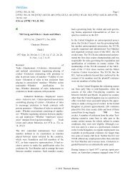
28 CHAPTER 5. ARCHITECTURE<br />
As only two real numbers are necessary to identify a qubit, we can map it<br />
to an arrow from the origin to the three-dimensional sphere of R 3 of radius 1,<br />
known as the Bloch Sphere.<br />
Every qubit can be represented by two angles that describe such an arrow<br />
(think of the Bloch sphere as the earth. You just need to specify only two<br />
numbers, the latitude <strong>and</strong> the longitude, to know where you are on the planet).<br />
The st<strong>and</strong>ard parametrization of the unit sphere is<br />
x = sin θ cos θ (5.82)<br />
y = sin θ sin θ (5.83)<br />
z = cos θ (5.84)<br />
However, there is yet another final caveat: suppose we use the representation<br />
above to map our qubit on the sphere. Then, the points (θ, φ) <strong>and</strong> (π −θ, φ+π)<br />
represent the same qubit, up to the factor −1!<br />
Exercise 5.4.5 Verify this last statement.<br />
Conclusion: the parametrization would map the same qubit twice, on the<br />
upper hemisphere <strong>and</strong> on the lower one. To mitigate this problem, we simply<br />
double the ”latitude” to cover the entire sphere at ”half speed”:<br />
Now we have it!<br />
x = sin 2θ cos θ (5.85)<br />
y = sin 2θ sin θ (5.86)<br />
z = cos 2θ (5.87)<br />
Figure 5.6: Bloch Sphere.
5.4. QUANTUM GATES 29<br />
Let us spend a few moments familiarizing ourselves with the Bloch Sphere<br />
<strong>and</strong> its geometry. The north pole corresponds to the state |0〉 <strong>and</strong> the south pole<br />
corresponds to the state |1〉. These two points can be taken as the geometrical<br />
image of the good ol’-fashioned bit. But there are many more qubits out there,<br />
<strong>and</strong> the Bloch sphere clearly shows it.<br />
Example 5.4.1 Let us find out which point of the sphere corresponds to the<br />
qubit<br />
|q〉 = cos(π)|0〉 + sin(π)e i π 2 |1〉 (5.88)<br />
Using the map we get.....<br />
It is your turn now:<br />
Exercise 5.4.6 Start from |q〉 = − 1 √<br />
2<br />
i|0〉 + 1 √<br />
2<br />
|1〉. Convert it to the canonical<br />
representation <strong>and</strong> then determine where it goes on the sphere.<br />
The precise meaning of the two angles in ♥ is the following: ϕ is half the<br />
angle that |ψ〉 makes from x along the equator <strong>and</strong> θ is the angle that |ψ〉 makes<br />
with the y axis.<br />
When a qubit is measured in the st<strong>and</strong>ard basis it collapses to a bit, or<br />
equivalently, to the north or south pole of the Bloch sphere. The probability<br />
of which pole the qubit will collapse to depends exclusively on how high or low<br />
the qubit is pointing, in other words, to its latitude. In particular, if the qubit<br />
happens to be on the equator, there is a 50 − 50 chance of collapsing to |0〉 <strong>and</strong><br />
|1〉. As the angle θ expresses the qubit’s latitude, it does control its chance of<br />
collapsing north or south.<br />
Exercise 5.4.7 Consider the qubit in Example 5.4.1. Its θ is equal to π 4 .<br />
Change it to π 3<br />
<strong>and</strong> picture the result. Then compute its likelihood of collapsing<br />
to the south pole after being observed.<br />
Take an arbitrary arrow <strong>and</strong> rotate it around the z axis;in the geographical<br />
metaphor, you are changing its longitude:<br />
Notice that the probability of which classical state it will collapse to is not<br />
affected. Such a state change is called a phase change. In the ♥ representation,<br />
this corresponds to altering the phase parameter e iϕ .<br />
Before we move on, one last important thing: just like |0〉 <strong>and</strong> |1〉 sit on<br />
opposite sides of the sphere, an arbitrary pair of orthogonal qubits is mapped<br />
to antipodal points of the Bloch Sphere.<br />
Exercise 5.4.8 Show that if a qubit has latitude 2θ <strong>and</strong> longitude φ on the<br />
sphere, its orthogonal lives in the antipode π − 2θ <strong>and</strong> π + φ.<br />
Another reason why the Bloch sphere is interesting is that every unitary 2 by<br />
2 matrix (i.e. a one-qubit operation) can be visualized as a way of manipulating<br />
the sphere. We have seen in chapter 2, page ??? that every unitary matrix<br />
is an isometry. This means that such a matrix maps qubits to qubits <strong>and</strong> the
30 CHAPTER 5. ARCHITECTURE<br />
inner product is preserved. Geometrically, this corresponds to a rotation or an<br />
inversion of the Bloch sphere.<br />
The X, Y <strong>and</strong> Z matrices are ways of “flipping” the Bloch sphere 180 0<br />
along the x, y <strong>and</strong> z axes respectively. Remember that X is nothing other<br />
the NOT gate <strong>and</strong> takes |0〉 to |1〉 <strong>and</strong> vice versa. But it does more, it takes<br />
everything above the equator to below the equator. The other Pauli matrices<br />
work similarly.<br />
Figure 5.7: A Rotation of the Bloch Sphere at y.<br />
There are times when we are not interested in performing a total flip but<br />
just want to turn the Bloch sphere θ degrees along an axis. These three matrices
5.4. QUANTUM GATES 31<br />
will work.<br />
R x (θ) = cos θ 2 I − i sinθ 2 X = ⎡<br />
⎣ cosθ 2<br />
−i sin<br />
2<br />
θ<br />
−i sin θ 2<br />
cos θ 2<br />
⎤<br />
⎦ (5.89)<br />
R y (θ) = cos θ 2 I − i sinθ 2 Y = ⎡<br />
R z (θ) = cos θ 2 I − i sinθ 2 Z = ⎡<br />
⎣ cosθ 2<br />
sin<br />
2<br />
θ<br />
−sin θ 2<br />
cos θ 2<br />
⎤<br />
⎦ (5.90)<br />
⎤<br />
⎣ e−iθ/2 0<br />
0<br />
e iθ/2 ⎦ (5.91)<br />
There are rotations around axis besides the x, y <strong>and</strong> z axis. Let D =<br />
(D x , D y , D z ) be a 3-dimensional vector of size 1 from the origin. That determines<br />
an axis of the Bloch sphere that we can spin around. The rotation<br />
matrix is given as<br />
R D (θ) = cos θ 2 I − i sinθ 2 (D xX + D y Y + D z Z). (5.92)<br />
Figure 5.8: A Rotation of the Bloch Sphere at D.<br />
As we have just seen, the Bloch sphere is a very valuable tool when it comes<br />
to underst<strong>and</strong>ing qubits <strong>and</strong> one-qubit operations. What about n-qubits? It<br />
turns out there is a high-dimension analogue of the sphere, but it is not easy<br />
to come to grip with. Indeed, it is a current research challenge to develop new<br />
ways of visualizing what happens when we manipulate several qubits at once.<br />
Entanglement, for instance, lies beyond the scope of the Bloch sphere (as it<br />
involves at least two qubits).
32 CHAPTER 5. ARCHITECTURE<br />
One of the central features of computer science is an operation that is done<br />
only under certain conditions <strong>and</strong> not under others. This is equivalent to an IF-<br />
THEN statement. If a certain (qu)bit is true, then a particular operation should<br />
be performed, otherwise the operation is not performed. For every n-qubit<br />
unitary operation U, we can create a unitary n+1-qubit operation Controlled-<br />
U or C U.<br />
|x〉<br />
•<br />
|x〉<br />
(5.93)<br />
/ n U / n<br />
This operation will perform the U operation if the top |x〉 input is a |1〉 <strong>and</strong><br />
will simply perform the identity operation if |x〉 is |0〉.<br />
For the simple case of<br />
⎡ ⎤<br />
U = ⎣ a b ⎦ (5.94)<br />
c d<br />
the controlled-U operation can be seen to be<br />
⎡<br />
⎤<br />
1 0 0 0<br />
0 1 0 0<br />
C U =<br />
. (5.95)<br />
⎢<br />
⎣<br />
0 0 a b⎥<br />
⎦<br />
0 0 c d<br />
This same construction works for matrices larger than 2 by 2.<br />
Exercise 5.4.9 Show that the constructed C U works as it should when the top<br />
qubit is set to |0〉 or set to |1〉.<br />
Exercise 5.4.10 Show that if U is unitary, then so is C U.<br />
Exercise 5.4.11 Show that the Toffoli gate is nothing more than C ( C NOT)
5.4. QUANTUM GATES 33<br />
Throughout the rest of this text we shall demonstrate the many operations<br />
that can be performed with quantum gates. However, there are limitations to<br />
what can be done with a quantum gate. For one thing, every operation must<br />
be reversible. Another limitation is a consequence of the The No-Cloning<br />
Theorem. This theorem says that it is impossible to clone an exact quantum<br />
state. In other words, it is impossible to make a copy of an arbitrary quantum<br />
state without first destroying the original. In “computerese,” this says that we<br />
can “cut” <strong>and</strong> “paste” a quantum state but we cannot “copy” <strong>and</strong> “paste” a<br />
quantum state. “Move” is possible; “Copy” is imposable.<br />
Why can’t we? What would such a cloning operation look like? There would<br />
be two different places having the same vector space that describes a quantum<br />
system, say V. Although these two systems would be apart, we are interested in<br />
looking at the two systems as one, i.e., we are interested in V ⊗ V. A potential<br />
cloning operation would be a linear map<br />
C : V ⊗ V −→ V ⊗ V (5.96)<br />
that should take an arbitrary state |x〉 in the first system <strong>and</strong>, perhaps, nothing<br />
in the second system <strong>and</strong> clone |x〉, i.e.,<br />
C(|x〉 ⊗ 0) = (|x〉 ⊗ |x〉). (5.97)<br />
This seems like a harmless enough operation, <strong>and</strong> there is no problem cloning<br />
for an arbitrary classical state |x〉. In fact, every Xerox machine clones <strong>and</strong><br />
every time we copy a file, classical states of information are cloned. However,<br />
this information is in a collapsed classical state. It is not in a superposition of<br />
states.<br />
The problem is cloning a superposition of states, that is, an arbitrary quantum<br />
state. Suppose we have a superposition of states √ . Cloning such a<br />
2<br />
|x〉 + |y〉<br />
state would mean that<br />
( ) ( )<br />
|x〉 + |y〉 |x〉 + |y〉 |x〉 + |y〉<br />
C √ ⊗ 0 = √ ⊗ √ . (5.98)<br />
2 2 2<br />
However if we insist that C is a quantum operation, then C must be linear <strong>and</strong><br />
hence must respect the scalar multiplication <strong>and</strong> the addition in V ⊗ V. If C<br />
was linear, then<br />
( ) ( )<br />
|x〉 + |y〉<br />
1<br />
C √ ⊗ 0 = C √2 (|x〉 + |y〉) ⊗ 0 = √ 1 C((|x〉 + |y〉) ⊗ 0) (5.99)<br />
2 2<br />
= 1 √<br />
2<br />
(C(|x〉⊗0+|y〉⊗0)) = 1 √<br />
2<br />
(C(|x〉⊗0)+C(|y〉⊗0)) = 1 √<br />
2<br />
((|x〉⊗|x〉)+(|y〉⊗|y〉))<br />
(5.100)<br />
(|x〉 ⊗ |x〉) + (|y〉 ⊗ |y〉)<br />
= √ . (5.101)<br />
2
34 CHAPTER 5. ARCHITECTURE<br />
But<br />
( |x〉 + |y〉<br />
√<br />
2<br />
⊗<br />
)<br />
|x〉 + |y〉 (|x〉 ⊗ |x〉) + (|y〉 ⊗ |y〉)<br />
√ ≠ √ . (5.102)<br />
2 2<br />
So C is not linear <strong>and</strong> hence no such map can exist.<br />
In contrast to cloning, there is no problem transporting arbitrary quantum<br />
states from one system to another. Such a transporting operation would be a<br />
linear map<br />
T : V ⊗ V −→ V ⊗ V (5.103)<br />
that should take an arbitrary state |x〉 in the first system <strong>and</strong>, say, nothing in<br />
the second system <strong>and</strong> transport |x〉 to the second system leaving nothing in<br />
the first system, i.e.,<br />
T (|x〉 ⊗ 0) = (0 ⊗ |x〉). (5.104)<br />
We do not run into the same problem if we transport a superposition of states.<br />
In detail,<br />
( ) ( )<br />
|x〉 + |y〉<br />
1<br />
T √ ⊗ 0 = T √2 (|x〉 + |y〉) ⊗ 0 = √ 1 T ((|x〉 + |y〉) ⊗ 0) (5.105)<br />
2 2<br />
= 1 √<br />
2<br />
T ((|x〉⊗0)+(|y〉⊗0)) = 1 √<br />
2<br />
(T (|x〉⊗0)+T (|y〉⊗0)) = 1 √<br />
2<br />
((0⊗|x〉)+(0⊗|y〉))<br />
=<br />
(|0 ⊗ (|x〉 + |y〉)<br />
√<br />
2<br />
(5.106)<br />
(|x〉 + |y〉)<br />
= 0 ⊗ √ . (5.107)<br />
2<br />
This is exactly what we would expect from a transporting operation. 4<br />
Fans of Star Trek have long known that when Scotty “beams” Captain Kirk<br />
down from the Starship Enterprise to the planet Zygon, he is transporting Captain<br />
Kirk to Zygon. The Kirk of the Enterprise gets destroyed <strong>and</strong> only the<br />
Zygon Kirk survives. Captain Kirk is not being cloned. (Would we really want<br />
many copies of Captain Kirk all over the Universe?)<br />
The reader might see an apparent contradiction in what we have stated. On<br />
the one h<strong>and</strong>, we have stated that the Toffoli <strong>and</strong> Fredkin gates can mimic the<br />
fanout gate. The matrices for the Toffoli <strong>and</strong> Fredkin gates are unitary, hence<br />
they are quantum gates. On the other h<strong>and</strong>, the no-cloning theorem says that<br />
no quantum gates can mimic the fanout operation. What is wrong here? Let us<br />
carefully examine the Fredkin gate. We have seen how this gate performs the<br />
cloning operation<br />
(x, 1, 0) ↦→ (x, ¬x, x). (5.108)<br />
However what would happen if the x input was in a superposition of states, say,<br />
|0〉<br />
√<br />
+ |1〉<br />
while leaving y = 1 <strong>and</strong> z = 0. This would correspond to the state<br />
2<br />
T<br />
000 001 010 011 100 101 110 111<br />
[<br />
0 0 √2 1 0 0 0 √2 1 0 ] . (5.109)<br />
4 In fact, we shall show how to transport arbitrary quantum states at the end of chapter 9.
5.4. QUANTUM GATES 35<br />
Multiplying this state with the Fredkin gate gives us<br />
⎡ ⎤ ⎡ ⎤<br />
0 0<br />
000 001 010 011 100 101 110 111<br />
⎡<br />
⎤<br />
000 1 0 0 0 0 0 0 0<br />
0<br />
0<br />
001 0 1 0 0 0 0 0 0<br />
1<br />
√ 1<br />
010 0 0 1 0 0 0 0 0<br />
2<br />
√ 2<br />
011 0 0 0 1 0 0 0 0<br />
0<br />
0<br />
100 0 0 0 0 1 0 0 0<br />
=<br />
. (5.110)<br />
0<br />
0<br />
101 0 0 0 0 0 0 1 0<br />
⎢<br />
⎥<br />
110 ⎣ 0 0 0 0 0 1 0 0 ⎦<br />
0<br />
1<br />
√ 2<br />
111 0 0 0 0 0 0 0 1<br />
1<br />
⎢√ ⎥ ⎢<br />
⎣ 2<br />
0 ⎥<br />
⎦ ⎣ ⎦<br />
0 0<br />
The resulting state is<br />
|0, 1, 0〉 + |1, 0, 1〉<br />
√<br />
2<br />
. (5.111)<br />
So, whereas on a classical bit x, the Fredkin gate performs the fanout operation<br />
as<br />
(x, 1, 0) ↦→ (x, ¬x, x) (5.112)<br />
on a superposition of states, the Fredkin gate performs the following very strange<br />
operation ( )<br />
|0〉 + |1〉<br />
|0, 1, 0〉 + |1, 0, 1〉<br />
√ , 1, 0 ↦→<br />
√ . (5.113)<br />
2 2<br />
This strange operation is not a fanout operation. And so the no-cloning theorem<br />
safely st<strong>and</strong>s.<br />
Exercise 5.4.12 Do a similar analysis for the Toffoli gate. Show that the way<br />
we set the Toffoli gate to perform the fanout operation does not clone a superposition<br />
of states.<br />
. . . . . . . . . . . . . . . . . . . . . . . . . . . . . . . . . . . . . . . . . . . . . . . . . . . . . . . . . . . . . . . . . . . . . . . . . . . . . .<br />
Reader’s Tip. The no-cloning theorem will be of major importance in<br />
chapters 9 <strong>and</strong> 10. □<br />
. . . . . . . . . . . . . . . . . . . . . . . . . . . . . . . . . . . . . . . . . . . . . . . . . . . . . . . . . . . . . . . . . . . . . . . . . . . . . .<br />
. . . . . . . . . . . . . . . . . . . . . . . . . . . . . . . . . . . . . . . . . . . . . . . . . . . . . . . . . . . . . . . . . . . . . . . . . . . . . .<br />
References:<br />
The basics of the qubits <strong>and</strong> quantum gates can be found in any textbook<br />
on quantum computing.<br />
The history of reverable computation can be found in [1]. This [3] readable<br />
article by one of the forefathers of reversible computation is strongly recommended.<br />
The no-cloning theorem was first proved in [2] <strong>and</strong> [4].
36 CHAPTER 5. ARCHITECTURE
Bibliography<br />
[1] Charles H. Bennett. Notes on the history of reversible computation. IBM<br />
J. Res. Dev., 32(1):16–23, 1988.<br />
[2] D. Dieks. Comunicating by epr devices. Phys. Letters A, 92(6):271–272,<br />
1982.<br />
[3] R. L<strong>and</strong>auer. <strong>Information</strong> is physical. Physics Today, 44:23–29, 1991.<br />
[4] W. K. Wootters <strong>and</strong> W. H. Zurek. A single quantum cannot be cloned.<br />
Nature, 299(5886):802–803, October 1982.<br />
37