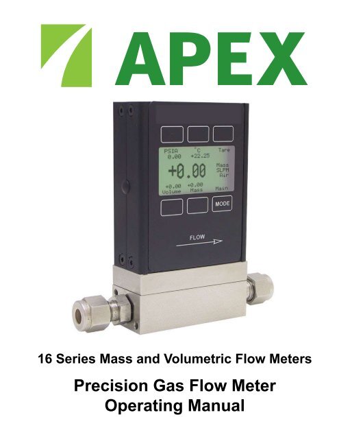
Precision Gas Flow Meter Operating Manual - Apex Mass Flow ...
Precision Gas Flow Meter Operating Manual - Apex Mass Flow ...
Precision Gas Flow Meter Operating Manual - Apex Mass Flow ...

You also want an ePaper? Increase the reach of your titles
YUMPU automatically turns print PDFs into web optimized ePapers that Google loves.
16 Series <strong>Mass</strong> and Volumetric <strong>Flow</strong> <strong>Meter</strong>s<br />
<strong>Precision</strong> <strong>Gas</strong> <strong>Flow</strong> <strong>Meter</strong><br />
<strong>Operating</strong> <strong>Manual</strong>
Notice: The manufacturer reserves the right to make any changes and improvements<br />
to the products described in this manual at any time and without notice. This manual<br />
is copyrighted. This document may not, in whole or in part, be copied, reproduced,<br />
translated, or converted to any electronic medium or machine readable form, for<br />
commercial purposes, without prior written consent from the copyright holder.<br />
Note: Although we provide assistance on our products both personally and through<br />
our literature, it is the complete responsibility of the user to determine the suitability<br />
of any product to their application.<br />
The manufacturer does not warrant or assume responsibility for the use of its<br />
products in life support applications or systems.<br />
Wide-Range Laminar <strong>Flow</strong> Element Patent:<br />
The wide-range laminar flow element and products using the wide-range laminar<br />
flow element are covered by U.S. Patent Number: 5,511,416. Manufacture or use of<br />
the wide-range laminar flow element in products other than products licensed under<br />
said patent will be deemed an infringement.<br />
10/24/06 Rev. 0 DOC-APEXMAN16
Table of Contents<br />
Page<br />
Installation 5<br />
Plumbing 5<br />
Mounting 5<br />
Application 5<br />
Power and Signal Connections 6<br />
RS-232 Digital Output Signal 7<br />
Standard Voltage (0-5 Vdc) Output Signal 7<br />
Optional 0-10 Vdc Output Signal 7<br />
Optional Current (4-20 mA) Output Signal 7<br />
Optional 2nd Analog Output Signal 7<br />
M Series <strong>Mass</strong> <strong>Flow</strong> <strong>Meter</strong> Operation 10<br />
Main Mode 10<br />
Tare 10<br />
<strong>Gas</strong> Absolute Pressure 11<br />
<strong>Gas</strong> Temperature 11<br />
Volumetric <strong>Flow</strong> Rate 11<br />
<strong>Mass</strong> <strong>Flow</strong> Rate 11<br />
Flashing Error Message 11<br />
Select Menu Mode 12<br />
<strong>Gas</strong> Select Mode 12<br />
Communication Select Mode 13<br />
Unit ID 13<br />
Baud 13<br />
Data Rate 13<br />
Manufacturer Data Mode 14<br />
V Series Volumetric <strong>Flow</strong> <strong>Meter</strong> Operation 15<br />
Main Mode 15<br />
Tare 15<br />
Flashing Error Message 16<br />
Select Menu Mode 16<br />
<strong>Gas</strong> Select Mode 16<br />
Communication Select Mode 16<br />
Manufacturer Data Mode 16<br />
RS-232 Output and Input 16<br />
Configuring HyperTerminal® 16<br />
Changing from Streaming to Polling Mode 17<br />
Tare 17<br />
<strong>Gas</strong> Select 17
Table of Contents<br />
Page<br />
Collecting Data 19<br />
Data Format 19<br />
Sending a Simple Script File to HyperTerminal® 20<br />
<strong>Operating</strong> Principle 21<br />
<strong>Gas</strong> Viscosity 21<br />
Other <strong>Gas</strong>es 22<br />
Volume <strong>Flow</strong> vs. <strong>Mass</strong> <strong>Flow</strong> 23<br />
Volumetric <strong>Flow</strong> and <strong>Mass</strong> <strong>Flow</strong> Conversion 23<br />
Compressibility 23<br />
Standard <strong>Gas</strong> Data Tables 24<br />
<strong>Gas</strong> Viscosities and Densities Table 25<br />
Volumetric <strong>Flow</strong> <strong>Meter</strong>s Under Pressure 26<br />
Troubleshooting 27<br />
Maintenance and Recalibration 28<br />
Warranty<br />
Technical Specifications 29<br />
Dimensional Drawings 33<br />
Additional Information<br />
Option: Totalizing Mode 36<br />
Option: Battery Pack 37<br />
Accessories 39<br />
<strong>Flow</strong> Conversion Table 39<br />
Calibration Certificate Pocket 40<br />
Table of Figures<br />
Figure 1. 8 Pin Mini-DIN Connector 6<br />
Figure 2. Mini-DIN to DB-9 Connection for RS-232 Signals 8<br />
Figure 3. Typical Multiple Device (Addressable) Wiring Configuration 8<br />
Figure 4. Optional Industrial Connector 9<br />
Figure 5. Proper Set Up for Remote Tare on <strong>Meter</strong>s 9<br />
Figure 6. Main Mode Display, M Series <strong>Flow</strong> <strong>Meter</strong> 10<br />
Figure 7. Select Menu Display 12<br />
Figure 8. <strong>Gas</strong> Select Display 12<br />
Figure 9. Communication Select Display 13<br />
Figure 10. Manufacturer Data Display 14<br />
Figure 11. Main Mode Display, V Series <strong>Flow</strong> <strong>Meter</strong> 15
Thank you for purchasing an <strong>Apex</strong> <strong>Gas</strong> <strong>Flow</strong> <strong>Meter</strong>. Please take the time to find and read the information<br />
contained in this manual. This will help to ensure that you get the best possible service from your<br />
instrument. This manual covers the following <strong>Apex</strong> instruments:<br />
Plumbing<br />
M Series 16 Bit <strong>Mass</strong> <strong>Gas</strong> <strong>Flow</strong> <strong>Meter</strong>s<br />
V Series 16 Bit Volumetric <strong>Gas</strong> <strong>Flow</strong> <strong>Meter</strong>s<br />
Installation<br />
All M or V Series <strong>Gas</strong> <strong>Flow</strong> <strong>Meter</strong>s are equipped with female inlet and outlet port connections. Because<br />
the flow meters set up a laminar flow condition within the flow body, no straight runs of pipe are required<br />
upstream or downstream of the meter. The inlet and outlet ports are equal in size and symmetric (inline).<br />
The port sizes (process connections) and mechanical dimensions for different flow ranges are<br />
shown on pages 29-32.<br />
<strong>Meter</strong>s with 10-32 ports have o-ring face seals and require no further sealant or tape. On other meters,<br />
avoid the use of pipe dopes or sealants on the ports as these compounds can cause permanent damage<br />
to the meter should they get into the flow stream. Use of thread sealing Teflon tape is recommended to<br />
prevent leakage around the threads. When applying the tape, avoid wrapping the first thread or two to<br />
minimize the possibility of getting a piece of shredded tape into the flow stream. When changing fittings,<br />
always clean any tape or debris from the port threads.<br />
It is also recommended that a 20 micron filter be installed upstream of meters with full scale ranges<br />
of 1(S)LPM or less and a 50 micron filter be installed upstream of meters with full scale ranges above<br />
1(S)LPM.<br />
Mounting<br />
All M or V Series <strong>Gas</strong> <strong>Flow</strong> <strong>Meter</strong>s have mounting holes for convenient mounting to flat panels. These<br />
meters are position insensitive and can be mounted in any orientation. The sizes and dimensions for<br />
the mounting holes are shown on pages 33-35.<br />
Application<br />
Maximum operating line pressure is 145 PSIG (1000 kPa).<br />
Caution: Exceeding the maximum specified line pressure may cause permanent damage to the<br />
solid-state differential pressure transducer.<br />
If the line pressure is higher than 145 PSIG (1000 kPa), a pressure regulator should be used upstream<br />
from the flow meter to reduce the pressure to 145 PSIG (1000 kPa) or less if possible. Although the<br />
meter’s operation is uni-directional, reversing the flow direction will inflict no damage as long as the<br />
maximum specified limits are not exceeded.<br />
Note: Avoid installations (such as snap acting solenoid valves upstream) that apply instantaneous<br />
high pressure to the meter as permanent damage to the differential pressure sensor could result.<br />
This damage is not covered under warranty!
Power and Signal Connections<br />
Power can be supplied to your M or V Series meter through either the power jack or the 8 pin Mini-DIN<br />
connector as shown in Figure 1. An AC to DC adapter which converts line AC power to DC voltage<br />
between 7 and 30 volts is required to use the power jack. The adapter current should be at least 100mA.<br />
The power jack accepts 2.1 mm female power plugs with positive centers. Cables and AC/DC adaptors<br />
may purchased from <strong>Apex</strong> (see Accessories page 42) and are commonly available at local electronics<br />
suppliers. Alternatively, power can be supplied through the Mini-DIN connector as shown below:<br />
AC/DC Adapter Jack<br />
3<br />
1 2<br />
3 4 5<br />
6<br />
1<br />
2<br />
4 5<br />
6 7 8<br />
7 8<br />
Pin Function<br />
Mini-DIN<br />
cable color<br />
1 Inactive or 4-20mA Primary Output Signal Black<br />
2<br />
Static 5.12 Vdc or Secondary Analog Output (4-20mA, 5Vdc, 10Vdc) or<br />
Basic Alarm<br />
Brown<br />
3 RS-232 Input Signal Red<br />
4 Analog Input Signal = Remote Tare (Ground to Tare) Orange<br />
5 RS-232 Output Signal Yellow<br />
6 0-5 Vdc (or 0-10 Vdc) Output Signal Green<br />
7 Power In (7-30 Vdc, 100mA) or (15-30Vdc for 4-20mA units) Blue<br />
8 Ground (common for power, communications and signals) Purple<br />
Note: The above pin-out is applicable to all the flow meters and controllers available with the Mini-<br />
DIN connector. The availability of different output signals depends on the flow meter options ordered.<br />
Underlined Items in the above table are optional configurations that are noted on the unit’s<br />
calibration sheet.<br />
Figure 1. 8 Pin Mini-DIN Connector<br />
CAUTION:Do not connect power to pins 1 through 6 as permanent damage can occur!<br />
Note: Upon initial review of the pin out diagram in Figure 1, it is common to mistake Pin 2 (labeled<br />
5.12 Vdc Output) as the standard 0-5 Vdc analog output signal! In fact Pin 2 is normally a constant<br />
5.12 Vdc that reflects the system bus voltage and can be used as a source for the input signal.
RS-232 Digital Output Signal<br />
If you will be using the RS-232 output signal, it is necessary to connect the RS-232 Output Signal (Pin<br />
5), the RS-232 Input Signal (Pin 3), and Ground (Pin 8) to your computer serial port as shown in Figure<br />
2. Adapter cables are available from the manufacturer or they can be constructed in the field with parts<br />
from an electronics supply house. In Figure 2, note that the diagrams represent the “port” side of the<br />
connections, i.e. the connector on top of the meter and the physical DB-9 serial port on the back of the<br />
computer. The cable ends will be mirror images of the diagram shown in Figure 2. (See page 16 for<br />
details on accessing RS-232 output.)<br />
Standard Voltage (0-5 Vdc) Output Signal<br />
All M or V Series flow meters have a 0-5 Vdc (optional 0-10 Vdc) output signal available on Pin 6. This<br />
is generally available in addition to other optionally ordered outputs. This voltage is usually in the range<br />
of 0.010 Vdc for zero flow and 5.0 Vdc for full-scale flow. The output voltage is linear over the entire<br />
range. Ground for this signal is common on Pin 8.<br />
Optional 0-10 Vdc Output Signal<br />
If your meter was ordered with a 0-10 Vdc output signal, it will be available on Pin 6. (See the Calibration<br />
Data Sheet that shipped with your meter to determine which output signals were ordered.) This voltage<br />
is usually in the range of 0.010 Vdc for zero flow and 10.0 Vdc for full-scale flow. The output voltage is<br />
linear over the entire range. Ground for this signal is common on Pin 8.<br />
Optional Current (4-20 mA) Output Signal<br />
If your meter was ordered with a 4-20 mA current output signal, it will be available on Pin 1. (See the<br />
Calibration Data Sheet that shipped with your meter to determine which output signals were ordered.)<br />
The current signal is 4 mA at 0 flow and 20 mA at the meter’s full scale flow. The output current is<br />
linear over the entire range. Ground for this signal is common on Pin 8. (Current output units require<br />
15-30Vdc power.)<br />
Note: This is a current sourcing device. Do not attempt to connect it to “loop powered” systems.<br />
Optional 2nd Analog Output Signal<br />
You may specify an optional 2nd analog output on Pin 2 at time of order. (See the Calibration Data<br />
Sheet that shipped with your meter to determine which output signals were ordered.) This output may<br />
be a 0-5 Vdc, 0-10 Vdc, or 4-20 mA analog signal that can represent any measured parameter. With<br />
this optional output, a volumetric flow meter could output the volumetric flow rate with a 0-5 Vdc signal<br />
(on pin 6) and a 4-20 mA signal (on pin 2), or a mass flow meter could output the mass flow rate (0-5<br />
Vdc on pin 6) and the absolute pressure (0-5 Vdc on pin 2).<br />
Note: This is a current sourcing device. Do not attempt to connect it to “loop powered” systems.
DB-9 Serial Port<br />
1 2 3 4 5<br />
6 7 8 9<br />
8 Pin Mini-DIN Port<br />
1 2<br />
3 4 5<br />
6 7 8<br />
6<br />
7<br />
8<br />
5----------Ground--------------------------------------Ground----------8<br />
3----------Transmit------------------------------------Receive---------3<br />
2----------Receive-------------------------------------Transmit--------5<br />
Figure 2. Mini-DIN to DB-9 Connection for RS-232 Signals<br />
Purple (Ground)<br />
Red<br />
Yellow<br />
Purple<br />
Unit A<br />
Red<br />
Yellow<br />
Purple<br />
Unit B<br />
Red<br />
Yellow<br />
Unit C<br />
5<br />
2<br />
5<br />
4 3 2<br />
1<br />
3<br />
9<br />
6<br />
8 7<br />
Female Serial Cable Front<br />
Figure 3. Typical Multiple Device (Addressable) Wiring Configuration
An optional industrial connector is also available:<br />
Pin Function Cable Color<br />
1 Power In ( + ) Red<br />
2 RS-232 Output Blue<br />
3 RS-232 Input Signal White<br />
4 Remote Tare (Ground to Tare) Green<br />
5 Ground (commom for power,<br />
Black<br />
communications and signals)<br />
6 Signal Out (Voltage or Current as ordered) Brown<br />
Figure 4. Optional Industrial Connector<br />
2<br />
1<br />
3<br />
6<br />
4<br />
5<br />
Note: The above pin-out is applicable to all the flow meters and controllers ordered with the industrial<br />
connector. The availability of different output signals depends on the flow meter options ordered.<br />
Figure 5. Proper set up for remote tare on meters (Momentarily ground Pin 4 to Tare)
M Series <strong>Mass</strong> <strong>Flow</strong> <strong>Meter</strong> Operation<br />
The M Series <strong>Mass</strong> <strong>Flow</strong> <strong>Meter</strong> provides a multitude of useful flow data in one simple, rugged device.<br />
The M Series can have several display “modes” depending on how the device is ordered. All M Series<br />
meters have a default Main Mode, Select Menu Mode, a <strong>Gas</strong> Select Mode (the <strong>Gas</strong> Select Mode may<br />
not be available on meters calibrated for a custom gas or blend), a Communication Select Mode and<br />
a Manufacturer Data Mode. (In addition, your device may have been ordered with a Totaliizing Mode,<br />
page 36.) The device defaults to Main Mode as soon as power is applied to the meter.<br />
Main Mode<br />
The main mode display defaults on power up with the mass flow on the primary display. The following<br />
parameters are displayed in the main mode as shown in Figure 6.<br />
PSIA o<br />
C Tare<br />
+13.49 +22.73<br />
MASS<br />
SCCM<br />
Air<br />
+0.000 +0.000<br />
Volume <strong>Mass</strong> Main<br />
Figure 6. Main Mode Display, M Series <strong>Flow</strong> <strong>Meter</strong><br />
The “MODE” button in the lower right hand corner toggles the display between Main Display and the<br />
Select Menu Display.<br />
Tare – Pushing the dynamically labeled “Tare” button in the upper right hand corner tares the flow meter<br />
and provides it with a reference point for zero flow. This is a simple but important step in obtaining<br />
accurate measurements. It is good practice to “zero” the flow meter each time it is powered up. If the<br />
flow reading varies significantly from zero after an initial tare, give the unit a minute or so to warm up<br />
and re-zero it.<br />
If possible, zero the unit near the expected operating pressure by positively blocking the flow downstream<br />
of the flow meter prior to pushing the “Tare” button. Zeroing the unit while there is any flow will directly<br />
affect the accuracy by providing a false zero point. If in doubt about whether a zero flow condition exists,<br />
remove the unit from the line and positively block both ports before pressing the “Tare” button. If the unit<br />
reads a significant negative value when removed from the line and blocked, it is a good indication that<br />
it was given a false zero. It is better to zero the unit at atmospheric pressure and a confirmed no flow<br />
conditions than to give it a false zero under line pressure.<br />
Note: A remote tare can be achieved by momentarily grounding pin 4 to tare as shown in Figure 5<br />
on page 9.<br />
10
<strong>Gas</strong> Absolute Pressure: The M Series flow meters utilize an absolute pressure sensor to measure<br />
the line pressure of the gas flow being monitored. This sensor references hard vacuum and accurately<br />
reads line pressure both above and below local atmospheric pressure. This parameter is located in<br />
the upper left corner of the display under the dynamic label “PSIA”. This parameter can be moved to<br />
the primary display by pushing the button just above the dynamic label (top left). The engineering unit<br />
associated with absolute pressure is pounds per square inch absolute (PSIA). This can be converted<br />
to gage pressure (psig = the reading obtained by a pressure gauge that reads zero at atmospheric<br />
pressure) by simply subtracting local atmospheric pressure from the absolute pressure reading:<br />
PSIG = PSIA – (Local Atmospheric Pressure)<br />
The flow meters use the absolute pressure of the gas in the calculation of the mass flow rate. For<br />
working in metric units, note that 1 PSI = 6.89 kPa.<br />
<strong>Gas</strong> Temperature: The M Series flow meters also utilize a temperature sensor to measure the line<br />
temperature of the gas flow being monitored. The temperature is displayed in engineering units of<br />
degrees Celsius (°C). The flow meters use the temperature of the gas in the calculation of the mass<br />
flow rate. This parameter is located in the upper middle portion of the display under “°C”. This parameter<br />
can be moved to the primary display by pushing the top center button above “°C”.<br />
Volumetric <strong>Flow</strong> Rate: The volumetric flow rate is determined using the <strong>Flow</strong> Measurement <strong>Operating</strong><br />
Principle described elsewhere in this manual. This parameter is located in the lower left corner of the<br />
display over “Volume”. This parameter can be moved to the primary display by pushing the “Volume”<br />
button (lower left). In order to get an accurate volumetric flow rate, the gas being measured must be<br />
selected (see <strong>Gas</strong> Select Mode). This is important because the device calculates the flow rate based on<br />
the viscosity of the gas at the measured temperature. If the gas being measured is not what is selected,<br />
an incorrect value for the viscosity of the gas will be used in the calculation of flow, and the resulting<br />
output will be inaccurate in direct proportion to the ratio between the two gases viscosities.<br />
<strong>Mass</strong> <strong>Flow</strong> Rate: The mass flow rate is the volumetric flow rate corrected to a standard temperature<br />
and pressure (typically 14.696 psia and 25°C). This parameter is located in the lower middle portion<br />
of the display over “<strong>Mass</strong>”. This parameter can be moved to the primary display by pushing the button<br />
located below “<strong>Mass</strong>” (bottom center). The meter uses the measured temperature and the measured<br />
absolute pressure to calculate what the flow rate would be if the gas pressure was at 1 atmosphere and<br />
the gas temperature was 25°C. This allows a solid reference point for comparing one flow to another.<br />
Flashing Error Message: Our flow meters and controllers display an error message (MOV = mass<br />
overrange, VOV = volumetric overrange, POV = pressure overrange, TOV = temperature overrange)<br />
when a measured parameter exceeds the range of the sensors in the device. When any item flashes<br />
on the display, neither the flashing parameter nor the mass flow measurement is accurate. Reducing<br />
the value of the flashing parameter to within specified limits will return the unit to normal operation and<br />
accuracy.<br />
11
Select Menu Mode<br />
Pushing “Mode” once will bring up the “Select Menu” display. Push the button nearest your selection to<br />
go to the corresponding display. Push “Mode” again to return to the Main Mode display. (Note: If your<br />
meter was ordered with Totalizing Mode option (page 36), pushing the “Mode” button once will bring up<br />
the “Totalizing Mode” display. Pushing “Mode” a second time will bring up the “Select Menu” display.)<br />
<strong>Gas</strong><br />
Select<br />
SELECT<br />
MENU<br />
Comm. Mfg.<br />
RS-232 Data Menu<br />
<strong>Gas</strong> Select Mode<br />
Figure 7. Select Menu Display<br />
The gas select mode is accessed by pressing the button above “<strong>Gas</strong> Select” on the Select Menu<br />
display. The display will appear as shown in Figure 8 below.<br />
PgUP PgDWN Main<br />
H2 Hydrogen<br />
He Helium<br />
>N2 Nitrogen<br />
N2O Nitrous Oxide<br />
Ne Neon<br />
O2 Oxygen<br />
UP DOWN <strong>Gas</strong><br />
Figure 8. <strong>Gas</strong> Select Display<br />
The selected gas is displayed on the default main mode display as shown in Figure 6, and is indicated<br />
by the arrow in the <strong>Gas</strong> Select Mode display in Figure 8. To change the selected gas, use the buttons<br />
under “UP” and “DOWN” or above “PgUP” and “PgDWN” to position the arrow in front of the desired<br />
gas. When the mode is cycled back to the Main Mode, the selected gas will be displayed on the main<br />
display. (Note: <strong>Gas</strong> Select Mode may not be available for units ordered for use with a custom gas or<br />
blend.)<br />
12
Communication Select Mode<br />
The Communication Select mode is accessed by pressing the button below “Comm. RS-232” on the<br />
Select Menu display. The screen will appear as shown in Figure 9 below.<br />
Select<br />
><br />
Unit ID (A).....A<br />
Baud (19200)....19200<br />
Data Rate......Fast<br />
Main<br />
Comm.<br />
UP DOWN RS-232<br />
Figure 9. Communication Select Display<br />
Unit ID – Valid unit identifiers are letters A-Z and @ (see Note below). This identifier allows the user<br />
to assign a unique address to each device so that multiple units can be connected to a single RS-232<br />
port on a computer. The Communication Select Mode allows you to view and/or change a unit’s unique<br />
address. To change the unit ID address, press the “Select” button in the upper left corner of the display<br />
until the cursor arrow is in front of the word “Unit ID”. Then, using the UP and DOWN buttons at the<br />
bottom of the display, change the unit ID to the desired letter. Any ID change will take effect when the<br />
Communication Select Screen is exited by pushing the MODE or Main button.<br />
Note: When the symbol @ is selected as the unit ID, the device will go into streaming mode when<br />
the Communication Select Mode is exited by pushing the MODE or Main button. See the RS-232<br />
Communications chapter in this manual for information about the streaming mode.<br />
Baud – The baud rate (bits per second) determines the rate at which data is passed back and forth<br />
between the instrument and the computer. Both devices must send/receive at the same baud rate in<br />
order for the devices to communicate via RS-232. The default baud rate for these devices is 19200<br />
baud, sometimes referred to as 19.2K baud. To change the baud rate in the Communication Select<br />
Mode, press the “Select” button in the upper left corner of the display until the cursor arrow is in front<br />
of the word “Baud”. Then, using the UP and DOWN buttons at the bottom of the display, select the<br />
required baud rate to match your computer or PLC. The choices are 38400, 19200, 9600, or 2400 baud.<br />
Any baud rate change will not take effect until power to the unit is cycled.<br />
Data Rate – Changing the Data Rate affects the rate at which the instrument dumps its data in the<br />
streaming mode. Slow is ½ the Fast rate. The speed of the Fast rate is determined by the selected<br />
baud rate. It is sometimes desirable to reduce the data rate if the communication speed bogs down<br />
the computer’s processor (as is not uncommon in older laptops), or to reduce the size of data files<br />
collected in the streaming mode. To change the data rate in the Communication Select Mode, press the<br />
“Select” button in the upper left corner of the display until the cursor arrow is in front of the word “Data<br />
Rate”. Then, using the UP and DOWN buttons at the bottom of the display, select either Fast or Slow.<br />
Any data rate change will be effective immediately upon changing the value between Fast and<br />
Slow.<br />
13
Manufacturer Data<br />
“Manufacturer Data” is accessed by pressing the “Mfg. Data” button on the Select Menu display (Figure<br />
7). The “Mfg 1” display shows the name and telephone number of the manufacturer. The“Mfg 2” display<br />
shows important information about your flow meter including the model number, serial number, and<br />
date of manufacture.<br />
<strong>Apex</strong><br />
Ph 404-474-3115<br />
Main<br />
Mfg 1<br />
Model M-10SLPM-D<br />
Serial No 27117<br />
Date Mfg.11/07/2005<br />
Calibrated By . DL<br />
Main<br />
Software GP07R23<br />
Mfg 2<br />
Figure 10. Manufacturer Data Displays<br />
14
V Series Volumetric <strong>Flow</strong> <strong>Meter</strong> Operation<br />
The V Series can have several display “modes” depending on how the device is ordered. All V Series<br />
meters have a default Main Mode,a Select Menu Mode, a <strong>Gas</strong> Select Mode (the <strong>Gas</strong> Select Mode<br />
may not be available on meters calibrated for a custom gas or blend), a Communication Select Mode<br />
and a Manufacturer Data Mode. (In addition, your device may have been ordered with a Totaliizing<br />
Mode, page 36.) The device defaults to Main Mode as soon as power is applied to the meter. Note that<br />
volumetric meters are intended for use in near atmospheric conditions (Please see page 26).<br />
Main Mode<br />
The main mode display shows the volumetric flow in the units specified at time of order. In the flow<br />
mode, only two buttons, Tare and Mode, are active as shown in Figure 11. The process gas that is<br />
selected is shown directly under the flow units.<br />
Tare<br />
Volume<br />
CCM<br />
Air<br />
+0.000<br />
Volume<br />
Main<br />
Figure 11. Main Mode Display, V Series <strong>Flow</strong> <strong>Meter</strong><br />
The “MODE” button in the lower right hand corner toggles the display between the Main Display and<br />
the Select Menu Display.<br />
Tare – Pushing the dynamically labeled “Tare” button in the upper right hand corner tares the flow meter<br />
and provides it with a reference point for zero flow. This is a simple but important step in obtaining<br />
accurate measurements. It is good practice to “zero” the flow meter each time it is powered up and<br />
whenever a known zero flow condition exists. If the flow reading varies significantly from zero after an<br />
initial tare, give the unit a minute or so to warm up and re-zero it.<br />
Zeroing the unit while there is any flow will directly affect the accuracy by providing a false zero point.<br />
If in doubt about whether a zero flow condition exists, remove the unit from the line and positively block<br />
both ports before pressing the “Tare” button. If the unit reads a significant negative value when removed<br />
from the line and blocked, it is a good indication that it was given a false zero. It is better to zero the<br />
unit at atmospheric pressure and a confirmed “no flow” condition than to give it a false zero under line<br />
pressure.<br />
Note: A remote tare can be achieved by momentarily grounding pin 4 to tare as shown in Figure 5 on<br />
page 9.<br />
15
Flashing Error Message: Our volumetric flow meters and controllers display an error message (VOV<br />
= volumetric overrange) when a measured parameter exceeds the range of the sensors in the device.<br />
When any item flashes on the display, the flashing parameter is not accurate. Reducing the value of the<br />
flashing parameter to within specified limits will return the unit to normal operation and accuracy.<br />
Select Menu Mode<br />
Pushing “Mode” once will bring up the “Select Menu” display (Figure 7, page 12). Push the button nearest<br />
your selection to go to the corresponding display. Push “Mode” again to return to the Main Mode<br />
display. (Note: If your meter was ordered with Totalizing Mode option (page 36), pushing the “Mode”<br />
button once will bring up the “Totalizing Mode” display. Pushing “Mode” a second time will bring up the<br />
“Select Menu” display.)<br />
<strong>Gas</strong> Select Mode<br />
The <strong>Gas</strong> Select Mode is accessed by pressing the button above “<strong>Gas</strong> Select” on the Select Menu<br />
display. The display will appear as shown in Figure 8 (page 12). The selected gas is displayed on the<br />
default main mode display as shown in Figure 11, and is indicated by the arrow in the gas select mode<br />
display in Figure 8. To change the selected gas, use the buttons under “UP” and “DOWN” or those<br />
above “PgUP” and “PgDWN” to position the arrow in front of the desired gas. When the mode is cycled<br />
back to the main mode, the selected gas will be displayed on the main display.<br />
Note: <strong>Gas</strong> Select Mode may not be available for units ordered for use with a custom gas or blend.<br />
Communication Select Mode<br />
The Communication Select mode is accessed by pressing the button below “Comm. RS-232” on the<br />
Select Menu display. Please see page 13 for Communication Select mode instructions.<br />
Manufacturer Data<br />
“Manufacturer Data” is accessed by pressing the “Mfg. Data” button on the Select Menu display (Figure<br />
7, page 12). The “Mfg 1” display shows the name and telephone number of the manufacturer. The“Mfg 2”<br />
display shows important information about your flow meter including the model number, serial number,<br />
and date of manufacture (Figure 10, page 14).<br />
Configuring HyperTerminal®:<br />
1.<br />
2.<br />
3.<br />
4.<br />
5.<br />
6.<br />
RS-232 Output and Input<br />
Open your HyperTerminal® RS-232 terminal program (installed under the “Accessories” menu on<br />
all Microsoft Windows operating systems).<br />
Select “Properties” from the file menu.<br />
Click on the “Configure” button under the “Connect To” tab. Be sure the program is set for: 19,200<br />
baud (or matches the baud rate selected in the RS-232 communications menu on the meter) and<br />
an 8-N-1-None (8 Data Bits, No Parity, 1 Stop Bit, and no <strong>Flow</strong> Control) protocol.<br />
Under the “Settings” tab, make sure the Terminal Emulation is set to ANSI or Auto Detect.<br />
Click on the “ASCII Setup” button and be sure the “Send Line Ends with Line Feeds” box is not<br />
checked and the “Echo Typed Characters Locally” box and the “Append Line Feeds to Incoming<br />
Lines” boxes are checked. Those settings not mentioned here are normally okay in the default<br />
position.<br />
Save the settings, close HyperTerminal® and reopen it.<br />
In Polling Mode, the screen should be blank except the blinking cursor. In order to get the data streaming<br />
16
to the screen, hit the “Enter” key several times to clear any extraneous information. Type “*@=@”<br />
followed by “Enter” (or using the RS-232 communcation select menu, select @ as identifier and exit the<br />
screen). If data still does not appear, check all the connections and com port assignments.<br />
Changing From Streaming to Polling Mode:<br />
When the meter is in the Streaming Mode, the screen is updated approximately 10-60 times per second<br />
(depending on the amount of data on each line) so that the user sees the data essentially in real time.<br />
It is sometimes desirable, and necessary when using more than one unit on a single RS-232 line, to be<br />
able to poll the unit.<br />
In Polling Mode the unit measures the flow normally, but only sends a line of data when it is “polled”.<br />
Each unit can be given its own unique identifier or address. Unless otherwise specified each unit is<br />
shipped with a default address of capital A. Other valid addresses are B thru Z.<br />
Once you have established communication with the unit and have a stream of information filling your<br />
screen:<br />
1.<br />
2.<br />
Type *@=A followed by “Enter” (or using the RS-232 communcation select menu, select A as identifier<br />
and exit the screen) to stop the streaming mode of information. Note that the flow of information will<br />
not stop while you are typing and you will not be able to read what you have typed. Also, the unit<br />
does not accept a backspace or delete in the line so it must be typed correctly. If in doubt, simply hit<br />
enter and start again. If the unit does not get exactly what it is expecting, it will ignore it. If the line<br />
has been typed correctly, the data will stop.<br />
You may now poll the unit by typing A followed by “Enter”. This does an instantaneous poll of unit<br />
A and returns the values once. You may type A “Enter” as many times as you like. Alternately you<br />
could resume streaming mode by typing *@=@ followed by “Enter”. Repeat step 1 to remove the<br />
unit from the streaming mode.<br />
3.<br />
To assign the unit a new address, type *@=New Address, e.g. *@=B. Care should be taken not to<br />
assign an address to a unit if more than one unit is on the RS232 line as all of the addresses will be<br />
reassigned. Instead, each should be individually attached to the RS-232 line, given an address, and<br />
taken off. After each unit has been given a unique address, they can all be put back on the same<br />
line and polled individually.<br />
Tare –Tareing (or zeroing) the flow meter provides it with a reference point for zero flow. This is a simple<br />
but important step in obtaining accurate measurements. It is good practice to “zero” the flow meter each<br />
time it is powered up. A unit may be Tared by following the instructions on page 10 or it may be Tared<br />
via RS-232 input.<br />
To send a Tare command via RS-232, enter the following strings:<br />
In Streaming Mode: $$V<br />
In Polling Mode: Address$$V (e.g. B$$V)<br />
17
<strong>Gas</strong> Select – The selected gas can be changed via RS-232 input. To change the selected gas, enter<br />
the following commands:<br />
In Streaming Mode: $$#<br />
In Polling Mode: Address$$# (e.g. B$$#)<br />
Where # is the number of the gas selected from the table below. Note that this also corresponds to the<br />
gas select menu on the flow meter display:<br />
# GAS<br />
0 Air Air<br />
1 Argon Ar<br />
2 Methane CH4<br />
3 Carbon Monoxide CO<br />
4 Carbon Dioxide CO2<br />
5 Ethane C2H6<br />
6 Hydrogen H2<br />
7 Helium He<br />
8 Nitrogen N2<br />
9 Nitrous Oxide N2O<br />
10 Neon Ne<br />
11 Oxygen O2<br />
12 Propane C3H8<br />
13 normal-Butane n-C4H10<br />
14 Acetylene C2H2<br />
15 Ethylene C2H4<br />
16 iso-Butane i-C2H10<br />
17 Krypton Kr<br />
18 Xenon Xe<br />
19 Sulfur Hexafluoride SF6<br />
20 75% Argon / 25% CO2 C-25<br />
21 90% Argon / 10% CO2 C-10<br />
22 92% Argon / 8% CO2 C-8<br />
23 98% Argon / 2% CO2 C-2<br />
24 75% CO2 / 25% Argon C-75<br />
25 75% Argon / 25% Helium A-75<br />
26 75% Helium / 25% Argon A-25<br />
27 90% Helium / 7.5% Argon / 2.5% CO2 A1025<br />
(Praxair - Helistar® A1025)<br />
28 90% Argon / 8% CO2 / 2% Oxygen Star29<br />
(Praxair - Stargon® CS)<br />
29 95% Argon / 5% Methane P-5<br />
For example, to select Propane, enter: $$12<br />
18
Collecting Data:<br />
The RS-232 output updates to the screen many times per second. Very short-term events can be<br />
captured simply by disconnecting (there are two telephone symbol icons at the top of the HyperTerminal®<br />
screen for disconnecting and connecting) immediately after the event in question. The scroll bar can be<br />
driven up to the event and all of the data associated with the event can be selected, copied, and pasted<br />
into Microsoft® Excel® or other spreadsheet program as described below.<br />
For longer term data, it is useful to capture the data in a text file. With the desired data streaming to the<br />
screen, select “Capture Text” from the Transfer Menu. Type in the path and file name you wish to use.<br />
Push the start button. When the data collection period is complete, simply select “Capture Text” from<br />
the Transfer Menu and select “Stop” from the sub-menu that appears.<br />
Data that is selected and copied, either directly from HyperTerminal® or from a text file can be pasted<br />
directly into Excel®. When the data is pasted it will all be in the selected column. Select “Text to<br />
Columns...” under the Data menu in Excel® and a Text to Columns Wizard (dialog box) will appear.<br />
Make sure that “Fixed Width” is selected under Original Data Type in the first dialog box and click “Next”.<br />
In the second dialog box, set the column widths as desired, but the default is usually acceptable. Click<br />
on “Next” again. In the third dialog box, make sure the column data format is set to “General”, and click<br />
“Finish”. This separates the data into columns for manipulation and removes symbols such as the plus<br />
signs from the numbers. Once the data is in this format, it can be graphed or manipulated as desired.<br />
For extended term data capture see: “Sending a Simple Script to HyperTerminal®” on page 20.<br />
Data Format:<br />
The data stream on the screen represents the flow parameters of the main mode in the units shown on<br />
the display. For volumetric flow meters, there are two columns of data representing volumetric flow rate<br />
in the units specified at time of order and the selected gas.<br />
+4.123 Air<br />
+4.123 Air<br />
+4.123 Air<br />
+4.123 Air<br />
+4.124 Air<br />
+4.125 Air<br />
V Series Volumetric <strong>Flow</strong> <strong>Meter</strong> Data Format<br />
For mass flow meters, there are 5 columns of data representing pressure, temperature, volumetric flow,<br />
mass flow and the selected gas. The first column is absolute pressure (normally in PSIA), the second<br />
column is temperature (normally in °C), the third column is volumetric flow rate (in the units specified at<br />
time of order and shown on the display), and the fourth column is mass flow (also in the units specified<br />
at time of order and shown on the display). For instance, if the meter was ordered in units of SCFM,<br />
the display on the meter would read 2.004 SCFM and the last two columns of the output below would<br />
represent volumetric flow and mass flow in CFM and SCFM respectively.<br />
+014.70 +025.00 +02.004 +02.004 Air<br />
+014.70 +025.00 +02.004 +02.004 Air<br />
+014.70 +025.00 +02.004 +02.004 Air<br />
+014.70 +025.00 +02.004 +02.004 Air<br />
+014.70 +025.00 +02.004 +02.004 Air<br />
+014.70 +025.00 +02.004 +02.004 Air<br />
M Series <strong>Mass</strong> <strong>Flow</strong> <strong>Meter</strong> Data Format<br />
19
Sending a Simple Script File to HyperTerminal®<br />
It is sometimes desirable to capture data for an extended period of time. Standard streaming mode<br />
information is useful for short term events, however, when capturing data for an extended period of<br />
time, the amount of data and thus the file size can become too large very quickly. Without any special<br />
programming skills, the user can use HyperTerminal and a text editing program such as Microsoft Word<br />
to capture text at user defined intervals.<br />
1. Open your text editing program, MS Word for example.<br />
2. Set the cap lock on so that you are typing in capital letters.<br />
3. Beginning at the top of the page, type A repeatedly. If you’re using MS Word, you can tell how<br />
many lines you have by the line count at the bottom of the screen. The number of lines will correspond<br />
to the total number of times the flow device will be polled, and thus the total number of lines of data it<br />
will produce.<br />
For example: A<br />
A<br />
A<br />
A<br />
A<br />
A<br />
will get a total of six lines of data from the flow meter, but you can enter as many as you like.<br />
The time between each line will be set in HyperTerminal.<br />
4. When you have as many lines as you wish, go to the File menu and select save. In the save dialog<br />
box, enter a path and file name as desired and in the “Save as Type” box, select the plain text (.txt)<br />
option. It is important that it be saved as a generic text file for HyperTerminal to work with it.<br />
5. Click Save.<br />
6. A file conversion box will appear. In the “End Lines With” drop down box, select CR Only. Everything<br />
else can be left as default.<br />
7. Click O.K.<br />
8. You have now created a “script” file to send to HyperTerminal. Close the file and exit the text editing<br />
program.<br />
9. Open HyperTerminal and establish communication with your flow device as outlined in the manual.<br />
10. Set the flow device to Polling Mode as described in the manual. Each time you type A, the<br />
meter should return one line of data to the screen.<br />
11. Go to the File menu in HyperTerminal and select “Properties”.<br />
12. Select the “Settings” tab.<br />
13. Click on the “ASCII Setup” button.<br />
14. The “Line Delay” box is defaulted to 0 milliseconds. This is where you will tell the program how often<br />
to read a line from the script file you’ve created. 1000 milliseconds is one second, so if you want a line<br />
of data every 30 seconds, you would enter 30000 into the box. If you want a line every 5 minutes, you<br />
would enter 300000 into the box.<br />
15. When you have entered the value you want, click on OK and OK in the Properties dialog box.<br />
16. Go the Transfer menu and select “Send Text File…” (NOT Send File…).<br />
17. Browse and select the text “script” file you created.<br />
18. Click Open.<br />
19. The program will begin “executing” your script file, reading one line at a time with the line delay you<br />
specified and the flow device will respond by sending one line of data for each poll it receives, when it<br />
receives it.<br />
You can also capture the data to another file as described in the manual under “Collecting Data”. You<br />
will be simultaneously sending it a script file and capturing the output to a separate file for analysis.<br />
20
<strong>Operating</strong> Principle<br />
All M or V Series <strong>Gas</strong> <strong>Flow</strong> <strong>Meter</strong>s are based on the accurate measurement of volumetric flow. The<br />
volumetric flow rate is determined by creating a pressure drop across a unique internal restriction,<br />
known as a Laminar <strong>Flow</strong> Element (LFE), and measuring differential pressure across it. The restriction<br />
is designed so that the gas molecules are forced to move in parallel paths along the entire length of the<br />
passage; hence laminar (streamline) flow is established for the entire range of operation of the device.<br />
Unlike other flow measuring devices, in laminar flow meters the relationship between pressure drop<br />
and flow is linear. The underlying principle of operation of the 16 Series flow meters is known as the<br />
Poiseuille Equation:<br />
Q = (P 1<br />
-P 2<br />
)r 4 /8ηL (Equation 1)<br />
Where: Q = Volumetric <strong>Flow</strong> Rate<br />
P 1<br />
= Static pressure at the inlet<br />
P 2<br />
= Static pressure at the outlet<br />
r = Radius of the restriction<br />
η = (eta) absolute viscosity of the fluid<br />
L = Length of the restriction<br />
Since , r and L are constant; Equation 1 can be rewritten as:<br />
Q = K (∆P/η) (Equation 2)<br />
Where K is a constant factor determined by the geometry of the restriction. Equation 2 shows the linear<br />
relationship between volumetric flow rate (Q) differential pressure (∆P) and absolute viscosity (η) in a<br />
simpler form.<br />
<strong>Gas</strong> Viscosity: In order to get an accurate volumetric flow rate, the gas being measured must be<br />
selected (see <strong>Gas</strong> Select Mode, page 12). This is important because the device calculates the flow<br />
ratebased on the viscosity of the gas at the measured temperature. If the gas being measured is<br />
not what is selected, an incorrect value for the viscosity of the gas will be used in the calculation of<br />
flow, and the resulting output will be inaccurate in direct proportion to the difference in the two gases<br />
viscosities.<br />
<strong>Gas</strong> viscosity, and thus gas composition, can be very important to the accuracy of the meter. Anything<br />
that has an effect on the gas viscosity (e.g. water vapor, odorant additives, etc.) will have a direct<br />
proportional effect on the accuracy. Selecting methane and measuring natural gas for instance, will<br />
result in a fairly decent reading, but it is not highly accurate (errors are typically < 0.6%) because<br />
natural gas contains small and varying amounts of other gases such as butane and propane that result<br />
in a viscosity that is somewhat different than pure methane.<br />
Absolute viscosity changes very little with pressure (within the operating ranges of these meters) therefore<br />
a true volumetric reading does not require a correction for pressure. Changes in gas temperature do<br />
affect viscosity. For this reason, the M or V Series internally compensate for this change.<br />
21
Other <strong>Gas</strong>es: M Series <strong>Flow</strong> <strong>Meter</strong>s can easily be used to measure the flow rate of gases other than<br />
those listed as long as “non-corrosive” gas compatibility is observed. For example, a flow meter that<br />
has been set for air can be used to measure the flow of argon.<br />
The conversion factor needed for measuring the flow of different gases is linear and is simply determined<br />
by the ratio of the absolute viscosity of the gases. This factor can be calculated as follows:<br />
Q og<br />
= Q 1<br />
[η 1<br />
/ η og<br />
]<br />
Where: Q 1<br />
= <strong>Flow</strong> rate indicated by the flow meter<br />
η 1<br />
= Viscosity of the calibrated gas at the measured temp.<br />
Q og<br />
= <strong>Flow</strong> rate of the alternate gas<br />
η og<br />
= Viscosity of the alternate gas at the measured temp.<br />
Say we have a meter set for air and we want to flow argon through it. With argon flowing through the<br />
meter, the display reads 110 SLPM. For ease of calculation, let us say the gas temperature is 25°C.<br />
What is the actual flow of argon?<br />
Q og<br />
= Actual Argon <strong>Flow</strong> Rate<br />
Q 1<br />
= <strong>Flow</strong> rate indicated by meter (110 SLPM)<br />
η 1<br />
= Viscosity of gas selected or calibrated for by the meter at the<br />
measured temp.<br />
η og<br />
= Viscosity of gas flowing through the meter at the measured temp.<br />
At 25°C, the absolute viscosity of Air (η 1<br />
) is 184.918 micropoise.<br />
At 25°C, the absolute viscosity of Argon (η og<br />
) is 225.593 micropoise.<br />
Q og<br />
= Q1 (η 1 / η og<br />
)<br />
Q og<br />
= 110 SLPM (184.918 / 225.593)<br />
Q og<br />
= 90.17 SLPM<br />
So, the actual flow of Argon through the meter is 90.17 SLPM. As you can see, because the Argon gas<br />
is more viscous than the Air the meter is set for, the meter indicates a higher flow than the actual flow.<br />
A good rule of thumb is: “At a given flow rate, the higher the viscosity, the higher the indicated flow.”<br />
Volume <strong>Flow</strong> vs. <strong>Mass</strong> <strong>Flow</strong>: At room temperature and low pressures the volumetric and mass flow<br />
rate will be nearly identical, however, these rates can vary drastically with changes in temperature and/<br />
or pressure because the temperature and pressure of the gas directly affects the volume. For example,<br />
assume a volumetric flow reading was used to fill balloons with 250 mL of helium, but the incoming<br />
line ran near a furnace that cycled on and off, intermittently heating the incoming helium. Because<br />
the volumetric meter simply measures the volume of gas flow, all of the balloons would initially be the<br />
same size. However, if all the balloons are placed in a room and allowed to come to an equilibrium<br />
temperature, they would generally all come out to be different sizes. If, on the other hand, a mass flow<br />
reading were used to fill the balloons with 250 standard mL of helium, the resulting balloons would<br />
initially be different sizes, but when allowed to come to an equilibrium temperature, they would all turn<br />
out to be the same size.<br />
This parameter is called corrected mass flow because the resulting reading has been compensated<br />
for temperature and pressure and can therefore be tied to the mass of the gas. Without knowing the<br />
temperature and pressure of the gas and thus the density, the mass of the gas cannot be determined.<br />
22
Once the corrected mass flow rate at standard conditions has been determined and the density at<br />
standard conditions is known (see the density table at the back of this manual), a true mass flow can<br />
be calculated as detailed in the following example:<br />
<strong>Mass</strong> <strong>Flow</strong> <strong>Meter</strong> Reading = 250 SCCM (Standard Cubic Centimeters/Minute)<br />
<strong>Gas</strong>: Helium<br />
<strong>Gas</strong> Density at 25C and 14.696 PSIA = .16353 grams/Liter<br />
True <strong>Mass</strong> <strong>Flow</strong> = (<strong>Mass</strong> <strong>Flow</strong> <strong>Meter</strong> Reading) X (<strong>Gas</strong> Density)<br />
True <strong>Mass</strong> <strong>Flow</strong> = (250 CC/min) X (1 Liter / 1000 CC) X (.16353 grams/Liter)<br />
True <strong>Mass</strong> <strong>Flow</strong> = 0.0409 grams/min of Helium<br />
Volumetric and <strong>Mass</strong> <strong>Flow</strong> Conversion: In order to convert volume to mass, the density of the gas<br />
must be known. The relationship between volume and mass is as follows:<br />
<strong>Mass</strong> = Volume x Density<br />
The density of the gas changes with temperature and pressure and therefore the conversion of<br />
volumetric flow rate to mass flow rate requires knowledge of density change. Using ideal gas laws, the<br />
effect of temperature on density is:<br />
ρ a<br />
/ ρ s<br />
= T s<br />
/ T a<br />
Where: ρ a<br />
= density @ flow condition<br />
T a<br />
= absolute temp @ flow condition in °Kelvin<br />
ρ s<br />
= density @ standard (reference ) condition<br />
T s<br />
= absolute temp @ standard (reference) condition in °Kelvin<br />
ºK = ºC + 273.15 Note: ºK=ºKelvin<br />
The change in density with pressure can also be described as:<br />
ρ a<br />
/ ρ s<br />
= P a<br />
/ P s<br />
Where: ρ a<br />
= density @ flow condition<br />
P a<br />
= flow absolute pressure<br />
ρ s<br />
= density @ standard (reference ) condition<br />
P s<br />
= Absolute pressure @ standard (reference) condition<br />
Therefore, in order to determine mass flow rate, two correction factors must be applied to volumetric<br />
rate: temperature effect on density and pressure effect on density.<br />
Compressibility: Heretofore, we have discussed the gasses as if they were “Ideal” in their characteristics.<br />
The ideal gas law is formulated as:<br />
PV=nRT where: P = Absolute Pressure<br />
V = Volume (or Volumetric <strong>Flow</strong> Rate)<br />
n = number moles (or Molar <strong>Flow</strong> Rate)<br />
R = <strong>Gas</strong> Constant (related to molecular weight)<br />
T = Absolute Temperature<br />
Most gasses behave in a nearly ideal manner when measured within the temperature and pressure<br />
limitations of our products. However, some gasses (such as propane and butane) can behave in a less<br />
than ideal manner within these constraints. The non-ideal gas law is formulated as:<br />
PV=ZnRT<br />
Where: “Z” is the compressibility factor. This can be seen in an increasingly blatant manner as gasses<br />
approach conditions where they condense to liquid. As the compressibility factor goes down (Z=1 is<br />
the ideal gas condition), the gas takes up less volume than what one would expect from the ideal gas<br />
calculation.<br />
23
This reduces to: P a V a / Z a T a = P s V s / Z s T s , eliminating R and n.<br />
Our mass flow meters model gas flows based upon the non-ideal gas characteristics of the calibrated<br />
gas. The flow corrections are normally made to 25 C and 14.696 PSIA and the compressibility factor<br />
of the gas under those conditions. This allows the user to multiply the mass flow rate by the density of<br />
the real gas at those standard conditions to get the mass flow rate in grams per minute.<br />
Because we incorporate the compressibility factor into our ‘full gas model’; attempts to manually<br />
compute mass flows from only the P, V, and T values shown on the display will sometimes result in<br />
modest errors.<br />
Note: Although the correct units for mass are expressed in grams, kilograms, etc. it has become standard<br />
that mass flow rate is specified in SLPM (standard liters / minute), SCCM (standard cubic centimeters<br />
/ minute) or SmL/M (standard milliliters / minute).<br />
This means that mass flow rate is calculated by normalizing the volumetric flow rate to some standard<br />
temperature and pressure (STP). By knowing the density at that STP, one can determine the mass flow<br />
rate in grams per minute, kilograms per hour, etc.<br />
STP is usually specified as the sea level conditions; however, no single standard exists for this<br />
convention. Examples of common reference conditions include:<br />
0°C and 14.696 PSIA<br />
25°C and 14.696 PSIA<br />
0°C and 760 torr (mmHG)<br />
70°F and 14.696 PSIA<br />
68°F and 29.92 inHG<br />
20°C and 760 torr (mmHG)<br />
M Series <strong>Flow</strong> <strong>Meter</strong>s reference 25ºC and14.696 PSIA (101.32kPa) - unless ordered otherwise.<br />
Refer to the calibration sheet to confirm the reference point.<br />
Standard <strong>Gas</strong> Data Tables: We have incorporated the latest data sets from NIST (including their<br />
REFPROP 7 data) in our products’ built-in gas property models. Be aware that calibrators that you may<br />
be spot checking against may be using older data sets such as the widely distributed Air Liquide data.<br />
This may generate apparent calibration discrepancies of up to 0.6% of reading on well behaved gases<br />
and as much as 3% of reading on some gases such as propane and butane, unless the standard was<br />
directly calibrated on the gas in question. As the older standards are phased out of the industry, this<br />
difference in readings will cease to be a problem. If you see a difference between the meter and your inhouse<br />
standard, in addition to calling <strong>Apex</strong>, call the manufacturer of your standard for clarification as to<br />
which data set they used in their calibration. This comparison will in all likelihood resolve the problem.<br />
24
<strong>Gas</strong><br />
Number<br />
Short Form<br />
Long Form<br />
Viscosity*<br />
25 deg C<br />
14.696 PSIA<br />
Density**<br />
25 deg C<br />
14.696 PSIA<br />
Compressibility<br />
25 deg C<br />
14.696 PSIA<br />
0 Air Air 184.918 1.1840 0.9997<br />
1 Ar Argon 225.593 1.6339 0.9994<br />
2 CH4 Methane 111.852 0.6569 0.9982<br />
3 CO Carbon Monoxide 176.473 1.1453 0.9997<br />
4 CO2 Carbon Dioxide 149.332 1.8080 0.9949<br />
5 C2H6 Ethane 93.540 1.2385 0.9924<br />
6 H2 Hydrogen 89.153 0.08235 1.0006<br />
7 He Helium 198.457 0.16353 1.0005<br />
8 N2 Nitrogen 178.120 1.1453 0.9998<br />
9 N2O Nitrous Oxide 148.456 1.8088 0.9946<br />
10 Ne Neon 311.149 0.8246 1.0005<br />
11 O2 Oxygen 204.591 1.3088 0.9994<br />
12 C3H8 Propane 81.458 1.8316 0.9841<br />
13 n-C4H10 normal-Butane 74.052 2.4494 0.9699<br />
14 C2H2 Acetylene 104.448 1.0720 0.9928<br />
15 C2H4 Ethylene 103.177 1.1533 0.9943<br />
16 i-C4H10 iso-Butane 74.988 2.4403 0.9728<br />
17 Kr Krypton 251.342 3.4274 0.9994<br />
18 Xe Xenon 229.785 5.3954 0.9947<br />
19 SF6 Sulfur Hexafluoride 153.532 6.0380 0.9887<br />
20 C-25 75% Argon / 25% CO2 205.615 1.6766 0.9987<br />
21 C-10 90% Argon / 10% CO2 217.529 1.6509 0.9991<br />
22 C-8 92% Argon / 8% CO2 219.134 1.6475 0.9992<br />
23 C-2 98% Argon / 2% CO2 223.973 1.6373 0.9993<br />
24 C-75 75% CO2 / 25% Argon 167.451 1.7634 0.9966<br />
25 A-75 75% Argon / 25% Helium 230.998 1.2660 0.9997<br />
26 A-25 75% Helium / 25% Argon 234.306 0.5306 1.0002<br />
27 A1025<br />
28 Star29<br />
90% Helium / 7.5% Argon /<br />
2.5% CO2<br />
(Praxair - Helistar® A1025)<br />
90% Argon / 8% CO2<br />
/ 2% Oxygen<br />
(Praxair - Stargon® CS)<br />
214.840 0.3146 1.0003<br />
218.817 1.6410 0.9992<br />
29 P-5 95% Argon / 5% Methane 223.483 1.5850 0.9993<br />
*in micropoise (1 Poise = gram / (cm) (sec)) ** Grams/Liter (NIST REFPROP 7 database)<br />
<strong>Gas</strong> Viscosities, Densities and Compressibilities at 25 o C<br />
25
<strong>Gas</strong><br />
Number<br />
Short Form<br />
Long Form<br />
Viscosity*<br />
0 deg C<br />
14.696 PSIA<br />
Density**<br />
0 deg C<br />
14.696 PSIA<br />
Compressibility<br />
0 deg C<br />
14.696 PSIA<br />
0 Air Air 172.588 1.2927 0.9994<br />
1 Ar Argon 209.566 1.7840 0.9991<br />
2 CH4 Methane 103.657 0.7175 0.9976<br />
3 CO Carbon Monoxide 165.130 1.2505 0.9994<br />
4 CO2 Carbon Dioxide 137.129 1.9768 0.9933<br />
5 C2H6 Ethane 86.127 1.3551 0.9900<br />
6 H2 Hydrogen 83.970 0.08988 1.0007<br />
7 He Helium 186.945 0.17849 1.0005<br />
8 N2 Nitrogen 166.371 1.2504 0.9995<br />
9 N2O Nitrous Oxide 136.350 1.9778 0.9928<br />
10 Ne Neon 293.825 0.8999 1.0005<br />
11 O2 Oxygen 190.555 1.4290 0.9990<br />
12 C3H8 Propane 74.687 2.0101 0.9787<br />
13 n-C4H10 normal-Butane 67.691 2.7048 0.9587<br />
14 C2H2 Acetylene 97.374 1.1728 0.9905<br />
15 C2H4 Ethylene 94.690 1.2611 0.9925<br />
16 i-C4H10 iso-Butane 68.759 2.6893 0.9627<br />
17 Kr Krypton 232.175 3.7422 0.9991<br />
18 Xe Xenon 212.085 5.8988 0.9931<br />
19 SF6 Sulfur Hexafluoride 140.890 6.6154 0.9850<br />
20 C-25 75% Argon / 25% CO2 190.579 1.8309 0.9982<br />
21 C-10 90% Argon / 10% CO2 201.897 1.8027 0.9987<br />
22 C-8 92% Argon / 8% CO2 203.423 1.7989 0.9988<br />
23 C-2 98% Argon / 2% CO2 208.022 1.7877 0.9990<br />
24 C-75 75% CO2 / 25% Argon 154.328 1.9270 0.9954<br />
25 A-75 75% Argon / 25% Helium 214.808 1.3821 0.9995<br />
26 A-25 75% Helium / 25% Argon 218.962 0.5794 1.0002<br />
27 A1025<br />
28 Star29<br />
90% Helium / 7.5% Argon<br />
/ 2.5% CO2<br />
(Praxair - Helistar® A1025)<br />
90% Argon / 8% CO2<br />
/ 2% Oxygen<br />
(Praxair - Stargon® CS)<br />
201.284 0.3434 1.0002<br />
203.139 1.7918 0.9988<br />
29 P-5 95% Argon / 5% Methane 207.633 1.7307 0.9990<br />
*in micropoise (1 Poise = gram / (cm) (sec)) ** Grams/Liter (NIST REFPROP 7 database)<br />
<strong>Gas</strong> Viscosities, Densities and Compressibilities at 0 o C<br />
26
Volumetric <strong>Flow</strong> <strong>Meter</strong>s Under Pressure<br />
V Series Volumetric <strong>Flow</strong> <strong>Meter</strong>s are intended for use in low pressure applications. This is<br />
because an accurate measurement of the volumetric flow rate by means of differential pressure<br />
requires the flow at the differential pressure sensor to be in a laminar state. The state of the flow<br />
is quantified by what is known as the Reynolds Number. If the Reynolds Number gets above a<br />
certain point, generally accepted as approximately 2000, the flow will become non-laminar. The<br />
Reynolds Number for a given Newtonian fluid flow is defined as:<br />
Re = ρVL/η<br />
Where: ρ = density<br />
V = average velocity<br />
L = Constant determined by length and geometry of passage<br />
η = absolute viscosity<br />
From this relationship we see that increasing the gas density or velocity increases the Reynolds<br />
Number, and increasing the gas viscosity decreases the Reynolds number. For a given gas in<br />
a given meter at a given temperature, L and η are roughly fixed constants.<br />
For the purpose of illustration, let us put two 100 (S)LPM flow meters, identical in every way<br />
except that one is a volumetric flow meter and one is a mass flow meter, in series with one<br />
another in a pipeline. Now let us pass a small constant air flow through the meters, thus fixing<br />
the velocity V though both meters. With the flow fixed, let us begin increasing the pressure,<br />
and thus the density ρ. The mass flow meter, which is measuring the absolute pressure and<br />
compensating for the density change registers this pressure increase as an increase in mass<br />
flow rate because the number of molecules of gas keeps going up in the fixed volume of flow.<br />
In addition, the Reynolds number has increased proportionately with the pressure increase<br />
because the density goes up with the pressure. If you increase the pressure high enough,<br />
the mass flow meter will max out at 100 SLPM, the Reynolds number has increased fairly<br />
dramatically, and the volumetric meter still registers your small fixed flow rate.<br />
Now if we maintain the higher pressure and try to take the volumetric meter up to its published<br />
full scale flow of 100 LPM, our density ρ AND our velocity V will be high, which often results<br />
in a high Reynolds number and non-laminar flow. When the flow is non-laminar, the Poiseuille<br />
Equation upon which we base our volumetric flow measurement is no longer valid and the<br />
meter reading is therefore no longer valid.<br />
<strong>Gas</strong> properties also need to be taken into account in deciding whether you can use a volumetric<br />
flow meter at a particular line pressure. Helium, which has a relatively low density and a<br />
relatively high viscosity at standard conditions, can generally get away with higher pressures in<br />
a volumetric flow meter. Propane, on the other hand, has a relatively high density and relatively<br />
low viscosity making it a considerably more difficult gas to measure at higher pressures in a<br />
volumetric flow meter. In air, most volumetric meters make valid full scale measurements up to<br />
10-15 PSIG line pressure.<br />
27
TROUBLESHOOTING<br />
Display does not come on or is weak.<br />
Check power and ground connections.<br />
<strong>Flow</strong> reading is approximately fixed either near zero or near full scale regardless of actual line<br />
flow.<br />
Differential pressure sensor may be damaged. Avoid installations that can subject sensor to pressure<br />
drops in excess of 10 PSID. A common cause of this problem is instantaneous application of highpressure<br />
gas as from a snap acting solenoid valve upstream of the meter. Damage due to excessive<br />
pressure differential is not covered by warranty.<br />
Displayed mass flow, volumetric flow, pressure or temperature is flashing and message MOV,<br />
VOV, POV or TOV is displayed:<br />
Our flow meters and controllers display an error message (MOV = mass overrange, VOV = volumetric<br />
overrange, POV = pressure overrange, TOV = temperature overrange) when a measured parameter<br />
exceeds the range of the sensors in the device. When any item flashes on the display, neither the<br />
flashing parameter nor the mass flow measurement is accurate. Reducing the value of the flashing<br />
parameter to within specified limits will return the unit to normal operation and accuracy.<br />
<strong>Meter</strong> reads negative flow when there is a confirmed no flow condition.<br />
This is an indication of an improper tare. If the meter is tared while there is flow, that flow is accepted as<br />
zero flow. When an actual zero flow condition exists, the meter will read a negative flow. Simply re-tare<br />
at the confirmed zero flow condition. Also note that while the meter is intended for positive flow, it will<br />
read negative flow with reasonable accuracy (it is not calibrated for bi-directional flow) and no damage<br />
will result.<br />
<strong>Meter</strong> does not agree with another meter I have in line.<br />
Volumetric meters will often not agree with one another when put in series because they are affected<br />
by pressure drops. Volumetric flow meters should not be compared to mass flow meters. <strong>Mass</strong> flow<br />
meters can be compared against one another provided there are no leaks between the two meters and<br />
they are set to the same standard temperature and pressure. Both meters must also be calibrated (or<br />
set) for the gas being measured. M Series mass flow meters are normally set to Standard Temperature<br />
and Pressure conditions of 25° C and 14.696 PSIA. Note: it is possible to special order meters with a<br />
customer specified set of standard conditions. The calibration sheet provided with each meter lists its<br />
standard conditions.<br />
<strong>Flow</strong> flutters or is jumpy.<br />
The meters are very fast and will pick up any actual flow fluctuations such as from a diaphragm pump,<br />
etc. Also, inspect the inside of the upstream connection for debris such a Teflon tape shreds. Note: M<br />
& V Series meters feature a programmable geometric running average (GRA) that can aid in allowing<br />
a rapidly fluctuating flow to be read.<br />
The output signal is lower than the reading at the display.<br />
This can occur if the output signal is measured some distance from the meter as voltage drops in the<br />
wires increase with distance. Using heavier gauge wires, especially in the ground wire, can reduce this<br />
effect.<br />
My volumetric meter reading is strange, inconsistent, or incorrect.<br />
Make sure you use a volumetric flow meter only under low pressure (close to atmospheric) and with<br />
little to no back pressure for accurate readings. <strong>Mass</strong> meters should be used for higher pressure<br />
applications. See page 26.<br />
RS-232 Serial Communications is not responding.<br />
Check that your meter is powered and connected properly. Be sure that the port on the computer to which<br />
the meter is connected is active. Confirm that the port settings are correct per the RS-232 instructions<br />
in this manual (Check the RS-232 communications select screen for current meter readings). Close<br />
HyperTerminal® and reopen it. Reboot your PC.<br />
28
Slower response than specified.<br />
M or V Series meters feature an RS-232 programmable Geometric Running Average (GRA). Depending<br />
on the full scale range of the meter, it may have the GRA set to enhance the stability/readability of<br />
the display, which would result in slower perceived response time. If you require the fastest possible<br />
response time, please consult the factory for written instructions on adjusting the GRA.<br />
Jumps to zero at low flow.<br />
M or V Series meters feature an RS-232 programmable zero deadband. The factory setting is usually<br />
0.5% of full scale. This can be adjusted via RS-232 programming between NONE and 6.375% of full<br />
scale. Contact the factory for more information.<br />
Discrepancies between old and new units.<br />
Please see “Standard <strong>Gas</strong> Data Tables” explanation on page 24.<br />
Maintenance and Recalibration<br />
General: M or V Series <strong>Flow</strong> <strong>Meter</strong>s require minimal maintenance. They have no moving parts. The<br />
single most important thing that affects the life and accuracy of these devices is the quality of the gas<br />
being measured. The meter is designed to measure CLEAN, DRY, NON-CORROSIVE gases. A 20<br />
micron filter (50 micron for 50 LPM and up) mounted upstream of the meter is highly recommended.<br />
Moisture, oil, and other contaminants can affect the laminar flow elements and/or reduce the area that<br />
is used to calculate the flow rate. This directly affects the accuracy.<br />
Recalibration: The recommended period for recalibration is once every year. Providing that the CLEAN,<br />
DRY, and NON-CORROSIVE mantra is observed, this periodic recalibration is sufficient. A label located<br />
on the back of the meter lists the recalibration due date. The meter should be returned to the factory for<br />
recalibration near the listed due date. Before calling to schedule a recalibration, please note the serial<br />
number on the back of the meter. The Serial Number, Model Number, and Date of Manufacture are also<br />
available on the Manufacture Data 2 screen (page 14).<br />
Cleaning: M or V Series <strong>Flow</strong> <strong>Meter</strong>s require no periodic cleaning. If necessary, the outside of the meter<br />
can be cleaned with a soft dry rag. Avoid excess moisture or solvents.<br />
For repairs, recalibrations, or recycling of this product contact:<br />
<strong>Apex</strong> Vacuum<br />
222 Riverstone Drive<br />
Canton, GA 30114<br />
USA<br />
Ph. 404-474-3115<br />
Website: www.apexvacuum.com<br />
Warranty<br />
This product is warranted to the original purchaser for a period of one year from the date of purchase<br />
to be free of defects in material or workmanship. Under this warranty the product will be repaired or<br />
replaced at manufacturer’s option, without charge for parts or labor when the product is carried or<br />
shipped prepaid to the factory together with proof of purchase. This warranty does not apply to cosmetic<br />
items, nor to products that are damaged, defaced or otherwise misused or subjected to abnormal use.<br />
See “Application” under the Installation section. Where consistent with state law, the manufacturer shall<br />
not be liable for consequential economic, property, or personal injury damages. The manufacturer does<br />
not warrant or assume responsibility for the use of its products in life support applications or systems.<br />
29
Technical Data for Micro <strong>Flow</strong> <strong>Mass</strong> & Volumetric <strong>Flow</strong> <strong>Meter</strong>s<br />
0-0.5SCCM Full Scale up to 0-50SCCM Full Scale<br />
Specification <strong>Mass</strong> <strong>Meter</strong> Volumetric <strong>Meter</strong> Description<br />
Accuracy ± 0.8% of Reading ±0.2% of Full Scale At calibration conditions after tare<br />
High Accuracy Option ± 0.4% of Reading ±0.2% of Full Scale At calibration conditions after tare<br />
Repeatability ± 0.2% Full Scale<br />
<strong>Operating</strong> Range 1% to 100% Full Scale Measure<br />
Typical Response Time 10 Milliseconds (Adjustable)<br />
Standard Conditions (STP) 25ºC & 14.696PSIA Not Applicable <strong>Mass</strong> Reference Conditions<br />
<strong>Operating</strong> Temperature −10 to +50 ºCelsius<br />
Zero Shift 0.02% Full Scale / ºCelsius / Atm<br />
Span Shift 0.02% Full Scale / ºCelsius / Atm<br />
Humidity Range 0 to 100% Non–Condensing<br />
Measurable <strong>Flow</strong> Rate 128% Full Scale<br />
Maximum Pressure 125 125* PSIG<br />
Input /Output Signal Digital<br />
<strong>Mass</strong>, Volume, Pressure<br />
& Temperature<br />
Volumetric <strong>Flow</strong><br />
RS-232 Serial<br />
Input / Output Signal Analog <strong>Mass</strong> <strong>Flow</strong> Volumetric <strong>Flow</strong> 0-5Vdc<br />
Optional Input / Output<br />
Signal Secondary Analog<br />
<strong>Mass</strong>, Volume, Pressure<br />
or Temperature<br />
Volumetric <strong>Flow</strong><br />
Electrical Connections 8 Pin Mini-DIN<br />
Supply Voltage<br />
Supply Current<br />
7 to 30 Vdc (15-30Vdc for 4-20mA outputs)<br />
0.035Amp (+ output current on 4-20mA)<br />
0-5 Vdc or 0-10Vdc or 4-<br />
20mA<br />
Mounting Attitude Sensitivity 0% Tare after installation<br />
Warm-up Time < 1 Second<br />
303 & 302 Stainless Steel, Viton®, Silicon, RTV, Glass Reinforced Nylon,<br />
Wetted Materials<br />
Aluminum, Buna-N.<br />
* Volumetric meters only: <strong>Operating</strong> pressure limitations determined by Reynolds number thresholds. For<br />
operating pressures >10PSIG, please contact the manufacturer for more details.<br />
Mechanical Specifications<br />
Full Scale <strong>Flow</strong><br />
<strong>Mass</strong> <strong>Meter</strong><br />
0.5SCCM up to<br />
1SCCM<br />
2SCCM up to<br />
50SCCM<br />
Full Scale <strong>Flow</strong><br />
Volumetric <strong>Meter</strong><br />
0.5CCM up to<br />
1CCM<br />
2CCM up to<br />
50CCM<br />
Mechanical<br />
Dimensions<br />
3.9”H x 2.4”W x 1.1”D<br />
Process Pressure Drop 2<br />
Connections 1 (PSID)<br />
10-32 Female<br />
Thread*<br />
∗ Units ≤50SCCM F.S. are shipped with 10-32 Male Buna-N O-ring face seal to 1/8” Female NPT fittings.<br />
These adaptor fittings were selected for customer convenience in process connection. It should be noted<br />
that the 1/8” Female NPT introduces additional dead volume. To minimize dead volume, please see<br />
Accessories for the 10-32 Male to 1/8”OD compression fitting.<br />
1. Compatible with Beswick®, Swagelok® tube, Parker®, face seal, push connect and compression adapter<br />
fittings.<br />
2. Lower Pressure Drops Available, please contact the manufacturer.<br />
Dimensional Drawings: page 33<br />
0.5<br />
1.0<br />
30
Technical Data for Low <strong>Flow</strong> <strong>Mass</strong> & Volumetric <strong>Flow</strong> <strong>Meter</strong>s<br />
>50SCCM Full Scale up to 0-20SLPM Full Scale<br />
Specification <strong>Mass</strong> <strong>Meter</strong> Volumetric <strong>Meter</strong> Description<br />
Accuracy ± 0.8% of Reading ±0.2% of Full Scale At calibration conditions after tare<br />
High Accuracy Option ± 0.4% of Reading ±0.2% of Full Scale At calibration conditions after tare<br />
Repeatability ± 0.2% Full Scale<br />
<strong>Operating</strong> Range 1% to 100% Full Scale Measure<br />
Typical Response Time 10 Milliseconds (Adjustable)<br />
Standard Conditions (STP) 25ºC & 14.696PSIA Not Applicable <strong>Mass</strong> Reference Conditions<br />
<strong>Operating</strong> Temperature −10 to +50 ºCelsius<br />
Zero Shift 0.02% Full Scale / ºCelsius / Atm<br />
Span Shift 0.02% Full Scale / ºCelsius / Atm<br />
Humidity Range 0 to 100% Non–Condensing<br />
Measurable <strong>Flow</strong> Rate 128% Full Scale<br />
Maximum Pressure 125 125* PSIG<br />
Input /Output Signal Digital<br />
<strong>Mass</strong>, Volume, Pressure<br />
& Temperature<br />
Volumetric <strong>Flow</strong><br />
RS-232 Serial<br />
Input / Output Signal Analog <strong>Mass</strong> <strong>Flow</strong> Volumetric <strong>Flow</strong> 0-5Vdc<br />
Optional Input / Output<br />
Signal Secondary Analog<br />
<strong>Mass</strong>, Volume, Pressure<br />
or Temperature<br />
Volumetric <strong>Flow</strong><br />
Electrical Connections 8 Pin Mini-DIN<br />
Supply Voltage<br />
Supply Current<br />
7 to 30 Vdc (15-30Vdc for 4-20mA outputs)<br />
0.035Amp (+ output current on 4-20mA)<br />
0-5 Vdc or 0-10Vdc or 4-<br />
20mA<br />
Mounting Attitude Sensitivity 0% Tare after installation<br />
Warm-up Time < 1 Second<br />
Wetted Materials<br />
303 & 302 Stainless Steel, Viton®, Silicon, RTV, Glass Reinforced Nylon,<br />
Aluminum.<br />
* Volumetric meters only: <strong>Operating</strong> pressure limitations determined by Reynolds number thresholds. For<br />
operating pressures >10PSIG, please contact the manufacturer for more details.<br />
Mechanical Specifications<br />
Full Scale <strong>Flow</strong><br />
<strong>Mass</strong> <strong>Meter</strong><br />
>50SCCM to<br />
10SLPM<br />
>50SCCM to<br />
20SLPM<br />
Full Scale <strong>Flow</strong><br />
Volumetric <strong>Meter</strong><br />
Mechanical<br />
Dimensions<br />
Process Pressure Drop 2<br />
Connections 1 (PSID)<br />
>50CCM to 10LPM 4.1”H x 2.4”W x 1.1”D 1/8” NPT Female 1.0<br />
>50CCM to 20LPM 4.2”H x 2.4”W x 1.1”D 1/8” NPT Female 1.0<br />
1. Compatible with Beswick®, Swagelok® tube, Parker®, face seal, push connect and compression adapter<br />
fittings.<br />
2. Lower Pressure Drops Available, please contact the manufacturer.<br />
Dimensional Drawings: page 33, 34<br />
31
Technical Data for Moderate <strong>Flow</strong> <strong>Mass</strong> & Volumetric <strong>Flow</strong> <strong>Meter</strong>s<br />
>20SLPM Full Scale up to 0-250SLPM Full Scale<br />
Specification <strong>Mass</strong> <strong>Meter</strong> Volumetric <strong>Meter</strong> Description<br />
Accuracy ± 0.8% of Reading ±0.2% of Full Scale At calibration conditions after tare<br />
High Accuracy Option ± 0.4% of Reading ±0.2% of Full Scale At calibration conditions after tare<br />
Repeatability ± 0.2% Full Scale<br />
<strong>Operating</strong> Range 1% to 100% Full Scale Measure<br />
Typical Response Time 10 Milliseconds (Adjustable)<br />
Standard Conditions (STP) 25ºC & 14.696PSIA Not Applicable <strong>Mass</strong> Reference Conditions<br />
<strong>Operating</strong> Temperature −10 to +50 ºCelsius<br />
Zero Shift 0.02% Full Scale / ºCelsius / Atm<br />
Span Shift 0.02% Full Scale / ºCelsius / Atm<br />
Humidity Range 0 to 100% Non–Condensing<br />
Measurable <strong>Flow</strong> Rate 128% Full Scale<br />
Maximum Pressure 125 125* PSIG<br />
Input /Output Signal Digital<br />
<strong>Mass</strong>, Volume, Pressure<br />
& Temperature<br />
Volumetric <strong>Flow</strong><br />
RS-232 Serial<br />
Input / Output Signal Analog <strong>Mass</strong> <strong>Flow</strong> Volumetric <strong>Flow</strong> 0-5Vdc<br />
Optional Input / Output<br />
Signal Secondary Analog<br />
<strong>Mass</strong>, Volume, Pressure<br />
or Temperature<br />
Volumetric <strong>Flow</strong><br />
Electrical Connections 8 Pin Mini-DIN<br />
Supply Voltage<br />
Supply Current<br />
7 to 30 Vdc (15-30Vdc for 4-20mA outputs)<br />
0.035Amp (+ output current on 4-20mA)<br />
0-5 Vdc or 0-10Vdc or 4-<br />
20mA<br />
Mounting Attitude Sensitivity 0% Tare after installation<br />
Warm-up Time < 1 Second<br />
Wetted Materials<br />
303 & 302 Stainless Steel, Viton®, Silicon, RTV, Glass Reinforced Nylon,<br />
Aluminum.<br />
* Volumetric meters only: <strong>Operating</strong> pressure limitations determined by Reynolds number thresholds. For<br />
operating pressures >10PSIG, please contact the manufacturer for more details.<br />
Mechanical Specifications<br />
Full Scale <strong>Flow</strong><br />
<strong>Mass</strong> <strong>Meter</strong><br />
Full Scale <strong>Flow</strong><br />
Volumetric <strong>Meter</strong><br />
Mechanical<br />
Dimensions<br />
Process Pressure Drop 2<br />
Connections 1 (PSID)<br />
>20 to 100SLPM >20 to 100SLPM 4.4”H x 4.0”W x 1.1”D 1/4” NPT Female 1.0<br />
>50SCCM to<br />
20SLPM<br />
>50CCM to 20LPM 5.0”H x 4.0”W x 1.6”D 1/2” NPT Female 1.7<br />
1. Compatible with Beswick®, Swagelok® tube, Parker®, face seal, push connect and compression adapter<br />
fittings.<br />
2. Lower Pressure Drops Available, please contact the manufacturer.<br />
Dimensional Drawings: page 34, 35<br />
32
Technical Data for High <strong>Flow</strong> <strong>Mass</strong> & Volumetric <strong>Flow</strong> <strong>Meter</strong>s<br />
>250 SLPM Full Scale up to 0-1500 SLPM Full Scale<br />
Specification <strong>Mass</strong> <strong>Meter</strong> Volumetric <strong>Meter</strong> Description<br />
Accuracy ± 0.8% of Reading ±0.2% of Full Scale At calibration conditions after tare<br />
High Accuracy Option ± 0.4% of Reading ±0.2% of Full Scale At calibration conditions after tare<br />
Repeatability ± 0.2% Full Scale<br />
<strong>Operating</strong> Range 1% to 100% Full Scale Measure<br />
Typical Response Time 10 Milliseconds (Adjustable)<br />
Standard Conditions (STP) 25ºC & 14.696PSIA Not Applicable <strong>Mass</strong> Reference Conditions<br />
<strong>Operating</strong> Temperature −10 to +50 ºCelsius<br />
Zero Shift 0.02% Full Scale / ºCelsius / Atm<br />
Span Shift 0.02% Full Scale / ºCelsius / Atm<br />
Humidity Range 0 to 100% Non–Condensing<br />
Measurable <strong>Flow</strong> Rate 128% Full Scale<br />
Maximum Pressure 125 125* PSIG<br />
Input /Output Signal Digital<br />
<strong>Mass</strong>, Volume, Pressure<br />
& Temperature<br />
Volumetric <strong>Flow</strong><br />
RS-232 Serial<br />
Input / Output Signal Analog <strong>Mass</strong> <strong>Flow</strong> Volumetric <strong>Flow</strong> 0-5Vdc<br />
Optional Input / Output<br />
Signal Secondary Analog<br />
<strong>Mass</strong>, Volume, Pressure<br />
or Temperature<br />
Volumetric <strong>Flow</strong><br />
Electrical Connections 8 Pin Mini-DIN<br />
Supply Voltage<br />
Supply Current<br />
7 to 30 Vdc (15-30Vdc for 4-20mA outputs)<br />
0.035Amp (+ output current on 4-20mA)<br />
0-5 Vdc or 0-10Vdc or 4-<br />
20mA<br />
Mounting Attitude Sensitivity 0% Tare after installation<br />
Warm-up Time < 1 Second<br />
Wetted Materials<br />
303 & 302 Stainless Steel, Viton®, Silicon, RTV, Glass Reinforced Nylon,<br />
Aluminum.<br />
* Volumetric meters only: <strong>Operating</strong> pressure limitations determined by Reynolds number thresholds. For<br />
operating pressures >10PSIG, please contact the manufacturer for more details.<br />
Mechanical Specifications<br />
Full Scale <strong>Flow</strong><br />
<strong>Mass</strong> <strong>Meter</strong><br />
>250SLPM<br />
Full Scale <strong>Flow</strong><br />
Volumetric <strong>Meter</strong><br />
>250LPM<br />
Mechanical<br />
Dimensions<br />
Process Pressure Drop 2<br />
Connections 1 (PSID)<br />
1000SLPM 1000LPM 5.0”H x 4.0”W x 1.6”D 3/4” NPT Female<br />
6.8<br />
1500SLPM 1500LPM 12.0<br />
1. Compatible with Beswick®, Swagelok® tube, Parker®, face seal, push connect and compression adapter<br />
fittings.<br />
2. Lower Pressure Drops Available, Please contact the manufacturer.<br />
2.5<br />
Dimensional Drawings: page 35<br />
33
Option: Totalizing Mode<br />
M or V Series <strong>Flow</strong> <strong>Meter</strong>s and Controllers can be purchased with the Totalizing Mode option. This<br />
option adds an additional mode screen that displays the total flow (normally in the units of the main flow<br />
screen) that has passed through the meter or controller since the last time the totalizer was cleared.<br />
The Totalizing Mode screen shown below is accessed by pushing the “MODE” button until the label<br />
over it reads “Total”. If your meter is ordered with Totalizing Mode option, pushing the “Mode” button<br />
once will bring up the “Totalizing Mode” display. Pushing “Mode” a second time will bring up the “Select<br />
Menu” display. Pushing it a third time will return you to the Main Mode Sreen.<br />
Hours <strong>Mass</strong> Clear<br />
0.3 0.00<br />
+0.0 SCCM<br />
<strong>Mass</strong><br />
SLtr<br />
Air<br />
Total<br />
Counter – The counter can have as many as six digits. At the time of order, the customer must specify<br />
the resolution of the count. This directly affects the maximum count. For instance, if a resolution of<br />
1/100ths of a liter is specified on a meter which is totalizing in liters, the maximum count would be<br />
9999.99 liters. If the same unit were specified with a 1 liter resolution, the maximum count would be<br />
999999 liters.<br />
Rollover – The customer can also specify at the time of order what the totalizer is to do when the<br />
maximum count is reached. The following options may be specified:<br />
No Rollover – When the counter reaches the maximum count it stops counting until the counter is<br />
cleared.<br />
Rollover – When the counter reaches the maximum count it automatically rolls over to zero and continues<br />
counting until the counter is cleared.<br />
Rollover with Notification – When the counter reaches the maximum count it automatically rolls over to<br />
zero, displays an overflow error, and continues counting until the counter is cleared.<br />
Hours.–.The display will show elapsed time since the last reset in 0.1 hour increments. The maximum<br />
measurable elapsed time is 6553.5 hours (about nine months). The hours count resets when the “clear”<br />
button is pushed, an RS-232 clear is executed or on loss of power<br />
Clear – The counter can be reset to zero at any time by pushing the dynamically labeled “Clear” button<br />
located above the upper right side of the display. To clear the counter via RS-232, establish serial<br />
communication with the meter or controller as described in the RS-232 section of the manual. To reset<br />
the counter, enter the following commands:<br />
In Streaming Mode: $$T <br />
In Polling (addressable) Mode: Address$$T <br />
(e.g. B$$T )<br />
37
Option: 9 Volt Battery Pack<br />
A Battery Pack that uses a common 9 Volt battery can be mounted to the top of your M or V Series <strong>Flow</strong><br />
<strong>Meter</strong>. Power is passed from the battery to the flow meter through the 8 pin Mini-DIN connector. Output<br />
signals from the flow meter or pressure guage are passed through the male connector on the bottom<br />
of the battery pack to the female connector on top of the battery pack so the signals can be accessed<br />
normally. Turn off the switch on top of the battery pack when the meter is not in use. (Note: The Battery<br />
Pack cannot be used with <strong>Flow</strong> Controllers)<br />
Normal (9V alkaline) battery life is approximately 8 hours (30-40 hours with a 9V-lithium battery), however<br />
many factors can affect this. Replace the battery as often as required. A common indicator that the battery<br />
may be approaching the end of its life is a sharp increase in the temperature indicated on the meter.<br />
This false signal can result when the voltage drops below its normally regulated level. This can affect<br />
the accuracy of the meter so it is good practice to check that the temperature is approximately correct<br />
(25°C is about room temperature) or use a fresh battery especially if the measurement is critical.<br />
Replacing the Battery:<br />
1.<br />
2.<br />
3.<br />
4.<br />
5.<br />
The battery can be replaced with the battery pack installed on the flow meter.<br />
Remove the four Phillips head screws from the back cover and gently remove it as shown below.<br />
Remove the 9V battery, pulling the top of the battery out first.<br />
Remove the old battery from the harness and replace it with a new battery.<br />
Install the new battery bottom end first and replace the back cover so that the cushioning pad<br />
presses directly down on the battery.<br />
Replace the four Phillips head screws.<br />
Battery Pack Back Cover Removal<br />
38
Battery Pack Installation and Removal:<br />
The battery must be removed before the battery pack can be installed or removed.<br />
1.<br />
2.<br />
3.<br />
4.<br />
5.<br />
6.<br />
7.<br />
Remove the back cover of the battery pack and remove the battery if installed (see “Replacing the<br />
Battery”).<br />
Carefully place the battery pack on top of the flow meter, being especially careful that the pins in the<br />
8 pin Mini-DIN plug are inserted properly into the 8 pin Mini-DIN socket on top of the flow meter. The<br />
two screws trapped in the bottom of the battery pack will not allow the plug to be completely inserted<br />
into the socket until they are screwed into place.<br />
Slip the included hex wrench into either of the two holes on the top of the battery pack as shown<br />
below and start the screw into the corresponding threaded hole in the top of the meter.<br />
Before the screw is tightened down all the way, move the hex wrench to the other hole and tighten<br />
the other screw gently down. Avoid over tightening the screw.<br />
Return the hex wrench to the first hole and tighten the first screw gently down. Avoid over tightening<br />
the screw.<br />
Install the battery and replace the back cover as described above.<br />
Removal is the reverse of the installation.<br />
Wrench Access Hole<br />
Wrench Access Hole<br />
3/32 Hex Wrench<br />
9 volt<br />
battery<br />
Trapped Mounting Screw<br />
Trapped Mounting Screw<br />
8 Pin Mini DIN Plug<br />
Back of<br />
<strong>Meter</strong><br />
Battery Pack Installation/Removal<br />
39
Accessories<br />
Battery Pack<br />
Muti-Drop Box<br />
8 Pin Male Mini-DIN connector cable, single ended, 6 foot length<br />
8 Pin Male Mini-DIN connector cable, double ended, 6 foot length<br />
8 Pin Male Mini-DIN connector cable, single ended, 25 foot length<br />
8 Pin Male Right Angle Mini-Din Cable, single ended, 6 foot length<br />
8 Pin Male Mini-DIN to DB9 Female Adaptor 6 foot length<br />
AC to DC 12 Volt Power Supply Adapter<br />
AC to DC 24 Volt Power Supply Adapter<br />
AC to DC 12 Volt European Power Supply Adapter<br />
AC to DC 24 Volt European Power Supply Adapter<br />
Industrial cable, 6 Pin, single ended, 10 foot length<br />
<strong>Flow</strong> Conversion Table:<br />
CCM CCH LPM LPH CFM CFH<br />
CFH 0.0021 0.00003 2.1189 0.035 60.0 1.0<br />
CFM 0.000035 0.0000005 0.035 0.00059 1.0 0.0166<br />
LPH 0.06 0.001 60.0 1.0 1699.0 28.316<br />
LPM 0.001 0.000017 1.0 0.0166 28.316 0.4719<br />
CCH 60.0 1.0 60000.0 1000.0 1699011.0 28317.0<br />
CCM 1.0 0.0167 1000.0 16.667 28317.0 471.947<br />
40
Serial Number: ____________________________<br />
Model Number: ____________________________<br />
Calibration Certificate<br />
(Store device calibration certificate in the pocket below.)<br />
41