CRYSTALSIX - Schoonover, Inc.
CRYSTALSIX - Schoonover, Inc. CRYSTALSIX - Schoonover, Inc.
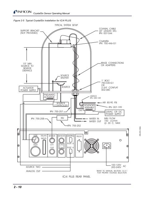
CrystalSix Sensor Operating Manual Figure 2-5 Typical CrystalSix Installation for IC/4 PLUS IPN 074-155G 2 - 10
CrystalSix Sensor Operating Manual 2.3.1 Crystal Sensor Installation Generally, install the sensor as far as possible from the evaporation source (a minimum of 10" or 25.4 cm) while still being in a position to accumulate thickness at a rate proportional to accumulation on the substrate. Figure 2-6 shows proper and improper methods of installing sensors. Figure 2-6 Sensor Installation Guidelines SENSORS CORRECT INCORRECT OBSTRUCTION INCORRECT CORRECT INCORRECT SOURCE IPN 074-155G To guard against spattering, use a source shutter to shield the sensor during the initial soak periods. If the crystal is hit with even a minute particle of molten material, it may be damaged and stop oscillating. Even in cases when it does not completely stop oscillating, it may immediately become unstable, or shortly after deposition begins instability may occur. Plan the installation to insure that there are no obstructions blocking a direct path between the sensor and the source. Install sensors in such a manner that the center axis of the crystal is aimed directly at the source to be monitored. Verify that the angle of the sensor location (with reference to the source) is well within the evaporant stream. Attach the sensor with a mounting bracket anchored to the deposition chamber. With the bracket in place, temporarily position and attach the sensor head as outlined in the general guidelines above. Next, temporarily install the feedthrough. You may now form, measure, and mark the sensor tubes (use the bending tool (IPN 750-036) to form tubes in the system). 2 - 11
- Page 1: O P E R A T I N G M A N U A L CRYST
- Page 4 and 5: Trademarks The trademarks of the pr
- Page 6 and 7: BUSINESS REPLY MAIL FIRST CLASS PER
- Page 9 and 10: CrystalSix Sensor Operating Manual
- Page 11 and 12: 1.1 Specifications for CrystalSix S
- Page 13 and 14: CrystalSix Sensor Operating Manual
- Page 15 and 16: CrystalSix Sensor Operating Manual
- Page 17 and 18: CrystalSix Sensor Operating Manual
- Page 19 and 20: CrystalSix Sensor Operating Manual
- Page 21 and 22: CrystalSix Sensor Operating Manual
- Page 23 and 24: CrystalSix Sensor Operating Manual
- Page 25: CrystalSix Sensor Operating Manual
- Page 29 and 30: CrystalSix Sensor Operating Manual
- Page 31 and 32: CrystalSix Sensor Operating Manual
- Page 33 and 34: CrystalSix Sensor Operating Manual
- Page 35 and 36: CrystalSix Sensor Operating Manual
- Page 37 and 38: 3.3 Electrical and Pneumatic Connec
- Page 39 and 40: CrystalSix Sensor Operating Manual
- Page 41 and 42: CrystalSix Sensor Operating Manual
- Page 43 and 44: CrystalSix Sensor Operating Manual
- Page 45 and 46: CrystalSix Sensor Operating Manual
- Page 47 and 48: CrystalSix Sensor Operating Manual
- Page 49 and 50: CrystalSix Sensor Operating Manual
- Page 51 and 52: CrystalSix Sensor Operating Manual
- Page 53 and 54: 4.6 Replacing the Bellows Assembly
- Page 55 and 56: CrystalSix Sensor Operating Manual
- Page 57 and 58: CrystalSix Sensor Operating Manual
CrystalSix Sensor Operating Manual<br />
Figure 2-5 Typical CrystalSix Installation for IC/4 PLUS<br />
IPN 074-155G<br />
2 - 10


