PTR 225 / PTR 225 S PTR 237 - Schoonover, Inc.
PTR 225 / PTR 225 S PTR 237 - Schoonover, Inc.
PTR 225 / PTR 225 S PTR 237 - Schoonover, Inc.

You also want an ePaper? Increase the reach of your titles
YUMPU automatically turns print PDFs into web optimized ePapers that Google loves.
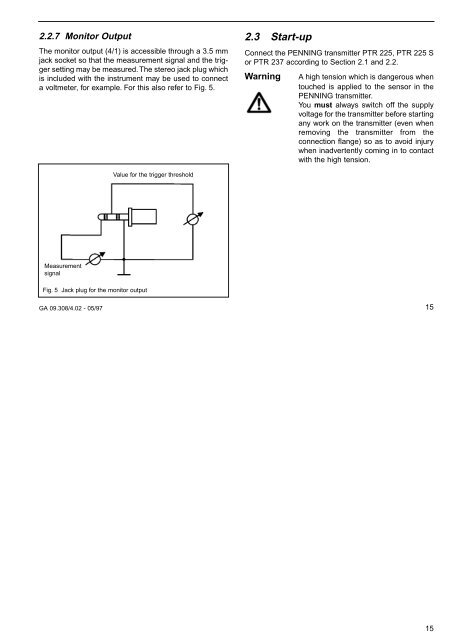
2.2.7 Monitor Output<br />
The monitor output (4/1) is accessible through a 3.5 mm<br />
jack socket so that the measurement signal and the trigger<br />
setting may be measured. The stereo jack plug which<br />
is included with the instrument may be used to connect<br />
a voltmeter, for example. For this also refer to Fig. 5.<br />
2.3 Start-up<br />
Connect the PENNING transmitter <strong>PTR</strong> <strong>225</strong>, <strong>PTR</strong> <strong>225</strong> S<br />
or <strong>PTR</strong> <strong>237</strong> according to Section 2.1 and 2.2.<br />
Warning<br />
A high tension which is dangerous when<br />
touched is applied to the sensor in the<br />
PENNING transmitter.<br />
You must always switch off the supply<br />
voltage for the transmitter before starting<br />
any work on the transmitter (even when<br />
removing the transmitter from the<br />
connection flange) so as to avoid injury<br />
when inadvertently coming in to contact<br />
with the high tension.<br />
Value for the trigger threshold<br />
Measurement<br />
signal<br />
Fig. 5 Jack plug for the monitor output<br />
GA 09.308/4.02 - 05/97<br />
15<br />
15