PTR 225 / PTR 225 S PTR 237 - Schoonover, Inc.
PTR 225 / PTR 225 S PTR 237 - Schoonover, Inc.
PTR 225 / PTR 225 S PTR 237 - Schoonover, Inc.

You also want an ePaper? Increase the reach of your titles
YUMPU automatically turns print PDFs into web optimized ePapers that Google loves.
Vacuum Pumps Instrumentation Fittings and Valves LEYBOLD VACUUM<br />
GA 09.308 / 4.02<br />
<strong>PTR</strong> <strong>225</strong> / <strong>PTR</strong> <strong>225</strong> S<br />
<strong>PTR</strong> <strong>237</strong><br />
PENNING Transmitter<br />
Cat. No.<br />
157 34; 164 34<br />
157 36<br />
Operating Instructions
Leybold Service<br />
If equipment is returned to LEYBOLD Vacuum GmbH, indicate whether<br />
the equipment is free of substances damaging to health or whether it<br />
is contaminated. If it is contaminated also indicate the nature of the<br />
hazard. LEYBOLD must return any equipment without a Declaration of<br />
Contamination to the sender’s address.<br />
General Remarks<br />
We reserve the right to alter the design or any data given in these Operating<br />
Instructions.<br />
The illustrations are not binding.<br />
Contents<br />
Page<br />
1 Description . . . . . . . . . . . . . . . . . . . . . . . . . . 3<br />
1.1 General . . . . . . . . . . . . . . . . . . . . . . . . . . . . . 3<br />
1.1.1 Purpose . . . . . . . . . . . . . . . . . . . . . . . . . . . . . 4<br />
1.2 Technical Data . . . . . . . . . . . . . . . . . . . . . . . . 4<br />
1.2.1 General Data . . . . . . . . . . . . . . . . . . . . . . . . . 4<br />
1.2.2 Measurement System . . . . . . . . . . . . . . . . . . . 5<br />
1.2.3 Signal Output . . . . . . . . . . . . . . . . . . . . . . . . . 5<br />
1.2.4 Switching Threshold (<strong>PTR</strong> <strong>225</strong> S only) . . . . . . 5<br />
1.2.5 Control Inputs . . . . . . . . . . . . . . . . . . . . . . . . . 5<br />
1.2.6 Status Output . . . . . . . . . . . . . . . . . . . . . . . . . 6<br />
1.2.7 Mechanical Data . . . . . . . . . . . . . . . . . . . . . . . 6<br />
1.2.8 Ambient Conditions . . . . . . . . . . . . . . . . . . . . . 6<br />
1.3 Technical Description . . . . . . . . . . . . . . . . . . . 6<br />
1.4 Equipment . . . . . . . . . . . . . . . . . . . . . . . . . . . 7<br />
1.4.1 Supplied Equipment . . . . . . . . . . . . . . . . . . . . 7<br />
1.4.2 Accessories . . . . . . . . . . . . . . . . . . . . . . . . . . 7<br />
2 Operation . . . . . . . . . . . . . . . . . . . . . . . . . . . 8<br />
Page<br />
2.1 Installation of the <strong>PTR</strong> <strong>225</strong>/<strong>225</strong> S/<strong>PTR</strong> <strong>237</strong> . . . 8<br />
2.2 Electrical Connection . . . . . . . . . . . . . . . . . . 10<br />
2.2.1 Power Supply . . . . . . . . . . . . . . . . . . . . . . . . 12<br />
2.2.2 Switching on the High Tension . . . . . . . . . . . . 12<br />
2.2.3 Measurement Signal Output . . . . . . . . . . . . . 13<br />
2.2.4 Status Output . . . . . . . . . . . . . . . . . . . . . . . . 13<br />
2.2.5 Identification . . . . . . . . . . . . . . . . . . . . . . . . . 14<br />
2.2.6 Switching Threshold (<strong>PTR</strong> <strong>225</strong> S) . . . . . . . . . 14<br />
2.2.7 Monitor Output . . . . . . . . . . . . . . . . . . . . . . . 15<br />
2.3 Start-up . . . . . . . . . . . . . . . . . . . . . . . . . . . . 15<br />
2.3.1 Operation . . . . . . . . . . . . . . . . . . . . . . . . . . . 16<br />
2.3.2 Measurement System Status Indication . . . . . 17<br />
2.3.3 Degassing . . . . . . . . . . . . . . . . . . . . . . . . . . 17<br />
2.4 Troubleshooting . . . . . . . . . . . . . . . . . . . . . . 18<br />
3 Maintenance . . . . . . . . . . . . . . . . . . . . . . . . 19<br />
3.1 LEYBOLD Service . . . . . . . . . . . . . . . . . . . . 19<br />
3.2 The Electronics Assembly . . . . . . . . . . . . . . . 19<br />
3.3 Cleaning the Sensor . . . . . . . . . . . . . . . . . . . 19<br />
3.3.1 Detaching the Electronics Assembly . . . . . . . 19<br />
3.3.2 Disassembly of the Sensor . . . . . . . . . . . . . . 20<br />
3.3.3 Cleaning the Individual Parts . . . . . . . . . . . . . 20<br />
3.3.4 Assembly of the Sensor . . . . . . . . . . . . . . . . 21<br />
3.3.5 Assembly of the Electronics Assembly . . . . . 21<br />
4 Spare Parts List . . . . . . . . . . . . . . . . . . . . . 21<br />
Annex 1 . . . . . . . . . . . . . . . . . . . . . . . . . . . . . . . . . 22<br />
Annex 2 . . . . . . . . . . . . . . . . . . . . . . . . . . . . . . . . . 24<br />
2 GA 09.308/4.02 - 05/97<br />
2
1 Description<br />
1.1 General<br />
The PENNING transmitter <strong>PTR</strong> <strong>225</strong>, <strong>PTR</strong> <strong>225</strong> S or<br />
<strong>PTR</strong> <strong>237</strong> is supplied ready for operation. Even so, we<br />
recommend to read these Operating Instructions with<br />
care so as to ensure optimum operating conditions right<br />
from the start.<br />
These Operating Instructions contain important information<br />
on the functions, installation, start-up, operation and<br />
troubleshooting of the PENNING transmitters <strong>PTR</strong> <strong>225</strong>,<br />
<strong>PTR</strong> <strong>225</strong> S or <strong>PTR</strong> <strong>237</strong>.<br />
Important remarks concerning operational safety and<br />
protection are emphazised as follows:<br />
Warning<br />
Caution<br />
GA 09.308/4.02 - 05/97<br />
Indicates procedures that must be strictly<br />
observed to prevent hazards to persons.<br />
Indicates procedures that must strictly<br />
be observed to prevent damage to, or<br />
destruction of the <strong>PTR</strong> <strong>225</strong>, <strong>PTR</strong> <strong>225</strong> S<br />
or <strong>PTR</strong> <strong>237</strong>.<br />
Note<br />
Indicates special technical requirements that the user<br />
must comply with.<br />
The references to diagrams, e.g. (4/1), consist of the Fig.<br />
No. and the item No. in that order.<br />
Unpack the <strong>PTR</strong> <strong>225</strong>, <strong>PTR</strong> <strong>225</strong> S or <strong>PTR</strong> <strong>237</strong> immediately<br />
after delivery, even if it is to be installed at a later<br />
date.<br />
Examine the packaging for any external damage. Completely<br />
remove all packaging materials.<br />
Note<br />
Retain the shipping container and the packaging materials<br />
in the event of complaints about damage.<br />
Check that the <strong>PTR</strong> <strong>225</strong>, <strong>PTR</strong> <strong>225</strong> S or <strong>PTR</strong> <strong>237</strong> is complete<br />
(see Section 1.4).<br />
Carefully examine the <strong>PTR</strong> <strong>225</strong>, <strong>PTR</strong> <strong>225</strong> S or <strong>PTR</strong> <strong>237</strong><br />
visually.<br />
If any damage is discovered, report it immediately to the<br />
forwarding agent and insurer. If the damaged part has to<br />
be replaced, please get in touch with the orders department.<br />
3<br />
3
1.1.1 Purpose<br />
The PENNING transmitter <strong>PTR</strong> <strong>225</strong>, <strong>PTR</strong> <strong>225</strong> S or <strong>PTR</strong><br />
<strong>237</strong> is a compact active pressure converter housing a<br />
PENNINGVAC measurement system as well as the corresponding<br />
operating electronics. They have been developed<br />
specifically for integration into vacuum systems<br />
and offer a measurement range from 1·10 -9 to 1·10 -2<br />
mbar.<br />
The transmitter is connected directly to the vacuum system<br />
through its DN 25 KF or DN 40 CF flange.<br />
The electrical connection is provided through a screened<br />
8-way FCC 68 connector.<br />
Moreover, the technical data as published in Section 1.2<br />
must be observed.<br />
1.2 Technical Data<br />
1.2.1 General Data<br />
Measurement range<br />
1·10 -9 to 1·10 -2 mbar/Torr<br />
Measurement uncertainty in the range<br />
from 1·10 -8 to 1·10 -4 mbar:<br />
Deviation from the characteristic<br />
± 30 % of the displayed value<br />
Average temperature coefficient of the output span<br />
< 0.5 % / K of the displayed value<br />
Reproducibility < 4 % of the displayed value<br />
Measurement principle<br />
Cold cathode ionization according to PENNING<br />
Supply voltage<br />
Power consumption<br />
14.5 to 36 V DC, typ. 24 V DC<br />
Ripple ≤ 2 Vpp<br />
< 2 W<br />
Protection IP 40<br />
Electromagnetic compatibility (EMI)<br />
CE mark<br />
interference tolerance to EN 50082-2, Tab. 1, 2, 3<br />
interference emission levels to EN 50081-1 and<br />
FCC Rules Part 15, Class B<br />
Flammability<br />
UL 94 - V2<br />
4 GA 09.308/4.02 - 05/97<br />
4
Status displays<br />
Operation (POWER)<br />
Ready to measure (ignited) READY<br />
Switching threshold (active)<br />
(<strong>PTR</strong> <strong>225</strong> S only)<br />
orange LED<br />
green LED<br />
green LED<br />
Permissible load resistance<br />
R a<br />
≥ 10 kΩ<br />
Measurement signal 0.66 V to 10 V;<br />
logarithmic, 1.333 V per decade<br />
Status signal (not ignited)<br />
0.4 V<br />
1.2.2 Measurement System<br />
Measurement system<br />
Vacuum connection<br />
detachable<br />
DN 25 KF or DN 40 CF<br />
Degassing temperature see Section 2.3.3<br />
Dead volume<br />
21 cm 3 approx.<br />
Materials in contact with the medium<br />
stainless steel, CrNi,<br />
Al 2<br />
O 3<br />
ceramics, NiFe, Ni, titanium<br />
Overpressure tolerance<br />
≤ 10 bar abs.<br />
(The limits for the flange connections must be observed)<br />
Operating voltage<br />
Ignition voltage<br />
1.2.3 Signal Output<br />
Signal output<br />
GA 09.308/4.02 - 05/97<br />
1.6 kV (current limited to < 0.5 mA)<br />
2.8 kV (current limited to < 0.5 mA)<br />
0 to 10.6 V<br />
1.2.4 Switching threshold<br />
(<strong>PTR</strong> <strong>225</strong> S only)<br />
Switching threshold<br />
Adjustment range<br />
Hysteresis<br />
Rating<br />
Error status<br />
1.2.5 Control Inputs<br />
Input resistance<br />
Relay changeover contact<br />
1·10 -9 to 1·10 -3 mbar / Torr<br />
± 30 % of the adjusted range<br />
DC 60 V, 0.5 A<br />
Resting contact when<br />
“not ignited”; “HV OFF” or “supply off”<br />
R E<br />
: 10 kΩ approx.<br />
High voltage cut-in with negative logic at Pin 7:<br />
High voltage ON<br />
at U < 2.5 V<br />
High voltage OFF<br />
at U > 4 V<br />
or<br />
5<br />
5
High voltage cut-in with positive<br />
logic at Pin 8:<br />
High voltage ON<br />
High voltage OFF<br />
(for this also refer to Fig. 3 and Section 2.2.2).<br />
at U > 12 V<br />
at U < 7 V<br />
1.2.7 Mechanical Data<br />
Dimensions (WxHxD) for<br />
<strong>PTR</strong> <strong>225</strong> / <strong>PTR</strong> <strong>225</strong> S<br />
Weight<br />
80 x 126 x 73 mm<br />
500 g approx.<br />
1.2.6 Status Output<br />
Up to Serial No. D 95 11 01000<br />
Field-effect transistor (FET)<br />
Caution<br />
100 mA max.,<br />
42 V DC max.<br />
When exceeding these maximum ratings,<br />
the <strong>PTR</strong> <strong>225</strong>, <strong>PTR</strong> <strong>225</strong> S, <strong>PTR</strong><br />
<strong>237</strong> itself and / or any connected equipment<br />
may be damaged.<br />
Ready to measure FET conductive (R i<br />
< 100 Ω)<br />
Fault<br />
FET off (R i<br />
> 100 kΩ)<br />
From Serial No. D 95 11 01000<br />
Voltage output which is programmable control compatible<br />
Ready to measure High level (13.5-35 V, max. 50 mA)<br />
Error (not ignited, HV off)<br />
0V<br />
For this refer also to Section 2.2.4.<br />
1.2.8 Ambient Conditions<br />
Storage temperature range -20 °C to +70 °C<br />
Climatic rating KWF to DIN 400 40<br />
Operating temperature range 10 °C to 50 °C<br />
Max. rel. humidity of the ambient air (on 30<br />
days per year, non-condensing) 70 % 1) or 95 % 2)<br />
1) usable measurement range 10 -2 to 10 -7 mbar<br />
2) usable measurement range 10 -2 to 10 -9 mbar<br />
1.3 Technical Description<br />
Based on a supply voltage of 24 V the <strong>PTR</strong> <strong>225</strong>, <strong>PTR</strong><br />
<strong>225</strong> S or <strong>PTR</strong> <strong>237</strong> generates the internal supply voltages<br />
required for operation of the integrated PENNING measurement<br />
system. The <strong>PTR</strong> <strong>225</strong>, <strong>PTR</strong> <strong>225</strong> S or <strong>PTR</strong> <strong>237</strong><br />
supplies a logarithmic representation of the vacuum<br />
pressure by way of a voltage signal which ranges from<br />
6 GA 09.308/4.02 - 05/97<br />
6
0.66 V to 10 V. Moreover, the high tension generated in<br />
the <strong>PTR</strong> <strong>225</strong>, <strong>PTR</strong> <strong>225</strong> S or <strong>PTR</strong> <strong>237</strong> can be switched on<br />
and off by applying an external control voltage or by<br />
connecting an external switch.<br />
When the gas discharge in the PENNING measurement<br />
system is ignited, the operating voltage is raised to 2.8<br />
kV. After successful ignition, this voltage then drops to<br />
1.6 kV thereby increasing the useful service life of the<br />
PENNING measurement system.<br />
A status output indicates the two possible conditions of<br />
the PENNING measurement system:<br />
1. not ignited (including high tension OFF) and<br />
2. ignited (and pressure > 3·10 -9 mbar).<br />
A much improved ignition characteristic in the high vacuum<br />
range has been obtained through the special design<br />
for the electrodes in the measurement system.<br />
The <strong>PTR</strong> <strong>225</strong> S PENNING transmitter is equipped with<br />
an adjustable switching threshold. The switching element<br />
is a relay. The status of the threshold is indicated by a<br />
LED.<br />
1.4 Equipment<br />
1.4.1 Supplied Equipment<br />
PENNING transmitter <strong>PTR</strong> <strong>225</strong> Cat. No. 157 34<br />
PENNING transmitter <strong>PTR</strong> <strong>225</strong> S Cat. No. 164 34<br />
PENNING transmitter <strong>PTR</strong> <strong>237</strong> Cat. No. 157 36<br />
Replacement cathode plate of titanium --<br />
3.5 mm jack plug --<br />
Operating Instructions GA 09.308<br />
1.4.2 Accessories<br />
Cat. No.<br />
10 m long connection cable with<br />
two FCC 68 plugs, screened 157 33<br />
TTR 211 S THERMOVAC transmitter 157 30<br />
Replacement cathode plates of titanium<br />
(5 pcs.) 162 91<br />
DN 20/25 KF clamping ring 183 42<br />
DN 25 KF (Al) centering ring 183 27<br />
For overpressure operation and degassing:<br />
Ultra sealing disc (3 pcs.) 883 75<br />
Clamping ring for ultra sealing discs 882 77<br />
GA 09.308/4.02 - 05/97<br />
7<br />
7
2 Operation<br />
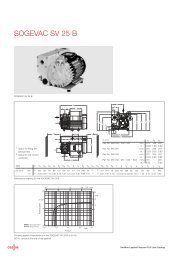
2.1 Installation of the <strong>PTR</strong> <strong>225</strong> /<br />
<strong>PTR</strong> <strong>225</strong> S / <strong>PTR</strong> <strong>237</strong><br />
Please check by referring to the technical data whether<br />
or not your transmitter is suitable for your application.<br />
The PENNING transmitters <strong>PTR</strong> <strong>225</strong>, <strong>PTR</strong> <strong>225</strong> S or <strong>PTR</strong><br />
<strong>237</strong> should preferably be mounted flange down. <strong>Inc</strong>lined<br />
installation is possible but the horizontal orientation must<br />
not be exceeded.<br />
Flange up installation is not permissible because under<br />
such circumstances condensate may collect in the <strong>PTR</strong><br />
<strong>225</strong>, <strong>PTR</strong> <strong>225</strong> S or <strong>PTR</strong> <strong>237</strong>. This will either adversely<br />
affect the measurements, or the sensor itself may possibly<br />
be damaged.<br />
The PENNING transmitter is equipped with a DN 25 KF<br />
or a DN 40 CF connection flange which is used to<br />
connect the transmitter to the mating connection flange<br />
on a vacuum system with the aid of a centering ring and<br />
a clamping ring.<br />
In the <strong>PTR</strong> <strong>225</strong>, <strong>PTR</strong> <strong>225</strong> S or <strong>PTR</strong> <strong>237</strong> the cathode<br />
plate (7/5) also acts as a baffle.<br />
For the dimensional drawing, see Fig. 1.<br />
8 GA 09.308/4.02 - 05/97<br />
8
73<br />
80<br />
POWER<br />
READY<br />
114<br />
126<br />
4<br />
12<br />
DN 25 KF<br />
Fig. 1 Dimensional drawing for <strong>PTR</strong> <strong>225</strong> and <strong>PTR</strong> <strong>225</strong> S<br />
GA 09.308/4.02 - 05/97<br />
9<br />
9
2.2 Electrical Connection<br />
The supply voltage and the high voltage switching signal<br />
as well as the measurement voltage signal are carried<br />
through the 8-way FCC 68 socket.<br />
The pinout is given in Fig. 2.<br />
Pin Signal Designation<br />
on the rear<br />
————————————————————————<br />
Pin 1 Supply voltage<br />
14.5 V to 36 V DC + 24 V DC<br />
Pin 2 0 V supply; used as the ground<br />
reference for the supply and<br />
control signal voltages.<br />
COMMON<br />
Pin 3 Pressure dependant logarithmic<br />
signal output<br />
SIGN 0 - 10 V<br />
Pin 4 „PM transmitter“ identification<br />
code (100 kΩ)<br />
IDENT<br />
Pin 5 Signal ground<br />
(use only for the<br />
pressure signal)<br />
SIGN COM<br />
Pin 6 Status (ready to measure) STATUS<br />
Pin 7 High tension „ON / OFF“<br />
(control input); Low active HV ON (L)<br />
Pin 8 High tension „ON / OFF“<br />
(control input); High active HV ON (H)<br />
Note<br />
Signal ground (Pin 5) and power supply ground (Pin 2)<br />
are internally linked. For this also refer to the block diagram<br />
of Fig. 3.<br />
Two examples of how to connect the <strong>PTR</strong> <strong>225</strong>,<br />
<strong>PTR</strong> <strong>225</strong> S or <strong>PTR</strong> <strong>237</strong> are given in Annex 2.<br />
Pin 1<br />
Fig. 2 Connection socket<br />
10 GA 09.308/4.02 - 05/97<br />
10
+ 10,5 V<br />
High tension switchover<br />
2,8 kV<br />
1,6 kV<br />
Ingnition<br />
Characteristic<br />
monitor<br />
adaptation<br />
R v 7,48 MΩ<br />
HV ON (L)<br />
HV ON (H)<br />
Status<br />
Signal output<br />
7<br />
8<br />
6<br />
3<br />
Signal ground<br />
5<br />
Power supply<br />
1<br />
LED<br />
"READY"<br />
LED<br />
"POWER"<br />
Identification<br />
4<br />
100 k Ω<br />
Measurement<br />
system<br />
Power supply ground<br />
2<br />
Fig. 3 Block diagram <strong>PTR</strong> <strong>225</strong>, <strong>PTR</strong> <strong>225</strong> S, <strong>PTR</strong> <strong>237</strong><br />
GA 09.308/4.02 - 05/97<br />
11<br />
11
2.2.1 Power Supply<br />
Warning The PENNING transmitter <strong>PTR</strong> <strong>225</strong>,<br />
<strong>PTR</strong> <strong>225</strong> S or <strong>PTR</strong> <strong>237</strong> may only be<br />
connected to supply units or measuring<br />
instruments which meet the requirements<br />
of mains isolated extra-low voltages<br />
(PELV) and VDE 0100.<br />
The PENNING transmitter <strong>PTR</strong> <strong>225</strong>, <strong>PTR</strong> <strong>225</strong> S or <strong>PTR</strong><br />
<strong>237</strong> is capable of operating off supply voltages ranging<br />
from 14.5 V to 36 V. A supply voltage of 24 V DC is<br />
recommended.<br />
The power supply must be connected to Pin 1 (+) and<br />
Pin 2 (power supply ground).<br />
2.2.2 Switching on the High Tension<br />
The high voltage may be switched on either through Pin<br />
7 using negative logic or Pin 8 using positive logic.<br />
Note<br />
Switching on via Pin 8 is only possible from Serial Number<br />
D 95 11 01000 onwards.<br />
In each case Pin 2 must be used as the reference potential.<br />
Pin 7 switches the high voltage on when<br />
- contact is established with Pin 2 or<br />
- a voltage of less than 2.5 V is present with reference to<br />
Pin 2.<br />
Pin 7 switches the high voltage off when<br />
- there is no contact with Pin 2 (open input) or<br />
- a voltage greater than 4 V is present with reference to<br />
Pin 2.<br />
Pin 8 switches the high voltage on when<br />
- contact is established with Pin 1 (supply voltage) or<br />
- a voltage greater than 12 V is present with reference to<br />
Pin 2.<br />
Pin 8 switches the high voltage off when<br />
- there is no contact with Pin 1 (open input) or<br />
- a voltage of less than 7 V is present with reference to<br />
Pin 2.<br />
Operation of the <strong>PTR</strong> <strong>225</strong>, <strong>PTR</strong> <strong>225</strong> S or <strong>PTR</strong> <strong>237</strong> in the<br />
pressure range above 10 -2 mbar will cause the accumulation<br />
of contaminations and will thus reduce service life.<br />
For this reason, the high tension should only be switched<br />
on or off when the pressure has dropped to the 10 -2 to<br />
10 -3 mbar range.<br />
The high tension may also be switched on or off directly<br />
by the output signal provided by a THERMOVAC TTR<br />
211 S / TTR 216 S transmitter. Thus the PENNING transmitter<br />
can be switched on or off automatically at a pressure<br />
of approximately 5·10 -3 mbar.<br />
12 GA 09.308/4.02 - 05/97<br />
12
2.2.3 Measurement Signal Output<br />
The <strong>PTR</strong> <strong>225</strong>, <strong>PTR</strong> <strong>225</strong> S or <strong>PTR</strong> <strong>237</strong> supplies a defined<br />
output signal ranging from 0.66 V to 10 V at Pin 3 with<br />
reference to Pin 5 which is signal ground. For this also<br />
refer to Table 1 in Annex 1. Table 1 has been included to<br />
clarify the relationship between the output voltage and<br />
the pressure.<br />
Note<br />
The measurement signal provided by the PENNING<br />
transmitter depends on the type of gas. The values stated<br />
in Table 1 apply to nitrogen and air. For other gases,<br />
corresponding correction factors must be used which are<br />
available from LEYBOLD upon request.<br />
2.2.4 Status Output<br />
When the gauge is ready to measure, this is indicated<br />
via the status output.<br />
Up to Serial No. D 95 11 01000 The „open drain“ output<br />
of a field-effect transistor (FET) is available at Pin 6. This<br />
output may be used to drive external components such<br />
as relays or valves, for example.<br />
From Serial No. D 95 11 01000 the status output supplies<br />
a voltage which is programmable control compatible<br />
GA 09.308/4.02 - 05/97<br />
Status Status signal at Pin 6<br />
(with respect to Pin 2)<br />
————————————————————————<br />
High voltage OFF 0 V<br />
High voltage ON<br />
(not yet ignited)<br />
High voltage ON<br />
at p < 3·10 -9 mbar<br />
High voltage ON<br />
at p > 3·10 -9 mbar<br />
0 V<br />
0 V<br />
High (13.5 - 32 V, depending<br />
on the supply voltage<br />
(50 mA max.)<br />
Note<br />
When the pressure drops below 3·10 -9 mbar, the status<br />
signal remains HIGH.<br />
Caution<br />
FET output: The max. voltage is 42 V DC.<br />
The max. load current is 100 mA DC.<br />
Voltage output: Load current is 50 mA max.<br />
When exceeding these maximum ratings<br />
the <strong>PTR</strong> <strong>225</strong>, <strong>PTR</strong> <strong>225</strong> S, <strong>PTR</strong> <strong>237</strong> itself<br />
and/or any connected equipment may be<br />
damaged.<br />
When the <strong>PTR</strong> <strong>225</strong>, <strong>PTR</strong> <strong>225</strong> S or <strong>PTR</strong> <strong>237</strong> is ready to<br />
make measurements, the FET is conductive. For this<br />
also refer to Section 2.3.2.<br />
13<br />
13
2.2.5 Identification<br />
For the purpose of identifying the connected type of<br />
transmitter and the pressure range, the PENNING transmitter<br />
is equipped with an identification resistor<br />
(R = 100 kΩ) between Pin 4 and Pin 2. This resistor may<br />
be sensed by connected operating or control units so<br />
that these can automatically adapt.<br />
Key to Fig. 4<br />
1 Monitor output<br />
2 Potentiometer for<br />
adjustment of the<br />
switching threshold<br />
3 LED (green)<br />
4 Connector<br />
Pin 1 Ground<br />
Pin 2 Normally open relay contact<br />
Pin 3 Center relay contact<br />
Pin 4 Normally closed contact<br />
2.2.6 Switching Threshold (<strong>PTR</strong> <strong>225</strong> S)<br />
The built-in switching threshold may be adjusted through<br />
potentiometer (4/2) in the range between 1·10 -3 -1·10 -9<br />
mbar.<br />
To adjust the threshold remove the cap (4/2) and use a<br />
screwdriver to adjust the threshold to the desired level.<br />
In order to check the adjustment, a voltmeter may be<br />
connected to the monitor output (4/1) (see Section 2.2.7<br />
and Table 1 in the Annex).<br />
The threshold switch is a floating relay (changeover<br />
contact) which may be accessed via pluggable screw<br />
terminals (4/4). When the pressure drops below the adjusted<br />
threshold, a green LED (4/3) comes on.<br />
In the case of a fault (i.e. discharge not present) or if the<br />
supply voltage has been switched off the relay contacts<br />
return to their rest position.<br />
Fig. 4 PENNING transmitter <strong>PTR</strong> <strong>225</strong> S<br />
1<br />
4<br />
1<br />
2<br />
3<br />
4<br />
14 GA 09.308/4.02 - 05/97<br />
14
2.2.7 Monitor Output<br />
The monitor output (4/1) is accessible through a 3.5 mm<br />
jack socket so that the measurement signal and the trigger<br />
setting may be measured. The stereo jack plug which<br />
is included with the instrument may be used to connect<br />
a voltmeter, for example. For this also refer to Fig. 5.<br />
2.3 Start-up<br />
Connect the PENNING transmitter <strong>PTR</strong> <strong>225</strong>, <strong>PTR</strong> <strong>225</strong> S<br />
or <strong>PTR</strong> <strong>237</strong> according to Section 2.1 and 2.2.<br />
Warning<br />
A high tension which is dangerous when<br />
touched is applied to the sensor in the<br />
PENNING transmitter.<br />
You must always switch off the supply<br />
voltage for the transmitter before starting<br />
any work on the transmitter (even when<br />
removing the transmitter from the<br />
connection flange) so as to avoid injury<br />
when inadvertently coming in to contact<br />
with the high tension.<br />
Value for the trigger threshold<br />
Measurement<br />
signal<br />
Fig. 5 Jack plug for the monitor output<br />
GA 09.308/4.02 - 05/97<br />
15<br />
15
2.3.1 Operation<br />
Apply the 24 V supply voltage to the transmitter.<br />
The orange „POWER“ LED (6/1) comes on.<br />
Switch the high tension on via the high tension switching<br />
input. See Section 2.2.2.<br />
After successful ignition and at a pressure > 3·10 -9 mbar<br />
the additional green or READY LED (6/2) will come on.<br />
Now the transmitter is ready to make measurements.<br />
No LED on.<br />
- Supply voltage is missing.<br />
→ Measurement signal: 0 V<br />
Only the orange LED (6/1) is on.<br />
- The supply voltage is present.<br />
- The high tension has not been switched on.<br />
→ Measurement signal: 0 V<br />
The green LED (6/2) is on, the orange LED (6/1) is on.<br />
- The supply voltage is present.<br />
- The high tension has been switched on.<br />
- The gas discharge has been started.<br />
- The pressure is over 3·10 -9 mbar.<br />
→ Measurement signal: > 0.66 V<br />
1<br />
POWER<br />
READY<br />
Key to Fig. 6<br />
1 „POWER“ LED (orange)<br />
2 „READY“ LED (green)<br />
2<br />
Fig. 6 PENNING transmitter - front view<br />
16 GA 09.308/4.02 - 05/97<br />
16
2.3.2 Measurement System Status<br />
Indication<br />
In the case of the PENNING method of measurement<br />
one only may draw conclusions as to proper functioning<br />
while the transmitter is in the measurement mode, i.e.<br />
when the gas discharge is running.<br />
Instruments up to Serial No. D 95 11 0100:<br />
Trouble-free operation („READY“ LED (6/2) is on, status<br />
output FET is conducting) is marked by the presence of<br />
a pressure dependant signal starting at a pressure of<br />
about 3·10 -9 mbar up to the range limit of 1·10 -2 mbar.<br />
When the „READY“ LED (6/2) is not on and the status<br />
output FET is not conducting:<br />
Cause 1: The pressure is below about 3·10 -9 mbar.<br />
Cause 2: No ignition of the gas discharge, even if the<br />
power supply voltage is present, the high tension<br />
has been switched on and a pressure<br />
between about 3·10 -9 mbar and 1·10 -2 mbar.<br />
Instruments from Serial No. D 95 11 0100:<br />
Trouble-free operation („READY“ LED (6/2) is on, status<br />
output HIGH) is marked by the presence of a pressure<br />
dependant signal starting at a pressure of about 3·10 -9<br />
mbar up to the range limit of 1·10 -2 mbar. When the pressure<br />
drops < 3·10 -9 mbar this status is also maintained.<br />
When the “READY” LED (6/2) is not on, status output 0<br />
V:<br />
GA 09.308/4.02 - 05/97<br />
Cause 1: When the high voltage was switcthed on the<br />
pressure was below 3·10 -9 mbar.<br />
Cause 2: No ignition of the gas discharge, even if the<br />
power supply voltage is present, the high tension<br />
has been switched on and a pressure<br />
between about 3·10 -9 mbar and 1·10 -2 mbar.<br />
2.3.3 Degassing<br />
Caution<br />
Caution<br />
Before baking out the sensing cell you<br />
must detach the electronics assembly<br />
from the sensing cell. The electronics<br />
assembly may be damaged when exceeding<br />
a temperature of 70 °C.<br />
Before baking out, you must make sure<br />
that an ultra sealing disc (<strong>PTR</strong> <strong>225</strong> /<br />
<strong>PTR</strong> <strong>225</strong> S) or a copper seal (<strong>PTR</strong> <strong>237</strong>)<br />
is used as the flange seal.<br />
The PENNING transmitters <strong>PTR</strong> <strong>225</strong>, <strong>PTR</strong> <strong>225</strong> S or <strong>PTR</strong><br />
<strong>237</strong> are equipped with all-metal sensing cells so that any<br />
outgassing caused by polymer seals is entirely avoided.<br />
After having detached the electronics (refer to Section<br />
3.3.1) from the sensing cell, the outgassing rate of the<br />
sensing cell may be reduced considerably by baking out,<br />
so that the accuracy of the measurements in the range<br />
below 1·10 -6 mbar is improved.<br />
17<br />
17
Note<br />
When using the transmitter chiefly in the UHV range<br />
(< 10 -8 mbar) it is recommended to remove the cathode<br />
plate. This helps to the reduce the surface area of the<br />
surfaces which may release gas.<br />
How to proceed in order to detach the electronics assembly<br />
is described in Section 3.3 (cleaning of the sensor).<br />
Permissible bake out temperatures:<br />
Sensing cell of the <strong>PTR</strong> <strong>225</strong> / <strong>PTR</strong> <strong>225</strong> S:<br />
200 °C (with ultra sealing<br />
disc)<br />
Sensing cell of the <strong>PTR</strong> <strong>237</strong>: 350 °C<br />
2.4 Troubleshooting<br />
No LED is on.<br />
Possible cause: Supply voltage is missing.<br />
The „POWER“ LED (6/1) is on, the „READY“ LED<br />
(6/2) is not on.<br />
Possible cause:<br />
• High tension has not been activated.<br />
• Pressure has dropped below 3·10 -9 mbar.<br />
• The gas discharge has not ignited.<br />
• Sensing cell not properly connected to the<br />
electronics assembly (e.g. after maintenance).<br />
• Missing anode ring (e.g. after maintenance).<br />
The measurement signal is always greater than 10 V<br />
even if the pressure is much lower than 10 -2 mbar.<br />
Possible cause: Short circuit in the sensing cell.<br />
Remedy: Clean the sensing cell. For this refer<br />
to Section 3.3.<br />
During pumpdown the measurement signal remains<br />
at some level although the pressure is dropping.<br />
Possible cause: Contamination within the<br />
sensing cell.<br />
Remedy: Replace the sensing cell.<br />
18 GA 09.308/4.02 - 05/97<br />
18
3 Maintenance<br />
3.1 LEYBOLD Service<br />
If equipment is returned to LEYBOLD, indicate whether<br />
the equipment free of substances damaging to health or<br />
whether it is contaminated. If it is contaminated also indicate<br />
the nature of the hazard. For this you must use a<br />
form which has been prepared by us which we will provide<br />
upon request.<br />
A copy of this form is reproduced at the end of these<br />
Operating Instructions: „Declaration of Contamination of<br />
Vacuum Instruments and Components“.<br />
Please attach this form to the equipment or enclose it<br />
with the equipment.<br />
This Declaration of Contamination is required to meet<br />
German Law and to protect our personnel.<br />
LEYBOLD must return any equipment without a „Declaration<br />
of Contamination“ to the sender’s address.<br />
3.2 The Electronics Assembly<br />
The electronics assembly of the PENNING transmitters<br />
<strong>PTR</strong> <strong>225</strong>, <strong>PTR</strong> <strong>225</strong> S or <strong>PTR</strong> <strong>237</strong> does not require any<br />
maintenance.<br />
3.3 Cleaning the Sensor<br />
Warning<br />
A high tension which is dangerous when<br />
touched is applied to the sensor in the<br />
PENNING transmitter.<br />
You must always switch off the supply<br />
voltage for the transmitter before starting<br />
any work on the transmitter (even when<br />
removing the transmitter from the<br />
connection flange) so as to avoid injury<br />
when inadvertently coming in to contact<br />
with the high tension.<br />
3.3.1 Detaching the Electronics Assembly<br />
In order to detach the electronics assembly and the<br />
magnet assembly (7/1) you must loosen the two cross<br />
head screws which can be accessed through two holes<br />
GA 09.308/4.02 - 05/97<br />
19<br />
19
in the rear of the transmitter by turning these by about<br />
1.5 turns.<br />
Then the electronics assembly and the magnet assembly<br />
(7/1) may be pulled off from the sensor housing.<br />
Caution<br />
The magnet assembly (7/1) may drop<br />
down during the pulling off process.<br />
Key to Fig. 7<br />
1 Magnet assembly<br />
2 Ignition aid<br />
3 Ceramics disc<br />
4 Anode ring<br />
5 Cathode plate<br />
6 Sensor housing with flange<br />
3.3.2 Disassembly of the Sensor<br />
The sensor consists of the vacuum housing, the anode<br />
ring (7/4) with ignition aid (7/2) and the cathode plate<br />
(7/5). See Fig. 7.<br />
How to disassemble:<br />
1) Use a pair of tweezers to pull the cathode plate (7/5)<br />
out of the sensor.<br />
2) Use a pair of pliers to pull the anode ring out from the<br />
housing; for this move the pliers to and fro a little.<br />
3) Detach the ceramics disc (7/3) from the current feedthrough.<br />
1<br />
2<br />
3<br />
1<br />
4<br />
3.3.3 Cleaning the Individual Parts<br />
Caution<br />
Do not damage the sealing surfaces of<br />
the vacuum flange!<br />
6<br />
Fig. 7 Sensor<br />
5<br />
20 GA 09.308/4.02 - 05/97<br />
20
In the case of severe contamination, the inside of the<br />
housing may be cleaned with steel wool or similar and<br />
then subjected to further cleaning with alcohol. Finally<br />
blow clean with oil-free pressurized air or nitrogen. Any<br />
possibly present flakes will be removed by blowing these<br />
out of the housing.<br />
If possible, the cathode plate (7/5) should be replaced by<br />
a new cathode plate. The same should be done for the<br />
anode ring (7/4) with the ignition aid (7/2) and the ceramics<br />
protection disc (7/3) which protects the current<br />
feed-through against contamination.<br />
3.3.4 Assembly of the Sensor<br />
The sensor is reassembled in the reverse order as for<br />
disassembly which is described in Section 3.3.2.<br />
When inserting the anode ring (7/4) you must make sure<br />
that a clearance of 0.5 to 1 mm max. remains between<br />
each of the wings of the ignition aid (7/2) and the wall of<br />
the housing. Moreover, make sure that the anode ring is<br />
lying snug on the ceramics disc.<br />
When inserting the cathode plate (7/5) into the housing<br />
the wings of the ignition aid (7/2) must not be bent.<br />
Therefore insert slowly and carefully.<br />
3.3.5 Assembly of the Electronics<br />
Assembly<br />
How to proceed:<br />
1) Place the magnet assembly on the sensor.<br />
2) Push the electronics assembly over the magnet<br />
assembly and the sensor, and turn slightly as required<br />
until the correct orientation between electronics<br />
assembly and sensor has been found. When the electronics<br />
assembly has been placed as required, the<br />
black magnet housing is fully surrounded by the housing<br />
of the <strong>PTR</strong> <strong>225</strong>, <strong>PTR</strong> <strong>225</strong> S or <strong>237</strong>.<br />
3) Retighten the cross head screws at the rear of the<br />
transmitter.<br />
4 Spare Parts List<br />
Cat. No.<br />
Cathode plates of titanium (5 pcs.) 162 91<br />
Sensor (DN 25 KF)<br />
complete with magnet assy. (PR 25) 157 52<br />
GA 09.308/4.02 - 05/97<br />
21<br />
21
Annex 1<br />
Table 1 Relationship between output voltage and pressure (U = 0.4 V; “not ignited”)<br />
U (Out)<br />
[V]<br />
Pressure<br />
[mbar]<br />
U (Out)<br />
[V]<br />
Pressure<br />
[mbar]<br />
U (Out)<br />
[V]<br />
Pressure<br />
[mbar]<br />
U (Out)<br />
[V]<br />
Pressure<br />
[mbar]<br />
0.667 1.00E-09<br />
0.8 1.26E-09<br />
1 1.78E-09<br />
1.1 2.11E-09<br />
1.2 2.51E-09<br />
1.3 2.99E-09<br />
1.4 3.55E-09<br />
1.5 4.22E-09<br />
1.6 5.01E-09<br />
1.7 5.96E-09<br />
1.8 7.08E-09<br />
1.9 8.41E-09<br />
2 1.00E-08<br />
2.1 1.19E-08<br />
2.2 1.41E-08<br />
2.3 1.68E-08<br />
2.4 2.00E-08<br />
2.5 2.37E-08<br />
2.6 2.82E-08<br />
2.7 3.35E-08<br />
2.8 3.98E-08<br />
2.9 4.73E-08<br />
3 5.62E-08<br />
3.1 6.68E-08<br />
3.2 7.94E-08<br />
3.3 9.44E-08<br />
3.4 1.12E-07<br />
3.5 1.33E-07<br />
3.6 1.59E-07<br />
3.7 1.88E-07<br />
3.8 2.24E-07<br />
3.9 2.66E-07<br />
4 3.16E-07<br />
4.1 3.76E-07<br />
4.2 4.47E-07<br />
4.3 5.31E-07<br />
4.4 6.31E-07<br />
4.5 7.50E-07<br />
4.6 8.91E-07<br />
4.7 1.06E-06<br />
4.8 1.26E-06<br />
4.9 1.50E-06<br />
5 1.78E-06<br />
5.1 2.11E-06<br />
5.2 2.51E-06<br />
5.3 2.99E-06<br />
5.4 3.55E-06<br />
5.5 4.22E-06<br />
5.6 5.01E-06<br />
5.7 5.96E-06<br />
5.8 7.08E-06<br />
5.9 8.41E-06<br />
6 1.00E-05<br />
6.1 1.19E-05<br />
6.2 1.41E-05<br />
6.3 1.68E-05<br />
6.4 2.00E-05<br />
6.5 2.37E-05<br />
6.6 2.82E-05<br />
6.7 3.35E-05<br />
6.8 3.98E-05<br />
6.9 4.73E-05<br />
7 5.62E-05<br />
7.1 6.68E-05<br />
7.2 7.94E-05<br />
7.3 9.44E-05<br />
7.4 1.12E-04<br />
7.5 1.33E-04<br />
7.6 1.59E-04<br />
7.7 1.88E-04<br />
7.8 2.24E-04<br />
7.9 2.66E-04<br />
8 3.16E-04<br />
8.1 3.76E-04<br />
8.2 4.47E-04<br />
8.3 5.31E-04<br />
8.4 6.31E-04<br />
8.5 7.50E-04<br />
8.6 8.91E-04<br />
8.7 1.06E-03<br />
8.8 1.26E-03<br />
8.9 1.50E-03<br />
9 1.78E-03<br />
9.1 2.11E-03<br />
9.2 2.51E-03<br />
9.3 2.99E-03<br />
9.4 3.55E-03<br />
9.5 4.22E-03<br />
9.6 5.01E-03<br />
9.7 5.96E-03<br />
9.8 7.08E-03<br />
9.9 8.41E-03<br />
10 1.00E-02<br />
22 GA 09.308/4.02 - 05/97<br />
22
Characteristic <strong>PTR</strong> <strong>225</strong> / <strong>PTR</strong> <strong>225</strong> S / <strong>PTR</strong> <strong>237</strong><br />
Equation:<br />
U(a) = [1.33·lg (p / mbar) + 12.66] Volt<br />
Output voltage U(a) / Volt<br />
Pressure p / mbar<br />
GA 09.308/4.02 - 05/97<br />
23<br />
23
Annex 2<br />
1<br />
<strong>PTR</strong> <strong>225</strong><br />
3<br />
Measurement<br />
signal<br />
5<br />
6<br />
8<br />
7<br />
0...10 V<br />
Status message<br />
HV ON (L)<br />
Relay, for<br />
example<br />
HV ON (H)<br />
HV-ON<br />
switch<br />
+<br />
GND<br />
14,5 ... 36 V<br />
HV-ON<br />
switch<br />
2<br />
Example for connecting the <strong>PTR</strong> <strong>225</strong>: Switching the high tension via an external switch or contact<br />
24<br />
GA 09.308/4.02 - 05/97<br />
24
1<br />
TTR 211 S<br />
3<br />
5<br />
0...10 V<br />
2<br />
1<br />
<strong>PTR</strong> <strong>225</strong><br />
3<br />
Measurement<br />
signal<br />
5<br />
6<br />
0...10 V<br />
Status message<br />
Relay, for<br />
example<br />
+<br />
GND<br />
14,5 ... 36 V<br />
7<br />
HV ON (L)<br />
2<br />
Example for connecting the <strong>PTR</strong> <strong>225</strong>: Switching the high tension automatically through a TTR 211 S / TTR 216 S THERMOVAC transmitter<br />
GA 09.308/4.02 - 05/97<br />
25<br />
25
Copies: Page 1 (white) to manufacturer or representative - Page 2 (yellow) attach to consignment packaging securety - Page 3 (blue) copy for file of sender<br />
S A M P L E<br />
Declaration of Contamination of Vacuum Equipment and Components<br />
The repair and/or service of vacuum equipment and components will only be carried out if a correctly completed declaration has<br />
been submitted. Non-completion will result in delay. The manufacturer could refuse to accept any equipment without a declaration.<br />
This declaration can only be completed and signed by authorized and qualified staff.<br />
1. Description of Vacuum Equipment and Components<br />
- Equipment type/model: _________________________________<br />
- Code No.: _________________________________<br />
- Serial No.: _________________________________<br />
- Invoice No.: _________________________________<br />
- Delivery date: __________________________<br />
3. Condition of the Vacuum Equipment and Components<br />
- Has the equipment been used?<br />
yes ❒ no ❒<br />
- What type of pump oil/liquid was used? _________<br />
- Is the equipment free from potentially<br />
harmful substances?<br />
yes ❒ (go to Section 5)<br />
no ❒ (go to Section 4)<br />
2. Reason for Return<br />
____________________________________________<br />
____________________________________________<br />
____________________________________________<br />
____________________________________________<br />
____________________________________________<br />
____________________________________________<br />
4. Process related Contamination of Vacuum<br />
Equipment and Components:<br />
- toxic yes ❒ no ❒<br />
- corrosive yes ❒ no ❒<br />
- explosive*) yes ❒ no ❒<br />
- biological hazard*) yes ❒ no ❒<br />
- radioactive*) yes ❒ no ❒<br />
- other harmful substances yes ❒ no ❒<br />
*) Vacuum equipment and components which have been contaminated by biological explosive or radioactive substances,<br />
will not accepted without written evidence of decontamination!<br />
Please list all substances, gases and by-products which may have come into contact with the equipment:<br />
Trade name<br />
Product name Chemical name Dangerous Measures First aid in case of<br />
Manufacturer (or Symbol) material class if spillage human contact<br />
1.<br />
2.<br />
3.<br />
4.<br />
5.<br />
5. Legally Binding Declaration<br />
I hereby declare that the information supplied on this form is complete and accurate. The despatch of the contaminated<br />
vacuum equipment and components will be in accordance with the appropriate regulations covering Packaging, Transportation<br />
and Labelling of Dangerous Substances.<br />
Name of organisation or company:_____________________________________________________________________<br />
Address: _____________________________ Post code:______________________________________<br />
Tel.: ______________________________________________________________________________<br />
Fax: _____________________________ Telex: _________________________________________<br />
Name: ______________________________________________________________________________<br />
Job title: ______________________________________________________________________________<br />
Date: _____________________________ Company stamp:<br />
Legally binding signature:____________________________________________________________________________<br />
Copyright © 1991 by MaschinenbauVerlag GmbH, Lyoner Straße 18, 6000 Frankfurt/M. 71 Order No.: 2121<br />
26<br />
GA 09.308/4.02 - 05/97<br />
26
This page has been left blank for your comments.<br />
GA 09.308/4.02 - 05/97<br />
27<br />
27
1.80.7.676.32 RSP 05.97<br />
Printed in Germany on chlorine-free bleached paper<br />
LEYBOLD VAKUUM GmbH<br />
Bonner Strasse 498 (Bayenthal)<br />
D-50968 Cologne<br />
Tel.: + 49 (221) 347-0<br />
Fax: + 49 (221) 347-1250<br />
http://www.leyboldvac.de<br />
e-mail:documentation@leyboldvac.de<br />
GA 09.308/4.02 - 05/97<br />
28