PC8177 - User Manual

Create successful ePaper yourself
Turn your PDF publications into a flip-book with our unique Google optimized e-Paper software.
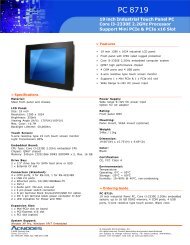
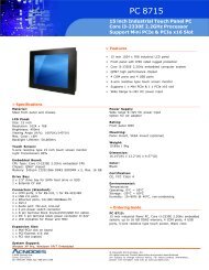
PC 8177<br />
Industrial Panel PC<br />
<strong>User</strong> <strong>Manual</strong><br />
PC 8177: 17” Industrial Panel PC with Quad- or Dual-Core<br />
i7 / i5/ i3 Processor<br />
14628 Central Ave,<br />
Chino, CA 91710<br />
tel:909.597.7588, fax:909.597.1939<br />
© Copyright 2013 Acnodes, Inc.<br />
All rights reserved. Product description and product specifications<br />
are subject to change without notice. For latest product information,<br />
please visit Acnodes’ web site at www.acnodes.com.
PC 8177<br />
Industrial Panel PC<br />
Dis claimers<br />
This manual has been carefully checked and believed to contain accurate information.<br />
Acnodes assumes no responsibility for any infringements of patents or any third party’s<br />
rights, and any liability arising from such use.<br />
Acnodes does not warrant or assume any legal liability or responsibility for the accuracy,<br />
completeness or usefulness of any information in this document. Acnodes does not make any<br />
commitment to update the information in this manual.<br />
Acnodes reserves the right to change or revise this document and/or product at any time<br />
without notice.<br />
No part of this document may be reproduced, stored in a retrieval system, or transmitted, in<br />
any form or by any means, electronic, mechanical, photocopying, recording, or otherwise,<br />
without the prior written permission of Acnodes Corporation.<br />
CAUT ION<br />
If you replace wrong batteries, it causes the danger of explosion. It is recommended by the<br />
manufacturer that you follow the manufacturer’s instructions to only replace the same or<br />
equivalent type of batter y, and dispose of used ones.<br />
14628 Central Ave,<br />
Chino, CA 91710<br />
tel:909.597.7588, fax:909.597.1939<br />
© Copyright 2013 Acnodes, Inc.<br />
All rights reserved. Product description and product specifications<br />
are subject to change without notice. For latest product information,<br />
please visit Acnodes’ web site at www.acnodes.com.
Safety Precautions<br />
Before getting started, read the following important cautions.<br />
1. Be sure to ground yourself to prevent static charge when installing the internal<br />
components. Use a grounding wrist strap and place all electronic components in any<br />
static-shielded devices. Most electronic components are sensitive to static electrical<br />
charge.<br />
2. Disconnect the power cords from the NA-550 Series before making any installation. Be<br />
sure both the system and the external devices are turned OFF. Sudden surge of power<br />
could ruin sensitive components. Make sure the NA-550 Series is properly grounded.<br />
3. Do not open the system’s top cover. If opening the cover for maintenance is a must, only<br />
a trained technician is allowed to do so. Integrated circuits on computer boards are<br />
sensitive to static electricity. To avoid damaging chips from electrostatic discharge,<br />
observe the following precautions:<br />
•<br />
Before handling a board or integrated circuit, touch an unpainted portion of the<br />
system unit chassis for a few seconds. This will help to discharge any static<br />
electricity on your body.<br />
•<br />
When handling boards and components, wear a wrist-grounding strap, available<br />
from most electronic component stores.<br />
Tra dema rks Acknowledgments<br />
Acnodes is a trademark of Acnodes Corporation.<br />
®<br />
Windows is a trademark of Microsoft Corporation.<br />
IBM, PC/AT, PS/2, VGA are trademarks of International Business Machines Corporation.<br />
Inte l<br />
® and Pentium ® are trademarks of Intel Corporation.<br />
AMI is trademark of American Megatrend Inc.<br />
Other brand names and<br />
respective owners.<br />
trademarks are the properties and registered brands of their
Table of Contents<br />
Disclaimers ..................................................................... ............................... . ii<br />
Safety Precautions .................................................... ................................... . iii<br />
Chapter 1 Introduction ............................................. 1<br />
1.1 General Description ......... ................................................... ................ 1<br />
1.2 Specifications ........................................... .......................................... . 2<br />
1.3 Dimensions and Outlines ............................................. ...................... 4<br />
1.4 I/O Outlets ................................................. .......................................... . 6<br />
1.5 Packing List .............................................. .......................................... . 7<br />
Chapter 2 Hardware and In stallation ...................... 9<br />
2.1 Open back cover ............................ ................................................... 10<br />
2.2 Serial Ports Interface ....... ................................................... .............. 11<br />
2.2.1 COM1 Data/Power Selection (JP10) ..........................................................11<br />
2.2.2 COM1 RS-232/422/485 Mode Setting (JP11, JP12, JP14) .......................11<br />
2.2.3 COM3 Data/Power Selection (JP13) ..........................................................11<br />
2.2.4 COM1&COM2 Connector ......................................................................... 12<br />
2.2.5 COM3 & COM4 Connectors...................................................................... 12<br />
2.3 Ethernet.......... ...................................................... ............................. . 13<br />
2.4 Mountings: Panel / Wall / Rack / Desktop / VESA ........................... 14<br />
2.4.1 VESA-ARM / Wall-Mount / Desktop-mount ............................................... 14<br />
2.4.2 Panel-mount Kit Assembly ........................................................................ 15<br />
2.4.3 Rack-mount Kit Assembly ......................................................................... 16<br />
2.5 HD D Installation.............................. .................................................. . 17<br />
2.6 DR AM Installation...................... ................................................... ..... 19<br />
2.7 CPU Installation.............................. .................................................. . 21<br />
2.8 CPU Cooler Installation ..................................................... ............... 23<br />
2.9 Wireless LAN Module Installation (optional)................................... 24<br />
2.10 Fan Tunnel Installation.... .................................................... .............. 26<br />
Chapter 3 AMI BIOS Setup Utility .......................... 27<br />
3.1 Starting ......... ..................................................................................... . 27<br />
3.2 Navigation K eys ............................. .................................................. . 27<br />
3.3 Main Menu................................................. ........................................ . 28<br />
3.4 Advanced Menu.............................. .................................................. . 29
3.5 Chipset Menu............................................ ......................................... 39<br />
3.6 Boot Menu................................................... ....................................... 43<br />
3.7 Security Menu........................................... ......................................... 44<br />
3.8 Save & Exit Menu ........................... ................................................... 45<br />
Chapter 4 Drivers Installation ............................... 47<br />
4.1 System ............... .................................................. .............................. 47<br />
4.2 Touch Screen............................................ ......................................... 47<br />
4.3 Embedded O.S................................ ................................................... 50<br />
APPENDIX A WATCHDOG TIMER ........................... 51<br />
About Watchdog Timer.......................... ...... ................................................ 51<br />
How to Use Watchdog Timer............ ...................................................... ..... 51<br />
APPENDIX B IAMT SETTINGS .............................. 53<br />
Entering MEBx ........ ....................................................... .............................. 53<br />
Set and Change Password .................... ....... ............................................... 54<br />
iAMT Web Console ......................................................................... ............ 55
Chapter 1<br />
Introduction<br />
This chapter contains general information and detailed specifications of the <strong>PC8177</strong>.<br />
Chapter 1 includes the following sections:<br />
• General Description<br />
• Specification<br />
• Dimensions<br />
• I/O Outlets<br />
• Package List<br />
1.1 Ge neral Description<br />
The <strong>PC8177</strong> adopts a 17-inch SXGA TFT LCD with 380-nits brightness and<br />
3rd&2nd Core i7/i5/i3 series, Pentium ® and Celeron ® processors and C216/Q77<br />
chipset to provide excellent and powerful computing performance. Furthermore, <strong>PC8177</strong><br />
adopts built-in speaker and option WLAN module for wireless connectivity.<br />
Industrial-grade front bezel<br />
<strong>PC8177</strong> adopts industrial-grade material front bezel which incorporates the advantages of light<br />
weight, high degree of hardness better heat releasing, easy-to-shape and anti-corrosion<br />
ability. Therefore, <strong>PC8177</strong> is especially suitable for most rugged industrial environments.<br />
Speaker and WLAN Antenna Supported<br />
<strong>PC8177</strong> features built-in speakers for kiosk application to display multimedia content<br />
program. It also supports WLAN module (optional) antenna for wireless network connectivity.
Powerful computing: 3rd Generation Core i7/i5/i3/Celeron processors<br />
<strong>PC8177</strong> features 3 rd &2 nd Core i7/i5/i3 series, Pentium ® and Celeron ® processors and<br />
C216/Q77 chipset which deliver high computing performance capability. Ivy Bridge CPU<br />
offers reliable and stable performance and rugged environment.<br />
1.2 Specifications<br />
Main CPU Board<br />
• CPU<br />
• 3rd&2nd Core i7/i5/i3 series, Pentium® and Celeron® processors<br />
• System Chipset<br />
• C216/Q77 Express Chipset<br />
• System Memory<br />
• 2 x 204-pin DDR3 1600/1333 MHz SO-DIMM socket<br />
• Supporting 8GB per dimm, maximum memory up to 16GB<br />
• BIOS<br />
• America Megatrends BIOS<br />
I/O System<br />
• Standard I/O<br />
• 1 x RS-232/422/485 with 5V&12V, 1 x RS-232 with 5V/12V, 2 x RS-232<br />
• 4 x USB 3.0<br />
• 2 x USB 2.0<br />
• 1 x HDMI<br />
• 1 x DVI-I<br />
• Ethernet<br />
• 2 x RJ45 for Giga Ethernet<br />
• Audio<br />
• 1 x Line-out<br />
• 1 x Mic-in<br />
• Expansion<br />
• 1 x Wireless Module(optional)<br />
• Storage<br />
• 2 x 2.5” or 1 x 3.5” SATA HDD<br />
• Power connector<br />
• 1 x AC plug
System Specification<br />
• 17” SXGA(1280 X 1024)LCD<br />
• 5 wired resistive Touch<br />
• IP65/NEMA4 aluminum front bezel<br />
• IP65 aluminum front bezel<br />
• Net Weight<br />
• 7 Kgs (15.43 lb)<br />
• Dimension (Main Body Size)<br />
• 410 x 80 x 338mm<br />
• Operation Temperature<br />
• 0? to 45?<br />
• Relative Humidity<br />
• 10% to 95% @ 40? , Non-Condensing<br />
• Power Input<br />
• 100~240VAC power connector<br />
NOTE 1. All specifications and images are subject to change without notice.<br />
2. Combo key: Pressing Brightness+ & Br ightness- means System ON/OFF.<br />
Pressing VOL+ & VOL- means voice mute.
1.3 Dimensions and Outlines<br />
The following diagrams show the dimensions and outlines of <strong>PC8177</strong>.
1.4 I/O Outlets<br />
Please refer to the following illustration for I/O locations of the <strong>PC8177</strong>.<br />
No Function<br />
1 1 x RS-232/422/485 with 5V&12V (COM1)<br />
2 1 x DVI-I<br />
3 2 x RJ45 for GIGA Ethernet<br />
4 1 x Line-out<br />
5 1 x RS-232 with 5V&12V (COM3)<br />
6 2 x USB2.0<br />
7 1 x AC Plug<br />
8 1 x switch for power on/off<br />
9 1 x RS-232 (COM2)<br />
10 1 x HDMI<br />
11 4 x USB3.0<br />
12 1 x MIC-in<br />
13 1 x RS-232 (COM4)
1.5 Packing List<br />
When you receive the <strong>PC8177</strong>, the bundled package should contain the following items:<br />
• <strong>PC8177</strong>unit x 1<br />
• Driver CD x1<br />
• Panel mount kit x 6<br />
• Wall/VESA mount kit x 1 (optional)<br />
• Rack mount kit x 1 (optional)<br />
• Power cord x 1<br />
• DVI to VGA adaptor<br />
• Fan Tunnel x 1<br />
If you cannot find the package or any items are missing, please contact Acnodes distributors<br />
immediately.
Chapter 2<br />
Hardware and Installation<br />
The <strong>PC8177</strong>provides rich I/O ports and flexible expansions for you to meet different<br />
demand. The chapter will show you how to install the hardware. It includes:<br />
•<br />
•<br />
•<br />
•<br />
•<br />
•<br />
•<br />
•<br />
•<br />
•<br />
Open back cover<br />
Serial Port Interface<br />
Ethernet<br />
Mounting Method<br />
Hard disk<br />
DRAM<br />
CPU<br />
CPU Cooler<br />
Wireless LAN Module(optional)<br />
Fan Tunnel
2.1 Ope n back cover<br />
This section tells users how to open back cover. Please follow the steps below.<br />
Step 1<br />
Unscrew 3 screws on the back cover and push to the right side. Please refer<br />
the photo below.<br />
Step 2<br />
Remove the back cover.
2.2 Seria l Ports Interface<br />
The <strong>PC8177</strong> has four serial ports. COM1 is RS-232/422/485, while COM2, COM3 and<br />
COM4 are RS-232.<br />
The following table shows you the pin assignments of this connector:<br />
2.2.1 COM1 Data/Pow er Selection (JP10)<br />
The COM1 port has +5V level power capability on DCD and +12V level on RI by setting<br />
this jumper. When COM1 is set to +5V or +12V level, please make sure the<br />
communication mode is RS-232 (see section 2.2.2).<br />
Description<br />
Power: Set CN15A pin 1 to +5V level<br />
Data: Set CN15A pin 1 to DCD (Default)<br />
ower: Set CN15A pin 9 to +12V level<br />
Data: Set CN15A pin 9 to RI (Default)<br />
Jumper Setting<br />
1-3 close<br />
3-5 close<br />
2-4 close<br />
4-6 close<br />
JP10<br />
2.2.2 COM1 RS-232/422/485 Mode Setting (JP11, JP12, JP14)<br />
Use these jumpers to set COM1 port to operate as RS-232, RS-422 or RS-485<br />
communication mode.<br />
Description<br />
RS-232 mode<br />
(Default)<br />
RS-422 mode<br />
RS-485 mode<br />
Jumper Setting<br />
JP11 3-5, 4-6 close<br />
JP12 1-2 close<br />
JP14 3-5, 4-6 close<br />
JP11 1-3, 2-4 close<br />
JP12 3-4 close<br />
JP14 1-3, 2-4 close<br />
JP11 1-3, 2-4 close<br />
JP12 5-6 close<br />
JP14 1-3, 2-4 close<br />
JP11 JP12 JP14<br />
2.2.3 COM3 Data/Pow er Selection (JP13)<br />
The COM3 port has +5V level power capability on DCD and +12V level on RI by setting<br />
this jum per.<br />
Description<br />
Power: Set CN13 pin 1 to +5V level<br />
Data: Set CN13 pin 1 to DCD (Default)<br />
Power: Set CN13 pin 8 to +12V level<br />
Data: Set CN13 pin 8 to RI (Default)<br />
Jumper Setting<br />
1-3 close<br />
3-5 close<br />
2-4 close<br />
4-6 close
2.2.4 COM1&COM2 C onnector<br />
The CN15 is a double-deck DB-9 connector. The upper connector (CN15A) is for COM1<br />
and the lower connector (CN15B) is for COM2. Note that the connectors (CN13 and<br />
CN15A) come with power capability on DCD and RI pins by setting jumpers (see section<br />
2.2.1).<br />
Pin Pin Signal<br />
CN15A (COM1)<br />
1 10 Data Carrier Detect (DCD)<br />
2 11 Receive Data (RXD)<br />
3 12 Transmit Data (TXD)<br />
4 13 Data Terminal Ready (DTR)<br />
5 14 Ground (GND)<br />
6 15 Data Set Ready (DSR)<br />
7 16 Request to Send (RTS)<br />
CN15B (COM2)<br />
8 17 Clear to Send (CTS)<br />
9 18 Ring Indicator (RI)<br />
2.2.5 COM3 & COM4 C onnectors<br />
The COM3 and COM4 i nterfac es are av aila ble through CN13 an d CN14,<br />
r espec tiv ely. Eac h o f thes e c onnec tors is a 2x 5 pi n 2.0 pitc h b ox header, see<br />
table bel ow for its pin a ss ignm ents .<br />
Pin<br />
Signal<br />
1 Data Carrier Detect (DCD)<br />
2 Data Set Ready (DSR)<br />
CN13/CN14<br />
3 Receive Data (RXD)<br />
4 Request to Send (RTS)<br />
5 Transmit Data (TXD)<br />
6 Clear to Send (CTS)<br />
7 Data Terminal Ready (DTR)<br />
8 Ring Indicator (RI)<br />
9 Ground (GND)<br />
10 NC
2.3 Etherne t<br />
The <strong>PC8177</strong> is equipped with two high performance plug and play Ethernet interfaces<br />
(RJ-45) which are fully compliant with the IEEE 802.3 standard. Connection can be<br />
established by plugging one end of the Ethernet cable into this RJ-45 connector and the other<br />
end to a 1000/100/10-Base-T hub.<br />
The Universal Serial Bus (compliant with USB 3.0 (5Gb/s)) connectors on the rear I/O are for<br />
installing USB peripherals such as keyboard, mouse, scanner, etc. Note that the CN10 carries<br />
LAN1, USB 3.0 port 2 and 3 signals while CN11 carries LAN2, USB 3.0 port 0 and 1 signals<br />
Pin<br />
LAN1 Signal (WG82579LM)/<br />
LAN2 Signal (WG82583V)<br />
Pin<br />
LAN1 Signal (WG82579LM)/<br />
LAN2 Signal (WG82583V)<br />
L1 MDI0+ L5 MDI2+<br />
L2 MDI0- L6 MDI2-<br />
L3 MDI1+ L7 MDI3+<br />
L4 MDI1- L8 MDI3-<br />
A<br />
B<br />
100 LAN LED (Green)/<br />
1000 LAN LED (Orange)<br />
Active LED<br />
CN10<br />
CN11<br />
Pin USB Signal Pin USB Signal<br />
1 USB_VCC(+5V level standby power) 10 USB_VCC (+5V level standby power)<br />
2 USB_Data2- 11 USB_Data3-<br />
3 USB_Data2+ 12 USB_Data3+<br />
4 GND 13 GND<br />
5 SSRX2- 14 SSRX3-<br />
6 SSRX2+ 15 SSRX3+<br />
7 GND 16 GND<br />
8 SSTX2- 17 SSTX3-<br />
9 SSTX2+ 18 SSTX3+
2.4 Mountings: Panel / Wall / Rack / Desktop / VESA<br />
There are 5 application options for the <strong>PC8177</strong>, including Panel/Wall/Rack/ Desktop/VESA<br />
mounting ways.<br />
2.4.1 VESA-ARM / Wall-Mount / Desktop-mount<br />
The <strong>PC8177</strong>provides VESA mount: 75x75 mm or 100x100mm. Screw six screws to<br />
fix the kit in the back chassis.<br />
^ VESA/ Wall mount bracket<br />
^ Putting the bracket on the back of system
? Fixing the bracket by six screws on the left and right side.<br />
2.4.2 Panel-mount Kit Assembl y<br />
The <strong>PC8177</strong>is designed for panel mount application. To mount the <strong>PC8177</strong>, the<br />
standard set of mounting k it (included in the system packaging) is needed.
2.4.3 Rack-mount Kit Assembly<br />
The <strong>PC8177</strong>is designed for rack mount application. To mount the <strong>PC8177</strong>, the<br />
standard set of mounting k it (included in the system packaging) is needed.<br />
Step 1<br />
Unscrew the fix screws from the left and right side of the system.<br />
Step 2<br />
Fixing the rack-mount bracket to the left and right of the system.
2.5 HDD Installation<br />
The <strong>PC8177</strong>provides a convenient Hard Disk Drive (HDD) bracket for users to install 2 x<br />
2.5” or 1 x 3.5” SATA HDD. Please follow the steps:<br />
Step 1<br />
Step 2<br />
Refer section 2.1 to open the back cover.<br />
Unscrew 4 screws to take off the HDD bracket.<br />
Step 3<br />
Fix the HDD on bracket by the screws.<br />
? 1 x 3.5” SATA HDD Kit ? 1 x 2.5” or 2 x 2.5” SATA HDD Kit<br />
? Fix the 3.5” HDD on the back of bracket ? Fix the 2.5” HDD on the right and left side of<br />
bracket
Step 4<br />
Fix the HDD bracket into the main base.<br />
Step 5<br />
Plug the power and SATA cables to connectors. Installation completes.
2.6 DR AM Insta llation<br />
The <strong>PC8177</strong>provides two 204-pin DDR3 SO-DIMM sock et that support system memory up to<br />
16GB. Please follow steps below to install the memory modules:<br />
Step 1<br />
Refer to section 2.1 to open the back cover and find out DIMM socket on<br />
mainboard (MANO871).<br />
Step 2<br />
Push the latches on each side of the SO-DIMM slot down.
Step 3<br />
Install the SO-DIMM module into the slot and press it firmly down until it seats<br />
correctly.<br />
Step 4<br />
The slot latches are levered upwards and latch on to the edges of the<br />
SO-DIMM.
2.7 CPU Installation<br />
The <strong>PC8177</strong>has an LGA1155 socket supporting 3 rd &2 nd Core i7/i5/i3 series, Pentium ®<br />
and Celeron ® processors and provides high computing performance for users.<br />
Step 1<br />
Press the hook of lever down with your thumb and pull it to the right side to<br />
release it from retention tab.<br />
Step 2<br />
Lift the tail of the load lever and rotate the load plate to fully open position.<br />
And, remove the protective plastic cover.
Step 3<br />
CPU aims at the socket and places the package carefully into the socket by<br />
purely vertical motion.<br />
NOTE Never touch fragile socket contacts to avoid damage and do not touch<br />
pr ocessor sensitive contacts at any time during installation.
2.8 CPU Cooler In stalla tion<br />
Step 1<br />
Making sure your CPU settled correctly on the socket.<br />
Step 2 Screw the cooling fan supporting base onto the CPU socket on the<br />
Motherboard and make sure the CPU fan is plugged to the CPU fan connector.<br />
And, Connect the CPU cooler power connector to the FAN1 connector
2.9 Wireless L AN Module Installation (optional)<br />
The <strong>PC8177</strong> provides one wireless LAN module to install. When installing the wireless<br />
LAN module, refer to the following instructions and illustration:<br />
Step 1<br />
Refer to section 2.1 to open the back cover and find out the wireless LAN<br />
module located.<br />
Step 2<br />
Fixing the wireless LAN module by 2 screws.
Step 3<br />
Plug in USB cable to the connector of WIFI module. And, find the built-in<br />
Antenna cable and connect it wireless LAN card.<br />
Step 4<br />
Lift the rubber stopper from the top of back cover.<br />
Step 5<br />
Install the antenna on the antenna connector.
2.10 Fan Tunnel Ins tallation<br />
The <strong>PC8177</strong> provides one fan tunnel to install. When installing the fan tunnel, refer to the<br />
following instructions and illustration:<br />
Step1<br />
Spread the fan tunnel out flat.<br />
Step2<br />
Tear the releasing paper from the dual face tape.<br />
Step3<br />
Fold each curved line.<br />
Step4<br />
Stick each side together.<br />
Step5<br />
Let fan cable through the fan tunnel and stick to the cooler.
Chapter 3<br />
AMI BIOS Setup Utility<br />
The AMI UEFI BIOS provides users with a built- in setup program to modify basic system<br />
configuration. All configured parameters are stored in a flash chip to save the setup information<br />
whenever the power is turned off. This chapter provides users with detailed description about<br />
how to set up basic system configuration through the AMI BIOS setup utility.<br />
3.1 Starting<br />
To enter the setup screens, follow the steps below:<br />
1. Turn on the computer and press the key immediately.<br />
2. After you press the key, the main BIOS setup menu displays. You can access the<br />
other setup screens from the main BIOS setup menu, such as the Advanced and Chipset<br />
menus.<br />
It is strongly recommended that you should avoid changing the chipset’s defaults. Both AMI<br />
and your system manufacturer have carefully set up these defaults that provide the best<br />
performance and reliability<br />
3.2 Navigation Ke ys<br />
The BIOS setup/utility uses a key-based navigation system called hot keys. Most of the BIOS<br />
setup utility hot keys can be used at any time during the setup navigation process. These k eys<br />
include , , , , keys, and so on.<br />
Note:<br />
Some of the navigation keys differ from one scr een to another.<br />
Hot Keys<br />
Left/Right<br />
Up/Down<br />
+ Plus/Minus<br />
Tab<br />
F1<br />
F2<br />
F3<br />
F4<br />
Esc<br />
Enter<br />
Description<br />
The Left and Right keys allow you to select a setup screen.<br />
The Up and Down keys allow you to select a setup screen or<br />
sub-screen.<br />
The Plus and Minus keys allow you to change the field value of a<br />
particular setup item.<br />
The key allo ws you to select setup fields.<br />
The key allows you to display the general help screen.<br />
The key allows you to load previous values.<br />
The key allows you to load optimized defaults.<br />
The key allows you to save any changes you have made and exit<br />
setup. Press the key to save your changes.<br />
The key allows you to discard any changes you have made and exit<br />
the setup. Press the key to exit the setup without saving your<br />
changes.<br />
The key allows you to display or change the setup option listed for a<br />
particular setup item. The key can also allow you to display the<br />
setup sub- screens.
3.3 Main Menu<br />
When you first enter the Setup Utility, you will enter the Main setup screen. You can always<br />
return to the Main setup screen by selecting the Main tab. There are two Main Setup options.<br />
They are described in this section. The Main BIOS Setup screen is shown below<br />
System Date/Time<br />
Use this option to change the system time and date. Highlight System Time or System Date<br />
using the keys. Enter new values through the keyboard. Press the key or the<br />
keys to move between fields. The date must be entered in MM/DD/YY format. The<br />
time is entered in HH:MM:SS format.
3.4 Adva nced Menu<br />
The Advanced menu also allows users to set configuration of the CPU and other system<br />
devices. You can select any of the items in the left frame of the screen to go to the sub menus:<br />
ACPI Settings<br />
Trusted Computing<br />
CPU Configuration<br />
SATA Configuration<br />
PCH-FW Configuration<br />
AMT Configuration<br />
USB Configuration<br />
NCT6627UD Super IO Configuration<br />
NCT6627UD HW Monitor<br />
For items marked with “”, please press for more options.
• ACPI Settings<br />
You can use this screen to select options for the ACPI Configuration, and change the value<br />
of the selected option. A description of the selected item appears on the right side of the<br />
screen.<br />
ACPI Sleep State<br />
Select the highest ACPI sleep state the system will enter when the suspend button is pressed.<br />
Configuration options are Suspend Disabled, S1 only (CPU Stop Clock), and S3 only<br />
(Suspend to RAM).<br />
To correctly support wake by use of USB from the S3 system power state, please refer to the<br />
following Microsoft’s link:<br />
http://support.microsoft.com/kb/841858/en-us
• Trusted Computing<br />
This screen provides function for specifying the TPM settings.<br />
Security Device Support<br />
Use this item to enable or disable BIOS support for security device.<br />
Security Device Support<br />
Display current TPM status information.
• CPU Configuration<br />
This screen shows the CPU information.<br />
EIST<br />
Enable or disable Speed Step. When enabled, CPU speed is controlled by the operating<br />
system. When disabled, CPU runs at its default speed.<br />
Turbo Mode<br />
This item is for enabling or disabling turbo mode. When enabled, it allows processor cores to<br />
run faster than marked frequency under certain conditions.<br />
Intel Virtualization Technology<br />
This item allows a hardware platform to run multiple operating systems separately and<br />
simultaneously, enabling one system to virtually function as several s ystems.<br />
Hyper-threading<br />
Use this item to enable or disable Hyper-Threading Technology, which makes a single physical<br />
processor perform multi-tasking function as two logical ones.
• SATA Configuration.<br />
In this Configuration menu, you can see the currently installed hardware in the SATA ports.<br />
During system boot up, the BIOS automatically detects the presence of SATA devices.<br />
SATA Controller(s)<br />
Enable or disable SATA device.<br />
SATA Mode Selection<br />
Determine how SATA controller(s) operate. Operation mode options are: IDE Mode, AHCI<br />
Mode and RAID Mode.
•<br />
PCH-FW Configuration<br />
This screen displays Management Engine (ME) Firm ware information.
•<br />
AMT Configuration<br />
Use this screen to configure AMT parameters.<br />
Intel AMT<br />
Enable or disable Active Management Technology BIOS Extension.<br />
Disable ME<br />
Enable or disable ME functionality.
• USB Configuration<br />
You can use this screen to select options for the USB Configuration, and change the value of<br />
the selected option. A description of the selected item appears on the right side of the screen.<br />
USB Devices<br />
Display all detected USB devices.<br />
Legacy USB Support<br />
Use this item to enable or disable support for USB device on legacy operating system. The<br />
default setting is Eenabled. Auto option dis ables legacy support if no USB devices are<br />
connected. Disable option will keep USB devices available only for EFI applications.
• NCT6627UD Super IO Configuration<br />
You can use this screen to select options for the Super IO Configuration, and change the value<br />
of the selected option. A description of the selected item appears on the right side of the<br />
screen. For items marked with “>”, please press for more options.<br />
Serial Port 1~4 Configuration<br />
Use this item to set parameters of serial port 1 to 4.
• NCT6627UD HW Monitor<br />
Use this screen for Smart Fan configuration and hardware health status monitoring.<br />
This screen displays the temperature of system and CPU, cooling fan speed in RPM and<br />
system voltages (VCORE, +12V, +3.3V and +5V).<br />
Smart Fan Function<br />
Enable or disable Smart Fan function.
3.5 Chipset Menu<br />
The Chipset menu allows users to change the advanced chipset settings. You can select any<br />
of the items in the left frame of the screen to go to the sub menus:<br />
PCH-IO Configuration<br />
System Agent (SA) Configuration<br />
For items marked with “>”, please press for more options.
• PCH-IO Configuration<br />
This screen allows you to set PCH parameters.<br />
USB Configuration<br />
Use this item for USB configuration settings.<br />
PCH Azalia Configuration<br />
Use this item for PCH Azalia configuration settings.<br />
Launch PXE OpROM policy<br />
Control the execution of UEFI and Legacy PXE OpROM.<br />
PCH LAN Controller<br />
Enable or disable PCH LAN controller.<br />
Wake on LAN<br />
Enable or disable Wake on LAN functionality.
• System Agent (SA) Configuration<br />
This screen shows System Agent information and provides function for specifying related<br />
parameters. For items marked with “>”, please press for more options.<br />
VT-d<br />
Enable or disable chipset virtualization technology for directed I/O. VT-d can help end users<br />
improve security and reliability of the systems and also improve performance of I/O<br />
devices in virtualized environment.<br />
Graphics Configuration<br />
Use this item for graphics configuration settings.<br />
Memory Configuration<br />
Use this item for memory configuration settings.
• Graphics Configuration<br />
Primary Display<br />
Allow you to select which graphics controller to use as the primary boot device.<br />
Primary IGFX Boot Display<br />
Allow you to select the display device which will be activated during POST. This has no effect if<br />
external graphics present. Secondary boot display selection will appear based on your<br />
selection. Primar y IGFX boot display options are: CRT, DVI, LVDS and HDMI.<br />
Secondary IGFX Boot Display<br />
Use this item to select secondary display device. Secondary IGFX boot display options are:<br />
CRT, DVI, LVDS and HDMI.<br />
LVDS Panel Type<br />
Use this item to select LVDS panel used by internal graphics controller by selecting the<br />
appropriate setup item.<br />
LVDS Brightness<br />
Select LVDS brightness that ranges from 30% to 100%. The default setting is 70%.<br />
DVMT Pre- Allocated<br />
Select DVMT pre-allocated memory size.<br />
DVMT Total Gfx Mem<br />
Select DVMT total memory size.<br />
Note: BIOS will default LVDS & CRT display.
3.6 Boot Menu<br />
The Boot menu allows users to change boot options of the system.<br />
Setup Prompt Timeout<br />
Number of seconds to wait for setup activation key. 65535(0xFFFF) means indefinite waiting.<br />
Bootup NumLock State<br />
Use this item to select the power-on state for the keyboard NumLock.<br />
Quiet Boot<br />
Select to display either POST output messages or a splash screen during boot-up.<br />
Fast Boot<br />
Enable or disable boot with initialization of minimal set of devices required to launch active<br />
boot option. Has no effect for BBS boot options.<br />
Boot Option Priorities<br />
These are settings for boot priority. Specify the boot device priority sequence from the<br />
available devices.<br />
Boot Option #1..#2<br />
These items are used to form the boot order and are dynamically generated. They represent<br />
either a legacy BBS (BIOS Boot Specification) class of devices or a native EFI boot entry.<br />
Press on each option to select the BBS class / EFI boot entry desired<br />
CD/DVD ROM Drive BBS/Hard Drive BBS Priorities<br />
These items are for configuring the boot order for a s pecific device class. These options are<br />
only visible if at least one device for this class is detected.
3.7 Security Menu<br />
The Security menu allows users to change the security settings for the system.<br />
Administrator Password<br />
This item indicates whether an administrator password has been set (installed or uninstalled).<br />
<strong>User</strong> Password<br />
This item indicates whether an user password has been set (installed or uninstalled).
3.8 Save & Exit Menu<br />
The Save & Exit menu allows users to load your system configuration with optimal or fail-safe<br />
default values.<br />
Save Changes and Exit<br />
When you have completed the system configuration changes, select this option to leave Setup<br />
and reboot the computer so the new system configuration parameters can take effect. Select<br />
Save Changes and Exit from the Exit menu and press . Select Ok to save changes<br />
and exit.<br />
Discard Changes and Exit<br />
Select this option to quit Setup without making any permanent changes to the system<br />
configuration. Select Discard Changes and Exit from the Exit menu and press . Select<br />
Ok to discard changes and exit.<br />
Save Changes and Reset<br />
When you have completed the system configuration changes, select this option to leave Setup<br />
and reboot the computer so the new system configuration parameters can take effect. Select<br />
Save Changes and Reset from the Save & Exit menu and press . Select Yes to save<br />
changes and reset.<br />
Discard Changes and Reset<br />
Select this option to quit Setup without making any permanent changes to the system<br />
configuration and reboot the computer. Select Discard Changes and Reset from the Save &<br />
Exit menu and press . Select Yes to discard changes and reset.<br />
Save Changes<br />
When you have completed the system configuration changes, select this option to save<br />
changes. Select Save Changes from the Save & Exit menu and press . Select yes to<br />
save changes.
Discard Changes<br />
Select this option to quit Setup without making any permanent changes to the system<br />
configuration. Select Discard Changes from the Save & Exit menu and press . Select<br />
Yes to discard changes.<br />
Restore Defaults<br />
It automatically sets all Setup options to a complete set of default settings when you select this<br />
option. Select Restore Defaults from the Save & Exit m enu and press .<br />
Save as <strong>User</strong> Defaults<br />
Select this option to save system configuration changes done so far as <strong>User</strong> Defaults. Select<br />
Save as <strong>User</strong> Defaults from the Save & Exit menu and press .<br />
Restore <strong>User</strong> Defaults<br />
It automatically sets all Setup options to a complete set of <strong>User</strong> Defaults when you select this<br />
option. Select Restore <strong>User</strong> Defaults from the Save & Exit menu and press .<br />
Launch EFI Shell from filesystem device<br />
Attempt to launch EFI Shell application (Shellx64.efi) from one of the available filesystem<br />
devices.
Chapter 4<br />
Drivers Installation<br />
4.1 S ystem<br />
<strong>PC8177</strong>supports Windows 7 and WES 7. To facilitate the installation of system driver,<br />
please carefully read the instructions in this chapter before start installing.<br />
Step 1<br />
Insert Driver CD and select the “\Drivers”.<br />
Step 2<br />
Select all files and follow the installing procedure.<br />
4.2 Touch Scre en<br />
The <strong>PC8177</strong>uses the 5-wire analog resistive. There are the specification and driver<br />
installation which are listed below.<br />
• Specification<br />
Touch Screen<br />
Touch Screen Controller<br />
5-wire Analog Resistive type<br />
PenMount 6500 USB Touch Screen Controller IC<br />
Communications<br />
USB interface<br />
Baud Rate<br />
19200 baud rate fixed<br />
Resolution 1280 X 1024
• Driver Installation- Windows 7<br />
The <strong>PC8177</strong>provides a touch screen driver that users can install it under the operating<br />
system Windows 7. To facilitate installation of the touch screen driver, you should read the<br />
instructions in this chapter carefully before you attempt installation.<br />
Step 1<br />
Insert Driver CD and follow the path to select the “\Drivers\Step 6. Touch”.<br />
Step 2<br />
Step 3<br />
Follow the installing procedure and press OK.<br />
Click Start menu and select “PenMount Utilities”; and then, a “PenMount<br />
Control Panel” pops out.
Step 4<br />
Select the “Standard Calibrate” tab.<br />
Step 5<br />
Calibrations:<br />
To adjust the display with touch panel, click “Calibration” and follow the calibrate<br />
point to do calibration; there are five points on screen for calibration.<br />
Step 6<br />
Press OK.
4.3 Embedde d O.S.<br />
The <strong>PC8177</strong>provides the Windows 7 Embedded. The O.S. is supported devices which are<br />
listed below.<br />
• WES 7<br />
Here are supported onboard devices:<br />
• Onboard Mult i I /O<br />
•<br />
•<br />
•<br />
•<br />
•<br />
•<br />
•<br />
S AT A HDD<br />
USB<br />
PS 2 Keyboard and mouse<br />
CRT/LCD display<br />
10/100/1 000 base-T Et hernet<br />
Onboard Audio<br />
Touch S creen<br />
PenMount Touch screen<br />
Before you can use and calibrate it, here is what you should do:<br />
1. Set up Penmount touch device driver by executing C:\Penmount\ Windows 2000-XP<br />
V5.0\setup.exe. When the installation is finished, an icon “PM” appears on the Taskbar.<br />
2. Calibrate Penmount touch by clicking on the “PM” icon, and the go on the calibration.<br />
3. Restart the computer.
APPENDIX A<br />
WATCHDOG TIMER<br />
About Watchdog Timer<br />
After the sys tem stops working for a while, it can be auto-reset by the watchdog timer. The<br />
integrated watchdog timer can be set up in the system reset mode by program.<br />
How to Use Watchdog Timer<br />
Start<br />
Un-Lock WDT:<br />
O 2E 87 ; Un-lock super I/O<br />
O 2E 87 ; Un-lock super I/O<br />
Select Logic device:<br />
O 2E 07<br />
O 2F 08<br />
Activate WDT:<br />
O 2E 30<br />
O 2F 01<br />
Set Second or Minute:<br />
O 2E F5<br />
O 2F N ; N=00 or 08 (See Note below)<br />
Set base timer:<br />
O 2E F6<br />
O 2F M ; M=00,01,02,…FF(Hex) ,Value=0 to 255<br />
WDT counting re-set timer:<br />
O 2E F6<br />
O 2F M ; M=00,01,02,…FF<br />
;IF to disable WDT:<br />
O 2E 30<br />
O 2F 00 ; Can be disabled at any time<br />
•<br />
Timeout Value Range<br />
• 1 to 255<br />
• Minute / Second
•<br />
Program Example<br />
2E, 87<br />
2E, 87<br />
2E, 07<br />
2F, 08 Logical Device 8<br />
2E, 30 Activate<br />
2F, 01<br />
2E, F5<br />
2F, N Set Minute or Second; N=08 (Min), 00(Sec)<br />
2E, F6<br />
2F, M Set Value; M=00~FF<br />
Note:<br />
If N=00h, the time base is set to second.<br />
M = time value<br />
00h: Time-out Disable<br />
01h: Time-out occurs after 1 second<br />
02h: Time-out occurs after 2 seconds<br />
03h: Time-out occurs after 3 seconds<br />
.<br />
.<br />
FFh: Time-out occurs after 255 seconds<br />
If N=08h, the time base is set to minute.<br />
M = time value<br />
00h: Time-out Disable<br />
01h: Time-out occurs after 1 minute<br />
02h: Time-out occurs after 2 minutes<br />
03h: Time-out occurs after 3 minutes<br />
.<br />
.<br />
FFh: Time-out occurs after 255 minutes
APPENDIX B<br />
IAMT SETTINGS<br />
The Active Management Technology iAMT) has decreased a major barrier to IT efficiency<br />
that uses built-in platform capabilities and popular third-party management and security<br />
applic ations to allow IT a better discovering, healing, and pr otection their networked<br />
computing assets.<br />
In order to utilize iAMT you must enter the ME BIOS ( during system startup),<br />
change the ME BIOS password, and then select “iAMT” as the manageability feature.<br />
Ente ring MEBx<br />
1. You must go to BIOS to enable iAMT function.<br />
2. Exit from BIOS after starting iAMT, and press to enter MEBx Setting.<br />
Note: t is better to press before the screen popping out.
Set and Change Password<br />
1. You will be asked to set a password when first log in. The default password is “admin”.<br />
2. You will be asked to change the password before setting ME.
3. You must confirm your new pass word while revising. The new password must contain:<br />
(example: !!11qqQQ) (default value).<br />
• Eight characters<br />
• One upper case<br />
• One lower case<br />
• One number<br />
• One special symbol, such as ! 、 $ or ; , (、 "<br />
, excepted)<br />
Underline ( _ ) and space are valid characters for password, but they won’t make higher<br />
complexity.<br />
iAMT Web Console<br />
1. From a web browser, please type http://(IP ADDRESS):16992, which connects to<br />
iAMT Web.<br />
Example: http://10.1.40.214:16992<br />
2. To log on, you will be requir ed to type in username and password for access to the Web.<br />
USER: admin (default value)<br />
PASS: (MEBx password)
3. Enter the iAMT Web.<br />
4. Click Remote Control, and select commands on the right side.<br />
5. When you have finished using the iAMT Web console, close the Web browser.