IDEC HW Series 22mm IEC Style Oiltight Switches & Pilot Devices
IDEC HW Series 22mm IEC Style Oiltight Switches & Pilot Devices
IDEC HW Series 22mm IEC Style Oiltight Switches & Pilot Devices

Create successful ePaper yourself
Turn your PDF publications into a flip-book with our unique Google optimized e-Paper software.
<strong>Switches</strong> & <strong>Pilot</strong> <strong>Devices</strong><br />
ø<strong>22mm</strong> - <strong>HW</strong> <strong>Series</strong><br />
Key features:<br />
• Locking lever removable contact blocks<br />
• Finger-safe IP20 contacts as standard, other terminal<br />
styles available<br />
• Tamperproof construction<br />
• All E-stops meet EN418 and are compliant with<br />
SEMI S2 standards<br />
• Worldwide approvals<br />
• Easy to assemble<br />
• Choice of black plastic or metallic front bezels<br />
• Incandescent or LED illumination<br />
• Transformer or full voltage<br />
• Slow make double break self cleaning contacts<br />
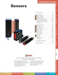
<strong>HW</strong> <strong>Series</strong> — <strong>22mm</strong> <strong>IEC</strong> <strong>Style</strong> Global Pushbuttons<br />
<strong>IDEC</strong>’s <strong>HW</strong> switches are “The best engineered switch in the world” for a<br />
reason. Carrying the CE mark, UL, CSA, CCC (Chinese), and TUV approvals, these<br />
switches are designed for use in almost any part of the world.<br />
Complete with finger-safe contact blocks offering IP20 protection, these 7/8”<br />
(<strong>22mm</strong>) switches include illuminated and non-illuminated pushbuttons, pilot<br />
Electrical<br />
File No. E68961<br />
Rated Operational Characteristics<br />
Maximum Inrush Current<br />
Rated Insulation Voltage<br />
Rated Switching Over-Voltage<br />
Rated Impulse Withstanding Voltage<br />
Rated Thermal Current<br />
Minimum Switching Capacity<br />
Electrical Reliability<br />
Lamp Ratings<br />
®<br />
File No. LR92374<br />
<strong>HW</strong>: The Best Engineered Switch in the World<br />
lights, selector switches, and emergency stop switches.<br />
All switches also incorporate mechanically keyed safety locking levers, ensuring<br />
correct installation and maintaining safety in high-vibration applications.<br />
Registration No. R9551089 (E-stops)<br />
Registration No. R50054316 (Dual Pushbuttons)<br />
Registration No. J9650511 (<strong>Pilot</strong> Lights)<br />
Registration No. J9551458 (all other switches)<br />
Specifications<br />
AC-15: A600 or Ue = 250V, le = 3A (NO, NC, NO-EM, NC-LB)<br />
DC-13: P600 or Ue = 125V, le = 1.1A (NO, NC)<br />
DC-13: Q600 or Ue = 125V, le = 0.9A (NO-EM, NC-LB)<br />
40 A (40 ms)<br />
600V<br />
Less than 4kV, conforming to <strong>IEC</strong>60947-1<br />
4kV for contact circuit, 2.5kV for lamp circuit<br />
10 Amp<br />
5 mA at 3V AC/DC<br />
MTBF < 1 fault for 10 million operation cycles (3V DC, 5mA)<br />
Incandescent: 1 W<br />
LEDs: 6V/17mA max, 12V & 24V/11mA max, 120 & 240V/10mA max<br />
Certificate No.<br />
2005010305145656<br />
<strong>Switches</strong> & <strong>Pilot</strong> <strong>Devices</strong> Signaling Lights Relays & Sockets Timers Contactors Terminal Blocks Circuit Breakers<br />
Phone: 800.894.0412 - Fax: 888.723.4773 - Web: www.clrwtr.com - Email: info@clrwtr.com
ø<strong>22mm</strong> - <strong>HW</strong> <strong>Series</strong><br />
<strong>Switches</strong> & <strong>Pilot</strong> <strong>Devices</strong><br />
Terminal Blocks<br />
Contactors<br />
Timers<br />
Relays & Sockets<br />
Signaling Lights <strong>Switches</strong> & <strong>Pilot</strong> <strong>Devices</strong><br />
Characteristics Contact Ratings<br />
Standards & Approvals<br />
Mechanical<br />
Contact Operation<br />
Positive Action Operation<br />
(Emergency Stops with NC contacts)<br />
Operating Force<br />
Recommended Terminal Torque<br />
Applicable Wire Size<br />
Contact Resistance<br />
Contact Gap<br />
Horsepower Rating<br />
Contact Material<br />
Operating Temperature<br />
Vibration Resistance<br />
Shock Resistance<br />
Slow break NC or NO, self-cleaning<br />
5.5mm to 10mm travel to latch, 45N minimum force to latch<br />
10mm maximum travel, 1,800 operations per hour maximum for a Pushlock Turn Reset<br />
900 operations per hour maximum for a Push-Pull<br />
Flush and extended pushbuttons—with 1NO or 1NC contact: 6.2±2N (momentary), 7.0±2N (maintained)<br />
Additional contacts—1NO or 1NC: +3.2N (momentary), + 3.3N (maintained)<br />
0.8 N m (7.1 in lb.)<br />
Minimum 1 x 22 AWG, max. 2 x 14 AWG or 1 x 12 AWG<br />
Initial contact resistance of 50mΩ or less<br />
4mm (NO and NC), 2mm (NO-EM and NC-LB)<br />
Reference Value: 1/4 HP @ 120V (1ø non-reversing), 1HP @ 240V (3ø non-reversing)<br />
Silver (gold plated contacts available - contact <strong>IDEC</strong>)<br />
Operation: –25 to +50°C (without freezing), Storage: –40 to +70°C (without freezing)<br />
10 to 55Hz, 98m/sec 2 (10G) conforming to <strong>IEC</strong>6068-2-6<br />
980m/sec 2 (100G) conforming to <strong>IEC</strong>6068-2-7<br />
Mechanical Life Momentary pushbuttons: 5,000,000 (900 operations per hour), All other switches: 500,000<br />
Conforming to Standards<br />
Approvals<br />
Circuit Breakers<br />
File No. E68961<br />
®<br />
File No. LR92374<br />
Registration No. R9551089 (E-stops)<br />
Registration No. R50054316 (Dual Pushbuttons)<br />
Registration No. J9650511 (<strong>Pilot</strong> Lights)<br />
Registration No. J9551458 (all other switches)<br />
Electric Shock Protection<br />
Degree of Protection<br />
(conforming to <strong>IEC</strong>60529)<br />
(conforming to NEMA ICS6-110)<br />
Certificate No.<br />
2005010305145656<br />
Pollution Degree (conforming to <strong>IEC</strong>60947-1)<br />
External Short-Circuit Protection<br />
EN60947-1, EN60947-5-1, VDE0660-200, UL508, CSA C22-2 No.14<br />
CSA: pushbuttons and selector switches: A600<br />
pilot lights and illuminated pushbuttons, direct supply pilot lights and illuminated pushbuttons with<br />
integral transformer (100/110, 115, 120, 200/220, 230, 240, 380, 400/440, 480V)<br />
UL: pushbuttons and selector switches: A600<br />
pilot lights and illuminated pushbuttons, direct supply pilot lights and illuminated pushbuttons with<br />
integral transformer (100/110, 115, 120, 200/220, 230, 240, 380, 400/440, 480V)<br />
TÜV: pushbuttons and selector switches: A600=P600 (NO, NC)/Q600 (NO-EM, NC-LB)<br />
pilot lights and illuminated pushbuttons, direct supply pilot lights and illuminated pushbuttons with<br />
integral transformer (100/110, 115, 120, 200/220, 230, 240, 380, 400/440, 480V)<br />
Class 0 conforming to <strong>IEC</strong>60536<br />
IP65 (from front of the panel)<br />
IP20 (Type <strong>HW</strong>-F contact block)<br />
NEMA 1, 2, 3, 3R, 3S, 4, 4X, 5, 12, 13 (from front of panel)<br />
3 for switches not using a transformer, 2 for switches using a transformer<br />
10A 250V fuse conforming to <strong>IEC</strong>60269-1<br />
Terminal Referencing<br />
Conforming to CENELEC EN50005<br />
Pushbuttons<br />
Contact Block<br />
Type <strong>HW</strong>-C/<strong>HW</strong>-F /<strong>HW</strong>-G<br />
Illuminated Pushbuttons<br />
Rated Insulation Voltage<br />
600V<br />
Selector <strong>Switches</strong><br />
Rated Continuous Current<br />
10A<br />
Illuminated Selector <strong>Switches</strong><br />
Contact Ratings by Utilization Category<br />
AC-15 (A600)<br />
Pushbutton Selectors<br />
<strong>IEC</strong> 60947-5-1<br />
DC-13 (P600)<br />
Operational Voltage 24V 48V 50V 110V 220V 440V<br />
AC-12 Control of resistive loads & solid state loads 10A — 10A 10A 6A 2A<br />
AC 50/60 Hz<br />
Operational<br />
AC-15 Control of electromagnetic loads (> 72VA) 10A — 7A 5A 3A 1A<br />
Current<br />
DC-12 Control of resistive loads & solid state loads 8A 5A — 2.2A 1.1A —<br />
DC<br />
DC-13 Control of electromagnets 5A 2A — 1.1A 0.6A —<br />
For dimensions, see page 601.<br />
Phone: 800.894.0412 - Fax: 888.723.4773 - Web: www.clrwtr.com - Email: info@clrwtr.com
<strong>Switches</strong> & <strong>Pilot</strong> <strong>Devices</strong><br />
ø<strong>22mm</strong> - <strong>HW</strong> <strong>Series</strong><br />
LED Lamp Ratings (LSTD Type)<br />
Model LSTD-6k LSTD-1k LSTD-2k LSTD-H2k LSTD-M4k<br />
Lamp Base<br />
BA9S/13<br />
Rated Voltage 6V AC/DC 12V AC/DC 24V AC/DC 120V AC 240V AC<br />
Voltage Range 6V AC/DC ±10% 12V AC/DC ±10% 24V AC/DC ±10% 120V AC ±5%<br />
240V AC<br />
±5%<br />
A, R, W: 17mA<br />
AC<br />
Current G, S: 8mA<br />
11mA 11mA 10mA 10mA<br />
Draw A, R, W: 14mA<br />
DC<br />
G, S: 5.5mA<br />
10mA 10mA – –<br />
Color Code<br />
A (amber), G (green), R (red), S (blue), W (white)<br />
Lamp Base Color<br />
Same as illumination color<br />
Voltage Marking<br />
Die stamped on the base<br />
Life (reference value)<br />
Approx. 50,000 hours (The luminance reduces to 50% the initial intensity when used on complete DC.)<br />
A, R, W A, R, W<br />
Internal Circuit<br />
G, S<br />
LED Chip<br />
LED Chip<br />
LED Chip<br />
Protection Diode<br />
Protection<br />
Protection<br />
Diode<br />
Diode<br />
Zener Diode<br />
Zener<br />
Zener<br />
Diode<br />
Diode<br />
In place of k,<br />
specify the Lens/LED<br />
Color Code.<br />
<strong>Switches</strong> & <strong>Pilot</strong> <strong>Devices</strong> Signaling Lights Relays & Sockets Timers Contactors Terminal Blocks Circuit Breakers<br />
Phone: 800.894.0412 - Fax: 888.723.4773 - Web: www.clrwtr.com - Email: info@clrwtr.com
ø<strong>22mm</strong> - <strong>HW</strong> <strong>Series</strong><br />
<strong>Switches</strong> & <strong>Pilot</strong> <strong>Devices</strong><br />
<strong>Switches</strong> & <strong>Pilot</strong> <strong>Devices</strong><br />
Non-Illuminated Round Pushbuttons (Assembled)<br />
Signaling Lights<br />
Relays & Sockets<br />
Timers<br />
Contactors<br />
Round Flush<br />
Round Extended<br />
Function Contacts Plastic Bezel Metal Bezel Plastic Bezel Metal Bezel<br />
Operator Only <strong>HW</strong>1B-M1-j <strong>HW</strong>4B-M1-j <strong>HW</strong>1B-M2-j <strong>HW</strong>4B-M2-j<br />
1NO <strong>HW</strong>1B-M1F10-j <strong>HW</strong>4B-M1F10-j <strong>HW</strong>1B-M2F10-j <strong>HW</strong>4B-M2F10-j<br />
1NC <strong>HW</strong>1B-M1F01-j <strong>HW</strong>4B-M1F01-j <strong>HW</strong>1B-M2F01-j <strong>HW</strong>4B-M2F01-j<br />
Momentary 1NO-1NC <strong>HW</strong>1B-M1F11-j <strong>HW</strong>4B-M1F11-j <strong>HW</strong>1B-M2F11-j <strong>HW</strong>4B-M2F11-j<br />
2NO <strong>HW</strong>1B-M1F20-j <strong>HW</strong>4B-M1F20-j <strong>HW</strong>1B-M2F20-j <strong>HW</strong>4B-M2F20-j<br />
2NC <strong>HW</strong>1B-M1F02-j <strong>HW</strong>4B-M1F02-j <strong>HW</strong>1B-M2F02-j <strong>HW</strong>4B-M2F02-j<br />
2NO-2NC <strong>HW</strong>1B-M1F22-j <strong>HW</strong>4B-M1F22-j <strong>HW</strong>1B-M2F22-j <strong>HW</strong>4B-M2F22-j<br />
Operator Only <strong>HW</strong>1B-A1-j <strong>HW</strong>4B-A1-j <strong>HW</strong>1B-A2-j <strong>HW</strong>4B-A2-j<br />
1NO <strong>HW</strong>1B-A1F10-j <strong>HW</strong>4B-A1F10-j <strong>HW</strong>1B-A2F10-j <strong>HW</strong>4B-A2F10-j<br />
1NC <strong>HW</strong>1B-A1F01-j <strong>HW</strong>4B-A1F01-j <strong>HW</strong>1B-A2F01-j <strong>HW</strong>4B-A2F01-j<br />
Maintained 1NO-1NC <strong>HW</strong>1B-A1F11-j <strong>HW</strong>4B-A1F11-j <strong>HW</strong>1B-A2F11-j <strong>HW</strong>4B-A2F11-j<br />
2NO <strong>HW</strong>1B-A1F20-j <strong>HW</strong>4B-A1F20-j <strong>HW</strong>1B-A2F20-j <strong>HW</strong>4B-A2F20-j<br />
2NC <strong>HW</strong>1B-A1F02-j <strong>HW</strong>4B-A1F02-j <strong>HW</strong>1B-A2F02-j <strong>HW</strong>4B-A2F02-j<br />
2NO-2NC <strong>HW</strong>1B-A1F22-j <strong>HW</strong>4B-A1F22-j <strong>HW</strong>1B-A2F22-j <strong>HW</strong>4B-A2F22-j<br />
Terminal Blocks<br />
Circuit Breakers<br />
j Button Color Code<br />
Color Code<br />
Black B<br />
Green G<br />
Red R<br />
Blue S<br />
White W<br />
Yellow Y<br />
Gray N*<br />
*Gray available for round flush only.<br />
1. In place of j, specify the Button Color Code from table below.<br />
2. For nameplates and accessories, see page 596 and 599.<br />
3. For dimensions, see page 601.<br />
4. For contact assembly part numbers, see page 600.<br />
5. All assembled part numbers in catalog include standard, fingersafe (<strong>HW</strong>-F...)<br />
contacts.<br />
6. Assembled units with spring-up terminals (<strong>HW</strong>-G...) can be ordered by<br />
removing an “F” from the part number (Ex. <strong>HW</strong>1B-M1F11-R becomes<br />
<strong>HW</strong>1B-M111-R).<br />
7. Operator only models include operator plus button.<br />
8. Additional contact configurations available (up to 6 total contacts).<br />
Phone: 800.894.0412 - Fax: 888.723.4773 - Web: www.clrwtr.com - Email: info@clrwtr.com
<strong>Switches</strong> & <strong>Pilot</strong> <strong>Devices</strong><br />
ø<strong>22mm</strong> - <strong>HW</strong> <strong>Series</strong><br />
Bezel<br />
1: Plastic Bezel<br />
4: Metal Bezel<br />
Part Number Structure<br />
H W 1 B - M 1 F 10 – R<br />
Function<br />
M: Momentary Action Operator<br />
A: Maintained Action 1: Flush<br />
Terminals<br />
2: Extended<br />
F: Fingersafe Contacts<br />
C: Exposed Screw Terminals<br />
blank: Spring-up Terminals<br />
Contact Blocks + Mounting Adaptor +<br />
Contact Blocks<br />
<strong>Style</strong> Contacts 1NO 1NC<br />
Standard<br />
Fingersafe<br />
(IP20)<br />
Spring-Up<br />
Terminal<br />
Exposed<br />
Screw<br />
Terminal<br />
Dummy<br />
Block<br />
<strong>HW</strong>-F10<br />
<strong>HW</strong>-F10R<br />
(early make)<br />
<strong>HW</strong>-G10<br />
<strong>HW</strong>-G10R<br />
(early make)<br />
<strong>HW</strong>-C10<br />
<strong>HW</strong>-C10R<br />
(early make)<br />
Contact Block Mounting Adaptor<br />
<strong>Style</strong><br />
Part Number<br />
<strong>HW</strong>-CB2C<br />
TW-DB<br />
1. Used to mount contact blocks to operator.<br />
2. <strong>IDEC</strong> strongly recommends using the safety lever<br />
lock to prevent heavy vibration or maintenance<br />
personnel from inadvertently unlocking contacts.<br />
Non-Illuminated Round Pushbuttons (Replacement Parts)<br />
<strong>HW</strong>-F01<br />
<strong>HW</strong>-F01R<br />
(late break)<br />
<strong>HW</strong>-G01<br />
<strong>HW</strong>-G01R<br />
(late break)<br />
<strong>HW</strong>-C01<br />
<strong>HW</strong>-C01R<br />
(late break)<br />
Safety<br />
Lever Lock<br />
+<br />
Anti-Rotation<br />
Ring<br />
Anti-Rotation Ring<br />
<strong>Style</strong><br />
Operators<br />
<strong>Style</strong><br />
Round Flush/<br />
Extended<br />
Contact Arrangement<br />
10: 1NO 20: 2NO<br />
01: 1NC 02: 2NC<br />
11: 1NO-NC 22: 2NO-2NC<br />
Button Colors<br />
B: Black<br />
G: Green<br />
R: Red<br />
S: Blue<br />
W: White<br />
Y: Yellow<br />
N: Gray*<br />
*Available for round<br />
flush only<br />
+ Operator + Button = Completed Unit<br />
Part Number<br />
<strong>HW</strong>9Z-RL<br />
Use with notched panel cutout to prevent<br />
unit rotation.<br />
Momentary<br />
Maintained<br />
Safety Lever Lock<br />
<strong>Style</strong> Part Number<br />
<strong>HW</strong>9Z-LS<br />
Plastic<br />
Bezel<br />
<strong>HW</strong>1B-M0<br />
<strong>HW</strong>1B-A0<br />
Metal<br />
Bezel<br />
<strong>HW</strong>4B-MO<br />
<strong>HW</strong>4B-AO<br />
Buttons<br />
<strong>Style</strong><br />
Round Flush<br />
Round Extended<br />
Part Number<br />
<strong>HW</strong>1A-B1-j<br />
<strong>HW</strong>1A-B2-j<br />
1. In place of j, specify the<br />
Button Color Code from table.<br />
j Button Color Code<br />
Color Code Color Code<br />
Black B White W<br />
Green G Yellow Y<br />
Red R Gray N*<br />
Blue S<br />
*Gray available for round flush<br />
only.<br />
<strong>Switches</strong> & <strong>Pilot</strong> <strong>Devices</strong> Signaling Lights Relays & Sockets Timers Contactors Terminal Blocks Circuit Breakers<br />
Phone: 800.894.0412 - Fax: 888.723.4773 - Web: www.clrwtr.com - Email: info@clrwtr.com
ø<strong>22mm</strong> - <strong>HW</strong> <strong>Series</strong><br />
<strong>Switches</strong> & <strong>Pilot</strong> <strong>Devices</strong><br />
<strong>Switches</strong> & <strong>Pilot</strong> <strong>Devices</strong><br />
Non-Illuminated Mushroom Head Pushbuttons (Assembled)<br />
Relays & Sockets<br />
Timers<br />
Contactors<br />
Signaling Lights<br />
ø29mm Mushroom Head<br />
ø40mm Mushroom Head<br />
Function Contacts Plastic Bezel Metal Bezel Plastic Bezel Metal Bezel<br />
Operator Only <strong>HW</strong>1B-M3-j <strong>HW</strong>4B-M3-j <strong>HW</strong>1B-M4-j <strong>HW</strong>4B-M4-j<br />
1NO <strong>HW</strong>1B-M3F10-j <strong>HW</strong>4B-M3F10-j <strong>HW</strong>1B-M4F10-j <strong>HW</strong>4B-M4F10-j<br />
1NC <strong>HW</strong>1B-M3F01-j <strong>HW</strong>4B-M3F01-j <strong>HW</strong>1B-M4F01-j <strong>HW</strong>4B-M4F01-j<br />
Momentary 1NO-1NC <strong>HW</strong>1B-M3F11-j <strong>HW</strong>4B-M3F11-j <strong>HW</strong>1B-M4F11-j <strong>HW</strong>4B-M4F11-j<br />
2NO <strong>HW</strong>1B-M3F20-j <strong>HW</strong>4B-M3F20-j <strong>HW</strong>1B-M4F20-j <strong>HW</strong>4B-M4F20-j<br />
2NC <strong>HW</strong>1B-M3F02-j <strong>HW</strong>4B-M3F02-j <strong>HW</strong>1B-M4F02-j <strong>HW</strong>4B-M4F02-j<br />
2NO-2NC <strong>HW</strong>1B-M3F22-j <strong>HW</strong>4B-M3F22-j <strong>HW</strong>1B-M4F22-j <strong>HW</strong>4B-M4F22-j<br />
Operator Only <strong>HW</strong>1B-A3-j <strong>HW</strong>4B-A3-j <strong>HW</strong>1B-A4-j <strong>HW</strong>4B-A4-j<br />
1NO <strong>HW</strong>1B-A3F10-j <strong>HW</strong>4B-A3F10-j <strong>HW</strong>1B-A4F10-j <strong>HW</strong>4B-A4F10-j<br />
1NC <strong>HW</strong>1B-A3F01-j <strong>HW</strong>4B-A3F01-j <strong>HW</strong>1B-A4F01-j <strong>HW</strong>4B-A4F01-j<br />
Maintained 1NO-1NC <strong>HW</strong>1B-A3F11-j <strong>HW</strong>4B-A3F11-j <strong>HW</strong>1B-A4F11-j <strong>HW</strong>4B-A4F11-j<br />
2NO <strong>HW</strong>1B-A3F20-j <strong>HW</strong>4B-A3F20-j <strong>HW</strong>1B-A4F20-j <strong>HW</strong>4B-A4F20-j<br />
2NC <strong>HW</strong>1B-A3F02-j <strong>HW</strong>4B-A3F02-j <strong>HW</strong>1B-A4F02-j <strong>HW</strong>4B-A4F02-j<br />
2NO-2NC <strong>HW</strong>1B-A3F22-j <strong>HW</strong>4B-A3F22-j <strong>HW</strong>1B-A4F22-j <strong>HW</strong>4B-A4F22-j<br />
Terminal Blocks<br />
Circuit Breakers<br />
ø60mm Mushroom Head<br />
Function Contacts Plastic Bezel<br />
Operator Only <strong>HW</strong>1B-M5-j*<br />
1NO<br />
<strong>HW</strong>1B-M5F10-j*<br />
1NC<br />
<strong>HW</strong>1B-M5F01-j*<br />
Momentary 1NO-1NC <strong>HW</strong>1B-M5F11-j*<br />
2NO<br />
<strong>HW</strong>1B-M5F20-j*<br />
2NC<br />
<strong>HW</strong>1B-M5F02-j*<br />
2NO-2NC <strong>HW</strong>1B-M5F22-j*<br />
j Button Color<br />
Code<br />
Color Code<br />
Black B<br />
Green G<br />
Red R<br />
Blue S<br />
White W<br />
Yellow Y<br />
1. In place of j, specify the Button Color Code from table.<br />
2. *60mm mushroom available only in red, green, black, and yellow.<br />
3. For nameplates and accessories, see page 596 and 599.<br />
4. For dimensions, see page 601.<br />
5. For contact assembly part numbers, see page 600.<br />
6. All assembled part numbers in catalog include standard fingersafe<br />
(<strong>HW</strong>-F...) contacts.<br />
7. Assembled units with spring-up terminals (<strong>HW</strong>-G...) can be ordered<br />
by removing an “F” from the part number (Ex. <strong>HW</strong>1B-M1F11-R<br />
becomes <strong>HW</strong>1B-M111-R).<br />
8. Units with exposed screw terminals (<strong>HW</strong>-C...) must be ordered as<br />
sub-components.<br />
9. Operator only models include operator plus button.<br />
10. Additional contact configurations available (up to 6 total contacts).<br />
Phone: 800.894.0412 - Fax: 888.723.4773 - Web: www.clrwtr.com - Email: info@clrwtr.com
<strong>Switches</strong> & <strong>Pilot</strong> <strong>Devices</strong><br />
ø<strong>22mm</strong> - <strong>HW</strong> <strong>Series</strong><br />
Bezel<br />
1: Plastic Bezel<br />
4: Metal Bezel<br />
(Not available for 60mm<br />
mushroom)<br />
Contact Blocks +<br />
Contact Blocks<br />
Function<br />
M: Momentary Action<br />
A: Maintained Action<br />
(Not available for 60mm jumbo<br />
mushroom pushbutton.)<br />
Mounting<br />
Adaptor<br />
<strong>Style</strong> Contacts 1NO 1NC<br />
Standard<br />
Fingersafe<br />
(IP20)<br />
Spring-Up<br />
Terminal<br />
Exposed<br />
Screw<br />
Terminal<br />
Dummy<br />
Block<br />
<strong>HW</strong>-F10<br />
<strong>HW</strong>-F10R<br />
(early make)<br />
<strong>HW</strong>-G10<br />
<strong>HW</strong>-G10R<br />
(early make)<br />
<strong>HW</strong>-C10<br />
<strong>HW</strong>-C10R<br />
(early make)<br />
Contact Block Mounting Adaptor<br />
<strong>Style</strong><br />
Part Number<br />
<strong>HW</strong>-CB2C<br />
Part Number Structure<br />
H W 1 B - M 3 F 10 – R<br />
Operator<br />
3: ø29mm Mushroom<br />
4: ø40mm Mushroom<br />
5: ø60mm Mushroom<br />
Terminals<br />
F: Fingersafe Contacts<br />
C: Exposed Screw Terminals<br />
blank: Spring-up Terminals<br />
Non-Illuminated Mushroom Head Pushbuttons (Replacement Parts)<br />
TW-DB<br />
1. Used to mount contact blocks to operator.<br />
2. <strong>IDEC</strong> strongly recommends using the<br />
safety lever lock to prevent heavy vibration<br />
or maintenance personnel from inadvertently<br />
unlocking contacts.<br />
+<br />
<strong>HW</strong>-F01<br />
<strong>HW</strong>-F01R<br />
(late break)<br />
<strong>HW</strong>-G01<br />
<strong>HW</strong>-G01R<br />
(late break)<br />
<strong>HW</strong>-C01<br />
<strong>HW</strong>-C01R<br />
(late break)<br />
Safety Lever<br />
Lock<br />
+<br />
Anti-Rotation<br />
Ring<br />
Safety Lever Lock<br />
<strong>Style</strong> Part Number<br />
Contact Arrangement<br />
10: 1NO 20: 2NO<br />
01: 1NC 02: 2NC<br />
11: 1NO-NC 22: 2NO-2NC<br />
Button Colors<br />
B: Black<br />
G: Green<br />
R: Red<br />
S: Blue<br />
W: White<br />
Y: Yellow<br />
+ Operator + Button = Completed Unit<br />
<strong>HW</strong>9Z-LS<br />
Anti-Rotation Ring<br />
Appearance<br />
Operators<br />
<strong>Style</strong><br />
ø29mm Mushroom<br />
ø40mm Mushroom<br />
Ø60mm Jumbo<br />
Mushroom<br />
Momentary<br />
Maintained<br />
Momentary<br />
Part Number<br />
<strong>HW</strong>9Z-RL<br />
Plastic Bezel<br />
<strong>HW</strong>1B-M0L<br />
<strong>HW</strong>1B-A0L<br />
<strong>HW</strong>1B-M5-j* –<br />
Metal<br />
Bezel<br />
<strong>HW</strong>4B-MOL<br />
<strong>HW</strong>4B-AOL<br />
1. *60mm mushroom operator includes non-removable button<br />
(available in red, black, green and yellow only).<br />
2. For nameplates and accessories, see page 596 and 599.<br />
3. For dimensions, see page 601.<br />
Buttons<br />
<strong>Style</strong><br />
ø29mm<br />
Mushroom Cap<br />
ø40mm<br />
Mushroom Cap<br />
Part Number<br />
<strong>HW</strong>1A-B3-j<br />
<strong>HW</strong>1A-B4-j<br />
1. In place of j, specify the Button<br />
Color Code from table.<br />
j Button Color Code<br />
Color Code Color Code<br />
Black B Blue S<br />
Green G White W<br />
Red R Yellow Y<br />
<strong>HW</strong>1B-M5 available only in black,<br />
red, green and yellow.<br />
<strong>Switches</strong> & <strong>Pilot</strong> <strong>Devices</strong> Signaling Lights Relays & Sockets Timers Contactors Terminal Blocks Circuit Breakers<br />
Phone: 800.894.0412 - Fax: 888.723.4773 - Web: www.clrwtr.com - Email: info@clrwtr.com
ø<strong>22mm</strong> - <strong>HW</strong> <strong>Series</strong><br />
<strong>Switches</strong> & <strong>Pilot</strong> <strong>Devices</strong><br />
<strong>Switches</strong> & <strong>Pilot</strong> <strong>Devices</strong><br />
Non-Illuminated Square Pushbuttons (Assembled)<br />
Circuit Breakers<br />
Signaling Lights<br />
Terminal Blocks<br />
Contactors<br />
Timers<br />
Relays & Sockets<br />
Function<br />
Momentary<br />
Maintained<br />
j Button Color Code<br />
Color Code<br />
Black B<br />
Green G<br />
Red R<br />
Blue S<br />
White W<br />
Yellow Y<br />
Contacts<br />
Square Flush<br />
Square Extended<br />
Plastic Bezel<br />
Plastic Bezel<br />
Operator Only <strong>HW</strong>2B-M1-j <strong>HW</strong>2B-M2-j<br />
1NO <strong>HW</strong>2B-M1F10-j <strong>HW</strong>2B-M2F10-j<br />
1NC <strong>HW</strong>2B-M1F01-j <strong>HW</strong>2B-M2F01-j<br />
1NO-1NC <strong>HW</strong>2B-M1F11-j <strong>HW</strong>2B-M2F11-j<br />
2NO <strong>HW</strong>2B-M1F20-j <strong>HW</strong>2B-M2F20-j<br />
2NC <strong>HW</strong>2B-M1F02-j <strong>HW</strong>2B-M2F02-j<br />
2NO-2NC <strong>HW</strong>2B-M1F22-j <strong>HW</strong>2B-M2F22-j<br />
Operator Only <strong>HW</strong>2B-A1-j <strong>HW</strong>2B-A2-j<br />
1NO <strong>HW</strong>2B-A1F10-j <strong>HW</strong>2B-A2F10-j<br />
1NC <strong>HW</strong>2B-A1F01-j <strong>HW</strong>2B-A2F01-j<br />
1NO-1NC <strong>HW</strong>2B-A1F11-j <strong>HW</strong>2B-A2F11-j<br />
2NO <strong>HW</strong>2B-A1F20-j <strong>HW</strong>2B-A2F20-j<br />
2NC <strong>HW</strong>2B-A1F02-j <strong>HW</strong>2B-A2F02-j<br />
2NO-2NC <strong>HW</strong>2B-A1F22-j <strong>HW</strong>2B-A2F22-j<br />
1. In place of j, specify the Button Color Code from table.<br />
2. For nameplates and accessories, see page 596 and 599.<br />
3. For dimensions, see page 601.<br />
4. For contact assembly part numbers, see page 600.<br />
5. Square pushbuttons available in plastic bezel only.<br />
6. All assembled part numbers in catalog include standard fingersafe (<strong>HW</strong>-F...) contacts.<br />
7. Assembled units with spring-up terminals (<strong>HW</strong>-G...) can be ordered by removing an<br />
“F” from the part number (Ex. <strong>HW</strong>2B-M1F11-R becomes <strong>HW</strong>1B-M111-R).<br />
8. Units with exposed screw terminals (<strong>HW</strong>-C...) must be ordered as sub-components.<br />
9. Operator only model includes operator and button.<br />
10. Additional contact configurations available (up to 6 total contacts).<br />
Phone: 800.894.0412 - Fax: 888.723.4773 - Web: www.clrwtr.com - Email: info@clrwtr.com
<strong>Switches</strong> & <strong>Pilot</strong> <strong>Devices</strong><br />
ø<strong>22mm</strong> - <strong>HW</strong> <strong>Series</strong><br />
Function<br />
M: Momentary Action<br />
A: Maintained Action<br />
Contact Blocks +<br />
Mounting<br />
Adaptor<br />
Operator<br />
1: Flush<br />
2: Extended<br />
Contact Blocks<br />
<strong>Style</strong> Contacts 1NO 1NC<br />
Standard<br />
Fingersafe<br />
(IP20)<br />
Spring-Up<br />
Terminal<br />
Exposed<br />
Screw<br />
Terminal<br />
Dummy<br />
Block<br />
<strong>HW</strong>-F10<br />
<strong>HW</strong>-F10R<br />
(early make)<br />
<strong>HW</strong>-G10<br />
<strong>HW</strong>-G10R<br />
(early make)<br />
<strong>HW</strong>-C10<br />
<strong>HW</strong>-C10R<br />
(early make)<br />
Contact Block Mounting Adaptor<br />
<strong>Style</strong><br />
Part Number<br />
<strong>HW</strong>-CB2C<br />
TW-DB<br />
1. Used to mount contact blocks to operator.<br />
2. <strong>IDEC</strong> strongly recommends using the safety<br />
lever lock to prevent heavy vibration or<br />
maintenance personnel from inadvertently<br />
unlocking contacts.<br />
Part Number Structure<br />
H W 2 B - M 1 F 10 – R<br />
Terminals<br />
F: Fingersafe Contacts<br />
C: Exposed Screw Terminals<br />
blank: Spring-up Terminals<br />
Non-Illuminated Square Pushbuttons (Replacement Parts)<br />
+<br />
<strong>HW</strong>-F01<br />
<strong>HW</strong>-F01R<br />
(late break)<br />
<strong>HW</strong>-G01<br />
<strong>HW</strong>-G01R<br />
(late break)<br />
<strong>HW</strong>-C01<br />
<strong>HW</strong>-C01R<br />
(late break)<br />
Safety<br />
Lever Lock<br />
+<br />
Anti-Rotation<br />
Ring<br />
Safety Lever Lock<br />
<strong>Style</strong> Part Number<br />
Contact Arrangement<br />
10: 1NO 20: 2NO<br />
01: 1NC 02: 2NC<br />
11: 1NO-NC 22: 2NO-2NC<br />
Button Colors<br />
B: Black<br />
G: Green<br />
R: Red<br />
S: Blue<br />
W: White<br />
Y: Yellow<br />
+ Operator + Button = Completed Unit<br />
<strong>HW</strong>9Z-LS<br />
Anti-Rotation Ring<br />
Appearance<br />
Operators<br />
<strong>Style</strong><br />
Square Flush<br />
Extended<br />
Part Number<br />
<strong>HW</strong>9Z-RL<br />
Use with notched panel cutout to<br />
prevent unit rotation.<br />
Momentary<br />
Maintained<br />
Plastic<br />
Bezel<br />
<strong>HW</strong>2B-M0<br />
<strong>HW</strong>2B-A0<br />
2. For nameplates and accessories, see<br />
pages 596 and 599.<br />
3. For dimensions, see page 601.<br />
Buttons<br />
<strong>Style</strong><br />
Square Flush<br />
Square Extended<br />
Part Number<br />
<strong>HW</strong>2A-B1-j<br />
<strong>HW</strong>2A-B2-j<br />
1. In place of j, specify the Button<br />
Color Code from table.<br />
j Button Color Code<br />
Color Code Color Code<br />
Black B Blue S<br />
Green G White W<br />
Red R Yellow Y<br />
<strong>Switches</strong> & <strong>Pilot</strong> <strong>Devices</strong> Signaling Lights Relays & Sockets Timers Contactors Terminal Blocks Circuit Breakers<br />
Phone: 800.894.0412 - Fax: 888.723.4773 - Web: www.clrwtr.com - Email: info@clrwtr.com
ø<strong>22mm</strong> - <strong>HW</strong> <strong>Series</strong><br />
<strong>Switches</strong> & <strong>Pilot</strong> <strong>Devices</strong><br />
<strong>Switches</strong> & <strong>Pilot</strong> <strong>Devices</strong><br />
Non-Illuminated E-Stop Pushbuttons (Assembled)<br />
Relays & Sockets<br />
Timers<br />
Signaling Lights<br />
Ø29mm Head Pushlock Turn Reset<br />
Ø40mm Head Pushlock Turn Reset<br />
Contacts Plastic Bezel Metal Bezel Plastic Bezel Metal Bezel<br />
Operator Only <strong>HW</strong>1B-V3j† <strong>HW</strong>4B-V3j† <strong>HW</strong>1B-V4j† <strong>HW</strong>4B-V4j†<br />
1NO <strong>HW</strong>1B-V3F10-j† <strong>HW</strong>4B-V3F10-j† <strong>HW</strong>1B-V4F10-j† <strong>HW</strong>4B-V4F10-j†<br />
1NC <strong>HW</strong>1B-V3F01-j† <strong>HW</strong>4B-V3F01-j† <strong>HW</strong>1B-V4F01-j† <strong>HW</strong>4B-V4F01-j†<br />
1NO-1NC <strong>HW</strong>1B-V3F11-j† <strong>HW</strong>4B-V3F11-j† <strong>HW</strong>1B-V4F11-j† <strong>HW</strong>4B-V4F11-j†<br />
2NO <strong>HW</strong>1B-V3F20-j† <strong>HW</strong>4B-V3F20-j† <strong>HW</strong>1B-V4F20-j† <strong>HW</strong>4B-V4F20-j†<br />
2NC <strong>HW</strong>1B-V3F02-j† <strong>HW</strong>4B-V3F02-j† <strong>HW</strong>1B-V4F02-j† <strong>HW</strong>4B-V4F02-j†<br />
Contactors<br />
Ø40mm Head EMO Pushlock Turn Reset<br />
Ø40mm Head Pushlock Key Reset<br />
Contacts Plastic Bezel Metal Bezel Plastic Bezel Metal Bezel<br />
Operator Only <strong>HW</strong>1B-V4R-EMO-2* <strong>HW</strong>4B-V4R-EMO-2* <strong>HW</strong>1B-X4R* <strong>HW</strong>4B-X4R*<br />
1NO <strong>HW</strong>1B-V4F10-R-EMO-2* <strong>HW</strong>4B-V4F10-R-EMO-2* <strong>HW</strong>1B-X4F10-R* <strong>HW</strong>4B-X4F10-R*<br />
1NC <strong>HW</strong>1B-V4F01-R-EMO-2* <strong>HW</strong>4B-V4F01-R-EMO-2* <strong>HW</strong>1B-X4F01-R* <strong>HW</strong>4B-X4F01-R*<br />
1NO-1NC <strong>HW</strong>1B-V4F11-R-EMO-2* <strong>HW</strong>4B-V4F11-R-EMO-2* <strong>HW</strong>1B-X4F11-R* <strong>HW</strong>4B-X4F11-R*<br />
2NO <strong>HW</strong>1B-V4F20-R-EMO-2* <strong>HW</strong>4B-V4F20-R-EMO-2* <strong>HW</strong>1B-X4F20-R* <strong>HW</strong>4B-X4F20-R*<br />
2NC <strong>HW</strong>1B-V4F02-R-EMO-2* <strong>HW</strong>4B-V4F02-R-EMO-2* <strong>HW</strong>1B-X4F02-R* <strong>HW</strong>4B-X4F02-R*<br />
Terminal Blocks<br />
Circuit Breakers<br />
Contacts<br />
Operator Only<br />
1NO<br />
1NC<br />
1NO-1NC<br />
2NO<br />
2NC<br />
ø60mm Head Pushlock Turn Reset<br />
Plastic Bezel<br />
<strong>HW</strong>1B-V5R*<br />
<strong>HW</strong>1B-V5F10-R*<br />
<strong>HW</strong>1B-V5F01-R*<br />
<strong>HW</strong>1B-V5F11-R*<br />
<strong>HW</strong>1B-V5F20-R*<br />
<strong>HW</strong>1B-V5F02-R*<br />
1. * Available in Red only.<br />
2. † Available in red or yellow. Insert color code in place of j (R: Red, Y: Yellow).<br />
2. For accessories, see page 599.<br />
3. For dimensions, see page 601.<br />
5. For nameplates and shrouds, see page 600.<br />
4. For contact assembly part numbers, see page 600.<br />
7. All <strong>HW</strong> series E-stops comply with EN60947-5-5, the <strong>IEC</strong> “E-Stop Addendum to the Low<br />
Voltage Directive,” this includes “tamper proof” operation whereby a change of contact state<br />
is not possible by “teasing” or “floating” the operator.<br />
8. All assembled part numbers in catalog include standard fingersafe (<strong>HW</strong>-F...) contacts.<br />
9. Assembled units with spring-up terminals (<strong>HW</strong>-G...) can be ordered by removing an “F” from<br />
the part number (Ex. <strong>HW</strong>1B-M1F11-R becomes <strong>HW</strong>1B-M111-R).<br />
10. Units with exposed screw terminals (<strong>HW</strong>-C...) must be ordered as sub-components.<br />
11. Operator only models include operator and button.<br />
12. Additional contact configurations available (up to 6 total contacts).<br />
Phone: 800.894.0412 - Fax: 888.723.4773 - Web: www.clrwtr.com - Email: info@clrwtr.com
<strong>Switches</strong> & <strong>Pilot</strong> <strong>Devices</strong><br />
ø<strong>22mm</strong> - <strong>HW</strong> <strong>Series</strong><br />
Bezel<br />
1: Plastic Bezel<br />
4: Metal Bezel<br />
(not available for 60mm<br />
jumbo mushroom)<br />
Function<br />
V: Pushlock Turn Reset<br />
X: Pushlock Key Reset<br />
Contact Blocks + Mounting Adaptor +<br />
Contact Blocks<br />
<strong>Style</strong> Contacts 1NO 1NC<br />
Standard<br />
Fingersafe<br />
(IP20)<br />
Spring-Up<br />
Terminal<br />
Exposed<br />
Screw<br />
Terminal<br />
Dummy<br />
Block<br />
<strong>HW</strong>-F10<br />
<strong>HW</strong>-F10R<br />
(early make)<br />
<strong>HW</strong>-G10<br />
<strong>HW</strong>-G10R<br />
(early make)<br />
<strong>HW</strong>-C10<br />
<strong>HW</strong>-C10R<br />
(early make)<br />
Contact Block Mounting Adaptor<br />
<strong>Style</strong><br />
Part Number<br />
<strong>HW</strong>-CB2C<br />
1. Used to mount contact blocks to operator.<br />
2. <strong>IDEC</strong> strongly recommends using the<br />
safety lever lock to prevent heavy<br />
vibration or maintenance personnel from<br />
inadvertently unlocking contacts.<br />
TW-DB<br />
Part Number Structure<br />
H W 1 B – V 3 F 10 – R – EMO-2<br />
Operator<br />
3: ø29mm Head<br />
4: ø40mm Head<br />
5: ø60mm Head<br />
Terminals<br />
F: Fingersafe<br />
C: Exposed Screw<br />
blank: Springup<br />
Contact Arrangement<br />
10: 1NO 20: 2NO<br />
01: 1NC 02: 2NC<br />
11: 1NO-NC 22: 2NO-2NC<br />
Non-Illuminated E-Stop Pushbuttons (Replacement Parts)<br />
<strong>HW</strong>-F01<br />
<strong>HW</strong>-F01R<br />
(late break)<br />
<strong>HW</strong>-G01<br />
<strong>HW</strong>-G01R<br />
(late break)<br />
<strong>HW</strong>-C01<br />
<strong>HW</strong>-C01R<br />
(late break)<br />
Safety Lever<br />
Lock<br />
+<br />
Anti-Rotation<br />
Ring<br />
Safety Lever Lock<br />
<strong>Style</strong> Part Number<br />
<strong>HW</strong>9Z-LS<br />
Engraved Button*<br />
EMO-2: EMO switch<br />
*Option available for red<br />
EMO E-Stop only<br />
Button Colors<br />
R: Red<br />
Y: Yellow<br />
Note: some switches only<br />
available in red.<br />
+ Operator = Completed Unit<br />
Anti-Rotation Ring<br />
Appearance<br />
Part Number<br />
<strong>HW</strong>9Z-RL<br />
Use with notched panel cutout to prevent unit<br />
rotation.<br />
Operators<br />
<strong>Style</strong> Plastic Metal<br />
ø29mm Head Pushlock Turn Reset<br />
red <strong>HW</strong>1B-V3R <strong>HW</strong>4B-V3R<br />
ø40mm Head Pushlock Turn Reset<br />
ø40mm Head EMO Pushlock Turn Reset*<br />
ø40mm Head Pushlock Key Reset*<br />
ø60mm Head Pushlock Turn Reset*<br />
yellow <strong>HW</strong>1B-V3Y <strong>HW</strong>4B-V3Y<br />
red <strong>HW</strong>1B-V4R <strong>HW</strong>4B-V4R<br />
yellow <strong>HW</strong>1B-V4Y <strong>HW</strong>4B-V4Y<br />
<strong>HW</strong>1B-V4R-EMO-2<br />
<strong>HW</strong>1B-X4R<br />
1. *Available in red only.<br />
2. All E-Stop buttons are not removable from the operator.<br />
<strong>HW</strong>1B-V5R –<br />
<strong>HW</strong>4B-V4R-EMO-2<br />
<strong>HW</strong>4B-X4R<br />
<strong>Switches</strong> & <strong>Pilot</strong> <strong>Devices</strong> Signaling Lights Relays & Sockets Timers Contactors Terminal Blocks Circuit Breakers<br />
Phone: 800.894.0412 - Fax: 888.723.4773 - Web: www.clrwtr.com - Email: info@clrwtr.com
ø<strong>22mm</strong> - <strong>HW</strong> <strong>Series</strong><br />
<strong>Switches</strong> & <strong>Pilot</strong> <strong>Devices</strong><br />
<strong>Switches</strong> & <strong>Pilot</strong> <strong>Devices</strong><br />
Push Pull & Unibody E-Stop Pushbuttons (Assembled)<br />
Relays & Sockets<br />
Signaling Lights<br />
ø40mm Head Push–Pull<br />
Contacts Plastic Bezel Metal Bezel<br />
Operator Only (Red) <strong>HW</strong>1B-Y2R <strong>HW</strong>4B-Y2R<br />
Operator Only (Yellow) <strong>HW</strong>1B-Y2Y <strong>HW</strong>4B-Y2Y<br />
1NO <strong>HW</strong>1B-Y2F10-j† <strong>HW</strong>4B-Y2F10-j†<br />
1NC <strong>HW</strong>1B-Y2F01-j† <strong>HW</strong>4B-Y2F01-j†<br />
Contacts<br />
1NO-1NC<br />
2NC<br />
1NO-2NC<br />
ø40mm Unibody Pushlock Turn Reset*<br />
Plastic Bezel<br />
<strong>HW</strong>1E-BV4F11-R<br />
<strong>HW</strong>1E-BV4F02-R<br />
<strong>HW</strong>1E-BV412R-TK2093-1<br />
1NO-1NC <strong>HW</strong>1B-Y2F11-j† <strong>HW</strong>4B-Y2F11-j†<br />
2NC <strong>HW</strong>1B-Y2F02-j† <strong>HW</strong>4B-Y2F02-j†<br />
Timers<br />
2NO <strong>HW</strong>1B-Y2F20-j† <strong>HW</strong>4B-Y2F20-j†<br />
Contactors<br />
Terminal Blocks<br />
Circuit Breakers<br />
Unibody Illuminated E-Stops*<br />
Contacts LED Incandescent<br />
1NO-1NC <strong>HW</strong>1E-LV4F11QD-R-l <strong>HW</strong>1E-LV4F11Q-R-l<br />
2NC <strong>HW</strong>1E-LV4F02QD-R-l <strong>HW</strong>1E-LV4F02Q-R-l<br />
2NC (with push-on<br />
illumination)<br />
1NO-1NC (with push-on<br />
illumination )<br />
<strong>HW</strong>1E-TV4F02QD-R-l<br />
<strong>HW</strong>1E-TV4F11QD-R-l<br />
<strong>HW</strong>1E-TV4F11Q-R-l<br />
<strong>HW</strong>1E-TV4F02Q-R-l<br />
l Full Voltage Code<br />
Voltage Code<br />
6VAC/DC 6V<br />
12VAC/DC 12V<br />
24VAC/DC 24V<br />
120V AC* 120V<br />
240V AC* 240V<br />
*LED only.<br />
Terminal Numbering<br />
(Unibody only)<br />
Models Terminal Number<br />
1NO-1NC NO = 13/14, NC = 11/12<br />
2NC NC = 11/12, NC = 21/22<br />
<strong>HW</strong>1E-L<br />
<strong>HW</strong>1E-T<br />
Lamp + = X2, Lamp - = X1<br />
1. * Available in Red only.<br />
2. † Available in red or yellow. Insert color code in place of j (R: Red, Y: Yellow).<br />
3. In place of l, specify Full Voltage Code.<br />
4. With single unit construction, the positive action contacts are integrated in the body of the switch. This provides an extra degree of safety and reliability for critical emergency stop functions.<br />
5. In the illuminated version, the light is independent of the switch action (except push-on LED model).<br />
6. For accessories, see page 599.<br />
7. For dimensions, see page 601.<br />
8. For nameplates and shrouds, see page 599.<br />
9. For contact assembly part numbers, see page 599.<br />
10. All <strong>HW</strong> <strong>Series</strong> E-Stop operators include non-removable color caps.<br />
11. All <strong>HW</strong> series E-Stops comply with EN60947-5-5, the <strong>IEC</strong> “E-Stop Addendum to the Low Voltage Directive,” this includes “tamper proof” operation whereby a change of contact state is not possible<br />
by “teasing” or “floating” the operator.<br />
12. All <strong>HW</strong> series E-Stop switches comply with SEMI S2 standards.<br />
13. All assembled part numbers in catalog include standard fingersafe (<strong>HW</strong>-F...) contacts.<br />
14. Assembled units with spring-up terminals (<strong>HW</strong>-G...) can be ordered by removing an “F” from the part number (Ex. <strong>HW</strong>1B-M1F11-R becomes <strong>HW</strong>1B-M111-R).<br />
15. Units with exposed screw terminals (<strong>HW</strong>-C...) must be ordered as sub-components.<br />
16. Additional contact configurations available (up to 6 total contacts).<br />
Phone: 800.894.0412 - Fax: 888.723.4773 - Web: www.clrwtr.com - Email: info@clrwtr.com
<strong>Switches</strong> & <strong>Pilot</strong> <strong>Devices</strong><br />
ø<strong>22mm</strong> - <strong>HW</strong> <strong>Series</strong><br />
Bezel<br />
1: Plastic Bezel<br />
4: Metal Bezel*<br />
(*not available for<br />
<strong>HW</strong>1E unibody)<br />
Function<br />
B: Push Pull<br />
E: Pushlock Turn Reset<br />
Part Number Structure<br />
H W 1 E – L V 4 F 11 – Q D R - 24V<br />
Illumination<br />
BV4: Non-illuminated (unibody style)<br />
LV4: Illuminated<br />
TV4: Illuminated Push On<br />
Y2: Non-illuminated Push Pull E-Stop<br />
Contact Blocks + Mounting Adaptor +<br />
Contact Blocks<br />
<strong>Style</strong> Contacts 1NO 1NC<br />
Standard<br />
Fingersafe<br />
(IP20)<br />
Spring-Up<br />
Terminal<br />
Exposed<br />
Screw<br />
Terminal<br />
Dummy<br />
Block<br />
<strong>HW</strong>-F10<br />
<strong>HW</strong>-F10R<br />
(early make)<br />
<strong>HW</strong>-G10<br />
<strong>HW</strong>-G10R<br />
(early make)<br />
<strong>HW</strong>-C10<br />
<strong>HW</strong>-C10R<br />
(early make)<br />
Contacts<br />
11: 1NO-1NC<br />
02: 2NC<br />
10: 1NO<br />
20: 2NO<br />
Lamp Code<br />
D: LED<br />
blank: Incandescent<br />
Button Colors<br />
R: Red<br />
Y: Yellow*<br />
(*only available in<br />
40mm Push Pull<br />
E-Stop)<br />
Illumination Circuit<br />
blank: 40mm Push Pull & Non-illuminated Unibody E-Stop<br />
Q: Illuminated Unibody E-Stop<br />
Illuminated & Non-Illuminated E-Stop Pushbuttons (Replacement Parts)<br />
TW-DB<br />
<strong>HW</strong>-F01<br />
<strong>HW</strong>-F01R<br />
(late break)<br />
<strong>HW</strong>-G01<br />
<strong>HW</strong>-G01R<br />
(late break)<br />
<strong>HW</strong>-C01<br />
<strong>HW</strong>-C01R<br />
(late break)<br />
1. There are no replacement parts for the <strong>HW</strong>1E unibody E-Stop.<br />
2. For illuminated unibody E-Stop, see page 600 for replacement lens.<br />
Safety Lever<br />
Lock<br />
+<br />
Anti-Rotation<br />
Ring<br />
Contact Block Mounting Adaptor<br />
<strong>Style</strong><br />
Part Number<br />
<strong>HW</strong>-CB2C<br />
1. Used to mount contact blocks to operator.<br />
2. <strong>IDEC</strong> strongly recommends using the<br />
safety lever lock to prevent heavy vibration<br />
or maintenance personnel from inadvertently<br />
unlocking contacts.<br />
Safety Lever Lock<br />
<strong>Style</strong> Part Number<br />
<strong>HW</strong>9Z-LS<br />
Full Voltage Code<br />
(Illuminated E-Stop)<br />
6V: 6V AC/DC<br />
12V: 12V AC/DC<br />
24V: 24V AC/DC<br />
120V: 120VC AC*<br />
240V: 240V AC*<br />
*LED only<br />
+ Operator = Completed Unit<br />
Anti-Rotation Ring<br />
Appearance<br />
Operators<br />
<strong>Style</strong><br />
ø40mm Head<br />
Push-Pull<br />
Part Number<br />
<strong>HW</strong>9Z-RL<br />
Use with notched panel cutout to<br />
prevent unit rotation.<br />
Plastic<br />
Metal<br />
Plastic<br />
Metal<br />
Part Number<br />
red<br />
yellow<br />
<strong>HW</strong>1B-Y2R<br />
<strong>HW</strong>4B-Y2R<br />
<strong>HW</strong>1B-Y2Y<br />
<strong>HW</strong>4B-Y2Y<br />
All E- Stop Buttons are not removable from the<br />
operator.<br />
<strong>Switches</strong> & <strong>Pilot</strong> <strong>Devices</strong> Signaling Lights Relays & Sockets Timers Contactors Terminal Blocks Circuit Breakers<br />
Phone: 800.894.0412 - Fax: 888.723.4773 - Web: www.clrwtr.com - Email: info@clrwtr.com
ø<strong>22mm</strong> - <strong>HW</strong> <strong>Series</strong><br />
<strong>Switches</strong> & <strong>Pilot</strong> <strong>Devices</strong><br />
<strong>Switches</strong> & <strong>Pilot</strong> <strong>Devices</strong><br />
E-Stop Stations<br />
Circuit Breakers<br />
Timers<br />
Signaling Lights<br />
Relays & Sockets<br />
29mm Pushlock Turn Reset<br />
40mm Pushlock Turn Reset<br />
Contacts Plastic Bezel Metal Bezel Plastic Bezel Metal Bezel<br />
1NO-1NC FB1W-<strong>HW</strong>1B-V311R FB1W-<strong>HW</strong>4B-V311R FB1W-<strong>HW</strong>1B-V411R FB1W-<strong>HW</strong>4B-V411R<br />
2NC FB1W-<strong>HW</strong>1B-V302R FB1W-<strong>HW</strong>4B-V302R FB1W-<strong>HW</strong>1B-V402R FB1W-<strong>HW</strong>4B-V402R<br />
Contactors<br />
40mm Push-Pull Reset<br />
40mm Pushlock Key Reset<br />
Contacts Plastic Bezel Metal Bezel Plastic Bezel Metal Bezel<br />
1NO-1NC FB1W-<strong>HW</strong>1B-Y211R FB1W-<strong>HW</strong>4B-Y211R FB1W-<strong>HW</strong>1B-X411R FB1W-<strong>HW</strong>4B-X411R<br />
2NC FB1W-<strong>HW</strong>1B-Y202R FB1W-<strong>HW</strong>4B-Y202R FB1W-<strong>HW</strong>1B-X402R FB1W-<strong>HW</strong>4B-X402R<br />
Terminal Blocks<br />
40mm EMO Pushlock Turn Reset<br />
Contacts Plastic Bezel Metal Bezel<br />
1NO-1NC FB1W-<strong>HW</strong>1B-V411R-EMO-2 FB1W-<strong>HW</strong>4B-V411R-EMO-2<br />
2NC FB1W-<strong>HW</strong>1B-V402R-EMO-2 FB1W-<strong>HW</strong>4B-V402R-EMO-2<br />
1. Maximum of two contact blocks.<br />
2. Box is supplied with yellow top and black bottom only.<br />
Phone: 800.894.0412 - Fax: 888.723.4773 - Web: www.clrwtr.com - Email: info@clrwtr.com
<strong>Switches</strong> & <strong>Pilot</strong> <strong>Devices</strong><br />
ø<strong>22mm</strong> - <strong>HW</strong> <strong>Series</strong><br />
Jumbo Dome<br />
LED<br />
Incandescent<br />
Operator Only<br />
Full Voltage<br />
24V AC/DC<br />
Operator Only<br />
Full Voltage<br />
24V AC/DC<br />
Jumbo Dome <strong>Pilot</strong> Lights (Assembled)<br />
Plastic Bezel<br />
<strong>HW</strong>1P-5Q0<br />
<strong>HW</strong>1P-5Q4-k<br />
<strong>HW</strong>1P-5Q7*<br />
<strong>HW</strong>1P-5Q7-k<br />
1. In place of k, specify the Lens/LED Color Code.<br />
2. *Incandescent operator comes with bulb.<br />
3. Available with spring-up terminals in 24V only.<br />
4. For nameplates and accessories, see page 596 and 599.<br />
5. For dimensions, see page 601.<br />
k Lens/LED Color Code<br />
Color<br />
Amber<br />
Green<br />
Red<br />
Blue<br />
White<br />
Yellow<br />
Code<br />
A<br />
G<br />
R<br />
S<br />
W<br />
Y<br />
Jumbo Dome Replacement Parts<br />
Item Appearance Description Part Number<br />
Lens<br />
LED Diffusing<br />
Lens*<br />
Polycarbonate Lens<br />
<strong>HW</strong>1A-P5k<br />
<strong>HW</strong>9Z-PP5C<br />
LED Lamps LED Lamp LSTDB-2k<br />
1. In place of k, specify the Lens/LED Color Code.<br />
2. *Diffusing lens for LED models only.<br />
3. Use white LED for yellow lens.<br />
Lamp Ratings<br />
Part<br />
Number<br />
Operating<br />
Voltage<br />
Rated<br />
Current<br />
Power<br />
Consumption<br />
LED<br />
LSTDB-2<br />
15mA 0.36W<br />
24V AC/DC ±10%<br />
Incandescent LSB-2 150mA 3.6W<br />
Actual Size<br />
Jumbo Dome<br />
<strong>Switches</strong> & <strong>Pilot</strong> <strong>Devices</strong> Signaling Lights Relays & Sockets Timers Contactors Terminal Blocks Circuit Breakers<br />
Phone: 800.894.0412 - Fax: 888.723.4773 - Web: www.clrwtr.com - Email: info@clrwtr.com
ø<strong>22mm</strong> - <strong>HW</strong> <strong>Series</strong><br />
<strong>Switches</strong> & <strong>Pilot</strong> <strong>Devices</strong><br />
<strong>Switches</strong> & <strong>Pilot</strong> <strong>Devices</strong><br />
<strong>Pilot</strong> Lights (Assembled)<br />
Circuit Breakers<br />
Timers<br />
Signaling Lights<br />
Relays & Sockets<br />
Round Flush<br />
Dome<br />
Plastic Bezel Metal Bezel Plastic Bezel Metal Bezel<br />
Operator Only <strong>HW</strong>1P-1FQ0-k <strong>HW</strong>4P-1FQ0-k <strong>HW</strong>1P-2FQ0-k <strong>HW</strong>4P-2FQ0-k<br />
Full Voltage <strong>HW</strong>1P-1FQm-k-l <strong>HW</strong>4P-1FQm-k-l <strong>HW</strong>1P-2FQm-k-l <strong>HW</strong>4P-2FQm-k-l<br />
120V AC <strong>HW</strong>1P-1FH2m-k <strong>HW</strong>4P-1FH2m-k <strong>HW</strong>1P-2FH2m-k <strong>HW</strong>4P-2FH2m-k<br />
Transformer<br />
240V AC <strong>HW</strong>1P-1FM4m-k <strong>HW</strong>4P-1FM4m-k <strong>HW</strong>1P-2FM4m-k <strong>HW</strong>4P-2FM4m-k<br />
480V AC <strong>HW</strong>1P-1FT8m-k <strong>HW</strong>4P-1FT8m-k <strong>HW</strong>1P-2FT8m-k <strong>HW</strong>4P-2FT8m-k<br />
DC-DC Converter* 110V DC <strong>HW</strong>1P-1D2D-k – <strong>HW</strong>1P-2D2D-k –<br />
Contactors<br />
Square Flush<br />
Plastic Bezel<br />
Operator Only<br />
<strong>HW</strong>2P-1FQ0-k<br />
Full Voltage<br />
<strong>HW</strong>2P-1FQm-k-l<br />
120V AC <strong>HW</strong>2P-1FH2m-k<br />
Transformer<br />
240V AC <strong>HW</strong>2P-1FM4m-k<br />
480V AC <strong>HW</strong>2P-1FT8m-k<br />
DC-DC Converter* 110V DC <strong>HW</strong>2P-1D2D-k<br />
Terminal Blocks<br />
k Lens/LED Color Code<br />
Color Code<br />
Amber A<br />
Green G<br />
Red R<br />
Blue S<br />
White W<br />
Yellow Y<br />
l Full Voltage Code<br />
Voltage<br />
Code<br />
6VAC/DC 6V<br />
12VAC/DC 12V<br />
24VAC/DC 24V<br />
120V AC (LED only) 120V<br />
240V AC (LED only) 240V<br />
m Lamp Type Code<br />
Lamp<br />
Code<br />
Incandescent Blank<br />
LED<br />
D<br />
1. In place of k, specify the Lens/LED Color Code from table below.<br />
2. In place of lspecify the Full Voltage Code from table below.<br />
3. In place of m specify Lamp Type Code from table below.<br />
4. *DC-DC convertor voltage input from 90-140V DC, comes with<br />
spring-up terminals only.<br />
5. DC-DC converter models with LED lamps only.<br />
6. For nameplates and accessories, see page 596 and 599.<br />
7. For dimensions, see page 601.<br />
8. <strong>Pilot</strong> lights do not come with anti-rotation ring.<br />
9. Operator models come with operator and lens.<br />
10. Yellow pilot light comes with white LED.<br />
Phone: 800.894.0412 - Fax: 888.723.4773 - Web: www.clrwtr.com - Email: info@clrwtr.com
<strong>Switches</strong> & <strong>Pilot</strong> <strong>Devices</strong><br />
ø<strong>22mm</strong> - <strong>HW</strong> <strong>Series</strong><br />
Bezel<br />
1: Round Plastic<br />
2: Square Plastic<br />
4: Round Metal<br />
Operator<br />
1: Flush<br />
2: Dome<br />
Part Number Structure<br />
H W 1 P – 2 F Q D – R – 12V<br />
Illumination Circuit<br />
Q: Full Voltage<br />
H2: 120V AC Transformer<br />
M4: 240V AC Transformer<br />
T8: 480V AC Transformer<br />
D2: DC-DC Converter<br />
Lamp Type Code<br />
D: LED<br />
Blank: Incandescent<br />
<strong>Pilot</strong> Lights (Replacement Parts)<br />
Lens/LED Colors<br />
A: Amber<br />
G: Green<br />
R: Red<br />
S: Blue<br />
W: White<br />
Y: Yellow<br />
Transformer* + Lamp + Operator + Lens = Completed Unit<br />
(not applicable for full voltage units)<br />
Transformer Units<br />
<strong>Style</strong> Voltage Part Number<br />
LED/Incandescent<br />
<strong>HW</strong>-FH20<br />
120V AC<br />
<strong>HW</strong>-MH20*<br />
<strong>HW</strong>-FM40<br />
240V AC<br />
<strong>HW</strong>-MM40*<br />
(6V secondary<br />
voltage)<br />
480V AC<br />
110V DC**<br />
<strong>HW</strong>-FT80<br />
<strong>HW</strong>-RT80*<br />
<strong>HW</strong>-RD0*<br />
1. *With spring-up terminals - to use spring-up terminal<br />
type, must use transformer type operator designed for<br />
spring-up transformer.<br />
2. ** DC-DC converter voltage input from 90-140V DC.<br />
Lamps<br />
<strong>Style</strong> Voltage Part Number<br />
6V AC/DC LSTD-6k<br />
LED<br />
12V AC/DC LSTD-1k<br />
24V AC/DC LSTD-2k<br />
120V AC LSTD-H2k<br />
240V AC LSTD-M4k<br />
Incandescent 6V AC/DC IS-6<br />
12V AC/DC<br />
24V AC/DC<br />
IS-12<br />
IS-24<br />
1. In place of k, specify the LED Color Code.<br />
2. The LED contains a current-limiting resistor<br />
and reverse polarity protection diodes.<br />
k LED Color Code<br />
Color Code Color Code<br />
Amber A Blue S<br />
Green G White W<br />
Red R<br />
For yellow lens use white LED.<br />
Lamp Voltage<br />
(full voltage units only)<br />
6V: 6V AC/DC<br />
12V: 12V AC/DC<br />
24V: 24V AC/DC<br />
120V: 120V AC*<br />
240V: 240V AC*<br />
*LED only<br />
Operators<br />
<strong>Style</strong> Type Plastic Bezel Metal Bezel<br />
Round Flush<br />
Standard <strong>HW</strong>1P-1FQ0 <strong>HW</strong>4P-1FQ0<br />
Full Voltage<br />
Spring-up Terminals <strong>HW</strong>1P-1Q0 <strong>HW</strong>4P-1Q0<br />
Transformer<br />
Standard <strong>HW</strong>1P-10 <strong>HW</strong>4P-10<br />
Spring-up Terminals <strong>HW</strong>1P-100 –<br />
Dome<br />
Standard <strong>HW</strong>1P-2FQ0 <strong>HW</strong>4P-2FQ0<br />
Full Voltage<br />
Spring-up Terminals <strong>HW</strong>1P-2Q0 <strong>HW</strong>4P-2Q0<br />
Transformer<br />
Standard <strong>HW</strong>1P-20 <strong>HW</strong>4P-20<br />
Spring-up Terminals <strong>HW</strong>1P-200 –<br />
Square Flush<br />
Standard <strong>HW</strong>2P-1FQ0 –<br />
Full Voltage<br />
Spring-up Terminals <strong>HW</strong>2P-1Q0<br />
Transformer<br />
Standard <strong>HW</strong>2P-10 –<br />
Spring-up Terminals <strong>HW</strong>2P-100 –<br />
Lenses<br />
<strong>Style</strong><br />
Round/<br />
Flush<br />
Dome<br />
Square/<br />
Flush<br />
1. Transformer type requires separate transformer & lamp. Must select correct transformer bases on standard or<br />
spring up terminal type. Use 6V lamps or LEDs.<br />
2. Full voltage type only requires lamp.<br />
Part Number<br />
<strong>HW</strong>1A-P1-l<br />
<strong>HW</strong>1A-P2-l<br />
<strong>HW</strong>2A-P1-l<br />
In place of l, specify the Lens Color Code.<br />
l Lens Color Code<br />
Color Code<br />
Amber A<br />
Green G<br />
Red R<br />
Blue S<br />
White W<br />
Yellow Y<br />
For yellow lens use white LED.<br />
<strong>Switches</strong> & <strong>Pilot</strong> <strong>Devices</strong> Signaling Lights Relays & Sockets Timers Contactors Terminal Blocks Circuit Breakers<br />
Phone: 800.894.0412 - Fax: 888.723.4773 - Web: www.clrwtr.com - Email: info@clrwtr.com
ø<strong>22mm</strong> - <strong>HW</strong> <strong>Series</strong><br />
<strong>Switches</strong> & <strong>Pilot</strong> <strong>Devices</strong><br />
<strong>Switches</strong> & <strong>Pilot</strong> <strong>Devices</strong><br />
Illuminated Round Pushbuttons (Assembled)<br />
Signaling Lights<br />
Illuminated Full Voltage Pushbuttons<br />
Relays & Sockets<br />
Timers<br />
Momentary<br />
Maintained<br />
Contacts<br />
Operator Only<br />
1NO<br />
1NC<br />
1NO-1NC<br />
2NO<br />
Operator Only<br />
1NO<br />
1NC<br />
1NO-1NC<br />
2NO<br />
Flush Extended Extended w/ Full Shroud<br />
Plastic Bezel Metal Bezel Plastic Bezel Metal Bezel Plastic Bezel Metal Bezel<br />
<strong>HW</strong>1L-M1-k<br />
<strong>HW</strong>1L-M1F10Qm-k-l<br />
<strong>HW</strong>1L-M1F01Qm-k-l<br />
<strong>HW</strong>1L-M1F11Qm-k-l<br />
<strong>HW</strong>1L-M1F20Qm-k-l<br />
<strong>HW</strong>1L-A1-k<br />
<strong>HW</strong>1L-A1F10Qm-k-l<br />
<strong>HW</strong>1L-A1F01Qm-k-l<br />
<strong>HW</strong>1L-A1F11Qm-k-l<br />
<strong>HW</strong>1L-A1F20Qm-k-l<br />
<strong>HW</strong>4L-M1-k<br />
<strong>HW</strong>4L-M1F10Qm-k-l<br />
<strong>HW</strong>4L-M1F01Qm-k-l<br />
<strong>HW</strong>4L-M1F11Qm-k-l<br />
<strong>HW</strong>4L-M1F20Qm-k-l<br />
<strong>HW</strong>4L-A1-k<br />
<strong>HW</strong>4L-A1F10Qm-k-l<br />
<strong>HW</strong>4L-A1F01Qm-k-l<br />
<strong>HW</strong>4L-A1F11Qm-k-l<br />
<strong>HW</strong>4L-A1F20Qm-k-l<br />
<strong>HW</strong>1L-M2-k<br />
<strong>HW</strong>1L-M2F10Qm-k-l<br />
<strong>HW</strong>1L-M2F01Qm-k-l<br />
<strong>HW</strong>1L-M2F11Qm-k-l<br />
<strong>HW</strong>1L-M2F20Qm-k-l<br />
<strong>HW</strong>1L-A2-k<br />
<strong>HW</strong>1L-A2F10Qm-k-l<br />
<strong>HW</strong>1L-A2F01Qm-k-l<br />
<strong>HW</strong>1L-A2F11Qm-k-l<br />
<strong>HW</strong>1L-A2F20Qm-k-l<br />
<strong>HW</strong>4L-M2-k<br />
<strong>HW</strong>4L-M2F10Qm-k-l<br />
<strong>HW</strong>4L-M2F01Qm-k-l<br />
<strong>HW</strong>4L-M2F11Qm-k-l<br />
<strong>HW</strong>4L-M2F20Qm-k-l<br />
<strong>HW</strong>4L-A2-k<br />
<strong>HW</strong>4L-A2F10Qm-k-l<br />
<strong>HW</strong>4L-A2F01Qm-k-l<br />
<strong>HW</strong>4L-A2F11Qm-k-l<br />
<strong>HW</strong>4L-A2F20Qm-k-l<br />
<strong>HW</strong>1L-MF2-k<br />
<strong>HW</strong>1L-MF2F10Qm-k-l<br />
<strong>HW</strong>1L-MF2F01Qm-k-l<br />
<strong>HW</strong>1L-MF2F11Qm-k-l<br />
<strong>HW</strong>1L-MF2F20Qm-k-l<br />
<strong>HW</strong>1L-AF2-k<br />
<strong>HW</strong>1L-AF2F10Qm-k-l<br />
<strong>HW</strong>1L-AF2F01Qm-k-l<br />
<strong>HW</strong>1L-AF2F11Qm-k-l<br />
<strong>HW</strong>1L-AF2F20Qm-k-l<br />
<strong>HW</strong>4L-MF2-k<br />
<strong>HW</strong>4L-MF2F10Qm-k-l<br />
<strong>HW</strong>4L-MF2F01Qm-k-l<br />
<strong>HW</strong>4L-MF2F11Qm-k-l<br />
<strong>HW</strong>4L-MF2F20Qm-k-l<br />
<strong>HW</strong>4L-AF2-k<br />
<strong>HW</strong>4L-AF2F10Qm-k-l<br />
<strong>HW</strong>4L-AF2F01Qm-k-l<br />
<strong>HW</strong>4L-AF2F11Qm-k-l<br />
<strong>HW</strong>4L-AF2F20Qm-k-l<br />
Illuminated Transformer Pushbuttons<br />
Contactors<br />
Terminal Blocks<br />
Circuit Breakers<br />
Momentary<br />
Maintained<br />
Contacts<br />
Operator Only<br />
1NO-1NC<br />
2NO<br />
Operator Only<br />
1NO-1NC<br />
2NO<br />
Flush Extended Extended w/ Full Shroud<br />
Plastic Bezel Metal Bezel Plastic Bezel Metal Bezel Plastic Bezel Metal Bezel<br />
<strong>HW</strong>1L-M1-k<br />
<strong>HW</strong>1L-M1F11lm-k<br />
<strong>HW</strong>1L-M1F20lm-k<br />
<strong>HW</strong>1L-A1-k<br />
<strong>HW</strong>1L-A1F11lm-k<br />
<strong>HW</strong>1L-A1F20lm-k<br />
1. In place of k, specify Lens/LED Color Code from<br />
table.<br />
2. In place of lspecify Voltage Code from table.<br />
3. In place of m specify Lamp Code from table.<br />
4. Light independent of switch position.<br />
5. For replacement part numbers, see page 567.<br />
6. For nameplates and accessories, see page 596.<br />
and 599.<br />
7. For dimensions, see page 601.<br />
8. For contact assembly part numbers, see page 600.<br />
9. Full voltage and transformer models use the same<br />
operator.<br />
10. Additional contact configurations available (up to 6<br />
total contacts).<br />
11. Yellow pushbutton comes with white LED.<br />
<strong>HW</strong>4L-M1-k<br />
<strong>HW</strong>4L-M1F11lm-k<br />
<strong>HW</strong>4L-M1F20lm-k<br />
<strong>HW</strong>4L-A1-k<br />
<strong>HW</strong>4L-A1F11lm-k<br />
<strong>HW</strong>4L-A1F20lm-k<br />
<strong>HW</strong>1L-M2-k<br />
<strong>HW</strong>1L-M2F11lm-k<br />
<strong>HW</strong>1L-M2F20lm-k<br />
<strong>HW</strong>1L-A2-k<br />
<strong>HW</strong>1L-A2F11lm-k<br />
<strong>HW</strong>1L-A2F20lm-k<br />
k Lens/LED Color Code<br />
Color Code<br />
Amber A<br />
Green G<br />
Red R<br />
Blue S<br />
White W<br />
Yellow Y<br />
Yellow LED not available. Use<br />
white LED for yellow lens.<br />
<strong>HW</strong>4L-M2-k<br />
<strong>HW</strong>4L-M2F11lm-k<br />
<strong>HW</strong>4L-M2F20lm-k<br />
<strong>HW</strong>4L-A2-k<br />
<strong>HW</strong>4L-A2F11lm-k<br />
<strong>HW</strong>4L-A2F20lm-k<br />
<strong>HW</strong>1L-MF2-k<br />
<strong>HW</strong>1L-MF2F11lm-k<br />
<strong>HW</strong>1L-MF2F20lm-k<br />
<strong>HW</strong>1L-AF2-k<br />
<strong>HW</strong>1L-AF2F11lm-k<br />
<strong>HW</strong>1L-AF2F20lm-k<br />
l Voltage Code<br />
Full Voltage<br />
Models<br />
Transformer<br />
Models<br />
Voltage Code Voltage Code<br />
6V AC/DC 6V 120V AC H2<br />
12V AC/DC 12V 240V AC M4<br />
24V AC/DC 24V 480V AC T8<br />
120V AC (LED only) 120V<br />
240V AC (LED only) 240V<br />
<strong>HW</strong>4L-MF2-k<br />
<strong>HW</strong>4L-MF2F11lm-k<br />
<strong>HW</strong>4L-MF2F20lm-k<br />
<strong>HW</strong>4L-AF2-k<br />
<strong>HW</strong>4L-AF2F11lm-k<br />
<strong>HW</strong>4L-AF2F20lm-k<br />
m Lamp Code<br />
Lamp Code<br />
Incandescent Blank<br />
LED D<br />
Phone: 800.894.0412 - Fax: 888.723.4773 - Web: www.clrwtr.com - Email: info@clrwtr.com
<strong>Switches</strong> & <strong>Pilot</strong> <strong>Devices</strong><br />
ø<strong>22mm</strong> - <strong>HW</strong> <strong>Series</strong><br />
Bezel<br />
1: Plastic<br />
4: Metal<br />
Transformer* +<br />
Function<br />
M: Momentary<br />
A: Maintained<br />
Contact<br />
Blocks<br />
+<br />
Part Number Structure<br />
H W 1 L – M F2 F 10 Q D – G – 12V<br />
Operator<br />
1F: Flush<br />
2F: Extended<br />
F2: Extended<br />
Lens Color<br />
A: Amber<br />
G: Green<br />
R: Red<br />
Contact Arrangement<br />
w/ shroud<br />
10: 1NO Illumination Circuit<br />
01: 1NC Q: Full Voltage<br />
11: 1NO-1NC H2: Transformer 120V AC<br />
20: 2NO M4: Transformer 240V AC<br />
Lamp Code<br />
T8: Transformer 480V AC<br />
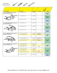
Illuminated Round Pushbuttons (Replacement Parts)<br />
Lead<br />
Holder<br />
*Transformer not needed with full voltage models.<br />
Lamp Circuit Components<br />
<strong>Style</strong> Description Terminals<br />
Lead Holder<br />
Dummy Block with<br />
Full Voltage Adaptor<br />
Full Voltage Adaptor<br />
Transformer Unit<br />
(6V secondary<br />
voltage)<br />
For use with <strong>HW</strong>-CBL on all<br />
illuminated pushbutton units.<br />
One required for each deck<br />
(pair) of contacts.<br />
For use with<br />
odd number of<br />
contacts.<br />
For use with<br />
even number of<br />
contacts.<br />
120VAC<br />
240VAC<br />
480VAC<br />
120V<br />
240V<br />
480V<br />
120V<br />
240V<br />
480V<br />
+<br />
Fingersafe<br />
Exposed<br />
Spring Up<br />
Fingersafe<br />
Exposed<br />
Fingersafe<br />
Spring Up<br />
Exposed<br />
Mounting<br />
Adaptor<br />
Part<br />
Number<br />
<strong>HW</strong>-LH3<br />
<strong>HW</strong>-DA1FB<br />
<strong>HW</strong>-DA1B<br />
<strong>HW</strong>-GA1<br />
TW-DA1FB<br />
TW-DA1B<br />
TW-F126B<br />
TW-F246B<br />
TW-F486B<br />
<strong>HW</strong>-T126<br />
<strong>HW</strong>-T246<br />
<strong>HW</strong>-L486<br />
TW-T126B<br />
TW-T246B<br />
TW-T486B<br />
DC-DC Converter 110VDC <strong>HW</strong>-L16D<br />
Operators<br />
<strong>Style</strong><br />
Round Flush/<br />
Extended<br />
Extended with<br />
Full Shroud<br />
<strong>HW</strong>-GA1 “Dummy Block with full voltage adaptor” does not require the<br />
use of <strong>HW</strong>-LH3.<br />
Plastic<br />
Bezel<br />
Metal<br />
Bezel<br />
Momentary <strong>HW</strong>1L-M0 <strong>HW</strong>4L-M0<br />
Maintained <strong>HW</strong>1L-A0 <strong>HW</strong>4L-A0<br />
Momentary <strong>HW</strong>1L-MF0 <strong>HW</strong>4L-MF0<br />
Maintained <strong>HW</strong>1L-AF0 <strong>HW</strong>4L-AF0<br />
+<br />
Safety<br />
Lever Lock<br />
+ Lamp +<br />
D: LED<br />
Blank: Incandescent<br />
Anti-Rotation<br />
Ring<br />
S: Blue<br />
W: White<br />
Y: Yellow<br />
+ Operator + Lens =<br />
Contact Blocks<br />
<strong>Style</strong> Contacts 1NO 1NC<br />
Standard<br />
Fingersafe (IP20)<br />
Spring-Up<br />
Terminal<br />
Exposed Screw<br />
Terminal<br />
<strong>HW</strong>-F10<br />
<strong>HW</strong>-F10R (early make)<br />
<strong>HW</strong>-G10<br />
<strong>HW</strong>-G10R (early make)<br />
<strong>HW</strong>-C10<br />
<strong>HW</strong>-C10R (early make)<br />
Lamp Voltage<br />
(full voltage units only)<br />
6V: 6V AC/DC<br />
12V: 12V AC/DC<br />
24V: 24V AC/DC<br />
120V: 120VC AC*<br />
240V: 240V AC*<br />
*LED only<br />
Completed<br />
Unit<br />
<strong>HW</strong>-F01<br />
<strong>HW</strong>-F01R (late break)<br />
<strong>HW</strong>-G01<br />
<strong>HW</strong>-G01R (late break)<br />
<strong>HW</strong>-C01<br />
<strong>HW</strong>-C01R (late break)<br />
1. All assembled part numbers in catalog include standard fingersafe (<strong>HW</strong>-F...) contacts.<br />
2. Assembled units with spring-up terminals (<strong>HW</strong>-G...) can be ordered by removing an “F” from<br />
the part number (Ex. <strong>HW</strong>1B-M1F11-R becomes <strong>HW</strong>1B-M111-R).<br />
3. Units with exposed screw terminals (<strong>HW</strong>-C...) must be ordered as sub-components.<br />
Contact Block Mounting Adaptor<br />
<strong>Style</strong><br />
Part Number<br />
<strong>HW</strong>-CBL<br />
1. Used to mount contact blocks to operator<br />
(first pair only).<br />
2. <strong>IDEC</strong> strongly recommends using the safety<br />
lever lock to prevent heavy vibration or<br />
maintenance personnel from inadvertently<br />
unlocking contacts.<br />
Safety Lever Lock<br />
<strong>Style</strong> Part Number<br />
Lenses<br />
<strong>Style</strong><br />
Round Flush<br />
Round Extended<br />
<strong>HW</strong>9Z-LS<br />
Part Number<br />
<strong>HW</strong>1A-L1-k<br />
<strong>HW</strong>1A-L2-k<br />
In place of k, specify the Lens<br />
Color Code from previous page.<br />
Anti-Rotation Ring<br />
Appearance<br />
Part<br />
Number<br />
<strong>HW</strong>9Z-RL<br />
Use with notched panel cutout to prevent<br />
unit rotation.<br />
Lamps<br />
<strong>Style</strong> Voltage Part Number<br />
6V AC/DC LSTD-6k<br />
LED 12V AC/DC LSTD-1k<br />
24V AC/DC LSTD-2k<br />
120V AC LSTD-H2k<br />
240V AC LSTD-M4k<br />
Incandescent<br />
6V AC/DC<br />
12V AC/DC<br />
24V AC/DC<br />
IS-6<br />
IS-12<br />
IS-24<br />
1. In place of k, specify the LED Color Code.<br />
2. The LED contains a current-limiting resistor<br />
and reverse polarity protection diodes.<br />
3. Yellow LED not available, use white LED<br />
when using yellow lens.<br />
<strong>Switches</strong> & <strong>Pilot</strong> <strong>Devices</strong> Signaling Lights Relays & Sockets Timers Contactors Terminal Blocks Circuit Breakers<br />
Phone: 800.894.0412 - Fax: 888.723.4773 - Web: www.clrwtr.com - Email: info@clrwtr.com
ø<strong>22mm</strong> - <strong>HW</strong> <strong>Series</strong><br />
<strong>Switches</strong> & <strong>Pilot</strong> <strong>Devices</strong><br />
<strong>Switches</strong> & <strong>Pilot</strong> <strong>Devices</strong><br />
Illuminated Mushroom & Square Pushbuttons (Assembled)<br />
Signaling Lights<br />
Relays & Sockets<br />
40mm Mushroom Head<br />
Square Flush<br />
Contacts Plastic Bezel Metal Bezel Plastic Bezel<br />
Operator Only † <strong>HW</strong>1L-M4-k <strong>HW</strong>4L-M4-k <strong>HW</strong>2L-M1-k<br />
1NO <strong>HW</strong>1L-M4F10Qm-k-l <strong>HW</strong>4L-M4F10Qm-k-l <strong>HW</strong>2L-M1F10Qm-k-l<br />
Momentary<br />
1NC <strong>HW</strong>1L-M4F01Qm-k-l <strong>HW</strong>4L-M4F01Qm-k-l <strong>HW</strong>2L-M1F01Qm-k-l<br />
Timers<br />
Full Voltage<br />
1NO-1NC <strong>HW</strong>1L-M4F11Qm-k-l <strong>HW</strong>4L-M4F11Qm-k-l <strong>HW</strong>2L-M1F11Qm-k-l<br />
2NO <strong>HW</strong>1L-M4F20Qm-k-l <strong>HW</strong>4L-M4F20Qm-k-l <strong>HW</strong>2L-M1F20Qm-k-l<br />
Operator Only † <strong>HW</strong>1L-A4-k <strong>HW</strong>4L-A4-k <strong>HW</strong>2L-A1-k<br />
1NO <strong>HW</strong>1L-A4F10Qm-k-l <strong>HW</strong>4L-A4F10Qm-k-l <strong>HW</strong>2L-A1F10Qm-k-l<br />
Maintained<br />
1NC <strong>HW</strong>1L-A4F01Qm-k-l <strong>HW</strong>4L-A4F01Qm-k-l <strong>HW</strong>2L-A1F01Qm-k-l<br />
1NO-1NC <strong>HW</strong>1L-A4F11Qm-k-l <strong>HW</strong>4L-A4F11Qm-k-l <strong>HW</strong>2L-A1F11Qm-k-l<br />
2NO <strong>HW</strong>1L-A4F20Qm-k-l <strong>HW</strong>4L-A4F20Qm-k-l <strong>HW</strong>2L-A1F20Qm-k-l<br />
Contactors<br />
Transformer<br />
Momentary<br />
Maintained<br />
1NO-1NC <strong>HW</strong>1L-M4F11lm-k <strong>HW</strong>4L-M4F11lm-k <strong>HW</strong>2L-M1F11lm-k<br />
2NO <strong>HW</strong>1L-M4F20lm-k <strong>HW</strong>4L-M4F20lm-k <strong>HW</strong>2L-M1F20lm-k<br />
1NO-1NC <strong>HW</strong>1L-A4F11lm-k <strong>HW</strong>4L-A4F11lm-k <strong>HW</strong>2L-A1F11lm-k<br />
2NO <strong>HW</strong>1L-A4F20lm-k <strong>HW</strong>4L-A4F20lm-k <strong>HW</strong>2L-A1F20lm-k<br />
Terminal Blocks<br />
Circuit Breakers<br />
1. † Full voltage and transformer units use the same<br />
operator.<br />
2. In place of k, specify the Lens/LED Color Code<br />
from table.<br />
3. In place of lspecify the Voltage Code from<br />
table.<br />
4. In place of m specify Lamp Type Code from<br />
table.<br />
5. Light independent of switch position<br />
6. For nameplates and accessories, see page 596.<br />
and 599.<br />
7. For dimensions, see page 601.<br />
8. For contact assembly part numbers, see page<br />
600.<br />
9. Additional contact configurations available (up to<br />
6 total contacts).<br />
10. Yellow pushbutton comes with white LED.<br />
k Lens/LED Color Code<br />
Color Code<br />
Amber A<br />
Green G<br />
Red R<br />
Blue S<br />
White W<br />
Yellow Y*<br />
1. *40mm mushroom lenses<br />
not available in yellow.<br />
2. Yellow LED not available.<br />
Use white LED for yellow<br />
lens.<br />
l Voltage Code<br />
Full Voltage<br />
Models<br />
Transformer<br />
Models<br />
Voltage Code Voltage Code<br />
6V AC/DC 6V 120V AC H2<br />
12V AC/DC 12V 240V AC M4<br />
24V AC/DC 24V 480V AC T8<br />
120V AC (LED only) 120V<br />
240V AC (LED only) 240V<br />
m Lamp Code<br />
Lamp Code<br />
Incandescent Blank<br />
LED D<br />
Phone: 800.894.0412 - Fax: 888.723.4773 - Web: www.clrwtr.com - Email: info@clrwtr.com
<strong>Switches</strong> & <strong>Pilot</strong> <strong>Devices</strong><br />
ø<strong>22mm</strong> - <strong>HW</strong> <strong>Series</strong><br />
Bezel<br />
1: Round Plastic<br />
2: Square Plastic<br />
4: Round Metal<br />
Transformer* +<br />
Function<br />
M: Momentary<br />
A: Maintained<br />
Contact<br />
Blocks<br />
+<br />
Part Number Structure<br />
H W 1 L – M 1 F 10 Q D – G – 12V<br />
Operator<br />
1: Square Flush<br />
4: Mushroom<br />
Lead<br />
Holder<br />
*Transformer not needed with full voltage models.<br />
Contact Arrangement<br />
10: 1NO Illumination Circuit<br />
01: 1NC Q: Full Voltage<br />
11: 1NO-1NC H2: Transformer 120V AC<br />
20: 2NO M4: Transformer 240V AC<br />
T8: Transformer 480V AC<br />
Lens Color<br />
A: Amber S: Blue<br />
G: Green W: White<br />
R: Red Y: Yellow<br />
Lamp Code<br />
D: LED<br />
Blank: Incandescent<br />
Illuminated Mushroom & Square Pushbuttons (Replacement Parts)<br />
+ Adaptor † +<br />
Lamp Circuit Components<br />
<strong>Style</strong> Description Terminals Part Number<br />
Lead Holder For use with <strong>HW</strong>-CBL on all<br />
illuminated pushbutton units.<br />
<strong>HW</strong>-LH3<br />
One required for each deck<br />
(pair) of contacts.<br />
Dummy Block with<br />
Full Voltage Adaptor<br />
Full Voltage Adaptor<br />
Transformer Unit<br />
(6V secondary<br />
voltage)<br />
For use with<br />
odd number of<br />
contacts.<br />
For use with<br />
even number of<br />
contacts.<br />
120VAC<br />
240VAC<br />
480VAC<br />
120V<br />
240V<br />
480V<br />
120V<br />
240V<br />
480V<br />
Fingersafe<br />
Exposed<br />
Spring Up<br />
Fingersafe<br />
Exposed<br />
Fingersafe<br />
Spring Up<br />
Exposed<br />
<strong>HW</strong>-DA1FB<br />
<strong>HW</strong>-DA1B<br />
<strong>HW</strong>-GA1<br />
TW-DA1FB<br />
TW-DA1B<br />
TW-F126B<br />
TW-F246B<br />
TW-F486B<br />
<strong>HW</strong>-T126<br />
<strong>HW</strong>-T246<br />
<strong>HW</strong>-L486<br />
TW-T126B<br />
TW-T246B<br />
TW-T486B<br />
DC-DC Converter 110VDC <strong>HW</strong>-L16D<br />
Operators<br />
<strong>Style</strong><br />
ø40mm<br />
Mushroom<br />
Square<br />
<strong>HW</strong>-GA1 “Dummy Block with full voltage adaptor” does not<br />
require the use of <strong>HW</strong>-LH3.<br />
Plastic<br />
Bezel<br />
Metal<br />
Bezel<br />
Momentary <strong>HW</strong>1L-M0L <strong>HW</strong>4L-M0L<br />
Maintained <strong>HW</strong>1L-A0L <strong>HW</strong>4L-A0L<br />
Momentary<br />
Maintained<br />
<strong>HW</strong>2L-M0<br />
<strong>HW</strong>2L-A0<br />
–<br />
Safety<br />
Lever Lock<br />
+ Lamp +<br />
Anti-Rotation<br />
Ring<br />
+ Operator + Lens =<br />
Contact Blocks<br />
<strong>Style</strong> Contacts 1NO 1NC<br />
Standard<br />
Fingersafe (IP20)<br />
Spring-Up<br />
Terminal<br />
Exposed Screw<br />
Terminal<br />
<strong>HW</strong>-F10<br />
<strong>HW</strong>-F10R (early make)<br />
<strong>HW</strong>-G10<br />
<strong>HW</strong>-G10R (early make)<br />
<strong>HW</strong>-C10<br />
<strong>HW</strong>-C10R (early make)<br />
Lamp Voltage<br />
(full voltage units only)<br />
6V: 6V AC/DC<br />
12V: 12V AC/DC<br />
24V: 24V AC/DC<br />
120V: 120VC AC*<br />
240V: 240V AC*<br />
*LED only<br />
Completed<br />
Unit<br />
<strong>HW</strong>-F01<br />
<strong>HW</strong>-F01R (late break)<br />
<strong>HW</strong>-G01<br />
<strong>HW</strong>-G01R (late break)<br />
<strong>HW</strong>-C01<br />
<strong>HW</strong>-C01R (late break)<br />
1. All assembled part numbers in catalog include standard fingersafe (<strong>HW</strong>-F...) contacts.<br />
2. Assembled units with spring-up terminals (<strong>HW</strong>-G...) can be ordered by removing an<br />
“F” from the part number (Ex. <strong>HW</strong>1B-M1F11-R becomes <strong>HW</strong>1B-M111-R).<br />
3. Units with exposed screw terminals (<strong>HW</strong>-C...) must be ordered as sub-components.<br />
Contact Block Mounting Adaptor<br />
<strong>Style</strong><br />
Part Number<br />
<strong>HW</strong>-CBL<br />
1. Used to mount contact blocks to<br />
operator (first pair only).<br />
2. <strong>IDEC</strong> strongly recommends using the<br />
safety lever lock to prevent heavy<br />
vibration or maintenance personnel<br />
from inadvertently unlocking contacts.<br />
Safety Lever Lock<br />
<strong>Style</strong> Part Number<br />
Lenses<br />
<strong>Style</strong><br />
ø40mm<br />
Mushroom<br />
Lens<br />
Square<br />
Flush<br />
<strong>HW</strong>9Z-LS<br />
Part Number<br />
ALW4BLU-k*<br />
<strong>HW</strong>2A-L1-k<br />
1. In place of k, specify the Lens Color Code.<br />
2. *Mushroom lens not available in yellow.<br />
Anti-Rotation Ring<br />
Appearance<br />
Part Number<br />
<strong>HW</strong>9Z-RL<br />
Use with notched panel cutout<br />
to prevent unit rotation.<br />
Lamps<br />
<strong>Style</strong> Voltage Part Number<br />
6V AC/DC LSTD-6k<br />
LED 12V AC/DC LSTD-1k<br />
24V AC/DC LSTD-2k<br />
120V AC LSTD-H2k<br />
240V AC LSTD-M4k<br />
Incandescent<br />
6V AC/DC<br />
12V AC/DC<br />
24V AC/DC<br />
IS-6<br />
IS-12<br />
IS-24<br />
1. In place of k, specify the LED Color Code.<br />
2. The LED contains a current-limiting resistor<br />
and reverse polarity protection diodes.<br />
3. Yellow LED not available, use white LED<br />
when using yellow lens.<br />
<strong>Switches</strong> & <strong>Pilot</strong> <strong>Devices</strong> Signaling Lights Relays & Sockets Timers Contactors Terminal Blocks Circuit Breakers<br />
Phone: 800.894.0412 - Fax: 888.723.4773 - Web: www.clrwtr.com - Email: info@clrwtr.com
ø<strong>22mm</strong> - <strong>HW</strong> <strong>Series</strong><br />
<strong>Switches</strong> & <strong>Pilot</strong> <strong>Devices</strong><br />
<strong>Switches</strong> & <strong>Pilot</strong> <strong>Devices</strong><br />
Selector <strong>Switches</strong> 2-Position (Assembled)<br />
Relays & Sockets<br />
Timers<br />
Circuit Breakers<br />
Signaling Lights<br />
2-Position Selector <strong>Switches</strong><br />
Contact<br />
Mounting<br />
Operator Only<br />
Operator<br />
Position<br />
1NO 1 O X<br />
1NO-<br />
1NC<br />
2NO<br />
2NO-<br />
2NC<br />
1<br />
2<br />
1<br />
2<br />
1<br />
2<br />
3<br />
4<br />
L<br />
O<br />
X<br />
O<br />
O<br />
X<br />
O<br />
X<br />
O<br />
R<br />
X<br />
O<br />
X<br />
X<br />
O<br />
X<br />
O<br />
X<br />
Handle<br />
Knob<br />
Lever<br />
Knob<br />
Lever<br />
Knob<br />
Lever<br />
Knob<br />
Lever<br />
Knob<br />
Lever<br />
Maintained<br />
Spring Return<br />
from Right<br />
L R L R<br />
<strong>HW</strong>nS-2T<br />
<strong>HW</strong>nS-2L<br />
<strong>HW</strong>nS-2TF10<br />
<strong>HW</strong>nS-2LF10<br />
<strong>HW</strong>nS-2TF11<br />
<strong>HW</strong>nS-2LF11<br />
<strong>HW</strong>nS-2TF20<br />
<strong>HW</strong>nS-2LF20<br />
<strong>HW</strong>nS-2TF22<br />
<strong>HW</strong>nS-2LF22<br />
<strong>HW</strong>nS-21T<br />
<strong>HW</strong>nS-21L<br />
<strong>HW</strong>nS-21TF10<br />
<strong>HW</strong>nS-21LF10<br />
<strong>HW</strong>nS-21TF11<br />
<strong>HW</strong>nS-21LF11<br />
<strong>HW</strong>nS-21TF20<br />
<strong>HW</strong>nS-21LF20<br />
<strong>HW</strong>nS-21TF22<br />
<strong>HW</strong>nS-21LF22<br />
Contactors<br />
Terminal Blocks<br />
1. In place of n enter 1 for plastic bezel or 4 for metal bezel.<br />
2. For nameplates, see page 596.<br />
3. All assembled part numbers in catalog include standard fingersafe<br />
(<strong>HW</strong>-F...) contacts.<br />
4. Assembled units with spring-up terminals (<strong>HW</strong>-G...) can be<br />
ordered by removing an “F” from the part number (Ex. <strong>HW</strong>1B-<br />
M1F11-R becomes <strong>HW</strong>1B-M111-R).<br />
5. Units with exposed screw terminals (<strong>HW</strong>-C...) must be ordered as<br />
sub-components.<br />
6. Standard color for knob and lever is black.<br />
7. Optional colors available for lever type. Must order in components.<br />
See next page for part numbers.<br />
8. Additional contact configurations available (up to 6 total contacts).<br />
9. For Truth Tables see page 608.<br />
n Bezel Type<br />
Type Code<br />
Plastic 1<br />
Metal 4<br />
Phone: 800.894.0412 - Fax: 888.723.4773 - Web: www.clrwtr.com - Email: info@clrwtr.com
<strong>Switches</strong> & <strong>Pilot</strong> <strong>Devices</strong><br />
ø<strong>22mm</strong> - <strong>HW</strong> <strong>Series</strong><br />
Part Number Structure<br />
H W 1 S - 2 1 T F 10<br />
Bezel<br />
1: Plastic # of Positions<br />
4: Metal 2: 2-Position Operator<br />
Handle<br />
blank: Maintained<br />
T: Knob<br />
1: Spring Return<br />
L: Lever<br />
from Right<br />
Contact Arrangement<br />
10: 1NO<br />
11: 1NO-1NC<br />
20: 2NO<br />
Selector <strong>Switches</strong> 2-Position (Replacement Parts)<br />
Anti-Rotation<br />
Contact Blocks + Mounting Adaptor + Safety Lever Lock +<br />
+ Operator = Completed Unit<br />
Ring<br />
Contact Blocks<br />
<strong>Style</strong> Contacts 1NO 1NC<br />
Standard<br />
Fingersafe<br />
(IP20)<br />
Spring-Up<br />
Terminal<br />
Exposed<br />
Screw<br />
Terminal<br />
Dummy<br />
Block<br />
<strong>HW</strong>-F10<br />
<strong>HW</strong>-F10R<br />
(early make)<br />
<strong>HW</strong>-G10<br />
<strong>HW</strong>-G10R<br />
(early make)<br />
<strong>HW</strong>-C10<br />
<strong>HW</strong>-C10R<br />
(early make)<br />
Contact Block Mounting Adaptor<br />
<strong>Style</strong><br />
Part Number<br />
<strong>HW</strong>-CB2C<br />
TW-DB<br />
<strong>HW</strong>-F01<br />
<strong>HW</strong>-F01R<br />
(late break)<br />
<strong>HW</strong>-G01<br />
<strong>HW</strong>-G01R<br />
(late break)<br />
<strong>HW</strong>-C01<br />
<strong>HW</strong>-C01R<br />
(late break)<br />
1. Used to mount contact blocks to operator (first pair only).<br />
2. <strong>IDEC</strong> strongly recommends using the safety lever lock to<br />
prevent heavy vibration or maintenance personnel from<br />
inadvertently unlocking contacts.<br />
Safety Lever Lock<br />
<strong>Style</strong> Part Number<br />
<strong>HW</strong>9Z-LS<br />
Anti-Rotation Ring<br />
<strong>Style</strong><br />
Part Number<br />
<strong>HW</strong>9Z-RL<br />
Use with notched panel cutout to prevent<br />
unit rotation.<br />
Operators<br />
<strong>Style</strong> Description Handle Plastic Bezel Metal Bezel<br />
Maintained<br />
Spring Return<br />
from Right<br />
Knob <strong>HW</strong>1S-2T <strong>HW</strong>4S-2T<br />
Lever <strong>HW</strong>1S-2 <strong>HW</strong>4S-2<br />
Knob <strong>HW</strong>1S-21T <strong>HW</strong>4S-21T<br />
Lever <strong>HW</strong>1S-21 <strong>HW</strong>4S-21<br />
1. Knob operator comes with black handle.<br />
2. To order lever type, lever and inserts must be ordered separately, along with lever<br />
operator. See part numbers below.<br />
Levers & Inserts<br />
<strong>Style</strong><br />
Lever<br />
Lever<br />
Color<br />
Insert<br />
Part Number<br />
ASWHHL-j<br />
TW-HC1-j<br />
Standard lever color is black. Standard<br />
insert color is white.<br />
j Handle/Insert<br />
Color Code<br />
Color Code<br />
Black* B<br />
Blue S<br />
Green G<br />
Red R<br />
Yellow Y<br />
White † W<br />
1. * Lever color inserts not available in black.<br />
2. † Lever not available in white.<br />
<strong>Switches</strong> & <strong>Pilot</strong> <strong>Devices</strong> Signaling Lights Relays & Sockets Timers Contactors Terminal Blocks Circuit Breakers<br />
Phone: 800.894.0412 - Fax: 888.723.4773 - Web: www.clrwtr.com - Email: info@clrwtr.com
ø<strong>22mm</strong> - <strong>HW</strong> <strong>Series</strong><br />
<strong>Switches</strong> & <strong>Pilot</strong> <strong>Devices</strong><br />
<strong>Switches</strong> & <strong>Pilot</strong> <strong>Devices</strong><br />
Selector <strong>Switches</strong> 3-Position (Assembled)<br />
Signaling Lights<br />
3–Position Selector <strong>Switches</strong><br />
Contact<br />
Mounting<br />
Operator Position Handle Maintained<br />
L C R<br />
C<br />
L R<br />
Spring Return<br />
from Right<br />
L<br />
C<br />
R<br />
Spring Return<br />
from Left<br />
L<br />
C<br />
R<br />
Spring Return<br />
Two-Way<br />
L<br />
C<br />
R<br />
Circuit Breakers<br />
Terminal Blocks<br />
Contactors<br />
Timers<br />
Relays & Sockets<br />
Operator Only<br />
1NO-<br />
1NC<br />
2NO<br />
2NC<br />
2NO-<br />
1NC<br />
2NO-<br />
2NC<br />
2NO-<br />
2NC<br />
4NO<br />
4NO<br />
4NC<br />
1<br />
2<br />
1<br />
2<br />
1<br />
2<br />
1<br />
2<br />
3<br />
1<br />
2<br />
3<br />
4<br />
1<br />
2<br />
3<br />
4<br />
1<br />
2<br />
3<br />
4<br />
1<br />
2<br />
3<br />
4<br />
1<br />
2<br />
3<br />
4<br />
0<br />
0<br />
X<br />
0<br />
0<br />
X<br />
X<br />
0<br />
0<br />
X<br />
0<br />
0<br />
X<br />
0<br />
X<br />
X<br />
0<br />
X<br />
0<br />
X<br />
0<br />
X<br />
0<br />
X<br />
0<br />
0<br />
X<br />
0<br />
X<br />
X<br />
0<br />
0<br />
0<br />
X<br />
X<br />
0<br />
0<br />
X<br />
0<br />
0<br />
X<br />
X<br />
0<br />
0<br />
X<br />
0<br />
0<br />
0<br />
0<br />
0<br />
0<br />
X<br />
0<br />
0<br />
X<br />
X<br />
X<br />
X<br />
X<br />
X<br />
0<br />
X<br />
X<br />
0<br />
0<br />
X<br />
0<br />
0<br />
X<br />
X<br />
0<br />
X<br />
0<br />
0<br />
X<br />
0<br />
X<br />
0<br />
X<br />
0<br />
X<br />
0<br />
X<br />
X<br />
0<br />
X<br />
0<br />
Knob<br />
Lever<br />
Knob<br />
Lever<br />
Knob<br />
Lever<br />
Knob<br />
Lever<br />
<strong>HW</strong>nS-3T*<br />
<strong>HW</strong>nS-3L<br />
<strong>HW</strong>nS-3TF11<br />
<strong>HW</strong>nS-3LF11<br />
<strong>HW</strong>nS-3TF20<br />
<strong>HW</strong>nS-3LF20<br />
<strong>HW</strong>nS-3TF02<br />
<strong>HW</strong>nS-3LF02<br />
1. In place of n enter 1 for plastic bezel or 4 for metal bezel.<br />
2. Knob operator includes black knob/lever operator includes black lever.<br />
3. * Three position operator is available with three different cams.<br />
<strong>HW</strong>nS-3T: Maintained (standard cam)<br />
<strong>HW</strong>nS-3ST: Maintained (S cam)<br />
<strong>HW</strong>nS-3JT: Maintained (J cam)<br />
4. Operator cams are color coded (white=standard cam, red=S cam, black =J cam).<br />
5. For nameplates, see page 596.<br />
6. For contact assembly part numbers, see page 600<br />
<strong>HW</strong>nS-31T<br />
<strong>HW</strong>nS-31L<br />
<strong>HW</strong>nS-31TF11<br />
<strong>HW</strong>nS-31LF11<br />
<strong>HW</strong>nS-31TF20<br />
<strong>HW</strong>nS-31LF20<br />
<strong>HW</strong>nS-31TF02<br />
<strong>HW</strong>nS-31LF02<br />
<strong>HW</strong>nS-32T<br />
<strong>HW</strong>nS-32L<br />
<strong>HW</strong>nS-32TF11<br />
<strong>HW</strong>nS-32LF11<br />
<strong>HW</strong>nS-32TF20<br />
<strong>HW</strong>nS-32LF20<br />
<strong>HW</strong>nS-32TF02<br />
<strong>HW</strong>nS-32LF02<br />
Knob <strong>HW</strong>nS-3JTF21N1 – – –<br />
<strong>HW</strong>nS-33T<br />
<strong>HW</strong>nS-33L<br />
<strong>HW</strong>nS-33TF11<br />
<strong>HW</strong>nS-33LF11<br />
<strong>HW</strong>nS-33TF20<br />
<strong>HW</strong>nS-33LF20<br />
<strong>HW</strong>nS-33TF02<br />
<strong>HW</strong>nS-33LF02<br />
Knob <strong>HW</strong>nS-3TF22 <strong>HW</strong>nS-31TF22 <strong>HW</strong>nS-32TF22 <strong>HW</strong>nS-33TF22<br />
Knob <strong>HW</strong>nS-3STF22N9 – – –<br />
Knob <strong>HW</strong>nS-3TF40 <strong>HW</strong>nS-31TF40 <strong>HW</strong>nS-32TF40 <strong>HW</strong>nS-33TF40<br />
Knob <strong>HW</strong>nS-3STF40N2 – – –<br />
Knob <strong>HW</strong>nS-3TF04 <strong>HW</strong>nS-31TF04 <strong>HW</strong>nS-32TF04 <strong>HW</strong>nS-33TF04<br />
n Bezel Type<br />
Type Code<br />
Plastic 1<br />
Metal 4<br />
7. All assembled part numbers in catalog include standard fingersafe (<strong>HW</strong>-F...) contacts.<br />
8. Assembled units with spring-up terminals (<strong>HW</strong>-G...) can be ordered by removing an “F”<br />
from the part number (Ex. <strong>HW</strong>1B-M1F11-R becomes <strong>HW</strong>1B-M111-R).<br />
9 . Units with exposed screw terminals (<strong>HW</strong>-C...) must be ordered as sub-components.<br />
10. Standard color for knob and lever is black.<br />
11. Optional colors available for lever type. Must order in components. See next page for<br />
part numbers.<br />
12. Additional contact configurations available (up to 6 total contacts).<br />
13. For Truth Tables see page 608.<br />
Phone: 800.894.0412 - Fax: 888.723.4773 - Web: www.clrwtr.com - Email: info@clrwtr.com
<strong>Switches</strong> & <strong>Pilot</strong> <strong>Devices</strong><br />
ø<strong>22mm</strong> - <strong>HW</strong> <strong>Series</strong><br />
Part Number Structure<br />
H W 1 S - 3 1 T F 20<br />
Bezel<br />
1: Plastic # of Positions<br />
4: Metal 3: 3-Position Operator<br />
Handle<br />
blank: Maintained<br />
T: Knob<br />
1: Spring Return from Right<br />
L: Lever<br />
2: Spring Return from Left<br />
3: Spring Return Two Way<br />
Contact Arrangement<br />
11: 1NO-1NC<br />
20: 2NO<br />
21: 2NO-1NC<br />
22: 2NO-2NC<br />
40: 4NO<br />
04: 4NC<br />
Selector <strong>Switches</strong> 3-Position (Replacement Parts)<br />
Anti-Rotation<br />
Contact Blocks + Mounting Adaptor + Safety Lever Lock +<br />
+ Operator = Completed Unit<br />
Ring<br />
Contact Blocks<br />
<strong>Style</strong> Contacts 1NO 1NC<br />
Standard <strong>HW</strong>-F10 <strong>HW</strong>-F01<br />
Fingersafe <strong>HW</strong>-F10R <strong>HW</strong>-F01R<br />
(IP20) (early make) (late break)<br />
Spring-Up<br />
Terminal<br />
Exposed<br />
Screw<br />
Terminal<br />
Dummy<br />
Block<br />
<strong>HW</strong>-G10<br />
<strong>HW</strong>-G10R<br />
(early make)<br />
<strong>HW</strong>-C10<br />
<strong>HW</strong>-C10R<br />
(early make)<br />
Contact Block Mounting Adaptor<br />
<strong>Style</strong><br />
Part Number<br />
<strong>HW</strong>-CB2C<br />
TW-DB<br />
<strong>HW</strong>-G01<br />
<strong>HW</strong>-G01R<br />
(late break)<br />
<strong>HW</strong>-C01<br />
<strong>HW</strong>-C01R<br />
(late break)<br />
1. Used to mount contact blocks to operator (first pair only).<br />
2. <strong>IDEC</strong> strongly recommends using the safety lever lock to<br />
prevent heavy vibration or maintenance personnel from inadvertently<br />
unlocking contacts.<br />
Safety Lever Lock<br />
<strong>Style</strong> Part Number<br />
<strong>HW</strong>9Z-LS<br />
Anti-Rotation Ring<br />
<strong>Style</strong><br />
Part Number<br />
<strong>HW</strong>9Z-RL<br />
Use with notched panel cutout to<br />
prevent unit rotation.<br />
Operators<br />
<strong>Style</strong> Description Handle Plastic Bezel Metal Bezel<br />
Maintained Knob <strong>HW</strong>1S-3T <strong>HW</strong>4S-3T<br />
(standard cam) Lever <strong>HW</strong>1S-3 <strong>HW</strong>4S-3<br />
Maintained (S cam) Knob <strong>HW</strong>1S-3ST <strong>HW</strong>4S-3ST<br />
Maintained (J cam) Knob <strong>HW</strong>1S-3JT <strong>HW</strong>4S-3JT<br />
Spring Return from Knob <strong>HW</strong>1S-31T <strong>HW</strong>4S-31T<br />
Right (standard cam) Lever <strong>HW</strong>1S-31 <strong>HW</strong>4S-31<br />
Spring Return from Knob <strong>HW</strong>1S-32T <strong>HW</strong>4S-32T<br />
Left (standard cam) Lever <strong>HW</strong>1S-32 <strong>HW</strong>4S-32<br />
2-Way Spring Return Knob <strong>HW</strong>1S-33T <strong>HW</strong>4S-33T<br />
(standard cam) Lever <strong>HW</strong>1S-33 <strong>HW</strong>4S-33<br />
1. Knob operator comes with black handle.<br />
2. Three position knob operator is available with three different cams.<br />
3. Operator cams are color coded (white=standard cam, red=S cam, black =J cam).<br />
4. To order lever type, lever and inserts must be ordered separately, along with lever operator.<br />
See part numbers below.<br />
Levers & Inserts<br />
<strong>Style</strong><br />
Lever<br />
Lever<br />
Color<br />
Insert<br />
Part Number<br />
ASWHHL-j<br />
TW-HC1-j<br />
Standard lever color is black. Standard<br />
insert color is white.<br />
j Handle/Insert Color Code<br />
Color Code Color Code<br />
Black* B Red R<br />
Blue S Yellow Y<br />
Green G White † W<br />
1. * Lever color inserts not<br />
available in black.<br />
2. † Lever not available in white.<br />
<strong>Switches</strong> & <strong>Pilot</strong> <strong>Devices</strong> Signaling Lights Relays & Sockets Timers Contactors Terminal Blocks Circuit Breakers<br />
Phone: 800.894.0412 - Fax: 888.723.4773 - Web: www.clrwtr.com - Email: info@clrwtr.com
ø<strong>22mm</strong> - <strong>HW</strong> <strong>Series</strong><br />
<strong>Switches</strong> & <strong>Pilot</strong> <strong>Devices</strong><br />
<strong>Switches</strong> & <strong>Pilot</strong> <strong>Devices</strong><br />
Selector <strong>Switches</strong> 4- & 5-Position (Assembled)<br />
Signaling Lights<br />
Relays & Sockets<br />
Timers<br />
4-Position Selector <strong>Switches</strong><br />
Contact<br />
Contactors<br />
Terminal Blocks<br />
Circuit Breakers<br />
Mounting<br />
Operator Only<br />
1NO-<br />
2NC<br />
1NO-<br />
3NC<br />
2NO-<br />
2NC<br />
1<br />
2<br />
3<br />
4<br />
1<br />
2<br />
3<br />
4<br />
1<br />
2<br />
3<br />
4<br />
Operator Position Handle Maintained<br />
1 2 3 4 1<br />
X<br />
0<br />
0<br />
0<br />
O<br />
O<br />
O<br />
O<br />
X<br />
O<br />
O<br />
O<br />
0<br />
X<br />
0<br />
0<br />
X<br />
X<br />
O<br />
O<br />
O<br />
X<br />
O<br />
O<br />
O<br />
0<br />
X<br />
0<br />
X<br />
O<br />
X<br />
O<br />
O<br />
O<br />
X<br />
O<br />
O<br />
0<br />
0<br />
0<br />
X<br />
O<br />
O<br />
X<br />
O<br />
O<br />
O<br />
X<br />
Knob<br />
Lever<br />
Knob<br />
Lever<br />
Knob<br />
Lever<br />
Knob<br />
Lever<br />
2<br />
<strong>HW</strong>nS-4T<br />
<strong>HW</strong>nS-4L<br />
3<br />
<strong>HW</strong>nS-4TF12<br />
<strong>HW</strong>nS-4LF12<br />
4<br />
<strong>HW</strong>nS-4TF13N6<br />
<strong>HW</strong>nS-4LF13N6<br />
<strong>HW</strong>nS-4TF22N3<br />
<strong>HW</strong>nS-4LF22N3<br />
5-Position Selector Switch<br />
Operator Position Handle Maintained<br />
Contact<br />
Mounting<br />
Operator Only<br />
2NO-<br />
2NC<br />
1<br />
2<br />
3<br />
4<br />
1 2 3 4 5<br />
X<br />
O<br />
O<br />
O<br />
O<br />
X<br />
O<br />
O<br />
O<br />
O<br />
O<br />
O<br />
O<br />
O<br />
X<br />
O<br />
O<br />
O<br />
O<br />
X<br />
Knob<br />
Lever<br />
Knob<br />
Lever<br />
1<br />
2<br />
3<br />
<strong>HW</strong>nS-5T<br />
<strong>HW</strong>nS-5L<br />
4<br />
5<br />
<strong>HW</strong>nS-5TF22N3<br />
<strong>HW</strong>nS-5LF22N3<br />
1. In place of n enter 1 for plastic bezel or 4 for metal bezel.<br />
2. Knob operator includes black knob/lever operator includes black lever.<br />
3. For nameplates, see page 596.<br />
4. For contact assembly part numbers, see page 600.<br />
5. Five position circuit cannot be made to make five independent contact closures.<br />
6. All assembled part numbers in catalog include standard fingersafe (<strong>HW</strong>-F...) contacts.<br />
7. Assembled units with spring-up terminals (<strong>HW</strong>-G...) can be ordered by removing an “F”<br />
from the part number (Ex. <strong>HW</strong>1B-M1F11-R becomes <strong>HW</strong>1B-M111-R).<br />
8. Units with exposed screw terminals (<strong>HW</strong>-C...) must be ordered as sub-components.<br />
9. Standard color for knob and lever is black.<br />
10. Optional colors available for lever type. Must order in components. See next page for<br />
part numbers.<br />
11. Additional contact configurations available (up to 6 total contacts).<br />
12. For Truth Tables see page 608.<br />
n Bezel Type<br />
Type Code<br />
Plastic 1<br />
Metal 4<br />
Phone: 800.894.0412 - Fax: 888.723.4773 - Web: www.clrwtr.com - Email: info@clrwtr.com
<strong>Switches</strong> & <strong>Pilot</strong> <strong>Devices</strong><br />
ø<strong>22mm</strong> - <strong>HW</strong> <strong>Series</strong><br />
Bezel<br />
1: Plastic<br />
4: Metal<br />
# of Positions<br />
4: 4-Position<br />
5: 5-Position<br />
Part Number Structure<br />
H W 1 S - 4 T F 13N6<br />
Handle<br />
T: Knob<br />
L: Lever<br />
Contact Arrangement<br />
(based on desired truth table)<br />
12: 1NO-2NC<br />
13N6: 1NO-3NC<br />
22N3: 2NO-2NC<br />
Selector <strong>Switches</strong> 4- & 5-Position (Replacement Parts)<br />
Anti-Rotation<br />
Contact Blocks + Mounting Adaptor + Safety Lever Lock +<br />
+ Operator = Completed Unit<br />
Ring<br />
Contact Blocks<br />
<strong>Style</strong> Contacts 1NO 1NC<br />
Standard<br />
Fingersafe<br />
(IP20)<br />
Spring-Up<br />
Terminal<br />
Exposed<br />
Screw<br />
Terminal<br />
Dummy<br />
Block<br />
<strong>HW</strong>-F10<br />
<strong>HW</strong>-F10R<br />
(early make)<br />
<strong>HW</strong>-G10<br />
<strong>HW</strong>-G10R<br />
(early make)<br />
<strong>HW</strong>-C10<br />
<strong>HW</strong>-C10R<br />
(early make)<br />
Contact Block Mounting Adaptor<br />
<strong>Style</strong><br />
Part Number<br />
<strong>HW</strong>-CB2C<br />
TW-DB<br />
<strong>HW</strong>-F01<br />
<strong>HW</strong>-F01R<br />
(late break)<br />
<strong>HW</strong>-G01<br />
<strong>HW</strong>-G01R<br />
(late break)<br />
<strong>HW</strong>-C01<br />
<strong>HW</strong>-C01R<br />
(late break)<br />
1. Used to mount contact blocks to operator (first pair only).<br />
2. <strong>IDEC</strong> strongly recommends using the safety lever lock to<br />
prevent heavy vibration or maintenance personnel from<br />
inadvertently unlocking contacts.<br />
Safety Lever Lock<br />
<strong>Style</strong> Part Number<br />
<strong>HW</strong>9Z-LS<br />
Anti-Rotation Ring<br />
<strong>Style</strong><br />
Part Number<br />
<strong>HW</strong>9Z-RL<br />
Use with notched panel cutout to prevent<br />
unit rotation.<br />
Operators<br />
<strong>Style</strong> Position Description Handle Plastic Bezel Metal Bezel<br />
4 Maintained<br />
5 Maintained<br />
Knob <strong>HW</strong>1S-4T <strong>HW</strong>4S-4T<br />
Lever <strong>HW</strong>1S-4 <strong>HW</strong>4S-4<br />
Knob <strong>HW</strong>1S-5T <strong>HW</strong>4S-5T<br />
Lever <strong>HW</strong>1S-5 <strong>HW</strong>4S-5<br />
1. Knob operator comes with black handle.<br />
2. To order lever type, lever and inserts must be ordered separately, along with lever operator. See<br />
part numbers below.<br />
Levers & Inserts<br />
<strong>Style</strong><br />
Lever<br />
Lever<br />
Color<br />
Insert<br />
Part Number<br />
ASWHHL-j<br />
TW-HC1-j<br />
Standard lever color is black. Standard<br />
insert color is white.<br />
j Handle/Insert<br />
Color Code<br />
Color Code<br />
Black* B<br />
Blue S<br />
Green G<br />
Red R<br />
Yellow Y<br />
White † W<br />
1. * Lever color inserts not<br />
available in black.<br />
2. † Lever not available in white.<br />
<strong>Switches</strong> & <strong>Pilot</strong> <strong>Devices</strong> Signaling Lights Relays & Sockets Timers Contactors Terminal Blocks Circuit Breakers<br />
Phone: 800.894.0412 - Fax: 888.723.4773 - Web: www.clrwtr.com - Email: info@clrwtr.com
ø<strong>22mm</strong> - <strong>HW</strong> <strong>Series</strong><br />
<strong>Switches</strong> & <strong>Pilot</strong> <strong>Devices</strong><br />
<strong>Switches</strong> & <strong>Pilot</strong> <strong>Devices</strong><br />
Key <strong>Switches</strong> 2-Position (Assembled)<br />
Signaling Lights<br />
2-Position Key <strong>Switches</strong><br />
Contact<br />
Mounting<br />
Operator<br />
Position<br />
L<br />
R<br />
Maintained<br />
Spring Return<br />
from Right<br />
L R L R<br />
Relays & Sockets<br />
Operator Only <strong>HW</strong>nK-2A <strong>HW</strong>nK-21B<br />
1NO 1 O X <strong>HW</strong>nK-2AF10 <strong>HW</strong>nK-21BF10<br />
1NO-<br />
1NC<br />
2NO<br />
2NO-<br />
2NC<br />
1<br />
2<br />
1<br />
2<br />
1<br />
2<br />
3<br />
4<br />
0<br />
X<br />
O<br />
O<br />
0<br />
X<br />
0<br />
X<br />
X<br />
0<br />
X<br />
X<br />
X<br />
0<br />
X<br />
0<br />
<strong>HW</strong>nK-2AF11<br />
<strong>HW</strong>nK-2AF20<br />
<strong>HW</strong>nK-2AF22<br />
<strong>HW</strong>nK-21BF11<br />
<strong>HW</strong>nK-21BF20<br />
<strong>HW</strong>nK-21BF22<br />
Timers<br />
Contactors<br />
Terminal Blocks<br />
1. In place of n enter 1 for plastic bezel or 4 for metal bezel.<br />
2. Key is removable in all maintained positions. Other key removable options available.<br />
3. Two keys are supplied with all switches.<br />
4. All standard operators are keyed alike.<br />
5. Other key removable options available. See table below<br />
6. For nameplates, see page 596.<br />
7. For contact assembly part numbers, see page 600.<br />
8. Key is retained in “Spring Return” position.<br />
9. All assembled part numbers in catalog include standard fingersafe (<strong>HW</strong>-F...) contacts.<br />
10. Assembled units with spring-up terminals (<strong>HW</strong>-G...) can be ordered by removing an “F” from the part<br />
number (Ex. <strong>HW</strong>1B-M1F11-R becomes <strong>HW</strong>1B-M111-R).<br />
11. Units with exposed screw terminals (<strong>HW</strong>-C...) must be ordered as sub-components.<br />
12. Additional contact configurations available (up to 6 total contacts).<br />
13. For Truth Tables see page 600.<br />
Key Removable Option Codes<br />
Code Description<br />
A Key not retained in any position (removable in all positions)<br />
B Key retained in right position only<br />
C Key retained in left position only<br />
n Bezel Type<br />
Type Code<br />
Plastic 1<br />
Metal 4<br />
Circuit Breakers<br />
Phone: 800.894.0412 - Fax: 888.723.4773 - Web: www.clrwtr.com - Email: info@clrwtr.com
<strong>Switches</strong> & <strong>Pilot</strong> <strong>Devices</strong><br />
ø<strong>22mm</strong> - <strong>HW</strong> <strong>Series</strong><br />
Bezel<br />
1: Plastic<br />
4: Metal<br />
# of Positions<br />
2: 2-Position<br />
Part Number Structure<br />
H W 1 K - 2 1 B F 10<br />
Operator<br />
blank: Maintained<br />
1: Spring Return from Right<br />
Contact Arrangement<br />
10: 1NO 20: 2NO<br />
11: 1NO-1NC 22: 2NO-2NC<br />
Key Retained Position<br />
A: Key not retained in any position (removable in all positions)<br />
B: Key retained in right position only<br />
C: Key retained in left position only<br />
Key <strong>Switches</strong> 2-Position (Replacement Parts)<br />
Anti-Rotation<br />
Contact Assembly + Mounting Adaptor + Safety Lever Lock +<br />
+ Operator = Completed Unit<br />
Ring<br />
Contact Blocks<br />
<strong>Style</strong> Contacts 1NO 1NC<br />
Standard<br />
Fingersafe<br />
(IP20)<br />
Spring-Up<br />
Terminal<br />
Exposed<br />
Screw<br />
Terminal<br />
Dummy<br />
Block<br />
<strong>HW</strong>-F10<br />
<strong>HW</strong>-F10R<br />
(early make)<br />
<strong>HW</strong>-G10<br />
<strong>HW</strong>-G10R<br />
(early make)<br />
<strong>HW</strong>-C10<br />
<strong>HW</strong>-C10R<br />
(early make)<br />
Contact Block Mounting Adaptor<br />
<strong>Style</strong><br />
Part Number<br />
<strong>HW</strong>-CB2C<br />
1. Used to mount contact blocks to operator<br />
(first pair only).<br />
2. <strong>IDEC</strong> strongly recommends using the<br />
safety lever lock to prevent heavy<br />
vibration or maintenance personnel from<br />
inadvertently unlocking contacts.<br />
TW-DB<br />
<strong>HW</strong>-F01<br />
<strong>HW</strong>-F01R<br />
(late break)<br />
<strong>HW</strong>-G01<br />
<strong>HW</strong>-G01R<br />
(late break)<br />
<strong>HW</strong>-C01<br />
<strong>HW</strong>-C01R<br />
(late break)<br />
Safety Lever Lock<br />
<strong>Style</strong> Part Number<br />
<strong>HW</strong>9Z-LS<br />
Anti-Rotation Ring<br />
<strong>Style</strong><br />
Part Number<br />
<strong>HW</strong>9Z-RL<br />
Use with notched panel cutout to prevent unit rotation.<br />
Operators<br />
<strong>Style</strong> Description Plastic Bezel Metal Bezel<br />
Maintained <strong>HW</strong>1K-2A <strong>HW</strong>4K-2A<br />
Maintained, key removed<br />
left only<br />
<strong>HW</strong>1K-2B<br />
<strong>HW</strong>4K-2B<br />
Spring Return from Right <strong>HW</strong>1K-21B <strong>HW</strong>4K-21B<br />
Maintained, key removed<br />
right only<br />
1. Operator includes two keys.<br />
2. All standard operators are keyed alike.<br />
<strong>HW</strong>1K-2C<br />
<strong>HW</strong>4K-2C<br />
<strong>Switches</strong> & <strong>Pilot</strong> <strong>Devices</strong> Signaling Lights Relays & Sockets Timers Contactors Terminal Blocks Circuit Breakers<br />
Phone: 800.894.0412 - Fax: 888.723.4773 - Web: www.clrwtr.com - Email: info@clrwtr.com
ø<strong>22mm</strong> - <strong>HW</strong> <strong>Series</strong><br />
<strong>Switches</strong> & <strong>Pilot</strong> <strong>Devices</strong><br />
<strong>Switches</strong> & <strong>Pilot</strong> <strong>Devices</strong><br />
Key <strong>Switches</strong> 3-Position (Assembled)<br />
Circuit Breakers<br />
Terminal Blocks<br />
Contactors<br />
Timers<br />
Relays & Sockets<br />
Signaling Lights<br />
3-Position Key <strong>Switches</strong><br />
Contact<br />
Mounting<br />
Operator Position<br />
L C R<br />
Maintained<br />
L<br />
C<br />
R<br />
Spring Return<br />
from Right<br />
L<br />
C<br />
R<br />
Spring Return<br />
from Left<br />
L<br />
C<br />
R<br />
Spring Return Two<br />
Way<br />
Operator Only <strong>HW</strong>nK-3A* <strong>HW</strong>nK-31B <strong>HW</strong>nK-32C <strong>HW</strong>nK-33D<br />
1NO-<br />
1NC<br />
2NO<br />
2NC<br />
2NO-<br />
1NC<br />
2NO-<br />
2NC<br />
2NO-<br />
2NC<br />
4NO<br />
4NO<br />
4NC<br />
1<br />
2<br />
1<br />
2<br />
1<br />
2<br />
1<br />
2<br />
3<br />
1<br />
2<br />
3<br />
4<br />
1<br />
2<br />
3<br />
4<br />
1<br />
2<br />
3<br />
4<br />
1<br />
2<br />
3<br />
4<br />
1<br />
2<br />
3<br />
4<br />
0<br />
0<br />
X<br />
0<br />
0<br />
X<br />
X<br />
0<br />
0<br />
X<br />
0<br />
0<br />
X<br />
0<br />
X<br />
X<br />
0<br />
X<br />
0<br />
X<br />
0<br />
X<br />
0<br />
X<br />
0<br />
0<br />
X<br />
0<br />
X<br />
X<br />
0<br />
0<br />
0<br />
X<br />
X<br />
0<br />
0<br />
X<br />
0<br />
0<br />
X<br />
X<br />
0<br />
0<br />
X<br />
0<br />
0<br />
0<br />
0<br />
0<br />
0<br />
X<br />
0<br />
0<br />
X<br />
X<br />
X<br />
X<br />
X<br />
X<br />
0<br />
X<br />
X<br />
0<br />
0<br />
X<br />
0<br />
0<br />
X<br />
X<br />
0<br />
X<br />
0<br />
0<br />
X<br />
0<br />
X<br />
0<br />
X<br />
0<br />
X<br />
0<br />
X<br />
X<br />
0<br />
X<br />
0<br />
1. In place of n enter 1 for plastic bezel or 4 for metal<br />
bezel.<br />
2. Key is removable in all maintained positions. Other<br />
key removable options available.<br />
3. Two keys are supplied with all switches.<br />
4. All standard operators are keyed alike.<br />
5. Other key removable options available. See table to<br />
the right.<br />
6. * Operator is available with three different cams.<br />
<strong>HW</strong>nK-3A: Maintained (standard cam)<br />
<strong>HW</strong>nK-3SA: Maintained (Cam S)<br />
<strong>HW</strong>nK-3JA: Maintained (Cam J)<br />
7. For nameplates, see page 596.<br />
<strong>HW</strong>nK-3AF11 <strong>HW</strong>nK-31BF11 <strong>HW</strong>nK-32CF11 <strong>HW</strong>nK-33DF11<br />
<strong>HW</strong>nK-3AF20 <strong>HW</strong>nK-31BF20 <strong>HW</strong>nK-32CF20 <strong>HW</strong>nK-33DF20<br />
<strong>HW</strong>nK-3AF02 <strong>HW</strong>nK-31BF02 <strong>HW</strong>nK-32CF02 <strong>HW</strong>nK-33DF02<br />
<strong>HW</strong>nK-3JAF21N1 – – –<br />
<strong>HW</strong>nK-3AF22 <strong>HW</strong>nK-31BF22 <strong>HW</strong>nK-32CF22 <strong>HW</strong>nK-33DF22<br />
<strong>HW</strong>nK-3SAF22N9 – – –<br />
<strong>HW</strong>nK-3AF40 <strong>HW</strong>nK-31BF40 <strong>HW</strong>nK-32CF40 <strong>HW</strong>nK-33DF40<br />
<strong>HW</strong>nK-3SAF40N2 – – –<br />
<strong>HW</strong>nK-3AF04 <strong>HW</strong>nK-31BF04 <strong>HW</strong>nK-32CF04 <strong>HW</strong>nK-33DF04<br />
8. For contact assembly part numbers, see page 600.<br />
9. All assembled part numbers in catalog include<br />
standard fingersafe (<strong>HW</strong>-F...) contacts.<br />
10. Assembled units with spring-up terminals (<strong>HW</strong>-G...)<br />
can be ordered by removing an “F” from the part<br />
number (Ex. <strong>HW</strong>1B-M1F11-R becomes <strong>HW</strong>1B-M111-<br />
R).<br />
11. Units with exposed screw terminals (<strong>HW</strong>-C...) must<br />
be ordered as sub-components.<br />
12. Additional contact configurations available (up to 6<br />
total contacts).<br />
13. For Truth Tables see page 608.<br />
L<br />
C<br />
R<br />
n Bezel Type<br />
Type Code<br />
Plastic 1<br />
Metal 4<br />
Key Removable Option Codes<br />
Code Description<br />
A Key not retained in any position (removable in all positions)<br />
B Key retained in right position only<br />
C Key retained in left position only<br />
D Key retained in left and right (3 position only)<br />
E Key retained in center only (3 position only)<br />
G Key retained right and center (3 position only)<br />
H Key retained left and center (3 position only)<br />
Phone: 800.894.0412 - Fax: 888.723.4773 - Web: www.clrwtr.com - Email: info@clrwtr.com
<strong>Switches</strong> & <strong>Pilot</strong> <strong>Devices</strong><br />
ø<strong>22mm</strong> - <strong>HW</strong> <strong>Series</strong><br />
Bezel<br />
1: Plastic<br />
4: Metal<br />
# of Positions<br />
3: 3-Position<br />
Part Number Structure<br />
H W 1 K - 3 1 B F 11<br />
Operator<br />
blank: Maintained<br />
1: Spring Return from Right<br />
2: Spring Return from Left<br />
3: Spring Return Two Way<br />
Contact Arrangement<br />
11: 1NO-1NC 40: 4NO<br />
20: 2NO 04: 4NC<br />
22: 2NO-2NC<br />
Key Removable Option Code<br />
(see chart on previous page)<br />
Key <strong>Switches</strong> 3-Position (Replacement Parts)<br />
Anti-Rotation<br />
Contact Assembly + Mounting Adaptor + Safety Lever Lock +<br />
+ Operator = Completed Unit<br />
Ring<br />
Contact Blocks<br />
<strong>Style</strong> Contacts 1NO 1NC<br />
Standard<br />
Fingersafe<br />
(IP20)<br />
Spring-Up<br />
Terminal<br />
Exposed<br />
Screw<br />
Terminal<br />
Dummy<br />
Block<br />
<strong>HW</strong>-F10<br />
<strong>HW</strong>-F10R<br />
(early make)<br />
<strong>HW</strong>-G10<br />
<strong>HW</strong>-G10R<br />
(early make)<br />
<strong>HW</strong>-C10<br />
<strong>HW</strong>-C10R<br />
(early make)<br />
Contact Block Mounting Adaptor<br />
<strong>Style</strong><br />
Part Number<br />
<strong>HW</strong>-CB2C<br />
1. Used to mount contact blocks to operator<br />
(first pair only).<br />
2. <strong>IDEC</strong> strongly recommends using the<br />
safety lever lock to prevent heavy vibration<br />
or maintenance personnel from inadvertently<br />
unlocking contacts.<br />
TW-DB<br />
<strong>HW</strong>-F01<br />
<strong>HW</strong>-F01R<br />
(late break)<br />
<strong>HW</strong>-G01<br />
<strong>HW</strong>-G01R<br />
(late break)<br />
<strong>HW</strong>-C01<br />
<strong>HW</strong>-C01R<br />
(late break)<br />
Safety Lever Lock<br />
<strong>Style</strong> Part Number<br />
<strong>HW</strong>9Z-LS<br />
Anti-Rotation Ring<br />
<strong>Style</strong><br />
Part Number<br />
<strong>HW</strong>9Z-RL<br />
Use with notched panel cutout to prevent<br />
unit rotation.<br />
Operators<br />
<strong>Style</strong> Description Plastic Bezel Metal Bezel<br />
Maintained (standard cam) <strong>HW</strong>1K-3A <strong>HW</strong>4K-3A<br />
Maintained (S cam) <strong>HW</strong>1K-3SA <strong>HW</strong>4K-3SA<br />
Maintained (J cam) <strong>HW</strong>1K-3JA <strong>HW</strong>4K-3JA<br />
Spring Return from Right (standard cam) <strong>HW</strong>1K-31B <strong>HW</strong>4K-31B<br />
Spring Return from Left (standard cam) <strong>HW</strong>1K-32C <strong>HW</strong>4K-32C<br />
2-Way Spring Return (standard cam) <strong>HW</strong>1K-33D <strong>HW</strong>4K-33D<br />
1. Operator includes two keys.<br />
2. All standard operators are keyed alike.<br />
3. Other key removable options available. See table on previous page.<br />
4. Key not removable from spring-returned position<br />
<strong>Switches</strong> & <strong>Pilot</strong> <strong>Devices</strong> Signaling Lights Relays & Sockets Timers Contactors Terminal Blocks Circuit Breakers<br />
Phone: 800.894.0412 - Fax: 888.723.4773 - Web: www.clrwtr.com - Email: info@clrwtr.com
ø<strong>22mm</strong> - <strong>HW</strong> <strong>Series</strong><br />
<strong>Switches</strong> & <strong>Pilot</strong> <strong>Devices</strong><br />
<strong>Switches</strong> & <strong>Pilot</strong> <strong>Devices</strong><br />
Illuminated Selector <strong>Switches</strong> 2-Position (Assembled)<br />
Signaling Lights<br />
Relays & Sockets<br />
Timers<br />
2-Position Illuminated Selector <strong>Switches</strong><br />
Contact<br />
Mounting<br />
<strong>Style</strong><br />
Operator<br />
Position<br />
L<br />
R<br />
Type<br />
Maintained<br />
Part Number<br />
Spring Return from<br />
Right<br />
L R L R<br />
Operator Only <strong>HW</strong>nF-2k <strong>HW</strong>nF-21k<br />
1NO-<br />
1NC<br />
2NO<br />
2NO-<br />
2NC<br />
1<br />
2<br />
1<br />
2<br />
1<br />
2<br />
3<br />
4<br />
O<br />
X<br />
O<br />
O<br />
O<br />
X<br />
O<br />
X<br />
X<br />
O<br />
X<br />
X<br />
X<br />
O<br />
X<br />
O<br />
Full Voltage <strong>HW</strong>nF-2F11Qm-k-l <strong>HW</strong>nF-21F11Qm-k-l<br />
Transformer<br />
120V<br />
240V<br />
480V<br />
<strong>HW</strong>nF-2F11H2m-k<br />
<strong>HW</strong>nF-2F11M4m-k<br />
<strong>HW</strong>nF-2F11T8m-k<br />
<strong>HW</strong>nF-21F11H2m-k<br />
<strong>HW</strong>nF-21F11M4m-k<br />
<strong>HW</strong>nF-21F11T8m-k<br />
Full Voltage <strong>HW</strong>nF-2F20Qm-k-l <strong>HW</strong>nF-21F20Qm-k-l<br />
Transformer<br />
120V<br />
240V<br />
480V<br />
<strong>HW</strong>nF-2F20H2m-k<br />
<strong>HW</strong>nF-2F20M4m-k<br />
<strong>HW</strong>nF-2F20T8m-k<br />
<strong>HW</strong>nF-21F20H2m-k<br />
<strong>HW</strong>nF-21F20M4m-k<br />
<strong>HW</strong>nF-21F20T8m-k<br />
Full Voltage <strong>HW</strong>nF-2F22Qm-k-l <strong>HW</strong>nF-21F22Qm-k-l<br />
Transformer<br />
120V<br />
240V<br />
480V<br />
<strong>HW</strong>nF-2F22H2m-k<br />
<strong>HW</strong>nF-2F22M4m-k<br />
<strong>HW</strong>nF-2F22T8m-k<br />
<strong>HW</strong>nF-21F22H2m-k<br />
<strong>HW</strong>nF-21F22M4m-k<br />
<strong>HW</strong>nF-21F22T8m-k<br />
Contactors<br />
Terminal Blocks<br />
Circuit Breakers<br />
1. In place of k specify Lens/LED color code.<br />
2. In place of l specify Full Voltage code.<br />
3. In place of m specify Lamp code.<br />
4. In place of n enter 1 for plastic bezel or 4 for metal bezel.<br />
5. For nameplates, see page 596.<br />
6. For contact assembly part numbers, see page 600.<br />
7. Light is independent of switch position.<br />
8. All assembled part numbers in catalog include standard fingersafe (<strong>HW</strong>-F...) contacts.<br />
9. Assembled units with spring-up terminals (<strong>HW</strong>-G...) can be ordered by removing an “F” from the part number (Ex.<br />
<strong>HW</strong>1B-M1F11-R becomes <strong>HW</strong>1B-M111-R).<br />
10. Units with exposed screw terminals (<strong>HW</strong>-C...) must be ordered as sub-components.<br />
11. Yellow selector switch comes with white LED.<br />
12. Additional contact configurations available (up to 6 total contacts).<br />
13. For Truth Tables see page 608.<br />
k Lens/LED Color Code<br />
Color Code<br />
Amber A<br />
Green G<br />
Red R<br />
Blue S<br />
White W<br />
Yellow Y<br />
l Full Voltage Code<br />
Full Voltage Models<br />
Voltage<br />
Code<br />
6VAC/DC 6V<br />
12VAC/DC 12V<br />
24VAC/DC 24V<br />
120V AC (LED only) 120V<br />
240V AC (LED only) 240V<br />
m Lamp Code<br />
Lamp Code<br />
Incandescent Blank<br />
LED D<br />
n Bezel Code<br />
Type Code<br />
Plastic 1<br />
Metal 4<br />
Phone: 800.894.0412 - Fax: 888.723.4773 - Web: www.clrwtr.com - Email: info@clrwtr.com
<strong>Switches</strong> & <strong>Pilot</strong> <strong>Devices</strong><br />
ø<strong>22mm</strong> - <strong>HW</strong> <strong>Series</strong><br />
Bezel<br />
1: Plastic<br />
4: Metal<br />
Transformer* +<br />
Position<br />
2: Maintained<br />
21: Spring Return<br />
from Right<br />
Contact<br />
Blocks<br />
+<br />
Part Number Structure<br />
H W 1 F – 21 F 20 Q D – G – 24V<br />
Contact Arrangement<br />
11: 1NO-1NC Illumination Circuit<br />
20: 2NO<br />
Q: Full Voltage<br />
22: 2NO-2NC H2: Transformer 120V AC<br />
M4: Transformer 240V AC<br />
T8: Tranformer 480V AC<br />
Lead<br />
Holder<br />
*Transformer not needed with full voltage models.<br />
Lamp Circuit Components<br />
<strong>Style</strong> Description Terminals<br />
Lead Holder<br />
Dummy Block with<br />
Full Voltage Adaptor<br />
Full Voltage Adaptor<br />
Transformer Unit<br />
(6V secondary<br />
voltage)<br />
For use with <strong>HW</strong>-CBL on all<br />
illuminated pushbutton units.<br />
One required for each deck<br />
(pair) of contacts.<br />
For use with<br />
odd number of<br />
contacts.<br />
For use with<br />
even number of<br />
contacts.<br />
120VAC<br />
240VAC<br />
480VAC<br />
120V<br />
240V<br />
480V<br />
120V<br />
240V<br />
480V<br />
Lens Color<br />
A: Amber S: Blue<br />
G: Green W: White<br />
R: Red Y: Yellow<br />
Lamp Code<br />
D: LED<br />
Blank: Incandescent<br />
Illuminated Selector <strong>Switches</strong> 2-Position (Replacement Parts)<br />
+<br />
Fingersafe<br />
Exposed<br />
Spring Up<br />
Fingersafe<br />
Exposed<br />
Fingersafe<br />
Spring Up<br />
Exposed<br />
Mounting<br />
Adaptor<br />
+<br />
Part<br />
Number<br />
<strong>HW</strong>-LH3<br />
<strong>HW</strong>-DA1FB<br />
<strong>HW</strong>-DA1B<br />
<strong>HW</strong>-GA1<br />
TW-DA1FB<br />
TW-DA1B<br />
TW-F126B<br />
TW-F246B<br />
TW-F486B<br />
<strong>HW</strong>-T126<br />
<strong>HW</strong>-T246<br />
<strong>HW</strong>-L486<br />
TW-T126B<br />
TW-T246B<br />
TW-T486B<br />
DC-DC Converter 110VDC <strong>HW</strong>-L16D<br />
1. <strong>HW</strong>-GA1 “Dummy Block with full voltage adaptor” does not require the<br />
use of <strong>HW</strong>-LH3.<br />
2. DC-DC convertor features spring-up terminals.<br />
3. DC-DC convertor applicable voltage range 90-140V DC.<br />
Operators<br />
Plastic<br />
<strong>Style</strong><br />
Description<br />
Metal Bezel<br />
Bezel<br />
Maintained <strong>HW</strong>1F-2 <strong>HW</strong>4F-2<br />
Spring return<br />
from right<br />
<strong>HW</strong>1F-21<br />
Illuminated knobs must be ordered separately.<br />
<strong>HW</strong>4F-21<br />
Safety<br />
Lever Lock<br />
+ Lamp +<br />
Anti-Rotation<br />
Ring<br />
Contact Blocks<br />
<strong>Style</strong> Contacts 1NO 1NC<br />
Standard<br />
Fingersafe (IP20)<br />
Spring-Up<br />
Terminal<br />
Exposed Screw<br />
Terminal<br />
Contact Block Mounting Adaptor<br />
<strong>Style</strong> Part Number<br />
<strong>HW</strong>-CBL<br />
1. Used to mount contact blocks to<br />
operator (first pair only).<br />
2. <strong>IDEC</strong> strongly recommends<br />
using the safety lever lock to prevent<br />
heavy vibration or maintenance<br />
personnel from inadvertently unlocking<br />
contacts.<br />
Safety Lever Lock<br />
<strong>Style</strong> Part Number<br />
<strong>HW</strong>9Z-LS<br />
Illuminated Knob<br />
Appearance Part Number<br />
<strong>HW</strong>9Z-FDY-k<br />
In place of k, specify the<br />
Color Code.<br />
Lamp Voltage<br />
(Full voltage units only)<br />
6V: 6V AC/DC<br />
12V: 12V AC/DC<br />
24V: 24V AC/DC<br />
120V: 120V AC*<br />
240V: 240V AC*<br />
*LED only<br />
+ Operator + Lens = Completed Unit<br />
<strong>HW</strong>-F10<br />
<strong>HW</strong>-F10R (early make)<br />
<strong>HW</strong>-G10<br />
<strong>HW</strong>-G10R (early make)<br />
<strong>HW</strong>-C10<br />
<strong>HW</strong>-C10R (early make)<br />
<strong>HW</strong>-F01<br />
<strong>HW</strong>-F01R (late break)<br />
<strong>HW</strong>-G01<br />
<strong>HW</strong>-G01R (late break)<br />
<strong>HW</strong>-C01<br />
<strong>HW</strong>-C01R (late break)<br />
k Lens/LED Color Code<br />
Color Code Color Code<br />
Amber A Blue S<br />
Green G White W<br />
Red R Yellow Y<br />
Anti-Rotation Ring<br />
<strong>Style</strong><br />
Part Number<br />
<strong>HW</strong>9Z-RL<br />
Use with notched panel cutout to<br />
prevent unit rotation.<br />
Lamps<br />
<strong>Style</strong> Voltage Part Number<br />
6V AC/DC LSTD-6k<br />
LED 12V AC/DC LSTD-1k<br />
24V AC/DC LSTD-2k<br />
120V AC LSTD-H2k<br />
240V AC LSTD-M4k<br />
Incandescent<br />
6V AC/DC IS-6<br />
12V AC/DC IS-12<br />
24V AC/DC IS-24<br />
1. In place of k, specify the LED Color Code.<br />
2. The LED contains a current-limiting resistor and<br />
reverse polarity protection diodes.<br />
3. Use white LED for yellow lens. Yellow LED not<br />
available.<br />
<strong>Switches</strong> & <strong>Pilot</strong> <strong>Devices</strong> Signaling Lights Relays & Sockets Timers Contactors Terminal Blocks Circuit Breakers<br />
Phone: 800.894.0412 - Fax: 888.723.4773 - Web: www.clrwtr.com - Email: info@clrwtr.com
ø<strong>22mm</strong> - <strong>HW</strong> <strong>Series</strong><br />
<strong>Switches</strong> & <strong>Pilot</strong> <strong>Devices</strong><br />
<strong>Switches</strong> & <strong>Pilot</strong> <strong>Devices</strong><br />
Illuminated Selector <strong>Switches</strong> 3-Position (Assembled)<br />
Circuit Breakers<br />
Terminal Blocks<br />
Contactors<br />
Timers<br />
Relays & Sockets<br />
Signaling Lights<br />
3-Position Illuminated Selector <strong>Switches</strong><br />
Contact<br />
Mounting<br />
<strong>Style</strong><br />
Operator Position Type Maintained<br />
L C R<br />
L<br />
C<br />
R<br />
Spring Return from<br />
Right<br />
L<br />
C<br />
R<br />
Part Number<br />
Spring Return from<br />
Left<br />
L<br />
C<br />
R<br />
Spring Return Two-<br />
Way<br />
Operator Only <strong>HW</strong>nF-3k <strong>HW</strong>nF-31k <strong>HW</strong>nF-32k <strong>HW</strong>nF-33k<br />
1NO-<br />
1NC<br />
2NO<br />
2NC<br />
2NO-<br />
2NC<br />
4NO<br />
4NC<br />
1<br />
2<br />
1<br />
2<br />
1<br />
2<br />
1<br />
2<br />
3<br />
4<br />
1<br />
2<br />
3<br />
4<br />
1<br />
2<br />
3<br />
4<br />
O<br />
O<br />
O<br />
0<br />
O<br />
X<br />
X<br />
O<br />
O<br />
X<br />
X<br />
O<br />
X<br />
O<br />
O<br />
X<br />
O<br />
X<br />
X<br />
O<br />
X<br />
0<br />
X<br />
X<br />
O<br />
O<br />
X<br />
X<br />
O<br />
O<br />
O<br />
O<br />
X<br />
X<br />
X<br />
X<br />
X<br />
X<br />
O<br />
X<br />
X<br />
O<br />
O<br />
X<br />
X<br />
O<br />
O<br />
X<br />
O<br />
X<br />
X<br />
O<br />
X<br />
O<br />
Full Voltage <strong>HW</strong>nF-3F11Qm-k-l <strong>HW</strong>nF-31F11Qm-k-l <strong>HW</strong>nF-32F11Qm-k-l <strong>HW</strong>nF-33F11Qm-k-l<br />
Transformer<br />
120V<br />
240V<br />
480V<br />
<strong>HW</strong>nF-3F11H2m-k<br />
<strong>HW</strong>nF-3F11M4m-k<br />
<strong>HW</strong>nF-3F11T8m-k<br />
<strong>HW</strong>nF-31F11H2m-k<br />
<strong>HW</strong>nF-31F11M4m-k<br />
<strong>HW</strong>nF-31F11T8m-k<br />
<strong>HW</strong>nF-32F11H2m-k<br />
<strong>HW</strong>nF-32F11M4m-k<br />
<strong>HW</strong>nF-32F11T8m-k<br />
L<br />
C<br />
R<br />
<strong>HW</strong>nF-33F11H2m-k<br />
<strong>HW</strong>nF-33F11M4m-k<br />
<strong>HW</strong>nF-33F11T8m-k<br />
Full Voltage <strong>HW</strong>nF-3F20Qm-k-l <strong>HW</strong>nF-31F20Qm-k-l <strong>HW</strong>nF-32F20Qm-k-l <strong>HW</strong>nF-33F20Qm-k-l<br />
Transformer<br />
120V<br />
240V<br />
480V<br />
<strong>HW</strong>nF-3F20H2m-k<br />
<strong>HW</strong>nF-3F20M4m-k<br />
<strong>HW</strong>nF-3F20T8m-k<br />
<strong>HW</strong>nF-31F20H2m-k<br />
<strong>HW</strong>nF-31F20M4m-k<br />
<strong>HW</strong>nF-31F20T8m-k<br />
<strong>HW</strong>nF-32F20H2m-k<br />
<strong>HW</strong>nF-32F20M4m-k<br />
<strong>HW</strong>nF-32F20T8m-k<br />
<strong>HW</strong>nF-33F20H2m-k<br />
<strong>HW</strong>nF-33F20M4m-k<br />
<strong>HW</strong>nF-33F20T8m-k<br />
Full Voltage <strong>HW</strong>nF-3F02Qm-k-l <strong>HW</strong>nF-31F02Qm-k-l <strong>HW</strong>nF-32F02Qm-k-l <strong>HW</strong>nF-33F02Qm-k-l<br />
Transformer<br />
120V<br />
240V<br />
480V<br />
<strong>HW</strong>nF-3F02H2m-k<br />
<strong>HW</strong>nF-3F02M4m-k<br />
<strong>HW</strong>nF-3F02T8m-k<br />
<strong>HW</strong>nF-31F02H2m-k<br />
<strong>HW</strong>nF-31F02M4m-k<br />
<strong>HW</strong>nF-31F02T8m-k<br />
<strong>HW</strong>nF-32F02H2m-k<br />
<strong>HW</strong>nF-32F02M4m-k<br />
<strong>HW</strong>nF-32F02T8m-k<br />
<strong>HW</strong>nF-33F02H2m-k<br />
<strong>HW</strong>nF-33F02M4m-k<br />
<strong>HW</strong>nF-33F02T8m-k<br />
Full Voltage <strong>HW</strong>nF-3F22Qm-k-l <strong>HW</strong>nF-31F22Qm-k-l <strong>HW</strong>nF-32F22Qm-k-l <strong>HW</strong>nF-33F22Qm-k-l<br />
Transformer<br />
120V<br />
240V<br />
480V<br />
<strong>HW</strong>nF-3F22H2m-k<br />
<strong>HW</strong>nF-3F22M4m-k<br />
<strong>HW</strong>nF-3F22T8m-k<br />
<strong>HW</strong>nF-31F22H2m-k<br />
<strong>HW</strong>nF-31F22M4m-k<br />
<strong>HW</strong>nF-31F22T8m-k<br />
<strong>HW</strong>nF-32F22H2m-k<br />
<strong>HW</strong>nF-32F22M4m-k<br />
<strong>HW</strong>nF-32F22T8m-k<br />
<strong>HW</strong>nF-33F22H2m-k<br />
<strong>HW</strong>nF-33F22M4m-k<br />
<strong>HW</strong>nF-33F22T8m-k<br />
Full Voltage <strong>HW</strong>nF-3F40Qm-k-l <strong>HW</strong>nF-31F40Qm-k-l <strong>HW</strong>nF-32F40Qm-k-l <strong>HW</strong>nF-33F40Qm-k-l<br />
Transformer<br />
120V<br />
240V<br />
480V<br />
<strong>HW</strong>nF-3F40H2m-k<br />
<strong>HW</strong>nF-3F40M4m-k<br />
<strong>HW</strong>nF-3F40T8m-k<br />
<strong>HW</strong>nF-31F40H2m-k<br />
<strong>HW</strong>nF-31F40M4m-k<br />
<strong>HW</strong>nF-31F40T8m-k<br />
<strong>HW</strong>nF-32F40H2m-k<br />
<strong>HW</strong>nF-32F40M4m-k<br />
<strong>HW</strong>nF-32F40T8m-k<br />
<strong>HW</strong>nF-33F40H2m-k<br />
<strong>HW</strong>nF-33F40M4m-k<br />
<strong>HW</strong>nF-33F40T8m-k<br />
Full Voltage <strong>HW</strong>nF-3F04Qm-k-l <strong>HW</strong>nF-31F04Qm-k-l <strong>HW</strong>nF-32F04Qm-k-l <strong>HW</strong>nF-33F04Qm-k-l<br />
Transformer<br />
1. In place of k specify Lens/LED color<br />
code.<br />
2. In place of l specify Full Voltage<br />
code.<br />
3. In place of m specify Lamp code.<br />
4. In place of n enter 1 for plastic bezel<br />
or 4 for metal bezel.<br />
5. For nameplates, see page 596.<br />
6. For contact assembly part numbers,<br />
see page 600.<br />
7. Light is independent of switch position.<br />
8. All assembled part numbers in catalog<br />
include standard fingersafe (<strong>HW</strong>-F...)<br />
contacts.<br />
120V<br />
240V<br />
480V<br />
<strong>HW</strong>nF-3F04H2m-k<br />
<strong>HW</strong>nF-3F04M4m-k<br />
<strong>HW</strong>nF-3F04T8m-k<br />
9. Assembled units with spring-up<br />
terminals (<strong>HW</strong>-G...) can be ordered<br />
by removing an “F” from the part<br />
number (Ex. <strong>HW</strong>1B-M1F11-R becomes<br />
<strong>HW</strong>1B-M111-R).<br />
10. Units with exposed screw terminals<br />
(<strong>HW</strong>-C...) must be ordered as subcomponents.<br />
11. Yellow selector switch comes<br />
with white LED.<br />
12. Additional contact configurations<br />
available (up to 6 total contacts).<br />
13. For Truth Tables see page 608.<br />
<strong>HW</strong>nF-31F04H2m-k<br />
<strong>HW</strong>nF-31F04M4m-k<br />
<strong>HW</strong>nF-31F04T8m-k<br />
k Lens/LED Color<br />
Color Code<br />
Amber A<br />
Green G<br />
Red R<br />
Blue S<br />
White W<br />
Yellow Y<br />
<strong>HW</strong>nF-32F04H2m-k<br />
<strong>HW</strong>nF-32F04M4m-k<br />
<strong>HW</strong>nF-32F04T8m-k<br />
l Full Voltage Code<br />
Full Voltage Models<br />
Voltage<br />
Code<br />
6VAC/DC 6V<br />
12VAC/DC 12V<br />
24VAC/DC 24V<br />
120V AC (LED only) 120V<br />
240V AC (LED only) 240V<br />
<strong>HW</strong>nF-33F04H2m-k<br />
<strong>HW</strong>nF-33F04M4m-k<br />
<strong>HW</strong>nF-33F04T8m-k<br />
m Lamp Code<br />
Lamp Code<br />
Incandescent Blank<br />
LED D<br />
n Bezel Code<br />
Type Code<br />
Plastic 1<br />
Metal 4<br />
Phone: 800.894.0412 - Fax: 888.723.4773 - Web: www.clrwtr.com - Email: info@clrwtr.com
<strong>Switches</strong> & <strong>Pilot</strong> <strong>Devices</strong><br />
ø<strong>22mm</strong> - <strong>HW</strong> <strong>Series</strong><br />
Bezel<br />
1: Plastic<br />
4: Metal<br />
Transformer* +<br />
Position<br />
3: Maintained Contact Arrangement<br />
31: Spring Return<br />
from Right<br />
32: Spring Return<br />
from Left<br />
33: Spring Return 2-Way<br />
11: 1NO-1NC<br />
20: 2NO<br />
02: 2NC<br />
22: 2NO-2NC<br />
40: 4NO<br />
04: 4NC<br />
Contact<br />
Blocks<br />
+<br />
Lead<br />
Holder<br />
*Transformer not needed with full voltage models.<br />
Lamp Circuit Components<br />
<strong>Style</strong> Description Terminals<br />
Lead Holder<br />
Dummy Block with<br />
Full Voltage Adaptor<br />
Full Voltage Adaptor<br />
Transformer Unit<br />
(6V secondary<br />
voltage)<br />
For use with <strong>HW</strong>-CBL on all<br />
illuminated pushbutton units.<br />
One required for each deck<br />
(pair) of contacts.<br />
For use with<br />
odd number of<br />
contacts.<br />
For use with<br />
even number of<br />
contacts.<br />
120VAC<br />
240VAC<br />
480VAC<br />
120V<br />
240V<br />
480V<br />
120V<br />
240V<br />
480V<br />
Part Number Structure<br />
H W 1 F – 31 F 20 Q D – G – 24V<br />
Illumination Circuit<br />
Q: Full Voltage<br />
H2: Transformer 120V AC<br />
M4: Transformer 240V AC<br />
T8: Tranformer 480V AC<br />
Lens Color<br />
A: Amber S: Blue<br />
G: Green W: White<br />
R: Red Y: Yellow<br />
Lamp Code<br />
D: LED<br />
Blank: Incandescent<br />
Illuminated Selector <strong>Switches</strong> 3-Position (Replacement Parts)<br />
+<br />
Fingersafe<br />
Exposed<br />
Spring Up<br />
Fingersafe<br />
Exposed<br />
Fingersafe<br />
Spring Up<br />
Exposed<br />
Mounting<br />
Adaptor<br />
+<br />
Part<br />
Number<br />
<strong>HW</strong>-LH3<br />
<strong>HW</strong>-DA1FB<br />
<strong>HW</strong>-DA1B<br />
<strong>HW</strong>-GA1<br />
TW-DA1FB<br />
TW-DA1B<br />
TW-F126B<br />
TW-F246B<br />
TW-F486B<br />
<strong>HW</strong>-T126<br />
<strong>HW</strong>-T246<br />
<strong>HW</strong>-L486<br />
TW-T126B<br />
TW-T246B<br />
TW-T486B<br />
DC-DC Converter 110VDC <strong>HW</strong>-L16D<br />
1. <strong>HW</strong>-GA1 “Dummy Block with full voltage adaptor” does not require the<br />
use of <strong>HW</strong>-LH3.<br />
2. DC-DC convertor features spring-up terminals.<br />
3. DC-DC convertor applicable voltage range 90-140V DC.<br />
Operators<br />
<strong>Style</strong> Description Plastic Bezel<br />
Metal<br />
Bezel<br />
Maintained <strong>HW</strong>1F-3 <strong>HW</strong>4F-3<br />
Spring return from right <strong>HW</strong>1F-31 <strong>HW</strong>4F-31<br />
Spring return from left <strong>HW</strong>1F-32 <strong>HW</strong>4F-32<br />
2-Way spring return <strong>HW</strong>1F-33 <strong>HW</strong>4F-33<br />
Illuminated knobs must be ordered separately.<br />
Safety<br />
Lever Lock<br />
+ Lamp +<br />
Anti-Rotation<br />
Ring<br />
Contact Blocks<br />
<strong>Style</strong> Contacts 1NO 1NC<br />
Standard<br />
Fingersafe (IP20)<br />
Spring-Up<br />
Terminal<br />
Exposed Screw<br />
Terminal<br />
Contact Block Mounting Adaptor<br />
<strong>Style</strong> Part Number<br />
<strong>HW</strong>-CBL<br />
1. Used to mount contact blocks to operator<br />
(first pair only).<br />
2. <strong>IDEC</strong> strongly recommends<br />
using the safety lever lock to prevent<br />
heavy vibration or maintenance<br />
personnel from inadvertently unlocking<br />
contacts.<br />
Safety Lever Lock<br />
<strong>Style</strong> Part Number<br />
<strong>HW</strong>9Z-LS<br />
Illuminated Knob<br />
Appearance Part Number<br />
<strong>HW</strong>9Z-FDY-k<br />
In place of k, specify the Color Code.<br />
Full Voltage Code<br />
6V: 6V AC/DC<br />
12V: 12V AC/DC<br />
24V: 24V AC/DC<br />
120V: 120V AC*<br />
240V: 240V AC*<br />
*LED only<br />
+ Operator + Lens = Completed Unit<br />
<strong>HW</strong>-F10<br />
<strong>HW</strong>-F10R (early make)<br />
<strong>HW</strong>-G10<br />
<strong>HW</strong>-G10R (early make)<br />
<strong>HW</strong>-C10<br />
<strong>HW</strong>-C10R (early make)<br />
<strong>HW</strong>-F01<br />
<strong>HW</strong>-F01R (late break)<br />
<strong>HW</strong>-G01<br />
<strong>HW</strong>-G01R (late break)<br />
<strong>HW</strong>-C01<br />
<strong>HW</strong>-C01R (late break)<br />
k Lens/LED Color Code<br />
Color Code Color Code<br />
Amber A Blue S<br />
Green G White W<br />
Red R Yellow Y<br />
Anti-Rotation Ring<br />
<strong>Style</strong><br />
Part Number<br />
<strong>HW</strong>9Z-RL<br />
Use with notched panel cutout to prevent<br />
unit rotation.<br />
Lamps<br />
<strong>Style</strong> Voltage Part Number<br />
6V AC/DC LSTD-6k<br />
LED 12V AC/DC LSTD-1k<br />
24V AC/DC LSTD-2k<br />
120V AC LSTD-H2k<br />
240V AC LSTD-M4k<br />
Incandescent<br />
6V AC/DC IS-6<br />
12V AC/DC IS-12<br />
24V AC/DC IS-24<br />
1. In place of k, specify the LED Color Code.<br />
2. The LED contains a current-limiting resistor and<br />
reverse polarity protection diodes.<br />
3. Use white LED for yellow lens. Yellow LED not<br />
available.<br />
<strong>Switches</strong> & <strong>Pilot</strong> <strong>Devices</strong> Signaling Lights Relays & Sockets Timers Contactors Terminal Blocks Circuit Breakers<br />
Phone: 800.894.0412 - Fax: 888.723.4773 - Web: www.clrwtr.com - Email: info@clrwtr.com
ø<strong>22mm</strong> - <strong>HW</strong> <strong>Series</strong><br />
<strong>Switches</strong> & <strong>Pilot</strong> <strong>Devices</strong><br />
<strong>Switches</strong> & <strong>Pilot</strong> <strong>Devices</strong><br />
Mono Lever <strong>Switches</strong> 2-Position (Assembled)<br />
Contactors<br />
Timers<br />
Relays & Sockets<br />
Signaling Lights<br />
2-Position Mono Lever <strong>Switches</strong><br />
<strong>Style</strong> Part Number Description<br />
<strong>HW</strong>1M<br />
Standard Lever<br />
<strong>HW</strong>1M-L<br />
Interlocking Lever<br />
<strong>HW</strong>1M-F1010-20<br />
<strong>HW</strong>1M-F2020-20<br />
<strong>HW</strong>1M-F1010-40<br />
<strong>HW</strong>1M-F2020-40<br />
<strong>HW</strong>1M-F0101-20<br />
<strong>HW</strong>1M-F0202-20<br />
<strong>HW</strong>1M-F0101-40<br />
<strong>HW</strong>1M-F0202-40<br />
<strong>HW</strong>1M-LF1010-20<br />
<strong>HW</strong>1M-LF2020-20<br />
<strong>HW</strong>1M-LF1010-40<br />
<strong>HW</strong>1M-LF2020-40<br />
<strong>HW</strong>1M-LF0101-20<br />
<strong>HW</strong>1M-LF0202-20<br />
<strong>HW</strong>1M-LF0101-40<br />
<strong>HW</strong>1M-LF0202-40<br />
Maintained up and down<br />
Spring return up and down<br />
Maintained up and down<br />
Spring return up and down<br />
Maintained right and left<br />
Spring return right and left<br />
Maintained right and left<br />
Spring return right and left<br />
Maintained up and down<br />
Spring return up and down<br />
Maintained up and down<br />
Spring return up and down<br />
Maintained right and left<br />
Spring return right and left<br />
Maintained right and left<br />
Spring return right and left<br />
1. All assembled part numbers in catalog include standard (<strong>HW</strong>-F...) contacts.<br />
2. Assembled units with spring-up terminals (<strong>HW</strong>-G...) can be ordered by removing an “F”<br />
from the part number (Ex. <strong>HW</strong>1B-M1F11-R becomes <strong>HW</strong>1B-M111-R).<br />
3. Units with exposed screw terminals (<strong>HW</strong>-C...) must be ordered as sub-components.<br />
4. Additional contact configurations available (up to 6 total contacts).<br />
Circuit Diagrams<br />
2 Position Left/Right<br />
Circuit<br />
Number<br />
20<br />
40<br />
Contact Mounting Position<br />
No. Left Center Right<br />
1 <strong>HW</strong>-F10 X 0 0<br />
2 <strong>HW</strong>-F10 0 0 X<br />
1 <strong>HW</strong>-F10 X 0 0<br />
2 <strong>HW</strong>-F10 0 0 X<br />
3 <strong>HW</strong>-F10 X 0 0<br />
4 <strong>HW</strong>-F10 0 0 X<br />
2 Position Up/Down<br />
Circuit Contact Mounting Position<br />
Number No. Down Center Up<br />
20<br />
1 <strong>HW</strong>-F10 X 0 0<br />
2 <strong>HW</strong>-F10 0 0 X<br />
1 <strong>HW</strong>-F10 X 0 0<br />
40<br />
2 <strong>HW</strong>-F10 0 0 X<br />
3 <strong>HW</strong>-F10 X 0 0<br />
4 <strong>HW</strong>-F10 0 0 X<br />
Circuit Breakers<br />
Terminal Blocks<br />
Phone: 800.894.0412 - Fax: 888.723.4773 - Web: www.clrwtr.com - Email: info@clrwtr.com
<strong>Switches</strong> & <strong>Pilot</strong> <strong>Devices</strong><br />
ø<strong>22mm</strong> - <strong>HW</strong> <strong>Series</strong><br />
Type<br />
blank: Standard<br />
L: Interlocking<br />
Contact Assembly + Mounting Adaptor +<br />
Contact Blocks<br />
<strong>Style</strong> Contacts 1NO 1NC<br />
Standard<br />
Fingersafe<br />
(IP20)<br />
Spring-Up<br />
Terminal<br />
Exposed<br />
Screw<br />
Terminal<br />
Dummy<br />
Block<br />
<strong>HW</strong>-F10<br />
<strong>HW</strong>-F10R<br />
(early make)<br />
<strong>HW</strong>-G10<br />
<strong>HW</strong>-G10R<br />
(early make)<br />
<strong>HW</strong>-C10<br />
<strong>HW</strong>-C10R<br />
(early make)<br />
Contact Block Mounting Adaptor<br />
<strong>Style</strong><br />
Part Number<br />
<strong>HW</strong>-CB2C<br />
Part Number Structure<br />
H W 1 M - L F 0 1 0 1 20<br />
up right down left<br />
Lever Action<br />
1: Maintained<br />
2: Spring<br />
0: Blocked<br />
Mono Lever <strong>Switches</strong> 2-Position (Sub-assembled) Part Numbers<br />
TW-DB<br />
<strong>HW</strong>-F01<br />
<strong>HW</strong>-F01R<br />
(late break)<br />
<strong>HW</strong>-G01<br />
<strong>HW</strong>-G01R<br />
(late break)<br />
<strong>HW</strong>-C01<br />
<strong>HW</strong>-C01R<br />
(late break)<br />
1. Used to mount contact blocks to operator (first pair only).<br />
2. <strong>IDEC</strong> strongly recommends using the safety<br />
lever lock (included) to prevent heavy vibration<br />
or maintenance personnel from inadvertently unlocking<br />
contacts.<br />
Safety Lever Lock<br />
<strong>Style</strong> Part Number<br />
<strong>HW</strong>9Z-LS<br />
Safety Lever<br />
Lock<br />
+<br />
Anti-Rotation<br />
Ring<br />
Anti-Rotation Ring<br />
<strong>Style</strong><br />
Circuit Number<br />
20 or 40 (see contact arrangement<br />
on previous page)<br />
+ Operator = Completed Unit<br />
Part Number<br />
<strong>HW</strong>9Z-RL<br />
Use with notched panel cutout to prevent<br />
unit rotation.<br />
Operators<br />
<strong>Style</strong> Description Part Number<br />
Standard Maintained Up/Down <strong>HW</strong>1M-1010<br />
Spring return Up/Down <strong>HW</strong>1M-2020<br />
Maintained Left/Right <strong>HW</strong>1M-0101<br />
Spring return Left/Right<br />
<strong>HW</strong>1M-0202<br />
Interlocking Maintained Up/Down <strong>HW</strong>1M-L1010<br />
Spring return Up/Down <strong>HW</strong>1M-L2020<br />
Maintained Left/Right <strong>HW</strong>1M-L0101<br />
Replacement Parts<br />
Item<br />
Part Number<br />
Black Cap<br />
Boot<br />
<strong>HW</strong>9Z-CPM<br />
Spring return Left/Right<br />
<strong>HW</strong>9Z-BLM (fits standard<br />
operator only)<br />
<strong>HW</strong>1M-L0202<br />
<strong>Switches</strong> & <strong>Pilot</strong> <strong>Devices</strong> Signaling Lights Relays & Sockets Timers Contactors Terminal Blocks Circuit Breakers<br />
Phone: 800.894.0412 - Fax: 888.723.4773 - Web: www.clrwtr.com - Email: info@clrwtr.com
ø<strong>22mm</strong> - <strong>HW</strong> <strong>Series</strong><br />
<strong>Switches</strong> & <strong>Pilot</strong> <strong>Devices</strong><br />
<strong>Switches</strong> & <strong>Pilot</strong> <strong>Devices</strong><br />
Mono Lever <strong>Switches</strong> 3- & 4-Position (Assembled)<br />
Contactors<br />
Timers<br />
Relays & Sockets<br />
Signaling Lights<br />
3-Position<br />
<strong>Style</strong> Part Number Description<br />
<strong>HW</strong>1M<br />
Standard Lever<br />
<strong>HW</strong>1M-L<br />
Interlocking Lever<br />
<strong>HW</strong>1M-F0121-30<br />
<strong>HW</strong>1M-F0222-30<br />
<strong>HW</strong>1M-LF0121-30<br />
<strong>HW</strong>1M-LF0222-30<br />
Maintained right and left,<br />
spring return down<br />
Spring return right, down, left<br />
Maintained right and left,<br />
spring return down<br />
Spring return right, down, left<br />
Circuit Diagram<br />
Circuit Contact Mounting<br />
Position<br />
Number No. Down Left Center Up Right<br />
1 <strong>HW</strong>-F01 0 0 0 O X<br />
30 2 <strong>HW</strong>-F01 X 0 0 O 0<br />
3 <strong>HW</strong>-F10 0 X 0 0 0<br />
4-Position<br />
<strong>Style</strong> Part Number Description<br />
<strong>HW</strong>1M-F1111-22N9 Maintained all positions<br />
<strong>HW</strong>1M<br />
Standard Lever<br />
<strong>HW</strong>1M-L<br />
Interlocking Lever<br />
<strong>HW</strong>1M-F1212-22N9<br />
<strong>HW</strong>1M-2121-22N9<br />
<strong>HW</strong>1M-2222-22N9<br />
<strong>HW</strong>1M-LF1111-22N9<br />
<strong>HW</strong>1M-LF1212-22N9<br />
<strong>HW</strong>1M-LF2121-22N9<br />
<strong>HW</strong>1M-LF2222-22N9<br />
Maintained up and down,<br />
spring left and right<br />
Spring up and down, maintained<br />
left and right<br />
Spring return all positions<br />
Maintained all positions<br />
Maintained up and down,<br />
spring left and right<br />
Spring up and down, maintained<br />
left and right<br />
Spring return all positions<br />
Circuit Diagram<br />
Circuit Contact Mounting<br />
Position<br />
Number No. Down Left Center Up Right<br />
1 <strong>HW</strong>-F01 0 O 0 0 X<br />
22N9<br />
2 <strong>HW</strong>-F01 X 0 0 0 0<br />
3 <strong>HW</strong>-F10 0 X 0 0 0<br />
4 <strong>HW</strong>-F10 0 0 0 X 0<br />
1. All assembled part numbers in catalog include standard (<strong>HW</strong>-F...) contacts.<br />
2. Assembled units with spring-up terminals (<strong>HW</strong>-G...) can be ordered by removing an “F” from the part number (Ex. <strong>HW</strong>1B-M1F11-R becomes <strong>HW</strong>1B-M111-R).<br />
3. Units with exposed screw terminals (<strong>HW</strong>-C...) must be ordered as sub-components.<br />
4. Additional contact configurations available (up to 6 total contacts).<br />
Circuit Breakers<br />
Terminal Blocks<br />
Phone: 800.894.0412 - Fax: 888.723.4773 - Web: www.clrwtr.com - Email: info@clrwtr.com
<strong>Switches</strong> & <strong>Pilot</strong> <strong>Devices</strong><br />
ø<strong>22mm</strong> - <strong>HW</strong> <strong>Series</strong><br />
Type<br />
blank: Standard<br />
L: Interlocking<br />
Contact Assembly + Mounting Adaptor +<br />
Contact Blocks<br />
<strong>Style</strong> Contacts 1NO 1NC<br />
Standard<br />
Fingersafe<br />
(IP20)<br />
Spring-Up<br />
Terminal<br />
Exposed<br />
Screw<br />
Terminal<br />
Dummy<br />
Block<br />
<strong>HW</strong>-F10<br />
<strong>HW</strong>-F10R<br />
(early make)<br />
<strong>HW</strong>-G10<br />
<strong>HW</strong>-G10R<br />
(early make)<br />
<strong>HW</strong>-C10<br />
<strong>HW</strong>-C10R<br />
(early make)<br />
Contact Block Mounting Adaptor<br />
<strong>Style</strong><br />
Part Number<br />
<strong>HW</strong>-CB2C<br />
Part Number Structure<br />
H W 1 M - L F 0 1 2 1 30<br />
up right down left<br />
Lever Action<br />
1: Maintained<br />
2: Spring<br />
0: Blocked<br />
Mono Lever <strong>Switches</strong> 3 & 4-Position (Sub-assembled) Part Numbers<br />
TW-DB<br />
<strong>HW</strong>-F01<br />
<strong>HW</strong>-F01R<br />
(late break)<br />
<strong>HW</strong>-G01<br />
<strong>HW</strong>-G01R<br />
(late break)<br />
<strong>HW</strong>-C01<br />
<strong>HW</strong>-C01R<br />
(late break)<br />
1. Used to mount contact blocks to operator (first pair only).<br />
2. <strong>IDEC</strong> strongly recommends using the safety lever lock (included)<br />
to prevent heavy vibration or maintenance personnel<br />
from inadvertently unlocking contacts.<br />
Safety Lever Lock<br />
<strong>Style</strong> Part Number<br />
<strong>HW</strong>9Z-LS<br />
Safety<br />
Lever Lock<br />
+<br />
Anti-Rotation<br />
Ring<br />
Anti-Rotation Ring<br />
<strong>Style</strong><br />
Circuit Number<br />
3 Position: 30<br />
4 Position: 22N9<br />
+ Operator = Completed Unit<br />
Part Number<br />
<strong>HW</strong>9Z-RL<br />
Use with notched panel cutout to prevent unit rotation.<br />
Operators<br />
<strong>Style</strong> Description Part Number<br />
Standard<br />
Interlocking<br />
Replacement Parts<br />
Item<br />
Part Number<br />
Black Cap<br />
Boot<br />
<strong>HW</strong>9Z-CPM<br />
Combination, 3 position<br />
Spring return, 3 position<br />
Maintained, 4 position<br />
Combination, 4 position<br />
Combination, 4 position<br />
Spring return, 4 position<br />
Combination, 3 position<br />
Spring return, 3 position<br />
Maintained, 4 position<br />
Combination, 4 position<br />
Combination, 4 position<br />
Spring return, 4 position<br />
<strong>HW</strong>9Z-BLM (fits standard<br />
operator only)<br />
<strong>HW</strong>1M-0121<br />
<strong>HW</strong>1M-0222<br />
<strong>HW</strong>1M-1111<br />
<strong>HW</strong>1M-1212<br />
<strong>HW</strong>1M-2121<br />
<strong>HW</strong>1M-2222<br />
<strong>HW</strong>1M-L0121<br />
<strong>HW</strong>1M-L0222<br />
<strong>HW</strong>1M-L1111<br />
<strong>HW</strong>1M-L1212<br />
<strong>HW</strong>1M-L2121<br />
<strong>HW</strong>1M-L2222<br />
<strong>Switches</strong> & <strong>Pilot</strong> <strong>Devices</strong> Signaling Lights Relays & Sockets Timers Contactors Terminal Blocks Circuit Breakers<br />
Phone: 800.894.0412 - Fax: 888.723.4773 - Web: www.clrwtr.com - Email: info@clrwtr.com
ø<strong>22mm</strong> - <strong>HW</strong> <strong>Series</strong><br />
<strong>Switches</strong> & <strong>Pilot</strong> <strong>Devices</strong><br />
<strong>Switches</strong> & <strong>Pilot</strong> <strong>Devices</strong><br />
Pushbutton Selectors (Assembled)<br />
Terminal Blocks<br />
Contactors<br />
Timers<br />
Relays & Sockets<br />
Signaling Lights<br />
2-Position Pushbutton Selectors<br />
Left<br />
Operator Position<br />
Right<br />
Cam Contacts Mounting Normal Push Normal Push Part Number<br />
A<br />
D<br />
E<br />
F<br />
N<br />
T<br />
Operator Only<br />
1NO-1NC<br />
2NO<br />
2NO-2NC<br />
Operator Only<br />
2NO<br />
2NO-2NC<br />
Operator Only<br />
2NO-2NC<br />
Operator Only<br />
2NO-2NC<br />
Operator Only<br />
2NO-2NC<br />
Operator Only<br />
2NO-2NC<br />
1<br />
2<br />
1<br />
2<br />
1<br />
2<br />
3<br />
4<br />
1<br />
2<br />
1<br />
2<br />
3<br />
4<br />
1<br />
2<br />
3<br />
4<br />
1<br />
2<br />
3<br />
4<br />
1<br />
2<br />
3<br />
4<br />
1<br />
2<br />
3<br />
4<br />
<strong>HW</strong>-F10<br />
<strong>HW</strong>-F01<br />
<strong>HW</strong>-F10<br />
<strong>HW</strong>-F10<br />
<strong>HW</strong>-F10<br />
<strong>HW</strong>-F01<br />
<strong>HW</strong>-F10<br />
<strong>HW</strong>-F01<br />
<strong>HW</strong>-F10<br />
<strong>HW</strong>-F10<br />
<strong>HW</strong>-F10<br />
<strong>HW</strong>-F10<br />
<strong>HW</strong>-F01<br />
<strong>HW</strong>-F01<br />
<strong>HW</strong>-F10<br />
<strong>HW</strong>-F10<br />
<strong>HW</strong>-F01<br />
<strong>HW</strong>-F01<br />
<strong>HW</strong>-F10<br />
<strong>HW</strong>-F10<br />
<strong>HW</strong>-F01<br />
<strong>HW</strong>-F01<br />
<strong>HW</strong>-F01<br />
<strong>HW</strong>-F10<br />
<strong>HW</strong>-F01<br />
<strong>HW</strong>-F10<br />
<strong>HW</strong>-F10<br />
<strong>HW</strong>-F10<br />
<strong>HW</strong>-F01<br />
<strong>HW</strong>-F01<br />
0<br />
X<br />
0<br />
0<br />
0<br />
X<br />
0<br />
X<br />
0<br />
0<br />
0<br />
0<br />
X<br />
X<br />
0<br />
0<br />
0<br />
X<br />
0<br />
0<br />
0<br />
X<br />
0<br />
0<br />
0<br />
0<br />
0<br />
0<br />
X<br />
X<br />
X<br />
0<br />
X<br />
X<br />
X<br />
0<br />
X<br />
0<br />
X<br />
0<br />
X<br />
0<br />
0<br />
X<br />
X<br />
0<br />
0<br />
X<br />
0<br />
X<br />
0<br />
0<br />
0<br />
X<br />
0<br />
X<br />
X<br />
X<br />
0<br />
0<br />
0<br />
0<br />
0<br />
X<br />
0<br />
0<br />
0<br />
0<br />
0<br />
0<br />
0<br />
0<br />
X<br />
X<br />
0<br />
0<br />
X<br />
0<br />
0<br />
0<br />
X<br />
0<br />
X<br />
0<br />
X<br />
0<br />
X<br />
X<br />
0<br />
0<br />
X<br />
0<br />
X<br />
X<br />
X<br />
0<br />
X<br />
0<br />
0<br />
X<br />
0<br />
X<br />
X<br />
0<br />
0<br />
X<br />
X<br />
0<br />
X<br />
0<br />
0<br />
0<br />
0<br />
X<br />
0<br />
X<br />
Blocked<br />
<strong>HW</strong>1R-2A-j<br />
<strong>HW</strong>1R-2AF11-j<br />
<strong>HW</strong>1R-2AF20-j<br />
<strong>HW</strong>1R-2AF22-j<br />
<strong>HW</strong>1R-2D-j<br />
<strong>HW</strong>1R-2DF20-j<br />
<strong>HW</strong>1R-2DF22N1-j<br />
<strong>HW</strong>1R-2E-j<br />
<strong>HW</strong>1R-2EF22N1-j<br />
<strong>HW</strong>1R-2F-j<br />
<strong>HW</strong>1R-2FF22N1-j<br />
<strong>HW</strong>1R-2N-j<br />
<strong>HW</strong>1R-2NF22N2-j<br />
<strong>HW</strong>1R-2T-j<br />
<strong>HW</strong>1R-2TF22N1-j<br />
j Button Color Code<br />
Color Code Color Code<br />
Black B White W<br />
Green G Yellow Y<br />
Red R Gray N<br />
Blue S<br />
Circuit Breakers<br />
1. All assembled part numbers in catalog include standard<br />
(<strong>HW</strong>-F...) contacts.<br />
2. Assembled units with spring-up terminals (<strong>HW</strong>-G...) can<br />
be ordered by removing an “F” from the part number (Ex.<br />
<strong>HW</strong>1B-M1F11-R becomes <strong>HW</strong>1B-M111-R).<br />
3. Units with exposed screw terminals (<strong>HW</strong>-C...) must be<br />
ordered as sub-components.<br />
4. Operator only models come with operator and button.<br />
5. Additional contact configurations available (up to 6 total<br />
contacts).<br />
Phone: 800.894.0412 - Fax: 888.723.4773 - Web: www.clrwtr.com - Email: info@clrwtr.com
<strong>Switches</strong> & <strong>Pilot</strong> <strong>Devices</strong><br />
ø<strong>22mm</strong> - <strong>HW</strong> <strong>Series</strong><br />
Operator<br />
A: Cam A<br />
D: Cam D<br />
E: Cam E<br />
F: Cam F<br />
N: Cam N<br />
T: Cam T<br />
Contact Blocks + Mounting Adaptor +<br />
Contact Blocks<br />
<strong>Style</strong> Contacts 1NO 1NC<br />
Standard<br />
Fingersafe<br />
(IP20)<br />
Spring-Up<br />
Terminal<br />
Exposed<br />
Screw<br />
Terminal<br />
Dummy<br />
Block<br />
<strong>HW</strong>-F10<br />
<strong>HW</strong>-F10R<br />
(early make)<br />
<strong>HW</strong>-G10<br />
<strong>HW</strong>-G10R<br />
(early make)<br />
<strong>HW</strong>-C10<br />
<strong>HW</strong>-C10R<br />
(early make)<br />
Contact Block Mounting Adaptor<br />
(safety lever lock included)<br />
<strong>Style</strong><br />
Part Number<br />
<strong>HW</strong>-CB2C<br />
TW-DB<br />
<strong>HW</strong>-F01<br />
Part Number Structure<br />
H W 1 R - 2 D F 22N1 – R<br />
Contact Arrangement Code<br />
11: 1NO-1NC<br />
20: 2NO<br />
(For additional contact codes see<br />
previous page)<br />
Pushbutton Selectors (Sub-assembled)<br />
Safety Lever<br />
Lock<br />
<strong>HW</strong>-F01R<br />
(late break)<br />
<strong>HW</strong>-G01<br />
<strong>HW</strong>-G01R<br />
(late break)<br />
<strong>HW</strong>-C01<br />
<strong>HW</strong>-C01R<br />
(late break)<br />
1. Used to mount contact blocks to operator (first pair only).<br />
2. <strong>IDEC</strong> strongly recommends using the safety<br />
lever lock (included) to prevent heavy vibration<br />
or maintenance personnel from inadvertently unlocking<br />
contacts.<br />
+<br />
Anti-Rotation<br />
Ring<br />
Safety Lever Lock<br />
<strong>Style</strong> Part Number<br />
<strong>HW</strong>9Z-LS<br />
Anti-Rotation Ring<br />
<strong>Style</strong><br />
Operators<br />
<strong>Style</strong><br />
Button Colors<br />
B: Black<br />
G: Green<br />
R: Red<br />
S: Blue<br />
W: White<br />
Y: Yellow<br />
N: Gray<br />
+ Operator + Button = Completed Unit<br />
Part Number<br />
<strong>HW</strong>9Z-RL<br />
Use with notched panel cutout to prevent<br />
unit rotation.<br />
Description<br />
Cam A<br />
Cam D<br />
Cam E<br />
Cam F<br />
Cam N<br />
Cam T<br />
Part<br />
Number<br />
<strong>HW</strong>1R-2A<br />
<strong>HW</strong>1R-2D<br />
<strong>HW</strong>1R-2E<br />
<strong>HW</strong>1R-2F<br />
<strong>HW</strong>1R-2N<br />
<strong>HW</strong>1R-2T<br />
Buttons<br />
<strong>Style</strong><br />
Round Flush<br />
Part Number<br />
<strong>HW</strong>1A-B1-j<br />
In place of j, specify the<br />
Button Color Code from table<br />
below.<br />
j Button Color Code<br />
Color Code Color Code<br />
Black B White W<br />
Green G Yellow Y<br />
Red R Gray N<br />
Blue S<br />
<strong>Switches</strong> & <strong>Pilot</strong> <strong>Devices</strong> Signaling Lights Relays & Sockets Timers Contactors Terminal Blocks Circuit Breakers<br />
Phone: 800.894.0412 - Fax: 888.723.4773 - Web: www.clrwtr.com - Email: info@clrwtr.com
ø<strong>22mm</strong> - <strong>HW</strong> <strong>Series</strong><br />
<strong>Switches</strong> & <strong>Pilot</strong> <strong>Devices</strong><br />
Relays & Sockets<br />
Signaling Lights <strong>Switches</strong> & <strong>Pilot</strong> <strong>Devices</strong><br />
Key features:<br />
• Two pushbuttons and a pilot light are integrated into one spacesaving<br />
ø22 mm control unit.<br />
• Momentary and interlock types are available for pushbuttons. Interlock<br />
type prevents both buttons from being pressed at the same time.<br />
• <strong>Pilot</strong> lights are available in full voltage and transformer with LED or<br />
incandescent lamps.<br />
• IP40 protection, IP65 when using silicon cover.<br />
• UL Listed, CSA approved, and EN compliant<br />
Applications:<br />
• Ideal for use as power switches and start/stop switches (available<br />
with I/ON and O/OFF markings on the buttons and a pilot light in the<br />
center).<br />
• Interlock type prevents two pushbuttons from being pressed at the<br />
same time.<br />
Dual Pushbutton <strong>Switches</strong><br />
Dual Pushbutton <strong>Switches</strong> (Assembled) Part Numbers<br />
Without Center <strong>Pilot</strong> Light<br />
Operation<br />
Type<br />
Button <strong>Style</strong><br />
Contact Arrangement<br />
Top Button Bottom Button<br />
Part Number<br />
mButton Color<br />
Code<br />
nLegend Code<br />
1NO 1NC <strong>HW</strong>7D-B11F1001-mn<br />
Timers<br />
Flush (top)<br />
Flush (bottom)<br />
1NO 1NO <strong>HW</strong>7D-B11F1010-mn<br />
1NO-1NC 1NO-1NC <strong>HW</strong>7D-B11F1111-mn<br />
2NO 2NC <strong>HW</strong>7D-B11F2002-mn<br />
Momentary<br />
2NO 2NO <strong>HW</strong>7D-B11F2020-mn<br />
1NO 1NC <strong>HW</strong>7D-B12F1001-mn<br />
Contactors<br />
Flush (top)<br />
Extended (bottom)<br />
Flush (top)<br />
Flush (bottom)<br />
1NO 1NO <strong>HW</strong>7D-B12F1010-mn<br />
1NO-1NC 1NO-1NC <strong>HW</strong>7D-B12F1111-mn<br />
2NO 2NC <strong>HW</strong>7D-B12F2002-mn<br />
2NO 2NO <strong>HW</strong>7D-B12F2020-mn<br />
1NO 1NC <strong>HW</strong>7D-B21F1001-mn<br />
1NO 1NO <strong>HW</strong>7D-B21F1010-mn<br />
1NO-1NC 1NO-1NC <strong>HW</strong>7D-B21F1111-mn<br />
2NO 2NC <strong>HW</strong>7D-B21F2002-mn<br />
GR:<br />
Green (top)<br />
Red (bottom)<br />
WB:<br />
White (top)<br />
Black (bottom)<br />
Blank:<br />
Without legend<br />
1:<br />
I/ON (top)<br />
O/OFF (bottom)<br />
Terminal Blocks<br />
Interlock*<br />
Flush (top)<br />
Extended (bottom)<br />
2NO 2NO <strong>HW</strong>7D-B21F2020-mn<br />
1NO 1NC <strong>HW</strong>7D-B22F1001-mn<br />
1NO 1NO <strong>HW</strong>7D-B22F1010-mn<br />
1NO-1NC 1NO-1NC <strong>HW</strong>7D-B22F1111-mn<br />
2NO 2NC <strong>HW</strong>7D-B22F2002-mn<br />
2NO 2NO <strong>HW</strong>7D-B22F2020-mn<br />
Circuit Breakers<br />
1. *Interlock type prevents both top and bottom buttons from being pressed simultaneously.<br />
2. Clear silicon rubber cover part number <strong>HW</strong>9Z-D7D.<br />
3. Additional contact configurations available (up to 6 total contacts).<br />
Phone: 800.894.0412 - Fax: 888.723.4773 - Web: www.clrwtr.com - Email: info@clrwtr.com
<strong>Switches</strong> & <strong>Pilot</strong> <strong>Devices</strong><br />
ø<strong>22mm</strong> - <strong>HW</strong> <strong>Series</strong><br />
With Center <strong>Pilot</strong> Light<br />
Operation<br />
Type<br />
Momentary<br />
Interlock*<br />
Button <strong>Style</strong> Top Button Bottom Button Part Number<br />
Flush (Top)<br />
Flush (Bottom)<br />
Flush (Top)<br />
Extended (Bottom)<br />
Flush (Top)<br />
Flush (Bottom)<br />
Flush (Top)<br />
Extended (Bottom)<br />
Flush (top)<br />
Flush (bottom)<br />
Flush (top)<br />
Extended (bottom)<br />
1. *Interlock type prevents both top and bottom buttons from being pressed simultaneously.<br />
2. Clear silicon rubber cover part number <strong>HW</strong>9Z-D7D.<br />
3. All assembled part numbers in catalog include standard (<strong>HW</strong>-F...) contacts.<br />
4. Assembled units with spring-up terminals (<strong>HW</strong>-G...) can be ordered by removing an “F” from the<br />
part number (Ex. <strong>HW</strong>1B-M1F11-R becomes <strong>HW</strong>1B-M111-R).<br />
5. Units with exposed screw terminals (<strong>HW</strong>-C...) must be ordered as sub-components.<br />
k<strong>Pilot</strong> Light Illumination<br />
& Voltage Code<br />
Full Voltage<br />
Voltage<br />
Code<br />
6V AC/DC, LED<br />
Q2<br />
12V AC/DC, LED Q3<br />
24V AC/DC, LED Q4<br />
120V AC, LED<br />
Q8<br />
6V AC/DC, Incandescent Q5*<br />
12V AC/DC, Incandescent Q6*<br />
24V AC/DC, Incandescent Q7*<br />
Step-Down Transformer<br />
(6V Secondary Lamp Voltage)<br />
Voltage<br />
Code<br />
120V AC, LED<br />
H22<br />
240V AC, LED<br />
M42<br />
480V AC, LED<br />
T82<br />
120V AC, Incandescent H25*<br />
240V AC, Incandescent M45*<br />
480V AC, Incandescent T85*<br />
*Only available for White Lens<br />
<strong>Pilot</strong> Lamp.<br />
l <strong>Pilot</strong> Lamp Color Code<br />
Color Code<br />
Amber A*<br />
Green G*<br />
Red R*<br />
Blue S*<br />
White W<br />
*Only available in<br />
LED illumination.<br />
1NO 1NC <strong>HW</strong>7D-L11F1001kl-mn<br />
1NO 1NO <strong>HW</strong>7D-L11F1010kl-mn<br />
1NO-1NC 1NO-1NC <strong>HW</strong>7D-L11F1111kl-mn<br />
2NO 2NC <strong>HW</strong>7D-L11F2002kl-mn<br />
2NO 2NO <strong>HW</strong>7D-L11F2020kl-mn<br />
1NO 1NC <strong>HW</strong>7D-L12F1001kl-mn<br />
1NO 1NO <strong>HW</strong>7D-L12F1010kl-mn<br />
1NO-1NC 1NO-1NC <strong>HW</strong>7D-L12F1111kl-mn<br />
2NO 2NC <strong>HW</strong>7D-L12F2002kl-mn<br />
2NO 2NO <strong>HW</strong>7D-L12F2020kl-mn<br />
1NO 1NC <strong>HW</strong>7D-L21F1001kl-mn<br />
1NO 1NO <strong>HW</strong>7D-L21F1010kl-mn<br />
1NO-1NC 1NO-1NC <strong>HW</strong>7D-L21F1111kl-mn<br />
2NO 2NC <strong>HW</strong>7D-L21F2002kl-mn<br />
2NO 2NO <strong>HW</strong>7D-L21F2020kl-mn<br />
1NO 1NC <strong>HW</strong>7D-L22F1001kl-mn<br />
1NO 1NO <strong>HW</strong>7D-L22F1010kl-mn<br />
1NO-1NC 1NO-1NC <strong>HW</strong>7D-L22F1111kl-mn<br />
2NO 2NC <strong>HW</strong>7D-L22F2002kl-mn<br />
2NO 2NO <strong>HW</strong>7D-L22F2020kl-mn<br />
mPushbutton Color Code<br />
Color<br />
Code<br />
Top Green<br />
Bottom Red<br />
GR<br />
Top White<br />
Bottom Black<br />
WB<br />
nEngraving Codes<br />
Engraving Code<br />
No Engraving Blank<br />
I/ON Top<br />
O/OFF Bottom<br />
1<br />
<strong>Switches</strong> & <strong>Pilot</strong> <strong>Devices</strong> Signaling Lights Relays & Sockets Timers Contactors Terminal Blocks Circuit Breakers<br />
Phone: 800.894.0412 - Fax: 888.723.4773 - Web: www.clrwtr.com - Email: info@clrwtr.com
ø<strong>22mm</strong> - <strong>HW</strong> <strong>Series</strong><br />
<strong>Switches</strong> & <strong>Pilot</strong> <strong>Devices</strong><br />
<strong>Switches</strong> & <strong>Pilot</strong> <strong>Devices</strong><br />
Signaling Lights<br />
<strong>Pilot</strong> Light<br />
B: Without Center <strong>Pilot</strong> Light<br />
L: With Center <strong>Pilot</strong> Light<br />
Button Arrangement<br />
11: Momentary (Flush/Flush)<br />
12: Momentary (Flush/Extended)<br />
21: Interlock (Flush/Flush)<br />
22: Interlock (Flush/Extended)<br />
Part Number Structure<br />
H W 7 D – L 21 F 20 20 H22 R – GR 1<br />
Contact Arrangement<br />
Top Button<br />
01: 1NC 02: 2NC<br />
10: 1NO 20: 2NO<br />
Bottom Button<br />
01: 1NC 02: 2NC<br />
10: 1NO 20: 2NO<br />
Voltage Code<br />
<strong>Pilot</strong> Lamp Color<br />
blank: without center pilot light A: Amber* Y: Yellow*<br />
Full Voltage* Transformer* G: Green* blank: without<br />
Q2: 6V LED H22: 120V AC LED R: Red*<br />
S: Blue*<br />
W: White<br />
center<br />
pilot light<br />
*For additional voltage codes, please see previous page<br />
*Only available in LED illumination.<br />
Dual Pushbutton <strong>Switches</strong> (Sub-assembled) Part Numbers<br />
Safety Lever<br />
Contact Blocks + Mounting Adaptor +<br />
+ Operator + Lens = Completed Unit<br />
Lock<br />
Engraving Code<br />
blank: No Engraving<br />
1: Top: I/ON<br />
Bottom: O/OFF<br />
Pushbutton Color<br />
GR: Top: Green<br />
Bottom: Red<br />
WB: Top: White<br />
Bottom: Black<br />
Circuit Breakers<br />
Terminal Blocks<br />
Contactors<br />
Timers<br />
Relays & Sockets<br />
Lamp Circuit Components with Fingersafe Terminals<br />
<strong>Style</strong><br />
Description<br />
Part<br />
Number<br />
For use with <strong>HW</strong>-CBL<br />
Lead Holder<br />
on all illuminated<br />
pushbutton units. One <strong>HW</strong>-LH3<br />
required for each deck<br />
(pair) of contacts.<br />
Dummy Block<br />
with Full Voltage<br />
Adaptor<br />
Full Voltage<br />
Adaptor<br />
Transformer Unit<br />
(6V secondary<br />
voltage)<br />
For use with odd<br />
number of contacts.<br />
For use with even<br />
number of contacts.<br />
120VAC<br />
240VAC<br />
480VAC<br />
Exposed and spring up terminals also available.<br />
Operators<br />
<strong>Style</strong> Button Part Number<br />
Flush (top)<br />
Flush (bottom)<br />
<strong>HW</strong>7D-*11m-n<br />
Flush (top)<br />
Extended (bottom)<br />
<strong>HW</strong>7D-*12m-n<br />
Momentary<br />
Interlock<br />
Flush (top)<br />
Flush (bottom)<br />
Flush (top)<br />
Extended (bottom)<br />
<strong>HW</strong>7D-*21m-n<br />
<strong>HW</strong>7D-*22m-n<br />
mPushbutton Color Code<br />
Color Code Color Code<br />
Top Green Top White<br />
GR<br />
WB<br />
Bottom Red Bottom Black<br />
<strong>HW</strong>-DA1FB<br />
TW-DA1FB<br />
TW-F126B<br />
TW-F246B<br />
TW-F486B<br />
Instead of * insert:<br />
B: Non-illuminated<br />
L: Illuminated<br />
Contact Blocks<br />
<strong>Style</strong> Contacts 1NO 1NC <strong>Style</strong> Contacts 1NO 1NC<br />
Standard<br />
Fingersafe<br />
(IP20)<br />
Dummy<br />
Block<br />
<strong>HW</strong>-F10<br />
<strong>HW</strong>-F10R<br />
(early make)<br />
<strong>HW</strong>-F01<br />
<strong>HW</strong>-F01R<br />
(late break)<br />
TW-DB<br />
Contact Block Mounting Adaptor<br />
<strong>Style</strong><br />
Part Number<br />
Non-illuminated<br />
<strong>HW</strong>-CB2C<br />
Illuminated (with<br />
<strong>HW</strong>-CBL<br />
<strong>Pilot</strong> Light)<br />
1. Used to mount contact blocks to operator (first<br />
pair only).<br />
2. <strong>IDEC</strong> strongly recommends using the safety<br />
lever lock (included) to prevent heavy vibration<br />
or maintenance personnel from inadvertently<br />
unlocking contacts.<br />
Safety Lever Lock<br />
<strong>Style</strong> Part Number<br />
<strong>HW</strong>9Z-LS<br />
Anti-Rotation Ring<br />
Appearance<br />
Part Number<br />
<strong>HW</strong>9Z-RL<br />
Use with notched panel cutout to prevent<br />
unit rotation.<br />
nEngraving Codes<br />
Engraving Code<br />
No Engraving Blank<br />
I/ON Top<br />
O/OFF Bottom<br />
1<br />
Spring-Up<br />
Terminal<br />
Exposed<br />
Screw<br />
Terminal<br />
<strong>HW</strong>-G10<br />
<strong>HW</strong>-G10R<br />
(early make)<br />
<strong>HW</strong>-C10<br />
<strong>HW</strong>-C10R<br />
(early make)<br />
<strong>HW</strong>-G01<br />
<strong>HW</strong>-G01R<br />
(late break)<br />
<strong>HW</strong>-C01<br />
<strong>HW</strong>-C01R<br />
(late break)<br />
Lamps/Lens<br />
<strong>Style</strong> Voltage Part Number<br />
6V AC/DC LSTD-6k<br />
12V AC/DC LSTD-1k<br />
24V AC/DC LSTD-2k<br />
120V AC LSTD-H2k<br />
240V AC LSTD-M4k<br />
LED<br />
Incandescent<br />
Nonilluminated<br />
Illuminated<br />
6V AC/DC<br />
12V AC/DC<br />
24V AC/DC<br />
IS-6<br />
IS-12<br />
IS-24<br />
<strong>HW</strong>9Z-B7B<br />
<strong>HW</strong>9Z-L7W<br />
1. In place of k, specify the LED Color Code.<br />
2. The LED contains a current-limiting resistor<br />
and reverse polarity protection diodes.<br />
kLED Color Code<br />
Color Code Color Code<br />
Amber A* Blue S*<br />
Green G* White W<br />
Red R*<br />
Only for LED illumination.<br />
Phone: 800.894.0412 - Fax: 888.723.4773 - Web: www.clrwtr.com - Email: info@clrwtr.com
<strong>Switches</strong> & <strong>Pilot</strong> <strong>Devices</strong><br />
ø<strong>22mm</strong> - <strong>HW</strong> <strong>Series</strong><br />
Contact Arrangement Chart<br />
Contact Arrangement Contact Block Top Button Bottom Button<br />
Top Button Bottom Button Contact Code Mounting Position Type Normal Push Normal Push<br />
1NO 1NO 1010<br />
1NO 1NC 1001<br />
1NC 1NO 0110<br />
1NC 1NC 0101<br />
1 NO X<br />
2 NO X<br />
1 NO X<br />
2 NC X<br />
1 NC X<br />
2 NO X<br />
1 NC X<br />
2 NC X<br />
1 NO X<br />
1NO 2NO 1020<br />
2 NO X<br />
3 Dummy<br />
4 NO X<br />
1 NO X<br />
1NO 1NO-1NC 1011<br />
2 NO X<br />
3 Dummy<br />
4 NC X<br />
1 NO X<br />
1NO 2NC 1002<br />
2 NC X<br />
3 Dummy<br />
4 NC X<br />
1 NC X<br />
1NC 2NO 0120<br />
2 NO X<br />
3 Dummy<br />
4 NO X<br />
1 NC X<br />
1NC 1NO-1NC 0111<br />
2 NO X<br />
3 Dummy<br />
4 NC X<br />
1 NC X<br />
1NC 2NC 0102<br />
2 NC X<br />
3 Dummy<br />
4 NC X<br />
1 NO X<br />
2NO 1NO 2010<br />
2 NO X<br />
3 NO X<br />
4 Dummy<br />
1 NO X<br />
2NO 1NC 2001<br />
2 NC X<br />
3 NO X<br />
4 Dummy<br />
1 NO X<br />
1NO-1NC 1NO 1110<br />
2 NO X<br />
3 NC X<br />
4 Dummy<br />
1 NO X<br />
1NO-1NC 1NC 1101<br />
2 NO X<br />
3 NC X<br />
4 Dummy<br />
1. Transformers can have two or four contact blocks only.<br />
2. Contact blocks 1 and 3 are actuated by the top button. Contact blocks 2 and 4 are actuated by the bottom button.<br />
Contact Block Mounting Position Example<br />
Mounting Position 3<br />
Mounting Position 1<br />
Mounting Position 4<br />
Mounting Position 2<br />
<strong>Switches</strong> & <strong>Pilot</strong> <strong>Devices</strong> Signaling Lights Relays & Sockets Timers Contactors Terminal Blocks Circuit Breakers<br />
Phone: 800.894.0412 - Fax: 888.723.4773 - Web: www.clrwtr.com - Email: info@clrwtr.com
ø<strong>22mm</strong> - <strong>HW</strong> <strong>Series</strong><br />
<strong>Switches</strong> & <strong>Pilot</strong> <strong>Devices</strong><br />
Circuit Breakers<br />
Terminal Blocks<br />
Contactors<br />
Timers<br />
Relays & Sockets<br />
Signaling Lights <strong>Switches</strong> & <strong>Pilot</strong> <strong>Devices</strong><br />
Contact Arrangement Chart (con’t)<br />
Top Button<br />
Contact Arrangement Contact Block Top Button Bottom Button<br />
Bottom<br />
Button<br />
2NC 1NO 0210<br />
2NC 1NC 0201<br />
2NO 2NO 2020<br />
2NO 1NO-1NC 2011<br />
2NO 2NC 2002<br />
1NO-1NC 2NO 1120<br />
1NO-1NC 1NO-1NC 1111<br />
1NO-1NC 2NC 1102<br />
2NC 2NO 0220<br />
2NC 1NO-1NC 0211<br />
2NC 2NC 0202<br />
Contact<br />
Code<br />
Mounting<br />
Position<br />
Type Normal Push Normal Push<br />
1 NC X<br />
2 NO X<br />
3 NC X<br />
4 Dummy<br />
1 NC X<br />
2 NC X<br />
3 NC X<br />
4 Dummy<br />
1 NO X<br />
2 NO X<br />
3 NO X<br />
4 NO X<br />
1 NO X<br />
2 NO X<br />
3 NO X<br />
4 NC X<br />
1 NO X<br />
2 NC X<br />
3 NO X<br />
4 NC X<br />
1 NO X<br />
2 NO X<br />
3 NC X<br />
4 NO X<br />
1 NO X<br />
2 NO X<br />
3 NC X<br />
4 NC X<br />
1 NO X<br />
2 NC X<br />
3 NC X<br />
4 NC X<br />
1 NC X<br />
2 NO X<br />
3 NC X<br />
4 NO X<br />
1 NC X<br />
2 NO X<br />
3 NC X<br />
4 NC X<br />
1 NC X<br />
2 NC X<br />
3 NC X<br />
4 NC X<br />
Contact Block Mounting Position Example<br />
Mounting Position 3<br />
Mounting Position 1<br />
Mounting Position 4<br />
Mounting Position 2<br />
Phone: 800.894.0412 - Fax: 888.723.4773 - Web: www.clrwtr.com - Email: info@clrwtr.com
<strong>Switches</strong> & <strong>Pilot</strong> <strong>Devices</strong><br />
ø<strong>22mm</strong> - <strong>HW</strong> <strong>Series</strong><br />
Reset Buttons (Assembled)<br />
Plastic Bezel<br />
Metal Bezel<br />
(Blank) <strong>HW</strong>1B-M1RS-jT <strong>HW</strong>4B-M1RS-jT<br />
Engraved “R” <strong>HW</strong>1B-M1RS-jT-ENG-R <strong>HW</strong>4B-M1RS-jT-ENG-R<br />
Rod<br />
<strong>Style</strong><br />
1. In place of j specify Button Color Code.<br />
2. 130mm (5.1”) overall length.<br />
3. 16mm flat base for easy alignment<br />
Part Number<br />
Contactor Reset Button<br />
j Button Color Code<br />
Color Code Color Code<br />
Black B White W<br />
Green G Yellow Y<br />
Red R Gray N<br />
Blue S<br />
Contactor Reset Button (Sub-assembled)<br />
Rod + Operator + Button = Completed Unit<br />
<strong>HW</strong>9Z-RS-TK2141<br />
Operator<br />
<strong>Style</strong> Plastic Metal<br />
<strong>HW</strong>1B-MO<br />
<strong>HW</strong>4B-MO<br />
Button<br />
<strong>Style</strong><br />
Part Number<br />
<strong>HW</strong>1A-B1-j<br />
In place of j, specify the Button<br />
Color Code from table.<br />
j Button Color Code<br />
Color Code Color Code<br />
Black B White W<br />
Green G Yellow Y<br />
Red R Gray N<br />
Blue S<br />
<strong>Switches</strong> & <strong>Pilot</strong> <strong>Devices</strong> Signaling Lights Relays & Sockets Timers Contactors Terminal Blocks Circuit Breakers<br />
Phone: 800.894.0412 - Fax: 888.723.4773 - Web: www.clrwtr.com - Email: info@clrwtr.com
ø<strong>22mm</strong> - <strong>HW</strong> <strong>Series</strong><br />
<strong>Switches</strong> & <strong>Pilot</strong> <strong>Devices</strong><br />
Terminal Blocks<br />
Contactors<br />
Timers<br />
Relays & Sockets<br />
Signaling Lights <strong>Switches</strong> & <strong>Pilot</strong> <strong>Devices</strong><br />
Nameplate (blank<br />
engraving plate<br />
included)<br />
Nameplate (engraved)<br />
Additional Insert<br />
(blank)<br />
Additional Insert<br />
(engraved)<br />
Nameplates - <strong>HW</strong> <strong>Series</strong><br />
<strong>HW</strong>AM–Black Plastic <strong>HW</strong>AQ–Black Plastic <strong>HW</strong>AS–Black Plastic <strong>HW</strong>AV–Yellow Plastic<br />
30<br />
12.1<br />
R14.9<br />
ø22<br />
29<br />
27<br />
Engraving Plate<br />
14.9<br />
14.5<br />
1.5<br />
2.7<br />
1<br />
30<br />
12.1<br />
R14.9<br />
ø22<br />
29<br />
27<br />
Engraving Plate<br />
<strong>HW</strong>AM-OB <strong>HW</strong>AQ-OB <strong>HW</strong>AS-OB<br />
<strong>HW</strong>AM-j <strong>HW</strong>AQ-j <strong>HW</strong>AS-j<br />
<strong>HW</strong>NP-O <strong>HW</strong>NP-O <strong>HW</strong>NP Dimensions<br />
27<br />
<strong>HW</strong>NP-j<br />
<strong>HW</strong>NP-j<br />
1. In place of j, insert either the standard legend code from table below or custom engraving delimited by “ “.<br />
2. Standard engravings are available at no charge.<br />
3. * <strong>HW</strong>AV-27 comes engraved “Emergency Stop” as shown in drawing.<br />
4. † <strong>HW</strong>AV5-27 and <strong>HW</strong>AV5-0 for 60mm diameter E-Stops (80mm diameter nameplate).<br />
Standard Legend Codes<br />
Pushbuttons Pushbuttons/Selector <strong>Switches</strong> Selector <strong>Switches</strong><br />
Legend Code Legend Code Legend Code Legend Code Legend Code<br />
AUTO<br />
CLOSE<br />
DOWN<br />
EMERG.STOP<br />
FAST<br />
FORWARD<br />
HAND<br />
HIGH<br />
IN<br />
INCH<br />
JOG<br />
LOW<br />
LOWER<br />
OFF<br />
ON<br />
101<br />
102<br />
103<br />
104<br />
105<br />
106<br />
107<br />
108<br />
109<br />
110<br />
111<br />
112<br />
113<br />
114<br />
115<br />
OPEN<br />
OUT<br />
RAISE<br />
RESET<br />
REVERSE<br />
RUN<br />
SLOW<br />
START<br />
STOP<br />
TEST<br />
UP<br />
I (Int’l On)<br />
O (Int’l Off)<br />
EMO<br />
116<br />
117<br />
118<br />
119<br />
120<br />
121<br />
122<br />
123<br />
125<br />
126<br />
127<br />
150<br />
151<br />
152<br />
AUTO-MAN<br />
CLOSE-OPEN<br />
DOWN-UP<br />
FAST-SLOW<br />
FOR-REV<br />
HAND-AUTO<br />
HIGH-LOW<br />
JOG-RUN<br />
LEFT-RIGHT<br />
LOWER-RAISE<br />
MAN-AUTO<br />
OFF-ON<br />
ON-OFF<br />
OPEN-CLOSE<br />
RAISE-LOWER<br />
201<br />
202<br />
203<br />
204<br />
205<br />
206<br />
207<br />
208<br />
209<br />
210<br />
211<br />
212<br />
213<br />
214<br />
215<br />
14.5 14.9<br />
1.9<br />
REV-FOR<br />
RUN-JOG<br />
RUN-SAFE<br />
SAFE-RUN<br />
SLOW-FAST<br />
START-STOP<br />
STOP-START<br />
UP-DOWN<br />
OI (Int’l OFF ON)<br />
2.7<br />
1<br />
216<br />
217<br />
218<br />
219<br />
220<br />
221<br />
222<br />
223<br />
250<br />
12<br />
45<br />
ø22<br />
1.6<br />
AUTO-MAN-OFF<br />
AUTO-OFF-MAN<br />
CLOSE-OFF-OPEN<br />
DOWN-OFF-SLOW<br />
FAST-OFF-SLOW<br />
FOR-OFF-REV<br />
LEFT-OFF-RIGHT<br />
LOWER-OFF-RAISE<br />
OFF-MAN-AUTO<br />
OFF-SLOW-FAST<br />
OFF-1-2<br />
OPEN-OFF-CLOSE<br />
SLOW-OFF-FAST<br />
SUMMER-OFF-WINTER<br />
UP-OFF-DOWN<br />
1-OFF-2<br />
HAND-OFF-AUTO<br />
1. To order engraved nameplates, add legend code to nameplate part number.<br />
2. Character height based on the number of characters and size of nameplate. Standard character size is 3/16”.<br />
3. Nameplates with standard legends are the same list price as blank nameplates.<br />
4. Nameplates have built-in anti-rotation feature for use with notched panel cut-outs. Additional anti-rotation ring (<strong>HW</strong>9Z-RL) is not necessary.<br />
301<br />
302<br />
303<br />
304<br />
305<br />
306<br />
307<br />
308<br />
309<br />
310<br />
311<br />
312<br />
313<br />
314<br />
315<br />
316<br />
317<br />
0.9<br />
ø60mm<br />
Circuit Breakers<br />
<strong>HW</strong>AV-O<br />
<strong>HW</strong>AV5-0†<br />
<strong>HW</strong>AV-27*<br />
<strong>HW</strong>AV5-27†<br />
<strong>22mm</strong><br />
Phone: 800.894.0412 - Fax: 888.723.4773 - Web: www.clrwtr.com - Email: info@clrwtr.com
<strong>Switches</strong> & <strong>Pilot</strong> <strong>Devices</strong><br />
ø<strong>22mm</strong> - <strong>HW</strong> <strong>Series</strong><br />
Nameplates Order Form — <strong>HW</strong> <strong>Series</strong><br />
Copy this order form and use it to specify Letter Height, Custom Engravings, Location of Engraving on Nameplate, and Quantity Desired.<br />
To ensure engraving accuracy, fax it to your <strong>IDEC</strong> representative or Distributor.<br />
Your Company:<br />
Name:<br />
Telephone:<br />
Fax & Email:<br />
<strong>HW</strong>AM Nameplate<br />
Engraving<br />
Location<br />
<strong>HW</strong>AQ Nameplate<br />
Engraving<br />
Location<br />
<strong>HW</strong>AS Nameplate<br />
Engraving Location A<br />
Engraving Location B<br />
Step 1.<br />
Choose Letter Size - 7/64” or 1/8”.<br />
Check the box for the letter size you want.<br />
Then write your lettering in box below the<br />
check boxes. Note: 1/8” size letters cannot<br />
exceed 9 characters.<br />
Step 2.<br />
Specify Quantity.<br />
Enter the number of nameplates<br />
desired in the box on the right.<br />
Qty<br />
Qty<br />
7/64”<br />
Letter<br />
Size<br />
1/8”<br />
Letter<br />
Size<br />
<strong>IDEC</strong> Rep/Distributor Contact:<br />
PO number (if known):<br />
<strong>IDEC</strong> Rep/Distributor Phone:<br />
<strong>IDEC</strong> Rep/Distributor Fax & Email:<br />
11 characters maximum<br />
(for 7/64” size letters)<br />
9 characters maximum<br />
(for 7/8” size letters)<br />
1 2 3 4 5 6 7 8 9 10 11<br />
7/64”<br />
Letter<br />
Size<br />
1/8”<br />
Letter<br />
Size<br />
Step 1.<br />
Choose Letter Size - 3/22” or 1/8”.<br />
Check the box for the letter size you want.<br />
Then write your lettering in box below the<br />
check boxes. Note: 1/8” size letters cannot<br />
exceed 9 characters.<br />
Step 2.<br />
Specify Quantity.<br />
Enter the number of nameplates<br />
desired in the box on the right.<br />
Step 3.<br />
Specify Location.<br />
Enter the location of engraving<br />
(A or B), in box on the right.<br />
11 characters maximum<br />
(for 7/64” size letters)<br />
9 characters maximum<br />
(for 7/8” size letters)<br />
1 2 3 4 5 6 7 8 9 10 11<br />
Qty<br />
Location<br />
3/32”<br />
Letter<br />
Size<br />
1/8”<br />
Letter<br />
Size<br />
20 characters maximum<br />
(for 3/32” size letters)<br />
14 characters maximum<br />
(for 7/8” size letters)<br />
Sample Letter Sizes<br />
7/64” Letters: A B C D<br />
1/8” Letters: A B C D<br />
Sample Letter Sizes<br />
7/64” Letters: A B C D<br />
1/8” Letters: A B C D<br />
1 2 3 4 5 6 7 8 9 10 11 12 13 14 15 16 17 18 19 20<br />
Sample Letter Sizes<br />
3/32” Letters: A B C D<br />
1/8” Letters: A B C D<br />
<strong>Switches</strong> & <strong>Pilot</strong> <strong>Devices</strong> Signaling Lights Relays & Sockets Timers Contactors Terminal Blocks Circuit Breakers<br />
Phone: 800.894.0412 - Fax: 888.723.4773 - Web: www.clrwtr.com - Email: info@clrwtr.com
ø<strong>22mm</strong> - <strong>HW</strong> <strong>Series</strong><br />
<strong>Switches</strong> & <strong>Pilot</strong> <strong>Devices</strong><br />
<strong>Switches</strong> & <strong>Pilot</strong> <strong>Devices</strong><br />
Switch Engraving Order Form – <strong>HW</strong> <strong>Series</strong><br />
Copy this order form and use it to specify Letter Height, Maximum Number of Lines and Text to be engraved.<br />
To ensure engraving accuracy, fax it to your <strong>IDEC</strong> representative or Distributor.<br />
Your Company:<br />
Telephone:<br />
Signaling Lights<br />
Name:<br />
Address:<br />
PO:<br />
Fax:<br />
Email:<br />
Part Number to be Engraved:<br />
Relays & Sockets<br />
Please check one of the boxes below to indicate your choice of engraving options:<br />
# of Lines<br />
Letter<br />
Height<br />
Square<br />
Switch<br />
Max. Characters<br />
Per Line<br />
# of<br />
Lines<br />
Letter<br />
Height<br />
Round<br />
Switch<br />
Max. Characters<br />
Per Line<br />
ø29mm, ø40mm Mushroom Head<br />
# of<br />
Lines<br />
Engraving<br />
Engraving<br />
Area 1<br />
Area 2 †<br />
Letter<br />
Height<br />
Max. Characters<br />
Per Line<br />
1<br />
5/32 5<br />
5/32 5<br />
5/32 5<br />
Engraving<br />
1<br />
1<br />
Area 1<br />
1/8 6 1/8 5 1/8 5<br />
Timers<br />
2<br />
5/32 5<br />
5/32 5<br />
5/32 7<br />
Engraving<br />
2<br />
1<br />
Area 2<br />
1/8 6 1/8 6 1/8 7<br />
3 1/8 6 3 1/8 5<br />
4 3/32 5 4 3/32 5<br />
Contactors<br />
Terminal Blocks<br />
Enter text to be engraved:<br />
Line 1:<br />
Line 2:<br />
Line 3:<br />
Line 4:<br />
1. Above mentioned specifications hold true for standard size pushbuttons (round and square).<br />
2. †<br />
Engraving Area 2 can be engraved for 40mm mushroom Head non-Illuminated push button only.<br />
3. Engraving is done on the button itself for non-Illuminated push buttons and on marking plate for illuminated push buttons and pilot lights.<br />
4. Please enter text exactly how you want it engraved, take care to emphasize capital or small letters.<br />
Sample Letter Sizes<br />
1/8 Letters:<br />
5/32 Letters:<br />
Circuit Breakers<br />
For <strong>IDEC</strong> Internal Use Only:<br />
Work Order #:<br />
Phone: 800.894.0412 - Fax: 888.723.4773 - Web: www.clrwtr.com - Email: info@clrwtr.com
<strong>Switches</strong> & <strong>Pilot</strong> <strong>Devices</strong><br />
ø<strong>22mm</strong> - <strong>HW</strong> <strong>Series</strong><br />
Accessories<br />
Item Appearance Description/Usage Part Number<br />
Locking Ring Wrench<br />
Lamp/LED Removal<br />
Tool<br />
Anti-Rotation Ring<br />
Rubber Mounting<br />
Hole Plug<br />
Metallic Mounting<br />
Hole Plug<br />
Barrier<br />
Pushbutton Clear<br />
Boot<br />
Padlock Cover<br />
Metallic tool used to tighten the plastic locking ring when installing the <strong>HW</strong><br />
series in a panel<br />
Rubber tool makes lamp/LED removal easier.<br />
Prevents rotation of switches in panel. (included with all assembled<br />
switches except pilot lights)<br />
Black rubber plug fills unused 7/8” mounting holes in panel.<br />
For plugging unused 7/8” mounting holes in the panel. Tighten the attached<br />
locking ring to a torque of 12 kfg-cm maximum<br />
Degree of protection: IP66<br />
To prevent contact between adjacent lead wires when buttons or switches<br />
are tightly mounted close together.<br />
Used to cover and protect pushbuttons<br />
Operating temperature: –50 to +60°C<br />
Plastic hinged padlockable cover to protect pushbuttons or selector<br />
switches. (Not intended for E-Stops)<br />
Degree of protection: IP65<br />
MW9Z-T1<br />
OR-55<br />
for notched panel<br />
cutout (standard)<br />
for round panel cutout<br />
OB-31<br />
LW9Z-BM<br />
<strong>HW</strong>-VL1<br />
Flush Pushbuttons<br />
Extended Pushbuttons<br />
<strong>HW</strong>9Z-KL1<br />
Tab Terminal Adapter Tab #250 (6.35 x 0.8mm): Single tab TW-FA1<br />
Mounting Adaptor<br />
Replacement Safety<br />
Lever Lock<br />
Reset Rod for<br />
Contactors Overload<br />
Replacement Operator<br />
Washer<br />
Replacement Locking<br />
Ring<br />
Switch Cover<br />
(Square)<br />
Used to mount round <strong>HW</strong> series (except Jumbo Mushroom,<br />
unibody, and square units) into a larger panel<br />
cut-out. (includes both pieces)<br />
Used to prevent contact mounting lever from moving due to heavy vibration<br />
or panel maintenance.<br />
22 to 30mm <strong>HW</strong>9Z-A30<br />
22 to 25mm <strong>HW</strong>9Z-A25<br />
<strong>HW</strong>9Z-LS<br />
5” rod used with <strong>HW</strong>1B-M0. <strong>HW</strong>9Z-RS-TK2141<br />
Provided with operator. Insert between bezel and locking ring.<br />
Plastic locking nut comes with all <strong>HW</strong> operators & assemblies.<br />
Used only with round or square flush pushbuttons.<br />
<strong>HW</strong>M-WASHER<br />
Standard (plastic)<br />
Optional (metal)<br />
Replacement Keys Pair of Keys (#231) <strong>HW</strong>9Z-SKP<br />
<strong>HW</strong>9Z-RL<br />
LW9Z-L<br />
OC-31<br />
OC-32<br />
<strong>HW</strong>9Z-K1 (spring return)<br />
<strong>HW</strong>9Z-K11 (maintained cover)<br />
<strong>HW</strong>9Z-LN<br />
<strong>HW</strong>9Z-LNM<br />
<strong>Switches</strong> & <strong>Pilot</strong> <strong>Devices</strong> Signaling Lights Relays & Sockets Timers Contactors Terminal Blocks Circuit Breakers<br />
Phone: 800.894.0412 - Fax: 888.723.4773 - Web: www.clrwtr.com - Email: info@clrwtr.com
ø<strong>22mm</strong> - <strong>HW</strong> <strong>Series</strong><br />
<strong>Switches</strong> & <strong>Pilot</strong> <strong>Devices</strong><br />
<strong>Switches</strong> & <strong>Pilot</strong> <strong>Devices</strong><br />
Signaling Lights<br />
Item Appearance Description/Usage Part Number<br />
Replacement Lens <strong>HW</strong> Illuminated Unibody Replacement Lens <strong>HW</strong>LV-LENSR<br />
Replacement Jumbo<br />
Dome Lens<br />
Replacement Jumbo<br />
LED Diffusing Lens<br />
Replacement LED<br />
Lamps for <strong>HW</strong><br />
Jumbo Dome<br />
Polycarbonate Replacement Lens<br />
(If using yellow lens, use white LED.)<br />
Replacement LED Lamp - applicable for jumbo pilot lights only<br />
<strong>HW</strong>1A-P5j<br />
j = (A, G, R, S, W, Y))<br />
<strong>HW</strong>9Z-PP5C<br />
LSTDB-2j<br />
j = (A, G, R, S, W)<br />
Relays & Sockets<br />
Rubber Cover for<br />
Dual Pushbuttons<br />
Barrier for Dual<br />
Pushbuttons<br />
Clear Silicon rubber cover<br />
Plastic barrier. Used when mounting the <strong>HW</strong>7 units on 30mm horizontal<br />
centers, to prevent possible interconnections between adjoining terminals.<br />
<strong>HW</strong>9Z-D7D<br />
<strong>HW</strong>-VG1<br />
EMO Sticker<br />
EMO<br />
Emergency stop nameplate sticker <strong>HW</strong>9Z-EMO-NP-TK2120<br />
Timers<br />
E-Stop Shrouds<br />
<strong>Style</strong> Part Numbers E-Stop Types<br />
Applicable<br />
Standards<br />
<strong>Style</strong> Part Numbers E-Stop Types<br />
Applicable<br />
Standards<br />
<strong>HW</strong>9Z-KG1<br />
40mm<br />
Mushroom Head<br />
SEMI S2-0703,<br />
12.5.1 Compliant<br />
<strong>HW</strong>9Z-KG3<br />
40mm<br />
Mushroom Head<br />
SEMI S2 Compliant<br />
(Approved by TUV)<br />
Contactors<br />
<strong>HW</strong>9Z-KG2<br />
40mm,<br />
and 60mm<br />
Mushroom Head<br />
SEMI S2-0703, 12.5.1 &<br />
SEMATECH Compliant<br />
<strong>HW</strong>9Z-KG4<br />
40mm<br />
Mushroom Head<br />
SEMI S2 Compliant<br />
(Approved by TUV)<br />
& SEMATECH<br />
Terminal Blocks<br />
Circuit Breakers<br />
Standard Contact Assemblies<br />
For use with Non-Illuminated Pushbuttons & E-Stops<br />
<strong>Style</strong> Contacts Part Number<br />
Standard Fingersafe Contacts<br />
Spring Up Terminal Contacts<br />
1NO<br />
1NC<br />
1NO/1NC<br />
2NO<br />
2NC<br />
2NO/2NC<br />
1NO<br />
1NC<br />
1NO/1NC<br />
2NO<br />
2NC<br />
2NO/2NC<br />
<strong>HW</strong>-CBF10<br />
<strong>HW</strong>-CBF01<br />
<strong>HW</strong>-CBF11<br />
<strong>HW</strong>-CBF20<br />
<strong>HW</strong>-CBF02<br />
<strong>HW</strong>-CBF22<br />
<strong>HW</strong>-CB10<br />
<strong>HW</strong>-CB01<br />
<strong>HW</strong>-CB11<br />
<strong>HW</strong>-CB20<br />
<strong>HW</strong>-CB02<br />
<strong>HW</strong>-CB22<br />
Gold contact option is available for spring-up terminals. Add suffix “MAU” to end<br />
of part number. For example, <strong>HW</strong>-CB20 becomes <strong>HW</strong>-CB20-MAU.<br />
Contact Assemblies<br />
Full Voltage Contact Assemblies<br />
For use with Illuminated Pushbuttons.<br />
<strong>Style</strong> Contacts Part Number<br />
Order lamp separately.<br />
1NO<br />
2NO<br />
1NO/1NC<br />
1NC<br />
2NC<br />
<strong>HW</strong>-FL10Q0<br />
<strong>HW</strong>-FL20Q0<br />
<strong>HW</strong>-FL11Q0<br />
<strong>HW</strong>-FL01Q0<br />
<strong>HW</strong>-FL02Q0<br />
Phone: 800.894.0412 - Fax: 888.723.4773 - Web: www.clrwtr.com - Email: info@clrwtr.com
<strong>Switches</strong> & <strong>Pilot</strong> <strong>Devices</strong><br />
ø<strong>22mm</strong> - <strong>HW</strong> <strong>Series</strong><br />
Transfomer Contact Assemblies<br />
For use with Illuminated Pushbuttons.<br />
<strong>Style</strong> Contacts Part Number<br />
120V AC<br />
with LED<br />
240V AC<br />
with LED<br />
480V AC<br />
with LED<br />
120V AC with<br />
Incandescent<br />
240V AC with<br />
Incandescent<br />
1. In place of k, specify the LED Color Code.<br />
k = A, G, R, S, or W<br />
2. 6V LED or incandescent lamp included.<br />
1NO<br />
2NO<br />
1NC<br />
1NO/1NC<br />
1NO<br />
2NO<br />
1NC<br />
1NO/1NC<br />
1NO<br />
2NO<br />
1NC<br />
1NO/1NC<br />
1NO<br />
2NO<br />
1NC<br />
1NO/1NC<br />
1NO<br />
2NO<br />
1NC<br />
1NO/1NC<br />
<strong>HW</strong>-FL10H2-k<br />
<strong>HW</strong>-FL20H2-k<br />
<strong>HW</strong>-FL01H2-k<br />
<strong>HW</strong>-FL11H2-k<br />
<strong>HW</strong>-FL10M4-k<br />
<strong>HW</strong>-FL20M4-k<br />
<strong>HW</strong>-FL01M4-k<br />
<strong>HW</strong>-FL11M4-k<br />
<strong>HW</strong>-FL10T8-k<br />
<strong>HW</strong>-FL20T8-k<br />
<strong>HW</strong>-FL01T8-k<br />
<strong>HW</strong>-FL11T8-k<br />
<strong>HW</strong>-FL10H2<br />
<strong>HW</strong>-FL20H2<br />
<strong>HW</strong>-FL01H2<br />
<strong>HW</strong>-FL11H2<br />
<strong>HW</strong>-FL10M4<br />
<strong>HW</strong>-FL20M4<br />
<strong>HW</strong>-FL01M4<br />
<strong>HW</strong>-FL11M4<br />
Dimensions (mm)<br />
Non-Illuminated Pushbuttons<br />
Flush (<strong>HW</strong>1B-M1, -A1) Extended (<strong>HW</strong>1B-M2, -A2) ø29mm Mushroom (<strong>HW</strong>1B-M3 -A3)<br />
M3.5 Terminal<br />
Screw<br />
Locking Ring<br />
50.2 (1 or 2 blocks)<br />
70.2 (4 blocks)<br />
Panel Thickness<br />
0.8 to 6<br />
13<br />
ø29<br />
25<br />
ø23.6<br />
29.4<br />
LOCK<br />
41.4<br />
M3.5 Terminal<br />
Screw<br />
Locking Ring<br />
50.2 (1 or 2 blocks)<br />
70.2 (4 blocks)<br />
Panel Thickness<br />
0.8 to 6<br />
13<br />
19<br />
ø23.6<br />
ø29<br />
25<br />
29.4<br />
LOCK<br />
41.4<br />
M3.5 Terminal<br />
Screw<br />
Locking Ring<br />
50.2 (1 or 2 blocks)<br />
70.2 (4 blocks)<br />
Panel Thickness<br />
0.8 to 6<br />
ø40mm Mushroom (<strong>HW</strong>1B-M4, -A4) ø60mm Mushroom (<strong>HW</strong>1B-M5) Square Flush (<strong>HW</strong>2B-M1, -A1)<br />
M3.5 Terminal<br />
Screw<br />
Locking Ring<br />
50.2 (1 or 2 blocks)<br />
70.2 (4 blocks)<br />
Panel Thickness<br />
0.8 to 6<br />
13<br />
23.2<br />
ø40<br />
25<br />
29.4<br />
LOCK<br />
41.4<br />
M3.5 Terminal<br />
Screw<br />
Locking Ring<br />
50.2 (1 or 2 blocks)<br />
70.2 (4 blocks)<br />
Panel Thickness 0.8 to 6<br />
15<br />
30<br />
ø60<br />
M3.5 Terminal<br />
Screw<br />
Locking Ring<br />
50.2 (1 or 2 blocks)<br />
70.2 (4 blocks)<br />
Square Extended (<strong>HW</strong>2B-M2, -A2) Contact Block (Bottom View) Terminal Wiring<br />
M3.5 Terminal<br />
Screw<br />
Locking Ring<br />
50.2 (1 or 2 blocks)<br />
70.2 (4 blocks)<br />
Panel Thickness<br />
0.8 to 6<br />
13<br />
19<br />
24.8<br />
25<br />
29.4<br />
LOCK<br />
29.6<br />
41.4<br />
1 contact block 2 contact blocks<br />
4 contact blocks<br />
13<br />
23.2<br />
13<br />
ø29<br />
Panel Thickness<br />
0.8 to 6<br />
25<br />
25<br />
29.4<br />
24.8<br />
29.4<br />
LOCK<br />
LOCK<br />
29.6<br />
Arrows indicate access directions for wiring<br />
41.4<br />
41.4<br />
<strong>Switches</strong> & <strong>Pilot</strong> <strong>Devices</strong> Signaling Lights Relays & Sockets Timers Contactors Terminal Blocks Circuit Breakers<br />
Phone: 800.894.0412 - Fax: 888.723.4773 - Web: www.clrwtr.com - Email: info@clrwtr.com
ø<strong>22mm</strong> - <strong>HW</strong> <strong>Series</strong><br />
<strong>Switches</strong> & <strong>Pilot</strong> <strong>Devices</strong><br />
<strong>Switches</strong> & <strong>Pilot</strong> <strong>Devices</strong><br />
Signaling Lights<br />
Operators<br />
Flush (Round & Square)<br />
Panel Thickness<br />
0.8 to 6<br />
13<br />
25<br />
ø23.6<br />
Extended with Full Shroud<br />
Round<br />
29.4<br />
LOCK<br />
LOCK<br />
41.4<br />
25<br />
Square<br />
24.8<br />
29.4<br />
LOCK<br />
29.6<br />
41.4<br />
Extended<br />
13<br />
18.5<br />
ø23.5<br />
25<br />
ø40mm Mushroom<br />
ø23.6<br />
29.4<br />
LOCK<br />
41.4<br />
LOCK<br />
Extended<br />
Dimensions (mm)<br />
Timers<br />
ø29.5<br />
ø23.6<br />
41.4<br />
ø40<br />
41.4<br />
25<br />
25<br />
Relays & Sockets<br />
29.4<br />
18.5<br />
Emergency Stop Pushbuttons<br />
ø29mm Head Pushlock Turn Reset (<strong>HW</strong>1B-V3)<br />
13<br />
23.2<br />
29.4<br />
Dimensions (mm)<br />
Panel Thickness 0.8 to 6<br />
Terminal Screw M3.5<br />
Gasket<br />
Locking Ring<br />
LOCK<br />
ø29<br />
25<br />
41.4<br />
1 contact block<br />
2 contact blocks<br />
4 contact blocks<br />
50.2 (1 or 2 blocks)<br />
70.2 (4 blocks)<br />
13<br />
32<br />
29.4<br />
Contactors<br />
ø40mm Head Pushlock Turn Reset (<strong>HW</strong>1B-V4)<br />
LOCK<br />
ø40mm Head EMO Pushlock Turn Reset (<strong>HW</strong>1B-V4)<br />
Locking Ring<br />
26.5<br />
25<br />
LOCK<br />
Lock Lever<br />
ø40<br />
ø40<br />
41.4<br />
20<br />
41.4<br />
25<br />
Terminal Blocks<br />
13<br />
29.4<br />
32<br />
ø40mm Head Pushlock Key Reset (<strong>HW</strong>1B-X4)<br />
LOCK<br />
50.2 (1 or 2 blocks) 13<br />
29.4<br />
70.2 (4 blocks)<br />
32<br />
ø60mm Head Pushlock Turn Reset (<strong>HW</strong>1B-V5)<br />
ø40<br />
41.4<br />
ø60<br />
25<br />
Circuit Breakers<br />
13<br />
32<br />
29.4<br />
15<br />
49.4 34.5<br />
Phone: 800.894.0412 - Fax: 888.723.4773 - Web: www.clrwtr.com - Email: info@clrwtr.com
<strong>Switches</strong> & <strong>Pilot</strong> <strong>Devices</strong><br />
ø<strong>22mm</strong> - <strong>HW</strong> <strong>Series</strong><br />
ø40mm Head Push-Pull (<strong>HW</strong>1B-Y2)<br />
13<br />
25.5<br />
ø40<br />
25<br />
Illuminated E-Stop Pushbuttons (<strong>HW</strong>1E-LV4)<br />
M3.5 Terminal Screw Gasket<br />
Terminal Cover<br />
Panel Thickness 0.8 to 6<br />
TOP Marking<br />
M3.5 Terminal Screw<br />
Lamp Terminal<br />
Terminal Arrangement (Bottom View)<br />
<strong>HW</strong>1E-BV4<br />
Side<br />
.2 (NC) .3 (NO)<br />
.1 (NC)<br />
.4 (NO)<br />
(1NO-1NC)<br />
Emergency Stop Stations<br />
76<br />
76<br />
Box Cover Mouting Screws<br />
Locking Ring<br />
61<br />
63<br />
29.4<br />
<strong>HW</strong>1E-LV4<br />
A<br />
<strong>HW</strong>1B-V4R<br />
LOCK<br />
11.5<br />
Box Cover<br />
14<br />
LAMP<br />
41.4<br />
59.5<br />
32<br />
TOP<br />
X1<br />
ø40<br />
.2 (NC) .3 (NO)<br />
.1 (NC)<br />
X2<br />
.4 (NO)<br />
(1NO-1NC)<br />
Box Base<br />
ø40mm Head Unibody Pushlock Turn Reset (<strong>HW</strong>1B-BV4)<br />
Panel Thickness 0.8 to 6<br />
M3.5 Terminal Screw Gasket<br />
Terminal Cover<br />
Locking Ring<br />
TOP Marking<br />
46<br />
48<br />
Mounting Hole<br />
ø22.3<br />
+0.4<br />
0<br />
R0.8 max.<br />
3.2<br />
Operator<br />
Dimension A (mm)<br />
Pushlock Turn Reset 32<br />
Pushlock Key Reset 32 (Key inserted: 49.4)<br />
Push Pull 25.5<br />
11.5<br />
+0.2<br />
0<br />
+0.4<br />
0<br />
24.1<br />
14<br />
32<br />
ø40<br />
The minimum mounting centers shown below<br />
are applicable to E-Stop switches with<br />
one layer of contact blocks (two contact<br />
blocks). When two layers of contact blocks<br />
are mounted, determine the minimum<br />
mounting centers for ease of wiring.<br />
Unit Vertical Spacing Horizontal Spacing<br />
<strong>HW</strong>1B-V3<br />
<strong>HW</strong>1B-V4<br />
<strong>HW</strong>1B-X4<br />
50 mm 50 mm<br />
<strong>HW</strong>1B-Y2<br />
<strong>HW</strong>1B-V5 60 mm 60 mm<br />
Mounting Hole Layout<br />
4-M4 Tapped Holes for Rear Mounting<br />
(Depth: 10 mm)<br />
2-Front Mounting Holes<br />
ø14 Knockout<br />
21<br />
15.5<br />
62<br />
Dimensions (mm)<br />
21<br />
41<br />
2-ø4.6<br />
<strong>Switches</strong> & <strong>Pilot</strong> <strong>Devices</strong> Signaling Lights Relays & Sockets Timers Contactors Terminal Blocks Circuit Breakers<br />
Phone: 800.894.0412 - Fax: 888.723.4773 - Web: www.clrwtr.com - Email: info@clrwtr.com
ø<strong>22mm</strong> - <strong>HW</strong> <strong>Series</strong><br />
<strong>Switches</strong> & <strong>Pilot</strong> <strong>Devices</strong><br />
<strong>Switches</strong> & <strong>Pilot</strong> <strong>Devices</strong><br />
<strong>Pilot</strong> Lights<br />
Full Voltage<br />
M3.5 Terminal Screw<br />
X2<br />
Panel Thickness 0.8 to 6<br />
Gasket<br />
Locking Ring<br />
Flush Dome Round/Dome Square Flush<br />
ø29<br />
Dimensions (mm)<br />
X1<br />
0.5<br />
44.7<br />
7<br />
17.5<br />
29.6<br />
Signaling Lights<br />
Transformer<br />
M3.5 Terminal Screw<br />
Flush<br />
Dome<br />
Round/Dome<br />
ø29<br />
Square Flush<br />
Mounting Hole Layout<br />
Close mounting on 30mm centers<br />
Degree of protection: IP65<br />
30 min.<br />
X1<br />
X2<br />
24<br />
1<br />
+0.4<br />
ø22.3 0<br />
29.6<br />
72.1<br />
7<br />
17.5<br />
29.6<br />
30 min.<br />
Relays & Sockets<br />
DC-DC Converter<br />
M3.5 Terminal Screw<br />
X1<br />
X2<br />
24<br />
Flush Dome Round/Dome Square Flush<br />
29.6 76.2<br />
7<br />
17.5<br />
29.6<br />
ø29<br />
When mounting transformer or DC-DC converter type<br />
units on 30mm centers vertically and horizontally, keep<br />
the ambient temperature below 40ºC.<br />
Jumbo Dome <strong>Pilot</strong> Lights<br />
Timers<br />
Panel Thickness 1 to 5<br />
M3.5 Terminal Screw<br />
ø66<br />
LED Lamp LSTDB<br />
Light blue:<br />
LSTDB<br />
Base BA9S/13<br />
Illumination Color<br />
Incandescent Lamp LSB<br />
Base BA9S/13<br />
ø10<br />
Mounting Hole Layout<br />
R0.8 max.<br />
ø22.3 +0.4<br />
0<br />
+0.2<br />
0 3.2<br />
20.4<br />
ø10.6<br />
2 27<br />
+0.4<br />
24.1 0<br />
Contactors<br />
Locking Ring<br />
Rubber Gasket<br />
0.5<br />
34.4<br />
50.5<br />
Illuminated Pushbuttons<br />
Full Voltage Models<br />
1 Contact Block 2 Contact Blocks 3 Contact Blocks<br />
85<br />
85<br />
Full Voltage Adapter<br />
Full Voltage Adapter<br />
Full Voltage Adapter<br />
Terminal Blocks<br />
M3.5 Terminal Screw<br />
Contact Block<br />
Locking Ring<br />
Panel<br />
Thickness<br />
0.8 to 6<br />
M3.5 Terminal Screw<br />
Contact Block Locking Ring<br />
Panel<br />
Thickness<br />
0.8 to 6<br />
M3.5 Terminal Screw<br />
Contact Block<br />
Locking Ring<br />
Panel<br />
Thickness<br />
0.8 to 6<br />
Circuit Breakers<br />
1 contact block<br />
50.2 (1 block)<br />
2 contact blocks<br />
65.8 (2 blocks)<br />
X1 X2<br />
3 contact blocks<br />
70.2 (3 blocks)<br />
Phone: 800.894.0412 - Fax: 888.723.4773 - Web: www.clrwtr.com - Email: info@clrwtr.com
<strong>Switches</strong> & <strong>Pilot</strong> <strong>Devices</strong><br />
ø<strong>22mm</strong> - <strong>HW</strong> <strong>Series</strong><br />
Illuminated Pushbuttons con’t<br />
4 Contact Blocks Terminal Wiring<br />
Arrows indicate access directions for wiring.<br />
Full Voltage Adapter<br />
M3.5 Terminal Screw<br />
Contact Block<br />
4 contact blocks<br />
Transformer Models<br />
3 4<br />
X1<br />
X2<br />
M3.5 Terminal Screws<br />
Locking Ring<br />
85.8 (4 contacts)<br />
89.7 (2 blocks)<br />
109.5 (4 blocks)<br />
Panel<br />
Thickness<br />
0.8 to 6<br />
Non-Illuminated Selector & Key <strong>Switches</strong><br />
Knob Operator<br />
M3.5 Terminal<br />
Screw<br />
1 contact block 2 contact blocks<br />
4 contact blocks<br />
Key Operator<br />
Illuminated Selector <strong>Switches</strong><br />
Full Voltage Model<br />
M3.5 Terminal Screw<br />
69.4 (2 blocks)<br />
89.4 (4 blocks)<br />
Panel Thickness 0.8 to 6<br />
Gasket<br />
Locking Ring<br />
48.5 (1 or 2 blocks)<br />
68.5 (3 or 4 blocks)<br />
7<br />
21<br />
25<br />
Contact Block<br />
Full Voltage Adaptor<br />
DC-DC Converter Models<br />
X2<br />
7<br />
13<br />
29.4<br />
X1<br />
M3.5 Terminal Screw<br />
21<br />
30.5<br />
LOCK<br />
ø29<br />
41.4<br />
ø28.8<br />
17<br />
25<br />
25<br />
Transformer<br />
X1<br />
29.4<br />
X2<br />
Safety Lever Lock<br />
89.5 (2 blocks)<br />
109.5 (4 blocks)<br />
29.4<br />
LOCK<br />
LOCK<br />
Transformer Model<br />
3 4<br />
X1<br />
X2<br />
41.4<br />
ø29.4<br />
41.4<br />
ø29<br />
M.3.5 Terminal<br />
Screw<br />
Locking Ring<br />
79.5 (2 blocks)<br />
99.5 (4 blocks)<br />
Dimensions (mm)<br />
Dimensions (mm)<br />
Terminal Wiring<br />
Arrows indicate access directions<br />
for wiring.<br />
Contact Block<br />
Full Voltage Adaptor<br />
Tranformer<br />
X1<br />
7<br />
X2<br />
25<br />
21 29.4<br />
LOCK<br />
41.4<br />
ø29<br />
<strong>Switches</strong> & <strong>Pilot</strong> <strong>Devices</strong> Signaling Lights Relays & Sockets Timers Contactors Terminal Blocks Circuit Breakers<br />
Phone: 800.894.0412 - Fax: 888.723.4773 - Web: www.clrwtr.com - Email: info@clrwtr.com
ø<strong>22mm</strong> - <strong>HW</strong> <strong>Series</strong><br />
<strong>Switches</strong> & <strong>Pilot</strong> <strong>Devices</strong><br />
Timers<br />
Relays & Sockets<br />
Signaling Lights <strong>Switches</strong> & <strong>Pilot</strong> <strong>Devices</strong><br />
Dual Pushbutton<br />
Without <strong>Pilot</strong> Light<br />
41.4<br />
With <strong>Pilot</strong> Light<br />
Full Voltage<br />
(Bottom Button)<br />
(Top Button)<br />
49.4 (2 contacts)<br />
69.4 (3 or 4 contacts)<br />
Panel Thickness 0.8 to 6<br />
Safety Lever Lock<br />
<strong>HW</strong><br />
Rubber Gasket<br />
0.5<br />
Locking Ring<br />
14.5<br />
20<br />
Full Voltage Adapter<br />
<strong>HW</strong><br />
69.4 (2 contacts), 89.4 (4 contacts)<br />
(Note)<br />
Without Button<br />
Markings<br />
29.8<br />
54.8<br />
With Button Markings<br />
(I/ON and O/OFF)<br />
ON<br />
OFF<br />
29.8<br />
54.8<br />
The depth of a 3-contact model depends on the combination of<br />
contact blocks at top and bottom pushbuttons.<br />
Top Button 1 contact block 2 contact blocks<br />
Bottom Button 2 contact blocks 1 contact block<br />
Depth 89.4 mm 69.4 mm<br />
Mounting Hole Layout<br />
ø22.3<br />
55 **<br />
+0.4<br />
0<br />
R0.8 max.<br />
*3.2<br />
+0.4<br />
0<br />
24.1<br />
30<br />
+0.2<br />
0<br />
Dimensions (mm)<br />
-The 3.2 mm recess is for preventing rotation<br />
and is not necessary when a nameplate<br />
or anti-rotation ring is not used.<br />
-When using the safety lever lock, determine<br />
the vertical spacing in consideration<br />
of convenience for installing and removing<br />
the safety lever lock.<br />
-Recommended vertical spacing: 100 mm<br />
-The minimum mounting centers are<br />
applicable to switches with one layer of<br />
contact blocks (two contact blocks). When<br />
two layers of contact blocks are mounted,<br />
determine the minimum mounting centers<br />
for ease of wiring.<br />
Transfomer (240V minimum)<br />
Transformer<br />
Transformer (480V)<br />
Transformer, DC-DC Converter<br />
<strong>HW</strong><br />
<strong>HW</strong><br />
Contactors<br />
79.5 (2 contacts), 99.5 (4 contacts)<br />
Terminal Blocks<br />
Circuit Breakers<br />
89.5 (2 contacts), 109.5 (4 contacts)<br />
M3.5 Terminal<br />
Screw<br />
Monolever<br />
Locking Ring Panel Thickness 0.8 to 6<br />
LOCK<br />
ø34.2<br />
Dimensions (mm)<br />
41.4<br />
25<br />
49.4 (2 blocks)<br />
69.4 (4 blocks)<br />
8<br />
72<br />
24ϒ<br />
36 max.<br />
29.4<br />
45.5<br />
24ϒ<br />
36 max.<br />
Phone: 800.894.0412 - Fax: 888.723.4773 - Web: www.clrwtr.com - Email: info@clrwtr.com
<strong>Switches</strong> & <strong>Pilot</strong> <strong>Devices</strong><br />
ø<strong>22mm</strong> - <strong>HW</strong> <strong>Series</strong><br />
LW9Z-BM<br />
Metallic Mounting Hole Plug<br />
Gasket<br />
Locking Ring<br />
ø25.8<br />
12 3<br />
<strong>HW</strong>9Z-D7D<br />
Dual Pushbutton Rubber Cover<br />
33<br />
58<br />
<strong>HW</strong>9Z-KL1<br />
Padlock Cover<br />
70<br />
30<br />
ø50<br />
(ID: ø44.4)<br />
<strong>HW</strong>9Z-KG1<br />
ø22<br />
64<br />
48<br />
TOP Marking<br />
Operator<br />
22.5<br />
ø22.2<br />
Key Hole ø8<br />
82.5<br />
R66.5<br />
80<br />
32<br />
Panel Thickness: 1.2 to 4<br />
29.5<br />
30<br />
38<br />
22<br />
OB-31<br />
Rubber Mounting Hole Plug<br />
3.5<br />
ø29<br />
ø25<br />
<strong>HW</strong>-VG1<br />
Dual Pushbutton Barrier<br />
45<br />
Panel Thickness<br />
0.8 to 3.2<br />
93<br />
24<br />
Waterproof Rubber<br />
Gasket 0.5t<br />
Gasket<br />
TOP Marking<br />
20 1.5<br />
Locking Ring<br />
3.5<br />
Accessory Dimensions<br />
<strong>HW</strong>9Z-RL<br />
Anti-Rotation Ring<br />
ø29<br />
ø22<br />
MW9Z-T1<br />
Locking Ring Wrench<br />
110<br />
<strong>HW</strong>LS-TK1971<br />
Safety Lever Lock<br />
Screwdriver<br />
1.5<br />
Safety Lever Lock<br />
Contact Block<br />
Mounting Adapter<br />
<strong>HW</strong>9Z-KG2<br />
ø22.2<br />
TOP Marking<br />
Operator<br />
ø90<br />
Panel Thickness: 1.2 to 4<br />
ø76.1<br />
TOP<br />
ø28<br />
Remove<br />
Operator<br />
36.5<br />
Panel<br />
TOP Marking<br />
Locking Ring<br />
OR-55<br />
Lamp/LED Removal Tool<br />
ø11.6<br />
<strong>HW</strong>-VL1<br />
Barrier<br />
<strong>HW</strong>9Z-KG3 <strong>HW</strong>9Z-KG4 LSTD<br />
ø22<br />
42<br />
ø66<br />
52<br />
35<br />
25<br />
ø74<br />
ø22<br />
50<br />
ø75<br />
67<br />
35<br />
25<br />
ø90<br />
45<br />
59<br />
20 1.5<br />
Lock Lever<br />
20.4<br />
26.5<br />
Install<br />
ø9.5<br />
LOCK<br />
ø14<br />
Safety Lever<br />
Lock<br />
ø10.6<br />
<strong>Switches</strong> & <strong>Pilot</strong> <strong>Devices</strong> Signaling Lights Relays & Sockets Timers Contactors Terminal Blocks Circuit Breakers<br />
Phone: 800.894.0412 - Fax: 888.723.4773 - Web: www.clrwtr.com - Email: info@clrwtr.com
ø<strong>22mm</strong> - <strong>HW</strong> <strong>Series</strong><br />
<strong>Switches</strong> & <strong>Pilot</strong> <strong>Devices</strong><br />
Circuit Breakers<br />
Terminal Blocks<br />
Contactors<br />
Timers<br />
Relays & Sockets<br />
Signaling Lights <strong>Switches</strong> & <strong>Pilot</strong> <strong>Devices</strong><br />
2 Position Selector <strong>Switches</strong><br />
<strong>HW</strong>1S-2T<br />
<strong>HW</strong>1K-2*<br />
<strong>HW</strong>1F-2<br />
<strong>HW</strong>1S-3T<br />
<strong>HW</strong>1K-3*<br />
<strong>HW</strong>1F-3<br />
Contact<br />
<strong>HW</strong>-F10<br />
(NO)<br />
<strong>HW</strong>-F01<br />
(NC)<br />
<strong>HW</strong>-F10R<br />
(NO-EM)<br />
<strong>HW</strong>-F01R<br />
(NC-LB)<br />
Mounting<br />
Position<br />
Operator<br />
Position<br />
Left Right<br />
L O X<br />
R O X<br />
L X O<br />
R X O<br />
L O X<br />
R O X<br />
L X O<br />
R X O<br />
3 Position Selector <strong>Switches</strong><br />
Contact<br />
Mounting Operator Position<br />
Position Left Center Right<br />
<strong>HW</strong>-F10 L X O O<br />
(NO) R O O X<br />
<strong>HW</strong>-F01 L O X X<br />
(NC)<br />
<strong>HW</strong>1S-3ST<br />
<strong>HW</strong>1K-3S*<br />
<strong>HW</strong>-F10R<br />
(NO-EM)<br />
<strong>HW</strong>-F01R<br />
(NC-LB)<br />
Contact<br />
<strong>HW</strong>-F10<br />
(NO)<br />
<strong>HW</strong>-F01<br />
(NC)<br />
<strong>HW</strong>-F10R<br />
(NO-EM)<br />
<strong>HW</strong>-F01R<br />
(NC-LB)<br />
R X X O<br />
L X O O<br />
R O O X<br />
L O X X<br />
R X X O<br />
Mounting Operator Position<br />
Position Left Center Right<br />
L X O O<br />
R O O X<br />
L O O X<br />
R X O O<br />
L X X O<br />
R O X X<br />
L O X X<br />
R X X O<br />
1. Mounting position indicates which side of operator each contact should be mounted (as<br />
viewed from the front of the panel).<br />
2. *For key removable code see page 579.<br />
Specification Charts<br />
Operator Truth Tables<br />
3 Position Selector <strong>Switches</strong> con’t<br />
<strong>HW</strong>1S-3JT<br />
<strong>HW</strong>1K-3J*<br />
Contact<br />
<strong>HW</strong>-F10<br />
(NO)<br />
<strong>HW</strong>-F01<br />
(NC)<br />
<strong>HW</strong>-FC10R<br />
(NO-EM)<br />
<strong>HW</strong>-F01R<br />
(NC-LB)<br />
Conforming to IED 947-5-1 Appendix C.<br />
Utilization categories AC-15 and DC-13.<br />
Operation rate: 1,800 op. hour<br />
Load factor:<br />
Inductive 0.4 ± 0.05<br />
Resistive 0.9 ± 0.05<br />
Mounting Operator Position<br />
Position Left Center Right<br />
L X O O<br />
R O O X<br />
L O X O<br />
R O X O<br />
L X O X<br />
R X O X<br />
L O X X<br />
R X X O<br />
4 Position Selector <strong>Switches</strong><br />
Contact<br />
Mounting Operator Position<br />
Position 1 2 3 4<br />
<strong>HW</strong>-F10 L X O O O<br />
(NO) R O O O X<br />
<strong>HW</strong>-F01 L O O X O<br />
(NC) R O X O O<br />
<strong>HW</strong>1S-4T<br />
<strong>HW</strong>-F10R L X X O X<br />
(NO-EM) R X O X X<br />
<strong>HW</strong>-F01R<br />
(NC-LB)<br />
L O X X X<br />
R X X X O<br />
5 Position Selector <strong>Switches</strong><br />
Contact<br />
Mounting<br />
Operator Position<br />
Position 1 2 3 4 5<br />
<strong>HW</strong>-F10 L X O O O O<br />
(NO) R O O O O X<br />
<strong>HW</strong>-F01 L O O O X O<br />
(NC) R O X O O O<br />
<strong>HW</strong>1S-5T<br />
<strong>HW</strong>-F10R L X X X O X<br />
(NO-EM) R X O X X X<br />
<strong>HW</strong>-F01R<br />
(NC-LB)<br />
3. <strong>HW</strong>1S-3T is identified by white plungers on the operator.<br />
4. <strong>HW</strong>1S-3ST is identified by red plungers on the operator.<br />
5. <strong>HW</strong>1S-3JT is identified by black plungers on the operator.<br />
L O X X X X<br />
R X X X X O<br />
Phone: 800.894.0412 - Fax: 888.723.4773 - Web: www.clrwtr.com - Email: info@clrwtr.com
<strong>Switches</strong> & <strong>Pilot</strong> <strong>Devices</strong><br />
ø<strong>22mm</strong> - <strong>HW</strong> <strong>Series</strong><br />
Turn off power to <strong>HW</strong> series control units before starting installation, removal,<br />
wiring, maintenance, and inspection of the products. Failure to turn power off<br />
may cause electrical shocks or fire hazard.<br />
To avoid the possibility of burning yourself, use the lamp holder tool when<br />
replacing lamps.<br />
Panel Mounting<br />
Remove the contact block assembly from the operator (for transformer type pilot<br />
lights, remove the transformer from the illumination unit). Remove the locking<br />
ring from the operator. Insert the operator into the panel cut-out from the front,<br />
tighten the locking ring from the back, then install the contact block assembly to<br />
the operator.<br />
Removing and Installing the Contact Block Assembly<br />
1. To remove the operator from the contact block, turn the locking lever in the<br />
direction of the arrow shown below. The operator can now be removed.<br />
2. To reinstall, place the TOP markings on the operator and the contact block<br />
mounting adapter in the same direction, and insert the operator into the<br />
contact block mounting adapter. Then turn the locking lever in the opposite<br />
direction.<br />
Notes for Panel Mounting<br />
1. When mounting the operator onto a panel, use the optional locking ring<br />
wrench (MW9Z-T1) to tighten the locking ring. Tightening torque must not<br />
exceed 2.0 N·m. Do not use pliers. Excessive tightening will damage the<br />
locking ring.<br />
2. For the contact blocks and transformers housing LED and incandescent lamps,<br />
make sure not to press the lamps too hard, otherwise the lamp socket may be<br />
damaged.<br />
Replacement of Lens<br />
Removing<br />
Remove the lens by inserting a screwdriver into the recess of the lens through<br />
the bezel.<br />
Installing<br />
Install the lens in the recess between the buttons by pressing against the bezel.<br />
<strong>HW</strong> Safety Precautions<br />
<strong>HW</strong> General Instructions<br />
For wiring, use wires of a proper size to meet voltage and current requirements.<br />
Tighten the M3.5 terminal screws to a tightening torque of 1.0 to 1.3 N·m.<br />
Failure to tighten terminal screws may cause overheating and fire.<br />
Safety Lever Lock<br />
<strong>IDEC</strong> strongly recommends using the safety lever lock (<strong>HW</strong>9Z-LS, yellow) to<br />
prevent heavy vibration or maintenance personnel from unlocking the contact<br />
assembly.<br />
1. <strong>HW</strong> series can be mounted vertically with a minimum spacing of 55 mm<br />
but spacing should be determined to ensure easy operation (recommended<br />
minimum spacing: 100 mm).<br />
2. Mount the control unit onto the panel, lock the lever, and push in the safety<br />
lever lock to install.<br />
3. When the spacing is narrower than the recommended value, with the lever unlocked,<br />
mount the safety lever lock and insert the contact unit to the operator.<br />
Then, lock the lever and strongly push in the safety lever lock to install.<br />
4. To remove the safety lever lock, insert a flat screwdriver into the safety lever<br />
and push upwards.<br />
Safety Lever Lock<br />
Screwdriver<br />
Contact Block<br />
Mounting Adapter<br />
Dual Pushbutton Instructions<br />
Remove<br />
Operator<br />
Panel<br />
Lock Lever<br />
26.5<br />
Install<br />
LOCK<br />
Safety Lever<br />
Lock<br />
<strong>Switches</strong> & <strong>Pilot</strong> <strong>Devices</strong> Signaling Lights Relays & Sockets Timers Contactors Terminal Blocks Circuit Breakers<br />
Phone: 800.894.0412 - Fax: 888.723.4773 - Web: www.clrwtr.com - Email: info@clrwtr.com
ø<strong>22mm</strong> - <strong>HW</strong> <strong>Series</strong><br />
<strong>Switches</strong> & <strong>Pilot</strong> <strong>Devices</strong><br />
<strong>Switches</strong> & <strong>Pilot</strong> <strong>Devices</strong><br />
Replacement of Lamps<br />
Lamps can be replaced by using the lamp holder tool (OR-55) from the front of<br />
the panel, or by removing the contact block assembly from the operator unit.<br />
Removing the Lamps from the Front of the Panel<br />
Dual Pushbuttons Instructions con’t<br />
Tightening Torque for Terminal Screws<br />
Tighten the M3.5 terminal screws to a torque of 1.0 to 1.3 N·m.<br />
Installation of LED Illuminated Units<br />
When using full voltage type LED illuminated units, provide protection against<br />
electrical noise, if necessary.<br />
Signaling Lights<br />
Relays & Sockets<br />
Removal<br />
1. To remove, slip the lamp<br />
holder tool onto the lamp<br />
head lightly. Then push<br />
slightly, and turn the lamp<br />
holder tool counterclockwise.<br />
Installation<br />
1. To install, insert the lamp<br />
head into the lamp holder<br />
tool, and hold the lamp as<br />
shown in the figure below.<br />
Lamp<br />
Lamp Holder Tool<br />
Applicable Wiring<br />
The applicable wire size is 2 mm 2 maximum. (solid wire ø1.6mm 2 maximum) One<br />
or two wires can be connected.<br />
Applicable Crimping Terminal<br />
7.9 max.<br />
ø3.6 min.<br />
4 max. 5.5 min.<br />
Be sure to use an insulation tube or cover on the crimping part of the crimping<br />
terminal to prevent electrical shocks.<br />
Solid Wire<br />
Timers<br />
2. Place the pins on the lamp<br />
base to the grooves in the<br />
lamp socket. Insert the lamp<br />
and turn it clockwise.<br />
About Pushbutton <strong>Switches</strong><br />
The pushbuttons cannot be<br />
removed or replaced!<br />
Lamp Base<br />
Do not attempt<br />
to remove the<br />
pushbuttons!<br />
ø1.6 max.<br />
8 max.<br />
Note: When connecting wires to contact blocks or transformers in the direction<br />
shown below, keep the insulation stripping length 6.6 mm at the maximum.<br />
Contactors<br />
Terminal Blocks<br />
Do not attempt to remove<br />
using a flat screwdriver or pincers,<br />
otherwise the pushbuttons<br />
may be damaged.<br />
Pushbuttons<br />
Narrow Mounting<br />
When mounting the units closely in a horizontal row on 30mm centers, use optional<br />
barriers to prevent interconnection between adjoining terminals. The barriers<br />
can be attached simply by pressing them onto the sides of contact blocks.<br />
30 30<br />
Barrier<br />
X1<br />
X2<br />
Inside<br />
X1<br />
Inside<br />
Installing the Rubber Cover<br />
When using the <strong>HW</strong>7D pushbuttons in places where the pushbuttons are<br />
subjected to water splash or an excessive amount of dust, make sure to use the<br />
<strong>HW</strong>9Z-D7D rubber boot (IP65) which is ordered separately.<br />
Notes for Installing the Rubber Cover<br />
Remove the gasket from the operator, and install the rubber boot on the operator.<br />
Pull out the seals of the rubber boot and place them around the operator sleeve<br />
as shown. Make sure that the seals are not twisted or tucked inside and that<br />
the gasket does not remain, otherwise the normal waterproof and dustproof<br />
characteristics are not ensured.<br />
1. Remove the gasket. 2. Install the rubber boot<br />
3. Rubber boot is<br />
on the pushbuttons.<br />
installed.<br />
X2<br />
Circuit Breakers<br />
When mounting transformer type illuminated<br />
units closely in a horizontal row on 30-mm<br />
centers, insert solid wires or stranded wires<br />
into inside of the terminal screw on the<br />
transformer (see figure on the right) to prevent<br />
short circuit between adjoining terminals.<br />
X1<br />
X2<br />
Inside<br />
X1<br />
Inside<br />
X2<br />
Gasket<br />
Remove<br />
Seals<br />
Seals<br />
Install<br />
Phone: 800.894.0412 - Fax: 888.723.4773 - Web: www.clrwtr.com - Email: info@clrwtr.com