IDEC / Datasensor Sensors - Clearwater Technologies, Inc.
IDEC / Datasensor Sensors - Clearwater Technologies, Inc.
IDEC / Datasensor Sensors - Clearwater Technologies, Inc.

Create successful ePaper yourself
Turn your PDF publications into a flip-book with our unique Google optimized e-Paper software.
<strong>Sensors</strong><br />
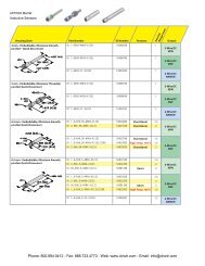
Fiber Optic: SA1C-FK<br />
Dimensions (mm)<br />
Panel Mounting Bracket (attachment)<br />
Not required for DIN Rail mounting<br />
Mounting Hole Layout<br />
Receiver<br />
Emitter<br />
ø4.4 x 2m<br />
holes<br />
Specifications<br />
SA1C-FK3 SA1C-FK3G<br />
Light Source Element<br />
Red LED √ –<br />
Green LED – √<br />
Sensing Distance Depends on the fiber unit (see page 173) √ √<br />
Power Voltage 12 to 24V DC (Operating voltage: 10 to 30V DC) ripple 10% maximum √ √<br />
Current Draw 80mA maximum √ √<br />
Analog Current Output 4 to 20mA, 5V DC maximum 1 √ √<br />
Digital Output NPN open collector 30V DC, 100mA maximum,1.5V maximum with short circuit protection √ √<br />
Operation Mode<br />
Dark ON (connect MODE line to GND line)<br />
Light ON (connect MODE line to power line)<br />
√<br />
√<br />
Response 0.5ms maximum 2 √ √<br />
Indicator Operation LED: Red, Stable LED: Green √ √<br />
Detectable Object Translucent object, opaque object √ √<br />
Hysteresis 20% maximum (using reflex fiber unit) √ √<br />
Sensitivity 4-turn adjustment √ √<br />
Operation Point Control 1 turn √ √<br />
Receiver Element Photo diode √ √<br />
Operating Temperature –25 to +55˚C (performance will be adversely affected if the sensor becomes coated with ice) √ √<br />
Storage Temperature –30 to +70˚C (performance will be adversely affected if the sensor becomes coated with ice) √ √<br />
Operating Humidity 35 to 85% RH (avoid condensation) √ √<br />
Extraneous Light Immunity Sunlight: 10,000 lux maximum; <strong>Inc</strong>andescent light: 3,000 lux (at the receiver) √ √<br />
Noise Resistance<br />
Normal mode: 500V (50ns to 1μs, 100Hz: Using a noise simulator)<br />
Common mode: 300V (50ns to 1μs, 100Hz: Using a noise simulator)<br />
√<br />
√<br />
Insulation Resistance Between live and dead parts: 20MΩ minimum, with 500V DC megger √ √<br />
Dielectric Strength Between live and dead parts: 1,000V, 1 minute √ √<br />
Vibration Resistance Damage limits: 10 to 55Hz; Single amplitude: 0.75mm 20 cycles in each of 3 axes √ √<br />
Shock Resistance Damage limits: 500 m/sec 2 10 cycles in each of 3 axes √ √<br />
Degree of Protection IP66—IEC Pub 529 √ √<br />
Cable Cable type: Ø4.4mm 5-core vinyl cabtyre cable 0.2mm2, 6’–6-3/4” (2m) long √ √<br />
Material Housing: PBT √ √<br />
Accessories<br />
Mounting bracket, adjusting screwdriver, load resistor (249Ω) for converting analog amperage<br />
to voltage (1 to 5V)<br />
√<br />
√<br />
Interference Prevention<br />
Up to 2 units can be installed in close proximity. For analog output, interference prevention is<br />
not possible.<br />
√<br />
√<br />
Weight Approximately 75g √ √<br />
1. Analog current output specification is based on the power voltage range from 12 to 24V DC (±10%).<br />
Use the attached resistor (249Ω, 1/4W) as a load resistance for converting analog output to voltage.<br />
2. Response time for analog current output is between 10% and 90% of the rise or fall of the voltage signal when using a 249Ω resistor.<br />
(when using a panel<br />
mounting bracket)<br />
PLCs Operator Interfaces Automation Software Power Supplies <strong>Sensors</strong> Communication & Networking<br />
<strong>Clearwater</strong> Tech - Phone: 800.894.0412 - Fax: 208.368.0415 - Web: www.clrwtr.com - Email: info@clrwtr.com165