IDEC / Datasensor Sensors - Clearwater Technologies, Inc.
IDEC / Datasensor Sensors - Clearwater Technologies, Inc.
IDEC / Datasensor Sensors - Clearwater Technologies, Inc.

You also want an ePaper? Increase the reach of your titles
YUMPU automatically turns print PDFs into web optimized ePapers that Google loves.
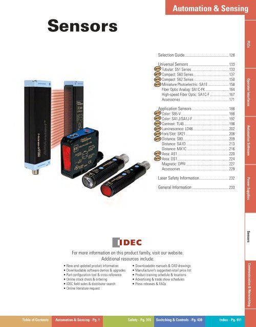
Automation & Sensing<br />
<strong>Sensors</strong><br />
W<br />
For more information on this product family, visit our website.<br />
Additional resources include:<br />
• New and updated product information<br />
• Downloadable software demos & upgrades<br />
• Part confi guration tool & cross reference<br />
• Online stock check & ordering<br />
• <strong>IDEC</strong> fi eld sales & distributor search<br />
• Online literature request<br />
• Downloadable manuals & CAD drawings<br />
• Manufacturer’s suggested retail price list<br />
• Product training schedule & locations<br />
• Advertising & trade show schedules<br />
• Press releases & FAQs<br />
www.idec.com/sensors<br />
Selection Guide ........................................... 128<br />
Universal <strong>Sensors</strong> ....................................... 133<br />
Tubular: S51 Series ........................................133<br />
Compact: S60 Series ......................................137<br />
Compact: S62 Series ......................................150<br />
Miniature Photoelectric: SA1E ......................158<br />
Fiber Optic Analog: SA1C-FK .........................164<br />
High-speed Fiber Optic: SA1C-F ....................167<br />
Accessories ....................................................171<br />
NEW<br />
NEW<br />
NEW<br />
NEW<br />
Application <strong>Sensors</strong> .................................... 188<br />
Color: S65-V ...................................................188<br />
Color: SA1J/SA1J-F .......................................192<br />
Contrast: TL46 ................................................198<br />
Luminescence: LD46 ......................................202<br />
Fork/Slot: SR21 ..............................................206<br />
Distance: S80 .................................................209<br />
Distance: SA1D ..............................................213<br />
Distance: MX1C .............................................216<br />
Area: AS1 .......................................................220<br />
Area: DS1 .......................................................224<br />
Magnetic: DPRI ..............................................227<br />
Accessories ....................................................229<br />
NEW<br />
NEW<br />
NEW<br />
NEW<br />
NEW<br />
NEW<br />
NEW<br />
NEW<br />
Laser Safety Information............................. 232<br />
General Information .................................... 233<br />
PLCs Operator Interfaces Automation Software Power Supplies <strong>Sensors</strong> Communication & Networking<br />
Table of Contents Automation & Sensing - Pg. 1 Safety - Pg. 315 Switching & Controls - Pg. 439 Index - Pg. 911
Selection Guide<br />
<strong>Sensors</strong><br />
Selection Guide<br />
Universal Photoelectric <strong>Sensors</strong><br />
PLCs<br />
NEW<br />
Tubular<br />
NEW<br />
NEW<br />
Compact<br />
NEW<br />
Models<br />
Operator Interfaces<br />
Page 133 137 150 158<br />
Series S51 S60 S62 SA1E<br />
Through-beam 0 - 20m 0 - 20m – 0 - 15m<br />
Retro-refl ective (on R2<br />
refl ector)<br />
0.1 - 4m – – –<br />
Automation Software<br />
Optic Function<br />
Polarized Retro-refl ective<br />
(on R2 refl ector)<br />
Retro-refl ective for<br />
Transparent Objects (on<br />
R2 refl ector)<br />
Diffuse Proximity<br />
0.1 - 3m 0.1 - 8m 0.3 - 20m cl. 2<br />
0.05 - 4m<br />
– 0 - 1.7m (coaxial) – –<br />
0 - 10cm<br />
1 - 45cm<br />
1 - 100cm<br />
5 - 200cm<br />
–<br />
0 - 70cm<br />
5 - 15cm<br />
Background Suppression –<br />
7 - 20cm<br />
5 - 10cm<br />
cl. 1<br />
30 - 300mm, 60 - 600mm<br />
60 - 1200mm, 200 - 2000mm<br />
30 - 150mm, 50 - 350mm<br />
cl. 2<br />
5 - 25cm<br />
Power Supplies<br />
<strong>Sensors</strong><br />
Specifications<br />
Through-beam with Fiber<br />
Optic<br />
Diffuse Proximity with<br />
Fiber Optic<br />
– – – –<br />
– – – –<br />
Power Supply V DC 10 - 30 10 - 30 10 - 30 10 - 30<br />
Output<br />
PNP √ √ √ √<br />
NPN √ √ √ √<br />
Connection<br />
Cable √ – – √<br />
Connector √ √ √ √<br />
Dimensions (mm) M18 x 55/68 15 x 50 x 50 18 x 50 x 50 11 x 31 x 19<br />
Housing Material PBT ABS ABS PC/PBT<br />
Mechanical Protection<br />
IP67<br />
Approvals<br />
Communication & Networking<br />
II3D II3D II3D<br />
128 <strong>Clearwater</strong> Tech - Phone: 800.894.0412 - Fax: 208.368.0415 www.idec.com- Web: www.clrwtr.com - Email: info@clrwtr.com
<strong>Sensors</strong><br />
Selection Guide<br />
Optic Function<br />
Specifications<br />
Universal Photoelectric <strong>Sensors</strong><br />
Fiber Optic<br />
Page 164 167<br />
Series SA1C-FK SA1C-F<br />
Through-beam – –<br />
Retro-refl ective (on R2 reflector) – –<br />
Polarized Retro-refl ective (on R2 reflector) – –<br />
Retro-refl ective for Transparent Objects (on<br />
R2 refl ector)<br />
– –<br />
Diffuse Proximity – –<br />
Background Suppression – –<br />
Through-beam with Fiber Optic 0 - 180mm 0 - 180mm<br />
Diffuse Proximity with Fiber Optic 0 - 60mm 0 - 60mm<br />
Power Supply V DC 12 - 24 10 - 30<br />
Output<br />
PNP<br />
√<br />
NPN √ √<br />
Connection<br />
Fiber Optic Cable √ √<br />
Connector – –<br />
Dimensions 26 x 72.7 x 13 26 x 72.7 x 13<br />
Housing Material PBT PBT<br />
Mechanical Protection IP66 IP66<br />
Approvals<br />
PLCs Operator Interfaces Automation Software Power Supplies <strong>Sensors</strong> Communication & Networking<br />
<strong>Clearwater</strong> Tech - Phone: 800.894.0412 - Fax: 208.368.0415 - Web: www.clrwtr.com - Email: info@clrwtr.com129
Selection Guide<br />
<strong>Sensors</strong><br />
Selection Guide con’t<br />
PLCs<br />
Application <strong>Sensors</strong><br />
Sensor Type Series Page Appearance Advantages Considerations<br />
S65 188<br />
NEW<br />
• High chromatic sensitivity to distinguish<br />
slight shade differences<br />
• Chromatic and C+I intensity can be set for<br />
each color<br />
• Ideal for high speed automatic packaging<br />
machines<br />
• 3-channel color sensor<br />
• C and C+I function with 10 settings<br />
• White light and RGB receiver<br />
• 3 independent outputs<br />
Operator Interfaces<br />
Color<br />
SA1J<br />
SA1J-F<br />
192<br />
• Use to detect registration marks (regardless<br />
of similarity of color) at high speed (0.3ms)<br />
• Use to distinguish between different shades<br />
of the same color<br />
• 3 LEDs (red, green and blue) provide a long<br />
life—no need to replace lamps<br />
• Use in wash-down environments<br />
• Use when long-distance range, high speed<br />
and small sensing spots are required for<br />
color sensing applications<br />
• Use the 3-color sensor for multiple outputs for sorting<br />
applications<br />
• Use the small spot version to detect small objects<br />
• Replace conventional contrast sensors with the<br />
SA1J for reliable color sensing<br />
• Use the auto-select mode to sort objects, to differentiate<br />
fine shades of the same color, or to detect<br />
objects moving to and from the sensor<br />
Automation Software<br />
Contrast TL46 198<br />
NEW<br />
• Automatic, manual and remote settings<br />
• Wide spectrum RGB LED emissions<br />
• Fast switching frequencies<br />
• Precision light spot with RGB LEDs<br />
• NPN and PNP outputs<br />
• 1 - 5.5V analog outputs<br />
• Bargraph and 4-digit display options<br />
Power Supplies<br />
Luminescense LD46 202<br />
NEW<br />
• High sensitivity on fluorescent marks<br />
• 10 - 100mm detection distance<br />
• NPN - PNP digital output, 0 - 5V analog<br />
output<br />
• High power LED UV light source<br />
• Can detect thin marks on even highly refl ective<br />
objects<br />
• Luminescent marks at longer distances can be<br />
detected<br />
• Special model for detection of labels on glass<br />
• Can detect marks on irregular surfaces such as wood<br />
<strong>Sensors</strong><br />
Fork/Slot SR21 206<br />
NEW<br />
• High speed 25kHz switching frequencies<br />
• Detecting semi-transparent labels<br />
• Detecting registration marks on transparent<br />
material<br />
• 2mm slot width<br />
• 20μ sec response time<br />
Communication & Networking<br />
130 <strong>Clearwater</strong> Tech - Phone: 800.894.0412 - Fax: 208.368.0415 www.idec.com- Web: www.clrwtr.com - Email: info@clrwtr.com
<strong>Sensors</strong><br />
Selection Guide<br />
Application <strong>Sensors</strong><br />
Sensor Type Series Page Appearance Advantages Considerations<br />
Distance<br />
Area/<br />
Dimensional<br />
Magnetic<br />
Proximity<br />
S80 209<br />
SA1D 213<br />
MX1C 216<br />
AS1 220<br />
DS1 224<br />
DPRI 227<br />
NEW<br />
NEW<br />
NEW<br />
• Time-of-flight technology<br />
• Ideal for precise measurement of distance<br />
• Use to detect position presence of large<br />
objects from a distance<br />
• The most reliable distance sensing, calculated<br />
using optical triangle between two<br />
points and the sensor<br />
• Analog output and digital output<br />
• Use in the most precise sensor applications,<br />
because of the minute size of the laser<br />
beam<br />
• Use to achieve precise positioning or alignment,<br />
visible beam is easy to aim<br />
• Analog and digital output<br />
• Short response time is great for conveyor<br />
and material handling applications<br />
• Ideal for feeding and downloading lines to<br />
count objects in random positions<br />
• Position and dimension measurement<br />
• 150mm<br />
• 5mm resolution, 1ms response time<br />
• Operating distance up to 2.1m<br />
• 0 - 10V analog output, PNP digital output<br />
available<br />
• Lightweight, compact design reduces<br />
mounting space requirements<br />
• Sealed reed contact<br />
• Long life and high reliability<br />
• Class 2 laser emission<br />
• Direct proximity measurement 7m<br />
• PNP - NPN, 4 - 20mA output<br />
• RS485 serial interface<br />
• Maximum analog output value corresponds to minimum<br />
sensing distance and minimum analog value<br />
corresponds to maximum distance<br />
IMPORTANT: Always consider safety when using laser<br />
sensors. Make sure laser beam cannot inadvertently<br />
shine into the eyes of people passing by or working in<br />
the vicinity. See safety information on page 232.<br />
• Area sensor with crossed beams<br />
• Operating distance is 2.1m<br />
• 0.2mm minimum detectable thickness<br />
• PNP out activated when beam is interrupted<br />
• 0 - 10V analog out proportional to dimension of<br />
object<br />
• Low response time of 1 - 3msec depending on<br />
distance dimension<br />
• Operating distance: 0 to 4mm<br />
PLCs Operator Interfaces Automation Software Power Supplies <strong>Sensors</strong> Communication & Networking<br />
<strong>Clearwater</strong> Tech - Phone: 800.894.0412 - Fax: 208.368.0415 - Web: www.clrwtr.com - Email: info@clrwtr.com131
<strong>Sensors</strong><br />
Tubular: S51 Series<br />
Universal <strong>Sensors</strong><br />
Tubular: S51 Series<br />
M18 Photoelectric <strong>Sensors</strong><br />
• Flat plastic housing<br />
• Cable or M12 connection with NPN or PNP output<br />
• Standard 3-wire connection confi guration<br />
• Selectable dark or light output<br />
The S51 series offers a cost-effective solution in M18 photoelectric sensors, with a wide range of<br />
operating distances.<br />
The diffuse proximity model has a 10cm fi xed operating distance with a wide emission spectrum. Also<br />
available is a version with a 1 - 40cm adjustable operating distance.<br />
Standard retro-refl ective models have an operating distance up to 4m while the polarized retro-refl ective<br />
models, used for reliable detection of refl ective objects, are fi tted with a sensitivity adjustment and have<br />
a 3.5m operating distance. The emitter and receiver models, used for longer operating distances, reach<br />
18 meters.<br />
The S51 series sensors, with cable or M12 connector and PNP or NPN output, provide a 3-wire connection<br />
confi guration in compliance with the EN60947-5-2 standard. The normally open output is activated<br />
in light mode in proximity models and in dark mode in retro-refl ective models. The output mode can be<br />
inverted using the dark/light selection input wire provided, making these extremely versatile sensors.<br />
PLCs Operator Interfaces Automation Software Power Supplies <strong>Sensors</strong> Communication & Networking<br />
<strong>Clearwater</strong> Tech - Phone: 800.894.0412 - Fax: 208.368.0415 - Web: www.clrwtr.com - Email: info@clrwtr.com133
Tubular: S51 Series<br />
<strong>Sensors</strong><br />
Retro-reflective A00, Short Diffused C10,<br />
Through-beam G00<br />
Dimensions (mm)<br />
Polarized Retro-reflective B01, Long Diffused C01,<br />
Through-beam F00<br />
PLCs<br />
2 - ø3.8<br />
Sensitivity Adjustment (B01, C01 models)<br />
2 - ø3.8<br />
Operator Interfaces<br />
Output Status LED<br />
(Power On LED on<br />
G00 model)<br />
M12<br />
Connector<br />
Output Status LED<br />
(Power On LED on<br />
Sensitivity Adjustment G00 model)<br />
(B01, C01 models)<br />
M12<br />
Connector<br />
Power Supplies<br />
Automation Software<br />
Connections<br />
Through-beam G00<br />
Indicators & Settings<br />
M12 Connector<br />
Sensitivity Adjustment (B01, C01 models)<br />
<strong>Sensors</strong><br />
Retro-reflective A00,<br />
Polarized Retro-reflective B01,<br />
Long Diffused C01, Short Diffused C10,<br />
Through-beam F00<br />
Output Status LED (Power On LED on G00 model)<br />
Sensitivity Adjustment (B01, C01 models)<br />
Cable Connection<br />
For information on accessories,<br />
see page 171.<br />
Communication & Networking<br />
Output Status LED (Power On LED on G00 model)<br />
134 <strong>Clearwater</strong> Tech - Phone: 800.894.0412 - Fax: 208.368.0415 www.idec.com- Web: www.clrwtr.com - Email: info@clrwtr.com
<strong>Sensors</strong><br />
Tubular: S51 Series<br />
Specifications<br />
Long Diffuse Proximity Operating Distance<br />
Short Diffuse Proximity Operating Distance<br />
1 - 40cm<br />
0 - 10cm<br />
Detection Diagrams<br />
Long Diffused C01<br />
Gray 18%<br />
White 90%<br />
Retro-reflective Operating Distance 0.1 - 4m on R2<br />
Polarized Retro-reflective Operating<br />
0.1 - 3m on R2<br />
Distance<br />
Through-beam Operating Distance<br />
0 - 18m<br />
Power Supply 10 - 30V DC 1<br />
Ripple<br />
≤ 2 Vpp<br />
Current Draw<br />
≤ 35 mA<br />
Infrared LED 880 nm<br />
Light Emission 2<br />
Red LED 650 nm (B01 models)<br />
Setting Sensitivity adjustment (B01, C01 models) 3<br />
Yellow OUTPUT LED (excl. G00 models)<br />
Indicators<br />
Green POWER LED (G00 models)<br />
Output Type<br />
NPN or PNP versions<br />
Output Current<br />
≤ 100mA<br />
Saturation Voltage<br />
≤ 2V<br />
1ms<br />
Response Time<br />
4ms (F00 mod.)<br />
≤ 500Hz<br />
Switching Frequency<br />
≤ 120Hz (F00 mod.)<br />
Operating Mode dark/light selectable 4<br />
Auxiliary Functions Test + and Test - (G00 mod.) 5<br />
2m ø4 mm cable 6<br />
Connection<br />
M12 4-pole connector 7<br />
Electrical Protection Class 2<br />
Mechanical Protection<br />
IP67<br />
Protection Devices A, B 8<br />
Housing Material<br />
PBT<br />
Lens Material<br />
PMMA<br />
Weight<br />
25g max.<br />
Operating Temperature<br />
-25 to +55ºC<br />
Storage Temperature<br />
-25 to +70ºC<br />
Reference Standard EN60947-5-2, UL 508<br />
1. Limit values.<br />
2. Average life of 100,000 hrs with T A<br />
= +25ºC.<br />
3. 270º single-turn sensitivity adjustment.<br />
4. With L/D input not connected the proximity models function in the light mode and the<br />
retro-reflective and through-beam models in the dark mode; the light mode can be selected<br />
by connecting the L/D input to +V DC, the dark mode connecting it to 0V DC.<br />
5. Emitter off with Test+ connected to +V DC and Test- to 0V DC.<br />
6. PVC, 4 x 0.14mm 2<br />
7. M12 connector compatible with quick connection systems.<br />
8. A - reverse polarity protection<br />
B - overload and short-circuit protection<br />
Short Diffused C10<br />
Gray 18% White 90%<br />
Retro-reflective A00<br />
R2<br />
R5<br />
Polarized Retro-reflective B01<br />
Through-beam F00/G00<br />
R2<br />
R5<br />
II3D<br />
PLCs Operator Interfaces Automation Software Power Supplies <strong>Sensors</strong> Communication & Networking<br />
<strong>Clearwater</strong> Tech - Phone: 800.894.0412 - Fax: 208.368.0415 - Web: www.clrwtr.com - Email: info@clrwtr.com135
Tubular: S51 Series<br />
<strong>Sensors</strong><br />
Operating Distance<br />
Retro-reflective A00 Polarized Retro-reflective B01 Long Diffused C01<br />
PLCs<br />
R2 Refl ector<br />
3.5 4<br />
4 4.5<br />
R2 Refl ector<br />
2.5 3<br />
40 45<br />
S51-PA-2-C01<br />
3 3.5 0 25 50 (cm)<br />
R5 Refl ector<br />
R5 Refl ector<br />
0 2.5 5 (m)<br />
0 2 4 (m)<br />
Short Diffused C10<br />
Through-beam F00/G00<br />
Operator Interfaces<br />
S51-PA-2-C10<br />
0 5 10 (cm)<br />
10<br />
F00/G00<br />
18 20<br />
0 10 20 (m)<br />
Recommended operating distance<br />
Maximum operating distance<br />
Automation Software<br />
Power Supplies<br />
<strong>Sensors</strong><br />
Part Numbers<br />
Optic Function Connection Output Part Number<br />
Retro-refl ective 2m cable PNP S51-PA-2-A00-PK<br />
Retro-refl ective 2m cable NPN S51-PA-2-A00-NK<br />
Retro-refl ective M12 connector PNP S51-PA-5-A00-PK<br />
Retro-refl ective M12 connector NPN S51-PA-5-A00-NK<br />
Polarized Retro-reflective 2m cable PNP S51-PA-2-B01-PK<br />
Polarized Retro-reflective 2m cable NPN S51-PA-2-B01-NK<br />
Polarized Retro-reflective M12 connector PNP S51-PA-5-B01-PK<br />
Polarized Retro-reflective M12 connector NPN S51-PA-5-B01-NK<br />
Long Diffuse Proximity 2m cable PNP S51-PA-2-C01-PK<br />
Long Diffuse Proximity 2m cable NPN S51-PA-2-C01-NK<br />
Long Diffuse Proximity M12 connector PNP S51-PA-5-C01-PK<br />
Long Diffuse Proximity M12 connector NPN S51-PA-5-C01-NK<br />
Short Diffuse Proximity 2m cable PNP S51-PA-2-C10-PK<br />
Short Diffuse Proximity 2m cable NPN S51-PA-2-C10-NK<br />
Short Diffuse Proximity M12 connector PNP S51-PA-5-C10-PK<br />
Short Diffuse Proximity M12 connector NPN S51-PA-5-C10-NK<br />
Receiver 2m cable PNP S51-PA-2-F00-PK<br />
Receiver 2m cable NPN S51-PA-2-F00-NK<br />
Receiver M12 connector PNP S51-PA-5-F00-PK<br />
Receiver M12 connector NPN S51-PA-5-F00-NK<br />
Emitter 2m cable – S51-PA-2-G00-XG<br />
Emitter M12 connector – S51-PA-5-G00-XG<br />
Additional models are available. Visit www.idec-ds.com for more information.<br />
Communication & Networking<br />
Connector Cables<br />
Number of<br />
Appearance<br />
Core Wires<br />
Type & Length Use with Part No.<br />
4 Straight, 5m<br />
CS-A1-02-G-05<br />
S51, S60,<br />
S62<br />
4 Right angle, 5m CS-A2-02-G-05<br />
136 <strong>Clearwater</strong> Tech - Phone: 800.894.0412 - Fax: 208.368.0415 www.idec.com- Web: www.clrwtr.com - Email: info@clrwtr.com
<strong>Sensors</strong><br />
Compact: S60 Series<br />
Compact: S60 Series<br />
Multifunction Optoelectronic <strong>Sensors</strong><br />
• Long operating distance<br />
• Sensitivity adjustment<br />
• Independent NO-NC outputs<br />
• M12 connection with standard NPN or PNP<br />
confi guration<br />
The S60 sensors have a sensitivity adjustment that provides quick and precise setting of the<br />
switching threshold. These sensors also have an M12 connection that can be used straight or<br />
rotated to a right-angle position. All versions have NPN or PNP outputs and standard confi gurations<br />
conforming to the EN60947-5-2 standard.<br />
PLCs Operator Interfaces Automation Software Power Supplies <strong>Sensors</strong> Communication & Networking<br />
<strong>Clearwater</strong> Tech - Phone: 800.894.0412 - Fax: 208.368.0415 - Web: www.clrwtr.com - Email: info@clrwtr.com137
Compact: S60 Series<br />
<strong>Sensors</strong><br />
Through-beam Sensor with Infrared Emission - 20m<br />
PLCs<br />
A detection system with separate emitter<br />
and receiver units, allows the user<br />
to reach larger operating distances. The<br />
sensitivity adjustment, present on the<br />
receiver, allows adjustments enabling<br />
the sensor to detect objects that block,<br />
even partially, the light emission. The IR<br />
emission is modulated to avoid interference<br />
with other light sources and can<br />
be turned off to test the sensor even<br />
without an object to detect.<br />
Dimensions (mm)<br />
Output status &<br />
stability LEDs<br />
(receiver); power<br />
on LED (emitter)<br />
Operator Interfaces<br />
M12 Connector<br />
Output<br />
Automation Software<br />
M12 Connector<br />
Output<br />
Power Supplies<br />
Emitter<br />
Receiver<br />
<strong>Sensors</strong><br />
Indicators & Settings<br />
Output status and stability<br />
LEDs (receiver); power on<br />
LED (emitter)<br />
Receiver Sensitivity Adjustment<br />
Connections<br />
Communication & Networking<br />
Single-turn sensitivity adjustment. Rotate clockwise to<br />
increase the operating distance.<br />
Emitter<br />
TEST +<br />
(white)<br />
0V -<br />
(blue)<br />
+10 - 30V DC<br />
(brown)<br />
TEST -<br />
(black)<br />
Receiver<br />
NC Output<br />
(white)<br />
0V -<br />
(blue)<br />
For information on accessories, see page 171.<br />
+10 - 30V DC<br />
(brown)<br />
NO Output<br />
(black)<br />
138 <strong>Clearwater</strong> Tech - Phone: 800.894.0412 - Fax: 208.368.0415 www.idec.com- Web: www.clrwtr.com - Email: info@clrwtr.com
<strong>Sensors</strong><br />
Compact: S60 Series<br />
Specifications<br />
S60-PA-5-F01-NN S60-PA-5-F01-PP S60-PA-5-G00-XG<br />
Operating distance 0 - 20m √ √ √<br />
Power supply 10 - 30V DC 1 √ √ √<br />
Ripple ≤ 2 Vpp √ √ √<br />
Current Draw ≤ 35mA √ √ √<br />
Light emission Infrared LED 880nm 2 – – √<br />
Spot dimension Aprox. 200mm at 4m – – √<br />
Setting Sensitivity adjustment 3 √ √ –<br />
Indicators<br />
Output type<br />
Yellow OUTPUT LED √ √ –<br />
Green STABILITY LED √ √ –<br />
Green POWER ON LED – – √<br />
PNP, NO and NC – √ –<br />
NPN, NO and NC √ – –<br />
Output current ≤ 100mA √ √ –<br />
Saturation voltage ≤ 2V √ √ –<br />
Response time 1ms √ √ –<br />
Switching frequency 500Hz √ √ –<br />
Operating mode dark on NO / light on NC √ √ –<br />
Connection M12 4-pole connector 4 √ √ √<br />
Electrical protection Class 2 √ √ √<br />
Mechanical protection IP67 √ √ √<br />
Protection devices A, B 5 √ √ √<br />
Housing material ABS √ √ √<br />
Lens material Window: PMMA 6 √ √ √<br />
Weight 40g max. √ √ √<br />
Operating temperature -25 to +55°C √ √ √<br />
Storage temperature -25 to +70°C √ √ √<br />
Reference standard EN60947-5-2, UL508 √ √ √<br />
Additional models are available. Visit www.idec-ds.com for more<br />
information.<br />
1. Limit values<br />
2. Average life of 100,000 hrs with T A<br />
= +25ºC<br />
3. 270º sensitivity adjustment<br />
Operating Distance<br />
0 5 10 15 20 (m)<br />
Recommended operating distance<br />
Maximum operating distance<br />
18 20<br />
4. Connector can be locked in two positions<br />
5. A - reverse polarity protection<br />
B - overload and short-circuit protection on receiver outputs<br />
6. Internal lens - Polycarbonate<br />
Excess Gain<br />
Detection Diagrams<br />
Detection Area<br />
II3D<br />
PLCs Operator Interfaces Automation Software Power Supplies <strong>Sensors</strong> Communication & Networking<br />
<strong>Clearwater</strong> Tech - Phone: 800.894.0412 - Fax: 208.368.0415 - Web: www.clrwtr.com - Email: info@clrwtr.com139
Compact: S60 Series<br />
<strong>Sensors</strong><br />
Polarized Retro-reflective Sensor with Red Emission - 8m<br />
PLCs<br />
With retro-reflective sensors, the object is<br />
detected when it interrupts the light beam<br />
generated between the sensor and its associated<br />
refl ector. High-polarization optic fi lters also allow<br />
reliable detection of very shiny objects, such as<br />
mirrored surfaces.<br />
Dimensions (mm)<br />
Output status &<br />
stability LEDs<br />
Operator Interfaces<br />
M12 Connector<br />
Output<br />
Automation Software<br />
M12 Connector<br />
Output<br />
Power Supplies<br />
Indicators & Settings<br />
Output status and stability<br />
LEDs<br />
Sensitivity Adjustment<br />
Connections<br />
<strong>Sensors</strong><br />
Single-turn sensitivity adjustment. Rotate clockwise<br />
to increase the operating distance.<br />
NC Output<br />
(white)<br />
+10 - 30V DC<br />
(brown)<br />
Communication & Networking<br />
0V -<br />
(blue)<br />
NO Output<br />
(black)<br />
For information on accessories, see page 171.<br />
140 <strong>Clearwater</strong> Tech - Phone: 800.894.0412 - Fax: 208.368.0415 www.idec.com- Web: www.clrwtr.com - Email: info@clrwtr.com
<strong>Sensors</strong><br />
Compact: S60 Series<br />
Specifications<br />
S60-PA-5-B01-NN<br />
S60-PA-5-B01-PP<br />
Operating Distance 0.1 - 8m (on R5) √ √<br />
Power Supply 10 - 30V DC 1 √ √<br />
Ripple ≤ 2Vpp √ √<br />
Current Draw ≤ 40mA √ √<br />
Light Emission red LED 660nm 2 √ √<br />
Spot Dimension aprox. 90mm at 3m √ √<br />
Setting sensitivity adjustment 3 √ √<br />
Indicators<br />
Output Type<br />
yellow OUTPUT LED √ √<br />
green STABILITY LED √ √<br />
PNP, NO and NC – √<br />
NPN, NO and NC √ –<br />
Output Current ≤ 100mA √ √<br />
Saturation Voltage ≤ 2V √ √<br />
Response Time 500μs √ √<br />
Switching Frequency 1kHz √ √<br />
Operating Mode dark on NO / light on NC √ √<br />
Connection M12 4-pole connector 4 √ √<br />
Electrical Protection class 2 √ √<br />
Mechanical Protection IP67 √ √<br />
Protection Devices A, B 5 √ √<br />
Housing Material ABS √ √<br />
Lens Material Window: PMMA 6 √ √<br />
Weight 40g max. √ √<br />
Operating Temperature -25 to +55°C √ √<br />
Storage Temperature -25 to +70°C √ √<br />
Reference Standard EN60947-5-2, UL508 √ √<br />
Additional models are available. Visit www.idec-ds.com for more<br />
information.<br />
1. Limit values<br />
2. Average life of 100,000 hrs with T A<br />
= +25 ºC<br />
3. 270º sensitivity adjustment<br />
Operating Distance<br />
R5 7<br />
R2 6 6.5<br />
0 2 4 6 8 10 (m)<br />
Recommended operating distance<br />
Maximum operating distance<br />
8<br />
4. Connector can be locked in two positions<br />
5. A - reverse polarity protection<br />
B - overload and short-circuit protection on outputs<br />
6. Internal lens - Polycarbonate<br />
Excess Gain<br />
R2<br />
R5<br />
Detection Diagrams<br />
R2<br />
Detection Area<br />
II3D<br />
R5<br />
PLCs Operator Interfaces Automation Software Power Supplies <strong>Sensors</strong> Communication & Networking<br />
<strong>Clearwater</strong> Tech - Phone: 800.894.0412 - Fax: 208.368.0415 - Web: www.clrwtr.com - Email: info@clrwtr.com141
Compact: S60 Series<br />
<strong>Sensors</strong><br />
Coaxial Polarized Retro-reflective Sensor for Transparent Objects - 2m<br />
PLCs<br />
The high sensitivity and reduced hysterisis of this<br />
retro-reflective sensor allows detection of the<br />
slightest light emission, even through transparent<br />
objects, such as glass, PET bottles or plastic fi lm<br />
sheets for packaging. The use of polarization fi l-<br />
ters helps to avoid inaccurate switching on shiny<br />
surfaces and coaxial optics improve the detection<br />
precision of the entire operating range.<br />
Dimensions (mm)<br />
Output<br />
status LED<br />
Operator Interfaces<br />
M12 Connector<br />
Output<br />
Automation Software<br />
M12 Connector<br />
Output<br />
Power Supplies<br />
Indicators & Settings<br />
Output status LED<br />
Sensitivity Adjustment<br />
Connections<br />
<strong>Sensors</strong><br />
Single-turn sensitivity adjustment. Rotate clockwise to increase the operating<br />
distance.<br />
NC Output<br />
(white)<br />
+10 - 30V DC<br />
(brown)<br />
Communication & Networking<br />
0V -<br />
(blue)<br />
NO Output<br />
(black)<br />
For information on accessories, see page 171.<br />
142 <strong>Clearwater</strong> Tech - Phone: 800.894.0412 - Fax: 208.368.0415 www.idec.com- Web: www.clrwtr.com - Email: info@clrwtr.com
<strong>Sensors</strong><br />
Compact: S60 Series<br />
Specifications<br />
S60-PA-5-T51-NN<br />
S60-PA-5-T51-PP<br />
Operating Distance 0 - 2m (on R5) √ √<br />
Power Supply 10 - 30V DC 1 √ √<br />
Ripple ≤ 2Vpp √ √<br />
Current Draw ≤ 40mA √ √<br />
Light Emission Red LED 660nm 2 √ √<br />
Spot Dimension Aprox. 50mm at 1.5m √ √<br />
Setting Sensitivity adjustment 3 √ √<br />
Indicators Yellow OUTPUT LED √ √<br />
Output Type<br />
PNP, NO and NC – √<br />
NPN, NO and NC √ –<br />
Output Current ≤ 100mA √ √<br />
Saturation Voltage ≤ 2V √ √<br />
Response Time 500μs √ √<br />
Switching Frequency 1kHz √ √<br />
Operating Mode dark on NO / light on NC √ √<br />
Connection M12 4-pole connector 4 √ √<br />
Electrical Protection Class 2 √ √<br />
Mechanical Protection IP67 √ √<br />
Protection Devices A, B 5 √ √<br />
Housing Material ABS √ √<br />
Lens Material Window in glass (tilted anti-reflection) 6 √ √<br />
Weight 40g max. √ √<br />
Operating Temperature -25 to +55ºC √ √<br />
Storage Temperature -25 to +70ºC √ √<br />
Reference Standard EN60947-5-2, UL508 √ √<br />
Additional models are available. Visit www.idec-ds.com for more<br />
information.<br />
1. Limit values<br />
2. Average life of 100,000 hrs with T A<br />
= +25 ºC<br />
3. 270º sensitivity adjustment<br />
Operating Distance<br />
R5<br />
R2<br />
0 0.5 1 1.5 2 (m)<br />
Recommended operating distance<br />
Maximum operating distance<br />
1.5 1.7<br />
1.7 2<br />
4. Connector can be locked in two positions<br />
5. A - reverse polarity protection<br />
B - overload and short-circuit protection on outputs<br />
6. Internal lens - glass<br />
Excess Gain<br />
R2<br />
R5<br />
Detection Diagrams<br />
R2<br />
II3D<br />
Detection Area<br />
R5<br />
PLCs Operator Interfaces Automation Software Power Supplies <strong>Sensors</strong> Communication & Networking<br />
<strong>Clearwater</strong> Tech - Phone: 800.894.0412 - Fax: 208.368.0415 - Web: www.clrwtr.com - Email: info@clrwtr.com143
Compact: S60 Series<br />
<strong>Sensors</strong><br />
Diffuse Proximity Sensor - 100cm<br />
PLCs<br />
This diffuse proximity sensor provides a reliable,<br />
simple and cost-effective solution for the direct<br />
detection of any object within the operating<br />
distance. The sensitivity adjustment is used to set<br />
the sensing distance easily and accurately. The<br />
visible red emission allows alignment of the sensor<br />
or object in short operating distances.<br />
Dimensions (mm)<br />
Output<br />
status LED<br />
Operator Interfaces<br />
M12 Connector<br />
Output<br />
Automation Software<br />
M12 Connector<br />
Output<br />
Power Supplies<br />
Indicators & Settings<br />
Output status LED<br />
Sensitivity Adjustment<br />
Connections<br />
<strong>Sensors</strong><br />
Single-turn sensitivity adjustment. Rotate clockwise<br />
to increase the operating distance.<br />
NC Output<br />
(white)<br />
+10 - 30V DC<br />
(brown)<br />
0V -<br />
(blue)<br />
NO Output<br />
(black)<br />
Communication & Networking<br />
For information on accessories, see page 171.<br />
144 <strong>Clearwater</strong> Tech - Phone: 800.894.0412 - Fax: 208.368.0415 www.idec.com- Web: www.clrwtr.com - Email: info@clrwtr.com
<strong>Sensors</strong><br />
Compact: S60 Series<br />
Specifications<br />
S60-PA-5-C01-NN<br />
S60-PA-5-C01-PP<br />
Operating Distance 0 - 100cm √ √<br />
Power Supply 10 - 30V DC 1 √ √<br />
Ripple ≤ 2Vpp √ √<br />
Current Draw ≤ 40mA √ √<br />
Light Emission Red LED 660nm 2 √ √<br />
Spot Dimension Approx. 50mm at 90cm √ √<br />
Setting Sensitivity adjustment 3 √ √<br />
Indicators<br />
Output Type<br />
Yellow OUTPUT LED √ √<br />
Green STABILITY LED √ √<br />
PNP, NO and NC – √<br />
NPN, NO and NC √ –<br />
Output Current ≤ 100mA √ √<br />
Saturation Voltage ≤ 2V √ √<br />
Response Time 1ms √ √<br />
Switching Frequency 500Hz √ √<br />
Operating Mode Light on NO / dark on NC √ √<br />
Connection M12 4-pole connector 4 √ √<br />
Electrical Protection Class 2 √ √<br />
Mechanical Protection IP67 √ √<br />
Protection Devices A, B 5 √ √<br />
Housing Material ABS √ √<br />
Lens Material Window: PMMA 6 √ √<br />
Weight 40g max. √ √<br />
Operating Temperature -25 to +55ºC √ √<br />
Storage Temperature -25 to +70ºC √ √<br />
Reference Standard EN60947-5-2, UL508 √ √<br />
Additional models are available. Visit www.idec-ds.com for more<br />
information.<br />
1. Limit values<br />
2. Average life of 100,000 hrs with T A<br />
= +25 ºC<br />
3. 270º sensitivity adjustment<br />
Operating Distance<br />
White<br />
Gray<br />
70 80<br />
100 110<br />
0 30 60 90 120 (cm)<br />
Recommended operating distance<br />
Maximum operating distance<br />
4. Connector can be locked in two positions<br />
5. A - reverse polarity protection<br />
B - overload and short-circuit protection on outputs<br />
6. Internal lens - polycarbonate<br />
Excess Gain<br />
Gray 18%<br />
White 90%<br />
Detection Diagrams<br />
II3D<br />
Detection Area<br />
White 90%<br />
Gray 18%<br />
PLCs Operator Interfaces Automation Software Power Supplies <strong>Sensors</strong> Communication & Networking<br />
<strong>Clearwater</strong> Tech - Phone: 800.894.0412 - Fax: 208.368.0415 - Web: www.clrwtr.com - Email: info@clrwtr.com145
Compact: S60 Series<br />
<strong>Sensors</strong><br />
Long Diffuse Proximity - 200cm<br />
PLCs<br />
This model of diffuse proximity sensor offers a<br />
long operating distance for direct detection of<br />
objects without the use of separate refl ectors or<br />
receivers. The detection distance can be set using<br />
the sensitivity adjustment. The green stability LED<br />
indicates that the received signal is higher than<br />
the minimum signal for output switching.<br />
Dimensions (mm)<br />
Output status<br />
and stability<br />
LEDs<br />
Operator Interfaces<br />
M12 Connector<br />
Output<br />
Automation Software<br />
M12 Connector<br />
Output<br />
Power Supplies<br />
Indicators & Settings<br />
Output status and<br />
stability LEDs<br />
Sensitivity Adjustment<br />
Connections<br />
<strong>Sensors</strong><br />
Single-turn sensitivity adjustment. Rotate clockwise<br />
to increase the operating distance.<br />
NC Output<br />
(white)<br />
+10 - 30V DC<br />
(brown)<br />
Communication & Networking<br />
0V -<br />
(blue)<br />
NO Output<br />
(black)<br />
For information on accessories, see page 171.<br />
146 <strong>Clearwater</strong> Tech - Phone: 800.894.0412 - Fax: 208.368.0415 www.idec.com- Web: www.clrwtr.com - Email: info@clrwtr.com
<strong>Sensors</strong><br />
Compact: S60 Series<br />
Specifications<br />
S60-PA-5-C11-NN<br />
S60-PA-5-C11-PP<br />
Operating Distance 5 - 200cm √ √<br />
Power Supply 10 - 30VDC 1 √ √<br />
Ripple ≤ 2 Vpp √ √<br />
Current Draw ≤ 40mA √ √<br />
Light Emission Infrared LED 880nm 2 √ √<br />
Spot Dimension Approx. 250mm at 1m √ √<br />
Setting Sensitivity adjustment 3 √ √<br />
Indicators<br />
Output Type<br />
Yellow OUTPUT LED √ √<br />
Green STABILITY LED √ √<br />
PNP, NO and NC – √<br />
NPN, NO and NC √ –<br />
Output Current ≤ 100mA √ √<br />
Saturation Voltage ≤ 2V √ √<br />
Response Time 1ms √ √<br />
Switching Frequency 500Hz √ √<br />
Operating Mode Light on NO / dark on NC √ √<br />
Connection M12 4-pole connector 4 √ √<br />
Electrical Protection Class 2 √ √<br />
Mechanical Protection IP67 √ √<br />
Protection Devices A, B 5 √ √<br />
Housing Material ABS √ √<br />
Lens Material Window: PMMA 6 √ √<br />
Weight 40g max. √ √<br />
Operating Temperature -25 to +55ºC √ √<br />
Storage Temperature -25 to +70ºC √ √<br />
Reference Standard EN60947-5-2, UL508 √ √<br />
Additional models are available. Visit www.idec-ds.com for more<br />
information.<br />
1. Limit values<br />
2. Average life of 100,000 hrs with T A<br />
= +25 ºC<br />
3. 270º sensitivity adjustment<br />
Operating Distance<br />
White 200<br />
Gray 120 140<br />
0 50 100 150 200 250 (cm)<br />
Recommended operating distance<br />
Maximum operating distance<br />
220<br />
4. Connector can be locked in two positions<br />
5. A - reverse polarity protection<br />
B - overload and short-circuit protection on outputs<br />
6. Internal lens - polycarbonate<br />
Excess Gain<br />
Gray 18%<br />
White 90%<br />
II3D<br />
Detection Diagrams<br />
Detection Area<br />
Gray 18%<br />
White 90%<br />
PLCs Operator Interfaces Automation Software Power Supplies <strong>Sensors</strong> Communication & Networking<br />
<strong>Clearwater</strong> Tech - Phone: 800.894.0412 - Fax: 208.368.0415 - Web: www.clrwtr.com - Email: info@clrwtr.com147
50<br />
Compact: S60 Series<br />
<strong>Sensors</strong><br />
PLCs<br />
The S60 series establishes a new standard in compact 50 x 50mm photoelectric<br />
sensors, offering a complete family of optical functions within a 15mm housing<br />
width.<br />
The standard dimensions, reduced housing width, and the multi-hole mounting<br />
system make the S60 series superior to the majority of compact sensors present<br />
on the market.<br />
Technological Advantages<br />
SMT Chip-size for Electronic Miniaturization<br />
Gains More Space for the Optics<br />
Coaxial Optics<br />
The models are available with M12 connectors, NPN or PNP output, and conform<br />
to EN60947-5-2 European standards.<br />
Operator Interfaces<br />
The M12 connector can be easily rotated to 90º and can be locked in straight<br />
or right-angle positions compared to the optic axis. The cable emerges at 45°<br />
and can be bent almost 360º. These characteristics allow the sensor to be easily<br />
mounted on any side and at any angle.<br />
The S60 series are available in through-beam, polarized retro-refl ective and<br />
diffuse proximity. The polarized retro-refl ective model is available with a coaxial<br />
optic version with the emitter optic axis coinciding with the receiver. This offers<br />
superior detection axis precision and eliminates the blind zone near the sensor.<br />
Automation Software<br />
Compact Photoelectric <strong>Sensors</strong><br />
Standard 50 x 50 x 15mm<br />
50<br />
40 - 42<br />
Complete External Shield for<br />
High Electromagnetic Compatibility<br />
Biaxial Optics<br />
Communication & Networking<br />
Power Supplies<br />
<strong>Sensors</strong><br />
15<br />
25<br />
31 - 42<br />
Coaxial optics are also available in the polarized retro-refl ective model for<br />
detection of transparent objects. This increases the performance of the optical<br />
function and its immunity to object movement inside the detection area.<br />
The range and switching threshold output can be selected from 50 - 150mm,<br />
with a ± 1mm precision; direct or inverse proportionality and light or dark operating<br />
modes can also be selected.<br />
148 <strong>Clearwater</strong> Tech - Phone: 800.894.0412 - Fax: 208.368.0415 www.idec.com- Web: www.clrwtr.com - Email: info@clrwtr.com
<strong>Sensors</strong><br />
Compact: S60 Series<br />
Part Numbers<br />
Function Connection Output Part Number Page Number<br />
Polarized Retro-reflective M12 connector NPN S60-PA-5-B01-NN<br />
Polarized Retro-reflective M12 connector PNP S60-PA-5-B01-PP<br />
Diffuse Proximity (100cm) M12 connector NPN S60-PA-5-C01-NN<br />
Diffuse Proximity (100cm) M12 connector PNP S60-PA-5-C01-PP<br />
Long Diffuse Proximity (200cm) M12 connector NPN S60-PA-5-C11-NN<br />
Long Diffuse Proximity (200cm) M12 connector PNP S60-PA-5-C11-PP<br />
Receiver M12 connector NPN S60-PA-5-F01-NN<br />
Receiver M12 connector PNP S60-PA-5-F01-PP<br />
Emitter M12 connector - S60-PA-5-G00-XG<br />
Retro-refl ective for<br />
transparent objects<br />
Retro-refl ective for<br />
transparent objects<br />
Additional models are available. Visit www.idec-ds.com for more information.<br />
Connector Cables<br />
Number of<br />
Appearance<br />
Core Wires<br />
M12 connector NPN S60-PA-5-T51-NN<br />
M12 connector PNP S60-PA-5-T51-PP<br />
Type & Length Use with Part No.<br />
4 Straight, 5m<br />
CS-A1-02-G-05<br />
S51, S60,<br />
S62<br />
4 Right angle, 5m CS-A2-02-G-05<br />
140<br />
144<br />
146<br />
138<br />
142<br />
PLCs Operator Interfaces Automation Software Power Supplies <strong>Sensors</strong> Communication & Networking<br />
<strong>Clearwater</strong> Tech - Phone: 800.894.0412 - Fax: 208.368.0415 - Web: www.clrwtr.com - Email: info@clrwtr.com149
Compact: S62 Series<br />
<strong>Sensors</strong><br />
Compact: S62 Series<br />
High-performance <strong>Sensors</strong><br />
Automation Software<br />
Operator Interfaces<br />
PLCs<br />
Power Supplies<br />
• High-resolution sensors with LED or Laser<br />
emission<br />
• Background suppression models ranging<br />
from 30 - 350mm<br />
• Polarized retro-refl ective with operating<br />
distances up to .3 - 20m<br />
• Sturdy ABS housing with compact 18 x 50 x<br />
50mm dimensions<br />
• NPN or PNP double output with standard<br />
NO-NC confi guration<br />
The S62 series, in a 18 x 50 x 50mm compact plastic housing, offers maximum performance for industrial<br />
automation applications.<br />
<strong>Sensors</strong><br />
The background suppression proximity models can detect up to 300mm using visible red LED emission,<br />
or up to 2000mm with infrared emission. The operating distance can be adjusted through a precise multiturn<br />
mechanical regulation of optical triangulation to obtain maximum immunity against color differences<br />
of the detected object or of the background, even if very refl ective.<br />
A visible red laser is available with a 50-350mm background suppression distance and a polarized retrorefl<br />
ective range reaching more than 20m.<br />
Communication & Networking<br />
These Laser sensors are characterized by a very small light spot, as well as a fast response time for<br />
excellent detection repeatability, even of very small objects or movement.<br />
150 <strong>Clearwater</strong> Tech - Phone: 800.894.0412 - Fax: 208.368.0415 www.idec.com- Web: www.clrwtr.com - Email: info@clrwtr.com
<strong>Sensors</strong><br />
Compact: S62 Series<br />
The background suppression proximity sensor can<br />
be set precisely over the limit that the object is not<br />
detected, even with subtle differences between<br />
objects with material or color variances.<br />
Threshold switching adjustment is easy and more<br />
precise due to the multi-turn mechanical sensitivity<br />
adjustment and numerical scale.<br />
The polarized retro-reflective model detects very<br />
shiny objects even with mirrored surfaces.<br />
Output Status LED<br />
S62-B<br />
Timer Sensitivity Adjustment<br />
Stability LED or Power ON LED<br />
(laser versions)<br />
NC Output<br />
(white)<br />
0V -<br />
(blue)<br />
+10 - 30V DC<br />
(brown)<br />
NO Output<br />
(black)<br />
50 1.1<br />
42<br />
10.7<br />
11 6<br />
Output LED<br />
6.18<br />
Stability LED<br />
50<br />
42<br />
Indicators & Settings<br />
Output Status LED<br />
Dimensions (mm)<br />
18.4<br />
14<br />
11<br />
0.75<br />
2<br />
18x45º<br />
Distance Adjustment<br />
Numerical Scale<br />
Stability LED or Power ON LED<br />
(laser versions)<br />
Connection<br />
M12 Connector<br />
Output<br />
18<br />
4.7<br />
M12<br />
Ø15<br />
16<br />
M12 Connector<br />
Output<br />
S62-M<br />
Distance Sensitivity Adjustment<br />
Numerical Scale<br />
For information on accessories, see page 171.<br />
PLCs Operator Interfaces Automation Software Power Supplies <strong>Sensors</strong> Communication & Networking<br />
<strong>Clearwater</strong> Tech - Phone: 800.894.0412 - Fax: 208.368.0415 - Web: www.clrwtr.com - Email: info@clrwtr.com151
Compact: S62 Series<br />
<strong>Sensors</strong><br />
Emission Type<br />
LED Emission<br />
PLCs<br />
Operator Interfaces<br />
Automation Software<br />
The ability of background suppression sensors to detect very small variances<br />
in contrast (between light and dark areas) allows detection of the<br />
presence or absence of a dark-colored target, even on a light-colored,<br />
very reflective background. However, if the target is much smaller than<br />
the light spot or smaller than the background area, detection can be diffi<br />
cult because of either low resolution or a “cross-eyed” effect (excessive<br />
light reflected by the background).<br />
The narrow light beam of the S62 Laser background suppression sensor is<br />
the right solution for good resolution and to avoid a “cross-eyed” effect.<br />
It can detect the smallest objects or their minimal movements, even with<br />
large and/or reflective background areas.<br />
The Laser polarized retro-refl ective sensor of the S62 series, as well<br />
as increasing maximum operating distance, offers improved detection<br />
resolution due to smaller dimensions of the light beam with respect to<br />
the LED emission beam.<br />
The minimum detectable dimension corresponds to the emission beam<br />
diameter at the detection distance. Using refl ectors (0.8mm microcubes)<br />
will help to achieve maximum resolution. For example, the R8 is suitable<br />
for short distances up to 2m, while the R7 or R20 models are for<br />
distances up to 22m.<br />
Laser Emission<br />
Communication & Networking<br />
<strong>Sensors</strong><br />
Power Supplies<br />
152 <strong>Clearwater</strong> Tech - Phone: 800.894.0412 - Fax: 208.368.0415 www.idec.com- Web: www.clrwtr.com - Email: info@clrwtr.com
<strong>Sensors</strong><br />
Compact: S62 Series<br />
Specifications for LED Emission Models<br />
Operating Distance<br />
S62-PA-5-M01 S62-PA-5-M11 S62-PA-5-M21 S62-PA-5-M31<br />
30 - 300mm √ – – –<br />
60 - 600mm – √ – –<br />
60 - 1200mm – – √ –<br />
200 - 2000mm – – – √<br />
Power Supply 10 - 30V DC 1 √ √ √ √<br />
Ripple ≤ 2 Vpp √ √ √ √<br />
Current Draw ≤ 40mA √ √ √ √<br />
2<br />
Red LED 660nm √ – – –<br />
Light Emission<br />
Infrared LED 880nm – √ √ √<br />
Spot Dimension<br />
6 x 6mm at 200mm √ – – –<br />
15 x 15mm at 400mm – √ √ –<br />
200 x 200 at 2000mm – – – √<br />
Setting 6-turn sensitivity adjustment √ √ √ √<br />
Indicators<br />
Output Type<br />
Yellow OUTPUT LED √ √ √ √<br />
Green STABILITY LED √ √ √ √<br />
PNP, NO and NC (-PP suffix) √ √ √ √<br />
NPN, NO and NC (-NN suffix) √ √ √ √<br />
Output Current ≤ 100mA √ √ √ √<br />
Saturation Voltage ≤ 2V √ √ √ √<br />
Response Time<br />
Max. Switching Frequency<br />
500μs √ √ – –<br />
1ms – – √ –<br />
1.5ms – – – √<br />
330Hz – – – √<br />
500Hz – – √ –<br />
1kHz √ √ – –<br />
Operating Mode Light on NO / dark on NC √ √ √ √<br />
Connection M12 4-pole connector 3 √ √ √ √<br />
Mechanical Protection IP67 √ √ √ √<br />
Protection Devices A, B 4 √ √ √ √<br />
Housing Material ABS √ √ √ √<br />
Lens Material<br />
Window: PMMA √ √ √ √<br />
Lenses: PC √ √ √ √<br />
Weight 40g max. √ √ √ √<br />
Operating Temperature -10 to +55ºC √ √ √ √<br />
Storage Temperature -20 to +70ºC √ √ √ √<br />
Reference Standard EN60947-5-2, UL508 √ √ √ √<br />
1. Limit values<br />
2. Average life of 100,000 hrs with T A<br />
= +25 ºC<br />
3. Connector can be locked in two positions<br />
4. A - reverse polarity protection<br />
B - overload and short-circuit protection<br />
II3D<br />
PLCs Operator Interfaces Automation Software Power Supplies <strong>Sensors</strong> Communication & Networking<br />
<strong>Clearwater</strong> Tech - Phone: 800.894.0412 - Fax: 208.368.0415 - Web: www.clrwtr.com - Email: info@clrwtr.com153
Compact: S62 Series<br />
<strong>Sensors</strong><br />
Detection Diagrams for Models with LED Emission<br />
30 - 300mm Background Suppression 60 - 600mm Background Suppression<br />
PLCs<br />
Operator Interfaces<br />
% Difference Object Distance<br />
White 90%<br />
Black 6%<br />
Setting Distance (mm)<br />
White 90%<br />
Gray 18%<br />
% Difference Object Distance<br />
White 90%<br />
Black 6%<br />
Setting Distance (mm)<br />
60 - 1200mm Background Suppression 200 - 2000mm Background Suppression<br />
White 90%<br />
Gray 18%<br />
Automation Software<br />
% Difference Object Distance<br />
White 90%<br />
Black 6%<br />
White 90%<br />
Gray 18%<br />
% Difference Object Distance<br />
White 90%<br />
Black 6%<br />
White 90%<br />
Gray 18%<br />
Setting Distance (mm)<br />
Setting Distance (mm)<br />
Power Supplies<br />
Operating Distance<br />
300<br />
S62-M0<br />
600<br />
S62-M1<br />
1000<br />
1200<br />
S62-M2<br />
2000 2200<br />
S62-M3<br />
0 500 1000 1500 2000 2500 (mm)<br />
<strong>Sensors</strong><br />
Recommended operating distance<br />
Maximum operating distance<br />
Communication & Networking<br />
154 <strong>Clearwater</strong> Tech - Phone: 800.894.0412 - Fax: 208.368.0415 www.idec.com- Web: www.clrwtr.com - Email: info@clrwtr.com
<strong>Sensors</strong><br />
Compact: S62 Series<br />
Specifications for Laser Emission Models<br />
S62-PL-5-B01<br />
S62-PL-5-M11<br />
Polarized Retro-reflective Operating Distance<br />
0.3 - 20m (using R2, refer to table on<br />
next page)<br />
√ –<br />
Background Suppr. Operating Distance 50 - 350mm – √<br />
Power Supply 10 - 30V DC 1 √ √<br />
Ripple ≤ 2 Vpp √ √<br />
Current Draw ≤ 30mA √ √<br />
Light Emission Red Laser 645 - 665nm 2 √ √<br />
Spot Dimension<br />
0.5mm at 0.5m<br />
√<br />
≤ 0.4mm at 150mm – √<br />
Setting<br />
270 degree sensitivity adjustment √ –<br />
6-turn sensitivity adjustment – √<br />
Indicators Yellow OUTPUT LED √ √<br />
Green POWER ON LED √ √<br />
Output Type<br />
PNP, NO and NC (-PP suffix) √ √<br />
NPN, NO and NC (-NN suffix) √ √<br />
Output Current ≤ 100mA √ √<br />
Saturation Voltage ≤ 2V √ √<br />
Response Time 200μs √ √<br />
Max. Switching Frequency 2.5 kHz √ √<br />
Operating Mode<br />
Light on NO / dark on NC – √<br />
Light on NC / dark on NO √ –<br />
Connection M12 4-pole connector 3 √ √<br />
Mechanical Protection IP67 √ √<br />
Protection Devices A, B 4 √ √<br />
Housing Material ABS √ √<br />
Lens Material<br />
Window: PMMA √ √<br />
Lenses: PC / PMMA √ √<br />
Weight 40g max. √ √<br />
Operating Temperature -10 to +55°C √ √<br />
Storage Temperature -20 to +70°C √ √<br />
Reference Standard<br />
EN60947-5-2, UL508 √ √<br />
EN60825-1, CDRH21 CFR 1040.10 √ √<br />
Additional models are available. Visit www.idec-ds.com for more information.<br />
1. Limit values<br />
2. Average life of 100,000 hrs with T A<br />
= +25 ºC<br />
3. Connector can be locked in two positions<br />
4. A - reverse polarity protection<br />
B - overload and short-circuit protection on outputs<br />
II3D<br />
PLCs Operator Interfaces Automation Software Power Supplies <strong>Sensors</strong> Communication & Networking<br />
<strong>Clearwater</strong> Tech - Phone: 800.894.0412 - Fax: 208.368.0415 - Web: www.clrwtr.com - Email: info@clrwtr.com155
Compact: S62 Series<br />
<strong>Sensors</strong><br />
Laser Polarized Retro-reflective<br />
Detection Diagrams for Models with Laser Emission<br />
Light Spot Dimension - Laser Polarized Retro-reflective<br />
mm<br />
Operator Interfaces<br />
Communication & Networking<br />
PLCs<br />
m<br />
Spot Diameter<br />
50 - 350mm Laser Background Suppression<br />
Distance (m)<br />
Automation Software<br />
% Difference Object Distance<br />
White 90%<br />
Black 6%<br />
White 90%<br />
Gray 18%<br />
Setting Distance (mm)<br />
Power Supplies<br />
Operating Distance<br />
Sensor Operating Distance (mm)<br />
Reflector Operating Distance (m)<br />
350 S62-M11<br />
R1 R2 R6 R7 / R20 R8<br />
0 100 200 300 400 (mm)<br />
0.3 - 16 0.3 - 20 0.4 - 22 0.3 - 22 0.2 - 2<br />
Recommended operating distance<br />
Maximum operating distance<br />
<strong>Sensors</strong><br />
R2 20 21<br />
R7 22 23<br />
0 5 10 15 20 25 (m)<br />
156 <strong>Clearwater</strong> Tech - Phone: 800.894.0412 - Fax: 208.368.0415 www.idec.com- Web: www.clrwtr.com - Email: info@clrwtr.com
<strong>Sensors</strong><br />
Compact: S62 Series<br />
Part Numbers<br />
Optic Function Connection Output Part Number<br />
300mm Background Suppression M12 connector PNP S62-PA-5-M01-PP<br />
300mm Background Suppression M12 connector NPN S62-PA-5-M01-NN<br />
600mm Background Suppression M12 connector PNP S62-PA-5-M11-PP<br />
600mm Background Suppression M12 connector NPN S62-PA-5-M11-NN<br />
1200mm Background Suppression M12 connector PNP S62-PA-5-M21-PP<br />
1200mm Background Suppression M12 connector NPN S62-PA-5-M21-NN<br />
2000mm Background Suppression M12 connector NPN S62-PA-5-M31-NN<br />
2000mm Background Suppression M12 connector PNP S62-PA-5-M31-PP<br />
20m Laser Polarized Retro-reflective M12 connector NPN S62-PL-5-B01-NN<br />
20m Laser Polarized Retro-reflective M12 connector PNP S62-PL-5-B01-PP<br />
350mm Laser Background Suppression M12 connector NPN S62-PL-5-M11-NN<br />
350mm Laser Background Suppression M12 connector PNP S62-PL-5-M11-PP<br />
Additional models are available. Visit www.idec-ds.com for more information.<br />
Connector Cables<br />
Appearance<br />
Number of<br />
Core Wires<br />
Type & Length Use with Part No.<br />
4 Straight, 5m<br />
CS-A1-02-G-05<br />
S51, S60,<br />
S62<br />
4 Right angle, 5m CS-A2-02-G-05<br />
PLCs Operator Interfaces Automation Software Power Supplies <strong>Sensors</strong> Communication & Networking<br />
<strong>Clearwater</strong> Tech - Phone: 800.894.0412 - Fax: 208.368.0415 - Web: www.clrwtr.com - Email: info@clrwtr.com157
Miniature: SA1E<br />
<strong>Sensors</strong><br />
Miniature Photoelectric: SA1E<br />
Simple, Compact Design for Worldwide Usage<br />
Communication & Networking<br />
Operator Interfaces<br />
Automation Software<br />
<strong>Sensors</strong><br />
PLCs<br />
Power Supplies<br />
• Six sensing methods<br />
• 1m proximity, 15cm with narrow beam<br />
• 4m polarized retro-refl ective<br />
• 15m through-beam<br />
• Standard 3 wire output confi guration<br />
• Cable and M8 connector types available<br />
• NPN output, PNP output, Light On, Dark On options<br />
• Long sensing ranges, high-speed response<br />
• CE marked, UL Listed<br />
Ensuring the accurate recognition of target objects is critical for many control systems. Reliable object<br />
recognition means fewer false alarms, increased productivity and less product rejection. When selecting<br />
sensors for your applications, the most important criteria to consider are: reliability, durability and ruggedness.<br />
The miniature SA1E photoelectric sensors incorporate all of these features in a compact housing, and<br />
are also easy-to-install and competitively priced. All SA1E photoelectric sensors are IP67 rated, UL/c-UL<br />
listed and CE marked. A choice of NPN or PNP outputs are available, as well as a choice of Dark ON or<br />
Light ON operation modes.<br />
158 <strong>Clearwater</strong> Tech - Phone: 800.894.0412 - Fax: 208.368.0415 www.idec.com- Web: www.clrwtr.com - Email: info@clrwtr.com
<strong>Sensors</strong><br />
Miniature: SA1E<br />
Cable Models<br />
19.4<br />
Note 1:<br />
Note 2:<br />
10.8<br />
6.4<br />
6.7<br />
Receiver<br />
Projector<br />
0.9<br />
2.9<br />
31.5<br />
25.4<br />
Note 1<br />
2-M3<br />
11.0<br />
7.5<br />
19.5<br />
3.4<br />
Operation LED<br />
(Yellow)<br />
Sensitivity Adjustment<br />
(6 turns)<br />
ø3.5<br />
Cable Output<br />
Dimensions (mm)<br />
Connector Models<br />
19.4<br />
10.8<br />
6.4<br />
6.7<br />
M8 Connector Output<br />
Stable LED is not provided on the background suppression type.<br />
The connector length is 18mm when a right-angle connector cable (SA9Z-CM8K-4L*) is attached.<br />
Indicators & Settings<br />
Sensitivity Adjustment<br />
Stability LED<br />
Output Status LED<br />
Power on LED<br />
(SA1E-T, -P, -D, -N models)<br />
Connections<br />
SA1E-B, SA1E-D, SA1E-N, SA1E-P<br />
M8 Connector<br />
Receiver<br />
Projector<br />
(Note 2)<br />
0.9<br />
2.9<br />
31.5<br />
25.4<br />
4.5<br />
6.2<br />
(Note 1)<br />
2-M3<br />
SA1E-T<br />
11.0<br />
7.5<br />
3.4<br />
19.5<br />
For information on accessories, see page 171.<br />
Operation LED<br />
(Yellow)<br />
Sensitivity Adjustment<br />
(6 turns)<br />
M8 x 1<br />
PLCs Operator Interfaces Automation Software Power Supplies <strong>Sensors</strong> Communication & Networking<br />
<strong>Clearwater</strong> Tech - Phone: 800.894.0412 - Fax: 208.368.0415 - Web: www.clrwtr.com - Email: info@clrwtr.com159
Miniature: SA1E<br />
<strong>Sensors</strong><br />
Detection Diagrams<br />
PLCs<br />
Operator Interfaces<br />
Automation Software<br />
Through-beam SA1E-T<br />
Excess Gain (Without slit) Lateral Displacement (Without slit) Angle (Without slit)<br />
Excess Gain<br />
100<br />
10<br />
1<br />
0 5 10 15 20<br />
Sensing Distance (m)<br />
Lateral Displacement Y (mm)<br />
600<br />
400<br />
200<br />
0<br />
Y<br />
-200<br />
X<br />
-400<br />
-600<br />
0 5 10 15 20<br />
Sensing Distance X (m)<br />
Receiver Angle θ (˚)<br />
60<br />
40<br />
20<br />
0<br />
-20<br />
<br />
-40<br />
X<br />
-60<br />
0<br />
Sensing Distance X (m)<br />
Polarized Retro-reflective SA1E-P<br />
Excess Gain Lateral Displacemet Angle (when using IAC-R5/-R8)<br />
Excess Gain<br />
100<br />
10<br />
IAC-R5/8<br />
IAC-R7<br />
IAC-RS1<br />
1 IAC-RS2 IAC-R6<br />
0 1 2 3 4 5<br />
Sensing Distance (m)<br />
Lateral Displacement Y (mm)<br />
80<br />
Y<br />
60<br />
X<br />
40<br />
20<br />
IAC-RS2<br />
0 IAC-RS1<br />
-20<br />
IAC-R7<br />
-40<br />
-60<br />
IAC-R5/8<br />
IAC-R6<br />
-80<br />
0 1 2 3 4 5<br />
Sensing Distance X (m)<br />
Reflector Angle θ (˚)<br />
60<br />
40<br />
20<br />
0<br />
IAC-RS1<br />
<br />
X IAC-R5/8<br />
IAC-R7 IAC-RS2<br />
IAC-R6<br />
-20<br />
-40<br />
-60<br />
0 1 2 3 4 5<br />
Sensing Distance X (m)<br />
Background Suppression SA1E-B<br />
Light Beam Diameter Lateral Displacement (Preset 100mm) Sensing Distance vs. Hysteresis<br />
Power Supplies<br />
Light Beam Diameter (mm)<br />
18<br />
16<br />
14<br />
12<br />
10<br />
8<br />
6<br />
4<br />
2<br />
0<br />
0 50 100 150 200 250<br />
Sensing Distance (mm)<br />
Lateral Displacement Y (mm)<br />
10<br />
5<br />
0<br />
Black<br />
Paper<br />
White<br />
Paper<br />
5<br />
Y<br />
Object: 200 × 200 mm matte paper<br />
-10 X<br />
0 25 50 75 100<br />
Sensing Distance (mm)<br />
Hysteresis<br />
10<br />
9<br />
8<br />
7<br />
6<br />
5<br />
4<br />
3<br />
2<br />
1<br />
0<br />
0 50 100 150 200<br />
Sensing Distance (mm)<br />
Black<br />
Paper<br />
Gray<br />
Paper<br />
White<br />
Paper<br />
Convergent SA1E-G<br />
Excess Gain Lateral Displacement Object Size vs Sensing Distance<br />
<strong>Sensors</strong><br />
Communication & Networking<br />
Excess Gain<br />
Operation<br />
Level<br />
Distance (mm)<br />
Lateral Displacement Y(mm)<br />
Object: 100mm<br />
white matte paper<br />
Sensing Distance X(mm)<br />
Sensing Distance X(mm)<br />
X<br />
Object: A mm<br />
white matte paper<br />
Side Length A(mm)<br />
160 <strong>Clearwater</strong> Tech - Phone: 800.894.0412 - Fax: 208.368.0415 www.idec.com- Web: www.clrwtr.com - Email: info@clrwtr.com
<strong>Sensors</strong><br />
Miniature: SA1E<br />
Diffuse-reflective SA1E-D<br />
Excess Gain Lateral Displacement Object Size vs. Sensing Distance<br />
Excess Gain<br />
100<br />
10<br />
1<br />
0 200 400 600 800 1000 1200<br />
Sensing Distance (mm)<br />
Lateral Displacement Y (mm)<br />
100<br />
80<br />
60<br />
40<br />
20<br />
0<br />
-20<br />
-40<br />
Y<br />
-60<br />
-80 X Object: 200 × 200 mm<br />
-100<br />
white matte paper<br />
0 200 400 600 800 1000 1200<br />
Sensing Distance X (mm)<br />
Sensing Distance X (mm)<br />
1400<br />
1200<br />
1000<br />
800<br />
600<br />
A<br />
400<br />
X<br />
200<br />
White matte paper of<br />
A mm square<br />
0<br />
0 50 100 150 200<br />
Side Length A (mm)<br />
Small-beam Reflective SA1E-N<br />
Excess Gain Lateral Displacement Object Size vs Sensing Distance<br />
Excess Gain<br />
100<br />
10<br />
1<br />
0 50 100 150 200 250<br />
Sensing Distance X (mm)<br />
Lateral Displacement Y (mm)<br />
15<br />
10<br />
5<br />
0<br />
-5<br />
-10<br />
Y<br />
Object: 100 mm 100 mm<br />
X white matte paper<br />
-15<br />
0 50 100 150 200 250<br />
Sensing Distance X (mm)<br />
Sensing Distance X (mm)<br />
300<br />
250<br />
200<br />
150<br />
100<br />
X<br />
50<br />
White matte paper of<br />
A mm square<br />
0<br />
0 20 40 60 80 100<br />
Side Length A (mm)<br />
Output Circuit & Wiring Diagrams<br />
NPN Output PNP Output Through-beam Emitter<br />
Main Circuit<br />
+V<br />
1<br />
Brown<br />
Load<br />
Black<br />
4<br />
OUT<br />
12 to 24V DC<br />
0V<br />
3<br />
Blue<br />
Main Circuit<br />
Connector Pin Assignment<br />
m (OUT) l (0V)<br />
k (NC)<br />
j (+V)<br />
+V<br />
1<br />
Brown<br />
12 to 24V DC<br />
OUT<br />
4<br />
Black<br />
3<br />
0V<br />
Blue<br />
Load<br />
Main Circuit<br />
A<br />
+V<br />
1<br />
Brown<br />
0V<br />
3<br />
Blue<br />
12 to 24V DC<br />
Connector Pin Assignment<br />
m (NC) l (0V)<br />
k (NC)<br />
j (+V)<br />
PLCs Operator Interfaces Automation Software Power Supplies <strong>Sensors</strong> Communication & Networking<br />
<strong>Clearwater</strong> Tech - Phone: 800.894.0412 - Fax: 208.368.0415 - Web: www.clrwtr.com - Email: info@clrwtr.com161
Miniature: SA1E<br />
<strong>Sensors</strong><br />
Specifications<br />
PLCs<br />
SA1E-P**-2M<br />
SA1E-N**-2M<br />
SA1E-D**-2M<br />
SA1E-T**-2M<br />
SA1E-B**-2M<br />
SA1E-G**-2M<br />
SA1E-P**C<br />
SA1E-N**C<br />
SA1E-D**C<br />
SA1E-T**C<br />
Communication & Networking<br />
<strong>Sensors</strong><br />
Power Supplies<br />
Automation Software<br />
Operator Interfaces<br />
SA1E-B**C<br />
SA1E-G**C<br />
Narrow Beam Proximity<br />
Operating Distance<br />
50 - 150mm – √ – – – – – √ – – – –<br />
Diffuse Proximity<br />
Operating Distance<br />
0 - 700mm – – √ – – – – – √ – – –<br />
Polarized Retro-reflective<br />
Operating Distance<br />
0.08 - 3m (on R5) √ – – – – – √ – – – – –<br />
Through-beam Operating<br />
Distance<br />
0 - 15m – – – √ – – – – – √ – –<br />
Background Suppression<br />
Distance<br />
250 - 200mm – – – – √ – – – – – √ –<br />
Convergent 5 to 35mm – – – – – √ – – – – – √<br />
Power Supply 10 - 30V DC 1 √ √ √ √ √ √ √ √ √ √ √ √<br />
Projector: 15mA, Receiver<br />
Current Draw<br />
20mA<br />
– – – √ – – – – – √ – –<br />
30mA max. √ √ √ – √ √ √ √ √ – √ √<br />
Light Emission 2 Red LED 665nm √ √ – √ √ – √ √ – √ √ –<br />
Infrared LED 870nm – – √ √ – √ – – √ √ – √<br />
Setting Sensitivity adjustment √ √ √ √ √ √ √ √ √ √ √ √<br />
Yellow OUTPUT LED √ √ √ √ √ √ √ √ √ √ √ √<br />
Indicators<br />
Green STABILITY LED √ √ √ √ – – √ √ √ √ – –<br />
Green POWER ON LED √ √ √ √ – – √ √ √ √ – –<br />
Output Type<br />
PNP or NPN (refer to part<br />
number table)<br />
√ √ √ √ √ √ √ √ √ √ √ √<br />
Operating Mode<br />
Dark On or Light On (refer<br />
to part number table)<br />
√ √ √ √ √ √ √ √ √ √ √ √<br />
Saturation Voltage ≤ 2V √ √ √ √ √ √ √ √ √ √ √ √<br />
Response Time 1ms √ √ √ √ √ √ √ √ √ √ √ √<br />
Switching Frequency 500Hz √ √ √ √ √ √ √ √ √ √ √ √<br />
Output Current ≤ 100mA √ √ √ √ √ √ √ √ √ √ √ √<br />
Connection<br />
2m cable, Ø 3.5mm √ √ √ √ √ √ – – – – – –<br />
4-pole M8 connector – – – – – – √ √ √ √ √ √<br />
Mechanical Protection IP67 √ √ √ √ √ √ √ √ √ √ √ √<br />
Protection Devices A, B 3 √ √ √ √ √ √ √ √ √ √ √ √<br />
Housing Material PC / PBT √ √ √ √ √ √ √ √ √ √ √ √<br />
Lens Material<br />
PMMA √ – – – – – √ – – – – –<br />
PC √ √ √ √ √ √ √ √ √ √<br />
10g – – – – – – √ √ √ √ – √<br />
20g – – – – – – – – – – √ –<br />
Weight<br />
30g √ √ √ √ – – – – – – – –<br />
50g – – – – – √ – – – – – –<br />
55g – – – – √ – – – – – – –<br />
Operating Temperature -25 to +55ºC √ √ √ √ √ √ √ √ √ √ √ √<br />
Storage Temperature -40 to +70ºC √ √ √ √ √ √ √ √ √ √ √ √<br />
Standard Reference EN60947-5-2 √ √ √ √ √ √ √ √ √ √ √ √<br />
1. Limit values<br />
2. Average life of 100,000 hrs with T A<br />
= +25ºC<br />
3. A - reverse polarity protection<br />
B - overload and short-circuit (SA1E- P, SA1E- N, SA1E-D, SA1E-T)<br />
162 <strong>Clearwater</strong> Tech - Phone: 800.894.0412 - Fax: 208.368.0415 www.idec.com- Web: www.clrwtr.com - Email: info@clrwtr.com
<strong>Sensors</strong><br />
Miniature: SA1E<br />
Part Numbers<br />
Function<br />
Convergent<br />
Background Suppression (Fixed Field)<br />
Diffuse Refl ective<br />
Small Beam Reflective<br />
Polarized Retro-reflective<br />
Through-beam<br />
Operation<br />
Mode<br />
Output<br />
Cable Type<br />
Cable<br />
Length<br />
Weight Dimensions Part Number<br />
Light On NPN Cable 2m 50g 31.5 x 10.8 x 19.5mm SA1E-GN1-2M<br />
Light On NPN M8 Connector – 10g 42.3 x 10.8 x 19.5mm SA1E-GN1C<br />
Dark On NPN Cable 2m 50g 31.5 x 10.8 x 19.5mm SA1E-GN2-2M<br />
Dark On NPN M8 Connector – 10g 42.3 x 10.8 x 19.5mm SA1E-GN2C<br />
Light On PNP Cable 2m 50g 31.5 x 10.8 x 19.5mm SA1E-GP1-2M<br />
Light On PNP M8 Connector – 10g 42.3 x 10.8 x 19.5mm SA1E-GP1C<br />
Dark On PNP Cable 2m 50g 31.5 x 10.8 x 19.5mm SA1E-GP2-2M<br />
Dark On PNP M8 Connector – 10g 42.3 x 10.8 x 19.5mm SA1E-GP2C<br />
Light On NPN Cable 2m 50g 31.5 x 10.8 x 19.5mm SA1E-BN1-2M<br />
Light On NPN M8 Connector – 10g 42.3 x 10.8 x 19.5mm SA1E-BN1C<br />
Dark On NPN Cable 2m 50g 31.5 x 10.8 x 19.5mm SA1E-BN2-2M<br />
Dark On NPN M8 Connector – 10g 42.3 x 10.8 x 19.5mm SA1E-BN2C<br />
Light On PNP Cable 2m 50g 31.5 x 10.8 x 19.5mm SA1E-BP1-2M<br />
Light On PNP M8 Connector – 10g 42.3 x 10.8 x 19.5mm SA1E-BP1C<br />
Dark On PNP Cable 2m 50g 31.5 x 10.8 x 19.5mm SA1E-BP2-2M<br />
Dark On PNP M8 Connector – 10g 42.3 x 10.8 x 19.5mm SA1E-BP2C<br />
Light On NPN Cable 2m 50g 31.5 x 10.8 x 19.5mm SA1E-DN1-2M<br />
Light On NPN M8 Connector – 10g 42.3 x 10.8 x 19.5mm SA1E-DN1C<br />
Dark On NPN Cable 2m 50g 31.5 x 10.8 x 19.5mm SA1E-DN2-2M<br />
Dark On NPN M8 Connector – 10g 42.3 x 10.8 x 19.5mm SA1E-DN2C<br />
Light On PNP Cable 2m 50g 31.5 x 10.8 x 19.5mm SA1E-DP1-2M<br />
Light On PNP M8 Connector – 10g 42.3 x 10.8 x 19.5mm SA1E-DP1C<br />
Dark On PNP Cable 2m 50g 31.5 x 10.8 x 19.5mm SA1E-DP2-2M<br />
Dark On PNP M8 Connector – 10g 42.3 x 10.8 x 19.5mm SA1E-DP2C<br />
Light On NPN Cable 2m 50g 31.5 x 10.8 x 19.5mm SA1E-NN1-2M<br />
Light On NPN M8 Connector – 10g 42.3 x 10.8 x 19.5mm SA1E-NN1C<br />
Dark On NPN Cable 2m 50g 31.5 x 10.8 x 19.5mm SA1E-NN2-2M<br />
Dark On NPN M8 Connector – 10g 42.3 x 10.8 x 19.5mm SA1E-NN2C<br />
Light On PNP Cable 2m 50g 31.5 x 10.8 x 19.5mm SA1E-NP1-2M<br />
Light On PNP M8 Connector – 10g 42.3 x 10.8 x 19.5mm SA1E-NP1C<br />
Dark On PNP Cable 2m 50g 31.5 x 10.8 x 19.5mm SA1E-NP2-2M<br />
Dark On PNP M8 Connector – 10g 42.3 x 10.8 x 19.5mm SA1E-NP2C<br />
Light On NPN Cable 2m 50g 31.5 x 10.8 x 19.5mm SA1E-PN1-2M<br />
Light On NPN M8 Connector – 10g 42.3 x 10.8 x 19.5mm SA1E-PN1C<br />
Dark On NPN Cable 2m 50g 31.5 x 10.8 x 19.5mm SA1E-PN2-2M<br />
Dark On NPN M8 Connector – 10g 42.3 x 10.8 x 19.5mm SA1E-PN2C<br />
Light On PNP Cable 2m 50g 31.5 x 10.8 x 19.5mm SA1E-PP1-2M<br />
Light On PNP M8 Connector – 10g 42.3 x 10.8 x 19.5mm SA1E-PP1C<br />
Dark On PNP Cable 2m 50g 31.5 x 10.8 x 19.5mm SA1E-PP2-2M<br />
Dark On PNP M8 Connector – 10g 42.3 x 10.8 x 19.5mm SA1E-PP2C<br />
Light On NPN Cable 2m 50g 31.5 x 10.8 x 19.5mm SA1E-TN1-2M<br />
Light On NPN M8 Connector – 20g 42.3 x 10.8 x 19.5mm SA1E-TN1C<br />
Dark On NPN Cable 2m 50g 31.5 x 10.8 x 19.5mm SA1E-TN2-2M<br />
Dark On NPN M8 Connector – 20g 42.3 x 10.8 x 19.5mm SA1E-TN2C<br />
Light On PNP Cable 2m 50g 31.5 x 10.8 x 19.5mm SA1E-TP1-2M<br />
Light On PNP M8 Connector – 20g 42.3 x 10.8 x 19.5mm SA1E-TP1C<br />
Dark On PNP Cable 2m 50g 31.5 x 10.8 x 19.5mm SA1E-TP2-2M<br />
Dark On PNP M8 Connector – 20g 42.3 x 10.8 x 19.5mm SA1E-TP2C<br />
PLCs Operator Interfaces Automation Software Power Supplies <strong>Sensors</strong> Communication & Networking<br />
<strong>Clearwater</strong> Tech - Phone: 800.894.0412 - Fax: 208.368.0415 - Web: www.clrwtr.com - Email: info@clrwtr.com163
Fiber Optic: SA1C-FK<br />
<strong>Sensors</strong><br />
Fiber Optic Analog: SA1C-FK<br />
Operator Interfaces<br />
Automation Software<br />
Communication & Networking<br />
<strong>Sensors</strong><br />
Power Supplies<br />
PLCs<br />
High-speed, miniature photoelectric sensors with<br />
analog (4 - 20mA) and digital output<br />
Senses gradual color changes<br />
Available in both red and green LEDs<br />
Through-beam and refl ected-light sensing available<br />
Ideal for either color mark applications or simple<br />
presence and absence applications requiring analog<br />
output<br />
Compact size allows for DIN rail mounting<br />
Fiber optic units available to address specifi c application<br />
needs<br />
Simple to install<br />
IP66 protection rating<br />
•<br />
•<br />
•<br />
•<br />
•<br />
•<br />
•<br />
•<br />
•<br />
Built on the foundation of SA1C-F, SA1C-FK is ideal for either color mark applications or simple presence<br />
and absence applications requiring analog output.<br />
Featuring analog and digital output, this sensor comes in through-beam or refl ected-light sensing styles.<br />
164 <strong>Clearwater</strong> Tech - Phone: 800.894.0412 - Fax: 208.368.0415 www.idec.com- Web: www.clrwtr.com - Email: info@clrwtr.com
<strong>Sensors</strong><br />
Fiber Optic: SA1C-FK<br />
Dimensions (mm)<br />
Panel Mounting Bracket (attachment)<br />
Not required for DIN Rail mounting<br />
Mounting Hole Layout<br />
Receiver<br />
Emitter<br />
ø4.4 x 2m<br />
holes<br />
Specifications<br />
SA1C-FK3 SA1C-FK3G<br />
Light Source Element<br />
Red LED √ –<br />
Green LED – √<br />
Sensing Distance Depends on the fiber unit (see page 173) √ √<br />
Power Voltage 12 to 24V DC (Operating voltage: 10 to 30V DC) ripple 10% maximum √ √<br />
Current Draw 80mA maximum √ √<br />
Analog Current Output 4 to 20mA, 5V DC maximum 1 √ √<br />
Digital Output NPN open collector 30V DC, 100mA maximum,1.5V maximum with short circuit protection √ √<br />
Operation Mode<br />
Dark ON (connect MODE line to GND line)<br />
Light ON (connect MODE line to power line)<br />
√<br />
√<br />
Response 0.5ms maximum 2 √ √<br />
Indicator Operation LED: Red, Stable LED: Green √ √<br />
Detectable Object Translucent object, opaque object √ √<br />
Hysteresis 20% maximum (using reflex fiber unit) √ √<br />
Sensitivity 4-turn adjustment √ √<br />
Operation Point Control 1 turn √ √<br />
Receiver Element Photo diode √ √<br />
Operating Temperature –25 to +55˚C (performance will be adversely affected if the sensor becomes coated with ice) √ √<br />
Storage Temperature –30 to +70˚C (performance will be adversely affected if the sensor becomes coated with ice) √ √<br />
Operating Humidity 35 to 85% RH (avoid condensation) √ √<br />
Extraneous Light Immunity Sunlight: 10,000 lux maximum; <strong>Inc</strong>andescent light: 3,000 lux (at the receiver) √ √<br />
Noise Resistance<br />
Normal mode: 500V (50ns to 1μs, 100Hz: Using a noise simulator)<br />
Common mode: 300V (50ns to 1μs, 100Hz: Using a noise simulator)<br />
√<br />
√<br />
Insulation Resistance Between live and dead parts: 20MΩ minimum, with 500V DC megger √ √<br />
Dielectric Strength Between live and dead parts: 1,000V, 1 minute √ √<br />
Vibration Resistance Damage limits: 10 to 55Hz; Single amplitude: 0.75mm 20 cycles in each of 3 axes √ √<br />
Shock Resistance Damage limits: 500 m/sec 2 10 cycles in each of 3 axes √ √<br />
Degree of Protection IP66—IEC Pub 529 √ √<br />
Cable Cable type: Ø4.4mm 5-core vinyl cabtyre cable 0.2mm2, 6’–6-3/4” (2m) long √ √<br />
Material Housing: PBT √ √<br />
Accessories<br />
Mounting bracket, adjusting screwdriver, load resistor (249Ω) for converting analog amperage<br />
to voltage (1 to 5V)<br />
√<br />
√<br />
Interference Prevention<br />
Up to 2 units can be installed in close proximity. For analog output, interference prevention is<br />
not possible.<br />
√<br />
√<br />
Weight Approximately 75g √ √<br />
1. Analog current output specification is based on the power voltage range from 12 to 24V DC (±10%).<br />
Use the attached resistor (249Ω, 1/4W) as a load resistance for converting analog output to voltage.<br />
2. Response time for analog current output is between 10% and 90% of the rise or fall of the voltage signal when using a 249Ω resistor.<br />
(when using a panel<br />
mounting bracket)<br />
PLCs Operator Interfaces Automation Software Power Supplies <strong>Sensors</strong> Communication & Networking<br />
<strong>Clearwater</strong> Tech - Phone: 800.894.0412 - Fax: 208.368.0415 - Web: www.clrwtr.com - Email: info@clrwtr.com165
Fiber Optic: SA1C-FK<br />
<strong>Sensors</strong><br />
Part Numbers<br />
Function Light Source Element Output Part Number<br />
Red LED<br />
SA1C-FK3<br />
PLCs<br />
Green LED<br />
Analog output + NPN output<br />
SA1C-FK3G<br />
For information on accessories, see<br />
page 171.<br />
Function is determined by the fiber optic unit used.<br />
Applications<br />
Communication & Networking<br />
<strong>Sensors</strong><br />
Power Supplies<br />
Automation Software<br />
Operator Interfaces<br />
166 <strong>Clearwater</strong> Tech - Phone: 800.894.0412 - Fax: 208.368.0415 www.idec.com- Web: www.clrwtr.com - Email: info@clrwtr.com
<strong>Sensors</strong><br />
Fiber Optic: SA1C-F<br />
High-speed Fiber Optic: SA1C-F<br />
•<br />
•<br />
•<br />
•<br />
Ideal for remote sensing applications<br />
Featuring quick-connect cable and easy-insert fi ber<br />
optic units for simple installation<br />
Through-beam and refl ected-light sensing available<br />
Sensing range up to 7.09” (180mm) for throughbeam<br />
sensors<br />
Dual outputs: Select NPN and PNP transistor<br />
outputs or NPN transistor output combined with a<br />
self-diagnostic output<br />
Outputs selectable for light on or dark on<br />
High-speed, 50μs response time<br />
Featuring variable off-delay (0 to 100msec) and fi netune<br />
sensitivity adjustment<br />
Stable LED makes alignment easy<br />
Red or green LEDs available for detecting color<br />
marks<br />
Mount on a 35mm DIN rail<br />
•<br />
•<br />
•<br />
•<br />
•<br />
•<br />
•<br />
The perfect fi ber optic sensor for applications where you have diffi culty mounting regular or miniature<br />
sensors or where accessability is a problem.<br />
Available in through-beam and retro-refl ective models, the built-in variable off-delay (0 - 10ms) can help<br />
you bring your complete system in tune.<br />
The 50μs response time ensures detection of fast moving targets in a high-speed manufacturing environment<br />
where speed counts.<br />
PLCs Operator Interfaces Automation Software Power Supplies <strong>Sensors</strong> Communication & Networking<br />
<strong>Clearwater</strong> Tech - Phone: 800.894.0412 - Fax: 208.368.0415 - Web: www.clrwtr.com - Email: info@clrwtr.com167
Fiber Optic: SA1C-F<br />
<strong>Sensors</strong><br />
Dimensions (mm)<br />
PLCs<br />
ø2.6 - 2 places<br />
4 x 2m<br />
Receiver Port<br />
Projector Port<br />
ø3.2mm - 2 places<br />
Operator Interfaces<br />
Operation<br />
LED<br />
Sensitivity<br />
Adjustment<br />
Operation<br />
Mode Selector<br />
Stable<br />
LED<br />
Off Delay<br />
Selector<br />
Communication & Networking<br />
<strong>Sensors</strong><br />
Power Supplies<br />
Automation Software<br />
Specifications<br />
General Specifications<br />
SA1C-FN, -FD<br />
(Standard Speed)<br />
SA1C-F1N, -F1D<br />
(High-speed)<br />
Power Voltage 12V to 24V DC √ √<br />
Operating Voltage 10V to 30V DC, ripple 10% (maximum) √ √<br />
Current Draw<br />
30mA (maximum) √ –<br />
40mA (maximum) – √<br />
Operating<br />
Temperature<br />
Amplifier only: –25° to +55°C<br />
Fiber optic cords (except heat-resistant types): –40° to +70°C<br />
Heat-resistant fiber optic cords: –40°C to +350°C<br />
(avoid ice coating)<br />
Operating Humidity 35 to 85% RH (avoid condensation) √ √<br />
Extraneous Light<br />
Immunity<br />
Material<br />
Degree of<br />
Protection<br />
Cable<br />
Sunlight: 10,000 lux (maximum); <strong>Inc</strong>andescent light: 3,000 lux (maximum) on receiver<br />
surface— defined as incident or unwanted light received by a sensor, unrelated to the<br />
presence or absence of the intended object<br />
Amplifier only: PBT resin (housing) with polycarbonate lens<br />
Fiber optic cords (except heat-resistant types): Nickel-plated brass (sensing head),<br />
polyethylene-covered PMMA (cord), and SUS304 stainless (sleeve)<br />
Heat-resistant fiber optic cords: SUS 304 stainless (sensing head) and SUS spiral tube<br />
around glass fiber cord<br />
IP66 — IEC Pub 529, sensors rated IP66 are dust-tight, water-resistant, and perform best<br />
when not subjected to heavy particle or water blasts<br />
Cable type: 0.2mm2; Vinyl cabtyre cable #24 AWG, 6’–6-3/4’ (2m) long<br />
Connector type: Ø 0.31” (8mm) 3- or 4-pin connector<br />
(cable ordered separately for quick connect sensors)<br />
Light Source Red or green LED (pulse-modulated) √ √<br />
Output<br />
NPN transistor: 30V DC (1.2V residual), 100mA (maximum)<br />
PNP transistor: 30V DC (2.0V residual), 200mA (maximum)<br />
√<br />
√<br />
Self-diagnostic: 30V DC (1.2V residual), 50mA (maximum)<br />
Response<br />
0.5ms (maximum) √ –<br />
50μs (maximum) – √<br />
Off Delay 0 to 100 ms (adjustable) √ √<br />
Sensitivity 4-turn adjustment √ √<br />
Minimum<br />
Bending Radius<br />
Fiber optic cord (except SA9F-TT, -DT, -TL, and -DL): 1”R (25mm); Sleeve: 0.39”R (10mm)<br />
SA9F-TT and -DT: 0.59”R (15mm); Sleeve: 0.39”R (10mm)<br />
SA9F-TL and DL: 0.59”R (15mm); Sleeve: Unbendable<br />
√<br />
√<br />
√<br />
√<br />
√<br />
√<br />
√<br />
√<br />
√<br />
√<br />
√<br />
√<br />
168 <strong>Clearwater</strong> Tech - Phone: 800.894.0412 - Fax: 208.368.0415 www.idec.com- Web: www.clrwtr.com - Email: info@clrwtr.com
<strong>Sensors</strong><br />
Fiber Optic: SA1C-F<br />
Function Specifications<br />
SA1C-FN, -FD<br />
(Standard Speed)<br />
SA1C-F1N, -F1D<br />
(High-speed)<br />
Operation Mode Light on or dark on (selectable by switch on amplifier) √ √<br />
Indicator<br />
Operation indicator: Red LED (out) √ √<br />
Stable level indicator: Green LED (stable) √ √<br />
Normal 500V √ –<br />
Mode 300V – √<br />
Noise<br />
Resistance Common 300V √ –<br />
Mode 150V – √<br />
Pulse Width 50ns –1μs, 100Hz (using a noise simulator) √ √<br />
Storage Temperature –30 to +70°C (avoid freezing) √ √<br />
Insulation Resistance 20M minimum with 500V DC megger (between live & dead parts) √ √<br />
Dielectric Strength 1000V, 1 minute (between live & dead parts) √ √<br />
Vibration Resistance<br />
Damage limits: 10 – 55Hz<br />
Amplitude: 1.5mm p-p, 20 cycles in each of 3 axes crossed (one cycle = 5<br />
√<br />
√<br />
minutes)<br />
Shock Resistance Damage limits: 500m/s 2 (approximately 49G), 10 shocks in each of 3 axes √ √<br />
Weight<br />
Cable type: Approximately 75g<br />
Quick-connect type: Approximately 30g<br />
√<br />
√<br />
Detecting Color Marks<br />
Background Color<br />
Color of Mark<br />
White Yellow Chartreuse Orange Red Magenta Turquoise Blue Violet Green Black<br />
White – v u v v u u u u u u<br />
Yellow v – u v v v u u u u u<br />
Chartreuse u u – o o v o u v u u<br />
Orange v v o – – v o u u u u<br />
Red v v o – – o o u u u u<br />
Magenta u v v v o – o o – o u<br />
Turquoise u u o o o o – o u v u<br />
Blue u u u u u o o – o o o<br />
Violet u u v u u – u o – o o<br />
Green u u u u u o v o o – o<br />
Black u u u u u u u o o o –<br />
o = Use Red LED<br />
v = Use Green LED<br />
u = Use Red or Green LED<br />
– = Not Detectable<br />
PLCs Operator Interfaces Automation Software Power Supplies <strong>Sensors</strong> Communication & Networking<br />
<strong>Clearwater</strong> Tech - Phone: 800.894.0412 - Fax: 208.368.0415 - Web: www.clrwtr.com - Email: info@clrwtr.com169
Fiber Optic: SA1C-F<br />
<strong>Sensors</strong><br />
Part Numbers<br />
Function Amplifier Output<br />
Light<br />
Source<br />
Response<br />
Through-Beam Units<br />
Diffuse-Reflected Units<br />
Part Number Range Part Number Range<br />
PLCs<br />
Operator Interfaces<br />
Automation Software<br />
SA1C-FN3E<br />
(Cable)<br />
SA1C-FN3EC<br />
(Quick-Connect)<br />
SA1C-FD3F<br />
(Cable)<br />
SA1C-FD3FC<br />
(Quick-Connect)<br />
SA1C-FN3EG<br />
(Cable)<br />
SA1C-FN3EGC<br />
(Quick-Connect)<br />
SA1C-FD3FG<br />
(Cable)<br />
SA1C-FD3FGC<br />
(Quick-Connect)<br />
30V DC<br />
NPN transistor:<br />
100mA (maximum)<br />
Self-diagnostic:<br />
50mA (maximum)<br />
30V DC<br />
NPN transistor:<br />
100mA (maximum)<br />
PNP transistor:<br />
200mA (maximum)<br />
30V DC<br />
NPN transistor:<br />
100mA (maximum)<br />
Self-diagnostic:<br />
50mA (maximum)<br />
30V DC<br />
NPN transistor:<br />
100mA (maximum)<br />
PNP transistor:<br />
200mA (maximum)<br />
Red LED<br />
Green<br />
LED<br />
Standard<br />
speed:<br />
0.5 ms<br />
Standard<br />
speed:<br />
0.5 ms<br />
SA9F-TS: ø0.16”<br />
(M4) Straight<br />
SA9F-TC: ø0.16”<br />
(M4) Coiled<br />
SA9F-TT: ø0.12”<br />
(M3) Straight<br />
SA9F-TM: ø0.16”<br />
(M4) Multicore<br />
SA9F-TH:<br />
Heat-resistant glass fiber<br />
SA9F-TL:<br />
Side view<br />
SA9F-TS: ø0.16”<br />
(M4) Straight<br />
SA9F-TC: ø0.16”<br />
(M4) Coiled<br />
SA9F-TT: ø0.12”<br />
(M3) Straight<br />
SA9F-TM: ø0.16”<br />
(M4) Multicore<br />
SA9F-TH:<br />
Heat-resistant glass fiber<br />
SA9F-TL:<br />
<strong>Inc</strong>ompatible with green LED<br />
180mm (7.09”)<br />
150mm (5.91”)<br />
50mm (1.97”)<br />
150mm (5.91”)<br />
100mm (3.94”)<br />
40mm (1.57”)<br />
16mm (0.63”)<br />
14mm (0.55”)<br />
5mm (0.20”)<br />
14mm (0.55”)<br />
8mm (0.31”)<br />
N/A<br />
SA9F-DS: ø0.24”<br />
(M6) Straight<br />
SA9F-DC: ø0.24”<br />
(M6) Coiled<br />
SA9F-DD: ø0.24”<br />
(M6) Coaxial<br />
SA9F-DT: ø0.12”<br />
(M3) Straight<br />
SA9F-DM: ø0.01”<br />
(0.26mm) Multicore<br />
SA9F-DH:<br />
Heat-resistant glass fiber<br />
SA9F-DL:<br />
Side view<br />
SA9F-DS: ø0.24”<br />
(M6) Straight<br />
SA9F-DC:<br />
<strong>Inc</strong>ompatible with green LED<br />
SA9F-DD: ø0.24”<br />
(M6) Coaxial<br />
SA9F-DT:<br />
<strong>Inc</strong>ompatible with green LED<br />
SA9F-DM: ø0.01”<br />
(0.26mm) Multicore<br />
SA9F-DH:<br />
<strong>Inc</strong>ompatible with green LED<br />
SA9F-DL:<br />
<strong>Inc</strong>ompatible with green LED<br />
60mm (2.36”)<br />
25mm (0.98”)<br />
60mm (2.36”)<br />
20mm (0.79”)<br />
60mm (2.36”)<br />
27mm (1.06”)<br />
10mm (0.39”)<br />
7mm (0.28”)<br />
N/A<br />
7mm (0.28”)<br />
N/A<br />
4mm (0.16”)<br />
N/A<br />
N/A<br />
Power Supplies<br />
SA1C-F1N3E<br />
(Cable)<br />
SA1C-F1N3EC<br />
(Quick-Connect)<br />
SA1C-F1D3F<br />
(Cable)<br />
SA1C-F1D3FC<br />
(Quick-Connect)<br />
30V DC<br />
NPN transistor:<br />
100mA (maximum)<br />
Self-diagnostic:<br />
50mA (maximum)<br />
30V DC<br />
NPN transistor:<br />
100mA (maximum)<br />
PNP transistor:<br />
200mA (maximum)<br />
Red LED<br />
Highspeed:<br />
50 μs<br />
SA9F-TS: ø0.16”<br />
(M4) Straight<br />
SA9F-TC: ø0.16”<br />
(M4) Coiled<br />
SA9F-TT: ø0.12”<br />
(M3) Straight<br />
SA9F-TM: ø0.16”<br />
(M4) Multicore<br />
SA9F-TH:<br />
Heat-resistant glass fiber<br />
SA9F-TL:<br />
Side view<br />
50mm (1.97”)<br />
40mm (1.57”)<br />
15mm (0.59”)<br />
40mm (1.57”)<br />
30mm (1.18”)<br />
13mm (0.51”)<br />
SA9F-DS: ø0.24”<br />
(M6) Straight<br />
SA9F-DC: ø0.24”<br />
(M6) Coiled<br />
SA9F-DD: ø0.24”<br />
(M6) Coaxial<br />
SA9F-DT: ø0.12”<br />
(M3) Straight<br />
SA9F-DM: ø0.01”<br />
(0.26mm) Multicore<br />
SA9F-DH:<br />
Heat-resistant glass fiber<br />
SA9F-DL:<br />
Side view<br />
20mm (0.79”)<br />
7mm (0.28”)<br />
20mm (0.79”)<br />
6mm (0.24”)<br />
18mm (0.71”)<br />
7mm (0.28”)<br />
3mm (0.12”)<br />
Function is determined by the fiber optic unit used.<br />
Communication & Networking<br />
<strong>Sensors</strong><br />
For information on accessories, see page 171.<br />
170 <strong>Clearwater</strong> Tech - Phone: 800.894.0412 - Fax: 208.368.0415 www.idec.com- Web: www.clrwtr.com - Email: info@clrwtr.com
<strong>Sensors</strong><br />
Accessories<br />
Universal <strong>Sensors</strong><br />
Accessories<br />
Reflectors<br />
Appearance Item Use with Part Number<br />
200 x 300mm self-adhesive<br />
refl ective tape<br />
200 x 300mm self-adhesive<br />
refl ective tape<br />
60 x 40mm self-adhesive<br />
refl ective tape<br />
Ø 23mm prismatic reflector<br />
with Ø 31mm support<br />
Ø 48mm prismatic reflector<br />
with Ø 63mm support<br />
18 x 54mm prismatic reflector<br />
with 22 x 82mm support<br />
47x 47mm prismatic reflector<br />
with 51.5 x 61mm support<br />
Ø 75mm prismatic reflector<br />
with Ø 82mm support<br />
36 x 55mm prismatic reflector<br />
with 40.5 x 60mm support<br />
38 x 40mm microprism reflector<br />
with 51 x 60.7mm support<br />
9.7 x 19mm microprism reflector<br />
with 13.8 x 23mm support<br />
Ø 23mm prismatic reflector<br />
with Ø 25mm self-adhesive<br />
support<br />
36 x 176mm prismatic reflector<br />
with 41 x 181mm support<br />
146 x 15mm prismatic reflector<br />
with 150 x 18mm support<br />
S51, S60,<br />
S62<br />
S94000600<br />
(model RT3870)<br />
S94000900<br />
(model RT3970)<br />
S94000604<br />
(model RT3970)<br />
S940700023<br />
(model R1)<br />
S940700048<br />
(model R2)<br />
S940700972<br />
(model R3)<br />
95A151010<br />
(model R4)<br />
S940700075<br />
(model R5)<br />
95A151020<br />
(model R6)<br />
95A151050<br />
(model R7)<br />
95A151060<br />
(model R8)<br />
95A151080<br />
(model R9)<br />
S19120000<br />
(model R10)<br />
95A155050<br />
(model R11)<br />
Reflectors<br />
Appearance Item Use with Part Number<br />
Brackets<br />
Ø 48mm prismatic reflector<br />
with Ø 63mm support<br />
S51, S60,<br />
S62<br />
Ø 48mm prismatic reflector<br />
with CH.52mm hexagon support<br />
Standard reflector<br />
Small reflector<br />
Large reflector<br />
Narrow (rear/side mounting)<br />
Narrow (rear mounting)<br />
Tape (35 x 40mm)<br />
Tape (70 x 80mm)<br />
SA1E<br />
Appearance Item Use with<br />
M18/14 mounting<br />
bracket<br />
M18 mounting bracket<br />
M18 mounting bracket<br />
M18 mounting bracket<br />
M18/14 adjustable<br />
mounting support (sensor<br />
not included)<br />
M18 jointed support<br />
support with micrometric<br />
regulation for M18<br />
tubular<br />
S51<br />
95A151090<br />
(model R20)<br />
S940710048<br />
(model S12)<br />
IAC-R5<br />
IAC-R6<br />
IAC-R8<br />
IAC-R7M<br />
IAC-R7B<br />
IAC-RS1<br />
IAC-RS2<br />
Part<br />
Number<br />
95ACC5230<br />
(model ST-5010)<br />
95ACC5240<br />
(model ST-5011)<br />
95ACC5250<br />
(model ST-5012)<br />
95ACC5270<br />
(model ST-5017)<br />
95ACC5300 (model<br />
S50-EASY-IN)<br />
95ACC5220<br />
(model JOINT-18)<br />
95ACC1380<br />
(model MICRO-18)<br />
PLCs Operator Interfaces Automation Software Power Supplies <strong>Sensors</strong> Communication & Networking<br />
<strong>Clearwater</strong> Tech - Phone: 800.894.0412 - Fax: 208.368.0415 - Web: www.clrwtr.com - Email: info@clrwtr.com171
Accessories<br />
<strong>Sensors</strong><br />
PLCs<br />
Brackets<br />
Appearance Item Use with<br />
Front protection<br />
Part<br />
Number<br />
G5000001 (model<br />
MEK-PROOF)<br />
Slits<br />
Appearance Item Slit Size<br />
Vertical<br />
slit<br />
0.5mm x 18mm<br />
1.0mm x 18mm<br />
2.0mm x 18mm<br />
Use<br />
with<br />
Part<br />
Number<br />
SA9Z-S06<br />
SA9Z-S07<br />
SA9Z-S08<br />
Min.<br />
Order Qty<br />
1pc adjustable support<br />
for M18 tubular<br />
S51<br />
895000006 (model<br />
SWING-18)<br />
Horizontal<br />
slit<br />
0.5mm x 6.5mm<br />
1.0mm x 6.5mm<br />
2.0mm x 6.5mm<br />
SA1E<br />
SA9Z-S09<br />
SA9Z-S10<br />
SA9Z-S11<br />
2<br />
Operator Interfaces<br />
2 pcs fixed support for<br />
M18 tubular<br />
Protection bracket with<br />
jointed support<br />
95ACC1370<br />
(model SP-40)<br />
95ACC5350 (model<br />
JOINT-60)<br />
Round slit<br />
ø0.5mm<br />
ø1.0mm<br />
ø2.0mm<br />
SA9Z-S12<br />
SA9Z-S13<br />
SA9Z-S14<br />
Air Blower Mounting Blocks<br />
Appearance Item Use with Part Number<br />
Automation Software<br />
Power Supplies<br />
S60 mounting bracket<br />
Protection bracket<br />
Protection bracket<br />
Mounting bracket<br />
Mounting bracket<br />
Protection bracket<br />
Protection bracket<br />
Vertical mounting<br />
bracket<br />
Horizontal mounting<br />
bracket<br />
Cover mounting<br />
bracket<br />
S60<br />
S60, S62,<br />
S65<br />
S62<br />
95ACC1320<br />
(model ST-504)<br />
95ACC5310<br />
(model ST-5018)<br />
95ACC5320<br />
(model ST-5019)<br />
95ACC5330<br />
(model ST-5020)<br />
95ACC5340<br />
(model ST-5021)<br />
95ACC2410<br />
(model ST-5053)<br />
95ACC2420<br />
(model ST-5054)<br />
SA9Z-K01<br />
SA9Z-K02<br />
SA9Z-K03<br />
Air blower mounting block SA1E SA9Z-A02<br />
Connector Cables (for connector model sensors)<br />
Number of<br />
Appearance<br />
Type & Length Use with Part No.<br />
Core Wires<br />
4 Straight, 5m<br />
CS-A1-02-G-05<br />
S51, S60,<br />
S62<br />
4 Right angle, 5m CS-A2-02-G-05<br />
4<br />
Straight, 2m<br />
Straight, 5m<br />
Right angle, 2m<br />
Right angle, 5m<br />
2m<br />
SA1E<br />
SA9Z-CM8K-4S2<br />
SA9Z-CM8K-4S5<br />
SA9Z-CM8K-4L2<br />
SA9Z-CM8K-4L5<br />
SA9C-CA4D2<br />
<strong>Sensors</strong><br />
Reflector mounting<br />
bracket<br />
SA1E<br />
IAC-L2<br />
photo not available 4<br />
5m<br />
2m<br />
SA1C-F<br />
SA9C-CA4D5<br />
SA9C-CA4D2S<br />
5m<br />
SA9C-CA4D5S<br />
Reflector mounting<br />
bracket<br />
IAC-L3<br />
Communication & Networking<br />
photo not available<br />
Reflector mounting<br />
bracket<br />
IAC-L5<br />
172 <strong>Clearwater</strong> Tech - Phone: 800.894.0412 - Fax: 208.368.0415 www.idec.com- Web: www.clrwtr.com - Email: info@clrwtr.com
<strong>Sensors</strong><br />
Accessories<br />
Diffuse-Reflected Light Fiber Optic Units - SA9F<br />
Appearance Part Number Description Use with Range<br />
SA9F-DS31<br />
No sleeve<br />
SA9F-DS32<br />
3.54” (90mm) sleeve<br />
SA9F-DS33<br />
1.77” (45mm) sleeve<br />
SA9F-DC31<br />
No sleeve<br />
SA9F-DC32<br />
3.54” (90mm) sleeve<br />
SA9F-DC33<br />
1.77” (45mm) sleeve<br />
(All three not compatible<br />
with green LED)<br />
SA9F-DT11<br />
No sleeve<br />
SA9F-DT12<br />
3.54” (90mm) sleeve<br />
SA9F-DT13<br />
1.77” (45mm) sleeve<br />
(All three not compatible<br />
with green LED)<br />
SA9F-DD31<br />
SA9F-DM74<br />
1 row = 32 fibers<br />
SA9F-DM75<br />
2 rows = 16 each<br />
(Not compatible<br />
with green LED)<br />
SA9F-DH21<br />
No sleeve<br />
SA9F-DH22<br />
3.54” (90mm) sleeve<br />
(Both not compatible<br />
with green LED)<br />
Straight: Two fibers<br />
ø1mm (0.04”)<br />
Threaded mount:<br />
ø6mm (M6)<br />
Detects:<br />
ø0.03mm (0.0012”)<br />
minimum object<br />
Coiled: Two fibers<br />
ø1mm (0.04”)<br />
Threaded mount:<br />
ø6mm (M6)<br />
Detects:<br />
ø0.03mm (0.0012”)<br />
minimum object<br />
Straight: Two fibers<br />
ø0.5mm (0.02”)<br />
Threaded mount:<br />
ø3mm (M3)<br />
Detects:<br />
ø0.03mm (0.0012”)<br />
minimum object<br />
Coaxial: Core<br />
ø1mm (0.04”) +<br />
16 fibers: ø0.26mm (0.01”)<br />
Threaded mount:<br />
ø6mm (M6)<br />
Detects:<br />
ø0.03mm (0.0012”)<br />
minimum object<br />
Multicore: 32 fibers<br />
ø0.26mm (0.010”)<br />
Detects:<br />
ø0.06mm (0.0024”)<br />
minimum object<br />
Heat-resistant glass: Two fibers<br />
ø0.7mm (0.03”)<br />
Threaded mount:<br />
ø4mm (M4)<br />
Detects:<br />
ø0.03mm (0.0012”)<br />
minimum object<br />
SA1C-FK3<br />
SA1C-FK3G<br />
SA1C-F<br />
SA1C-FK3<br />
SA1C-FK3G<br />
SA1C-F<br />
SA1C-FK3<br />
SA1C-FK3G<br />
SA1C-F<br />
SA1C-FK3<br />
SA1C-FK3G<br />
SA1C-F<br />
SA1C-FK<br />
SA1C-FK3G<br />
SA1C-F<br />
(not compatible<br />
with SA9F-DM75,<br />
SA9F-DM76)<br />
SA1C-FK3<br />
SA1C-FK3G<br />
SA1C-F<br />
60mm (2.36”)<br />
7mm (0.28”)<br />
25mm (0.98”)<br />
—<br />
20mm (0.78”)<br />
—<br />
60mm (2.36”)<br />
7mm (0.28”)<br />
60mm (2.36”)<br />
4mm (0.16”)<br />
27mm (1.06” )<br />
—<br />
PLCs Operator Interfaces Automation Software Power Supplies <strong>Sensors</strong> Communication & Networking<br />
<strong>Clearwater</strong> Tech - Phone: 800.894.0412 - Fax: 208.368.0415 - Web: www.clrwtr.com - Email: info@clrwtr.com173
Accessories<br />
<strong>Sensors</strong><br />
Through-Beam Fiber Optic Units - SA9F<br />
Appearance Part Number Description Amplifier Range<br />
PLCs<br />
SA9F-TS21<br />
No sleeve<br />
SA9F-TS23<br />
1.77” (45mm) sleeve<br />
Straight fiber:<br />
ø1mm (0.04”)<br />
Threaded mount:<br />
ø4mm (M4)<br />
Detects:<br />
ø0.3mm (0.012”)<br />
minimum object<br />
SA1C-FK3<br />
SA1C-FK3G<br />
SA1C-F<br />
180mm (7.09”)<br />
16mm (0.63”)<br />
Operator Interfaces<br />
SA9F-TC21<br />
No sleeve<br />
Coiled fiber:<br />
ø1mm (0.04”)<br />
Threaded mount:<br />
ø4mm (M4)<br />
Detects:<br />
ø0.3mm (0.012”)<br />
minimum object<br />
SA1C-FK3<br />
SA1C-FK3G<br />
SA1C-F<br />
150mm (5.91”)<br />
14mm (0.55”)<br />
Automation Software<br />
Power Supplies<br />
SA9F-TT11<br />
No sleeve<br />
SA9F-TM21<br />
No sleeve<br />
SA9F-TM22<br />
3.54” (90mm) sleeve<br />
SA9F-TM23<br />
1.77” (45mm) sleeve<br />
16 fibers (cluster)<br />
SA9F-TM74<br />
16 fibers in one row<br />
Straight fiber:<br />
ø0.5mm (0.02”)<br />
Threaded mount:<br />
ø3mm (M3)<br />
Detects:<br />
ø0.15mm (0.006”)<br />
minimum object<br />
Multicore:<br />
ø0.26mm (0.010”)<br />
Threaded mount:<br />
ø4mm (M4)<br />
Detects:<br />
ø0.3mm (0.012”)<br />
minimum object<br />
Multicore:<br />
16 fibers (one row)<br />
ø0.26mm (0.010”)<br />
Detects:<br />
ø0.06mm (0.0024”)<br />
minimum object<br />
SA1C-FK3<br />
SA1C-FK3G<br />
SA1C-F<br />
SA1C-FK3<br />
SA1C-FK3G<br />
SA1C-F<br />
SA1C-FK3<br />
SA1C-FK3G<br />
SA1C-F<br />
50mm (1.97”)<br />
5mm (0.2”)<br />
150mm (5.91”)<br />
14mm (0.55”)<br />
150mm (5.91”)<br />
14mm (0.55”)<br />
<strong>Sensors</strong><br />
SA9F-TH21<br />
No sleeve<br />
SA9F-TH22<br />
3.54” (90mm) sleeve<br />
Heat-resistant glass fiber:<br />
ø1mm (0.04”)<br />
Threaded mount:<br />
ø4mm (M4)<br />
Detects:<br />
ø0.3mm (0.012”)<br />
minimum object<br />
SA1C-FK3<br />
SA1C-FK3G<br />
SA1C-F<br />
100mm (3.94”)<br />
8mm (0.31”)<br />
Communication & Networking<br />
174 <strong>Clearwater</strong> Tech - Phone: 800.894.0412 - Fax: 208.368.0415 www.idec.com- Web: www.clrwtr.com - Email: info@clrwtr.com
<strong>Sensors</strong><br />
Accessories<br />
Miscellaneous Accessories<br />
Description Use with Part Number<br />
Fiber cutter<br />
Set of 2 easy-insert adaptors<br />
Lens attachment<br />
for long-range detection of<br />
opaque objects, minimum<br />
size: Ø 0.14” (3.5mm)<br />
Side view attachment<br />
to rotate axis by 90° for<br />
detection of opaque objects,<br />
minimum size: Ø 0.14” (3.5mm)<br />
Side-on attachment<br />
for narrow clearance,<br />
Range: 1.26” (32mm),<br />
for detection of transparent<br />
or opaque objects<br />
Attachment for high-accuracy:<br />
Range: 0.4” ± 0.04” (10mm ± 1mm), for<br />
detection of transparent or opaque objects<br />
All fiber units except<br />
heat resistant<br />
SA9F-TT, SA9F-TL,<br />
SA9F-DT, and SA9F-DL<br />
SA1C-F through-beam fiber unit only<br />
Sensing ranges: Standard speed red LED:<br />
SA9F-TS21: 1.3m (4’ – 3-3/16”)<br />
SA9F-TC21: 1m (3’ – 3-3/8”) 0.1m (3.94”)<br />
SA9F-TM21: 1.05m (3’ – 5-3/8”)<br />
Sensing ranges: Standard speed green LED:<br />
SA9F-TS21: 0.135m (5.31”)<br />
SA9F-TC21: 0.1m (3.94”)<br />
SA9F-TM21: 0.13m (5.12”)<br />
Sensing ranges: High-speed red LED:<br />
SA9F-TS21: 0.4m (5.75”)<br />
SA9F-TC21: 0.3m (1.81”)<br />
SA9F-TM21: 0.38m (4.96”)<br />
SA1C-F through-beam fiber unit only<br />
Sensing ranges: Standard speed red LED:<br />
SA9F-TS21: 200mm (7.87”)<br />
SA9F-TC21: 130mm (5.12”)<br />
SA9F-TM21: 160mm (6.30”)<br />
Sensing ranges: High-speed red LED:<br />
SA9F-TS21: 50mm (1.97”)<br />
SA9F-TC21: 35mm (1.38”)<br />
SA9F-TM21: 40mm (1.57”)<br />
SA1C-F diffuse-reflected light fiber unit only<br />
Sensing ranges: Standard speed red LED:<br />
SA9F-TS21: 35mm (1.38”)<br />
SA9F-TC21: 30mm (1.81”)<br />
SA9F-TM21: 35mm (1.38”)<br />
SA1C-F through-beam fiber unit only<br />
Sensing ranges: Standard speed red LED:<br />
SA9F-TS21:<br />
SA9F-TC21:<br />
SA9F-TM21:<br />
10mm ± 1mm<br />
(0.394” ± 0.039”)<br />
HxLxD: 23x 45 x 8mm (0.91” x 1.77” x 0.31”)<br />
<strong>Inc</strong>luded with fiber units; order replacement only<br />
ø2.2 x 24mm long (ø0.087” (OD) x 0.945”)<br />
<strong>Inc</strong>luded with applicable fiber optic units; order<br />
replacement set only<br />
SA9Z-F01<br />
SA9Z-F02<br />
SA9Z-F11<br />
SA9Z-F12<br />
SA9Z-F13<br />
SA9Z-F14<br />
PLCs Operator Interfaces Automation Software Power Supplies <strong>Sensors</strong> Communication & Networking<br />
<strong>Clearwater</strong> Tech - Phone: 800.894.0412 - Fax: 208.368.0415 - Web: www.clrwtr.com - Email: info@clrwtr.com175
Accessories<br />
<strong>Sensors</strong><br />
Dimensions (mm)<br />
Reflectors<br />
S940700023 (model R1) S940700048 (model R2), 95A151090 (model R20)<br />
PLCs<br />
2 - ø3.2 holes<br />
55 4.6<br />
8<br />
Communication & Networking<br />
Operator Interfaces<br />
Automation Software<br />
Power Supplies<br />
<strong>Sensors</strong><br />
31<br />
37<br />
43<br />
2.7 3.5<br />
6.2<br />
48<br />
Ø 63<br />
74<br />
n°. 2 Ø 4.3<br />
86<br />
S940700972 (model R3) 95A151010 (model R4)<br />
61<br />
3.4<br />
Ø 8<br />
71<br />
82<br />
51.5<br />
10 20 10<br />
Ø 4.5<br />
22 7.4<br />
8<br />
51<br />
4.3<br />
3.5<br />
S940700075 (model R5) 95A151020 (model R6)<br />
60<br />
52<br />
Ø 3.5<br />
8<br />
34<br />
3.5 40.5<br />
176 <strong>Clearwater</strong> Tech - Phone: 800.894.0412 - Fax: 208.368.0415 www.idec.com- Web: www.clrwtr.com - Email: info@clrwtr.com
<strong>Sensors</strong><br />
Accessories<br />
95A151050 (model R7) 95A151060 (model R8) 95A151080 (model R9)<br />
Dimensions (mm)<br />
60.7<br />
23<br />
5.5<br />
25.2<br />
6 51<br />
51<br />
M4<br />
20<br />
3.5<br />
10<br />
1<br />
4.9<br />
S19120000 (model R10) 95A155050 (model R11) S940710048 (model S12)<br />
181<br />
41<br />
150<br />
8.2<br />
8<br />
IAC-R5 IAC-R6 IAC-RS1<br />
72<br />
60<br />
51<br />
2-ø4.3<br />
(Effective reflecting area: 47.2 × 47.2 mm)<br />
3<br />
9<br />
34.3<br />
42.3<br />
8<br />
18<br />
Ø 2<br />
150<br />
35.3<br />
25<br />
19<br />
4 (21)<br />
1<br />
2-ø3.6<br />
(Effective reflecting area: 30 × 31 mm)<br />
9.7<br />
4.9<br />
13.8<br />
8.3<br />
0.2<br />
3.3<br />
40<br />
2.8<br />
6 52<br />
8<br />
11.5<br />
35<br />
60<br />
37<br />
11.5<br />
2 - M4X6<br />
23.5<br />
48.5<br />
14<br />
PLCs Operator Interfaces Automation Software Power Supplies <strong>Sensors</strong> Communication & Networking<br />
<strong>Clearwater</strong> Tech - Phone: 800.894.0412 - Fax: 208.368.0415 - Web: www.clrwtr.com - Email: info@clrwtr.com177
Accessories<br />
<strong>Sensors</strong><br />
Brackets<br />
Dimensions (mm)<br />
95ACC5230 (model ST-5010)<br />
95ACC5240 (model ST-5011)<br />
Communication & Networking<br />
Automation Software<br />
<strong>Sensors</strong><br />
Power Supplies<br />
Operator Interfaces<br />
PLCs<br />
95ACC5250 (model ST-5012)<br />
95ACC5270 (model ST-5017)<br />
178 <strong>Clearwater</strong> Tech - Phone: 800.894.0412 - Fax: 208.368.0415 www.idec.com- Web: www.clrwtr.com - Email: info@clrwtr.com
<strong>Sensors</strong><br />
Accessories<br />
95ACC5300 (model S50-EASY-IN<br />
Dimensions (mm)<br />
M3 Screws<br />
M6 Screws<br />
2 - ø8.5mm<br />
95ACC5220 (model JOINT-18)<br />
M3 Screws<br />
PLCs Operator Interfaces Automation Software Power Supplies <strong>Sensors</strong> Communication & Networking<br />
<strong>Clearwater</strong> Tech - Phone: 800.894.0412 - Fax: 208.368.0415 - Web: www.clrwtr.com - Email: info@clrwtr.com179
Accessories<br />
<strong>Sensors</strong><br />
95ACC1380 (model MICRO-18)<br />
895000006 (model SWING-18)<br />
Dimensions (mm)<br />
Automation Software<br />
Operator Interfaces<br />
PLCs<br />
95ACC1370 (model SP-40)<br />
G5000001 (model MEK-PROOF)<br />
Power Supplies<br />
13<br />
<strong>Sensors</strong><br />
Communication & Networking<br />
ø22<br />
M18 x 1<br />
ø13<br />
Glass<br />
7<br />
10<br />
180 <strong>Clearwater</strong> Tech - Phone: 800.894.0412 - Fax: 208.368.0415 www.idec.com- Web: www.clrwtr.com - Email: info@clrwtr.com
<strong>Sensors</strong><br />
Accessories<br />
95ACC5350 (model JOINT-60)<br />
95ACC1320 (model ST-504)<br />
Dimensions (mm)<br />
2 - 5<br />
2 - ø10.5<br />
2 - ø6.5<br />
4 - ø4.3<br />
95ACC5310 (model ST-5018)<br />
2 - Ø4.1<br />
2 - R16<br />
2 - Ø4.3<br />
2 - 4<br />
2 - 10<br />
2 - R20<br />
2 - R9<br />
2 - 4.5<br />
95ACC5320 (model ST-5019)<br />
2 - R5<br />
2 - 4.5<br />
2 - R15<br />
4 - ø4.3<br />
2 - R20<br />
2 - ø6.5<br />
4 - ø4.3<br />
PLCs Operator Interfaces Automation Software Power Supplies <strong>Sensors</strong> Communication & Networking<br />
<strong>Clearwater</strong> Tech - Phone: 800.894.0412 - Fax: 208.368.0415 - Web: www.clrwtr.com - Email: info@clrwtr.com181
30º<br />
20º<br />
2<br />
8<br />
5<br />
2<br />
8<br />
Accessories<br />
<strong>Sensors</strong><br />
95ACC5330 (model ST-5020)<br />
95ACC5340 (model ST-5021)<br />
Dimensions (mm)<br />
PLCs<br />
R16<br />
ø4.1<br />
ø4.1<br />
ø4.3<br />
2<br />
ø4.4<br />
2<br />
21<br />
ø4.4<br />
ø4.4<br />
ø4.4<br />
30º<br />
= =<br />
R20.5<br />
R16<br />
Operator Interfaces<br />
16.5<br />
= =<br />
ø4.3<br />
R16<br />
30º<br />
26.5<br />
8 20<br />
= =<br />
50<br />
= =<br />
2<br />
= =<br />
35º<br />
R12.5<br />
2<br />
12<br />
= =<br />
40<br />
R12.5<br />
10<br />
20<br />
28<br />
19<br />
ø4.1 4.5<br />
= =<br />
10º<br />
= =<br />
28<br />
9<br />
Automation Software<br />
ø5.1<br />
R15<br />
ø4.3<br />
R40<br />
ø5.3<br />
95ACC2410 (model ST-5053)<br />
62<br />
5<br />
95ACC2420 (model ST-5054)<br />
88<br />
Power Supplies<br />
ø4.3<br />
10º<br />
R16<br />
9<br />
R5<br />
ø5,1<br />
ø4.1<br />
R15<br />
ø4.3<br />
ø4.1<br />
20º<br />
R40<br />
ø5.3<br />
<strong>Sensors</strong><br />
R16<br />
Communication & Networking<br />
41<br />
23<br />
44<br />
= =<br />
21<br />
42<br />
ø4.3<br />
R15<br />
ø6.5<br />
R20<br />
ø4.3<br />
= =<br />
50<br />
= =<br />
40<br />
= =<br />
26<br />
= =<br />
56<br />
50<br />
= =<br />
ø4.3<br />
ø4.3<br />
R20<br />
ø6.5<br />
10º<br />
= =<br />
11<br />
ø4.3<br />
10º<br />
= =<br />
R5<br />
49<br />
73<br />
30º<br />
= =<br />
R15<br />
182 <strong>Clearwater</strong> Tech - Phone: 800.894.0412 - Fax: 208.368.0415 www.idec.com- Web: www.clrwtr.com - Email: info@clrwtr.com
<strong>Sensors</strong><br />
Accessories<br />
SA9Z-K01<br />
SA1E with SA9Z-K01 Mounting Bracket<br />
0.5<br />
19.5<br />
Dimensions (mm)<br />
1.2<br />
SA9Z-K02<br />
55.0<br />
10.6 34.8<br />
1.2<br />
14.6<br />
42.5<br />
14(<br />
8.0<br />
14°<br />
3.4<br />
12.3 25.4<br />
(Material: Stainless Steel)<br />
6.0<br />
14°<br />
4.5<br />
21.5<br />
13.7<br />
(Material: Stainless Steel)<br />
17.6<br />
21.5<br />
12.7<br />
7°<br />
3.2<br />
R12.0<br />
3.4<br />
ˆø3.4<br />
4.5<br />
15.3 25.4<br />
12.0 5.0<br />
8.4<br />
R12.0<br />
25.0<br />
10.8<br />
12.7<br />
24.8<br />
13.4<br />
(3.2)<br />
17.1<br />
25.4<br />
42.5<br />
1.2<br />
6.0<br />
(Note 1)<br />
(Note 2)<br />
12.3<br />
14°<br />
3.4<br />
21.5<br />
13.7<br />
7°<br />
R12.0<br />
31.5 1.5<br />
9.3<br />
3.4<br />
Note 1: Center of optical axis (through-beam type)<br />
Note 2: Center of optical axis (polarized retro-reflective,<br />
diffuse reflective, and small-beam reflective type)<br />
SA1E with SA9Z-K02 Mounting Bracket<br />
55.0<br />
34.8<br />
10.6<br />
17.1<br />
(Note 1)<br />
(Note 2)<br />
12.7<br />
28.0<br />
1.2<br />
8.0<br />
14.6 (3.2)<br />
14°<br />
1.0 19.5<br />
4.5<br />
21.5<br />
12.7<br />
4.5<br />
12.0 5.0<br />
1.5<br />
15.3 25.4<br />
12.3 31.5<br />
8.4<br />
Note 1: Center of optical axis (through-beam type)<br />
Note 2: Center of optical axis (polarized retro-reflective,<br />
diffuse reflective, and small-beam reflective type)<br />
R12.0<br />
PLCs Operator Interfaces Automation Software Power Supplies <strong>Sensors</strong> Communication & Networking<br />
<strong>Clearwater</strong> Tech - Phone: 800.894.0412 - Fax: 208.368.0415 - Web: www.clrwtr.com - Email: info@clrwtr.com183
Accessories<br />
<strong>Sensors</strong><br />
PLCs<br />
Operator Interfaces<br />
Automation Software<br />
Reflector Mounting Brackets<br />
Dimensions (mm)<br />
IAC-L2 IAC-L3 Connector Cable (one side connector)<br />
113<br />
42<br />
Material: SPCC (zinc chromate plating, black)<br />
Power Supplies<br />
Communication & Networking<br />
<strong>Sensors</strong><br />
28<br />
5.5 19<br />
74<br />
60<br />
37<br />
30<br />
58<br />
6<br />
4-ø4.4<br />
2-ø3.4<br />
70<br />
2<br />
25<br />
35<br />
25<br />
8-M3 × 0.5 holes<br />
4.5<br />
10<br />
16<br />
10<br />
8<br />
6<br />
11<br />
44<br />
20<br />
Material: SPCC (zinc plating)<br />
1.6<br />
Straight Type<br />
SA9Z-CM8K-4Sc<br />
jBlack<br />
kBlue<br />
lWhite<br />
mBrown<br />
Right-angle Type<br />
SA9Z-CM8K-4Lc<br />
ø9.6<br />
16.5<br />
ø9.6<br />
ø5.2<br />
32<br />
Note: Dielectric strength when installed<br />
on the switch<br />
Between live part and mounting bracket:<br />
1000V AC (except between live part<br />
and clamping ring)<br />
jBlack<br />
kBlue<br />
Cable length: 2 or 5 m<br />
lWhite<br />
mBrown<br />
28<br />
ø5.2<br />
Cable length: 2 or 5 m<br />
Note: Dielectric strength when installed<br />
on the switch<br />
Between live part and mounting bracket:<br />
1000V AC (except between live part<br />
and clamping ring)<br />
Cables for SA1C-F<br />
SA9C-CA4D2, SA9C-CA4D5<br />
SA9C-CA4D2S, SA9C-CA4D5S<br />
4<br />
2<br />
3<br />
1<br />
Ø 0.40"<br />
(10.2mm)<br />
Ø 0.22"<br />
(5.7mm)<br />
1.18"<br />
(30mm)<br />
0.52"<br />
(13.3mm)<br />
Ø 0.18"<br />
(4.5mm)<br />
6' – 6-3/4" (2m)<br />
or<br />
16' – 4-7/8" (5m)<br />
2.48"<br />
(63mm)<br />
22AWG (0.25mm 2 )<br />
Four Wires<br />
4<br />
2<br />
3<br />
1<br />
Ø 0.40"<br />
(10.2mm)<br />
Ø 0.22"<br />
(5.7mm)<br />
1.18"<br />
(30mm)<br />
0.52"<br />
(13.3mm)<br />
Ø 0.18"<br />
(4.5mm)<br />
6' – 6-3/4" (2m)<br />
or<br />
16' – 4-7/8" (5m)<br />
2.48"<br />
(63mm)<br />
22AWG (0.25mm 2 )<br />
Four Wires<br />
184 <strong>Clearwater</strong> Tech - Phone: 800.894.0412 - Fax: 208.368.0415 www.idec.com- Web: www.clrwtr.com - Email: info@clrwtr.com
<strong>Sensors</strong><br />
Accessories<br />
Miscellaneous Accessories<br />
Dimensions (mm)<br />
SA9Z-F01<br />
SA9Z-F02<br />
Opening for fiber cables<br />
Attachments for Fiber Optic Sensor SA1C-F<br />
SA9Z-F11<br />
Fiber Optic<br />
Distance (mm)<br />
Model SA1C-F* SA1C-F*G SA1C-F1*<br />
SA9F-TS21 1300 135 400<br />
SA9F-TC21 1000 100 300<br />
SA9F-TM21 1050 130 380<br />
SA9Z-F13<br />
0.098"<br />
(2.5mm)<br />
0.18"<br />
(4.5mm)<br />
Ø 0.16"<br />
(M4)<br />
0.20"<br />
(5mm)<br />
0.098"<br />
(2.5mm)<br />
0.53"<br />
(13.5mm)<br />
0.71"<br />
(18mm)<br />
Ø 0.12"<br />
(M3)<br />
0.39"<br />
(10mm)<br />
Diffuse-Reflective Light Fiber Optic Units<br />
SA9F-DS31<br />
<br />
Opening for fiber cables<br />
0.26"<br />
(6.5mm)<br />
Ø 0.12"<br />
(3mm)<br />
0.16"<br />
(4mm)<br />
SA9Z-F12<br />
Lens ø3<br />
Fiber Optic Distance (mm)<br />
Model SA1C-F* SA1C-F1*<br />
SA9F-TS21 200 50<br />
SA9F-TC21 130 35<br />
SA9F-TM21 160 40<br />
SA9Z-F14<br />
0.47"<br />
(12mm)<br />
Ø 0.14"<br />
(3.5mm)<br />
1.38"<br />
(35mm)<br />
SA9F-DS32, SA9F-DS33<br />
0.79"<br />
(20mm)<br />
0.20"<br />
(5mm)<br />
0.63"<br />
(16mm)<br />
<br />
1.28"<br />
(32.5mm)<br />
0.98"<br />
(25mm)<br />
PLCs Operator Interfaces Automation Software Power Supplies <strong>Sensors</strong> Communication & Networking<br />
<strong>Clearwater</strong> Tech - Phone: 800.894.0412 - Fax: 208.368.0415 - Web: www.clrwtr.com - Email: info@clrwtr.com185
Accessories<br />
<strong>Sensors</strong><br />
Diffuse-Reflective Light Fiber Optic Units con’t<br />
SA9F-DC31<br />
SA9F-DC32, SA9F-DC33<br />
Dimensions (mm)<br />
<br />
<br />
Power Supplies<br />
PLCs<br />
Straight<br />
Operator Interfaces<br />
SA9F-DT11<br />
<br />
SA9F-DT12, SA9F-DT13<br />
<br />
SA9F-DD31<br />
SA9F-DM74<br />
Automation Software<br />
<br />
<br />
2 - ø3.2 mounting<br />
holes<br />
SA9F-DM75<br />
<br />
2 - ø3.2mm<br />
mounting holes<br />
SA9F-DH21<br />
<strong>Sensors</strong><br />
<br />
Communication & Networking<br />
SA9F-DH22<br />
<br />
186 <strong>Clearwater</strong> Tech - Phone: 800.894.0412 - Fax: 208.368.0415 www.idec.com- Web: www.clrwtr.com - Email: info@clrwtr.com
<strong>Sensors</strong><br />
Accessories<br />
Diffuse-Reflective Light Fiber Optic Units con’t<br />
SA9F-TS21<br />
SA9F-TS23<br />
Dimensions (mm)<br />
2 - mounting screws washer 2 - mounting screws washer<br />
SA9F-TC21<br />
SA9F-TT11<br />
(straight)<br />
2 - mounting screws washer<br />
2 - mounting screws washer<br />
SA9F-TM21<br />
SA9F-TM22, SA9F-TM23<br />
2 - mounting screws washer<br />
2 - mounting screws washer<br />
SA9F-TM74<br />
SA9F-TH21<br />
2 - ø3.2mm mounting holes<br />
PLCs Operator Interfaces Automation Software Power Supplies <strong>Sensors</strong> Communication & Networking<br />
<strong>Clearwater</strong> Tech - Phone: 800.894.0412 - Fax: 208.368.0415 - Web: www.clrwtr.com - Email: info@clrwtr.com187
Color: S65-V<br />
<strong>Sensors</strong><br />
Application <strong>Sensors</strong><br />
PLCs<br />
Color: S65-V<br />
Compact 50 x 50<br />
Communication & Networking<br />
Automation Software<br />
Operator Interfaces<br />
Power Supplies<br />
<strong>Sensors</strong><br />
• 3 channel color sensor with C or C+I functions<br />
and 10 tolerance levels<br />
• White light LED emission and RGB photoreceiver<br />
• 3 independent NPN or PNP outputs and RS485<br />
serial interface<br />
• 2 push-button easy setting and 4-digit display<br />
The S65-V color sensor offers the best performance for color detection in a standard 50 x 50 x 25mm<br />
housing.<br />
The sensor can memorize and recognize 3 colors on 3 independent channels. C (chromaticity) or C+I<br />
(chromaticity and intensity) detection algorithm and tolerance levels can be selected for each color.<br />
Additional functions include keylock and synchronization with external events through a specifi c input.<br />
The control panel has two push-buttons for setting the sensor, LED outputs and a 4-digit display for messages<br />
and sensor confi guration.<br />
188 <strong>Clearwater</strong> Tech - Phone: 800.894.0412 - Fax: 208.368.0415 www.idec.com- Web: www.clrwtr.com - Email: info@clrwtr.com
<strong>Sensors</strong><br />
Color: S65-V<br />
The S65-V color sensor can be confi gured in either<br />
‘C’ or ‘C+I’ detection modes. The ‘C’ mode is used<br />
to obtain a larger depth of field, or to detect colors<br />
on different opaque, shiny or refl ecting surfaces.<br />
The ‘C+I’ mode offers higher sensitivity towards<br />
tone variations, and is recommended for detection<br />
of different colors on the same material. It will<br />
also distinguish gray tones.<br />
Indicators & Settings<br />
Output “OR”<br />
function LED<br />
Set Button<br />
Output Status LEDs<br />
4 Digit Display<br />
Selection Button<br />
Connections<br />
Dimensions (mm)<br />
M12 Connector Output,<br />
can be oriented in two<br />
positions<br />
Output “OR”<br />
function LED<br />
For information on accessories, see page 229.<br />
M12 Connector Output,<br />
can be oriented in two<br />
positions<br />
PLCs Operator Interfaces Automation Software Power Supplies <strong>Sensors</strong> Communication & Networking<br />
<strong>Clearwater</strong> Tech - Phone: 800.894.0412 - Fax: 208.368.0415 - Web: www.clrwtr.com - Email: info@clrwtr.com189
Color: S65-V<br />
<strong>Sensors</strong><br />
Specifications<br />
<strong>Sensors</strong><br />
Power Supplies<br />
Automation Software<br />
Operator Interfaces<br />
PLCs<br />
S65-PA-V19-NNN<br />
S65-PA-V19-PPP<br />
Operating Distance 5 - 45mm * √ √<br />
Power Supply 10 - 30V DC 1 √ √<br />
Ripple 2Vpp √ √<br />
Current Draw 60mA at 24V √ √<br />
Light Emission white LED 400 -700nm 2 √ √<br />
Spot Dimension approx. 4mm at 20mm √ √<br />
Setting<br />
Indicators<br />
Output Type<br />
SET button √ √<br />
SEL button √ √<br />
4 digit display √ √<br />
green active OUTPUT LEDs √ √<br />
yellow ‘OR’ function OUTPUT LED √ √<br />
PNP - NO – √<br />
NPN - NO √ –<br />
Output Current ≤ 100mA √ √<br />
Saturation Voltage ≤ 2V √ √<br />
Response Time 1ms (FAST); 5ms (NORM) √ √<br />
Switching Frequency 500Hz (FAST); 100 Hz (NORM) √ √<br />
Operating Mode C or C+I independent for each channel √ √<br />
Tolerance Level selectable from TOL0 to TOL9 √ √<br />
Timing Function selectable between 5, 10, 20, 30 & 40ms √ √<br />
Auxiliary Functions<br />
ext. synchronism √ √<br />
keylock 3 √ √<br />
Connection M12 8-pole connector 4 √ √<br />
Electrical Protection class 2 √ √<br />
Mechanical Protection IP67 √ √<br />
Protection Devices A, B 5 √ √<br />
Housing Material ABS √ √<br />
Lens Material glass √ √<br />
Weight 100g max. √ √<br />
Operating Temperature -10 to +55ºC √ √<br />
Storage Temperature -25 to +70ºC √ √<br />
Reference Standard EN60947-5-2, UL508 √ √<br />
* Refer to detection diagram on next page.<br />
1. Limit values<br />
2. Average life of 100,000 hrs with T A<br />
= +25 ºC<br />
3. Is activated with SYNC connected to +V at power up<br />
4. Connector can be locked in two different positions<br />
5. A - reverse polarity protection<br />
B - overload and short-circuit protection<br />
Communication & Networking<br />
190 <strong>Clearwater</strong> Tech - Phone: 800.894.0412 - Fax: 208.368.0415 www.idec.com- Web: www.clrwtr.com - Email: info@clrwtr.com
<strong>Sensors</strong><br />
Color: S65-V<br />
Detection Diagram<br />
Operating Distance According to Target Reflectivity Degree<br />
Target Refl ectivity %<br />
Operating Distance<br />
Part Numbers<br />
Function Connection Output RS485 Part Number<br />
Color Sensor M12 connector NPN – S65-PA-5-V19-NNN<br />
Color Sensor M12 connector PNP – S65-PA-5-V19-PPP<br />
Additional models are available. Visit www.idec-ds.com for more information.<br />
Connector Cable (for connector model sensors)<br />
Appearance Type & Length Use with Part No.<br />
5m axial 8-pole<br />
M12 cable<br />
S65, S80 CS-A1-06-B-05<br />
White<br />
Light Yellow<br />
Dark Blue<br />
Black<br />
For information on accessories, see<br />
page 229.<br />
PLCs Operator Interfaces Automation Software Power Supplies <strong>Sensors</strong> Communication & Networking<br />
<strong>Clearwater</strong> Tech - Phone: 800.894.0412 - Fax: 208.368.0415 - Web: www.clrwtr.com - Email: info@clrwtr.com191
Color: SA1J/SA1J-F<br />
<strong>Sensors</strong><br />
Color: SA1J/ SA1J-F<br />
Full Color <strong>Sensors</strong><br />
Operator Interfaces<br />
Automation Software<br />
PLCs<br />
•<br />
•<br />
•<br />
•<br />
•<br />
Choice of a 3-color version or a 1-color version<br />
Fast response (0.3ms)—perfect for sensing complex color<br />
marks at high speed<br />
Three LEDs (Red, Green, and Blue) provide a long life<br />
Set sensor with the touch of a button<br />
Highly sensitive to variations in color; can distinguish<br />
between subtle shades of the same color<br />
IP67<br />
•<br />
SA1J:<br />
• Easy alignment and targeting using a visible spot<br />
• Up to 60mm sensing distance<br />
Power Supplies<br />
SA1J-F<br />
• Wide assortment of fi ber optic heads fi t in tight mounting<br />
areas<br />
The SA1J series of sensors are a proven leader among inexpensive color recognition sensors. With a<br />
high response speed of 0.3msec and superb color discriminating electronics, the SA1J full color sensor is<br />
the perfect solution for almost any color detection application.<br />
<strong>Sensors</strong><br />
Communication & Networking<br />
This full color sensor is simple to program. You literally just touch a button and your target reference<br />
color is programmed. With the SA1J’s small visible beam spot, this sensor is easy to align in complex<br />
applications.<br />
The SA1J is available in 1- or 3-color models. The SA1J 3-color sensor offers users the added benefi t of<br />
three reference color registration and three individual outputs. This is ideal for multiple color registration.<br />
The SA1J-F is also ideal for color sorting and quality control applications where space is limited. The<br />
SA1J-F can utilize a wide assortment of fi ber optic heads to fi t in the smallest of mounting areas. The<br />
SA1J-F offers both one and three color programmable sensors for multiple-color sorting applications.<br />
With the touch of a button, the SA1J-F is programmed and ready to take on diffi cult applications.<br />
192 <strong>Clearwater</strong> Tech - Phone: 800.894.0412 - Fax: 208.368.0415 www.idec.com- Web: www.clrwtr.com - Email: info@clrwtr.com
<strong>Sensors</strong><br />
Color: SA1J/SA1J-F<br />
A cost-effective solution for full color<br />
sensing applications—<strong>IDEC</strong>’s SA1J<br />
full color recognition sensor. Outstanding<br />
benefits of the SA1J include an<br />
extremely high response speed (0.3ms)<br />
and high resolution.<br />
Specifications<br />
General Specifications<br />
Full Color Recognition Sensor - SA1J<br />
Dimensions (mm)<br />
Ø5.4 (length 2000)<br />
SA1J-C1N1<br />
1-Color Version<br />
SA1J-C1P1<br />
SA1J-C2N1<br />
SA1J-C2P1<br />
SA1J-C1N3<br />
3-Color Version<br />
Power Voltage<br />
12 to 24V DC (ripple 10% maximum)<br />
Operating voltage: 10 to 30V DC<br />
√ √ √ √ √ √ √ √<br />
Current Draw 150mA maximum √ √ √ √ √ √ √ √<br />
Dielectric Strength Between live and dead parts: 1,000V AC, 1 minute √ √ √ √ √ √ √ √<br />
Insulation Resistance Between live and dead parts: 20MΩ minimum (500V DC megger) √ √ √ √ √ √ √ √<br />
Operating<br />
Temperature<br />
–10 to +50˚C<br />
(performance will be adversely affected if the sensor becomes<br />
coated with ice)<br />
SA1J-C1P3<br />
SA1J-C2N3<br />
SA1J-C2P3<br />
√ √ √ √ √ √ √ √<br />
Operating Humidity 35 to 85% RH (avoid condensation) √ √ √ √ √ √ √ √<br />
Storage Temperature –30 to +70˚C √ √ √ √ √ √ √ √<br />
Vibration Resistance<br />
Damage limits: 10 to 55Hz<br />
Single amplitude: 0.75mm<br />
√ √ √ √ √ √ √ √<br />
2 hours in each of 3 axes<br />
Shock Resistance<br />
Damage limits: 500m/s2 (approximately 50G)<br />
5 shocks in each of 3 axes<br />
√ √ √ √ √ √ √ √<br />
Extraneous Light<br />
Immunity<br />
Material<br />
Sunlight: 10,000 lux maximum<br />
Halogen lamp: 3,000 lux maximum<br />
Housing: Aluminum<br />
Lens: Glass<br />
Cover: Polyarylate<br />
√ √ √ √ √ √ √ √<br />
√ √ √ √ √ √ √ √<br />
Degree of Protection IP67—IEC Pub 529 √ √ √ √ √ √ √ √<br />
Cable<br />
Cable type: ø5.4mm 5-core oiltight vinyl<br />
cabtyre cable (0.2mm 2 ) 2m long<br />
√ √ √ √ – – – –<br />
Cable type: ø5.4mm 7-core oiltight vinyl<br />
cabtyre cable (0.2mm 2 ) 2m long<br />
– – – – √ √ √ √<br />
Weight Approximately 250g √ √ √ √ √ √ √ √<br />
Dimensions (HxWxD) 1.97” x 1.18” x 3.15” (50 x 30 x 80mm) √ √ √ √ √ √ √ √<br />
Accessories Adjusting screwdriver √ √ √ √ √ √ √ √<br />
PLCs Operator Interfaces Automation Software Power Supplies <strong>Sensors</strong> Communication & Networking<br />
<strong>Clearwater</strong> Tech - Phone: 800.894.0412 - Fax: 208.368.0415 - Web: www.clrwtr.com - Email: info@clrwtr.com193
Color: SA1J/SA1J-F<br />
<strong>Sensors</strong><br />
PLCs<br />
Operator Interfaces<br />
Automation Software<br />
Function Specifications<br />
Reference Color<br />
Registration<br />
Tolerance<br />
Inspection Mode<br />
1-Color Version<br />
3-Color Version<br />
Set dial to A: Push SET button (sensor aimed at color target A);<br />
sensor records reference color A in EEPROM memory<br />
Set dial to B: Push SET button (sensor aimed at color target B);<br />
sensor records reference color B in EEPROM memory<br />
Set dial to C: Push SET button (sensor aimed at color target C);<br />
sensor records reference color C in EEPROM memory<br />
Digital setting for 5 degrees of inspection<br />
sensitivity (normal run mode only)<br />
Selectable: Color component only (C) or color component plus intensity (C+I) (depth of color)<br />
Push SET button (sensor aimed at color target); sensor records<br />
reference color in EEPROM memory<br />
Digital setting for 5 degrees of<br />
inspection sensitivity<br />
Operation Mode —<br />
Selectable:<br />
S run: Auto select, sensor determines tolerance (no need to set<br />
tolerance)<br />
Normal run mode: Manually select<br />
tolerance (1–5) for each reference color<br />
Synchronous Mode<br />
Selectable: Internal response mode or synchronized with an external signal<br />
Response Mode<br />
Control Output<br />
Operation LED<br />
Off-Delay Timer<br />
Timer<br />
High-speed (F): 0.3ms<br />
Normal speed (N): 1ms<br />
Slow speed (S): 5ms<br />
On: Detected color matches target color<br />
NPN or PNP transistor open collector<br />
30V DC, 100mA maximum<br />
Residual: 1.5V maximum, short circuit protection<br />
High-speed (F): 0.8ms<br />
Normal speed (N): 1.5ms<br />
Slow speed (S): 6ms<br />
Control output A on: Detected color corresponds to target color<br />
A*<br />
Control output B on: Detected color corresponds to target color<br />
B*<br />
Control output C on: Detected color corresponds to target color<br />
C*<br />
NPN or PNP transistor open collector<br />
30V DC, 100mA maximum<br />
Residual: 1.5V maximum, short circuit protection<br />
On: When control output is on (yellow LED)<br />
Selectable: Timer ON (T-ON) or Timer OFF (T-OFF)<br />
OFF delay timer 40ms<br />
Power Supplies<br />
SET Input<br />
External Synchronous<br />
Input<br />
NPN:<br />
30V DC maximum/3.6mA<br />
(when connected to 0V)<br />
Typical operating voltage:<br />
(0V) +4V maximum<br />
PNP:<br />
30V DC maximum/3mA<br />
(when connected to 24V)<br />
Typical operating voltage:<br />
(+V) –4V maximum<br />
NPN:<br />
30V DC maximum/3.6mA<br />
(when connected to 0V)<br />
Typical operating voltage:<br />
(0V) +4V maximum<br />
PNP:<br />
30V DC maximum/3mA<br />
(when connected to 24V)<br />
Typical operating voltage:<br />
(+V) –4V maximum<br />
Light Source<br />
1. Each channel has its own independent short circuit protection.<br />
2. *The target color is defined by the operation mode setting.<br />
3 LEDs (Red, Green, Blue)<br />
Communication & Networking<br />
<strong>Sensors</strong><br />
194 <strong>Clearwater</strong> Tech - Phone: 800.894.0412 - Fax: 208.368.0415 www.idec.com- Web: www.clrwtr.com - Email: info@clrwtr.com
<strong>Sensors</strong><br />
Color: SA1J/SA1J-F<br />
This line of full color sensors offers<br />
<strong>IDEC</strong>’s proven color sensing technology<br />
in a fi ber optic version. The SA1J-F is<br />
ideal for color sorting and quality control<br />
applications where space is limited. The<br />
SA1J-F utilizes a wide assortment of<br />
fi ber optic heads to fit in the smallest<br />
of mounting areas. This product line<br />
offers both 1- and 3-color programmable<br />
sensors for multiple color sorting<br />
applications. With the touch of a button,<br />
the SA1J-F is programmed and ready<br />
to work. The SA1J-F also has a remote<br />
lead for programming by a remote PLC<br />
or switch.<br />
General Specifications<br />
Full Color Fiber Optic Sensor - SA1J-F<br />
Dimensions<br />
Receiver<br />
Emitter<br />
cable<br />
length 2m<br />
Panel Mounting<br />
Bracket<br />
6.4 (7.4 if mounting<br />
bracket is used)<br />
Panel Mounting Bracket<br />
Specifications<br />
1-Color Version<br />
3-Color Version<br />
SA1J-F1N1 SA1J-F1P1 SA1J-F1N3 SA1J-F1P3<br />
Power Voltage<br />
12 to 24V DC (ripple 10% maximum)<br />
Operating voltage: 10 to 30V DC<br />
√ √ √ √<br />
Current Draw 150mA maximum √ √ √ √<br />
Dielectric Strength Between live and dead parts: 1,000V AC, 1 minute √ √ √ √<br />
Insulation Resistance Between live and dead parts: 20MΩ minimum (500V DC megger) √ √ √ √<br />
Operating<br />
Temperature<br />
–10 to +50˚C<br />
(no freezing)<br />
√ √ √ √<br />
Operating Humidity 35 to 85% RH (avoid condensation) √ √ √ √<br />
Storage Temperature –30 to +70˚C √ √ √ √<br />
Vibration Resistance<br />
Damage limits: 10 to 55Hz<br />
Single amplitude: 0.75mm<br />
√ √ √ √<br />
2 hours in each of 3 axes<br />
Shock Resistance<br />
Damage limits: 500m/s 2 (approximately 50G)<br />
5 shocks in each of 3 axes<br />
√ √ √ √<br />
Extraneous Light<br />
Immunity<br />
Material<br />
Sunlight: 10,000 lux maximum<br />
<strong>Inc</strong>andescent lamp: 3,000 lux maximum<br />
Housing: Aluminum<br />
Lens: Glass<br />
Cover: Polyarylate<br />
√ √ √ √<br />
√ √ √ √<br />
Degree of Protection IP65 (when inserting the fiber unit and tightening the cover) √ √ √ √<br />
Cable<br />
0.2mm2 ø5.4mm 5-core vinyl cabtyre cable, 2m long √ √ – –<br />
0.2mm2 ø5.4mm 7-core vinyl cabtyre cable, 2m long – – √ √<br />
Weight Approximately 190g √ √ √ √<br />
Dimensions (HxWxD) 47H x 25W x 82.4D mm √ √ √ √<br />
Accessories<br />
Mounting bracket √ √ √ √<br />
Adjusting screwdriver √ √ √ √<br />
Mounting Holes<br />
Mounting Holes<br />
PLCs Operator Interfaces Automation Software Power Supplies <strong>Sensors</strong> Communication & Networking<br />
<strong>Clearwater</strong> Tech - Phone: 800.894.0412 - Fax: 208.368.0415 - Web: www.clrwtr.com - Email: info@clrwtr.com195
Color: SA1J/SA1J-F<br />
<strong>Sensors</strong><br />
Power Supplies<br />
Automation Software<br />
Operator Interfaces<br />
PLCs<br />
Function Specifications<br />
Reference Color Set<br />
1-Color Version<br />
3-Color Version<br />
SA1J-F1N1 SA1J-F1P1 SA1J-F1N3 SA1J-F1P3<br />
Teaching system, 1-color √ √ – –<br />
Teaching system, 3-colors – – √ √<br />
Inspection Tolerance 5-step digital setting √ √ √ √<br />
Inspection Mode Color (C) / Color + Intensity (C+1) √ √ √ √<br />
Normal Run Mode (1 to 5) √ √ – –<br />
Operation Mode<br />
Normal Run Mode (1 to 5)<br />
Select Run Mode<br />
– – √ √<br />
Synchronous Mode<br />
Internal Synchronous Mode (INT) /<br />
External Synchronous Mode (EXT)<br />
√ √ √ √<br />
Response Mode Fast (F) / Normal (N) / Slow (S) √ √ √<br />
OFF-delay Timer Timer On (T-ON) / Timer Off (T-OFF) √ √ √ √<br />
NPN open collector 30V DC,<br />
100mA maximum<br />
Voltage Drop 1.5V maximum<br />
√ – √ –<br />
Protected against short circuit<br />
Control Output<br />
PNP open collector 30V DC,<br />
100mA maximum<br />
Voltage Drop 1.5V maximum<br />
Protected against short circuit<br />
– √ – √<br />
SET input/<br />
External Synchronous Input<br />
Operation Indicator<br />
30V DC maximum / 3.6mA (when<br />
connected to 0V)<br />
Typical Operating Voltage: (0V) +<br />
√ – √ –<br />
4V maximum<br />
30V DC maximum / 3.0mA (when<br />
connected to 24V)<br />
Typical Operating Voltage: (+V)<br />
- 4V maximum<br />
– √ – √<br />
Yellow LED √ √ –<br />
Yellow LED<br />
(3-color individual display)<br />
– √ √<br />
Timer OFF-delay timer 40 msec √ √ √ √<br />
Output Operation Equivalent Output √ √ √ √<br />
FAST (0.3 msec),<br />
NORMAL (1 msec),<br />
√ √ – –<br />
SLOW (5 msec) selectable<br />
Response Time<br />
FAST (0.8 msec)<br />
NORMAL (1.5 msec)<br />
– – √ √<br />
SLOW (6 msec) selectable<br />
Light Source Three LEDs (red, green, blue) √ √ √ √<br />
Communication & Networking<br />
<strong>Sensors</strong><br />
196 <strong>Clearwater</strong> Tech - Phone: 800.894.0412 - Fax: 208.368.0415 www.idec.com- Web: www.clrwtr.com - Email: info@clrwtr.com
<strong>Sensors</strong><br />
Color: SA1J/SA1J-F<br />
Part Numbers<br />
SA1J<br />
Function Spot Diameter Sensing Distance Inspection Spot Output<br />
ø4mm (ø0.157”)<br />
ø6mm (ø0.236”)<br />
ø8mm (ø0.315”)<br />
ø2.5mm (ø0.098”)<br />
ø3mm (ø0.118”)<br />
ø4.5mm (ø0.177”)<br />
40mm (1.575”)<br />
50mm 1.969”)<br />
60mm (2.362”)<br />
15mm (0.591”)<br />
20mm (0.787”)<br />
25mm (0.984”)<br />
Standard<br />
Small<br />
SA1J-F<br />
Function Type Output Type Part Numbers<br />
1-color NPN open collector SA1J-F1N1<br />
3-color 30V DC, 100mA SA1J-F1N3<br />
1-color PNP open collector SA1J-F1P1<br />
3-color 30V DC, 100mA SA1J-F1P3<br />
Applications<br />
Part Numbers<br />
1-Color Versions<br />
3-Color Versions<br />
NPN SA1J-C1N1 SA1J-C1N3<br />
PNP SA1J-C1P1 SA1J-C1P3<br />
NPN SA1J-C2N1 SA1J-C2N3<br />
PNP SA1J-C2P1 SA1J-C2P3<br />
For information on accessories, see<br />
page 229.<br />
PLCs Operator Interfaces Automation Software Power Supplies <strong>Sensors</strong> Communication & Networking<br />
<strong>Clearwater</strong> Tech - Phone: 800.894.0412 - Fax: 208.368.0415 - Web: www.clrwtr.com - Email: info@clrwtr.com197
Contrast: TL46<br />
<strong>Sensors</strong><br />
Contrast: TL46<br />
Digital Contrast Sensor with Metal Housing<br />
Communication & Networking<br />
Operator Interfaces<br />
Automation Software<br />
Power Supplies<br />
PLCs<br />
<strong>Sensors</strong><br />
• RGB LED<br />
• Automatic, manual and remote setting<br />
• 20kHz switching frequency<br />
• NPN/PNP and analog outputs<br />
• Standard mounting, M12 connector<br />
rotates in 5 positions<br />
The TL46 digital contrast sensor is characterized in terms of resolution, defi nition and precision of the<br />
light spot emitted by RGB LEDs, fast response time and high switching speed. The sensor, developed in a<br />
sturdy metal housing with standard mounting, is available for applications requiring innovative technology<br />
at the best price/performance ratio.<br />
The TL46-WL has 3 push-buttons to set the sensor, 4 LEDs signaling the output status, sensor acquisition<br />
condition, delay output activation and push-button activation. A bar graph is also available for manual<br />
setting of the threshold to detect particularly diffi cult contrasts. It also has a 20kHz switching frequency.<br />
Accessory lenses with 9 - 40mm focal distance are available, as well as a high-resolution focusing lens<br />
and a PMMA plastic lens particularly suitable for food applications with standard 9mm focal distance.<br />
198 <strong>Clearwater</strong> Tech - Phone: 800.894.0412 - Fax: 208.368.0415 www.idec.com- Web: www.clrwtr.com - Email: info@clrwtr.com
<strong>Sensors</strong><br />
Contrast: TL46<br />
Setting Dimensions (mm)<br />
The switching threshold is set by pressing twice on the SET<br />
button; the fi rst for the mark, the second for the background.<br />
The threshold level can also be set manually by pressing the<br />
‘+’ and ‘-‘ buttons, which increase or reduce the threshold as<br />
shown on the bar graph or display.<br />
Indicators & Settings<br />
Green Ready LED<br />
Yellow Output LED<br />
+ / - Button<br />
SET Button<br />
Orange Delay LED<br />
Orange Keylock LED<br />
+ / - Button<br />
Bar Graph<br />
Connection<br />
1- 5.5V DC output<br />
(white)<br />
0V DC<br />
(blue)<br />
4 - M5 (depth 6mm)<br />
4 - M5 (depth 6mm)<br />
2 - ø4 mounting holes<br />
Remote<br />
(gray)<br />
+10 - 30V DC<br />
(brown)<br />
NPN/PNP output<br />
(black)<br />
An M12 4-pole connector can be used if PIN5 function is not necessary.<br />
PLCs Operator Interfaces Automation Software Power Supplies <strong>Sensors</strong> Communication & Networking<br />
<strong>Clearwater</strong> Tech - Phone: 800.894.0412 - Fax: 208.368.0415 - Web: www.clrwtr.com - Email: info@clrwtr.com199
Contrast: TL46<br />
<strong>Sensors</strong><br />
Specifications<br />
Vertical Spot<br />
<strong>Sensors</strong><br />
Power Supplies<br />
Automation Software<br />
Operator Interfaces<br />
PLCs<br />
TL46-WL-815<br />
Power Supply 10 - 30 V DC 1 , reverse polarity protection √<br />
Current Draw 85mA max. √<br />
Light Emission RGB LED (630nm red, 520nm green, 465nm blue) 2 √<br />
Spot Dimension 1.5 x 5mm (with standard 9mm lens) √<br />
Spot Orientation Vertical √<br />
Operating Distance 6 - 12mm (with standard 9mm lens) √<br />
Depth Of Field ± 3 mm (with standard 9mm lens) √<br />
Setting Automatic / manual / remote √<br />
Indicators<br />
Yellow OUTPUT LED<br />
Green ready LED<br />
Orange delay LED<br />
Orange keylock LED<br />
5-segment bargraph<br />
Output Type NPN/PNP programmable √<br />
Output Current 100 mA max. √<br />
Saturation Voltage ≤ 2 V √<br />
Response Time 25μs √<br />
Switching Frequency 20kHz √<br />
Operating Mode Dark/light selectable √<br />
Analog Output 0 - 5.5V (3V on 90% white) √<br />
Timing Function 20ms programmable √<br />
Auxiliary Functions Keylock √<br />
Connections M12 5-pole connector 3 3 √<br />
Electrical Protection Class 2, double insulation √<br />
Mechanical Protection IP67 √<br />
Protection Devices A, B 4 √<br />
Housing Material Aluminum √<br />
Lens Material Glass √<br />
Weight 170g max. √<br />
Operating Temperature -10 to 55ºC √<br />
Storage Temperature -20 to 70ºC √<br />
Reference Standard EN60947-5-2, UL508 √<br />
1. Limit values<br />
2. Average life of 100,000 hrs with T A<br />
= +25 ºC<br />
3. Connector block can rotate to 5 positions<br />
4. A - reverse polarity protection<br />
B - overload and short-circuit protection<br />
√<br />
√<br />
√<br />
√<br />
√<br />
II3D<br />
Communication & Networking<br />
200 <strong>Clearwater</strong> Tech - Phone: 800.894.0412 - Fax: 208.368.0415 www.idec.com- Web: www.clrwtr.com - Email: info@clrwtr.com
<strong>Sensors</strong><br />
Contrast: TL46<br />
9mm Standard Lens<br />
(1.5 x 5mm spot at focal point)<br />
Detection Diagrams<br />
18mm Accessory Lens<br />
(2 x 7mm spot at focal point)<br />
22mm Accessory Lens<br />
(2 x 8mm spot at focal point)<br />
28mm Accessory Lens<br />
(2 x 9mm spot at focal point)<br />
Part Number<br />
Function Version Spot Part Number<br />
mm<br />
Standard Vertical TL46-WL-815<br />
Additional models are available. Visit www.idec-ds.com for more information.<br />
Connector Cables (for connector model sensors)<br />
Appearance Type & Length Use with Part No.<br />
5m axial 5-pole<br />
M12 cable<br />
mm<br />
TL46, LD46,<br />
DS1 (receiver),<br />
AS1 (receiver)<br />
40mm Accessory Lens<br />
(2.4 x 11mm spot at focal point)<br />
CS-A1-03-G-05<br />
mm<br />
mm<br />
For information on accessories,<br />
see page 229.<br />
mm<br />
PLCs Operator Interfaces Automation Software Power Supplies <strong>Sensors</strong> Communication & Networking<br />
<strong>Clearwater</strong> Tech - Phone: 800.894.0412 - Fax: 208.368.0415 - Web: www.clrwtr.com - Email: info@clrwtr.com201
Luminescence: LD46<br />
<strong>Sensors</strong><br />
Luminescence: LD46<br />
UV LED Emission <strong>Sensors</strong><br />
Automation Software<br />
Communication & Networking<br />
Operator Interfaces<br />
PLCs<br />
• UV luminescent mark detection<br />
• High-powered UV emission for improved sensitivity<br />
• Fast switching frequency and response time<br />
• Easy setting with a clear bar graph indicator<br />
Power Supplies<br />
<strong>Sensors</strong><br />
Luminescence sensors emit ultraviolet (UV) light and receive visible light refl ected from luminescent<br />
surfaces. This technology allows the detection of fl uorescent marks (even invisible to the human eye)<br />
on any object independent of its material, color or distance, inside the operating range. In addition, it<br />
ignores light interference or refl ections from non-luminescent surfaces, like glass, mirrors or shiny metal<br />
surfaces.<br />
Luminescence sensors can be utilized in many different applications., For example, in pharmaceutical<br />
and cosmetic industries they can detect labels on glass vials or bottles, or verify packaging. They can be<br />
used to check fl uorescent selection marks in woodworking and ceramic tile production; detect whitened<br />
paper or fl uorescent glues in automatic packaging, and identify fl uorescent cutting guides or labels in<br />
textile industries. In addition, they can be used to verify fl uorescent paints, lubricants, gaskets or fi ttings<br />
in mechanical industries; or check money and credit cards in vending machines or cash dispensers. The<br />
high power and shape of the LD46 sensor light spot enable the detection of critical targets with a very<br />
poor, non-homogeneous or low luminescent light level, such as raw wood, corrugated cartons, fabric or<br />
ceramic tiles.<br />
202 <strong>Clearwater</strong> Tech - Phone: 800.894.0412 - Fax: 208.368.0415 www.idec.com- Web: www.clrwtr.com - Email: info@clrwtr.com
<strong>Sensors</strong><br />
Luminescence: LD46<br />
The switching threshold can easily be set by pressing<br />
the ‘+’ and ‘-’ buttons that increase or decrease the<br />
sensitivity level that can be seen on the bar graph<br />
indicator. The sensor has a KEYLOCK function that<br />
deactivates the keyboard preventing accidental sensor<br />
setting. The keyboard is locked when the sensor<br />
is turned on and can be activated by pressing the SET<br />
button for 5 seconds until the keylock LED turns on.<br />
The keyboard automatically locks again if not used for<br />
2 minutes.<br />
Indicators & Settings<br />
Green Ready LED<br />
Yellow Output LED<br />
+/- Button<br />
SET Button<br />
Orange Delay LED<br />
Orange Keylock LED<br />
+/- Button<br />
Bar Graph<br />
4 - M5 (depth 6mm)<br />
2 - ø4 mounting holes<br />
Connection<br />
NPN output<br />
(white)<br />
0V -<br />
(blue)<br />
Dimensions (mm)<br />
4 - M5 (depth 6mm)<br />
+15 - 30V DC<br />
(brown)<br />
PNP output<br />
(black)<br />
Analog Output<br />
(gray)<br />
PLCs Operator Interfaces Automation Software Power Supplies <strong>Sensors</strong> Communication & Networking<br />
<strong>Clearwater</strong> Tech - Phone: 800.894.0412 - Fax: 208.368.0415 - Web: www.clrwtr.com - Email: info@clrwtr.com203
Luminescence: LD46<br />
<strong>Sensors</strong><br />
Specifications<br />
Light Spot<br />
<strong>Sensors</strong><br />
Power Supplies<br />
Automation Software<br />
Operator Interfaces<br />
PLCs<br />
LD46-UL-715<br />
Power Supply 15 - 30V DC, reverse polarity protection √<br />
Current Draw 50mA max at 24V DC √<br />
Light Emission UV LED, 375nm 1 √<br />
Spot Dimension 2 x 8mm at 10mm √<br />
Operating Distance 10 - 20mm √<br />
Setting Manual using ‘+’, ‘-’ and SET push-buttons √<br />
Indicators<br />
Output Type<br />
Yellow OUTPUT LED<br />
Green ready LED<br />
Orange delay LED<br />
Orange keylock LED<br />
5-segment bar graph<br />
NPN<br />
PNP<br />
Output Current 100 mA max. √<br />
Saturation Voltage ≤ 2V √<br />
Response Time 250μs √<br />
Switching Frequency 2kHz √<br />
Operating Mode Light √<br />
Analog Output 0.75 - 5.5V max. √<br />
Timing Function 20ms selectable √<br />
Auxiliary Functions Keylock √<br />
Connections M12 5-pole connector 2 √<br />
Electrical Protection Double insulation √<br />
Mechanical Protection IP67 √<br />
Protection Devices A, B 3 √<br />
Housing Material Aluminum √<br />
Lens Material Glass √<br />
Weight 180 g max. √<br />
Operating Temperature -10 to 55ºC √<br />
Storage Temperature -20 to 70ºC √<br />
Reference Standard EN60947-5-2, UL508 √<br />
1. Average life of 100,000 hrs with T A<br />
= +25 ºC<br />
2. Connector block can rotate to 2 positions<br />
3. A - reverse polarity protection<br />
B - overload and short-circuit protection<br />
√<br />
√<br />
√<br />
√<br />
√<br />
√<br />
√<br />
The UV emission power and the sharpness of the<br />
light spot enable the detection of critical targets<br />
with very poor or non-homogeneous luminescence<br />
level.<br />
UL Pending<br />
II3D<br />
Communication & Networking<br />
204 <strong>Clearwater</strong> Tech - Phone: 800.894.0412 - Fax: 208.368.0415 www.idec.com- Web: www.clrwtr.com - Email: info@clrwtr.com
<strong>Sensors</strong><br />
Luminescence: LD46<br />
9mm Standard Lens<br />
(2 x 8mm spot size at 10mm)<br />
Detection Diagrams<br />
22mm Standard Lens<br />
(3 x 11mm spot size at 24mm)<br />
40mm Standard Lens<br />
(4 x 15mm spot size at 50mm)<br />
Part Number<br />
Function Operating Distance Part Number<br />
10 - 20 mm LD46-UL-715<br />
Additional models are available. Visit www.idec-ds.com for more information.<br />
Connector Cables (for connector model sensors)<br />
Appearance Type & Length Use with Part No.<br />
5m axial 5-pole<br />
M12 cable<br />
mm<br />
TL46, LD46,<br />
DS1 (receiver),<br />
AS1 (receiver)<br />
CS-A1-03-G-05<br />
mm<br />
For information on accessories, see<br />
page 229.<br />
mm<br />
PLCs Operator Interfaces Automation Software Power Supplies <strong>Sensors</strong> Communication & Networking<br />
<strong>Clearwater</strong> Tech - Phone: 800.894.0412 - Fax: 208.368.0415 - Web: www.clrwtr.com - Email: info@clrwtr.com205
Fork/Slot: SR21<br />
<strong>Sensors</strong><br />
Fork/Slot: SR21<br />
Micro-processor Based Slot <strong>Sensors</strong> For Labeling & Packaging<br />
Communication & Networking<br />
<strong>Sensors</strong><br />
Operator Interfaces<br />
PLCs<br />
Automation Software<br />
Power Supplies<br />
• High 25kHz switching frequency<br />
• Red/green light models<br />
• Detection of semi-transparent labels<br />
• Detection of registration marks on semitransparent<br />
labels<br />
• 4-wire independent NPN and PNP output<br />
The SR21 series slot sensors, with a 2mm slot width, provide a 12-bit (4096 step) resolution, a 20μs<br />
response time and a switching frequency of 25kHz.<br />
The setting of the switching threshold is carried-out by simply pressing a button, or dynamically during<br />
label (or other reference) movement.<br />
The SR21-RG model with double red or green light is ideal for print registration mark detection on transparent<br />
fi lms for automatic packaging.<br />
206 <strong>Clearwater</strong> Tech - Phone: 800.894.0412 - Fax: 208.368.0415 www.idec.com- Web: www.clrwtr.com - Email: info@clrwtr.com
<strong>Sensors</strong><br />
Fork/Slot: SR21<br />
Dimensions (mm)<br />
Connector Locking Screw*<br />
*M8 connector block can be rotated 90º<br />
Indicators & Settings<br />
Output LED Teach Button<br />
Ready/Error LED<br />
Connections<br />
PLCs Operator Interfaces Automation Software Power Supplies <strong>Sensors</strong> Communication & Networking<br />
<strong>Clearwater</strong> Tech - Phone: 800.894.0412 - Fax: 208.368.0415 - Web: www.clrwtr.com - Email: info@clrwtr.com207
Fork/Slot: SR21<br />
<strong>Sensors</strong><br />
Power Supplies<br />
Automation Software<br />
Operator Interfaces<br />
PLCs<br />
Specifications<br />
SR21-RG<br />
Power Supply 10 - 30V DC, reverse polarity protection √<br />
Current Draw 55mA max. √<br />
Light Emission Red 635nm/green LED 535nm √<br />
Resolution 0.5mm √<br />
Slot Width 2mm √<br />
Slot Depth 50mm √<br />
Detection Point Depth 7.5mm √<br />
Setting AUTO SET push-button √<br />
Indicators<br />
Yellow OUTPUT LED<br />
√<br />
Green/red dual color READY/ERROR LED<br />
√<br />
Output Type NPN and PNP √<br />
Saturation Voltage 2V max. √<br />
Output Current 100mA max., short-circuit protection √<br />
Response Time 20μs max. √<br />
Switching Frequency 25kHz √<br />
Operating Mode Dark/light configurable √<br />
Connection M8 4-pole connector √<br />
Electrical Protection Class 1 √<br />
Mechanical Protection IP65 √<br />
Housing Material Aluminum √<br />
Lens Material Glass √<br />
Weight 120g max. √<br />
Operating Temperature -20 to +60ºC √<br />
Storage Temperature -20 to +70ºC √<br />
Reference Standard EN60947-5-2 √<br />
Additional models are available. Visit www.idec-ds.com for more information.<br />
Part Number<br />
Function Emission Frequency Part Number<br />
red/green 25kHz SR21-RG<br />
For information on accessories, see<br />
page 229.<br />
<strong>Sensors</strong><br />
Additional models are available. Visit www.idec-ds.com for more information.<br />
Communication & Networking<br />
Connector Cables (for connector model sensors)<br />
Appearance Type & Length Use with Part No.<br />
5m axial 4-pole M8<br />
cable<br />
5m radial 4-pole M8<br />
cable<br />
SR21<br />
CS-B1-02-G-05<br />
CS-B2-02-G-05<br />
208 <strong>Clearwater</strong> Tech - Phone: 800.894.0412 - Fax: 208.368.0415 www.idec.com- Web: www.clrwtr.com - Email: info@clrwtr.com
<strong>Sensors</strong><br />
Distance: S80<br />
Distance: S80<br />
Laser Distance Sensor with Time-of-Flight Measurement<br />
• High precision and speed<br />
• Measurement range adjustable to 7m<br />
• 4-digit display and RS485 serial interface<br />
The S80 series, in a compact sturdy metal housing, offers an innovative class 2 laser distance sensor<br />
with time-of-fl ight measurement. This technology, based on the measurement of the time between the<br />
emission and receipt of the laser light pulses, ensures accurate distance detection.<br />
The sensors function from 0.3 to 7m, within an adjustable range, in positioning or detection applications,<br />
such as double-threshold background suppression over long distances.<br />
All models have two outputs, available in both the NPN and PNP models, that can be set at different<br />
distances. While the measurement value is a 4-20mA analog output and RS485 serial interface; the latter<br />
can also be used to set all the sensor parameters.<br />
In addition, the S80 series offers the option to adjust the 4-20mA analog output. This feature allows<br />
the minimum and maximum values of the operating distance to be set and linked to the minimum and<br />
maximum current.<br />
A 4-digit display shows the distance, as well as the parameters that can be set using the three buttons.<br />
PLCs Operator Interfaces Automation Software Power Supplies <strong>Sensors</strong> Communication & Networking<br />
<strong>Clearwater</strong> Tech - Phone: 800.894.0412 - Fax: 208.368.0415 - Web: www.clrwtr.com - Email: info@clrwtr.com209
Distance: S80<br />
<strong>Sensors</strong><br />
PLCs<br />
Laser distance sensors with time-of-fl ight measurement<br />
are suitable for long distance measurements<br />
offering constant performance along the entire range.<br />
Resolution represents the minimum dimension, or the<br />
smallest target detected by the sensor.<br />
Linearity indicates the maximum deviation of the<br />
analog output with respect to the ideal value and is<br />
expressed as a percentage of the full range.<br />
M5 2 holes<br />
8mm depth<br />
Dimensions (mm)<br />
Temperature drift indicates the maximum deviation in<br />
relation to variations in the sensor temperature and is<br />
expressed in mm/ºC.<br />
Operator Interfaces<br />
Finally, repeatability represents the variation of the<br />
measurement made different times on a target at the<br />
same distance.<br />
ø5.2 3 holes<br />
Automation Software<br />
Output “OR”<br />
function LED<br />
Alarm LED<br />
M12 connector<br />
output, adjustable<br />
in 2 positions<br />
Indicators & Settings<br />
Connection<br />
Power Supplies<br />
Output Status LED<br />
Output “OR” Function LED<br />
Response Time LED<br />
4-digit Display<br />
<strong>Sensors</strong><br />
+/- Selection Button<br />
+/- Selection Button<br />
Alarm LED<br />
RX/TX+<br />
(pink)<br />
0V<br />
(blue)<br />
Output 2<br />
(gray)<br />
Output 1<br />
(yellow)<br />
Analog Output<br />
(black)<br />
Communication & Networking<br />
NPN output<br />
(white)<br />
Sync<br />
(red)<br />
+15 - 30V DC<br />
(brown)<br />
210 <strong>Clearwater</strong> Tech - Phone: 800.894.0412 - Fax: 208.368.0415 www.idec.com- Web: www.clrwtr.com - Email: info@clrwtr.com
<strong>Sensors</strong><br />
Distance: S80<br />
Specifications<br />
S80-MH-5-YL09-PPIZ<br />
S80-MH-5-YL09-NNIZ<br />
Direct Measurement Range 1 0.3 - 7m scalable √ √<br />
Digital Resolution 0.4mm √ √<br />
Linearity 0.3% √ √<br />
Temperature Drift ±0.6mm/ºC √ √<br />
Repeatability 2<br />
3mm @ 4m √ √<br />
7mm @ 7m √ √<br />
Switching Output Hysteresis 3 5mm √ √<br />
Power Supply 15 - 30 V DC (limit values) √ √<br />
Ripple 2Vpp max. √ √<br />
Current Draw 110mA max. @ 24V DC √ √<br />
Light Emission Red Laser 665nm, class 2 √ √<br />
Setting<br />
Indicators (On Control Panel)<br />
Indicators (On Front)<br />
Output Type<br />
SET push-button √ √<br />
+/- push-button √ √<br />
4-digit display √ √<br />
Yellow OUTPUT LED √ √<br />
Green OUTPUT STATUS LED √ √<br />
Green FAST mode LED √ √<br />
Yellow OUTPUT LED √ √<br />
Red ALARM LED √ √<br />
2 PNP or 2 NPN √ √<br />
4 - 20 mA analog √ √<br />
Output Current ≤ 100mA √ √<br />
Saturation Voltage ≤ 2V √ √<br />
Response Time<br />
Switching Frequency<br />
5ms (NORMAL) √ √<br />
1ms (FAST) √ √<br />
100Hz (NORMAL) √ √<br />
500Hz (FAST) √ √<br />
Timing Function Selectable between 5, 10, 20, 30, 40ms √ √<br />
Auxiliary Functions<br />
Synchronism (SYNC) √ √<br />
Keylock 4 √ √<br />
RS485 serial interface √ √<br />
Connection M12 8-pole connector √ √<br />
Electrical Protection class 2 √ √<br />
Mechanical Protection IP67 √ √<br />
Protection Devices A, B 5 √ √<br />
Housing Material aluminium √ √<br />
Lens Material Glass √ √<br />
Weight 330g max. √ √<br />
Operating Temperature -10 to +50ºC √ √<br />
Storage Temperature -25 to +70ºC √ √<br />
Reference Standard EN60947-5-2, EN60825-1, UL508 √ √<br />
1. On target 90% white<br />
2. In Normal mode with 5 ms response time<br />
3. Active with SYNC wire connected to + V DC for at least 1 s at powering<br />
4. Connector can be locked in two positions<br />
5. A - reverse polarity protection<br />
B - overload and short-circuit protection<br />
CAUTION<br />
DO NOT STARE INTO BEAM<br />
CLASS 2 LASER PRODUCT<br />
EN60825-1 (1994) - IEC825-1 (1993)<br />
Max.power < 1mW<br />
II3D<br />
665nm<br />
PLCs Operator Interfaces Automation Software Power Supplies <strong>Sensors</strong> Communication & Networking<br />
<strong>Clearwater</strong> Tech - Phone: 800.894.0412 - Fax: 208.368.0415 - Web: www.clrwtr.com - Email: info@clrwtr.com211
Distance: S80<br />
<strong>Sensors</strong><br />
Detection Diagrams<br />
Analog Output Digital Outputs Direct Measurement Distance<br />
(According to Object Reflection Degree)<br />
PLCs<br />
Operator Interfaces<br />
Analog Output<br />
p<br />
p<br />
mA<br />
V<br />
20<br />
12<br />
4<br />
q<br />
Measured distance<br />
q<br />
q<br />
Digital Output<br />
Measurement field<br />
mm<br />
0<br />
Min.<br />
Max.<br />
Distance<br />
q<br />
q<br />
24<br />
0<br />
q<br />
Set switching<br />
distance<br />
Hysteresis<br />
q q<br />
q<br />
q<br />
q<br />
Min.<br />
Max.<br />
Distance<br />
Part Numbers<br />
Function Max. Distance Reflector Connection Output Part Number<br />
q<br />
Object reflection %<br />
black grey<br />
white<br />
q<br />
q<br />
q 18%<br />
6%<br />
q<br />
90%<br />
72%<br />
54%<br />
36%<br />
p<br />
Communication & Networking<br />
Automation Software<br />
<strong>Sensors</strong><br />
Power Supplies<br />
q<br />
0.3 1 2 3 4 5 6 7<br />
Measurement distance<br />
m<br />
7m no M12 connector PNP S80-MH-5-YL09-PPIZ<br />
7m no M12 connector NPN S80-MH-5-YL09-NNIZ<br />
Additional models are available. Visit www.idec-ds.com for more information.<br />
For information on accessories, see page<br />
229.<br />
Connector Cable (for connector model sensors)<br />
Appearance Type & Length Use with Part No.<br />
5m axial 8-pole<br />
M12 cable<br />
S65, S80 CS-A1-06-B-05<br />
212 <strong>Clearwater</strong> Tech - Phone: 800.894.0412 - Fax: 208.368.0415 www.idec.com- Web: www.clrwtr.com - Email: info@clrwtr.com
<strong>Sensors</strong><br />
Distance: SA1D<br />
Distance: SA1D<br />
Analog Distance Detection <strong>Sensors</strong><br />
Center of<br />
Projection<br />
• Triangulation ensures high-precision when sensing the<br />
presence or position of objects<br />
• Wide sensing range: 7.87” to 19.69” (200 to 500mm)<br />
• Select analog output (20 to 4mA) for continuous values;<br />
use digital output (on/off); or use both together<br />
• Far and near limits can be defi ned for detecting objects<br />
within a specifi ed zone<br />
• A ten-dot LED level meter provides a dynamic display of<br />
detected positions and also shows near and far settings<br />
• Alarm output indicates when sensing conditions may result<br />
in inaccurate results<br />
SA1D sensor provides versatile, accurate distance sensing for your specifi c application needs. Both in<br />
analog and digital output style for comparison.<br />
The advantage of the SA1D is that the shape, size, material, and color do not detract from accurate<br />
measurement.<br />
(M4) Tapped<br />
two Places<br />
Dimensions (mm)<br />
Wiring<br />
Wire Color Name Function<br />
Brown +V 12 to 24V DC, 100mA (maximum)<br />
Black OUT Digital Output, 30V DC, 100mA<br />
Orange ALM Alarm Output, 30V DC, 100mA<br />
Blue GND Power Ground (0 V)<br />
White ANALOG Analog Output, 20 to 4mA<br />
Shield GND Shield<br />
An analog output line may be extended up to 33’ (10m), as long<br />
as the cable used is equal to or superior to the cable provided.<br />
Other lines may be extended up to 164’ (50m), using #22 AWG<br />
(0.3mm2) wire.<br />
PLCs Operator Interfaces Automation Software Power Supplies <strong>Sensors</strong> Communication & Networking<br />
<strong>Clearwater</strong> Tech - Phone: 800.894.0412 - Fax: 208.368.0415 - Web: www.clrwtr.com - Email: info@clrwtr.com213
Distance: SA1D<br />
<strong>Sensors</strong><br />
PLCs<br />
Operator Interfaces<br />
Specifications<br />
General Specifications<br />
SA1D-LK4<br />
Power Voltage 12 to 24V DC ± 10% (ripple 10% maximum) √ √<br />
Current Draw 100mA (maximum) √ √<br />
Dielectric Strength Not specified due to capacitor grounding √ √<br />
Insulation Resistance Not specified due to capacitor grounding √ √<br />
Operating Temperature 0° to +55°C (performance will be adversely affected if the sensor becomes coated with ice) √ √<br />
Operating Humidity 35 to 85% RH (avoid condensation) √ √<br />
Storage Temperature –20° to +70°C √ √<br />
Vibration Resistance Damage limits: 10 to 55Hz, amplitude 1.5mm p-p, 2 hours in each of 3 axes (power off) √ √<br />
Shock Resistance Damage limits: 500m/sec2 (approximately 50G), 5 shocks in each of 3 axes √ √<br />
Extraneous Light Immunity<br />
Sunlight: 10,000 lux; <strong>Inc</strong>andescent light: 3,000 lux (maximum)<br />
— defined as the incident or unwanted light received by a sensor, unrelated to the<br />
√<br />
√<br />
presence or absence of the intended object<br />
Material Housing: Diecast zinc; Filter and lens: Acrylic √ √<br />
Degree of Protection IP65 √ √<br />
Cable Cable type: 5-core cabtyre cable 0.2mm2, 6’–6-3/4” (2m) long √ √<br />
Weight Approximately 350g √ √<br />
Dimensions 2.68”H x 0.83”W x 1.97”D (68mm H x 21mm W x 50mm D) √ √<br />
SA1D-LL4<br />
Automation Software<br />
Power Supplies<br />
<strong>Sensors</strong><br />
Function Specifications<br />
Analog Output 20 to 4mA, 5V (maximum), fixed range √ √<br />
Digital Output<br />
NPN or PNP transistor open collector, 30V DC, 100mA (maximum),<br />
Residual: 1V (NPN), 2V (PNP)<br />
√<br />
√<br />
Alarm Output<br />
NPN or PNP transistor open collector, 30V DC, 100mA (maximum),<br />
Residual: 1V (NPN), 2V (PNP)<br />
√<br />
√<br />
Level Meter<br />
(10-dot LED display)<br />
Analog: Represents object distance corresponding to analog output on a 10-dot LED display<br />
Digital: Indicates near or far limit settings<br />
Out LED On: When digital output is on √ √<br />
Power LED On: When power is on √ √<br />
Alarm LED On: When reflected light is excessive or insufficient √ √<br />
Digital Output Digital output and OUT LED turns on when object is within near and far limits √ √<br />
Digital Output Setting 14-turn control for far/near setting (far and near limits can be set separately) √ √<br />
Response Time<br />
High-speed (F): 5ms (maximum)<br />
Normal speed (S): 50ms (maximum)<br />
√<br />
√<br />
Repeat Error<br />
High-speed: 4% (maximum)<br />
Normal speed: 2% (maximum)<br />
√<br />
√<br />
Hysteresis 10% (maximum), defined as the difference between the operating point and the release point √ √<br />
Light Source Element Infrared LED (modulation mode) √ √<br />
Wavelength 880nm (infrared LED) √ √<br />
Receiver Element Position sensitive device (PSD) √ √<br />
Detectable Object Opaque √ √<br />
√<br />
Communication & Networking<br />
√<br />
214 <strong>Clearwater</strong> Tech - Phone: 800.894.0412 - Fax: 208.368.0415 www.idec.com- Web: www.clrwtr.com - Email: info@clrwtr.com
<strong>Sensors</strong><br />
Distance: SA1D<br />
Part Numbers<br />
Function Sensing Range Reference Object Output Part Number<br />
200 to 500mm (7.87” to 19.69”)<br />
NPN<br />
SA1D-LK4<br />
White: 75 x 75mm<br />
(2.95” x 2.95”)<br />
200 to 500mm (7.87” to 19.69”) PNP SA1D-LL4<br />
Applications<br />
For information on accessories,<br />
see page 229.<br />
PLCs Operator Interfaces Automation Software Power Supplies <strong>Sensors</strong> Communication & Networking<br />
<strong>Clearwater</strong> Tech - Phone: 800.894.0412 - Fax: 208.368.0415 - Web: www.clrwtr.com - Email: info@clrwtr.com215
Distance: MX1C<br />
<strong>Sensors</strong><br />
Distance: MX1C<br />
Self-Contained Laser Displacement <strong>Sensors</strong><br />
Communication & Networking<br />
Operator Interfaces<br />
PLCs<br />
Automation Software<br />
Power Supplies<br />
•<br />
•<br />
•<br />
•<br />
•<br />
•<br />
•<br />
•<br />
Analog output (20 to 4mA) can be selected for continuous values;<br />
digital output (on/off) can be used; or both can be used together<br />
Miniature sensor head is compact for high-density installations<br />
Visible beam is easy to align with target<br />
Adjustable response speed<br />
Shape, size, color and material do not detract from accurate<br />
measurement (see note)<br />
Wide sensing range: 2.36” to 6.30” (60mm to 160mm)<br />
A ten-dot dynamic display shows detected positions<br />
Alarm output indicates when sensing conditions may result in<br />
inaccurate results<br />
The MX1C is a self contained laser displacement sensor. Featuring a small size and high resolution of 50<br />
microns (0.002”), the MX1C is perfect for small mounting areas with delicate applications. The MX1C is easy<br />
to align with its visible Red laser.The MX1C offers a 4-20mA analog output, and, a discrete transistor output<br />
for displacement determination.<br />
The MX1C utilizes triangulation to determine object displacement. The sensor head projects a laser beam to<br />
the object. The diffuse-refl ected light from the object’s surface is received as a spot image. This spot image<br />
moves from position A to B on the PSD (position sensitive device). Optical triangle is used to compute the<br />
exact distance between the sensor and the object.<br />
1. Laser sensing of mirror-like surfaces is not recommended. For best results detecting refl ective surfaces, tilt the sensor to<br />
reduce direct laser reflection. Sensing at a small angle (approximately ±10°) does not signifi cantly reduce sensing accuracy<br />
or linearity of resulting analog output.<br />
2. WARNING: Class IIIa laser. Do not allow the laser to shine directly into the eyes. Always consider eye safety when installing<br />
a laser sensor. Make sure that the laser beam cannot inadvertently shine into the eyes of people passing by or working in<br />
the vicinity. See laser safety information on page 232.<br />
<strong>Sensors</strong><br />
Center of<br />
Projection<br />
Dimensions (mm)<br />
(M4) Tapped<br />
Two Places<br />
216 <strong>Clearwater</strong> Tech - Phone: 800.894.0412 - Fax: 208.368.0415 www.idec.com- Web: www.clrwtr.com - Email: info@clrwtr.com
<strong>Sensors</strong><br />
Distance: MX1C<br />
Specifications<br />
General Specifications<br />
Function Specifications<br />
MX1C-AK1<br />
Power Voltage 24V DC (ripple 10% maximum) √ √<br />
Current Draw 200mA (maximum) √ √<br />
Dielectric Strength Between live and dead parts: 500V AC, 1 minute √ √<br />
Insulation Resistance Between live and dead parts: 100MΩ (minimum), with 500V DC megger √ √<br />
Operating Temperature 0 to +45°C (performance will be adversely affected if the sensor becomes coated with ice) √ √<br />
Storage Temperature –20°C to +70°C √ √<br />
Operating Humidity 35% to 85% RH (avoid condensation) √ √<br />
Vibration Resistance Damage limits: 10 to 55Hz, amplitude 1.5mm p-p, 2 hours in each of 3 axes (when de-energized) √ √<br />
Shock Resistance Damage limits: 100m/sec 2 (approximately 10G), 5 shocks in each of 3 axes √ √<br />
Extraneous<br />
Light Immunity<br />
<strong>Inc</strong>andescent light: 3,000 lux (maximum) — defined as incident or unwanted light received by a<br />
sensor, unrelated to the presence or absence of intended object<br />
Material Housing: diecast zinc; Filter: glass; Lens: acrylic; Rear cover: polyarylate √ √<br />
Degree of Protection<br />
IP65 — IEC Pub 529; <strong>Sensors</strong> rated IP65 are dust-tight, water-resistant, and perform best when not<br />
subjected to heavy particle or water blasts<br />
√<br />
√<br />
Cable Cable type: 6-core cabtyre cable 0.3mm2, 6’ 6 3/4” (2m) long √ √<br />
Weight Approximately 400g √ √<br />
Dimensions 1.97”D x 0.83”W x 3.07”D (50mm H x 21mm W x 78mm D) √ √<br />
Resolution<br />
0.002” (50 μm)—measuring conditions: sensing a white ceramic object at the reference sensing<br />
distance (60mm) using the normal response speed (50ms) at 25˚C<br />
√<br />
√<br />
Analog Output 20 to 4mA, 5V (maximum), fixed range √ √<br />
Digital Output NPN or PNP transistor open collector: 30V DC, 100mA (maximum); Residual: 1V (NPN), 2V (PNP) √ √<br />
Alarm Output NPN or PNP transistor open collector: 30V DC, 100mA (maximum); Residual: 1V (NPN), 2V (PNP) √ √<br />
Level Meter (ten-dot LED)<br />
Analog: Represents analog output level according to the object distance<br />
Digital: Indicates preset position for near limit<br />
√<br />
√<br />
Out LED On: When digital output on √ √<br />
Laser Diode LED On: While laser is emitted (LD ON), laser emits approximately 1 second after power-up √ √<br />
Alarm LED On: When reflected light is insufficient √ √<br />
Digital Output<br />
On: When object is within the near limit setting and beyond the close end of the sensing range (≥<br />
2.36” or 60mm from the sensor)<br />
√<br />
√<br />
Digital Output Setting Fine-tuning dial for near limit setting √ √<br />
Response Time High-speed (F): 5ms (maximum); Normal speed (S): 50ms (maximum) √ √<br />
Detectable Object Non-mirror-like surfaces √ √<br />
Analog Adjustment 0.20” (5mm) = 0.8mA using multi-turn dial √ √<br />
Linearity<br />
±100 μm ±1% of displacement value, defined as how linear (i.e. accurate) the actual analog output<br />
is, with respect to distance<br />
√<br />
√<br />
Hysteresis 0.039” (1mm), defined as the difference between the operating point and the release point √ √<br />
Temperature Drift 5 μA per °C with 1.97” (50mm) square white ceramic √ √<br />
Light Source Element Visible laser diode (670nm), 5 mW laser √ √<br />
Receiver Element PSD (position sensitive device) √ √<br />
√<br />
MX1C-AL1<br />
√<br />
PLCs Operator Interfaces Automation Software Power Supplies <strong>Sensors</strong> Communication & Networking<br />
<strong>Clearwater</strong> Tech - Phone: 800.894.0412 - Fax: 208.368.0415 - Web: www.clrwtr.com - Email: info@clrwtr.com217
Distance: MX1C<br />
<strong>Sensors</strong><br />
Part Numbers<br />
Function Output Sensing Range Resolution Part Numbers<br />
PLCs<br />
NPN<br />
PNP<br />
60 to 160mm<br />
(2.36” to 6.30”)<br />
0.002” (50μm)<br />
MX1C-AK1<br />
MX1C-AL1<br />
Applications<br />
Operator Interfaces<br />
Checking for warped boards<br />
Sensing loose caps<br />
Communication & Networking<br />
Power Supplies<br />
Automation Software<br />
Detecting the height and width of wood or blocks<br />
Positioning of a robot or actuator<br />
<strong>Sensors</strong><br />
Detecting the thickness of lumber<br />
Detecting overlapping sheets/<br />
Counting sheets of paper<br />
Sensing the roundness of a roller<br />
218 <strong>Clearwater</strong> Tech - Phone: 800.894.0412 - Fax: 208.368.0415 www.idec.com- Web: www.clrwtr.com - Email: info@clrwtr.com
<strong>Sensors</strong><br />
Distance: MX1C<br />
Installation<br />
See page 233 for general sensor instructions. Below are considerations specifi c<br />
to the MX1C miniature laser sensors.<br />
When installing multiple sensors, provide the recommended clearance as shown<br />
below, to prevent the interference of signals.<br />
A B C<br />
L<br />
L A B C<br />
2.36” (60mm) 0 0 0<br />
4.33” (110mm) 0 0.79” (20mm) 1.97” (50mm)<br />
6.30” (160mm) 0.79” (20mm) 2.36” (60mm) 3.94” (100mm)<br />
Laser sensing of mirror-like surfaces is not recommended, as the sensor receiver<br />
is designed for detecting diffuse-refl ected light. Direct laser refl ection may result<br />
in unreliable results.<br />
For best results detecting refl ective surfaces, tilt the sensor to reduce direct<br />
laser refl ection. Sensing at a small angle (approximately ±10°) does not signifi -<br />
cantly reduce the sensing accuracy or linearity of the resulting analog output.<br />
WARNING: Class IIIa laser. Do not allow the laser to shine directly into the<br />
eyes. Always consider eye safety when installing a laser sensor. Make sure<br />
laser beam cannot inadvertently shine into the eyes of people passing by or<br />
working in the vicinity. See laser safety information on page 232.<br />
Projected Beam Characteristics<br />
0.12"<br />
(3mm)<br />
0.06"<br />
(1.5mm)<br />
17.1˚<br />
2.36"<br />
(60mm)<br />
L<br />
0.08"<br />
(2mm)<br />
0.04"<br />
(1mm)<br />
9.9˚<br />
0.02"<br />
(0.5mm)<br />
6.9˚<br />
4.33"<br />
(110mm)<br />
0.04"<br />
(1mm)<br />
6.30"<br />
(160mm)<br />
Note: The beam spot is magnified for<br />
the purpose of the dimensions only.<br />
Due to the focusing characteristics of the lens, the projected beam of a laser<br />
sensor gets smaller (converges) from the near end to the far end of the sensing<br />
range. The beam gets larger (diverges) beyond the far end of the sensing range.<br />
L<br />
Wiring<br />
Wire Color Name Function<br />
Brown +V 24V DC, 200mA (maximum)<br />
Black OUT Digital Output, 30V DC, 100mA<br />
Orange ALM Alarm Output, 30V DC, 100mA<br />
Blue GND Power Ground (0 V)<br />
White ANALOG Analog Output, 20 to 4mA<br />
Peach LD RMT Remote Interlock On/Off Switch<br />
Shield A. GND Analog Ground<br />
The analog output line may be extended up to 33’ (10m), as long<br />
as the cable used is equal to or superior to the cable provided.<br />
Other lines may be extended up to 164’ (50m), using #22 AWG<br />
(0.3mm2) wire.<br />
Schematics<br />
NPN (MX1C-AK1)<br />
Main<br />
Circuit<br />
PNP (MX1C-AL1)<br />
Main<br />
Circuit<br />
+ V<br />
OUT<br />
ALM<br />
GND<br />
REMOTE<br />
ANALOG<br />
20 to 4mA<br />
Shield<br />
REMOTE<br />
+ V<br />
OUT<br />
ALM<br />
GND<br />
ANALOG<br />
20 to 4mA<br />
Shield<br />
Load<br />
24V DC<br />
Switch: On<br />
Laser: Locked<br />
Out<br />
Load<br />
Analog<br />
Input<br />
Switch: On<br />
Laser: Locked<br />
Out<br />
24V DC<br />
Analog<br />
Input<br />
PLCs Operator Interfaces Automation Software Power Supplies <strong>Sensors</strong> Communication & Networking<br />
<strong>Clearwater</strong> Tech - Phone: 800.894.0412 - Fax: 208.368.0415 - Web: www.clrwtr.com - Email: info@clrwtr.com219
Area: AS1<br />
<strong>Sensors</strong><br />
Area: AS1<br />
High-resolution Photoelectric Light Grids<br />
Automation Software<br />
Communication & Networking<br />
Power Supplies<br />
<strong>Sensors</strong><br />
Operator Interfaces<br />
PLCs<br />
• Area sensors with crossed beams<br />
• 100mm height<br />
• Operating distance 2.1m<br />
• 0.2mm minimum detectable object thickness<br />
• PNP output and Scan mode input<br />
The photoelectric light grids of the AS1 series are crossed-beam area sensors able to detect all objects,<br />
as small as a 0.2mm thickness, inside a 100mm height, over operating distances reaching 2.1m between<br />
emitter and receiver.<br />
AS1 area sensors are an ideal solution for detection of very small objects, even when moving and in<br />
varying positions inside a controlled height and width. The distance between emitter and receiver can<br />
range from 0.3 to 2.1m.<br />
With their short response time, ultra-compact AS1 light grids are perfect for fast conveyor lines, such as<br />
insertion and downloading lines, and for detection and counting of objects in random positions.<br />
220 <strong>Clearwater</strong> Tech - Phone: 800.894.0412 - Fax: 208.368.0415 www.idec.com- Web: www.clrwtr.com - Email: info@clrwtr.com
<strong>Sensors</strong><br />
Area: AS1<br />
The PNP output is activated every time an object<br />
is detected between the receiver and emitter.<br />
Dimensions (mm)<br />
The AS1 has a high resolution with a light array<br />
that has 16 beams to ensure accurate detection.<br />
Selection inputs of the SCAN MODE can confi g-<br />
ure 4 different crossed-beam scanning modes.<br />
These different modes allow variances in detection<br />
performance, in particular, resolution can be<br />
increased to 0.2mm thickness, or response time<br />
to less than 3ms.<br />
Receiver (RX)<br />
SEL_RX<br />
0V<br />
1 = brown = +24 V DC<br />
2 = white = SEL_RX<br />
3 = blue = 0V<br />
4 = black = Switching Output<br />
5 = gra y = SYNC<br />
+24V DC<br />
SYNC (gTX)<br />
Switching<br />
Output<br />
Connections<br />
Emitter (TX)<br />
SEL_TX<br />
0V<br />
1 = brown = +24V DC<br />
2 = white = SEL_TX<br />
3 = blue = 0V<br />
4 = black = SYNC<br />
2 - ø4.5<br />
4 - M2<br />
+24V DC<br />
SYNC (fRX)<br />
PLCs Operator Interfaces Automation Software Power Supplies <strong>Sensors</strong> Communication & Networking<br />
<strong>Clearwater</strong> Tech - Phone: 800.894.0412 - Fax: 208.368.0415 - Web: www.clrwtr.com - Email: info@clrwtr.com221
Area: AS1<br />
<strong>Sensors</strong><br />
PLCs<br />
Operator Interfaces<br />
Automation Software<br />
Specifications<br />
AS1-LD-HR-010-J<br />
Power Supply 24V DC ± 15% √<br />
Current Draw - Emitting Unit 150mA max. √<br />
Current Draw - Receiving Unit 40mA max. load excluded √<br />
Outputs 1 PNP output √<br />
Load Current Output 100mA; short-circuit protection √<br />
Saturation Voltage Output ≤ 1.5V at T=25ºC √<br />
Emission Type Infrared LED 880nm √<br />
Response Time 2.75 - 8ms √<br />
Number of Optics 16 √<br />
Resolution Refer to tables √<br />
Operating Distance 0.3 — 2.1m √<br />
Receiver Indicators<br />
Green POWER ON LED<br />
√<br />
Yellow OUT LED<br />
√<br />
Emitter Indicators Green POWER ON LED √<br />
Operating Temperature 0 to + 50ºC √<br />
Storage Temperature - 25 to + 70ºC √<br />
Humidity 15 - 95% √<br />
Mechanical Protection IP65 √<br />
Housing Material Aluminium √<br />
Optics Material PMMA √<br />
Connections<br />
M12 4-pole connector (TX)<br />
√<br />
M12 5-pole connector (RX)<br />
√<br />
Weight 300g √<br />
II3D<br />
Power Supplies<br />
Operating Distance<br />
Communication & Networking<br />
<strong>Sensors</strong><br />
222 <strong>Clearwater</strong> Tech - Phone: 800.894.0412 - Fax: 208.368.0415 www.idec.com- Web: www.clrwtr.com - Email: info@clrwtr.com
<strong>Sensors</strong><br />
Area: AS1<br />
High-resolution Scanning Mode<br />
Prog. Nº SEL_RX SEL_TX Resolution Response Time (msec )<br />
1 0V DC or FLOAT 0V DC or FLOAT LOW 2.75<br />
2 0V DC or FLOAT 24V DC M/L 3<br />
3 24V DC 0V DC or FLOAT M/H 7.75<br />
4 24V DC 24V DC HIGH 8<br />
Scan Mode 1 Scan Mode 2 Scan Mode 3-4<br />
Part Number<br />
High-speed / Low-resolution<br />
Minimum Object Detection<br />
Flat = 0.4 (thickness) x 100 (width) mm<br />
Cylindrical Objects = ø6mm<br />
Function Distance Resolution Height Part Number<br />
0.3 — 2.1 m High 100 mm AS1-LD-HR-010-J<br />
Additional models are available. Visit www.idec-ds.com for more information.<br />
Connector Cables (for connector model sensors)<br />
Appearance Type & Length Use with Part No.<br />
5m axial 4-pole<br />
M12 cable<br />
5m radial 4-pole<br />
M12 cable<br />
5m axial 5-pole<br />
M12 cable<br />
S51, S60, S62,<br />
DS1 (emitter)<br />
AS1 (emitter)<br />
TL46, LD46,<br />
DS1 (receiver),<br />
AS1 (receiver)<br />
High-speed / Mid-resol. Central Area<br />
Minimum Object Detection<br />
Flat = 0.4 (thickness) x 90 (width) mm<br />
Cylindrical Objects = ø6mm<br />
CS-A1-02-G-05<br />
CS-A2-02-G-05<br />
CS-A1-03-G-05<br />
For information on accessories, see<br />
page 229.<br />
Low-speed / High-resolution<br />
Minimum Object Detection<br />
Flat = 0.2 (thickness) x 75 (width) mm<br />
Cylindrical Objects = ø6mm<br />
PLCs Operator Interfaces Automation Software Power Supplies <strong>Sensors</strong> Communication & Networking<br />
<strong>Clearwater</strong> Tech - Phone: 800.894.0412 - Fax: 208.368.0415 - Web: www.clrwtr.com - Email: info@clrwtr.com223
Area: DS1<br />
<strong>Sensors</strong><br />
Area: DS1<br />
Detection & Measurement Light Grids with Analog Output<br />
Communication & Networking<br />
Automation Software<br />
Operator Interfaces<br />
Power Supplies<br />
PLCs<br />
<strong>Sensors</strong><br />
• Position and dimension measurement<br />
• 5mm resolution and 1ms response time<br />
• 100 to 300mm height<br />
• Operating distance up to 2.1m<br />
• PNP digital and 0-10V analog outputs<br />
The DS1 AREAscan sensor is a compact multibeam light grid suitable for detection and measurement<br />
of objects with different shapes and sizes. DS1 is available with 100mm height, 5mm resolution and an<br />
operating distance of 2.1m.<br />
The electronics are fully integrated and as a result, no external drivers are required. A value is supplied<br />
through the analog 0-10V output that is proportional to the number of interrupted beams.<br />
The PNP digital output is activated every time a beam between emitter and receiver is interrupted. The<br />
response time, less than 3ms, depending on the height and measurement resolution, allows installation<br />
on the fastest machines and processes.<br />
224 <strong>Clearwater</strong> Tech - Phone: 800.894.0412 - Fax: 208.368.0415 www.idec.com- Web: www.clrwtr.com - Email: info@clrwtr.com
<strong>Sensors</strong><br />
Area: DS1<br />
The measurement of the object’s position or dimensions,<br />
placed inside the sensitive area, is obtained<br />
by the 0 - 10V analog output, which supplies a signal<br />
proportional to the number of interrupted beams.<br />
The PNP digital output is activated each time the<br />
beam is interrupted by an object; in this case, the<br />
yellow OUT LED on the receiving unit panel turns on.<br />
A green POWER ON LED, also on this panel, signals<br />
the wrong alignment between the emitting and<br />
receiving units, as well as when an object moves<br />
outside or near the maximum operating distance.<br />
Receiver (RX)<br />
Analog<br />
Output<br />
0V<br />
1 = brown = +24 V DC<br />
2 = white = Analog Output<br />
3 = blue = 0V<br />
4 = black = Switching Output<br />
5 = gray = SYNC<br />
+24V DC<br />
SYNC (gTX)<br />
Switching<br />
Output<br />
200.1<br />
157 24 10.8<br />
Connections<br />
Dimensions (mm)<br />
M12<br />
Emitter (TX)<br />
Not Used<br />
0V<br />
22<br />
1 = brown = +24V DC<br />
2 = white = Not Used<br />
3 = blue = 0V<br />
4 = black = SYNC<br />
15.5<br />
43.2<br />
4 M2Nº4 - ø4.5 2 - ø4.5 Nº2<br />
+24V DC<br />
179.1<br />
SYNC (fRX)<br />
PLCs Operator Interfaces Automation Software Power Supplies <strong>Sensors</strong> Communication & Networking<br />
<strong>Clearwater</strong> Tech - Phone: 800.894.0412 - Fax: 208.368.0415 - Web: www.clrwtr.com - Email: info@clrwtr.com225
Area: DS1<br />
<strong>Sensors</strong><br />
PLCs<br />
Operator Interfaces<br />
Automation Software<br />
Specifications<br />
DS1-LD-HR-015-JV<br />
Power Supply 24V DC ± 15% √<br />
Current Draw - Emitter Unit 150mA max. √<br />
Current Draw - Receiver Unit 50mA max. without load √<br />
Outputs<br />
PNP<br />
√<br />
Analog output 0 - 10V<br />
√<br />
Load Current On PNP Output 100mA; short circuit protection √<br />
Saturation Voltage On PNP Output ≤1.5 V at T=25ºC √<br />
Response Time 1ms - 2.75ms √<br />
Emission Type Infrared LED 880nm √<br />
Resolution 5 - 7mm √<br />
Measurement Precision ± 3.5 - 7mm √<br />
Operating Distance 0.15 - 2.1m √<br />
Receiver Indicators<br />
Green POWER ON LED<br />
√<br />
Yellow OUT LED<br />
√<br />
Emitter Indicators Green POWER ON LED √<br />
Operating Temperature 0 to + 55°C √<br />
Storage Temperature - 25 to + 70°C √<br />
Humidity 15 - 95% √<br />
Mechanical Protection IP65 √<br />
Housing Material Aluminium √<br />
Optics Material PMMA √<br />
Connections<br />
M12 4-pole connector for TX<br />
√<br />
M12 5-pole connector for RX<br />
√<br />
Weight: 340g √<br />
II3D<br />
Power Supplies<br />
Detection Diagrams<br />
Minimum Resolution (mm)<br />
Variation of the minimum resolution,<br />
according to the operating<br />
distance between the emitting<br />
and receiving units.<br />
Operating Distance (mm)<br />
<strong>Sensors</strong><br />
Part Numbers<br />
Function Resolution Height Part Number<br />
Connector Cables (for connector model sensors)<br />
Appearance Type & Length Use with Part No.<br />
Communication & Networking<br />
high 150mm DS1-LD-HR-015-JV<br />
Additional models are available. Visit www.idec-ds.com for more information.<br />
For information on accessories, see page 229.<br />
5m axial 4-pole<br />
M12 cable<br />
5m radial 4-pole<br />
M12 cable<br />
5m axial 5-pole<br />
M12 cable<br />
S51, S60, S62,<br />
DS1 (emitter)<br />
AS1 (emitter)<br />
TL46, LD46,<br />
DS1 (receiver),<br />
AS1 (receiver)<br />
CS-A1-02-G-05<br />
CS-A2-02-G-05<br />
CS-A1-03-G-05<br />
226 <strong>Clearwater</strong> Tech - Phone: 800.894.0412 - Fax: 208.368.0415 www.idec.com- Web: www.clrwtr.com - Email: info@clrwtr.com
<strong>Sensors</strong><br />
Magnetic: DPRI<br />
Magnetic: DPRI<br />
Magnetic Proximity Switches<br />
Dimensions<br />
• Lightweight, compact design reduces mounting space<br />
requirements<br />
• Compact size allows units to be mounted in close<br />
proximity to each other<br />
• Sealed reed contact can be used in dusty locations<br />
• Long life and high reliability<br />
The DPRI magnetic proximity switch incorporates a sealed reed switch and four magnets inside a compact<br />
housing. This self-contained proximity switch requires no external power supply and can detect the<br />
presence of magnetic objects without contact.<br />
39.37"<br />
(1000mm)<br />
(10mm)<br />
0.39"<br />
0.24"<br />
(6mm)<br />
0.47"<br />
(12mm)<br />
0.2"<br />
(5mm)<br />
0.7"<br />
(18mm)<br />
1.46"<br />
(37mm)<br />
1.12"<br />
(28.5mm)<br />
(18.5mm)<br />
0.73"<br />
Single Mounting<br />
0.39"<br />
(10mm)<br />
M3 or 3, 2-3, 6 dia<br />
Close Mounting of 2 units<br />
‰<br />
0.39"<br />
(10mm)<br />
P<br />
0.35"<br />
‰<br />
P = 0.75" (19mm)<br />
0.39"<br />
(9mm) (10mm)<br />
PLCs Operator Interfaces Automation Software Power Supplies <strong>Sensors</strong> Communication & Networking<br />
<strong>Clearwater</strong> Tech - Phone: 800.894.0412 - Fax: 208.368.0415 - Web: www.clrwtr.com - Email: info@clrwtr.com227
Magnetic: DPRI<br />
<strong>Sensors</strong><br />
PLCs<br />
Operator Interfaces<br />
Automation Software<br />
Specifications<br />
Normal Switching Distance 5mm ±10% √<br />
Operating Distance 0 to 4mm √<br />
Release Distance Over switching distance, 9mm (maximum) √<br />
Repeat Error ON 0.05mm (maximum) √<br />
Repeat Error OFF 0.15mm (maximum) √<br />
Temperature Error (–10 to 50˚C) ±0.5mm or less (20˚C as standard) √<br />
Response Speed 300Hz or less (bounce 0.4ms or less) √<br />
DPRI-01<br />
Contact Configuration 1NO √<br />
Switching Capacity<br />
AC: 10VA (maximum)<br />
DC: 10W (maximum)<br />
√<br />
Output<br />
AC: 100V (maximum)<br />
Operating Voltage<br />
DC: 100V (maximum)<br />
√<br />
Operating Current<br />
AC: 0.25A (maximum)<br />
DC: 0.25A (maximum)<br />
√<br />
Initial Contact Resistance 0.35Ω (maximum) √<br />
Shock Resistance 20G or less √<br />
Ambient Temperature Range –10 to +50˚C √<br />
Sensing Object Magnetic materials: Fe, Ni, Cu, Ferrite, etc. √<br />
Standard Sensing Object 30 x 20 x 1mm, Ferromagnetic soft iron plate √<br />
Life Expectancy<br />
Electrical 20,000,000 operations √<br />
Mechanical 1,000,000,000 operations √<br />
Lead Wire<br />
Cable type: 5mm 2-core vinyl cabtyre cable, 3-1/3’ (1m)<br />
long<br />
√<br />
Weight Approximately 40g √<br />
Power Supplies<br />
Part Number<br />
Description<br />
Magnetic Proximity Switch<br />
Part Number<br />
DPRI-01<br />
For information on accessories,<br />
see page 229.<br />
<strong>Sensors</strong><br />
Operation Principle<br />
The DPRI magnetic proximity switch incorporates a sealed reed switch and four magnets inside a compact<br />
housing. This self-contained proximity switch requires no external power supply and can detect the<br />
presence of magnetic objects without contact.<br />
Communication & Networking<br />
228 <strong>Clearwater</strong> Tech - Phone: 800.894.0412 - Fax: 208.368.0415 www.idec.com- Web: www.clrwtr.com - Email: info@clrwtr.com
<strong>Sensors</strong><br />
Accessories<br />
Application <strong>Sensors</strong><br />
Accessories<br />
Brackets<br />
Appearance Item Use with<br />
Mounting bracket<br />
Mounting bracket<br />
L shaped mounting<br />
bracket<br />
S60, S62,<br />
S65<br />
Connector Cables (for connector model sensors)<br />
Appearance Type & Length Use with Part No.<br />
5m axial 4-pole<br />
M12 cable<br />
5m radial 4-pole<br />
M12 cable<br />
5m axial 8-pole<br />
M12 cable<br />
5m axial 5-pole<br />
M12 cable<br />
5m axial 4-pole M8<br />
cable<br />
5m radial 4-pole M8<br />
cable<br />
S80<br />
S51, S60, S62,<br />
DS1 (emitter)<br />
AS1 (emitter)<br />
Part<br />
Number<br />
95ACC5330<br />
(model ST-5020)<br />
95ACC5340<br />
(model ST-5021)<br />
95ACC2260<br />
(model ST-5037)<br />
CS-A1-02-G-05<br />
CS-A2-02-G-05<br />
S65, S80 CS-A1-06-B-05<br />
TL46, LD46,<br />
DS1 (receiver),<br />
AS1 (receiver)<br />
SR21<br />
CS-A1-03-G-05<br />
CS-B1-02-G-05<br />
CS-B2-02-G-05<br />
Lenses<br />
Appearance Item Use with<br />
Part<br />
Number<br />
Plastic lens with 9mm focus<br />
95ACC2540<br />
Plastic lens with 18mm focus<br />
95ACC1030<br />
TL46<br />
Plastic lens with 22mm focus<br />
95ACC1000<br />
Plastic lens with 28mm focus 890000194<br />
Plastic lens with 40mm focus TL46, LD46 95ACC1220<br />
Diffuse-Reflected Light Fiber Optic Unit<br />
Inspection Spot Sensing Range Use With Part Numbers<br />
ø 2.5 mm<br />
10mm<br />
SA9F-DA11<br />
ø 5 mm 20mm SA1J, SA1J-F SA9F-DA12<br />
ø 8 mm 30mm SA9F-DA13<br />
Lens Attachments<br />
Description Use With Sensing Range Part Number<br />
For long range detection<br />
SA9F-TS21 300mm<br />
of opaque SA9F-TC21 200mm<br />
SA9Z-F11<br />
objects<br />
SA9F-TM21 150mm<br />
SA9F-TS21 25mm<br />
Sideview attachment<br />
SA9F-TC21 20mm<br />
SA9Z-F12<br />
SA9F-TM21 20mm<br />
Miscellaneous Accessories<br />
Description Use with Part Number<br />
Fiber cutter<br />
All fiber units except<br />
heat resistant<br />
HxLxD: 0.91” x 1.77” x<br />
0.31” (23x 45 x 8Dmm)<br />
<strong>Inc</strong>luded with fiber units;<br />
order replacement only<br />
SA9Z-F01<br />
PLCs Operator Interfaces Automation Software Power Supplies <strong>Sensors</strong> Communication & Networking<br />
<strong>Clearwater</strong> Tech - Phone: 800.894.0412 - Fax: 208.368.0415 - Web: www.clrwtr.com - Email: info@clrwtr.com229
30º<br />
20º<br />
Accessories<br />
<strong>Sensors</strong><br />
95ACC5330 (model ST-5020)<br />
Dimensions (mm)<br />
95ACC5340 (model ST-5021)<br />
PLCs<br />
R16<br />
ø4.1<br />
ø4.1<br />
ø4.3<br />
2<br />
ø4.4<br />
2<br />
21<br />
ø4.4<br />
ø4.4<br />
ø4.4<br />
30º<br />
= =<br />
R20.5<br />
R16<br />
Operator Interfaces<br />
16.5<br />
= =<br />
ø4.3<br />
R16<br />
30º<br />
26.5<br />
8 20<br />
= =<br />
50<br />
= =<br />
2<br />
= =<br />
35º<br />
R12.5<br />
2<br />
12<br />
= =<br />
40<br />
R12.5<br />
10<br />
20<br />
28<br />
19<br />
ø4.1 4.5<br />
= =<br />
10º<br />
= =<br />
28<br />
9<br />
Automation Software<br />
R15<br />
ø4.3<br />
R40<br />
ø5.3<br />
95ACC2260 (model ST-5037)<br />
ø5.1<br />
5<br />
Communication & Networking<br />
<strong>Sensors</strong><br />
Power Supplies<br />
230 <strong>Clearwater</strong> Tech - Phone: 800.894.0412 - Fax: 208.368.0415 www.idec.com- Web: www.clrwtr.com - Email: info@clrwtr.com
<strong>Sensors</strong><br />
Accessories<br />
95ACC2540 (model No. 9 PMMA) 95ACC1030 (model No. 18 glass) 95ACC1000 (model No. 22 glass)<br />
Dimensions (mm)<br />
9<br />
Ø 25<br />
M20x0.75<br />
Ø 25<br />
Ø 18.8<br />
M20x0.75<br />
5.5<br />
4.5<br />
890000194 (model No. 28 glass) 95ACC1220 (model No. 40 glass)<br />
6 42<br />
44<br />
SA9Z-F01<br />
Opening for fiber cables<br />
M20x0.75<br />
Ø 33<br />
Ø 18.8<br />
M20x0.75<br />
Ø 33<br />
21.5<br />
25.4<br />
Opening for fiber<br />
Ø 28<br />
31.5<br />
28<br />
M20x0.75<br />
PLCs Operator Interfaces Automation Software Power Supplies <strong>Sensors</strong> Communication & Networking<br />
<strong>Clearwater</strong> Tech - Phone: 800.894.0412 - Fax: 208.368.0415 - Web: www.clrwtr.com - Email: info@clrwtr.com231
Laser Safety<br />
<strong>Sensors</strong><br />
Laser Safety Information<br />
PLCs<br />
Installation: If a sensor is installed so that the laser beam may shine or refl ect<br />
into the eyes of a person passing by or working in the vicinity, place an opaque<br />
sheet of material in front of the beam to prevent potential eye injury. For people<br />
working near a laser sensor, protective glasses which screen out a signifi cant<br />
amount of the harmful radiation are recommended at all times.<br />
All laser sensors also include a remote interlock terminal which can be used to<br />
turn the laser on or off with an external switch, as required, to operate the sensor<br />
safely from a remote location.<br />
To avoid exposure to harmful radiation, never disassemble a laser sensor.<br />
Operator Interfaces<br />
WARNING: Do not allow class IIIa and IIIb laser beams to shine directly into the<br />
eyes. Do not allow lasers to refl ect from a glossy, shiny, or refl ective surface into<br />
the eyes.<br />
Automation Software<br />
Labelling: <strong>IDEC</strong> laser sensors include CDRH-approved safety warnings shown<br />
below, in compliance with federal regulations of the Center for Devices and<br />
Radiological Health.<br />
MX1C Miniature Laser Sensor:<br />
Class IIIa Laser (670nm) Visible Beam<br />
Power Supplies<br />
All Laser <strong>Sensors</strong>:<br />
Identifi cation and Certification<br />
mfd.: FEBRUARY 1997<br />
<strong>Sensors</strong><br />
Product conforms to<br />
21 CFR1040<br />
Communication & Networking<br />
MX1C Visible Laser:<br />
Aperture Warning<br />
AVOID EXPOSURE –<br />
Laser light is emitted<br />
from this aperture.<br />
232 <strong>Clearwater</strong> Tech - Phone: 800.894.0412 - Fax: 208.368.0415 www.idec.com- Web: www.clrwtr.com - Email: info@clrwtr.com
<strong>Sensors</strong><br />
General Information<br />
Specifications<br />
Do not operate a sensor under any conditions exceeding these specifi cations.<br />
Do not operate a sensor under current and voltage conditions other than those<br />
for which the individual sensor is rated.<br />
Do not exceed the recommended operating temperature and humidity. Although<br />
sensors are rated for operation below 0°C, this specifi cation does not imply<br />
that performance characteristics will remain constant under prolonged freezing<br />
conditions. Continued exposure and the accompanying frost, ice, dew, and condensation<br />
which accumulate on the optical surface will adversely affect sensor<br />
performance.<br />
To maintain performance characteristics, do not exceed vibration and shock<br />
resistance ratings while operating a sensor. In addition, avoid impacts to the<br />
sensor housing which are severe enough to adversely affect the waterproof<br />
characteristics.<br />
IEC (International Electrotechnical Commission) Ratings<br />
<strong>Sensors</strong> rated IP67 are resistant to moisture when occasionally immersed in<br />
water. <strong>Sensors</strong> rated IP64 through IP66 are resistant to moisture when occasionally<br />
subjected to splashing or when located in the vicinity of turbulent waters.<br />
These ratings do not imply that a sensor is intended for use under continual<br />
high-pressure water spray. Avoid such applications to maintain optimal sensor<br />
performance.<br />
<strong>Sensors</strong> rated IP64 through IP67 are dust-tight and water-tight. For best performance,<br />
avoid using any sensor in an area where it will be subjected to heavy<br />
particle blasts and where dust, water, or steam will accumulate on the optical<br />
surface.<br />
Start-up<br />
Do not test the housing for dielectric strength and insulation resistance, since<br />
the housing is connected to the electronic circuit ground of a sensor. Do not<br />
perform dielectric strength and insulation resistance tests on electrical systems<br />
without disconnecting photoelectric sensors, as such testing may result in damage<br />
to the sensor.<br />
Several lines of sensors, as noted in the individual operation sections, are provided<br />
with an internal circuit to turn an output off for a specifi ed amount of time<br />
upon power-up. This delay is normal; it prevents a transient state when turning<br />
power on.<br />
Optimum Performance<br />
The optical surface of each sensor must be cleaned on a regular basis for<br />
continual superior performance. Use a soft cloth dipped in isopropyl alcohol to<br />
remove dust and moisture build-up.<br />
IMPORTANT: Do not use organic solvents (such as thinner, ammonia, caustic<br />
soda, or benzene) to clean any part of a sensor.<br />
All sensors experience signal inconsistencies under the infl uence of inductive<br />
noise. Do not use sensors in close proximity to transformers, large inductive<br />
motors or generators. Avoid using sensors in direct contact with sources of<br />
excessive heat. Also avoid operation in close proximity to welding equipment.<br />
General Information<br />
Light<br />
Visible light is electromagnetic radiation with a wavelength between<br />
390 and 770nm. White light is composed of all the visible<br />
spectrum components in equal quantity; the predominance of<br />
a specifi c wavelength determines the color of the light. Light Emitting<br />
Diodes (LEDs) are the most common light used in optoelectronics.<br />
Transmission, Absorption, Reflection<br />
When light hits an object three things<br />
take place at the same time: refl ection<br />
(ρ), absorption (α) and transmission<br />
(τ); with parameters and ratios<br />
that vary according to the object<br />
themselves, which are then further<br />
differentiated by material, surface, thickness and/or color. These elements can<br />
be detected using a photoelectric sensor.<br />
Extraneous Light<br />
Bright, extraneous light such as sunlight, incandescent lights, or fluorescent<br />
lights may impair the performance of sensors in detecting color or light.<br />
Make sure that extraneous light does not exceed recommended levels found in<br />
the individual specifi cations sections. When 500 lux is specifi ed, this is equal to<br />
50 footcandles. The average factory illumination is ordinarily below this level,<br />
except in areas where visual inspection is being performed. Only in such brightly<br />
lit areas is incident light of particular concern.<br />
Unwanted light interference can often be avoided simply by making sure that the<br />
optical receiver is not aimed directly toward a strong light source. When mounting<br />
direction cannot be adjusted, place a light barrier between all nearby light<br />
sources and the receiver.<br />
Through-beam <strong>Sensors</strong><br />
With through-beam sensors, the light emitter and receiver are<br />
contained in two different housings that are mounted one in front of<br />
the other. The light beam emitted by the emitter directly hits the<br />
receiver; each object that interrupts the beam is detected. This system is used to<br />
obtain large signal differences<br />
(when the light directly hits the<br />
receiver and when the object<br />
interrupts the beam) with the<br />
highest Excess Gain and the<br />
largest operating distance reaching<br />
up to 50m. These sensors can<br />
operate in the harshest environmental<br />
conditions, such as in the<br />
presence of dirt or dust. The disadvantage is that two units have to be wired (an<br />
emitter and receiver). The through-beam optic function operates typically in dark<br />
mode: the output is activated when the object interrupts the beam between the<br />
emitter and receiver.<br />
It is strongly recommended to avoid using any sensor where it will be continually subjected to elements which<br />
impair performance or cause corrosive damage to the sensor. In particular, avoid strong vibrations and<br />
shocks, corrosive gases, oils and chemicals, as well as blasts of water, steam, dust or other particles.<br />
PLCs Operator Interfaces Automation Software Power Supplies <strong>Sensors</strong> Communication & Networking<br />
<strong>Clearwater</strong> Tech - Phone: 800.894.0412 - Fax: 208.368.0415 - Web: www.clrwtr.com - Email: info@clrwtr.com233
General Information<br />
<strong>Sensors</strong><br />
Communication & Networking<br />
<strong>Sensors</strong><br />
Power Supplies<br />
Automation Software<br />
Operator Interfaces<br />
PLCs<br />
A slit attachment is available to modify the beam size of through-beam sensors.<br />
This option is recommended for detecting very small objects (near the size of the<br />
smallest object which a sensor can detect) or for eliminating light interference<br />
when sensors are mounted in close proximity.<br />
Retro-reflective<br />
Photoelectric sensors with this function contain both the emitter and<br />
receiver inside the same<br />
housing. The emitted<br />
light beam is reflected on the<br />
receiver due to a prismatic<br />
refl ector; an object is detected<br />
when it interrupts the beam.<br />
Compared to the through-beam<br />
optic function, the signal<br />
difference is reduced (when the<br />
light is freely reflected by the<br />
refl ector and when an object<br />
interrupts the beam) so Excess Gain is reduced and maximum operating<br />
distances can reach 12 meters. It is necessary to operate in clean environments<br />
without dirt or dust. A retro-refl ective sensor typically operates in the dark mode:<br />
output is activated when an object interrupts the light beam between the sensor<br />
and refl ector.<br />
When installing sensors which detect refl ected light, make sure that unwanted<br />
light refl ections from nearby surfaces, such as the fl oor, walls, refl ective machinery<br />
or stainless steel, do not reach the optical receiver.<br />
Also, make sure that reflected-light sensors mounted in close proximity do not<br />
cause interfering reflections. When it is not possible to maintain the recommended<br />
clearance between sensors, as noted in the individual installation sections,<br />
provide light barriers between sensors.<br />
Prismatic Reflector<br />
A prismatic reflector is able to refl ect incident light in a parallel manner, with a<br />
refl ection coefficient higher than any other object for angles less than 15°. Typically<br />
the operating distance proportionally increases according to the refl ector’s<br />
dimensions. The reflector can rotate the incident light’s polarization plane at 90°.<br />
Retro-refl ection<br />
with prismatic<br />
refl ector<br />
Retro-refl ection<br />
with fl at reflective<br />
surface<br />
Polarized Retro-reflective<br />
In presence of critical detection of objects with very refl ective surfaces,<br />
such as shiny metals or mirrored glass, retrorefl ex sensors with polarized<br />
filters have to be used. In polarized retrorefl ex sensors, the emission<br />
light is polarized on a vertical plane, while the reception is obtained only<br />
through a polarized filter on a horizontal plane. A prismatic refl ector rotates the<br />
light plane at a right angle, while the light refl ected from the object maintains<br />
polarization plane unvaried and is blocked by the fi lter placed on the receiver.<br />
Consequently, only the light refl ected by the prismatic refl ector is received.<br />
Retro-reflective for Transparent Objects<br />
For detection of transparent objects, such as PET bottles or Mylar<br />
sheets, a low-hysteresis retro-refl ective sensor (capable of detecting<br />
small signal differences) can be used. These sensors detect small<br />
signal differences that the light undergoes when it passes through a transparent<br />
object.<br />
Diffuse Proximity<br />
Photoelectric sensors with this function contain both the emitter and<br />
receiver inside the same housing. The emitted light beam is reflected<br />
on to the receiver directly by the object, which is detectedwithout the<br />
need of prismatic refl ectors. Proximity<br />
sensors represent the most economic<br />
and fastest mounting solution.<br />
However, they work with weaker<br />
signals compared to retro-refl ective<br />
sensors. Excess Gain is reduced and<br />
operating distance, depending on the<br />
object’s refl ection degree, can only<br />
reach 2 meters.<br />
A proximity sensor normally operates<br />
in light mode: the output is activated when an object enters the detection area<br />
and refl ects light emitted by the sensor.<br />
Background Suppression<br />
Background suppression sensors allow the operator to precisely set the<br />
maximum detection distance. The operating distance adjustment is not<br />
based upon the receiver’s<br />
sensitivity, but is obtained through<br />
optic triangulation, mechanically<br />
acting on the lenses or photoelements<br />
angle or electronically using PSD<br />
(Position-Sensitive Detectors)<br />
receiving systems. Consequently the<br />
detection of an object is independent<br />
of other objects behind (or in the<br />
background), which are suppressed.<br />
Moreover, due to this adjustment<br />
method, all objects can be detected at<br />
the same distance independent of<br />
their color.<br />
Distance <strong>Sensors</strong><br />
Distance sensors supply an analog signal of 0-10V or 4-20mA proportional<br />
to the measurement of the distance between the emitting optics<br />
and the target.<br />
The main technologies involved are optic triangulation and time-of-flight. The<br />
fi rst allows very precise measurements on short distances, while the second is<br />
ideal for medium and long distances.<br />
234 <strong>Clearwater</strong> Tech - Phone: 800.894.0412 - Fax: 208.368.0415 www.idec.com- Web: www.clrwtr.com - Email: info@clrwtr.com
<strong>Sensors</strong><br />
General Information<br />
Slot <strong>Sensors</strong><br />
A slot sensor is a version of a through-beam retro-refl ective sensor,<br />
where the emitter and receiver are<br />
placed opposite each other on the<br />
inside of an U-shaped housing. Any target that<br />
passes through the internal slot interrupts the<br />
beam and is detected. Due to their construction,<br />
slot sensors are great for applications with short<br />
operating distances. The most typical slot sensor<br />
applications are hole or teeth detection on gears,<br />
label detection, or edge control and continuity of<br />
sheets or tapes. The emission is generally<br />
infrared light; however visible red or green<br />
emission versions are available and able to detect references such as registration<br />
marks, that present color contrasts on transparent fi lm.<br />
Contrast <strong>Sensors</strong><br />
Contrast sensors (also defi ned as color mark readers) present a<br />
proximity function but, instead of detecting only the presence or<br />
absence of an object, they are able to distinguish between two<br />
surfaces. This accomplished by<br />
detecting the contrast produced by<br />
the different reflection degrees. In<br />
this manner a dark reference mark<br />
(low refl ection) can be detected<br />
due to the contrast with a lighter<br />
surface (high reflection), or vice<br />
versa. In the presence of colored<br />
surfaces, the contrast is highlighted<br />
using an LED, typically red or<br />
green. For general purposes a white light is used because the full light spectrum<br />
detects the majority of contrasts. White light emission is obtained through<br />
lamps, or LEDs in most sensors, enabling the detection of very slight contrasts<br />
due to different surface treatments, even of the same material and color.<br />
Contrast sensors are mainly used in automatic packaging machines for registration<br />
mark detection to synchronize folding, cutting and welding.<br />
Contrast on White Background<br />
Mark Color Red LED Green LED White LED<br />
Red no medium medium<br />
Orange low medium medium<br />
Yellow low low medium<br />
Green high no medium<br />
Blue high medium high<br />
Violet medium high high<br />
Brown low medium high<br />
Black high high high<br />
Gray medium medium medium<br />
White no no yes<br />
Luminescence <strong>Sensors</strong><br />
‘Luminescence’ is defi ned as visible light emission from fluorescent or<br />
phosphorous substances, due to electromagnetic radiation absorption.<br />
Luminescence sensors emit ultraviolet light, which is reflected at a<br />
higher wavelength (minor energy) on a<br />
fl uorescent surface, shifting into the<br />
visible light spectrum. Ultraviolet light<br />
emission is obtained using special<br />
lamps, or LEDs in sensors. UV<br />
emission is modulated and the visible<br />
light reception is synchronized.<br />
Maximum immunity against external<br />
interferences, such as refl ections<br />
caused by very shiny surfaces, is<br />
obtained. In addition, fl uorescent targets, invisible to the human eye, can be<br />
detected. Luminescence sensors are used in various industries: detecting labels<br />
on glass or mirrors in pharmaceutical and cosmetic fi elds; selecting tiles marked<br />
with fl uorescent marks in the ceramic industry; determining the presence of<br />
fl uorescent glues on paper for automatic packaging; distinguishing cutting and<br />
sewing guides in textile manufacturing; checking fl uorescent paints or lubricants<br />
in mechanical production.<br />
Color <strong>Sensors</strong><br />
The color of an object depends on all the color components of the<br />
incident light which are being refl ected, eliminating those which have<br />
been absorbed. The dominant color is defi ned as ‘hue’ and depends on<br />
the refl ected light’s wavelength.<br />
‘Saturation’ indicates<br />
the pureness of the color with<br />
respect to white and is<br />
represented as a percentage.<br />
Hue and saturation together<br />
are defi ned as ‘chromaticity’.<br />
Color or chromatic sensors<br />
have a proximity function with<br />
generally three RGB LEDs for<br />
light emission. The color of<br />
an object is identifi ed according to the different refl ection coefficients obtained<br />
with red (R), green (G) and blue (B) light emissions. More simply, yellow can be<br />
identifi ed by R=50% G=50% B=0% refl ections; orange by R=75% G=25% B=0%<br />
refl ections; pink by R=50% G=0% B=0% refl ections; but possible combinations<br />
are really infi nite. Color sensors operate only on refl ection ratios and are not infl<br />
uenced by light intensity, defi ned as ‘brilliance ‘or ‘luminance’. There is a wide<br />
range of applications, ranging from quality and process controls, to automatic<br />
material handling for identifi cation, orientation and selection of objects according<br />
to color.<br />
Fiber Optic <strong>Sensors</strong><br />
Universal functions of through-beam and proximity sensors, as well as<br />
application functions ranging from contrast and luminescence to color<br />
detection, can be obtained using fi ber optic sensors. The optical fibers<br />
can be thought of as cables that transport light and can be used to place the<br />
sensor’s optics in small spaces, or to detect very small objects.<br />
An optical fi ber is composed of cylindrical glass (or a plastic core), surrounded<br />
by Tefl on or Silicon coating. The difference between the core and the coating<br />
refraction indexes allows the light to be diffused inside the fi ber in a guided<br />
manner. The coating is covered by a plastic or metal sheath, which has an exclusively<br />
mechanical protection function. Fibers with a glass core and metal sheath<br />
are suitable for very high temperature uses, or for particular mechanical requirements.<br />
Plastic fi bers, offering great adaptability, are the most diffused in all<br />
PLCs Operator Interfaces Automation Software Power Supplies <strong>Sensors</strong> Communication & Networking<br />
<strong>Clearwater</strong> Tech - Phone: 800.894.0412 - Fax: 208.368.0415 - Web: www.clrwtr.com - Email: info@clrwtr.com235
General Information<br />
<strong>Sensors</strong><br />
<strong>Sensors</strong><br />
Power Supplies<br />
Automation Software<br />
Operator Interfaces<br />
PLCs<br />
applications. Plastic optic fibers have a standard 2.2mm external diameter and<br />
generally have a cylindrical threaded metal head on the end used for mechanical<br />
mounting. These fibers are usually 1 and 2 meters in length as reductions in performance<br />
become significant with lengths over 5 meters. Plastic optic fi bers can<br />
be shortened using a special fi ber-cutting tool, but, it can only be used a limited<br />
number of times. Cutting the fi ber with a non-sharp or non-perpendicular blade<br />
will reduce operating distance. High temperature, extra-fl exible or high effi ciency<br />
plastic optic fibers are also available.<br />
Through-beam fi bers<br />
Proximity fi bers<br />
Laser <strong>Sensors</strong><br />
A LASER (Light Amplifi cation by Stimulated Emission of Radiation) is<br />
an electronic device, such as a diode, that converts an energy source<br />
into a very thin and concentrated light beam, suitable for detecting<br />
very small objects or to reach very long operating distances. With reference to<br />
the safety of laser radiation (according to the EN60825-1 European standard)<br />
class 1 requires that the laser device is safe under<br />
reasonable operating conditions and is not dangerous<br />
for people in any situation; while class 2 states that<br />
the eye cannot be protected just by looking away or<br />
blinking, thus precautions must be adopted to avoid<br />
staring into the beam.<br />
IMPORTANT: Always consider safety when installing a laser sensor of any<br />
kind. Make sure that the laser beam cannot inadvertently shine into the eyes of<br />
people passing by or working in the vicinity. See safety information on page 232.<br />
Mounting<br />
Mounting brackets and hardware are included with sensors, where applicable.<br />
Use the hardware for mounting, along with washers and spring washers or lock<br />
nuts. Do not overtighten hardware. Overtightening causes damage to the housing<br />
and will adversely affect the waterproof characteristics of the sensor.<br />
Best results can be obtained when the sensor is mounted so that the object<br />
sensed is in the center of the beam, rather than when the object is located near<br />
the edges of the sensing window. In addition, the most reliable sensing occurs<br />
when the majority of the objects being sensed are well within the sensing range,<br />
rather than at the extreme near and far limits.<br />
When extending sensor cables and wires, make sure to use cables equal or<br />
superior to that recommended in the individual specifi cations sections.<br />
When wiring terminals, be sure to prevent contact between adjoining terminals.<br />
When using ring or fork lug terminals, use the insulated sleeve style only. Each<br />
sensor terminal can accept only one ring or fork lug terminal.<br />
Power Supply<br />
Noise resistance characteristics are improved when a sensor is grounded to the<br />
0V power terminal. If the 0V power terminal is not at ground potential, use a<br />
ceramic 0.01μF capacitor which can withstand 250V AC minimum.<br />
Part Number Output Ratings<br />
PS5R-A12 12V DC, 0.62A<br />
PS5R-A24 24V DC, 0.32A<br />
When using a switching power supply, be sure to ground<br />
the FG terminal to eliminate high-frequency noise. The<br />
power supply should include an insulating transformer, not<br />
an autotransformer.<br />
The compact PS5R-A power supply is the perfect companion<br />
item for most <strong>IDEC</strong> sensors. This power supply is only<br />
1.77” (45mm) wide, 3.15” (80mm) tall, and 2.76” (70mm)<br />
deep. Call an <strong>IDEC</strong> representative for more details.<br />
Miscellaneous<br />
Strong magnetic fi elds may detract from the accuracy of the sensing measurements.<br />
Avoid mounting a sensor directly to machinery, since the housing is connected<br />
to the electronic circuit ground of the sensor. If it is necessary to mount a<br />
sensor on machinery, use the insulating plate and sleeve provided.<br />
Communication & Networking<br />
Wiring<br />
Avoid running high-voltages or power lines in the same conduit with sensor<br />
signal lines. This prevents inaccurate results or damage from induced noise. Use<br />
a separate conduit when the infl uence of power lines or electromagnetic equipment<br />
may occur, particularly when the distance of the wiring is extended.<br />
IMPORTANT: Connect the sensor cables and wires as noted in the individual<br />
Wiring sections. Failure to connect as shown in wiring diagrams will result in<br />
damage to the internal circuit.<br />
236 <strong>Clearwater</strong> Tech - Phone: 800.894.0412 - Fax: 208.368.0415 www.idec.com- Web: www.clrwtr.com - Email: info@clrwtr.com
<strong>Sensors</strong><br />
General Information<br />
Glossary<br />
Attenuation: Reduction of beam intensity as a result of environmental factors<br />
such as dust, humidity, steam, etc.<br />
Dark on: Output energized when light is not detected by the receiving element.<br />
For through-beam sensors, light from the projector is not detected by the receiver<br />
when an object is present. For refl ected light sensors, light is not detected<br />
when it is not reflected from an object surface.<br />
Diffuse-reflected light sensors: <strong>Sensors</strong> that detect all scattered and refl<br />
ected light. Light reflected from nearby surfaces, as well as the intended object<br />
surface, is detected. Diffuse-refl ected light sensors are often called “proximity<br />
switches,” since they switch when any object is near. Also use to detect color<br />
contrast when colors reflect light intensity differently (green LED recommended<br />
for this application).<br />
EEPROM: Acronym which stands for electronically erasable, programmable,<br />
read only memory.<br />
Excess gain: Ratio of optical power available at a given projector-to-receiver<br />
range divided by the minimum optical power required to trigger the receiver.<br />
Extraneous light: <strong>Inc</strong>ident light received by a sensor, not related to the<br />
presence or absence of an object being detected. Extraneous light is usually<br />
unwanted background light such as sunlight and incandescent lamps in close<br />
proximity.<br />
ΔE: The measurement of color difference as a three-variable function, located on<br />
an XYZ axis of light, hue, and chroma values.<br />
Hysteresis: The lag in response shown by an object in reacting to changes in<br />
the forces affecting it . Operating point and release point at different levels. For<br />
solid state sensors, this is accomplished electrically. For mechanical switches, it<br />
results from storing potential energy before the transition occurs.<br />
Light on: Output energized when light is detected by the receiving element. For<br />
through-beam sensors, light from the projector is detected by the receiver when<br />
an object is not present. For refl ected light sensors, light is detected when it is<br />
refl ected from an objects surface.<br />
Linearity: The measure of the extent to which a certain response is directly<br />
proportional to the applied excitation.<br />
NPN/PNP: Types of open collector transistors. NPN is a sink transistor; output<br />
on establishes negative potential difference. PNP is a source transistor; output<br />
on establishes positive potential difference.<br />
Polarizing: Filtering out all refl ected light except that which is projected in one<br />
plane only. Polarized retro-refl ected light sensors detect the light from cornercube<br />
type reflectors when an object is not present.<br />
Reflected-light sensors: <strong>Sensors</strong> with the projector and receiver in one housing.<br />
Light is projected by the light source, and refl ected light is received by the<br />
optical surface. <strong>Inc</strong>ludes diffuse-refl ected, retro-refl ected, limited-refl ected, and<br />
spot-refl ected sensors.<br />
Repeatability: Ability of a sensor to reproduce output readings consistently<br />
when the same value is applied consecutively, in the same direction, for a specifi<br />
ed number of cycles, or for a specifi ed time duration.<br />
Resolution: Overall dimension of the smallest object which can be detected<br />
(when sensing the presence of an object) or smallest increment of distance<br />
which can be distinguished with reliable results (when sensing the position of<br />
an object).<br />
Response time: Time elapsed between input and output. Total response time is<br />
the sum of object detection, amplifi er response, and output response times.<br />
Retro-reflective: This type of refl ected light sensor uses a special reflector to<br />
return projected light when an object is not present. Sensor detects the presence<br />
of an object when the light is refl ected differently.<br />
Through-beam sensors: <strong>Sensors</strong> with a separate projector and receiver. The<br />
light source from the projector is detected by the receiver, except when an object<br />
is present.<br />
Transient: Undesirable surge of current (many times larger than normal current)<br />
for a very short period, such as during the start-up of an inductive motor.<br />
PLCs Operator Interfaces Automation Software Power Supplies <strong>Sensors</strong> Communication & Networking<br />
<strong>Clearwater</strong> Tech - Phone: 800.894.0412 - Fax: 208.368.0415 - Web: www.clrwtr.com - Email: info@clrwtr.com237