
You also want an ePaper? Increase the reach of your titles
YUMPU automatically turns print PDFs into web optimized ePapers that Google loves.
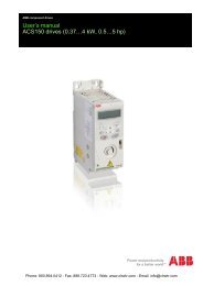
YASKAWA AC Drive P1000<br />
Industrial Fan and Pump Drive<br />
<strong>Technical</strong> <strong>Manual</strong><br />
Type: CIMR-PU A<br />
Models: 200 V Class: 3/4 to 175 HP ND<br />
400 V Class: 3/4 to 500 HP ND<br />
600 V Class: 2 to 250 HP ND<br />
To properly use the product, read this manual thoroughly and retain<br />
for easy reference, inspection, and maintenance. Ensure the end user<br />
receives this manual.<br />
MANUAL NO. SIEP YAIP1U 01A<br />
Receiving<br />
Mechanical Installation<br />
Electrical Installation<br />
Start-Up Programming &<br />
Operation<br />
Parameter Details<br />
Troubleshooting<br />
Periodic Inspection &<br />
Maintenance<br />
Peripheral Devices &<br />
Options<br />
Specifications<br />
Parameter List<br />
MEMOBUS/Modbus<br />
Communications<br />
Standards Compliance<br />
Quick Reference Sheet<br />
1<br />
2<br />
3<br />
4<br />
5<br />
6<br />
7<br />
8<br />
A<br />
B<br />
C<br />
D<br />
E
Copyright © 2012 YASKAWA ELECTRIC CORPORATION. All rights reserved.<br />
No part of this publication may be reproduced, stored in a retrieval system, or transmitted, in any form or by any means,<br />
mechanical, electronic, photocopying, recording, or otherwise, without the prior written permission of Yaskawa. No patent<br />
liability is assumed with respect to the use of the information contained herein. Moreover, because Yaskawa is constantly<br />
striving to improve its high-quality products, the information contained in this manual is subject to change without notice.<br />
Every precaution has been taken in the preparation of this manual. Yaskawa assumes no responsibility for errors or omissions.<br />
Neither is any liability assumed for damages resulting from the use of the information contained in this publication.
u Quick Reference<br />
Easily Set Parameters for Specific Applications<br />
Preset parameter defaults are available for setting up applications. Refer to Application Selection on<br />
page 118.<br />
Perform Auto-Tuning<br />
Automatic tuning sets motor parameters. Refer to Auto-Tuning on page 121.<br />
Maintenance Check Using Drive Monitors<br />
Use drive monitors to check if fans, capacitors, or other components require maintenance. Refer to Performance Life Monitors Maintenance<br />
Monitors on page 329.<br />
Fault Display and Troubleshooting<br />
Refer to Drive Alarms, Faults, and Errors on page 279 and Refer to Troubleshooting without Fault Display on page 314.<br />
Standards Compliance<br />
Refer to European Standards on page 500 and Refer to UL and CSA Standards on page 507 .<br />
CE marking applies to 200 V class and 400 V class models only.<br />
Phone: 800.894.0412 - Fax: 888.723.4773 - Web: www.clrwtr.com - Email: info@clrwtr.com<br />
YASKAWA SIEP YAIP1U 01A AC Drive - P1000 <strong>Technical</strong> <strong>Manual</strong> 3
This Page Intentionally Blank<br />
Phone: 800.894.0412 - Fax: 888.723.4773 - Web: www.clrwtr.com - Email: info@clrwtr.com<br />
4 YASKAWA SIEP YAIP1U 01A AC Drive - P1000 <strong>Technical</strong> <strong>Manual</strong>
Table of Contents<br />
QUICK REFERENCE ....................................................................................... 3<br />
i. PREFACE & GENERAL SAFETY.................................................................. 15<br />
i.1 Preface ....................................................................................................................... 16<br />
Applicable Documentation....................................................................................................... 16<br />
Symbols................................................................................................................................... 16<br />
Terms and Abbreviations ........................................................................................................ 16<br />
Trademarks ............................................................................................................................. 16<br />
i.2 General Safety ........................................................................................................... 17<br />
Supplemental Safety Information ............................................................................................ 17<br />
Safety Messages..................................................................................................................... 18<br />
General Application Precautions ............................................................................................. 20<br />
Motor Application Precautions................................................................................................. 21<br />
Drive Label Warning Example................................................................................................. 24<br />
Warranty Information............................................................................................................... 24<br />
1. RECEIVING .................................................................................................... 25<br />
1.1 Section Safety............................................................................................................ 26<br />
1.2 General Description .................................................................................................. 27<br />
P1000 Model Selection ........................................................................................................... 27<br />
Control Mode Details............................................................................................................... 28<br />
1.3 Model Number and Nameplate Check ..................................................................... 29<br />
Nameplate ............................................................................................................................... 29<br />
1.4 Drive Models and Enclosure Types......................................................................... 32<br />
1.5 Component Names.................................................................................................... 34<br />
IP20/NEMA Type 1 Enclosure................................................................................................. 34<br />
IP00/Open Type Enclosure ..................................................................................................... 37<br />
Front Views ............................................................................................................................. 41<br />
2. MECHANICAL INSTALLATION..................................................................... 43<br />
2.1 Section Safety............................................................................................................ 44<br />
2.2 Mechanical Installation ............................................................................................. 46<br />
Installation Environment .......................................................................................................... 46<br />
Installation Orientation and Spacing........................................................................................ 46<br />
Digital Operator Remote Usage .............................................................................................. 48<br />
Exterior and Mounting Dimensions ......................................................................................... 51<br />
YASKAWA SIEP YAIP1U 01A AC Drive - P1000 <strong>Technical</strong> <strong>Manual</strong> 5
Table of Contents<br />
3. ELECTRICAL INSTALLATION .............................................................................. 59<br />
3.1 Section Safety......................................................................................................................60<br />
3.2 Standard Connection Diagram...........................................................................................62<br />
3.3 Main Circuit Connection Diagram......................................................................................65<br />
Three-Phase 200 V Class Models 2A0004 to 2A0081<br />
Three-Phase 400 V Class Models 4A0002 to 4A0044<br />
Three-Phase 600 V Class Models 5A0003 to 5A0032 .................................................................... 65<br />
Three-Phase 200 V Class Models 2A0110, 2A0138<br />
Three-Phase 400 V Class Models 4A0058, 4A0072<br />
Three-Phase 600 V Class Models 5A0041, 5A0052 ....................................................................... 65<br />
Three-Phase 200 V Class Models 2A0169 to 2A0211<br />
Three-Phase 400 V Class Models 4A0088 to 4A0139<br />
Three-Phase 600 V Class Models 5A0062 to 5A0099 .................................................................... 66<br />
Three-Phase 200 V Class Models 2A0250 to 2A0415<br />
Three-Phase 400 V Class Models 4A0165 to 4A0675<br />
Three-Phase 600 V Class Models 5A0125 to 5A0242 .................................................................... 66<br />
3.4 Terminal Block Configuration ............................................................................................67<br />
3.5 Terminal Cover ....................................................................................................................69<br />
Models 2A0004 to 2A0081, 4A0002 to 4A0044, 5A0003 to 5A0032<br />
(IP20/NEMA Type 1 Enclosure)....................................................................................................... 69<br />
Models 2A0110 to 2A0250, 4A0208 to 4A0675, and 5A0125 to 5A0242 (IP00/Open Type<br />
Enclosure)........................................................................................................................................ 70<br />
3.6 Digital Operator and Front Cover.......................................................................................71<br />
Removing/Reattaching the Digital Operator...................................................................................... 71<br />
Removing/Reattaching the Front Cover ............................................................................................ 71<br />
3.7 Top Protective Cover ..........................................................................................................74<br />
Removing the Top Protective Cover ................................................................................................. 74<br />
Reattaching the Top Protective Cover .............................................................................................. 74<br />
3.8 Main Circuit Wiring..............................................................................................................75<br />
Main Circuit Terminal Functions........................................................................................................ 75<br />
Protecting Main Circuit Terminals ..................................................................................................... 75<br />
Wire Gauges and Tightening Torque ................................................................................................ 77<br />
Main Circuit Terminal and Motor Wiring ............................................................................................ 83<br />
3.9 Control Circuit Wiring .........................................................................................................86<br />
Control Circuit Connection Diagram.................................................................................................. 86<br />
Control Circuit Terminal Block Functions .......................................................................................... 86<br />
Terminal Configuration ...................................................................................................................... 88<br />
Wiring the Control Circuit Terminal ................................................................................................... 89<br />
Switches and Jumpers on the Terminal Board.................................................................................. 91<br />
3.10 Control I/O Connections .....................................................................................................92<br />
Sinking/Sourcing Mode Switch for Digital Inputs............................................................................... 92<br />
Using the Pulse Train Output ............................................................................................................ 92<br />
Terminals A1, A2, and A3 Input Signal Selection.............................................................................. 93<br />
Terminal AM/FM Signal Selection ..................................................................................................... 94<br />
MEMOBUS/Modbus Termination ...................................................................................................... 94<br />
3.11 Connect to a PC...................................................................................................................95<br />
3.12 External Interlock ................................................................................................................96<br />
Drive Ready....................................................................................................................................... 96<br />
6 YASKAWA SIEP YAIP1U 01A AC Drive - P1000 <strong>Technical</strong> <strong>Manual</strong>
Table of Contents<br />
3.13 Wiring Checklist ..................................................................................................................97<br />
4. START-UP PROGRAMMING & OPERATION....................................................... 99<br />
4.1 Section Safety....................................................................................................................100<br />
4.2 Using the Digital Operator................................................................................................101<br />
Keys and Displays........................................................................................................................... 101<br />
LCD Display .................................................................................................................................... 102<br />
ALARM (ALM) LED Displays........................................................................................................... 103<br />
LO/RE LED and RUN LED Indications............................................................................................ 103<br />
Menu Structure for Digital Operator ................................................................................................ 105<br />
4.3 The Drive, Programming, and Clock Adjustment Modes ..............................................106<br />
Real-Time Clock (RTC) ................................................................................................................... 106<br />
Clock Adjustment ............................................................................................................................ 106<br />
Navigating the Drive and Programming Modes............................................................................... 109<br />
Changing Parameter Settings or Values ......................................................................................... 110<br />
Verifying Parameter Changes: Verify Menu .................................................................................... 112<br />
Simplified Setup Using the Setup Groups ....................................................................................... 113<br />
Switching Between LOCAL and REMOTE...................................................................................... 114<br />
4.4 Start-Up Flowchart ............................................................................................................116<br />
4.5 Powering Up the Drive ......................................................................................................117<br />
Powering Up the Drive and Operation Status Display..................................................................... 117<br />
4.6 Application Selection........................................................................................................118<br />
A1-03 = 8008: Pump ....................................................................................................................... 118<br />
A1-03 = 8009: Pump w/ PI .............................................................................................................. 118<br />
A1-03 = 8010: Fan .......................................................................................................................... 119<br />
A1-03 = 8011: Fan w/ PI ................................................................................................................. 119<br />
Default Values for Fan and Pump Applications............................................................................... 120<br />
4.7 Auto-Tuning .......................................................................................................................121<br />
Types of Auto-Tuning ...................................................................................................................... 121<br />
Before Auto-Tuning the Drive.......................................................................................................... 121<br />
Auto-Tuning Interruption and Fault Codes ...................................................................................... 122<br />
Auto-Tuning Operation Example ..................................................................................................... 122<br />
T1: Parameter Settings during Induction Motor Auto-Tuning .......................................................... 124<br />
4.8 No-Load Operation Test Run............................................................................................126<br />
No-Load Operation Test Run .......................................................................................................... 126<br />
4.9 Test Run with Load Connected........................................................................................128<br />
Test Run with the Load Connected ................................................................................................. 128<br />
4.10 Verifying Parameter Settings and Backing Up Changes...............................................129<br />
Backing Up Parameter Values: o2-03 ............................................................................................. 129<br />
Parameter Access Level: A1-01...................................................................................................... 129<br />
Password Settings: A1-04, A1-05 ................................................................................................... 129<br />
Copy Function ................................................................................................................................. 130<br />
4.11 Test Run Checklist ............................................................................................................131<br />
5. PARAMETER DETAILS ....................................................................................... 133<br />
5.1 A: Initialization...................................................................................................................134<br />
A1: Initialization ............................................................................................................................... 134<br />
A2: User Parameters....................................................................................................................... 138<br />
YASKAWA SIEP YAIP1U 01A AC Drive - P1000 <strong>Technical</strong> <strong>Manual</strong> 7
Table of Contents<br />
5.2 b: Application.....................................................................................................................139<br />
b1: Operation Mode Selection......................................................................................................... 139<br />
b2: DC Injection Braking and Short Circuit Braking......................................................................... 144<br />
b3: Speed Search............................................................................................................................ 145<br />
b4: Delay Timers ............................................................................................................................. 151<br />
b5: PID Control................................................................................................................................ 151<br />
EZ Sleep/Wake-up Function ........................................................................................................... 159<br />
b6: Dwell Function........................................................................................................................... 165<br />
b8: Energy Saving ........................................................................................................................... 166<br />
5.3 C: Tuning............................................................................................................................168<br />
C1: Acceleration and Deceleration Times ....................................................................................... 168<br />
C2: S-Curve Characteristics............................................................................................................ 169<br />
C3: Slip Compensation.................................................................................................................... 170<br />
C4: Torque Compensation .............................................................................................................. 171<br />
C6: Carrier Frequency..................................................................................................................... 171<br />
5.4 d: Reference Settings .......................................................................................................173<br />
d1: Frequency Reference................................................................................................................ 173<br />
d2: Frequency Upper/Lower Limits ................................................................................................. 175<br />
d3: Jump Frequency........................................................................................................................ 176<br />
d4: Frequency Reference Hold and Up/Down 2 Function............................................................... 177<br />
d6: Field Weakening and Field Forcing........................................................................................... 181<br />
5.5 E: Motor Parameters .........................................................................................................182<br />
E1: V/f Pattern for Motor 1............................................................................................................... 182<br />
E2: Motor 1 Parameters .................................................................................................................. 186<br />
5.6 F: Option Settings .............................................................................................................189<br />
F4: Analog Monitor Card Settings ................................................................................................... 189<br />
F6: Communication Option Card..................................................................................................... 190<br />
CC-Link Parameters........................................................................................................................ 191<br />
MECHATROLINK Parameters ........................................................................................................ 191<br />
PROFIBUS-DP Parameters ............................................................................................................ 192<br />
CANopen Parameters ..................................................................................................................... 193<br />
DeviceNet Parameters .................................................................................................................... 193<br />
5.7 H: Terminal Functions.......................................................................................................196<br />
H1: Multi-Function Digital Inputs ..................................................................................................... 196<br />
H2: Multi-Function Digital Outputs................................................................................................... 206<br />
H3: Multi-Function Analog Inputs .................................................................................................... 216<br />
H4: Multi-Function Analog Outputs ................................................................................................. 221<br />
H5: MEMOBUS/Modbus Serial Communication ............................................................................. 223<br />
H6: Pulse Train Input/Output........................................................................................................... 223<br />
5.8 L: Protection Functions ....................................................................................................225<br />
L1: Motor Protection ........................................................................................................................ 225<br />
L2: Momentary Power Loss Ride-Thru............................................................................................ 229<br />
L3: Stall Prevention ......................................................................................................................... 235<br />
L4: Speed Detection........................................................................................................................ 241<br />
L5: Fault Restart.............................................................................................................................. 242<br />
L6: Torque Detection....................................................................................................................... 243<br />
L8: Drive Protection......................................................................................................................... 245<br />
5.9 n: Special Adjustments.....................................................................................................251<br />
n1: Hunting Prevention.................................................................................................................... 251<br />
n3: High Slip Braking (HSB) and Overexcitation Braking................................................................ 251<br />
8 YASKAWA SIEP YAIP1U 01A AC Drive - P1000 <strong>Technical</strong> <strong>Manual</strong>
Table of Contents<br />
5.10 o: Operator Related Settings............................................................................................254<br />
o1: Digital Operator Display Selection............................................................................................. 254<br />
o2: Digital Operator Keypad Functions ........................................................................................... 256<br />
o3: Copy Function ........................................................................................................................... 259<br />
o4: Maintenance Monitor Settings................................................................................................... 259<br />
5.11 S: Special Application.......................................................................................................262<br />
S1: Dynamic Audible Noise Control Function ................................................................................. 262<br />
S2: Programmable Run Timers....................................................................................................... 263<br />
S3: Secondary PI (PI2) Control ....................................................................................................... 268<br />
S6: P1000 Protection ...................................................................................................................... 271<br />
T: Motor Tuning ............................................................................................................................... 272<br />
5.12 U: Monitor Parameters......................................................................................................273<br />
U1: Operation Status Monitors ........................................................................................................ 273<br />
U2: Fault Trace................................................................................................................................ 273<br />
U3: Fault History.............................................................................................................................. 273<br />
U4: Maintenance Monitors .............................................................................................................. 273<br />
U5: PID Monitors ............................................................................................................................. 273<br />
U6: Operation Status Monitors ........................................................................................................ 273<br />
6. TROUBLESHOOTING.......................................................................................... 275<br />
6.1 Section Safety....................................................................................................................276<br />
6.2 Motor Performance Fine-Tuning......................................................................................278<br />
Fine-Tuning V/f Control ................................................................................................................... 278<br />
Parameters to Minimize Motor Hunting and Oscillation .................................................................. 278<br />
6.3 Drive Alarms, Faults, and Errors .....................................................................................279<br />
Types of Alarms, Faults, and Errors................................................................................................ 279<br />
Alarm and Error Displays ................................................................................................................ 280<br />
6.4 Fault Detection ..................................................................................................................283<br />
Fault Displays, Causes, and Possible Solutions ............................................................................. 283<br />
6.5 Alarm Detection.................................................................................................................297<br />
Alarm Codes, Causes, and Possible Solutions ............................................................................... 297<br />
6.6 Operator Programming Errors .........................................................................................304<br />
Operator Programming Error Codes, Causes, and Possible Solutions........................................... 304<br />
6.7 Auto-Tuning Fault Detection ............................................................................................307<br />
Auto-Tuning Codes, Causes, and Possible Solutions..................................................................... 307<br />
6.8 Copy Function Related Displays .....................................................................................310<br />
Tasks, Errors, and Troubleshooting ................................................................................................ 310<br />
6.9 Diagnosing and Resetting Faults.....................................................................................312<br />
Fault Occurs Simultaneously with Power Loss ............................................................................... 312<br />
If the Drive Still has Power After a Fault Occurs ............................................................................. 312<br />
Viewing Fault Trace Data After Fault .............................................................................................. 312<br />
Fault Reset Methods ....................................................................................................................... 313<br />
6.10 Troubleshooting without Fault Display...........................................................................314<br />
Common Problems.......................................................................................................................... 314<br />
Cannot Change Parameter Settings ............................................................................................... 314<br />
Motor Does Not Rotate Properly after Pressing RUN Button or after Entering External Run<br />
Command ...................................................................................................................................... 315<br />
Motor is Too Hot.............................................................................................................................. 316<br />
YASKAWA SIEP YAIP1U 01A AC Drive - P1000 <strong>Technical</strong> <strong>Manual</strong> 9
Table of Contents<br />
oPE02 Error Occurs When Lowering the Motor Rated Current Setting .......................................... 317<br />
Motor Stalls during Acceleration or Acceleration Time is Too Long................................................ 317<br />
Drive Frequency Reference Differs from the Controller Frequency Reference Command ............. 318<br />
Excessive Motor Oscillation and Erratic Rotation............................................................................ 318<br />
Deceleration Takes Longer Than Expected with Dynamic Braking Enabled .................................. 318<br />
Noise From Drive or Motor Cables When the Drive is Powered On ............................................... 319<br />
Ground Fault Circuit Interrupter (GFCI) Trips During Run .............................................................. 319<br />
Connected Machinery Vibrates When Motor Rotates ..................................................................... 319<br />
PID Output Fault.............................................................................................................................. 320<br />
Insufficient Starting Torque ............................................................................................................. 320<br />
Motor Rotates After the Drive Output is Shut Off (Motor Rotates During DC Injection Braking)..... 320<br />
Output Frequency is Not as High as Frequency Reference............................................................ 320<br />
Sound from Motor............................................................................................................................ 320<br />
Motor Does Not Restart after Power Loss....................................................................................... 321<br />
7. PERIODIC INSPECTION & MAINTENANCE ...................................................... 323<br />
7.1 Section Safety....................................................................................................................324<br />
7.2 Inspection ..........................................................................................................................326<br />
Recommended Daily Inspection...................................................................................................... 326<br />
Recommended Periodic Inspection................................................................................................. 327<br />
7.3 Periodic Maintenance .......................................................................................................329<br />
Replacement Parts.......................................................................................................................... 329<br />
7.4 Drive Cooling Fans............................................................................................................331<br />
Number of Cooling Fans ................................................................................................................. 331<br />
Cooling Fan Component Names ..................................................................................................... 333<br />
Cooling Fan Replacement: 2A0018 to 2A0081, 4A0007 to 4A0044, and 5A0006 to 5A0032 ........ 333<br />
Cooling Fan Replacement: 2A0110, 2A0138, 4A0058, 4A0072, 5A0041, and 5A0052 ................. 336<br />
Cooling Fan Replacement: 4A0088 and 4A0103 ............................................................................ 338<br />
Cooling Fan Replacement: 2A0169 to 2A0415, 4A0139 to 4A0362, and 5A0062 to 5A0242 ........ 340<br />
Cooling Fan Replacement: 4A0414 ................................................................................................ 344<br />
Cooling Fan Replacement: 4A0515 and 4A0675 ............................................................................ 346<br />
7.5 Drive Replacement ............................................................................................................350<br />
Serviceable Parts ............................................................................................................................ 350<br />
Terminal Board................................................................................................................................ 350<br />
Replacing the Drive ......................................................................................................................... 351<br />
8. PERIPHERAL DEVICES & OPTIONS ................................................................. 353<br />
8.1 Section Safety....................................................................................................................354<br />
8.2 Drive Options and Peripheral Devices ............................................................................355<br />
8.3 Connecting Peripheral Devices .......................................................................................356<br />
8.4 Option Installation.............................................................................................................357<br />
Prior to Installing the Option ............................................................................................................ 357<br />
Communication Option Installation Example................................................................................... 358<br />
Communication Option Installation Example................................................................................... 360<br />
8.5 Installing Peripheral Devices ...........................................................................................363<br />
Dynamic Braking Options................................................................................................................ 363<br />
Installing a Molded Case Circuit Breaker (MCCB) or Ground Fault Circuit Interrupter (GFCI) ....... 366<br />
Installing a Magnetic Contactor at the Power Supply Side.............................................................. 366<br />
Connecting an AC Reactor or DC Link Choke ................................................................................ 367<br />
Connecting a Surge Absorber ......................................................................................................... 367<br />
10 YASKAWA SIEP YAIP1U 01A AC Drive - P1000 <strong>Technical</strong> <strong>Manual</strong>
Table of Contents<br />
Connecting a Noise Filter ................................................................................................................ 368<br />
Installing Input Fuses ...................................................................................................................... 369<br />
Attachment for External Heatsink Mounting .................................................................................... 371<br />
Installing a Motor Thermal Overload (oL) Relay on the Drive Output ............................................. 371<br />
A. SPECIFICATIONS ................................................................................................ 373<br />
A.1 Power Ratings ...................................................................................................................374<br />
Three-Phase 200 V Class Drive Models 2A0004 to 2A0030 .......................................................... 374<br />
Three-Phase 200 V Class Drive Models 2A0040 to 2A0211 .......................................................... 375<br />
Three-Phase 200 V Class Drive Models 2A0250 to 2A0415 .......................................................... 376<br />
Three-Phase 400 V Class Drive Models 4A0002 to 4A0031 .......................................................... 377<br />
Three-Phase 400 V Class Drive Models 4A0038 to 4A0165 .......................................................... 378<br />
Three-Phase 400 V Class Drive Models 4A0208 to 4A0675 .......................................................... 379<br />
Three-Phase 600 V Class Drive Models 5A0003 to 5A0032 .......................................................... 380<br />
Three-Phase 600 V Class Drive Models 5A0041 to 5A0099 .......................................................... 381<br />
Three-Phase 600 V Class Drive Models 5A0125 to 5A0242 .......................................................... 382<br />
A.2 Drive Specifications ..........................................................................................................383<br />
A.3 Drive Watt Loss Data ........................................................................................................385<br />
A.4 Drive Derating Data ...........................................................................................................387<br />
Rated Current Depending on Carrier Frequency ............................................................................ 387<br />
Temperature Derating ..................................................................................................................... 389<br />
Altitude Derating.............................................................................................................................. 390<br />
B. PARAMETER LIST............................................................................................... 391<br />
B.1 Understanding Parameter Descriptions..........................................................................392<br />
Parameter Icons .............................................................................................................................. 392<br />
Parameter Groups........................................................................................................................... 392<br />
B.2 A: Initialization Parameters ..............................................................................................393<br />
A1: Initialization ............................................................................................................................... 393<br />
A2: User Parameters....................................................................................................................... 393<br />
B.3 b: Application.....................................................................................................................394<br />
b1: Operation Mode Selection......................................................................................................... 394<br />
b2: DC Injection Braking and Short Circuit Braking......................................................................... 394<br />
b3: Speed Search............................................................................................................................ 395<br />
b4: Timer Function .......................................................................................................................... 396<br />
b5: PID Control................................................................................................................................ 396<br />
b6: Dwell Function........................................................................................................................... 399<br />
b8: Energy Saving ........................................................................................................................... 399<br />
B.4 C: Tuning............................................................................................................................400<br />
C1: Acceleration and Deceleration Times ....................................................................................... 400<br />
C2: S-Curve Characteristics............................................................................................................ 400<br />
C3: Slip Compensation.................................................................................................................... 401<br />
C4: Torque Compensation .............................................................................................................. 401<br />
C6: Carrier Frequency..................................................................................................................... 401<br />
B.5 d: References.....................................................................................................................402<br />
d1: Frequency Reference................................................................................................................ 402<br />
d2: Frequency Upper/Lower Limits ................................................................................................. 403<br />
d3: Jump Frequency........................................................................................................................ 403<br />
d4: Frequency Reference Hold and Up/Down 2 Function............................................................... 403<br />
d6: Field Weakening and Field Forcing........................................................................................... 404<br />
YASKAWA SIEP YAIP1U 01A AC Drive - P1000 <strong>Technical</strong> <strong>Manual</strong> 11
Table of Contents<br />
B.6 E: Motor Parameters .........................................................................................................405<br />
E1: V/f Pattern ................................................................................................................................. 405<br />
E2: Motor 1 Parameters .................................................................................................................. 406<br />
F4: Analog Monitor Card (AO-A3) ................................................................................................... 406<br />
F6, F7: Communication Option Card............................................................................................... 407<br />
B.7 H Parameters: Multi-Function Terminals ........................................................................411<br />
H1: Multi-Function Digital Inputs ..................................................................................................... 411<br />
H2: Multi-Function Digital Outputs................................................................................................... 414<br />
H3: Multi-Function Analog Inputs .................................................................................................... 416<br />
H4: Analog Outputs ......................................................................................................................... 417<br />
H5: MEMOBUS/Modbus Serial Communication ............................................................................. 418<br />
H6: Pulse Train Input/Output........................................................................................................... 419<br />
B.8 L: Protection Function ......................................................................................................420<br />
L1: Motor Protection ........................................................................................................................ 420<br />
L2: Momentary Power Loss Ride-Thru............................................................................................ 420<br />
L3: Stall Prevention ......................................................................................................................... 421<br />
L4: Speed Detection........................................................................................................................ 422<br />
L5: Fault Restart.............................................................................................................................. 423<br />
L6: Torque Detection....................................................................................................................... 423<br />
L8: Drive Protection......................................................................................................................... 425<br />
B.9 n: Special Adjustment.......................................................................................................427<br />
n1: Hunting Prevention.................................................................................................................... 427<br />
n3: High Slip Braking (HSB) and Overexcitation Braking................................................................ 427<br />
B.10 o: Operator-Related Settings ...........................................................................................428<br />
o1: Digital Operator Display Selection............................................................................................. 428<br />
o2: Digital Operator Keypad Functions ........................................................................................... 429<br />
o3: Copy Function ........................................................................................................................... 429<br />
o4: Maintenance Monitor Settings................................................................................................... 430<br />
B.11 S: Special Application.......................................................................................................431<br />
S1: Dynamic Noise Control Function .............................................................................................. 431<br />
S2: Programmable Run Timers....................................................................................................... 431<br />
S3: Secondary PI (PI2) Control ....................................................................................................... 434<br />
S6: P1000 Protection ...................................................................................................................... 435<br />
B.12 T: Motor Tuning .................................................................................................................436<br />
T1: Induction Motor Auto-Tuning..................................................................................................... 436<br />
B.13 U: Monitors.........................................................................................................................437<br />
U1: Operation Status Monitors ........................................................................................................ 437<br />
U2: Fault Trace................................................................................................................................ 439<br />
U3: Fault History.............................................................................................................................. 440<br />
U4: Maintenance Monitors .............................................................................................................. 441<br />
U5: PID Monitors ............................................................................................................................. 443<br />
U6: Operation Status Monitors ........................................................................................................ 444<br />
B.14 V/f Pattern Default Values.................................................................................................445<br />
B.15 Defaults by Drive Model....................................................................................................446<br />
C. MEMOBUS/MODBUS COMMUNICATIONS........................................................ 463<br />
C.1 MEMOBUS/Modbus Configuration ..................................................................................464<br />
C.2 Communication Specifications........................................................................................465<br />
C.3 Connecting to a Network ..................................................................................................466<br />
12 YASKAWA SIEP YAIP1U 01A AC Drive - P1000 <strong>Technical</strong> <strong>Manual</strong>
Table of Contents<br />
Network Cable Connection.............................................................................................................. 466<br />
Wiring Diagram for Multiple Connections ........................................................................................ 466<br />
Network Termination ....................................................................................................................... 467<br />
C.4 MEMOBUS/Modbus Setup Parameters ...........................................................................468<br />
MEMOBUS/Modbus Serial Communication.................................................................................... 468<br />
C.5 Drive Operations by MEMOBUS/Modbus........................................................................471<br />
Observing the Drive Operation........................................................................................................ 471<br />
Controlling the Drive........................................................................................................................ 471<br />
C.6 Communications Timing...................................................................................................472<br />
Command Messages from Master to Drive..................................................................................... 472<br />
Response Messages from Drive to Master ..................................................................................... 472<br />
C.7 Message Format ................................................................................................................473<br />
Message Content ............................................................................................................................ 473<br />
Slave Address ................................................................................................................................. 473<br />
Function Code ................................................................................................................................. 473<br />
Data................................................................................................................................................. 473<br />
Error Check ..................................................................................................................................... 473<br />
C.8 Message Examples ...........................................................................................................475<br />
Reading Drive MEMOBUS/Modbus Register Contents .................................................................. 475<br />
Loopback Test................................................................................................................................. 475<br />
Writing to Multiple Registers............................................................................................................ 476<br />
C.9 MEMOBUS/Modbus Data Table........................................................................................477<br />
Command Data ............................................................................................................................... 477<br />
Monitor Data.................................................................................................................................... 478<br />
Broadcast Messages....................................................................................................................... 489<br />
Fault Trace Contents....................................................................................................................... 490<br />
Alarm Register Contents ................................................................................................................. 492<br />
C.10 Enter Command.................................................................................................................493<br />
Enter Command Types ................................................................................................................... 493<br />
Enter Command Settings when Upgrading the Drive...................................................................... 493<br />
C.11 Communication Errors .....................................................................................................494<br />
MEMOBUS/Modbus Error Codes.................................................................................................... 494<br />
Slave Not Responding..................................................................................................................... 494<br />
C.12 Self-Diagnostics ................................................................................................................495<br />
D. STANDARDS COMPLIANCE .............................................................................. 497<br />
D.1 Section Safety....................................................................................................................498<br />
D.2 European Standards .........................................................................................................500<br />
CE Low Voltage Directive Compliance............................................................................................ 500<br />
EMC Guidelines Compliance .......................................................................................................... 502<br />
D.3 UL and CSA Standards .....................................................................................................507<br />
UL Standards Compliance .............................................................................................................. 507<br />
CSA Standards Compliance............................................................................................................ 520<br />
Drive Motor Overload Protection ..................................................................................................... 520<br />
Precautionary Notes on External Heatsink (IP00/Open Type Enclosure) ....................................... 522<br />
E. QUICK REFERENCE SHEET .............................................................................. 525<br />
E.1 Drive and Motor Specifications........................................................................................526<br />
YASKAWA SIEP YAIP1U 01A AC Drive - P1000 <strong>Technical</strong> <strong>Manual</strong> 13
Table of Contents<br />
Drive Specifications......................................................................................................................... 526<br />
Motor Specifications ........................................................................................................................ 526<br />
E.2 Basic Parameter Settings .................................................................................................527<br />
Basic Setup ..................................................................................................................................... 527<br />
V/f Pattern Setup ............................................................................................................................. 527<br />
Motor Setup..................................................................................................................................... 527<br />
Multi-Function Digital Inputs ............................................................................................................ 527<br />
Pulse Train Input/Analog Inputs ...................................................................................................... 528<br />
Multi-Function Digital Outputs ......................................................................................................... 528<br />
Monitor Outputs............................................................................................................................... 528<br />
E.3 User Setting Table.............................................................................................................529<br />
INDEX ................................................................................................................... 535<br />
Phone: 800.894.0412 - Fax: 888.723.4773 - Web: www.clrwtr.com - Email: info@clrwtr.com<br />
14 YASKAWA SIEP YAIP1U 01A AC Drive - P1000 <strong>Technical</strong> <strong>Manual</strong>
i<br />
Preface & General Safety<br />
This section provides safety messages pertinent to this product that, if not heeded, may result in fatality,<br />
personal injury, or equipment damage. Yaskawa is not responsible for the consequences of ignoring<br />
these instructions.<br />
i.1 PREFACE...............................................................................................................16<br />
i.2 GENERAL SAFETY...............................................................................................17<br />
Phone: 800.894.0412 - Fax: 888.723.4773 - Web: www.clrwtr.com - Email: info@clrwtr.com<br />
YASKAWA SIEP YAIP1U 01A AC Drive - P1000 <strong>Technical</strong> <strong>Manual</strong> 15
i.1 Preface<br />
i.1 Preface<br />
Yaskawa manufactures products used as components in a wide variety of industrial systems and equipment. The selection and<br />
application of Yaskawa products remain the responsibility of the equipment manufacturer or end user. Yaskawa accepts no<br />
responsibility for the way its products are incorporated into the final system design. Under no circumstances should any<br />
Yaskawa product be incorporated into any product or design as the exclusive or sole safety control. Without exception, all<br />
controls should be designed to detect faults dynamically and fail safely under all circumstances. All systems or equipment<br />
designed to incorporate a product manufactured by Yaskawa must be supplied to the end user with appropriate warnings and<br />
instructions as to the safe use and operation of that part. Any warnings provided by Yaskawa must be promptly provided to<br />
the end user. Yaskawa offers an express warranty only as to the quality of its products in conforming to standards and<br />
specifications published in the Yaskawa manual. NO OTHER WARRANTY, EXPRESS OR IMPLIED, IS OFFERED.<br />
Yaskawa assumes no liability for any personal injury, property damage, losses, or claims arising from misapplication of its<br />
products.<br />
This manual is designed to ensure correct and suitable application of drives. Read this manual before attempting to install,<br />
operate, maintain, or inspect a drive and keep it in a safe, convenient location for future reference. Be sure you understand all<br />
precautions and safety information before attempting application.<br />
u Applicable Documentation<br />
The following manuals are available for P1000 series drives:<br />
P1000 Series AC Drive <strong>Technical</strong> <strong>Manual</strong> (SIEPYAIP1U01)<br />
This manual provides detailed information on parameter settings, drive functions, and MEMOBUS/<br />
Modbus specifications. Use this manual to expand drive functionality and to take advantage of higher<br />
performance features. This manual is available for download on our documentation website.<br />
om.<br />
P1000 Series AC Drive Quick Start Guide (TOEPYAIP1U01)<br />
Read this guide first. This guide is packaged together with the product and contains basic information<br />
required to install and wire the drive. It also gives an overview of fault diagnostics, maintenance, and<br />
parameter settings. The purpose of this guide is to prepare the drive for a trial run with an application and<br />
for basic operation. This manual is available for download on our documentation website<br />
wm.<br />
u Symbols<br />
Note:<br />
TERMS<br />
Indicates a supplement or precaution that does not cause drive damage.<br />
Indicates a term or definition used in this manual.<br />
u Terms and Abbreviations<br />
TERMS<br />
• Drive: Yaskawa P1000-Series Drive<br />
• BCD: Binary Coded Decimal<br />
• H: Hexadecimal Number Format<br />
• IGBT: Insulated Gate Bipolar Transistor<br />
• kbps: Kilobits per Second<br />
• MAC: Media Access Control<br />
• Mbps: Megabits per Second<br />
• r/min: Revolutions per Minute<br />
• V/f: V/f Control<br />
u Trademarks<br />
• CANopen is a trademark of CAN in Automation (CiA).<br />
• CC-Link is a trademark of CC-Link Partner Association (CLPA).<br />
• DeviceNet is a trademark of Open DeviceNet Vendor Association, Inc. (ODVA).<br />
• PROFIBUS-DP is a trademark of PROFIBUS International (PI).<br />
• MECHATROLINK-I/MECHATROLINK-II are trademarks of MECHATROLINK Members Association (MMA).<br />
• Other companies and product names mentioned in this manual are trademarks of those companies.<br />
16 YASKAWA SIEP YAIP1U 01A AC Drive - P1000 <strong>Technical</strong> <strong>Manual</strong>
i.2 General Safety<br />
i.2 General Safety<br />
u Supplemental Safety Information<br />
General Precautions<br />
• The diagrams in this manual may be indicated without covers or safety shields to show details. Replace the covers or shields before<br />
operating the drive and run the drive according to the instructions described in this manual.<br />
• Any illustrations, photographs, or examples used in this manual are provided as examples only and may not apply to all products to<br />
which this manual is applicable.<br />
• The products and specifications described in this manual or the content and presentation of the manual may be changed without notice<br />
to improve the product and/or the manual.<br />
• When ordering a new copy of the manual due to damage or loss, contact your Yaskawa representative or the nearest Yaskawa sales<br />
office and provide the manual number shown on the front cover.<br />
• If nameplate becomes worn or damaged, order a replacement from your Yaskawa representative or the nearest Yaskawa sales office.<br />
WARNING<br />
Read and understand this manual before installing, operating or servicing this drive. The drive must be installed according<br />
to this manual and local codes.<br />
The following conventions are used to indicate safety messages in this manual. Failure to heed these messages could result<br />
in serious or fatal injury or damage to the products or to related equipment and systems.<br />
DANGER<br />
Indicates a hazardous situation, which, if not avoided, will result in death or serious injury.<br />
WARNING<br />
Indicates a hazardous situation, which, if not avoided, could result in death or serious injury.<br />
WARNING! may also be indicated by a bold key word embedded in the text followed by an italicized safety message.<br />
CAUTION<br />
Indicates a hazardous situation, which, if not avoided, could result in minor or moderate injury.<br />
CAUTION! may also be indicated by a bold key word embedded in the text followed by an italicized safety message.<br />
Indicates a property damage message.<br />
NOTICE<br />
NOTICE: may also be indicated by a bold key word embedded in the text followed by an italicized safety message.<br />
Phone: 800.894.0412 - Fax: 888.723.4773 - Web: www.clrwtr.com - Email: info@clrwtr.com<br />
YASKAWA SIEP YAIP1U 01A AC Drive - P1000 <strong>Technical</strong> <strong>Manual</strong> 17
i.2 General Safety<br />
u Safety Messages<br />
DANGER<br />
Heed the safety messages in this manual.<br />
Failure to comply will result in death or serious injury.<br />
The operating company is responsible for any injuries or equipment damage resulting from failure to heed the warnings in<br />
this manual.<br />
Electrical Shock Hazard<br />
Do not connect or disconnect wiring while the power is on.<br />
Failure to comply will result in death or serious injury.<br />
Before servicing, disconnect all power to the equipment. The internal capacitor remains charged even after the power supply<br />
is turned off. After shutting off the power, wait for at least the amount of time specified on the drive before touching any<br />
components.<br />
WARNING<br />
Sudden Movement Hazard<br />
System may start unexpectedly upon application of power, resulting in death or serious injury.<br />
Clear all personnel from the drive, motor and machine area before applying power. Secure covers, couplings, shaft keys and<br />
machine loads before applying power to the drive.<br />
Electrical Shock Hazard<br />
Do not attempt to modify or alter the drive in any way not explained in this manual.<br />
Failure to comply could result in death or serious injury.<br />
Yaskawa is not responsible for any modification of the product made by the user. This product must not be modified.<br />
Do not allow unqualified personnel to use equipment.<br />
Failure to comply could result in death or serious injury.<br />
Maintenance, inspection, and replacement of parts must be performed only by authorized personnel familiar with installation,<br />
adjustment and maintenance of AC drives.<br />
Do not remove covers or touch circuit boards while the power is on.<br />
Failure to comply could result in death or serious injury.<br />
Make sure the protective earthing conductor complies with technical standards and local safety regulations.<br />
Because the leakage current exceeds 3.5 mA in models 4A0414 and larger, IEC 61800-5-1 states that either the power supply<br />
must be automatically disconnected in case of discontinuity of the protective earthing conductor or a protective earthing<br />
conductor with a cross-section of at least 10 mm 2 (Cu) or 16 mm 2 (Al) must be used. Failure to comply may result in death<br />
or serious injury.<br />
Always use appropriate equipment for Ground Fault Circuit Interrupters (GFCIs).<br />
The drive can cause a residual current with a DC component in the protective earthing conductor. Where a residual current<br />
operated protective or monitoring device is used for protection in case of direct or indirect contact, always use a type B GFCI<br />
according to IEC 60755.<br />
Fire Hazard<br />
Do not use an improper voltage source.<br />
Failure to comply could result in death or serious injury by fire.<br />
Verify that the rated voltage of the drive matches the voltage of the incoming power supply before applying power.<br />
Phone: 800.894.0412 - Fax: 888.723.4773 - Web: www.clrwtr.com - Email: info@clrwtr.com<br />
18 YASKAWA SIEP YAIP1U 01A AC Drive - P1000 <strong>Technical</strong> <strong>Manual</strong>
i.2 General Safety<br />
WARNING<br />
Install adequate branch circuit protection according to applicable local codes and this Installation <strong>Manual</strong>. Failure<br />
to comply could result in fire and damage to the drive or injury to personnel.<br />
The device is suitable for use on a circuit capable of delivering not more than 100,000 RMS symmetrical amperes, 240 Vac<br />
maximum (200 V class) and 480 Vac maximum (400 V class), and 600 Vac maximum (600 V class) when protected by<br />
branch circuit protection devices specified in this supplement.<br />
Crush Hazard<br />
Do not use this drive in lifting applications without installing external safety circuitry to prevent accidental dropping<br />
of the load.<br />
The drive does not possess built-in load drop protection for lifting applications.<br />
Failure to comply could result in death or serious injury from falling loads.<br />
Install electrical and/or mechanical safety circuit mechanisms independent of drive circuitry.<br />
CAUTION<br />
Crush Hazard<br />
Do not carry the drive by the front cover.<br />
Failure to comply may result in minor or moderate injury from the main body of the drive falling.<br />
NOTICE<br />
Observe proper electrostatic discharge procedures (ESD) when handling the drive and circuit boards.<br />
Failure to comply may result in ESD damage to the drive circuitry.<br />
Do not perform a withstand voltage test on any part of the drive.<br />
Failure to comply could result in damage to the sensitive devices within the drive.<br />
Do not operate damaged equipment.<br />
Failure to comply could result in further damage to the equipment.<br />
Do not connect or operate any equipment with visible damage or missing parts.<br />
If a fuse is blown or a Ground Fault Circuit Interrupter (GFCI) is tripped, check the wiring and the selection of the<br />
peripheral devices.<br />
Contact your supplier if the cause cannot be identified after checking the above.<br />
Do not restart the drive immediately operate the peripheral devices if a fuse is blown or a GFCI is tripped.<br />
Check the wiring and the selection of peripheral devices to identify the cause. Contact your supplier before restarting the<br />
drive or the peripheral devices if the cause cannot be identified.<br />
Install adequate branch circuit short circuit protection per applicable codes.<br />
Failure to comply could result in damage to the drive.<br />
The drive is suitable for use on a circuit capable of delivering not more than 100,000 RMS symmetrical Amperes, 240 Vac<br />
maximum (200 V Class), 480 Vac maximum (400 V Class), and 600 Vac maximum (600 V Class) when protected by<br />
Bussmann Type FWH or FWP fuses as specified in Factory Recommended Branch Circuit Protection on page 500.<br />
Do not expose the drive to halogen group disinfectants.<br />
Failure to comply may cause damage to the electrical components in the drive.<br />
Do not pack the drive in wooden materials that have been fumigated or sterilized.<br />
Do not sterilize the entire package after the product is packed.<br />
Phone: 800.894.0412 - Fax: 888.723.4773 - Web: www.clrwtr.com - Email: info@clrwtr.com<br />
YASKAWA SIEP YAIP1U 01A AC Drive - P1000 <strong>Technical</strong> <strong>Manual</strong> 19
i.2 General Safety<br />
u General Application Precautions<br />
• Selection<br />
Installing a Reactor<br />
Use an AC reactor or DC link choke in the following situations:<br />
• to suppress harmonic current.<br />
• to smooth peak current that results from capacitor switching.<br />
• when the power supply is above 600 kVA.<br />
• when the drive is running from a power supply system with thyristor converters.<br />
Note: A DC link choke is built in to drive models 2A0110 to 2A0415 and 4A0058 to 4A0675.<br />
4000<br />
Power supply harmonics<br />
reactor required<br />
Power Supply<br />
Capacity (kVA)<br />
600<br />
0<br />
Reactor<br />
unnecessary<br />
60 400<br />
Drive Capacity (kVA)<br />
Figure i.1 Installing a Reactor<br />
Drive Capacity<br />
For specialized motors, make sure that the motor rated current is less than the rated output current for the drive.<br />
When running more than one motor in parallel from a single drive, the capacity of the drive should be larger than [total motor<br />
rated current × 1.1].<br />
Starting Torque<br />
The overload rating for the drive determines the starting and accelerating characteristics of the motor. Expect lower torque<br />
than when running from line power. To get more starting torque, use a larger drive or increase both the motor and drive capacity.<br />
Emergency Stop<br />
During a drive fault condition, the output shuts off but the motor does not stop immediately. A mechanical brake may be<br />
required when it is necessary to stop the motor faster than the ability of the Fast Stop function of the drive.<br />
Options<br />
NOTICE: The B1, B2, , –, +1, +2, and +3 terminals are used to connect optional drive-specific compatible devices only. Connecting non-<br />
Yaskawa-approved devices to these terminals may damage the drive.<br />
Repetitive Starting/Stopping<br />
Laundry machines, punching presses, and other applications with frequent starts and stops often approach 150% of their rated<br />
current values. Heat stress generated from repetitive high current will shorten the life span of the IGBTs.<br />
Yaskawa recommends lowering the carrier frequency, particularly when audible noise is not a concern. It is beneficial to<br />
reduce the load, increase the acceleration and deceleration times, or switch to a larger drive to help keep peak current levels<br />
under 150%. Be sure to check the peak current levels when starting and stopping repeatedly during the initial test run, and<br />
make adjustments accordingly.<br />
• Installation<br />
Enclosure Panels<br />
Keep the drive in a clean environment by installing the drive in an enclosure panel or selecting an installation area free of<br />
airborne dust, lint, and oil mist. Be sure to leave the required space between drives to provide for cooling, and take proper<br />
measures so the ambient temperature remains within allowable limits and keep flammable materials away from the drive.<br />
Yaskawa offers protective designs for drives that must be used in areas subjected to oil mist and excessive vibration. Contact<br />
Yaskawa or your Yaskawa agent for details.<br />
Installation Direction<br />
NOTICE: Install the drive upright as specified in the manual. Refer to Mechanical Installation on page 46 for more information on<br />
installation. Failure to comply may damage the drive due to improper cooling.<br />
20 YASKAWA SIEP YAIP1U 01A AC Drive - P1000 <strong>Technical</strong> <strong>Manual</strong>
• Settings<br />
Upper Limits<br />
NOTICE: The drive is capable of running the motor up to 400 Hz. Be sure to set the upper limit for the frequency of the drive to prevent the<br />
possible danger of accidentally operating equipment at higher than rated speed. The default setting for the maximum output frequency is<br />
60 Hz.<br />
DC Injection Braking<br />
NOTICE: Excessive current during DC Injection Braking and excessive duration of DC Injection Braking can cause motor overheat.<br />
Acceleration/Deceleration Times<br />
Acceleration and deceleration times are affected by the amount of torque generated by the motor, the load torque, and the<br />
inertia moment. Set a longer accel/decel time when Stall Prevention is enabled. The accel/decel times are lengthened for as<br />
long as the Stall Prevention function is in operation. Install one of the available braking options or increase the capacity of the<br />
drive for faster acceleration and deceleration.<br />
• General Handling<br />
Wiring Check<br />
NOTICE: Do not connect power supply lines to output terminals U/T1, V/T2, or W/T3. Failure to comply will destroy the drive. Be sure to<br />
perform a final check of all sequence wiring and other connections before turning on the power and also check for short circuits on the<br />
control terminals, which may damage the drive.<br />
Selecting a Circuit Breaker or Circuit Interrupter<br />
Yaskawa recommends installing a Ground Fault Circuit Interrupter (GFCI) to the power supply side. The GFCI should be<br />
designed for use with AC drives (e.g., Type B according to IEC 60755).<br />
Select a Molded Case Circuit Breaker (MCCB) or GFCI with a rated current 1.5 to 2 times higher than the drive rated current<br />
to avoid nuisance trips caused by harmonics in the drive input current. Refer to Installing a Molded Case Circuit Breaker<br />
(MCCB) or Ground Fault Circuit Interrupter (GFCI) on page 366 for more information.<br />
Magnetic Contactor Installation<br />
WARNING! Fire Hazard. Shut off the drive with a magnetic contactor (MC) when a fault occurs in any external equipment such as braking<br />
resistors. Refer to Installing a Magnetic Contactor at the Power Supply Side on page 366. Failure to comply may cause resistor<br />
overheating, fire, and injury to personnel.<br />
NOTICE: To get the full performance life out of the electrolytic capacitors and circuit relays, refrain from switching the drive power supply<br />
off and on more than once every 30 minutes. Frequent use can damage the drive. Use the drive to stop and start the motor.<br />
Inspection and Maintenance<br />
WARNING! Electrical Shock Hazard. Capacitors in the drive do not immediately discharge after shutting off the power. Wait for at least the<br />
amount of time specified on the drive before touching any components after shutting off the power. Failure to comply may cause injury to<br />
personnel from electrical shock.<br />
WARNING! Burn Hazard. Because the heatsink can get very hot during operation, take proper precautions to prevent burns. When replacing<br />
the cooling fan, shut off the power and wait at least 15 minutes to be sure that the heatsink has cooled down. Failure to comply may cause<br />
burn injury to personnel.<br />
Wiring<br />
Yaskawa recommends using ring terminals on all drive models. Drive models 2A0069 to 2A0415 and 4A0058 to 4A0675<br />
require the use of use ring terminals for UL/cUL compliance. Use only the tools recommended by the terminal manufacturer<br />
for crimping.<br />
Transporting the Drive<br />
NOTICE: Never steam clean the drive. During transport, keep the drive from coming into contact with salts, fluorine, bromine, phthalate<br />
ester, and other such harmful chemicals.<br />
u Motor Application Precautions<br />
• Standard Induction Motors<br />
i.2 General Safety<br />
Low-Speed Range<br />
The cooling fan of a standard motor should sufficiently cool the motor at the rated speed. As the self-cooling capability of<br />
such a motor reduces with the speed, applying full torque at low speed will possibly damage the motor. Reduce the load torque<br />
as the motor slows to prevent motor damage from overheat. Figure i.2 shows the allowable load characteristics for a Yaskawa<br />
standard motor. Use a motor designed specifically for operation with a drive when 100% continuous torque is needed at low<br />
speeds.<br />
Phone: 800.894.0412 - Fax: 888.723.4773 - Web: www.clrwtr.com - Email: info@clrwtr.com<br />
YASKAWA SIEP YAIP1U 01A AC Drive - P1000 <strong>Technical</strong> <strong>Manual</strong> 21
i.2 General Safety<br />
Torque<br />
(%)<br />
25% ED (or 15 min)<br />
40% ED (or 20 min)<br />
60% ED (or 40 min)<br />
100<br />
90<br />
80<br />
70<br />
60<br />
50<br />
Continuous operation<br />
3 6 20<br />
60<br />
Frequency (Hz)<br />
Figure i.2 Allowable Load Characteristics for a Yaskawa Motor<br />
Insulation Tolerance<br />
NOTICE: Consider motor voltage tolerance levels and motor insulation in applications with an input voltage of over 440 V or particularly<br />
long wiring distances.<br />
High-Speed Operation<br />
NOTICE: Problems may occur with the motor bearings and dynamic balance of the machine when operating a motor beyond its rated speed.<br />
Contact the motor or machine manufacturer.<br />
Torque Characteristics<br />
Torque characteristics differ compared to operating the motor directly from line power. The user should have a full<br />
understanding of the load torque characteristics for the application.<br />
Vibration and Shock<br />
The drive allows selection of high carrier PWM control and low carrier PWM. Selecting high carrier PWM can help reduce<br />
motor oscillation.<br />
Take particular caution when adding a variable speed drive to an application running a motor from line power at a constant<br />
speed. If resonance occurs, install shock-absorbing rubber around the base of the motor and enable the Jump frequency selection<br />
to prevent continuous operation in the resonant frequency range.<br />
Audible Noise<br />
Noise created during run varies by the carrier frequency setting. When using a high carrier frequency, audible noise from the<br />
motor is comparable to the motor noise generated when running from line power. Operating above the rated motor speed can<br />
create unpleasant motor noise.<br />
• Synchronous Motors<br />
• Contact Yaskawa or a Yaskawa agent when planning to use a synchronous motor not endorsed by Yaskawa.<br />
• Use a standard induction motor when running multiple synchronous motors simultaneously. A single drive does not have<br />
this capability.<br />
• A synchronous motor may rotate slightly in the opposite direction of the Run command at start depending on parameter<br />
settings and rotor position.<br />
• The amount of generated starting torque differs depending on the control mode and motor type. Set up the motor with the<br />
drive after verifying the starting torque, allowable load characteristics, impact load tolerance, and speed control range.<br />
Contact Yaskawa or a Yaskawa agent when planning to use a motor that does not fall within these specifications:<br />
• To restart a coasting motor rotating over 200 Hz while in V/f Control, first use the Short Circuit Braking function to bring<br />
the motor to a stop. Short Circuit Braking requires a special braking resistor. Contact Yaskawa or a Yaskawa agent for<br />
details.<br />
• To restart a coasting motor rotating below 200 Hz, use the Speed Search function if the motor cable is not too long. If the<br />
motor cable is relatively long, stop the motor using Short Circuit Braking.<br />
• Specialized Motors<br />
Multi-Pole Motor<br />
The rated current of a multi-pole motor differs from that of a standard motor, so be sure to check the maximum current when<br />
selecting a drive. Always stop the motor before switching between the number of motor poles. The motor will coast to stop if<br />
a regen overvoltage (ov) fault occurs or if overcurrent (oC) protection is triggered.<br />
22 YASKAWA SIEP YAIP1U 01A AC Drive - P1000 <strong>Technical</strong> <strong>Manual</strong>
i.2 General Safety<br />
Submersible Motor<br />
The rated current of a submersible motor is greater than that of a standard motor, so select the drive capacity accordingly. Use<br />
a motor cable large enough to avoid decreasing the maximum torque level from voltage drop caused by a long motor cable.<br />
Explosion-Proof Motor<br />
The motor and the drive must be tested together to be certified as explosion-proof. The drive is not designed for explosionproof<br />
areas.<br />
When attaching an encoder to an explosion-proof motor, make sure the encoder is also explosion-proof. Use an insulating<br />
signal converter to connect the encoder signal lines to the speed feedback option card.<br />
Geared Motor<br />
Make sure that the gear and the lubricant are rated for the desired speed range to avoid gear damage when operating at low<br />
speeds or very high speeds. Consult with the manufacturer for applications that require operation outside the rated speed range<br />
of the motor or gear box.<br />
Single-Phase Motor<br />
Variable speed drives are not designed to operate with single phase motors. Using capacitors to start the motor causes excessive<br />
current to flow and can damage drive components. A split-phase start or a repulsion start can burn out the starter coils because<br />
the internal centrifugal switch is not activated. The drive is for use with three-phase motors only.<br />
Motor with Brake<br />
Take caution when using the drive to operate a motor with a built-in holding brake. If the brake is connected to the output side<br />
of the drive, it may not release at start due to low voltage levels, so be sure to install a separate power supply for the motor<br />
brake. Note that motors with built-in brakes tend to generate a fair amount of noise when running at low speeds.<br />
• Notes on Power Transmission Machinery<br />
Installing an AC drive in machinery that was previously connected directly to the power supply will allow the machine to<br />
operate at variable speeds. Continuous operation outside of the rated speeds can wear on lubrication material in gear boxes<br />
and other power transmission parts. Make sure that lubrication is sufficient within the entire speed range to avoid machine<br />
damage. Note that operation above the rated speed can increase the noise generated by the machine.<br />
Phone: 800.894.0412 - Fax: 888.723.4773 - Web: www.clrwtr.com - Email: info@clrwtr.com<br />
YASKAWA SIEP YAIP1U 01A AC Drive - P1000 <strong>Technical</strong> <strong>Manual</strong> 23
i.2 General Safety<br />
u Drive Label Warning Example<br />
Always heed the warning information listed in Figure i.3 in the position shown in Figure i.4.<br />
WARNING<br />
Risk of electric shock.<br />
Read manual before installing.<br />
Wait 5 minutes for capacitor<br />
discharge after disconnecting<br />
power supply.<br />
To conform to requirements,<br />
make sure to ground the supply<br />
neutral for 400V class.<br />
After opening the manual switch<br />
between the drive and motor,<br />
please wait 5 minutes before<br />
inspecting, performing<br />
maintenance or wiring the drive.<br />
●<br />
●<br />
●<br />
●<br />
●<br />
Hot surfaces<br />
Top and Side surfaces may<br />
become hot. Do not touch.<br />
Figure i.3 Warning Information Example<br />
600V 3Phase 5.5kW/3.7kW<br />
Warning Label<br />
u Warranty Information<br />
Figure i.4 Warning Information Position<br />
• Restrictions<br />
The drive is not designed or manufactured for use in devices or systems that may directly affect or threaten human lives or<br />
health.<br />
Customers who intend to use the product described in this manual for devices or systems relating to transportation, health<br />
care, space aviation, atomic power, electric power, or in underwater applications must first contact their Yaskawa<br />
representatives or the nearest Yaskawa sales office.<br />
WARNING! Injury to Personnel. This product has been manufactured under strict quality-control guidelines. However, if this product is to<br />
be installed in any location where failure of this product could involve or result in a life-and-death situation or loss of human life or in a facility<br />
where failure may cause a serious accident or physical injury, safety devices must be installed to minimize the likelihood of any accident.<br />
Phone: 800.894.0412 - Fax: 888.723.4773 - Web: www.clrwtr.com - Email: info@clrwtr.com<br />
24 YASKAWA SIEP YAIP1U 01A AC Drive - P1000 <strong>Technical</strong> <strong>Manual</strong>
1<br />
Receiving<br />
This chapter explains how to inspect the drive upon receipt, and gives an overview of the different<br />
enclosure types and components.<br />
1.1 SECTION SAFETY.................................................................................................26<br />
1.2 GENERAL DESCRIPTION.....................................................................................27<br />
1.3 MODEL NUMBER AND NAMEPLATE CHECK....................................................29<br />
1.4 DRIVE MODELS AND ENCLOSURE TYPES........................................................32<br />
1.5 COMPONENT NAMES...........................................................................................34<br />
Phone: 800.894.0412 - Fax: 888.723.4773 - Web: www.clrwtr.com - Email: info@clrwtr.com<br />
YASKAWA SIEP YAIP1U 01A AC Drive - P1000 <strong>Technical</strong> <strong>Manual</strong> 25
1.1 Section Safety<br />
1.1 Section Safety<br />
CAUTION<br />
Do not carry the drive by the front cover or the terminal cover.<br />
Failure to comply may cause the main body of the drive to fall, resulting in minor or moderate injury.<br />
NOTICE<br />
Observe proper electrostatic discharge procedures (ESD) when handling the drive and circuit boards.<br />
Failure to comply may result in ESD damage to the drive circuitry.<br />
A motor connected to a PWM drive may operate at a higher temperature than a utility-fed motor and the operating<br />
speed range may reduce motor cooling capacity.<br />
Ensure that the motor is suitable for drive duty and/or the motor service factor is adequate to accommodate the additional<br />
heating with the intended operating conditions.<br />
Phone: 800.894.0412 - Fax: 888.723.4773 - Web: www.clrwtr.com - Email: info@clrwtr.com<br />
26 YASKAWA SIEP YAIP1U 01A AC Drive - P1000 <strong>Technical</strong> <strong>Manual</strong>
1.2 General Description<br />
1.2 General Description<br />
u P1000 Model Selection<br />
Refer to Table 1.1 for drive selection depending on motor power.<br />
Note:<br />
The models and capacities in shown here are based on standard settings and operation conditions. Higher carrier frequencies and higher<br />
ambient temperatures require derating.<br />
Motor Power<br />
HP<br />
Table 1.1 P1000 Models<br />
Three-Phase 200 V Class Three-Phase 400 V Class Three-Phase 600 V Class<br />
Drive Model<br />
Rated Output<br />
Current (A) <br />
Drive Model<br />
Rated Output<br />
Current (A) <br />
Drive Model<br />
Rated Output<br />
Current (A) <br />
0.75 2A0004 3.5 4A0002 2.1 – –<br />
1 2A0006 6 – – –<br />
2<br />
3<br />
5<br />
2A0008 8 4A0004 4.1 5A0003 2.7<br />
– – – – – –<br />
– – – – – –<br />
2A0010 9.6 4A0005 5.4 5A0004 3.9<br />
2A0012 12 4A0007 6.9 – –<br />
– – – – – –<br />
2A0018 17.5 4A0009 8.8 5A0006 6.1<br />
7.5 2A0021 21 4A0011 11.1 5A0009 9<br />
10 2A0030 30 4A0018 17.5 5A0011 11<br />
15 2A0040 40 4A0023 23 5A0017 17<br />
20 2A0056 56 4A0031 31 5A0022 22<br />
25 2A0069 69 4A0038 38 5A0027 27<br />
25-30<br />
– – – – – –<br />
– – – – – –<br />
30 2A0081 81 4A0044 44 5A0032 32<br />
40 2A0110 110 4A0058 58 5A0041 41<br />
50 2A0138 138 4A0072 72 5A0052 52<br />
50-60<br />
– – – – – –<br />
– – – – – –<br />
60 2A0169 169 4A0088 88 5A0062 62<br />
75 2A0211 211 4A0103 103 5A0077 77<br />
100 2A0250 250 4A0139 139 5A0099 99<br />
125 2A0312 312 4A0165 165 5A0125 125<br />
125-150 – – – – – –<br />
150 2A0360 360 4A0208 208 5A0145 145<br />
175 2A0415 415 – – – –<br />
200 – – 4A0250 250 5A0192 192<br />
250 – – 4A0296 296 5A0242 242<br />
300 – – 4A0362 362 – –<br />
350 – – 4A0414 414 – –<br />
400-450 – – 4A0515 515 – –<br />
400-450-500 – – – – – –<br />
500-550 – – 4A0675 675 – –<br />
These values assume the carrier frequency is set to 2 kHz.<br />
Note:<br />
Current derating is required when setting the carrier frequency higher. Refer to Drive Derating Data on page 387 for details.<br />
Receiving<br />
1<br />
Phone: 800.894.0412 - Fax: 888.723.4773 - Web: www.clrwtr.com - Email: info@clrwtr.com<br />
YASKAWA SIEP YAIP1U 01A AC Drive - P1000 <strong>Technical</strong> <strong>Manual</strong> 27
1.2 General Description<br />
u Control Mode Details<br />
Table 1.2 gives an overview of the various P1000 control mode features.<br />
Type of Applications<br />
Control Characteristics<br />
Application-Specific<br />
Application-Specific<br />
Table 1.2 Control Mode Details<br />
Motor Type Induction Motors Comments<br />
Control Mode V/f –<br />
Basic Description V/f control –<br />
Motor Type IM –<br />
Multi Motor YES –<br />
Motor data unknown YES –<br />
Speed Control Range 1:40<br />
Speed Accuracy ±2 to 3%<br />
Speed Response<br />
Starting Torque<br />
Auto-Tuning<br />
Speed Search<br />
Energy-Saving Control<br />
High Slip Braking<br />
Kinetic Energy Buffering<br />
Overexcitation<br />
Deceleration<br />
Overvoltage Suppression<br />
3 Hz (approx.)<br />
150% at 3 Hz<br />
• Energy Saving Tuning<br />
• Line to line resistance<br />
YES<br />
YES<br />
YES<br />
YES<br />
YES<br />
YES<br />
May fluctuate with characteristics and motor<br />
temperature.<br />
Speed deviation when operating at constant<br />
speed may fluctuate with characteristics and<br />
motor temperature.<br />
Max. frequency of a speed reference signal<br />
that the drive can follow may fluctuate with<br />
characteristics and motor temperature.<br />
Starting torque may fluctuate with<br />
characteristics and motor temperature.<br />
Performance may differ by capacity.<br />
Automatically adjusts parameter settings<br />
that concern electrical characteristics of the<br />
motor.<br />
Bi-directional speed detection of a coasting<br />
motor to restart it without stopping.<br />
Saves energy by always operating the motor<br />
at its maximum efficiency.<br />
Increases motor loss to allow for faster<br />
deceleration than normal without a braking<br />
resistor. Effectiveness may vary based on<br />
motor characteristics.<br />
Decelerates the drive to allow it to ride<br />
through a momentary power loss and<br />
continue operation.<br />
Provides fast deceleration without using a<br />
braking resistor.<br />
Prevents overvoltage by increasing speed<br />
during regeneration.<br />
Phone: 800.894.0412 - Fax: 888.723.4773 - Web: www.clrwtr.com - Email: info@clrwtr.com<br />
28 YASKAWA SIEP YAIP1U 01A AC Drive - P1000 <strong>Technical</strong> <strong>Manual</strong>
1.3 Model Number and Nameplate Check<br />
Please perform the following tasks after receiving the drive:<br />
• Inspect the drive for damage.<br />
If the drive appears damaged upon receipt, contact the shipper immediately.<br />
• Verify receipt of the correct model by checking the information on the nameplate.<br />
• If you have received the wrong model or the drive does not function properly, contact your supplier.<br />
u Nameplate<br />
1.3 Model Number and Nameplate Check<br />
200/400 V Class<br />
A<br />
:<br />
H<br />
G<br />
F<br />
E<br />
D<br />
MODEL : CIMR-PU2A0004FAA REV : A<br />
C/C : CIMR-PU2A0004FAA<br />
INPUT : AC3PH 200-240V 50/60Hz 3. 9A<br />
OUTPUT : AC3PH 0-240V 0-400Hz 3. 5A<br />
MASS : 3. 3 kg<br />
PRG : 8500<br />
O / N : 6W3050-0-100 VAJ123456<br />
S / N : J0073D207410100<br />
FILE NO : E131457 IP20<br />
YASKAWA ELECTRIC CORPORATION<br />
C<br />
PASS<br />
Assembled in USA<br />
IND.CONT.EQ.<br />
7J48 B<br />
B<br />
Receiving<br />
1<br />
600 V Class<br />
A<br />
H<br />
G<br />
F<br />
E<br />
D<br />
MODEL<br />
C/C<br />
INPUT<br />
OUTPUT<br />
MASS<br />
O / N<br />
S / N<br />
: CIMR-PU5A0003FAA REV : A<br />
: CIMR-PU5A0003FAA<br />
: AC3PH 500-600V 50/60Hz 3. 6A<br />
: AC3PH 0-600V 0-400Hz 2. 7A<br />
: 3.4 kg<br />
PRG : 8500<br />
: 6W3050-2-100 VAJ123456<br />
: J0073D207410100<br />
IND.CONT.EQ.<br />
7J48 B<br />
B<br />
FILE NO : E131457 IP20<br />
PASS<br />
YASKAWA ELECTRIC CORPORATION<br />
Assembled in USA<br />
C<br />
A – Normal Duty Amps<br />
B – Software version<br />
C – Enclosure type<br />
D – Serial number<br />
E – Lot number<br />
F – Output specifications<br />
G – Input specifications<br />
H – AC drive model<br />
Figure 1.1 Nameplate Information Example<br />
Phone: 800.894.0412 - Fax: 888.723.4773 - Web: www.clrwtr.com - Email: info@clrwtr.com<br />
YASKAWA SIEP YAIP1U 01A AC Drive - P1000 <strong>Technical</strong> <strong>Manual</strong> 29
1.3 Model Number and Nameplate Check<br />
CIMR - P U 2 A 0021 F A A<br />
Drive<br />
No.<br />
U<br />
P1000<br />
Series<br />
Region<br />
Code<br />
USA<br />
No.<br />
2<br />
4<br />
5<br />
No.<br />
Customized<br />
Specifications<br />
No.<br />
Enclosure<br />
Type <br />
A Standard model IP00/Open<br />
A<br />
Type<br />
Voltage Class<br />
3-phase, 200-240 Vac<br />
3-phase, 380-480 Vac<br />
3-phase, 500-600 Vac<br />
F<br />
No.<br />
A<br />
K<br />
M<br />
N<br />
S<br />
IP20/NEMA<br />
Type 1<br />
Environmental<br />
Specification <br />
Standard<br />
Gas-resistant<br />
Humidity- and<br />
dust-resistant<br />
Oil-resistant<br />
Vibration-resistant<br />
Design<br />
Revision<br />
Order<br />
Refer to the tables below<br />
Refer to Drive Models and Enclosure Types on page 32 for differences regarding enclosure protection types and<br />
component descriptions.<br />
Drives with these specifications do not guarantee complete protection for the environmental conditions indicated.<br />
• Three-Phase 200 V<br />
Table 1.3 Model Number and Specifications (200 V)<br />
Drive Model Max. Motor Capacity kW (HP) Rated Output Current A<br />
2A0004 0.75 (0.75) 3.5<br />
2A0006 1.1 (1) 6.0<br />
2A0008 1.5 (2) 8.0<br />
2A0010 2.2 (3) 9.6<br />
2A0012 3.0 (3) 12<br />
2A0018 3.7 (5) 17.5<br />
2A0021 5.5 (7.5) 21<br />
2A0030 7.5 (10) 30<br />
2A0040 11 (15) 40<br />
2A0056 15 (20) 56<br />
2A0069 18.5 (25) 69<br />
2A0081 22 (30) 81<br />
2A0110 30 (40) 110<br />
2A0138 37 (50) 138<br />
2A0169 45 (60) 169<br />
2A0211 55 (75) 211<br />
2A0250 75 (100) 250<br />
2A0312 90 (125) 312<br />
2A0360 110 (150) 360<br />
2A0415 110 (175) 415<br />
Phone: 800.894.0412 - Fax: 888.723.4773 - Web: www.clrwtr.com - Email: info@clrwtr.com<br />
30 YASKAWA SIEP YAIP1U 01A AC Drive - P1000 <strong>Technical</strong> <strong>Manual</strong>
1.3 Model Number and Nameplate Check<br />
• Three-Phase 400 V<br />
Table 1.4 Model Number and Specifications (400 V)<br />
Drive Model Max. Motor Capacity kW (HP) Rated Output Current A<br />
4A0002 0.75 (0.75) 2.1<br />
4A0004 1.5 (2) 4.1<br />
4A0005 2.2 (3) 5.4<br />
4A0007 3.0 (3) 6.9<br />
4A0009 3.7 (5) 8.8<br />
4A0011 5.5 (7.5) 11.1<br />
4A0018 7.5 (10) 17.5<br />
4A0023 11 (15) 23<br />
4A0031 15 (20) 31<br />
4A0038 18.5 (25) 38<br />
4A0044 22 (30) 44<br />
4A0058 30 (40) 58<br />
4A0072 37 (50) 72<br />
4A0088 45 (60) 88<br />
4A0103 55 (75) 103<br />
4A0139 75 (100) 139<br />
4A0165 90 (125) 165<br />
4A0208 110 (150) 208<br />
4A0250 132 (200) 250<br />
4A0296 160 (250) 296<br />
4A0362 185 (300) 362<br />
4A0414 220 (350) 414<br />
4A0515 250 (400-450) 515<br />
4A0675 355 (500-550) 675<br />
• Three-Phase 600 V<br />
Table 1.5 Model Number and Specifications (600 V)<br />
Drive Model Max. Motor Capacity kW (HP) Rated Output Current A<br />
5A0003 1.5 (2) 2.7<br />
5A0004 2.2 (3) 3.9<br />
5A0006 3.7 (5) 6.1<br />
5A0009 5.5 (7.5) 9<br />
5A0011 7.5 (10) 11<br />
5A0017 11 (15) 17<br />
5A0022 15 (20) 22<br />
5A0027 18.5 (25) 27<br />
5A0032 22 (30) 32<br />
5A0041 30 (40) 41<br />
5A0052 37 (50) 52<br />
5A0062 45 (60) 62<br />
5A0077 55 (75) 77<br />
5A0099 75 (100) 99<br />
5A0125 90 (125) 125<br />
5A0145 110 (150) 145<br />
5A0192 160 (200) 192<br />
5A0242 185 (250) 242<br />
Receiving<br />
1<br />
Phone: 800.894.0412 - Fax: 888.723.4773 - Web: www.clrwtr.com - Email: info@clrwtr.com<br />
YASKAWA SIEP YAIP1U 01A AC Drive - P1000 <strong>Technical</strong> <strong>Manual</strong> 31
1.4 Drive Models and Enclosure Types<br />
1.4 Drive Models and Enclosure Types<br />
Two types of enclosures are offered for P1000 drives:<br />
• IP20/NEMA Type 1 enclosure models mount to an indoor wall or in an enclosure panel.<br />
• IP00/Open Type enclosure models are designed for installation in an enclosure panel that serves to protect personnel from<br />
injury caused by accidentally touching live parts.<br />
Table 1.6 describes drive enclosures and models.<br />
Voltage Class<br />
Three-Phase<br />
200 V Class<br />
Table 1.6 Drive Models and Enclosure Types<br />
IP20/NEMA Type 1 Enclosure <br />
Drive Model Number<br />
Enclosure Type<br />
IP00/Open Type Enclosure<br />
Drive Model Number<br />
2A0004F <br />
2A0006F <br />
2A0008F <br />
2A0010F <br />
2A0012F <br />
2A0018F <br />
2A0021F <br />
2A0030F <br />
2A0040F <br />
2A0056F <br />
2A0069F <br />
2A0081F <br />
2A0110F <br />
2A0138F <br />
2A0169F <br />
2A0211F <br />
2A0250A<br />
2A0312A<br />
2A0360A<br />
2A0415A<br />
Three-Phase<br />
400 V Class<br />
4A0002F <br />
4A0004F <br />
4A0005F <br />
4A0007F <br />
4A0009F <br />
4A0011F <br />
4A0018F <br />
4A0023F <br />
4A0031F <br />
4A0038F <br />
4A0044F <br />
4A0058F <br />
Phone: 800.894.0412 - Fax: 888.723.4773 - Web: www.clrwtr.com - Email: info@clrwtr.com<br />
32 YASKAWA SIEP YAIP1U 01A AC Drive - P1000 <strong>Technical</strong> <strong>Manual</strong>
1.4 Drive Models and Enclosure Types<br />
Voltage Class<br />
Three-Phase<br />
400 V Class<br />
IP20/NEMA Type 1 Enclosure <br />
Drive Model Number<br />
Enclosure Type<br />
IP00/Open Type Enclosure<br />
Drive Model Number<br />
4A0072F <br />
4A0088F <br />
4A0103F <br />
4A0139F <br />
4A0165F <br />
4A0208A<br />
4A0250A<br />
Three-Phase<br />
600 V Class<br />
4A0296A<br />
4A0362A<br />
4A0414A<br />
4A0515A<br />
4A0675A<br />
5A0003F <br />
5A0004F <br />
5A0006F <br />
5A0009F <br />
5A0011F <br />
5A0017F <br />
5A0022F <br />
5A0027F <br />
5A0032F <br />
5A0041F <br />
5A0052F <br />
5A0062F <br />
5A0077F <br />
5A0099F <br />
5A0125A<br />
5A0145A<br />
5A0192A<br />
5A0242A<br />
Receiving<br />
1<br />
Removing the top protective cover from a IP20/NEMA Type 1 enclosure drive voids NEMA Type 1 protection while retaining IP20 conformity.<br />
Customers may convert these models to IP20/NEMA Type 1 enclosures using an IP20/NEMA Type 1 Kit. Refer to IP20/NEMA Type 1 Kit<br />
Selection on page 58 to select the appropriate kit.<br />
Contact a Yaskawa representative for IP20/NEMA Type 1 Kit availability for these models.<br />
Phone: 800.894.0412 - Fax: 888.723.4773 - Web: www.clrwtr.com - Email: info@clrwtr.com<br />
YASKAWA SIEP YAIP1U 01A AC Drive - P1000 <strong>Technical</strong> <strong>Manual</strong> 33
1.5 Component Names<br />
1.5 Component Names<br />
This section gives an overview of the drive components described in this manual.<br />
Note:<br />
1. Refer to Using the Digital Operator on page 101 for a description of the operator keypad.<br />
2. The drive may have no cooling fans or up to two cooling fans depending on the model.<br />
u IP20/NEMA Type 1 Enclosure<br />
• Three-Phase AC 200 V Models 2A0004F to 2A0081F<br />
Three-Phase AC 400 V Models 4A0002F to 4A0044F<br />
Three-Phase AC 600 V Models 5A0003F to 5A0032F<br />
O<br />
N<br />
M<br />
L<br />
K<br />
A<br />
B<br />
C<br />
J<br />
D<br />
I<br />
E<br />
H<br />
G F<br />
A – Front cover<br />
B – USB port (type-B)<br />
C – Digital operator<br />
D – Terminal cover<br />
E – Terminal cover screw<br />
F – Conduit bracket front cover<br />
G – Rubber bushing<br />
H – Conduit bracket<br />
I – Terminal board<br />
J – Optional 24 V DC power supply<br />
connector cover<br />
K – Heatsink<br />
L – Mounting hole<br />
M – Top protective cover<br />
N – Cooling fan <br />
O – Fan finger guard <br />
Figure 1.2 Exploded View of IP20/NEMA Type 1 Components (Model 2A0030F)<br />
Drive models 2A0018, 2A0021, 4A0007 to 4A0011, 5A0006F, and 5A0009F have a single cooling fan. Drive models 2A0004<br />
to 2A0012, 4A0002 to 4A0005, 5A0003F, and 5A0004F do not have a cooling fan or a fan finger guard.<br />
34 YASKAWA SIEP YAIP1U 01A AC Drive - P1000 <strong>Technical</strong> <strong>Manual</strong>
1.5 Component Names<br />
• Three-Phase AC 200 V Models 2A0110F, 2A0138F<br />
Three-Phase AC 400 V Models 4A0058F to 4A0103F<br />
Three-Phase AC 600 V Models 5A0041F, 5A0052F<br />
O<br />
N<br />
M<br />
L<br />
A<br />
K<br />
B<br />
C<br />
D<br />
E<br />
J<br />
F<br />
I<br />
G<br />
Receiving<br />
H<br />
1<br />
A – Front cover<br />
B – USB port (type-B)<br />
C – Digital operator<br />
D – Front cover screw<br />
E – Drive cover<br />
F – Terminal cover<br />
G – Conduit bracket front cover<br />
H – Conduit bracket<br />
I – Terminal board<br />
J – Optional 24 V DC power supply<br />
connector cover<br />
K – Heatsink<br />
L – Mounting hole<br />
M – Top protective cover<br />
N – Cooling fan<br />
O – Fan finger guard<br />
Figure 1.3 Exploded View of IP20 Enclosure Components (Model 2A0110F)<br />
Phone: 800.894.0412 - Fax: 888.723.4773 - Web: www.clrwtr.com - Email: info@clrwtr.com<br />
YASKAWA SIEP YAIP1U 01A AC Drive - P1000 <strong>Technical</strong> <strong>Manual</strong> 35
1.5 Component Names<br />
• Three-Phase AC 200 V Models 2A0169F, 2A0211F<br />
Three-Phase AC 400 V Models 4A0139F to 4A0165F<br />
Three-Phase AC 600 V Models 5A0062F to 5A0099F<br />
P<br />
A<br />
B<br />
O<br />
C<br />
N<br />
D<br />
M<br />
E<br />
F<br />
G<br />
L<br />
J<br />
H<br />
K<br />
I<br />
A – Fan guard<br />
B – Cooling fan<br />
C – Fan bracket<br />
D – Front cover<br />
E – USB port (type-B)<br />
F – Digital operator<br />
G – Drive cover<br />
H – Terminal cover<br />
I – Conduit bracket front cover<br />
J – Front cover<br />
K – Conduit bracket<br />
L – Terminal board<br />
M – Optional 24 V DC power supply<br />
connector cover<br />
N – Heatsink<br />
O – Mounting hole<br />
P – Top protective cover<br />
Figure 1.4 Exploded View of IP20/NEMA Type 1 Enclosure Components (Model 4A0165F)<br />
Phone: 800.894.0412 - Fax: 888.723.4773 - Web: www.clrwtr.com - Email: info@clrwtr.com<br />
36 YASKAWA SIEP YAIP1U 01A AC Drive - P1000 <strong>Technical</strong> <strong>Manual</strong>
1.5 Component Names<br />
u IP00/Open Type Enclosure<br />
• Three-Phase AC 200 V Models 2A0250A, 2A0312A<br />
Three-Phase AC 400 V Model 4A0208A<br />
Three-Phase AC 600 V Models 5A0125A, 5A0145A<br />
A<br />
B<br />
M<br />
C<br />
L<br />
K<br />
D<br />
E<br />
F<br />
J<br />
G<br />
I<br />
H<br />
Receiving<br />
1<br />
A – Fan guard<br />
B – Cooling fan<br />
C – Fan bracket<br />
D – Front cover<br />
E – USB port (type-B)<br />
F – Digital operator<br />
G – Drive cover<br />
H – Terminal cover<br />
I – Front cover screw<br />
J – Terminal board<br />
K – Optional 24 V DC power supply<br />
connector cover<br />
L – Heatsink<br />
M – Mounting hole<br />
Figure 1.5 Exploded view of IP00/Open Type Enclosure Components (Model 4A0208A)<br />
Phone: 800.894.0412 - Fax: 888.723.4773 - Web: www.clrwtr.com - Email: info@clrwtr.com<br />
YASKAWA SIEP YAIP1U 01A AC Drive - P1000 <strong>Technical</strong> <strong>Manual</strong> 37
1.5 Component Names<br />
• Three-Phase AC 200 V Models 2A0360A, 2A0415A<br />
Three-Phase AC 400 V Models 4A0250A to 4A0362A<br />
Three-Phase AC 600 V Models 5A0192A, 5A0242A<br />
A<br />
N<br />
B<br />
C<br />
M<br />
D E<br />
F<br />
G<br />
L<br />
H<br />
K<br />
J<br />
I<br />
A – Fan guard<br />
B – Cooling fan<br />
C – Fan bracket<br />
D – Circulation fan <br />
E – Front cover<br />
F – USB port (type-B)<br />
G – Digital operator<br />
H – Drive cover<br />
I – Terminal cover<br />
J – Front cover screw<br />
K – Terminal board<br />
L – Optional 24 V DC power supply<br />
connector cover<br />
M – Heatsink<br />
N – Mounting hole<br />
Figure 1.6 Exploded view of IP00/Open Type Enclosure Components (Model 4A0362A)<br />
Drive models 2A0360, 2A0415, and 4A0362 have a built-in circulation fan.<br />
Phone: 800.894.0412 - Fax: 888.723.4773 - Web: www.clrwtr.com - Email: info@clrwtr.com<br />
38 YASKAWA SIEP YAIP1U 01A AC Drive - P1000 <strong>Technical</strong> <strong>Manual</strong>
1.5 Component Names<br />
• Three-Phase AC 400 V Model 4A0414A<br />
M<br />
A<br />
B<br />
C<br />
D<br />
O<br />
E<br />
N<br />
M<br />
L<br />
K<br />
J<br />
F<br />
G<br />
I<br />
H<br />
A – Fan guard<br />
B – Cooling fan<br />
C – Fan bracket<br />
D – Digital operator<br />
E – Drive cover 1<br />
F – Drive cover 2<br />
G – Terminal cover<br />
H – USB port (type-B)<br />
I – Front cover screw<br />
J – Front cover<br />
K – Circulation fan<br />
L – Terminal board<br />
M – Mounting hole<br />
N – Optional 24 V DC power supply<br />
connector cover<br />
O – Heatsink<br />
Figure 1.7 Exploded view of IP00/Open Type Enclosure Components (Model 4A0414A)<br />
Receiving<br />
1<br />
Phone: 800.894.0412 - Fax: 888.723.4773 - Web: www.clrwtr.com - Email: info@clrwtr.com<br />
YASKAWA SIEP YAIP1U 01A AC Drive - P1000 <strong>Technical</strong> <strong>Manual</strong> 39
1.5 Component Names<br />
• Three-Phase AC 400 V Models 4A0515A, 4A0675A<br />
N<br />
P<br />
A<br />
B<br />
C<br />
O<br />
D<br />
E<br />
F<br />
N<br />
M<br />
L<br />
G<br />
K<br />
J<br />
I<br />
H<br />
A – Circuit board cooling fan<br />
B – Cooling fan<br />
C – Fan bracket<br />
D – Circulation Fan<br />
E – Digital operator<br />
F – Drive cover 1<br />
G – Drive cover 2<br />
H – Terminal cover<br />
I – USB port (type-B)<br />
J – Front cover screw<br />
K – Front cover<br />
L – Circuit board cooling fan unit case<br />
M – Terminal board<br />
N – Mounting hole<br />
O – Heatsink<br />
P – Fan guard<br />
Figure 1.8 Exploded view of IP00/Open Type Enclosure Components (Model 4A0675A)<br />
Phone: 800.894.0412 - Fax: 888.723.4773 - Web: www.clrwtr.com - Email: info@clrwtr.com<br />
40 YASKAWA SIEP YAIP1U 01A AC Drive - P1000 <strong>Technical</strong> <strong>Manual</strong>
1.5 Component Names<br />
u Front Views<br />
2A0012F<br />
2A110A<br />
K<br />
K<br />
L<br />
J<br />
L<br />
J<br />
I<br />
H<br />
G<br />
F<br />
E<br />
M<br />
A<br />
B<br />
I<br />
G<br />
F<br />
H<br />
E<br />
M<br />
A<br />
B<br />
D<br />
C<br />
D<br />
Receiving<br />
A – Terminal board connector<br />
B – Jumper S1 (Refer to Terminals A1,<br />
A2, and A3 Input Signal Selection<br />
on page 93)<br />
C – DIP switch S2 (Refer to MEMOBUS/<br />
Modbus Termination on page 94)<br />
D – Sink/source jumper S3 (Refer to<br />
Sinking/Sourcing Mode Switch for<br />
Digital Inputs on page 92)<br />
E – Ground terminal<br />
F – Terminal board (Refer to Control<br />
Circuit Wiring on page 86)<br />
G – Main circuit terminal (Refer to<br />
Wiring the Main Circuit Terminal<br />
on page 84)<br />
Figure 1.9 Front View of Drives<br />
H – Protective cover to prevent<br />
miswiring<br />
I – Option card connector (CN5-C)<br />
J – Option card connector (CN5-B)<br />
K – Option card connector (CN5-A)<br />
L – Jumper S5 (Refer to Terminal AM/<br />
FM Signal Selection on page 94)<br />
M – DIP switch S4<br />
1<br />
Phone: 800.894.0412 - Fax: 888.723.4773 - Web: www.clrwtr.com - Email: info@clrwtr.com<br />
YASKAWA SIEP YAIP1U 01A AC Drive - P1000 <strong>Technical</strong> <strong>Manual</strong> 41
1.5 Component Names<br />
This Page Intentionally Blank<br />
Phone: 800.894.0412 - Fax: 888.723.4773 - Web: www.clrwtr.com - Email: info@clrwtr.com<br />
42 YASKAWA SIEP YAIP1U 01A AC Drive - P1000 <strong>Technical</strong> <strong>Manual</strong>
2<br />
Mechanical Installation<br />
This chapter explains how to properly mount and install the drive.<br />
2.1 SECTION SAFETY.................................................................................................44<br />
2.2 MECHANICAL INSTALLATION.............................................................................46<br />
Phone: 800.894.0412 - Fax: 888.723.4773 - Web: www.clrwtr.com - Email: info@clrwtr.com<br />
YASKAWA SIEP YAIP1U 01A AC Drive - P1000 <strong>Technical</strong> <strong>Manual</strong> 43
2.1 Section Safety<br />
2.1 Section Safety<br />
WARNING<br />
Fire Hazard<br />
Provide sufficient cooling when installing the drive inside an enclosed panel or cabinet.<br />
Failure to comply could result in overheating and fire.<br />
When multiple drives are placed inside the same enclosure panel, install proper cooling to ensure air entering the enclosure<br />
does not exceed 40 °C.<br />
Crush Hazard<br />
Use a dedicated lifter when transporting the drive by a lifter.<br />
Failure to comply may result in serious injury or death from falling equipment.<br />
Only use vertical suspension to temporarily lift the drive during installation to an enclosure panel. Do not use vertical<br />
suspension to transport the drive.<br />
Failure to comply may result in serious injury or death from falling equipment.<br />
Use screws to securely affix the drive front cover, terminal blocks, and other drive components prior to vertical<br />
suspension.<br />
Failure to comply may result in serious injury or death from falling equipment.<br />
Do not subject the drive to vibration or impact greater than 1.96 m/s 2 (0.2 G) while it is suspended by the cables.<br />
Failure to comply may result in serious injury or death from falling equipment.<br />
Do not attempt to flip the drive over or leave the drive unattended while it is suspended by the wires.<br />
Failure to comply may result in serious injury or death from falling equipment.<br />
CAUTION<br />
Crush Hazard<br />
Do not carry the drive by the front cover or the terminal cover.<br />
Failure to comply may result in minor or moderate injury from the main body of the drive falling.<br />
NOTICE<br />
Equipment Hazard<br />
Prevent foreign matter such as metal shavings or wire clippings from falling into the drive during drive installation<br />
and project construction.<br />
Failure to comply could result in damage to the drive. Place a temporary cover over the top during installation. Be sure to<br />
remove the temporary cover before start-up, as the cover will reduce ventilation and cause the unit to overheat.<br />
Observe proper electrostatic discharge (ESD) procedures when handling the drive.<br />
Failure to comply could result in ESD damage to the drive circuitry.<br />
Operating the motor in the low-speed range diminishes the cooling effects, increases motor temperature, and may<br />
lead to motor damage by overheating.<br />
Reduce the motor torque in the low-speed range whenever using a standard blower cooled motor. If 100% torque is required<br />
continuously at low speed, consider using a special drive or vector-control motor. Select a motor that is compatible with the<br />
required load torque and operating speed range.<br />
The speed range for continuous operation differs according to the lubrication method and motor manufacturer.<br />
If the motor is to be operated at a speed higher than the rated speed, consult with the manufacturer.<br />
Continuously operating an oil-lubricated motor in the low-speed range may result in burning.<br />
Phone: 800.894.0412 - Fax: 888.723.4773 - Web: www.clrwtr.com - Email: info@clrwtr.com<br />
44 YASKAWA SIEP YAIP1U 01A AC Drive - P1000 <strong>Technical</strong> <strong>Manual</strong>
2.1 Section Safety<br />
NOTICE<br />
When the input voltage is 440 V or higher or the wiring distance is greater than 100 meters, pay special attention to<br />
the motor insulation voltage or use a drive-rated motor with reinforced insulation.<br />
Failure to comply could lead to motor winding failure.<br />
Motor vibration may increase when operating a machine in variable-speed mode, if that machine previously operated<br />
at a constant speed.<br />
Install vibration-proof rubber on the motor base or use the frequency jump function to skip a frequency resonating the<br />
machine.<br />
The motor may require more acceleration torque with drive operation than with a commercial power supply.<br />
Set a proper V/f pattern by checking the load torque characteristics of the machine to be used with the motor.<br />
The rated input current of submersible motors is higher than the rated input current of standard motors.<br />
Select an appropriate drive according to its rated output current. When the distance between the motor and drive is long, use<br />
a cable thick enough to connect the motor to the drive to prevent motor torque reduction.<br />
The current rating differs for a motor with variable pole pitches differs from a standard motor.<br />
Check the maximum current of the motor before selecting the drive capacity. Only switch motor poles when the motor is<br />
stopped. Switching between motor during run will trigger overcurrent protection circuitry or result in overvoltage from<br />
regeneration, and the motor will simply coast to stop.<br />
When using an explosion-proof motor, it must be subject to an explosion-proof test in conjunction with the drive.<br />
This is also applicable when an existing explosion-proof motor is to be operated with the drive. Since the drive itself is not<br />
explosion-proof, always install it in a safe place.<br />
Never lift the drive up while the cover is removed.<br />
This can damage the terminal board and other components.<br />
Mechanical Installation<br />
2<br />
Phone: 800.894.0412 - Fax: 888.723.4773 - Web: www.clrwtr.com - Email: info@clrwtr.com<br />
YASKAWA SIEP YAIP1U 01A AC Drive - P1000 <strong>Technical</strong> <strong>Manual</strong> 45
2.2 Mechanical Installation<br />
2.2 Mechanical Installation<br />
This section outlines specifications, procedures, and the environment for proper mechanical installation of the drive.<br />
u Installation Environment<br />
Install the drive in an environment matching the specifications in Table 2.1 to help prolong the optimum performance life of<br />
the drive.<br />
Environment<br />
Installation Area<br />
Ambient Temperature<br />
Humidity<br />
Indoors<br />
Storage Temperature -20 to +60 °C<br />
Surrounding Area<br />
Altitude<br />
Vibration<br />
Orientation<br />
Table 2.1 Installation Environment<br />
Conditions<br />
-10 °C to +40 °C (IP20/NEMA Type 1 enclosure)<br />
-10 °C to +50 °C (IP00/Open Type enclosure)<br />
Drive reliability improves in environments without wide temperature fluctuations.<br />
When using the drive in an enclosure panel, install a cooling fan or air conditioner in the area to ensure that the air<br />
temperature inside the enclosure does not exceed the specified levels.<br />
Do not allow ice to develop on the drive.<br />
95% RH or less and free of condensation<br />
Install the drive in an area free from:<br />
• oil mist and dust<br />
• metal shavings, oil, water, or other foreign materials<br />
• radioactive materials<br />
• combustible materials (e.g., wood)<br />
• harmful gases and liquids<br />
• excessive vibration<br />
• chlorides<br />
• direct sunlight.<br />
1000 m or lower, up to 3000 m with derating. Refer to Drive Derating Data on page 387 for details.<br />
10 to 20 Hz at 9.8 m/s 2<br />
20 to 55 Hz at 5.9 m/s 2 (Models 2A0004 to 2A0211, 4A0002 to 4A0165, and 5A0003 to 5A0099) or<br />
2.0 m/s 2 (Models 2A0250 to 2A0415, 4A0208 to 4A0675, and 5A0125 to 5A0242)<br />
Install the drive vertically to maintain maximum cooling effects.<br />
NOTICE: Avoid placing drive peripheral devices, transformers, or other electronics near the drive as the noise created can lead to erroneous<br />
operation. If such devices must be used in close proximity to the drive, take proper steps to shield the drive from noise.<br />
NOTICE: Prevent foreign matter such as metal shavings and wire clippings from falling into the drive during installation. Failure to comply<br />
could result in damage to the drive. Place a temporary cover over the top of the drive during installation. Remove the temporary cover before<br />
drive start-up, as the cover will reduce ventilation and cause the drive to overheat.<br />
u Installation Orientation and Spacing<br />
Install the drive upright as illustrated in Figure 2.1 to maintain proper cooling.<br />
Figure 2.1 Correct Installation Orientation<br />
Phone: 800.894.0412 - Fax: 888.723.4773 - Web: www.clrwtr.com - Email: info@clrwtr.com<br />
46 YASKAWA SIEP YAIP1U 01A AC Drive - P1000 <strong>Technical</strong> <strong>Manual</strong>
2.2 Mechanical Installation<br />
• Single Drive Installation<br />
Figure 2.2 shows the installation distance required to maintain sufficient space for airflow and wiring. Install the heatsink<br />
against a closed surface to avoid diverting cooling air around the heatsink.<br />
Side Clearance<br />
Top/Bottom Clearance<br />
A<br />
C<br />
A<br />
B<br />
B<br />
C<br />
D<br />
D<br />
A – 50 mm minimum<br />
B – 30 mm minimum<br />
C – 120 mm minimum<br />
D – Airflow direction<br />
Figure 2.2 Correct Installation Spacing<br />
Note:<br />
IP20/NEMA Type 1 enclosure and IP00/Open Type enclosure models require the same amount of space above and below the drive for<br />
installation.<br />
• Multiple Drive Installation (Side-by-Side Installation)<br />
Models 2A0004 to 2A0081, 4A0002 to 4A0044, and 5A0003 to 5A0032 can take advantage of Side-by-Side installation.<br />
When installing multiple drives into the same enclosure panel, mount the drives according to Figure 2.2.<br />
When mounting drives with the minimum clearance of 2 mm according to Figure 2.3, set parameter L8-35 to 1 while<br />
considering derating. Refer to L8-35: Installation Method Selection on page 249 for details.<br />
A<br />
Side Clearance<br />
C<br />
Line up the tops of the drives.<br />
A<br />
Top/Bottom Clearance<br />
D<br />
Mechanical Installation<br />
2<br />
A<br />
B<br />
B<br />
A<br />
D<br />
Note:<br />
A – 50 mm minimum<br />
B – 30 mm minimum<br />
C – 2 mm minimum<br />
D – 120 mm minimum<br />
Figure 2.3 Space Between Drives (Side-by-Side Mounting)<br />
Align the tops of the drives when installing drives of different heights in the same enclosure panel. Leave space between the tops and bottoms<br />
of stacked drives for easier cooling fan replacement.<br />
Remove the top protective covers of all drives as shown in Figure 2.4 when mounting IP20/NEMA Type 1 enclosure drives<br />
side-by-side. Refer to Top Protective Cover on page 74 to remove and reattach the top protective cover.<br />
YASKAWA SIEP YAIP1U 01A AC Drive - P1000 <strong>Technical</strong> <strong>Manual</strong> 47
2.2 Mechanical Installation<br />
Figure 2.4 IP20/NEMA 1 Side-by-Side Mounting in Enclosure<br />
u Digital Operator Remote Usage<br />
• Remote Operation<br />
The digital operator mounted on the drive can be removed and connected to the drive using an extension cable up to 3 m long<br />
to facilitate operation when the drive is installed in a location where it can not be easily accessed.<br />
The digital operator can also be permanently mounted remote locations such as panel doors using an extension cable and an<br />
installation support set (depending on the installation type).<br />
Note:<br />
Refer to Drive Options and Peripheral Devices on page 355 for information on extension cables and installation support sets.<br />
Drive<br />
Operator<br />
Comm Port<br />
S/N : J007XE273710001<br />
Communication Cable Connector<br />
Figure 2.5 Communication Cable Connection<br />
Phone: 800.894.0412 - Fax: 888.723.4773 - Web: www.clrwtr.com - Email: info@clrwtr.com<br />
48 YASKAWA SIEP YAIP1U 01A AC Drive - P1000 <strong>Technical</strong> <strong>Manual</strong>
• Digital Operator Remote Installation<br />
Digital Operator Dimensions<br />
12.2 1.6<br />
Installation holes (2-M3 screws, depth 5)<br />
2.2 Mechanical Installation<br />
S/N : J007XE273710001<br />
15<br />
90<br />
78<br />
60<br />
7.9<br />
44<br />
minimum<br />
50<br />
Unit: mm<br />
Figure 2.6 Digital Operator Dimensions<br />
NEMA Keypad Kits<br />
Yaskawa offers keypad kits that provide the functionality of the digital operator on enclosures designed for NEMA Type 1,<br />
3R, 4, 4X, 12, or IPX6 environments. These kits are for use with digital operator models JVOP-180 and JVOP-182.<br />
Keypad Kit Model<br />
UUX000526<br />
UUX000527<br />
Table 2.2 Installation Environment<br />
Blank label on the front.<br />
Yaskawa brand label on the front.<br />
Installation Types and Required Materials<br />
The digital operator mounts to an enclosure two different ways:<br />
• External/face-mount installs the operator outside the enclosure panel<br />
• Internal/flush-mount installs the operator inside the enclosure panel<br />
Installation<br />
Method<br />
External/<br />
Face-Mount<br />
Internal/<br />
Flush-Mount<br />
Description<br />
Table 2.3 Digital Operator Installation Methods and Required Tools<br />
Description<br />
Simplified installation with<br />
the digital operator is<br />
mounted on the outside of<br />
the panel with two screws.<br />
Encloses the digital<br />
operator in the panel. The<br />
front of the digital operator<br />
is flush with the outside of<br />
the panel.<br />
Installation<br />
Support Sets<br />
Model<br />
– –<br />
Installation Support Set A<br />
(for mounting with screws<br />
through holes in the panel)<br />
Installation Support Set B<br />
(for use with threaded studs<br />
that are fixed to the panel)<br />
EZZ020642A<br />
EZZ020642B<br />
Required Tools<br />
Phillips screwdriver<br />
(#1)<br />
Phillips screwdriver<br />
(#1, #2)<br />
Phillips screwdriver (#1)<br />
Wrench (7 mm)<br />
NOTICE: Prevent foreign matter such as metal shavings or wire clippings from falling into the drive during installation and project<br />
construction. Failure to comply could result in damage to the drive. Place a temporary cover over the top of the drive during installation.<br />
Remove the temporary cover before drive start-up, as the cover will reduce ventilation and cause the drive to overheat.<br />
External/Face-Mount<br />
1. Cut an opening in the enclosure panel for the digital operator as shown in Figure 2.8.<br />
2. Position the digital operator so the display faces outwards, and mount it to the enclosure panel as shown in Figure<br />
2.7.<br />
Mechanical Installation<br />
2<br />
Phone: 800.894.0412 - Fax: 888.723.4773 - Web: www.clrwtr.com - Email: info@clrwtr.com<br />
YASKAWA SIEP YAIP1U 01A AC Drive - P1000 <strong>Technical</strong> <strong>Manual</strong> 49
2.2 Mechanical Installation<br />
Digital Operator<br />
M3 x 6<br />
Phillips recessed<br />
pan head machine screw x 2<br />
Enclosure panel<br />
Unit: mm<br />
Figure 2.7 External/Face-Mount Installation<br />
22<br />
2<br />
22<br />
26<br />
78<br />
14<br />
22<br />
Unit: mm<br />
Figure 2.8 Panel Cut-Out Dimensions (External/Face-Mount Installation)<br />
Internal/Flush-Mount<br />
An internal flush-mount requires an installation support set that must be purchased separately. Contact a Yaskawa<br />
representative to order an installation support set and mounting hardware. Figure 2.9 illustrates how to attach the Installation<br />
Support Set A.<br />
1. Cut an opening in the enclosure panel for the digital operator as shown in Figure 2.10.<br />
2. Mount the digital operator to the installation support.<br />
3. Mount the installation support set and digital operator to the enclosure panel.<br />
Enclosure panel<br />
Digital Operator<br />
M4 × 10<br />
Installation Support Set A<br />
Phillips truss head screw × 4<br />
(for panel widths between 1 and 1.6) M3 × 6<br />
Phillips recessed<br />
pan head machine screw × 2<br />
Unit: mm<br />
Figure 2.9 Internal/Flush Mount Installation<br />
Note:<br />
Use a gasket between the enclosure panel and the digital operator in environments with a significant amount of dust or other airborne debris.<br />
Phone: 800.894.0412 - Fax: 888.723.4773 - Web: www.clrwtr.com - Email: info@clrwtr.com<br />
50 YASKAWA SIEP YAIP1U 01A AC Drive - P1000 <strong>Technical</strong> <strong>Manual</strong>
2.2 Mechanical Installation<br />
89 +0.5<br />
0<br />
120<br />
45<br />
59 +0.5<br />
0<br />
Unit : mm<br />
Figure 2.10 Panel Cut-Out Dimensions (Internal/Flush-Mount Installation)<br />
u Exterior and Mounting Dimensions<br />
Protective<br />
Design<br />
IP20/NEMA<br />
Type 1<br />
Enclosure<br />
IP00/Open Type<br />
Enclosure<br />
Three-Phase<br />
200 V Class<br />
2A0004F<br />
2A0006F<br />
2A0008F<br />
2A0010F<br />
2A0012F<br />
2A0018F<br />
2A0021F<br />
2A0030F<br />
2A0040F<br />
2A0056F<br />
2A0069F<br />
2A0081F<br />
2A0110F<br />
2A0138F<br />
2A0169F<br />
2A0211F<br />
Table 2.4 Drive Models and Types<br />
Drive Model<br />
Three-Phase<br />
400 V Class<br />
4A0002F<br />
4A0004F<br />
4A0005F<br />
4A0007F<br />
4A0009F<br />
4A0011F<br />
4A0018F<br />
4A0023F<br />
4A0031F<br />
4A0038F<br />
4A0044F<br />
4A0058F<br />
4A0072F<br />
4A0088F<br />
4A0103F<br />
4A0139F<br />
4A0165F<br />
4A0208A <br />
2A0250A <br />
4A0250A <br />
2A0312A <br />
4A0296A <br />
2A0360A <br />
4A0362A <br />
2A0415A 4A0414A <br />
4A0515A <br />
Three-Phase<br />
600 V Class<br />
5A0003F<br />
5A0004F<br />
5A0006F<br />
5A0009F<br />
5A0011F<br />
5A0017F<br />
5A0022F<br />
5A0027F<br />
5A0032F<br />
5A0041F<br />
5A0052F<br />
5A0062F<br />
5A0077F<br />
5A0099F<br />
4A0675A 5A0125A <br />
Page<br />
52<br />
5A0145A <br />
5A0192A <br />
5A0242A 56<br />
Customers may convert these models to IP20/NEMA Type 1 enclosures using an IP20/NEMA Type 1 Kit. Refer to IP20/NEMA Type 1 Kit<br />
Selection on page 58 to select the appropriate kit.<br />
Contact a Yaskawa representative for IP20/NEMA Type 1 Kit availability for these models.<br />
Mechanical Installation<br />
2<br />
Phone: 800.894.0412 - Fax: 888.723.4773 - Web: www.clrwtr.com - Email: info@clrwtr.com<br />
YASKAWA SIEP YAIP1U 01A AC Drive - P1000 <strong>Technical</strong> <strong>Manual</strong> 51
2.2 Mechanical Installation<br />
• IP20/NEMA Type 1 Enclosure Drives<br />
Note:<br />
Removing the top protective cover or bottom conduit bracket from an IP20/NEMA Type 1 enclosure drive voids NEMA Type 1 protection<br />
while maintaining IP20 conformity.<br />
W1<br />
4-d<br />
W1<br />
4-d<br />
t2<br />
H2<br />
H3<br />
H3<br />
H2<br />
H1<br />
H0<br />
H1<br />
H0<br />
H<br />
H4<br />
H<br />
W<br />
D<br />
D1<br />
t1<br />
Max.W2<br />
W Max.W2 D<br />
D1<br />
t1<br />
Figure 1<br />
Figure 2<br />
Table 2.5 Dimensions for IP20/NEMA Type 1 Enclosure: 200 V Class<br />
Dimensions (in)<br />
Drive Model<br />
Figure W H D W1 W2 H0 H1 H2 H3 H4 D1 t1 t2 d Wt. (lb)<br />
2A0004F<br />
5.51 11.81 5.79 4.80 – 10.24 9.76 0.24 1.57 0.06 1.50 0.20 – M5 7.3<br />
2A0006F 5.51 11.81 5.79 4.80 – 10.24 9.76 0.24 1.57 0.06 1.50 0.20 – M5 7.3<br />
2A0008F 5.51 11.81 5.79 4.80 – 10.24 9.76 0.24 1.57 0.06 1.50 0.20 – M5 7.5<br />
2A0010F 5.51 11.81 5.79 4.80 – 10.24 9.76 0.24 1.57 0.06 1.50 0.20 – M5 7.5<br />
2A0012F 5.51 11.81 5.79 4.80 – 10.24 9.76 0.24 1.57 0.06 1.50 0.20 – M5 7.5<br />
2A0018F 1 5.51 11.81 6.46 4.80 – 10.24 9.76 0.24 1.57 0.06 2.17 0.20 – M5 8.2<br />
2A0021F<br />
<br />
5.51 11.81 6.46 4.80 – 10.24 9.76 0.24 1.57 0.06 2.17 0.20 – M5 8.2<br />
2A0030F 5.51 11.81 6.57 4.80 – 10.24 9.76 0.24 1.57 0.06 2.17 0.20 – M5 9.3<br />
2A0040F 5.51 11.81 6.57 4.80 – 10.24 9.76 0.24 1.57 0.06 2.17 0.20 – M5 9.3<br />
2A0056F 7.09 13.39 7.36 6.30 – 11.81 11.18 0.31 1.57 0.06 2.95 0.20 – M5 13.0<br />
2A0069F 8.66 15.75 7.76 7.56 – 13.78 13.19 0.31 1.97 0.06 3.07 0.20 – M6 20.1<br />
2A0081F 8.66 15.75 7.76 7.56 – 13.78 13.19 0.31 1.97 0.06 3.07 0.20 – M6 22.0<br />
2A0110F<br />
10.00 21.02 10.16 7.68 0.31 15.75 15.16 0.30 5.28 – 3.94 0.09 0.09 M6 50.7<br />
2A0138F 2 10.98 24.17 10.16 8.66 0.31 17.72 17.13 0.30 6.46 – 3.94 0.09 0.09 M6 61.7<br />
2A0169F<br />
<br />
12.95 28.74 11.14 10.24 0.31 21.65 21.06 0.30 7.09 – 4.33 0.09 0.09 M6 90.4<br />
2A0211F 12.95 28.74 11.14 10.24 0.31 21.65 21.06 0.30 7.09 – 4.33 0.09 0.09 M6 92.6<br />
Dimensions below are the dimensions of IP00/Open Type models after customer installation of the appropriate IP20/NEMA Type 1 Kit.<br />
2A0250A<br />
17.95 37.80 12.99 12.80 0.31 27.76 26.77 0.49 10.04 – 5.12 0.13 0.13 M10 183.0<br />
2A0312A 2 17.95 37.80 12.99 12.80 0.31 27.76 26.77 0.49 10.04 – 5.12 0.13 0.13 M10 194.0<br />
2A0360A 19.84 45.98 13.78 14.57 0.31 31.50 30.43 0.51 14.49 – 5.12 0.18 0.18 M12 238.1<br />
Removing the top protective cover from a IP20/NEMA Type 1 enclosure drive voids NEMA Type 1 protection while retaining IP20 conformity.<br />
Phone: 800.894.0412 - Fax: 888.723.4773 - Web: www.clrwtr.com - Email: info@clrwtr.com<br />
52 YASKAWA SIEP YAIP1U 01A AC Drive - P1000 <strong>Technical</strong> <strong>Manual</strong>
2.2 Mechanical Installation<br />
Drive Model<br />
4A0002F<br />
Table 2.6 Dimensions for IP20/NEMA Type 1 Enclosure: 400 V Class<br />
Dimensions (in)<br />
Figure W H D W1 W2 H0 H1 H2 H3 H4 D1 t1 t2 d Wt. (lb)<br />
5.51 11.81 5.79 4.80 – 10.24 9.76 0.24 1.57 0.06 1.50 0.20 – M5 7.5<br />
4A0004F 5.51 11.81 5.79 4.80 – 10.24 9.76 0.24 1.57 0.06 1.50 0.20 – M5 7.5<br />
4A0005F 5.51 11.81 5.79 4.80 – 10.24 9.76 0.24 1.57 0.06 1.50 0.20 – M5 7.5<br />
4A0007F 5.51 11.81 6.46 4.80 – 10.24 9.76 0.24 1.57 0.06 2.17 0.20 – M5 7.9<br />
4A0009F 5.51 11.81 6.46 4.80 – 10.24 9.76 0.24 1.57 0.06 2.17 0.20 – M5 8.2<br />
4A0011F<br />
1<br />
5.51 11.81 6.46 4.80 – 10.24 9.76 0.24 1.57 0.06 2.17 0.20 – M5 8.2<br />
4A0018F 5.51 11.81 6.57 4.80 – 10.24 9.76 0.24 1.57 0.06 2.17 0.20 – M5 9.0<br />
4A0023F 5.51 11.81 6.57 4.80 – 10.24 9.76 0.24 1.57 0.06 2.17 0.20 – M5 9.0<br />
4A0031F 7.09 13.39 6.57 6.30 – 11.81 11.18 0.31 1.57 0.06 2.17 0.20 – M5 12.6<br />
4A0038F 7.09 13.39 7.36 6.30 – 11.81 11.18 0.31 1.57 0.06 2.95 0.20 – M5 13.2<br />
4A0044F 8.66 15.75 7.76 7.56 – 13.78 13.19 0.31 1.97 0.06 3.07 0.20 – M6 19.2<br />
4A0058F<br />
10.00 18.31 10.16 7.68 0.31 15.75 15.16 0.30 2.56 – 3.94 0.09 0.09 M6 50.7<br />
4A0072F 10.98 20.28 10.16 8.66 0.31 17.72 17.13 0.30 2.56 – 3.94 0.09 0.09 M6 59.5<br />
4A0088F 2 12.95 24.80 10.16 10.24 0.31 20.08 19.49 0.30 4.72 – 4.13 0.09 0.13 M6 86.0<br />
4A0103F<br />
<br />
12.95 24.80 10.16 10.24 0.31 20.08 19.49 0.30 4.72 – 4.13 0.09 0.13 M6 86.0<br />
4A0139F 12.95 28.74 11.14 10.24 0.31 21.65 21.06 0.30 7.09 – 4.33 0.09 0.09 M6 99.2<br />
4A0165F 12.95 28.74 11.14 10.24 0.31 21.65 21.06 0.30 7.09 – 4.33 0.09 0.09 M6 101.4<br />
Dimensions below are the dimensions of IP00/Open Type models after customer installation of the appropriate IP20/NEMA Type 1 Kit.<br />
4A0208A<br />
17.95 37.80 12.99 12.80 0.31 27.76 26.77 0.49 10.04 – 5.12 0.13 0.13 M10 191.8<br />
4A0250A 19.84 45.98 13.78 14.57 0.31 31.50 30.43 0.51 14.49 – 5.12 0.18 0.18 M12 233.7<br />
2<br />
4A0296A 19.84 45.98 13.78 14.57 0.31 31.50 30.43 0.51 14.49 – 5.12 0.18 0.18 M12 246.9<br />
4A0362A 19.84 45.98 13.78 14.57 0.31 31.50 30.43 0.51 14.49 – 5.12 0.18 0.18 M12 257.9<br />
Removing the top protective cover from a IP20/NEMA Type 1 enclosure drive voids NEMA Type 1 protection while retaining IP20 conformity.<br />
Drive Model<br />
5A0003F<br />
Table 2.7 Dimensions for IP20/NEMA Type 1 Enclosure: 600 V Class<br />
Dimensions (in)<br />
Figure W H D W1 W2 H0 H1 H2 H3 H4 D1 t1 t2 d Wt. (lb)<br />
5.51 11.81 5.79 4.80 – 10.24 9.76 0.24 1.57 0.06 1.50 0.20 – M5 7.5<br />
5A0004F 5.51 11.81 5.79 4.80 – 10.24 9.76 0.24 1.57 0.06 1.50 0.20 – M5 7.5<br />
5A0006F 5.51 11.81 6.46 4.80 – 10.24 9.76 0.24 1.57 0.06 2.17 0.20 – M5 8.2<br />
5A0009F 5.51 11.81 6.46 4.80 – 10.24 9.76 0.24 1.57 0.06 2.17 0.20 – M5 8.2<br />
5A0011F<br />
1<br />
5.51 11.81 6.57 4.80 – 10.24 9.76 0.24 1.57 0.06 2.17 0.20 – M5 9.0<br />
5A0017F 7.09 13.39 7.36 6.30 – 11.81 11.18 0.31 1.57 0.06 2.95 0.20 – M5 13.2<br />
5A0022F 7.09 13.39 7.36 6.30 – 11.81 11.18 0.31 1.57 0.06 2.95 0.20 – M5 13.2<br />
5A0027F 8.66 15.75 7.76 7.56 – 13.78 13.19 0.31 1.97 0.06 3.07 0.20 – M6 19.2<br />
5A0032F 8.66 15.75 7.76 7.56 – 13.78 13.19 0.31 1.97 0.06 3.07 0.20 – M6 19.2<br />
5A0041F<br />
10.98 20.28 10.16 8.66 0.31 17.72 17.13 0.30 2.56 – 3.94 0.09 0.09 M6 59.5<br />
5A0052F 10.98 20.28 10.16 8.66 0.31 17.72 17.13 0.30 2.56 – 3.94 0.09 0.09 M6 59.5<br />
5A0062F 2 12.95 28.74 11.14 10.24 0.31 21.65 21.06 0.30 7.09 – 4.33 0.09 0.09 M6 99.2<br />
5A0077F 12.95 28.74 11.14 10.24 0.31 21.65 21.06 0.30 7.09 – 4.33 0.09 0.09 M6 99.2<br />
5A0099F 12.95 28.74 11.14 10.24 0.31 21.65 21.06 0.30 7.09 – 4.33 0.09 0.09 M6 99.2<br />
Dimensions below are the dimensions of IP00/Open Type models after customer installation of the appropriate IP20/NEMA Type 1 Kit.<br />
5A0125A<br />
17.95 37.80 12.99 12.80 0.31 27.76 26.77 0.49 10.04 – 5.12 0.13 0.13 M10 191.8<br />
5A0145A 17.95 37.80 12.99 12.80 0.31 27.76 26.77 0.49 10.04 – 5.12 0.13 0.13 M10 191.8<br />
2<br />
5A0192A 19.84 45.98 13.78 14.57 0.31 31.50 30.43 0.51 14.49 – 5.12 0.18 0.18 M12 233.7<br />
5A0242A 19.84 45.98 13.78 14.57 0.31 31.50 30.43 0.51 14.49 – 5.12 0.18 0.18 M12 257.9<br />
Removing the top protective cover or bottom conduit bracket from an IP20/NEMA Type 1 enclosure drive voids NEMA Type 1 protection while<br />
maintaining IP20 conformity.<br />
Mechanical Installation<br />
2<br />
YASKAWA SIEP YAIP1U 01A AC Drive - P1000 <strong>Technical</strong> <strong>Manual</strong> 53
2.2 Mechanical Installation<br />
IP20/NEMA Type 1 Enclosure Conduit Bracket Dimensions<br />
W<br />
W<br />
Ød6<br />
W<br />
W1<br />
W1<br />
W<br />
Ød5<br />
Ød6<br />
W<br />
W2<br />
W1<br />
W1<br />
W<br />
W2<br />
Ød5<br />
Ød6<br />
Ød5<br />
D2<br />
Ød7<br />
Ød7<br />
D3<br />
D3<br />
D2<br />
D1<br />
D1<br />
D1<br />
W1<br />
W1<br />
D<br />
D<br />
D D3<br />
D2<br />
Figure 1<br />
Figure 2<br />
Figure 3<br />
W<br />
W2<br />
W1<br />
W1<br />
W<br />
W2<br />
Ød5<br />
W<br />
W1<br />
W2<br />
W2<br />
W<br />
W1<br />
Ød5<br />
Ød6<br />
W<br />
W1<br />
W<br />
W1<br />
Ød5<br />
Ød6<br />
Ød6<br />
Ød7<br />
D<br />
D<br />
D<br />
D3<br />
D1<br />
D1<br />
D2<br />
D3<br />
D2<br />
D1<br />
D3<br />
D2<br />
Ød7<br />
Figure 6<br />
Figure 4<br />
Figure 5<br />
W<br />
W<br />
W2<br />
W1 W4<br />
W3 W3<br />
Ød5<br />
Ød6<br />
W<br />
W1<br />
W2<br />
W1<br />
W2<br />
W<br />
Ød5<br />
Ød6<br />
W<br />
W<br />
W1 W1<br />
W4 W4<br />
W3<br />
Ød5<br />
Ød6<br />
Ød7<br />
D<br />
D<br />
D4<br />
D3<br />
D2<br />
D1<br />
D<br />
D3<br />
D2<br />
D1<br />
D3<br />
D2<br />
D1<br />
W2<br />
W2<br />
Ød7<br />
W3<br />
W3<br />
Ød7<br />
Figure 9<br />
Figure 7<br />
Figure 8<br />
Table 2.8 Conduit Bracket Dimensions for IP20/NEMA Type 1<br />
Drive Model<br />
Dimensions (in)<br />
Diameter (in)<br />
Figure W D W1 W2 W3 W4 D1 D2 D3 D4 d5 d6 d7<br />
200 V Class<br />
2A0004F<br />
1.7 1.5 1.5 – – – 1.6 2.8 3.1 – 0.9 1.4 –<br />
2A0006F 1.7 1.5 1.5 – – – 1.6 2.8 3.1 – 0.9 1.4 –<br />
2A0008F 1 1.7 1.5 1.5 – – – 1.6 2.8 3.1 – – – –<br />
2A0010F 1.7 1.5 1.5 – – – 1.6 2.8 3.1 – 0.9 1.4 –<br />
2A0012F 1.7 2.2 1.5 – – – 1.6 2.8 3.1 – 0.9 1.4 –<br />
Phone: 800.894.0412 - Fax: 888.723.4773 - Web: www.clrwtr.com - Email: info@clrwtr.com<br />
54 YASKAWA SIEP YAIP1U 01A AC Drive - P1000 <strong>Technical</strong> <strong>Manual</strong>
2.2 Mechanical Installation<br />
Drive Model<br />
Dimensions (in)<br />
Diameter (in)<br />
Figure W D W1 W2 W3 W4 D1 D2 D3 D4 d5 d6 d7<br />
2A0018F<br />
1.7 2.2 1.5 – – – 1.6 2.8 3.1 – 1.4 0.9 1.7<br />
2A0021F 1.7 2.2 1.5 – – – 1.6 2.8 3.1 – 1.4 0.9 1.7<br />
2A0030F 1.7 2.2 1.5 – – – 1.6 2.8 3.1 – 1.4 0.9 1.7<br />
2A0040F 2 1 3 2.2 – – – 1.9 3.3 2.1 – 1.4 0.9 1.7<br />
2A0056F 1 3 2.2 – – – 1.9 3.3 2.1 – 1.4 0.9 1.7<br />
2A0069F 1.1 3.1 2.5 – – – 2 3.4 2.2 – 1.4 0.9 1.7<br />
2A0081F 1.1 3.1 2.5 – – – 2 3.4 2.2 – 1.4 0.9 1.7<br />
2A0110F 4 3.4 3.9 1.5 0.9 – – 3.9 1.7 1.0 – 2.4 1.1 –<br />
2A0138F 5 3.9 3.9 3.5 1.6 – – 3.9 1.7 1.0 – 2.0 2.4 1.1<br />
2A0169F<br />
4.4 4.3 2.2 0.6 1.2 2.6 4.7 4.3 2.1 1.6 2.0 1.4 2.4<br />
7<br />
2A0211F 4.4 4.3 2.2 0.6 1.2 2.6 4.7 4.3 2.1 1.6 2.0 1.4 2.4<br />
2A0250A<br />
6.9 5.1 3.6 3.3 1.0 – 5.4 2.0 1.6 – 2.0 2.4 1.4<br />
8<br />
2A0312A 6.9 5.1 3.6 3.3 1.0 – 5.4 2.0 1.6 – 2.0 2.4 1.4<br />
2A0360A 9 7.5 5.1 4.1 1.2 1.1 2.8 6.2 2.8 2.0 – 2.0 2.4 1.7<br />
400 V Class<br />
4A0002F<br />
1.7 1.5 1.5 – – – 1.6 2.8 3.1 – 0.9 1.4 –<br />
4A0004F 1.7 1.5 1.5 – – – 1.6 2.8 3.1 – 0.9 1.4 –<br />
4A0005F 1.7 1.5 1.5 – – – 1.6 2.8 3.1 – 0.9 1.4 –<br />
4A0007F 1 1.7 2.2 1.5 – – – 1.6 2.8 3.1 – 0.9 1.4 –<br />
4A0009F 1.7 2.2 1.5 – – – 1.6 2.8 3.1 – 0.9 1.4 –<br />
4A0011F 1.7 2.2 1.5 – – – 1.6 2.8 3.1 – 0.9 1.4 –<br />
4A0018F 1.7 2.2 1.5 – – – 1.6 2.8 3.1 – 0.9 1.4 –<br />
4A0023F<br />
1 3 2.2 – – – 1.9 3.3 2.1 – 1.4 0.9 1.7<br />
4A0031F 1 3 2.2 – – – 1.9 3.3 2.1 – 1.4 0.9 1.7<br />
2<br />
4A0038F 1.1 3.1 2.5 – – – 2 3.4 2.2 – 1.4 0.9 1.7<br />
4A0044F 1.1 3.1 2.5 – – – 2 3.4 2.2 – 1.4 0.9 1.7<br />
4A0058F<br />
3.4 3.9 1.5 0.9 – – 3.9 1.7 1.0 – 2.4 1.1 2.0<br />
3<br />
4A0072F 3.5 3.9 1.6 0.9 – – 3.9 1.7 1.0 – 2.4 1.1 2.0<br />
4A0088F<br />
3.3 4.1 0.9 – – – 3.9 2.6 1.0 – 2.0 2.4 1.1<br />
6<br />
4A0103F 3.3 4.1 0.9 – – – 3.9 2.6 1.0 – 2.0 2.4 1.1<br />
4A0139F<br />
4.4 4.3 2.2 0.6 1.2 2.6 4.7 4.3 2.1 1.6 2.0 1.4 2.4<br />
7<br />
4A0165F 4.4 4.3 2.2 0.6 1.2 2.6 4.7 4.3 2.1 1.6 2.0 1.4 2.4<br />
4A0208A 8 6.9 5.1 3.6 3.3 1.0 – 5.4 2.0 1.6 – 2.0 2.4 1.4<br />
4A0250A<br />
7.5 5.1 4.1 1.2 1.1 2.8 6.2 2.8 2.0 – 2.0 2.4 1.7<br />
4A0296A 9 7.5 5.1 4.1 1.2 1.1 2.8 6.2 2.8 2.0 – 2.0 2.4 1.7<br />
4A0362A 7.5 5.1 4.1 1.2 1.1 2.8 6.2 2.8 2.0 – 2.0 2.4 1.7<br />
600 V Class<br />
5A0003F<br />
1.7 1.5 1.5 – – – 1.6 2.8 3.1 – 0.9 1.4 –<br />
5A0004F 1.7 1.5 1.5 – – – 1.6 2.8 3.1 – 0.9 1.4 –<br />
5A0006F 1 1.7 2.2 1.5 – – – 1.6 2.8 3.1 – 0.9 1.4 –<br />
5A0009F 1.7 2.2 1.5 – – – 1.6 2.8 3.1 – 0.9 1.4 –<br />
5A0011F 1.7 2.2 1.5 – – – 1.6 2.8 3.1 – 0.9 1.4 –<br />
Mechanical Installation<br />
2<br />
Phone: 800.894.0412 - Fax: 888.723.4773 - Web: www.clrwtr.com - Email: info@clrwtr.com<br />
YASKAWA SIEP YAIP1U 01A AC Drive - P1000 <strong>Technical</strong> <strong>Manual</strong> 55
2.2 Mechanical Installation<br />
Drive Model<br />
5A0017F<br />
Dimensions (in)<br />
Diameter (in)<br />
Figure W D W1 W2 W3 W4 D1 D2 D3 D4 d5 d6 d7<br />
1 3 2.2 – – – 1.9 3.3 2.1 – 1.4 0.9 1.7<br />
5A0022F 1 3 2.2 – – – 1.9 3.3 2.1 – 1.4 0.9 1.7<br />
2<br />
5A0027F 1.1 3.1 2.5 – – – 2 3.4 2.2 – 1.4 0.9 1.7<br />
5A0032F 1.1 3.1 2.5 – – – 2 3.4 2.2 – 1.4 0.9 1.7<br />
5A0041F<br />
3.5 3.9 1.6 0.9 – – 3.9 1.7 1.0 – 2.4 1.1 2.0<br />
3<br />
5A0052F 3.5 3.9 1.6 0.9 – – 3.9 1.7 1.0 – 2.4 1.1 2.0<br />
5A0062F<br />
4.4 4.3 2.2 0.6 1.2 2.6 4.7 4.3 2.1 1.6 2.0 1.4 2.4<br />
5A0077F 7 4.4 4.3 2.2 0.6 1.2 2.6 4.7 4.3 2.1 1.6 2.0 1.4 2.4<br />
5A0099F 4.4 4.3 2.2 0.6 1.2 2.6 4.7 4.3 2.1 1.6 2.0 1.4 2.4<br />
5A0125A<br />
6.9 5.1 3.6 3.3 1.0 – 5.4 2.0 1.6 – 2.0 2.4 1.4<br />
8<br />
5A0145A 6.9 5.1 3.6 3.3 1.0 – 5.4 2.0 1.6 – 2.0 2.4 1.4<br />
5A0192A<br />
7.5 5.1 4.1 1.2 1.1 2.8 6.2 2.8 2.0 – 2.0 2.4 1.7<br />
9<br />
5A0242A 7.5 5.1 4.1 1.2 1.1 2.8 6.2 2.8 2.0 – 2.0 2.4 1.7<br />
Note:<br />
Removing the top protective cover or bottom conduit bracket from an IP20/NEMA Type 1 enclosure drive voids NEMA Type 1 protection<br />
while maintaining IP20 conformity.<br />
• IP00/Open Type Enclosure Drives<br />
W1<br />
4-d<br />
t2<br />
W1 4-d<br />
t2<br />
H1<br />
H<br />
H1<br />
H<br />
Max W2<br />
W<br />
H2<br />
Max W2<br />
D<br />
t1<br />
D1<br />
Max W2<br />
W<br />
H2<br />
Max W2<br />
D<br />
D1<br />
t1<br />
W1<br />
6-d<br />
Figure 1<br />
Figure 2<br />
W3<br />
W3<br />
t2<br />
W1<br />
W3 W4 W3 8-d<br />
t2<br />
H1<br />
H<br />
H1<br />
H<br />
Max W2<br />
W<br />
H2<br />
Max W2<br />
D<br />
D1<br />
t1<br />
Max W2<br />
W<br />
H2<br />
Max W2<br />
t1<br />
D1<br />
D<br />
Figure 3<br />
Figure 4<br />
Phone: 800.894.0412 - Fax: 888.723.4773 - Web: www.clrwtr.com - Email: info@clrwtr.com<br />
56 YASKAWA SIEP YAIP1U 01A AC Drive - P1000 <strong>Technical</strong> <strong>Manual</strong>
2.2 Mechanical Installation<br />
Drive<br />
Model<br />
2A0250A<br />
<br />
Table 2.9 Dimensions for IP00/Open Type Enclosure: 200 V Class<br />
Dimensions (in)<br />
Figure W H D W1 W2 H1 H2 D1 t1 t2 d Wt. (lb)<br />
17.72 27.76 12.99 12.80 0.39 26.77 0.49 5.12 0.13 0.13 M10 167.6<br />
2A0312A<br />
<br />
2A0360A<br />
<br />
1<br />
17.72 27.76 12.99 12.80 0.39 26.77 0.49 5.12 0.13 0.13 M10 176.4<br />
19.69 31.50 13.78 14.57 0.39 30.43 0.51 5.12 0.18 0.18 M12 216.1<br />
2A0415A 19.69 31.50 13.78 14.57 0.39 30.43 0.51 5.12 0.18 0.18 M12 218.3<br />
Customers may convert these models to IP20/NEMA Type 1 enclosures using an IP20/NEMA Type 1 Kit. Refer to IP20/NEMA Type 1 Kit<br />
Selection on page 58 to select the appropriate kit.<br />
Drive<br />
Model<br />
4A0208A<br />
<br />
Table 2.10 Dimensions for IP00/Open Type Enclosure: 400 V Class<br />
Dimensions (in)<br />
Figure W H D W1 W2 W3 W4 H1 H2 D1 t1 t2 d Wt. (lb)<br />
17.72 27.76 12.99 12.80 0.39 – – 26.77 0.49 5.12 0.13 0.13 M10 174.2<br />
4A0250A<br />
<br />
4A0296A<br />
<br />
4A0362A<br />
<br />
1<br />
19.69 31.50 13.78 14.57 0.39 – – 30.43 0.51 5.12 0.18 0.18 M12 211.6<br />
19.69 31.50 13.78 14.57 0.39 – – 30.43 0.51 5.12 0.18 0.18 M12 224.9<br />
19.69 31.50 13.78 14.57 0.39 – – 30.43 0.51 5.12 0.18 0.18 M12 235.9<br />
4A0414A 2 19.69 37.40 14.57 14.57 0.31 – – 36.34 0.51 5.31 0.18 0.18 M12 275.6<br />
4A0515A<br />
26.38 44.88 14.57 17.32 0.24 8.66 – 43.70 0.59 5.91 0.18 0.18 M12 476.2<br />
3<br />
4A0675A 26.38 44.88 14.57 17.32 0.24 8.66 – 43.70 0.59 5.91 0.18 0.18 M12 487.2<br />
Customers may convert these models to IP20/NEMA Type 1 enclosures using an IP20/NEMA Type 1 Kit. Refer to IP20/NEMA Type 1 Kit<br />
Selection on page 58 to select the appropriate kit.<br />
Drive<br />
Model<br />
5A0125A<br />
<br />
Table 2.11 Dimensions for IP00/Open Type Enclosure: 600 V Class<br />
Dimensions (in)<br />
Figure W H D W1 W2 W3 W4 H1 H2 D1 t1 t2 d Wt. (lb)<br />
17.72 27.76 12.99 12.80 0.39 – – 26.77 0.49 5.12 0.13 0.13 M10 174.2<br />
Mechanical Installation<br />
2<br />
5A0145A<br />
<br />
5A0192A<br />
<br />
5A0242A<br />
<br />
1<br />
17.72 27.76 12.99 12.80 0.39 – – 26.77 0.49 5.12 0.13 0.13 M10 174.2<br />
19.69 31.50 13.78 14.57 0.39 – – 30.43 0.51 5.12 0.18 0.18 M12 235.9<br />
19.69 31.50 13.78 14.57 0.39 – – 30.43 0.51 5.12 0.18 0.18 M12 235.9<br />
Customers may convert these models to IP20/NEMA Type 1 enclosures using an IP20/NEMA Type 1 Kit. Refer to IP20/NEMA Type 1 Kit<br />
Selection on page 58 to select the appropriate kit.<br />
Phone: 800.894.0412 - Fax: 888.723.4773 - Web: www.clrwtr.com - Email: info@clrwtr.com<br />
YASKAWA SIEP YAIP1U 01A AC Drive - P1000 <strong>Technical</strong> <strong>Manual</strong> 57
2.2 Mechanical Installation<br />
IP20/NEMA Type 1 Kit Selection<br />
Customers may convert IP00/Open Type models to IP20/NEMA Type 1 enclosures. Refer to Table 2.12 to select the<br />
appropriate IP20/NEMA Type 1 Kit when performing the conversion.<br />
Contact a Yaskawa representative for IP20/NEMA Type 1 Kit availability for IP00/Open Type models not listed.<br />
IP00/Open Type<br />
Drive Model<br />
2A0250A<br />
2A0312A<br />
2A0360A<br />
4A0208A<br />
4A0250A<br />
4A0296A<br />
4A0362A<br />
5A0125A<br />
5A0145A<br />
5A0192A<br />
5A0242A<br />
Table 2.12 IP20/NEMA Type 1 Kit Selection<br />
IP20/NEMA Type 1 Kit Code<br />
100-054-503<br />
100-054-504<br />
100-054-503<br />
100-054-504<br />
Comments<br />
Refer to IP20/NEMA Type 1 Enclosure<br />
Drives on page 52 for drive dimensions with the<br />
IP20/NEMA Type 1 Kit installed.<br />
Phone: 800.894.0412 - Fax: 888.723.4773 - Web: www.clrwtr.com - Email: info@clrwtr.com<br />
58 YASKAWA SIEP YAIP1U 01A AC Drive - P1000 <strong>Technical</strong> <strong>Manual</strong>
3<br />
Electrical Installation<br />
This chapter explains proper procedures for wiring the control circuit terminals, motor, and power<br />
supply.<br />
3.1 SECTION SAFETY.................................................................................................60<br />
3.2 STANDARD CONNECTION DIAGRAM.................................................................62<br />
3.3 MAIN CIRCUIT CONNECTION DIAGRAM............................................................65<br />
3.4 TERMINAL BLOCK CONFIGURATION................................................................67<br />
3.5 TERMINAL COVER................................................................................................69<br />
3.6 DIGITAL OPERATOR AND FRONT COVER........................................................71<br />
3.7 TOP PROTECTIVE COVER...................................................................................74<br />
3.8 MAIN CIRCUIT WIRING.........................................................................................75<br />
3.9 CONTROL CIRCUIT WIRING................................................................................86<br />
3.10 CONTROL I/O CONNECTIONS.............................................................................92<br />
3.11 CONNECT TO A PC...............................................................................................95<br />
3.12 EXTERNAL INTERLOCK.......................................................................................96<br />
3.13 WIRING CHECKLIST.............................................................................................97<br />
Phone: 800.894.0412 - Fax: 888.723.4773 - Web: www.clrwtr.com - Email: info@clrwtr.com<br />
YASKAWA SIEP YAIP1U 01A AC Drive - P1000 <strong>Technical</strong> <strong>Manual</strong> 59
3.1 Section Safety<br />
3.1 Section Safety<br />
DANGER<br />
Electrical Shock Hazard<br />
Do not connect or disconnect wiring while the power is on.<br />
Failure to comply will result in death or serious injury.<br />
WARNING<br />
Electrical Shock Hazard<br />
Do not operate equipment with covers removed.<br />
Failure to comply could result in death or serious injury.<br />
The diagrams in this section may show drives without covers or safety shields to show details. Be sure to reinstall covers or<br />
shields before operating the drives and run the drives according to the instructions described in this manual.<br />
Make sure the protective earthing conductor complies with technical standards and local safety regulations.<br />
Because the leakage current exceeds 3.5 mA in models 4A0414 and larger, IEC 61800-5-1 states that either the power supply<br />
must be automatically disconnected in case of discontinuity of the protective earthing conductor or a protective earthing<br />
conductor with a cross-section of at least 10 mm 2 (Cu) or 16 mm 2 (Al) must be used. Failure to comply may result in death<br />
or serious injury.<br />
Always use appropriate equipment for Ground Fault Circuit Interrupters (GFCIs).<br />
The drive can cause a residual current with a DC component in the protective earthing conductor. Where a residual current<br />
operated protective or monitoring device is used for protection in case of direct or indirect contact, always use a type B GFCI<br />
according to IEC 60755.<br />
Always ground the motor-side grounding terminal.<br />
Improper equipment grounding could result in death or serious injury by contacting the motor case.<br />
Do not perform work on the drive while wearing loose clothing, jewelry or without eye protection.<br />
Failure to comply could result in death or serious injury.<br />
Remove all metal objects such as watches and rings, secure loose clothing, and wear eye protection before beginning work<br />
on the drive.<br />
Do not remove covers or touch circuit boards while the power is on.<br />
Failure to comply could result in death or serious injury.<br />
Do not allow unqualified personnel to perform work on the drive.<br />
Failure to comply could result in death or serious injury.<br />
Installation, maintenance, inspection, and servicing must be performed only by authorized personnel familiar with<br />
installation, adjustment, and maintenance of AC drives.<br />
Do not touch any terminals before the capacitors have fully discharged.<br />
Failure to comply could result in death or serious injury.<br />
Before wiring terminals, disconnect all power to the equipment. The internal capacitor remains charged even after the power<br />
supply is turned off. After shutting off the power, wait for at least the amount of time specified on the drive before touching<br />
any components.<br />
Fire Hazard<br />
Tighten all terminal screws to the specified tightening torque.<br />
Loose electrical connections could result in death or serious injury by fire due to overheating of electrical connections.<br />
Do not use improper combustible materials.<br />
Failure to comply could result in death or serious injury by fire.<br />
Do not install the drive to a combustible surface. Never place combustible materials on the drive.<br />
60 YASKAWA SIEP YAIP1U 01A AC Drive - P1000 <strong>Technical</strong> <strong>Manual</strong>
3.1 Section Safety<br />
WARNING<br />
Do not use an improper voltage source.<br />
Failure to comply could result in death or serious injury by fire.<br />
Verify that the rated voltage of the drive matches the voltage of the incoming power supply before applying power.<br />
When installing dynamic braking options, perform all wiring exactly as specified in the wiring diagrams provided.<br />
Failure to do so can result in fire. Improper wiring may damage braking components.<br />
CAUTION<br />
Do not carry the drive by the front cover or the terminal cover.<br />
Failure to comply may cause the main body of the drive to fall, resulting in minor or moderate injury.<br />
NOTICE<br />
Observe proper electrostatic discharge procedures (ESD) when handling the drive and circuit boards.<br />
Failure to comply may result in ESD damage to the drive circuitry.<br />
Never connect or disconnect the motor from the drive while the drive is outputting voltage.<br />
Improper equipment sequencing could result in damage to the drive.<br />
Do not use unshielded cable for control wiring.<br />
Failure to comply may cause electrical interference resulting in poor system performance. Use shielded, twisted-pair wires<br />
and ground the shield to the ground terminal of the drive.<br />
Do not allow unqualified personnel to use the product.<br />
Failure to comply could result in damage to the drive or braking circuit.<br />
Carefully review instruction manual TOBPC72060000 or TOBPC72060001 when connecting a dynamic braking option to<br />
the drive.<br />
Do not modify the drive circuitry.<br />
Failure to comply could result in damage to the drive and will void warranty.<br />
Yaskawa is not responsible for any modification of the product made by the user. This product must not be modified.<br />
Check all the wiring to ensure that all connections are correct after installing the drive and connecting any other<br />
devices.<br />
Failure to comply could result in damage to the drive.<br />
Electrical Installation<br />
3<br />
Phone: 800.894.0412 - Fax: 888.723.4773 - Web: www.clrwtr.com - Email: info@clrwtr.com<br />
YASKAWA SIEP YAIP1U 01A AC Drive - P1000 <strong>Technical</strong> <strong>Manual</strong> 61
3.2 Standard Connection Diagram<br />
3.2 Standard Connection Diagram<br />
Connect the drive and peripheral devices as shown in Figure 3.1. It is possible to set and run the drive via the digital operator<br />
without connecting digital I/O wiring. This section does not discuss drive operation; Refer to Start-Up Programming &<br />
Operation on page 99 for instructions on operating the drive.<br />
NOTICE: Inadequate wiring could result in damage to the drive. Install adequate branch circuit short circuit protection per applicable codes.<br />
The drive is suitable for circuits capable of delivering not more than 100,000 RMS symmetrical amperes, 240 Vac maximum (200 V class),<br />
480 Vac maximum (400 V class), 600 Vac maximum (600 V class).<br />
NOTICE: When the input voltage is 440 V or higher or the wiring distance is greater than 100 meters, pay special attention to the motor<br />
insulation voltage or use a drive duty motor. Failure to comply could lead to motor insulation breakdown.<br />
NOTICE: Do not connect AC control circuit ground to drive enclosure. Improper drive grounding can cause control circuit malfunction.<br />
Note:<br />
The minimum load for the relay outputs M1-M2, M3-M4, MA-MB-MC, and MD-ME-MF is 10 mA.<br />
Phone: 800.894.0412 - Fax: 888.723.4773 - Web: www.clrwtr.com - Email: info@clrwtr.com<br />
62 YASKAWA SIEP YAIP1U 01A AC Drive - P1000 <strong>Technical</strong> <strong>Manual</strong>
3.2 Standard Connection Diagram<br />
Wiring sequence should shut off<br />
power to the drive when a fault<br />
output is triggered.<br />
Three-Phase<br />
Power Supply<br />
R<br />
200 to 600 V<br />
50/60 Hz<br />
S<br />
(Depending on T<br />
model capacity)<br />
Multi-function<br />
analog/pulse<br />
train inputs<br />
Main<br />
Switch<br />
Multi-function<br />
digtial inputs<br />
(default setting)<br />
Terminals -, +1, +2, B1, B2 are<br />
for connection options. Never<br />
connect power supply lines to<br />
these terminals<br />
Fuse<br />
Forward Run / Stop<br />
Reverse Run / Stop<br />
External fault<br />
Fault reset<br />
Multi-speed step 1<br />
Multi-speed step 2<br />
Jog speed<br />
External Baseblock<br />
Sink / Source mode<br />
selection wire link<br />
(default: Sink) <br />
2 kΩ<br />
MEMOBUS/Modbus comm.<br />
RS-422/RS-485<br />
max. 115.2 kBps<br />
EMC<br />
Filter<br />
+24 Vdc +<br />
Transducer<br />
Supply<br />
(max. 150 mA) -<br />
R/L1<br />
S/L2<br />
T/L3<br />
S1<br />
S2<br />
S3<br />
S4<br />
S5<br />
S6<br />
S7<br />
S8<br />
SN<br />
SC<br />
SP<br />
R<br />
+<br />
R<br />
-<br />
S<br />
+<br />
S-<br />
IG<br />
DC link choke<br />
(option)<br />
U<br />
X<br />
Jumper<br />
+ 2 + 1 - B1 B2<br />
+24 V <br />
Main Circuit<br />
Shield ground terminal<br />
P1000 Drive<br />
Control Circuit<br />
<br />
<br />
Option board<br />
connectors<br />
CN5-C<br />
CN5-B<br />
CN5-A<br />
RP Pulse Train Input (max 32 kHz)<br />
<br />
+V Power supply +10.5 Vdc, max. 20 mA<br />
Termination resistor<br />
(120 Ω, 1/2 W)<br />
DIP<br />
Switch S2<br />
Off<br />
FM<br />
AM<br />
Braking resistor<br />
(option) <br />
Terminal board<br />
jumpers and switches<br />
DIP Switch S2<br />
On<br />
Term. Res. On/Off<br />
Jumper S1<br />
A1/A2/A3 Volt./Curr.<br />
Selection<br />
Jumper S5<br />
V<br />
AM/FM Volt./Curr.<br />
I Selection<br />
A1 Analog Input 1 (Frequency Reference Bias)<br />
0 to +/-10Vdc (20 kΩ)<br />
4 to 20 mA (250 Ω) / 0 to 20 mA (250 Ω)<br />
A2 Analog Input 2 (Frequency Reference Bias)<br />
0 to +10Vdc (20 kΩ)<br />
4 to 20 mA (250 Ω) / 0 to 20 mA (250 Ω) <br />
A3 Analog Input 3 (Aux. Frequency Reference)<br />
0 to +/-10Vdc (20 kΩ)<br />
AC 4 to 20 mA (250 Ω) / 0 to 20 mA (250 Ω) <br />
0 V<br />
Note: When A1 & A3 using current input<br />
Resolution = 10 bit plus sign<br />
24V<br />
SN<br />
A1 A2 A3<br />
V<br />
I<br />
<br />
0 V<br />
U/T1<br />
V/T2<br />
W/T3<br />
MA<br />
MB<br />
MC<br />
MD<br />
ME<br />
MF<br />
M1<br />
M2<br />
M3<br />
M4<br />
FM<br />
AM<br />
AC<br />
E (G)<br />
FU<br />
FV<br />
FW<br />
Ground<br />
<br />
U<br />
V<br />
W<br />
M<br />
Cooling fan<br />
M<br />
Fault output<br />
250 Vac, max. 1 A<br />
30 Vdc, max 1 A<br />
(min. 5 Vdc, 10 mA)<br />
Multi-function relay output (Speed Agree H2-03)<br />
250 Vac, max. 1 A<br />
30 Vdc, max 1 A<br />
(min. 5 Vdc, 10 mA)<br />
Multi-function relay output (During Run H2-01)<br />
250 Vac, max. 1 A<br />
30 Vdc, max 1 A<br />
(min. 5 Vdc, 10 mA)<br />
Multi-function relay output (Zero Speed H2-02)<br />
250 Vac, max. 1 A<br />
30 Vdc, max 1 A<br />
(min. 5 Vdc, 10 mA)<br />
Multi-function analog output 1<br />
- + (Output frequency)<br />
FM -10 to +10 Vdc (2mA)<br />
or 4 to 20 mA <br />
Multi-function analog output 2<br />
- + AM (Output current)<br />
-10 to +10 Vdc (2mA)<br />
or 4 to 20 mA <br />
Electrical Installation<br />
3<br />
shielded line twisted-pair shielded line control circuit terminal main circuit terminal<br />
Figure 3.1 Drive Standard Connection Diagram (example: model 2A0040)<br />
Remove the jumper when installing a DC link choke. Models 2A0110 to 2A0415 and 4A0058 to 4A0675 come with a built-in<br />
DC link choke.<br />
YASKAWA SIEP YAIP1U 01A AC Drive - P1000 <strong>Technical</strong> <strong>Manual</strong> 63
3.2 Standard Connection Diagram<br />
Set L8-55 to 0 to disable the protection function of the built-in braking transistor of the drive when using an optional regenerative<br />
converter or dynamic braking option. Leaving L8-55 enabled may cause a braking resistor fault (rF). Additionally, disable Stall<br />
Prevention (L3-04 = 0) when using an optional regenerative converter, regenerative or braking units, or dynamic braking option.<br />
Leaving If L3-04 enabled may prevent the drive from stopping within the specified deceleration time.<br />
Supplying power to the control circuit separately from the main circuit requires 24 V power supply (option).<br />
This figure illustrates an example of a sequence input to S1 through S8 using a non-powered relay or an NPN transistor. Install<br />
the wire link between terminals SC-SP for Sink mode, between SC-SN for Source mode, or leave the link out for external power<br />
supply. Never short terminals SP and SN, as it will damage the drive.<br />
This voltage source supplies a maximum current of 150 mA.<br />
The maximum output current capacity for the +V terminal on the control circuit is 20 mA. Never short terminals +V and AC, as<br />
it can cause erroneous operation or damage the drive.<br />
Set jumper S1 to select between a voltage or current input signal to terminal A2. The default setting is for current input.<br />
Set jumper S1 to select between a voltage or current input signal to terminal A1 and A3. The default setting is for voltage input.<br />
Set DIP switch S2 to the ON position to enable the termination resistor in the last drive in a MEMOBUS/Modbus network.<br />
Monitor outputs work with devices such as analog frequency meters, ammeters, voltmeters, and wattmeters. They are not<br />
intended for use as a feedback-type signal.<br />
Use jumper S5 to select between voltage or current output signals at terminals AM and FM. Set parameters H4-07 and H4-08<br />
accordingly.<br />
Self-cooling motors do not require the same wiring necessary for motors with cooling fans.<br />
WARNING! Sudden Movement Hazard. Do not close the wiring for the control circuit unless the multifunction input terminal parameters are<br />
properly set. Improper sequencing of run/stop circuitry could result in death or serious injury from moving equipment.<br />
WARNING! Sudden Movement Hazard. Ensure start/stop and safety circuits are wired properly and in the correct state before energizing<br />
the drive. Failure to comply could result in death or serious injury from moving equipment. When programmed for 3-Wire control, a momentary<br />
closure on terminal S1 may cause the drive to start.<br />
WARNING! Sudden Movement Hazard. When using a 3-Wire sequence, set the drive to 3-Wire sequence prior to wiring the control terminals<br />
and set parameter b1-17 to 0 so the drive will not accept a Run command at power up (default). If the drive is wired for a 3-Wire sequence<br />
but set up for a 2-Wire sequence (default), and parameter b1-17 is set to 1 so the drive accepts a Run command at power up, the motor<br />
will rotate in reverse direction at drive power up and may cause injury.<br />
WARNING! Sudden Movement Hazard. Confirm the drive I/O signals and external sequence before executing the application preset<br />
function. Executing the application preset function or setting A1-03 ≠ 0 will change the drive I/O terminal functions and may cause unexpected<br />
equipment operation. Failure to comply may cause death or serious injury.<br />
NOTICE: When using the automatic fault restart function with wiring designed to shut off the power supply upon drive fault, make sure the<br />
drive does not trigger a fault output during fault restart (L5-02 = 0, default). Failure to comply will prevent the automatic fault restart function<br />
from working properly.<br />
Phone: 800.894.0412 - Fax: 888.723.4773 - Web: www.clrwtr.com - Email: info@clrwtr.com<br />
64 YASKAWA SIEP YAIP1U 01A AC Drive - P1000 <strong>Technical</strong> <strong>Manual</strong>
3.3 Main Circuit Connection Diagram<br />
Refer to diagrams in this section when wiring the main circuit of the drive. Connections may vary based on drive capacity.<br />
The DC power supply for the main circuit also provides power to the control circuit.<br />
NOTICE: Do not use the negative DC bus terminal “–” as a ground terminal. This terminal is at high DC voltage potential. Improper wiring<br />
connections could damage the drive.<br />
u Three-Phase 200 V Class Models 2A0004 to 2A0081<br />
Three-Phase 400 V Class Models 4A0002 to 4A0044<br />
Three-Phase 600 V Class Models 5A0003 to 5A0032<br />
B1 B2<br />
3.3 Main Circuit Connection Diagram<br />
+1<br />
+2<br />
R/L1<br />
S/L2<br />
Relay<br />
+<br />
Current<br />
sensor<br />
U/T1<br />
V/T2<br />
T/L3<br />
W/T3<br />
–<br />
Gate board<br />
Control<br />
board<br />
Operator<br />
Figure 3.2 Connecting Main Circuit Terminals<br />
u Three-Phase 200 V Class Models 2A0110, 2A0138<br />
Three-Phase 400 V Class Models 4A0058, 4A0072<br />
Three-Phase 600 V Class Models 5A0041, 5A0052<br />
B1 B2<br />
Electrical Installation<br />
+1<br />
R/L1<br />
S/L2<br />
DC link<br />
choke<br />
Relay<br />
+<br />
Current<br />
sensor<br />
U/T1<br />
V/T2<br />
3<br />
T/L3<br />
W/T3<br />
–<br />
Gate board<br />
Control<br />
board<br />
Operator<br />
Figure 3.3 Connecting Main Circuit Terminals<br />
Phone: 800.894.0412 - Fax: 888.723.4773 - Web: www.clrwtr.com - Email: info@clrwtr.com<br />
YASKAWA SIEP YAIP1U 01A AC Drive - P1000 <strong>Technical</strong> <strong>Manual</strong> 65
3.3 Main Circuit Connection Diagram<br />
u Three-Phase 200 V Class Models 2A0169 to 2A0211<br />
Three-Phase 400 V Class Models 4A0088 to 4A0139<br />
Three-Phase 600 V Class Models 5A0062 to 5A0099<br />
+3<br />
+1<br />
R/L1<br />
S/L2<br />
DC link<br />
choke<br />
Relay<br />
+<br />
Current<br />
sensor<br />
U/T1<br />
V/T2<br />
T/L3<br />
W/T3<br />
–<br />
Gate board<br />
Control<br />
board<br />
Operator<br />
Figure 3.4 Connecting Main Circuit Terminals<br />
u Three-Phase 200 V Class Models 2A0250 to 2A0415<br />
Three-Phase 400 V Class Models 4A0165 to 4A0675<br />
Three-Phase 600 V Class Models 5A0125 to 5A0242<br />
+3<br />
+1<br />
R/L1<br />
S/L2<br />
DC link<br />
choke<br />
Relay<br />
+<br />
Current<br />
sensor<br />
U/T1<br />
V/T2<br />
T/L3<br />
W/T3<br />
–<br />
24 V<br />
Power<br />
Supply<br />
Gate board<br />
Control<br />
board<br />
Operator<br />
Figure 3.5 Connecting Main Circuit Terminals<br />
Phone: 800.894.0412 - Fax: 888.723.4773 - Web: www.clrwtr.com - Email: info@clrwtr.com<br />
66 YASKAWA SIEP YAIP1U 01A AC Drive - P1000 <strong>Technical</strong> <strong>Manual</strong>
3.4 Terminal Block Configuration<br />
3.4 Terminal Block Configuration<br />
Figure 3.6 and Figure 3.7 show the different main circuit terminal arrangements for the drive capacities.<br />
CIMR-P 2A0004, 0006, 0008, 0010,<br />
0012, 0018, 0021<br />
CIMR-P 4A0002, 0004, 0005, 0007<br />
0009, 0011<br />
CIMR-P 5A0003, 0004, 0006, 0009<br />
B1<br />
B2<br />
CIMR-P 2A0030, 0040<br />
CIMR-P 4A0018, 0023<br />
CIMR-P 5A0011<br />
CIMR-P 2A0056<br />
CIMR-P 4A0031, 0038, 0044<br />
CIMR-P 5A0017, 0022, 0027, 0032<br />
–<br />
B1<br />
B2<br />
R/L1 S/L2 T/L3<br />
_<br />
+1 +2<br />
B1 B2 U/T1 V/T2 W/T3 R/L1 S/L2 T/L3<br />
_<br />
+1 +2 U/T1 V/T2 W/T3<br />
R/L1 S/L2 T/L3 +1 +2 U/T1 V/T2 W/T3<br />
CIMR-P 2A0069, 0081<br />
CIMR-P 2A0110, 0138<br />
CIMR-P 4A0058, 0072<br />
CIMR-P 5A0041, 0052<br />
+1 +2<br />
B1<br />
B2<br />
R/L1 S/L2 T/L3 U/T1 V/T2 W/T3<br />
_<br />
B1<br />
B2<br />
+1<br />
R/L1 S/L2 T/L3 U/T1 V/T2 W/T3<br />
Electrical Installation<br />
3<br />
Figure 3.6 Main Circuit Terminal Block Configuration<br />
Phone: 800.894.0412 - Fax: 888.723.4773 - Web: www.clrwtr.com - Email: info@clrwtr.com<br />
YASKAWA SIEP YAIP1U 01A AC Drive - P1000 <strong>Technical</strong> <strong>Manual</strong> 67
3.4 Terminal Block Configuration<br />
CIMR-P 4A0088, 0103 CIMR-P 2A0169, 0211, 0250, 0312, 0360, 0415 <br />
CIMR-P 4A0139, 0165, 0208, 0250, 0296, 0362 <br />
CIMR-P 5A0062, 0077, 0099, 0125, 0145, 0192, 0242 <br />
R/L1 S/L2 T/L3 +1 +3 U/T1 V/T2 W/T3<br />
+1 +3<br />
R/L1 S/L2 T/L3 U/T1 V/T2 W/T3<br />
CIMR-P<br />
4A0414<br />
– +1 +3<br />
CIMR-P 4A0515, 0675<br />
R/L1 S/L2 T/L3 U/T1 V/T2 W/T3<br />
– +1 +3<br />
R/L1 S/L2 T/L3 U/T1 V/T2 W/T3<br />
Figure 3.7 Main Circuit Terminal Block Configuration (continued)<br />
Terminal block design differs slightly for models 2A0250 to 2A0415, 4A0208 to 4A0362, and 5A0125 to 5A0242.<br />
Phone: 800.894.0412 - Fax: 888.723.4773 - Web: www.clrwtr.com - Email: info@clrwtr.com<br />
68 YASKAWA SIEP YAIP1U 01A AC Drive - P1000 <strong>Technical</strong> <strong>Manual</strong>
3.5 Terminal Cover<br />
Follow the procedure below to remove the terminal cover for wiring and to reattach the terminal cover after wiring is complete.<br />
u Models 2A0004 to 2A0081, 4A0002 to 4A0044, 5A0003 to 5A0032<br />
(IP20/NEMA Type 1 Enclosure)<br />
• Removing the Terminal Cover<br />
1. Loosen the terminal cover screw using a #2 Phillips screwdriver. Screw sizes vary by drive model.<br />
3.5 Terminal Cover<br />
Figure 3.8 Removing the Terminal Cover on an IP20/NEMA Type 1 Enclosure Drive<br />
2. Push in on the tab located on the bottom of the terminal cover and gently pull forward to remove the terminal cover.<br />
Figure 3.9 Removing the Terminal Cover on an IP20/NEMA Type 1 Enclosure Drive<br />
• Reattaching the Terminal Cover<br />
Power lines and signal wiring should pass through the opening provided. Refer to Wiring the Main Circuit Terminal on<br />
page 84 and Wiring the Control Circuit Terminal on page 89 for details on wiring.<br />
Reattach the terminal cover after completing the wiring to the drive and other devices.<br />
Electrical Installation<br />
3<br />
Connect ground wiring first,<br />
followed by the main circuit,<br />
and then wire the control circuit.<br />
Power lines and signal wiring<br />
exit through the opening provided.<br />
Figure 3.10 Reattaching the Terminal Cover on an IP20/NEMA Type 1 Enclosure Drive<br />
Phone: 800.894.0412 - Fax: 888.723.4773 - Web: www.clrwtr.com - Email: info@clrwtr.com<br />
YASKAWA SIEP YAIP1U 01A AC Drive - P1000 <strong>Technical</strong> <strong>Manual</strong> 69
3.5 Terminal Cover<br />
u Models 2A0110 to 2A0250, 4A0208 to 4A0675, and 5A0125 to 5A0242 (IP00/Open Type<br />
Enclosure)<br />
• Removing the Terminal Cover<br />
1. Loosen the screws on the terminal cover, then pull down on the cover.<br />
Note:<br />
The terminal cover and the number of terminal cover screws differ depending on the drive model. Refer to Component<br />
Names on page 34 for details.<br />
CAUTION! Do not completely remove the cover screws, just loosen them. If the cover screws are removed completely, the terminal<br />
cover may fall off causing an injury.<br />
Figure 3.11 Removing the Terminal Cover on an IP00/Open Type Enclosure Drive<br />
2. Pull forward on the terminal cover to free it from the drive.<br />
Figure 3.12 Removing the Terminal Cover on an IP00/Open Type Enclosure Drive<br />
• Reattaching the Terminal Cover<br />
After wiring the terminal board and other devices, double-check connections and reattach the terminal cover. Refer to Wiring<br />
the Main Circuit Terminal on page 84 and Wiring the Control Circuit Terminal on page 89 for details on wiring.<br />
<br />
Figure 3.13 Reattaching the Terminal Cover on an IP00/Open Type Enclosure Drive<br />
Connect the ground wiring first, then the main circuit wiring, and finally the control circuit wiring.<br />
Phone: 800.894.0412 - Fax: 888.723.4773 - Web: www.clrwtr.com - Email: info@clrwtr.com<br />
70 YASKAWA SIEP YAIP1U 01A AC Drive - P1000 <strong>Technical</strong> <strong>Manual</strong>
3.6 Digital Operator and Front Cover<br />
Detach the digital operator from the drive for remote operation or when opening the front cover to install an option card.<br />
NOTICE: Be sure to remove the digital operator prior to opening or reattaching the front cover. Leaving the digital operator plugged into the<br />
drive when removing the front cover can result in erroneous operation caused by a poor connection. Firmly fasten the front cover back into<br />
place before reattaching the digital operator.<br />
u Removing/Reattaching the Digital Operator<br />
3.6 Digital Operator and Front Cover<br />
• Removing the Digital Operator<br />
While pressing on the tab located on the right side of the digital operator, pull the digital operator forward to remove it from<br />
the drive.<br />
Figure 3.14 Removing the Digital Operator<br />
• Reattaching the Digital Operator<br />
Insert the digital operator into the opening in the top cover while aligning it with the notches on the left side of the opening.<br />
Next, press gently on the right side of the operator until it clicks into place.<br />
u Removing/Reattaching the Front Cover<br />
Figure 3.15 Reattaching the Digital Operator<br />
• Removing the Front Cover<br />
Models 2A0004 to 2A0081, 4A0002 to 4A0044, and 5A0003 to 5A0032<br />
After removing the terminal cover and the digital operator, loosen the screw that affixes the front cover (models<br />
2A0056, 4A0038, 5A0022, and 5A0027 do not use a screw to affix the front cover) . Pinch in on the tabs found on each side<br />
of the front cover, then pull forward to remove it from the drive.<br />
Electrical Installation<br />
3<br />
Figure 3.16 Remove the Front Cover (2A0004 to 2A0081, 4A0002 to 4A0044, and 5A0003 to 5A0032)<br />
Models 2A0110 to 2A0415 and 4A0058 to 4A0675<br />
1. Remove the terminal cover and the digital operator.<br />
2. Loosen the installation screw on the front cover.<br />
3. Use a straight-edge screwdriver to loosen the hooks on each side of the cover that hold it in place.<br />
YASKAWA SIEP YAIP1U 01A AC Drive - P1000 <strong>Technical</strong> <strong>Manual</strong> 71
3.6 Digital Operator and Front Cover<br />
Hook<br />
Hook<br />
Front cover<br />
installation screw<br />
Free hooks on both<br />
sides of the cover<br />
Figure 3.17 Remove the Front Cover (2A0010 to 2A0415 and 4A0058 to 4A0675)<br />
4. Unhook the left side of the front cover then swing the left side towards you as shown in Figure 3.18 until the cover<br />
comes off.<br />
Figure 3.18 Remove the Front Cover (2A0010 to 2A0415 and 4A0058 to 4A0675)<br />
Phone: 800.894.0412 - Fax: 888.723.4773 - Web: www.clrwtr.com - Email: info@clrwtr.com<br />
72 YASKAWA SIEP YAIP1U 01A AC Drive - P1000 <strong>Technical</strong> <strong>Manual</strong>
• Reattaching the Front Cover<br />
Models 2A0004 to 2A0081, 4A0002 to 4A0044, and 5A0003 to 5A0032<br />
Reverse the instructions given in Remove the Front Cover (2A0004 to 2A0081, 4A0002 to 4A0044, and 5A0003 to 5A0032)<br />
on page 71 to reattach the front cover. Pinch inwards on the hooks found on each side of the front cover while guiding it back<br />
into the drive. Make sure it clicks firmly into place.<br />
Models 2A0110 to 2A0415 and 4A0058 to 4A0675<br />
1. Slide the front cover so the hooks on the top connect to the drive.<br />
3.6 Digital Operator and Front Cover<br />
Figure 3.19 Reattach the Front Cover (2A0110 to 2A0415 and 4A0058 to 4A0675)<br />
2. After connecting the hooks to the drive, press firmly on the cover to lock it into place.<br />
Electrical Installation<br />
3<br />
Phone: 800.894.0412 - Fax: 888.723.4773 - Web: www.clrwtr.com - Email: info@clrwtr.com<br />
YASKAWA SIEP YAIP1U 01A AC Drive - P1000 <strong>Technical</strong> <strong>Manual</strong> 73
3.7 Top Protective Cover<br />
3.7 Top Protective Cover<br />
Drive models 2A0004 to 2A0081, 4A0002 to 4A0044, and 5A0003 to 5A0032 are designed to IP20/NEMA Type 1<br />
specifications with a protective cover on the top. Removing this top protective cover or the bottom conduit bracket from an<br />
IP20/NEMA Type 1 enclosure drive voids the NEMA Type 1 protection while maintaining IP20 conformity.<br />
u Removing the Top Protective Cover<br />
Insert the tip of a straight-edge screwdriver into the small opening located on the front edge of the top protective cover. Gently<br />
apply pressure as shown in the figure below to free the cover from the drive.<br />
Note: Removing the top protective cover or the bottom conduit bracket from an IP20/NEMA Type 1 enclosure drive voids the NEMA Type 1<br />
protection while maintaining IP20 conformity.<br />
Figure 3.20 Removing the Top Protective Cover<br />
u Reattaching the Top Protective Cover<br />
Insert the two small protruding hooks on the rear side of the top protective cover into the provided mounting holes near the<br />
back of the drive, then press down on the front side of the top protective cover to fasten the cover into place.<br />
Protective Cover<br />
Mounting Holes<br />
Figure 3.21 Reattaching the Protective Cover<br />
Phone: 800.894.0412 - Fax: 888.723.4773 - Web: www.clrwtr.com - Email: info@clrwtr.com<br />
74 YASKAWA SIEP YAIP1U 01A AC Drive - P1000 <strong>Technical</strong> <strong>Manual</strong>
3.8 Main Circuit Wiring<br />
This section describes the functions, specifications, and procedures required to safely and properly wire the main circuit in<br />
the drive.<br />
NOTICE: Do not solder the ends of wire connections to the drive. Soldered wiring connections can loosen over time. Improper wiring practices<br />
could result in drive malfunction due to loose terminal connections.<br />
NOTICE: Do not switch the drive input to start or stop the motor. Frequently switching the drive on and off shortens the life of the DC bus<br />
charge circuit and the DC bus capacitors, and can cause premature drive failures. For the full performance life, refrain from switching the<br />
drive on and off more than once every 30 minutes.<br />
Refer to Input Fuse Installation on page 518 for details on fuse selection.<br />
3.8 Main Circuit Wiring<br />
u Main Circuit Terminal Functions<br />
200 V<br />
Class<br />
400 V<br />
Class<br />
600 V<br />
Class<br />
Terminal<br />
Drive Model<br />
R/L1<br />
S/L2<br />
T/L3<br />
U/T1<br />
V/T2<br />
W/T3<br />
B1<br />
B2<br />
Table 3.1 Main Circuit Terminal Functions<br />
Type<br />
2A0004 to 2A0081 2A0110 to 2A0138 2A0169 to 2A0415<br />
4A0002 to 4A0044 4A0058, 4A0072 4A0088 to 4A0675<br />
5A0003 to 5A0032 5A0041 to 5A0052 5A0062 to 5A0242<br />
+2 • DC link choke<br />
+1<br />
connection<br />
(+1, +2)<br />
(remove the<br />
shorting bar<br />
between<br />
–<br />
+1 and +2)<br />
• DC power supply<br />
input<br />
(+1, −)<br />
Function<br />
Main circuit power supply input Connects line power to the drive 63<br />
Braking resistor<br />
+3 Not available<br />
Drive output Connects to the motor 63<br />
DC power supply<br />
input<br />
(+1, −)<br />
Not available<br />
For 200 V class: 100 Ω or less<br />
For 400 V class: 10 Ω or less<br />
For 600 V class: 10 Ω or less<br />
Not available<br />
• DC power supply<br />
input (+1, −)<br />
• Braking unit<br />
connection (+3, −)<br />
Available for connecting a braking<br />
resistor or a braking resistor unit option<br />
For connecting:<br />
• the drive to a DC power supply<br />
(terminals +1 and – are not EU/CE<br />
or UL approved)<br />
• dynamic braking options<br />
• a DC link choke<br />
Page<br />
363<br />
367<br />
Grounding terminal 84<br />
Note: Use terminals B1 and – when installing a CDBR-type braking unit on drives with built-in braking transistors (Models 2A0004 to 2A0138,<br />
4A0002 to 4A0072, and 5A0003 to 5A0052).<br />
Electrical Installation<br />
3<br />
u Protecting Main Circuit Terminals<br />
• Insulation Caps or Sleeves<br />
Use insulation caps or sleeves when wiring the drive with crimp terminals. Take particular care to ensure that the wiring does<br />
not touch nearby terminals or the surrounding case.<br />
• Insulation Barrier<br />
Insulation barriers are packaged with drive models 4A0414 through 4A0675 to provide added protection between terminals.<br />
Yaskawa recommends using the provided insulation barriers to ensure proper wiring. Refer to Figure 3.22 for instructions on<br />
placement of the insulation barriers.<br />
Phone: 800.894.0412 - Fax: 888.723.4773 - Web: www.clrwtr.com - Email: info@clrwtr.com<br />
YASKAWA SIEP YAIP1U 01A AC Drive - P1000 <strong>Technical</strong> <strong>Manual</strong> 75
3.8 Main Circuit Wiring<br />
Insulation Barrier<br />
Figure 3.22 Installing Insulation Barriers<br />
Phone: 800.894.0412 - Fax: 888.723.4773 - Web: www.clrwtr.com - Email: info@clrwtr.com<br />
76 YASKAWA SIEP YAIP1U 01A AC Drive - P1000 <strong>Technical</strong> <strong>Manual</strong>
u Wire Gauges and Tightening Torque<br />
Use the tables in this section to select the appropriate wires and crimp terminals.<br />
Gauges listed in the tables are for use in the United States.<br />
Note: 1. Wire gauge recommendations based on drive continuous current ratings (ND) using 75 °C 600 Vac vinyl-sheathed wire assuming ambient<br />
temperature within 40 °C and wiring distance less than 100 m.<br />
2. Terminals +1, +2, +3, –, B1 and B2 are for connecting optional devices such as a DC link choke or braking resistor. Do not connect<br />
other nonspecific devices to these terminals.<br />
• Consider the amount of voltage drop when selecting wire gauges. Increase the wire gauge when the voltage drop is greater<br />
than 2% of motor rated voltage. Ensure the wire gauge is suitable for the terminal block. Use the following formula to<br />
calculate the amount of voltage drop:<br />
Line drop voltage (V) = 3 × wire resistance (Ω/km) × wire length (m) × current (A) × 10 -3<br />
• Refer to instruction manual TOBP C720600 00 for braking transistor option or braking resistor option wire gauges.<br />
• Use terminals +1 and – when connecting a regenerative converter or a regen unit.<br />
NOTICE: Do not connect a braking resistor to terminals +1 or –. Failure to comply may cause damage to the drive circuitry.<br />
• Use terminals B1 and – when installing a CDBR-type braking unit on drives with built-in braking transistors (models 2A0004<br />
to 2A0138, 4A0002 to 4A0072, and 5A0003 to 5A0052).<br />
NOTICE: Do not connect a braking resistor to terminals +1 or –. Failure to comply may cause damage to the drive circuitry.<br />
• Refer to UL Standards Compliance on page 507 for information on UL compliance.<br />
Yaskawa recommends using closed-loop crimp terminals on all drive models. UL/cUL approval requires the use of closedloop<br />
crimp terminals when wiring the drive main circuit terminals on models 2A0110 to 2A0415 and 4A0058 to 4A0675. Use<br />
only the tools recommended by the terminal manufacturer for crimping. Refer to Closed-Loop Crimp Terminal Size on page<br />
514 for closed-loop crimp terminal recommendations.<br />
The wire gauges listed in the following tables are Yaskawa recommendations. Refer to local codes for proper wire gauge<br />
selections.<br />
• Three-Phase 200 V Class<br />
Drive Model<br />
2A0004<br />
2A0006<br />
2A0008<br />
2A0010<br />
2A0012<br />
2A0018<br />
2A0021<br />
Table 3.2 Wire Gauge and Torque Specifications (Three-Phase 200 V Class)<br />
Terminal<br />
Recomm. Gauge<br />
AWG, kcmil<br />
Wire Range<br />
AWG, kcmil<br />
R/L1, S/L2, T/L3 14 14 to 10<br />
U/T1, V/T2, W/T3 14 14 to 10<br />
–, +1, +2 – 14 to 10<br />
B1, B2 – 14 to 10<br />
10 14 to 10<br />
R/L1, S/L2, T/L3 12 14 to 10<br />
U/T1, V/T2, W/T3 14 14 to 10<br />
–, +1, +2 – 14 to 10<br />
B1, B2 – 14 to 10<br />
10 14 to 10<br />
R/L1, S/L2, T/L3 10 12 to 10<br />
U/T1, V/T2, W/T3 10 14 to 10<br />
–, +1, +2 – 14 to 10<br />
B1, B2 – 14 to 10<br />
10 14 to 10<br />
R/L1, S/L2, T/L3 10 12 to 10<br />
U/T1, V/T2, W/T3 10 12 to 10<br />
–, +1, +2 – 12 to 10<br />
B1, B2 – 14 to 10<br />
10 12 to 10<br />
Screw<br />
Size<br />
M4<br />
M4<br />
M4<br />
M4<br />
3.8 Main Circuit Wiring<br />
Tightening Torque<br />
N·m (lb.in.)<br />
1.2 to 1.5<br />
(10.6 to 13.3)<br />
1.2 to 1.5<br />
(10.6 to 13.3)<br />
1.2 to 1.5<br />
(10.6 to 13.3)<br />
1.2 to 1.5<br />
(10.6 to 13.3)<br />
Electrical Installation<br />
3<br />
Phone: 800.894.0412 - Fax: 888.723.4773 - Web: www.clrwtr.com - Email: info@clrwtr.com<br />
YASKAWA SIEP YAIP1U 01A AC Drive - P1000 <strong>Technical</strong> <strong>Manual</strong> 77
3.8 Main Circuit Wiring<br />
Drive Model<br />
2A0030<br />
2A0040<br />
2A0056<br />
2A0069<br />
2A0081<br />
Terminal<br />
Recomm. Gauge<br />
AWG, kcmil<br />
Wire Range<br />
AWG, kcmil<br />
R/L1, S/L2, T/L3 8 10 to 6<br />
U/T1, V/T2, W/T3 8 10 to 6<br />
–, +1, +2 – 10 to 6<br />
B1, B2 – 14 to 10<br />
Screw<br />
Size<br />
M4<br />
8 10 to 8 M5<br />
R/L1, S/L2, T/L3 6 8 to 6<br />
U/T1, V/T2, W/T3 8 8 to 6<br />
–, +1, +2 – 6<br />
B1, B2 – 12 to 10<br />
M4<br />
8 10 to 8 M5<br />
R/L1, S/L2, T/L3 4 6 to 4<br />
U/T1, V/T2, W/T3 4 6 to 4<br />
–, +1, +2 – 6 to 4<br />
B1, B2 – 10 to 6 M5<br />
M6<br />
6 8 to 6 M6<br />
R/L1, S/L2, T/L3 3 4 to 3<br />
U/T1, V/T2, W/T3 3 4 to 3<br />
–, +1, +2 – 4 to 3<br />
B1, B2 – 8 to 6 M5<br />
M8<br />
6 6 to 4 M6<br />
R/L1, S/L2, T/L3 2 3 to 2<br />
U/T1, V/T2, W/T3 2 3 to 2<br />
–, +1, +2 – 3 to 2<br />
B1, B2 – 6 M5<br />
M8<br />
6 6 to 4 M6<br />
2A0110 –, +1 – 2 to 1/0<br />
R/L1, S/L2, T/L3 1/0 3 to 1/0<br />
U/T1, V/T2, W/T3 1/0 3 to 1/0<br />
B1, B2 – 6 to 1/0<br />
6 6 to 4<br />
2A0138 R/L1, S/L2, T/L3<br />
U/T1, V/T2, W/T3<br />
–, +1<br />
2/0<br />
2/0<br />
–<br />
1 to 2/0<br />
1 to 2/0<br />
1/0 to 3/0<br />
B1, B2 – 4 to 2/0<br />
M8<br />
M10<br />
4 4 M8<br />
2A0169 –, +1 – 1 to 4/0<br />
R/L1, S/L2, T/L3 4/0 2/0 to 4/0<br />
U/T1, V/T2, W/T3 4/0 3/0 to 4/0<br />
+3 – 1/0 to 4/0<br />
4 4 to 2<br />
2A0211 –, +1 – 1 to 4/0<br />
R/L1, S/L2, T/L3 1/0 × 2P 1/0 to 2/0<br />
U/T1, V/T2, W/T3 1/0 × 2P 1/0 to 2/0<br />
+3 – 1/0 to 4/0<br />
4 4 to 1/0<br />
M10<br />
M10<br />
Tightening Torque<br />
N·m (lb.in.)<br />
2.1 to 2.3<br />
(18.4 to 20.4)<br />
2 to 2.5<br />
(17.7 to 22.1)<br />
2.1 to 2.3<br />
(18.4 to 20.4)<br />
2 to 2.5<br />
(17.7 to 22.1)<br />
5.4 to 6.0<br />
(47.8 to 53.1)<br />
2.7 to 3.0<br />
(23.9 to 26.6)<br />
4 to 6<br />
(35.4 to 53.1)<br />
9.9 to 11.0<br />
(87.6 to 97.4)<br />
2.7 to 3.0<br />
(23.9 to 26.6)<br />
4 to 6<br />
(35.4 to 53.1)<br />
9.9 to 11.0<br />
(87.6 to 97.4)<br />
2.7 to 3.0<br />
(23.9 to 26.6)<br />
4 to 6<br />
(35.4 to 53.1)<br />
9 to 11<br />
(79.7 to 97.4)<br />
18 to 23<br />
(159 to 204)<br />
9 to 11<br />
(79.7 to 97.4)<br />
18 to 23<br />
(159 to 204)<br />
18 to 23<br />
(159 to 204)<br />
78 YASKAWA SIEP YAIP1U 01A AC Drive - P1000 <strong>Technical</strong> <strong>Manual</strong>
3.8 Main Circuit Wiring<br />
Drive Model<br />
Terminal<br />
Recomm. Gauge<br />
AWG, kcmil<br />
Wire Range<br />
AWG, kcmil<br />
Screw<br />
Size<br />
R/L1, S/L2, T/L3 3/0 × 2P 3/0 to 300<br />
U/T1, V/T2, W/T3 3/0 × 2P 3/0 to 300<br />
M12<br />
–, +1 – 3/0 to 300<br />
+3 – 2 to 300 M10<br />
3 3 to 300 M12<br />
R/L1, S/L2, T/L3 4/0 × 2P 3/0 to 300<br />
U/T1, V/T2, W/T3 3/0 × 2P 3/0 to 300<br />
M12<br />
–, +1 – 3/0 to 300<br />
+3 – 3/0 to 300 M10<br />
2 2 to 300 M12<br />
R/L1, S/L2, T/L3 250 × 2P 4/0 to 600<br />
U/T1, V/T2, W/T3 4/0 × 2P 4/0 to 600<br />
M12<br />
–, +1 – 250 to 600<br />
+3 – 3/0 to 600 M10<br />
1 1 to 350 M12<br />
R/L1, S/L2, T/L3 350 × 2P 250 to 600<br />
U/T1, V/T2, W/T3 300 × 2P 300 to 600<br />
M12<br />
–, +1 – 300 to 600<br />
+3 – 3/0 to 600 M10<br />
1 1 to 350 M12<br />
Tightening Torque<br />
N·m (lb.in.)<br />
32 to 40<br />
(283 to 354)<br />
18 to 23<br />
(159 to 204)<br />
32 to 40<br />
(283 to 354)<br />
32 to 40<br />
(283 to 354)<br />
18 to 23<br />
(159 to 204)<br />
32 to 40<br />
(283 to 354)<br />
32 to 40<br />
(283 to 354)<br />
18 to 23<br />
(159 to 204)<br />
32 to 40<br />
(283 to 354)<br />
32 to 40<br />
(283 to 354)<br />
18 to 23<br />
(159 to 204)<br />
32 to 40<br />
(283 to 354)<br />
When installing an EMC filter, additional measures must be taken to comply with IEC61800-5-1. Refer to EMC Filter Installation on page 502<br />
for details.<br />
Drive models 2A0110 to 2A0415 require the use of UL-Listed closed-loop crimp terminals for UL/cUL compliance. Use only the tools recommended<br />
by the terminal manufacturer for crimping.<br />
• Three-Phase 400 V Class<br />
Drive Model<br />
4A0002<br />
4A0004<br />
4A0005<br />
4A0007<br />
4A0009<br />
4A0011<br />
Table 3.3 Wire Gauge and Torque Specifications (Three-Phase 400 V Class)<br />
Terminal<br />
Recomm. Gauge<br />
AWG, kcmil<br />
Wire Range<br />
AWG, kcmil<br />
R/L1, S/L2, T/L3 14 14 to 10<br />
U/T1, V/T2, W/T3 14 14 to 10<br />
–, +1, +2 – 14 to 10<br />
B1, B2 – 14 to 10<br />
12 14 to 12<br />
R/L1, S/L2, T/L3 14 14 to 10<br />
U/T1, V/T2, W/T3 14 14 to 10<br />
–, +1, +2 – 14 to 10<br />
B1, B2 – 14 to 10<br />
10 14 to 10<br />
R/L1, S/L2, T/L3 12 14 to 10<br />
U/T1, V/T2, W/T3 14 14 to 10<br />
–, +1, +2 – 14 to 10<br />
B1, B2 – 14 to 10<br />
10 14 to 10<br />
Screw<br />
Size<br />
M4<br />
M4<br />
M4<br />
Tightening Torque<br />
N·m (lb.in.)<br />
1.2 to 1.5<br />
(10.6 to 13.3)<br />
1.2 to 1.5<br />
(10.6 to 13.3)<br />
1.2 to 1.5<br />
(10.6 to 13.3)<br />
Electrical Installation<br />
3<br />
Phone: 800.894.0412 - Fax: 888.723.4773 - Web: www.clrwtr.com - Email: info@clrwtr.com<br />
YASKAWA SIEP YAIP1U 01A AC Drive - P1000 <strong>Technical</strong> <strong>Manual</strong> 79
3.8 Main Circuit Wiring<br />
Drive Model<br />
4A0018<br />
4A0023<br />
4A0031<br />
4A0038<br />
4A0044<br />
Terminal<br />
Recomm. Gauge<br />
AWG, kcmil<br />
Wire Range<br />
AWG, kcmil<br />
R/L1, S/L2, T/L3 10 12 to 6<br />
U/T1, V/T2, W/T3 10 12 to 6<br />
–, +1, +2 – 12 to 6<br />
B1, B2 – 12 to 10<br />
Screw<br />
Size<br />
M4<br />
10 14 to 10 M5<br />
R/L1, S/L2, T/L3 10 10 to 6<br />
U/T1, V/T2, W/T3 10 10 to 6<br />
–, +1, +2 – 12 to 6<br />
B1, B2 – 12 to 10<br />
M4<br />
10 12 to 10 M5<br />
R/L1, S/L2, T/L3 8 8 to 6<br />
U/T1, V/T2, W/T3 8 10 to 6<br />
–, +1, +2 – 10 to 6<br />
B1, B2 – 10 to 8 M5<br />
8 10 to 8 M6<br />
R/L1, S/L2, T/L3 6 8 to 6<br />
U/T1, V/T2, W/T3 8 8 to 6<br />
–, +1, +2 – 6<br />
B1, B2 – 10 to 8 M5<br />
6 10 to 6 M6<br />
R/L1, S/L2, T/L3 6 6 to 4<br />
U/T1, V/T2, W/T3 6 6 to 4<br />
–, +1, +2 – 6 to 4<br />
B1, B2 – 10 to 8 M5<br />
Tightening Torque<br />
N·m (lb.in.)<br />
2.1 to 2.3<br />
(18.4 to 20.4)<br />
2 to 2.5<br />
(17.7 to 22.1)<br />
2.1 to 2.3<br />
(18.4 to 20.4)<br />
2 to 2.5<br />
(17.7 to 22.1)<br />
M5 2.7 to 3.0<br />
(23.9 to 26.6)<br />
4 to 6<br />
(35.4 to 53.1)<br />
M5 2.7 to 3.0<br />
(23.9 to 26.6)<br />
M6<br />
6 8 to 6 M6<br />
4A0058 –, +1 – 6 to 1<br />
R/L1, S/L2, T/L3 4 6 to 4<br />
U/T1, V/T2, W/T3 4 6 to 4<br />
B1, B2 – 8 to 4<br />
6 8 to 6<br />
4A0072 –, +1 – 4 to 1<br />
R/L1, S/L2, T/L3 3 4 to 3<br />
U/T1, V/T2, W/T3 3 4 to 3<br />
B1, B2 – 6 to 3<br />
6 6<br />
4A0088 –, +1 – 3 to 1/0<br />
R/L1, S/L2, T/L3 2 3 to 1/0<br />
U/T1, V/T2, W/T3 2 3 to 1/0<br />
+3 – 6 to 1/0<br />
4 6 to 4<br />
4A0103 –, +1 – 3 to 1/0<br />
R/L1, S/L2, T/L3 1/0 2 to 1/0<br />
U/T1, V/T2, W/T3 1 2 to 1/0<br />
+3 – 4 to 1/0<br />
4 6 to 4<br />
M8<br />
M8<br />
M8<br />
M8<br />
4 to 6<br />
(35.4 to 53.1)<br />
5.4 to 6.0<br />
(47.8 to 53.1)<br />
2.7 to 3.0<br />
(23.9 to 26.6)<br />
4 to 6<br />
(35.4 to 53.1)<br />
9 to 11<br />
(79.7 to 97.4)<br />
9 to 11<br />
(79.7 to 97.4)<br />
9 to 11<br />
(79.7 to 97.4)<br />
9 to 11<br />
(79.7 to 97.4)<br />
Phone: 800.894.0412 - Fax: 888.723.4773 - Web: www.clrwtr.com - Email: info@clrwtr.com<br />
80 YASKAWA SIEP YAIP1U 01A AC Drive - P1000 <strong>Technical</strong> <strong>Manual</strong>
3.8 Main Circuit Wiring<br />
Drive Model<br />
Terminal<br />
Recomm. Gauge<br />
AWG, kcmil<br />
Wire Range<br />
AWG, kcmil<br />
4A0139 –, +1 – 1/0 to 4/0<br />
R/L1, S/L2, T/L3 3/0 1/0 to 4/0<br />
U/T1, V/T2, W/T3 2/0 1/0 to 4/0<br />
+3 – 3 to 4/0<br />
4 4<br />
4A0165 –,+1 – 1 to 4/0<br />
R/L1, S/L2, T/L3 4/0 3/0 to 4/0<br />
U/T1, V/T2, W/T3 4/0 3/0 to 4/0<br />
+3 – 1/0 to 4/0<br />
4 4 to 2<br />
4A0208 –,+1 – 1 to 250<br />
R/L1, S/L2, T/L3 300 2 to 300<br />
U/T1, V/T2, W/T3 300 2 to 300<br />
+3 – 3 to 3/0<br />
4 4 to 300<br />
4A0250 –,+1 – 3/0 to 600<br />
R/L1, S/L2, T/L3 400 1 to 600<br />
U/T1, V/T2, W/T3 400 1/0 to 600<br />
+3 – 1 to 325<br />
2 2 to 350<br />
Screw<br />
Size<br />
R/L1, S/L2, T/L3 500 2/0 to 600<br />
U/T1, V/T2, W/T3 500 2/0 to 600<br />
M12<br />
–,+1 – 3/0 to 600<br />
+3 – 1 to 325 M10<br />
M10<br />
M10<br />
M10<br />
M10<br />
2 2 to 350 M12<br />
R/L1, S/L2, T/L3 4/0 × 2P 3/0 to 600<br />
U/T1, V/T2, W/T3 4/0 × 2P 3/0 to 600<br />
M12<br />
–,+1 – 4/0 to 600<br />
+3 – 3/0 to 600 M10<br />
1 1 to 350 M12<br />
4A0414 –,+1 – 3/0 to 300<br />
R/L1, S/L2, T/L3 300 × 2P 4/0 to 300<br />
U/T1, V/T2, W/T3 300 × 2P 4/0 to 300<br />
+3 – 3/0 to 300<br />
1 1 to 3/0<br />
4A0515 –,+1 – 1/0 to 300<br />
R/L1, S/L2, T/L3 3/0 × 4P 3/0 to 300<br />
U/T1, V/T2, W/T3 4/0 × 4P 3/0 to 300<br />
+3 – 1/0 to 300<br />
1/0 1/0 to 300<br />
4A0675 –,+1 – 1/0 to 300<br />
R/L1, S/L2, T/L3 300 × 4P 4/0 to 300<br />
U/T1, V/T2, W/T3 300 × 4P 4/0 to 300<br />
+3 – 1/0 to 300<br />
2/0 2/0 to 300<br />
M12<br />
M12<br />
M12<br />
Tightening Torque<br />
N·m (lb.in.)<br />
18 to 23<br />
(159 to 204)<br />
18 to 23<br />
(159 to 204)<br />
18 to 23<br />
(159 to 204)<br />
18 to 23<br />
(159 to 204)<br />
32 to 40<br />
(283 to 354)<br />
18 to 23<br />
(159 to 204)<br />
32 to 40<br />
(283 to 354)<br />
32 to 40<br />
(283 to 354)<br />
18 to 23<br />
(159 to 204)<br />
32 to 40<br />
(283 to 354)<br />
32 to 40<br />
(283 to 354)<br />
32 to 40<br />
(283 to 354)<br />
32 to 40<br />
(283 to 354)<br />
Electrical Installation<br />
3<br />
Drive models 4A0058 to 4A0675 require the use of UL-Listed closed-loop crimp terminals for UL/cUL compliance. Use only the tools recommended<br />
by the terminal manufacturer for crimping.<br />
When installing an EMC filter, additional measures must be taken to comply with IEC61800-5-1. Refer to EMC Filter Installation on page 502<br />
for details.<br />
YASKAWA SIEP YAIP1U 01A AC Drive - P1000 <strong>Technical</strong> <strong>Manual</strong> 81
3.8 Main Circuit Wiring<br />
• Three-Phase 600 V Class<br />
Drive Model<br />
5A0003<br />
5A0004<br />
5A0006<br />
5A0009<br />
5A0011<br />
5A0017<br />
5A0022<br />
5A0027<br />
5A0032<br />
5A0041<br />
5A0052<br />
5A0062<br />
Table 3.4 Wire Gauge and Torque Specifications (Three-Phase 600 V Class)<br />
Terminal<br />
Recomm. Gauge<br />
AWG, kcmil<br />
Wire Range<br />
AWG, kcmil<br />
R/L1, S/L2, T/L3 14 14 to 10<br />
U/T1, V/T2, W/T3 14 14 to 10<br />
–, +1, +2 – 14 to 10<br />
B1, B2 – 14 to 10<br />
10 14 to 10<br />
R/L1, S/L2, T/L3 14 14 to 10<br />
U/T1, V/T2, W/T3 14 14 to 10<br />
–, +1, +2 – 14 to 10<br />
B1, B2 – 14 to 10<br />
10 12 to 10<br />
R/L1, S/L2, T/L3 10 14 to 6<br />
U/T1, V/T2, W/T3 14 14 to 6<br />
–, +1, +2 – 14 to 6<br />
B1, B2 – 14 to 10<br />
Screw<br />
Size<br />
M4<br />
M4<br />
M4<br />
8 12 to 8 M5<br />
R/L1, S/L2, T/L3 10 10 to 6<br />
U/T1, V/T2, W/T3 10 10 to 6<br />
–, +1, +2 – 10 to 6<br />
B1, B2 – 10 to 8<br />
M5<br />
8 12 to 8 M6<br />
R/L1, S/L2, T/L3 8 10 to 6<br />
U/T1, V/T2, W/T3 10 10 to 6<br />
–, +1, +2 – 10 to 6<br />
B1, B2 – 10 to 8<br />
M5<br />
8 10 to 6 M6<br />
R/L1, S/L2, T/L3 6 6 to 4<br />
U/T1, V/T2, W/T3 6 6 to 4<br />
–, +1, +2 – 6 to 4<br />
B1, B2 – 10 to 8 M5<br />
M6<br />
6 10 to 6 M6<br />
R/L1, S/L2, T/L3 6 10 to 3<br />
U/T1, V/T2, W/T3 6 10 to 3<br />
–, +1 – 6 to 1<br />
B1, B2 – 12 to 3<br />
6 6<br />
R/L1, S/L2, T/L3 4 10 to 3<br />
U/T1, V/T2, W/T3 6 10 to 3<br />
–, +1 – 6 to 1<br />
B1, B2 – 8 to 3<br />
6 6<br />
R/L1, S/L2, T/L3 4 10 to 4/0<br />
U/T1, V/T2, W/T3 4 10 to 4/0<br />
–, +1 – 4 to 4/0<br />
+3 – 6 to 4/0<br />
4 4<br />
M8<br />
M8<br />
M10<br />
Tightening Torque<br />
N·m (lb.in.)<br />
1.2 to 1.5<br />
(10.6 to 13.3)<br />
1.2 to 1.5<br />
(10.6 to 13.3)<br />
1.2 to 1.5<br />
(10.6 to 13.3)<br />
2 to 2.5<br />
(17.7 to 22.1)<br />
2 to 2.5<br />
(17.7 to 22.1)<br />
4 to 6<br />
(35.4 to 53.1)<br />
2 to 2.5<br />
(17.7 to 22.1)<br />
4 to 6<br />
(35.4 to 53.1)<br />
4 to 6<br />
(35.4 to 53.1)<br />
2 to 2.5<br />
(17.7 to 22.1)<br />
4 to 6<br />
(35.4 to 53.1)<br />
9 to 11<br />
(79.7 to 97.4)<br />
9 to 11<br />
(79.7 to 97.4)<br />
18 to 23<br />
(159 to 204)<br />
82 YASKAWA SIEP YAIP1U 01A AC Drive - P1000 <strong>Technical</strong> <strong>Manual</strong>
3.8 Main Circuit Wiring<br />
Drive Model<br />
Terminal<br />
Recomm. Gauge<br />
AWG, kcmil<br />
Wire Range<br />
AWG, kcmil<br />
Screw<br />
Size<br />
Tightening Torque<br />
N·m (lb.in.)<br />
R/L1, S/L2, T/L3 3 10 to 4/0<br />
5A0077<br />
U/T1, V/T2, W/T3 3 10 to 4/0<br />
–, +1 – 3 to 4/0<br />
+3 – 6 to 4/0<br />
M10<br />
18 to 23<br />
(159 to 204)<br />
4 4<br />
R/L1, S/L2, T/L3 1/0 10 to 4/0<br />
5A0099<br />
U/T1, V/T2, W/T3 1 10 to 4/0<br />
–, +1 – 2 to 4/0<br />
+3 – 4 to 4/0<br />
M10<br />
18 to 23<br />
(159 to 204)<br />
4 4<br />
R/L1, S/L2, T/L3 2/0 1 to 300<br />
5A0125<br />
U/T1, V/T2, W/T3 2/0 1 to 300<br />
–, +1 – 2/0 to 3/0<br />
+3 – 1 to 1/0<br />
M10<br />
18 to 23<br />
(159 to 204)<br />
3 4 to 300<br />
R/L1, S/L2, T/L3 3/0 2/0 to 300<br />
5A0145<br />
U/T1, V/T2, W/T3 3/0 2/0 to 300<br />
–, +1 – 3/0 to 4/0<br />
+3 – 1/0 to 2/0<br />
M10<br />
18 to 23<br />
(159 to 204)<br />
3 4 to 300<br />
5A0192<br />
R/L1, S/L2, T/L3 300 2/0 to 600<br />
U/T1, V/T2, W/T3 250 2/0 to 600<br />
–, +1 – 2/0 to 400<br />
+3 – 2/0 to 250 M10<br />
M12<br />
32 to 40<br />
(283 to 354)<br />
18 to 23<br />
(159 to 204)<br />
5A0242<br />
1 1 to 350 M12<br />
R/L1, S/L2, T/L3 400 2/0 to 600<br />
U/T1, V/T2, W/T3 350 2/0 to 600<br />
–, +1 – 2/0 to 500<br />
+3 – 250 to 300 M10<br />
M12<br />
32 to 40<br />
(283 to 354)<br />
32 to 40<br />
(283 to 354)<br />
18 to 23<br />
(159 to 204)<br />
Electrical Installation<br />
1 1 to 350 M12<br />
32 to 40<br />
(283 to 354)<br />
3<br />
u Main Circuit Terminal and Motor Wiring<br />
This section outlines the various steps, precautions, and checkpoints for wiring the main circuit terminals and motor terminals.<br />
WARNING! Electrical Shock Hazard. Do not connect the AC power line to the output terminals of the drive. Failure to comply could result<br />
in death or serious injury by fire as a result of drive damage from line voltage application to output terminals.<br />
NOTICE: When connecting the motor to the drive output terminals U/T1, V/T2, and W/T3, the phase order for the drive and motor should<br />
match. Failure to comply with proper wiring practices may cause the motor to run in reverse if the phase order is backward.<br />
NOTICE: Do not connect phase-advancing capacitors or LC/RC noise filters to the output circuits. Failure to comply could result in damage<br />
to the drive, phase-advancing capacitors, LC/RC noise filters or ground fault circuit interrupters.<br />
• Cable Length Between Drive and Motor<br />
Voltage drop along the motor cable may cause reduced motor torque when the wiring between the drive and the motor is too<br />
long, especially at low frequency output. This can also be a problem when motors are connected in parallel with a fairly long<br />
motor cable. Drive output current will increase as the leakage current from the cable increases. An increase in leakage current<br />
may trigger an overcurrent situation and weaken the accuracy of the current detection.<br />
Adjust the drive carrier frequency according to Table 3.5. If the motor wiring distance exceeds 100 m because of the system<br />
configuration, reduce the ground currents. Refer to C6-02: Carrier Frequency Selection on page 171.<br />
Phone: 800.894.0412 - Fax: 888.723.4773 - Web: www.clrwtr.com - Email: info@clrwtr.com<br />
YASKAWA SIEP YAIP1U 01A AC Drive - P1000 <strong>Technical</strong> <strong>Manual</strong> 83
3.8 Main Circuit Wiring<br />
Table 3.5 Cable Length Between Drive and Motor<br />
Cable Length 50 m or less 100 m or less Greater than 100 m<br />
Carrier Frequency 15 kHz or less 5 kHz or less 2 kHz or less<br />
Note:<br />
When setting carrier frequency for drives running multiple motors, calculate cable length as the total wiring distance to all connected motors.<br />
• Ground Wiring<br />
Follow the precautions below when wiring the ground for one drive or a series of drives.<br />
WARNING! Electrical Shock Hazard. Make sure the protective earthing conductor complies with technical standards and local safety<br />
regulations. Because the leakage current exceeds 3.5 mA in models 4A0414 and larger, IEC 61800-5-1 states that either the power supply<br />
must be automatically disconnected in case of discontinuity of the protective earthing conductor or a protective earthing conductor with a<br />
cross-section of at least 10 mm 2 (Cu) or 16 mm 2 (Al) must be used. Failure to comply may result in death or serious injury.<br />
WARNING! Electrical Shock Hazard. Always use a ground wire that complies with technical standards on electrical equipment and minimize<br />
the length of the ground wire. Improper equipment grounding may cause dangerous electrical potentials on equipment chassis, which could<br />
result in death or serious injury.<br />
WARNING! Electrical Shock Hazard. Be sure to ground the drive ground terminal (200 V class: ground to 100 Ω or less; 400 V class: ground<br />
to 10 Ω or less; 600 V class: ground to 10 Ω or less). Improper equipment grounding could result in death or serious injury by contacting<br />
ungrounded electrical equipment.<br />
NOTICE: Do not share the ground wire with other devices such as welding machines or large-current electrical equipment. Improper<br />
equipment grounding could result in drive or equipment malfunction due to electrical interference.<br />
NOTICE: When using more than one drive, ground multiple drives according to instructions. Improper equipment grounding could result in<br />
abnormal operation of drive or equipment.<br />
Refer to Figure 3.23 when using multiple drives. Do not loop the ground wire.<br />
Figure 3.23 Multiple Drive Wiring<br />
• Wiring the Main Circuit Terminal<br />
WARNING! Electrical Shock Hazard. Shut off the power supply to the drive before wiring the main circuit terminals. Failure to comply may<br />
result in death or serious injury.<br />
Wire the main circuit terminals after the terminal board has been properly grounded.<br />
Models 2A0004 to 2A0081, 4A0002 to 4A0044, and 5A0003 to 5A0032 have a cover placed over the DC bus and braking<br />
circuit terminals prior to shipment to help prevent miswiring. Use wire cutters to cut away covers as needed for terminals.<br />
B1<br />
B2<br />
A<br />
B<br />
R/L1 S/L2 T/L3<br />
_<br />
+1 +2 U/T1 V/T2 W/T3<br />
A – Braking circuit protective cover<br />
B – DC bus protective cover<br />
Figure 3.24 Protecting Cover to Prevent Miswiring (Model 5A0011)<br />
Phone: 800.894.0412 - Fax: 888.723.4773 - Web: www.clrwtr.com - Email: info@clrwtr.com<br />
84 YASKAWA SIEP YAIP1U 01A AC Drive - P1000 <strong>Technical</strong> <strong>Manual</strong>
3.8 Main Circuit Wiring<br />
• Main Circuit Connection Diagram<br />
Refer to Main Circuit Connection Diagram on page 65 when wiring terminals on the main power circuit of the drive.<br />
WARNING! Fire Hazard. The braking resistor connection terminals are B1 and B2. Do not connect braking resistors to any other terminals.<br />
Improper wiring connections could cause the braking resistor to overheat and cause death or serious injury by fire. Failure to comply may<br />
result in damage to the braking circuit or drive.<br />
Electrical Installation<br />
3<br />
Phone: 800.894.0412 - Fax: 888.723.4773 - Web: www.clrwtr.com - Email: info@clrwtr.com<br />
YASKAWA SIEP YAIP1U 01A AC Drive - P1000 <strong>Technical</strong> <strong>Manual</strong> 85
3.9 Control Circuit Wiring<br />
3.9 Control Circuit Wiring<br />
u Control Circuit Connection Diagram<br />
Refer to Figure 3.1 on page 63 when wiring terminals on the drive control circuit.<br />
u Control Circuit Terminal Block Functions<br />
Drive parameters determine which functions apply to the multi-function digital inputs (S1 to S8), multi-function digital outputs<br />
(M1 to M4), multi-function analog inputs (A1 to A3), and multi-function analog monitor output (FM, AM). The default setting<br />
is listed next to each terminal in Figure 3.1 on page 63.<br />
WARNING! Sudden Movement Hazard. Always check the operation and wiring of control circuits after being wired. Operating a drive with<br />
untested control circuits could result in death or serious injury.<br />
WARNING! Sudden Movement Hazard. Confirm the drive I/O signals and external sequence before starting test run. Setting parameter<br />
A1-03 may change the I/O terminal function automatically from the factory setting. Refer to Application Selection on page 118. Failure<br />
to comply may result in death or serious injury.<br />
• Input Terminals<br />
Table 3.6 lists the input terminals on the drive. Text in parenthesis indicates the default setting for each multi-function input.<br />
Table 3.6 Control Circuit Input Terminals<br />
Type No. Terminal Name (Function) Function (Signal Level) Default Setting Page<br />
Multi-Function<br />
Digital Inputs<br />
S1<br />
S2<br />
S3<br />
S4<br />
S5<br />
S6<br />
S7<br />
S8<br />
Multi-function input 1<br />
(Closed: Forward run, Open: Stop)<br />
Multi-function input 2<br />
(Closed: Reverse run, Open: Stop)<br />
Multi-function input 3<br />
(External fault, N.O.)<br />
Multi-function input 4<br />
(Fault reset)<br />
Multi-function input 5<br />
(Multi-step speed reference 1)<br />
Multi-function input 6<br />
(Multi-step speed reference 2)<br />
Multi-function input 7<br />
(Jog reference)<br />
Multi-function input 8<br />
(Baseblock command (N.O.))<br />
SC Multi-function input common Multi-function input common<br />
• Photocoupler<br />
• 24 Vdc, 8 mA<br />
• Refer to Sinking/Sourcing Mode Switch for Digital Inputs on<br />
page 92.<br />
SP Digital input power supply +24 Vdc 24 Vdc power supply for digital inputs, 150 mA max<br />
196<br />
92<br />
SN<br />
Digital input power supply 0 V<br />
24 V transducer power supply 0 V<br />
NOTICE: Do not jumper or short terminals SP and SN. Failure<br />
to comply will damage the drive.<br />
92<br />
Phone: 800.894.0412 - Fax: 888.723.4773 - Web: www.clrwtr.com - Email: info@clrwtr.com<br />
86 YASKAWA SIEP YAIP1U 01A AC Drive - P1000 <strong>Technical</strong> <strong>Manual</strong>
3.9 Control Circuit Wiring<br />
Type No. Terminal Name (Function) Function (Signal Level) Default Setting Page<br />
Analog Inputs /<br />
Pulse Train<br />
Input<br />
RP<br />
Multi-function pulse train input<br />
(Frequency reference)<br />
• Input frequency range: 0 to 32 kHz<br />
• Signal Duty Cycle: 30 to 70%<br />
• High level: 3.5 to 13.2 Vdc, low level: 0.0 to 0.8 Vdc<br />
• Input impedance: 3 kΩ<br />
+V Power supply for analog inputs 10.5 Vdc (max allowable current 20 mA) 139<br />
24 V<br />
A1<br />
A2<br />
A3<br />
+24 Vdc transducer power supply for customer<br />
use<br />
Multi-function analog input 1<br />
(Frequency reference bias)<br />
Multi-function analog input 2<br />
(Frequency reference bias)<br />
Multi-function analog input 3<br />
(Frequency reference bias)<br />
150 mA maximum capacity –<br />
• -10 to 10 Vdc, 0 to 10 Vdc (input impedance: 20 kΩ)<br />
• 4 to 20 mA, 0 to 20 mA (input impedance: 250 Ω)<br />
• Voltage or current input must be selected by jumper S1 and H3-01.<br />
• -10 to 10 Vdc, 0 to 10 Vdc (input impedance: 20 kΩ)<br />
• 4 to 20 mA, 0 to 20 mA (input impedance: 250 Ω)<br />
• Voltage or current input must be selected by jumper S1 and H3-09.<br />
• -10 to 10 Vdc, 0 to 10 Vdc (input impedance: 20 kΩ)<br />
• 4 to 20 mA, 0 to 20 mA (input impedance: 250 Ω)<br />
• Voltage or current input must be selected by jumper S1 and H3-05.<br />
AC Frequency reference common 0 V 139<br />
E (G) Ground for shielded lines and option cards – –<br />
• Output Terminals<br />
Table 3.7 lists the output terminals on the drive. Text in parenthesis indicates the default setting for each multi-function output.<br />
140<br />
223<br />
139<br />
216<br />
139<br />
139<br />
218<br />
139<br />
Table 3.7 Control Circuit Output Terminals<br />
Type No. Terminal Name (Function) Function (Signal Level) Default Setting Page<br />
Fault Relay<br />
Output<br />
Multi-Function<br />
Digital Output<br />
<br />
Monitor<br />
Output<br />
MA<br />
MB<br />
MC<br />
MD<br />
ME<br />
MF<br />
M1<br />
M2<br />
M3<br />
M4<br />
FM<br />
AM<br />
N.O.<br />
N.C. output<br />
Fault output common<br />
N.O.<br />
N.C. Output<br />
Common (Speed agree)<br />
Multi-function digital output (During run)<br />
Multi-function digital output (Zero speed)<br />
Analog monitor output 1 (Output frequency)<br />
Analog monitor output 2 (Output current)<br />
30 Vdc, 10 mA to 1 A; 250 Vac, 10 mA to 1 A<br />
Minimum load: 5 Vdc, 10 mA<br />
30 Vdc, 10 mA to 1 A; 250 Vac, 10 mA to 1 A<br />
Minimum load: 5 Vdc, 10 mA<br />
30 Vdc, 10 mA to 1 A; 250 Vac, 10 mA to 1 A<br />
Minimum load: 5 Vdc, 10 mA<br />
206<br />
206<br />
-10 to +10 Vdc, or 0 to +10 Vdc 221<br />
AC Monitor common 0 V –<br />
Refrain from assigning functions to digital relay outputs that involve frequent switching, as doing so may shorten relay performance life. Switching<br />
life is estimated at 200,000 times (assumes 1 A, resistive load).<br />
Connect a suppression diode as shown in Figure 3.25 when driving a reactive load such as a relay coil. Ensure the diode rating<br />
is greater than the circuit voltage.<br />
Electrical Installation<br />
3<br />
B<br />
A<br />
C<br />
D<br />
A – External power, 48 V max.<br />
B – Suppression diode<br />
C – Coil<br />
D – 50 mA or less<br />
Figure 3.25 Connecting a Suppression Diode<br />
Phone: 800.894.0412 - Fax: 888.723.4773 - Web: www.clrwtr.com - Email: info@clrwtr.com<br />
YASKAWA SIEP YAIP1U 01A AC Drive - P1000 <strong>Technical</strong> <strong>Manual</strong> 87
3.9 Control Circuit Wiring<br />
• Serial Communication Terminals<br />
Table 3.8 Control Circuit Terminals: Serial Communications<br />
Type No. Signal Name Function (Signal Level)<br />
MEMOBUS/Modbus<br />
Communication R- Communications input (-)<br />
S+ Communications output (+)<br />
R+ Communications input (+)<br />
S- Communications output (-)<br />
MEMOBUS/Modbus communication: Use an<br />
RS-422 or RS-485 cable to connect the drive.<br />
IG Shield ground 0 V<br />
RS-422/RS-485<br />
MEMOBUS/Modbus<br />
communication<br />
protocol<br />
115.2 kbps (max.)<br />
Enable the termination resistor in the last drive in a MEMOBUS/Modbus network by setting DIP switch S2 to the ON position. Refer to Control<br />
I/O Connections on page 92 for more information on the termination resistor.<br />
u Terminal Configuration<br />
The control circuit terminals are arranged as shown in Figure 3.26.<br />
E(G) IG R+ R- S+ S-<br />
M1 M2 M3 M4<br />
V+ AC A1 A2 A3 FM AM AC RP AC 24V<br />
MD ME MF<br />
E(G) IG R+ R- S+ S-<br />
V+ AC A1 A2 A3 FM AM AC RP AC 24V<br />
S1 S2 S3 S4 S5 S6 S7 S8 SN SC SP<br />
M1 M2 M3 M4<br />
MD ME MF<br />
MA MB MC<br />
S1 S2 S3 S4 S5 S6 S7 S8 SN SC SP<br />
MA MB MC<br />
Figure 3.26 Control Circuit Terminal Arrangement<br />
• Wire Size and Torque Specifications<br />
Select appropriate wire type and gauges from Table 3.9. For simpler and more reliable wiring, use crimp ferrules on the wire<br />
ends. Refer to Table 3.10 for ferrule terminal types and sizes.<br />
Terminal<br />
S1-S8, SC, SN, SP<br />
RP, V+, A1, A2, A3,<br />
AC, 24 V<br />
MA, MB, MC, MD, ME,<br />
MF<br />
M1-M4<br />
FM, AM, AC<br />
R+, R-, S+, S-, IG<br />
Screw<br />
Size<br />
M3<br />
Tightening<br />
Torque<br />
N•m<br />
(lb. in)<br />
0.5 to 0.6<br />
(4.4 to 5.3)<br />
Table 3.9 Wire Gauges<br />
Bare Wire Terminal<br />
Applicable<br />
wire size<br />
mm 2 (AWG)<br />
Stranded wire:<br />
0.2 to 1.0<br />
(24 to 16)<br />
Solid wire:<br />
0.2 to 1.5<br />
(24 to 16)<br />
Recomm.<br />
wire size<br />
mm 2 (AWG)<br />
0.75 (18)<br />
Ferrule-Type Terminal<br />
Applicable<br />
wire size<br />
mm 2 (AWG)<br />
0.25 to 0.5<br />
(24 to 20)<br />
Recomm.<br />
wire size<br />
mm 2 (AWG)<br />
0.5 (20)<br />
Wire Type<br />
Shielded wire,<br />
etc.<br />
Phone: 800.894.0412 - Fax: 888.723.4773 - Web: www.clrwtr.com - Email: info@clrwtr.com<br />
88 YASKAWA SIEP YAIP1U 01A AC Drive - P1000 <strong>Technical</strong> <strong>Manual</strong>
• Ferrule-Type Wire Terminals<br />
Yaskawa recommends using CRIMPFOX 6, a crimping tool manufactured by PHOENIX CONTACT, to prepare wire ends<br />
with insulated sleeves before connecting to the drive. See Table 3.10 for dimensions.<br />
d1<br />
3.9 Control Circuit Wiring<br />
L<br />
8 mm<br />
d2<br />
Figure 3.27 Ferrule Dimensions<br />
Table 3.10 Ferrule Terminal Types and Sizes<br />
Size mm 2 (AWG) Type L (mm) d1 (mm) d2 (mm) Manufacturer<br />
0.25 (24) AI 0.25-8YE 12.5 0.8 1.8<br />
0.34 (22) AI 0.34-8TQ 10.5 0.8 1.8<br />
0.5 (20)<br />
AI 0.5-8WH or<br />
AI 0.5-8OG<br />
14 1.1 2.5<br />
PHOENIX CONTACT<br />
u Wiring the Control Circuit Terminal<br />
This section describes the proper procedures and preparations for wiring the control terminals.<br />
WARNING! Electrical Shock Hazard. Do not remove covers or touch the circuit boards while the power is on. Failure to comply could result<br />
in death or serious injury.<br />
NOTICE: Separate control circuit wiring from main circuit wiring (terminals R/L1, S/L2, T/L3, B1, B2, U/T1, V/T2, W/T3, -, +1, +2) and other<br />
high-power lines. Improper wiring practices could result in drive malfunction due to electrical interference.<br />
NOTICE: Separate wiring for digital output terminals MA, MB, MC, MD, ME, MF and M1 to M4 from wiring to other control circuit lines.<br />
Improper wiring practices could result in drive or equipment malfunction or nuisance trips.<br />
NOTICE: Use a class 2 power supply when connecting to the control terminals. Improper application of peripheral devices could result in<br />
drive performance degradation due to improper power supply. Refer to NEC Article 725 Class 1, Class 2, and Class 3 Remote-Control,<br />
Signaling, and Power Limited Circuits for requirements concerning class 2 power supplies.<br />
NOTICE: Insulate shields with tape or shrink tubing to prevent contact with other signal lines and equipment. Improper wiring practices could<br />
result in drive or equipment malfunction due to short circuit.<br />
NOTICE: Connect the shield of shielded cable to the appropriate ground terminal. Improper equipment grounding could result in drive or<br />
equipment malfunction or nuisance trips.<br />
Wire the control circuit only after terminals have been properly grounded and main circuit wiring is complete. Refer to<br />
Terminal Board Wiring Guide on page 90 for details. Prepare the ends of the control circuit wiring as shown in Figure<br />
3.30. Refer to Wire Gauges on page 88.<br />
NOTICE: Do not tighten screws beyond the specified tightening torque. Failure to comply may result in erroneous operation, damage to the<br />
terminal block, or cause a fire.<br />
Electrical Installation<br />
3<br />
NOTICE: Use shielded twisted-pair cables as indicated to prevent operating faults. Improper wiring practices could result in drive or<br />
equipment malfunction due to electrical interference.<br />
Connect control wires as shown in Figure 3.28 and Figure 3.29.<br />
Phone: 800.894.0412 - Fax: 888.723.4773 - Web: www.clrwtr.com - Email: info@clrwtr.com<br />
YASKAWA SIEP YAIP1U 01A AC Drive - P1000 <strong>Technical</strong> <strong>Manual</strong> 89
3.9 Control Circuit Wiring<br />
A<br />
Preparing wire<br />
terminal ends<br />
C<br />
D<br />
B<br />
A – Loosen screw to insert wire.<br />
B – Single wire or stranded wire<br />
Figure 3.28 Terminal Board Wiring Guide<br />
C – Avoid fraying wire strands when<br />
stripping insulation from wire. Strip<br />
length 5.5 mm.<br />
D – Blade depth of 0.4 mm or less<br />
Blade width of 2.5 mm or less<br />
Figure 3.29 Terminal Board Location Inside the Drive<br />
When setting the frequency by analog reference from an external potentiometer, use shielded twisted-pair wires (preparing<br />
wire ends as shown in Figure 3.30) and connect the shield to the ground terminal of the drive.<br />
A<br />
E<br />
B<br />
C<br />
D<br />
A – Drive side<br />
B – Insulation<br />
C – Control device side<br />
D – Shield sheath (insulate with tape)<br />
E – Shield<br />
Figure 3.30 Preparing the Ends of Shielded Cables<br />
NOTICE: The analog signal wiring between the drive and the operator station or peripheral equipment should not exceed 50 meters when<br />
using an analog signal from a remote source to supply the frequency reference. Failure to comply could result in poor system performance.<br />
Phone: 800.894.0412 - Fax: 888.723.4773 - Web: www.clrwtr.com - Email: info@clrwtr.com<br />
90 YASKAWA SIEP YAIP1U 01A AC Drive - P1000 <strong>Technical</strong> <strong>Manual</strong>
3.9 Control Circuit Wiring<br />
u Switches and Jumpers on the Terminal Board<br />
The terminal board is equipped with several switches used to adapt the drive I/Os to the external control signals. Figure<br />
3.31 shows the location of these switches. Refer to Control I/O Connections on page 92 for setting instructions.<br />
Jumper S1<br />
A1/A2/A3 Volt/Curr.<br />
Selection<br />
V<br />
Jumper S5<br />
Terminal AM/FM Signal<br />
Selection<br />
I<br />
V<br />
I<br />
DIP Switch S2<br />
RS-422/485 Termination<br />
Resistor<br />
Off<br />
A1 A2 A3<br />
On<br />
AM<br />
FM<br />
Figure 3.31 Locations of Jumpers and Switches on the Terminal Board<br />
Electrical Installation<br />
3<br />
Phone: 800.894.0412 - Fax: 888.723.4773 - Web: www.clrwtr.com - Email: info@clrwtr.com<br />
YASKAWA SIEP YAIP1U 01A AC Drive - P1000 <strong>Technical</strong> <strong>Manual</strong> 91
3.10 Control I/O Connections<br />
3.10 Control I/O Connections<br />
u Sinking/Sourcing Mode Switch for Digital Inputs<br />
Use the wire jumper between terminals SC and SP or SC and SN to select between Sink mode, Source mode or external power<br />
supply for the digital inputs S1 to S8 as shown in Table 3.11 (Default: Sink mode, internal power supply).<br />
NOTICE: Do not short terminals SP and SN. Failure to comply will damage the drive.<br />
Mode<br />
Table 3.11 Digital Input Sink/Source/External Power Supply Selection<br />
Drive Internal Power Supply<br />
(Terminals SN and SP)<br />
External 24 Vdc Power Supply<br />
S7<br />
S7<br />
S8<br />
S8<br />
Sinking Mode (NPN)<br />
SN<br />
SN<br />
SC<br />
SC<br />
SP<br />
24 Vdc<br />
External<br />
24 Vdc<br />
SP<br />
24 Vdc<br />
S7<br />
S7<br />
S8<br />
S8<br />
Sourcing Mode (PNP)<br />
SN<br />
SN<br />
SC<br />
SC<br />
SP<br />
24 Vdc<br />
External<br />
24 Vdc<br />
SP<br />
24 Vdc<br />
u Using the Pulse Train Output<br />
The pulse train output terminal MP can supply power or be used with an external power supply.<br />
NOTICE: Connect peripheral devices in accordance with the specifications. Failure to comply may cause unexpected drive operation, and<br />
can damage the drive or connected circuits.<br />
• Using Power from the Pulse Output Terminal (Source Mode)<br />
The high voltage level of the pulse output terminal depends on the load impedance.<br />
Load Impedance R L (kΩ)<br />
Output Voltage V MP (V) (insulated)<br />
1.5 kΩ 5 V<br />
4 kΩ 8 V<br />
10 kΩ 10 V<br />
Note: The load resistance needed in order to get a certain high level voltage V MP can be calculated by: R L = V MP • 2 / (12 – V MP )<br />
Phone: 800.894.0412 - Fax: 888.723.4773 - Web: www.clrwtr.com - Email: info@clrwtr.com<br />
92 YASKAWA SIEP YAIP1U 01A AC Drive - P1000 <strong>Technical</strong> <strong>Manual</strong>
3.10 Control I/O Connections<br />
MP<br />
Load Impedance<br />
V MP<br />
R L<br />
AC<br />
Figure 3.32 Pulse Output Connection Using Internal Voltage Supply<br />
• Using External Power Supply (Sink Mode)<br />
The high voltage level of the pulse output signal depends on the external voltage applied. The voltage must be between 12<br />
and 15 Vdc. The load resistance must be adjusted so that the current is lower than 16 mA.<br />
External Power Supply (V)<br />
Load Impedance (kΩ)<br />
12 to 15 Vdc ±10% 1.0 kΩ or higher<br />
External Power Supply<br />
Load Impedance<br />
MP<br />
Sink Current<br />
AC<br />
Figure 3.33 Pulse Output Connection Using External Voltage Supply<br />
u Terminals A1, A2, and A3 Input Signal Selection<br />
Terminals A1, A2, and A3 can be used to input either a voltage or a current signal. Select the signal type using jumper S1 as<br />
explained in Table 3.12. Set parameters H3-01, H3-05, and H3-09 accordingly as shown in Table 3.13. Refer to Switches<br />
and Jumpers on the Terminal Board on page 91 for locating jumper S1.<br />
Note:<br />
If terminals A1 and A2 are both set for frequency bias (H3-02 = 0 and H3-10 = 0), both input values will be combined to create the frequency<br />
reference.<br />
Jumper S1<br />
Electrical Installation<br />
3<br />
V<br />
I<br />
A1 A2 A3<br />
Figure 3.34 Terminal A2 Set to Current Input; A1 and A3 Set to Voltage Input<br />
Table 3.12 Jumper S1 Settings<br />
Setting<br />
Description<br />
V (top position) Voltage input (-10 to +10 V or 0 to 10 V)<br />
I (bottom position)<br />
Current input (4 to 20 mA or 0 to 20 mA)<br />
Phone: 800.894.0412 - Fax: 888.723.4773 - Web: www.clrwtr.com - Email: info@clrwtr.com<br />
YASKAWA SIEP YAIP1U 01A AC Drive - P1000 <strong>Technical</strong> <strong>Manual</strong> 93
3.10 Control I/O Connections<br />
Table 3.13 Voltage/Current Selection Parameter Details<br />
No. Parameter Name Description<br />
H3-01 Terminal A1 signal level selection<br />
H3-05 Terminal A3 signal level selection<br />
H3-09 Terminal A2 signal level selection<br />
Selects the signal level for terminal A1.<br />
0: 0 to 10 Vdc<br />
1: -10 to 10 Vdc<br />
2: 4 to 20 mA<br />
3: 0 to 20 mA<br />
Selects the signal level for terminal A3.<br />
0: 0 to 10 Vdc<br />
1: -10 to 10 Vdc<br />
2: 4 to 20 mA<br />
3: 0 to 20 mA<br />
Selects the signal level for terminal A2.<br />
0: 0 to 10 Vdc<br />
1: -10 to 10 Vdc<br />
2: 4 to 20 mA<br />
3: 0 to 20 mA<br />
Setting<br />
Range<br />
Default<br />
Setting<br />
0 to 3 0<br />
0 to 3 2<br />
0 to 3 0<br />
u Terminal AM/FM Signal Selection<br />
The signal type for terminals AM and FM can be set to either voltage or current output using jumper S5 on the terminal board<br />
as explained in Table 3.14. When changing the setting of jumper S5, parameters H4-07 and H4-08 must be set accordingly.<br />
The default selection is voltage output for both terminals. Refer to Switches and Jumpers on the Terminal Board on page<br />
91 for locating jumper S5.<br />
Table 3.14 Jumper S5 Settings<br />
Terminal Voltage Output Current Output<br />
Terminal AM<br />
V<br />
I<br />
V<br />
I<br />
FM<br />
AM<br />
FM<br />
AM<br />
Terminal FM<br />
V<br />
I<br />
V<br />
I<br />
FM<br />
AM<br />
FM<br />
AM<br />
Table 3.15 Parameter H4-07 and H4-08 Details<br />
No. Parameter Name Description<br />
H4-07 Terminal AM signal level selection 0: 0 to 10 Vdc<br />
H4-08 Terminal FM signal level selection<br />
1: -10 to 10 Vdc<br />
2: 4 to 20 mA<br />
Setting<br />
Range<br />
Default<br />
Setting<br />
0 to 2 0<br />
u MEMOBUS/Modbus Termination<br />
This drive is equipped with a built-in termination resistor for the RS-422/485 communication port. DIP switch S2 enables or<br />
disabled the termination resistor as shown in Table 3.16. The OFF position is the default. The termination resistor should be<br />
placed to the ON position when the drive is the last in a series of slave drives. Refer to Switches and Jumpers on the Terminal<br />
Board on page 91 to locate switch S2.<br />
Note:<br />
S2 Position<br />
ON<br />
OFF<br />
Table 3.16 MEMOBUS/Modbus Switch Settings<br />
Description<br />
Internal termination resistor ON<br />
Internal termination resistor OFF (default setting)<br />
Refer to MEMOBUS/Modbus Communications on page 463 for details on MEMOBUS/Modbus.<br />
Phone: 800.894.0412 - Fax: 888.723.4773 - Web: www.clrwtr.com - Email: info@clrwtr.com<br />
94 YASKAWA SIEP YAIP1U 01A AC Drive - P1000 <strong>Technical</strong> <strong>Manual</strong>
3.11 Connect to a PC<br />
This drive is equipped with a USB port (type-B).<br />
3.11 Connect to a PC<br />
The drive can connect to a USB port on a PC using a USB 2.0, AB-type cable (sold separately). After connecting the drive to<br />
a PC, Yaskawa DriveWizard Industrial software can be used to monitor drive performance and manage parameter settings.<br />
Contact Yaskawa for more information on DriveWizard Industrial.<br />
USB Cable<br />
(Type-AB)<br />
(Type-B)<br />
(Type-A)<br />
PC<br />
Figure 3.35 Connecting to a PC (USB)<br />
Electrical Installation<br />
3<br />
Phone: 800.894.0412 - Fax: 888.723.4773 - Web: www.clrwtr.com - Email: info@clrwtr.com<br />
YASKAWA SIEP YAIP1U 01A AC Drive - P1000 <strong>Technical</strong> <strong>Manual</strong> 95
3.12 External Interlock<br />
3.12 External Interlock<br />
Systems that may be affected during drive fault conditions should be interlocked with the drive fault output and ready signal.<br />
u Drive Ready<br />
When the “Drive ready” signal has been set to one of the multi-function contact outputs, that output will close whenever the<br />
drive is ready to accept a Run command or is already running. Under the following conditions the Drive ready signal will<br />
switch off and remain off, even if a Run command is entered:<br />
• when the power supply is shut off<br />
• during a fault<br />
• when there is problem with the control power supply<br />
• when a parameter setting error makes the drive unable to run even if a Run command has been entered<br />
• when a fault such as overvoltage or undervoltage is triggered as soon as the Run command is entered<br />
• when the drive is in the Programming mode and will not accept a Run command even when entered<br />
• Interlock Circuit Example<br />
Two drives running a single application might interlock with the controller using the Drive Ready and Fault output signals as<br />
shown below. Figure 3.36 illustrates how the application would not be able to run if either drive experiences a fault or is<br />
unable to supply a Drive Ready signal.<br />
Terminal Output Signal Parameter Setting<br />
MA, MB, MC Fault –<br />
M1-M2 Drive Ready H2-01 = 06<br />
Ready1 Ready2 Fault1<br />
Drive Ready<br />
Fault2<br />
Stop<br />
Operation<br />
Circuit<br />
Drive Ready<br />
Run<br />
Drive 1<br />
Controller<br />
Run<br />
S1<br />
SC<br />
Fault<br />
Output<br />
MA<br />
MB<br />
MC<br />
Relay 1<br />
SA<br />
Max<br />
250 Vac<br />
Relay 1<br />
Fault 1<br />
Drive Ready<br />
M1<br />
M2<br />
Relay 2<br />
SA<br />
Relay 2<br />
Ready 1<br />
Drive 2<br />
Controller<br />
Run<br />
S1<br />
SC<br />
Fault<br />
Output<br />
MA<br />
MB<br />
MC<br />
Relay 1<br />
SA<br />
Max<br />
250 Vac<br />
Relay 1<br />
Fault 2<br />
Drive Ready<br />
M1<br />
M2<br />
Relay 2<br />
SA<br />
Relay 2<br />
Ready 2<br />
Figure 3.36 Interlock Circuit Example<br />
Phone: 800.894.0412 - Fax: 888.723.4773 - Web: www.clrwtr.com - Email: info@clrwtr.com<br />
96 YASKAWA SIEP YAIP1U 01A AC Drive - P1000 <strong>Technical</strong> <strong>Manual</strong>
3.13 Wiring Checklist<br />
3.13 Wiring Checklist<br />
No. Item Page(s)<br />
Drive, Peripherals, Option Cards<br />
1 Check drive model number to ensure receipt of correct model. 29<br />
2 Make sure you have the correct braking resistors, DC link chokes, noise filters, and other peripheral devices. 355<br />
3 Check the option card model number. 355<br />
Installation Area and Physical Setup<br />
4 Ensure that the area surrounding the drive complies with specifications. 46<br />
Power Supply Voltage, Output Voltage<br />
5 The voltage from the power supply should be within the input voltage specification range of the drive. 182<br />
6 The voltage rating for the motor should match the drive output specifications. 29<br />
7 Verify that the drive is properly sized to run the motor.<br />
272<br />
Main Circuit Wiring<br />
8 Confirm proper branch circuit protection as specified by national and local codes. 62<br />
9 Properly wire the power supply to drive terminals R/L1, S/L2, and T/L3. 65<br />
10<br />
Properly wire the drive and motor together.<br />
The motor lines and drive output terminals R/T1, V/T2, and W/T3 should match in order to produce the desired phase<br />
order. If the phase order is incorrect, the drive will rotate in the opposite direction.<br />
11 Use 600 Vac vinyl-sheathed wire for the power supply and motor lines. 77<br />
12<br />
Use the correct wire gauges for the main circuit. Refer to Wire Gauges and Tightening Torque on page 77.<br />
• Consider the amount of voltage drop when selecting wire gauges. Increase the wire gauge when the voltage drop is<br />
greater than 2% of motor rated voltage. Ensure the wire gauge is suitable for the terminal block. Use the following<br />
formula to calculate the amount of voltage drop:<br />
Line drop voltage (V) = 3 × wire resistance (Ω/km) × wire length (m) × current (A) × 10 -3<br />
• If the cable between the drive and motor exceeds 50 m, adjust the carrier frequency set to C6-02 accordingly.<br />
13 Properly ground the drive. Review page 84. 84<br />
14 Tighten control circuit and grounding terminal screws. Refer to Wire Gauges and Tightening Torque on page 77. 77<br />
15<br />
Set up overload protection circuits when running multiple motors from a single drive.<br />
Power supply<br />
Drive<br />
MC1<br />
MC2<br />
MCn<br />
OL1<br />
OL2<br />
OLn<br />
M1<br />
M2<br />
Mn<br />
MC1 - MCn ... magnetic contactor<br />
OL 1 - OLn ... thermal relay<br />
83<br />
77<br />
84<br />
–<br />
Electrical Installation<br />
3<br />
16<br />
Note:<br />
Close MC1 – MCn before operating the drive. MC1 – MCn cannot be switched off during run.<br />
Install a magnetic contactor when using a dynamic braking option. Properly install the resistor and ensure that overload<br />
protection shuts off the power supply using the magnetic contactor.<br />
17 Verify phase advancing capacitors, input noise filters, or GFCIs are NOT installed on the output side of the drive. –<br />
Control Circuit Wiring<br />
18 Use twisted-pair line for all drive control circuit wiring. 89<br />
19 Ground the shields of shielded wiring to the GND terminal. 89<br />
20 For 3-Wire sequence, set parameters for multi-function contact input terminals S1 – S8, and wire control circuits. –<br />
21 Properly wire any option cards. 89<br />
22 Check for any other wiring mistakes. Only use a multimeter to check wiring. –<br />
23 Properly fasten drive control circuit terminal screws. Refer to Wire Gauges and Tightening Torque on page 77. 77<br />
24 Pick up all wire clippings. –<br />
25 Ensure that no frayed wires on the terminal block are touching other terminals or connections. –<br />
26 Properly separate control circuit wiring and main circuit wiring. –<br />
27 Analog signal line wiring should not exceed 50 m. –<br />
28 Safe Disable input wiring should not exceed 30 m. –<br />
363<br />
YASKAWA SIEP YAIP1U 01A AC Drive - P1000 <strong>Technical</strong> <strong>Manual</strong> 97
3.13 Wiring Checklist<br />
This Page Intentionally Blank<br />
Phone: 800.894.0412 - Fax: 888.723.4773 - Web: www.clrwtr.com - Email: info@clrwtr.com<br />
98 YASKAWA SIEP YAIP1U 01A AC Drive - P1000 <strong>Technical</strong> <strong>Manual</strong>
4<br />
Start-Up Programming & Operation<br />
This chapter explains the functions of the digital operator and how to program the drive for initial<br />
operation.<br />
4.1 SECTION SAFETY...............................................................................................100<br />
4.2 USING THE DIGITAL OPERATOR......................................................................101<br />
4.3 THE DRIVE, PROGRAMMING, AND CLOCK ADJUSTMENT MODES.............106<br />
4.4 START-UP FLOWCHART....................................................................................116<br />
4.5 POWERING UP THE DRIVE................................................................................117<br />
4.6 APPLICATION SELECTION................................................................................118<br />
4.7 AUTO-TUNING.....................................................................................................121<br />
4.8 NO-LOAD OPERATION TEST RUN....................................................................126<br />
4.9 TEST RUN WITH LOAD CONNECTED...............................................................128<br />
4.10 VERIFYING PARAMETER SETTINGS AND BACKING UP CHANGES............129<br />
4.11 TEST RUN CHECKLIST.......................................................................................131<br />
Phone: 800.894.0412 - Fax: 888.723.4773 - Web: www.clrwtr.com - Email: info@clrwtr.com<br />
YASKAWA SIEP YAIP1U 01A AC Drive - P1000 <strong>Technical</strong> <strong>Manual</strong> 99
4.1 Section Safety<br />
4.1 Section Safety<br />
DANGER<br />
Electrical Shock Hazard<br />
Do not connect or disconnect wiring while the power is on.<br />
Failure to comply will result in death or serious injury.<br />
WARNING<br />
Electrical Shock Hazard<br />
Do not operate equipment with covers removed.<br />
Failure to comply could result in death or serious injury.<br />
The diagrams in this section may include drives without covers or safety shields to illustrate details. Be sure to reinstall<br />
covers or shields before operating the drives and run the drives according to the instructions described in this manual.<br />
Do not remove covers or touch circuit boards while the power is on.<br />
Failure to comply could result in death or serious injury.<br />
Prepare a separate holding brake.<br />
Wire the holding brake so when a fault occurs, it is activated by an external sequence and shuts the power off or triggers an<br />
emergency switch. Failure to comply could result in death or serious injury.<br />
Phone: 800.894.0412 - Fax: 888.723.4773 - Web: www.clrwtr.com - Email: info@clrwtr.com<br />
100 YASKAWA SIEP YAIP1U 01A AC Drive - P1000 <strong>Technical</strong> <strong>Manual</strong>
4.2 Using the Digital Operator<br />
Use the digital operator to enter Run and Stop commands, edit parameters, and display data including fault and alarm<br />
information.<br />
u Keys and Displays<br />
4.2 Using the Digital Operator<br />
DIGITAL OPERATOR ALM 12<br />
1<br />
F1<br />
F2<br />
11<br />
2<br />
3<br />
10<br />
ESC<br />
RESET<br />
RUN<br />
LO<br />
RE<br />
ENTER<br />
STOP<br />
9<br />
8<br />
4 5 6 7<br />
Figure 4.1 Keys and Displays on the Digital Operator<br />
No. Display Name Function<br />
1<br />
F1<br />
F2<br />
Function Key<br />
(F1, F2)<br />
The functions assigned to F1 and F2 vary depending on the currently displayed menu. The<br />
name of each function appears in the lower half of the display window.<br />
2 ESC ESC Key<br />
3 RESET Key<br />
• Returns to the previous display.<br />
• Moves the cursor one space to the left.<br />
• Pressing and holding this button will return to the Frequency Reference display.<br />
• Moves the cursor to the right.<br />
• Resets the drive to clear a fault situation.<br />
4 RUN RUN Key Starts the drive in LOCAL mode.<br />
5 Up Arrow Key<br />
6 Down Arrow Key<br />
7 STOP<br />
STOP Key Stops drive operation.<br />
8 ENTER Key<br />
Scrolls up to display the next item, selects parameter numbers, and increments setting<br />
values.<br />
Scrolls down to display the previous item, selects parameter numbers, and decrements<br />
setting values.<br />
• Enters parameter values and settings.<br />
• Selects a menu item to move between displays<br />
9 LO/RE Selection Key Switches drive control between the operator (LOCAL) and an external source (REMOTE)<br />
for the Run command and frequency reference.<br />
Start-Up Programming<br />
& Operation<br />
4<br />
10 RUN Light Lit while the drive is operating the motor. Refer to page 103 for details.<br />
11 LO/RE Light<br />
Lit while the operator is selected to run the drive (LOCAL mode). Refer to page 103 for<br />
details.<br />
12 ALM LED Light Refer to ALARM (ALM) LED Displays on page 103.<br />
The STOP key has highest priority. Pressing the STOP key will always cause the drive to stop the motor, even if a Run command is active at any<br />
external Run command source. To disable the STOP key priority, set parameter o2-02 to 0.<br />
The LO/RE key can only switch between LOCAL and REMOTE when the drive is stopped. To disable the LO/RE key to prohibit switching between<br />
LOCAL and REMOTE, set parameter o2-01 to 0.<br />
Phone: 800.894.0412 - Fax: 888.723.4773 - Web: www.clrwtr.com - Email: info@clrwtr.com<br />
YASKAWA SIEP YAIP1U 01A AC Drive - P1000 <strong>Technical</strong> <strong>Manual</strong> 101
]<br />
4.2 Using the Digital Operator<br />
u LCD Display<br />
1 2 3<br />
4<br />
5<br />
6<br />
9<br />
8<br />
7<br />
Figure 4.2 LCD Display<br />
Table 4.1 Display and Contents<br />
No. Name Display Content<br />
1 Operation Mode Menus<br />
2 Mode Display Area<br />
MODE<br />
MONITR<br />
VERIFY<br />
PRMSET<br />
A.TUNE<br />
SETUP<br />
DRV<br />
PRG<br />
Displayed when in Mode Selection.<br />
Displayed when in Monitor Mode.<br />
Indicates the Verify Menu.<br />
Displayed when in Parameter Setting Mode.<br />
Displayed during Auto-Tuning.<br />
Displayed when in Setup Mode.<br />
Displayed when in Drive Mode.<br />
Displayed when in Programming Mode.<br />
3 Ready Rdy Indicates the drive is ready to run.<br />
4 Data Display — Displays specific data and operation data.<br />
5<br />
6<br />
AI Displayed when the frequency reference is assigned to the Analog Input of the drive.<br />
Frequency<br />
Reference<br />
COM<br />
Displayed when the frequency reference is assigned to the MEMOBUS/Modbus Communication<br />
Assignment Inputs of the drive.<br />
OPR Displayed when the frequency reference is assigned to the LCD Operator Option.<br />
OP Displayed when the frequency reference is assigned to an Option Unit of the drive.<br />
RP<br />
Displayed when the frequency reference is assigned to the Pulse Train Input of the drive.<br />
Display RREF Displayed when the run command is supplied from a remote source.<br />
RSEQ Displayed when the run command is supplied from a remote source.<br />
LO/RE<br />
LSEQ Displayed when the run command is supplied from the operator keypad.<br />
LREF<br />
Displayed when the run command is supplied from the operator keypad.<br />
7<br />
Function Key 2<br />
(F2)<br />
8 FWD/REV<br />
FWD/REV Pressing<br />
F2<br />
switches between forward and reverse.<br />
DATA Pressing<br />
→ Pressing<br />
RESET Pressing<br />
F2<br />
F2<br />
F2<br />
scrolls to the next display.<br />
scrolls the cursor to the right.<br />
resets the existing drive fault error.<br />
FWD Indicates forward motor operation.<br />
REV Indicates reverse motor operation.<br />
Phone: 800.894.0412 - Fax: 888.723.4773 - Web: www.clrwtr.com - Email: info@clrwtr.com<br />
102 YASKAWA SIEP YAIP1U 01A AC Drive - P1000 <strong>Technical</strong> <strong>Manual</strong>
4.2 Using the Digital Operator<br />
No. Name Display Content<br />
9<br />
Function Key 1<br />
(F1)<br />
JOG<br />
HELP<br />
←<br />
HOME<br />
ESC<br />
Pressing<br />
Pressing<br />
Pressing<br />
Pressing<br />
Pressing<br />
Displayed when in Frequency Reference Mode.<br />
Displayed when in Frequency Reference Mode and Monitor Mode.<br />
u ALARM (ALM) LED Displays<br />
F1<br />
F1<br />
F1<br />
F1<br />
F1<br />
executes the Jog function.<br />
displays the Help menu.<br />
scrolls the cursor to the left.<br />
returns to the top menu (Frequency Reference).<br />
returns to the previous display.<br />
Table 4.2 ALARM (ALM) LED Status and Contents<br />
State Content Display<br />
Illuminated<br />
Flashing<br />
Off<br />
When the drive detects an alarm or error.<br />
• When an alarm occurs.<br />
• When an oPE is detected.<br />
• When a fault or error occurs during Auto-Tuning.<br />
Normal operation (no fault or alarm).<br />
u LO/RE LED and RUN LED Indications<br />
Table 4.3 LO/RE LED and RUN LED Indications<br />
LED Lit Flashing Flashing Quickly Off<br />
When the operator is selected<br />
for Run command and<br />
frequency reference control<br />
(LOCAL)<br />
During run<br />
— —<br />
• During deceleration to<br />
stop<br />
• When a Run command is<br />
input and frequency<br />
reference is 0 Hz<br />
• While the drive was set to LOCAL,<br />
a Run command was entered to the<br />
input terminals then the drive was<br />
switched to REMOTE.<br />
• A Run command was entered via<br />
the input terminals while the drive<br />
was not in Drive Mode.<br />
• During deceleration when a Fast<br />
Stop command was entered.<br />
• The drive output is shut off by the<br />
Safe Disable function.<br />
• The STOP key was pressed while<br />
drive was running in REMOTE.<br />
• The drive was powered up with<br />
b1-17 = 0 (default) while the Run<br />
command is active.<br />
When a device other than the operator<br />
is selected for Run command and<br />
frequency reference control<br />
(REMOTE)<br />
During stop<br />
Start-Up Programming<br />
& Operation<br />
4<br />
Examples<br />
Refer to Figure 4.3 for the difference between “flashing” and “flashing quickly”.<br />
Phone: 800.894.0412 - Fax: 888.723.4773 - Web: www.clrwtr.com - Email: info@clrwtr.com<br />
YASKAWA SIEP YAIP1U 01A AC Drive - P1000 <strong>Technical</strong> <strong>Manual</strong> 103
4.2 Using the Digital Operator<br />
1 s<br />
Flashing<br />
ON<br />
ON<br />
Flashing<br />
quickly<br />
ON<br />
ON<br />
ON<br />
ON<br />
Figure 4.3 RUN LED Status and Meaning<br />
Drive output frequency<br />
/<br />
Frequency setting<br />
during stop<br />
6 Hz<br />
0 Hz<br />
RUN<br />
STOP<br />
RUN<br />
STOP<br />
RUN LED<br />
OFF<br />
ON<br />
OFF<br />
OFF<br />
Flashing<br />
Figure 4.4 RUN LED and Drive Operation<br />
Phone: 800.894.0412 - Fax: 888.723.4773 - Web: www.clrwtr.com - Email: info@clrwtr.com<br />
104 YASKAWA SIEP YAIP1U 01A AC Drive - P1000 <strong>Technical</strong> <strong>Manual</strong>
4.2 Using the Digital Operator<br />
u Menu Structure for Digital Operator<br />
Turn the power on<br />
(RUN LED lit)<br />
- MODE - DRV Rdy<br />
FREF (OPR)<br />
U1-01= 0.00Hz<br />
U1-02= 0.00Hz LSEQ<br />
U1-03= 0.00A LREF<br />
JOG FWD FWD/REV<br />
-MONITR- DRV Rdy<br />
FREF (d1-01)<br />
U1-01= 000.00Hz<br />
(0.00~60.00)<br />
“0.00Hz”<br />
FWD<br />
←<br />
→<br />
<br />
- MODE - DRV Rdy<br />
Monitor Menu<br />
U1-01= 0.00Hz<br />
U1-02= 0.00Hz LSEQ<br />
U1-03= 0.00A LREF<br />
JOG FWD FWD/REV<br />
-MONITR- DRV Rdy<br />
Monitor<br />
U1 -01= 0.00Hz<br />
U1-02= 0.00Hz LSEQ<br />
U1-03= 0.00A LREF<br />
JOG FWD FWD/REV<br />
-MONITR- DRV Rdy<br />
Frequency Ref<br />
U1- 01 = 0.00Hz<br />
U1-02= 0.00Hz LSEQ<br />
U1-03= 0.00A LREF<br />
JOG FWD FWD/REV<br />
- MODE - PRG<br />
Modified Consts<br />
Modified<br />
X Parameters<br />
HELP<br />
FWD<br />
DATA<br />
<br />
-MONITR- DRV Rdy<br />
Output Freq<br />
U1- 02 = 0.00Hz<br />
U1-03= 0.00A LSEQ<br />
U1-04= 0 LREF<br />
JOG FWD FWD/REV<br />
-MONITR- DRV Rdy<br />
Fault Trace<br />
U2 -01= oC<br />
U2-02= oPr LSEQ<br />
U2-03= 0.00Hz LREF<br />
JOG FWD FWD/REV<br />
- MODE - PRG<br />
Quick Setting<br />
Initial Display <br />
HELP FWD DATA<br />
- MODE - PRG<br />
Programming<br />
P1000<br />
YASKAWA<br />
P1000<br />
XXXV, X.X/X.XkW<br />
XX.XX/XX.XXA<br />
<br />
<br />
HELP<br />
FWD<br />
DATA<br />
- MODE - PRG Rdy<br />
Auto-Tuning<br />
HELP<br />
AUTO<br />
FWD<br />
DATA<br />
Figure 4.5 Digital Operator Menu and Screen Structure<br />
Start-Up Programming<br />
& Operation<br />
4<br />
Pressing RUN will start the motor.<br />
Drive cannot operate motor.<br />
Flashing characters are shown as 0 .<br />
“X” characters are used as examples in this manual. The LCD Operator will display the actual setting values.<br />
The Frequency Reference appears after the initial display that shows the product name.<br />
The information that appears on the display will vary depending on the drive.<br />
Phone: 800.894.0412 - Fax: 888.723.4773 - Web: www.clrwtr.com - Email: info@clrwtr.com<br />
YASKAWA SIEP YAIP1U 01A AC Drive - P1000 <strong>Technical</strong> <strong>Manual</strong> 105
4.3 The Drive, Programming, and Clock Adjustment Modes<br />
4.3 The Drive, Programming, and Clock Adjustment Modes<br />
The drive has a Drive Mode to operate the motor, a Programming Mode to edit parameter settings, and a Clock Adjustment<br />
Mode to adjust the Real Time Clock.<br />
Drive Mode: In Drive Mode the user can operate the motor and observe U Monitor parameters. Parameter settings cannot be<br />
edited or changed when in Drive Mode.<br />
Programming Mode: In Programming Mode the user can edit and verify parameter settings and perform Auto-Tuning. When<br />
the drive is in Programming Mode it will not accept a Run command unless b1-08 is set to 1.<br />
Note:<br />
1. If b1-08 is set to 0, the drive will only accept a Run command in Drive Mode. After editing parameters, the user must exit the Programming<br />
Mode and enter Drive Mode before operating the motor.<br />
2. Set b1-08 to 1 to allow motor operation from the drive while in Programming Mode.<br />
u Real-Time Clock (RTC)<br />
The drive has a Clock Adjustment Mode to set and adjust the Real-Time Clock.<br />
Clock Adjustment Mode: When o4-17 is set to 1, the digital operator will show the Clock Adjustment display. In Clock<br />
Adjustment Mode, the user can adjust the Real-Time Clock. When the drive is in Clock Adjustment Mode, it will not accept<br />
a Run command.<br />
u Clock Adjustment<br />
The digital operator will display the Real Time Clock Adjustment Display in Figure 4.6 when the drive is powered up for the<br />
first time. Refer to <strong>Manual</strong> Clock Adjustment Procedure by Setting o4-17 to 1 on page 107 for the Real-Time Clock setting<br />
procedure.<br />
Note:<br />
Setting the Real-Time Clock will clear a “TIM” alarm.<br />
YYYY/MM/DD HH:MM<br />
20 1 0/01/01 00:00<br />
Second per month<br />
+ 0 sec<br />
FWD<br />
A – Real Time Clock Setting Display B – Gain/Loss Adjustment Display<br />
Figure 4.6 Real Time Clock Adjustment Display<br />
A<br />
B<br />
Display<br />
YYYY<br />
MM<br />
DD<br />
HH:MM<br />
Second per month<br />
Description<br />
Set the year with the last two digits.<br />
Set the month with two digits.<br />
Set the day with two digits.<br />
Set the hours and minutes, with two digits for each.<br />
Set the gain or loss in seconds per month.<br />
Moving the Cursor<br />
Pressing the F2 key or the RESET key will move the cursor to the digit on the right. Pressing the F1 key will move the cursor<br />
to the left.<br />
Changing Settings<br />
• Changing YYYY/MM/DD HH:MM: Pressing the up arrow key will increase the number selected by the cursor from 0 to<br />
9. Pressing the down arrow key will decrease the number selected by the cursor from 0 to 9.<br />
• Setting the Seconds per Month: Pressing the up arrow key will increase the number selected by the cursor from -504 to<br />
+488 in increments of 8. Pressing the down arrow key will decrease the number selected by the cursor from -504 to +488<br />
in increments of 8.<br />
Phone: 800.894.0412 - Fax: 888.723.4773 - Web: www.clrwtr.com - Email: info@clrwtr.com<br />
106 YASKAWA SIEP YAIP1U 01A AC Drive - P1000 <strong>Technical</strong> <strong>Manual</strong>
Verifying the New Time Setting<br />
After pressing ENTER , the display will indicate “Entry accepted” and the new time value will be saved to the Real-Time<br />
Clock (RTC).<br />
If there is a problem with the entered time, the operator will indicate “Input error” and the screen will return to the time setting<br />
display.<br />
Canceling the Input<br />
Pressing the ESC key will display “Aborted” on the operator, and no value will be saved to the RTC. Pressing OFF will abort<br />
the setting process without any display, and no setting changes will be saved to the RTC.<br />
Exiting from the Time Setting Screen Without Making Any Changes<br />
If no changes are entered, the display will exit Real Time Clock Adjustment Display after a few seconds and no changes will<br />
be saved.<br />
• Real-Time Clock Setting at Initial Power-up of a New Drive<br />
Setting the Real-time clock is required at power-up of a new drive or after digital operatr battery replacement.<br />
Table 4.4 illustrates how to set the Real-Time Clock at initial power-up of a new drive.<br />
4.3 The Drive, Programming, and Clock Adjustment Modes<br />
Table 4.4 Clock Adjustment Procedure at Power-up of a New Drive<br />
Procedure Display<br />
1<br />
Turn the power on. The Real Time Clock Adjustment Display will appear. Use the right arrow<br />
key to select the desired digit, then set the correct date and time using the up and down arrow<br />
keys.<br />
ALM<br />
YYYY/MM/DD HH:MM<br />
20 1 0/01/01 00:00<br />
Second per month<br />
+ 0 sec<br />
2<br />
After entering the Real-Time Clock data, press the ENTER key to save the changes.<br />
The display will indicate “Entry Accepted” and return to the initial display in step 3 and the alarm<br />
LED will be OFF.<br />
Entry accepted<br />
ALM<br />
3 Initial display.<br />
• <strong>Manual</strong> Clock Adjustment by Setting o4-17 to 1<br />
The following actions are possible in the Clock Adjustment Mode:<br />
• Set the current time<br />
• Check the time set to the drive Real-Time Clock<br />
Table 4.5 illustrates how to set the Real-Time Clock manually.<br />
Table 4.5 <strong>Manual</strong> Clock Adjustment Procedure by Setting o4-17 to 1<br />
- MODE - DRV Rdy<br />
Freq Ref (AI)<br />
U1-01= 0.00Hz<br />
U1-02= 0.00Hz LSEQ<br />
U1-03= 0.00 A LREF<br />
JOG FWD<br />
Procedure Display<br />
Start-Up Programming<br />
& Operation<br />
4<br />
1<br />
The “Time Not Set” (TIM) display will appear if the Real-Time Clock data is not entered within<br />
30 seconds of power-up on a new drive.<br />
Refer to 294 for details on the TIM display.<br />
ALM<br />
- MODE - DRV<br />
TIM<br />
Time Not Set<br />
FWD<br />
RESET<br />
2<br />
Use the up and down arrow keys to scroll through display menu until the screen shows<br />
“Programming”.<br />
- MODE -<br />
ALM<br />
PRG<br />
Programming<br />
HELP<br />
FWD<br />
DATA<br />
YASKAWA SIEP YAIP1U 01A AC Drive - P1000 <strong>Technical</strong> <strong>Manual</strong> 107
4.3 The Drive, Programming, and Clock Adjustment Modes<br />
Procedure Display<br />
3 Press the ENTER key to enter select the parameter setting mode.<br />
ALM<br />
- PRMSET - PRG<br />
Initialization<br />
A1-00 = 0<br />
Select Language<br />
FWD<br />
4 Use the up and down arrow keys to scroll through display menu until parameter o4-17 appears.<br />
ALM<br />
- PRMSET - PRG<br />
Maintenance<br />
o4-17 = 0<br />
Set time<br />
FWD<br />
5 Press the ENTER key until “0” flashes.<br />
ALM<br />
- PRMSET - PRG<br />
Set time<br />
o4-17= 0 *0*<br />
- -<br />
“0”<br />
FWD<br />
6 Press the up arrow key so that the display changes to “1”.<br />
ALM<br />
- PRMSET - PRG<br />
Set time<br />
o4-17= 1 *0*<br />
Set<br />
“0”<br />
FWD<br />
7<br />
Press the ENTER key and the time setting screen will appear. Use the right arrow key to select<br />
the desired digit, then set the correct date and time using the up and down arrow keys.<br />
ALM<br />
YYYY/MM/DD HH:MM<br />
20 1 0/01/01 00:00<br />
Second per month<br />
+ 0 sec<br />
8<br />
After entering the correct time, press the ENTER key to save the changes.<br />
The display will return to the display shown in step 5 and the alarm LED will be OFF.<br />
Entry accepted<br />
ALM<br />
• o4-17: Real-Time Clock Setting<br />
No.<br />
(Addr.<br />
Hex)<br />
o4-17<br />
(3100)<br />
Setting 0: — —<br />
No Setting (Default)<br />
Name Description Values<br />
Set/Reset Real-time Clock<br />
Set Time<br />
Sets the current date and time for the Real-Time Clock.<br />
0: — — No Setting 0: — —<br />
Default: 0<br />
1: Real-Time Clock Set<br />
1: Set<br />
Range: 0 to 2<br />
2: Real-Time Clock Reset 2: Reset<br />
Setting 1: Set<br />
When o4-17 is set to 1, the digital operator will show the Clock Adjustment display. In Clock Adjustment Mode the user can<br />
adjust the Real-Time Clock.<br />
Setting 2: Reset<br />
When o4-17 is set to 2, the Real-Time Clock data is cleared. A TIM fault will occur until o4-17 is set to 1 and the Real-Time<br />
Clock is set.<br />
Phone: 800.894.0412 - Fax: 888.723.4773 - Web: www.clrwtr.com - Email: info@clrwtr.com<br />
108 YASKAWA SIEP YAIP1U 01A AC Drive - P1000 <strong>Technical</strong> <strong>Manual</strong>
u Navigating the Drive and Programming Modes<br />
4.3 The Drive, Programming, and Clock Adjustment Modes<br />
The drive is set to operate in Drive Mode when it is first powered up. Switch between display screens by using the<br />
keys.<br />
and<br />
Mode Contents Operator Display Description<br />
Power Up<br />
Frequency<br />
Reference<br />
(default)<br />
- MODE - DRV Rdy<br />
FREF (OPR)<br />
U1-01= 0.00Hz<br />
U1-02= 0.00Hz LSEQ<br />
U1-03= 0.00A LREF<br />
JOG FWD FWD/REV<br />
This display screen allows the user to monitor and change the frequency reference while<br />
the drive is running. Refer to The Drive, Programming, and Clock Adjustment<br />
Modes on page 106.<br />
Note:<br />
The user can select the data displayed when the drive is first powered up<br />
with parameter o1-02.<br />
Drive Mode<br />
Monitor Display<br />
- MODE - DRV Rdy<br />
Monitor Menu<br />
U1-01= 0.00Hz<br />
U1-02= 0.00Hz LSEQ<br />
U1-03= 0.00A LREF<br />
JOG FWD FWD/REV<br />
Lists the monitor parameters (Uo-oo parameters) available in the drive.<br />
Press the Enter Key and then use the Up, Down, ESC, and Reset keys to navigate through<br />
the drive monitors.<br />
Verify Menu<br />
- MODE - PRG<br />
Modified Consts<br />
Modified<br />
X Parameters<br />
HELP<br />
FWD<br />
DATA<br />
Lists all parameters that have been edited or changed from default settings. Refer to<br />
Verifying Parameter Changes: Verify Menu on page 112.<br />
Setup Group<br />
- MODE - PRG<br />
Quick Setting<br />
HELP<br />
FWD<br />
DATA<br />
A select list of parameters necessary to get the drive operating quickly. Refer to<br />
Using the Setup Groups on page 113.<br />
Note:<br />
Parameters listed in the Setup Group differ depending the Application<br />
Preset in parameter A1-06. Refer to Application Selection on page 118.<br />
Programming<br />
Mode<br />
Parameter<br />
Setting Mode<br />
- MODE - PRG<br />
Programming<br />
HELP<br />
FWD<br />
DATA<br />
Allows the user to access and edit all parameter settings. Refer to Parameter List on<br />
page 391.<br />
Start-Up Programming<br />
& Operation<br />
Auto-Tuning<br />
Mode<br />
- MODE - PRG Rdy<br />
Auto-Tuning<br />
AUTO<br />
Motor parameters are calculated and set automatically. Refer to Auto-Tuning on<br />
page 121.<br />
4<br />
HELP<br />
FWD<br />
DATA<br />
Drive Mode<br />
Frequency<br />
Reference<br />
- MODE - DRV Rdy<br />
FREF (OPR)<br />
U1-01= 0.00Hz<br />
U1-02= 0.00Hz LSEQ<br />
U1-03= 0.00A LREF<br />
JOG FWD FWD/REV<br />
Returns to the frequency reference display screen.<br />
• Drive Mode Details<br />
The following actions are possible in the Drive Mode:<br />
• Run and stop the drive<br />
• Monitor the operation status of the drive (frequency reference, output frequency, output current, output voltage, etc.)<br />
• View information on an alarm<br />
• View a history of alarms that have occurred<br />
YASKAWA SIEP YAIP1U 01A AC Drive - P1000 <strong>Technical</strong> <strong>Manual</strong> 109
4.3 The Drive, Programming, and Clock Adjustment Modes<br />
Figure 4.7 illustrates how to change the frequency reference from F 0.00 (0 Hz) to F 6.00 (6 Hz) while in the Drive Mode.<br />
This example assumes the drive is set to LOCAL.<br />
Frequency reference<br />
display at power up<br />
- MODE - DRV Rdy<br />
FREF (OPR)<br />
U1-01= 0.00Hz<br />
U1-02= 0.00Hz LSEQ<br />
U1-03= 0.00A LREF<br />
JOG FWD FWD/REV<br />
Press to select LOCAL<br />
-MONITR- DRV Rdy<br />
FREF (d1-01)<br />
U1-01= 000.00Hz<br />
(0.00 ~ 60.00)<br />
“0.00Hz”<br />
FWD<br />
←<br />
→<br />
F1<br />
left<br />
F2<br />
right<br />
Press until the frequency<br />
reference changes to 006.00 Hz<br />
-MONITR- DRV Rdy<br />
FREF (d1-01)<br />
U1-01= 006.00Hz<br />
Entry Accepted (0.00 ~ 60.00)<br />
“0.00Hz”<br />
FWD<br />
-MONITR- DRV Rdy<br />
FREF (d1-01)<br />
U1-01= 006.00Hz<br />
(0.00 ~ 60.00)<br />
“0.00Hz”<br />
FWD<br />
←<br />
→<br />
←<br />
→<br />
ESC<br />
- MODE - DRV Rdy<br />
FREF (OPR)<br />
U1-01= 6.00Hz<br />
U1-02= 0.00Hz LSEQ<br />
U1-03= 0.00A LREF<br />
JOG FWD FWD/REV<br />
Note:<br />
Figure 4.7 Setting the Frequency Reference while in the Drive Mode<br />
The drive will not accept a change to the frequency reference until the ENTER key is pressed after the frequency reference is entered. This<br />
feature prevents accidental setting of the frequency reference. To have the drive accept changes to the frequency reference as soon as changes<br />
are made without requiring the ENTER key, set o2-05 to 1.<br />
• Programming Mode Details<br />
The following actions are possible in the Programming Mode:<br />
• Parameter Setting Mode: Access and edit all parameter settings.<br />
• Verify Menu: View a list of parameters that have been changed from the default values.<br />
• Setup Group: Access a list of commonly used parameters to simplify setup (Refer to Simplified Setup Using the Setup<br />
Groups on page 113).<br />
• Auto-Tuning Mode: Automatically calculate and set motor parameters to optimize drive performance.<br />
u Changing Parameter Settings or Values<br />
This example explains changing C1-02 (Deceleration Time 1) from 10.0 seconds (default) to 20.0 seconds.<br />
1. Turn on the power to the drive. The initial display appears.<br />
Step Display/Result<br />
- MODE - DRV Rdy<br />
FREF (OPR)<br />
U1-01= 0.00Hz<br />
U1-02= 0.00Hz LSEQ<br />
U1-03= 0.00A LREF<br />
JOG FWD FWD/REV<br />
2.<br />
Press or until the Parameter Setting Mode screen appears.<br />
- MODE - PRG<br />
Programming<br />
HELP FWD DATA<br />
-PRMSET- PRG<br />
Initialization<br />
3.<br />
Press<br />
to enter the parameter menu tree.<br />
A1-00= 0<br />
Select Language<br />
←<br />
FWD<br />
→<br />
4.<br />
5.<br />
Press or to select the C parameter group.<br />
Press<br />
two times.<br />
←<br />
C1-01= 10.0 sec<br />
Accel Time 1<br />
←<br />
C1-01= 10.0 sec<br />
Accel Time 1<br />
FWD<br />
→<br />
FWD<br />
-PRMSET- PRG<br />
Basic Setup<br />
-PRMSET- PRG<br />
-PRMSET- PRG<br />
Accel/Decel<br />
Accel Time 1<br />
→<br />
C1-01= 10.0Sec<br />
(0.0~6000.0)<br />
“10.0 sec”<br />
FWD<br />
←<br />
→<br />
Phone: 800.894.0412 - Fax: 888.723.4773 - Web: www.clrwtr.com - Email: info@clrwtr.com<br />
110 YASKAWA SIEP YAIP1U 01A AC Drive - P1000 <strong>Technical</strong> <strong>Manual</strong>
4.3 The Drive, Programming, and Clock Adjustment Modes<br />
Step Display/Result<br />
6.<br />
Press or to select parameter C1-02.<br />
-PRMSET- PRG<br />
Decel Time 1<br />
C1-02= 10.0Sec<br />
(0.0~6000.0)<br />
“10.0 sec”<br />
FWD<br />
←<br />
→<br />
7.<br />
Press<br />
to view the current setting value (10.0 s). The leftmost digit flashes.<br />
-PRMSET- PRG<br />
Decel Time 1<br />
C1-02= 0010.0Sec<br />
(0.0~6000.0)<br />
“10.0 sec”<br />
FWD<br />
←<br />
→<br />
8.<br />
Press<br />
F1<br />
,<br />
F2<br />
, or until the desired number is selected. “1” flashes.<br />
-PRMSET- PRG<br />
Decel Time 1<br />
C1-02=0010.0Sec<br />
(0.0~6000.0)<br />
“10.0 sec”<br />
FWD<br />
←<br />
→<br />
9. Press and enter 0020.0.<br />
C1-02=0020.0Sec<br />
(0.0~6000.0)<br />
“10.0 sec”<br />
FWD<br />
←<br />
→<br />
10.<br />
Press to confirm the change. Entry Accepted<br />
11. The display automatically returns to the screen shown in Step 4.<br />
12.<br />
Press as many times as necessary to return to the initial display.<br />
-PRMSET- PRG<br />
Decel Time 1<br />
-PRMSET- PRG<br />
Decel Time 1<br />
C1-02= 20.0Sec<br />
(0.0~6000.0)<br />
“10.0 sec”<br />
FWD<br />
←<br />
→<br />
- MODE - DRV Rdy<br />
FREF (OPR)<br />
U1-01= 0.00Hz<br />
U1-02= 0.00Hz LSEQ<br />
U1-03= 0.00A LREF<br />
JOG FWD FWD/REV<br />
Start-Up Programming<br />
& Operation<br />
4<br />
Phone: 800.894.0412 - Fax: 888.723.4773 - Web: www.clrwtr.com - Email: info@clrwtr.com<br />
YASKAWA SIEP YAIP1U 01A AC Drive - P1000 <strong>Technical</strong> <strong>Manual</strong> 111
4.3 The Drive, Programming, and Clock Adjustment Modes<br />
u Verifying Parameter Changes: Verify Menu<br />
The Verify Menu lists edited parameters from the Programming Mode or as a result of Auto-Tuning. The Verify Menu helps<br />
determine which settings have been changed, and is particularly useful when replacing a drive. If no settings have been changed,<br />
the Verify Menu will read “None”. The Verify Menu also allows users to quickly access and re-edit any parameter settings<br />
that have been changed.<br />
Note:<br />
The Verify Menu will not display parameters from the A1 group (except for A1-02) even if those parameters have been changed from their<br />
default settings.<br />
The following example is a continuation of the steps above. Here, parameter C1-02 is accessed using the Verify Menu, and<br />
is changed again from 10.0 s to 20.0 s.<br />
To check the list of edited parameters:<br />
1. Turn on the power to the drive. The initial display appears.<br />
Step Display/Result<br />
- MODE - DRV Rdy<br />
FREF (OPR)<br />
U1-01= 0.00Hz<br />
U1-02= 0.00Hz LSEQ<br />
U1-03= 0.00A LREF<br />
JOG FWD FWD/REV<br />
2.<br />
3.<br />
4.<br />
Press or until the display shows the top of the Verify Menu.<br />
Press<br />
settings.<br />
to enter the list of parameters that have been edited from their original default<br />
If parameters other than C1-02 have been changed, use or to scroll until C1-02<br />
appears.<br />
Press<br />
to access the setting value. Left digit flashes.<br />
- MODE - PRG<br />
Modified Consts<br />
Modified<br />
X Parameters<br />
HELP<br />
FWD<br />
DATA<br />
- VERIFY - PRG<br />
Accel Time 1 Rdy<br />
C1-02 = 20.0sec<br />
(0.0~6000.0)<br />
“10.0sec”<br />
Home FWD DATA<br />
- VERIFY - PRG<br />
Accel Time 1 Rdy<br />
C1-01=0020.0sec<br />
(0.0~6000.0)<br />
“10.0sec”<br />
Home FWD DATA<br />
Phone: 800.894.0412 - Fax: 888.723.4773 - Web: www.clrwtr.com - Email: info@clrwtr.com<br />
112 YASKAWA SIEP YAIP1U 01A AC Drive - P1000 <strong>Technical</strong> <strong>Manual</strong>
u Simplified Setup Using the Setup Groups<br />
The Setup Groups list the basic parameters necessary to set up the drive for a given application. Setup groups expedite the<br />
startup process for an application by showing only the most important parameters for the application.<br />
• Using the Setup Groups<br />
Figure 4.8 illustrates how to enter and how to change parameters in the Setup Group.<br />
4.3 The Drive, Programming, and Clock Adjustment Modes<br />
The default setting for the Setup Group is a group of parameters most commonly use in general-purpose applications. Refer<br />
to Application Selection on page 118 to select an Application Preset and change the Setup Group to parameters optimal for<br />
the application selected. .<br />
- MODE - DRV Rdy<br />
FREF (OPR)<br />
U1-01= 0.00Hz<br />
U1-02= 0.00Hz LSEQ<br />
U1-03= 0.00A LREF<br />
JOG FWD FWD/REV<br />
Frequency reference<br />
appears when<br />
powered up<br />
- MODE - PRG<br />
Quick Setting<br />
HELP FWD DATA<br />
<br />
- SETUP - PRG Rdy<br />
Application Sel<br />
A1-06= 0 *0*<br />
General<br />
A1-06 value cannot be set.<br />
It is for display only.<br />
Home FWD DATA<br />
Parameter Display<br />
- SETUP - PRG Rdy<br />
Control Method<br />
A1-02= 0 *0*<br />
V/f Control<br />
Home FWD DATA<br />
- SETUP - PRG Rdy<br />
Ref Source 1<br />
- SETUP - PRG Rdy<br />
Ref Source 1<br />
b1-01= 1 *1*<br />
Analog Input<br />
Home FWD DATA<br />
- SETUP - PRG Rdy<br />
Run Source 1<br />
b1-02= 1 *1*<br />
Digital Inputs<br />
Home FWD DATA<br />
Entry Accepted<br />
b1-01= 1 *1*<br />
Analog Input<br />
“1”<br />
FWD<br />
←<br />
→<br />
Control Circuit<br />
Terminal<br />
<br />
- SETUP - PRG Rdy<br />
Ref Source 1<br />
b1-01= 0 *1*<br />
Operator<br />
“1”<br />
FWD<br />
←<br />
Operator<br />
<br />
→<br />
Start-Up Programming<br />
& Operation<br />
- SETUP - PRG Rdy<br />
StallP Decel Sel<br />
4<br />
L3-04= 1 *1*<br />
General Purpose<br />
Home FWD DATA<br />
Figure 4.8 Setup Group Example<br />
Use the up and down arrow keys to scroll through the Setup Group. Press the ENTER key to view or change parameter settings.<br />
To return to the previous menu without saving changes, press the ESC key.<br />
Phone: 800.894.0412 - Fax: 888.723.4773 - Web: www.clrwtr.com - Email: info@clrwtr.com<br />
YASKAWA SIEP YAIP1U 01A AC Drive - P1000 <strong>Technical</strong> <strong>Manual</strong> 113
DIGITAL OPERATOR JVOP-180<br />
ALM<br />
4.3 The Drive, Programming, and Clock Adjustment Modes<br />
• Setup Group Parameters<br />
Table 4.6 lists the parameters available by default in the Setup Group. Selecting an Application Preset in through initialization<br />
in parameter A1-03 automatically changes the parameters selected for the Setup Group. Refer to Application Selection on<br />
page 118 for details on parameters and default values for the fan and pump Setup Groups.<br />
No. Parameter Name Setting Range Default<br />
A1-03 Initialize Parameters<br />
0, 1110, 2220, 3330, 5550,<br />
8008, 8009, 8010, 8011<br />
0<br />
Setting 0: No initialization (default)<br />
Setting 1110: User Initialize (parameter values must be stored using parameter o2-03)<br />
Setting 2220: 2-Wire Initialize<br />
Setting 3330: 3-Wire Initialize<br />
Setting 5550: Terminal/Control Initialize<br />
Setting 8008: Pump<br />
Setting 8009: Pump w/ PI<br />
Setting 8010: Fan<br />
Setting 8011: Fan w/ PI<br />
Use the Programming Mode to access parameters not displayed in the Setup Group.<br />
Parameter<br />
Table 4.6 General Purpose Application Setup Group Parameters (A1-03 = 0)<br />
Name<br />
A1-06 Application Preset Selection (Monitor only)<br />
b1-01 Frequency Reference Selection 1<br />
b1-02 Run Command Selection 1<br />
b1-03 Stopping Method Selection<br />
b1-04 Reverse Operation Selection<br />
C1-01 Acceleration Time 1<br />
C1-02 Deceleration Time 1<br />
d1-01 Frequency Reference 1<br />
d2-01 Frequency Reference Upper Limit<br />
d2-02 Frequency Reference Lower Limit<br />
u Switching Between LOCAL and REMOTE<br />
Parameter<br />
E2-01 Motor Rated Current<br />
Name<br />
L2-01 Momentary Power Loss Operation Selection<br />
L5-01 Number of Auto Restart Attempts<br />
L6-01 Torque Detection 1 Selection<br />
L6-02 Torque Detection 1 Level<br />
L6-03 Torque Detection 1 Time<br />
o1-06 User Monitor Selection Mode<br />
o1-07 Second Line Monitor Selection<br />
o1-08 Third Line Monitor Selection<br />
LOCAL mode is when the drive is set to accept the Run command from the digital operator RUN key. REMOTE mode is<br />
when the drive is set to accept the Run command from an external device (i.e., input terminals or serial communications).<br />
WARNING! Sudden Movement Hazard. The drive may start unexpectedly if the Run command is already applied when switching from<br />
LOCAL mode to REMOTE mode when b1-07 = 1, resulting in death or serious injury. Be sure all personnel are clear of rotating machinery.<br />
Switch the operation between LOCAL and REMOTE using the LO/RE key on the digital operator or via a digital input.<br />
Note:<br />
1. After selecting LOCAL, the LO/RE light will remain lit.<br />
2. The drive will not allow the user to switch between LOCAL and REMOTE during run.<br />
• Using the LO/RE Key on the Digital Operator<br />
Step Display/Result<br />
1. Turn on the power to the drive. The initial display appears.<br />
- MODE - DRV Rdy<br />
FREF (A1/A2)<br />
U1-01= 0.00Hz<br />
U1-02= 0.00Hz RSEQ<br />
U1-03= 0.00A RREF<br />
JOG FWD FWD/REV<br />
2.<br />
Press . The LO/RE light will light up. The drive is now in LOCAL.<br />
To set the drive for REMOTE operation, press the key again.<br />
- MODE - DRV Rdy<br />
FREF (OPR)<br />
U1-01= 0.00Hz<br />
U1-02= 0.00Hz LSEQ<br />
U1-03= 0.00A LREF<br />
JOG FWD FWD/REV<br />
F1<br />
F2<br />
LO<br />
ESC<br />
RE<br />
RESET<br />
ENTER<br />
RUN STOP<br />
114 YASKAWA SIEP YAIP1U 01A AC Drive - P1000 <strong>Technical</strong> <strong>Manual</strong>
4.3 The Drive, Programming, and Clock Adjustment Modes<br />
• Using Input Terminals S1 through S8 to Switch between LOCAL and REMOTE<br />
It is possible to switch between LOCAL and REMOTE modes using one of the digital input terminals S1 through S8 (set the<br />
corresponding parameter H1-oo to “1”).<br />
Setting H1-oo to 1 disables the LO/RE key on the digital operator. Refer to H1: Multi-Function Digital Inputs on page<br />
196 for details.<br />
Start-Up Programming<br />
& Operation<br />
4<br />
Phone: 800.894.0412 - Fax: 888.723.4773 - Web: www.clrwtr.com - Email: info@clrwtr.com<br />
YASKAWA SIEP YAIP1U 01A AC Drive - P1000 <strong>Technical</strong> <strong>Manual</strong> 115
4.4 Start-Up Flowchart<br />
4.4 Start-Up Flowchart<br />
Figure 4.9 summarizes steps required to start the drive and gives quick references to help familiarize the user with start-up<br />
procedures.<br />
START<br />
Install and wire the drive as explained in Chapters 1, 2, and 3.<br />
Apply main power to the drive while following safety guidelines.<br />
Application Presets<br />
A1-03 used?<br />
YES<br />
Set the basic parameters<br />
• b1-01/b1-02 for frequency reference selection and run command source selection<br />
• H1-oo,H2-oo,H3-oo,H4-oo,H6-oo for I/O terminal setting<br />
• d1-oo for using multi-speed references<br />
• C1-oo and C2-oo for accel/decel and S-curve time settings<br />
• L3-04 if using dynamic braking options<br />
• L8-55 = 0 if using a regen converter<br />
NO<br />
Refer to<br />
Application<br />
Selection Section<br />
Set or verify the V/f pattern settings E1-oo.<br />
Energy Savings (b8-01 = 1)<br />
or Speed Estimation Search (b3-24 = 1)<br />
enabled when b3-01 = 1 or L2-01 = 1, 2?<br />
YES<br />
NO<br />
Is the motor cable<br />
longer than 50 meters?<br />
YES<br />
Perform Rotational Auto-Tuning<br />
for V/f Control (T1-01 = 3)<br />
NO<br />
Perform Stationary Auto-Tuning<br />
for Stator Resistance (T1-01 = 2)<br />
Run the motor without load; check the rotation direction and operation.<br />
Verify external signal commands to the drive work as desired.<br />
Couple the load or machine to the motor.<br />
Run the machine and check for desired operation.<br />
Fine tune parameters. Adjust application settings if necessary.<br />
Check the machine operation and verify parameter settings.<br />
Drive is ready to run the application.<br />
Figure 4.9 Simple Setup with Energy Savings or Speed Search<br />
Note:<br />
1. Execute Stationary Auto-Tuning for Line-to-Line Resistance if the drive has been Auto-Tuned and then moved to a different location<br />
where the motor cable length exceeds 50 m.<br />
2. Perform Auto-Tuning again after installing an AC reactor or other such components to the output side of the drive.<br />
116 YASKAWA SIEP YAIP1U 01A AC Drive - P1000 <strong>Technical</strong> <strong>Manual</strong>
4.5 Powering Up the Drive<br />
4.5 Powering Up the Drive<br />
u Powering Up the Drive and Operation Status Display<br />
• Powering Up the Drive<br />
Review the following checklist before turning the power on.<br />
Item to Check<br />
Power supply voltage<br />
Drive output terminals and<br />
motor terminals<br />
Control circuit terminals<br />
Drive control terminal status<br />
Status of the load and connected<br />
machinery<br />
200 V class: Three-phase 200 to 240 Vac 50/60 Hz<br />
400 V class: Three-phase 380 to 480 Vac 50/60 Hz<br />
600 V class: Three-phase 500 to 600 Vac 50/60 Hz<br />
Description<br />
Properly wire the power supply input terminals (R/L1, S/L2, T/L3).<br />
Check for proper grounding of drive and motor.<br />
Properly wire drive output terminals U/T1, V/T2, and W/T3 with motor terminals U, V, and W.<br />
Check control circuit terminal connections.<br />
Open all control circuit terminals (off).<br />
Decouple the motor from the load.<br />
• Status Display<br />
When the power supply to the drive is turned on, the digital operator lights will appear as follows:<br />
Status Name Description<br />
DIGITAL OPERATOR JVOP-180<br />
ALARM<br />
Normal<br />
Operation<br />
- MODE - DRV<br />
FREF (OPR)<br />
U1-01= 0.00Hz<br />
U1-02= 0.00Hz<br />
U1-03= 0.00A<br />
Rdy<br />
LSEQ<br />
LREF<br />
The data display area displays the frequency reference.<br />
is lit.<br />
JOG FWD FWD/REV<br />
DIGITAL ESC OPERATOR JVOP-180<br />
LO<br />
RE<br />
ALM<br />
Fault<br />
RESET<br />
ENTER<br />
- MODE - DRV<br />
RUNEF3<br />
STOP<br />
Ext Fault S3<br />
FWD RESET<br />
External fault (example)<br />
ESC<br />
LO<br />
RE<br />
RESET<br />
ENTER<br />
RUN STOP<br />
Data displayed varies by the type of fault. Refer to Fault Displays, Causes, and Possible<br />
Solutions on page 283 for more information. and are lit.<br />
Start-Up Programming<br />
& Operation<br />
4<br />
Phone: 800.894.0412 - Fax: 888.723.4773 - Web: www.clrwtr.com - Email: info@clrwtr.com<br />
YASKAWA SIEP YAIP1U 01A AC Drive - P1000 <strong>Technical</strong> <strong>Manual</strong> 117
4.6 Application Selection<br />
4.6 Application Selection<br />
Application Presets are available to facilitate drive setup for commonly used applications. Selecting one of these Application<br />
Presets automatically assigns functions to the input and output terminals and sets a predefined group of parameters to values<br />
appropriate for the selected application.<br />
In addition, the parameters most likely to be changed are assigned to the group of User Parameters, A2-01 through A2-16.<br />
User Parameters are part of the Setup Group, which provides quicker access by eliminating the need to scroll through multiple<br />
menus.<br />
Note:<br />
1. Application Presets can only be selected if all drive parameters are at their original default settings.<br />
2. Entering a value to A1-03 to enable an Application Preset will fix that value to the parameter. The value cannot be changed without first<br />
setting A1-03 to 2220 or 3330 to initialize the drive.<br />
WARNING! Sudden Movement Hazard. Confirm the drive I/O signals and external sequence before performing a test run. Setting parameter<br />
A1-03 may automatically change the I/O terminal function from the default setting. Failure to comply may result in death or serious injury.<br />
No. Parameter Name Settings Default<br />
A1-03 Initialize Parameters<br />
A1-06 Application Presets (monitor only)<br />
0: No initialization (default)<br />
1110: User Initialize (parameter values<br />
must be stored using parameter o2-03)<br />
2220: 2-Wire Initialize<br />
3330: 3-Wire Initialize<br />
5550: Terminal/Control Initialize<br />
8008: Pump<br />
8009: Pump w/ PI<br />
8010: Fan<br />
8011: Fan w/ PI<br />
0: Disabled<br />
8: Pump<br />
9: Pump w/ PI<br />
10: Fan<br />
11: Fan w/ PI<br />
0<br />
0<br />
u A1-03 = 8008: Pump<br />
Table 4.7 Pump Application Parameters<br />
Parameter Name Page<br />
A1-06 Application Preset Selection (monitor only) 118<br />
b1-01 Frequency Reference Selection 139<br />
b1-02 Run Command Selection 140<br />
b1-03 Stopping Method Selection 141<br />
b1-04 Reverse Operation Selection 143<br />
C1-01 Acceleration Time 1 168<br />
C1-02 Deceleration Time 1 168<br />
d1-01 Frequency Reference 1 173<br />
E2-01 Motor Rated Current 186<br />
L2-01 Momentary Power Loss Operation Selection 229<br />
L5-01 Number of Auto Restart Attempts 243<br />
L5-04 Fault Reset Interval Time 243<br />
o1-06 User Monitor Selection Mode 254<br />
o1-07 Second Line Monitor Selection 255<br />
o1-08 Third Line Monitor Selection 255<br />
u A1-03 = 8009: Pump w/ PI<br />
Table 4.8 Pump w/ PI Application Parameters<br />
Parameter Name Page<br />
A1-06 Application Preset Selection (monitor only) 118<br />
b1-02 Run Command Selection 140<br />
118 YASKAWA SIEP YAIP1U 01A AC Drive - P1000 <strong>Technical</strong> <strong>Manual</strong>
4.6 Application Selection<br />
Parameter Name Page<br />
b1-03 Stopping Method Selection 141<br />
b1-04 Reverse Operation Selection 143<br />
b5-19 PID Setpoint Value 159<br />
b5-38 PID Setpoint User Display 161<br />
b5-39 PID Setpoint Display Digits 161<br />
b5-46 PID Unit Selection 161<br />
b5-90 EZ Sleep Unit 162<br />
b5-91 EZ Minimum Speed 162<br />
b5-92 EZ Sleep Level 162<br />
b5-94 EZ Wake-up Level 162<br />
C1-01 Acceleration Time 1 168<br />
C1-02 Deceleration Time 1 168<br />
E2-01 Motor Rated Current 186<br />
H3-09 Terminal A2 Signal Level Selection 218<br />
L5-01 Number of Auto Restart Attempts 243<br />
L5-04 Fault Reset Interval Time 243<br />
o1-07 Second Line Monitor Selection 255<br />
o1-08 Third Line Monitor Selection 255<br />
u A1-03 = 8010: Fan<br />
Table 4.9 Fan Application Parameters<br />
Parameter Name Page<br />
A1-06 Application Preset Selection (monitor only) 118<br />
b1-01 Frequency Reference Selection 139<br />
b1-02 Run Command Selection 140<br />
b1-03 Stopping Method Selection 141<br />
b1-04 Reverse Operation Selection 143<br />
C1-01 Acceleration Time 1 168<br />
C1-02 Deceleration Time 1 168<br />
d1-01 Frequency Reference 1 173<br />
d2-01 Frequency Reference Upper Limit 175<br />
d2-02 Frequency Reference Lower Limit 175<br />
E2-01 Motor Rated Current 186<br />
L5-01 Number of Auto Restart Attempts 243<br />
L5-04 Fault Reset Interval Time 243<br />
o1-06 User Monitor Selection Mode 254<br />
o1-07 Second Line Monitor Selection 255<br />
o1-08 Third Line Monitor Selection 255<br />
Start-Up Programming<br />
& Operation<br />
4<br />
u A1-03 = 8011: Fan w/ PI<br />
Table 4.10 Fan Application Parameters<br />
Parameter Name Page<br />
A1-06 Application Preset Selection (monitor only) 118<br />
b1-02 Run Command Selection 140<br />
b1-03 Stopping Method Selection 141<br />
b1-04 Reverse Operation Selection 143<br />
b5-12 PI Feedback Loss Detection Selection 157<br />
b5-19 PID Setpoint Value 159<br />
b5-38 PID Setpoint User Display 161<br />
YASKAWA SIEP YAIP1U 01A AC Drive - P1000 <strong>Technical</strong> <strong>Manual</strong> 119
4.6 Application Selection<br />
Parameter Name Page<br />
b5-39 PID Setpoint Display Digits 161<br />
b5-46 PID Unit Selection 161<br />
b5-90 EZ Sleep Unit 162<br />
b5-91 EZ Minimum Speed 162<br />
b5-92 EZ Sleep Level 162<br />
b5-94 EZ Wake-up Level 162<br />
C1-01 Acceleration Time 1 168<br />
C1-02 Deceleration Time 1 168<br />
E2-01 Motor Rated Current 186<br />
H3-09 Terminal A2 Signal Level Selection 218<br />
L5-01 Number of Auto Restart Attempts 243<br />
L5-04 Fault Reset Interval Time 243<br />
o1-07 Second Line Monitor Selection 255<br />
o1-08 Third Line Monitor Selection 255<br />
u Default Values for Fan and Pump Applications<br />
Table 4.11 Fan and Pump Application Defaults<br />
A1-03 Setting<br />
Parameter 8008 8009 8010 8011<br />
A1-02 0: V/f Control 0: V/f Control 0: V/f Control 0: V/f Control<br />
b1-04 – – 1: Reverse Disabled 1: Reverse Disabled<br />
b3-05 – – 10.0 s 10.0 s<br />
b5-01 – 1: PID Enabled – 1: PID Enabled<br />
b5-03 – – – 5.0 s<br />
b5-08 – – – 2.00 s<br />
b5-13 – – – 2%<br />
b5-14 – – – 25.0 s<br />
b5-18 – 1: Enabled (b5-19) – 1: Enabled (b5-19)<br />
b5-20 – 3: User Set – 3: User Set<br />
b5-46 – – – 1: PSI<br />
b5-89 – 1: EZ Sleep/Wake Up – 1: EZ Sleep/Wake Up<br />
C1-01 – – 90.0 s 60.0 s<br />
C1-02 – – 90.0 s 60.0 s<br />
C2-01 – – 5.00 s 5.00 s<br />
C2-02 – – 5.00 s 5.00 s<br />
C2-03 – – 5.00 s 5.00 s<br />
C2-04 – – 5.00 s 5.00 s<br />
H3-10 – B: PID Feedback B: PID Feedback<br />
L2-01 2: CPU Active 2: CPU Active 2: CPU Active 2: CPU Active<br />
L3-02 – – 110% 110%<br />
L3-06 – – 100% 100%<br />
L4-05 – – 0: Stop –<br />
L5-04 – – 180.0 s 180.0 s<br />
L5-05 1: L5-04 Interval 1: L5-04 Interval 1: L5-04 Interval 1: L5-04 Interval<br />
o1-06 – 1: Selectable – 1: Selectable<br />
o1-07 – 102: Output Frequency – 102: Output Frequency<br />
o1-08 – 501: Feedback – 501: Feedback<br />
Phone: 800.894.0412 - Fax: 888.723.4773 - Web: www.clrwtr.com - Email: info@clrwtr.com<br />
120 YASKAWA SIEP YAIP1U 01A AC Drive - P1000 <strong>Technical</strong> <strong>Manual</strong>
4.7 Auto-Tuning<br />
4.7 Auto-Tuning<br />
u Types of Auto-Tuning<br />
The drive offers different types of Auto-Tuning for induction motors. Refer to the tables below to select the type of Auto-<br />
Tuning that bests suits the application. Refer to Start-Up Flowchart on page 116 for directions on executing Auto-Tuning.<br />
• Auto-Tuning for Induction Motors<br />
This feature automatically sets the V/f pattern and motor parameters E1-oo and E2-oo for an induction motor.<br />
Table 4.12 Types of Auto-Tuning for Induction Motors<br />
Type Setting Application Conditions and Benefits<br />
Stationary Auto-Tuning for Line-to-<br />
Line Resistance<br />
Rotational Auto-Tuning for V/f<br />
Control<br />
T1-01 = 2<br />
T1-01 = 3<br />
• The drive is used in V/f Control and other Auto-Tuning selections are not possible.<br />
• Perform when entering motor data manually while using motor cables longer than 50<br />
m.<br />
• Drive and motor capacities differ.<br />
• Tunes the drive after the cable between the drive and motor has been replaced with a<br />
cable over 50 m long. Assumes Auto-Tuning has already been performed.<br />
• Recommended for applications using Speed Estimation Speed Search or using the<br />
Energy Saving function in V/f Control.<br />
• Assumes motor can rotate while Auto-Tuning is executed. Increases accuracy for<br />
certain functions like torque compensation, slip compensation, Energy Saving, and<br />
Speed Search.<br />
Table 4.13 lists the data that must be entered for Auto-Tuning. Make sure this data is available before starting Auto-Tuning.<br />
The necessary information is usually listed on the motor nameplate or in the motor test report provided by the motor<br />
manufacturer. Refer to Start-Up Flowchart on page 116 for details on the Auto-Tuning process.<br />
Table 4.13 Auto-Tuning Input Data<br />
Input Value Input Parameter Unit<br />
2<br />
Line-to-Line Resistance<br />
Tuning Type (T1-01)<br />
3<br />
Rotational for V/f<br />
Control<br />
Motor rated power T1-02 kW YES YES<br />
Motor rated voltage T1-03 Vac – YES<br />
Motor rated current T1-04 A YES YES<br />
Motor rated frequency T1-05 Hz – YES<br />
Number of motor poles T1-06 - – YES<br />
Motor rated Speed T1-07 r/min – YES<br />
Motor iron loss T1-11 W – YES<br />
u Before Auto-Tuning the Drive<br />
Check the items below before Auto-Tuning the drive.<br />
• Basic Auto-Tuning Preparations<br />
• Auto-Tuning requires the user to input data from the motor nameplate or motor test report. Make sure this data is available<br />
before Auto-Tuning the drive.<br />
• For best performance, the drive input supply voltage must be at least equal to or greater than the motor rated voltage.<br />
Note: Better performance is possible when using a motor with a base voltage that is lower than the input supply voltage (20 V for 200 V class<br />
models, 40 V for 400 V class models, and 60 V for 600 V class models). This is particularly important when operating the motor above<br />
90% of base speed, where high torque precision is required.<br />
• To cancel Auto-Tuning, press the STOP key on the digital operator.<br />
• When using a motor contactor, make sure it is closed throughout the Auto-Tuning process.<br />
Table 4.14 describes digital input and output terminal operation while Auto-Tuning is executed.<br />
Start-Up Programming<br />
& Operation<br />
4<br />
Phone: 800.894.0412 - Fax: 888.723.4773 - Web: www.clrwtr.com - Email: info@clrwtr.com<br />
YASKAWA SIEP YAIP1U 01A AC Drive - P1000 <strong>Technical</strong> <strong>Manual</strong> 121
4.7 Auto-Tuning<br />
Table 4.14 Auto-Tuning Input Data<br />
Motor Type Auto-Tuning Type Digital Input Digital Output<br />
IM Motor<br />
Stationary Auto-Tuning for Line-to-Line Resistance<br />
Rotational Auto-Tuning for V/f Control<br />
Digital input functions<br />
are disabled.<br />
Digital input functions are disabled.<br />
Functions the same as during normal operation<br />
• Notes on Rotational Auto-Tuning<br />
• Decouple the load from the motor to achieve optimal performance from Rotational Auto-Tuning. Rotational Auto-Tuning<br />
is best suited for applications requiring high performance over a wide speed range.<br />
• If it is not possible to decouple the motor and load, reduce the load so it is less than 30% of the rated load. Performing<br />
Rotational Auto-Tuning with a higher load will set motor parameters incorrectly, and can cause irregular motor rotation.<br />
• Ensure the motor-mounted brake is fully released, if installed.<br />
• Connected machinery should be allowed to rotate the motor.<br />
• Notes on Stationary Auto-Tuning<br />
Stationary Auto-Tuning modes analyze motor characteristics by injecting current into the motor for approximately one minute.<br />
WARNING! Electrical Shock Hazard. When executing stationary Auto-Tuning, the motor does not rotate but power is applied. Do not touch<br />
the motor until Auto-Tuning is completed. Failure to comply may result in injury or death from electrical shock.<br />
WARNING! Sudden Movement Hazard. If installed, do not release the mechanical brake during Stationary Auto-Tuning. Inadvertent brake<br />
release may cause damage to equipment or injury to personnel. Ensure that the mechanical brake release circuit is not controlled by the<br />
drive multi-function digital outputs.<br />
u Auto-Tuning Interruption and Fault Codes<br />
If tuning results are abnormal or the STOP key is pressed before completion, Auto-Tuning will be interrupted and a fault code<br />
will appear on the digital operator.<br />
A<br />
B<br />
DIGITAL OPERATOR JVOP-180<br />
ALM<br />
- A.TUNE - DRV<br />
Tune Proceeding Rdy<br />
X.XX Hz/ X.XXA<br />
><br />
FWD<br />
ALM<br />
- MODE - DRV<br />
DIGITAL OPERATOR JVOP-180<br />
Er-03<br />
STOP key<br />
FWD RESET<br />
A – During Auto-Tuning<br />
ESC<br />
RESET<br />
RUN<br />
u Auto-Tuning Operation Example<br />
LO<br />
RE<br />
ENTER<br />
STOP<br />
B – Auto-Tuning Aborted<br />
Figure 4.10 Auto-Tuning Aborted Display<br />
The following example demonstrates Stationary Auto-Tuning for Line-to-Line Resistance.<br />
• Selecting the Type of Auto-Tuning<br />
1. Turn on the power to the drive. The initial display appears.<br />
ESC<br />
RESET<br />
RUN<br />
Step Display/Result<br />
LO<br />
RE<br />
ENTER<br />
STOP<br />
- MODE - DRV Rdy<br />
FREF (OPR)<br />
U1-01= 0.00Hz<br />
U1-02= 0.00Hz LSEQ<br />
U1-03= 0.00A LREF<br />
JOG FWD FWD/REV<br />
2.<br />
Press or until the Auto-Tuning display appears.<br />
- MODE - PRG<br />
Auto-Tuning<br />
AUTO<br />
HELP FWD DATA<br />
3.<br />
Press<br />
to begin setting parameters.<br />
- A.TUNE - PRG Rdy<br />
Tuning Mode Sel<br />
T1-01= 2 *2*<br />
Term Resistance<br />
ESC FWD DATA<br />
Phone: 800.894.0412 - Fax: 888.723.4773 - Web: www.clrwtr.com - Email: info@clrwtr.com<br />
122 YASKAWA SIEP YAIP1U 01A AC Drive - P1000 <strong>Technical</strong> <strong>Manual</strong>
4.7 Auto-Tuning<br />
4.<br />
Press<br />
to display the value for T1-01.<br />
Step Display/Result<br />
- A.TUNE - PRG Rdy<br />
Tuning Mode Sel<br />
T1-01= 2 *2*<br />
Term Resistance<br />
“2”<br />
FWD<br />
5.<br />
Save the setting by pressing . Entry Accepted<br />
6. The display automatically returns to the display shown in Step 3.<br />
- A.TUNE - PRG Rdy<br />
Tuning Mode Sel<br />
T1-01= 2 *2*<br />
Term Resistance<br />
ESC FWD DATA<br />
• Enter Data from the Motor Nameplate<br />
After selecting the type of Auto-Tuning, enter the data required from the motor nameplate.<br />
Note:<br />
These instructions continue from Step 6 in “Selecting the Type of Auto-Tuning”.<br />
Step Display/Result<br />
1. Press to access the motor output power parameter T1-02.<br />
- A.TUNE - PRG Rdy<br />
Mtr Rated Power<br />
T1-02= 0.75kW<br />
(0.00 ~ 650.00)<br />
“0.75kW”<br />
ESC FWD DATA<br />
2.<br />
Press<br />
to view the default setting.<br />
- A.TUNE - PRG Rdy<br />
Mtr Rated Power<br />
T1-02= 000.75kW<br />
(0.00 ~ 650.00)<br />
“0.75kW”<br />
FWD<br />
3. Press<br />
kW.<br />
F1<br />
left ,<br />
F2<br />
right , , , and to enter the motor power nameplate data in<br />
- A.TUNE - PRG Rdy<br />
Mtr Rated Power<br />
T1-02= 000.40kW<br />
(0.00 ~ 650.00)<br />
“0.75kW”<br />
FWD<br />
4.<br />
Press to save the setting. Entry Accepted<br />
5. The display automatically returns to the display in Step 1.<br />
- A.TUNE - PRG Rdy<br />
Mtr Rated Power<br />
T1-02= 0.40kW<br />
(0.00 ~ 650.00)<br />
“0.75kW”<br />
ESC FWD DATA<br />
Start-Up Programming<br />
& Operation<br />
4<br />
6.<br />
Repeat Steps 1 through 5 to set the following parameters:<br />
• T1-03, Motor Rated Voltage (Rotational Auto-Tuning for V/f Control only)<br />
• T1-04, Motor Rated Current<br />
• T1-05, Motor Base Frequency (Rotational Auto-Tuning for V/f Control only)<br />
• T1-06, Number of Motor Poles (Rotational Auto-Tuning for V/f Control only)<br />
• T1-07, Motor Base Frequency (Rotational Auto-Tuning for V/f Control only)<br />
- A.TUNE - PRG<br />
Rated Voltage<br />
T1-03= 200.0VAC<br />
(0.0 ~ 255.0)<br />
“200.0VAC”<br />
ESC FWD DATA<br />
- A.TUNE - PRG<br />
Rated Current<br />
T1-04= X.XX A<br />
(0.35 ~ 7.00)<br />
“X.XX A”<br />
ESC FWD DATA<br />
Phone: 800.894.0412 - Fax: 888.723.4773 - Web: www.clrwtr.com - Email: info@clrwtr.com<br />
YASKAWA SIEP YAIP1U 01A AC Drive - P1000 <strong>Technical</strong> <strong>Manual</strong> 123
4.7 Auto-Tuning<br />
• Starting Auto-Tuning<br />
WARNING! Sudden Movement Hazard. The drive and motor may start unexpectedly during Auto-Tuning, which could result in death or<br />
serious injury. Ensure the area surrounding the drive motor and load are clear before proceeding with Auto-Tuning.<br />
WARNING! Electrical Shock Hazard. High voltage will be supplied to the motor when Stationary Auto-Tuning is performed even with the<br />
motor stopped, which could result in death or serious injury. Do not touch the motor until Auto-Tuning has been completed.<br />
NOTICE: Rotational Auto-Tuning will not function properly if a holding brake is engaged on the load. Failure to comply could result in improper<br />
operation of the drive. Ensure the motor can freely spin before beginning Auto-Tuning.<br />
Enter the required information from the motor nameplate. Press<br />
Note:<br />
These instructions continue from Step 6 in “Enter Data from the Motor Nameplate”.<br />
to proceed to the Auto-Tuning start display.<br />
Step Display/Result<br />
1. After entering the data listed on the motor nameplate, press to confirm.<br />
- A.TUNE - DRV<br />
Auto-Tuning Rdy<br />
0.00 Hz/ 0.00A<br />
Tuning Ready ?<br />
Press RUN key<br />
ESC FWD<br />
2.<br />
Press to activate Auto-Tuning. flashes. The drive begins by injecting current<br />
into the motor for about 1 min, and then starts to rotate the motor.<br />
Note:<br />
The first digit on the display indicates which motor is undergoing<br />
Auto-Tuning. The second digit indicates the type of Auto-Tuning being<br />
performed.<br />
- A.TUNE - DRV<br />
Tune Proceeding Rdy<br />
X.XX Hz/ X.XXA<br />
><br />
FWD<br />
- MODE -<br />
DRV<br />
3. Auto-Tuning finishes in approximately one to two minutes.<br />
End<br />
Tune Successful<br />
FWD RESET<br />
u T1: Parameter Settings during Induction Motor Auto-Tuning<br />
The T1-oo parameters set the Auto-Tuning input data for induction motor tuning.<br />
Note:<br />
For motors operating in the field weakening range, first perform the Auto-Tuning with the base data. After Auto-Tuning is complete, change<br />
E1-04, Maximum Output Frequency, to the desired value.<br />
• T1-01: Auto-Tuning Mode Selection<br />
Sets the type of Auto-Tuning to be used. Refer to Auto-Tuning for Induction Motors on page 121 for details on the different<br />
types of Auto-Tuning.<br />
No. Name Setting Range Default<br />
T1-01 Auto-Tuning Mode Selection 2, 3 2<br />
Setting 2: Stationary Auto-Tuning for Line-to-Line Resistance<br />
Setting 3: Rotational Auto-Tuning for V/f Control<br />
• T1-02: Motor Rated Power<br />
Sets the motor rated power according to the motor nameplate value.<br />
No. Name Setting Range Default<br />
T1-02 Motor Rated Power 0.00 to 650.00 kW Determined by o2-04<br />
• T1-03: Motor Rated Voltage (T1-01 = 3)<br />
Sets the motor rated voltage according to the motor nameplate value. Enter the voltage base speed here if the motor is operating<br />
above base speed.<br />
Enter the voltage needed to operate the motor under no-load conditions at rated speed to T1-03 for better control precision<br />
around rated speed when using a vector control mode. The no-load voltage can usually be found in the motor test report<br />
available from the manufacturer. If the motor test report is not available, enter approximately 90% of the rated voltage printed<br />
on the motor nameplate. This may increase the output current and reduce the overload margin.<br />
No. Name Setting Range Default<br />
T1-03 Motor Rated Voltage 0.0 to 255.5 V 200.0 V <br />
124 YASKAWA SIEP YAIP1U 01A AC Drive - P1000 <strong>Technical</strong> <strong>Manual</strong>
4.7 Auto-Tuning<br />
Values shown are specific to 200 V class drives. Double value for 400 V class drives. Multiply value by 2.875 for 600 V class drives.<br />
• T1-04: Motor Rated Current<br />
Sets the motor rated current according to the motor nameplate value. Enter the current at the motor base speed.<br />
No. Name Setting Range Default<br />
T1-04 Motor Rated Current<br />
10 to 200% of drive rated<br />
current<br />
o2-04<br />
• T1-05: Motor Base Frequency (T1-01 = 2)<br />
Sets the motor rated frequency according to the motor nameplate value. If a motor with an extended speed range is used or<br />
the motor is used in the field weakening area, enter the maximum frequency to E1-04 after Auto-Tuning is complete.<br />
No. Name Setting Range Default<br />
T1-05 Motor Base Frequency 0.0 to 400.0 Hz 60.0 Hz<br />
• T1-06: Number of Motor Poles (T1-01 = 3)<br />
Sets the number of motor poles according to the motor nameplate value.<br />
No. Name Setting Range Default<br />
T1-06 Number of Motor Poles 2 to 48 4<br />
• T1-07: Motor Base Speed (T1-01 = 3)<br />
Sets the motor rated speed according to the motor nameplate value. Enter the speed at base frequency when using a motor<br />
with an extended speed range or if using the motor in the field weakening area.<br />
No. Name Setting Range Default<br />
T1-07 Motor Base Speed 1750 r/min<br />
• T1-11: Motor Iron Loss (T1-01 = 3)<br />
Provides iron loss information to determine the Energy Saving coefficient. T1-11 will first display the value for the motor iron<br />
loss that the drive automatically calculated the when motor capacity was entered to T1-02. Enter the motor iron loss value<br />
listed to T1-11 if the motor test report is available.<br />
No. Name Setting Range Default<br />
T1-11 Motor Iron Loss 0 to 65535 W<br />
14 W<br />
Differs depending<br />
on motor code and<br />
motor parameter<br />
settings.<br />
Start-Up Programming<br />
& Operation<br />
4<br />
Phone: 800.894.0412 - Fax: 888.723.4773 - Web: www.clrwtr.com - Email: info@clrwtr.com<br />
YASKAWA SIEP YAIP1U 01A AC Drive - P1000 <strong>Technical</strong> <strong>Manual</strong> 125
DIGITAL OPERATOR JVOP-180<br />
DIGITAL OPERATOR JVOP-180<br />
4.8 No-Load Operation Test Run<br />
4.8 No-Load Operation Test Run<br />
u No-Load Operation Test Run<br />
This section explains how to operate the drive with the motor decoupled from the load during a test run.<br />
• Before Starting the Motor<br />
Check the following items before operation:<br />
• Ensure the area around the motor is safe.<br />
• Ensure external emergency stop circuitry is working properly and other safety precautions have been taken.<br />
• During Operation<br />
Check the following items during operation:<br />
• The motor should rotate smoothly (i.e., no abnormal noise or oscillation).<br />
• The motor should accelerate and decelerate smoothly.<br />
• No-Load Operation Instructions<br />
The following example illustrates a test run procedure using the digital operator.<br />
Note:<br />
Before starting the motor, set the frequency reference d1-01 to 6 Hz.<br />
1. Turn on the power to the drive. The initial display appears.<br />
Step Display/Result<br />
- MODE - DRV Rdy<br />
FREF (OPR)<br />
U1-01= 0.00Hz<br />
U1-02= 0.00Hz LSEQ<br />
U1-03= 0.00A LREF<br />
JOG FWD FWD/REV<br />
ALARM<br />
- MODE - DRV Rdy<br />
FREF (OPR)<br />
U1-01= 0.00Hz<br />
U1-02= 0.00Hz LSEQ<br />
U1-03= 0.00A LREF<br />
JOG FWD FWD/REV<br />
F1<br />
F2<br />
2.<br />
Press<br />
to select LOCAL. The LO/RE light will turn on.<br />
ESC<br />
RESET<br />
LO<br />
RE<br />
ENTER<br />
RUN<br />
STOP<br />
Off<br />
On<br />
ALARM<br />
- MODE - DRV Rdy<br />
FREF (OPR)<br />
U1-01= 6.00Hz<br />
U1-02= 0.00Hz LSEQ<br />
U1-03= 0.00A LREF<br />
JOG FWD FWD/REV<br />
3. Press to give the drive a Run command. RUN will light and the motor will rotate<br />
at 6 Hz.<br />
F1<br />
ESC<br />
RESET<br />
RUN<br />
F2<br />
LO<br />
RE<br />
ENTER<br />
STOP<br />
RUN<br />
Off<br />
Motor<br />
RUN<br />
On<br />
4. Ensure the motor is rotating in the correct direction and that no faults or alarms occur.<br />
Forward<br />
5.<br />
If there is no error in step 4, press to increase the frequency reference. Increase the<br />
frequency in increments of 10 Hz, verifying smooth operation at all speeds. For each<br />
frequency, check the drive output current using monitor U1-03. The current should be well<br />
below the motor rated current.<br />
– –<br />
Phone: 800.894.0412 - Fax: 888.723.4773 - Web: www.clrwtr.com - Email: info@clrwtr.com<br />
126 YASKAWA SIEP YAIP1U 01A AC Drive - P1000 <strong>Technical</strong> <strong>Manual</strong>
4.8 No-Load Operation Test Run<br />
Step Display/Result<br />
- MODE - DRV Rdy<br />
FREF (OPR)<br />
U1-01= 60.00Hz<br />
U1-02= 0.00Hz LSEQ<br />
U1-03= 0.00A LREF<br />
JOG FWD FWD/REV<br />
F1<br />
F2<br />
6. The drive should operate normally. Press<br />
motor comes to a complete stop.<br />
STOP<br />
to stop the motor. RUN flashes until the<br />
ESC<br />
RESET<br />
RUN<br />
LO<br />
RE<br />
ENTER<br />
STOP<br />
RUN<br />
Off<br />
RUN<br />
On<br />
Start-Up Programming<br />
& Operation<br />
4<br />
Phone: 800.894.0412 - Fax: 888.723.4773 - Web: www.clrwtr.com - Email: info@clrwtr.com<br />
YASKAWA SIEP YAIP1U 01A AC Drive - P1000 <strong>Technical</strong> <strong>Manual</strong> 127
4.9 Test Run with Load Connected<br />
4.9 Test Run with Load Connected<br />
u Test Run with the Load Connected<br />
After performing a no-load test run, connect the motor and proceed to run the motor and load together.<br />
• Precautions for Connected Machinery<br />
WARNING! Sudden Movement Hazard. Clear all personnel from the drive, motor, and machine area before applying power. System may<br />
start unexpectedly upon application of power, causing death or serious injury.<br />
WARNING! Sudden Movement Hazard. Always check the operation of any fast stop circuits after they are wired. Fast stop circuits are<br />
required to provide safe and quick shutdown of the drive. Prepare to initiate an emergency stop during the test run. Operating a drive with<br />
untested emergency circuits could result in death or serious injury.<br />
• The motor should come to a complete stop without problems.<br />
• Connect the load and machinery to the motor.<br />
• Fasten all installation screws properly and check that the motor and connected machinery are held in place.<br />
• Checklist Before Operation<br />
• The motor should rotate in the proper direction.<br />
• The motor should accelerate and decelerate smoothly.<br />
• Operating the Motor under Loaded Conditions<br />
Test run the application similarly to the no-load test procedure when connecting the machinery to the motor.<br />
• Monitor U1-03 for overcurrent during operation.<br />
• If the application permits running the load in the reverse direction, change the motor direction and the frequency reference<br />
while watching for abnormal motor oscillation or vibration.<br />
• Correct any problems that occur with hunting, oscillation, and other control-related issues.<br />
Phone: 800.894.0412 - Fax: 888.723.4773 - Web: www.clrwtr.com - Email: info@clrwtr.com<br />
128 YASKAWA SIEP YAIP1U 01A AC Drive - P1000 <strong>Technical</strong> <strong>Manual</strong>
4.10 Verifying Parameter Settings and Backing Up Changes<br />
Use the Verify Menu to check all changes to parameter settings. Refer to Verifying Parameter Changes: Verify Menu on<br />
page 112.<br />
Save the verified parameter settings. Change the access level or set a password to the drive to prevent accidental modification<br />
of parameter settings.<br />
u Backing Up Parameter Values: o2-03<br />
4.10 Verifying Parameter Settings and Backing Up Changes<br />
Setting o2-03 to 1 saves all parameter settings before resetting o2-03 to 0. The drive can now recall all the saved parameters<br />
by performing a User Initialization (A1-03 = 1110).<br />
No.<br />
Parameter<br />
Name<br />
o2-03 User Defaults<br />
A1-03<br />
Initialize<br />
Parameters<br />
Description<br />
Lets the user create a set of default settings for a User Initialization.<br />
0: Saved/Not Set<br />
1: Set Defaults - Saves current parameter settings as the default values for a User<br />
Initialization.<br />
2: Clear All - Clears the currently saved user settings. After saving the user parameter set<br />
value, the items of 1110 (User Initialization) are displayed in A1-03 (User Parameter Default<br />
Value).<br />
Selects a method to initialize the parameters.<br />
0: No initialization<br />
1110: User Initialize (parameter values must be stored using parameter o2-03)<br />
2220: 2-Wire Initialize (parameter initialized prior to shipment)<br />
3330: 3-Wire Initialize<br />
5550: Terminal/Control Initialize<br />
8008: Pump<br />
8009: Pump w/ PI<br />
8010: Fan<br />
8011: Fan w/ PI<br />
Setting<br />
Range<br />
Default<br />
Setting<br />
0 to 2 0<br />
0 to 8011 0<br />
u Parameter Access Level: A1-01<br />
Setting the Access Level for “Operation only” (A1-01 = 0) allows the user to access parameters A1-oo and Uo-oo only.<br />
Other parameters are not displayed.<br />
Setting the Access Level for “User Parameters” (A1-01 = 1) allows the user to access only the parameters that have been<br />
previously saved as User Parameters. This is helpful when displaying only the relevant parameters for a specific application.<br />
No.<br />
A1-01<br />
A2-01<br />
to<br />
A2-32<br />
A2-33<br />
Parameter<br />
Name<br />
Access Level<br />
Selection<br />
User<br />
Parameters 1<br />
to 32<br />
User<br />
Parameter<br />
Automatic<br />
Selection<br />
Description<br />
1: User Parameters. Only recently changed parameters from application parameters A2-01 to<br />
A2-16 and A2-17 to A2 -32 can be set and monitored.<br />
2: Advanced Access Level. All parameters can be set and monitored.<br />
Parameters selected by the user are saved as User Parameters, including recently viewed<br />
parameters and parameters specifically selected for quick access.<br />
If parameter A2-33 is set to 1, recently viewed parameters will be listed between A2-17 and A2-32.<br />
Parameters A2-01 through A2-16 must be manually selected by the user.<br />
If A2-33 is set to 0, recently viewed parameters will not be saved to the group of User Parameters.<br />
A2-oo parameters are now available for manual programming.<br />
0: Parameters A2-01 through A2-32 are reserved for the user to create a group of User Parameters.<br />
1: Save history of recently viewed parameters. Recently edited parameters will be saved to A2-17<br />
through A2-32 for quick access. The most recently changed parameter is saved to A2-17. The<br />
second most recently changed parameter is saved to A2-18, etc.<br />
u Password Settings: A1-04, A1-05<br />
Setting<br />
Range<br />
Default<br />
0 to 2 2<br />
b1-01 to<br />
oo-oo<br />
–<br />
0, 1 0<br />
The user can set a password in parameter A1-05 to restrict access to the drive. The password must be entered to A1-04 to<br />
unlock parameter access (i.e., parameter setting A1-04 must match the value programmed into A1-05). The following<br />
parameters cannot be viewed or edited until the value entered to A1-04 correctly matches the value set to A1-05: A1-01, A1-03,<br />
A1-06, and A2-01 through A2-33.<br />
Note: Parameter A1-05 is hidden from view. To display A1-05, access parameter A1-04 and press and simultaneously.<br />
Start-Up Programming<br />
& Operation<br />
4<br />
Phone: 800.894.0412 - Fax: 888.723.4773 - Web: www.clrwtr.com - Email: info@clrwtr.com<br />
YASKAWA SIEP YAIP1U 01A AC Drive - P1000 <strong>Technical</strong> <strong>Manual</strong> 129
4.10 Verifying Parameter Settings and Backing Up Changes<br />
u Copy Function<br />
Parameter settings can be copied to another drive to simplify parameter restoration or multiple drive setup. The drive supports<br />
the following copy options:<br />
• LCD Operator (standard in all models)<br />
The LCD operator used to operate the drive supports copying, importing, and verifying parameter settings and contains a<br />
Real Time Clock.Refer to o3: Copy Function on page 259 for details.<br />
• USB Copy Unit and CopyUnitManager<br />
The copy unit is an external option connected to the drive to copy parameter settings from one drive and save those settings<br />
to another drive. Refer to the manual supplied with the USB Copy Unit for instructions.<br />
The CopyUnitManager is a PC software tool. It allows the user to load parameter settings from the Copy Unit onto a PC,<br />
or from the PC onto a Copy Unit. This is useful when managing parameters for various drives or applications. Refer to the<br />
manual supplied with the CopyUnitManager for instructions.<br />
• DriveWizard Industrial<br />
DriveWizard Industrial is a PC software tool for parameter management, monitoring, and diagnosis. DriveWizard Industrial<br />
can load, store, and copy drive parameter settings. For details, refer to Help in the DriveWizard Industrial software.<br />
Phone: 800.894.0412 - Fax: 888.723.4773 - Web: www.clrwtr.com - Email: info@clrwtr.com<br />
130 YASKAWA SIEP YAIP1U 01A AC Drive - P1000 <strong>Technical</strong> <strong>Manual</strong>
4.11 Test Run Checklist<br />
4.11 Test Run Checklist<br />
Review the checklist before performing a test run. Check each item that applies.<br />
No. Checklist Page<br />
1 Thoroughly read the manual before performing a test run. –<br />
2 Turn the power on. 117<br />
3 Set the voltage for the power supply to E1-01. 182<br />
Check the items that correspond to the control mode being used.<br />
WARNING! Sudden Movement Hazard. Ensure start/stop and safety circuits are wired properly and in the correct state before energizing<br />
the drive. Failure to comply could result in death or serious injury from moving equipment. When programmed for 3-Wire control, a momentary<br />
closure on terminal S1 may cause the drive to start.<br />
No. Checklist Page<br />
4 Select the best V/f pattern according to the application and motor characteristics. –<br />
5<br />
Select Stationary Auto-Tuning for Line-to-Line Resistance or Rotational Auto-Tuning for V/f Control if using Energy<br />
Saving functions.<br />
6 Decouple the motor for Rotational Auto-Tuning for V/f Control. 121<br />
7<br />
Enter the following data depending on Auto-Tuning method according to the information listed on the motor nameplate:<br />
• Motor rated power to T1-02 (kW)<br />
• Motor rated voltage to T1-03 (V)<br />
• Motor rated current to T1-04 (A)<br />
• Motor base frequency to T1-05 (Hz)<br />
• Number of motor poles to T1-06<br />
• Motor base speed to T1-07 (r/min)<br />
8 The should light after giving a Run command. –<br />
9 To give Run command and frequency reference from the digital operator, press “LO/RE” key to set to LOCAL. 114<br />
10 If the motor rotates in the opposite direction during test run, switch two of U/T1, V/T2, W/T3, or change b1-14. 117<br />
11 Set motor rated current (E2-01) and motor protection (L1-01) values for motor thermal protection. –<br />
12 Set the drive for REMOTE when control circuit terminals provide the Run command and frequency reference. 114<br />
13<br />
If the control circuit terminals should supply the frequency reference, select the correct voltage input signal level<br />
(0 to +10 V or -10 to +10 V) or the correct current input signal level (4 to 20 mA or 0 to 20 mA).<br />
14 Set the proper signal level to terminals A1, A2, A3 (0 to 20 mA, 4to 20 mA, 0 to +10 V or -10 to +10 V). 139<br />
15<br />
16<br />
For A1, A2, and A3, when current input is used, switch the jumper on S1 from the V-side to I-side. Set the level for current<br />
signal used with parameter H3-01 for terminal A1, H3-09 for terminal A2, H3-05 for terminal A3, (set “2” for 4 to 20<br />
mA, or “3” for 0 to 20 mA). V = Voltage, I = Current analog input signal.<br />
If an analog input supplies the frequency reference, make sure it produces the desired frequency reference. Make the<br />
following adjustments if the drive does not operate as expected:<br />
Gain adjustment: Set the maximum voltage/current signal and adjust the analog input gain (H3-03 for A1, H3-11 for A2,<br />
H3-07 for A3) until the frequency reference value reaches the desired value.<br />
Bias adjustment: Set the minimum voltage/current signal and adjust the analog input bias (H3-04 for A1, H3-12 for A2,<br />
H3-08 for A3) until the frequency reference value reaches the desired minimum value.<br />
121<br />
–<br />
139<br />
139<br />
–<br />
Start-Up Programming<br />
& Operation<br />
4<br />
Phone: 800.894.0412 - Fax: 888.723.4773 - Web: www.clrwtr.com - Email: info@clrwtr.com<br />
YASKAWA SIEP YAIP1U 01A AC Drive - P1000 <strong>Technical</strong> <strong>Manual</strong> 131
4.11 Test Run Checklist<br />
This Page Intentionally Blank<br />
Phone: 800.894.0412 - Fax: 888.723.4773 - Web: www.clrwtr.com - Email: info@clrwtr.com<br />
132 YASKAWA SIEP YAIP1U 01A AC Drive - P1000 <strong>Technical</strong> <strong>Manual</strong>
5<br />
Parameter Details<br />
5.1 A: INITIALIZATION..............................................................................................134<br />
5.2 B: APPLICATION.................................................................................................139<br />
5.3 C: TUNING............................................................................................................168<br />
5.4 D: REFERENCE SETTINGS................................................................................173<br />
5.5 E: MOTOR PARAMETERS..................................................................................182<br />
5.6 F: OPTION SETTINGS.........................................................................................189<br />
5.7 H: TERMINAL FUNCTIONS.................................................................................196<br />
5.8 L: PROTECTION FUNCTIONS............................................................................225<br />
5.9 N: SPECIAL ADJUSTMENTS..............................................................................251<br />
5.10 O: OPERATOR RELATED SETTINGS................................................................254<br />
5.11 S: SPECIAL APPLICATION.................................................................................262<br />
5.12 U: MONITOR PARAMETERS..............................................................................273<br />
Phone: 800.894.0412 - Fax: 888.723.4773 - Web: www.clrwtr.com - Email: info@clrwtr.com<br />
YASKAWA SIEP YAIP1U 01A AC Drive - P1000 <strong>Technical</strong> <strong>Manual</strong> 133
5.1 A: Initialization<br />
5.1 A: Initialization<br />
The initialization group contains parameters associated with initial drive setup, including parameters involving the display<br />
language, access levels, initialization, and password.<br />
u A1: Initialization<br />
• A1-00: Language Selection<br />
Selects the display language for the digital operator.<br />
Note:<br />
This parameter is not reset when the drive is initialized using parameter A1-03.<br />
No. Parameter Name Setting Range Default<br />
A1-00 Language Selection 0 to 7 0<br />
Setting 0: English<br />
Setting 1: Japanese<br />
Setting 2: German<br />
Setting 3: French<br />
Setting 4: Italian<br />
Setting 5: Spanish<br />
Setting 6: Portuguese<br />
Setting 7: Chinese<br />
• A1-01: Access Level Selection<br />
Allows or restricts access to drive parameters.<br />
No. Parameter Name Setting Range Default<br />
A1-01 Access Level Selection 0 to 2 2<br />
Setting 0: Operation only<br />
Access to only parameters A1-01, A1-04, and all U monitor parameters.<br />
Setting 1: User Parameters<br />
Access to only a specific list of parameters set to A2-01 through A2-32. These User Parameters can be accessed using the<br />
Setup Mode of the digital operator.<br />
Setting 2: Advanced Access Level (A) and Setup Access Level (S)<br />
All parameters can be viewed and edited.<br />
Notes on Parameter Access<br />
• If the drive parameters are password protected by A1-04 and A1-05, parameters A1-00 through A1-03, A1-06, and all A2<br />
parameters cannot be modified.<br />
• If a digital input terminal programmed for “Program lockout” (H1-oo = 1B) is enabled, parameter values cannot be<br />
modified, even if A1-01 is set to 1 or 2.<br />
• If parameters are changed via serial communication, it will not be possible to edit or change parameter settings with the<br />
digital operator until an Enter command is issued to the drive from the serial communication.<br />
• A1-03: Initialize Parameters<br />
Resets parameters to default values or performs an Application Preset for fan or pump applications. After initialization, the<br />
setting for A1-03 automatically returns to 0.<br />
No. Parameter Name Setting Range Default<br />
A1-03 Initialize Parameters<br />
0, 1110, 2220, 3330, 5550,<br />
8008, 8009, 8010, 8011<br />
0<br />
134 YASKAWA SIEP YAIP1U 01A AC Drive - P1000 <strong>Technical</strong> <strong>Manual</strong>
5.1 A: Initialization<br />
Setting 1110: User Initialize<br />
Resets parameters to the values selected by the user as User Settings. User Settings are stored when parameter o2-03 is set to<br />
“1: Set defaults”.<br />
Note:<br />
User Initialization resets all parameters to a user-defined set of default values previously saved to the drive. Set parameter o2-03 to 2 to<br />
clear the user-defined default values.<br />
Setting 2220: 2-Wire Initialization<br />
Resets parameters to default settings with digital inputs S1 and S2 configured as Forward run and Reverse run, respectively.<br />
Refer to Setting 40, 41: Forward Run, Reverse Run Command for 2-Wire Sequence on page 203 for more information on<br />
digital input functions.<br />
Setting 3330: 3-Wire Initialization<br />
Resets parameters to default settings with digital inputs S1, S2, and S5 configured as Run, Stop, and Forward/Reverse<br />
respectively. Refer to Setting 0: 3-Wire Sequence on page 197 for more information on digital input functions.<br />
Notes on Parameter Initialization<br />
The parameters shown in Table 5.1 will not be reset when the drive is initialized by setting A1-03 = 2220 or 3330.<br />
Table 5.1 Parameters Not Changed by Drive Initialization<br />
No.<br />
Parameter Name<br />
A1-00 Language Selection<br />
E1-03 V/f Pattern Selection<br />
F6-08 Communication Parameter Reset<br />
L8-35 Installation Selection<br />
o2-04 Drive/kVA Selection<br />
Setting 5550: Terminal/Control Initialize<br />
An oPE04 error appears on the digital operator when a terminal block with settings saved to its built-in memory is installed<br />
in a drive that has edited parameters. Set A1-03 to 5550 to use the parameter settings saved to the terminal block memory.<br />
Setting 8008: Pump<br />
Application Preset for pump applications. Refer to Application Selection on page 118 for a list of parameters and default<br />
values for this Application Preset.<br />
Setting 8009: Pump w/ PI<br />
Application Preset for pump applications. Refer to Application Selection on page 118 for a list of parameters and default<br />
values for this Application Preset.<br />
Setting 8010: Fan<br />
Application Preset for pump applications. Refer to Application Selection on page 118 for a list of parameters and default<br />
values for this Application Preset.<br />
Setting 8011: Fan w/ PI<br />
Application Preset for pump applications. Refer to Application Selection on page 118 for a list of parameters and default<br />
values for this Application Preset.<br />
Parameter Details<br />
5<br />
• A1-04, A1-05: Password and Password Setting<br />
Parameter A1-04 enters the password when the drive is locked; parameter A1-05 is a hidden parameter that sets the password.<br />
No. Parameter Name Setting Range Default<br />
A1-04 Password<br />
A1-05 Password Setting<br />
0000 to 9999 0000<br />
How to Use the Password<br />
The user can set a password in parameter A1-05 to restrict access to the drive. The password must be entered to A1-04 to<br />
unlock parameter access (i.e., parameter setting A1-04 must match the value programmed into A1-05). The following<br />
parameters cannot be viewed or edited until the value entered to A1-04 correctly matches the value set to A1-05: A1-01,A1-03,<br />
A1-06, and A2-01 through A2-33.<br />
The instructions below demonstrate how to set password “1234”. An explanation follows on how to enter that password to<br />
unlock the parameters.<br />
YASKAWA SIEP YAIP1U 01A AC Drive - P1000 <strong>Technical</strong> <strong>Manual</strong> 135
5.1 A: Initialization<br />
1. Turn on the power to the drive. The initial display appears.<br />
Table 5.2 Setting the Password for Parameter Lock<br />
Step Display/Result<br />
- MODE - DRV Rdy<br />
Freq Ref (AI)<br />
U1-01= 0.00Hz<br />
U1-02= 0.00Hz LSEQ<br />
U1-03= 0.00 A LREF<br />
JOG FWD<br />
2.<br />
Press or until the Parameter Setting Mode screen appears.<br />
- MODE - PRG<br />
Programming<br />
HELP FWD DATA<br />
3.<br />
Press<br />
to enter the parameter menu tree.<br />
-PRMSET- PRG<br />
Initialization<br />
A1-00= 0<br />
Select Language<br />
←<br />
FWD<br />
→<br />
4.<br />
Select the flashing digits by pressing<br />
5. Select A1-04 by pressing .<br />
6.<br />
Press<br />
Note:<br />
while holding down<br />
OFF<br />
F1<br />
,<br />
F2<br />
, or .<br />
at the same time. A1-05 will appear.<br />
A1-00= 0 *0*<br />
English<br />
←<br />
←<br />
FWD<br />
→<br />
A1- 04 = 0<br />
(0~9999)<br />
“0”<br />
FWD<br />
“0”<br />
A1-05 is hidden and will not display by pressing only . ← FWD →<br />
→<br />
-PRMSET- PRG<br />
Select Language<br />
-PRMSET- PRG<br />
Enter Password<br />
-PRMSET- PRG<br />
Select Password<br />
A1- 05 = 0<br />
(0~9999)<br />
7.<br />
Press .<br />
-PRMSET- PRG<br />
Select Password<br />
A1- 05 = 0000<br />
(0~9999)<br />
“0”<br />
FWD<br />
←<br />
→<br />
8.<br />
Use<br />
F1<br />
,<br />
F2<br />
, , and to enter the password.<br />
-PRMSET- PRG<br />
Select Password<br />
A1- 05 = 1234<br />
(0~9999)<br />
“0”<br />
FWD<br />
←<br />
→<br />
9.<br />
Press to save what was entered. Entry Accepted<br />
10. The display automatically returns to the display shown in step 6.<br />
-PRMSET- PRG<br />
Select Password<br />
A1- 05 = 0<br />
(0~9999)<br />
“0”<br />
FWD<br />
←<br />
→<br />
1.<br />
2.<br />
Press<br />
Press<br />
Table 5.3 Check if A1-03 Init Parameters is Locked (continuing from step 10 above)<br />
to display A1-03.<br />
, making sure that the setting values cannot be changed.<br />
Step Display/Result<br />
-PRMSET- PRG<br />
Init Parameters<br />
A1-03= 0 0<br />
No Initialize<br />
←<br />
FWD<br />
→<br />
Phone: 800.894.0412 - Fax: 888.723.4773 - Web: www.clrwtr.com - Email: info@clrwtr.com<br />
136 YASKAWA SIEP YAIP1U 01A AC Drive - P1000 <strong>Technical</strong> <strong>Manual</strong>
5.1 A: Initialization<br />
Step Display/Result<br />
3.<br />
Press<br />
to return to the first display.<br />
- MODE - PRG<br />
Programming<br />
HELP FWD DATA<br />
Table 5.4 Enter the Password to Unlock Parameters (continuing from step 3 above)<br />
Step Display/Result<br />
1.<br />
Press<br />
to enter the parameter setup display.<br />
-PRMSET- PRG<br />
Initialization<br />
A1-00= 0<br />
Select Language<br />
←<br />
FWD<br />
→<br />
2.<br />
Press<br />
F1<br />
,<br />
F2<br />
3.<br />
Press to scroll to A1-04 and .<br />
4. Enter the password “1234”.<br />
, to select the flashing digits as shown.<br />
A1-00= 0 *0*<br />
English<br />
←<br />
←<br />
FWD<br />
→<br />
A1- 04 = 0<br />
(0~9999)<br />
“0”<br />
FWD<br />
←<br />
→<br />
-PRMSET- PRG<br />
Enter Password<br />
A1-04= 1234<br />
V/f Control<br />
FWD<br />
→<br />
5.<br />
Press to save the new password. Entry Accepted<br />
6. Drive returns to the parameter display.<br />
7.<br />
8.<br />
Press<br />
Press<br />
and scroll to A1-03.<br />
to display the value set to A1-03. If the first “0” blinks, parameter settings are unlocked.<br />
9. Use and to change the value if desired (though changing the Init Parameters at this point<br />
is not typically done).<br />
-PRMSET- PRG<br />
Select Language<br />
-PRMSET- PRG<br />
Enter Password<br />
-PRMSET- PRG<br />
Enter Password<br />
A1- 04 = 0<br />
(0~9999)<br />
“0”<br />
FWD<br />
←<br />
←<br />
→<br />
-PRMSET- PRG<br />
Init Parameters<br />
A1-03= 0 0<br />
No Initialize<br />
←<br />
FWD<br />
→<br />
-PRMSET- PRG<br />
Init Parameters<br />
A1-03 = 0 0<br />
No Initialize<br />
←<br />
FWD<br />
→<br />
-PRMSET- PRG<br />
Init Parameters<br />
A1-03= 2220 0<br />
2-Wire Initial<br />
“0”<br />
FWD<br />
→<br />
Parameter Details<br />
5<br />
10.<br />
Press to save the setting, or press to return to the previous display without saving changes. Entry Accepted<br />
11. The display automatically returns to the parameter display.<br />
-PRMSET- PRG<br />
Init Parameters<br />
A1-03= 0 0<br />
No Initialize<br />
←<br />
FWD<br />
→<br />
Note:<br />
1. Parameter settings can be edited after entering the correct password.<br />
2. Performing a 2-Wire or 3-Wire initialization resets the password to “0000”.<br />
YASKAWA SIEP YAIP1U 01A AC Drive - P1000 <strong>Technical</strong> <strong>Manual</strong> 137
5.1 A: Initialization<br />
• A1-06: Application Preset<br />
Several Application Presets are available to facilitate drive setup for commonly used applications. Selecting one of these<br />
Application Presets automatically assigns functions to the input and output terminals and sets a predefined group of parameters<br />
to values appropriate for the selected application.<br />
In addition, the parameters most likely to be changed are assigned to the group of User Parameters, A2-01 through A2-16.<br />
User Parameters are part of the Setup Group, which provides quicker access by eliminating the need to scroll through multiple<br />
menus.<br />
u A2: User Parameters<br />
• A2-01 to A2-32: User Parameters 1 to 32<br />
The user can select up to 32 parameters and assign them to parameters A2-01 through A2-32 to provide quicker access by<br />
eliminating the need to scroll through multiple menus. The User Parameter list can also save the most recently edited<br />
parameters.<br />
No. Parameter Name Setting Range Default<br />
A2-01 to A2-32 User Parameters 1 to 32 b1-01 to s6–07<br />
Determined by<br />
A1-03<br />
Saving User Parameters<br />
To save specific parameters to A2-01 through A2-32, set parameter A1-01 to 2 to allow access to all parameters, then enter<br />
the parameter number to one of the A2-oo parameters to assign it to the list of User Parameters. Finally, set A1-01 to 1 to<br />
restrict access so users can only set and refer to the parameters saved as User Parameters.<br />
• A2-33: User Parameter Automatic Selection<br />
Determines whether recently edited parameters are saved to the second half of the User Parameters (A2-17 to A2-32) for<br />
quicker access.<br />
No. Parameter Name Setting Range Default<br />
A2-33 User Parameter Automatic Selection 0, 1 0<br />
Setting 0: Do not save list of recently edited parameters<br />
Set A2-33 to 0 to manually select the parameters listed in the User Parameter group.<br />
Setting 1: Save list of recently edited parameters<br />
Set A2-33 to 1 to automatically save recently edited parameters to A2-17 through A2-32. A total of 16 parameters are saved<br />
with the most recently edited parameter set to A2-17, the second most recently to A2-18, and so on. Access the User Parameters<br />
using the Setup Mode of the digital operator.<br />
Phone: 800.894.0412 - Fax: 888.723.4773 - Web: www.clrwtr.com - Email: info@clrwtr.com<br />
138 YASKAWA SIEP YAIP1U 01A AC Drive - P1000 <strong>Technical</strong> <strong>Manual</strong>
5.2 b: Application<br />
5.2 b: Application<br />
u b1: Operation Mode Selection<br />
• b1-01: Frequency Reference Selection 1<br />
Selects the frequency reference source 1 for the REMOTE mode.<br />
Note:<br />
1. If a Run command is input to the drive but the frequency reference entered is 0 or below the minimum frequency, the RUN indicator<br />
LED on the digital operator will light and the STOP indicator will flash.<br />
2. Press the LO/RE key to set the drive to LOCAL and use the operator keypad to enter the frequency reference.<br />
No. Parameter Name Setting Range Default<br />
b1-01 Frequency Reference Selection 1 0 to 4 1<br />
Setting 0: Operator keypad<br />
Using this setting, the frequency reference can be input by:<br />
• switching between the multi-speed references in the d1-oo parameters.<br />
• entering the frequency reference on the operator keypad.<br />
Setting 1: Terminals (analog input terminals)<br />
Using this setting, an analog frequency reference can be entered as a voltage or current signal from terminals A1, A2, or A3.<br />
Voltage Input<br />
Voltage input can be used at any of the three analog input terminals. Make the settings as described in Table 5.5 for the input<br />
used.<br />
Terminal<br />
A1<br />
A2<br />
A3<br />
2 k<br />
Signal Level<br />
Table 5.5 Analog Input Settings for Frequency Reference Using Voltage Signals<br />
Signal Level<br />
Selection<br />
Parameter Settings<br />
0 to 10 Vdc H3-01 = 0 H3-02 = 0<br />
-10 to +10 Vdc H3-01 = 1 (Frequency Reference Bias)<br />
0 to 10 Vdc H3-09 = 0 H3-10 = 0<br />
-10 to +10 Vdc H3-09 = 1 (Frequency Reference Bias)<br />
0 to 10 Vdc H3-05 = 0 H3-06 = 0<br />
-10 to +10 Vdc H3-05 = 1 (Frequency Reference Bias)<br />
0 to 10 V<br />
Drive<br />
+V 10.5 V, 20 mA power supply<br />
A1 Analog Input 1<br />
A2 Analog Input 2<br />
A3 Analog Input 3<br />
Function Selection Gain Bias<br />
OR<br />
+10 V<br />
Customer<br />
+/- 10 V<br />
Supply<br />
-10 V<br />
4 k<br />
Notes<br />
H3-03 H3-04 –<br />
H3-11 H3-12<br />
H3-07 H3-08<br />
-10 to 10 V<br />
Set jumper S1 on the terminal<br />
board to “V” for voltage input.<br />
Set DIP switch S4 on the<br />
terminal board to “AI”.<br />
Drive<br />
+V 10.5 V, 20 mA power supply<br />
A1 Analog Input 1<br />
A2 Analog Input 2<br />
A3 Analog Input 3<br />
Parameter Details<br />
5<br />
AC Analog input common<br />
Common<br />
AC Analog input common<br />
Current Input<br />
Figure 5.1 Setting the Frequency Reference as a Voltage Signal at Terminal A1<br />
Input terminals, A1, A2, and A3 can accept a current input signal. Refer to Table 5.6 for an example to set terminal A2 for<br />
current input.<br />
Phone: 800.894.0412 - Fax: 888.723.4773 - Web: www.clrwtr.com - Email: info@clrwtr.com<br />
YASKAWA SIEP YAIP1U 01A AC Drive - P1000 <strong>Technical</strong> <strong>Manual</strong> 139
5.2 b: Application<br />
Terminal<br />
A2<br />
Signal<br />
Level<br />
Table 5.6 Analog Input Settings for Frequency Reference Using a Current Signal<br />
Signal Level<br />
Selection<br />
4 to 20 mA H3-09 = 2<br />
0 to 20 mA H3-09 = 3<br />
Parameter Settings<br />
Function<br />
Selection<br />
H3-10 = 0<br />
(Frequency Bias)<br />
Gain<br />
Bias<br />
H3-11 H3-12<br />
Notes<br />
Make sure to set jumper S1 on the<br />
terminal board to “I” for current<br />
input.<br />
Jumper S1<br />
A1/A2/A3<br />
Voltage/Current<br />
Selection<br />
A1 A2 A3<br />
V<br />
I<br />
Drive<br />
+V 10.5 V, 20 mA power supply<br />
0 or 4 to 20 mA<br />
A1 Analog Input 1<br />
A2 Analog Input 2<br />
A3 Analog Input 3<br />
AC Analog input common<br />
Figure 5.2 Setting the Frequency Reference as a Current Signal to Terminal A2<br />
Switching between Main/Auxiliary Frequency References<br />
The frequency reference input can be switched between the analog terminals A1, A2, and A3 using multi-speed inputs. Refer<br />
to Multi-Step Speed Selection on page 173 for details on using this function.<br />
Setting 2: MEMOBUS/Modbus Communications<br />
This setting requires entering the frequency reference via the RS-485/422 serial communications port (control terminals R+,<br />
R-, S+, S-). Refer to MEMOBUS/Modbus Configuration on page 464 for instructions.<br />
Setting 3: Option card<br />
This setting requires entering the frequency reference via an option board plugged into connector CN5-A on the drive control<br />
board. Consult the option board manual for instructions on integrating the drive with the communication system.<br />
Note:<br />
If the frequency reference source is set for Option PCB (b1-01 = 3), but an option board is not installed, an oPE05 Operator Programming<br />
Error will be displayed on the digital operator and the drive will not run.<br />
Setting 4: Pulse Train Input<br />
This setting requires a pulse train signal to terminal RP to provide the frequency reference. Follow the directions below to<br />
verify that the pulse signal is working properly.<br />
Verifying the Pulse Train is Working Properly<br />
• Set b1-04 to 4 and set H6-01 to 0.<br />
• Set the H6-02 to the pulse train frequency value that equals 100% of the frequency reference.<br />
• Enter a pulse train signal to terminal RP and check for the correct frequency reference on the display.<br />
• b1-02: Run Command Selection 1<br />
Determines the Run command source 1 in the REMOTE mode.<br />
No. Parameter Name Setting Range Default<br />
b1-02 Run Command Selection 1 0 to 3 1<br />
Setting 0: Operator<br />
This setting requires entering the Run command via the digital operator RUN key and also illuminates the LO/RE indicator<br />
on the digital operator.<br />
Setting 1: Control Circuit Terminal<br />
This setting requires entering the Run command via the digital input terminals using one of following sequences:<br />
• 2-Wire sequence 1:<br />
Phone: 800.894.0412 - Fax: 888.723.4773 - Web: www.clrwtr.com - Email: info@clrwtr.com<br />
140 YASKAWA SIEP YAIP1U 01A AC Drive - P1000 <strong>Technical</strong> <strong>Manual</strong>
Two inputs (FWD/Stop-REV/Stop). Set A1-03 to 2220 to initialize the drive and preset terminals S1 and S2 to these<br />
functions. This is the default setting of the drive. Refer to Setting 40, 41: Forward Run, Reverse Run Command for 2-<br />
Wire Sequence on page 203.<br />
• 2-Wire sequence 2:<br />
Two inputs (Start/Stop-FWD/REV). Refer to Setting 42, 43: Run and Direction Command for 2-Wire Sequence 2 on<br />
page 203.<br />
• 3-Wire sequence:<br />
Three inputs (Start-Stop-FWD/REV). Set A1-03 to 3330 to initialize the drive and preset terminals S1, S2, and S5 to these<br />
functions. Refer to Setting 0: 3-Wire Sequence on page 197.<br />
Setting 2: MEMOBUS/Modbus Communications<br />
This setting requires entering the Run command via serial communications by connecting the RS-485/422 serial<br />
communication cable to control terminals R+, R-, S+, and S- on the removable terminal block. Refer to MEMOBUS/Modbus<br />
Configuration on page 464 for instructions.<br />
Setting 3: Option Card<br />
This setting requires entering the Run command via the communication option board by plugging a communication option<br />
board into the CN5-A port on the control PCB. Refer to the option board manual for instructions on integrating the drive into<br />
the communication system.<br />
Note:<br />
If b1-02 is set to 3, but an option board is not installed in CN5-A, an oPE05 operator programming error will be displayed on the digital<br />
operator and the drive will not run.<br />
• b1-03: Stopping Method Selection<br />
Selects how the drive stops the motor when the Run command is removed or when a Stop command is entered.<br />
No. Parameter Name Setting Range Default<br />
b1-03 Stopping Method Selection 0 to 3 0<br />
Setting 0: Ramp to Stop<br />
When the Run command is removed, the drive will decelerate the motor to stop. The deceleration rate is determined by the<br />
active deceleration time. The default deceleration time is set to parameter C1-02.<br />
When the output frequency falls below the level set in parameter b2-01, the drive will start DC injection, Zero Speed Control,<br />
or Short Circuit Braking. Refer to b2-01: DC Injection Braking Start Frequency on page 144 for details.<br />
Setting 1: Coast to Stop<br />
When the Run command is removed, the drive will shut off its output and the motor will coast (uncontrolled deceleration) to<br />
stop. The stopping time is determined by the inertia and the friction in the driven system.<br />
Run<br />
command<br />
Output<br />
frequency<br />
Motor speed<br />
ON<br />
OFF<br />
Drive output is shut off<br />
5.2 b: Application<br />
Parameter Details<br />
5<br />
Figure 5.3 Coast to Stop<br />
Note:<br />
After a stop is initiated, any subsequent Run command entered will be ignored until the minimum baseblock time (L2-03) has expired. Do<br />
not enter Run command until it has come to a complete stop. Use DC Injection at Start (Refer to b2-03: DC Injection Braking Time at<br />
Start on page 145) or Speed Search (Refer to b3: Speed Search on page 145) to restart the motor before it has completely stopped.<br />
Setting 2: DC Injection Braking to Stop<br />
When the Run command is removed, the drive will enter baseblock (turn off its output) for the minimum baseblock time<br />
(L2-03). When the minimum baseblock time has expired, the drive will inject the amount DC Injection Braking is set in<br />
parameter b2-02 into the motor windings to brake the motor. The stopping time in DC Injection Braking to Stop is significantly<br />
faster compared to Coast to Stop.<br />
Phone: 800.894.0412 - Fax: 888.723.4773 - Web: www.clrwtr.com - Email: info@clrwtr.com<br />
YASKAWA SIEP YAIP1U 01A AC Drive - P1000 <strong>Technical</strong> <strong>Manual</strong> 141
5.2 b: Application<br />
Run<br />
command<br />
Output<br />
frequency<br />
ON<br />
OFF<br />
DC Injection Braking<br />
with the current set in<br />
b2-02<br />
Motor speed<br />
Motor coasts<br />
Minimum Baseblock<br />
Time (L2-03)<br />
Figure 5.4 DC Injection Braking to Stop<br />
DC Injection Braking time is determined by the value set to b2-04 and the output frequency at the time the Run command is<br />
removed. It can be calculated by:<br />
DC Injection brake time<br />
=<br />
(b2-04) x 10 x Output frequency<br />
Max. output frequency (E1-04)<br />
DC Injection braking time<br />
b2-04×10<br />
b2-04<br />
10%<br />
Output frequency when<br />
Stop command was entered<br />
100%<br />
(Maximum output<br />
frequency)<br />
Note:<br />
Figure 5.5 DC Injection Braking Time Depending on Output Frequency<br />
If an overcurrent (oC) fault occurs during DC Injection Braking to Stop, lengthen the minimum baseblock time (L2-03) until the fault no<br />
longer occurs.<br />
Setting 3: Coast to Stop with Timer<br />
When the Run command is removed, the drive will turn off its output and the motor will coast to stop. The drive will not start<br />
if a Run command is input before the time t (C1-02) has expired. Cycle the Run command that was activated during time t<br />
after t has expired to start the drive.<br />
Run command<br />
ON OFF ON OFF ON<br />
Output<br />
frequency<br />
Drive output shut off<br />
Run wait time t<br />
Figure 5.6 Coast to Stop with Timer<br />
The wait time t is determined by the output frequency when the Run command is removed and by the active deceleration time.<br />
Phone: 800.894.0412 - Fax: 888.723.4773 - Web: www.clrwtr.com - Email: info@clrwtr.com<br />
142 YASKAWA SIEP YAIP1U 01A AC Drive - P1000 <strong>Technical</strong> <strong>Manual</strong>
5.2 b: Application<br />
Active deceleration time<br />
Run wait time t<br />
Min Baseblock Time (L2-03)<br />
Min output<br />
frequency<br />
Output frequency<br />
when Stop command<br />
was entered<br />
100%<br />
(Max output<br />
frequency)<br />
Figure 5.7 Run Wait Time Depending on Output Frequency<br />
• b1-04: Reverse Operation Selection<br />
Enables and disables Reverse operation. For some applications, reverse motor rotation is not appropriate and may cause<br />
problems (e.g., air handling units, pumps, etc.).<br />
No. Parameter Name Setting Range Default<br />
b1-04 Reverse Operation Selection 0, 1 0<br />
Setting 0: Reverse operation enabled<br />
Possible to operate the motor in both forward and reverse directions.<br />
Setting 1: Reverse operation disabled<br />
Drive disregards a Reverse run command or a negative frequency reference.<br />
• b1-07: LOCAL/REMOTE Run Selection<br />
The drive has three separate control sources that can be switched using digital inputs (H1-oo = 1 (LOCAL/REMOTE<br />
Selection) or 2 (External reference 1/2)) or the LO/RE key on the digital operator. Refer to Setting 1: LOCAL/REMOTE<br />
Selection on page 197, Refer to Setting 2: External Reference 1/2 Selection on page 198 and Refer to o2-01: LO/RE<br />
(LOCAL/REMOTE) Key Function Selection on page 256 for details.<br />
• LOCAL: Digital operator. The digital operator sets the frequency reference and Run command.<br />
• REMOTE: External reference 1. The frequency reference and Run command source are set by b1-01 and b1-02.<br />
• REMOTE: External reference 2. The frequency reference and Run command source are set by b1-15 and b1-16.<br />
When switching from LOCAL to REMOTE, or between External reference 1 and External reference 2, the Run command<br />
may already be present at the location at which the source is being switched. In this case, use parameter b1-07 to determine<br />
how the Run command is treated.<br />
No. Parameter Name Setting Range Default<br />
b1-07 LOCAL/REMOTE Run Selection 0, 1 0<br />
Setting 0: Run command must be cycled<br />
When the Run command source differs between the old source and the new source (e.g., the old source was the terminals and<br />
the new source is serial communication), and the Run command is active at the new source as the switchover occurs, the drive<br />
will not start or the drive will stop operation if it was previously running. The Run command must be cycled at the new source<br />
to restart the drive.<br />
Setting 1: Accept Run command at the new source<br />
When the Run command is active at the new source, the drive starts or continues operation if it was previously running.<br />
WARNING! Sudden Movement Hazard. The drive may start unexpectedly if switching control sources when b1-07 = 1. Clear all personnel<br />
from rotating machinery and electrical connections prior to switching control sources. Failure to comply may cause death or serious injury.<br />
• b1-08: Run command selection while in Programming Mode<br />
As a safety precaution, the drive will not normally respond to a Run command input when the digital operator is being used<br />
to adjust parameters in Programming Mode (Verify Menu, Setup Mode, Parameter Settings Mode, and Auto-Tuning Mode).<br />
If required by the application, set b1-08 to allow the drive to run while in Programming Mode.<br />
No. Parameter Name Setting Range Default<br />
b1-08 Run Command Selection while in Programming Mode 0 to 2 0<br />
Parameter Details<br />
5<br />
YASKAWA SIEP YAIP1U 01A AC Drive - P1000 <strong>Technical</strong> <strong>Manual</strong> 143
5.2 b: Application<br />
Setting 0: Disabled<br />
A Run command is not accepted while the digital operator is in Programming Mode.<br />
Setting 1: Enabled<br />
A Run command is accepted in any digital operator mode.<br />
Setting 2: Prohibit programming during run<br />
It is not possible to enter the Programming Mode as long as the drive output is active. The Programming Mode cannot be<br />
displayed during Run.<br />
• b1-11: Drive Delay Time Setting<br />
If a time is set to b1-11, the drive will delay executing a Run command until the set time has expired. During Drive Delay<br />
Time execution, the digital operator keypad will display “WrUn”. Both Alarm and Run indicators will blink while the drive<br />
waits to execute the Run command.<br />
No. Parameter Name Setting Range Default<br />
b1-11 Drive Delay Time Setting 0 to 600 s 0<br />
• b1-14: Phase Order Selection<br />
Sets the phase order for drive output terminals U/T1, V/T2, and W/T3.<br />
Switching motor phases will reverse the direction of the motor.<br />
No. Parameter Name Setting Range Default<br />
b1-14 Phase Order Selection 0, 1 0<br />
• b1-15: Frequency Reference Selection 2<br />
Enabled when H1-oo = 2 and the terminal is closed. Refer to Setting 2: External Reference 1/2 Selection on page 198 and<br />
Refer to b1-02: Run Command Selection 1 on page 140 for details.<br />
No. Parameter Name Setting Range Default<br />
b1-15 Frequency Reference Selection 2 0 to 4 0<br />
• b1-16: Run Command Selection 2<br />
Enabled when H1-oo = 2 and the terminal is closed. Refer to Setting 2: External Reference 1/2 Selection on page 198 and<br />
Refer to b1-01: Frequency Reference Selection 1 on page 139 for details.<br />
No. Parameter Name Setting Range Default<br />
b1-16 Run Command Selection 2 0 to 3 0<br />
• b1-17: Run Command at Power Up<br />
Determines whether an external Run command that is active during power up will start the drive.<br />
No. Parameter Name Setting Range Default<br />
b1-17 Run Command at Power Up 0, 1<br />
u b2: DC Injection Braking and Short Circuit Braking<br />
These parameters determine operation of the DC Injection Braking, Zero Speed Control, and Short Circuit Braking features.<br />
• b2-01: DC Injection Braking Start Frequency<br />
Active when “Ramp to Stop” is selected as the stopping method (b1-03 = 0).<br />
No. Name Setting Range Default<br />
b2-01 DC Injection Braking Start Frequency 0.0 to 10.0 Hz 0.5<br />
V/f Control<br />
Sets the starting frequency for DC Injection Braking at Stop. When the output frequency falls below the setting of b2-01, DC<br />
Injection Braking is enabled for the time set in parameter b2-04.<br />
144 YASKAWA SIEP YAIP1U 01A AC Drive - P1000 <strong>Technical</strong> <strong>Manual</strong>
5.2 b: Application<br />
Output<br />
Frequency<br />
E1-09 Min. Frequency<br />
b2-01 Zero Speed Level<br />
DC Injection<br />
Braking<br />
b2-04<br />
Time<br />
Figure 5.8 DC Injection Braking at Stop for V/f<br />
Note:<br />
If b2-01 is set to a smaller value than E1-09 (Minimum Frequency), then DC Injection Braking will begin when the frequency falls to the<br />
E1-09 value.<br />
• b2-02: DC Injection Braking Current<br />
Sets the DC Injection Braking current as a percentage of the drive rated current. The carrier frequency is automatically reduced<br />
to 1 kHz when this parameter is set to more than 50%.<br />
No. Name Setting Range Default<br />
b2-02 DC Injection Braking Current 0 to 100% 50%<br />
• b2-03: DC Injection Braking Time at Start<br />
Sets DC Injection Braking time at start. Disabled when set to 0.00 s.<br />
No. Name Setting Range Default<br />
b2-03 DC Injection Braking Time at Start 0.00 to 10.00 s 0.00 s<br />
• b2-04: DC Injection Braking Time at Stop<br />
Sets DC Injection Braking time at stop.<br />
No. Name Setting Range Default<br />
b2-04 DC Injection Braking Time at Stop 0.00 to 10.00 s 0.50 s<br />
u b3: Speed Search<br />
The Speed Search function allows the drive to detect the speed of a rotating motor shaft that is driven by external forces and<br />
start the motor operation directly from the detected speed without first stopping the machine.<br />
Example: When a momentary loss of power occurs, the drive output shuts off and the motor coasts. When power returns, the<br />
drive can find the speed of the coasting motor and restart it directly.<br />
For induction motors, the drive offers two types of Speed Search than can be selected by parameter b3-24 (Speed Estimation<br />
and Current Detection). Both methods are explained below and followed by a description of all relevant parameters.<br />
• Current Detection Speed Search (b3-24 = 0)<br />
Current Detection Speed Search detects the motor speed by looking at motor current in IM motors. When Speed Search is<br />
started it reduces the output frequency starting from either the maximum output frequency or the frequency reference while<br />
increasing the output voltage using the time set in parameter L2-04. As long as the current is higher than the level set to b3-02,<br />
the output frequency is lowered using the time constant set to b3-03. If the current falls below b3-02, the drive assumes that<br />
the output frequency and motor speed are the same and accelerates or decelerates to the frequency reference.<br />
Be aware that sudden acceleration may occur when using this method of Speed Search with relatively light loads.<br />
Figure 5.9 illustrates Current Detection Speed Search operation after a momentary power loss (L2-01 must be set to 1 or 2):<br />
Parameter Details<br />
5<br />
Phone: 800.894.0412 - Fax: 888.723.4773 - Web: www.clrwtr.com - Email: info@clrwtr.com<br />
YASKAWA SIEP YAIP1U 01A AC Drive - P1000 <strong>Technical</strong> <strong>Manual</strong> 145
5.2 b: Application<br />
AC power<br />
supply<br />
Output frequency before<br />
momentary power loss<br />
ON<br />
OFF<br />
Decel time<br />
set to b3-03<br />
Waits for twice<br />
as long as L2-04<br />
Output<br />
frequency<br />
Selected<br />
frequency<br />
reference<br />
Speed Search operation<br />
current set to b3-02<br />
Output<br />
current<br />
Min. Baseblock Time (L2-03)<br />
b3-05<br />
Note:<br />
Figure 5.9 Current Detection Speed Search after Power Loss<br />
After power is restored, the drive waits until the time set to b3-05 has passed before performing Speed Search. Thereby the Speed Search<br />
may start not at the end of L2-03 but even later.<br />
When Speed Search is applied automatically with the Run command, the drive waits for the minimum baseblock time set to<br />
L2-03 before starting Speed Search. If L2-03 is lower than the time set to parameter b3-05, then b3-05 is used as the wait time.<br />
Decel time set<br />
set to b3-03<br />
Waits for twice<br />
as long as L2-04<br />
OFF ON<br />
Run command<br />
Max. output frequency<br />
or the specified<br />
frequency reference<br />
Output<br />
frequency<br />
Selected<br />
frequency<br />
reference<br />
b3-02<br />
Output current<br />
Minimum Baseblock Time (L2-03)<br />
Figure 5.10 Current Detection Speed Search at Start or Speed Search Command by Digital Input<br />
Notes on Using Current Detection Type Speed Search<br />
• Shorten the Speed Search deceleration time set to b3-03 if an oL1 fault occurs while performing Current Detection Speed<br />
Search.<br />
• Increase the minimum baseblock time set to L2-03 if an overcurrent or overvoltage fault occurs when performing Speed<br />
Search after power is restored following a momentary power loss.<br />
• Speed Estimation Type Speed Search (b3-24 = 1)<br />
This method can be used for a single induction motor connected to a drive. Do not use this method if the motor is one or more<br />
frame size smaller than the drive, at motor speeds above 200 Hz, or when using a single drive to operate more than one motor.<br />
Speed Estimation is executed in the two steps described below:<br />
Step 1: Back EMF Voltage Estimation<br />
This method is used by Speed Search after baseblock (e.g., a power loss where the drive CPU continued to run and the Run<br />
command was kept active). Here, the drive estimates the motor speed by analyzing the back EMF voltage and outputs the<br />
estimated frequency and increases the voltage using the time constant set in parameter L2-04. After that, the motor is accelerated<br />
or decelerated to the frequency reference starting from the detected speed. If there is not enough residual voltage in the motor<br />
windings to perform the calculations described above, the drive will automatically proceed to step 2.<br />
Phone: 800.894.0412 - Fax: 888.723.4773 - Web: www.clrwtr.com - Email: info@clrwtr.com<br />
146 YASKAWA SIEP YAIP1U 01A AC Drive - P1000 <strong>Technical</strong> <strong>Manual</strong>
5.2 b: Application<br />
AC power<br />
supply<br />
Output<br />
frequency<br />
ON<br />
OFF<br />
Starts at the speed<br />
that was detected<br />
Selected<br />
frequency<br />
reference<br />
Output<br />
current<br />
Several miliseconds<br />
Min. Baseblock Time<br />
(L2-03)<br />
b3 -05 <br />
Figure 5.11 Speed Search after Baseblock<br />
After AC power is restored, the drive will wait for at least the time set to b3-05. If the power interruption is longer than<br />
the minimum baseblock time set to L2-03, the drive will wait until the time set to b3-05 has passed after power is restored<br />
before starting Speed Search.<br />
Step 2: Current Injection<br />
Current Injection is performed when there is insufficient residual voltage in the motor after extended power losses, when Speed<br />
Search is applied with the Run command (b3-01 = 1), or when an External search command is used.<br />
This feature injects the amount of DC current set to b3-06 to the motor and detects the speed by measuring the current feedback.<br />
The drive then outputs the detected frequency and increases the voltage using the time constant set to parameter L2-04 while<br />
looking at the motor current.<br />
The output frequency is reduced if the current is higher than the level in b3-02. When the current falls below b3-02, the motor<br />
speed is assumed to be found and the drive starts to accelerate or decelerate to the frequency reference.<br />
Decelerates at the Speed<br />
Search decel time set to b3-03<br />
Waits twice as long as L2-04<br />
OFF<br />
Run command<br />
Output<br />
frequency<br />
Output<br />
current<br />
ON<br />
Starts at the speed<br />
speed that was detected<br />
1.0 s<br />
Frequency reference<br />
set to the drive<br />
b3-02<br />
Parameter Details<br />
Min. Baseblock Time (L2-03) <br />
5<br />
Figure 5.12 Speed Search at Start<br />
The wait time for Speed Search (b3-05) determines the lower limit.<br />
Notes on Using Speed Estimation Speed Search<br />
• Perform Rotational Auto-Tuning for V/f Control (T1-01 = 3) prior to using Speed Estimation in V/f Control and perform<br />
Stationary Auto-Tuning for Line-to-Line Resistance (T1-01 = 2) again if the there is a change in the cable length between<br />
the drive and motor.<br />
• Use Current Detection to search for speeds beyond 200 Hz if the application is running multiple motors from the same drive<br />
or if the motor is considerably smaller than the capacity of the drive.<br />
• Speed Estimation may have trouble finding the actual speed if the motor cable is very long. Use Current Detection in these<br />
instances.<br />
• Use Current Detection instead of Speed Estimation when operating motors smaller than 1.5 kW because Speed Estimation<br />
might not be able to detect the speed or rotation of these smaller motors, in which case Speed Estimation would stop the<br />
motor.<br />
YASKAWA SIEP YAIP1U 01A AC Drive - P1000 <strong>Technical</strong> <strong>Manual</strong> 147
5.2 b: Application<br />
• Speed Search Activation<br />
Speed Search can be activated using any of the methods 1 through 5 described below. The Speed Search type must be selected<br />
in parameter b3-24 independent of the activation method.<br />
Method 1. Automatically activate Speed Search with every Run command. External Speed Search commands are ignored.<br />
Method 2. Activate Speed Search using the digital input terminals.<br />
Use the input functions for H1-oo in Table 5.7.<br />
Table 5.7 Speed Search Activation by Digital Inputs<br />
Setting Description b3-24 = 0 b3-24 = 1<br />
61<br />
62<br />
External Search<br />
Command 1<br />
External Search<br />
Command 2<br />
Closed: Activate Current Detection Speed Search from the<br />
maximum output frequency (E1-04).<br />
Closed: Activate Current Detection Speed Search from the<br />
frequency reference.<br />
Activate Speed Estimation<br />
Speed Search<br />
To activate Speed Search by a digital input, the input must be set together with the Run command or the Run command must<br />
be entered after giving the Speed Search command.<br />
Method 3. After automatic fault restart.<br />
When the number of maximum fault restarts in parameter L5-01 is set higher than 0, the drive will automatically perform<br />
Speed Search as specified by b3-24 following a fault.<br />
Method 4. After momentary power loss.<br />
This mode requires that the Power Loss Ride-Thru function is enabled during CPU operation (L2-01 = 1 or 2). Refer to L2-01:<br />
Momentary Power Loss Operation Selection on page 229.<br />
Method 5. After external baseblock is released.<br />
The drive will resume the operation starting with Speed Search if the Run command is present and the output frequency is<br />
above the minimum frequency when the Baseblock command (H1-oo = 8 or 9) is released. For this operation mode, set the<br />
operation during an external Baseblock command to hold the output frequency (H1-13 = 0).<br />
• b3-01: Speed Search Selection at Start<br />
Determines if Speed Search is automatically performed when a Run command is issued.<br />
No. Parameter Name Setting Range Default<br />
b3-01 Speed Search Selection at Start 0, 1 0<br />
Setting 0: Disabled<br />
This setting starts operating the drive at the minimum output frequency when the Run command is entered. If external Speed<br />
Search 1 or 2 is already enabled by a digital input, the drive will start operating with Speed Search.<br />
Setting 1: Enabled<br />
This setting performs Speed Search when the Run command is entered. The drive begins running the motor after Speed Search<br />
is complete.<br />
• b3-02: Speed Search Deactivation Current<br />
Sets the operating current for Speed Search as a percentage of the drive rated current. Normally there is no need to change<br />
this setting. Lower this value if the drive has trouble restarting.<br />
No. Name Setting Range Default<br />
b3-02 Speed Search Deactivation Current 0 to 200% 120%<br />
• b3-03: Speed Search Deceleration Time<br />
Sets the output frequency reduction ramp used by Current Detection Speed Search (b3-24 = 0) and by the Current Injection<br />
Method of Speed Estimation (b3-24 = 1). The time entered into b3-03 will be the time to decelerate from maximum frequency<br />
(E1-04) to minimum frequency (E1-09).<br />
No. Name Setting Range Default<br />
b3-03 Speed Search Deceleration Time 0.1 to 10.0 s 2.0 s<br />
Phone: 800.894.0412 - Fax: 888.723.4773 - Web: www.clrwtr.com - Email: info@clrwtr.com<br />
148 YASKAWA SIEP YAIP1U 01A AC Drive - P1000 <strong>Technical</strong> <strong>Manual</strong>
5.2 b: Application<br />
• b3-04: V/f Gain During Speed Search<br />
During Speed Search, the output voltage calculated from the V/f pattern is multiplied with this value. Changing this value can<br />
help reduce the output current during Speed Search.<br />
No. Name Setting Range Default<br />
b3-04 V/f Gain During Speed Search 10 to 100%<br />
Determined by<br />
o2-04<br />
• b3-05: Speed Search Delay Time<br />
In cases where an output contactor is used between the drive and the motor, the contactor must be closed before Speed Search<br />
can be performed. This parameter can be used to delay the Speed Search operation, giving the contactor enough time to close<br />
completely.<br />
No. Name Setting Range Default<br />
b3-05 Speed Search Delay Time 0.0 to 100.0 s 0.2 s<br />
• b3-06: Output Current 1 During Speed Search<br />
Sets the current injected to the motor at the beginning of Speed Estimation Speed Search as a coefficient for the motor rated<br />
current.<br />
No. Name Setting Range Default<br />
b3-06 Output Current 1 during Speed Search 0.0 to 2.0<br />
Determined by<br />
o2-04<br />
• b3-07: Output Current 2 during Speed Search (Speed Estimation Type)<br />
Sets the amount of output current during Speed Estimation Speed Search as a coefficient for the no-load current. Output current<br />
during Speed Search is automatically limited by the drive rated current. Increase this setting value in increments of 0.1 if the<br />
drive fails to perform Speed Estimation<br />
No. Name Setting Range Default<br />
b3-07 Output Current 2 during Speed Search (Speed Estimation Type) 0.0 to 5.0<br />
Determined by<br />
o2-04<br />
• b3-08: Current Control Gain during Speed Search (Speed Estimation Type)<br />
Sets the proportional gain for the current controller during Speed Search.<br />
No. Name Setting Range Default<br />
b3-08 Current Control Gain during Speed Search (Speed Estimation Type) 0.00 to 6.00 0.8<br />
• b3-10: Speed Search Detection Compensation Gain<br />
Sets the gain for the detected motor speed of the Speed Estimation Speed Search. Increase the setting only if an overvoltage<br />
fault occurs when the drive restarts the motor.<br />
Parameter Details<br />
5<br />
No. Name Setting Range Default<br />
b3-10 Speed Search Detection Compensation Gain 1.00 to 1.20 1.05<br />
• b3-12: Minimum Current Detection Level during Speed Search<br />
Sets the minimum current detection level during Speed Search. Increase this setting value in increments of 0.1 if the drive<br />
fails to perform Speed Estimation.<br />
No. Name Setting Range Default<br />
b3-12 Minimum Current Detection Level during Speed Search 2.0 to 10.0 6.0<br />
• b3-14: Bi-Directional Speed Search Selection<br />
Sets how the drive determines the motor rotation direction when performing Speed Estimation Speed Search.<br />
No. Parameter Name Setting Range Default<br />
b3-14 Bi-Directional Speed Search Selection 0, 1 1<br />
YASKAWA SIEP YAIP1U 01A AC Drive - P1000 <strong>Technical</strong> <strong>Manual</strong> 149
5.2 b: Application<br />
Setting 0: Disabled<br />
The drive uses the frequency reference to determine the direction of motor rotation to restart the motor.<br />
Setting 1: Enabled<br />
The drive detects the motor rotation direction to restart the motor.<br />
• b3-17: Speed Search Restart Current Level<br />
Sets the current level at which Speed Estimation is restarted as a percentage of drive rated current to avoid overcurrent and<br />
overvoltage problems since a large current can flow into the drive if the difference between the estimated frequency and the<br />
actual motor speed is too big when performing Speed Estimation.<br />
No. Name Setting Range Default<br />
b3-17 Speed Search Restart Current Level 0 to 200%<br />
• b3-18: Speed Search Restart Detection Time<br />
Sets the time for which the current must be above the level set in b3-17 before restarting Speed Search.<br />
No. Name Setting Range Default<br />
b3-18 Speed Search Restart Detection Time 0.00 to 1.00 s 0.10 s<br />
• b3-19: Number of Speed Search Restarts<br />
Sets the number of times the drive should attempt to find the speed and restart the motor. If the number of restart attempts<br />
exceeds the value set to b3-19, the SEr fault will occur and the drive will stop.<br />
No. Name Setting Range Default<br />
b3-19 Number of Speed Search Restarts 0 to 10 3<br />
• b3-24: Speed Search Method Selection<br />
Sets the Speed Search method used.<br />
No. Parameter Name Setting Range Default<br />
b3-24 Speed Search Method Selection 0, 1 0<br />
• b3-25: Speed Search Wait Time<br />
Sets the wait time between Speed Search restarts. Increase the wait time if problems occur with overcurrent, overvoltage, or<br />
if the SEr fault occurs.<br />
No. Name Setting Range Default<br />
b3-25 Speed Search Wait Time 0.0 to 30.0 s 0.5 s<br />
• b3-26: Direction Determining Level<br />
Sets the level that determines the direction of motor rotation. Increase this value if the drive fails to detect the direction of the<br />
motor correctly.<br />
No. Name Setting Range Default<br />
b3-26 Direction Determining Level 40 to 60000<br />
Determined by<br />
o2-04<br />
• b3-27: Start Speed Search Select<br />
Selects a condition to activate Speed Search Selection at Start (b3-01) or External Speed Search Command 1 or 2 from the<br />
multi-function input.<br />
No. Name Setting Range Default<br />
b3-27 Start Speed Search Select 0, 1 0<br />
Phone: 800.894.0412 - Fax: 888.723.4773 - Web: www.clrwtr.com - Email: info@clrwtr.com<br />
150 YASKAWA SIEP YAIP1U 01A AC Drive - P1000 <strong>Technical</strong> <strong>Manual</strong>
5.2 b: Application<br />
Setting 0: Triggered when a Run Command Is Issued (Normal)<br />
Setting 1: Triggered when an External Baseblock Is Released<br />
u b4: Delay Timers<br />
The timer function is independent of drive operation and can delay the switching of a digital output triggered by a digital input<br />
signal and help eliminate chattering switch noise from sensors. An on-delay and off-delay can be set separately.<br />
To enable the timer function, set a multi-function input to “Timer input” (H1-oo = 18) and set a multi-function output to<br />
“Timer output” (H2-oo = 12). Only one timer can be used.<br />
• b4-01, b4-02: Timer Function On-Delay, Off-Delay Time<br />
b4-01 sets the on-delay time for switching the timer output. b4-02 sets the off-delay time for switching the timer output.<br />
No. Name Setting Range Default<br />
b4-01 Timer Function On-Delay Time 0.0 to 3000.0 s 0.0 s<br />
b4-02 Timer Function Off-Delay Time 0.0 to 3000.0 s 0.0 s<br />
• Timer Function Operation<br />
The timer function switches on when the timer function input closes for longer than the value set to b4-01. The timer function<br />
switches off when the timer function input is open for longer than the value set to b4-02. Figure 5.13 illustrates the timer<br />
function operation:<br />
Multi-function Contact<br />
Input: Timer Function<br />
ON<br />
ON<br />
On (Closed)<br />
Off (Open)<br />
Multi-function Contact<br />
Output: Timer Function<br />
ON<br />
ON<br />
On (Closed)<br />
Off (Open)<br />
b4-01 b4-02 b4-01 b4-02<br />
Figure 5.13 Timer Operation<br />
u b5: PID Control<br />
The drive has a built-in Proportional + Integral + Derivative (PID) controller that uses the difference between the target value<br />
and the feedback value to adjust the drive output frequency to minimize deviation and provide accurate closed loop control<br />
of system variables such as pressure or temperature.<br />
• P Control<br />
The output of P control is the product of the deviation and the P gain so that it follows the deviation directly and linearly. With<br />
P control, only an offset between the target and feedback remains.<br />
• I Control<br />
The output of I control is the integral of the deviation. It minimizes the offset between target and feedback value that typically<br />
remains when pure P control is used. The integral time (I time) constant determines how fast the offset is eliminated.<br />
• D Control<br />
D control predicts the deviation signal by multiplying its derivative (slope of the deviation) with a time constant, then adds<br />
this value to the PID input. This way the D portion of a PID controller provides a braking action to the controller response and<br />
can reduce the tendency to oscillate and overshoot.<br />
D control tends to amplify noise on the deviation signal, which can result in control instability. Only use D control when<br />
absolutely necessary.<br />
• PID Operation<br />
To better demonstrate PID functionality, Figure 5.14 illustrates how the PID output changes when the PID input (deviation)<br />
jumps from 0 to a constant level.<br />
Parameter Details<br />
5<br />
Phone: 800.894.0412 - Fax: 888.723.4773 - Web: www.clrwtr.com - Email: info@clrwtr.com<br />
YASKAWA SIEP YAIP1U 01A AC Drive - P1000 <strong>Technical</strong> <strong>Manual</strong> 151
5.2 b: Application<br />
PID input<br />
Time<br />
PID output<br />
I control<br />
PID Output<br />
D control<br />
P control<br />
Time<br />
• Using PID Control<br />
Applications for PID control are listed in Table 5.8.<br />
Figure 5.14 PID Operation<br />
Table 5.8 Using PID Control<br />
Application Description Sensors Used<br />
Speed Control<br />
Machinery speed is fed back and adjusted to meet the target value. Synchronous control is<br />
performed using speed data from other machinery as the target value<br />
Tachometer<br />
Pressure Maintains constant pressure using pressure feedback. Pressure sensor<br />
Fluid Control Keeps flow at a constant level by feeding back flow data. Flow rate sensor<br />
Temperature<br />
Control<br />
Maintains a constant temperature by controlling a fan with a thermostat.<br />
• PID Setpoint Input Methods<br />
The PID setpoint input depends on the PID function setting in parameter b5-01.<br />
Thermocoupler,<br />
Thermistor<br />
If parameter b5-01 is set to 1 or 2, the frequency reference in b1-01 (or b1-15) or one of the inputs listed in Table 5.9 becomes<br />
the PID setpoint.<br />
If b5-01 is set to 3 or 4, then the PID setpoint can be input from one of the sources listed in Table 5.9.<br />
Table 5.9 PID Setpoint Sources<br />
PID Setpoint Source<br />
Settings<br />
Analog Input A1<br />
Set H3-02 = C<br />
Analog Input A2<br />
Set H3-10 = C<br />
Analog Input A3<br />
Set H3-06 = C<br />
MEMOBUS/Modbus Register 0006 H Set bit 1 in register 000F H to 1 and input the setpoint to register 0006 H<br />
Pulse Input RP Set H6-01 = 2<br />
Parameter b5-19 Set parameter b5-18 = 1 and input the PID setpoint to b5-19<br />
Note:<br />
A duplicate allocation of the PID setpoint input will cause an oPE alarm.<br />
• PID Feedback Input Methods<br />
Input one feedback signal for normal PID control or input two feedback signals can for controlling a differential process value.<br />
Normal PID Feedback<br />
Input the PID feedback signal from one of the sources listed in Table 5.10:<br />
PID Feedback Source<br />
Analog Input A1<br />
Analog Input A2<br />
Analog Input A3<br />
Table 5.10 PID Feedback Sources<br />
Settings<br />
Set H3-02 = B<br />
Set H3-10 = B<br />
Set H3-06 = B<br />
Phone: 800.894.0412 - Fax: 888.723.4773 - Web: www.clrwtr.com - Email: info@clrwtr.com<br />
152 YASKAWA SIEP YAIP1U 01A AC Drive - P1000 <strong>Technical</strong> <strong>Manual</strong>
5.2 b: Application<br />
PID Feedback Source<br />
Pulse Input RP Set H6-01 = 1<br />
Settings<br />
Note:<br />
A duplicate allocation of the PID feedback input will cause an oPE alarm.<br />
Differential Feedback<br />
The second PID feedback signal for differential feedback can come from the sources listed in Table 5.11. The differential<br />
feedback function is automatically enabled when a differential feedback input is assigned.<br />
PID Differential Feedback Source<br />
Table 5.11 PID Differential Feedback Sources<br />
Settings<br />
Analog Input A1 Set H3-02 = 16<br />
Analog Input A2 Set H3-10 = 16<br />
Analog Input A3 Set H3-06 = 16<br />
Note:<br />
A duplicate allocation of the PID differential feedback input will cause an oPE alarm.<br />
Parameter Details<br />
5<br />
Phone: 800.894.0412 - Fax: 888.723.4773 - Web: www.clrwtr.com - Email: info@clrwtr.com<br />
YASKAWA SIEP YAIP1U 01A AC Drive - P1000 <strong>Technical</strong> <strong>Manual</strong> 153
-<br />
• PID Block Diagram<br />
+<br />
+<br />
Frequency Reference<br />
Frequency Reference 1 to 16<br />
d1-01 to d1-16<br />
Analog Input A1/A2/A3<br />
Serial Comm<br />
Option Card<br />
Frequency<br />
Reference<br />
b1-01/15<br />
0<br />
1<br />
2<br />
3<br />
Pulse Input<br />
4<br />
PID Mode<br />
b5-01 = 1/2 b5-01 = 3/4<br />
PID Target<br />
b5-19<br />
b5-18=1<br />
not 1<br />
Analog Input A1/A2/A3<br />
Pulse Input<br />
H3-02/10=C<br />
H6-01=2<br />
not C<br />
not 2<br />
PID SFS Cancel DI<br />
H1-oo=34<br />
On<br />
Reg. 0Fh, bit 1<br />
Off<br />
MEMOBUS Reg. 0006h<br />
1 0<br />
PID Soft<br />
Starter b5-17<br />
PID Feedback<br />
0<br />
Pulse Input<br />
not 1<br />
H6-01=1<br />
Analog Input A1/A2/A3<br />
Analog Input A1/A2/A3<br />
H3-02/10=B<br />
0<br />
not 16<br />
H3-02/10<br />
= 16<br />
- +<br />
PID Differential<br />
Feedback<br />
(U5-05)<br />
not B<br />
PID Feedback<br />
(U5-01)<br />
+<br />
+<br />
Z -1<br />
PID Set Point<br />
(U5-04)<br />
+<br />
Adjusted<br />
PID Feedback<br />
(U5-06)<br />
Derivative<br />
Time<br />
b5-05<br />
1 or 3<br />
+<br />
+<br />
2 or 4<br />
b5-01<br />
PID Input<br />
(U5-02)<br />
PID Input<br />
Limit<br />
b5-35<br />
PID disable when:<br />
- b5-01=0<br />
- a JOG Command is Input<br />
- PID Disable by Digital Input Enabled<br />
Disabled<br />
+<br />
+<br />
Enabled<br />
PID Ouput<br />
(U5-03)<br />
Upper Limit<br />
Fmax x109%<br />
0<br />
1<br />
Lower Limit 0<br />
Upper Limit<br />
Fmax x109%<br />
Lower Limit<br />
Fmax x109%<br />
Proportional<br />
Gain<br />
b5-02<br />
0 0<br />
+<br />
0 + +<br />
P 1/s b5-08<br />
-1<br />
1<br />
PID Input<br />
Characteristic<br />
H1-oo=35 or<br />
b5-09<br />
1<br />
I-time<br />
b5-03<br />
Integral Hold<br />
H1-oo=31<br />
Z -1 +<br />
+<br />
+<br />
b5-05<br />
I - limit<br />
b5-04<br />
Z -1<br />
Derivative<br />
Time<br />
1<br />
Integral Reset<br />
H1-oo=30<br />
1 or 3<br />
2 or 4<br />
+<br />
b5-01<br />
PID Output<br />
Upper/Lower<br />
Limit<br />
b5-06 / b5-34<br />
PID Delay<br />
Time<br />
-1<br />
0<br />
1<br />
PID Output<br />
Characteristic<br />
b5-09<br />
+<br />
b5-15<br />
Sleep Level<br />
b5-16<br />
Delay<br />
Timer<br />
RUN<br />
On/Off<br />
Sleep Function<br />
SFS<br />
C1-oo<br />
Output<br />
Frequency<br />
b5-11<br />
Enable / Disable Reverse<br />
Operation when PID<br />
Output is Negative<br />
Always 1 when<br />
b5-01 = 3/4<br />
b5-07<br />
b5-10<br />
PID Output<br />
Gain<br />
PID Offset<br />
-<br />
5.2 b: Application<br />
Figure 5.15 PID Block Diagram<br />
154 YASKAWA SIEP YAIP1U 01A AC Drive - P1000 <strong>Technical</strong> <strong>Manual</strong>
5.2 b: Application<br />
• b5-01: PID Function Setting<br />
Enables and disables the PID operation and selects the PID operation mode.<br />
No. Parameter Name Setting Range Default<br />
b5-01 PID Function Setting 0, 1 0<br />
Setting 0: PID disabled<br />
Setting 1: Output frequency = PID output 1<br />
The PID controller is enabled and the PID output builds the frequency reference. The PID input is D controlled.<br />
• b5-02: Proportional Gain Setting (P)<br />
Sets the P gain applied to the PID input. Larger values will tend to reduce the error but may cause oscillations if set too high,<br />
while lower values may allow too much offset between the setpoint and feedback.<br />
No. Name Setting Range Default<br />
b5-02 Proportional Gain Setting (P) 0.00 to 25.00 1.00<br />
• b5-03: Integral Time Setting (I)<br />
Sets the time constant used to calculate the integral of the PID input. The shorter the integral time set to b5-03, the faster the<br />
offset will be eliminated. If the integral time is set too short, however, overshoot or oscillation may occur. To turn off the<br />
integral time, set b5-03 to 0.00.<br />
No. Name Setting Range Default<br />
b5-03 Integral Time Setting (I) 0.0 to 360.0 s 1.0 s<br />
• b5-04: Integral Limit Setting<br />
Sets the maximum output possible from the integral block as a percentage of the maximum frequency (E1-04).<br />
Note:<br />
No. Name Setting Range Default<br />
b5-04 Integral Limit Setting 0.0 to 100.0% 100.0%<br />
On some applications, especially those with rapidly varying loads, the output of the PID function may show a fair amount of oscillation.<br />
Program b5-04 to apply a limit to the integral output and suppress this oscillation.<br />
• b5-05: Derivative Time (D)<br />
Sets the time the drive predicts the PID input/PID feedback signal based on the derivative of the PID input/PID feedback.<br />
Longer time settings improve the response but can cause vibrations, while shorter time settings reduce the overshoot but reduce<br />
controller responsiveness. D control is disabled by setting b5-05 to zero seconds.<br />
No. Name Setting Range Default<br />
b5-05 Derivative Time (D) 0.00 to 10.00 s 0.00 s<br />
• b5-06: PID Output Limit<br />
Sets the maximum output possible from the entire PID controller as a percentage of the maximum frequency (E1-04).<br />
No. Name Setting Range Default<br />
b5-06 PID Output Limit 0.0 to 100.0% 100.0%<br />
• b5-07: PID Offset Adjustment<br />
Sets the offset added to the PID controller output as a percentage of the maximum frequency (E1-04).<br />
No. Name Setting Range Default<br />
b5-07 PID Offset Adjustment -100.0 to 100.0% 0.0%<br />
• b5-08: PID Primary Delay Time Constant<br />
Sets the time constant for the filter applied to the output of the PID controller. Normally, change is not required.<br />
Parameter Details<br />
5<br />
Phone: 800.894.0412 - Fax: 888.723.4773 - Web: www.clrwtr.com - Email: info@clrwtr.com<br />
YASKAWA SIEP YAIP1U 01A AC Drive - P1000 <strong>Technical</strong> <strong>Manual</strong> 155
5.2 b: Application<br />
No. Name Setting Range Default<br />
b5-08 PID Primary Delay Time Constant 0.00 to 10.00 s 0.00 s<br />
Note:<br />
Useful when there is a fair amount of oscillation or when rigidity is low. Set to a value larger than the cycle of the resonant frequency.<br />
Increasing this time constant may reduce the responsiveness of the drive.<br />
• b5-09: PID Output Level Selection<br />
Reverses the sign of the PID controller output signal. Normally a positive PID input (feedback smaller than setpoint) leads to<br />
positive PID output.<br />
No. Parameter Name Setting Range Default<br />
b5-09 PID Output Level Selection 0, 1 0<br />
Setting 0: Normal Output<br />
A positive PID input causes an increase in the PID output (direct acting).<br />
Setting 1: Reverse Output<br />
A positive PID input causes a decrease in the PID output (reverse acting).<br />
• b5-10: PID Output Gain Setting<br />
Applies a gain to the PID output and can be helpful when the PID function is used to trim the frequency reference (b5-01 = 3<br />
or 4).<br />
No. Name Setting Range Default<br />
b5-10 PID Output Gain Setting 0.00 to 25.00 1.00<br />
• b5-11: PID Output Reverse Selection<br />
Determines whether a negative PID output reverses the direction of drive operation. This parameter has no effect when the<br />
PID function trims the frequency reference (b5-01 = 3 or 4) and the PID output will not be limited (same as b5-11 = 1).<br />
Note:<br />
When using setting 1, make sure reverse operation is permitted by b1–04.<br />
No. Parameter Name Setting Range Default<br />
b5-11 PID Output Reverse Selection 0, 1 0<br />
Setting 0: Reverse Disabled<br />
Negative PID output will be limited to 0 and the drive output will be stopped.<br />
Setting 1: Reverse Enabled<br />
Negative PID output will cause the drive to run in the opposite direction.<br />
• PID Feedback Loss Detection<br />
The PID feedback loss detection function detects broken sensors or broken sensor wiring. It should be used when PID control<br />
is enabled to prevent critical machine conditions (e.g., acceleration to max. frequency) caused by a feedback loss.<br />
Feedback loss can be detected in two ways:<br />
• Feedback Low Detection<br />
Detected when the feedback falls below a certain level for longer than the specified time. This function is set up using<br />
parameters b5-12 to b5-14.<br />
• Feedback High Detection<br />
Detected when the feedback rises above a certain level for longer than the specified time. This function is set up using<br />
parameters b5-12, b5-36, and b5-37.<br />
The following figure illustrates the working principle of feedback loss detection when the feedback signal is too low. Feedback<br />
high detection works in the same way.<br />
Phone: 800.894.0412 - Fax: 888.723.4773 - Web: www.clrwtr.com - Email: info@clrwtr.com<br />
156 YASKAWA SIEP YAIP1U 01A AC Drive - P1000 <strong>Technical</strong> <strong>Manual</strong>
5.2 b: Application<br />
PID feedback value<br />
PID<br />
Feedback<br />
Detection<br />
Loss Level<br />
(b5-13)<br />
no FbL<br />
detection<br />
FbL detection<br />
time<br />
PID Feedback<br />
Loss Detection Time<br />
(b5-14)<br />
PID Feedback<br />
Loss Detection Time<br />
(b5-14)<br />
Figure 5.16 PID Feedback Loss Detection<br />
• b5-12: PID Feedback Loss Detection Selection<br />
Enables or disables the feedback loss detection and sets the operation when a feedback loss is detected.<br />
No. Parameter Name Setting Range Default<br />
b5-12 PID Feedback Loss Detection Selection 0 to 5 0<br />
Setting 0: Digital Output Only<br />
A digital output set for “PID feedback low” (H2-oo = 3E) will be triggered if the PID feedback value is below the detection<br />
level set to b5-13 for the time set to b5-14 or longer. A digital output set for “PID feedback high” (H2-oo = 3F) will be<br />
triggered if the PID feedback value is beyond the detection level set to b5-36 for longer than the time set to b5-37. Neither a<br />
fault nor an alarm is displayed on the digital operator and the drive will continue operation. The output resets when the feedback<br />
value leaves the loss detection range.<br />
Setting 1: Feedback Loss Alarm<br />
If the PID feedback value falls below the level set to b5-13 for longer than the time set to b5-14, a “FBL - Feedback Low”<br />
alarm will be displayed and a digital output set for “PID feedback low” (H2-oo = 3E) will be triggered. If the PID feedback<br />
value exceeds the level set to b5-36 for longer than the time set to b5-37, a “FBH - Feedback High” alarm will be displayed<br />
and a digital output set for “PID feedback high” (H2-oo = 3F) will be triggered. Both events trigger an alarm output (H1-<br />
oo = 10). The drive will continue operation. The alarm and outputs reset when the feedback value leaves the loss detection<br />
range.<br />
Setting 2: Feedback Loss Fault<br />
If the PID feedback value falls below the level set to b5-13 for longer than the time set to b5-14, a “FbL - Feedback Low”<br />
fault will be displayed. If the PID feedback value exceeds the level set to b5-36 for longer than the time set to b5-37, a “FbH<br />
- Feedback High” fault will be displayed. Both events trigger a fault output (H1-oo = E) and cause the drive to stop the<br />
motor.<br />
Setting 3: Digital output only, even if PID is disabled by digital input<br />
Same as b5-12 = 0. Detection remains active when PID is disabled by a digital input (H1-oo = 19).<br />
Setting 4: Feedback loss alarm, even if PID is disabled by digital input<br />
Same as b5-12 = 1. Detection remains active when PID is disabled by a digital input (H1-oo = 19).<br />
Setting 5: Feedback loss fault, even if PID is disabled by digital input<br />
Same as b5-12 = 2. Detection remains active when PID is disabled by a digital input (H1-oo = 19).<br />
• b5-13: PID Feedback Low Detection Level<br />
Sets the feedback level used for PID feedback low detection. The PID feedback must fall below this level for longer than the<br />
time set to b5-14 before feedback loss is detected.<br />
No. Name Setting Range Default<br />
b5-13 PID Feedback Low Detection Level 0 to 100% 0%<br />
• b5-14: PID Feedback Low Detection Time<br />
Sets the time that the PID feedback has to fall below b5-13 before feedback loss is detected.<br />
Parameter Details<br />
5<br />
YASKAWA SIEP YAIP1U 01A AC Drive - P1000 <strong>Technical</strong> <strong>Manual</strong> 157
5.2 b: Application<br />
No. Name Setting Range Default<br />
b5-14 PID Feedback Loss Detection Time 0.0 to 25.5 s 1.0 s<br />
• b5-36: PID Feedback High Detection Level<br />
Sets the feedback level used for PID feedback high detection. The PID feedback must exceed this level for longer than the<br />
time set to b5-37 before feedback loss is detected.<br />
No. Name Setting Range Default<br />
b5-36 PID Feedback High Detection Level 0 to 100% 100%<br />
• b5-37: PID Feedback High Detection Time<br />
Sets the time that the PID feedback must exceed the value set to b5-36 before feedback loss is detected.<br />
No. Name Setting Range Default<br />
b5-37 PID Feedback High Detection Time 0.0 to 25.5 s 1.0 s<br />
• PID Sleep<br />
The PID Sleep function stops the drive when the PID output or the frequency reference falls below the PID Sleep operation<br />
level for a certain time. The drive will resume operating when the PID output or frequency reference rise above the PID Sleep<br />
operation level for the specified time. An example of PID Sleep operation appears in the figure below.<br />
PID Output<br />
PID Sleep Level ( b5-15)<br />
Sleep Delay Time<br />
Internal Run<br />
command<br />
External Run<br />
command<br />
During Run<br />
Run<br />
b5-16 b5-16<br />
Stop<br />
Sleep Delay Time<br />
Run command enabled<br />
Continues to output “During Run”<br />
Figure 5.17 PID Sleep Operation<br />
Notes on using the PID Sleep function<br />
• The PID Sleep function is active even when PID control is disabled.<br />
• The PID Sleep function stops the motor according to the stopping method set to b1-03.<br />
The parameters necessary to control the PID Sleep function are explained below.<br />
• b5-15: PID Sleep Function Start Level<br />
Sets the level that triggers PID Sleep.<br />
The drive goes into Sleep mode if the PID output or frequency reference is smaller than b5-15 for longer than the time set to<br />
b5-16. The drive resumes operation when the PID output or frequency reference is above b5-15 for longer than the time set<br />
to b5-16.<br />
No. Name Setting Range Default<br />
b5-15 PID Sleep Function Start Level 0.0 to 400.0 Hz 0.0 Hz<br />
• b5-16: PID Sleep Delay Time<br />
Sets the delay time to activate or deactivate the PID Sleep function.<br />
No. Name Setting Range Default<br />
b5-16 PID Sleep Delay Time 0.0 to 25.5 s 0.0 s<br />
• b5-17: PID Accel/Decel Time<br />
The PID acceleration/deceleration time is applied on the PID setpoint value.<br />
When the setpoint changes quickly, the normal C1-oo acceleration times reduce the responsiveness of the system as they<br />
are applied after the PID output. The PID accel/decel time helps avoid the hunting and overshoot and undershoot that can<br />
result from the reduced responsiveness.<br />
158 YASKAWA SIEP YAIP1U 01A AC Drive - P1000 <strong>Technical</strong> <strong>Manual</strong>
The PID acceleration/deceleration time can be canceled using a digital input programmed for “PID SFS cancel” (H1-oo =<br />
34).<br />
No. Name Setting Range Default<br />
b5-17 PID Accel/Decel Time 0.0 to 6000.0 s 0.0 s<br />
• b5-18: PID Setpoint Selection<br />
Enables or disables parameter b5-19 for PID setpoint.<br />
5.2 b: Application<br />
Refer to Figure 5.18 for the digital operator home screen display when PID is enabled and b5-18 is set to 1, enabling PID<br />
Setpoint Selection.<br />
- MODE - DRV RDY<br />
PID Setpoint Cmd<br />
U5-99= 30.00%<br />
U5-01= 50.55% LSEQ<br />
U5-02= -50.55% RREF<br />
JOG<br />
ENTER<br />
ESC<br />
- MONITR - DRV RDY<br />
PID Setpoint<br />
b5-19= 030.00%<br />
(0.00~100.00)<br />
←<br />
“0.00%”<br />
→<br />
ENTER<br />
Figure 5.18 PID Setpoint Selection Display<br />
No. Parameter Name Setting Range Default<br />
b5-18 PID Setpoint Selection 0, 1 0<br />
Setting 0: Disabled<br />
Parameter b5-19 is not used as the PID setpoint.<br />
Setting 1: Enabled<br />
Parameter b5-19 is used as PID setpoint.<br />
• b5-19: PID Setpoint Value<br />
Used as the PID setpoint if parameter b5-18 = 1.<br />
Note:<br />
Values set above b5–38 will be internally limited to b5–38.<br />
No. Name Setting Range Default<br />
b5-19 PID Setpoint Value 0.00 to 600.00% 0.00%<br />
u EZ Sleep/Wake-up Function<br />
To enable EZ Sleep/Wake-up functionality on the drive, first set parameter b5-89 to 1. The default setting for b5-89 is 0, which<br />
disables the EZ Sleep functionality and related parameters, except for parameter b5-91, EZ Sleep Minimum Speed.<br />
Setting b5-89 to 1 disables the existing PID Sleep function (b5-15) and enables the EZ Sleep/Wake-up functionality.<br />
EZ Sleep and Minimum Speed Units<br />
Parameter b5-90, EZ Sleep Unit, determines the unit, range, and resolution of parameters b5-92 and b5-93. When set to Hz,<br />
the range is 0.1 to 400.0 Hz. When set to RPM, the range is 0 to 24000 RPM. Changing b5-90 will NOT automatically rescale<br />
the values of b5-92 and b5-93.<br />
Minimum Speed<br />
Parameter b5-91, EZ Minimum Speed, acts as a lower limit on the PID output. This value is internally limited to the higher<br />
value between b5-34 or d2-02 and is active regardless of the b5-89 setting. When this limit is active, the PID integrator will<br />
be held to avoid integral wind-up. Parameter b5-90 determines whether the value is input in Hz or RPM.<br />
Sleep<br />
When the output frequency (or speed) is at or below the EZ Sleep Level (b5-92) for the time set in EZ Sleep Time (b5-93),<br />
the drive will sleep. The EZ Sleep Level is internally lower limited to the b5-92 setting.<br />
Wake-up using Absolute Level (b5-95 = 0)<br />
For Normal Acting PID, the PID Feedback must drop below the EZ Wake-up Level (b5-94) for the time set in EZ Wake-up<br />
Time (b5-96) in order for the drive to wake-up.<br />
Parameter Details<br />
5<br />
YASKAWA SIEP YAIP1U 01A AC Drive - P1000 <strong>Technical</strong> <strong>Manual</strong> 159
5.2 b: Application<br />
For Reverse Acting PID, the PID Feedback must rise above the b5-94 level for the time set in b5-96 in order for the drive to<br />
wake-up.<br />
Wake-up using Setpoint Delta Level (b5-95 = 1)<br />
For Normal Acting PID, the wake-up level is determined by the PID Setpoint minus the b5-94 level. The PID Feedback must<br />
drop below the wake-up level for the time set in b5-96 in order for the drive to wake-up<br />
For Reverse Acting PID, the wake-up level is determined by the PID Setpoint plus the b5-94 level. The PID Feedback must<br />
rise above the wake-up level for the time set in b5-96 in order for the drive to wake-up.<br />
Refer to Figure 5.19 and Figure 5.20 for detailed diagrams of EZ Sleep/Wake-up functions.<br />
Wake-up<br />
Level<br />
reached<br />
Wake-up<br />
Timer<br />
expired<br />
Sleep<br />
Level<br />
reached<br />
Above<br />
Sleep<br />
Level<br />
Sleep<br />
Level<br />
reached<br />
Sleep<br />
Timer<br />
expired<br />
Wake-up<br />
Level<br />
reached<br />
Wake-up<br />
Level<br />
reached<br />
Wake-up<br />
Level<br />
reached<br />
Wake-up<br />
Timer<br />
expired<br />
PID Set-point<br />
PID Feedback<br />
Wake-up Level <br />
Above<br />
Wake-up<br />
Level<br />
Above<br />
Wake-up<br />
Level<br />
b5-96<br />
b5-93<br />
b5-93<br />
b5-96 b5-96 b5-96<br />
Minimum Speed<br />
(b5-91) <br />
Output Frequency<br />
Run Command<br />
Sleeping<br />
Sleeping<br />
Determined by EZ Wake-up Level (b5-94) and EZ Wake-up Mode (b5-95)<br />
EZ Sleep Level (b5-92) is left at default (0.0 Hz), thus effectively making b5-91 the Sleep Level<br />
Figure 5.19 EZ Sleep/Wake-up with Normal Acting PID and b5-92 = 0.0 Hz<br />
Wake-up<br />
Level<br />
reached<br />
Wake-up<br />
Timer<br />
expired<br />
Sleep<br />
Level<br />
reached<br />
Sleep<br />
Timer<br />
expired<br />
Wake-up<br />
Level<br />
reached<br />
Wake-up<br />
Level<br />
reached<br />
Wake-up<br />
Level<br />
reached<br />
Wake-up<br />
Timer<br />
expired<br />
Above<br />
Wake-up<br />
Level<br />
Above<br />
Wake-up<br />
Level<br />
Wake-up Level <br />
PID Feedback<br />
PID Set-point<br />
b5-96<br />
b5-93 b5-96 b5-96 b5-96<br />
EZ Sleep Level<br />
(B5-92)<br />
Minimum Speed<br />
(B5-91)<br />
Output Frequency<br />
Run Command<br />
Sleeping<br />
Determined by EZ Wake-up Level (B5-94) and EZ Wake-up Mode (B5-95)<br />
Figure 5.20 EZ Sleep/Wake-up with Reverse Acting PID and b5-92 > b5-91<br />
• b5-20: PID Setpoint Scaling<br />
Determines the units for the PID Setpoint Value (b5-19) and monitors U5-01 and U5-04.<br />
No. Parameter Name Setting Range Default<br />
b5-20 PID Setpoint Scaling 0 to 3 1<br />
Setting 0: 0.01 Hz<br />
The setpoint and PID monitors are displayed in Hz with a resolution of 0.01 Hz.<br />
160 YASKAWA SIEP YAIP1U 01A AC Drive - P1000 <strong>Technical</strong> <strong>Manual</strong>
5.2 b: Application<br />
Setting 1: 0.01% (100.00%: Maximum Frequency)<br />
The setpoint and PID monitors are displayed as a percentage with a resolution of 0.01%.<br />
Setting 2: r/min (Set the Motor Poles)<br />
The setpoint and PID monitors are displayed in r/min with a resolution of 1 r/min.<br />
Setting 3: User Defined (Determined by b5-38 and b5-39)<br />
Parameters b5-38 and b5-39 determine the units based on b5-46 setting.<br />
• b5-38, b5-39: PID Setpoint User Display, PID Setpoint Display Digits<br />
When parameter b5-20 is set to 3, parameters b5-38 and b5-39 set a user-defined display for the PID setpoint (b5-19) and PID<br />
feedback monitors (U5-01, U5-04).<br />
Parameter b5-38 determines the display value when the maximum frequency is output and parameter b5-39 determines the<br />
number of digits. The setting value is equal to the number of decimal places.<br />
No. Name Setting Range Default<br />
b5-38 PID Setpoint User Display 1 to 60000 10000<br />
b5-39 PID Setpoint Display Digits 0 to 3 2<br />
Setting 0: No decimal places<br />
Setting 1: One decimal place<br />
Setting 2: Two decimal places<br />
Setting 3: Three decimal places<br />
• b5-46: PID Setpoint Monitor Unit Selection<br />
Sets the digital operator display units in U5-01 and U5-04 when b5-20 is set to 3.<br />
No. Name Setting Range Default<br />
b5-46 PI Setpoint Monitor Unit Selection 0 to 15; 25 0<br />
Setting 0: WC (Inch of Water)<br />
Setting 1: PSI (Pounds per Square Inch)<br />
Setting 2: GPM (Gallons per Minute)<br />
Setting 3: F (Degrees Fahrenheit)<br />
Setting 4: CFM (Cubic Feet per Minute)<br />
Setting 5: CMH (Cubic Meters per Hour)<br />
Setting 6: LPH (Liters per Hour)<br />
Setting 7: LPS (Liters per Second)<br />
Setting 8: Bar (Bar)<br />
Setting 9: Pa (Pascal)<br />
Setting 10: C (Degrees Celsius)<br />
Setting 11: Mtr (Meters)<br />
Setting 12: Ft (Feet)<br />
Setting 13: LPN (Liters per Minute)<br />
Setting 14: CMM (Cubic Meters per Minute)<br />
Setting 15: “Hg (Inches of Mercury)<br />
Setting 25: None<br />
• b5-89: Sleep Method Selection<br />
Determines how the drive sleeps and wakes-up when using PID.<br />
Parameter Details<br />
5<br />
No. Name Setting Range Default<br />
b5-89 Sleep Method Selection 0, 1 0<br />
Phone: 800.894.0412 - Fax: 888.723.4773 - Web: www.clrwtr.com - Email: info@clrwtr.com<br />
YASKAWA SIEP YAIP1U 01A AC Drive - P1000 <strong>Technical</strong> <strong>Manual</strong> 161
5.2 b: Application<br />
Setting 0: Standard<br />
Setting 1: EZ Sleep/Wake-up<br />
• b5-90: EZ Sleep Unit<br />
Sets the unit, range, and resolution of parameters b5-91 and b5-92.<br />
No. Name Setting Range Default<br />
b5-90 EZ Sleep Unit 0, 1 0<br />
Unit and resolution are determined by b5-20, b5-39, and b5-46. Internally limited to b5-38. Changing b5-20, b5-38 and b5-39 will not automatically<br />
update the value of this parameter.<br />
Setting 0: Hz<br />
Setting 1: RPM (number of motor poles must be entered)<br />
• b5-91: EZ Minimum Speed<br />
Sets the PID minimum speed and integral lower limit.<br />
The lower limit of the internal value is the higher of b5-34 and d2-02.<br />
No. Name Setting Range Default<br />
b5-91 EZ Minimum Speed<br />
0.0 to 400.0 Hz <br />
or 0 to 24000 RPM<br />
Unit and resolution are determined by b5-20, b5-39, and b5-46. Internally limited to b5-38. Changing b5-20, b5-38 and b5-39 will not automatically<br />
update the value of this parameter.<br />
• b5-92: EZ Sleep Level<br />
When the drive output frequency (or speed) is at or below this level for the time set in b5-93, the drive will go to sleep.<br />
The internal lower limit of this parameter is b5-91 (EZ Min Speed) + 1 Hz.<br />
No. Name Setting Range Default<br />
b5-92 EZ Sleep Level<br />
0.0 to 400.0 Hz <br />
or 0 to 24000 RPM<br />
Unit and resolution are determined by b5-20, b5-39, and b5-46. Internally limited to b5-38. Changing b5-20, b5-38 and b5-39 will not automatically<br />
update the value of this parameter.<br />
• b5-93: EZ Sleep Time<br />
The drive will go to sleep when the drive output frequency is at or below the level set to b5-92 for the time set in this parameter.<br />
No. Name Setting Range Default<br />
b5-93 EZ Sleep Tim 0.0 to 10000.0 5.0 s<br />
Unit and resolution are determined by b5-20, b5-39, and b5-46. Internally limited to b5-38. Changing b5-20, b5-38 and b5-39 will not automatically<br />
update the value of this parameter.<br />
• b5-94: EZ Wake-up Level<br />
If b5-95 is set to 0 (Absolute), the drive wakes-up when the PID Feedback (H3-oo = 20) drops below this level for the time<br />
set in b5-96. For reverse-acting, the PID Feedback has to be above this level for the time set in b5-96.<br />
If b5-95 is set to 1 (Setpoint Delta), the drive wakes-up when the PID Feedback (H3-oo = 20) drops below the PID Setpoint<br />
minus this level (for normal acting PID) for the time set in b5-96. For reverse-acting, Wake-up level is PID Setpoint plus this<br />
level. The PID Feedback has to be above the wake-up level for the time set in b5-96.<br />
No. Name Setting Range Default<br />
b5-94 EZ Wake-up Level 0.00 to 600.00% 0.00<br />
Unit and resolution are determined by b5-20, b5-39, and b5-46. Internally limited to b5-38. Changing b5-20, b5-38 and b5-39 will not automatically<br />
update the value of this parameter.<br />
• b5-95: EZ Wake-up Mode<br />
Sets how the wake-up level is determined.<br />
0.0<br />
0.0<br />
162 YASKAWA SIEP YAIP1U 01A AC Drive - P1000 <strong>Technical</strong> <strong>Manual</strong>
5.2 b: Application<br />
No. Name Setting Range Default<br />
b5-95 EZ Wake-up Mode 0, 1 0<br />
Unit and resolution are determined by b5-20, b5-39, and b5-46. Internally limited to b5-38. Changing b5-20, b5-38 and b5-39 will not automatically<br />
update the value of this parameter.<br />
Setting 0: Absolute<br />
Setting 1: Setpoint Data<br />
• b5-96: EZ Wake-up Time<br />
The drive will wake up when the PID Feedback drops below the b5–94, EZ Wake-up Level for the time set in this parameter.<br />
No. Name Setting Range Default<br />
b5-96 EZ Wake-up Time 0.0 to 1000.0 1.0 s<br />
Unit and resolution are determined by b5-20, b5-39, and b5-46. Internally limited to b5-38. Changing b5-20, b5-38 and b5-39 will not automatically<br />
update the value of this parameter.<br />
Setting 0: Absolute<br />
Setting 1: Setpoint Data<br />
• b5-34: PID Output Lower Limit<br />
Sets the minimum possible PID controller output as a percentage of the maximum output frequency (E1-04). The lower limit<br />
is disabled when set to 0.00%<br />
No. Name Setting Range Default<br />
b5-34 PID Output Lower Limit -100.0 to 100.0% 0.00%<br />
• b5-35: PID Input Limit<br />
Sets the maximum allowed PID input as a percentage of the maximum output frequency (E1-04). Parameter b5-35 acts as a<br />
bipolar limit.<br />
No. Name Setting Range Default<br />
b5-35 PID Input Limit 0 to 1000.0% 1000.0%<br />
• b5-40: Frequency Reference Monitor Content During PID<br />
Sets the content of the frequency reference monitor display (U1-01) when PID control is active.<br />
No. Name Setting Range Default<br />
b5-40 Frequency Reference Monitor Content During PID 0, 1 0<br />
Setting 0: Frequency Reference after PID<br />
Monitor U1-01 displays the frequency reference increased or reduced for the PID output.<br />
Setting 1: Frequency Reference<br />
Monitor U1-01 displays the frequency reference value.<br />
• b5-41: PI Unit Selection<br />
Sets the display units in U5-14 and U5-15.<br />
Parameter Details<br />
5<br />
No. Name Setting Range Default<br />
b5-41 PI Output 2 Unit Selection 0 to 15; 25 0<br />
Phone: 800.894.0412 - Fax: 888.723.4773 - Web: www.clrwtr.com - Email: info@clrwtr.com<br />
YASKAWA SIEP YAIP1U 01A AC Drive - P1000 <strong>Technical</strong> <strong>Manual</strong> 163
5.2 b: Application<br />
Setting 0: WC (Inch of Water)<br />
Setting 1: PSI (Pounds per Square Inch)<br />
Setting 2: GPM (Gallons per Minute)<br />
Setting 3: F (Degrees Fahrenheit)<br />
Setting 4: CFM (Cubic Feet per Minute)<br />
Setting 5: CMH (Cubic Meters per Hour)<br />
Setting 6: LPH (Liters per Hour)<br />
Setting 7: LPS (Liters per Second)<br />
Setting 8: Bar (Bar)<br />
Setting 9: Pa (Pascal)<br />
Setting 10: C (Degrees Celsius)<br />
Setting 11: Mtr (Meters)<br />
Setting 12: Ft (Feet)<br />
Setting 13: LPM (Liters per Minute)<br />
Setting 14: CMM (Cubic Meters per Minute)<br />
Setting 15: Hg (Inches of Mercury)<br />
Setting 25: None<br />
• b5-42: PI Output Monitor Calculation Method<br />
No. Name Setting Range Default<br />
b5-42 PI Output Monitor Calculation Method 0 to 3 0<br />
Setting 0: Linear<br />
The monitor displays PID output.<br />
Setting 1: Square Root<br />
The monitor displays square root PID output.<br />
Setting 2: Quadratic<br />
The monitor displays 1/(PID output) 2<br />
Setting 3: Cubic<br />
The monitor displays 1/(PID output) 3<br />
Note:<br />
Used for U5-14 and U5-15 only.<br />
• b5-43/b5-44: Custom PI Output Monitor Setting 1/2<br />
Set the maximum monitor value at maximum frequency. U5-14 and U5-15 show Custom PI output. U5-14 shows the upper<br />
4 digits and U5-15 shows the lower 4 digits. It shows 999999.99 maximum.<br />
Note:<br />
No. Name Setting Range Default<br />
b5-43 PI Output 2 Monitor Max Upper 4 Digits 0 to 9999 0<br />
b5-44 PI Output 2 Monitor Max Lower 4 Digits 0 to 99.99 0<br />
Used for U5-14 and U5-15 only.<br />
• b5-45: PI Output 2 Monitor Minimum<br />
b5-14 shows Custom PI Output. b5-45 sets the minimum display value at zero speed. This function is effective when b5-42<br />
is set to 0 (Linear).<br />
Note:<br />
No. Name Setting Range Default<br />
b5-45 PI Output 2 Monitor Minimum 0 to 999.9 0<br />
Used for U5-14 and U5-15 only.<br />
• b5-47: PID Output Reverse Selection 2<br />
Determines whether a negative PID output reverses the direction of drive operation. When the PID function is used to trim<br />
the frequency reference (b5-01 = 3 or 4), this parameter has no effect and the PID output will not be limited<br />
(same as b5-11 = 1).<br />
164 YASKAWA SIEP YAIP1U 01A AC Drive - P1000 <strong>Technical</strong> <strong>Manual</strong>
5.2 b: Application<br />
No. Name Setting Range Default<br />
b5-47 PID Output Reverse Selection 2 0, 1 1<br />
Setting 0: Reverse Disabled<br />
Negative PID output will be limited to 0 and the drive output will be stopped.<br />
Setting 1: Reverse Enabled<br />
Negative PID output will cause the drive to run in the opposite direction.<br />
• Fine-Tuning PID<br />
Follow the directions below to fine tune PID control parameters:<br />
Table 5.12 PID Fine Tuning<br />
Goal Tuning Procedure Result<br />
Response<br />
Before adjustment<br />
Suppress overshoot<br />
• Reduce the derivative time (b5-05)<br />
• Increase the integral time (b5-03)<br />
After adjustment<br />
Time<br />
Response<br />
After adjustment<br />
Achieve stability quickly while<br />
allowing some overshoot<br />
• Decrease the integral time (b5-03)<br />
• Increase the derivative time (b5-05)<br />
Before adjustment<br />
Time<br />
Before adjustment<br />
Response<br />
Suppress long cycle oscillations<br />
(longer than the integral time setting)<br />
Increase the integral time (b5-03)<br />
Suppress short cycle oscillations<br />
• If oscillation cycle time is close to the<br />
derivative time, reduce the derivative<br />
time (b5-05).<br />
• If the derivative time is set to 0.00 s and<br />
oscillations are still a problem, reduce<br />
the proportional gain (b5-02) or increase<br />
the PID primary delay time (b5-08)<br />
Response<br />
After adjustment<br />
Time<br />
Before adjustment<br />
After adjustment<br />
Time<br />
Parameter Details<br />
5<br />
u b6: Dwell Function<br />
The Dwell function temporarily holds the frequency reference at a predefined value for a set time then continues accelerating<br />
or decelerating.<br />
The Dwell function helps prevent speed loss when starting and stopping a heavy load with induction motors.<br />
Figure 5.21 illustrates how the Dwell function works.<br />
Note:<br />
Set the stopping method to "Ramp to Stop" (b1-03 = 0) to use the Dwell function.<br />
Phone: 800.894.0412 - Fax: 888.723.4773 - Web: www.clrwtr.com - Email: info@clrwtr.com<br />
YASKAWA SIEP YAIP1U 01A AC Drive - P1000 <strong>Technical</strong> <strong>Manual</strong> 165
5.2 b: Application<br />
OFF<br />
Run Command<br />
ON<br />
OFF<br />
Output Frequency<br />
b6-01<br />
b6-03<br />
b6-02 b6-04<br />
Figure 5.21 Dwell Function at Start and Stop<br />
• b6-01, b6-02: Dwell Reference, Dwell Time at Start<br />
Parameter b6-01 determines the frequency that is held for the time set in b6-02 during acceleration.<br />
No. Name Setting Range Default<br />
b6-01 Dwell Reference at Start 0.0 to 400.0 Hz 0.0 Hz<br />
b6-02 Dwell Time at Start 0.0 to 10.0 s 0.0 s<br />
• b6-03, b6-04: Dwell Reference, Dwell Time at Stop<br />
Parameter b6-03 determines the frequency that is held for the time set in b6-04 during deceleration.<br />
No. Name Setting Range Default<br />
b6-03 Dwell Reference at Stop 0.0 to 400.0 Hz 0.0 Hz<br />
b6-04 Dwell Time at Stop 0.0 to 10.0 s 0.0 s<br />
u b8: Energy Saving<br />
The Energy Saving feature improves overall system operating efficiency by operating the motor at its most efficient level.<br />
Note:<br />
1. Energy Saving is not designed for applications that experience instantaneous heavy loads or applications that rarely operate with light<br />
load conditions.<br />
2. Energy Saving is designed for applications with variable torque (Normal Duty) and is not appropriate for applications where the load<br />
may suddenly increase.<br />
3. The performance of the Energy Saving function depends on the accuracy of the motor data. Always perform Auto-Tuning and correctly<br />
enter the motor data before using this function.<br />
• b8-01: Energy Saving Control Selection<br />
Enables or disables the Energy Saving function.<br />
No. Parameter Name Setting Range Default<br />
b8-01 Energy Saving Control Selection 0, 1 0<br />
Setting 0: Disabled<br />
Setting 1: Enabled<br />
• b8-04: Energy Saving Coefficient Value<br />
Determines the level of maximum motor efficiency. Setting range is 0.0 to 2000.0 for drives 3.7 kW and smaller. The display<br />
resolution depends on the rated output power of the drive.<br />
Note:<br />
No. Name Setting Range Default<br />
b8-04 Energy Saving Coefficient Value 0.00 to 655.00<br />
Determined by<br />
E2-11, and o2-04<br />
The default value changes if the motor rated capacity set to E2-11 is changed. The Energy Saving coefficient is set automatically when<br />
Auto-Tuning for Energy Saving is performed (Refer to Auto-Tuning on page 121).<br />
• b8-05: Power Detection Filter Time<br />
Determines how often in milliseconds the output power is measured. The Energy Saving function continuously searches out<br />
the lowest output voltage to achieve minimum output power.<br />
166 YASKAWA SIEP YAIP1U 01A AC Drive - P1000 <strong>Technical</strong> <strong>Manual</strong>
5.2 b: Application<br />
Reducing this setting increases the response time. If the filter time is too short, the motor may become unstable with a lighter<br />
load.<br />
No. Name Setting Range Default<br />
b8-05 Power Detection Filter Time 0 to 2000 ms 20 ms<br />
• b8-06: Search Operation Voltage Limit<br />
Sets the voltage limit for the Speed Search optimal output voltage detection as a percentage of the maximum output voltage.<br />
The drive will keep the output voltage above this level during the search operation to prevent motor stalling.<br />
No. Name Setting Range Default<br />
b8-06 Search Operation Voltage Limit 0 to 100% 0%<br />
Parameter Details<br />
5<br />
Phone: 800.894.0412 - Fax: 888.723.4773 - Web: www.clrwtr.com - Email: info@clrwtr.com<br />
YASKAWA SIEP YAIP1U 01A AC Drive - P1000 <strong>Technical</strong> <strong>Manual</strong> 167
5.3 C: Tuning<br />
5.3 C: Tuning<br />
C parameters set the characteristics for acceleration, deceleration, and S-curves. Other parameters in the C group cover settings<br />
for slip compensation, torque compensation, and carrier frequency.<br />
u C1: Acceleration and Deceleration Times<br />
• C1-01 to C1-04: Accel, Decel Times 1 and 2<br />
Two different sets of acceleration and deceleration times can be set in the drive by digital inputs, motor selection, or switched<br />
automatically.<br />
Acceleration time parameters always set the time to accelerate from 0 Hz to the maximum output frequency (E1-04).<br />
Deceleration time parameters always set the time to decelerate from maximum output frequency to 0 Hz. C1-01 and C1-02<br />
are the default active accel/decel settings.<br />
No. Parameter Name Setting Range Default<br />
C1-01 Acceleration Time 1<br />
C1-02 Deceleration Time 1<br />
C1-03 Acceleration Time 2<br />
0.0 to 6000.0 s 10.0 s<br />
C1-04 Deceleration Time 2<br />
The setting range for the acceleration and deceleration times is determined by the accel/decel time setting units in C1-10. For example, if the time<br />
is set in units of 0.01 s (C1-10 = 0), the setting range becomes 0.00 to 600.00 s.<br />
Switching Acceleration Times by Digital Input<br />
Accel/decel time 1 is active by default if no input is set. Activate accel/decel times 2, 3, and 4 by digital inputs<br />
(H1-oo = 7 and 1A) as explained in Table 5.13.<br />
Accel/Decel Time Sel. 1<br />
H1-oo = 7<br />
Table 5.13 Accel/Decel Time Selection by Digital Input<br />
Accel/Decel Time Sel. 2<br />
H1-oo = 1A<br />
Acceleration<br />
Active Times<br />
Deceleration<br />
0 0 C1-01 C1-02<br />
1 0 C1-03 C1-04<br />
Figure 5.22 shows an operation example for changing accel/decel. times. The example below requires that the stopping method<br />
be set for “Ramp to stop” (b1-03 = 0).<br />
Output<br />
frequency<br />
Accel Time 1<br />
(C1-01)<br />
Decel Time 1<br />
(C1-02)<br />
Decel Time 2<br />
Accel Time 2<br />
(C1-04)<br />
(C1-03)<br />
Decel Time 1<br />
(C1-02)<br />
Time<br />
FWD (REV)<br />
Run command<br />
ON OFF ON<br />
Accel/Decel Time Selection 1<br />
(Terminals S1 to S8, H1-oo = “7”)<br />
ON<br />
OFF<br />
Figure 5.22 Timing Diagram of Accel/Decel Time Change<br />
• C1-11: Accel/Decel Time Switching Frequency<br />
Sets the frequency at which the drive switches between accel/decel time settings.<br />
No. Parameter Name Setting Range Default<br />
C1-11 Accel/Decel Time Switching Frequency 0.0 to 400.0 Hz 0.0 Hz<br />
Phone: 800.894.0412 - Fax: 888.723.4773 - Web: www.clrwtr.com - Email: info@clrwtr.com<br />
168 YASKAWA SIEP YAIP1U 01A AC Drive - P1000 <strong>Technical</strong> <strong>Manual</strong>
• C1-09: Fast Stop Time<br />
Sets a special deceleration used when a select group of faults occur (e.g., L8-03 Overheat Pre-Alarm Operation Selection) or<br />
when closing a digital input configured as H1-oo = 15 (N.O. input) or 17 (N.C. input). A momentary closure of the digital<br />
input will trigger the Fast Stop operation; it does not have to be closed continuously.<br />
The drive cannot be restarted after initiating a Fast Stop operation until after completing deceleration, clearing the Fast Stop<br />
input, and cycling the Run command.<br />
A digital output programmed for “During Fast Stop” (H2-oo = 4C) will be closed as long as Fast Stop is active.<br />
No. Parameter Name Setting Range Default<br />
C1-09 Fast Stop Time 0.0 to 6000.0 s 10.0 s<br />
The setting range for the acceleration and deceleration times is determined by the accel/decel time setting units in C1-10. For example, if the time<br />
is set in units of 0.01 s (C1-10 = 0), the setting range becomes 0.00 to 600.00 s<br />
NOTICE: Rapid deceleration can trigger an overvoltage fault. The drive output shuts off when faulted and the motor coasts. Set an<br />
appropriate Fast Stop time to C1-09 to avoid this uncontrolled motor state and to ensure that the motor stops quickly and safely.<br />
• C1-10: Accel/Decel Time Setting Units<br />
Determines the units for the acceleration and deceleration times set to C1-01 through C1-09 using parameter C1-10.<br />
No. Parameter Name Setting Range Default<br />
C1-10 Accel/Decel Time Setting Units 0, 1 1<br />
Setting 0: 0.01 s units<br />
The accel/decel times are set in 0.01 s units. The setting range will be 0.00 to 600.00 s. C1-10 cannot be set to 0 if any of the<br />
parameters C1-01 to C1-09 are set to 600.1 seconds or more.<br />
Setting 1: 0.1 s units<br />
The accel/decel times are set in 0.1 s units. The setting range will be 0.0 to 6000.0 s.<br />
5.3 C: Tuning<br />
u C2: S-Curve Characteristics<br />
Use S-curve characteristics to smooth acceleration and deceleration and minimize abrupt shock to the load. Set S-curve<br />
characteristic time during acceleration/deceleration at start and acceleration/deceleration at stop.<br />
• C2-01 to C2-04: S-Curve Characteristics<br />
C2-01 through C2-04 set separate S-curves for each section of the acceleration or deceleration.<br />
No. Parameter Name Setting Range Default<br />
C2-01 S-Curve Characteristic at Accel Start<br />
0.20 s<br />
C2-02 S-Curve Characteristic at Accel End 0.20 s<br />
0.00 to 10.00 s<br />
C2-03 S-Curve Characteristic at Decel Start 0.20 s<br />
C2-04 S-Curve Characteristic at Decel End 0.00 s<br />
Figure 5.23 illustrates S-curve application.<br />
Parameter Details<br />
5<br />
FWD run<br />
REV run<br />
Output<br />
frequency<br />
C2-01<br />
C2-02<br />
C2-03<br />
C2-04<br />
C2-01<br />
C2-04<br />
C2-02<br />
C2-03<br />
Figure 5.23 S-Curve Timing Diagram - FWD/REV Operation<br />
Setting the S-curve will increase the acceleration and deceleration times.<br />
• Actual accel time = accel time setting + (C2-01 + C2-02) / 2<br />
• Actual decel time = decel time setting + (C2-03 + C2-04) / 2<br />
YASKAWA SIEP YAIP1U 01A AC Drive - P1000 <strong>Technical</strong> <strong>Manual</strong> 169
5.3 C: Tuning<br />
u C3: Slip Compensation<br />
The Slip Compensation function improves the speed accuracy of an induction motor. By adjusting the output frequency in<br />
accordance with the motor load, it compensates the slip and makes the motor speed equal to the frequency reference.<br />
Note:<br />
Perform Auto-Tuning and make sure that the motor rated current (E2-01), the motor rated slip (E2-02), and the no-load current (E2-03)<br />
have all been set properly before making any adjustments to slip compensation parameters.<br />
• C3-01: Slip Compensation Gain<br />
Sets the gain for the motor slip compensation function. Although this parameter rarely needs to be changed, adjustments may<br />
be necessary under the following circumstances:<br />
• Increase the setting if the motor at constant speed is slower than the frequency reference.<br />
• Decrease the setting if the motor at constant speed is faster than the frequency reference.<br />
No. Parameter Name Setting Range Default<br />
C3-01 Slip Compensation Gain 0.0 to 2.5 0.0<br />
• C3-02: Slip Compensation Primary Delay Time<br />
Adjusts the filter on the output side of the slip compensation function. Although this parameter rarely needs to be changed,<br />
adjustments may be necessary in the following situations:<br />
• Decrease the setting when the slip compensation response is too slow.<br />
• Increase this setting when speed is unstable.<br />
No. Parameter Name Setting Range Default<br />
C3-02 Slip Compensation Primary Delay Time 0 to 10000 ms 2000 ms<br />
• C3-03: Slip Compensation Limit<br />
Sets the upper limit for the slip compensation function as a percentage of the motor rated slip (E2-02).<br />
No. Parameter Name Setting Range Default<br />
C3-03 Slip Compensation Limit 0 to 250% 200%<br />
The slip compensation limit is constant throughout the constant torque range (frequency reference ≤ E1-06). In the constant<br />
power range (frequency reference ≥ E1-06), it is increased based on C3-03 and the output frequency as shown in the following<br />
diagram.<br />
E1-04<br />
E1-06 × C3-03<br />
C3-03<br />
E1-06<br />
Base<br />
Frequency<br />
E1-04<br />
Maximum<br />
Frequency<br />
Output Frequency<br />
Figure 5.24 Slip Compensation Limit<br />
• C3-04: Slip Compensation Selection during Regeneration<br />
Enables or disables slip compensation during regenerative operation. When slip compensation during regeneration has been<br />
activated and a regenerative load is applied, it might be necessary to use a dynamic braking option (braking resistor, braking<br />
resistor unit, or braking unit).<br />
This function does not operate when the output frequency is too low, regardless of whether it has been enabled.<br />
No. Parameter Name Setting Range Default<br />
C3-04 Slip Compensation Selection during Regeneration 0 to 2 0<br />
Setting 0: Disabled<br />
Slip compensation is not provided. Depending on the load and mode of operation, the actual motor speed will be lower or<br />
higher than the frequency reference.<br />
170 YASKAWA SIEP YAIP1U 01A AC Drive - P1000 <strong>Technical</strong> <strong>Manual</strong>
Setting 1: Enabled (6 Hz and above)<br />
Slip compensation is enabled during regenerative operation. It will not be active at output frequencies below 6 Hz.<br />
Setting 2: Enabled (compensation provided wherever possible)<br />
Slip compensation is enabled during regenerative operation and at frequencies as low as 2 Hz. The drive uses the motor rated<br />
slip set to E2-02 to automatically calculate the frequency range where compensation will be disabled.<br />
u C4: Torque Compensation<br />
The torque compensation function compensates for insufficient torque production at start-up or when a load is applied.<br />
Note:<br />
Set the motor parameters and V/f pattern properly before setting torque compensation parameters.<br />
• C4-01: Torque Compensation Gain<br />
Sets the gain for the torque compensation function.<br />
No. Parameter Name Setting Range Default<br />
C4-01 Torque Compensation Gain 0.00 to 2.50 1.00<br />
• C4-02: Torque Compensation Primary Delay Time 1<br />
Sets the delay time used for applying torque compensation.<br />
No. Parameter Name Setting Range Default<br />
C4-02 Torque Compensation Primary Delay Time 1 0 to 60000 ms 200 ms<br />
u C6: Carrier Frequency<br />
• C6-02: Carrier Frequency Selection<br />
Sets the switching frequency of the drive output transistors. Changes to the switching frequency lower audible noise and reduce<br />
leakage current.<br />
No. Parameter Name Setting Range Default<br />
C6-02 Carrier Frequency Selection 1 to 9; A, F 7<br />
5.3 C: Tuning<br />
Settings:<br />
C6-02 Carrier Frequency C6-02 Carrier Frequency C6-02 Carrier Frequency<br />
1 2.0 kHz 5 12.5 kHz 9 Swing PWM 3<br />
2 5.0 kHz 6 15.0 kHz A Swing PWM 4<br />
3 8.0 kHz 7 Swing PWM 1 B to E: No setting possible<br />
4 10.0 kHz 8 Swing PWM 2 F User defined (C6-03 to C6-05)<br />
Note: Swing PWM uses a carrier frequency of 2.0 kHz as a base, then applies a special PWM pattern to reduce the audible noise.<br />
Guidelines for Carrier Frequency Parameter Setup<br />
Symptom<br />
Remedy<br />
Speed and torque are unstable at low speeds<br />
Noise from the drive affects peripheral devices<br />
Excessive leakage current from the drive<br />
Lower the carrier frequency.<br />
Wiring between the drive and motor is too long <br />
Audible motor noise is too loud Increase the carrier frequency or use Swing PWM. <br />
Parameter Details<br />
5<br />
The carrier frequency may need to be lowered if the motor cable is too long. Refer to Table 5.14.<br />
The default carrier frequency is Swing PWM (C6-02 = 7), using a 2 kHz base. Increasing the carrier frequency is permissible , however the drive<br />
rated current is reduced when the carrier frequency is increased.<br />
Table 5.14 Wiring Distance and Carrier Frequency<br />
Wiring Distance Up to 50 m Up to 100 m Greater than 100 m<br />
Recommended setting value for C6-02<br />
1 to F (up to 15 kHz)<br />
1 to 2 (up to 5 kHz),<br />
7 (Swing PWM)<br />
1 (up to 2 kHz), 7 (Swing PWM)<br />
YASKAWA SIEP YAIP1U 01A AC Drive - P1000 <strong>Technical</strong> <strong>Manual</strong> 171
5.3 C: Tuning<br />
• C6-03, C6-04, C6-05: Carrier Frequency Upper Limit, Lower Limit, Proportional Gain<br />
These parameters set a user-defined or a variable carrier frequency. Set C6-02 to F to set the upper and lower limits and the<br />
carrier frequency proportional gain.<br />
No. Parameter Name Setting Range Default<br />
C6-03 Carrier Frequency Upper Limit 1.0 to 15.0 kHz<br />
C6-04 Carrier Frequency Lower Limit 1.0 to 15.0 kHz<br />
C6-05 Carrier Frequency Proportional Gain 0 to 99<br />
Determined by<br />
C6-02<br />
Setting a Fixed User Defined Carrier Frequency<br />
A carrier frequency between the fixed selectable values can be entered in parameter C6-03 when C6-02 is set to F.<br />
In V/f Control, adjust parameter C6-04 to the same value as C6-03.<br />
Setting a Variable Carrier Frequency (V/f Control)<br />
In V/f Control, the carrier frequency can be set up to change linearly with the output frequency by setting the upper and lower<br />
limits for the carrier frequency and the carrier frequency proportional gain (C6-03, C6-04, C6-05) as shown in Figure 5.25.<br />
Carrier Frequency<br />
C6-03<br />
C6-04<br />
Output<br />
Frequency<br />
x C6-05<br />
E1-04<br />
Max Output Frequency<br />
Output Frequency<br />
Figure 5.25 Carrier Frequency Changes Relative to Output Frequency<br />
Note:<br />
When C6-05 is set lower than 7, C6-04 is disabled and the carrier frequency will be fixed to the value set in C6-03.<br />
Phone: 800.894.0412 - Fax: 888.723.4773 - Web: www.clrwtr.com - Email: info@clrwtr.com<br />
172 YASKAWA SIEP YAIP1U 01A AC Drive - P1000 <strong>Technical</strong> <strong>Manual</strong>
5.4 d: Reference Settings<br />
5.4 d: Reference Settings<br />
The figure below gives an overview of the reference input, selections, and priorities.<br />
Pulse Train Input<br />
Option Card<br />
MEMOBUS comm.<br />
Terminal A1/A2/A3<br />
d1-01<br />
(Freq.Ref 1)<br />
b1-01<br />
(Freq. Reference Source 1)<br />
=4<br />
=3<br />
=2<br />
=1<br />
=0<br />
Digital Input<br />
H1-oo = 2<br />
0<br />
1<br />
LO/RE Key on Digital Operator or<br />
Digital Input H1-oo = 1<br />
Remote<br />
Local<br />
MS 1<br />
Pulse Train Input<br />
Option card<br />
MEMOBUS comm.<br />
Terminal A1/A2/A3<br />
d1-01<br />
(Freq. Ref. 1)<br />
b1-15<br />
(Freq. Reference Source 2)<br />
=4<br />
=3<br />
=2<br />
=1<br />
=0<br />
Set to supply the<br />
auxiliary frequency reference<br />
Terminal A2<br />
Frequency<br />
Reference<br />
4 through 16<br />
d1-02<br />
Terminal A3<br />
d1-03<br />
d1-04<br />
d1-15<br />
d1-16<br />
Jog Frequency d1-17<br />
H3-10 = 2<br />
MS 2<br />
H3-10 = 2<br />
H3-06 = 3<br />
MS 3<br />
H3-06 = 3<br />
MS 4<br />
MS 15<br />
MS 16<br />
Jog<br />
Open<br />
Close<br />
Multi-Step Speed<br />
NetRef<br />
1<br />
0<br />
1<br />
0<br />
ComRef<br />
Frequency<br />
Reference<br />
Memobus Register 0001h, bit 4 if<br />
standard 2 wire sequence selected,<br />
usually 0<br />
Set from Communications<br />
Option Card, usually 0<br />
Digital Input (H1-oo)<br />
Jog Reference (=6),<br />
FJOG(=12), RJOG(=13)<br />
u d1: Frequency Reference<br />
Figure 5.26 Frequency Reference Setting Hierarchy<br />
• d1-01 to d1-17: Frequency Reference 1 to 16 and Jog Frequency Reference<br />
The drive lets the user switch between up to 17 preset frequency references during run (including the Jog reference) through<br />
the digital input terminals. The drive uses the acceleration and deceleration times that have been selected when switching<br />
between each frequency reference.<br />
The Jog frequency overrides all other frequency references and must be selected by a separate digital input.<br />
The multi-speed references 1, 2, and 3 can be provided by analog inputs.<br />
No. Parameter Name Setting Range Default<br />
d1-01 to d1-16 Frequency Reference 1 to 16 0.00 to 400.00 Hz 0.00 Hz<br />
d1-17 Jog Frequency Reference 0.00 to 400.00 Hz 6.00 Hz<br />
The upper limit is determined by the maximum output frequency (E1-04) and upper limit for the frequency reference (d2-01).<br />
Multi-Step Speed Selection<br />
To use several speed references for a multi-step speed sequence, set the H1-oo parameters to 3, 4, 5, and 32. To assign the<br />
Jog reference to a digital input, set H1-oo to 6.<br />
Notes on using analog inputs as Multi-Speed 1, 2, and 3:<br />
• Multi-Step Speed 1<br />
Set b1-01 to 1 to set terminal A1 analog input to Multi-Step Speed 1.<br />
Set b1-01 to 0 when setting d1-01, Frequency Reference 1, to Multi-Step Speed 1.<br />
• Multi-Step Speed 2<br />
Set H3-06, Terminal A3 Function Selection, to 2 (Auxiliary Frequency Reference 1) when setting terminal A3 analog input<br />
to Multi-Step Speed 2.<br />
Parameter Details<br />
5<br />
YASKAWA SIEP YAIP1U 01A AC Drive - P1000 <strong>Technical</strong> <strong>Manual</strong> 173
5.4 d: Reference Settings<br />
Set H3-06 to F (Through mode) when setting d1-02, Frequency Reference 2, to Multi-Step Speed 2.<br />
• Multi-Step Speed 3<br />
Set H3-10, Terminal A2 Function Selection, to 3 (Auxiliary Frequency Reference 2) when setting terminal A2 analog input<br />
to Multi-Step Speed 3.<br />
Set H3-10 to F (Through mode) when setting d1-03, Frequency Reference 3, to Multi-Step Speed 3.<br />
Set H3-09 to 0 and set jumper S1 on the control circuit terminal board to V (voltage) for A2 when inputting 0 to 10 V to<br />
terminal A2 analog input.<br />
Select the different speed references as shown in Table 5.15. Figure 5.27 illustrates the multi-step speed selection.<br />
Reference<br />
Table 5.15 Multi-Step Speed Reference and Terminal Switch Combinations<br />
Multi-Step<br />
Speed<br />
H1-oo = 3<br />
Multi-Step<br />
Speed 2<br />
H1-oo = 4<br />
Multi-Step<br />
Speed 3<br />
H1-oo = 5<br />
Multi-Step<br />
Speed 4<br />
H1-oo = 32<br />
Jog Reference<br />
H1-oo = 6<br />
Frequency Reference 1 (set in b1-01) OFF OFF OFF OFF OFF<br />
Frequency Reference 2<br />
(d1-02 or input terminal A1, A2, A3)<br />
Frequency Reference 3<br />
(d1-03 or input terminal A1, A2, A3)<br />
ON OFF OFF OFF OFF<br />
OFF ON OFF OFF OFF<br />
Frequency Reference 4 (d1-04) ON ON OFF OFF OFF<br />
Frequency Reference 5 (d1-05) OFF OFF ON OFF OFF<br />
Frequency Reference 6 (d1-06) ON OFF ON OFF OFF<br />
Frequency Reference 7 (d1-07) OFF ON ON OFF OFF<br />
Frequency Reference 8 (d1-08) ON ON ON OFF OFF<br />
Frequency Reference 9 (d1-09) OFF OFF OFF ON OFF<br />
Frequency Reference 10 (d1-10) ON OFF OFF ON OFF<br />
Frequency Reference 11 (d1-11) OFF ON OFF ON OFF<br />
Frequency Reference 12 (d1-12) ON ON OFF ON OFF<br />
Frequency Reference 13 (d1-13) OFF OFF ON ON OFF<br />
Frequency Reference 14 (d1-14) ON OFF ON ON OFF<br />
Frequency Reference 15 (d1-15) OFF ON ON ON OFF<br />
Frequency Reference 16 (d1-16) ON ON ON ON OFF<br />
Jog Frequency Reference (d1-17) − − − − ON<br />
The Jog frequency overrides all other frequency references.<br />
Phone: 800.894.0412 - Fax: 888.723.4773 - Web: www.clrwtr.com - Email: info@clrwtr.com<br />
174 YASKAWA SIEP YAIP1U 01A AC Drive - P1000 <strong>Technical</strong> <strong>Manual</strong>
5.4 d: Reference Settings<br />
d1-16<br />
Frequency<br />
reference<br />
d1-14<br />
d1-15<br />
d1-13<br />
d1-12<br />
d1-07<br />
d1-06<br />
d1-05<br />
d1-01<br />
(A1)<br />
d1-02<br />
(A2)<br />
d1-01<br />
(A3)<br />
d1-04<br />
d1-17<br />
FWD (REV) Run/Stop<br />
ON<br />
Time<br />
Multi-step Speed Ref. 1<br />
ON<br />
ON<br />
ON<br />
ON ON ON<br />
Multi-step Speed Ref. 2<br />
ON<br />
ON<br />
ON<br />
ON<br />
Multi-step Speed Ref. 3<br />
ON<br />
ON<br />
Multi-step Speed Ref. 4<br />
ON<br />
Jog Reference<br />
ON<br />
Figure 5.27 Preset Reference Timing Diagram<br />
u d2: Frequency Upper/Lower Limits<br />
Upper and lower frequency limits prevent motor speed from going above or below levels that may cause resonance or<br />
equipment damage.<br />
• d2-01: Frequency Reference Upper Limit<br />
Sets the maximum frequency reference as a percentage of the maximum output frequency. This limit applies to all frequency<br />
references.<br />
Even if the frequency reference is set to a higher value, the drive internal frequency reference will not exceed this value.<br />
No. Parameter Name Setting Range Default<br />
d2-01 Frequency Reference Upper Limit 0.0 to 110.0% 100.0%<br />
• d2-02: Frequency Reference Lower Limit<br />
Sets the minimum frequency reference as a percentage of the maximum output frequency. This limit applies to all frequency<br />
references.<br />
If a lower reference than this value is entered, the drive will run at the limit set to d2-02. If the drive is started with a lower<br />
reference than d2-02, it will accelerate up to d2-02.<br />
No. Parameter Name Setting Range Default<br />
d2-02 Frequency Reference Lower Limit 0.0 to 110.0% 0.0%<br />
Parameter Details<br />
5<br />
Phone: 800.894.0412 - Fax: 888.723.4773 - Web: www.clrwtr.com - Email: info@clrwtr.com<br />
YASKAWA SIEP YAIP1U 01A AC Drive - P1000 <strong>Technical</strong> <strong>Manual</strong> 175
5.4 d: Reference Settings<br />
Internal frequency<br />
reference<br />
d2-01<br />
Frequency Reference Upper Limit<br />
Operating<br />
range<br />
d2-02<br />
Frequency Reference Lower Limit<br />
Set frequency reference<br />
Figure 5.28 Frequency Reference: Upper and Lower Limits<br />
• d2-03: Master Speed Reference Lower Limit<br />
Sets a lower limit as a percentage of the maximum output frequency that will only affect a frequency reference entered from<br />
the analog input terminals (A1, A2, or A3). This is unlike parameter d2-02, which affects all frequency references regardless<br />
of their source.<br />
Note:<br />
When lower limits are set to both parameters d2-02 and d2-03, the drive uses the greater of those two values as the lower limit.<br />
No. Parameter Name Setting Range Default<br />
d2-03 Master Speed Reference Lower Limit 0.0 to 110.0% 0.0%<br />
u d3: Jump Frequency<br />
• d3-01 to d3-04: Jump Frequencies 1, 2, 3 and Jump Frequency Width<br />
The Jump frequencies are frequency ranges at which the drive will not operate. The drive can be programmed with three<br />
separate Jump frequencies to avoid operating at speeds that cause resonance in driven machinery. If the speed reference falls<br />
within a Jump frequency dead band, the drive will clamp the frequency reference just below the dead band and only accelerate<br />
past it when the frequency reference rises above the upper end of the dead band.<br />
Setting parameters d3-01 through d3-03 to 0.0 Hz disables the Jump frequency function.<br />
No. Parameter Name Setting Range Default<br />
d3-01 Jump Frequency 1 0.0 to 400.0 Hz 0.0 Hz<br />
d3-02 Jump Frequency 2 0.0 to 400.0 Hz 0.0 Hz<br />
d3-03 Jump Frequency 3 0.0 to 400.0 Hz 0.0 Hz<br />
d3-04 Jump Frequency Width 0.0 to 20.0 Hz 1.0 Hz<br />
Figure 5.29 shows the relationship between the Jump frequency and the output frequency.<br />
Frequency<br />
Reference<br />
Frequency<br />
reference<br />
decreases<br />
Frequency<br />
reference<br />
increases<br />
Jump<br />
Frequency<br />
Width (d3-04)<br />
Jump<br />
Frequency<br />
Width (d3-04)<br />
Jump<br />
Frequency<br />
Width (d3-04)<br />
Jump<br />
Frequency 3<br />
d3-03<br />
Jump<br />
Frequency 2<br />
d3-02<br />
Jump<br />
Frequency 1<br />
d3-01<br />
Output<br />
Frequency<br />
Figure 5.29 Jump Frequency Operation<br />
Note:<br />
1. The drive will use the active accel/decel time to pass through the specified dead band range, but will not allow continuous operation in<br />
that range.<br />
176 YASKAWA SIEP YAIP1U 01A AC Drive - P1000 <strong>Technical</strong> <strong>Manual</strong>
5.4 d: Reference Settings<br />
2. When setting more than one Jump frequency, make sure that the parameters do not overlap.<br />
u d4: Frequency Reference Hold and Up/Down 2 Function<br />
• d4-01: Frequency Reference Hold Function Selection<br />
Determines whether the frequency reference or the frequency bias (Up/Down 2) value is saved when the Stop command is<br />
entered or the power supply is shut down. This parameter is effective when either of the digital input functions listed below<br />
are used:<br />
• Accel/decel ramp hold function (H1-oo= A)<br />
• Up/Down function (H1-oo = 10 and 11)<br />
• Up/Down 2 function (H1-oo = 75 and 76)<br />
No. Parameter Name Setting Range Default<br />
d4-01 Frequency Reference Hold Function Selection 0, 1 0<br />
The operation depends on the function used with parameter d4-01.<br />
Setting 0: Disabled<br />
• Acceleration hold<br />
The hold value will be reset to 0 Hz when the Stop command is entered or the drive power is switched off. The active<br />
frequency reference will be the value the drive uses when it restarts.<br />
• Up/Down<br />
The frequency reference value will be reset to 0 Hz when the Stop command is entered or the drive power is switched off.<br />
The drive will start from 0 Hz when it is restarted.<br />
• Up/Down 2<br />
The frequency bias is not saved when the Stop command is entered, or 5 s after the Up/Down 2 command has been released.<br />
The Up/Down 2 function will start with a bias of 0% when the drive is restarted.<br />
Setting 1: Enabled<br />
• Acceleration hold<br />
The last hold value will be saved when the Run command or the drive power is switched off and the drive will use the saved<br />
value as the frequency reference when it restarts. Make sure to continuously enable the multi-function input terminal set for<br />
“Accel/decel ramp hold” (H1-oo = A) or the hold value will be cleared when the power is switched on.<br />
Power supply<br />
Forward Run / Stop<br />
Hold Accel/Decel<br />
Frequency reference<br />
OFF<br />
OFF<br />
ON<br />
ON<br />
ON<br />
OFF<br />
ON<br />
OFF<br />
OFF<br />
ON<br />
ON<br />
Parameter Details<br />
5<br />
Output frequency d4-01 = 1<br />
d4-01 = 0<br />
Hold<br />
Hold<br />
• Up/Down<br />
Figure 5.30 Frequency Reference Hold with Accel/Decel Hold Function<br />
The frequency reference value will be saved when the Run command or the drive power is switched off. The drive will use<br />
the frequency reference that was saved when it restarts.<br />
• Up/Down 2 with frequency reference from digital operator<br />
When a Run command is active and the Up/Down 2 command is released for longer than 5 s, the Up/Down 2 bias value is<br />
added to the frequency reference and then reset to 0. This new frequency reference is saved and will also be used to restart<br />
the drive after the power is cycled.<br />
YASKAWA SIEP YAIP1U 01A AC Drive - P1000 <strong>Technical</strong> <strong>Manual</strong> 177
5.4 d: Reference Settings<br />
Output<br />
frequency<br />
Bias is added to frequency<br />
reference and reset to 0<br />
Frequency<br />
reference<br />
Bias<br />
5 s<br />
5 s<br />
Up 2 command<br />
Figure 5.31 Up/Down 2 Example with Reference from Digital Operator and d4-01 = 1<br />
• Up/Down 2 with frequency reference from input sources other than the digital operator<br />
When a Run command is active and the Up/Down 2 command is released for longer than 5 s, the bias value will be saved<br />
in parameter d4-06. When restarting after the power is switched off, the drive will add the value saved in d4-06 as a bias to<br />
the frequency reference.<br />
Output<br />
frequency<br />
Bias is saved in parameter d4-06<br />
d4-06 value<br />
Bias<br />
5 s<br />
5 s<br />
Up 2 command<br />
Figure 5.32 Up/Down 2 Example with Other Reference than Digital Operator and d4-01 = 1<br />
Note:<br />
Set the limits for Up/Down 2 properly when using d4-01 = 1 in combination with the Up/Down 2 function. Refer to d4-08: Frequency<br />
Reference Bias Upper Limit (Up/Down 2) on page 180 and Refer to d4-09: Frequency Reference Bias Lower Limit (Up/Down 2) on<br />
page 180 for details on the limit settings.<br />
Clearing the Saved Value<br />
Depending on which function is used, it is possible to clear the saved frequency reference value by:<br />
• Releasing the input programmed for Acceleration hold.<br />
• Setting an Up or Down command while no Run command is active.<br />
• Resetting parameter d4-06 to zero. Refer to d4-06: Frequency Reference Bias (Up/Down 2) on page 180 for details.<br />
• d4-03: Frequency Reference Bias Step (Up/Down 2)<br />
Sets the bias added to or subtracted from the frequency reference by the Up/Down 2 function.<br />
No. Parameter Name Setting Range Default<br />
d4-03 Frequency Reference Bias Step (Up/Down 2) 0.00 to 99.99 Hz 0.00 Hz<br />
The operation depends on the set value:<br />
Setting d4-03 = 0.00 Hz<br />
While the Up 2 or Down 2 command is enabled, the bias value is increased or decreased using the accel/decel times determined<br />
by parameter d4-04.<br />
Phone: 800.894.0412 - Fax: 888.723.4773 - Web: www.clrwtr.com - Email: info@clrwtr.com<br />
178 YASKAWA SIEP YAIP1U 01A AC Drive - P1000 <strong>Technical</strong> <strong>Manual</strong>
5.4 d: Reference Settings<br />
Output<br />
frequency<br />
Bias value is increased using the<br />
accel/decel times as set in d4-04<br />
Bias<br />
Up 2 command<br />
Figure 5.33 Up/Down 2 Bias when d4-03 = 0.00 Hz<br />
Setting d4-03 ≠ 0.00 Hz<br />
When an Up 2 or Down 2 command is enabled, the bias is increased or decreased in steps for the value set in d4-03. The<br />
frequency reference changes with the accel/decel times determined by parameter d4-04.<br />
Output<br />
frequency<br />
Bias<br />
Bias value is increased in steps as<br />
defined in d4-03<br />
Drive uses accel/decel times as<br />
set in d4-04<br />
Up 2 command<br />
Figure 5.34 Up/Down 2 Bias when d4-03 > 0.00 Hz<br />
• d4-04: Frequency Reference Bias Accel/Decel (Up/Down 2)<br />
Determines the accel/decel times used to increase or decrease the frequency reference or bias when using the Up/Down 2<br />
function.<br />
No. Parameter Name Setting Range Default<br />
d4-04 Frequency Reference Bias Accel/Decel (Up/Down 2) 0, 1 0<br />
Setting 0: Current Accel/Decel Time<br />
The drive uses the currently active accel/decel time.<br />
Setting 1: Accel/Decel Time 4<br />
The drive uses accel/decel time 4 set to parameters C1-07 and C1-08.<br />
Note:<br />
The functionality of setting 1 is only accessible via MEMOBUS/Modbus communications.<br />
Parameter Details<br />
5<br />
• d4-05: Frequency Reference Bias Operation Mode Selection (Up/Down 2)<br />
Determines if the bias value is held when the Up/Down 2 inputs are both released or both enabled. The parameter is effective<br />
only when parameter d4-03 is set to 0.00.<br />
No. Parameter Name Setting Range Default<br />
d4-05<br />
Frequency Reference Bias Operation Mode Selection<br />
(Up/Down 2)<br />
0, 1 0<br />
Setting 0: Hold Bias Value<br />
The bias value will be held if no input Up 2 or Down 2 is active.<br />
Setting 1: Reset Bias Value<br />
The bias is reset to 0% when inputs Up 2 and Down 2 are both on or both off. The drive will use the accel/decel time as selected<br />
in d4-04 to accelerate or decelerate to the frequency reference value.<br />
Phone: 800.894.0412 - Fax: 888.723.4773 - Web: www.clrwtr.com - Email: info@clrwtr.com<br />
YASKAWA SIEP YAIP1U 01A AC Drive - P1000 <strong>Technical</strong> <strong>Manual</strong> 179
5.4 d: Reference Settings<br />
• d4-06: Frequency Reference Bias (Up/Down 2)<br />
Saves the frequency reference bias value set by the Up/Down 2 function as a percentage of the maximum output frequency.<br />
The function of this parameter depends on the Up/Down 2 function configuration. This parameter is not normally used when<br />
the digital operator sets the frequency reference.<br />
• The value set to d4-06 will be applied during run, however the value is reset when the frequency reference changes (including<br />
multi-step references) and is disabled when d4-01 = 0 and the Run command is removed.<br />
• When d4-01 = 0 and the frequency reference is set by a source other than the digital operator, the value set in d4-06 is added<br />
to or subtracted from the frequency reference.<br />
• When d4-01 = 1 and the frequency reference is set by a source other than the digital operator, the bias value adjusted with<br />
the Up/Down 2 inputs is stored in d4-06 when 5 s have passed after releasing the Up 2 or Down 2 command. The frequency<br />
reference will return to the value without the Up/Down 2 command.<br />
No. Parameter Name Setting Range Default<br />
d4-06 Frequency Reference Bias (Up/Down 2) -99.9 to 100.0% 0.0%<br />
Conditions that Reset or Disable d4-06<br />
• The Up/Down 2 function has not been assigned to the multi-function terminals.<br />
• The frequency reference source has been changed (including LOCAL/REMOTE or External reference 1/2 switch over by<br />
digital inputs).<br />
• d4-03 = 0 Hz, d4-05 = 1, and the Up/Down 2 commands are both open or both closed.<br />
• Any changes to the maximum frequency set to E1-04.<br />
• d4-07: Analog Frequency Reference Fluctuation Limit (Up/Down 2)<br />
Handles frequency reference changes while the Up 2 or Down 2 terminal is enabled. If the frequency reference changes for<br />
more than the level set to d4-07, then the bias value will be held,and the drive will accelerate or decelerate following the<br />
frequency reference. When the frequency reference is reached, the bias hold is released and the bias follows the Up/Down 2<br />
input commands.<br />
This parameter is applicable only if the frequency reference is set by an analog or pulse input.<br />
No. Parameter Name Setting Range Default<br />
d4-07 Analog Frequency Reference Fluctuation Limit (Up/Down 2) 0.1 to 100.0% 0.01.%<br />
• d4-08: Frequency Reference Bias Upper Limit (Up/Down 2)<br />
Sets the upper limit of the Up/Down 2 bias (monitor U6-20) and the value that can be saved in parameter d4-06. Set this<br />
parameter to an appropriate value before using the Up/Down 2 function.<br />
Note:<br />
When the frequency reference is set by the digital operator (b1-01 = 0) and d4-01 = 1, the bias value will be added to the frequency reference<br />
if no Up/Down 2 command is received for 5 s, and will be reset to 0 afterwards. From that point, the bias can be increased up to the limit<br />
set in d4-08 again.<br />
No. Parameter Name Setting Range Default<br />
d4-08 Frequency Reference Bias Upper Limit (Up/Down 2) 0.0 to 100.0% 1.0%<br />
• d4-09: Frequency Reference Bias Lower Limit (Up/Down 2)<br />
Sets the lower limit of the Up/Down 2 bias (monitor U6-20) and the value that can be saved in parameter d4-06. Set this<br />
parameter to an appropriate value before using the Up/Down 2 function.<br />
Note:<br />
When the frequency reference is set by the digital operator (b1-01 = 0) and d4-01 = 1, the bias value will be added to the frequency reference<br />
if no Up/Down 2 command is received for 5 s, and will be reset to 0 afterwards. If the bias is increased using the Up 2 command, it cannot<br />
be reduced with a Down 2 command when the limit set in d4-09 is 0. Set a negative lower limit in d4-09 to allow speed reduction in this<br />
situation.<br />
No. Parameter Name Setting Range Default<br />
d4-09 Frequency Reference Bias Lower Limit (Up/Down 2) -99.9 to 0.0% 0.0%<br />
• d4-10: Up/Down Frequency Reference Limit Selection<br />
Selects how the lower frequency limit is set when using the Up/Down function. Refer to Setting 10, 11: Up/Down<br />
Function on page 199 for details on the Up/Down function in combination with frequency reference limits.<br />
Phone: 800.894.0412 - Fax: 888.723.4773 - Web: www.clrwtr.com - Email: info@clrwtr.com<br />
180 YASKAWA SIEP YAIP1U 01A AC Drive - P1000 <strong>Technical</strong> <strong>Manual</strong>
5.4 d: Reference Settings<br />
No. Parameter Name Setting Range Default<br />
d4-10 Up/Down Frequency Reference Limit Selection 0, 1 0<br />
Setting 0: Lower Limit is Determined by d2-02 or Analog Input<br />
The higher value between d2-02 and an analog input programmed for Frequency bias (A1, A2, A3) determines the lower<br />
frequency reference limit.<br />
Note:<br />
When using the External Reference 1/2 (H1-oo = 2) to switch between the Up/Down function and an analog input as the reference source,<br />
the analog value becomes the lower reference limit when the Up/Down command is active. Set d4-10 to 1 to make the Up/Down function<br />
independent of the analog input value.<br />
Setting 1: Lower Limit is Determined by d2-02<br />
Only parameter d2-02 sets the lower frequency reference limit.<br />
u d6: Field Weakening and Field Forcing<br />
Field Weakening<br />
The Field Weakening function reduces the output voltage to a predefined level to reduce the energy consumption of the motor.<br />
To activate the Field Weakening function, use a digital input programmed for H1-oo = 63. Only use Field Weakening with<br />
a known and unchanging light load condition. Use the Energy Saving function (b8-oo parameters) when Energy Saving for<br />
various different load conditions is required.<br />
• d6-01: Field Weakening Level<br />
Sets the level to which the output voltage is reduced when Field Weakening is activated. Set as percentage of the maximum<br />
output voltage.<br />
No. Parameter Name Setting Range Default<br />
d6-01 Field Weakening Level 0 to 100% 80%<br />
• d6-02: Field Weakening Frequency Limit<br />
Sets the minimum output frequency at which field weakening can be activated. Field Weakening cannot be activated for<br />
frequencies below d6-02.<br />
No. Parameter Name Setting Range Default<br />
d6-02 Field Weakening Frequency Limit 0 to 400.0 Hz 0.0 Hz<br />
Parameter Details<br />
5<br />
Phone: 800.894.0412 - Fax: 888.723.4773 - Web: www.clrwtr.com - Email: info@clrwtr.com<br />
YASKAWA SIEP YAIP1U 01A AC Drive - P1000 <strong>Technical</strong> <strong>Manual</strong> 181
5.5 E: Motor Parameters<br />
5.5 E: Motor Parameters<br />
E parameters cover V/f pattern and motor data settings.<br />
u E1: V/f Pattern for Motor 1<br />
• E1-01: Input Voltage Setting<br />
Adjusts the levels of some protective features of the drive (overvoltage, Stall Prevention, etc.). Set this parameter to the nominal<br />
voltage of the AC power supply.<br />
NOTICE: Set parameter E1-01 to match the input voltage of the drive. Drive input voltage (not motor voltage) must be set in E1-01 for the<br />
protective features to function properly. Failure to set the correct drive input voltage will result in improper drive operation.<br />
No. Parameter Name Setting Range Default<br />
E1-01 Input Voltage Setting 155 to 255 V 230 V <br />
Values shown are specific to 200 V class drives. Double the value for 400 V class drives. Multiply the value by 2.875 for 600 V class drives.<br />
E1-01 Related Values<br />
The input voltage setting determines the overvoltage and undervoltage detection levels, the operation levels of the braking<br />
transistor, the KEB function, and the overvoltage suppression function.<br />
Voltage<br />
200 V<br />
Class<br />
400 V<br />
Class<br />
600 V<br />
Class<br />
Setting Value<br />
of E1-01<br />
ov Detection Level/Dynamic<br />
Braking Transistor Detection<br />
Level (rr Detection Level)<br />
Uv Detection Level<br />
(L2-05)<br />
(Approximate Values)<br />
Desired DC Bus Voltage<br />
during KEB (L2-11)<br />
ov Suppression /<br />
Stall Prevention Level<br />
(L3-17)<br />
All settings 410 V / 394 V 190 V 260 V 375 V<br />
setting ≥ 400 V 820 V / 788 V 380 V 500 V 750 V<br />
setting < 400 V 820 V / 788 V 350 V 460 V 750 V<br />
All settings 1178 V / 1132 V 475 V 635 V 930 V<br />
The braking transistor operation levels are valid for the drive internal braking transistor. When using a CDBR braking unit, refer to instruction<br />
manual TOBPC72060000 or TOBPC72060001.<br />
• V/f Pattern Settings (E1-03)<br />
The drive uses a V/f pattern to adjust the output voltage relative to the frequency reference. There are 15 different predefined<br />
V/f patterns (setting 0 to E) from which to select, each with varying voltage profiles, saturation levels (frequency at which<br />
maximum voltage is reached), and maximum frequencies. Additionally, one custom V/f pattern is available (setting F) that<br />
requires the user to create the pattern using parameters E1-04 through E1-10.<br />
• E1-03: V/f Pattern Selection<br />
Selects the V/f pattern for the drive and motor from 15 predefined patterns or creates a custom V/f pattern.<br />
No. Parameter Name Setting Range Default<br />
E1-03 V/f Pattern Selection 0 to F F <br />
Parameter is not reset to the default value when the drive is initialized using A1-03.<br />
Setting a Predefined V/f Pattern (Setting 0 to E)<br />
Choose the V/f pattern that best meets the application demands from Table 5.16. These settings are available only in<br />
V/f Control modes. Set the correct value to E1-03. Parameters E1-04 to E1-13 can only be monitored, not changed.<br />
Note:<br />
1. Setting an improper V/f pattern may result in low motor torque or increased current due to overexcitation.<br />
2. Drive initialization does not reset parameter E1-03.<br />
Phone: 800.894.0412 - Fax: 888.723.4773 - Web: www.clrwtr.com - Email: info@clrwtr.com<br />
182 YASKAWA SIEP YAIP1U 01A AC Drive - P1000 <strong>Technical</strong> <strong>Manual</strong>
5.5 E: Motor Parameters<br />
Table 5.16 Predefined V/f Patterns<br />
Setting Specification Characteristic Application<br />
0 50 Hz<br />
1 60 Hz<br />
2 60 Hz (with 50 Hz base)<br />
3 72 Hz (with 60 Hz base)<br />
4 50 Hz, Heavy Duty 2<br />
5 50 Hz, Heavy Duty 1<br />
6 50 Hz, Heavy Duty 1<br />
7 50 Hz, Heavy Duty 2<br />
8 50 Hz, mid starting torque<br />
9 50 Hz, high starting torque<br />
A<br />
B<br />
C<br />
D<br />
E<br />
60 Hz, mid starting torque<br />
60 Hz, high starting torque<br />
90 Hz (with 60 Hz base)<br />
120 Hz (with 60 Hz base)<br />
180 Hz (with 60 Hz base)<br />
Constant torque<br />
Variable torque<br />
High starting torque<br />
Constant output<br />
F<br />
60 Hz Constant torque<br />
For general purpose applications. Torque remains constant<br />
regardless of changes to speed.<br />
For fans, pumps, and other applications where the required<br />
torque changes as a function of the speed.<br />
Select high starting torque when:<br />
• Wiring between the drive and motor exceeds 150 m.<br />
• A large amount of starting torque is required.<br />
• An AC reactor is installed.<br />
Output voltage is constant when operating at greater than<br />
60 Hz.<br />
For general purpose applications. Torque remains constant<br />
regardless of changes to speed.<br />
Setting F enables a custom V/f pattern by changing parameters E1-04 to E1-13. When the drive is shipped, the default values for parameters E1-04<br />
to E1-13 are the same as those of setting 1.<br />
The following tables show details on predefined V/f patterns.<br />
Predefined V/f Patterns for Models 2A0004 to 2A0021, 4A0002 to 4A0011, and 5A0003 to 5A0009<br />
The values in the following graphs are specific to 200 V class drives. Double the values for 400 V class drives. Multiply the<br />
values by 2.875 for 600 V drives.<br />
Table 5.17 Constant Torque Characteristics, Settings 0 to 3<br />
Setting = 0 50 Hz Setting = 1 60 Hz Setting = 2 60 Hz Setting = 3 72 Hz<br />
200<br />
200<br />
200<br />
200<br />
Voltage (V)<br />
15<br />
9<br />
0 1.3 2.5 50<br />
Frequency (Hz)<br />
Voltage (V)<br />
15<br />
9<br />
0 1.5 3 60<br />
Frequency (Hz)<br />
Voltage (V)<br />
15<br />
9<br />
0 1.5 3 50 60<br />
Frequency (Hz)<br />
Voltage (V)<br />
15<br />
9<br />
0 1.5 3 60 72<br />
Frequency (Hz)<br />
Table 5.18 Derated Torque Characteristics, Settings 4 to 7<br />
Setting = 4 50 Hz Setting = 5 50 Hz Setting = 6 60 Hz Setting = 7 60 Hz<br />
200<br />
200<br />
200<br />
200<br />
Parameter Details<br />
5<br />
Voltage (V)<br />
35<br />
8<br />
0 1.3 25 50<br />
Frequency (Hz)<br />
Voltage (V)<br />
50<br />
9<br />
0 1.3 25 50<br />
Frequency (Hz)<br />
Voltage (V)<br />
35<br />
8<br />
0 1.5 30 60<br />
Frequency (Hz)<br />
Voltage (V)<br />
50<br />
9<br />
0 1.5 30 60<br />
Frequency (Hz)<br />
Table 5.19 High Starting Torque, Settings 8 to B<br />
Setting = 8 50 Hz Setting = 9 50 Hz Setting = A 60 Hz Setting = B 60 Hz<br />
200<br />
200<br />
200<br />
200<br />
Voltage (V)<br />
19<br />
11<br />
0 1.3 2.5 50<br />
Frequency (Hz)<br />
Voltage (V)<br />
24<br />
13<br />
0 1.3 2.5 50<br />
Frequency (Hz)<br />
Voltage (V)<br />
19<br />
11<br />
0 1.5 3 60<br />
Frequency (Hz)<br />
Voltage (V)<br />
24<br />
15<br />
0 1.5 3 60<br />
Frequency (Hz)<br />
YASKAWA SIEP YAIP1U 01A AC Drive - P1000 <strong>Technical</strong> <strong>Manual</strong> 183
5.5 E: Motor Parameters<br />
Table 5.20 Rated Output Operation, Settings C to F<br />
Setting = C 90 Hz Setting = D 120 Hz Setting = E 180 Hz Setting = F 60 Hz<br />
200<br />
200<br />
200<br />
230<br />
Voltage (V)<br />
15<br />
9<br />
0 1.5 3 60 90<br />
Frequency (Hz)<br />
Voltage (V)<br />
15<br />
9<br />
0 1.5 3 60 120<br />
Frequency (Hz)<br />
Voltage (V)<br />
15<br />
9<br />
0 1.5 3 60 180<br />
Frequency (Hz)<br />
Voltage (V)<br />
17.3<br />
10.2<br />
0 1.5 3 60<br />
Frequency (Hz)<br />
Predefined V/f Patterns for Models 2A0030 to 2A0211, 4A0018 to 4A0103, and 5A0011 to 5A0077<br />
The values in the following graphs are specific to 200 V class drives. Double the values for 400 V class drives. Multiply the<br />
values by 2.875 for 600 V class drives.<br />
Table 5.21 Rated Torque Characteristics, Settings 0 to 3<br />
Setting = 0 50 Hz Setting = 1 60 Hz Setting = 2 60 Hz Setting = 3 72 Hz<br />
200<br />
200<br />
200<br />
200<br />
Voltage (V)<br />
14<br />
7<br />
0 1.3 2.5 50<br />
Frequency (Hz)<br />
Voltage (V)<br />
14<br />
7<br />
0 1.5 3 60<br />
Frequency (Hz)<br />
Voltage (V)<br />
14<br />
7<br />
7<br />
0 1.5 3 50 60<br />
0 1.5 3 60 72<br />
Frequency (Hz)<br />
Frequency (Hz)<br />
Voltage (V)<br />
14<br />
Table 5.22 Derated Torque Characteristics, Settings 4 to 7<br />
Setting = 4 50 Hz Setting = 5 50 Hz Setting = 6 60 Hz Setting = 7 60 Hz<br />
200<br />
200<br />
200<br />
200<br />
Voltage (V)<br />
35<br />
6<br />
0 1.3 25 50<br />
Frequency (Hz)<br />
Voltage (V)<br />
50<br />
7<br />
0 1.3 25 50<br />
Frequency (Hz)<br />
Voltage (V)<br />
35<br />
6<br />
0 1.5 30 60<br />
Frequency (Hz)<br />
Voltage (V)<br />
50<br />
7<br />
0 1.5 30 60<br />
Frequency (Hz)<br />
Table 5.23 High Starting Torque, Settings 8 to B<br />
Setting = 8 50 Hz Setting = 9 50 Hz Setting = A 60 Hz Setting = B 60 Hz<br />
200<br />
200<br />
200<br />
200<br />
Voltage (V)<br />
18<br />
9<br />
0 1.3 2.5 50<br />
Frequency (Hz)<br />
Voltage (V)<br />
23<br />
11<br />
0 1.3 2.5 50<br />
Frequency (Hz)<br />
Voltage (V)<br />
18<br />
9<br />
0 1.5 3 60<br />
Frequency (Hz)<br />
Voltage (V)<br />
23<br />
13<br />
0 1.5 3 60<br />
Frequency (Hz)<br />
Table 5.24 Constant Output, Settings C to F<br />
Setting = C 90 Hz Setting = D 120 Hz Setting = E 180 Hz Setting = F 60 Hz<br />
200<br />
200<br />
200<br />
230<br />
Voltage (V)<br />
14<br />
7<br />
0 1.5 3 60 90<br />
Frequency (Hz)<br />
Voltage (V)<br />
14<br />
7<br />
0<br />
1.5 3 60 120<br />
Frequency (Hz)<br />
Voltage (V)<br />
14<br />
7<br />
0 1.5 3 60 180<br />
Frequency (Hz)<br />
Voltage (V)<br />
16.1<br />
8.1<br />
0 1.5 3 60<br />
Frequency (Hz)<br />
Predefined V/f Patterns for Models 2A0250 to 2A0415, 4A0139 to 4A0675, and 5A0099 to 5A0242<br />
The values in the following graphs are specific to 200 V class drives. Double the values for 400 V class drives. Multiply the<br />
values by 2.875 for 600 V class drives.<br />
Phone: 800.894.0412 - Fax: 888.723.4773 - Web: www.clrwtr.com - Email: info@clrwtr.com<br />
184 YASKAWA SIEP YAIP1U 01A AC Drive - P1000 <strong>Technical</strong> <strong>Manual</strong>
5.5 E: Motor Parameters<br />
Table 5.25 Rated Torque Characteristics, Settings 0 to 3<br />
Setting = 0 50 Hz Setting = 1 60 Hz Setting = 2 60 Hz Setting = 3 72 Hz<br />
200<br />
200<br />
200<br />
200<br />
Voltage (V)<br />
Voltage (V)<br />
Voltage (V)<br />
Voltage (V)<br />
12<br />
12<br />
6<br />
6<br />
0 1.3 2.5 50<br />
0 1.5 3 60<br />
Frequency (Hz)<br />
Frequency (Hz)<br />
12<br />
6<br />
6<br />
0 1.5 3 50 60<br />
0 1.5 3 60 72<br />
Frequency (Hz)<br />
Frequency (Hz)<br />
Table 5.26 Derated Torque Characteristics, Settings 4 to 7<br />
Setting = 4 50 Hz Setting = 5 50 Hz Setting = 6 60 Hz Setting = 7 60 Hz<br />
200<br />
200<br />
200<br />
200<br />
Voltage (V)<br />
35<br />
5<br />
0 1.3 25 50<br />
Frequency (Hz)<br />
Voltage (V)<br />
50<br />
6<br />
0 1.3 25 50<br />
Frequency (Hz)<br />
Voltage (V)<br />
35<br />
5<br />
0 1.5 30 60<br />
Frequency (Hz)<br />
Voltage (V)<br />
12<br />
50<br />
6<br />
0 1.5 30 60<br />
Frequency (Hz)<br />
Table 5.27 High Starting Torque, Settings 8 to B<br />
Setting = 8 50 Hz Setting = 9 50 Hz Setting = A 60 Hz Setting = B 60 Hz<br />
200<br />
200<br />
200<br />
200<br />
Voltage (V)<br />
15<br />
7<br />
0 1.3 2.5 50<br />
Frequency (Hz)<br />
Voltage (V)<br />
20<br />
9<br />
0 1.3 2.5 50<br />
Frequency (Hz)<br />
Voltage (V)<br />
15<br />
7<br />
0 1.5 3 60<br />
Frequency (Hz)<br />
Voltage (V)<br />
20<br />
11<br />
0 1.5 3 60<br />
Frequency (Hz)<br />
Table 5.28 Constant Output, Settings C to F<br />
Setting = C 90 Hz Setting = D 120 Hz Setting = E 180 Hz Setting = F 60 Hz<br />
200<br />
200<br />
200<br />
230<br />
Voltage (V)<br />
12<br />
6<br />
0 1.5 3 60 90<br />
Frequency (Hz)<br />
Voltage (V)<br />
12<br />
6<br />
0 1.5 3 60 120<br />
Frequency (Hz)<br />
Voltage (V)<br />
12<br />
6<br />
0 1.5 3 60 180<br />
Frequency (Hz)<br />
Voltage (V)<br />
13.8<br />
6.9<br />
0 1.5 3 60<br />
Frequency (Hz)<br />
Setting a Custom V/f Pattern (Setting F: Default)<br />
Setting parameter E1-03 to F allows the user to set up a custom V/f pattern by changing parameters E1-04 to E1-13.<br />
When initialized, the default values for parameters E1-04 to E1-13 will be equal to Predefined V/f pattern 1.<br />
• V/f Pattern Settings E1-04 to E1-13<br />
If E1-03 is set to a preset V/f pattern (i.e., a value other than F), the user can monitor the V/f pattern in parameters E1-04<br />
through E1-13. To create a new V/f pattern, set E1-03 to F. Refer to V/f Pattern on page 186 for an example custom V/f<br />
pattern.<br />
Parameter Details<br />
5<br />
No. Parameter Name Setting Range Default<br />
E1-04 Maximum Output Frequency 40.0 to 400.0 Hz 60.0 Hz<br />
E1-05 Maximum Voltage 0.0 to 255.0 V 575.0 V<br />
E1-06 Base Frequency 0.0 to [E1-04] 60.0 Hz<br />
E1-07 Middle Output Frequency 0.0 to [E1-04] 3.0 Hz<br />
E1-08 Middle Output Frequency Voltage 0.0 to 255.0 V 15.0 V<br />
E1-09 Minimum Output Frequency 0.0 to [E1-04] 1.5 Hz<br />
E1-10 Minimum Output Frequency Voltage 0.0 to 255.0 V 9.0 V<br />
YASKAWA SIEP YAIP1U 01A AC Drive - P1000 <strong>Technical</strong> <strong>Manual</strong> 185
5.5 E: Motor Parameters<br />
No. Parameter Name Setting Range Default<br />
E1-11 Middle Output Frequency 2 0.0 to [E1-04] 0.0 Hz <br />
E1-12 Middle Output Frequency Voltage 2 0.0 to 255.0 V 0.0 V <br />
E1-13 Base Voltage 0.0 to 255.0 V 0.0 V <br />
Values shown are specific to 200 V class drives. Double the value for 400 V class drives. Multiply the value by 2.875 for 600 V class drives.<br />
The drive changes these settings when Auto-Tuning is performed (Rotational Auto-Tuning, Stationary Auto-Tuning 1, 2).<br />
Parameter ignored when E1-11 and E1-12 are set to 0.0.<br />
E1-13 and E1-05 are set to the same value when Auto-Tuning is performed.<br />
Output Voltage (V)<br />
E1-05<br />
E1-12<br />
E1-13<br />
E1-08<br />
E1-10<br />
E1-09 E1-07 E1-06 E1-11 E1-04<br />
Frequency (Hz)<br />
Figure 5.35 V/f Pattern<br />
Note: 1. The following condition must be true when setting up the V/f pattern: E1-09 ≤ E1-07 < E1-06 ≤ E1-11 ≤ E1-04<br />
2. To make the V/f pattern a straight line below E1-06, set E1-09 equal to E1-07. In this case the E1-08 setting is disregarded.<br />
3. E1-03 is unaffected when the drive is initialized, but E1-04 through E1-13 return to their default values.<br />
4. Only use E1-11, E1-12, and E1-13 to fine-tune the V/f pattern in the constant output range. These parameters rarely need to be changed.<br />
u E2: Motor 1 Parameters<br />
These parameters contain the motor data needed for motor 1. Performing Auto-Tuning (including Rotational Auto-Tuning<br />
and Stationary Auto-Tuning 1 and 2) automatically sets these parameters. Refer to Auto-Tuning Fault Detection on page<br />
307 for details if Auto-Tuning cannot be performed.<br />
• E2-01: Motor Rated Current<br />
Provides motor control, protects the motor, and calculates torque limits. Set E2-01 to the full load amps (FLA) stamped on<br />
the motor nameplate. If Auto-Tuning completes successfully, the value entered to T1-04 will automatically be saved to E2-01.<br />
Note:<br />
No. Parameter Name Setting Range Default<br />
E2-01 Motor Rated Current<br />
10% to 200% of the drive<br />
rated current<br />
Determined by<br />
o2-04<br />
1. The number of decimal places in the parameter value depends on the drive model. This value has two decimal places (0.01 A) if the<br />
drive is set for a maximum applicable motor capacity up to and including 11 kW, and one decimal place (0.1 A) if the maximum applicable<br />
motor capacity is higher than 11 kW. Refer to Power Ratings on page 374 for details.<br />
2. An oPE02 error will occur if the motor rated current in E2-01 is set lower than the motor no-load current in E2-03. Set E2-03 correctly<br />
to prevent this error.<br />
• E2-02: Motor Rated Slip<br />
Sets the motor rated slip in Hz to provide motor control, protect the motor, and calculate torque limits. This value is<br />
automatically set during Auto-Tuning (Rotational Auto-Tuning, Stationary Auto-Tuning 1 and 2).<br />
No. Parameter Name Setting Range Default<br />
E2-02 Motor Rated Slip 0.00 to 20.00 Hz<br />
Determined by<br />
o2-04<br />
If Auto-Tuning cannot be performed, calculate the motor rated slip using the information written on the motor nameplate and<br />
the formula below:<br />
E2-02 = f - (n × p)/120<br />
(f: rated frequency (Hz), n: rated motor speed (r/min), p: number of motor poles)<br />
Phone: 800.894.0412 - Fax: 888.723.4773 - Web: www.clrwtr.com - Email: info@clrwtr.com<br />
186 YASKAWA SIEP YAIP1U 01A AC Drive - P1000 <strong>Technical</strong> <strong>Manual</strong>
• E2-03: Motor No-Load Current<br />
Set the no-load current for the motor in amperes when operating at the rated frequency and the no-load voltage. The drive sets<br />
E2-03 during the Auto-Tuning process (Rotational Auto-Tuning and Stationary Auto-Tuning 1, 2). The motor no-load current<br />
listed in the motor test report can also be entered to E2-03 manually. Contact the motor manufacturer to receive a copy of the<br />
motor test report.<br />
No. Parameter Name Setting Range Default<br />
E2-03 Motor No-Load Current<br />
0 to [E2-01]<br />
(unit: 0.01 A)<br />
5.5 E: Motor Parameters<br />
Determined by<br />
o2-04<br />
Note:<br />
The number of decimal places in the parameter value depends on the drive model 1. This value has two decimal places (0.01 A) if the drive<br />
is set for a maximum applicable motor capacity up to and including 11 kW, and one decimal place (0.1 A) if the maximum applicable motor<br />
capacity is higher than 11 kW. Refer to Power Ratings on page 374 for details.<br />
• E2-04: Number of Motor Poles<br />
Set the number of motor poles to E2-04. If Auto-Tuning completes successfully, the value entered to T1-06 will automatically<br />
be saved to E2-04.<br />
No. Parameter Name Setting Range Default<br />
E2-04 Number of Motor Poles 2 to 48 4<br />
• E2-05: Motor Line-to-Line Resistance<br />
Sets the line-to-line resistance of the motor stator winding. If Auto-Tuning completes successfully, this value is automatically<br />
calculated. Enter this value as line-to-line and not for each motor phase.<br />
If Auto-Tuning is not possible, contact the motor manufacturer to find out the line-to-line resistance or measure it manually.<br />
When using the manufacturer motor test report, calculate E2-05 by one of the formulas below:<br />
• E-type insulation: Multiply 0.92 times the resistance value (Ω) listed on the test report at 75 °C.<br />
• B-type insulation: Multiply 0.92 times the resistance value (Ω) listed on the test report at 75 °C.<br />
• F-type insulation: Multiply 0.87 times the resistance value (Ω) listed on the test report at 115 °C.<br />
No. Parameter Name Setting Range Default<br />
E2-05 Motor Line-to-Line Resistance 0.000 to 65.000 mΩ<br />
Determined by<br />
o2-04<br />
• E2-06: Motor Leakage Inductance<br />
Sets the voltage drop due to motor leakage inductance as a percentage of motor rated voltage. This value is automatically set<br />
during Auto-Tuning (Rotational Auto-Tuning, Stationary Auto-Tuning 1, 2).<br />
No. Parameter Name Setting Range Default<br />
E2-06 Motor Leakage Inductance 0.0 to 40.0%<br />
Determined by<br />
o2-04<br />
• E2-10: Motor Iron Loss for Torque Compensation<br />
Sets the motor iron loss in watts.<br />
No. Parameter Name Setting Range Default<br />
E2-10 Motor Iron Loss for Torque Compensation 0 to 65535 W<br />
Determined by<br />
o2-04<br />
• E2-11: Motor Rated Power<br />
Sets the motor rated power in kW. If Auto-Tuning completes successfully, the value entered to T1-02 will automatically be<br />
saved to E2-11.<br />
No. Parameter Name Setting Range Default<br />
E2-11 Motor Rated Power 0.00 to 650.00 kW<br />
Determined by<br />
o2-04<br />
Parameter Details<br />
5<br />
Phone: 800.894.0412 - Fax: 888.723.4773 - Web: www.clrwtr.com - Email: info@clrwtr.com<br />
YASKAWA SIEP YAIP1U 01A AC Drive - P1000 <strong>Technical</strong> <strong>Manual</strong> 187
5.5 E: Motor Parameters<br />
• Setting Motor Parameters <strong>Manual</strong>ly<br />
Follow the instructions below when setting motor-related parameters manually instead of Auto-Tuning. Refer to the motor<br />
test report included with the motor to ensure the correct data is entered into the drive.<br />
Set the Motor Rated Current<br />
Enter the motor rated current listed on the nameplate of the motor to E2-01.<br />
Set the Motor Rated Slip<br />
Calculate the motor rated slip using the base speed listed on the motor nameplate. Refer to the formula below, then enter that<br />
value to E2-02.<br />
Motor rated slip = rated frequency [Hz] – base speed [r/min] × (no. of motor poles) / 120<br />
Set the No-Load Current<br />
Enter the no-load current at rated frequency and rated voltage to E2-03. This information is not usually listed on the nameplate.<br />
Contact the motor manufacturer if the data cannot be found.<br />
The default setting of the no-load current is for performance with a 4-pole Yaskawa motor.<br />
Set the Line-to-Line Resistance<br />
E2-05 is normally set during Auto-Tuning. If Auto-Tuning cannot be performed, contact the motor manufacturer to determine<br />
the correct resistance between motor lines. The motor test report can also be used to calculate this value using the formulas<br />
below:<br />
• E-type insulation: Multiply 0.92 times the resistance value (Ω) listed on the test report at 75 °C.<br />
• B-type insulation: Multiply 0.92 times the resistance value (Ω) listed on the test report at 75 °C.<br />
• F-type insulation: Multiply 0.87 times the resistance value (Ω) listed on the test report at 115 °C.<br />
Set the Motor Leakage Inductance<br />
The motor leakage inductance set to E2-06 determines the amount of voltage drop relative to the motor rated voltage. Enter<br />
this value for motors with a low degree of inductance, such as high-speed motors. This information is usually not listed on the<br />
motor nameplate. Contact the motor manufacturer if the data cannot be found.<br />
Set the Motor Iron-Core Saturation Coefficient 1, 2<br />
E2-07 and E2-08 are set when Auto-Tuning is performed.<br />
Set the Motor Iron Loss for Torque Compensation<br />
Enter this value in watts to E2-10. The drive uses this setting to improve the precision of torque compensation.<br />
Phone: 800.894.0412 - Fax: 888.723.4773 - Web: www.clrwtr.com - Email: info@clrwtr.com<br />
188 YASKAWA SIEP YAIP1U 01A AC Drive - P1000 <strong>Technical</strong> <strong>Manual</strong>
5.6 F: Option Settings<br />
5.6 F: Option Settings<br />
u F4: Analog Monitor Card Settings<br />
These parameters set the drive for operation with the analog output option card AO-A3. Refer to the instruction manual<br />
packaged with the option card for specific details on installation, wiring, input signal level selection, and parameter setup.<br />
• F4-01, F4-03: Terminal V1, V2 Monitor Selection<br />
Selects the data to output from analog terminal V1. Enter the final three digits of Uo-ooto determine which monitor data<br />
is output from the option card. Some monitors are only available in certain control modes.<br />
No. Parameter Name Setting Range Default<br />
F4-01 Terminal V1 Monitor Selection 000 to 999 102<br />
F4-03 Terminal V2 Monitor Selection 000 to 999 103<br />
• F4-02, F4-04, F4-05, F4-06: Terminal V1, V2 Monitor Gain and Bias<br />
Parameters F4-02 and F4-04 determine the gain, while parameters F4-05 and F4-06 set the bias. These parameters are set as<br />
a percentage of the output signal from V1 and V2 where 100% equals 10 V output. The terminal output voltage is limited to<br />
10 V.<br />
No. Parameter Name Setting Range Default<br />
F4-02 Terminal V1 Monitor Gain -999.9 to 999.9% 100.0%<br />
F4-04 Terminal V2 Monitor Gain -999.9 to 999.9% 50.0%<br />
F4-05 Terminal V1 Monitor Bias -999.9 to 999.9% 0.0%<br />
F4-06 Terminal V2 Monitor Bias -999.9 to 999.9% 0.0%<br />
Using Gain and Bias to Adjust Output Signal Level<br />
The output signal is adjustable while the drive is stopped.<br />
Terminal V1<br />
1. View the value set to F4-02 (Terminal V1 Monitor Gain) on the digital operator. A voltage equal to 100% of the<br />
parameter being set in F4-01 will be output from terminal V1.<br />
2. Adjust F4-02 viewing the monitor connected to the terminal V1.<br />
3. View the value set to F4-05 on the digital operator, terminal V1 will output a voltage equal to 0% of the parameter<br />
being set in F4-01.<br />
4. Adjust F4-05 viewing the output signal on the terminal V1.<br />
Terminal V2<br />
1. View the value set to F4-02 (Terminal V2 Monitor Gain) on the digital operator. A voltage equal to 100% of the<br />
parameter being viewed in F4-03 will be output from terminal V2.<br />
2. Adjust F4-04 viewing the monitor connected to the terminal V2.<br />
3. View the value set to F4-06 on the digital operator, terminal V2 will output a voltage equal to 0% of the parameter<br />
being set in F4-03.<br />
4. Adjust F4-06 viewing the output signal on the terminal V2.<br />
Parameter Details<br />
5<br />
• F4-07, F4-08: Terminal V1, V2 Signal Level<br />
Sets the output signal level for terminals V1 and V2.<br />
No. Parameter Name Setting Range Default<br />
F4-07 Terminal V1 Signal Level 0, 1 0<br />
F4-08 Terminal V2 Signal Level 0, 1 0<br />
Setting 0: 0 to 10 V<br />
Setting 1: -10 to 10 V<br />
Phone: 800.894.0412 - Fax: 888.723.4773 - Web: www.clrwtr.com - Email: info@clrwtr.com<br />
YASKAWA SIEP YAIP1U 01A AC Drive - P1000 <strong>Technical</strong> <strong>Manual</strong> 189
5.6 F: Option Settings<br />
u F6: Communication Option Card<br />
These parameters configure communication option cards and communication fault detection methods.<br />
Some parameters apply to all communication option cards and some parameters apply to certain network options only. The<br />
option cards are applicable to the parameter rows marked with an “O”.<br />
Parameter<br />
F6-01 to F6-03,<br />
F6-06 to F6-08<br />
F6-04, F6-10,<br />
F6-11, F6-14<br />
Communication Protocol<br />
CC-Link MECHATROLINK-II PROFIBUS-DP CANopen DeviceNet<br />
O O O O O<br />
O – – – –<br />
F6-20 to F6-26 – O – – –<br />
F6-30 to F6-32 – – O – –<br />
F6-35 to F6-36 – – – O –<br />
F6-50 to F6-63 – – – – O<br />
• F6-01: Communications Error Operation Selection<br />
Determines drive operation when a communication error occurs.<br />
No. Parameter Name Setting Range Default<br />
F6-01 Communications Error Operation Selection 0 to 3 1<br />
Setting 0: Ramp to stop (uses the deceleration time set to C1-02)<br />
Setting 1: Coast to stop<br />
Setting 2: Fast Stop (uses the Fast Stop time set to C1-09)<br />
Setting 3: Alarm only (continue operation)<br />
• F6-02: External Fault from Comm. Option Detection Selection<br />
Determines the detection method of an external fault initiated by a communication option (EF0).<br />
No. Parameter Name Setting Range Default<br />
F6-02 External Fault from Comm. Option Detection Selection 0, 1 0<br />
Setting 0: Always detected<br />
Setting 1: Detection during Run only<br />
• F6-03: External Fault from Comm. Option Operation Selection<br />
Determines drive operation when an external fault is initiated by a communication option (EF0).<br />
No. Parameter Name Setting Range Default<br />
F6-03 External Fault from Comm. Option Operation Selection 0 to 3 1<br />
Setting 0: Ramp to stop<br />
Setting 1: Coast to stop<br />
Setting 2: Fast Stop<br />
Setting 3: Alarm only (continue operation)<br />
• F6-07: NetRef/ComRef Function Selection<br />
Selects the treatment of multi-step speed inputs when the NetRef command is set.<br />
No. Parameter Name Setting Range Default<br />
F6-07 NetRef/ComRef Function Selection 0, 1 0<br />
190 YASKAWA SIEP YAIP1U 01A AC Drive - P1000 <strong>Technical</strong> <strong>Manual</strong>
5.6 F: Option Settings<br />
Setting 0: Multi-step speed operation disabled<br />
Multi-step speed input frequency references are disabled when the NetRef command is selected.<br />
Setting 1: Multi-step speed operation enabled<br />
Multi-step speed inputs are still active and can override the frequency reference from the communications option even when<br />
the NetRef command is selected.<br />
• F6-08: Reset Communication Parameters<br />
Determines whether F6-oo communication-related parameters are reset after initialization.<br />
No. Parameter Name Setting Range Default<br />
F6-08 Reset Communication Parameters 0, 1 0<br />
Setting 0: Do not reset F6-oo parameters after initialization using A1-03<br />
Setting 1: Reset F6-oo parameters after initialization using A1-03<br />
Note: F6-08 is not reset when the drive is initialized.<br />
u CC-Link Parameters<br />
Parameters F6-04, F6-10, F6-11, and F6-14 set the drive to operate on a CC-Link network.<br />
• F6-04: bUS Error Detection Time<br />
Sets the delay time for bUS error detection.<br />
No. Parameter Name Setting Range Default<br />
F6-04 bUS Error Detection Time 0.0 to 5.0 s 2.0 s<br />
• F6-10: CC-Link Node Address<br />
Sets the node address of a CC-Link option board.<br />
No. Parameter Name Setting Range Default<br />
F6-10 CC-Link Node Address 0 to 64 0<br />
• F6-11: CC-Link Communication Speed<br />
Sets the communication speed for a CC-Link option card.<br />
Settings:<br />
No. Parameter Name Setting Range Default<br />
F6-11 CC-Link Communication Speed 0 to 4 0<br />
F6-11 Communication Speed F6-11 Communication Speed<br />
0 156 kbps 3 5 Mbps<br />
1 625 kbps 4 10 Mbps<br />
2 2.5 Mbps – –<br />
Parameter Details<br />
5<br />
• F6-14: CC-Link bUS Error Auto Reset<br />
Selects whether a bUS error can be automatically reset if automatic fault retry is enabled.<br />
No. Parameter Name Setting Range Default<br />
F6-14 CC-Link bUS Error Auto Reset 0, 1 0<br />
Setting 0: Disabled, auto reset not possible<br />
Setting 1: Enabled, auto reset possible<br />
u MECHATROLINK Parameters<br />
Parameters F6-20 through F6-26 run the MECHATROLINK options.<br />
YASKAWA SIEP YAIP1U 01A AC Drive - P1000 <strong>Technical</strong> <strong>Manual</strong> 191
5.6 F: Option Settings<br />
• F6–20: MECHATROLINK Station Address<br />
No. Parameter Name Setting Range Default<br />
F6–20 MECHATROLINK Station Address 20, 3F 21<br />
• F6-21: MECHATROLINK Frame Size<br />
No. Parameter Name Setting Range Default<br />
F6–21 MECHATROLINK Frame Size 0, 1 0<br />
Setting 0: 32 byte<br />
Setting 1: 17 byte<br />
• F6-22: MECHATROLINK Link Speed<br />
No. Parameter NamMECHATROLINK Frame Size Setting Range Default<br />
F6–22 MECHATROLINK Link Speed 0, 1 0<br />
Setting 0: 10 Mbps<br />
Setting 1: 4 Mbps<br />
• F6-23 – F6-24: MECHATROLINK Monitor Selection<br />
Sets the output signal level for terminals V1 and V2.<br />
No. Parameter Name Setting Range Default<br />
F6–23 MECHATROLINK –II Monitor Selection (E) 0, FFFF 0<br />
F6–24 MECHATROLINK –II Monitor Selection (F) 0, FFFF 0<br />
• F6-25: Operation Selection at Watchdog Timer Error<br />
No. Parameter Name Setting Range Default<br />
F6–25 Operation Selection at Watchdog Timer Error (E5) 0 to 3 1<br />
Setting 0: Ramp to stop. Decelerate using the deceleration time in C1-02.<br />
Setting 1: Coast to stop.<br />
Setting 2: Fast stop. Decelerate using the deceleration time in C1-09.<br />
Setting 3: Alarm only<br />
• F6-26: MECHATROLINK bUS Errors Detected<br />
Sets the number of option communicaiton errors (bUS).<br />
No. Parameter Name Setting Range Default<br />
F6-26 MECHATROLINK bUS Errors Detected 2 to 10 2<br />
u PROFIBUS-DP Parameters<br />
Parameters F6-30 through F6-32 set the drive to run on a PROFIBUS-DP network.<br />
• F6-30: PROFIBUS-DP Node Address<br />
Sets the node address of a PROFIBUS-DP option card.<br />
No. Parameter Name Setting Range Default<br />
F6-30 PROFIBUS-DP Node Address 0 to 125 0<br />
• F6-31: PROFIBUS-DP Clear Mode Selection<br />
Determines the operation when a Clear Mode command is received.<br />
No. Parameter Name Setting Range Default<br />
F6-31 PROFIBUS-DP Clear Mode Selection 0, 1 0<br />
Setting 0: Reset<br />
Resets the drive operation (frequency reference, inputs, outputs etc.).<br />
192 YASKAWA SIEP YAIP1U 01A AC Drive - P1000 <strong>Technical</strong> <strong>Manual</strong>
5.6 F: Option Settings<br />
Setting 1: Maintain the previous state<br />
Returns the drive status to the state prior to receiving the command.<br />
• F6-32: PROFIBUS-DP Data Format Selection<br />
Selects the data format used for PROFIBUS-DP communication.<br />
No. Parameter Name Setting Range Default<br />
F6-32 PROFIBUS-DP Data Format Selection 0, 1 0<br />
Setting 0: PPO-type data format<br />
Setting 1: Conventional data format<br />
u CANopen Parameters<br />
Parameters F6-35 and F6-36 set the drive to operate on a CANopen network.<br />
• F6-35: CANopen Node ID Selection<br />
Selects the node ID of a CANopen option board.<br />
No. Parameter Name Setting Range Default<br />
F6-35 CANopen Node ID Selection 0 to 126 0<br />
• F6-36: CANopen Communication Speed<br />
Sets the communication speed for a CANopen option card.<br />
No. Parameter Name Setting Range Default<br />
F6-36 CANopen Communication Speed 0 to 8 6<br />
Settings:<br />
F6-36 Communication Speed F6-36 Communication Speed<br />
0 Auto detection 5 250 kbps<br />
1 10 kbps 6 500 kbps<br />
2 20 kbps 7 800 kbps<br />
3 50 kbps 8 1 Mbps<br />
4 125 kbps – –<br />
u DeviceNet Parameters<br />
Parameters F6-50 through F6-63 set the drive to operate on a DeviceNet network.<br />
• F6-50: DeviceNet MAC Address<br />
Sets the MAC address for a DeviceNet option card.<br />
Parameter Details<br />
5<br />
No. Parameter Name Setting Range Default<br />
F6-50 DeviceNet MAC Address 0 to 64 64<br />
• F6-51: DeviceNet Communication Speed<br />
Sets the communication speed for a DeviceNet option card.<br />
To assign the baud rate for the drive from the upper controller, set F6-51 = 3.<br />
To make the drive detect the network speed, set F6-51 = 4. The drive will automatically adjust itself after detecting the network<br />
speed.<br />
No. Parameter Name Setting Range Default<br />
F6-51 DeviceNet Communication Speed 0 to 4 4<br />
Phone: 800.894.0412 - Fax: 888.723.4773 - Web: www.clrwtr.com - Email: info@clrwtr.com<br />
YASKAWA SIEP YAIP1U 01A AC Drive - P1000 <strong>Technical</strong> <strong>Manual</strong> 193
5.6 F: Option Settings<br />
Settings:<br />
F6-51 Communication Speed F6-51 Communication Speed<br />
0 125 kbps 3 Adjustable from Network<br />
1 250 kbps 4 Auto detection<br />
2 500 kbps – –<br />
• F6-52: DeviceNet PCA Setting<br />
Defines the format for data the drive receives from the DeviceNet master.<br />
No. Parameter Name Setting Range Default<br />
F6-52 DeviceNet PCA Setting 0 to 255 21<br />
• F6-53: DeviceNet PPA Setting<br />
Defines the format for data sent from the drive to the DeviceNet master.<br />
No. Parameter Name Setting Range Default<br />
F6-53 DeviceNet PPA Setting 0 to 255 71<br />
• F6-54: DeviceNet Idle Mode Fault Detection<br />
Determines whether the drive triggers an EF0 fault when no data is received from the master (e.g., when the master is idling).<br />
No. Parameter Name Setting Range Default<br />
F6-54 DeviceNet Idle Mode Fault Detection 0, 1 0<br />
Setting 0: Enabled<br />
Setting 1: Disabled, no fault detection<br />
• F6-55: DeviceNet Baud Rate Monitor<br />
Displays the baud rate currently being used for network communications. F6-55 is used only as a monitor.<br />
Settings:<br />
No. Parameter Name Setting Range Default<br />
F6-55 DeviceNet Baud Rate Monitor 0 to 2 (read only) 0<br />
F6-55 Communication Speed F6-55 Communication Speed<br />
0 125 kbps 2 500 kbps<br />
1 250 kbps – –<br />
• F6-56 to F6-61: DeviceNet Scaling Factors<br />
These parameters define scaling factors for drive monitors in the DeviceNet Class ID 2AH - AC/DC Drive Object.<br />
No. Parameter Name Setting Range Default<br />
F6-56 DeviceNet Speed Scaling -15 to 15 0<br />
F6-57 DeviceNet Current Scaling -15 to 15 0<br />
F6-58 DeviceNet Torque Scaling -15 to 15 0<br />
F6-59 DeviceNet Power Scaling -15 to 15 0<br />
F6-60 DeviceNet Voltage Scaling -15 to 15 0<br />
F6-61 DeviceNet Time Scaling -15 to 15 0<br />
Setting<br />
The monitor value in the AC/DC Drive Object 2AH is calculated by:<br />
AC/DC Drive Object 2AH Monitor = Drive Value × 2 Scaling<br />
Example:<br />
If the drive output frequency monitor (U1-02) is 5.00 and the scaling is set to F6-56 = 6, then the value in the AC/DC Drive<br />
Object 2AH, Instance 1, Attribute 7 would be 500 × 2 6 = 32000.<br />
194 YASKAWA SIEP YAIP1U 01A AC Drive - P1000 <strong>Technical</strong> <strong>Manual</strong>
• F6-62: DeviceNet Heartbeat Interval<br />
Sets the heartbeat interval for DeviceNet communications. A setting of 0 disables the heartbeat function.<br />
No. Parameter Name Setting Range Default<br />
F6-62 DeviceNet Heartbeat Interval 0 to 10 0<br />
• F6-63: DeviceNet Network MAC ID<br />
Displays the MAC ID assigned to the drive. F6-63 is used only as a monitor.<br />
No. Parameter Name Setting Range Default<br />
F6-63 DeviceNet Network MAC ID 0 to 63 (read only) 63<br />
• F6-64 to F6-71: Dynamic Assembly Parameters (Reserved)<br />
5.6 F: Option Settings<br />
Parameter Details<br />
5<br />
Phone: 800.894.0412 - Fax: 888.723.4773 - Web: www.clrwtr.com - Email: info@clrwtr.com<br />
YASKAWA SIEP YAIP1U 01A AC Drive - P1000 <strong>Technical</strong> <strong>Manual</strong> 195
5.7 H: Terminal Functions<br />
5.7 H: Terminal Functions<br />
H parameters assign functions to the external terminals.<br />
u H1: Multi-Function Digital Inputs<br />
• H1-01 to H1-08: Functions for Terminals S1 to S8<br />
These parameters assign functions to the multi-function digital inputs. The various functions and settings are listed in Table<br />
5.29.<br />
No.<br />
Parameter Name<br />
Setting<br />
Range<br />
Default<br />
H1-01 Multi-Function Digital Input Terminal S1 Function Selection 1 to 9F 40 (F) : Forward Run Command (2-Wire sequence)<br />
H1-02 Multi-Function Digital Input Terminal S2 Function Selection 1 to 9F 41 (F) : Reverse Run Command (2-Wire sequence)<br />
H1-03 Multi-Function Digital Input Terminal S3 Function Selection 0 to 9F 24: External Fault<br />
H1-04 Multi-Function Digital Input Terminal S4 Function Selection 0 to 9F 14: Fault Reset<br />
H1-05 Multi-Function Digital Input Terminal S5 Function Selection 0 to 9F 3 (0) : Multi-Step Speed Reference 1<br />
H1-06 Multi-Function Digital Input Terminal S6 Function Selection 0 to 9F 4 (3) : Multi-Step Speed Reference 2<br />
H1-07 Multi-Function Digital Input Terminal S7 Function Selection 0 to 9F 6 (4) : Jog Reference Selection<br />
H1-08 Multi-Function Digital Input Terminal S8 Function Selection 0 to 9F 8: (6) : External Baseblock Command<br />
Number appearing in parenthesis is the default value after performing a 3-Wire initialization (A1-03 = 3330).<br />
Setting Function Page<br />
0 3-Wire Sequence 197<br />
1 LOCAL/REMOTE Selection 197<br />
2 External Reference 1/2 Selection 198<br />
3 Multi-Step Speed Reference 1<br />
4 Multi-Step Speed Reference 2<br />
5 Multi-Step Speed Reference 3<br />
Table 5.29 Multi-Function Digital Input Terminal Settings<br />
198<br />
6 Jog reference Selection 198<br />
7 Accel/Decel Time Selection 1 198<br />
8 Baseblock Command (N.O.)<br />
9 Baseblock Command (N.C.)<br />
198<br />
A Accel/Decel Ramp Hold 198<br />
B Drive Overheat Alarm (oH2) 199<br />
C Analog Terminal Input Selection 199<br />
F Through Mode 199<br />
10 Up Command<br />
11 Down Command<br />
12 Forward Jog<br />
13 Reverse Jog<br />
199<br />
200<br />
14 Fault Reset 200<br />
15 Fast Stop (N.O.) 200<br />
17 Fast Stop (N.C.) 200<br />
18 Timer Function Input 201<br />
19 PID Disable 201<br />
1A Accel/Decel Time Selection 2 201<br />
1B Program Lockout 201<br />
1E Reference Sample Hold 201<br />
20 to 2F External Fault 202<br />
30 PID Integral Reset 202<br />
31 PID Integral Hold 202<br />
Setting Function Page<br />
32 Multi-Step Speed Reference 4 202<br />
34 PID Soft Starter Cancel 202<br />
35 PID Input Level Selection 202<br />
40 Forward Run Command (2-Wire sequence)<br />
41 Reverse Run Command (2-Wire sequence)<br />
42 Run Command (2-Wire sequence 2)<br />
43 FWD/REV Command (2-Wire sequence 2)<br />
203<br />
203<br />
47 Node Setup 203<br />
51 Disable Sequence Timers 203<br />
52 Cancel Active Sequence Timer 203<br />
60 DC Injection Braking Command 203<br />
61 External Speed Search Command 1 204<br />
62 External Speed Search Command 2 204<br />
63 Field Weakening 204<br />
65 KEB Ride-Thru 1 (N.C.)<br />
66 KEB Ride-Thru 1 (N.O.)<br />
204<br />
67 Communications Test Mode 204<br />
68 High Slip Braking (HSB) 204<br />
6A Drive Enabled 204<br />
75 Up 2 Command<br />
76 Down 2 Command<br />
7A<br />
7B<br />
KEB Ride-Thru 2 (N.C.)<br />
KEB Ride-Thru 2 (N.O.)<br />
204<br />
205<br />
A8 Secondary PI Disable (N.O.) 206<br />
A9 Secondary PI Disable (N.C.) 206<br />
AA Secondary PI Inverse Operation 206<br />
AB Secondary PI Integral Reset 206<br />
AC Secondary PI Integral Hold 206<br />
AD Select Secondary PI Parameters 206<br />
196 YASKAWA SIEP YAIP1U 01A AC Drive - P1000 <strong>Technical</strong> <strong>Manual</strong>
5.7 H: Terminal Functions<br />
Setting Function Page<br />
AF Emergency Override Forward Run 206<br />
Setting Function Page<br />
B0 Emergency Override Reverse Run 206<br />
Setting 0: 3-Wire Sequence<br />
The digital input programmed for 3-Wire control becomes the forward/reverse directional input, S1 becomes the Run command<br />
input, and S2 becomes the Stop command input.<br />
The drive starts the motor when the input S1 set for the Run command closes for longer than 2 ms. The drive stops the operation<br />
when the Stop input S2 releases for 2 ms. When the digital input programmed for a forward/reverse operation is open, the<br />
drive is set for forward operation. When the digital input is closed, the drive is set for reverse operation.<br />
Note:<br />
Input the Run and Stop commands via S1 and S2 when selecting a 3-Wire sequence.<br />
Stop Switch<br />
(N.C.)<br />
Run Switch<br />
(N.O.)<br />
S1<br />
DRIVE<br />
Run Command (Runs when Closed)<br />
S2<br />
Stop Command (Stops when Open)<br />
S5<br />
SC<br />
FWD/REV (Multi-Function Input)<br />
(H1-05 = 0)<br />
Sequence Input Common<br />
Figure 5.36 3-Wire Sequence Wiring Diagram<br />
2 ms min.<br />
Run command<br />
Can be either ON or OFF<br />
Stop command<br />
OFF (stopped)<br />
Forward/reverse<br />
command<br />
OFF (forward)<br />
ON (reverse)<br />
Motor speed<br />
TIME<br />
Stop Forward<br />
Reverse Stop Foward<br />
Note:<br />
Figure 5.37 3-Wire Sequence<br />
1. The Run command must be closed for more than 2 ms.<br />
2. If the Run command is active at power up and b1-17 = 0 (Run command at power up not accepted), the Run LED will flash to indicate<br />
that protective functions are operating. If required by the application, set b1-17 to 1 to automatically issue the Run command upon drive<br />
power up.<br />
WARNING! Sudden Movement Hazard. Ensure start/stop and safety circuits are wired properly and in the correct state before applying<br />
power to the drive. Failure to comply could result in death or serious injury from moving equipment.<br />
Parameter Details<br />
WARNING! Sudden Movement Hazard. The drive may start unexpectedly in reverse direction after power up if it is wired for 3-Wire sequence<br />
but set up for 2-Wire sequence (default). Make sure b1-17 is set to “0” (drive does not accept a Run command active at power up). When<br />
initializing the drive use 3-Wire initialization. Failure to comply could result in death or serious injury from moving equipment.<br />
5<br />
Setting 1: LOCAL/REMOTE Selection<br />
This setting allows the input terminal to determine if the drive will run in LOCAL mode or REMOTE mode.<br />
Status<br />
Closed<br />
Open<br />
Note:<br />
Description<br />
LOCAL: Frequency reference and Run command are input from the digital operator.<br />
REMOTE: Frequency reference and Run command are input from the selected external reference. If a digital input set to H1-oo = 2<br />
is active, they will be read from external reference source 2 (b1-15 and b1-16). In all other cases they will be read from external reference<br />
source 1 (b1-01 and b1-02).<br />
1. The LO/RE key on the digital operator is disabled when one of the multi-function input terminals is set to for LOCAL/REMOTE.<br />
2. When the drive is set to LOCAL, the LO/RE LED will light.<br />
3. The default setting of the drive does not allow switching between LOCAL and REMOTE during run. To allow the drive to switch<br />
between LOCAL and REMOTE during run, Refer to b1-07: LOCAL/REMOTE Run Selection on page 143.<br />
Phone: 800.894.0412 - Fax: 888.723.4773 - Web: www.clrwtr.com - Email: info@clrwtr.com<br />
YASKAWA SIEP YAIP1U 01A AC Drive - P1000 <strong>Technical</strong> <strong>Manual</strong> 197
5.7 H: Terminal Functions<br />
Setting 2: External Reference 1/2 Selection<br />
This function switches the Run command and frequency reference source between External reference 1 and 2 if the drive is<br />
in the REMOTE mode.<br />
Status<br />
Open<br />
Closed<br />
Note:<br />
Description<br />
External reference 1 is used (defined by parameters b1-01 and b1-02)<br />
External reference 2 is used (defined by parameters b1-15 and b1-16)<br />
Default drive settings do not allow switching between External reference 1 and 2 during run. Refer to b1-07: LOCAL/REMOTE Run<br />
Selection on page 143 if this feature is required by the application.<br />
Setting 3 to 5: Multi-Step Speed Reference 1 to 3<br />
Switches multi-step speed frequency references d1-01 to d1-08 by digital inputs. Refer to d1: Frequency Reference on page<br />
173 for details.<br />
Setting 6: Jog Reference Selection<br />
The Jog frequency set in parameter d1-17 becomes the frequency reference when the input terminal closes. Refer to d1:<br />
Frequency Reference on page 173 for details.<br />
Setting 7: Accel/Decel Time Selection 1<br />
Switches between accel/decel times 1 (C1-01 and C1-02) and 2 (C1-03 and C1-04). Refer to C1-01 to C1-04: Accel, Decel<br />
Times 1 and 2 on page 168 for details.<br />
Setting 8, 9: Baseblock Command (N.O., N.C.)<br />
When the drive receives a baseblock command, the output transistors stop switching, the motor coasts to stop, and a bb alarm<br />
flashes on the digital operator to indicate baseblock. When baseblock ends while a Run command is active, the drive performs<br />
Speed Search to restart the motor.<br />
DIgital Input Function<br />
Input Open<br />
Drive Operation<br />
Input Closed<br />
Setting 8 (N.C.) Baseblock (Interrupt output) Normal operation<br />
Setting 9 (N.O.) Normal operation Baseblock (Interrupt output)<br />
WARNING! Sudden Movement Hazard. When using a mechanical holding brake with the drive in a lifting application, close the brake when<br />
the drive output is cut off by a baseblock command triggered by one of the input terminals. Failure to comply will result in a slipping load<br />
from the motor suddenly coasting when the baseblock command is entered and may cause serious injury or death.<br />
Run command<br />
OFF<br />
ON<br />
Baseblock input<br />
ON<br />
Baseblock<br />
release<br />
Frequency<br />
reference<br />
Begin Speed Search from the<br />
previous frequency reference<br />
Output frequency<br />
Output off, motor coasts<br />
Figure 5.38 Baseblock Operation During Run<br />
Setting A: Accel/Decel Ramp Hold<br />
When the digital input programmed for the Accel/decel ramp hold function closes, the drive locks (holds) the output frequency.<br />
Acceleration or deceleration resumes when the input is reopened.<br />
If the Accel/decel ramp hold function is enabled (d4-01 = 1), the drive saves the output frequency to memory when the Ramp<br />
Hold input is closed. When the drive is restarted after stop or after power supply interruption, the saved output frequency<br />
becomes the frequency reference (provided that the Accel/decel ramp hold input is still closed). Refer to d4-01: Frequency<br />
Reference Hold Function Selection on page 177 for details.<br />
198 YASKAWA SIEP YAIP1U 01A AC Drive - P1000 <strong>Technical</strong> <strong>Manual</strong>
5.7 H: Terminal Functions<br />
Setting B: Drive Overheat Alarm (oH2)<br />
Triggers an oH2 alarm when the contact closes. Drive operation is not affected because this is an alarm.<br />
Setting C: Analog Terminal Input Selection (Terminal A1, A2, A3)<br />
When closed, the terminals specified in H3-14 are enabled. When open, the drive disregards the input signal to the analog<br />
terminals.<br />
Setting F: Through Mode<br />
Select this setting when using the terminal in a pass-through mode. When set to F, an input does not trigger any function in<br />
the drive. Setting F, however, still allows the input status to be read out by a PLC via a communication option or MEMOBUS/<br />
Modbus communications.<br />
Setting 10, 11: Up/Down Function<br />
The Up/Down function allows the frequency reference to be set by two push buttons when one digital input is programmed<br />
as the Up input (H1-oo= 10) to increase the frequency reference and the other digital input is programmed as the Down input<br />
(H1-oo= 11) to decrease the frequency reference.<br />
The Up/Down function takes priority over the frequency references from the digital operator, the analog inputs, and the pulse<br />
input (b1-01 = 0, 1, 4). When using the Up/Down function, references provided by these sources will be disregarded.<br />
The inputs operate as shown in Table 5.30:<br />
Note:<br />
Status<br />
Up (10) Down (11)<br />
Table 5.30 Up, Down Command<br />
Drive Operation<br />
Open Open Hold current frequency reference<br />
Closed Open Increase frequency reference<br />
Open Closed Decrease frequency reference<br />
Closed Closed Hold current frequency reference<br />
1. An oPE03 alarm occurs when only one of the Up/Down functions is programmed to a digital input.<br />
2. An oPE03 alarm occurs when the Up/Down function is assigned to the terminals and a different digital input is programmed for the<br />
Accel/decel ramp hold function. For more information on alarms, Refer to Drive Alarms, Faults, and Errors on page 279.<br />
3. The Up/Down function can only be used for External reference 1. Consider this when using Up/Down and the external reference switching<br />
command (H1-oo = 2).<br />
Using the Up/Down Function with Frequency Reference Hold (d4-01)<br />
• If the frequency reference hold function is disabled (d4-01 = 0), the Up/Down frequency reference will be reset to 0 when<br />
the Run command is cleared or the power is cycled.<br />
• When d4-01 = 1, the drive will save the frequency reference set by the Up/Down function. When the Run command or the<br />
power is cycled, the drive will restart with the saved reference value. Close the Up or Down input without an active Run<br />
command to reset the saved value. Refer to d4-01: Frequency Reference Hold Function Selection on page 177.<br />
Using the Up/Down Function with Frequency Reference Limits<br />
Parameter d2-01 determines the upper frequency reference limit.<br />
The value for the lower frequency reference limit depends on the parameter d4-10 setting. This value can be set by an analog<br />
input or parameter d2-02. Refer to d4-10: Up/Down Frequency Reference Limit Selection on page 180 for details. When a<br />
Run command is applied, the lower limits function as follows:<br />
• If the lower limit is set by d2-02 only, the drive accelerates to this limit as soon as a Run command is entered.<br />
• If the lower limit is determined by an analog input only, the drive accelerates to the limit when both the Run command and<br />
an Up or Down command are active. The drive will not start running if only the Run command is active.<br />
• If the lower limit is set by both an analog input and d2-02, and the analog limit is higher than the d2-02 value, the drive<br />
accelerates to the d2-02 value when a Run command is input. When the d2-02 value is reached, the drive accelerates to the<br />
analog limit only if an Up or Down command is set.<br />
Figure 5.39 shows an Up/Down function example with a lower frequency reference limit set by d2-02, and the frequency<br />
reference hold function both enabled and disabled.<br />
Parameter Details<br />
5<br />
Phone: 800.894.0412 - Fax: 888.723.4773 - Web: www.clrwtr.com - Email: info@clrwtr.com<br />
YASKAWA SIEP YAIP1U 01A AC Drive - P1000 <strong>Technical</strong> <strong>Manual</strong> 199
5.7 H: Terminal Functions<br />
Output frequency<br />
upper limit<br />
Lower limit<br />
Accelerates to<br />
lower limit<br />
Same<br />
frequency<br />
d4-01 = 1<br />
d4-01 = 0<br />
FWD run/stop<br />
ON<br />
Up command<br />
Down command<br />
ON<br />
ON<br />
Frequency<br />
reference<br />
reset<br />
Power supply<br />
ON<br />
ON<br />
Figure 5.39 Up/Down Command Operation<br />
Setting 12, 13: Forward Jog, Reverse Jog<br />
Digital inputs programmed as Forward Jog (H1-oo = 12) and Reverse Jog (H1-oo = 13) will be Jog inputs that do not<br />
require a Run command. Closing the terminal set for Forward Jog input will cause the drive to ramp to the Jog frequency<br />
reference (d1-17) in the forward direction. The Reverse Jog will cause the same action in the reverse direction. The Forward<br />
Jog and Reverse Jog command can be set independently.<br />
Note:<br />
The Forward Jog and Reverse Jog commands override all other frequency references. However, if the drive is set to prohibit reverse rotation<br />
(b1-04 = 1), activating Reverse Jog will have no effect. Inputting both the Forward Jog and Reverse Jog are simultaneously for 500 ms or<br />
longer will trigger an alarm will and the drive will ramp to stop.<br />
Output<br />
Frequency<br />
d1-17<br />
d1-17<br />
FJOG<br />
ON<br />
RJOG<br />
ON<br />
Figure 5.40 FJOG/RJOG Operation<br />
Setting 14: Fault Reset<br />
When the drive detects a fault condition, the fault output contact closes, the drive output shuts off, and the motor coasts to<br />
stop (specific stopping methods can be selected for some faults such as L1-04 for motor overheat). After removing the Run<br />
command, clear the fault either by pressing the RESET key on the digital operator or closing a digital input configured as a<br />
Fault Reset (H1-oo = 14).<br />
Note:<br />
Remove the Run command prior to resetting a fault. Fault Reset commands are ignored while the Run command is present.<br />
Setting 15, 17: Fast Stop (N.O., N.C.)<br />
The Fast Stop function operates similar to an emergency stop input to the drive. If a Fast Stop command is input while the<br />
drive is running, the drive decelerates to a stop in the deceleration time set to C1-09 (Refer to C1-09: Fast Stop Time on page<br />
169). The drive can only be restarted after bringing the drive to a complete stop, turning off the Fast Stop input, and switching<br />
off the Run command.<br />
• To trigger the Fast Stop function with an N.O. switch, set H1-oo = 15.<br />
• To trigger the Fast Stop function with an N.C. switch, set H1-oo = 17.<br />
Figure 5.41 shows an operation example of Fast Stop.<br />
Phone: 800.894.0412 - Fax: 888.723.4773 - Web: www.clrwtr.com - Email: info@clrwtr.com<br />
200 YASKAWA SIEP YAIP1U 01A AC Drive - P1000 <strong>Technical</strong> <strong>Manual</strong>
5.7 H: Terminal Functions<br />
Run/Stop<br />
ON<br />
ON<br />
Fast-Stop<br />
H1- = 17<br />
ON<br />
ON<br />
Decelerates at C1-09<br />
Output Frequency<br />
TIME<br />
Figure 5.41 Fast Stop Sequence<br />
NOTICE: Rapid deceleration can trigger an overvoltage fault. When faulted, the drive output shuts off, and the motor coasts. To avoid this<br />
uncontrolled motor state and to ensure that the motor stops quickly and safely, set an appropriate Fast Stop time to C1-09.<br />
Setting 18: Timer Function Input<br />
This setting configures a digital input terminal as the input for the timer function. Use this setting combination with the timer<br />
function output (H2-oo = 12). Refer to b4: Delay Timers on page 151 for details.<br />
Setting 19: PID Disable<br />
Close a digital input to indefinitely disable the PID function. When the input is released, the drive resumes PID operation.<br />
Refer to PID Block Diagram on page 154.<br />
Setting 1A: Accel/Decel Time Selection 2<br />
Selects accel/decel times 1 to 4 in combination with the Accel/decel time selection 1 command. Refer to C1-01 to C1-04:<br />
Accel, Decel Times 1 and 2 on page 168 for details.<br />
Setting 1B: Program Lockout<br />
Parameter values cannot be changed when an input is programmed for Program Lockout and the input is open. It is still possible,<br />
however, to view and monitor parameter settings.<br />
Setting 1E: Reference Sample Hold<br />
This function allows the user to sample an analog frequency reference signal being input to terminal A1, A2, or A3 and hold<br />
the frequency reference at the sampled level. When the Analog Frequency Reference Sample/Hold function is held for at least<br />
100 ms, the drive reads the analog input and changes the frequency reference to the newly sampled speed as illustrated in<br />
Figure 5.42.<br />
When the power is shut off and the sampled analog frequency reference is cleared, the frequency reference is reset to 0.<br />
Analog signal<br />
Frequency<br />
reference<br />
Parameter Details<br />
5<br />
Time<br />
Referenece<br />
Sample Hold Input<br />
100 ms<br />
OFF<br />
100 ms<br />
ON<br />
Figure 5.42 Analog Frequency Reference Sample/Hold<br />
An oPE03 error will occur when one of the following functions is used simultaneously with the Analog frequency reference<br />
sample/hold command:<br />
• Hold accel/decel stop (setting: A)<br />
• Up command, Down command (setting: 10, 11)<br />
• Offset frequency (setting: 44 to 46)<br />
• Up or Down functions (setting: 75, 76)<br />
YASKAWA SIEP YAIP1U 01A AC Drive - P1000 <strong>Technical</strong> <strong>Manual</strong> 201
5.7 H: Terminal Functions<br />
Setting 20 to 2F: External Fault<br />
The External fault command stops the drive when problems occur with external devices.<br />
To use the External fault command, set one of the multi-function digital inputs to a value between 20 and 2F. The digital<br />
operator will display EFo where o is the number of the terminal to which the external fault signal is assigned.<br />
For example, if an external fault signal is input to terminal S3, “EF3” will be displayed.<br />
Select the value to be set in H1-oo from a combination of any of the following three conditions:<br />
• Signal input level from peripheral devices (N.O., N.C.)<br />
• External fault detection method<br />
• Operation after external fault detection<br />
Table 5.31 shows the relationship between the conditions and the value set to H1-oo:<br />
Terminal statuses, detection conditions, and stopping methods marked with an “O” are applicable to the corresponding settings.<br />
Setting<br />
Table 5.31 Stopping Method for External Fault<br />
Terminal Status Detection Conditions Stopping Method<br />
N.O.<br />
N.C.<br />
Always<br />
Detected<br />
Detected<br />
during Run<br />
only<br />
Ramp to Stop<br />
(fault)<br />
20 O O O<br />
21 O O O<br />
22 O O O<br />
23 O O O<br />
Coast to Stop<br />
(fault)<br />
24 O O O<br />
25 O O O<br />
26 O O O<br />
27 O O O<br />
Fast Stop<br />
(fault)<br />
28 O O O<br />
29 O O O<br />
2A O O O<br />
2B O O O<br />
Alarm Only<br />
(continue<br />
running)<br />
2C O O O<br />
2D O O O<br />
2E O O O<br />
2F O O O<br />
Determine the terminal status for each fault, i.e., whether the terminal is normally open or normally closed.<br />
Determine whether detection for each fault should be enabled only during run or always detected.<br />
Setting 30: PID Integral Reset<br />
Configuring one of the digital inputs for PID integral reset (H1-oo = 30) resets the value of the integral component in PID<br />
control to 0 when the terminal is closed. Refer to PID Block Diagram on page 154 for more details.<br />
Setting 31: PID Integral Hold<br />
Configuring a digital input for Integral Hold (H1-0o = 31) locks the value of the integral component of the PID control as<br />
long as the input is active. The PID controller resumes integral operation from the hold value as soon as the integral hold input<br />
is released. Refer to PID Block Diagram on page 154 for more information on this function.<br />
Setting 32: Multi-Step Speed Reference 4<br />
Selects the multi-step speeds d1-09 to d1-16 in combination with the input terminal set for Multi-Step Speed 1, 2 and 3. Refer<br />
to d1-01 to d1-17: Frequency Reference 1 to 16 and Jog Frequency Reference on page 173.<br />
Setting 34: PID Soft Starter Cancel<br />
A digital input configured as a PID soft starter cancel input (H1-0o = 34) enables or disables the PID soft starter and cancels<br />
the PID accel/decel time (b5-17). Refer to PID Block Diagram on page 154.<br />
Setting 35: PID Input Level Selection<br />
Allows an input terminal to switch the sign of the PID input. Refer to PID Block Diagram on page 154 for details.<br />
202 YASKAWA SIEP YAIP1U 01A AC Drive - P1000 <strong>Technical</strong> <strong>Manual</strong>
5.7 H: Terminal Functions<br />
Setting 40, 41: Forward Run, Reverse Run Command for 2-Wire Sequence<br />
Configures the drive for a 2-Wire sequence.<br />
When an input terminal set to 40 closes, the drive operates in the forward direction. When an input set for 41 closes, the drive<br />
operates in reverse. Closing both inputs simultaneously will result in an external fault.<br />
Note: 1. This function cannot be used simultaneously with settings 42 and 43.<br />
2. The same functions are assigned to terminals S1 and S2 when the drive is initialized for 2-Wire sequence.<br />
Forward Run<br />
S1<br />
Drive<br />
Reverse Run<br />
S2<br />
SC Digital Input Common<br />
Figure 5.43 Example Wiring Diagram for 2-Wire Sequence<br />
Setting 42, 43: Run and Direction Command for 2-Wire Sequence 2<br />
Sets the drive for 2-Wire sequence 2.<br />
When an input terminal programmed for 42 closes, the drive will operate in the selected direction. The drive will stop when<br />
the input opens.<br />
The input programmed for 43 selects the direction. If the input is open, forward direction is selected. If the input is closed,<br />
reverse direction is selected.<br />
Note: This function cannot be used simultaneously with settings 40 and 41.<br />
Setting 47: Node Setup<br />
If the SI-S3 option card is connected, closing this terminal sets a node address for operation on a CANopen network.<br />
Setting 51: Sequence Timer Disable<br />
Drive ignores sequence timers and runs normally (based on b1-02/b1-16 source).<br />
Setting 52: Sequence Timer Cancel<br />
The sequence timers are canceled.<br />
Setting 60: DC Injection Braking Command<br />
DC Injection Braking is activated when a DC Injection Braking command is input while the drive is stopped. DC Injection<br />
Braking is released when a Run command or a Jog command is input. Refer to b2: DC Injection Braking and Short Circuit<br />
Braking on page 144 for details on setting up the DC Injection Braking function.<br />
The diagram below illustrates DC Injection Braking:<br />
DC Injection braking<br />
command<br />
OFF<br />
ON<br />
OFF<br />
Parameter Details<br />
5<br />
FWD Run command<br />
OFF<br />
ON<br />
OFF<br />
Output frequency<br />
DC Injection<br />
braking<br />
DC Injection Braking<br />
Start Frequency<br />
(b2-01)<br />
DC Injection<br />
braking<br />
Figure 5.44 DC Injection Braking Input Timing Diagram<br />
Phone: 800.894.0412 - Fax: 888.723.4773 - Web: www.clrwtr.com - Email: info@clrwtr.com<br />
YASKAWA SIEP YAIP1U 01A AC Drive - P1000 <strong>Technical</strong> <strong>Manual</strong> 203
5.7 H: Terminal Functions<br />
Setting 61, 62: External Speed Search Command 1, 2<br />
These input functions enable Speed Search even if parameter b3-01 = 0 (no Speed Search at start). Refer to Speed Search<br />
Activation on page 148 for details on how to use the input signals. Refer to b3: Speed Search on page 145 for more about<br />
Speed Search.<br />
Note:<br />
Simultaneously assigning Speed Search 1 and Speed Search 2 to the input terminals will trigger an oPE03 error.<br />
Setting 63: Field Weakening<br />
Enabled in V/f Control. When this input is closed, Field Weakening is performed. For details, see d6: Field Weakening and<br />
Field Forcing.<br />
Setting 65, 66: KEB Ride-Thru 1 (N.C.), 2 (N.O.)<br />
Enables the KEB Ride-Thru function selected in parameter L2-29. Refer to KEB Ride-Thru Function on page 229 for more<br />
information on this function.<br />
DIgital Input Function<br />
Input Open<br />
Drive Operation<br />
Input Closed<br />
Setting 65 (N.C.) KEB Ride-Thru Deceleration Normal operation<br />
Setting 66 (N.O.) Normal operation KEB Ride-Thru Deceleration<br />
Note:<br />
Simultaneously assigning KEB Ride-Thru 1 and KEB Ride-Thru 2 to the input terminals will trigger an oPE03 error.<br />
Setting 67: Communication Test Mode<br />
The drive has a built-in function to self-diagnose serial communications operation. The test involves wiring the send and<br />
receive terminals of the RS-422/RS-485 port together. The drive transmits data and then confirms that the communications<br />
are received normally. Refer to Self-Diagnostics on page 495 for details on how to use this function.<br />
Setting 68: High Slip Braking (HSB)<br />
Closing an input programmed for this function triggers High Slip Braking. After starting HSB, bring the drive to a complete<br />
stop and remove the HSB command before restarting. Refer to n3: High Slip Braking (HSB) and Overexcitation Braking<br />
on page 251.<br />
Setting 6A: Drive Enable<br />
A digital input configured as a “Drive enable” (H1-oo = 6A) will prevent the drive from executing a Run command until<br />
the input is closed. When the input is open, the digital operator will display “dnE” to indicate that the drive is disabled.<br />
If a Run command is enabled before the terminal set for “Drive enable” closes, then the drive will not run until the Run<br />
command is cycled (i.e., a new Run command is required). If the input is opened while the drive is running, the drive will stop<br />
according to the stop method set to b1-03 (Refer to b1-03: Stopping Method Selection on page 141).<br />
Setting 75, 76: Up 2/Down 2 Function<br />
The Up/Down 2 function adds a bias to the frequency reference. The input programmed for 75 will increase the bias and the<br />
input programmed for 76 will decrease the bias. Table 5.32 explains how the Up/Down 2 function works depending on the<br />
frequency reference source and parameters d4-01, d5-03, and d4-05. Refer to d4: Frequency Reference Hold and Up/Down<br />
2 Function on page 177 for detailed explanations of these and other Up/Down 2 related parameters.<br />
Note:<br />
1. The Up/Down 2 functions must be set as a pair.<br />
2. When using the Up/Down 2 function, set appropriate bias limit values to parameters d4-08 and d4-09.<br />
Phone: 800.894.0412 - Fax: 888.723.4773 - Web: www.clrwtr.com - Email: info@clrwtr.com<br />
204 YASKAWA SIEP YAIP1U 01A AC Drive - P1000 <strong>Technical</strong> <strong>Manual</strong>
5.7 H: Terminal Functions<br />
Condition<br />
1<br />
Freq. Ref.<br />
Source<br />
0<br />
2 1<br />
Multi-Step Speed<br />
Reference<br />
3 1 --<br />
4<br />
Multi-Step Speed<br />
Value<br />
Reference<br />
other --<br />
5 than 0<br />
1<br />
6<br />
Other (analog<br />
comm., etc.)<br />
0 0<br />
7 1<br />
8<br />
9<br />
Other (analog<br />
comm, etc.)<br />
Table 5.32 Up/Down 2 Operations<br />
d4-03 d4-05 d4-01 Operation Frequency Saved<br />
0<br />
0 1 --<br />
Value<br />
10<br />
other<br />
than 0<br />
--<br />
1<br />
0 • Accelerates (increases the bias) while the Up 2<br />
terminal is closed.<br />
• Decelerates (decreases the bias) while Down 2 is<br />
closed.<br />
• Holds output frequency (holds the bias) when no<br />
Up 2 or Down 2 input or both active.<br />
• Resets the bias when the reference changes.<br />
• Operates with the frequency reference in all other<br />
situations.<br />
• Accelerates (increases the bias) while the Up 2<br />
terminal is closed.<br />
• Decelerates (decreases the bias) while Down 2 is<br />
closed.<br />
• Otherwise operates at the frequency reference.<br />
0 • When the Up 2 is enabled, the drive accelerates to<br />
the frequency reference plus d4-03 (bias is<br />
increased for d4-03).<br />
• When Down 2 is enabled, the drive decelerates to<br />
the frequency reference minus d4-03 (bias is<br />
decreased for d4-03).<br />
• Holds output frequency (holds the bias) when<br />
neither Up/Down 2 inputs are active or both inputs<br />
are active.<br />
• Resets the bias when the reference changes.<br />
• Operates with the frequency reference in all other<br />
situations.<br />
0 • Accelerates (increases the bias) while the Up 2<br />
terminal is closed.<br />
• Decelerates (decreases the bias) while Down 2 is<br />
closed.<br />
• Holds output frequency (holds the bias) when<br />
neither Up/Down 2 inputs are active or both inputs<br />
are active.<br />
• If the frequency reference changes for more than<br />
the time set to d4-07 during accel/decel, bias value<br />
is held until the output frequency meets the<br />
reference (speed agree).<br />
• Accelerates (increases the bias) while the Up 2<br />
terminal is closed.<br />
• Decelerates (decreases the bias) while Down 2 is<br />
closed.<br />
• Otherwise operates at the frequency reference<br />
0 • When Up 2 is enabled, drive accelerates to the<br />
frequency reference plus d4-03 (increases the bias<br />
for d4-03).<br />
• When Down 2 is enabled, drive decelerates to the<br />
frequency reference minus d4-03 (decreases the<br />
bias for d4-03).<br />
• If the frequency reference changes for more than<br />
d4-07 during accel/decel, bias value is held until the<br />
output frequency meets the reference (speed agree).<br />
Not saved<br />
If the bias and frequency reference<br />
are constant for 5 s, the bias is<br />
added to the active frequency<br />
reference and reset afterwards.<br />
Not saved<br />
Not saved<br />
If the bias and frequency reference<br />
are constant for 5 s, the bias is<br />
added to the active frequency<br />
reference and reset afterwards.<br />
Not saved<br />
If the bias is constant for 5 s, it is<br />
saved to parameter d4-06. The<br />
frequency reference cannot be<br />
overwritten, so only the bias is<br />
saved.<br />
Not saved<br />
Not saved<br />
If the bias is constant for 5 s, it is<br />
saved to parameter d4-06. The<br />
frequency reference cannot be<br />
overwritten, so only the bias is<br />
saved.<br />
Parameter Details<br />
5<br />
Setting 7A, 7B: KEB Ride-Thru 2 (N.C., N.O.)<br />
An input terminal set to 7A or 7B can trigger Single Drive KEB Ride-Thru during deceleration. L2-29 is disregarded if this<br />
is enabled. Refer to KEB Ride-Thru Function on page 229 for details.<br />
Note:<br />
Digital Input Function<br />
Drive Operation<br />
Input Open<br />
Input Closed<br />
Setting 7A (N.C.) Single Drive KEB Ride-Thru 2 Normal operation<br />
Setting 7B (N.O.) Normal operation Single Drive KEB Ride-Thru 2<br />
Simultaneously assigning KEB Ride-Thru 1 and KEB Ride-Thru 2 to the input terminals will trigger an oPE03 error.<br />
YASKAWA SIEP YAIP1U 01A AC Drive - P1000 <strong>Technical</strong> <strong>Manual</strong> 205
5.7 H: Terminal Functions<br />
Setting A8: PI2 Disable (N.O.)<br />
Disables the secondary PI controller. Output behavior depends on the setting of S3-12<br />
Setting A9: PI2 Disable (N.C.)<br />
Enables the secondary PI controller (when open, output behavior depends on the setting of S3-12).<br />
Setting AA: PI2 Inverse Operation<br />
Changes the sign of the secondary PI controller input (reverse acting PI control).<br />
Setting AB: PI2 Integral Reset<br />
Resets the secondary PI controller integral value.<br />
Setting AC: PI2 Integral Hold<br />
Locks the value of the secondary PI controller integral value.<br />
Setting AD: Select PI2 Parameters<br />
Uses the secondary PI controller Proportional and Integral adjustments (S3-06 and S3-07) instead of the primary PI controller<br />
Proportional and Integral adjustments (b5-02 and b5-03). Only valid when S3-01 = 0 (secondary PI controller disabled).<br />
Note:<br />
This multi-function input has no effect on the secondary PI controller. It is only used for the primary PI controller (b5-oo).<br />
Emergency Override Function<br />
The Emergency Override function is activated by closing the digital input programmed for Emergency Override Forward Run<br />
(H1-oo = AF) or Emergency Override Reverse Run (H1-oo = B0).<br />
If H1-oo = 6A (Drive Enable) is programmed, it must be opened to disable the drive for Emergency Override to take effect.<br />
Closing both Emergency Override digital inputs at the same time will trigger an External Fault (EF) error.<br />
When the drive is in Emergency Override, the frequency reference source is dependent on parameter S6-02, Emergency<br />
Override Reference Selection. When S6-02 is set to 0 (Use S6-01 Reference), the drive will run at the S6-01 setting. When<br />
S6-02 is set to 1 (Use Frequency Ref), the drive will use the currently selected frequency reference (based on b1-01 and<br />
LOCAL/REMOTE) as the run speed.<br />
An alarm will flash during Emergency Override indicating that the function is active and the direction the drive is commanded<br />
to run.<br />
Resettable faults occurring when Emergency Override is activated will be cleared.<br />
The drive will perform unlimited speed search retries during Emergency Override.<br />
When Emergency Stop is active and Emergency Override is activated, the drive will run in Emergency Override mode.<br />
The CALL (Serial Communication Error) mechanism is deactivated when Emergency Override is activated.<br />
The Emergency Override function has priority over the PID Sleep feature (b5-15/b5-16).<br />
Setting AF: Emergency Override Forward Run<br />
Enables Emergency Override Forward Run (Enabled when S6-01 = 1).<br />
Setting B0: Emergency Override Reverse Run<br />
Enables Emergency Override Reverse Run (Enabled when S6-01 = 1).<br />
u H2: Multi-Function Digital Outputs<br />
• H2-01 to H2-03: Terminal M1-M2, M3-M4, and MD-ME-MF Function Selection<br />
The drive has three multi-function output terminals. Table 5.33 lists the functions available for theses terminals using H2-01,<br />
H2-02, and H2-03.<br />
No. Parameter Name Setting Range Default<br />
H2-01 Terminal M1-M2 Function Selection (relay) 0 to 192 0: During Run<br />
H2-02 Terminal M3-M4 Function Selection (relay) 0 to 192 1: Zero Speed<br />
H2-03 Terminal MD-ME-MF Function Selection (relay) 0 to 192 2: Speed agree 1<br />
Setting Function<br />
0 During Run 207<br />
1 Zero Speed 207<br />
Table 5.33 Multi-Function Digital Output Terminal Settings<br />
Setting Function<br />
2 Speed Agree 1 208<br />
3 User-Set Speed Agree 1 208<br />
206 YASKAWA SIEP YAIP1U 01A AC Drive - P1000 <strong>Technical</strong> <strong>Manual</strong>
5.7 H: Terminal Functions<br />
Setting Function<br />
4 Frequency Detection 1 209<br />
5 Frequency Detection 2 209<br />
6 Drive Ready 209<br />
7 DC Bus Undervoltage 210<br />
8 During Baseblock (N.O.) 210<br />
9 Frequency Reference Source 210<br />
A Run Command Source 210<br />
B Torque Detection 1 (N.O.) 210<br />
C Frequency Reference Loss 210<br />
D Braking Resistor Fault 210<br />
E Fault 210<br />
F Through Mode 211<br />
10 Minor Fault 211<br />
11 Fault Reset Command Active 211<br />
12 Timer Output 211<br />
13 Speed Agree 2 211<br />
14 User-Set Speed Agree 2 211<br />
15 Frequency Detection 3 212<br />
16 Frequency Detection 4 212<br />
17 Torque Detection 1 (N.C.)<br />
18 Torque Detection 2 (N.O.)<br />
210<br />
19 Torque Detection 2 (N.C.) 210<br />
1A During Reverse 213<br />
1B During Baseblock (N.C.) 213<br />
1E Restart Enabled 213<br />
1F Motor Overload Alarm (oL1) 213<br />
Not available in models 2A0169 to 2A0415 and 4A0088 to 4A0675.<br />
Setting 0: During Run<br />
Output closes when the drive is outputting a voltage.<br />
Setting Function<br />
20 Drive Overheat Pre-Alarm (oH) 213<br />
22 Mechanical Weakening Detection 214<br />
2F Maintenance Period 214<br />
37 During Frequency Output 214<br />
38 Drive Enabled 214<br />
39 Watt Hour Pulse Output 214<br />
3C LOCAL/REMOTE Status 214<br />
3D During Speed Search 214<br />
3E PID Feedback Low 214<br />
3F PID Feedback High 214<br />
4A During KEB Operation 214<br />
4C During Fast Stop 214<br />
4D oH Pre-Alarm Time Limit 215<br />
4E Braking Transistor Fault (rr) 215<br />
4F Braking Resistor Overheat (rH) 215<br />
50 Waiting to Run 215<br />
51 Sequence timer 1 215<br />
52 Sequence timer 2 215<br />
53 Sequence timer 3 215<br />
54 Sequence timer 4 215<br />
58 UL6 Detected 215<br />
60 Internal Cooling Fan Alarm 215<br />
71 Secondary PI Feedback Low 215<br />
72 Secondary PI Feedback High 215<br />
100 to 192 Functions 0 to 92 with Inverse Output 215<br />
Status<br />
Open<br />
Closed<br />
Description<br />
Drive is stopped.<br />
A Run command is input or the drive is in deceleration or DC injection.<br />
Run command<br />
OFF ON<br />
Parameter Details<br />
Baseblock<br />
command<br />
OFF<br />
ON<br />
5<br />
Output<br />
frequency<br />
During Run<br />
OFF<br />
ON<br />
Figure 5.45 During Run Time Chart<br />
Setting 1: Zero Speed<br />
Terminal closes when the output frequency falls below the minimum output frequency set to E1-09 or b2-01.<br />
Status<br />
Description<br />
Open Output frequency is above the minimum output frequency set to E1-09 or b2-01<br />
Closed Output frequency is less than the minimum output frequency set to E1-09 or b2-01<br />
Phone: 800.894.0412 - Fax: 888.723.4773 - Web: www.clrwtr.com - Email: info@clrwtr.com<br />
YASKAWA SIEP YAIP1U 01A AC Drive - P1000 <strong>Technical</strong> <strong>Manual</strong> 207
5.7 H: Terminal Functions<br />
Output frequency<br />
or<br />
motor speed<br />
E1-09 (Max. Output Frequency) or<br />
b2-01 (Zero Speed Level)<br />
Zero Speed<br />
OFF<br />
ON<br />
Figure 5.46 Zero-Speed Time Chart<br />
Setting 2: Speed Agree 1 (f ref /f out Agree 1)<br />
Closes when the actual output frequency is within the Speed Agree Width (L4-02) of the current frequency reference regardless<br />
of the direction.<br />
Status<br />
Open<br />
Closed<br />
Note:<br />
Description<br />
Output frequency or motor speed does not match the frequency reference while the drive is running.<br />
Output frequency or motor speed is within the range of frequency reference ±L4-02.<br />
Detection works in forward and reverse.<br />
Frequency<br />
reference<br />
Output Frequency<br />
or Motor Speed<br />
L4-02<br />
L4-02<br />
Speed agree 1<br />
OFF<br />
ON<br />
Figure 5.47 Speed Agree 1 Time Chart<br />
Refer to L4-01, L4-02: Speed Agreement Detection Level and Detection Width on page 241 for more details.<br />
Setting 3: User-Set Speed Agree 1 (f ref /f set Agree 1)<br />
Closes when the actual output frequency and the frequency reference are within the speed agree width (L4-02) of the<br />
programmed speed agree level (L4-01).<br />
Status<br />
Open<br />
Closed<br />
Note:<br />
Description<br />
Output frequency or motor speed and frequency reference are not both within the range of L4-01 ±L4-02.<br />
Output frequency or motor speed and the frequency reference are both within the range of L4-01 ±L4-02.<br />
Frequency detection works in forward and reverse. The value of L4-01 is used as the detection level for both directions.<br />
Frequency reference + L4-02<br />
Frequency reference<br />
L4-01 + L4-02<br />
Frequency reference – L4-02<br />
L4-01<br />
0 Hz<br />
Output frequency<br />
During<br />
Forward<br />
L4-01 – L4-02<br />
During Reverse<br />
Output frequency<br />
–L4-01 + L4-02<br />
–L4-01<br />
Frequency reference + L4-02<br />
–L4-01 – L4-02<br />
Frequency reference<br />
User Set<br />
Speed Agree 1<br />
OFF OFF OFF<br />
ON ON ON ON<br />
Frequency reference – L4-02<br />
Figure 5.48 User Set Speed Agree 1 Time Chart<br />
Phone: 800.894.0412 - Fax: 888.723.4773 - Web: www.clrwtr.com - Email: info@clrwtr.com<br />
208 YASKAWA SIEP YAIP1U 01A AC Drive - P1000 <strong>Technical</strong> <strong>Manual</strong>
5.7 H: Terminal Functions<br />
Refer to L4-01, L4-02: Speed Agreement Detection Level and Detection Width on page 241 for more instructions.<br />
Setting 4: Frequency Detection 1<br />
The output opens when the output frequency rises above the detection level set in L4-01 plus the detection width set in L4-02.<br />
The terminal remains open until the output frequency or motor speed fall below the level set in L4-01.<br />
Status<br />
Open<br />
Closed<br />
Note:<br />
Description<br />
Output frequency or motor speed exceeded L4-01 + L4-02.<br />
Output frequency or motor speed is below L4-01 or has not exceeded L4-01 + L4-02.<br />
Frequency detection works in forward and reverse. The value of L4-01 is used as the detection level for both directions.<br />
Output Frequency<br />
or Motor Speed<br />
L4-02<br />
L4-01<br />
L4-02<br />
L4-01<br />
Frequency<br />
detection 1<br />
ON<br />
OFF<br />
Figure 5.49 Frequency Detection 1 Time Chart<br />
Refer to L4-01, L4-02: Speed Agreement Detection Level and Detection Width on page 241 for more details.<br />
Setting 5: Frequency Detection 2<br />
The output closes when the output frequency is above the detection level set in L4-01. The terminal remains closed until the<br />
output frequency or motor speed fall below L4-01 minus the setting of L4-02.<br />
Status<br />
Open<br />
Closed<br />
Note:<br />
Description<br />
Output frequency or motor speed is below L4-01 minus L4-02 or has not exceeded L4-01.<br />
Output frequency or motor speed exceeded L4-01.<br />
Frequency detection works in forward and reverse. The value of L4-01 is used as the detection level for both directions.<br />
Output Frequency<br />
or Motor Speed<br />
L4-02<br />
L4-01<br />
Parameter Details<br />
L4-01<br />
5<br />
L4-02<br />
Frequency<br />
Detection 2<br />
OFF<br />
ON<br />
Figure 5.50 Frequency Detection 2 Time Chart<br />
Refer to L4-01, L4-02: Speed Agreement Detection Level and Detection Width on page 241 for more details.<br />
Setting 6: Drive Ready<br />
The output closes when the drive is ready to operate the motor. The terminal will not close under the conditions listed below,<br />
and any Run commands will be disregarded.<br />
• When the power is shut off<br />
• During a fault<br />
• When the internal power supply of the drive has malfunctioned<br />
• When a parameter setting error makes it impossible to run<br />
• Although stopped, an overvoltage or undervoltage situation occurs<br />
YASKAWA SIEP YAIP1U 01A AC Drive - P1000 <strong>Technical</strong> <strong>Manual</strong> 209
5.7 H: Terminal Functions<br />
• While editing a parameter in the Programming Mode (when b1-08 = 0)<br />
Setting 7: DC Bus Undervoltage<br />
The output closes when the DC bus voltage or control circuit power supply drops below the trip level set in L2-05. A fault in<br />
the DC bus circuit will also cause the terminal set for “DC bus undervoltage” to close.<br />
Status<br />
Open<br />
Closed<br />
DC bus voltage is above the level set to L2-05.<br />
DC bus voltage has fallen below the trip level set to L2-05.<br />
Description<br />
Setting 8: During Baseblock (N.O.)<br />
The output closes to indicate that the drive is in a baseblock state. While in baseblock, output transistors do not switch and no<br />
main circuit voltage is output.<br />
Status<br />
Open<br />
Closed<br />
Drive is not in a baseblock state.<br />
Baseblock is being executed.<br />
Description<br />
Setting 9: Frequency Reference Source<br />
Displays the currently selected frequency reference source.<br />
Status<br />
Open<br />
Closed<br />
Description<br />
Frequency reference is provided from External reference 1 (b1-01) or External reference 2 (b1-15).<br />
Frequency reference is being sourced from the digital operator.<br />
Setting A: Run Command Source<br />
Displays the currently selected Run command source.<br />
Status<br />
Open<br />
Closed<br />
Description<br />
Run command is provided from External reference 1 (b1-02) or 2 (b1-16).<br />
Run command is being sourced from the digital operator.<br />
Setting B, 17, 18, 19: Torque Detection 1 (N.O., N.C.), Torque Detection 2 (N.O., N.C.)<br />
These digital output functions signal an overtorque or undertorque situation to an external device.<br />
Set up the torque detection levels and select the output function from the table below. Refer to L6: Torque Detection on page<br />
243 for details.<br />
Setting Status Description<br />
B<br />
Closed<br />
17 Open<br />
18 Closed<br />
19 Open<br />
Torque detection 1 (N.O.):<br />
Output current/torque exceeds (overtorque detection) or is below (undertorque detection) the torque value set in<br />
parameter L6-02 for longer than the time specified in parameter L6-03.<br />
Torque detection 1 (N.C.):<br />
Output current/torque exceeds (overtorque detection) or is below (undertorque detection) the torque value set in<br />
parameter L6-02 for longer than the time specified in parameter L6-03.<br />
Torque detection 2 (N.O.):<br />
Output current/torque exceeds (overtorque detection) or is below (undertorque detection) the torque value set in<br />
parameter L6-05 for longer than the time specified in parameter L6-06.<br />
Torque detection 2 (N.C.):<br />
Output current/torque exceeds (overtorque detection) or is below (undertorque detection) the torque value set in<br />
parameter L6-05 for longer than the time specified in parameter L6-06.<br />
Setting C: Frequency Reference Loss<br />
An output set for this function closes when frequency reference loss is detected. Refer to L4-05: Frequency Reference Loss<br />
Detection Selection on page 241 for details.<br />
Setting D: Braking Resistor Fault<br />
An output programmed for this function closes when the dynamic braking resistor (DB) overheats or the braking transistor is<br />
in a fault condition.<br />
Setting E: Fault<br />
The output closes when the drive faults (excluding CPF00 and CPF01 faults).<br />
Phone: 800.894.0412 - Fax: 888.723.4773 - Web: www.clrwtr.com - Email: info@clrwtr.com<br />
210 YASKAWA SIEP YAIP1U 01A AC Drive - P1000 <strong>Technical</strong> <strong>Manual</strong>
Setting F: Through Mode<br />
Select this setting when using the terminal in a pass-through mode. When set to F, an output does not trigger any function in<br />
the drive. Setting F, however, still allows the output status to be read by a PLC via a communication option or MEMOBUS/<br />
Modbus communications.<br />
Setting 10: Minor Fault<br />
The output closes when a minor fault condition is present.<br />
5.7 H: Terminal Functions<br />
Setting 11: Fault Reset Command Active<br />
The output closes when there is an attempt to reset a fault situation from the control circuit terminals, via serial communications,<br />
or using a communications option card.<br />
Setting 12: Timer Output<br />
This setting configures a digital output terminal as the output for the timer function. Refer to b4: Delay Timers on page 151<br />
for details.<br />
Setting 13: Speed Agree 2 (f ref /f out Agree 2)<br />
The output closes when the actual output frequency is within the speed agree width (L4-04) of the current frequency reference,<br />
regardless of the direction.<br />
Status<br />
Open<br />
Closed<br />
Note:<br />
Description<br />
Output frequency or motor speed does not match the frequency reference while the drive is running.<br />
Output frequency or motor speed is within the range of frequency reference ±L4-04.<br />
Detection works in forward and reverse.<br />
Frequency<br />
reference<br />
Output Frequency<br />
or Motor Speed<br />
L4-04<br />
L4-04<br />
Speed Agree 2<br />
OFF<br />
ON<br />
Figure 5.51 Speed Agree 2 Time Chart<br />
Refer to L4-03, L4-04: Speed Agreement Detection Level and Detection Width (+/-) on page 241 for more details.<br />
Setting 14: User-Set Speed Agree 2 (f ref /f set Agree 2)<br />
The output closes when the actual output frequency and the frequency reference are within the speed agree width (L4-04) of<br />
the programmed speed agree level (L4-03).<br />
Parameter Details<br />
5<br />
Status<br />
Open<br />
Closed<br />
Note:<br />
Description<br />
Output frequency or motor speed and frequency reference are both outside the range of L4-03 ±L4-04.<br />
Output frequency or motor speed and the frequency reference are both within the range of L4-03 ±L4-04.<br />
The detection level L4-03 is a signed value; detection works in the specified direction only.<br />
Phone: 800.894.0412 - Fax: 888.723.4773 - Web: www.clrwtr.com - Email: info@clrwtr.com<br />
YASKAWA SIEP YAIP1U 01A AC Drive - P1000 <strong>Technical</strong> <strong>Manual</strong> 211
5.7 H: Terminal Functions<br />
Frequency reference + L4-04<br />
Frequency reference<br />
L4-03<br />
L4-03 + L4-04<br />
Frequency reference – L4-04<br />
0 Hz<br />
During<br />
Forward<br />
L4-03 – L4-04<br />
Output frequency<br />
Output frequency<br />
Frequency<br />
reference<br />
User Set<br />
Speed Agree 2<br />
OFF<br />
ON<br />
OFF<br />
ON<br />
Figure 5.52 User-Set Speed Agree 2 Example with a Positive L3-04 Value<br />
Refer to L4-03, L4-04: Speed Agreement Detection Level and Detection Width (+/-) on page 241 for more details.<br />
Setting 15: Frequency Detection 3<br />
The output opens when the output frequency rises above the detection level set in L4-03 plus the detection with set in L4-04.<br />
The terminal remains open until the output frequency or motor speed falls below the level set in L4-03. The detection level<br />
L4-03 is a signed value; detection works in the specified direction only.<br />
Status<br />
Open<br />
Closed<br />
Output frequency or motor speed exceeded L4-03 plus L4-04.<br />
Description<br />
Output frequency or motor speed is below L4-03 or has not exceeded L4-03 plus L4-04.<br />
Output Frequency<br />
or Motor Speed<br />
L4-04<br />
L4-03<br />
Frequency<br />
detection 3<br />
ON<br />
OFF<br />
Figure 5.53 Frequency Detection 3 Example with a Positive L3-04 Value<br />
Refer to L4-03, L4-04: Speed Agreement Detection Level and Detection Width (+/-) on page 241 for more details.<br />
Setting 16: Frequency Detection 4<br />
The output closes when the output frequency is above the detection level set in L4-03. The terminal remains closed until the<br />
output frequency or motor speed falls below L4-03 minus the setting of L4-04.<br />
Status<br />
Open<br />
Closed<br />
Note:<br />
Description<br />
Output frequency or motor speed is below L4-03 minus L4-04 or has not exceeded L4-03.<br />
Output frequency or motor speed exceeded L4-03.<br />
The detection level L4-03 is a signed value; detection works in the specified direction only.<br />
Phone: 800.894.0412 - Fax: 888.723.4773 - Web: www.clrwtr.com - Email: info@clrwtr.com<br />
212 YASKAWA SIEP YAIP1U 01A AC Drive - P1000 <strong>Technical</strong> <strong>Manual</strong>
5.7 H: Terminal Functions<br />
Output Frequency<br />
or Motor Speed<br />
L4-04<br />
L4-03<br />
Frequency<br />
Detection 4<br />
OFF<br />
ON<br />
Figure 5.54 Frequency Detection 4 Example with Positive L3-04 Value<br />
Refer to L4-03, L4-04: Speed Agreement Detection Level and Detection Width (+/-) on page 241 for more details.<br />
Setting 1A: During Reverse<br />
A digital output set for “During reverse” closes when the drive is running the motor in the reverse direction.<br />
Status<br />
Open<br />
Closed<br />
Motor is being driven in the forward direction or stopped.<br />
Motor is being driven in reverse.<br />
Output frequency<br />
Description<br />
FWD Run command<br />
REV Run command<br />
During Reverse<br />
OFF<br />
ON<br />
time<br />
Figure 5.55 Reverse Direction Output Example Time Chart<br />
Setting 1B: During Baseblock (N.C.)<br />
The output opens to indicate that the drive is in a baseblock state. While Baseblock is executed, output transistors do not switch<br />
and no main circuit voltage is output.<br />
Status<br />
Open<br />
Closed<br />
Baseblock is being executed.<br />
Drive is not in a baseblock state.<br />
Description<br />
Setting 1E: Restart Enabled<br />
An output set for “Restart enabled” closes when the drive attempts to restart after a fault has occurred.<br />
The fault restart function allows the drive to automatically clear a fault. The terminal set to 1E will close after the fault is<br />
cleared and the drive has attempted to restart. If the drive cannot successfully restart within the number of attempts permitted<br />
by L5-01, a fault will be triggered and the terminal set to 1E will open. Refer to L5: Fault Restart on page 242 for details on<br />
automatic restart.<br />
Setting 1F: Motor Overload Alarm (oL1)<br />
The output closes when the motor overload level estimated by the oL1 fault detection exceeds 90% of the oL1 detection level.<br />
Refer to L1-01: Motor Overload Protection Selection on page 225.<br />
Setting 20: Drive Overheat Pre-Alarm (oH)<br />
The output closes when the drive heatsink temperature reaches the level specified by parameter L8-02. Refer to L8-02:<br />
Overheat Alarm Level on page 245 for details on drive overheat detection.<br />
Parameter Details<br />
5<br />
Phone: 800.894.0412 - Fax: 888.723.4773 - Web: www.clrwtr.com - Email: info@clrwtr.com<br />
YASKAWA SIEP YAIP1U 01A AC Drive - P1000 <strong>Technical</strong> <strong>Manual</strong> 213
5.7 H: Terminal Functions<br />
Setting 22: Mechanical Weakening Detection<br />
The output closes when a mechanical weakening situation is detected.<br />
Setting 2F: Maintenance Period<br />
The output closes when the cooling fan, DC bus capacitors, or DC bus pre-charge relay may require maintenance as determined<br />
by the estimated performance life span of those components. Components performance life is displayed as a percentage on<br />
the digital operator screen. Refer to Periodic Maintenance on page 329.<br />
Setting 37: During Frequency Output<br />
The output closes when the drive is outputting a frequency.<br />
Status<br />
Open<br />
Closed<br />
Description<br />
Drive is stopped or one of the following functions is being performed: baseblock, DC Injection Braking, Short Circuit Braking.<br />
Drive is outputting frequency.<br />
run command<br />
OFF<br />
ON<br />
baseblock<br />
command<br />
OFF<br />
ON<br />
output<br />
frequency<br />
during run<br />
OFF<br />
ON<br />
during frequency<br />
output<br />
OFF<br />
ON<br />
Figure 5.56 During Frequency Output Time Chart<br />
Setting 38: Drive Enable<br />
Reflects the status of a digital input configured as a “Drive enable” input (H1-oo = 6A). If that digital input closes, then the<br />
digital output set for “Drive enable” will also close.<br />
Setting 39: Watt Hour Pulse Output<br />
Outputs a pulse to indicate the watt hours. Refer to H2-06: Watt Hour Output Unit Selection on page 215 for details.<br />
Setting 3C: LOCAL/REMOTE Status<br />
The output terminal closes while the drive is set for LOCAL and opens when in REMOTE.<br />
Status<br />
Open<br />
Closed<br />
Description<br />
REMOTE: The external reference that has been selected (either b1-01 and b1-02 or b1-15 and b1-16) is used as frequency reference<br />
and Run command source.<br />
LOCAL: The digital operator is used as frequency reference and Run command source.<br />
Setting 3D: During Speed Search<br />
The output terminal closes while Speed Search is being performed. Refer to b3: Speed Search on page 145 for details.<br />
Setting 3E: PID Feedback Low<br />
Output terminal closes when a PID feedback loss (FbL) is detected. The feedback is considered to be lost if it falls below the<br />
level set to b5-13 for longer than the time set to b5-14. Refer to PID Feedback Loss Detection on page 156 for details.<br />
Setting 3F: PID Feedback High<br />
Output terminal closes when a PID feedback loss (FbH) is detected. The feedback is considered to be lost if it rises beyond<br />
the level set to b5-36 for longer than the time set to b5-37. Refer to PID Feedback Loss Detection on page 156 for details.<br />
Setting 4A: During KEB Operation<br />
The output terminal closes while KEB is being performed. Refer to KEB Ride-Thru Function on page 229 for a KEB function<br />
description.<br />
Setting 4C: During Fast Stop<br />
The output terminal closes when a Fast Stop is being executed. Refer to Setting 15, 17: Fast Stop (N.O., N.C.) on page 200.<br />
214 YASKAWA SIEP YAIP1U 01A AC Drive - P1000 <strong>Technical</strong> <strong>Manual</strong>
5.7 H: Terminal Functions<br />
Setting 4D: oH Pre-Alarm Time Limit<br />
The output terminal closes when the drive is reducing the speed due to a drive overheat alarm (L8-03 = 4) and the overheat<br />
alarm has not disappeared after 10 frequency reduction operation cycles. Refer to L8-03: Overheat Pre-Alarm Operation<br />
Selection on page 246 for a more detailed description.<br />
Setting 4E: Braking Transistor Fault (rr)<br />
The output closes if the internal braking transistor reaches the overheat level.<br />
Setting 4F: Braking Resistor Overheat (rH)<br />
The output closes when the braking resistor exceeds the overheat level. The braking resistor may overheat due to motor<br />
regeneration or short deceleration time setting.<br />
Setting 50: Waiting to Run (WrUn)<br />
The drive will delay executing a Run command until the time set to b1-11 has expired.<br />
Setting 51: Sequence Timer 1 Active<br />
Sequence Timer 1 is active.<br />
Setting 52: Sequence Timer 2 Active<br />
Sequence Timer 2 is active.<br />
Setting 53: Sequence Timer 3 Active<br />
Sequence Timer 3 is active.<br />
Setting 54: Sequence Timer 4 Active<br />
Sequence Timer 4 is active.<br />
Setting 58: Underload Detection<br />
Underload is detected when the output current falls below the underload detection level defined by L6-14 and L6-02.<br />
Setting 60: Internal Cooling Fan Alarm<br />
The output closes when the drive internal cooling fan has failed.<br />
Setting 71: Secondary PI Feedback Low<br />
The PI2 feedback level is too low.<br />
Setting 72: Secondary PI Feedback High<br />
The PI2 feedback level is too high.<br />
Setting 100 to 192: Functions 0 to 92 with Inverse Output<br />
These settings have the same function as settings 0 to 92 but with inverse output. Set as 1oo, where the “1” indicates inverse<br />
output and the last two digits specify the setting number of the function.<br />
Examples:<br />
• For inverse output of “8: During baseblock”, set 108.<br />
• For inverse output of “4A: During KEB” set 14A.<br />
• H2-06: Watt Hour Output Unit Selection<br />
When one of the multi-function terminals is set to output the number of watt hours (H2-01, H2-02, or H2-03 = 39), parameter<br />
H2-06 determines the units for the output signal.<br />
This output function provides a watt hour meter or a PLC input by a 200 ms pulse signal. H2-06 determines the frequency that<br />
pulses are issued to keep track of the kWh for the drive.<br />
No. Parameter Name Setting Range Default<br />
H2-06 Watt Hour Output Unit Selection<br />
0: 0.1 kWh units<br />
1: 1 kWh units<br />
2: 10 kWh units<br />
3: 100 kWh units<br />
4: 1000 kWh units<br />
0<br />
Parameter Details<br />
5<br />
Note:<br />
1. A negative power output (i.e., regeneration) does not subtract from the total watt hours.<br />
2. The drive keeps track of the watt hours as long as the control circuit has power. The value is reset when the power supply is shut off.<br />
Phone: 800.894.0412 - Fax: 888.723.4773 - Web: www.clrwtr.com - Email: info@clrwtr.com<br />
YASKAWA SIEP YAIP1U 01A AC Drive - P1000 <strong>Technical</strong> <strong>Manual</strong> 215
5.7 H: Terminal Functions<br />
H2-06<br />
(Pulse Output Unit)<br />
Integral Power (every 100 ms)<br />
H2-01 to 03<br />
(Multi-function Output)<br />
OFF<br />
ON<br />
OFF<br />
0.2 s<br />
Figure 5.57 Watt Hour Output Example<br />
u H3: Multi-Function Analog Inputs<br />
The drive is equipped with three multi-function analog input terminals: A1, A2, and A3. Refer to Multi-Function Analog<br />
Input Terminal Settings on page 219 for a listing of the functions that can be set to these terminals.<br />
• H3-01: Terminal A1 Signal Level Selection<br />
Selects the input signal level for analog input A1.<br />
No. Name Setting Range Default<br />
H3-01 Terminal A1 Signal Level Selection 0 to 3 0<br />
Setting 0: 0 to 10 Vdc<br />
The input level is 0 to 10 Vdc. The minimum input level is limited to 0%, so that a negative input signal due to gain and bias<br />
settings will be read as 0%.<br />
Setting 1: -10 to 10 Vdc<br />
The input level is -10 to 10 Vdc. If the resulting voltage is negative after being adjusted by gain and bias settings, then the<br />
motor will rotate in reverse.<br />
Setting 2: 4 to 20 mA<br />
Setting 3: 0 to 20 mA<br />
• H3-02: Terminal A1 Function Selection<br />
Selects the input signal level for analog input A3. Refer to Multi-Function Analog Input Terminal Settings on page 219 for<br />
instructions on adjusting the signal level.<br />
No. Name Setting Range Default<br />
H3-02 Terminal A1 Function Selection 0 to 32 0<br />
• H3-03, H3-04: Terminal A1 Gain and Bias Settings<br />
Parameter H3-03 sets the level of the selected input value that is equal to 10 Vdc input at terminal A1 (gain).<br />
Parameter H3-04 sets the level of the selected input value that is equal to 0 V input at terminal A1 (bias).<br />
Use both parameters to adjust the characteristics of the analog input signal to terminal A1.<br />
No. Name Setting Range Default<br />
H3-03 Terminal A1 Gain Setting -999.9 to 999.9% 100.0%<br />
H3-04 Terminal A1 Bias Setting -999.9 to 999.9% 0.0%<br />
Setting Examples<br />
• Gain H3-03 = 200%, bias H3-04 = 0, terminal A1 as frequency reference input (H3-02 = 0):<br />
A 10 Vdc input is equivalent to a 200% frequency reference and 5 Vdc is equivalent to a 100% frequency reference. Since<br />
the drive output is limited by the maximum frequency parameter (E1-04), the frequency reference will be equal to E1-04<br />
above 5 Vdc.<br />
Phone: 800.894.0412 - Fax: 888.723.4773 - Web: www.clrwtr.com - Email: info@clrwtr.com<br />
216 YASKAWA SIEP YAIP1U 01A AC Drive - P1000 <strong>Technical</strong> <strong>Manual</strong>
5.7 H: Terminal Functions<br />
H3-01 = 0 H3-01 = 1<br />
Gain = 200 % Gain = 200 %<br />
Frequency<br />
reference<br />
100 %<br />
E1-04<br />
-10 V<br />
100%<br />
E1-04<br />
-5 V<br />
0 V 5 V 10 V<br />
-100%<br />
E1-04<br />
Bias = 0 %<br />
0 V<br />
5 V<br />
10 V<br />
Gain = -200 %<br />
Figure 5.58 Frequency Reference Setting by Analog Input with Increased Gain<br />
• Gain H3-03 = 100%, bias H3-04 = -25%, terminal A1 as frequency reference input:<br />
An input of 0 Vdc will be equivalent to a -25% frequency reference.<br />
When parameter H3-01 = 0, the frequency reference is 0% between 0 and 2 Vdc input.<br />
When parameter H3-01 = 1, the motor will rotate in reverse between -10 and 2 Vdc input.<br />
H3-01 = 0 H3-01 = 1<br />
100 %<br />
100%<br />
Frequency<br />
reference<br />
0<br />
-25%<br />
H3-01 = 0<br />
2.0 V 10 V<br />
Analog Input<br />
Voltage<br />
H3-01 = 1<br />
-10 V<br />
-6.0 V<br />
2.0 V 10 V<br />
-25% Analog Input<br />
Voltage<br />
-100%<br />
E1-04<br />
-150%<br />
Figure 5.59 Frequency Reference Setting by Analog Input with Negative Bias<br />
• H3-05: Terminal A3 Signal Level Selection<br />
Determines the function assigned to analog input terminal A3. Refer to Multi-Function Analog Input Terminal Settings on<br />
page 219 for a list of functions and descriptions.<br />
No. Name Setting Range Default<br />
H3-05 Terminal A3 Signal Level Selection 0 to 3 0<br />
Setting 0: 0 to 10 Vdc<br />
The input level is 0 to 10 Vdc. See the explanation provided for H3-01. Refer to Setting 0: 0 to 10 Vdc on page 216.<br />
Setting 1: -10 to 10 Vdc<br />
The input level is -10 to 10 Vdc. See the explanation provided for H3-01. Refer to Setting 1: -10 to 10 Vdc on page 216.<br />
Setting 2: 4 to 20 mA<br />
Setting 3: 0 to 20 mA<br />
• H3-06: Terminal A3 Function Selection<br />
Determines the function assigned to analog input terminal A3. Refer to Multi-Function Analog Input Terminal Settings on<br />
page 219 for a list of functions and descriptions.<br />
No. Name Setting Range Default<br />
H3-06 Terminal A3 Function Selection 0 to 31 2<br />
• H3-07, H3-08: Terminal A3 Gain and Bias Setting<br />
Parameter H3-07 sets the level of the selected input value that is equal to 10 Vdc input at terminal A3 (gain).<br />
Parameter H3-08 sets the level of the selected input value that is equal to 0 V input at terminal A3 (bias).<br />
Parameter Details<br />
5<br />
YASKAWA SIEP YAIP1U 01A AC Drive - P1000 <strong>Technical</strong> <strong>Manual</strong> 217
5.7 H: Terminal Functions<br />
No. Name Setting Range Default<br />
H3-07 Terminal A3 Gain Setting -999.9 to 999.9% 100.0%<br />
H3-08 Terminal A3 Bias Setting -999.9 to 999.9% 0.0%<br />
• H3-09: Terminal A2 Signal Level Selection<br />
Selects the input signal level for analog input A2. Set jumper S1 on the terminal board accordingly for a voltage input or<br />
current input.<br />
No. Name Setting Range Default<br />
H3-09 Terminal A2 Signal Level Selection 0 to 3 2<br />
Setting 0: 0 to 10 Vdc<br />
The input level is 0 to 10 Vdc. Refer to Setting 0: 0 to 10 Vdc on page 216.<br />
Setting 1: -10 to 10 Vdc<br />
The input level is -10 to 10 Vdc. Refer to Setting 1: -10 to 10 Vdc on page 216.<br />
Setting 2: 4 to 20 mA<br />
The input level is 4 to 20 mA. Negative input values by negative bias or gain settings will be limited to 0%.<br />
Setting 3: 0 to 20 mA<br />
The input level is 0 to 20 mA. Negative input values by negative bias or gain settings will be limited to 0%.<br />
• H3-10: Terminal A2 Function Selection<br />
Determines the function assigned to analog input terminal A2. Refer to Multi-Function Analog Input Terminal Settings on<br />
page 219 for a list of functions and descriptions.<br />
No. Name Setting Range Default<br />
H3-10 Terminal A2 Function Selection 0 to 32 0<br />
• H3-11, H3-12: Terminal A2 Gain and Bias Setting<br />
Parameter H3-11 sets the level of the input value selected that is equal to 10 Vdc input or 20 mA input to terminal A2.<br />
Parameter H3-12 sets the level of the input value selected that is equal to 0 V, 4 mA or 0 mA input at terminal A2.<br />
Use both parameters to adjust the characteristics of the analog input signal to terminal A2. The setting works in the same way<br />
as parameters H3-03 and H3-04 for analog input A1.<br />
No. Name Setting Range Default<br />
H3-11 Terminal A2 Gain Setting -999.9 to 999.9% 100.0%<br />
H3-12 Terminal A2 Bias Setting -999.9 to 999.9% 0.0%<br />
• H3-13: Analog Input Filter Time Constant<br />
Parameter H3-13 sets the time constant for a first order filter that will be applied to the analog inputs.<br />
An analog input filter prevents erratic drive control when using a “noisy” analog reference. Drive operation becomes more<br />
stable as the programmed time becomes longer, but it also becomes less responsive to rapidly changing analog signals.<br />
No. Name Setting Range Default<br />
H3-13 Analog Input Filter Time Constant 0.00 to 2.00 s 0.03 s<br />
• H3-14: Analog Input Terminal Enable Selection<br />
When one of the multi-function digital input parameters is set for “Analog input enable” (H1-oo = C), the value set to H3-14<br />
determines which analog input terminals are enabled and which terminals are disabled when the input is closed. All analog<br />
input terminals will be enabled all of the time if H1-oo is not set to C.<br />
No. Name Setting Range Default<br />
H3-14 Analog Input Terminal Enable Selection 1 to 7 7<br />
Setting 1: A1 only enabled<br />
218 YASKAWA SIEP YAIP1U 01A AC Drive - P1000 <strong>Technical</strong> <strong>Manual</strong>
5.7 H: Terminal Functions<br />
Setting 2: A2 only enabled<br />
Setting 3: A1 and A2 only enabled<br />
Setting 4: A3 only enabled<br />
Setting 5: A1 and A3 only enabled<br />
Setting 6: A2 and A3 only enabled<br />
Setting 7: All analog input terminals enabled<br />
• H3-16 to H3-18: Terminal A1/A2/A3 Offset<br />
Set the offset level of the selected input value to terminals A1, A2, or A3 that is equal to 0 Vdc input. These parameters rarely<br />
require adjustment.<br />
No. Name Setting Range Default<br />
H3-16 Terminal A1 Offset -500 to 500 0<br />
H3-17 Terminal A2 Offset -500 to 500 0<br />
H3-18 Terminal A3 Offset -500 to 500 0<br />
• Multi-Function Analog Input Terminal Settings<br />
See Table 5.34 for information on how H3-02, H3-10, and H3-06 determine functions for terminals A1, A2, and A3.<br />
Note:<br />
The scaling of all input functions depends on the gain and bias settings for the analog inputs. Set these to appropriate values when selecting<br />
and adjusting analog input functions.<br />
Setting Function Page<br />
0 Frequency Bias 219<br />
1 Frequency Gain 219<br />
2 Auxiliary Frequency Reference 1 219<br />
3 Auxiliary Frequency Reference 2 220<br />
4 Output Voltage Bias 220<br />
5 Accel/Decel Time Gain 220<br />
6 DC Injection Braking Current 220<br />
7 Torque Detection Level 220<br />
8 Stall Prevention Level During Run 220<br />
9 Output Frequency Lower Limit Level 221<br />
Table 5.34 Multi-Function Analog Input Terminal Settings<br />
Setting Function Page<br />
B PID Feedback 221<br />
C PID Setpoint 221<br />
D Frequency Bias 221<br />
E Motor Temperature (PTC Input) 221<br />
16 Differential PID Feedback 221<br />
17 Motor Thermistor (NTC) 221<br />
1F Through Mode 221<br />
25 Secondary PI Setpoint 221<br />
26 Secondary PI Feedback 221<br />
Setting 0: Frequency Bias<br />
The input value of an analog input set to this function will be added to the analog frequency reference value. When the frequency<br />
reference is supplied by a different source other than the analog inputs, this function will have no effect. Use this setting also<br />
when only one of the analog inputs is used to supply the frequency reference.<br />
By default, analog inputs A1 and A2 are set for this function. Simultaneously using A1 and A2 increases the frequency reference<br />
by the total of all inputs.<br />
Example: If the analog frequency reference from analog input terminal A1 is 50% and a bias of 20% is applied by analog input<br />
terminal A2, the resulting frequency reference will be 70% of the maximum output frequency.<br />
Setting 1: Frequency Gain<br />
The input value of an analog input set to this function will be multiplied with the analog frequency reference value.<br />
Example: If the analog frequency reference from analog input terminal A1 is 80% and a gain of 50% is applied from analog<br />
input terminal A2, the resulting frequency reference will be 40% of the maximum output frequency.<br />
Setting 2: Auxiliary Reference 1<br />
Sets the auxiliary frequency reference 1 when multi-step speed operation is selected. Refer to Multi-Step Speed Selection on<br />
page 173 for details.<br />
Parameter Details<br />
5<br />
Phone: 800.894.0412 - Fax: 888.723.4773 - Web: www.clrwtr.com - Email: info@clrwtr.com<br />
YASKAWA SIEP YAIP1U 01A AC Drive - P1000 <strong>Technical</strong> <strong>Manual</strong> 219
5.7 H: Terminal Functions<br />
Setting 3: Auxiliary Reference 2<br />
Sets the auxiliary frequency reference 2 when multi-step speed operation is selected. Refer to Multi-Step Speed Selection on<br />
page 173 for details.<br />
Setting 4: Output Voltage Bias<br />
Voltage bias boosts the output voltage of the V/f curve as a percentage of the maximum output voltage (E1-05). Available<br />
only when using V/f Control.<br />
Setting 5: Accel/Decel Time Gain<br />
Adjusts the gain level for the acceleration and deceleration times set to parameters C1-01 through C1-04.<br />
The drive acceleration time is calculated by multiplying the gain level to C1-oo as follows:<br />
C1-oo × Accel/decel time gain = Drive accel/decel time<br />
100%<br />
50%<br />
Acceleration/deceleration gain from 1 to 10 V<br />
=<br />
(10 V)<br />
Input Voltage (V)<br />
× 10 (%)<br />
20%<br />
10%<br />
0 1V 2V 5 V 10 V<br />
Figure 5.60 Accel/Decel Time Gain with Analog Input Terminal<br />
Setting 6: DC Injection Braking Current<br />
The current level used for DC Injection Braking is set as a percentage of the drive rated current.<br />
DC Injection Braking Current Level<br />
100%<br />
Drive Rated<br />
Current<br />
0<br />
(4)<br />
10 V<br />
(20 mA)<br />
Figure 5.61 DC Injection Braking Current Using an Analog Input Terminal<br />
Setting 7: Torque Detection Level<br />
Using this setting, the overtorque/undertorque detection level for torque detection 1 (L6-01) can be set by an analog input.<br />
The analog input replaces the level set to L6-02. An analog input of 100% (10 V or 20 mA) sets a torque detection level equal<br />
to 100% drive rated current/motor rated torque. Adjust the analog input gain if higher detection level settings are required.<br />
Refer to L6: Torque Detection on page 243 for details on torque detection.<br />
Setting 8: Stall Prevention Level<br />
Allows an analog input signal to adjust the Stall Prevention level. Figure 5.62 shows the setting characteristics. The drive will<br />
use the lower value of the Stall Prevention level set to L3-06 or the level coming from the selected analog input terminal.<br />
Stall Prevention Level during Run<br />
100%<br />
30%<br />
0<br />
30% 100%<br />
Analog Input Level<br />
Figure 5.62 Stall Prevention During Run Using an Analog Input Terminal<br />
Phone: 800.894.0412 - Fax: 888.723.4773 - Web: www.clrwtr.com - Email: info@clrwtr.com<br />
220 YASKAWA SIEP YAIP1U 01A AC Drive - P1000 <strong>Technical</strong> <strong>Manual</strong>
5.7 H: Terminal Functions<br />
Setting 9: Output Frequency Lower Limit Level<br />
The user can adjust the lower limit of the output frequency using an analog input signal.<br />
Setting B: PID Feedback<br />
Supplies the PID feedback value. This setting requires PID operation to be enabled in b5-01. Refer to PID Feedback Input<br />
Methods on page 152.<br />
Setting C: PID Setpoint<br />
Supplies the PID setpoint value and makes the frequency reference selected in parameter b1-01 no longer the PID setpoint.<br />
PID operation to be enabled in b5-01 to use this setting. Refer to PID Setpoint Input Methods on page 152.<br />
Setting D: Frequency Bias<br />
The input value of an analog input set to this function will be added to the frequency reference. This function can be used with<br />
any frequency reference source.<br />
Setting E: Motor Temperature<br />
In addition to motor overload fault detection oL1, it is possible to use a Positive Temperature Coefficient (PTC) thermistor<br />
for motor insulation protection. Refer to Motor Protection Using a Positive Temperature Coefficient (PTC) Thermistor on<br />
page 227 for a detailed explanation.<br />
Setting 16: Differential PID Feedback<br />
If an analog value is set for this function, the PID controller is set for differential feedback. The difference of the PID feedback<br />
input value and the differential feedback input value builds the feedback value used to calculate the PID input. Refer to PID<br />
Feedback Input Methods on page 152.<br />
Setting 17: Motor Thermistor (NTC)<br />
Used as a complement or a substitution for oL1. Refer to Motor Protection Using an NTC Thermistor Input on page for<br />
details.<br />
Setting 1F: Through Mode<br />
An input does not affect any drive function, but the input level can still be read out by a PLC via a communication option or<br />
MEMOBUS/Modbus communications.<br />
Setting 25: Secondary PI Setpoint<br />
10 V = S3-02 (maximum output frequency)<br />
Setting 26: Secondary PI Feedback<br />
10 V = S3-02 (maximum output frequency)<br />
u H4: Multi-Function Analog Outputs<br />
These parameters assign functions to analog output terminals FM and AM for monitoring a specific aspect of drive<br />
performance.<br />
• H4-01, H4-04: Multi-Function Analog Output Terminal FM, AM Monitor Selection<br />
Sets the desired drive monitor parameter Uo-oo to output as an analog value via terminal FM and AM. Refer to U: Monitor<br />
Parameters on page 273 for a list of all monitors. The “Analog Output Level” column indicates whether a monitor can be<br />
used for analog output.<br />
Example: Enter “103” for U1-03.<br />
Parameter Details<br />
5<br />
No. Name Setting Range Default<br />
H4-01 Multi-Function Analog Output Terminal FM Monitor Selection 000 to 999 102<br />
H4-04 Multi-Function Analog Output Terminal AM Monitor Selection 000 to 999 103<br />
A setting of 031 or 000 applies no drive monitor to the analog output. With this setting, terminal functions as well as FM and<br />
AM output levels can be set by a PLC via a communication option or MEMOBUS/Modbus (through mode).<br />
• H4-02, H4-03: Multi-Function Analog Output Terminal FM Gain and Bias<br />
H4-05, H4-06: Multi-Function Analog Output Terminal AM Gain and Bias<br />
Parameters H4-02 and H4-05 set the terminal FM and AM output signal level when the value of the selected monitor is at<br />
100%. Parameters H4-03 and H4-06 set the terminal FM and AM output signal level when the value of the selected monitor<br />
is at 0%. Both are set as a percentage, where 100% equals 10 Vdc or 20 mA analog output and 0% equals 0 V or 4 mA. The<br />
output voltage of both terminals is limited to +/-10 Vdc.<br />
YASKAWA SIEP YAIP1U 01A AC Drive - P1000 <strong>Technical</strong> <strong>Manual</strong> 221
5.7 H: Terminal Functions<br />
The output signal range can be selected between 0 to +10 Vdc or -10 to +10 Vdc, or 4 to 20 mA using parameter H4-07 and<br />
H4-08. Figure 5.63 illustrates how gain and bias settings work.<br />
No. Name Setting Range Default<br />
H4-02 Multi-Function Analog Output Terminal FM Gain -999.9 to 999.9% 100.0%<br />
H4-03 Multi-Function Analog Output Terminal FM Bias -999.9 to 999.9% 0.0%<br />
H4-05 Multi-Function Analog Output Terminal AM Gain -999.9 to 999.9% 50.0%<br />
H4-06 Multi-Function Analog Output Terminal AM Bias -999.9 to 999.9% 0.0%<br />
Using Gain and Bias to Adjust Output Signal Level<br />
The output signal is adjustable while the drive is stopped.<br />
Terminal FM<br />
1. View the value set to H4-02 (Terminal FM Monitor Gain) on the digital operator. A voltage equal to 100% of the<br />
parameter being set in H4-01 will be output from terminal FM.<br />
2. Adjust H4-02 viewing the monitor connected to the terminal FM.<br />
3. View the value set to H4-03 on the digital operator; terminal FM will output a voltage equal to 0% of the parameter<br />
being set in H4-01.<br />
4. Adjust H4-03 viewing the output signal on the terminal FM.<br />
Terminal AM<br />
1. View the value set to H4-05 (Terminal AM Monitor Gain) on the digital operator. A voltage equal to 100% of the<br />
parameter being set in H4-04 will be output from terminal AM.<br />
2. Adjust H4-05 viewing the monitor connected to the terminal AM.<br />
3. View the value set to H4-06 on the digital operator; terminal AM will output a voltage equal to 0% of the parameter<br />
being set in H4-04.<br />
4. Adjust H4-06 viewing the output signal on the terminal AM.<br />
H4-07, 08 = 0 H4-07, 08 = 1<br />
10 V<br />
Output Voltage<br />
5 V<br />
0 V<br />
0%<br />
Monitor Value<br />
100%<br />
Gain 150%<br />
Bias 0%<br />
Gain 100%<br />
Bias 0%<br />
Gain 50%<br />
Bias 0%<br />
15 V<br />
Output Voltage<br />
10 V<br />
5 V<br />
-100%<br />
-5 V<br />
-10 V<br />
-15 V<br />
100%<br />
Monitor Value<br />
Gain = 150%<br />
Bias = 0%<br />
Gain = 100%<br />
Bias = 0%<br />
Gain = 50%<br />
Bias = 0%<br />
Figure 5.63 Analog Output Gain and Bias Setting Example 1 and 2<br />
Set H4-03 to 30% for an output signal of 3 V at terminal FM when the monitored value is at 0%.<br />
10 V<br />
H4-07, 08 = 0 H4-07, 08 = 1<br />
Output Voltage<br />
10V<br />
Gain = 100%<br />
Bias = 30%<br />
Gain = 100%<br />
Bias = 0%<br />
Output Voltage<br />
Bias 30%<br />
Gain 100%<br />
-100%<br />
3 V<br />
3 V<br />
Bias 0%<br />
Gain 100%<br />
-4 V<br />
100%<br />
Monitor Value<br />
0 V<br />
0%<br />
Monitor Value<br />
100%<br />
-10 V<br />
Figure 5.64 Analog Output Gain and Bias Setting Example 3<br />
222 YASKAWA SIEP YAIP1U 01A AC Drive - P1000 <strong>Technical</strong> <strong>Manual</strong>
• H4-07, H4-08: Multi-Function Analog Output Terminal FM, AM Signal Level Selection<br />
Sets the voltage output level of U parameter (monitor parameter) data to terminal FM and terminal AM using parameters<br />
H4-07 and H4-08.<br />
No. Name Setting Range Default<br />
H4-07<br />
Multi-Function Analog Output Terminal FM<br />
Signal Level Selection<br />
0 to 2 0<br />
H4-08<br />
Multi-Function Analog Output Terminal AM<br />
Signal Level Selection<br />
0 to 2 0<br />
Setting 0: 0 to 10 V<br />
Setting 1: -10 V to 10 V<br />
Setting 2: 4 to 20 mA<br />
u H5: MEMOBUS/Modbus Serial Communication<br />
Serial communication is possible in the drive using the built-in RS-422/485 port (terminals R+, R-, S+, S-) and programmable<br />
logic controllers (PLCs) or similar devices running the MEMOBUS/Modbus protocol.<br />
The H5-oo parameters set the drive for MEMOBUS/Modbus Communications. Refer to MEMOBUS/Modbus Serial<br />
Communication on page 468 for detailed descriptions of the H5-oo parameters.<br />
u H6: Pulse Train Input/Output<br />
A one-track pulse train signal with a maximum frequency of 32 kHz can be input to the drive at terminal RP. This pulse train<br />
signal can be used as the frequency reference, for PID functions, or as the speed feedback signal in V/f Control.<br />
The pulse output monitor terminal MP can output drive monitor values as a pulse train signal with a maximum frequency of<br />
32 kHz in sinking or sourcing mode. Refer to Using the Pulse Train Output on page 92 for details.<br />
Use parameters H6-oo to set the scale and other aspects of the pulse input terminal RP and pulse output terminal MP.<br />
• H6-01: Pulse Train Input Terminal RP Function Selection<br />
Selects the function of pulse train input terminal RP.<br />
No. Name Setting Range Default<br />
H6-01 Pulse Train Input Terminal RP Function Selection 0 to 2 0<br />
Setting 0: Frequency reference<br />
If the pulse input is set for this function and the frequency reference source is set to pulse input (b1-01, b1-15 = 4), the drive<br />
reads the frequency value from terminal RP.<br />
Setting 1: PID feedback value<br />
Using this setting, the feedback value for PID control can be supplied as a pulse signal at terminal RP. Refer to b5: PID<br />
Control on page 151 for details on PID control.<br />
Setting 2: PID setpoint value<br />
Using this setting, the setpoint value for PID control can be supplied as a pulse signal at terminal RP. Refer to b5: PID<br />
Control on page 151 for details on PID control.<br />
• H6-02: Pulse Train Input Scaling<br />
Sets the pulse signal frequency that is equal to 100% of the input value selected in parameter H6-01.<br />
5.7 H: Terminal Functions<br />
No. Name Setting Range Default<br />
H6-02 Pulse Train Input Scaling 100 to 32000 Hz 1440 Hz<br />
• H6-03: Pulse Train Input Gain<br />
Sets the level of the input value selected in H6-01 when a pulse train signal with the frequency set in H6-02 is input to terminal<br />
RP.<br />
No. Name Setting Range Default<br />
H6-03 Pulse Train Input Gain 0.0 to 1000.0% 100.0%<br />
Parameter Details<br />
5<br />
YASKAWA SIEP YAIP1U 01A AC Drive - P1000 <strong>Technical</strong> <strong>Manual</strong> 223
5.7 H: Terminal Functions<br />
• H6-04: Pulse Train Input Bias<br />
Sets the level of the input value selected in H6-01 when no signal (0 Hz) is input to terminal RP.<br />
No. Name Setting Range Default<br />
H6-04 Pulse Train Input Bias -100.0 to 100.0% 0.0%<br />
• H6-05: Pulse Train Input Filter Time<br />
Sets the pulse train input filter time constant in seconds.<br />
No. Name Setting Range Default<br />
H6-05 Pulse Train Input Filter Time 0.00 to 2.00 s 0.10 s<br />
• H6-08: Pulse Train Input Minimum Frequency<br />
Sets the minimum output frequency detected by the pulse train input. Increasing this setting reduces the time the drive needs<br />
to react to changes in the input signal.<br />
• The pulse input value becomes 0 when the pulse input frequency falls below this level.<br />
• Enabled when H6-01 = 0, 1, or 2.<br />
• When simple speed feedback in V/f Control is set as the function for terminal RP (H6-01 = 3), the minimum frequency<br />
becomes the detection time for PG disconnect (F1-14).<br />
No. Name Setting Range Default<br />
H6-08 Pulse Train Input Minimum Frequency 0.1 to 1000.0 Hz 0.5 Hz<br />
Phone: 800.894.0412 - Fax: 888.723.4773 - Web: www.clrwtr.com - Email: info@clrwtr.com<br />
224 YASKAWA SIEP YAIP1U 01A AC Drive - P1000 <strong>Technical</strong> <strong>Manual</strong>
5.8 L: Protection Functions<br />
5.8 L: Protection Functions<br />
u L1: Motor Protection<br />
• L1-01: Motor Overload Protection Selection<br />
The drive has an electronic overload protection function that estimates the motor overload level based on output current, output<br />
frequency, thermal motor characteristics, and time. When the drive detects a motor overload an oL1 fault is triggered and the<br />
drive output shuts off.<br />
L1-01 sets the overload protection function characteristics according to the motor being used.<br />
No. Name Setting Range Default<br />
L1-01 Motor Overload Protection Selection 0 to 6 1<br />
Note:<br />
1. When the motor protection function is enabled (L1-01≠ 0), an oL1 alarm can be output through one of the multi-function outputs by<br />
setting H2-01 to 1F. The output closes when the motor overload level reaches 90% of the oL1 detection level.<br />
2. Set L1-01 to a value between 1 and 6 when running a single motor from the drive to select a method to protect the motor from overheat.<br />
An external thermal relay is not necessary.<br />
Setting 0: Disabled (motor overload protection is not provided)<br />
Use this setting if no motor overheat protection is desired or if multiple motors are connected to a single drive. If multiple<br />
motors are connected to a single drive, install a thermal relay for each motor as shown in Figure 5.65.<br />
Power<br />
supply<br />
Drive<br />
MC1<br />
L10<br />
M1<br />
MC2<br />
L20<br />
M2<br />
MC1, MC2: Magnetic contactors<br />
L10, L20: Thermal relays<br />
Figure 5.65 Example of Protection Circuit Design for Multiple Motors<br />
NOTICE: Thermal protection cannot be provided when running multi-motors simultaneously with the same drive, or when using motors with<br />
a relatively high current rating compared to other standard motors (such as a submersible motor). Failure to comply could result in motor<br />
damage. Disable the electronic overload protection of the drive (L1-01 = “0: Disabled”) and protect each motor with individual motor thermal<br />
overloads.<br />
Note:<br />
Close MC1 and MC2 before operating the drive. MC1 and MC2 cannot be switched off during run.<br />
Setting 1: General-purpose motor (standard self-cooled)<br />
Because the motor is self-cooled, the overload tolerance drops when the motor speed is lowered. The drive appropriately<br />
adjusts the electrothermal trigger point according to the motor overload characteristics, protecting the motor from overheat<br />
throughout the entire speed range.<br />
Overload Tolerance Cooling Ability Overload Characteristics<br />
Parameter Details<br />
5<br />
Torque (%)<br />
150<br />
100<br />
90<br />
60<br />
50<br />
60 s<br />
Continuous<br />
Rated Speed=100% Speed<br />
A<br />
A: Max. speed for 200LJ and above<br />
B: Max. speed for 160MJ to 180 LJ<br />
C: Max. speed for 132MJ and below<br />
B<br />
C<br />
Motor designed to operate from line<br />
power.<br />
Motor cooling is most effective when<br />
running at rated base frequency (check<br />
the motor nameplate or specifications).<br />
Continuous operation at less than line<br />
power frequency with 100% load can<br />
trigger motor overload protection<br />
(oL1). A fault is output and the motor<br />
will coast to stop.<br />
05 33 100 120 167 200<br />
Speed (%)<br />
Phone: 800.894.0412 - Fax: 888.723.4773 - Web: www.clrwtr.com - Email: info@clrwtr.com<br />
YASKAWA SIEP YAIP1U 01A AC Drive - P1000 <strong>Technical</strong> <strong>Manual</strong> 225
5.8 L: Protection Functions<br />
Setting 2: Drive dedicated motor (speed range for constant torque: 1:10)<br />
Use this setting when operating a drive duty motor that allows constant torque in a speed range of 1:10. The drive will allow<br />
the motor to run with 100% load from 10% up to 100% speed. Running at slower speeds with full load can trigger an overload<br />
fault.<br />
Overload Tolerance Cooling Ability Overload Characteristics<br />
Torque (%)<br />
150<br />
100<br />
55<br />
50<br />
60 s<br />
Continuous<br />
Rated Speed=100% Speed<br />
A: Max. speed for 200LJ and above<br />
B: Max. speed for 160MJ to 180 LJ<br />
C: Max. speed for 132MJ and below<br />
A<br />
B<br />
Motor is designed to effectively cool<br />
itself even at low speeds.<br />
Continuous operation with 100% load<br />
from 6 Hz to E1-06, Motor Base<br />
Frequency.<br />
C<br />
0110 100120 167 200<br />
Speed (%)<br />
Setting 3: Vector motor (speed range for constant torque: 1:100)<br />
Use this setting when operating a drive-dedicated motor that allows constant torque in a speed range of 1:100. This motor type<br />
is allowed to run with 100% load from 1% up to 100% speed. Running slower speeds with full load can trigger an overload<br />
fault.<br />
Torque (%)<br />
150<br />
100<br />
90<br />
50<br />
60 s<br />
Overload Tolerance Cooling Ability Overload Characteristics<br />
Continuous<br />
0 1 100120 167 200<br />
Rated Speed=100% Speed<br />
A: Max. speed for 200LJ and above<br />
B: Max. speed for 160MJ to 180 LJ<br />
C: Max. speed for 132MJ and below<br />
A<br />
Speed (%)<br />
B<br />
C<br />
Motor is designed to effectively cool<br />
itself at speeds near 0.6 Hz.<br />
Continuous operation with 100% load<br />
from 0.6 Hz to E1-06, Motor Base<br />
Frequency.<br />
Continuous operation below 0.6 Hz<br />
may cause an oL1 or oL2 fault.<br />
Setting 6: General-purpose motor<br />
Note: General-purpose motors are designed with a base speed that operates at line frequency (50/60 Hz depending on geographic region).<br />
Because the motor is self-cooled, the overload tolerance drops when the motor speed is lowered. The drive appropriately<br />
adjusts the electrothermal trigger point according to the motor overload characteristics and protects the motor from overheat<br />
throughout the entire speed range.<br />
Torque (%)<br />
150<br />
100<br />
90<br />
60<br />
50<br />
60 s<br />
Continuous<br />
Overload Tolerance Cooling Ability Overload Characteristics<br />
A<br />
05 33 100 120 167 200<br />
Speed (%)<br />
Rated Speed=100% Speed<br />
A: Max. speed for 200LJ and above<br />
B: Max. speed for 160MJ to 180 LJ<br />
C: Max. speed for 132MJ and below<br />
B<br />
C<br />
Motor designed to operate from line<br />
power. Motor cooling is most effective<br />
when running at rated base frequency<br />
(check the motor nameplate or<br />
specifications)<br />
Continuous operation at less than line<br />
power frequency with 100% load can<br />
trigger motor overload protection<br />
(oL1). A fault is output and the motor<br />
will coast to stop.<br />
Phone: 800.894.0412 - Fax: 888.723.4773 - Web: www.clrwtr.com - Email: info@clrwtr.com<br />
226 YASKAWA SIEP YAIP1U 01A AC Drive - P1000 <strong>Technical</strong> <strong>Manual</strong>
• L1-02: Motor Overload Protection Time<br />
Sets the detection time of motor overheat due to overload. This setting rarely requires adjustment, but should correlate with<br />
the motor overload tolerance protection time for performing a hot start.<br />
No. Name Setting Range Default<br />
L1-02 Motor Overload Protection Time 0.1 to 5.0 minutes 1.0 minutes<br />
Defaulted to operate with an allowance of 150% overload operation for one minute in a hot start.<br />
Figure 5.66 illustrates an example of the electrothermal protection operation time using a general-purpose motor operating at<br />
the value of E1-06, Motor Base Speed, with L1-02 set to one minute.<br />
During normal operation, motor overload protection operates in the area between a cold start and a hot start.<br />
• Cold start: Motor protection operation time in response to an overload situation that was suddenly reached when starting a<br />
stationary motor.<br />
• Hot start: Motor protection operation time in response to an overload situation that occurred during sustained operation at<br />
rated current.<br />
Operation time (minutes)<br />
5.8 L: Protection Functions<br />
10<br />
7<br />
3<br />
Cold start<br />
1<br />
0.4<br />
Hot start<br />
0.1<br />
0 100 150 200<br />
Motor current (%)<br />
E2-01 = 100% motor current<br />
Figure 5.66 Motor Protection Operation Time<br />
• Motor Protection Using a Positive Temperature Coefficient (PTC) Thermistor<br />
Connect a motor PTC can to an analog input of the drive for motor overheat protection.<br />
The motor overheat alarm level triggers an oH3 alarm and the drive continues the operation selected in L1-03. The overheat<br />
fault level triggers an oH4 fault, outputs a fault signal, and the drive stops the motor using the stop method selected in L1-04.<br />
Connect the PTC between terminals AC and A3 and set jumper S4 on the terminal board to “PTC” as shown in Figure 5.67.<br />
Set H3-05 to 0 and H3-06 to E.<br />
Parameter Details<br />
Multi-function input<br />
Drive<br />
MA<br />
Fault output<br />
MB<br />
5<br />
DIP Switch S4<br />
MC<br />
PTC<br />
M1<br />
M2<br />
AI<br />
A3 (0-10 V)<br />
M3<br />
M4<br />
Multi-function<br />
digital outputs<br />
PTC<br />
thermistor<br />
M5<br />
M6<br />
AC<br />
Figure 5.67 Connection of a Motor PTC<br />
YASKAWA SIEP YAIP1U 01A AC Drive - P1000 <strong>Technical</strong> <strong>Manual</strong> 227
5.8 L: Protection Functions<br />
The PTC must exhibit the characteristics shown in Figure 5.68 in one motor phase. The motor overload protection of the drive<br />
expects 3 of these PTCs to be connected in a series.<br />
Resistance ( )<br />
Class F<br />
150 ºC<br />
Class H<br />
180 ºC<br />
Tr: threshold value<br />
Tr’<br />
Temperature<br />
Tr - 5K (oH3 Alarm Level)<br />
Tr<br />
Tr + 5K (oH4 Fault Level)<br />
Figure 5.68 Motor PTC Characteristics<br />
Set up overheat detection using a PTC using parameters L1-03, L1-04, and L1-05 as explained in the following sections.<br />
• L1-03: Motor Overheat Alarm Operation Selection (PTC input)<br />
Sets the drive operation when the PTC input signal reaches the motor overheat alarm level (oH3).<br />
No. Name Setting Range Default<br />
L1-03 Motor Overheat Alarm Operation Selection (PTC input) 0 to 3 3<br />
Setting 0: Ramp to stop<br />
The drive stops the motor using the deceleration time 1 set in parameter C1-02.<br />
Setting 1: Coast to stop<br />
The drive output is switched off and the motor coasts to stop.<br />
Setting 2: Fast Stop<br />
The drive stops the motor using the Fast Stop time set in parameter C1-09.<br />
Setting 3: Alarm only<br />
The operation is continued and an oH3 alarm is displayed on the digital operator.<br />
• L1-04: Motor Overheat Fault Operation Selection (PTC input)<br />
Sets the drive operation when the PTC input signal reaches the motor overheat fault level (oH4).<br />
No. Name Setting Range Default<br />
L1-04 Motor Overheat Fault Operation Selection (PTC input) 0 to 2 1<br />
Setting 0: Ramp to Stop<br />
The drive stops the motor using the deceleration time 1 set in parameter C1-02.<br />
Setting 1: Coast to Stop<br />
The drive output is switched off and the motor coasts to stop.<br />
Setting 2: Fast Stop<br />
The drive stops the motor using the Fast Stop time set in parameter C1-09.<br />
• L1-05: Motor Temperature Input Filter Time (PTC input)<br />
Sets a filter on the PTC input signal to prevent erroneous detection of a motor overheat fault.<br />
No. Name Setting Range Default<br />
L1-05 Motor Temperature Input Filter Time (PTC input) 0.00 to 10.00 s 0.20 s<br />
• L1-13: Continuous Electrothermal Operation Selection<br />
Determines whether to hold the current value of the electrothermal motor protection (L1-01) when the power supply is<br />
interrupted.<br />
228 YASKAWA SIEP YAIP1U 01A AC Drive - P1000 <strong>Technical</strong> <strong>Manual</strong>
5.8 L: Protection Functions<br />
No. Name Setting Range Default<br />
L1-13 Continuous Electrothermal Operation Selection 0 to 2 1<br />
Setting 0: Disabled<br />
Setting 1: Enabled<br />
Setting 2: Enabled (RTC)<br />
u L2: Momentary Power Loss Ride-Thru<br />
• L2-01: Momentary Power Loss Operation Selection<br />
When a momentary power loss occurs (DC bus voltage falls below the level set in L2-05), the drive can automatically return<br />
to the operation it was performing prior to the power loss based on certain conditions.<br />
No. Name Setting Range Default<br />
L2-01 Momentary Power Loss Operation Selection 0 to 5 2<br />
Setting 0: Disabled (default)<br />
If power is not restored within 15 ms, a Uv1 fault will result and the motor coasts to stop.<br />
Setting 1: Recover within L2-02<br />
When a momentary power loss occurs, the drive output will be shut off. If the power returns within the time set to parameter<br />
L2-02, the drive will perform Speed Search and attempt to resume operation. If power is not restored within this time (i.e.,<br />
DC bus voltage level remains below Uv1 detection level L2-05), then a Uv1 fault is triggered and the drive will stop.<br />
Setting 2: Recover as long as CPU has power<br />
When a momentary power loss occurs, the drive output will be shut off. If the power returns and the drive control circuit has<br />
power, the drive will attempt to perform Speed Search and resume the operation. This will not trigger a Uv1 fault.<br />
Setting 3: Kinetic Energy Backup (KEB) Ride-Thru operation within L2-02<br />
The drive decelerates using regenerative energy from the motor until the time set in L2-02 has expired. It then tries to accelerate<br />
back to the frequency reference. If the power does not return within the time set to L2-02, it will trigger a Uv1 fault and the<br />
drive output will shut off. The type of KEB operation is determined by the L2-29 setting.<br />
Setting 4: KEB Ride-Thru as long as CPU has power<br />
The drive decelerates using regenerative energy from the motor until the power returns and then restarts. If the motor comes<br />
to a stop before the power returns, the drive loses control power and the drive output shuts off. A Uv1 fault is not triggered.<br />
The type of KEB operation is determined by the L2-29 setting.<br />
Setting 5: Ramp to stop with KEB deceleration<br />
The drive ramps to stop using the regenerative energy from the motor. Even if the power is restored, the drive will continue<br />
to decelerate until the motor comes to a complete stop. The type of KEB operation is determined by the L2-29 setting. If an<br />
input terminal set for KEB 1 (H1-oo = 65, 66) is triggered while the drive is decelerating, it will accelerate back up to speed<br />
when the input is released.<br />
Notes on Settings 1 through 5<br />
• “Uv” will flash on the operator while the drive is attempting to recover from a momentary power loss. A fault signal is not<br />
output at this time.<br />
• A Momentary Power Loss Unit is available to allow for a longer momentary power loss ride through time in models<br />
2A0004 to 2A0056 and 4A0002 to 4A0031. This option makes it possible to continue running the drive after up to two<br />
seconds of power loss.<br />
• When using a magnetic contactor between the motor and the drive, keep the magnetic contactor closed as long as the drive<br />
performs KEB operation or attempts to restart with Speed Search.<br />
• Keep the Run command active during KEB operation or the drive cannot accelerate back to the frequency reference when<br />
the power returns.<br />
• When L2-01 is set to 3, 4, or 5, KEB Ride-Thru will be executed as specified in L2-29.<br />
• KEB Ride-Thru Function<br />
When the drive detects a power loss, KEB Ride-Thru decelerates the motor and uses regenerative energy to keep the main<br />
circuit operating. Despite power loss, the drive output is not interrupted.<br />
Choose between Single Drive KEB Ride-Thru 1 and 2 (L2-29 = 0 or 1 for applications driven by a single drive.<br />
Parameter Details<br />
5<br />
YASKAWA SIEP YAIP1U 01A AC Drive - P1000 <strong>Technical</strong> <strong>Manual</strong> 229
5.8 L: Protection Functions<br />
Choose between System KEB Ride-Thru 1 and 2, (L2-29 = 2 or 3) for applications where multiple drives have to perform<br />
KEB operation while keeping a certain speed ratio.<br />
Single Drive KEB Ride-Thru 1 (L2-29 = 0)<br />
After KEB Ride-Thru begins, the drive uses regenerative energy from the motor to keep the DC bus voltage at the level set<br />
to L2-11 while adjusting the rate of deceleration based on the time set to L2-06. The user must set L2-06 properly to prevent<br />
Uv1 and ov faults.<br />
Note:<br />
Shorten the KEB deceleration time (L2-06) if undervoltage (Uv1) occurs in the DC bus. Increase the KEB deceleration time if overvoltage<br />
(ov) occurs.<br />
Single Drive KEB Ride-Thru 2 (L2-29 = 1)<br />
The drive uses information about the inertia of the connected machinery to determine the deceleration rate necessary to keep<br />
the DC bus voltage at the level set in parameter L2-11. The resulting deceleration time is calculated based on the system inertia<br />
and cannot be adjusted.<br />
System KEB Ride-Thru 1 (L2-29 = 2)<br />
The drive decelerates at the KEB deceleration time set to L2-06. L2-06 is the time required to decelerate from the current<br />
frequency reference to 0. Using this setting, multiple drives can decelerate while keeping the speed ratio constant between<br />
those drives. This function requires a braking resistor and disregards the voltage level in the DC bus.<br />
System KEB Ride-Thru 2 (L2-29 = 3)<br />
The drive decelerates based on the KEB deceleration time set to L2-06 while monitoring the DC bus voltage. If the voltage<br />
level rises, the drive briefly holds the frequency before continuing to decelerate.<br />
• KEB Ride-Thru Start<br />
KEB operation is triggered independently of the selected KEB operation mode. When the KEB function is selected as the<br />
function to be executed when power loss operation occurs (L2-01 = 3, 4, or 5), then KEB Ride-Thru will be activated if one<br />
of the following conditions becomes true:<br />
• A digital input programmed for H1-oo = 65 or 66 is activated. This will start KEB operation using the mode selected in<br />
parameter L2-29.<br />
• A digital input programmed for H1-oo = 7A or 7B is activated. This will automatically select Single KEB Ride-Thru 2,<br />
disregarding the setting of L2-29.<br />
• The DC bus voltage fell below the level specified in L2-05. The KEB operation will start as specified in L2-29.<br />
Note: Attempting to simultaneously assign KEB Ride-Thru 1 and 2 to input terminals will trigger an oPE3 error.<br />
When using a digital input to trigger KEB operation and the device controlling the input acts relatively slow, set a minimum<br />
KEB operation time in parameter L2-10. In the example below, the DC bus voltage triggers KEB operation and a digital input<br />
triggers the Hold command.<br />
Main Power Supply<br />
0 V<br />
KEB Digital Input<br />
Power loss<br />
L2-10<br />
KEB digital input is<br />
set with in L2-10<br />
DC bus voltage<br />
Output Frequency<br />
0 V<br />
L2-05 (Uv Detection Level)<br />
Input holds KEB operation,<br />
even though voltage has<br />
returned<br />
L2-11 (Desired DC Bus Voltage)<br />
0 Hz<br />
KEB deceleration is<br />
triggered by DC bus voltage<br />
Figure 5.69 KEB Operation Using a KEB Input<br />
• KEB Ride-Thru End Detection<br />
The KEB function end detection depends on the setting of parameter L2-01 and whether a digital input programmed for KEB<br />
(H1-oo = 65, 66, 7A, 7B) is used.<br />
230 YASKAWA SIEP YAIP1U 01A AC Drive - P1000 <strong>Technical</strong> <strong>Manual</strong>
KEB Ride-Thru Operation in L2-02, Input Terminals Not Used<br />
Here, L2-01 = 3 and the input terminals have not been set for KEB Ride-Thru (H1-oo does not equal 65, 66, 7A, 7B). After<br />
decelerating for the time set in parameter L2-02, the drive ends KEB operation and attempts to accelerate back to the frequency<br />
reference. A Uv1 fault occurs and the drive output shuts off if the power does not return within the time set to L2-02.<br />
Power Loss shorter than L2-02<br />
Power Loss longer than L2-02<br />
5.8 L: Protection Functions<br />
Main Power Supply<br />
0 V<br />
Power Loss<br />
0 V<br />
Power Loss<br />
DC Bus Voltage<br />
L2-11 (Desired DC Bus Voltage)<br />
L2-11 (Desired DC<br />
Bus Voltage)<br />
0 V<br />
Output Frequency<br />
L2-02<br />
(Power Loss<br />
Ride-Thru Time)<br />
L2-05 (Uv Detection Level)<br />
Acceleration using L2-07 or<br />
C1-01/03/05/07 if L2-07 = 0<br />
0 V<br />
L2-02<br />
(Power Loss<br />
Ride-Thru Time)<br />
L2-05 (Uv Detection Level)<br />
Drive attempts to restart but<br />
power has not returned<br />
Uv1 fault is triggered<br />
0 Hz<br />
KEB Deceleration<br />
0 Hz<br />
KEB Deceleration<br />
Figure 5.70 KEB Operation Using L2-02, Without KEB Input<br />
KEB Ride-Thru Operation Within L2-02, Input Terminals Used<br />
Here, L2-01 = 3 and an input terminal is set to issue KEB Ride-Thru (H1-oo = 65, 66, 7A, 7B). After decelerating for the<br />
time set in parameter L2-02, the drive checks the DC bus voltage and the status of the digital input. If the DC bus voltage is<br />
still below the level set in L2-11 or if the KEB digital input is still active, KEB deceleration continues. If the voltage level has<br />
risen above the value set to L2-11, then normal operation is resumed.<br />
Note:<br />
If L2-10 is set to a longer time than L2-02, the drive checks the DC bus voltage level and the status of the terminal assigned to KEB Ride-<br />
Thru after the time set to L2-02 passes. The drive will then try to restart.<br />
Power loss shorter than L2-02<br />
Power loss longer than L2-02<br />
Main Power Supply<br />
0 V<br />
Power Loss<br />
L2-10<br />
0 V<br />
Power Loss<br />
L2-10<br />
KEB Digital Input<br />
DC bus voltage<br />
Output Frequency<br />
0 V<br />
0 Hz<br />
L2-02<br />
(Power Loss<br />
Ride-Thru Time)<br />
KEB deceleration is<br />
triggered by DC bus voltage<br />
L2-11 (Desired DC Bus Voltage)<br />
L2-05 (Uv Detection Level)<br />
KEB restart after<br />
L2-02 has passed<br />
0 V<br />
0 Hz<br />
KEB deceleration is<br />
triggered by DC bus voltage<br />
L2-02<br />
(Power Loss<br />
Ride-Thru Time)<br />
L2-11 (Desired DC Bus Voltage)<br />
L2-05 (Uv Detection Level)<br />
KEB restart triggered by<br />
digital input release<br />
Parameter Details<br />
5<br />
Figure 5.71 KEB Operation Using L2-02 and KEB Input<br />
KEB Ride-Thru Operation as Long as CPU Has Power, KEB Input Not Used<br />
Here, L2-01 = 4 and the input terminals have not been set for KEB Ride-Thru (H1-oo does not equal 65, 66, 7A, 7B). After<br />
decelerating for the time set to parameter L2-10, the drive checks the DC bus voltage level. Deceleration continues if the DC<br />
bus voltage is lower than the level set in L2-11. Normal operation resumes when the DC bus voltage rises above the value of<br />
L2-11.<br />
Phone: 800.894.0412 - Fax: 888.723.4773 - Web: www.clrwtr.com - Email: info@clrwtr.com<br />
YASKAWA SIEP YAIP1U 01A AC Drive - P1000 <strong>Technical</strong> <strong>Manual</strong> 231
5.8 L: Protection Functions<br />
Power Loss Shorter than L2-10 Power Loss Longer than L2-10<br />
Main Power Supply<br />
0 V<br />
Power Loss<br />
0 V<br />
Power Loss<br />
DC Bus Voltage<br />
L2-11 (Desired DC Bus Voltage)<br />
L2-11 (Desired DC Bus Voltage)<br />
Output Frequency<br />
0 V<br />
L2-10<br />
(Min. KEB Operation<br />
Time)<br />
L2-05 (Uv Detection Level)<br />
Acceleration using L2-07 or<br />
C1-01/03/05/07 if L2-07 = 0<br />
0 V<br />
L2-10<br />
(Min. KEB<br />
Op. Time)<br />
L2-05 (Uv Detection Level)<br />
Acceleration using L2-07 or<br />
C1-01/03/05/07 if L2-07 = 0<br />
0 Hz<br />
KEB Deceleration<br />
0 Hz<br />
KEB Deceleration<br />
Figure 5.72 KEB Operation Using L2-10, Without KEB Input<br />
KEB Ride-Thru Operation as Long as CPU Has Power, KEB Input Used<br />
Here, L2-01 = 3 and an input terminal is set to issue KEB Ride-Thru (H1-oo = 65, 66, 7A, 7B). After decelerating for the<br />
time set to parameter L2-10, the drive checks the DC bus voltage and the status of the digital input. Deceleration continues if<br />
the DC bus voltage is still below the level set in L2-11 or if the digital input assigned to KEB Ride-Thru is still active. Normal<br />
operation resumes when the DC bus voltage rises above the value of L2-11 and the terminal that initiated KEB Rid-Thru is<br />
released.<br />
Power loss shorter than L2-10<br />
Power loss longer than L2-10<br />
Main Power Supply<br />
0 V<br />
Power Loss<br />
0 V<br />
Power Loss<br />
KEB Digital Input<br />
DC bus voltage<br />
L2-11 (Desired DC Bus Voltage)<br />
L2-11 (Desired DC Bus Voltage)<br />
L2-05 (Uv Detection Level)<br />
L2-05 (Uv Detection Level)<br />
Output Frequency<br />
0 V<br />
L2-10 (Minimum KEB<br />
Operation Time)<br />
KEB restart after<br />
L2-02 has passed<br />
0 V<br />
L2-10 (Min.<br />
KEB<br />
Operation<br />
Time)<br />
KEB restart after<br />
L2-02 has passed<br />
0 Hz<br />
KEB deceleration is<br />
triggered by DC bus voltage<br />
0 Hz<br />
KEB deceleration is<br />
triggered by DC bus voltage<br />
Figure 5.73 KEB Operation Using L2-10 and KEB Input<br />
L2-01 = 5<br />
KEB operation ends when the motor has come to a stop, even if the power returns and the digital input terminal that initiated<br />
KEB Ride-Thru is cleared.<br />
• KEB Operation Wiring Example<br />
Figure 5.74 shows a wiring example to trigger the KEB Ride-Thru at power loss using an undervoltage relay. When a power<br />
loss occurs, the undervoltage relay triggers KEB Ride-Thru at terminal S6 (H1-06 = 65, 66, 7A, 7B). Note that using System<br />
KEB Ride-Thru requires an additional dynamic braking option.<br />
Note:<br />
1. Do not switch off the Run command during momentary power loss. If the Run command is shut off, the drive will not accelerate back<br />
to speed when the power is restored.<br />
2. A dynamic braking option is required to use System KEB 1 (L2-29 = 2).<br />
Phone: 800.894.0412 - Fax: 888.723.4773 - Web: www.clrwtr.com - Email: info@clrwtr.com<br />
232 YASKAWA SIEP YAIP1U 01A AC Drive - P1000 <strong>Technical</strong> <strong>Manual</strong>
5.8 L: Protection Functions<br />
Braking<br />
Resistor<br />
Required for System KEB<br />
Ride-Thru 1 only (L2-29 = 2)<br />
B1<br />
B2<br />
L1<br />
R/L1<br />
U/T1<br />
L2<br />
S/L2<br />
V/T2<br />
M<br />
L3<br />
T/L3<br />
W/T3<br />
UV Detection<br />
Relay<br />
S6 - KEB command 1 or 2<br />
S1 - Start command<br />
SC<br />
Figure 5.74 KEB Function Wiring Example<br />
• Parameters for KEB Ride-Thru<br />
Table 5.35 lists parameters needed to set up KEB Ride-Thru depending on the type of KEB Ride-Thru selected in L2-29.<br />
Table 5.35 KEB Function Related Adjustments<br />
Parameter Name Setting Instructions<br />
C1-09 Fast Stop Time<br />
C2-03<br />
L2-05<br />
S-Curve at Deceleration<br />
Start<br />
Undervoltage Detection<br />
Level<br />
L2-06 KEB Deceleration Time<br />
L2-07 KEB Acceleration Time<br />
L2-08<br />
Frequency Gain at KEB<br />
Start<br />
L2-10 KEB Detection Time<br />
L2-11<br />
L3-20<br />
Desired DC Bus Voltage<br />
during KEB<br />
Main Circuit Adjustment<br />
Gain<br />
• Increase if an overvoltage fault occurs during KEB deceleration.<br />
• Decrease if an undervoltage fault occurs during KEB deceleration.<br />
• Shorten if undervoltage occurs immediately after KEB Ride-Thru is<br />
triggered.<br />
• Lengthen this setting if overvoltage occurs immediately after KEB<br />
operation starts.<br />
Increase if an undervoltage fault occurs at KEB operation start to let the<br />
drive detect power loss more quickly.<br />
• Increase if an overvoltage fault occurs during KEB deceleration<br />
• Decrease if an undervoltage fault occurs during KEB deceleration<br />
Adjust to the desired acceleration time. If set to 0, standard acceleration<br />
times are used (C1-01, C1-03, C1-05, C1-07).<br />
• Increase if an undervoltage fault occurs immediately after KEB<br />
operation starts.<br />
• Decrease if an overvoltage fault occurs immediately after KEB<br />
operation starts.<br />
• Increase when a digital input is set for KEB Ride-Thru and an<br />
undervoltage fault occurs after power was lost because the device<br />
controlling the input does not react quickly enough.<br />
• If the DC bus voltage overshoots after KEB Ride-Thru begins (and<br />
no input terminal is set to KEB Ride-Thru), increase L2-10 to longer<br />
than the overshoot.<br />
• Set to approximately 1.22 times the input voltage for Single Drive<br />
KEB Ride-Thru 2.<br />
• Set to approximately 1.4 times the input voltage for Single Drive KEB<br />
Ride-Thru 1 and System KEB Ride-Thru modes.<br />
• Increase this setting in steps of 0.1 if overvoltage or undervoltage<br />
occurs at the beginning of deceleration<br />
• Reduce if torque ripple occurs during deceleration while executing<br />
KEB Ride-Thru.<br />
KEB Mode (L2-29)<br />
0 1 2 3<br />
YES NO NO NO<br />
YES NO YES YES<br />
YES YES YES YES<br />
NO NO YES YES<br />
YES YES YES YES<br />
YES NO YES YES<br />
YES YES YES YES<br />
YES YES YES YES<br />
NO YES NO NO<br />
Parameter Details<br />
5<br />
Phone: 800.894.0412 - Fax: 888.723.4773 - Web: www.clrwtr.com - Email: info@clrwtr.com<br />
YASKAWA SIEP YAIP1U 01A AC Drive - P1000 <strong>Technical</strong> <strong>Manual</strong> 233
5.8 L: Protection Functions<br />
Parameter Name Setting Instructions<br />
L3-21<br />
Accel/Decel Rate<br />
Calculation Gain<br />
• Reduce L3-21 in steps of 0.05 if there is a fairly large speed or current<br />
ripple.<br />
• Decreasing this setting too much can cause a slow DC bus voltage<br />
control response, and may lead to problems with overvoltage or<br />
undervoltage.<br />
KEB Mode (L2-29)<br />
0 1 2 3<br />
NO YES NO NO<br />
L3-24 Motor Acceleration Time Set the motor acceleration time as described on page 240. NO YES NO NO<br />
L3-25 Load Inertia Ratio Set the load/inertia ratio as described on page 240. NO YES NO NO<br />
• L2-02: Momentary Power Loss Ride-Thru Time<br />
Sets the maximum time allowed to ride through a power loss. If power loss operation exceeds this time, the drive will attempt<br />
to accelerate back to the frequency reference. This parameter is valid if L2-01 = 1 or 3.<br />
Note:<br />
The amount of time the drive is capable of recovering after a power loss is determined by the capacity of the drive. Drive capacity determines<br />
the upper limit for L2-02.<br />
No. Name Setting Range Default<br />
L2-02 Momentary Power Loss Ride-Thru Time 0.0 to 25.5 s Determined by o2-04<br />
• L2-03: Momentary Power Loss Minimum Baseblock Time<br />
Sets the minimum baseblock time when power is restored following a momentary power loss. This determines the time the<br />
drive waits for the residual voltage in the motor to dissipate. Increase this setting if overcurrent or overvoltage occurs at the<br />
beginning of Speed Search, after a power loss, or during DC Injection Braking.<br />
No. Name Setting Range Default<br />
L2-03 Momentary Power Loss Minimum Baseblock Time 0.1 to 5.0 s Determined by o2-04<br />
• L2-04: Momentary Power Loss Voltage Recovery Ramp Time<br />
Sets the time for the drive to restore the output voltage to the level specified by the V/f pattern after Speed Search. The setting<br />
value determines the time for the voltage to go from 0 V to the maximum voltage.<br />
No. Name Setting Range Default<br />
L2-04 Momentary Power Loss Voltage Recovery Ramp Time 0.0 to 5.0 s Determined by o2-04<br />
• L2-05: Undervoltage Detection Level (Uv)<br />
Determines the voltage at which a Uv1 fault is triggered or at which the KEB function is activated. This setting rarely needs<br />
to be changed.<br />
No. Name Setting Range Default<br />
L2-05 Undervoltage Detection Level 150 to 210 Vdc Determined by<br />
E1-01 <br />
Values are specific to 200 V class drives. Double the value for 400 V class drives. Multiply the value by 2.875 for 600 V class drives.<br />
The default setting for 400 V class drives depends on whether the drive input voltage is over 400 V or under 400 V.<br />
Note:<br />
1. Install an AC reactor option on the input side of the power supply when setting L2-05 below the default value to prevent damage to<br />
drive circuitry.<br />
2. If using KEB Ride-Thru and L2-05 is set too low, then undervoltage in the DC bus (Uv1) will be triggered before KEB Ride-Thru can<br />
be executed. Take caution not to set this value too low.<br />
• L2-06: KEB Deceleration Time<br />
Sets the time to decelerate from the frequency reference at the time KEB Ride-Thru was initiated to zero speed. This setting<br />
can be used only when L2-29 = 2 ( System KEB Ride-Thru 1).<br />
No. Name Setting Range Default<br />
L2-06 KEB Deceleration Time 0.00 to 6000.0 s 0.00 s<br />
Setting range is determined by the accel/decel time units set in C1-10. If the time is set in units of 0.01 s (C1-10 = 0), the setting range becomes<br />
0.00 to 600.00 s.<br />
Phone: 800.894.0412 - Fax: 888.723.4773 - Web: www.clrwtr.com - Email: info@clrwtr.com<br />
234 YASKAWA SIEP YAIP1U 01A AC Drive - P1000 <strong>Technical</strong> <strong>Manual</strong>
• L2-07: KEB Acceleration Time<br />
Sets the time to reaccelerate from the speed when KEB was deactivated to the frequency reference.<br />
When set to 0.0 s, the drive will accelerate to speed according to the active acceleration time set in C1-01 or C1-03.<br />
No. Name Setting Range Default<br />
L2-07 KEB Acceleration Time 0.00 to 6000.0 s 0.00 s<br />
Setting range is determined by the accel/decel time units set in C1-10. If the time is set in units of 0.01 s (C1-10 = 0), the setting range becomes<br />
0.00 to 600.00 s.<br />
• L2-08: Frequency Gain at KEB Start<br />
When the KEB Ride-Thru command is input, the output frequency is reduced in a single step to quickly get the motor into a<br />
regenerative state. Calculate the amount of this frequency reduction using the formula below. L2-08 can only be used with<br />
induction motors.<br />
Amount of reduction = Slip frequency prior to KEB × (L2-08) × 2<br />
No. Name Setting Range Default<br />
L2-08 Frequency Gain at KEB Start 0 to 300% 100%<br />
• L2-10: KEB Detection Time (Minimum KEB Time)<br />
5.8 L: Protection Functions<br />
No. Name Setting Range Default<br />
L2-10 KEB Detection Time 0 to 2000 ms 50 ms<br />
• L2-11: DC Bus Voltage Setpoint during KEB<br />
Determines the setpoint (target value) for the DC bus voltage during Single KEB Ride-Thru 2. For Single KEB Ride-Thru 1<br />
and System KEB Ride-Thru, parameter L2-11 defines the voltage level to end KEB Ride-Thru.<br />
No. Name Setting Range Default<br />
L2-11 DC Bus Voltage Setpoint during KEB 150 to 400 Vdc [E1-01] × 1.22<br />
Values are specific to 200 V class drives. Double the value for 400 V class drives. Multiply the value by 2.875 for 600 V class drives, but set the<br />
value below 1040 Vdc (overvoltage protection level).<br />
• L2-29: KEB Method Selection<br />
Selects the way the Kinetic Energy Buffering function operates.<br />
Note:<br />
If a multi function input is set for Single KEB Ride-Thru 2 (H1-oo = 7A, 7B), the setting of L2-29 is disregarded and the KEB mode equal<br />
to L2-29 = 1 is automatically selected.<br />
No. Name Setting Range Default<br />
L2-29 KEB Method Selection 0 to 3 0<br />
Setting 0: Single Drive KEB Ride-Thru 1<br />
Setting 1: Single Drive KEB Ride-Thru 2<br />
Parameter Details<br />
5<br />
Setting 2: System KEB Ride-Thru 1<br />
Setting 3: System KEB Ride-Thru 2<br />
Refer to KEB Ride-Thru Function on page 229 for detailed explanations.<br />
u L3: Stall Prevention<br />
The motor may experience excessive slip because it cannot keep up with the frequency reference when the load is too high or<br />
acceleration and deceleration times are too short. If the motor slips during acceleration, it usually causes an overcurrent fault<br />
(oC), drive overload (oL2), or motor overload (oL1). If the motor slips during deceleration, it can cause excessive regenerative<br />
power to flow back into the DC bus capacitors, and eventually cause the drive to fault out from overvoltage (oV). The Stall<br />
Prevention Function prevents the motor from stalling and while allowing the motor to reach the desired speed without requiring<br />
the user to change the acceleration or deceleration time settings. The Stall Prevention function can be set separately for<br />
acceleration, operating at constant speeds, and deceleration.<br />
YASKAWA SIEP YAIP1U 01A AC Drive - P1000 <strong>Technical</strong> <strong>Manual</strong> 235
5.8 L: Protection Functions<br />
• L3-01: Stall Prevention Selection during Acceleration<br />
Stall Prevention during acceleration prevents tripping with overcurrent (oC), motor overload (oL1), or drive overload (oL2)<br />
faults common when accelerating with heavy loads.<br />
L3-01 determines the type of Stall prevention the drive should use during acceleration.<br />
No. Name Setting Range Default<br />
L3-01 Stall Prevention Selection during Acceleration 0 to 2 1<br />
Setting 0: Disabled<br />
No Stall Prevention is provided. If the acceleration time is too short, the drive may not be able to get the motor up to speed<br />
fast enough, causing an overload fault.<br />
Setting 1: Enabled<br />
Enables Stall Prevention during acceleration.<br />
Acceleration is reduced when the output current value exceeds 85% of the level set to parameter L3-02 for a longer than the<br />
time set to L3-27. The acceleration stops when the current exceeds L3-02. Acceleration continues when the current falls below<br />
L3-02 for longer than the time set to L3-27.<br />
The Stall Prevention level is automatically reduced in the constant power range. Refer to L3-03: Stall Prevention Limit during<br />
Acceleration on page 236.<br />
Output current<br />
L3-02<br />
Stall Prevention Level<br />
During Acceleration<br />
L3-02<br />
-15%<br />
Output frequency<br />
Time<br />
Controls the output frequency<br />
to prevent the motor from stalling<br />
Time<br />
Figure 5.75 Stall Prevention During Acceleration for Induction Motors<br />
Setting 2: Intelligent Stall Prevention<br />
The drive disregards the selected acceleration time and attempts to accelerate in the minimum time. The acceleration rate is<br />
adjusted so the current does not exceed the value set to parameter L3-02.<br />
• L3-02: Stall Prevention Level during Acceleration<br />
Sets the output current level at which the Stall Prevention during acceleration is activated.<br />
No. Name Setting Range Default<br />
L3-02 Stall Prevention Level during Acceleration 0 to 150%<br />
The upper limit and default value is determined by parameter L8-38, Carrier Frequency Reduction.<br />
• Lower L3-02 if stalling occurs when using a motor that is relatively small compared to the drive.<br />
• Also set parameter L3-03 when operating the motor in the constant power range.<br />
<br />
• L3-03: Stall Prevention Limit during Acceleration<br />
The Stall Prevention level is automatically reduced when the motor is operated in the constant power range. L3-03 sets the<br />
lower limit for this reduction as a percentage of the drive rated current.<br />
236 YASKAWA SIEP YAIP1U 01A AC Drive - P1000 <strong>Technical</strong> <strong>Manual</strong>
5.8 L: Protection Functions<br />
No. Name Setting Range Default<br />
L3-03 Stall Prevention Limit during Acceleration 0 to 100% 50%<br />
Stall Prevention level during Acceleration<br />
L3-02<br />
L3-03<br />
E1-06<br />
Base frequency<br />
Output frequency<br />
Figure 5.76 Stall Prevention Level and Limit During Acceleration<br />
• L3-04: Stall Prevention Selection during Deceleration<br />
Stall Prevention during deceleration controls the deceleration based on the DC bus voltage and prevents an overvoltage fault<br />
caused by high inertia or rapid deceleration.<br />
No. Name Setting Range Default<br />
L3-04 Stall Prevention Selection During Deceleration 0 to 5 1<br />
Setting 0: Disabled<br />
The drive decelerates according to the set deceleration time. With high inertia loads or rapid deceleration, an overvoltage fault<br />
may occur. If an overvoltage fault occurs, use dynamic braking options or switch to another L3-04 selection.<br />
Setting 1: General-purpose Stall Prevention<br />
The drive tries to decelerate within the set deceleration time. The drive pauses deceleration when the DC bus voltage exceeds<br />
the Stall Prevention level and then continues deceleration when the DC bus voltage drops below that level. Stall Prevention<br />
may be triggered repeatedly to avoid an overvoltage fault. The DC bus voltage level for Stall Prevention depends on the input<br />
voltage setting E1-01.<br />
Note:<br />
Drive Input Voltage<br />
Stall Prevention Level during Deceleration<br />
200 V Class 377 Vdc<br />
400 V Class 754 Vdc<br />
600 V Class 1084 Vdc<br />
1. Do not use this setting in combination with a Dynamic Braking Resistor or other dynamic braking options. If Stall Prevention during<br />
deceleration is enabled, it will be triggered before the braking resistor option can operate.<br />
2. This method may lengthen the total deceleration time compared to the set value. If this is not appropriate for the application consider<br />
using a dynamic braking option.<br />
Figure 5.77 illustrates the function of Stall Prevention during deceleration.<br />
Parameter Details<br />
5<br />
Output Frequency<br />
Deceleration characteristics<br />
when Stall Prevention was<br />
triggered during deceleration<br />
Time<br />
specified deceleration time<br />
Figure 5.77 Stall Prevention During Deceleration<br />
Phone: 800.894.0412 - Fax: 888.723.4773 - Web: www.clrwtr.com - Email: info@clrwtr.com<br />
YASKAWA SIEP YAIP1U 01A AC Drive - P1000 <strong>Technical</strong> <strong>Manual</strong> 237
5.8 L: Protection Functions<br />
Setting 2: Intelligent Stall Prevention<br />
The drive adjusts the deceleration rate so the DC bus voltage is kept at the level set to parameter L3-17. This produces the<br />
shortest possible deceleration time while protecting the motor from stalling. The selected deceleration time is disregarded and<br />
the achievable deceleration time cannot be smaller than 1/10 of the set deceleration time.<br />
This function uses the following parameters for adjusting the deceleration rate:<br />
• DC bus voltage gain (L3-20)<br />
• Deceleration rate calculations gain (L3-21)<br />
• Inertia calculations for motor acceleration time (L3-24)<br />
• Load inertia ratio (L3-25)<br />
Note: The deceleration time is not constant. Do not use Intelligent Stall Prevention in applications where stopping accuracy is a concern. Use<br />
dynamic braking options instead.<br />
Setting 3: Stall Prevention with dynamic braking option<br />
Enables the Stall Prevention function while using a dynamic braking resistor.<br />
Setting 4: Overexcitation Deceleration 1<br />
Overexcitation Deceleration 1 (increasing the motor flux) is faster than deceleration with no Stall Prevention (L3-04 = 0).<br />
Setting 4 changes the selected decel time and functions to provide protection from an overvoltage trip. Refer to Overexcitation<br />
Deceleration (Induction Motors) on page 252 for details.<br />
Setting 5: Overexcitation Deceleration 2<br />
Overexcitation Deceleration 2 slows down the motor while trying to maintain the DC bus voltage at the level set to parameter<br />
L3-17. This function shortens the achievable deceleration time more than by using Overexcitation Deceleration 1. Setting 5<br />
will shorten/lengthen the decel time to maintain the L3-17 bus level. Refer to Overexcitation Deceleration (Induction<br />
Motors) on page 252 for details.<br />
• L3-05: Stall Prevention Selection during Run<br />
Determines how Stall Prevention works during Run. Stall Prevention during run prevents the motor from stalling by<br />
automatically reducing the speed when a transient overload occurs while the motor is running at constant speed.<br />
No. Name Setting Range Default<br />
L3-05 Stall Prevention Selection During Run 0 to 2 1<br />
Note:<br />
Stall Prevention during run is disabled when the output frequency is 6 Hz or lower regardless of the L3-05 and L3-06 settings.<br />
Setting 0: Disabled<br />
Drive runs at the set frequency reference. A heavy load may cause the motor to stall and trip the drive with an oC or oL fault.<br />
Setting 1: Decelerate using C1-02<br />
If the current exceeds the Stall Prevention level set in parameter L3-06, the drive will decelerate at decel time 1 (C1-02). When<br />
the current level drops below the value of L3-06 minus 2% for 100 ms, the drive accelerates back to the frequency reference<br />
at the active acceleration time.<br />
Setting 2: Decelerate using C1-04<br />
Same as setting 1 except the drive decelerates at decel time 2 (C1-04).<br />
• L3-06: Stall Prevention Level during Run<br />
Sets the current level to trigger Stall Prevention during run. Depending on the setting of parameter L3-23, the level is<br />
automatically reduced in the constant power range (speed beyond base speed). A setting of 100% is equal to the drive rated<br />
current.<br />
The Stall Prevention level can be adjusted using an analog input. Refer to Multi-Function Analog Input Terminal Settings<br />
on page 219 for details.<br />
No. Name Setting Range Default<br />
L3-06 Stall Prevention Level During Run 30 to 150%<br />
The upper limit and default for this setting is determined by L8-38.<br />
<br />
• Overvoltage Suppression Function<br />
Suppresses overvoltage faults by decreasing the regenerative torque limit and slightly increasing the output frequency when<br />
the DC bus voltage rises. This function can drive loads with cyclic regenerative operation, such as a punch press or other<br />
applications that involve repetitive crank movements.<br />
238 YASKAWA SIEP YAIP1U 01A AC Drive - P1000 <strong>Technical</strong> <strong>Manual</strong>
The regenerative torque limit and the output frequency are adjusted during ov suppression so that the DC bus voltage does<br />
not exceed the level set to parameter L3-17. In addition to the parameters explained below, ov suppression also uses these<br />
settings for frequency adjustment:<br />
• DC bus voltage gain (L3-20)<br />
• Deceleration rate calculations gain (L3-21)<br />
• Inertia calculations for motor acceleration time (L3-24)<br />
• Load inertia ratio (L3-25)<br />
Note: 1. The motor speed will exceed the frequency reference when overvoltage suppression is triggered. Consequently, overvoltage suppression<br />
is not appropriate in applications that require a perfect match between the frequency reference and the motor speed.<br />
2. Disable overvoltage suppression when using a braking resistor.<br />
3. Overvoltage may still occur if there is a sudden increase to a regenerative load.<br />
4. This function is enabled only when operating just below the maximum frequency. Overvoltage suppression does not increase the output<br />
frequency beyond the maximum frequency. If the application requires this, increase the maximum frequency and change the base<br />
frequency setting.<br />
• L3-11: Overvoltage Suppression Function Selection<br />
Enables or disables the overvoltage suppression function.<br />
5.8 L: Protection Functions<br />
No. Name Setting Range Default<br />
L3-11 Overvoltage Suppression Function Selection 0, 1 0<br />
Setting 0: Disabled<br />
The regenerative torque limit and the output frequency are not adjusted. A regenerative load may trip the drive with an<br />
overvoltage fault. Use this setting if dynamic braking options are installed.<br />
Setting 1: Enabled<br />
When the DC bus voltage rises due to regenerative load, an overvoltage fault is prevented by decreasing the regenerative<br />
torque limit and increasing the output frequency.<br />
• L3-17: Target DC Bus Voltage for Overvoltage Suppression and Stall Prevention<br />
Sets the target DC bus voltage level used by the overvoltage suppression function (L3-11 = 1), Intelligent Stall Prevention<br />
during deceleration (L3-04 = 2).<br />
No. Name Setting Range Default<br />
L3-17<br />
Target DC Bus Voltage for Overvoltage Suppression<br />
and Stall Prevention<br />
150 to 400 Vdc 375 Vdc<br />
Values are specific to 200 V class drives. Double the value for 400 V class drives. Multiply the value by 2.875 for 600 V class drives, but set the<br />
value below 1040 Vdc (overvoltage protection level).<br />
This value is initialized when E1-01 is changed.<br />
• L3-20: DC Bus Voltage Adjustment Gain<br />
Determines the proportional gain used by overvoltage suppression (L3-11 = 1), Single Drive KEB 2 (L2-29 = 1), KEB Ride-<br />
Thru 2 (H1-oo = 7A or 7B) ,and Intelligent Stall Prevention during deceleration (L3-04 = 2) to control the DC bus voltage.<br />
No. Name Setting Range Default<br />
L3-20 DC Bus Voltage Adjustment Gain 0.00 to 5.00 1.00<br />
Adjustment for Single Drive KEB 2 (L2-29 = 1) and Intelligent Stall Prevention During Deceleration<br />
• Increase this setting slowly in steps of 0.1 if overvoltage or undervoltage occurs at the beginning of deceleration.<br />
• Decrease this setting if there is a fair amount of speed or torque ripple.<br />
Adjustment for Overvoltage Suppression<br />
• Increase this setting slowly in steps of 0.1 if overvoltage suppression is enabled (L3-11 = 1) and a sudden increase in a<br />
regenerative load causes an overvoltage fault.<br />
• Decrease this setting if there is a fair amount of speed or torque ripple.<br />
• L3-21: Accel/Decel Rate Calculation Gain<br />
Determines the proportional gain used by overvoltage suppression (L3-11 = 1), Single Drive KEB 2 (L2-29 = 1), and Intelligent<br />
Stall Prevention during deceleration (L3-04 = 2) to calculate acceleration and deceleration rates.<br />
<br />
Parameter Details<br />
5<br />
YASKAWA SIEP YAIP1U 01A AC Drive - P1000 <strong>Technical</strong> <strong>Manual</strong> 239
5.8 L: Protection Functions<br />
No. Name Setting Range Default<br />
L3-21 Accel/Decel Rate Calculation Gain 0.10 to 10.00 1.00<br />
Adjustment for Single Drive KEB 2 (L2-29 = 1) and Intelligent Stall Prevention During Deceleration<br />
• Reduce L3-21 in steps of 0.05 if there is a fairly large speed or current ripple.<br />
• Small reductions of L3-21 can help solve problems with overvoltage and overcurrent.<br />
• Decreasing this setting too much can cause slow DC bus voltage control response and may also lengthen deceleration times<br />
beyond optimal levels.<br />
Adjustment for Overvoltage Suppression<br />
• Increase this setting in steps of 0.1 if overvoltage occurs as a result of a regenerative load when overvoltage suppression is<br />
enabled (L3-11 = 1).<br />
• Decrease L3-21 in steps of 0.05 if there is a fairly large speed ripple when overvoltage suppression is enabled.<br />
• L3-23: Automatic Reduction Selection for Stall Prevention during Run<br />
Reduces the Stall Prevention during run level in the constant power range.<br />
No. Name Setting Range Default<br />
L3-23 Automatic Reduction Selection for Stall Prevention During Run 0, 1 0<br />
Setting 0: Disabled<br />
The level set in L3-06 is used throughout the entire speed range.<br />
Setting 1: Enabled<br />
The Stall Prevention level during run is reduced in the constant power range. The lower limit will be 40% of L3-06.<br />
• L3-24: Motor Acceleration Time for Inertia Calculations<br />
Sets the time to accelerate the motor from stop to the maximum speed at motor rated torque. Set this parameter when using<br />
Single Drive KEB 2 (L2-29 = 1), Intelligent Stall Prevention during Deceleration (L3-04 = 2), or the Overvoltage Suppression<br />
function (L3-11 = 1).<br />
No. Name Setting Range Default<br />
L3-24 Motor Acceleration Time for Inertia Calculations 0.001 to 10.000 s Determined by o2-04 <br />
Parameter L3-24 is defaulted for a Yaskawa standard 4-pole motor. During Auto-Tuning, L3-24 will be initialized to a Yaskawa standard 4-pole<br />
motor if parameter E2-11 is changed.<br />
<strong>Manual</strong> Parameter Setup<br />
Make the calculations in the formula below:<br />
L3-24 =<br />
2 J [kgm 2 ] n [r/min]<br />
rated<br />
60 T [Nm]<br />
rated<br />
Calculate the rated torque in the formula below:<br />
T [Nm] =<br />
rated<br />
60 P [kW] 10 3<br />
Motor<br />
2 n [r/min]<br />
rated<br />
• L3-25: Load Inertia Ratio<br />
Determines the ratio between the rotor inertia and the load. Set this parameter when using Single Drive KEB 2 (L2-29 = 1),<br />
Intelligent Stall Prevention during deceleration (L3-04 = 2), or the overvoltage suppression function (L3-11 = 1).<br />
No. Name Setting Range Default<br />
L3-25 Load Inertia Ratio 1.0 to 1000.0 1.0<br />
When set incorrectly, a fairly large current ripple can result during Single Drive KEB 2 (L2-29 = 1). This may cause overvoltage<br />
suppression (L3-11 = 1) or other faults such as ov, Uv1, and oC.<br />
<strong>Manual</strong> Parameter Setup<br />
Calculate parameter L3-25 in the formula below:<br />
240 YASKAWA SIEP YAIP1U 01A AC Drive - P1000 <strong>Technical</strong> <strong>Manual</strong>
5.8 L: Protection Functions<br />
L3-25 =<br />
Machine Inertia<br />
Motor Inertia<br />
• L3-26: Additional DC Bus Capacitors<br />
Sets the capacity of any additionally installed DC bus capacitors. This data is used in calculations for Single Drive KEB Ride-<br />
Thru 2. Adjust this setting only if external capacity is connected to the DC bus and Single Drive KEB 2 is used.<br />
No. Name Setting Range Default<br />
L3-26 Additional DC Bus Capacitors 0 to 65000 μF 0 μF<br />
• L3-27: Stall Prevention Detection Time<br />
Sets a delay time from when the Stall Prevention level is reached and the actual Stall Prevention function is activated.<br />
No. Name Setting Range Default<br />
L3-27 Stall Prevention Detection Time 0 to 5000 ms 50 ms<br />
u L4: Speed Detection<br />
These parameters set up the speed agree and speed detection functions that can be assigned to the multi-function output<br />
terminals.<br />
• L4-01, L4-02: Speed Agreement Detection Level and Detection Width<br />
Parameter L4-01 sets the detection level for the digital output functions Speed agree 1, User-set speed agree 1, Frequency<br />
detection 1, and Frequency detection 2.<br />
Parameter L4-02 sets the hysteresis level for these functions.<br />
No. Name Setting Range Default<br />
L4-01 Speed Agreement Detection Level 0.0 to 400.0 Hz 0.0 Hz<br />
L4-02 Speed Agreement Detection Width 0.0 to 20.0 Hz 2.0 Hz<br />
Refer to H2-01 to H2-03: Terminal M1-M2, M3-M4, and MD-ME-MF Function Selection on page 206, Settings 2, 3, 4,<br />
and 5.<br />
• L4-03, L4-04: Speed Agreement Detection Level and Detection Width (+/-)<br />
Parameter L4-03 sets the detection level for the digital output functions Speed agree 2, User-set speed agree 2, Frequency<br />
detection 3, and Frequency detection 4.<br />
Parameter L4-04 sets the hysteresis level for these functions.<br />
No. Name Setting Range Default<br />
L4-03 Speed Agreement Detection Level (+/-) -400.0 to 400.0 Hz 0.0 Hz<br />
L4-04 Speed Agreement Detection Width (+/-) 0.0 to 20.0 Hz 2.0 Hz<br />
Refer to H2-01 to H2-03: Terminal M1-M2, M3-M4, and MD-ME-MF Function Selection on page 206, Settings 13, 14,<br />
15, and 16.<br />
Parameter Details<br />
5<br />
• L4-05: Frequency Reference Loss Detection Selection<br />
The drive can detect a loss of an analog frequency reference from input A1, A2, or A3. Frequency reference loss is detected<br />
when the frequency reference drops below 10% of the reference or below 5% of the maximum output frequency within 400<br />
ms.<br />
Analog<br />
frequency<br />
reference<br />
100%<br />
10%<br />
400 ms<br />
Loss of<br />
Reference<br />
output<br />
OFF<br />
ON<br />
time<br />
Figure 5.78 Loss of Reference Function<br />
YASKAWA SIEP YAIP1U 01A AC Drive - P1000 <strong>Technical</strong> <strong>Manual</strong> 241
5.8 L: Protection Functions<br />
Set H2-01, H2-02, or H2-03 to C for a digital output to trigger when frequency reference loss occurs. Refer to Setting C:<br />
Frequency Reference Loss on page 210 for details on setting the output function.<br />
Parameter L4-05 selects the operation when a frequency reference loss is detected.<br />
No. Name Setting Range Default<br />
L4-05 Frequency Reference Loss Detection Selection 0, 1 0<br />
Setting 0: Stop<br />
Drive follows the frequency reference (which is no longer present) and stops the motor.<br />
Setting 1: Continue operation with reduced frequency reference<br />
The drive will continue operation at the frequency reference value set to parameter L4-06. When the external frequency<br />
reference value is restored, the operation is continued with the frequency reference.<br />
• L4-06: Frequency Reference at Reference Loss<br />
Sets the frequency reference level at which the drive runs when L4-05 = 1 and when detecting a reference loss. The value is<br />
set as a percentage of the frequency reference before the loss was detected.<br />
No. Name Setting Range Default<br />
L4-06 Frequency Reference at Reference Loss 0.0 to 100.0% 80.0%<br />
• L4-07: Speed Agreement Detection Selection<br />
Determines when frequency detection is active using parameters L4-01 through L4-04.<br />
No. Name Setting Range Default<br />
L4-07 Speed Agreement Detection Selection 0, 1 0<br />
Setting 0: No Detection during Baseblock<br />
Setting 1: Detection always Enabled<br />
u L5: Fault Restart<br />
After a fault has occurred, Fault Restart attempts to automatically restart the motor and continue operation instead of stopping.<br />
The drive can perform a self-diagnostic check and resume the operation after a fault has occurred. If the self-check is successful<br />
and the cause of the fault has disappeared, the drive restarts by first performing Speed Search (Refer to b3: Speed Search on<br />
page 145 for details).<br />
Note:<br />
1. The wiring sequence should remove the Forward/Reverse command when a fault is triggered and output is shut off.<br />
2. When the Forward/Reverse command is removed, the drive can perform a self-diagnostic check and attempt to restart the fault<br />
automatically.<br />
WARNING! Sudden Movement Hazard. Do not use the fault restart function in lifting applications. Fault restart may cause the machine to<br />
drop the load, which could result in death or serious injury.<br />
The drive can attempt to restart itself following the faults listed below.<br />
Fault Name Fault Name<br />
GF Ground Fault oL4 Overtorque 2<br />
LF Output Open Phase ov DC Bus Overvoltage<br />
oC Overcurrent PF Input Phase Loss<br />
oH1 Drive Overheat rH Braking Resistor Fault<br />
oL1 Motor Overload rr Braking Transistor Fault<br />
oL2 Drive Overload Uv1 DC Bus Undervoltage <br />
oL3 Overtorque 1<br />
When L2-01 is set to 1 through 4 (continue operation during momentary power loss)<br />
Use parameters L5-01 to L5-05 to set up automatic fault restart.<br />
Set H2-01, H2-02, or H2-03 to 1E. to output a signal during fault restart.<br />
242 YASKAWA SIEP YAIP1U 01A AC Drive - P1000 <strong>Technical</strong> <strong>Manual</strong>
• L5-01: Number of Auto Restart Attempts<br />
Sets the number of times that the drive may attempt to restart itself.<br />
Parameter L5-05 determines the method of incrementing the restart counter. When the counter reaches the number set to L5-01,<br />
the operation stops and the fault must be manually cleared and reset.<br />
The restart counter is incremented at each restart attempt, regardless of whether the attempt was successful. When the counter<br />
reaches the number set to L5-01, the operation stops and the fault must be manually cleared and reset.<br />
The number of fault restarts is reset to zero when:<br />
• The drive operates normally for 10 minutes following a fault restart.<br />
• A fault is cleared manually after protective functions are triggered.<br />
• The power supply is cycled.<br />
No. Name Setting Range Default<br />
L5-01 Number of Auto Restart Attempts 0 to 10 Times 0 Times<br />
• L5-02: Auto Restart Fault Output Operation Selection<br />
Determines if a fault output is triggered (H2-oo = E) when the drive attempts to restart.<br />
No. Name Setting Range Default<br />
L5-02 Auto Restart Fault Output Operation Selection 0, 1 0<br />
Setting 0: No Fault Output<br />
Setting 1: Fault Output Is Set<br />
• L5-04: Fault Reset Interval Time<br />
Determines the amount of time to wait between restart attempts when parameter L5-05 is set to 1.<br />
No. Name Setting Range Default<br />
L5-04 Fault Reset Interval Time 0.5 to 600.0 s 10.0 s<br />
• L5-05: Fault Reset Operation Selection<br />
No. Name Setting Range Default<br />
L5-05 Fault Reset Operation Selection 0, 1 0<br />
Setting 0: Count Successful Restarts<br />
The drive will continuously attempt to restart. If it restarts successfully, the restart counter is increased. This operation is<br />
repeated each time a fault occurs until the counter reaches the value set to L5-01.<br />
Setting 1: Count Restart Attempts<br />
The drive will attempt to restart using the time interval set to parameter L5-04. A record is kept of the number of attempts to<br />
restart to the drive, regardless of whether those attempts were successful. When the number of attempted restarts exceeds the<br />
value set to L5-01, the drive stops attempting to restart.<br />
u L6: Torque Detection<br />
The drive provides two independent torque detection functions that trigger an alarm or fault signal when the load is too heavy<br />
(oL), or suddenly drops (UL). These functions are set up using the L6-oo parameters. Program the digital outputs as shown<br />
below to indicate the underload or overload condition to an external device:<br />
Note:<br />
When overtorque occurs in the application, the drive may stop due to overcurrent (oC) or overload (oL1). To prevent the drive from stopping,<br />
use torque detection to indicate an overload situation to the controller before oC or oL1 occur. Use undertorque detection to discover<br />
application problems like a torn belt, a pump shutting off, or other similar trouble.<br />
H2-01, H2-02, H2-03<br />
Setting<br />
Description<br />
B<br />
Torque detection 1, N.O. (output closes when overload or underload is detected)<br />
17 Torque detection 1, N.C. (output opens when overload or underload is detected)<br />
18 Torque detection 2, N.O. (output closes when overload or underload is detected)<br />
19 Torque detection 2, N.C. (output opens when overload or underload is detected)<br />
Figure 5.79 and Figure 5.80 illustrate the functions of overtorque and undertorque detection.<br />
5.8 L: Protection Functions<br />
Parameter Details<br />
5<br />
YASKAWA SIEP YAIP1U 01A AC Drive - P1000 <strong>Technical</strong> <strong>Manual</strong> 243
5.8 L: Protection Functions<br />
Motor current / torque<br />
L6-02/05<br />
10 % hysteresis<br />
10 % hysteresis<br />
Torque detection 1 (NO)<br />
or<br />
Torque detection 2 (NO)<br />
L6-03/06<br />
ON<br />
L6-03/06<br />
ON<br />
Figure 5.79 Overtorque Detection Operation<br />
Motor current / torque<br />
10 % hysteresis<br />
L6-02/05<br />
Torque detection 1 (NO)<br />
or<br />
Torque detection 2 (NO)<br />
L6-03/06<br />
ON<br />
L6-03/06<br />
ON<br />
Note:<br />
Figure 5.80 Undertorque Detection Operation<br />
1. The torque detection function uses a hysteresis of 10% of the drive rated output current and motor rated torque.<br />
2. The level is set as a percentage of the drive rated output current. .<br />
• L6-01, L6-04: Torque Detection Selection 1, 2<br />
The torque detection function is triggered when the current or torque exceed the levels set to L6-02 and L6-05 for longer than<br />
the times set to L6-03 and L6-06. L6-01 and L6-04 select the conditions for detection and the operation that follows.<br />
No. Name Setting Range Default<br />
L6-01 Torque Detection Selection 1 0 to 12 0<br />
L6-04 Torque Detection Selection 2 0 to 8 0<br />
Setting 0: Disabled<br />
Setting 1: oL3, oL4 at speed agree (Alarm)<br />
Overtorque detection is active only when the output speed is equal to the frequency reference (i.e., no detection during<br />
acceleration and deceleration). The operation continues after detecting overtorque and triggering an oL3/oL4 alarm.<br />
Setting 2: oL3, oL4 at run (Alarm)<br />
Overtorque detection works as long as the Run command is active. The operation continues after detecting overtorque and<br />
triggering an oL3/oL4 alarm.<br />
Setting 3: oL3, oL4 at speed agree (Fault)<br />
Overtorque detection is active only when the output speed is equal to the frequency reference, i.e., no detection during<br />
acceleration and deceleration. The operation stops and triggers an oL3/oL4 fault.<br />
Setting 4: oL3, oL4 at run (Fault)<br />
Overtorque detection works as long as a Run command is active. The operation stops and triggers an oL3/oL4 fault.<br />
Setting 5: UL3, UL4 at speed agree (Alarm)<br />
Undertorque detection is active only when the output speed is equal to the frequency reference, i.e., no detection during<br />
acceleration and deceleration. The operation continues after detecting overtorque and triggering a UL3/UL4 alarm.<br />
Setting 6: UL3, UL4 at Run (Alarm)<br />
Undertorque detection works as long as the Run command is active. The operation continues after detecting overtorque and<br />
triggering a UL3/UL4 alarm.<br />
Phone: 800.894.0412 - Fax: 888.723.4773 - Web: www.clrwtr.com - Email: info@clrwtr.com<br />
244 YASKAWA SIEP YAIP1U 01A AC Drive - P1000 <strong>Technical</strong> <strong>Manual</strong>
5.8 L: Protection Functions<br />
Setting 7: UL3, UL4 at Speed Agree (Fault)<br />
Undertorque detection is active only when the output speed is equal to the frequency reference, i.e., no detection during<br />
acceleration and deceleration. The operation stops and triggers a UL3/UL4 fault.<br />
Setting 8: UL3, UL4 at run (Fault)<br />
Undertorque detection works as long as a Run command is active. The operation stops and triggers a UL3/UL4 fault.<br />
Setting 9: UL6 at speed agree (Alarm)<br />
Setting 10: UL6 during run (Alarm)<br />
Setting 11: UL6 at speed agree (Fault)<br />
Setting 12: UL6 during run (Fault)<br />
• L6-02, L6-05: Torque Detection Level 1, 2<br />
These parameters set the detection levels for torque detection functions 1 and 2 as a percentage of the drive rated output current.<br />
No. Name Setting Range Default<br />
L6-02 Torque Detection Level 1 0 to 300% 150%<br />
L6-05 Torque Detection Level 2 0 to 300% 150%<br />
Note:<br />
The torque detection level 1 (L6-02) can also be supplied by an analog input terminal set to H3-oo = 7. Here, the analog value has priority<br />
and the setting in L6-02 is disregarded. Torque detection level 2 (L6-05) cannot be set by an analog input.<br />
• L6-03, L6-06: Torque Detection Time 1, 2<br />
These parameters determine the time required to trigger an alarm or fault after exceeding the levels in L6-02 and L6-05.<br />
No. Name Setting Range Default<br />
L6-03 Torque Detection Time 1 0.0 to 10.0 s 0.1 s<br />
L6-06 Torque Detection Time 2 0.0 to 10.0 s 0.1 s<br />
• L6-13: Motor Underload Protection Selection<br />
Sets the motor underload protection (UL6) based on motor load.<br />
No. Name Setting Range Default<br />
L6-13 Motor Underload Protection Selection 0, 1 0<br />
Setting 0: Base frequency enable<br />
Setting 1: Max frequency enable<br />
• L6-14: Motor Underload Protection Level at Minimum Frequency<br />
Sets the motor underload protection (UL6) based on motor load.<br />
No. Name Setting Range Default<br />
L6-14 Motor Underload Protection Level at Minimum Frequency 0 to 300% 15%<br />
u L8: Drive Protection<br />
• L8-01: Internal Dynamic Braking Resistor Protection Selection (ERF type)<br />
Selects the dynamic braking resistor protection when using an optional heatsink mounted braking resistor (ERF type, 3% ED).<br />
No. Name Setting Range Default<br />
L8-01<br />
Internal Dynamic Braking Resistor Protection Selection<br />
(ERF type)<br />
0, 1 0<br />
Setting 0: Disabled<br />
Disables braking resistor protection. Use this setting for any dynamic braking option other than the Yaskawa ERF-type resistor.<br />
Setting 1: Enabled<br />
Enables protection for Yaskawa ERF-type resistors.<br />
• L8-02: Overheat Alarm Level<br />
Sets the overheat alarm (oH) detection level.<br />
Parameter Details<br />
5<br />
YASKAWA SIEP YAIP1U 01A AC Drive - P1000 <strong>Technical</strong> <strong>Manual</strong> 245
5.8 L: Protection Functions<br />
The drive outputs an alarm when the heatsink temperature exceeds the overheat alarm level. If the drive is set to continue<br />
operation after this alarm occurs (L8-03 = 4) and the temperature reaches the overheat fault level, the drive will trigger an oH1<br />
fault and stop operation.<br />
When an output terminal is set for the oH pre-alarm (H2-oo = 20), the switch will close when the heatsink temperature rises<br />
above L8-02.<br />
No. Name Setting Range Default<br />
L8-02 Overheat Alarm Level 50 to 150 °C<br />
Determined by<br />
o2-04<br />
• L8-03: Overheat Pre-Alarm Operation Selection<br />
Sets the operation when an overheat pre-alarm is detected.<br />
Note:<br />
Change L8-03 setting only when necessary.<br />
No. Name Setting Range Default<br />
L8-03 Overheat Pre-Alarm Operation Selection 0 to 4 3<br />
Setting 0: Ramp to stop<br />
If an overheat alarm occurs, the drive decelerates to stop using the currently selected deceleration time. If a digital output is<br />
programmed for “fault” (H2-oo = E), this output will be triggered.<br />
Setting 1: Coast to stop<br />
If an overheat alarm occurs, the drive switches off the output and the motor coasts to stop. If a digital output is programmed<br />
for “fault” (H2-oo = E), this output will be triggered.<br />
Setting 2: Fast Stop<br />
If an overheat alarm occurs, the drive decelerates to stop using the Fast Stop time (C1-09). If a digital output is programmed<br />
for “fault” (H2-oo = E), this output will be triggered.<br />
Setting 3: Alarm only<br />
If an overheat alarm occurs, an alarm is output and the drive continues operation.<br />
Setting 4: Operation with reduced speed<br />
If an overheat alarm occurs, the operation continues with the speed reduced to the level set to parameter L8-19. If the oH alarm<br />
is still present after 10 s, the speed is reduced again. The amount of speed reduction depends on how often the alarm repeats.<br />
If the oH alarm disappears while the drive is operating at a reduced speed, the drive will switch to the previous speed in 10 s<br />
increments until reaching base frequency. Figure 5.81 explains the operation with reduced speed during an oH alarm. A digital<br />
output programmed for 4D is switched when the oH alarm is still active after ten reduction cycles.<br />
Output frequency<br />
10 s<br />
10 s 10 s 10 s 10 s 10 s 10 s<br />
f ref<br />
f ref<br />
× (L8-19)<br />
f ref<br />
× (L8-19) 2<br />
f ref<br />
× (L8-19) 3<br />
oH<br />
Alarm<br />
oH<br />
Alarm<br />
Reset oH<br />
Alarm<br />
oH<br />
Alarm<br />
Reset oH<br />
Alarm<br />
etc.<br />
oH<br />
Alarm<br />
f ref<br />
× (L8-19) 4<br />
time<br />
oH alarm number<br />
Digital ouput (4D)<br />
Figure 5.81 Output Frequency Reduction During Overheat Alarm<br />
246 YASKAWA SIEP YAIP1U 01A AC Drive - P1000 <strong>Technical</strong> <strong>Manual</strong>
• L8-19: Frequency Reduction Rate during Overheat Pre-Alarm<br />
Specifies the output frequency reduction when L8-03 is set to 4 and an oH alarm is present. Set as a factor of the maximum<br />
output frequency.<br />
No. Name Setting Range Default<br />
L8-19 Frequency Reduction Rate During Overheat Pre-Alarm 0.1 to 0.9 0.8<br />
• L8-05: Input Phase Loss Protection Selection<br />
Enables or disables the input phase loss detection.<br />
No. Name Setting Range Default<br />
L8-05 Input Phase Loss Protection Selection 0, 1 1<br />
Setting 0: Disabled<br />
Setting 1: Enabled<br />
Enables input phase loss detection. Since measuring the DC bus ripple detects input phase loss, a power supply voltage<br />
imbalance or main circuit capacitor deterioration may also trigger a phase loss fault (PF).<br />
Detection is disabled if:<br />
• The drive is decelerating.<br />
• No Run command is active.<br />
• Output current is less than or equal to 30% of the drive rated current.<br />
• L8-07: Output Phase Loss Protection Selection<br />
Enables or disables the output phase loss detection triggered when the output current falls below 5% of the drive rated current.<br />
Note:<br />
Output phase loss detection can mistakenly be triggered if the motor rated current is very small compared to the drive rating. Disable this<br />
parameter in such cases.<br />
No. Name Setting Range Default<br />
L8-07 Output Phase Loss Protection Selection 0 to 2 1<br />
Setting 0: Disabled<br />
Setting 1: Fault when One Phase Is Lost<br />
An output phase loss fault (LF) is triggered when one output phase is lost. The output shuts off and the motor coasts to stop.<br />
Setting 2: Fault when Two Phases Are Lost<br />
An output phase loss fault (LF) is triggered when two or more output phases are lost. The output shuts off and the motor coasts<br />
to stop.<br />
• L8-09: Output Ground Fault Detection Selection<br />
Enables or disables the output ground fault detection.<br />
No. Name Setting Range Default<br />
L8-09 Output Ground Fault Detection Selection 0, 1 1<br />
Setting 0: Disabled<br />
Ground faults are not detected.<br />
Setting 1: Enabled<br />
A ground fault (GF) is triggered when high leakage current or a ground short circuit occurs in one or two output phases.<br />
• L8-10: Heatsink Cooling Fan Operation Selection<br />
Selects the heatsink cooling fan operation.<br />
5.8 L: Protection Functions<br />
No. Name Setting Range Default<br />
L8-10 Heatsink Cooling Fan Operation Selection 0, 1 0<br />
Setting 0: Run with timer<br />
The fan is switched on when a Run command is active and switched off with the delay set to parameter L8-11 after releasing<br />
the Run command. This setting extends the fan lifetime.<br />
Parameter Details<br />
5<br />
YASKAWA SIEP YAIP1U 01A AC Drive - P1000 <strong>Technical</strong> <strong>Manual</strong> 247
5.8 L: Protection Functions<br />
Setting 1: Run always<br />
The fan runs when power is supplied to the drive.<br />
• L8-11: Heatsink Cooling Fan Off-Delay Time<br />
Sets the cooling fan switch off-delay time if parameter L8-10 is set to 0.<br />
No. Name Setting Range Default<br />
L8-11 Heatsink Cooling Fan Off-Delay Time 0 to 300 s 60 s<br />
• L8-12: Ambient Temperature Setting<br />
Automatically adapts the drive rated current to safe values when used with parameter L8-35. This eliminates the need to reduce<br />
the drive rated current when the temperature where the drive is mounted is above the specified values. Refer to Temperature<br />
Derating on page 389 for details.<br />
No. Name Setting Range Default<br />
L8-12 Ambient Temperature Setting -10 to +50 °C 40 °C<br />
• L8-15: oL2 Characteristics Selection at Low Speeds<br />
Selects whether the drive overload capability (oL fault detection level) is reduced at low speeds to prevent premature output<br />
transistor failures.<br />
Note:<br />
Contact Yaskawa for consultation before disabling this function. Disabling this function may shorten the operating life of the power<br />
transistors.<br />
No. Name Setting Range Default<br />
L8-15 oL2 Characteristics Selection at Low Speed 0, 1 1<br />
Setting 0: Protection Disabled at Low Speed<br />
The overload protection level is not reduced. Frequently operating the drive with high output current at low speed can lead to<br />
premature drive faults.<br />
Setting 1: Protection Enabled at Low Speed<br />
The overload protection level (oL2 fault detection level) is automatically reduced at speeds below 6 Hz. At zero speed, the<br />
overload is derated by 50%.<br />
• L8-18: Software Current Limit Selection<br />
Enables or disables the Software Current Limit (CLA) protection function to prevent main circuit transistor failures caused<br />
by high current.<br />
Note:<br />
Do not change this setting unless absolutely necessary. Leave the Software CLA enabled for proper drive protection and operation.<br />
No. Name Setting Range Default<br />
L8-18 Software Current Limit Selection 0, 1 0<br />
Setting 0: Software CLA Disabled<br />
The drive may trip on an oC fault if the load is too heavy or the acceleration is too short.<br />
Setting 1: Software CLA Enabled<br />
When the Software CLA current level is reached, the drive reduces the output voltage to reduce the current. Normal operation<br />
continues when the current level drops below the Software CLA level.<br />
• L8-32: Main Contactor and Cooling Fan Power Supply Failure Selection<br />
Determines drive operation when a FAn fault occurs.<br />
No. Name Setting Range Default<br />
L8-32 Main Contactor and Cooling Fan Power Supply Failure Selection 0 to 4 1<br />
Setting 0: Ramp to stop<br />
The drive stops the motor using the deceleration time set in parameter C1-02.<br />
Setting 1: Coast to stop<br />
The drive output is switched off and the motor coasts to a stop.<br />
248 YASKAWA SIEP YAIP1U 01A AC Drive - P1000 <strong>Technical</strong> <strong>Manual</strong>
5.8 L: Protection Functions<br />
Setting 2: Fast stop<br />
The drive stops the motor using the Fast stop time set in parameter C1-09.<br />
Setting 3: Alarm only<br />
The operation is continued and a FAn alarm is displayed on the digital operator.<br />
Setting 4: Operation with reduced speed<br />
The operation is continued, but the speed is reduced to the level set in parameter L8-19.<br />
Note:<br />
“FAn” is detected as an error when Settings 0 or 2 are selected; it is detected as an alarm when Settings 3 or 4 are selected.<br />
• L8-35: Installation Method Selection<br />
Selects the type of installation for the drive and changes the drive overload (oL2) limits accordingly. Refer to Temperature<br />
Derating on page 389 for details.<br />
Note:<br />
1. Initialization does not reset this parameter.<br />
2. The value is preset to the appropriate value when the drive is shipped. Change the value only when using Side-by-Side installation or<br />
when mounting a standard drive with the heatsink outside the cabinet.<br />
No. Name Setting Range Default<br />
L8-35 Installation Method Selection 0 to 3<br />
<br />
Default setting is determined by drive model.<br />
Setting 2: Model code 2A0004 to 2A0211, 4A0002 to 4A0165, and 5A0003 to 5A0242<br />
Setting 0: Model code 2A0250 to 2A0415 and 4A0208 to 4A1200.<br />
Setting 0: IP00/Open-Chassis enclosure<br />
For an Open Type enclosure drive installed with at a minimum of 30 mm space to the next drive or a cabinet wall.<br />
Setting 1: Side-by-Side mounting<br />
For drives mounted according to Yaskawa Side-by-Side specifications (requires 2 mm between drives).<br />
Setting 2: IP20/NEMA Type 1 enclosure<br />
For drives compliant with IP20/NEMA Type 1 enclosure specifications.<br />
Setting 3: Finless drive or external heatsink Installation<br />
For finless drives or a standard drive mounted with the heatsink outside the cabinet or enclosure panel.<br />
• L8-38: Carrier Frequency Reduction Selection<br />
Selects the operation of the carrier frequency reduction function. Reduces the carrier frequency when the output current exceeds<br />
a certain level. This temporarily increases the overload capability (oL2 detection), allowing the drive to run through transient<br />
load peaks without tripping.<br />
No. Name Setting Range Default<br />
L8-38 Carrier Frequency Reduction Selection 0 to 2 2<br />
Setting 0: Disabled<br />
No carrier frequency reduction at high current.<br />
Setting 1: Enabled for output frequencies below 6 Hz<br />
The carrier frequency is reduced at speeds below 6 Hz when the current exceeds 100% of the drive rated current. The drive<br />
returns to the normal carrier frequency when the current falls below 88% or the output frequency exceeds 7 Hz.<br />
Setting 2: Enabled for entire frequency range<br />
The carrier frequency is reduced at the following speeds:<br />
• Below 6 Hz when the current exceeds 100% of the drive rated current.<br />
• Above 7 Hz when the current exceeds 112% of the drive rated current.<br />
The drive uses the delay time set in parameter L8-40 and a hysteresis of 12% when switching the carrier frequency back to<br />
the set value.<br />
• L8-40: Carrier Frequency Reduction Off-Delay Time<br />
Sets a hold time before returning to the original carrier frequency setting after the carrier frequency has been temporarily<br />
derated as determined by L8-38. The carrier frequency reduction function is disabled when this value is 0.00 s.<br />
Parameter Details<br />
5<br />
YASKAWA SIEP YAIP1U 01A AC Drive - P1000 <strong>Technical</strong> <strong>Manual</strong> 249
5.8 L: Protection Functions<br />
No. Name Setting Range Default<br />
L8-40 Carrier Frequency Reduction Off-Delay Time 0.00 to 2.00 s 0.50 s<br />
• L8-41: High Current Alarm Selection<br />
Triggers a high current alarm (HCA) when the output current exceeds 150% of the drive rated current.<br />
No. Name Setting Range Default<br />
L8-41 High Current Alarm Selection 0, 1 0<br />
Setting 0: Disabled<br />
No alarm is detected.<br />
Setting 1: Enabled<br />
An alarm is triggered when the output current exceeds 150% of the drive rated current. A digital output set for an alarm<br />
(H2-oo = 10) will close.<br />
• L8-55: Internal Braking Transistor Protection<br />
Enables or disables protection for the internal braking transistor.<br />
Note: This parameter is not available in models 4A0930 and 4A1200.<br />
No. Name Setting Range Default<br />
L8-55 Internal Braking Transistor Protection 0, 1 0<br />
Setting 0: Disabled<br />
Disable braking transistor protection when not using the internal braking transistor, including the following instances:<br />
• When using a regen converter such as DC5.<br />
• When using a regen unit such as RC5.<br />
• When using external braking transistor options like CDBR units.<br />
• When using the drive in common DC bus applications and the internal braking unit is not installed.<br />
Enabling L8-55 under such conditions can incorrectly trigger a braking transistor fault (rr).<br />
Setting 1: Enabled<br />
Enable L8-55 when connecting a braking resistor or a braking resistor unit to the drive built-in braking transistor.<br />
Models 2A0004 to 2A0138, 4A0002 to 4A0072, and 5A0003 to 5A0052 come with a built-in braking transistor.<br />
• L8-93: LSo Detection Time at Low Speed<br />
Sets the amount of time until baseblock is executed after LSo has been detected at low speed.<br />
A setting of 0.0 s disables this parameter.<br />
No. Name Setting Range Default<br />
L8-93 LSo Detection Time at Low Speed 0.0 to 10.0 s 1.0 s<br />
• L8-94: LSo Detection Level at Low Speed<br />
Determines the detection level of Sto at low speed. Set as a percentage of the maximum frequency (E1-04).<br />
No. Name Setting Range Default<br />
L8-94 LSo Detection Level at Low Speed 0 to 10% 3%<br />
• L8-95: Average LSo Frequency at Low Speed<br />
Sets the average number of times LSo can occur at low speed.<br />
No. Name Setting Range Default<br />
L8-95 Average LSo Frequency at Low Speed 1 to 50 times 10 times<br />
Phone: 800.894.0412 - Fax: 888.723.4773 - Web: www.clrwtr.com - Email: info@clrwtr.com<br />
250 YASKAWA SIEP YAIP1U 01A AC Drive - P1000 <strong>Technical</strong> <strong>Manual</strong>
5.9 n: Special Adjustments<br />
5.9 n: Special Adjustments<br />
These parameters control a variety of specialized adjustments and functions, including Hunting Prevention, High Slip Braking,<br />
and Overexcitation Braking.<br />
u n1: Hunting Prevention<br />
Hunting Prevention prevents the drive from hunting as a result of low inertia and operating with light load. Hunting often<br />
occurs with a high carrier frequency and an output frequency below 30 Hz.<br />
• n1-01: Hunting Prevention Selection<br />
Enables or disables the Hunting Prevention function.<br />
Note:<br />
This function is available only when using V/f Control. Disable Hunting Prevention when drive response is more important than suppressing<br />
motor oscillation. This function may be disabled without problems in applications with high inertia loads or relatively heavy loads.<br />
No. Name Setting Range Default<br />
n1-01 Hunting Prevention Selection 0, 1 1<br />
Setting 0: Disabled<br />
Setting 1: Enabled<br />
• n1-02: Hunting Prevention Gain Setting<br />
Sets the gain for the Hunting Prevention Function.<br />
No. Name Setting Range Default<br />
n1-02 Hunting Prevention Gain Setting 0.00 to 2.50 1.00<br />
Although this parameter rarely needs to be changed, it may require adjustment in the following situations:<br />
• If the motor vibrates while lightly loaded and n1-01 = 1, increase the gain by 0.1 until vibration ceases.<br />
• If the motor stalls while n1-01 = 1, decrease the gain by 0.1 until the stalling ceases.<br />
• n1-03: Hunting Prevention Time Constant<br />
Determines the responsiveness of the Hunting Prevention function (affects the primary delay time for Hunting Prevention).<br />
No. Name Setting Range Default<br />
n1-03 Hunting Prevention Time Constant 0 to 500 ms<br />
Determined by<br />
o2-04<br />
Although this parameter rarely needs to be changed, it may require adjustment in the following situations:<br />
• Increase this value for applications with a large load inertia. A higher setting leads to slower response, which can result in<br />
oscillation at lower frequencies.<br />
• Lower this setting if oscillation occurs at low speed.<br />
• n1-05: Hunting Prevention Gain while in Reverse<br />
This parameter functions the same as n1-02, except it is used when rotating in reverse. See the explanation for n1-02.<br />
Note:<br />
n1-02 is enabled for forward and reverse operation when n1-05 = 0.0 ms.<br />
Parameter Details<br />
5<br />
No. Name Setting Range Default<br />
n1-05 Hunting Prevention Gain while in Reverse 0.00 to 2.50 0.00<br />
u n3: High Slip Braking (HSB) and Overexcitation Braking<br />
• High Slip Braking (V/f)<br />
HSB works in V/f Control only and decreases the stopping time compared to normal deceleration without using dynamic<br />
braking options. HSB reduces the output frequency in large steps to stop the motor and produce a high slip, which dissipates<br />
the regenerative energy created from decelerating the load in the motor windings. Due to the increased temperature of the<br />
motor windings, do not use HSB to frequently stop the motor. The duty cycle should be around 5% or lower.<br />
YASKAWA SIEP YAIP1U 01A AC Drive - P1000 <strong>Technical</strong> <strong>Manual</strong> 251
5.9 n: Special Adjustments<br />
Notes on using High Slip Braking<br />
• The set deceleration time is ignored during HSB. Use Overexcitation Deceleration 1 (L3-04 = 4) or a dynamic braking option<br />
to stop the motor within a specified time.<br />
• Braking time varies based on the load inertia and motor characteristics.<br />
• Enabling HSB and KEB Ride-Thru simultaneously will trigger an oPE03 error.<br />
• HSB must be triggered by a digital input set to H1-oo = 68. After the HSB command is given, the drive will not restart<br />
until the motor is completely stopped and the Run command is cycled.<br />
• Use parameters n3-01 through n3-04 to adjust HSB.<br />
• n3-01: High Slip Braking Deceleration Frequency Width<br />
Sets the step width for frequency reduction during HSB. Increase n3-01 if DC bus overvoltage (ov) occurs during HSB.<br />
No. Name Setting Range Default<br />
n3-01 High Slip Braking Deceleration Frequency Width 1 to 20% 5%<br />
• n3-02: High Slip Braking Current Limit<br />
Sets the maximum current to be output during an HSB stop as a percentage of motor rated current (E2-01). Reducing the<br />
current limit increases the deceleration time. This value must not exceed the drive overload capacity.<br />
• Lower this setting if overvoltage occurs during HSB.<br />
• Lower this setting if motor current is too high during HSB. High current can damage the motor due to overheat.<br />
• The default setting is 120% when the drive is set for Normal Duty.<br />
No. Name Setting Range Default<br />
n3-02 High Slip Braking Current Limit 100 to 200%<br />
Determined by<br />
L8-38<br />
• n3-03: High Slip Braking Dwell Time at Stop<br />
When the motor reaches a relatively low speed at the end of HSB, the output frequency is kept at the minimum output frequency<br />
set to E1-09 for the time set to n3-03. Increase this time if the inertia is very high and the motor coasts after HSB is complete.<br />
No. Name Setting Range Default<br />
n3-03 High Slip Braking Dwell Time at Stop 0.0 to 10.0 s 1.0 s<br />
• n3-04: High Slip Braking Overload Time<br />
Sets the time required for an HSB overload fault (oL7) to occur when the drive output frequency does not change during an<br />
HSB stop due to excessive load inertia or the load rotating the motor. To protect the motor from overheat, the drive trips with<br />
an oL7 fault if these conditions last longer than the time set in n3-04.<br />
No. Name Setting Range Default<br />
n3-04 High Slip Braking Overload Time 30 to 1200 s 40 s<br />
• Overexcitation Deceleration (Induction Motors)<br />
Increases the flux during deceleration and allows shorter deceleration time settings without the use of a braking resistor.<br />
Enabled by setting L3-04 to 4 or 5. Refer to L3-04: Stall Prevention Selection during Deceleration on page 237.<br />
Notes on Overexcitation Deceleration<br />
• Frequently applying Overexcitation Deceleration raises the motor temperature because regenerative energy is mainly<br />
dissipated as heat in the motor. In cases where frequent application is required, make sure the motor temperature does not<br />
exceed the maximum allowable value or consider using a braking resistor option in lieu of Overexcitation Deceleration.<br />
• During Overexcitation Deceleration 2, Hunting Prevention in V/f Control is disabled.<br />
• Do not use Overexcitation Deceleration in combination with a braking resistor option.<br />
Parameter Adjustments<br />
• Use parameters n3-13 through n3-23 to adjust Overexcitation Deceleration.<br />
• When repetitive or long Overexcitation Deceleration causes motor overheat, lower the overexcitation gain (n3-13) and reduce<br />
the overslip suppression current level (n3-21).<br />
• During Overexcitation Deceleration 1 (L3-04 = 4), the drive decelerates at the active deceleration time (C1-02 and C1-04).<br />
Set this time so no overvoltage (ov) fault occurs.<br />
252 YASKAWA SIEP YAIP1U 01A AC Drive - P1000 <strong>Technical</strong> <strong>Manual</strong>
• During Overexcitation Deceleration 2 (L3-04 = 5), the drive decelerates using the active deceleration time while adjusting<br />
the deceleration rate to keep the DC bus voltage at the level set to L3-17. The actual stopping time will be longer or shorter<br />
than the set deceleration time depending on the motor characteristics and the load inertia. Increase the deceleration time if<br />
overvoltage occurs (ov).<br />
• Entering a Run command during Overexcitation Deceleration cancels overexcitation operation and the drive reaccelerates<br />
to the specified speed.<br />
• n3-13: Overexcitation Deceleration Gain<br />
Multiplies a gain to the V/f pattern output value during Overexcitation Deceleration to determine the level of overexcitation.<br />
The drive returns to the normal V/f value after the motor has stopped or when it is accelerating to the frequency reference.<br />
No. Name Setting Range Default<br />
n3-13 Overexcitation Deceleration Gain 1.00 to 1.40 1.10<br />
The optimum setting for n3-13 depends on the motor flux saturation characteristics.<br />
• Gradually increase the gain to 1.25 to 1.30 to improve the braking power of Overexcitation Deceleration.<br />
• Lower n3-13 when flux saturation characteristics cause overcurrent. A high setting sometimes causes overcurrent (oC),<br />
motor overload (oL1), or drive overload (oL2). Lowering n3-21 can also help remedy these problems.<br />
• n3-14: High Frequency Injection during Overexcitation Deceleration<br />
Enables High Frequency Injection while Overexcitation Deceleration is executed. Injecting high frequency into the motor<br />
increases loss and shortens deceleration time. This function tends to increase audible noise from the motor, and may not be<br />
desirable in environments where motor noise is a concern.<br />
No. Name Setting Range Default<br />
n3-14 High Frequency Injection During Overexcitation Deceleration 0, 1 0<br />
Setting 0: Disabled<br />
Setting 1: Enabled<br />
5.9 n: Special Adjustments<br />
• n3-21: High Slip Suppression Current Level<br />
If the motor current exceeds the value set to n3-21 during Overexcitation Deceleration due to flux saturation, the drive<br />
automatically reduces the overexcitation gain. Parameter n3-21 is set as a percentage of the drive rated current.<br />
Set this parameter to a relatively low value to optimize deceleration. If overcurrent, oL1, or oL2 occur during Overexcitation<br />
Deceleration, reduce the high slip suppression current level.<br />
No. Name Setting Range Default<br />
n3-21 High Slip Suppression Current Level 0 to 150% 100%<br />
• n3-23: Overexcitation Operation Selection<br />
Limits the Overexcitation Deceleration operation selected in parameter L3-04 to forward only or reverse only.<br />
No. Name Setting Range Default<br />
n3-23 Overexcitation Operation Selection 0 to 2 0<br />
Parameter Details<br />
5<br />
Setting 0: Overexcitation Operation as Selected in L3-04 in Forward and Reverse Direction<br />
Setting 1: Overexcitation Operation as Selected in L3-04 in Forward Direction Only<br />
Setting 2: Overexcitation Operation as Selected in L3-04 in Reverse Direction Only<br />
Phone: 800.894.0412 - Fax: 888.723.4773 - Web: www.clrwtr.com - Email: info@clrwtr.com<br />
YASKAWA SIEP YAIP1U 01A AC Drive - P1000 <strong>Technical</strong> <strong>Manual</strong> 253
5.10 o: Operator Related Settings<br />
5.10 o: Operator Related Settings<br />
These parameters control the various functions, features, and display of the digital operator.<br />
u o1: Digital Operator Display Selection<br />
These parameters determine the data display on the digital operator.<br />
• o1-01: Drive Mode Unit Monitor Selection<br />
The frequency reference display appears when the drive is powered up. Pressing the up arrow key will display the following<br />
data: frequency reference → rotational direction → output frequency → output current → o1-01 selection.<br />
Parameter o1-01 selects the content of the last monitor in this sequence.<br />
No. Name Setting Range Default<br />
o1-01 Drive Mode Unit Monitor Selection 104 to 809 106 (U1-06)<br />
• o1-02: User Monitor Selection after Power Up<br />
Selects which monitor parameter is displayed upon power up by entering the 1- oo part of U1-oo. Certain monitors are<br />
not available in some control modes. Refer to U: Monitor Parameters on page 273 for a list of monitors.<br />
No. Name Setting Range Default<br />
o1-02 User Monitor Selection after Power Up 1 to 5 1<br />
Setting 1: Frequency reference (U1-01)<br />
Setting 2: Motor direction<br />
Setting 3: Output frequency (U1-02)<br />
Setting 4: Output current (U1-03)<br />
Setting 5: User-selected monitor (set by o1-01)<br />
• o1-03: Digital Operator Display Selection<br />
Sets the units used to display the frequency reference and output frequency. Set o1-03 to 3 for user-set units before setting<br />
parameters o1-10 and o1-11.<br />
No. Name Setting Range Default<br />
o1-03 Digital Operator Display Selection 0 to 3 0<br />
Setting 0: 0.01 Hz units<br />
Setting 1: 0.01% units (100% = max. output frequency)<br />
Setting 2: r/min units (calculated by the max output frequency and the no. of motor poles)<br />
Setting 3: User-set units (set by o1-09, o1-10, o1-11)<br />
Set the value used for the maximum frequency reference to o1-10. Set the placement of the decimal point in this number to<br />
o1-11.<br />
For example, to have the maximum output frequency displayed as “100.00”, set o1-10 to 1000 and o1-11 to 2 (i.e., 1000 with<br />
2 decimal points).<br />
Note:<br />
1. Parameter o1-03 allows the programmer to change the units used in the following parameters and monitors:<br />
U1-01: frequency reference<br />
U1-02: output frequency<br />
U1-16: output frequency after softstarter (accel/decel ramp generator)<br />
d1-01 to d1-17: frequency references<br />
2. Setting o1-03 to 2 requires entering the number of motor poles to E2-04.<br />
• o1-06: User Monitor Selection Mode<br />
Select between standard sequential monitors or selectable monitors to be displayed on the 2nd and 3rd lines of the digital<br />
operator display.<br />
254 YASKAWA SIEP YAIP1U 01A AC Drive - P1000 <strong>Technical</strong> <strong>Manual</strong>
Use parameters o1-07 and o1-08 to select and fix the second and third monitors shown in the Home (Frequency Reference)<br />
and Monitor screen to ensure that those monitors are always visible when scrolling through the monitor list.<br />
No. Name Setting Range Default<br />
o1-06 User Monitor Selection Mode 0, 1 0<br />
Setting 0: 3 Mon Sequential (displays the next 2 sequential monitors)<br />
Setting 1: 3 Mon Selectable (set by o1-07 and o1-08)<br />
• o1-07: Second Line User Monitor Selection<br />
Selects the monitor that is shown in the second line. Effective only when o1-06 is set to 1.<br />
Enter the last three digits of the monitor parameter number to be displayed: Uo-oo. For example, set “403” to display<br />
monitor parameter U4-03.<br />
No. Name Setting Range Default<br />
o1-07 Second Line User Monitor Selection 101 to 799 102<br />
• o1-08: Third Line User Monitor Selection<br />
Selects the monitor that is shown in the third line. Effective only when o1-06 is set to 1.<br />
Enter the last three digits of the monitor parameter number to be displayed: Uo-oo. For example, set “403” to display<br />
monitor parameter U4-03.<br />
No. Name Setting Range Default<br />
o1-07 Second Line User Monitor Selection 101 to 799 103<br />
• o1-09: Frequency Reference Display Units<br />
Selects the monitor that is shown in the third line. Enter the last three digits of the monitor parameter number to be displayed:<br />
Uo-oo. For example, set "403" to display monitor parameter U4-03.<br />
Note: Parameter is effective only when o1-06 is set to 1.<br />
5.10 o: Operator Related Settings<br />
No. Name Setting Range Default<br />
o1-09 Frequency Reference Display Units 0 to 15; 24, 25 25<br />
Setting 0: Inch of Water (WC)<br />
Setting 1: Pounds per Square Inch (PSI)<br />
Setting 2: Gallons per Minute (GPM)<br />
Setting 3: Degrees Fahrenheit (F)<br />
Setting 4: Cubic Feet per Minute (CFM)<br />
Setting 5: Cubic Meters per Hour (CMH)<br />
Setting 6: Liters per Hour (LPH)<br />
Setting 7: Liters per Second (LPS)<br />
Setting 8: Bar (Bar)<br />
Setting 9: Pascals (Pa)<br />
Setting 10: Degrees Celsius (C)<br />
Setting 11: Meters (Mtr)<br />
Setting 12: Feet (Ft)<br />
Setting 13: Liters per Minute (LPN)<br />
Setting 14: Cubic Meters per Minute (CMM)<br />
Setting 15: Inches of Mercury (Hg)<br />
Setting 24: Custom Units (determined by o1-13 to o1-15)<br />
Setting 25: None<br />
• o1-10: User-Set Display Units Maximum Value<br />
Determines the display value that is equal to the maximum output frequency.<br />
Parameter Details<br />
5<br />
Phone: 800.894.0412 - Fax: 888.723.4773 - Web: www.clrwtr.com - Email: info@clrwtr.com<br />
YASKAWA SIEP YAIP1U 01A AC Drive - P1000 <strong>Technical</strong> <strong>Manual</strong> 255
5.10 o: Operator Related Settings<br />
No. Name Setting Range Default<br />
o1-10 User-Set Display Units Maximum Value 1 to 60000<br />
Determined by<br />
o1-03<br />
• o1-11: User-Set Display Units Decimal Display<br />
Determines how many decimal points should be used to set and display the frequency reference.<br />
No. Name Setting Range Default<br />
o1-11 User-Set Display Units Decimal Display 0 to 3<br />
Determined by<br />
o1-03<br />
Setting 0: No Decimal Point<br />
Setting 1: One Decimal Point<br />
Setting 2: Two Decimal Points<br />
Setting 3: Three Decimal Points<br />
• o1-13: Frequency Reference and Frequency Related Monitor Custom Units 1<br />
Sets the first character of the customer-specified unit display when o1-03 is set to 3 and o1-09 is set to 24.<br />
No. Name Setting Range Default<br />
o1-13<br />
Frequency Reference and Frequency Related Monitor Custom Units<br />
1<br />
30 to 7A 41<br />
• o1-14: Frequency Reference and Frequency Related Monitor Custom Units 2<br />
Sets the second character of the customer-specified unit display when o1-03 is set to 3 and o1-09 is set to 24.<br />
No. Name Setting Range Default<br />
o1-14<br />
Frequency Reference and Frequency Related Monitor Custom Units<br />
2<br />
30 to 7A 41<br />
• o1-15: Frequency Reference and Frequency Related Monitor Custom Units 3<br />
Sets the third character of the customer-specified unit display when o1-03 is set to 3 and o1-09 is set to 24.<br />
No. Name Setting Range Default<br />
o1-14<br />
Frequency Reference and Frequency Related Monitor Custom Units<br />
3<br />
30 to 7A 41<br />
u o2: Digital Operator Keypad Functions<br />
These parameters determine the functions assigned to the operator keys.<br />
• o2-01: LO/RE (LOCAL/REMOTE) Key Function Selection<br />
Determines whether the LO/RE key on the digital operator will be enabled for switching between LOCAL and REMOTE.<br />
No. Name Setting Range Default<br />
o2-01 LO/RE Key Function Selection 0, 1 1<br />
Setting 0: Disabled<br />
The LO/RE key is disabled.<br />
Setting 1: Enabled<br />
The LO/RE switches between LOCAL and REMOTE operation. Switching is possible during stop only. When LOCAL is<br />
selected, the LED indicator on the LO/RE key will light up.<br />
WARNING! Sudden Movement Hazard. The drive may start unexpectedly if the Run command is already applied when switching from<br />
LOCAL mode to REMOTE mode when b1-07 = 1, resulting in death or serious injury. Check all mechanical or electrical connections<br />
thoroughly before making any setting changes to o2-01 and b1-07. Table 5.36 lists the setting combinations for o2-01 and b1-07.<br />
Phone: 800.894.0412 - Fax: 888.723.4773 - Web: www.clrwtr.com - Email: info@clrwtr.com<br />
256 YASKAWA SIEP YAIP1U 01A AC Drive - P1000 <strong>Technical</strong> <strong>Manual</strong>
5.10 o: Operator Related Settings<br />
Table 5.36 LO/RE Key and b1-07<br />
o2-01 b1-07 Switch from LOCAL to REMOTE Switch from REMOTE to LOCAL<br />
0 Not possible Not possible<br />
0<br />
1 Not possible Not possible<br />
0<br />
Will not run until a new Run command is<br />
entered.<br />
Run not possible<br />
1<br />
If a Run command is entered, the drive will start<br />
1 running as soon as the LO/RE key is pushed to Run not possible<br />
change from LOCAL to REMOTE.<br />
• o2-02: STOP Key Function Selection<br />
Determines if the STOP key on the digital operator will stop drive operation when the drive is controlled from a remote source<br />
(i.e., not from digital operator).<br />
No. Name Setting Range Default<br />
o2-02 STOP Key Function Selection 0, 1 1<br />
Setting 0: Disabled<br />
Setting 1: Enabled<br />
The STOP key will terminate drive operation even if the Run command source is not assigned to the digital operator. Cycle<br />
the Run command to restart the drive if the drive has been stopped by pressing the STOP key.<br />
• o2-03: User Parameter Default Value<br />
After completely setting up drive parameters, save the values as user-set defaults with parameter o2-03. After saving the values,<br />
parameter A1-03 (Initialize Parameters) will offer the choice of "1110: User Initialize". Selecting 1110 resets all parameters<br />
to the user-set default values. Refer to A1-03: Initialize Parameters on page 134 for details on drive initialization.<br />
No. Name Setting Range Default<br />
o2-03 User Parameter Default Value 0 to 2 0<br />
Setting 0: No Change (Awaiting Command)<br />
Setting 1: Set User Initialize Values<br />
The current parameter settings are saved as user-set default for a later User Initialization. Setting o2-03 to 1 and pressing the<br />
ENTER key saves the values and returns the display to 0.<br />
Setting 2: Clear User Initialize Values<br />
All user-set defaults for “User Initialize” are cleared. Setting o2-03 to 2 and pressing the ENTER key erases the values and<br />
returns the display to 0.<br />
• o2-04: Drive Model Selection<br />
Set this parameter when replacing the control board or the terminal board. Refer to Defaults by Drive Model on page 446 for<br />
information on drive model selection.<br />
NOTICE: Drive performance will suffer and protective functions will not operate properly if the correct drive capacity is not set to o2-04.<br />
No. Name Setting Range Default<br />
o2-04 Drive Model Selection -<br />
Determined by<br />
drive capacity<br />
Parameter Details<br />
5<br />
Note:<br />
Change o2-04 setting only when necessary.<br />
• o2-05: Frequency Reference Setting Method Selection<br />
Determines if the ENTER key must be pressed after changing the frequency reference using the digital operator while in the<br />
Drive Mode.<br />
No. Name Setting Range Default<br />
o2-05 Frequency Reference Setting Method Selection 0, 1 0<br />
Phone: 800.894.0412 - Fax: 888.723.4773 - Web: www.clrwtr.com - Email: info@clrwtr.com<br />
YASKAWA SIEP YAIP1U 01A AC Drive - P1000 <strong>Technical</strong> <strong>Manual</strong> 257
5.10 o: Operator Related Settings<br />
Setting 0: ENTER key required<br />
The ENTER key must be pressed every time the frequency reference is changed using the digital operator for the drive to<br />
accept the change.<br />
Setting 1: ENTER key not required<br />
The output frequency changes immediately when the reference is changed by the up or down arrow keys on the digital operator.<br />
The ENTER key does not need to be pressed. The frequency reference (Fref) is saved to memory after remaining unchanged<br />
for 5 seconds.<br />
• o2-06: Operation Selection when Digital Operator is Disconnected<br />
Determines whether the drive will stop when the digital operator is removed in LOCAL mode or when b1-02 or b1-16 is set<br />
to 0. When the operator is reconnected, the display will indicate that it was disconnected.<br />
No. Name Setting Range Default<br />
o2-06 Digital Operator Disconnection Operation 0, 1 1<br />
Setting 0: Continue operation<br />
The operation continues.<br />
Setting 1: Trigger a fault<br />
The operation stops and triggers an oPr fault. The motor coasts to stop.<br />
• o2-07: Motor Direction at Power Up when Using Operator<br />
Determines the direction the motor will rotate after the drive is powered up and the Run command is given from the digital<br />
operator.<br />
Note: This parameter is effective only when the Run command is set to be given from the digital operator (b1-02, b1-16 = 0).<br />
No. Name Setting Range Default<br />
o2-07 Motor Direction at Power Up when Using Operator 0, 1 0<br />
Setting 0: Forward<br />
Setting 1: Reverse<br />
• o2-20: Operator Run Save at Power Loss<br />
When running during a power loss, the Run command is issued via the digital operator and the Run state is saved to the<br />
EEPROM.<br />
When power is restored, the Run command is automatically applied if the LOCAL/REMOTE or FREF conditions have not<br />
changed in the drive.<br />
When this parameter is set to 0 (disabled) the drive will ignore the Run state of the drive when power is lost. When this<br />
parameter is set to 1 (enabled), and the active Run source is from the digital operator, the drive will save the Run status during<br />
power-down.<br />
When power is restored, and the drive is still in operator mode, the previous Run status will be loaded and will apply the Run<br />
command.<br />
If the Run command was issued while the drive was running in LOCAL mode (triggered through the operator key) and power<br />
was cycled, the drive will not automatically run, as the default starting state is REMOTE operation.<br />
Note:<br />
The Run Status is saved on the terminal board and on the control card. If the Run Status does not match (e.g., if the terminal board was<br />
replaced), the Run Status is reset and the drive will not run on the next power-up.<br />
WARNING! Sudden Movement Hazard. If o2-20 is set to 1 and o2-06 is set to 0, the drive will continue running when the digital operator is<br />
removed and may run automatically when power is cycled, resulting in death or serious injury. Clear all personnel from the drive, motor and<br />
machine area before applying power. Secure covers, couplings, shaft keys and machine loads before applying power to the drive.<br />
No. Name Setting Range Default<br />
o2-20 Operator Run Save at Power Loss 0, 1 0<br />
Phone: 800.894.0412 - Fax: 888.723.4773 - Web: www.clrwtr.com - Email: info@clrwtr.com<br />
258 YASKAWA SIEP YAIP1U 01A AC Drive - P1000 <strong>Technical</strong> <strong>Manual</strong>
5.10 o: Operator Related Settings<br />
Setting 0: Disabled<br />
Setting 1: Enabled<br />
u o3: Copy Function<br />
These parameters control the Copy function of the digital operator. The Copy function stores parameter settings into the<br />
memory of the digital operator to facilitate the transfer of those settings to other drives that are the same model, capacity, and<br />
same control mode setting. Refer to Copy Function Related Displays on page 310 for a description of errors and displays.<br />
• o3-01: Copy Function Selection<br />
Instructs the drive to Read, Write, or Verify parameter settings.<br />
No. Name Setting Range Default<br />
o3-01 Copy Function Selection 0 to 3 0<br />
Setting 0: Copy Select (no function)<br />
Setting 1: INV --> OP READ<br />
Copies all parameters from the drive to the digital operator.<br />
Note:<br />
The copy protection for the digital operator is enabled by default. Set o3-01 to 1 to unlock copy protection.<br />
Setting 2: OP --> INV WRITE<br />
Copies all parameters from the digital operator to the drive.<br />
Setting 3: OPINV VERIFY<br />
Compares the parameters in the drive with the parameter settings saved on the digital operator for matches.<br />
• o3-02: Copy Allowed Selection<br />
Allows and restricts the use of the Copy function.<br />
No. Name Setting Range Default<br />
o3-02 Copy Allowed Selection 0, 1 0<br />
Setting 0: Disabled<br />
Setting 1: Enabled<br />
u o4: Maintenance Monitor Settings<br />
• o4-01: Cumulative Operation Time Setting<br />
Sets the cumulative operation time of the drive. The user can also manually set this parameter to begin keeping track of<br />
operation time from some desired value. Total operation time can be viewed in monitor U4-01.<br />
Note:<br />
The value in o4-01 is set in 10 h units. For example, a setting of 30 will set the cumulative operation time counter to 300 h. 300 h will also<br />
be displayed in monitor U4-01.<br />
No. Name Setting Range Default<br />
o4-01 Cumulative Operation Time Setting 0 to 9999 0<br />
Parameter Details<br />
5<br />
• o4-02: Cumulative Operation Time Selection<br />
Selects the conditions for how the drive keeps track of its total operation time. This time log can be viewed in monitor U4-01.<br />
No. Name Setting Range Default<br />
o4-02 Cumulative Operation Time Selection 0, 1 0<br />
Setting 0: Power on time<br />
The drive logs the time it is connected to a power supply, regardless of whether the motor is running.<br />
Setting 1: Run time<br />
The drive logs the time that the output is active including when the Run command is active (even if the motor is not rotating)<br />
and when there is voltage output.<br />
Phone: 800.894.0412 - Fax: 888.723.4773 - Web: www.clrwtr.com - Email: info@clrwtr.com<br />
YASKAWA SIEP YAIP1U 01A AC Drive - P1000 <strong>Technical</strong> <strong>Manual</strong> 259
5.10 o: Operator Related Settings<br />
• o4-03: Cooling Fan Operation Time Setting<br />
Sets the value for how long the cooling fan has been operating. This value can be viewed in monitor U4-03. Parameter o4-03<br />
also sets the base value used for the cooling fan maintenance, which is displayed in U4-04. Reset this parameter to 0 after<br />
replacing the cooling fan.<br />
Note: 1. The value in o4-03 increases after every 10 hours of use. A setting of 30 will set the cooling fan operation time counter to 300 h. “300”<br />
will be displayed in monitor U4-03.<br />
2. The cooling fan may require maintenance at an earlier date in harsher environments.<br />
No. Name Setting Range Default<br />
o4-03 Cooling Fan Operation Time Setting 0 to 9999 0<br />
• o4-05: Capacitor Maintenance Setting<br />
Sets value of the maintenance monitor for the DC bus capacitors displayed in U4-05 as a percentage of the total expected<br />
performance life. Reset this value to 0 after replacing the DC bus capacitors.<br />
Note:<br />
The actual maintenance time will depend on the environment where the drive is used.<br />
No. Name Setting Range Default<br />
o4-05 Capacitor Maintenance Setting 0 to 150% 0%<br />
• o4-07: DC Bus Pre-Charge Relay Maintenance Setting<br />
Sets the value of the softcharge bypass relay maintenance time displayed in U4-06 as a percentage of the total expected<br />
performance life. Reset this value to 0 after replacing the bypass relay.<br />
Note:<br />
The actual maintenance time will depend on the environment where the drive is used.<br />
No. Name Setting Range Default<br />
o4-07 DC Bus Pre-charge Relay Maintenance Setting 0 to 150% 0%<br />
• o4-09: IGBT Maintenance Setting<br />
Sets the value of the IGBT maintenance time displayed in U4-07 as a percentage of the total expected performance life. Reset<br />
this value to 0 after replacing the IGBTs.<br />
Note:<br />
The actual maintenance time will depend on the environment where the drive is used.<br />
No. Name Setting Range Default<br />
o4-09 IGBT Maintenance Setting 0 to 150% 0%<br />
• o4-11: U2, U3 Initialization<br />
Resets the fault trace and fault history monitors (U2-oo and U3-oo). Initializing the drive using A1-03 does not reset these<br />
monitors.<br />
No. Name Setting Range Default<br />
o4-11 U2, U3 Initialization 0, 1 0<br />
Setting 0: No Action<br />
The drive keeps the previously saved record concerning fault trace and fault history.<br />
Setting 1: Reset Fault Data<br />
Resets the data for the U2-oo and U3-oo monitors. Setting o4-11 to 1 and pressing the ENTER key erases fault data and<br />
returns the display to 0.<br />
• o4-12: kWh Monitor Initialization<br />
Resets the kWh monitors U4-10 and U4-11. Initializing the drive or cycling the power does not reset these monitors.<br />
No. Name Setting Range Default<br />
o4-12 kWh Monitor Initialization 0, 1 0<br />
Setting 0: No Action<br />
The kWh data are maintained.<br />
Phone: 800.894.0412 - Fax: 888.723.4773 - Web: www.clrwtr.com - Email: info@clrwtr.com<br />
260 YASKAWA SIEP YAIP1U 01A AC Drive - P1000 <strong>Technical</strong> <strong>Manual</strong>
Setting 1: Reset kWh Data<br />
Resets the kWh counter. The monitors U4-10 and U4-11 will display “0” after they are initialized. Setting o4-12 to 1 and<br />
pressing the ENTER erases kWh data and returns the display to 0.<br />
• o4-13: Number of Run Commands Counter Initialization<br />
Resets the Run command counter displayed in U4-02. Initializing the drive or cycling the power does not reset this monitor.<br />
No. Name Setting Range Default<br />
o4-13 Number of Run Commands Counter Initialization 0, 1 0<br />
Setting 0: No Action<br />
The Run command data are kept.<br />
Setting 1: Number of Run Commands Counter<br />
Resets the Run command counter. The monitor U4-02 will show 0. Setting o4-13 to 1 and pressing the ENTER key erases the<br />
counter value and returns the display to 0.<br />
• o4-17: Real-Time Clock Setting<br />
No. Name Setting Range Default<br />
o4-17 Set/Reset Real-Time Clock 0 to 2 0<br />
Setting 0: — —<br />
No Setting (Default)<br />
5.10 o: Operator Related Settings<br />
Setting 1: Set<br />
When o4-17 is set to 1, the digital operator will show the Clock Adjustment display. In Clock Adjustment Mode the user can<br />
adjust the Real-Time Clock.<br />
Setting 2: Reset<br />
When o4-17 is set to 2, the Real-Time Clock data is cleared. A TIM fault will occur until o4-17 is set to 1 and the Real-Time<br />
Clock is set.<br />
• o4-20: Time Display Format<br />
No. Name Setting Range Default<br />
o4-20 Time Display Format 0, 1 0<br />
Sets the time display format.<br />
Setting 0: 12-Hour<br />
Setting 1: 24-Hour<br />
Parameter Details<br />
5<br />
Phone: 800.894.0412 - Fax: 888.723.4773 - Web: www.clrwtr.com - Email: info@clrwtr.com<br />
YASKAWA SIEP YAIP1U 01A AC Drive - P1000 <strong>Technical</strong> <strong>Manual</strong> 261
5.11 S: Special Application<br />
5.11 S: Special Application<br />
u S1: Dynamic Audible Noise Control Function<br />
The Dynamic Audible Noise Control Function reduces audible noise by suppressing the output voltage.<br />
This function is available when using V/f Control mode and can help to quickly restore output voltage after an impact has<br />
caused a sudden increase in the time constant. Dynamic Audible Noise Control is useful in applications where load impact is<br />
common.<br />
Energy Saving (b8-01 = 1) and Dynamic Audible Noise Control (S1-01 = 1) cannot be used simultaneously.<br />
Procedure<br />
1. Set S1-01 to 1 to enable Dynamic Audible Noise Control.<br />
Note: 1. When S1-01 is set to 1, the tolerance to impact loading is reduced when compared to V/f Control (without Energy Saving).<br />
2. Disable Dynamic Audible Noise Control for applications without an impact load.<br />
2. Responsiveness is increased because the addition of a load causes the level of the current to rise.<br />
Increase the value of S1-02. The flux will become stronger and the torque will rise, but load movement will be minimized<br />
by the Dynamic Audible Noise Control function.<br />
Set S1-03 and S1-04 to a small value. Voltage is recovered quicker during impact load conditions. Under certain<br />
conditions voltage stability may become poor.<br />
Lower the value of S1-05. The voltage level will drop and speed up voltage restoration when the load is increased.<br />
3. Increase the value of S1-03 to increase the effectiveness of Dynamic Audible Noise Control if the output voltage<br />
remains high.<br />
4. Decrease the value of S1-06 to increase drive response to an impact load.<br />
5. When the output voltage is unstable, increase the difference between S1-03 and S1-04 and increase S1-05 and S1-06<br />
to slow the load response.<br />
• S1-01: Dynamic Audible Noise Control Selection<br />
Reduces audible noise by decreasing the output voltage in variable torque applications with light loads.<br />
Note:<br />
Setting b8-01 to 1 and S1-01 to 1 will trigger an oPE16 error.<br />
No. Name Setting Range Default<br />
S1-01 Dynamic Audible Noise Control Selection 0 or 1 1<br />
Setting 0: Disabled<br />
Setting 1: Enabled<br />
• S1-02: Voltage Reduction Rate<br />
Sets the rate at which the output voltage will be reduced as a percentage of the V/f pattern when operating with no load.<br />
No. Name Setting Range Default<br />
S1-02 Voltage Reduction Rate 50.0 to 100.0% 50.0%<br />
• S1-03: Voltage Restoration Level<br />
Sets the level when the drive should start restoring the voltage as a percentage of the drive rated torque.<br />
The voltage is reduced when the torque output has decreased to the level set in S1-03.<br />
The method used to reduce the voltage level is selected in accordance with the characteristics of the voltage reduction rate<br />
defined by the S1-03 and S1-04 settings.<br />
Note:<br />
Setting S1-04 to a value less than that of S1-03 + 10.0 will trigger an oPE02 error.<br />
No. Name Setting Range Default<br />
S1-03 Voltage Restoration Level 0.0 to 90.0% 20.0%<br />
Phone: 800.894.0412 - Fax: 888.723.4773 - Web: www.clrwtr.com - Email: info@clrwtr.com<br />
262 YASKAWA SIEP YAIP1U 01A AC Drive - P1000 <strong>Technical</strong> <strong>Manual</strong>
• S1-04: Voltage Restoration Complete Level<br />
Sets the level at which voltage restoration for the V/f pattern is complete as a percentage of the drive rated torque. If the output<br />
torque rises above the value of S1-04, then the voltage will be controlled in a manner specified by the V/f pattern setting.<br />
Note:<br />
Setting S1-04 to a value less than that of S1-03 + 10.0 will trigger an oPE02 error.<br />
No. Name Setting Range Default<br />
S1-04 Voltage Restoration Complete Level S1-03 + 10.0 to 100.0% 50.0%<br />
• S1-05: Voltage Restoration Sensitivity Time Constant<br />
Sets the level of sensitivity of the output torque as well as that of the LPF time constant for the voltage reduction rate. The<br />
level of sensitivity can be adjusted in accordance with the load response.<br />
The LPF time constant is used to calculate the value of the output torque sensitivity time constant.<br />
The voltage reduction rate is based on the torque output. Select LPF to prevent voltage fluctuation.<br />
The Dynamic Audible Noise Control Function outputs the rate of voltage reduction as a percentage within the allowable range<br />
(Max: 100%, Min: S1-02 value).<br />
No. Name Setting Range Default<br />
S1-05 Voltage Restoration Sensitivity Time Constant 0.000 to 3.000 s 1.000 s<br />
• S1-06: Voltage Restoration Time Constant at Impact<br />
Sets the voltage restoration time constant if an impact load is added.<br />
Sets the time constant that enables the voltage level to rise if the speed suddenly changes upon impact.<br />
No. Name Setting Range Default<br />
S1-06 Voltage Restoration Time Constant at Impact 0.000 to 1.000 s 0.050 s<br />
• S1-07: Output Phase Loss Level for Dynamic Noise Control<br />
Reduces the output phase loss level when Dynamic Noise Control is active.<br />
5.11 S: Special Application<br />
No. Name Setting Range Default<br />
S1-07 Output Phase Loss Level for Dynamic Noise Control 10.0 to 100.0% 100.0%<br />
u S2: Programmable Run Timers<br />
• Programmable Run Timers for Real Time Clock (RTC)<br />
Programmable run timers allow the drive to start and stop automatically at specified times. The timers can be configured to<br />
run daily, on weekdays, on weekends, or only on specific days of the week.<br />
Sequence Timer 1<br />
When the current time reaches the value set in parameter S2-01 (Sequence Timer 1 Start Time), the drive will execute the<br />
action set in parameter S2-04 (Sequence Timer 1 Selection), provided the current day is selected via S2-03 (Sequence Timer<br />
1 Day Selection). The drive will stop executing the S2-04 action when the S2-02 (Sequence Timer 1 Stop Time) is reached.<br />
When S2-04 = 0 or the Disable Sequence Timers multi-function input (H1-oo= 51) is closed, Sequence Timer 1 has no effect<br />
on the drive Run command. The drive runs normally based on the status of the selected run source (b1-02/b1-16). If S2-04 =<br />
1 or 2 and the Disable Sequence Timers input is open, the drive will run during the Sequence Timer 1 active time, provided<br />
the drive has a valid Run command. The frequency reference that is used is set by S2-05 (Sequence Timer 1 Reference Source).<br />
When S2-04 = 2, PI control is disabled.<br />
If the Cancel Active Sequence Timer multi-function input (H1-oo = 52) transitions from open to closed while Sequence<br />
Timer 1 is active, the timer will be disabled until the next scheduled sequence timer occurrence. Sequence Timer 1 can be reenabled<br />
by cycling the drive Run command. The Sequence Timer 1 multi-function output (H2-oo = 50) will close while<br />
Sequence Timer 1 is active regardless of the S2-04 selection.<br />
When S2-01 = S2-02, Sequence Timer 1 is active continuously for the days selected in S2-03. The timer will start at the S2-01/<br />
S2-02 time on the first day and stop at the same time on the last day. If only one day is selected in S2-03, the timer will stop<br />
at 24:00 on that day. If “daily” is selected in S2-03, the timer will run from the start/stop time until 24:00 every day.<br />
An S2-01 or S2-02 setting of 24:00 corresponds to midnight on the following day. For example, if S2-01 = 8:00, S2-02 =<br />
24:00, and S2-03 = 9 (Saturday), Sequence Timer 1 will be active from 8:00 AM Saturday until 12:00 AM Sunday.<br />
Parameter Details<br />
5<br />
YASKAWA SIEP YAIP1U 01A AC Drive - P1000 <strong>Technical</strong> <strong>Manual</strong> 263
5.11 S: Special Application<br />
When S2-04 = 1 or 2, Sequence Timer 1 is active and the drive is running, the digital operator screen will appear as shown in<br />
Figure 5.82.<br />
- MODE - DRV RDY<br />
Seq Timer 1 RUN<br />
U1-01= 30.00 Hz<br />
U1-02= 30.00Hz<br />
U1-03= 2.10A<br />
JOG<br />
FWD<br />
LSEQ<br />
RREF<br />
FWD/REV<br />
Figure 5.82 Sequence Timer 1 Run<br />
When the drive has a run command, S2-04 = 1 or 2 and Sequence Timer 1 is not active, the digital operator will appear as<br />
shown in 264.<br />
- MODE - DRV RDY<br />
Seq Timers OFF<br />
U1-01= 30.00 Hz<br />
U1-02= 0.00Hz<br />
U1-03= 0.00A<br />
JOG<br />
FWD<br />
LSEQ<br />
RREF<br />
FWD/REV<br />
Figure 5.83 Sequence Timers Off<br />
Sequence Timers 2 to 4<br />
These timers operate identically to Sequence Timer 1. Parameters S2-06 to S2-20 configure Sequence Timers 2 to 4.<br />
Priority<br />
If multiple sequence timers overlap, the timer with the lowest number has priority.<br />
Sequence Timer 1 = highest priority<br />
Sequence Timer 4 = lowest priority<br />
Note:<br />
Jog Forward/Reverse has higher priority than any of the Sequence Timers.<br />
Examples of Sequence Timers<br />
If multiple sequence timers overlap, the timer with the lowest number has priority.<br />
Sequence Timer 1 = highest priority<br />
Sequence Timer 4 = lowest priority<br />
Mon Tue Wed Thur Fri Sat Sun<br />
0:00<br />
1:00<br />
2:00<br />
3:00<br />
4:00<br />
5:00<br />
6:00<br />
7:00<br />
8:00<br />
9:00<br />
Sequence Timer 3<br />
Sequence Timer 1<br />
10:00<br />
Run at d1-03<br />
Run at d1-01<br />
11:00<br />
12:00<br />
13:00<br />
14:00<br />
15:00<br />
16:00<br />
17:00 Sequence Timer 4<br />
18:00<br />
19:00 Activate Sequence<br />
Sequence Timer 2<br />
20:00 Timer 4 digital output<br />
Run at d1-02 with PI control disabled<br />
21:00<br />
22:00<br />
23:00<br />
Figure 5.84 Sequence Timer Example 1<br />
264 YASKAWA SIEP YAIP1U 01A AC Drive - P1000 <strong>Technical</strong> <strong>Manual</strong>
5.11 S: Special Application<br />
0:00<br />
1:00<br />
2:00<br />
3:00<br />
4:00<br />
5:00<br />
6:00<br />
7:00<br />
8:00<br />
9:00<br />
10:00<br />
11:00<br />
12:00<br />
13:00<br />
14:00<br />
15:00<br />
16:00<br />
17:00<br />
18:00<br />
19:00<br />
20:00<br />
21:00<br />
22:00<br />
23:00<br />
Mon<br />
Tue<br />
Wed<br />
Sequence Timer 1<br />
Run at d1-01<br />
Thur<br />
Fri<br />
Sat<br />
Sequence Timer 2<br />
Run at d1-03<br />
Sun<br />
Sequence Timer 2<br />
(cont.)<br />
Figure 5.85 Sequence Timer Example 2<br />
0:00<br />
1:00<br />
2:00<br />
3:00<br />
4:00<br />
5:00<br />
6:00<br />
7:00<br />
8:00<br />
9:00<br />
10:00<br />
11:00<br />
12:00<br />
13:00<br />
14:00<br />
15:00<br />
16:00<br />
17:00<br />
18:00<br />
19:00<br />
20:00<br />
21:00<br />
22:00<br />
23:00<br />
Mon<br />
Tue<br />
Wed<br />
Sequence Timer 1<br />
Run at d1-01<br />
Sequence Timer 2<br />
Run at d1-02 with PI control disabled<br />
Thur<br />
Figure 5.86 Sequence Timer Example 3<br />
Fri<br />
Sat<br />
Sequence Timer 3<br />
Run at d1-03<br />
Timing Charts<br />
In Figure 5.87 S2-04 = 1, S2-05 = 0, S2-09 = 2, S2-10 = 1. It shows the effect of Run command and sequence timer disable<br />
input.<br />
Run<br />
command<br />
Seq Timer Disable<br />
multi-function input<br />
Sun<br />
Parameter Details<br />
5<br />
d1-01<br />
Output<br />
frequency<br />
d1-02<br />
Sequence Timer 1<br />
multi-function output<br />
Sequence Timer 2<br />
multi-function output<br />
Figure 5.87 Timing Chart 1<br />
YASKAWA SIEP YAIP1U 01A AC Drive - P1000 <strong>Technical</strong> <strong>Manual</strong> 265
5.11 S: Special Application<br />
In Figure 5.88 S2-04 = 1, S2-05 = 0, S2-09 = 2, S2-10 = 1. It shows the effect of sequence timer disable input.<br />
Run<br />
command<br />
Seq Timer<br />
Cancel input<br />
d1-01<br />
Output<br />
frequency<br />
d1-02<br />
Sequence Timer 1<br />
multi-function output<br />
Sequence Timer 2<br />
multi-function output<br />
Figure 5.88 Timing Chart 2<br />
In Figure 5.89 S2-04 = 1, S2-05 = 0, S2-09 = 2, S2-10 = 1. It shows the effect of sequence timer cancel input with run recycle.<br />
Run<br />
command<br />
Seq Timer<br />
Cancel input<br />
d1-01<br />
Output<br />
frequency<br />
d 1 - 02<br />
Sequence Timer 1<br />
multi - function output<br />
Sequence Timer 2<br />
multi - function output<br />
Figure 5.89 Timing Chart 3<br />
In Figure 5.90 S2-04 = 1, S2-05 = 0, S2-09 = 2, S2-10 = 1. It shows the effect of HAND mode.<br />
Run<br />
command<br />
HAND mode<br />
d1-01<br />
Output<br />
frequency<br />
HAND mode<br />
freq ref<br />
d1-02<br />
Sequence Timer 1<br />
multi-function output<br />
Sequence Timer 2<br />
multi-function output<br />
Figure 5.90 Timing Chart 4<br />
• S2-01/S2-06/S2-11/S2-16: Sequence Timers 1 to 4 Start Time<br />
Sets the start times for timers 1 to 4. The values must be set less than or equal to S2-02/S2-07/S2-12/S2-17.<br />
Phone: 800.894.0412 - Fax: 888.723.4773 - Web: www.clrwtr.com - Email: info@clrwtr.com<br />
266 YASKAWA SIEP YAIP1U 01A AC Drive - P1000 <strong>Technical</strong> <strong>Manual</strong>
No. Name Setting Range Default<br />
S2-01 Sequence Timer 1 Start Time 00:00 to 24:00 00:00<br />
S2-06 Sequence Timer 2 Start Time 00:00 to 24:00 00:00<br />
S2-11 Sequence Timer 3 Start Time 00:00 to 24:00 00:00<br />
S2-16 Sequence Timer 4 Start Time 00:00 to 24:00 00:00<br />
• S2-02/S2-07/S2-12/S2-17: Sequence Timers 1 to 4 Stop Time<br />
Sets the stop times for timers 1 to 4. The values must be set greater than or equal to S2-01/S2-06/S2-11/S2-16.<br />
No. Name Setting Range Default<br />
S2-02 Sequence Timer 1 Stop Time 00:00 to 24:00 00:00<br />
S2-07 Sequence Timer 2 Stop Time 00:00 to 24:00 00:00<br />
S2-12 Sequence Timer 3 Stop Time 00:00 to 24:00 00:00<br />
S2-17 Sequence Timer 4 Stop Time 00:00 to 24:00 00:00<br />
• S2-03/S2-08/S2-13/S2-18: Sequence Timers 1 to 4 Day Selection<br />
Sets the days for which sequence timers 1 to 4 are active.<br />
No. Name Setting Range Default<br />
S2-03 Sequence Timer 1 Day Selection 0 to 10 0<br />
S2-08 Sequence Timer 2 Day Selection 0 to 10 0<br />
S2-13 Sequence Timer 3 Day Selection 0 to 10 0<br />
S2-18 Sequence Timer 4 Day Selection 0 to 10 0<br />
Setting 0: Timer Disabled<br />
Setting 1: Daily<br />
Setting 2: Mon - Fri<br />
Setting 3: Sat - Sun<br />
Setting 4: Monday<br />
Setting 5: Tuesday<br />
Setting 6: Wednesday<br />
Setting 7: Thursday<br />
Setting 8: Friday<br />
Setting 9: Saturday<br />
Setting 10: Sunday<br />
• S2-04/S2-09/S2-14/S2-19: Sequence Timers 1/2/3/4 Selection<br />
Sets the action that occurs when sequence timers 1 to 4 are active.<br />
5.11 S: Special Application<br />
No. Name Setting Range Default<br />
S2-04 Sequence Timer 1 Selection 0 to 2 0<br />
S2-09 Sequence Timer 2 Selection 0 to 2 0<br />
S2-14 Sequence Timer 3 Selection 0 to 2 0<br />
S2-19 Sequence Timer 4 Selection 0 to 2 0<br />
Setting 0: Digital Output Only<br />
Setting 1: Run<br />
Setting 2: Run - PI Disable<br />
• S2-05/S2-10/S2-15/S2-20: Sequence Timers 1/2/3/4 Reference Source<br />
Selects the frequency reference source used for running the drive when sequence timers 1 to 4 are active (only applicable when<br />
S2-04/S2-09/S2-14/S2-19 are set to 1 or 2).<br />
Parameter Details<br />
5<br />
Phone: 800.894.0412 - Fax: 888.723.4773 - Web: www.clrwtr.com - Email: info@clrwtr.com<br />
YASKAWA SIEP YAIP1U 01A AC Drive - P1000 <strong>Technical</strong> <strong>Manual</strong> 267
5.11 S: Special Application<br />
No. Name Setting Range Default<br />
S2-05 Sequence Timer 1 Reference Source 0 to 6 0<br />
S2-10 Sequence Timer 2 Reference Source 0 to 6 0<br />
S2-15 Sequence Timer 3 Reference Source 0 to 6 0<br />
S2-20 Sequence Timer 4 Reference Source 0 to 6 0<br />
Setting 0: Operator (d1-01)<br />
Setting 1: Operator (d1-02)<br />
Setting 2: Operator (d1-03)<br />
Setting 3: Operator (d1-04)<br />
Setting 4: Terminals<br />
Setting 5: Serial Communication<br />
Setting 6: Option Card<br />
Setting 7: Pulse Input<br />
u S3: Secondary PI (PI2) Control<br />
The drive has a built in PI (Proportional + Integral) controller that can be used for closed loop control of system variables such<br />
as pressure or temperature. The difference between the target and the feedback value (deviation) is fed into the PI controller<br />
and the PI controller outputs the frequency to U5-oo for monitoring. Refer to b5: PID Control on page 151 for details.<br />
S3-05<br />
PI Setpoint<br />
Terminal A1/A2/A3<br />
MEMOBUS XXXXh<br />
PI2 Setpoint<br />
Terminal A1/A2/A3<br />
H3-02/H3-06/<br />
H3-10=26<br />
MEMOBUS<br />
000FH<br />
bit 4 = 1<br />
U5-17<br />
PI2 Setpoint<br />
+<br />
-<br />
H3-02/<br />
H3-06/<br />
H3-10=26<br />
U5-19<br />
PI2 Input<br />
PI2 P Gain<br />
S3-06<br />
-1<br />
PI2 Invert<br />
Multi-function<br />
Input Closed<br />
S3-11 = 0<br />
-1<br />
S3-11 = 1<br />
PI2<br />
Integral<br />
Hold Multifunction<br />
Input<br />
PI2 I Time<br />
1 +<br />
S3-07 +<br />
S3-08<br />
PI2 I Limit<br />
<br />
z -1<br />
Lower Limit:<br />
S3-10<br />
PI2 Output Lower Limit<br />
PI2 Integral<br />
Reset Multi-<br />
Function Input<br />
S3-12<br />
2<br />
1<br />
0<br />
+ Upper Limit:<br />
S3-09<br />
PI2 Output Upper<br />
Limit<br />
U5-20<br />
PI2 Output<br />
Lower Limit:<br />
S3-10 PI2 Disable<br />
PI2 Output Lower Limit Multi-function<br />
Input <br />
U5-18<br />
PI2 Feedback<br />
Actual integral limit is calculated as follows:<br />
Upper limit = Min (S3-08, S3-09 - PI2 P portion)<br />
Lower limit = Min (-S3-08, S3-10 - PI2 P portion)<br />
• S3-01: Secondary PI Enable Selection<br />
Determines when the secondary PI controller is enabled.<br />
When PI2 Disable multi-function input is closed, set PI Integrator as follows:<br />
S3-12 = 1: PI I Value = S3-10<br />
S3-12 = 2: PI I Value = S3-05<br />
Figure 5.91 PI2 Block Diagram<br />
No. Name Setting Range Default<br />
S3-01 Secondary PI Enable Selection 0 to 3 0<br />
Setting 0: Secondary PI Disabled<br />
Setting 1: Always<br />
Setting 2: Drive Running<br />
Setting 3: Motor Running<br />
Available when the drive is not at zero speed, not in base block, and not in DC injection.<br />
• S3-02: Secondary PI User Display<br />
Sets the scale value of 100% PI input. The decimal place shifts based on S3-03.<br />
268 YASKAWA SIEP YAIP1U 01A AC Drive - P1000 <strong>Technical</strong> <strong>Manual</strong>
5.11 S: Special Application<br />
No. Name Setting Range Default<br />
S3-02 Secondary PI User Display 0 to 60000 10000 <br />
Unit is determined by S3-03.<br />
• S3-03: Secondary PI Display Digits<br />
Sets the decimal place display for secondary PI units.<br />
No. Name Setting Range Default<br />
S3-03 Secondary PI Display Digits 0 to 3 2<br />
Setting 0: No Decimal Places<br />
Setting 1: One Decimal Place<br />
Setting 2: Two Decimal Places<br />
Setting 3: Three Decimal Places<br />
• S3-04: Secondary PI Unit Selection<br />
Sets units for secondary PI control function.<br />
No. Name Setting Range Default<br />
S3-04 Secondary PI Unit Selection 0 to 15 15<br />
Setting 0: Inch of Water (WC)<br />
Setting 1: Pounds per Square Inch (PSI)<br />
Setting 2: Gallons per Minute (GPM)<br />
Setting 3: Degrees Fahrenheit (F)<br />
Setting 4: Cubic Feet per Minute (CFM)<br />
Setting 5: Cubic Meters per Hour (CMH)<br />
Setting 6: Liters per Hour (LPH)<br />
Setting 7: Liters per Second (LPS)<br />
Setting 8: Bar (Bar)<br />
Setting 9: Pascals (Pa)<br />
Setting 10: Degrees Celsius (C)<br />
Setting 11: Meters (Mtr) (Ft: Feet)<br />
Setting 12: Liters per Minute (LPN)<br />
Setting 13: Cubic Meters per Minute (CMM)<br />
Setting 14: No Unit<br />
Setting 15: Percentage (%)<br />
• S3-05: Secondary PI Setpoint Value<br />
Sets the secondary PI controller target value<br />
Parameter Details<br />
5<br />
No. Name Setting Range Default<br />
S3-05 Secondary PI Setpoint Value 0.00 to 600.00 0.00 <br />
Upper limit is S3-02, decimal place holder is determined by S3-03.<br />
Unit is determined by S3-04.<br />
• S3-06: Secondary PI Proportional Gain Setting<br />
Sets the proportional gain of the secondary PI controller. A setting of 0.00 disables P control.<br />
No. Name Setting Range Default<br />
S3-06 Secondary PI Proportional Gain Setting 0.00 to 25.00 1.00<br />
• S3-07: Secondary PI Integral Time Setting<br />
Sets the integral time for the secondary PI controller. A setting of 0.0s disables integral control.<br />
YASKAWA SIEP YAIP1U 01A AC Drive - P1000 <strong>Technical</strong> <strong>Manual</strong> 269
5.11 S: Special Application<br />
No. Name Setting Range Default<br />
S3-07 Secondary PI Integral Time Setting 0.0 to 360.0 s 1.0 s<br />
• S3-08: Secondary PI Integral Limit Setting<br />
Sets the maximum output possible from the integrator.<br />
No. Name Setting Range Default<br />
S3-08 Secondary PI Integral Limit Setting 0.0 to 100.0% 100.0%<br />
• S3-09: Secondary PI Output Upper Limit<br />
Sets the maximum output possible from the secondary PI controller.<br />
No. Name Setting Range Default<br />
S3-09 Secondary PI Output Upper Limit 0 to 100.0% 100.0%<br />
• S3-10: Secondary PI Output Lower Limit<br />
Sets the minimum output possible from the secondary PI controller.<br />
No. Name Setting Range Default<br />
S3-10 Secondary PI Output Lower Limit -100.00 to 100.00 0.00%<br />
• S3-11: Secondary PI Output Level Selection<br />
Sets the secondary PI controller output direction.<br />
No. Name Setting Range Default<br />
S3-11 Secondary PI Output Level Selection 0 or 1 0<br />
Setting 0: Normal Output (Direct Acting)<br />
Setting 1: Reverse Output (Reverse Acting)<br />
• S3-12: Secondary PI Disable Mode<br />
Selects the secondary PI controller output when disabled.<br />
No. Name Setting Range Default<br />
S3-12 Secondary PI Disable Mode 0 to 2 0<br />
Setting 0: No Output (0%)<br />
Setting 1: Lower Limit (S3-10)<br />
Setting 2: Setpoint<br />
• S3-13: Secondary PI Low Feedback Detection Level<br />
Sets the secondary PI low feedback detection level.<br />
No. Name Setting Range Default<br />
S3-13 Secondary PI Low Feedback Detection Level 0.00 to 600.00 0.00 <br />
Upper limit is S3-02, decimal place holder is determined by S3-03.<br />
Unit is determined by S3-04.<br />
Phone: 800.894.0412 - Fax: 888.723.4773 - Web: www.clrwtr.com - Email: info@clrwtr.com<br />
270 YASKAWA SIEP YAIP1U 01A AC Drive - P1000 <strong>Technical</strong> <strong>Manual</strong>
5.11 S: Special Application<br />
S3-13<br />
PI2 Low Feedback<br />
Detection Level<br />
PI2 Feedback<br />
(U5-18)<br />
+<br />
-<br />
PI2 disabled<br />
S3-17 = 0<br />
S3-14<br />
PI2 Low Feedback<br />
Detection Time<br />
On-delay<br />
Timer<br />
S3-16<br />
PI2 High Feedback<br />
Detection Time<br />
False<br />
True<br />
Multi-function output<br />
H2-oo = 71<br />
PI2 Feedback Low<br />
S3-15<br />
PI2 High Feedback<br />
Detection Level<br />
+<br />
-<br />
On-delay<br />
Timer<br />
False<br />
True<br />
Multi-function output<br />
H2-oo = 72<br />
PI2 Feedback Low<br />
Figure 5.92 PI Low Feedback Detection Level<br />
• S3-14: Secondary PI Low Feedback Detection Time<br />
Sets the secondary PI low feedback detection delay time in seconds.<br />
No. Name Setting Range Default<br />
S3-14 Secondary PI Low Feedback Detection Time 0.0 to 25.5 s 1.0 s<br />
• S3-15: Secondary PI High Feedback Level<br />
Sets the secondary PI high feedback detection level.<br />
No. Name Setting Range Default<br />
S3-15 Secondary PI High Feedback Level 0.00 to 600.00 300.0 <br />
Upper limit is S3-02, decimal place holder is determined by S3-03.<br />
Unit is determined by S3-04.<br />
• S3-16: Secondary PI High Feedback Detection Time<br />
Sets the secondary PI high feedback detection delay time in seconds.<br />
No. Name Setting Range Default<br />
S3-16 Secondary PI High Feedback Detection Time 0.0 to 25.5 s 1.0 s<br />
• S3-17: Secondary PI Feedback Detection Selection<br />
Selects when secondary PI controller low and high feedback detection is active.<br />
No. Name Setting Range Default<br />
S3-17 Secondary PI Feedback Detection Selection 0 or 1 0<br />
Parameter Details<br />
5<br />
Setting 0: Secondary PI Enabled<br />
Setting 1: Always<br />
u S6: P1000 Protection<br />
• S6-01: Emergency Override Speed<br />
Sets the sped command used in emergency override mode when S6-02 = 0.<br />
No. Name Setting Range Default<br />
S6-01 Emergency Override Speed 0.00 to 240.00 Hz 0.00 Hz<br />
• S6-02: Emergency Override Reference Selection<br />
Selects the emergency override speed source.<br />
Phone: 800.894.0412 - Fax: 888.723.4773 - Web: www.clrwtr.com - Email: info@clrwtr.com<br />
YASKAWA SIEP YAIP1U 01A AC Drive - P1000 <strong>Technical</strong> <strong>Manual</strong> 271
5.11 S: Special Application<br />
No. Name Setting Range Default<br />
S6-02 Emergency Override Reference Selection 0, 1 0<br />
Setting 0: Use S6-01 Reference<br />
Setting 1: Use Frequency Reference<br />
• S6-07: Output Phase Loss Detection Level for Dynamic Audible Noise Control<br />
Sets the output phase loss detection level for Dynamic Audible Noise Control. Decrease the setting in steps of 10% when<br />
output phase loss is detected erroneously. This setting rarely needs to be changed.<br />
No. Name Setting Range Default<br />
S6-07<br />
Output Phase Loss Detection Level for Dynamic Audible Noise<br />
Control<br />
10.0 to 100.0% 100.0%<br />
u T: Motor Tuning<br />
Auto-Tuning automatically sets and tunes parameters required for optimal motor performance.<br />
Refer to Auto-Tuning on page 121 for details on Auto-Tuning parameters.<br />
Phone: 800.894.0412 - Fax: 888.723.4773 - Web: www.clrwtr.com - Email: info@clrwtr.com<br />
272 YASKAWA SIEP YAIP1U 01A AC Drive - P1000 <strong>Technical</strong> <strong>Manual</strong>
5.12 U: Monitor Parameters<br />
Monitor parameters let the user view various aspects of drive performance using the digital operator display. Some monitors<br />
can be output from terminals FM and AM by assigning the specific monitor parameter number (Uo-oo) to H4-01 and H4-04.<br />
Refer to H4-01, H4-04: Multi-Function Analog Output Terminal FM, AM Monitor Selection on page 221 for details on<br />
assigning functions to an analog output.<br />
u U1: Operation Status Monitors<br />
Status monitors display drive status data such as output frequency and output current. Refer to U1: Operation Status<br />
Monitors on page 437 for a complete list of U1-oo monitors and descriptions.<br />
u U2: Fault Trace<br />
Use these monitor parameters to view the status of various drive aspects when a fault occurs.<br />
This information is helpful for determining the cause of a fault. Refer to U2: Fault Trace on page 439 for a complete list of<br />
U2-oo monitors and descriptions.<br />
U2-oo monitors are not reset when the drive is initialized. Refer to o4-11: U2, U3 Initialization on page 260 for instructions<br />
on how to reset these monitor values.<br />
Note:<br />
Fault histories are not kept when CPF00, CPF01, CPF06, CPF24, oFA00, oFb00, oFC00, Uv1, Uv2, or Uv3 occur.<br />
u U3: Fault History<br />
These parameters display faults that have occurred during operation as well as the drive operation time when those faults<br />
occurred. Refer to U3: Fault History on page 440 for a complete list of U3-oo monitors and descriptions.<br />
U3-oo monitors are not reset when the drive is initialized. Refer to o4-11: U2, U3 Initialization on page 260 for instructions<br />
on how to reset these monitor values.<br />
Note:<br />
Fault histories are not kept when CPF00, CPF01, CPF06, CPF24, oFA00, oFb00, oFC00, Uv1, Uv2, or Uv3 occur.<br />
u U4: Maintenance Monitors<br />
5.12 U: Monitor Parameters<br />
Maintenance monitors show:<br />
• Runtime data of the drive and cooling fans and number of Run commands issued<br />
• Maintenance data and replacement information for various drive components<br />
• kWh data<br />
• Highest peak current that has occurred and output frequency at the time the peak current occurred<br />
• Motor overload status information<br />
• Detailed information about the present Run command and frequency reference source selection<br />
Refer to U4: Maintenance Monitors on page 441 for a complete list of U4-oo monitors and descriptions.<br />
u U5: PID Monitors<br />
These monitors display various aspects of PID control. Refer to PID Block Diagram on page 154 for details on how these<br />
monitors display PID data.<br />
Refer to U5: PID Monitors on page 443 for a complete list of U5-oo monitors and descriptions.<br />
Parameter Details<br />
5<br />
u U6: Operation Status Monitors<br />
U6 Control monitors show motor secondary current data.<br />
Refer to U6: Operation Status Monitors on page 444 for a complete list of U6-oo monitors and descriptions.<br />
Phone: 800.894.0412 - Fax: 888.723.4773 - Web: www.clrwtr.com - Email: info@clrwtr.com<br />
YASKAWA SIEP YAIP1U 01A AC Drive - P1000 <strong>Technical</strong> <strong>Manual</strong> 273
5.12 U: Monitor Parameters<br />
This Page Intentionally Blank<br />
Phone: 800.894.0412 - Fax: 888.723.4773 - Web: www.clrwtr.com - Email: info@clrwtr.com<br />
274 YASKAWA SIEP YAIP1U 01A AC Drive - P1000 <strong>Technical</strong> <strong>Manual</strong>
6<br />
Troubleshooting<br />
This chapter provides descriptions of the drive faults, alarms, errors, related displays, and guidance for<br />
troubleshooting. This chapter can also serve as a reference guide for tuning the drive during a trial run.<br />
6.1 SECTION SAFETY...............................................................................................276<br />
6.2 MOTOR PERFORMANCE FINE-TUNING...........................................................278<br />
6.3 DRIVE ALARMS, FAULTS, AND ERRORS........................................................279<br />
6.4 FAULT DETECTION.............................................................................................283<br />
6.5 ALARM DETECTION...........................................................................................297<br />
6.6 OPERATOR PROGRAMMING ERRORS............................................................304<br />
6.7 AUTO-TUNING FAULT DETECTION..................................................................307<br />
6.8 COPY FUNCTION RELATED DISPLAYS...........................................................310<br />
6.9 DIAGNOSING AND RESETTING FAULTS.........................................................312<br />
6.10 TROUBLESHOOTING WITHOUT FAULT DISPLAY..........................................314<br />
Phone: 800.894.0412 - Fax: 888.723.4773 - Web: www.clrwtr.com - Email: info@clrwtr.com<br />
YASKAWA SIEP YAIP1U 01A AC Drive - P1000 <strong>Technical</strong> <strong>Manual</strong> 275
6.1 Section Safety<br />
6.1 Section Safety<br />
WARNING<br />
Electrical Shock Hazard<br />
Do not connect or disconnect wiring while the power is on.<br />
Failure to comply could result in death or serious injury.<br />
Before servicing, disconnect all power to the equipment. The internal capacitor remains charged even after the power supply<br />
is turned off. The charge indicator LED will extinguish when the DC bus voltage is below 50 Vdc. To prevent electric shock,<br />
wait for at least the time specified on the warning label; after all indicators are OFF, measure for unsafe voltages to confirm<br />
the drive is safe prior to servicing.<br />
Do not operate equipment with covers removed.<br />
Failure to comply could result in death or serious injury.<br />
The diagrams in this section may illustrate drives without covers or safety shields to display details. Be sure to reinstall covers<br />
or shields before operating the drives and run the drives according to the instructions described in this manual.<br />
Always ground the motor-side grounding terminal.<br />
Improper equipment grounding could result in death or serious injury by contacting the motor case.<br />
Do not touch terminals before the capacitors have fully discharged.<br />
Failure to comply could result in death or serious injury.<br />
Before servicing, disconnect all power to the equipment. The internal capacitor remains charged even after the power supply<br />
is turned off. The charge indicator LED will extinguish when the DC bus voltage is below 50 Vdc. To prevent electric shock,<br />
wait for at least the time specified on the warning label; after all indicators are OFF, measure for unsafe voltages to confirm<br />
the drive is safe prior to servicing.<br />
After blowing a fuse or tripping a GFCI, do not attempt to restart the drive or operate peripheral devices until five<br />
minutes pass and CHARGE lamp is OFF.<br />
Failure to comply could result in death, serious injury, and damage to the drive.<br />
Check wiring and peripheral device ratings to identify the cause of trips.<br />
Contact your supplier if the cause cannot be identified.<br />
Do not allow unqualified personnel to perform work on the drive.<br />
Failure to comply could result in death or serious injury.<br />
Installation, maintenance, inspection and servicing must be performed only by authorized personnel familiar with installation,<br />
adjustment and maintenance of AC drives.<br />
Do not perform work on the drive while wearing loose clothing, jewelry, or without eye protection.<br />
Failure to comply could result in death or serious injury.<br />
Remove all metal objects such as watches and rings, secure loose clothing and wear eye protection before beginning work<br />
on the drive.<br />
Do not remove covers or touch circuit boards while the power is on.<br />
Failure to comply could result in death or serious injury.<br />
Fire Hazard<br />
Tighten all terminal screws to the specified tightening torque.<br />
Loose electrical connections could result in death or serious injury by fire due to overheating of electrical connections.<br />
Do not use an improper voltage source.<br />
Failure to comply could result in death or serious injury by fire.<br />
Verify that the rated voltage of the drive matches the voltage of the incoming drive input power before applying power.<br />
Phone: 800.894.0412 - Fax: 888.723.4773 - Web: www.clrwtr.com - Email: info@clrwtr.com<br />
276 YASKAWA SIEP YAIP1U 01A AC Drive - P1000 <strong>Technical</strong> <strong>Manual</strong>
6.1 Section Safety<br />
WARNING<br />
Do not use improper combustible materials.<br />
Failure to comply could result in death or serious injury by fire.<br />
Attach the drive to metal or other noncombustible material.<br />
NOTICE<br />
Observe proper electrostatic discharge procedures (ESD) when handling the drive and circuit boards.<br />
Failure to comply may result in ESD damage to the drive circuitry.<br />
Never connect or disconnect the motor from the drive while the drive is outputting voltage.<br />
Improper equipment sequencing could result in damage to the drive.<br />
Do not use unshielded cable for control wiring.<br />
Failure to comply may cause electrical interference resulting in poor system performance. Use shielded twisted-pair wires<br />
and ground the shield to the ground terminal of the drive.<br />
Do not modify the drive circuitry.<br />
Failure to comply could result in damage to the drive and will void warranty.<br />
Yaskawa is not responsible for modification of the product made by the user.<br />
Check all the wiring after installing the drive and connecting other devices to ensure that all connections are correct.<br />
Failure to comply could result in damage to the drive.<br />
Troubleshooting<br />
6<br />
Phone: 800.894.0412 - Fax: 888.723.4773 - Web: www.clrwtr.com - Email: info@clrwtr.com<br />
YASKAWA SIEP YAIP1U 01A AC Drive - P1000 <strong>Technical</strong> <strong>Manual</strong> 277
6.2 Motor Performance Fine-Tuning<br />
6.2 Motor Performance Fine-Tuning<br />
This section offers helpful information for counteracting oscillation, hunting, and other problems that occur while performing<br />
a trial run. Refer to the section below that corresponds to the motor control method used.<br />
Note:<br />
This section describes commonly edited parameters that may be set incorrectly. Consult Yaskawa for more information on detailed settings<br />
and for fine-tuning the drive.<br />
u Fine-Tuning V/f Control<br />
Table 6.1 Parameters for Fine-Tuning Performance in V/f Control<br />
Problem Parameter No. Corrective Action Default<br />
Motor hunting and<br />
oscillation at speeds<br />
between 10 and 40 Hz<br />
• Motor noise<br />
• Motor hunting and<br />
oscillation at speeds<br />
up to 40 Hz<br />
• Poor torque or speed<br />
response<br />
• Motor hunting and<br />
oscillation<br />
• Poor motor torque at<br />
speeds below 10 Hz<br />
• Motor hunting and<br />
oscillation<br />
• Poor motor torque at<br />
low speeds<br />
• Motor instability at<br />
motor start<br />
Poor speed precision<br />
(V/f control)<br />
Hunting Prevention<br />
Gain (n1-02)<br />
Carrier Frequency<br />
Selection (C6-02)<br />
Torque Compensation<br />
Primary Delay Time<br />
(C4-02)<br />
Torque Compensation<br />
Gain (C4-01)<br />
Mid Output Voltage A<br />
(E1-08)<br />
Minimum Output<br />
Voltage (E1-10)<br />
Slip Compensation Gain<br />
(C3-01)<br />
• Reduce the setting if insufficient motor torque relative to the<br />
size of the load causes hunting.<br />
• Increase the setting when motor hunting and oscillation occur<br />
with a light load.<br />
• Reduce the setting if hunting occurs when using a motor with<br />
a relatively low inductance, such as a high-frequency motor or<br />
a motor with a larger frame size.<br />
• Increase the carrier frequency If the motor noise is too loud.<br />
• Lower the carrier frequency when motor hunting and<br />
oscillation occur at speeds up to 40 Hz.<br />
• The default setting for the carrier frequency depends on the<br />
drive capacity (o2-04).<br />
• Reduce the setting if motor torque and speed response are too<br />
slow.<br />
• Increase the setting if motor hunting and oscillation occur.<br />
• Increase the setting if motor torque is insufficient at speeds<br />
below 10 Hz.<br />
• Reduce the setting if motor hunting and oscillation with a<br />
relatively light load.<br />
• Increase the setting if motor torque is insufficient at speeds<br />
below 10 Hz.<br />
• Reduce the setting If motor instability occurs at motor start.<br />
Set the motor-rated current (E2-01), motor-rated slip (E2-02),<br />
and motor no-load current (E2-03), then adjust the slip<br />
compensation gain (C3-01).<br />
u Parameters to Minimize Motor Hunting and Oscillation<br />
Suggested<br />
Setting<br />
1.00 0.10 to 2.00<br />
1 (2 kHz) 1 to max. setting<br />
200 ms 100 to 1000 ms<br />
1.00 0.50 to 1.50<br />
Depends on<br />
o2-04, Drive<br />
Model<br />
Selection<br />
0.0<br />
(no slip<br />
compensation)<br />
Default setting<br />
±5 V<br />
In addition to the parameters discussed in table Table 6.1, parameters in Table 6.2 indirectly affect motor hunting and<br />
oscillation.<br />
0.5 to 1.5<br />
Name<br />
(Parameter No.)<br />
Dwell Function<br />
(b6-01 through b6-04)<br />
Accel/Decel Time<br />
(C1-01 through C1-11)<br />
S-Curve Characteristics<br />
(C2-01 through C2-04)<br />
Jump Frequency<br />
(d3-01 through d3-04)<br />
Analog Filter Time Constant<br />
(H3-13)<br />
Stall Prevention<br />
(L3-01 through L3-06, L3-11)<br />
Table 6.2 Parameters that Affect Control Performance in Applications<br />
Application<br />
Prevents motor speed loss by maintaining the output frequency when working with heavy loads or when there<br />
is powerful backlash on the machine side.<br />
Adjusting accel and decel times will affect the torque presented to the motor during acceleration or<br />
deceleration.<br />
Prevents shock at the beginning and end of acceleration and deceleration.<br />
Skips over the resonant frequencies of connected machinery.<br />
Prevents fluctuation in the analog input signal due to noise.<br />
• Prevents motor speed loss and overvoltage when the load is too heavy or during sudden acceleration/<br />
deceleration.<br />
• Adjustment is not normally necessary because Stall Prevention is enabled as a default. Set L3-04 to 0 to<br />
disable Stall Prevention during deceleration when using a braking resistor.<br />
278 YASKAWA SIEP YAIP1U 01A AC Drive - P1000 <strong>Technical</strong> <strong>Manual</strong>
6.3 Drive Alarms, Faults, and Errors<br />
6.3 Drive Alarms, Faults, and Errors<br />
u Types of Alarms, Faults, and Errors<br />
Check the digital operator for information about possible faults if the drive or motor fails to operate. Refer to Using the Digital<br />
Operator on page 101.<br />
If problems occur that are not covered in this manual, contact the nearest Yaskawa representative with the following<br />
information:<br />
• Drive model<br />
• Software version<br />
• Date of purchase<br />
• Description of the problem<br />
Table 6.3 contains descriptions of the various types of alarms, faults, and errors that may occur while operating the drive.<br />
Faults<br />
Type<br />
Minor Faults and<br />
Alarms<br />
Operation Errors<br />
Tuning Errors<br />
Copy Function Errors<br />
Table 6.3 Types of Alarms, Faults, and Errors<br />
Drive Response<br />
When the drive detects a fault:<br />
• The digital operator displays text indicating the specific fault and the ALM indicator LED remains lit until the fault is reset.<br />
• The fault interrupts drive output and the motor coasts to a stop.<br />
• Some faults allow the user to select the stopping method when the fault occurs.<br />
• Fault output terminals MA-MC will close, and MB-MC will open.<br />
The drive will remain inoperable until the fault is cleared. Refer to Fault Reset Methods on page 313.<br />
When the drive detects an alarm or a minor fault:<br />
• The digital operator displays text indicating the specific alarm or minor fault, and the ALM indicator LED flashes.<br />
• The drive continues running the motor, although some alarms allow the user to select a stopping method when the alarm<br />
occurs.<br />
• A multi-function contact output set to be tripped by a minor fault (H2- oo = 10) closes. If the output is set to be tripped<br />
by an alarm, the contact will not close.<br />
• The digital operator displays text indicating a specific alarm and the ALM indicator LED flashes.<br />
Remove the cause of the problem to reset a minor fault or alarm.<br />
An operation error occurs when parameter settings conflict or do not match hardware settings (such as with an option card).<br />
When the drive detects an operation error:<br />
• The digital operator displays text indicating the specific error.<br />
• Multi-function contact outputs do not operate.<br />
The drive will not operate the motor until the error has been reset. Correct the settings that caused the operation error to clear<br />
the error.<br />
Tuning errors occur while performing Auto-Tuning.<br />
When the drive detects a tuning error:<br />
• The digital operator displays text indicating the specific error.<br />
• Multi-function contact outputs do not operate.<br />
• Motor coasts to stop.<br />
Remove the cause of the error and repeat the Auto-Tuning process.<br />
Copy Function Errors occur when using the digital operator or the USB Copy Unit to copy, read, or verify parameter settings.<br />
• The digital operator displays text indicating the specific error.<br />
• Multi-function contact outputs do not operate.<br />
Pressing any key on the digital operator will clear the fault. Investigate the cause of the problem (such as model incompatibility)<br />
and try again.<br />
Troubleshooting<br />
6<br />
Phone: 800.894.0412 - Fax: 888.723.4773 - Web: www.clrwtr.com - Email: info@clrwtr.com<br />
YASKAWA SIEP YAIP1U 01A AC Drive - P1000 <strong>Technical</strong> <strong>Manual</strong> 279
6.3 Drive Alarms, Faults, and Errors<br />
u Alarm and Error Displays<br />
• Faults<br />
Table 6.4 gives an overview of possible fault codes. Conditions such as overvoltages can trip faults and alarms. It is important<br />
to distinguish between faults and alarms to determine the proper corrective actions.<br />
When the drive detects a fault, the ALM indicator LED lights, the fault code appears on the digital operator, and the fault<br />
contact MA-MB-MC triggers. An alarm is present if the ALM LED blinks and the fault code on the digital operator flashes.<br />
Refer to Minor Faults and Alarms on page 281 for a list of alarm codes.<br />
Digital<br />
Operator<br />
Display<br />
Name<br />
Table 6.4 Fault Displays<br />
Page<br />
bAT Digital Operator Battery Voltage Low 283<br />
boL Braking Transistor Overload Fault 283<br />
bUS Option Communication Error 283<br />
CE MEMOBUS/Modbus Communication Error 283<br />
CPF11 to<br />
CPF14<br />
<br />
CPF16 to<br />
CPF19<br />
<br />
Control Circuit Error 283<br />
Control Circuit Error 283<br />
CPF02 A/D Conversion Error 284<br />
CPF03 Control Board Connection Error 284<br />
CPF06<br />
EEPROM Memory Data Error 284<br />
CPF07,<br />
CPF08<br />
CPF20,<br />
CPF21<br />
<br />
Terminal Board Connection Error 284<br />
Control Circuit Error 284<br />
CPF22 Hybrid IC Error 284<br />
CPF23 Control Board Connection Error 285<br />
CPF24<br />
Drive Unit Signal Fault 285<br />
CPF25 Terminal Board Not Connected 285<br />
CPF26 to<br />
CPF35,<br />
CPF40 to<br />
CPF43<br />
Control Circuit Error 285<br />
E5 SI-T3 Watchdog Timer Error 285<br />
EF0 Option Card External Fault 285<br />
EF1 to EF8<br />
External Fault<br />
(input terminal S1 to S8)<br />
285<br />
Err EEPROM Write Error 286<br />
FAn Internal Fan Fault 285<br />
FbH Excessive PID Feedback 286<br />
FbL PID Feedback Loss 287<br />
GF Ground Fault 287<br />
LF Output Phase Loss 287<br />
nSE Node Setup Error 287<br />
oC Overcurrent 287<br />
oFA00<br />
<br />
Option Card Connection Error<br />
(CN5-A)<br />
288<br />
oFA01 Option Card Fault (CN5-A) 288<br />
Digital<br />
Operator<br />
Display<br />
oFA03 to<br />
oFA06<br />
oFA10,<br />
oFA11<br />
oFA12 to<br />
oFA17<br />
oFA30 to<br />
oFA43<br />
oFb00<br />
<br />
Option Card Error<br />
(CN5-A)<br />
Option Card Error<br />
(CN5-A)<br />
Name<br />
Option Card Connection Error<br />
(CN5-A)<br />
Comm Option Card Connection Error<br />
(CN5-A)<br />
Option Card Connection Error<br />
(CN5-B)<br />
Page<br />
288<br />
288<br />
288<br />
288<br />
289<br />
oFb01 Option Card Fault (CN5-B) 289<br />
oFb02 Option Card Fault (CN5-B) 289<br />
oFb03,<br />
oFb11<br />
oFb12 to<br />
oFb17<br />
oFC00<br />
<br />
Option Card Error (CN5-B) 289<br />
Option Card Connection Error<br />
(CN5-B)<br />
Option Card Connection Error<br />
(CN5-C)<br />
289<br />
289<br />
oFC01 Option Card Fault (CN5-C) 289<br />
oFC02 Option Card Fault (CN5-C) 290<br />
oFC03,<br />
oFC11<br />
oFC12 to<br />
oFC17<br />
oFC50 to<br />
oFC55<br />
Option Card Error (CN5-C) 290<br />
Option Card Connection Error<br />
(CN5-C)<br />
290<br />
Option Card Error (CN5-C) 290<br />
oH Heatsink Overheat 290<br />
oH1 Heatsink Overheat 290<br />
oH4 Motor Overheat Fault (PTC input) 301<br />
oL1 Motor Overload 291<br />
oL2 Drive Overload 291<br />
oL3 Overtorque Detection 1 291<br />
oL4 Overtorque Detection 2 292<br />
oL7 High Slip Braking oL 292<br />
oPr Operator Connection Fault 292<br />
ov Overvoltage 292<br />
PF Input Phase Loss 293<br />
rF Braking Resistor Fault 293<br />
rH Dynamic Braking Resistor 293<br />
rr Dynamic Braking Transistor 294<br />
SC IGBT Short Circuit or Ground Fault 294<br />
SEr Too Many Speed Search Restarts 294<br />
TdE Time Data Error 294<br />
280 YASKAWA SIEP YAIP1U 01A AC Drive - P1000 <strong>Technical</strong> <strong>Manual</strong>
6.3 Drive Alarms, Faults, and Errors<br />
Digital<br />
Operator<br />
Display<br />
Name<br />
Page<br />
TIE Time Interval Error 294<br />
TIM Time Not Set 294<br />
UL3 Undertorque Detection 1 295<br />
UL4 Undertorque Detection 2 295<br />
UL6 Motor Underload 295<br />
Uv1<br />
Undervoltage 295<br />
Digital<br />
Operator<br />
Display<br />
Name<br />
Page<br />
Uv2<br />
Control Power Supply Undervoltage 296<br />
Uv3<br />
Soft Charge Circuit Fault 296<br />
voF Output Voltage Detection Fault 296<br />
vToL VT Overload 296<br />
Displayed as CPF00 when occurring at drive power up. When one of the faults occurs after successfully starting the drive, the display will show<br />
CPF01.<br />
Displayed as CPF20 when occurring at drive power up. When one of the faults occurs after successfully starting the drive, the display will show<br />
CPF21.<br />
Fault histories are not kept when CPF00, CPF01, CPF06, CPF24, oFA00, oFb00, oFC00, Uv1, Uv2, or Uv3 occur.<br />
• Minor Faults and Alarms<br />
Refer to Table 6.5 for an overview of possible alarm codes. Conditions such as overvoltages can trip faults and alarms. It is<br />
important to distinguish between faults and alarms to determine the proper corrective actions.<br />
When the drive detects an alarm, the ALM indicator LED blinks and the alarm code display flashes. Most alarms trigger a<br />
digital output programmed for alarm output (H2-oo = 10). A fault (not an alarm) is present if the ALM LED lights without<br />
blinking. Refer to Faults on page 280 for information on fault codes.<br />
Digital<br />
Operator<br />
Display<br />
AEr<br />
Name<br />
SI-T Station Number Setting Error<br />
(CC-Link, CANopen,<br />
MECHATROLINK-II)<br />
Table 6.5 Minor Fault and Alarm Displays<br />
Minor Fault<br />
Output<br />
(H2-oo = 10)<br />
Page<br />
YES 297<br />
bAT HOA Keypad Battery Voltage Low YES 283<br />
bb Drive Baseblock No output 297<br />
boL Braking Transistor Overload Fault YES 297<br />
bUS<br />
CALL<br />
CE<br />
Option Card Communications<br />
Error<br />
Serial Communication<br />
Transmission Error<br />
MEMOBUS/Modbus<br />
Communication Error<br />
YES 297<br />
YES 297<br />
YES 298<br />
CrST Cannot Reset YES 298<br />
dnE Drive Disabled YES 298<br />
E5 SI-T3 Watchdog Timer Error YES 285<br />
EoF Emergency Override Forward Run YES 299<br />
Eor Emergency Override Reverse Run YES 299<br />
EF Run Command Input Error YES 298<br />
EF0 Option Card External Fault YES 298<br />
EF1 to EF8<br />
External Fault<br />
(input terminal S1 to S8)<br />
YES 299<br />
FbH Excessive PID Feedback YES 299<br />
FbL PID Feedback Loss YES 300<br />
HCA Current Alarm YES 300<br />
Output when H2-oo = 2F.<br />
Digital<br />
Operator<br />
Display<br />
Name<br />
Minor Fault<br />
Output<br />
(H2-oo = 10)<br />
Page<br />
LT-1 Cooling Fan Maintenance Time No output 300<br />
LT-2 Capacitor Maintenance Time No output 300<br />
LT-3<br />
Soft Charge Bypass Relay<br />
Maintenance Time<br />
No output 300<br />
LT-4 IGBT Maintenance Time (50%) No output 301<br />
oH Heatsink Overheat YES 301<br />
oH2 Drive Overheat YES 301<br />
oH3 Motor Overheat YES 301<br />
ov Overvoltage YES 302<br />
PASS<br />
rUn<br />
SE<br />
MEMOBUS/Modbus Test Mode<br />
Complete<br />
During Run 2, Motor Switch<br />
Command Input<br />
MEMOBUS/Modbus Test Mode<br />
Fault<br />
No output 302<br />
YES 302<br />
YES 302<br />
TdE Time Data Error YES 294<br />
TIE Time Interval Error YES 294<br />
TrPC IGBT Maintenance Time (90%) YES 302<br />
UL6 Motor Underload YES 295<br />
Uv Undervoltage YES 303<br />
wRUn Run Delay Timer is Active YES 303<br />
Troubleshooting<br />
6<br />
Phone: 800.894.0412 - Fax: 888.723.4773 - Web: www.clrwtr.com - Email: info@clrwtr.com<br />
YASKAWA SIEP YAIP1U 01A AC Drive - P1000 <strong>Technical</strong> <strong>Manual</strong> 281
6.3 Drive Alarms, Faults, and Errors<br />
• Operation Errors<br />
Digital<br />
Operator<br />
Display<br />
Name<br />
Table 6.6 Operation Error Displays<br />
Page<br />
oPE01 Drive Unit Setting Error 304<br />
oPE02 Parameter Setting Range Error 304<br />
oPE03 Multi-Function Input Setting Error 304<br />
oPE04 Terminal Board Mismatch Error 305<br />
oPE05 Run Command Selection Error 305<br />
oPE07 Multi-Function Analog Input Selection Error 305<br />
• Auto-Tuning Errors<br />
Digital<br />
Operator<br />
Display<br />
Name<br />
Digital<br />
Operator<br />
Display<br />
Table 6.7 Auto-Tuning Error Displays<br />
Page<br />
End1 Excessive V/f Setting 307<br />
End2 Motor Iron Core Saturation Coefficient Error 307<br />
End3 Rated Current Setting Alarm 307<br />
End4 Adjusted Slip Value Fell Below Lower Limit 307<br />
End5 Resistance Between Lines Error 307<br />
End6 Leakage Inductance Alarm 307<br />
End7 No-Load Current Alarm 308<br />
Er-01 Motor Data Error 308<br />
Er-02 Alarm 308<br />
Name<br />
Page<br />
oPE09 PID Control Selection Error 306<br />
oPE10 V/f Data Setting Error 306<br />
oPE11 Carrier Frequency Setting Error 306<br />
oPE13 Pulse Train Monitor Selection Error 306<br />
oPE28 Sequence Timer Error 306<br />
Digital<br />
Operator<br />
Display<br />
• Errors and Displays When Using the Copy Function<br />
Digital<br />
Operator<br />
Display<br />
Name<br />
Table 6.8 Copy Errors<br />
Page<br />
CoPy Writing parameter settings (flashing) 310<br />
CPyE Error writing data 310<br />
CSEr Copy unit error 310<br />
dFPS Drive model mismatch 310<br />
End Task complete 310<br />
iFEr Communication error 310<br />
Name<br />
Page<br />
Er-03 STOP Button Input 308<br />
Er-04 Line-to-Line Resistance Error 308<br />
Er-05 No-Load Current Error 308<br />
Er-08 Rated Slip Error 309<br />
Er-09 Acceleration Error 309<br />
Er-11 Motor Speed Error 309<br />
Er-12 Current Detection Error 309<br />
Er-13 Leakage Inductance Error 309<br />
Er-17 Reverse Prohibited Error 309<br />
Digital<br />
Operator<br />
Display<br />
Name<br />
Page<br />
ndAT Model, voltage class, capacity mismatch 310<br />
rdEr Error reading data 311<br />
rEAd Reading parameter settings (flashing) 311<br />
vAEr Voltage class, capacity mismatch 311<br />
vFyE Parameter setting mismatch 311<br />
vrFy Comparing parameter settings (flashing) 311<br />
Phone: 800.894.0412 - Fax: 888.723.4773 - Web: www.clrwtr.com - Email: info@clrwtr.com<br />
282 YASKAWA SIEP YAIP1U 01A AC Drive - P1000 <strong>Technical</strong> <strong>Manual</strong>
6.4 Fault Detection<br />
6.4 Fault Detection<br />
u Fault Displays, Causes, and Possible Solutions<br />
Faults are detected for drive protection, and cause the drive to stop while triggering the fault output terminal MA-MB-MC.<br />
Remove the cause of the fault and manually clear the fault before attempting to run the drive again.<br />
Digital Operator Display<br />
Table 6.9 Detailed Fault Displays, Causes, and Possible Solutions<br />
bAT bAT Digital Operator Battery Voltage Low<br />
Cause<br />
The digital operator battery is low<br />
Replace the digital operator battery.<br />
Fault Name<br />
Possible Solution<br />
Digital Operator Display<br />
Cause<br />
boL<br />
The wrong braking resistor is installed<br />
Digital Operator Display<br />
Cause<br />
bUS<br />
No signal was received from the PLC<br />
Faulty communications wiring or an existing<br />
short circuit<br />
Communication data error occurred due to<br />
noise<br />
The option card is damaged<br />
The option card is not properly connected to<br />
the drive<br />
Digital Operator Display<br />
Cause<br />
CE<br />
Faulty communications wiring or an existing<br />
short circuit<br />
Communication data error occurred due to<br />
noise<br />
Braking Transistor Overload Fault<br />
The braking transistor reached its overload level.<br />
Select the correct braking resistor.<br />
Option Communication Error<br />
Fault Name<br />
Possible Solution<br />
Fault Name<br />
• The connection was lost after establishing initial communication.<br />
• Only detected when the run command frequency reference is assigned to an option card.<br />
Possible Solution<br />
• Check for faulty wiring.<br />
• Correct the wiring.<br />
• Check for disconnected cables and short circuits and repair as needed.<br />
• Check the various options available to minimize the effects of noise.<br />
• Counteract noise in the control circuit, main circuit, and ground wiring.<br />
• Ensure that other equipment such as switches or relays do not cause noise. Use surge absorbers if<br />
necessary.<br />
• Use only recommended cables or other shielded line. Ground the shield on the controller side or the<br />
drive input power side.<br />
• Separate all communication wiring from drive power lines. Install an EMC noise filter to the drive<br />
power supply input.<br />
Replace the option card if there are no problems with the wiring and the error continues to occur.<br />
• The connector pins on the option card do not line up properly with the connector pins on the drive.<br />
• Reinstall the option card.<br />
MEMOBUS/Modbus Communication Error<br />
Fault Name<br />
Control data was not received for the CE detection time set to H5-09.<br />
Possible Solution<br />
• Check for faulty wiring.<br />
• Correct the wiring.<br />
• Check for disconnected cables and short circuits and repair as needed.<br />
• Check the various options available to minimize the effects of noise.<br />
• Counteract noise in the control circuit, main circuit, and ground wiring.<br />
• Use only recommended cables or other shielded line. Ground the shield on the controller side or the<br />
drive input power side.<br />
• Ensure that other equipment such as switches or relays do not cause noise. Use surge suppressors if<br />
required.<br />
• Separate all communication wiring from drive power lines. Install an EMC noise filter to the drive<br />
power supply input.<br />
Troubleshooting<br />
6<br />
Digital Operator Display<br />
or<br />
CPF11 to CPF14<br />
CPF16 to CPF19<br />
Control Circuit Error<br />
Fault Name<br />
YASKAWA SIEP YAIP1U 01A AC Drive - P1000 <strong>Technical</strong> <strong>Manual</strong> 283
6.4 Fault Detection<br />
Cause<br />
There is a self-diagnostic error in the control<br />
circuit<br />
Connector on the operator is damaged<br />
Digital Operator Display<br />
Cause<br />
Control circuit is damaged<br />
CPF02<br />
Digital Operator Display<br />
Cause<br />
There is a connection error<br />
CPF03<br />
Drive fails to operate properly due to noise<br />
interference<br />
Digital Operator Display<br />
Cause<br />
CPF06<br />
There is an error in EEPROM control circuit<br />
The power supply was switched off while<br />
parameters were being saved to the drive<br />
Digital Operator Display<br />
Cause<br />
CPF07<br />
CPF08<br />
There is a faulty connection between the<br />
terminal board and the control board<br />
Possible Solution<br />
• Cycle power to the drive.<br />
• If the problem continues, replace the control board or the entire drive. Contact Yaskawa or a Yaskawa<br />
representative for instructions on replacing the control board.<br />
Replace the operator.<br />
A/D Conversion Error<br />
Fault Name<br />
An A/D conversion error or control circuit error occurred.<br />
Possible Solution<br />
• Cycle power to the drive.<br />
• If the problem continues, replace the control board or the entire drive. Contact Yaskawa or a Yaskawa<br />
representative for instructions on replacing the control board.<br />
Control Board Connection Error<br />
Fault Name<br />
Connection error between the control board and the drive<br />
Possible Solution<br />
• Turn off the power and check the connection between the control board and the drive.<br />
• If the problem continues, replace the control board or the entire drive. Contact Yaskawa or a Yaskawa<br />
representative for instructions on replacing the control board.<br />
• Check the various options available to minimize the effects of noise.<br />
• Counteract noise in the control circuit, main circuit, and ground wiring.<br />
• Use only recommended cables or other shielded line. Ground the shield on the controller side or the<br />
drive input power side.<br />
• Ensure that other equipment such as switches or relays do not cause noise. Use surge suppressors if<br />
required.<br />
• Separate all communication wiring from drive power lines. Install an EMC noise filter to the drive<br />
power supply input.<br />
EEPROM Memory Data Error<br />
Error in the data saved to EEPROM<br />
Fault Name<br />
Possible Solution<br />
• Turn off the power and check the connection between the control board and the drive.<br />
• If the problem continues, replace the control board or the entire drive. Contact Yaskawa or a Yaskawa<br />
representative for instructions on replacing the control board.<br />
Reinitialize the drive (A1-03 = 2220, 3330).<br />
Terminal Board Connection Error<br />
Fault Name<br />
Possible Solution<br />
• Turn off the power and reconnect the terminal board.<br />
• If the problem continues, replace the control board or the entire drive. Contact Yaskawa or a Yaskawa<br />
representative for instructions on replacing the control board.<br />
Digital Operator Display<br />
or CPF20 or CPF21 Control Circuit Error<br />
Hardware is damaged<br />
Cause<br />
Fault Name<br />
Possible Solution<br />
• Cycle power to the drive.<br />
• If the problem continues, replace the control board or the entire drive. Contact Yaskawa or a Yaskawa<br />
representative for instructions on replacing the control board.<br />
Digital Operator Display<br />
Cause<br />
CPF22<br />
Hybrid IC Failure<br />
Fault Name<br />
Possible Solution<br />
284 YASKAWA SIEP YAIP1U 01A AC Drive - P1000 <strong>Technical</strong> <strong>Manual</strong>
6.4 Fault Detection<br />
Hybrid IC failure on the power board<br />
Digital Operator Display<br />
Hardware is damaged<br />
Cause<br />
CPF23<br />
Digital Operator Display<br />
Hardware is damaged<br />
Cause<br />
CPF24<br />
Digital Operator Display<br />
Cause<br />
CPF25<br />
Terminal board is not connected correctly<br />
Digital Operator Display<br />
to<br />
to<br />
Hardware is damaged<br />
Cause<br />
CPF26 to CPF35<br />
CPF40 to CPF43<br />
Digital Operator Display<br />
Cause<br />
E5<br />
Data has not been received from the PLC<br />
Digital Operator Display<br />
Cause<br />
EF0<br />
An external fault was received from the PLC<br />
and F6-03 is set to a value other than 3.<br />
Problem with the PLC program<br />
Digital Operator Display<br />
EF1<br />
EF2<br />
EF3<br />
EF4<br />
• Cycle power to the drive.<br />
• If the problem continues, replace the power board or the entire drive. Contact Yaskawa or a Yaskawa<br />
representative for instructions on replacing the power board.<br />
Control Board Connection Error<br />
Fault Name<br />
Connection error between the control board and the drive<br />
Possible Solution<br />
• Turn off the power and check the connection between the control board and the drive.<br />
• If the problem continues, replace the control board or the entire drive. Contact Yaskawa or a Yaskawa<br />
representative for instructions on replacing the control board.<br />
Drive Unit Signal Fault<br />
Fault Name<br />
The drive capacity cannot be detected correctly (drive capacity is checked when the drive is powered up).<br />
Possible Solution<br />
If the problem continues, replace the control board or the entire drive. Contact Yaskawa or a Yaskawa<br />
representative for instructions on replacing the control board.<br />
Terminal Board Not Connected<br />
Fault Name<br />
Possible Solution<br />
Reconnect the terminal board to the connector on the drive, then cycle the power to the drive.<br />
Control Circuit Error<br />
CPU error<br />
Fault Name<br />
Possible Solution<br />
If the problem continues, replace the control board or the entire drive. Contact Yaskawa or a Yaskawa<br />
representative for instructions on replacing the control board.<br />
SI-T3 Watchdog Timer Error<br />
The watchdog timed out.<br />
Fault Name<br />
Possible Solution<br />
Execute DISCONNECT or ALM_CLR, then issue a CONNECT command or SYNC_SET command and<br />
proceed to phase 3. Refer to the SI-T3 Option <strong>Technical</strong> <strong>Manual</strong> for more details on troubleshooting.<br />
Option Card External Fault<br />
An external fault condition is present.<br />
• Remove the cause of the external fault.<br />
• Remove the external fault input from the PLC.<br />
Check the PLC program and correct problems.<br />
External Fault (input terminal S1)<br />
External fault at multi-function input terminal S1.<br />
External Fault (input terminal S2)<br />
External fault at multi-function input terminal S2.<br />
External Fault (input terminal S3)<br />
External fault at multi-function input terminal S3.<br />
External Fault (input terminal S4)<br />
External fault at multi-function input terminal S4.<br />
Fault Name<br />
Possible Solution<br />
Fault Name<br />
Troubleshooting<br />
6<br />
Phone: 800.894.0412 - Fax: 888.723.4773 - Web: www.clrwtr.com - Email: info@clrwtr.com<br />
YASKAWA SIEP YAIP1U 01A AC Drive - P1000 <strong>Technical</strong> <strong>Manual</strong> 285
6.4 Fault Detection<br />
Cause<br />
EF5<br />
EF6<br />
EF7<br />
EF8<br />
An external device tripped an alarm function<br />
Wiring is incorrect<br />
Multi-function contact input setting is<br />
incorrect<br />
External Fault (input terminal S5)<br />
External fault at multi-function input terminal S5.<br />
External Fault (input terminal S6)<br />
External fault at multi-function input terminal S6.<br />
External Fault (input terminal S7)<br />
External fault at multi-function input terminal S7.<br />
External Fault (input terminal S8)<br />
External fault at multi-function input terminal S8.<br />
Possible Solution<br />
Remove the cause of the external fault and reset the fault.<br />
• Properly connect the signal lines to the terminals assigned for external fault detection<br />
(H1-oo = 20 to 2B).<br />
• Reconnect the signal line.<br />
• Check for unused terminals set for H1-oo = 20 to 2B (External Fault).<br />
• Change the terminal settings.<br />
Digital Operator Display<br />
Err<br />
EEPROM Write Error<br />
Data cannot be written to the EEPROM<br />
Fault Name<br />
Cause<br />
Noise has corrupted data while writing to the<br />
EEPROM<br />
Hardware problem<br />
Digital Operator Display<br />
Cause<br />
FAn<br />
Internal cooling fan has malfunctioned<br />
Fault detected in the internal cooling fan or<br />
magnetic contactor to the power supply.<br />
Digital Operator Display<br />
Cause<br />
Parameters are set inappropriately<br />
Incorrect PID feedback wiring<br />
FbH<br />
There is a problem with the feedback sensor<br />
Possible Solution<br />
• Press “ENTER” on the digital operator.<br />
• Correct the parameter setting.<br />
• Cycle power to the drive.<br />
• If the problem continues, replace the control board or the entire drive. Contact Yaskawa or a Yaskawa<br />
representative for instructions on replacing the control board.<br />
If the problem continues, replace the control board or the entire drive. Contact Yaskawa or a Yaskawa<br />
representative for instructions on replacing the control board.<br />
Internal Fan Fault<br />
Fan or magnetic contactor failure<br />
Fault Name<br />
Possible Solution<br />
• Cycle power to the drive.<br />
• Check for fan operation.<br />
• Verify the cumulative operation time of the fan with monitor U4-03, and verify the cumulative operation<br />
time of the fan maintenance timer with U4-04.<br />
• If the cooling fan has exceeded its expected performance life or is damaged in any other way, follow<br />
the replacement instructions in the Peripheral Devices & Options chapter.<br />
• Cycle power to the drive.<br />
• If the fault continues to occur, replace the power board/gate drive board or the entire drive.<br />
• Contact Yaskawa or a Yaskawa representative for instructions on replacing the power board/gate drive<br />
board.<br />
Excessive PID Feedback<br />
Fault Name<br />
PID feedback input is greater than the level set to b5-36 for longer than the time set to b5-37. Set b5-12<br />
to 2 or 5 to enable fault detection.<br />
Check b5-36 and b5-37 settings.<br />
Correct the wiring.<br />
• Check the sensor on the control side.<br />
• Replace the sensor if damaged.<br />
Possible Solution<br />
Phone: 800.894.0412 - Fax: 888.723.4773 - Web: www.clrwtr.com - Email: info@clrwtr.com<br />
286 YASKAWA SIEP YAIP1U 01A AC Drive - P1000 <strong>Technical</strong> <strong>Manual</strong>
6.4 Fault Detection<br />
Digital Operator Display<br />
FbL<br />
Cause<br />
Parameters are set inappropriately<br />
Incorrect PID feedback wiring<br />
There is a problem with the feedback sensor<br />
PID Feedback Loss<br />
Fault Name<br />
PID feedback loss detection is programmed to trigger a fault (b5-12 = 2 or 5) and the PID feedback level<br />
is below the detection level set to b5-13 for longer than the time set to b5-14.<br />
Check b5-13 and b5-14 settings.<br />
Correct the wiring.<br />
• Check the sensor on the control side.<br />
• Replace the sensor if damaged.<br />
Possible Solution<br />
Digital Operator Display<br />
Cause<br />
Motor insulation is damaged<br />
GF<br />
A damaged motor cable is creating a short<br />
circuit<br />
Excessive leakage current at the drive output<br />
The drive started to run during a current offset<br />
fault or while coasting to a stop<br />
Hardware problem<br />
Ground Fault<br />
Fault Name<br />
• A current short to ground exceeded 50% of rated current on the output side of the drive.<br />
• Setting L8-09 to 1 enables ground fault detection.<br />
• Check the insulation resistance of the motor.<br />
• Replace the motor.<br />
Possible Solution<br />
• Check the motor cable.<br />
• Remove the short circuit and reapply power to the drive<br />
• Check the resistance between the cable and the ground terminal .<br />
• Replace the cable.<br />
• Reduce the carrier frequency.<br />
• Reduce the amount of stray capacitance.<br />
• Set b3-01 to 1 to enable Speed Search at Start.<br />
• Perform Speed Search 1 or 2 (H1-oo = 61 or 62) via one of the external terminals.<br />
If the problem continues, replace the control board or the entire drive. Contact Yaskawa or a Yaskawa<br />
representative for instructions on replacing the control board.<br />
Digital Operator Display<br />
Cause<br />
The output cable is disconnected<br />
The motor winding is damaged<br />
The output terminal is loose<br />
LF<br />
The rated current of the motor being used is<br />
less than 5% of the drive rated current<br />
An output transistor is damaged<br />
A single-phase motor is being used<br />
Digital Operator Display<br />
Cause<br />
nSE<br />
The node setup terminal closed during run.<br />
A Run command was issued while the node<br />
setup function was active.<br />
Digital Operator Display<br />
oC<br />
Output Phase Loss<br />
Fault Name<br />
• Phase loss on the output side of the drive.<br />
• Setting L8-07 to 1 or 2 enables Phase Loss Detection.<br />
Possible Solution<br />
• Check for wiring errors and properly connect the output cable.<br />
• Correct the wiring.<br />
• Check the resistance between motor lines.<br />
• Replace the motor if the winding is damaged.<br />
• Apply the tightening torque specified in this manual to fasten the terminals. Refer to Wire Gauges<br />
and Tightening Torque on page 77 for details.<br />
Check the drive and motor capacities.<br />
If the problem continues, replace the control board or the entire drive. Contact Yaskawa or a Yaskawa<br />
representative for instructions on replacing the control board.<br />
The drive cannot operate a single phase motor.<br />
Node Setup Error<br />
Fault Name<br />
A terminal assigned to the node setup function closed during run.<br />
Stop the drive when using the node setup function.<br />
Overcurrent<br />
Possible Solution<br />
Fault Name<br />
Drive sensors detected an output current greater than the specified overcurrent level.<br />
Troubleshooting<br />
6<br />
YASKAWA SIEP YAIP1U 01A AC Drive - P1000 <strong>Technical</strong> <strong>Manual</strong> 287
6.4 Fault Detection<br />
Cause<br />
The motor has been damaged due to<br />
overheating or the motor insulation is<br />
damaged<br />
One of the motor cables has shorted out or<br />
there is a grounding problem<br />
The load is too heavy<br />
The acceleration or deceleration times are too<br />
short<br />
• Check the insulation resistance.<br />
• Replace the motor.<br />
Possible Solution<br />
• Check the motor cables.<br />
• Remove the short circuit and reapply power to the drive.<br />
• Check the resistance between the motor cables and the ground terminal .<br />
• Replace damaged cables.<br />
• Measure the current flowing into the motor.<br />
• Replace the drive with a larger capacity drive if the current value exceeds the rated current.<br />
• Determine if there is sudden fluctuation in the current level.<br />
• Reduce the load to avoid sudden changes in the current level or switch to a larger drive.<br />
Calculate the torque needed during acceleration relative to the load inertia and the specified acceleration<br />
time. If it is not possible to set the proper amount of torque, make the following changes:<br />
• Increase the acceleration time (C1-01, C1-03).<br />
• Increase the S-curve characteristics (C2-01 through C2-04).<br />
• Increase the capacity of the drive.<br />
The drive is attempting to operate a specialized • Check the motor capacity.<br />
motor or a motor larger than the maximum size • Ensure that the rated capacity of the drive is greater than or equal to the capacity rating found on the<br />
allowed<br />
motor nameplate.<br />
Magnetic contactor (MC) on the output side of<br />
the drive has turned on or off<br />
V/f setting is not operating as expected<br />
Excessive torque compensation<br />
Drive fails to operate properly due to noise<br />
interference<br />
Overexcitation gain is set too high<br />
Run command was applied while motor was<br />
coasting<br />
The rated output current of the drive is too<br />
small<br />
Set up the operation sequence so the MC does not trip while the drive is outputting current.<br />
• Check the ratios between the voltage and frequency.<br />
• Set parameters E1-04 through E1-10 appropriately.<br />
• Lower the voltage if it is too high relative to the frequency.<br />
• Check the amount of torque compensation.<br />
• Reduce the torque compensation gain (C4-01) until there is no speed loss and less current.<br />
• Review the possible solutions provided for handling noise interference.<br />
• Review the section on handling noise interference on page 319 and check the control circuit lines, main<br />
circuit lines, and ground wiring.<br />
• Check if the fault occurs simultaneously with overexcitation function operation.<br />
• Consider motor flux saturation and reduce the value of n3-13 (Overexcitation Deceleration Gain).<br />
• Set b3-01 to 1 to enable Speed Search at Start.<br />
• Program the Speed Search command input through one of the multi-function contact input terminals<br />
(H1-oo = 61 or 62).<br />
Use a larger drive.<br />
Digital Operator Display<br />
Cause<br />
oFA00<br />
The option card installed into port CN5-A is<br />
incompatible with the drive<br />
Digital Operator Display<br />
Cause<br />
oFA01<br />
The option card connection to port CN5-A is<br />
faulty<br />
Digital Operator Display<br />
to<br />
oFA03 to oFA06<br />
, oFA10, oFA11<br />
Fault Name<br />
Option Card Connection Error at Option Port CN5-A<br />
Option compatibility error<br />
Possible Solution<br />
Check if the drive supports the option card to be installed. Contact Yaskawa for assistance.<br />
Option Card Fault at Option Port CN5-A<br />
Option not properly connected<br />
Fault Name<br />
Possible Solution<br />
• Turn off the power and reconnect the option card.<br />
• Check if the option card is properly plugged into the option port. Make sure the card is fixed properly.<br />
• If the option is not a communication option card, try to use the card in a different option port. If the<br />
option card works properly in a different option port, CN5-A is damaged, and the drive requires<br />
replacement. If the error persists (oFb01 or oFC01 occur), replace the option card.<br />
Option Card Error Occurred at Option Port CN5-A<br />
Fault Name<br />
288 YASKAWA SIEP YAIP1U 01A AC Drive - P1000 <strong>Technical</strong> <strong>Manual</strong>
6.4 Fault Detection<br />
to oFA12 to oFA17 Option Card Connection Error (CN5-A)<br />
to oFA30 to oFA43 Communication Option Card Connection Error (CN5-A)<br />
Cause<br />
Option card or hardware is damaged<br />
Possible Solution<br />
• Cycle power to the drive.<br />
• If the problem continues, replace the control board or the entire drive. Contact Yaskawa or a Yaskawa<br />
representative for instructions on replacing the control board.<br />
Digital Operator Display<br />
Cause<br />
oFb00<br />
The option card installed into port CN5-B is<br />
incompatible with the drive<br />
A communication option card has been<br />
installed in option port CN5-B<br />
Digital Operator Display<br />
Cause<br />
oFb01<br />
The option card connection to port CN5-B is<br />
faulty<br />
Digital Operator Display<br />
Cause<br />
oFb02<br />
An option card of the same type is already<br />
installed in option port CN5-A<br />
An input option card is already installed in<br />
option port CN5-A<br />
Digital Operator Display<br />
to<br />
to<br />
Cause<br />
oFb03 to oFb11<br />
oFb12 to oFb17<br />
Option card or hardware is damaged<br />
Digital Operator Display<br />
Cause<br />
oFC00<br />
The option card installed into port CN5-C is<br />
incompatible with the drive<br />
A communication option card has been<br />
installed in option port CN5-C<br />
Option Card Fault at Option Port CN5-B<br />
Option compatibility error<br />
Fault Name<br />
Possible Solution<br />
Make sure the drive supports the option card to be installed. Contact Yaskawa for assistance.<br />
Communication option cards are only supported by option port CN5-A. It is not possible to install more<br />
than one communication option.<br />
Option Card Fault at Option Port CN5-B<br />
Option not properly connected<br />
Fault Name<br />
Possible Solution<br />
• Turn off the power and reconnect the option card.<br />
• Check if the option card is properly plugged into the option port. Make sure the card is fixed properly.<br />
• Try to use the card in a different option port. If the option card works properly in a different option<br />
port, CN5-B is damaged, and the drive requires replacement. If the error persists (oFA01 or oFC01<br />
occur), replace the option card.<br />
Option Card Fault at Option Port CN5-B<br />
Same type of option card is currently connected<br />
Fault Name<br />
Possible Solution<br />
Only one of each option card type can only be installed simultaneously. Make sure only one type of option<br />
card is connected.<br />
Install a communication option. More than one of the same type of card cannot be installed simultaneously.<br />
Option card error occurred at Option Port CN5-B<br />
Fault Name<br />
Possible Solution<br />
• Cycle power to the drive.<br />
• If the problem continues, replace the control board or the entire drive. Contact Yaskawa or a Yaskawa<br />
representative for instructions on replacing the control board.<br />
Fault Name<br />
Option Card Connection Error at Option Port CN5-C<br />
Option compatibility error<br />
Possible Solution<br />
Confirm that the drive supports the option card to be installed. Contact Yaskawa for assistance.<br />
Communication option cards are only supported by option port CN5-A. It is not possible to install more<br />
than one communication option.<br />
Troubleshooting<br />
6<br />
Digital Operator Display<br />
Cause<br />
oFC01<br />
Option Card Fault at Option Port CN5-C<br />
Option not properly connected<br />
Fault Name<br />
Possible Solution<br />
Phone: 800.894.0412 - Fax: 888.723.4773 - Web: www.clrwtr.com - Email: info@clrwtr.com<br />
YASKAWA SIEP YAIP1U 01A AC Drive - P1000 <strong>Technical</strong> <strong>Manual</strong> 289
6.4 Fault Detection<br />
The option card connection to port CN5-C is<br />
faulty.<br />
• Turn the power off and reconnect the option card.<br />
• Check if the option card is properly plugged into the option port. Make sure the card is fixed properly.<br />
• Try to use the card in a different option port. If the option card works properly in a different option<br />
port, CN5-C is damaged, and the drive requires replacement. If the error persists (oFA01 or oFb01<br />
occur), replace the option card.<br />
Digital Operator Display<br />
Cause<br />
oFC02<br />
An option card of the same type is already<br />
installed in option port CN5-A or CN5-B.<br />
An input option card is already installed in<br />
option port CN5-A or CN5-B.<br />
Digital Operator Display<br />
to<br />
to<br />
Cause<br />
oFC03 to oFC11<br />
oFC12 to oFC17<br />
Option card or hardware is damaged<br />
Option Card Fault at Option Port CN5-C<br />
Same type of option card is currently connected<br />
Fault Name<br />
Possible Solution<br />
Only one of each option card type can only be installed simultaneously. Make sure only one type of option<br />
card is connected.<br />
Install a communication option, a digital input option, or an analog input option. More than one of the<br />
same type of card cannot be installed simultaneously.<br />
Option Card Error Occurred at Option Port CN5-C<br />
Fault Name<br />
Possible Solution<br />
• Cycle power to the drive.<br />
• If the problem continues, replace the control board or the entire drive. Contact Yaskawa or a Yaskawa<br />
representative for instructions on replacing the control board.<br />
Digital Operator Display<br />
Fault Name<br />
to oFC50 to oFC55 Option Card Error Occurred at Option Port CN5-C<br />
Cause<br />
Possible Solution<br />
Option card or hardware is damaged Refer to the option manual for details.<br />
Digital Operator Display<br />
oH<br />
Cause<br />
Surrounding temperature is too high<br />
Load is too heavy<br />
Internal cooling fan is stopped<br />
Digital Operator Display<br />
oH1<br />
Cause<br />
Surrounding temperature is too high<br />
Load is too heavy<br />
Heatsink Overheat<br />
Fault Name<br />
The heatsink temperature exceeded the overheat pre-alarm level set to L8-02. The default value for L8-02<br />
is determined by drive capacity (o2-04).<br />
Possible Solution<br />
• Check the temperature surrounding the drive. Verify temperature is within drive specifications.<br />
• Improve the air circulation within the enclosure panel.<br />
• Install a fan or air conditioner to cool the surrounding area.<br />
• Remove anything near the drive that might be producing excessive heat.<br />
• Measure the output current.<br />
• Decrease the load.<br />
• Lower the carrier frequency (C6-02).<br />
• Replace the cooling fan. Refer to Cooling Fan Replacement: 2A0018 to 2A0081, 4A0007 to 4A0044,<br />
and 5A0006 to 5A0032 on page 333.<br />
• After replacing the cooling fan, set parameter o4-03 to 0 to reset the cooling fan maintenance.<br />
Overheat 1 (Heatsink Overheat)<br />
Fault Name<br />
The heatsink temperature exceeded the drive overheat level. Overheat level is determined by drive<br />
capacity (o2-04).<br />
Possible Solution<br />
• Check the temperature surrounding the drive.<br />
• Improve the air circulation within the enclosure panel.<br />
• Install a fan or air conditioner to cool the surrounding area.<br />
• Remove anything near the drive that might be producing excessive heat.<br />
• Measure the output current.<br />
• Lower the carrier frequency (C6-02).<br />
• Reduce the load.<br />
Phone: 800.894.0412 - Fax: 888.723.4773 - Web: www.clrwtr.com - Email: info@clrwtr.com<br />
290 YASKAWA SIEP YAIP1U 01A AC Drive - P1000 <strong>Technical</strong> <strong>Manual</strong>
6.4 Fault Detection<br />
Digital Operator Display<br />
Load is too heavy<br />
Cause<br />
oL1<br />
Cycle times are too short during acceleration<br />
and deceleration<br />
A general-purpose motor is driven below the<br />
rated speed with a high load<br />
The output voltage is too high<br />
The wrong motor rated current is set to E2-01<br />
The base frequency is set incorrectly<br />
The electrical thermal protection<br />
characteristics and motor overload<br />
characteristics do not match<br />
The electrical thermal relay is operating at the<br />
wrong level<br />
Motor overheated by overexcitation operation<br />
Parameters related to Speed Search are set<br />
incorrectly<br />
Output current fluctuation due to power<br />
supply loss<br />
Motor Overload<br />
The electronic motor overload protection tripped<br />
Reduce the load.<br />
Fault Name<br />
Possible Solution<br />
Increase the acceleration and deceleration times (C1-01 through C1-04).<br />
• Reduce the load.<br />
• Increase the speed.<br />
• If the motor is supposed to operate at low speeds, either increase the motor capacity or use a motor<br />
specifically designed to operate in the desired speed range.<br />
• Adjust the user-set V/f pattern (E1-04 through E1-10) by reducing E1-08 and E1-10.<br />
• Do not set E1-08 and E1-10 too low. This reduces load tolerance at low speeds.<br />
• Check the motor-rated current.<br />
• Enter the motor rated current to parameter E2-01 as indicated on the motor nameplate.<br />
• Check the rated frequency indicated on the motor nameplate.<br />
• Enter the rated frequency to E1-06 (Base Frequency).<br />
• Check the motor characteristics.<br />
• Correct the type of motor protection that has been selected (L1-01).<br />
• Install an external thermal relay.<br />
• Check the current rating listed on the motor nameplate.<br />
• Check the value set for the motor rated current (E2-01).<br />
• Overexcitation increases the motor loss and the motor temperature. Excessive duration of<br />
overexcitation may cause motor damage. Prevent excessive overexcitation operation or apply proper<br />
cooling to the motor.<br />
• Reduce the excitation deceleration gain (n3-13).<br />
• Set L3-04 (Stall Prevention during Deceleration) to a value other than 4.<br />
• Check values set to Speed Search related parameters.<br />
• Adjust the Speed Search current and Speed Search deceleration times (b3-02 and b3-03 respectively).<br />
• After Auto-Tuning, set b3-24 to 1 to enable Speed Estimation Speed Search.<br />
Check the power supply for phase loss.<br />
Digital Operator Display<br />
Load is too heavy<br />
Cause<br />
oL2<br />
Drive Overload<br />
Fault Name<br />
The thermal sensor of the drive triggered overload protection.<br />
Reduce the load.<br />
Possible Solution<br />
Acceleration or deceleration time is too short Increase the settings for the acceleration and deceleration times (C1-01 through C1-04).<br />
The output voltage is too high<br />
Drive capacity is too small<br />
Overload occurred when operating at low<br />
speeds<br />
Excessive torque compensation<br />
Parameters related to Speed Search are set<br />
incorrectly<br />
Output current fluctuation due to input phase<br />
loss<br />
• Adjust the preset V/f pattern (E1-04 through E1-10) by reducing E1-08 and E1-10.<br />
• Do not lower E1-08 and E1-10 excessively. This reduces load tolerance at low speeds.<br />
Replace the drive with a larger model.<br />
• Reduce the load when operating at low speeds.<br />
• Replace the drive with a model that is one frame size larger.<br />
• Lower the carrier frequency (C6-02).<br />
Reduce the torque compensation gain in parameter C4-01 until there is no speed loss but less current.<br />
• Check the settings for all Speed Search related parameters.<br />
• Adjust the current used during Speed Search (b3-03) and the Speed Search deceleration time (b3-02).<br />
• After Auto-Tuning, set b3-24 to 1 to enable Speed Estimation Speed Search.<br />
Check the power supply for phase loss.<br />
Troubleshooting<br />
6<br />
Digital Operator Display<br />
oL3<br />
Overtorque Detection 1<br />
Fault Name<br />
The current has exceeded the value set for torque detection (L6-02) for longer than the allowable time<br />
(L6-03).<br />
YASKAWA SIEP YAIP1U 01A AC Drive - P1000 <strong>Technical</strong> <strong>Manual</strong> 291
6.4 Fault Detection<br />
Cause<br />
Parameter settings are not appropriate for the<br />
load<br />
Fault on the machine side (e.g., machine is<br />
locked up)<br />
Digital Operator Display<br />
Cause<br />
oL4<br />
Parameter settings are not appropriate for the<br />
load<br />
Digital Operator Display<br />
Excessive load inertia<br />
Cause<br />
Motor is driven by the load<br />
oL7<br />
Something on the load side is restricting<br />
deceleration<br />
The overload time during High Slip Braking<br />
is too short<br />
Check L6-02 and L6-03 settings.<br />
Possible Solution<br />
Check the status of the load. Remove the cause of the fault.<br />
Overtorque Detection 2<br />
Fault Name<br />
The current has exceeded the value set for Overtorque Detection 2 (L6-05) for longer than the allowable<br />
time (L6-06).<br />
Check the settings of parameters L6-05 and L6-06.<br />
High Slip Braking oL<br />
Possible Solution<br />
Fault Name<br />
The output frequency stayed constant for longer than the time set to n3-04 during High Slip Braking.<br />
Possible Solution<br />
• Reduce deceleration times in parameters C1-02 and C1-04 for applications that do not use High Slip<br />
Braking.<br />
• Use a braking resistor to shorten deceleration time.<br />
• Increase parameter n3-04 (High-slip Braking Overload Time).<br />
• Install a thermal relay and increase the setting of n3-04 to maximum value.<br />
Digital Operator Display<br />
Cause<br />
oPr<br />
External operator is not properly connected to<br />
the drive<br />
Digital Operator Display<br />
Cause<br />
ov<br />
External Digital Operator Connection Fault<br />
Fault Name<br />
The external operator has been disconnected from the drive.<br />
Note:<br />
An oPr fault will occur when all of the following conditions are true:<br />
•Output is interrupted when the operator is disconnected (o2-06 = 1).<br />
•The Run command is assigned to the operator (b1-02 = 0 and LOCAL has been selected).<br />
Possible Solution<br />
• Check the connection between the operator and the drive.<br />
• Replace the cable if damaged.<br />
• Turn off the drive input power and disconnect the operator. Reconnect the operator and reapply drive<br />
input power.<br />
Overvoltage<br />
Fault Name<br />
Voltage in the DC bus has exceeded the overvoltage detection level.<br />
• For 200 V class drives: approximately 410 V<br />
• For 400 V class drives: approximately 820 V (740 V when E1-01 is less than 400)<br />
• For 600 V class drives: approximately 1040 V<br />
Possible Solution<br />
• Increase the deceleration time (C1-02 and C1-04).<br />
Deceleration time is too short and regenerative • Install a dynamic braking resistor or a dynamic braking resistor unit.<br />
energy is flowing from the motor into the drive • Set L3-04 to 1 to enable stall prevention during deceleration. Stall Prevention is enabled as the default<br />
setting.<br />
Fast acceleration time causes the motor to<br />
overshoot the speed reference<br />
Excessive braking load<br />
• Check if sudden drive acceleration triggers an overvoltage alarm.<br />
• Increase the acceleration time.<br />
• Use longer S-curve acceleration and deceleration times.<br />
• Enable the Overvoltage Suppression function (L3-11 = 1).<br />
• Lengthen the S-curve at acceleration end.<br />
The braking torque was too high, causing regenerative energy to charge the DC bus. Reduce the braking<br />
torque, use a dynamic braking option, or lengthen decel time.<br />
Phone: 800.894.0412 - Fax: 888.723.4773 - Web: www.clrwtr.com - Email: info@clrwtr.com<br />
292 YASKAWA SIEP YAIP1U 01A AC Drive - P1000 <strong>Technical</strong> <strong>Manual</strong>
6.4 Fault Detection<br />
Surge voltage entering from the drive input<br />
power<br />
Ground fault in the output circuit causes the<br />
DC bus capacitor to overcharge<br />
Improper parameters related to Speed Search<br />
(including Speed Search after a momentary<br />
power loss and after a fault restart)<br />
Drive input power voltage is too high<br />
The braking transistor or braking resistor are<br />
wired incorrectly<br />
Drive fails to operate properly due to noise<br />
interference<br />
Load inertia is set incorrectly<br />
Motor hunting occurs<br />
Install a DC link choke.<br />
Note:<br />
Voltage surge can result from a thyristor convertor and phase advancing capacitor using<br />
the same input power supply.<br />
• Check the motor wiring for ground faults.<br />
• Correct grounding shorts and reapply power.<br />
• Check the settings for Speed Search-related parameters.<br />
• Enable Speed Search restart function (b3-19 greater than or equal to 1 to 10).<br />
• Adjust the current level during Speed Search and the deceleration time (b3-02 and b3-03 respectively).<br />
• Perform Stationary Auto-Tuning for line-to-line resistance and then set b3-14 to 1 to enable Speed<br />
Estimation Speed Search.<br />
• Check the voltage.<br />
• Lower drive input power voltage within the limits listed in the specifications.<br />
• Check braking transistor and braking resistor wiring for errors.<br />
• Properly rewire the braking resistor device.<br />
• Review the list of possible solutions provided for controlling noise.<br />
• Review the section on handling noise interference on page 319 and check the control circuit lines, main<br />
circuit lines, and ground wiring.<br />
• Check the load inertia settings when using KEB, overvoltage suppression, or Stall Prevention during<br />
deceleration.<br />
• Adjust the load inertia ratio in L3-25 to better match the load.<br />
• Adjust the parameters that control hunting.<br />
• Set the gain for Hunting Prevention (n1-02).<br />
• Adjust the AFR time constant (n2-02 and n2-03).<br />
Digital Operator Display<br />
Cause<br />
PF<br />
There is phase loss in the drive input power<br />
There is loose wiring in the drive input power<br />
terminals<br />
There is excessive fluctuation in the drive<br />
input power voltage<br />
Input Phase Loss<br />
Fault Name<br />
Drive input power has an open phase or has a large imbalance of voltage between phases. Detected when<br />
L8-05 is set 1 (enabled).<br />
Possible Solution<br />
• Check for wiring errors in the main circuit drive input power.<br />
• Correct the wiring.<br />
• Ensure the terminals are tightened properly.<br />
• Apply the tightening torque as specified in this manual. Refer to Wire Gauges and Tightening<br />
Torque on page 77 for details.<br />
• Check the voltage from the drive input power.<br />
• Review the possible solutions for stabilizing the drive input power.<br />
There is poor balance between voltage phases Stabilize drive input power or disable phase loss detection.<br />
The main circuit capacitors are worn<br />
Digital Operator Display<br />
Cause<br />
rF<br />
The proper braking resistor option has not<br />
been installed<br />
A regenerative converter, regenerative unit, or<br />
braking unit is being used<br />
• Check the maintenance time for the capacitors (U4-05).<br />
• Replace the capacitor if U4-05 is greater than 90%. For instructions on replacing the capacitor, contact<br />
Yaskawa or a Yaskawa representative.<br />
Check for problems with the drive input power. If drive input power appears normal but the alarm<br />
continues to occur, replace either the control board or the entire drive. For instructions on replacing the<br />
control board, contact Yaskawa or a Yaskawa representative.<br />
Braking Resistor Fault<br />
The resistance of the braking resistor is too low.<br />
Fault Name<br />
Possible Solution<br />
Select a braking resistor option that it fits the drive braking transistor specification.<br />
Set L8-55 to 0 to disable the braking transistor protection selection.<br />
Troubleshooting<br />
6<br />
Digital Operator Display<br />
Cause<br />
rH<br />
Braking Resistor Overheat<br />
Fault Name<br />
Braking resistor protection was triggered.<br />
Fault detection is enabled when L8-01 = 1 (disabled as a default).<br />
Possible Solution<br />
YASKAWA SIEP YAIP1U 01A AC Drive - P1000 <strong>Technical</strong> <strong>Manual</strong> 293
6.4 Fault Detection<br />
Deceleration time is too short and excessive<br />
regenerative energy is flowing back into the<br />
drive<br />
• Check the load, deceleration time, and speed.<br />
• Reduce the load inertia.<br />
• Increase the deceleration times (C1-01 to C1-04).<br />
• Replace the dynamic braking option with a larger device that can handle the power that is discharged.<br />
The duty cycle is too high Check the duty cycle. Maximum of 3% duty cycle is available when L8-01 = 1.<br />
Excessive braking inertia<br />
The braking operation duty cycle is too high<br />
The proper braking resistor has not been<br />
installed<br />
Note:<br />
Recalculate braking load and braking power. Reduce the braking load by adjusting braking resistor<br />
settings.<br />
Check the braking operation duty cycle. Braking resistor protection for ERF-type braking resistors<br />
(L8-01 = 1) allows a braking duty cycle of maximum 3%.<br />
• Check the specifications and conditions for the braking resistor device.<br />
• Select the optimal braking resistor.<br />
The magnitude of the braking load trips the braking resistor overheat alarm, NOT the surface temperature. Using the braking resistor more<br />
frequently than its rating permits will trip the alarm even when the braking resistor surface is not very hot.<br />
Digital Operator Display<br />
rr<br />
Cause<br />
The braking transistor is damaged<br />
The control circuit is damaged<br />
Digital Operator Display<br />
SC<br />
Cause<br />
IGBT fault<br />
IGBT short circuit detection circuit fault<br />
The drive is damaged<br />
Dynamic Braking Transistor<br />
The built-in dynamic braking transistor failed.<br />
Fault Name<br />
Possible Solution<br />
• Cycle power to the drive and check for reoccurrence of the fault.<br />
• Replace either the control board or the entire drive. For instructions on replacing the control board,<br />
contact Yaskawa or a Yaskawa representative.<br />
IGBT Short Circuit or Ground Fault<br />
Fault Name<br />
Possible Solution<br />
• Check motor wiring.<br />
• Turn off the power supply, then turn it on. If the problem continues, contact your Yaskawa<br />
representative or the nearest Yaskawa sales office.<br />
• Check the drive output side short circuit for a broken output transistor<br />
B1 and U/T1, V/T2, W/T3<br />
– and U/T1, V/T2, W/T3<br />
• Contact your Yaskawa representative or nearest Yaskawa sales office.<br />
Digital Operator Display<br />
Cause<br />
SEr<br />
Parameters related to Speed Search are set to<br />
the wrong values<br />
The motor is coasting in the opposite direction<br />
of the Run command<br />
Digital Operator Display<br />
TdE TdE Time Data Error<br />
Cause<br />
An error has occurred in the Real-Clock Time<br />
function of the digital operator<br />
Digital Operator Display<br />
Too Many Speed Search Restarts<br />
TIE TIE Time Interval Error<br />
Cause<br />
An error has occurred in the Real-Clock Time<br />
function of the digital operator<br />
Fault Name<br />
The number of Speed Search restarts exceeded the value set to b3-19.<br />
Possible Solution<br />
• Reduce the detection compensation gain during Speed Search (b3-10).<br />
• Increase the current level when attempting Speed Search (b3-17).<br />
• Increase the detection time during Speed Search (b3-18).<br />
• Repeat Auto-Tuning.<br />
Set b3-14 to 1 to enable Bi-Directional Speed Search.<br />
Fault Name<br />
Possible Solution<br />
Replace the digital operator. For instructions on replacing the digital operator, contact Yaskawa or your<br />
nearest sales representative.<br />
Fault Name<br />
Possible Solution<br />
Replace the digital operator. For instructions on replacing the digital operator, contact Yaskawa or your<br />
nearest sales representative.<br />
Digital Operator Display<br />
TIM TIM Time Not Set<br />
Fault Name<br />
294 YASKAWA SIEP YAIP1U 01A AC Drive - P1000 <strong>Technical</strong> <strong>Manual</strong>
6.4 Fault Detection<br />
Cause<br />
The Real-Time Clock for the digital operator<br />
is not set in parameter o4-17<br />
• The drive is a new drive, first power-up<br />
condition<br />
• o4-17 was set to 2, Reset, by the user,<br />
manually clearing the Real-Time Clock<br />
data.<br />
The user did not set the Real Time Clock when<br />
prompted following power-up.<br />
The digital operator battery is low or the<br />
battery has been replaced<br />
An error has occurred in the Real-Time Clock<br />
function of the digital operator<br />
Possible Solution<br />
Set o4-17 to 1 to set the time for the digital operator.<br />
The drive will display the "TIM" alarm (Time Not Set) when the Real time Clock is not set . Additionally,<br />
at power up, if the "TIM" condition is present, the drive will automatically switch to the time setting<br />
screen (o4-17 = 1) for 30 seconds to prompt the user to set the Real-Time Clock.<br />
Cycle power to the drive and set the Real Time Clock within 30 seconds of power-up, or set the clock<br />
manually via parameter o4-17.<br />
Replace the digital operator battery and set the Real-Time Clock.<br />
Replace the digital operator. For instructions on replacing the digital operator, contact Yaskawa or your<br />
nearest sales representative.<br />
Digital Operator Display<br />
Cause<br />
UL3<br />
Parameter settings are not appropriate for the<br />
load<br />
There is a fault on the machine side<br />
Digital Operator Display<br />
Cause<br />
UL4<br />
Parameter settings are not appropriate for the<br />
load<br />
There is a fault on the machine side<br />
Undertorque Detection 1<br />
Fault Name<br />
The current has fallen below the minimum value set for torque detection (L6-02) for longer than the<br />
allowable time (L6-03).<br />
Check the settings of parameters L6-02 and L6-03.<br />
Check the load for any problems.<br />
Undertorque Detection 2<br />
Possible Solution<br />
Fault Name<br />
The current has fallen below the minimum value set for torque detection (L6-05) for longer than the<br />
allowable time (L6-06).<br />
Check L6-05 and L6-06 settings<br />
Check the load for any problems.<br />
Possible Solution<br />
Digital Operator Display<br />
UL6<br />
Cause<br />
UL6<br />
The output current has fallen below the motor<br />
underload curve defined in L6-14 for longer<br />
than the time set to L6-03<br />
Digital Operator Display<br />
Cause<br />
Input power phase loss<br />
Uv1<br />
One of the drive input power wiring terminals<br />
is loose<br />
Motor Underload<br />
Fault Name<br />
The weight of the load has fallen below the underload curve defined in L6-14.<br />
Possible Solution<br />
Adjust the value set to L6-14 so that output current remains above the motor underload curve during<br />
normal operation.<br />
DC Bus Undervoltage<br />
Fault Name<br />
One of the following conditions occurred while the drive was running:<br />
• Voltage in the DC bus fell below the undervoltage detection level (L2-05).<br />
• For 200 V class drives: approximately 190 V<br />
• For 400 V class drives: approximately 380 V (350 V when E1-01 is less than 400)<br />
• For 600 V class drives: approximately 475 V<br />
The fault is output only if L2-01 is set to 0 or 1 and the DC bus voltage has fallen below the level set to<br />
L2-05 for longer than the time set to L2-02.<br />
Possible Solution<br />
• The main circuit drive input power is wired incorrectly.<br />
• Correct the wiring.<br />
• Ensure there are no loose terminals.<br />
• Apply the tightening torque specified in this manual to fasten the terminals. Refer to Wire Gauges<br />
and Tightening Torque on page 77 for details.<br />
Troubleshooting<br />
6<br />
Phone: 800.894.0412 - Fax: 888.723.4773 - Web: www.clrwtr.com - Email: info@clrwtr.com<br />
YASKAWA SIEP YAIP1U 01A AC Drive - P1000 <strong>Technical</strong> <strong>Manual</strong> 295
6.4 Fault Detection<br />
There is a problem with the voltage from the<br />
drive input power<br />
The power has been interrupted<br />
The main circuit capacitors are worn<br />
The relay or contactor on the soft-charge<br />
bypass circuit is damaged<br />
Digital Operator Display<br />
Cause<br />
Uv2<br />
In drive models 2A0004 to 2A0056 or 4A0002<br />
to 4A0031, L2-02 was changed from its<br />
default value without installing a Momentary<br />
Power Loss Ride-Thru unit<br />
Control power supply wiring is damaged<br />
Internal circuitry is damaged<br />
• Check the voltage.<br />
• Correct the voltage to be within the range listed in drive input power specifications.<br />
• If there is no problem with the power supply to the main circuit, check for problems with the main<br />
circuit magnetic contactor.<br />
Correct the drive input power.<br />
• Check the maintenance time for the capacitors (U4-05).<br />
• Replace either the control board or the entire drive if U4-05 exceeds 90%. For instructions on replacing<br />
the control board, contact Yaskawa or a Yaskawa representative.<br />
• Cycle power to the drive and see if the fault reoccurs.<br />
• If the problem continues, replace either the control board or the entire drive. For instructions on<br />
replacing the control board, contact Yaskawa or a Yaskawa representative.<br />
• Check monitor U4-06 for the performance life of the soft-charge bypass.<br />
• Replace either the control board or the entire drive if U4-06 exceeds 90%. For instructions on replacing<br />
the control board, contact Yaskawa or a Yaskawa representative.<br />
Control Power Supply Voltage Fault<br />
Fault Name<br />
Voltage is too low for the control drive input power.<br />
Possible Solution<br />
Correct the setting to L2-02 or install an optional Momentary Power Loss Ride-Thru unit.<br />
• Cycle power to the drive. Check if the fault reoccurs.<br />
• If the problem continues, replace the control board, the entire drive, or the control power supply. For<br />
instructions on replacing the control board, contact Yaskawa or a Yaskawa representative.<br />
• Cycle power to the drive. Check if the fault reoccurs.<br />
• If the problem continues, replace either the control board or the entire drive. For instructions on<br />
replacing the control board, contact Yaskawa or a Yaskawa representative.<br />
Digital Operator Display<br />
Cause<br />
Uv3<br />
The relay or contactor on the soft-charge<br />
bypass circuit is damaged<br />
Undervoltage 3 (Soft-Charge Bypass Circuit Fault)<br />
The soft-charge bypass circuit failed.<br />
Fault Name<br />
Possible Solution<br />
• Cycle power to the drive and see if the fault reoccurs.<br />
• If the problem continues, replace either the control board or the entire drive. For instructions on<br />
replacing the control board, contact Yaskawa or a Yaskawa representative.<br />
• Check monitor U4-06 for the performance life of the soft-charge bypass.<br />
• Replace either the control board or the entire drive if U4-06 exceeds 90%. For instructions on replacing<br />
the control board, contact Yaskawa or a Yaskawa representative.<br />
Digital Operator Display<br />
Cause<br />
voF<br />
Output Voltage Detection Fault<br />
Fault Name<br />
Problem detected with the voltage on the output side of the drive.<br />
Possible Solution<br />
Hardware is damaged. Internal drive module • Lower ambient temperature.<br />
MC / FAN overheat protection circuit board is • Replace the control board or the entire drive. For instructions on replacing the control board, contact<br />
due to abnormal ambient operating power. Yaskawa or a Yaskawa representative.<br />
Digital Operator Display<br />
Cause<br />
vToL<br />
The output current of the drive has been<br />
elevated for a set length of time.<br />
VT Overload<br />
The application may not be suited for the drive<br />
• The application may not be suited for the drive<br />
• The drive is undersized for the load<br />
Fault Name<br />
Possible Solution<br />
Phone: 800.894.0412 - Fax: 888.723.4773 - Web: www.clrwtr.com - Email: info@clrwtr.com<br />
296 YASKAWA SIEP YAIP1U 01A AC Drive - P1000 <strong>Technical</strong> <strong>Manual</strong>
6.5 Alarm Detection<br />
6.5 Alarm Detection<br />
u Alarm Codes, Causes, and Possible Solutions<br />
Alarms are drive protection functions that do not necessarily cause the drive to stop. After removing the cause of an alarm,<br />
the drive will return to the same status is was before the alarm occurred.<br />
When an alarm has been triggered, the ALM light on the digital operator display blinks and the alarm code display flashes. If<br />
a multi-function output is set for an alarm (H2-oo = 10), that output terminal will be triggered.<br />
Note:<br />
If a multi-function output is set to close when an alarm occurs (H2-oo = 10), it will also close when maintenance periods are reached,<br />
triggering alarms LT-1 through LT-4 (triggered only if H2-oo = 2F).<br />
Digital Operator Display<br />
Cause<br />
AEr<br />
Station number is set outside the possible<br />
setting range.<br />
Table 6.10 Alarm Codes, Causes, and Possible Solutions<br />
Minor Fault Name<br />
Communication Option Station Number Setting Error (CC-Link, CANopen, MECHATROLINK-II)<br />
Option card node address is outside of the acceptable setting range.<br />
Possible Solutions<br />
• Set parameter F6-10 to the proper value when using a CC-Link option.<br />
• Set parameter F6-35 to the proper value when using a CANopen option.<br />
Digital Operator Display<br />
Cause<br />
bb<br />
External baseblock signal was entered via<br />
one of the multi-function input terminals<br />
(S1 to S8).<br />
Digital Operator Display<br />
Cause<br />
boL<br />
The proper braking resistor has not been<br />
installed.<br />
Minor Fault Name<br />
Baseblock<br />
Drive output interrupted as indicated by an external baseblock signal.<br />
Possible Solutions<br />
Check external sequence and baseblock signal input timing.<br />
Minor Fault Name<br />
Braking Transistor Overload Fault<br />
The braking transistor in the drive has been overloaded.<br />
Possible Solutions<br />
Select the proper braking resistor.<br />
Digital Operator Display<br />
Cause<br />
bUS<br />
Connection is broken or master controller<br />
stopped communicating.<br />
Option is damaged.<br />
The option is not properly connected to the<br />
drive.<br />
A data error occurred due to noise.<br />
Option Communication Error<br />
Minor Fault Name<br />
• The connection was lost after initial communication was established.<br />
• Assign a Run command frequency reference to the option.<br />
Possible Solutions<br />
• Check for faulty wiring.<br />
• Correct the wiring.<br />
• Check for disconnected cables and short circuits. Repair as needed.<br />
If there are no problems with the wiring and the fault continues to occur, replace the option.<br />
• The connector pins on the option are not properly lined up with the connector pins on the drive.<br />
• Reinstall the option.<br />
• Check options available to minimize the effects of noise.<br />
• Take steps to counteract noise in the control circuit wiring, main circuit lines and ground wiring.<br />
• Try to reduce noise on the controller side.<br />
• Use surge absorbers on magnetic contactors or other equipment causing the disturbance.<br />
• Use recommended cables or some other type of shielded line. Ground the shield to the controller side or<br />
on the input power side.<br />
• Separate the wiring for communication devices from the drive input power lines. Install an EMC noise<br />
filter to the drive input power.<br />
Troubleshooting<br />
6<br />
Digital Operator Display<br />
CALL<br />
Serial Communication Transmission Error<br />
Communication has not yet been established.<br />
Minor Fault Name<br />
YASKAWA SIEP YAIP1U 01A AC Drive - P1000 <strong>Technical</strong> <strong>Manual</strong> 297
6.5 Alarm Detection<br />
Cause<br />
Possible Solutions<br />
Communications wiring is faulty, there is a • Check for wiring errors.<br />
short circuit, or something is not connected • Correct the wiring.<br />
properly.<br />
• Check for disconnected cables and short circuits. Repair as needed.<br />
Programming error on the master side.<br />
Communications circuitry is damaged.<br />
Termination resistor setting is incorrect.<br />
Check communications at start-up and correct programming errors.<br />
• Perform a self-diagnostics check.<br />
• If the problem continues, replace either the control board or the entire drive. For instructions on replacing<br />
the control board, contact Yaskawa or your nearest sales representative.<br />
Install a termination resistor at both ends of a communication line. Set the internal termination resistor switch<br />
correctly on slave drives. Place DIP switch S2 to the ON position.<br />
Digital Operator Display<br />
Cause<br />
CE<br />
A data error occurred due to noise.<br />
Communication protocol is incompatible.<br />
The CE detection time (H5-09) is set<br />
shorter than the time required for a<br />
communication cycle to take place.<br />
Incompatible PLC software settings or<br />
there is a hardware problem.<br />
Communications cable is disconnected or<br />
damaged.<br />
MEMOBUS/Modbus Communication Error<br />
Minor Fault Name<br />
Control data was not received correctly for two seconds.<br />
Possible Solutions<br />
• Check options available to minimize the effects of noise.<br />
• Take steps to counteract noise in the control circuit wiring, main circuit lines, and ground wiring.<br />
• Reduce noise on the controller side.<br />
• Use surge absorbers for the magnetic contactors or other components that may be causing the disturbance.<br />
• Use only recommended shielded line. Ground the shield on the controller side or on the drive input power<br />
side.<br />
• Separate all wiring for communication devices from drive input power lines. Install an EMC noise filter<br />
to the drive input power supply.<br />
• Check the H5 parameter settings and the protocol setting in the controller.<br />
• Ensure settings are compatible.<br />
• Check the PLC.<br />
• Change the software settings in the PLC.<br />
• Set a longer CE detection time using parameter H5-09.<br />
• Check the PLC.<br />
• Remove the cause of the error on the controller side.<br />
• Check the connector to make sure the cable has a signal.<br />
• Replace the communications cable.<br />
Digital Operator Display<br />
Cause<br />
CrST<br />
Fault reset was being executed when a Run<br />
command was entered.<br />
Cannot Reset<br />
Minor Fault Name<br />
Possible Solutions<br />
• Ensure that a Run command cannot be entered from the external terminals or option during fault reset.<br />
• Turn off the Run command.<br />
Digital Operator Display<br />
Cause<br />
dnE<br />
“Drive Enable” is set to a multi-function<br />
contact input (H1-oo = 6A) and that<br />
signal was switched off.<br />
Drive Disabled<br />
Check the operation sequence.<br />
Minor Fault Name<br />
Possible Solutions<br />
Digital Operator Display<br />
EF<br />
Cause<br />
Sequence error<br />
Minor Fault Name<br />
Forward/Reverse Run Command Input Error<br />
Both forward run and reverse run closed simultaneously for longer than 0.5 s.<br />
Possible Solutions<br />
Check the forward and reverse command sequence and correct the problem.<br />
Note: When minor fault EF detected, motor ramps to stop.<br />
Digital Operator Display<br />
Cause<br />
EF0<br />
Option Card External Fault<br />
An external fault condition is present.<br />
Minor Fault Name<br />
Possible Solutions<br />
298 YASKAWA SIEP YAIP1U 01A AC Drive - P1000 <strong>Technical</strong> <strong>Manual</strong>
6.5 Alarm Detection<br />
An external fault was received from the<br />
PLC with F6-03 set to 3, which allows the<br />
drive to continue running after an external<br />
fault occurs.<br />
• Remove the cause of the external fault.<br />
• Remove the external fault input from the PLC.<br />
There is a problem with the PLC program. Check the PLC program and correct problems.<br />
Digital Operator Display<br />
Cause<br />
EF1<br />
EF2<br />
EF3<br />
EF4<br />
EF5<br />
EF6<br />
EF7<br />
EF8<br />
An external device has tripped an alarm<br />
function.<br />
Wiring is incorrect.<br />
Multi-function contact inputs are set<br />
incorrectly.<br />
External Fault (Input Terminal S1)<br />
External fault at multi-function input terminal S1.<br />
External fault (input terminal S2)<br />
External fault at multi-function input terminal S2.<br />
External fault (input terminal S3)<br />
External fault at multi-function input terminal S3.<br />
External fault (input terminal S4)<br />
External fault at multi-function input terminal S4.<br />
External fault (input terminal S5)<br />
External fault at multi-function input terminal S5.<br />
External fault (input terminal S6)<br />
External fault at multi-function input terminal S6.<br />
External fault (input terminal S7)<br />
External fault at multi-function input terminal S7.<br />
External fault (input terminal S8)<br />
External fault at multi-function input terminal S8.<br />
Minor Fault Name<br />
Possible Solutions<br />
Remove the cause of the external fault and reset the multi-function input value.<br />
• Ensure the signal lines have been connected properly to the terminals assigned for external fault detection<br />
(H1-oo = 2C to 2F).<br />
• Reconnect the signal line.<br />
• Check if the unused terminals have been set for H1-oo = 2C to 2F (External Fault).<br />
• Change the terminal settings.<br />
Digital Operator Display<br />
EoF EoF Emergency Override Forward Run<br />
Cause<br />
The multi-function digital input for<br />
EmergOverrideFWD (H1-oo = AF) has<br />
been closed.<br />
Digital Operator Display<br />
Minor Fault Name<br />
Possible Solution<br />
Open H1-oo = AF if the emergency condition is no longer present<br />
Eor Eor Emergency Override Reverse Run<br />
Cause<br />
The multi-function digital input for<br />
EmergOverrideREV (H1-oo = B0) has<br />
been closed.<br />
Minor Fault Name<br />
Possible Solution<br />
Open H1-oo = B0 if the emergency condition is no longer present<br />
Troubleshooting<br />
6<br />
Digital Operator Display<br />
Cause<br />
FbH<br />
Parameter settings for b5-36 and b5-37 are<br />
incorrect.<br />
PID feedback wiring is faulty.<br />
Feedback sensor has malfunctioned.<br />
Feedback input circuit is damaged.<br />
Excessive PID Feedback<br />
Minor Fault Name<br />
The PID feedback input is higher than the level set to b5-36 for longer than the time set to b5-37, and b5-12<br />
is set to 1 or 4.<br />
Check parameters b5-36 and b5-37.<br />
Correct the wiring.<br />
Check the sensor and replace it if damaged.<br />
Possible Solutions<br />
Replace either the control board or the entire drive. For instructions on replacing the control board, contact<br />
Yaskawa or your nearest sales representative.<br />
YASKAWA SIEP YAIP1U 01A AC Drive - P1000 <strong>Technical</strong> <strong>Manual</strong> 299
6.5 Alarm Detection<br />
Digital Operator Display<br />
Cause<br />
FbL<br />
Parameter settings for b5-13 and b5-14 are<br />
incorrect.<br />
PID feedback wiring is faulty.<br />
Feedback sensor has malfunctioned.<br />
Feedback input circuit is damaged.<br />
Digital Operator Display<br />
Load is too heavy.<br />
Cause<br />
HCA<br />
Acceleration and deceleration times are too<br />
short.<br />
A special-purpose motor is being used, or<br />
the drive is attempting to run a motor<br />
greater than the maximum allowable<br />
capacity.<br />
PID Feedback Loss<br />
Minor Fault Name<br />
The PID feedback input is lower than the level set to b5-13 for longer than the time set to b5-14.<br />
Check parameters b5-13 and b5-14.<br />
Correct the wiring.<br />
Check the sensor and replace it if damaged.<br />
Possible Solutions<br />
Replace either the control board or the entire drive. For instructions on replacing the control board, contact<br />
Yaskawa or your nearest sales representative.<br />
Current Alarm<br />
Minor Fault Name<br />
Drive current exceeded overcurrent warning level (150% of the rated current).<br />
Possible Solutions<br />
Reduce the load for applications with repetitive operations (i.e., stops and starts), or replace the drive.<br />
• Calculate the torque required during acceleration and for the inertia moment.<br />
• If the torque level is not right for the load, take the following steps:<br />
• Increase the acceleration and deceleration times (C1-01 through C1-04).<br />
• Increase the capacity of the drive.<br />
• Check the motor capacity.<br />
• Use a motor appropriate for the drive. Ensure the motor is within the allowable capacity range.<br />
The current level increased due to Speed<br />
Search after a momentary power loss or<br />
The alarm will only appear briefly. There is no need to take action to prevent the alarm from occurring in<br />
while attempting to perform a fault restart.<br />
such instances.<br />
Digital Operator Display<br />
Cause<br />
LT-1<br />
The cooling fan has reached 90% of its<br />
expected performance life.<br />
Digital Operator Display<br />
Cause<br />
LT-2<br />
The main circuit and control circuit<br />
capacitors have reached 90% of their<br />
expected performance lives.<br />
Digital Operator Display<br />
Cause<br />
LT-3<br />
The DC bus soft charge relay has reached<br />
90% of expected performance life.<br />
Cooling Fan Maintenance Time<br />
Minor Fault Name<br />
The cooling fan has reached its expected maintenance period and may need to be replaced.<br />
Note: An alarm output (H2-oo = 10) will only be triggered if both (H2-oo = 2F and H2-oo =<br />
10) are set.<br />
Possible Solutions<br />
Replace the cooling fan and set o4-03 to 0 to reset the Maintenance Monitor.<br />
Capacitor Maintenance Time<br />
Minor Fault Name<br />
The main circuit and control circuit capacitors are nearing the end of their expected performance life.<br />
Note: An alarm output (H2-oo = 10) will only be triggered if H2-oo = 2F.<br />
Possible Solutions<br />
Replace either the control board or the entire drive. For instructions on replacing the control board, contact<br />
Yaskawa or your nearest sales representative.<br />
Soft Charge Bypass Relay Maintenance Time<br />
Minor Fault Name<br />
The DC bus soft charge relay is nearing the end of its expected performance life.<br />
Note: An alarm output (H2-oo = 10) will only be triggered if H2-oo = 2F.<br />
Possible Solutions<br />
Replace either the control board or the entire drive. For instructions on replacing the control board, contact<br />
Yaskawa or your nearest sales representative.<br />
Phone: 800.894.0412 - Fax: 888.723.4773 - Web: www.clrwtr.com - Email: info@clrwtr.com<br />
300 YASKAWA SIEP YAIP1U 01A AC Drive - P1000 <strong>Technical</strong> <strong>Manual</strong>
6.5 Alarm Detection<br />
Digital Operator Display<br />
Cause<br />
LT-4<br />
IGBTs have reached 50% of their expected<br />
performance life.<br />
Digital Operator Display<br />
Cause<br />
oH<br />
Surrounding temperature is too high<br />
Internal cooling fan has stopped.<br />
Airflow around the drive is restricted.<br />
Digital Operator Display<br />
Cause<br />
oH2<br />
An external device triggered an overheat<br />
warning in the drive.<br />
Digital Operator Display<br />
Cause<br />
oH3<br />
Motor thermostat wiring is faulty (PTC<br />
input).<br />
There is a fault on the machine side (e.g.,<br />
the machine is locked up).<br />
Motor has overheated.<br />
Digital Operator Display<br />
oH4<br />
IGBT Maintenance Time (50%)<br />
Minor Fault Name<br />
IGBTs have reached 50% of their expected performance life.<br />
Note: An alarm output (H2-oo = 10) will only be triggered if H2-oo = 2F.<br />
Possible Solutions<br />
Check the load, carrier frequency, and output frequency.<br />
Heatsink Overheat<br />
Minor Fault Name<br />
The temperature of the heatsink exceeded the overheat pre-alarm level set to L8-02 (90-100 °C). Default<br />
value for L8-02 is determined by drive capacity (o2-04).<br />
Possible Solutions<br />
• Check the surrounding temperature.<br />
• Improve the air circulation within the enclosure panel.<br />
• Install a fan or air conditioner to cool surrounding area.<br />
• Remove anything near drive that may cause extra heat.<br />
• Replace the cooling fan. Refer to Cooling Fan Replacement: 2A0018 to 2A0081, 4A0007 to 4A0044,<br />
and 5A0006 to 5A0032 on page 333.<br />
• After replacing the drive, set parameter o4-03 to 0 to reset the cooling fan operation time.<br />
• Provide proper installation space around the drive as indicated in the manual. Refer to Installation<br />
Orientation and Spacing on page 46 for details.<br />
• Allow for the proper space and ensure that there is sufficient circulation around the control panel.<br />
• Check for dust or other foreign materials clogging the cooling fan.<br />
• Clear debris caught in the fan that restricts air circulation.<br />
Drive Overheat Warning<br />
Minor Fault Name<br />
“Drive Overheat Warning” was input to a multi-function input terminal, S1 through S8 (H1-oo= B).<br />
Possible Solutions<br />
Search for the device that tripped the overheat warning. Remove the cause of the problem.<br />
Motor Overheat<br />
Minor Fault Name<br />
The motor overheat signal entered to a multi-function analog input terminal exceeded the alarm level (H3-02,<br />
H3-06 or H3-10 = E).<br />
Repair the PTC input wiring.<br />
• Check the status of the machine.<br />
• Remove the cause of the fault.<br />
Possible Solutions<br />
• Check the load size, accel/decel times, and cycle times.<br />
• Decrease the load.<br />
• Increase accel and decel times (C1-01 to C1-04).<br />
• Adjust the preset V/f pattern (E1-04 through E1-10). This involves reducing E1-08 and E1-10.<br />
Note: Refrain from lowering E1-08 and E1-10 excessively to prevent a reduction in load tolerance<br />
at low speeds.<br />
• Check the motor-rated current.<br />
• Enter motor-rated current on motor nameplate (E2-01).<br />
• Ensure the motor cooling system is operating normally.<br />
• Repair or replace the motor cooling system.<br />
Motor Overheat Fault (PTC Input)<br />
Fault Name<br />
• The motor overheat signal to analog input terminal A1, A2, or A3 exceeded the fault detection level.<br />
• Detection requires setting multi-function analog inputs H3-02, H3-10, or H3-06 to E.<br />
Troubleshooting<br />
6<br />
YASKAWA SIEP YAIP1U 01A AC Drive - P1000 <strong>Technical</strong> <strong>Manual</strong> 301
6.5 Alarm Detection<br />
Cause<br />
Motor has overheated<br />
Possible Solution<br />
• Check the size of the load, the accel/decel times, and the cycle times.<br />
• Decrease the load.<br />
• Increase the acceleration and deceleration times (C1-01 through C1-04).<br />
• Adjust the preset V/f pattern (E1-04 through E1-10) by reducing E1-08 and E1-10.<br />
• Do not set E1-08 and E1-10 too low. This reduces load tolerance at low speeds.<br />
• Check the motor rated current.<br />
• Enter the motor rated current to parameter E2-01 as indicated on the motor nameplate.<br />
• Ensure the motor cooling system is operating normally.<br />
• Repair or replace the motor cooling system.<br />
Digital Operator Display<br />
Cause<br />
ov<br />
Surge voltage present in the drive input<br />
power.<br />
The motor is short-circuited.<br />
Ground current has overcharged the main<br />
circuit capacitors via the drive input power.<br />
Noise interference causes the drive to<br />
operate incorrectly.<br />
DC Bus Overvoltage<br />
Minor Fault Name<br />
The DC bus voltage exceeded the trip point.<br />
• For 200 V class drives: approximately 410 V<br />
• For 400 V class drives: approximately 820 V (740 V when E1-01 is less than 400)<br />
• For 600 V class drives: approximately 1040 V<br />
Possible Solutions<br />
• Install a DC link choke or an AC reactor.<br />
• Voltage surge can result from a thyristor convertor and a phase advancing capacitor operating on the same<br />
drive input power system.<br />
• Check the motor power cable, relay terminals and motor terminal box for short circuits.<br />
• Correct grounding shorts and turn the power back on.<br />
• Review possible solutions for handling noise interference.<br />
• Review section on handling noise interference and check control circuit lines, main circuit lines and ground<br />
wiring.<br />
• If the magnetic contactor is identified as a source of noise, install a surge protector to the MC coil.<br />
Set number of fault restarts (L5-01) to a value other than 0.<br />
Digital Operator Display<br />
Cause<br />
PASS<br />
MEMOBUS/Modbus test has finished<br />
normally.<br />
Digital Operator Display<br />
Cause<br />
rUn<br />
A motor switch command was entered<br />
during run.<br />
Digital Operator Display<br />
Cause<br />
SE<br />
A digital input set to 67H (MEMOBUS/<br />
Modbus test) was closed while the drive<br />
was running.<br />
Digital Operator Display<br />
Cause<br />
TrPC<br />
IGBTs have reached 90% of their expected<br />
performance life.<br />
MEMOBUS/Modbus Comm. Test Mode Complete<br />
This verifies that the test was successful.<br />
Motor Switch during Run<br />
Minor Fault Name<br />
Possible Solutions<br />
Minor Fault Name<br />
A command to switch motors was entered during run.<br />
Possible Solutions<br />
Change the operation pattern so that the motor switch command is entered while the drive is stopped.<br />
Minor Fault Name<br />
MEMOBUS/Modbus Communication Test Mode Error<br />
Note:<br />
This alarm will not trigger a multi-function output terminal that is set for alarm output<br />
(H2-oo = 10).<br />
Stop the drive and run the test again.<br />
IGBT Maintenance Time (90%)<br />
Possible Solutions<br />
Minor Fault Name<br />
IGBTs have reached 90% of their expected performance life.<br />
Replace the drive.<br />
Possible Solutions<br />
302 YASKAWA SIEP YAIP1U 01A AC Drive - P1000 <strong>Technical</strong> <strong>Manual</strong>
6.5 Alarm Detection<br />
Digital Operator Display<br />
Cause<br />
Uv<br />
Phase loss in the drive input power.<br />
Loose wiring in the drive input power<br />
terminals.<br />
There is a problem with the drive input<br />
power voltage.<br />
Drive internal circuitry is worn.<br />
Undervoltage<br />
Minor Fault Name<br />
One of the following conditions was true when the drive was stopped and a Run command was entered:<br />
• DC bus voltage dropped below the level specified in L2-05.<br />
• Contactor to suppress inrush current in the drive was opened.<br />
• Low voltage in the control drive input power. This alarm outputs only if L2-01 is not 0 and DC bus voltage<br />
is under L2-05.<br />
Possible Solutions<br />
Check for wiring errors in the main circuit drive input power. Correct the wiring.<br />
• Ensure the terminals have been properly tightened.<br />
• Apply the tightening torque to the terminals as specified. Refer to Wire Gauges and Tightening<br />
Torque on page 77.<br />
• Check the voltage.<br />
• Lower the voltage of the drive input power so that it is within the limits listed in the specifications.<br />
• Check the maintenance time for the capacitors (U4-05).<br />
• Replace either the control board or the entire drive if U4-05 exceeds 90%. For instructions on replacing<br />
the control board, contact Yaskawa or your nearest sales representative.<br />
The drive input power transformer is too • Check for an alarm when the magnetic contactor, line breaker, and leakage breaker are closed.<br />
small and voltage drops when the power is<br />
switched on.<br />
• Check the capacity of the drive input power transformer.<br />
Air inside the drive is too hot.<br />
The CHARGE light is broken or<br />
disconnected.<br />
Check the temperature inside the drive.<br />
Replace either the control board or the entire drive. For instructions on replacing the control board, contact<br />
Yaskawa or your nearest sales representative.<br />
Digital Operator Display<br />
Cause<br />
WrUn<br />
The Run command has been applied and<br />
the b1-11 timer is active.<br />
Minor Fault Name<br />
Waiting for Run<br />
Possible Solutions<br />
Adjust b1-11 to the desired delay time. The drive sill start normally after the b1-11 timer expires.<br />
Troubleshooting<br />
6<br />
Phone: 800.894.0412 - Fax: 888.723.4773 - Web: www.clrwtr.com - Email: info@clrwtr.com<br />
YASKAWA SIEP YAIP1U 01A AC Drive - P1000 <strong>Technical</strong> <strong>Manual</strong> 303
6.6 Operator Programming Errors<br />
6.6 Operator Programming Errors<br />
u Operator Programming Error Codes, Causes, and Possible Solutions<br />
An Operator Programming Error (oPE) occurs when a contradictory parameter is set or an individual parameter is set to an<br />
inappropriate value.<br />
The drive will not operate until the parameter or parameters causing the problem are set correctly. An oPE, however, does not<br />
trigger an alarm or fault output. If an oPE occurs, investigate the cause and refer to Table 6.11 for the appropriate action. When<br />
an oPE appears on the operator display, press the ENTER button to view U1-18 and see which parameter is causing the oPE.<br />
Digital Operator Display<br />
Cause<br />
Table 6.11 oPE Codes, Causes, and Possible Solutions<br />
oPE01<br />
The drive model selection (o2-04) and the actual capacity of the drive are<br />
not the same.<br />
Digital Operator Display<br />
Cause<br />
Parameters were set outside the possible setting range.<br />
Note:<br />
oPE02<br />
Drive Capacity Setting Fault<br />
Error Name<br />
Drive capacity and the value set to o2-04 do not match.<br />
Correct the value set to o2-04.<br />
Parameter Range Setting Error<br />
Possible Solutions<br />
Error Name<br />
Use U1-18 to find parameters set outside the range.<br />
Set parameters to the proper values.<br />
When multiple errors occur simultaneously, other errors are given precedence over oPE02.<br />
Digital Operator Display<br />
Cause<br />
oPE03<br />
• The same function is assigned to two multi-function inputs.<br />
• Excludes “Not used” and “External Fault.”<br />
Multi-Function Input Selection Error<br />
Possible Solutions<br />
Error Name<br />
A contradictory setting is assigned to multi-function contact inputs H1-01<br />
to H1-08.<br />
Possible Solutions<br />
• Ensure all multi-function inputs are assigned to different functions.<br />
• Re-enter the multi-function settings to ensure this does not occur.<br />
The Up command was set but the Down command was not, or vice versa<br />
(settings 10 vs. 11).<br />
Properly set the functions that required for use in combination with other<br />
The Up 2 command was set but the Down 2 command was not, or vice versa functions.<br />
(settings 75 vs. 76).<br />
• Run/Stop command for a 2-wire sequence was set (H1-oo = 42), but<br />
Forward/Reverse command (H1-oo = 43) was not.<br />
• “Drive Enable” is set to multi-function input S1 or S2 (H1-01 = 6A or<br />
H1-02 = 6A).<br />
Two of the following functions are set simultaneously:<br />
• Up/Down Command (10 vs. 11)<br />
• Up 2/Down 2 Command (75 vs. 76)<br />
• Hold Accel/Decel Stop (A)<br />
• Analog Frequency Reference Sample/Hold (1E)<br />
• Offset Frequency 1, 2, 3 Calculations (44, 45, 46)<br />
The Up/Down command (10, 11) and PID control (b5-01) are enabled<br />
simultaneously.<br />
Properly set the functions that required for use in combination with other<br />
functions.<br />
• Check if contradictory settings have simultaneously been assigned to the<br />
multi-function input terminals.<br />
• Correct setting errors.<br />
Set b5-01 to 0 to disable control PID or disable the Up/Down command.<br />
Phone: 800.894.0412 - Fax: 888.723.4773 - Web: www.clrwtr.com - Email: info@clrwtr.com<br />
304 YASKAWA SIEP YAIP1U 01A AC Drive - P1000 <strong>Technical</strong> <strong>Manual</strong>
6.6 Operator Programming Errors<br />
Settings for N.C. and N.O. input for the following functions were selected<br />
simultaneously:<br />
• External Search Command 1 and External Search Command 2 (61 vs. 62)<br />
• Fast Stop N.O. and Fast Stop N.C. (15 vs. 17)<br />
• KEB for Momentary Power Loss and High Slip Braking<br />
(65, 66, 7A, 7B vs. 68)<br />
• Motor Switch Command and Accel/Decel Time 2 (16 vs. 1A)<br />
• KEB Command 1 and KEB Command 2 (65, 66 vs. 7A, 7B)<br />
• FWD Run Command (or REV) and FWD/REV Run Command (2-wire)<br />
(40, 41 vs. 42, 43)<br />
• External DB Command and Drive Enable (60 vs. 6A)<br />
• Motor Switch Command and Up 2/Down 2 Command (16 vs. 75, 76)<br />
One of the following settings was entered while H1-oo = 2 (External<br />
Reference 1/2):<br />
• b1-15 = 4 (Pulse Train Input) but the pulse train input selection is not set<br />
for the frequency reference (H6-01 > 0)<br />
• b1-15 or b1-16 set to 3 but no option card is connected<br />
• Although b1-15 = 1 (Analog Input) and H3-02 or H3-10 are set to 0<br />
(Frequency Bias)<br />
H2-oo is set to 38 (Drive Enabled) and H1-oo is not set to 6A (Drive<br />
Enable).<br />
• Check if contradictory settings have simultaneously been assigned to the<br />
multi-function input terminals.<br />
• Correct setting errors.<br />
Correct the settings for the multi-function input terminal parameters.<br />
Digital Operator Display<br />
Cause<br />
oPE04<br />
The drive, control board, or terminal board have been replaced and the<br />
parameter settings between the control board and the terminal board no<br />
longer match.<br />
Digital Operator Display<br />
Cause<br />
oPE05<br />
Frequency reference is assigned to an option card (b1-01 = 3) and an input<br />
option card is not connected to the drive.<br />
The Run command is assigned to an option card (b1-02 = 3) and an input<br />
option card is not connected to the drive.<br />
Frequency reference is assigned to the pulse train input (b1-01 = 4) and<br />
terminal RP is not set for frequency reference input (H6-01 > 0)<br />
Error Name<br />
Initialization Required, Term Ctrl Chg<br />
Possible Solutions<br />
Set A1-03 to 5550 to load the parameter settings stored in the terminal board<br />
to the drive. Initialize parameters after drive replacement by setting A1-03<br />
to 1110 or 2220.<br />
Error Name<br />
Run Command/Frequency Reference Source Selection Error<br />
Possible Solutions<br />
Reconnect the input option card to the drive.<br />
Set H6-01 to 0.<br />
Digital Operator Display<br />
Cause<br />
oPE07<br />
At least two analog input terminals are set to the same function (i.e., at least<br />
two of these parameters have the same setting: H3-02, H3-10, or H3-06).<br />
The following simultaneous contradictory settings:<br />
• H3-02, H3-10, or H3-06 = B (PID Feedback) while H6-01<br />
(Pulse Train Input) = 1 (PID Feedback)<br />
• H3-02, H3-10, or H3-06 = C (PID Target Value) while H6-01 = 2<br />
(pulse train input sets the PID target value)<br />
• H3-02, H3-10, or H3-06 = C (PID Target Value) while b5-18 = 1<br />
(enables b5-19 as the target PID value)<br />
• H6-01 = 2 (PID target) while b5-18 = 1<br />
(enables b5-19 as the target PID value)<br />
Error Name<br />
Multi-Function Analog Input Selection Error<br />
A contradictory setting is assigned to multi-function analog inputs H3-02,<br />
H3-10, or H3-06 and PID functions conflict.<br />
Possible Solutions<br />
Change the settings to H3-02, H3-10, and H3-06 so that functions no longer<br />
conflict.<br />
Note:<br />
Both 0 (Frequency Reference Bias) and F (Not Used) can be<br />
set to H3-02, H3-10, or H3-06 simultaneously.<br />
Disable one of the PID selections.<br />
Troubleshooting<br />
6<br />
Phone: 800.894.0412 - Fax: 888.723.4773 - Web: www.clrwtr.com - Email: info@clrwtr.com<br />
YASKAWA SIEP YAIP1U 01A AC Drive - P1000 <strong>Technical</strong> <strong>Manual</strong> 305
6.6 Operator Programming Errors<br />
Digital Operator Display<br />
Cause<br />
oPE09<br />
PID Control Selection Fault<br />
Error Name<br />
PID control function selection is incorrect. Requires that PID control is<br />
enabled (b5-01 = 1 to 4).<br />
Possible Solutions<br />
The following simultaneous contradictory settings have occurred:<br />
• b5-15 is not set to 0.0 (PID Sleep Function Operation Level)<br />
• Set b5-15 to a value other than 0.0.<br />
• The stopping method is set to either DC Injection Braking or coast to stop • Set the stopping method to coast to stop or ramp to stop (b1-03 = 0 or 1).<br />
with a timer (b1-03 = 2 or 3).<br />
b5-01 is set to 1 or 2, enabling PID control, but the lower limit for the<br />
frequency reference (d2-02) is not set to 0 while reverse output is enabled<br />
(b5-11 = 1).<br />
b5-01 is set to 3 or 4, enabling PID control, but the lower limit for the<br />
frequency reference (d2-01) is not 0.<br />
Correct the parameter settings.<br />
Correct the parameter settings.<br />
V/f pattern setting error.<br />
Digital Operator Display<br />
Cause<br />
oPE10<br />
V/f Data Setting Error<br />
Error Name<br />
One of the following setting errors has occurred:<br />
E1-09 ≤ E1-07 < E1-06 ≤ E1-11 ≤ E1-04<br />
Possible Solutions<br />
Correct the settings for E1-04, E1-06, E1-07, E1-09, and E1-11.<br />
Digital Operator Display<br />
Cause<br />
oPE11<br />
Carrier Frequency Setting Error<br />
Error Name<br />
Correct the setting for the carrier frequency.<br />
The following simultaneous contradictory settings have occurred: C6-05 ><br />
6 and C6-04 > C6-03 (carrier frequency lower limit is greater than the upper<br />
limit).<br />
Correct the parameter settings.<br />
If C6-05 ≤ 6, the drive operates at C6-03.<br />
The upper and lower limits between C6-02 and C6-05 are contradictory.<br />
Possible Solutions<br />
oPE28<br />
Digital Operator Display<br />
Cause<br />
One of the following contradictory settings is true:<br />
• S2-01 > S2-02<br />
• S2-06 > S2-07<br />
• S2-11 > S2-12<br />
• S2-16 > S2-17<br />
oPE28<br />
Error Name<br />
Sequence Timer Error<br />
One or more of the sequence timers is not set in the correct order.<br />
Possible Solutions<br />
Correct the parameter settings.<br />
Phone: 800.894.0412 - Fax: 888.723.4773 - Web: www.clrwtr.com - Email: info@clrwtr.com<br />
306 YASKAWA SIEP YAIP1U 01A AC Drive - P1000 <strong>Technical</strong> <strong>Manual</strong>
6.7 Auto-Tuning Fault Detection<br />
When the Auto-Tuning faults shown below are detected, the fault is displayed on the operator and the motor coasts to a stop.<br />
Auto-Tuning faults do not trigger a multi-function terminal set for fault or alarm output.<br />
An Endo error indicates that although Auto-Tuning has successfully completed, there is some discrepancy in the calculations.<br />
If an Endo error occurs, check for the cause of the error using the table in this section, and perform Auto-Tuning again or<br />
manually set the motor parameters after fixing the problem. Start the application if no problem can be diagnosed despite the<br />
existence of the Endo error.<br />
u Auto-Tuning Codes, Causes, and Possible Solutions<br />
Digital Operator Display<br />
Cause<br />
End1<br />
The torque reference exceeded 20% during<br />
Auto-Tuning.<br />
The results from Auto-Tuning the no-load<br />
current exceeded 80%.<br />
Digital Operator Display<br />
Cause<br />
End2<br />
Motor data entered during Auto-Tuning<br />
was incorrect.<br />
Table 6.12 Auto-Tuning Codes, Causes, and Possible Solutions<br />
Error Name<br />
Excessive V/f Setting (detected only during Rotational Auto-Tuning and displayed after Auto-Tuning is<br />
complete)<br />
Possible Solutions<br />
• Prior to Auto-Tuning, verify the information on the motor nameplate.<br />
• Enter proper values from motor nameplate to parameters T1-02 and T1-04 and repeat Auto-Tuning.<br />
• If possible, disconnect the motor from the load and perform Auto-Tuning. If the load cannot be uncoupled,<br />
use the current Auto-Tuning results.<br />
Error Name<br />
Motor Iron-Core Saturation Coefficient (detected only during Rotational Auto-Tuning and displayed after<br />
Auto-Tuning is complete)<br />
Possible Solutions<br />
• Make sure the data entered to the T1 parameters match the information written on the motor nameplate.<br />
• Restart Auto-Tuning and enter the correct information.<br />
Results from Auto-Tuning are outside the<br />
parameter setting range, assigning the ironcore<br />
saturation coefficients (E2-07 and • Disconnect the motor from machine and perform Rotational Auto-Tuning.<br />
• Check and correct faulty motor wiring.<br />
E2-08) to temporary values.<br />
6.7 Auto-Tuning Fault Detection<br />
Digital Operator Display<br />
Cause<br />
End3<br />
The correct current rating printed on the<br />
motor nameplate was not entered into<br />
T1-04.<br />
Error Name<br />
Rated Current Setting Alarm (displayed after Auto-Tuning is complete)<br />
• Check the setting of parameter T1-04.<br />
• Check the motor data and repeat Auto-Tuning.<br />
Possible Solutions<br />
Digital Operator Display<br />
Cause<br />
End4<br />
The calculated slip is outside the allowable<br />
range.<br />
Digital Operator Display<br />
Cause<br />
End5<br />
The calculated resistance value is outside<br />
the allowable range.<br />
Adjusted Slip Calculation Error<br />
Error Name<br />
Possible Solutions<br />
• Make sure the data entered for Auto-Tuning is correct.<br />
• If possible, perform Rotational Auto-Tuning. If not possible, perform Stationary Auto-Tuning 2.<br />
Resistance Tuning Error<br />
Error Name<br />
Possible Solutions<br />
• Double-check the data entered for the Auto-Tuning process.<br />
• Check the motor and motor cable connection for faults.<br />
Troubleshooting<br />
6<br />
Digital Operator Display<br />
Cause<br />
End6<br />
The calculated leakage inductance value is<br />
outside the allowable range.<br />
Error Name<br />
Leakage Inductance Alarm<br />
Possible Solutions<br />
Double-check the data entered for the Auto-Tuning process.<br />
Phone: 800.894.0412 - Fax: 888.723.4773 - Web: www.clrwtr.com - Email: info@clrwtr.com<br />
YASKAWA SIEP YAIP1U 01A AC Drive - P1000 <strong>Technical</strong> <strong>Manual</strong> 307
6.7 Auto-Tuning Fault Detection<br />
Digital Operator Display<br />
Cause<br />
End7<br />
The entered no-load current value was<br />
outside the allowable range.<br />
Auto-Tuning results were less than 5% of<br />
the motor rated current.<br />
Error Name<br />
No-Load Current Alarm<br />
Possible Solutions<br />
Check and correct faulty motor wiring.<br />
Double-check the data entered for the Auto-Tuning process.<br />
Digital Operator Display<br />
Cause<br />
Er-01<br />
Motor data or data entered during<br />
Auto-Tuning was incorrect<br />
.<br />
Motor output power and motor-rated<br />
current settings (T1-02 and T1-04) do not<br />
match.<br />
Motor rated current and detected no-load<br />
current are inconsistent.<br />
Motor Data Error<br />
Error Name<br />
Possible Solutions<br />
• Check that the motor data entered to T1 parameters matches motor nameplate input before Auto-Tuning.<br />
• Restart Auto-Tuning and enter the correct information.<br />
• Check the drive and motor capacities.<br />
• Correct the settings of parameters T1-02 and T1-04.<br />
• Check the motor rated current and no-load current.<br />
• Correct the settings of parameters T1-04 and E2-03.<br />
Digital Operator Display<br />
Cause<br />
Er-02<br />
An alarm was triggered during Auto-<br />
Tuning.<br />
Digital Operator Display<br />
Cause<br />
Er-03<br />
Auto-Tuning canceled by pressing STOP<br />
button.<br />
Digital Operator Display<br />
Cause<br />
Er-04<br />
Motor data entered during Auto-Tuning<br />
was incorrect.<br />
Results from Auto-Tuning are outside the<br />
parameter setting range or the tuning<br />
process took too long.<br />
Faulty motor cable or cable connection.<br />
Digital Operator Display<br />
Cause<br />
Er-05<br />
Motor data entered during Auto-Tuning<br />
was incorrect.<br />
Results from Auto-Tuning are outside the<br />
parameter setting range or the tuning<br />
process took too long.<br />
The load was too high during Rotational<br />
Auto-tuning.<br />
Minor Fault<br />
Error Name<br />
Possible Solutions<br />
Exit the Auto-Tuning menu, check the alarm code, remove the alarm cause, and repeat Auto-Tuning.<br />
STOP Button Input<br />
Error Name<br />
Possible Solutions<br />
Auto-Tuning did not complete properly. Restart Auto-Tuning.<br />
Line-to-Line Resistance Error<br />
Error Name<br />
Possible Solutions<br />
• Make sure the data entered to the T1 parameters match the information written on the motor nameplate.<br />
• Restart Auto-Tuning and enter the correct information.<br />
Check and correct faulty motor wiring.<br />
No-Load Current Error<br />
Error Name<br />
Possible Solutions<br />
• Make sure the data entered to the T1 parameters match the information written on the motor nameplate.<br />
• Restart Auto-Tuning and enter the correct information.<br />
• Check and correct faulty motor wiring.<br />
• Perform Rotational Auto-Tuning.<br />
• Disconnect the motor from machine and restart Auto-Tuning. If motor and load cannot be uncoupled make<br />
sure the load is lower than 30%.<br />
• If a mechanical brake is installed, make sure it is fully lifted during tuning.<br />
Phone: 800.894.0412 - Fax: 888.723.4773 - Web: www.clrwtr.com - Email: info@clrwtr.com<br />
308 YASKAWA SIEP YAIP1U 01A AC Drive - P1000 <strong>Technical</strong> <strong>Manual</strong>
6.7 Auto-Tuning Fault Detection<br />
Digital Operator Display<br />
Cause<br />
Er-08<br />
Motor data entered during Auto-Tuning<br />
was incorrect.<br />
Results from Auto-Tuning are outside the<br />
parameter setting range or the tuning<br />
process took too long.<br />
The load was too high during rotational<br />
Auto-tuning.<br />
Digital Operator Display<br />
Cause<br />
Er-09<br />
The motor did not accelerate for the<br />
specified acceleration time.<br />
The load was too high during Rotational<br />
Auto-Tuning.<br />
Digital Operator Display<br />
Cause<br />
Torque reference is too high.<br />
Er-11<br />
Digital Operator Display<br />
Cause<br />
Er-12<br />
One of the motor phases is missing:<br />
(U/T1, V/T2, W/T3).<br />
The current exceeded the current rating of<br />
the drive.<br />
The current is too low.<br />
Attempted Auto-Tuning without motor<br />
connected to the drive.<br />
Current detection signal error.<br />
Digital Operator Display<br />
Cause<br />
Er-13<br />
Drive was unable to complete tuning for<br />
leakage inductance within 300 seconds.<br />
Digital Operator Display<br />
Rated Slip Error<br />
Error Name<br />
Possible Solutions<br />
• Make sure the data entered to the T1 parameters match the information written on the motor nameplate.<br />
• Restart Auto-Tuning and enter the correct information.<br />
• Check and correct faulty motor wiring.<br />
• Perform Rotational Auto-Tuning.<br />
• Disconnect the motor from machine and restart Auto-Tuning. If motor and load cannot be uncoupled make<br />
sure the load is lower than 30%.<br />
• If a mechanical brake is installed, make sure it is fully lifted during tuning.<br />
Acceleration Error<br />
Error Name<br />
Possible Solutions<br />
• Increase the acceleration time (C1-01).<br />
• Disconnect the machine from the motor if possible.<br />
• Disconnect the motor from machine and restart Auto-Tuning. If motor and load cannot be uncoupled make<br />
sure the load is lower than 30%.<br />
• If a mechanical brake is installed, make sure it is fully lifted during tuning.<br />
Motor Speed Fault<br />
Error Name<br />
Possible Solutions<br />
• Increase the acceleration time (C1-01).<br />
• Disconnect the machine from the motor if possible.<br />
Current Detection Error<br />
Check motor wiring and correct any problems.<br />
Error Name<br />
Possible Solutions<br />
• Check motor wiring for a short between motor lines.<br />
• Close any magnetic contactors used between motors.<br />
• Replace the control board or the entire drive. For instructions on replacing the control board, contact<br />
Yaskawa or your nearest sales representative.<br />
Connect the motor and restart Auto-Tuning.<br />
Replace the control board or the entire drive. For instructions on replacing the control board, contact Yaskawa<br />
or your nearest sales representative.<br />
Leakage Inductance Error<br />
Error Name<br />
Possible Solutions<br />
• Check all wiring and correct any mistakes.<br />
• Check the motor rated current value written on the motor nameplate and enter the correct value to T1-04.<br />
Error Name<br />
Troubleshooting<br />
6<br />
Er-17<br />
Reverse Prohibited Error<br />
Cause<br />
Drive is prohibited from rotating the motor<br />
in reverse while attempting to perform<br />
Inertia Tuning.<br />
Possible Solutions<br />
• Inertia Auto-Tuning cannot be performed if the drive is restricted from rotating in reverse.<br />
• Assuming it is acceptable for the application to rotate in reverse, set b1-04 to 0 and then perform Inertia<br />
Tuning.<br />
Phone: 800.894.0412 - Fax: 888.723.4773 - Web: www.clrwtr.com - Email: info@clrwtr.com<br />
YASKAWA SIEP YAIP1U 01A AC Drive - P1000 <strong>Technical</strong> <strong>Manual</strong> 309
6.8 Copy Function Related Displays<br />
6.8 Copy Function Related Displays<br />
u Tasks, Errors, and Troubleshooting<br />
The table below lists the messages and errors that may appear when using the Copy function.<br />
When executing the tasks offered by the Copy function, the operator will indicate the task being performed. When an error<br />
occurs, a code appears on the operator to indicate the error. Note that errors related to the Copy function do not trigger a multifunction<br />
output terminal that has been set up to close when a fault or alarm occurs. To clear an error, simply press any key on<br />
the operator and the error display will disappear.<br />
Table 6.13 lists the corrective action that can be taken when an error occurs.<br />
Note:<br />
1. Whenever using the copy function, the drive should be fully stopped.<br />
2. The drive will not accept a Run command while the Copy function is being executed.<br />
3. Parameters can only be saved to a drive when the voltage class, capacity, control mode, and software version match.<br />
Digital Operator Display<br />
CoPy<br />
Cause<br />
Parameters are being written to the drive.<br />
Table 6.13 Copy Function Task and Error Displays<br />
Task<br />
Writing Parameter Settings (flashing)<br />
Possible Solutions<br />
This is not an error.<br />
Digital Operator Display<br />
CPyE<br />
Cause<br />
Failed writing parameters<br />
Error Writing Data<br />
Attempt to write parameters again.<br />
Task<br />
Possible Solutions<br />
Hardware fault<br />
Digital Operator Display<br />
Cause<br />
CSEr<br />
Digital Operator Display<br />
Cause<br />
dFPS<br />
The drives used in the copy and write process are<br />
not the same model.<br />
• The drive from which the parameters were<br />
copied is a different model.<br />
• The drive to be written to is a different model.<br />
Copy Unit Error<br />
Replace the operator or the USB Copy Unit.<br />
Drive Model Mismatch<br />
Task<br />
Possible Solutions<br />
Task<br />
Possible Solutions<br />
• Verify the model number of the drive from which the parameters were copied and the model of<br />
the drive to which those parameters will be written.<br />
• Make sure the two drives are the same model and have the same software version.<br />
Digital Operator Display<br />
End Task Complete<br />
Cause<br />
Finished reading, writing, or verifying parameters. This is not an error.<br />
Task<br />
Possible Solutions<br />
Digital Operator Display<br />
Cause<br />
iFEr<br />
A communication error occurred between the drive<br />
and the operator or the USB copy unit.<br />
A non-compatible cable is being used to connect<br />
the USB Copy Unit and the drive.<br />
Digital Operator Display<br />
Cause<br />
ndAT<br />
Task<br />
Communication Error<br />
Possible Solutions<br />
Check the cable connection.<br />
Use the cable originally packaged with the USB Copy Unit.<br />
Task<br />
Model, Voltage Class, Capacity Mismatch<br />
Possible Solutions<br />
Phone: 800.894.0412 - Fax: 888.723.4773 - Web: www.clrwtr.com - Email: info@clrwtr.com<br />
310 YASKAWA SIEP YAIP1U 01A AC Drive - P1000 <strong>Technical</strong> <strong>Manual</strong>
6.8 Copy Function Related Displays<br />
The drive from which the parameters were copied<br />
and the drive to which the parameters will be<br />
written have different electrical specifications, Make sure model numbers and specifications are the same for both drives.<br />
capacities, are set to different control modes, or are<br />
different models.<br />
The device being used to write the parameters is<br />
blank and does not have any parameters saved on<br />
it.<br />
Digital Operator Display<br />
Cause<br />
rdEr<br />
Failed while attempting to read parameter settings<br />
from the drive.<br />
Make sure all connections are correct, and copy the parameter settings onto the USB Copy Unit or<br />
the operator.<br />
Error Reading Data<br />
Task<br />
Possible Solutions<br />
Press and hold the READ key on the USB Copy Unit for at least one second to have the unit read<br />
parameters from the drive.<br />
Digital Operator Display<br />
Cause<br />
rEAd<br />
Displayed while the parameter settings are being<br />
read onto the USB Copy Unit.<br />
Reading Parameter Settings (flashing)<br />
This is not an error.<br />
Task<br />
Possible Solutions<br />
Digital Operator Display<br />
Cause<br />
vAEr<br />
The drive from which the parameters were copied<br />
and the drive on which the Verify mode is being<br />
performed have different electrical specifications<br />
or are a different capacity.<br />
Digital Operator Display<br />
Cause<br />
vFyE<br />
Indicates that parameter settings that have been<br />
Read and loaded onto the Copy Unit or Digital<br />
Operator are different.<br />
Voltage Class, Capacity Mismatch<br />
Task<br />
Possible Solutions<br />
Make sure electrical specifications and capacities are the same for both drives.<br />
Task<br />
Parameter settings in the drive and those saved to the copy function are not the same<br />
Possible Solutions<br />
To synchronize parameters, either write the parameters saved on the USB Copy Unit or digital<br />
operator onto the drive, or Read the parameter settings on the drive onto the USB Copy Unit.<br />
Digital Operator Display<br />
Cause<br />
vrFy<br />
The Verify mode has confirmed that parameters<br />
settings on the drive and parameters read to the copy This is not an error.<br />
device are identical.<br />
Comparing Parameter Settings (flashing)<br />
Task<br />
Possible Solutions<br />
Troubleshooting<br />
6<br />
Phone: 800.894.0412 - Fax: 888.723.4773 - Web: www.clrwtr.com - Email: info@clrwtr.com<br />
YASKAWA SIEP YAIP1U 01A AC Drive - P1000 <strong>Technical</strong> <strong>Manual</strong> 311
6.9 Diagnosing and Resetting Faults<br />
6.9 Diagnosing and Resetting Faults<br />
When a fault occurs and the drive stops, follow the instructions below to remove whatever conditions triggered the fault, then<br />
restart the drive.<br />
Note:<br />
An oC/SC fault will be displayed in the event of an IGBT failure. It may not be possible to reset this fault until the IGBT problem is corrected.<br />
u Fault Occurs Simultaneously with Power Loss<br />
WARNING! Electrical Shock Hazard. Ensure there are no short circuits between the main circuit terminals (R/L1, S/L2, and T/L3) or between<br />
the ground and main circuit terminals before restarting the drive. Failure to comply may result in serious injury or death and will cause<br />
damage to equipment.<br />
1. Turn on the drive input power.<br />
2. Use monitor parameters U2-oo to display data on the operating status of the drive just before the fault occurred.<br />
3. Remove the cause of the fault and reset.<br />
Note:<br />
1. To find out what faults were triggered, check the fault history in U2-02. Information on drive status when the fault occurred<br />
such as the frequency, current, and voltage can be found in U2-03 through U2-20. Refer to Viewing Fault Trace Data<br />
After Fault on page 312 for information on how to view fault data.<br />
2. When the fault continues to be displayed after cycling power, remove the cause of the fault and reset.<br />
u If the Drive Still has Power After a Fault Occurs<br />
1. Look at the digital operator for information on the fault that occurred.<br />
2. Refer to Fault Displays, Causes, and Possible Solutions on page 283.<br />
3. Reset the fault. Refer to Fault Reset Methods on page 313.<br />
u Viewing Fault Trace Data After Fault<br />
1. Turn on the drive input power. The first screen displays.<br />
Step Display/Result<br />
- MODE - DRV Rdy<br />
FREF (OPR)<br />
U1-01= 0.00Hz<br />
U1-02= 0.00Hz LSEQ<br />
U1-03= 0.00A LREF<br />
JOG FWD FWD/REV<br />
2.<br />
Press or until the monitor screen is displayed.<br />
- MODE - DRV Rdy<br />
Monitor Menu<br />
U1-01= 0.00Hz<br />
U1-02= 0.00Hz LSEQ<br />
U1-03= 0.00A LREF<br />
JOG FWD FWD/REV<br />
3.<br />
Press<br />
to display the parameter setting screen.<br />
-MONITR- DRV Rdy<br />
Monitor<br />
U1 -01= 0.00Hz<br />
U1-02= 0.00Hz LSEQ<br />
U1-03= 0.00A LREF<br />
JOG FWD FWD/REV<br />
4. Press and to scroll to monitor U2-02. The fault code shown in U2-02<br />
is the fault that occurred most recently.<br />
Press to view drive status information when fault occurred.<br />
5. Parameters U2-03 through U2-20 help determine the cause of a fault.<br />
Parameters to be monitored differ depending on the control mode.<br />
- MONITR - DRV Rdy<br />
Last Fault<br />
U2-02= oC<br />
U2-03= 0.00Hz LSEQ<br />
U2-04= 0.00Hz LREF<br />
JOG FWD FWD/REV<br />
- MONITR - DRV Rdy<br />
Frequency Ref<br />
U2-03= 0.00Hz<br />
U2-04= 0.00Hz LSEQ<br />
U2-05= 0.00A LREF<br />
JOG FWD FWD/REV<br />
- MONITR - DRV Rdy<br />
Heatsink Temp<br />
U2-20= XX °C<br />
U2-01= ----- LSEQ<br />
U2-02= ----- LREF<br />
JOG FWD FWD/REV<br />
Phone: 800.894.0412 - Fax: 888.723.4773 - Web: www.clrwtr.com - Email: info@clrwtr.com<br />
312 YASKAWA SIEP YAIP1U 01A AC Drive - P1000 <strong>Technical</strong> <strong>Manual</strong>
u Fault Reset Methods<br />
6.9 Diagnosing and Resetting Faults<br />
When a fault occurs, the cause of the fault must be removed and the drive must be restarted. The table below lists the different<br />
ways to restart the drive.<br />
After the Fault Occurs<br />
Procedure<br />
Fix the cause of the fault, restart the drive, and<br />
reset the fault<br />
Press on the digital operator when the error code<br />
is displayed.<br />
RESET<br />
- MODE - DRV<br />
oC<br />
Overcurrent<br />
FWD RESET<br />
F1<br />
F2<br />
LO<br />
ESC<br />
RE<br />
RESET<br />
RUN<br />
ENTER<br />
STOP<br />
Resetting via Fault Reset Digital Input S4<br />
Close then open the fault signal digital input via<br />
terminal S4. S4 is set for “Fault Reset” as default<br />
(H1-04 = 14).<br />
Drive<br />
Fault Reset Switch<br />
S4 Fault Reset Digital Input<br />
SC Digital Input Common<br />
Turn off the main power supply if the above methods do not reset the fault. Reapply power after the<br />
digital operator display has turned off.<br />
2 ON<br />
1 OFF<br />
Note:<br />
If the Run command is present, the drive will disregard any attempts to reset the fault. Remove the Run command before attempting to clear<br />
a fault situation.<br />
Troubleshooting<br />
6<br />
Phone: 800.894.0412 - Fax: 888.723.4773 - Web: www.clrwtr.com - Email: info@clrwtr.com<br />
YASKAWA SIEP YAIP1U 01A AC Drive - P1000 <strong>Technical</strong> <strong>Manual</strong> 313
6.10 Troubleshooting without Fault Display<br />
6.10 Troubleshooting without Fault Display<br />
This section describes troubleshooting problems that do not trip an alarm or fault.<br />
The following symptoms indicate that the drive is not set correctly for proper performance with the motor. Refer to Motor<br />
Performance Fine-Tuning on page 278 for guidance on troubleshooting.<br />
• Motor hunting and oscillation<br />
• Poor motor torque<br />
• Poor speed precision<br />
• Poor motor torque and speed response<br />
• Motor noise<br />
u Common Problems<br />
Common Problems<br />
Page<br />
Cannot Change Parameter Settings 314<br />
Motor Does Not Rotate 315<br />
Motor Does Not Rotate Properly after Pressing RUN Button<br />
or after Entering External Run Command<br />
Motor Rotates in the Opposite Direction from the Run<br />
Command<br />
Motor Rotates in One Direction Only 316<br />
Motor is Too Hot 316<br />
oPE02 Error Occurs When Lowering the Motor Rated Current Setting 317<br />
Motor Stalls During Acceleration or With Large Loads 317<br />
Drive Frequency Reference Differs from the Controller Frequency Reference Command 318<br />
Excessive Motor Oscillation and Erratic Rotation 318<br />
Deceleration Takes Longer Than Expected with Dynamic Braking Enabled 318<br />
Noise From Drive or Motor Cables When the Drive is Powered On 319<br />
Ground Fault Circuit Interrupter (GFCI) Trips During Run 319<br />
Connected Machinery Vibrates When Motor Rotates<br />
Unexpected Noise from Connected Machinery 319<br />
Oscillation or Hunting 319<br />
PID Output Fault 320<br />
Insufficient Starting Torque 320<br />
Motor Rotates After the Drive Output is Shut Off (Motor Rotates During DC Injection Braking) 320<br />
Output Frequency is not as High as Frequency Reference 320<br />
Buzzing Sound from Motor at 2 kHz 320<br />
Motor Does Not Restart after Power Loss 321<br />
u Cannot Change Parameter Settings<br />
Cause<br />
The drive is running the motor<br />
(i.e., the Run command is present).<br />
The Access Level is set to restrict access to parameter<br />
settings.<br />
The operator is not in the Parameter Setup Mode<br />
(the screen will display “PAr”).<br />
A multi-function contact input terminal is set to allow<br />
or restrict parameter editing<br />
(H1-01 through H1-08 = 1B).<br />
Possible Solutions<br />
• Stop the drive and switch over to the Programming Mode.<br />
• Most parameters cannot be edited during run.<br />
• Set the Access Level to allow parameters to be edited (A1-01 = 2).<br />
• See what mode the operator is currently set for.<br />
• Parameters cannot be edited when in the Setup Mode (“STUP”). Switch modes so that “PAr”<br />
appears on the screen. Refer to The Drive, Programming, and Clock Adjustment Modes on<br />
page 106.<br />
• When the terminal is open, parameters cannot be edited.<br />
• Turn on the multi-function contact input set to 1B.<br />
316<br />
Phone: 800.894.0412 - Fax: 888.723.4773 - Web: www.clrwtr.com - Email: info@clrwtr.com<br />
314 YASKAWA SIEP YAIP1U 01A AC Drive - P1000 <strong>Technical</strong> <strong>Manual</strong>
6.10 Troubleshooting without Fault Display<br />
Cause<br />
The wrong password was entered.<br />
Undervoltage was detected.<br />
Possible Solutions<br />
• If the password entered to A1-04 does not match the password saved to A1-05, then drive<br />
settings cannot be changed.<br />
• Reset the password.<br />
If you cannot remember the password:<br />
•<br />
Scroll to A1-04. Press<br />
STOP<br />
and simultaneously. Parameter A1-05 will appear.<br />
• Set a new password to parameter A1-05.<br />
• Check the drive input power voltage by looking at the DC bus voltage (U1-07).<br />
• Check all main circuit wiring.<br />
u Motor Does Not Rotate Properly after Pressing RUN Button or after Entering External<br />
Run Command<br />
• Motor Does Not Rotate<br />
Cause<br />
The drive is not in the Drive Mode.<br />
was pushed.<br />
Possible Solutions<br />
• Check if the DRV light on the digital operator is lit.<br />
• Enter the Drive Mode to begin operating the motor. Refer to The Drive, Programming, and Clock Adjustment<br />
Modes on page 106.<br />
Stop the drive and check if the correct frequency reference source is selected. If the operator keypad shall be the<br />
source, the LO/RE button LED must be on. If the source is REMOTE, it must be off.<br />
Take the following steps to solve the problem:<br />
•<br />
Push .<br />
Auto-Tuning has just completed.<br />
A Fast Stop was executed and has<br />
not yet been reset.<br />
Settings are incorrect for the source<br />
that provides the Run command.<br />
There is faulty wiring in the control<br />
circuit terminals.<br />
The drive has been set to accept the<br />
frequency reference from the<br />
incorrect source.<br />
• If o2-01 is set to 0, then the LO/RE button will be disabled.<br />
• When Auto-Tuning completes, the drive is switched back to the Programming Mode. The Run command will<br />
not be accepted unless the drive is in the Drive Mode.<br />
• Use the digital operator to enter the Drive Mode. Refer to The Drive, Programming, and Clock Adjustment<br />
Modes on page 106.<br />
Reset the Fast Stop command.<br />
Check parameter b1-02 (Run Command Selection).<br />
Set b1-02 so that it corresponds with the correct Run command source.<br />
0: Digital operator<br />
1: Control circuit terminal (default setting)<br />
2: MEMOBUS/Modbus communications<br />
3: Option card<br />
• Check the wiring for the control terminal.<br />
• Correct wiring mistakes.<br />
• Check the input terminal status monitor (U1-10).<br />
Check parameter b1-01 (Frequency Reference Selection 1).<br />
Set b1-01 to the correct source of the frequency reference.<br />
0: Digital operator<br />
1: Control circuit terminal (default setting)<br />
2: MEMOBUS/Modbus communications<br />
3: Option card<br />
4: Pulse train input (RP)<br />
The terminal set to accept the main<br />
speed reference is set to the incorrect Refer to Terminals A1, A2, and A3 Input Signal Selection on page 93.<br />
voltage and/or current.<br />
Selection for the sink/source mode<br />
and the internal/external power<br />
supply is incorrect.<br />
Frequency reference is too low.<br />
Multi-function analog input is set up<br />
to accept gain for the frequency<br />
reference, but no voltage (current)<br />
has been provided.<br />
Check jumper S3. Refer to Sinking/Sourcing Mode Switch for Digital Inputs on page 92.<br />
• Check the frequency reference monitor (U1-01).<br />
• Increase the frequency by changing the maximum output frequency (E1-09).<br />
• Check the multi-function analog input settings.<br />
• Check if analog input A1, A2, or A3 is set for frequency reference gain (H3-02, H3-10, H3-06 = 1). If so, check<br />
if the correct signal is applied to the terminal. The gain and the frequency reference will be 0 if no signal is<br />
applied to the gain input.<br />
• Check if H3-02, H3-10, and H3-06 have been set to the proper values.<br />
• Check if the analog input value has been set properly. (U1-13 to U1-15)<br />
Troubleshooting<br />
6<br />
YASKAWA SIEP YAIP1U 01A AC Drive - P1000 <strong>Technical</strong> <strong>Manual</strong> 315
6.10 Troubleshooting without Fault Display<br />
Cause<br />
Possible Solutions<br />
STOP<br />
was pressed when the drive<br />
was started from a REMOTE source.<br />
• STOP<br />
Pressing will decelerate the drive to stop.<br />
• Switch off the Run command and then re-enter a new Run command.<br />
• STOP<br />
Set o2-02 to 0 to disable .<br />
Motor starting torque is too low. Refer to Motor Performance Fine-Tuning on page 278.<br />
Frequency reference value is too low<br />
or the drive does not accept the value Enter a value that is above the minimum output frequency determined by E1-09.<br />
entered.<br />
The sequence Start/Stop sequence is<br />
set up incorrectly.<br />
• If the drive is supposed to be set up for a 2-wire sequence, then ensure parameters H1-03 through H1-08 are not<br />
set to 0.<br />
• If the drive is supposed to be set up for a 3-wire sequence, then one of the parameters H1-03 through H1-08 must<br />
be set to 0. Terminal S1 will become the Start, terminal S2 will become the Stop input.<br />
• Motor Rotates in the Opposite Direction from the Run Command<br />
Cause<br />
Phase wiring between the drive and motor is incorrect.<br />
Possible Solutions<br />
• Check the motor wiring.<br />
• Switch two motor cables (U, V, and W) to reverse motor direction.<br />
• Connect drive output terminals U/T1, V/T2, and W/T3 in the right order to match motor<br />
terminals U, V, and W.<br />
• Change the setting of parameter b1-14.<br />
Typically, forward is designated as being counterclockwise when looking from the motor shaft<br />
(see figure below).<br />
1<br />
The forward direction for the motor is set up incorrectly.<br />
The motor is running at almost 0 Hz and the Speed<br />
Search estimated the speed to be in the opposite<br />
direction.<br />
Note:<br />
1. Forward Rotating Motor (looking down the motor shaft)<br />
2. Motor Shaft<br />
• Disable bi-directional search (b3-14 = 0) so that Speed Search is performed only in the<br />
specified direction.<br />
Check the motor specifications for the forward and reverse directions. The motor specifications will vary depending on the manufacturer<br />
of the motor.<br />
• Motor Rotates in One Direction Only<br />
Cause<br />
The drive prohibits reverse rotation.<br />
A Reverse run signal has not been entered, although<br />
3-Wire sequence is selected.<br />
u Motor is Too Hot<br />
2<br />
Possible Solutions<br />
• Check parameter b1-04.<br />
• Set parameter b1-04 to 0 to allow the motor to rotate in reverse.<br />
• Make sure that one of the input terminals S3 to S8 used for the 3-Wire sequence has been set<br />
for reverse.<br />
The load is too heavy.<br />
Cause<br />
The air around the motor is too hot.<br />
The drive is operating in a vector control mode but<br />
Auto-Tuning has not yet been performed.<br />
Possible Solutions<br />
If the load is too heavy for the motor, the motor will overheat as it exceeds its rated torque value<br />
for an extended period of time.<br />
Keep in mind that the motor also has a short-term overload rating in addition to the possible<br />
solutions provided below:<br />
• Reduce the load.<br />
• Increase the acceleration and deceleration times.<br />
• Check the values set for the motor protection (L1-01, L1-02) as well as the motor rated current<br />
(E2-01).<br />
• Increase motor capacity.<br />
• Check the ambient temperature.<br />
• Cool the area until it is within the specified temperature range.<br />
• Perform Auto-Tuning.<br />
• Calculate the motor value and reset the motor parameters.<br />
316 YASKAWA SIEP YAIP1U 01A AC Drive - P1000 <strong>Technical</strong> <strong>Manual</strong>
6.10 Troubleshooting without Fault Display<br />
Cause<br />
Insufficient voltage insulation between motor phases.<br />
The motor fan has stopped or is clogged.<br />
The carrier frequency is too low.<br />
Possible Solutions<br />
When the motor cable is long, high voltage surges occur between the motor coils and drive<br />
switching.<br />
Normally, surges can reach up to three times the drive input power supply voltage.<br />
• Use a motor with a voltage tolerance higher than the max voltage surge.<br />
• Use an inverter-duty motor rated for use with AC drives when using the motor on drives rated<br />
higher than 200 V class.<br />
• Install an AC reactor on the output side of the drive. The carrier frequency should be set to 2<br />
kHz when installing an AC reactor.<br />
Check the motor fan.<br />
Increase the carrier frequency to lower the current harmonic distortion and lower the motor<br />
temperature.<br />
u oPE02 Error Occurs When Lowering the Motor Rated Current Setting<br />
Cause<br />
Motor rated current and the motor no-load current<br />
setting in the drive are incorrect.<br />
Possible Solutions<br />
• The user is trying to set the motor rated current in E2-01 to a value lower than the no-load<br />
current set in E2-03.<br />
• Make sure that value set in E2-01 is higher than E2-03.<br />
• If it is necessary to set E2-01 lower than E2-03, first lower the value set to E2-03, then change<br />
the setting in E2-01 as needed.<br />
u Motor Stalls during Acceleration or Acceleration Time is Too Long<br />
Cause<br />
Torque limit has been reached or current suppression<br />
keeps the drive from accelerating.<br />
Load is too heavy.<br />
Torque limit is not set properly.<br />
Frequency reference is too low.<br />
Load is too heavy.<br />
Acceleration time has been set too long.<br />
Motor characteristics and drive parameter settings are<br />
incompatible with one another.<br />
Incorrect frequency reference setting.<br />
The Stall Prevention level during acceleration and<br />
deceleration set too low.<br />
The Stall Prevention level during run has been set too<br />
low.<br />
Possible Solutions<br />
Take the following steps to resolve the problem:<br />
• Reduce the load.<br />
• Increase motor capacity.<br />
Note: Although the drive has a Stall Prevention function and a Torque Compensation<br />
Limit function, accelerating too quickly or trying to drive an excessively large<br />
load can exceed the capabilities of the motor.<br />
Check the torque limit setting.<br />
• Check the maximum output frequency (E1-04).<br />
• Increase E1-04 if it is set too low.<br />
Check U1-01 for proper frequency reference.<br />
Check if a frequency reference signal switch has been set to one of the multi-function input<br />
terminals.<br />
Check for low gain level set to terminals A1, A2, or A3 (H3-03, H3-11, H3-07).<br />
• Reduce the load so that the output current remains within the motor rated current.<br />
• In extruder and mixer applications, the load will sometimes increase as the temperature drops.<br />
• Increase the acceleration time.<br />
• Check if the mechanical brake is fully releasing as it should.<br />
Check if the acceleration time parameters have been set too long (C1-01, C1-03).<br />
• Set the correct V/f pattern so that it matches the characteristics of the motor being used.<br />
• Check the V/f pattern set to E1-03.<br />
• Execute Rotational Auto-Tuning.<br />
• Check the multi-function analog input settings. Multi-function analog input terminal A1, A2,<br />
or A3 is set for frequency gain (H3-02, H3-10, or H3-06 is set to “1”), but there is no voltage<br />
or current input provided.<br />
• Make sure H3-02, H3-10, and H3-06 are set to the proper values.<br />
• See if the analog input value is set to the right value (U1-13 to U1-15).<br />
• Check the Stall Prevention level during acceleration (L3-02).<br />
• If L3-02 is set too low, acceleration may be taking too long.<br />
• Increase L3-02.<br />
• Check the Stall Prevention level during run (L3-06).<br />
• If L3-06 is set too low, speed will drop as the drive outputs torque.<br />
• Increase the setting value.<br />
Troubleshooting<br />
6<br />
YASKAWA SIEP YAIP1U 01A AC Drive - P1000 <strong>Technical</strong> <strong>Manual</strong> 317
6.10 Troubleshooting without Fault Display<br />
Cause<br />
Drive reached the limitations of the V/f motor control<br />
method.<br />
Possible Solutions<br />
• The motor cable may be long enough (over 50 m) to require Auto-Tuning for line-to-line<br />
resistance.<br />
• Be aware that V/f Control is comparatively limited when it comes to producing torque at low<br />
speeds.<br />
u Drive Frequency Reference Differs from the Controller Frequency Reference Command<br />
Cause<br />
The analog input gain and bias for the frequency<br />
reference input are set to incorrect values.<br />
A frequency bias signal is being entered via analog<br />
input terminals A1 to A3.<br />
PID control is enabled, and the drive is consequently<br />
adjusting the output frequency to match the PID<br />
setpoint. The drive will only accelerate to the<br />
maximum output frequency set in E1-04 while PID<br />
control is active.<br />
Possible Solutions<br />
• Check the gain and bias settings for the analog inputs that are used to set the frequency reference.<br />
Check parameters H3-03 and H3-04 for input A1, check parameters H3-11 and H3-12 for input<br />
A2, and check parameters H3-07 and H3-08 for input A3.<br />
• Set these parameters to the appropriate values.<br />
• If more than one of multi-function analog inputs A1 to A3 is set for frequency reference bias<br />
(H3-02, H3-10, or H3-06 is set to “0”), then the sum of all signals builds the frequency reference.<br />
• Make sure that H3-02, H3-10, and H3-06 are set appropriately.<br />
• Check the input level set for terminals A1 to A3 (U1-13 to U1-15).<br />
If PID control is not necessary for the application, disable it by setting b5-01 to 0.<br />
u Excessive Motor Oscillation and Erratic Rotation<br />
Cause<br />
Poor balance between motor phases.<br />
Hunting prevention function is disabled.<br />
Possible Solutions<br />
Check drive input power voltage to ensure that it provides stable power.<br />
• Enable Hunting Prevention (n1-01 = 1).<br />
• Increase the AFR gain (n2-01) or the AFR time constant (n2-02).<br />
u Deceleration Takes Longer Than Expected with Dynamic Braking Enabled<br />
L3-04 is set incorrectly.<br />
Cause<br />
The deceleration time is set too long.<br />
Insufficient motor torque.<br />
Reaching the torque limit.<br />
Load exceeded the internal torque limit determined by<br />
the drive rated current.<br />
Possible Solutions<br />
• Check the Stall Prevention level during deceleration (L3-04).<br />
• If a dynamic braking option has been installed, disable Stall Prevention during deceleration<br />
(L3-04 = 0).<br />
Set deceleration to more appropriate time (C1-02, C1-04).<br />
• Assuming parameter settings are normal and that no overvoltage occurs when there is<br />
insufficient torque, it is likely that the demand on the motor has exceeded the motor capacity.<br />
• Use a larger motor.<br />
• Check the settings for the torque limit (L7-01 through L7-04).<br />
• If the torque limit is enabled, deceleration might take longer than expected because the drive<br />
cannot output more torque than the limit setting. Ensure the torque limit is set to a high enough<br />
value.<br />
• Increase the torque limit setting.<br />
• If multi-function analog input terminal A1, A2, or A3 is set to torque limit (H3-02, H3-10, or<br />
H3-06 equals 10, 11, 12, or 15), ensure that the analog input levels are set to the correct levels.<br />
• Ensure H3-02, H3-10, and H3-06 are set to the right levels.<br />
• Ensure the analog input is set to the correct value (U1-13 to U1-15).<br />
Switch to a larger capacity drive.<br />
Phone: 800.894.0412 - Fax: 888.723.4773 - Web: www.clrwtr.com - Email: info@clrwtr.com<br />
318 YASKAWA SIEP YAIP1U 01A AC Drive - P1000 <strong>Technical</strong> <strong>Manual</strong>
6.10 Troubleshooting without Fault Display<br />
u Noise From Drive or Motor Cables When the Drive is Powered On<br />
Cause<br />
Relay switching in the drive<br />
generates excessive noise.<br />
Possible Solutions<br />
• Lower the carrier frequency (C6-02).<br />
• Install a noise filter on the input side of drive input power.<br />
• Install a noise filter on the output side of the drive.<br />
• Place the wiring inside a metal conduit to shield it from switching noise.<br />
• Ground the drive and motor properly.<br />
• Separate the main circuit wiring and the control lines.<br />
• Make sure wires and the motor have been properly grounded.<br />
u Ground Fault Circuit Interrupter (GFCI) Trips During Run<br />
Cause<br />
Excessive leakage current trips<br />
GFCI.<br />
Possible Solutions<br />
• Check the wiring and rating of peripheral devices.<br />
• Increase the GFCI sensitivity or use GFCI with a higher threshold.<br />
• Lower the carrier frequency (C6-02).<br />
• Reduce the length of the cable used between the drive and the motor.<br />
• Install a noise filter or reactor on the output side of the drive. Set the carrier frequency to 2 kHz when connecting<br />
a reactor.<br />
• Disable the internal EMC filter.<br />
u Connected Machinery Vibrates When Motor Rotates<br />
• Unexpected Noise from Connected Machinery<br />
Cause<br />
The carrier frequency is at the resonant frequency of<br />
the connected machinery.<br />
The drive output frequency is the same as the resonant<br />
frequency of the connected machinery.<br />
Possible Solutions<br />
Adjust the carrier frequency using parameters C6-02 through C6-05.<br />
• Adjust the parameters used for the Jump frequency function (d3-01 through d3-04) to skip the<br />
problem-causing bandwidth.<br />
• Place the motor on a rubber pad to reduce vibration.<br />
Note:<br />
The drive may have trouble assessing the status of the load due to white noise generated from using Swing PWM (C6-02 = 7 to A).<br />
• Oscillation or Hunting<br />
Insufficient tuning.<br />
Cause<br />
Gain is too low when using PID control.<br />
The frequency reference is assigned to an external<br />
source and the signal is noisy.<br />
The cable between the drive and motor is too long.<br />
Possible Solutions<br />
Perform Auto-Tuning.<br />
Refer to Motor Performance Fine-Tuning on page 278.<br />
Refer to b5: PID Control on page 151 for details.<br />
• Ensure that noise is not affecting the signal lines.<br />
• Separate main circuit wiring and control circuit wiring.<br />
• Use twisted-pair cables or shielded wiring for the control circuit.<br />
• Increase the analog input time filter constant (H3-13).<br />
• Perform Auto-Tuning.<br />
• Reduce the length of the cable.<br />
Troubleshooting<br />
6<br />
Phone: 800.894.0412 - Fax: 888.723.4773 - Web: www.clrwtr.com - Email: info@clrwtr.com<br />
YASKAWA SIEP YAIP1U 01A AC Drive - P1000 <strong>Technical</strong> <strong>Manual</strong> 319
6.10 Troubleshooting without Fault Display<br />
u PID Output Fault<br />
No PID feedback input.<br />
Cause<br />
The level of detection and the target value do not<br />
correspond with each other.<br />
Reverse drive output frequency and speed detection.<br />
When output frequency rises, the sensor detects a<br />
speed decrease.<br />
Adjustment made to PID parameter settings are<br />
insufficient.<br />
Possible Solutions<br />
• Check the multi-function analog input terminal settings.<br />
• Set multi-function analog input terminal A1, A2, or A3 for PID feedback (H3-02, H3-10, or<br />
H3-06 = “B”).<br />
• A signal input to the terminal selection for PID feedback is needed.<br />
• Check the connection of the feedback signal.<br />
• Check the various PID-related parameter settings.<br />
• No PID feedback input to the terminal causes the value detected to be 0, causing a PID fault<br />
and the drive to operate at max frequency.<br />
• PID control keeps the difference between target and detection values at 0. Set the input level<br />
for the values relative to one another.<br />
• Use analog input gains H3-03 and H3-11 to adjust PID target and feedback signal scaling.<br />
Set PID output for reverse characteristics (b5-09 = 1).<br />
Refer to b5: PID Control on page 151 for details.<br />
u Insufficient Starting Torque<br />
Cause<br />
Possible Solutions<br />
Auto-Tuning has not yet been performed. Perform Auto-Tuning. Refer to Motor Performance Fine-Tuning on page 278.<br />
Only Stationary Auto-Tuning was performed.<br />
Perform Rotational Auto-Tuning.<br />
u Motor Rotates After the Drive Output is Shut Off (Motor Rotates During DC Injection<br />
Braking)<br />
Cause<br />
DC Injection Braking is set too low and the drive<br />
cannot decelerate properly.<br />
The stopping method is set so that the drive coasts to<br />
stop.<br />
Possible Solutions<br />
• Adjust the DC Injection braking settings.<br />
• Increase the current level for DC Injection Braking (b2-02).<br />
• Increase the DC Injection Braking time at stop (b2-04).<br />
Set b1-03 (Stopping Method Selection) to 0 or 2.<br />
u Output Frequency is Not as High as Frequency Reference<br />
Cause<br />
Frequency reference is set within the range of the Jump<br />
frequency.<br />
Upper limit for the frequency reference has been<br />
exceeded.<br />
Large load triggered Stall Prevention function during<br />
acceleration.<br />
u Sound from Motor<br />
Cause<br />
Exceeded 110% of the rated output current of the drive<br />
while operating at low speeds.<br />
Possible Solutions<br />
• Adjust the parameters used for the Jump frequency function (d3-01, d3-02, d3-03).<br />
• Enabling the Jump frequency prevents the drive from outputting the frequencies specified in<br />
the Jump range.<br />
• Set the maximum output frequency and the upper limit for the frequency reference to more<br />
appropriate values (E1-04, d2-01).<br />
• The following calculation yields the upper value for the output frequency:<br />
E1-04 x d2-01 / 100<br />
• Reduce the load.<br />
• Adjust the Stall Prevention level during acceleration (L3-02).<br />
Possible Solutions<br />
• If the output current rises too high at low speeds, the carrier frequency is automatically reduced<br />
and causes a whining or buzzing sound.<br />
• If the sound is coming from the motor, disable carrier frequency derating (L8-38 = 0).<br />
• Disabling the automatic carrier frequency derating increases the chances of an overload fault<br />
(oL2). Switch to a larger capacity motor if oL2 faults occur too frequently.<br />
Phone: 800.894.0412 - Fax: 888.723.4773 - Web: www.clrwtr.com - Email: info@clrwtr.com<br />
320 YASKAWA SIEP YAIP1U 01A AC Drive - P1000 <strong>Technical</strong> <strong>Manual</strong>
6.10 Troubleshooting without Fault Display<br />
u Motor Does Not Restart after Power Loss<br />
Cause<br />
The Run command was not issued again when power<br />
was restored.<br />
The relay that is supposed to maintain the Run<br />
command has been switched off.<br />
Possible Solutions<br />
• Check the sequence and wiring that has been set up to enter the Run command.<br />
• A relay should be set up to make sure the Run command remains enabled throughout any power<br />
loss.<br />
Check wiring and circuitry for the relay intended to keep the Run command enabled.<br />
Troubleshooting<br />
6<br />
Phone: 800.894.0412 - Fax: 888.723.4773 - Web: www.clrwtr.com - Email: info@clrwtr.com<br />
YASKAWA SIEP YAIP1U 01A AC Drive - P1000 <strong>Technical</strong> <strong>Manual</strong> 321
6.10 Troubleshooting without Fault Display<br />
This Page Intentionally Blank<br />
Phone: 800.894.0412 - Fax: 888.723.4773 - Web: www.clrwtr.com - Email: info@clrwtr.com<br />
322 YASKAWA SIEP YAIP1U 01A AC Drive - P1000 <strong>Technical</strong> <strong>Manual</strong>
7<br />
Periodic Inspection & Maintenance<br />
This chapter describes the periodic inspection and maintenance of the drive to ensure that it receives<br />
the proper care to maintain overall performance.<br />
7.1 SECTION SAFETY...............................................................................................324<br />
7.2 INSPECTION........................................................................................................326<br />
7.3 PERIODIC MAINTENANCE.................................................................................329<br />
7.4 DRIVE COOLING FANS.......................................................................................331<br />
7.5 DRIVE REPLACEMENT.......................................................................................350<br />
Phone: 800.894.0412 - Fax: 888.723.4773 - Web: www.clrwtr.com - Email: info@clrwtr.com<br />
YASKAWA SIEP YAIP1U 01A AC Drive - P1000 <strong>Technical</strong> <strong>Manual</strong> 323
7.1 Section Safety<br />
7.1 Section Safety<br />
WARNING<br />
Electrical Shock Hazard<br />
Do not connect or disconnect wiring while the power is on.<br />
Failure to comply could result in death or serious injury.<br />
Before servicing, disconnect all power to the equipment. The internal capacitor remains charged even after the power supply<br />
is turned off. The charge indicator LED will extinguish when the DC bus voltage is below 50 Vdc. To prevent electric shock,<br />
wait for at least the time specified on the warning label; after all indicators are OFF, measure for unsafe voltages to confirm<br />
the drive is safe prior to servicing.<br />
Do not operate equipment with covers removed.<br />
Failure to comply could result in death or serious injury.<br />
The diagrams in this section may show drives without covers or safety shields to show details. Be sure to reinstall covers or<br />
shields before operating the drives and run the drives according to the instructions described in this manual.<br />
Always ground the motor-side grounding terminal.<br />
Improper equipment grounding could result in death or serious injury by contacting the motor case.<br />
Do not remove covers or touch circuit boards while the power is on.<br />
Failure to comply could result in death or serious injury.<br />
Do not allow unqualified personnel to perform work on the drive.<br />
Failure to comply could result in death or serious injury.<br />
Installation, maintenance, inspection, and servicing must be performed only by authorized personnel familiar with<br />
installation, adjustment, and maintenance of AC drives.<br />
Do not perform work on the drive while wearing loose clothing, jewelry or without eye protection.<br />
Failure to comply could result in death or serious injury.<br />
Remove all metal objects such as watches and rings, secure loose clothing, and wear eye protection before beginning work<br />
on the drive.<br />
Do not touch any terminals before the capacitors have fully discharged.<br />
Failure to comply could result in death or serious injury.<br />
Before servicing, disconnect all power to the equipment. The internal capacitor remains charged even after the power supply<br />
is turned off. The charge indicator LED will extinguish when the DC bus voltage is below 50 Vdc. To prevent electric shock,<br />
wait for at least the time specified on the warning label; after all indicators are OFF, measure the DC bus voltage level to<br />
confirm it has reached a safe level.<br />
Fire Hazard<br />
Tighten all terminal screws to the specified tightening torque.<br />
Loose electrical connections could result in death or serious injury by fire due to overheating of electrical connections.<br />
Do not use an improper voltage source.<br />
Failure to comply could result in death or serious injury by fire.<br />
Verify that the rated voltage of the drive matches the voltage of the incoming power supply before applying power.<br />
Do not use improper combustible materials.<br />
Failure to comply could result in death or serious injury by fire.<br />
Attach the drive to metal or other noncombustible material.<br />
Phone: 800.894.0412 - Fax: 888.723.4773 - Web: www.clrwtr.com - Email: info@clrwtr.com<br />
324 YASKAWA SIEP YAIP1U 01A AC Drive - P1000 <strong>Technical</strong> <strong>Manual</strong>
7.1 Section Safety<br />
NOTICE<br />
Observe proper electrostatic discharge procedures (ESD) when handling the drive and circuit boards.<br />
Failure to comply may result in ESD damage to the drive circuitry.<br />
Follow cooling fan replacement instructions. The cooling fan cannot operate properly when it is installed incorrectly<br />
and could seriously damage the drive.<br />
Follow the instructions in this manual to replace the cooling fan, making sure that the label is on top before inserting the<br />
cooling fan into the drive. To ensure maximum useful product life, replace both cooling fans when performing maintenance.<br />
Never connect or disconnect the motor from the drive while the drive is outputting voltage.<br />
Improper equipment sequencing could result in damage to the drive.<br />
Do not use unshielded cable for control wiring.<br />
Failure to comply may cause electrical interference resulting in poor system performance. Use shielded, twisted-pair wires<br />
and ground the shield to the ground terminal of the drive.<br />
Do not allow unqualified personnel to use the product.<br />
Failure to comply could result in damage to the drive or braking circuit.<br />
Maintenance, inspection, and replacement of parts must be performed only by authorized personnel familiar with installation,<br />
adjustment and maintenance of AC drives.<br />
Do not modify the drive circuitry.<br />
Failure to comply could result in damage to the drive and will void warranty.<br />
Yaskawa is not responsible for any modification of the product made by the user. This product must not be modified.<br />
Check all the wiring to ensure that all connections are correct after installing the drive and connecting any other<br />
devices.<br />
Failure to comply could result in damage to the drive.<br />
Comply with proper wiring practices.<br />
The motor may run in reverse if the phase order is backward.<br />
Connect motor input terminals U, V and W to drive output terminals U/T1, V/T2, and W/T3. The phase order for the drive<br />
and motor should match.<br />
Frequently switching the drive power supply to stop and start the motor can damage the drive.<br />
To get the full performance life out of the electrolytic capacitors and circuit relays, refrain from switching the drive power<br />
supply off and on more than once every 30 minutes. Frequent use can damage the drive. Use the drive to stop and start the<br />
motor.<br />
Do not operate damaged equipment.<br />
Failure to comply could result in further damage to the equipment.<br />
Do not connect or operate any equipment with visible damage or missing parts.<br />
Periodic Inspection &<br />
Maintenance<br />
7<br />
Phone: 800.894.0412 - Fax: 888.723.4773 - Web: www.clrwtr.com - Email: info@clrwtr.com<br />
YASKAWA SIEP YAIP1U 01A AC Drive - P1000 <strong>Technical</strong> <strong>Manual</strong> 325
7.2 Inspection<br />
7.2 Inspection<br />
Power electronics have limited life and may exhibit changes in characteristics or performance deterioration after years of use<br />
under normal conditions. To help avoid such problems, it is important to perform preventive maintenance and periodic<br />
inspection on the drive.<br />
Drives contain a variety of power electronics such as power transistors, semiconductors, capacitors, resistors, fans, and relays.<br />
The electronics in the drive serve a critical role in maintaining proper motor control.<br />
Follow the inspection lists provided in this chapter as a part of a regular maintenance program.<br />
Note: The drive will require more frequent inspection if it is placed in harsh environments, such as:<br />
• High ambient temperatures<br />
• Frequent starting and stopping<br />
• Fluctuations in the AC supply or load<br />
• Excessive vibrations or shock loading<br />
• Dust, metal dust, salt, sulfuric acid, chlorine atmospheres<br />
• Poor storage conditions.<br />
Perform the first equipment inspection one to two years after installation.<br />
u Recommended Daily Inspection<br />
Table 7.1 outlines the recommended daily inspection for Yaskawa drives. Check the following items on a daily basis to avoid<br />
premature deterioration in performance or product failure. Copy this checklist and mark the “Checked” column after each<br />
inspection.<br />
Table 7.1 General Recommended Daily Inspection Checklist<br />
Inspection Category Inspection Points Corrective Action Checked<br />
Motor<br />
Cooling<br />
Environment<br />
Load<br />
Power Supply Voltage<br />
Inspect for abnormal oscillation or noise coming from<br />
the motor.<br />
Inspect for abnormal heat generated from the drive or<br />
motor and visible discoloration.<br />
Inspect drive cooling fan and circulation fan operation.<br />
Verify the drive environment complies with the<br />
specifications listed in Installation Environment on<br />
page 46.<br />
The drive output current should not be higher than the<br />
motor or drive rating for an extended period of time.<br />
Check main power supply and control voltages.<br />
• Check the load coupling.<br />
• Measure motor vibration.<br />
• Tighten all loose components.<br />
Check for the following:<br />
• Excessive load.<br />
• Loose connections.<br />
• Dirty heatsink or motor.<br />
• Ambient temperature.<br />
Check for the following:<br />
• Clogged or dirty fan.<br />
• Correct Fan operation parameter setting.<br />
Eliminate the source of contaminants or correct poor<br />
environment.<br />
Check for the following:<br />
• Excessive load.<br />
• Correct motor parameter settings.<br />
• Correct the voltage or power supply to within<br />
nameplate specifications.<br />
• Verify all main circuit phases.<br />
Phone: 800.894.0412 - Fax: 888.723.4773 - Web: www.clrwtr.com - Email: info@clrwtr.com<br />
326 YASKAWA SIEP YAIP1U 01A AC Drive - P1000 <strong>Technical</strong> <strong>Manual</strong>
7.2 Inspection<br />
u Recommended Periodic Inspection<br />
Table 7.2 outlines the recommended periodic inspections for Yaskawa drive installations. Although periodic inspections should<br />
generally be performed once a year; the drive may require more frequent inspection in harsh environments or with rigorous<br />
use. Operating and environmental conditions, along with experience in each application, will determine the actual inspection<br />
frequency for each installation. Periodic inspection will help to avoid premature deterioration in performance or product failure.<br />
Copy this checklist and mark the “Checked” column after each inspection.<br />
• Periodic Inspection<br />
WARNING! Electrical Shock Hazard. Do not inspect, connect, or disconnect any wiring while the power is on. Failure to comply can result<br />
in serious personal injury. Before servicing, disconnect all power to the equipment. The internal capacitor remains charged even after the<br />
power supply is turned off. The charge indicator LED will extinguish when the DC bus voltage is below 50 Vdc. To prevent electric shock,<br />
wait for at least the time specified on the warning label; after all indicators are OFF, measure for unsafe voltages to confirm the drive is safe<br />
prior to servicing.<br />
Table 7.2 Periodic Inspection Checklist<br />
Inspection Area Inspection Points Corrective Action Checked<br />
General<br />
Conductors and<br />
Wiring<br />
Terminals<br />
Relays and Contactors<br />
Braking Resistors<br />
Electrolytic Capacitor<br />
Diode, IGBT<br />
(Power Transistor)<br />
Operation Check<br />
General<br />
Circuit Boards<br />
Main Circuit Periodic Inspection<br />
• Inspect equipment for discoloration from overheating<br />
or deterioration.<br />
• Inspect for damaged or deformed parts.<br />
Inspect for dirt, foreign particles, or dust collection on<br />
components.<br />
• Inspect wiring and connections for discoloration,<br />
damage, or heat stress.<br />
• Inspect wire insulation and shielding for wear.<br />
Inspect terminals for stripped, damaged, or loose<br />
connections.<br />
• Inspect contactors and relays for excessive noise<br />
during operation.<br />
• Inspect coils for signs of overheating such as melted<br />
or cracked insulation.<br />
Inspect for discoloration of heat stress on or around<br />
resistors.<br />
• Inspect for leaking, discoloration, or cracks.<br />
• Check if the cap has come off, for any swelling, or if<br />
the sides have burst open.<br />
Inspect for dust or other foreign material collected on the<br />
surface.<br />
Check for increased vibration or abnormal noise.<br />
Motor Periodic Inspection<br />
Control Circuit Periodic Inspection<br />
• Inspect terminals for stripped, damaged, or loose<br />
connections.<br />
• Make sure all terminals have been properly tightened.<br />
Check for any odor, discoloration, and rust. Make sure<br />
connections are properly fastened and that no dust or oil<br />
mist has accumulated on the surface of the board.<br />
• Replace damaged components as required.<br />
• The drive has few serviceable parts and may require<br />
complete drive replacement.<br />
• Inspect enclosure door seal if used.<br />
• Use dry air to clear away foreign matter. Use a<br />
pressure of 39.2 × 10 4 to 58.8 × 10 4 Pa<br />
(4 - 6 kg•cm 2 ) (57 to 85 psi).<br />
• Replace components if cleaning is not possible.<br />
Repair or replace damaged wiring.<br />
Tighten loose screws and replace damaged screws or<br />
terminals.<br />
• Check coil voltage for overvoltage or undervoltage<br />
conditions.<br />
• Replace damaged removable relays, contactors, or<br />
circuit board.<br />
• Minor discoloration may be acceptable.<br />
• Check for loose connections if discoloration exists.<br />
The drive has few serviceable parts and may require<br />
complete drive replacement.<br />
Use dry air to clear away foreign matter. Use a<br />
pressure of 39.2 × 10 4 to 58.8 × 10 4 Pa<br />
(4 - 6 kg•cm 2 ) (57 to 85 psi).<br />
Stop the motor and contact qualified maintenance<br />
personnel as required.<br />
• Tighten loose screws and replace damaged screws<br />
or terminals.<br />
• If terminals are integral to a circuit board, then<br />
board or drive replacement may be required.<br />
• Fix any loose connections.<br />
• If an antistatic cloth or vacuum plunger cannot be<br />
used, replace the board.<br />
• Do not use any solvents to clean the board.<br />
• Use dry air to clear away foreign matter. Use a<br />
pressure of 39.2 × 10 4 to 58.8 × 10 4 Pa<br />
(4 - 6 kg•cm 2 ) (57 to 85 psi).<br />
The drive has few serviceable parts and may require<br />
complete drive replacement.<br />
Periodic Inspection &<br />
Maintenance<br />
7<br />
Phone: 800.894.0412 - Fax: 888.723.4773 - Web: www.clrwtr.com - Email: info@clrwtr.com<br />
YASKAWA SIEP YAIP1U 01A AC Drive - P1000 <strong>Technical</strong> <strong>Manual</strong> 327
7.2 Inspection<br />
Inspection Area Inspection Points Corrective Action Checked<br />
Cooling Fan,<br />
Circulation Fan,<br />
Control Board<br />
Cooling Fan<br />
Heatsink<br />
Air Duct<br />
Digital Operator<br />
Cooling System Periodic Inspection<br />
• Check for abnormal oscillation or unusual noise.<br />
• Check for damaged or missing fan blades.<br />
Inspect for dust or other foreign material collected on the<br />
surface.<br />
Inspect air intake and exhaust openings. They must be<br />
free from obstruction and properly installed.<br />
Display Periodic Inspection<br />
• Make sure data appears on the display properly.<br />
• Inspect for dust or other foreign material that may have<br />
collected on surrounding components.<br />
• Replace as required.<br />
• Refer to Drive Cooling Fans on page 331 for<br />
information on cleaning or replacing the fan.<br />
Use dry air to clear away foreign matter. Use a<br />
pressure of 39.2 × 10 4 to 58.8 × 10 4 Pa<br />
(4 - 6 kg•cm 2 ) (57 to 85 psi).<br />
• Visually inspect the area.<br />
• Clear obstructions and clean air duct as required.<br />
• Contact the nearest sales office if there is any<br />
trouble with the display or keypad.<br />
• Clean the digital operator.<br />
Phone: 800.894.0412 - Fax: 888.723.4773 - Web: www.clrwtr.com - Email: info@clrwtr.com<br />
328 YASKAWA SIEP YAIP1U 01A AC Drive - P1000 <strong>Technical</strong> <strong>Manual</strong>
7.3 Periodic Maintenance<br />
7.3 Periodic Maintenance<br />
The drive has Maintenance Monitors that keep track of component wear. This feature provides advance maintenance warning<br />
and eliminates the need to shut down the entire system for unexpected problems. The drive allows the user to check predicted<br />
maintenance periods for the components listed below.<br />
• Cooling Fan, Circulation Fan, Control Board Cooling Fan<br />
• Electrolytic Capacitors<br />
• Inrush Prevention Circuit<br />
• IGBTs<br />
For replacement parts, contact the distributor where the drive was purchased or contact Yaskawa directly.<br />
u Replacement Parts<br />
Table 7.3 contains the estimated performance life of components that require replacement during the life of the drive. Only<br />
use Yaskawa replacement parts for the appropriate drive model and revision.<br />
Component<br />
Cooling Fan, Circulation Fan<br />
Table 7.3 Estimated Performance Life<br />
Estimated Performance Life<br />
10 years<br />
Electrolytic Capacitors 10 years <br />
The drive has few serviceable parts and may require complete drive replacement.<br />
NOTICE: Estimated performance life based on specific usage conditions. These conditions are provided for the purpose of replacing parts<br />
to maintain performance. Some parts may require more frequent replacement due to poor environments or rigorous use.<br />
Usage conditions for estimated performance life:<br />
Ambient temperature: Yearly average of 40 °C (IP00/Open Type enclosure)<br />
Load factor: 80% maximum<br />
Operation time: 24 hours a day<br />
• Performance Life Monitors Maintenance Monitors<br />
The drive calculates the maintenance period for components that may require replacement during the life of the drive. A<br />
percentage of the maintenance period is displayed on the digital operator by viewing the appropriate monitor parameter.<br />
When the maintenance period reaches 100%, there is increased risk that the drive may malfunction. Yaskawa recommends<br />
checking the maintenance period regularly to ensure maximum performance life.<br />
Refer to Recommended Periodic Inspection on page 327 for more details.<br />
Table 7.4 Performance Life Monitors Used for Component Replacement<br />
Parameter Component Contents<br />
U4-03<br />
Cooling Fan<br />
Circulation Fan<br />
Control Board Cooling<br />
Fan<br />
Displays the accumulated operation time of the fan from 0 to 99999 hours. This value is automatically reset to<br />
0 after it reaches 99999.<br />
U4-04 Displays the accumulated fan operation time as a percentage of the specified maintenance period.<br />
U4-05 DC Bus Capacitors Displays the accumulated time the capacitors are used as a percentage of the specified maintenance period.<br />
U4-06<br />
Inrush (pre-charge)<br />
Relay<br />
Displays the number of times the drive is powered up as a percentage of the performance life of the inrush<br />
circuit.<br />
U4-07 IGBT Displays the percentage of the maintenance period reached by the IGBTs.<br />
Periodic Inspection &<br />
Maintenance<br />
7<br />
Phone: 800.894.0412 - Fax: 888.723.4773 - Web: www.clrwtr.com - Email: info@clrwtr.com<br />
YASKAWA SIEP YAIP1U 01A AC Drive - P1000 <strong>Technical</strong> <strong>Manual</strong> 329
7.3 Periodic Maintenance<br />
• Alarm Outputs for Maintenance Monitors<br />
An output can be set up to inform the user when a specific components has neared its expected performance life.<br />
When one of multi-function digital output terminals has been assigned the maintenance monitor function (H2-oo = 2F), the<br />
terminal will close when the cooling fan, DC bus capacitors, or DC bus pre-charge relay reach 90% of the expected performance<br />
life, or when the IGBTs have reached 50% of their expected performance life. Additionally the digital operator will display<br />
an alarm like shown in Table 7.5 to indicate the specific components that may need maintenance.<br />
Table 7.5 Maintenance Alarms<br />
Digital Operator Alarm Display Function Corrective Action<br />
<br />
LT-1<br />
The cooling fans have reached 90% of their designated<br />
life time.<br />
Replace the cooling fan.<br />
<br />
LT-2<br />
<br />
LT-3<br />
<br />
LT-4<br />
<br />
TrPC<br />
The DC bus capacitors have reached 90% of their<br />
designated life time.<br />
The DC bus charge circuit has reached 90% of its<br />
designated life time.<br />
The IGBTs have reached 50% of their designated life<br />
time.<br />
The IGBTs have reached 90% of their designated life<br />
time.<br />
Contact a Yaskawa representative or the<br />
nearest Yaskawa sales office on<br />
possible drive replacement.<br />
Contact a Yaskawa representative or the<br />
nearest Yaskawa sales office on<br />
possible drive replacement.<br />
Check the load, carrier frequency, and<br />
output frequency.<br />
Contact a Yaskawa representative or the<br />
nearest Yaskawa sales office on<br />
possible drive replacement.<br />
This alarm message will be output only if the Maintenance Monitor function is assigned to one of the digital outputs (H2-oo = 2F). The alarm<br />
will also trigger a digital output that is programmed for alarm indication (H2-oo = 10).<br />
This alarm message will always be output, even if the Maintenance Monitor function is not assigned to any of the digital outputs (H2-oo = 2F).<br />
The alarm will also trigger a digital output that is programmed for alarm indication (H2-oo = 10).<br />
• Related Drive Parameters<br />
Use parameters o4-03, o4-05, o4-07, and o4-09 to reset a Maintenance Monitor to zero after replacing a specific component.<br />
Refer to Parameter List on page 391 for details on parameter settings.<br />
NOTICE: If these parameters are not reset after the corresponding parts have been replaced, the Maintenance Monitor function will continue<br />
to count down the performance life from the value that was reached with the old part. If the Maintenance Monitor is not reset, the drive will<br />
not have the correct value of the performance life for the new component.<br />
Phone: 800.894.0412 - Fax: 888.723.4773 - Web: www.clrwtr.com - Email: info@clrwtr.com<br />
330 YASKAWA SIEP YAIP1U 01A AC Drive - P1000 <strong>Technical</strong> <strong>Manual</strong>
7.4 Drive Cooling Fans<br />
7.4 Drive Cooling Fans<br />
NOTICE: Follow cooling fan replacement instructions. The cooling fan cannot operate properly when installed incorrectly and could seriously<br />
damage the drive. To ensure maximum useful product life, replace all cooling fans when performing maintenance.<br />
Contact a Yaskawa representative or the nearest Yaskawa sales office to order replacement cooling fans as required.<br />
For drives with multiple cooling fans, replace all the fans when performing maintenance to ensure maximum product<br />
performance life.<br />
u Number of Cooling Fans<br />
Drive Model Cooling Fans Circulation Fans Control Board Cooling Fans Page<br />
Three-Phase 200 V Class<br />
2A0004 – – – –<br />
2A0006 – – – –<br />
2A0008 – – – –<br />
2A0010 – – – –<br />
2A0012 – – – –<br />
2A0018 1 – –<br />
2A0021 1 – –<br />
2A0030 2 – –<br />
2A0040 2 – –<br />
333<br />
2A0056 2 – –<br />
2A0069 2 – –<br />
2A0081 2 – –<br />
2A0110 2 – –<br />
2A0138 2 – –<br />
336<br />
2A0169 2 – –<br />
2A0211 2 – –<br />
2A0250 2 – –<br />
2A0312 2 – –<br />
340<br />
2A0360 3 1 –<br />
2A0415 3 1 –<br />
Three-Phase 400 V Class<br />
4A0002 – – – –<br />
4A0004 – – – –<br />
4A0005 – – – –<br />
4A0007 1 – –<br />
4A0009 1 – –<br />
4A0011 1 – –<br />
4A0018 2 – –<br />
4A0023 2 – –<br />
333<br />
4A0031 2 – –<br />
4A0038 2 – –<br />
4A0044 2 – –<br />
4A0058 2 – –<br />
4A0072 2 – –<br />
336<br />
4A0088 2 – –<br />
4A0103 2 – –<br />
338<br />
Periodic Inspection &<br />
Maintenance<br />
7<br />
Phone: 800.894.0412 - Fax: 888.723.4773 - Web: www.clrwtr.com - Email: info@clrwtr.com<br />
YASKAWA SIEP YAIP1U 01A AC Drive - P1000 <strong>Technical</strong> <strong>Manual</strong> 331
7.4 Drive Cooling Fans<br />
Drive Model Cooling Fans Circulation Fans Control Board Cooling Fans Page<br />
4A0139 2 – –<br />
4A0165 2 – –<br />
4A0208 2 – –<br />
4A0250 3 – –<br />
340<br />
4A0296 3 – –<br />
4A0362 3 1 –<br />
4A0414 3 1 – 344<br />
4A0515 3 2 2<br />
4A0675 3 2 2<br />
346<br />
Three-Phase 600 V Class<br />
5A0003 – – – –<br />
5A0004 – – – –<br />
5A0006 1 – –<br />
5A0009 1 – –<br />
5A0011 2 – –<br />
5A0017 2 – –<br />
333<br />
5A0022 2 – –<br />
5A0027 2 – –<br />
5A0032 2 – –<br />
5A0041 2 – –<br />
5A0052 2 – –<br />
336<br />
5A0062 2 – –<br />
5A0077 2 – –<br />
5A0099 2 – –<br />
5A0125 2 – –<br />
340<br />
5A0145 2 – –<br />
5A0192 3 – –<br />
5A0242 3 1 –<br />
Phone: 800.894.0412 - Fax: 888.723.4773 - Web: www.clrwtr.com - Email: info@clrwtr.com<br />
332 YASKAWA SIEP YAIP1U 01A AC Drive - P1000 <strong>Technical</strong> <strong>Manual</strong>
u Cooling Fan Component Names<br />
7.4 Drive Cooling Fans<br />
WARNING! Electrical Shock Hazard. Do not connect or disconnect wiring while the power is on. Failure to comply can result in serious<br />
personal injury. Before servicing the drive, disconnect all power to the equipment. The internal capacitor remains charged even after the<br />
power supply is turned off. After shutting off the power, wait for at least the amount of time specified on the drive before touching any<br />
components.<br />
CAUTION! Burn Hazard. Do not touch a hot drive heatsink. Failure to comply could result in minor or moderate injury. Shut off the power<br />
to the drive when replacing the cooling fan. To prevent burns, wait at least 15 minutes and ensure the heatsink has cooled down.<br />
2A0018 to 2A0081<br />
4A0007 to 2A0044<br />
5A0003 to 5A0032<br />
A<br />
2A0110 to 2A0138<br />
4A0058 to 4A0103<br />
5A0041 to 5A0052<br />
2A0169 to 2A0415<br />
4A0139 to 4A0362<br />
5A0062 to 5A0242<br />
D<br />
A<br />
D<br />
B<br />
C<br />
D<br />
G<br />
E<br />
Figure 7.1 Cooling Fan Component Names<br />
A – Fan finger guard<br />
B – Fan guard<br />
C – Cable cover<br />
D – Cooling fan<br />
E – Fan bracket<br />
F – Circulation fan base<br />
G – Circulation fan<br />
H – Circuit board cooling fan<br />
I – Circuit board cooling fan unit case<br />
Figure 7.2 Cooling Fan Component Names (Continued)<br />
u Cooling Fan Replacement: 2A0018 to 2A0081, 4A0007 to 4A0044, and 5A0006 to 5A0032<br />
WARNING! Electrical Shock Hazard. Do not connect or disconnect wiring while the power is on. Failure to comply can result in serious<br />
personal injury. Before servicing the drive, disconnect all power to the equipment. The internal capacitor remains charged even after the<br />
power supply is turned off. After shutting off the power, wait for at least the amount of time specified on the drive before touching any<br />
components.<br />
CAUTION! Burn Hazard. Do not touch a hot drive heatsink. Failure to comply could result in minor or moderate injury. Shut off the power<br />
to the drive when replacing the cooling fan. To prevent burns, wait at least 15 minutes and ensure the heatsink has cooled down.<br />
NOTICE: Follow cooling fan replacement instructions. Improper fan replacement could cause damage to equipment. Make sure the fan is<br />
facing upwards when installing the replacement fan into the drive. Replace all fans when performing maintenance to help ensure maximum<br />
useful product life.<br />
Periodic Inspection &<br />
Maintenance<br />
7<br />
Phone: 800.894.0412 - Fax: 888.723.4773 - Web: www.clrwtr.com - Email: info@clrwtr.com<br />
YASKAWA SIEP YAIP1U 01A AC Drive - P1000 <strong>Technical</strong> <strong>Manual</strong> 333
7.4 Drive Cooling Fans<br />
• Removing the Cooling Fan Finger Guard and Cooling Fan<br />
1. Depress the right and left sides of the fan cover tabs and pull upward. Remove the fan cover from the top of the drive.<br />
The following figure illustrates a drive with a single cooling fan.<br />
Figure 7.3 Remove the Cooling Fan Finger Guard: 2A0018 to 2A0081, 4A0007 to 4A0044, and 5A0006 to 5A0032<br />
2. Remove the cooling fan cartridge. Disconnect the pluggable connector and remove the fan.<br />
Figure 7.4 Remove the Cooling Fan: 2A0018 to 2A0081, 4A0007 to 4A0044, and 5A0006 to 5A0032<br />
Phone: 800.894.0412 - Fax: 888.723.4773 - Web: www.clrwtr.com - Email: info@clrwtr.com<br />
334 YASKAWA SIEP YAIP1U 01A AC Drive - P1000 <strong>Technical</strong> <strong>Manual</strong>
• Installing the Cooling Fan<br />
NOTICE: Prevent Equipment Damage. Follow cooling fan replacement instructions. Improper cooling fan replacement could result in<br />
damage to equipment. When installing the replacement cooling fan into the drive, make sure the fan is facing upwards. To ensure maximum<br />
useful product life, replace all cooling fans when performing maintenance.<br />
Reverse the procedure described above to reinstall the cooling fan.<br />
1. Install the replacement cooling fan into the drive, ensuring the alignment pins line up as shown in the figure below.<br />
B<br />
7.4 Drive Cooling Fans<br />
C<br />
A<br />
A – Push the connectors together so<br />
no space remains between them<br />
B – Label facing up<br />
C – Make sure the alignment pins line<br />
up properly<br />
Figure 7.5 Install the Cooling Fan: 2A0018 to 2A0081, 4A0007 to 4A0044, and 5A0006 to 5A0032<br />
2. Properly connect the fan power lines, then place the cable back into the recess of the drive.<br />
A<br />
B<br />
A – Back<br />
B – Front<br />
Figure 7.6 Connect the Cooling Fan Power Supply Connectors: 2A0018 to 2A0081, 4A0007 to 4A0044,<br />
and 5A0006 to 5A0032<br />
3. While pressing in on the hooks on the left and right sides of the fan finger guard, guide the fan finger guard until it<br />
clicks back into place.<br />
Periodic Inspection &<br />
Maintenance<br />
7<br />
Figure 7.7 Reattach the Fan Finger Guard: 2A0018 to 2A0081, 4A0007 to 4A0044, and 5A0006 to 5A0032<br />
4. Turn on the power supply and set o4-03 to 0 to reset the Maintenance Monitor cooling fan operation time.<br />
Phone: 800.894.0412 - Fax: 888.723.4773 - Web: www.clrwtr.com - Email: info@clrwtr.com<br />
YASKAWA SIEP YAIP1U 01A AC Drive - P1000 <strong>Technical</strong> <strong>Manual</strong> 335
7.4 Drive Cooling Fans<br />
u Cooling Fan Replacement: 2A0110, 2A0138, 4A0058, 4A0072, 5A0041, and 5A0052<br />
WARNING! Electrical Shock Hazard. Do not connect or disconnect wiring while the power is on. Failure to comply can result in serious<br />
personal injury. Before servicing the drive, disconnect all power to the equipment. The internal capacitor remains charged even after the<br />
power supply is turned off. After shutting off the power, wait for at least the amount of time specified on the drive before touching any<br />
components.<br />
CAUTION! Burn Hazard. Do not touch a hot drive heatsink. Failure to comply could result in minor or moderate injury. Shut off the power<br />
to the drive when replacing the cooling fan. To prevent burns, wait at least 15 minutes and ensure the heatsink has cooled down.<br />
NOTICE: Follow cooling fan and circulation fan replacement instructions. Improper fan replacement may cause damage to equipment. When<br />
installing the replacement fan into the drive, make sure the fan is facing upwards. Replace all fans when performing maintenance to help<br />
ensure maximum useful product life.<br />
• Removing the Cooling Fan Finger Guard and Cooling Fan<br />
1. While pressing in on the hooks located on the left and right sides of the fan finger guard, free the fan finger guard<br />
leading by lifting the back end first.<br />
Figure 7.8 Remove the Cooling Fan Finger Guard: 2A0110, 2A0138, 4A0058, 4A0072, 5A0041, and 5A0052<br />
2. Lift out the back end of the fan finger guard first. Unplug the replay connector and free the fan finger guard from the<br />
drive.<br />
Lift the fan finger guard out of<br />
the drive leading with the<br />
back end.<br />
Figure 7.9 Remove the Cooling Fan: 2A0110, 2A0138, 4A0058, 4A0072, 5A0041, and 5A0052<br />
• Installing the Cooling Fan<br />
Reverse the procedure described above to reinstall the cooling fan.<br />
1. Properly connect the fan power lines.<br />
2. Place the power supply connectors and cable back into the recess of the drive.<br />
Phone: 800.894.0412 - Fax: 888.723.4773 - Web: www.clrwtr.com - Email: info@clrwtr.com<br />
336 YASKAWA SIEP YAIP1U 01A AC Drive - P1000 <strong>Technical</strong> <strong>Manual</strong>
7.4 Drive Cooling Fans<br />
A<br />
B<br />
A – Back<br />
B – Front<br />
Figure 7.10 Cooling Fan Power Supply Connectors: 2A0110, 2A0138, 4A0058, 4A0072, 5A0041, and 5A0052<br />
3. Install the replacement fan into the drive.<br />
Insert the fan at an angle so that<br />
it tilts towards the front of the<br />
drive. Next press down on the<br />
back of the fan that still protrudes<br />
from the drive so that the fan<br />
snaps into place.<br />
Figure 7.11 Install the Cooling Fan: 2A0110, 2A0138, 4A0058, 4A0072, 5A0041, and 5A0052<br />
4. Tilt up the back end of the fan finger guard and slide the fan finger guard into the opening near the front of the drive,<br />
then guide the fan finger guard into place.<br />
Insertion area<br />
Front of drive Back of drive<br />
Cross-Section<br />
Fan finger guard Back of drive<br />
Hook<br />
Hook<br />
Front of drive<br />
Figure 7.12 Reattach the Fan Cover: 2A0110, 2A0138, 4A0058, 4A0072, 5A0041, and 5A0052<br />
Periodic Inspection &<br />
Maintenance<br />
7<br />
5. Press in on the hooks of the left and right sides of the fan cover and guide the fan finger guard until it clicks into place.<br />
Figure 7.13 Reattach the Fan Finger Guard: 2A0110, 2A0138, 4A0058, 4A0072, 5A0041, and 5A0052<br />
6. Turn on the power supply and set o4-03 to 0 to reset the Maintenance Monitor cooling fan operation time.<br />
YASKAWA SIEP YAIP1U 01A AC Drive - P1000 <strong>Technical</strong> <strong>Manual</strong> 337
7.4 Drive Cooling Fans<br />
u Cooling Fan Replacement: 4A0088 and 4A0103<br />
WARNING! Electrical Shock Hazard. Do not connect or disconnect wiring while the power is on. Failure to comply can result in serious<br />
personal injury. Before servicing the drive, disconnect all power to the equipment. The internal capacitor remains charged even after the<br />
power supply is turned off. After shutting off the power, wait for at least the amount of time specified on the drive before touching any<br />
components.<br />
CAUTION! Burn Hazard. Do not touch a hot drive heatsink. Failure to comply could result in minor or moderate injury. Shut off the power<br />
to the drive when replacing the cooling fan. To prevent burns, wait at least 15 minutes and ensure the heatsink has cooled down.<br />
NOTICE: Follow cooling fan and circulation fan replacement instructions. Improper fan replacement may cause damage to equipment. When<br />
installing the replacement fan into the drive, make sure the fan is facing upwards. Replace all fans when performing maintenance to help<br />
ensure maximum useful product life.<br />
• Removing the Cooling Fan Finger Guard and Cooling Fan<br />
1. While pressing in on the hooks located on the left and right sides of the fan finger guard, free the fan finger guard by<br />
lifting the back end first.<br />
Figure 7.14 Remove the Cooling Fan Finger Guard: 4A0088 and 4A0103<br />
2. Lift up directly on the cooling fan as shown in Figure 7.15. Unplug the relay connector and release the fan from the<br />
drive.<br />
Figure 7.15 Remove the Cooling Fan: 4A0088 and 4A0103<br />
Phone: 800.894.0412 - Fax: 888.723.4773 - Web: www.clrwtr.com - Email: info@clrwtr.com<br />
338 YASKAWA SIEP YAIP1U 01A AC Drive - P1000 <strong>Technical</strong> <strong>Manual</strong>
7.4 Drive Cooling Fans<br />
• Installing the Cooling Fan<br />
Reverse the procedure describe above to reinstall the cooling fan.<br />
1. Install the replacement fan into the drive. Align the pins as shown in Figure 7.16.<br />
Figure 7.16 Install the Cooling Fan: 4A0088 and 4A0103<br />
2. Properly connect the fan power lines then replace the power supply connectors and cables into the recess of the drive.<br />
A<br />
B<br />
A – Back<br />
B – Front<br />
Figure 7.17 Cooling Fan Power Supply Connectors: 4A0088 and 4A0103<br />
3. Angle the fan finger guard as shown in Figure 7.18 and insert the connector tabs into the corresponding holes on the<br />
drive.<br />
Holes for connector tabs.<br />
Periodic Inspection &<br />
Maintenance<br />
Fan finger guard<br />
Four tabs<br />
Back of Drive<br />
7<br />
Hook<br />
Hook<br />
Front of Drive<br />
Figure 7.18 Reattach the Fan Finger Guard: 4A0088 and 4A0103<br />
4. While pressing in on the hooks of the left and right sides of the fan finger guard, guide the fan finger guard until it clicks<br />
back into place.<br />
Phone: 800.894.0412 - Fax: 888.723.4773 - Web: www.clrwtr.com - Email: info@clrwtr.com<br />
YASKAWA SIEP YAIP1U 01A AC Drive - P1000 <strong>Technical</strong> <strong>Manual</strong> 339
7.4 Drive Cooling Fans<br />
Figure 7.19 Reattach the Fan Finger Guard: 4A0088 and 4A0103<br />
5. Turn on the power supply and set o4-03 to 0 to reset the Maintenance Monitor cooling fan operation time.<br />
u Cooling Fan Replacement: 2A0169 to 2A0415, 4A0139 to 4A0362, and 5A0062 to 5A0242<br />
WARNING! Electrical Shock Hazard. Do not connect or disconnect wiring while the power is on. Failure to comply can result in serious<br />
personal injury. Before servicing the drive, disconnect all power to the equipment. The internal capacitor remains charged even after the<br />
power supply is turned off. After shutting off the power, wait for at least the amount of time specified on the drive before touching any<br />
components.<br />
CAUTION! Burn Hazard. Do not touch a hot drive heatsink. Failure to comply could result in minor or moderate injury. Shut off the power<br />
to the drive when replacing the cooling fan. To prevent burns, wait at least 15 minutes and ensure the heatsink has cooled down.<br />
NOTICE: Follow cooling fan and circulation fan replacement instructions. Improper fan replacement may cause damage to equipment. When<br />
installing the replacement fan into the drive, make sure the fan is facing upwards. Replace all fans when performing maintenance to help<br />
ensure maximum useful product life.<br />
• Removing and Disassembling the Cooling Fan Unit<br />
1. Remove the terminal cover and front cover.<br />
2. Remove the fan connector (CN6).<br />
Remove the fan connectors (CN6, CN7) in models 2A0360, 2A0415, 4A0362, and 5A0242.<br />
2A0169, 2A0211,<br />
4A0139, 4A0165<br />
5A0062, 5A0077<br />
5A0099<br />
A<br />
C<br />
A<br />
2A0250, 2A0312, 4A0208<br />
5A0125, 5A0145<br />
2A0360, 2A0415,<br />
4A0250, 4A0296, 4A0362<br />
5A0192, 5A0242<br />
A<br />
B<br />
B<br />
D<br />
C<br />
C<br />
E<br />
B<br />
A – Fan unit<br />
B – Fan relay cable<br />
C – Fan connector (CN6)<br />
D – Circulation fan relay cable<br />
E – Fan connector (CN7)<br />
Figure 7.20 Cooling Fan Replacement: Fan Unit and Connectors<br />
3. Remove the screws holding the fan unit in place and slide the fan unit out of the drive.<br />
Phone: 800.894.0412 - Fax: 888.723.4773 - Web: www.clrwtr.com - Email: info@clrwtr.com<br />
340 YASKAWA SIEP YAIP1U 01A AC Drive - P1000 <strong>Technical</strong> <strong>Manual</strong>
7.4 Drive Cooling Fans<br />
Figure 7.21 Remove the Fan Unit: 2A0169 to 2A0415, 4A0139 to 4A0362, and 5A0062 to 5A0242<br />
4. Remove the fan guard and replace the cooling fans.<br />
Note: Do not pinch the fan cable between parts when reassembling the fan unit.<br />
4A0250, 4A0296<br />
2A0360, 2A0415,<br />
4A0362,<br />
5A0192, 5A0242<br />
2A0169, 2A0211, 2A0250, 2A0312,<br />
4A0139, 4A0165, 4A0208, 5A0062,<br />
5A0077, 5A0099, 5A0125, 5A0145<br />
A<br />
A<br />
A<br />
B<br />
B<br />
C<br />
C<br />
C<br />
D<br />
A – Fan guard<br />
B – Cable cover<br />
C – Cooling fan<br />
D – Circulation fan<br />
Figure 7.22 Fan Unit Disassembly: 2A0169 to 2A0415, 4A0139 to 4A0362, and 5A0062 to 5A0242<br />
• Cooling Fan Wiring: 2A0169, 2A0211, 4A0139, 4A0165, and 5A0062 to 5A0099<br />
1. Position the protective tube so the fan connector sits in the center of the protective tube.<br />
Protective tube<br />
Periodic Inspection &<br />
Maintenance<br />
7<br />
2. Place the fan connector covered by the tube as shown in Figure 7.23.<br />
Phone: 800.894.0412 - Fax: 888.723.4773 - Web: www.clrwtr.com - Email: info@clrwtr.com<br />
YASKAWA SIEP YAIP1U 01A AC Drive - P1000 <strong>Technical</strong> <strong>Manual</strong> 341
7.4 Drive Cooling Fans<br />
2A0169, 2A0211, 4A0139<br />
5A0062, 5A0077, 5A0099 4A0165<br />
Connector for fan B1<br />
Fan B1<br />
Fan B2<br />
Connector for fan B2<br />
Figure 7.23 Cooling Fan Wiring: 2A0169, 2A0211, 4A0139, 4A0165, and 5A0062 to 5A0099<br />
3. Make sure that the protective tube does not stick out beyond the fan guard.<br />
• Cooling Fan Wiring: 2A0250, 2A0312, 4A0208, 5A0125, and 5A0145<br />
1. Position the protective tube so the fan connector sits in the center of the protective tube.<br />
Protective tube<br />
2. Insert the connector for fan B2 and guide the lead wire for fan B2 so the cable hook holds it in place.<br />
Insert the connector for fan B1.<br />
Cable hook<br />
Fan B1<br />
Fan B2<br />
Connector for fan B2<br />
Connector for fan B1<br />
Figure 7.24 Cooling Fan Wiring: 2A0250, 2A0312, 4A0208, 5A0125, and 5A0145<br />
3. Make sure that the protective tube does not stick out beyond the fan guard.<br />
• Cooling Fan Wiring: 2A0360, 2A0415, 4A0250 to 4A0362, 5A0192, and 5A0242<br />
1. Position the protective tube so the fan connector sits in the center of the protective tube.<br />
Protective tube<br />
2. In the space between fans 1 and 2, place the fan connector for fan B2 in front of the fan connector for fan B1.<br />
3. Place the connector for fan B3 between fans B2 and B3.<br />
342 YASKAWA SIEP YAIP1U 01A AC Drive - P1000 <strong>Technical</strong> <strong>Manual</strong>
7.4 Drive Cooling Fans<br />
Connector for fan B1<br />
Cable cover<br />
Fan B3<br />
Fan B1<br />
Fan B2<br />
Connector for fan B3<br />
Connector for fan B2<br />
Figure 7.25 Cooling Fan Wiring: 2A0360, 2A0415, 4A0250 to 4A0362, 5A0192, and 5A0242<br />
4. Double-check the relay connector to ensure it is properly connected.<br />
5. Reattach the cable cover to its original position and tighten the screws so the fan guard holds the cable cover in place.<br />
Note:<br />
Do not pinch the fan cable between parts when reassembling the fan unit.<br />
• Installing the Cooling Fan Unit<br />
1. Reverse the procedure described above to reinstall the cooling fan unit.<br />
Figure 7.26 Install the Cooling Fan Unit: 2A0169 to 2A0415 and 4A0139 to 4A0362, and 5A0062 to 5A0242<br />
2. Reattach the covers and digital operator.<br />
3. Turn on the power supply and set o4-03 to 0 to reset the Maintenance Monitor cooling fan operation time.<br />
Periodic Inspection &<br />
Maintenance<br />
7<br />
YASKAWA SIEP YAIP1U 01A AC Drive - P1000 <strong>Technical</strong> <strong>Manual</strong> 343
7.4 Drive Cooling Fans<br />
u Cooling Fan Replacement: 4A0414<br />
WARNING! Electrical Shock Hazard. Do not connect or disconnect wiring while the power is on. Failure to comply can result in serious<br />
personal injury. Before servicing the drive, disconnect all power to the equipment. The internal capacitor remains charged even after the<br />
power supply is turned off. After shutting off the power, wait for at least the amount of time specified on the drive before touching any<br />
components.<br />
CAUTION! Burn Hazard. Do not touch a hot drive heatsink. Failure to comply could result in minor or moderate injury. Shut off the power<br />
to the drive when replacing the cooling fan. To prevent burns, wait at least 15 minutes and ensure the heatsink has cooled down.<br />
NOTICE: Follow cooling fan and circulation fan replacement instructions. Improper fan replacement may cause damage to equipment. When<br />
installing the replacement fan into the drive, make sure the fan is facing upwards. Replace all fans when performing maintenance to help<br />
ensure maximum useful product life.<br />
• Removing and Disassembling the Cooling Fan Unit<br />
1. Remove the terminal cover and front covers 1 and 2.<br />
2. Remove the fan connector (CN6).<br />
A<br />
E<br />
F<br />
B<br />
C<br />
D<br />
G<br />
H<br />
A – Fan unit<br />
B – Circulation fan unit<br />
C – Circulation fan<br />
D – Circulation fan relay cable<br />
E – Fan relay cable<br />
F – Fan connector (CN6)<br />
G – Hook<br />
H – Fan connector (CN7)<br />
Figure 7.27 Component Names: 4A0414<br />
3. Remove the circulation fan relay cable from the hook. Remove the fan connector (CN7).<br />
4. Remove the screws holding the fan units in place and slide the fan units out of the drive.<br />
Figure 7.28 Remove the Fan Unit: 4A0414<br />
5. Remove the fan guard and circulation fan casing. Replace the cooling fans.<br />
Phone: 800.894.0412 - Fax: 888.723.4773 - Web: www.clrwtr.com - Email: info@clrwtr.com<br />
344 YASKAWA SIEP YAIP1U 01A AC Drive - P1000 <strong>Technical</strong> <strong>Manual</strong>
7.4 Drive Cooling Fans<br />
A<br />
B<br />
C<br />
D<br />
E<br />
A – Fan guard<br />
B – Cooling fan<br />
C – Fan unit case<br />
D – Circulation fan base<br />
E – Circulation fan<br />
Figure 7.29 Fan Unit Disassembly: 4A0414<br />
• Cooling Fan Wiring<br />
1. Position the protective tube so the fan connector sits in the center of the protective tube.<br />
Protective tube<br />
2. Place the fan connector covered by the tube as shown in Figure 7.30.<br />
Cooling Fan B1 Cooling Fan B2 Cooling Fan B3<br />
Connector<br />
for fan B1<br />
Connector<br />
for fan B2<br />
Figure 7.30 Cooling Fan Wiring: 4A0414<br />
3. Double-check the relay connector to ensure that it is properly connected.<br />
• Installing the Cooling Fan Unit<br />
1. Reverse the procedure described above to reinstall the cooling fan unit.<br />
Connector<br />
for fan B3<br />
Periodic Inspection &<br />
Maintenance<br />
7<br />
Phone: 800.894.0412 - Fax: 888.723.4773 - Web: www.clrwtr.com - Email: info@clrwtr.com<br />
YASKAWA SIEP YAIP1U 01A AC Drive - P1000 <strong>Technical</strong> <strong>Manual</strong> 345
7.4 Drive Cooling Fans<br />
Figure 7.31 Install the Cooling Fan Unit: 4A0414<br />
2. Reattach the covers and digital operator.<br />
3. Turn on the power supply and set o4-03 to 0 to reset the Maintenance Monitor cooling fan operation time.<br />
u Cooling Fan Replacement: 4A0515 and 4A0675<br />
WARNING! Electrical Shock Hazard. Do not connect or disconnect wiring while the power is on. Failure to comply can result in serious<br />
personal injury. Before servicing the drive, disconnect all power to the equipment. The internal capacitor remains charged even after the<br />
power supply is turned off. After shutting off the power, wait for at least the amount of time specified on the drive before touching any<br />
components.<br />
CAUTION! Burn Hazard. Do not touch a hot drive heatsink. Failure to comply could result in minor or moderate injury. Shut off the power<br />
to the drive when replacing the cooling fan. To prevent burns, wait at least 15 minutes and ensure the heatsink has cooled down.<br />
NOTICE: Follow cooling fan and circulation fan replacement instructions. Improper fan replacement may cause damage to equipment. When<br />
installing the replacement fan into the drive, make sure the fan is facing upwards. Replace all fans when performing maintenance to help<br />
ensure maximum useful product life.<br />
• Removing and Disassembling the Cooling Fan Unit<br />
1. Remove the terminal cover and front covers 1 and 2.<br />
2. Remove the connectors for the cooling fan relay and the circuit board cooling fan.<br />
B<br />
A<br />
C<br />
D<br />
A – Fan unit<br />
B – Fan relay connector<br />
C – Circuit board cooling fan<br />
D – Circuit board cooling fan case<br />
E<br />
F<br />
G<br />
F<br />
E<br />
E – Hook<br />
F – Circuit board cooling fan<br />
connector<br />
G – Circuit board cooling fan cable<br />
Figure 7.32 Component Names: 4A0515 and 4A0675<br />
3. Loosen all nine screws and slide the panel to the right.<br />
Phone: 800.894.0412 - Fax: 888.723.4773 - Web: www.clrwtr.com - Email: info@clrwtr.com<br />
346 YASKAWA SIEP YAIP1U 01A AC Drive - P1000 <strong>Technical</strong> <strong>Manual</strong>
7.4 Drive Cooling Fans<br />
Screw<br />
Slide Panel<br />
Screw<br />
Figure 7.33 Remove the Fan Unit: 4A0515 and 4A0675<br />
4. Remove the slide panel, fan unit, and circuit board cooling fan unit.<br />
Figure 7.34 Remove the Fan Unit: 4A0515 and 4A0675<br />
5. Replace the cooling fans.<br />
Note: Do not pinch the fan cable between parts when reassembling the fan unit.<br />
B<br />
A<br />
Periodic Inspection &<br />
Maintenance<br />
7<br />
A – Cooling fan<br />
B – Fan unit case<br />
Figure 7.35 Fan Unit Disassembly: 4A0515 and 4A0675<br />
6. Turn the fan unit over and replace the circulation fans.<br />
Phone: 800.894.0412 - Fax: 888.723.4773 - Web: www.clrwtr.com - Email: info@clrwtr.com<br />
YASKAWA SIEP YAIP1U 01A AC Drive - P1000 <strong>Technical</strong> <strong>Manual</strong> 347
7.4 Drive Cooling Fans<br />
A<br />
B<br />
7. Replace the cooling fans.<br />
A – Circulation fan 1 B – Circulation fan 2<br />
Figure 7.36 Fan Unit Disassembly: 4A0515 and 4A0675<br />
A<br />
B<br />
A – Circuit board cooling fan<br />
B – Circuit board cooling fan case<br />
Figure 7.37 Fan Unit Disassembly: 4A0515 and 4A0675<br />
• Cooling Fan Wiring<br />
1. Place the cooling fan connectors and guide the lead wires so they are held in place by the cable hooks.<br />
Cooling Fan B1<br />
Cooling Fan B2<br />
Cooling Fan B3<br />
Relay Connector Relay Connector Relay Connector<br />
Cooling Fan B4<br />
Cooling Fan B5<br />
Figure 7.38 Cooling Fan Wiring: 4A0515 and 4A0675<br />
2. Guide the lead wires so that they are held in place by the cable hooks and place the circulation fan connectors between<br />
the fan and the fan unit.<br />
Phone: 800.894.0412 - Fax: 888.723.4773 - Web: www.clrwtr.com - Email: info@clrwtr.com<br />
348 YASKAWA SIEP YAIP1U 01A AC Drive - P1000 <strong>Technical</strong> <strong>Manual</strong>
7.4 Drive Cooling Fans<br />
Relay Connector<br />
Cooling Fan B3 Cooling Fan B2 Cooling Fan B1<br />
Relay Connector<br />
Cooling Fan B5<br />
Cooling Fan B4<br />
Figure 7.39 Cooling Fan Wiring: 4A0515 and 4A0675<br />
3. Position the protective tube so the fan connector sits in the center of the protective tube. (Circuit board cooling fans<br />
only)<br />
Protective tube<br />
4. Guide the lead wires through the provided hooks so the wires are held in place.<br />
Circuit Board Cooling Fan B6 Circuit Board Cooling Fan B7<br />
Relay Connector<br />
Relay Connector<br />
Figure 7.40 Cooling Fan Wiring: 4A0515 and 4A0675<br />
5. Double-check the relay connector to ensure that it is properly connected.<br />
• Installing the Cooling Fan Unit<br />
1. Reverse the procedure described above to reinstall the cooling fan unit.<br />
Periodic Inspection &<br />
Maintenance<br />
7<br />
Figure 7.41 Install the Cooling Fan Unit: 4A0515 and 4A0675<br />
2. Reattach the covers and digital operator.<br />
3. Turn on the power supply and set o4-03 to 0 to reset the Maintenance Monitor cooling fan operation time.<br />
Phone: 800.894.0412 - Fax: 888.723.4773 - Web: www.clrwtr.com - Email: info@clrwtr.com<br />
YASKAWA SIEP YAIP1U 01A AC Drive - P1000 <strong>Technical</strong> <strong>Manual</strong> 349
7.5 Drive Replacement<br />
7.5 Drive Replacement<br />
u Serviceable Parts<br />
The drive contains some serviceable parts. The following parts can be replaced over the life span of the drive:<br />
• Terminal board I/O PCBs<br />
• Cooling fan(s)<br />
• Front cover<br />
Replace the drive if the main power circuitry is damaged. Contact your local Yaskawa representative before replacing parts<br />
if the drive is still under warranty. Yaskawa reserves the right to replace or repair the drive according to Yaskawa warranty<br />
policy.<br />
u Terminal Board<br />
The drive has a modular I/O terminal block that facilitates quick drive replacement. The terminal board contains on-board<br />
memory that stores all drive parameter settings and allows the parameters to be saved and transferred to the replacement drive.<br />
To transfer the terminal board, disconnect the terminal board from the damaged drive and reconnect it to the replacement<br />
drive. There is no need to manually reprogram the replacement drive after transferring the terminal board.<br />
Note:<br />
If the damaged drive and the new replacement drive are have different capacities, the data stored in the terminal board cannot be transferred<br />
to the new drive and an oPE01 error will appear on the display. The terminal board can still be used, but parameter setting from the old<br />
drive cannot be transferred. The replacement drive must be initialized and manually programmed.<br />
F<br />
A<br />
B<br />
E<br />
A – Removable terminal board<br />
B – Charge LED<br />
C – Conduit bracket<br />
C<br />
Figure 7.42 Terminal Board<br />
D<br />
D – Conduit bracket cover screws<br />
E – Conduit bracket mounting screws<br />
F – Terminal board locking screws<br />
Phone: 800.894.0412 - Fax: 888.723.4773 - Web: www.clrwtr.com - Email: info@clrwtr.com<br />
350 YASKAWA SIEP YAIP1U 01A AC Drive - P1000 <strong>Technical</strong> <strong>Manual</strong>
7.5 Drive Replacement<br />
u Replacing the Drive<br />
WARNING! Electrical Shock Hazard. Do not connect or disconnect wiring while the power is on. Failure to comply can result in serious<br />
personal injury. Before servicing the drive, disconnect all power to the equipment. The internal capacitor remains charged even after the<br />
power supply is turned off. After shutting off the power, wait for at least the amount of time specified on the drive before touching any<br />
components.<br />
WARNING! Electrical Shock Hazard. Do not allow unqualified personnel to perform work on the drive. Failure to comply could result in<br />
serious injury. Installation, maintenance, inspection and servicing must be performed only by authorized personnel familiar with installation,<br />
adjustment and maintenance of AC drives.<br />
NOTICE: Observe proper electrostatic discharge procedures (ESD) when handling the drive and circuit boards. Failure to comply may result<br />
in ESD damage to the drive circuitry.<br />
The following procedure explains how to replace a drive.<br />
This section provides instructions for drive replacement only.<br />
To install option boards or other types of options, refer to the specific manuals for those options.<br />
NOTICE: When transferring a braking transistor, braking resistor, or other type of option from a damaged drive to a new replacement drive,<br />
make sure it is working properly before reconnecting it to the new drive. Replace broken options to prevent immediate breakdown of the<br />
replacement drive.<br />
1. Remove the terminal cover.<br />
Figure 7.43 Remove the Terminal Cover<br />
2. Loosen the screws holding the terminal board in place. Remove the screw securing the bottom cover and remove the<br />
bottom cover from the drive.<br />
Note:<br />
IP00/Open Type enclosure drives do not have a bottom cover or conduit.<br />
Periodic Inspection &<br />
Maintenance<br />
7<br />
Figure 7.44 Unscrew the Terminal Board and Remove the Bottom Cover<br />
3. Slide the terminal board as illustrated by the arrows to remove it from the drive along with the bottom cover.<br />
Phone: 800.894.0412 - Fax: 888.723.4773 - Web: www.clrwtr.com - Email: info@clrwtr.com<br />
YASKAWA SIEP YAIP1U 01A AC Drive - P1000 <strong>Technical</strong> <strong>Manual</strong> 351
7.5 Drive Replacement<br />
Figure 7.45 Remove the Terminal Board<br />
Figure 7.46 Disconnected Removable Terminal Board<br />
4. Disconnect all option cards and options, making sure they are intact before reusing.<br />
5. Replace the drive and wire the main circuit.<br />
• Installing the Drive<br />
1. After wiring the main circuit, connect the terminal block to the drive as shown in Figure 7.47. Use the installation screw<br />
to fasten the terminal block into place.<br />
Figure 7.47 Install the Terminal Board<br />
2. Reconnect options for the new drive the same way the options were connected in the old drive. Connect option boards<br />
to the same option ports in the new drive that were used in the old drive.<br />
3. Replace the terminal cover.<br />
4. After powering on the drive, all parameter settings are transferred from the terminal board to the drive memory. If an<br />
oPE04 error occurs, load the parameter settings saved on the terminal board to the new drive by setting parameter<br />
A1-03 to 5550. Reset the Maintenance Monitor function timers by setting parameters o4-01 through o4-12 to 0, and<br />
parameter o4-13 to 1.<br />
Phone: 800.894.0412 - Fax: 888.723.4773 - Web: www.clrwtr.com - Email: info@clrwtr.com<br />
352 YASKAWA SIEP YAIP1U 01A AC Drive - P1000 <strong>Technical</strong> <strong>Manual</strong>
8<br />
Peripheral Devices & Options<br />
This chapter explains the installation of peripheral devices and options available for the drive.<br />
8.1 SECTION SAFETY...............................................................................................354<br />
8.2 DRIVE OPTIONS AND PERIPHERAL DEVICES................................................355<br />
8.3 CONNECTING PERIPHERAL DEVICES.............................................................356<br />
8.4 OPTION INSTALLATION.....................................................................................357<br />
8.5 INSTALLING PERIPHERAL DEVICES................................................................363<br />
Phone: 800.894.0412 - Fax: 888.723.4773 - Web: www.clrwtr.com - Email: info@clrwtr.com<br />
YASKAWA SIEP YAIP1U 01A AC Drive - P1000 <strong>Technical</strong> <strong>Manual</strong> 353
8.1 Section Safety<br />
8.1 Section Safety<br />
DANGER<br />
Electrical Shock Hazard<br />
Do not connect or disconnect wiring while the power is on.<br />
Failure to comply will result in death or serious injury.<br />
The internal capacitor remains charged even after the power supply is turned off. After shutting off the power, wait for at<br />
least the amount of time specified on the drive before touching any components.<br />
WARNING<br />
Electrical Shock Hazard<br />
Do not operate equipment with covers removed.<br />
Failure to comply could result in death or serious injury.<br />
The diagrams in this section may show drives without covers or safety shields to show details. Be sure to reinstall covers or<br />
shields before operating the drives and run the drives according to the instructions described in this manual.<br />
Do not remove covers or touch circuit boards while the power is on.<br />
Failure to comply could result in death or serious injury.<br />
Do not allow unqualified personnel to perform work on the drive.<br />
Failure to comply could result in death or serious injury.<br />
Installation, maintenance, inspection and servicing must be performed only by authorized personnel familiar with installation,<br />
adjustment and maintenance of AC drives.<br />
Do not perform work on the drive while wearing loose clothing, jewelry or without eye protection.<br />
Failure to comply could result in death or serious injury.<br />
Remove all metal objects such as watches and rings, secure loose clothing and wear eye protection before beginning work<br />
on the drive.<br />
Always ground the motor-side grounding terminal.<br />
Improper equipment grounding could result in death or serious injury by contacting the motor case.<br />
Fire Hazard<br />
Tighten all terminal screws to the specified tightening torque.<br />
Loose electrical connections could result in death or serious injury by fire due to overheating of electrical connections.<br />
NOTICE<br />
Observe proper electrostatic discharge procedures (ESD) when handling the drive and circuit boards.<br />
Failure to comply may result in ESD damage to the drive circuitry.<br />
Never connect or disconnect the motor from the drive while the drive is outputting voltage.<br />
Improper equipment sequencing could result in damage to the drive.<br />
If a fuse is blown or a Ground Fault Circuit Interrupter (GFCI) is tripped, check the wiring and the selection of the<br />
peripheral devices.<br />
Contact your supplier if the cause cannot be identified after checking the above.<br />
Do not restart the drive or immediately operate the peripheral devices if a fuse is blown or a GFCI is tripped.<br />
Check the wiring and the selection of peripheral devices to identify the cause. Contact your supplier before restarting the<br />
drive or the peripheral devices if the cause cannot be identified.<br />
Phone: 800.894.0412 - Fax: 888.723.4773 - Web: www.clrwtr.com - Email: info@clrwtr.com<br />
354 YASKAWA SIEP YAIP1U 01A AC Drive - P1000 <strong>Technical</strong> <strong>Manual</strong>
8.2 Drive Options and Peripheral Devices<br />
8.2 Drive Options and Peripheral Devices<br />
Table 8.1 lists the names of the various peripheral devices, accessories, and options available for Yaskawa drives. Contact<br />
Yaskawa or your Yaskawa agent to order these peripheral devices.<br />
• Peripheral Device Selection: Refer to the Yaskawa catalog for selection and part numbers.<br />
• Peripheral Device Installation: Refer to the corresponding option manual for installation instructions.<br />
Table 8.1 Available Peripheral Devices<br />
Option Model Number Description<br />
Power Options<br />
DC link choke – Improves the power factor by suppressing harmonic distortion from the power supply.<br />
AC Reactor –<br />
Braking Resistor –<br />
Analog Monitor<br />
AO-A3<br />
Protects the drive when operating from a large power supply and improves the power factor by<br />
suppressing harmonic distortion. Highly recommended for power supplies that exceed 600 kVA.<br />
For use with systems that require dynamic braking with up to 3% ED. If higher ED is required,<br />
use a Braking Resistor Unit.<br />
Note:<br />
Not rated for 600 V class drive models.<br />
Input/Output Option Cards<br />
• Provides extra multi-function analog output terminals<br />
• Output channels: 2<br />
• Output voltage: -10 to 10 V, 11-bit (signed)<br />
Communication Option Cards<br />
EtherNet/IP SI-EN3 Connects to an EtherNet/IP network.<br />
Modbus TCP/IP SI-EM3 Connects to a Modbus TCP/IP network.<br />
DeviceNet SI-N3 Connects to a DeviceNet network<br />
PROFIBUS-DP SI-P3 Connects to a PROFIBUS-DP network.<br />
MECHATROLINK-II SI-T3 Connects to a MECHATROLINK-II network.<br />
BACnet SI-B3 Connects to a BACnet network.<br />
CC-Link SI-C3 Connects to a CC-Link network<br />
CANopen SI-S3 Connects to a CANopen network.<br />
Remote Operator Cable<br />
USB Copy Unit<br />
Attachment for External<br />
Heatsink<br />
IP20/NEMA Type 1 Kit<br />
IP20/NEMA Type 1, 4, 12<br />
Blank Keypad Kit<br />
IP20/NEMA Type 1, 4, 12<br />
Yaskawa Logo Keypad Kit<br />
24 V Power Supply<br />
UWR000051, 1 m cable<br />
UWR000052, 2 m cable<br />
JVOP-181<br />
EZZ020800A/B/C/D<br />
100-054-503<br />
100-054-504<br />
UUX0000526<br />
UUX0000527<br />
200 V Class: PS-A10LB<br />
400 V Class: PS-A10HB<br />
600 V Class: PS-A10HB<br />
Interface Options<br />
RJ-45, 8-pin straight through, UTP CAT5e, extension cable (1 m or 2 m) to connect the digital<br />
operator for remote operation.<br />
• Allows the user to copy and verify parameter settings between drives.<br />
• Functions as an adapter to connect the drive to a USB port on a PC.<br />
Mechanical Options<br />
Installation kit for mounting the drive with the heatsink outside of the panel (Side-by-Side<br />
mounting possible)<br />
Parts to make the drive conform to IP20/NEMA Type 1 enclosure requirements.<br />
Provides digital operator (JVOP-180, JVOP-182) functionality on an enclosure designed for<br />
IP20/NEMA Type 1, 3R, 4, 4X, 12, or IPo6 environment. This keypad has a blank label on the<br />
front.<br />
Provides digital operator (JVOP-180, JVOP-182) functionality on an enclosure designed for<br />
IP20/NEMA Type 1, 3R, 4, 4X, 12, or IPo6 environment. This keypad has a Yaksawa brand<br />
label on the front.<br />
Others<br />
Supplies the drive controller with 24 Vdc power during main power loss.<br />
PC Software Tools<br />
DriveWizard Industrial Contact Yaskawa PC tool for drive setup and parameter management<br />
Limited support. Contact a Yaskawa representative or the nearest Yaskawa sales office for assistance.<br />
Peripheral Devices &<br />
Options<br />
8<br />
Phone: 800.894.0412 - Fax: 888.723.4773 - Web: www.clrwtr.com - Email: info@clrwtr.com<br />
YASKAWA SIEP YAIP1U 01A AC Drive - P1000 <strong>Technical</strong> <strong>Manual</strong> 355
Read<br />
Verify<br />
Copy<br />
LOCK<br />
JVOP-181<br />
USB Copy Unit<br />
COM ERR<br />
YASKAWA<br />
8.3 Connecting Peripheral Devices<br />
8.3 Connecting Peripheral Devices<br />
Figure 8.1 illustrates how to configure the drive and motor to operate with various peripheral devices.<br />
Refer to the specific manual for the devices shown below for more detailed installation instructions.<br />
Engineering Software Tool<br />
DriveWizard Industrial<br />
Power<br />
Supply<br />
LCD Operator<br />
USB Copy unit<br />
USB Cable<br />
(Type-AB)<br />
Line<br />
Breaker<br />
(MCCB)<br />
or<br />
Leakage<br />
Breaker<br />
Surge<br />
Absorber<br />
Drive<br />
USB Type-AB Cable<br />
(sold separately)<br />
B1 B2<br />
PC<br />
+2<br />
+1<br />
DC Link Choke<br />
AC Reactor<br />
Braking Resistor<br />
or Braking Resistor Unit<br />
Ground<br />
Input Side<br />
Noise Filter<br />
24 V control<br />
power supply<br />
unit<br />
R/L1 S/L2 T/L3<br />
U/T1V/T2W/T3<br />
Output Side<br />
Noise Filter<br />
Motor<br />
Ground<br />
Figure 8.1 Connecting Peripheral Devices<br />
Note:<br />
If the drive is set to trigger a fault output when the fault restart function is activated (L5-02 = 1), then a sequence to interrupt power when<br />
a fault occurs will turn off the power to the drive while the drive attempts to restart. The default setting for L5-02 is 0 (fault output active<br />
during restart).<br />
Phone: 800.894.0412 - Fax: 888.723.4773 - Web: www.clrwtr.com - Email: info@clrwtr.com<br />
356 YASKAWA SIEP YAIP1U 01A AC Drive - P1000 <strong>Technical</strong> <strong>Manual</strong>
8.4 Option Installation<br />
8.4 Option Installation<br />
This section provides instructions on installing the options in Table 8.2.<br />
u Prior to Installing the Option<br />
Prior to installing the option, wire the drive, make necessary connections to the drive terminals, and verify that the drive<br />
functions normally without the option installed.<br />
Table 8.2 below lists the number of options that can be connected to the drive and the drive ports for connecting those options.<br />
Table 8.2 Option Installation<br />
Option Port/Connector Number of Options Possible<br />
SI-B3, SI-EN3, SI-EM3, SI-N3, SI-P3, SI-T3, SI-C3,<br />
SI-S3<br />
CN5-A 1<br />
AO-A3 CN5-A, B, C 1<br />
Figure 8.2 shows an exploded view of the drive with the option and related components for reference.<br />
I<br />
J<br />
K M A<br />
L<br />
B<br />
H<br />
G<br />
F<br />
E<br />
NS<br />
TX<br />
MS<br />
RX<br />
C<br />
A – Drive front cover<br />
B – Digital operator<br />
C – LED label (for communication<br />
options)<br />
D – Drive terminal cover<br />
E – Removable tabs for wire routing<br />
F – Included screws<br />
G – Ground wire<br />
Figure 8.2 Drive Components with Option<br />
D<br />
H – Drive grounding terminal (FE)<br />
I – Connector CN5-C<br />
J – Connector CN5-B<br />
K – Connector CN5-A<br />
L – Insertion point for CN5 connector<br />
M – Option<br />
Peripheral Devices &<br />
Options<br />
8<br />
Phone: 800.894.0412 - Fax: 888.723.4773 - Web: www.clrwtr.com - Email: info@clrwtr.com<br />
YASKAWA SIEP YAIP1U 01A AC Drive - P1000 <strong>Technical</strong> <strong>Manual</strong> 357
8.4 Option Installation<br />
u Communication Option Installation Example<br />
Remove the front covers of the drive before installing the option. Communication options can inserted only into the CN5-A<br />
connector located on the drive control board.<br />
Preparing the Drive<br />
1. Shut off power to the drive, wait the appropriate amount of time for voltage to dissipate, then remove the digital operator<br />
(B) and front covers (A, D). Front cover removal varies by model.<br />
DANGER! Electrical Shock Hazard. Do not connect or disconnect wiring while the power is on. Failure to comply will result in death<br />
or serious injury. Before installing the option, disconnect all power to the drive. The internal capacitor remains charged even after<br />
the power supply is turned off. The charge indicator LED will extinguish when the DC bus voltage is below 50 Vdc. To prevent<br />
electric shock, wait at least five minutes after all indicators are off and measure the DC bus voltage level to confirm safe level.<br />
NOTICE: Damage to Equipment. Observe proper electrostatic discharge procedures (ESD) when handling the option, drive, and<br />
circuit boards. Failure to comply may result in ESD damage to circuitry.<br />
A<br />
B<br />
D<br />
Figure 8.3 Remove the Front Covers and Digital Operator<br />
2. With the front covers and digital operator removed, apply the LED label (C) in the appropriate position on the drive<br />
top front cover (A).<br />
A<br />
NS<br />
TX<br />
MS<br />
RX<br />
C<br />
Figure 8.4 Apply the LED Label<br />
Connecting Option and Ground Wire<br />
1. Insert the option (M) into the CN5-A connector (K) located on the drive and fasten it using one of the included screws<br />
(F).<br />
Phone: 800.894.0412 - Fax: 888.723.4773 - Web: www.clrwtr.com - Email: info@clrwtr.com<br />
358 YASKAWA SIEP YAIP1U 01A AC Drive - P1000 <strong>Technical</strong> <strong>Manual</strong>
NS MS<br />
8.4 Option Installation<br />
K<br />
L<br />
M<br />
F<br />
TX RX<br />
Figure 8.5 Insert the Option<br />
2. Connect the ground wire (G) to the ground terminal (H) using one of the remaining provided screws (F). Connect the<br />
other end of the ground wire (G) to the remaining ground terminal and installation hole on the option (M) using the<br />
last remaining provided screw (F) and tighten both screws to 0.5 ~ 0.6 N m or (4.4 ~ 5.3 in lbs).<br />
M<br />
H<br />
NS MS<br />
TX RX<br />
G<br />
F<br />
Note:<br />
Figure 8.6 Connect the Ground Wire<br />
There are two screw holes on the drive for use as ground terminals. When connecting three options, two ground wires will need<br />
to share the same drive ground terminal.<br />
Wiring the Option<br />
1. Route the option wiring.<br />
Depending on the drive model, some drives may require routing the wiring through the side of the front cover to the<br />
outside to provide adequate space for the wiring. In these cases, using diagonal cutting pliers, cut out the perforated<br />
openings on the left side of the drive front cover. Sharp edges along the cut out should be smoothed down with a file<br />
or sand paper to prevent any damage to the wires.<br />
When installing option cards to models 2A0004 to 2A0040, 4A0002 to 4A0023, and 5A0003 to 5A0011, it may be<br />
necessary to route the cables connected to the option through the top cover to the outside. Models 2A0056 to 2A0415,<br />
4A0031 to 4A1200, and 5A0017 to 5A0242 have enough space to keep all wiring inside the unit.<br />
2. Connect the communication cables to the option terminal block (TB1).<br />
Note:<br />
Separate the communications cables from the main circuit cables and other wiring and power cables. Use properly grounded<br />
shielded cables for the communication cables to prevent problems caused by electrical interference.<br />
Replacing the Drive Covers and Digital Operator<br />
1. Replace and secure the front covers of the drive (A, D) and replace the digital operator (B).<br />
Peripheral Devices &<br />
Options<br />
8<br />
Phone: 800.894.0412 - Fax: 888.723.4773 - Web: www.clrwtr.com - Email: info@clrwtr.com<br />
YASKAWA SIEP YAIP1U 01A AC Drive - P1000 <strong>Technical</strong> <strong>Manual</strong> 359
8.4 Option Installation<br />
A<br />
B<br />
NS MS<br />
TX RX<br />
D<br />
Figure 8.7 Replace the Front Covers and Digital Operator<br />
Note:<br />
Take proper precautions when wiring the option so that the front covers will easily fit back onto the drive. Make sure no cables<br />
are pinched between the front covers and the drive when replacing the covers.<br />
u Communication Option Installation Example<br />
Remove the front covers of the drive before installing the option. Communication options can inserted only into the CN5-A<br />
connector located on the drive control board.<br />
Preparing the Drive<br />
1. Shut off power to the drive, wait the appropriate amount of time for voltage to dissipate, then remove the digital operator<br />
(B) and front covers (A, D). Front cover removal varies by model.<br />
DANGER! Electrical Shock Hazard. Do not connect or disconnect wiring while the power is on. Failure to comply will result in death<br />
or serious injury. Before installing the option, disconnect all power to the drive. The internal capacitor remains charged even after<br />
the power supply is turned off. The charge indicator LED will extinguish when the DC bus voltage is below 50 Vdc. To prevent<br />
electric shock, wait at least five minutes after all indicators are off and measure the DC bus voltage level to confirm safe level.<br />
NOTICE: Damage to Equipment. Observe proper electrostatic discharge procedures (ESD) when handling the option, drive, and<br />
circuit boards. Failure to comply may result in ESD damage to circuitry.<br />
A<br />
B<br />
D<br />
Figure 8.8 Remove the Front Covers and Digital Operator<br />
2. With the front covers and digital operator removed, apply the LED label (C) in the appropriate position on the drive<br />
top front cover (A).<br />
Phone: 800.894.0412 - Fax: 888.723.4773 - Web: www.clrwtr.com - Email: info@clrwtr.com<br />
360 YASKAWA SIEP YAIP1U 01A AC Drive - P1000 <strong>Technical</strong> <strong>Manual</strong>
8.4 Option Installation<br />
A<br />
NS<br />
TX<br />
MS<br />
RX<br />
C<br />
Figure 8.9 Apply the LED Label<br />
Connecting Option and Ground Wire<br />
1. Insert the option (M) into the CN5-A connector (K) located on the drive and fasten it using one of the included screws<br />
(F).<br />
K<br />
L<br />
M<br />
F<br />
NS MS<br />
TX RX<br />
Figure 8.10 Insert the Option<br />
2. Connect the ground wire (G) to the ground terminal (H) using one of the remaining provided screws (F). Connect the<br />
other end of the ground wire (G) to the remaining ground terminal and installation hole on the option (M) using the<br />
last remaining provided screw (F) and tighten both screws to 0.5 ~ 0.6 N m or (4.4 ~ 5.3 in lbs).<br />
Peripheral Devices &<br />
Options<br />
8<br />
Phone: 800.894.0412 - Fax: 888.723.4773 - Web: www.clrwtr.com - Email: info@clrwtr.com<br />
YASKAWA SIEP YAIP1U 01A AC Drive - P1000 <strong>Technical</strong> <strong>Manual</strong> 361
NS MS<br />
8.4 Option Installation<br />
M<br />
H<br />
TX RX<br />
G<br />
F<br />
Note:<br />
Figure 8.11 Connect the Ground Wire<br />
There are two screw holes on the drive for use as ground terminals. When connecting three options, two ground wires will need<br />
to share the same drive ground terminal.<br />
Wiring the Option<br />
1. Route the option wiring.<br />
Depending on the drive model, some drives may require routing the wiring through the side of the front cover to the<br />
outside to provide adequate space for the wiring. In these cases, using diagonal cutting pliers, cut out the perforated<br />
openings on the left side of the drive front cover. Sharp edges along the cut out should be smoothed down with a file<br />
or sand paper to prevent any damage to the wires.<br />
When installing option cards to models 2A0004 to 2A0040, 4A0002 to 4A0023, and 5A0003 to 5A0011, it may be<br />
necessary to route the cables connected to the option through the top cover to the outside. Models 2A0056 to 2A0415,<br />
4A0031 to 4A1200, and 5A0017 to 5A0242 have enough space to keep all wiring inside the unit.<br />
2. Connect the communication cables to the option terminal block (TB1).<br />
Note:<br />
Separate the communications cables from the main circuit cables and other wiring and power cables. Use properly grounded<br />
shielded cables for the communication cables to prevent problems caused by electrical interference.<br />
Replacing the Drive Covers and Digital Operator<br />
1. Replace and secure the front covers of the drive (A, D) and replace the digital operator (B).<br />
A<br />
B<br />
NS MS<br />
TX RX<br />
D<br />
Figure 8.12 Replace the Front Covers and Digital Operator<br />
Note:<br />
Take proper precautions when wiring the option so that the front covers will easily fit back onto the drive. Make sure no cables<br />
are pinched between the front covers and the drive when replacing the covers.<br />
362 YASKAWA SIEP YAIP1U 01A AC Drive - P1000 <strong>Technical</strong> <strong>Manual</strong>
8.5 Installing Peripheral Devices<br />
This section describes the proper steps and precautions to take when installing or connecting various peripheral devices to the<br />
drive.<br />
NOTICE: Use a class 2 power supply when connecting to the control terminals. Improper application of peripheral devices could result in<br />
drive performance degradation due to improper power supply. Refer to NEC Article 725 Class 1, Class 2, and Class 3 Remote-Control,<br />
Signaling, and Power Limited Circuits for requirements concerning class 2 power supplies.<br />
u Dynamic Braking Options<br />
Dynamic braking (DB) helps bring the motor to a smooth and rapid stop when working with high inertia loads. As the drive<br />
lowers the frequency of a motor moving a high inertia load, regeneration occurs. This can cause an overvoltage situation when<br />
the regenerative energy flows back into the DC bus capacitors. A braking resistor prevents these overvoltage faults.<br />
NOTICE: Do not allow unqualified personnel to use the product. Failure to comply could result in damage to the drive or braking circuit.<br />
Carefully review the braking resistor instruction manual when connecting a braking resistor option to the drive.<br />
Note:<br />
8.5 Installing Peripheral Devices<br />
1. Properly size the braking circuit to dissipate the power required to decelerate the load in the desired time. Ensure that the braking circuit<br />
can dissipate the energy for the set deceleration time prior to running the drive.<br />
2. Set L8-55 to 0 to disable the internal braking transistor of the drive protection when using braking resistor options.<br />
3. Set L3-04 to 0 to disable Stall Prevention during deceleration when using a regenerative converter, a regenerative unit, a braking resistor,<br />
or the Braking Resistor Unit. The default setting for the Stall Prevention function (enabled) will interfere with the braking resistor.<br />
WARNING! Fire Hazard. The braking resistor connection terminals are B1 and B2. Do not connect a braking resistor directly to any other<br />
terminals. Improper wiring connections could result in death or serious injury by fire. Failure to comply may result in damage to the braking<br />
circuit or drive.<br />
NOTICE: Connect braking resistors to the drive as shown in the I/O wiring examples. Improperly wiring braking circuits could result in damage<br />
to the drive or equipment.<br />
• Installing a Braking Resistor: ERF type<br />
ERF type braking resistors provide dynamic braking capability with up to 3% ED. They can be directly connected to the B1<br />
and B2 terminals of the drive as shown in Figure 8.13.<br />
Enable the drive braking resistor overload protection by setting L8-01 to 1 when using ERF type resistors.<br />
B1<br />
Drive<br />
Braking Resistor<br />
B2<br />
Figure 8.13 Connecting a Braking Resistor: ERF Type<br />
• Installing a Braking Resistor Unit: LKEB type<br />
LKEB type braking resistors provide dynamic braking capability with up to 10% ED. They can be directly connected to the<br />
drives B1 and B2 terminals as shown in Figure 8.14. The LKEB unit has a thermal overload contact that should be utilized<br />
in order to switch off the drive in case braking resistor overheat occurs.<br />
The internal braking resistor overload protection of the drive cannot protect LKEB resistors. Set L8-01 to 0 to disable this<br />
function.<br />
Peripheral Devices &<br />
Options<br />
8<br />
YASKAWA SIEP YAIP1U 01A AC Drive - P1000 <strong>Technical</strong> <strong>Manual</strong> 363
8.5 Installing Peripheral Devices<br />
Braking Resistor Unit<br />
(LKEB type)<br />
B1<br />
P 1<br />
Drive<br />
Thermal Relay<br />
Trip Contact<br />
B2<br />
B 2<br />
Figure 8.14 Connecting a Braking Resistor Unit: LKEB Type<br />
(Models 2A0004 to 2A0138, 4A0002 to 4A0072, and 5A0003 to 5A0052)<br />
• Installing Other Types of Braking Resistors<br />
When installing braking resistors other than the ERF or LKEB types, make sure that the drive internal braking transistor will<br />
not be overloaded with the required duty cycle and the selected resistance value. Use a resistor that is equipped with a thermal<br />
overload relay contact, and utilize this contact to switch off the drive in case of braking resistor overheat.<br />
• Braking Resistor Overload Protection<br />
If using a braking resistor option, a sequence such as the one shown in Figure 8.15 should be set up to interrupt the power<br />
supply in case the braking resistor overheats.<br />
R<br />
S<br />
T<br />
Circuit Breaker<br />
200/400/600 V<br />
MC<br />
R/L1<br />
S/L2<br />
T/L3<br />
THRX<br />
OFF<br />
ON<br />
MC<br />
Drive<br />
SA<br />
MC<br />
THRX<br />
1 2<br />
Braking Resistor Unit<br />
(Close: Overheat)<br />
SA<br />
Figure 8.15 Power Supply Interrupt for Overheat Protection (Example)<br />
• Installing a Braking Unit: CDBR Type<br />
To install a CDBR type braking unit, connect the +3 terminal of the drive to the positive terminal on the braking unit.<br />
Next, wire together the negative terminals on the drive and braking unit. Terminal +2 is not used.<br />
Connect the braking resistor to CDBR terminals +0 and -0.<br />
Wire the thermal overload relay contact of the CDBR and the braking resistor in series, and connect this signal to a drive<br />
digital input. Use this input to trigger a fault in the drive in case a CDBR or braking resistor overload occurs.<br />
Set L8-55 to 0 to disable dynamic braking transistor protection.<br />
364 YASKAWA SIEP YAIP1U 01A AC Drive - P1000 <strong>Technical</strong> <strong>Manual</strong>
8.5 Installing Peripheral Devices<br />
Braking Unit<br />
(CDBR type)<br />
Braking Resistor Unit<br />
(LKEB type)<br />
+ 3 + + 0<br />
P<br />
1<br />
Drive<br />
Thermal Overload<br />
Protector Trip Contact<br />
−<br />
− − 0 B<br />
2<br />
3 4<br />
Thermal Relay<br />
Trip Contact<br />
Note:<br />
Figure 8.16 Connecting a Braking Unit (CDBR type) and Braking Resistor Unit (LKEB type)<br />
(Models 2A0169 to 2A0415 and 4A0088 to 4A1200)<br />
To install a CDBR type braking unit to the drive with a built-in dynamic braking transistor (models 2A0004 to 2A0138 and<br />
4A0002 to 4A0072), connect the drive B1 terminal to the positive terminal on the braking unit. Next, wire the negative terminals on the<br />
drive and braking unit together. Terminal B2 is not used.<br />
• Using Braking Units in Parallel<br />
When multiple braking units are used, they must be installed with a master-slave configuration with a single braking unit<br />
acting as the master. Figure 8.17 illustrates how to wire braking units in parallel.<br />
Wire the thermal overload contact relays of all CDBRs and all braking resistors in series, then connect this signal to a drive<br />
digital input. This input can be used to trigger a fault in the drive in case of overload in any of the CDBRs or braking resistors.<br />
Braking Resistor<br />
Overheat Contact<br />
(Thermal Relay Trip Contact)<br />
Braking Resistor<br />
Overheat Contact<br />
(Thermal Relay Trip Contact)<br />
Braking Resistor<br />
Overheat Contact<br />
(Thermal Relay Trip Contact)<br />
+ 3<br />
−<br />
1<br />
P<br />
2<br />
B<br />
Braking<br />
Resistor<br />
Unit<br />
1 2 Braking<br />
1 2<br />
Resistor<br />
P B Unit<br />
P B<br />
Braking<br />
Resistor<br />
Unit<br />
Drive<br />
− + + 0 − 0<br />
− + + 0 − 0<br />
− + + 0 − 0<br />
1<br />
2<br />
Level Detector<br />
SLAVE<br />
MASTER<br />
+15<br />
5 1<br />
6 2<br />
MASTER<br />
SLAVE<br />
5<br />
6<br />
1<br />
2<br />
MASTER<br />
SLAVE<br />
5<br />
6<br />
Braking Unit 1<br />
Cooling Fin Overheat Contact<br />
(Thermoswitch Contact)<br />
Braking Unit 2<br />
3 4 3 4 3<br />
Cooling Fin Overheat Contact<br />
(Thermoswitch Contact)<br />
Figure 8.17 Connecting Braking Units in Parallel<br />
Braking Unit 3<br />
Cooling Fin Overheat Contact<br />
(Thermoswitch Contact)<br />
4<br />
Peripheral Devices &<br />
Options<br />
8<br />
YASKAWA SIEP YAIP1U 01A AC Drive - P1000 <strong>Technical</strong> <strong>Manual</strong> 365
8.5 Installing Peripheral Devices<br />
u Installing a Molded Case Circuit Breaker (MCCB) or Ground Fault Circuit Interrupter<br />
(GFCI)<br />
Install an MCCB or GFCI for line protection between the power supply and the main circuit power supply input terminals<br />
R/L1, S/L2, and T/L3. This protects the main circuit and devices wired to the main circuit while also providing overload<br />
protection.<br />
NOTICE: Prevent Equipment Damage. Install a fuse and a GFCI to models 4A0930 and 4A1200, Failure to comply may result in damage<br />
to the power supply in the event of a short circuit.<br />
Consider the following when selecting and installing an MCCB or GFCI:<br />
• The capacity of the MCCB or GFCI should be 1.5 to 2 times the rated output current of the drive. Use an MCCB or GFCI<br />
to keep the drive from faulting out instead of using overheat protection (150% for one minute at the rated output current).<br />
• If several drives are connected to one MCCB or GFCI that is shared with other equipment, use a sequence that shuts the<br />
power OFF when errors are output by using magnetic contactor (MC) as shown in Figure 8.18.<br />
B<br />
A<br />
MCCB or GFCI<br />
MC<br />
R/L1<br />
S/L2<br />
T/L3<br />
C<br />
MC<br />
SA<br />
MB<br />
MC<br />
A – Power supply<br />
B – Drive<br />
MC<br />
C – Control power supply<br />
Figure 8.18 Power Supply Interrupt Wiring (Example)<br />
WARNING! Electrical Shock Hazard. Disconnect the MCCB (or GFCI) and MC before wiring terminals. Failure to comply may result in<br />
serious injury or death.<br />
• Application Precautions when Installing a GFCI<br />
Drive outputs generate high-frequency leakage current as a result of high-speed switching. Install a GFCI on the input side of<br />
the drive to switch off potentially harmful leakage current.<br />
Factors in determining leakage current:<br />
• Size of the AC drive<br />
• AC drive carrier frequency<br />
• Motor cable type and length<br />
• EMI/RFI filter<br />
If the GFCI trips spuriously, consider changing these items or use a GFCI with a higher trip level.<br />
Note: Choose a GFCI designed specifically for an AC drive. The operation time should be at least 0.1 s with sensitivity amperage of at least 200<br />
mA per drive. The output waveform of the drive and built-in EMC filter may cause an increase in leakage current. This may in turn cause<br />
the leakage breaker to malfunction. Increase the sensitivity amperage or lower the carrier frequency to correct the problem.<br />
u Installing a Magnetic Contactor at the Power Supply Side<br />
Install a magnetic contactor (MC) to the drive input for the purposes explained below.<br />
• Disconnecting the Power Supply<br />
Shut off the drive with an MC when a fault occurs in any external equipment such as braking resistors.<br />
NOTICE: Do not connect electromagnetic switches or MCs to the output motor circuits without proper sequencing. Improper sequencing of<br />
output motor circuits could result in damage to the drive.<br />
NOTICE: Install an MC on the input side of the drive when the drive should not automatically restart after power loss. To get the full<br />
performance life out of the electrolytic capacitors and circuit relays, refrain from switching the drive power supply off and on more than once<br />
every 30 minutes. Frequent use can damage the drive. Use the drive to stop and start the motor.<br />
NOTICE: Use a magnetic contactor (MC) to ensure that power to the drive can be completely shut off when necessary. The MC should be<br />
wired so that it opens when a fault output terminal is triggered.<br />
Note:<br />
1. Install an MC to the drive input side to prevent the drive from restarting automatically when power is restored after momentary power<br />
loss.<br />
2. Set up a delay that prevents the MC from opening prematurely to continue operating the drive through a momentary power loss.<br />
366 YASKAWA SIEP YAIP1U 01A AC Drive - P1000 <strong>Technical</strong> <strong>Manual</strong>
• Protecting the Braking Resistor or Braking Resistor Unit<br />
Use an MC on the input side of the drive to protect a braking resistor or braking resistor unit from overheat or fire.<br />
WARNING! Fire Hazard. When using a braking unit, use a thermal relay on the braking resistors and configure a fault contact output for the<br />
braking resistor unit to disconnect drive main power via an input contactor. Inadequate braking circuit protection could result in death or<br />
serious injury by fire from overheating resistors.<br />
u Connecting an AC Reactor or DC Link Choke<br />
AC reactors and DC link chokes suppress surges in current and improve the power factor on the input side of the drive.<br />
Use an AC reactor, a DC link choke, or both in the following situations:<br />
• To suppress harmonic current or improve the power factor of the power supply.<br />
• When using a phase advancing capacitor switch.<br />
• With a large capacity power supply transformer (over 600 kVA).<br />
Note: Use an AC reactor or DC link choke when also connecting a thyristor converter (such as a DC drive) to the same power supply system,<br />
regardless of the conditions of the power supply.<br />
• Connecting an AC Reactor<br />
A<br />
B<br />
U<br />
V<br />
W<br />
C<br />
X<br />
Y<br />
Z<br />
R/L1<br />
S/L2<br />
T/L3<br />
D<br />
8.5 Installing Peripheral Devices<br />
A – Power supply<br />
B – MCCB<br />
C – AC reactor<br />
D – Drive<br />
Figure 8.19 Connecting an AC Reactor<br />
• Connecting a DC Link Choke<br />
A DC link choke can be installed to drive models 2A0004 to 2A0081, 4A0002 to 4A0044, and 5A0003 to 5A0032. When<br />
installing a DC link choke, remove the jumper between terminals +1 and +2 (terminals are jumpered for shipment). The jumper<br />
must be installed if not using a DC link choke. Refer to Figure 8.20 for an example of DC link choke wiring.<br />
A<br />
B<br />
R/L1<br />
S/L2<br />
T/L3<br />
C<br />
+ 1 + 2<br />
A – Power supply<br />
B – MCCB<br />
u Connecting a Surge Absorber<br />
D<br />
C – Drive<br />
D – DC link choke<br />
Figure 8.20 Connecting a DC Link Choke<br />
A surge absorber suppresses surge voltage generated from switching an inductive load near the drive. Inductive loads include<br />
magnetic contactors, relays, valves, solenoids, and brakes. Always use a surge absorber or diode when operating with an<br />
inductive load.<br />
WARNING! Fire Hazard. Due to surge absorber short circuit on drive output terminals U/T1, V/T2, and W/T3, do not connect surge absorbers<br />
to the drive output power terminals. Failure to comply may result in serious injury or death by fire or flying debris.<br />
Peripheral Devices &<br />
Options<br />
8<br />
YASKAWA SIEP YAIP1U 01A AC Drive - P1000 <strong>Technical</strong> <strong>Manual</strong> 367
8.5 Installing Peripheral Devices<br />
u Connecting a Noise Filter<br />
• Input-Side Noise Filter<br />
Drive outputs generate noise as a result of high-speed switching. This noise flows from inside the drive back to the power<br />
supply, possibly affecting other equipment. Installing a noise filter to the input side of the drive can reduce the amount of noise<br />
flowing back into the power supply. This also prevents noise from entering the drive from the power supply.<br />
• Use a noise filter specifically designed for AC drives.<br />
• Install the noise filter as close as possible to the drive.<br />
A<br />
MCCB<br />
R<br />
B<br />
U<br />
R/L1<br />
C<br />
S<br />
T<br />
V<br />
W<br />
S/L2<br />
T/L3<br />
E<br />
MCCB<br />
A – Power supply<br />
B – Input-side noise filter<br />
(model LNFD-oo)<br />
D<br />
C – Drive<br />
D – Other control device<br />
Figure 8.21 Input-Side Noise Filter (Three-Phase 200/400 V)<br />
• Output-Side Noise Filter<br />
A noise filter on the output side of the drive reduces inductive noise and radiated noise. Figure 8.22 illustrates an example of<br />
output-side noise filter wiring.<br />
NOTICE: Do not connect phase-advancing capacitors or LC/RC noise filters to the output circuits. Improper application of noise filters could<br />
result in damage to the drive.<br />
B<br />
C<br />
A<br />
MCCB<br />
R/L1<br />
S/L2<br />
T/L3<br />
U/T1<br />
V/T2<br />
W/T3<br />
1<br />
2<br />
3<br />
4<br />
5<br />
6<br />
D<br />
M<br />
A – Power supply<br />
B – Drive<br />
C – Output-side noise filter<br />
D – Motor<br />
Figure 8.22 Output-Side Noise Filter<br />
• Radiated Noise: Electromagnetic waves radiated from the drive and cables create noise throughout the radio bandwidth<br />
that can affect surrounding devices.<br />
• Induced Noise: Noise generated by electromagnetic induction can affect the signal line and may cause the controller to<br />
malfunction.<br />
Preventing Induced Noise<br />
Use a noise filter on the output side or use shielded cables. Lay the cables at least 30 cm away from the signal line to prevent<br />
induced noise.<br />
368 YASKAWA SIEP YAIP1U 01A AC Drive - P1000 <strong>Technical</strong> <strong>Manual</strong>
8.5 Installing Peripheral Devices<br />
B<br />
A<br />
MCCB<br />
R/L1<br />
U/T1<br />
C<br />
D<br />
S/L2<br />
T/L3<br />
V/T2<br />
W/T3<br />
M<br />
E<br />
G<br />
A – Power supply<br />
B – Drive<br />
C – Shielded motor cable<br />
D – Motor<br />
E – Separate at least 30 cm<br />
F – Controller<br />
G – Signal line<br />
Figure 8.23 Preventing Induced Noise<br />
Reducing Radiated and Radio Frequency Noise<br />
The drive, input lines, and output lines generate radio frequency noise. Use noise filters on input and output sides and install<br />
the drive in a metal enclosure panel to reduce radio frequency noise.<br />
Note:<br />
The cable running between the drive and motor should be as short as possible.<br />
B<br />
MCCB<br />
C<br />
R/L1<br />
S/L2<br />
T/L3<br />
A<br />
D<br />
U/T1<br />
V/T2<br />
W/T3<br />
E<br />
F<br />
F<br />
G<br />
M<br />
A – Metal enclosure<br />
B – Power supply<br />
C – Noise filter<br />
D – Drive<br />
E – Noise filter<br />
F – Shielded motor cable<br />
G – Motor<br />
Figure 8.24 Reducing Radio Frequency Noise<br />
u Installing Input Fuses<br />
NOTICE: If a fuse is blown or a Ground Fault Circuit Interrupter (GFCI) is tripped, check the wiring and the selection of the peripheral devices.<br />
Check the wiring and the selection of peripheral devices to identify the cause. Contact Yaskawa before restarting the drive or the peripheral<br />
devices if the cause cannot be identified<br />
• Factory Recommended Branch Circuit Protection<br />
Yaskawa recommends installing one of the following types of branch circuit protection to maintain compliance with UL508C.<br />
Semiconductor protective type fuses are preferred. Alternate branch circuit protection devices are also listed in Table 8.3.<br />
Drive Model<br />
Table 8.3 Factory Recommended P1000 AC Drive Branch Circuit Protection<br />
Nominal<br />
Output Power<br />
HP<br />
AC Drive Input<br />
Amps<br />
MCCB Rating<br />
Amps<br />
<br />
200 V Class<br />
Time Delay Fuse<br />
Rating Amps <br />
Non-time Delay<br />
Fuse Rating<br />
Amps <br />
Bussman Semiconductor<br />
Fuse<br />
Rating (Fuse<br />
Ampere) <br />
2A0004 0.75 3.9 15 6.25 10 FWH-70B (70)<br />
2A0006 1 - 1.5 7.3 15 12 20 FWH-70B (70)<br />
2A0008 2 8.8 15 15 25 FWH-70B (70)<br />
2A0010 3 10.8 20 17.5 30 FWH-70B (70)<br />
2A0012 3 13.9 25 20 40 FWH-70B (70)<br />
Peripheral Devices &<br />
Options<br />
8<br />
YASKAWA SIEP YAIP1U 01A AC Drive - P1000 <strong>Technical</strong> <strong>Manual</strong> 369
8.5 Installing Peripheral Devices<br />
Drive Model<br />
Nominal<br />
Output Power<br />
HP<br />
AC Drive Input<br />
Amps<br />
MCCB Rating<br />
Amps<br />
<br />
Time Delay Fuse<br />
Rating Amps <br />
Non-time Delay<br />
Fuse Rating<br />
Amps <br />
Bussman Semiconductor<br />
Fuse<br />
Rating (Fuse<br />
Ampere) <br />
2A0018 5 18.5 35 30 50 FWH-90B(90)<br />
2A0021 7.5 24 45 40 70 FWH-90B(90)<br />
2A0030 10 37 60 60 110 FWH-100B (100)<br />
2A0040 15 52 100 90 150 FWH-200B (200)<br />
2A0056 20 68 125 110 200 FWH-200B (200)<br />
2A0069 25 80 150 125 225 FWH-200B (200)<br />
2A0081 30 96 175 150 275 FWH-300A (300)<br />
2A0110 40 111 200 175 300 FWH-300A (300)<br />
2A0138 50 136 250 225 400 FWH-350A (350)<br />
2A0169 60 164 300 250 450 FWH-400A (400)<br />
2A0211 75 200 400 350 600 FWH-400A (400)<br />
2A0250 100 271 500 450 800 FWH-600A (600)<br />
2A0312 125 324 600 500 800 FWH-700A (700)<br />
2A0360 150 394 700 600 1000 FWH-800A (800)<br />
2A0415 175 471 900 800 1400 FWH-1000A (1000)<br />
400 V Class<br />
4A0002 1 2.1 15 3.5 6 FWH-40B (40)<br />
4A0004 2 4.3 15 7.5 12 FWH-50B (50)<br />
4A0005 3 5.9 15 10 17.5 FWH-70B (70)<br />
4A0007 3 8.1 15 12 20 FWH-70B (70)<br />
4A0009 5 9.4 15 15 25 FWH-90B (90)<br />
4A0011 7.5 14 25 20 40 FWH-90B (90)<br />
4A0018 10 20 40 35 60 FWH-80B (80)<br />
4A0023 15 24 45 40 70 FWH-100B (100)<br />
4A0031 20 38 75 60 110 FWH-125B (125)<br />
4A0038 25 44 75 75 125 FWH-200B (200)<br />
4A0044 30 52 100 90 150 FWH-250A (250)<br />
4A0058 40 58 100 100 150 FWH-250A (250)<br />
4A0072 50 71 125 110 200 FWH-250A (250)<br />
4A0088 60 86 150 150 250 FWH-250A (250)<br />
4A0103 75 105 200 175 300 FWH-250A (250)<br />
4A0139 100 142 250 225 400 FWH-350A (350)<br />
4A0165 125 170 300 250 500 FWH-400A (400)<br />
4A0208 150 207 400 350 600 FWH-500A (500)<br />
4A0250 200 248 450 400 700 FWH-600A (600)<br />
4A0296 250 300 600 500 800 FWH-700A (700)<br />
4A0362 300 346 600 600 1000 FWH-800A (800)<br />
4A0414 350 410 800 700 1200 FWH-800A (800)<br />
4A0515 400 - 450 465 900 800 1350 FWH-1000A (1000)<br />
4A0675 500 - 600 657 1200 1100 1800 FWH-1200A (1200)<br />
600 V Class<br />
5A0003 2 3.6 15 6.25 10 FWP-50B (50)<br />
5A0004 3 5.1 15 8 15 FWP-50B (50)<br />
5A0006 5 8.3 15 12 20 FWP-60B (60)<br />
5A0009 7.5 12 20 20 35 FWP-60B (60)<br />
5A0011 10 16 30 25 45 FWP-70B (70)<br />
5A0017 15 23 40 40 60 FWP-100B (100)<br />
370 YASKAWA SIEP YAIP1U 01A AC Drive - P1000 <strong>Technical</strong> <strong>Manual</strong>
8.5 Installing Peripheral Devices<br />
Drive Model<br />
Nominal<br />
Output Power<br />
HP<br />
AC Drive Input<br />
Amps<br />
MCCB Rating<br />
Amps<br />
<br />
Time Delay Fuse<br />
Rating Amps <br />
Non-time Delay<br />
Fuse Rating<br />
Amps <br />
Bussman Semiconductor<br />
Fuse<br />
Rating (Fuse<br />
Ampere) <br />
5A0022 20 31 60 50 90 FWP-100B (100)<br />
5A0027 25 38 75 60 110 FWP-125A (125)<br />
5A0032 30 45 75 75 125 FWP-125A (125)<br />
5A0041 40 44 75 75 125 FWP-175A (175)<br />
5A0052 50 54 100 90 150 FWP-175A (175)<br />
5A0062 60 66 125 110 175 FWP-250A (250)<br />
5A0077 75 80 150 125 225 FWP-250A (250)<br />
5A0099 100 108 175 175 300 FWP-250A (250)<br />
5A0125 125 129 225 225 350 FWP-350A (350)<br />
5A0145 150 158 300 275 450 FWP-350A (350)<br />
5A0192 200 228 400 350 600 FWP-600A (600)<br />
5A0242 250 263 500 450 700 FWP-600A (600)<br />
Maximum MCCB Rating is 15 A, or 200 % of drive input current rating, whichever is larger. MCCB voltage rating must be 600 VAC or greater.<br />
Maximum Time Delay fuse is 175% of drive input current rating. This covers any Class CC, J or T class fuse.<br />
Maximum Non-time Delay fuse is 300% of drive input current rating. This covers any CC, J or T class fuse.<br />
When using semiconductor fuses, Bussman FWH and FWP are required for UL compliance. Select FWH for 200 V Class and 400 V Class models<br />
and FWP fuses for 600 V models.<br />
Class L fuse is also approved for this rating.<br />
u Attachment for External Heatsink Mounting<br />
An external attachment can be used to project the heatsink outside of an enclosure to ensure that there is sufficient air circulation<br />
around the heatsink.<br />
Contact a Yaskawa sales representative or Yaskawa directly for more information on this attachment.<br />
u Installing a Motor Thermal Overload (oL) Relay on the Drive Output<br />
Motor thermal overload relays protect the motor by disconnecting power lines to the motor due to a motor overload condition.<br />
Install a motor thermal overload relay between the drive and motor:<br />
• When operating multiple motors on a single AC drive.<br />
• When using a power line bypass to operate the motor directly from the power line.<br />
It is not necessary to install a motor thermal overload relay when operating a single motor from a single AC drive. The AC<br />
drive has UL recognized electronic motor overload protection built into the drive software.<br />
Note:<br />
1. Disable the motor protection function (L1-01 = 0) when using an external motor thermal overload relay.<br />
2. The relay should shut off main power on the input side of the main circuit when triggered.<br />
• General Precautions when Using Thermal Overload Relays<br />
Consider the following application precautions when using motor thermal overload relays on the output of AC drives to prevent<br />
nuisance trips or overheat of the motor at low speeds:<br />
1. Low speed motor operation<br />
2. Use of multiple motors on a single AC drive<br />
3. Motor cable length<br />
4. Nuisance tripping resulting from high AC drive carrier frequency.<br />
Low Speed Operation and Motor Thermal oL Relays<br />
Generally, thermal relays are applied on general-purpose motors. When general-purpose motors are driven by AC drives, the<br />
motor current is approximately 5% to 10% greater than if driven by a commercial power supply. In addition, the cooling<br />
capacity of a motor with a shaft-driven fan decreases when operating at low speeds. Motor overheating may occur even when<br />
the load current is within the motor rated value. A thermal relay cannot effectively protect the motor due to the reduction of<br />
cooling at low speeds. For this reason, apply the UL recognized electronic thermal overload protection function built into the<br />
drive whenever possible.<br />
Peripheral Devices &<br />
Options<br />
8<br />
YASKAWA SIEP YAIP1U 01A AC Drive - P1000 <strong>Technical</strong> <strong>Manual</strong> 371
8.5 Installing Peripheral Devices<br />
UL recognized electronic thermal overload function of the drive: Speed-dependent heat characteristics are simulated using<br />
data from standard motors and force-ventilated motors. The motor is protected from overload using this function.<br />
Using a Single Drive to Operate Multiple Motors<br />
Set parameter L1-01 to 0 to disable thermal overload protection for the drive.<br />
Note:<br />
The UL recognized electronic thermal overload function cannot be applied when operating multiple motors with a single drive.<br />
Long Motor Cables<br />
When a high carrier frequency and long motor cables are used, nuisance tripping of the thermal relay may occur due to increased<br />
leakage current. To avoid this, reduce the carrier frequency or increase the tripping level of the thermal overload relay.<br />
Nuisance Tripping Due to a High AC Drive Carrier Frequency<br />
Current waveforms generated by high carrier frequency PWM drives tend to increase the temperature in overload relays. It<br />
may be necessary to increase the trip level setting when encountering nuisance triggering of the relay.<br />
WARNING! Fire Hazard. Confirm an actual motor overload condition is not present prior to increasing the thermal oL trip setting. Check<br />
local electrical codes before making adjustments to motor thermal overload settings. Failure to comply could result in death or serious injury.<br />
372 YASKAWA SIEP YAIP1U 01A AC Drive - P1000 <strong>Technical</strong> <strong>Manual</strong>
Appendix: A<br />
Specifications<br />
A.1 POWER RATINGS...............................................................................................374<br />
A.2 DRIVE SPECIFICATIONS....................................................................................383<br />
A.3 DRIVE WATT LOSS DATA..................................................................................385<br />
A.4 DRIVE DERATING DATA....................................................................................387<br />
YASKAWA SIEP YAIP1U 01A AC Drive - P1000 <strong>Technical</strong> <strong>Manual</strong> 373
A.1 Power Ratings<br />
A.1 Power Ratings<br />
u Three-Phase 200 V Class Drive Models 2A0004 to 2A0030<br />
Item<br />
Table A.1 Power Ratings (Three-Phase 200 V Class)<br />
Specification<br />
Drive Model 2A0004 2A0006 2A0008 2A0010 2A0012 2A0018 2A0021 2A0030<br />
Maximum Applicable Motor<br />
Capacity (HP) ND Rating 0.75 1 2 3 3 5 7.5 10<br />
Input<br />
Output<br />
Input Current (A) ND Rating 3.9 7.3 8.8 10.8 13.9 18.5 24 37<br />
Rated Voltage<br />
Rated Frequency<br />
Three-phase 200 to 240 Vac 50/60 Hz/270 to 340 Vdc <br />
Allowable Voltage Fluctuation -15 to 10%<br />
Allowable Frequency Fluctuation ±5%<br />
Input Power (kVA) ND Rating 2.2 3.1 4.1 5.8 7.8 9.5 14 18<br />
Rated Output Capacity<br />
(kVA) ND Rating 1.3 2.3 3 3.7 4.6 6.7 8 11.4<br />
Rated Output Current (A) ND Rating 3.5 6 8 9.6 12 17.5 21 30<br />
Overload Tolerance<br />
Carrier Frequency<br />
Maximum Output Voltage (V)<br />
Maximum Output Frequency (Hz)<br />
ND Rating: 120% of rated output current for 60 s<br />
(Derating may be required for applications that start and stop frequently)<br />
User adjustable between 2 to 15 kHz<br />
Three-phase 200 to 240 V (proportional to input voltage)<br />
400 Hz (user-set)<br />
The motor capacity (HP) refers to a NEC rated 4-pole motor. The rated output current of the drive output amps should be equal to or greater than<br />
the motor current. Select the appropriate capacity drive if operating the motor continuously above motor nameplate current.<br />
Assumes operation at the rated output current. Input current rating varies depending on the power supply transformer, input reactor, wiring<br />
connections, and power supply impedance.<br />
DC is not available for UL/CE standards.<br />
Rated motor capacity is calculated with a rated output voltage of 220 V.<br />
Carrier frequency is set to 2 kHz. Current derating is required in order to raise the carrier frequency.<br />
374 YASKAWA SIEP YAIP1U 01A AC Drive - P1000 <strong>Technical</strong> <strong>Manual</strong>
A.1 Power Ratings<br />
u Three-Phase 200 V Class Drive Models 2A0040 to 2A0211<br />
Item<br />
Table A.2 Power Ratings Continued (Three-Phase 200 V Class)<br />
Specification<br />
Drive Model 2A0040 2A0056 2A0069 2A0081 2A0110 2A0138 2A0169 2A0211<br />
Maximum Applicable Motor Capacity<br />
(HP) ND Rating 15 20 25 30 40 50 60 75<br />
Input<br />
Output<br />
Input Current (A) ND Rating 52 68 80 96 111 136 164 200<br />
Rated Voltage<br />
Rated Frequency<br />
Three-phase 200 to 240 Vac 50/60 Hz/270 to 340 Vdc <br />
Allowable Voltage Fluctuation -15 to 10%<br />
Allowable Frequency Fluctuation ±5%<br />
Input Power (kVA) ND Rating 27 36 44 52 51 62 75 91<br />
Rated Output Capacity<br />
(kVA) ND Rating 15.2 21 26 31 42 53 64 80<br />
Rated Output Current (A) ND Rating 40 56 69 81 110 138 169 211<br />
Overload Tolerance<br />
Carrier Frequency<br />
Maximum Output Voltage (V)<br />
Maximum Output Frequency (Hz)<br />
ND Rating: 120% of rated output current for 60 s<br />
(Derating may be required for applications that start and stop frequently)<br />
User adjustable between 2 to 15 kHz<br />
Three-phase 200 to 240 V (proportional to input voltage)<br />
400 Hz (user-set)<br />
User adjustable<br />
between 2 and<br />
10 kHz<br />
The motor capacity (HP) refers to a NEC rated 4-pole motor. The rated output current of the drive output amps should be equal to or greater than<br />
the motor current. Select the appropriate capacity drive if operating the motor continuously above motor nameplate current.<br />
Assumes operation at the rated output current. Input current rating varies depending on the power supply transformer, input reactor, wiring<br />
connections, and power supply impedance.<br />
DC is not available for UL/CE standards.<br />
Rated motor capacity is calculated with a rated output voltage of 220 V.<br />
Carrier frequency is set to 2 kHz. Current derating is required in order to raise the carrier frequency.<br />
Specifications<br />
A<br />
YASKAWA SIEP YAIP1U 01A AC Drive - P1000 <strong>Technical</strong> <strong>Manual</strong> 375
A.1 Power Ratings<br />
u Three-Phase 200 V Class Drive Models 2A0250 to 2A0415<br />
Table A.3 Power Ratings Continued (Three-Phase 200 V Class)<br />
Item<br />
Specification<br />
Drive Models 2A0250 2A0312 2A0360 2A0415<br />
Maximum Applicable Motor Capacity (HP) ND Rating 100 125 150 175<br />
Input<br />
Output<br />
Input Current (A) ND Rating 271 324 394 471<br />
Rated Voltage<br />
Rated Frequency<br />
Three-phase 200 to 240 Vac 50/60 Hz/270 to 340 Vdc <br />
Allowable Voltage Fluctuation -15 to 10%<br />
Allowable Frequency Fluctuation ±5%<br />
Input Power (kVA) ND Rating 124 148 180 215<br />
Rated Output Capacity (kVA) ND Rating 95 119 137 158<br />
Rated Output Current (A) ND Rating 250 312 360 415<br />
Overload Tolerance<br />
Carrier Frequency<br />
Maximum Output Voltage (V)<br />
Maximum Output Frequency (Hz)<br />
ND Rating: 120% of rated output current for 60 s<br />
(Derating may be required for applications that start and stop frequently)<br />
User adjustable between 2 to 10 kHz<br />
Three-phase 200 to 240 V (proportional to input voltage)<br />
400 Hz (user-set)<br />
The motor capacity (HP) refers to a NEC rated 4-pole motor. The rated output current of the drive output amps should be equal to or greater than<br />
the motor current. Select the appropriate capacity drive if operating the motor continuously above motor nameplate current.<br />
Assumes operation at the rated output current. Input current rating varies depending on the power supply transformer, input reactor, wiring<br />
connections, and power supply impedance.<br />
DC is not available for UL/CE standards.<br />
Rated motor capacity is calculated with a rated output voltage of 220 V.<br />
Carrier frequency is set to 2 kHz. Current derating is required in order to raise the carrier frequency.<br />
376 YASKAWA SIEP YAIP1U 01A AC Drive - P1000 <strong>Technical</strong> <strong>Manual</strong>
A.1 Power Ratings<br />
u Three-Phase 400 V Class Drive Models 4A0002 to 4A0031<br />
Item<br />
Table A.4 Power Ratings (Three-Phase 400 V Class)<br />
Specification<br />
Drive Models 4A0002 4A0004 4A0005 4A0007 4A0009 4A0011 4A0018 4A0023 4A0031<br />
Maximum Applicable Motor<br />
Capacity (HP) ND Rating 0.75 2 3 3 5 7.5 10 15 20<br />
Input<br />
Output<br />
Input Current (A) ND Rating 2.1 4.3 5.9 8.1 9.4 14 20 24 38<br />
Rated Voltage<br />
Rated Frequency<br />
Three-phase: 380 to 480 Vac 50/60 Hz/510 to 680 Vdc <br />
Allowable Voltage Fluctuation -15 to 10%<br />
Allowable Frequency Fluctuation ±5%<br />
Input Power (kVA) ND Rating 2.3 4.3 6.1 8.1 10.0 14.5 19.4 28.4 37.5<br />
Rated Output Capacity<br />
(kVA) <br />
Rated Output Current<br />
(A)<br />
Overload Tolerance<br />
Carrier Frequency<br />
Maximum Output Voltage (V)<br />
Maximum Output Frequency (Hz)<br />
ND Rating<br />
1.6 3.1 4.1 5.3 6.7 8.5 13.3 17.5 24<br />
ND Rating<br />
2.1 4.1 5.4 6.9 8.8 11.1 17.5 23 31<br />
ND Rating: 120% of rated output current for 60 s<br />
(Derating may be required for applications that start and stop frequently)<br />
User adjustable between 2 to 15 kHz<br />
Three-phase: 380 to 480 V (proportional to input voltage)<br />
400 Hz (user-adjustable)<br />
The motor capacity (HP) refers to a NEC rated 4-pole motor. The rated output current of the drive output amps should be equal to or greater than<br />
the motor current. Select the appropriate capacity drive if operating the motor continuously above motor nameplate current.<br />
Assumes operation at the rated output current. Input current rating varies depending on the power supply transformer, input reactor, wiring conditions,<br />
and power supply impedance.<br />
DC is not available for UL/CE standards.<br />
Rated motor capacity is calculated with a rated output voltage of 440 V.<br />
Carrier frequency is set to 2 kHz. Current derating is required in order to raise the carrier frequency.<br />
Specifications<br />
A<br />
YASKAWA SIEP YAIP1U 01A AC Drive - P1000 <strong>Technical</strong> <strong>Manual</strong> 377
A.1 Power Ratings<br />
u Three-Phase 400 V Class Drive Models 4A0038 to 4A0165<br />
Item<br />
Table A.5 Power Ratings Continued (Three-Phase 400 V Class)<br />
Specification<br />
Drive Models 4A0038 4A0044 4A0058 4A0072 4A0088 4A0103 4A0139 4A0165<br />
Maximum Applicable Motor<br />
Capacity (HP) ND Rating 25 30 40 50 60 75 100 125<br />
Input<br />
Output<br />
Input Current (A) ND Rating 44 52 58 71 86 105 142 170<br />
Rated Voltage<br />
Rated Frequency<br />
Three-phase: 380 to 480 Vac 50/60 Hz/510 to 680 Vdc <br />
Allowable Voltage Fluctuation -15 to 10%<br />
Allowable Frequency Fluctuation ±5%<br />
Input Power (kVA) ND Rating 46.6 54.9 53.0 64.9 78.6 96.0 130 156<br />
Rated Output Capacity<br />
(kVA) ND Rating 29 34 44 55 67 78 106 126<br />
Rated Output Current<br />
(A)<br />
Overload Tolerance<br />
Carrier Frequency<br />
Maximum Output Voltage (V)<br />
Maximum Output Frequency (Hz)<br />
ND Rating 38 44 58 72 88 103 139 165<br />
ND Rating: 120% of rated output current for 60 s<br />
(Derating may be required for applications that start and stop frequently)<br />
User adjustable between 2 to 15 kHz<br />
Three-phase: 380 to 480 V (proportional to input voltage)<br />
400 Hz (user-adjustable)<br />
User adjustable<br />
between 2 to<br />
10 kHz<br />
The motor capacity (HP) refers to a NEC rated 4-pole motor. The rated output current of the drive output amps should be equal to or greater than<br />
the motor current. Select the appropriate capacity drive if operating the motor continuously above motor nameplate current.<br />
Assumes operation at the rated output current. Input current rating varies depending on the power supply transformer, input reactor, wiring conditions,<br />
and power supply impedance.<br />
DC is not available for UL/CE standards.<br />
Rated motor capacity is calculated with a rated output voltage of 440 V.<br />
Carrier frequency is set to 2 kHz. Current derating is required in order to raise the carrier frequency.<br />
378 YASKAWA SIEP YAIP1U 01A AC Drive - P1000 <strong>Technical</strong> <strong>Manual</strong>
A.1 Power Ratings<br />
u Three-Phase 400 V Class Drive Models 4A0208 to 4A0675<br />
Item<br />
Table A.6 Power Ratings Continued (Three-Phase 400 V Class)<br />
Specification<br />
Drive Models 4A0208 4A0250 4A0296 4A0362 4A0414 4A0515 4A0675<br />
Maximum Applicable Motor Capacity<br />
(HP) ND Rating 150 200 250 300 350 400-450 500-550<br />
Input Current (A) ND Rating 207 248 300 346 410 465 657<br />
Input<br />
Output<br />
Rated Voltage<br />
Rated Frequency<br />
Three-phase: 380 to 480 Vac 50/60 Hz/510 to 680 Vdc <br />
Allowable Voltage Fluctuation -15 to 10%<br />
Allowable Frequency Fluctuation ±5%<br />
Input Power (kVA) ND Rating 189 227 274 316 375 425 601<br />
Rated Output Capacity<br />
(kVA) ND Rating 159 191 226 276 316 392 514<br />
Rated Output Current (A) ND Rating 208 250 296 362 414 515 675<br />
Overload Tolerance<br />
ND Rating: 120% of rated output current for 60 s<br />
(Derating may be required for applications that start and stop frequently)<br />
Carrier Frequency User-adjustable between 2 and 10 kHz User-adjustable between 2 and 5 kHz<br />
Maximum Output Voltage (V)<br />
Maximum Output Frequency (Hz)<br />
Three-phase: 380 to 480 V (proportional to input voltage)<br />
400 Hz (user-adjustable)<br />
The motor capacity (HP) refers to a NEC rated 4-pole motor. The rated output current of the drive output amps should be equal to or greater than<br />
the motor current. Select the appropriate capacity drive if operating the motor continuously above motor nameplate current.<br />
Assumes operation at the rated output current. Input current rating varies depending on the power supply transformer, input reactor, wiring conditions,<br />
and power supply impedance.<br />
DC is not available for UL/CE standards.<br />
Rated motor capacity is calculated with a rated output voltage of 440 V.<br />
Carrier frequency is set to 2 kHz. Current derating is required in order to raise the carrier frequency.<br />
Specifications<br />
A<br />
YASKAWA SIEP YAIP1U 01A AC Drive - P1000 <strong>Technical</strong> <strong>Manual</strong> 379
A.1 Power Ratings<br />
u Three-Phase 600 V Class Drive Models 5A0003 to 5A0032<br />
Item<br />
Table A.7 Power Ratings (Three-Phase 600 V Class)<br />
Specification<br />
Drive Models 5A0003 5A0004 5A0006 5A0009 5A0011 5A0017 5A0022 5A0027 5A0032<br />
Maximum Applicable Motor<br />
Capacity (HP) ND Rating 2 3 5 7.5 10 15 20 25 30<br />
Input<br />
Output<br />
Input Current<br />
(A) ND Rating 3.6 5.1 8.3 12 16 23 31 38 45<br />
Rated Voltage<br />
Rated Frequency<br />
Three-phase 500 to 600 Vac 50/60 Hz<br />
Allowable Voltage Fluctuation -10 (-15) to +10%<br />
Allowable Frequency<br />
Fluctuation<br />
Input Power<br />
(kVA)<br />
Rated Output<br />
Capacity (kVA)<br />
<br />
Rated Output<br />
Current (A)<br />
Overload Tolerance<br />
ND Rating 4.1 5.8 9.5 14 18 26 35 43 51<br />
ND Rating<br />
2.7 3.9 6.1 9 11 17 22 27 32<br />
ND Rating<br />
2.7 3.9 6.1 9 11 17 22 27 32<br />
±5%<br />
ND Rating: 120% of rated output current for 60 s<br />
(Derating may be required for applications that start and stop frequently)<br />
Carrier Frequency User adjustable between 2 and 15 kHz User adjustable between 2 and 10 kHz<br />
Maximum Output Voltage (V)<br />
Maximum Output Frequency<br />
(Hz)<br />
Three-phase 500 to 600 V (proportional to input voltage)<br />
400 Hz (user-set)<br />
The motor capacity (HP) refers to a NEC rated 4-pole motor. The rated output current of the drive output amps should be equal to or greater than<br />
the motor current. Select the appropriate capacity drive if operating the motor continuously above motor nameplate current.<br />
Assumes operation at the rated output current. Input current rating varies depending on the power supply transformer, input reactor, wiring<br />
connections, and power supply impedance.<br />
Rated motor capacity is calculated with a rated output voltage of 575 V.<br />
Carrier frequency is set to 2 kHz. Current derating is required to raise the carrier frequency.<br />
380 YASKAWA SIEP YAIP1U 01A AC Drive - P1000 <strong>Technical</strong> <strong>Manual</strong>
A.1 Power Ratings<br />
u Three-Phase 600 V Class Drive Models 5A0041 to 5A0099<br />
Item<br />
Table A.8 Power Ratings Continued (Three-Phase 600 V Class)<br />
Specification<br />
Drive Models 5A0041 5A0052 5A0062 5A0077 5A0099<br />
Maximum Applicable Motor Capacity (HP) ND Rating 40 50 60 75 100<br />
Input<br />
Output<br />
Input Current (A) ND Rating 44 54 66 80 108<br />
Rated Voltage<br />
Rated Frequency<br />
Three-phase 500 to 600 Vac 50/60 Hz<br />
Allowable Voltage Fluctuation -10 (-15) to +10%<br />
Allowable Frequency Fluctuation ±5%<br />
Input Power (kVA) ND Rating 50 62 75 91 123<br />
Rated Output Capacity (kVA) ND Rating 41 52 62 77 99<br />
Rated Output Current (A) ND Rating 41 52 62 77 99<br />
Overload Tolerance<br />
Carrier Frequency<br />
Maximum Output Voltage (V)<br />
Maximum Output Frequency (Hz)<br />
ND Rating: 120% of rated output current for 60 s<br />
(Derating may be required for applications that start and stop frequently)<br />
User adjustable between 2 and 10 kHz<br />
Three-phase 500 to 600 V (proportional to input voltage)<br />
400 Hz (user-set)<br />
User<br />
adjustable<br />
between 2 and<br />
8 kHz<br />
The motor capacity (HP) refers to a NEC rated 4-pole motor. The rated output current of the drive output amps should be equal to or greater than<br />
the motor current. Select the appropriate capacity drive if operating the motor continuously above motor nameplate current.<br />
Assumes operation at the rated output current. Input current rating varies depending on the power supply transformer, input reactor, wiring<br />
connections, and power supply impedance.<br />
Rated motor capacity is calculated with a rated output voltage of 575 V.<br />
Carrier frequency can be increased to 2 kHz while keeping this current derating. Higher carrier frequency settings require derating.<br />
Specifications<br />
A<br />
YASKAWA SIEP YAIP1U 01A AC Drive - P1000 <strong>Technical</strong> <strong>Manual</strong> 381
A.1 Power Ratings<br />
u Three-Phase 600 V Class Drive Models 5A0125 to 5A0242<br />
Item<br />
Table A.9 Power Ratings Continued (Three-Phase 600 V Class)<br />
Specification<br />
Drive Models 5A0125 5A0145 5A0192 5A0242<br />
Maximum Applicable Motor Capacity (HP) ND Rating 125 150 200 250<br />
Input<br />
Output<br />
Input Current (A) ND Rating 129 158 228 263<br />
Rated Voltage<br />
Rated Frequency<br />
Three-phase 500 to 600 Vac 50/60 Hz<br />
Allowable Voltage Fluctuation -10 (-15) to +10%<br />
Allowable Frequency Fluctuation ±5%<br />
Input Power (kVA) ND Rating 147 181 261 301<br />
Rated Output Capacity (kVA) ND Rating 124 144 191 241<br />
Rated Output Current (A) ND Rating 125 145 192 242<br />
Overload Tolerance<br />
Carrier Frequency<br />
Maximum Output Voltage (V)<br />
Maximum Output Frequency (Hz)<br />
ND Rating: 120% of rated output current for 60 s<br />
(Derating may be required for applications that start and stop frequently)<br />
User adjustable between 2 and 3 kHz<br />
Three-phase 500 to 600 V (proportional to input voltage)<br />
400 Hz (user-set)<br />
The motor capacity (HP) refers to a NEC rated 4-pole motor. The rated output current of the drive output amps should be equal to or greater than<br />
the motor current. Select the appropriate capacity drive if operating the motor continuously above motor nameplate current.<br />
Assumes operation at the rated output current. Input current rating varies depending on the power supply transformer, input reactor, wiring<br />
connections, and power supply impedance.<br />
Rated motor capacity is calculated with a rated output voltage of 575 V.<br />
Carrier frequency can be increased to 2 kHz while keeping this current derating. Higher carrier frequency settings require derating.<br />
382 YASKAWA SIEP YAIP1U 01A AC Drive - P1000 <strong>Technical</strong> <strong>Manual</strong>
A.2 Drive Specifications<br />
A.2 Drive Specifications<br />
Note:<br />
1. Perform rotational Auto-Tuning to obtain the performance specifications given below.<br />
2. For optimum performance life of the drive, install the drive in an environment that meets the required specifications.<br />
Control<br />
Characteristics<br />
Protection<br />
Functions<br />
Item<br />
Control Method<br />
Frequency Control Range<br />
Frequency Accuracy<br />
(Temperature Fluctuation)<br />
Frequency Setting Resolution<br />
V/f Control (V/f)<br />
0.01 to 400 Hz<br />
Output Frequency Resolution 0.001 Hz<br />
Frequency Setting Signal<br />
Starting Torque <br />
Speed Control Range V/f: 1:40<br />
Accel/Decel Time<br />
Braking Torque<br />
Braking Transistor<br />
V/f Characteristics<br />
Main Control Functions<br />
Motor Protection<br />
Momentary Overcurrent<br />
Protection<br />
Specification<br />
Digital input: within ±0.01% of the max output frequency (-10 to +40 °C)<br />
Analog input: within ±0.1% of the max output frequency (25 °C ±10 °C)<br />
Digital inputs: 0.01 Hz<br />
Analog inputs: 1/2048 of the maximum output frequency setting (11 bit plus sign)<br />
Resolution of analog inputs A1 and A3 is 10 bit + sign in current mode<br />
Main speed frequency reference: DC -10 to +10 V (20 kΩ), DC 0 to +10 V (20 kΩ),<br />
4 to 20 mA (250 Ω), 0 to 20 mA (250 Ω)<br />
Main speed reference: Pulse train input (max. 32 kHz)<br />
V/f: 150% at 3 Hz<br />
0.0 to 6000.0 s (2 selectable combinations of independent acceleration and deceleration settings)<br />
Approx. 20% (approx. 125% when using braking resistor) <br />
• Short-time decel torque : over 100% for 0.4/ 0.75 kW motors, over 50% for 1.5 kW motors, and<br />
over 20% for 2.2 kW and above motors (overexcitation braking/High Slip Braking: approx. 40%)<br />
• Continuous regenerative torque: approx. 20% (approx. 125% with dynamic braking resistor<br />
option : 10% ED, 10s)<br />
Models 2A0004 to 2A0138, 4A0002 to 4A0072, and 5A0003 to 5A0052 have a built-in braking<br />
transistor.<br />
User-selected programs and V/f preset patterns possible<br />
Droop Control, Feed Forward Control, Momentary Power Loss Ride-Thru, Speed Search, Overtorque/<br />
Undertorque Detection, Torque Limit, 17 Step Speed (max), Accel/decel Switch, S-curve Accel/decel,<br />
3-wire Sequence, Auto-tuning (rotational, stationary tuning), Dwell, Cooling Fan on/off Switch, Slip<br />
Compensation, Torque Compensation, Frequency Jump, Upper/lower Limits for Frequency Reference,<br />
DC Injection Braking at Start and Stop, Overexcitation Braking, High Slip Braking, PI Control (with<br />
sleep function), Energy Saving Control, MEMOBUS/Modbus Comm. (RS-422/RS-485 max, 115.2<br />
kbps), Fault Restart, Application Presets, Removable Terminal Block with Parameter Backup Function,<br />
Online Tuning, KEB, Overexcitation Deceleration, Overvoltage Suppression, High Frequency<br />
Injection, Dynamic Noise Control<br />
Electronic thermal overload relay<br />
Drive stops when output current exceeds 170% of rated output current<br />
Overload Protection Drive stops when rated output current is 120% for 60 s <br />
Overvoltage Protection<br />
Undervoltage Protection<br />
200 V class: Stops when DC bus voltage exceeds approx. 410 V<br />
400 V class: Stops when DC bus voltage exceeds approx. 820 V<br />
600 V class: Stops when DC bus voltage exceeds approx. 1040 V<br />
200 V class: Stops when DC bus voltage falls below approx. 190 V<br />
400 V class: Stops when DC bus voltage falls below approx. 380 V<br />
600 V class: Stops when DC bus voltage falls below approx. 475 V<br />
Specifications<br />
A<br />
YASKAWA SIEP YAIP1U 01A AC Drive - P1000 <strong>Technical</strong> <strong>Manual</strong> 383
A.2 Drive Specifications<br />
Protection<br />
Functions<br />
Environment<br />
Safety Standard<br />
Item<br />
Momentary Power Loss<br />
Ride-Thru<br />
Heatsink Overheat Protection Thermistor<br />
Braking Resistor Overheat<br />
Protection<br />
Stall Prevention<br />
Specification<br />
Immediately stop after 15 ms or longer power loss .<br />
Continuous operation during power loss than 2 s (standard) <br />
Ground Protection Electronic circuit protection <br />
DC Bus Charge LED<br />
Area of Use<br />
Ambient Temperature<br />
Humidity<br />
Storage Temperature<br />
Altitude<br />
Vibration/Shock<br />
Overheat input signal for braking resistor (Optional ERF-type, 3% ED)<br />
Stall Prevention is available during acceleration, deceleration, and during run.<br />
Remains lit until DC bus voltage falls below 50 V<br />
Indoors<br />
-10 to +40 °C (IP20/NEMA Type 1 enclosure), -10 to +50 °C (IP00/Open Type enclosure)<br />
95 RH% or less (no condensation)<br />
-20 to +60 °C (short-term temperature during transportation)<br />
Up to 1000 meters without derating, up to 3000 m with output current and voltage derating. Refer to<br />
Altitude Derating on page 390 for details.<br />
10 to 20 Hz: 9.8 m/s 2<br />
20 to 55 Hz: 5.9 m/s 2 (2A0004 to 2A0211, 4A0002 to 4A0165, and 5A0003 to 5A0099)<br />
2.0 m/s 2 (2A0250 to 2A0415, 4A0208 to 4A0675, and 5A0125 to 5A0242)<br />
UL 508C (Power Conversion), UL/cUL listed, CSA 22.2 No. 14-05 (Industrial Control Equipment),<br />
CE marked, RoHS compliant, EN 61800-5-1 (LVD), EN 61800-3 (EMC), IEC60529<br />
Protection Design IP00/Open Type enclosure, IP20/NEMA Type 1 enclosure <br />
The accuracy of these values depends on motor characteristics, ambient conditions, and drive settings. Specifications may vary with different motors<br />
and with changing motor temperature. Contact Yaskawa for consultation.<br />
Disable Stall Prevention during deceleration (L3-04 = 0) when using a regenerative converter, a regenerative unit, a braking resistor or the Braking<br />
Resistor Unit. The default setting for the Stall Prevention function will interfere with the braking resistor.<br />
Instantaneous average deceleration torque refers to the torque required to decelerate the motor (uncoupled from the load) from the rated motor speed<br />
down to zero in the shortest time.<br />
Actual specifications may vary depending on motor characteristics.<br />
Overload protection may be triggered when operating with 150% of the rated output current if the output frequency is less than 6 Hz.<br />
May be shorter due to load conditions and motor speed.<br />
A separate Momentary Power Loss Ride-Thru Unit is required for models 2A0004 to 2A0056 and 4A0002 to 4A0031 if the application needs to<br />
continue running for up to 2 seconds during a momentary power loss.<br />
Ground protection cannot be provided when the impedance of the ground fault path is too low, or when the drive is powered up while a ground<br />
fault is present at the output.<br />
Removing the top protective cover or bottom conduit bracket from an IP20/NEMA Type 1 enclosure drive voids NEMA Type 1 protection while<br />
maintaining IP20 conformity. This is applicable to models 2A0004 to 2A0211, 4A0002 to 4A0165, and 5A0003 to 5A0242.<br />
384 YASKAWA SIEP YAIP1U 01A AC Drive - P1000 <strong>Technical</strong> <strong>Manual</strong>
A.3 Drive Watt Loss Data<br />
A.3 Drive Watt Loss Data<br />
Table A.10 Watt Loss 200 V Class Three-Phase Models<br />
Drive Model<br />
Normal Duty<br />
Rated Amps (A) Heatsink Loss (W) Interior Unit Loss (W) Total Loss (W)<br />
2A0004 3.5 18.4 47 66<br />
2A0006 6.0 31 51 82<br />
2A0008 8.0 43 52 95<br />
2A0010 9.6 57 58 115<br />
2A0012 12.0 77 64 141<br />
2A0018 17.5 101 67 168<br />
2A0021 21 138 83 222<br />
2A0030 30 262 117 379<br />
2A0040 40 293 145 437<br />
2A0056 56 371 175 546<br />
2A0069 69 491 205 696<br />
2A0081 81 527 257 785<br />
2A0110 110 719 286 1005<br />
2A0138 138 842 312 1154<br />
2A0169 169 1014 380 1394<br />
2A0211 211 1218 473 1691<br />
2A0250 250 1764 594 2358<br />
2A0312 312 2020 665 2686<br />
2A0360 360 2698 894 3591<br />
2A0415 415 2672 954 3626<br />
Value assumes the carrier frequency is set to 2 kHz.<br />
Table A.11 Watt Loss 400 V Class Three-Phase Models<br />
Drive Model<br />
Normal Duty<br />
Rated Amps (A) Heatsink Loss (W) Interior Unit Loss (W) Total Loss (W)<br />
4A0002 2.1 20 48 68<br />
4A0004 4.1 32 49 81<br />
4A0005 5.4 45 53 97<br />
4A0007 6.9 62 59 121<br />
4A0009 8.8 66 60 126<br />
4A0011 11.1 89 73 162<br />
4A0018 17.5 177 108 285<br />
4A0023 23 216 138 354<br />
4A0031 31 295 161 455<br />
4A0038 38 340 182 521<br />
4A0044 44 390 209 599<br />
4A0058 58 471 215 686<br />
4A0072 72 605 265 870<br />
4A0088 88 684 308 993<br />
4A0103 103 848 357 1205<br />
4A0139 139 1215 534 1749<br />
4A0165 165 1557 668 2224<br />
4A0208 208 1800 607 2408<br />
4A0250 250 2379 803 3182<br />
4A0296 296 2448 905 3353<br />
4A0362 362 3168 1130 4298<br />
Specifications<br />
A<br />
YASKAWA SIEP YAIP1U 01A AC Drive - P1000 <strong>Technical</strong> <strong>Manual</strong> 385
A.3 Drive Watt Loss Data<br />
Drive Model<br />
Normal Duty<br />
Rated Amps (A) Heatsink Loss (W) Interior Unit Loss (W) Total Loss (W)<br />
4A0414 414 3443 1295 4738<br />
4A0515 515 4850 1668 6518<br />
4A0675 675 4861 2037 6898<br />
Value assumes the carrier frequency is set to 2 kHz.<br />
Table A.12 Watt Loss Three-Phase 600 V Class Three-Phase Models<br />
Drive Model<br />
Normal Duty<br />
Rated Amps (A) Heatsink Loss (W) Interior Unit Loss (W) Total Loss (W)<br />
5A0003 2.7 21.5 23.3 44.8<br />
5A0004 3.9 27.5 33.6 61.1<br />
5A0006 6.1 28.1 43.7 71.8<br />
5A0009 9.0 43.4 68.9 112.3<br />
5A0011 11 56.1 88.0 144.0<br />
5A0017 17 96.6 146.7 243.2<br />
5A0022 22 99.4 178.3 277.7<br />
5A0027 27 132.1 227.2 359.3<br />
5A0032 32 141.6 279.9 421.5<br />
5A0041 41 330.8 136.2 467.0<br />
5A0052 52 427.8 166.2 594.0<br />
5A0062 62 791.2 279.0 1070.2<br />
5A0077 77 959.1 329.4 1288.6<br />
5A0099 99 1253.2 411.7 1664.9<br />
5A0125 125 1641 537 2178<br />
5A0145 145 1860 603 2463<br />
5A0192 192 2420 769 3189<br />
5A0242 242 3100 1131 4231<br />
Value assumes the carrier frequency is set to 2 kHz.<br />
386 YASKAWA SIEP YAIP1U 01A AC Drive - P1000 <strong>Technical</strong> <strong>Manual</strong>
A.4 Drive Derating Data<br />
The drive can be operated at above the rated temperature, altitude, and default carrier frequency by derating the drive capacity.<br />
u Rated Current Depending on Carrier Frequency<br />
The table below shows the drive output current depending on the carrier frequency settings.<br />
• Normal Duty Rating (ND)<br />
The 2 kHz values shown for ND in Table A.15 are equal to the drive rated current shown on the drive nameplate. Increasing<br />
the carrier frequency above 2 kHz will reduce the ND rated output current of the drive as shown in Table A.15.<br />
Drive Model<br />
Table A.13 Three-Phase 200 V Class Carrier Frequency and Current Derating<br />
Three-Phase 200 V Class<br />
Rated Current [A]<br />
Normal Duty Rating (ND)<br />
2 kHz 8 kHz 15 kHz<br />
2A0004 3.5 3.2 2.56<br />
2A0006 6 5 4<br />
2A0008 8 6.9 5.5<br />
2A0010 9.6 8 6.4<br />
2A0012 12 11 8.8<br />
2A0018 17.5 14 11.2<br />
2A0021 21 17.5 14<br />
2A0030 30 25 20<br />
2A0040 40 33 26.4<br />
2A0056 56 47 37.6<br />
2A0069 69 60 48<br />
2A0081 81 75 53<br />
2A0110 110 85 60<br />
2A0138 138 115 81<br />
A.4 Drive Derating Data<br />
Three-Phase 200 V Class<br />
Rated Current [A]<br />
Drive Model<br />
Normal Duty Rating (ND)<br />
2 kHz 5 kHz 10 kHz<br />
2A0169 169 145 116<br />
2A0211 211 180 144<br />
2A0250 250 215 172<br />
2A0312 312 283 226<br />
2A0360 360 346 277<br />
2A0415 415 415 332<br />
Table A.14 Three-Phase 400 V Class Carrier Frequency and Current Derating<br />
Three-Phase 400 V Class<br />
Rated Current [A]<br />
Drive Model<br />
Normal Duty Rating (ND)<br />
2 kHz 8 kHz 15 kHz<br />
4A0002 2.1 1.8 1.1<br />
4A0004 4.1 3.4 2<br />
4A0005 5.4 4.8 2.9<br />
4A0007 6.9 5.5 3.3<br />
4A0009 8.8 7.2 4.3<br />
Specifications<br />
A<br />
YASKAWA SIEP YAIP1U 01A AC Drive - P1000 <strong>Technical</strong> <strong>Manual</strong> 387
A.4 Drive Derating Data<br />
Three-Phase 400 V Class<br />
Rated Current [A]<br />
Drive Model<br />
Normal Duty Rating (ND)<br />
2 kHz 8 kHz 15 kHz<br />
4A0011 11.1 9.2 5.5<br />
4A0018 17.5 14.8 8.9<br />
4A0023 23 18 10.8<br />
4A0031 31 24 14.4<br />
4A0038 38 31 18.6<br />
4A0044 44 39 23.4<br />
4A0058 58 45 27<br />
4A0072 72 60 36<br />
4A0088 88 75 45<br />
4A0103 103 91 55<br />
Three-Phase 400 V Class<br />
Rated Current [A]<br />
Drive Model<br />
Normal Duty Rating (ND)<br />
2 kHz 5 kHz 10 kHz<br />
4A0139 139 112 78<br />
4A0165 165 150 105<br />
4A0208 208 180 126<br />
4A0250 250 216 151<br />
4A0296 296 260 182<br />
4A0362 362 304 213<br />
4A0414 414 370 –<br />
4A0515 515 397 –<br />
4A0675 675 528 –<br />
Table A.15 Carrier Frequency and Current Derating<br />
Three-Phase 600 V Class<br />
Rated Current [A]<br />
Drive Model<br />
Normal Duty Rating (ND)<br />
2 kHz 8 kHz 10 kHz 15 kHz<br />
5A0003 2.7 2.2 2.0 1.3<br />
5A0004 3.9 3.4 3.1 2.1<br />
5A0006 6.1 4.9 4.3 2.9<br />
5A0009 9 7.5 6.6 4.5<br />
5A0011 11 9.3 8.2 5.6<br />
5A0017 17 13.3 11.8 –<br />
5A0022 22 17.0 15.1 –<br />
5A0027 27 22.0 19.5 –<br />
5A0032 32 27.3 24.4 –<br />
Three-Phase 600 V Class<br />
Rated Current [A]<br />
Drive Model<br />
Normal Duty Rating (ND)<br />
2 kHz 5 kHz 8 kHz 10 kHz<br />
5A0041 41.0 39.7 33.5 29.4<br />
5A0052 52.0 50.3 42.5 37.3<br />
5A0062 62.0 61.3 49.7 41.9<br />
5A0077 77.0 76.2 61.7 52.0<br />
388 YASKAWA SIEP YAIP1U 01A AC Drive - P1000 <strong>Technical</strong> <strong>Manual</strong>
A.4 Drive Derating Data<br />
Drive Model<br />
Three-Phase 600 V Class<br />
Rated Current [A]<br />
Normal Duty Rating (ND)<br />
2 kHz 5 kHz 8 kHz 10 kHz<br />
5A0099 99.0 80.0 55.1 –<br />
Drive Model<br />
u Temperature Derating<br />
Three-Phase 600 V Class<br />
Rated Current [A]<br />
Normal Duty Rating (ND)<br />
2 kHz 3 kHz<br />
5A0125 125.0 93.0<br />
5A0145 145.0 108.0<br />
5A0192 192.0 148.0<br />
5A0242 242.0 187.0<br />
To ensure the maximum performance life, the drive output current must be derated as shown in Figure A.1 when the drive is<br />
installed in areas with high ambient temperature or if drives are mounted side-by-side in a cabinet. In order to ensure reliable<br />
drive overload protection, set parameters L8-12 and L8-35 according to the installation conditions.<br />
• Parameter Settings<br />
No. Name Description Range Def.<br />
L8-12<br />
L8-35<br />
Ambient<br />
Temperature Setting<br />
Installation Method<br />
Selection<br />
Adjust the drive overload (oL2) protection level when the drive is installed<br />
in an environment that exceeds its ambient temperature rating.<br />
0: IP00/Open-Chassis Enclosure<br />
1: Side-by-Side Mounting<br />
2: IP20/NEMA Type 1 Enclosure<br />
3: Finless Drive or External Heatsink Installation<br />
Default setting is determined by drive model.<br />
Setting 0: (Models 2A0250 to 2A0415 and 4A0208 to 4A0675)<br />
Setting 2: (Models 2A0004 to 2A0211, 4A0002 to 4A0165, and 5A0003 to 5A0242).<br />
IP00/Open-Chassis Enclosure<br />
Drive operation between -10 °C and +50 °C allows 100% continuous current without derating.<br />
-10 to +50 +40 °C<br />
0 to 3 <br />
Side-by-Side Mounting<br />
Drive operation between -10 °C and +30 °C allows 100% continuous current without derating. Operation between +30 °C and<br />
+50 °C requires output current derating.<br />
IP20/NEMA Type 1 Enclosure<br />
Drive operation between -10 °C and +40 °C allows 100% continuous current without derating. Operation between +40 °C and<br />
+50 °C requires output current derating.<br />
External Heatsink Installation, Finless Drive<br />
Drive operation between -10 °C and +40 °C allows 100% continuous current without derating. Operation between +40 °C and<br />
+50 °C requires output current derating.<br />
Specifications<br />
A<br />
YASKAWA SIEP YAIP1U 01A AC Drive - P1000 <strong>Technical</strong> <strong>Manual</strong> 389
A.4 Drive Derating Data<br />
Drive Rating<br />
(%)<br />
100<br />
L8-35 = 0: IP00/Open-Chassis Enclosure<br />
L8-35 = 2: IP20/NEMA Type 1 Enclosure<br />
L8-35 = 3: External Heatsink lnstallation<br />
85<br />
70<br />
55<br />
L8-35 = 1: Side-by-Side Mounting<br />
0<br />
-10 30 40 50<br />
L8-12<br />
(Ambient temp: °C)<br />
u Altitude Derating<br />
Figure A.1 Ambient Temperature and Installation Method Derating<br />
The drive standard ratings are valid for installation altitudes up to 1000 m. For installations from 1000 m to 3000 m, the drive<br />
rated voltage and the rated output current must be derated for 0.2% per 100 m.<br />
390 YASKAWA SIEP YAIP1U 01A AC Drive - P1000 <strong>Technical</strong> <strong>Manual</strong>
Appendix: B<br />
Parameter List<br />
This appendix contains a full listing of all parameters and settings available in the drive.<br />
B.1 UNDERSTANDING PARAMETER DESCRIPTIONS...........................................392<br />
B.2 A: INITIALIZATION PARAMETERS....................................................................393<br />
B.3 B: APPLICATION.................................................................................................394<br />
B.4 C: TUNING............................................................................................................400<br />
B.5 D: REFERENCES.................................................................................................402<br />
B.6 E: MOTOR PARAMETERS..................................................................................405<br />
B.7 H PARAMETERS: MULTI-FUNCTION TERMINALS..........................................411<br />
B.8 L: PROTECTION FUNCTION...............................................................................420<br />
B.9 N: SPECIAL ADJUSTMENT................................................................................427<br />
B.10 O: OPERATOR-RELATED SETTINGS................................................................428<br />
B.11 S: SPECIAL APPLICATION.................................................................................431<br />
B.12 T: MOTOR TUNING..............................................................................................436<br />
B.13 U: MONITORS......................................................................................................437<br />
B.14 V/F PATTERN DEFAULT VALUES.....................................................................445<br />
B.15 DEFAULTS BY DRIVE MODEL...........................................................................446<br />
YASKAWA SIEP YAIP1U 01A AC Drive - P1000 <strong>Technical</strong> <strong>Manual</strong> 391
B.1 Understanding Parameter Descriptions<br />
B.1 Understanding Parameter Descriptions<br />
u Parameter Icons<br />
The table below lists icons used in this section.<br />
Symbol<br />
Table B.1 Icons Used in Parameter Descriptions<br />
Parameter can be changed during run.<br />
Description<br />
u Parameter Groups<br />
Parameter<br />
Group<br />
Name<br />
Table B.2 P1000 Parameter Groups<br />
Page<br />
A1 Initialization Parameters 393<br />
A2 User Parameters 393<br />
b1 Operation Mode Selection 394<br />
b2 DC Injection Braking and Short Circuit Braking 394<br />
b3 Speed Search 395<br />
b4 Timer Function 396<br />
b5 PID Control 396<br />
b6 Dwell Function 399<br />
b8 Energy Saving 399<br />
C1 Acceleration and Deceleration Times 400<br />
C2 S-Curve Characteristics 400<br />
C3 Slip Compensation 401<br />
C4 Torque Compensation 401<br />
C6 Carrier Frequency 401<br />
d1 Frequency Reference 402<br />
d3 Jump Frequency 403<br />
d6 Field Weakening and Field Forcing 404<br />
E2 Motor 1 Parameters 406<br />
F4 Analog Monitor Card (AO-A3) 406<br />
H1 Multi-Function Digital Inputs 411<br />
H2 Multi-Function Digital Outputs 414<br />
H3 Multi-Function Analog Inputs 416<br />
H4 Multi-Function Analog Outputs 417<br />
H5 MEMOBUS/Modbus Serial Communication 418<br />
H6 Pulse Train Input/Output 419<br />
Parameter<br />
Group<br />
Name<br />
Page<br />
L1 Motor Protection 420<br />
L2 Momentary Power Loss Ride-Thru 420<br />
L3 Stall Prevention 421<br />
L4 Speed Detection 422<br />
L5 Fault Restart 423<br />
L6 Torque Detection 423<br />
L8 Drive Protection 425<br />
n1 Hunting Prevention 427<br />
n3<br />
High Slip Braking (HSB) and Overexcitation<br />
Braking<br />
427<br />
o1 Digital Operator Display Selection 428<br />
o2 Digital Operator Keypad Functions 429<br />
o3 Copy Function 429<br />
o4 Maintenance Monitor Settings 430<br />
S1 Dynamic Noise Control Function 431<br />
S2 Programmable Run Timers 431<br />
S3 Secondary PI (PI2) Control 434<br />
S6 P1000 Protection 435<br />
T1 Induction Motor Auto-Tuning 436<br />
U2 Fault Trace 439<br />
U3 Fault History 440<br />
U4 Maintenance Monitors 441<br />
U5 PID Monitors 443<br />
U6 Operation Status Monitors 444<br />
392 YASKAWA SIEP YAIP1U 01A AC Drive - P1000 <strong>Technical</strong> <strong>Manual</strong>
B.2 A: Initialization Parameters<br />
The A parameter group creates the operating environment for the drive. This includes the parameter Access Level, Motor<br />
Control Method, Password, User Parameters and more.<br />
u A1: Initialization<br />
No.<br />
(Addr.<br />
Hex)<br />
A1-00<br />
(100)<br />
<br />
A1-01<br />
(101)<br />
<br />
A1-03<br />
(103)<br />
A1-04<br />
(104)<br />
A1-05<br />
(105)<br />
A1-06<br />
(127)<br />
Language Selection<br />
Name Description Values Page<br />
Access Level Selection<br />
Initialize Parameters<br />
Password<br />
Password Setting<br />
Application Preset<br />
0: English<br />
1: Japanese<br />
2: German<br />
3: French<br />
4: Italian<br />
5: Spanish<br />
6: Portuguese<br />
7: Chinese<br />
Default: 0<br />
Range: 0 to 7<br />
0: View and set A1-01 and A1-04. Uo-oo parameters can also be viewed.<br />
1: User Parameters (access to a set of parameters selected by the user, A2-01 Default: 2<br />
to A2-32)<br />
Range: 0 to 2<br />
2: Advanced Access (access to view and set all parameters)<br />
0: No initialization<br />
1110: User Initialize (parameter values must be stored using parameter o2-03)<br />
2220: 2-Wire initialization<br />
3330: 3-Wire initialization<br />
Default: 0<br />
5550: oPE04 error reset<br />
Range: 0 to 5550;<br />
8008 Pump<br />
8008 to 8011<br />
8009: Pump w/ PI<br />
8010: Fan<br />
8011: Fan w/ PI<br />
When the value set into A1-04 does not match the value set into A1-05,<br />
parameters A1-01 through A1-03 and A2-01 through A2-33 cannot be<br />
changed.<br />
When the value set into A1-04 does not match the value set into A1-05,<br />
parameters A1-01 through A1-03 and A2-01 through A2-33 cannot be<br />
changed.<br />
0: General-purpose<br />
8: Pump<br />
9: Pump w/PI<br />
10: Fan<br />
11: Fan w/PI<br />
Note:<br />
This parameter is not settable. It is used as a monitor only.<br />
Parameter setting value is not reset to the default value when the drive is initialized.<br />
Default setting value is dependent on the Initialization parameter A1-03.<br />
u A2: User Parameters<br />
B.2 A: Initialization Parameters<br />
Default: 0000<br />
Min.: 0000<br />
Max.: 9999<br />
Default: 0000<br />
Min.: 0000<br />
Max.: 9999<br />
Default: 0<br />
Range: 0; 8 to 11<br />
134<br />
134<br />
134<br />
135<br />
135<br />
138<br />
No.<br />
(Addr.<br />
Hex)<br />
A2-01 to<br />
A2-32<br />
(106 to<br />
125)<br />
A2-33<br />
(126)<br />
Name Description Values Page<br />
User Parameters 1 to 32<br />
User Parameter Automatic<br />
Selection<br />
Default setting value is dependent on the Initialization parameter A1-03.<br />
Recently edited parameters are listed here. The user can also select parameters<br />
to appear here for quicker access.<br />
Default: <br />
Range: b1-01 to<br />
S6-07<br />
0: Parameters A2-01 to A2-32 are reserved for the user to create a list of User<br />
Parameters.<br />
Default: 0<br />
1: Save history of recently viewed parameters. Recently edited parameters will Range: 0, 1<br />
be saved to A2-17 through A2-32 for quicker access.<br />
138<br />
138<br />
Parameter List<br />
B<br />
YASKAWA SIEP YAIP1U 01A AC Drive - P1000 <strong>Technical</strong> <strong>Manual</strong> 393
B.3 b: Application<br />
B.3 b: Application<br />
Application parameters configure the source of the Run command, DC Injection Braking, Speed Search, timer functions, PID<br />
control, the Dwell function, Energy Savings, and a variety of other application-related settings.<br />
u b1: Operation Mode Selection<br />
No.<br />
(Addr.<br />
Hex)<br />
b1-01<br />
(180)<br />
b1-02<br />
(181)<br />
b1-03<br />
(182)<br />
b1-04<br />
(183)<br />
b1-07<br />
(186)<br />
b1-08<br />
(187)<br />
b1-11<br />
(1DF)<br />
b1-14<br />
(1C3)<br />
b1-15<br />
(1C4)<br />
b1-16<br />
(1C5)<br />
b1-17<br />
(1C6)<br />
Frequency Reference<br />
Selection 1<br />
Run Command<br />
Selection 1<br />
Name Description Values Page<br />
Stopping Method Selection<br />
Reverse Operation Selection<br />
LOCAL/REMOTE Run<br />
Selection<br />
Run Command Selection in<br />
Programming Mode<br />
Run Delay Time Setting<br />
Run Delay Time<br />
Phase Order Selection<br />
Frequency Reference<br />
Selection 2<br />
Run Command<br />
Selection 2<br />
Run Command at Power Up<br />
0: Digital operator<br />
1: Analog input terminals<br />
2: MEMOBUS/Modbus communications<br />
3: Option PCB<br />
4: Pulse input (terminal RP)<br />
0: Digital operator<br />
1: Digital input terminals<br />
2: MEMOBUS/Modbus communications<br />
3: Option PCB<br />
0: Ramp to stop<br />
1: Coast to stop<br />
2: DC Injection Braking to stop<br />
3: Coast with timer<br />
0: Reverse enabled.<br />
1: Reverse disabled.<br />
0: An external Run command must be cycled at the new source in order to be<br />
activated.<br />
1: An external Run command at the new source is accepted immediately.<br />
0: Run command is not accepted while in Programming Mode.<br />
1: Run command is accepted while in Programming Mode.<br />
2: Prohibit entering Programming Mode during run.<br />
After a Run command is entered, the drive output waits until this delay time<br />
has passed before starting.<br />
0: Standard<br />
1: Switch phase order (reverses the direction of the motor)<br />
Enabled when an input terminal set for “External reference” (H1-oo = 2)<br />
closes.<br />
0: Digital operator<br />
1: Terminals (analog input terminals)<br />
2: MEMOBUS/Modbus communications<br />
3: Option card<br />
4: Pulse train input<br />
Enabled when a terminal set for “External reference” (H1-oo = 2) closes.<br />
0: Digital operator<br />
1: Digital input terminals<br />
2: MEMOBUS/Modbus communications<br />
3: Option card<br />
0: Disregarded. A new Run command must be issued after power up.<br />
1: Allowed. Motor will start immediately after power up if a Run command<br />
is already enabled.<br />
Default: 1<br />
Range: 0 to 4<br />
Default: 1<br />
Range: 0 to 3<br />
Default: 0<br />
Range: 0 to 3<br />
Default: 0<br />
Range: 0, 1<br />
Default: 0<br />
Range: 0, 1<br />
Default: 0<br />
Range: 0 to 2<br />
Default: 0 s<br />
Min.: 0<br />
Max.: 600<br />
Default: 0<br />
Range: 0, 1<br />
Default: 0<br />
Range: 0 to 4<br />
Default: 0<br />
Range: 0 to 3<br />
Default: 0<br />
Range: 0, 1<br />
139<br />
140<br />
141<br />
143<br />
143<br />
143<br />
144<br />
144<br />
144<br />
144<br />
144<br />
u b2: DC Injection Braking and Short Circuit Braking<br />
No.<br />
(Addr.<br />
Hex)<br />
b2-01<br />
(189)<br />
b2-02<br />
(18A)<br />
b2-03<br />
(18B)<br />
Name Description Values Page<br />
DC Injection Braking Start<br />
Frequency<br />
DC Injection Braking<br />
Current<br />
DC Injection Braking Time<br />
at Start<br />
Sets the frequency at which DC Injection Braking starts when “Ramp to stop”<br />
(b1-03 = 0) is selected.<br />
Default: 0.5 Hz<br />
Min.: 0.0<br />
Max.: 10.0<br />
Sets the DC Injection Braking current as a percentage of the drive rated current. Default: 50%<br />
Min.: 0<br />
Max.: 100<br />
Sets DC Injection Braking time at start. Disabled when set to 0.00 seconds.<br />
Default: 0.00 s<br />
Min.: 0.00<br />
Max.: 10.00<br />
144<br />
145<br />
145<br />
394 YASKAWA SIEP YAIP1U 01A AC Drive - P1000 <strong>Technical</strong> <strong>Manual</strong>
B.3 b: Application<br />
No.<br />
(Addr.<br />
Hex)<br />
b2-04<br />
(18C)<br />
Name Description Values Page<br />
DC Injection Braking Time<br />
at Stop<br />
Sets DC Injection Braking time at stop.<br />
Default: 0.50 s<br />
Min.: 0.00<br />
Max.: 10.00<br />
145<br />
u b3: Speed Search<br />
No.<br />
(Addr<br />
Hex.)<br />
b3-01<br />
(191)<br />
b3-02<br />
(192)<br />
b3-03<br />
(193)<br />
b3-04<br />
(194)<br />
b3-05<br />
(195)<br />
b3-06<br />
(196)<br />
b3-07<br />
(197)<br />
b3-08<br />
(198)<br />
b3-10<br />
(19A)<br />
b3-12<br />
(19C)<br />
b3-14<br />
(19E)<br />
b3-17<br />
(1F0)<br />
b3-18<br />
(1F1)<br />
b3-19<br />
(1F2)<br />
b3-24<br />
(1C0)<br />
b3-25<br />
(1C8)<br />
b3-26<br />
(1C7)<br />
b3-27<br />
(1C9)<br />
Name Description Values Page<br />
Speed Search Selection at<br />
Start<br />
Speed Search Deactivation<br />
Current<br />
Speed Search Deceleration<br />
Time<br />
V/f Gain during Speed<br />
Search<br />
Speed Search Delay Time<br />
Output Current 1 during<br />
Speed Search<br />
Output Current 2 during<br />
Speed Search (Speed<br />
Estimation Type)<br />
Current Control Gain during<br />
Speed Search (Speed<br />
Estimation Type)<br />
Speed Search Detection<br />
Compensation Gain<br />
Minimum Current Detection<br />
Level during Speed Search<br />
Bi-Directional Speed Search<br />
Selection<br />
Speed Search Restart<br />
Current Level<br />
Speed Search Restart<br />
Detection Time<br />
Number of Speed Search<br />
Restarts<br />
Speed Search Method<br />
Selection<br />
Speed Search Wait Time<br />
Direction Determining<br />
Level<br />
Start Speed Search Select<br />
0: Disabled<br />
1: Enabled<br />
Sets the current level at which the speed is assumed to be detected and Speed<br />
Search is ended. Set as a percentage of the drive rated current.<br />
Sets output frequency reduction time during Speed Search.<br />
Default: 0<br />
Range: 0, 1<br />
Default: 120%<br />
Min.: 0<br />
Max.: 200<br />
Default: 2.0 s<br />
Min.: 0.1<br />
Max.: 10.0<br />
Determines how much to lower the V/f ratio during Speed Search. Default: <br />
Output voltage during Speed Search equals the V/f setting multiplied by b3-04. Min.: 10%<br />
Max.: 100%<br />
When using an external contactor on the output side, b3-05 delays executing<br />
Speed Search after a momentary power loss to allow time for the contactor to<br />
close.<br />
Sets the current injected to the motor at the beginning of Speed Estimation<br />
Speed Search. Set as a coefficient for the motor rated current.<br />
Sets the amount of output current during Speed Estimation Speed Search as a<br />
coefficient for the no-load current.<br />
Default: 0.2 s<br />
Min.: 0.0<br />
Max.: 100.0<br />
Default: <br />
Min.: 0.0<br />
Max.: 2.0<br />
Default: <br />
Min.: 0.0<br />
Max.: 5.0<br />
Sets the proportional gain for the current controller during Speed Search. Default: 0.8<br />
Min.: 0.00<br />
Max.: 6.00<br />
Sets the gain which is applied to the speed detected by Speed Estimation Speed<br />
Search before the motor is reaccelerated. Increase this setting if ov occurs<br />
when performing Speed Search after a relatively long period of baseblock.<br />
Default: 1.05<br />
Min.: 1.00<br />
Max.: 1.20<br />
Sets the minimum current detection level during Speed Search. Default: 6.0<br />
Min.: 2.0<br />
Max.: 10.0<br />
0: Disabled (uses the direction of the frequency reference)<br />
1: Enabled (drive detects which way the motor is rotating)<br />
Sets the Speed Search restart current level as a percentage of the drive rated<br />
current.<br />
Sets the time to detect Speed Search restart.<br />
Sets the number of times the drive can attempt to restart when performing<br />
Speed Search.<br />
0: Current Detection<br />
1: Speed Estimation<br />
Default: 1<br />
Range: 0, 1<br />
Default: 150%<br />
Min.: 0<br />
Max.: 200<br />
Default: 0.10 s<br />
Min.: 0.00<br />
Max.: 1.00<br />
Default: 3<br />
Min.: 0<br />
Max.: 10<br />
Default: 0<br />
Range: 0, 1<br />
Sets the time the drive must wait between each Speed Search restart attempt. Default: 0.5 s<br />
Min.: 0.0<br />
Max.: 30.0<br />
Sets the level that determines the direction of motor rotation. Default: <br />
Min.: 40<br />
Max.: 60000<br />
Selects a condition to activate Speed Search Selection at Start (b3-01) or<br />
External Speed Search Command 1 or 2 from the multi-function input.<br />
0: Triggered when a Run command is issued (normal).<br />
1: Triggered when an external baseblock is released.<br />
Default setting is dependent on parameter o2-04, Drive Model Selection.<br />
Default: 0<br />
Range: 0, 1<br />
148<br />
148<br />
148<br />
149<br />
149<br />
149<br />
149<br />
149<br />
149<br />
149<br />
149<br />
150<br />
150<br />
150<br />
150<br />
150<br />
150<br />
150<br />
Parameter List<br />
B<br />
YASKAWA SIEP YAIP1U 01A AC Drive - P1000 <strong>Technical</strong> <strong>Manual</strong> 395
B.3 b: Application<br />
u b4: Timer Function<br />
No.<br />
(Addr.<br />
Hex)<br />
b4-01<br />
(1A3)<br />
b4-02<br />
(1A4)<br />
Name Description Values Page<br />
Timer Function On-Delay<br />
Time<br />
Timer Function Off-Delay<br />
Time<br />
Sets the on-delay and off-delay times for a digital timer output<br />
(H2-oo=12).<br />
The output is triggered by a digital input programmed to<br />
H1-oo=18).<br />
Default: 0.0 s<br />
Min.: 0.0<br />
Max.: 3000.0<br />
Default: 0.0 s<br />
Min.: 0.0<br />
Max.: 3000.0<br />
151<br />
151<br />
u b5: PID Control<br />
No.<br />
(Addr.<br />
Hex)<br />
b5-01<br />
(1A5)<br />
b5-02<br />
(1A6)<br />
b5-03<br />
(1A7)<br />
b5-04<br />
(1A8)<br />
b5-05<br />
(1A9)<br />
b5-06<br />
(1AA)<br />
b5-07<br />
(1AB)<br />
b5-08<br />
(1AC)<br />
b5-09<br />
(1AD)<br />
b5-10<br />
(1AE)<br />
b5-11<br />
(1AF)<br />
b5-12<br />
(1B0)<br />
b5-13<br />
(1B1)<br />
PID Function Setting<br />
Name Description Values Page<br />
Proportional Gain Setting<br />
(P)<br />
Integral Time Setting (I)<br />
Integral Limit Setting<br />
Derivative Time (D)<br />
PID Output Limit<br />
PID Offset Adjustment<br />
PID Primary Delay Time<br />
Constant<br />
PID Output Level Selection<br />
PID Output Gain Setting<br />
PID Output Reverse<br />
Selection<br />
PID Feedback Loss<br />
Detection Selection<br />
PID Feedback Loss<br />
Detection Level<br />
0: Disabled<br />
1: Enabled (PID output becomes output frequency reference, deviation D<br />
controlled)<br />
Default: 0<br />
Range: 0, 1<br />
Sets the proportional gain of the PID controller. Default: 1.00<br />
Min.: 0.00<br />
Max.: 25.00<br />
Sets the integral time for the PID controller.<br />
Sets the maximum output possible from the integrator as a percentage of the<br />
maximum output frequency.<br />
Sets D control derivative time.<br />
Sets the maximum output possible from the entire PID controller as a<br />
percentage of the maximum output frequency.<br />
Applies an offset to the PID controller output. Set as a percentage of the<br />
maximum output frequency.<br />
Sets a low pass filter time constant on the output of the PID controller.<br />
0: Normal output (direct acting)<br />
1: Reverse output (reverse acting)<br />
Default: 1.0 s<br />
Min.: 0.0<br />
Max.: 360.0<br />
Default: 100.0%<br />
Min.: 0.0<br />
Max.: 100.0<br />
Default: 0.00 s<br />
Min.: 0.00<br />
Max.: 10.00<br />
Default: 100.0%<br />
Min.: 0.0<br />
Max.: 100.0<br />
Default: 0.0%<br />
Min.: -100.0<br />
Max.: 100.0<br />
Default: 0.00 s<br />
Min.: 0.00<br />
Max.: 10.00<br />
Default: 0<br />
Range: 0, 1<br />
Sets the gain applied to the PID output. Default: 1.00<br />
Min.: 0.00<br />
Max.: 25.00<br />
0: Negative PID output triggers zero limit.<br />
1: Rotation direction reverses with negative PID output.<br />
Note:<br />
When using setting 1, make sure reverse operation is permitted<br />
by b1-04.<br />
Default: 0<br />
Range: 0, 1<br />
0: No fault. Digital output only.<br />
1: Fault detection. Alarm output, drive continues operation.<br />
2: Fault detection. Fault output, drive output is shut off.<br />
3: No fault. Digital output only. No fault detection when PID control is<br />
disabled.<br />
Default: 0<br />
4: Fault detection. Alarm is triggered and drive continues to run. Fault<br />
Range: 0 to 5<br />
detection even when PID is disabled.<br />
5: Fault detection. Drive output shuts off. No fault detection when PID control<br />
is disabled.<br />
Sets the PID feedback loss detection level as a percentage of the maximum<br />
output frequency.<br />
Default: 0%<br />
Min.: 0<br />
Max.: 100<br />
155<br />
155<br />
155<br />
155<br />
155<br />
155<br />
155<br />
155<br />
156<br />
156<br />
156<br />
157<br />
157<br />
396 YASKAWA SIEP YAIP1U 01A AC Drive - P1000 <strong>Technical</strong> <strong>Manual</strong>
B.3 b: Application<br />
No.<br />
(Addr.<br />
Hex)<br />
b5-14<br />
(1B2)<br />
b5-15<br />
(1B3)<br />
b5-16<br />
(1B4)<br />
b5-17<br />
(1B5)<br />
b5-18<br />
(1DC)<br />
b5-19<br />
(1DD)<br />
<br />
b5-20<br />
(1E2)<br />
b5-34<br />
(19F)<br />
b5-35<br />
(1A0)<br />
b5-36<br />
(1A1)<br />
b5-37<br />
(1A2)<br />
b5-38<br />
(1FE)<br />
b5-39<br />
(1FF)<br />
b5-40<br />
(17F)<br />
b5-41<br />
(160)<br />
PID Feedback Loss<br />
Detection Time<br />
Name Description Values Page<br />
PID Sleep Function Start<br />
Level<br />
PID Sleep Delay Time<br />
PID Accel/Decel Time<br />
PID Setpoint Selection<br />
PID Setpoint Value<br />
PID Setpoint Scaling<br />
PID Disp Scaling<br />
PID Output Lower Limit<br />
PID Input Limit<br />
PID Feedback High<br />
Detection Level<br />
PID Feedback High<br />
Detection Time<br />
PID Setpoint User Display<br />
PID UsrDspMaxVal<br />
PID Setpoint Display Digits<br />
PID UsrDspDigits<br />
Frequency Reference<br />
Monitor Content during PID<br />
PI Output 2 Unit Selection<br />
PI Out2 Unit Sel<br />
Sets a delay time for PID feedback loss.<br />
Sets the frequency level that triggers the sleep function.<br />
Sets a delay time before the sleep function is triggered.<br />
Sets the acceleration and deceleration time to PID setpoint.<br />
0: Disabled<br />
1: Enabled<br />
Sets the PID target value as a percentage of the maximum output frequency<br />
when b5-18 is set to 1.<br />
Note: Values set above b5-38 will be internally limited to b5-38<br />
0: 0.01 Hz units<br />
1: 0.01% units (100% = max output frequency)<br />
2: RPM (number of motor poles must entered)<br />
3: User-set (set scaling to b5-38 and b5-39, units based on b5-46 setting)<br />
Sets the minimum output possible from the PID controller as a percentage of<br />
the maximum output frequency.<br />
Limits the PID control input (deviation signal) as a percentage of the maximum<br />
output frequency. Acts as a bipolar limit.<br />
Sets the PID feedback high detection level as a percentage of the maximum<br />
output frequency.<br />
Sets the PID feedback high level detection delay time.<br />
Default: 1.0 s<br />
Min.: 0.0<br />
Max.: 25.5<br />
Default: 0.0 Hz<br />
Min.: 0.0<br />
Max.: 400.0<br />
Default: 0.0 s<br />
Min.: 0.0<br />
Max.: 25.5<br />
Default: 0.0 s<br />
Min.: 0.0<br />
Max.: 6000.0<br />
Default: 0<br />
Range: 0, 1<br />
Default: 0.00%<br />
Min.: 0.00<br />
Max.: 600.00<br />
Default: 1<br />
Range: 0 to 3<br />
Default: 0.00%<br />
Min.: -100.00<br />
Max.: 100.00<br />
Default: 1000.0%<br />
Min.: 0.0<br />
Max.: 1000.0<br />
Default: 100%<br />
Min.: 0<br />
Max.: 100<br />
Default: 1.0 s<br />
Min.: 0.0<br />
Max.: 25.5<br />
Scales the PID units to the maximum output frequency. Default: 10000<br />
Min.: 1<br />
Max.: 60000<br />
0: No decimal places<br />
1: One decimal place<br />
2: Two decimal places<br />
3: Three decimal places<br />
Default: 2<br />
Range: 0 to 3<br />
0: Display the frequency reference (U1-01) after PID compensation has been<br />
added.<br />
Default: 0<br />
1: Display the frequency reference (U1-01) before PID compensation has been Range: 0, 1<br />
added.<br />
0: WC 0: WC (Inch of water)<br />
1: PSI 1: PSI (Pounds per square inch)<br />
2: GPM 2: GPM (Gallons per minute)<br />
3: F 3: °F (Degrees Fahrenheit)<br />
4: CFM 4: CFM (Cubic feet per minute)<br />
5: CMH 5: CMH (Cubic meters per hour)<br />
6: LPH 6: LPH (Liters per hour)<br />
7: LPS 7: LPS (Liters per second)<br />
8: Bar 8: Bar (Bar)<br />
Default: 0<br />
Range: 0 to 15; 25<br />
9: Pa 9: Pa (Pascal)<br />
10: C 10: °C (Degrees Celsius)<br />
11: Mtr 11: Mtr (Meters)<br />
12: Ft 12: Ft (Feet)<br />
13: LPM 13: LPM (Liters per minute)<br />
14: CMM 14: CMM (Cubic meters per minute)<br />
15: “Hg 15: Hg (Inches of Mercury)<br />
25: None 25: None<br />
157<br />
158<br />
158<br />
158<br />
159<br />
159<br />
160<br />
163<br />
163<br />
158<br />
158<br />
161<br />
161<br />
163<br />
163<br />
Parameter List<br />
B<br />
YASKAWA SIEP YAIP1U 01A AC Drive - P1000 <strong>Technical</strong> <strong>Manual</strong> 397
B.3 b: Application<br />
No.<br />
(Addr.<br />
Hex)<br />
Name Description Values Page<br />
b5-42<br />
(161)<br />
b5-43<br />
(162)<br />
b5-44<br />
(163)<br />
b5-45<br />
(164)<br />
b5-46<br />
(165)<br />
b5-47<br />
(17D)<br />
b5-89<br />
(B89)<br />
PI Output 2 Calculation<br />
Mode<br />
PI Out2 Calc Mode<br />
PI Output 2 Monitor Max<br />
Upper 4 Digits<br />
PI Out2 MonMax U<br />
PI Output 2 Monitor Max<br />
Lower 4 Digits<br />
PI Out2 MonMax L<br />
PI Output 2 Monitor<br />
Minimum<br />
PI Out2 MonMin<br />
PID Units Selection<br />
PID Unit Sel<br />
Reverse Operation Selection<br />
2 by PID Output<br />
Output Rev Sel2<br />
Sleep Method Selection<br />
Sleep Method Sel<br />
0: Linear - the monitor displays PID output 0: Linear<br />
1: Square root - the monitor displays square root PID output 1: Square root<br />
2: Quadratic - the monitor displays 1/(PID output) 2: 1/f2<br />
3: Cubic - the monitor displays 1/(PID output) 3: 1/f3<br />
Note:<br />
Used for U5-14 and U5-15 only.<br />
Sets the upper 4 digits of the maximum monitor value.<br />
Used with b5-44 to set maximum monitor value of U5-14 and U5-15 at<br />
maximum frequency.<br />
Note:<br />
Used for U5-14 and U5-15 only.<br />
Sets the lower 4 digits of the maximum monitor value.<br />
Used with b5-43 to set maximum monitor value of U5-14 and U5-15 at<br />
maximum frequency.<br />
Note:<br />
Used for U5-14 and U5-15 only.<br />
Sets the minimum display value at zero speed.<br />
This function is effective when b5-42 is set to 0 (Linear output mode).<br />
Note:<br />
Used for U5-14 and U5-15 only.<br />
Default: 0<br />
Range: 0 to 3<br />
Default: 0<br />
Min.: 0<br />
Max.: 9999<br />
Default: 0<br />
Min.: 0<br />
Max.: 99.99<br />
Default: 0<br />
Min.: 0<br />
Max.: 999.9<br />
Sets the display units for parameter b5-19, and monitors U5-01, U5-04 and<br />
U5-99<br />
0: WC 0: WC (Inch of water)<br />
1: PSI 1: PSI (Pounds per square inch)<br />
2: GPM 2: GPM (Gallons per minute)<br />
3: F 3: °F (Degrees Fahrenheit)<br />
4: CFM 4: CFM (Cubic feet per minute)<br />
5: CMH 5: CMH (Cubic meters per hour)<br />
6: LPH 6: LPH (Liters per hour)<br />
7: LPS 7: LPS (Liters per second)<br />
Default: 0<br />
8: Bar 8: Bar (Bar)<br />
Range: 0 to 15; 25<br />
9: Pa 9: Pa (Pascal)<br />
10: C 10: °C (Degrees Celsius)<br />
11: Mtr 11: Mtr (Meters)<br />
12: Ft 12: Ft (Feet)<br />
13: LPM 13: LPM (Liters per minute)<br />
14: CMM 14: CMM (Cubic meters per minute)<br />
15: “Hg 15: Hg (Inches of Mercury)<br />
25: None 25: None<br />
0: Zero limit when PID output is a negative value.<br />
1: Reverse operation when PID output is a negative value<br />
(Zero limit if the reverse operation is prohibited by b1-04).<br />
Determines how the drive sleeps and wakes-up when using PID.<br />
0: Standard<br />
1: EZ Sleep/Wake-up<br />
Default: 1<br />
Range: 0, 1<br />
Default: 0<br />
Range: 0, 1<br />
164<br />
164<br />
164<br />
164<br />
161<br />
163<br />
161<br />
b5-90<br />
(B90)<br />
<br />
EZ Sleep Unit<br />
EZ Sleep Unit<br />
Sets the unit, range, and resolution of parameters b5-91 and b5-92.<br />
0: Hz<br />
1: RPM (number of motor poles must be entered)<br />
Default: 0<br />
Range: 0, 1<br />
162<br />
b5-91<br />
(B91)<br />
<br />
EZ Minimum Speed<br />
EZ Min Speed<br />
Sets the PID minimum speed and integral lower limit.<br />
The internal value is lower limited to the higher setting between b5-34 and<br />
d2-02.<br />
Default: 0.0 Hz<br />
Range: 0.0 to<br />
400.0 Hz<br />
or 0 to 24000 RPM<br />
<br />
162<br />
b5-92<br />
(B92)<br />
<br />
b5-93<br />
(B93)<br />
<br />
EZ Sleep Level<br />
EZ Sleep Level<br />
EZ Sleep Time<br />
EZ Sleep Time<br />
The drive will go to sleep when the drive output frequency (or speed) is at or<br />
below this level for the time set in b5-93.<br />
This parameter is internally lower limited to b5-91 (EZ Min Speed) + 1Hz.<br />
The drive will go to sleep when the drive output frequency is at or below the<br />
level set to b5-92 for the time set in this parameter.<br />
Default: 0.0 Hz<br />
Range: 0.0 to<br />
400.0 Hz<br />
or 0 to 24000 RPM<br />
<br />
Default: 5.0 s<br />
Min.: 0.0<br />
Max.: 1000.0<br />
162<br />
162<br />
398 YASKAWA SIEP YAIP1U 01A AC Drive - P1000 <strong>Technical</strong> <strong>Manual</strong>
B.3 b: Application<br />
No.<br />
(Addr.<br />
Hex)<br />
b5-94<br />
(B94)<br />
<br />
b5-95<br />
(B95)<br />
<br />
b5-96<br />
(B96)<br />
<br />
EZ Wake-up Level<br />
EZ Wake-up Lvl<br />
EZ Wake-up Mode<br />
EZ Wake-up Mode<br />
EZ Wake-up Time<br />
EZ Wake-up Time<br />
Name Description Values Page<br />
When b5-95 is set to 0 (Absolute), the drive wakes-up when the PID Feedback<br />
(H3-oo = 20) drops below this level for the time set in b5-96.<br />
For reverse-acting, the PID Feedback must be above this level for the time set<br />
in b5-96.<br />
When b5-95 is set to 1 (Setpoint Delta), the drive wakes-up when the PID<br />
Feedback (H3-oo = 20) drops below the PID Setpoint minus this level (for<br />
normal acting PID) for the time set in b5-96.<br />
For reverse-acting, Wake-up level is PID Setpoint plus this level. The PID<br />
Feedback must be above the wake-up level for the time set in b5-96.<br />
Sets how the wake-up level is determined.<br />
0: Absolute<br />
1: Setpoint Delta<br />
The drive will wake up when the PID Feedback drops below the b5-94, EZ<br />
Wake-up Level for the time set in this parameter.<br />
Default: 0.00%<br />
Min.: 0.00<br />
Max.: 600.00<br />
Default: 0<br />
Range: 0, 1<br />
Default: 1.0 s<br />
Min.: 0.0<br />
Max.: 1000.0<br />
162<br />
162<br />
163<br />
Unit and resolution are determined by b5-20, b5-39 and b5-46. Internally limited to b5-38. Changing b5-20, b5-38 and b5-39 will not automatically<br />
update the value of this parameter.<br />
Parameter is only effective when EZ Sleep is enabled by setting b5-89 to 1.<br />
Unit, range and resolution is determined by b5-90. Changing b5-90 will not automatically update the value of this parameter.<br />
u b6: Dwell Function<br />
No.<br />
(Addr.<br />
Hex)<br />
b6-01<br />
(1B6)<br />
b6-02<br />
(1B7)<br />
b6-03<br />
(1B8)<br />
b6-04<br />
(1B9)<br />
Name Description Values Page<br />
Dwell Reference at Start<br />
Dwell Time at Start<br />
Dwell Reference at Stop<br />
Dwell Time at Stop<br />
Parameters b6-01 and b6-02 set the frequency to hold and the time to maintain<br />
that frequency at start.<br />
Parameters b6-03 and b6-04 set the frequency to hold and the time to maintain<br />
that frequency at stop.<br />
Default: 0.0 Hz<br />
Min.: 0.0<br />
Max.: 400.0<br />
Default: 0.0 s<br />
Min.: 0.0<br />
Max.: 10.0<br />
Default: 0.0 Hz<br />
Min.: 0.0<br />
Max.: 400.0<br />
Default: 0.0 s<br />
Min.: 0.0<br />
Max.: 10.0<br />
166<br />
166<br />
166<br />
166<br />
u b8: Energy Saving<br />
No.<br />
(Addr.<br />
Hex)<br />
b8-01<br />
(1CC)<br />
b8-04<br />
(1CF)<br />
b8-05<br />
(1D0)<br />
b8-06<br />
(1D1)<br />
Name Description Values Page<br />
Energy Saving Control<br />
Selection<br />
Energy Saving Coefficient<br />
Value<br />
0: Disabled<br />
1: Enabled<br />
Determines the level of maximum motor efficiency. Setting range is 0.0 to<br />
2000.0 for drives 3.7 kW and smaller. The display resolution depends on the<br />
rated output power of the drive.<br />
Sets a time constant filter for output power detection.<br />
Power Detection Filter Time<br />
Search Operation Voltage<br />
Limit<br />
Sets the limit for the voltage search operation as a percentage of the motor<br />
rated voltage.<br />
Default setting is dependent on parameter o2-04, Drive Model Selection.<br />
Parameter value changes automatically if E2-11 is manually changed or changed by Auto-Tuning.<br />
Default: 0<br />
Range: 0, 1<br />
Default: <br />
Min.: 0.00<br />
Max.: 655.00<br />
Default: 20 ms<br />
Min.: 0<br />
Max.: 2000<br />
Default: 0%<br />
Min.: 0<br />
Max.: 100<br />
166<br />
166<br />
166<br />
167<br />
Parameter List<br />
B<br />
YASKAWA SIEP YAIP1U 01A AC Drive - P1000 <strong>Technical</strong> <strong>Manual</strong> 399
B.4 C: Tuning<br />
B.4 C: Tuning<br />
C parameters are used to adjust the acceleration and deceleration times, S-curves, torque compensation, and carrier frequency<br />
selections.<br />
u C1: Acceleration and Deceleration Times<br />
No.<br />
(Addr.<br />
Hex)<br />
C1-01<br />
(200) Acceleration Time 1<br />
C1-02<br />
(201) Deceleration Time 1<br />
Name Description Values Page<br />
Sets the time to accelerate from 0 to maximum frequency.<br />
Sets the time to decelerate from maximum frequency to 0.<br />
168<br />
Default: 10.0 s<br />
Min.: 0.0<br />
Max.: 6000.0 <br />
168<br />
C1-03<br />
(202) Acceleration Time 2<br />
C1-04<br />
(203) Deceleration Time 2<br />
Sets the time to accelerate from 0 to maximum frequency.<br />
Sets the time to decelerate from maximum frequency to 0.<br />
168<br />
Default: 10.0 s<br />
Min.: 0.0<br />
Max.: 6000.0 <br />
168<br />
C1-09<br />
(208) Fast Stop Time<br />
C1-10<br />
(209)<br />
C1-11<br />
(20A)<br />
Accel/Decel Time Setting<br />
Units<br />
Accel/Decel Time<br />
Switching Frequency<br />
Sets the time for the Fast Stop function.<br />
0: 0.01 s (0.00 to 600.00 s)<br />
1: 0.1 s (0.0 to 6000.0 s)<br />
Sets the frequency to switch between accel/decel time settings<br />
Default: 10.0 s<br />
Min.: 0.0<br />
Max.: 6000.0 169<br />
Default: 1<br />
Range: 0, 1<br />
Default: 0.0 Hz<br />
Min.: 0.0<br />
Max.: 400.0<br />
Setting range value is dependent on parameter C1-10, Accel/Decel Time Setting Units. When C1-10 = 0 (units of 0.01 seconds), the setting range<br />
becomes 0.00 to 600.00 seconds.<br />
u C2: S-Curve Characteristics<br />
169<br />
168<br />
No.<br />
(Addr.<br />
Hex)<br />
C2-01<br />
(20B)<br />
C2-02<br />
(20C)<br />
C2-03<br />
(20D)<br />
C2-04<br />
(20E)<br />
Name Description Values Page<br />
S-Curve Characteristic at<br />
Accel Start<br />
S-Curve Characteristic at<br />
Accel End<br />
S-Curve Characteristic at<br />
Decel Start<br />
S-Curve Characteristic at<br />
Decel End<br />
The S-curve can be controlled at the four points shown below.<br />
Run Command<br />
Output Frequency<br />
ON<br />
C2-02 C2-03<br />
OFF<br />
C2-01 C2-04<br />
Time<br />
Default: 0.20 s<br />
Min.: 0.00<br />
Max.: 10.00<br />
Default: 0.20 s<br />
Min.: 0.00<br />
Max.: 10.00<br />
Default: 0.20 s<br />
Min.: 0.00<br />
Max.: 10.00<br />
Default: 0.00 s<br />
Min.: 0.00<br />
Max.: 10.00<br />
169<br />
169<br />
169<br />
169<br />
400 YASKAWA SIEP YAIP1U 01A AC Drive - P1000 <strong>Technical</strong> <strong>Manual</strong>
B.4 C: Tuning<br />
u C3: Slip Compensation<br />
No.<br />
(Addr.<br />
Hex)<br />
C3-01<br />
(20F)<br />
Name Description Values Page<br />
Slip Compensation Gain<br />
C3-02<br />
(210) Slip Compensation Primary<br />
Delay Time<br />
C3-03<br />
(211)<br />
C3-04<br />
(212)<br />
Slip Compensation Limit<br />
Slip Compensation<br />
Selection during<br />
Regeneration<br />
u C4: Torque Compensation<br />
No.<br />
(Addr.<br />
Hex)<br />
C4-01<br />
(215) Torque Compensation Gain<br />
C4-02<br />
(216) Torque Compensation<br />
Primary Delay Time 1<br />
Sets the gain for the motor slip compensation function used for motor 1. Default: 0.0<br />
Min.: 0.0<br />
Max.: 2.5<br />
Adjusts the slip compensation function delay time used for motor 1.<br />
Sets an upper limit for the slip compensation function as a percentage of motor<br />
rated slip for motor 1 (E2-02).<br />
0: Disabled.<br />
1: Enabled above 6 Hz.<br />
2: Enabled whenever slip compensation is possible.<br />
Default: 2000 ms<br />
Min.: 0<br />
Max.: 10000<br />
Default: 200%<br />
Min.: 0<br />
Max.: 250<br />
Default: 0<br />
Range: 0 to 2<br />
Name Description Values Page<br />
Sets the gain for the automatic torque (voltage) boost function and helps to<br />
produce better starting torque. Used for motor 1.<br />
Sets the torque compensation filter time.<br />
Default: 1.00<br />
Min.: 0.00<br />
Max.: 2.50<br />
Default: 200 ms<br />
Min.: 0 ms<br />
Max.: 60000 ms<br />
170<br />
170<br />
170<br />
170<br />
171<br />
171<br />
u C6: Carrier Frequency<br />
No.<br />
(Addr.<br />
Hex)<br />
C6-02<br />
(224)<br />
C6-03<br />
(225)<br />
C6-04<br />
(226)<br />
C6-05<br />
(227)<br />
Name Description Values Page<br />
Carrier Frequency Selection<br />
Carrier Frequency Upper<br />
Limit<br />
Carrier Frequency Lower<br />
Limit<br />
Carrier Frequency<br />
Proportional Gain<br />
1: 2.0 kHz<br />
2: 5.0 kHz (4.0 kHz)<br />
3: 8.0 kHz (6.0 kHz)<br />
4: 10.0 kHz (8.0 kHz)<br />
5: 12.5 kHz (10.0 kHz)<br />
6: 15.0 kHz (12.0 kHz)<br />
7: Swing PWM1 (Audible sound 1)<br />
8: Swing PWM2 (Audible sound 2)<br />
9: Swing PWM3 (Audible sound 3)<br />
A: Swing PWM4 (Audible sound 4)<br />
B to E: No setting possible<br />
F: User-defined (determined by C6-03 through C6-05)<br />
Determines the upper and lower limits for the carrier frequency.<br />
Carrier Frequency<br />
C6-03<br />
C6-04<br />
Output Frequency<br />
× (C6-05) × K<br />
E1-04<br />
Max Output<br />
Frequency<br />
Default setting value is dependent on parameter C6-02, Carrier Frequency Selection.<br />
Output<br />
Frequency<br />
Default: 7<br />
Range: 1 to 9;<br />
A, F<br />
Default: <br />
Min.: 1.0 kHz<br />
Max.: 15.0 kHz<br />
Default:<br />
<br />
Min.: 1.0 kHz<br />
Max.: 15.0 kHz<br />
Default:<br />
<br />
Min.: 0<br />
Max.: 99<br />
171<br />
172<br />
172<br />
172<br />
Parameter List<br />
B<br />
YASKAWA SIEP YAIP1U 01A AC Drive - P1000 <strong>Technical</strong> <strong>Manual</strong> 401
B.5 d: References<br />
B.5 d: References<br />
Reference parameters set the various frequency reference values during operation.<br />
u d1: Frequency Reference<br />
No.<br />
(Addr.<br />
Hex)<br />
d1-01<br />
(280) Frequency Reference 1<br />
d1-02<br />
(281) Frequency Reference 2<br />
d1-03<br />
(282) Frequency Reference 3<br />
d1-04<br />
(283) Frequency Reference 4<br />
d1-05<br />
(284) Frequency Reference 5<br />
d1-06<br />
(285) Frequency Reference 6<br />
d1-07<br />
(286) Frequency Reference 7<br />
d1-08<br />
(287) Frequency Reference 8<br />
d1-09<br />
(288) Frequency Reference 9<br />
d1-10<br />
(28B) Frequency Reference 10<br />
d1-11<br />
(28C) Frequency Reference 11<br />
d1-12<br />
(28D) Frequency Reference 12<br />
d1-13<br />
(28E) Frequency Reference 13<br />
d1-14<br />
(28F) Frequency Reference 14<br />
d1-15<br />
(290) Frequency Reference 15<br />
d1-16<br />
(291) Frequency Reference 16<br />
Name Description Values Page<br />
Sets the frequency reference for the drive. Setting units are determined by<br />
parameter o1-03.<br />
Sets the frequency reference for the drive. Setting units are determined by<br />
parameter o1-03.<br />
Sets the frequency reference for the drive. Setting units are determined by<br />
parameter o1-03.<br />
Sets the frequency reference for the drive. Setting units are determined by<br />
parameter o1-03.<br />
Sets the frequency reference for the drive. Setting units are determined by<br />
parameter o1-03.<br />
Sets the frequency reference for the drive. Setting units are determined by<br />
parameter o1-03.<br />
Sets the frequency reference for the drive. Setting units are determined by<br />
parameter o1-03.<br />
Sets the frequency reference for the drive. Setting units are determined by<br />
parameter o1-03.<br />
Sets the frequency reference for the drive. Setting units are determined by<br />
parameter o1-03.<br />
Sets the frequency reference for the drive. Setting units are determined by<br />
parameter o1-03.<br />
Sets the frequency reference for the drive. Setting units are determined by<br />
parameter o1-03.<br />
Sets the frequency reference for the drive. Setting units are determined by<br />
parameter o1-03.<br />
Sets the frequency reference for the drive. Setting units are determined by<br />
parameter o1-03.<br />
Sets the frequency reference for the drive. Setting units are determined by<br />
parameter o1-03.<br />
Sets the frequency reference for the drive. Setting units are determined by<br />
parameter o1-03.<br />
Sets the frequency reference for the drive. Setting units are determined by<br />
parameter o1-03.<br />
Default: 0.00 Hz<br />
Min.: 0.00<br />
Max.: 400.00 173<br />
Default: 0.00 Hz<br />
Min.: 0.00<br />
Max.: 400.00 173<br />
Default: 0.00 Hz<br />
Min.: 0.00<br />
Max.: 400.00 173<br />
Default: 0.00 Hz<br />
Min.: 0.00<br />
Max.: 400.00 173<br />
Default: 0.00 Hz<br />
Min.: 0.00<br />
Max.: 400.00 173<br />
Default: 0.00 Hz<br />
Min.: 0.00<br />
Max.: 400.00 173<br />
Default: 0.00 Hz<br />
Min.: 0.00<br />
Max.: 400.00 173<br />
Default: 0.00 Hz<br />
Min.: 0.00<br />
Max.: 400.00 173<br />
Default: 0.00 Hz<br />
Min.: 0.00<br />
Max.: 400.00 173<br />
Default: 0.00 Hz<br />
Min.: 0.00<br />
Max.: 400.00 173<br />
Default: 0.00 Hz<br />
Min.: 0.00<br />
Max.: 400.00 173<br />
Default: 0.00 Hz<br />
Min.: 0.00<br />
Max.: 400.00 173<br />
Default: 0.00 Hz<br />
Min.: 0.00<br />
Max.: 400.00 173<br />
Default: 0.00 Hz<br />
Min.: 0.00<br />
Max.: 400.00 173<br />
Default: 0.00 Hz<br />
Min.: 0.00<br />
Max.: 400.00 173<br />
Default: 0.00 Hz<br />
Min.: 0.00<br />
Max.: 400.00 173<br />
402 YASKAWA SIEP YAIP1U 01A AC Drive - P1000 <strong>Technical</strong> <strong>Manual</strong>
B.5 d: References<br />
No.<br />
(Addr.<br />
Hex)<br />
d1-17<br />
(292) Jog Frequency Reference<br />
Name Description Values Page<br />
Sets the Jog frequency reference. Setting units are determined by parameter<br />
o1-03.<br />
Default: 6.00 Hz<br />
Min.: 0.00<br />
Max.: 400.00 173<br />
Range upper limit is determined by parameters d2-01, Frequency Reference Upper Limit, and E1-04, Maximum Output Frequency.<br />
u d2: Frequency Upper/Lower Limits<br />
No.<br />
(Addr.<br />
Hex.)<br />
d2-01<br />
(289)<br />
d2-02<br />
(28A)<br />
d2-03<br />
(293)<br />
Name Description Setting Page<br />
Frequency Reference Upper<br />
Limit<br />
Frequency Reference Lower<br />
Limit<br />
Master Speed Reference<br />
Lower Limit<br />
Sets the frequency reference upper limit as a percentage of the maximum<br />
output frequency.<br />
Sets the frequency reference lower limit as a percentage of the maximum<br />
output frequency.<br />
Sets the lower limit for frequency references from analog inputs as a<br />
percentage of the maximum output frequency.<br />
Default: 100.0%<br />
Min.: 0.0<br />
Max.: 110.0<br />
Default: 0.0%<br />
Min.: 0.0<br />
Max.: 110.0<br />
Default: 0.0%<br />
Min.: 0.0<br />
Max.: 110.0<br />
175<br />
175<br />
176<br />
u d3: Jump Frequency<br />
No.<br />
(Addr.<br />
Hex)<br />
d3-01<br />
(294)<br />
d3-02<br />
(295)<br />
d3-03<br />
(296)<br />
d3-04<br />
(297)<br />
Jump Frequency 1<br />
Jump Frequency 2<br />
Jump Frequency 3<br />
Name Description Values Page<br />
Jump Frequency Width<br />
Eliminates problems with resonant vibration of the motor/machine by<br />
avoiding continuous operation in predefined frequency ranges. The drive<br />
accelerates and decelerates the motor through the prohibited frequency ranges.<br />
Setting 0.0 disables this function.<br />
Parameters must be set so that d3-01 ≥ d3-02 ≥ d3-03.<br />
Sets the dead-band width around each selected prohibited frequency reference<br />
point.<br />
Default: 0.0 Hz<br />
Min.: 0.0<br />
Max.: 400.0<br />
Default: 0.0 Hz<br />
Min.: 0.0<br />
Max.: 400.0<br />
Default: 0.0 Hz<br />
Min.: 0.0<br />
Max.: 400.0<br />
Default: 1.0 Hz<br />
Min.: 0.0<br />
Max.: 20.0<br />
176<br />
176<br />
176<br />
176<br />
u d4: Frequency Reference Hold and Up/Down 2 Function<br />
No.<br />
(Addr.<br />
Hex)<br />
d4-01<br />
(298)<br />
d4-03<br />
(2AA)<br />
d4-04<br />
(2AB)<br />
Name Description Values Page<br />
Frequency Reference Hold<br />
Function Selection<br />
Frequency Reference Bias<br />
Step (Up/Down 2)<br />
Frequency Reference Bias<br />
Accel/Decel (Up/Down 2)<br />
0: Disabled. Drive starts from zero when the power is switched on.<br />
1: Enabled. At power up, the drive starts the motor at the Hold frequency that<br />
Default: 0<br />
was saved.<br />
Range: 0, 1<br />
Sets the bias added to the frequency reference when the Up 2 and Down 2<br />
digital inputs are enabled (H1-oo = 75, 76).<br />
0: Use selected accel/decel time.<br />
1: Use accel/decel time 4 (C1-07 and C1-08).<br />
Note:<br />
The functionality of setting 1 is only accessible via<br />
MEMOBUS/Modbus communication.<br />
Default: 0.00 Hz<br />
Min.: 0.00<br />
Max.: 99.99<br />
Default: 0<br />
Range: 0, 1<br />
177<br />
178<br />
179<br />
Parameter List<br />
B<br />
YASKAWA SIEP YAIP1U 01A AC Drive - P1000 <strong>Technical</strong> <strong>Manual</strong> 403
B.5 d: References<br />
No.<br />
(Addr.<br />
Hex)<br />
d4-05<br />
(2AC)<br />
d4-06<br />
(2AD)<br />
d4-07<br />
(2AE)<br />
d4-08<br />
(2AF)<br />
d4-09<br />
(2B0)<br />
d4-10<br />
(2B6)<br />
Name Description Values Page<br />
Frequency Reference Bias<br />
Operation Mode Selection<br />
(Up/Down 2)<br />
Frequency Reference Bias<br />
(Up/Down 2)<br />
Analog Frequency<br />
Reference Fluctuation Limit<br />
(Up/Down 2)<br />
Frequency Reference Bias<br />
Upper Limit (Up/Down 2)<br />
Frequency Reference Bias<br />
Lower Limit (Up/Down 2)<br />
Up/Down Frequency<br />
Reference Limit Selection<br />
0: Bias value is held if no input Up 2 or Down 2 is active.<br />
1: When the Up 2 reference and Down 2 reference are both on or both off, the Default: 0<br />
applied bias becomes 0. The specified accel/decel times are used for Range: 0, 1<br />
acceleration or deceleration.<br />
The Up/Down 2 bias value is saved in d4-06 when the frequency reference is<br />
not input by the digital operator. Set as a percentage of the maximum output<br />
frequency.<br />
Limits how much the frequency reference is allowed to change while an input<br />
terminal set for Up 2 or Down 2 is enabled. If the frequency reference changes<br />
for more than the set value, then the bias value is held and the drive accelerates<br />
or decelerates to the frequency reference. Set as a percentage of the maximum<br />
output frequency.<br />
Sets the upper limit for the bias and the value that can be saved in d4-06. Set<br />
as a percentage of the maximum output frequency.<br />
Sets the lower limit for the bias and the value that can be saved in d4-06. Set<br />
as a percentage of the maximum output frequency.<br />
0: The lower limit is determined by d2-02 or an analog input.<br />
1: The lower limit is determined by d2-02.<br />
Default: 0.0%<br />
Min.: -99.9<br />
Max.: 100.0<br />
Default: 0.01%<br />
Min.: 0.01<br />
Max.: 100.0<br />
Default: 1.0%<br />
Min.: 0.0<br />
Max.: 100.0<br />
Default: 0.0%<br />
Min.: -99.9<br />
Max.: 0.0<br />
Default: 0<br />
Range: 0, 1<br />
179<br />
180<br />
180<br />
180<br />
180<br />
180<br />
u d6: Field Weakening and Field Forcing<br />
No.<br />
(Addr<br />
Hex.)<br />
d6-01<br />
(2A0)<br />
d6-02<br />
(2A1)<br />
Name Description Values Page<br />
Field Weakening Level<br />
Field Weakening Frequency<br />
Limit<br />
Sets the drive output voltage for the Field Weakening function as a percentage<br />
of the maximum output voltage.<br />
Enabled when a multi-function input is set for Field Weakening (H1-oo =<br />
63).<br />
Sets the lower limit of the frequency range where Field Weakening control is<br />
valid.<br />
The Field Weakening command is valid only at frequencies above this setting<br />
and only when the output frequency matches the frequency reference (speed<br />
agree).<br />
Default: 80%<br />
Min.: 0<br />
Max.: 100<br />
Default: 0.0 Hz<br />
Min.: 0.0<br />
Max.: 400.0<br />
181<br />
181<br />
404 YASKAWA SIEP YAIP1U 01A AC Drive - P1000 <strong>Technical</strong> <strong>Manual</strong>
B.6 E: Motor Parameters<br />
B.6 E: Motor Parameters<br />
u E1: V/f Pattern<br />
No.<br />
(Addr.<br />
Hex)<br />
E1-01<br />
(300)<br />
Input Voltage Setting<br />
Name Description Values Page<br />
This parameter must be set to the power supply voltage.<br />
WARNING! Electrical Shock Hazard. Drive input voltage (not motor Default: 230 V <br />
voltage) must be set in E1-01 for the protective features of the drive to Min.: 155<br />
182<br />
function properly. Failure to do so may result in equipment damage Max.: 255 <br />
and/or death or personal injury.<br />
E1-03<br />
(302)<br />
E1-04<br />
(303)<br />
E1-05<br />
(304)<br />
E1-06<br />
(305)<br />
E1-07<br />
(306)<br />
E1-08<br />
(307)<br />
E1-09<br />
(308)<br />
E1-10<br />
(309)<br />
E1-11<br />
(30A)<br />
<br />
E1-12<br />
(30B)<br />
<br />
E1-13<br />
(30C)<br />
V/f Pattern Selection<br />
Maximum Output<br />
Frequency<br />
Maximum Voltage<br />
Base Frequency<br />
Middle Output Frequency<br />
Middle Output Frequency<br />
Voltage<br />
Minimum Output Frequency<br />
Minimum Output Frequency<br />
Voltage<br />
Middle Output Frequency 2<br />
Middle Output Frequency<br />
Voltage 2<br />
Base Voltage<br />
0: 50 Hz, Constant torque 1<br />
1: 60 Hz, Constant torque 2<br />
2: 60 Hz, Constant torque 3 (50 Hz base)<br />
3: 72 Hz, Constant torque 4 (60 Hz base)<br />
4: 50 Hz, Variable torque 1<br />
5: 50 Hz, Variable torque 2<br />
6: 60 Hz, Variable torque 3<br />
7: 60 Hz, Variable torque 4<br />
8: 50 Hz, High starting torque 1<br />
9: 50 Hz, High starting torque 2<br />
A: 60 Hz, High starting torque 3<br />
B: 60 Hz, High starting torque 4<br />
C: 90 Hz (60 Hz base)<br />
D: 120 Hz (60 Hz base)<br />
E: 180 Hz (60 Hz base)<br />
F: Custom V/f, E1-04 through E1-13 settings define the V/f pattern<br />
These parameters are only applicable when E1-03 is set to F.<br />
To set linear V/f characteristics, set the same values for E1-07 and E1-09.<br />
In this case, the setting for E1-08 will be disregarded. Ensure that the four<br />
frequencies are set according to these rules:<br />
E1-09 ≤ E1-07 < E1-06 ≤ E1-11 ≤ E1-04<br />
Output Voltage (V)<br />
E1-05<br />
E1-12<br />
E1-13<br />
E1-08<br />
E1-10<br />
E1-09 E1-07 E1-06 E1-11 E1-04<br />
Frequency (Hz)<br />
Default: F <br />
Range: 0 to 9;<br />
A to FF<br />
Default: 60.0 Hz<br />
Min.: 40.0<br />
Max.: 400.0<br />
Default: 575 V <br />
Min.: 0.0<br />
Max.: 255.0<br />
Default: 60.0 Hz<br />
Min.: 0.0<br />
Max.: E1-04<br />
Default: 3.0 Hz<br />
Min.: 0.0<br />
Max.: E1-04<br />
Default: 15.0 V <br />
Min.: 0.0 V<br />
Max.: 255.0 V<br />
Default: 1.5 Hz<br />
Min.: 0.0<br />
Max.: E1-04<br />
Default: 9.0 V <br />
Min.: 0.0 V<br />
Max.: 255.0 V<br />
Default: 0.0 Hz<br />
Min.: 0.0<br />
Max.: E1-04<br />
182<br />
185<br />
185<br />
185<br />
185<br />
185<br />
185<br />
185<br />
185<br />
Default: 0.0 V<br />
Min.: 0.0<br />
Max.: 255.0 V 185<br />
Default: 0.0 V <br />
Min.: 0.0<br />
Max.: 255.0 V 185<br />
Values shown are specific to 200 V class drives. Double the value for 400 V class drives. Multiply the value by 2.875 for 600 V class drives.<br />
Parameter setting value is not reset to the default value when the drive is initialized.<br />
When Auto-Tuning is performed, E1-13 and E1-05 will be set to the same value.<br />
Parameter ignored when E1-11 (Motor 1 Mid Output Frequency 2) and E1-12 (Motor 1 Mid Output Frequency Voltage 2) are set to 0.0.<br />
Parameter List<br />
B<br />
YASKAWA SIEP YAIP1U 01A AC Drive - P1000 <strong>Technical</strong> <strong>Manual</strong> 405
B.6 E: Motor Parameters<br />
u E2: Motor 1 Parameters<br />
No.<br />
(Addr.<br />
Hex)<br />
E2-01<br />
(30E)<br />
Motor Rated Current<br />
Name Description Values Page<br />
Sets the motor nameplate full load current in amps. Automatically set during<br />
Auto-Tuning.<br />
Default: <br />
Min.: 10% of drive<br />
rated current<br />
Max.: 200% of<br />
drive rated current<br />
<br />
186<br />
E2-02<br />
(30F)<br />
E2-03<br />
(310)<br />
E2-04<br />
(311)<br />
E2-05<br />
(312)<br />
E2-06<br />
(313)<br />
E2-10<br />
(317)<br />
E2-11<br />
(318)<br />
Motor Rated Slip<br />
Motor No-Load Current<br />
Number of Motor Poles<br />
Motor Line-to-Line<br />
Resistance<br />
Motor Leakage Inductance<br />
Motor Iron Loss for Torque<br />
Compensation<br />
Motor Rated Power<br />
Sets the motor rated slip. Automatically set during Auto-Tuning. Default: <br />
Min.: 0.00 Hz<br />
Max.: 20.00 Hz<br />
Sets the no-load current for the motor. Automatically set during Auto-Tuning. Default: <br />
Min.: 0 A<br />
Max.: E2-01 187<br />
Sets the number of motor poles. Automatically set during Auto-Tuning. Default: 4<br />
Min.: 2<br />
Max.: 48<br />
Sets the phase-to-phase motor resistance. Automatically set during<br />
Auto-Tuning.<br />
Sets the voltage drop due to motor leakage inductance as a percentage of motor<br />
rated voltage. Automatically set during Auto-Tuning.<br />
Default: <br />
Min.: 0.000 Ω<br />
Max.: 65.000 Ω<br />
Default: <br />
Min.: 0.0%<br />
Max.: 40.0%<br />
Sets the motor iron loss. Default: <br />
Min.: 0 W<br />
Max.: 65535 W<br />
Sets the motor rated power in kilowatts (1 HP = 0.746 kW). Automatically set<br />
during Auto-Tuning.<br />
Default: <br />
Min.: 0.00 kW<br />
Max.: 650.00 kW<br />
Default setting is dependent on parameter o2-04, Drive Model Selection.<br />
The number of decimal places in the parameter value depends on the drive model 1. This value has two decimal places (0.01 A) if the drive is set<br />
for a maximum applicable motor capacity up to and including 11 kW, and one decimal place (0.1 A) if the maximum applicable motor capacity is<br />
higher than 11 kW.<br />
u F4: Analog Monitor Card (AO-A3)<br />
No.<br />
(Addr.<br />
Hex)<br />
F4-01<br />
(391)<br />
Terminal V1 Monitor<br />
Selection<br />
F4-02<br />
(392) Terminal V1 Monitor Gain<br />
F4-03<br />
(393)<br />
Terminal V2 Monitor<br />
Selection<br />
F4-04<br />
(394) Terminal V2 Monitor Gain<br />
F4-05<br />
(395) Terminal V1 Monitor Bias<br />
F4-06<br />
(396) Terminal V2 Monitor Bias<br />
F4-07<br />
(397)<br />
Name Description Values Page<br />
Terminal V1 Signal Level<br />
Sets the monitor signal for output from terminal V1. Set this parameter to the<br />
last three digits of the desired Uo-oo monitor. Some U parameters are<br />
available only in certain control modes.<br />
Default: 102<br />
Range: 000 to 999<br />
Sets the gain for voltage output via terminal V1. Default: 100.0%<br />
Min.: -999.9<br />
Max.: 999.9<br />
Sets the monitor signal for output from terminal V2. Set this parameter to the<br />
last three digits of the desired Uo-oo monitor. Some U parameters are<br />
available only in certain control modes.<br />
Default: 103<br />
Range: 000 to 999<br />
Sets the gain for voltage output via terminal V2. Default: 50.0%<br />
Min.: -999.9<br />
Max.: 999.9<br />
Sets the amount of bias added to the voltage output via terminal V1. Default: 0.0%<br />
Min.: -999.9<br />
Max.: 999.9<br />
Sets the amount of bias added to the voltage output via terminal V2. Default: 0.0%<br />
Min.: -999.9<br />
Max.: 999.9<br />
0: 0 to 10 V<br />
1: -10 to 10 V<br />
Default: 0<br />
Range: 0, 1<br />
186<br />
187<br />
187<br />
187<br />
187<br />
187<br />
189<br />
189<br />
189<br />
189<br />
189<br />
189<br />
189<br />
406 YASKAWA SIEP YAIP1U 01A AC Drive - P1000 <strong>Technical</strong> <strong>Manual</strong>
B.6 E: Motor Parameters<br />
No.<br />
(Addr.<br />
Hex)<br />
F4-08<br />
(398)<br />
Name Description Values Page<br />
Terminal V2 Signal Level<br />
0: 0 to 10 V<br />
1: -10 to 10 V<br />
Default: 0<br />
Range: 0, 1<br />
189<br />
u F6, F7: Communication Option Card<br />
Parameters F6-01 through F6-03 and F6-06 through F6-08 are used for CC-Link, CANopen, DeviceNet, PROFIBUS-DP, and<br />
MECHATROLINK-II options. Other parameters in the F6 group are used for communication-protocol-specific settings. F7<br />
parameters are used for EtherNet/IP, Modbus TCP/IP, and PROFINET options.<br />
No.<br />
(Addr.<br />
Hex)<br />
F6-01<br />
(3A2)<br />
F6-02<br />
(3A3)<br />
F6-03<br />
(3A4)<br />
F6-04<br />
(3A5)<br />
F6-07<br />
(3A8)<br />
F6-08<br />
(36A)<br />
<br />
F6-10<br />
(3B6)<br />
F6-11<br />
(3B7)<br />
F6-14<br />
(3BB)<br />
F6-20<br />
(36B)<br />
F6-21<br />
(36C)<br />
F6-22<br />
(36D)<br />
F6-23<br />
(36E)<br />
F6-24<br />
(36F)<br />
F6-25<br />
(3C9)<br />
F6-26<br />
(3CA)<br />
Name Description Values Page<br />
Communications Error<br />
Operation Selection<br />
External Fault from Comm.<br />
Option Detection Selection<br />
External Fault from Comm.<br />
Option Operation Selection<br />
bUS Error Detection Time<br />
Multi-Step Speed Enable/<br />
Disable Selection when<br />
NefRef/ComRef is Selected<br />
Reset Communication<br />
Parameters<br />
CC-Link Node Address<br />
CC-Link Communication<br />
Speed<br />
CC-Link bUS Error Auto<br />
Reset<br />
MECHATROLINK Station<br />
Address<br />
MECHATROLINK Frame<br />
Size<br />
MECHATROLINK Link<br />
Speed<br />
MECHATROLINK<br />
Monitor Selection (E)<br />
MECHATROLINK<br />
Monitor Selection (F)<br />
Operation Selection at<br />
Watchdog Timer Error (E5)<br />
MECHATROLINK bUS<br />
Errors Detected<br />
0: Ramp to stop. Decelerate to stop using the deceleration time in C1-02.<br />
1: Coast to stop.<br />
2: Fast Stop. Decelerate to stop using the deceleration time in C1-09.<br />
3: Alarm only.<br />
0: Always detected.<br />
1: Detection during run only.<br />
0: Ramp to stop. Decelerate to stop using the deceleration time in C1-02.<br />
1: Coast to stop.<br />
2: Fast Stop. Decelerate to stop using the deceleration time in C1-09.<br />
3: Alarm only.<br />
Sets the delay time for error detection if a bus error occurs.<br />
0: Multi-step reference disabled (same as F7)<br />
1: Multi-step reference enabled (same as V7)<br />
0: Communication-related parameters (F6-oo) are not reset when the drive<br />
is initialized using A1-03.<br />
1: Reset all communication-related parameters (F6-oo) when the drive is<br />
initialized using A1-03.<br />
Default: 1<br />
Range: 0 to 3<br />
Default: 0<br />
Range: 0, 1<br />
Default: 1<br />
Range: 0 to 3<br />
Default: 2.0 s<br />
Min.: 0.0<br />
Max.: 5.0<br />
Default: 0<br />
Range: 0, 1<br />
Default: 0<br />
Range: 0, 1<br />
Sets the node address if a CC-Link option is installed. Default: 0<br />
Min.: 0<br />
Max.: 64<br />
0: 156 Kbps<br />
1: 625 Kbps<br />
2: 2.5 Mbps<br />
3: 5 Mbps<br />
4: 10 Mbps<br />
0: Disabled<br />
1: Enabled<br />
Sets the station address when the MECHATROLINK-II option has been<br />
installed.<br />
0: 32 byte<br />
1: 17 byte<br />
0: 10 Mbps<br />
1: 4 Mbps<br />
Default: 0<br />
Range: 0 to 4<br />
Default: 0<br />
Range: 0, 1<br />
Default: 21<br />
Min.: 20<br />
Max.: 3F<br />
Default: 0<br />
Range: 0, 1<br />
Default: 0<br />
Range: 0, 1<br />
Sets the MECHATROLINK-II monitor (E). Default: 0<br />
Min.: 0<br />
Max.: FFFF<br />
Sets the MECHATROLINK-II monitor (F). Default: 0<br />
Min.: 0<br />
Max.: FFFF<br />
0: Ramp to stop. Decelerate using the deceleration time in C1-02.<br />
1: Coast to stop<br />
2: Fast stop. Decelerate using the deceleration time in C1-09.<br />
3: Alarm only<br />
Default: 1<br />
Range: 0 to 3<br />
Sets the number of option communication errors (bUS). Default: 2<br />
Min.: 2<br />
Max.: 10<br />
190<br />
190<br />
190<br />
191<br />
190<br />
191<br />
191<br />
191<br />
191<br />
—<br />
—<br />
—<br />
—<br />
—<br />
—<br />
—<br />
Parameter List<br />
B<br />
YASKAWA SIEP YAIP1U 01A AC Drive - P1000 <strong>Technical</strong> <strong>Manual</strong> 407
B.6 E: Motor Parameters<br />
No.<br />
(Addr.<br />
Hex)<br />
F6-30<br />
(3CB)<br />
F6-31<br />
(3CC)<br />
F6-32<br />
(3CD)<br />
F6-35<br />
(3D0)<br />
F6-36<br />
(3D1)<br />
F6-50<br />
(3C1)<br />
F6-51<br />
(3C2)<br />
F6-52<br />
(3C3)<br />
F6-53<br />
(3C4)<br />
F6-54<br />
(3C5)<br />
F6-55<br />
(3C6)<br />
F6-56<br />
(3D7)<br />
F6-57<br />
(3D8)<br />
F6-58<br />
(3D9)<br />
F6-59<br />
(3DA)<br />
F6-60<br />
(3DB)<br />
F6-61<br />
(3DC)<br />
F6-62<br />
(3DD)<br />
F6-63<br />
(3DE)<br />
PROFIBUS-DP Node<br />
Address<br />
Name Description Values Page<br />
PROFIBUS-DP Clear Mode<br />
Selection<br />
PROFIBUS-DP Data<br />
Format Selection<br />
CANopen Node ID<br />
Selection<br />
CANopen Communication<br />
Speed<br />
DeviceNet MAC Address<br />
DeviceNet Communication<br />
Speed<br />
DeviceNet PCA Setting<br />
DeviceNet PPA Setting<br />
DeviceNet Idle Mode Fault<br />
Detection<br />
DeviceNet Baud Rate<br />
Monitor<br />
DeviceNet Speed Scaling<br />
DeviceNet Current Scaling<br />
DeviceNet Torque Scaling<br />
DeviceNet Power Scaling<br />
DeviceNet Voltage Scaling<br />
DeviceNet Time Scaling<br />
DeviceNet Heartbeat<br />
Interval<br />
DeviceNet Network MAC<br />
ID<br />
Sets the node address. Default: 0<br />
Min.: 0<br />
Max.: 125<br />
0: Resets drive operation with a Clear mode command.<br />
1: Maintains the previous operation state when Clear mode command is given. Default: 0<br />
Range: 0, 1<br />
0: PPO Type<br />
1: Conventional<br />
Default: 0<br />
Range: 0, 1<br />
Sets the node address. Default: 0<br />
Min.: 0<br />
Max.: 126<br />
0: Auto-detection<br />
1: 10 kbps<br />
2: 20 kbps<br />
3: 50 kbps<br />
4: 125 kbps<br />
5: 250 kbps<br />
6: 500 kbps<br />
7: 800 kbps<br />
8: 1 Mbps<br />
Default: 6<br />
Range: 0 to 8<br />
Selects the drive MAC address. Default: 64<br />
Min.: 0<br />
Max.: 64<br />
0: 125 kbps<br />
1: 250 kbps<br />
2: 500 kbps<br />
3: Adjustable from network<br />
4: Detect automatically<br />
Default: 4<br />
Range: 0 to 4<br />
Sets the format of the data set from the DeviceNet master to the drive. Default: 21<br />
Min.: 0<br />
Max.: 255<br />
Sets the format of the data set from the drive to the DeviceNet master. Default: 71<br />
Min.: 0<br />
Max.: 255<br />
0: Enabled<br />
1: Disabled, no fault detection<br />
Verifies the baud rate running on the network.<br />
0: 125 kbps<br />
1: 250 kbps<br />
2: 500 kbps<br />
Default: 0<br />
Range: 0, 1<br />
Default: 0<br />
Range: 0 to 2<br />
Sets the scaling factor for the speed monitor in DeviceNet. Default: 0<br />
Min.: -15<br />
Max.: 15<br />
Sets the scaling factor for the output current monitor in DeviceNet. Default: 0<br />
Min.: -15<br />
Max.: 15<br />
Sets the scaling factor for the torque monitor in DeviceNet. Default: 0<br />
Min.: -15<br />
Max.: 15<br />
Sets the scaling factor for the power monitor in DeviceNet. Default: 0<br />
Min.: -15<br />
Max.: 15<br />
Sets the scaling factor for the voltage monitor in DeviceNet. Default: 0<br />
Min.: -15<br />
Max.: 15<br />
Sets the scaling factor for the time monitor in DeviceNet. Default: 0<br />
Min.: -15<br />
Max.: 15<br />
Sets the heartbeat interval for DeviceNet communications. Default: 0<br />
Min.: 0<br />
Max.: 10<br />
Saves and monitors settings 0 to 63 of F6-50 (DeviceNet MAC Address). Default: 63<br />
Min.: 0<br />
Max.: 63<br />
192<br />
192<br />
193<br />
193<br />
193<br />
193<br />
193<br />
194<br />
194<br />
194<br />
194<br />
194<br />
194<br />
194<br />
194<br />
194<br />
194<br />
195<br />
195<br />
408 YASKAWA SIEP YAIP1U 01A AC Drive - P1000 <strong>Technical</strong> <strong>Manual</strong>
B.6 E: Motor Parameters<br />
No.<br />
(Addr.<br />
Hex)<br />
F6-64 to<br />
F6-71<br />
(3DF to<br />
3C8)<br />
F7-01<br />
(3E5)<br />
<br />
Reserved<br />
IP Address 1<br />
Name Description Values Page<br />
Reserved for Dynamic I/O Assembly Parameters.<br />
Sets the most significant octet of network static IP address.<br />
Default: 192<br />
Range: 0 to 255<br />
– –<br />
–<br />
F7-02<br />
(3E6)<br />
<br />
IP Address 2<br />
Sets the second most significant octet of network static IP address.<br />
Default: 168<br />
Range: 0 to 255<br />
–<br />
F7-03<br />
(3E7)<br />
<br />
IP Address 3<br />
Sets the third most significant octet of network static IP address.<br />
Default: 1<br />
Range: 0 to 255<br />
–<br />
F7-04<br />
(3E8)<br />
<br />
IP Address 4<br />
Sets the fourth most significant octet of network static IP address.<br />
Default: 20<br />
Range: 0 to 255<br />
–<br />
F7-05<br />
(3E9)<br />
Subnet Mask 1<br />
Sets the most significant octet of network static Subnet Mask. Default: 255<br />
Range: 0 to 255<br />
–<br />
F7-06<br />
(3EA)<br />
Subnet Mask 2<br />
Sets the second most significant octet of network static Subnet Mask. Default: 255<br />
Range: 0 to 255<br />
–<br />
F7-07<br />
(3EB)<br />
Subnet Mask 3<br />
Sets the third most significant octet of network static Subnet Mask. Default: 255<br />
Range: 0 to 255<br />
–<br />
F7-08<br />
(3EC)<br />
Subnet Mask 4<br />
Sets the fourth most significant octet of network static Subnet Mask. Default: 0<br />
Range: 0 to 255<br />
–<br />
F7-09<br />
(3ED)<br />
Gateway Address 1<br />
Sets the most significant octet of network Gateway address. Default: 192<br />
Range: 0 to 255<br />
–<br />
F7-10<br />
(3EE)<br />
Gateway Address 2<br />
Sets the second most significant octet of network Gateway address. Default: 168<br />
Range: 0 to 255<br />
–<br />
F7-11<br />
(3EF)<br />
Gateway Address 3<br />
Sets the third most significant octet of network Gateway address. Default: 1<br />
Range: 0 to 255<br />
–<br />
F7-12<br />
(3E0)<br />
Gateway Address 4<br />
Sets the fourth most significant octet of network Gateway address. Default: 1<br />
Range: 0 to 255<br />
–<br />
F7-13<br />
(3F1)<br />
Address Mode at Startup<br />
Select the option address setting method<br />
0: Static <br />
1: BOOTP<br />
2: DHCP<br />
Default: 2<br />
Range: 0 to 2<br />
–<br />
F7-14<br />
(3F2)<br />
Duplex Mode Selection<br />
Selects duplex mode setting.<br />
0: Half duplex forced<br />
1: Auto-negotiate duplex mode and communication speed<br />
2: Full duplex forced<br />
Default: 1<br />
Range: 0 to 2<br />
–<br />
F7-15<br />
(3F3)<br />
Communication Speed<br />
Selection<br />
Sets the communication speed<br />
10: 10 Mbps<br />
100: 100 Mbps<br />
Default: 10<br />
Range: 10, 100<br />
–<br />
F7-16<br />
(3F4)<br />
Communication Loss<br />
Timeout<br />
Sets the timeout value for communication loss detection in tenths of a second.<br />
A value of 0 disables the connection timeout.<br />
Example: An entered value of 100 represents 10.0 seconds.<br />
Default: 0<br />
Min.: 0<br />
Max.: 300<br />
–<br />
F7-17<br />
(3F5)<br />
EtherNet/IP Speed Scaling<br />
Factor<br />
Sets the scaling factor for the speed monitor in EtherNet/IP Class ID 2AH<br />
Object.<br />
Default: 0<br />
Min.: -15<br />
Max.: 15<br />
–<br />
F7-18<br />
(3F6)<br />
F7-19<br />
(3F7)<br />
F7-20<br />
(3F8)<br />
EtherNet/IP Current Scaling<br />
Factor<br />
EtherNet/IP Torque Scaling<br />
Factor<br />
EtherNet/IP Power Scaling<br />
Factor<br />
Sets the scaling factor for the output current monitor in EtherNet/IP Class ID<br />
2AH Object.<br />
Sets the scaling factor for the torque monitor in EtherNet/IP Class ID 2AH<br />
Object.<br />
Sets the scaling factor for the power monitor in EtherNet/IP Class ID 2AH<br />
Object.<br />
Default: 0<br />
Min.: -15<br />
Max.: 15<br />
Default: 0<br />
Min.: -15<br />
Max.: 15<br />
Default: 0<br />
Min.: -15<br />
Max.: 15<br />
–<br />
–<br />
–<br />
Parameter List<br />
B<br />
F7-21<br />
(3F9)<br />
EtherNet/IP Voltage Scaling<br />
Factor<br />
Sets the scaling factor for the voltage monitor in EtherNet/IP Class ID 2AH<br />
Object.<br />
Default: 0<br />
Min.: -15<br />
Max.: 15<br />
–<br />
YASKAWA SIEP YAIP1U 01A AC Drive - P1000 <strong>Technical</strong> <strong>Manual</strong> 409
B.6 E: Motor Parameters<br />
No.<br />
(Addr.<br />
Hex)<br />
F7-22<br />
(3FA)<br />
F7-23 to<br />
F7-32<br />
(3FB to<br />
374)<br />
F7-33 to<br />
F7-42<br />
(375 to<br />
37E)<br />
Name Description Values Page<br />
EtherNet/IP Time Scaling<br />
Dynamic Output Assembly<br />
Parameters<br />
Dynamic Input Assembly<br />
Parameters<br />
Sets the scaling factor for the time monitor in EtherNet/IP Class ID 2AH<br />
Object.<br />
Default: 0<br />
Min.: -15<br />
Max.: 15<br />
Parameters used in Output Assembly 116. Each parameter contains a<br />
MEMOBUS/Modbus address. The value received for Output Assembly 116<br />
will be written to this corresponding MEMOBUS/Modbus address. A<br />
MEMOBUS/Modbus address value of 0 means that the value received for<br />
Output Assembly 116 will not be written to any MEMOBUS/Modbus register.<br />
Default: 0 –<br />
Parameters used in Input Assembly 166. Each parameter contains a<br />
MEMOBUS/Modbus address. The value sent for Input Assembly 166 will be<br />
read from this corresponding MEMOBUS/Modbus address. A MEMOBUS/<br />
Modbus address value of 0 means that the value sent for Input Assembly 166<br />
Default: 0 –<br />
is not defined by the user, therefore the option default register value will be<br />
returned.<br />
Parameter setting value is not reset to the default value when the drive is initialized.<br />
Cycle power for setting changes to take effect.<br />
If F7-13 is set to 0, all IP addresses (F7-01 to F7-04) must be unique.<br />
–<br />
410 YASKAWA SIEP YAIP1U 01A AC Drive - P1000 <strong>Technical</strong> <strong>Manual</strong>
B.7 H Parameters: Multi-Function Terminals<br />
H parameters assign functions to the multi-function input and output terminals.<br />
u H1: Multi-Function Digital Inputs<br />
No.<br />
(Addr.<br />
Hex)<br />
H1-01<br />
(438)<br />
H1-02<br />
(439)<br />
H1-03<br />
(400)<br />
H1-04<br />
(401)<br />
H1-05<br />
(402)<br />
H1-06<br />
(403)<br />
H1-07<br />
(404)<br />
H1-08<br />
(405)<br />
Name Description Values Page<br />
Multi-Function Digital Input<br />
Terminal S1 Function<br />
Selection<br />
Multi-Function Digital Input<br />
Terminal S2 Function<br />
Selection<br />
Multi-Function Digital Input<br />
Terminal S3 Function<br />
Selection<br />
Multi-Function Digital Input<br />
Terminal S4 Function<br />
Selection<br />
Multi-Function Digital Input<br />
Terminal S5 Function<br />
Selection<br />
Multi-Function Digital Input<br />
Terminal S6 Function<br />
Selection<br />
Multi-Function Digital Input<br />
Terminal S7 Function<br />
Selection<br />
Multi-Function Digital Input<br />
Terminal S8 Function<br />
Selection<br />
Assigns a function to the multi-function digital inputs.<br />
Refer to pages 411 to 414 for descriptions of setting values.<br />
Note: Set unused terminals to F.<br />
Assigns a function to the multi-function digital inputs.<br />
Refer to pages 411 to 414 for descriptions of setting values.<br />
Note: Set unused terminals to F.<br />
Assigns a function to the multi-function digital inputs.<br />
Refer to pages 411 to 414 for descriptions of setting values.<br />
Note: Set unused terminals to F.<br />
Assigns a function to the multi-function digital inputs.<br />
Refer to pages 411 to 414 for descriptions of setting values.<br />
Note: Set unused terminals to F.<br />
Assigns a function to the multi-function digital inputs.<br />
Refer to pages 411 to 414 for descriptions of setting values.<br />
Note: Set unused terminals to F.<br />
Assigns a function to the multi-function digital inputs.<br />
Refer to pages 411 to 414 for descriptions of setting values.<br />
Note: Set unused terminals to F.<br />
Assigns a function to the multi-function digital inputs.<br />
Refer to pages 411 to 414 for descriptions of setting values.<br />
Note: Set unused terminals to F.<br />
Assigns a function to the multi-function digital inputs.<br />
Refer to pages 411 to 414 for descriptions of setting values.<br />
Note: Set unused terminals to F.<br />
Value in parenthesis is the default setting when a 3-Wire initialization is performed (A1-03 = 3330).<br />
B.7 H Parameters: Multi-Function Terminals<br />
Default: 40 (F) <br />
Min.: 1<br />
Max.: 9F<br />
Default: 41 (F) <br />
Min.: 1<br />
Max.: 9F<br />
Default: 24<br />
Min.: 0<br />
Max.: 9F<br />
Default: 14<br />
Min.: 0<br />
Max.: 9F<br />
Default: 3 (0) <br />
Min.: 0<br />
Max.: 9F<br />
Default: 4 (3) <br />
Min.: 0<br />
Max.: 9F<br />
Default: 6 (4) <br />
Min.: 0<br />
Max.: 9F<br />
Default: 8 (6) <br />
Min.: 0<br />
Max.: 9F<br />
196<br />
196<br />
196<br />
196<br />
196<br />
196<br />
196<br />
196<br />
H1-oo<br />
Setting<br />
0 3-Wire sequence<br />
1 LOCAL/REMOTE selection<br />
H1 Multi-Function Digital Input Selections<br />
Function Description Page<br />
2 External reference 1/2 selection<br />
3 Multi-Step Speed Reference 1<br />
4 Multi-Step Speed Reference 2<br />
5 Multi-Step Speed Reference 3<br />
6 Jog reference selection<br />
7 Accel/decel time selection 1<br />
Closed: Reverse rotation (only if the drive is set up for 3-Wire sequence)<br />
Terminals S1 and S2 are automatically set up for the Run command and Stop command.<br />
Open: REMOTE (parameter settings determine the source of the frequency Reference 1 or 2<br />
(b1-01, b1-02 or b1-15, b1-16)<br />
Closed: LOCAL, Frequency reference and Run command are input from the digital operator.<br />
Open: Run command and frequency reference source 1 (determined by b1-01 and b1-02)<br />
Closed: Run command and frequency reference source 2 (determined by b1-15 and b1-16)<br />
When input terminals are set to Multi-Step Speed References 1 through 3, switching<br />
combinations of those terminals will create a multi-step speed sequence using the frequency<br />
references set in d1-01 through d1-08.<br />
When input terminals are set to Multi-Step Speed References 1 through 3, switching<br />
combinations of those terminals will create a multi-step speed sequence using the frequency<br />
references set in d1-01 through d1-08.<br />
When input terminals are set to Multi-Step Speed References 1 through 3, switching<br />
combinations of those terminals will create a multi-step speed sequence using the frequency<br />
references set in d1-01 through d1-08.<br />
Closed: Jog frequency reference (d1-17) selected. Jog has priority over all other reference<br />
sources.<br />
Used to switch between accel/decel time 1 (set in C1-01, C1-02) and accel/decel time 2 (set<br />
in C1-03, C1-04).<br />
8 Baseblock command (N.O.) Closed: No drive output 198<br />
197<br />
197<br />
198<br />
198<br />
198<br />
198<br />
198<br />
198<br />
Parameter List<br />
B<br />
YASKAWA SIEP YAIP1U 01A AC Drive - P1000 <strong>Technical</strong> <strong>Manual</strong> 411
B.7 H Parameters: Multi-Function Terminals<br />
H1-oo<br />
Setting<br />
H1 Multi-Function Digital Input Selections<br />
Function Description Page<br />
9 Baseblock command (N.C.) Open: No drive output 198<br />
A<br />
Accel/decel ramp hold<br />
Open: Accel/decel is not held<br />
Closed: The drive pauses during acceleration or deceleration and maintains the output<br />
frequency.<br />
B Drive overheat alarm (oH2) Closed: Closes when an oH2 alarm occurs 199<br />
C<br />
F<br />
Analog terminal input selection<br />
Through mode<br />
10 Up command<br />
11 Down command<br />
Open: Function assigned by H3-14 is disabled.<br />
Closed: Function assigned by H3-14 is enabled.<br />
Select this setting when using the terminal in a pass-through mode. The terminal does not<br />
trigger a drive function but can be used as digital input for the controller the drive is connected<br />
to.<br />
The drive accelerates when the Up command terminal closes, and decelerates when the Down<br />
command closes. When both terminals are closed or both are open, the drive holds the<br />
frequency reference. The Up and Down commands must always be used in conjunction with<br />
one another.<br />
The drive accelerates when the Up command terminal closes, and decelerates when the Down<br />
command closes. When both terminals are closed or both are open, the drive holds the<br />
frequency reference. The Up and Down commands must always be used in conjunction with<br />
one another.<br />
12 Forward Jog Closed: Runs forward at the Jog frequency d1-17. 200<br />
13 Reverse Jog Closed: Runs reverse at the Jog frequency d1-17. 200<br />
14 Fault reset Closed: Resets faults if the cause is cleared and the Run command is removed. 200<br />
15 Fast Stop (N.O.) Closed: Decelerates at the Fast Stop time set to C1-09. 200<br />
17 Fast Stop (N.C.) Open: Decelerates to stop at the Fast Stop time set to C1-09. 200<br />
18 Timer function input<br />
19 PID disable<br />
1A Accel/decel time selection 2<br />
1B<br />
Program lockout<br />
Triggers the timer set up by parameters b4-01 and b4-02. Must be set in conjunction with the<br />
timer function output (H2-oo = 12).<br />
Open: PID control enabled<br />
Closed: PID control disabled<br />
Used in conjunction with an input terminal set for “Accel/decel time selection 1”<br />
(H1-oo = 7), and allows the drive to switch between accel/decel times 3 and 4.<br />
Open: Parameters cannot be edited (except for U1-01 if the reference source is assigned to<br />
the digital operator).<br />
Closed: Parameters can be edited and saved.<br />
1E Reference sample hold Closed: Samples the analog frequency reference and operates the drive at that speed. 201<br />
20 to 2F External fault<br />
20: N.O., Always detected, ramp to stop<br />
21: N.C., Always detected, ramp to stop<br />
22: N.O., During run, ramp to stop<br />
23: N.C., During run, ramp to stop<br />
24: N.O., Always detected, coast to stop<br />
25: N.C., Always detected, coast to stop<br />
26: N.O., During run, coast to stop<br />
27: N.C., During run, coast to stop<br />
28: N.O., Always detected, Fast Stop<br />
29: N.C., Always detected, Fast Stop<br />
2A: N.O., During run, Fast Stop<br />
2B: N.C., During run, Fast Stop<br />
2C: N.O., Always detected, alarm only (continue running)<br />
2D: N.C., Always detected, alarm only (continue running)<br />
2E: N.O., During run, alarm only (continue running)<br />
2F: N.C., During run, alarm only (continue running)<br />
30 PID integral reset Closed: Resets the PID control integral value. 202<br />
31 PID integral hold<br />
32<br />
Multi-Step Speed<br />
Reference 4<br />
34 PID soft starter cancel<br />
Open: Performs integral operation.<br />
Closed: Maintains the current PID control integral value.<br />
Used in combination with input terminals set to Multi-Step Speed Reference 1, 2, and 3. Use<br />
parameters d1-09 to d1-16 to set reference values.<br />
Open: PID soft starter is enabled.<br />
Closed: Disables the PID soft starter b5-17.<br />
35 PID input level selection Closed: Inverts the PID input signal. 202<br />
40<br />
Forward run command<br />
(2-Wire sequence)<br />
Open: Stop<br />
Closed: Forward run<br />
Note: Cannot be set together with settings 42 or 43.<br />
198<br />
199<br />
199<br />
199<br />
199<br />
201<br />
201<br />
201<br />
201<br />
202<br />
202<br />
202<br />
202<br />
203<br />
412 YASKAWA SIEP YAIP1U 01A AC Drive - P1000 <strong>Technical</strong> <strong>Manual</strong>
B.7 H Parameters: Multi-Function Terminals<br />
H1-oo<br />
Setting<br />
41<br />
42<br />
43<br />
Reverse run command<br />
(2-Wire sequence)<br />
Run command<br />
(2-Wire sequence 2)<br />
FWD/REV command<br />
(2-Wire sequence 2)<br />
H1 Multi-Function Digital Input Selections<br />
Function Description Page<br />
Open: Stop<br />
Closed: Reverse run<br />
Note: Cannot be set together with settings 42 or 43.<br />
Open: Stop<br />
Closed: Run<br />
Note: Cannot be set together with settings 40 or 41.<br />
Open: Forward<br />
Closed: Reverse<br />
Note:<br />
Determines motor direction, but does not issue a Run command. Cannot be set<br />
together with settings 40 or 41.<br />
47 Node setup Closed: Node setup for SI-S3 enabled. 203<br />
51<br />
52<br />
Sequence Timer Disable<br />
SeqTimer Disable Closed: Drive ignores sequence timers and runs normally (based on b1-02/b1-16 source). 203<br />
Sequence Timer Cancel<br />
SeqTimer Cancel<br />
Closed: When the input changes from open to closed, the currently active sequence timer is<br />
disabled. Operation will resume with the next scheduled sequence timer. Cycling the Run<br />
command after the current sequence timer has been canceled will re-enable the sequence<br />
timer.<br />
60 DC Injection Braking command Closed: Triggers DC Injection Braking. 203<br />
61<br />
62<br />
External Speed Search<br />
command 1<br />
External Speed Search<br />
command 2<br />
Closed: Activates Current Detection Speed Search from the maximum output frequency<br />
(E1-04).<br />
Closed: Activates Current Detection Speed Search from the frequency reference. 204<br />
63 Field weakening Closed: The drive performs Field Weakening control as set for d6-01 and d6-02. 204<br />
65 KEB Ride-Thru 1 (N.C.) Open: KEB Ride-Thru 1 enabled. 204<br />
66 KEB Ride-Thru 1 (N.O.) Closed: KEB Ride-Thru 1 enabled. 204<br />
67 Communications test mode<br />
Tests the MEMOBUS/Modbus RS-422/RS-485 interface. Displays “PASS” if the test<br />
completes successfully.<br />
68 High Slip Braking (HSB) Closed: Activates High Slip Braking to stop the drive during a Run command. 204<br />
6A<br />
Drive enable<br />
75 Up 2 command<br />
76 Down 2 command<br />
7A<br />
7B<br />
A8<br />
A9<br />
AA<br />
KEB Ride-Thru 2 (N.C.)<br />
KEB Ride-Thru 2 (N.O.)<br />
Secondary PI Disable (N.O.)<br />
PI2 Disable N.O.<br />
Secondary PI Disable (N.C.)<br />
PI2 Disable N.C.<br />
Secondary PI Inverse Operation<br />
PI2 Invert<br />
Open: Drive disabled. If this input is opened during run, the drive will stop as specified by<br />
b1-03.<br />
Closed: Ready for operation.<br />
Used to control the bias added to the frequency reference by the Up/Down 2 function. The<br />
Up 2 and Down 2 commands must always be used in conjunction with one another.<br />
Used to control the bias added to the frequency reference by the Up/Down 2 function. The<br />
Up 2 and Down 2 commands must always be used in conjunction with one another.<br />
Open: KEB Ride-Thru 2 enabled. Drive disregards L2-29 and performs Single Drive KEB<br />
Ride-Thru 2.<br />
Closed: KEB Ride-Thru 2 enabled. Drive disregards L2-29 and performs Single Drive KEB<br />
Ride-Thru 2.<br />
Closed: Disables the secondary PI controller. Output behavior depends on the setting of<br />
S3-12.<br />
Closed: Enables the secondary PI controller. Output behavior depends on the setting of S3-12<br />
when open.<br />
Closed: Changes the sign of the secondary PI controller input (reverse acting PI control).<br />
203<br />
203<br />
203<br />
203<br />
204<br />
204<br />
204<br />
204<br />
204<br />
205<br />
205<br />
206<br />
206<br />
206<br />
AB<br />
AC<br />
AD<br />
Secondary PI Integral Reset<br />
PI2 Intgrl Reset<br />
Secondary PI Integral Hold<br />
PI2 Intgrl Hold<br />
Select Secondary PI Parameters<br />
Select PI2 Parms<br />
Closed: Resets the secondary PI controller integral value.<br />
Closed: Locks the value of the secondary PI controller integral value.<br />
Closed: Uses the secondary PI controller Proportional and Integral adjustments (S3-06 and<br />
S3-07) instead of the primary PI controller Proportional and Integral adjustments (b5-02 and<br />
b5-03). Only valid when S3-01 = 0 (secondary PI controller disabled).<br />
Note:<br />
This multi-function input has no effect on the secondary PI controller. It is only<br />
used for the primary PI controller (b5-oo).<br />
206<br />
206<br />
206<br />
Parameter List<br />
B<br />
AF<br />
Emergency Override Forward Run<br />
EmergOverrideFWD<br />
Closed: Run the drive forward using the speed set in S6-02.<br />
206<br />
YASKAWA SIEP YAIP1U 01A AC Drive - P1000 <strong>Technical</strong> <strong>Manual</strong> 413
B.7 H Parameters: Multi-Function Terminals<br />
H1-oo<br />
Setting<br />
B0<br />
H1 Multi-Function Digital Input Selections<br />
Function Description Page<br />
Emergency Override Reverse Run<br />
EmergOverrideREV<br />
Closed: Run the drive in reverse using the speed set in S6-02.<br />
206<br />
u H2: Multi-Function Digital Outputs<br />
No.<br />
(Addr.<br />
Hex)<br />
H2-01<br />
(40B)<br />
H2-02<br />
(40C)<br />
H2-03<br />
(40D)<br />
H2-06<br />
(437)<br />
Name Description Values Page<br />
Terminal M1-M2 function<br />
selection (relay)<br />
Terminal M3-M4 function<br />
selection (relay)<br />
Terminal MD-ME-MF<br />
Function Selection<br />
Watt Hour Output Unit<br />
Selection<br />
Refer to H2 Multi-Function Digital Output Settings on pages 414 to 415 for<br />
descriptions of setting values.<br />
Outputs a 200 ms pulse signal when the watt-hour counter increases by the<br />
units selected.<br />
0: 0.1 kWh units<br />
1: 1 kWh units<br />
2: 10 kWh units<br />
3: 100 kWh units<br />
4: 1000 kWh units<br />
Default: 0<br />
Range: 0 to 192<br />
Default: 1<br />
Range: 0 to 192<br />
Default: 2<br />
Range: 0 to 192<br />
Default: 0<br />
Range: 0 to 4<br />
206<br />
206<br />
206<br />
215<br />
H2-oo<br />
Setting<br />
H2 Multi-Function Digital Output Settings<br />
Function Description Page<br />
0 During run Closed: A Run command is active or voltage is output. 207<br />
1 Zero speed<br />
Open: Output frequency is above the minimum output frequency set in E1-09.<br />
Closed: Output frequency is below the minimum output frequency set in E1-09.<br />
2 Speed agree 1 Closed: Output frequency equals the speed reference (plus or minus the hysteresis set to L4-02). 208<br />
3 User-set speed agree 1<br />
4 Frequency detection 1<br />
5 Frequency detection 2<br />
Closed: Output frequency and speed reference equal L4-01 (plus or minus the hysteresis set to<br />
L4-02).<br />
Closed: Output frequency is less than or equal to the value in L4-01 with hysteresis determined<br />
by L4-02.<br />
Closed: Output frequency is greater than or equal to the value in L4-01 with hysteresis determined<br />
by L4-02.<br />
6 Drive ready Closed: Power up is complete and the drive is ready to accept a Run command. 209<br />
7 DC bus undervoltage Closed: DC bus voltage is below the Uv trip level set in L2-05. 210<br />
8 During baseblock (N.O.) Closed: Drive has entered the baseblock state (no output voltage). 210<br />
9 Frequency reference source<br />
A<br />
Run command source<br />
Open: External Reference 1 or 2 supplies the frequency reference (set in b1-01 or b1-15).<br />
Closed: Digital operator supplies the frequency reference.<br />
Open: External Reference 1 or 2 supplies the Run command (set in b1-02 or b1-16).<br />
Closed: Digital operator supplies the Run command.<br />
B Torque detection 1 (N.O.) Closed: An overtorque or undertorque situation has been detected. 210<br />
C<br />
Frequency reference loss<br />
Closed: Analog frequency reference has been lost.<br />
Frequency reference loss is detected when the frequency reference drops below 10% of the<br />
reference within 400 ms.<br />
D Braking resistor fault Closed: Braking resistor or transistor is overheated or faulted out. 210<br />
E Fault Closed: Fault occurred. 210<br />
F Through mode Set this value when using the terminal in the pass-through mode. 211<br />
10 Minor fault Closed: An alarm has been triggered, or the IGBTs have reached 90% of their expected life span. 211<br />
11 Fault reset command active<br />
Closed: A command has been entered to clear a fault via the input terminals or from the serial<br />
network.<br />
12 Timer output Closed: Timer output. 211<br />
13 Speed agree 2 Closed: When drive output frequency equals the frequency reference ±L4-04. 211<br />
14 User-set speed agree 2 Closed: When the drive output frequency is equal to the value in L4-03 ±L4-04. 211<br />
15 Frequency detection 3 Closed: When the drive output frequency is less than or equal to the value in L4-03 ±L4-04. 212<br />
207<br />
208<br />
209<br />
209<br />
210<br />
210<br />
210<br />
211<br />
414 YASKAWA SIEP YAIP1U 01A AC Drive - P1000 <strong>Technical</strong> <strong>Manual</strong>
B.7 H Parameters: Multi-Function Terminals<br />
H2-oo<br />
Setting<br />
H2 Multi-Function Digital Output Settings<br />
Function Description Page<br />
16 Frequency detection 4 Closed: When the output frequency is greater than or equal to the value in L4-03 ±L4-04. 212<br />
17 Torque detection 1 (N.C.) Open: Overtorque or undertorque has been detected.<br />
18 Torque detection 2 (N.O.) Closed: Overtorque or undertorque has been detected.<br />
19 Torque detection 2 (N.C.) Open: Overtorque or undertorque has been detected. 210<br />
1A During reverse Closed: Drive is running in the reverse direction. 213<br />
1B During baseblock (N.C.) Open: Drive has entered the baseblock state (no output voltage). 213<br />
1E Restart enabled Closed: An automatic restart is performed 213<br />
1F Motor overload alarm (oL1) Closed: oL1 is at 90% of its trip point or greater. An oH3 situation also triggers this alarm. 213<br />
20 Drive overheat pre-alarm (oH) Closed: Heatsink temperature exceeds the parameter L8-02 value. 213<br />
22<br />
2F<br />
Mechanical weakening<br />
detection<br />
Maintenance period<br />
37 During frequency output<br />
Closed: Mechanical weakening detected.<br />
Closed: Cooling fan, electrolytic capacitors, IGBTs, or the soft charge bypass relay may require<br />
maintenance.<br />
Open: Either the drive has stopped or baseblock, DC Injection Braking, or Initial Excitation is<br />
being performed.<br />
Closed: Drive is running the motor (not in a baseblock state and DC Injection is not being<br />
performed).<br />
38 Drive enabled Closed: Multi-function input set for “Drive enable” is closed (H1-oo = 6A) 214<br />
39 Watt hour pulse output Output units are determined by H2-06. Outputs a pulse every 200 ms to indicate the kWh count. 214<br />
3C<br />
LOCAL/REMOTE status<br />
Open: REMOTE<br />
Closed: LOCAL<br />
3D During speed search Closed: Speed Search is being executed. 214<br />
3E PID feedback low Closed: PID feedback level is too low. 214<br />
3F PID feedback high Closed: The PID feedback level is too high. 214<br />
4A During KEB Ride-Thru Closed: KEB Ride-Thru is being performed. 214<br />
4C During fast stop Closed: A Fast Stop command has been entered from the operator or input terminals. 214<br />
4D oH Pre-alarm time limit Closed: oH pre-alarm time limit has passed. 215<br />
4E Braking transistor fault (rr) Closed: The built-in dynamic braking transistor failed. 215<br />
4F Braking resistor overheat (oH) Closed: The dynamic braking resistor has overheated. 215<br />
50 Waiting to Run Closed: b1-11 Timer is active. 215<br />
51<br />
Sequence timer 1<br />
SeqTimer Disable<br />
Closed: Sequence timer 1 is active.<br />
210<br />
214<br />
214<br />
214<br />
214<br />
215<br />
52<br />
Sequence timer 2<br />
SeqTimer Cancel<br />
Closed: Sequence timer 2 is active.<br />
215<br />
53<br />
Sequence timer 3<br />
Sequence timer 3<br />
Closed: Sequence timer 3 is active.<br />
215<br />
54<br />
Sequence timer 4<br />
Sequence Timer 4<br />
Closed: Sequence timer 4 is active.<br />
215<br />
58<br />
Underload detection<br />
UL6<br />
Closed: Underload is detected.<br />
215<br />
60 Internal cooling fan alarm Closed: Internal cooling fan alarm 215<br />
71<br />
72<br />
100 to 192<br />
Secondary PI Feedback Low<br />
PI2 Feedback Low<br />
Secondary PI Feedback High<br />
PI2 FeedbackHigh<br />
Function 0 to 92 with inverse<br />
output<br />
Closed: PI2 feedback level is too low.<br />
Closed: The PI2 feedback level is too high.<br />
Inverts the output switching of the multi-function output functions.<br />
Set the last two digits of 1oo to reverse the output signal of that specific function.<br />
215<br />
215<br />
215<br />
Parameter List<br />
B<br />
YASKAWA SIEP YAIP1U 01A AC Drive - P1000 <strong>Technical</strong> <strong>Manual</strong> 415
B.7 H Parameters: Multi-Function Terminals<br />
u H3: Multi-Function Analog Inputs<br />
No.<br />
(Addr.<br />
Hex)<br />
H3-01<br />
(410)<br />
H3-02<br />
(434)<br />
Name Description Values Page<br />
Terminal A1 Signal Level<br />
Selection<br />
Terminal A1 Function<br />
Selection<br />
H3-03<br />
(411) Terminal A1 Gain Setting<br />
H3-04<br />
(412) Terminal A1 Bias Setting<br />
H3-05<br />
(413)<br />
H3-06<br />
(414)<br />
Terminal A3 Signal Level<br />
Selection<br />
Terminal A3 Function<br />
Selection<br />
H3-07<br />
(415) Terminal A3 Gain Setting<br />
H3-08<br />
(416) Terminal A3 Bias Setting<br />
H3-09<br />
(417)<br />
H3-10<br />
(418)<br />
Terminal A2 Signal Level<br />
Selection<br />
Terminal A2 Function<br />
Selection<br />
H3-11<br />
(419) Terminal A2 Gain Setting<br />
H3-12<br />
(41A)<br />
H3-13<br />
(41B)<br />
H3-14<br />
(41C)<br />
H3-16<br />
(2F0)<br />
Terminal A2 Bias Setting<br />
Analog Input Filter Time<br />
Constant<br />
Analog Input Terminal<br />
Enable Selection<br />
Terminal A1 Offset<br />
0: 0 to 10 V<br />
1: -10 to 10 V<br />
2: 4 to 20 mA<br />
3: 0 to 20 mA<br />
Note:<br />
Use Jumper S1 to set input terminal A1 for a current or voltage<br />
input signal.<br />
Default: 0<br />
Range: 0 to 3<br />
Sets the function of terminal A1. Default: 0<br />
Range: 0 to 32<br />
Sets the level of the input value selected in H3-02 when 10 V is input at<br />
terminal A1.<br />
Sets the level of the input value selected in H3-02 when 0 V is input at terminal<br />
A1.<br />
0: 0 to 10 V<br />
1: -10 to 10 V<br />
2: 4 to 20 mA<br />
3: 0 to 20 mA<br />
Note:<br />
Use Jumper S1 to set input terminal A3 for a current or voltage<br />
input signal.<br />
Default: 100.0%<br />
Min.: -999.9<br />
Max.: 999.9<br />
Default: 0.0%<br />
Min.: -999.9<br />
Max.: 999.9<br />
Default: 0<br />
Range: 0 to 3<br />
Sets the function of terminal A3. Default: 2<br />
Range: 0 to 32<br />
Sets the level of the input value selected in H3-06 when 10 V is input at<br />
terminal A3.<br />
Sets the level of the input value selected in H3-06 when 0 V is input at terminal<br />
A3.<br />
0: 0 to 10 V<br />
1: -10 to 10 V<br />
2: 4 to 20 mA<br />
3: 0 to 20 mA<br />
Note:<br />
Use Jumper S1 to set input terminal A2 for a current or voltage<br />
input signal.<br />
Default: 100.0%<br />
Min.: -999.9<br />
Max.: 999.9<br />
Default: 0.0%<br />
Min.: -999.9<br />
Max.: 999.9<br />
Default: 2<br />
Range: 0 to 3<br />
Sets the function of terminal A2. Default: 0<br />
Range: 0 to 32<br />
Sets the level of the input value selected in H3-10 when 10 V (20 mA) is input<br />
at terminal A2.<br />
Sets the level of the input value selected in H3-10 when 0 V (0 or 4 mA) is<br />
input at terminal A2.<br />
Sets a primary delay filter time constant for terminals A1, A2, and A3. Used<br />
for noise filtering.<br />
Determines which analog input terminals will be enabled when a digital input<br />
programmed for “Analog input enable” (H1-oo = C) is activated.<br />
1: Terminal A1 only<br />
2: Terminal A2 only<br />
3: Terminals A1 and A2 only<br />
4: Terminal A3 only<br />
5: Terminals A1 and A3<br />
6: Terminals A2 and A3<br />
7: All terminals enabled<br />
Default: 100.0%<br />
Min.: -999.9<br />
Max.: 999.9<br />
Default: 0.0%<br />
Min.: -999.9<br />
Max.: 999.9<br />
Default: 0.03 s<br />
Min.: 0.00<br />
Max.: 2.00<br />
Default: 7<br />
Range: 1 to 7<br />
Adds an offset when the analog signal to terminal A1 is at 0 V. Default: 0<br />
Min.: -500<br />
Max.: 500<br />
216<br />
216<br />
216<br />
216<br />
217<br />
217<br />
217<br />
217<br />
218<br />
218<br />
218<br />
218<br />
218<br />
218<br />
219<br />
416 YASKAWA SIEP YAIP1U 01A AC Drive - P1000 <strong>Technical</strong> <strong>Manual</strong>
B.7 H Parameters: Multi-Function Terminals<br />
No.<br />
(Addr.<br />
Hex)<br />
H3-17<br />
(2F1)<br />
H3-18<br />
(2F2)<br />
Terminal A2 Offset<br />
Terminal A3 Offset<br />
Name Description Values Page<br />
Adds an offset when the analog signal to terminal A2 is at 0 V. Default: 0<br />
Min.: -500<br />
Max.: 500<br />
Adds an offset when the analog signal to terminal A3 is at 0 V. Default: 0<br />
Min.: -500<br />
Max.: 500<br />
219<br />
219<br />
H3-oo<br />
Setting<br />
H3 Multi-Function Analog Input Settings<br />
Function Description Page<br />
0 Frequency bias 10 V = E1-04 (maximum output frequency) 219<br />
1 Frequency gain<br />
0 to 10 V signal allows a setting of 0 to 100%. -10 to 0 V signal allows a setting of -100<br />
to 0%.<br />
2 Auxiliary frequency reference 1 10 V = E1-04 (maximum output frequency) 219<br />
3 Auxiliary frequency reference 2 10 V = E1-04 (maximum output frequency) 220<br />
4 Output voltage bias 10 V = E1-05 (motor rated voltage) 220<br />
5 Accel/decel time gain 10 V = 100% 220<br />
6 DC Injection Braking current 10 V = Drive rated current 220<br />
7<br />
Overtorque/undertorque<br />
detection level<br />
10 V = Drive rated current (V/f)<br />
8 Stall Prevention level during run 10 V = Drive rated current 220<br />
9 Output frequency lower limit level 10 V = E1-04 (maximum output frequency) 221<br />
B PID feedback 10 V = 100% 221<br />
C PID setpoint 10 V = 100% 221<br />
D Frequency bias 10 V = E1-04 (maximum output frequency) 221<br />
E<br />
Motor Temperature (PTC Input)<br />
10 V = 100%<br />
Note:<br />
A 12 kΩ resistor must be connected between terminals A1, A2, or A3 and<br />
V+ for PTC functionality.<br />
16 Differential PID feedback 10 V = 100% 221<br />
17 Motor Thermistor (NTC)<br />
10 V = -9 °C<br />
0 V = 234 °C<br />
1F Through mode Set this value when using the terminal in the pass-through mode. 221<br />
25<br />
Secondary PI Setpoint<br />
PI2 Setpoint<br />
10 V = S3-02 (maximum output frequency)<br />
219<br />
220<br />
221<br />
221<br />
221<br />
26<br />
Secondary PI Feedback<br />
PI2 Feedback<br />
10 V = S3-02 (maximum output frequency)<br />
221<br />
u H4: Analog Outputs<br />
No.<br />
(Addr.<br />
Hex)<br />
H4-01<br />
(41D)<br />
H4-02<br />
(41E)<br />
H4-03<br />
(41F)<br />
H4-04<br />
(420)<br />
Name Description Values Page<br />
Multi-Function Analog<br />
Output Terminal FM<br />
Monitor Selection<br />
Multi-Function Analog<br />
Output Terminal FM Gain<br />
Multi-Function Analog<br />
Output Terminal FM Bias<br />
Multi-Function Analog<br />
Output Terminal AM<br />
Monitor Selection<br />
Selects the data to be output through multi-function analog output terminal<br />
FM.<br />
Set the desired monitor parameter to the digits available in Uo-oo.<br />
For example, enter “103” for U1-03.<br />
Sets the signal level at terminal FM that is equal to 100% of the selected<br />
monitor value.<br />
Sets the signal level at terminal FM that is equal to 0% of the selected monitor<br />
value.<br />
Selects the data to be output through multi-function analog output terminal<br />
AM.<br />
Set the desired monitor parameter to the digits available in Uo-oo.<br />
For example, enter “103” for U1-03.<br />
Default: 102<br />
Range: 000 to 999<br />
Default: 100.0%<br />
Min.: -999.9<br />
Max.: 999.9<br />
Default: 0.0%<br />
Min.: -999.9<br />
Max.: 999.9<br />
Default: 103<br />
Range: 000 to 999<br />
221<br />
221<br />
221<br />
221<br />
Parameter List<br />
B<br />
YASKAWA SIEP YAIP1U 01A AC Drive - P1000 <strong>Technical</strong> <strong>Manual</strong> 417
B.7 H Parameters: Multi-Function Terminals<br />
No.<br />
(Addr.<br />
Hex)<br />
H4-05<br />
(421) Multi-Function Analog<br />
Output Terminal AM Gain<br />
H4-06<br />
(422) Multi-Function Analog<br />
Output Terminal AM Bias<br />
H4-07<br />
(423)<br />
H4-08<br />
(424)<br />
Name Description Values Page<br />
Multi-Function Analog<br />
Output Terminal FM Signal<br />
Level Selection<br />
Sets the signal level at terminal AM that is equal to 100% of the selected<br />
monitor value.<br />
Sets the signal level at terminal AM that is equal to 0% of the selected monitor<br />
value.<br />
0: 0 to 10 V<br />
1: -10 to 10 V<br />
2: 4 to 20mA<br />
Multi-Function Analog 0: 0 to 10 V<br />
Output Terminal AM Signal 1: -10 to 10 V<br />
Level Selection<br />
2: 4 to 20 mA<br />
u H5: MEMOBUS/Modbus Serial Communication<br />
No.<br />
(Addr.<br />
Hex)<br />
H5-01<br />
(425)<br />
<br />
H5-02<br />
(426)<br />
H5-03<br />
(427)<br />
H5-04<br />
(428)<br />
H5-05<br />
(429)<br />
H5-06<br />
(42A)<br />
H5-07<br />
(42B)<br />
H5-09<br />
(435)<br />
H5-10<br />
(436)<br />
H5-11<br />
(43C)<br />
H5-12<br />
(43D)<br />
Drive Node Address<br />
Default: 50.0%<br />
Min.: -999.9<br />
Max.: 999.9<br />
Default: 0.0%<br />
Min.: -999.9<br />
Max.: 999.9<br />
Default: 0<br />
Range: 0 to 2<br />
Default: 0<br />
Range: 0 to 2<br />
Name Description Values Page<br />
Communication Speed<br />
Selection<br />
Communication Parity<br />
Selection<br />
Stopping Method after<br />
Communication Error (CE)<br />
Communication Fault<br />
Detection Selection<br />
Drive Transmit Wait Time<br />
RTS Control Selection<br />
CE Detection Time<br />
Unit Selection for<br />
MEMOBUS/Modbus<br />
Register 0025H<br />
Communications ENTER<br />
Function Selection<br />
Run Command Method<br />
Selection<br />
Selects drive station node number (address) for MEMOBUS/Modbus<br />
terminals R+, R-, S+, S-. Cycle power for the setting to take effect.<br />
0: 1200 bps<br />
1: 2400 bps<br />
2: 4800 bps<br />
3: 9600 bps<br />
4: 19200 bps<br />
5: 38400 bps<br />
6: 57600 bps<br />
7: 76800 bps<br />
8: 115200 bps<br />
Cycle power for the setting to take effect.<br />
0: No parity<br />
1: Even parity<br />
2: Odd parity<br />
Cycle power for the setting to take effect.<br />
0: Ramp to stop<br />
1: Coast to stop<br />
2: Fast Stop<br />
3: Alarm only<br />
0: Disabled<br />
1: Enabled. If communication is lost for more than two seconds, a CE fault<br />
will occur.<br />
Set the wait time between receiving and sending data.<br />
0: Disabled. RTS is always on.<br />
1: Enabled. RTS turns on only when sending.<br />
Sets the time required to detect a communications error.<br />
Adjustment may be needed when networking several drives.<br />
0: 0.1 V units<br />
1: 1 V units<br />
Default: 1F (Hex)<br />
Min.: 0<br />
Max.: FF<br />
Default: 3<br />
Range: 0 to 8<br />
Default: 0<br />
Range: 0 to 2<br />
Default: 3<br />
Range: 0 to 3<br />
Default: 1<br />
Range: 0, 1<br />
Default: 5 ms<br />
Min.: 5<br />
Max.: 65<br />
Default: 1<br />
Range: 0, 1<br />
Default: 2.0 s<br />
Min.: 0.0<br />
Max.: 10.0<br />
Default: 0<br />
Range: 0, 1<br />
0: Drive requires an Enter command before accepting any changes to<br />
parameter settings.<br />
Default: 1<br />
1: Parameter changes are activated immediately without the Enter command.<br />
Range: 0, 1<br />
0: FWD/Stop, REV/Stop<br />
1: Run/Stop, FWD/REV<br />
If this parameter is set to 0, the drive will be unable to respond to MEMOBUS/Modbus commands.<br />
Default: 0<br />
Range: 0, 1<br />
221<br />
221<br />
223<br />
223<br />
468<br />
468<br />
468<br />
468<br />
468<br />
469<br />
469<br />
469<br />
469<br />
470<br />
470<br />
418 YASKAWA SIEP YAIP1U 01A AC Drive - P1000 <strong>Technical</strong> <strong>Manual</strong>
B.7 H Parameters: Multi-Function Terminals<br />
u H6: Pulse Train Input/Output<br />
No.<br />
(Addr.<br />
Hex)<br />
H6-01<br />
(42C)<br />
H6-02<br />
(42D)<br />
H6-03<br />
(42E)<br />
H6-04<br />
(42F)<br />
Name Description Values Page<br />
Pulse Train Input Terminal<br />
RP Function Selection<br />
Pulse Train Input Scaling<br />
Pulse Train Input Gain<br />
Pulse Train Input Bias<br />
0: Frequency reference<br />
1: PID feedback value<br />
2: PID setpoint value<br />
Sets the terminal RP input signal frequency that is equal to 100% of the value<br />
selected in H6-01.<br />
Sets the level of the value selected in H6-01 when a frequency with the value<br />
set in H6-02 is input.<br />
Default: 0<br />
Range: 0 to 2<br />
Default: 1440 Hz<br />
Min.: 100<br />
Max.: 32000<br />
Default: 100.0%<br />
Min.: 0.0<br />
Max.: 1000.0<br />
Sets the level of the value selected in H6-01 when 0 Hz is input. Default: 0.0%<br />
Min.: -100.0<br />
Max.: 100.0<br />
H6-05<br />
Sets the pulse train input filter time constant.<br />
(430) Pulse Train Input Filter Time<br />
H6-08<br />
(43F)<br />
Pulse Train Input Minimum<br />
Frequency<br />
Sets the minimum frequency for the pulse train input to be detected. Enabled<br />
when H6-01 = 0, 1, or 2.<br />
Default: 0.10 s<br />
Min.: 0.00<br />
Max.: 2.00<br />
Default: 0.5 Hz<br />
Min.: 0.1<br />
Max.: 1000.0<br />
223<br />
223<br />
223<br />
224<br />
224<br />
224<br />
Parameter List<br />
B<br />
YASKAWA SIEP YAIP1U 01A AC Drive - P1000 <strong>Technical</strong> <strong>Manual</strong> 419
B.8 L: Protection Function<br />
B.8 L: Protection Function<br />
L parameters provide protection to the drive and motor, including control during momentary power loss, Stall Prevention,<br />
frequency detection, fault restarts, overtorque detection, and other types of hardware protection.<br />
u L1: Motor Protection<br />
No.<br />
(Addr.<br />
Hex)<br />
Name Description Values Page<br />
L1-01<br />
(480)<br />
Motor Overload Protection<br />
Selection<br />
0: Disabled<br />
1: General purpose motor (standard fan cooled)<br />
2: Drive dedicated motor with a speed range of 1:10<br />
3: Vector motor with a speed range of 1:100<br />
Default: 1<br />
6: General purpose motor (50 Hz)<br />
Range: 0 to 6<br />
The drive may not be able to provide protection when using multiple motors,<br />
even if overload is enabled in L1-01. Set L1-01 to 0 and install separate thermal<br />
relays to each motor.<br />
225<br />
L1-02<br />
(481)<br />
Motor Overload Protection<br />
Time<br />
Sets the motor thermal overload protection (oL1) time.<br />
Default: 1.0 min<br />
Min.: 0.1<br />
Max.: 5.0<br />
227<br />
L1-03<br />
(482)<br />
Motor Overheat Alarm<br />
Operation Selection<br />
(PTC input)<br />
Sets operation when the motor temperature analog input (H3-02, H3-10, or<br />
H3-06 = E) exceeds the oH3 alarm level.<br />
0: Ramp to stop<br />
1: Coast to stop<br />
2: Fast Stop (decelerate to stop using the deceleration time in C1-09)<br />
3: Alarm only (“oH3” will flash)<br />
Default: 3<br />
Range: 0 to 3<br />
228<br />
L1-04<br />
(483)<br />
Motor Overheat Fault<br />
Operation Selection<br />
(PTC input)<br />
Sets stopping method when the motor temperature analog input (H3-02,<br />
H3-10, or H3-06 = E) exceeds the oH4 fault level.<br />
0: Ramp to stop<br />
1: Coast to stop<br />
2: Fast Stop (decelerate to stop using the deceleration time in C1-09)<br />
Default: 1<br />
Range: 0 to 2<br />
228<br />
L1-05<br />
(484)<br />
Motor Temperature Input<br />
Filter Time (PTC input)<br />
Adjusts the filter for the motor temperature analog input (H3-02, H3-10, or<br />
H3-06 = E).<br />
Default: 0.20 s<br />
Min.: 0.00<br />
Max.: 10.00<br />
228<br />
L1-13<br />
(46D)<br />
Continuous Electrothermal<br />
Operation Selection<br />
0: Disabled<br />
1: Enabled<br />
2: Enabled (RTC)<br />
Default: 1<br />
Range: 0 to 2<br />
228<br />
u L2: Momentary Power Loss Ride-Thru<br />
No.<br />
(Addr.<br />
Hex)<br />
L2-01<br />
(485)<br />
L2-02<br />
(486)<br />
L2-03<br />
(487)<br />
L2-04<br />
(488)<br />
Name Description Values Page<br />
Momentary Power Loss<br />
Operation Selection<br />
Momentary Power Loss<br />
Ride-Thru Time<br />
Momentary Power Loss<br />
Minimum Baseblock Time<br />
Momentary Power Loss<br />
Voltage Recovery Ramp<br />
Time<br />
0: Disabled. Drive trips on Uv1 fault when power is lost.<br />
1: Recover within the time set in L2-02. Uv1 will be detected if power loss is<br />
longer than L2-02.<br />
2: Recover as long as CPU has power. Uv1 is not detected.<br />
Default: 2<br />
3: KEB deceleration for the time set to L2-02.<br />
Range: 0 to 5<br />
4: KEB deceleration as long as CPU has power.<br />
5: KEB deceleration to stop.<br />
Sets the Power Loss Ride-Thru time. Enabled only when L2-01 = 1 or 3. Default: <br />
Min.: 0.0 s<br />
Max.: 25.5 s<br />
Sets the minimum wait time for residual motor voltage decay before the drive<br />
output reenergizes after performing Power Loss Ride-Thru.<br />
Increasing the time set to L2-03 may help if overcurrent or overvoltage occur<br />
during Speed Search or during DC Injection Braking.<br />
Sets the time for the output voltage to return to the preset V/f pattern during<br />
Speed Search.<br />
Default: <br />
Min.: 0.1 s<br />
Max.: 5.0 s<br />
Default: <br />
Min.: 0.0 s<br />
Max.: 5.0 s<br />
229<br />
234<br />
234<br />
234<br />
420 YASKAWA SIEP YAIP1U 01A AC Drive - P1000 <strong>Technical</strong> <strong>Manual</strong>
B.8 L: Protection Function<br />
No.<br />
(Addr.<br />
Hex)<br />
L2-05<br />
(489)<br />
L2-06<br />
(48A)<br />
L2-07<br />
(48B)<br />
L2-08<br />
(48C)<br />
L2-10<br />
(48E)<br />
L2-11<br />
(461)<br />
L2-29<br />
(475)<br />
Name Description Values Page<br />
Undervoltage Detection<br />
Level (Uv1)<br />
KEB Deceleration Time<br />
KEB Acceleration Time<br />
Frequency Gain at KEB<br />
Start<br />
KEB Detection Time<br />
(Minimum KEB Time)<br />
DC Bus Voltage Setpoint<br />
during KEB<br />
KEB Method Selection<br />
Sets the DC bus undervoltage trip level.<br />
Sets the time required to decelerate from the speed when KEB was activated<br />
to zero speed.<br />
Sets the time to accelerate to the frequency reference when momentary power<br />
loss is over. If set to 0.0, the active acceleration time is used.<br />
Sets the percentage of output frequency reduction at the beginning of<br />
deceleration when the KEB Ride-Thru function is started.<br />
Reduction = (slip frequency before KEB) × L2-08 × 2<br />
Sets the time to perform KEB Ride-Thru.<br />
Default: 190 Vdc<br />
<br />
Min.: 150 Vdc<br />
Max.: 210 Vdc 234<br />
Default: 0.00 s<br />
Min.: 0.00<br />
Max.: 6000.0 234<br />
Default: 0.00 s<br />
Min.: 0.00<br />
Max.: 6000.0 235<br />
Default: 100%<br />
Min.: 0<br />
Max.: 300<br />
Default: 50 ms<br />
Min.: 0<br />
Max.: 2000<br />
Sets the desired value of the DC bus voltage during KEB Ride-Thru. Default: <br />
[E1-01] × 1.22<br />
Min.: 150 Vdc<br />
Max.: 400 Vdc 235<br />
0: Single Drive KEB Ride-Thru 1<br />
1: Single Drive KEB Ride-Thru 2<br />
2: System KEB Ride-Thru 1<br />
3: System KEB Ride-Thru 2<br />
Default: 0<br />
Range: 0 to 3<br />
Default setting is dependent on parameter o2-04, Drive Model Selection.<br />
Default setting is dependent on parameter E1-01, Input voltage Setting.<br />
Values shown are specific to 200 V class drives. Double the value for 400 V class drives. Multiply the value by 2.875 for 600 V class drives.<br />
Setting range value is dependent on parameter C1-10, Accel/Decel Time Setting Units. When C1-10 = 0 (units of 0.01 seconds), the setting range<br />
becomes 0.00 to 600.00 seconds.<br />
Values shown are specific to 200 V class drives. Double the value for 400 V class drives. Multiply the value by 2.875 for 600 V class drives, but<br />
set the value below 1040 Vdc (overvoltage protection level).<br />
u L3: Stall Prevention<br />
235<br />
235<br />
235<br />
No.<br />
(Addr.<br />
Hex)<br />
L3-01<br />
(48F)<br />
L3-02<br />
(490)<br />
L3-03<br />
(491)<br />
L3-04<br />
(492)<br />
Name Description Values Page<br />
Stall Prevention Selection<br />
during Acceleration<br />
Stall Prevention Level<br />
during Acceleration<br />
Stall Prevention Limit<br />
during Acceleration<br />
Stall Prevention Selection<br />
during Deceleration<br />
0: Disabled.<br />
1: General purpose. Acceleration is paused as long as the current is above the<br />
L3-02 setting.<br />
Default: 1<br />
2: Intelligent. Accelerate in the shortest possible time without exceeding the<br />
Range: 0 to 2<br />
L3-02 level.<br />
Used when L3-01 = 1 or 2. 100% is equal to the drive rated current. Default: <br />
Min.: 0%<br />
Max.: 150% 236<br />
Sets Stall Prevention lower limit during acceleration when operating in the<br />
constant power range. Set as a percentage of drive rated current.<br />
Default: 50%<br />
Min.: 0<br />
Max.: 100<br />
0: Disabled. Deceleration at the active deceleration rate. An ov fault may<br />
occur.<br />
1: General purpose. Deceleration is paused when the DC bus voltage exceeds<br />
the Stall Prevention level.<br />
2: Intelligent. Decelerate as fast as possible while avoiding ov faults. Default: 1<br />
3: Stall Prevention with braking resistor. Stall Prevention during deceleration Range: 0 to 5<br />
is enabled in coordination with dynamic braking.<br />
4: Overexcitation Deceleration. Decelerates while increasing the motor flux.<br />
5: Overexcitation Deceleration 2. Adjust the deceleration rate according to the<br />
DC bus voltage.<br />
236<br />
236<br />
237<br />
Parameter List<br />
B<br />
YASKAWA SIEP YAIP1U 01A AC Drive - P1000 <strong>Technical</strong> <strong>Manual</strong> 421
B.8 L: Protection Function<br />
No.<br />
(Addr.<br />
Hex)<br />
L3-05<br />
(493)<br />
L3-06<br />
(494)<br />
L3-11<br />
(4C7)<br />
L3-17<br />
(462)<br />
L3-20<br />
(465)<br />
L3-21<br />
(466)<br />
L3-23<br />
(4FD)<br />
L3-24<br />
(46E)<br />
L3-25<br />
(46F)<br />
L3-26<br />
(455)<br />
L3-27<br />
(456)<br />
Name Description Values Page<br />
Stall Prevention Selection<br />
during Run<br />
Stall Prevention Level<br />
during Run<br />
Overvoltage Suppression<br />
Function Selection<br />
Target DC Bus Voltage for<br />
Overvoltage Suppression<br />
and Stall Prevention<br />
DC Bus Voltage Adjustment<br />
Gain<br />
Accel/Decel Rate<br />
Calculation Gain<br />
Automatic Reduction<br />
Selection for Stall<br />
Prevention during Run<br />
Motor Acceleration Time for<br />
Inertia Calculations<br />
Load Inertia Ratio<br />
Additional DC Bus<br />
Capacitors<br />
Stall Prevention Detection<br />
Time<br />
0: Disabled. Drive runs at a set frequency. A heavy load may cause speed loss.<br />
1: Decel time 1. Uses the deceleration time set to C1-02 while Stall Prevention<br />
is performed.<br />
Default: 1<br />
2: Decel time 2. Uses the deceleration time set to C1-04 while Stall Prevention<br />
Range: 0 to 2<br />
is performed.<br />
Enabled when L3-05 is set to 1 or 2. 100% is equal to the drive rated current. Default: <br />
Min.: 30%<br />
Max.: 150% 238<br />
Enables or disables the ov suppression function, which allows the drive to<br />
change the output frequency as the load changes to prevent an ov fault.<br />
0: Disabled<br />
1: Enabled<br />
Sets the desired value for the DC bus voltage during overvoltage suppression<br />
and Stall Prevention during deceleration.<br />
Sets the proportional gain for KEB Ride-Thru, Stall Prevention, and<br />
overvoltage suppression.<br />
Sets the proportional gain used to calculate the deceleration rate during KEB<br />
Ride-Thru, ov suppression function, and Stall Prevention during deceleration<br />
(L3-04 = 2).<br />
Default: 0<br />
Range: 0, 1<br />
238<br />
239<br />
Default: 375 Vdc<br />
<br />
Min.: 150<br />
Max.: 400 239<br />
Default: 1.00<br />
Min.: 0.00<br />
Max.: 5.00<br />
Default: 1.00<br />
Min.: 0.10<br />
Max.: 10.00<br />
0: Sets the Stall Prevention level set in L3-04 that is used throughout the entire<br />
frequency range.<br />
Default: 0<br />
1: Automatic Stall Prevention level reduction in the constant output range. The Range: 0, 1<br />
lower limit value is 40% of L3-06.<br />
Sets the time needed to accelerate the uncoupled motor at rated torque from<br />
stop to the maximum frequency.<br />
Default: <br />
Min: 0.001 s<br />
Max: 10.000 s<br />
Sets the ratio between the motor and machine inertia. Default: 1.0<br />
Min.: 1.0<br />
Max.: 1000.0<br />
When DC bus capacitors have been added externally, be sure to add those<br />
values to the internal capacitor table for proper DC bus calculations.<br />
Sets the time the current must exceed the Stall Prevention level to activate<br />
Stall Prevention.<br />
Default: 0 μF<br />
Min: 0<br />
Max: 65000<br />
Default: 50 ms<br />
Min.: 0<br />
Max.: 5000<br />
Upper limit is dependent on parameter L8-38, Frequency Reduction Selection.<br />
Default setting is dependent on parameter E1-01, Input voltage Setting.<br />
Values shown are specific to 200 V class drives. Double the value for 400 V class drives. Multiply the value by 2.875 for 600 V class drives, but<br />
set the value below 1040 Vdc (overvoltage protection level).<br />
Parameter value changes automatically if E2-11 is manually changed or changed by Auto-Tuning.<br />
Default setting is dependent on parameter o2-04, Drive Model Selection.<br />
u L4: Speed Detection<br />
239<br />
239<br />
240<br />
240<br />
240<br />
241<br />
241<br />
No.<br />
(Addr.<br />
Hex)<br />
L4-01<br />
(499)<br />
L4-02<br />
(49A)<br />
L4-03<br />
(49B)<br />
Name Description Values Page<br />
Speed Agreement Detection<br />
Level<br />
Speed Agreement Detection<br />
Width<br />
Speed Agreement Detection<br />
Level (+/-)<br />
L4-01 sets the frequency detection level for digital output functions<br />
H2-oo = 2, 3, 4, 5.<br />
Default: 0.0 Hz<br />
Min.: 0.0<br />
Max.: 400.0<br />
L4-02 sets the hysteresis or allowable margin for speed detection. Default: 2.0<br />
Min.: 0.0<br />
Max.: 20.0<br />
L4-03 sets the frequency detection level for digital output functions<br />
H2-oo = 13, 14, 15, 16.<br />
Default: 0.0 Hz<br />
Min.: -400.0<br />
Max.: 400.0<br />
241<br />
241<br />
241<br />
422 YASKAWA SIEP YAIP1U 01A AC Drive - P1000 <strong>Technical</strong> <strong>Manual</strong>
B.8 L: Protection Function<br />
No.<br />
(Addr.<br />
Hex)<br />
L4-04<br />
(49C)<br />
L4-05<br />
(49D)<br />
L4-06<br />
(4C2)<br />
L4-07<br />
(470)<br />
Name Description Values Page<br />
Speed Agreement Detection<br />
Width (+/-)<br />
Frequency Reference Loss<br />
Detection Selection<br />
Frequency Reference at<br />
Reference Loss<br />
Speed Agreement Detection<br />
Selection<br />
L4-04 sets the hysteresis or allowable margin for speed detection. Default: 2.0<br />
Min.: 0.0<br />
Max.: 20.0<br />
0: Stop. Drive stops when the frequency reference is lost.<br />
1: Run. Drive runs at a reduced speed when the frequency reference is lost.<br />
Sets the percentage of the frequency reference that the drive should run with<br />
when the frequency reference is lost.<br />
0: No detection during baseblock.<br />
1: Detection always enabled.<br />
Default: 0<br />
Range: 0, 1<br />
Default: 80.0%<br />
Min.: 0.0<br />
Max.: 100.0<br />
Default: 0<br />
Range: 0, 1<br />
241<br />
241<br />
242<br />
242<br />
u L5: Fault Restart<br />
No.<br />
(Addr.<br />
Hex)<br />
L5-01<br />
(49E)<br />
L5-02<br />
(49F)<br />
L5-04<br />
(46C)<br />
L5-05<br />
(467)<br />
Name Description Values Page<br />
Number of Auto Restart<br />
Attempts<br />
Auto Restart Fault Output<br />
Operation Selection<br />
Fault Reset Interval Time<br />
Fault Reset Operation<br />
Selection<br />
Sets the number of times the drive may attempt to restart after the following<br />
faults occur: GF, LF, oC, ov, PF, rH, rr, oL1, oL2, oL3, oL4, STo, Uv1.<br />
0: Fault output not active.<br />
1: Fault output active during restart attempt.<br />
Sets the amount of time to wait between performing fault restarts.<br />
0: Continuously attempt to restart while incrementing restart counter only at<br />
a successful restart (same as F7 and G7).<br />
1: Attempt to restart with the interval time set in L5-04 and increment the<br />
restart counter with each attempt (same as V7).<br />
Default: 0<br />
Min.: 0<br />
Max.: 10<br />
Default: 0<br />
Range: 0, 1<br />
Default: 10.0 s<br />
Min.: 0.5<br />
Max.: 600.0<br />
Default: 0<br />
Range: 0, 1<br />
243<br />
243<br />
243<br />
243<br />
u L6: Torque Detection<br />
No.<br />
(Addr.<br />
Hex)<br />
L6-01<br />
(4A1)<br />
L6-02<br />
(4A2)<br />
L6-03<br />
(4A3)<br />
Torque Detection<br />
Selection 1<br />
Torque Detection<br />
Level 1<br />
Torque Detection<br />
Time 1<br />
Name Description Values Page<br />
0: Disabled<br />
1: oL3 detection only active during speed agree, operation continues after<br />
detection<br />
2: oL3 detection always active during run, operation continues after detection<br />
3: oL3 detection only active during speed agree, output shuts down on an oL3<br />
fault<br />
4: oL3 detection always active during run, output shuts down on an oL3 fault<br />
5: UL3 detection only active during speed agree, operation continues after<br />
detection<br />
Default: 0<br />
6: UL3 detection always active during run, operation continues after detection<br />
Range: 0 to 12<br />
7: UL3 detection only active during speed agree, output shuts down on an oL3<br />
fault<br />
8: UL3 detection always active during run, output shuts down on an oL3 fault<br />
9: UL6 Alarm at Speed Agree<br />
10: UL6 Alarm during Run<br />
11: UL6 Fault at Speed Agree<br />
12: UL6 Fault during Run<br />
Sets the overtorque and undertorque detection level. Default: 15%<br />
Min.: 0<br />
Max.: 300<br />
Sets the time an overtorque or undertorque condition must exist to trigger<br />
torque detection 1.<br />
Default: 10.0 s<br />
Min.: 0.0<br />
Max.: 10.0<br />
244<br />
245<br />
245<br />
Parameter List<br />
B<br />
YASKAWA SIEP YAIP1U 01A AC Drive - P1000 <strong>Technical</strong> <strong>Manual</strong> 423
B.8 L: Protection Function<br />
No.<br />
(Addr.<br />
Hex)<br />
L6-04<br />
(4A4)<br />
L6-05<br />
(4A5)<br />
L6-06<br />
(4A6)<br />
L6-13<br />
(62E)<br />
Torque Detection<br />
Selection 2<br />
Torque Detection<br />
Level 2<br />
Torque Detection<br />
Time 2<br />
Name Description Values Page<br />
Motor Underload Protection<br />
Selection<br />
Underload Select<br />
0: Disabled<br />
1: oL4 detection only active during speed agree, operation continues after<br />
detection<br />
2: oL4 detection always active during run, operation continues after detection<br />
3: oL4 detection only active during speed agree, output shuts down on an oL4<br />
fault<br />
4: oL4 detection always active during run, output shuts down on an oL4 fault<br />
Default: 0<br />
5: UL4 detection only active during speed agree, operation continues after<br />
Range: 0 to 8<br />
detection<br />
6: UL4 detection always active during run, operation continues after detection<br />
7: UL4 detection only active during speed agree, output shuts down on an oL4<br />
fault<br />
8: UL4 detection always active during run, output shuts down on an oL4 fault<br />
Sets the overtorque and undertorque detection level. Default: 150%<br />
Min.: 0<br />
Max.: 300<br />
Sets the time an overtorque or undertorque condition must exist to trigger<br />
torque detection 2.<br />
Default: 0.1 s<br />
Min.: 0.0<br />
Max.: 10.0<br />
Sets the motor underload protection (UL6) based on motor load.<br />
0: Base frequency enable 0: Base Freq Enable<br />
1: Max frequency enable 1: Max Freq Enable<br />
Default: 0<br />
Range: 0, 1<br />
244<br />
245<br />
245<br />
244<br />
L6-14<br />
(62F)<br />
Motor Underload Protection<br />
Level at Minimum<br />
Frequency<br />
Underload Level<br />
Sets the UL6 detection level at minimum frequency by percentage of drive<br />
rated current. Default: 15%<br />
Min.: 0<br />
Max.: 300<br />
244<br />
424 YASKAWA SIEP YAIP1U 01A AC Drive - P1000 <strong>Technical</strong> <strong>Manual</strong>
B.8 L: Protection Function<br />
u L8: Drive Protection<br />
No.<br />
(Addr.<br />
Hex)<br />
L8-01<br />
(4AD)<br />
L8-02<br />
(4AE)<br />
L8-03<br />
(4AF)<br />
L8-05<br />
(4B1)<br />
L8-07<br />
(4B3)<br />
L8-09<br />
(4B5)<br />
L8-10<br />
(4B6)<br />
L8-11<br />
(4B7)<br />
L8-12<br />
(4B8)<br />
L8-15<br />
(4BB)<br />
L8-18<br />
(4BE)<br />
L8-19<br />
(4BF)<br />
L8-32<br />
(4E2)<br />
L8-35<br />
(4EC)<br />
L8-38<br />
(4EF)<br />
L8-40<br />
(4F1)<br />
L8-41<br />
(4F2)<br />
L8-55<br />
(45F)<br />
L8-93<br />
(73C)<br />
Name Description Values Page<br />
Internal Dynamic Braking<br />
Resistor Protection<br />
Selection (ERF type)<br />
Overheat Alarm Level<br />
Overheat Pre-Alarm<br />
Operation Selection<br />
Input Phase Loss Protection<br />
Selection<br />
Output Phase Loss<br />
Protection Selection<br />
Output Ground Fault<br />
Detection Selection<br />
Heatsink Cooling Fan<br />
Operation Selection<br />
Heatsink Cooling Fan Off<br />
Delay Time<br />
Ambient Temperature<br />
Setting<br />
oL2 Characteristics<br />
Selection at Low Speeds<br />
Software Current Limit<br />
Selection<br />
Frequency Reduction Rate<br />
during Overheat Pre-Alarm<br />
Main Contactor and Cooling<br />
Fan Power Supply Failure<br />
Selection<br />
Installation Method<br />
Selection<br />
Carrier Frequency<br />
Reduction<br />
Carrier Frequency<br />
Reduction Off Delay Time<br />
High Current Alarm<br />
Selection<br />
Internal Braking Transistor<br />
Protection<br />
LSo Detection Time at Low<br />
Speed<br />
0: Resistor overheat protection disabled<br />
1: Resistor overheat protection enabled<br />
Default: 0<br />
Range: 0, 1<br />
An overheat alarm occurs when heatsink temperature exceeds the L8-02 level. Default: <br />
Min.: 50 °C<br />
Max.: 150 °C<br />
0: Ramp to stop. A fault is triggered.<br />
1: Coast to stop. A fault is triggered.<br />
2: Fast Stop. Decelerate to stop using the deceleration time in C1-09. A fault<br />
is triggered.<br />
3: Continue operation. An alarm is triggered.<br />
4: Continue operation at reduced speed as set in L8-19.<br />
Selects the detection of input current phase loss, power supply voltage<br />
imbalance, or main circuit electrolytic capacitor deterioration.<br />
0: Disabled<br />
1: Enabled<br />
0: Disabled<br />
1: Enabled (triggered by a single phase loss)<br />
2: Enabled (triggered when two phases are lost)<br />
0: Disabled<br />
1: Enabled<br />
0: During run only. Fan operates only during run for L8-11 seconds after stop.<br />
1: Fan always on. Cooling fan operates whenever the drive is powered up.<br />
Sets a delay time to shut off the cooling fan after the Run command is removed<br />
when L8-10 = 0.<br />
Default: 3<br />
Range: 0 to 4<br />
Default: 1<br />
Range: 0, 1<br />
Default: 1<br />
Range: 0 to 2<br />
Default: 1<br />
Range: 0, 1<br />
Default: 0<br />
Range: 0, 1<br />
Default: 60 s<br />
Min.: 0<br />
Max.: 300<br />
Enter the ambient temperature. This value adjusts the oL2 detection level. Default: 40 °C<br />
Min.: -10<br />
Max.: 50<br />
0: No oL2 level reduction below 6 Hz.<br />
1: oL2 level is reduced linearly below 6 Hz. It is halved at 0 Hz.<br />
0: Disabled<br />
1: Enabled<br />
Specifies the frequency reference reduction gain at overheat pre-alarm when<br />
L8-03 = 4.<br />
Determines drive response when a fault occurs with the internal cooling fan.<br />
0: Ramp to stop<br />
1: Coast to stop<br />
2: Fast stop (Decelerate to stop using the deceleration time set to C1-09)<br />
3: Alarm only (“FAn” will flash)<br />
4: Continue operation at reduced speed as set to L8-19.<br />
0: IP00/Open-Chassis enclosure<br />
1: Side-by-Side mounting<br />
2: IP20/NEMA Type 1 enclosure<br />
3: Finless model drive or external heatsink installation<br />
0: Disabled<br />
1: Enabled below 6 Hz<br />
2: Enabled for the entire speed range<br />
Sets the time that the drive continues running with reduced carrier frequency<br />
after the carrier reduction condition is gone. Setting 0.00 s disables the carrier<br />
frequency reduction time.<br />
Default: 1<br />
Range: 0, 1<br />
Default: 0<br />
Range: 0, 1<br />
Default: 0.8<br />
Min.: 0.1<br />
Max.: 0.9<br />
Default: 1<br />
Range: 0 to 4<br />
Default: <br />
Range: 0 to 3<br />
Default: 2<br />
Range: 0 to 2<br />
Default: 0.5 s<br />
Min.: 0.00<br />
Max.: 2.00<br />
0: Disabled<br />
1: Enabled. An alarm is triggered at output currents above 150% of drive rated<br />
Default: 0<br />
current.<br />
Range: 0, 1<br />
0: Disabled. Disable when using a regen converter or optional braking unit.<br />
1: Protection enabled.<br />
Sets the amount of time until baseblock is executed after detecting pull-out at<br />
low speed.<br />
Default: 1<br />
Range: 0, 1<br />
Default: 1.0 s<br />
Min.: 0.0<br />
Max.: 10.0<br />
245<br />
245<br />
246<br />
247<br />
247<br />
247<br />
247<br />
248<br />
248<br />
248<br />
248<br />
247<br />
248<br />
249<br />
249<br />
249<br />
250<br />
250<br />
250<br />
Parameter List<br />
B<br />
YASKAWA SIEP YAIP1U 01A AC Drive - P1000 <strong>Technical</strong> <strong>Manual</strong> 425
B.8 L: Protection Function<br />
No.<br />
(Addr.<br />
Hex)<br />
L8-94<br />
(73D)<br />
L8-95<br />
(73D)<br />
Name Description Values Page<br />
LSo Detection Level at Low<br />
Speed<br />
Average LSo Frequency at<br />
Low Speed<br />
Determines the detection level of pull-out at low speed. Default: 3%<br />
Min.: 0<br />
Max.: 10<br />
Sets the average number of times pull-out can occur at low speed.<br />
Default setting is dependent on parameter o2-04, Drive Model Selection.<br />
Parameter setting value is not reset to the default value when the drive is initialized.<br />
Default setting is determined by the drive model:<br />
Setting 2: Model code CIMR-Po2A0004 to 2A0211, 4A0002 to 4A0165, and 5A0003 to 5A0242<br />
Setting 0: Model code CIMR-Po2A0250 to 2A0415 and 4A0208 to 4A0675<br />
Default: 10 times<br />
Min.: 1<br />
Max.: 50<br />
250<br />
250<br />
426 YASKAWA SIEP YAIP1U 01A AC Drive - P1000 <strong>Technical</strong> <strong>Manual</strong>
B.9 n: Special Adjustment<br />
The n parameters adjust more advanced performance characteristics such as Hunting Prevention, High Slip Braking, and<br />
Overexcitation Braking.<br />
u n1: Hunting Prevention<br />
No.<br />
(Addr.<br />
Hex)<br />
n1-01<br />
(580)<br />
n1-02<br />
(581)<br />
n1-03<br />
(582)<br />
n1-05<br />
(530)<br />
Hunting Prevention<br />
Selection<br />
Name Description Values Page<br />
Hunting Prevention Gain<br />
Setting<br />
Hunting Prevention Time<br />
Constant<br />
Hunting Prevention Gain<br />
while in Reverse<br />
0: Disabled<br />
1: Enabled<br />
Default setting is dependent on parameter o2-04, Drive Model Selection.<br />
If the motor vibrates while lightly loaded, increase the gain by 0.1 until<br />
vibration ceases. If the motor stalls, decrease the gain by 0.1 until the stalling<br />
ceases.<br />
Default: 1<br />
Range: 0, 1<br />
Default: 1.00<br />
Min.: 0.00<br />
Max.: 2.50<br />
Sets the time constant used for Hunting Prevention. Default: <br />
Min.: 0 ms<br />
Max.: 500 ms<br />
Sets the gain used for Hunting Prevention. If set to 0, the gain set to n1-02 is<br />
used for operation in reverse.<br />
u n3: High Slip Braking (HSB) and Overexcitation Braking<br />
B.9 n: Special Adjustment<br />
Default: 0.00<br />
Min.: 0.00<br />
Max.: 2.50<br />
251<br />
251<br />
251<br />
251<br />
No.<br />
(Addr.<br />
Hex)<br />
n3-01<br />
(588)<br />
n3-02<br />
(589)<br />
n3-03<br />
(58A)<br />
n3-04<br />
(58B)<br />
n3-13<br />
(531)<br />
n3-14<br />
(532)<br />
n3-21<br />
(579)<br />
n3-23<br />
(57B)<br />
Name Description Values Page<br />
High-Slip Braking<br />
Deceleration Frequency<br />
Width<br />
High-Slip Braking Current<br />
Limit<br />
High-Slip Braking Dwell<br />
Time at Stop<br />
High-Slip Braking Overload<br />
Time<br />
Overexcitation Deceleration<br />
Gain<br />
High Frequency Injection<br />
during Overexcitation<br />
Deceleration<br />
High-Slip Suppression<br />
Current Level<br />
Overexcitation Operation<br />
Selection<br />
Sets the output frequency reduction step width for when the drive stops the<br />
motor using HSB. Set as a percentage of the maximum output frequency.<br />
Increase this setting if overvoltage occurs during HSB.<br />
Default: 5%<br />
Min.: 1<br />
Max.: 20<br />
Sets the current limit during HSB as a percentage of the motor rated current. Default: <br />
Min.: 100%<br />
Max.: 200%<br />
Sets the time the drive will run with minimum frequency (E1-09) at the end<br />
of deceleration.<br />
If this time is set too low, the machine inertia can cause the motor to rotate<br />
slightly after HSB.<br />
Sets the time required for an HSB overload fault (oL7) to occur when the drive<br />
output frequency does not change during an HSB stop. This parameter does<br />
not typically require adjustment.<br />
Sets the gain applied to the V/f pattern during Overexcitation Deceleration<br />
(L3-04 = 4).<br />
0: Disabled<br />
1: Enabled<br />
Sets output current level at which the drive will start reducing the<br />
overexcitation gain in order to prevent a too high motor slip during<br />
Overexcitation Deceleration. Set as a percentage of the drive rated current.<br />
0: Enabled in both directions<br />
1: Enabled only when rotating forward<br />
2: Enabled only when in reverse<br />
Default setting is dependent on parameter L8-38, Frequency Reduction Selection.<br />
Default: 1.0 s<br />
Min.: 0.0<br />
Max.: 10.0<br />
Default: 40 s<br />
Min.: 30<br />
Max.: 1200<br />
Default: 1.10<br />
Min.: 1.00<br />
Max.: 1.40<br />
Default: 0<br />
Range: 0, 1<br />
Default: 100%<br />
Min.: 0<br />
Max.: 150<br />
Default: 0<br />
Range: 0 to 2<br />
252<br />
252<br />
252<br />
252<br />
253<br />
253<br />
253<br />
253<br />
Parameter List<br />
B<br />
YASKAWA SIEP YAIP1U 01A AC Drive - P1000 <strong>Technical</strong> <strong>Manual</strong> 427
B.10 o: Operator-Related Settings<br />
B.10 o: Operator-Related Settings<br />
The o parameters set up the digital operator displays.<br />
u o1: Digital Operator Display Selection<br />
No.<br />
(Addr.<br />
Hex)<br />
o1-01<br />
(500) Drive Mode Unit Monitor<br />
Selection<br />
o1-02<br />
(501) User Monitor Selection after<br />
Power Up<br />
o1-03<br />
(502)<br />
o1-06<br />
(517)<br />
o1-07<br />
(518)<br />
o1-08<br />
(519)<br />
o1-09<br />
(51C)<br />
o1-10<br />
(520)<br />
o1-11<br />
(521)<br />
o1-13<br />
(3105)<br />
Name Description Values Page<br />
Digital Operator Display<br />
Selection<br />
User Monitor Selection<br />
Mode<br />
Monitor Mode Sel<br />
Second Line Monitor<br />
Selection<br />
2nd Monitor Sel<br />
Third Line Monitor<br />
Selection<br />
3rd Monitor Sel<br />
Frequency Reference<br />
Display Units<br />
Fref Disp Unit<br />
User-Set Display Units<br />
Maximum Value<br />
User-Set Display Units<br />
Decimal Display<br />
Frequency Reference and<br />
Frequency Related Monitor<br />
Custom Units 1<br />
Fref Cust Unit 1<br />
Selects the content of the last monitor that is shown when scrolling through<br />
Drive Mode display. Enter the last three digits of the monitor parameter<br />
number to be displayed: Uo-oo.<br />
1: Frequency reference (U1-01)<br />
2: Direction<br />
3: Output frequency (U1-02)<br />
4: Output current (U1-03)<br />
5: User-selected monitor (set by o1-01)<br />
Sets the units the drive should use to display the frequency reference and motor<br />
speed monitors.<br />
0: 0.01 Hz<br />
1: 0.01% (100% = E1-04)<br />
2: r/min (calculated using the number of motor poles setting in E2-04)<br />
3: User-selected units (set by o1-09, o1-10 and o1-11)<br />
Selects the monitors displayed on the second and third lines of the digital<br />
operator display.<br />
0: 3 Monitor Sequential (displays the next two sequential monitors) 0: 3 Mon<br />
Sequential<br />
1: 3 Monitor Selectable 1: 3 Mon Selectable (set by o1-07 and o1-08)<br />
Selects the monitor that is shown in the second line.<br />
Enter the last three digits of the monitor parameter number to be displayed:<br />
Uo-oo. For example, set "403" to display monitor parameter U4-03.<br />
Note: Parameter is effective only when o1-06 is set to 1.<br />
Selects the monitor that is shown in the third line.<br />
Enter the last three digits of the monitor parameter number to be displayed:<br />
Uo-oo. For example, set "403" to display monitor parameter U4-03.<br />
Note: Parameter is effective only when o1-06 is set to 1.<br />
Default: 106<br />
(Monitor U1-06)<br />
Range: 104 to 809<br />
Default: 1<br />
Range: 1 to 5<br />
Default: 0<br />
Range: 0 to 3<br />
Default: 0<br />
Range: 0, 1<br />
Default: 102<br />
Range: 101 to 799<br />
Default: 103<br />
Range: 101 to 799<br />
Sets unit display for the frequency reference parameters and frequency related<br />
monitors when o1-03 = 3.<br />
0: WC 0: WC (Inch of water)<br />
1: PSI 1: PSI (Pounds per square inch)<br />
2: GPM 2: GPM (Gallons per minute)<br />
3: F 3: °F (Degrees Fahrenheit)<br />
4: CFM 4: CFM (Cubic feet per minute)<br />
5: CMH 5: CMH (Cubic meters per hour)<br />
6: LPH 6: LPH (Liters per hour)<br />
7: LPS 7: LPS (Liters per second)<br />
Default: 25<br />
8: Bar 8: Bar (Bar)<br />
Range: 0 to 15; 24,<br />
25<br />
9: Pa 9: Pa (Pascal)<br />
10: C 10: °C (Degrees Celsius)<br />
11: Mtr 11: Mtr (Meters)<br />
12: Ft 12: Ft (Feet)<br />
13: LPM 13: LPM (Liters per minute)<br />
14: CMM 14: CMM (Cubic meters per minute)<br />
15: “Hg 15: Hg (inches of mercury)<br />
24: Custom units (determined by o1-13 to o1-15)<br />
25: None 25: No Unit<br />
These settings define the display values when o1-03 is set to 3.<br />
o1-10 sets the display value that is equal to the maximum output frequency.<br />
o1-11 sets the position of the decimal position.<br />
Default: <br />
Range: 1 to 60000<br />
Default: <br />
Range: 0 to 3<br />
Sets the first character of the customer-specified unit display when o1-03 is<br />
set to 3 and o1-09 is set to 24. Default: 41<br />
Range: 30 to 7A<br />
254<br />
254<br />
254<br />
254<br />
254<br />
254<br />
254<br />
255<br />
256<br />
256<br />
428 YASKAWA SIEP YAIP1U 01A AC Drive - P1000 <strong>Technical</strong> <strong>Manual</strong>
B.10 o: Operator-Related Settings<br />
No.<br />
(Addr.<br />
Hex)<br />
o1-14<br />
(3106)<br />
Name Description Values Page<br />
Frequency Reference and<br />
Frequency Related Monitor<br />
Custom Units 2<br />
Fref Cust Unit 2<br />
Sets the second character of the customer-specified unit display when o1-03<br />
is set to 3 and o1-09 is set to 24. Default: 41<br />
Range: 30 to 7A<br />
256<br />
o1-15<br />
(3107)<br />
Frequency Reference and<br />
Frequency Related Monitor<br />
Custom Units 3<br />
Fref Cust Unit 3<br />
Sets the third character of the customer-specified unit display when o1-03 is<br />
set to 3 and o1-09 is set to 24. Default: 41<br />
Range: 30 to 7A<br />
256<br />
Default setting is dependent on parameter o1-03, Digital Operator Display Selection.<br />
u o2: Digital Operator Keypad Functions<br />
No.<br />
(Addr.<br />
Hex)<br />
o2-01<br />
(505)<br />
o2-02<br />
(506)<br />
o2-03<br />
(507)<br />
o2-04<br />
(508)<br />
o2-05<br />
(509)<br />
o2-06<br />
(50A)<br />
o2-07<br />
(527)<br />
o2-20<br />
(81E)<br />
LO/RE Key Function<br />
Selection<br />
STOP Key Function<br />
Selection<br />
Name Description Values Page<br />
User Parameter Default<br />
Value<br />
Drive Model Selection<br />
Frequency Reference<br />
Setting Method Selection<br />
Operation Selection when<br />
Digital Operator is<br />
Disconnected<br />
Motor Direction at Power<br />
Up when Using Operator<br />
Operator RUN Save at<br />
Power Loss<br />
0: Disabled<br />
1: Enabled. LO/RE key switches between LOCAL and REMOTE operation.<br />
0: Disabled. STOP key is disabled in REMOTE operation.<br />
1: Enabled. STOP key is always enabled.<br />
0: No change.<br />
1: Set defaults. Saves parameter settings as default values for a User<br />
Initialization.<br />
2: Clear all. Clears the default settings that have been saved for a User<br />
Initialization.<br />
Default: 1<br />
Range: 0, 1<br />
Default: 1<br />
Range: 0, 1<br />
Default: 0<br />
Range: 0 to 2<br />
Enter the drive model. Setting required only if installing a new control board. Default:<br />
Determined by<br />
drive capacity<br />
0: ENTER key must be pressed to enter a frequency reference.<br />
1: ENTER key is not required. The frequency reference can be adjusted using<br />
Default: 0<br />
the up and down arrow keys only.<br />
Range: 0, 1<br />
0: The drive continues operating if the digital operator is disconnected.<br />
1: An oPr fault is triggered and the motor coasts to stop.<br />
This parameter requires assigning drive operation to the digital operator.<br />
0: Forward<br />
1: Reverse<br />
When running during a power loss, the Run command is issued via the digital<br />
operator and the Run state is saved to the EEPROM.<br />
When power is restored, the Run command is automatically applied if the<br />
LOCAL/REMOTE or FREF conditions have not changed in the drive.<br />
0: Disabled<br />
1: Enabled<br />
Default: 1<br />
Range: 0, 1<br />
Default: 0<br />
Range: 0, 1<br />
Default: 0<br />
Range: 0, 1<br />
256<br />
257<br />
257<br />
257<br />
257<br />
258<br />
258<br />
258<br />
u o3: Copy Function<br />
No.<br />
(Addr.<br />
Hex)<br />
o3-01<br />
(515)<br />
o3-02<br />
(516)<br />
Name Description Values Page<br />
Copy Function Selection<br />
Copy Allowed Selection<br />
0: No action<br />
1: Read parameters from the drive, saving them onto the digital operator.<br />
Default: 0<br />
2: Copy parameters from the digital operator, writing them to the drive.<br />
3: Verify parameter settings on the drive to check if they match the data saved<br />
Range: 0 to 3<br />
on the operator.<br />
0: Read operation prohibited<br />
1: Read operation allowed<br />
Default: 0<br />
Range: 0, 1<br />
259<br />
259<br />
Parameter List<br />
B<br />
YASKAWA SIEP YAIP1U 01A AC Drive - P1000 <strong>Technical</strong> <strong>Manual</strong> 429
B.10 o: Operator-Related Settings<br />
u o4: Maintenance Monitor Settings<br />
No.<br />
(Addr.<br />
Hex)<br />
o4-01<br />
(50B)<br />
o4-02<br />
(50C)<br />
o4-03<br />
(50E)<br />
o4-05<br />
(51D)<br />
o4-07<br />
(523)<br />
o4-09<br />
(525)<br />
o4-11<br />
(510)<br />
o4-12<br />
(512)<br />
o4-13<br />
(528)<br />
o4-17<br />
(3100)<br />
o4-20<br />
(81F)<br />
Name Description Values Page<br />
Cumulative Operation Time<br />
Setting<br />
Cumulative Operation Time<br />
Selection<br />
Cooling Fan Operation Time<br />
Setting<br />
Capacitor Maintenance<br />
Setting<br />
DC Bus Pre-Charge Relay<br />
Maintenance Setting<br />
IGBT Maintenance Setting<br />
U2, U3 Initialization<br />
kWh Monitor Initialization<br />
Number of Run Commands<br />
Counter Initialization<br />
Set/Reset Real-Time Clock<br />
Time Display Format<br />
Sets the value for the cumulative operation time of the drive in units of 10 h. Default: 0<br />
Min.: 0<br />
Max.: 9999<br />
0: Logs power-on time<br />
1: Logs operation time when the drive output is active (output operation time). Default: 0<br />
Range: 0, 1<br />
Sets the value of the fan operation time monitor U4-03 in units of 10 h. Default: 0<br />
Min.: 0<br />
Max.: 9999<br />
Sets the value of the Maintenance Monitor for the capacitors. See U4-05 to<br />
check when the capacitors may need to be replaced.<br />
Sets the value of the Maintenance Monitor for the soft charge bypass relay.<br />
See U4-06 to check when the bypass relay may need to be replaced.<br />
Sets the value of the Maintenance Monitor for the IGBTs. See U4-07 for IGBT<br />
replacement times.<br />
0: U2-oo and U3-oo monitor data is not reset when the drive is initialized<br />
(A1-03).<br />
1: U2-oo and U3-oo monitor data is reset when the drive is initialized<br />
(A1-03).<br />
Default: 0%<br />
Min.: 0<br />
Max.: 150<br />
Default: 0%<br />
Min.: 0<br />
Max.: 150<br />
Default: 0%<br />
Min.: 0<br />
Max.: 150<br />
Default: 0<br />
Range: 0, 1<br />
0: U4-10 and U4-11 monitor data is not reset when the drive is initialized<br />
(A1-03).<br />
Default: 0<br />
1: U4-10 and U4-11 monitor data is reset when the drive is initialized (A1-03).<br />
Range: 0, 1<br />
0: Number of Run commands counter is not reset when the drive is initialized<br />
(A1-03).<br />
1: Number of Run commands counter is reset when the drive is initialized<br />
(A1-03).<br />
Sets the current date and time for the Real-Time Clock.<br />
0: - -<br />
1: Set<br />
2: Reset<br />
Sets the time display format.<br />
0: 12-hour<br />
1: 24-hour<br />
Default: 0<br />
Range: 0, 1<br />
Default: 0<br />
Range: 0 to 2<br />
Default: 0<br />
Range: 0, 1<br />
259<br />
259<br />
260<br />
260<br />
260<br />
260<br />
260<br />
260<br />
261<br />
108<br />
261<br />
430 YASKAWA SIEP YAIP1U 01A AC Drive - P1000 <strong>Technical</strong> <strong>Manual</strong>
B.11 S: Special Application<br />
B.11 S: Special Application<br />
u S1: Dynamic Noise Control Function<br />
No.<br />
(Addr.<br />
Hex)<br />
S1-01<br />
(3200)<br />
Name Description Values Page<br />
Dynamic Audible Noise<br />
Control Function Selection<br />
Dyn Noise Ctrl<br />
0: Disabled 0: Disabled<br />
1: Enabled 1: Enabled<br />
Default: 1<br />
Range: 0, 1<br />
262<br />
S1-02<br />
(3201)<br />
S1-03<br />
(3202)<br />
S1-04<br />
(3203)<br />
S1-05<br />
(3204)<br />
S1-06<br />
(3205)<br />
S1-07<br />
(323C)<br />
Voltage Reduction Rate<br />
Volt Reduce Amt<br />
Voltage Restoration Level<br />
V Reduce On Lvl<br />
Voltage Restoration<br />
Complete Level<br />
V Reduce Off Lvl<br />
Voltage Restoration<br />
Sensitivity Time Constant<br />
Sensitivity Time<br />
Voltage Restoration Time<br />
Constant at Impact<br />
Impact Load Time<br />
Output Phase Loss Level for<br />
Dynamic Noise Control<br />
DNC Outp Ph Loss<br />
Sets the rate at which the output voltage will be reduced as a percentage of the<br />
V/f pattern when operating with no load.<br />
Sets the level when the drive should start restoring the voltage as a percentage<br />
of the drive rated torque.<br />
Sets the level at which voltage restoration for the V/f pattern is complete as a<br />
percentage of the drive rated torque. If the output torque rises above the value<br />
of S1-04, then the voltage will be controlled in a manner specified by the V/f<br />
pattern setting.<br />
Sets the level of sensitivity of the output torque and LPF time constants for<br />
the voltage reduction rate. The level of sensitivity can be adjusted in<br />
accordance with the load response.<br />
Sets the voltage restoration time constant if an impact load is added.<br />
Default: 50.0%<br />
Min.: 50.0<br />
Max.: 100.0<br />
Default: 20.0%<br />
Min.: 0.0<br />
Max.: 90.0<br />
Default: 50.0%<br />
Min.: S1-03 + 10.0<br />
Max.: 100.0<br />
Default: 1.000 s<br />
Min.: 0.000<br />
Max.: 3.000<br />
Default: 0.050 s<br />
Min.: 0.000<br />
Max.: 1.000<br />
Reduces the output phase loss level when Dynamic Noise Control is active. Default: 100.0%<br />
Min.: 10.0<br />
Max.: 100.0<br />
262<br />
262<br />
263<br />
263<br />
263<br />
263<br />
u S2: Programmable Run Timers<br />
No.<br />
(Addr.<br />
Hex)<br />
S2-01<br />
(3206)<br />
S2-02<br />
(3207)<br />
S2-03<br />
(3208)<br />
S2-04<br />
(3209)<br />
Name Description Values Page<br />
Sequence Timer 1 Start<br />
Time<br />
Tmr 1 Start Time<br />
Sequence Timer 1 Stop Time<br />
Tmr 1 Stop Time<br />
Sequence Timer 1 Day<br />
Selection<br />
Tmr 1 Day Sel<br />
Sequence Timer 1 Selection<br />
Tmr 1 Seq Sel<br />
Sets the start time for timer 1. The value must be set less than or equal to S2-02. Default: 00:00<br />
Min.: 00:00<br />
Max.: 24:00 266<br />
Sets the stop time for timer 1. The value must be set greater than or equal to<br />
S2-01.<br />
Default: 00:00<br />
Min.: 00:00<br />
Max.: 24:00 267<br />
Sets the days for which sequence timer 1 is active.<br />
0: Timer disabled 0: Timer disabled<br />
1: Daily 1: Daily<br />
2: Mon - Fri 2: Mon - Fri<br />
3: Sat - Sun 3: Sat - Sun<br />
4: Monday 4: Monday<br />
Default: 0<br />
5: Tuesday 5: Tuesday<br />
Range: 0 to 10<br />
6: Wednesday 6: Wednesday<br />
7: Thursday 7: Thursday<br />
8: Friday 8: Friday<br />
9: Saturday 9: Saturday<br />
10: Sunday 10: Sunday<br />
Sets the action that occurs when sequence timers 1 is active.<br />
0: Digital output only 0: Digital out only<br />
Default: 0<br />
1: Run 1: Run<br />
Range: 0 to 2<br />
2: Run - PI disable 2: Run - PI Disable<br />
267<br />
267<br />
Parameter List<br />
B<br />
YASKAWA SIEP YAIP1U 01A AC Drive - P1000 <strong>Technical</strong> <strong>Manual</strong> 431
B.11 S: Special Application<br />
No.<br />
(Addr.<br />
Hex)<br />
S2-05<br />
(320A)<br />
S2-06<br />
(320B)<br />
S2-07<br />
(320C)<br />
S2-08<br />
(320D)<br />
S2-09<br />
(320E)<br />
S2-10<br />
(320F)<br />
S2-11<br />
(3210)<br />
S2-12<br />
(3211)<br />
S2-13<br />
(3212)<br />
Name Description Values Page<br />
Sequence Timer 1 Reference<br />
Source<br />
Tmr 1 Ref Source<br />
Sequence Timer 2 Start<br />
Time<br />
Tmr 2 Start Time<br />
Sequence Timer 2 Stop Time<br />
Tmr 2 Stop Time<br />
Sequence Timer 2 Day<br />
Selection<br />
Tmr 2 Day Sel<br />
Sequence Timer 2 Selection<br />
Tmr 2 Seq Sel<br />
Sequence Timer 2 Reference<br />
Source<br />
Tmr 2 Ref Source<br />
Sequence Timer 3 Start<br />
Time<br />
Tmr 3 Start Time<br />
Sequence Timer 3 Stop Time<br />
Tmr 3 Stop Time<br />
Sequence Timer 3 Day<br />
Selection<br />
Tmr 3 Day Sel<br />
Selects the frequency reference source used for running the drive when<br />
sequence timer 1 is active (only applicable when S2-04 is set to 1 or 2).<br />
0: Operator (d1-01) 0: Operator (d1-01)<br />
1: Operator (d1-02) 1: Operator (d1-02)<br />
2: Operator (d1-03) 2: Operator (d1-03)<br />
3: Operator (d1-04) 3: Operator (d1-04)<br />
4: Terminals 4: Terminals<br />
5: Serial communication 5: Serial com<br />
6: Option card 6: Option PCB<br />
7: Pulse input<br />
Default: 0<br />
Range: 0 to 7<br />
Sets the start time for timer 2. The value must be set less than or equal to S2-07. Default: 00:00<br />
Min.: 00:00<br />
Max.: 24:00 266<br />
Sets the stop time for timer 2. The value must be set greater than or equal to<br />
S2-06.<br />
267<br />
Default: 00:00<br />
Min.: 00:00<br />
Max.: 24:00 267<br />
Sets the days for which sequence timer 2 is active.<br />
0: Timer disabled 0: Timer disabled<br />
1: Daily 1: Daily<br />
2: Mon - Fri 2: Mon - Fri<br />
3: Sat - Sun 3: Sat - Sun<br />
4: Monday 4: Monday<br />
Default: 0<br />
5: Tuesday 5: Tuesday<br />
Range: 0 to 10<br />
6: Wednesday 6: Wednesday<br />
7: Thursday 7: Thursday<br />
8: Friday 8: Friday<br />
9: Saturday 9: Saturday<br />
10: Sunday 10: Sunday<br />
Sets the action that occurs when sequence timer 2 is active.<br />
0: Digital output only 0: Digital out only<br />
Default: 0<br />
1: Run 1: Run<br />
Range: 0 to 2<br />
2: Run - PI disable 2: Run - PI Disable<br />
Selects the frequency reference source used for running the drive when<br />
sequence timer 2 is active (only applicable when S2-09 is set to 1 or 2).<br />
0: Operator (d1-01) 0: Operator (d1-01)<br />
1: Operator (d1-02) 1: Operator (d1-02)<br />
2: Operator (d1-03) 2: Operator (d1-03)<br />
3: Operator (d1-04) 3: Operator (d1-04)<br />
4: Terminals 4: Terminals<br />
5: Serial communication 5: Serial com<br />
6: Option card 6: Option PCB<br />
7: Pulse input<br />
Default: 0<br />
Range: 0 to 7<br />
Sets the start time for timer 3. The value must be set less than or equal to S2-12. Default: 00:00<br />
Min.: 00:00<br />
Max.: 24:00 266<br />
Sets the stop time for timer 3. The value must be set greater than or equal to<br />
S2-11.<br />
267<br />
267<br />
267<br />
Default: 00:00<br />
Min.: 00:00<br />
Max.: 24:00 267<br />
Sets the days for which sequence timer 3 is active.<br />
0: Timer disabled 0: Timer disabled<br />
1: Daily 1: Daily<br />
2: Mon - Fri 2: Mon - Fri<br />
3: Sat - Sun 3: Sat - Sun<br />
4: Monday 4: Monday<br />
Default: 0<br />
5: Tuesday 5: Tuesday<br />
Range: 0 to 10<br />
6: Wednesday 6: Wednesday<br />
7: Thursday 7: Thursday<br />
8: Friday 8: Friday<br />
9: Saturday 9: Saturday<br />
10: Sunday 10: Sunday<br />
267<br />
432 YASKAWA SIEP YAIP1U 01A AC Drive - P1000 <strong>Technical</strong> <strong>Manual</strong>
B.11 S: Special Application<br />
No.<br />
(Addr.<br />
Hex)<br />
S2-14<br />
(3213)<br />
S2-15<br />
(3214)<br />
S2-16<br />
(3215)<br />
S2-17<br />
(3216)<br />
S2-18<br />
(3217)<br />
S2-19<br />
(3218)<br />
S2-20<br />
(3219)<br />
Name Description Values Page<br />
Sequence Timer 3 Selection<br />
Tmr 3 Seq Sel<br />
Sequence Timer 3 Reference<br />
Source<br />
Tmr 3 Ref Source<br />
Sequence Timer 4 Start<br />
Time<br />
Tmr 4 Start Time<br />
Sequence Timer 4 Stop Time<br />
Tmr 4 Stop Time<br />
Sequence Timer 4 Day<br />
Selection<br />
Tmr 4 Day Sel<br />
Sequence Timer 4 Selection<br />
Tmr 4 Seq Sel<br />
Sequence Timer 4 Reference<br />
Source<br />
Tmr 4 Ref Source<br />
Sets the action that occurs when sequence timer 3 is active.<br />
0: Digital output only 0: Digital out only<br />
Default: 0<br />
1: Run 1: Run<br />
Range: 0 to 2<br />
2: Run - PI disable 2: Run - PI Disable<br />
Selects the frequency reference source used for running the drive when<br />
sequence timer 3 is active (only applicable when S2-14 is set to 1 or 2).<br />
0: Operator (d1-01) 0: Operator (d1-01)<br />
1: Operator (d1-02) 1: Operator (d1-02)<br />
2: Operator (d1-03) 2: Operator (d1-03)<br />
3: Operator (d1-04) 3: Operator (d1-04)<br />
4: Terminals 4: Terminals<br />
5: Serial communication 5: Serial com<br />
6: Option card 6: Option PCB<br />
7: Pulse input<br />
Default: 0<br />
Range: 0 to 7<br />
Sets the start time for timer 4. The value must be set less than or equal to S2-17. Default: 00:00<br />
Min.: 00:00<br />
Max.: 24:00 266<br />
Sets the stop time for timer 4. The value must be set greater than or equal to<br />
S2-16.<br />
267<br />
267<br />
Default: 00:00<br />
Min.: 00:00<br />
Max.: 24:00 267<br />
Sets the days for which sequence timer 4 is active.<br />
0: Timer disabled 0: Timer disabled<br />
1: Daily 1: Daily<br />
2: Mon - Fri 2: Mon - Fri<br />
3: Sat - Sun 3: Sat - Sun<br />
4: Monday 4: Monday<br />
Default: 0<br />
5: Tuesday 5: Tuesday<br />
Range: 0 to 10<br />
6: Wednesday 6: Wednesday<br />
7: Thursday 7: Thursday<br />
8: Friday 8: Friday<br />
9: Saturday 9: Saturday<br />
10: Sunday 10: Sunday<br />
Sets the action that occurs when sequence timer 4 is active.<br />
0: Digital output only 0: Digital out only<br />
Default: 0<br />
1: Run 1: Run<br />
Range: 0 to 2<br />
2: Run - PI disable 2: Run - PI Disable<br />
Selects the frequency reference source used for running the drive when<br />
sequence timer 4 is active (only applicable when S2-19 is set to 1 or 2).<br />
0: Operator (d1-01) 0: Operator (d1-01)<br />
1: Operator (d1-02) 1: Operator (d1-02)<br />
2: Operator (d1-03) 2: Operator (d1-03)<br />
3: Operator (d1-04) 3: Operator (d1-04)<br />
4: Terminals 4: Terminals<br />
5: Serial communication 5: Serial com<br />
6: Option card 6: Option PCB<br />
7: Pulse input<br />
Setting the sequence timer start time to a higher value than the sequence timer stop time disables that sequence timer.<br />
Default: 0<br />
Range: 0 to 7<br />
267<br />
267<br />
267<br />
Parameter List<br />
B<br />
YASKAWA SIEP YAIP1U 01A AC Drive - P1000 <strong>Technical</strong> <strong>Manual</strong> 433
B.11 S: Special Application<br />
u S3: Secondary PI (PI2) Control<br />
No.<br />
(Addr.<br />
Hex)<br />
S3-01<br />
(321A)<br />
S3-02<br />
(321B)<br />
S3-03<br />
(321C)<br />
S3-04<br />
(321D)<br />
S3-05<br />
(321E)<br />
S3-06<br />
(321F)<br />
S3-07<br />
(3220)<br />
S3-08<br />
(3221)<br />
S3-09<br />
(3222)<br />
S3-10<br />
(3223)<br />
S3-11<br />
(3224)<br />
Secondary PI Enable<br />
Selection<br />
PI2 Enable Sel<br />
Name Description Values Page<br />
Secondary PI User Display<br />
PI2 UsrDspMaxVal<br />
Secondary PI Display Digits<br />
PI2 UsrDspDigits<br />
Secondary PI Unit<br />
Selection<br />
PI2 Unit Sel<br />
Secondary PI Setpoint Value<br />
PI2 Setpoint<br />
Secondary PI Proportional<br />
Gain Setting<br />
PI2 Gain<br />
Secondary PI Integral Time<br />
Setting<br />
PI2 I Time<br />
Secondary PI Integral Limit<br />
Setting<br />
PI2 I Limit<br />
Secondary PI Output Upper<br />
Limit<br />
PI2 Upper Limit<br />
Secondary PI Output Lower<br />
Limit<br />
PI2 Lower Lim<br />
Secondary PI Output Level<br />
Selection<br />
PI2 Out Lvl Sel<br />
Determines when the secondary PI controller is enabled.<br />
0: Disabled 0: Disabled<br />
1: Always 1: Always<br />
2: Drive running 2: Drive running<br />
3: Motor running 3: Motor running<br />
Note:<br />
Setting 3 does not run the motor at zero speed, baseblock, or in<br />
DC injection.<br />
Default: 0<br />
Range: 0 to 3<br />
Sets the scale value of 100% PI input. Default: 10000<br />
Min.: 0<br />
Max.: 60000<br />
Sets the decimal place display for secondary PI units.<br />
0: No decimal places 0: No Dec (XXXXX)<br />
1: One decimal place Default: 2<br />
1: 1 Dec (XXXX.X)<br />
Range: 0 to 3<br />
2: Two decimal places 2. 2 Dec (XXX.XX)<br />
3: Three decimal places 3: 3 Dec (XX.XXX)<br />
Sets the units for the secondary PI control function.<br />
0: Inch of water (WC) 0: WC<br />
1: Pounds per square inch (PSI) 1: PSI<br />
2: Gallons per minute (GPM) 2: GPM<br />
3: Degrees Fahrenheit (F) 3: °F<br />
4: Cubic feet per minute (CFM) 4: CFM<br />
5: Cubic meters per hour (CMH) 5: CMH<br />
6: Liters per hour (LPH) 6: LPH<br />
7: Liters per second (LPS) Default: 15<br />
7: LPS<br />
Range: 0 to 15<br />
8: Bar (Bar) 8: Bar<br />
9: Pascals (Pa) 9: Pa<br />
10: Degrees Celsius (C) 10: °C<br />
11: Meters (Mtr) (Ft: Feet) 11: Mtr<br />
12: Liters per minute (LPM) 12: LPM<br />
13: Cubic meters per minute (CMM) 13: CMM<br />
14: No unit 14: No unit<br />
15: Percentage (%) 15: %<br />
Sets the secondary PI controller target value. Default: 0.00 <br />
Min.: 0.00<br />
Max.: 600.00 269<br />
Sets the proportional gain of the secondary PI controller. A setting of 0.00<br />
disables P control.<br />
Sets the integral time for the secondary PI controller. A setting of 0.0 s disables<br />
integral control.<br />
Default: 1.00<br />
Min.: 0.00<br />
Max.: 25.00<br />
Default: 1.0 s<br />
Min.: 0.0<br />
Max.: 360.0<br />
Sets the maximum output possible from the integrator. Default: 100.0%<br />
Min.: 0.0<br />
Max.: 100.0<br />
Sets the maximum output possible from the secondary PI controller. Default: 100.0%<br />
Min.: 0.0<br />
Max.: 100.0<br />
Sets the minimum output possible from the secondary PI controller. Default: 0.00%<br />
Min.: -100.00<br />
Max.: 100.00<br />
Sets the secondary PI controller output direction.<br />
0: Normal Output 0: Normal Character (direct acting)<br />
1: Reverse Output 1: Rev Character (reverse acting)<br />
Default: 0<br />
Range: 0, 1<br />
268<br />
268<br />
269<br />
269<br />
269<br />
269<br />
270<br />
270<br />
270<br />
270<br />
434 YASKAWA SIEP YAIP1U 01A AC Drive - P1000 <strong>Technical</strong> <strong>Manual</strong>
B.11 S: Special Application<br />
No.<br />
(Addr.<br />
Hex)<br />
S3-12<br />
(3225) Secondary PI Disable Mode<br />
PI2 Disable Mode<br />
S3-13<br />
(3226)<br />
S3-14<br />
(3227)<br />
S3-15<br />
(3228)<br />
S3-16<br />
(3229)<br />
S3-17<br />
(322A)<br />
Name Description Values Page<br />
Secondary PI Low Feedback<br />
Detection Level<br />
PI2 Low FB Lvl<br />
Secondary PI Low Feedback<br />
Detection Time<br />
PI2 Low FB Time<br />
Secondary PI High<br />
Feedback Level<br />
PI2 High FB Lvl<br />
Secondary PI High<br />
Feedback Detection Time<br />
PI2 High FB Tim<br />
Secondary PI Feedback<br />
Detection Selection<br />
PI2 FB Det Sel<br />
Unit is determined by S3-04.<br />
Upper limit is S3-02, decimal placeholder is determined by S3-03.<br />
u S6: P1000 Protection<br />
Selects the secondary PI controller output when disabled.<br />
0: No output (0%) 0: No output<br />
Default: 0<br />
1: Lower Limit (S3-10) 1: Lower Limit (S3-10)<br />
Range: 0 to 2<br />
2: Setpoint 2: Setpoint<br />
Sets the secondary PI low feedback detection level. Default: 0.00 <br />
Min.: 0.00<br />
Max.: 600.00 270<br />
Sets the secondary PI low feedback detection delay time in seconds.<br />
Default: 1.0 s<br />
Min.: 0.0<br />
Max.: 25.5<br />
Sets the secondary PI high feedback detection level. Default: 100.00 <br />
Min.: 0.00<br />
Max.: 600.00 271<br />
Sets the secondary PI high feedback detection delay time in seconds.<br />
Default: 1.0 s<br />
Min.: 0.0<br />
Max.: 25.5<br />
Selects when secondary PI controller low and high feedback detection are<br />
active.<br />
Default: 0<br />
0: Secondary PI enabled 0: PI2 Enabled<br />
Range: 0, 1<br />
1: Always 1: Always<br />
270<br />
271<br />
271<br />
271<br />
No.<br />
(Addr.<br />
Hex)<br />
S6-01<br />
(3236)<br />
S6-02<br />
(3237)<br />
S6-07<br />
(323C)<br />
Name Description Values Page<br />
Emergency Override Speed<br />
E Override Speed Sets the speed command used in emergency override mode when S6-02 = 0.<br />
Emergency Override<br />
Reference Selection<br />
E OverrideRefSel<br />
Output Phase Loss Level for<br />
Dynamic Noise Control<br />
DNC Outp Ph Loss<br />
Default: 0.00 Hz<br />
Min.: 0.00<br />
Max.: 240.00<br />
Selects the emergency override speed source.<br />
0: Use S6-01 Reference 0: Use S6-01 Ref<br />
1: Use Frequency Reference 1: Use Freq Ref<br />
Default: 0<br />
Range: 0, 1<br />
Reduces the output phase loss level when Dynamic Noise Control is active.<br />
Default: 100.0%<br />
Min.: 10.0<br />
Max.: 100.0<br />
271<br />
271<br />
272<br />
Parameter List<br />
B<br />
YASKAWA SIEP YAIP1U 01A AC Drive - P1000 <strong>Technical</strong> <strong>Manual</strong> 435
B.12 T: Motor Tuning<br />
B.12 T: Motor Tuning<br />
Enter data into the following parameters to tune the motor and drive for optimal performance.<br />
u T1: Induction Motor Auto-Tuning<br />
No.<br />
(Addr.<br />
Hex)<br />
T1-01<br />
(701)<br />
T1-02<br />
(702)<br />
T1-03<br />
(703)<br />
T1-04<br />
(704)<br />
T1-05<br />
(705)<br />
T1-06<br />
(706)<br />
T1-07<br />
(707)<br />
T1-11<br />
(70B)<br />
Auto-Tuning Mode<br />
Selection<br />
Motor Rated Power<br />
Motor Rated Voltage<br />
Motor Rated Current<br />
Name Description Values Page<br />
Motor Base Frequency<br />
Number of Motor Poles<br />
Motor Base Speed<br />
Motor Iron Loss<br />
2: Stationary Auto-Tuning for Line-to-Line Resistance<br />
3: Rotational Auto-Tuning for V/f Control (necessary for Energy Savings and<br />
Default: 2<br />
Speed Estimation Speed Search)<br />
Range: 2, 3<br />
Sets the motor rated power as specified on the motor nameplate.<br />
Note:<br />
Use the following formula to convert horsepower into kilowatts:<br />
1HP = 0.746 kW.<br />
Sets the motor rated voltage as specified on the motor nameplate.<br />
Default: <br />
Min.: 0.00 kW<br />
Max.: 650.00 kW<br />
124<br />
124<br />
Default: 200.0 V<br />
<br />
Min: 0.0<br />
Max: 255.0 124<br />
Sets the motor rated current as specified on the motor nameplate. Default: <br />
Min.: 10% of drive<br />
rated current<br />
Max.: 200% of<br />
drive rated current<br />
Sets the rated frequency of the motor as specified on the motor nameplate.<br />
Default: 60.0 Hz<br />
Min.: 0.0<br />
Max.: 400.0<br />
Sets the number of motor poles as specified on the motor nameplate. Default: 4<br />
Min.: 2<br />
Max.: 48<br />
Sets the rated speed of the motor as specified on the motor nameplate.<br />
Sets the iron loss for determining the Energy Saving coefficient.<br />
The value is set to E2-10 (motor iron loss) set when the power is cycled. If<br />
T1-02 is changed, a default value appropriate for the motor capacity that was<br />
entered will appear.<br />
Default: 1750 r/min<br />
Min.: 0<br />
Max.: 24000<br />
Default: 14 W <br />
Min.: 0<br />
Max.: 65535<br />
Default setting is dependent on parameter o2-04, Drive Model Selection.<br />
Values shown are specific to 200 V class drives. Double the value for 400 V class drives. Multiply the value by 2.875 for 600 V class drives.<br />
Default setting value differs depending on the motor code value and motor parameter settings.<br />
125<br />
125<br />
125<br />
125<br />
125<br />
436 YASKAWA SIEP YAIP1U 01A AC Drive - P1000 <strong>Technical</strong> <strong>Manual</strong>
B.13 U: Monitors<br />
B.13 U: Monitors<br />
Monitor parameters allow the user to view drive status, fault information, and other data concerning drive operation.<br />
u U1: Operation Status Monitors<br />
No.<br />
(Addr.<br />
Hex)<br />
U1-01<br />
(40)<br />
U1-02<br />
(41)<br />
U1-03<br />
(42)<br />
U1-04<br />
(43)<br />
U1-06<br />
(45)<br />
U1-07<br />
(46)<br />
U1-08<br />
(47)<br />
U1-10<br />
(49)<br />
U1-11<br />
(4A)<br />
Name<br />
Frequency Reference<br />
Output Frequency<br />
Output Current<br />
Control Method<br />
Description<br />
Monitors the frequency reference. Display units are determined by o1-03.<br />
Displays the output frequency. Display units are determined by o1-03.<br />
Displays the output current.<br />
Analog Output<br />
Level<br />
Unit<br />
10 V: Max frequency 0.01 Hz<br />
10 V: Max frequency 0.01 Hz<br />
10 V: Drive rated<br />
current<br />
0: V/f Control No signal output<br />
available<br />
<br />
Output Voltage Reference Displays the output voltage. 10 V: 200 Vrms 0.1 Vac<br />
DC Bus Voltage Displays the DC bus voltage. 10 V: 400 V 1 Vdc<br />
Output Power<br />
Input Terminal Status<br />
Output Terminal Status<br />
Displays the output power (this value is calculated internally).<br />
Displays the input terminal status.<br />
U1 - 10=00000000<br />
Displays the output terminal status.<br />
U1 - 11=00000000<br />
1<br />
1<br />
1<br />
1<br />
1<br />
1<br />
1<br />
1<br />
1<br />
1<br />
Digital input 1<br />
(terminal S1 enabled)<br />
Digital input 2<br />
(terminal S2 enabled)<br />
Digital input 3<br />
(terminal S3 enabled)<br />
Digital input 4<br />
(terminal S4 enabled)<br />
Digital input 5<br />
(terminal S5 enabled)<br />
Digital input 6<br />
(terminal S6 enabled)<br />
Digital input 7<br />
(terminal S7 enabled)<br />
Digital input 8<br />
(terminal S8 enabled)<br />
Multi-Function<br />
Digital Output<br />
(terminal M1-M2)<br />
Multi-Function<br />
Digital Output<br />
(terminal M3-M4)<br />
Multi-Function<br />
Digital Output<br />
Not Used<br />
Fault<br />
(terminal Relay<br />
MA-MC closed<br />
MA-MC open)<br />
10 V: Drive capacity<br />
(motor capacity) kW<br />
No signal output<br />
available<br />
No signal output<br />
available<br />
1<br />
MD-ME-MF)<br />
1 0(terminal<br />
–<br />
<br />
–<br />
–<br />
Parameter List<br />
B<br />
YASKAWA SIEP YAIP1U 01A AC Drive - P1000 <strong>Technical</strong> <strong>Manual</strong> 437
B.13 U: Monitors<br />
No.<br />
(Addr.<br />
Hex)<br />
U1-12<br />
(4B)<br />
U1-13<br />
(4E)<br />
U1-14<br />
(4F)<br />
U1-15<br />
(50)<br />
U1-16<br />
(53)<br />
U1-18<br />
(61)<br />
U1-19<br />
(66)<br />
U1-24<br />
(7D)<br />
U1-25<br />
(4D)<br />
U1-26<br />
(5B)<br />
U1-29<br />
(7AA)<br />
U1-75<br />
(851)<br />
U1-76<br />
(852)<br />
U1-77<br />
(853)<br />
U1-78<br />
(854)<br />
Drive Status<br />
Name<br />
Terminal A1 Input Level<br />
Terminal A2 Input Level<br />
Terminal A3 Input Level<br />
Output Frequency after<br />
Soft Starter<br />
oPE Fault Parameter<br />
MEMOBUS/Modbus<br />
Error Code<br />
Input Pulse Monitor<br />
Software Number (Flash)<br />
Software No. (ROM)<br />
Software No. (PWM)<br />
Time-Hour/Minute<br />
Date – Year<br />
Date – Month/Day<br />
Date – Week Day<br />
Verifies the drive operation status.<br />
Description<br />
U1 - 12=00000000<br />
1<br />
1<br />
1<br />
1<br />
1<br />
1<br />
1<br />
1<br />
During run<br />
During zero-speed<br />
During REV<br />
During fault reset<br />
signal input<br />
During speed agree<br />
Drive ready<br />
During alarm<br />
detection<br />
Displays the signal level to analog input terminal A1.<br />
Displays the signal level to analog input terminal A2.<br />
Displays the signal level to analog input terminal A3.<br />
During fault detection<br />
Displays output frequency with ramp time and S-curves. Units determined<br />
by o1-03.<br />
Displays the parameter number that caused the oPE02 or oPE08 operation<br />
error.<br />
Displays the contents of a MEMOBUS/Modbus error.<br />
U1 - 19=00000000<br />
1<br />
1<br />
0<br />
1<br />
1<br />
1<br />
1<br />
0<br />
CRC Error<br />
Data Length Error<br />
Not Used<br />
Parity Error<br />
Overrun Error<br />
Framing Error<br />
Timed Out<br />
Not Used<br />
Displays the frequency to pulse train input terminal RP.<br />
FLASH ID<br />
ROM ID<br />
PWM ID<br />
Displays the current time (Hours and Minutes).<br />
Displays the current year.<br />
Displays the current date (Month and Date).<br />
Displays the current date of the week.<br />
0: Sunday<br />
1: Monday<br />
2: Tuesday<br />
3: Wednesday<br />
4: Thursday<br />
5: Friday<br />
6: Saturday<br />
Analog Output<br />
Level<br />
No signal output<br />
available<br />
Unit<br />
10 V: 100% 0.1%<br />
10 V: 100% 0.1%<br />
10 V: 100% 0.1%<br />
10 V: Max frequency 0.01 Hz<br />
No signal output<br />
available<br />
No signal output<br />
available<br />
Determined by H6-02<br />
No signal output<br />
available<br />
No signal output<br />
available<br />
No signal output<br />
available<br />
No signal output<br />
available<br />
No signal output<br />
available<br />
No signal output<br />
available<br />
No signal output<br />
available<br />
The number of decimal places in the parameter value depends on the drive model and the ND selection. This value has two decimal places (0.01<br />
A) if the drive is set for a maximum applicable motor capacity up to and including 11 kW, and one decimal place (0.1 A) if the maximum applicable<br />
motor capacity is higher than 11 kW.<br />
When reading the value of this monitor via MEMOBUS/Modbus, a value of 8192 is equal to 100% of the drive rated output current.<br />
–<br />
–<br />
–<br />
1 Hz<br />
–<br />
–<br />
–<br />
–<br />
–<br />
–<br />
–<br />
438 YASKAWA SIEP YAIP1U 01A AC Drive - P1000 <strong>Technical</strong> <strong>Manual</strong>
B.13 U: Monitors<br />
Values shown are specific to 200 V class drives. Double the value for 400 V class drives. Multiply the value by 2.875 for 600 V class drives.<br />
The display resolution depends on the ND selection. This value has two decimal places (0.01 kW) if the drive is set for a maximum applicable<br />
motor capacity up to and including 11 kW, and one decimal place (0.1 kW) if the maximum applicable motor capacity is higher than 11 kW.<br />
u U2: Fault Trace<br />
No.<br />
(Addr.<br />
Hex)<br />
U2-01<br />
(80)<br />
U2-02<br />
(81)<br />
U2-03<br />
(82)<br />
U2-04<br />
(83)<br />
U2-05<br />
(84)<br />
U2-07<br />
(86)<br />
U2-08<br />
(87)<br />
U2-09<br />
(88)<br />
U2-11<br />
(8A)<br />
U2-12<br />
(8B)<br />
U2-13<br />
(8C)<br />
U2-14<br />
(8D)<br />
U2-15<br />
(7E0)<br />
U2-20<br />
(8E)<br />
U2-27<br />
(7FA)<br />
U2-28<br />
(7FC)<br />
U2-30<br />
(3008)<br />
Name<br />
Current Fault<br />
Previous Fault<br />
Frequency Reference at<br />
Previous Fault<br />
Output Frequency at<br />
Previous Fault<br />
Output Current at Previous<br />
Fault<br />
Output Voltage at<br />
Previous Fault<br />
DC Bus Voltage at<br />
Previous Fault<br />
Output Power at Previous<br />
Fault<br />
Input Terminal Status at<br />
Previous Fault<br />
Output Terminal Status at<br />
Previous Fault<br />
Drive Operation Status at<br />
Previous Fault<br />
Cumulative Operation<br />
Time at Previous Fault<br />
Soft Starter Speed<br />
Reference at Previous<br />
Fault<br />
Heatsink Temperature at<br />
Previous Fault<br />
Motor Temperature at<br />
Previous Fault (NTC)<br />
Malfunctioned Module<br />
Date Year at Previous<br />
Fault<br />
Date Year YYYY<br />
Displays the current fault.<br />
Displays the previous fault.<br />
Description<br />
Displays the frequency reference at the previous fault.<br />
Displays the output frequency at the previous fault.<br />
Displays the output current at the previous fault.<br />
Displays the output voltage at the previous fault.<br />
Displays the DC bus voltage at the previous fault.<br />
Displays the output power at the previous fault.<br />
Displays the input terminal status at the previous fault. Displayed as in<br />
U1-10.<br />
Displays the output status at the previous fault. Displays the same status<br />
displayed in U1-11.<br />
Displays the operation status of the drive at the previous fault. Displays the<br />
same status displayed in U1-12.<br />
Displays the cumulative operation time at the previous fault.<br />
Displays the speed reference for the soft starter at the previous fault.<br />
Displays the temperature of the heatsink when the most recent fault<br />
occurred.<br />
Displays the temperature of the motor when the most recent fault occurred.<br />
Display the module where the previous fault occurred at a decimal number.<br />
Displays the year when the most recent fault occurred.<br />
Analog Output<br />
Level<br />
No signal output<br />
available<br />
No signal output<br />
available<br />
No signal output<br />
available<br />
No signal output<br />
available<br />
No signal output<br />
available<br />
No signal output<br />
available<br />
No signal output<br />
available<br />
No signal output<br />
available<br />
No signal output<br />
available<br />
No signal output<br />
available<br />
No signal output<br />
available<br />
No signal output<br />
available<br />
No signal output<br />
available<br />
No signal output<br />
available<br />
No signal output<br />
available<br />
No signal output<br />
available<br />
No signal output<br />
available<br />
Unit<br />
–<br />
–<br />
0.01 Hz<br />
0.01 Hz<br />
<br />
0.1 Vac<br />
1 Vdc<br />
0.1 kW<br />
–<br />
–<br />
–<br />
1 h<br />
0.01 Hz<br />
1 °C<br />
1 °C<br />
–<br />
–<br />
U2-31<br />
(3009)<br />
Date Month and Day at<br />
Previous Fault<br />
Date Mo Day MMDD<br />
Displays the date and day when the most recent fault occurred.<br />
No signal output<br />
available<br />
–<br />
U2-32<br />
(300A)<br />
Time Hours and Minutes at<br />
Previous Fault<br />
Time Hr Min HHMM<br />
Displays the time when the most recent fault occurred.<br />
No signal output<br />
available<br />
The number of decimal places in the parameter value depends on the drive model and the ND selection. This value has two decimal places (0.01<br />
A) if the drive is set for a maximum applicable motor capacity up to and including 11 kW, and one decimal place (0.1 A) if the maximum applicable<br />
motor capacity is higher than 11 kW.<br />
When reading the value of this monitor via MEMOBUS/Modbus, a value of 8192 is equal to 100% of the drive rated output current.<br />
–<br />
Parameter List<br />
B<br />
YASKAWA SIEP YAIP1U 01A AC Drive - P1000 <strong>Technical</strong> <strong>Manual</strong> 439
B.13 U: Monitors<br />
u U3: Fault History<br />
No.<br />
(Addr.<br />
Hex)<br />
U3-01 to<br />
U3-04<br />
(90 to 93<br />
(800 to<br />
803))<br />
U3-05 to<br />
U3-10<br />
(804 to<br />
809)<br />
U3-11 to<br />
U3-14<br />
(94 to 97<br />
(80A to<br />
80D))<br />
U3-15 to<br />
U3-20<br />
(80E to<br />
813)<br />
U3-21<br />
(300B)<br />
Name<br />
First to 4th Most Recent<br />
Fault<br />
5th to 10th Most Recent<br />
Fault<br />
Cumulative Operation<br />
Time at 1st to 4th Most<br />
Recent Fault<br />
Cumulative Operation<br />
Time at 5th to 10th Most<br />
Recent Fault<br />
Date Year at Most Recent<br />
Fault<br />
Fault 1 YYYY<br />
Description<br />
Displays the first to the fourth most recent faults.<br />
Displays the fifth to the tenth most recent faults.<br />
After ten faults, data for the oldest fault is deleted. The most recent fault<br />
appears in U3-01, with the next most recent fault appearing in U3-02. The<br />
data is moved to the next monitor parameter each time a fault occurs.<br />
Displays the cumulative operation time when the first to the fourth most<br />
recent faults occurred.<br />
Displays the cumulative operation time when the fifth to the tenth most<br />
recent faults occurred.<br />
Displays the year when the most recent fault occurred.<br />
Analog Output<br />
Level<br />
No signal output<br />
available<br />
No signal output<br />
available<br />
No signal output<br />
available<br />
No signal output<br />
available<br />
No signal output<br />
available<br />
Unit<br />
–<br />
–<br />
1 h<br />
1 h<br />
–<br />
U3-22<br />
(300C)<br />
Date Month and Day at<br />
Most Recent Fault<br />
Fault 1 MMDD<br />
Displays the date and day when the most recent faults occurred.<br />
No signal output<br />
available<br />
–<br />
U3-23<br />
(300D)<br />
Time Hours and Minutes<br />
at Most Recent Fault<br />
Fault 1 HHMM<br />
Displays the time when the most recent fault occurred.<br />
No signal output<br />
available<br />
–<br />
U3-24<br />
(300E)<br />
Date Year at 2nd Most<br />
Recent Fault<br />
Fault 2 YYYY<br />
Displays the year when the second most recent fault occurred.<br />
No signal output<br />
available<br />
–<br />
U3-25<br />
(300F)<br />
Date Month and Day at<br />
2nd Most Recent Fault<br />
Fault 2 MMDD<br />
Displays the date and day when the second most recent fault occurred.<br />
No signal output<br />
available<br />
–<br />
U3-26<br />
(3010)<br />
Time Hours and Minutes<br />
at 2nd Most Recent Fault<br />
Fault 2 HHMM<br />
Displays the time when the second most recent fault occurred.<br />
No signal output<br />
available<br />
–<br />
U3-27<br />
(3011)<br />
Date Year at 3rd Most<br />
Recent Fault<br />
Fault 3 YYYY<br />
Displays the year when the most third recent fault occurred.<br />
No signal output<br />
available<br />
–<br />
U3-28<br />
(3012)<br />
Date Month and Day at 3rd<br />
Most Recent Fault<br />
Fault 3 MMDD<br />
Displays the date and day when the third most recent fault occurred.<br />
No signal output<br />
available<br />
–<br />
U3-29<br />
(3013)<br />
Time Hours and Minutes<br />
at 3rd Most Recent Fault<br />
Fault 3 HHMM<br />
Displays the time when the third most recent fault occurred.<br />
No signal output<br />
available<br />
–<br />
U3-30<br />
(3014)<br />
Date Year at 4th Most<br />
Recent Fault<br />
Fault 4 YYYY<br />
Displays the year when the fourth most recent fault occurred.<br />
No signal output<br />
available<br />
–<br />
U3-31<br />
(3015)<br />
Date Month and Day at 4th<br />
Most Recent Fault<br />
Fault 4 MMDD<br />
Displays the date and day when the fourth most recent fault occurred.<br />
No signal output<br />
available<br />
–<br />
U3-32<br />
(3016<br />
Time Hours and Minutes<br />
at 4th Most Recent Fault<br />
Fault 4 HHMM<br />
Displays the time when the fourth most recent fault occurred.<br />
No signal output<br />
available<br />
–<br />
U3-33<br />
(3017)<br />
Date Year at 5th Most<br />
Recent Fault<br />
Fault 5 YYYY<br />
Displays the year when the fifth most recent fault occurred.<br />
No signal output<br />
available<br />
–<br />
U3-34<br />
(3018)<br />
Date Month and Day at 5th<br />
Most Recent Fault<br />
Fault 5 MMDD<br />
Displays the date and day when the fifth most recent fault occurred.<br />
No signal output<br />
available<br />
–<br />
440 YASKAWA SIEP YAIP1U 01A AC Drive - P1000 <strong>Technical</strong> <strong>Manual</strong>
B.13 U: Monitors<br />
No.<br />
(Addr.<br />
Hex)<br />
Name<br />
Description<br />
Analog Output<br />
Level<br />
Unit<br />
U3-35<br />
(3019)<br />
Time Hours and Minutes<br />
at 5th Most Recent Fault<br />
Fault 5 HHMM<br />
Displays the time when the fifth most recent fault occurred.<br />
No signal output<br />
available<br />
–<br />
U3-36<br />
(301A)<br />
Date Year at 6th Most<br />
Recent Fault<br />
Fault 6 YYYY<br />
Displays the year when the sixth most recent fault occurred.<br />
No signal output<br />
available<br />
–<br />
U3-37<br />
(301B)<br />
Date Month and Day a 6th<br />
Most Recent Fault<br />
Fault 6 MMDD<br />
Displays the date and day when the sixth most recent fault occurred.<br />
No signal output<br />
available<br />
–<br />
U3-38<br />
(301C)<br />
Time Hours and Minutes<br />
at 6th Most Recent Fault<br />
Fault 6 HHMM<br />
Displays the time when the most sixth recent fault occurred.<br />
No signal output<br />
available<br />
–<br />
U3-39<br />
(301D)<br />
Date Year at 7th Most<br />
Recent Fault<br />
Fault 7 YYYY<br />
Displays the year when the most seventh recent fault occurred.<br />
No signal output<br />
available<br />
–<br />
U3-40<br />
(301E)<br />
Date Month and Day at 7th<br />
Most Recent Fault<br />
Fault 7 MMDD<br />
Displays the date and day when the seventh most recent fault occurred.<br />
No signal output<br />
available<br />
–<br />
U3-41<br />
(301F)<br />
Time Hours and Minutes<br />
at 7th Most Recent Fault<br />
Fault 7 HHMM<br />
Displays the time when the seventh most recent fault occurred.<br />
No signal output<br />
available<br />
–<br />
U3-42<br />
(3020)<br />
Date Year at 8th Most<br />
Recent Fault<br />
Fault 8 YYYY<br />
Displays the year when the eighth most recent fault occurred.<br />
No signal output<br />
available<br />
–<br />
U3-43<br />
(3021)<br />
Date Month and Day 8th at<br />
Most Recent Fault<br />
Fault 8 MMDD<br />
Displays the date and day when the eighth most recent fault occurred.<br />
No signal output<br />
available<br />
–<br />
U3-44<br />
(3022)<br />
Time Hours and Minutes<br />
at 8th Most Recent Fault<br />
Fault 8 HHMM<br />
Displays the time when the eighth most recent fault occurred.<br />
No signal output<br />
available<br />
–<br />
U3-45<br />
(3023)<br />
Date Year at 9th Most<br />
Recent Fault<br />
Fault 9 YYYY<br />
Displays the year when the ninth most recent fault occurred.<br />
No signal output<br />
available<br />
–<br />
U3-46<br />
(3024)<br />
Date Month and Day at 9th<br />
Most Recent Fault<br />
Fault 9 MMDD<br />
Displays the date and day when the ninth most recent fault occurred.<br />
No signal output<br />
available<br />
–<br />
U3-47<br />
(3025)<br />
Time Hours and Minutes<br />
at 9th Most Recent Fault<br />
Fault 9 HHMM<br />
Displays the time when the ninth most recent fault occurred.<br />
No signal output<br />
available<br />
–<br />
U3-48<br />
(3026)<br />
Date Year at 10th Most<br />
Recent Fault<br />
Fault 10 YYYY<br />
Displays the year when the tenth most recent fault occurred.<br />
No signal output<br />
available<br />
–<br />
U3-49<br />
(3027)<br />
Date Month and Day at<br />
10th Most Recent Fault<br />
Fault 10 MMDD<br />
Displays the date and day when the tenth most recent fault occurred.<br />
No signal output<br />
available<br />
–<br />
U3-50<br />
(3028)<br />
Time Hours and Minutes<br />
at 10th Most Recent<br />
Fault 10 HHMM<br />
Displays the time when the tenth most recent fault occurred.<br />
No signal output<br />
available<br />
–<br />
u U4: Maintenance Monitors<br />
No.<br />
(Addr.<br />
Hex)<br />
U4-01<br />
(4C)<br />
U4-02<br />
(75)<br />
Name<br />
Cumulative Operation<br />
Time<br />
Number of Run<br />
Commands<br />
Description<br />
Displays the cumulative operation time of the drive. The value for the<br />
cumulative operation time counter can be reset in parameter o4-01. Use<br />
parameter o4-02 to determine if the operation time should start as soon as<br />
the power is switched on or only while the Run command is present. The<br />
maximum number displayed is 99999, after which the value is reset to 0.<br />
Analog Output<br />
Level<br />
No signal output<br />
available<br />
Displays the number of times the Run command is entered. Reset the<br />
number of Run commands using parameter o4-13. This value will reset to<br />
No signal output<br />
0 and start counting again after reaching 65535.<br />
available<br />
Unit<br />
1 h<br />
1 Time<br />
Parameter List<br />
B<br />
YASKAWA SIEP YAIP1U 01A AC Drive - P1000 <strong>Technical</strong> <strong>Manual</strong> 441
B.13 U: Monitors<br />
No.<br />
(Addr.<br />
Hex)<br />
U4-03<br />
(67)<br />
U4-04<br />
(7E)<br />
U4-05<br />
(7C)<br />
U4-06<br />
(7D6)<br />
U4-07<br />
(7D7)<br />
U4-08<br />
(68)<br />
U4-09<br />
(5E)<br />
U4-10<br />
(5C)<br />
U4-11<br />
(5D)<br />
U4-13<br />
(7CF)<br />
U4-14<br />
(7D0)<br />
U4-16<br />
(7D8)<br />
U4-18<br />
(7DA)<br />
U4-19<br />
(7DB)<br />
U4-20<br />
(7DC)<br />
Name<br />
Cooling Fan Operation<br />
Time<br />
Cooling Fan Maintenance<br />
Capacitor Maintenance<br />
Soft Charge Bypass Relay<br />
Maintenance<br />
IGBT Maintenance<br />
Heatsink Temperature<br />
LED Check<br />
kWh, Lower 4 Digits<br />
kWh, Upper 5 Digits<br />
Peak Hold Current<br />
Peak Hold Output<br />
Frequency<br />
Motor Overload Estimate<br />
(oL1)<br />
Frequency Reference<br />
Source Selection<br />
Frequency Reference from<br />
MEMOBUS/Modbus<br />
Comm.<br />
Option Frequency<br />
Reference<br />
Description<br />
Analog Output<br />
Level<br />
Displays the cumulative operation time of the cooling fan. The default value<br />
for the fan operation time is reset in parameter o4-03. This value will reset<br />
No signal output<br />
to 0 and start counting again after reaching 99999.<br />
available<br />
Displays main cooling fan usage time as a percentage of its expected<br />
performance life. Parameter o4-03 can be used to reset this monitor.<br />
Replace the fan when this monitor reaches 90%.<br />
Displays main circuit capacitor usage time as a percentage of their expected<br />
performance life. Parameter o4-05 can be used to reset this monitor.<br />
Replace the capacitor when this monitor reaches 90%.<br />
Displays the soft charge bypass relay maintenance time as a percentage of<br />
its estimated performance life. Parameter o4-07 can be used to reset this<br />
monitor.<br />
Replace the soft charge bypass relay when this monitor reaches 90%.<br />
Displays IGBT usage time as a percentage of the expected performance<br />
life. Parameter o4-09 can be used to reset this monitor.<br />
Replace the IGBT when this monitor reaches 90%.<br />
Displays the heatsink temperature.<br />
Lights all segments of the LED to verify that the display is working<br />
properly.<br />
Monitors the drive output power. The value is shown as a 9-digit number<br />
displayed across two monitor parameters, U4-10 and U4-11.<br />
Example:<br />
12345678.9 kWh is displayed as:<br />
U4-10: 678.9 kWh<br />
U4-11: 12345 MWh<br />
Displays the highest current value that occurred during run.<br />
Displays the output frequency when the current value shown in U4-13<br />
occurred.<br />
Shows the value of the motor overload detection accumulator. 100% is<br />
equal to the oL1 detection level.<br />
Displays the source for the frequency reference as XY-nn.<br />
X: indicates which reference is used:<br />
1 = Reference 1 (b1-01)<br />
2 = Reference 2 (b1-15)<br />
Y-nn: indicates the reference source<br />
0-01 = Digital operator<br />
1-01 = Analog (terminal A1)<br />
1-02 = Analog (terminal A2)<br />
1-03 = Analog (terminal A3)<br />
2-02 to 17 = Multi-step speed (d1-02 to 17)<br />
3-01 = MEMOBUS/Modbus communications<br />
4-01 = Communication option card<br />
5-01 = Pulse input<br />
Displays the frequency reference provided by MEMOBUS/Modbus<br />
(decimal).<br />
Displays the frequency reference input by an option card (decimal).<br />
No signal output<br />
available<br />
No signal output<br />
available<br />
No signal output<br />
available<br />
No signal output<br />
available<br />
Unit<br />
1 h<br />
1%<br />
1%<br />
1%<br />
1%<br />
10 V: 100 °C 1 °C<br />
No signal output<br />
available<br />
No signal output<br />
available<br />
No signal output<br />
available<br />
No signal output<br />
available<br />
No signal output<br />
available<br />
–<br />
1 kWh<br />
1 MWh<br />
0.01 A<br />
<br />
0.01 Hz<br />
10 V: 100% 0.1%<br />
No signal output<br />
available<br />
No signal output<br />
available<br />
No signal output<br />
available<br />
–<br />
0.01%<br />
–<br />
442 YASKAWA SIEP YAIP1U 01A AC Drive - P1000 <strong>Technical</strong> <strong>Manual</strong>
B.13 U: Monitors<br />
No.<br />
(Addr.<br />
Hex)<br />
U4-21<br />
(7DD)<br />
U4-22<br />
(7DE)<br />
U4-23<br />
(7DF)<br />
U4-32<br />
(7FB)<br />
U4-37<br />
(1044)<br />
U4-38<br />
(1045)<br />
U4-39<br />
(1046)<br />
Name<br />
Run Command Source<br />
Selection<br />
MEMOBUS/Modbus<br />
Communications<br />
Reference<br />
Communication Option<br />
Card Reference<br />
Motor Temperature (NTC)<br />
oH Alarm Location<br />
Monitor<br />
FAn Alarm Location<br />
Monitor<br />
voF Alarm Location<br />
Monitor<br />
Description<br />
Analog Output<br />
Level<br />
Displays the source for the Run command as XY-nn.<br />
X: Indicates which Run source is used:<br />
1 = Reference 1 (b1-02)<br />
2 = Reference 2 (b1-16)<br />
Y: Input power supply data<br />
0 = Digital operator<br />
1 = External terminals<br />
3 = MEMOBUS/Modbus communications<br />
4 = Communication option card<br />
nn: Run command limit status data<br />
00: No limit status.<br />
No signal output<br />
01: Run command was left on when stopped in the PRG mode<br />
available<br />
02: Run command was left on when switching from LOCAL to REMOTE<br />
operation<br />
03: Waiting for soft charge bypass contactor after power up (Uv or Uv1<br />
flashes after 10 s)<br />
04: Waiting for “Run command prohibited” time period to end<br />
05: Fast Stop (digital input, digital operator)<br />
06: b1-17 (Run command given at power-up)<br />
07: During baseblock while coast to stop with timer<br />
08: Frequency reference is below minimal reference during baseblock<br />
09: Waiting for Enter command<br />
Displays the drive control data set by MEMOBUS/Modbus<br />
communications register no. 0001H as a four-digit hexadecimal number.<br />
Displays drive control data set by an option card as a four-digit hexadecimal<br />
number.<br />
Displays the motor temperature (NTC).<br />
U4-32 will display “20 °C” when a multi-function analog input is not set<br />
for motor thermistor input (H1-oo = 17H).<br />
Displays the module where the oH alarm occurred as a binary number.<br />
Displays the module where the FAn alarm occurred as a binary number.<br />
Displays the module where the voF alarm occurred as a binary number.<br />
No signal output<br />
available<br />
No signal output<br />
available<br />
Unit<br />
200 °C 1 °C<br />
No signal output<br />
available<br />
No signal output<br />
available<br />
No signal output<br />
available<br />
When reading the value of this monitor via MEMOBUS/Modbus, a value of 8192 is equal to 100% of the drive rated output current.<br />
u U5: PID Monitors<br />
–<br />
–<br />
–<br />
–<br />
–<br />
–<br />
No.<br />
(Addr.<br />
Hex)<br />
U5-01<br />
(57)<br />
U5-02<br />
(63)<br />
U5-03<br />
(64)<br />
U5-04<br />
(65)<br />
U5-05<br />
(7D2)<br />
U5-06<br />
(7D3)<br />
U5-14<br />
(86B)<br />
U5-15<br />
(86C)<br />
Name<br />
PID Feedback 1<br />
PID Input<br />
PID Output<br />
PID Setpoint<br />
PID Differential Feedback<br />
PID Adjusted Feedback<br />
PI Output 2 Upper 4 Digits<br />
PI Output2 U4<br />
PI Output 2 Lower 4 Digits<br />
PI Output2 L4<br />
Displays the PID feedback value.<br />
Description<br />
Displays the amount of PID input (deviation between PID setpoint and<br />
feedback).<br />
Displays PID control output.<br />
Displays the PID setpoint.<br />
Displays the 2nd PID feedback value if differential feedback is used (H3-<br />
oo = 16).<br />
Analog Output<br />
Level<br />
10 V: 100%<br />
Unit<br />
0.01%<br />
<br />
10 V: 100% 0.01%<br />
10 V: 100% 0.01%<br />
10 V: 100%<br />
0.01%<br />
<br />
10 V: 100% 0.01%<br />
Displays the difference of both feedback values if differential feedback is<br />
used (U5-01 - U5-05). If differential feedback is not used, then U5-01 and 10 V: 100% 0.01%<br />
U5-06 will be the same.<br />
Displays the custom PI output.<br />
U5-14 shows the upper 4 digits while U5-15 shows the lower 4 digits.<br />
Monitors are scaled by b5-43 and b5-44<br />
Displays the custom PI output.<br />
U5-14 shows the upper 4 digits while U5-15 shows the lower 4 digits.<br />
Monitors are scaled by b5-43 and b5-44.<br />
No signal output<br />
available<br />
No signal output<br />
available<br />
1<br />
<br />
0.01<br />
<br />
Parameter List<br />
B<br />
YASKAWA SIEP YAIP1U 01A AC Drive - P1000 <strong>Technical</strong> <strong>Manual</strong> 443
B.13 U: Monitors<br />
No.<br />
(Addr.<br />
Hex)<br />
U5-17<br />
(86E)<br />
U5-18<br />
(86F)<br />
U5-19<br />
(870)<br />
U5-20<br />
(871)<br />
U5-30<br />
(3000)<br />
U5-31<br />
(3001)<br />
U5-32<br />
(3002)<br />
U5-33<br />
(3003)<br />
U5-99<br />
(1599)<br />
Name<br />
Description<br />
Analog Output<br />
Level<br />
PI2 Setpoint<br />
PI2 Setpoint Displays the secondary PI setpoint. Dependent upon S3-02 <br />
PI2 Feedback<br />
PI2 Feedback Displays the secondary PI feedback value. Dependent upon S3-02 <br />
PI2 Input<br />
PI2 Input Displays the secondary PI input (deviation between PI target and feedback). Dependent upon S3-02 <br />
PI2 Output<br />
PI2 Output Displays the secondary PI control output. Dependent upon S3-02 <br />
Time Hr Min HHMM<br />
Time Hr Min HHMM<br />
Date Year<br />
Date Year<br />
Date Mo Day MMDD<br />
Date Mo Day MMDD<br />
Date Week 000W<br />
Date Week<br />
PID Setpoint Command<br />
PID Setpoint Cmd<br />
Displays the current time (Hours and Minutes).<br />
Displays the current year.<br />
Displays the current date (Month and Day).<br />
No signal output<br />
available<br />
No signal output<br />
available<br />
No signal output<br />
available<br />
Displays the current date of the week.<br />
0: Sunday 0: Sunday<br />
1: Monday 1: Monday<br />
2: Tuesday 2: Tuesday<br />
No signal output<br />
3: Wednesday 3: Wednesday<br />
available<br />
4: Thursday 4: Thursday<br />
5: Friday 5: Friday<br />
6: Saturday 6: Saturday<br />
Displays the PID Setpoint commanded by the source.<br />
No signal output<br />
available<br />
Unit<br />
1<br />
1<br />
1<br />
1<br />
0.01%<br />
<br />
Unit, range and resolution is determined by b5-20, b5-38, b5-39, and b5-46<br />
Unit is determined by b5-41<br />
Unit is determined by S3-04.<br />
u U6: Operation Status Monitors<br />
No.<br />
(Addr.<br />
Hex)<br />
Name<br />
Description<br />
Analog Output<br />
Level<br />
Unit<br />
U6-01<br />
(51)<br />
Motor Secondary Current<br />
(Iq)<br />
Displays the value of the motor secondary current (Iq). Motor rated<br />
secondary current is 100%.<br />
10 V: Motor secondary<br />
rated current<br />
0.1%<br />
Note:<br />
Fault histories are not kept when CPF00, CPF01, CPF06, CPF24, oFA00, oFb00, oFC00, Uv1, Uv2, or Uv3 occur.<br />
444 YASKAWA SIEP YAIP1U 01A AC Drive - P1000 <strong>Technical</strong> <strong>Manual</strong>
B.14 V/f Pattern Default Values<br />
The following tables show the V/f pattern setting default values depending on the V/f pattern selection (E1-03).<br />
Table B.3 E1-03 V/f Pattern Settings for Drive Capacity: 2A0004 to 2A0021, 4A0002 to 4A0011, and 5A0003 to 5A0009<br />
No. Unit V/f Control<br />
E1-03 - 0 1 2 3 4 5 6 7 8 9 A B C D E F<br />
E1-04 Hz 50.0 60.0 60.0 72.0 50.0 50.0 60.0 60.0 50.0 50.0 60.0 60.0 90.0 120.0 180.0 60.0<br />
E1-05 V 200.0 200.0 200.0 200.0 200.0 200.0 200.0 200.0 200.0 200.0 200.0 200.0 200.0 200.0 200.0 230.0<br />
E1-06 Hz 50.0 60.0 50.0 60.0 50.0 50.0 60.0 60.0 50.0 50.0 60.0 60.0 60.0 60.0 60.0 60.0<br />
E1-07 Hz 2.5 3.0 3.0 3.0 25.0 25.0 30.0 30.0 2.5 2.5 3.0 3.0 3.0 3.0 3.0 3.0<br />
E1-08 V 15.0 15.0 15.0 15.0 35.0 50.0 35.0 50.0 19.0 24.0 19.0 24.0 15.0 15.0 15.0 17.3<br />
E1-09 Hz 1.3 1.5 1.5 1.5 1.3 1.3 1.5 1.5 1.3 1.3 1.5 1.5 1.5 1.5 1.5 1.5<br />
E1-10 V 9.0 9.0 9.0 9.0 8.0 9.0 8.0 9.0 11.0 13.0 11.0 15.0 9.0 9.0 9.0 10.2<br />
Values shown here are specific to 200 V class drives. Double the value for 400 V class drives. Multiply the value by 2.875 for 600 V class drives.<br />
Table B.4 E1-03 V/f Pattern Settings for Drive Capacity: 2A0030 to 2A0211, 4A0018 to 4A0103, and 5A0011 to 5A0077<br />
No. Unit V/f Control<br />
E1-03 - 0 1 2 3 4 5 6 7 8 9 A B C D E<br />
E1-04 Hz 50.0 60.0 60.0 72.0 50.0 50.0 60.0 60.0 50.0 50.0 60.0 60.0 90.0 120.0 180.0 60.0<br />
E1-05 V 200.0 200.0 200.0 200.0 200.0 200.0 200.0 200.0 200.0 200.0 200.0 200.0 200.0 200.0 200.0 230.0<br />
E1-06 Hz 50.0 60.0 50.0 60.0 50.0 50.0 60.0 60.0 50.0 50.0 60.0 60.0 60.0 60.0 60.0 60.0<br />
E1-07 Hz 2.5 3.0 3.0 3.0 25.0 25.0 30.0 30.0 2.5 2.5 3.0 3.0 3.0 3.0 3.0 3.0<br />
E1-08 V 14.0 14.0 14.0 14.0 35.0 50.0 35.0 50.0 18.0 23.0 18.0 23.0 14.0 14.0 14.0 16.1<br />
E1-09 Hz 1.3 1.5 1.5 1.5 1.3 1.3 1.5 1.5 1.3 1.3 1.5 1.5 1.5 1.5 1.5 1.5<br />
E1-10 V 7.0 7.0 7.0 7.0 6.0 7.0 6.0 7.0 9.0 11.0 9.0 13.0 7.0 7.0 7.0 8.1<br />
This value determines the default values for E1-04 through E1-10.<br />
Values shown here are specific to 200 V class drives. Double the value for 400 V class drives. Multiply the value by 2.875 for 600 V class drives.<br />
Table B.5 E1-03 V/f Pattern Settings for Drive Capacity: 2A0250 to 2A0415, 4A0139 to 4A1200, and 5A0099 to 5A0242<br />
No. Unit V/f Control<br />
B.14 V/f Pattern Default Values<br />
E1-03 - 0 1 2 3 4 5 6 7 8 9 A B C D E<br />
E1-04 Hz 50.0 60.0 60.0 72.0 50.0 50.0 60.0 60.0 50.0 50.0 60.0 60.0 90.0 120.0 180.0 60.0<br />
E1-05 V 200.0 200.0 200.0 200.0 200.0 200.0 200.0 200.0 200.0 200.0 200.0 200.0 200.0 200.0 200.0 230.0<br />
E1-06 Hz 50.0 60.0 50.0 60.0 50.0 50.0 60.0 60.0 50.0 50.0 60.0 60.0 60.0 60.0 60.0 60.0<br />
E1-07 Hz 2.5 3.0 3.0 3.0 25.0 25.0 30.0 30.0 2.5 2.5 3.0 3.0 3.0 3.0 3.0 3.0<br />
E1-08 V 12.0 12.0 12.0 12.0 35.0 50.0 35.0 50.0 15.0 20.0 15.0 20.0 12.0 12.0 12.0 13.8<br />
E1-09 Hz 1.3 1.5 1.5 1.5 1.3 1.3 1.5 1.5 1.3 1.3 1.5 1.5 1.5 1.5 1.5 1.5<br />
E1-10 V 6.0 6.0 6.0 6.0 5.0 6.0 5.0 6.0 7.0 9.0 7.0 11.0 6.0 6.0 6.0 6.9<br />
This value determines the default values for E1-04 through E1-10 .<br />
Values shown here are specific to 200 V class drives. Double the value for 400 V class drives. Multiply the value by 2.875 for 600 V class drives.<br />
F<br />
<br />
F<br />
<br />
Parameter List<br />
B<br />
Phone: 800.894.0412 - Fax: 888.723.4773 - Web: www.clrwtr.com - Email: info@clrwtr.com<br />
YASKAWA SIEP YAIP1U 01A AC Drive - P1000 <strong>Technical</strong> <strong>Manual</strong> 445
B.15 Defaults by Drive Model<br />
B.15 Defaults by Drive Model<br />
The following tables show parameters and default settings that change with the drive model selection (o2-04).<br />
Table B.6 200 V Class Drives Default Settings by Drive Model Selection and ND settings<br />
No. Name Unit Default Settings<br />
– Model CIMR-Po – 2A0004 2A0006 2A0008 2A0010<br />
o2-04 Drive Model Selection Hex. 62 63 64 65<br />
E2-11 Motor Rated Output kW (HP)<br />
0.75<br />
(0.75)<br />
b3-04 V/f Gain during Speed Search % 100 100 100 100<br />
b3-06 Output Current 1 during Speed Search – 1 0.5 0.5 0.5<br />
b3-07<br />
Output Current 2 during Speed Search<br />
(Speed Estimation Type)<br />
1.1<br />
(1)<br />
1.5<br />
(2)<br />
– – – – –<br />
b3-26 Start Speed Search Select – – – – –<br />
b8-03 Energy Saving Control Filter Time Constant s 0.50 0.50 0.50 0.50<br />
b8-04 Energy Saving Coefficient Value – 223.7 196.6 169.4 156.8<br />
C5-17 Motor Inertia kgm 2 0.0028 0.0068 0.0068 0.0088<br />
C6-02 Carrier Frequency Selection – 7 7 7 7<br />
E2-01 Motor Rated Current A 3.3 4.9 6.2 8.5<br />
E2-02 Motor Rated Slip Hz 2.5 2.6 2.6 2.9<br />
E2-03 Motor No-Load Current A 1.8 2.3 2.8 3<br />
E2-05 Motor Line-to-Line Resistance Ω 5.156 3.577 1.997 1.601<br />
E2-06 Motor Leakage Inductance % 13.8 18.5 18.5 18.4<br />
E2-10 Motor Iron Loss for Torque Compensation W 26 38 53 77<br />
L2-02 Momentary Power Loss Ride-Thru Time s 0.1 0.2 0.3 0.3<br />
L2-03 Momentary Power Loss Minimum Baseblock Time s 0.3 0.4 0.4 0.5<br />
L2-04 Momentary Power Loss Voltage Recovery Time s 0.3 0.3 0.3 0.3<br />
L3-24 Motor Acceleration Time for Inertia Calculations s 0.142 0.142 0.166 0.145<br />
L8-02 Overheat Alarm Level °C 115 115 115 115<br />
L8-35 Installation Method Selection – 2 2 2 2<br />
L8-38 Carrier Frequency Reduction Selection – 2 2 2 2<br />
n1-03 Hunting Prevention Time Constant ms 10 10 10 10<br />
2.2<br />
(3)<br />
Phone: 800.894.0412 - Fax: 888.723.4773 - Web: www.clrwtr.com - Email: info@clrwtr.com<br />
446 YASKAWA SIEP YAIP1U 01A AC Drive - P1000 <strong>Technical</strong> <strong>Manual</strong>
B.15 Defaults by Drive Model<br />
No. Name Unit Default Settings<br />
– Model CIMR-Po – 2A0012 2A0018 2A0021 2A0030<br />
o2-04 Drive Model Selection Hex. 66 67 68 6A<br />
E2-11 Motor Rated Output kW (HP)<br />
b3-04 V/f Gain during Speed Search % 100 100 100 100<br />
b3-06 Output Current 1 during Speed Search – 0.5 0.5 0.5 0.5<br />
b3-07<br />
Output Current 2 during Speed Search<br />
(Speed Estimation Type)<br />
3.0<br />
(3)<br />
3.7<br />
(5)<br />
5.5<br />
(7.5)<br />
7.5<br />
(10)<br />
– – – – –<br />
b3-26 Start Speed Search Select – – – – –<br />
b8-03 Energy Saving Control Filter Time Constant s 0.50 0.50 0.50 0.50<br />
b8-04 Energy Saving Coefficient Value – 136.4 122.9 94.75 72.69<br />
C5-17 Motor Inertia kgm 2 0.0158 0.0158 0.0255 0.037<br />
C6-02 Carrier Frequency Selection – 7 7 7 7<br />
E2-01 Motor Rated Current A 11.4 14 19.6 26.6<br />
E2-02 Motor Rated Slip Hz 2.7 2.73 1.5 1.3<br />
E2-03 Motor No-Load Current A 3.7 4.5 5.1 8<br />
E2-05 Motor Line-to-Line Resistance Ω 1.034 0.771 0.399 0.288<br />
E2-06 Motor Leakage Inductance % 19 19.6 18.2 15.5<br />
E2-10 Motor Iron Loss for Torque Compensation W 91 112 172 262<br />
L2-02 Momentary Power Loss Ride-Thru Time s 0.5 1 1 1<br />
L2-03 Momentary Power Loss Minimum Baseblock Time s 0.5 0.6 0.7 0.8<br />
L2-04 Momentary Power Loss Voltage Recovery Time s 0.3 0.3 0.3 0.3<br />
L3-24 Motor Acceleration Time for Inertia Calculations s 0.145 0.154 0.168 0.175<br />
L8-02 Overheat Alarm Level °C 125 110 110 120<br />
L8-35 Installation Method Selection – 2 2 2 2<br />
L8-38 Carrier Frequency Reduction Selection – 2 2 2 2<br />
n1-03 Hunting Prevention Time Constant ms 10 10 10 10<br />
Parameter List<br />
B<br />
Phone: 800.894.0412 - Fax: 888.723.4773 - Web: www.clrwtr.com - Email: info@clrwtr.com<br />
YASKAWA SIEP YAIP1U 01A AC Drive - P1000 <strong>Technical</strong> <strong>Manual</strong> 447
B.15 Defaults by Drive Model<br />
No. Name Unit Default Settings<br />
– Model CIMR-Po – 2A0040 2A0056 2A0069 2A0081<br />
o2-04 Drive Model Selection Hex. 6B 6D 6E 6F<br />
E2-11 Motor Rated Power<br />
b3-04 V/f Gain during Speed Search % 100 100 100 100<br />
b3-06 Output Current 1 during Speed Search – 0.5 0.5 0.5 0.5<br />
b3-07<br />
Output Current 2 during Speed Search<br />
(Speed Estimation Type)<br />
kW<br />
(HP)<br />
11<br />
(15)<br />
15<br />
(20)<br />
18.5<br />
(25)<br />
22<br />
(30)<br />
– – – – –<br />
b3-26 Start Speed Search Select – – – – –<br />
b8-03 Energy Saving Control Filter Time Constant s 0.50 0.50 0.50 0.50<br />
b8-04 Energy Saving Coefficient Value – 70.44 63.13 57.87 51.79<br />
C5-17 Motor Inertia kgm 2 0.053 0.076 0.138 0.165<br />
C6-02 Carrier Frequency Selection – 7 7 7 7<br />
E2-01 Motor Rated Current A 39.7 53 65.8 77.2<br />
E2-02 Motor Rated Slip Hz 1.7 1.6 1.67 1.7<br />
E2-03 Motor No-Load Current A 11.2 15.2 15.7 18.5<br />
E2-05 Motor Line-to-Line Resistance Ω 0.23 0.138 0.101 0.079<br />
E2-06 Motor Leakage Inductance % 19.5 17.2 15.7 19.5<br />
E2-10 Motor Iron Loss for Torque Compensation W 245 272 505 538<br />
L2-02 Momentary Power Loss Ride-Thru Time s 1 2 2 2<br />
L2-03 Momentary Power Loss Minimum Baseblock Time s 0.9 1 1 1<br />
L2-04 Momentary Power Loss Voltage Recovery Time s 0.3 0.6 0.6 0.6<br />
L3-24 Motor Acceleration Time for Inertia Calculations s 0.265 0.244 0.317 0.355<br />
L8-02 Overheat Alarm Level °C 125 120 120 125<br />
L8-35 Installation Method Selection – 2 2 2 2<br />
L8-38 Carrier Frequency Reduction Selection – 2 2 2 2<br />
n1-03 Hunting Prevention Time Constant ms 10 10 10 10<br />
Phone: 800.894.0412 - Fax: 888.723.4773 - Web: www.clrwtr.com - Email: info@clrwtr.com<br />
448 YASKAWA SIEP YAIP1U 01A AC Drive - P1000 <strong>Technical</strong> <strong>Manual</strong>
B.15 Defaults by Drive Model<br />
No. Name Unit Default Settings<br />
– Model CIMR-Po – 2A0110 2A0138 2A0169 2A0211<br />
o2-04 Drive Model Selection Hex. 70 72 73 74<br />
E2-11 Motor Rated Power kW (HP)<br />
b3-04 V/f Gain during Speed Search % 80 80 80 80<br />
b3-06 Output Current 1 during Speed Search – 0.5 0.5 0.5 0.5<br />
b3-07<br />
Output Current 2 during Speed Search<br />
(Speed Estimation Type)<br />
30<br />
(40)<br />
37<br />
(50)<br />
45<br />
(60)<br />
55<br />
(75)<br />
– – – – –<br />
b3-26 Start Speed Search Select – – – – –<br />
b8-03 Energy Saving Control Filter Time Constant s 0.50 0.50 0.50 2.00<br />
b8-04 Energy Saving Coefficient Value – 46.27 38.16 35.78 31.35<br />
C5-17 Motor Inertia kgm 2 0.220 0.273 0.333 0.490<br />
C6-02 Carrier Frequency Selection – 7 7 7 7<br />
E2-01 Motor Rated Current A 105 131 160 190<br />
E2-02 Motor Rated Slip Hz 1.8 1.33 1.6 1.43<br />
E2-03 Motor No-Load Current A 21.9 38.2 44 45.6<br />
E2-05 Motor Line-to-Line Resistance Ω 0.064 0.039 0.03 0.022<br />
E2-06 Motor Leakage Inductance % 20.8 18.8 20.2 20.5<br />
E2-10 Motor Iron Loss for Torque Compensation W 699 823 852 960<br />
L2-02 Momentary Power Loss Ride-Thru Time s 2 2 2 2<br />
L2-03 Momentary Power Loss Minimum Baseblock Time s 1.1 1.1 1.2 1.3<br />
L2-04 Momentary Power Loss Voltage Recovery Ramp Time s 0.6 0.6 1 1<br />
L3-24 Motor Acceleration Time for Inertia Calculations s 0.323 0.32 0.387 0.317<br />
L8-02 Overheat Alarm Level °C 130 130 130 125<br />
L8-35 Installation Method Selection – 0 0 0 0<br />
L8-38 Carrier Frequency Reduction Selection – 2 2 2 2<br />
n1-03 Hunting Prevention Time Constant ms 10 10 10 10<br />
Parameter List<br />
B<br />
Phone: 800.894.0412 - Fax: 888.723.4773 - Web: www.clrwtr.com - Email: info@clrwtr.com<br />
YASKAWA SIEP YAIP1U 01A AC Drive - P1000 <strong>Technical</strong> <strong>Manual</strong> 449
B.15 Defaults by Drive Model<br />
No. Name Unit Default Settings<br />
– Model CIMR-Po – 2A0250 2A0312 2A0360 2A0415<br />
o2-04 Drive Model Selection Hex. 75 76 77 78<br />
E2-11 Motor Rated Power kW (HP)<br />
b3-04 V/f Gain during Speed Search % 80 80 80 80<br />
b3-06 Output Current 1 during Speed Search – 0.7 0.7 0.7 0.7<br />
b3-07<br />
Output Current 2 during Speed Search<br />
(Speed Estimation Type)<br />
30<br />
(100)<br />
37<br />
(125)<br />
45<br />
(150)<br />
55<br />
(175)<br />
– – – – –<br />
b3-26 Start Speed Search Select – – – – –<br />
b8-03 Energy Saving Control Filter Time Constant s 2.00 2.00 2.00 2.00<br />
b8-04 Energy Saving Coefficient Value – 23.1 20.65 18.12 18.12<br />
C5-17 Motor Inertia kgm 2 0.90 1.10 1.90 1.90<br />
C6-02 Carrier Frequency Selection – 7 7 7 7<br />
E2-01 Motor Rated Current A 260 260 260 260<br />
E2-02 Motor Rated Slip Hz 1.39 1.39 1.39 1.39<br />
E2-03 Motor No-Load Current A 72 72 72 72<br />
E2-05 Motor Line-to-Line Resistance Ω 0.023 0.023 0.023 0.023<br />
E2-06 Motor Leakage Inductance % 20 20 20 20<br />
E2-10 Motor Iron Loss for Torque Compensation W 1200 1200 1200 1200<br />
L2-02 Momentary Power Loss Ride-Thru Time s 2 2 2 2<br />
L2-03 Momentary Power Loss Minimum Baseblock Time s 1.5 1.5 1.7 1.7<br />
L2-04 Momentary Power Loss Voltage Recovery Ramp Time s 1 1 1 1<br />
L3-24 Motor Acceleration Time for Inertia Calculations s 0.533 0.592 0.646 0.646<br />
L8-02 Overheat Alarm Level °C 115 120 120 120<br />
L8-35 Installation Method Selection – 0 0 0 0<br />
L8-38 Carrier Frequency Reduction Selection – 2 2 2 2<br />
n1-03 Hunting Prevention Time Constant ms 10 10 100 100<br />
Phone: 800.894.0412 - Fax: 888.723.4773 - Web: www.clrwtr.com - Email: info@clrwtr.com<br />
450 YASKAWA SIEP YAIP1U 01A AC Drive - P1000 <strong>Technical</strong> <strong>Manual</strong>
B.15 Defaults by Drive Model<br />
Table B.7 400 V Class Drives Default Settings by Drive Model<br />
No. Name Unit Default Settings<br />
– Model CIMR-Po – 4A0002 4A0004 4A0005 4A0007<br />
o2-04 Drive Model Selection Hex. 92 93 94 95<br />
E2-11 Motor rated power kW (HP)<br />
0.75<br />
(0.75)<br />
b3-04 V/f Gain during Speed Search % 100 100 100 100<br />
b3-06 Output Current 1 during Speed Search – 0.5 0.5 0.5 0.5<br />
b3-07<br />
Output Current 2 during Speed Search<br />
(Speed Estimation Type)<br />
1.5<br />
(2)<br />
2.2<br />
(3)<br />
– – – – –<br />
b3-26 Start Speed Search Select – – – – –<br />
b8-03 Energy Saving Control Filter Time Constant s 0.50 0.50 0.50 0.50<br />
b8-04 Energy Saving Coefficient Value – 447.4 338.8 313.6 265.7<br />
C5-17 Motor Inertia kgm 2 0.0028 0.0068 0.0088 0.0158<br />
C6-02 Carrier Frequency Selection – 7 7 7 7<br />
E2-01 Motor Rated Current A 1.6 3.1 4.2 5.7<br />
E2-02 Motor Rated Slip Hz 2.6 2.5 3 2.7<br />
E2-03 Motor No-Load Current A 0.8 1.4 1.5 1.9<br />
E2-05 Motor Line-to-Line Resistance Ω 22.459 10.1 6.495 4.360<br />
E2-06 Motor Leakage Inductance % 14.3 18.3 18.7 19<br />
E2-10 Motor Iron Loss for Torque Compensation W 26 53 77 105<br />
L2-02 Momentary Power Loss Ride-Thru Time s 0.1 0.2 0.3 0.5<br />
L2-03 Momentary Power Loss Min. Baseblock Time s 0.3 0.4 0.5 0.5<br />
L2-04 Momentary Power Loss Voltage Recovery Time s 0.3 0.3 0.3 0.3<br />
L3-24 Motor Acceleration Time for Inertia Calculations s 0.142 0.166 0.145 0.145<br />
L8-02 Overheat Alarm Level °C 110 110 110 110<br />
L8-35 Installation Method Selection – 2 2 2 2<br />
L8-38 Carrier Frequency Reduction Selection – 2 2 2 2<br />
n1-03 Hunting Prevention Time Constant ms 10 10 10 10<br />
3.0<br />
(3)<br />
Parameter List<br />
B<br />
Phone: 800.894.0412 - Fax: 888.723.4773 - Web: www.clrwtr.com - Email: info@clrwtr.com<br />
YASKAWA SIEP YAIP1U 01A AC Drive - P1000 <strong>Technical</strong> <strong>Manual</strong> 451
B.15 Defaults by Drive Model<br />
No. Name Unit Default Settings<br />
– Model CIMR-Po – 4A0009 4A0011 4A0018 4A0023<br />
o2-04 Drive Model Selection Hex. 96 97 9A<br />
E2-11 Motor Rated Power kW (HP)<br />
b3-04 V/f Gain during Speed Search % 100 100 100 100<br />
b3-06 Output Current 1 during Speed Search – 0.5 0.5 0.5 0.5<br />
b3-07<br />
Output Current 2 during Speed Search<br />
(Speed Estimation Type)<br />
3.7<br />
(5)<br />
5.5<br />
(7.5)<br />
7.5<br />
(10)<br />
11<br />
(15)<br />
– – – – –<br />
b3-26 Start Speed Search Select – – – – –<br />
b8-03 Energy Saving Control Filter Time Constant s 0.50 0.50 0.50 0.50<br />
b8-04 Energy Saving Coefficient Value – 245.8 189.5 145.38 140.88<br />
C5-17 Motor Inertia kgm 2 0.0158 0.0255 0.037 0.053<br />
C6-02 Carrier Frequency Selection – 7 7 7 7<br />
E2-01 Motor Rated Current A 7 9.8 13.3 19.9<br />
E2-02 Motor Rated Slip Hz 2.7 1.5 1.3 1.7<br />
E2-03 Motor No-Load Current A 2.3 2.6 4 5.6<br />
E2-05 Motor Line-to-Line Resistance Ω 3.333 1.595 1.152 0.922<br />
E2-06 Motor Leakage Inductance % 19.3 18.2 15.5 19.6<br />
E2-10 Motor Iron Loss for Torque Compensation W 130 193 263 385<br />
L2-02 Momentary Power Loss Ride-Thru Time s 0.5 0.5 0.8 1<br />
L2-03 Momentary Power Loss Min. Baseblock Time s 0.6 0.7 0.8 0.9<br />
L2-04 Momentary Power Loss Voltage Recovery Time s 0.3 0.3 0.3 0.3<br />
L3-24 Motor Acceleration Time for Inertia Calculations s 0.154 0.168 0.175 0.265<br />
L8-02 Overheat Alarm Level °C 110 110 110 115<br />
L8-35 Installation Method Selection – 2 2 2 2<br />
L8-38 Carrier Frequency Reduction Selection – 2 2 2 2<br />
n1-03 Hunting Prevention Time Constant ms 10 10 10 10<br />
Phone: 800.894.0412 - Fax: 888.723.4773 - Web: www.clrwtr.com - Email: info@clrwtr.com<br />
452 YASKAWA SIEP YAIP1U 01A AC Drive - P1000 <strong>Technical</strong> <strong>Manual</strong>
B.15 Defaults by Drive Model<br />
No. Name Unit Default Settings<br />
– Model CIMR-Po – 4A0031 4A0038 4A0044 4A0058<br />
o2-04 Drive Model Selection Hex. 9C 9D 9E 9F<br />
E2-11 Motor Rated Power kW (HP)<br />
b3-04 V/f Gain during Speed Search % 100 100 100 100<br />
b3-06 Output Current 1 during Speed Search – 0.5 0.5 0.5 0.5<br />
b3-07<br />
Output Current 2 during Speed Search<br />
(Speed Estimation Type)<br />
15<br />
(20)<br />
18.5<br />
(25)<br />
22<br />
(30)<br />
30<br />
(40)<br />
– – – – –<br />
b3-26 Start Speed Search Select – – – – –<br />
b8-03 Energy Saving Control Filter Time Constant s 0.50 0.50 0.50 0.50<br />
b8-04 Energy Saving Coefficient Value – 126.26 115.74 103.58 92.54<br />
C5-17 Motor Inertia kgm 2 0.076 0.138 0.165 0.220<br />
C6-02 Carrier Frequency Selection – 7 7 7 7<br />
E2-01 Motor Rated Current A 26.5 32.9 38.6 52.3<br />
E2-02 Motor Rated Slip Hz 1.6 1.67 1.7 1.8<br />
E2-03 Motor No-Load Current A 7.6 7.8 9.2 10.9<br />
E2-05 Motor Line-to-Line Resistance Ω 0.55 0.403 0.316 0.269<br />
E2-06 Motor Leakage Inductance % 17.2 20.1 23.5 20.7<br />
E2-10 Motor Iron Loss for Torque Compensation W 440 508 586 750<br />
L2-02 Momentary Power Loss Ride-Thru Time s 2 2 2 2<br />
L2-03 Momentary Power Loss Minimum Baseblock Time s 1 1 1 1.1<br />
L2-04 Momentary Power Loss Voltage Recovery Time s 0.6 0.6 0.6 0.6<br />
L3-24 Motor Acceleration Time for Inertia Calculations s 0.244 0.317 0.355 0.323<br />
L8-02 Overheat Alarm Level °C 120 120 115 120<br />
L8-35 Installation Method Selection – 2 2 2 0<br />
L8-38 Carrier Frequency Reduction Selection – 2 2 2 2<br />
n1-03 Hunting Prevention Time Constant ms 10 10 10 10<br />
Parameter List<br />
B<br />
Phone: 800.894.0412 - Fax: 888.723.4773 - Web: www.clrwtr.com - Email: info@clrwtr.com<br />
YASKAWA SIEP YAIP1U 01A AC Drive - P1000 <strong>Technical</strong> <strong>Manual</strong> 453
B.15 Defaults by Drive Model<br />
No. Name Unit Default Settings<br />
– Model CIMR-Po – 4A0072 4A0088 4A0103 4A0139<br />
o2-04 Drive Model Selection Hex. A1 A2 A3 A4<br />
E2-11 Motor rated power kW (HP)<br />
b3-04 V/f Gain during Speed Search % 100 100 80 60<br />
b3-06 Output Current 1 during Speed Search – 0.5 0.5 0.5 0.7<br />
b3-07<br />
Output Current 2 during Speed Search<br />
(Speed Estimation Type)<br />
37<br />
(50)<br />
45<br />
(60)<br />
55<br />
(75)<br />
75<br />
(100)<br />
– – – – –<br />
b3-26 Start Speed Search Select – – – – –<br />
b8-03 Energy Saving Control Filter Time Constant s 0.50 0.50 2.00 2.00<br />
b8-04 Energy Saving Coefficient Value – 76.32 71.56 67.2 46.2<br />
C5-17 Motor Inertia kgm 2 0.273 0.333 0.490 0.90<br />
C6-02 Carrier Frequency Selection – 7 7 7 7<br />
E2-01 Motor Rated Current A 65.6 79.7 95 130<br />
E2-02 Motor Rated Slip Hz 1.33 1.6 1.46 1.39<br />
E2-03 Motor No-Load Current A 19.1 22 24 36<br />
E2-05 Motor Line-to-Line Resistance Ω 0.155 0.122 0.088 0.092<br />
E2-06 Motor Leakage Inductance % 18.8 19.9 20 20<br />
E2-10 Motor Iron Loss for Torque Compensation W 925 1125 1260 1600<br />
L2-02 Momentary Power Loss Ride-Thru Time s 2 2 2 2<br />
L2-03 Momentary Power Loss Min. Basebl. Time s 1.1 1.2 1.2 1.3<br />
L2-04 Momentary Power Loss Volt. Recov. Time s 0.6 0.6 1 1<br />
L3-24 Motor Acceleration Time for Inertia Calculations s 0.32 0.387 0.317 0.533<br />
L8-02 Overheat Alarm Level °C 120 110 120 130<br />
L8-35 Installation Method Selection – 0 0 0 0<br />
L8-38 Carrier Frequency Reduction Selection – 2 2 2 2<br />
n1-03 Hunting Prevention Time Constant ms 10 10 10 30<br />
Phone: 800.894.0412 - Fax: 888.723.4773 - Web: www.clrwtr.com - Email: info@clrwtr.com<br />
454 YASKAWA SIEP YAIP1U 01A AC Drive - P1000 <strong>Technical</strong> <strong>Manual</strong>
B.15 Defaults by Drive Model<br />
No. Name Unit Default Settings<br />
– Model CIMR-Po – 4A0165 4A0208 4A0250 4A0296<br />
o2-04 Drive Model Selection Hex. A5 A6 A7 A8<br />
E2-11 Motor rated power kW (HP)<br />
b3-04 V/f Gain during Speed Search % 60 60 60 60<br />
b3-06 Output Current 1 during Speed Search – 0.7 0.7 0.7 0.7<br />
b3-07<br />
Output Current 2 during Speed Search<br />
(Speed Estimation Type)<br />
90<br />
(125)<br />
110<br />
(150)<br />
132<br />
(200)<br />
160<br />
(250)<br />
– – – – –<br />
b3-26 Start Speed Search Select – – – – –<br />
b8-03 Energy Saving Control Filter Time Constant s 2.00 2.00 2.00 2.00<br />
b8-04 Energy Saving Coefficient Value – 38.91 36.23 32.79 30.13<br />
C5-17 Motor Inertia kgm 2 1.10 1.90 2.10 3.30<br />
C6-02 Carrier Frequency Selection – 7 7 7 7<br />
E2-01 Motor Rated Current A 156 190 223 270<br />
E2-02 Motor Rated Slip Hz 1.4 1.4 1.38 1.35<br />
E2-03 Motor No-Load Current A 40 49 58 70<br />
E2-05 Motor Line-to-Line Resistance Ω 0.056 0.046 0.035 0.029<br />
E2-06 Motor Leakage Inductance % 20 20 20 20<br />
E2-10 Motor Iron Loss for Torque Compensation W 1760 2150 2350 2850<br />
L2-02 Momentary Power Loss Ride-Thru Time s 2 2 2 2<br />
L2-03 Momentary Power Loss Min. Basebl. Time s 1.5 1.7 1.7 1.8<br />
L2-04 Momentary Power Loss Volt. Recov. Time s 1 1 1 1<br />
L3-24 Motor Acceleration Time for Inertia Calculations s 0.592 0.646 0.673 0.777<br />
L8-02 Overheat Alarm Level °C 130 120 120 125<br />
L8-35 Installation Method Selection – 0 0 0 0<br />
L8-38 Carrier Frequency Reduction Selection – 2 2 2 2<br />
n1-03 Hunting Prevention Time Constant ms 30 30 30 30<br />
Parameter List<br />
B<br />
Phone: 800.894.0412 - Fax: 888.723.4773 - Web: www.clrwtr.com - Email: info@clrwtr.com<br />
YASKAWA SIEP YAIP1U 01A AC Drive - P1000 <strong>Technical</strong> <strong>Manual</strong> 455
B.15 Defaults by Drive Model<br />
No. Name Unit Default Settings<br />
– Model CIMR-Po – 4A0362 4A0414 4A0515 4A0675<br />
o2-04 Drive Model Selection Hex. A9 AA AC AE<br />
E2-11 Motor rated power kW (HP)<br />
b3-04 V/f Gain during Speed Search % 60 60 60 60<br />
b3-06 Output Current 1 during Speed Search – 0.7 0.7 0.7 0.7<br />
b3-07<br />
Output Current 2 during Speed Search<br />
(Speed Estimation Type)<br />
185<br />
(300)<br />
220<br />
(350)<br />
250<br />
(400<br />
-450)<br />
355<br />
(500<br />
-550)<br />
– – – – –<br />
b3-26 Start Speed Search Select – – – – –<br />
b8-03 Energy Saving Control Filter Time Constant s 2.00 2.00 2.00 2.00<br />
b8-04 Energy Saving Coefficient Value – 30.57 27.13 21.76 23.84<br />
C5-17 Motor Inertia kgm 2 3.60 4.10 6.50 12.00<br />
C6-02 Carrier Frequency Selection – 7 7 7 7<br />
E2-01 Motor Rated Current A 310 370 500 650<br />
E2-02 Motor Rated Slip Hz 1.3 1.3 1.25 1<br />
E2-03 Motor No-Load Current A 81 96 130 130<br />
E2-05 Motor Line-to-Line Resistance Ω 0.025 0.02 0.014 0.012<br />
E2-06 Motor Leakage Inductance % 20 20 20 20<br />
E2-10 Motor Iron Loss for Torque Compensation W 3200 3700 4700 5560<br />
L2-02 Momentary Power Loss Ride-Thru Time s 2 2 2 2<br />
L2-03 Momentary Power Loss Min. Basebl. Time s 1.9 2 2.1 2.3<br />
L2-04 Momentary Power Loss Volt. Recov. Time s 1 1 1 1<br />
L3-24 Motor Acceleration Time for Inertia Calculations s 0.864 0.91 1.392 1.667<br />
L8-02 Overheat Alarm Level °C 130 140 140 140<br />
L8-35 Installation Method Selection – 0 0 0 0<br />
L8-38 Carrier Frequency Reduction Selection – 2 2 2 2<br />
n1-03 Hunting Prevention Time Constant ms 30 100 100 100<br />
Phone: 800.894.0412 - Fax: 888.723.4773 - Web: www.clrwtr.com - Email: info@clrwtr.com<br />
456 YASKAWA SIEP YAIP1U 01A AC Drive - P1000 <strong>Technical</strong> <strong>Manual</strong>
B.15 Defaults by Drive Model<br />
Table B.8 600 V Class Drives Default Settings by Drive Model<br />
No. Name Unit<br />
– Model CIMR-Po – 5A0003 5A0004 5A0006 5A0009 5A0011<br />
o2-04 Drive Model Selection Hex. C3 C4 C5 C7<br />
E2-11 Motor Rated Power<br />
kW<br />
(HP)<br />
b3-04 V/f Gain during Speed Search % 100 100 100 100 100<br />
b3-06 Output Current 1 during Speed Search – 0.5 0.5 0.5 0.5 0.5<br />
b3-07<br />
Output Current 2 during Speed Search<br />
(Speed Estimation Type)<br />
1.5<br />
(2)<br />
2.2<br />
(3)<br />
3.7<br />
(5)<br />
5.5<br />
(7.5)<br />
– – – – – –<br />
b3-26 Start Speed Search Select – – – – – –<br />
b8-03 Energy Saving Control Filter Time Constant s 0.50 0.50 0.50 0.50 0.50<br />
b8-04 Energy Saving Coefficient Value – 494.4 415.3 320.2 239.95 199.86<br />
C5-17 Motor Inertia kgm 2 0.0068 0.0088 0.0158 0.0255 0.037<br />
C6-02 Carrier Frequency Selection – 7 7 7 7 7<br />
E2-01 Motor Rated Current A 2.7 3.9 6.1 9 11<br />
E2-02 Motor Rated Slip Hz 2.5 3.0 2.7 1.5 1.3<br />
E2-03 Motor No-Load Current A 0.8 1.2 1.8 2.7 3.3<br />
E2-05 Motor Line-to-Line Resistance Ω 13.72 8.825 4.936 2.601 1.446<br />
E2-06 Motor Leakage Inductance % 18.3 18.7 19.3 18.2 15.5<br />
E2-10 Motor Iron Loss for Torque Compensation W 53 77 130 193 263<br />
L2-02 Momentary Power Loss Ride-Thru Time s 0.2 0.3 0.5 0.5 0.8<br />
L2-03<br />
L2-04<br />
L3-24<br />
Momentary Power Loss Minimum Baseblock<br />
Time<br />
Momentary Power Loss Voltage Recovery<br />
Time<br />
Motor Acceleration Time for Inertia<br />
Calculations<br />
s 0.5 0.5 0.8 0.8 1<br />
7.5<br />
(10)<br />
s 0.5 0.5 0.6 0.7 0.8<br />
s 0.166 0.145 0.154 0.168 0.175<br />
L8-02 Overheat Alarm Level °C 110 110 110 110 115<br />
L8-35 Installation Method Selection – 2 2 2 2 2<br />
L8-38 Carrier Frequency Reduction Selection – 2 2 2 2 2<br />
n1-03 Hunting Prevention Time Constant ms 10 10 10 10 10<br />
Parameter List<br />
B<br />
Phone: 800.894.0412 - Fax: 888.723.4773 - Web: www.clrwtr.com - Email: info@clrwtr.com<br />
YASKAWA SIEP YAIP1U 01A AC Drive - P1000 <strong>Technical</strong> <strong>Manual</strong> 457
B.15 Defaults by Drive Model<br />
No. Name Unit Default Settings<br />
– Model CIMR-Po – 5A0017 5A0022 5A0027 5A0032<br />
o2-04 Drive Model Selection Hex. CA CC CD CE<br />
E2-11 Motor Rated Power kW (HP)<br />
b3-04 V/f Gain during Speed Search % 100 100 100 100<br />
b3-06 Output Current 1 during Speed Search – 0.5 0.5 0.5 0.5<br />
b3-07<br />
Output Current 2 during Speed Search<br />
(Speed Estimation Type)<br />
11<br />
(15)<br />
15<br />
(20)<br />
18.5<br />
(25)<br />
– – – – –<br />
b3-26 Start Speed Search Select – – – – –<br />
b8-03 Energy Saving Control Filter Time Constant s 0.5 0.5 0.5 0.5<br />
b8-04 Energy Saving Coefficient Value – 172 154 140 129<br />
C5-17 Motor Inertia kgm 2 0.053 0.076 0.138 0.165<br />
C6-02 Carrier Frequency Selection – 7 7 7 7<br />
E2-01 Motor Rated Current A 17 22 27 32<br />
E2-02 Motor Rated Slip Hz 1.7 1.6 1.67 1.7<br />
E2-03 Motor No-Load Current A 5.1 6.6 8.1 9.6<br />
E2-05 Motor Line-to-Line Resistance Ω 1.17 0.9 0.66 0.52<br />
E2-06 Motor Leakage Inductance % 19.6 17.2 20.1 23.5<br />
E2-10 Motor Iron Loss for Torque Compensation W 385 440 508 586<br />
L2-02 Momentary Power Loss Ride-Thru Time s 1 2 2 2<br />
L2-03 Momentary Power Loss Minimum Baseblock Time s 1 1.2 1.2 1.2<br />
L2-04 Momentary Power Loss Voltage Recovery Time s 0.9 1 1 1<br />
L3-24 Motor Acceleration Time for Inertia Calculations s 0.27 0.24 0.32 0.36<br />
L8-02 Overheat Alarm Level °C 120 120 115 115<br />
L8-35 Installation Method Selection – 2 2 2 2<br />
L8-38 Carrier Frequency Reduction Selection – 2 2 2 2<br />
n1-03 Hunting Prevention Time Constant ms 10 10 10 10<br />
22<br />
(30)<br />
Phone: 800.894.0412 - Fax: 888.723.4773 - Web: www.clrwtr.com - Email: info@clrwtr.com<br />
458 YASKAWA SIEP YAIP1U 01A AC Drive - P1000 <strong>Technical</strong> <strong>Manual</strong>
B.15 Defaults by Drive Model<br />
No. Name Unit Default Settings<br />
– Model CIMR-Po – 5A0041 5A0052 5A0062<br />
o2-04 Drive Model Selection Hex. CF D1 D2<br />
E2-11 Motor Rated Power kW (HP)<br />
b3-04 V/f Gain during Speed Search % 80 80 80<br />
b3-06 Output Current 1 during Speed Search – 0.5 0.5 0.5<br />
b3-07<br />
Output Current 2 during Speed Search<br />
(Speed Estimation Type)<br />
30<br />
(40)<br />
37<br />
(50)<br />
45<br />
(60)<br />
– – – –<br />
b3-26 Start Speed Search Select – – – –<br />
b8-03 Energy Saving Control Filter Time Constant s 0.5 0.5 0.5<br />
b8-04 Energy Saving Coefficient Value – 115.57 97.01 90.07<br />
C5-17 Motor Inertia kgm 2 0.220 0.273 0.333<br />
C6-02 Carrier Frequency Selection – 7 7 7<br />
E2-01 Motor Rated Current A 41 52 62<br />
E2-02 Motor Rated Slip Hz 1.8 1.33 1.6<br />
E2-03 Motor No-Load Current A 12.3 15.6 18.8<br />
E2-05 Motor Line-to-Line Resistance Ω 0.438 0.267 0.21<br />
E2-06 Motor Leakage Inductance % 20.7 18.8 19.9<br />
E2-10 Motor Iron Loss for Torque Compensation W 750 925 1125<br />
L2-02 Momentary Power Loss Ride-Thru Time s 2 2 2<br />
L2-03 Momentary Power Loss Minimum Baseblock Time s 1.2 1.2 1.5<br />
L2-04 Momentary Power Loss Voltage Recovery Time s 1.1 1.2 1.3<br />
L3-24 Motor Acceleration Time for Inertia Calculations s 0.323 0.32 0.387<br />
L8-02 Overheat Alarm Level °C 110 110 110<br />
L8-35 Installation Method Selection – 2 2 2<br />
L8-38 Carrier Frequency Reduction Selection – 2 2 2<br />
n1-03 Hunting Prevention Time Constant ms 10 10 10<br />
Parameter List<br />
B<br />
Phone: 800.894.0412 - Fax: 888.723.4773 - Web: www.clrwtr.com - Email: info@clrwtr.com<br />
YASKAWA SIEP YAIP1U 01A AC Drive - P1000 <strong>Technical</strong> <strong>Manual</strong> 459
B.15 Defaults by Drive Model<br />
No. Name Unit Default Settings<br />
– Model CIMR-Po – 5A0077 5A0099<br />
o2-04 Drive Model Selection Hex. D3 D4<br />
E2-11 Motor Rated Power kW (HP)<br />
b3-04 V/f Gain during Speed Search % 80 80<br />
b3-06 Output Current 1 during Speed Search – 0.5 0.5<br />
b3-07<br />
Output Current 2 during Speed Search<br />
(Speed Estimation Type)<br />
55<br />
(75)<br />
75<br />
(100)<br />
– – –<br />
b3-26 Start Speed Search Select – – –<br />
b8-03 Energy Saving Control Filter Time Constant s 2 2<br />
b8-04 Energy Saving Coefficient Value – 80.87 70.07<br />
C5-17 Motor Inertia kgm 2 0.490 0.90<br />
C6-02 Carrier Frequency Selection – 7 7<br />
E2-01 Motor Rated Current A 77 99<br />
E2-02 Motor Rated Slip Hz 1.46 1.39<br />
E2-03 Motor No-Load Current A 23.1 29.7<br />
E2-05 Motor Line-to-Line Resistance Ω 0.15 0.099<br />
E2-06 Motor Leakage Inductance % 20 20<br />
E2-10 Motor Iron Loss for Torque Compensation W 1260 1600<br />
L2-02 Momentary Power Loss Ride-Thru Time s 2 2<br />
L2-03 Momentary Power Loss Minimum Baseblock Time s 1.8 1.8<br />
L2-04 Momentary Power Loss Voltage Recovery Time s 1.5 1.6<br />
L3-24 Motor Acceleration Time for Inertia Calculations s 0.317 0.533<br />
L8-02 Overheat Alarm Level °C 110 110<br />
L8-35 Installation Method Selection – 2 2<br />
L8-38 Carrier Frequency Reduction Selection – 2 2<br />
n1-03 Hunting Prevention Time Constant ms 10 30<br />
Phone: 800.894.0412 - Fax: 888.723.4773 - Web: www.clrwtr.com - Email: info@clrwtr.com<br />
460 YASKAWA SIEP YAIP1U 01A AC Drive - P1000 <strong>Technical</strong> <strong>Manual</strong>
B.15 Defaults by Drive Model<br />
No. Name Unit Default Settings<br />
– Model CIMR-Po – 5A0125 5A0145 5A0192 5A0242<br />
o2-04 Drive Model Selection Hex. D5 D6 D7 D9<br />
E2-11 Motor Rated Power kW (HP)<br />
b3-04 V/f Gain during Speed Search % 80 80 80 80<br />
b3-06 Output Current 1 during Speed Search – 0.5 0.5 0.5 0.5<br />
b3-07<br />
Output Current 2 during Speed Search<br />
(Speed Estimation Type)<br />
90<br />
(125)<br />
110<br />
(150)<br />
160<br />
(200)<br />
185<br />
(250)<br />
– – – – –<br />
b3-26 Start Speed Search Select – – – – –<br />
b8-03 Energy Saving Control Filter Time Constant s 2.00 2.00 2.00 2.00<br />
b8-04 Energy Saving Coefficient Value – 61.50 58.67 49.90 42.90<br />
C5-17 Motor Inertia kgm 2 1.10 1.90 2.10 4.10<br />
C6-02 Carrier Frequency Selection – 7 7 7 7<br />
E2-01 Motor Rated Current A 125 145 192 242<br />
E2-02 Motor Rated Slip Hz 1.39 1.40 1.35 1.35<br />
E2-03 Motor No-Load Current A 37.5 43.2 57.6 57.6<br />
E2-05 Motor Line-to-Line Resistance Ω 0.079 0.060 0.037 0.037<br />
E2-06 Motor Leakage Inductance % 20.0 20.0 20.0 20.0<br />
E2-10 Motor Iron Loss for Torque Compensation W 2150 2150 2850 2850<br />
L2-02 Momentary Power Loss Ride-Thru Time s 2.0 2.0 2.0 2.0<br />
L2-03 Momentary Power Loss Minimum Baseblock Time s 2.0 2.0 2.0 2.0<br />
L2-04 Momentary Power Loss Voltage Recovery Time s 1.7 1.8 2.0 2.0<br />
L3-24 Motor Acceleration Time for Inertia Calculations s 0.592 0.646 0.673 0.864<br />
L8-02 Overheat Alarm Level °C 110 110 110 110<br />
L8-35 Installation Method Selection – 0 0 0 0<br />
L8-38 Carrier Frequency Reduction Selection – 2 2 2 2<br />
n1-03 Hunting Prevention Time Constant ms 30 30 30 30<br />
Parameter List<br />
B<br />
Phone: 800.894.0412 - Fax: 888.723.4773 - Web: www.clrwtr.com - Email: info@clrwtr.com<br />
YASKAWA SIEP YAIP1U 01A AC Drive - P1000 <strong>Technical</strong> <strong>Manual</strong> 461
B.15 Defaults by Drive Model<br />
This Page Intentionally Blank<br />
Phone: 800.894.0412 - Fax: 888.723.4773 - Web: www.clrwtr.com - Email: info@clrwtr.com<br />
462 YASKAWA SIEP YAIP1U 01A AC Drive - P1000 <strong>Technical</strong> <strong>Manual</strong>
Appendix: C<br />
MEMOBUS/Modbus Communications<br />
C.1 MEMOBUS/MODBUS CONFIGURATION...........................................................464<br />
C.2 COMMUNICATION SPECIFICATIONS................................................................465<br />
C.3 CONNECTING TO A NETWORK.........................................................................466<br />
C.4 MEMOBUS/MODBUS SETUP PARAMETERS...................................................468<br />
C.5 DRIVE OPERATIONS BY MEMOBUS/MODBUS................................................471<br />
C.6 COMMUNICATIONS TIMING...............................................................................472<br />
C.7 MESSAGE FORMAT............................................................................................473<br />
C.8 MESSAGE EXAMPLES.......................................................................................475<br />
C.9 MEMOBUS/MODBUS DATA TABLE..................................................................477<br />
C.10 ENTER COMMAND..............................................................................................493<br />
C.11 COMMUNICATION ERRORS..............................................................................494<br />
C.12 SELF-DIAGNOSTICS...........................................................................................495<br />
Phone: 800.894.0412 - Fax: 888.723.4773 - Web: www.clrwtr.com - Email: info@clrwtr.com<br />
YASKAWA SIEP YAIP1U 01A AC Drive - P1000 <strong>Technical</strong> <strong>Manual</strong> 463
C.1 MEMOBUS/Modbus Configuration<br />
C.1 MEMOBUS/Modbus Configuration<br />
Drives can be controlled from a PLC or other master device via serial communications using the MEMOBUS/Modbus protocol.<br />
MEMOBUS/Modbus communications can be configured using one master (PLC) and up to 255 slaves. The drive has slave<br />
functionality only, and serial communication is normally initiated from the master and responded to by the slaves.<br />
The master communicates with the specified slave drive. The address or node for each slave must be set prior so the master<br />
can communicate with the slave at that address. A slave that receives a command from the master will perform the specified<br />
function and send a response back to the master.<br />
Master (PLC or other)<br />
Slave (Drive)<br />
Figure C.1 Connecting Multiple Drives to a PLC<br />
Phone: 800.894.0412 - Fax: 888.723.4773 - Web: www.clrwtr.com - Email: info@clrwtr.com<br />
464 YASKAWA SIEP YAIP1U 01A AC Drive - P1000 <strong>Technical</strong> <strong>Manual</strong>
C.2 Communication Specifications<br />
C.2 Communication Specifications<br />
MEMOBUS/Modbus specifications appear in Table C.1:<br />
Item<br />
Interface<br />
Communications Cycle<br />
Communication Parameters<br />
Protocol<br />
Max Number of Slaves<br />
Table C.1 MEMOBUS/Modbus Communications Specifications<br />
Specifications<br />
RS-422, RS-485<br />
Asynchronous (Start-stop synchronization)<br />
Communication Speeds Available 1.2; 2.4; 4.8; 9.6; 19.2; 38.4; 57.6; 76.8; 115.2 kbps<br />
Data length<br />
8-bit (fixed)<br />
Parity<br />
Select even, odd, or none<br />
Stop bit<br />
1-bit (fixed)<br />
MEMOBUS/Modbus (using RTU mode only)<br />
31 drives (RS-485)<br />
MEMOBUS/Modbus<br />
Communications<br />
C<br />
Phone: 800.894.0412 - Fax: 888.723.4773 - Web: www.clrwtr.com - Email: info@clrwtr.com<br />
YASKAWA SIEP YAIP1U 01A AC Drive - P1000 <strong>Technical</strong> <strong>Manual</strong> 465
C.3 Connecting to a Network<br />
C.3 Connecting to a Network<br />
This section explains how to connect the drive to a MEMOBUS/Modbus network and the network termination required for a<br />
connection.<br />
u Network Cable Connection<br />
Follow the instructions below to connect the drive to a MEMOBUS/Modbus network.<br />
1. With the power shut off, connect the communications cable to the drive and the master. Use terminals TB5 for<br />
MEMOBUS/Modbus.<br />
IG R+ R- S+ S-<br />
(TB5)<br />
S–<br />
S+<br />
R–<br />
R+<br />
IG<br />
Send (–)<br />
Send (+)<br />
Receive (–)<br />
Receive (+)<br />
Shield Ground<br />
Note:<br />
Figure C.2 Serial Communications Cable Connection Terminals (TB5)<br />
Separate the communications cables from the main circuit cables and other wiring and power cables. Use shielded cables for<br />
the communications cables, and properly shielded clamps to prevent problems with noise. When using RS-485<br />
communications, connect S+ to R+, and S- to R- as shown in the diagram below.<br />
2. Check or set the termination resistor selection at all slaves. Use the description in Network Termination on page<br />
467 for slaves that are P1000 drives.<br />
3. Switch the power on.<br />
4. Set the parameters needed for serial communications (H5-01 through H5-12) using the digital operator.<br />
5. Shut the power off and wait until the display on the digital operator goes out completely.<br />
6. Turn the power back on.<br />
7. The drive is now ready to begin communicating with the master.<br />
u Wiring Diagram for Multiple Connections<br />
Figure C.3 and Figure C.4 explain the wiring diagrams for multiple connections using MEMOBUS/Modbus communication.<br />
• RS-485 Interface<br />
PLC<br />
R–<br />
R+<br />
S–<br />
S+<br />
IG<br />
S–<br />
S+<br />
R–<br />
R+<br />
IG<br />
S2<br />
Drive<br />
OFF<br />
S–<br />
S+<br />
R–<br />
R+<br />
IG<br />
S2<br />
Drive<br />
OFF<br />
S–<br />
S+<br />
R–<br />
R+<br />
IG<br />
Drive<br />
S2<br />
ON<br />
Figure C.3 RS-485 Interface<br />
Note:<br />
1. Turn on the DIP switch on the drive that is located at the end of the network. All other slave devices must have this DIP switch set to<br />
the OFF position.<br />
2. Set H5-07 to 1 when using the RS-485 interface.<br />
Phone: 800.894.0412 - Fax: 888.723.4773 - Web: www.clrwtr.com - Email: info@clrwtr.com<br />
466 YASKAWA SIEP YAIP1U 01A AC Drive - P1000 <strong>Technical</strong> <strong>Manual</strong>
C.3 Connecting to a Network<br />
• RS-422 Interface<br />
PLC<br />
R–<br />
R+<br />
S–<br />
S+<br />
IG<br />
S–<br />
S+<br />
R–<br />
R+<br />
IG<br />
S2<br />
Drive<br />
OFF<br />
S–<br />
S+<br />
R–<br />
R+<br />
IG<br />
S2<br />
Drive<br />
OFF<br />
S–<br />
S+<br />
R–<br />
R+<br />
IG<br />
Drive<br />
S2<br />
ON<br />
u Network Termination<br />
Figure C.4 RS-422 Interface<br />
The two ends of the MEMOBUS/Modbus network line have to be terminated. The drive has a built in termination resistor that<br />
can be enabled or disabled using DIP switch S2. If a drive is located at the end of a network line, enable the termination resistor<br />
by setting DIP switch S2 to the ON position. Disable the termination resistor on all slaves that are not located at the network<br />
line end.<br />
MEMOBUS/Modbus<br />
Communications<br />
C<br />
YASKAWA SIEP YAIP1U 01A AC Drive - P1000 <strong>Technical</strong> <strong>Manual</strong> 467
C.4 MEMOBUS/Modbus Setup Parameters<br />
C.4 MEMOBUS/Modbus Setup Parameters<br />
u MEMOBUS/Modbus Serial Communication<br />
This section describes parameters necessary to set up MEMOBUS/Modbus communications.<br />
• H5-01: Drive Node Address<br />
Sets the drive station node number (address) for MEMOBUS/Modbus terminals R+, R-, S+, S- . .<br />
Note:<br />
Cycle the power after changing this parameter to enable the new setting.<br />
No. Name Setting Range Default<br />
H5-01 Drive Slave Address 1F (Hex)<br />
• H5-02: Communication Speed Selection<br />
Sets the MEMOBUS/Modbus communications speed.<br />
Note:<br />
Cycle the power after changing this parameter to enable the new setting.<br />
No. Name Setting Range Default<br />
H5-02 Communication Speed Selection 0 to 8 3<br />
H5-02 Communication Speed H5-02 Communication Speed<br />
0 1200 bps 5 38400 bps<br />
1 2400 bps 6 57600 bps<br />
2 4800 bps 7 76800 bps<br />
3 9600 bps 8 115200 bps<br />
4 19200 bps<br />
• H5-03: Communication Parity Selection<br />
Sets the parity used for communications.<br />
Note:<br />
Cycle the power after changing this parameter to enable the new setting.<br />
No. Name Setting Range Default<br />
H5-03 Communication Parity Selection 0 to 2 0<br />
Setting 0: No parity<br />
Setting 1: Even parity<br />
Setting 2: Odd parity<br />
• H5-04: Stopping Method after Communication Error<br />
Selects the stopping method after a communications error (CE) has occurred.<br />
No. Name Setting Range Default<br />
H5-04 Stopping Method after CE 0 to 3 3<br />
Setting 0: Ramp to stop (uses the deceleration time currently enabled)<br />
Setting 1: Cost to stop<br />
Setting 2: Fast Stop<br />
Setting 3: Alarm only (continue operation)<br />
• H5-05: Communication Fault Detection Selection<br />
Enables or disables the CE detection for communications.<br />
No. Name Setting Range Default<br />
H5-05 Communication Fault Detection Selection 0 or 1 1<br />
Setting 0: Disabled<br />
No communication error detection. The drive continues operation.<br />
468 YASKAWA SIEP YAIP1U 01A AC Drive - P1000 <strong>Technical</strong> <strong>Manual</strong>
Setting 1: Enabled<br />
If the drive does not receive data from the master for longer than the time set to H5-09, then a CE fault will be triggered and<br />
the drive will operate as determined by parameter H5-04.<br />
• H5-06: Drive Transmit Wait Time<br />
Sets the time the drive waits after receiving data from a master until responding data.<br />
C.4 MEMOBUS/Modbus Setup Parameters<br />
No. Name Setting Range Default<br />
H5-06 Drive Transmit Wait Time 5 to 65 ms 5 ms<br />
PLC→Drive<br />
Drive→PLC<br />
PLC→Drive<br />
Command message Response message Command message<br />
Time<br />
24 bit length H5-06 setting<br />
• H5-07: RTS Control Selection<br />
Enables or disables RTS control.<br />
Figure C.5 Drive Transmit Wait Time Setting<br />
No. Name Setting Range Default<br />
H5-07 RTS Control Selection 0 or 1 1<br />
Setting 0: Disabled. RTS is always on.<br />
Use this setting with point-to-point or multi-drop RS-422 communications.<br />
Setting 1: Enabled. RTS switches while sending.<br />
Use this setting when using RS-485 signals for communications or when using the RS-422 signals for point-to-point<br />
communications.<br />
• H5-09: Communications Fault Detection Time<br />
Sets the time the communications must be lost before the drive triggers a CE fault.<br />
No. Name Setting Range Default<br />
H5-09 Communications Fault Detection Time 0.0 to 10.0 s 2.0 s<br />
• H5-10: Unit Selection for MEMOBUS/Modbus Register 0025H<br />
Sets the unit for the output voltage monitor value in MEMOBUS/Modbus register 0025H.<br />
No. Name Setting Range Default<br />
H5-10 Unit Selection for MEMOBUS/Modbus Register 0025H 0 or 1 0<br />
Setting 0: 0.1 V units<br />
Setting 1: 1 V units<br />
MEMOBUS/Modbus<br />
Communications<br />
C<br />
YASKAWA SIEP YAIP1U 01A AC Drive - P1000 <strong>Technical</strong> <strong>Manual</strong> 469
C.4 MEMOBUS/Modbus Setup Parameters<br />
• H5-11: Communications Enter Function Selection<br />
Selects whether an Enter command is necessary to change parameter values via MEMOBUS/Modbus communications. Refer<br />
to Enter Command on page 493.<br />
No. Name Setting Range Default<br />
H5-11 Communications Enter Function Selection 0 or 1 1<br />
Setting 0: Enter command necessary<br />
Parameter changes become effective after an Enter command. An Enter command must only be sent after the last parameter<br />
change, not for each single parameter.<br />
Setting 1: Enter command not necessary<br />
Parameter value changes become effective immediately without the need to send an Enter command.<br />
• H5-12: Run Command Method Selection<br />
Selects the type of sequence used when the Run command source is set to MEMOBUS/Modbus communications<br />
(b1-02, b1-16 = 2).<br />
No. Name Setting Range Default<br />
H5-12 Run Command Method Selection 0 or 1 0<br />
Setting 0: FWD/Stop, REV/Stop<br />
Setting bit 0 of MEMOBUS/Modbus register 0001H will start and stop the drive in the forward direction. Setting bit 1 will<br />
start and stop the drive in reverse.<br />
Setting 1: Run/Stop, FWD/REV<br />
Setting bit 0 of MEMOBUS/Modbus register 0001H will start and stop the drive. Setting bit 1 changes the direction.<br />
470 YASKAWA SIEP YAIP1U 01A AC Drive - P1000 <strong>Technical</strong> <strong>Manual</strong>
C.5 Drive Operations by MEMOBUS/Modbus<br />
The drive operations that can be performed by MEMOBUS/Modbus communication depend on drive parameter settings. This<br />
section explains the functions that can be used and related parameter settings.<br />
u Observing the Drive Operation<br />
A PLC can perform the following actions with MEMOBUS/Modbus communications at any time regardless of parameter<br />
settings (except for H5-ooparameters):<br />
• observe drive status and drive control terminal status from a PLC.<br />
• read and write parameters.<br />
• set and reset faults.<br />
• set multi-function inputs.<br />
Note: Input settings from the input terminals (S1 to S8) and from MEMOBUS/Modbus communications are both linked by a logical OR operation.<br />
u Controlling the Drive<br />
Select an external reference and adjust the parameters in Table C.2 accordingly to start and stop the drive or set the frequency<br />
reference using MEMOBUS/Modbus communications.<br />
Table C.2 Setting Parameters for Drive Control from MEMOBUS/Modbus<br />
Reference Source Parameter Name Required Setting<br />
External Reference 1<br />
External Reference 2<br />
C.5 Drive Operations by MEMOBUS/Modbus<br />
b1-01 Frequency Reference Selection 1 2<br />
b1-02 Run Command Selection 1 2<br />
b1-15 Frequency Reference Selection 2 2<br />
b1-16 Run Command Selection 2 2<br />
Refer to b1-01: Frequency Reference Selection 1 on page 139 and Refer to b1-02: Run Command Selection 1 on page<br />
140 for details on external reference parameter selections. Refer to Setting 2: External Reference 1/2 Selection on page<br />
198 for instructions on selecting external references 1 and 2.<br />
MEMOBUS/Modbus<br />
Communications<br />
C<br />
YASKAWA SIEP YAIP1U 01A AC Drive - P1000 <strong>Technical</strong> <strong>Manual</strong> 471
C.6 Communications Timing<br />
C.6 Communications Timing<br />
To prevent a communications overrun in the slave drive, the master should wait a certain time between sending messages to<br />
the same drive. In the same way, the slave drive must wait before sending response messages to prevent an overrun in the<br />
master. This section explains the message timing.<br />
u Command Messages from Master to Drive<br />
The master must wait for a specified time between receiving a response and resending the same type of command to the same<br />
slave drive to prevent overrun and data loss. The minimum wait time depends on the command as shown in Table C.3.<br />
Table C.3 Minimum Wait Time for Sending Messages<br />
Command Type Example Minimum Wait Time<br />
1<br />
• Control command (Run, Stop)<br />
• Set inputs/outputs<br />
• Read monitors and parameter values<br />
5 ms <br />
2 Write parameters<br />
H5-11 = 0: 50 ms<br />
H5-11 = 1: 200 ms <br />
3 Save changes using an Enter command<br />
200 ms to 2 s, depending on the number<br />
of parameters that were changed <br />
4 Enter with storage to drive EEPROM after initialization 5 s<br />
If the drive receives command type 1 data during the minimum wait time, it will perform the command and then respond. However, if it receives<br />
a command type 2 or 3 during that time, either a communication error will result or the command will be ignored.<br />
Set a timer in the master to check how long it takes for the slave drive(s) to respond to the master. If no response is received<br />
within a certain amount of time, the master should try resending the message.<br />
u Response Messages from Drive to Master<br />
If the drive receives a command from the master, it will process the data received and wait for the time set in H5-06 until it<br />
responds. Increase H5-06 if the drive response causes overrun in the master.<br />
PLC→Drive<br />
Drive→PLC<br />
PLC→Drive<br />
Command message Response message Command message<br />
Time<br />
24 bit length H5-06<br />
setting<br />
Figure C.6 Minimum Response Wait Time<br />
472 YASKAWA SIEP YAIP1U 01A AC Drive - P1000 <strong>Technical</strong> <strong>Manual</strong>
C.7 Message Format<br />
C.7 Message Format<br />
u Message Content<br />
In MEMOBUS/Modbus communications, the master sends commands to the slave, and the slave responds. The message<br />
format is configured for both sending and receiving as shown below, and the length of data packets depends on the command<br />
(function) content.<br />
u Slave Address<br />
SLAVE ADDRESS<br />
FUNCTION CODE<br />
DATA<br />
ERROR CHECK<br />
The slave address in the message defines the note the message is sent to. Use addresses between 0 and FF (hex). If a message<br />
with slave address 0 is sent (broadcast), the command from the master will be received by all slaves. The slaves do not provide<br />
a response to a broadcast type message.<br />
u Function Code<br />
The three types of function codes are shown in the table below.<br />
Function<br />
Code<br />
Function Name<br />
Command Message<br />
Data Length (bytes)<br />
Response Message<br />
Minimum Maximum Minimum Maximum<br />
03H Read MEMOBUS/Modbus registers 8 8 7 37<br />
08H Loopback test 8 8 8 8<br />
10H Write to multiple MEMOBUS/Modbus registers 11 41 8 8<br />
u Data<br />
Configure consecutive data by combining the MEMOBUS/Modbus register address (test code in case of a loopback test) and<br />
the data the register contains. The data length changes depending on the command details.<br />
A drive MEMOBUS/Modbus register always has a data length of two bytes. Data written into drive registers must also always<br />
have a length of two bytes. Register data read out from the drive will always consist of two bytes.<br />
u Error Check<br />
The drive uses a CRC-16 (cyclic redundancy check, checksum method) for checking data validity. Use the procedure described<br />
below when calculating the CRC-16 checksum for command data or when verifying response data.<br />
• Command Data<br />
When the drive receives data, it calculates the CRC-16 checksum from the data and compares it to the CRC-16 value received<br />
within the message. Both must match before a command is processed.<br />
An initial value of FFFFH (i.e., all 16 bits equal 1) must be used for CRC-16 calculations in the MEMOBUS/Modbus protocol.<br />
Calculate the CRC-16 checksum using the following steps:<br />
1. The starting value is FFFFH.<br />
2. Perform an XOR operation of this value and the slave address.<br />
3. Right shift the result.<br />
4. When the overflow bit of the shift operation becomes 1, perform an XOR operation of the result from step 3 above<br />
and the fix value A001H.<br />
5. Repeat steps 3 and 4 until eight shift operations have been performed.<br />
6. After eight shift operations, perform an XOR operation with the result and the next data in the message (function code,<br />
register address, data). Continue with steps 3 to 5 until the last data has been processed.<br />
7. The result of the last shift or XOR operation is the checksum.<br />
MEMOBUS/Modbus<br />
Communications<br />
C<br />
YASKAWA SIEP YAIP1U 01A AC Drive - P1000 <strong>Technical</strong> <strong>Manual</strong> 473
C.7 Message Format<br />
The example in Table C.4 shows the CRC-16 calculation of the slave address 02H and the function code 03H, yielding the<br />
result D140H.<br />
Note:<br />
This example does not show the calculation for a complete MEMOBUS/Modbus command. Normally data would follow in the calculation.<br />
Table C.4 CRC-16 Checksum Calculation Example<br />
Description Calculation Overflow Description Calculation Overflow<br />
Initial Value (FFFFH) 1111 1111 1111 1111 Function Code 03H 0000 0000 0000 0011<br />
Address 02H 0000 0000 0000 0010 XOR w result 1000 0001 0011 1101<br />
XOR w initial value 1111 1111 1111 1101 Shift 1 0100 0000 1001 1110 1<br />
Shift 1 0111 1111 1111 1110 1 XOR w A001H 1010 0000 0000 0001<br />
XOR w A001H 1010 0000 0000 0001 XOR result 1110 0000 1001 1111<br />
XOR result 1101 1111 1111 1111 Shift 2 0111 0000 0100 1111 1<br />
Shift 2 0110 1111 1111 1111 1 XOR w A001H 1010 0000 0000 0001<br />
XOR w A001H 1010 0000 0000 0001 XOR result 1101 0000 0100 1110<br />
XOR result 1100 1111 1111 1110 Shift 3 0110 1000 0010 0111 0<br />
Shift 3 0110 0111 1111 1111 0 Shift 4 0011 0100 0001 0011 1<br />
Shift 4 0011 0011 1111 1111 1 XOR w A001H 1010 0000 0000 0001<br />
XOR w A001H 1010 0000 0000 0001 XOR result 1001 0100 0001 0010<br />
XOR result 1001 0011 1111 1110 Shift 5 0100 1010 0000 1001 0<br />
Shift 5 0100 1001 1111 1111 0 Shift 6 0010 0101 0000 0100 1<br />
Shift 6 0010 0100 1111 1111 1 XOR w A001H 1010 0000 0000 0001<br />
XOR w A001H 1010 0000 0000 0001 XOR result 1000 0101 0000 0101<br />
XOR result 1000 0100 1111 1110 Shift 7 0100 0010 1000 0010 1<br />
Shift 7 0100 0010 0111 1111 0 XOR w A001H 1010 0000 0000 0001<br />
Shift 8 0010 0001 0011 1111 1 XOR result 1110 0010 1000 0011<br />
XOR w A001H 1010 0000 0000 0001 Shift 8 0111 0001 0100 0001 1<br />
XOR result 1000 0001 0011 1110 XOR w A001H 1010 0000 0000 0001<br />
XOR result 1101 0001 0100 0000<br />
1101 0001 0100 0000<br />
Perform operations with next data (function code)<br />
CRC-16<br />
D 1 4 0<br />
(upper) (lower)<br />
Continue from here with next data.<br />
• Response Data<br />
Perform a CRC-16 calculation on the response message data as described above as a validation check. The result should match<br />
the CRC-16 checksum received within the response message.<br />
474 YASKAWA SIEP YAIP1U 01A AC Drive - P1000 <strong>Technical</strong> <strong>Manual</strong>
C.8 Message Examples<br />
C.8 Message Examples<br />
Below are some examples of command and response messages.<br />
u Reading Drive MEMOBUS/Modbus Register Contents<br />
Using the function code 03H (Read), a maximum of 16 MEMOBUS/Modbus registers can be read out at a time.<br />
The following table shows message examples when reading status signals, error details, data link status, and frequency<br />
references from the slave 2 drive.<br />
Command Message Response Message (normal) Response Message (fault)<br />
Slave Address 02H Slave Address 02H Slave Address 02H<br />
Function Code 03H Function Code 03H Function Code 83H<br />
Starting No.<br />
Data Quantity<br />
CRC-16<br />
u Loopback Test<br />
Upper 00H Data Quantity 08H Error Code 03H<br />
Lower 20H 1st storage Upper 00H<br />
Upper F1H<br />
register<br />
CRC-16<br />
Upper 00H Lower 65H Lower 31H<br />
Lower 04H Next storage Upper 00H<br />
Upper 45H register Lower 00H<br />
Lower F0H Next storage<br />
register<br />
Next storage<br />
register<br />
CRC-16<br />
Upper<br />
Lower<br />
Upper<br />
Lower<br />
Upper<br />
Lower<br />
Function code 08H performs a loopback test that returns a response message with exactly the same content as the command<br />
message. The response message can be used to check communications between the master and slave. User-defined test code<br />
and data values can also be set.<br />
The following table shows a message example when performing a loopback test with the slave 1 drive.<br />
Command Message Response Message (normal) Response Message (fault)<br />
Slave Address 01H Slave Address 01H Slave Address 01H<br />
Function Code 08H Function Code 08H Function Code 88H<br />
Test Code<br />
Data<br />
CRC-16<br />
Upper 00H<br />
Upper 00H Error Code 01H<br />
Test Code<br />
Lower 00H Lower 00H<br />
Upper 86H<br />
CRC-16<br />
Upper A5H<br />
Upper A5H Lower 50H<br />
Data<br />
Lower 37H Lower 37H<br />
00H<br />
00H<br />
01H<br />
F4H<br />
AFH<br />
82H<br />
Upper DAH<br />
Upper DAH<br />
CRC-16<br />
Lower 8DH Lower 8DH<br />
MEMOBUS/Modbus<br />
Communications<br />
C<br />
YASKAWA SIEP YAIP1U 01A AC Drive - P1000 <strong>Technical</strong> <strong>Manual</strong> 475
C.8 Message Examples<br />
u Writing to Multiple Registers<br />
Function code 10H allows the user to write multiple drive MEMOBUS/Modbus registers with one message. This process<br />
works similar to reading registers, in that the address of the first register to be written and the data quantity are set in the<br />
command message. The data to be written must be consecutive so that the register addresses are in order, starting from the<br />
specified address in the command message. The data order must be high byte then lower byte.<br />
The following table shows an example of a message where a forward operation has been set with a frequency reference of<br />
60.0 Hz for the slave 1 drive.<br />
If parameter values are changed using the Write command, an Enter command may be necessary to activate or save the data<br />
depending on the setting of H5-11. Refer to H5-11: Communications Enter Function Selection on page 470 and Refer to<br />
Enter Command on page 493 for detailed descriptions.<br />
Command Message Response Message (normal) Response Message (fault)<br />
Slave Address 01H Slave Address 01H Slave Address 01H<br />
Function Code 10H Function Code 10H Function Code 90H<br />
Starting No.<br />
Data Quantity<br />
Upper 00H<br />
Upper 00H Error Code 02H<br />
Starting No.<br />
Lower 01H Lower 01H<br />
Upper<br />
CDH<br />
CRC-16<br />
Upper 00H<br />
Upper 00H Lower C1H<br />
Data Quantity<br />
Lower 02H Lower 02H<br />
Number of Bytes<br />
04H<br />
Upper 10H<br />
CRC-16<br />
Upper 00H Lower 08H<br />
Starting Data<br />
Lower 01H<br />
Next Data<br />
CRC-16<br />
Note:<br />
Upper<br />
Lower<br />
Upper<br />
Lower<br />
02H<br />
58H<br />
63H<br />
39H<br />
Double the number of the data quantity for the number of bytes in the command message.<br />
476 YASKAWA SIEP YAIP1U 01A AC Drive - P1000 <strong>Technical</strong> <strong>Manual</strong>
C.9 MEMOBUS/Modbus Data Table<br />
The table below lists all MEMOBUS/Modbus data. There are three types of data: command data, monitor data, and broadcast<br />
data.<br />
u Command Data<br />
It is possible to both read and write command data.<br />
Note:<br />
Bits that are not used should be set to 0. Refrain from writing to reserved registers.<br />
C.9 MEMOBUS/Modbus Data Table<br />
Register No.<br />
0000H<br />
0001H<br />
Reserved<br />
Operation Commands and Multi-function Inputs<br />
bit 0<br />
bit 1<br />
bit 2<br />
bit 3<br />
bit 4<br />
bit 5<br />
Contents<br />
H5-12 = 0: Forward Run Command (0 = Stop, 1 = Forward Run)<br />
H5-12 = 1: Run Command (0 = Stop, 1 = Run)<br />
H5-12 = 0: Reverse Run Command (0 = Stop, 1 = Reverse Run)<br />
H5-12 = 1: Forward/Reverse (0 = Forward, 1 = Reverse)<br />
External Fault (EF0)<br />
Fault Reset<br />
Multi-Function Input 1<br />
Function is ComRef when H1-01 = 40 (Forward/Stop). Refer to d: Reference Settings on page 173 for<br />
ComRef explanations.<br />
Multi-Function Input 2<br />
Function is ComCtrl when H1-02 = 41 (Reverse/Stop).<br />
bit 6 Multi-Function Input 3<br />
bit 7 Multi-Function Input 4<br />
bit 8 Multi-Function Input 5<br />
bit 9 Multi-Function Input 6<br />
bit A Multi-Function Input 7<br />
bit B Multi-Function Input 8<br />
bit C to F<br />
Reserved<br />
0002H Frequency Reference Units are determined by parameter o1-03.<br />
0003H<br />
0004H to 0005H<br />
0006H<br />
Output voltage gain/<br />
Unit: 0.1%<br />
Range: 20 (2.0%) to 2000 (200.0%), Default when power on: 1000 (100.0%)<br />
Reserved<br />
PID Target, 0.01% units, signed<br />
0007H Analog Output Terminal FM Setting (10 V / 4000 H)<br />
0008H Analog Output Terminal AM Setting (10 V / 4000 H)<br />
0009H<br />
Settings for Multi-Function Digital Outputs<br />
bit 0<br />
bit 1<br />
bit 2<br />
bit 3 to 5<br />
Multi-Function Contact Output (Terminal M1-M2)<br />
Multi-Function Contact Output (Terminal M3-M4)<br />
Multi-Function Contact Output (Terminal MD-MF)<br />
Reserved<br />
bit 6 Enables the function in bit 7<br />
bit 7<br />
bit 8 to F<br />
Fault Contact Output (terminal MA/MB-MC)<br />
Reserved<br />
000AH Pulse Output Terminal MP Setting, 1 Hz units, Setting Range: 0 to 32000<br />
000BH to 000CH<br />
000DH<br />
000EH<br />
Reserved<br />
PI2 Setpoint<br />
Reserved<br />
MEMOBUS/Modbus<br />
Communications<br />
C<br />
YASKAWA SIEP YAIP1U 01A AC Drive - P1000 <strong>Technical</strong> <strong>Manual</strong> 477
C.9 MEMOBUS/Modbus Data Table<br />
Register No.<br />
000FH<br />
0010H to 001AH<br />
Control Selection Setting<br />
bit 0<br />
bit 1<br />
bit 2, 3<br />
bit 4<br />
bit 5 to B<br />
bit C<br />
bit D<br />
bit E<br />
bit F<br />
Reserved<br />
Reserved<br />
PID Setpoint Input<br />
Reserved<br />
PI2 Target Input<br />
Reserved<br />
Contents<br />
Enable Terminal S5 Input for Broadcast Data<br />
Enable Terminal S6 Input for Broadcast Data<br />
Enable Terminal S7 Input for Broadcast Data<br />
Enable Terminal S8 Input for Broadcast Data<br />
001BH Analog Monitor Option AO-A3 Analog Output 1 (10 V/4000 H)<br />
001CH Analog Monitor Option AO-A3 Analog Output 2 (10 V/4000 H)<br />
001DH to 001FH<br />
3004H<br />
3005H<br />
3006H<br />
3007H<br />
302FH<br />
3030H<br />
Reserved<br />
Set Time – Hours/Minutes (HHmm)<br />
Set Date – Year/Day of Week (YYdd)<br />
Set Date – Month/Day (MMDD)<br />
RTC Set Command/Statud<br />
0 = Complete<br />
1 = Set RTC data using registers 3004H to 3006H<br />
8 = failed<br />
RTC Enter<br />
0 = Overwrite RTC data using registers 3004H to 3006H. Only effective when 3030H bit 1 (RTC Enter Enable) is set.<br />
bit 1<br />
bit 2<br />
u Monitor Data<br />
Monitor data can be read only.<br />
RTC Enter Enable<br />
RTC TIE Fault Enable<br />
Register No.<br />
0020H<br />
Drive Status 1<br />
bit 0<br />
bit 1<br />
bit 2<br />
bit 3<br />
bit 4<br />
bit 5<br />
bit 6<br />
bit 7<br />
bit 8 to bit D<br />
bit E<br />
bit F<br />
Contents<br />
During Run<br />
During Reverse<br />
Drive Ready<br />
Fault<br />
Data Setting Error<br />
Multi-Function Contact Output (terminal M1-M2)<br />
Reserved<br />
ComRef status<br />
ComCtrl status<br />
478 YASKAWA SIEP YAIP1U 01A AC Drive - P1000 <strong>Technical</strong> <strong>Manual</strong>
C.9 MEMOBUS/Modbus Data Table<br />
Register No.<br />
0021H<br />
0022H<br />
Fault Contents 1<br />
bit 0<br />
bit 1<br />
bit 2<br />
bit 3<br />
bit 4<br />
bit 5<br />
bit 6<br />
bit 7<br />
bit 8<br />
bit 9<br />
bit A<br />
bit B<br />
bit C<br />
bit D<br />
bit E<br />
bit F<br />
Data Link Status<br />
bit 0<br />
bit 1<br />
bit 2<br />
bit 3<br />
bit 4<br />
bit 5<br />
bit 6 to bit F<br />
0023H Frequency Reference <br />
0024H Output Frequency <br />
0025H<br />
0026H<br />
0027H<br />
0028H<br />
0029H<br />
Contents<br />
Overcurrent (oC), Ground fault (GF)<br />
Overvoltage (ov)<br />
Drive Overload (oL2)<br />
Overheat 1 (oH1), Drive Overheat Warning (oH2)<br />
Dynamic Braking Transistor Fault (rr), Braking Resistor Overheat (rH)<br />
Reserved<br />
PID Feedback Loss (FbL / FbH)<br />
EF to EF8: External Fault<br />
CPFoo: Hardware Fault (includes oFx)<br />
Motor Overload (oL1), Overtorque Detection 1/2 (oL3/oL4), Undertorque Detection 1/2 (UL3/<br />
UL4)<br />
Reserved<br />
Main Circuit Undervoltage (Uv)<br />
Undervoltage (Uv1), Control Power Supply Undervoltage (Uv2), Soft Charge Circuit Fault (Uv3)<br />
Output Phase Loss (LF), Input Phase Loss (PF)<br />
MEMOBUS/Modbus Communication Error (CE), Option Communication Error (bUS)<br />
Operator Connection Fault (oPr)<br />
Writing data or switching motors<br />
Reserved<br />
Upper or lower limit error<br />
Data conformity error<br />
Writing to EEPROM<br />
Reserved<br />
Output Voltage Reference, 0.1 V units (units are determined by parameter H5-10)<br />
Output Current, 0.1 A units<br />
Output Power<br />
Reserved<br />
Fault Contents 2<br />
bit 0<br />
bit 1<br />
bit 2<br />
bit 3<br />
bit 4<br />
bit 5<br />
bit 6<br />
bit 7 to bit F<br />
IGBT Short Circuit (SC)<br />
Ground Fault (GF)<br />
Input Phase Loss (PF)<br />
Output Phase Loss (LF)<br />
Braking Resistor Overheat (rH)<br />
Reserved<br />
Motor Overheat 2 (PTC input) (oH4)<br />
Reserved<br />
MEMOBUS/Modbus<br />
Communications<br />
C<br />
YASKAWA SIEP YAIP1U 01A AC Drive - P1000 <strong>Technical</strong> <strong>Manual</strong> 479
C.9 MEMOBUS/Modbus Data Table<br />
Register No.<br />
002AH<br />
002BH<br />
002CH<br />
002DH<br />
Contents<br />
Alarm Contents 1<br />
bit 0, 1<br />
Reserved<br />
bit 2<br />
Run Command Input Error (EF)<br />
bit 3<br />
Drive Baseblock (bb)<br />
bit 4<br />
Overtorque Detection 1 (oL3)<br />
bit 5<br />
Heatsink Overheat (oH)<br />
bit 6<br />
Overvoltage (ov)<br />
bit 7<br />
Undervoltage (Uv)<br />
bit 8<br />
Cooling Fan Error (FAn)<br />
bit 9<br />
MEMOBUS/Modbus Communication Error (CE)<br />
bit A<br />
Option Communication Error (bUS)<br />
bit B<br />
Undertorque Detection 1/2 (UL3/UL4)<br />
bit C<br />
Motor Overheat (oH3)<br />
bit D<br />
PID Feedback Loss (FbL, FbH)<br />
bit E<br />
Reserved<br />
bit F<br />
Serial Communication Transmission Error (CALL)<br />
Input Terminal Status<br />
bit 0<br />
Terminal S1 Closed<br />
bit 1<br />
Terminal S2 Closed<br />
bit 2<br />
Terminal S3 Closed<br />
bit 3<br />
Terminal S4 Closed<br />
bit 4<br />
Terminal S5 Closed<br />
bit 5<br />
Terminal S6 Closed<br />
bit 6<br />
Terminal S7 Closed<br />
bit 7<br />
Terminal S8 Closed<br />
bit 8 to bit F<br />
Reserved<br />
Drive Status 2<br />
bit 0<br />
During Run<br />
bit 1<br />
Zero Speed<br />
bit 2<br />
Speed Agree<br />
bit 3<br />
User Speed Agree<br />
bit 4 Frequency Detection 1<br />
bit 5 Frequency Detection 2<br />
bit 6<br />
Drive Ready<br />
bit 7<br />
During Undervoltage<br />
bit 8<br />
During Baseblock<br />
bit 9<br />
Frequency Reference from Operator Keypad<br />
bit A<br />
Run Command from Operator Keypad<br />
bit B Over/Undertorque 1, 2<br />
bit C<br />
Frequency Reference Loss<br />
bit D<br />
During Fault Restart<br />
bit E<br />
Fault<br />
bit F<br />
Communication Timeout<br />
Output Terminal Status<br />
bit 0<br />
Multi-Function Contact Output (Terminal M1-M2)<br />
bit 1<br />
Multi-Function Contact Output (Terminal M3-M4)<br />
bit 2<br />
Multi-Function Contact Output (Terminal MD-MF)<br />
bit 3 to 6<br />
Reserved<br />
bit 7<br />
Fault Contact Output (terminal MA/MB-MC)<br />
bit 8 to F<br />
Reserved<br />
480 YASKAWA SIEP YAIP1U 01A AC Drive - P1000 <strong>Technical</strong> <strong>Manual</strong>
C.9 MEMOBUS/Modbus Data Table<br />
Register No.<br />
002EH<br />
002FH<br />
0030H<br />
0031H<br />
0032H to 0033H<br />
0034H<br />
0035H<br />
Reserved<br />
Contents<br />
Frequency Reference Bias (from Up/Down 2 Function), 0.1% units<br />
Reserved<br />
DC Bus Voltage, 1 Vdc units<br />
Reserved<br />
0036H, 0037H Reserved<br />
0038H<br />
0039H<br />
003AH<br />
003BH, 003CH<br />
003DH<br />
003EH<br />
003FH<br />
0040H to 004AH<br />
004BH<br />
004CH to 007EH<br />
007FH<br />
0080H to 0097H<br />
0098H<br />
0099H<br />
009AH<br />
009BH<br />
009CH to 00AAH<br />
Product Code 1 [ASCII], Product Type<br />
Product Code 2 [ASCII], Region Code<br />
PID Feedback, 0.1% units, unsigned, 100% / max. output frequency<br />
PID Input, 0.1% units, signed, 100% / max. output frequency<br />
PID Output, 0.1% units, signed, 100% / max. output frequency<br />
Reserved<br />
Communications Error Contents <br />
bit 0<br />
bit 1<br />
bit 2<br />
bit 3<br />
bit 4<br />
bit 5<br />
bit 6<br />
bit 7 to bit F<br />
Output Frequency<br />
CRC Error<br />
Data Length Error<br />
Reserved<br />
Parity Error<br />
Overrun Error<br />
Framing Error<br />
Timeout<br />
Reserved<br />
r/min <br />
0.01% units<br />
Used for various monitors U1-oo. Refer to U: Monitors on page 437 for parameter details.<br />
Drive status (U1-12)<br />
bit 0<br />
bit 1<br />
bit 2<br />
bit 3<br />
bit 4<br />
bit 5<br />
bit 6<br />
bit 7<br />
bit 8<br />
bit 9<br />
bit A to B<br />
bit E<br />
bit F<br />
During Run<br />
During Zero Speed<br />
During Reverse Run<br />
During Fault Reset Signal Input<br />
During Speed Agree<br />
Drive Ready<br />
Alarm<br />
Fault<br />
During Operation Error (oPEoo)<br />
During Momentary Power Loss<br />
Reserved<br />
ComRef status, NetRef status<br />
ComCtrl status, NetCtrl status<br />
Used for various monitors U1-oo, U4-oo, U5-oo and U6-oo. Refer to U2: Fault Trace on page 439 and Refer to U3:<br />
Fault History on page 440 for parameter details.<br />
Alarm Code, Refer to Alarm Register Contents on page 492 for alarm codes.<br />
Used for monitors U2-oo, U3-oo. Refer to U: Monitors on page 437 for parameter details and Refer to Fault Trace<br />
Contents on page 490 for register value descriptions.<br />
High Word of Accumulated Operation Time Monitor, 10 h units (U4-01)<br />
Low Word of Accumulated Operation Time Monitor, 1 h units (U4-01)<br />
High Word of Cooling Fan Operation Time Monitor (U4-03)<br />
Low Word of Cooling Fan Operation Time Monitor (U4-03)<br />
Reserved<br />
00ABH Drive Rated Current <br />
00ACH to 00AFH<br />
Reserved<br />
MEMOBUS/Modbus<br />
Communications<br />
C<br />
YASKAWA SIEP YAIP1U 01A AC Drive - P1000 <strong>Technical</strong> <strong>Manual</strong> 481
C.9 MEMOBUS/Modbus Data Table<br />
Register No.<br />
00B0H<br />
00B1H<br />
00B2H<br />
00B3H<br />
00B4H<br />
00B5H<br />
00B6H<br />
00B7H<br />
00B8H<br />
00B9H to 00BEH<br />
00BFH<br />
00C0H<br />
00C1H<br />
Option Code Connected to<br />
CN5-A<br />
Reserved<br />
Option Code Connected to CN5-B<br />
Option Code Connected to CN5-C<br />
Reserved<br />
Frequency Reference After<br />
Soft-starter (U1-16)<br />
Frequency Reference<br />
Reserved<br />
Contents<br />
Register contains ASCII code of the option card.<br />
AO-A3 = 0004H<br />
Communication Option: Register contains ASCII code of first and third digit of the option card<br />
type number.<br />
Example: Register value is 5343H for “SC” if an SI-C3 option card is installed.<br />
r/min units <br />
0.01% units<br />
r/min <br />
0.01% units<br />
Lists the last two digits of operation error code oPEoo.<br />
Fault Contents 3<br />
bit 1<br />
bit 2<br />
bit 3<br />
bit 4<br />
bit 5<br />
bit 6<br />
bit 7<br />
bit 8<br />
bit 9<br />
bit A<br />
bit B<br />
bit C<br />
bit D<br />
bit E<br />
bit F<br />
Fault Contents 4<br />
bit 0<br />
bit 1<br />
bit 2<br />
bit 3<br />
bit 4<br />
bit 5<br />
bit 6<br />
bit 7 to 9<br />
bit A<br />
bit B<br />
bit C<br />
bit D<br />
bit E<br />
bit F<br />
Undervoltage (Uv1)<br />
Control Power Supply Undervoltage (Uv2)<br />
Soft Charge Circuit Fault (Uv3)<br />
IGBT Short Circuit (SC)<br />
Ground Fault (GF)<br />
Overcurrent (oC)<br />
Overvoltage (ov)<br />
Heatsink Overheat (oH)<br />
Heatsink Overheat (oH1)<br />
Motor Overload (oL1)<br />
Drive Overload (oL2)<br />
Overtorque Detection 1 (oL3)<br />
Overtorque Detection 2 (oL4)<br />
Dynamic Braking Transistor Fault (rr)<br />
Braking Resistor Overheat (rH)<br />
External Fault at input terminal S3 (EF3)<br />
External Fault at input terminal S4 (EF4)<br />
External Fault at input terminal S5 (EF5)<br />
External Fault at input terminal S6 (EF6)<br />
External Fault at input terminal S7 (EF7)<br />
External Fault at input terminal S8 (EF8)<br />
Cooling Fan Error (FAn)<br />
Reserved<br />
Input Phase Loss (PF)<br />
Output Phase Loss (LF)<br />
Motor Overheat (PTC input) (oH3)<br />
Digital Operator Connection Fault (oPr)<br />
EEPROM Write Error (Err)<br />
Motor Overheat Fault (PTC input) (oH4)<br />
482 YASKAWA SIEP YAIP1U 01A AC Drive - P1000 <strong>Technical</strong> <strong>Manual</strong>
C.9 MEMOBUS/Modbus Data Table<br />
Register No.<br />
Contents<br />
Fault Contents 5<br />
bit 0<br />
MEMOBUS/Modbus Communication Error (CE)<br />
bit 1<br />
Option Communication Error (bUS)<br />
bit 2 to 5<br />
Reserved<br />
bit 6<br />
Option External Fault (EF0)<br />
00C2H<br />
bit 7<br />
PID Feedback Loss (FbL)<br />
bit 8<br />
Undertorque Detection 1 (UL3)<br />
bit 9<br />
Undertorque Detection 2 (UL4)<br />
bit A<br />
High Slip Braking Overload (oL7)<br />
bit B to E<br />
Reserved<br />
bit F<br />
Hardware Fault (includes oFx)<br />
Fault Contents 6<br />
bit 0 to 4<br />
Reserved<br />
bit 5<br />
Current Imbalance (LF2)<br />
bit 6<br />
Pullout Detection (STo)<br />
00C3H<br />
bit 7<br />
Reserved<br />
bit 8<br />
SI-T3 Watchdog Error (E5)<br />
bit 9<br />
Reserved<br />
bit A<br />
Too many speed search restarts (SEr)<br />
bit B to F<br />
Reserved<br />
Fault Contents 7<br />
bit 0<br />
PID Feedback Loss (FbH)<br />
bit 1<br />
External Fault 1, input terminal S1 (EF1)<br />
bit 2<br />
External Fault 2, input terminal S2 (EF2)<br />
bit 3, 4<br />
Reserved<br />
00C4H<br />
bit 5<br />
Current Offset Fault (CoF)<br />
bit 6 to B<br />
Reserved<br />
bit C<br />
Output Voltage Detection Fault (voF)<br />
bit D<br />
Braking Resistor Fault (rF)<br />
bit E<br />
Braking Transistor Overload Fault (boL)<br />
bit F<br />
Motor Overheat (NTC Input) (oH5)<br />
Fault Contents 8<br />
bit 0<br />
Reserved<br />
bit 1<br />
Node Setup Fault (nSE)<br />
bit 2<br />
Thermistor Disconnect (THo)<br />
00C5H<br />
bit 3<br />
bit 4 to 8<br />
Variable Torque Overload (VToL)<br />
Reserved<br />
bit 9<br />
Underload Detection 6 (UL6)<br />
bit A, B<br />
Reserved<br />
00C6H to 00C7H<br />
bit C<br />
bit D<br />
bit E<br />
bit F<br />
Reserved<br />
HOA Time Not Set (TIM)<br />
HOA Battery Low (bAT)<br />
HOA Time Data Error (TdE)<br />
HOA Time Interval Error (TIE)<br />
MEMOBUS/Modbus<br />
Communications<br />
C<br />
YASKAWA SIEP YAIP1U 01A AC Drive - P1000 <strong>Technical</strong> <strong>Manual</strong> 483
C.9 MEMOBUS/Modbus Data Table<br />
Register No.<br />
00C8H<br />
00C9H<br />
00CAH<br />
Alarm Contents 2<br />
bit 0<br />
bit 1<br />
bit 2<br />
bit 3<br />
bit 4<br />
bit 5<br />
bit 6<br />
bit 7<br />
bit 8<br />
bit 9<br />
bit A<br />
bit B<br />
bit C<br />
bit D<br />
bit E<br />
bit F<br />
Alarm Contents 3<br />
bit 0, 1<br />
bit 2<br />
bit 3<br />
bit 4<br />
bit 5<br />
bit 6<br />
bit 7<br />
bit 8<br />
bit 9<br />
bit A, B<br />
bit C<br />
bit D<br />
bit E<br />
bit F<br />
Alarm Contents 4<br />
bit 0<br />
bit 1<br />
bit 2 to 5<br />
bit 6<br />
bit 7<br />
bit 9<br />
bit A to F<br />
Contents<br />
Undervoltage (Uv)<br />
Overvoltage (ov)<br />
Heatsink Overheat (oH)<br />
Drive Overheat (oH2)<br />
Overtorque 1 (oL3)<br />
Overtorque 2 (oL4)<br />
Run Commands Input Error (EF)<br />
Drive Baseblock (bb)<br />
External Fault 3, input terminal S3 (EF3)<br />
External Fault 4, input terminal S4 (EF4)<br />
External Fault 5, input terminal S5 (EF5)<br />
External Fault 6, input terminal S6 (EF6)<br />
External Fault 7, input terminal S7 (EF7)<br />
External Fault 8, input terminal S8 (EF8)<br />
Cooling Fan Error (FAn)<br />
Reserved<br />
Reserved<br />
Digital Operator Connection Fault (oPr)<br />
MEMOBUS/Modbus Communication Error (CE)<br />
Option Communication Error (bUS)<br />
Serial Communication Transmission Error (CALL)<br />
Motor Overload (oL1)<br />
Drive Overload (oL2)<br />
Reserved<br />
Option Card External fault (EF0)<br />
Reserved<br />
Serial Communication Transmission Error (CALL)<br />
Undertorque Detection 1 (UL3)<br />
Undertorque Detection 2 (UL4)<br />
MEMOBUS/Modbus Test Mode Fault (SE)<br />
Reserved<br />
Motor Overheat 1 (PTC Input) (oH3)<br />
Reserved<br />
PID Feedback Loss (FbL)<br />
PID Feedback Loss (FbH)<br />
Drive Disabled (dnE)<br />
Reserved<br />
484 YASKAWA SIEP YAIP1U 01A AC Drive - P1000 <strong>Technical</strong> <strong>Manual</strong>
C.9 MEMOBUS/Modbus Data Table<br />
Register No.<br />
Contents<br />
Alarm Contents 5<br />
bit 0<br />
SI-T3 Watchdog Error (E5)<br />
bit 1<br />
SI-T3 Station Address Setting Error (AEr)<br />
bit 2<br />
SI-T3 Comm. Cycle Setting Error (CyC)<br />
bit 3<br />
High Current Alarm (HCA)<br />
00CBH<br />
bit 4<br />
bit 5<br />
Cooling Fan Maintenance Time (LT-1)<br />
Soft Charge Bypass Relay Maintenance Time (LT-2)<br />
bit 6<br />
Reserved<br />
bit 7<br />
SI-S EEPROM Error (EEP)<br />
bit 8<br />
External Fault 1 (input terminal S1) (EF1)<br />
bit 9<br />
External Fault 2 (input terminal S2) (EF2)<br />
bit A to F<br />
Reserved<br />
Alarm Contents 6<br />
bit 0<br />
Output Voltage Detection Fault (VoF)<br />
bit 1<br />
IGBT Maintenance Time (90%) (TrPC)<br />
bit 2<br />
Capacitor Maintenance Time (LT-3)<br />
bit 3<br />
IGBT Maintenance Time (50%) (LT-4)<br />
bit 4<br />
Braking Transistor Overload Fault (boL)<br />
00CCH<br />
bit 5 to 6<br />
Reserved<br />
bit 7<br />
Motor Overheat (NTC Input) (oH5)<br />
bit 8 to B<br />
Reserved<br />
bit C<br />
Thermistor Disconnect (THo)<br />
bit D<br />
Underload Detection 6 (UL6)<br />
bit E<br />
Waiting for Run (wRUn)<br />
bit F<br />
Reserved<br />
00CDH<br />
Reserved<br />
bit 0, 1<br />
Reserved<br />
bit 2<br />
Time Not Set (TIM)<br />
bit 3<br />
Battery Low (bAT)<br />
00CEH<br />
bit 4<br />
Time Deviation Error (TdE)<br />
bit 5<br />
Reserved<br />
bit 6<br />
Emergency Override FWD (EoF)<br />
bit 7<br />
Emergency Override REV (Eor)<br />
00CFH<br />
Reserved<br />
CPF Contents 1<br />
bit 0, 1<br />
Reserved<br />
bit 2<br />
A/D Conversion Error (CPF02)<br />
bit 3<br />
PWM Data Fault (CPF03)<br />
bit 4, 5<br />
Reserved<br />
bit 6<br />
EEPROM Memory Data Error (CPF06)<br />
00D0H<br />
bit 7<br />
bit 8<br />
bit 9, A<br />
bit B<br />
bit C<br />
bit D<br />
bit E<br />
bit F<br />
Terminal Board Connection Error (CPF07)<br />
EEPROM Serial Communications Fault (CPF08)<br />
Reserved<br />
RAM Fault (CPF11)<br />
FLASH Memory Fault (CPF12)<br />
Watchdog Circuit Exception (CPF13)<br />
Control Circuit Fault (CPF14)<br />
Reserved<br />
MEMOBUS/Modbus<br />
Communications<br />
C<br />
YASKAWA SIEP YAIP1U 01A AC Drive - P1000 <strong>Technical</strong> <strong>Manual</strong> 485
C.9 MEMOBUS/Modbus Data Table<br />
Register No.<br />
00D1H<br />
00D2H<br />
00D3H to 00D7H<br />
00D8H<br />
00D9H<br />
00DAH to 00DBH<br />
CPF Contents 2<br />
bit 0<br />
bit 1<br />
bit 2<br />
bit 3<br />
bit 4<br />
bit 5<br />
bit 6<br />
bit 7<br />
bit 8<br />
bit 9<br />
bit A<br />
bit B<br />
bit C<br />
bit D<br />
bit E<br />
bit F<br />
bit 0<br />
bit 1<br />
bit 2<br />
bit 3<br />
bit 4 to 7<br />
bit 8<br />
bit 9<br />
bit A<br />
bit B<br />
bit C<br />
bit D<br />
bit E, F<br />
oFA0x Contents (CN5-A)<br />
oFA0x Contents (CN5-A)<br />
bit 0<br />
bit 1<br />
bit 2<br />
bit 3, 4<br />
bit 5<br />
bit 6<br />
bit 7 to F<br />
oFA1x Contents (CN5-A)<br />
bit 0<br />
bit 1<br />
bit 2<br />
bit 3<br />
bit 4<br />
bit 5<br />
bit 6<br />
bit 7<br />
bit 8 to F<br />
Reserved<br />
Contents<br />
Clock Fault (CPF16)<br />
Timing Fault (CPF17)<br />
Control Circuit Fault (CPF18)<br />
Control Circuit Fault (CPF19)<br />
Hardware fault at power up (CPF20)<br />
Hardware fault at communication start up (CPF21)<br />
A/D Conversion Fault (CPF22)<br />
PWM Feedback Fault (CPF23)<br />
Drive Unit Signal Fault (CPF24)<br />
Terminal board is not properly connected. (CPF25)<br />
ASIC BB Circuit Error (CPF26)<br />
ASIC PWM Setting Register Error (CPF27)<br />
ASIC PWM Pattern Error (CPF28)<br />
ASIC On-delay Error (CPF29)<br />
ASIC BBON Error (CPF30)<br />
ASIC Code Error (CPF31)<br />
ASIC Start-up Error (CPF32)<br />
Watch-dog Error (CPF33)<br />
ASIC Power/Clock Error (CPF34)<br />
External A/D Converter Error (CPF35)<br />
Reserved<br />
Control Circuit Error (CPF40)<br />
Control Circuit Error (CPF41)<br />
Control Circuit Error (CPF42)<br />
Control Circuit Error (CPF43)<br />
Control Circuit Error (CPF44)<br />
Control Circuit Error (CPF45)<br />
Reserved<br />
Option Compatibility Error (oFA00)<br />
Option not properly connected (oFA01)<br />
Same type of option card already connected (oFA02)<br />
Reserved<br />
A/D Conversion Error (oFA05)<br />
Option Response Error (oFA06)<br />
Reserved<br />
Option RAM Fault (oFA10)<br />
Option Operation Mode Fault (SLMOD) (oFA11)<br />
Drive Receive CRC Error (oFA12)<br />
Drive Receive Frame Error (oFA13)<br />
Drive Receive Abort Error (oFA14)<br />
Option Receive CRC Error (oFA15)<br />
Option Receive Frame Error (oFA16)<br />
Option Receive Abort Error (oFA17)<br />
Reserved<br />
486 YASKAWA SIEP YAIP1U 01A AC Drive - P1000 <strong>Technical</strong> <strong>Manual</strong>
C.9 MEMOBUS/Modbus Data Table<br />
Register No.<br />
00DBH<br />
00DCH<br />
00DDH<br />
00DEH to 00DFH<br />
oFA3x Contents (CN5-A)<br />
bit 0<br />
bit 1<br />
bit 2<br />
bit 3<br />
bit 4<br />
bit 5<br />
bit 6<br />
bit 7<br />
bit 8<br />
bit 9<br />
bit A<br />
bit B<br />
bit C<br />
bit D<br />
bit E, F<br />
oFb0x Contents (CN5-B)<br />
bit 0<br />
bit 1<br />
bit 2<br />
bit 3, 4<br />
bit 5<br />
bit 6<br />
bit 7 to F<br />
oFb1x Contents (CN5-B)<br />
bit 0<br />
bit 1<br />
bit 2<br />
bit 3<br />
bit 4<br />
bit 5<br />
bit 6<br />
bit 7<br />
bit 8 to F<br />
Reserved<br />
Contents<br />
Comm. ID Error (oFA30)<br />
Model Code Error (oFA31)<br />
Sumcheck Error (oFA32)<br />
Comm. option timeout waiting for response (oFA33)<br />
MEMOBUS Timeout (oFA34)<br />
Drive timeout waiting for response (oFA35)<br />
CI Check Error (oFA36)<br />
Drive timeout waiting for response (oFA37)<br />
Control Command Selection Error (oFA38)<br />
Drive timeout waiting for response (oFA39)<br />
Control Response Selection 1 Error (oFA40)<br />
Drive timeout waiting for response (oFA41)<br />
Control Response Selection 2 Error (oFA42)<br />
Control Response Selection Error (oFA43)<br />
Reserved<br />
Option compatibility error (oFb00)<br />
Option not properly connected (oFb01)<br />
Same type of option card already connected (oFb02)<br />
Reserved<br />
A/D Conversion Fault (oFb05)<br />
Option Response Error (oFb06)<br />
Reserved<br />
Option RAM Fault (oFb10)<br />
Option Operation Mode Fault (SLMOD) (oFb11)<br />
Drive Receive CRC Error (oFb12)<br />
Drive Receive Frame Error (oFb13)<br />
Drive Receive Abort Error (oFb14)<br />
Option Receive CRC Error (oFb15)<br />
Option Receive Frame Error (oFb16)<br />
Option Receive Abort Error (oFb17)<br />
Reserved<br />
MEMOBUS/Modbus<br />
Communications<br />
C<br />
YASKAWA SIEP YAIP1U 01A AC Drive - P1000 <strong>Technical</strong> <strong>Manual</strong> 487
C.9 MEMOBUS/Modbus Data Table<br />
Register No.<br />
00E0H<br />
00E1H<br />
00E2H<br />
00E3H, 00E4H<br />
oFb3x Contents (CN5-B)<br />
bit 0<br />
bit 1<br />
bit 2<br />
bit 3<br />
bit 4<br />
bit 5<br />
bit 6<br />
bit 7<br />
bit 8<br />
bit 9<br />
bit A<br />
bit B<br />
bit C<br />
bit D<br />
bit E, F<br />
oFC0x Contents (CN5-C)<br />
bit 0<br />
bit 1<br />
bit 2<br />
bit 3, 4<br />
bit 5<br />
bit 6<br />
bit 7 to F<br />
oFC1x Contents (CN5-C)<br />
bit 0<br />
bit 1<br />
bit 2<br />
bit 3<br />
bit 4<br />
bit 5<br />
bit 6<br />
bit 7<br />
bit 8 to F<br />
Reserved<br />
Contents<br />
Comm. ID Error (oFb30)<br />
Model Code Error (oFb31)<br />
Sumcheck Error (oFb32)<br />
Comm. option timeout waiting for response (oFb33)<br />
MEMOBUS Timeout (oFb34)<br />
Drive timeout waiting for response (oFb35)<br />
CI Check Error (oFb36)<br />
Drive timeout waiting for response (oFb37)<br />
Control Command Selection Error (oFb38)<br />
Drive timeout waiting for response (oFb39)<br />
Control Response Selection 1 Error (oFb40)<br />
Drive timeout waiting for response (oFb41)<br />
Control Response Selection 2 Error (oFb42)<br />
Control Response Selection Error (oFb43)<br />
Reserved<br />
Option compatibility error (oFC00)<br />
Option not properly connected (oFC01)<br />
Same type of option card already connected (oFC02)<br />
Reserved<br />
A/D Conversion Fault (oFC05)<br />
Option Response Error (oFC06)<br />
Reserved<br />
Option RAM Fault (oFC10)<br />
Option Operation Mode Fault (SLMOD) (oFC11)<br />
Drive Receive CRC Error (oFC12)<br />
Drive Receive Frame Error (oFC13)<br />
Drive Receive Abort Error (oFC14)<br />
Option Receive CRC Error (oFC15)<br />
Option Receive Frame Error (oFC16)<br />
Option Receive Abort Error (oFC17)<br />
Reserved<br />
488 YASKAWA SIEP YAIP1U 01A AC Drive - P1000 <strong>Technical</strong> <strong>Manual</strong>
C.9 MEMOBUS/Modbus Data Table<br />
Register No.<br />
00E5H<br />
00E6H to 00FFH<br />
oFC3x Contents (CN5-C)<br />
bit 0<br />
bit 1<br />
bit 2<br />
bit 3<br />
bit 4<br />
bit 5<br />
bit 6<br />
bit 7<br />
bit 8<br />
bit 9<br />
bit A<br />
bit B<br />
bit C<br />
bit D<br />
bit E, F<br />
Reserved<br />
Contents<br />
Comm. ID Error (oFC30)<br />
Model Code Error (oFC31)<br />
Sumcheck Error (oFC32)<br />
Comm. option timeout waiting for response (oFC33)<br />
MEMOBUS Timeout (oFC34)<br />
Drive timeout waiting for response (oFC35)<br />
CI Check Error (oFC36)<br />
Drive timeout waiting for response (oFC37)<br />
Control Command Selection Error (oFC38)<br />
Drive timeout waiting for response (oFC39)<br />
Control Response Selection 1 Error (oFC40)<br />
Drive timeout waiting for response (oFC41)<br />
Control Response Selection 2 Error (oFC42)<br />
Control Response Selection Error (oFC43)<br />
Reserved<br />
Parameter o1-03, Digital Operator Display Selection, determines the units.<br />
The number of decimal places in the parameter value depends on the drive model. This value has two decimal places (0.01 A) if the drive is set for<br />
a maximum applicable motor capacity up to and including 11 kW, and one decimal place (0.1 A) if the maximum applicable motor capacity is<br />
higher than 11 kW. Refer to Power Ratings on page 374.<br />
Communication error contents are saved until the fault is reset.<br />
Set the number of motor poles to parameter E2-04.<br />
u Broadcast Messages<br />
Data can be written from the master to all slave devices at the same time.<br />
The slave address in a broadcast command message must be set to 00H. All slaves will receive the message, but will not<br />
respond.<br />
Register No.<br />
Contents<br />
Digital Input Command<br />
bit 0<br />
Forward Run (0: Stop 1: Run)<br />
bit 1<br />
Direction Command (0: Forward, 1: Reverse)<br />
bit 2, 3<br />
Reserved<br />
bit 4<br />
External Fault<br />
0001H bit 5<br />
Fault Reset<br />
bit 6 to B<br />
Reserved<br />
bit C<br />
Multi-Function Digital Input S5<br />
bit D<br />
Multi-Function Digital Input S6<br />
bit E<br />
Multi-Function Digital Input S7<br />
bit F<br />
Multi-Function Digital Input S8<br />
0002H Frequency Reference 30000/100%<br />
MEMOBUS/Modbus<br />
Communications<br />
C<br />
YASKAWA SIEP YAIP1U 01A AC Drive - P1000 <strong>Technical</strong> <strong>Manual</strong> 489
C.9 MEMOBUS/Modbus Data Table<br />
u Fault Trace Contents<br />
The table below shows the fault codes that can be read out by MEMOBUS/Modbus commands from the U2-oo monitor<br />
parameters.<br />
Fault Code<br />
0002H<br />
0003H<br />
0004H<br />
0005H<br />
0006H<br />
0007H<br />
0008H<br />
0009H<br />
000AH<br />
000BH<br />
000CH<br />
000DH<br />
000EH<br />
000FH<br />
0010H<br />
0011H<br />
0012H<br />
0013H<br />
0014H<br />
0015H<br />
0016H<br />
001BH<br />
001CH<br />
001DH<br />
001EH<br />
001FH<br />
0020H<br />
0021H<br />
0022H<br />
0027H<br />
0028H<br />
0029H<br />
002AH<br />
002BH<br />
0030H<br />
0036H<br />
0037H<br />
003BH<br />
0041H<br />
0042H<br />
0043H<br />
0046H<br />
0047H<br />
0048H<br />
004DH<br />
Fault Name<br />
Undervoltage (Uv1)<br />
Control Power Supply Undervoltage (Uv2)<br />
Soft Charge Circuit Fault (Uv3)<br />
IGBT Short Circuit (SC)<br />
Ground Fault (GF)<br />
Overcurrent (oC)<br />
Overvoltage (ov)<br />
Heatsink Overheat (oH)<br />
Heatsink Overheat (oH1)<br />
Motor Overload (oL1)<br />
Drive Overload (oL2)<br />
Overtorque Detection 1 (oL3)<br />
Overtorque Detection 2 (oL4)<br />
Dynamic Braking Transistor (rr)<br />
Braking Resistor Overheat (rH)<br />
External Fault at Input Terminal S3 (EF3)<br />
External Fault at Input Terminal S4 (EF4)<br />
External Fault at Input Terminal S5 (EF5)<br />
External Fault at Input Terminal S6 (EF6)<br />
External Fault at Input Terminal S7 (EF7)<br />
External Fault at Input Terminal S8 (EF8)<br />
Input Phase Loss (PF)<br />
Output Phase Loss (LF)<br />
Motor Overheat (PTC input) (oH3)<br />
Digital Operator Connection (oPr)<br />
EEPROM Write Error (Err)<br />
Motor Overheat (PTC input) (oH4)<br />
MEMOBUS/Modbus Communication Error (CE)<br />
Option Communication Error (bUS)<br />
Option External Fault (EF0)<br />
PID Feedback Loss (FbL)<br />
Undertorque Detection 1 (UL3)<br />
Undertorque Detection 2 (UL4)<br />
High Slip Braking Overload (oL7)<br />
Hardware Fault (including oFx)<br />
Output Current Imbalance (LF2)<br />
Pullout Detection (Sto)<br />
Too Many Speed Search Restarts (SEr)<br />
PID Feedback Loss (FbH)<br />
External Fault 1, Input Terminal S1 (EF1)<br />
External Fault 2, Input Terminal S2 (EF2)<br />
Current Offset Fault (CoF)<br />
PLC Detection Error 1 (PE1)<br />
PLC Detection Error 2 (PE2)<br />
Output Voltage Detection Fault (voF)<br />
Table C.5 Fault Trace / History Register Contents<br />
Fault Code<br />
Fault Name<br />
004EH Braking Resistor Transistor Fault (rF)<br />
004FH Braking Transistor Overload Fault (boL)<br />
0050H Motor Overheat (NTC Input) (oH5)<br />
0052H Node Setup Fault (nSE)<br />
0053H Thermistor Disconnect (THo)<br />
005AH Underload Detection 6 (UL6)<br />
005DH HOA Time Not Set (TIM)<br />
005EH HOA Battery Low (bAT)<br />
005FH HOA Time Deviation Error (TdE)<br />
0060H HOA Time Interval Error (TIE)<br />
0083H A/D Conversion Error (CPF02)<br />
0084H PWM Data Fault (CPF03)<br />
0087H EEPROM Memory Data Error (CPF06)<br />
0088H Terminal Board Connection Error (CPF07)<br />
0089H EEPROM Serial Communication Fault (CPF08)<br />
008CH RAM Fault (CPF11)<br />
008DH Flash Memory Circuit Exception (CPF12)<br />
008EH Watchdog Circuit Exception (CPF13)<br />
008FH Control Circuit Fault (CPF14)<br />
0091H Clock Fault (CPF16)<br />
0092H Timing Fault (CPF17)<br />
0093H Control Circuit Fault (CPF18)<br />
0094H Control Circuit Fault (CPF19)<br />
0095H Hardware Fault at Power Up (CPF20)<br />
0096H Hardware Fault at Communication Start Up (CPF21)<br />
0097H A/D Conversion Fault (CPF22)<br />
0098H PWM Feedback Fault (CPF23)<br />
0099H Drive Unit Signal Fault (CPF24)<br />
009AH Terminal Board is Not Properly Connected. (CPF25)<br />
009BH ASIC BB Circuit Error (CPF26)<br />
009CH ASIC PWM Setting Register Error (CPF27)<br />
009DH ASIC PWM Pattern Error (CPF28)<br />
009EH ASIC On-delay Error (CPF29)<br />
009FH ASIC BBON Error (CPF30)<br />
00A0H ASIC Code Error (CPF31)<br />
00A1H ASIC Start-up Error (CPF32)<br />
00A2H Watch-dog Error (CPF33)<br />
00A3H ASIC Power/Clock Error (CPF34)<br />
00A4H External A/D Converter Error (CPF35)<br />
00A9H Control Circuit Error (CPF40)<br />
00AAH Control Circuit Error (CPF41)<br />
00ABH Control Circuit Error (CPF42)<br />
00ACH Control Circuit Error (CPF43)<br />
00ADH Control Circuit Error (CPF44)<br />
00AEH Control Circuit Error (CPF45)<br />
490 YASKAWA SIEP YAIP1U 01A AC Drive - P1000 <strong>Technical</strong> <strong>Manual</strong>
C.9 MEMOBUS/Modbus Data Table<br />
Fault Code<br />
Fault Name<br />
Fault Code<br />
Fault Name<br />
0101H<br />
Option Compatibility Error (oFA00)<br />
0232H<br />
Model Code Error (oFb31)<br />
0102H<br />
Option Not Properly Connected (oFA01)<br />
0233H<br />
Sumcheck Error (oFb32)<br />
0103H<br />
0106H<br />
0107H<br />
0111H<br />
0112H<br />
0113H<br />
0114H<br />
0115H<br />
0116H<br />
0117H<br />
0118H<br />
0131H<br />
0132H<br />
0133H<br />
Same Type of Option Card Already Connected<br />
(oFA02)<br />
A/D Conversion Error (oFA05)<br />
Option Response Error (oFA06)<br />
Option RAM Fault (oFA10)<br />
Option Operation Mode Fault (SLMOD) (oFA11)<br />
Drive Receive CRC Error (oFA12)<br />
Drive Receive Frame Error (oFA13)<br />
Drive Receive Abort Error (oFA14)<br />
Option Receive CRC Error (oFA15)<br />
Option Receive Frame Error (oFA16)<br />
Option Receive Abort Error (oFA17)<br />
Comm. ID Error (oFA30)<br />
Model Code Error (oFA31)<br />
Sumcheck Error (oFA32)<br />
0234H<br />
0235H<br />
0236H<br />
0237H<br />
0238H<br />
0239H<br />
023AH<br />
023BH<br />
023CH<br />
023DH<br />
023EH<br />
0301H<br />
0302H<br />
0303H<br />
Comm. option Timeout Waiting for Response (oFb33)<br />
MEMOBUS Timeout (oFb34)<br />
Drive Timeout Waiting for Response (oFb35)<br />
CI Check Error (oFb36)<br />
Drive Timeout Waiting for Response (oFb37)<br />
Control Command Selection Error (oFb38)<br />
Drive Timeout Waiting for Response (oFb39)<br />
Control Response Selection 1 Error (oFb40)<br />
Drive Timeout Waiting for Response (oFb41)<br />
Control Response Selection 2 Error (oFb42)<br />
Control Response Selection Error (oFb43)<br />
Option Compatibility Error (oFC00)<br />
Option Not Properly Connected (oFC01)<br />
Same Type of Option Card Already Connected<br />
(oFC02)<br />
0134H<br />
0135H<br />
0136H<br />
0137H<br />
0138H<br />
0139H<br />
013AH<br />
013BH<br />
013CH<br />
013DH<br />
013EH<br />
0200H<br />
0202H<br />
0203H<br />
0206H<br />
0207H<br />
0211H<br />
0212H<br />
0213H<br />
0214H<br />
0215H<br />
0216H<br />
0217H<br />
0218H<br />
0231H<br />
Comm. Option Timeout Waiting for Response<br />
(oFA33)<br />
MEMOBUS Timeout (oFA34)<br />
Drive Timeout Waiting for Response (oFA35)<br />
CI Check Error (oFA36)<br />
Drive Timeout Waiting for Response (oFA37)<br />
Control Command Selection Error (oFA38)<br />
Drive Timeout Waiting for Response (oFA39)<br />
Control Response Selection 1 Error (oFA40)<br />
Drive Timeout Waiting for Response (oFA41)<br />
Control Response Selection 2 Error (oFA42)<br />
Control Response Selection Error (oFA43)<br />
Option Compatibility Error (oFb00)<br />
Option Connection Error (oFb01)<br />
Same Type of Option Card Already Connected<br />
(oFb02)<br />
A/D Conversion Error (oFb05)<br />
Option Response Error (oFb06)<br />
Option RAM Fault (oFb10)<br />
Option Operation Mode Fault (SLMOD) (oFb11)<br />
Drive Receive CRC Error (oFb12)<br />
Drive Receive Frame Error (oFb13)<br />
Drive Receive Abort Error (oFb14)<br />
Option Receive CRC Error (oFb15)<br />
Option Receive Frame Error (oFb16)<br />
Option Receive Abort Error (oFb17)<br />
Comm. ID Error (oFb30)<br />
0306H<br />
0307H<br />
0311H<br />
0312H<br />
0313H<br />
0314H<br />
0315H<br />
0316H<br />
0317H<br />
0318H<br />
0331H<br />
0332H<br />
0333H<br />
0334H<br />
0335H<br />
0336H<br />
0337H<br />
0338H<br />
0339H<br />
033AH<br />
033BH<br />
033CH<br />
033DH<br />
033EH<br />
A/D Conversion Error (oFC05)<br />
Option Response Error (oFC06)<br />
Option RAM Fault (oFC10)<br />
Option Operation Mode Fault (SLMOD) (oFC11)<br />
Drive Receive CRC Error (oFC12)<br />
Drive Receive Frame Error (oFC13)<br />
Drive Receive Abort Error (oFC14)<br />
Option Receive CRC Error (oFC15)<br />
Option Receive Frame Error (oFC16)<br />
Option Receive Abort Error (oFC17)<br />
Comm. ID Error (oFC30)<br />
Model Code Error (oFC31)<br />
Sumcheck Error (oFC32)<br />
Comm. Option Timeout Waiting for Response<br />
(oFC33)<br />
MEMOBUS Timeout (oFC34)<br />
Drive Timeout Waiting for Response (oFC35)<br />
CI Check Error (oFC36)<br />
Drive Timeout Waiting for Response (oFC37)<br />
Control Command Selection Error (oFC38)<br />
Drive Timeout Waiting for Response (oFC39)<br />
Control Response Selection 1 Error (oFC40)<br />
Drive Timeout Waiting for Response (oFC41)<br />
Control Response Selection 2 Error (oFC42)<br />
Control Response Selection Error (oFC43)<br />
MEMOBUS/Modbus<br />
Communications<br />
C<br />
YASKAWA SIEP YAIP1U 01A AC Drive - P1000 <strong>Technical</strong> <strong>Manual</strong> 491
C.9 MEMOBUS/Modbus Data Table<br />
u Alarm Register Contents<br />
The table below shows the alarm codes that can be read out from MEMOBUS/Modbus register 007FH.<br />
Fault Code<br />
0001H<br />
0002H<br />
0003H<br />
0004H<br />
0005H<br />
0006H<br />
0007H<br />
0008H<br />
0009H<br />
000AH<br />
000BH<br />
000CH<br />
000DH<br />
000EH<br />
000FH<br />
0014H<br />
0015H<br />
0016H<br />
0017H<br />
0018H<br />
001AH<br />
001BH<br />
001DH<br />
001EH<br />
001FH<br />
0020H<br />
0022H<br />
Fault Name<br />
Undervoltage (Uv)<br />
Overvoltage (ov)<br />
Heatsink Overheat (oH)<br />
Drive Overheat (oH2)<br />
Overtorque 1 (oL3)<br />
Overtorque 2 (oL4)<br />
Run commands input error (EF)<br />
Drive Baseblock (bb)<br />
External Fault 3, input terminal S3 (EF3)<br />
External Fault 4, input terminal S4 (EF4)<br />
External Fault 5, input terminal S5 (EF5)<br />
External Fault 6, input terminal S6 (EF6)<br />
External Fault 7, input terminal S7 (EF7)<br />
External Fault 8, input terminal S8 (EF8)<br />
Cooling Fan Error (FAn)<br />
MEMOBUS/Modbus Communication Error (CE)<br />
Option Communication Error (bUS)<br />
Serial Communication Transmission Error (CALL)<br />
Motor Overload (oL1)<br />
Drive Overload (oL2)<br />
Option Card External Fault (EF0)<br />
Motor Switch command input during run (rUn)<br />
Serial Communication Transmission Error (CALL)<br />
Undertorque Detection 1 (UL3)<br />
Undertorque Detection 2 (UL4)<br />
MEMOBUS/Modbus Test Mode Fault (SE)<br />
Motor Overheat (oH3)<br />
Table C.6 Alarm Register 007FH Contents<br />
Fault Code<br />
Fault Name<br />
0027H PID Feedback Loss (FbL)<br />
0028H PID Feedback Loss (FbH)<br />
002AH Drive Disabled (dnE)<br />
0031H SI-T3 Watchdog Error (E5)<br />
0032H SI-T3 Station Address Setting Error (AEr)<br />
0033H SI-T3 Comm. Cycle Setting Error (CyC)<br />
0034H High Current Alarm (HCA)<br />
0035H Cooling Fan Maintenance Time (LT-1)<br />
0036H Capacitor Maintenance Time (LT-2)<br />
0038H SI-S EEPROM Error (EEP)<br />
0039H External Fault (input terminal S1) (EF1)<br />
003AH External Fault (input terminal S2) (EF2)<br />
003FH PLC Alarm (PA1)<br />
0040H PLC Alarm (PA2)<br />
0041H Output Voltage Detection Fault (voF)<br />
0042H IGBT Maintenance Time (90%) (TrPC)<br />
0043H Soft Charge Bypass Relay Maintenance Time (LT-3)<br />
0044H IGBT Maintenance Time (50%) (LT-4)<br />
0045H Braking Transistor Overload (boL)<br />
0048H Motor Overheat (NTC Input) (oH5)<br />
004EH Underload Detection 6 (UL6)<br />
004FH Waiting for Run (wRUn)<br />
0063H HOA Time Not Set (TIM)<br />
0064H HOA Battery Low (bAT)<br />
0065H HOA Time Deviation Error (TdE)<br />
0067H Emergency Override FWD (EoF)<br />
0068H Emergency Override REV (Eor)<br />
492 YASKAWA SIEP YAIP1U 01A AC Drive - P1000 <strong>Technical</strong> <strong>Manual</strong>
C.10 Enter Command<br />
When writing parameters to the drive from the PLC using MEMOBUS/Modbus communication, parameter H5-11 determines<br />
whether an Enter command must be issued to enable these parameters. This section describes the types and functions of the<br />
Enter commands.<br />
u Enter Command Types<br />
C.10 Enter Command<br />
The drive supports two types of Enter commands as shown in Table C.7. An Enter command is enabled by writing 0 to register<br />
numbers 0900H or 0910H. It is only possible to write to these registers; attempting to read from these registers will cause an<br />
error.<br />
Register No.<br />
0900H<br />
0910H<br />
Table C.7 Enter Command Types<br />
Description<br />
Simultaneously writes data into the EEPROM (non-volatile memory) of the drive and enables the data in RAM. Parameter<br />
changes remain after cycling power.<br />
Writes data in the RAM only. Parameter changes are lost when the drive is shut off.<br />
Note:<br />
The EEPROM can only be written to 100,000 times, so it is recommended to limit the number of times writing to the EEPROM. The Enter<br />
command registers are write-only and if these registers are read, the register address will be invalid (Error code: 02H). An Enter command<br />
is not required when reference or broadcast data are sent to the drive.<br />
u Enter Command Settings when Upgrading the Drive<br />
When replacing previous Yaskawa drive models with the P1000 and keeping the MEMOBUS/Modbus communications<br />
settings, set parameter H5-11 in accordance with the Enter command configuration in the older drive. H5-11 determines<br />
whether an Enter command is necessary to activate parameter changes in the drive.<br />
• If upgrading from a G7, F7, or P7 series drive to a P1000, set parameter H5-11 to 0.<br />
• If upgrading from a V7 series drive to a P1000, set parameter H5-11 to 1.<br />
• H5-11 and the Enter Command<br />
An enter command is not required when writing registers 0000H to 001FH. Changes to those registers take effect immediately,<br />
independent of the setting in parameter H5-11.<br />
H5-11 Settings H5-11 = 0 H5-11 = 1<br />
Drive being replaced G7, F7, P7 V7<br />
How parameter settings are enabled When the Enter command is received from the master.<br />
Upper/lower limit check<br />
Default value of related parameters<br />
Error handling when setting<br />
multiple parameters<br />
Upper/lower limit check is performed, taking the settings<br />
of related parameters into account.<br />
Not affected. The settings of related parameters remain<br />
unchanged. They must be changed manually if needed.<br />
Data is accepted even if one setting is invalid. The invalid<br />
setting will be discarded. No error message occurs.<br />
As soon as the value is changed.<br />
Checks only the upper/lower limits of the parameters that<br />
were changed.<br />
Default settings of related parameters are changed<br />
automatically.<br />
Error occurs if only one setting is invalid. All data that<br />
was sent are discarded.<br />
MEMOBUS/Modbus<br />
Communications<br />
C<br />
YASKAWA SIEP YAIP1U 01A AC Drive - P1000 <strong>Technical</strong> <strong>Manual</strong> 493
C.11 Communication Errors<br />
C.11 Communication Errors<br />
u MEMOBUS/Modbus Error Codes<br />
A list of MEMOBUS/Modbus errors appears below.<br />
When an error occurs, remove whatever caused the error and restart communications.<br />
Error Code<br />
01H<br />
02H<br />
03H<br />
21H<br />
22H<br />
23H<br />
24H<br />
Function Code Error<br />
Error Name<br />
Cause<br />
• Attempted to set a function code from a PLC other than 03H, 08H, and 10H.<br />
Register Number Error<br />
• A register number specified in the command message does not exist.<br />
• Attempted to send a broadcast message using other register numbers than 0001H or 0002H.<br />
Bit Count Error<br />
• Read data or write data is greater than 16 bits. Invalid command message quantity.<br />
• In a write message, the “Number of Data Items” contained within the message does not equal twice the amount of data words<br />
(i.e., the total of Data 1+ Data 2, etc.).<br />
Data Setting Error<br />
• Control data or parameter write data is outside the allowable setting range.<br />
• Attempted to write a contradictory parameter setting.<br />
Write Mode Error<br />
• During run, the user attempted to write a parameter that cannot be written to during run.<br />
• During an EEPROM memory data error (CPF06), the master attempted to write to a parameter other than A1-00 to A1-05,<br />
E1-03, or o2-04.<br />
• Attempted to write to read-only data.<br />
DC Bus Undervoltage Write Error<br />
• During an undervoltage situation, the master attempted to write to parameters that cannot be written to during undervoltage.<br />
Write Error During Parameter Process<br />
• Master attempted writing to the drive while the drive was processing parameter data.<br />
u Slave Not Responding<br />
In the following situations, the slave drive will ignore the command message sent from the master, and not send a response<br />
message:<br />
• When a communications error (overrun, framing, parity, or CRC-16) is detected in the command message.<br />
• When the slave address in the command message and the slave address in the drive do not match (remember to set the slave<br />
address for the drive using H5-01).<br />
• When the gap between two blocks (8-bit) of a message exceeds 24 bits.<br />
• When the command message data length is invalid.<br />
Note: If the slave address specified in the command message is 00H, all slaves execute the write function, but do not return response messages<br />
to the master.<br />
494 YASKAWA SIEP YAIP1U 01A AC Drive - P1000 <strong>Technical</strong> <strong>Manual</strong>
C.12 Self-Diagnostics<br />
C.12 Self-Diagnostics<br />
The drive has a built-in self-diagnosing function of the serial communication interface circuits. To perform the self-diagnosis<br />
function, use the following procedure.<br />
DANGER! Electrical Shock Hazard. Do not connect or disconnect wiring while the power is on. Failure to comply will result in death or<br />
serious injury. Before servicing, disconnect all power to the equipment. The internal capacitor remains charged even after the power supply<br />
is turned off. The charge indicator LED will extinguish when the DC bus voltage is below 50 Vdc. To prevent electric shock, wait at least<br />
one minute after all indicators are OFF and measure the DC bus voltage level to confirm safe level.<br />
1. Turn on the power to the drive.<br />
2. Note the present terminal S6 function selection setting (H1-06) and set it for the communications test mode<br />
(H1-06 = 67).<br />
3. Turn off the power to the drive.<br />
4. With the power off, wire the drive as shown in Figure C.7, connecting terminals R+ and S+, R- and S-, and S6 and<br />
SC.<br />
E(G) IG R+ R- S+ S-<br />
M1 M2 M3 M4<br />
V+ AC A1 A2 A3 FM AM AC RP AC 24V<br />
MD ME MF<br />
E(G) IG R+ R- S+ S-<br />
V+ AC A1 A2 A3 FM AM AC RP AC 24V<br />
S1 S2 S3 S4 S5 S6 S7 S8 SN SC SP<br />
M1 M2 M3 M4<br />
MD ME MF<br />
MA MB MC<br />
S1 S2 S3 S4 S5 S6 S7 S8 SN SC SP<br />
MA MB MC<br />
Figure C.7 Terminal Connections for Communication Self-Diagnostics<br />
5. Set jumper S3 to source mode (internal power supply).<br />
6. Turn the power to the drive back on.<br />
7. During normal operation, the drive will display “Pass” to indicate that the communications test mode is operating<br />
normally.<br />
When a fault occurs, the drive will display “CE” on the keypad display.<br />
8. Turn off the power supply.<br />
9. Remove the wire jumpers from terminal R+, R-, S+, S-, and S6-SC. Reset jumper S3 to its original position and set<br />
terminal S6 to its original function.<br />
10.Return to normal operation.<br />
MEMOBUS/Modbus<br />
Communications<br />
C<br />
YASKAWA SIEP YAIP1U 01A AC Drive - P1000 <strong>Technical</strong> <strong>Manual</strong> 495
C.12 Self-Diagnostics<br />
This Page Intentionally Blank<br />
496 YASKAWA SIEP YAIP1U 01A AC Drive - P1000 <strong>Technical</strong> <strong>Manual</strong>
Appendix: D<br />
Standards Compliance<br />
This appendix explains the guidelines and criteria for maintaining CE and UL standards.<br />
D.1 SECTION SAFETY...............................................................................................498<br />
D.2 EUROPEAN STANDARDS..................................................................................500<br />
D.3 UL AND CSA STANDARDS................................................................................507<br />
YASKAWA SIEP YAIP1U 01A AC Drive - P1000 <strong>Technical</strong> <strong>Manual</strong> 497
D.1 Section Safety<br />
D.1 Section Safety<br />
WARNING<br />
Electrical Shock Hazard<br />
Do not connect or disconnect wiring while the power is on.<br />
Failure to comply could result in death or serious injury.<br />
Before servicing, disconnect all power to the equipment. The internal capacitor remains charged even after the power supply<br />
is turned off. The charge indicator LED will extinguish when the DC bus voltage is below 50 Vdc. To prevent electric shock,<br />
wait for at least the time specified on the warning label; After all indicators are OFF, measure the DC bus voltage level to<br />
confirm it has reached a safe level.<br />
Do not operate equipment with covers removed.<br />
Failure to comply could result in death or serious injury.<br />
The diagrams in this section may show drives without covers or safety shields to show details. Be sure to reinstall covers or<br />
shields before operating the drives and run the drives according to the instructions described in this manual.<br />
Always ground the motor-side grounding terminal.<br />
Improper equipment grounding could result in death or serious injury by contacting the motor case.<br />
Do not touch any terminals before the capacitors have fully discharged.<br />
Failure to comply could result in death or serious injury.<br />
Before wiring terminals, disconnect all power to the equipment. The internal capacitor remains charged even after the power<br />
supply is turned off. After shutting off the power, wait for at least the amount of time specified on the drive before touching<br />
any components.<br />
Do not allow unqualified personnel to perform work on the drive.<br />
Failure to comply could result in death or serious injury.<br />
Installation, maintenance, inspection, and servicing must be performed only by authorized personnel familiar with<br />
installation, adjustment and maintenance of AC drives.<br />
Do not perform work on the drive while wearing loose clothing, jewelry or without eye protection.<br />
Failure to comply could result in death or serious injury.<br />
Remove all metal objects such as watches and rings, secure loose clothing, and wear eye protection before beginning work<br />
on the drive.<br />
Do not remove covers or touch circuit boards while the power is on.<br />
Failure to comply could result in death or serious injury.<br />
Fire Hazard<br />
Tighten all terminal screws to the specified tightening torque.<br />
Loose electrical connections could result in death or serious injury by fire due to overheating of electrical connections.<br />
Do not use an improper voltage source.<br />
Failure to comply could result in death or serious injury by fire.<br />
Verify that the rated voltage of the drive matches the voltage of the incoming power supply before applying power.<br />
Do not use improper combustible materials.<br />
Failure to comply could result in death or serious injury by fire.<br />
Attach the drive to metal or other noncombustible material.<br />
498 YASKAWA SIEP YAIP1U 01A AC Drive - P1000 <strong>Technical</strong> <strong>Manual</strong>
D.1 Section Safety<br />
NOTICE<br />
Observe proper electrostatic discharge procedures (ESD) when handling the drive and circuit boards.<br />
Failure to comply may result in ESD damage to the drive circuitry.<br />
Never connect or disconnect the motor from the drive while the drive is outputting voltage.<br />
Improper equipment sequencing could result in damage to the drive.<br />
Do not use unshielded wire for control wiring.<br />
Failure to comply may cause electrical interference resulting in poor system performance. Use shielded twisted-pair wires<br />
and ground the shield to the ground terminal of the drive.<br />
Do not modify the drive circuitry.<br />
Failure to comply could result in damage to the drive and will void warranty.<br />
Yaskawa is not responsible for modification of the product made by the user. This product must not be modified.<br />
Check all the wiring to ensure that all connections are correct after installing the drive and connecting other devices.<br />
Failure to comply could result in damage to the drive.<br />
If a fuse is blown or a Ground Fault Circuit Interrupter (GFCI) is tripped, check the wiring and the selection of the<br />
peripheral devices.<br />
Contact your supplier if the cause cannot be identified after checking the above.<br />
Do not restart the drive immediately operate the peripheral devices if a fuse is blown or a GFCI is tripped.<br />
Check the wiring and the selection of peripheral devices to identify the cause. Contact your supplier before restarting the<br />
drive or the peripheral devices if the cause cannot be identified.<br />
Standards Compliance<br />
D<br />
YASKAWA SIEP YAIP1U 01A AC Drive - P1000 <strong>Technical</strong> <strong>Manual</strong> 499
D.2 European Standards<br />
D.2 European Standards<br />
Figure D.1 CE Mark<br />
The CE mark indicates compliance with European safety and environmental regulations. It is required for engaging in business<br />
and commerce in Europe.<br />
European standards include the Machinery Directive for machine manufacturers, the Low Voltage Directive for electronics<br />
manufacturers, and the EMC guidelines for controlling noise.<br />
This drive displays the CE mark based on the EMC guidelines and the Low Voltage Directive.<br />
• Low Voltage Directive: 2006/95/EC<br />
• EMC Guidelines: 2004/108/EC<br />
Devices used in combination with this drive must also be CE certified and display the CE mark. When using drives displaying<br />
the CE mark in combination with other devices, it is ultimately the responsibility of the user to ensure compliance with CE<br />
standards. After setting up the device, verify that conditions meet European standards.<br />
Note:<br />
600 V class drives (models 5oooooo) are not compliant with European Standards.<br />
u CE Low Voltage Directive Compliance<br />
This drive has been tested according to European standard IEC61800-5-1, and it fully complies with the Low Voltage Directive.<br />
To comply with the Low Voltage Directive, be sure to meet the following conditions when combining this drive with other<br />
devices:<br />
• Area of Use<br />
Do not use drives in areas with pollution higher than severity 2 and overvoltage category 3 in accordance with IEC664.<br />
• Factory Recommended Branch Circuit Protection<br />
Yaskawa recommends installing one of the following types of branch circuit protection to maintain compliance with UL508C.<br />
Semiconductor protective type fuses are preferred. Alternate branch circuit protection devices are also listed in Table D.1.<br />
NOTICE: If a fuse is blown or a Ground Fault Circuit Interrupter (GFCI) is tripped, check the wiring and the selection of peripheral devices<br />
to identify the cause. Contact Yaskawa before restarting the drive or the peripheral devices if the cause cannot be identified.<br />
Drive Model<br />
Table D.1 Factory Recommended Drive Branch Circuit Protection<br />
Model<br />
Three-Phase 200 V Class<br />
Fuse Type<br />
Manufacturer: Bussmann<br />
Fuse Ampere Rating (A)<br />
2A0004 FWH-70B 70<br />
2A0006 FWH-70B 70<br />
2A0008 FWH-70B 70<br />
2A0010 FWH-70B 70<br />
2A0012 FWH-70B 70<br />
2A0018 FWH-90B 90<br />
2A0021 FWH-90B 90<br />
2A0030 FWH-100B 100<br />
2A0040 FWH-200B 200<br />
2A0056 FWH-200B 200<br />
2A0069 FWH-200B 200<br />
2A0081 FWH-300A 300<br />
2A0110 FWH-300A 300<br />
2A0138 FWH-350A 350<br />
500 YASKAWA SIEP YAIP1U 01A AC Drive - P1000 <strong>Technical</strong> <strong>Manual</strong>
D.2 European Standards<br />
Fuse Type<br />
Drive Model<br />
Manufacturer: Bussmann<br />
Model<br />
Fuse Ampere Rating (A)<br />
2A0169 FWH-400A 400<br />
2A0211 FWH-400A 400<br />
2A0250 FWH-600A 600<br />
2A0312 FWH-700A 700<br />
2A0360 FWH-800A 800<br />
2A0415 FWH-1000A 1000<br />
Three-Phase 400 V Class<br />
4A0002 FWH-40B 40<br />
4A0004 FWH-50B 50<br />
4A0005 FWH-70B 70<br />
4A0007 FWH-70B 70<br />
4A0009 FWH-90B 90<br />
4A0011 FWH-90B 90<br />
4A0018 FWH-80B 80<br />
4A0023 FWH-100B 100<br />
4A0031 FWH-125B 125<br />
4A0038 FWH-200B 200<br />
4A0044 FWH-250A 250<br />
4A0058 FWH-250A 250<br />
4A0072 FWH-250A 250<br />
4A0088 FWH-250A 250<br />
4A0103 FWH-250A 250<br />
4A0139 FWH-350A 350<br />
4A0165 FWH-400A 400<br />
4A0208 FWH-500A 500<br />
4A0250 FWH-600A 600<br />
4A0296 FWH-700A 700<br />
4A0362 FWH-800A 800<br />
4A0414 FWH-800A 800<br />
4A0515 FWH-1000A 1000<br />
4A0675 FWH-1200A 1200<br />
Three-Phase 600 V Class<br />
5A0003 FWP-50B 50<br />
5A0004 FWP-50B 50<br />
5A0006 FWP-60B 60<br />
5A0009 FWP-60B 60<br />
5A0011 FWP-70B 70<br />
5A0017 FWP-100B 100<br />
5A0022 FWP-100B 100<br />
5A0027 FWP-125A 125<br />
5A0032 FWP-125A 125<br />
5A0041 FWP-175A 175<br />
5A0052 FWP-175A 175<br />
5A0062 FWP-250A 250<br />
5A0077 FWP-250A 250<br />
5A0099 FWP-250A 250<br />
Standards Compliance<br />
D<br />
YASKAWA SIEP YAIP1U 01A AC Drive - P1000 <strong>Technical</strong> <strong>Manual</strong> 501
D.2 European Standards<br />
Drive Model<br />
Model<br />
Fuse Type<br />
Manufacturer: Bussmann<br />
Fuse Ampere Rating (A)<br />
5A0125 FWP-350A 350<br />
5A0145 FWP-350A 350<br />
5A0192 FWP-600A 600<br />
5A0242 FWP-600A 600<br />
600 V class drives are not compliant with European Standards.<br />
• Guarding Against Harmful Materials<br />
When installing IP00/Open Type enclosure drives, use an enclosure that prevents foreign material from entering the drive<br />
from above or below.<br />
• Grounding<br />
The drive is designed to be used in T-N (grounded neutral point) networks. If installing the drive in other types of grounded<br />
systems, contact your Yaskawa representative for instructions.<br />
u EMC Guidelines Compliance<br />
This drive is tested according to European standards EN61800-3: 2004.<br />
• EMC Filter Installation<br />
The following conditions must be met to ensure continued compliance with guidelines. Refer to EMC Filters on page<br />
505 for EMC filter selection.<br />
Installation Method<br />
Verify the following installation conditions to ensure that other devices and machinery used in combination with this drive<br />
also comply with EMC guidelines.<br />
1. Install an EMC noise filter to the input side specified by Yaskawa for compliance with European standards.<br />
2. Place the drive and EMC noise filter in the same enclosure.<br />
3. Use braided shield cable for the drive and motor wiring, or run the wiring through a metal conduit.<br />
4. Keep wiring as short as possible. Ground the shield on both the drive side and the motor side.<br />
B<br />
A<br />
U/T1<br />
D<br />
U<br />
C<br />
V/T2<br />
W/T3<br />
V<br />
W<br />
M<br />
A – Drive<br />
B – 10 m max cable length between<br />
drive and motor<br />
C – Motor<br />
E<br />
Figure D.2 Installation Method<br />
D – Metal conduit<br />
E – Ground wire should be as short as<br />
possible.<br />
5. Make sure the protective earthing conductor complies with technical standards and local safety regulations.<br />
WARNING! Electrical Shock Hazard. Because the leakage current exceeds 3.5 mA in models 4A0414 to 4A1200, IEC 61800-5-1<br />
states that either the power supply must be automatically disconnected in case of discontinuity of the protective earthing conductor,<br />
or a protective earthing conductor with a cross-section of at least 10 mm 2 (Cu) or 16 mm 2 (Al) must be used. Failure to comply<br />
may result in death or serious injury.<br />
502 YASKAWA SIEP YAIP1U 01A AC Drive - P1000 <strong>Technical</strong> <strong>Manual</strong>
D.2 European Standards<br />
A<br />
A – Braided shield cable<br />
B – Metal panel<br />
C B<br />
C – Cable clamp (conductive)<br />
Figure D.3 Ground Area<br />
6. Connect a DC link choke to minimize harmonic distortion. Refer to DC Link Chokes for EN 61000-3-2<br />
Compliance on page 506.<br />
Standards Compliance<br />
D<br />
YASKAWA SIEP YAIP1U 01A AC Drive - P1000 <strong>Technical</strong> <strong>Manual</strong> 503
D.2 European Standards<br />
Three-Phase 200 V / 400 V Class<br />
A<br />
B<br />
C<br />
D<br />
K<br />
E<br />
J<br />
B<br />
I<br />
F<br />
H<br />
G<br />
A – Make sure the ground wire is<br />
grounded<br />
B – Grounding surface (remove any<br />
paint or sealant)<br />
C – Metal plate<br />
D – Enclosure panel<br />
E – Drive<br />
F – Motor cable (braided shield cable,<br />
max. 10 m)<br />
G – Motor<br />
H – Cable shield ground<br />
I – Cable clamp<br />
J – Ground plate (scrape off any<br />
visible paint)<br />
K – EMC noise filter<br />
Figure D.4 EMC Filter and Drive Installation for CE Compliance (Three-Phase 200 V / 400 V Class)<br />
504 YASKAWA SIEP YAIP1U 01A AC Drive - P1000 <strong>Technical</strong> <strong>Manual</strong>
• EMC Filters<br />
Install the drive with the EMC filters listed in Table D.2 to comply with the EN61800-3 requirements.<br />
D.2 European Standards<br />
Drive Model<br />
2A0004<br />
2A0006<br />
2A0008<br />
2A0010<br />
2A0012<br />
2A0018<br />
2A0021<br />
2A0030<br />
2A0040<br />
2A0056<br />
2A0069<br />
2A0081<br />
2A0110<br />
2A0138<br />
2A0169<br />
2A0211<br />
2A0250<br />
2A0312<br />
2A0360<br />
2A0415<br />
4A0002<br />
4A0004<br />
4A0005<br />
4A0007<br />
4A0009<br />
4A0011<br />
4A0018<br />
4A0023<br />
4A0031<br />
4A0038<br />
4A0044<br />
4A0058<br />
4A0072<br />
4A0088<br />
4A0103<br />
4A0139<br />
4A0165<br />
Table D.2 EN61800-3 Filters<br />
Type Rated Current (A) Weight (lb)<br />
Filter Data (Manufacturer: Schaffner)<br />
Three-Phase 200 V Class<br />
Dimensions<br />
[W x D x H] (in)<br />
Y x X (in)<br />
FS5972-10-07 10 2.6 5.6 × 1.8 × 13.0 4.5 × 12.3<br />
FS5972-18-07 18 2.9 5.6 × 1.8 × 13.0 4.5 × 12.3<br />
FS5972-35-07 35 4.6 8.1 × 2.0 × 14.0 6.9 × 13.2<br />
FS5972-60-07 60 8.8 9.3 × 2.6 × 16.1 8.1 × 15.4<br />
FS5972-100-35 100 7.5 3.5 × 5.9 × 13.0 2.6 × 10.0<br />
FS5972-170-40 170 13.2 4.7 × 6.7 × 17.8 4.0 × 14.4<br />
FS5972-250-37 250 25.8 5.1 × 9.5 × 24.0 3.5 × 19.6<br />
FS5972-410-99 410 23.1 10.2 × 4.5 × 15.2 9.3 × 4.7<br />
FS5972-600-99 600 24.3 10.2 × 5.3 × 15.2 9.3 × 4.7<br />
Three-Phase 400 V Class<br />
FS5972-10-07 10 2.7 5.6 × 1.8 × 13.0 4.5 × 12.3<br />
FS5972-18-07 18 2.9 5.6 × 1.8 × 13.0 4.5 × 12.3<br />
FS5972-35-07 35 4.6 8.1 × 2.0 × 14.0 6.9 × 13.2<br />
FS5972-60-07 60 8.8 9.3 × 2.6 × 16.1 8.0 × 15.4<br />
FS5972-100-35 100 16.5 3.5 × 5.9 × 13.0 2.6 × 10.0<br />
FS5972-170-35 170 10.4 4.7 × 6.7 × 17.8 4.0 × 14.4<br />
4A0208 FS5972-250-37 250 25.8 5.1 × 9.5 × 24.0 3.5 × 19.6<br />
4A0250<br />
4A0296<br />
4A0362<br />
4A0414<br />
4A0515<br />
FS5972-410-99 410 23.1 10.2 × 4.5 × 15.2 9.3 × 4.7<br />
FS5972-600-99 600 24.3 10.2 × 5.3 × 15.2 9.3 × 4.7<br />
4A0675 FS5972-800-99 800 69.4 11.8 × 6.3 × 28.2 10.8 × 8.3<br />
Figure<br />
1<br />
2<br />
3<br />
1<br />
2<br />
3<br />
Standards Compliance<br />
D<br />
YASKAWA SIEP YAIP1U 01A AC Drive - P1000 <strong>Technical</strong> <strong>Manual</strong> 505
H<br />
D.2 European Standards<br />
W<br />
D Y W<br />
Y<br />
D<br />
X<br />
Figure 1<br />
W<br />
Y<br />
Figure 2<br />
X<br />
H<br />
X<br />
X<br />
H<br />
D<br />
Figure 3<br />
Figure D.5 EMC Filter Dimensions<br />
• DC Link Chokes for EN 61000-3-2 Compliance<br />
Table D.3 DC Link Chokes for Harmonic Reduction<br />
DC Link Chokes<br />
Drive Model<br />
Model<br />
200 V Three-Phase Units<br />
2A0004<br />
UZDA-B<br />
2A0006<br />
400 V Three-Phase Units<br />
4A0002<br />
UZDA-B<br />
4A0004<br />
Note: DC link chokes are not required for other models to comply with EMC.<br />
Rating<br />
5.4 A<br />
8 mH<br />
3.2 A<br />
28 mH<br />
506 YASKAWA SIEP YAIP1U 01A AC Drive - P1000 <strong>Technical</strong> <strong>Manual</strong>
D.3 UL and CSA Standards<br />
D.3 UL and CSA Standards<br />
u UL Standards Compliance<br />
The UL/cUL mark applies to products in the United States and Canada. It indicates that UL has performed product testing and<br />
evaluation, and determined that their stringent standards for product safety have been met. For a product to receive UL<br />
certification, all components inside that product must also receive UL certification.<br />
Figure D.6 UL/cUL Mark<br />
This drive is tested in accordance with UL standard UL508C and complies with UL requirements. The conditions described<br />
below must be met to maintain compliance when using this drive in combination with other equipment:<br />
• Installation Area<br />
Do not install the drive to an area greater than pollution degree 2 (UL standard).<br />
• Main Circuit Terminal Wiring<br />
Yaskawa recommends using closed-loop crimp terminals on all drive models. To maintain UL/cUL approval, UL-Listed<br />
closed-loop crimp terminals are specifically required when wiring the drive main circuit terminals on models 2A0110 to<br />
2A0415, 4A0058 to 4A0675, and 5A0041 to 5A0242. Use only the tools recommended by the terminal manufacturer for<br />
crimping. Refer to Closed-Loop Crimp Terminal Size on page 514 for closed-loop crimp terminal recommendations.<br />
The wire gauges listed in the following tables are Yaskawa recommendations. Refer to local codes for proper wire gauge<br />
selections.<br />
Note: The mark indicates the terminals for protective ground connection as defined in IEC60417-5019.<br />
Grounding impedance:<br />
200 V: 100 Ω or less<br />
400 V: 10 Ω or less<br />
600 V: 10 Ω or less<br />
Wire Gauges and Tightening Torques<br />
Table D.4 Wire Gauge and Torque Specifications (Three-Phase 200 V Class)<br />
Drive Model<br />
2A0004<br />
2A0006<br />
2A0008<br />
2A0010<br />
2A0012<br />
Terminal<br />
Recomm. Gauge<br />
AWG, kcmil<br />
Wire Range<br />
AWG, kcmil<br />
R/L1, S/L2, T/L3 14 14 to 10<br />
U/T1, V/T2, W/T3 14 14 to 10<br />
–, +1, +2 – 14 to 10<br />
B1, B2 – 14 to 10<br />
10 14 to 10<br />
R/L1, S/L2, T/L3 12 14 to 10<br />
U/T1, V/T2, W/T3 14 14 to 10<br />
–, +1, +2 – 14 to 10<br />
B1, B2 – 14 to 10<br />
Screw<br />
Size<br />
M4<br />
M4<br />
Tightening Torque<br />
N·m (lb.in.)<br />
1.2 to 1.5<br />
(10.6 to 13.3)<br />
1.2 to 1.5<br />
(10.6 to 13.3)<br />
2A0018<br />
10 14 to 10<br />
R/L1, S/L2, T/L3 10 12 to 10<br />
U/T1, V/T2, W/T3 10 14 to 10<br />
–, +1, +2 – 14 to 10<br />
B1, B2 – 14 to 10<br />
10 14 to 10<br />
M4<br />
1.2 to 1.5<br />
(10.6 to 13.3)<br />
Standards Compliance<br />
D<br />
YASKAWA SIEP YAIP1U 01A AC Drive - P1000 <strong>Technical</strong> <strong>Manual</strong> 507
D.3 UL and CSA Standards<br />
Drive Model<br />
2A0021<br />
2A0030<br />
2A0040<br />
2A0056<br />
2A0069<br />
2A0081<br />
Terminal<br />
Recomm. Gauge<br />
AWG, kcmil<br />
Wire Range<br />
AWG, kcmil<br />
R/L1, S/L2, T/L3 10 12 to 10<br />
U/T1, V/T2, W/T3 10 12 to 10<br />
–, +1, +2 – 12 to 10<br />
B1, B2 – 14 to 10<br />
10 12 to 10<br />
R/L1, S/L2, T/L3 8 10 to 6<br />
U/T1, V/T2, W/T3 8 10 to 6<br />
–, +1, +2 – 10 to 6<br />
B1, B2 – 14 to 10<br />
Screw<br />
Size<br />
M4<br />
M4<br />
8 10 to 8 M5<br />
R/L1, S/L2, T/L3 6 8 to 6<br />
U/T1, V/T2, W/T3 8 8 to 6<br />
–, +1, +2 – 6<br />
B1, B2 – 12 to 10<br />
M4<br />
8 10 to 8 M5<br />
R/L1, S/L2, T/L3 4 6 to 4<br />
U/T1, V/T2, W/T3 4 6 to 4<br />
–, +1, +2 – 6 to 4<br />
B1, B2 – 10 to 6 M5<br />
M6<br />
6 8 to 6 M6<br />
R/L1, S/L2, T/L3 3 4 to 3<br />
U/T1, V/T2, W/T3 3 4 to 3<br />
–, +1, +2 – 4 to 3<br />
B1, B2 – 8 to 6 M5<br />
M8<br />
6 6 to 4 M6<br />
R/L1, S/L2, T/L3 2 3 to 2<br />
U/T1, V/T2, W/T3 2 3 to 2<br />
–, +1, +2 – 3 to 2<br />
B1, B2 – 6 M5<br />
M8<br />
6 6 to 4 M6<br />
2A0110 –, +1 – 2 to 1/0<br />
R/L1, S/L2, T/L3 1/0 3 to 1/0<br />
U/T1, V/T2, W/T3 1/0 3 to 1/0<br />
B1, B2 – 6 to 1/0<br />
6 6 to 4<br />
2A0138 R/L1, S/L2, T/L3<br />
U/T1, V/T2, W/T3<br />
–, +1<br />
2/0<br />
2/0<br />
–<br />
1 to 2/0<br />
1 to 2/0<br />
1/0 to 3/0<br />
B1, B2 – 4 to 2/0<br />
M8<br />
M10<br />
4 4 M8<br />
2A0169 –, +1 – 1 to 4/0<br />
R/L1, S/L2, T/L3 4/0 2/0 to 4/0<br />
U/T1, V/T2, W/T3 4/0 3/0 to 4/0<br />
+3 – 1/0 to 4/0<br />
4 4 to 2<br />
M10<br />
Tightening Torque<br />
N·m (lb.in.)<br />
1.2 to 1.5<br />
(10.6 to 13.3)<br />
2.1 to 2.3<br />
(18.4 to 20.4)<br />
2 to 2.5<br />
(17.7 to 22.1)<br />
2.1 to 2.3<br />
(18.4 to 20.4)<br />
2 to 2.5<br />
(17.7 to 22.1)<br />
5.4 to 6.0<br />
(47.8 to 53.1)<br />
2.7 to 3.0<br />
(23.9 to 26.6)<br />
4 to 6<br />
(35.4 to 53.1)<br />
9.9 to 11.0<br />
(87.6 to 97.4)<br />
2.7 to 3.0<br />
(23.9 to 26.6)<br />
4 to 6<br />
(35.4 to 53.1)<br />
9.9 to 11.0<br />
(87.6 to 97.4)<br />
2.7 to 3.0<br />
(23.9 to 26.6)<br />
4 to 6<br />
(35.4 to 53.1)<br />
9 to 11<br />
(79.7 to 97.4)<br />
18 to 23<br />
(159 to 204)<br />
9 to 11<br />
(79.7 to 97.4)<br />
18 to 23<br />
(159 to 204)<br />
508 YASKAWA SIEP YAIP1U 01A AC Drive - P1000 <strong>Technical</strong> <strong>Manual</strong>
D.3 UL and CSA Standards<br />
Drive Model<br />
Terminal<br />
Recomm. Gauge<br />
AWG, kcmil<br />
Wire Range<br />
AWG, kcmil<br />
2A0211 –, +1 – 1 to 4/0<br />
R/L1, S/L2, T/L3 1/0 × 2P 1/0 to 2/0<br />
U/T1, V/T2, W/T3 1/0 × 2P 1/0 to 2/0<br />
+3 – 1/0 to 4/0<br />
4 4 to 1/0<br />
Screw<br />
Size<br />
R/L1, S/L2, T/L3 3/0 × 2P 3/0 to 300<br />
U/T1, V/T2, W/T3 3/0 × 2P 3/0 to 300<br />
M12<br />
–, +1 – 3/0 to 300<br />
+3 – 2 to 300 M10<br />
M10<br />
3 3 to 300 M12<br />
R/L1, S/L2, T/L3 4/0 × 2P 3/0 to 300<br />
U/T1, V/T2, W/T3 3/0 × 2P 3/0 to 300<br />
M12<br />
–, +1 – 3/0 to 300<br />
+3 – 3/0 to 300 M10<br />
2 2 to 300 M12<br />
R/L1, S/L2, T/L3 250 × 2P 4/0 to 600<br />
U/T1, V/T2, W/T3 4/0 × 2P 4/0 to 600<br />
M12<br />
–, +1 – 250 to 600<br />
+3 – 3/0 to 600 M10<br />
1 1 to 350 M12<br />
R/L1, S/L2, T/L3 350 × 2P 250 to 600<br />
U/T1, V/T2, W/T3 300 × 2P 300 to 600<br />
M12<br />
–, +1 – 300 to 600<br />
+3 – 3/0 to 600 M10<br />
1 1 to 350 M12<br />
Tightening Torque<br />
N·m (lb.in.)<br />
18 to 23<br />
(159 to 204)<br />
32 to 40<br />
(283 to 354)<br />
18 to 23<br />
(159 to 204)<br />
32 to 40<br />
(283 to 354)<br />
32 to 40<br />
(283 to 354)<br />
18 to 23<br />
(159 to 204)<br />
32 to 40<br />
(283 to 354)<br />
32 to 40<br />
(283 to 354)<br />
18 to 23<br />
(159 to 204)<br />
32 to 40<br />
(283 to 354)<br />
32 to 40<br />
(283 to 354)<br />
18 to 23<br />
(159 to 204)<br />
32 to 40<br />
(283 to 354)<br />
When installing an EMC filter, additional measures must be taken to comply with IEC61800-5-1. Refer to EMC Filter Installation on page 502<br />
for details.<br />
Drive models 2A0110 to 2A0415 require the use of UL-Listed closed-loop crimp terminals for UL/cUL compliance. Use only the tools recommended<br />
by the terminal manufacturer for crimping.<br />
Standards Compliance<br />
D<br />
YASKAWA SIEP YAIP1U 01A AC Drive - P1000 <strong>Technical</strong> <strong>Manual</strong> 509
D.3 UL and CSA Standards<br />
Drive Model<br />
4A0002<br />
4A0004<br />
4A0005<br />
4A0007<br />
4A0009<br />
4A0011<br />
4A0018<br />
4A0023<br />
4A0031<br />
4A0038<br />
4A0044<br />
Table D.5 Wire Gauge and Torque Specifications (Three-Phase 400 V Class)<br />
Terminal<br />
Recomm. Gauge<br />
AWG, kcmil<br />
Wire Range<br />
AWG, kcmil<br />
R/L1, S/L2, T/L3 14 14 to 10<br />
U/T1, V/T2, W/T3 14 14 to 10<br />
–, +1, +2 – 14 to 10<br />
B1, B2 – 14 to 10<br />
12 14 to 12<br />
R/L1, S/L2, T/L3 14 14 to 10<br />
U/T1, V/T2, W/T3 14 14 to 10<br />
–, +1, +2 – 14 to 10<br />
B1, B2 – 14 to 10<br />
10 14 to 10<br />
R/L1, S/L2, T/L3 12 14 to 10<br />
U/T1, V/T2, W/T3 14 14 to 10<br />
–, +1, +2 – 14 to 10<br />
B1, B2 – 14 to 10<br />
10 14 to 10<br />
R/L1, S/L2, T/L3 10 12 to 6<br />
U/T1, V/T2, W/T3 10 12 to 6<br />
–, +1, +2 – 12 to 6<br />
B1, B2 – 12 to 10<br />
Screw<br />
Size<br />
M4<br />
M4<br />
M4<br />
M4<br />
10 14 to 10 M5<br />
R/L1, S/L2, T/L3 10 10 to 6<br />
U/T1, V/T2, W/T3 10 10 to 6<br />
–, +1, +2 – 12 to 6<br />
B1, B2 – 12 to 10<br />
M4<br />
10 12 to 10 M5<br />
R/L1, S/L2, T/L3 8 8 to 6<br />
U/T1, V/T2, W/T3 8 10 to 6<br />
–, +1, +2 – 10 to 6<br />
B1, B2 – 10 to 8 M5<br />
8 10 to 8 M6<br />
R/L1, S/L2, T/L3 6 8 to 6<br />
U/T1, V/T2, W/T3 8 8 to 6<br />
–, +1, +2 – 6<br />
B1, B2 – 10 to 8 M5<br />
6 10 to 6 M6<br />
R/L1, S/L2, T/L3 6 6 to 4<br />
U/T1, V/T2, W/T3 6 6 to 4<br />
–, +1, +2 – 6 to 4<br />
B1, B2 – 10 to 8 M5<br />
Tightening Torque<br />
N·m (lb.in.)<br />
1.2 to 1.5<br />
(10.6 to 13.3)<br />
1.2 to 1.5<br />
(10.6 to 13.3)<br />
1.2 to 1.5<br />
(10.6 to 13.3)<br />
2.1 to 2.3<br />
(18.4 to 20.4)<br />
2 to 2.5<br />
(17.7 to 22.1)<br />
2.1 to 2.3<br />
(18.4 to 20.4)<br />
2 to 2.5<br />
(17.7 to 22.1)<br />
M5 2.7 to 3.0<br />
(23.9 to 26.6)<br />
4 to 6<br />
(35.4 to 53.1)<br />
M5 2.7 to 3.0<br />
(23.9 to 26.6)<br />
M6<br />
6 8 to 6 M6<br />
4A0058 –, +1 – 6 to 1<br />
R/L1, S/L2, T/L3 4 6 to 4<br />
U/T1, V/T2, W/T3 4 6 to 4<br />
B1, B2 – 8 to 4<br />
6 8 to 6<br />
M8<br />
4 to 6<br />
(35.4 to 53.1)<br />
5.4 to 6.0<br />
(47.8 to 53.1)<br />
2.7 to 3.0<br />
(23.9 to 26.6)<br />
4 to 6<br />
(35.4 to 53.1)<br />
9 to 11<br />
(79.7 to 97.4)<br />
510 YASKAWA SIEP YAIP1U 01A AC Drive - P1000 <strong>Technical</strong> <strong>Manual</strong>
D.3 UL and CSA Standards<br />
Drive Model<br />
Terminal<br />
Recomm. Gauge<br />
AWG, kcmil<br />
Wire Range<br />
AWG, kcmil<br />
4A0072 –, +1 – 4 to 1<br />
R/L1, S/L2, T/L3 3 4 to 3<br />
U/T1, V/T2, W/T3 3 4 to 3<br />
B1, B2 – 6 to 3<br />
6 6<br />
4A0088 –, +1 – 3 to 1/0<br />
R/L1, S/L2, T/L3 2 3 to 1/0<br />
U/T1, V/T2, W/T3 2 3 to 1/0<br />
+3 – 6 to 1/0<br />
4 6 to 4<br />
4A0103 –, +1 – 3 to 1/0<br />
R/L1, S/L2, T/L3 1/0 2 to 1/0<br />
U/T1, V/T2, W/T3 1 2 to 1/0<br />
+3 – 4 to 1/0<br />
4 6 to 4<br />
4A0139 –, +1 – 1/0 to 4/0<br />
R/L1, S/L2, T/L3 3/0 1/0 to 4/0<br />
U/T1, V/T2, W/T3 2/0 1/0 to 4/0<br />
+3 – 3 to 4/0<br />
4 4<br />
4A0165 –,+1 – 1 to 4/0<br />
R/L1, S/L2, T/L3 4/0 3/0 to 4/0<br />
U/T1, V/T2, W/T3 4/0 3/0 to 4/0<br />
+3 – 1/0 to 4/0<br />
4 4 to 2<br />
4A0208 –,+1 – 1 to 250<br />
R/L1, S/L2, T/L3 300 2 to 300<br />
U/T1, V/T2, W/T3 300 2 to 300<br />
+3 – 3 to 3/0<br />
4 4 to 300<br />
4A0250 –,+1 – 3/0 to 600<br />
R/L1, S/L2, T/L3 400 1 to 600<br />
U/T1, V/T2, W/T3 400 1/0 to 600<br />
+3 – 1 to 325<br />
2 2 to 350<br />
Screw<br />
Size<br />
R/L1, S/L2, T/L3 500 2/0 to 600<br />
U/T1, V/T2, W/T3 500 2/0 to 600<br />
M12<br />
–,+1 – 3/0 to 600<br />
+3 – 1 to 325 M10<br />
M8<br />
M8<br />
M8<br />
M10<br />
M10<br />
M10<br />
M10<br />
2 2 to 350 M12<br />
R/L1, S/L2, T/L3 4/0 × 2P 3/0 to 600<br />
U/T1, V/T2, W/T3 4/0 × 2P 3/0 to 600<br />
M12<br />
–,+1 – 4/0 to 600<br />
+3 – 3/0 to 600 M10<br />
1 1 to 350 M12<br />
Tightening Torque<br />
N·m (lb.in.)<br />
9 to 11<br />
(79.7 to 97.4)<br />
9 to 11<br />
(79.7 to 97.4)<br />
9 to 11<br />
(79.7 to 97.4)<br />
18 to 23<br />
(159 to 204)<br />
18 to 23<br />
(159 to 204)<br />
18 to 23<br />
(159 to 204)<br />
18 to 23<br />
(159 to 204)<br />
32 to 40<br />
(283 to 354)<br />
18 to 23<br />
(159 to 204)<br />
32 to 40<br />
(283 to 354)<br />
32 to 40<br />
(283 to 354)<br />
18 to 23<br />
(159 to 204)<br />
32 to 40<br />
(283 to 354)<br />
Standards Compliance<br />
D<br />
YASKAWA SIEP YAIP1U 01A AC Drive - P1000 <strong>Technical</strong> <strong>Manual</strong> 511
D.3 UL and CSA Standards<br />
Drive Model<br />
Terminal<br />
Recomm. Gauge<br />
AWG, kcmil<br />
Wire Range<br />
AWG, kcmil<br />
4A0414 –,+1 – 3/0 to 300<br />
R/L1, S/L2, T/L3 300 × 2P 4/0 to 300<br />
U/T1, V/T2, W/T3 300 × 2P 4/0 to 300<br />
+3 – 3/0 to 300<br />
1 1 to 3/0<br />
4A0515 –,+1 – 1/0 to 300<br />
R/L1, S/L2, T/L3 3/0 × 4P 3/0 to 300<br />
U/T1, V/T2, W/T3 4/0 × 4P 3/0 to 300<br />
+3 – 1/0 to 300<br />
1/0 1/0 to 300<br />
4A0675 –,+1 – 1/0 to 300<br />
R/L1, S/L2, T/L3 300 × 4P 4/0 to 300<br />
U/T1, V/T2, W/T3 300 × 4P 4/0 to 300<br />
+3 – 1/0 to 300<br />
2/0 2/0 to 300<br />
Screw<br />
Size<br />
M12<br />
M12<br />
M12<br />
Tightening Torque<br />
N·m (lb.in.)<br />
32 to 40<br />
(283 to 354)<br />
32 to 40<br />
(283 to 354)<br />
32 to 40<br />
(283 to 354)<br />
Drive models 4A0058 to 4A0675 require the use of UL-Listed closed-loop crimp terminals for UL/cUL compliance. Use only the tools recommended<br />
by the terminal manufacturer for crimping.<br />
When installing an EMC filter, additional measures must be taken to comply with IEC61800-5-1. Refer to EMC Filter Installation on page 502<br />
for details.<br />
512 YASKAWA SIEP YAIP1U 01A AC Drive - P1000 <strong>Technical</strong> <strong>Manual</strong>
D.3 UL and CSA Standards<br />
Table D.6 Wire Gauge and Torque Specifications (Three-Phase 600 V Class)<br />
Drive Model<br />
Terminal<br />
Recomm. Gauge<br />
AWG, kcmil<br />
Wire Range<br />
AWG, kcmil<br />
Screw<br />
Size<br />
Tightening Torque<br />
N·m (lb.in.)<br />
R/L1, S/L2, T/L3 14 14 to 10<br />
5A0003<br />
5A0004<br />
5A0006<br />
U/T1, V/T2, W/T3 14 14 to 10<br />
–, +1, +2 – 14 to 10<br />
B1, B2 – 14 to 10<br />
M4<br />
1.2 to 1.5<br />
(10.6 to 13.3)<br />
10 14 to 10<br />
R/L1, S/L2, T/L3 14 14 to 10<br />
5A0009<br />
U/T1, V/T2, W/T3 14 14 to 10<br />
–, +1, +2 – 14 to 10<br />
B1, B2 – 14 to 10<br />
M4<br />
1.2 to 1.5<br />
(10.6 to 13.3)<br />
10 12 to 10<br />
R/L1, S/L2, T/L3 10 14 to 6<br />
5A0011<br />
U/T1, V/T2, W/T3 14 14 to 6<br />
–, +1, +2 – 14 to 6<br />
B1, B2 – 14 to 10<br />
M4<br />
1.2 to 1.5<br />
(10.6 to 13.3)<br />
8 12 to 8 M5<br />
2 to 2.5<br />
(17.7 to 22.1)<br />
R/L1, S/L2, T/L3 10 10 to 6<br />
5A0017<br />
U/T1, V/T2, W/T3 10 10 to 6<br />
–, +1, +2 – 10 to 6<br />
B1, B2 – 10 to 8<br />
M5<br />
2 to 2.5<br />
(17.7 to 22.1)<br />
8 12 to 8 M6<br />
4 to 6<br />
(35.4 to 53.1)<br />
R/L1, S/L2, T/L3 8 10 to 6<br />
5A0022<br />
U/T1, V/T2, W/T3 10 10 to 6<br />
–, +1, +2 – 10 to 6<br />
B1, B2 – 10 to 8<br />
M5<br />
2 to 2.5<br />
(17.7 to 22.1)<br />
8 10 to 6 M6<br />
4 to 6<br />
(35.4 to 53.1)<br />
5A0027<br />
5A0032<br />
R/L1, S/L2, T/L3 6 6 to 4<br />
U/T1, V/T2, W/T3 6 6 to 4<br />
–, +1, +2 – 6 to 4<br />
B1, B2 – 10 to 8 M5<br />
M6<br />
4 to 6<br />
(35.4 to 53.1)<br />
2 to 2.5<br />
(17.7 to 22.1)<br />
6 10 to 6 M6<br />
4 to 6<br />
(35.4 to 53.1)<br />
R/L1, S/L2, T/L3 6 10 to 3<br />
5A0041<br />
U/T1, V/T2, W/T3 6 10 to 3<br />
–, +1 – 6 to 1<br />
B1, B2 – 12 to 3<br />
M8<br />
9 to 11<br />
(79.7 to 97.4)<br />
6 6<br />
R/L1, S/L2, T/L3 4 10 to 3<br />
5A0052<br />
5A0062<br />
U/T1, V/T2, W/T3 6 10 to 3<br />
–, +1 – 6 to 1<br />
B1, B2 – 8 to 3<br />
6 6<br />
R/L1, S/L2, T/L3 4 10 to 4/0<br />
U/T1, V/T2, W/T3 4 10 to 4/0<br />
–, +1 – 4 to 4/0<br />
+3 – 6 to 4/0<br />
4 4<br />
M8<br />
M10<br />
9 to 11<br />
(79.7 to 97.4)<br />
18 to 23<br />
(159 to 204)<br />
Standards Compliance<br />
D<br />
YASKAWA SIEP YAIP1U 01A AC Drive - P1000 <strong>Technical</strong> <strong>Manual</strong> 513
D.3 UL and CSA Standards<br />
Drive Model<br />
5A0077<br />
5A0099<br />
5A0125<br />
5A0145<br />
5A0192<br />
5A0242<br />
Terminal<br />
Recomm. Gauge<br />
AWG, kcmil<br />
Wire Range<br />
AWG, kcmil<br />
R/L1, S/L2, T/L3 3 10 to 4/0<br />
U/T1, V/T2, W/T3 3 10 to 4/0<br />
–, +1 – 3 to 4/0<br />
+3 – 6 to 4/0<br />
4 4<br />
R/L1, S/L2, T/L3 1/0 10 to 4/0<br />
U/T1, V/T2, W/T3 1 10 to 4/0<br />
–, +1 – 2 to 4/0<br />
+3 – 4 to 4/0<br />
4 4<br />
R/L1, S/L2, T/L3 2/0 1 to 300<br />
U/T1, V/T2, W/T3 2/0 1 to 300<br />
–, +1 – 2/0 to 3/0<br />
+3 – 1 to 1/0<br />
3 4 to 300<br />
R/L1, S/L2, T/L3 3/0 2/0 to 300<br />
U/T1, V/T2, W/T3 3/0 2/0 to 300<br />
–, +1 – 3/0 to 4/0<br />
+3 – 1/0 to 2/0<br />
3 4 to 300<br />
R/L1, S/L2, T/L3 300 2/0 to 600<br />
U/T1, V/T2, W/T3 250 2/0 to 600<br />
–, +1 – 2/0 to 400<br />
Screw<br />
Size<br />
+3 – 2/0 to 250 M10<br />
M10<br />
M10<br />
M10<br />
M10<br />
M12<br />
1 1 to 350 M12<br />
R/L1, S/L2, T/L3 400 2/0 to 600<br />
U/T1, V/T2, W/T3 350 2/0 to 600<br />
–, +1 – 2/0 to 500<br />
+3 – 250 to 300 M10<br />
M12<br />
1 1 to 350 M12<br />
Tightening Torque<br />
N·m (lb.in.)<br />
18 to 23<br />
(159 to 204)<br />
18 to 23<br />
(159 to 204)<br />
18 to 23<br />
(159 to 204)<br />
18 to 23<br />
(159 to 204)<br />
32 to 40<br />
(283 to 354)<br />
18 to 23<br />
(159 to 204)<br />
32 to 40<br />
(283 to 354)<br />
32 to 40<br />
(283 to 354)<br />
18 to 23<br />
(159 to 204)<br />
32 to 40<br />
(283 to 354)<br />
Closed-Loop Crimp Terminal Recommendations<br />
Yaskawa recommends crimp terminals made by JST and Tokyo DIP (or equivalent) for the insulation cap. Table D.7 matches<br />
the wire gauges and terminal screw sizes with Yaskawa-recommended crimp terminals, tools, and insulation caps. Refer to<br />
the appropriate Wire Gauge and Torque Specifications table for the wire gauge and screw size for your drive model. Place<br />
orders with a Yaskawa representative or the Yaskawa sales department.<br />
The closed-loop crimp terminal sizes and values listed in Table D.7 are Yaskawa recommendations.<br />
Wire gauge values shown in bold italic are the recommended values. Refer to local codes for proper selections.<br />
Drive Model<br />
2A0004<br />
2A0006<br />
2A0008<br />
2A0010<br />
Table D.7 Closed-Loop Crimp Terminal Size<br />
Wire Gauge (AWG, kcmil)<br />
Crimp<br />
Tool<br />
R/L1, S/L2, T/L3 U/T1, V/T2, W/T3<br />
Screw<br />
Size<br />
Terminal<br />
Model<br />
Number<br />
Machine No. Die Jaw<br />
14<br />
12<br />
10<br />
M4<br />
200 V Class<br />
R2-4<br />
Insulation<br />
Cap Model<br />
No.<br />
Code <br />
TP-003 100-054-028<br />
YA-4 AD-900<br />
R5.5-4 TP-005 100-054-029<br />
514 YASKAWA SIEP YAIP1U 01A AC Drive - P1000 <strong>Technical</strong> <strong>Manual</strong>
D.3 UL and CSA Standards<br />
Drive Model<br />
2A0012<br />
2A0018<br />
2A0021<br />
2A0030<br />
2A0040<br />
2A0056<br />
2A0069<br />
2A0081<br />
2A0110<br />
2A0138<br />
2A0169<br />
2A0211<br />
2A0250<br />
2A0312<br />
Wire Gauge (AWG, kcmil)<br />
Crimp<br />
Tool<br />
R/L1, S/L2, T/L3 U/T1, V/T2, W/T3<br />
Screw<br />
Size<br />
Terminal<br />
Model<br />
Number<br />
Machine No. Die Jaw<br />
14 14<br />
12 12<br />
10<br />
– 14<br />
12<br />
10<br />
12<br />
10<br />
10<br />
M4<br />
M4<br />
R2-4<br />
Insulation<br />
Cap Model<br />
No.<br />
Code <br />
TP-003 100-054-028<br />
YA-4 AD-900<br />
R5.5-4 TP-005 100-054-029<br />
R2-4<br />
TP-003 100-054-028<br />
YA-4 AD-900<br />
R5.5-4 TP-005 100-054-029<br />
M4 R5.5-4 YA-4 AD-900 TP-005 100-054-029<br />
R5.5-4<br />
AD-900 TP-005 100-054-029<br />
8 M4 8-4 YA-4 AD-901 TP-008 100-054-031<br />
6 14-NK4 AD-902 TP-014 100-054-033<br />
8 8<br />
8-4<br />
AD-901 TP-008 100-054-031<br />
M4<br />
YA-4<br />
6 6 14-NK4 AD-902 TP-014 100-054-033<br />
6<br />
R14-6<br />
AD-952 TP-014 100-051-261<br />
M6<br />
YA-5<br />
4 R22-6 AD-953 TP-022 100-051-262<br />
4<br />
R22-8<br />
AD-953 TP-022 100-051-263<br />
M8<br />
YA-5<br />
3 R38-8 AD-954 TP-038 100-051-264<br />
3<br />
2<br />
3<br />
2<br />
1<br />
M8 R38-8 YA-5 AD-954 TP-038 100-051-264<br />
M8<br />
R38-8 YA-5 AD-954 TP-038 100-051-264<br />
1/0 R60-8 YA-5 AD-955 TP-060 100-051-265<br />
1<br />
R38-10<br />
TD-321,<br />
100-061-114<br />
M10<br />
YF-1 TD-311<br />
TP-060<br />
1/0 R60-10 100-051-266<br />
YET-300-1<br />
2/0 70-10<br />
TD-323,<br />
TD-312<br />
TP-080 100-054-036<br />
2/0 –<br />
70-10<br />
TD-323,<br />
100-054-036<br />
M10<br />
YF-1 TD-312<br />
TP-080<br />
3/0 80-10 100-051-267<br />
YET-300-1<br />
4/0 R100-10<br />
TD-324,<br />
TD-312<br />
TP-100 100-051-269<br />
1/0 × 2P<br />
R60-10<br />
M10<br />
2/0 × 2P 70-10<br />
3/0 × 2P<br />
80-L12<br />
YF-1<br />
YET-300-1<br />
TD-321,<br />
TD-311<br />
TD-323,<br />
TD-312<br />
TD-323,<br />
TD-312<br />
TP-060 100-051-266<br />
TP-080 100-054-036<br />
TP-080 100-051-558<br />
4/0 × 2P 100-L12<br />
TD-324,<br />
M12<br />
YF-1 TD-312<br />
TP-100 100-051-560<br />
YET-300-1<br />
– 250 × 2P 150-L12<br />
TP-150 100-051-562<br />
250 –<br />
TD-325,<br />
R150-12 TD-313 TP-150 100-051-273<br />
300<br />
3/0 × 2P 3/0 × 2P<br />
80-L12<br />
4/0 × 2P 4/0 × 2P M12 100-L12<br />
250 × 2P<br />
300 × 2P<br />
150-L12<br />
YF-1<br />
YET-300-1<br />
TD-323,<br />
TD-312<br />
TD-324,<br />
TD-312<br />
TD-325,<br />
TD-313<br />
TP-080 100-051-558<br />
TP-100 100-051-560<br />
TP-150 100-051-562<br />
Standards Compliance<br />
D<br />
YASKAWA SIEP YAIP1U 01A AC Drive - P1000 <strong>Technical</strong> <strong>Manual</strong> 515
D.3 UL and CSA Standards<br />
Drive Model<br />
2A0360<br />
2A0415<br />
4A0002<br />
4A0004<br />
4A0005<br />
4A0007<br />
4A0009<br />
4A0011<br />
4A0018<br />
4A0023<br />
4A0031<br />
4A0038<br />
4A0044<br />
4A0058<br />
4A0072<br />
4A0088<br />
4A0103<br />
Wire Gauge (AWG, kcmil)<br />
Crimp<br />
Tool<br />
R/L1, S/L2, T/L3 U/T1, V/T2, W/T3<br />
Screw<br />
Size<br />
Terminal<br />
Model<br />
Number<br />
Machine No. Die Jaw<br />
4/0 × 2P 4/0 × 2P<br />
100-L12<br />
TD-324,<br />
TD-312<br />
Insulation<br />
Cap Model<br />
No.<br />
Code <br />
TP-100 100-051-560<br />
250 × 2P 250 × 2P<br />
150-L12<br />
TD-325,<br />
TD-313<br />
TP-150 100-051-562<br />
300 × 2P<br />
M12<br />
YF-1<br />
350 × 2P 180-L12 YET-300-1 TD-327,<br />
100-066-688<br />
TD-314<br />
TP-200<br />
400 × 2P 200-L12 100-051-564<br />
500 × 2P<br />
600 600 × 2P<br />
250 × 2P –<br />
300 × 2P 300 × 2P<br />
325-12<br />
150-L12<br />
TD-328,<br />
TD-315<br />
TD-325,<br />
TD-313<br />
TP-325 100-051-277<br />
TP-150 100-051-562<br />
350 × 2P 350 × 2P 180-L12<br />
M12<br />
YF-1 TD-327,<br />
100-066-688<br />
YET-300-1 TD-314<br />
TP-200<br />
400 × 2P 200-L12 100-051-564<br />
500 × 2P<br />
600 × 2P<br />
14<br />
12<br />
10<br />
14 14<br />
12 12<br />
10<br />
M4<br />
M4<br />
325-12<br />
400 V Class<br />
R2-4<br />
TD-328,<br />
TD-315<br />
TP-325 100-051-277<br />
TP-003 100-054-028<br />
YA-4 AD-900<br />
R5.5-4 TP-005 100-054-029<br />
R2-4<br />
TP-003 100-054-028<br />
YA-4 AD-900<br />
R5.5-4 TP-005 100-054-029<br />
12<br />
R5.5-4<br />
AD-900 TP-005 100-054-029<br />
10<br />
M4<br />
YA-4<br />
8 8-4 AD-901 TP-008 100-054-031<br />
6 14-NK4 AD-902 TP-014 100-054-033<br />
10<br />
R5.5-4<br />
AD-900 TP-005 100-054-029<br />
8 M4 8-4 YA-4 AD-901 TP-008 100-054-031<br />
6 14-NK4 AD-902 TP-014 100-054-033<br />
– 10<br />
R5.5-5<br />
AD-900 TP-005 100-054-030<br />
8 M5 R8-5 YA-4 AD-901 TP-008 100-054-032<br />
6 R14-5 AD-902 TP-014 100-054-034<br />
8 8<br />
R8-5<br />
AD-901 TP-008 100-054-032<br />
M5<br />
YA-4<br />
6 6 R14-5 AD-902 TP-014 100-054-034<br />
6<br />
R14-6<br />
AD-952 TP-014 100-051-261<br />
M6<br />
YA-5<br />
4 R22-6 AD-953 TP-022 100-051-262<br />
6<br />
R14-8<br />
AD-952 TP-014 100-054-035<br />
M8<br />
YA-5<br />
4 R22-8 AD-953 TP-022 100-051-263<br />
4<br />
R22-8<br />
AD-953 TP-022 100-051-263<br />
M8<br />
YA-5<br />
3 R38-8 AD-954 TP-038 100-051-264<br />
3<br />
2<br />
1<br />
M8<br />
R38-8<br />
YA-5<br />
AD-954 TP-038 100-051-264<br />
1/0 R60-8 AD-955 TP-060 100-051-265<br />
2<br />
1 1<br />
M8<br />
R38-8<br />
YA-5<br />
AD-954 TP-038 100-051-264<br />
1/0 1/0 R60-8 AD-955 TP-060 100-051-265<br />
516 YASKAWA SIEP YAIP1U 01A AC Drive - P1000 <strong>Technical</strong> <strong>Manual</strong>
D.3 UL and CSA Standards<br />
Drive Model<br />
4A0139<br />
4A0165<br />
4A0208<br />
4A0250<br />
4A0296<br />
4A0362<br />
4A0414<br />
Wire Gauge (AWG, kcmil)<br />
Crimp<br />
Tool<br />
R/L1, S/L2, T/L3 U/T1, V/T2, W/T3<br />
Screw<br />
Size<br />
Terminal<br />
Model<br />
Number<br />
Machine No. Die Jaw<br />
1/0<br />
R60-10<br />
TD-321,<br />
TD-311<br />
Insulation<br />
Cap Model<br />
No.<br />
Code <br />
TP-060 100-051-266<br />
2/0 2/0 70-10<br />
M10<br />
YF-1 TD-323,<br />
100-054-036<br />
YET-300-1 TD-312<br />
TP-080<br />
3/0 3/0 80-10 100-051-267<br />
4/0 R100-10<br />
3/0<br />
80-10<br />
M10<br />
4/0 R100-10<br />
2 × 2P<br />
1 × 2P<br />
38-L10<br />
3/0 × 2P 80-L10<br />
M10<br />
4/0 R100-10<br />
250<br />
300<br />
1 × 2P –<br />
R150-10<br />
38-L10<br />
3/0 × 2P 80-L10<br />
4/0 × 2P 100-L10<br />
YF-1<br />
YET-300-1<br />
YF-1<br />
YET-150-1<br />
YF-1<br />
YET-150-1<br />
TD-324,<br />
TD-312<br />
TD-323,<br />
TD-312<br />
TD-324,<br />
TD-312<br />
TD-224,<br />
TD-212<br />
TD-227,<br />
TD-214<br />
TD-228,<br />
TD-214<br />
TD-229,<br />
TD-215<br />
TD-224,<br />
TD-212<br />
TD-227,<br />
TD-214<br />
TD-228,<br />
TD-214<br />
TP-100 100-051-269<br />
TP-080 100-051-267<br />
TP-100 100-051-269<br />
TP-038 100-051-556<br />
TP-080 100-051-557<br />
TP-100 100-051-269<br />
TP-150 100-051-272<br />
TP-038 100-051-556<br />
TP-080 100-051-557<br />
TP-100 100-051-559<br />
250 × 2P M10 150-L10 TD-229, TP-150 100-051-561<br />
300 R150-10 TD-215 TP-150 100-051-272<br />
350 180-10<br />
TD-327,<br />
100-066-687<br />
TD-314<br />
TP-200<br />
400 200-10 YF-1<br />
100-051-563<br />
500<br />
YET-300-1<br />
325-10<br />
TD-328,<br />
TD-315<br />
TP-325 100-051-565<br />
600<br />
3/0 × 2P<br />
80-L12<br />
4/0 × 2P 100-L12<br />
TD-323,<br />
TD-312<br />
TD-324,<br />
TD-312<br />
TP-080 100-051-558<br />
TP-100 100-051-560<br />
250 × 2P<br />
150-L12<br />
TD-325,<br />
M12<br />
YF-1 TD-313<br />
TP-150 100-051-562<br />
300 × 2P<br />
– 350 × 2P 180-L12<br />
YET-300-1<br />
100-066-688<br />
350 – 180-12<br />
TD-327,<br />
TD-314<br />
TP-200 100-066-689<br />
400 R200-12 100-051-275<br />
500<br />
600<br />
3/0 × 2P<br />
325-12<br />
80-L12<br />
4/0 × 2P 100-L12<br />
TD-328,<br />
TD-315<br />
TD-323,<br />
TD-312<br />
TD-324,<br />
TD-312<br />
TP-325 100-051-277<br />
TP-080 100-051-558<br />
TP-100 100-051-560<br />
250 × 2P<br />
150-L12<br />
TD-325,<br />
M12<br />
YF-1<br />
TD-313<br />
TP-150 100-051-562<br />
300 × 2P<br />
YET-300-1<br />
350 × 2P 180-L12 TD-327,<br />
100-066-688<br />
TD-314<br />
TP-200<br />
400 × 2P 200-L12 100-051-564<br />
500<br />
600<br />
4/0 × 2P<br />
250 × 2P<br />
300 × 2P<br />
M12<br />
325-12<br />
100-L12<br />
150-L12<br />
YF-1<br />
YET-300-1<br />
TD-328,<br />
TD-315<br />
TD-324,<br />
TD-312<br />
TD-325,<br />
TD-313<br />
TP-325 100-051-277<br />
TP-100 100-051-560<br />
TP-150 100-051-562<br />
Standards Compliance<br />
D<br />
YASKAWA SIEP YAIP1U 01A AC Drive - P1000 <strong>Technical</strong> <strong>Manual</strong> 517
D.3 UL and CSA Standards<br />
Drive Model<br />
4A0515<br />
4A0675<br />
Wire Gauge (AWG, kcmil)<br />
Crimp<br />
Tool<br />
R/L1, S/L2, T/L3 U/T1, V/T2, W/T3<br />
Screw<br />
Size<br />
Terminal<br />
Model<br />
Number<br />
Machine No. Die Jaw<br />
3/0 × 4P 3/0 × 4P<br />
80-L12<br />
4/0 × 4P 4/0 × 4P M12 100-L12<br />
250 × 4P<br />
300 × 2P<br />
4/0 × 4P<br />
250 × 4P<br />
300 × 4P<br />
M12<br />
150-L12<br />
100-L12<br />
150-L12<br />
YF-1<br />
YET-300-1<br />
YF-1<br />
YET-300-1<br />
TD-323,<br />
TD-312<br />
TD-324,<br />
TD-312<br />
TD-325,<br />
TD-313<br />
TD-324,<br />
TD-312<br />
TD-325,<br />
TD-313<br />
Insulation<br />
Cap Model<br />
No.<br />
Code <br />
TP-080 100-051-558<br />
TP-100 100-051-560<br />
TP-150 100-051-562<br />
TP-100 100-051-560<br />
TP-150 100-051-562<br />
Codes refer to a set of three crimp terminals and three insulation caps. Prepare input and output wiring using two sets for each connection.<br />
Example 1: Models with 300 kcmil for both input and output require one set for input terminals and one set for output terminals, so the user should<br />
order two sets of [100-051-272].<br />
Example 2: Models with 4/0 AWG × 2P for both input and output require two sets for input terminals and two sets for output terminals, so the user<br />
should order four sets of [100-051-560].<br />
Note:<br />
Use crimp insulated terminals or insulated shrink tubing for wiring connections. Wires should have a continuous maximum allowable<br />
temperature of 75 °C 600 Vac UL-approved vinyl-sheathed insulation.<br />
Input Fuse Installation<br />
Yaskawa recommends installing one of the following types of branch circuit protection to maintain compliance with UL508C.<br />
Semiconductor protective type fuses are preferred. Alternate branch circuit protection devices are also listed in Table 8.3.<br />
Drive Model<br />
Table D.8 Factory Recommended AC Drive Branch Circuit Protection (Normal Duty)<br />
Nominal<br />
Output Power<br />
HP<br />
AC Drive Input<br />
Amps<br />
MCCB Rating<br />
Amps<br />
<br />
200 V Class<br />
Time Delay Fuse<br />
Rating Amps <br />
Non-time Delay<br />
Fuse Rating<br />
Amps <br />
Bussman Semiconductor<br />
Fuse<br />
Rating (Fuse<br />
Ampere) <br />
2A0004 0.75 3.9 15 6.25 10 FWH-70B (70)<br />
2A0006 1 - 1.5 7.3 15 12 20 FWH-70B (70)<br />
2A0008 2 8.8 15 15 25 FWH-70B (70)<br />
2A0010 3 10.8 20 17.5 30 FWH-70B (70)<br />
2A0012 3 13.9 25 20 40 FWH-70B (70)<br />
2A0018 5 18.5 35 30 50 FWH-90B(90)<br />
2A0021 7.5 24 45 40 70 FWH-90B(90)<br />
2A0030 10 37 60 60 110 FWH-100B (100)<br />
2A0040 15 52 100 90 150 FWH-200B (200)<br />
2A0056 20 68 125 110 200 FWH-200B (200)<br />
2A0069 25 80 150 125 225 FWH-200B (200)<br />
2A0081 30 96 175 150 275 FWH-300A (300)<br />
2A0110 40 111 200 175 300 FWH-300A (300)<br />
2A0138 50 136 250 225 400 FWH-350A (350)<br />
2A0169 60 164 300 250 450 FWH-400A (400)<br />
2A0211 75 200 400 350 600 FWH-400A (400)<br />
2A0250 100 271 500 450 800 FWH-600A (600)<br />
2A0312 125 324 600 500 800 FWH-700A (700)<br />
2A0360 150 394 700 600 1000 FWH-800A (800)<br />
2A0415 175 471 900 800 1400 FWH-1000A (1000)<br />
400 V Class<br />
4A0002 1 2.1 15 3.5 6 FWH-40B (40)<br />
4A0004 2 4.3 15 7.5 12 FWH-50B (50)<br />
4A0005 3 5.9 15 10 17.5 FWH-70B (70)<br />
518 YASKAWA SIEP YAIP1U 01A AC Drive - P1000 <strong>Technical</strong> <strong>Manual</strong>
D.3 UL and CSA Standards<br />
Drive Model<br />
Nominal<br />
Output Power<br />
HP<br />
AC Drive Input<br />
Amps<br />
MCCB Rating<br />
Amps<br />
<br />
Time Delay Fuse<br />
Rating Amps <br />
Non-time Delay<br />
Fuse Rating<br />
Amps <br />
Bussman Semiconductor<br />
Fuse<br />
Rating (Fuse<br />
Ampere) <br />
4A0007 3 8.1 15 12 20 FWH-70B (70)<br />
4A0009 5 9.4 15 15 25 FWH-90B (90)<br />
4A0011 7.5 14 25 20 40 FWH-90B (90)<br />
4A0018 10 20 40 35 60 FWH-80B (80)<br />
4A0023 15 24 45 40 70 FWH-100B (100)<br />
4A0031 20 38 75 60 110 FWH-125B (125)<br />
4A0038 25 44 75 75 125 FWH-200B (200)<br />
4A0044 30 52 100 90 150 FWH-250A (250)<br />
4A0058 40 58 100 100 150 FWH-250A (250)<br />
4A0072 50 71 125 110 200 FWH-250A (250)<br />
4A0088 60 86 150 150 250 FWH-250A (250)<br />
4A0103 75 105 200 175 300 FWH-250A (250)<br />
4A0139 100 142 250 225 400 FWH-350A (350)<br />
4A0165 125 170 300 250 500 FWH-400A (400)<br />
4A0208 150 207 400 350 600 FWH-500A (500)<br />
4A0250 200 248 450 400 700 FWH-600A (600)<br />
4A0296 250 300 600 500 800 FWH-700A (700)<br />
4A0362 300 346 600 600 1000 FWH-800A (800)<br />
4A0414 350 410 800 700 1200 FWH-800A (800)<br />
4A0515 400 - 450 465 900 800 1350 FWH-1000A (1000)<br />
4A0675 500 - 600 657 1200 1100 1800 FWH-1200A (1200)<br />
600 V Class<br />
5A0003 2 3.6 15 6.25 10 FWP-50B (50)<br />
5A0004 3 5.1 15 8 15 FWP-50B (50)<br />
5A0006 5 8.3 15 12 20 FWP-60B (60)<br />
5A0009 7.5 12 20 20 35 FWP-60B (60)<br />
5A0011 10 16 30 25 45 FWP-70B (70)<br />
5A0017 15 23 40 40 60 FWP-100B (100)<br />
5A0022 20 31 60 50 90 FWP-100B (100)<br />
5A0027 25 38 75 60 110 FWP-125A (125)<br />
5A0032 30 45 75 75 125 FWP-125A (125)<br />
5A0041 40 44 75 75 125 FWP-175A (175)<br />
5A0052 50 54 100 90 150 FWP-175A (175)<br />
5A0062 60 66 125 110 175 FWP-250A (250)<br />
5A0077 75 80 150 125 225 FWP-250A (250)<br />
5A0099 100 108 175 175 300 FWP-250A (250)<br />
5A0125 125 129 225 225 350 FWP-350A (350)<br />
5A0145 150 158 300 275 450 FWP-350A (350)<br />
5A0192 200 228 400 350 600 FWP-600A (600)<br />
5A0242 250 263 500 450 700 FWP-600A (600)<br />
Maximum MCCB Rating is 15 A, or 200 % of drive input current rating, whichever is larger. MCCB voltage rating must be 600 VAC or greater.<br />
Maximum Time Delay fuse is 175% of drive input current rating. This covers any Class CC, J or T class fuse.<br />
Maximum Non-time Delay fuse is 300% of drive input current rating. This covers any CC, J or T class fuse.<br />
When using semiconductor fuses, Bussman FWH and FWP are required for UL compliance. Select FWH for 200 V Class and 400 V Class models<br />
and FWP fuses for 600 V models.<br />
Class L fuse is also approved for this rating.<br />
Standards Compliance<br />
D<br />
YASKAWA SIEP YAIP1U 01A AC Drive - P1000 <strong>Technical</strong> <strong>Manual</strong> 519
D.3 UL and CSA Standards<br />
• Low Voltage Wiring for Control Circuit Terminals<br />
Wire low voltage wires with NEC Class 1 circuit conductors. Refer to national state or local codes for wiring. The external<br />
power supply shall be a UL listed Class 2 power supply source or equivalent only.<br />
Table D.9 Control Circuit Terminal Power Supply<br />
Input / Output Terminal Signal Power Supply Specifications<br />
Open Collector Outputs P1, P2, PC, DM+, DM- Requires class 2 power supply<br />
Digital inputs<br />
Analog inputs / outputs<br />
S1 to S8, SC, HC, H1, H2<br />
+V, -V, A1, A2, A3, AC, AM, FM<br />
Use the internal LVLC power supply of the drive. Use class<br />
2 for external power supply.<br />
Use the internal LVLC power supply of the drive. Use class<br />
2 for external power supply.<br />
• Drive Short Circuit Rating<br />
The drive is suitable for use on a circuit capable of delivering not more than 100,000 RMS symmetrical Amperes, 240 Vac<br />
maximum (200 V Class), 480 Vac maximum (400 V Class), and 600 Vac maximum (600 V Class) when protected by Bussmann<br />
Type FWH or FWP fuses as specified in Factory Recommended Branch Circuit Protection on page 500.<br />
u CSA Standards Compliance<br />
Figure D.7 CSA Mark<br />
• CSA for Industrial Control Equipment<br />
The drive is CSA-certified as Industrial Control Equipment Class 3211.<br />
Specifically, the drive is certified to: CAN/CSA C22.2 No. 04-04 and CAN/CSA C22.2 No.14-05.<br />
u Drive Motor Overload Protection<br />
Set parameter E2-01 (motor rated current) to the appropriate value to enable motor overload protection. The internal motor<br />
overload protection is UL listed and in accordance with the NEC and CEC.<br />
• E2-01: Motor Rated Current<br />
Setting Range: Model-dependent<br />
Default Setting: Model-dependent<br />
Parameter E2-01 protects the motor when parameter L1-01 is not set to 0. The default for L1-01 is 1, which enables protection<br />
for standard induction motors.<br />
If Auto-Tuning has been performed successfully, the motor data entered to T1-04 is automatically written to parameter E2-01.<br />
If Auto-Tuning has not been performed, manually enter the correct motor rated current to parameter E2-01.<br />
520 YASKAWA SIEP YAIP1U 01A AC Drive - P1000 <strong>Technical</strong> <strong>Manual</strong>
• L1-01: Motor Overload Protection Selection<br />
The drive has an electronic overload protection function (oL1) based on time, output current, and output frequency that protects<br />
the motor from overheating. The electronic thermal overload function is UL-recognized, so it does not require an external<br />
thermal relay for single motor operation.<br />
This parameter selects the motor overload curve used according to the type of motor applied.<br />
Setting<br />
Table D.10 Overload Protection Settings<br />
Description<br />
0 Disabled Disabled the internal motor overload protection of the drive.<br />
1 Standard fan-cooled motor (default)<br />
2 Drive duty motor with a speed range of 1:10<br />
3 Vector motor with a speed range of 1:100<br />
6 Standard fan-cooled motor (50 Hz)<br />
Selects protection characteristics for a standard self-cooled motor with limited cooling capabilities<br />
when running below the rated speed. The motor overload detection level (oL1) is automatically<br />
reduced when running below the motor rated speed.<br />
Selects protection characteristics for a motor with self-cooling capability within a speed range of<br />
10:1. The motor overload detection level (oL1) is automatically reduced when running below<br />
1/10 of the motor rated speed.<br />
Selects protection characteristics for a motor capable of cooling itself at any speed including zero<br />
speed (externally cooled motor). The motor overload detection level (oL1) is constant over the<br />
entire speed range.<br />
Selects protection characteristics for a standard self-cooled motor with limited cooling capabilities<br />
when running below the rated speed. The motor overload detection level (oL1) is automatically<br />
reduced when running below the motor rated speed.<br />
When connecting the drive to more than one motor for simultaneous operation, disable the electronic overload protection<br />
(L1-01 = 0) and wire each motor with its own motor thermal overload relay.<br />
Enable motor overload protection (L1-01 ≠ 0) when connecting the drive to a single motor, unless another motor overload<br />
preventing device is installed. The drive electronic thermal overload function causes an oL1 fault, which shuts off the output<br />
of the drive and prevents additional overheating of the motor. The motor temperature is continually calculated while the drive<br />
is powered up.<br />
• L1-02: Motor Overload Protection Time<br />
Setting Range: 0.1 to 5.0 min<br />
Factory Default: 1.0 min<br />
Parameter L1-02 determines how long the motor is allowed to operate before the oL1 fault occurs when the drive is running<br />
at 60 Hz and at 150% of the full load amp rating (E2-01) of the motor. Adjusting the value of L1-02 can shift the set of oL1<br />
curves up the y axis of the diagram below, but will not change the shape of the curves.<br />
Time (min)<br />
D.3 UL and CSA Standards<br />
10<br />
7<br />
3<br />
1<br />
Cold Start<br />
0.4<br />
0.1<br />
0 100 150 200<br />
Hot Start<br />
Motor Current (%)<br />
(E2-01=100 %)<br />
Figure D.8 Motor Overload Protection Time<br />
Standards Compliance<br />
D<br />
YASKAWA SIEP YAIP1U 01A AC Drive - P1000 <strong>Technical</strong> <strong>Manual</strong> 521
D.3 UL and CSA Standards<br />
u Precautionary Notes on External Heatsink (IP00/Open Type Enclosure)<br />
When using an external heatsink, UL compliance requires covering exposed capacitors in the main circuit to prevent injury<br />
to surrounding personnel.<br />
The portion of the external heatsink that projects out can be protected with the enclosure or with the appropriate capacitor<br />
cover after completing drive installation. Use Table D.11 to match drive models with available capacitor covers. Order<br />
capacitor covers from a Yaskawa representative or directly from the Yaskawa sales department.<br />
Refer to Figure D.9 for a detailed description of the capacitor cover parts.<br />
Table D.11 Capacitor Cover<br />
Drive Model Code Number Model<br />
2A0110 100-061-273 ECAT31875-11<br />
2A0138 100-061-274 ECAT31876-11<br />
2A0169<br />
2A0211<br />
2A0250<br />
2A0312<br />
2A0360<br />
2A0415<br />
100-061-275 ECAT31877-11<br />
100-061-277 ECAT31726-11<br />
100-061-278 ECAT31698-11<br />
4A0058 100-061-273 ECAT31875-11<br />
4A0072 100-061-274 ECAT31876-11<br />
4A0088<br />
4A0103<br />
4A0139<br />
4A0165<br />
100-061-276 ECAT31878-11<br />
100-061-275 ECAT31877-11<br />
4A0208 100-061-277 ECAT31726-11<br />
4A0250<br />
4A0296<br />
4A0362<br />
100-061-278 ECAT31698-11<br />
4A0414 100-061-279 ECAT31740-11<br />
4A0515<br />
4A0675<br />
5A0041<br />
5A0052<br />
5A0062<br />
5A0077<br />
5A0099<br />
5A0125<br />
5A0145<br />
5A0192<br />
5A0242<br />
Requires two sets.<br />
100-061-280 ECAT31746-11<br />
100-061-274 ECAT31876-11<br />
100-061-275 ECAT31877-11<br />
100-061-277 ECAT31726-11<br />
100-061-278 ECAT31698-11<br />
522 YASKAWA SIEP YAIP1U 01A AC Drive - P1000 <strong>Technical</strong> <strong>Manual</strong>
D.3 UL and CSA Standards<br />
A<br />
B<br />
C<br />
E<br />
D<br />
A – Drive (outside panel)<br />
B – Drive (inside panel)<br />
C – Opening to capacitors<br />
Figure D.9 Capacitor Cover<br />
D – Installation screws<br />
E – Capacitor cover<br />
Standards Compliance<br />
D<br />
YASKAWA SIEP YAIP1U 01A AC Drive - P1000 <strong>Technical</strong> <strong>Manual</strong> 523
D.3 UL and CSA Standards<br />
This Page Intentionally Blank<br />
524 YASKAWA SIEP YAIP1U 01A AC Drive - P1000 <strong>Technical</strong> <strong>Manual</strong>
Appendix: E<br />
Quick Reference Sheet<br />
This section provides tables to keep record of the drive specifications, motor specifications, and drive<br />
settings. Fill in the table data after commissioning the application and have them ready when contacting<br />
Yaskawa for technical assistance.<br />
E.1 DRIVE AND MOTOR SPECIFICATIONS.............................................................526<br />
E.2 BASIC PARAMETER SETTINGS........................................................................527<br />
E.3 USER SETTING TABLE.......................................................................................529<br />
YASKAWA SIEP YAIP1U 01A AC Drive - P1000 <strong>Technical</strong> <strong>Manual</strong> 525
E.1 Drive and Motor Specifications<br />
E.1 Drive and Motor Specifications<br />
u Drive Specifications<br />
AC drive model<br />
Input specifications<br />
Output specifications<br />
Lot number<br />
Serial number<br />
MODEL : CIMR-PU2A0004FAA REV : A<br />
C/C : CIMR-PU2A0004FAA<br />
INPUT : AC3PH 200-240V 50/60Hz 3. 9A<br />
OUTPUT : AC3PH 0-240V 0-400Hz 3. 5A<br />
MASS : 3. 3 kg<br />
PRG : 8500<br />
O / N : 6W3050-0-100 VAJ123456<br />
S / N : J0073D207410100<br />
IND.CONT.EQ.<br />
7J48 B<br />
Software version<br />
FILE NO : E131457 IP20<br />
PASS<br />
YASKAWA ELECTRIC CORPORATION<br />
Assembled in USA<br />
Enclosure type<br />
Items<br />
Model<br />
Serial Number<br />
Software Version (PRG)<br />
Options used<br />
Date of Usage<br />
CIMR-P<br />
Description<br />
u Motor Specifications<br />
• Induction Motor<br />
Items Description Items Description<br />
Manufacturer<br />
Motor Rated Current<br />
(T1-04)<br />
Model<br />
Motor Base<br />
Frequency (T1-05)<br />
Motor Rated Power<br />
(T1-02)<br />
Motor Rated Voltage<br />
(T1-03)<br />
Note:<br />
HP<br />
These values must be entered as part of the Auto-Tuning process.<br />
• Motor Speed Encoder (if used)<br />
V<br />
Number of Motor<br />
Poles (T1-06)<br />
Motor Base Speed<br />
(T1-07)<br />
Items Description Items Description<br />
Manufacturer Resolution<br />
Interface<br />
A<br />
Hz<br />
r/min<br />
526 YASKAWA SIEP YAIP1U 01A AC Drive - P1000 <strong>Technical</strong> <strong>Manual</strong>
E.2 Basic Parameter Settings<br />
E.2 Basic Parameter Settings<br />
Use the following tables to keep records of important parameters. Have this data available when contacting Yaskawa technical<br />
support.<br />
u Basic Setup<br />
Item Setting Value Memo<br />
Frequency Reference Source b1-01 =<br />
Run Command Source b1-02 =<br />
u V/f Pattern Setup<br />
Item Setting Value Memo<br />
V/f Pattern Selection E1-03 =<br />
Max. Output Frequency E1-04 =<br />
Max. Voltage E1-05 =<br />
Base Frequency E1-06 =<br />
Mid. Output Frequency E1-07 =<br />
Mid. Output Frequency Volt. E1-08 =<br />
Min. Output Frequency E1-09 =<br />
Min. Output Frequency Volt. E1-10 =<br />
u Motor Setup<br />
Motor Type Item Setting Value Memo<br />
Motor Rated Current E2-01 =<br />
Motor Rated Slip E2-02 =<br />
Motor No-Load Current E2-03 =<br />
Induction No. of Motor Poles E2-04 =<br />
Line-to-Line Resistance E2-05 =<br />
Motor Leakage<br />
Inductance<br />
E2-06 =<br />
u Multi-Function Digital Inputs<br />
Terminal Input Used<br />
Setting Value<br />
and Function Name<br />
S1 H1-01 =<br />
S2 H1-02 =<br />
S3 H1-03 =<br />
S4 H1-04 =<br />
S5 H1-05 =<br />
S6 H1-06 =<br />
S7 H1-07 =<br />
S8 H1-08 =<br />
Memo<br />
Quick Reference Sheet<br />
YASKAWA SIEP YAIP1U 01A AC Drive - P1000 <strong>Technical</strong> <strong>Manual</strong> 527<br />
E
E.2 Basic Parameter Settings<br />
u Pulse Train Input/Analog Inputs<br />
Terminal Input Used<br />
Setting Value<br />
and Function Name<br />
RP H6-01 =<br />
A1 H3-02 =<br />
A2 H3-10 =<br />
A3 H3-06 =<br />
Memo<br />
u Multi-Function Digital Outputs<br />
Terminal Output Used<br />
Setting Value<br />
and Function Name<br />
M1-M2 H2-01 =<br />
M3-M4 H2-02 =<br />
MD-ME-<br />
MF<br />
H2-03 =<br />
Memo<br />
u Monitor Outputs<br />
Terminal Output Used<br />
Setting Value<br />
and Function Name<br />
FM H4-01 =<br />
AM H4-04 =<br />
Memo<br />
528 YASKAWA SIEP YAIP1U 01A AC Drive - P1000 <strong>Technical</strong> <strong>Manual</strong>
E.3 User Setting Table<br />
Use the Verify Menu to determine which parameters have been changed from their original default settings<br />
below the parameter number indicates that the parameter setting can be changed during run.<br />
E.3 User Setting Table<br />
No.<br />
Name<br />
User<br />
Setting<br />
No.<br />
Name<br />
User<br />
Setting<br />
A1-00<br />
A1-01<br />
Language Selection<br />
Access Level Selection<br />
A1-03 Initialize Parameters<br />
A1-04 Password<br />
A1-05 Password Setting<br />
b3-26 Direction Determining Level<br />
b3-27 Start Speed Search Select<br />
b4-01 Timer Function On-Delay Time<br />
b4-02 Timer Function Off-Delay Time<br />
b5-01 PID Function Setting<br />
b5-02<br />
Proportional Gain Setting (P)<br />
A1-06 Application Preset<br />
A2-01 to<br />
A2-32<br />
User Parameters, 1 to 32<br />
A2-33 User Parameter Automatic Selection<br />
b5-03<br />
b5-04<br />
Integral Time Setting (I)<br />
Integral Limit Setting<br />
b1-01 Frequency Reference Selection 1<br />
b1-02 Run Command Selection 1<br />
b5-05<br />
Derivative Time (D)<br />
b1-03 Stopping Method Selection<br />
b1-04 Reverse Operation Selection<br />
b5-06<br />
PID Output Limit<br />
b1-07 LOCAL/REMOTE Run Selection<br />
b1-08<br />
Run Command Selection while in Programming<br />
Mode<br />
b1-11 Run Delay Time Setting<br />
b1-14 Phase Order Selection<br />
b1-15 Frequency Reference Selection 2<br />
b1-16 Run Command Selection 2<br />
b1-17 Run Command at Power Up<br />
b2-01 DC Injection Braking Start Frequency<br />
b2-02 DC Injection Braking Current<br />
b2-03 DC Injection Braking Time at Start<br />
b2-04 DC Injection Braking Time at Stop<br />
b3-01 Speed Search Selection at Start<br />
b3-02 Speed Search Deactivation Current<br />
b3-03 Speed Search Deceleration Time<br />
b3-04 V/f Gain during Speed Search<br />
b3-05 Speed Search Delay Time<br />
b3-06 Output Current 1 during Speed Search<br />
b3-07<br />
b3-08<br />
Output Current 2 during Speed Search (Speed<br />
Estimation Type)<br />
Current Control Gain during Speed Search (Speed<br />
Estimation Type)<br />
b3-10 Speed Search Detection Compensation Gain<br />
b5-07<br />
PID Offset Adjustment<br />
b5-08<br />
PID Primary Delay Time Constant<br />
b5-09 PID Output Level Selection<br />
b5-10<br />
PID Output Gain Setting<br />
b5-11 PID Output Reverse Selection<br />
b5-12 PID Feedback Loss Detection Selection<br />
b5-13 PID Feedback Loss Detection Level<br />
b5-14 PID Feedback Loss Detection Time<br />
b5-15 PID Sleep Function Start Level<br />
b5-16 PID Sleep Delay Time<br />
b5-17 PID Accel/Decel Time<br />
b5-18 PID Setpoint Selection<br />
b5-19<br />
PID Setpoint Value<br />
b5-20 PID Setpoint Scaling<br />
b5-34<br />
PID Output Lower Limit<br />
b5-35<br />
PID Input Limit<br />
b3-12<br />
Minimum Current Detection Level during Speed<br />
Search<br />
b3-14 Bi-Directional Speed Search Selection<br />
b3-17 Speed Search Restart Current Level<br />
b3-18 Speed Search Restart Detection Time<br />
b3-19 Number of Speed Search Restarts<br />
b3-24 Speed Search Method Selection<br />
b3-25 Speed Search Wait Time<br />
b5-36 PID Feedback High Detection Level<br />
b5-37 PID Feedback High Detection Time<br />
b5-38 PID Setpoint User Display<br />
b5-39 PID Setpoint Display Digits<br />
b5-40 Frequency Reference Monitor Content during PID<br />
b5-41 PI Output 2 Unit Selection<br />
b5-42<br />
PI Output 2 Calculation Mode<br />
Quick Reference Sheet<br />
YASKAWA SIEP YAIP1U 01A AC Drive - P1000 <strong>Technical</strong> <strong>Manual</strong> 529<br />
E
E.3 User Setting Table<br />
No.<br />
Name<br />
User<br />
Setting<br />
No.<br />
Name<br />
User<br />
Setting<br />
b5-43<br />
b5-44<br />
PI Output 2 Monitor Max Upper 4 Digits<br />
PI Output 2 Monitor Max Lower 4 Digits<br />
C3-03 Slip Compensation Limit<br />
C3-04 Slip Compensation Selection during Regeneration<br />
C4-01<br />
Torque Compensation Gain<br />
b5-45<br />
PI Output 2 Monitor Minimum<br />
C4-02<br />
Torque Compensation Primary Delay Time<br />
b5-46 PID Units Selection<br />
b5-47 Reverse Operation Selection 2 by PID Output<br />
b5-89<br />
Sleep Method Selection<br />
b5-90 EZ Sleep Unit<br />
b5-91<br />
EZ Minimum Speed<br />
b5-92<br />
EZ Sleep Level<br />
b5-93<br />
EZ Sleep Time<br />
b5-94<br />
EZ Wake-up Level<br />
b5-95 EZ Wake-up Mode<br />
b5-96<br />
EZ Wake-up Time<br />
C6-02 Carrier Frequency Selection<br />
C6-03 Carrier Frequency Upper Limit<br />
C6-04 Carrier Frequency Lower Limit<br />
C6-05 Carrier Frequency Proportional Gain<br />
d1-01<br />
Frequency Reference 1<br />
d1-02<br />
Frequency Reference 2<br />
d1-03<br />
Frequency Reference 3<br />
d1-04<br />
Frequency Reference 4<br />
d1-05<br />
Frequency Reference 5<br />
d1-06<br />
Frequency Reference 6<br />
b6-01 Dwell Reference at Start<br />
b6-02 Dwell Time at Start<br />
b6-03 Dwell Reference at Stop<br />
b6-04 Dwell Time at Stop<br />
b8-01 Energy Saving Control Selection<br />
b8-04 Energy Saving Coefficient Value<br />
b8-05 Power Detection Filter Time<br />
b8-06 Search Operation Voltage Limit<br />
C1-01<br />
Acceleration Time 1<br />
d1-07<br />
d1-08<br />
d1-09<br />
d1-10<br />
d1-11<br />
Frequency Reference 7<br />
Frequency Reference 8<br />
Frequency Reference 9<br />
Frequency Reference 10<br />
Frequency Reference 11<br />
C1-02<br />
Deceleration Time 1<br />
d1-12<br />
Frequency Reference 12<br />
C1-03<br />
Acceleration Time 2<br />
d1-13<br />
Frequency Reference 13<br />
C1-04<br />
Deceleration Time 2<br />
d1-14<br />
Frequency Reference 14<br />
C1-09<br />
Fast-Stop Time<br />
d1-15<br />
Frequency Reference 15<br />
C1-10 Accel/Decel Time Setting Units<br />
C1-11 Accel/Decel Time Switching Frequency<br />
C2-01 S-Curve Characteristic at Accel Start<br />
C2-02 S-Curve Characteristic at Accel End<br />
C2-03 S-Curve Characteristic at Decel Start<br />
C2-04 S-Curve Characteristic at Decel End<br />
C3-01<br />
Slip Compensation Gain<br />
C3-02<br />
Slip Compensation Primary Delay Time<br />
d1-16<br />
Frequency Reference 16<br />
d1-17<br />
Jog Frequency Reference<br />
d2-01 Frequency Reference Upper Limit<br />
d2-02 Frequency Reference Lower Limit<br />
d2-03 Master Speed Reference Lower Limit<br />
d3-01 Jump Frequency 1<br />
d3-02 Jump Frequency 2<br />
d3-03 Jump Frequency 3<br />
530 YASKAWA SIEP YAIP1U 01A AC Drive - P1000 <strong>Technical</strong> <strong>Manual</strong>
E.3 User Setting Table<br />
No.<br />
Name<br />
User<br />
Setting<br />
No.<br />
Name<br />
User<br />
Setting<br />
d3-04 Jump Frequency Width<br />
F6-01 Communications Error Operation Selection<br />
d4-01 Frequency Reference Hold Function Selection<br />
d4-03<br />
Frequency Reference Bias Step (Up/Down 2)<br />
d4-04 Frequency Reference Bias Accel/Decel (Up/Down<br />
2)<br />
d4-05 Frequency Reference Bias Operation Mode<br />
Selection (Up/Down 2)<br />
d4-06 Frequency Reference Bias (Up/Down 2)<br />
F6-02<br />
F6-03<br />
External Fault from Comm. Option Detection<br />
Selection<br />
External Fault from Comm. Option Operation<br />
Selection<br />
F6-04 bUS Error Detection Time<br />
F6-07<br />
Multi-Step Speed Enable/Disable Selection when<br />
NefRef/ComRef is Selected<br />
F6-08 Reset Communication Parameters<br />
F6-10 CC-Link Node Address<br />
d4-07 Analog Frequency Reference Fluctuation Limit<br />
(Up/Down 2)<br />
F6-11 CC-Link Communications Speed<br />
F6-14 CC-Link bUS Error Auto Reset<br />
d4-08 Frequency Reference Bias Upper Limit (Up/Down<br />
2)<br />
F6-20 MECHATROLINK Station Address<br />
F6-21 MECHATROLINK Frame Size<br />
d4-09 Frequency Reference Bias Lower Limit (Up/Down<br />
2)<br />
d4-10 Up/Down Frequency Reference Limit Selection<br />
d6-01 Field Weakening Level<br />
d6-02 Field Weakening Frequency Limit<br />
E1-01 Input Voltage Setting<br />
E1-03 V/f Pattern Selection<br />
E1-04 Maximum Output Frequency<br />
E1-05 Maximum Voltage<br />
E1-06 Base Frequency<br />
E1-07 Middle Output Frequency<br />
E1-08 Middle Output Frequency Voltage<br />
E1-09 Minimum Output Frequency<br />
E1-10 Minimum Output Frequency Voltage<br />
E1-11 Middle Output Frequency 2<br />
E1-12 Middle Output Frequency Voltage 2<br />
E1-13 Base Voltage<br />
E2-01 Motor Rated Current<br />
E2-02 Motor Rated Slip<br />
E2-03 Motor No-Load Current<br />
E2-04 Number of Motor Poles<br />
E2-05 Motor Line-to-Line Resistance<br />
E2-06 Motor Leakage Inductance<br />
E2-10 Motor Iron Loss for Torque Compensation<br />
E2-11 Motor Rated Power<br />
F4-01 Terminal V1 Monitor Selection<br />
F4-02<br />
Terminal V1 Monitor Gain<br />
F4-03 Terminal V2 Monitor Selection<br />
F4-04<br />
F4-05<br />
F4-06<br />
Terminal V2 Monitor Gain<br />
Terminal V1 Monitor Bias<br />
Terminal V2 Monitor Bias<br />
F4-07 Terminal V1 Signal Level<br />
F4-08 Terminal V2 Signal Level<br />
F6-22 MECHATROLINK Link Speed<br />
F6-23 MECHATROLINK Monitor Selection (E)<br />
F6-24 MECHATROLINK Monitor Selection (F)<br />
F6-25 Operation Selection at Watchdog Timer Error (E5)<br />
F6-26 MECHATROLINK bUS Errors Detected<br />
F6-30 PROFIBUS-DP Node Address<br />
F6-31 PROFIBUS-DP Clear Mode Selection<br />
F6-32 PROFIBUS-DP Data Format Selection<br />
F6-35 CANopen Node ID Selection<br />
F6-36 CANopen Communication Speed<br />
F6-50 DeviceNet MAC Address<br />
F6-51 DeviceNet Communication Speed<br />
F6-52 DeviceNet PCA Setting<br />
F6-53 DeviceNet PPA Setting<br />
F6-54 DeviceNet Idle Mode Fault Detection<br />
F6-55 DeviceNet Baud Rate Monitor<br />
F6-56 DeviceNet Speed Scaling<br />
F6-57 DeviceNet Current Scaling<br />
F6-58 DeviceNet Torque Scaling<br />
F6-59 DeviceNet Power Scaling<br />
F6-60 DeviceNet Voltage Scaling<br />
F6-61 DeviceNet Time Scaling<br />
F6-62 DeviceNet Heartbeat Interval<br />
F6-63 DeviceNet Network MAC ID<br />
H1-01<br />
H1-02<br />
H1-03<br />
H1-04<br />
H1-05<br />
H1-06<br />
H1-07<br />
Multi-Function Digital Input Terminal S1 Function<br />
Selection<br />
Multi-Function Digital Input Terminal S2 Function<br />
Selection<br />
Multi-Function Digital Input Terminal S3 Function<br />
Selection<br />
Multi-Function Digital Input Terminal S4 Function<br />
Selection<br />
Multi-Function Digital Input Terminal S5 Function<br />
Selection<br />
Multi-Function Digital Input Terminal S6 Function<br />
Selection<br />
Multi-Function Digital Input Terminal S7 Function<br />
Selection<br />
Quick Reference Sheet<br />
YASKAWA SIEP YAIP1U 01A AC Drive - P1000 <strong>Technical</strong> <strong>Manual</strong> 531<br />
E
E.3 User Setting Table<br />
No.<br />
Name<br />
User<br />
Setting<br />
No.<br />
Name<br />
User<br />
Setting<br />
H1-08<br />
Multi-Function Digital Input Terminal S8 Function<br />
Selection<br />
H2-01 Multi-Function Contact Output (terminal M1-M2)<br />
H2-02<br />
H2-03<br />
Multi-Function Contact Output 2 (terminal M3-<br />
M4)<br />
Multi-Function Contact Output (terminal MD-ME-<br />
MF)<br />
H2-06 Watt Hour Output Unit Selection<br />
H3-01 Terminal A1 Signal Level Selection<br />
H3-02 Terminal A1 Function Selection<br />
H3-03<br />
H3-04<br />
Terminal A1 Gain Setting<br />
Terminal A1 Bias Setting<br />
H3-05 Terminal A3 Signal Level Selection<br />
H3-06 Terminal A3 Function Selection<br />
H3-07<br />
Terminal A3 Gain Setting<br />
H5-06 Drive Transmit Wait Time<br />
H5-07 RTS Control Selection<br />
H5-09 CE Detection Time<br />
H5-10<br />
Unit Selection for MEMOBUS/Modbus Register<br />
0025H<br />
H5-11 Communications ENTER Function Selection<br />
H5-12 Run Command Method Selection<br />
H6-01 Pulse Train Input Terminal RP Function Selection<br />
H6-02<br />
H6-03<br />
H6-04<br />
H6-05<br />
Pulse Train Input Scaling<br />
Pulse Train Input Gain<br />
Pulse Train Input Bias<br />
Pulse Train Input Filter Time<br />
H6-08 Pulse Train Input Minimum Frequency<br />
H3-08<br />
Terminal A3 Bias Setting<br />
L1-01 Motor Overload Protection Selection<br />
L1-02 Motor Overload Protection Time<br />
H3-09 Terminal A2 Signal Level Selection<br />
H3-10 Terminal A2 Function Selection<br />
H3-11<br />
H3-12<br />
Terminal A2 Gain Setting<br />
Terminal A2 Bias Setting<br />
H3-13 Analog Input Filter Time Constant<br />
H3-14 Analog Input Terminal Enable Selection<br />
H3-16 Terminal A1 Offset<br />
H3-17 Terminal A2 Offset<br />
H3-18 Terminal A3 Offset<br />
H4-01<br />
H4-02<br />
H4-03<br />
H4-04<br />
H4-05<br />
H4-06<br />
H4-07<br />
H4-08<br />
Multi-Function Analog Output Terminal FM<br />
Monitor Selection<br />
Multi-Function Analog Output Terminal FM Gain<br />
Multi-Function Analog Output Terminal FM Bias<br />
Multi-Function Analog Output Terminal AM<br />
Monitor Selection<br />
Multi-Function Analog Output Terminal AM Gain<br />
Multi-Function Analog Output Terminal AM Bias<br />
Multi-Function Analog Output Terminal FM<br />
Signal Level Selection<br />
Multi-Function Analog Output Terminal AM<br />
Signal Level Selection<br />
H5-01 Drive Node Address<br />
H5-02 Communication Speed Selection<br />
H5-03 Communication Parity Selection<br />
H5-04 Stopping Method After Communication Error (CE)<br />
H5-05 Communication Fault Detection Selection<br />
L1-03<br />
L1-04<br />
Motor Overheat Alarm Operation Selection (PTC<br />
input)<br />
Motor Overheat Fault Operation Selection (PTC<br />
input)<br />
L1-05 Motor Temperature Input Filter Time (PTC input)<br />
L1-13 Continuous Electrothermal Operation Selection<br />
L1-15 Motor 1 Thermistor Selection (NTC)<br />
L1-16 Motor 1 Overheat Temperature<br />
L1-20 Operation at Motor Overheat (oH5)<br />
L2-01 Momentary Power Loss Operation Selection<br />
L2-02 Momentary Power Loss Ride-Thru Time<br />
L2-03 Momentary Power Loss Minimum Baseblock Time<br />
L2-04<br />
Momentary Power Loss Voltage Recovery Ramp<br />
Time<br />
L2-05 Undervoltage Detection Level (Uv1)<br />
L2-06 KEB Deceleration Time<br />
L2-07 KEB Acceleration Time<br />
L2-08 Frequency Gain at KEB Start<br />
L2-10 KEB Detection Time (Minimum KEB Time)<br />
L2-11 DC Bus Voltage Setpoint during KEB<br />
L2-29 KEB Method Selection<br />
L3-01 Stall Prevention Selection during Acceleration<br />
L3-02 Stall Prevention Level during Acceleration<br />
L3-03 Stall Prevention Limit during Acceleration<br />
L3-04 Stall Prevention Selection during Deceleration<br />
L3-05 Stall Prevention Selection during Run<br />
L3-06 Stall Prevention Level during Run<br />
L3-11 Overvoltage Suppression Function Selection<br />
L3-17<br />
Target DC Bus Voltage for Overvoltage<br />
Suppression and Stall Prevention<br />
L3-20 DC Bus Voltage Adjustment Gain<br />
L3-21 Accel/Decel Rate Calculation Gain<br />
532 YASKAWA SIEP YAIP1U 01A AC Drive - P1000 <strong>Technical</strong> <strong>Manual</strong>
E.3 User Setting Table<br />
No.<br />
Name<br />
User<br />
Setting<br />
No.<br />
Name<br />
User<br />
Setting<br />
L3-23<br />
Automatic Reduction Selection for Stall Prevention<br />
during Run<br />
L3-24 Motor Acceleration Time for Inertia Calculations<br />
L3-25 Load Inertia Ratio<br />
L3-26 Additional DC Bus Capacitors<br />
L3-27 Stall Prevention Detection Time<br />
L4-01 Speed Agreement Detection Level<br />
L4-02 Speed Agreement Detection Width<br />
L4-03 Speed Agreement Detection Level (+/-)<br />
L4-04 Speed Agreement Detection Width (+/-)<br />
L4-05 Frequency Reference Loss Detection Selection<br />
n1-01 Hunting Prevention Selection<br />
n1-02 Hunting Prevention Gain Setting<br />
n1-03 Hunting Prevention Time Constant<br />
n1-05 Hunting Prevention Gain while in Reverse<br />
n3-01 High-Slip Braking Deceleration Frequency Width<br />
n3-02 High-Slip Braking Current Limit<br />
n3-03 High-Slip Braking Dwell Time at Stop<br />
n3-04 High-Slip Braking Overload Time<br />
n3-13 Overexcitation Deceleration Gain<br />
n3-14<br />
High Frequency Injection during Overexcitation<br />
Deceleration<br />
L4-06 Frequency Reference at Reference Loss<br />
n3-21 High-Slip Suppression Current Level<br />
L4-07 Speed Agreement Detection Selection<br />
n3-23 Overexcitation Operation Selection<br />
L5-01 Number of Auto Restart Attempts<br />
L5-02 Auto Restart Fault Output Operation Selection<br />
L5-04 Fault Reset Interval Time<br />
L5-05 Fault Reset Operation Selection<br />
L6-01 Torque Detection Selection 1<br />
L6-02 Torque Detection Level 1<br />
L6-03 Torque Detection Time 1<br />
L6-04 Torque Detection Selection 2<br />
L6-05 Torque Detection Level 2<br />
L6-06 Torque Detection Time 2<br />
L6-13 Motor Underload Protection Selection<br />
L6-14<br />
L8-01<br />
Motor Underload Protection Level at Minimum<br />
Frequency<br />
Internal Dynamic Braking Resistor Protection<br />
Selection (ERF type)<br />
L8-02 Overheat Alarm Level<br />
L8-03 Overheat Pre-Alarm Operation Selection<br />
L8-05 Input Phase Loss Protection Selection<br />
L8-07 Output Phase Loss Protection<br />
L8-09 Output Ground Fault Detection Selection<br />
L8-10 Heatsink Cooling Fan Operation Selection<br />
L8-11 Heatsink Cooling Fan Off Delay Time<br />
L8-12 Ambient Temperature Setting<br />
L8-15 oL2 Characteristics Selection at Low Speeds<br />
L8-18 Software Current Limit Selection<br />
L8-19<br />
L8-32<br />
Frequency Reduction Rate during Overheat<br />
Pre-Alarm<br />
Main Contactor and Cooling Fan Power Supply<br />
Failure Selection<br />
L8-35 Installation Method Selection<br />
L8-38 Carrier Frequency Reduction Selection<br />
L8-40 Carrier Frequency Reduction Off-Delay Time<br />
L8-41 High Current Alarm Selection<br />
L8-55 Internal Braking Transistor Protection<br />
L8-78 Power Unit Output Phase Loss Protection<br />
L8-93 LSo Detection Time at Low Speed<br />
L8-94 LSo Detection Level at Low Speed<br />
L8-95 Average LSo Frequency at Low Speed<br />
o1-01<br />
o1-02<br />
Drive Mode Unit Monitor Selection<br />
User Monitor Selection After Power Up<br />
o1-03 Digital Operator Display Selection<br />
o1-06 User Monitor Selection Mode<br />
o1-07 Second Line Monitor Selection<br />
o1-08 Third Line Monitor Selection<br />
o1-09 Frequency Reference Display Units<br />
o1-10 User-Set Display Units Maximum Value<br />
o1-11 User-Set Display Units Decimal Display<br />
o1-13<br />
o1-14<br />
o1-15<br />
Frequency Reference and Frequency Related<br />
Monitor Custom Units 1<br />
Frequency Reference and Frequency Related<br />
Monitor Custom Units 2<br />
Frequency Reference and Frequency Related<br />
Monitor Custom Units 3<br />
o2-01 LO/RE Key Function Selection<br />
o2-02 STOP Key Function Selection<br />
o2-03 User Parameter Default Value<br />
o2-04 Drive Model Selection<br />
o2-05 Frequency Reference Setting Method Selection<br />
o2-06<br />
Operation Selection when Digital Operator is<br />
Disconnected<br />
o2-07 Motor Direction at Power Up when Using Operator<br />
o2-20<br />
Operator RUN Save at Power Loss<br />
o3-01 Copy Function Selection<br />
o3-02 Copy Allowed Selection<br />
o4-01 Cumulative Operation Time Setting<br />
o4-02 Cumulative Operation Time Selection<br />
o4-03 Cooling Fan Maintenance Operation Time Setting<br />
o4-05 Capacitor Maintenance Setting<br />
o4-07 DC Bus Pre-charge Relay Maintenance Setting<br />
o4-09 IGBT Maintenance Setting<br />
o4-11 U2, U3 Initialize Selection<br />
o4-12 kWh Monitor Initialization<br />
o4-13 Number of Run Commands Counter Initialization<br />
Quick Reference Sheet<br />
YASKAWA SIEP YAIP1U 01A AC Drive - P1000 <strong>Technical</strong> <strong>Manual</strong> 533<br />
E
E.3 User Setting Table<br />
No.<br />
Name<br />
User<br />
Setting<br />
No.<br />
Name<br />
User<br />
Setting<br />
o4-17 Set/Reset Real-Time Clock<br />
o4-20 Time Display Format<br />
S1-01 Stillness Control Selection<br />
S1-02 Voltage Reduction Rate<br />
S1-03 Voltage Restoration Level<br />
S1-04 Voltage Restoration Complete Level<br />
S1-05 Voltage Restoration Sensitivity Time Constant<br />
S1-06 Voltage Restoration Time Constant at Impact<br />
S1-07<br />
Output Phase Loss Level for Dynamic Noise<br />
Control<br />
S3-05<br />
S3-06<br />
S3-07<br />
S3-08<br />
S3-09<br />
Secondary PI Setpoint Value<br />
Secondary PI Proportional Gain Setting<br />
Secondary PI Integral Time Setting<br />
Secondary PI Integral Limit Setting<br />
Secondary PI Output Upper Limit<br />
S2-01 Sequence Timer 1 Start Time<br />
S2-02 Sequence Timer 1 Stop Time<br />
S3-10<br />
Secondary PI Output Lower Limit<br />
S2-03 Sequence Timer 1 Day Selection<br />
S2-04 Sequence Timer 1 Selection<br />
S3-11<br />
Secondary PI Output Level Selection<br />
S2-05 Sequence Timer 1 Reference Source<br />
S2-06 Sequence Timer 2 Start Time<br />
S3-12<br />
Secondary PI Disable Mode<br />
S2-07 Sequence Timer 2 Stop Time<br />
S2-08 Sequence Timer 2 Day Selection<br />
S3-13<br />
Secondary PI Low Feedback Detection Level<br />
S2-09 Sequence Timer 2 Selection<br />
S2-10 Sequence Timer 2 Reference Source<br />
S3-14<br />
Secondary PI Low Feedback Detection Time<br />
S2-11 Sequence Timer 3 Start Time<br />
S2-12 Sequence Timer 3 Stop Time<br />
S3-15<br />
Secondary PI High Feedback Level<br />
S2-13 Sequence Timer 3 Day Selection<br />
S2-14 Sequence Timer 3 Selection<br />
S3-16<br />
Secondary PI High Feedback Detection Time<br />
S2-15 Sequence Timer 3 Reference Source<br />
S2-16 Sequence Timer 4 Start Time<br />
S3-17<br />
Secondary PI Feedback Detection Selection<br />
S2-17 Sequence Timer 4 Stop Time<br />
S2-18 Sequence Timer 4 Day Selection<br />
S2-19 Sequence Timer 4 Selection<br />
S2-20 Sequence Timer 4 Reference Source<br />
S3-01<br />
Secondary PI Enable Selection<br />
S6-01 Emergency Override Speed<br />
S6-02 Emergency Override Reference Selection<br />
S6-07<br />
Output Phase Loss Level for Dynamic Noise<br />
Control<br />
T1-01 Auto-Tuning Mode Selection<br />
T1-02 Motor Rated Power<br />
S3-02<br />
Secondary PI User Display<br />
T1-03 Motor Rated Voltage<br />
T1-04 Motor Rated Current<br />
S3-03<br />
Secondary PI Display Digits<br />
T1-05 Motor Base Frequency<br />
T1-06 Number of Motor Poles<br />
S3-04<br />
Secondary PI Unit Selection<br />
T1-07 Motor Base Speed<br />
T1-11 Motor Iron Loss<br />
534 YASKAWA SIEP YAIP1U 01A AC Drive - P1000 <strong>Technical</strong> <strong>Manual</strong>
-<br />
-.................................................................................75<br />
+<br />
+1 ..............................................................................75<br />
+2 ..............................................................................75<br />
+3 ..............................................................................75<br />
+V..............................................................................87<br />
Numerics<br />
24 V Power Supply ........................................................355<br />
2-Wire Initialization .......................................................135<br />
3-Wire Initialization .......................................................135<br />
3-Wire Sequence...........................................................135<br />
3-Wire Sequence Wiring Diagram ......................................197<br />
5th Most Recent Fault.....................................................440<br />
A<br />
A/D Conversion Error.....................................................284<br />
A1..............................................................................87<br />
A1-01........................................................................129<br />
A1-03........................................................................129<br />
A1-04........................................................................315<br />
A1-04, A1-05: Password and Password Setting .......................135<br />
A1-05........................................................................315<br />
A2..............................................................................87<br />
A2-01........................................................................129<br />
A2-32........................................................................129<br />
A2-33........................................................................129<br />
A3..............................................................................87<br />
AC .............................................................................87<br />
Accel/Decel Rate Calculation Gain .....................................239<br />
Accel/Decel Time....................................................278, 383<br />
Accel/Decel Time Setting Units .........................................169<br />
Accel/Decel Time Switching Frequency ...............................168<br />
Acceleration Error .........................................................309<br />
Acceleration Time .........................................................168<br />
Access Level Selection..............................................129, 134<br />
AC Reactor .................................................................355<br />
Additional DC Bus Capacitors...........................................241<br />
Adjusted Slip Calculation Error .........................................307<br />
AEr...........................................................................297<br />
Alarm Outputs for Maintenance Monitors .............................330<br />
Alarm Register 007FH Contents.........................................492<br />
Alarms and Errors ............................................................3<br />
Allowable Frequency Fluctuation .........377, 378, 379, 380, 381, 382<br />
Allowable Voltage Fluctuation ............377, 378, 379, 380, 381, 382<br />
ALM LED Light ...........................................................101<br />
Index<br />
Altitude........................................................................46<br />
AM.............................................................................87<br />
Ambient Temperature .......................................................46<br />
Ambient Temperature and Installation Method Derating ............390<br />
Ambient Temperature Setting................................248, 389, 425<br />
Analog Filter Time Constant .............................................278<br />
Analog Frequency Reference Fluctuation Limit.......................180<br />
Analog Frequency Reference Sample/Hold............................201<br />
Analog Input Filter Time Constant......................................218<br />
Analog Inputs / Pulse Train Input .........................................87<br />
Analog Input Terminal Enable Selection...............................218<br />
Analog Monitor Card Settings ...........................................189<br />
AO-A3.......................................................................355<br />
AO-A3 Settings ............................................................189<br />
Application Selection ........................................................3<br />
Attachment for External Heatsink .................................355, 371<br />
Automatic Reduction Selection for Stall Prevention during Run...240,<br />
422<br />
Auto Restart Fault Output Operation Selection........................243<br />
Auto Restart Operation Selection........................................423<br />
Auto-Tuning.......................................................3, 121, 124<br />
Auto-Tuning Codes........................................................307<br />
Auto-Tuning Errors........................................................282<br />
Auto-Tuning Fault Codes.................................................122<br />
Auto-Tuning Fault Detection.............................................186<br />
Auto-Tuning Fault Solutions.............................................307<br />
Auto-Tuning for Induction Motors ......................................121<br />
Auto-Tuning Input Data ............................................121, 122<br />
Auto-Tuning Interruption and Fault Codes.............................122<br />
Auto-Tuning Mode Selection ......................................124, 436<br />
B<br />
B1 ..............................................................................75<br />
b1-01.........................................................................315<br />
b1-02.........................................................................315<br />
b1-04.........................................................................316<br />
B2 ..............................................................................75<br />
b2-02.........................................................................320<br />
b2-04.........................................................................320<br />
b5-09.........................................................................320<br />
b6-01 through b6-04.......................................................278<br />
Backing Up Parameter Values ...........................................129<br />
Baseblock ...................................................................297<br />
Base Frequency ............................................................185<br />
Base Voltage ...............................................................186<br />
Basic Auto-Tuning Preparations.........................................121<br />
bAT ..........................................................................283<br />
YASKAWA SIEP YAIP1U 01A AC Drive - P1000 <strong>Technical</strong> <strong>Manual</strong> 535
Index<br />
bb.................................................................................. 297<br />
Bi-Directional Speed Search Selection ...................................... 149<br />
boL.......................................................................... 283, 297<br />
Braking circuit protective cover ................................................84<br />
Braking Resistor .......................................................... 355, 363<br />
Braking Resistor Fault ......................................................... 293<br />
Braking Resistor Overheat..................................................... 293<br />
Braking Resistor Overheat Protection ....................................... 384<br />
Braking Resistor Overload Protection ....................................... 364<br />
Braking Torque ................................................................. 383<br />
Braking Transistor .............................................................. 383<br />
Braking Transistor Overload Fault ..................................... 283, 297<br />
Broadcast Messages ............................................................ 489<br />
bUS ......................................................................... 283, 297<br />
bUS Error Detection Time..................................................... 191<br />
C<br />
C1-01 ............................................................................. 112<br />
C2-01 through C2-04........................................................... 278<br />
C3-01 ............................................................................. 278<br />
C4-01 ............................................................................. 278<br />
C4-02 ............................................................................. 278<br />
C6-02 ...................................................................97, 278, 319<br />
C6-05 ............................................................................. 319<br />
Cable Length Between Drive and Motor ......................................83<br />
CALL............................................................................. 297<br />
Cannot Change Parameter Settings........................................... 314<br />
Cannot Reset .................................................................... 298<br />
CANopen Communication Speed ............................................ 193<br />
CANopen Node ID Selection ................................................. 193<br />
CANopen Parameters .................................................... 190, 193<br />
Capacitor Maintenance......................................................... 442<br />
Capacitor Maintenance Setting ......................................... 260, 430<br />
Capacitor Maintenance Time.................................................. 300<br />
Carrier Frequency......... 171, 374, 375, 376, 377, 378, 379, 380, 381, 382<br />
Carrier Frequency and Current Derating .............................. 387, 388<br />
Carrier Frequency Lower Limit............................................... 172<br />
Carrier Frequency Proportional Gain ........................................ 172<br />
Carrier Frequency Reduction.................................................. 425<br />
Carrier Frequency Reduction Off-Delay Time ............................. 249<br />
Carrier Frequency Reduction Selection...................................... 249<br />
Carrier Frequency Selection...............................................83, 278<br />
Carrier Frequency Setting Error .............................................. 306<br />
Carrier Frequency Upper Limit ............................................... 172<br />
CC-Link bUS Error Auto Reset............................................... 191<br />
CC-Link Communication Speed.............................................. 191<br />
CC-Link Node Address ........................................................ 191<br />
CC-Link Parameters...................................................... 190, 191<br />
CE........................................................................... 283, 298<br />
CE Detection Time ............................................................. 469<br />
CE Low Voltage Directive Compliance ..................................... 500<br />
CE mark.......................................................................... 500<br />
Changing Parameter Settings or Values ..................................... 110<br />
Circulation Fan....................................................................40<br />
Clock Adjustment Mode....................................................... 106<br />
Closed-Loop Crimp Terminal Size.............................................77<br />
Coast to stop..................................................................... 141<br />
Coast to Stop with Timer ...................................................... 142<br />
Comm. option card connection error (CN5-A) ............................. 289<br />
Command Messages from Master to Drive ................................. 472<br />
Communication Error .......................................................... 310<br />
Communication Fault Detection Selection .................................. 468<br />
Communication Option Card.................................................. 190<br />
Communication Option Card Reference..................................... 443<br />
Communication Option Station Number Setting Error (CC-Link, CANopen,<br />
MECHATROLINK-II)......................................................... 297<br />
Communication Parity Selection ............................................. 468<br />
Communications Enter Function Selection ................................. 470<br />
Communications Error Operation Selection ................................ 190<br />
Communication Speed Selection ............................................. 468<br />
Communications Timing ...................................................... 472<br />
Comparing Parameter Settings................................................ 311<br />
Component Names ...............................................................34<br />
Conduit bracket .............................................................. 34, 36<br />
Conduit Bracket Dimensions for IP20/NEMA Type 1 ......................54<br />
Conduit bracket front cover .....................................................34<br />
Connected Machinery Vibrates When Motor Rotates ..................... 319<br />
Connecting a DC Link Choke................................................. 367<br />
Connecting an AC Reactor .................................................... 367<br />
Connecting a Noise Filter...................................................... 368<br />
Connecting a Suppression Diode ...............................................87<br />
Connecting a Surge Absorber ................................................. 367<br />
Connecting Braking Units in Parallel ........................................ 365<br />
Connecting Peripheral Devices ............................................... 356<br />
Connecting to a PC (USB).......................................................95<br />
Connection of a Motor PTC................................................... 227<br />
Continuous Electrothermal Operation Selection ..................... 228, 420<br />
Control Board Connection Error........................................ 284, 285<br />
Control Circuit Error ............................................... 283, 284, 285<br />
Control Circuit Input Terminals ................................................86<br />
Control Circuit Output Terminals ..............................................87<br />
Control Circuit Terminal Block Functions ....................................86<br />
Control Mode................................................................28, 437<br />
Control Mode Features...........................................................28<br />
Control Power Supply Voltage Fault......................................... 296<br />
Cooling Fan................................................. 34, 35, 37, 38, 39, 40<br />
Cooling fan ........................................................................36<br />
Cooling Fan Maintenance ..................................................... 442<br />
Cooling Fan Maintenance Setting (Operation Time) ...................... 430<br />
Cooling Fan Maintenance Time .............................................. 300<br />
Cooling Fan Operation Time.................................................. 442<br />
Cooling Fan Operation Time Setting......................................... 260<br />
Cooling Fan Replacement ..................................................... 290<br />
CoPy.............................................................................. 310<br />
Copy Allowed Selection ....................................................... 259<br />
Copy Function................................................................... 130<br />
Copy Function Errors .......................................................... 279<br />
Copy Function Selection....................................................... 259<br />
Copy Unit Error................................................................. 310<br />
CopyUnitManager .............................................................. 130<br />
CPF02 ............................................................................ 284<br />
CPF03 ............................................................................ 284<br />
CPF06 ............................................................................ 284<br />
CPF07 ............................................................................ 284<br />
CPF08 ............................................................................ 284<br />
CPF11 to CPF14 ................................................................ 283<br />
CPF16 to CPF19 ................................................................ 283<br />
CPF20 ............................................................................ 284<br />
CPF21 ............................................................................ 284<br />
CPF22 ............................................................................ 284<br />
536 YASKAWA SIEP YAIP1U 01A AC Drive - P1000 <strong>Technical</strong> <strong>Manual</strong>
CPF23 ............................................................................ 285<br />
CPF24 ............................................................................ 285<br />
CPF25 ............................................................................ 285<br />
CPF26 to CPF35 ................................................................ 285<br />
CPF40 to CPF43 ................................................................ 285<br />
CPyE ............................................................................. 310<br />
CRC-16 .......................................................................... 473<br />
CRC-16 Checksum Calculation Example ................................... 474<br />
CrST .............................................................................. 298<br />
CSEr .............................................................................. 310<br />
Cumulative Operation Time................................................... 441<br />
Cumulative Operation Time at 5th Most Recent Fault .................... 440<br />
Cumulative Operation Time at Most Recent Fault......................... 440<br />
Cumulative Operation Time at Previous Fault.............................. 439<br />
Cumulative Operation Time Selection................................. 259, 430<br />
Cumulative Operation Time Setting ................................... 259, 430<br />
Current Alarm ................................................................... 300<br />
Current Detection Error........................................................ 309<br />
Current Detection Speed Search .............................................. 145<br />
Current Fault .................................................................... 439<br />
Custom PI Output Monitor Setting 1/2 ...................................... 164<br />
Custom PI Output Monitor Setting 3......................................... 164<br />
Cyclic Redundancy Check..................................................... 473<br />
D<br />
d2-01.............................................................................. 320<br />
d3-01.............................................................................. 319<br />
d3-01 through d3-04............................................................ 278<br />
d3-04.............................................................................. 319<br />
Daily Inspection................................................................. 326<br />
DC bus circuit protective cover.................................................84<br />
DC Bus Overvoltage ........................................................... 302<br />
DC Bus Pre-Charge Relay Maintenance Setting ........................... 260<br />
DC Bus Undervoltage.......................................................... 295<br />
DC Bus Voltage................................................................. 437<br />
DC Bus Voltage Adjustment Gain ........................................... 239<br />
DC Bus Voltage at Previous Fault............................................ 439<br />
DC Bus Voltage Setpoint during KEB....................................... 235<br />
DC Injection Braking at Stop ................................................. 320<br />
DC Injection Braking Current........................................... 145, 320<br />
DC Injection Braking Input Timing Diagram............................... 203<br />
DC Injection Braking Start Frequency....................................... 141<br />
DC Injection Braking Time at Start .......................................... 141<br />
DC Injection Braking Time at Stop .......................................... 145<br />
DC Injection Braking to Stop ................................................. 141<br />
DC link choke ................................................................... 355<br />
DC Link Chokes for EN 61000-3-2 Compliance........................... 503<br />
D Control ........................................................................ 151<br />
Deceleration Rate Calculation Gain.......................................... 422<br />
Deceleration Time .............................................................. 168<br />
Defaults by Drive Model Selection (o2-04)................................. 257<br />
Delay Timers .................................................................... 151<br />
Derivative Time (D)............................................................ 155<br />
Desired DC Bus Voltage during KEB ....................................... 421<br />
DeviceNet Baud Rate Monitor................................................ 194<br />
DeviceNet Communication Speed............................................ 193<br />
DeviceNet Heartbeat Interval ................................................. 195<br />
DeviceNet Idle Mode Fault Detection ....................................... 194<br />
DeviceNet MAC Address...................................................... 193<br />
DeviceNet Network MAC ID ................................................. 195<br />
Index<br />
DeviceNet Parameters.................................................... 190, 193<br />
DeviceNet PCA Setting........................................................ 194<br />
DeviceNet PPA Setting ........................................................ 194<br />
DeviceNet Scaling Factors .................................................... 194<br />
dFPS .............................................................................. 310<br />
Diagnosing and Resetting Faults ............................................. 312<br />
Digital Operator .................................. 34, 35, 36, 37, 38, 39, 40, 34<br />
Digital Operator Battery Voltage Low....................................... 283<br />
Digital Operator Dimensions....................................................49<br />
Digital Operator Display Selection..................................... 254, 428<br />
Digital Operator Installation Methods and Required Tools.................49<br />
Digital Operator Keypad Functions .......................................... 256<br />
Digital Operator Menu and Screen Structure ............................... 105<br />
Digital Operator Remote Installation ..........................................49<br />
digital operator remote usage ...................................................48<br />
Dimensions for IP00/Open Type Enclosure: 200 V Class ..................57<br />
Dimensions for IP00/Open Type Enclosure: 400 V Class ..................57<br />
Dimensions for IP00/Open Type Enclosure: 600V Class ...................57<br />
Dimensions for IP20/NEMA Type 1 Enclosure: 200 V Class..............52<br />
Dimensions for IP20/NEMA Type 1 Enclosure: 400 V Class..............53<br />
Dimensions for IP20/NEMA Type 1 Enclosure: 600 V Class..............53<br />
DIP Switch S2.....................................................................41<br />
dnE................................................................................ 298<br />
Down Arrow Key............................................................... 101<br />
Drive/kVA Selection ........................................................... 429<br />
Drive Capacity Setting Fault .................................................. 304<br />
Drive Cooling Fans............................................................. 328<br />
Drive Cover................................................. 35, 36, 37, 38, 39, 40<br />
Drive Delay Time Setting ..................................................... 144<br />
Drive Derating Data ..............................................................27<br />
Drive Disabled .................................................................. 298<br />
Drive Mode ................................................................ 106, 109<br />
Drive Model Mismatch ........................................................ 310<br />
Drive Models and Types.........................................................51<br />
Drive Model Selection ......................................................... 257<br />
Drive Mode Unit Monitor Selection ................................... 254, 428<br />
Drive Operation Status at Previous Fault.................................... 439<br />
Drive Overheat Warning....................................................... 301<br />
Drive Overload.................................................................. 291<br />
Drive Ready .......................................................................96<br />
Drive Replacement ............................................................. 350<br />
Drive Slave Address............................................................ 468<br />
Drive Specifications ............................................................ 383<br />
Drive Status...................................................................... 438<br />
Drive Transmit Wait Time .................................................... 469<br />
Drive Unit Signal Fault ........................................................ 285<br />
Drive Watt Loss Data .......................................................... 385<br />
DriveWizard Industrial................................................... 130, 355<br />
During Frequency Output Time Chart ....................................... 214<br />
During Run Time Chart........................................................ 207<br />
Dwell Function............................................................ 165, 278<br />
Dwell Reference at Start ....................................................... 166<br />
Dwell Reference at Stop ....................................................... 166<br />
Dwell Time at Start............................................................. 166<br />
Dwell Time at Stop ............................................................. 166<br />
Dynamic Audible Noise Control Function Selection ...................... 431<br />
Dynamic Audible Noise Control Selection.................................. 262<br />
Dynamic Braking Options..................................................... 363<br />
Dynamic Braking Transistor .................................................. 294<br />
Dynamic Noise Control Function ............................................ 262<br />
YASKAWA SIEP YAIP1U 01A AC Drive - P1000 <strong>Technical</strong> <strong>Manual</strong> 537
Index<br />
E<br />
E (G)................................................................................87<br />
E1-03 ............................................................................. 317<br />
E1-04 ....................................................................... 317, 320<br />
E1-08 ............................................................................. 278<br />
E1-09 ............................................................................. 315<br />
E1-10 ............................................................................. 278<br />
E2-01 ....................................................................... 278, 520<br />
E2-02 ............................................................................. 278<br />
E2-03 ....................................................................... 278, 308<br />
E5 ................................................................................. 285<br />
EEPROM Memory Data Error................................................ 284<br />
EEPROM Write Error.......................................................... 286<br />
EF ................................................................................. 298<br />
EF0 ......................................................................... 285, 298<br />
EF1 ......................................................................... 285, 299<br />
EF2 ......................................................................... 285, 299<br />
EF3 ......................................................................... 285, 299<br />
EF4 ......................................................................... 285, 299<br />
EF5 ......................................................................... 286, 299<br />
EF6 ......................................................................... 286, 299<br />
EF7 ......................................................................... 286, 299<br />
EF8 ......................................................................... 286, 299<br />
EMC Filter and Drive Installation for CE Compliance.................... 504<br />
EMC Filter Installation...........................................................79<br />
EMC Filters...................................................................... 502<br />
EMC Guidelines ................................................................ 500<br />
EMC Guidelines Compliance ................................................. 502<br />
Emergency Override Reference Selection................................... 271<br />
Emergency Override Speed ................................................... 271<br />
EN61800-3 Filters .............................................................. 505<br />
Enclosure Types ..................................................................32<br />
End................................................................................ 310<br />
End1 .............................................................................. 307<br />
End2 .............................................................................. 307<br />
End3 .............................................................................. 307<br />
End4 .............................................................................. 307<br />
End5 .............................................................................. 307<br />
End6 .............................................................................. 307<br />
End7 .............................................................................. 308<br />
Energy Saving................................................................... 166<br />
Energy Saving Coefficient Value............................................. 166<br />
Energy Saving Control Selection ............................................. 166<br />
Enter Command................................................................. 470<br />
Enter command necessary ..................................................... 470<br />
Enter command not necessary ................................................ 470<br />
Enter Command Settings when Upgrading the Drive...................... 493<br />
Enter Command Types......................................................... 493<br />
Enter Data from the Motor Nameplate....................................... 123<br />
ENTER Key ..................................................................... 101<br />
EoF ............................................................................... 299<br />
Eor ................................................................................ 299<br />
Er-01.............................................................................. 308<br />
Er-02.............................................................................. 308<br />
Er-03.............................................................................. 308<br />
Er-04.............................................................................. 308<br />
Er-05.............................................................................. 308<br />
Er-08.............................................................................. 309<br />
Er-09.............................................................................. 309<br />
Er-11.............................................................................. 309<br />
Er-12.............................................................................. 309<br />
Er-13.............................................................................. 309<br />
Er-17.............................................................................. 309<br />
Err................................................................................. 286<br />
Error Reading Data ............................................................. 311<br />
Errors and Displays When Using the Copy Function...................... 282<br />
Error Writing Data.............................................................. 310<br />
European Standards ............................................................... 3<br />
Excessive Motor Oscillation and Erratic Rotation ......................... 318<br />
Excessive PID Feedback................................................. 286, 299<br />
Excessive V/f Setting........................................................... 307<br />
Exterior and Mounting Dimensions ............................................51<br />
External Digital Operator Connection Fault ................................ 292<br />
External Fault ....................................................... 285, 286, 299<br />
External Fault from Comm. Option Detection Selection.................. 190<br />
External Fault from Comm. Option Operation Selection ................. 190<br />
External Interlock.................................................................96<br />
EZ Minimum Speed ............................................................ 162<br />
EZ Sleep Level.................................................................. 162<br />
EZ Sleep Unit ................................................................... 162<br />
EZ Wake-up Level.............................................................. 162<br />
F<br />
FAn ............................................................................... 286<br />
FAn Alarm Location Monitor................................................. 443<br />
Fan Bracket ...............................................................37, 38, 39<br />
Fan bracket ........................................................................36<br />
Fan Cover ..................................................................... 34, 35<br />
Fan Finger Guard ............................................................ 34, 35<br />
Fan Guard............................................................ 37, 38, 39, 40<br />
Fast Stop Sequence ............................................................. 201<br />
Fast Stop Time .................................................................. 169<br />
Fault Causes and Solutions .................................................... 283<br />
Fault Detection .................................................................. 283<br />
Fault Displays ................................................................... 283<br />
Fault History............................................................... 273, 312<br />
Fault Relay Output................................................................87<br />
Fault Reset Interval Time................................................ 243, 423<br />
Fault Reset Methods............................................................ 279<br />
Fault Reset Operation Selection ........................................ 243, 423<br />
Fault Restart ..................................................................... 213<br />
Faults ....................................................................... 279, 280<br />
Fault Trace................................................................. 273, 312<br />
FbH ......................................................................... 286, 299<br />
FbL ......................................................................... 287, 300<br />
Ferrule Dimensions...............................................................89<br />
Ferrule Terminal Types and Sizes..............................................89<br />
Ferrule-Type Wire Terminals ...................................................89<br />
Field Weakening ................................................................ 181<br />
Field Weakening Frequency Limit ........................................... 181<br />
Field Weakening Level ........................................................ 181<br />
Fine-Tuning V/f Control ...................................................... 278<br />
FJOG/RJOG Operation ........................................................ 200<br />
FM ..................................................................................87<br />
Forward/Reverse Run Command Input Error............................... 298<br />
Frequency Accuracy (Temperature Fluctuation) ........................... 383<br />
Frequency Control Range...................................................... 383<br />
Frequency Detection 1 Time Chart........................................... 209<br />
Frequency Detection 2 Time Chart........................................... 209<br />
538 YASKAWA SIEP YAIP1U 01A AC Drive - P1000 <strong>Technical</strong> <strong>Manual</strong>
Frequency Detection 3 Example with a Positive L3-04 Value ........... 212<br />
Frequency Detection 4 Example with Positive L3-04 Value ............. 213<br />
Frequency Gain at KEB Start ................................................. 235<br />
Frequency Reduction Rate during Overheat Pre-Alarm............. 247, 425<br />
Frequency Reference ..................................................... 173, 437<br />
Frequency Reference and Frequency Related Monitor Custom Units 1<br />
............................................................................... 256, 428<br />
Frequency Reference and Frequency Related Monitor Custom Units 2<br />
............................................................................... 256, 429<br />
Frequency Reference and Frequency Related Monitor Custom Units 3<br />
............................................................................... 256, 429<br />
Frequency Reference at Previous Fault...................................... 439<br />
Frequency Reference at Reference Loss............................... 242, 423<br />
Frequency Reference Bias..................................................... 178<br />
Frequency Reference Bias Accel/Decel ..................................... 179<br />
Frequency Reference Bias Lower Limit..................................... 178<br />
Frequency Reference Bias Operation Mode Selection .................... 179<br />
Frequency Reference Bias Step............................................... 178<br />
Frequency Reference Bias Upper Limit ..................................... 178<br />
Frequency Reference Display Units.................................... 255, 428<br />
Frequency Reference from MEMOBUS/Modbus Comm. ................ 442<br />
Frequency Reference Hold .................................................... 177<br />
Frequency Reference Hold Function Selection............................. 177<br />
Frequency Reference Loss Detection Selection ...................... 210, 423<br />
Frequency Reference Lower Limit ........................................... 175<br />
Frequency Reference Monitor Content During PID ....................... 163<br />
Frequency Reference Selection ............................................... 394<br />
Frequency Reference Selection 1....................................... 139, 315<br />
Frequency Reference Selection 2............................................. 144<br />
Frequency Reference Setting / Decimal Display ........................... 428<br />
Frequency Reference Setting and User-Set Display ....................... 428<br />
Frequency Reference Setting Hierarchy ..................................... 173<br />
Frequency Reference Setting Method Selection...................... 257, 429<br />
Frequency Reference Source Selection ...................................... 442<br />
Frequency Reference Upper Limit ........................................... 175<br />
Frequency Setting Resolution................................................. 383<br />
Frequency Setting Signal ...................................................... 383<br />
Front Cover .............................................34, 35, 36, 37, 38, 39, 40<br />
Front Cover Screw..............................................35, 37, 38, 39, 40<br />
Function Code................................................................... 473<br />
Functions for Terminals S1 to S8............................................. 196<br />
Fuse............................................................................... 369<br />
Fuse Selection ....................................................... 369, 500, 518<br />
G<br />
General Safety Information......................................................17<br />
GF................................................................................. 287<br />
Ground Fault .................................................................... 287<br />
Ground Terminal..................................................................41<br />
Ground Wiring ....................................................................84<br />
H<br />
H1 Multi-Function Digital Input Selections................................. 411<br />
H3-01...............................................................................94<br />
H3-02................................................................. 317, 318, 320<br />
H3-05...............................................................................94<br />
H3-09...............................................................................94<br />
H3-10....................................................................... 318, 320<br />
H3-11............................................................................. 320<br />
H3-13....................................................................... 278, 319<br />
H3 Multi-Function Analog Input Settings................................... 417<br />
Index<br />
HCA .............................................................................. 300<br />
Heatsink.................................................34, 35, 36, 37, 38, 39, 40<br />
Heatsink Cooling Fan Off-Delay Time ...................................... 248<br />
Heatsink Cooling Fan Operation Delay Time .............................. 425<br />
Heatsink Cooling Fan Operation Selection............................ 247, 425<br />
Heatsink Overheat ........................................................ 290, 301<br />
Heatsink Temperature.......................................................... 442<br />
High Current Alarm Selection ................................................ 250<br />
High Frequency Injection during Overexcitation Deceleration .......... 253<br />
High Slip Braking .............................................................. 251<br />
High Slip Braking Current Limit ............................................. 252<br />
High-Slip Braking Current Limit ............................................. 427<br />
High Slip Braking Deceleration Frequency Width......................... 252<br />
High-Slip Braking Deceleration Frequency Width......................... 427<br />
High Slip Braking Dwell Time at Stop ...................................... 252<br />
High-Slip Braking Dwell Time at Stop ...................................... 427<br />
High-slip Braking oL........................................................... 292<br />
High Slip Braking Overload Time............................................ 252<br />
High-Slip Braking Overload Time ........................................... 427<br />
High Slip Suppression Current Level ........................................ 253<br />
High-Slip Suppression Current Level........................................ 427<br />
HSB............................................................................... 204<br />
Humidity ...........................................................................46<br />
Hunting Prevention ............................................................. 251<br />
Hunting Prevention Gain ...................................................... 278<br />
Hunting Prevention Gain Setting ....................................... 251, 427<br />
Hunting Prevention Gain while in Reverse ........................... 251, 427<br />
Hunting Prevention Selection ........................................... 251, 427<br />
Hunting Prevention Time Constant .................................... 251, 427<br />
Hybrid IC Failure ............................................................... 284<br />
I<br />
I/O Connections...................................................................88<br />
I Control.......................................................................... 151<br />
iFEr ............................................................................... 310<br />
IG ...................................................................................88<br />
IGBT Maintenance ............................................................. 442<br />
IGBT Maintenance Setting .............................................. 260, 430<br />
IGBT Maintenance Time (50%) .............................................. 301<br />
IGBT Maintenance Time (90%) ............................................. 302<br />
IGBT Short Circuit or Ground Fault ......................................... 294<br />
Induced Noise ................................................................... 368<br />
Initialization ..................................................................... 134<br />
Initialization Required ......................................................... 305<br />
Initialize Parameters...................................................... 129, 134<br />
Initial Operation................................................................. 116<br />
Input Current .................... 374, 375, 376, 377, 378, 379, 380, 381, 382<br />
Input Fuses........................................................... 369, 500, 518<br />
Input Phase Loss ................................................................ 293<br />
Input Phase Loss Protection Selection ................................. 247, 425<br />
Input Power...................... 374, 375, 376, 377, 378, 379, 380, 381, 382<br />
Input Pulse Monitor ............................................................ 438<br />
Input Terminals ................................................................. 115<br />
Input Terminal Status .......................................................... 437<br />
Input Terminal Status at Previous Fault ..................................... 439<br />
Input Voltage Setting........................................................... 182<br />
Inrush Prevention Circuit Fault ............................................... 296<br />
Inrush Prevention Relay Maintenance Setting.............................. 430<br />
Inspection .................................................................. 326, 327<br />
Installation Area ..................................................................46<br />
YASKAWA SIEP YAIP1U 01A AC Drive - P1000 <strong>Technical</strong> <strong>Manual</strong> 539
Index<br />
Installation Environment.........................................................46<br />
Installation Method Selection ...................................................47<br />
Installation Orientation...........................................................46<br />
Installation Orientation and Spacing ...........................................46<br />
Installation Spacing...............................................................47<br />
Installing a Braking Resistor\: ERF type .................................... 363<br />
Installing a Braking Resistor Unit\: LKEB type............................ 363<br />
Installing a Braking Unit\: CDBR Type ..................................... 364<br />
Installing a GFCI................................................................ 366<br />
Installing a Magnetic Contactor ................................................21<br />
Installing a Molded Case Circuit Breaker (MCCB)..........................21<br />
Installing a Motor Thermal Overload (oL) Relay on the Drive Output<br />
..................................................................................... 371<br />
Installing Other Types of Braking Resistors ................................ 364<br />
Installing Peripheral Devices.................................................. 363<br />
Installing the Cooling Fan ..................................................... 335<br />
Integral Limit Setting........................................................... 155<br />
Integral Time Setting (I) ....................................................... 155<br />
Interlock Circuit Example .......................................................96<br />
Internal Dynamic Braking Resistor Protection Selection (ERF type)...245,<br />
425<br />
IP00/Open Type Enclosure......................................................32<br />
IP20/NEMA Type 1 Enclosure .................................................32<br />
IP20/NEMA Type 1 Kit ....................................................... 355<br />
IP20/NEMA Type 1 Kit Selection..............................................58<br />
J<br />
Jog Frequency Reference ...................................................... 173<br />
Jumper S1..........................................................................41<br />
Jumper S1 Settings ...............................................................93<br />
Jump Frequency........................................................... 176, 278<br />
Jump Frequency Width ........................................................ 176<br />
K<br />
KEB Acceleration Time ................................................. 235, 421<br />
KEB Deceleration Time ................................................. 234, 421<br />
KEB Detection Time ........................................................... 235<br />
KEB Function Related Adjustments ......................................... 233<br />
KEB Method Selection......................................................... 235<br />
KEB Operation Using a KEB Input .......................................... 230<br />
KEB Operation Using L2-02, Without KEB Input......................... 231<br />
KEB Operation Using L2-02 and KEB Input............................... 231<br />
KEB Operation Using L2-10, Without KEB Input......................... 232<br />
KEB Operation Using L2-10 and KEB Input............................... 232<br />
KEB Operation Wiring Example ............................................. 232<br />
KEB Ride-Thru End Detection ............................................... 230<br />
KEB Ride-Thru Function...................................................... 204<br />
KEB Ride-Thru Start........................................................... 230<br />
KEB Start Output Frequency Reduction..................................... 421<br />
Keys and Displays on the Digital Operator ................................. 101<br />
kWh............................................................................... 442<br />
kWh, Lower 4 Digits ........................................................... 442<br />
kWh, Upper 5 Digits ........................................................... 442<br />
kWh Monitor Initialization .................................................... 260<br />
kWh Monitor Initial Value Selection ........................................ 430<br />
L<br />
L3-01 through L3-06 ........................................................... 278<br />
L3-02 ....................................................................... 317, 320<br />
L3-04 ............................................................................. 318<br />
L3-06 ............................................................................. 317<br />
L3-11 ............................................................................. 278<br />
L7-01 through L7-04 ........................................................... 318<br />
L8-12 ............................................................................. 389<br />
L8-35 ............................................................................. 389<br />
L8-38 ............................................................................. 320<br />
Language Selection............................................................. 134<br />
LCD Display .................................................................... 102<br />
Leakage Inductance Alarm .................................................... 307<br />
Leakage Inductance Error ..................................................... 309<br />
LED Check ...................................................................... 442<br />
LF ................................................................................. 287<br />
Line-to-Line Resistance Error................................................. 308<br />
LO/RE................................................................ 103, 114, 126<br />
LO/RE (LOCAL/REMOTE) Key Function Selection..................... 143<br />
LO/RE LED ..................................................................... 103<br />
LO/RE Light..................................................................... 101<br />
LO/RE Selection Key .......................................................... 101<br />
Load Inertia Ratio......................................................... 240, 422<br />
LOCAL........................................................................... 114<br />
LOCAL/REMOTE Key Function Selection ................................ 429<br />
LOCAL/REMOTE Run Selection............................................ 143<br />
Loopback Test................................................................... 475<br />
Loss of Reference Function ................................................... 241<br />
Low Voltage Directive......................................................... 500<br />
Low Voltage Wiring for Control Circuit Terminals ....................... 520<br />
LT-1 .............................................................................. 300<br />
LT-2 .............................................................................. 300<br />
LT-3 .............................................................................. 300<br />
LT-4 .............................................................................. 301<br />
M<br />
M1 ..................................................................................87<br />
M2 ..................................................................................87<br />
M3 ..................................................................................87<br />
M4 ..................................................................................87<br />
MA..................................................................................87<br />
Main Circuit Connection Diagram ........................................ 65, 85<br />
Main Circuit Terminal ...........................................................41<br />
Main Circuit Terminal and Motor Wiring.....................................83<br />
Main Circuit Terminal Block Configuration..................................67<br />
Main Circuit Terminal Functions...............................................75<br />
Main Circuit Terminal Wiring ..................................................41<br />
Main Circuit Wiring..............................................................75<br />
Main Power Circuit Voltage Adjustment Gain ............................. 422<br />
Maintenance ............................................................... 214, 330<br />
Maintenance Alarms ........................................................... 330<br />
Maintenance Monitors ......................................................... 273<br />
Maintenance Monitor Settings ................................................ 259<br />
Master Speed Reference Lower Limit ....................................... 176<br />
Maximum Applicable Motor Capacity ....374, 375, 376, 377, 378, 379,<br />
380, 381, 382<br />
Maximum Output Frequency....185, 374, 375, 376, 377, 378, 379, 380,<br />
381, 382<br />
Maximum Output Voltage..... 374, 375, 376, 377, 378, 379, 380, 381, 382<br />
Maximum Voltage.............................................................. 185<br />
MB..................................................................................87<br />
MC..................................................................................87<br />
MD..................................................................................87<br />
ME ..................................................................................87<br />
MECHATROLINK-II Parameters ........................................... 190<br />
540 YASKAWA SIEP YAIP1U 01A AC Drive - P1000 <strong>Technical</strong> <strong>Manual</strong>
MEMOBUS/Modbus Comm. Test Mode Complete ....................... 302<br />
MEMOBUS/Modbus Communication Error.......................... 283, 298<br />
MEMOBUS/Modbus Communications Reference......................... 443<br />
MEMOBUS/Modbus Communication Test Mode Error.................. 302<br />
MEMOBUS/Modbus Data Table............................................. 477<br />
MEMOBUS/Modbus Error Code ............................................ 438<br />
MEMOBUS/Modbus Error Codes ........................................... 494<br />
MEMOBUS/Modbus Setup Parameters ..................................... 468<br />
MEMOBUS/Modbus Specifications ......................................... 465<br />
MEMOBUS/Modbus Switch Settings .........................................94<br />
MEMOBUS/Modbus Termination .............................................41<br />
Menu Structure for Digital Operator ......................................... 105<br />
Message Format................................................................. 473<br />
MF ..................................................................................87<br />
Middle Output Frequency ..................................................... 185<br />
Middle Output Frequency 2 ................................................... 186<br />
Middle Output Frequency Voltage ........................................... 185<br />
Middle Output Frequency Voltage 2......................................... 186<br />
Mid Output Voltage A ......................................................... 278<br />
Minimum KEB Time........................................................... 235<br />
Minimum Output Frequency .................................................. 185<br />
Minimum Output Frequency Voltage........................................ 185<br />
Minimum Output Voltage ..................................................... 278<br />
Minimum Wait Time for Sending Messages................................ 472<br />
Minor Alarms ................................................................... 280<br />
Minor Fault ...................................................................... 308<br />
Minor Fault and Alarm Displays ............................................. 281<br />
Minor Faults ..................................................................... 280<br />
Minor Faults and Alarms ................................................ 279, 280<br />
Model, Voltage Class, Capacity Mismatch.................................. 310<br />
Model Number and Nameplate Check.........................................29<br />
Modes ............................................................................ 106<br />
Momentary Overcurrent Protection .......................................... 383<br />
Momentary Power Loss Minimum Baseblock Time................. 234, 420<br />
Momentary Power Loss Operation Selection ......................... 148, 420<br />
Momentary Power Loss Ride-Thru .................................... 229, 384<br />
Momentary Power Loss Ride-Thru Time ............................. 234, 420<br />
Momentary Power Loss Voltage Recovery Ramp Time ............ 234, 420<br />
Monitor Output....................................................................87<br />
Monitor Parameters....................................................... 221, 437<br />
Most Recent Fault .............................................................. 440<br />
Motor 1 Parameters............................................................. 186<br />
Motor Acceleration Time for Inertia Calculations ................... 240, 422<br />
Motor Base Frequency ............................................. 123, 125, 436<br />
Motor Base Speed ........................................................ 125, 436<br />
Motor Data Error................................................................ 308<br />
Motor Direction at Power Up when Using Operator................. 258, 429<br />
Motor Does Not Rotate ........................................................ 315<br />
Motor Hunting and Oscillation Control Parameters ....................... 278<br />
Motor Iron-Core Saturation Coefficient ..................................... 307<br />
Motor Iron Loss........................................................... 125, 436<br />
Motor Iron Loss for Torque Compensation ................................. 187<br />
Motor is Too Hot ............................................................... 316<br />
Motor Leakage Inductance .................................................... 187<br />
Motor Line-to-Line Resistance ............................................... 187<br />
Motor No-Load Current........................................................ 187<br />
Motor Overheat ................................................................. 301<br />
Motor Overheat Alarm Operation Selection .......................... 228, 420<br />
Motor Overheat Fault (PTC Input) ........................................... 301<br />
Motor Overheat Fault Operation Selection............................ 228, 420<br />
Index<br />
Motor Overload ................................................................. 291<br />
Motor Overload Estimate (oL1) .............................................. 442<br />
Motor Overload Protection Selection ............................ 213, 420, 521<br />
Motor Overload Protection Time ................................. 227, 420, 521<br />
Motor Parameters ............................................................... 182<br />
Motor Performance Fine-Tuning ............................................. 278<br />
Motor Poles...................................................................... 123<br />
Motor Produces Insufficient Torque ......................................... 320<br />
Motor Protection ................................................................ 225<br />
Motor Protection Using a Positive Temperature Coefficient Thermistor<br />
..................................................................................... 221<br />
Motor PTC Characteristics .................................................... 228<br />
Motor Rated Current ......................................... 125, 186, 436, 520<br />
Motor Rated Power................................................. 124, 187, 436<br />
Motor Rated Slip................................................................ 186<br />
Motor Rated Voltage ..................................................... 124, 436<br />
Motor Rotates After the Drive Output is Shut Off ......................... 320<br />
Motor Rotates Faster Than the Frequency Reference...................... 318<br />
Motor Rotates in One Direction Only........................................ 316<br />
Motor Secondary Current (Iq) ................................................ 444<br />
Motor Speed Fault .............................................................. 309<br />
Motor Stalls During Acceleration or With Large Loads .................. 317<br />
Motor Switch during Run...................................................... 302<br />
Motor Temperature (NTC ..................................................... 443<br />
Motor Temperature Input Filter Time.................................. 228, 420<br />
Motor Underload................................................................ 295<br />
Motor Underload Protection Level at Minimum Frequency........ 245, 424<br />
Motor Underload Protection Selection................................. 245, 424<br />
Motor Wiring......................................................................83<br />
Mounting Hole ..................................................35, 37, 38, 39, 40<br />
Mounting hole................................................................ 34, 36<br />
Multi-Function Analog Inputs ................................................ 216<br />
Multi-Function Analog Input Selection Error............................... 305<br />
Multi-Function Analog Input Terminal Settings ........................... 216<br />
Multi-Function Analog Outputs .............................................. 221<br />
Multi-Function Analog Output Terminal AM Bias ........................ 222<br />
Multi-Function Analog Output Terminal AM Gain........................ 222<br />
Multi-Function Analog Output Terminal AM Monitor Selection........ 221<br />
Multi-Function Analog Output Terminal AM Signal Level Selection<br />
..................................................................................... 223<br />
Multi-Function Analog Output Terminal FM Bias......................... 222<br />
Multi-Function Analog Output Terminal FM Gain ........................ 222<br />
Multi-Function Analog Output Terminal FM Monitor Selection ........ 221<br />
Multi-Function Analog Output Terminal FM Signal Level Selection<br />
..................................................................................... 223<br />
Multi-Function Digital Inputs.............................................86, 115<br />
Multi-Function Digital Input Terminal Settings............................ 196<br />
Multi-Function Digital Output ..................................................87<br />
Multi-Function Digital Outputs............................................... 206<br />
Multi-Function Digital Output Terminal Settings.......................... 206<br />
Multi-Function Input Selection Error ........................................ 304<br />
Multiple Drive Installation ......................................................47<br />
Multiple Drive Wiring ...........................................................84<br />
Multi-Step Speed Selection.................................................... 140<br />
L1-01 ............................................................................ 521<br />
N<br />
n1-02.............................................................................. 278<br />
Nameplate..........................................................................29<br />
ndAT.............................................................................. 310<br />
YASKAWA SIEP YAIP1U 01A AC Drive - P1000 <strong>Technical</strong> <strong>Manual</strong> 541
Index<br />
NetRef/ComRef Function Selection.......................................... 190<br />
Network Termination .......................................................... 466<br />
Noise From the Drive or Motor Cables When the Drive is Powered On<br />
..................................................................................... 319<br />
No-Load Current Alarm ....................................................... 308<br />
No-Load Current Error......................................................... 308<br />
No-Load Operation ............................................................. 126<br />
No-Load Operation Test Run ................................................. 126<br />
Notes on Rotational Auto-Tuning ............................................ 122<br />
Notes on Stationary Auto-Tuning ............................................ 122<br />
nSE ............................................................................... 287<br />
Number of Auto Restart Attempts...................................... 243, 423<br />
Number of Motor Poles ............................................ 125, 187, 436<br />
Number of Run Commands ................................................... 441<br />
Number of Run Commands Counter Initialization......................... 261<br />
Number of Speed Search Restarts ............................................ 150<br />
O<br />
o2-01.............................................................................. 315<br />
o2-03.............................................................................. 129<br />
oC ................................................................................. 287<br />
oFA00 ............................................................................ 288<br />
oFA01 ............................................................................ 288<br />
oFA03 to oFA06 ................................................................ 288<br />
oFA10 ............................................................................ 288<br />
oFA11 ............................................................................ 288<br />
oFA12 to oFA17 ................................................................ 289<br />
oFA30 to oFA43 ................................................................ 289<br />
oFb00............................................................................. 289<br />
oFb01............................................................................. 289<br />
oFb02............................................................................. 289<br />
oFb03 to oFb11 ................................................................. 289<br />
oFb12 to oFb17 ................................................................. 289<br />
oFC00 ............................................................................ 289<br />
oFC01 ............................................................................ 289<br />
oFC02 ............................................................................ 290<br />
oFC03 to oFC11 ................................................................ 290<br />
oFC12 to oFC17 ................................................................ 290<br />
oFC50 to oFC55 ................................................................ 290<br />
oH........................................................................... 290, 301<br />
oH1 ............................................................................... 290<br />
oH2 ............................................................................... 301<br />
oH3 ............................................................................... 301<br />
oH4 ............................................................................... 301<br />
oH Alarm Location Monitor .................................................. 443<br />
oL1................................................................................ 291<br />
oL2.......................................................................... 291, 320<br />
oL2 Characteristics Selection at Low Speeds......................... 248, 425<br />
oL3................................................................................ 291<br />
oL4................................................................................ 292<br />
oL7................................................................................ 292<br />
oPE ............................................................................... 304<br />
oPE01 ............................................................................ 304<br />
oPE02 ............................................................................ 304<br />
oPE03 ............................................................................ 304<br />
oPE04 ............................................................................ 305<br />
oPE05 ............................................................................ 305<br />
oPE07 ............................................................................ 305<br />
oPE09 ............................................................................ 306<br />
oPE10 ............................................................................ 306<br />
oPE11 ............................................................................ 306<br />
oPE28 ............................................................................ 306<br />
oPE Fault Parameter............................................................ 438<br />
Operating with the Load Connected.......................................... 128<br />
Operation Errors .......................................................... 279, 282<br />
Operation Selection when Digital Operator is Disconnected ....... 258, 429<br />
Operation Status Monitors..................................................... 273<br />
Operator Programming Errors ................................................ 304<br />
Operator Related Settings...................................................... 254<br />
Operator RUN Save at Power Loss .................................... 258, 429<br />
oPr ................................................................................ 292<br />
Optional 24 V DC power supply connector cover .... 34, 35, 36, 37, 38, 39<br />
Option card connection error (CN5-A) ...................................... 289<br />
Option Card Connection Error at Option Port CN5-A..................... 288<br />
Option Card Connection Error at Option Port CN5-C..................... 289<br />
Option card connector (CN5-A) ................................................41<br />
Option card connector (CN5-B) ................................................41<br />
Option card connector (CN5-C) ................................................41<br />
Option card error occurred at option port CN5-A .......................... 288<br />
Option card error occurred at option port CN5-B .......................... 289<br />
Option card error occurred at option port CN5-C .......................... 290<br />
Option Card External Fault.............................................. 285, 298<br />
Option Card Fault at Option Port CN5-A ................................... 288<br />
Option Card Fault at Option Port CN5-B.................................... 289<br />
Option Card Fault at Option Port CN5-C.............................. 289, 290<br />
Option Communication Error ........................................... 283, 297<br />
Option Frequency Reference.................................................. 442<br />
Option Installation .............................................................. 357<br />
Option Settings.................................................................. 189<br />
Oscillation or Hunting.......................................................... 319<br />
Output Current .................................................................. 437<br />
Output Current 1 During Speed Search...................................... 149<br />
Output Current at Previous Fault ............................................. 439<br />
Output Frequency............................................................... 437<br />
Output Frequency after Soft Start ............................................ 438<br />
Output Frequency at Previous Fault.......................................... 439<br />
Output Frequency is not as High as Frequency Reference................ 320<br />
Output Frequency Reduction During Overheat Alarm .................... 246<br />
Output Frequency Resolution ................................................. 383<br />
Output Ground Fault Detection Selection ............................. 247, 425<br />
Output Phase Loss .............................................................. 287<br />
Output Phase Loss Detection Level for Dynamic Audible Noise Control<br />
..................................................................................... 272<br />
Output Phase Loss Level for Dynamic Noise Control..................... 263<br />
Output Phase Loss Protection ................................................. 425<br />
Output Phase Loss Protection Selection ..................................... 247<br />
Output Power.................................................................... 437<br />
Output Power at Previous Fault............................................... 439<br />
Output Terminal Status ........................................................ 437<br />
Output Terminal Status at Previous Fault ................................... 439<br />
Output Voltage at Previous Fault............................................. 439<br />
Output Voltage Detection Fault............................................... 296<br />
Output Voltage Reference ..................................................... 437<br />
ov............................................................................ 292, 302<br />
Overcurrent ...................................................................... 287<br />
Overexcitation Deceleration................................................... 238<br />
Overexcitation Deceleration Gain ...................................... 253, 427<br />
Overexcitation Operation Selection .................................... 253, 427<br />
Overheat 1 (Heatsink Overheat) .............................................. 290<br />
Overheat Alarm Level.................................................... 213, 425<br />
542 YASKAWA SIEP YAIP1U 01A AC Drive - P1000 <strong>Technical</strong> <strong>Manual</strong>
Overheat Pre-Alarm Operation Selection ............................. 215, 425<br />
Overload Protection ............................................................ 383<br />
Overload Tolerance............. 374, 375, 376, 377, 378, 379, 380, 381, 382<br />
Overtorque Detection 1 ........................................................ 291<br />
Overtorque Detection 2 ........................................................ 292<br />
Overtorque Detection Operation.............................................. 244<br />
Overvoltage...................................................................... 292<br />
Overvoltage Protection......................................................... 383<br />
Overvoltage Suppression Function........................................... 238<br />
Overvoltage Suppression Function Selection ............................... 239<br />
ov Suppression Function Selection........................................... 422<br />
P<br />
P1000 Models .....................................................................27<br />
Parameter Access Level........................................................ 129<br />
Parameter Range Setting Error................................................ 304<br />
Parameter Settings .............................................................. 110<br />
Parameters for KEB Ride-Thru ............................................... 233<br />
Parameters to Minimize Motor Hunting and Oscillation.................. 278<br />
PASS ............................................................................. 302<br />
Password ................................................................... 129, 135<br />
Password Setting................................................................ 135<br />
Password Settings............................................................... 129<br />
P Control ......................................................................... 151<br />
Peak Hold Current .............................................................. 442<br />
Peak Hold Output Frequency ................................................. 442<br />
Performance Life ............................................................ 329, 3<br />
Performance Life Monitors Maintenance Monitors........................... 3<br />
Periodic Inspection ............................................................. 327<br />
Periodic Maintenance .......................................................... 214<br />
PF ................................................................................. 293<br />
PG-B3 Settings.................................................................. 189<br />
PG-X3 Settings.................................................................. 189<br />
Phase Order Selection.......................................................... 144<br />
PID Accel/Decel Time ......................................................... 158<br />
PID Block Diagram............................................................. 154<br />
PID Control...................................................................... 151<br />
PID Feedback 1 ................................................................. 443<br />
PID Feedback High Detection Level......................................... 158<br />
PID Feedback High Detection Time ......................................... 158<br />
PID Feedback Input Methods ................................................. 152<br />
PID Feedback Loss ....................................................... 287, 300<br />
PID Feedback Loss Detection Selection..................................... 157<br />
PID Feedback Low Detection Level ......................................... 157<br />
PID Feedback Low Detection Time.......................................... 157<br />
PID Fine Tuning ................................................................ 165<br />
PID Function Setting ........................................................... 155<br />
PID Input (feedback) ........................................................... 443<br />
PID Input Limit ................................................................. 163<br />
PID Monitors .................................................................... 273<br />
PID Offset Adjustment......................................................... 155<br />
PID Output....................................................................... 443<br />
PID Output Fault................................................................ 320<br />
PID Output Gain Setting....................................................... 156<br />
PID Output Level Selection ................................................... 156<br />
PID Output Limit ............................................................... 155<br />
PID Output Lower Limit....................................................... 163<br />
PID Output Reverse Selection ................................................ 156<br />
PID Output Reverse Selection 2 .............................................. 164<br />
PID Primary Delay Time Constant........................................... 155<br />
Index<br />
PID Setpoint ..................................................................... 443<br />
PID Setpoint Display Digits................................................... 161<br />
PID Setpoint Input Methods................................................... 152<br />
PID Setpoint Scaling ........................................................... 160<br />
PID Setpoint Selection ......................................................... 159<br />
PID Setpoint User Display .................................................... 161<br />
PID Setpoint Value ............................................................. 159<br />
PID Sleep ........................................................................ 158<br />
PID Sleep Delay Time ......................................................... 158<br />
PID Sleep Function Start Level............................................... 158<br />
PI Output Monitor Calculation Method...................................... 164<br />
PI Setpoint Monitor Unit Selection........................................... 161<br />
PI Unit Selection................................................................ 163<br />
Power Detection Filter Time .................................................. 166<br />
Powering Up the Drive......................................................... 117<br />
Power Ratings (Three-Phase 200 V Class)...................... 374, 375, 376<br />
Power Ratings (Three-Phase 400 V Class)...................... 377, 378, 379<br />
Power Ratings (Three-Phase 600 V Class)...................... 380, 381, 382<br />
Predefined V/f Patterns ........................................................ 183<br />
Preface..............................................................................16<br />
Preparing the Ends of Shielded Cables ........................................90<br />
Preset Reference Timing Diagram ........................................... 175<br />
Previous Fault ................................................................... 439<br />
PROFIBUS-DP Clear Mode Selection ...................................... 192<br />
PROFIBUS-DP Data Format Selection...................................... 193<br />
PROFIBUS-DP Node Address ............................................... 192<br />
PROFIBUS-DP Parameters ............................................. 190, 192<br />
Programmable Run Timers for Real Time Clock (RTC).................. 263<br />
Programming Mode ...................................................... 106, 110<br />
Proportional Gain Setting (P) ................................................. 155<br />
Protective Cover ..................................................................47<br />
Protective Covers, Reattaching .................................................70<br />
Protective Covers, Removing .............................................. 69, 70<br />
Protective cover to prevent miswiring .........................................41<br />
PTC ............................................................................... 221<br />
Pulse Output Connection Using External Voltage Supply ..................93<br />
Pulse Output Connection Using Internal Voltage Supply...................93<br />
Pulse Train Input/Output....................................................... 223<br />
Pulse Train Input Bias.......................................................... 224<br />
Pulse Train Input Filter Time ................................................. 224<br />
Pulse Train Input Gain ......................................................... 223<br />
Pulse Train Input Minimum Frequency...................................... 224<br />
Pulse Train Input Scaling ...................................................... 223<br />
Pulse Train Input Terminal RP Function Selection ........................ 223<br />
R<br />
R-....................................................................................88<br />
R/L1 ................................................................................75<br />
R+...................................................................................88<br />
Radiated and Radio Frequency Noise........................................ 369<br />
Ramp to stop .................................................................... 141<br />
Rated Current Depending on Carrier Frequency ........................... 387<br />
Rated Current Setting Alarm .................................................. 307<br />
Rated Output Capacity ......... 374, 375, 376, 377, 378, 379, 380, 381, 382<br />
Rated Output Current........... 374, 375, 376, 377, 378, 379, 380, 381, 382<br />
Rated Slip Error................................................................. 309<br />
Rated Voltage, Rated Frequency ..374, 375, 376, 377, 378, 379, 380, 381,<br />
382<br />
rdEr ............................................................................... 311<br />
READ ............................................................................ 259<br />
YASKAWA SIEP YAIP1U 01A AC Drive - P1000 <strong>Technical</strong> <strong>Manual</strong> 543
Index<br />
rEAd .............................................................................. 311<br />
Reading Drive MEMOBUS/Modbus Register Contents .................. 475<br />
Reading Parameter Settings ................................................... 311<br />
Real Time Clock ................................................................ 263<br />
Reattaching the Digital Operator ...............................................71<br />
Reattaching the Front Cover ....................................................73<br />
Reattaching the Protective Cover...............................................74<br />
Reattaching the Terminal Cover on an IP00/Open Type Enclosure Drive<br />
.......................................................................................70<br />
Reattaching the Terminal Cover on an IP20/NEMA Type 1 Enclosure Drive<br />
.......................................................................................69<br />
REMOTE ........................................................................ 114<br />
Removing the Cooling Fan .................................................... 334<br />
Removing the Digital Operator .................................................71<br />
Removing the Front Cover ......................................................71<br />
Removing the Protective Cover.................................................74<br />
Removing the Terminal Cover on an IP00/Open Type Enclosure Drive<br />
.......................................................................................70<br />
Removing the Terminal Cover on an IP20/NEMA Type 1 Enclosure Drive<br />
.......................................................................................69<br />
Replacement Parts .............................................................. 329<br />
Replacing the Drive ............................................................ 351<br />
Reset Communication Parameters............................................ 191<br />
RESET Key...................................................................... 101<br />
Resistance Tuning Error ....................................................... 307<br />
Response Messages from Drive to Master .................................. 472<br />
Reverse Direction Output Example Time Chart............................ 213<br />
Reverse Operation Selection .................................................. 143<br />
Reverse Prohibited Error....................................................... 309<br />
rF.................................................................................. 293<br />
rH ................................................................................. 293<br />
Rotational Auto-Tuning........................................................ 122<br />
Rotational Auto-Tuning for V/f Control..................................... 121<br />
RP...................................................................................87<br />
rr................................................................................... 294<br />
RS-422 Interface ................................................................ 467<br />
RS-485 Interface ................................................................ 466<br />
RTS Control Selection ......................................................... 469<br />
Rubber Bushing ...................................................................34<br />
rUn................................................................................ 302<br />
Run Command/Frequency Reference Source Selection Error............ 305<br />
Run Command at Power Up................................................... 144<br />
Run Command Method Selection ............................................ 470<br />
Run Command Selection ...................................................... 315<br />
Run Command Selection 1 .............................................. 140, 394<br />
Run Command Selection 2 .................................................... 144<br />
Run command selection while in Programming Mode .................... 143<br />
Run Command Source Selection ............................................. 443<br />
RUN Key ........................................................................ 101<br />
RUN LED........................................................................ 103<br />
RUN Light ....................................................................... 101<br />
S<br />
S-....................................................................................88<br />
S: Special Application.......................................................... 262<br />
S: Special Parameters .......................................................... 431<br />
S/L2.................................................................................75<br />
S+ ...................................................................................88<br />
S1 ...................................................................................86<br />
S1: Dynamic Noise Control Function........................................ 431<br />
S2 ...................................................................................86<br />
S2: Programmable Run Timers ......................................... 263, 431<br />
S3 ...................................................................................86<br />
S4 ...................................................................................86<br />
S5 ...................................................................................86<br />
S6 ...................................................................................86<br />
S7 ...................................................................................86<br />
S8 ...................................................................................86<br />
Safety Hazard Definitions .......................................................17<br />
Safety Information................................................................17<br />
Safety Standard ................................................................. 384<br />
SC.............................................................................86, 294<br />
S-Curve Characteristics .................................................. 169, 278<br />
SE ................................................................................. 302<br />
Search Operation Voltage Limit .............................................. 167<br />
Secondary PI (PI2) Control.................................................... 268<br />
Secondary PI Disable Mode............................................. 270, 435<br />
Secondary PI Display Digits ............................................ 269, 434<br />
Secondary PI Enable Selection ......................................... 268, 434<br />
Secondary PI Feedback Detection Selection.......................... 271, 435<br />
Secondary PI High Feedback Detection Time ........................ 271, 435<br />
Secondary PI High Feedback Level.................................... 271, 435<br />
Secondary PI Integral Limit Setting.................................... 270, 434<br />
Secondary PI Integral Time Setting .................................... 269, 434<br />
Secondary PI Low Feedback Detection Level ........................ 270, 435<br />
Secondary PI Low Feedback Detection Time ........................ 271, 435<br />
Secondary PI Output Level Selection.................................. 270, 434<br />
Secondary PI Output Lower Limit ..................................... 270, 434<br />
Secondary PI Output Upper Limit...................................... 270, 434<br />
Secondary PI Proportional Gain Setting............................... 269, 434<br />
Secondary PI Setpoint Value............................................ 269, 434<br />
Secondary PI Unit Selection ............................................ 269, 434<br />
Secondary PI User Display .............................................. 268, 434<br />
Second Line Monitor Selection ............................................... 428<br />
Self-diagnosing function of the serial communication interface circuits<br />
..................................................................................... 495<br />
Sequence Timer 1............................................................... 263<br />
Sequence Timer 1 Day Selection ............................................. 431<br />
Sequence Timer 1 Reference Source......................................... 432<br />
Sequence Timer 1 Selection................................................... 431<br />
Sequence Timer 1 Start Time ................................................. 431<br />
Sequence Timer 1 Stop Time ................................................. 431<br />
Sequence Timer 2 Day Selection ............................................. 432<br />
Sequence Timer 2 Reference Source......................................... 432<br />
Sequence Timer 2 Selection................................................... 432<br />
Sequence Timer 2 Start Time ................................................. 432<br />
Sequence Timer 2 Stop Time ................................................. 432<br />
Sequence Timer 3 Day Selection ............................................. 432<br />
Sequence Timer 3 Reference Source......................................... 433<br />
Sequence Timer 3 Selection................................................... 433<br />
Sequence Timer 3 Start Time ................................................. 432<br />
Sequence Timer 3 Stop Time ................................................. 432<br />
Sequence Timer 4 Day Selection ............................................. 433<br />
Sequence Timer 4 Reference Source......................................... 433<br />
Sequence Timer 4 Selection................................................... 433<br />
Sequence Timer 4 Start Time ................................................. 433<br />
Sequence Timer 4 Stop Time ................................................. 433<br />
Sequence Timer Error.......................................................... 306<br />
Sequence Timers 1/2/3/4 Reference Source................................. 267<br />
Sequence Timers 1/2/3/4 Selection........................................... 267<br />
544 YASKAWA SIEP YAIP1U 01A AC Drive - P1000 <strong>Technical</strong> <strong>Manual</strong>
Index<br />
YASKAWA SIEP YAIP1U 01A AC Drive - P1000 <strong>Technical</strong> <strong>Manual</strong> 545
Index<br />
Terminal V1 Monitor Gain .................................................... 189<br />
Terminal V1 Monitor Selection............................................... 189<br />
Terminal V1 Signal Level ..................................................... 189<br />
Terminal V2 Monitor Bias .................................................... 189<br />
Terminal V2 Monitor Gain .................................................... 189<br />
Terminal V2 Monitor Selection............................................... 189<br />
Terminal V2 Signal Level ..................................................... 189<br />
Test Run........................................................ 121, 122, 124, 126<br />
Test Run Checklist.............................................................. 131<br />
Test Run with Load Connected ............................................... 128<br />
Third Line Monitor Selection ................................................. 428<br />
TIE................................................................................ 294<br />
Tightening Torque ................................................................77<br />
TIM ............................................................................... 294<br />
Time Data Error................................................................. 294<br />
Time Interval Error ............................................................. 294<br />
Time Not Set .................................................................... 294<br />
Timer Function Off-Delay Time.............................................. 151<br />
Timer Function On-Delay Time .............................................. 151<br />
Too Many Speed Search Restarts............................................. 294<br />
Top Protective Cover.............................................................34<br />
Top protective Cover.............................................................36<br />
Torque Compensation.......................................................... 171<br />
Torque Compensation Gain ............................................. 171, 278<br />
Torque Compensation Primary Delay Time .......................... 171, 278<br />
Torque Detection ............................................................... 210<br />
Torque Detection Level 1................................................ 245, 423<br />
Torque Detection Level 2................................................ 245, 424<br />
Torque Detection Selection 1 ........................................... 244, 423<br />
Torque Detection Selection 2 ........................................... 244, 424<br />
Torque Detection Time 1 ................................................ 245, 423<br />
Torque Detection Time 2 ................................................ 245, 424<br />
Torque Specifications, Three Phase 200 V Class ......................77, 507<br />
Torque Specifications, Three Phase 400 V Class ......................79, 510<br />
Torque Specifications, Three Phase 600 V Class ......................82, 513<br />
Troubleshooting without Fault Display......................................... 3<br />
TrPC .............................................................................. 302<br />
Tuning Errors.................................................................... 279<br />
Types of Alarms, Faults, and Errors ......................................... 279<br />
Types of Auto-Tuning for Induction Motors................................ 121<br />
U<br />
U/T1 ................................................................................75<br />
U1-01....................................................................... 315, 317<br />
U1-07............................................................................. 315<br />
U1-09............................................................................. 315<br />
U2, U3 Initialization............................................................ 260<br />
U2, U3 Initial Value Selection ................................................ 430<br />
U2-02............................................................................. 312<br />
U2-03 through U2-17 .......................................................... 312<br />
U4-05............................................................................. 303<br />
UL3 ............................................................................... 295<br />
UL4 ............................................................................... 295<br />
UL6 ............................................................................... 295<br />
UL and CSA Standards ........................................................... 3<br />
UL Standards Compliance.......................................................77<br />
Undertorque Detection 1....................................................... 295<br />
Undertorque Detection 2....................................................... 295<br />
Undertorque Detection Operation ............................................ 244<br />
Undervoltage .................................................................... 303<br />
Undervoltage 3 .................................................................. 296<br />
Undervoltage 3 (Soft-Charge Bypass Circuit Fault) ....................... 296<br />
Undervoltage Detection Level (Uv1) .................................. 234, 421<br />
Undervoltage Protection ....................................................... 383<br />
Unexpected Noise from Connected Machinery............................. 319<br />
Unit Code ........................................................................ 257<br />
Unit Selection for MEMOBUS/Modbus Register 0025H................. 469<br />
Up/Down 2 Function ........................................................... 177<br />
Up/Down 2 Operations......................................................... 205<br />
Up/Down Command Operation............................................... 200<br />
Up/Down Frequency Reference Limit Selection ........................... 180<br />
Up Arrow Key................................................................... 101<br />
USB Copy Unit ........................................................... 130, 355<br />
USB port (type-B) ................................ 34, 35, 36, 37, 38, 39, 40, 95<br />
User Defaults .................................................................... 129<br />
User Monitor Selection after Power Up ............................... 254, 428<br />
User Monitor Selection Mode................................................. 428<br />
User Parameter Automatic Selection............................. 129, 138, 393<br />
User Parameter Default Value .......................................... 257, 429<br />
User Parameters................................................................. 129<br />
User Parameters 1 to 32............................................ 129, 138, 393<br />
User-Set Display Units Decimal Display.................................... 256<br />
User-Set Display Units Maximum Value.................................... 255<br />
User Set Speed Agree 1 Time Chart ......................................... 208<br />
User Set Speed Agree 2 Example with a Positive L3-04 Value.......... 212<br />
Using Braking Units in Parallel............................................... 365<br />
Using the Pulse Train Output ...................................................92<br />
Uv................................................................................. 303<br />
Uv1 ............................................................................... 295<br />
Uv2 ............................................................................... 296<br />
Uv3 ............................................................................... 296<br />
V<br />
V/f Characteristics .............................................................. 383<br />
V/f Control.........................................................................28<br />
V/f Control Mode Tuning ..................................................... 278<br />
V/f Control Mode Tuning Parameters ....................................... 278<br />
V/f Data Setting Error.......................................................... 306<br />
V/f Gain During Speed Search................................................ 149<br />
V/f Pattern Defaults ............................................................ 445<br />
V/f Pattern for Motor 1......................................................... 182<br />
V/f Pattern Selection ..................................................... 182, 317<br />
V/T2 ................................................................................75<br />
vAEr .............................................................................. 311<br />
VERIFY.......................................................................... 259<br />
Verifying Parameter Changes................................................. 109<br />
Verify Menu ..................................................................... 109<br />
vFyE .............................................................................. 311<br />
voF................................................................................ 296<br />
voF Alarm Location Monitor ................................................. 443<br />
Voltage Class, Capacity Mismatch .......................................... 311<br />
Voltage drop calculation formula...............................................77<br />
Voltage Reduction Rate.................................................. 262, 431<br />
Voltage Restoration Complete Level .................................. 263, 431<br />
Voltage Restoration Level............................................... 262, 431<br />
Voltage Restoration Sensitivity Time Constant ...................... 263, 431<br />
Voltage Restoration Time Constant at Impact ........................ 263, 431<br />
vrFy............................................................................... 311<br />
vToL.............................................................................. 296<br />
VT Overload..................................................................... 296<br />
546 YASKAWA SIEP YAIP1U 01A AC Drive - P1000 <strong>Technical</strong> <strong>Manual</strong>
Index<br />
W<br />
W/T3................................................................................75<br />
Waiting for Run................................................................. 303<br />
Warranty Information ............................................................24<br />
Watt Hour Output Example ................................................... 216<br />
Watt Hour Output Unit Selection............................................. 214<br />
Watt Loss 200 V Class Three Phase Models................................ 385<br />
Watt Loss 400 V Class Three Phase Models................................ 385<br />
Watt Loss Three-Phase 600 V Class Models............................... 386<br />
Wire Gauge, Three Phase 200 V Class ..................................77, 507<br />
Wire Gauge, Three Phase 400 V Class ..................................79, 510<br />
Wire Gauge, Three Phase 600 V Class ..................................82, 513<br />
Wire Gauges.......................................................................77<br />
Wiring Checklist ..................................................................97<br />
Wiring Diagram for 2-Wire Sequence ....................................... 203<br />
Wiring Distance................................................................. 171<br />
Wiring the Control Circuit Terminal...........................................69<br />
WRITE ........................................................................... 259<br />
Writing Parameter Settings.................................................... 310<br />
Writing to Multiple Registers ................................................. 476<br />
WrUn ............................................................................. 303<br />
Z<br />
Zero-Speed Time Chart ........................................................ 208<br />
YASKAWA SIEP YAIP1U 01A AC Drive - P1000 <strong>Technical</strong> <strong>Manual</strong> 547
Revision History<br />
The revision dates and the numbers of the revised manuals appear on the bottom of the back cover.<br />
Date of Publication<br />
Revision<br />
Number<br />
Section<br />
Revised Content<br />
June 2012 – – First Edition. This manual supports drive software version PRG: 8500.