IDEC Switches & Pilot Devices Catalog
IDEC Switches & Pilot Devices Catalog
IDEC Switches & Pilot Devices Catalog

You also want an ePaper? Increase the reach of your titles
YUMPU automatically turns print PDFs into web optimized ePapers that Google loves.
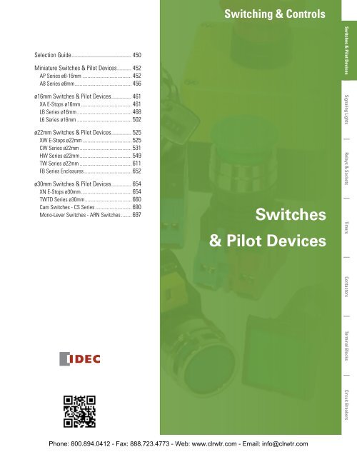
Switching & Controls<br />
Selection Guide........................................... 450<br />
Miniature <strong>Switches</strong> & <strong>Pilot</strong> <strong>Devices</strong>........... 452<br />
AP Series ø8-16mm....................................... 452<br />
A8 Series ø8mm............................................. 456<br />
ø16mm <strong>Switches</strong> & <strong>Pilot</strong> <strong>Devices</strong>............... 461<br />
XA E-Stops ø16mm........................................ 461<br />
LB Series ø16mm........................................... 468<br />
L6 Series ø16mm........................................... 502<br />
ø22mm <strong>Switches</strong> & <strong>Pilot</strong> <strong>Devices</strong>............... 525<br />
XW E-Stops ø22mm....................................... 525<br />
CW Series ø22mm......................................... 531<br />
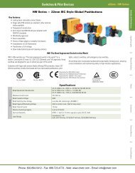
HW Series ø22mm......................................... 549<br />
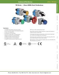
TW Series ø22mm......................................... 611<br />
FB Series Enclosures...................................... 652<br />
ø30mm <strong>Switches</strong> & <strong>Pilot</strong> <strong>Devices</strong>............... 654<br />
XN E-Stops ø30mm........................................ 654<br />
TWTD Series ø30mm..................................... 660<br />
Cam <strong>Switches</strong> - CS Series............................. 690<br />
Mono-Lever <strong>Switches</strong> - ARN <strong>Switches</strong>......... 697<br />
<strong>Switches</strong><br />
& <strong>Pilot</strong> <strong>Devices</strong><br />
<strong>Switches</strong> & <strong>Pilot</strong> <strong>Devices</strong> Signaling Lights Relays & Sockets Timers Contactors Terminal Blocks Circuit Breakers<br />
Phone: 800.894.0412 - Fax: 888.723.4773 - Web: www.clrwtr.com - Email: info@clrwtr.com
Selection Guide<br />
<strong>Switches</strong> & <strong>Pilot</strong> <strong>Devices</strong><br />
<strong>Switches</strong> & <strong>Pilot</strong> <strong>Devices</strong><br />
Selection Guide<br />
Appearance Product Series Mounting Hole Contact Rating Contact Mounting Function Page<br />
AP<br />
ø8mm, ø10mm,<br />
ø12mm, ø16mm<br />
N/A N/A <strong>Pilot</strong> light 452<br />
A8 ø8mm 1A Unibody Pushbutton, <strong>Pilot</strong> Light 456<br />
Signaling Lights<br />
XA<br />
5A<br />
Removable/<br />
Unibody<br />
E-Stop 461<br />
A6 1A Unibody<br />
Pushbutton, <strong>Pilot</strong> Light,<br />
Selector Switch, Key<br />
Switch, Stop Switch<br />
Relays & Sockets<br />
ø16mm<br />
LB 3A Removable<br />
Pushbutton, <strong>Pilot</strong> Light,<br />
Selector Switch, Key<br />
Switch<br />
468<br />
Timers<br />
L6 5A Removable<br />
Pushbutton, <strong>Pilot</strong> Light,<br />
Selector Switch, Key<br />
Switch, Stop Switch,<br />
Buzzer<br />
502<br />
XW<br />
5A Removable E-Stop 525<br />
Contactors<br />
CW 10A Removable<br />
Pushbutton, <strong>Pilot</strong> light,<br />
selector switch, key<br />
selector<br />
531<br />
Terminal Blocks<br />
ø22mm<br />
HW 10A Removable<br />
TW 10A Removable<br />
Pushbutton, <strong>Pilot</strong> Light,<br />
Selector Switch, Key<br />
Switch, E-Stop, Mono-<br />
Lever<br />
Pushbutton, <strong>Pilot</strong> Light,<br />
Selector Switch, Key<br />
Switch, Stop Switch<br />
549<br />
611<br />
Circuit Breakers<br />
FB N/A N/A Enclosures 652<br />
Phone: 800.894.0412 - Fax: 888.723.4773 - Web: www.clrwtr.com - Email: info@clrwtr.com
<strong>Switches</strong> & <strong>Pilot</strong> <strong>Devices</strong><br />
Selection Guide<br />
Selection Guide con’t<br />
Appearance Product Series Mounting Hole Contact Rating Contact Mounting Function Page<br />
XN<br />
TWTD 10A Removable<br />
ø30mm<br />
5A Removable E-Stop 654<br />
Pushbutton, <strong>Pilot</strong> Light,<br />
Selector Switch, Key<br />
Switch, Stop Switch<br />
CS 10A Unibody Cam Switch 690<br />
ARN 10A Removable MonoLever 697<br />
LW Flush<br />
ø25mm, 25 x<br />
25mm<br />
5A<br />
Removable<br />
Pushbutton, <strong>Pilot</strong> Light,<br />
Selector Switch, Key<br />
Switch<br />
660<br />
<strong>Switches</strong> & <strong>Pilot</strong> <strong>Devices</strong> Signaling Lights Relays & Sockets Timers Contactors Terminal Blocks Circuit Breakers<br />
Phone: 800.894.0412 - Fax: 888.723.4773 - Web: www.clrwtr.com - Email: info@clrwtr.com
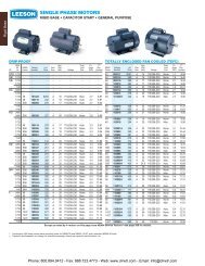
Miniature ø8-16mm AP Series<br />
<strong>Switches</strong> & <strong>Pilot</strong> <strong>Devices</strong><br />
<strong>Switches</strong> & <strong>Pilot</strong> <strong>Devices</strong><br />
Signaling Lights<br />
Key features:<br />
• Long service life, low maintenance<br />
• Space saving miniature style<br />
• Dome or flat lens models<br />
• Built-in current-limiting resistor<br />
• Five illumination colors: red, green, amber, yellow, and white<br />
• Transformer (120V AC and 240V AC) and DC-DC Converter (110V DC)<br />
options on 12mm and 16mm units<br />
AP Series — Miniature <strong>Pilot</strong> Lights<br />
UL Recognized<br />
File No. E55996<br />
CSA Certified<br />
File No. LR21451<br />
*<br />
Relays & Sockets<br />
Timers<br />
Contactors<br />
*AP8/AP1 series only.<br />
Specifications<br />
Lamp<br />
Operational Voltage<br />
Current Ratings<br />
Operating Temp.<br />
Operating Humidity<br />
Insul. Resistance<br />
Rev. Withstand Voltage<br />
Solder Terminal<br />
Degree of Protection<br />
Built-in LED with current limiting resistor<br />
5, 6, 12, 24VDC (full voltage),<br />
110/120, 220/240VAC, (with transformer)<br />
110VDC (with converter)<br />
AP8: 5V DC/9mA, 12V DC/9mA, 24V DC/9mA, 12V AC/15mA, 24V AC/15mA<br />
AP1: 5V DC/9mA, 12V DC/9mA, 24V DC/9mA, 12V AC/15mA, 24V AC/15mA<br />
AP2: 6V DC/33mA, 12V DC/22mA, 24V DC/11mA<br />
AP6: 6V DC/33mA, 12V DC/22mA, 24V DC/11mA<br />
-20ºC to +55ºC<br />
45 to 85% RH<br />
100MΩ min. (500V DC megger)<br />
Between live and dead parts<br />
AP2/AP6: 100V<br />
AP1/AP8: 200V<br />
Soldering 260ºC maximum (5 sec.)<br />
AP8: IP40 (dustproof)<br />
Other Series: IP65 (oiltight)<br />
Terminal Blocks<br />
Optional Adaptors/Converters<br />
Model Transformer DC-DC Converter<br />
Applicable Units<br />
AP2 & AP6 (with 6V LED only)<br />
Operating Voltage<br />
110/120VAC 50/60 Hz<br />
220/240VAC 50/60 Hz<br />
110V DC (90 to 140V DC)<br />
Power Consumption 1.6 VA maximum 1W maximum<br />
Insulation Voltage 250 V AC 140V DC<br />
Insulation Resistance<br />
10MΩ min. (500V DC megger) Between live and dead parts<br />
Dielectric Strength<br />
2,000V AC, 1 minute Between live/dead parts<br />
2,000V AC, 1 minute Between terminals<br />
2,000V AC, 1 minute Between live/dead parts<br />
1,500V AC, 1 minute Between terminals<br />
Available as one piece only (replacement LEDs are not available).<br />
Circuit Breakers<br />
Phone: 800.894.0412 - Fax: 888.723.4773 - Web: www.clrwtr.com - Email: info@clrwtr.com
<strong>Switches</strong> & <strong>Pilot</strong> <strong>Devices</strong><br />
Miniature ø8-16mm AP Series<br />
AP Miniature <strong>Pilot</strong> Lights - ø8 & ø10mm<br />
AP8 Series - Ø8mm<br />
AP1 Series - Ø10mm<br />
1. In place of k, specify the color code.<br />
2. For dimensions, see page 455.<br />
3. For accessories, see page 454.<br />
Miniature <strong>Pilot</strong> Lights<br />
Style Lens Style Operating Voltage Part Numbers<br />
Dome<br />
Flat<br />
Dome<br />
Flat<br />
5V DC +/- 5%<br />
12V AC/DC +/- 10%<br />
24V AC/DC +/- 10%<br />
5V DC +/- 5%<br />
12V AC/DC +/- 10%<br />
24V AC/DC +/- 10%<br />
5V DC +/- 5%<br />
12V AC/DC +/- 10%<br />
24V AC/DC +/- 10%<br />
5V DC +/- 5%<br />
12V AC/DC +/- 10%<br />
24V AC/DC +/- 10%<br />
AP8M255-k<br />
AP8M211-k<br />
AP8M222-k<br />
AP8M155-k<br />
AP8M111-k<br />
AP8M122-k<br />
AP1M255-k<br />
AP1M211-k<br />
AP1M222-k<br />
AP1M155-k<br />
AP1M111-k<br />
AP1M122-k<br />
AP Miniature <strong>Pilot</strong> Lights - ø12 & ø16mm<br />
Style Lens Style Operating Voltage Part Numbers<br />
AP2 Series - Ø12mm<br />
AP6 Series - Ø16mm<br />
1. In place of k, specify the color code.<br />
2. For dimensions, see page 455.<br />
3. For accessories, see page 454.<br />
Dome<br />
Flat<br />
Dome<br />
Optional Transformers and DC-DC Converters (for AP2 and AP6 only)<br />
Style<br />
Transformer<br />
DC-DC Converter<br />
Flat<br />
Voltage<br />
110/120V AC<br />
220/240V AC<br />
110V DC<br />
(90–140V DC)<br />
1. Optional Transformers and DC-DC converters snap onto the back of AP2 or AP6 pilot lights.<br />
2. Transformers and DC-DC Converters step down to 6V.<br />
3. For dimensions, see page 455.<br />
6V DC +/- 5%<br />
12V DC +/- 10%<br />
24V DC +/- 10%<br />
6V DC +/- 5%<br />
12V DC +/- 10%<br />
24V DC +/- 10%<br />
6V DC +/- 5%<br />
12V DC +/- 10%<br />
24V DC +/- 10%<br />
6V DC +/- 5%<br />
12V DC +/- 10%<br />
24V DC +/- 10%<br />
AP2M266-k<br />
AP2M211-k<br />
AP2M222-k<br />
AP2M166-k<br />
AP2M111-k<br />
AP2M122-k<br />
AP6M266-k<br />
AP6M211-k<br />
AP6M222-k<br />
AP6M166-k<br />
AP6M111-k<br />
AP6M122-k<br />
Part Numbers<br />
Used with AP2 Series Used with AP6 Series<br />
AP2-0126D<br />
AP2-0246D<br />
AP2-016DD<br />
AP6-0126D<br />
AP6-0246D<br />
AP6-016DD<br />
k Color Codes<br />
Color<br />
Code<br />
Amber<br />
A<br />
Green<br />
G<br />
Red<br />
R<br />
Blue S*<br />
Warm White W<br />
Cool White PW<br />
Yellow<br />
Y<br />
* Available in only the AP8 and<br />
AP1 series.<br />
k Color Codes<br />
Color<br />
Amber<br />
Green<br />
Red<br />
Warm White<br />
Yellow<br />
Code<br />
A<br />
G<br />
R<br />
W<br />
Y<br />
<strong>Switches</strong> & <strong>Pilot</strong> <strong>Devices</strong> Signaling Lights Relays & Sockets Timers Contactors Terminal Blocks Circuit Breakers<br />
Phone: 800.894.0412 - Fax: 888.723.4773 - Web: www.clrwtr.com - Email: info@clrwtr.com
Miniature ø8-16mm AP Series<br />
<strong>Switches</strong> & <strong>Pilot</strong> <strong>Devices</strong><br />
<strong>Switches</strong> & <strong>Pilot</strong> <strong>Devices</strong><br />
Signaling Lights<br />
Accessories — AP Series<br />
Item Appearance Description Used With Part Number<br />
Ø 16mm units<br />
MT-001<br />
Made of metal. Used for tightening plastic locking ring<br />
Locking Ring<br />
Ø 12mm units<br />
MT-002<br />
during installation. Tightening torque should not exceed<br />
Wrench<br />
3kgf-cm<br />
Ø 10mm units<br />
MT-003<br />
Ø 8mm units<br />
MT-004<br />
Mounting<br />
Hole Plug<br />
Transformer<br />
Removal Tool<br />
Made of rubber. Fills unused mounting holes to provide IP65<br />
protection<br />
Unused 8mm panel cutouts<br />
Unused 10mm panel cutouts<br />
Unused 12mm panel cutouts<br />
Unused 16mm panel cutouts<br />
AP2 and AP6 snap on transformer<br />
and DC-DC converter<br />
AL-B8<br />
AL-B1<br />
AL-B2<br />
AL-B6<br />
MT-100<br />
AP1M Flat<br />
AP1M-L1-k<br />
AP1M Dome<br />
AP1M-L2-k<br />
Relays & Sockets<br />
Replacement<br />
Lenses<br />
Lenses (included with all units).<br />
AP2M Flat<br />
AP2M Dome<br />
AP6M Flat<br />
AP6M Dome<br />
AP2M-L1-k<br />
AP2M-L2-k<br />
AP6M-L1-k<br />
AP6M-L2-k<br />
1. In place of k, specify the Lens Color Code.<br />
2. Internal LED is fixed and cannot be removed or replaced.<br />
Timers<br />
Contactors<br />
k Lens Color Codes<br />
Color<br />
Code<br />
Amber<br />
A<br />
Green<br />
G<br />
Red<br />
R<br />
Blue S*<br />
White<br />
W<br />
Yellow<br />
Y<br />
*Blue available in AP8/AP1<br />
series only.<br />
Circuit Breakers<br />
Terminal Blocks<br />
Phone: 800.894.0412 - Fax: 888.723.4773 - Web: www.clrwtr.com - Email: info@clrwtr.com
<strong>Switches</strong> & <strong>Pilot</strong> <strong>Devices</strong><br />
Miniature ø8-16mm AP Series<br />
<strong>Pilot</strong> Lights (AP Series)<br />
Style<br />
Panel Cut-out<br />
Dimensions — AP Series<br />
AP8 AP1 AP2 AP6<br />
Flat Dome Flat Dome Flat Dome<br />
Ø 0.319” (+0.0118, –0)<br />
8.1mm (+0.3, –0)<br />
Ø 0.398” (+0.0118, –0)<br />
10.1mm (+0.3, –0)<br />
w/ Adaptor or<br />
Converter<br />
Flat<br />
Dome<br />
w/ Adaptor or<br />
Converter<br />
Ø 0.480” (+0.0118, –0) 12.2mm (+0.3, –0) Ø 0.638” (+0.0118, –0) 16.2mm (+0.3, –0)<br />
Outside Dimension Ø 0.386” (9.8mm) Ø 0.472” (12mm) Ø 0.551” (14mm) 0.709” (18mm) Ø 0.709” (18mm) 0.709” (18mm)<br />
AP6<br />
Dome<br />
Flat<br />
ø18<br />
ø18<br />
ø15.6<br />
ø15.6<br />
13.5<br />
9.5<br />
5.5<br />
5.5<br />
When using the Transformer unit<br />
(When using the DC-DC converter unit)<br />
AP1<br />
Dome<br />
Flat<br />
Panel Thickness: 0.8 to 6 mm<br />
ø12<br />
ø10<br />
ø12<br />
-<br />
ø10<br />
Gasket<br />
10<br />
9.5<br />
5.5<br />
5.5<br />
TOP<br />
Panel Thickness: 0.8 to 6 mm<br />
Gasket<br />
21.5<br />
29.5<br />
2.2<br />
Transformer unit<br />
(or DC-DC converter unit)<br />
71<br />
8<br />
7<br />
1.5<br />
ø16.2<br />
+0.2<br />
0<br />
+<br />
-<br />
Panel Cut-out<br />
M3 terminal<br />
screw<br />
58.7 18<br />
2.2<br />
21.5 8<br />
29.5<br />
2.8<br />
4<br />
1.5<br />
0<br />
+0.2<br />
ø10.1<br />
1.3<br />
+<br />
X1<br />
X2<br />
Panel Cut-out<br />
+ Terminal<br />
18<br />
– Terminal<br />
AP2<br />
Dome<br />
ø14<br />
Flat<br />
ø14<br />
ø12<br />
ø12<br />
11.5<br />
9.5<br />
5.5<br />
5.5<br />
When using the Transformer unit<br />
(When using the DC-DC converter unit)<br />
AP8<br />
Dome<br />
Flat<br />
Panel Thickness: 0.8 to 6 mm<br />
ø9.8<br />
ø9.8<br />
ø8<br />
ø8<br />
Gasket<br />
5.5<br />
9.5<br />
5.5<br />
8.5<br />
Panel Thickness: 0.8 to 6 mm<br />
Gasket<br />
TOP<br />
21.5<br />
29.5<br />
2.2<br />
1.5<br />
5<br />
Transformer unit<br />
(or DC-DC converter unit)<br />
71<br />
58.7<br />
2.2<br />
21.5 8<br />
29.5<br />
3 2.8<br />
1.5<br />
ø12.2<br />
+0.2<br />
0<br />
+<br />
-<br />
Panel Cut-out<br />
+0.2<br />
0<br />
ø8.1<br />
M3 terminal<br />
screw<br />
1.3<br />
X1<br />
X2<br />
18<br />
Panel Cut-out<br />
+ Terminal<br />
18<br />
– Terminal<br />
<strong>Switches</strong> & <strong>Pilot</strong> <strong>Devices</strong> Signaling Lights Relays & Sockets Timers Contactors Terminal Blocks Circuit Breakers<br />
Phone: 800.894.0412 - Fax: 888.723.4773 - Web: www.clrwtr.com - Email: info@clrwtr.com
Miniature ø8mm A8 Series<br />
<strong>Switches</strong> & <strong>Pilot</strong> <strong>Devices</strong><br />
<strong>Switches</strong> & <strong>Pilot</strong> <strong>Devices</strong><br />
Signaling Lights<br />
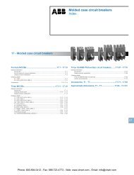
Key features:<br />
• 21/64” (8mm) round mounting hole<br />
• Compact Design Saves Space<br />
• Bright and Vivid Illumination<br />
• Choice of Shapes and Functions<br />
• Gold Clad Silver Contacts for reliable low level switching<br />
• Snap action contacts<br />
• IP40 (Dustproof) Construction<br />
A8 Series — Miniature <strong>Switches</strong> and <strong>Pilot</strong> <strong>Devices</strong>: 8mm<br />
Circuit Breakers<br />
Terminal Blocks<br />
Contactors<br />
Timers<br />
Relays & Sockets<br />
UL Listed<br />
File No. E55996<br />
Specifications<br />
LED Lamp Life<br />
Contact Configuration<br />
Maximum Voltage<br />
Thermal Current<br />
Contact Material<br />
Terminal Style<br />
Operating Temperature<br />
Operating Humidity<br />
Contact Resistance<br />
Insulation Resistance<br />
Vibration Resistance<br />
Shock Resistance<br />
Electrical Life<br />
Mechanical Life<br />
Degree of Protection<br />
Soldering Temperature<br />
Dielectric Strength<br />
CSA Certified<br />
File No. LR21451<br />
50,000 hours approximately (reduced to half of original intensity)<br />
SPDT<br />
250V AC/DC<br />
3A<br />
Gold-clad Silver<br />
Solder Tab Terminal<br />
–25º to +55ºC (no freezing)<br />
45 to 85% RH<br />
50mΩ maximum (initial value)<br />
100MΩ minimum<br />
(500V DC megger)<br />
5 to 55Hz, 0.75mm amplitude<br />
Damage limits: 500m/sec 2 (approx. 50G)<br />
Operating extremes: 200m/sec 2 (approx. 20G)<br />
100,000 operations minimum<br />
Maintained: 100,000 (1200 operations/hour)<br />
Momentary: 200,000 minimum<br />
IP40 Enclosed/Dustproof<br />
20W/5 seconds or 260ºC/3 seconds<br />
Switch Unit: 2,000V AC, 1 min. between live/dead part and terminals<br />
of different poles; 1,000V AC, 1 minute between terminals of the same<br />
pole; 1,500V AC, 1 minute between contact and lamp terminals.<br />
Illumination Unit: 2,000V AC, 1 min. between live part/ground<br />
Contact Ratings<br />
Operating Voltage 24V 120V 240V<br />
AC Resistive — 1.0A 0.5A<br />
50/60Hz Inductive — 0.7A 0.5A<br />
DC<br />
Resistive 1.0A 0.2A —<br />
Inductive 0.7A 0.1A —<br />
1. AC Inductive Load, PF = 0.6 – 0.7; DC Inductive Load, L/R = 7.<br />
2. Minimum applicable load (reference value) is 5V AC/DC 3mA<br />
(applicable range is subject to the operating conditions and load).<br />
Phone: 800.894.0412 - Fax: 888.723.4773 - Web: www.clrwtr.com - Email: info@clrwtr.com
<strong>Switches</strong> & <strong>Pilot</strong> <strong>Devices</strong><br />
Miniature ø8mm A8 Series<br />
Non-Illuminated Pushbuttons<br />
Style<br />
AB8 Non-Illuminated Pushbuttons (Assembled)<br />
Contact<br />
Momentary<br />
Part Numbers<br />
Maintained<br />
Round SPDT AB8M-M1-j AB8M-A1-j<br />
Square SPDT AB8Q-M1-j AB8Q-A1-j<br />
Rectangular SPDT AB8H-M1-j AB8H-A1-j<br />
1. In place of j, specify button color code from the table below.<br />
2. For accessories, see page 459.<br />
3. For dimensions, see page 460.<br />
j Button Color Codes<br />
Color<br />
Code<br />
Black<br />
B<br />
Green<br />
G<br />
Red<br />
R<br />
Blue<br />
S<br />
White<br />
W<br />
Yellow<br />
Y<br />
<strong>Switches</strong> & <strong>Pilot</strong> <strong>Devices</strong> Signaling Lights Relays & Sockets Timers Contactors Terminal Blocks Circuit Breakers<br />
Phone: 800.894.0412 - Fax: 888.723.4773 - Web: www.clrwtr.com - Email: info@clrwtr.com
Miniature ø8mm A8 Series<br />
<strong>Switches</strong> & <strong>Pilot</strong> <strong>Devices</strong><br />
<strong>Switches</strong> & <strong>Pilot</strong> <strong>Devices</strong><br />
Illuminated Pushbuttons<br />
Style<br />
AL8 Illuminated Pushbuttons & <strong>Pilot</strong> Lights (Assembled)<br />
Contact<br />
Momentary<br />
Part Numbers<br />
Maintained<br />
<strong>Pilot</strong> Light<br />
Part Number<br />
Round SPDT AL8M-M11-k AL8M-A11-k AL8M-P1-k<br />
Signaling Lights<br />
Relays & Sockets<br />
Square SPDT AL8Q-M11-k AL8Q-A11-k AL8Q-P1-k<br />
Rectangular SPDT AL8H-M11-k AL8H-A11-k AL8H-P1-k<br />
1. In place of k, specify lens color code from table on the right.<br />
2. A replaceable LED lamp is included with the operator.<br />
3. Because the LED lamp does not contain an internal current limiting resistor, an external resistor must be added.<br />
For recommended values, see table below.<br />
4. For accessories, see page 459.<br />
5. For dimensions, see page 460.<br />
k LED/Lens Color Codes<br />
Color<br />
Code<br />
Amber<br />
A<br />
Green<br />
G<br />
Red<br />
R<br />
White<br />
W<br />
Yellow<br />
Y<br />
Timers<br />
Replacement LEDs<br />
LED Voltage and Recommended Current Limiting Resistor<br />
Lens Color LED Lamp Part Number Voltage External Resistor<br />
Amber Amber LAD-SA 5V DC<br />
150Ω, 1/2W<br />
Green Green LAD-SG<br />
6V DC<br />
200Ω, 1/2W<br />
12V DC<br />
510Ω, 1W<br />
Red Red LAD-SR<br />
24V DC<br />
1.1kΩ, 1W<br />
White Yellow* LAD-SY<br />
Yellow Yellow LAD-SY<br />
* White units use a white lens and a yellow LED.<br />
Contactors<br />
Terminal Blocks<br />
LED Lamp Ratings: LED Specifications<br />
LED<br />
Lamp<br />
Forward<br />
Current<br />
I f<br />
Forward Voltage<br />
(Nominal)<br />
V f<br />
Reverse<br />
Voltage<br />
V r<br />
Amber 20mA 2.2V 4V<br />
Green 20mA 2.1V 4V<br />
Red 20mA 1.7V 4V<br />
Yellow 20mA 2.2V 4V<br />
Operating Voltage & External<br />
Current Limiting Resistor<br />
(Recommended Value)<br />
5V DC: 150Ω, 1/2W<br />
6V DC: 200Ω, 1/2W<br />
12V DC: 510Ω, 1W<br />
24V DC: 1.1kΩ, 1W<br />
When LED lamps are used at voltages other than those stated above, external resistor value, R, is determined by the<br />
following formula: R = (Operating Voltage – V f<br />
) / I f<br />
Circuit Breakers<br />
Phone: 800.894.0412 - Fax: 888.723.4773 - Web: www.clrwtr.com - Email: info@clrwtr.com
<strong>Switches</strong> & <strong>Pilot</strong> <strong>Devices</strong><br />
Miniature ø8mm A8 Series<br />
Locking Ring Wrench<br />
Lens Removal Tool<br />
Lamp Holder Tool<br />
Switch Guard<br />
Terminal Cover<br />
Adaptor Socket<br />
AL-C8<br />
Mounting Hole Plug<br />
Replacements LEDs<br />
Replacement Lenses<br />
Replacement Buttons<br />
Accessories<br />
Item Description Used With Part Number<br />
AL-C8V shown attached<br />
1. In place of j, specify Button Color Code from the table.<br />
2. In place of k, specify Lens Color Code from table.<br />
Made of metal. Used for tightening plastic locking ring during<br />
installation. Tightening torque should not exceed 3kgf-cm<br />
All units<br />
MT-004<br />
Made of metal. Used for removing lens or button from the housing Illuminated pushbuttons and pilot lights MT-101<br />
Made of rubber. Used for removing and replacing LED lamps in<br />
illuminated units<br />
Used to avoid operating the pushbutton inadvertently. Cover flips<br />
open 90˚. Provides IP40 protection<br />
Illuminated pushbuttons and pilot lights<br />
Round & square units<br />
Rectangular units<br />
OR-66<br />
AL-K8<br />
AL-KH8<br />
Made of translucent nylon. Fits over and shields the terminals All units AL-V8<br />
Plug-on adaptor with solder terminals, allows easy control unit<br />
replacement.<br />
Plug-on adaptor with PCB terminals, allows easy control unit<br />
replacement.<br />
Made of rubber. Fills unused mounting holes to provide IP65<br />
protection<br />
LED lamp is included in every illuminated control unit. Replacement<br />
lamp is ordered separately. External current limiting resistor<br />
required.<br />
All units<br />
Extra panel cutouts<br />
Illuminated units and pilot lights<br />
Illuminated pushbuttons<br />
and pilot lights<br />
Non-Illuminated buttons<br />
j Button Color Codes<br />
Color<br />
Code<br />
Black<br />
B<br />
Green<br />
G<br />
Red<br />
R<br />
Blue<br />
S<br />
White<br />
W<br />
Yellow<br />
Y<br />
Round<br />
Square<br />
Rectangular<br />
Round<br />
Square<br />
Rectangular<br />
AL-C8<br />
AL-C8V<br />
AL-B8<br />
LAD-SR (red)<br />
LAD-SG (green)<br />
LAD-SA (amber)<br />
LAD-SY (yellow)<br />
AL8M-LK1-k<br />
AL8Q-LK1-k<br />
AL8H-LK1-k<br />
AB8M-BK1-j<br />
AB8Q-BK1-j<br />
AB8H-BK1-j<br />
k LED/Lens Color Codes<br />
Color<br />
Code<br />
Amber<br />
A<br />
Green<br />
G<br />
Red<br />
R<br />
White<br />
W<br />
Yellow<br />
Y<br />
<strong>Switches</strong> & <strong>Pilot</strong> <strong>Devices</strong> Signaling Lights Relays & Sockets Timers Contactors Terminal Blocks Circuit Breakers<br />
Phone: 800.894.0412 - Fax: 888.723.4773 - Web: www.clrwtr.com - Email: info@clrwtr.com
Miniature ø8mm A8 Series<br />
<strong>Switches</strong> & <strong>Pilot</strong> <strong>Devices</strong><br />
<strong>Switches</strong> & <strong>Pilot</strong> <strong>Devices</strong><br />
A∆8<br />
2.5<br />
Panel Thickness 0.5 to 6<br />
Locking Ring<br />
Terminal Width<br />
1.8 × 0.4t<br />
Rectangular<br />
(TOP)<br />
Dimensions<br />
Square<br />
(TOP)<br />
Round<br />
(TOP)<br />
Panel Cut-Out (not drawn to scale)<br />
Rectangular<br />
ø8 +0.2<br />
0<br />
2.5<br />
5<br />
5.5<br />
ø9<br />
5.5<br />
12<br />
9<br />
c 9<br />
ø9<br />
9 min.<br />
Signaling Lights<br />
(TOP)<br />
NC<br />
7<br />
22 9<br />
Round/Square<br />
ø8 +0.2<br />
0<br />
12 min.<br />
NO<br />
+0.2<br />
0<br />
Relays & Sockets<br />
Timers<br />
2.5<br />
2.5<br />
Holes<br />
Contactors<br />
rd Terminal<br />
Hole Layout)<br />
Terminal Blocks<br />
Lamp<br />
Terminal (+)<br />
COM<br />
Terminal Sockets<br />
Lamp<br />
Terminal (–)<br />
Solder Terminal<br />
(AL-C8)<br />
Terminal Arrangement<br />
(TOP)<br />
Lamp<br />
Terminal (+)<br />
33<br />
NC<br />
NO<br />
COM<br />
17<br />
(Bottom View)<br />
Terminal Cover<br />
AL-V8, Ø 21/64" (8mm)<br />
17.3<br />
33.5<br />
Lamp<br />
Terminal (–)<br />
Terminal 0.8 × 0.3t<br />
33<br />
For Round/Square Units<br />
(AL-K8)<br />
2.5<br />
14.5<br />
8.5<br />
6<br />
10<br />
5 8.8<br />
17 3<br />
ø9.1<br />
6.3<br />
2.5<br />
11 min.<br />
17.5 min.<br />
PC Board Terminal<br />
(AL-C8V)<br />
9 min.<br />
Terminal Arrangement<br />
6.3<br />
(TOP)<br />
For Rectangular Units<br />
Switch Guard, Ø 21/64" (8mm)<br />
(AL-KH8)<br />
NC<br />
12<br />
21.5 Panel Thickness 0.5 to 5<br />
14.5<br />
8.5<br />
2.5<br />
Circuit Breakers<br />
+0.2<br />
6<br />
2.5<br />
5-1.0 0 Holes<br />
(PC Board Terminal<br />
Mounting Hole Layout)<br />
14.5<br />
8.5<br />
6<br />
Lamp<br />
Terminal (+)<br />
10<br />
13 min.<br />
17.5 min.<br />
For Round/Square Units<br />
(AL-K8)<br />
17.5 min.<br />
NO<br />
COM<br />
(Bottom View)<br />
9 min.<br />
Lamp<br />
Terminal (–)<br />
14.5<br />
8.5<br />
6<br />
12.5<br />
For Round/Square Units<br />
(AL-K8)<br />
14.5<br />
8.5<br />
6<br />
10<br />
12<br />
11 min.<br />
17.5 min.<br />
For Rectangular Units<br />
(AL-KH8)<br />
17.5 min.<br />
For Rectan<br />
(AL-KH8)<br />
14.5<br />
8.5<br />
6<br />
21.5<br />
12.5<br />
11 min.<br />
13 min.<br />
Phone: 800.894.0412 - Fax: 888.723.4773 - Web: www.clrwtr.com - Email: info@clrwtr.com
<strong>Switches</strong> & <strong>Pilot</strong> <strong>Devices</strong><br />
ø16mm XA E-Stops<br />
Key features:<br />
• Two button sizes: ø29 and ø40mm<br />
• Lead-free, RoHS compliant, (EU directive 2002/95/EC)<br />
• Depth behind the panel:<br />
Standard - only 27.9mm for 1 to 4 contacts<br />
Unibody - only 23.9mm for 1NC or 2NC<br />
• <strong>IDEC</strong>’s original “Safe break action” ensures that the NC contacts open<br />
when the contact block is detached from the operator.<br />
• Push-to-lock, Pull or Turn-to-reset operator<br />
• Direct opening action mechanism (IEC60947-5-5, 5.2, IEC60947-5-1,<br />
Annex K)<br />
• Safety lock mechanism (IEC60947-5-5, 6.2)<br />
• Degree of protection:<br />
Standard - IP65 (IEC60529)<br />
Unibody - IP65 and IP40 (IEC 60529)<br />
• UL, c-UL recognized. EN compliant<br />
• UL NISD2 category emergency stop button (File# E305148)<br />
Specifications<br />
16mm XA E-Stops<br />
UL File No. E68691 CCC No. 2005010305150899<br />
Model Standard Unibody<br />
Applicable Standards<br />
Operating Temperature<br />
Operating Humidity<br />
Storage Temperature<br />
IEC60947‐5‐1, EN60947‐5‐1, IEC60947‐5‐5, EN60947‐5‐5, UL508,<br />
UL991, CSA C22.2 No. 14<br />
Non‐illuminated: –25 to +60°C (no freezing),<br />
Illuminated: –25 to +55°C (no freezing)<br />
45 to 85% RH (no condensation)<br />
–45 to +80°C<br />
Operating Force Push‐to‐lock: 10.5N Pull‐to‐reset: 10N Turn‐to‐reset: 0.16N·m<br />
UL508, CSA C22.2 No.14, IEC 60947‐5‐1, EN 60947‐5‐1<br />
IEC 60947‐5‐5 Note , EN 60947‐5‐5 Note , JIS C8201‐5‐1<br />
−25 to +60°C (no freezing)<br />
Minimum Force Required for<br />
Direct Opening Action<br />
60N<br />
40N<br />
Min Operator Stroke Required<br />
for Direct Opening Action<br />
4mm<br />
Maximum Operator Stroke<br />
4.5mm<br />
Contact Resistance<br />
50mΩ maximum (initial value)<br />
Contact Material<br />
Gold plated silver<br />
Insulation Resistance<br />
100MΩ minimum (500V DC megger)<br />
Impulse Withstand Voltage<br />
2.5kV<br />
Pollution Degree 3 (inside LED unit: 2) 3<br />
Operation Frequency<br />
900 operations/hour<br />
Shock Resistance Operating extremes: 150 m/s 2 , Damage limits: 1000 m/s 2<br />
Vibration Resistance Operating extremes: 10 to 500Hz, amplitude 0.35mm acceleration 50m/s 2 , Damage limits: 10 to 500Hz, amplitude 0.35mm acceleration 50m/s 2<br />
Mechanical Life<br />
250,000 operations minimum<br />
Electrical Life<br />
100,000 operations minimum, (250,000 operations minimum @ 24V AC/DC, 100mA)<br />
Degree of Protection IP65 (IEC60529) IP65, IP40 (IEC 60529)<br />
Terminal Style Solder terminal, PC board terminal Solder/tab #110 terminal<br />
Recommended Tightening<br />
Torque for Locking Ring<br />
0.88N·m<br />
Wire Size<br />
16 AWG max<br />
Soldering Conditions<br />
310 to 350°C, 3 seconds maximum<br />
Weight<br />
Note: Except for stop switches (operator color: yellow and gray)<br />
ø29mm: 23g<br />
ø40mm: 28g<br />
ø29mm mushroom: 14g<br />
ø40mm mushroom: 17g<br />
<strong>Switches</strong> & <strong>Pilot</strong> <strong>Devices</strong> Signaling Lights Relays & Sockets Timers Contactors Terminal Blocks Circuit Breakers<br />
Phone: 800.894.0412 - Fax: 888.723.4773 - Web: www.clrwtr.com - Email: info@clrwtr.com
ø16mm XA E-Stops<br />
<strong>Switches</strong> & <strong>Pilot</strong> <strong>Devices</strong><br />
Terminal Blocks<br />
Contactors<br />
Timers<br />
Relays & Sockets<br />
Signaling Lights <strong>Switches</strong> & <strong>Pilot</strong> <strong>Devices</strong><br />
Non-Illuminated XA E-Stop<br />
Part Numbers<br />
Style Termination Monitor Contacts Main Contacts Part Number<br />
29mm<br />
Mushroom<br />
40mm<br />
Mushroom<br />
Illuminated XA E-Stop<br />
PCB Terminal<br />
Solder Terminal<br />
PCB Terminal<br />
Solder Terminal<br />
1NO 1NC XA1E-BV311V-R<br />
– 2NC XA1E-BV302V-R<br />
1NO 3NC XA1E-BV313V-R<br />
– 4NC XA1E-BV304V-R<br />
1NO 1NC XA1E-BV311-R<br />
– 2NC XA1E-BV302-R<br />
1NO 3NC XA1E-BV313-R<br />
– 4NC XA1E-BV304-R<br />
1NO 1NC XA1E-BV411V-R<br />
– 2NC XA1E-BV402V-R<br />
1NO 3NC XA1E-BV413V-R<br />
– 4NC XA1E-BV404V-R<br />
1NO 1NC XA1E-BV411-R<br />
– 2NC XA1E-BV402-R<br />
1NO 3NC XA1E-BV413-R<br />
– 4NC XA1E-BV404-R<br />
Style Termination Monitor Contacts Main Contacts Part Number<br />
29mm<br />
Mushroom<br />
40mm<br />
Mushroom<br />
PCB Terminal<br />
Solder Terminal<br />
PCB Terminal<br />
Solder Terminal<br />
All illuminated XA E-Stops come with a replaceable 24V AC/DC LED.<br />
Part Number Key<br />
XA1E - L V 3 11 Q4 V - R<br />
1NO 1NC XA1E-LV311Q4V-R<br />
– 2NC XA1E-LV302Q4V-R<br />
1NO 3NC XA1E-LV313Q4V-R<br />
– 4NC XA1E-LV304Q4V-R<br />
1NO 1NC XA1E-LV311Q4-R<br />
– 2NC XA1E-LV302Q4-R<br />
1NO 3NC XA1E-LV313Q4-R<br />
– 4NC XA1E-LV304Q4-R<br />
1NO 1NC XA1E-LV411Q4V-R<br />
– 2NC XA1E-LV402Q4V-R<br />
1NO 3NC XA1E-LV413Q4V-R<br />
– 4NC XA1E-LV404Q4V-R<br />
1NO 1NC XA1E-LV411Q4-R<br />
– 2NC XA1E-LV402Q4-R<br />
1NO 3NC XA1E-LV413Q4-R<br />
– 4NC XA1E-LV404Q4-R<br />
Circuit Breakers<br />
Illumination<br />
B: Non-Illuminated<br />
L: Illuminated<br />
Mushroom Size<br />
3: ø29mm<br />
4: ø40mm<br />
Contact Configuration<br />
11: 1NO - 1NC<br />
02: 2NC<br />
13: 1NO - 3NC<br />
04: 4NC<br />
Terminal<br />
Blank: solder tab<br />
V: PCB<br />
Voltage Code<br />
Blank: Non-illuminated<br />
Q4: Illuminated 24V AC/DC<br />
Phone: 800.894.0412 - Fax: 888.723.4773 - Web: www.clrwtr.com - Email: info@clrwtr.com
<strong>Switches</strong> & <strong>Pilot</strong> <strong>Devices</strong><br />
ø16mm XA E-Stops<br />
Unibody XA E-Stop<br />
Style<br />
29mm Mushroom<br />
40mm Mushroom<br />
Unibody XA Stop Switch<br />
Contact<br />
IP40 (black housing)<br />
Part Number<br />
1NC XA1E-BV3U01KT-R XA1E-BV3U01T-R<br />
2NC XA1E-BV3U02KT-R XA1E-BV3U02T-R<br />
1NC XA1E-BV4U01KT-R XA1E-BV4U01T-R<br />
2NC XA1E-BV4U02KT-R XA1E-BV4U02T-R<br />
Style Operator Type Contact j Color Code<br />
EMO XA E-Stop<br />
29mm<br />
Mushroom<br />
40mm<br />
Mushroom<br />
1NC<br />
IP40<br />
(black housing)<br />
XA1E-BV3U01KT-j<br />
IP65 (yellow housing)<br />
Part Number<br />
IP65<br />
(yellow housing)<br />
XA1E-BV3U01T-j<br />
2NC Y: yellow<br />
XA1E-BV3U02KT-j XA1E-BV3U02T-j<br />
1NC<br />
N: gray<br />
XA1E-BV4U01KT-j XA1E-BV4U01T-j<br />
2NC XA1E-BV4U02KT-j XA1E-BV4U02T-j<br />
Style NC Main Contact NO Monitor Contact Part Number<br />
40mm Mushroom<br />
1NC - XA1E-BV401-RH-EMO<br />
2NC - XA1E-BV402-RH-EMO<br />
3NC - XA1E-BV403-RH-EMO<br />
4NC - XA1E-BV404-RH-EMO<br />
1NC 1NO XA1E-BV411-RH-EMO<br />
2NC 1NO XA1E-BV412-RH-EMO<br />
3NC 1NO XA1E-BV413-RH-EMO<br />
<strong>Switches</strong> & <strong>Pilot</strong> <strong>Devices</strong> Signaling Lights Relays & Sockets Timers Contactors Terminal Blocks Circuit Breakers<br />
Phone: 800.894.0412 - Fax: 888.723.4773 - Web: www.clrwtr.com - Email: info@clrwtr.com
ø16mm XA E-Stops<br />
<strong>Switches</strong> & <strong>Pilot</strong> <strong>Devices</strong><br />
<strong>Switches</strong> & <strong>Pilot</strong> <strong>Devices</strong><br />
Signaling Lights<br />
Relays & Sockets<br />
Contact Ratings<br />
Standard<br />
Rated Insulation Voltage (Ui) 300V (illuminated part: 60V)<br />
Rated Current (Ith)<br />
5A<br />
Rated Operating Voltage (Ue) 30V 125V 250V<br />
AC 50/60Hz<br />
Resistive Load (AC-12) – 3A 3A<br />
Inductive Load (AC-15) – 1.5A 1.5A<br />
DC<br />
Resistive Load (DC-12) 2A 0.4A 0.2A<br />
Inductive Load (DC-13) 1A 0.22A 0.1A<br />
AC 50/60Hz<br />
Resistive Load (AC-12) – 1.2A 0.6A<br />
Inductive Load (AC-14) – 0.6A 0.3A<br />
DC<br />
Resistive Load (DC-12) 2A 0.4A 0.2A<br />
Inductive Load (DC-13) 1A 0.22A 0.1A<br />
Unibody<br />
Rated Insulation Voltage (Ui)<br />
250V<br />
Thermal Current (Ith)<br />
5A<br />
Rated Operating Voltage (Ue) 30V 125V 250V<br />
AC 50/60Hz<br />
Resistive Load (AC-12) – 5A 3A<br />
Inductive Load (AC-15) – 3A 1.5A<br />
DC<br />
Resistive Load (DC-12) 2A 0.4A 0.2A<br />
Inductive Load (DC-13) 1A 0.22A 0.1A<br />
Rated Operating Current<br />
Rated Operating<br />
Current<br />
Main<br />
Contacts (NC)<br />
Timers<br />
Contactors<br />
Terminal Blocks<br />
Circuit Breakers<br />
Monitor<br />
Contacts (NO)<br />
Minimum applicable load: 5V AC/DC, 1mA (reference value).<br />
The rated operating currents are measured at resistive/inductive load types specified<br />
in IEC 60947-5-1.<br />
Mounting Hole Layout<br />
øA<br />
Y<br />
Panel Cutout<br />
ø16.2<br />
+0.2<br />
0<br />
X<br />
+0.2<br />
1.7 0<br />
+0.2<br />
0<br />
17.9<br />
PC Board Layout - Bottom View<br />
Non-Illuminated<br />
19.8<br />
8.7<br />
19.8<br />
8.7<br />
6.5<br />
10-ø1.2 holes<br />
11.2<br />
3-ø1.7 holes<br />
Measurements<br />
Model øA X & Y<br />
ø29mm<br />
40mm min<br />
16.2 +0.2<br />
ø40mm<br />
50mm min<br />
Illuminated<br />
19.8<br />
8.7<br />
19.8<br />
8.7<br />
4.5<br />
6.5<br />
10-ø1.2 holes<br />
11.2<br />
3-ø1.7 holes<br />
Illuminated Unit LED Ratings<br />
Operating Voltage<br />
Current<br />
24V AC/DC ±10%<br />
11mA<br />
Depth Behind the Panel<br />
Depth (mm)<br />
Description<br />
27.9 (Standard) 1 - 4 contacts, both illuminated and non-illuminated<br />
23.9 (Unibody) 1NC or 2NC<br />
Terminal Arrangements (Bottom View)<br />
4NC 1NO-3NC 2NC 1NO-1NC<br />
Non-Illuminated<br />
TOP<br />
TOP<br />
1 2<br />
1 2<br />
3 4<br />
1 2<br />
TOP<br />
TOP<br />
Left<br />
2<br />
1<br />
Illuminated<br />
2 1<br />
TOP<br />
1 2<br />
1<br />
2<br />
Right<br />
Left<br />
1 2<br />
4 3<br />
TOP<br />
1 2<br />
1<br />
2<br />
Right<br />
Left<br />
1 2<br />
4 3<br />
TOP<br />
3 4<br />
1<br />
2<br />
Right<br />
Left<br />
1 2<br />
4 3<br />
TOP<br />
3 4<br />
1<br />
2<br />
Right<br />
Left<br />
1 2<br />
LED<br />
1<br />
2<br />
Right<br />
Left<br />
2<br />
1<br />
LED<br />
1<br />
2<br />
Right<br />
Left<br />
2<br />
1<br />
LED<br />
1<br />
2<br />
Right<br />
Left<br />
2<br />
1<br />
LED<br />
1<br />
2<br />
Right<br />
X1<br />
2<br />
1<br />
X2<br />
X1<br />
4 3<br />
X2<br />
X1<br />
4 3<br />
X2<br />
X1<br />
4 3<br />
X2<br />
Phone: 800.894.0412 - Fax: 888.723.4773 - Web: www.clrwtr.com - Email: info@clrwtr.com
<strong>Switches</strong> & <strong>Pilot</strong> <strong>Devices</strong><br />
ø16mm XA E-Stops<br />
ø29mm Button<br />
ø40mm Button<br />
ø29<br />
ø40<br />
25.8<br />
30.4<br />
20.6<br />
Non-Illuminated<br />
30.4<br />
3.1<br />
29.4<br />
PC Board Terminal Type<br />
Dimensions (mm)<br />
Mounting Panel Thickness: 0.5 to 3.7<br />
ø29.8<br />
27.2<br />
Terminal Cover<br />
XA9Z-VL2<br />
19.8<br />
8.7<br />
Rubber Gasket<br />
Locking Ring<br />
2.1<br />
25.8 20.6<br />
30.4<br />
Solder Terminal Type<br />
Unibody EMO<br />
Panel Thickness 0.8 to 4.5<br />
10.2 0.5<br />
Solder/Tab Terminal #110<br />
(Behind the panel: 23.9)<br />
ø16.2<br />
+0.2<br />
0<br />
+0.2<br />
1.7 0<br />
+0.2<br />
0<br />
17.9<br />
ø29 mm Mushroom<br />
ø29.0<br />
20.6<br />
ø40 mm Mushroom<br />
ø40<br />
Illuminated<br />
30.4<br />
3.1<br />
29.4<br />
PC Board Terminal<br />
Mounting Panel Thickness: 0.5 to 3.7<br />
ø29.8<br />
27.2<br />
19.8<br />
8.7<br />
Terminal Cover<br />
XA9Z-VL2<br />
4.5<br />
Rubber Gasket<br />
Locking Ring<br />
2.1 25.8 20.6<br />
30.4<br />
Solder Terminal<br />
8.0 15.9 20.6<br />
Mounting Hole<br />
Panel Cut-out<br />
ø15.8<br />
Accessories<br />
Description<br />
Replacement LED Unit: Solder Terminal<br />
Replacement LED Unit: PCB Terminal<br />
Terminal Cover for contact block (solder terminal only)<br />
Accessories: Nameplates<br />
Part Numbers<br />
XA9Z-LED2R<br />
XA9Z-LED2VR<br />
XA9Z-VL2<br />
Appearance Legend Part Number Inner Ø Outer Ø<br />
(blank) HAAV-0 16mm 43mm<br />
“Emergency Stop” HAAV-27 16mm 43mm<br />
(blank) HAAV4-0 16mm 60mm<br />
“Emergency Stop” HAAV4-27 16mm 60mm<br />
30.4<br />
27.2<br />
Terminal Cover<br />
XA9Z-VL2<br />
Panel Thickness 0.5 to 3.7<br />
ø29.8<br />
19.8<br />
8.7<br />
Rubber Gasket<br />
Locking Ring<br />
2.1<br />
25.8<br />
30.4 20.6<br />
Solder Terminal Type<br />
ø16.2<br />
21<br />
+0.2<br />
0<br />
+0.2<br />
1.7 0<br />
Accessories: Shroud<br />
Appearance Part Number Applicable Standards<br />
Applicable<br />
Mushroom Size<br />
29mm<br />
40mm<br />
XA9Z-KG1<br />
+0.2<br />
0<br />
17.9<br />
SEMI S2 Compliant<br />
(Approved by TUV)<br />
ø40<br />
<strong>Switches</strong> & <strong>Pilot</strong> <strong>Devices</strong> Signaling Lights Relays & Sockets Timers Contactors Terminal Blocks Circuit Breakers<br />
Phone: 800.894.0412 - Fax: 888.723.4773 - Web: www.clrwtr.com - Email: info@clrwtr.com
ø16mm XA E-Stops<br />
<strong>Switches</strong> & <strong>Pilot</strong> <strong>Devices</strong><br />
<strong>Switches</strong> & <strong>Pilot</strong> <strong>Devices</strong><br />
Removing the Contact Block<br />
First unlock the operator button. While pushing up the white bayonet ring, using<br />
a small screwdriver (width: 2.5 to 3 mm) if necessary, turn the contact block<br />
counterclockwise and pull out. Do not exert excessive force when using a<br />
screwdriver, otherwise the bayonet ring may be damaged.<br />
Bayonet Ring<br />
Operating Instructions<br />
Align the small p marking on the edge of the operator base with the TOP marking<br />
on the contact block. Press the contact block onto the operator and turn the<br />
contact block clockwise until the bayonet ring clicks.<br />
Notes for Installing the Contact Block<br />
Check that the contact block is securely installed on the operator. When the<br />
emergency stop switch is properly assembled, the bayonet ring is in place as<br />
shown below.<br />
Signaling Lights<br />
TOP marking<br />
k Turn<br />
Relays & Sockets<br />
k Turn counterclockwise<br />
Notes for Removing the Contact Block<br />
j Push<br />
1. When the contact block is removed, the monitor contact (NO contact) is<br />
closed.<br />
2. While removing the contact block, do not exert excessive force, otherwise the<br />
switch may be damaged.<br />
p marking<br />
Removing the LED Unit<br />
j Press<br />
TOP marking (contact block)<br />
Pull out the LED unit while squeezing the latches on the LED unit using the LED<br />
unit removal tool (MT-101).<br />
Panel Mounting<br />
Timers<br />
Remove the locking ring from the operator and check that the rubber gasket is in<br />
place. Insert the operator from panel front into the panel hole. Face the side with<br />
the anti-rotation tab on the operator upward, and tighten the locking ring.<br />
Operator Unit<br />
Anti-rotation Tab<br />
Rubber Gasket<br />
Squeeze the LED unit on the<br />
latches and pull out.<br />
Contactors<br />
TOP side<br />
Latches<br />
Locking Ring<br />
Notes for Panel Mounting<br />
Terminal Blocks<br />
To mount XA emergency stop switches onto a panel, tighten the locking ring to<br />
a tightening torque of 0.88 N·m maximum using ring wrench MT-001. Do not use<br />
pliers. Do not exert excessive force, otherwise the locking ring may be damaged.<br />
Installing the Contact Block<br />
First turn the bayonet ring to the unlocked position.<br />
Bayonet Ring<br />
Installing the LED Unit<br />
Align the top of the LED unit with the TOP marking on the contact block. Push the<br />
LED unit into the contact block.<br />
Circuit Breakers<br />
Unlocked<br />
Locked<br />
TOP side<br />
Phone: 800.894.0412 - Fax: 888.723.4773 - Web: www.clrwtr.com - Email: info@clrwtr.com
<strong>Switches</strong> & <strong>Pilot</strong> <strong>Devices</strong><br />
ø16mm XA E-Stops<br />
Wiring<br />
1. The applicable wire size is 16 AWG maximum.<br />
2. Solder the terminal at a temperature of 310 to 350°C within 3 seconds using<br />
a soldering iron. Sn-Ag-Cu solder is recommended. When soldering, do not<br />
touch the switch with the soldering iron. Also ensure that no tensile force is<br />
applied to the terminals. Do not bend the terminals or apply excessive force to<br />
the terminals.<br />
3. Use a non-corrosive rosin flux.<br />
4. Because the terminal spacing is narrow, use protective tubes or heat shrinkable<br />
tubes to avoid burning of wire coating or short circuit.<br />
PC Board Terminal Type<br />
1. When mounting a contact block on a PC board, provide sufficient rotating<br />
space for the PC board when installing and removing the contact block.<br />
2. When mounting an XA emergency stop switch on a PC board, make sure that<br />
the operator is securely installed.<br />
About PC Board and Circuit Design<br />
1. Use PC boards made of glass epoxy copper-clad laminated sheets of 1.6 mm<br />
in thickness, with double-sided through holes.<br />
2. PC boards and circuits must withstand rated voltage and current, including<br />
instantaneous current and voltage at switching.<br />
3. The minimum applicable load is 5V AC/DC, 1 mA.<br />
4. Within the 2.8* mm areas shown in the figure below, terminals touch the PC<br />
board, resulting in possible short circuit on the printed circuit. When designing<br />
a PC board pattern, take this possibility into consideration.<br />
19.8<br />
8.7<br />
Solder Surface<br />
Surface for installing<br />
components<br />
(0.5)<br />
(0.5)<br />
Safety Precautions<br />
(0.5)<br />
19.8<br />
8.7<br />
(0.5) 1.6 (PC Board)<br />
10-ø1.2 holes<br />
Solder Surface<br />
2.8* 2.8*<br />
Operating Instructions, continued<br />
2.8*<br />
2.8*<br />
Surface for installing<br />
components<br />
All dimensions in mm.<br />
• Turn off power to the XA series emergency stop switch before starting<br />
installation, removal, wiring, maintenance, and inspection of the relays.<br />
Failure to turn power off may cause electrical shock or fire hazard.<br />
• Use the LED unit removal tool when replacing the LED unit to avoid burning<br />
your hands.<br />
Installing Insulation Terminal Cover<br />
To install the terminal cover (XA9Z-VL2), align the TOP marking on the terminal<br />
cover with TOP marking on the contact block, and press the terminal cover<br />
toward the contact block.<br />
Note: For wiring, insert the wires into the holes in the terminal cover before soldering.<br />
Contact Bounce<br />
When the button is reset by pulling or turning, the NC main contacts will bounce.<br />
When pressing the button, the NO monitor contacts will bounce.<br />
When designing a control circuit, take the contact bounce time into consideration<br />
(reference value: 20 ms).<br />
Nameplate<br />
When anti-rotation is not required, remove the projection from the nameplate<br />
using pliers.<br />
Handling<br />
Projection<br />
Nameplate<br />
Do not expose the switch to excessive shock and vibration, otherwise the switch<br />
may be deformed or damaged, causing malfunction or operation failure.<br />
• Use wires of the proper size to meet the voltage and current requirements,<br />
and solder the wires correctly. If soldering is incomplete, the wire may heat<br />
during operation, causing a fire hazard.<br />
<strong>Switches</strong> & <strong>Pilot</strong> <strong>Devices</strong> Signaling Lights Relays & Sockets Timers Contactors Terminal Blocks Circuit Breakers<br />
Phone: 800.894.0412 - Fax: 888.723.4773 - Web: www.clrwtr.com - Email: info@clrwtr.com
ø16mm - LB Series<br />
<strong>Switches</strong> & <strong>Pilot</strong> <strong>Devices</strong><br />
<strong>Switches</strong> & <strong>Pilot</strong> <strong>Devices</strong><br />
Signaling Lights<br />
Relays & Sockets<br />
LB Series — Miniature <strong>Switches</strong> and <strong>Pilot</strong> <strong>Devices</strong><br />
Flush bezel projects only 2mm from front of panel. Standard<br />
bezel has a panel depth of only 27.9mm! Removable<br />
contact blocks are ideal for single board mounting.<br />
Key features:<br />
• Pushbuttons, selector switches, and key selector switches with up<br />
to 3PDT contacts.<br />
• Key selectors with keys that are difficult to duplicate. Seven different<br />
key numbers to choose from.<br />
• Black or metallic flush bezels available.<br />
• Bright and clear LED illuminated face.<br />
• Choice of either gold-clad or silver contacts.<br />
• Degree of protection: IP65 (from the front of the panel)<br />
Applicable Standards Mark File No. or Organization<br />
UL508<br />
UL Recognition<br />
No.E55996<br />
CSA 22.2 No.14 CSA File No. LR 21451<br />
EN60947-5-1<br />
TÜV Rheinland<br />
EU Low Voltage Directive<br />
GB14048.5<br />
Timers<br />
Specifications<br />
Contactors<br />
Terminal Blocks<br />
Operating Temperature<br />
Storage Temperature<br />
Operating Humidity<br />
Contact Resistance<br />
Insulation Resistance<br />
Dielectric<br />
Strength<br />
Switch<br />
Illumination<br />
Vibration Resistance<br />
Shock Resistance<br />
Mechanical Life<br />
(minimum operations)<br />
–25 to +60°C (no freezing)<br />
Illuminated units: –25 to +55°C<br />
–30 to +80°C (no freezing)<br />
45 to 85% RH (no condensation)<br />
50 mW maximum (initial value)<br />
100 MW minimum (500V DC megger)<br />
Between live part and ground: 2,000V AC, 1 minute<br />
Between terminals of different pole: 2,000V AC, 1 minute<br />
Between terminals of the same poles: 1,000V AC, 1 minute<br />
Between live part and ground: 2,000V AC, 1 minute<br />
Operating extremes/Damage limits: 5 to 55 Hz, amplitude<br />
0.5 mm<br />
Operating extremes: 100 m/s 2<br />
Damage limits: 1,000 m/s 2<br />
Momentary: 2,000,000<br />
Maintained: 250,000<br />
Selector switches: 250,000<br />
Key selector switches: 250,000<br />
Electrical Life<br />
(minimum operations)<br />
Momentary: 50,000 / 100,000 1<br />
Maintained: 50,000 / 100,000 2<br />
Selector switches: 50,000 / 100,000 2<br />
Key selector switches: 50,000 / 100,000 2<br />
Degree of Protection IP65 (IEC 60529)<br />
Solder/tab terminal #110<br />
Terminal Style<br />
PC board terminal<br />
Bezel<br />
Black plastic or metallic<br />
14g (illuminated pushbutton)<br />
13g (pilot light)<br />
13g (pushbutton)<br />
Weight (approx.) 15g (selector switch)<br />
27g (key selector switch)<br />
15g (illuminated pushbutton with guard)<br />
14g (pushbutton with guard)<br />
1. Switching frequency 1,800 operations/h.<br />
2. Switching frequency 1,200 operations/h.<br />
Circuit Breakers<br />
Phone: 800.894.0412 - Fax: 888.723.4773 - Web: www.clrwtr.com - Email: info@clrwtr.com
<strong>Switches</strong> & <strong>Pilot</strong> <strong>Devices</strong><br />
ø16mm - LB Series<br />
Contact Ratings<br />
Gold Contact (switch base color: blue)<br />
Rated Insulation Voltage<br />
Rated Thermal Current<br />
250V<br />
Rated Operating Voltage 30V DC 125V AC<br />
Rated Operating Current (resistive load) 0.1A 0.1A<br />
Contact Material<br />
3A<br />
Minimum applicable load (reference value): 5V AC/DC, 1 mA<br />
Silver Contact (switch base color: gray)<br />
Rated Insulation Voltage<br />
Gold-clad silver<br />
250V<br />
Rated Operating Voltage 30V 125V 250V<br />
AC Resistive load — 5A 5A<br />
50/60Hz Inductive load — 3A 1.5A<br />
Resistive load 5A 1.1A —<br />
DC<br />
Rated Operating<br />
Inductive load 2.5A 0.55A —<br />
Current<br />
AC Resistive load — 5A 3A<br />
50/60Hz Inductive load — 3A 1.5A<br />
DC<br />
Resistive load 3A 0.6A —<br />
Inductive load 1A 0.22A —<br />
Rated Thermal Current<br />
5A<br />
Contact Material<br />
Silver<br />
AC inductive load: PF=0.6 to 0.7 DC inductive load: L/R=7 ms max.<br />
LED Ratings<br />
Rated Voltage 5V DC 12V AC/DC 24V AC/DC<br />
Voltage Range 5V DC±5% 12V AC/DC±10% 24V AC/DC ±10%<br />
LED Part No. LB9Z-LED5k LB9Z-LED1k LB9Z-LED2k<br />
Rated Current A, R: 22 mA G, PW, S: 16 mA<br />
Voltage Rating Marked on the side of the LED unit<br />
LED Life<br />
(reference value)<br />
Internal<br />
Circuit<br />
Approx. 30,000 hours<br />
(until the brightness reduces to 50% of the initial value)<br />
A, PW, R A, PW, R<br />
X1<br />
(+)<br />
X2<br />
(–)<br />
X1<br />
X2<br />
G, S G, S<br />
X1<br />
(+)<br />
1. For k (color code): A (amber), G (green), PW (white), R (red), S (blue)<br />
2. Use the white LED for yellow illumination.<br />
3. LED lamp contains a current-limiting resistor.<br />
X2<br />
(–)<br />
X1<br />
X2<br />
LED Chip<br />
Protection Diode<br />
Zener Diode<br />
Resistor<br />
Varistor<br />
<strong>Switches</strong> & <strong>Pilot</strong> <strong>Devices</strong> Signaling Lights Relays & Sockets Timers Contactors Terminal Blocks Circuit Breakers<br />
Phone: 800.894.0412 - Fax: 888.723.4773 - Web: www.clrwtr.com - Email: info@clrwtr.com
ø16mm - LB Series<br />
<strong>Switches</strong> & <strong>Pilot</strong> <strong>Devices</strong><br />
<strong>Switches</strong> & <strong>Pilot</strong> <strong>Devices</strong><br />
Style<br />
Standard Bezel (black)<br />
Operation<br />
Operating<br />
Voltage<br />
Illuminated Pushbuttons (Assembled)<br />
Contact<br />
Solder/Tab<br />
Terminal<br />
(silver contacts)<br />
Standard Bezel<br />
PC Board<br />
Terminal<br />
(gold contacts)<br />
Solder/Tab<br />
Terminal<br />
(silver contacts)<br />
Flush Bezel<br />
PC Board Terminal<br />
(gold contacts)<br />
SPDT LBjL-M1T51k LBjL-M1T11Vk LBlmL-M1T51k LBlmL-M1T11Vk<br />
Color Code k<br />
Signaling Lights<br />
5V DC<br />
DPDT LBjL-M1T61k LBjL-M1T21Vk LBlmL-M1T61k LBlmL-M1T21Vk<br />
SPDT LBjL-M1T53k LBjL-M1T13Vk LBlmL-M1T53k LBlmL-M1T13Vk<br />
Momentary<br />
12V AC/DC<br />
DPDT LBjL-M1T63k LBjL-M1T23Vk LBlmL-M1T63k LBlmL-M1T23Vk<br />
Relays & Sockets<br />
Flush Bezel (metallic or black)<br />
24V AC/DC<br />
SPDT LBjL-M1T54k LBjL-M1T14Vk LBlmL-M1T54k LBlmL-M1T14Vk<br />
DPDT LBjL-M1T64k LBjL-M1T24Vk LBlmL-M1T64k LBlmL-M1T24Vk<br />
Specify the color<br />
code in place of<br />
k in the Part<br />
Number:<br />
Timers<br />
5V DC<br />
SPDT LBjL-A1T51k LBjL-A1T11Vk LBlmL-A1T51k LBlmL-A1T11Vk<br />
DPDT LBjL-A1T61k LBjL-A1T21Vk LBlmL-A1T61k LBlmL-A1T21Vk<br />
A: amber<br />
G: green<br />
R: red<br />
S: blue<br />
PW: white<br />
Y: yellow<br />
SPDT LBjL-A1T53k LBjL-A1T13Vk LBlmL-A1T53k LBlmL-A1T13Vk<br />
Maintained<br />
12V AC/DC<br />
Contactors<br />
Black Bezel with Guard<br />
DPDT LBjL-A1T63k LBjL-A1T23Vk LBlmL-A1T63k LBlmL-A1T23Vk<br />
SPDT LBjL-A1T54k LBjL-A1T14Vk LBlmL-A1T54k LBlmL-A1T14Vk<br />
24V AC/DC<br />
DPDT LBjL-A1T64k LBjL-A1T24Vk LBlmL-A1T64k LBlmL-A1T24Vk<br />
Terminal Blocks<br />
Circuit Breakers<br />
1. For Standard Bezel part numbers specify:<br />
- Bezel shape in place of j. 1 (round), 2 (square), 3 (rectangular)<br />
- Lens/LED color in place of k. A (amber), G (green), PW (white), R (red), S (blue), Y (yellow)<br />
2. For Flush Bezel part numbers specify:<br />
- Bezel shape in place of l. 6 (round), 7 (square), 8 (rectangular)<br />
- Lens/LED color in place of k. A (amber), G (green), PW (white), R (red), S (blue), Y (yellow)<br />
- Bezel material in place of m. M (metallic), Blank (black), G (black with guard)<br />
3. Solder/Tab terminals have silver contacts and PC Board Terminals have gold contacts.<br />
4. Illuminated pushbuttons contain an LED unit.<br />
5. See page 483 for dimensions.<br />
6. See page 496 for replacement LED units.<br />
7. Illuminated pushbuttons can be used with legend markings. Engraving can be done on a marking plate which is placed in the lens, or a clear film can be printed and placed in the lens.<br />
See page 498 for details on the marking plate and film.<br />
Phone: 800.894.0412 - Fax: 888.723.4773 - Web: www.clrwtr.com - Email: info@clrwtr.com
<strong>Switches</strong> & <strong>Pilot</strong> <strong>Devices</strong><br />
ø16mm - LB Series<br />
Operators<br />
Illuminated Pushbuttons (Sub-Assembled)<br />
Contact + Operator + LED Module + Lens = Complete Part<br />
Style Style Momentary Maintained<br />
Contact Blocks<br />
Standard (Plastic)<br />
Flush Mount (Plastic)<br />
Flush Mount (Metallic)<br />
Flush Mount (Built-in switch guard)<br />
Terminal Style Material Contact<br />
Solder/Tab<br />
PCB<br />
Silver<br />
Gold<br />
SPDT<br />
DPDT<br />
SPDT<br />
DPDT<br />
Round LB1L-M0 LB1L-A0<br />
Square LB2L-M0 LB2L-A0<br />
Rectangular LB3L-M0 LB3L-A0<br />
Round LB6L-M0 LB6L-A0<br />
Square LB7L-M0 LB7L-A0<br />
Rectangular LB8L-M0 LB8L-A0<br />
Round LB6ML-M0 LB6ML-A0<br />
Square LB7ML-M0 LB7ML-A0<br />
Rectangular LB8ML-M0 LB8ML-A0<br />
Round LB6GL-M0 LB6GL-A0<br />
Square LB7GL-M0 LB7GL-A0<br />
Rectangular LB8GL-M0 LB8GL-A0<br />
Part<br />
Number<br />
LB-T50<br />
LB-T60<br />
LB-T10V<br />
LB-T20V<br />
Lenses<br />
Style Color Part Number<br />
Round<br />
Square<br />
Rectangular<br />
Amber<br />
Green<br />
Red<br />
Blue<br />
White<br />
Yellow<br />
Amber<br />
Green<br />
Red<br />
Blue<br />
White<br />
Yellow<br />
Amber<br />
Green<br />
Red<br />
Blue<br />
White<br />
Yellow<br />
LED Module<br />
Style Color Voltage Part Number<br />
5V LB9Z-LED5A<br />
Amber 12V LB9Z-LED1A<br />
24V LB9Z-LED2A<br />
5V LB9Z-LED5G<br />
Green 12V LB9Z-LED1G<br />
24V LB9Z-LED2G<br />
5V LB9Z-LED5R<br />
Red 12V LB9Z-LED1R<br />
24V LB9Z-LED2R<br />
5V LB9Z-LED5S<br />
Blue 12V LB9Z-LED1S<br />
24V LB9Z-LED2S<br />
5V LB9Z-LED5PW<br />
White 12V LB9Z-LED1PW<br />
24V LB9Z-LED2PW<br />
For yellow illumination, use white LED’s.<br />
LB1A-L1A<br />
LB1A-L1G<br />
LB1A-L1R<br />
LB1A-L1S<br />
LB1A-L1W<br />
LB1A-L1Y<br />
LB2A-L1A<br />
LB2A-L1G<br />
LB2A-L1R<br />
LB2A-L1S<br />
LB2A-L1W<br />
LB2A-L1Y<br />
LB3A-L1A<br />
LB3A-L1G<br />
LB3A-L1R<br />
LB3A-L1S<br />
LB3A-L1W<br />
LB3A-L1Y<br />
<strong>Switches</strong> & <strong>Pilot</strong> <strong>Devices</strong> Signaling Lights Relays & Sockets Timers Contactors Terminal Blocks Circuit Breakers<br />
Phone: 800.894.0412 - Fax: 888.723.4773 - Web: www.clrwtr.com - Email: info@clrwtr.com
ø16mm - LB Series<br />
<strong>Switches</strong> & <strong>Pilot</strong> <strong>Devices</strong><br />
<strong>Switches</strong> & <strong>Pilot</strong> <strong>Devices</strong><br />
Style<br />
Operating<br />
Voltage<br />
Solder/Tab<br />
Terminal<br />
(silver contacts)<br />
<strong>Pilot</strong> Lights (Assembled)<br />
Standard Bezel<br />
PC Board<br />
Terminal<br />
(gold contacts)<br />
Solder/Tab<br />
Terminal<br />
(silver contacts)<br />
Flush Bezel<br />
PC Board<br />
Terminal<br />
(gold contacts)<br />
Color Code k<br />
Standard Bezel (black)<br />
Signaling Lights<br />
5V DC LBjP-1T01k LBjP-1T01Vk LBlmP-1T01k LBlmP-1T01Vk<br />
Relays & Sockets<br />
Specify the color code<br />
in place of k in the<br />
Part Number.:<br />
Flush Bezel (metallic or black)<br />
12V AC/DC LBjP-1T03k LBjP-1T03Vk LBlmP-1T03k LBlmP-1T03Vk<br />
A: amber<br />
G: green<br />
PW: white<br />
R: red<br />
S: blue<br />
Y: yellow<br />
Circuit Breakers<br />
Contactors<br />
Terminal Blocks<br />
Timers<br />
24V AC/DC LBjP-1T04k LBjP-1T04Vk LBlmP-1T04k LBlmP-1T04Vk<br />
1. For Standard Bezel part numbers specify:<br />
- Bezel shape in place of j. 1 (round), 2 (square), 3 (rectangular)<br />
- Lens/LED color in place of k. A (amber), G (green), PW (white), R (red), S (blue), Y (yellow)<br />
2. For Flush Bezel part numbers specify:<br />
- Bezel shape in place of l. 6 (round), 7 (square), 8 (rectangular)<br />
- Lens/LED color in place of k. A (amber), G (green), PW (white), R (red), S (blue), Y (yellow)<br />
- Bezel material in place of m. M (metallic), Blank (black)<br />
3. <strong>Pilot</strong> lights contain an LED unit.<br />
4. See page 484 for dimensions.<br />
5. See page 496 for replacement LED unit.<br />
Phone: 800.894.0412 - Fax: 888.723.4773 - Web: www.clrwtr.com - Email: info@clrwtr.com
<strong>Switches</strong> & <strong>Pilot</strong> <strong>Devices</strong><br />
ø16mm - LB Series<br />
Operators<br />
<strong>Pilot</strong> Lights (Sub-Assembled)<br />
Contact + Operator + LED Module + Lens = Complete Part<br />
Style Mounting Style Style Part Number<br />
Standard<br />
(Plastic)<br />
Flush Mount<br />
(Plastic)<br />
Flush Mount<br />
(Metallic)<br />
Round<br />
Square<br />
Rectangular<br />
Round<br />
Square<br />
Rectangular<br />
Round<br />
Square<br />
Rectangular<br />
LB1P-0<br />
LB2P-0<br />
LB3P-0<br />
LB6P-0<br />
LB7P-0<br />
LB8P-0<br />
LB6MP-0<br />
LB7MP-0<br />
LB8MP-0<br />
LED Module<br />
Style Color Voltage Part Number<br />
5V LB9Z-LED5A<br />
Amber 12V LB9Z-LED1A<br />
24V LB9Z-LED2A<br />
5V LB9Z-LED5G<br />
Green 12V LB9Z-LED1G<br />
24V LB9Z-LED2G<br />
5V LB9Z-LED5R<br />
Red 12V LB9Z-LED1R<br />
24V LB9Z-LED2R<br />
5V LB9Z-LED5S<br />
Blue 12V LB9Z-LED1S<br />
24V LB9Z-LED2S<br />
5V LB9Z-LED5PW<br />
White 12V LB9Z-LED1PW<br />
24V LB9Z-LED2PW<br />
For yellow illumination, use white LED’s.<br />
Lenses<br />
Style Color Part Number<br />
Amber LB1A-P1A<br />
Round<br />
Green LB1A-P1G<br />
Red<br />
LB1A-P1R<br />
Blue LB1A-P1S<br />
White LB1A-P1W<br />
Yellow LB1A-P1Y<br />
Amber LB2A-P1A<br />
Square<br />
Green LB2A-P1G<br />
Red<br />
LB2A-P1R<br />
Blue LB2A-P1S<br />
White LB2A-P1W<br />
Yellow LB2A-P1Y<br />
Rectangular<br />
Amber LB3A-P1A<br />
Green LB3A-P1G<br />
Red<br />
LB3A-P1R<br />
Blue LB3A-P1S<br />
White LB3A-P1W<br />
Yellow LB3A-P1Y<br />
Contact Blocks<br />
Terminal Style<br />
Solder Tab<br />
PCB<br />
Part Number<br />
LB-T00<br />
LB-T00V<br />
<strong>Switches</strong> & <strong>Pilot</strong> <strong>Devices</strong> Signaling Lights Relays & Sockets Timers Contactors Terminal Blocks Circuit Breakers<br />
Phone: 800.894.0412 - Fax: 888.723.4773 - Web: www.clrwtr.com - Email: info@clrwtr.com
ø16mm - LB Series<br />
<strong>Switches</strong> & <strong>Pilot</strong> <strong>Devices</strong><br />
<strong>Switches</strong> & <strong>Pilot</strong> <strong>Devices</strong><br />
Style<br />
Standard Bezel (black)<br />
Operation<br />
Contact<br />
Material<br />
Non-Illuminated Pushbuttons (Assembled)<br />
Contact<br />
Solder/Tab<br />
Terminal<br />
(silver contacts)<br />
Standard Bezel<br />
PC Board<br />
Terminal<br />
(gold contacts)<br />
Solder/Tab<br />
Terminal<br />
(silver contacts)<br />
Flush Bezel<br />
PC Board<br />
Terminal<br />
(gold contacts)<br />
Color Code k<br />
SPDT LBjB-M1T5k LBjB-M1T1Vk LBlmB-M1T5k LBlmB-M1T1Vk<br />
Circuit Breakers<br />
Signaling Lights<br />
Momentary<br />
Gold<br />
DPDT LBjB-M1T6k LBjB-M1T2Vk LBlmB-M1T6k LBlmB-M1T2Vk<br />
Relays & Sockets<br />
Flush Bezel (metallic or black)<br />
3PDT LBjB-M1T7k LBjB-M1T3Vk LBlmB-M1T7k LBlmB-M1T3Vk<br />
Specify the color<br />
code in place of k<br />
in the Part Number:<br />
Timers<br />
SPDT LBjB-A1T5k LBjB-A1T1Vk LBlmB-A1T5k LBlmB-A1T1k<br />
B: black<br />
G: green<br />
R: red<br />
S: blue<br />
W: white<br />
Y: yellow<br />
Maintained<br />
Gold<br />
DPDT LBjB-A1T6k LBjB-A1T2Vk LBlmB-A1T6k LBlmB-A1T2k<br />
Contactors<br />
Black Bezel with Guard<br />
3PDT LBjB-A1T7k LBjB-A1T3Vk LBlmB-A1T7k LBlmB-A1T3k<br />
Terminal Blocks<br />
1. For Standard Bezel part numbers specify:<br />
- Bezel shape in place of j. 1 (round), 2 (square), 3 (rectangular)<br />
- Lens/LED color in place of k. B (black), G (green), R (red), S (blue), W (white), Y (yellow)<br />
2. For Flush Bezel part numbers specify:<br />
- Bezel shape in place of l. 6 (round), 7 (square), 8 (rectangular)<br />
- Lens/LED color in place of k. B (black), G (green), R (red), S (blue), W (white), Y (yellow)<br />
- Bezel material in place of m. M (metallic), Blank (black)<br />
3. See page 487 for dimensions.<br />
4. Lens can be used with legend markings. Engraving can be done on a marking plate which is placed into the lens, or a clear film can be printed and placed under the lens. For details on<br />
the marking plate and film, see page 498.<br />
Phone: 800.894.0412 - Fax: 888.723.4773 - Web: www.clrwtr.com - Email: info@clrwtr.com
<strong>Switches</strong> & <strong>Pilot</strong> <strong>Devices</strong><br />
ø16mm - LB Series<br />
Operators<br />
Non-Illuminated Pushbuttons (Sub-Assembled)<br />
Contact + Operator + Button = Complete Part<br />
Style Style Momentary Maintained<br />
Standard<br />
(Plastic)<br />
Flush Mount (Plastic)<br />
Flush Mount (Metallic)<br />
Flush Mount<br />
(Built-in switch guard)<br />
Round LB1L-M0 LB1L-A0<br />
Square LB2L-M0 LB2L-A0<br />
Rectangular LB3L-M0 LB3L-A0<br />
Round LB6L-M0 LB6L-A0<br />
Square LB7L-M0 LB7L-A0<br />
Rectangular LB8L-M0 LB8L-A0<br />
Round LB6ML-M0 LB6ML-A0<br />
Square LB7ML-M0 LB7ML-A0<br />
Rectangular LB8ML-M0 LB8ML-A0<br />
Round LB6GL-M0 LB6GL-A0<br />
Square LB7GL-M0 LB7GL-A0<br />
Rectangular LB8GL-M0 LB8GL-A0<br />
Contact Blocks<br />
Terminal Style Material Contact Part Number<br />
SPDT LB-T5<br />
Solder/Tab Silver DPDT LB-T6<br />
3PDT LB-T7<br />
SPDT LB-T1V<br />
PCB Gold DPDT LB-T2V<br />
3PDT LB-T3V<br />
Buttons<br />
Style Color Part Number<br />
Black LB1A-B1B<br />
Green LB1A-B1G<br />
Round Red LB1A-B1R<br />
Blue LB1A-B1S<br />
White LB1A-B1W<br />
Yellow LB1A-B1Y<br />
Black LB2A-B1B<br />
Green LB2A-B1G<br />
Square<br />
Red LB2A-B1R<br />
Blue LB2A-B1S<br />
White LB2A-B1W<br />
Yellow LB2A-B1Y<br />
Black LB3A-B1B<br />
Green LB3A-B1G<br />
Rectangular<br />
Red LB3A-B1R<br />
Blue LB3A-B1S<br />
White LB3A-B1W<br />
Yellow LB3A-B1Y<br />
<strong>Switches</strong> & <strong>Pilot</strong> <strong>Devices</strong> Signaling Lights Relays & Sockets Timers Contactors Terminal Blocks Circuit Breakers<br />
Phone: 800.894.0412 - Fax: 888.723.4773 - Web: www.clrwtr.com - Email: info@clrwtr.com
ø16mm - LB Series<br />
<strong>Switches</strong> & <strong>Pilot</strong> <strong>Devices</strong><br />
<strong>Switches</strong> & <strong>Pilot</strong> <strong>Devices</strong><br />
Signaling Lights<br />
Relays & Sockets<br />
Style Operator Position Contact<br />
Standard Bezel (black)<br />
90°<br />
2-position<br />
Maintained<br />
L<br />
R<br />
Spring return from right<br />
L<br />
Maintained<br />
R<br />
L C R<br />
Selector <strong>Switches</strong> (Assembled)<br />
Solder/Tab<br />
Terminal<br />
(silver contacts)<br />
Standard Bezel<br />
PC Board<br />
Terminal<br />
(gold contacts)<br />
Solder/Tab<br />
Terminal<br />
(silver contacts)<br />
Flush Bezel<br />
PC Board<br />
Terminal<br />
(gold contacts)<br />
SPDT LBjS-2T5 LBjS-2T1V LBlmS-2T5 LBlmS-2T1V<br />
DPDT LBjS-2T6 LBjS-2T2V LBlmS-2T6 LBlmS-2T2V<br />
3PDT LBjS-2T7 LBjS-2T3V LBlmS-2T7 LBlmS-2T3V<br />
SPDT LBjS-21T5 LBjS-21T1V LBlmS-21T5 LBlmS-21T1V<br />
DPDT LBjS-21T6 LBjS-21T2V LBlmS-21T6 LBlmS-21T2V<br />
3PDT LBjS-21T7 LBjS-21T3V LBlmS-21T7 LBlmS-21T3V<br />
DPDT LBjS-3T6 LBjS-3T2V LBlmS-3T6 LBlmS-3T2V<br />
Flush Bezel (metallic or black)<br />
3PDT LBjS-3T7 LBjS-3T3V LBlmS-3T7 LBlmS-3T3V<br />
Timers<br />
Contactors<br />
45°<br />
3-position<br />
Spring return from right<br />
L C R<br />
Spring return from left<br />
L C R<br />
DPDT LBjS-31T6 LBjS-31T2V LBlmS-31T6 LBlmS-31T2V<br />
3PDT LBjS-31T7 LBjS-31T3V LBlmS-31T7 LBlmS-31T3V<br />
DPDT LBjS-32T6 LBjS-32T2V LBlmS-32T6 LBlmS-32T2V<br />
3PDT LBjS-32T7 LBjS-32T3V LBlmS-32T7 LBlmS-32T3V<br />
Spring return two-way<br />
L C R<br />
DPDT LBjS-33T6 LBjS-33T2V LBlmS-33T6 LBlmS-33T2V<br />
3PDT LBjS-33T7 LBjS-33T3V LBlmS-33T7 LBlmS-33T3V<br />
Terminal Blocks<br />
1. For Standard Bezel part numbers specify bezel shape in place of j. 1 (round), 2 (square), 3 (rectangular)<br />
2. For Flush Bezel part numbers specify:<br />
-Bezel shape in place of l. 6 (round), 7 (square), 8 (rectangular)<br />
- Bezel material in place of m. M (metallic), Blank (black)<br />
3. For Contact Operation, see page 481.<br />
4. For dimensions, see page 488.<br />
Circuit Breakers<br />
Phone: 800.894.0412 - Fax: 888.723.4773 - Web: www.clrwtr.com - Email: info@clrwtr.com
<strong>Switches</strong> & <strong>Pilot</strong> <strong>Devices</strong><br />
ø16mm - LB Series<br />
Operators<br />
Style Shape Position Function Part Number<br />
Standard (Plastic)<br />
Flush Mount (Plastic)<br />
Round<br />
Square<br />
Rectangular<br />
Round<br />
Square<br />
Rectangular<br />
2<br />
3<br />
2<br />
3<br />
2<br />
3<br />
2<br />
3<br />
2<br />
3<br />
2<br />
3<br />
Selector <strong>Switches</strong> (Sub-Assembled)<br />
Contact + Operator = Complete Part<br />
Maintained<br />
Spring from right<br />
Maintained<br />
Spring from right<br />
Spring from left<br />
Spring from both<br />
Maintained<br />
Spring from right<br />
Maintained<br />
Spring from right<br />
Spring from left<br />
Spring from both<br />
Maintained<br />
Spring from right<br />
Maintained<br />
Spring from right<br />
Spring from left<br />
Spring from both<br />
Maintained<br />
Spring from right<br />
Maintained<br />
Spring from right<br />
Spring from left<br />
Spring from both<br />
Maintained<br />
Spring from right<br />
Maintained<br />
Spring from right<br />
Spring from left<br />
Spring from both<br />
Maintained<br />
Spring from right<br />
Maintained<br />
Spring from right<br />
Spring from left<br />
Spring from both<br />
LB1S-2Y<br />
LB1S-21Y<br />
LB1S-3Y<br />
LB1S-31Y<br />
LB1S-32Y<br />
LB1S-33Y<br />
LB2S-2Y<br />
LB2S-21Y<br />
LB2S-3Y<br />
LB2S-31Y<br />
LB2S-32Y<br />
LB2S-33Y<br />
LB3S-2Y<br />
LB3S-21Y<br />
LB3S-3Y<br />
LB3S-31Y<br />
LB3S-32Y<br />
LB3S-33Y<br />
LB6S-2Y<br />
LB6S-21Y<br />
LB6S-3Y<br />
LB6S-31Y<br />
LB6S-32Y<br />
LB6S-33Y<br />
LB7S-2Y<br />
LB7S-21Y<br />
LB7S-3Y<br />
LB7S-31Y<br />
LB7S-32Y<br />
LB7S-33Y<br />
LB8S-2Y<br />
LB8S-21Y<br />
LB8S-3Y<br />
LB8S-31Y<br />
LB8S-32Y<br />
LB8S-33Y<br />
Style Shape Position Function Part Number<br />
Maintained LB6MS-2Y<br />
2<br />
Spring from right LB6MS-21Y<br />
Maintained LB6MS-3Y<br />
Spring from right LB6MS-31Y<br />
3<br />
Spring from left LB6MS-32Y<br />
Spring from both LB6MS-33Y<br />
Flush Mount<br />
Maintained LB7MS-2Y<br />
(Metallic)<br />
2<br />
Spring from right LB7MS-21Y<br />
Maintained LB7MS-3Y<br />
Spring from right LB7MS-31Y<br />
3<br />
Spring from left LB7MS-32Y<br />
Spring from both LB7MS-33Y<br />
Maintained LB8MS-2Y<br />
2<br />
Spring from right LB8MS-21Y<br />
Maintained LB8MS-3Y<br />
Spring from right LB8MS-31Y<br />
3<br />
Spring from left LB8MS-32Y<br />
Spring from both LB8MS-33Y<br />
Round<br />
Square<br />
Rectangular<br />
Contacts<br />
Terminal Style Material Contact Part Number<br />
SPDT LB-T5<br />
Solder/Tab Silver DPDT LB-T6<br />
3PDT LB-T7<br />
PCB<br />
Gold<br />
SPDT<br />
DPDT<br />
3PDT<br />
Note: SPDT contacts applicable for 2-position switches only.<br />
LB-T1V<br />
LB-T2V<br />
LB-T3V<br />
<strong>Switches</strong> & <strong>Pilot</strong> <strong>Devices</strong> Signaling Lights Relays & Sockets Timers Contactors Terminal Blocks Circuit Breakers<br />
Phone: 800.894.0412 - Fax: 888.723.4773 - Web: www.clrwtr.com - Email: info@clrwtr.com
ø16mm - LB Series<br />
<strong>Switches</strong> & <strong>Pilot</strong> <strong>Devices</strong><br />
<strong>Switches</strong> & <strong>Pilot</strong> <strong>Devices</strong><br />
Style<br />
Operator<br />
Position<br />
Key retained<br />
at •<br />
Key Selector <strong>Switches</strong> (Assembled)<br />
Contact<br />
Solder/Tab Terminal<br />
(silver contacts)<br />
Standard Bezel<br />
PC Board Terminal<br />
(gold contacts)<br />
Solder/Tab Terminal<br />
(silver contacts)<br />
Flush Bezel<br />
PC Board Terminal<br />
(gold contacts)<br />
SPDT LBjK-2T5A LBjK-2T1VA LBlmK-2T5A LBlmK-2T1VA<br />
A<br />
L<br />
R<br />
DPDT LBjK-2T6A LBjK-2T2VA LBlmK-2T6A LBlmK-2T2VA<br />
Signaling Lights<br />
Relays & Sockets<br />
Standard Bezel (black)<br />
90° 2-position<br />
Maintained<br />
Spring return<br />
from right<br />
B<br />
C<br />
B<br />
L<br />
L<br />
L<br />
R<br />
R<br />
R<br />
3PDT LBjK-2T7A LBjK-2T3VA LBlmK-2T7A LBlmK-2T3VA<br />
SPDT LBjK-2T5B LBjK-2T1VB LBlmK-2T5B LBlmK-2T1VB<br />
DPDT LBjK-2T6B LBjK-2T2VB LBlmK-2T6B LBlmK-2T2VB<br />
3PDT LBjK-2T7B LBjK-2T3VB LBlmK-2T7B LBlmK-2T3VB<br />
SPDT LBjK-2T5C LBjK-2T1VC LBlmK-2T5C LBlmK-2T1VC<br />
DPDT LBjK-2T6C LBjK-2T2VC LBlmK-2T6C LBlmK-2T2VC<br />
3PDT LBjK-2T7C LBjK-2T3VC LBlmK-2T7C LBlmK-2T3VC<br />
SPDT LBjK-21T5B LBjK-21T1VB LBlmK-21T5B LBlmK-21T1VB<br />
DPDT LBjK-21T6B LBjK-21T2VB LBlmK-21T6B LBlmK-21T2VB<br />
3PDT LBjK-21T7B LBjK-21T3VB LBlmK-21T7B LBlmK-21T3VB<br />
Timers<br />
Flush Bezel (metallic or black)<br />
A<br />
B<br />
L<br />
L<br />
C R<br />
DPDT LBjK-3T6A LBjK-3T2VA LBlmK-3T6A LBlmK-3T2VA<br />
3PDT LBjK-3T7A LBjK-3T3VA LBlmK-3T7A LBlmK-3T3VA<br />
C R<br />
DPDT LBjK-3T6B LBjK-3T2VB LBlmK-3T6B LBlmK-3T2VB<br />
3PDT LBjK-3T7B LBjK-3T3VB LBlmK-3T7B LBlmK-3T3VB<br />
C<br />
C DPDT LBjK-3T6C LBjK-3T2VC LBlmK-3T6C LBlmK-3T2VC<br />
L R<br />
3PDT LBjK-3T7C LBjK-3T3VC LBlmK-3T7C LBlmK-3T3VC<br />
Contactors<br />
Circuit Breakers<br />
45° 3-position<br />
Terminal Blocks<br />
Maintained<br />
D<br />
E<br />
C DPDT LBjK-3T6D LBjK-3T2VD LBlmK-3T6D LBlmK-3T2VD<br />
L R<br />
L<br />
3PDT LBjK-3T7D LBjK-3T3VD LBlmK-3T7D LBlmK-3T3VD<br />
C R<br />
DPDT LBjK-3T6E LBjK-3T2VE LBlmK-3T6E LBlmK-3T2VE<br />
3PDT LBjK-3T7E LBjK-3T3VE LBlmK-3T7E LBlmK-3T3VE<br />
G<br />
H<br />
L<br />
L<br />
C DPDT LBjK-3T6G LBjK-3T2VG LBlmK-3T6G LBlmK-3T2VG<br />
R<br />
C<br />
R<br />
3PDT LBjK-3T7G LBjK-3T3VG LBlmK-3T7G LBlmK-3T3VG<br />
DPDT LBjK-3T6H LBjK-3T2VH LBlmK-3T6H LBlmK-3T2VH<br />
3PDT LBjK-3T7H LBjK-3T3VH LBlmK-3T7H LBlmK-3T3VH<br />
Assembled Key Selector <strong>Switches</strong> con’t on next page.<br />
Phone: 800.894.0412 - Fax: 888.723.4773 - Web: www.clrwtr.com - Email: info@clrwtr.com
<strong>Switches</strong> & <strong>Pilot</strong> <strong>Devices</strong><br />
ø16mm - LB Series<br />
Key Selector <strong>Switches</strong> con’t<br />
Style<br />
Standard Bezel (black)<br />
Flush Bezel (metallic or black)<br />
Operator<br />
Position<br />
45° 3-position<br />
Spring return from right<br />
Spring return from left<br />
Spring return<br />
two-way<br />
B<br />
D<br />
G<br />
C<br />
D<br />
H<br />
D<br />
Key retained<br />
at •<br />
L<br />
L<br />
L<br />
L<br />
L<br />
L<br />
L<br />
C<br />
C<br />
C<br />
C<br />
C<br />
C<br />
C<br />
R<br />
R<br />
R<br />
R<br />
R<br />
R<br />
R<br />
Contact<br />
Solder/Tab Terminal<br />
(silver contacts)<br />
Standard Bezel<br />
PC Board Terminal<br />
(gold contacts)<br />
1. Key is retained at • and removable at positions.<br />
2. Two keys are supplied.<br />
3. For Standard Bezel part numbers specify bezel shape in place of j. 1 (round), 2 (square), 3 (rectangular)<br />
4. For Flush Bezel part numbers specify:<br />
- Bezel shape in place of l. 6 (round), 7 (square), 8 (rectangular)<br />
- Bezel material in place of m. M (metallic), Blank (black)<br />
5. For Contact Operation, see page 481.<br />
6. For dimensions, see page 490.<br />
7. For additional security, wave keys also available.<br />
Add the letter “S” before the “T” in the part no. Example: LB1K-31ST1A<br />
Besides the standard wave key (key number 0H), six other keys are available.<br />
To order other keys, specify the key number as shown below:<br />
Example: LB1K-31ST2B-1H (Key number is indicated on the key cylinder. Standard keys do not have a key number indication.)<br />
(blank): Standard wave key (0H)<br />
1H to 2H: Reversible wave key<br />
3H to 6H: Non-reversible wave key<br />
8. If ordering standard wave key (0H), subcomponents are available, see next page.<br />
9. If ordering other than standard wave key (for example, key number 6H), only completed switches are available.<br />
Solder/Tab Terminal<br />
(silver contacts)<br />
Flush Bezel<br />
PC Board Terminal<br />
(gold contacts)<br />
DPDT LBjK-31T6B LBjK-31T2VB LBlmK-31T6B LBlmK-31T2VB<br />
3PDT LBjK-31T7B LBjK-31T3VB LBlmK-31T7B LBlmK-31T3VB<br />
DPDT LBjK-31T6D LBjK-31T2VD LBlmK-31T6D LBlmK-31T2VD<br />
3PDT LBjK-31T7D LBjK-31T3VD LBlmK-31T7D LBlmK-31T3VD<br />
DPDT LBjK-31T6G LBjK-31T2VG LBlmK-31T6G LBlmK-31T2VG<br />
3PDT LBjK-31T7G LBjK-31T3VG LBlmK-31T7G LBlmK-31T3VG<br />
DPDT LBjK-32T6C LBjK-32T2VC LBlmK-32T6C LBlmK-32T2VC<br />
3PDT LBjK-32T7C LBjK-32T3VC LBlmK-32T7C LBlmK-32T3VC<br />
DPDT LBjK-32T6D LBjK-32T2VD LBlmK-32T6D LBlmK-32T2VD<br />
3PDT LBjK-32T7D LBjK-32T3VD LBlmK-32T7D LBlmK-32T3VD<br />
DPDT LBjK-32T6H LBjK-32T2VH LBlmK-32T6H LBlmK-32T2VH<br />
3PDT LBjK-32T7H LBjK-32T3VH LBlmK-32T7H LBlmK-32T3VH<br />
DPDT LBjK-33T6D LBjK-33T2VD LBlmK-33T6D LBlmK-33T2VD<br />
3PDT LBjK-33T7D LBjK-33T3VD LBlmK-33T7D LBlmK-33T3VD<br />
<strong>Switches</strong> & <strong>Pilot</strong> <strong>Devices</strong> Signaling Lights Relays & Sockets Timers Contactors Terminal Blocks Circuit Breakers<br />
Phone: 800.894.0412 - Fax: 888.723.4773 - Web: www.clrwtr.com - Email: info@clrwtr.com
ø16mm - LB Series<br />
<strong>Switches</strong> & <strong>Pilot</strong> <strong>Devices</strong><br />
<strong>Switches</strong> & <strong>Pilot</strong> <strong>Devices</strong><br />
Key Selector <strong>Switches</strong> (Sub-Assembled)<br />
Contact + Operator = Complete Part<br />
Terminal Blocks<br />
Contactors<br />
Timers<br />
Relays & Sockets<br />
Signaling Lights<br />
Operators<br />
Style Shape Position Function Part Number<br />
Round<br />
Rectangular<br />
Square<br />
Round<br />
Rectangular<br />
Square<br />
Maintained LB1K-2n<br />
2<br />
Spring from right LB1K-21B<br />
Maintained LB1K-3n<br />
Spring from right LB1K-31n<br />
3<br />
Spring from left LB1K-32n<br />
Standard (plastic)<br />
Spring from both LB1K-33D<br />
Maintained LB2K-2n<br />
2<br />
Spring from right LB2K-21B<br />
Flush Mount (plastic)<br />
3<br />
2<br />
3<br />
2<br />
3<br />
2<br />
3<br />
2<br />
3<br />
Maintained LB2K-3n<br />
Spring from right LB2K-31n<br />
Spring from left LB2K-32n<br />
Spring from both LB2K-33D<br />
Maintained LB3K-2n<br />
Spring from right LB3K-21B<br />
Maintained LB3K-3n<br />
Spring from right LB3K-31n<br />
Spring from left LB3K-32n<br />
Spring from both LB3K-33D<br />
Maintained LB6K-2n<br />
Spring from right LB6K-21B<br />
Maintained LB6K-3n<br />
Spring from right LB6K-31n<br />
Spring from left LB6K-32n<br />
Spring from both LB6K-33D<br />
Maintained LB7K-2n<br />
Spring from right LB7K-21B<br />
Maintained LB7K-3n<br />
Spring from right LB7K-31n<br />
Spring from left LB7K-32n<br />
Spring from both LB7K-33D<br />
Maintained LB8K-2n<br />
Spring from right LB8K-21B<br />
Maintained LB8K-3n<br />
Spring from right LB8K-31n<br />
Spring from left LB8K-32n<br />
Spring from both LB8K-33D<br />
Style Shape Position Function Part Number<br />
Flush Mount<br />
(metallic)<br />
Contacts<br />
Round<br />
Square<br />
Rectangular<br />
2<br />
3<br />
2<br />
3<br />
2<br />
3<br />
Maintained<br />
Spring from right<br />
Maintained<br />
Spring from right<br />
Spring from left<br />
Spring from both<br />
Maintained<br />
Spring from right<br />
Maintained<br />
Spring from right<br />
Spring from left<br />
Spring from both<br />
Maintained<br />
Spring from right<br />
Maintained<br />
Spring from right<br />
Spring from left<br />
Spring from both<br />
LB6MK-2n<br />
LB6MK-21B<br />
LB6MK-3n<br />
LB6MK-31n<br />
LB6MK-32n<br />
LB6MK-33D<br />
LB7MK-2n<br />
LB7MK-21B<br />
LB7MK-3n<br />
LB7MK-31n<br />
LB7MK-32n<br />
LB7MK-33D<br />
LB8MK-2n<br />
LB8MK-21B<br />
LB8MK-3n<br />
LB8MK-31n<br />
LB8MK-32n<br />
LB8MK-33D<br />
1. In place of n specify retention option code from table below.<br />
2. For standard wave key operators, add “S” to part number before the key retention<br />
code from table below. (For example, LB6K-2B with wave key would be LB6K-2SB.)<br />
Terminal Style Material Contact Part Number<br />
Solder/Tab<br />
PCB<br />
Silver<br />
Gold<br />
SPDT<br />
DPDT<br />
3PDT<br />
SPDT<br />
DPDT<br />
3PDT<br />
LB-T5<br />
LB-T6<br />
LB-T7<br />
LB-T1V<br />
LB-T2V<br />
LB-T3V<br />
Retention Option Code<br />
Circuit Breakers<br />
Code<br />
A<br />
B<br />
C<br />
D<br />
Description<br />
Key not retained in any position (Removable in all positions)<br />
Key retained in right position only<br />
Key retained in left position only<br />
Key retained in left and right (3 position only)<br />
Code<br />
E<br />
G<br />
H<br />
Description<br />
Key retained in center only (3 position only)<br />
Key retained in right and center (3 position only)<br />
Key retained in left and center (3 position only)<br />
Phone: 800.894.0412 - Fax: 888.723.4773 - Web: www.clrwtr.com - Email: info@clrwtr.com
<strong>Switches</strong> & <strong>Pilot</strong> <strong>Devices</strong><br />
ø16mm - LB Series<br />
Contact Operation<br />
90°<br />
2-position<br />
45°<br />
3-position<br />
L C R<br />
L<br />
Maintained<br />
Mounting Hole Layout<br />
ø16.2 +0.2<br />
0<br />
18<br />
∗2<br />
Standard Bezels<br />
18<br />
∗1<br />
*1 Rectangular: 24 mm<br />
3PDT: 23.2 mm<br />
*2 3PDT: 21 mm<br />
R<br />
Maintained<br />
Operator Position & Contact Operation (Top View)<br />
Position Contact Left Center Right<br />
L C R<br />
Spring return<br />
from right<br />
L<br />
R<br />
Spring return from right<br />
L C R<br />
Spring return<br />
from left<br />
ø18.2 +0.2<br />
0<br />
22<br />
∗2<br />
L C R<br />
Spring return<br />
two-way<br />
SPDT<br />
DPDT<br />
3PDT<br />
DPDT<br />
When using the LB series with a rubber boot or terminal cover, make sure to note the dimensions on pages 492 and 493.<br />
3PDT<br />
NO1 NC1<br />
C1<br />
Left Right<br />
NO1 NC1 NO2 NC2<br />
C1<br />
C2<br />
Left Center Right<br />
NO1NC1NO2NC2NO3NC3<br />
C1<br />
C2<br />
C3<br />
Left Right<br />
NO1 NC1 NO2 NC2<br />
C1<br />
C2<br />
Left Center Right<br />
NO1NC1<br />
NO2NC2<br />
NO3NC3<br />
C1<br />
C2<br />
Flush Bezels<br />
C3<br />
Left Right<br />
NO1 NC1 NO2 NC2<br />
C1<br />
C2<br />
Left Center Right<br />
NO1NC1<br />
NO2NC2<br />
NO3NC3<br />
C1<br />
C2<br />
C3<br />
NO1 NC1<br />
C1<br />
Left Right<br />
NO1 NC1 NO2 NC2<br />
C1<br />
C2<br />
Left Center Right<br />
NO1 NC1 NO2NC2<br />
NO3 NC3<br />
C1<br />
C2<br />
C3<br />
Left Right<br />
NO1 NC1 NO2 NC2<br />
C1<br />
C2<br />
Left Center Right<br />
NO1NC1<br />
NO2NC2<br />
NO3NC3<br />
Round Square Rectangular<br />
22<br />
∗1<br />
22<br />
∗2<br />
22<br />
∗1<br />
18.2 +0.2<br />
0<br />
18.2 +0.2<br />
0<br />
22<br />
∗2<br />
C1<br />
C2<br />
28<br />
C3<br />
24.2 +0.2<br />
0<br />
*1 3PDT: 23.2 mm<br />
*2 <strong>Switches</strong> with Guard: 45 mm<br />
<strong>Switches</strong> & <strong>Pilot</strong> <strong>Devices</strong> Signaling Lights Relays & Sockets Timers Contactors Terminal Blocks Circuit Breakers<br />
Phone: 800.894.0412 - Fax: 888.723.4773 - Web: www.clrwtr.com - Email: info@clrwtr.com
ø16mm - LB Series<br />
<strong>Switches</strong> & <strong>Pilot</strong> <strong>Devices</strong><br />
<strong>Switches</strong> & <strong>Pilot</strong> <strong>Devices</strong><br />
PC Board Drilling Layout (mm)<br />
Notes for Designing PC Board and Circuit<br />
1. Use 1.6-mm-thick glass epoxy PC board with drilled holes.<br />
2. Design a circuit so that the LB series can operate within the rated voltage and current range. Make sure that inrush current and voltage do not exceed the rating.<br />
3. Minimum applicable load is 5V AC/DC, 1mA on gold contacts.<br />
4. Since the *2.8-mm-wide terminal touches the PC board as shown below , short circuit may occur with pattern lines. Design a circuit that prevents short circuits.<br />
Signaling Lights<br />
Relays & Sockets<br />
Timers<br />
SPDT/DPDT Contacts<br />
Lamp Terminal (+)<br />
Lamp Terminal (−)<br />
Lamp Terminal (+)<br />
Lamp Terminal (−)<br />
3.85 6.95<br />
(0.5)<br />
(0.5)<br />
(0.5) 3.85 6.95<br />
(0.5)<br />
(0.5)<br />
(0.5)<br />
4.0<br />
4.0<br />
0<br />
(0.5)<br />
(0.5)<br />
(0.5)<br />
(0.5)<br />
9-ø1.2<br />
(0.8) (0.8) (0.8) (0.8)<br />
9-ø1.2 +0.1<br />
9-ø1.2 +0.1<br />
3PDT Contacts<br />
+0.1<br />
0<br />
+0.1<br />
0<br />
0<br />
9-ø1.2<br />
SW Terminal SW Terminal<br />
SW Terminal SW Terminal<br />
DPDT DPDT<br />
SW Terminal SW Terminal<br />
Contactors<br />
Terminal Blocks<br />
Circuit Breakers<br />
SW Terminal SW Terminal<br />
(0.8)<br />
(0.8)<br />
Lamp Lamp Terminal Terminal<br />
SW Terminal SW Terminal<br />
SPDT SPDT<br />
(0.8) (0.8) (0.8) (0.8)<br />
(0.8) (0.8)<br />
8 8<br />
8 8<br />
(0.8)<br />
(0.8)<br />
(0.8)<br />
(0.8)<br />
NC Terminal<br />
NO NC Terminal<br />
NO<br />
COM<br />
Terminal<br />
Terminal<br />
COM Terminal<br />
Soldered<br />
Side<br />
Soldered<br />
Side<br />
(0.5)<br />
(0.5)<br />
NC Terminal<br />
NO<br />
NC Terminal<br />
Terminal<br />
COM NO Terminal Terminal<br />
COM Terminal<br />
6.0<br />
6.0<br />
5 5<br />
5 5<br />
2.4<br />
2.4<br />
2.4<br />
Soldered<br />
Side<br />
Soldered<br />
Side<br />
2.4<br />
1.6<br />
(PC Board)<br />
1.6<br />
(PC Board)<br />
∗2.8 ∗2.8 ∗2.8 ∗2.8<br />
Mounting<br />
Side<br />
Mounting<br />
Side<br />
1.6<br />
(PC Board)<br />
1.6<br />
(PC Board)<br />
∗2.8<br />
∗2.8<br />
∗2.8 ∗2.8<br />
∗2.8 ∗2.8<br />
Mounting<br />
Side<br />
Mounting<br />
Side<br />
2.4 2.4 5 5 5 5 2.4 2.4<br />
Soldered<br />
Side<br />
Soldered<br />
Side<br />
1.6<br />
(PC Board)<br />
1.6<br />
(PC Board)<br />
∗2.8<br />
∗2.8<br />
∗2.8<br />
∗2.8<br />
∗2.8<br />
∗2.8<br />
Mounting<br />
Side<br />
Mounting<br />
Side<br />
PC Board Drilling Layout (Bottom View)<br />
SPDT/DPDT Contacts<br />
0.5<br />
ø6 drilled hole<br />
for operating<br />
the locking lever<br />
(Note 3)<br />
3PDT Contacts<br />
9-ø1.2 (Note 2)<br />
1.45<br />
ø6 drilled hole<br />
for operating<br />
the locking lever<br />
(Note 3)<br />
8-ø1.2 (Note 2)<br />
3.85<br />
1<br />
( Note 1) 5 5<br />
6.95<br />
9.3<br />
1.95 (Note 1)<br />
8<br />
1<br />
(Note 1)<br />
8<br />
5 5<br />
10<br />
1. When designing, note the alignment of the center lines of the contact blocks and operators.<br />
2. The diameter of the terminal hole is ø1.2.<br />
3. Hole diameter may vary to meet installation requirements. Determine the location and the size of the hole so that the locking<br />
lever can be operated.<br />
Phone: 800.894.0412 - Fax: 888.723.4773 - Web: www.clrwtr.com - Email: info@clrwtr.com
<strong>Switches</strong> & <strong>Pilot</strong> <strong>Devices</strong><br />
ø16mm - LB Series<br />
Illuminated Pushbutton<br />
Standard Bezels<br />
17.8<br />
15.8<br />
LOCK<br />
17.8<br />
3 3<br />
Flush Bezels<br />
SPDT/DPDT Contacts<br />
17.8<br />
17.8<br />
15.8<br />
15.8<br />
17.8<br />
15.8<br />
17.8<br />
15.8<br />
LOCK<br />
LOCK<br />
17.8<br />
17.8<br />
LOCK<br />
LOCK<br />
17.8<br />
17.8<br />
3 3<br />
3 3<br />
Switch with Guard<br />
3<br />
3<br />
3<br />
3<br />
5 5<br />
5 5<br />
5 5<br />
3.85<br />
3.85<br />
6.95<br />
6.95<br />
1<br />
1<br />
3.85<br />
6.95<br />
1<br />
2<br />
5.5<br />
0.8W × 0.5t<br />
6 6<br />
1 6.95 3.85<br />
∗<br />
Gasket<br />
Locking Ring<br />
7<br />
Mounting<br />
Plate<br />
2.8W × 0.5t<br />
Dimensions (mm)<br />
8.8<br />
20.9<br />
PC Board Terminal Solder/Tab Terminal<br />
6 6<br />
6 6<br />
2<br />
2<br />
5.5<br />
5.5<br />
PC PC Board Board Terminal Terminal<br />
6.95 3.85<br />
6.95 3.85<br />
0.8W<br />
0.8W<br />
×<br />
×<br />
0.5t<br />
0.5t<br />
5<br />
5<br />
5<br />
5<br />
1<br />
1<br />
2<br />
2<br />
5.5<br />
5.5<br />
PC PC Board Board Terminal Terminal<br />
6<br />
6<br />
1 6.95 3.85<br />
1 6.95 3.85<br />
0.8W<br />
0.8W<br />
×<br />
×<br />
0.5t<br />
0.5t<br />
6<br />
6<br />
Panel<br />
Panel<br />
Thickness:<br />
Thickness:<br />
0.5<br />
0.5<br />
to<br />
to<br />
3.2<br />
3.2<br />
mm<br />
mm<br />
Gasket<br />
Gasket<br />
Locking<br />
Locking<br />
Ring<br />
Ring<br />
3.85<br />
3.85<br />
6.95<br />
6.95<br />
Mounting<br />
Mounting<br />
Bracket<br />
Bracket<br />
2.8W<br />
2.8W<br />
×<br />
×<br />
0.5t<br />
0.5t<br />
∗∗<br />
7<br />
7<br />
27.9<br />
27.9<br />
2<br />
2<br />
Solder/Tab Solder/Tab Terminal Terminal<br />
Panel<br />
Panel<br />
Thickness:<br />
Thickness:<br />
0.5<br />
0.5<br />
to<br />
to<br />
3.2<br />
3.2<br />
mm<br />
mm<br />
Gasket<br />
Gasket<br />
Locking<br />
Locking<br />
Ring<br />
Ring<br />
Mounting<br />
Mounting<br />
Bracket<br />
Bracket<br />
2.8W<br />
2.8W<br />
×<br />
×<br />
0.5t<br />
0.5t<br />
1<br />
1<br />
∗∗<br />
2<br />
2<br />
7<br />
7<br />
27.9<br />
27.9<br />
5.2<br />
5.2<br />
Solder/Tab Solder/Tab Terminal Terminal<br />
Panel Thickness:<br />
0.5 to 3.2 mm<br />
5.7<br />
9<br />
0.6<br />
24.2<br />
24.2<br />
ø22<br />
ø22<br />
30.4<br />
30.4<br />
Round Round<br />
Square Square<br />
22<br />
22<br />
Rectangular<br />
Rectangular<br />
28<br />
28<br />
Round Round<br />
Square Square<br />
22<br />
22<br />
Rectangular<br />
Rectangular<br />
28<br />
28<br />
Round<br />
Square<br />
18<br />
Rectangular<br />
24<br />
ø22 ø22<br />
22<br />
22<br />
11<br />
11<br />
22.5<br />
22.5<br />
11<br />
11<br />
22.5 22.5<br />
22.5 22.5<br />
11<br />
11<br />
ø18<br />
18<br />
1<br />
1<br />
2.6<br />
2.6<br />
1.2<br />
1.2<br />
1<br />
1<br />
2.6<br />
2.6<br />
1.2<br />
1.2<br />
1.2<br />
2-R0.6<br />
2-R0.6<br />
∗ ∗ Solder/Tab Solder/Tab Terminal Terminal<br />
2-R0.6<br />
2-R0.6<br />
1 2.6<br />
∗ ∗Solder/Tab Terminal Terminal<br />
2-R0.6<br />
∗Solder/Tab Terminal<br />
<strong>Switches</strong> & <strong>Pilot</strong> <strong>Devices</strong> Signaling Lights Relays & Sockets Timers Contactors Terminal Blocks Circuit Breakers<br />
Phone: 800.894.0412 - Fax: 888.723.4773 - Web: www.clrwtr.com - Email: info@clrwtr.com
ø16mm - LB Series<br />
<strong>Switches</strong> & <strong>Pilot</strong> <strong>Devices</strong><br />
<strong>Switches</strong> & <strong>Pilot</strong> <strong>Devices</strong><br />
<strong>Pilot</strong> Lights<br />
Standard Bezels<br />
Gasket<br />
Locking Ring<br />
Panel Thickness:<br />
0.5 to 3.2 mm<br />
5.7<br />
Round<br />
Square<br />
ø18<br />
Mounting<br />
Plate<br />
0.6<br />
Signaling Lights<br />
17.8<br />
15.8<br />
LOCK<br />
17.8<br />
3<br />
3<br />
2<br />
5.5<br />
0.8W × 0.5t<br />
3 3<br />
∗<br />
7<br />
2.8W × 0.5t<br />
8.8<br />
20.9<br />
9<br />
18<br />
Rectangular<br />
24<br />
18<br />
1.2<br />
1 2.6<br />
2-R0.6<br />
Relays & Sockets<br />
Flush Bezels<br />
PC Board Terminal Solder/Tab Terminal<br />
Panel Thickness:<br />
0.5 to 3.2 mm<br />
Gasket<br />
Locking Ring<br />
Round<br />
ø22<br />
∗Solder/Tab Terminal<br />
Timers<br />
LOCK<br />
1 6.95 3.85<br />
0.8W × 0.5t<br />
2.8W × 0.5t<br />
22<br />
Circuit Breakers<br />
17.8<br />
15.8<br />
6 6<br />
22<br />
3<br />
Mounting<br />
Bracket<br />
Square<br />
Rectangular<br />
1 2.6<br />
Contactors<br />
17.8<br />
3<br />
2<br />
5.5<br />
∗<br />
7<br />
27.9 2<br />
PC Board Terminal Solder/Tab Terminal<br />
28<br />
1.2<br />
Terminal Blocks<br />
2-R0.6<br />
∗ Solder/Tab Terminal<br />
Terminal Arrangement (Bottom View)<br />
Illuminated Pushbuttons<br />
Lamp<br />
Terminal (+)<br />
Lamp<br />
Terminal (−)<br />
22<br />
24<br />
21<br />
TOP<br />
X1<br />
X2<br />
12<br />
14<br />
11<br />
<strong>Pilot</strong> Lights<br />
Lamp<br />
Terminal (+)<br />
Lamp<br />
Terminal (−)<br />
TOP<br />
X1<br />
X2<br />
(SPDT contacts on the right only)<br />
Phone: 800.894.0412 - Fax: 888.723.4773 - Web: www.clrwtr.com - Email: info@clrwtr.com
<strong>Switches</strong> & <strong>Pilot</strong> <strong>Devices</strong><br />
ø16mm - LB Series<br />
Non-Illuminated Pushbuttons<br />
Standard Bezels<br />
SPDT/DPDT Contacts<br />
17.8<br />
15.8<br />
17.8<br />
15.8<br />
3PDT Contacts<br />
20.8<br />
18.8<br />
20.8<br />
11.9<br />
18.8<br />
11.9<br />
LOCK<br />
LOCK<br />
17.8<br />
17.8<br />
LOCK<br />
LOCK<br />
11.1<br />
11.1 23<br />
23<br />
5<br />
5<br />
1 6.95 3.85<br />
6<br />
6<br />
3.85<br />
6.95<br />
1<br />
2 ∗<br />
8.8<br />
5.5 2 ∗ 7 20.9 8.89<br />
5.5<br />
PC Board Terminal<br />
7 20.9 9<br />
Solder/Tab Terminal<br />
PC Board Terminal Solder/Tab Terminal<br />
8<br />
8<br />
5<br />
5<br />
5<br />
5<br />
1.95<br />
8<br />
8<br />
1<br />
5<br />
5<br />
1 6.95 3.85<br />
1.95<br />
1<br />
0.8W × 0.5t<br />
0.8W × 0.5t<br />
6<br />
6<br />
6<br />
6<br />
8 8<br />
1.95<br />
8 8<br />
0.8W × 0.5t<br />
0.8W × 0.5t<br />
6<br />
6<br />
1<br />
Gasket<br />
Locking RingGasket<br />
Locking Ring<br />
3.85<br />
6.95<br />
1<br />
Mounting<br />
Plate<br />
Mounting<br />
Plate<br />
2.8W × 0.5t<br />
2.8W × 0.5t<br />
Gasket<br />
Locking RingGasket<br />
Locking Ring<br />
1.95<br />
1<br />
Mounting<br />
Plate<br />
Mounting<br />
Plate<br />
2.8W × 0.5t<br />
2.8W × 0.5t<br />
∗<br />
2<br />
8.8<br />
∗<br />
5.5 2<br />
7 20.9 8.89<br />
5.5<br />
7 20.9 9<br />
PC Board Terminal Solder/Tab Terminal<br />
PC Board Terminal Solder/Tab Terminal<br />
Panel Thickness: Round<br />
0.5 to 3.2 mm<br />
Panel Thickness: Round<br />
0.5 5.7to 3.2 mm<br />
5.7<br />
0.6<br />
0.6<br />
0.6<br />
Square<br />
Square<br />
24<br />
ø18<br />
18<br />
18<br />
Rectangular<br />
Rectangular<br />
Panel Thickness:<br />
0.5 to 3.2 mm Round<br />
Panel Thickness:<br />
0.5 to 3.2 mm Round<br />
5.7<br />
5.7<br />
0.6<br />
Square<br />
Square<br />
24<br />
24<br />
18<br />
ø18<br />
18<br />
18<br />
Rectangular<br />
Rectangular<br />
24<br />
18<br />
ø18<br />
18<br />
1.2<br />
ø18<br />
18<br />
1 2.6<br />
1 2.6<br />
2-R0.6<br />
2-R0.6<br />
∗ Solder/Tab Terminal<br />
∗ Solder/Tab Terminal<br />
1.2<br />
1.2<br />
1 2.6<br />
1 2.6<br />
2-R0.6<br />
2-R0.6<br />
∗ Solder/Tab Terminal<br />
∗ Solder/Tab Terminal<br />
1.2<br />
<strong>Switches</strong> & <strong>Pilot</strong> <strong>Devices</strong> Signaling Lights Relays & Sockets Timers Contactors Terminal Blocks Circuit Breakers<br />
Phone: 800.894.0412 - Fax: 888.723.4773 - Web: www.clrwtr.com - Email: info@clrwtr.com
ø16mm - LB Series<br />
<strong>Switches</strong> & <strong>Pilot</strong> <strong>Devices</strong><br />
<strong>Switches</strong> & <strong>Pilot</strong> <strong>Devices</strong><br />
Signaling Lights<br />
Non-Illuminated Pushbuttons<br />
Flush Bezels<br />
SPDT/DPDT Contacts<br />
17.8<br />
15.8<br />
LOCK<br />
5<br />
5<br />
1 6.95 3.85<br />
6<br />
6<br />
3.85<br />
Round<br />
Square<br />
22<br />
ø22<br />
Relays & Sockets<br />
27.9<br />
2<br />
28<br />
Round<br />
Timers<br />
Contactors<br />
Circuit Breakers<br />
Terminal Blocks<br />
6.95<br />
0.8W × 0.5t<br />
1<br />
Panel Thickness:<br />
0.5 to 3.2 mm<br />
Gasket<br />
Locking Ring<br />
Mounting<br />
Bracket<br />
2.8W × 0.5t<br />
Rectangular<br />
*<br />
22<br />
1 2.6<br />
17.8<br />
3PDT Contacts<br />
2<br />
5.5<br />
∗<br />
PC Board Terminal Solder/Tab Terminal<br />
7<br />
Panel Thickness:<br />
0.5 to 3.2 mm<br />
Gasket<br />
Locking Ring<br />
ø22<br />
1.2<br />
2-R0.6<br />
∗ Solder/Tab Terminal<br />
8 8<br />
1<br />
8<br />
8<br />
1<br />
1.95<br />
1.95<br />
Mounting<br />
Bracket<br />
Square<br />
LOCK<br />
0.8W × 0.5t<br />
2.8W × 0.5t<br />
22<br />
Rectangular<br />
1 2.6<br />
20.8<br />
18.8<br />
11.9<br />
11.1<br />
23<br />
5 5<br />
6 6<br />
2<br />
5.5<br />
∗<br />
7<br />
27.9<br />
PC Board Terminal Solder/Tab Terminal<br />
2<br />
28<br />
22<br />
1.2<br />
2-R0.6<br />
∗ Solder/Tab Terminal<br />
Phone: 800.894.0412 - Fax: 888.723.4773 - Web: www.clrwtr.com - Email: info@clrwtr.com
<strong>Switches</strong> & <strong>Pilot</strong> <strong>Devices</strong><br />
ø16mm - LB Series<br />
22<br />
24<br />
Non-Illuminated Pushbuttons<br />
Switch with Guard<br />
SPDT/DPDT Contacts<br />
17.8<br />
15.8<br />
LOCK<br />
17.8<br />
3PDT Contacts<br />
20.8<br />
18.8<br />
11.9<br />
LOCK<br />
11.1<br />
23<br />
5<br />
5<br />
1 6.95 3.85<br />
0.8W × 0.5t<br />
6<br />
6<br />
2<br />
5.5<br />
3.85<br />
6.95<br />
1<br />
∗<br />
Panel Thickness:<br />
0.5 to 3.2 mm<br />
Gasket<br />
Locking Ring<br />
2.8W × 0.5t<br />
7<br />
Mounting<br />
Bracket<br />
27.9<br />
PC Board Terminal Solder/Tab Terminal<br />
8<br />
8<br />
1.95<br />
5<br />
5<br />
0.8W × 0.5t<br />
1<br />
8 8<br />
6<br />
6<br />
2<br />
5.5<br />
Terminal Arrangement (Bottom View)<br />
SPDT/DPDT Contacts<br />
TOP<br />
12 22<br />
14 24<br />
TOP<br />
1.95<br />
1<br />
∗<br />
7<br />
2<br />
Panel Thickness:<br />
0.5 to 3.2 mm<br />
Gasket<br />
Locking Ring<br />
2.8W × 0.5t<br />
Mounting<br />
Bracket<br />
27.9<br />
24.2<br />
PC Board Terminal Solder/Tab Terminal<br />
2<br />
5.2<br />
24.2<br />
3PDT Contacts<br />
5.2<br />
30.4<br />
ø22<br />
Round<br />
Square<br />
22<br />
Rectangular<br />
21 11 21 11<br />
31 21 3111<br />
21 11<br />
PDT contacts (SPDT on the contacts right only) on the right only)<br />
12<br />
14<br />
32<br />
34<br />
TOP<br />
22<br />
24<br />
3212<br />
3414<br />
ø22<br />
30.4<br />
TOP<br />
22<br />
24<br />
28<br />
12<br />
14<br />
22<br />
28<br />
11<br />
11<br />
11<br />
Round<br />
Square<br />
22.5<br />
22.5<br />
22.5<br />
Rectangular<br />
11<br />
11<br />
11<br />
1.2<br />
22.5<br />
22.5<br />
1 2.6<br />
2-R0.6<br />
∗ Solder/Tab Terminal<br />
22.5<br />
1.2<br />
1 2.6<br />
2-R0.6<br />
∗ Solder/Tab Terminal<br />
<strong>Switches</strong> & <strong>Pilot</strong> <strong>Devices</strong> Signaling Lights Relays & Sockets Timers Contactors Terminal Blocks Circuit Breakers<br />
Phone: 800.894.0412 - Fax: 888.723.4773 - Web: www.clrwtr.com - Email: info@clrwtr.com
ø16mm - LB Series<br />
<strong>Switches</strong> & <strong>Pilot</strong> <strong>Devices</strong><br />
<strong>Switches</strong> & <strong>Pilot</strong> <strong>Devices</strong><br />
Selector <strong>Switches</strong><br />
Standard Bezels<br />
SPDT/DPDT Contacts<br />
3.85<br />
3.85<br />
Round<br />
Round<br />
Square<br />
Square<br />
ø18<br />
ø18<br />
Round<br />
Round<br />
Square<br />
Square<br />
Signaling Lights<br />
Relays & Sockets<br />
Timers<br />
0.6<br />
0.6<br />
Contactors<br />
Terminal Blocks<br />
Circuit Breakers<br />
6.95<br />
6.95<br />
6.95 3.85<br />
6.95 3.85<br />
Gasket<br />
Gasket<br />
Locking Ring<br />
Locking Ring<br />
Mounting<br />
Plate<br />
Mounting<br />
Plate<br />
Panel Thickness:<br />
0.5<br />
Panel<br />
to 3.2<br />
Thickness:<br />
mm<br />
0.5 to 3.2 mm<br />
0.6<br />
0.6<br />
ø18<br />
ø18<br />
17.8<br />
17.8<br />
15.8<br />
15.8<br />
LOCK<br />
LOCK<br />
17.8<br />
17.8<br />
3PDT Contacts<br />
5 5<br />
5 5<br />
1<br />
1<br />
1.95<br />
1.95<br />
0.8W × 0.5t<br />
0.8W × 0.5t<br />
18<br />
18<br />
18<br />
2.8W × 0.5t<br />
18<br />
2.8W × 0.5t<br />
Rectangular<br />
Rectangular<br />
Rectangular<br />
Rectangular<br />
6 6<br />
6 6<br />
1<br />
1<br />
18<br />
18<br />
2<br />
8.8 8.7<br />
2 ∗<br />
8.8 8.7<br />
5.5 ∗ 7 20.9 15.5<br />
5.5<br />
7 20.9 15.5<br />
PC<br />
PC<br />
Board<br />
Board<br />
Terminal<br />
Terminal<br />
Knob<br />
Knob<br />
Operator<br />
Operator<br />
Solder/Tab<br />
Solder/Tab<br />
Terminal<br />
Terminal<br />
2.8W × 0.5t<br />
2.8W × 0.5t<br />
6 6<br />
6 6<br />
1.2<br />
1.2<br />
1<br />
1<br />
1.2<br />
1.2<br />
∗<br />
8.8 8.7<br />
∗<br />
8.8 8.7<br />
7 20.9 18.1<br />
7 20.9 18.1<br />
Lever<br />
Lever<br />
Operator<br />
Operator<br />
Solder/Tab<br />
Solder/Tab<br />
Terminal<br />
Terminal<br />
Panel Thickness:<br />
Gasket<br />
0.5<br />
Panel<br />
to 3.2<br />
Thickness:<br />
mm<br />
Gasket<br />
0.5 to 3.2 mm<br />
Locking Ring<br />
Locking Ring<br />
1.95<br />
1.95<br />
24<br />
24<br />
Knob<br />
Knob<br />
Operator<br />
Operator<br />
1 2.6<br />
1 2.6<br />
2-R0.6<br />
2-R0.6<br />
∗ ∗Solder/Tab Terminal<br />
Terminal<br />
Round<br />
Round<br />
ø18<br />
ø18<br />
10.9<br />
10.9<br />
24<br />
24<br />
Lever<br />
Lever<br />
Operator<br />
Operator<br />
Round<br />
Round<br />
18<br />
18<br />
ø18<br />
ø18<br />
8 8<br />
8 8<br />
8 8<br />
8 8<br />
Square<br />
Square<br />
Square<br />
Square<br />
Mounting<br />
Plate<br />
Mounting<br />
Plate<br />
0.8W 0.8W × × 0.5t 0.5t<br />
LOCK<br />
LOCK<br />
2.8W × 0.5t<br />
2.8W × 0.5t<br />
18<br />
18<br />
Rectangular<br />
Rectangular<br />
18<br />
18<br />
Rectangular<br />
Rectangular<br />
20.8<br />
20.8<br />
18.8<br />
18.8<br />
11.9<br />
11.9<br />
11.1<br />
11.1<br />
23<br />
23<br />
5 5<br />
5 5<br />
1<br />
1<br />
6 6<br />
6 6<br />
1.2<br />
6 6<br />
6 6<br />
1.2 ∗1<br />
1<br />
∗1<br />
1<br />
∗<br />
2 ∗<br />
8.8 8.7<br />
2<br />
8.8 8.7<br />
5.5<br />
7 20.9 15.5<br />
5.5<br />
7 20.9 15.5<br />
PC<br />
PC<br />
Board<br />
Board<br />
Terminal<br />
Terminal<br />
Knob<br />
Knob<br />
Operator<br />
Operator<br />
Solder/Tab<br />
Solder/Tab<br />
Terminal<br />
Terminal<br />
0.8W × 0.5t<br />
0.8W × 0.5t<br />
8.8 8.7<br />
8.8 8.7<br />
7 20.9 18.1<br />
7 20.9 18.1<br />
Lever<br />
Lever<br />
Operator<br />
Operator<br />
Solder/Tab<br />
Solder/Tab<br />
Terminal<br />
Terminal<br />
1.2<br />
1.2<br />
18<br />
18<br />
24<br />
24<br />
Knob<br />
Knob<br />
Operator<br />
Operator<br />
1 2.6<br />
1 2.6<br />
2-R0.6<br />
2-R0.6<br />
∗ ∗ Solder/Tab<br />
Solder/Tab<br />
Terminal<br />
Terminal<br />
18<br />
18<br />
24<br />
24<br />
Lever<br />
Lever<br />
Operator<br />
Operator<br />
Phone: 800.894.0412 - Fax: 888.723.4773 - Web: www.clrwtr.com - Email: info@clrwtr.com
<strong>Switches</strong> & <strong>Pilot</strong> <strong>Devices</strong><br />
ø16mm - LB Series<br />
20.8<br />
18.8<br />
22<br />
24<br />
Selector Switch<br />
Flush Bezels<br />
SPDT/DPDT Contacts<br />
17.8<br />
17.8 15.8<br />
15.8<br />
11.9<br />
LOCK<br />
LOCK<br />
17.8<br />
17.8<br />
3PDT Contacts<br />
20.8<br />
18.8<br />
11.9<br />
LOCK<br />
LOCK<br />
11.1<br />
11.1 23<br />
23<br />
5 5<br />
3.85<br />
6.95<br />
1<br />
6 6<br />
6 6<br />
1 6.95 3.85<br />
1 6.95 3.85<br />
2<br />
2<br />
∗<br />
28 28<br />
5.5 2<br />
7 27.9 28.5<br />
∗<br />
28 28<br />
5.5<br />
7 27.9 8.5<br />
PC Board Terminal Knob Operator Solder/Tab Terminal Knob Operator Lever Operator<br />
PC Board Terminal Knob 2.8W Operator × 0.5t Solder/Tab Terminal Knob Operator Lever Operator<br />
1 2.6<br />
2.8W × 0.5t<br />
1 2.6<br />
8<br />
8<br />
5<br />
5 5<br />
1.95<br />
8<br />
8<br />
1<br />
5<br />
3.85<br />
6.95<br />
1<br />
5<br />
5<br />
1.95<br />
1<br />
0.8W × 0.5t<br />
0.8W × 0.5t<br />
6 6<br />
6 6<br />
6<br />
1<br />
1.95<br />
8 8<br />
8 8<br />
0.8W × 0.5t<br />
0.8W × 0.5t<br />
1<br />
6<br />
6<br />
Panel Thickness:<br />
0.5 to 3.2 mm<br />
Panel Thickness:<br />
Gasket 0.5 to 3.2 mm<br />
Locking Ring Gasket<br />
Locking Ring<br />
Mounting<br />
Bracket<br />
Mounting<br />
Bracket<br />
2.8W × 0.5t<br />
2.8W × 0.5t<br />
2<br />
∗<br />
7 27.9 11.1 2<br />
∗<br />
Lever Operator 7 Solder/Tab 27.9 Terminal 11.1<br />
Lever Operator Solder/Tab Terminal<br />
Panel Thickness:<br />
0.5 to 3.2 mm<br />
Panel Thickness:<br />
Gasket 0.5 to 3.2 mm<br />
Locking Ring Gasket<br />
Locking Ring<br />
Mounting<br />
Bracket<br />
Mounting<br />
Bracket<br />
2.8W × 0.5t<br />
2.8W × 0.5t<br />
ø22<br />
22<br />
Rectangular 22<br />
Rectangular<br />
2 ∗<br />
2<br />
28<br />
28<br />
5.5 2 ∗ 7 27.9 28.5<br />
28<br />
28<br />
Knob Operator Lever Operator<br />
5.5<br />
7 27.9 8.5<br />
PC Board Terminal Knob Operator Solder/Tab Terminal Knob Operator Lever Operator<br />
PC Board Terminal Knob Operator Solder/Tab Terminal<br />
1 2.6<br />
1 2.6<br />
6<br />
6<br />
6<br />
1.2<br />
1<br />
6<br />
6<br />
1<br />
1.95<br />
1<br />
∗<br />
2<br />
∗ 7 27.9 11.1 2<br />
7 27.9 11.1<br />
Lever Operator Solder/Tab Terminal<br />
Lever Operator Solder/Tab Terminal<br />
1.2<br />
1<br />
Terminal Arrangement (Bottom View)<br />
SPDT/DPDT Contacts<br />
TOP<br />
22<br />
24<br />
12<br />
14<br />
TOP<br />
3PDT Contacts<br />
21 21 11 11<br />
31 31 21 211<br />
11<br />
(SPDT contacts (SPDT contacts the right on the only) right only)<br />
12<br />
14<br />
32<br />
34<br />
TOP<br />
322<br />
34 24<br />
TOP<br />
22 12<br />
24 14<br />
Round<br />
Round<br />
Square<br />
Square<br />
1.2<br />
Round<br />
Round<br />
Square<br />
Square<br />
22<br />
ø22<br />
22<br />
Rectangular 22<br />
Rectangular<br />
12<br />
14<br />
1.2<br />
22<br />
ø22<br />
22<br />
Round<br />
Round<br />
Square<br />
Square<br />
ø22<br />
22<br />
Rectangular 22<br />
Rectangular<br />
22<br />
2-R0.6<br />
2-R0.6<br />
∗ Solder/Tab Terminal<br />
∗ Solder/Tab Terminal<br />
1.2<br />
ø22<br />
22<br />
Round<br />
Round<br />
Square<br />
Square<br />
ø22<br />
22<br />
22<br />
Rectangular<br />
Rectangular<br />
22<br />
22<br />
2-R0.6<br />
2-R0.6<br />
∗ Solder/Tab Terminal<br />
∗ Solder/Tab Terminal<br />
1.2<br />
ø22<br />
ø22<br />
22<br />
<strong>Switches</strong> & <strong>Pilot</strong> <strong>Devices</strong> Signaling Lights Relays & Sockets Timers Contactors Terminal Blocks Circuit Breakers<br />
Phone: 800.894.0412 - Fax: 888.723.4773 - Web: www.clrwtr.com - Email: info@clrwtr.com
ø16mm - LB Series<br />
<strong>Switches</strong> & <strong>Pilot</strong> <strong>Devices</strong><br />
<strong>Switches</strong> & <strong>Pilot</strong> <strong>Devices</strong><br />
Signaling Lights<br />
Key Selector <strong>Switches</strong><br />
Standard Bezels<br />
SPDT/DPDT Contacts<br />
1 1 2.6 2.6<br />
1.2<br />
1.2<br />
2-R0.6 2-R0.6<br />
∗ ∗ Solder/Tab Terminal<br />
LOCK LOCK<br />
Gasket Gasket<br />
Locking Locking Ring Ring<br />
Mounting<br />
Bracket Bracket<br />
2.8W 2.8W × 0.5t × 0.5t<br />
2.8W 2.8W × 0.5t × 0.5t<br />
Panel Panel Thickness:<br />
0.5 0.5 to to 3.2 3.2 mm mm<br />
0.6 0.6<br />
ø18<br />
ø18<br />
Relays & Sockets<br />
PC PC Board Board Terminal<br />
Solder/Tab Terminal<br />
Panel Panel Thickness:<br />
Gasket Gasket 0.5 0.5 to to 3.2 3.2 mm mm<br />
Locking Locking Ring Ring<br />
1 1 2.6 2.6<br />
Timers<br />
Mounting<br />
Bracket Bracket<br />
LOCK LOCK<br />
2.8W 2.8W × 0.5t × 0.5t<br />
2.8W 2.8W × 0.5t × 0.5t<br />
Contactors<br />
Circuit Breakers<br />
Terminal Blocks<br />
17.8 17.8<br />
18<br />
18<br />
1.95<br />
1.95<br />
1.95<br />
1.95<br />
1.2<br />
1.2<br />
2-R0.6 2-R0.6<br />
∗ ∗ Solder/Tab Terminal<br />
8<br />
8<br />
20.8<br />
20.8<br />
18.8<br />
11.9<br />
18.8<br />
11.9<br />
8<br />
8<br />
8 8<br />
8 8<br />
0.6 0.6<br />
5<br />
5<br />
5<br />
5<br />
6<br />
6<br />
6<br />
6<br />
18<br />
18<br />
1<br />
1<br />
3.85<br />
3.85<br />
6.95<br />
6.95<br />
17.8<br />
17.8<br />
15.8<br />
15.8<br />
6<br />
6<br />
6<br />
6<br />
1<br />
1<br />
18 18<br />
5<br />
5<br />
18<br />
18<br />
1 6.95 3.85<br />
1 6.95 3.85<br />
2 2<br />
5.5 5.5<br />
1.2<br />
1.2<br />
∗ ∗<br />
8.8 8.8<br />
7 7 20.9 20.9<br />
9 9<br />
25.1 25.1<br />
24 24<br />
3PDT Contacts<br />
18 18<br />
1<br />
1<br />
5<br />
5<br />
11.1 11.1<br />
23 23<br />
2 2<br />
1.2<br />
1.2<br />
5.5 5.5<br />
PC PC Board Board Terminal<br />
∗ ∗<br />
8.8 8.8 9 9<br />
7 7 20.9 20.9<br />
25.1 25.1<br />
Solder/Tab Terminal<br />
24 24<br />
Phone: 800.894.0412 - Fax: 888.723.4773 - Web: www.clrwtr.com - Email: info@clrwtr.com
<strong>Switches</strong> & <strong>Pilot</strong> <strong>Devices</strong><br />
ø16mm - LB Series<br />
22<br />
24<br />
Key Selector <strong>Switches</strong><br />
Flush Bezels<br />
SPDT/DPDT Contacts<br />
3PDT Contacts<br />
Terminal Arrangement (Bottom View)<br />
SPDT/DPDT Contacts<br />
TOP<br />
22<br />
24<br />
TOP<br />
12<br />
14<br />
12<br />
14<br />
3PDT Contacts<br />
21 21 11 11<br />
31 31 21 21 11 11<br />
(SPDT contacts (SPDT contacts the right on the only) right only)<br />
32<br />
34<br />
TOP<br />
32 22<br />
34 24<br />
TOP<br />
22 12<br />
24 14<br />
12<br />
14<br />
<strong>Switches</strong> & <strong>Pilot</strong> <strong>Devices</strong> Signaling Lights Relays & Sockets Timers Contactors Terminal Blocks Circuit Breakers<br />
Phone: 800.894.0412 - Fax: 888.723.4773 - Web: www.clrwtr.com - Email: info@clrwtr.com
ø16mm - LB Series<br />
<strong>Switches</strong> & <strong>Pilot</strong> <strong>Devices</strong><br />
<strong>Switches</strong> & <strong>Pilot</strong> <strong>Devices</strong><br />
Accessories<br />
Item Material Part Number Remarks<br />
Locking Ring Wrench<br />
60.0<br />
ø18.0<br />
Metal: Nickel-plated<br />
brass<br />
MT-001<br />
Used to tighten the locking ring when installing the units on to the panel.<br />
Lens Removal Tool<br />
Signaling Lights<br />
60.0<br />
Stainless Steel MT-101 Used to remove the lens or button.<br />
Relays & Sockets<br />
Switch Guard (180°<br />
Spring return)<br />
Switch Guard for<br />
Single Board Mounting<br />
For round / square<br />
standard units<br />
For rectangular<br />
standard units<br />
For rectangular<br />
units<br />
Guard: Polyacetal<br />
Base: Polyarylate<br />
Guard: Polyacetal<br />
Base: Polyarylate<br />
AL-K6SP<br />
AL-KH6SP<br />
LA9Z-K3<br />
Degree of protection: IP65<br />
Used to protect standard pushbuttons and illuminated pushbuttons from inadvertent<br />
operation.<br />
See page 495 for dimensions.<br />
With the gasket mounted on the switch, attach the switch guard and mount on the<br />
panel.<br />
Note: not applicable for flush mounted units. Select operator with built-in switch<br />
guard.<br />
Degree of protection: IP65<br />
With the gasket mounted on the switch, attach the switch guard and mount on the<br />
panel.<br />
See page 495 for dimensions.<br />
Timers<br />
Rubber Boot<br />
for Standard Bezels<br />
1<br />
1. For round units<br />
LB9Z-D1<br />
Contactors<br />
For Standard Bezels<br />
2<br />
3<br />
Silicon Rubber<br />
2. For square units LB9Z-D2<br />
Degree of protection: IP65<br />
See page 494 for dimensions.<br />
See page 499 for mounting.<br />
3. For rectangular<br />
units<br />
LB9Z-D3<br />
Terminal Blocks<br />
Mounting Hole Plug<br />
Metal<br />
Plug: Metal (Zinc diecast)<br />
Locking nut: Polyacetal<br />
Gasket: Nitrile rubber<br />
AL-BM6<br />
Degree of protection: IP65<br />
Tightening torque: 0.1 to 0.29 N•m<br />
See page 494 for dimensions.<br />
Mounting Hole Plug<br />
Circuit Breakers<br />
Rubber Nitrile rubber (black) AL-B6<br />
Degree of protection: IP65<br />
See page 494 for dimensions.<br />
Accessories con’t on next page.<br />
Phone: 800.894.0412 - Fax: 888.723.4773 - Web: www.clrwtr.com - Email: info@clrwtr.com
<strong>Switches</strong> & <strong>Pilot</strong> <strong>Devices</strong><br />
ø16mm - LB Series<br />
Accessories, con’t<br />
Item Material Part Number Remarks<br />
For Flush Bezels<br />
Rubber Boot<br />
for Flush Bezels<br />
1<br />
2<br />
3<br />
Mounting Hole Plug<br />
1<br />
2<br />
3<br />
Terminal Cover<br />
1 2<br />
1. For round units<br />
LB9Z-D6<br />
2. For square units Silicon Rubber<br />
LB9Z-D7<br />
3. For rectangular<br />
units<br />
1. For round units<br />
Plug: Polyamide (Black)<br />
LB9Z-D8<br />
Gasket: Nitrile rubber<br />
2. For square units LB9Z-BS7<br />
3. For rectangular<br />
units<br />
Mounting Plate: Stainless<br />
Steel<br />
LB9Z-BS6<br />
LB9Z-BS8<br />
1. For SPDT/DPDT contacts LB9Z-VL2<br />
2. For 3PDT contacts LB9Z-VL3<br />
Degree of protection: IP65<br />
See page 494 for dimensions.<br />
See page 499 for mounting.<br />
Degree of protection: IP65<br />
Panel thickness: 0.5 to 3.2 mm<br />
See page 494 for dimensions.<br />
See page 495 for dimensions.<br />
<strong>Switches</strong> & <strong>Pilot</strong> <strong>Devices</strong> Signaling Lights Relays & Sockets Timers Contactors Terminal Blocks Circuit Breakers<br />
Phone: 800.894.0412 - Fax: 888.723.4773 - Web: www.clrwtr.com - Email: info@clrwtr.com
ø16mm - LB Series<br />
<strong>Switches</strong> & <strong>Pilot</strong> <strong>Devices</strong><br />
<strong>Switches</strong> & <strong>Pilot</strong> <strong>Devices</strong><br />
Rubber Boot<br />
Standard Bezel<br />
Accessory Dimensions (mm)<br />
For round units (LB9Z-D1) For square units (LB9Z-D2) For rectangular units (LB9Z-D3)<br />
ø20<br />
20<br />
26<br />
Circuit Breakers<br />
Signaling Lights<br />
11.5<br />
11.5<br />
11.5<br />
Relays & Sockets<br />
20<br />
Flush Bezel<br />
For round units (LB9Z-D6) For square units (LB9Z-D7) For rectangular units (LB9Z-D8)<br />
ø24<br />
24<br />
30<br />
4<br />
4<br />
4<br />
24<br />
Mounting Hole Plug<br />
Standard Bezels<br />
Timers<br />
AL-B6<br />
0<br />
+0.2<br />
ø16.2<br />
AL-BM6<br />
2.5 12<br />
0<br />
+0.2<br />
ø16.2<br />
ø17.8<br />
Gasket<br />
Locking Ring<br />
Panel Thickness: 0.5 to 6 mm<br />
Mounting Hole<br />
Layout<br />
Mounting Hole<br />
Layout<br />
Contactors<br />
Flush Bezels<br />
For round units<br />
(LB9Z-BS6)<br />
ø22<br />
For square units<br />
(LB9Z-BS7)<br />
For rectangular units<br />
(LB9Z-BS8)<br />
Gasket<br />
Mounting Plate<br />
Locking Ring<br />
Panel Thickness:<br />
0.5 to 3.2 mm<br />
Terminal Blocks<br />
Mounting Hole Layout Mounting Hole Layout Mounting Hole Layout<br />
0<br />
ø18.2 +0.2<br />
18.2 +0.2<br />
0<br />
22<br />
28<br />
24.2 +0.2<br />
0<br />
22<br />
18.1<br />
2<br />
18.2 +0.2 0<br />
Phone: 800.894.0412 - Fax: 888.723.4773 - Web: www.clrwtr.com - Email: info@clrwtr.com
<strong>Switches</strong> & <strong>Pilot</strong> <strong>Devices</strong><br />
ø16mm - LB Series<br />
Terminal Cover<br />
Standard Bezel<br />
For SPDT/DPDT contacts (LB9Z-VL2)<br />
29.9<br />
12.5<br />
4.4<br />
TOP<br />
19.6<br />
17.6<br />
2.2<br />
Switch Guard for Standard Bezel Models<br />
Accessory Dimensions (mm), con’t<br />
For 3PDT contacts (LB9Z-VL3)<br />
For round / square units (AL-K6SP) For rectangular units (AL-KH6SP )<br />
18.0 24.0<br />
11.0<br />
13.0<br />
23.5<br />
[For round / square units]<br />
For Single Board Mounting (LA9Z-K3)<br />
23.5<br />
23.5<br />
13<br />
13<br />
11<br />
11<br />
Standard Key<br />
22<br />
8.1<br />
18<br />
7<br />
24<br />
ø3.0<br />
24<br />
1.8<br />
29.9<br />
12.5<br />
[For rectangular 32.6 units]<br />
33<br />
33<br />
R22<br />
32.6<br />
R22<br />
11.0<br />
13.0<br />
23.5<br />
12.4<br />
12.4<br />
TOP<br />
24.8<br />
20.6<br />
Panel Thickness<br />
0.5 to 3.2<br />
Panel Thickness<br />
0.5 to 3.2<br />
Wave Key<br />
6.3<br />
8.8<br />
8.8<br />
22<br />
Logo Side<br />
22<br />
Logo Side<br />
33<br />
14<br />
14<br />
R22<br />
34<br />
14<br />
Panel Thickness<br />
0.5 to 2.0<br />
Note: The panel depth is the same for switches with or<br />
without switch guards. Both models can be installed on<br />
the same PC board.<br />
0 H 3 H<br />
Key No. Side<br />
Key No. Side<br />
Key No.<br />
Key No.<br />
<strong>Switches</strong> & <strong>Pilot</strong> <strong>Devices</strong> Signaling Lights Relays & Sockets Timers Contactors Terminal Blocks Circuit Breakers<br />
Phone: 800.894.0412 - Fax: 888.723.4773 - Web: www.clrwtr.com - Email: info@clrwtr.com
ø16mm - LB Series<br />
<strong>Switches</strong> & <strong>Pilot</strong> <strong>Devices</strong><br />
<strong>Switches</strong> & <strong>Pilot</strong> <strong>Devices</strong><br />
Signaling Lights<br />
Relays & Sockets<br />
Replacement Parts<br />
Item Material Part Number Remarks<br />
Lens<br />
Button<br />
Marking Plate<br />
Locking Ring<br />
For round units<br />
For square units<br />
For rectangular units<br />
For round units<br />
For square units<br />
For rectangular units<br />
For round units<br />
For square units<br />
For rectangular units<br />
For all units<br />
Polyarylate<br />
ø15.4 H4mm<br />
Polyarylate<br />
15.4, H4mm<br />
Polyarylate<br />
W21.4 x H4 x D15.4mm<br />
Polyarylate<br />
15.4, H4mm<br />
Polyarylate<br />
15.4, H4mm<br />
Polyarylate<br />
W21.4 x H4 x D15.4<br />
Acrylic<br />
ø13.7 H0.8<br />
Acrylic<br />
13.7, H0.8mm<br />
Acrylic<br />
W19.7 x H0.8 (0.4) x D13.7mm<br />
Polyamide<br />
ø17.9, H3.9mm<br />
AL6M-Lk<br />
AL6Q-Lk<br />
AL6H-Lk<br />
AB6M-Bk<br />
AB6Q-Bk<br />
AB6H-Bk<br />
AL6M-k<br />
AL6Q-k<br />
AL6H-k<br />
LB9Z-LNP<br />
Specify the color code in place of k in the part number.<br />
A: Amber, C: Clear, G: Green, R: Red, S: Blue, Y: Yellow<br />
Note: Use a clear lens for or white (PW) illumination.<br />
Specify the color code in place of k in the part number.<br />
B: Black, G: Green, R: Red,<br />
S: Blue W: White, Y: Yellow<br />
Specify the color code in place of k in the part number.<br />
B: Black, W: White<br />
See page 498 for dimensions and engraving area.<br />
Timers<br />
Anti-rotation Ring<br />
Anti-rotation Ring<br />
For standard bezel<br />
For flush bezel<br />
Metal<br />
(Stainless steel)<br />
17.9, t0.6mm<br />
Metal<br />
(Stainless steel)<br />
W21 x H8.2 x D20.6<br />
t0.8mm<br />
LB9Z-LP1<br />
LB9Z-LP6<br />
Spare Standard Key<br />
For key selector switches Nickel-plated Brass AS6-SK See page 495 for dimensions.<br />
Contactors<br />
Spare Wave key<br />
Non-reversible Wave Key<br />
Reversible Wave Key<br />
For Wave key selector<br />
switches<br />
Diecast zinc alloy (nickel plated)<br />
W14 x H2 x D30.8mm<br />
LA9Z-SK-n<br />
Specify Wave key number in place of n in the part number.<br />
0H: Standard wave key (reversible)<br />
1H to 2H: Reversible wave key<br />
3H to 6H: Non-reversible wave key<br />
See page 495 for dimensions.<br />
Terminal Blocks<br />
LB Series Replacement LED Unit<br />
Item Rated Operating Voltage Part Number k Color Code<br />
Circuit Breakers<br />
LED Unit<br />
DC5V<br />
AC/DC12V<br />
AC/DC24V<br />
LB9Z-LED5k<br />
LB9Z-LED1k<br />
LB9Z-LED2k<br />
A<br />
G<br />
PW<br />
R<br />
S<br />
Specify color code in place of the k in the part number. R: Red, G:<br />
Green, A: Amber, S: Blue, PW: White<br />
All illuminated LB series contain an LED unit.<br />
Use a white (PW) LED unit for yellow (Y) illumination.<br />
Phone: 800.894.0412 - Fax: 888.723.4773 - Web: www.clrwtr.com - Email: info@clrwtr.com
<strong>Switches</strong> & <strong>Pilot</strong> <strong>Devices</strong><br />
ø16mm - LB Series<br />
• Turn off the power to the LB series control units before installation, removal,<br />
wiring, maintenance, and inspection. Failure to turn power off may cause<br />
electrical shocks or fire hazard.<br />
• To avoid burning your hand, use the lamp holder tool when replacing<br />
the lamps.<br />
Wiring<br />
1. Solder the terminals at 350°C within 3 seconds using a 60W soldering iron.<br />
Sn-Ag-Cu type is recommended. When soldering, do not touch the LB series<br />
with the soldering iron. Also ensure that no tensile force is applied to the<br />
terminals. Do not bend the terminal or apply excessive force to the terminal.<br />
2. Use non-corrosive liquid flux.<br />
Terminal Cover<br />
Solder/tab terminal<br />
Insert the terminal cover into the contact block with the TOP markings on the<br />
contact block and the terminal cover in the same direction.<br />
Note: When wiring, insert the lead wires into the terminal cover holes before soldering. After wiring,<br />
terminal covers cannot be installed.<br />
Standard Bezel<br />
Flush Bezel<br />
Operating Environment<br />
• Do not use the LB series where corrosive gases exist or under an environment<br />
exceeding the operating temperature and humidity ranges. Otherwise,<br />
damages due to contact failure or change of surface color may occur.<br />
• Major parts of the switch are plastic. Scratches or damages may occur<br />
when scraped with a sharp object or applied with excessive load or shock.<br />
Note that this may cause operation and appearance failure of the operator<br />
and bezel.<br />
• Adherence of detergent, cutting oil, or special chemicals to the switch<br />
may result in operation failures and appearance failures such as change of<br />
surface color.<br />
Handling<br />
Contacts (micro switch)<br />
When using NC (normally closed) and NO (normally open) contacts of the same<br />
microswitch, avoid connections of different voltages, or connections of different<br />
types of power supplies. Failure to observe this instruction may cause a shortcircuit.<br />
Safety Precautions<br />
Instructions<br />
• For wiring, use wires of a proper size to meet voltage and current requirements.<br />
Solder correctly according to the instructions in “Wiring” and “Notes<br />
on Terminal Cover.” Improper soldering may cause overheating and create a<br />
fire hazard. Also, when using tab terminals, use receptacles of appropriate<br />
size.<br />
Removing and Installing the Contact Block<br />
1. Turn the locking lever on the contact block in the direction opposite to the<br />
arrow on the housing. Then the contact block can be removed.<br />
2. Insert the contact block with the TOP markings on the contact block and the<br />
operator placed in the same direction. Then lock the units, turning the locking<br />
lever in the direction of the arrow.<br />
locking lever<br />
Panel Mounting<br />
Remove the contact block from the operator. Insert the operator into the panel<br />
cut-out from the front, then install the contact block to the operator.<br />
Standard Bezel<br />
TOP<br />
Flush Bezel<br />
TOP<br />
Panel<br />
Panel<br />
➀ Anti-rotation Ring<br />
➁ Locking Ring<br />
TOP<br />
➀Anti-rotation Ring<br />
➁ Locking Ring<br />
TOP<br />
Contact Block<br />
Contact Block<br />
Notes on Mounting<br />
Use the optional ring wrench (MT-001) to mount the operator onto the panel.<br />
Tightening torque should not exceed 0.7 N·m. Do not use pliers. Excessive tightening<br />
will damage the locking ring.<br />
<strong>Switches</strong> & <strong>Pilot</strong> <strong>Devices</strong> Signaling Lights Relays & Sockets Timers Contactors Terminal Blocks Circuit Breakers<br />
Phone: 800.894.0412 - Fax: 888.723.4773 - Web: www.clrwtr.com - Email: info@clrwtr.com
ø16mm - LB Series<br />
<strong>Switches</strong> & <strong>Pilot</strong> <strong>Devices</strong><br />
<strong>Switches</strong> & <strong>Pilot</strong> <strong>Devices</strong><br />
Replacing the Lens<br />
Standard Bezel<br />
From the opposite side of the TOP marking, remove the operator (lens, marking<br />
plate, and lens holder) using the optional lens removal tool (MT-101) by gripping<br />
the recesses of the color lens. Removing from the TOP side may damage the<br />
metallic bezel.<br />
Lens Unit and Contact Block Installation<br />
To insert the lens unit into the operator, press in the lens unit by making sure<br />
that the latch on the operator is aligned with the latch on the lens unit.<br />
Round lens unit<br />
Latch<br />
Round lens unit<br />
Latch<br />
Square lens unit<br />
Latch<br />
Square lens unit<br />
Latch<br />
Signaling Lights<br />
Standard Bezel<br />
TOP Latch TOP Latch<br />
TOP Latch TOP Latch<br />
Recess<br />
Round Lens Recess Unit Square Lens Unit<br />
Operator<br />
Latch<br />
Latch<br />
Removing the Operator (standard bezel)<br />
Operator<br />
Relays & Sockets<br />
Flush Bezel<br />
From the opposite side of the TOP marking, push the tip of the flat screwdriver to<br />
the groove of the color lens and pull out the operator (lens, marking plate, lens<br />
holder). Removing from the TOP side may damage the metallic bezel.<br />
Flush Bezel<br />
TOP Latch TOP Latch<br />
Recess<br />
Timers<br />
Contactors<br />
Removing the Operator (flush bezel)<br />
Replacing the Marking Plate<br />
Remove the marking plate by pushing the lens from the rear to disengage the<br />
latches between the lens and holder, using the screwdriver as shown below.<br />
Operator<br />
Marking Plates and Films<br />
For illuminated pushbuttons and pushbuttons with illuminated lens, legends and<br />
symbols can be engraved on the marking plates, or printed film can be inserted<br />
under the lens for labelling purposes.<br />
Marking Plate and Marking Film Size<br />
Lens Round Square Rectangular<br />
Built-in Marking Plate<br />
ø12.0<br />
0.8<br />
Engraving<br />
Area<br />
12.0<br />
ø13.7<br />
0.8<br />
Engraving<br />
Area<br />
12.0<br />
13.7<br />
12.0<br />
0.8<br />
Engraving<br />
Area<br />
18.0<br />
19.7×13.7<br />
• Engraving must be made on the engraving area within 0.5 mm deep.<br />
• The marking plate is made of white acrylic resin.<br />
Terminal Blocks<br />
Note: A transparent film inside the lens holder is attached to the unit to make it waterproof and cannot<br />
be removed.<br />
2. Insert a marking plate into the color lens, and press the lens onto the lens<br />
holder to engage the latches. Pay attention to the orientation of the marking<br />
plate.<br />
Recesses<br />
Engage<br />
Latches<br />
Applicable Marking Film<br />
ø13.6<br />
11.8 ø13.6<br />
• Film thickness: 0.1 mm per film<br />
• Marking film is not included.<br />
• Recommended marking film: Polyester film<br />
Marking Plate and Film Insertion Order<br />
Engraved Surface<br />
13.6<br />
TOP<br />
19.6<br />
Circuit Breakers<br />
Engraving<br />
Surface<br />
Color Lens<br />
Marking<br />
Plate<br />
Lens<br />
Holder<br />
Lens<br />
Marking<br />
Film Plate<br />
Lens<br />
Holder<br />
Operator<br />
The marking plate must be engraved on thespecified side as shown above. Pay<br />
attention to the orientation of the marking plate.<br />
Phone: 800.894.0412 - Fax: 888.723.4773 - Web: www.clrwtr.com - Email: info@clrwtr.com
<strong>Switches</strong> & <strong>Pilot</strong> <strong>Devices</strong><br />
ø16mm - LB Series<br />
Replacing the LED Unit<br />
The LED unit can be replaced by pulling the lens unit out of the contact block.<br />
Contact Block<br />
LED Unit<br />
Orientation of the LED unit<br />
Insert the LED unit into the contact block with the TOP markings on the contact<br />
block and LED unit in the same orientation.<br />
TOP<br />
TOP<br />
Notes on replacing the LED Unit<br />
• When replacing the LED unit, make sure that static electricity is not applied.<br />
• Make sure that the LB series has cooled down before replacing the LED unit.<br />
• To avoid getting burned, be careful not to touch the unit while it is still hot.<br />
Notes on Using Quick Connect Terminals<br />
1. Use #110 tab quick connects, 0.5 mm-thick.<br />
2. When connecting the terminals on the left and center, make sure that<br />
surfaces of the quick connects face each other. Otherwise, a short-circuit may<br />
occur.<br />
TOP<br />
Correct<br />
TOP<br />
Incorrect<br />
3. Apply only horizontal force against the panel to the tab. The switch may be<br />
damaged if a force other than a horizontal force is applied.<br />
Installing Rubber Boots<br />
When using the switches in enviroments subject to splashing water or an excessive<br />
amount of dust, make sure to use an optional rubber boot.<br />
As shown in the drawing below, j remove the gasket from the operator, and k<br />
attach the rubber boot from the front (button side).<br />
Standard Bezels<br />
For rectangular and square units, pull out the seals of the rubber boot and place<br />
them around the operator sleeve as shown below. Make sure that the seals are<br />
not twisted or tucked inside and that the gasket is removed, otherwise waterproof<br />
and dustproof characteristics are not ensured.<br />
How to Install the Rubber Boot<br />
Rectangular<br />
Seals<br />
Square<br />
Seals<br />
Round<br />
Seals<br />
Seals<br />
➁<br />
Mount<br />
➁<br />
Mount<br />
Gasket<br />
➁<br />
Mount<br />
Gasket<br />
Gasket<br />
Operator<br />
Operator<br />
➀<br />
Remove<br />
Operator<br />
➀<br />
Remove<br />
➀<br />
Remove<br />
Rubber boot installed<br />
Rubber boot installed<br />
Rubber boot installed<br />
<strong>Switches</strong> & <strong>Pilot</strong> <strong>Devices</strong> Signaling Lights Relays & Sockets Timers Contactors Terminal Blocks Circuit Breakers<br />
Phone: 800.894.0412 - Fax: 888.723.4773 - Web: www.clrwtr.com - Email: info@clrwtr.com
ø16mm - LB Series<br />
<strong>Switches</strong> & <strong>Pilot</strong> <strong>Devices</strong><br />
<strong>Switches</strong> & <strong>Pilot</strong> <strong>Devices</strong><br />
Signaling Lights<br />
Relays & Sockets<br />
Flush Bezels<br />
Mount the rubber boot so that the protrusion at the bottom surface of the operator<br />
fits with the recess on the operator, placing the rubber boot all around the<br />
operator sleeve.<br />
Make sure that the protrusion on the rubber boot and the recess on the operator<br />
fits correctly, otherwise, the waterproof and dustproof characteristics are not<br />
ensured.<br />
How to Install the Rubber Boot<br />
➁ Mount<br />
Protrusion<br />
Gasket<br />
Recess<br />
➀<br />
Remove<br />
Note: Install the rubber boot before mounting the unit to the panel.<br />
Correct<br />
Good<br />
Example Example<br />
Incorrect Bad<br />
Example<br />
Maintained Pushbuttons<br />
Do not replace the buttons when the pushbutton is in the maintained position.<br />
Replacing the button in the maintained position may damage the internal<br />
mechanism. Also, do not remove the contact block with the button in the maintained<br />
position. The contact may not operate properly when the contact block is<br />
remounted.<br />
Pushbuttons and Illuminated Pushbuttons with Switch Guard<br />
Do not apply force to the switch guard when the switch guard is not attached to<br />
a panel. When opening the switch guard, do not open more than 180°. The hinge<br />
may break.<br />
Selector <strong>Switches</strong><br />
When turning the operator or key, make sure that they are turned to the correct<br />
position.<br />
Selector <strong>Switches</strong> with Key<br />
Observe the following instructions to prevent malfunction or damage.<br />
• Do not remove the key from any key retained position.<br />
• In addition to the standard key (key number 0H), six other key numbers are<br />
available. Use a key of the matching number with the key cylinder. The standard<br />
key does not have a key number indication.<br />
• Keys are available in two types.<br />
Key numbers 0H (standard), 1H, and 2H are reversible keys which can be<br />
inserted in two ways.<br />
Key numbers 3H, 4H, 5H, and 6H are non-reversible keys. Make sure of correct<br />
insertion direction.<br />
Circuit Breakers<br />
Terminal Blocks<br />
Contactors<br />
Timers<br />
Phone: 800.894.0412 - Fax: 888.723.4773 - Web: www.clrwtr.com - Email: info@clrwtr.com
<strong>Switches</strong> & <strong>Pilot</strong> <strong>Devices</strong><br />
ø16mm - LB Series<br />
Single Board Mounting<br />
The <strong>IDEC</strong> LB series is available for single board mounting.<br />
Rear<br />
ø6 drilled hole<br />
for operating the<br />
locking lever<br />
Installing and Removing Contact Blocks<br />
Turn the locking lever to install and remove contact blocks on a PC board using a<br />
screwdriver from a hole in the PC board.<br />
Determine the location of the switches so that the locking lever can be operated.<br />
Mounting Holes and Assembly Procedure<br />
Drill mounting holes in the panel as shown below. When the units are mounted<br />
collectively, provide adequate clearance.<br />
Panel Cut-out<br />
Standard Bezels<br />
+0.1<br />
ø16.0 0<br />
1.9<br />
+_+<br />
14.8 _ 0.05<br />
0.05<br />
Standard Bezels<br />
SPDT/DPDT Contactsv<br />
ø16.0 +0.1<br />
18<br />
or more<br />
0<br />
18<br />
or more<br />
(24 or more for<br />
rectangular units)<br />
Flush Bezels<br />
4-R0.5 or less<br />
ø18.2 ±0.1<br />
1.9 ±0.05<br />
3PDT Contacts<br />
ø16.0 +0.1<br />
21<br />
or more<br />
0<br />
17.1 ±0.05<br />
23.2<br />
or more<br />
(24 or more for<br />
rectangular units)<br />
Flush Bezels<br />
SPDT/DPDT Contacts<br />
45 mm minimum for switches<br />
with guard<br />
22 min<br />
ø18.2 ±0.1<br />
22 min<br />
18.2 ±0.1<br />
∗<br />
22 min<br />
∗<br />
∗<br />
22 min<br />
22 min<br />
24.2 ±0.1<br />
3PDT Contacts<br />
45 mm minimum for switches<br />
with guard<br />
ø18.2 ±0.1<br />
18.2 ±0.1 18.2 ±0.1<br />
18.2 ±0.1<br />
28 min 28 min<br />
Assembly Procedure<br />
1. Install the operator to the panel.<br />
22 min<br />
22 min<br />
∗ 22 min<br />
∗<br />
∗<br />
23.2 min<br />
23.2 min<br />
24.2 ±0.1<br />
2. Mount the contact block to the operator from the back of the panel.<br />
3. Turn the locking lever to lock the contact block.<br />
4. Insert a PC board and solder.<br />
Notes:<br />
1. Make sure that each terminal is inserted into the PC board correctly.<br />
2. Do not apply tensile force to the connector cable for an extended period of time.<br />
3. Do not expose the contact block to water.<br />
4. Ensure to lock contact blocks when the contact blocks are installed on the operators.<br />
<strong>Switches</strong> & <strong>Pilot</strong> <strong>Devices</strong> Signaling Lights Relays & Sockets Timers Contactors Terminal Blocks Circuit Breakers<br />
Phone: 800.894.0412 - Fax: 888.723.4773 - Web: www.clrwtr.com - Email: info@clrwtr.com
ø16mm - L6 Series<br />
<strong>Switches</strong> & <strong>Pilot</strong> <strong>Devices</strong><br />
<strong>Switches</strong> & <strong>Pilot</strong> <strong>Devices</strong><br />
Signaling Lights<br />
Key features:<br />
• 5/8” (16mm) mounting holes<br />
• Locking lever removable contact blocks<br />
• Solder terminal or PCB terminal options<br />
• Available assembled or as sub-components<br />
• Worldwide approvals<br />
• Incandescent or LED illumination<br />
• Snap action contacts<br />
UL Recognized<br />
File No. E55996<br />
L6 Series — Miniature <strong>Switches</strong> and <strong>Pilot</strong> <strong>Devices</strong><br />
CSA Certified<br />
File No. LR21451<br />
Registration No. R9551089 (E-stops)<br />
Registration No. J9551458 (all other switches)<br />
Registration No. R95650511 (<strong>Pilot</strong> Lights)<br />
Circuit Breakers<br />
Terminal Blocks<br />
Contactors<br />
Timers<br />
Relays & Sockets<br />
Contact Ratings<br />
Lamp Ratings<br />
Conforming to Standards EN60947-1, EN60947-5-1, VDE0660-200, UL508, CSA C22-2 N0.14<br />
Operating Temperature<br />
Vibration Resistance<br />
Shock Resistance<br />
Mechanical Life<br />
Operation: –25 to +55°C (without freezing), 45 to 85% RH<br />
Storage: -30 to +80°C (without freezing)<br />
5 to 55Hz, 1.0 peak-peak amplitude max<br />
Operating limit: 100 m/sec 2 (approximately 10G)<br />
Damage limit: 1000 m/sec 2 (approximately 100G)<br />
Momentary pushbuttons 2,000,000 operations minimum<br />
All others: 250,000 operations minimum<br />
Degree of Protection IP65 (conforming to IEC 60529)<br />
Dielectric Strength<br />
Insulation Resistance<br />
Rated Insulation Voltage<br />
Rated Thermal Current<br />
Contact Resistance<br />
Rated Operating Current<br />
Minimum Recommended Load (reference value for silver<br />
contacts)<br />
Terminal Style<br />
Contact Form<br />
Contact Material<br />
Electrical Life (at full load)<br />
Lamp Current Draw<br />
Lamp Life<br />
Switch unit: between live and ground: 2500 volt AC, 1 minute<br />
between terminals of different poles: 2500 volt AC, 1 minute<br />
between terminals of same pole: 1000 volt AC, 1 minute<br />
Illumination unit: between live part and ground: 2500 volt AC, 1 minute<br />
100MΩ minimum (using 500V DC megger)<br />
250V AC/DC<br />
Gold Contacts (pcb): 3A<br />
Silver Contacts (solder): 5A<br />
50Ω maximum initial value<br />
Silver Contacts<br />
(Solder Terminals)<br />
Gold Clad Contacts<br />
(PCB terminals)<br />
30V 125V 250V 30V 125V<br />
AC resistive — 5A 2A AC inductive - 0.1A<br />
AC inductive — 2A 1.5A DC resistive 0.1A —<br />
DC resistive 3A 0.4A —<br />
DC inductive 1A 0.2A —<br />
5V AC/DC, 1mA<br />
0.110” Solder Tab /PCB<br />
Snap Action, Double Throw<br />
Solder Tab: Pure Silver /PCB: Gold Plated Silver<br />
Momentary pushbuttons: 100,000 operations minimum (1800 operations / hour)<br />
All others: 100,000 operations minimum (1200 operations / hour)<br />
5V DC LED: 8mA<br />
6V AC/DC LED: 7mA<br />
12V AC/DC LED: 8mA<br />
24V AC/DC LED: 8mA<br />
120V AC = 8mA<br />
6V AC/DC incandescent: 100 mA<br />
12V AC/DC incandescent: 50 mA<br />
24V AC/DC incandescent: 25 mA<br />
Incandescent: 2000 hours./LED 50,000 hours. (on pure DC, half-life intensity)<br />
Phone: 800.894.0412 - Fax: 888.723.4773 - Web: www.clrwtr.com - Email: info@clrwtr.com
<strong>Switches</strong> & <strong>Pilot</strong> <strong>Devices</strong><br />
ø16mm - L6 Series<br />
Built-in LED Lamp Ratings<br />
Model LFTD-5k LFTD-1k LFTD-2k LFTD-H2k<br />
Lamp Base<br />
SX6S/8x5.4<br />
Rated Voltage 5V DC 12V AC/DC 24V AC/DC 120V AC<br />
Operating Voltage 5V DC ±5% 12V AC/DC ±10% 24V AC/DC ±10% 120V AC ±5%<br />
Current Draw<br />
Color Code k<br />
Lamp Base Color<br />
Voltage Marking<br />
Life (reference value)<br />
Internal Circuit<br />
Non-Illuminated Pushbuttons<br />
Oversize Round<br />
Extended<br />
AC — 9mA 9mA 8mA<br />
DC 8mA 8mA 8mA —<br />
Specify a color code in place of k in the Part No: A (amber), G (green), R (red), S (blue), W (white), Y (yellow)<br />
Same as illumination color<br />
Stamped on the lamp base<br />
Approx. 50,000 hours<br />
A, R, W, Y A, R, W, Y<br />
(+) (–)<br />
Style Operation Contact<br />
Oversize Square Flush<br />
Oversize Square<br />
Extended<br />
Mushroom<br />
Momentary<br />
Maintained<br />
Momentary<br />
Maintained<br />
Momentary<br />
Maintained<br />
Momentary<br />
Maintained<br />
G, S G, S<br />
(+) (–) LED Chip<br />
Protection Diode<br />
Zener Diode<br />
Non-Illuminated Pushbuttons (Assembled)<br />
Terminal Style<br />
Solder Tab PCB<br />
SPDT HA1B-M2C5-j HA1B-M2C1V-j<br />
DPDT HA1B-M2C6-j HA1B-M2C2V-j<br />
SPDT HA1B-A2C5-j HA1B-A2C1V-j<br />
DPDT HA1B-A2C6-j HA1B-A2C2V-j<br />
SPDT HA2B-M1C5-j HA2B-M1C1V-j<br />
DPDT HA2B-M1C6-j HA2B-M1C2V-j<br />
SPDT HA2B-A1C5-j HA2B-A1C1V-j<br />
DPDT HA2B-A1C6-j HA2B-A1C2V-j<br />
SPDT HA2B-M2C5-j HA2B-M2C1V-j<br />
DPDT HA2B-M2C6-j HA2B-M2C2V-j<br />
SPDT HA2B-A2C5-j HA2B-A2C1V-j<br />
DPDT HA2B-A2C6-j HA2B-A2C2V-j<br />
SPDT HA1B-M3C5-j HA1B-M3C1V-j<br />
DPDT HA1B-M3C6-j HA1B-M3C2V-j<br />
SPDT HA1B-A3C5-j HA1B-A3C1V-j<br />
DPDT HA1B-A3C6-j HA1B-A3C2V-j<br />
jButton Color Codes<br />
Color Code Color Code<br />
Black B Blue S<br />
Green G White W<br />
Red R Yellow Y<br />
1. In place of j specify Button Color Code from table.<br />
2. Illuminated (translucent) style lenses also available, specify as such: instead of LA1B-M1C5-j use LA1B-M1C5L-k in place of k<br />
(specify Lens Color Code from next page.)<br />
3. PCB terminal models also available with silver contacts (change “1” or “2” to “5” or “6” respectively, ie LA1B-M1C1V-j becomes<br />
LA1B-M1C5V-j).<br />
LED Chip<br />
Protection Diode<br />
Zener Diode<br />
<strong>Switches</strong> & <strong>Pilot</strong> <strong>Devices</strong> Signaling Lights Relays & Sockets Timers Contactors Terminal Blocks Circuit Breakers<br />
Phone: 800.894.0412 - Fax: 888.723.4773 - Web: www.clrwtr.com - Email: info@clrwtr.com
ø16mm - L6 Series<br />
<strong>Switches</strong> & <strong>Pilot</strong> <strong>Devices</strong><br />
<strong>Switches</strong> & <strong>Pilot</strong> <strong>Devices</strong><br />
Non-Illuminated Pushbuttons (Sub-Assembled)<br />
Contact + Safety Lever Lock + Operator + Button = Complete Part<br />
Signaling Lights<br />
Operators<br />
Style Momentary Maintained<br />
Oversize Round<br />
Buttons/Lenses<br />
Oversize Round<br />
Flush<br />
Style Button Lens<br />
Contacts<br />
Style<br />
Contacts<br />
Terminal Style<br />
Solder<br />
Tab<br />
PCB<br />
HA1B-MO<br />
HA1B-AO<br />
HA1A-B1-j<br />
HA1A-L1-k*<br />
Gold<br />
SPDT<br />
DPDT<br />
HA-C1<br />
HA-C2<br />
HA-C1V<br />
HA-C2V<br />
Relays & Sockets<br />
Oversize Square<br />
HA2B-MO<br />
HA2B-AO<br />
Oversize Round<br />
Extended<br />
HA1A-B2-j –<br />
Silver<br />
SPDT<br />
DPDT<br />
HA-C5<br />
HA-C6<br />
HA-C5V<br />
HA-C6V<br />
Mushroom<br />
Safety Lever Lock<br />
Timers<br />
HA1B-MOL<br />
HA1B-A0L<br />
1. In place of j specify Button Color Code from table<br />
on right.<br />
2. In place of k specify Lens Color Code from table<br />
on right.<br />
3. *requires HA1L-M0 or HA1L-A0 operator instead<br />
of HA1B-M0 or HA1B-A0.<br />
4. **requires HA2L-M0 or HA2L-A0 instead of<br />
HA2B-M0 or HA2B-A0.<br />
Oversize Square<br />
Flush<br />
Oversize Square<br />
Extended<br />
HA2A-B1-j<br />
HA2A-L1-k**<br />
HA2A-B2-j –<br />
Style<br />
Part Number<br />
HA9Z-LS<br />
j Button Color Code<br />
Color Code<br />
Black B<br />
Green G<br />
Red R<br />
Contactors<br />
Mushroom<br />
Blue<br />
White<br />
Yellow<br />
S<br />
W<br />
Y<br />
HA1A-B3-j<br />
HA1A-L3-k<br />
k Lens Color Code<br />
Color<br />
Code<br />
Amber<br />
A<br />
Terminal Blocks<br />
Green<br />
Red<br />
Blue<br />
Yellow<br />
White<br />
G<br />
R<br />
S<br />
Y<br />
W<br />
Circuit Breakers<br />
Phone: 800.894.0412 - Fax: 888.723.4773 - Web: www.clrwtr.com - Email: info@clrwtr.com
<strong>Switches</strong> & <strong>Pilot</strong> <strong>Devices</strong><br />
ø16mm - L6 Series<br />
Key features:<br />
• PCB or Solder Terminals<br />
• Locking Lever Removable Contact Blocks<br />
• Positive Action Contacts<br />
• 1 or 2 form B (SPST-NC) Contacts<br />
• IP65 Protection<br />
• 16mm Mounting Hole<br />
• Tamper Proof Construction<br />
File No. DK95-00138<br />
CSA<br />
File No. LR21451<br />
HA1B/HA1E Stop Switch<br />
UL Recognized<br />
File No. E55996<br />
Specifications<br />
Contact Form<br />
1 or 2 form B (SPST-NC)<br />
Termination<br />
PCB or Solder Terminal<br />
Contact Material<br />
Silver<br />
Applicable Standards EN60947-5-1, UL508, CSA 22.2. No. 14<br />
Rated Insulation Voltage<br />
250V AC/DC<br />
Degree of Protection<br />
IP65<br />
Conditional Short-Circuit Current and<br />
Short-Circuit Protective Device<br />
Positive opening travel<br />
Positive<br />
Opening<br />
Operation<br />
Minimum force required to achieve positive<br />
opening operation of all break contacts.<br />
Maximum travel including travel beyond the<br />
minimum travel position<br />
Maximum frequency of actuation<br />
50 A (at 250V) 10A 250V Fuse, operation<br />
class M according to IEC269-1 and IEC269-2<br />
3.4mm<br />
10.3 N (2 form B contacts)<br />
5.5mm<br />
1,200 operations/hour<br />
Pollution Degree 3<br />
Positive Action Stop Switch<br />
Stop<br />
Switch<br />
Style Operation Contact<br />
Pushlock/<br />
Turn Reset<br />
Short Body<br />
DPST(NC) (2 form B)<br />
SPST-NC (1 form B)<br />
DPST-NC (2 form B)<br />
1. Button is non-removable, available in red and as complete assembled unit only.<br />
2. Stop Switch does not come with safety lever lock.<br />
Buzzers (IP40)<br />
Buzzer-Rectangular<br />
Style<br />
Operating Voltage<br />
Direct<br />
Opening<br />
Action<br />
Nameplates<br />
HAAV–Yellow Plastic<br />
ø43mm<br />
Marking<br />
Blank<br />
Accessories: Shroud<br />
Part Number<br />
HAAV-0<br />
Terminal Style Style Part Number Applicable Standards<br />
Solder Tab PCB<br />
HA1B-V2E2R<br />
HA1E-V2S1R<br />
HA1E-V2S2R<br />
Terminal Style<br />
Solder/<br />
PCB<br />
Tab<br />
6V AC/DC ± 10% LA3Z-1X2 LA3Z-1X2V<br />
12V to 24 AC/DC ± 10% LA3Z-1X4 LA3Z-1X4V<br />
HA1B-<br />
V2E2VR<br />
—<br />
XA9Z-KG1<br />
SEMI S2 Compliant<br />
(Approved by TUV)<br />
Buzzer Ratings<br />
Frequency<br />
2 khz ± 500 HZ<br />
Amplitude<br />
80db @ 0.1m (at rated voltage)<br />
Operating Voltage 6V AC/DC or 12 - 24V AC/DC ± 10%<br />
Adjustable Cycle 55 to 600 cycles per minute<br />
Current Draw<br />
DC: 7mA<br />
AC: 20mA<br />
Life<br />
1000 hrs. minimum<br />
Insulation Voltage 60V AC/DC<br />
Operating Temperature<br />
-20 to 55ºC (no freezing), 45 to 85%<br />
RH<br />
Degree of Protection IP40<br />
<strong>Switches</strong> & <strong>Pilot</strong> <strong>Devices</strong> Signaling Lights Relays & Sockets Timers Contactors Terminal Blocks Circuit Breakers<br />
Phone: 800.894.0412 - Fax: 888.723.4773 - Web: www.clrwtr.com - Email: info@clrwtr.com
ø16mm - L6 Series<br />
<strong>Switches</strong> & <strong>Pilot</strong> <strong>Devices</strong><br />
<strong>Switches</strong> & <strong>Pilot</strong> <strong>Devices</strong><br />
<strong>Pilot</strong> Lights<br />
Style<br />
Oversize Round<br />
Terminal Style<br />
Solder Tab<br />
PCB<br />
<strong>Pilot</strong> Lights (Assembled)<br />
kLens/LED Color Codes<br />
Color Code<br />
Amber A<br />
Green G<br />
Red<br />
R<br />
Signaling Lights<br />
Oversize Square<br />
HA1P-1C0l-k<br />
HA1P-1C0lV-k<br />
Blue S<br />
White W<br />
Yellow Y<br />
lVoltage/Lamp Code<br />
Voltage<br />
Code<br />
HA2P-1C0l-k<br />
HA2P-1C0lV-k<br />
5V DC LED 1<br />
6V AC/DC LED 2<br />
Relays & Sockets<br />
Oversize Round Unibody<br />
HA1P-1l-k —<br />
12V AC/DC LED 3<br />
24V AC/DC LED 4<br />
120V AC LED 8<br />
6V AC/DC Incandescent 5<br />
12V AC/DC Incandescent 6<br />
24V AC/DC Incandescent 7<br />
Oversize Square Unibody<br />
Timers<br />
HA2P-1l-k —<br />
1. In place of k specify Lens/LED Color Code from table.<br />
2. In place of l specify Voltage Code from table.<br />
Circuit Breakers<br />
Terminal Blocks<br />
Contactors<br />
Phone: 800.894.0412 - Fax: 888.723.4773 - Web: www.clrwtr.com - Email: info@clrwtr.com
<strong>Switches</strong> & <strong>Pilot</strong> <strong>Devices</strong><br />
ø16mm - L6 Series<br />
<strong>Pilot</strong> Lights (Sub-Assembled)<br />
Terminals + Safety Lever Lock + Lamp Holder + Lamp + Operator + Lens = Completed Unit<br />
Operators<br />
Oversize Round<br />
Style<br />
Oversize Square<br />
Oversize Round Unibody<br />
Oversize Square Unibody<br />
Part Number<br />
HA1P-0<br />
HA2P-0<br />
HA1P-00<br />
HA2P-00<br />
Lenses<br />
Style<br />
Oversize Round<br />
Oversize Square<br />
Lamps<br />
LED<br />
Part Number<br />
HA1A-P1-k<br />
HA2A-P1-k<br />
In place of k specify lens color code.<br />
Style Voltage Part Number<br />
Incandescent<br />
5V DC<br />
6V AC/DC<br />
12V AC/DC<br />
24V AC/DC<br />
120 V AC<br />
6V AC/DC<br />
12V AC/DC<br />
24V AC/DC<br />
LFTD-5k<br />
LFTD-6k<br />
LFTD-1k<br />
LFTD-2k<br />
LFTD-H2k<br />
LH-06<br />
LH-14<br />
LH-28<br />
In place of k specify LED color code from table below.<br />
Terminals<br />
Style Solder Tab PCB<br />
HA-C00<br />
Not required for unibody operators.<br />
Lamp Holder<br />
Style<br />
Safety Lever Lock<br />
Style<br />
k Lens/LED Color Codes<br />
Color Code<br />
Amber A<br />
Green G<br />
Red<br />
R<br />
Blue<br />
S<br />
Yellow Y<br />
White<br />
W<br />
Part Number<br />
HA9Z-AH<br />
Part Number<br />
HA9Z-LS<br />
HA-C00V<br />
<strong>Switches</strong> & <strong>Pilot</strong> <strong>Devices</strong> Signaling Lights Relays & Sockets Timers Contactors Terminal Blocks Circuit Breakers<br />
Phone: 800.894.0412 - Fax: 888.723.4773 - Web: www.clrwtr.com - Email: info@clrwtr.com
ø16mm - L6 Series<br />
<strong>Switches</strong> & <strong>Pilot</strong> <strong>Devices</strong><br />
<strong>Switches</strong> & <strong>Pilot</strong> <strong>Devices</strong><br />
Signaling Lights<br />
Relays & Sockets<br />
Illuminated Pushbuttons<br />
Oversize Round<br />
Oversize Square<br />
Mushroom<br />
Style Operation Contact<br />
Momentary<br />
Maintained<br />
Momentary<br />
Maintained<br />
Momentary<br />
Maintained<br />
SPDT<br />
DPDT<br />
SPDT<br />
DPDT<br />
SPDT<br />
DPDT<br />
SPDT<br />
DPDT<br />
SPDT<br />
DPDT<br />
SPDT<br />
DPDT<br />
Illuminated Pushbuttons (Assembled)<br />
Solder Tab<br />
HA1L-M1C5l-k<br />
HA1L-M1C6l-k<br />
HA1L-A1C5l-k<br />
HA1L-A1C6l-k<br />
HA2L-M1C5l-k<br />
HA2L-M1C6l-k<br />
HA2L-A1C5l-k<br />
HA2L-A1C6l-k<br />
HA1L-M3C5l-k<br />
HA1L-M3C6l-k<br />
HA1L-A3C5l-k<br />
HA1L-A3C6l-k<br />
Terminal Style<br />
PCB<br />
HA1L-M1C1lV-k<br />
HA1L-M1C2lV-k<br />
HA1L-A1C1lV-k<br />
HA1L-A1C2lV-k<br />
HA2L-M1C1lV-k<br />
HA2L-M1C2lV-k<br />
HA2L-A1C1lV-k<br />
HA2L-A1C2lV-k<br />
HA1L-M3C1lV-k<br />
HA1L-M3C2lV-k<br />
HA1L-A3C1lV-k<br />
HA1L-A3C2lV-k<br />
kLens Color Codes<br />
Color Code<br />
Amber A<br />
Green G<br />
Red R<br />
Blue S<br />
Yellow Y<br />
White W<br />
lVoltage/Lamp Code<br />
Voltage<br />
Code<br />
5V DC LED 1<br />
6V AC/DC LED 2<br />
12V AC/DC LED 3<br />
24V AC/DC LED 4<br />
120 V AC LED 8<br />
6V AC/DC Incandescent 5<br />
12V AC/DC Incandescent 6<br />
24V AC/DC Incandescent 7<br />
Timers<br />
1. In place of k specify Lens Color Code from table.<br />
2. In place of l specify Voltage Code from table.<br />
3. PCB terminal models also available with silver contacts change “1” or “2” to “5” or “6” respectively, (ie LA1L-<br />
M1C14V-j becomes LA1L-M1C54V-j).<br />
4. Light independent of switch position.<br />
Circuit Breakers<br />
Terminal Blocks<br />
Contactors<br />
Phone: 800.894.0412 - Fax: 888.723.4773 - Web: www.clrwtr.com - Email: info@clrwtr.com
<strong>Switches</strong> & <strong>Pilot</strong> <strong>Devices</strong><br />
ø16mm - L6 Series<br />
Illuminated Pushbuttons (Sub-Assembled)<br />
Terminals + Safety Lever Lock + Lamp Holder + Lamp + Operator + Lens = Completed Unit<br />
Operators<br />
Oversize Round<br />
Oversize Square<br />
Mushroom<br />
Style Momentary Maintained<br />
k Lens/LED Color Codes<br />
Color<br />
Amber<br />
Green<br />
Red<br />
Blue<br />
Yellow<br />
White<br />
Code<br />
A<br />
G<br />
R<br />
S<br />
Y<br />
W<br />
HA1L-MO<br />
HA2L-MO<br />
HA1B-MOL<br />
HA1L-A0<br />
HA2L-AO<br />
HA1B-AOL<br />
Lenses<br />
Style<br />
Oversize Round<br />
Oversize Square<br />
Mushroom<br />
Part Number<br />
HA1A-L1-k<br />
HA2A-L1-k<br />
HA1A-L3-k<br />
In place of k specify lens color code.<br />
Lamps<br />
LED<br />
Style Voltage Part Number<br />
Incandescent<br />
Contacts<br />
Style<br />
Lamp Holder<br />
Style<br />
Gold<br />
Silver<br />
Safety Lever Lock<br />
Style<br />
5V DC<br />
6V AC/DC<br />
12V AC/DC<br />
24V AC/DC<br />
120 V AC<br />
6V AC/DC<br />
12V AC/DC<br />
24V AC/DC<br />
Contacts<br />
SPDT<br />
DPDT<br />
SPDT<br />
DPDT<br />
LFTD-5k<br />
LFTD-6k<br />
LFTD-1k<br />
LFTD-2k<br />
LFTD-H2k<br />
LH-06<br />
LH-14<br />
LH-28<br />
Terminal Style<br />
Solder<br />
PCB<br />
Tab<br />
HA-C10<br />
HA-C20<br />
HA-C50<br />
HA-C60<br />
Part Number<br />
HA9Z-AH<br />
Part Number<br />
HA9Z-LS<br />
HA-C10V<br />
HA-C20V<br />
HA-C50V<br />
HA-C60V<br />
<strong>Switches</strong> & <strong>Pilot</strong> <strong>Devices</strong> Signaling Lights Relays & Sockets Timers Contactors Terminal Blocks Circuit Breakers<br />
Phone: 800.894.0412 - Fax: 888.723.4773 - Web: www.clrwtr.com - Email: info@clrwtr.com
ø16mm - L6 Series<br />
<strong>Switches</strong> & <strong>Pilot</strong> <strong>Devices</strong><br />
<strong>Switches</strong> & <strong>Pilot</strong> <strong>Devices</strong><br />
Signaling Lights<br />
Relays & Sockets<br />
Selector <strong>Switches</strong><br />
Oversize Round<br />
Style Position Contact<br />
90˚ 2 -Position<br />
45˚ 3-Position<br />
Maintained<br />
Spring return<br />
from right<br />
Maintained<br />
Spring return<br />
from right<br />
Spring return<br />
from left<br />
2-Way spring<br />
return<br />
Selector <strong>Switches</strong> (Assembled)<br />
Solder Tab<br />
Terminal Style<br />
PCB<br />
L R<br />
DPDT HA1S-2C6 HA1S-2C2V<br />
L R DPDT HA1S-21C6 HA1S-21C2V<br />
L<br />
C<br />
R DPDT HA1S-3C6 HA1S-3C2V<br />
L R DPDT HA1S-31C6 HA1S-31C2V<br />
L<br />
L<br />
C<br />
C<br />
R DPDT HA1S-32C6 HA1S-32C2V<br />
R DPDT HA1S-33C6 HA1S-33C2V<br />
1. All assembled selector switches use DPDT contacts.<br />
2. For SPDT contacts see sub-components on next page.<br />
3. PCB terminal models also available with silver contacts change “1” or “2” to “5” or “6” respectively, (ie LA1S-21C2V<br />
becomes LA1S-21C6V).<br />
Contact Operations<br />
(for all selectors)<br />
Contacts<br />
2-pos.<br />
(DPDT)<br />
3-pos.<br />
(DPDT)<br />
Left<br />
Right<br />
Left<br />
Center<br />
Right<br />
Operator Position and<br />
Contact Operation<br />
Left Right<br />
Contact Contact<br />
NO NC NO NC<br />
C<br />
C<br />
Left Right<br />
Contact Contact<br />
NO NC NO NC<br />
C<br />
C<br />
Left Right<br />
Contact Contact<br />
NO NC NO NC<br />
C<br />
C<br />
Left Right<br />
Contact Contact<br />
NO NC NO NC<br />
C<br />
C<br />
Left Right<br />
Contact Contact<br />
NO NC NO NC<br />
C<br />
C<br />
As viewed from front of switch.<br />
Circuit Breakers<br />
Terminal Blocks<br />
Contactors<br />
Timers<br />
Phone: 800.894.0412 - Fax: 888.723.4773 - Web: www.clrwtr.com - Email: info@clrwtr.com
<strong>Switches</strong> & <strong>Pilot</strong> <strong>Devices</strong><br />
ø16mm - L6 Series<br />
Operators<br />
Oversize Round<br />
Safety Lever Lock<br />
Style<br />
Selector <strong>Switches</strong> (Sub-Assembled)<br />
Contact + Safety Lever Lock + Operator = Complete Part<br />
Style Position Function Part Number<br />
Part Number<br />
HA9Z-LS<br />
2<br />
3<br />
Maintained<br />
Spring from right<br />
Maintained<br />
Spring from right<br />
Spring from left<br />
Spring from both<br />
HA1S-2Y<br />
HA1S-21Y<br />
HA1S-3Y<br />
HA1S-31Y<br />
HA1S-32Y<br />
HA1S-33Y<br />
Contacts<br />
Style<br />
Gold<br />
Silver<br />
Contacts<br />
SPDT<br />
DPDT<br />
SPDT<br />
DPDT<br />
Terminal Style<br />
Solder<br />
PCB<br />
Tab<br />
HA-C1<br />
HA-C2<br />
HA-C5<br />
HA-C6<br />
1. All assembled switches listed on previous page<br />
use DPDT contacts.<br />
2. SPDT Contacts for use on 2 position selector<br />
switch only<br />
HA-C1V<br />
HA-C2V<br />
HA-C5V<br />
HA-C6V<br />
<strong>Switches</strong> & <strong>Pilot</strong> <strong>Devices</strong> Signaling Lights Relays & Sockets Timers Contactors Terminal Blocks Circuit Breakers<br />
Phone: 800.894.0412 - Fax: 888.723.4773 - Web: www.clrwtr.com - Email: info@clrwtr.com
ø16mm - L6 Series<br />
<strong>Switches</strong> & <strong>Pilot</strong> <strong>Devices</strong><br />
Terminal Blocks<br />
Contactors<br />
Timers<br />
Relays & Sockets<br />
Signaling Lights <strong>Switches</strong> & <strong>Pilot</strong> <strong>Devices</strong><br />
Key <strong>Switches</strong><br />
Oversize Round<br />
Style Position Contact<br />
90˚ 2 -Position<br />
45˚ 3-Position<br />
Maintained<br />
Spring return<br />
from right<br />
Maintained<br />
Spring return<br />
from right<br />
Spring return<br />
from left<br />
2-Way spring<br />
return<br />
Key <strong>Switches</strong> (Assembled)<br />
Solder Tab<br />
Terminal Style<br />
PCB<br />
L R<br />
DPDT HA1K-2C6l HA1K-2C2Vl<br />
L R DPDT HA1K-21C6B HA1K-21C2VB<br />
L<br />
L<br />
L<br />
L<br />
C<br />
C<br />
C<br />
C<br />
R DPDT HA1K-3C6l HA1K-3C2Vl<br />
R DPDT HA1K-31C6l HA1K-31C2Vl<br />
R DPDT HA1K-32C6l HA1K-32C2Vl<br />
R DPDT HA1K-33C6D HA1K-33C2VD<br />
1. In place of l specify Key Retention Code from next page.<br />
2. All assembled key switches have DPDT contacts. For SPDT see sub-assembled on next page.<br />
3. PCB terminal models also available with silver contacts change “1” or “2” to “5” or “6” respectively, (ie LA1K-2C2Vl<br />
becomes LA1K-2C6Vl).<br />
Contact Operations<br />
(for all selectors)<br />
Contacts<br />
2-pos.<br />
(DPDT)<br />
3-pos.<br />
(DPDT)<br />
Left<br />
Right<br />
Left<br />
Center<br />
Right<br />
Operator Position and<br />
Contact Operation<br />
As viewed from front of switch.<br />
Left Right<br />
Contact Contact<br />
NO NC NO NC<br />
C<br />
C<br />
Left Right<br />
Contact Contact<br />
NO NC NO NC<br />
C<br />
C<br />
Left Right<br />
Contact Contact<br />
NO NC NO NC<br />
C<br />
C<br />
Left Right<br />
Contact Contact<br />
NO NC NO NC<br />
C<br />
C<br />
Left Right<br />
Contact Contact<br />
NO NC NO NC<br />
C<br />
C<br />
l Key Retention Option Codes<br />
Code<br />
A<br />
B<br />
C<br />
D<br />
E<br />
G<br />
H<br />
Description<br />
Key not retained in any position<br />
(removable in all positions)<br />
Key retained in right position only<br />
Key retained in left position only<br />
Key retained in left and right<br />
(3 position only)<br />
Key retained in center only<br />
(3 position only)<br />
Key retained right and center<br />
(3 position only)<br />
Key retained left and center<br />
(3 position only)<br />
Key cannot be removed from a<br />
spring-return position.<br />
Circuit Breakers<br />
Phone: 800.894.0412 - Fax: 888.723.4773 - Web: www.clrwtr.com - Email: info@clrwtr.com
<strong>Switches</strong> & <strong>Pilot</strong> <strong>Devices</strong><br />
ø16mm - L6 Series<br />
Operators<br />
Oversize Round<br />
Selector <strong>Switches</strong> (Sub-Assembled)<br />
Contact + Safety Lever Lock + Operator = Complete Part<br />
Style Position Function Part Number<br />
1. In place of l specify key removable code from table on right.<br />
2. Operator includes two keys.<br />
2<br />
3<br />
Maintained<br />
Spring from right<br />
Maintained<br />
Spring from right<br />
Spring from left<br />
Spring from both<br />
HA1K-2l<br />
HA1K-21B<br />
HA1K-3l<br />
HA1K-31l<br />
HA1K-32l<br />
HA1K-33D<br />
Contacts<br />
Style<br />
Gold<br />
Silver<br />
Contacts<br />
SPDT<br />
DPDT<br />
SPDT<br />
DPDT<br />
Terminal Style<br />
Solder<br />
PCB<br />
Tab<br />
HA-C1<br />
HA-C2<br />
HA-C5<br />
HA-C6<br />
1. All assembled switches listed on previous page<br />
use DPDT contacts.<br />
2. SPDT Contacts for use on 2 position selector<br />
switch only<br />
Safety Lever Lock<br />
Style<br />
Part Number<br />
HA9Z-LS<br />
l Key Retention Option Codes<br />
Code<br />
Description<br />
Key not retained in any position<br />
A<br />
(removable in all positions)<br />
B Key retained in right position only<br />
C Key retained in left position only<br />
Key retained in left and right<br />
D<br />
(3 position only)<br />
Key retained in center only<br />
E<br />
(3 position only)<br />
Key retained right and center<br />
G<br />
(3 position only)<br />
Key retained left and center<br />
H<br />
(3 position only)<br />
HA-C1V<br />
HA-C2V<br />
HA-C5V<br />
HA-C6V<br />
Key cannot be removed from a spring-return position.<br />
<strong>Switches</strong> & <strong>Pilot</strong> <strong>Devices</strong> Signaling Lights Relays & Sockets Timers Contactors Terminal Blocks Circuit Breakers<br />
Phone: 800.894.0412 - Fax: 888.723.4773 - Web: www.clrwtr.com - Email: info@clrwtr.com
ø16mm - L6 Series<br />
<strong>Switches</strong> & <strong>Pilot</strong> <strong>Devices</strong><br />
Timers<br />
Relays & Sockets<br />
Signaling Lights <strong>Switches</strong> & <strong>Pilot</strong> <strong>Devices</strong><br />
Illuminated Selector <strong>Switches</strong><br />
Round<br />
Square<br />
Rectangular<br />
Style Position Contact<br />
90˚ 2 -Position<br />
45˚ 3-Position<br />
90˚ 2 -Position<br />
45˚ 3-Position<br />
90˚ 2 -Position<br />
Maintained<br />
Spring return<br />
from right<br />
Maintained<br />
Spring return<br />
from right<br />
Spring return<br />
from left<br />
2-Way<br />
spring return<br />
Maintained<br />
Spring return<br />
from right<br />
Maintained<br />
Spring return<br />
from right<br />
Spring return<br />
from left<br />
2-Way<br />
spring return<br />
Maintained<br />
Spring return<br />
from right<br />
Illuminated Selector <strong>Switches</strong> (Assembled)<br />
Solder Tab<br />
Terminal Style<br />
PCB<br />
L R<br />
DPDT LA1F-2C6l-k LA1F-2C2lV-k<br />
L R DPDT LA1F-21C6l-k LA1F-21C2lV-k<br />
L<br />
L<br />
L<br />
L<br />
C<br />
C<br />
C<br />
C<br />
R DPDT LA1F-3C6l-k LA1F-3C2lV-k<br />
R DPDT LA1F-31C6l-k LA1F-31C2lV-k<br />
R DPDT LA1F-32C6l-k LA1F-32C2lV-k<br />
R DPDT LA1F-33C6l-k LA1F-33C2lV-k<br />
L R<br />
DPDT LA2F-2C6l-k LA2F-2C2lV-k<br />
L R DPDT LA2F-21C6l-k LA2F-21C2lV-k<br />
L<br />
L<br />
L<br />
L<br />
C<br />
C<br />
C<br />
C<br />
R DPDT LA2F-3C6l-k LA2F-3C2lV-k<br />
R DPDT LA2F-31C6l-k LA2F-31C2lV-k<br />
R DPDT LA2F-32C6l-k LA2F-32C2lV-k<br />
R DPDT LA2F-33C6l-k LA2F-33C2lV-k<br />
L R<br />
DPDT LA3F-2C6l-k LA3F-2C2lV-k<br />
L R DPDT LA3F-21C6l-k LA3F-21C2lV-k<br />
Contact Operations<br />
(for all selectors)<br />
Contacts<br />
2-pos.<br />
(DPDT)<br />
3-pos.<br />
(DPDT)<br />
Left<br />
Right<br />
Left<br />
Center<br />
Right<br />
Operator Position and<br />
Contact Operation<br />
As viewed from front of switch.<br />
k Lens/LED Color Codes<br />
Left Right<br />
Contact Contact<br />
NO NC NO NC<br />
C<br />
C<br />
Left Right<br />
Contact Contact<br />
NO NC NO NC<br />
C<br />
C<br />
Left Right<br />
Contact Contact<br />
NO NC NO NC<br />
C<br />
C<br />
Left Right<br />
Contact Contact<br />
NO NC NO NC<br />
C<br />
C<br />
Left Right<br />
Contact Contact<br />
NO NC NO NC<br />
Color Code Color Code<br />
Amber A Blue S<br />
Green G Yellow Y<br />
Red R White W<br />
C<br />
C<br />
Contactors<br />
45˚ 3-Position<br />
Maintained<br />
Spring return<br />
from right<br />
Spring return<br />
from left<br />
L<br />
L<br />
L<br />
C<br />
C<br />
C<br />
R DPDT LA3F-3C6l-k LA3F-3C2lV-k<br />
R DPDT LA3F-31C6l-k LA3F-31C2lV-k<br />
R DPDT LA3F-32C6l-k LA3F-32C2lV-k<br />
l Voltage/Lamp Code<br />
Voltage<br />
Code<br />
5V DC LED 1<br />
6V AC/DC LED 2<br />
12V AC/DC LED 3<br />
2-Way<br />
spring return<br />
L<br />
C<br />
R DPDT LA3F-33C6l-k LA3F-33C2lV-k<br />
24V AC/DC LED 4<br />
120V AC LED 8<br />
Terminal Blocks<br />
Circuit Breakers<br />
Oversize Round<br />
90˚ 2 -Position<br />
45˚ 3-Position<br />
Maintained<br />
Spring return<br />
from right<br />
Maintained<br />
Spring return<br />
from right<br />
Spring return<br />
from left<br />
2-Way<br />
spring return<br />
L R<br />
DPDT HA1F-2C6l-k HA1F-2C2lV-k<br />
L R DPDT HA1F-21C6l-k HA1F-21C2lV-k<br />
C<br />
L<br />
C<br />
L<br />
C<br />
L<br />
C<br />
L<br />
R DPDT HA1F-3C6l-k HA1F-3C2lV-k<br />
R DPDT HA1F-31C6l-k HA1F-31C2lV-k<br />
R DPDT HA1F-32C6l-k HA1F-32C2lV-k<br />
R DPDT HA1F-33C6l-k HA1F-33C2lV-k<br />
6V AC/DC Incandescent 5<br />
12V AC/DC Incandescent 6<br />
24V AC/DC Incandescent 7<br />
1. In place of k specify Lens/LED Color Code<br />
from table above.<br />
2. In place of l specify Voltage Code from<br />
table above.<br />
3. All switches listed have DPDT contacts. For<br />
SPDT see sub-assembled on next page.<br />
4. PCB terminal models also available with<br />
silver contacts change “1” or “2” to “5” or<br />
“6” respectively, (ie LA1F-2C24V-k becomes<br />
LA1F-2C64V-k).<br />
5. Light independent of switch position.<br />
Phone: 800.894.0412 - Fax: 888.723.4773 - Web: www.clrwtr.com - Email: info@clrwtr.com
<strong>Switches</strong> & <strong>Pilot</strong> <strong>Devices</strong><br />
ø16mm - L6 Series<br />
Operators<br />
Round<br />
Square<br />
Illuminated Selector <strong>Switches</strong> (Sub-Assembled)<br />
Contacts + Safety Lever Lock + Lamp Holder + Lamp + Operator + Lens/Handle = Completed Unit<br />
Rectangular<br />
Oversize<br />
Round<br />
Contacts<br />
Style<br />
Gold<br />
Silver<br />
Style Position Function Part Number<br />
Contacts<br />
SPDT<br />
DPDT<br />
SPDT<br />
DPDT<br />
Terminal Style<br />
Solder<br />
PCB<br />
Tab<br />
HA-C10<br />
HA-C20<br />
HA-C50<br />
HA-C60<br />
2<br />
3<br />
2<br />
3<br />
2<br />
3<br />
2<br />
3<br />
HA-C10V<br />
HA-C20V<br />
HA-C50V<br />
HA-C60V<br />
All assembled selectors on previous pages use DPDT<br />
contacts. SPDT contacts are for use only on two position<br />
selectors.<br />
Maintained<br />
Spring from right<br />
Maintained<br />
Spring from right<br />
Spring from left<br />
Spring from both<br />
Maintained<br />
Spring from right<br />
Maintained<br />
Spring from right<br />
Spring from left<br />
Spring from both<br />
Maintained<br />
Spring from right<br />
Maintained<br />
Spring from right<br />
Spring from left<br />
Spring from both<br />
Maintained<br />
Spring from right<br />
Maintained<br />
Spring from right<br />
Spring from left<br />
Spring from both<br />
Lenses/Handles<br />
Style<br />
Standard<br />
Oversize<br />
LA1F-20<br />
LA1F-210<br />
LA1F-30<br />
LA1F-310<br />
LA1F-320<br />
LA1F-330<br />
LA2F-20<br />
LA2F-210<br />
LA2F-30<br />
LA2F-310<br />
LA2F-320<br />
LA2F-330<br />
LA3F-20<br />
LA3F-210<br />
LA3F-30<br />
LA3F-310<br />
LA3F-320<br />
LA3F-330<br />
HA1F-20<br />
HA1F-210<br />
HA1F-30<br />
HA1F-310<br />
HA1F-320<br />
HA1F-330<br />
Part Number<br />
LA1A-F-k<br />
HA1A-F-k<br />
In place of k specify lens color code from table.<br />
Safety Lever Lock<br />
Style<br />
Lamp Holder<br />
Style<br />
Part Number<br />
HA9Z-LS<br />
Part Number<br />
HA9Z-AH<br />
Lamps<br />
Style Voltage Part Number<br />
LED<br />
5V DC<br />
6V AC/DC<br />
12V AC/DC<br />
24V AC/DC<br />
120V AC<br />
LFTD-5k<br />
LFTD-6k<br />
LFTD-1k<br />
LFTD-2k<br />
LFTD-H2k<br />
Incandescent<br />
6V AC/DC<br />
12V AC/DC<br />
24V AC/DC<br />
LH-06<br />
LH-14<br />
LH-28<br />
In place of k specify LED color code from table below.<br />
k Lens/LED Color Codes<br />
Color Code<br />
Amber A<br />
Green G<br />
Red<br />
R<br />
Blue<br />
S<br />
Yellow Y<br />
White<br />
W<br />
<strong>Switches</strong> & <strong>Pilot</strong> <strong>Devices</strong> Signaling Lights Relays & Sockets Timers Contactors Terminal Blocks Circuit Breakers<br />
Phone: 800.894.0412 - Fax: 888.723.4773 - Web: www.clrwtr.com - Email: info@clrwtr.com
ø16mm - L6 Series<br />
<strong>Switches</strong> & <strong>Pilot</strong> <strong>Devices</strong><br />
<strong>Switches</strong> & <strong>Pilot</strong> <strong>Devices</strong><br />
Pushbutton Selectors<br />
Style<br />
Pushbutton Selectors (Assembled)<br />
j Button Color Codes<br />
Terminal Style<br />
Solder Tab<br />
PCB<br />
Color<br />
Amber<br />
Code<br />
A<br />
Color<br />
Blue<br />
Code<br />
S<br />
2 Position HA1R-2C6-j HA1R-2C2V-j<br />
Green G Yellow Y<br />
3 Position HA1R-3C6-j HA1R-3C2V-j<br />
Red R White W<br />
Signaling Lights<br />
Relays & Sockets<br />
1. In place of j specify Button Color Code.<br />
2. PCB terminal models also available with silver contacts (change “1” or “2” to “5” or “6”<br />
respectively, ie HA1R-2C2V-j becomes HA1R-2C6V-j).<br />
3. Pushed position, momentary only.<br />
Contact Operation<br />
Style<br />
2 Position<br />
3 Position<br />
Operator Position<br />
Left Center Right<br />
Normal Pushed Normal Pushed Normal Pushed<br />
Left Right<br />
Contact Contact<br />
NO NC NO NC<br />
C<br />
C<br />
Left Right<br />
Contact Contact<br />
NO NC NO NC<br />
C<br />
C<br />
Left Right<br />
Contact Contact<br />
NO NC NO NC<br />
C<br />
C<br />
Left Right<br />
Contact Contact<br />
NO NC NO NC<br />
C<br />
C<br />
— —<br />
Left Right<br />
Contact Contact<br />
NO NC NO NC<br />
C<br />
C<br />
Blocked<br />
Left Right<br />
Contact Contact<br />
NO NC NO NC<br />
C<br />
C<br />
Left Right<br />
Contact Contact<br />
NO NC NO NC<br />
C<br />
C<br />
Left Right<br />
Contact Contact<br />
NO NC NO NC<br />
C<br />
C<br />
Left Right<br />
Contact Contact<br />
NO NC NO NC<br />
C<br />
C<br />
Contact Operation<br />
Contacts<br />
2-pos.<br />
(DPDT)<br />
2-pos.<br />
(DPDT)<br />
3-pos.<br />
(DPDT)<br />
Operator Position and Contact Information<br />
Maintained<br />
Spring from Top<br />
Spring Return<br />
from Bottom<br />
All models<br />
As viewed from front of switch.<br />
Down Center Up<br />
Left Right<br />
Contact Contact<br />
NO NC NO NC<br />
C<br />
C<br />
Left Right<br />
Contact Contact<br />
NO NC NO NC<br />
C<br />
C<br />
Left Right<br />
Contact Contact<br />
NO NC NO NC<br />
C<br />
C<br />
Left Right<br />
Contact Contact<br />
NO NC NO NC<br />
Left Right Left Right Left Right<br />
Contact Contact Contact Contact Contact Contact<br />
NO NC NO NC NO NC NO NC NO NC NO NC<br />
C<br />
C<br />
C<br />
C<br />
C<br />
C<br />
C<br />
C<br />
Timers<br />
Lever <strong>Switches</strong><br />
Style Operation Contacts<br />
Solder Tab<br />
Terminal Type<br />
PCB<br />
U<br />
Maintained<br />
D<br />
DPDT LA1T-2C6 LA1T-2C2V<br />
2 -Position<br />
Spring return from top<br />
D<br />
U<br />
DPDT LA1T-21C6 LA1T-21C2V<br />
Contactors<br />
Spring return from bottom<br />
Maintained<br />
U<br />
D<br />
U<br />
C<br />
D<br />
DPDT LA1T-22C6 LA1T-22C2V<br />
DPDT LA1T-3C6 LA1T-3C2V<br />
U<br />
Terminal Blocks<br />
3-Position<br />
Spring return from top<br />
Spring return from bottom<br />
Spring return from both<br />
C<br />
D<br />
U<br />
C<br />
D<br />
U<br />
C<br />
D<br />
DPDT LA1T-31C6 LA1T-31C2V<br />
DPDT LA1T-32C6 LA1T-32C2V<br />
DPDT LA1T-33C6 LA1T-33C2V<br />
Circuit Breakers<br />
1. PCB terminal models also available with silver contacts (change “1” or “2” to “5” or “6” respectively, ie LA1T-2C2V becomes<br />
LA1T-2C6V).<br />
2. Terminology: U = up, D = down, C = center.<br />
Phone: 800.894.0412 - Fax: 888.723.4773 - Web: www.clrwtr.com - Email: info@clrwtr.com
<strong>Switches</strong> & <strong>Pilot</strong> <strong>Devices</strong><br />
ø16mm - L6 Series<br />
Switch Engraving Order Form – L6 Series<br />
Copy this order form and use it to specify Letter Height, Maximum Number of Lines and Text to be engraved.<br />
To insure engraving accuracy, fax it to your <strong>IDEC</strong> representative or Distributor.<br />
Your Company:<br />
Name:<br />
Address:<br />
PO:<br />
Please check one of the boxes below to indicate your choice of engraving options:<br />
# of Lines<br />
Rectangular<br />
Switch<br />
Letter<br />
Height<br />
Max. Characters<br />
Per Line<br />
# of Lines<br />
Letter<br />
Height<br />
Telephone:<br />
Fax:<br />
Email:<br />
Part Number to be Engraved:<br />
Square<br />
Switch<br />
Max. Characters<br />
Per Line<br />
# of<br />
Lines<br />
Letter<br />
Height<br />
Round<br />
Switch<br />
Max. Characters<br />
Per Line<br />
1 5/32 6 1 5/32 5<br />
5/32 3<br />
1<br />
5/32 6<br />
5/32 5 1/8 3<br />
2<br />
2<br />
1/8 6 1/8 6 2 Custom*<br />
3 1/8 6 3 1/8 6 3 Custom*<br />
4 N/A 4 N/A 4 N/A<br />
Enter text to be engraved:<br />
Line 1:<br />
Line 2:<br />
Line 3:<br />
Line 4:<br />
For <strong>IDEC</strong> Internal Use Only:<br />
Work Order #:<br />
1. Above mentioned specifications hold true for standard size pushbuttons (round, square and rectangular).<br />
2. Oversize pushbuttons and pilot lights allow you to engrave 1 additional character.<br />
3. Engraving is done on the button itself for non-iIlluminated push buttons and on marking plate for illuminated pushbuttons and pilot lights.<br />
4. Please enter text exactly how you want it engraved, take care to emphasize capital or small letters.<br />
*Engraving is possible, but character size will be<br />
smaller than standard sizes.<br />
Sample Letter Sizes<br />
1/8 Letters:<br />
5/32 Letters:<br />
<strong>Switches</strong> & <strong>Pilot</strong> <strong>Devices</strong> Signaling Lights Relays & Sockets Timers Contactors Terminal Blocks Circuit Breakers<br />
Phone: 800.894.0412 - Fax: 888.723.4773 - Web: www.clrwtr.com - Email: info@clrwtr.com
ø16mm - L6 Series<br />
<strong>Switches</strong> & <strong>Pilot</strong> <strong>Devices</strong><br />
<strong>Switches</strong> & <strong>Pilot</strong> <strong>Devices</strong><br />
Accessories<br />
Item Appearance Specifications Part Number Notes<br />
Ring Wrench Made of metal MT-001<br />
Used for tightening the plastic locking ring when installing<br />
the L6 series unit on a panel.<br />
Tightening torque should not exceed 9kgf cm when<br />
tightening the locking ring.<br />
Lamp Holder Tool<br />
(Made of Rubber)<br />
Made of rubber. Used for removing and replacing<br />
LED and incandescent lamps in illuminated units.<br />
OR-44<br />
Rubber tool used for replacing LED and incandescent<br />
lamps.<br />
Signaling Lights<br />
Lens Removal Tool For Illuminated pushbuttons and pilot lights. MT-101 Used for removing the lens or button from the housing.<br />
LED Lamp<br />
5V DC<br />
6V AC/DC<br />
12V AC/DC<br />
24V AC/DC<br />
120V AC<br />
LFTD-5k<br />
LFTD-6k<br />
LFTD-1k<br />
LFTD-2k<br />
LFTD-H2k<br />
T 1-3/4 miniature flange base. In place of j specify LED<br />
Color Code (A, G, R, S, W, Y).<br />
Relays & Sockets<br />
Incandescent Lamp<br />
Switch Guard<br />
6V AC/DC<br />
12V AC/DC<br />
24V AC/DC<br />
180 degrees<br />
opening,<br />
spring return<br />
Oversize Round/Sq<br />
LH-06<br />
LH-14<br />
LH-28<br />
HA9Z-K1<br />
0.5W, T 1-3/4 miniature flange base<br />
Prevents inadvertent switch operation. IP65 oiltight<br />
rated.<br />
All removable contacts H6-VL2 Covers terminals to prevent possible electric shock.<br />
Terminal Cover<br />
Made of white nylon<br />
Unibody <strong>Pilot</strong> Lights<br />
H6-PVL<br />
Timers<br />
Mounting Hole Plug<br />
Rubber<br />
Aluminum<br />
AL-B6<br />
AL-BM6<br />
Fills unused panel cutouts. Made of nitrile rubber. Pushin<br />
installation from front of panel. IP65 (oiltight) rated.<br />
Fills unused panel cutouts. Made of aluminum. Screwon<br />
locking ring from inside of panel. IP65 (oiltight) rated.<br />
Replacement Keys for HA1K (#231) – oversize KG9Z-SK Pair of keys.<br />
Contactors<br />
Replacement<br />
Engraving Inserts<br />
Oversize Round<br />
Oversize Square<br />
Mushroom<br />
HA9Z-P1-W<br />
HA9Z-P2-W<br />
HA9Z-P13-W<br />
Replacement<br />
Locking Ring<br />
All models<br />
HA9Z-LN<br />
Terminal Blocks<br />
Replacement<br />
Anti-Rotation Ring<br />
Replacement<br />
Selector Inserts<br />
L6 oversize<br />
HA9Z-LP<br />
HA9Z-HC1-j<br />
Prevents rotation of switches in panel. (included with all<br />
assembled switches)<br />
Applicable to round oversize selectors only<br />
j = (G, R, S, W, Y)<br />
Replacement<br />
Safety Lever Lock<br />
HA9Z-LS<br />
Circuit Breakers<br />
Phone: 800.894.0412 - Fax: 888.723.4773 - Web: www.clrwtr.com - Email: info@clrwtr.com
<strong>Switches</strong> & <strong>Pilot</strong> <strong>Devices</strong><br />
ø16mm - L6 Series<br />
Item Appearance Description Used With Part Number<br />
Flush Bezel<br />
Switch Guard<br />
w/ Flush Bezel<br />
(spring return)<br />
Flush bezels not applicable for oversize units.<br />
Lever <strong>Switches</strong> (LA1T)<br />
10.8<br />
24<br />
Emergency Stop Switch (HA1B)<br />
ø0.83"<br />
(21mm)<br />
RO.61"<br />
(15.5mm)<br />
+<br />
NC<br />
NC<br />
-<br />
ø0.70"<br />
(17.8mm)<br />
LOCK<br />
ø18<br />
0.62"<br />
(15.8mm)<br />
0.34"<br />
(8.7mm)<br />
0.21"<br />
(5.4mm)<br />
ø24mm round, metal (aluminum color), panel cut-out ø20.2mm<br />
ø24mm round, plastic (black), panel cut-out ø20.2mm<br />
024mm square, plastic (black), panel cut-out 020.2mm<br />
24 x 30mm rectangular, plastic (black), panel cut-out ø20.2 x<br />
26.2mm<br />
Rectangular, plastic (black)<br />
Dimensions (mm)<br />
Buzzer (LA3Z)<br />
ø21<br />
PCB Terminal<br />
15.8<br />
0.20"<br />
(5.2mm)<br />
Emergency Stop Switch (HA1E) - Short Body Style<br />
6<br />
R15.5<br />
X2<br />
Rubber Washer<br />
Stopper<br />
Locking Ring<br />
0.41"<br />
(10.5mm)<br />
1.42" (36mm)<br />
17.8<br />
X1<br />
0.53"<br />
(13.5mm)<br />
LOCK<br />
2.7<br />
6<br />
5.5<br />
2<br />
Panel Thickness<br />
0.02"-0.24" (0.5~6.0mm)<br />
0.43"<br />
(11mm)<br />
0.98" (25mm)<br />
PC Board Terminal<br />
0.8W×0.5t<br />
Illuminated selector switches.<br />
1.2<br />
2-R0.6<br />
1<br />
L6 Switch<br />
+<br />
Flush Bezel<br />
=<br />
Flush Switch<br />
Tab Terminal<br />
2.8W×0.5t<br />
2.6<br />
10.5 13.5<br />
9 36 9<br />
Ø 0.98"<br />
(24.9mm)<br />
Panel Thickness<br />
0.5 to 6<br />
LA9Z-SM61<br />
LA9Z-S61B<br />
LA9Z-S71B<br />
LA9Z-S81B<br />
LA9Z-KS8<br />
24<br />
18<br />
<strong>Switches</strong> & <strong>Pilot</strong> <strong>Devices</strong> Signaling Lights Relays & Sockets Timers Contactors Terminal Blocks Circuit Breakers<br />
Phone: 800.894.0412 - Fax: 888.723.4773 - Web: www.clrwtr.com - Email: info@clrwtr.com
ø16mm - L6 Series<br />
<strong>Switches</strong> & <strong>Pilot</strong> <strong>Devices</strong><br />
<strong>Switches</strong> & <strong>Pilot</strong> <strong>Devices</strong><br />
Illuminated Selector <strong>Switches</strong> (LA*F)<br />
6.4<br />
6.8<br />
1.45<br />
Panel Thickness 0.5 to 6<br />
Gasket<br />
Locking Ring<br />
TO<br />
P<br />
LOCK<br />
Anti-rotation Ring<br />
0.6<br />
R15.5<br />
PC Board Terminal<br />
Width 0.8×0.5t<br />
Tab Terminal Width 2.8×0.5t<br />
Round Square Rectangular<br />
ø18<br />
LOCK<br />
Signaling Lights<br />
ø21<br />
15.8<br />
X1<br />
X2<br />
X2<br />
C NO NC<br />
17.8<br />
C NO NC<br />
5 5<br />
1<br />
5.5<br />
2<br />
6 6<br />
1<br />
1.2<br />
1<br />
2.6<br />
10.5 13.5 9<br />
9 36 17<br />
18 24<br />
18<br />
PC Board Terminal<br />
Solder/Tab Terminal<br />
PC Board Drilling Layout (Bottom View)<br />
Relays & Sockets<br />
Panel Cut-Out<br />
ø16.2 +0.2<br />
0<br />
Illuminated Pushbuttons,<br />
Illuminated Selector <strong>Switches</strong><br />
6.4 6.8<br />
1.45<br />
1<br />
<strong>Pilot</strong> Lights, Selector <strong>Switches</strong>,<br />
Key Selector <strong>Switches</strong><br />
Pushbutton Lever <strong>Switches</strong><br />
Circuit Breakers<br />
Timers<br />
Contactors<br />
24<br />
5<br />
7.85<br />
1<br />
24<br />
Terminal Blocks<br />
ø1.2 Hole<br />
5<br />
5<br />
5<br />
6.8<br />
1.45<br />
1<br />
5<br />
ø1.2 Hole<br />
ø1.2 Hole<br />
HA1B E-Stop<br />
PCB Mounting Pattern<br />
0.21"<br />
(5.3mm)<br />
0.21"<br />
(5.3mm)<br />
5<br />
C<br />
C<br />
0.21"<br />
(5.4mm)<br />
0.34"<br />
(8.7mm)<br />
Ø 0.05"<br />
(1.2mm)<br />
Oversize Flush Pushbutton and <strong>Pilot</strong> Lights<br />
X2 X1<br />
X2<br />
NO NC<br />
NO NC<br />
1.02 [25.9]<br />
0.43 [11.0]<br />
0.94 [24.0]<br />
Phone: 800.894.0412 - Fax: 888.723.4773 - Web: www.clrwtr.com - Email: info@clrwtr.com
<strong>Switches</strong> & <strong>Pilot</strong> <strong>Devices</strong><br />
ø16mm - L6 Series<br />
Oversize Extended Non-Illuminated Pushbutton<br />
Oversize Unibody <strong>Pilot</strong> Lights<br />
Mushroom Pushbuttons<br />
C NO NC<br />
C NO NC<br />
NC<br />
C<br />
NO NC<br />
C<br />
Oversize Selector Switch<br />
C NO NC<br />
C NO NC<br />
NO<br />
1.48 [37.5]<br />
0.79 [20.0]<br />
0.59 [15.1]<br />
0.77 [19.5]<br />
1.18 [30.0]<br />
0.94 [23.8]<br />
<strong>Switches</strong> & <strong>Pilot</strong> <strong>Devices</strong> Signaling Lights Relays & Sockets Timers Contactors Terminal Blocks Circuit Breakers<br />
Phone: 800.894.0412 - Fax: 888.723.4773 - Web: www.clrwtr.com - Email: info@clrwtr.com
C<br />
C<br />
ø16mm - L6 Series<br />
<strong>Switches</strong> & <strong>Pilot</strong> <strong>Devices</strong><br />
<strong>Switches</strong> & <strong>Pilot</strong> <strong>Devices</strong><br />
Oversize Key Switch<br />
NO NC<br />
NO NC<br />
Signaling Lights<br />
Lever Switch<br />
C NO NC<br />
C NO NC<br />
1.54 [39.0]<br />
Relays & Sockets<br />
Flush Bezel<br />
0.94 [23.8]<br />
Selector <strong>Switches</strong><br />
Mounting<br />
Bracket<br />
Gasket<br />
Flush<br />
Bezel Metal Plastic<br />
Illuminated<br />
Lever<br />
Timers<br />
Contactors<br />
Round<br />
Square<br />
Rectangular<br />
22.6<br />
23<br />
0.8<br />
9.8<br />
27.4<br />
21.4<br />
21.4<br />
ø21.4<br />
0.9<br />
26 20 20<br />
ø 20<br />
8.5<br />
8.5<br />
2<br />
2<br />
ø18<br />
ø24<br />
24<br />
24<br />
18<br />
18<br />
14.8<br />
ø24<br />
ø18<br />
24<br />
30<br />
2<br />
10<br />
2<br />
17<br />
Terminal Blocks<br />
Flush Bezel Mounting Hole Layout<br />
Round Square Rectangular<br />
+0.2<br />
ø20.2 – 0.1<br />
9.3<br />
+0.2<br />
20.2 – 0.1<br />
2<br />
+0.2<br />
26.2 – 0.1<br />
24 min.∗<br />
Circuit Breakers<br />
24 min.∗<br />
24 min.∗<br />
20.2<br />
+0.2<br />
-0.1<br />
24 min.∗<br />
24 min.∗<br />
30 min.∗<br />
Phone: 800.894.0412 - Fax: 888.723.4773 - Web: www.clrwtr.com - Email: info@clrwtr.com
<strong>Switches</strong> & <strong>Pilot</strong> <strong>Devices</strong><br />
ø16mm - L6 Series<br />
Terminal Configurations<br />
AL-K6SP<br />
Non Illuminated Pushbutton <strong>Pilot</strong> Lights Illuminated Pushbuttons Buzzer<br />
H6-VL2<br />
TOP<br />
C NO NC<br />
C NO NC<br />
47 TOP<br />
15<br />
4<br />
21<br />
Lamp Terminal<br />
(+)<br />
Lamp Terminal<br />
(−)<br />
17.6<br />
AL-B6<br />
ø18<br />
ø16.5<br />
2 6<br />
X2 X2 X1<br />
TOP<br />
Lamp Terminal<br />
(+)<br />
Lamp Terminal<br />
(−)<br />
AL-BM6 LFTD LED Lamp<br />
2.5 12<br />
Internal Circuit<br />
ø17.8<br />
Gasket<br />
AL-B6<br />
ø18<br />
ø16.5<br />
2 6<br />
Locking Ring<br />
Panel Thickness 0.5 to 6<br />
X2 X2 X1<br />
TOP<br />
C NO NC<br />
C NO NC<br />
Input<br />
Terminal<br />
(X2)<br />
X2<br />
X2<br />
Steady<br />
Slow<br />
Quick<br />
X1 X1<br />
LED Chip<br />
Protective Diode<br />
Zener Diode<br />
Input<br />
Terminal<br />
(X1)<br />
Buzzer<br />
Sound<br />
Switch<br />
<strong>Switches</strong> & <strong>Pilot</strong> <strong>Devices</strong> Signaling Lights Relays & Sockets Timers Contactors Terminal Blocks Circuit Breakers<br />
Phone: 800.894.0412 - Fax: 888.723.4773 - Web: www.clrwtr.com - Email: info@clrwtr.com
ø16mm - L6 Series<br />
<strong>Switches</strong> & <strong>Pilot</strong> <strong>Devices</strong><br />
<strong>Switches</strong> & <strong>Pilot</strong> <strong>Devices</strong><br />
Signaling Lights<br />
Pushbutton Assembly<br />
Lamp Installation<br />
Lamps can be replaced in two ways:<br />
1. If contacts are accessible (or pushbutton not installed in a panel) then it is<br />
easiest to first remove the contacts from the operator. This will allow easy<br />
access to the lamp/lamp-holder assembly. Grab lamp, depress slightly, and<br />
turn counter clockwise. Lamp can then be removed by pushing it back through<br />
the lamp holder.<br />
2. If contacts are not accessible, then the lamp can be replaced by first removing<br />
the lens from the operator. Just pull lens straight out either with a fingernail<br />
or optional lens removal tool (MT-101). Lamp/lamp-holder assembly can then<br />
be removed with lamp removal tool (OR-44). Insert lamp removal tool through<br />
operator, depress slightly, turn counter clockwise, then pull lamp/lamp-holder<br />
assembly out. Lamp can then be removed by pushing it back through the lamp<br />
holder.<br />
General Instructions<br />
Relays & Sockets<br />
Engraving Lenses<br />
All buttons and lenses can be engraved directly on the outside surface. Illuminated<br />
lenses also allow for engraving on a plate that is underneath the colored<br />
section of the lens. Remove the colored section of the lens by pulling on the<br />
edge while simultaneously unhooking it from the latches on the lens holder. The<br />
marking plate will then be accessible. It can then be engraved or a thin marked<br />
insert (such as mylar or paper) can be sandwiched between the marking plate<br />
and colored section of the lens.<br />
Grooves<br />
Fitting Grooves<br />
Engraving<br />
Surface<br />
Color Lens Marking Plate Lens Holder<br />
Timers<br />
Panel Mounting<br />
Before any unit can be mounted into a panel, the contact block must be removed. Slide metal locking lever and pull contact off. Loosen and remove the locking ring<br />
and square anti-rotation ring from the operator and insert operator through panel cutout from the front of the panel. Slide on anti-rotation ring and tighten locking<br />
ring, using locking ring wrench (MT-001). Slide contact block onto operator, observing TOP marking on both parts. Slide metal locking lever in direction indicated by<br />
LOCK. The yellow plastic safety lever lock can then be snapped onto the locking lever; this will prevent vibration or maintenance actions from releasing the contact<br />
from the operator.<br />
Contactors<br />
Terminal Blocks<br />
PCB Mounting<br />
Being able to separate the contacts from the operator allows for assembly of the<br />
front panel components (operator and lens) to be performed in tandem with the<br />
PC board assembly and soldering. For applications where multiple rows of pushbuttons<br />
are mounted closely together, or where other components may obstruct<br />
access to the contact locking lever, be sure to include access holes in the PC<br />
board (refer to PC board layout dimensions for location). Also be sure to allow for<br />
space above and to the side of contact to ensure that no components block the<br />
contact block locking lever. PC board pins are designed to rest on the PCB, take<br />
this into consideration to ensure that pins do not short closely spaced traces.<br />
Circuit Breakers<br />
Phone: 800.894.0412 - Fax: 888.723.4773 - Web: www.clrwtr.com - Email: info@clrwtr.com
<strong>Switches</strong> & <strong>Pilot</strong> <strong>Devices</strong><br />
ø22mm XW E-Stops<br />
22mm XW E-Stops<br />
Key features:<br />
• The depth behind the panel is only 48.7 mm for 1 to 4 contacts (with terminal cover)<br />
for illuminated and non-illuminated units.<br />
• <strong>IDEC</strong>’s original “Safe break action” ensures that the NC contacts open when the contact<br />
block is detached from the operator.<br />
• 1 to 4NC main contacts and 1 or 2NO monitor contacts<br />
• Push-to-lock, Pull or Turn-to-reset operator<br />
• Safety lock mechanism (IEC60947-5-5, 6.2)<br />
• Degree of protection IP65 (IEC60529)<br />
• Fingersafe (IP20) terminals<br />
• Two button sizes: ø40 and ø60 mm<br />
• Push-ON illumination type available (40mm mushroom head)<br />
• Direct opening action mechanism (IEC60947-5-5, 5.2, IEC60947-5-1, Annex K)<br />
• RoHS compliant (EU directive 2002/95/EC).<br />
• UL c-UL listed. EN compliant<br />
• UL NISD category emergency stop device (File# E305148)<br />
Specifications<br />
Applicable Standards IEC60947-5-1, EN60947-5-1, IEC60947-5-5, EN60947-5-5, UL508, UL991, CSA C22.2 No. 14<br />
Operating Temperature<br />
Operating Humidity<br />
Storage Temperature<br />
Operating Force<br />
Non-illuminated: –25 to +60°C (no freezing), Illuminated: –25 to +55°C (no freezing)<br />
45 to 85% RH (no condensation)<br />
–45 to +80°C<br />
Push-to-lock: 32N<br />
Pull-to-reset: 21N<br />
Turn-to-reset: 0.27N·m<br />
Minimum Force Required for<br />
Direct Opening Action<br />
80N<br />
Min Operator Stroke Required<br />
for Direct Opening Action<br />
4mm<br />
Maximum Operator Stroke 4.5mm<br />
Contact Resistance<br />
50mΩ maximum (initial value)<br />
Contact Material<br />
Gold plated silver<br />
Insulation Resistance<br />
100MΩ minimum (500V DC megger)<br />
Impulse Withstand Voltage 2.5kV<br />
Pollution Degree 3<br />
Operation Frequency<br />
900 operations/hour<br />
Shock Resistance<br />
Operating extremes: 150m/s 2 (15G), Damage limits: 1000m/s 2 (100G)<br />
Vibration Resistance<br />
Operating extremes: 10 to 500Hz, amplitude 0.35mm acceleration 50m/s 2<br />
Damage limits: 10 to 500Hz, amplitude 0.35mm acceleration 50m/s 2<br />
Mechanical Life<br />
250,000 operations minimum<br />
Electrical Life<br />
100,000 operations minimum, (250,000 operations minimum @ 24V AC/DC, 100mA)<br />
Degree of Protection<br />
Operator: IP65 (IEC60529)<br />
Terminal: IP20 (when XW9Z-VL2MF is installed)<br />
Terminal Style<br />
M3.0 screw terminal<br />
Recommended Tightening<br />
Torque for Locking Ring<br />
2.0N·m<br />
Wire Size<br />
16 AWG max<br />
Weight<br />
ø40mm: 72g<br />
ø60mm: 81g<br />
UL File #E68961 CCC No. 2005010305150897<br />
<strong>Switches</strong> & <strong>Pilot</strong> <strong>Devices</strong> Signaling Lights Relays & Sockets Timers Contactors Terminal Blocks Circuit Breakers<br />
Phone: 800.894.0412 - Fax: 888.723.4773 - Web: www.clrwtr.com - Email: info@clrwtr.com
ø22mm XW E-Stops<br />
<strong>Switches</strong> & <strong>Pilot</strong> <strong>Devices</strong><br />
<strong>Switches</strong> & <strong>Pilot</strong> <strong>Devices</strong><br />
Signaling Lights<br />
Relays & Sockets<br />
Part Numbers<br />
Style Operator Type Monitor Contact Main Contact Part Number<br />
Non-Illuminated<br />
Illuminated 1<br />
40mm Mushroom<br />
60mm Mushroom<br />
40mm Mushroom LED<br />
with built-in 24V AC/DC LED<br />
1. The light is independent of the position of the switch, except for push-on LED type.<br />
2. The light only operates when the switch is pressed as it is internally wired.<br />
1NO 1NC XW1E-BV411M-R<br />
– 2NC XW1E-BV402M-R<br />
2NO 2NC XW1E-BV422M-R<br />
1NO 3NC XW1E-BV413M-R<br />
– 4NC XW1E-BV404M-R<br />
1NO 1NC XW1E-BV511M-R<br />
– 2NC XW1E-BV502M-R<br />
2NO 2NC XW1E-BV522M-R<br />
1NO 3NC XW1E-BV513M-R<br />
– 4NC XW1E-BV504M-R<br />
1NO 1NC XW1E-LV411Q4M-R<br />
– 2NC XW1E-LV402Q4M-R<br />
2NO 2NC XW1E-LV422Q4M-R<br />
1NO 3NC XW1E-LV413Q4M-R<br />
– 4NC XW1E-LV404Q4M-R<br />
40mm Mushroom Push-ON LED 2 1NO 2NC XW1E-TV412Q4M-R<br />
XW Series EMO <strong>Switches</strong><br />
Style NC Main Contact NO Monitor Contact Part Number<br />
Timers<br />
Contactors<br />
1NC - XW1E-BV401M-RH-EMO<br />
40mm Mushroom<br />
2NC - XW1E-BV402M-RH-EMO<br />
3NC - XW1E-BV403M-RH-EMO<br />
4NC - XW1E-BV404M-RH-EMO<br />
1NC 1NO XW1E-BV411M-RH-EMO<br />
2NC 1NO XW1E-BV412M-RH-EMO<br />
3NC 1NO XW1E-BV413M-RH-EMO<br />
2NC 2NO XW1E-BV422M-RH-EMO<br />
FB Enclosures with XW E-Stops<br />
Style Style NC Contact NO Contact Part Number<br />
2NC – FB1W-XW1E-BV402MR<br />
Terminal Blocks<br />
Circuit Breakers<br />
40mm Push-lock<br />
Turn/Pull Reset<br />
Non-Illuminated<br />
40mm Push-lock<br />
Turn/Pull Reset<br />
Illuminated*<br />
60mm Push-lock<br />
Turn/Pull Reset<br />
Non-Illuminated<br />
1NC 1NO FB1W-XW1E-BV411MR<br />
2NC 2NO FB1W-XW1E-BV422MR<br />
3NC 1NO FB1W-XW1E-BV413MR<br />
4NC – FB1W-XW1E-BV404MR<br />
2NC – FB1W-XW1E-LV402MR<br />
1NC 1NO FB1W-XW1E-LV411MR<br />
2NC 2NO FB1W-XW1E-LV422MR<br />
3NC 1NO FB1W-XW1E-LV413MR<br />
4NC – FB1W-XW1E-LV404MR<br />
2NC – FB1W-XW1E-BV502MR<br />
1NC 1NO FB1W-XW1E-BV511MR<br />
2NC 2NO FB1W-XW1E-BV522MR<br />
For added safety, Switch<br />
Guards and Nameplates can be<br />
used with E-Stop Enclosures<br />
3NC 1NO FB1W-XW1E-BV513MR *LED illumination voltage: 24V AC/DC<br />
4NC – FB1W-XW4E-BV504MR<br />
Phone: 800.894.0412 - Fax: 888.723.4773 - Web: www.clrwtr.com - Email: info@clrwtr.com
<strong>Switches</strong> & <strong>Pilot</strong> <strong>Devices</strong><br />
ø22mm XW E-Stops<br />
Contact Ratings<br />
Rated Insulation Voltage (Ui)<br />
Rated Current (Ith)<br />
250V<br />
Rated Operating Voltage (Ue) 30V 125V 250V<br />
Rated Operating Current<br />
Main<br />
Contacts (NC)<br />
Monitor<br />
Contacts (NO)<br />
AC 50/60Hz<br />
DC<br />
AC 50/60Hz<br />
DC<br />
5A<br />
Resistive Load (AC-12) – 5A 3A<br />
Inductive Load (AC-15) – 3A 1.5A<br />
Resistive Load (DC-12) 2A 0.4A 0.2A<br />
Inductive Load (DC-13) 1A 0.22A 0.1A<br />
Resistive Load (AC-12) – 1.2A 0.6A<br />
Inductive Load (AC-14) – 0.6A 0.3A<br />
Resistive Load (DC-12) Panel 2AThickness 0.80.4A to 6 0.2A<br />
Inductive Load (DC-13) 1A 0.22A 0.1A<br />
Minimum applicable load: 5V AC/DC, 1mA (reference value).<br />
The rated operating currents are measured at resistive/inductive load types specified<br />
in IEC 60947-5-1.<br />
Illuminated Unit LED Ratings<br />
Operating Voltage<br />
24V AC/DC ±10%<br />
Depth Behind the Panel<br />
Depth (mm)<br />
Illuminated<br />
18.5 20.1<br />
Push-ON<br />
18.5 20.1<br />
Current<br />
15mA<br />
Description<br />
Gasket<br />
Locking Ring<br />
48.7 1 - 4 contacts, both illuminated and non-illuminated<br />
IP20 Protection Cover<br />
XW9Z-VL2MF<br />
M3 Terminal<br />
Screw<br />
37<br />
48.7<br />
R<br />
0.5<br />
32<br />
Mounting Hole Layout<br />
øA<br />
Y<br />
Panel Cutout<br />
R0.8 max.<br />
ø22.3<br />
+0.4<br />
0<br />
Panel Cut-out<br />
X<br />
+0.2<br />
3.2 0<br />
+0.4<br />
0<br />
24.1<br />
Part Number Key<br />
ø40<br />
Terminal Cover<br />
XW9Z-VL2M<br />
Measurements<br />
Size øA X & Y<br />
40mm 22.3 +0.4 70mm min<br />
Panel Thickness 0.8 to 6<br />
M3 Terminal<br />
Screw<br />
Gasket 0.5<br />
Locking Ring<br />
XW1E - L V 4 11 Q4M - R<br />
Illumination<br />
B: Non-Illuminated<br />
L: Illuminated LED<br />
T: Illuminated<br />
Push-ON LED<br />
Mushroom Size<br />
4: ø40mm<br />
5: ø60mm<br />
(non-illuminated only)<br />
37<br />
R<br />
Contact Configuration<br />
11: 1NO - 1NC<br />
02: 2NC<br />
13: 1NO - 3NC<br />
04: 4NC<br />
47.2<br />
48.7<br />
22: 2NO-2NC<br />
12: 1NO-2NC (Push-ON<br />
LED only)<br />
01: 1NC (EMO switch only)<br />
03: 3NC (EMO switch only)<br />
Terminal Arrangements (Bottom View)<br />
4NC 1NO-3NC 2NC 1NO-1NC 2NO-2NC 1NO-2NC<br />
Non-Illuminated<br />
L<br />
*2<br />
*1<br />
TOP<br />
*1 *2<br />
*2<br />
Illuminated<br />
L<br />
*1 *2<br />
X1<br />
*1<br />
*2<br />
TOP<br />
*1<br />
*2<br />
LED<br />
*1<br />
*1<br />
*2<br />
*1<br />
*2<br />
X2<br />
R<br />
R<br />
L<br />
L<br />
*1 *2<br />
*2<br />
*1<br />
X1<br />
TOP<br />
*1 *2<br />
*4<br />
TOP<br />
*3<br />
*1 *2<br />
LED<br />
*4 *3<br />
*1<br />
*2<br />
*1<br />
*2<br />
X2<br />
R<br />
R<br />
L<br />
L<br />
*1 *2<br />
*2<br />
*1<br />
X1<br />
TOP<br />
*3 *4<br />
*4<br />
TOP<br />
*3<br />
*3 *4<br />
LED<br />
*4 *3<br />
*1<br />
*2<br />
*1<br />
*2<br />
X2<br />
R<br />
R<br />
L<br />
L<br />
*1 *2<br />
*2<br />
*1<br />
X1<br />
*1<br />
*4<br />
TOP<br />
TOP<br />
*2<br />
*3<br />
*3 *4<br />
LED<br />
*4 *3<br />
*1<br />
*2<br />
*1<br />
*2<br />
X2<br />
R<br />
R<br />
L<br />
L<br />
*1 *2<br />
*1 *2<br />
X1<br />
TOP<br />
*3 *4<br />
*4 *3<br />
TOP<br />
*3 *4<br />
LED<br />
*4 *3<br />
*2 *1<br />
*2 *1<br />
X2<br />
R<br />
R<br />
Push-ON<br />
L<br />
∗1 ∗2<br />
∗3<br />
TOP<br />
∗4<br />
LED<br />
X1<br />
∗2 ∗1<br />
X2<br />
Terminal Marking Description<br />
R<br />
Color<br />
R: red<br />
RH-EMO: red with EMO<br />
engraving<br />
32<br />
Voltage Code<br />
Blank: Non-illuminated<br />
Q4: Illuminated 24V AC/DC<br />
TOP<br />
• Contact Type<br />
11 12<br />
1-2: NC main contact<br />
3-4: NO monitor contact<br />
• Contact Number (1-4)<br />
L<br />
R<br />
Starting with the<br />
contact on TOP in a<br />
34 33<br />
counterclockwise direction.<br />
Note:<br />
(Example: 1NO-3NC contact)<br />
1: contact on the TOP<br />
2: contact on the Left<br />
3: contact on the Bottom<br />
4: contact on the Right<br />
21 22<br />
42 41<br />
<strong>Switches</strong> & <strong>Pilot</strong> <strong>Devices</strong> Signaling Lights Relays & Sockets Timers Contactors Terminal Blocks Circuit Breakers<br />
Phone: 800.894.0412 - Fax: 888.723.4773 - Web: www.clrwtr.com - Email: info@clrwtr.com
ø22mm XW E-Stops<br />
<strong>Switches</strong> & <strong>Pilot</strong> <strong>Devices</strong><br />
<strong>Switches</strong> & <strong>Pilot</strong> <strong>Devices</strong><br />
XW Non-Illuminated (with terminal cover)<br />
Panel Thickness Panel 0.8 Thickness to 6 0.8 to 6<br />
18.5 20.1<br />
R<br />
R<br />
ø22.3<br />
R0.8 max.<br />
+0.4<br />
0<br />
Dimensions (mm)<br />
XW LED Illuminated/Push-ON (with terminal cover)<br />
R0.8 max.<br />
+0.2 18.5 20.1<br />
+0.2<br />
3.2 0<br />
3.2 0<br />
ø22.3<br />
+0.4<br />
0<br />
+0.4<br />
0<br />
24.1<br />
Illuminated<br />
+0.4<br />
0<br />
24.1<br />
Panel Thickness 0.8 0.8 to to 6 6<br />
R<br />
R0.8 max.<br />
ø22.3<br />
+0.4<br />
0<br />
+0.2<br />
3.2 0<br />
+0.4<br />
0<br />
24.1<br />
0.5<br />
Signaling Lights<br />
ø22.3<br />
M3 Terminal Screw<br />
18.5 20.1<br />
LED Push-ON Type<br />
R0.8 max.<br />
+0.4<br />
0<br />
18.5 20.1<br />
+0.2<br />
3.2 0<br />
Panel Cut-out<br />
ø40<br />
+0.4<br />
0<br />
24.1<br />
Terminal Cover<br />
XW9Z-VL2M<br />
37<br />
IP20 Protection Cover<br />
XW9Z-VL2MF<br />
M3 Terminal<br />
Screw<br />
37<br />
Gasket 0.5<br />
Locking Ring<br />
Gasket<br />
Locking Ring<br />
47.2<br />
48.7<br />
48.7<br />
32<br />
0.5<br />
32<br />
ø60<br />
Panel Cut-out<br />
Panel Cut-out<br />
ø40<br />
Push-ON<br />
M3 Terminal<br />
Screw<br />
18.5 20.1<br />
ø40<br />
32<br />
Terminal Cover<br />
IP20 Protection Cover<br />
XW9Z-VL2M<br />
XW9Z-VL2MF<br />
37<br />
Gasket<br />
Locking Ring Ring<br />
47.2<br />
48.7<br />
ø60<br />
0.5<br />
32<br />
Panel Cut-out<br />
ø40mm Button<br />
ø40<br />
M3 Terminal<br />
Screw<br />
Terminal Cover<br />
XW9Z-VL2M<br />
37<br />
Relays & Sockets<br />
32<br />
ø40mm Button<br />
32<br />
ø60mm Button<br />
EMO<br />
R0.8 max.<br />
R0.8 max.<br />
0.5<br />
+0.2<br />
3.2 0<br />
0.5<br />
+0.2<br />
3.2 0<br />
ø22.3<br />
+0.4<br />
0<br />
ø22.3<br />
+0.4<br />
0<br />
Timers<br />
Panel Cut-out<br />
+0.4<br />
0<br />
24.1<br />
Panel Cut-out<br />
+0.4<br />
0<br />
24.1<br />
47.2<br />
48.7<br />
32.2<br />
47.2<br />
48.7<br />
32.2<br />
18.5<br />
20.1<br />
M3 Terminal Screw<br />
Rubber Gasket<br />
ø40<br />
18.5<br />
20.1<br />
M3 Terminal Screw<br />
Rubber Gasket<br />
ø40<br />
37<br />
21<br />
Contactors<br />
37<br />
21<br />
Terminal Cover<br />
XW9Z-VL2MF<br />
Locking Ring<br />
Panel Thickness 0.8 to 6<br />
Accessories: Terminal Covers<br />
Terminal Cover<br />
XW9Z-VL2M<br />
Appearance Description Part Numbers<br />
Locking Ring<br />
Panel Thickness 0.8 to 6<br />
Accessories: Shrouds<br />
Appearance Part Numbers E-Stop Types Applicable Standards<br />
Terminal Cover for contact block<br />
XW9Z-VL2M<br />
HW9Z-KG1<br />
40mm<br />
Mushroom Head<br />
SEMI S2-0703, 12.5.1<br />
Compliant<br />
Terminal Blocks<br />
Accessories: Nameplates<br />
IP20 Fingersafe Cover<br />
XW9Z-VL2MF<br />
Appearance Legend Part Number Inner Ø Outer Ø<br />
(blank) HWAV-0 22mm 60mm<br />
HW9Z-KG2<br />
HW9Z-KG3<br />
40mm,<br />
and 60mm<br />
Mushroom Head<br />
40mm<br />
Mushroom Head<br />
SEMI S2-0703, 12.5.1 &<br />
SEMATECH Compliant<br />
SEMI S2 Compliant<br />
(Approved by TUV)<br />
Circuit Breakers<br />
“Emergency Stop” HWAV-27 22mm 60mm<br />
(blank) HWAV5-0 22mm 80mm<br />
“Emergency Stop” HWAV5-27 22mm 80mm<br />
Use 60mm nameplates for 40mm mushroom buttons and 80mm nameplates for 60mm<br />
mushroom buttons.<br />
HW9Z-KG4<br />
40mm<br />
Mushroom Head<br />
SEMI S2 Compliant<br />
(Approved by TUV)<br />
& SEMATECH<br />
Phone: 800.894.0412 - Fax: 888.723.4773 - Web: www.clrwtr.com - Email: info@clrwtr.com
<strong>Switches</strong> & <strong>Pilot</strong> <strong>Devices</strong><br />
ø22mm XW E-Stops<br />
Removing the Contact Block<br />
First unlock the operator button. Grab the bayonet ring j and pull back the<br />
bayonet ring until the latch pin clicks k, then turn the contact block counterclockwise<br />
and pull out l.<br />
k Turn counterclockwise<br />
j Grab<br />
k Pull<br />
Notes for removing the contact block<br />
j Grab<br />
Operating Instructions<br />
Installing the Contact Block<br />
Bayonet Ring<br />
1. When the contact block is removed, the monitor contact (NO contact) is<br />
closed.<br />
2. While removing the contact block, do not exert excessive force, otherwise the<br />
switch may be damaged.<br />
3. An LED lamp is built into the contact block for illuminated pushbuttons. When<br />
removing the contact block, pull the contact block straight to prevent damage<br />
to the LED lamp. If excessive force is exerted, the LED lamp may be damaged<br />
and fail to light.<br />
Panel Mounting<br />
Remove the locking ring from the operator and check that the rubber gasket is<br />
in place. Insert the operator from panel front into the panel hole. Face the side<br />
without thread on the operator with TOP marking upward, and tighten the locking<br />
ring using ring wrench MW9Z-T1 to a torque of 2.0 N·m maximum.<br />
Operator without thread<br />
TOP marking<br />
Rubber Gasket<br />
Notes for Panel Mounting<br />
Locking Ring<br />
To prevent the XW emergency stop switch from rotating when resetting from<br />
the latched position, use of an anti-rotation ring (HW9Z-RL) or a nameplate is<br />
recommended.<br />
First unlock the operator button. Align the small t marking on the edge of the<br />
operator with the small s marking on the yellow bayonet ring. Hold the contact<br />
block, not the bayonet ring. Press the contact block onto the operator and turn<br />
the contact block clockwise until the bayonet ring clicks.<br />
q marking p marking<br />
j Push<br />
Notes for installing the contact block<br />
k Turn clockwise<br />
Make sure that the bayonet ring is in the locked position. Check that the two<br />
projections on the bayonet ring are securely in place.<br />
Wiring<br />
Projections<br />
Latched<br />
The applicable wire size is 16 AWG maximum.<br />
Unlatched<br />
<strong>Switches</strong> & <strong>Pilot</strong> <strong>Devices</strong> Signaling Lights Relays & Sockets Timers Contactors Terminal Blocks Circuit Breakers<br />
Phone: 800.894.0412 - Fax: 888.723.4773 - Web: www.clrwtr.com - Email: info@clrwtr.com
ø22mm XW E-Stops<br />
<strong>Switches</strong> & <strong>Pilot</strong> <strong>Devices</strong><br />
<strong>Switches</strong> & <strong>Pilot</strong> <strong>Devices</strong><br />
Signaling Lights<br />
Screw Terminal<br />
1. Wire thickness: AWG18 to 16<br />
2. Tighten the M3 terminal screw to a tightening torque of 0.6 to 1.0 N·m.<br />
Installing and Removing Terminal Covers<br />
XW9Z-VL2M<br />
To install the terminal cover, align the TOP marking on the terminal cover with<br />
the TOP marking on the contact block. Place the two projections on the bottom<br />
side of the contact block into the slots in the terminal cover. Press the terminal<br />
cover toward the contact block.<br />
TOP marking<br />
IP20 Protection Terminal Cover<br />
XW9Z-VL2MF<br />
To install the IP20 protection cover, align the TOP marking on the cover with the<br />
TOP marking on the contact block, and press the cover toward the contact block.<br />
TOP marking<br />
(Press)<br />
TOP marking<br />
Relays & Sockets<br />
Timers<br />
Contactors<br />
j Place the projections<br />
on the contact block<br />
k Press the<br />
terminal cover<br />
To remove the terminal cover, pull out the two latches on the top side of the<br />
terminal cover. Do not exert excessive force to the latches, otherwise the latches<br />
may break.<br />
TOP Markings<br />
Pull out the latches<br />
1. Once installed, the XW9Z-VL2MF cannot be removed.<br />
2. The XW9Z-VL2MF cannot be installed after wiring.<br />
3. With the XW9Z-VL2MF installed, crimping terminals cannot be used.<br />
4. Make sure that the XW9Z-VL2MF is securely installed. IP20 protection cannot be achieved<br />
when installed loosely, and electric shocks may occur.<br />
Contact Bounce<br />
When the button is reset by pulling or turning, the NC main contacts will bounce.<br />
When pressing the button, the NO monitor contacts will bounce.<br />
When designing a control circuit, take the contact bounce time into consideration<br />
(reference value: 20 ms).<br />
LED Illuminated <strong>Switches</strong><br />
LED lamp is built into the contact block and cannot be replaced.<br />
Installing the Anti-rotation Ring<br />
HW9Z-RL<br />
Align the side without thread on the operator with TOP marking, the small s<br />
marking on the anti-rotation ring, and the recess on the mounting panel.<br />
Without thread<br />
marking on the anti-rotation ring<br />
TOP marking<br />
Terminal Blocks<br />
Anti-rotation Ring (HW9Z-RL)<br />
Circuit Breakers<br />
Phone: 800.894.0412 - Fax: 888.723.4773 - Web: www.clrwtr.com - Email: info@clrwtr.com
<strong>Switches</strong> & <strong>Pilot</strong> <strong>Devices</strong><br />
ø22mm - CW Series<br />
ø22 Flush Mount CW <strong>Switches</strong> & <strong>Pilot</strong> <strong>Devices</strong><br />
Flush bezel projects only 2.5mm from front of panel and only 39.9mm<br />
behind the panel!<br />
Key features:<br />
• ø22.3mm mounting hole compliant with IEC 60947-5-1<br />
• 3.5-mm operator travel for pushbuttons ensures comfortable and reliable operation<br />
• Black and metallic bezels available<br />
• Illuminated pushbuttons, pushbuttons, pilot lights, selector switches and key<br />
selector switches are available<br />
• Direct opening NC contact<br />
• Seven different keys can be chosen for key selector switches<br />
• 10A contact rating; up to three contact blocks for non-illuminated and two contact<br />
blocks for illuminated models can be connected<br />
• Contact blocks can be removed by locking lever<br />
• IP20 finger-safe screw terminals<br />
• UL Type 4X rating<br />
Applicable Standards Mark File No. or Organization<br />
UL508<br />
UL/c-UL File No. E68961<br />
CSA C22.2 No.14<br />
EN60947-5-1<br />
TÜV SÜD<br />
EC Low Voltage Directive<br />
Specifications<br />
Operating Temperature<br />
Non-illuminated: –25 to +60°C (no freezing)<br />
LED illuminated: –25 to +55°C (no freezing)<br />
Operating Humidity<br />
45 to 85% RH (no condensation)<br />
Storage Temperature<br />
–40 to +80°C<br />
Contact Resistance<br />
50 mΩ maximum (initial value)<br />
Insulation Resistance<br />
100 MΩ minimum (500V DC megger)<br />
Overvoltage Category II (IEC 60664-1)<br />
Impulse Withstand Voltage 2.5 kV (IEC60664-1/60947-5-1)<br />
Pollution Degree<br />
3 (IEC60947-5-1)<br />
Vibration Resistance<br />
Operating extremes: 5 to 55Hz, amplitude 0.5 mm<br />
Shock Resistance<br />
Operating extremes: 100 m/s 2<br />
Damage limits: 1000 m/s 2<br />
Mechanical Life<br />
(minimum operations)<br />
Electrical Life<br />
(minimum operations)<br />
Degree of Protection (IEC60529)<br />
Short-circuit Protection<br />
Electrical Shock Protection<br />
Terminal Style<br />
Bezel Material<br />
Applicable Wire Size<br />
Recommended<br />
Tightening Torque<br />
Pushbutton, illuminated pushbutton: 2,000,000<br />
Selector switch: 250,000<br />
Key selector switch: 250,000<br />
50,000 (see Contact Ratings)<br />
100,000 (see Contact Ratings)<br />
(switching frequency 1800 operations/h)<br />
Panel front: IP65<br />
Type 4X<br />
Terminals: IP20<br />
250V/10A fuse, (Type aM IEC60269-1, IEC602069-2)<br />
Class II (IEC61140)<br />
Screw terminal (M3.5 slotted Phillips screw)<br />
Polyamide<br />
Up to 2 wires of 2 mm 2 (solid wire ø1.6)<br />
maximum (AWG14 to 16)<br />
(Ring terminal cannot be used)<br />
Terminal:<br />
1.0 to 1.3 N·m<br />
Locking ring: 1.2 N·m<br />
Contact Ratings<br />
Rated Insulation Voltage (Ui)<br />
300V<br />
Rated Thermal Current (Ith)<br />
10A<br />
Rated Operating Voltage (Ue) 24V 120V 240V<br />
Rated<br />
Operating<br />
Current<br />
(Ie)<br />
Contact Material<br />
Electrical Life<br />
50,000<br />
operations<br />
Electrical Life<br />
100,000<br />
operations<br />
AC<br />
50/60 Hz<br />
DC<br />
AC<br />
50/60 Hz<br />
DC<br />
Resistive Load<br />
(AC-12)<br />
Inductive Load<br />
(AC-15)<br />
Resistive Load<br />
(DC-12)<br />
Inductive Load<br />
(DC-13)<br />
Resistive Load<br />
(AC-12)<br />
Inductive Load<br />
(AC-15)<br />
Resistive Load<br />
(DC-12)<br />
Inductive Load<br />
(DC-13)<br />
10A 10A 6A<br />
10A 6A 3A<br />
8A 2.2A 1.1A<br />
4A 1.1A 0.55A<br />
5A 5A 3A<br />
5A 3A 1.5A<br />
4A 1.1A 0.55A<br />
2A 0.55A 0.27A<br />
Silver<br />
1. Minimum applicable load (reference value): 3V AC/DC, 5 mA (Applicable range is subject<br />
to the operating conditions and load.)<br />
2. The operational current represents the classification by making and breaking currents<br />
(IEC 60947-5-1).<br />
3. UL, c-UL rating: A300<br />
Direct Opening of Key Selector Switch<br />
2-position (3NC) 3-position (2NC)<br />
Operator Angle for Direct Opening Action 90° 45°<br />
Minimum Operator Torque for Direct 0.2 N·m 0.3 N·m<br />
Opening Action<br />
Maximum Operator Angle 90° 45°<br />
<strong>Switches</strong> & <strong>Pilot</strong> <strong>Devices</strong> Signaling Lights Relays & Sockets Timers Contactors Terminal Blocks Circuit Breakers<br />
Phone: 800.894.0412 - Fax: 888.723.4773 - Web: www.clrwtr.com - Email: info@clrwtr.com
ø22mm - CW Series<br />
<strong>Switches</strong> & <strong>Pilot</strong> <strong>Devices</strong><br />
<strong>Switches</strong> & <strong>Pilot</strong> <strong>Devices</strong><br />
Weights<br />
Illuminated Pushbutton<br />
Pushbutton<br />
<strong>Pilot</strong> Light<br />
Selector Switch<br />
Key Selector Switch<br />
46g (CW1L-M1E02QH, 2 contact blocks)<br />
45g (CW1B-M1E03, 3 contact blocks)<br />
27g (CW1P-1EQH)<br />
48g (CW1S-2E03, 3 contact blocks)<br />
61g (CW1K-2E03, 3 contact blocks)<br />
Signaling Lights<br />
LED Module<br />
Rated Insulation Voltage (Ui)<br />
250V<br />
Rated Operating Voltage (Ue) 6V AC/DC 12V AC/DC 24V AC/DC 100/120V AC 230/240V AC<br />
Operating Voltage Range 6V AC/DC±10% 12V AC/DC±10% 24V AC/DC±10% 100/120V AC±10% 230/240V AC±10%<br />
Illumination Color Code k<br />
A (amber), G (green), PW (white), R (red), S (blue)<br />
LED Module Part Number CW-EAQ2k CW-EAQ3k CW-EAQ4k CW-EAQHk CW-EAQM4k<br />
Current Draw 15 mA 15 mA 16.5 mA 18 mA 18 mA<br />
Life (reference value)<br />
Approx. 30,000 hours<br />
Relays & Sockets<br />
Internal Circuit<br />
X1<br />
X2<br />
R<br />
R<br />
LED Chip<br />
Rectifying Diode<br />
Zener Diode<br />
Resistor<br />
X1<br />
X2<br />
R<br />
R<br />
C<br />
R<br />
LED Chip<br />
Rectifying Diode<br />
Zener Diode<br />
Resistor<br />
Capacitor<br />
1. Specify an illumination color code in place of k in the part number.<br />
2. Use the white (PW) LED module for yellow illumination.<br />
Timers<br />
Mounting Hole Layout<br />
IEC 60947-5-1 compliant<br />
R0.8 max.<br />
3.2<br />
+0.2<br />
0<br />
ø22.3<br />
+0.4<br />
0<br />
Circuit Breakers<br />
Terminal Blocks<br />
Contactors<br />
50<br />
24.1<br />
+0.4<br />
0<br />
30<br />
Note: Determine mounting centers to<br />
ensure proper spacing.<br />
Phone: 800.894.0412 - Fax: 888.723.4773 - Web: www.clrwtr.com - Email: info@clrwtr.com
<strong>Switches</strong> & <strong>Pilot</strong> <strong>Devices</strong><br />
ø22mm - CW Series<br />
Style<br />
Round Flush<br />
CW0L-01<br />
(black bezel)<br />
(metallic bezel)<br />
Round Extended<br />
CW0L-02<br />
(black bezel)<br />
(metallic bezel)<br />
Operating<br />
Voltage<br />
6V AC/DC<br />
12V AC/DC<br />
24V AC/DC<br />
100/120V AC<br />
230/240V AC<br />
6V AC/DC<br />
12V AC/DC<br />
24V AC/DC<br />
100/120V AC<br />
230/240V AC<br />
Contact<br />
Configuration<br />
Illuminated Pushbuttons (Assembled)<br />
Black Bezel<br />
Metallic Bezel<br />
1NO CW1L-1E10Q2k CW4L-1E10Q2k<br />
1NC CW1L-1E01Q2k CW4L-1E01Q2k<br />
1NO-1NC CW1L-1E11Q2k CW4L-1E11Q2k<br />
2NO CW1L-1E20Q2k CW4L-1E20Q2k<br />
2NC CW1L-1E02Q2k CW4L-1E02Q2k<br />
1NO CW1L-1E10Q3k CW4L-1E10Q3k<br />
1NC CW1L-1E01Q3k CW4L-1E01Q3k<br />
1NO-1NC CW1L-1E11Q3k CW4L-1E11Q3k<br />
2NO CW1L-1E20Q3k CW4L-1E20Q3k<br />
2NC CW1L-1E02Q3k CW4L-1E02Q3k<br />
1NO CW1L-1E10Q4k CW4L-1E10Q4k<br />
1NC CW1L-1E01Q4k CW4L-1E01Q4k<br />
1NO-1NC CW1L-1E11Q4k CW4L-1E11Q4k<br />
2NO CW1L-1E20Q4k CW4L-1E20Q4k<br />
2NC CW1L-1E02Q4k CW4L-1E02Q4k<br />
1NO CW1L-1E10QHk CW4L-1E10QHk<br />
1NC CW1L-1E01QHk CW4L-1E01QHk<br />
1NO-1NC CW1L-1E11QHk CW4L-1E11QHk<br />
2NO CW1L-1E20QHk CW4L-1E20QHk<br />
2NC CW1L-1E02QHk CW4L-1E02QHk<br />
1NO CW1L-1E10QM4k CW4L-1E10QM4k<br />
1NC CW1L-1E01QM4k CW4L-1E01QM4k<br />
1NO-1NC CW1L-1E11QM4k CW4L-1E11QM4k<br />
2NO CW1L-1E20QM4k CW4L-1E20QM4k<br />
2NC CW1L-1E02QM4k CW4L-1E02QM4k<br />
1NO CW1L-2E10Q2k CW4L-2E10Q2k<br />
1NC CW1L-2E01Q2k CW4L-2E01Q2k<br />
1NO-1NC CW1L-2E11Q2k CW4L-2E11Q2k<br />
2NO CW1L-2E20Q2k CW4L-2E20Q2k<br />
2NC CW1L-2E02Q2k CW4L-2E02Q2k<br />
1NO CW1L-2E10Q3k CW4L-2E10Q3k<br />
1NC CW1L-2E01Q3k CW4L-2E01Q3k<br />
1NO-1NC CW1L-2E11Q3k CW4L-2E11Q3k<br />
2NO CW1L-2E20Q3k CW4L-2E20Q3k<br />
2NC CW1L-2E02Q3k CW4L-2E02Q3k<br />
1NO CW1L-2E10Q4k CW4L-2E10Q4k<br />
1NC CW1L-2E01Q4k CW4L-2E01Q4k<br />
1NO-1NC CW1L-2E11Q4k CW4L-2E11Q4k<br />
2NO CW1L-2E20Q4k CW4L-2E20Q4k<br />
2NC CW1L-2E02Q4k CW4L-2E02Q4k<br />
1NO CW1L-2E10QHk CW4L-2E10QHk<br />
1NC CW1L-2E01QHk CW4L-2E01QHk<br />
1NO-1NC CW1L-2E11QHk CW4L-2E11QHk<br />
2NO CW1L-2E20QHk CW4L-2E20QHk<br />
2NC CW1L-2E02QHk CW4L-2E02QHk<br />
1NO CW1L-2E10QM4k CW4L-2E10QM4k<br />
1NC CW1L-2E01QM4k CW4L-2E01QM4k<br />
1NO-1NC CW1L-2E11QM4k CW4L-2E11QM4k<br />
2NO CW1L-2E20QM4k CW4L-2E20QM4k<br />
2NC CW1L-2E02QM4k CW4L-2E02QM4k<br />
Illumination Color<br />
Code k<br />
A: amber<br />
G: green<br />
PW: white<br />
R: red<br />
S: blue<br />
Y: yellow<br />
A: amber<br />
G: green<br />
PW: white<br />
R: red<br />
S: blue<br />
Y: yellow<br />
1. Specify an illumination color code in<br />
place of k in the Part Number.<br />
2. Specify function code in place of <br />
in the Part Number. M: momentary, A:<br />
maintained<br />
3. See page 543 for dimensions.<br />
4. See next page for replacement LED<br />
modules.<br />
5. A dummy block is installed when one<br />
contact block is used.<br />
<strong>Switches</strong> & <strong>Pilot</strong> <strong>Devices</strong> Signaling Lights Relays & Sockets Timers Contactors Terminal Blocks Circuit Breakers<br />
Phone: 800.894.0412 - Fax: 888.723.4773 - Web: www.clrwtr.com - Email: info@clrwtr.com
ø22mm - CW Series<br />
<strong>Switches</strong> & <strong>Pilot</strong> <strong>Devices</strong><br />
<strong>Switches</strong> & <strong>Pilot</strong> <strong>Devices</strong><br />
Illuminated Pushbuttons (Sub-assembled)<br />
Contact Blocks + LED Module + Mounting Adapter + Operator + Lens = Completed Unit<br />
Signaling Lights<br />
Relays & Sockets<br />
Contact Blocks<br />
Style Contacts 1NO 1NC<br />
LED Module<br />
Style<br />
Finger-safe screw<br />
terminal<br />
Dummy Block<br />
Part Number<br />
YW-E10R<br />
CW-DB<br />
YW-E01<br />
Operators<br />
Style<br />
Lens<br />
Style<br />
Momentary<br />
Maintained<br />
Black<br />
Bezel<br />
Metallic<br />
Bezel<br />
Round Flush CW1L-M10 CW4L-M10<br />
Round Extended CW1L-M20 CW4L-M20<br />
Round Flush CW1L-A10 CW4L-A10<br />
Round Extended CW1L-A20 CW4L-A20<br />
Part Number<br />
j Lens/LED<br />
Color Code<br />
Color Code<br />
Amber A<br />
Green G<br />
Red R<br />
Blue S<br />
White PW<br />
Yellow Y<br />
k Voltage Code<br />
Voltage Code<br />
6V AC/DC 2<br />
12V AC/DC 3<br />
Timers<br />
CW-EAQ kj<br />
Round<br />
Flush<br />
CW9Z-L11j<br />
24V AC/DC 4<br />
100/120V AC H<br />
230/240V AC M4<br />
1. In place of j, specify the Lens/LED Color Code<br />
from table.<br />
2. In place of k, specify the Voltage Code from table.<br />
3. Use PW LED for yellow lens.<br />
Round<br />
Extended<br />
CW9Z-L12j<br />
Contactors<br />
Contact Block Mounting Adaptor<br />
Style<br />
Part Number<br />
1. In place of j, specify the Lens/LED Color<br />
Code from table.<br />
CW-CN<br />
Circuit Breakers<br />
Terminal Blocks<br />
Phone: 800.894.0412 - Fax: 888.723.4773 - Web: www.clrwtr.com - Email: info@clrwtr.com
<strong>Switches</strong> & <strong>Pilot</strong> <strong>Devices</strong><br />
ø22mm - CW Series<br />
Style<br />
Round Flush<br />
CW0B-01<br />
(black bezel)<br />
Round Extended<br />
CW0B-02<br />
(metallic bezel)<br />
Contact Blocks<br />
Style Contacts 1NO 1NC<br />
Finger-safe screw<br />
terminal<br />
Dummy Block<br />
Non-Illuminated Pushbuttons (Assembled)<br />
Contact<br />
Configuration<br />
Black Bezel Metallic Bezel Button Color Code j<br />
1NO CW1B-1E10j CW4B-1E10j<br />
1NC CW1B-1E01j CW4B-1E01j<br />
1NO-1NC CW1B-1E11j CW4B-1E11j<br />
2NO CW1B-1E20j CW4B-1E20j<br />
2NC CW1B-1E02j CW4B-1E02j<br />
2NO-1NC* CW1B-M1E21j CW4B-M1E21j<br />
1NO-2NC* CW1B-M1E12j CW4B-M1E12j<br />
3NO* CW1B-M1E30j CW4B-M1E30j<br />
3NC* CW1B-M1E03j CW4B-M1E03j<br />
1NO CW1B-2E10j CW4B-2E10j<br />
1NC CW1B-2E01j CW4B-2E01j<br />
1NO-1NC CW1B-2E11j CW4B-2E11j<br />
2NO CW1B-2E20j CW4B-2E20j<br />
2NC CW1B-2E02j CW4B-2E02j<br />
2NO-1NC* CW1B-M2E21j CW4B-M2E21j<br />
1NO-2NC* CW1B-M2E12j CW4B-M2E12j<br />
3NO* CW1B-M2E30j CW4B-M2E30j<br />
3NC* CW1B-M2E03j CW4B-M2E03j<br />
B: black<br />
G: green<br />
R: red<br />
S: blue<br />
W: white<br />
Y: yellow<br />
Non-Illuminated Pushbuttons (Sub-assembled)<br />
Contact Blocks + LED Module + Lens = Completed Unit<br />
YW-E10R<br />
Contact Block Mounting Adaptor<br />
Style<br />
Part Number<br />
CW-CN<br />
CW-DB<br />
YW-E01<br />
Operators*<br />
Style Black Bezel Metallic Bezel<br />
Momentary<br />
Maintained<br />
1. Specify a button color code in place of j.<br />
2. *Operator button is not removable from operator.<br />
Round Flush CW1B-M1j CW4B-M1j<br />
Round Extended CW1B-M2j CW4B-M2j<br />
Round Flush CW1B-A1j CW4B-A1j<br />
Round Extended CW1B-A2j CW4B-A2j<br />
1. Specify a button color code in place of j in the part<br />
number.<br />
2. Specify function code in place of in the Part<br />
Number. M: momentary, A: maintained<br />
3. See page 543 for dimensions.<br />
4. Two or one dummy block is installed when one or<br />
two contact blocks are used, respectively.<br />
*These contact configurations are not available in<br />
maintained action<br />
j Button Color Code<br />
Color Code<br />
Black B<br />
Green G<br />
Red R<br />
Blue S<br />
White W<br />
Yellow Y<br />
<strong>Switches</strong> & <strong>Pilot</strong> <strong>Devices</strong> Signaling Lights Relays & Sockets Timers Contactors Terminal Blocks Circuit Breakers<br />
Phone: 800.894.0412 - Fax: 888.723.4773 - Web: www.clrwtr.com - Email: info@clrwtr.com
ø22mm - CW Series<br />
<strong>Switches</strong> & <strong>Pilot</strong> <strong>Devices</strong><br />
<strong>Switches</strong> & <strong>Pilot</strong> <strong>Devices</strong><br />
<strong>Pilot</strong> Lights (Assembled)<br />
Style Operating Voltage Black Bezel Metallic Bezel Illumination Color Code k<br />
Round Flush Lens<br />
CW0P-1<br />
6V AC/DC CW1P-1EQ2k CW4P-1EQ2k<br />
12V AC/DC CW1P-1EQ3k CW4P-1EQ3k<br />
24V AC/DC CW1P-1EQ4k CW4P-1EQ4k<br />
Signaling Lights<br />
(black bezel)<br />
Round Dome Lens<br />
CW0P-2<br />
100/120V AC CW1P-1EQHk CW4P-1EQHk<br />
230/240V AC CW1P-1EQM4k CW4P-1EQM4k<br />
6V AC/DC CW1P-2EQ2k CW4P-2EQ2k<br />
12V AC/DC CW1P-2EQ3k CW4P-2EQ3k<br />
A: amber<br />
G: green<br />
R: red<br />
S: blue<br />
PW: white<br />
Y: yellow<br />
24V AC/DC CW1P-2EQ4k CW4P-2EQ4k<br />
Relays & Sockets<br />
(metallic bezel)<br />
100/120V AC CW1P-2EQHk CW4P-2EQHk<br />
230/240V AC CW1P-2EQM4k CW4P-2EQM4k<br />
1. Specify an illumination color code in place of<br />
k in the Part Number<br />
2. See page 543 for dimensions.<br />
3. See page 545 for replacement LED modules.<br />
4. Two dummy blocks are installed.<br />
<strong>Pilot</strong> Lights (Sub-assembled)<br />
Contact Blocks* + LED Module + Mounting Adapter + Operator + Lens = Completed Unit<br />
Timers<br />
* 2 dummy blocks are required for each completed pilot light.<br />
Contact Block<br />
Contact Block Mounting Adaptor<br />
Lens<br />
Contactors<br />
Style Contacts Part Number<br />
LED Module<br />
Dummy Block<br />
CW-DB<br />
Style<br />
Part Number<br />
CW-CN<br />
Style<br />
Round<br />
Flush<br />
Round<br />
Dome<br />
Part Number<br />
CW9Z-L11j<br />
CW9Z-L15j<br />
Terminal Blocks<br />
Circuit Breakers<br />
Style<br />
Part Number<br />
CW-EAQ kj<br />
1. In place of j, specify the Lens/LED Color<br />
Code from table.<br />
2. In place of k, specify the Voltage Code<br />
from table.<br />
3. Use PW LED for yellow lens.<br />
Operators<br />
Style<br />
Black<br />
Bezel<br />
CW1P-00<br />
Metallic<br />
Bezel<br />
CW4P-00<br />
1. In place of j, specify the Lens/LED Color<br />
Code from table.<br />
j Lens/LED<br />
Color Code<br />
Color Code<br />
Amber A<br />
Green G<br />
Red R<br />
Blue S<br />
White PW<br />
Yellow Y<br />
k Voltage Code<br />
Voltage Code<br />
6V AC/DC 2<br />
12V AC/DC 3<br />
24V AC/DC 4<br />
100/120V AC H<br />
230/240V AC M4<br />
Phone: 800.894.0412 - Fax: 888.723.4773 - Web: www.clrwtr.com - Email: info@clrwtr.com
<strong>Switches</strong> & <strong>Pilot</strong> <strong>Devices</strong><br />
ø22mm - CW Series<br />
Shape<br />
No. of Positions<br />
90° 2-position<br />
CW0S<br />
(Knob Operator)<br />
Contact<br />
Configuration<br />
1NO<br />
(10)<br />
1NC<br />
(01)<br />
1NO-1NC<br />
(11)<br />
2NO<br />
(20)<br />
2NC<br />
(02)<br />
2NO-1NC<br />
(21)<br />
1NO-2NC<br />
(12)<br />
3NO<br />
(30)<br />
3NC<br />
(03)<br />
Mounting<br />
Position<br />
Selector <strong>Switches</strong> (Assembled)<br />
(black bezel)<br />
Contact Block Operator Position L R<br />
1 NO<br />
Type L R<br />
2 — Dummy<br />
3 — Dummy<br />
1 — Dummy<br />
2 — Dummy<br />
3 NC<br />
1 NO<br />
2 — Dummy<br />
3 NC<br />
1 NO<br />
2 — Dummy<br />
3 NO<br />
1 NC<br />
2 — Dummy<br />
3 NC<br />
1 NO<br />
2 NO<br />
3 NC<br />
1 NO<br />
2 NC<br />
3 NC<br />
1 NO<br />
2 NO<br />
3 NO<br />
1 NC<br />
2 NC<br />
3 NC<br />
1. Specify a bezel color code in place of 0 in the part number: 1 (black bezel), 4 (metallic bezel).<br />
2. Lever operator is also available. For dimensions, see page 544.<br />
3. To order a lever operator selector switch, insert L before E in the knob operator part number.<br />
Example: Knob Operator part number CW1S-2E10 becomes CW1S-2LE10 for Lever Operator.<br />
Lever Operator<br />
CW1S-0L<br />
(black bezel)<br />
CW4S-0L<br />
(metallic bezel)<br />
Maintained<br />
CW0S-2E10<br />
CW0S-2E01<br />
CW0S-2E11<br />
CW0S-2E20<br />
CW0S-2E02<br />
CW0S-2E21<br />
CW0S-2E12<br />
CW0S-2E30<br />
CW0S-2E03<br />
(metallic bezel)<br />
Contact Block Mounting Position<br />
1 2 3<br />
1 NO<br />
2 NC<br />
3 NC<br />
L<br />
R<br />
Spring return<br />
from right<br />
CW0S-21E10<br />
CW0S-21E01<br />
CW0S-21E11<br />
CW0S-21E20<br />
CW0S-21E02<br />
CW0S-21E21<br />
CW0S-21E12<br />
CW0S-21E30<br />
CW0S-21E03<br />
Left Center Right<br />
L C R<br />
Operator<br />
Position<br />
<strong>Switches</strong> & <strong>Pilot</strong> <strong>Devices</strong> Signaling Lights Relays & Sockets Timers Contactors Terminal Blocks Circuit Breakers<br />
Phone: 800.894.0412 - Fax: 888.723.4773 - Web: www.clrwtr.com - Email: info@clrwtr.com
ø22mm - CW Series<br />
<strong>Switches</strong> & <strong>Pilot</strong> <strong>Devices</strong><br />
<strong>Switches</strong> & <strong>Pilot</strong> <strong>Devices</strong><br />
No. of<br />
Positions<br />
Contact<br />
Configuration<br />
1NO-1NC<br />
(11)<br />
Contact Block<br />
Mounting<br />
Position<br />
Operator<br />
Position<br />
Type L C R<br />
1 NO<br />
2 — Dummy<br />
3 NC<br />
L<br />
C<br />
R<br />
Maintained<br />
L<br />
C<br />
R<br />
Spring return<br />
from right<br />
L<br />
C<br />
R<br />
Spring return<br />
from left<br />
L<br />
C<br />
R<br />
Spring return<br />
two-way<br />
CW0S-3E11 CW0S-31E11 CW0S-32E11 CW0S-33E11<br />
Signaling Lights<br />
1NO-1NC<br />
(11N1)<br />
1NO-1NC<br />
(11N2)<br />
1NO-1NC<br />
(11N3)<br />
1 NC<br />
2 — Dummy<br />
3 NO<br />
1 NO<br />
2 NC<br />
3 — Dummy<br />
1 — Dummy<br />
2 NC<br />
3 NO<br />
CW0S-3E11N1 CW0S-31E11N1 CW0S-32E11N1 CW0S-33E11N1<br />
CW0S-3E11N2 CW0S-31E11N2 CW0S-32E11N2 CW0S-33E11N2<br />
CW0S-3E11N3 CW0S-31E11N3 CW0S-32E11N3 CW0S-33E11N3<br />
Relays & Sockets<br />
1NO-1NC<br />
(11N4)<br />
2NO<br />
(20)<br />
1 — Dummy<br />
2 NO<br />
3 NC<br />
1 NO<br />
2 — Dummy<br />
3 NO<br />
CW0S-3E11N4 CW0S-31E11N4 CW0S-32E11N4 CW0S-33E11N4<br />
CW0S-3E20 CW0S-31E20 CW0S-32E20 CW0S-33E20<br />
2NO<br />
(20N1)<br />
1 — Dummy<br />
2 NO<br />
3 NO<br />
CW0S-3E20N1 CW0S-31E20N1 CW0S-32E20N1 CW0S-33E20N1<br />
Timers<br />
45°<br />
3-position<br />
2NC<br />
(02)<br />
2NC<br />
(02N1)<br />
1 NC<br />
2 — Dummy<br />
3 NC<br />
1 — Dummy<br />
2 NC<br />
3 NC<br />
CW0S-3E02 CW0S-31E02 CW0S-32E02 CW0S-33E02<br />
CW0S-3E02N1 CW0S-31E02N1 CW0S-32E02N1 CW0S-33E02N1<br />
2NO-1NC<br />
(21)<br />
1 NO<br />
2 NO<br />
3 NC<br />
CW0S-3E21 CW0S-31E21 CW0S-32E21 CW0S-33E21<br />
Contactors<br />
2NO-1NC<br />
(21N1)<br />
1NO-2NC<br />
(12)<br />
1 NO<br />
2 NC<br />
3 NO<br />
1 NO<br />
2 NC<br />
3 NC<br />
CW0S-3E21N1 CW0S-31E21N1 CW0S-32E21N1 CW0S-33E21N1<br />
CW0S-3E12 CW0S-31E12 CW0S-32E12 CW0S-33E12<br />
Terminal Blocks<br />
1NO-2NC<br />
(12N1)<br />
3NO<br />
(30)<br />
3NC<br />
(03)<br />
1 NC<br />
2 NO<br />
3 NC<br />
1 NO<br />
2 NO<br />
3 NO<br />
1 NC<br />
2 NC<br />
3 NC<br />
CW0S-3E12N1 CW0S-31E12N1 CW0S-32E12N1 CW0S-33E12N1<br />
CW0S-3E30 CW0S-31E30 CW0S-32E30 CW0S-33E30<br />
CW0S-3E03 CW0S-31E03 CW0S-32E03 CW0S-33E03<br />
Circuit Breakers<br />
1. Specify a bezel color code in place of 0 in the Part Number, 1 (black bezel), 4 (metallic bezel)<br />
2. For the contact block mounting position, see page 540.<br />
3. Lever operator is also available. For dimensions, see page 544.<br />
4. To order a lever operator selector switch, insert L before E in the knob operator part number.<br />
Example: Knob Operator part number CW1S-3E11 becomes CW1S-3LE11 for Lever Operator.<br />
Phone: 800.894.0412 - Fax: 888.723.4773 - Web: www.clrwtr.com - Email: info@clrwtr.com
<strong>Switches</strong> & <strong>Pilot</strong> <strong>Devices</strong><br />
ø22mm - CW Series<br />
Contact Blocks<br />
Style Contacts 1NO 1NC<br />
Finger-safe screw<br />
terminal<br />
Dummy Block<br />
Selector <strong>Switches</strong> (Sub-assembled)<br />
Contact Block + Mounting Adaptor + Operator = Completed Unit<br />
YW-E10R<br />
Contact Block Mounting Adaptor<br />
Style<br />
Operators<br />
Part Number<br />
CW-CN<br />
CW-DB<br />
YW-E01<br />
Style Position Handle Description Black Bezel Metallic Bezel<br />
(knob operator shown)<br />
2 position<br />
3 position<br />
Lever or knob is supplied with operator.<br />
Knob<br />
Lever<br />
Knob<br />
Lever<br />
Maintained CW1S-2 CW4S-2<br />
Spring return from right CW1S-21 CW4S-21<br />
Maintained CW1S-2L CW4S-2L<br />
Spring return from right CW1S-21L CW4S-21L<br />
Maintained CW1S-3 CW4S-3<br />
Spring return from right CW1S-31 CW4S-31<br />
Spring return from left CW1S-32 CW4S-32<br />
Spring return two-way CW1S-33 CW4S-33<br />
Maintained CW1S-3L CW4S-3L<br />
Spring return from right CW1S-31L CW4S-31L<br />
Spring return from left CW1S-32L CW4S-32L<br />
Spring return two-way CW1S-33L CW4S-33L<br />
<strong>Switches</strong> & <strong>Pilot</strong> <strong>Devices</strong> Signaling Lights Relays & Sockets Timers Contactors Terminal Blocks Circuit Breakers<br />
Phone: 800.894.0412 - Fax: 888.723.4773 - Web: www.clrwtr.com - Email: info@clrwtr.com
ø22mm - CW Series<br />
<strong>Switches</strong> & <strong>Pilot</strong> <strong>Devices</strong><br />
<strong>Switches</strong> & <strong>Pilot</strong> <strong>Devices</strong><br />
Shape<br />
CW0K<br />
Key Selector <strong>Switches</strong> (Assembled)<br />
(black bezel)<br />
(metallic bezel)<br />
Circuit Breakers<br />
Terminal Blocks<br />
Contactors<br />
Timers<br />
Relays & Sockets<br />
Signaling Lights<br />
No. of Positions<br />
90° 2-position<br />
Contact<br />
Configuration<br />
1NO<br />
(10)<br />
1NC<br />
(01)<br />
1NO-1NC<br />
(11)<br />
2NO<br />
(20)<br />
2NC<br />
(02)<br />
2NO-1NC<br />
(21)<br />
1NO-2NC<br />
(12)<br />
3NO<br />
(30)<br />
3NC<br />
(03)<br />
Mounting<br />
Position<br />
Contact Block<br />
Operator Position<br />
Type L R<br />
1 NO<br />
2 — Dummy<br />
3 — Dummy<br />
1 — Dummy<br />
2 — Dummy<br />
3 NC<br />
1 NO<br />
2 — Dummy<br />
3 NC<br />
1 NO<br />
2 — Dummy<br />
3 NO<br />
1 NC<br />
2 — Dummy<br />
3 NC<br />
1 NO<br />
2 NO<br />
3 NC<br />
1 NO<br />
2 NC<br />
3 NC<br />
1 NO<br />
2 NO<br />
3 NO<br />
1 NC<br />
2 NC<br />
3 NC<br />
L<br />
R<br />
Maintained<br />
CW0K-2AE10<br />
CW0K-2AE01<br />
CW0K-2AE11<br />
CW0K-2AE20<br />
CW0K-2AE02<br />
CW0K-2AE21<br />
CW0K-2AE12<br />
CW0K-2AE30<br />
CW0K-2AE03<br />
L<br />
R<br />
Spring return<br />
from right<br />
CW0K-21BE10<br />
CW0K-21BE01<br />
CW0K-21BE11<br />
CW0K-21BE20<br />
CW0K-21BE02<br />
CW0K-21BE21<br />
CW0K-21BE12<br />
CW0K-21BE30<br />
CW0K-21BE03<br />
1. Specify a bezel color code in place of 0 in the Part Number: 1 (black bezel), 4 (metallic bezel).<br />
2. On the spring-returned models, the key can be released only from the maintained position. On the maintained models, the key can be released from any position. Key retained positions<br />
are also available. See below.<br />
3. Two keys are supplied.<br />
4. Key cylinder material: Metal<br />
5. Besides the standard key (key number 0H), six other keys are also available. See below.<br />
6. For the contact block mounting position, see page 541.<br />
7. For dimensions, see page 544.<br />
8. When ordering an optional key or optional key retained positions, specify designation codes as shown below:<br />
Example: CW1K-2AE10-1H<br />
(blank):<br />
1H to 2H:<br />
3H to 6H:<br />
Standard key (0H, reversible)<br />
Reversible key<br />
Non-reversible key<br />
Key removal position code<br />
2-position<br />
A: Removable in all positions<br />
B: Removable in left only<br />
C: Removable in right only<br />
Note: Key is retained in all spring-returned positions.<br />
Note:<br />
Key number is indicated on the key cylinder.<br />
Standard keys do not have a key number indication.<br />
3-position<br />
A: Removable in all positions<br />
B: Removable in left and center<br />
C: Removable in right and center<br />
D: Removable in center only<br />
E: Removable in right and left<br />
G: Removable in left only<br />
H: Removable in right only<br />
Phone: 800.894.0412 - Fax: 888.723.4773 - Web: www.clrwtr.com - Email: info@clrwtr.com
<strong>Switches</strong> & <strong>Pilot</strong> <strong>Devices</strong><br />
ø22mm - CW Series<br />
No. of<br />
Positions<br />
45°<br />
3-position<br />
Contact<br />
Configuration<br />
1NO-1NC<br />
(11)<br />
1NO-1NC<br />
(11N1)<br />
1NO-1NC<br />
(11N2)<br />
1NO-1NC<br />
(11N3)<br />
1NO-1NC<br />
(11N4)<br />
2NO<br />
(20)<br />
2NO (20N1)<br />
2NC<br />
(02)<br />
2NC (02N1)<br />
2NO-1NC (21)<br />
2NO-1NC<br />
(21N1)<br />
1NO-2NC (12)<br />
1NO-2NC<br />
(12N1)<br />
3NO<br />
(30)<br />
3NC<br />
(03)<br />
Contact Block<br />
Mounting<br />
Position<br />
Operator<br />
Position<br />
Type L C R<br />
1 NO<br />
2 — Dummy<br />
3 NC<br />
1 NC<br />
2 — Dummy<br />
3 NO<br />
1 NO<br />
2 NC<br />
3 — Dummy<br />
1 — Dummy<br />
2 NC<br />
3 NO<br />
1 — Dummy<br />
2 NO<br />
3 NC<br />
1 NO<br />
2 — Dummy<br />
3 NO<br />
1 — Dummy<br />
2 NO<br />
3 NO<br />
1 NC<br />
2 — Dummy<br />
3 NC<br />
1 — Dummy<br />
2 NC<br />
3 NC<br />
1 NO<br />
2 NO<br />
3 NC<br />
1 NO<br />
2 NC<br />
3 NO<br />
1 NO<br />
2 NC<br />
3 NC<br />
1 NC<br />
2 NO<br />
3 NC<br />
1 NO<br />
2 NO<br />
3 NO<br />
1 NC<br />
2 NC<br />
3 NC<br />
L<br />
C<br />
R<br />
Maintained<br />
1. Specify a bezel color code in place of 0 in the Part Number: 1 (black bezel),<br />
4 (metallic bezel)<br />
2. On the spring-returned types, the key can be released only from the maintained position.<br />
On the maintained types, the key can be released from every position. Key retained positions<br />
are also available. See page 540.<br />
3. Two keys are supplied.<br />
4. Key cylinder material: Metal<br />
5. Besides the standard key (key number 0H), six other keys are<br />
also available. See page 540.<br />
6. For the contact block mounting position, see right.<br />
7. For dimensions, see page 544.<br />
L<br />
C<br />
R<br />
Spring return<br />
from right<br />
L<br />
C<br />
R<br />
Spring return<br />
from left<br />
L<br />
C<br />
R<br />
Spring return<br />
two-way<br />
CW0K-3AE11 CW0K-31BE11 CW0K-32CE11 CW0K-33DE11<br />
CW0K-3AE11N1 CW0K-31BE11N1 CW0K-32CE11N1 CW0K-33DE11N1<br />
CW0K-3AE11N2 CW0K-31BE11N2 CW0K-32CE11N2 CW0K-33DE11N2<br />
CW0K-3AE11N3 CW0K-31BE11N3 CW0K-32CE11N3 CW0K-33DE11N3<br />
CW0K-3AE11N4 CW0K-31BE11N4 CW0K-32CE11N4 CW0K-33DE11N4<br />
CW0K-3AE20 CW0K-31BE20 CW0K-32CE20 CW0K-33DE20<br />
CW0K-3AE20N1 CW0K-31BE20N1 CW0K-32CE20N1 CW0K-33DE20N1<br />
CW0K-3AE02 CW0K-31BE02 CW0K-32CE02 CW0K-33DE02<br />
CW0K-3AE02N1 CW0K-31BE02N1 CW0K-32CE02N1 CW0K-33DE02N1<br />
CW0K-3AE21 CW0K-31BE21 CW0K-32CE21 CW0K-33DE21<br />
CW0K-3AE21N1 CW0K-31BE21N1 CW0K-32CE21N1 CW0K-33DE21N1<br />
CW0K-3AE12 CW0K-31BE12 CW0K-32CE12 CW0K-33DE12<br />
CW0K-3AE12N1 CW0K-31BE12N1 CW0K-32CE12N1 CW0K-33DE12N1<br />
CW0K-3AE30 CW0K-31BE30 CW0K-32CE30 CW0K-33DE30<br />
CW0K-3AE03 CW0K-31BE03 CW0K-32CE03 CW0K-33DE03<br />
Contact Block Mounting Position<br />
1 2 3 Left Center Right<br />
1 NO<br />
2 NC<br />
3 NC<br />
L C R<br />
Operator<br />
Position<br />
<strong>Switches</strong> & <strong>Pilot</strong> <strong>Devices</strong> Signaling Lights Relays & Sockets Timers Contactors Terminal Blocks Circuit Breakers<br />
Phone: 800.894.0412 - Fax: 888.723.4773 - Web: www.clrwtr.com - Email: info@clrwtr.com
ø22mm - CW Series<br />
<strong>Switches</strong> & <strong>Pilot</strong> <strong>Devices</strong><br />
<strong>Switches</strong> & <strong>Pilot</strong> <strong>Devices</strong><br />
Key Selector <strong>Switches</strong> (Sub-assembled)<br />
Contact Block + Mounting Adaptor + Operator = Completed Unit<br />
Signaling Lights<br />
Contact Block<br />
Style Contacts 1NO 1NC<br />
Contact Block Mounting Adaptor<br />
Style<br />
Part Number<br />
Finger-safe screw<br />
terminal<br />
YW-E10R<br />
YW-E01<br />
CW-CN<br />
Relays & Sockets<br />
Dummy Block<br />
CW-DB<br />
Timers<br />
Contactors<br />
Terminal Blocks<br />
Operator<br />
Style Position Description Black Bezel Metallic Bezel<br />
Maintained, key removable all positions CW1K-2A CW4K-2A<br />
2 position<br />
Maintained, key removed left only CW1K-2B CW4K-2B<br />
Maintained, key removed right only CW1K-2C CW4K-2C<br />
Spring return from right CW1K-21B CW4K-21B<br />
Maintained, key removable all positions CW1K-3A CW1K-3A<br />
Maintained, key removed left and center only CW1K-3B CW4K-3B<br />
Maintained, key removed right and center only CW1K-3C CW4K-3C<br />
Maintained, key removed center only CW1K-3D CW4K-3D<br />
Maintained, key removed left and right only CW1K-3E CW4K-3E<br />
Maintained, key removed left only CW1K-3G CW4K-3G<br />
3 position<br />
Maintained, key removed right only CW1K-3H CW4K-3H<br />
Spring return from right, key removed left and center only CW1K-31B CW4K-31B<br />
Spring return from right, key removed center only CW1K-31D CW4K-31D<br />
Spring return from right, key removed left only CW1K-31G CW4K-31G<br />
Spring return from left, key removed right and center only CW1K-32C CW4K-32C<br />
Spring return from left, key removed center only CW1K-32D CW4K-32D<br />
Spring return from left, key removed right only CW1K-32H CW4K-32H<br />
Spring return two-way, key removed center only CW1K-33D CW4K-33D<br />
2 keys supplied with operator.<br />
Circuit Breakers<br />
Phone: 800.894.0412 - Fax: 888.723.4773 - Web: www.clrwtr.com - Email: info@clrwtr.com
3<br />
3<br />
2<br />
2<br />
1<br />
1<br />
3<br />
3<br />
2<br />
2<br />
1<br />
1<br />
3<br />
3<br />
2<br />
2<br />
1<br />
1<br />
<strong>Switches</strong> & <strong>Pilot</strong> <strong>Devices</strong><br />
ø22mm - CW Series<br />
Illuminated Pushbuttons<br />
Round Flush<br />
M3.5 Terminal Screw<br />
Contact Block<br />
10<br />
10<br />
10<br />
M3.5 Terminal Screw<br />
LED Module<br />
41.4<br />
Pushbuttons<br />
Round Flush<br />
M3.5 Terminal Screw<br />
Contact Block<br />
10 10 10<br />
41.4<br />
<strong>Pilot</strong> Lights<br />
Round Flush<br />
10<br />
10<br />
10<br />
M3.5<br />
Terminal Screw<br />
LED Module<br />
41.4<br />
Momentary: 39.9<br />
Maintained: 44.6<br />
Momentary: 39.9<br />
Maintained: 44.6<br />
39.9<br />
Panel Thickness 0.8 to 3.2<br />
0.5<br />
Locking Ring<br />
0.5<br />
Locking Ring<br />
2.5<br />
ø19.5<br />
Lens Diameter<br />
ø28<br />
2.5<br />
ø19.5<br />
Button Diameter<br />
ø28<br />
Gasket<br />
Panel Thickness 0.8 to 3.2<br />
0.5<br />
Locking Ring<br />
Gasket<br />
28.5<br />
28.5<br />
Panel Thickness 0.8 to 3.2<br />
2.5<br />
Gasket<br />
ø19.5<br />
(Lens Diameter)<br />
ø28<br />
28.5<br />
30<br />
30<br />
LOCK<br />
30<br />
LOCK<br />
LOCK<br />
Round Extended<br />
M3.5 Terminal Screw<br />
Contact Block<br />
10<br />
10<br />
10<br />
M3.5 Terminal Screw<br />
LED Module<br />
41.4<br />
Round Extended<br />
M3.5 Terminal Screw<br />
Contact Block<br />
10<br />
10<br />
10<br />
41.4<br />
Round Dome<br />
10<br />
10<br />
10<br />
M3.5<br />
Terminal Screw<br />
LED Module<br />
41.4<br />
Locking Ring<br />
Momentary: 39.9<br />
Maintained: 44.6<br />
Momentary: 39.9<br />
Maintained: 44.6<br />
39.9<br />
0.5<br />
Locking Ring<br />
Locking Ring<br />
2.5<br />
5.2<br />
Panel Thickness 0.8 to 3.2<br />
0.5<br />
ø19.5<br />
Lens Diameter<br />
ø28<br />
2.5<br />
5.2<br />
ø19.5<br />
Button Diameter<br />
ø28<br />
Gasket<br />
Panel Thickness 0.8 to 3.2<br />
0.5<br />
Gasket<br />
ø19.5<br />
(Lens Diameter)<br />
ø28<br />
2.5<br />
4.1<br />
28.5<br />
28.5<br />
Panel Thickness 0.8 to 3.2<br />
Gasket<br />
28.5<br />
30<br />
30<br />
LOCK<br />
30<br />
LOCK<br />
LOCK<br />
<strong>Switches</strong> & <strong>Pilot</strong> <strong>Devices</strong> Signaling Lights Relays & Sockets Timers Contactors Terminal Blocks Circuit Breakers<br />
Phone: 800.894.0412 - Fax: 888.723.4773 - Web: www.clrwtr.com - Email: info@clrwtr.com
3<br />
3<br />
2<br />
2<br />
1<br />
1<br />
3<br />
2<br />
1<br />
ø22mm - CW Series<br />
<strong>Switches</strong> & <strong>Pilot</strong> <strong>Devices</strong><br />
<strong>Switches</strong> & <strong>Pilot</strong> <strong>Devices</strong><br />
Selector <strong>Switches</strong><br />
Knob Operator<br />
M3.5 Terminal Screw<br />
Contact Block<br />
10<br />
10<br />
Panel Thickness 0.8 to 3.2<br />
Lever Operator<br />
M3.5 Terminal Screw<br />
Contact Block<br />
10<br />
10<br />
Panel Thickness 0.8 to 3.2<br />
0.5<br />
Signaling Lights<br />
Relays & Sockets<br />
39.9<br />
2.5<br />
Timers<br />
Contactors<br />
Terminal Blocks<br />
Circuit Breakers<br />
41.4<br />
ø28<br />
10<br />
10<br />
0.5<br />
Locking Ring<br />
Gasket<br />
28.5<br />
45°<br />
Operator Angle<br />
LOCK<br />
45°<br />
Locking Ring<br />
Gasket<br />
28.5<br />
45°<br />
Operator Angle<br />
LOCK<br />
45°<br />
41.4<br />
ø28<br />
Key Selector <strong>Switches</strong><br />
M3.5 Terminal Screw<br />
Contact Block<br />
10<br />
13.1<br />
Panel Thickness 0.8 to 3.2<br />
30<br />
39.9<br />
Keys<br />
Reversible Key<br />
8.8<br />
8.8<br />
22<br />
22<br />
2.5<br />
17.1<br />
30<br />
10<br />
10<br />
14<br />
41.4<br />
0.5<br />
Locking Ring Gasket<br />
2.5<br />
10.4<br />
ø28<br />
28.5<br />
45°<br />
39.9<br />
31.5<br />
30<br />
Key No.: 0H to 2H (reversible key)<br />
1.5<br />
Operator Angle<br />
LOCK<br />
45°<br />
6.3 6.3 4.8 4.8<br />
Logo Stamping<br />
Logo Stamping Key No.<br />
Key No.<br />
0 H 0 H 3 H 3 H<br />
Key No. Stamping<br />
Key No. Stamping<br />
Non-reversible Key<br />
8.8 22<br />
8.8 22<br />
Logo Stamping<br />
Logo Stamping<br />
14<br />
14 14<br />
Key No.<br />
Key No.<br />
31.5<br />
Key No.: 3H to 6H (non-reversible key)<br />
Key No. Stamping<br />
Key No. Stamping<br />
Phone: 800.894.0412 - Fax: 888.723.4773 - Web: www.clrwtr.com - Email: info@clrwtr.com
<strong>Switches</strong> & <strong>Pilot</strong> <strong>Devices</strong><br />
ø22mm - CW Series<br />
Item Appearance Material Part Number Remarks<br />
Locking<br />
Ring<br />
Wrench<br />
Mounting<br />
Hole Plug<br />
LED Modules<br />
Brass<br />
Polyamide<br />
(black)<br />
MW9Z-T1<br />
LW9Z-BP1<br />
Accessories<br />
• Used to tighten the locking ring when installing the<br />
CW series control unit in a panel cut-out<br />
• Weight: Approx 150g<br />
• Used to plug an unnecessary ø22.3mm hole in the panel<br />
• Degree of protection: IP65<br />
• Panel thickness: 0.8 to 6.0mm<br />
Shape Operating Voltage Range Current Draw Part Number Illumination Color Code k<br />
Replacement Parts<br />
6V AC/DC±10%<br />
12V AC/DC±10%<br />
15 mA<br />
15 mA<br />
CW-EAQ2k<br />
CW-EAQ3k<br />
Specify an illumination color code<br />
in place of k in the Part Number<br />
A: amber<br />
24V AC/DC±10% 16.5 mA CW-EAQ4k G: green<br />
100/120V AC±10% 18 mA CW-EAQHk<br />
PW: white<br />
R: red<br />
230/240V AC±10% 18 mA CW-EAQM4k S: blue<br />
Item Material Part Number Remarks<br />
Lens<br />
1 3<br />
2<br />
Contact Blocks<br />
1 Round<br />
Flush<br />
2 Round<br />
Extended<br />
3 Round<br />
Dome<br />
Polyalylate<br />
Polyalylate<br />
Polyalylate<br />
CW9Z-L11k<br />
CW9Z-L12k<br />
CW9Z-L15k<br />
Color code k: A (amber), C (clear), G (green), R (red), S (blue), Y (yellow)<br />
Use a clear (C) lens for white (PW) illumination.<br />
1: For illuminated pushbutton, pilot light<br />
2: For illuminated pushbutton<br />
3: For pilot light<br />
1NO<br />
1NC<br />
YW-E10R<br />
YW-E01<br />
Dummy Block Polyamide (black) CW-DB<br />
Locking Ring Polyamide (black) CW9Z-LN<br />
Housing color: Blue/Black<br />
Terminal No.: 3-4<br />
Housing color: Reddish purple<br />
Terminal No.: 1-2<br />
110<br />
Use a white (PW) LED module for yellow (Y) illumination.<br />
Gasket Nitrile rubber CW9Z-WM Waterproof gasket between CW control unit bezel and the mounting panel.<br />
Spare<br />
Key<br />
Rubber<br />
Boot<br />
(clear)<br />
Round<br />
Flush<br />
Non-reversible<br />
Reversible<br />
Round<br />
Extended<br />
Zinc (nickel-plated)<br />
LA9Z-SK-0<br />
CW9Z-D11<br />
CW9Z-D12<br />
Nameplate Plastic CWAM-OB<br />
Specify a key No. in place of 0.<br />
0H: Standard key (reversible)<br />
1H to 2H: Reversible key<br />
3H to 6H: Non-reversible key<br />
For dimensions, see page 544.<br />
Use for flush buttons and pilot lights.<br />
Use for extended buttons and dome pilot.<br />
ø28<br />
<strong>Switches</strong> & <strong>Pilot</strong> <strong>Devices</strong> Signaling Lights Relays & Sockets Timers Contactors Terminal Blocks Circuit Breakers<br />
Phone: 800.894.0412 - Fax: 888.723.4773 - Web: www.clrwtr.com - Email: info@clrwtr.com
ø22mm - CW Series<br />
<strong>Switches</strong> & <strong>Pilot</strong> <strong>Devices</strong><br />
<strong>Switches</strong> & <strong>Pilot</strong> <strong>Devices</strong><br />
Signaling Lights<br />
Relays & Sockets<br />
Nameplate<br />
Nameplate<br />
(blank engraving<br />
plate included)<br />
Nameplate<br />
(engraved)<br />
Additional Insert<br />
(blank)<br />
Additional Insert<br />
(engraved)<br />
Nameplates - CW Series<br />
Standard Legend Codes<br />
CWAM–Black Plastic Pushbuttons Pushbuttons/Selector <strong>Switches</strong> Selector <strong>Switches</strong><br />
CWAM-OB<br />
CWAM-j<br />
HWNP-O<br />
HWNP-j<br />
HWNP<br />
Dimensions<br />
27<br />
1. In place of j, insert either the standard legend code<br />
from table below or custom engraving delimited by “ “.<br />
2. Standard engravings are available at no charge.<br />
12<br />
Legend Code Legend Code Legend Code Legend Code Legend Code<br />
AUTO<br />
CLOSE<br />
DOWN<br />
EMERG.STOP<br />
FAST<br />
FORWARD<br />
HAND<br />
HIGH<br />
IN<br />
INCH<br />
JOG<br />
LOW<br />
LOWER<br />
OFF<br />
ON<br />
101<br />
102<br />
103<br />
104<br />
105<br />
106<br />
107<br />
108<br />
109<br />
110<br />
111<br />
112<br />
113<br />
114<br />
115<br />
OPEN<br />
OUT<br />
RAISE<br />
RESET<br />
REVERSE<br />
RUN<br />
SLOW<br />
START<br />
STOP<br />
TEST<br />
UP<br />
I (Int’l On)<br />
O (Int’l Off)<br />
EMO<br />
116<br />
117<br />
118<br />
119<br />
120<br />
121<br />
122<br />
123<br />
125<br />
126<br />
127<br />
150<br />
151<br />
152<br />
AUTO-MAN<br />
CLOSE-OPEN<br />
DOWN-UP<br />
FAST-SLOW<br />
FOR-REV<br />
HAND-AUTO<br />
HIGH-LOW<br />
JOG-RUN<br />
LEFT-RIGHT<br />
LOWER-RAISE<br />
MAN-AUTO<br />
OFF-ON<br />
ON-OFF<br />
OPEN-CLOSE<br />
RAISE-LOWER<br />
201<br />
202<br />
203<br />
204<br />
205<br />
206<br />
207<br />
208<br />
209<br />
210<br />
211<br />
212<br />
213<br />
214<br />
215<br />
REV-FOR<br />
RUN-JOG<br />
RUN-SAFE<br />
SAFE-RUN<br />
SLOW-FAST<br />
START-STOP<br />
STOP-START<br />
UP-DOWN<br />
OI (Int’l OFF ON)<br />
216<br />
217<br />
218<br />
219<br />
220<br />
221<br />
222<br />
223<br />
250<br />
AUTO-MAN-OFF<br />
AUTO-OFF-MAN<br />
CLOSE-OFF-OPEN<br />
DOWN-OFF-SLOW<br />
FAST-OFF-SLOW<br />
FOR-OFF-REV<br />
LEFT-OFF-RIGHT<br />
LOWER-OFF-RAISE<br />
OFF-MAN-AUTO<br />
OFF-SLOW-FAST<br />
OFF-1-2<br />
OPEN-OFF-CLOSE<br />
SLOW-OFF-FAST<br />
SUMMER-OFF-WINTER<br />
UP-OFF-DOWN<br />
1-OFF-2<br />
HAND-OFF-AUTO<br />
1. To order engraved nameplates, add legend code to nameplate part number.<br />
2. Character height based on the number of characters and size of nameplate. Standard character size is 3/16”.<br />
3. Nameplates with standard legends are the same list price as blank nameplates.<br />
301<br />
302<br />
303<br />
304<br />
305<br />
306<br />
307<br />
308<br />
309<br />
310<br />
311<br />
312<br />
313<br />
314<br />
315<br />
316<br />
317<br />
Nameplates Order Form — CW Series<br />
Timers<br />
Copy this order form and use it to specify Letter Height, Custom Engravings, Location of Engraving on Nameplate, and Quantity Desired.<br />
To ensure engraving accuracy, fax it to your <strong>IDEC</strong> representative or Distributor.<br />
Your Company:<br />
<strong>IDEC</strong> Rep/Distributor Contact:<br />
Name:<br />
PO number (if known):<br />
Telephone:<br />
<strong>IDEC</strong> Rep/Distributor Phone:<br />
Contactors<br />
Terminal Blocks<br />
Fax & Email:<br />
CWAM Nameplate<br />
Engraving<br />
Location<br />
Step 1.<br />
Choose Letter Size - 7/64” or 1/8”.<br />
Check the box for the letter size you want.<br />
Then write your lettering in box below the<br />
check boxes. Note: 1/8” size letters cannot<br />
exceed 9 characters.<br />
Step 2.<br />
Specify Quantity.<br />
Enter the number of nameplates<br />
desired in the box on the right.<br />
Qty<br />
7/64”<br />
Letter<br />
Size<br />
1/8”<br />
Letter<br />
Size<br />
<strong>IDEC</strong> Rep/Distributor Fax & Email:<br />
11 characters maximum<br />
(for 7/64” size letters)<br />
9 characters maximum<br />
(for 7/8” size letters)<br />
1 2 3 4 5 6 7 8 9 10 11<br />
Circuit Breakers<br />
Sample Letter Sizes<br />
7/64” Letters: A B C D<br />
1/8” Letters: A B C D<br />
Phone: 800.894.0412 - Fax: 888.723.4773 - Web: www.clrwtr.com - Email: info@clrwtr.com
<strong>Switches</strong> & <strong>Pilot</strong> <strong>Devices</strong><br />
ø22mm - CW Series<br />
Turn off the power to CW series switches before installation, removal, wiring<br />
and maintenance. Failure to turn power off may cause electrical shocks or fire<br />
hazard.<br />
Notes for Operation<br />
When using the CW series switches in a safetyrelated<br />
circuit of a control system, observe safety<br />
rules and regulations of each country concerning<br />
particular applications of the actual machines and<br />
facilities. Perform risk assessment before operation<br />
to ensure safety.<br />
Operating Conditions<br />
In corrosive gas or high-temperature, high-humidity<br />
environments, contact failure due to corrosion or<br />
color change or breakage of the housing may occur.<br />
Main parts of the CW series switches are made<br />
of plastic. Do not scratch the surface with a sharp<br />
object or apply excessive electric shock or load,<br />
otherwise the switches may be damaged. In<br />
particular, keep the button, lens and bezel from such<br />
damage, otherwise appearance and function may be<br />
impaired.<br />
Do not apply detergents, cutting oils, or chemicals<br />
which may impair the function and appearance of<br />
the CW series switches.<br />
Panel Mounting<br />
First remove the contact block and then the locking<br />
ring from the operator. Insert the operator into the<br />
panel cut-out from the front, tighten the locking ring<br />
from the back, then install the contact block to the<br />
operator.<br />
Mounting Hole<br />
1. Mounting hole dimensions are in compliance with<br />
IEC60947-5-1.<br />
2. If the anti-rotation projection is removed from<br />
the bezel, CW series switches can be mounted<br />
in ø22.3mm mounting holes. To remove the antirotation<br />
projection, remove the gasket and use<br />
cutting pliers to break the projection.<br />
Safety Precautions<br />
Operating Instructions<br />
Removing and Installing the Contact Unit<br />
1. To remove the contact block from the operator,<br />
push the yellow locking lever and turn it to the<br />
left.<br />
Locking Lever<br />
2. To install, align the TOP marking on the operator<br />
with the TOP marking on the contact block mounting<br />
adaptor, and turn the locking lever to the right.<br />
Installation in Panel Cut-out<br />
Remove the locking ring from the operator. With the<br />
anti-rotation projection on the operator aligned with<br />
the recess in the mounting hole, insert the operator<br />
into the mounting hole. Tighten the locking ring from<br />
the rear of the panel.<br />
Anti-rotation projection<br />
Recess in mounting hole<br />
When wiring, use wires of a proper size to meet the voltage and current requirements.<br />
Tighten the M3.5 terminal screws to a tightening torque of 1.0 to 1.3<br />
N·m. Failure to tighten the terminal screws may cause overheating and fire.<br />
Panel<br />
TOP marking on illuminated pushbuttons,<br />
pushbuttons and pilot lights<br />
Locking Ring<br />
TOP marking on selector and key selector<br />
switches<br />
Note for Panel Mounting<br />
When installing the operator in a panel cut-out,<br />
use the optional locking ring wrench (MW9Z-T1) to<br />
tighten the locking ring to a recommended tightening<br />
torque of 1.2 N·m. Do not use pliers and do not<br />
tighten excessively, otherwise the operator may be<br />
damaged.<br />
Illuminated Pushbuttons and <strong>Pilot</strong> Lights<br />
Removing the Lens<br />
To remove the lens from an illuminated pushbutton<br />
or pilot light, insert a flat screwdriver under the<br />
flange of the lens at 90° from the TOP marking and<br />
twist the screwdriver.<br />
Do not insert the screwdriver too far and do not apply<br />
excessive force to the lens, otherwise the bezel<br />
surface may be damaged.<br />
Screwdriver Insertion Direction<br />
TOP Marking<br />
TOP Marking<br />
Screwdriver Insertion Angle<br />
Approx. 30°<br />
Panel Surface<br />
Installing the Lens<br />
Turn the groove in the lens to the TOP marking on<br />
the operator housing. With the groove aligned with<br />
the ridge, press the lens in.<br />
TOP Marking<br />
Ridge<br />
Groove in the Lens<br />
Marking<br />
Marking film can be applied for inscriptions or<br />
identification.<br />
Applicable Marking Film Size<br />
Illuminated Pushbutton (Round Flush)<br />
<strong>Pilot</strong> Light (Round Flush, Round Extended)<br />
ø15.9<br />
Illuminated Pushbutton (Round<br />
Extended)<br />
13.8 12.6<br />
ø15.9<br />
Thickness: 0.2 mm maximum<br />
Film material: Polyester (recommended)<br />
Note: Film is not supplied and must be provided by the user.<br />
<strong>Switches</strong> & <strong>Pilot</strong> <strong>Devices</strong> Signaling Lights Relays & Sockets Timers Contactors Terminal Blocks Circuit Breakers<br />
Phone: 800.894.0412 - Fax: 888.723.4773 - Web: www.clrwtr.com - Email: info@clrwtr.com
ø22mm - CW Series<br />
<strong>Switches</strong> & <strong>Pilot</strong> <strong>Devices</strong><br />
Signaling Lights <strong>Switches</strong> & <strong>Pilot</strong> <strong>Devices</strong><br />
Pushbuttons<br />
Pushbutton caps cannot be removed. Do not tamper<br />
with the cap using a screwdriver or pliers, otherwise<br />
it may be damaged.<br />
Selector <strong>Switches</strong><br />
Turn the selector operator or key to the detent<br />
positions.<br />
Key Selector <strong>Switches</strong><br />
To prevent malfunction and damage, take the following<br />
precautions.<br />
Operating Instructions, con’t<br />
Contact Blocks and LED Modules<br />
To remove the contact block from the operator, insert<br />
a flat screwdriver under the latch and push the<br />
screwdriver down as shown below. Before removing<br />
the LED module, first remove all contact blocks, and<br />
then remove the LED module in the same manner.<br />
Applicable Crimping Terminals<br />
Spade terminal<br />
When using crimping terminals, be sure to use<br />
insulating tubes or insulated crimping terminals.<br />
6.9 max.<br />
3.6 min.<br />
Crimping Terminal<br />
11.5 max.<br />
8.1 max.<br />
Insulation Tube<br />
Wire<br />
Timers<br />
Relays & Sockets<br />
• Completely insert the key before turning.<br />
• Do not remove the key while turning.<br />
• Besides the standard key (0H), six other keys<br />
are available. Use only a key with a number<br />
that matches the number on the switches’ key<br />
cylinder. (The standard key does not have a key<br />
number.)<br />
• Keys are available in two shapes.<br />
-0H (standard), 1H, 2H: reversible keys<br />
-3H, 4H, 5H, 6H: non-reversible keys<br />
Make sure of correct insertion direction.<br />
Wiring<br />
Applicable Wires<br />
Stranded wire: 2.0 mm2 maximum (14AWG)<br />
Solid wire: ø1.6 mm maximum<br />
ø1.6 max.<br />
8.0 max.<br />
One or two wires can be connected to the terminal.<br />
0.5 min.<br />
Ferrule<br />
When connecting two ferrules to one terminal, use<br />
ferrules without insulation.<br />
1.7 max.<br />
Insulation<br />
8.0 max.<br />
1.7 max.<br />
8.0 max.<br />
When using spade terminals or ferrules, ensure that<br />
they are inserted completely.<br />
Ring terminals cannot be used.<br />
Screw Tightening Torque<br />
Tighten the M3.5 terminal screws to a recommended<br />
torque of 1.0 to 1.3 N·m.<br />
Circuit Breakers<br />
Terminal Blocks<br />
Contactors<br />
Phone: 800.894.0412 - Fax: 888.723.4773 - Web: www.clrwtr.com - Email: info@clrwtr.com
<strong>Switches</strong> & <strong>Pilot</strong> <strong>Devices</strong><br />
ø22mm - HW Series<br />
Key features:<br />
• Locking lever removable contact blocks<br />
• Finger-safe IP20 contacts as standard, other terminal<br />
styles available<br />
• Tamperproof construction<br />
• All E-stops meet EN418 and are compliant with<br />
SEMI S2 standards<br />
• Worldwide approvals<br />
• Easy to assemble<br />
• Choice of black plastic or metallic front bezels<br />
• Incandescent or LED illumination<br />
• Transformer or full voltage<br />
• Slow make double break self cleaning contacts<br />
HW Series — 22mm IEC Style Global Pushbuttons<br />
<strong>IDEC</strong>’s HW switches are “The best engineered switch in the world” for a<br />
reason. Carrying the CE mark, UL, CSA, CCC (Chinese), and TUV approvals, these<br />
switches are designed for use in almost any part of the world.<br />
Complete with finger-safe contact blocks offering IP20 protection, these 7/8”<br />
(22mm) switches include illuminated and non-illuminated pushbuttons, pilot<br />
Electrical<br />
File No. E68961<br />
Rated Operational Characteristics<br />
Maximum Inrush Current<br />
Rated Insulation Voltage<br />
Rated Switching Over-Voltage<br />
Rated Impulse Withstanding Voltage<br />
Rated Thermal Current<br />
Minimum Switching Capacity<br />
Electrical Reliability<br />
Lamp Ratings<br />
®<br />
File No. LR92374<br />
HW: The Best Engineered Switch in the World<br />
lights, selector switches, and emergency stop switches.<br />
All switches also incorporate mechanically keyed safety locking levers, ensuring<br />
correct installation and maintaining safety in high-vibration applications.<br />
Registration No. R9551089 (E-stops)<br />
Registration No. R50054316 (Dual Pushbuttons)<br />
Registration No. J9650511 (<strong>Pilot</strong> Lights)<br />
Registration No. J9551458 (all other switches)<br />
Specifications<br />
AC-15: A600 or Ue = 250V, le = 3A (NO, NC, NO-EM, NC-LB)<br />
DC-13: P600 or Ue = 125V, le = 1.1A (NO, NC)<br />
DC-13: Q600 or Ue = 125V, le = 0.9A (NO-EM, NC-LB)<br />
40 A (40 ms)<br />
600V<br />
Less than 4kV, conforming to IEC60947-1<br />
4kV for contact circuit, 2.5kV for lamp circuit<br />
10 Amp<br />
5 mA at 3V AC/DC<br />
MTBF < 1 fault for 10 million operation cycles (3V DC, 5mA)<br />
Incandescent: 1 W<br />
LEDs: 6V/17mA max, 12V & 24V/11mA max, 120 & 240V/10mA max<br />
Certificate No.<br />
2005010305145656<br />
<strong>Switches</strong> & <strong>Pilot</strong> <strong>Devices</strong> Signaling Lights Relays & Sockets Timers Contactors Terminal Blocks Circuit Breakers<br />
Phone: 800.894.0412 - Fax: 888.723.4773 - Web: www.clrwtr.com - Email: info@clrwtr.com
ø22mm - HW Series<br />
<strong>Switches</strong> & <strong>Pilot</strong> <strong>Devices</strong><br />
Terminal Blocks<br />
Contactors<br />
Timers<br />
Relays & Sockets<br />
Signaling Lights <strong>Switches</strong> & <strong>Pilot</strong> <strong>Devices</strong><br />
Characteristics Contact Ratings<br />
Standards & Approvals<br />
Mechanical<br />
Contact Operation<br />
Positive Action Operation<br />
(Emergency Stops with NC contacts)<br />
Operating Force<br />
Recommended Terminal Torque<br />
Applicable Wire Size<br />
Contact Resistance<br />
Contact Gap<br />
Horsepower Rating<br />
Contact Material<br />
Operating Temperature<br />
Vibration Resistance<br />
Shock Resistance<br />
Slow break NC or NO, self-cleaning<br />
5.5mm to 10mm travel to latch, 45N minimum force to latch<br />
10mm maximum travel, 1,800 operations per hour maximum for a Pushlock Turn Reset<br />
900 operations per hour maximum for a Push-Pull<br />
Flush and extended pushbuttons—with 1NO or 1NC contact: 6.2±2N (momentary), 7.0±2N (maintained)<br />
Additional contacts—1NO or 1NC: +3.2N (momentary), + 3.3N (maintained)<br />
0.8 N m (7.1 in lb.)<br />
Minimum 1 x 22 AWG, max. 2 x 14 AWG or 1 x 12 AWG<br />
Initial contact resistance of 50mΩ or less<br />
4mm (NO and NC), 2mm (NO-EM and NC-LB)<br />
Reference Value: 1/4 HP @ 120V (1ø non-reversing), 1HP @ 240V (3ø non-reversing)<br />
Silver (gold plated contacts available - contact <strong>IDEC</strong>)<br />
Operation: –25 to +50°C (without freezing), Storage: –40 to +70°C (without freezing)<br />
10 to 55Hz, 98m/sec 2 (10G) conforming to IEC6068-2-6<br />
980m/sec 2 (100G) conforming to IEC6068-2-7<br />
Mechanical Life Momentary pushbuttons: 5,000,000 (900 operations per hour), All other switches: 500,000<br />
Conforming to Standards<br />
Approvals<br />
Circuit Breakers<br />
File No. E68961<br />
®<br />
File No. LR92374<br />
Registration No. R9551089 (E-stops)<br />
Registration No. R50054316 (Dual Pushbuttons)<br />
Registration No. J9650511 (<strong>Pilot</strong> Lights)<br />
Registration No. J9551458 (all other switches)<br />
Electric Shock Protection<br />
Degree of Protection<br />
(conforming to IEC60529)<br />
(conforming to NEMA ICS6-110)<br />
Certificate No.<br />
2005010305145656<br />
Pollution Degree (conforming to IEC60947-1)<br />
External Short-Circuit Protection<br />
EN60947-1, EN60947-5-1, VDE0660-200, UL508, CSA C22-2 No.14<br />
CSA: pushbuttons and selector switches: A600<br />
pilot lights and illuminated pushbuttons, direct supply pilot lights and illuminated pushbuttons with<br />
integral transformer (100/110, 115, 120, 200/220, 230, 240, 380, 400/440, 480V)<br />
UL: pushbuttons and selector switches: A600<br />
pilot lights and illuminated pushbuttons, direct supply pilot lights and illuminated pushbuttons with<br />
integral transformer (100/110, 115, 120, 200/220, 230, 240, 380, 400/440, 480V)<br />
TÜV: pushbuttons and selector switches: A600=P600 (NO, NC)/Q600 (NO-EM, NC-LB)<br />
pilot lights and illuminated pushbuttons, direct supply pilot lights and illuminated pushbuttons with<br />
integral transformer (100/110, 115, 120, 200/220, 230, 240, 380, 400/440, 480V)<br />
Class 0 conforming to IEC60536<br />
IP65 (from front of the panel)<br />
IP20 (Type HW-F contact block)<br />
NEMA 1, 2, 3, 3R, 3S, 4, 4X, 5, 12, 13 (from front of panel)<br />
3 for switches not using a transformer, 2 for switches using a transformer<br />
10A 250V fuse conforming to IEC60269-1<br />
Terminal Referencing<br />
Conforming to CENELEC EN50005<br />
Pushbuttons<br />
Contact Block<br />
Type HW-C/HW-F /HW-G<br />
Illuminated Pushbuttons<br />
Rated Insulation Voltage<br />
600V<br />
Selector <strong>Switches</strong><br />
Rated Continuous Current<br />
10A<br />
Illuminated Selector <strong>Switches</strong><br />
Contact Ratings by Utilization Category<br />
AC-15 (A600)<br />
Pushbutton Selectors<br />
IEC 60947-5-1<br />
DC-13 (P600)<br />
Operational Voltage 24V 48V 50V 110V 220V 440V<br />
AC-12 Control of resistive loads & solid state loads 10A — 10A 10A 6A 2A<br />
AC 50/60 Hz<br />
Operational<br />
AC-15 Control of electromagnetic loads (> 72VA) 10A — 7A 5A 3A 1A<br />
Current<br />
DC-12 Control of resistive loads & solid state loads 8A 5A — 2.2A 1.1A —<br />
DC<br />
DC-13 Control of electromagnets 5A 2A — 1.1A 0.6A —<br />
For dimensions, see page 601.<br />
Phone: 800.894.0412 - Fax: 888.723.4773 - Web: www.clrwtr.com - Email: info@clrwtr.com
<strong>Switches</strong> & <strong>Pilot</strong> <strong>Devices</strong><br />
ø22mm - HW Series<br />
LED Lamp Ratings (LSTD Type)<br />
Model LSTD-6k LSTD-1k LSTD-2k LSTD-H2k LSTD-M4k<br />
Lamp Base<br />
BA9S/13<br />
Rated Voltage 6V AC/DC 12V AC/DC 24V AC/DC 120V AC 240V AC<br />
Voltage Range 6V AC/DC ±10% 12V AC/DC ±10% 24V AC/DC ±10% 120V AC ±5%<br />
240V AC<br />
±5%<br />
A, R, W: 17mA<br />
AC<br />
Current G, S: 8mA<br />
11mA 11mA 10mA 10mA<br />
Draw A, R, W: 14mA<br />
DC<br />
G, S: 5.5mA<br />
10mA 10mA – –<br />
Color Code<br />
A (amber), G (green), R (red), S (blue), W (white)<br />
Lamp Base Color<br />
Same as illumination color<br />
Voltage Marking<br />
Die stamped on the base<br />
Life (reference value)<br />
Approx. 50,000 hours (The luminance reduces to 50% the initial intensity when used on complete DC.)<br />
A, R, W A, R, W<br />
Internal Circuit<br />
G, S<br />
LED Chip<br />
LED Chip<br />
LED Chip<br />
Protection Diode<br />
Protection<br />
Protection<br />
Diode<br />
Diode<br />
Zener Diode<br />
Zener<br />
Zener<br />
Diode<br />
Diode<br />
In place of k,<br />
specify the Lens/LED<br />
Color Code.<br />
<strong>Switches</strong> & <strong>Pilot</strong> <strong>Devices</strong> Signaling Lights Relays & Sockets Timers Contactors Terminal Blocks Circuit Breakers<br />
Phone: 800.894.0412 - Fax: 888.723.4773 - Web: www.clrwtr.com - Email: info@clrwtr.com
ø22mm - HW Series<br />
<strong>Switches</strong> & <strong>Pilot</strong> <strong>Devices</strong><br />
<strong>Switches</strong> & <strong>Pilot</strong> <strong>Devices</strong><br />
Non-Illuminated Round Pushbuttons (Assembled)<br />
Signaling Lights<br />
Relays & Sockets<br />
Timers<br />
Contactors<br />
Round Flush<br />
Round Extended<br />
Function Contacts Plastic Bezel Metal Bezel Plastic Bezel Metal Bezel<br />
Operator Only HW1B-M1-j HW4B-M1-j HW1B-M2-j HW4B-M2-j<br />
1NO HW1B-M1F10-j HW4B-M1F10-j HW1B-M2F10-j HW4B-M2F10-j<br />
1NC HW1B-M1F01-j HW4B-M1F01-j HW1B-M2F01-j HW4B-M2F01-j<br />
Momentary 1NO-1NC HW1B-M1F11-j HW4B-M1F11-j HW1B-M2F11-j HW4B-M2F11-j<br />
2NO HW1B-M1F20-j HW4B-M1F20-j HW1B-M2F20-j HW4B-M2F20-j<br />
2NC HW1B-M1F02-j HW4B-M1F02-j HW1B-M2F02-j HW4B-M2F02-j<br />
2NO-2NC HW1B-M1F22-j HW4B-M1F22-j HW1B-M2F22-j HW4B-M2F22-j<br />
Operator Only HW1B-A1-j HW4B-A1-j HW1B-A2-j HW4B-A2-j<br />
1NO HW1B-A1F10-j HW4B-A1F10-j HW1B-A2F10-j HW4B-A2F10-j<br />
1NC HW1B-A1F01-j HW4B-A1F01-j HW1B-A2F01-j HW4B-A2F01-j<br />
Maintained 1NO-1NC HW1B-A1F11-j HW4B-A1F11-j HW1B-A2F11-j HW4B-A2F11-j<br />
2NO HW1B-A1F20-j HW4B-A1F20-j HW1B-A2F20-j HW4B-A2F20-j<br />
2NC HW1B-A1F02-j HW4B-A1F02-j HW1B-A2F02-j HW4B-A2F02-j<br />
2NO-2NC HW1B-A1F22-j HW4B-A1F22-j HW1B-A2F22-j HW4B-A2F22-j<br />
Terminal Blocks<br />
Circuit Breakers<br />
j Button Color Code<br />
Color Code<br />
Black B<br />
Green G<br />
Red R<br />
Blue S<br />
White W<br />
Yellow Y<br />
Gray N*<br />
*Gray available for round flush only.<br />
1. In place of j, specify the Button Color Code from table below.<br />
2. For nameplates and accessories, see page 596 and 599.<br />
3. For dimensions, see page 601.<br />
4. For contact assembly part numbers, see page 600.<br />
5. All assembled part numbers in catalog include standard, fingersafe (HW-F...)<br />
contacts.<br />
6. Assembled units with spring-up terminals (HW-G...) can be ordered by<br />
removing an “F” from the part number (Ex. HW1B-M1F11-R becomes<br />
HW1B-M111-R).<br />
7. Operator only models include operator plus button.<br />
8. Additional contact configurations available (up to 6 total contacts).<br />
Phone: 800.894.0412 - Fax: 888.723.4773 - Web: www.clrwtr.com - Email: info@clrwtr.com
<strong>Switches</strong> & <strong>Pilot</strong> <strong>Devices</strong><br />
ø22mm - HW Series<br />
Bezel<br />
1: Plastic Bezel<br />
4: Metal Bezel<br />
Part Number Structure<br />
H W 1 B - M 1 F 10 – R<br />
Function<br />
M: Momentary Action Operator<br />
A: Maintained Action 1: Flush<br />
Terminals<br />
2: Extended<br />
F: Fingersafe Contacts<br />
C: Exposed Screw Terminals<br />
blank: Spring-up Terminals<br />
Contact Blocks + Mounting Adaptor +<br />
Contact Blocks<br />
Style Contacts 1NO 1NC<br />
Standard<br />
Fingersafe<br />
(IP20)<br />
Spring-Up<br />
Terminal<br />
Exposed<br />
Screw<br />
Terminal<br />
Dummy<br />
Block<br />
HW-F10<br />
HW-F10R<br />
(early make)<br />
HW-G10<br />
HW-G10R<br />
(early make)<br />
HW-C10<br />
HW-C10R<br />
(early make)<br />
Contact Block Mounting Adaptor<br />
Style<br />
Part Number<br />
HW-CB2C<br />
TW-DB<br />
1. Used to mount contact blocks to operator.<br />
2. <strong>IDEC</strong> strongly recommends using the safety lever<br />
lock to prevent heavy vibration or maintenance<br />
personnel from inadvertently unlocking contacts.<br />
Non-Illuminated Round Pushbuttons (Replacement Parts)<br />
HW-F01<br />
HW-F01R<br />
(late break)<br />
HW-G01<br />
HW-G01R<br />
(late break)<br />
HW-C01<br />
HW-C01R<br />
(late break)<br />
Safety<br />
Lever Lock<br />
+<br />
Anti-Rotation<br />
Ring<br />
Anti-Rotation Ring<br />
Style<br />
Operators<br />
Style<br />
Round Flush/<br />
Extended<br />
Contact Arrangement<br />
10: 1NO 20: 2NO<br />
01: 1NC 02: 2NC<br />
11: 1NO-NC 22: 2NO-2NC<br />
Button Colors<br />
B: Black<br />
G: Green<br />
R: Red<br />
S: Blue<br />
W: White<br />
Y: Yellow<br />
N: Gray*<br />
*Available for round<br />
flush only<br />
+ Operator + Button = Completed Unit<br />
Part Number<br />
HW9Z-RL<br />
Use with notched panel cutout to prevent<br />
unit rotation.<br />
Momentary<br />
Maintained<br />
Safety Lever Lock<br />
Style Part Number<br />
HW9Z-LS<br />
Plastic<br />
Bezel<br />
HW1B-M0<br />
HW1B-A0<br />
Metal<br />
Bezel<br />
HW4B-MO<br />
HW4B-AO<br />
Buttons<br />
Style<br />
Round Flush<br />
Round Extended<br />
Part Number<br />
HW1A-B1-j<br />
HW1A-B2-j<br />
1. In place of j, specify the<br />
Button Color Code from table.<br />
j Button Color Code<br />
Color Code Color Code<br />
Black B White W<br />
Green G Yellow Y<br />
Red R Gray N*<br />
Blue S<br />
*Gray available for round flush<br />
only.<br />
<strong>Switches</strong> & <strong>Pilot</strong> <strong>Devices</strong> Signaling Lights Relays & Sockets Timers Contactors Terminal Blocks Circuit Breakers<br />
Phone: 800.894.0412 - Fax: 888.723.4773 - Web: www.clrwtr.com - Email: info@clrwtr.com
ø22mm - HW Series<br />
<strong>Switches</strong> & <strong>Pilot</strong> <strong>Devices</strong><br />
<strong>Switches</strong> & <strong>Pilot</strong> <strong>Devices</strong><br />
Non-Illuminated Mushroom Head Pushbuttons (Assembled)<br />
Relays & Sockets<br />
Timers<br />
Contactors<br />
Signaling Lights<br />
ø29mm Mushroom Head<br />
ø40mm Mushroom Head<br />
Function Contacts Plastic Bezel Metal Bezel Plastic Bezel Metal Bezel<br />
Operator Only HW1B-M3-j HW4B-M3-j HW1B-M4-j HW4B-M4-j<br />
1NO HW1B-M3F10-j HW4B-M3F10-j HW1B-M4F10-j HW4B-M4F10-j<br />
1NC HW1B-M3F01-j HW4B-M3F01-j HW1B-M4F01-j HW4B-M4F01-j<br />
Momentary 1NO-1NC HW1B-M3F11-j HW4B-M3F11-j HW1B-M4F11-j HW4B-M4F11-j<br />
2NO HW1B-M3F20-j HW4B-M3F20-j HW1B-M4F20-j HW4B-M4F20-j<br />
2NC HW1B-M3F02-j HW4B-M3F02-j HW1B-M4F02-j HW4B-M4F02-j<br />
2NO-2NC HW1B-M3F22-j HW4B-M3F22-j HW1B-M4F22-j HW4B-M4F22-j<br />
Operator Only HW1B-A3-j HW4B-A3-j HW1B-A4-j HW4B-A4-j<br />
1NO HW1B-A3F10-j HW4B-A3F10-j HW1B-A4F10-j HW4B-A4F10-j<br />
1NC HW1B-A3F01-j HW4B-A3F01-j HW1B-A4F01-j HW4B-A4F01-j<br />
Maintained 1NO-1NC HW1B-A3F11-j HW4B-A3F11-j HW1B-A4F11-j HW4B-A4F11-j<br />
2NO HW1B-A3F20-j HW4B-A3F20-j HW1B-A4F20-j HW4B-A4F20-j<br />
2NC HW1B-A3F02-j HW4B-A3F02-j HW1B-A4F02-j HW4B-A4F02-j<br />
2NO-2NC HW1B-A3F22-j HW4B-A3F22-j HW1B-A4F22-j HW4B-A4F22-j<br />
Terminal Blocks<br />
Circuit Breakers<br />
ø60mm Mushroom Head<br />
Function Contacts Plastic Bezel<br />
Operator Only HW1B-M5-j*<br />
1NO<br />
HW1B-M5F10-j*<br />
1NC<br />
HW1B-M5F01-j*<br />
Momentary 1NO-1NC HW1B-M5F11-j*<br />
2NO<br />
HW1B-M5F20-j*<br />
2NC<br />
HW1B-M5F02-j*<br />
2NO-2NC HW1B-M5F22-j*<br />
j Button Color<br />
Code<br />
Color Code<br />
Black B<br />
Green G<br />
Red R<br />
Blue S<br />
White W<br />
Yellow Y<br />
1. In place of j, specify the Button Color Code from table.<br />
2. *60mm mushroom available only in red, green, black, and yellow.<br />
3. For nameplates and accessories, see page 596 and 599.<br />
4. For dimensions, see page 601.<br />
5. For contact assembly part numbers, see page 600.<br />
6. All assembled part numbers in catalog include standard fingersafe<br />
(HW-F...) contacts.<br />
7. Assembled units with spring-up terminals (HW-G...) can be ordered<br />
by removing an “F” from the part number (Ex. HW1B-M1F11-R<br />
becomes HW1B-M111-R).<br />
8. Units with exposed screw terminals (HW-C...) must be ordered as<br />
sub-components.<br />
9. Operator only models include operator plus button.<br />
10. Additional contact configurations available (up to 6 total contacts).<br />
Phone: 800.894.0412 - Fax: 888.723.4773 - Web: www.clrwtr.com - Email: info@clrwtr.com
<strong>Switches</strong> & <strong>Pilot</strong> <strong>Devices</strong><br />
ø22mm - HW Series<br />
Bezel<br />
1: Plastic Bezel<br />
4: Metal Bezel<br />
(Not available for 60mm<br />
mushroom)<br />
Contact Blocks +<br />
Contact Blocks<br />
Function<br />
M: Momentary Action<br />
A: Maintained Action<br />
(Not available for 60mm jumbo<br />
mushroom pushbutton.)<br />
Mounting<br />
Adaptor<br />
Style Contacts 1NO 1NC<br />
Standard<br />
Fingersafe<br />
(IP20)<br />
Spring-Up<br />
Terminal<br />
Exposed<br />
Screw<br />
Terminal<br />
Dummy<br />
Block<br />
HW-F10<br />
HW-F10R<br />
(early make)<br />
HW-G10<br />
HW-G10R<br />
(early make)<br />
HW-C10<br />
HW-C10R<br />
(early make)<br />
Contact Block Mounting Adaptor<br />
Style<br />
Part Number<br />
HW-CB2C<br />
Part Number Structure<br />
H W 1 B - M 3 F 10 – R<br />
Operator<br />
3: ø29mm Mushroom<br />
4: ø40mm Mushroom<br />
5: ø60mm Mushroom<br />
Terminals<br />
F: Fingersafe Contacts<br />
C: Exposed Screw Terminals<br />
blank: Spring-up Terminals<br />
Non-Illuminated Mushroom Head Pushbuttons (Replacement Parts)<br />
TW-DB<br />
1. Used to mount contact blocks to operator.<br />
2. <strong>IDEC</strong> strongly recommends using the<br />
safety lever lock to prevent heavy vibration<br />
or maintenance personnel from inadvertently<br />
unlocking contacts.<br />
+<br />
HW-F01<br />
HW-F01R<br />
(late break)<br />
HW-G01<br />
HW-G01R<br />
(late break)<br />
HW-C01<br />
HW-C01R<br />
(late break)<br />
Safety Lever<br />
Lock<br />
+<br />
Anti-Rotation<br />
Ring<br />
Safety Lever Lock<br />
Style Part Number<br />
Contact Arrangement<br />
10: 1NO 20: 2NO<br />
01: 1NC 02: 2NC<br />
11: 1NO-NC 22: 2NO-2NC<br />
Button Colors<br />
B: Black<br />
G: Green<br />
R: Red<br />
S: Blue<br />
W: White<br />
Y: Yellow<br />
+ Operator + Button = Completed Unit<br />
HW9Z-LS<br />
Anti-Rotation Ring<br />
Appearance<br />
Operators<br />
Style<br />
ø29mm Mushroom<br />
ø40mm Mushroom<br />
Ø60mm Jumbo<br />
Mushroom<br />
Momentary<br />
Maintained<br />
Momentary<br />
Part Number<br />
HW9Z-RL<br />
Plastic Bezel<br />
HW1B-M0L<br />
HW1B-A0L<br />
HW1B-M5-j* –<br />
Metal<br />
Bezel<br />
HW4B-MOL<br />
HW4B-AOL<br />
1. *60mm mushroom operator includes non-removable button<br />
(available in red, black, green and yellow only).<br />
2. For nameplates and accessories, see page 596 and 599.<br />
3. For dimensions, see page 601.<br />
Buttons<br />
Style<br />
ø29mm<br />
Mushroom Cap<br />
ø40mm<br />
Mushroom Cap<br />
Part Number<br />
HW1A-B3-j<br />
HW1A-B4-j<br />
1. In place of j, specify the Button<br />
Color Code from table.<br />
j Button Color Code<br />
Color Code Color Code<br />
Black B Blue S<br />
Green G White W<br />
Red R Yellow Y<br />
HW1B-M5 available only in black,<br />
red, green and yellow.<br />
<strong>Switches</strong> & <strong>Pilot</strong> <strong>Devices</strong> Signaling Lights Relays & Sockets Timers Contactors Terminal Blocks Circuit Breakers<br />
Phone: 800.894.0412 - Fax: 888.723.4773 - Web: www.clrwtr.com - Email: info@clrwtr.com
ø22mm - HW Series<br />
<strong>Switches</strong> & <strong>Pilot</strong> <strong>Devices</strong><br />
<strong>Switches</strong> & <strong>Pilot</strong> <strong>Devices</strong><br />
Non-Illuminated Square Pushbuttons (Assembled)<br />
Circuit Breakers<br />
Signaling Lights<br />
Terminal Blocks<br />
Contactors<br />
Timers<br />
Relays & Sockets<br />
Function<br />
Momentary<br />
Maintained<br />
j Button Color Code<br />
Color Code<br />
Black B<br />
Green G<br />
Red R<br />
Blue S<br />
White W<br />
Yellow Y<br />
Contacts<br />
Square Flush<br />
Square Extended<br />
Plastic Bezel<br />
Plastic Bezel<br />
Operator Only HW2B-M1-j HW2B-M2-j<br />
1NO HW2B-M1F10-j HW2B-M2F10-j<br />
1NC HW2B-M1F01-j HW2B-M2F01-j<br />
1NO-1NC HW2B-M1F11-j HW2B-M2F11-j<br />
2NO HW2B-M1F20-j HW2B-M2F20-j<br />
2NC HW2B-M1F02-j HW2B-M2F02-j<br />
2NO-2NC HW2B-M1F22-j HW2B-M2F22-j<br />
Operator Only HW2B-A1-j HW2B-A2-j<br />
1NO HW2B-A1F10-j HW2B-A2F10-j<br />
1NC HW2B-A1F01-j HW2B-A2F01-j<br />
1NO-1NC HW2B-A1F11-j HW2B-A2F11-j<br />
2NO HW2B-A1F20-j HW2B-A2F20-j<br />
2NC HW2B-A1F02-j HW2B-A2F02-j<br />
2NO-2NC HW2B-A1F22-j HW2B-A2F22-j<br />
1. In place of j, specify the Button Color Code from table.<br />
2. For nameplates and accessories, see page 596 and 599.<br />
3. For dimensions, see page 601.<br />
4. For contact assembly part numbers, see page 600.<br />
5. Square pushbuttons available in plastic bezel only.<br />
6. All assembled part numbers in catalog include standard fingersafe (HW-F...) contacts.<br />
7. Assembled units with spring-up terminals (HW-G...) can be ordered by removing an<br />
“F” from the part number (Ex. HW2B-M1F11-R becomes HW1B-M111-R).<br />
8. Units with exposed screw terminals (HW-C...) must be ordered as sub-components.<br />
9. Operator only model includes operator and button.<br />
10. Additional contact configurations available (up to 6 total contacts).<br />
Phone: 800.894.0412 - Fax: 888.723.4773 - Web: www.clrwtr.com - Email: info@clrwtr.com
<strong>Switches</strong> & <strong>Pilot</strong> <strong>Devices</strong><br />
ø22mm - HW Series<br />
Function<br />
M: Momentary Action<br />
A: Maintained Action<br />
Contact Blocks +<br />
Mounting<br />
Adaptor<br />
Operator<br />
1: Flush<br />
2: Extended<br />
Contact Blocks<br />
Style Contacts 1NO 1NC<br />
Standard<br />
Fingersafe<br />
(IP20)<br />
Spring-Up<br />
Terminal<br />
Exposed<br />
Screw<br />
Terminal<br />
Dummy<br />
Block<br />
HW-F10<br />
HW-F10R<br />
(early make)<br />
HW-G10<br />
HW-G10R<br />
(early make)<br />
HW-C10<br />
HW-C10R<br />
(early make)<br />
Contact Block Mounting Adaptor<br />
Style<br />
Part Number<br />
HW-CB2C<br />
TW-DB<br />
1. Used to mount contact blocks to operator.<br />
2. <strong>IDEC</strong> strongly recommends using the safety<br />
lever lock to prevent heavy vibration or<br />
maintenance personnel from inadvertently<br />
unlocking contacts.<br />
Part Number Structure<br />
H W 2 B - M 1 F 10 – R<br />
Terminals<br />
F: Fingersafe Contacts<br />
C: Exposed Screw Terminals<br />
blank: Spring-up Terminals<br />
Non-Illuminated Square Pushbuttons (Replacement Parts)<br />
+<br />
HW-F01<br />
HW-F01R<br />
(late break)<br />
HW-G01<br />
HW-G01R<br />
(late break)<br />
HW-C01<br />
HW-C01R<br />
(late break)<br />
Safety<br />
Lever Lock<br />
+<br />
Anti-Rotation<br />
Ring<br />
Safety Lever Lock<br />
Style Part Number<br />
Contact Arrangement<br />
10: 1NO 20: 2NO<br />
01: 1NC 02: 2NC<br />
11: 1NO-NC 22: 2NO-2NC<br />
Button Colors<br />
B: Black<br />
G: Green<br />
R: Red<br />
S: Blue<br />
W: White<br />
Y: Yellow<br />
+ Operator + Button = Completed Unit<br />
HW9Z-LS<br />
Anti-Rotation Ring<br />
Appearance<br />
Operators<br />
Style<br />
Square Flush<br />
Extended<br />
Part Number<br />
HW9Z-RL<br />
Use with notched panel cutout to<br />
prevent unit rotation.<br />
Momentary<br />
Maintained<br />
Plastic<br />
Bezel<br />
HW2B-M0<br />
HW2B-A0<br />
2. For nameplates and accessories, see<br />
pages 596 and 599.<br />
3. For dimensions, see page 601.<br />
Buttons<br />
Style<br />
Square Flush<br />
Square Extended<br />
Part Number<br />
HW2A-B1-j<br />
HW2A-B2-j<br />
1. In place of j, specify the Button<br />
Color Code from table.<br />
j Button Color Code<br />
Color Code Color Code<br />
Black B Blue S<br />
Green G White W<br />
Red R Yellow Y<br />
<strong>Switches</strong> & <strong>Pilot</strong> <strong>Devices</strong> Signaling Lights Relays & Sockets Timers Contactors Terminal Blocks Circuit Breakers<br />
Phone: 800.894.0412 - Fax: 888.723.4773 - Web: www.clrwtr.com - Email: info@clrwtr.com
ø22mm - HW Series<br />
<strong>Switches</strong> & <strong>Pilot</strong> <strong>Devices</strong><br />
<strong>Switches</strong> & <strong>Pilot</strong> <strong>Devices</strong><br />
Non-Illuminated E-Stop Pushbuttons (Assembled)<br />
Relays & Sockets<br />
Timers<br />
Signaling Lights<br />
Ø29mm Head Pushlock Turn Reset<br />
Ø40mm Head Pushlock Turn Reset<br />
Contacts Plastic Bezel Metal Bezel Plastic Bezel Metal Bezel<br />
Operator Only HW1B-V3j† HW4B-V3j† HW1B-V4j† HW4B-V4j†<br />
1NO HW1B-V3F10-j† HW4B-V3F10-j† HW1B-V4F10-j† HW4B-V4F10-j†<br />
1NC HW1B-V3F01-j† HW4B-V3F01-j† HW1B-V4F01-j† HW4B-V4F01-j†<br />
1NO-1NC HW1B-V3F11-j† HW4B-V3F11-j† HW1B-V4F11-j† HW4B-V4F11-j†<br />
2NO HW1B-V3F20-j† HW4B-V3F20-j† HW1B-V4F20-j† HW4B-V4F20-j†<br />
2NC HW1B-V3F02-j† HW4B-V3F02-j† HW1B-V4F02-j† HW4B-V4F02-j†<br />
Contactors<br />
Ø40mm Head EMO Pushlock Turn Reset<br />
Ø40mm Head Pushlock Key Reset<br />
Contacts Plastic Bezel Metal Bezel Plastic Bezel Metal Bezel<br />
Operator Only HW1B-V4R-EMO-2* HW4B-V4R-EMO-2* HW1B-X4R* HW4B-X4R*<br />
1NO HW1B-V4F10-R-EMO-2* HW4B-V4F10-R-EMO-2* HW1B-X4F10-R* HW4B-X4F10-R*<br />
1NC HW1B-V4F01-R-EMO-2* HW4B-V4F01-R-EMO-2* HW1B-X4F01-R* HW4B-X4F01-R*<br />
1NO-1NC HW1B-V4F11-R-EMO-2* HW4B-V4F11-R-EMO-2* HW1B-X4F11-R* HW4B-X4F11-R*<br />
2NO HW1B-V4F20-R-EMO-2* HW4B-V4F20-R-EMO-2* HW1B-X4F20-R* HW4B-X4F20-R*<br />
2NC HW1B-V4F02-R-EMO-2* HW4B-V4F02-R-EMO-2* HW1B-X4F02-R* HW4B-X4F02-R*<br />
Terminal Blocks<br />
Circuit Breakers<br />
Contacts<br />
Operator Only<br />
1NO<br />
1NC<br />
1NO-1NC<br />
2NO<br />
2NC<br />
ø60mm Head Pushlock Turn Reset<br />
Plastic Bezel<br />
HW1B-V5R*<br />
HW1B-V5F10-R*<br />
HW1B-V5F01-R*<br />
HW1B-V5F11-R*<br />
HW1B-V5F20-R*<br />
HW1B-V5F02-R*<br />
1. * Available in Red only.<br />
2. † Available in red or yellow. Insert color code in place of j (R: Red, Y: Yellow).<br />
2. For accessories, see page 599.<br />
3. For dimensions, see page 601.<br />
5. For nameplates and shrouds, see page 600.<br />
4. For contact assembly part numbers, see page 600.<br />
7. All HW series E-stops comply with EN60947-5-5, the IEC “E-Stop Addendum to the Low<br />
Voltage Directive,” this includes “tamper proof” operation whereby a change of contact state<br />
is not possible by “teasing” or “floating” the operator.<br />
8. All assembled part numbers in catalog include standard fingersafe (HW-F...) contacts.<br />
9. Assembled units with spring-up terminals (HW-G...) can be ordered by removing an “F” from<br />
the part number (Ex. HW1B-M1F11-R becomes HW1B-M111-R).<br />
10. Units with exposed screw terminals (HW-C...) must be ordered as sub-components.<br />
11. Operator only models include operator and button.<br />
12. Additional contact configurations available (up to 6 total contacts).<br />
Phone: 800.894.0412 - Fax: 888.723.4773 - Web: www.clrwtr.com - Email: info@clrwtr.com
<strong>Switches</strong> & <strong>Pilot</strong> <strong>Devices</strong><br />
ø22mm - HW Series<br />
Bezel<br />
1: Plastic Bezel<br />
4: Metal Bezel<br />
(not available for 60mm<br />
jumbo mushroom)<br />
Function<br />
V: Pushlock Turn Reset<br />
X: Pushlock Key Reset<br />
Contact Blocks + Mounting Adaptor +<br />
Contact Blocks<br />
Style Contacts 1NO 1NC<br />
Standard<br />
Fingersafe<br />
(IP20)<br />
Spring-Up<br />
Terminal<br />
Exposed<br />
Screw<br />
Terminal<br />
Dummy<br />
Block<br />
HW-F10<br />
HW-F10R<br />
(early make)<br />
HW-G10<br />
HW-G10R<br />
(early make)<br />
HW-C10<br />
HW-C10R<br />
(early make)<br />
Contact Block Mounting Adaptor<br />
Style<br />
Part Number<br />
HW-CB2C<br />
1. Used to mount contact blocks to operator.<br />
2. <strong>IDEC</strong> strongly recommends using the<br />
safety lever lock to prevent heavy<br />
vibration or maintenance personnel from<br />
inadvertently unlocking contacts.<br />
TW-DB<br />
Part Number Structure<br />
H W 1 B – V 3 F 10 – R – EMO-2<br />
Operator<br />
3: ø29mm Head<br />
4: ø40mm Head<br />
5: ø60mm Head<br />
Terminals<br />
F: Fingersafe<br />
C: Exposed Screw<br />
blank: Springup<br />
Contact Arrangement<br />
10: 1NO 20: 2NO<br />
01: 1NC 02: 2NC<br />
11: 1NO-NC 22: 2NO-2NC<br />
Non-Illuminated E-Stop Pushbuttons (Replacement Parts)<br />
HW-F01<br />
HW-F01R<br />
(late break)<br />
HW-G01<br />
HW-G01R<br />
(late break)<br />
HW-C01<br />
HW-C01R<br />
(late break)<br />
Safety Lever<br />
Lock<br />
+<br />
Anti-Rotation<br />
Ring<br />
Safety Lever Lock<br />
Style Part Number<br />
HW9Z-LS<br />
Engraved Button*<br />
EMO-2: EMO switch<br />
*Option available for red<br />
EMO E-Stop only<br />
Button Colors<br />
R: Red<br />
Y: Yellow<br />
Note: some switches only<br />
available in red.<br />
+ Operator = Completed Unit<br />
Anti-Rotation Ring<br />
Appearance<br />
Part Number<br />
HW9Z-RL<br />
Use with notched panel cutout to prevent unit<br />
rotation.<br />
Operators<br />
Style Plastic Metal<br />
ø29mm Head Pushlock Turn Reset<br />
red HW1B-V3R HW4B-V3R<br />
ø40mm Head Pushlock Turn Reset<br />
ø40mm Head EMO Pushlock Turn Reset*<br />
ø40mm Head Pushlock Key Reset*<br />
ø60mm Head Pushlock Turn Reset*<br />
yellow HW1B-V3Y HW4B-V3Y<br />
red HW1B-V4R HW4B-V4R<br />
yellow HW1B-V4Y HW4B-V4Y<br />
HW1B-V4R-EMO-2<br />
HW1B-X4R<br />
1. *Available in red only.<br />
2. All E-Stop buttons are not removable from the operator.<br />
HW1B-V5R –<br />
HW4B-V4R-EMO-2<br />
HW4B-X4R<br />
<strong>Switches</strong> & <strong>Pilot</strong> <strong>Devices</strong> Signaling Lights Relays & Sockets Timers Contactors Terminal Blocks Circuit Breakers<br />
Phone: 800.894.0412 - Fax: 888.723.4773 - Web: www.clrwtr.com - Email: info@clrwtr.com
ø22mm - HW Series<br />
<strong>Switches</strong> & <strong>Pilot</strong> <strong>Devices</strong><br />
<strong>Switches</strong> & <strong>Pilot</strong> <strong>Devices</strong><br />
Push Pull & Unibody E-Stop Pushbuttons (Assembled)<br />
Relays & Sockets<br />
Signaling Lights<br />
ø40mm Head Push–Pull<br />
Contacts Plastic Bezel Metal Bezel<br />
Operator Only (Red) HW1B-Y2R HW4B-Y2R<br />
Operator Only (Yellow) HW1B-Y2Y HW4B-Y2Y<br />
1NO HW1B-Y2F10-j† HW4B-Y2F10-j†<br />
1NC HW1B-Y2F01-j† HW4B-Y2F01-j†<br />
Contacts<br />
1NO-1NC<br />
2NC<br />
1NO-2NC<br />
ø40mm Unibody Pushlock Turn Reset*<br />
Plastic Bezel<br />
HW1E-BV4F11-R<br />
HW1E-BV4F02-R<br />
HW1E-BV412R-TK2093-1<br />
1NO-1NC HW1B-Y2F11-j† HW4B-Y2F11-j†<br />
2NC HW1B-Y2F02-j† HW4B-Y2F02-j†<br />
Timers<br />
2NO HW1B-Y2F20-j† HW4B-Y2F20-j†<br />
Contactors<br />
Terminal Blocks<br />
Circuit Breakers<br />
Unibody Illuminated E-Stops*<br />
Contacts LED Incandescent<br />
1NO-1NC HW1E-LV4F11QD-R-l HW1E-LV4F11Q-R-l<br />
2NC HW1E-LV4F02QD-R-l HW1E-LV4F02Q-R-l<br />
2NC (with push-on<br />
illumination)<br />
1NO-1NC (with push-on<br />
illumination )<br />
HW1E-TV4F02QD-R-l<br />
HW1E-TV4F11QD-R-l<br />
HW1E-TV4F11Q-R-l<br />
HW1E-TV4F02Q-R-l<br />
l Full Voltage Code<br />
Voltage Code<br />
6VAC/DC 6V<br />
12VAC/DC 12V<br />
24VAC/DC 24V<br />
120V AC* 120V<br />
240V AC* 240V<br />
*LED only.<br />
Terminal Numbering<br />
(Unibody only)<br />
Models Terminal Number<br />
1NO-1NC NO = 13/14, NC = 11/12<br />
2NC NC = 11/12, NC = 21/22<br />
HW1E-L<br />
HW1E-T<br />
Lamp + = X2, Lamp - = X1<br />
1. * Available in Red only.<br />
2. † Available in red or yellow. Insert color code in place of j (R: Red, Y: Yellow).<br />
3. In place of l, specify Full Voltage Code.<br />
4. With single unit construction, the positive action contacts are integrated in the body of the switch. This provides an extra degree of safety and reliability for critical emergency stop functions.<br />
5. In the illuminated version, the light is independent of the switch action (except push-on LED model).<br />
6. For accessories, see page 599.<br />
7. For dimensions, see page 601.<br />
8. For nameplates and shrouds, see page 599.<br />
9. For contact assembly part numbers, see page 599.<br />
10. All HW Series E-Stop operators include non-removable color caps.<br />
11. All HW series E-Stops comply with EN60947-5-5, the IEC “E-Stop Addendum to the Low Voltage Directive,” this includes “tamper proof” operation whereby a change of contact state is not possible<br />
by “teasing” or “floating” the operator.<br />
12. All HW series E-Stop switches comply with SEMI S2 standards.<br />
13. All assembled part numbers in catalog include standard fingersafe (HW-F...) contacts.<br />
14. Assembled units with spring-up terminals (HW-G...) can be ordered by removing an “F” from the part number (Ex. HW1B-M1F11-R becomes HW1B-M111-R).<br />
15. Units with exposed screw terminals (HW-C...) must be ordered as sub-components.<br />
16. Additional contact configurations available (up to 6 total contacts).<br />
Phone: 800.894.0412 - Fax: 888.723.4773 - Web: www.clrwtr.com - Email: info@clrwtr.com
<strong>Switches</strong> & <strong>Pilot</strong> <strong>Devices</strong><br />
ø22mm - HW Series<br />
Bezel<br />
1: Plastic Bezel<br />
4: Metal Bezel*<br />
(*not available for<br />
HW1E unibody)<br />
Function<br />
B: Push Pull<br />
E: Pushlock Turn Reset<br />
Part Number Structure<br />
H W 1 E – L V 4 F 11 – Q D R - 24V<br />
Illumination<br />
BV4: Non-illuminated (unibody style)<br />
LV4: Illuminated<br />
TV4: Illuminated Push On<br />
Y2: Non-illuminated Push Pull E-Stop<br />
Contact Blocks + Mounting Adaptor +<br />
Contact Blocks<br />
Style Contacts 1NO 1NC<br />
Standard<br />
Fingersafe<br />
(IP20)<br />
Spring-Up<br />
Terminal<br />
Exposed<br />
Screw<br />
Terminal<br />
Dummy<br />
Block<br />
HW-F10<br />
HW-F10R<br />
(early make)<br />
HW-G10<br />
HW-G10R<br />
(early make)<br />
HW-C10<br />
HW-C10R<br />
(early make)<br />
Contacts<br />
11: 1NO-1NC<br />
02: 2NC<br />
10: 1NO<br />
20: 2NO<br />
Lamp Code<br />
D: LED<br />
blank: Incandescent<br />
Button Colors<br />
R: Red<br />
Y: Yellow*<br />
(*only available in<br />
40mm Push Pull<br />
E-Stop)<br />
Illumination Circuit<br />
blank: 40mm Push Pull & Non-illuminated Unibody E-Stop<br />
Q: Illuminated Unibody E-Stop<br />
Illuminated & Non-Illuminated E-Stop Pushbuttons (Replacement Parts)<br />
TW-DB<br />
HW-F01<br />
HW-F01R<br />
(late break)<br />
HW-G01<br />
HW-G01R<br />
(late break)<br />
HW-C01<br />
HW-C01R<br />
(late break)<br />
1. There are no replacement parts for the HW1E unibody E-Stop.<br />
2. For illuminated unibody E-Stop, see page 600 for replacement lens.<br />
Safety Lever<br />
Lock<br />
+<br />
Anti-Rotation<br />
Ring<br />
Contact Block Mounting Adaptor<br />
Style<br />
Part Number<br />
HW-CB2C<br />
1. Used to mount contact blocks to operator.<br />
2. <strong>IDEC</strong> strongly recommends using the<br />
safety lever lock to prevent heavy vibration<br />
or maintenance personnel from inadvertently<br />
unlocking contacts.<br />
Safety Lever Lock<br />
Style Part Number<br />
HW9Z-LS<br />
Full Voltage Code<br />
(Illuminated E-Stop)<br />
6V: 6V AC/DC<br />
12V: 12V AC/DC<br />
24V: 24V AC/DC<br />
120V: 120VC AC*<br />
240V: 240V AC*<br />
*LED only<br />
+ Operator = Completed Unit<br />
Anti-Rotation Ring<br />
Appearance<br />
Operators<br />
Style<br />
ø40mm Head<br />
Push-Pull<br />
Part Number<br />
HW9Z-RL<br />
Use with notched panel cutout to<br />
prevent unit rotation.<br />
Plastic<br />
Metal<br />
Plastic<br />
Metal<br />
Part Number<br />
red<br />
yellow<br />
HW1B-Y2R<br />
HW4B-Y2R<br />
HW1B-Y2Y<br />
HW4B-Y2Y<br />
All E- Stop Buttons are not removable from the<br />
operator.<br />
<strong>Switches</strong> & <strong>Pilot</strong> <strong>Devices</strong> Signaling Lights Relays & Sockets Timers Contactors Terminal Blocks Circuit Breakers<br />
Phone: 800.894.0412 - Fax: 888.723.4773 - Web: www.clrwtr.com - Email: info@clrwtr.com
ø22mm - HW Series<br />
<strong>Switches</strong> & <strong>Pilot</strong> <strong>Devices</strong><br />
<strong>Switches</strong> & <strong>Pilot</strong> <strong>Devices</strong><br />
E-Stop Stations<br />
Circuit Breakers<br />
Timers<br />
Signaling Lights<br />
Relays & Sockets<br />
29mm Pushlock Turn Reset<br />
40mm Pushlock Turn Reset<br />
Contacts Plastic Bezel Metal Bezel Plastic Bezel Metal Bezel<br />
1NO-1NC FB1W-HW1B-V311R FB1W-HW4B-V311R FB1W-HW1B-V411R FB1W-HW4B-V411R<br />
2NC FB1W-HW1B-V302R FB1W-HW4B-V302R FB1W-HW1B-V402R FB1W-HW4B-V402R<br />
Contactors<br />
40mm Push-Pull Reset<br />
40mm Pushlock Key Reset<br />
Contacts Plastic Bezel Metal Bezel Plastic Bezel Metal Bezel<br />
1NO-1NC FB1W-HW1B-Y211R FB1W-HW4B-Y211R FB1W-HW1B-X411R FB1W-HW4B-X411R<br />
2NC FB1W-HW1B-Y202R FB1W-HW4B-Y202R FB1W-HW1B-X402R FB1W-HW4B-X402R<br />
Terminal Blocks<br />
40mm EMO Pushlock Turn Reset<br />
Contacts Plastic Bezel Metal Bezel<br />
1NO-1NC FB1W-HW1B-V411R-EMO-2 FB1W-HW4B-V411R-EMO-2<br />
2NC FB1W-HW1B-V402R-EMO-2 FB1W-HW4B-V402R-EMO-2<br />
1. Maximum of two contact blocks.<br />
2. Box is supplied with yellow top and black bottom only.<br />
Phone: 800.894.0412 - Fax: 888.723.4773 - Web: www.clrwtr.com - Email: info@clrwtr.com
<strong>Switches</strong> & <strong>Pilot</strong> <strong>Devices</strong><br />
ø22mm - HW Series<br />
Jumbo Dome<br />
LED<br />
Incandescent<br />
Operator Only<br />
Full Voltage<br />
24V AC/DC<br />
Operator Only<br />
Full Voltage<br />
24V AC/DC<br />
Jumbo Dome <strong>Pilot</strong> Lights (Assembled)<br />
Plastic Bezel<br />
HW1P-5Q0<br />
HW1P-5Q4-k<br />
HW1P-5Q7*<br />
HW1P-5Q7-k<br />
1. In place of k, specify the Lens/LED Color Code.<br />
2. *Incandescent operator comes with bulb.<br />
3. Available with spring-up terminals in 24V only.<br />
4. For nameplates and accessories, see page 596 and 599.<br />
5. For dimensions, see page 601.<br />
k Lens/LED Color Code<br />
Color<br />
Amber<br />
Green<br />
Red<br />
Blue<br />
White<br />
Yellow<br />
Code<br />
A<br />
G<br />
R<br />
S<br />
W<br />
Y<br />
Jumbo Dome Replacement Parts<br />
Item Appearance Description Part Number<br />
Lens<br />
LED Diffusing<br />
Lens*<br />
Polycarbonate Lens<br />
HW1A-P5k<br />
HW9Z-PP5C<br />
LED Lamps LED Lamp LSTDB-2k<br />
1. In place of k, specify the Lens/LED Color Code.<br />
2. *Diffusing lens for LED models only.<br />
3. Use white LED for yellow lens.<br />
Lamp Ratings<br />
Part<br />
Number<br />
Operating<br />
Voltage<br />
Rated<br />
Current<br />
Power<br />
Consumption<br />
LED<br />
LSTDB-2<br />
15mA 0.36W<br />
24V AC/DC ±10%<br />
Incandescent LSB-2 150mA 3.6W<br />
Actual Size<br />
Jumbo Dome<br />
<strong>Switches</strong> & <strong>Pilot</strong> <strong>Devices</strong> Signaling Lights Relays & Sockets Timers Contactors Terminal Blocks Circuit Breakers<br />
Phone: 800.894.0412 - Fax: 888.723.4773 - Web: www.clrwtr.com - Email: info@clrwtr.com
ø22mm - HW Series<br />
<strong>Switches</strong> & <strong>Pilot</strong> <strong>Devices</strong><br />
<strong>Switches</strong> & <strong>Pilot</strong> <strong>Devices</strong><br />
<strong>Pilot</strong> Lights (Assembled)<br />
Circuit Breakers<br />
Timers<br />
Signaling Lights<br />
Relays & Sockets<br />
Round Flush<br />
Dome<br />
Plastic Bezel Metal Bezel Plastic Bezel Metal Bezel<br />
Operator Only HW1P-1FQ0-k HW4P-1FQ0-k HW1P-2FQ0-k HW4P-2FQ0-k<br />
Full Voltage HW1P-1FQm-k-l HW4P-1FQm-k-l HW1P-2FQm-k-l HW4P-2FQm-k-l<br />
120V AC HW1P-1FH2m-k HW4P-1FH2m-k HW1P-2FH2m-k HW4P-2FH2m-k<br />
Transformer<br />
240V AC HW1P-1FM4m-k HW4P-1FM4m-k HW1P-2FM4m-k HW4P-2FM4m-k<br />
480V AC HW1P-1FT8m-k HW4P-1FT8m-k HW1P-2FT8m-k HW4P-2FT8m-k<br />
DC-DC Converter* 110V DC HW1P-1D2D-k – HW1P-2D2D-k –<br />
Contactors<br />
Square Flush<br />
Plastic Bezel<br />
Operator Only<br />
HW2P-1FQ0-k<br />
Full Voltage<br />
HW2P-1FQm-k-l<br />
120V AC HW2P-1FH2m-k<br />
Transformer<br />
240V AC HW2P-1FM4m-k<br />
480V AC HW2P-1FT8m-k<br />
DC-DC Converter* 110V DC HW2P-1D2D-k<br />
Terminal Blocks<br />
k Lens/LED Color Code<br />
Color Code<br />
Amber A<br />
Green G<br />
Red R<br />
Blue S<br />
White W<br />
Yellow Y<br />
l Full Voltage Code<br />
Voltage<br />
Code<br />
6VAC/DC 6V<br />
12VAC/DC 12V<br />
24VAC/DC 24V<br />
120V AC (LED only) 120V<br />
240V AC (LED only) 240V<br />
m Lamp Type Code<br />
Lamp<br />
Code<br />
Incandescent Blank<br />
LED<br />
D<br />
1. In place of k, specify the Lens/LED Color Code from table below.<br />
2. In place of lspecify the Full Voltage Code from table below.<br />
3. In place of m specify Lamp Type Code from table below.<br />
4. *DC-DC convertor voltage input from 90-140V DC, comes with<br />
spring-up terminals only.<br />
5. DC-DC converter models with LED lamps only.<br />
6. For nameplates and accessories, see page 596 and 599.<br />
7. For dimensions, see page 601.<br />
8. <strong>Pilot</strong> lights do not come with anti-rotation ring.<br />
9. Operator models come with operator and lens.<br />
10. Yellow pilot light comes with white LED.<br />
Phone: 800.894.0412 - Fax: 888.723.4773 - Web: www.clrwtr.com - Email: info@clrwtr.com
<strong>Switches</strong> & <strong>Pilot</strong> <strong>Devices</strong><br />
ø22mm - HW Series<br />
Bezel<br />
1: Round Plastic<br />
2: Square Plastic<br />
4: Round Metal<br />
Operator<br />
1: Flush<br />
2: Dome<br />
Part Number Structure<br />
H W 1 P – 2 F Q D – R – 12V<br />
Illumination Circuit<br />
Q: Full Voltage<br />
H2: 120V AC Transformer<br />
M4: 240V AC Transformer<br />
T8: 480V AC Transformer<br />
D2: DC-DC Converter<br />
Lamp Type Code<br />
D: LED<br />
Blank: Incandescent<br />
<strong>Pilot</strong> Lights (Replacement Parts)<br />
Lens/LED Colors<br />
A: Amber<br />
G: Green<br />
R: Red<br />
S: Blue<br />
W: White<br />
Y: Yellow<br />
Transformer* + Lamp + Operator + Lens = Completed Unit<br />
(not applicable for full voltage units)<br />
Transformer Units<br />
Style Voltage Part Number<br />
LED/Incandescent<br />
HW-FH20<br />
120V AC<br />
HW-MH20*<br />
HW-FM40<br />
240V AC<br />
HW-MM40*<br />
(6V secondary<br />
voltage)<br />
480V AC<br />
110V DC**<br />
HW-FT80<br />
HW-RT80*<br />
HW-RD0*<br />
1. *With spring-up terminals - to use spring-up terminal<br />
type, must use transformer type operator designed for<br />
spring-up transformer.<br />
2. ** DC-DC converter voltage input from 90-140V DC.<br />
Lamps<br />
Style Voltage Part Number<br />
6V AC/DC LSTD-6k<br />
LED<br />
12V AC/DC LSTD-1k<br />
24V AC/DC LSTD-2k<br />
120V AC LSTD-H2k<br />
240V AC LSTD-M4k<br />
Incandescent 6V AC/DC IS-6<br />
12V AC/DC<br />
24V AC/DC<br />
IS-12<br />
IS-24<br />
1. In place of k, specify the LED Color Code.<br />
2. The LED contains a current-limiting resistor<br />
and reverse polarity protection diodes.<br />
k LED Color Code<br />
Color Code Color Code<br />
Amber A Blue S<br />
Green G White W<br />
Red R<br />
For yellow lens use white LED.<br />
Lamp Voltage<br />
(full voltage units only)<br />
6V: 6V AC/DC<br />
12V: 12V AC/DC<br />
24V: 24V AC/DC<br />
120V: 120V AC*<br />
240V: 240V AC*<br />
*LED only<br />
Operators<br />
Style Type Plastic Bezel Metal Bezel<br />
Round Flush<br />
Standard HW1P-1FQ0 HW4P-1FQ0<br />
Full Voltage<br />
Spring-up Terminals HW1P-1Q0 HW4P-1Q0<br />
Transformer<br />
Standard HW1P-10 HW4P-10<br />
Spring-up Terminals HW1P-100 –<br />
Dome<br />
Standard HW1P-2FQ0 HW4P-2FQ0<br />
Full Voltage<br />
Spring-up Terminals HW1P-2Q0 HW4P-2Q0<br />
Transformer<br />
Standard HW1P-20 HW4P-20<br />
Spring-up Terminals HW1P-200 –<br />
Square Flush<br />
Standard HW2P-1FQ0 –<br />
Full Voltage<br />
Spring-up Terminals HW2P-1Q0<br />
Transformer<br />
Standard HW2P-10 –<br />
Spring-up Terminals HW2P-100 –<br />
Lenses<br />
Style<br />
Round/<br />
Flush<br />
Dome<br />
Square/<br />
Flush<br />
1. Transformer type requires separate transformer & lamp. Must select correct transformer bases on standard or<br />
spring up terminal type. Use 6V lamps or LEDs.<br />
2. Full voltage type only requires lamp.<br />
Part Number<br />
HW1A-P1-l<br />
HW1A-P2-l<br />
HW2A-P1-l<br />
In place of l, specify the Lens Color Code.<br />
l Lens Color Code<br />
Color Code<br />
Amber A<br />
Green G<br />
Red R<br />
Blue S<br />
White W<br />
Yellow Y<br />
For yellow lens use white LED.<br />
<strong>Switches</strong> & <strong>Pilot</strong> <strong>Devices</strong> Signaling Lights Relays & Sockets Timers Contactors Terminal Blocks Circuit Breakers<br />
Phone: 800.894.0412 - Fax: 888.723.4773 - Web: www.clrwtr.com - Email: info@clrwtr.com
ø22mm - HW Series<br />
<strong>Switches</strong> & <strong>Pilot</strong> <strong>Devices</strong><br />
<strong>Switches</strong> & <strong>Pilot</strong> <strong>Devices</strong><br />
Illuminated Round Pushbuttons (Assembled)<br />
Signaling Lights<br />
Illuminated Full Voltage Pushbuttons<br />
Relays & Sockets<br />
Timers<br />
Momentary<br />
Maintained<br />
Contacts<br />
Operator Only<br />
1NO<br />
1NC<br />
1NO-1NC<br />
2NO<br />
Operator Only<br />
1NO<br />
1NC<br />
1NO-1NC<br />
2NO<br />
Flush Extended Extended w/ Full Shroud<br />
Plastic Bezel Metal Bezel Plastic Bezel Metal Bezel Plastic Bezel Metal Bezel<br />
HW1L-M1-k<br />
HW1L-M1F10Qm-k-l<br />
HW1L-M1F01Qm-k-l<br />
HW1L-M1F11Qm-k-l<br />
HW1L-M1F20Qm-k-l<br />
HW1L-A1-k<br />
HW1L-A1F10Qm-k-l<br />
HW1L-A1F01Qm-k-l<br />
HW1L-A1F11Qm-k-l<br />
HW1L-A1F20Qm-k-l<br />
HW4L-M1-k<br />
HW4L-M1F10Qm-k-l<br />
HW4L-M1F01Qm-k-l<br />
HW4L-M1F11Qm-k-l<br />
HW4L-M1F20Qm-k-l<br />
HW4L-A1-k<br />
HW4L-A1F10Qm-k-l<br />
HW4L-A1F01Qm-k-l<br />
HW4L-A1F11Qm-k-l<br />
HW4L-A1F20Qm-k-l<br />
HW1L-M2-k<br />
HW1L-M2F10Qm-k-l<br />
HW1L-M2F01Qm-k-l<br />
HW1L-M2F11Qm-k-l<br />
HW1L-M2F20Qm-k-l<br />
HW1L-A2-k<br />
HW1L-A2F10Qm-k-l<br />
HW1L-A2F01Qm-k-l<br />
HW1L-A2F11Qm-k-l<br />
HW1L-A2F20Qm-k-l<br />
HW4L-M2-k<br />
HW4L-M2F10Qm-k-l<br />
HW4L-M2F01Qm-k-l<br />
HW4L-M2F11Qm-k-l<br />
HW4L-M2F20Qm-k-l<br />
HW4L-A2-k<br />
HW4L-A2F10Qm-k-l<br />
HW4L-A2F01Qm-k-l<br />
HW4L-A2F11Qm-k-l<br />
HW4L-A2F20Qm-k-l<br />
HW1L-MF2-k<br />
HW1L-MF2F10Qm-k-l<br />
HW1L-MF2F01Qm-k-l<br />
HW1L-MF2F11Qm-k-l<br />
HW1L-MF2F20Qm-k-l<br />
HW1L-AF2-k<br />
HW1L-AF2F10Qm-k-l<br />
HW1L-AF2F01Qm-k-l<br />
HW1L-AF2F11Qm-k-l<br />
HW1L-AF2F20Qm-k-l<br />
HW4L-MF2-k<br />
HW4L-MF2F10Qm-k-l<br />
HW4L-MF2F01Qm-k-l<br />
HW4L-MF2F11Qm-k-l<br />
HW4L-MF2F20Qm-k-l<br />
HW4L-AF2-k<br />
HW4L-AF2F10Qm-k-l<br />
HW4L-AF2F01Qm-k-l<br />
HW4L-AF2F11Qm-k-l<br />
HW4L-AF2F20Qm-k-l<br />
Illuminated Transformer Pushbuttons<br />
Contactors<br />
Terminal Blocks<br />
Circuit Breakers<br />
Momentary<br />
Maintained<br />
Contacts<br />
Operator Only<br />
1NO-1NC<br />
2NO<br />
Operator Only<br />
1NO-1NC<br />
2NO<br />
Flush Extended Extended w/ Full Shroud<br />
Plastic Bezel Metal Bezel Plastic Bezel Metal Bezel Plastic Bezel Metal Bezel<br />
HW1L-M1-k<br />
HW1L-M1F11lm-k<br />
HW1L-M1F20lm-k<br />
HW1L-A1-k<br />
HW1L-A1F11lm-k<br />
HW1L-A1F20lm-k<br />
1. In place of k, specify Lens/LED Color Code from<br />
table.<br />
2. In place of lspecify Voltage Code from table.<br />
3. In place of m specify Lamp Code from table.<br />
4. Light independent of switch position.<br />
5. For replacement part numbers, see page 567.<br />
6. For nameplates and accessories, see page 596.<br />
and 599.<br />
7. For dimensions, see page 601.<br />
8. For contact assembly part numbers, see page 600.<br />
9. Full voltage and transformer models use the same<br />
operator.<br />
10. Additional contact configurations available (up to 6<br />
total contacts).<br />
11. Yellow pushbutton comes with white LED.<br />
HW4L-M1-k<br />
HW4L-M1F11lm-k<br />
HW4L-M1F20lm-k<br />
HW4L-A1-k<br />
HW4L-A1F11lm-k<br />
HW4L-A1F20lm-k<br />
HW1L-M2-k<br />
HW1L-M2F11lm-k<br />
HW1L-M2F20lm-k<br />
HW1L-A2-k<br />
HW1L-A2F11lm-k<br />
HW1L-A2F20lm-k<br />
k Lens/LED Color Code<br />
Color Code<br />
Amber A<br />
Green G<br />
Red R<br />
Blue S<br />
White W<br />
Yellow Y<br />
Yellow LED not available. Use<br />
white LED for yellow lens.<br />
HW4L-M2-k<br />
HW4L-M2F11lm-k<br />
HW4L-M2F20lm-k<br />
HW4L-A2-k<br />
HW4L-A2F11lm-k<br />
HW4L-A2F20lm-k<br />
HW1L-MF2-k<br />
HW1L-MF2F11lm-k<br />
HW1L-MF2F20lm-k<br />
HW1L-AF2-k<br />
HW1L-AF2F11lm-k<br />
HW1L-AF2F20lm-k<br />
l Voltage Code<br />
Full Voltage<br />
Models<br />
Transformer<br />
Models<br />
Voltage Code Voltage Code<br />
6V AC/DC 6V 120V AC H2<br />
12V AC/DC 12V 240V AC M4<br />
24V AC/DC 24V 480V AC T8<br />
120V AC (LED only) 120V<br />
240V AC (LED only) 240V<br />
HW4L-MF2-k<br />
HW4L-MF2F11lm-k<br />
HW4L-MF2F20lm-k<br />
HW4L-AF2-k<br />
HW4L-AF2F11lm-k<br />
HW4L-AF2F20lm-k<br />
m Lamp Code<br />
Lamp Code<br />
Incandescent Blank<br />
LED D<br />
Phone: 800.894.0412 - Fax: 888.723.4773 - Web: www.clrwtr.com - Email: info@clrwtr.com
<strong>Switches</strong> & <strong>Pilot</strong> <strong>Devices</strong><br />
ø22mm - HW Series<br />
Bezel<br />
1: Plastic<br />
4: Metal<br />
Transformer* +<br />
Function<br />
M: Momentary<br />
A: Maintained<br />
Contact<br />
Blocks<br />
+<br />
Part Number Structure<br />
H W 1 L – M F2 F 10 Q D – G – 12V<br />
Operator<br />
1F: Flush<br />
2F: Extended<br />
F2: Extended<br />
Lens Color<br />
A: Amber<br />
G: Green<br />
R: Red<br />
Contact Arrangement<br />
w/ shroud<br />
10: 1NO Illumination Circuit<br />
01: 1NC Q: Full Voltage<br />
11: 1NO-1NC H2: Transformer 120V AC<br />
20: 2NO M4: Transformer 240V AC<br />
Lamp Code<br />
T8: Transformer 480V AC<br />
Illuminated Round Pushbuttons (Replacement Parts)<br />
Lead<br />
Holder<br />
*Transformer not needed with full voltage models.<br />
Lamp Circuit Components<br />
Style Description Terminals<br />
Lead Holder<br />
Dummy Block with<br />
Full Voltage Adaptor<br />
Full Voltage Adaptor<br />
Transformer Unit<br />
(6V secondary<br />
voltage)<br />
For use with HW-CBL on all<br />
illuminated pushbutton units.<br />
One required for each deck<br />
(pair) of contacts.<br />
For use with<br />
odd number of<br />
contacts.<br />
For use with<br />
even number of<br />
contacts.<br />
120VAC<br />
240VAC<br />
480VAC<br />
120V<br />
240V<br />
480V<br />
120V<br />
240V<br />
480V<br />
+<br />
Fingersafe<br />
Exposed<br />
Spring Up<br />
Fingersafe<br />
Exposed<br />
Fingersafe<br />
Spring Up<br />
Exposed<br />
Mounting<br />
Adaptor<br />
Part<br />
Number<br />
HW-LH3<br />
HW-DA1FB<br />
HW-DA1B<br />
HW-GA1<br />
TW-DA1FB<br />
TW-DA1B<br />
TW-F126B<br />
TW-F246B<br />
TW-F486B<br />
HW-T126<br />
HW-T246<br />
HW-L486<br />
TW-T126B<br />
TW-T246B<br />
TW-T486B<br />
DC-DC Converter 110VDC HW-L16D<br />
Operators<br />
Style<br />
Round Flush/<br />
Extended<br />
Extended with<br />
Full Shroud<br />
HW-GA1 “Dummy Block with full voltage adaptor” does not require the<br />
use of HW-LH3.<br />
Plastic<br />
Bezel<br />
Metal<br />
Bezel<br />
Momentary HW1L-M0 HW4L-M0<br />
Maintained HW1L-A0 HW4L-A0<br />
Momentary HW1L-MF0 HW4L-MF0<br />
Maintained HW1L-AF0 HW4L-AF0<br />
+<br />
Safety<br />
Lever Lock<br />
+ Lamp +<br />
D: LED<br />
Blank: Incandescent<br />
Anti-Rotation<br />
Ring<br />
S: Blue<br />
W: White<br />
Y: Yellow<br />
+ Operator + Lens =<br />
Contact Blocks<br />
Style Contacts 1NO 1NC<br />
Standard<br />
Fingersafe (IP20)<br />
Spring-Up<br />
Terminal<br />
Exposed Screw<br />
Terminal<br />
HW-F10<br />
HW-F10R (early make)<br />
HW-G10<br />
HW-G10R (early make)<br />
HW-C10<br />
HW-C10R (early make)<br />
Lamp Voltage<br />
(full voltage units only)<br />
6V: 6V AC/DC<br />
12V: 12V AC/DC<br />
24V: 24V AC/DC<br />
120V: 120VC AC*<br />
240V: 240V AC*<br />
*LED only<br />
Completed<br />
Unit<br />
HW-F01<br />
HW-F01R (late break)<br />
HW-G01<br />
HW-G01R (late break)<br />
HW-C01<br />
HW-C01R (late break)<br />
1. All assembled part numbers in catalog include standard fingersafe (HW-F...) contacts.<br />
2. Assembled units with spring-up terminals (HW-G...) can be ordered by removing an “F” from<br />
the part number (Ex. HW1B-M1F11-R becomes HW1B-M111-R).<br />
3. Units with exposed screw terminals (HW-C...) must be ordered as sub-components.<br />
Contact Block Mounting Adaptor<br />
Style<br />
Part Number<br />
HW-CBL<br />
1. Used to mount contact blocks to operator<br />
(first pair only).<br />
2. <strong>IDEC</strong> strongly recommends using the safety<br />
lever lock to prevent heavy vibration or<br />
maintenance personnel from inadvertently<br />
unlocking contacts.<br />
Safety Lever Lock<br />
Style Part Number<br />
Lenses<br />
Style<br />
Round Flush<br />
Round Extended<br />
HW9Z-LS<br />
Part Number<br />
HW1A-L1-k<br />
HW1A-L2-k<br />
In place of k, specify the Lens<br />
Color Code from previous page.<br />
Anti-Rotation Ring<br />
Appearance<br />
Part<br />
Number<br />
HW9Z-RL<br />
Use with notched panel cutout to prevent<br />
unit rotation.<br />
Lamps<br />
Style Voltage Part Number<br />
6V AC/DC LSTD-6k<br />
LED 12V AC/DC LSTD-1k<br />
24V AC/DC LSTD-2k<br />
120V AC LSTD-H2k<br />
240V AC LSTD-M4k<br />
Incandescent<br />
6V AC/DC<br />
12V AC/DC<br />
24V AC/DC<br />
IS-6<br />
IS-12<br />
IS-24<br />
1. In place of k, specify the LED Color Code.<br />
2. The LED contains a current-limiting resistor<br />
and reverse polarity protection diodes.<br />
3. Yellow LED not available, use white LED<br />
when using yellow lens.<br />
<strong>Switches</strong> & <strong>Pilot</strong> <strong>Devices</strong> Signaling Lights Relays & Sockets Timers Contactors Terminal Blocks Circuit Breakers<br />
Phone: 800.894.0412 - Fax: 888.723.4773 - Web: www.clrwtr.com - Email: info@clrwtr.com
ø22mm - HW Series<br />
<strong>Switches</strong> & <strong>Pilot</strong> <strong>Devices</strong><br />
<strong>Switches</strong> & <strong>Pilot</strong> <strong>Devices</strong><br />
Illuminated Mushroom & Square Pushbuttons (Assembled)<br />
Signaling Lights<br />
Relays & Sockets<br />
40mm Mushroom Head<br />
Square Flush<br />
Contacts Plastic Bezel Metal Bezel Plastic Bezel<br />
Operator Only † HW1L-M4-k HW4L-M4-k HW2L-M1-k<br />
1NO HW1L-M4F10Qm-k-l HW4L-M4F10Qm-k-l HW2L-M1F10Qm-k-l<br />
Momentary<br />
1NC HW1L-M4F01Qm-k-l HW4L-M4F01Qm-k-l HW2L-M1F01Qm-k-l<br />
Timers<br />
Full Voltage<br />
1NO-1NC HW1L-M4F11Qm-k-l HW4L-M4F11Qm-k-l HW2L-M1F11Qm-k-l<br />
2NO HW1L-M4F20Qm-k-l HW4L-M4F20Qm-k-l HW2L-M1F20Qm-k-l<br />
Operator Only † HW1L-A4-k HW4L-A4-k HW2L-A1-k<br />
1NO HW1L-A4F10Qm-k-l HW4L-A4F10Qm-k-l HW2L-A1F10Qm-k-l<br />
Maintained<br />
1NC HW1L-A4F01Qm-k-l HW4L-A4F01Qm-k-l HW2L-A1F01Qm-k-l<br />
1NO-1NC HW1L-A4F11Qm-k-l HW4L-A4F11Qm-k-l HW2L-A1F11Qm-k-l<br />
2NO HW1L-A4F20Qm-k-l HW4L-A4F20Qm-k-l HW2L-A1F20Qm-k-l<br />
Contactors<br />
Transformer<br />
Momentary<br />
Maintained<br />
1NO-1NC HW1L-M4F11lm-k HW4L-M4F11lm-k HW2L-M1F11lm-k<br />
2NO HW1L-M4F20lm-k HW4L-M4F20lm-k HW2L-M1F20lm-k<br />
1NO-1NC HW1L-A4F11lm-k HW4L-A4F11lm-k HW2L-A1F11lm-k<br />
2NO HW1L-A4F20lm-k HW4L-A4F20lm-k HW2L-A1F20lm-k<br />
Terminal Blocks<br />
Circuit Breakers<br />
1. † Full voltage and transformer units use the same<br />
operator.<br />
2. In place of k, specify the Lens/LED Color Code<br />
from table.<br />
3. In place of lspecify the Voltage Code from<br />
table.<br />
4. In place of m specify Lamp Type Code from<br />
table.<br />
5. Light independent of switch position<br />
6. For nameplates and accessories, see page 596.<br />
and 599.<br />
7. For dimensions, see page 601.<br />
8. For contact assembly part numbers, see page<br />
600.<br />
9. Additional contact configurations available (up to<br />
6 total contacts).<br />
10. Yellow pushbutton comes with white LED.<br />
k Lens/LED Color Code<br />
Color Code<br />
Amber A<br />
Green G<br />
Red R<br />
Blue S<br />
White W<br />
Yellow Y*<br />
1. *40mm mushroom lenses<br />
not available in yellow.<br />
2. Yellow LED not available.<br />
Use white LED for yellow<br />
lens.<br />
l Voltage Code<br />
Full Voltage<br />
Models<br />
Transformer<br />
Models<br />
Voltage Code Voltage Code<br />
6V AC/DC 6V 120V AC H2<br />
12V AC/DC 12V 240V AC M4<br />
24V AC/DC 24V 480V AC T8<br />
120V AC (LED only) 120V<br />
240V AC (LED only) 240V<br />
m Lamp Code<br />
Lamp Code<br />
Incandescent Blank<br />
LED D<br />
Phone: 800.894.0412 - Fax: 888.723.4773 - Web: www.clrwtr.com - Email: info@clrwtr.com
<strong>Switches</strong> & <strong>Pilot</strong> <strong>Devices</strong><br />
ø22mm - HW Series<br />
Bezel<br />
1: Round Plastic<br />
2: Square Plastic<br />
4: Round Metal<br />
Transformer* +<br />
Function<br />
M: Momentary<br />
A: Maintained<br />
Contact<br />
Blocks<br />
+<br />
Part Number Structure<br />
H W 1 L – M 1 F 10 Q D – G – 12V<br />
Operator<br />
1: Square Flush<br />
4: Mushroom<br />
Lead<br />
Holder<br />
*Transformer not needed with full voltage models.<br />
Contact Arrangement<br />
10: 1NO Illumination Circuit<br />
01: 1NC Q: Full Voltage<br />
11: 1NO-1NC H2: Transformer 120V AC<br />
20: 2NO M4: Transformer 240V AC<br />
T8: Transformer 480V AC<br />
Lens Color<br />
A: Amber S: Blue<br />
G: Green W: White<br />
R: Red Y: Yellow<br />
Lamp Code<br />
D: LED<br />
Blank: Incandescent<br />
Illuminated Mushroom & Square Pushbuttons (Replacement Parts)<br />
+ Adaptor † +<br />
Lamp Circuit Components<br />
Style Description Terminals Part Number<br />
Lead Holder For use with HW-CBL on all<br />
illuminated pushbutton units.<br />
HW-LH3<br />
One required for each deck<br />
(pair) of contacts.<br />
Dummy Block with<br />
Full Voltage Adaptor<br />
Full Voltage Adaptor<br />
Transformer Unit<br />
(6V secondary<br />
voltage)<br />
For use with<br />
odd number of<br />
contacts.<br />
For use with<br />
even number of<br />
contacts.<br />
120VAC<br />
240VAC<br />
480VAC<br />
120V<br />
240V<br />
480V<br />
120V<br />
240V<br />
480V<br />
Fingersafe<br />
Exposed<br />
Spring Up<br />
Fingersafe<br />
Exposed<br />
Fingersafe<br />
Spring Up<br />
Exposed<br />
HW-DA1FB<br />
HW-DA1B<br />
HW-GA1<br />
TW-DA1FB<br />
TW-DA1B<br />
TW-F126B<br />
TW-F246B<br />
TW-F486B<br />
HW-T126<br />
HW-T246<br />
HW-L486<br />
TW-T126B<br />
TW-T246B<br />
TW-T486B<br />
DC-DC Converter 110VDC HW-L16D<br />
Operators<br />
Style<br />
ø40mm<br />
Mushroom<br />
Square<br />
HW-GA1 “Dummy Block with full voltage adaptor” does not<br />
require the use of HW-LH3.<br />
Plastic<br />
Bezel<br />
Metal<br />
Bezel<br />
Momentary HW1L-M0L HW4L-M0L<br />
Maintained HW1L-A0L HW4L-A0L<br />
Momentary<br />
Maintained<br />
HW2L-M0<br />
HW2L-A0<br />
–<br />
Safety<br />
Lever Lock<br />
+ Lamp +<br />
Anti-Rotation<br />
Ring<br />
+ Operator + Lens =<br />
Contact Blocks<br />
Style Contacts 1NO 1NC<br />
Standard<br />
Fingersafe (IP20)<br />
Spring-Up<br />
Terminal<br />
Exposed Screw<br />
Terminal<br />
HW-F10<br />
HW-F10R (early make)<br />
HW-G10<br />
HW-G10R (early make)<br />
HW-C10<br />
HW-C10R (early make)<br />
Lamp Voltage<br />
(full voltage units only)<br />
6V: 6V AC/DC<br />
12V: 12V AC/DC<br />
24V: 24V AC/DC<br />
120V: 120VC AC*<br />
240V: 240V AC*<br />
*LED only<br />
Completed<br />
Unit<br />
HW-F01<br />
HW-F01R (late break)<br />
HW-G01<br />
HW-G01R (late break)<br />
HW-C01<br />
HW-C01R (late break)<br />
1. All assembled part numbers in catalog include standard fingersafe (HW-F...) contacts.<br />
2. Assembled units with spring-up terminals (HW-G...) can be ordered by removing an<br />
“F” from the part number (Ex. HW1B-M1F11-R becomes HW1B-M111-R).<br />
3. Units with exposed screw terminals (HW-C...) must be ordered as sub-components.<br />
Contact Block Mounting Adaptor<br />
Style<br />
Part Number<br />
HW-CBL<br />
1. Used to mount contact blocks to<br />
operator (first pair only).<br />
2. <strong>IDEC</strong> strongly recommends using the<br />
safety lever lock to prevent heavy<br />
vibration or maintenance personnel<br />
from inadvertently unlocking contacts.<br />
Safety Lever Lock<br />
Style Part Number<br />
Lenses<br />
Style<br />
ø40mm<br />
Mushroom<br />
Lens<br />
Square<br />
Flush<br />
HW9Z-LS<br />
Part Number<br />
ALW4BLU-k*<br />
HW2A-L1-k<br />
1. In place of k, specify the Lens Color Code.<br />
2. *Mushroom lens not available in yellow.<br />
Anti-Rotation Ring<br />
Appearance<br />
Part Number<br />
HW9Z-RL<br />
Use with notched panel cutout<br />
to prevent unit rotation.<br />
Lamps<br />
Style Voltage Part Number<br />
6V AC/DC LSTD-6k<br />
LED 12V AC/DC LSTD-1k<br />
24V AC/DC LSTD-2k<br />
120V AC LSTD-H2k<br />
240V AC LSTD-M4k<br />
Incandescent<br />
6V AC/DC<br />
12V AC/DC<br />
24V AC/DC<br />
IS-6<br />
IS-12<br />
IS-24<br />
1. In place of k, specify the LED Color Code.<br />
2. The LED contains a current-limiting resistor<br />
and reverse polarity protection diodes.<br />
3. Yellow LED not available, use white LED<br />
when using yellow lens.<br />
<strong>Switches</strong> & <strong>Pilot</strong> <strong>Devices</strong> Signaling Lights Relays & Sockets Timers Contactors Terminal Blocks Circuit Breakers<br />
Phone: 800.894.0412 - Fax: 888.723.4773 - Web: www.clrwtr.com - Email: info@clrwtr.com
ø22mm - HW Series<br />
<strong>Switches</strong> & <strong>Pilot</strong> <strong>Devices</strong><br />
<strong>Switches</strong> & <strong>Pilot</strong> <strong>Devices</strong><br />
Selector <strong>Switches</strong> 2-Position (Assembled)<br />
Relays & Sockets<br />
Timers<br />
Circuit Breakers<br />
Signaling Lights<br />
2-Position Selector <strong>Switches</strong><br />
Contact<br />
Mounting<br />
Operator Only<br />
Operator<br />
Position<br />
1NO 1 O X<br />
1NO-<br />
1NC<br />
2NO<br />
2NO-<br />
2NC<br />
1<br />
2<br />
1<br />
2<br />
1<br />
2<br />
3<br />
4<br />
L<br />
O<br />
X<br />
O<br />
O<br />
X<br />
O<br />
X<br />
O<br />
R<br />
X<br />
O<br />
X<br />
X<br />
O<br />
X<br />
O<br />
X<br />
Handle<br />
Knob<br />
Lever<br />
Knob<br />
Lever<br />
Knob<br />
Lever<br />
Knob<br />
Lever<br />
Knob<br />
Lever<br />
Maintained<br />
Spring Return<br />
from Right<br />
L R L R<br />
HWnS-2T<br />
HWnS-2L<br />
HWnS-2TF10<br />
HWnS-2LF10<br />
HWnS-2TF11<br />
HWnS-2LF11<br />
HWnS-2TF20<br />
HWnS-2LF20<br />
HWnS-2TF22<br />
HWnS-2LF22<br />
HWnS-21T<br />
HWnS-21L<br />
HWnS-21TF10<br />
HWnS-21LF10<br />
HWnS-21TF11<br />
HWnS-21LF11<br />
HWnS-21TF20<br />
HWnS-21LF20<br />
HWnS-21TF22<br />
HWnS-21LF22<br />
Contactors<br />
Terminal Blocks<br />
1. In place of n enter 1 for plastic bezel or 4 for metal bezel.<br />
2. For nameplates, see page 596.<br />
3. All assembled part numbers in catalog include standard fingersafe<br />
(HW-F...) contacts.<br />
4. Assembled units with spring-up terminals (HW-G...) can be<br />
ordered by removing an “F” from the part number (Ex. HW1B-<br />
M1F11-R becomes HW1B-M111-R).<br />
5. Units with exposed screw terminals (HW-C...) must be ordered as<br />
sub-components.<br />
6. Standard color for knob and lever is black.<br />
7. Optional colors available for lever type. Must order in components.<br />
See next page for part numbers.<br />
8. Additional contact configurations available (up to 6 total contacts).<br />
9. For Truth Tables see page 608.<br />
n Bezel Type<br />
Type Code<br />
Plastic 1<br />
Metal 4<br />
Phone: 800.894.0412 - Fax: 888.723.4773 - Web: www.clrwtr.com - Email: info@clrwtr.com
<strong>Switches</strong> & <strong>Pilot</strong> <strong>Devices</strong><br />
ø22mm - HW Series<br />
Part Number Structure<br />
H W 1 S - 2 1 T F 10<br />
Bezel<br />
1: Plastic # of Positions<br />
4: Metal 2: 2-Position Operator<br />
Handle<br />
blank: Maintained<br />
T: Knob<br />
1: Spring Return<br />
L: Lever<br />
from Right<br />
Contact Arrangement<br />
10: 1NO<br />
11: 1NO-1NC<br />
20: 2NO<br />
Selector <strong>Switches</strong> 2-Position (Replacement Parts)<br />
Anti-Rotation<br />
Contact Blocks + Mounting Adaptor + Safety Lever Lock +<br />
+ Operator = Completed Unit<br />
Ring<br />
Contact Blocks<br />
Style Contacts 1NO 1NC<br />
Standard<br />
Fingersafe<br />
(IP20)<br />
Spring-Up<br />
Terminal<br />
Exposed<br />
Screw<br />
Terminal<br />
Dummy<br />
Block<br />
HW-F10<br />
HW-F10R<br />
(early make)<br />
HW-G10<br />
HW-G10R<br />
(early make)<br />
HW-C10<br />
HW-C10R<br />
(early make)<br />
Contact Block Mounting Adaptor<br />
Style<br />
Part Number<br />
HW-CB2C<br />
TW-DB<br />
HW-F01<br />
HW-F01R<br />
(late break)<br />
HW-G01<br />
HW-G01R<br />
(late break)<br />
HW-C01<br />
HW-C01R<br />
(late break)<br />
1. Used to mount contact blocks to operator (first pair only).<br />
2. <strong>IDEC</strong> strongly recommends using the safety lever lock to<br />
prevent heavy vibration or maintenance personnel from<br />
inadvertently unlocking contacts.<br />
Safety Lever Lock<br />
Style Part Number<br />
HW9Z-LS<br />
Anti-Rotation Ring<br />
Style<br />
Part Number<br />
HW9Z-RL<br />
Use with notched panel cutout to prevent<br />
unit rotation.<br />
Operators<br />
Style Description Handle Plastic Bezel Metal Bezel<br />
Maintained<br />
Spring Return<br />
from Right<br />
Knob HW1S-2T HW4S-2T<br />
Lever HW1S-2 HW4S-2<br />
Knob HW1S-21T HW4S-21T<br />
Lever HW1S-21 HW4S-21<br />
1. Knob operator comes with black handle.<br />
2. To order lever type, lever and inserts must be ordered separately, along with lever<br />
operator. See part numbers below.<br />
Levers & Inserts<br />
Style<br />
Lever<br />
Lever<br />
Color<br />
Insert<br />
Part Number<br />
ASWHHL-j<br />
TW-HC1-j<br />
Standard lever color is black. Standard<br />
insert color is white.<br />
j Handle/Insert<br />
Color Code<br />
Color Code<br />
Black* B<br />
Blue S<br />
Green G<br />
Red R<br />
Yellow Y<br />
White † W<br />
1. * Lever color inserts not available in black.<br />
2. † Lever not available in white.<br />
<strong>Switches</strong> & <strong>Pilot</strong> <strong>Devices</strong> Signaling Lights Relays & Sockets Timers Contactors Terminal Blocks Circuit Breakers<br />
Phone: 800.894.0412 - Fax: 888.723.4773 - Web: www.clrwtr.com - Email: info@clrwtr.com
ø22mm - HW Series<br />
<strong>Switches</strong> & <strong>Pilot</strong> <strong>Devices</strong><br />
<strong>Switches</strong> & <strong>Pilot</strong> <strong>Devices</strong><br />
Selector <strong>Switches</strong> 3-Position (Assembled)<br />
Signaling Lights<br />
3–Position Selector <strong>Switches</strong><br />
Contact<br />
Mounting<br />
Operator Position Handle Maintained<br />
L C R<br />
C<br />
L R<br />
Spring Return<br />
from Right<br />
L<br />
C<br />
R<br />
Spring Return<br />
from Left<br />
L<br />
C<br />
R<br />
Spring Return<br />
Two-Way<br />
L<br />
C<br />
R<br />
Circuit Breakers<br />
Terminal Blocks<br />
Contactors<br />
Timers<br />
Relays & Sockets<br />
Operator Only<br />
1NO-<br />
1NC<br />
2NO<br />
2NC<br />
2NO-<br />
1NC<br />
2NO-<br />
2NC<br />
2NO-<br />
2NC<br />
4NO<br />
4NO<br />
4NC<br />
1<br />
2<br />
1<br />
2<br />
1<br />
2<br />
1<br />
2<br />
3<br />
1<br />
2<br />
3<br />
4<br />
1<br />
2<br />
3<br />
4<br />
1<br />
2<br />
3<br />
4<br />
1<br />
2<br />
3<br />
4<br />
1<br />
2<br />
3<br />
4<br />
0<br />
0<br />
X<br />
0<br />
0<br />
X<br />
X<br />
0<br />
0<br />
X<br />
0<br />
0<br />
X<br />
0<br />
X<br />
X<br />
0<br />
X<br />
0<br />
X<br />
0<br />
X<br />
0<br />
X<br />
0<br />
0<br />
X<br />
0<br />
X<br />
X<br />
0<br />
0<br />
0<br />
X<br />
X<br />
0<br />
0<br />
X<br />
0<br />
0<br />
X<br />
X<br />
0<br />
0<br />
X<br />
0<br />
0<br />
0<br />
0<br />
0<br />
0<br />
X<br />
0<br />
0<br />
X<br />
X<br />
X<br />
X<br />
X<br />
X<br />
0<br />
X<br />
X<br />
0<br />
0<br />
X<br />
0<br />
0<br />
X<br />
X<br />
0<br />
X<br />
0<br />
0<br />
X<br />
0<br />
X<br />
0<br />
X<br />
0<br />
X<br />
0<br />
X<br />
X<br />
0<br />
X<br />
0<br />
Knob<br />
Lever<br />
Knob<br />
Lever<br />
Knob<br />
Lever<br />
Knob<br />
Lever<br />
HWnS-3T*<br />
HWnS-3L<br />
HWnS-3TF11<br />
HWnS-3LF11<br />
HWnS-3TF20<br />
HWnS-3LF20<br />
HWnS-3TF02<br />
HWnS-3LF02<br />
1. In place of n enter 1 for plastic bezel or 4 for metal bezel.<br />
2. Knob operator includes black knob/lever operator includes black lever.<br />
3. * Three position operator is available with three different cams.<br />
HWnS-3T: Maintained (standard cam)<br />
HWnS-3ST: Maintained (S cam)<br />
HWnS-3JT: Maintained (J cam)<br />
4. Operator cams are color coded (white=standard cam, red=S cam, black =J cam).<br />
5. For nameplates, see page 596.<br />
6. For contact assembly part numbers, see page 600<br />
HWnS-31T<br />
HWnS-31L<br />
HWnS-31TF11<br />
HWnS-31LF11<br />
HWnS-31TF20<br />
HWnS-31LF20<br />
HWnS-31TF02<br />
HWnS-31LF02<br />
HWnS-32T<br />
HWnS-32L<br />
HWnS-32TF11<br />
HWnS-32LF11<br />
HWnS-32TF20<br />
HWnS-32LF20<br />
HWnS-32TF02<br />
HWnS-32LF02<br />
Knob HWnS-3JTF21N1 – – –<br />
HWnS-33T<br />
HWnS-33L<br />
HWnS-33TF11<br />
HWnS-33LF11<br />
HWnS-33TF20<br />
HWnS-33LF20<br />
HWnS-33TF02<br />
HWnS-33LF02<br />
Knob HWnS-3TF22 HWnS-31TF22 HWnS-32TF22 HWnS-33TF22<br />
Knob HWnS-3STF22N9 – – –<br />
Knob HWnS-3TF40 HWnS-31TF40 HWnS-32TF40 HWnS-33TF40<br />
Knob HWnS-3STF40N2 – – –<br />
Knob HWnS-3TF04 HWnS-31TF04 HWnS-32TF04 HWnS-33TF04<br />
n Bezel Type<br />
Type Code<br />
Plastic 1<br />
Metal 4<br />
7. All assembled part numbers in catalog include standard fingersafe (HW-F...) contacts.<br />
8. Assembled units with spring-up terminals (HW-G...) can be ordered by removing an “F”<br />
from the part number (Ex. HW1B-M1F11-R becomes HW1B-M111-R).<br />
9 . Units with exposed screw terminals (HW-C...) must be ordered as sub-components.<br />
10. Standard color for knob and lever is black.<br />
11. Optional colors available for lever type. Must order in components. See next page for<br />
part numbers.<br />
12. Additional contact configurations available (up to 6 total contacts).<br />
13. For Truth Tables see page 608.<br />
Phone: 800.894.0412 - Fax: 888.723.4773 - Web: www.clrwtr.com - Email: info@clrwtr.com
<strong>Switches</strong> & <strong>Pilot</strong> <strong>Devices</strong><br />
ø22mm - HW Series<br />
Part Number Structure<br />
H W 1 S - 3 1 T F 20<br />
Bezel<br />
1: Plastic # of Positions<br />
4: Metal 3: 3-Position Operator<br />
Handle<br />
blank: Maintained<br />
T: Knob<br />
1: Spring Return from Right<br />
L: Lever<br />
2: Spring Return from Left<br />
3: Spring Return Two Way<br />
Contact Arrangement<br />
11: 1NO-1NC<br />
20: 2NO<br />
21: 2NO-1NC<br />
22: 2NO-2NC<br />
40: 4NO<br />
04: 4NC<br />
Selector <strong>Switches</strong> 3-Position (Replacement Parts)<br />
Anti-Rotation<br />
Contact Blocks + Mounting Adaptor + Safety Lever Lock +<br />
+ Operator = Completed Unit<br />
Ring<br />
Contact Blocks<br />
Style Contacts 1NO 1NC<br />
Standard HW-F10 HW-F01<br />
Fingersafe HW-F10R HW-F01R<br />
(IP20) (early make) (late break)<br />
Spring-Up<br />
Terminal<br />
Exposed<br />
Screw<br />
Terminal<br />
Dummy<br />
Block<br />
HW-G10<br />
HW-G10R<br />
(early make)<br />
HW-C10<br />
HW-C10R<br />
(early make)<br />
Contact Block Mounting Adaptor<br />
Style<br />
Part Number<br />
HW-CB2C<br />
TW-DB<br />
HW-G01<br />
HW-G01R<br />
(late break)<br />
HW-C01<br />
HW-C01R<br />
(late break)<br />
1. Used to mount contact blocks to operator (first pair only).<br />
2. <strong>IDEC</strong> strongly recommends using the safety lever lock to<br />
prevent heavy vibration or maintenance personnel from inadvertently<br />
unlocking contacts.<br />
Safety Lever Lock<br />
Style Part Number<br />
HW9Z-LS<br />
Anti-Rotation Ring<br />
Style<br />
Part Number<br />
HW9Z-RL<br />
Use with notched panel cutout to<br />
prevent unit rotation.<br />
Operators<br />
Style Description Handle Plastic Bezel Metal Bezel<br />
Maintained Knob HW1S-3T HW4S-3T<br />
(standard cam) Lever HW1S-3 HW4S-3<br />
Maintained (S cam) Knob HW1S-3ST HW4S-3ST<br />
Maintained (J cam) Knob HW1S-3JT HW4S-3JT<br />
Spring Return from Knob HW1S-31T HW4S-31T<br />
Right (standard cam) Lever HW1S-31 HW4S-31<br />
Spring Return from Knob HW1S-32T HW4S-32T<br />
Left (standard cam) Lever HW1S-32 HW4S-32<br />
2-Way Spring Return Knob HW1S-33T HW4S-33T<br />
(standard cam) Lever HW1S-33 HW4S-33<br />
1. Knob operator comes with black handle.<br />
2. Three position knob operator is available with three different cams.<br />
3. Operator cams are color coded (white=standard cam, red=S cam, black =J cam).<br />
4. To order lever type, lever and inserts must be ordered separately, along with lever operator.<br />
See part numbers below.<br />
Levers & Inserts<br />
Style<br />
Lever<br />
Lever<br />
Color<br />
Insert<br />
Part Number<br />
ASWHHL-j<br />
TW-HC1-j<br />
Standard lever color is black. Standard<br />
insert color is white.<br />
j Handle/Insert Color Code<br />
Color Code Color Code<br />
Black* B Red R<br />
Blue S Yellow Y<br />
Green G White † W<br />
1. * Lever color inserts not<br />
available in black.<br />
2. † Lever not available in white.<br />
<strong>Switches</strong> & <strong>Pilot</strong> <strong>Devices</strong> Signaling Lights Relays & Sockets Timers Contactors Terminal Blocks Circuit Breakers<br />
Phone: 800.894.0412 - Fax: 888.723.4773 - Web: www.clrwtr.com - Email: info@clrwtr.com
ø22mm - HW Series<br />
<strong>Switches</strong> & <strong>Pilot</strong> <strong>Devices</strong><br />
<strong>Switches</strong> & <strong>Pilot</strong> <strong>Devices</strong><br />
Selector <strong>Switches</strong> 4- & 5-Position (Assembled)<br />
Signaling Lights<br />
Relays & Sockets<br />
Timers<br />
4-Position Selector <strong>Switches</strong><br />
Contact<br />
Contactors<br />
Terminal Blocks<br />
Circuit Breakers<br />
Mounting<br />
Operator Only<br />
1NO-<br />
2NC<br />
1NO-<br />
3NC<br />
2NO-<br />
2NC<br />
1<br />
2<br />
3<br />
4<br />
1<br />
2<br />
3<br />
4<br />
1<br />
2<br />
3<br />
4<br />
Operator Position Handle Maintained<br />
1 2 3 4 1<br />
X<br />
0<br />
0<br />
0<br />
O<br />
O<br />
O<br />
O<br />
X<br />
O<br />
O<br />
O<br />
0<br />
X<br />
0<br />
0<br />
X<br />
X<br />
O<br />
O<br />
O<br />
X<br />
O<br />
O<br />
O<br />
0<br />
X<br />
0<br />
X<br />
O<br />
X<br />
O<br />
O<br />
O<br />
X<br />
O<br />
O<br />
0<br />
0<br />
0<br />
X<br />
O<br />
O<br />
X<br />
O<br />
O<br />
O<br />
X<br />
Knob<br />
Lever<br />
Knob<br />
Lever<br />
Knob<br />
Lever<br />
Knob<br />
Lever<br />
2<br />
HWnS-4T<br />
HWnS-4L<br />
3<br />
HWnS-4TF12<br />
HWnS-4LF12<br />
4<br />
HWnS-4TF13N6<br />
HWnS-4LF13N6<br />
HWnS-4TF22N3<br />
HWnS-4LF22N3<br />
5-Position Selector Switch<br />
Operator Position Handle Maintained<br />
Contact<br />
Mounting<br />
Operator Only<br />
2NO-<br />
2NC<br />
1<br />
2<br />
3<br />
4<br />
1 2 3 4 5<br />
X<br />
O<br />
O<br />
O<br />
O<br />
X<br />
O<br />
O<br />
O<br />
O<br />
O<br />
O<br />
O<br />
O<br />
X<br />
O<br />
O<br />
O<br />
O<br />
X<br />
Knob<br />
Lever<br />
Knob<br />
Lever<br />
1<br />
2<br />
3<br />
HWnS-5T<br />
HWnS-5L<br />
4<br />
5<br />
HWnS-5TF22N3<br />
HWnS-5LF22N3<br />
1. In place of n enter 1 for plastic bezel or 4 for metal bezel.<br />
2. Knob operator includes black knob/lever operator includes black lever.<br />
3. For nameplates, see page 596.<br />
4. For contact assembly part numbers, see page 600.<br />
5. Five position circuit cannot be made to make five independent contact closures.<br />
6. All assembled part numbers in catalog include standard fingersafe (HW-F...) contacts.<br />
7. Assembled units with spring-up terminals (HW-G...) can be ordered by removing an “F”<br />
from the part number (Ex. HW1B-M1F11-R becomes HW1B-M111-R).<br />
8. Units with exposed screw terminals (HW-C...) must be ordered as sub-components.<br />
9. Standard color for knob and lever is black.<br />
10. Optional colors available for lever type. Must order in components. See next page for<br />
part numbers.<br />
11. Additional contact configurations available (up to 6 total contacts).<br />
12. For Truth Tables see page 608.<br />
n Bezel Type<br />
Type Code<br />
Plastic 1<br />
Metal 4<br />
Phone: 800.894.0412 - Fax: 888.723.4773 - Web: www.clrwtr.com - Email: info@clrwtr.com
<strong>Switches</strong> & <strong>Pilot</strong> <strong>Devices</strong><br />
ø22mm - HW Series<br />
Bezel<br />
1: Plastic<br />
4: Metal<br />
# of Positions<br />
4: 4-Position<br />
5: 5-Position<br />
Part Number Structure<br />
H W 1 S - 4 T F 13N6<br />
Handle<br />
T: Knob<br />
L: Lever<br />
Contact Arrangement<br />
(based on desired truth table)<br />
12: 1NO-2NC<br />
13N6: 1NO-3NC<br />
22N3: 2NO-2NC<br />
Selector <strong>Switches</strong> 4- & 5-Position (Replacement Parts)<br />
Anti-Rotation<br />
Contact Blocks + Mounting Adaptor + Safety Lever Lock +<br />
+ Operator = Completed Unit<br />
Ring<br />
Contact Blocks<br />
Style Contacts 1NO 1NC<br />
Standard<br />
Fingersafe<br />
(IP20)<br />
Spring-Up<br />
Terminal<br />
Exposed<br />
Screw<br />
Terminal<br />
Dummy<br />
Block<br />
HW-F10<br />
HW-F10R<br />
(early make)<br />
HW-G10<br />
HW-G10R<br />
(early make)<br />
HW-C10<br />
HW-C10R<br />
(early make)<br />
Contact Block Mounting Adaptor<br />
Style<br />
Part Number<br />
HW-CB2C<br />
TW-DB<br />
HW-F01<br />
HW-F01R<br />
(late break)<br />
HW-G01<br />
HW-G01R<br />
(late break)<br />
HW-C01<br />
HW-C01R<br />
(late break)<br />
1. Used to mount contact blocks to operator (first pair only).<br />
2. <strong>IDEC</strong> strongly recommends using the safety lever lock to<br />
prevent heavy vibration or maintenance personnel from<br />
inadvertently unlocking contacts.<br />
Safety Lever Lock<br />
Style Part Number<br />
HW9Z-LS<br />
Anti-Rotation Ring<br />
Style<br />
Part Number<br />
HW9Z-RL<br />
Use with notched panel cutout to prevent<br />
unit rotation.<br />
Operators<br />
Style Position Description Handle Plastic Bezel Metal Bezel<br />
4 Maintained<br />
5 Maintained<br />
Knob HW1S-4T HW4S-4T<br />
Lever HW1S-4 HW4S-4<br />
Knob HW1S-5T HW4S-5T<br />
Lever HW1S-5 HW4S-5<br />
1. Knob operator comes with black handle.<br />
2. To order lever type, lever and inserts must be ordered separately, along with lever operator. See<br />
part numbers below.<br />
Levers & Inserts<br />
Style<br />
Lever<br />
Lever<br />
Color<br />
Insert<br />
Part Number<br />
ASWHHL-j<br />
TW-HC1-j<br />
Standard lever color is black. Standard<br />
insert color is white.<br />
j Handle/Insert<br />
Color Code<br />
Color Code<br />
Black* B<br />
Blue S<br />
Green G<br />
Red R<br />
Yellow Y<br />
White † W<br />
1. * Lever color inserts not<br />
available in black.<br />
2. † Lever not available in white.<br />
<strong>Switches</strong> & <strong>Pilot</strong> <strong>Devices</strong> Signaling Lights Relays & Sockets Timers Contactors Terminal Blocks Circuit Breakers<br />
Phone: 800.894.0412 - Fax: 888.723.4773 - Web: www.clrwtr.com - Email: info@clrwtr.com
ø22mm - HW Series<br />
<strong>Switches</strong> & <strong>Pilot</strong> <strong>Devices</strong><br />
<strong>Switches</strong> & <strong>Pilot</strong> <strong>Devices</strong><br />
Key <strong>Switches</strong> 2-Position (Assembled)<br />
Signaling Lights<br />
2-Position Key <strong>Switches</strong><br />
Contact<br />
Mounting<br />
Operator<br />
Position<br />
L<br />
R<br />
Maintained<br />
Spring Return<br />
from Right<br />
L R L R<br />
Relays & Sockets<br />
Operator Only HWnK-2A HWnK-21B<br />
1NO 1 O X HWnK-2AF10 HWnK-21BF10<br />
1NO-<br />
1NC<br />
2NO<br />
2NO-<br />
2NC<br />
1<br />
2<br />
1<br />
2<br />
1<br />
2<br />
3<br />
4<br />
0<br />
X<br />
O<br />
O<br />
0<br />
X<br />
0<br />
X<br />
X<br />
0<br />
X<br />
X<br />
X<br />
0<br />
X<br />
0<br />
HWnK-2AF11<br />
HWnK-2AF20<br />
HWnK-2AF22<br />
HWnK-21BF11<br />
HWnK-21BF20<br />
HWnK-21BF22<br />
Timers<br />
Contactors<br />
Terminal Blocks<br />
1. In place of n enter 1 for plastic bezel or 4 for metal bezel.<br />
2. Key is removable in all maintained positions. Other key removable options available.<br />
3. Two keys are supplied with all switches.<br />
4. All standard operators are keyed alike.<br />
5. Other key removable options available. See table below<br />
6. For nameplates, see page 596.<br />
7. For contact assembly part numbers, see page 600.<br />
8. Key is retained in “Spring Return” position.<br />
9. All assembled part numbers in catalog include standard fingersafe (HW-F...) contacts.<br />
10. Assembled units with spring-up terminals (HW-G...) can be ordered by removing an “F” from the part<br />
number (Ex. HW1B-M1F11-R becomes HW1B-M111-R).<br />
11. Units with exposed screw terminals (HW-C...) must be ordered as sub-components.<br />
12. Additional contact configurations available (up to 6 total contacts).<br />
13. For Truth Tables see page 600.<br />
Key Removable Option Codes<br />
Code Description<br />
A Key not retained in any position (removable in all positions)<br />
B Key retained in right position only<br />
C Key retained in left position only<br />
n Bezel Type<br />
Type Code<br />
Plastic 1<br />
Metal 4<br />
Circuit Breakers<br />
Phone: 800.894.0412 - Fax: 888.723.4773 - Web: www.clrwtr.com - Email: info@clrwtr.com
<strong>Switches</strong> & <strong>Pilot</strong> <strong>Devices</strong><br />
ø22mm - HW Series<br />
Bezel<br />
1: Plastic<br />
4: Metal<br />
# of Positions<br />
2: 2-Position<br />
Part Number Structure<br />
H W 1 K - 2 1 B F 10<br />
Operator<br />
blank: Maintained<br />
1: Spring Return from Right<br />
Contact Arrangement<br />
10: 1NO 20: 2NO<br />
11: 1NO-1NC 22: 2NO-2NC<br />
Key Retained Position<br />
A: Key not retained in any position (removable in all positions)<br />
B: Key retained in right position only<br />
C: Key retained in left position only<br />
Key <strong>Switches</strong> 2-Position (Replacement Parts)<br />
Anti-Rotation<br />
Contact Assembly + Mounting Adaptor + Safety Lever Lock +<br />
+ Operator = Completed Unit<br />
Ring<br />
Contact Blocks<br />
Style Contacts 1NO 1NC<br />
Standard<br />
Fingersafe<br />
(IP20)<br />
Spring-Up<br />
Terminal<br />
Exposed<br />
Screw<br />
Terminal<br />
Dummy<br />
Block<br />
HW-F10<br />
HW-F10R<br />
(early make)<br />
HW-G10<br />
HW-G10R<br />
(early make)<br />
HW-C10<br />
HW-C10R<br />
(early make)<br />
Contact Block Mounting Adaptor<br />
Style<br />
Part Number<br />
HW-CB2C<br />
1. Used to mount contact blocks to operator<br />
(first pair only).<br />
2. <strong>IDEC</strong> strongly recommends using the<br />
safety lever lock to prevent heavy<br />
vibration or maintenance personnel from<br />
inadvertently unlocking contacts.<br />
TW-DB<br />
HW-F01<br />
HW-F01R<br />
(late break)<br />
HW-G01<br />
HW-G01R<br />
(late break)<br />
HW-C01<br />
HW-C01R<br />
(late break)<br />
Safety Lever Lock<br />
Style Part Number<br />
HW9Z-LS<br />
Anti-Rotation Ring<br />
Style<br />
Part Number<br />
HW9Z-RL<br />
Use with notched panel cutout to prevent unit rotation.<br />
Operators<br />
Style Description Plastic Bezel Metal Bezel<br />
Maintained HW1K-2A HW4K-2A<br />
Maintained, key removed<br />
left only<br />
HW1K-2B<br />
HW4K-2B<br />
Spring Return from Right HW1K-21B HW4K-21B<br />
Maintained, key removed<br />
right only<br />
1. Operator includes two keys.<br />
2. All standard operators are keyed alike.<br />
HW1K-2C<br />
HW4K-2C<br />
<strong>Switches</strong> & <strong>Pilot</strong> <strong>Devices</strong> Signaling Lights Relays & Sockets Timers Contactors Terminal Blocks Circuit Breakers<br />
Phone: 800.894.0412 - Fax: 888.723.4773 - Web: www.clrwtr.com - Email: info@clrwtr.com
ø22mm - HW Series<br />
<strong>Switches</strong> & <strong>Pilot</strong> <strong>Devices</strong><br />
<strong>Switches</strong> & <strong>Pilot</strong> <strong>Devices</strong><br />
Key <strong>Switches</strong> 3-Position (Assembled)<br />
Circuit Breakers<br />
Terminal Blocks<br />
Contactors<br />
Timers<br />
Relays & Sockets<br />
Signaling Lights<br />
3-Position Key <strong>Switches</strong><br />
Contact<br />
Mounting<br />
Operator Position<br />
L C R<br />
Maintained<br />
L<br />
C<br />
R<br />
Spring Return<br />
from Right<br />
L<br />
C<br />
R<br />
Spring Return<br />
from Left<br />
L<br />
C<br />
R<br />
Spring Return Two<br />
Way<br />
Operator Only HWnK-3A* HWnK-31B HWnK-32C HWnK-33D<br />
1NO-<br />
1NC<br />
2NO<br />
2NC<br />
2NO-<br />
1NC<br />
2NO-<br />
2NC<br />
2NO-<br />
2NC<br />
4NO<br />
4NO<br />
4NC<br />
1<br />
2<br />
1<br />
2<br />
1<br />
2<br />
1<br />
2<br />
3<br />
1<br />
2<br />
3<br />
4<br />
1<br />
2<br />
3<br />
4<br />
1<br />
2<br />
3<br />
4<br />
1<br />
2<br />
3<br />
4<br />
1<br />
2<br />
3<br />
4<br />
0<br />
0<br />
X<br />
0<br />
0<br />
X<br />
X<br />
0<br />
0<br />
X<br />
0<br />
0<br />
X<br />
0<br />
X<br />
X<br />
0<br />
X<br />
0<br />
X<br />
0<br />
X<br />
0<br />
X<br />
0<br />
0<br />
X<br />
0<br />
X<br />
X<br />
0<br />
0<br />
0<br />
X<br />
X<br />
0<br />
0<br />
X<br />
0<br />
0<br />
X<br />
X<br />
0<br />
0<br />
X<br />
0<br />
0<br />
0<br />
0<br />
0<br />
0<br />
X<br />
0<br />
0<br />
X<br />
X<br />
X<br />
X<br />
X<br />
X<br />
0<br />
X<br />
X<br />
0<br />
0<br />
X<br />
0<br />
0<br />
X<br />
X<br />
0<br />
X<br />
0<br />
0<br />
X<br />
0<br />
X<br />
0<br />
X<br />
0<br />
X<br />
0<br />
X<br />
X<br />
0<br />
X<br />
0<br />
1. In place of n enter 1 for plastic bezel or 4 for metal<br />
bezel.<br />
2. Key is removable in all maintained positions. Other<br />
key removable options available.<br />
3. Two keys are supplied with all switches.<br />
4. All standard operators are keyed alike.<br />
5. Other key removable options available. See table to<br />
the right.<br />
6. * Operator is available with three different cams.<br />
HWnK-3A: Maintained (standard cam)<br />
HWnK-3SA: Maintained (Cam S)<br />
HWnK-3JA: Maintained (Cam J)<br />
7. For nameplates, see page 596.<br />
HWnK-3AF11 HWnK-31BF11 HWnK-32CF11 HWnK-33DF11<br />
HWnK-3AF20 HWnK-31BF20 HWnK-32CF20 HWnK-33DF20<br />
HWnK-3AF02 HWnK-31BF02 HWnK-32CF02 HWnK-33DF02<br />
HWnK-3JAF21N1 – – –<br />
HWnK-3AF22 HWnK-31BF22 HWnK-32CF22 HWnK-33DF22<br />
HWnK-3SAF22N9 – – –<br />
HWnK-3AF40 HWnK-31BF40 HWnK-32CF40 HWnK-33DF40<br />
HWnK-3SAF40N2 – – –<br />
HWnK-3AF04 HWnK-31BF04 HWnK-32CF04 HWnK-33DF04<br />
8. For contact assembly part numbers, see page 600.<br />
9. All assembled part numbers in catalog include<br />
standard fingersafe (HW-F...) contacts.<br />
10. Assembled units with spring-up terminals (HW-G...)<br />
can be ordered by removing an “F” from the part<br />
number (Ex. HW1B-M1F11-R becomes HW1B-M111-<br />
R).<br />
11. Units with exposed screw terminals (HW-C...) must<br />
be ordered as sub-components.<br />
12. Additional contact configurations available (up to 6<br />
total contacts).<br />
13. For Truth Tables see page 608.<br />
L<br />
C<br />
R<br />
n Bezel Type<br />
Type Code<br />
Plastic 1<br />
Metal 4<br />
Key Removable Option Codes<br />
Code Description<br />
A Key not retained in any position (removable in all positions)<br />
B Key retained in right position only<br />
C Key retained in left position only<br />
D Key retained in left and right (3 position only)<br />
E Key retained in center only (3 position only)<br />
G Key retained right and center (3 position only)<br />
H Key retained left and center (3 position only)<br />
Phone: 800.894.0412 - Fax: 888.723.4773 - Web: www.clrwtr.com - Email: info@clrwtr.com
<strong>Switches</strong> & <strong>Pilot</strong> <strong>Devices</strong><br />
ø22mm - HW Series<br />
Bezel<br />
1: Plastic<br />
4: Metal<br />
# of Positions<br />
3: 3-Position<br />
Part Number Structure<br />
H W 1 K - 3 1 B F 11<br />
Operator<br />
blank: Maintained<br />
1: Spring Return from Right<br />
2: Spring Return from Left<br />
3: Spring Return Two Way<br />
Contact Arrangement<br />
11: 1NO-1NC 40: 4NO<br />
20: 2NO 04: 4NC<br />
22: 2NO-2NC<br />
Key Removable Option Code<br />
(see chart on previous page)<br />
Key <strong>Switches</strong> 3-Position (Replacement Parts)<br />
Anti-Rotation<br />
Contact Assembly + Mounting Adaptor + Safety Lever Lock +<br />
+ Operator = Completed Unit<br />
Ring<br />
Contact Blocks<br />
Style Contacts 1NO 1NC<br />
Standard<br />
Fingersafe<br />
(IP20)<br />
Spring-Up<br />
Terminal<br />
Exposed<br />
Screw<br />
Terminal<br />
Dummy<br />
Block<br />
HW-F10<br />
HW-F10R<br />
(early make)<br />
HW-G10<br />
HW-G10R<br />
(early make)<br />
HW-C10<br />
HW-C10R<br />
(early make)<br />
Contact Block Mounting Adaptor<br />
Style<br />
Part Number<br />
HW-CB2C<br />
1. Used to mount contact blocks to operator<br />
(first pair only).<br />
2. <strong>IDEC</strong> strongly recommends using the<br />
safety lever lock to prevent heavy vibration<br />
or maintenance personnel from inadvertently<br />
unlocking contacts.<br />
TW-DB<br />
HW-F01<br />
HW-F01R<br />
(late break)<br />
HW-G01<br />
HW-G01R<br />
(late break)<br />
HW-C01<br />
HW-C01R<br />
(late break)<br />
Safety Lever Lock<br />
Style Part Number<br />
HW9Z-LS<br />
Anti-Rotation Ring<br />
Style<br />
Part Number<br />
HW9Z-RL<br />
Use with notched panel cutout to prevent<br />
unit rotation.<br />
Operators<br />
Style Description Plastic Bezel Metal Bezel<br />
Maintained (standard cam) HW1K-3A HW4K-3A<br />
Maintained (S cam) HW1K-3SA HW4K-3SA<br />
Maintained (J cam) HW1K-3JA HW4K-3JA<br />
Spring Return from Right (standard cam) HW1K-31B HW4K-31B<br />
Spring Return from Left (standard cam) HW1K-32C HW4K-32C<br />
2-Way Spring Return (standard cam) HW1K-33D HW4K-33D<br />
1. Operator includes two keys.<br />
2. All standard operators are keyed alike.<br />
3. Other key removable options available. See table on previous page.<br />
4. Key not removable from spring-returned position<br />
<strong>Switches</strong> & <strong>Pilot</strong> <strong>Devices</strong> Signaling Lights Relays & Sockets Timers Contactors Terminal Blocks Circuit Breakers<br />
Phone: 800.894.0412 - Fax: 888.723.4773 - Web: www.clrwtr.com - Email: info@clrwtr.com
ø22mm - HW Series<br />
<strong>Switches</strong> & <strong>Pilot</strong> <strong>Devices</strong><br />
<strong>Switches</strong> & <strong>Pilot</strong> <strong>Devices</strong><br />
Illuminated Selector <strong>Switches</strong> 2-Position (Assembled)<br />
Signaling Lights<br />
Relays & Sockets<br />
Timers<br />
2-Position Illuminated Selector <strong>Switches</strong><br />
Contact<br />
Mounting<br />
Style<br />
Operator<br />
Position<br />
L<br />
R<br />
Type<br />
Maintained<br />
Part Number<br />
Spring Return from<br />
Right<br />
L R L R<br />
Operator Only HWnF-2k HWnF-21k<br />
1NO-<br />
1NC<br />
2NO<br />
2NO-<br />
2NC<br />
1<br />
2<br />
1<br />
2<br />
1<br />
2<br />
3<br />
4<br />
O<br />
X<br />
O<br />
O<br />
O<br />
X<br />
O<br />
X<br />
X<br />
O<br />
X<br />
X<br />
X<br />
O<br />
X<br />
O<br />
Full Voltage HWnF-2F11Qm-k-l HWnF-21F11Qm-k-l<br />
Transformer<br />
120V<br />
240V<br />
480V<br />
HWnF-2F11H2m-k<br />
HWnF-2F11M4m-k<br />
HWnF-2F11T8m-k<br />
HWnF-21F11H2m-k<br />
HWnF-21F11M4m-k<br />
HWnF-21F11T8m-k<br />
Full Voltage HWnF-2F20Qm-k-l HWnF-21F20Qm-k-l<br />
Transformer<br />
120V<br />
240V<br />
480V<br />
HWnF-2F20H2m-k<br />
HWnF-2F20M4m-k<br />
HWnF-2F20T8m-k<br />
HWnF-21F20H2m-k<br />
HWnF-21F20M4m-k<br />
HWnF-21F20T8m-k<br />
Full Voltage HWnF-2F22Qm-k-l HWnF-21F22Qm-k-l<br />
Transformer<br />
120V<br />
240V<br />
480V<br />
HWnF-2F22H2m-k<br />
HWnF-2F22M4m-k<br />
HWnF-2F22T8m-k<br />
HWnF-21F22H2m-k<br />
HWnF-21F22M4m-k<br />
HWnF-21F22T8m-k<br />
Contactors<br />
Terminal Blocks<br />
Circuit Breakers<br />
1. In place of k specify Lens/LED color code.<br />
2. In place of l specify Full Voltage code.<br />
3. In place of m specify Lamp code.<br />
4. In place of n enter 1 for plastic bezel or 4 for metal bezel.<br />
5. For nameplates, see page 596.<br />
6. For contact assembly part numbers, see page 600.<br />
7. Light is independent of switch position.<br />
8. All assembled part numbers in catalog include standard fingersafe (HW-F...) contacts.<br />
9. Assembled units with spring-up terminals (HW-G...) can be ordered by removing an “F” from the part number (Ex.<br />
HW1B-M1F11-R becomes HW1B-M111-R).<br />
10. Units with exposed screw terminals (HW-C...) must be ordered as sub-components.<br />
11. Yellow selector switch comes with white LED.<br />
12. Additional contact configurations available (up to 6 total contacts).<br />
13. For Truth Tables see page 608.<br />
k Lens/LED Color Code<br />
Color Code<br />
Amber A<br />
Green G<br />
Red R<br />
Blue S<br />
White W<br />
Yellow Y<br />
l Full Voltage Code<br />
Full Voltage Models<br />
Voltage<br />
Code<br />
6VAC/DC 6V<br />
12VAC/DC 12V<br />
24VAC/DC 24V<br />
120V AC (LED only) 120V<br />
240V AC (LED only) 240V<br />
m Lamp Code<br />
Lamp Code<br />
Incandescent Blank<br />
LED D<br />
n Bezel Code<br />
Type Code<br />
Plastic 1<br />
Metal 4<br />
Phone: 800.894.0412 - Fax: 888.723.4773 - Web: www.clrwtr.com - Email: info@clrwtr.com
<strong>Switches</strong> & <strong>Pilot</strong> <strong>Devices</strong><br />
ø22mm - HW Series<br />
Bezel<br />
1: Plastic<br />
4: Metal<br />
Transformer* +<br />
Position<br />
2: Maintained<br />
21: Spring Return<br />
from Right<br />
Contact<br />
Blocks<br />
+<br />
Part Number Structure<br />
H W 1 F – 21 F 20 Q D – G – 24V<br />
Contact Arrangement<br />
11: 1NO-1NC Illumination Circuit<br />
20: 2NO<br />
Q: Full Voltage<br />
22: 2NO-2NC H2: Transformer 120V AC<br />
M4: Transformer 240V AC<br />
T8: Tranformer 480V AC<br />
Lead<br />
Holder<br />
*Transformer not needed with full voltage models.<br />
Lamp Circuit Components<br />
Style Description Terminals<br />
Lead Holder<br />
Dummy Block with<br />
Full Voltage Adaptor<br />
Full Voltage Adaptor<br />
Transformer Unit<br />
(6V secondary<br />
voltage)<br />
For use with HW-CBL on all<br />
illuminated pushbutton units.<br />
One required for each deck<br />
(pair) of contacts.<br />
For use with<br />
odd number of<br />
contacts.<br />
For use with<br />
even number of<br />
contacts.<br />
120VAC<br />
240VAC<br />
480VAC<br />
120V<br />
240V<br />
480V<br />
120V<br />
240V<br />
480V<br />
Lens Color<br />
A: Amber S: Blue<br />
G: Green W: White<br />
R: Red Y: Yellow<br />
Lamp Code<br />
D: LED<br />
Blank: Incandescent<br />
Illuminated Selector <strong>Switches</strong> 2-Position (Replacement Parts)<br />
+<br />
Fingersafe<br />
Exposed<br />
Spring Up<br />
Fingersafe<br />
Exposed<br />
Fingersafe<br />
Spring Up<br />
Exposed<br />
Mounting<br />
Adaptor<br />
+<br />
Part<br />
Number<br />
HW-LH3<br />
HW-DA1FB<br />
HW-DA1B<br />
HW-GA1<br />
TW-DA1FB<br />
TW-DA1B<br />
TW-F126B<br />
TW-F246B<br />
TW-F486B<br />
HW-T126<br />
HW-T246<br />
HW-L486<br />
TW-T126B<br />
TW-T246B<br />
TW-T486B<br />
DC-DC Converter 110VDC HW-L16D<br />
1. HW-GA1 “Dummy Block with full voltage adaptor” does not require the<br />
use of HW-LH3.<br />
2. DC-DC convertor features spring-up terminals.<br />
3. DC-DC convertor applicable voltage range 90-140V DC.<br />
Operators<br />
Plastic<br />
Style<br />
Description<br />
Metal Bezel<br />
Bezel<br />
Maintained HW1F-2 HW4F-2<br />
Spring return<br />
from right<br />
HW1F-21<br />
Illuminated knobs must be ordered separately.<br />
HW4F-21<br />
Safety<br />
Lever Lock<br />
+ Lamp +<br />
Anti-Rotation<br />
Ring<br />
Contact Blocks<br />
Style Contacts 1NO 1NC<br />
Standard<br />
Fingersafe (IP20)<br />
Spring-Up<br />
Terminal<br />
Exposed Screw<br />
Terminal<br />
Contact Block Mounting Adaptor<br />
Style Part Number<br />
HW-CBL<br />
1. Used to mount contact blocks to<br />
operator (first pair only).<br />
2. <strong>IDEC</strong> strongly recommends<br />
using the safety lever lock to prevent<br />
heavy vibration or maintenance<br />
personnel from inadvertently unlocking<br />
contacts.<br />
Safety Lever Lock<br />
Style Part Number<br />
HW9Z-LS<br />
Illuminated Knob<br />
Appearance Part Number<br />
HW9Z-FDY-k<br />
In place of k, specify the<br />
Color Code.<br />
Lamp Voltage<br />
(Full voltage units only)<br />
6V: 6V AC/DC<br />
12V: 12V AC/DC<br />
24V: 24V AC/DC<br />
120V: 120V AC*<br />
240V: 240V AC*<br />
*LED only<br />
+ Operator + Lens = Completed Unit<br />
HW-F10<br />
HW-F10R (early make)<br />
HW-G10<br />
HW-G10R (early make)<br />
HW-C10<br />
HW-C10R (early make)<br />
HW-F01<br />
HW-F01R (late break)<br />
HW-G01<br />
HW-G01R (late break)<br />
HW-C01<br />
HW-C01R (late break)<br />
k Lens/LED Color Code<br />
Color Code Color Code<br />
Amber A Blue S<br />
Green G White W<br />
Red R Yellow Y<br />
Anti-Rotation Ring<br />
Style<br />
Part Number<br />
HW9Z-RL<br />
Use with notched panel cutout to<br />
prevent unit rotation.<br />
Lamps<br />
Style Voltage Part Number<br />
6V AC/DC LSTD-6k<br />
LED 12V AC/DC LSTD-1k<br />
24V AC/DC LSTD-2k<br />
120V AC LSTD-H2k<br />
240V AC LSTD-M4k<br />
Incandescent<br />
6V AC/DC IS-6<br />
12V AC/DC IS-12<br />
24V AC/DC IS-24<br />
1. In place of k, specify the LED Color Code.<br />
2. The LED contains a current-limiting resistor and<br />
reverse polarity protection diodes.<br />
3. Use white LED for yellow lens. Yellow LED not<br />
available.<br />
<strong>Switches</strong> & <strong>Pilot</strong> <strong>Devices</strong> Signaling Lights Relays & Sockets Timers Contactors Terminal Blocks Circuit Breakers<br />
Phone: 800.894.0412 - Fax: 888.723.4773 - Web: www.clrwtr.com - Email: info@clrwtr.com
ø22mm - HW Series<br />
<strong>Switches</strong> & <strong>Pilot</strong> <strong>Devices</strong><br />
<strong>Switches</strong> & <strong>Pilot</strong> <strong>Devices</strong><br />
Illuminated Selector <strong>Switches</strong> 3-Position (Assembled)<br />
Circuit Breakers<br />
Terminal Blocks<br />
Contactors<br />
Timers<br />
Relays & Sockets<br />
Signaling Lights<br />
3-Position Illuminated Selector <strong>Switches</strong><br />
Contact<br />
Mounting<br />
Style<br />
Operator Position Type Maintained<br />
L C R<br />
L<br />
C<br />
R<br />
Spring Return from<br />
Right<br />
L<br />
C<br />
R<br />
Part Number<br />
Spring Return from<br />
Left<br />
L<br />
C<br />
R<br />
Spring Return Two-<br />
Way<br />
Operator Only HWnF-3k HWnF-31k HWnF-32k HWnF-33k<br />
1NO-<br />
1NC<br />
2NO<br />
2NC<br />
2NO-<br />
2NC<br />
4NO<br />
4NC<br />
1<br />
2<br />
1<br />
2<br />
1<br />
2<br />
1<br />
2<br />
3<br />
4<br />
1<br />
2<br />
3<br />
4<br />
1<br />
2<br />
3<br />
4<br />
O<br />
O<br />
O<br />
0<br />
O<br />
X<br />
X<br />
O<br />
O<br />
X<br />
X<br />
O<br />
X<br />
O<br />
O<br />
X<br />
O<br />
X<br />
X<br />
O<br />
X<br />
0<br />
X<br />
X<br />
O<br />
O<br />
X<br />
X<br />
O<br />
O<br />
O<br />
O<br />
X<br />
X<br />
X<br />
X<br />
X<br />
X<br />
O<br />
X<br />
X<br />
O<br />
O<br />
X<br />
X<br />
O<br />
O<br />
X<br />
O<br />
X<br />
X<br />
O<br />
X<br />
O<br />
Full Voltage HWnF-3F11Qm-k-l HWnF-31F11Qm-k-l HWnF-32F11Qm-k-l HWnF-33F11Qm-k-l<br />
Transformer<br />
120V<br />
240V<br />
480V<br />
HWnF-3F11H2m-k<br />
HWnF-3F11M4m-k<br />
HWnF-3F11T8m-k<br />
HWnF-31F11H2m-k<br />
HWnF-31F11M4m-k<br />
HWnF-31F11T8m-k<br />
HWnF-32F11H2m-k<br />
HWnF-32F11M4m-k<br />
HWnF-32F11T8m-k<br />
L<br />
C<br />
R<br />
HWnF-33F11H2m-k<br />
HWnF-33F11M4m-k<br />
HWnF-33F11T8m-k<br />
Full Voltage HWnF-3F20Qm-k-l HWnF-31F20Qm-k-l HWnF-32F20Qm-k-l HWnF-33F20Qm-k-l<br />
Transformer<br />
120V<br />
240V<br />
480V<br />
HWnF-3F20H2m-k<br />
HWnF-3F20M4m-k<br />
HWnF-3F20T8m-k<br />
HWnF-31F20H2m-k<br />
HWnF-31F20M4m-k<br />
HWnF-31F20T8m-k<br />
HWnF-32F20H2m-k<br />
HWnF-32F20M4m-k<br />
HWnF-32F20T8m-k<br />
HWnF-33F20H2m-k<br />
HWnF-33F20M4m-k<br />
HWnF-33F20T8m-k<br />
Full Voltage HWnF-3F02Qm-k-l HWnF-31F02Qm-k-l HWnF-32F02Qm-k-l HWnF-33F02Qm-k-l<br />
Transformer<br />
120V<br />
240V<br />
480V<br />
HWnF-3F02H2m-k<br />
HWnF-3F02M4m-k<br />
HWnF-3F02T8m-k<br />
HWnF-31F02H2m-k<br />
HWnF-31F02M4m-k<br />
HWnF-31F02T8m-k<br />
HWnF-32F02H2m-k<br />
HWnF-32F02M4m-k<br />
HWnF-32F02T8m-k<br />
HWnF-33F02H2m-k<br />
HWnF-33F02M4m-k<br />
HWnF-33F02T8m-k<br />
Full Voltage HWnF-3F22Qm-k-l HWnF-31F22Qm-k-l HWnF-32F22Qm-k-l HWnF-33F22Qm-k-l<br />
Transformer<br />
120V<br />
240V<br />
480V<br />
HWnF-3F22H2m-k<br />
HWnF-3F22M4m-k<br />
HWnF-3F22T8m-k<br />
HWnF-31F22H2m-k<br />
HWnF-31F22M4m-k<br />
HWnF-31F22T8m-k<br />
HWnF-32F22H2m-k<br />
HWnF-32F22M4m-k<br />
HWnF-32F22T8m-k<br />
HWnF-33F22H2m-k<br />
HWnF-33F22M4m-k<br />
HWnF-33F22T8m-k<br />
Full Voltage HWnF-3F40Qm-k-l HWnF-31F40Qm-k-l HWnF-32F40Qm-k-l HWnF-33F40Qm-k-l<br />
Transformer<br />
120V<br />
240V<br />
480V<br />
HWnF-3F40H2m-k<br />
HWnF-3F40M4m-k<br />
HWnF-3F40T8m-k<br />
HWnF-31F40H2m-k<br />
HWnF-31F40M4m-k<br />
HWnF-31F40T8m-k<br />
HWnF-32F40H2m-k<br />
HWnF-32F40M4m-k<br />
HWnF-32F40T8m-k<br />
HWnF-33F40H2m-k<br />
HWnF-33F40M4m-k<br />
HWnF-33F40T8m-k<br />
Full Voltage HWnF-3F04Qm-k-l HWnF-31F04Qm-k-l HWnF-32F04Qm-k-l HWnF-33F04Qm-k-l<br />
Transformer<br />
1. In place of k specify Lens/LED color<br />
code.<br />
2. In place of l specify Full Voltage<br />
code.<br />
3. In place of m specify Lamp code.<br />
4. In place of n enter 1 for plastic bezel<br />
or 4 for metal bezel.<br />
5. For nameplates, see page 596.<br />
6. For contact assembly part numbers,<br />
see page 600.<br />
7. Light is independent of switch position.<br />
8. All assembled part numbers in catalog<br />
include standard fingersafe (HW-F...)<br />
contacts.<br />
120V<br />
240V<br />
480V<br />
HWnF-3F04H2m-k<br />
HWnF-3F04M4m-k<br />
HWnF-3F04T8m-k<br />
9. Assembled units with spring-up<br />
terminals (HW-G...) can be ordered<br />
by removing an “F” from the part<br />
number (Ex. HW1B-M1F11-R becomes<br />
HW1B-M111-R).<br />
10. Units with exposed screw terminals<br />
(HW-C...) must be ordered as subcomponents.<br />
11. Yellow selector switch comes<br />
with white LED.<br />
12. Additional contact configurations<br />
available (up to 6 total contacts).<br />
13. For Truth Tables see page 608.<br />
HWnF-31F04H2m-k<br />
HWnF-31F04M4m-k<br />
HWnF-31F04T8m-k<br />
k Lens/LED Color<br />
Color Code<br />
Amber A<br />
Green G<br />
Red R<br />
Blue S<br />
White W<br />
Yellow Y<br />
HWnF-32F04H2m-k<br />
HWnF-32F04M4m-k<br />
HWnF-32F04T8m-k<br />
l Full Voltage Code<br />
Full Voltage Models<br />
Voltage<br />
Code<br />
6VAC/DC 6V<br />
12VAC/DC 12V<br />
24VAC/DC 24V<br />
120V AC (LED only) 120V<br />
240V AC (LED only) 240V<br />
HWnF-33F04H2m-k<br />
HWnF-33F04M4m-k<br />
HWnF-33F04T8m-k<br />
m Lamp Code<br />
Lamp Code<br />
Incandescent Blank<br />
LED D<br />
n Bezel Code<br />
Type Code<br />
Plastic 1<br />
Metal 4<br />
Phone: 800.894.0412 - Fax: 888.723.4773 - Web: www.clrwtr.com - Email: info@clrwtr.com
<strong>Switches</strong> & <strong>Pilot</strong> <strong>Devices</strong><br />
ø22mm - HW Series<br />
Bezel<br />
1: Plastic<br />
4: Metal<br />
Transformer* +<br />
Position<br />
3: Maintained Contact Arrangement<br />
31: Spring Return<br />
from Right<br />
32: Spring Return<br />
from Left<br />
33: Spring Return 2-Way<br />
11: 1NO-1NC<br />
20: 2NO<br />
02: 2NC<br />
22: 2NO-2NC<br />
40: 4NO<br />
04: 4NC<br />
Contact<br />
Blocks<br />
+<br />
Lead<br />
Holder<br />
*Transformer not needed with full voltage models.<br />
Lamp Circuit Components<br />
Style Description Terminals<br />
Lead Holder<br />
Dummy Block with<br />
Full Voltage Adaptor<br />
Full Voltage Adaptor<br />
Transformer Unit<br />
(6V secondary<br />
voltage)<br />
For use with HW-CBL on all<br />
illuminated pushbutton units.<br />
One required for each deck<br />
(pair) of contacts.<br />
For use with<br />
odd number of<br />
contacts.<br />
For use with<br />
even number of<br />
contacts.<br />
120VAC<br />
240VAC<br />
480VAC<br />
120V<br />
240V<br />
480V<br />
120V<br />
240V<br />
480V<br />
Part Number Structure<br />
H W 1 F – 31 F 20 Q D – G – 24V<br />
Illumination Circuit<br />
Q: Full Voltage<br />
H2: Transformer 120V AC<br />
M4: Transformer 240V AC<br />
T8: Tranformer 480V AC<br />
Lens Color<br />
A: Amber S: Blue<br />
G: Green W: White<br />
R: Red Y: Yellow<br />
Lamp Code<br />
D: LED<br />
Blank: Incandescent<br />
Illuminated Selector <strong>Switches</strong> 3-Position (Replacement Parts)<br />
+<br />
Fingersafe<br />
Exposed<br />
Spring Up<br />
Fingersafe<br />
Exposed<br />
Fingersafe<br />
Spring Up<br />
Exposed<br />
Mounting<br />
Adaptor<br />
+<br />
Part<br />
Number<br />
HW-LH3<br />
HW-DA1FB<br />
HW-DA1B<br />
HW-GA1<br />
TW-DA1FB<br />
TW-DA1B<br />
TW-F126B<br />
TW-F246B<br />
TW-F486B<br />
HW-T126<br />
HW-T246<br />
HW-L486<br />
TW-T126B<br />
TW-T246B<br />
TW-T486B<br />
DC-DC Converter 110VDC HW-L16D<br />
1. HW-GA1 “Dummy Block with full voltage adaptor” does not require the<br />
use of HW-LH3.<br />
2. DC-DC convertor features spring-up terminals.<br />
3. DC-DC convertor applicable voltage range 90-140V DC.<br />
Operators<br />
Style Description Plastic Bezel<br />
Metal<br />
Bezel<br />
Maintained HW1F-3 HW4F-3<br />
Spring return from right HW1F-31 HW4F-31<br />
Spring return from left HW1F-32 HW4F-32<br />
2-Way spring return HW1F-33 HW4F-33<br />
Illuminated knobs must be ordered separately.<br />
Safety<br />
Lever Lock<br />
+ Lamp +<br />
Anti-Rotation<br />
Ring<br />
Contact Blocks<br />
Style Contacts 1NO 1NC<br />
Standard<br />
Fingersafe (IP20)<br />
Spring-Up<br />
Terminal<br />
Exposed Screw<br />
Terminal<br />
Contact Block Mounting Adaptor<br />
Style Part Number<br />
HW-CBL<br />
1. Used to mount contact blocks to operator<br />
(first pair only).<br />
2. <strong>IDEC</strong> strongly recommends<br />
using the safety lever lock to prevent<br />
heavy vibration or maintenance<br />
personnel from inadvertently unlocking<br />
contacts.<br />
Safety Lever Lock<br />
Style Part Number<br />
HW9Z-LS<br />
Illuminated Knob<br />
Appearance Part Number<br />
HW9Z-FDY-k<br />
In place of k, specify the Color Code.<br />
Full Voltage Code<br />
6V: 6V AC/DC<br />
12V: 12V AC/DC<br />
24V: 24V AC/DC<br />
120V: 120V AC*<br />
240V: 240V AC*<br />
*LED only<br />
+ Operator + Lens = Completed Unit<br />
HW-F10<br />
HW-F10R (early make)<br />
HW-G10<br />
HW-G10R (early make)<br />
HW-C10<br />
HW-C10R (early make)<br />
HW-F01<br />
HW-F01R (late break)<br />
HW-G01<br />
HW-G01R (late break)<br />
HW-C01<br />
HW-C01R (late break)<br />
k Lens/LED Color Code<br />
Color Code Color Code<br />
Amber A Blue S<br />
Green G White W<br />
Red R Yellow Y<br />
Anti-Rotation Ring<br />
Style<br />
Part Number<br />
HW9Z-RL<br />
Use with notched panel cutout to prevent<br />
unit rotation.<br />
Lamps<br />
Style Voltage Part Number<br />
6V AC/DC LSTD-6k<br />
LED 12V AC/DC LSTD-1k<br />
24V AC/DC LSTD-2k<br />
120V AC LSTD-H2k<br />
240V AC LSTD-M4k<br />
Incandescent<br />
6V AC/DC IS-6<br />
12V AC/DC IS-12<br />
24V AC/DC IS-24<br />
1. In place of k, specify the LED Color Code.<br />
2. The LED contains a current-limiting resistor and<br />
reverse polarity protection diodes.<br />
3. Use white LED for yellow lens. Yellow LED not<br />
available.<br />
<strong>Switches</strong> & <strong>Pilot</strong> <strong>Devices</strong> Signaling Lights Relays & Sockets Timers Contactors Terminal Blocks Circuit Breakers<br />
Phone: 800.894.0412 - Fax: 888.723.4773 - Web: www.clrwtr.com - Email: info@clrwtr.com
ø22mm - HW Series<br />
<strong>Switches</strong> & <strong>Pilot</strong> <strong>Devices</strong><br />
<strong>Switches</strong> & <strong>Pilot</strong> <strong>Devices</strong><br />
Mono Lever <strong>Switches</strong> 2-Position (Assembled)<br />
Relays & Sockets<br />
Circuit Breakers<br />
Timers<br />
Contactors<br />
Terminal Blocks<br />
Signaling Lights<br />
2-Position Mono Lever <strong>Switches</strong><br />
Style Part Number Description<br />
HW1M<br />
Standard Lever<br />
HW1M-L<br />
Interlocking Lever<br />
HW1M-F1010-20<br />
HW1M-F2020-20<br />
HW1M-F1010-40<br />
HW1M-F2020-40<br />
HW1M-F0101-20<br />
HW1M-F0202-20<br />
HW1M-F0101-40<br />
HW1M-F0202-40<br />
HW1M-LF1010-20<br />
HW1M-LF2020-20<br />
HW1M-LF1010-40<br />
HW1M-LF2020-40<br />
HW1M-LF0101-20<br />
HW1M-LF0202-20<br />
HW1M-LF0101-40<br />
HW1M-LF0202-40<br />
Maintained up and down<br />
Spring return up and down<br />
Maintained up and down<br />
Spring return up and down<br />
Maintained right and left<br />
Spring return right and left<br />
Maintained right and left<br />
Spring return right and left<br />
Maintained up and down<br />
Spring return up and down<br />
Maintained up and down<br />
Spring return up and down<br />
Maintained right and left<br />
Spring return right and left<br />
Maintained right and left<br />
Spring return right and left<br />
1. All assembled part numbers in catalog include standard (HW-F...) contacts.<br />
2. Assembled units with spring-up terminals (HW-G...) can be ordered by removing an “F”<br />
from the part number (Ex. HW1B-M1F11-R becomes HW1B-M111-R).<br />
3. Units with exposed screw terminals (HW-C...) must be ordered as sub-components.<br />
4. Additional contact configurations available (up to 6 total contacts).<br />
Circuit Diagrams<br />
2 Position Left/Right<br />
Circuit<br />
Number<br />
20<br />
40<br />
Contact Mounting Position<br />
No. Left Center Right<br />
1 HW-F10 X 0 0<br />
2 HW-F10 0 0 X<br />
1 HW-F10 X 0 0<br />
2 HW-F10 0 0 X<br />
3 HW-F10 X 0 0<br />
4 HW-F10 0 0 X<br />
2 Position Up/Down<br />
Circuit Contact Mounting Position<br />
Number No. Down Center Up<br />
20<br />
1 HW-F10 X 0 0<br />
2 HW-F10 0 0 X<br />
1 HW-F10 X 0 0<br />
40<br />
2 HW-F10 0 0 X<br />
3 HW-F10 X 0 0<br />
4 HW-F10 0 0 X<br />
Phone: 800.894.0412 - Fax: 888.723.4773 - Web: www.clrwtr.com - Email: info@clrwtr.com
<strong>Switches</strong> & <strong>Pilot</strong> <strong>Devices</strong><br />
ø22mm - HW Series<br />
Type<br />
blank: Standard<br />
L: Interlocking<br />
Contact Assembly + Mounting Adaptor +<br />
Contact Blocks<br />
Style Contacts 1NO 1NC<br />
Standard<br />
Fingersafe<br />
(IP20)<br />
Spring-Up<br />
Terminal<br />
Exposed<br />
Screw<br />
Terminal<br />
Dummy<br />
Block<br />
HW-F10<br />
HW-F10R<br />
(early make)<br />
HW-G10<br />
HW-G10R<br />
(early make)<br />
HW-C10<br />
HW-C10R<br />
(early make)<br />
Contact Block Mounting Adaptor<br />
Style<br />
Part Number<br />
HW-CB2C<br />
Part Number Structure<br />
H W 1 M - L F 0 1 0 1 20<br />
up right down left<br />
Lever Action<br />
1: Maintained<br />
2: Spring<br />
0: Blocked<br />
Mono Lever <strong>Switches</strong> 2-Position (Sub-assembled) Part Numbers<br />
TW-DB<br />
HW-F01<br />
HW-F01R<br />
(late break)<br />
HW-G01<br />
HW-G01R<br />
(late break)<br />
HW-C01<br />
HW-C01R<br />
(late break)<br />
1. Used to mount contact blocks to operator (first pair only).<br />
2. <strong>IDEC</strong> strongly recommends using the safety<br />
lever lock (included) to prevent heavy vibration<br />
or maintenance personnel from inadvertently unlocking<br />
contacts.<br />
Safety Lever Lock<br />
Style Part Number<br />
HW9Z-LS<br />
Safety Lever<br />
Lock<br />
+<br />
Anti-Rotation<br />
Ring<br />
Anti-Rotation Ring<br />
Style<br />
Circuit Number<br />
20 or 40 (see contact arrangement<br />
on previous page)<br />
+ Operator = Completed Unit<br />
Part Number<br />
HW9Z-RL<br />
Use with notched panel cutout to prevent<br />
unit rotation.<br />
Operators<br />
Style Description Part Number<br />
Standard Maintained Up/Down HW1M-1010<br />
Spring return Up/Down HW1M-2020<br />
Maintained Left/Right HW1M-0101<br />
Spring return Left/Right<br />
HW1M-0202<br />
Interlocking Maintained Up/Down HW1M-L1010<br />
Spring return Up/Down HW1M-L2020<br />
Maintained Left/Right HW1M-L0101<br />
Replacement Parts<br />
Item<br />
Part Number<br />
Black Cap<br />
Boot<br />
HW9Z-CPM<br />
Spring return Left/Right<br />
HW9Z-BLM (fits standard<br />
operator only)<br />
HW1M-L0202<br />
<strong>Switches</strong> & <strong>Pilot</strong> <strong>Devices</strong> Signaling Lights Relays & Sockets Timers Contactors Terminal Blocks Circuit Breakers<br />
Phone: 800.894.0412 - Fax: 888.723.4773 - Web: www.clrwtr.com - Email: info@clrwtr.com
ø22mm - HW Series<br />
<strong>Switches</strong> & <strong>Pilot</strong> <strong>Devices</strong><br />
<strong>Switches</strong> & <strong>Pilot</strong> <strong>Devices</strong><br />
Mono Lever <strong>Switches</strong> 3- & 4-Position (Assembled)<br />
Contactors<br />
Timers<br />
Relays & Sockets<br />
Signaling Lights<br />
3-Position<br />
Style Part Number Description<br />
HW1M<br />
Standard Lever<br />
HW1M-L<br />
Interlocking Lever<br />
HW1M-F0121-30<br />
HW1M-F0222-30<br />
HW1M-LF0121-30<br />
HW1M-LF0222-30<br />
Maintained right and left,<br />
spring return down<br />
Spring return right, down, left<br />
Maintained right and left,<br />
spring return down<br />
Spring return right, down, left<br />
Circuit Diagram<br />
Circuit Contact Mounting<br />
Position<br />
Number No. Down Left Center Up Right<br />
1 HW-F01 0 0 0 O X<br />
30 2 HW-F01 X 0 0 O 0<br />
3 HW-F10 0 X 0 0 0<br />
4-Position<br />
Style Part Number Description<br />
HW1M-F1111-22N9 Maintained all positions<br />
HW1M<br />
Standard Lever<br />
HW1M-L<br />
Interlocking Lever<br />
HW1M-F1212-22N9<br />
HW1M-2121-22N9<br />
HW1M-2222-22N9<br />
HW1M-LF1111-22N9<br />
HW1M-LF1212-22N9<br />
HW1M-LF2121-22N9<br />
HW1M-LF2222-22N9<br />
Maintained up and down,<br />
spring left and right<br />
Spring up and down, maintained<br />
left and right<br />
Spring return all positions<br />
Maintained all positions<br />
Maintained up and down,<br />
spring left and right<br />
Spring up and down, maintained<br />
left and right<br />
Spring return all positions<br />
Circuit Diagram<br />
Circuit Contact Mounting<br />
Position<br />
Number No. Down Left Center Up Right<br />
1 HW-F01 0 O 0 0 X<br />
22N9<br />
2 HW-F01 X 0 0 0 0<br />
3 HW-F10 0 X 0 0 0<br />
4 HW-F10 0 0 0 X 0<br />
1. All assembled part numbers in catalog include standard (HW-F...) contacts.<br />
2. Assembled units with spring-up terminals (HW-G...) can be ordered by removing an “F” from the part number (Ex. HW1B-M1F11-R becomes HW1B-M111-R).<br />
3. Units with exposed screw terminals (HW-C...) must be ordered as sub-components.<br />
4. Additional contact configurations available (up to 6 total contacts).<br />
Circuit Breakers<br />
Terminal Blocks<br />
Phone: 800.894.0412 - Fax: 888.723.4773 - Web: www.clrwtr.com - Email: info@clrwtr.com
<strong>Switches</strong> & <strong>Pilot</strong> <strong>Devices</strong><br />
ø22mm - HW Series<br />
Type<br />
blank: Standard<br />
L: Interlocking<br />
Contact Assembly + Mounting Adaptor +<br />
Contact Blocks<br />
Style Contacts 1NO 1NC<br />
Standard<br />
Fingersafe<br />
(IP20)<br />
Spring-Up<br />
Terminal<br />
Exposed<br />
Screw<br />
Terminal<br />
Dummy<br />
Block<br />
HW-F10<br />
HW-F10R<br />
(early make)<br />
HW-G10<br />
HW-G10R<br />
(early make)<br />
HW-C10<br />
HW-C10R<br />
(early make)<br />
Contact Block Mounting Adaptor<br />
Style<br />
Part Number<br />
HW-CB2C<br />
Part Number Structure<br />
H W 1 M - L F 0 1 2 1 30<br />
up right down left<br />
Lever Action<br />
1: Maintained<br />
2: Spring<br />
0: Blocked<br />
Mono Lever <strong>Switches</strong> 3 & 4-Position (Sub-assembled) Part Numbers<br />
TW-DB<br />
HW-F01<br />
HW-F01R<br />
(late break)<br />
HW-G01<br />
HW-G01R<br />
(late break)<br />
HW-C01<br />
HW-C01R<br />
(late break)<br />
1. Used to mount contact blocks to operator (first pair only).<br />
2. <strong>IDEC</strong> strongly recommends using the safety lever lock (included)<br />
to prevent heavy vibration or maintenance personnel<br />
from inadvertently unlocking contacts.<br />
Safety Lever Lock<br />
Style Part Number<br />
HW9Z-LS<br />
Safety<br />
Lever Lock<br />
+<br />
Anti-Rotation<br />
Ring<br />
Anti-Rotation Ring<br />
Style<br />
Circuit Number<br />
3 Position: 30<br />
4 Position: 22N9<br />
+ Operator = Completed Unit<br />
Part Number<br />
HW9Z-RL<br />
Use with notched panel cutout to prevent unit rotation.<br />
Operators<br />
Style Description Part Number<br />
Standard<br />
Interlocking<br />
Replacement Parts<br />
Item<br />
Part Number<br />
Black Cap<br />
Boot<br />
HW9Z-CPM<br />
Combination, 3 position<br />
Spring return, 3 position<br />
Maintained, 4 position<br />
Combination, 4 position<br />
Combination, 4 position<br />
Spring return, 4 position<br />
Combination, 3 position<br />
Spring return, 3 position<br />
Maintained, 4 position<br />
Combination, 4 position<br />
Combination, 4 position<br />
Spring return, 4 position<br />
HW9Z-BLM (fits standard<br />
operator only)<br />
HW1M-0121<br />
HW1M-0222<br />
HW1M-1111<br />
HW1M-1212<br />
HW1M-2121<br />
HW1M-2222<br />
HW1M-L0121<br />
HW1M-L0222<br />
HW1M-L1111<br />
HW1M-L1212<br />
HW1M-L2121<br />
HW1M-L2222<br />
<strong>Switches</strong> & <strong>Pilot</strong> <strong>Devices</strong> Signaling Lights Relays & Sockets Timers Contactors Terminal Blocks Circuit Breakers<br />
Phone: 800.894.0412 - Fax: 888.723.4773 - Web: www.clrwtr.com - Email: info@clrwtr.com
ø22mm - HW Series<br />
<strong>Switches</strong> & <strong>Pilot</strong> <strong>Devices</strong><br />
<strong>Switches</strong> & <strong>Pilot</strong> <strong>Devices</strong><br />
Pushbutton Selectors (Assembled)<br />
Terminal Blocks<br />
Contactors<br />
Timers<br />
Relays & Sockets<br />
Signaling Lights<br />
2-Position Pushbutton Selectors<br />
Left<br />
Operator Position<br />
Right<br />
Cam Contacts Mounting Normal Push Normal Push Part Number<br />
A<br />
D<br />
E<br />
F<br />
N<br />
T<br />
Operator Only<br />
1NO-1NC<br />
2NO<br />
2NO-2NC<br />
Operator Only<br />
2NO<br />
2NO-2NC<br />
Operator Only<br />
2NO-2NC<br />
Operator Only<br />
2NO-2NC<br />
Operator Only<br />
2NO-2NC<br />
Operator Only<br />
2NO-2NC<br />
1<br />
2<br />
1<br />
2<br />
1<br />
2<br />
3<br />
4<br />
1<br />
2<br />
1<br />
2<br />
3<br />
4<br />
1<br />
2<br />
3<br />
4<br />
1<br />
2<br />
3<br />
4<br />
1<br />
2<br />
3<br />
4<br />
1<br />
2<br />
3<br />
4<br />
HW-F10<br />
HW-F01<br />
HW-F10<br />
HW-F10<br />
HW-F10<br />
HW-F01<br />
HW-F10<br />
HW-F01<br />
HW-F10<br />
HW-F10<br />
HW-F10<br />
HW-F10<br />
HW-F01<br />
HW-F01<br />
HW-F10<br />
HW-F10<br />
HW-F01<br />
HW-F01<br />
HW-F10<br />
HW-F10<br />
HW-F01<br />
HW-F01<br />
HW-F01<br />
HW-F10<br />
HW-F01<br />
HW-F10<br />
HW-F10<br />
HW-F10<br />
HW-F01<br />
HW-F01<br />
0<br />
X<br />
0<br />
0<br />
0<br />
X<br />
0<br />
X<br />
0<br />
0<br />
0<br />
0<br />
X<br />
X<br />
0<br />
0<br />
0<br />
X<br />
0<br />
0<br />
0<br />
X<br />
0<br />
0<br />
0<br />
0<br />
0<br />
0<br />
X<br />
X<br />
X<br />
0<br />
X<br />
X<br />
X<br />
0<br />
X<br />
0<br />
X<br />
0<br />
X<br />
0<br />
0<br />
X<br />
X<br />
0<br />
0<br />
X<br />
0<br />
X<br />
0<br />
0<br />
0<br />
X<br />
0<br />
X<br />
X<br />
X<br />
0<br />
0<br />
0<br />
0<br />
0<br />
X<br />
0<br />
0<br />
0<br />
0<br />
0<br />
0<br />
0<br />
0<br />
X<br />
X<br />
0<br />
0<br />
X<br />
0<br />
0<br />
0<br />
X<br />
0<br />
X<br />
0<br />
X<br />
0<br />
X<br />
X<br />
0<br />
0<br />
X<br />
0<br />
X<br />
X<br />
X<br />
0<br />
X<br />
0<br />
0<br />
X<br />
0<br />
X<br />
X<br />
0<br />
0<br />
X<br />
X<br />
0<br />
X<br />
0<br />
0<br />
0<br />
0<br />
X<br />
0<br />
X<br />
Blocked<br />
HW1R-2A-j<br />
HW1R-2AF11-j<br />
HW1R-2AF20-j<br />
HW1R-2AF22-j<br />
HW1R-2D-j<br />
HW1R-2DF20-j<br />
HW1R-2DF22N1-j<br />
HW1R-2E-j<br />
HW1R-2EF22N1-j<br />
HW1R-2F-j<br />
HW1R-2FF22N1-j<br />
HW1R-2N-j<br />
HW1R-2NF22N2-j<br />
HW1R-2T-j<br />
HW1R-2TF22N1-j<br />
j Button Color Code<br />
Color Code Color Code<br />
Black B White W<br />
Green G Yellow Y<br />
Red R Gray N<br />
Blue S<br />
Circuit Breakers<br />
1. All assembled part numbers in catalog include standard<br />
(HW-F...) contacts.<br />
2. Assembled units with spring-up terminals (HW-G...) can<br />
be ordered by removing an “F” from the part number (Ex.<br />
HW1B-M1F11-R becomes HW1B-M111-R).<br />
3. Units with exposed screw terminals (HW-C...) must be<br />
ordered as sub-components.<br />
4. Operator only models come with operator and button.<br />
5. Additional contact configurations available (up to 6 total<br />
contacts).<br />
Phone: 800.894.0412 - Fax: 888.723.4773 - Web: www.clrwtr.com - Email: info@clrwtr.com
<strong>Switches</strong> & <strong>Pilot</strong> <strong>Devices</strong><br />
ø22mm - HW Series<br />
Operator<br />
A: Cam A<br />
D: Cam D<br />
E: Cam E<br />
F: Cam F<br />
N: Cam N<br />
T: Cam T<br />
Contact Blocks + Mounting Adaptor +<br />
Contact Blocks<br />
Style Contacts 1NO 1NC<br />
Standard<br />
Fingersafe<br />
(IP20)<br />
Spring-Up<br />
Terminal<br />
Exposed<br />
Screw<br />
Terminal<br />
Dummy<br />
Block<br />
HW-F10<br />
HW-F10R<br />
(early make)<br />
HW-G10<br />
HW-G10R<br />
(early make)<br />
HW-C10<br />
HW-C10R<br />
(early make)<br />
Contact Block Mounting Adaptor<br />
(safety lever lock included)<br />
Style<br />
Part Number<br />
HW-CB2C<br />
TW-DB<br />
HW-F01<br />
Part Number Structure<br />
H W 1 R - 2 D F 22N1 – R<br />
Contact Arrangement Code<br />
11: 1NO-1NC<br />
20: 2NO<br />
(For additional contact codes see<br />
previous page)<br />
Pushbutton Selectors (Sub-assembled)<br />
Safety Lever<br />
Lock<br />
HW-F01R<br />
(late break)<br />
HW-G01<br />
HW-G01R<br />
(late break)<br />
HW-C01<br />
HW-C01R<br />
(late break)<br />
1. Used to mount contact blocks to operator (first pair only).<br />
2. <strong>IDEC</strong> strongly recommends using the safety<br />
lever lock (included) to prevent heavy vibration<br />
or maintenance personnel from inadvertently unlocking<br />
contacts.<br />
+<br />
Anti-Rotation<br />
Ring<br />
Safety Lever Lock<br />
Style Part Number<br />
HW9Z-LS<br />
Anti-Rotation Ring<br />
Style<br />
Operators<br />
Style<br />
Button Colors<br />
B: Black<br />
G: Green<br />
R: Red<br />
S: Blue<br />
W: White<br />
Y: Yellow<br />
N: Gray<br />
+ Operator + Button = Completed Unit<br />
Part Number<br />
HW9Z-RL<br />
Use with notched panel cutout to prevent<br />
unit rotation.<br />
Description<br />
Cam A<br />
Cam D<br />
Cam E<br />
Cam F<br />
Cam N<br />
Cam T<br />
Part<br />
Number<br />
HW1R-2A<br />
HW1R-2D<br />
HW1R-2E<br />
HW1R-2F<br />
HW1R-2N<br />
HW1R-2T<br />
Buttons<br />
Style<br />
Round Flush<br />
Part Number<br />
HW1A-B1-j<br />
In place of j, specify the<br />
Button Color Code from table<br />
below.<br />
j Button Color Code<br />
Color Code Color Code<br />
Black B White W<br />
Green G Yellow Y<br />
Red R Gray N<br />
Blue S<br />
<strong>Switches</strong> & <strong>Pilot</strong> <strong>Devices</strong> Signaling Lights Relays & Sockets Timers Contactors Terminal Blocks Circuit Breakers<br />
Phone: 800.894.0412 - Fax: 888.723.4773 - Web: www.clrwtr.com - Email: info@clrwtr.com
ø22mm - HW Series<br />
<strong>Switches</strong> & <strong>Pilot</strong> <strong>Devices</strong><br />
Relays & Sockets<br />
Signaling Lights <strong>Switches</strong> & <strong>Pilot</strong> <strong>Devices</strong><br />
Key features:<br />
• Two pushbuttons and a pilot light are integrated into one spacesaving<br />
ø22 mm control unit.<br />
• Momentary and interlock types are available for pushbuttons. Interlock<br />
type prevents both buttons from being pressed at the same time.<br />
• <strong>Pilot</strong> lights are available in full voltage and transformer with LED or<br />
incandescent lamps.<br />
• IP40 protection, IP65 when using silicon cover.<br />
• UL Listed, CSA approved, and EN compliant<br />
Applications:<br />
• Ideal for use as power switches and start/stop switches (available<br />
with I/ON and O/OFF markings on the buttons and a pilot light in the<br />
center).<br />
• Interlock type prevents two pushbuttons from being pressed at the<br />
same time.<br />
Dual Pushbutton <strong>Switches</strong><br />
Dual Pushbutton <strong>Switches</strong> (Assembled) Part Numbers<br />
Without Center <strong>Pilot</strong> Light<br />
Operation<br />
Type<br />
Button Style<br />
Contact Arrangement<br />
Top Button Bottom Button<br />
Part Number<br />
mButton Color<br />
Code<br />
nLegend Code<br />
Timers<br />
Flush (top)<br />
Flush (bottom)<br />
1NO 1NC HW7D-B11F1001-mn<br />
1NO 1NO HW7D-B11F1010-mn<br />
1NO-1NC 1NO-1NC HW7D-B11F1111-mn<br />
2NO 2NC HW7D-B11F2002-mn<br />
Momentary<br />
2NO 2NO HW7D-B11F2020-mn<br />
1NO 1NC HW7D-B12F1001-mn<br />
Contactors<br />
Flush (top)<br />
Extended (bottom)<br />
Flush (top)<br />
Flush (bottom)<br />
1NO 1NO HW7D-B12F1010-mn<br />
1NO-1NC 1NO-1NC HW7D-B12F1111-mn<br />
2NO 2NC HW7D-B12F2002-mn<br />
2NO 2NO HW7D-B12F2020-mn<br />
1NO 1NC HW7D-B21F1001-mn<br />
1NO 1NO HW7D-B21F1010-mn<br />
1NO-1NC 1NO-1NC HW7D-B21F1111-mn<br />
2NO 2NC HW7D-B21F2002-mn<br />
GR:<br />
Green (top)<br />
Red (bottom)<br />
WB:<br />
White (top)<br />
Black (bottom)<br />
Blank:<br />
Without legend<br />
1:<br />
I/ON (top)<br />
O/OFF (bottom)<br />
Terminal Blocks<br />
Interlock*<br />
Flush (top)<br />
Extended (bottom)<br />
2NO 2NO HW7D-B21F2020-mn<br />
1NO 1NC HW7D-B22F1001-mn<br />
1NO 1NO HW7D-B22F1010-mn<br />
1NO-1NC 1NO-1NC HW7D-B22F1111-mn<br />
2NO 2NC HW7D-B22F2002-mn<br />
2NO 2NO HW7D-B22F2020-mn<br />
Circuit Breakers<br />
1. *Interlock type prevents both top and bottom buttons from being pressed simultaneously.<br />
2. Clear silicon rubber cover part number HW9Z-D7D.<br />
3. Additional contact configurations available (up to 6 total contacts).<br />
Phone: 800.894.0412 - Fax: 888.723.4773 - Web: www.clrwtr.com - Email: info@clrwtr.com
<strong>Switches</strong> & <strong>Pilot</strong> <strong>Devices</strong><br />
ø22mm - HW Series<br />
With Center <strong>Pilot</strong> Light<br />
Operation<br />
Type<br />
Momentary<br />
Interlock*<br />
Button Style Top Button Bottom Button Part Number<br />
Flush (Top)<br />
Flush (Bottom)<br />
Flush (Top)<br />
Extended (Bottom)<br />
Flush (Top)<br />
Flush (Bottom)<br />
Flush (Top)<br />
Extended (Bottom)<br />
Flush (top)<br />
Flush (bottom)<br />
Flush (top)<br />
Extended (bottom)<br />
1. *Interlock type prevents both top and bottom buttons from being pressed simultaneously.<br />
2. Clear silicon rubber cover part number HW9Z-D7D.<br />
3. All assembled part numbers in catalog include standard (HW-F...) contacts.<br />
4. Assembled units with spring-up terminals (HW-G...) can be ordered by removing an “F” from the<br />
part number (Ex. HW1B-M1F11-R becomes HW1B-M111-R).<br />
5. Units with exposed screw terminals (HW-C...) must be ordered as sub-components.<br />
k<strong>Pilot</strong> Light Illumination<br />
& Voltage Code<br />
Full Voltage<br />
Voltage<br />
Code<br />
6V AC/DC, LED<br />
Q2<br />
12V AC/DC, LED Q3<br />
24V AC/DC, LED Q4<br />
120V AC, LED<br />
Q8<br />
6V AC/DC, Incandescent Q5*<br />
12V AC/DC, Incandescent Q6*<br />
24V AC/DC, Incandescent Q7*<br />
Step-Down Transformer<br />
(6V Secondary Lamp Voltage)<br />
Voltage<br />
Code<br />
120V AC, LED<br />
H22<br />
240V AC, LED<br />
M42<br />
480V AC, LED<br />
T82<br />
120V AC, Incandescent H25*<br />
240V AC, Incandescent M45*<br />
480V AC, Incandescent T85*<br />
*Only available for White Lens<br />
<strong>Pilot</strong> Lamp.<br />
l <strong>Pilot</strong> Lamp Color Code<br />
Color Code<br />
Amber A*<br />
Green G*<br />
Red R*<br />
Blue S*<br />
White W<br />
*Only available in<br />
LED illumination.<br />
1NO 1NC HW7D-L11F1001kl-mn<br />
1NO 1NO HW7D-L11F1010kl-mn<br />
1NO-1NC 1NO-1NC HW7D-L11F1111kl-mn<br />
2NO 2NC HW7D-L11F2002kl-mn<br />
2NO 2NO HW7D-L11F2020kl-mn<br />
1NO 1NC HW7D-L12F1001kl-mn<br />
1NO 1NO HW7D-L12F1010kl-mn<br />
1NO-1NC 1NO-1NC HW7D-L12F1111kl-mn<br />
2NO 2NC HW7D-L12F2002kl-mn<br />
2NO 2NO HW7D-L12F2020kl-mn<br />
1NO 1NC HW7D-L21F1001kl-mn<br />
1NO 1NO HW7D-L21F1010kl-mn<br />
1NO-1NC 1NO-1NC HW7D-L21F1111kl-mn<br />
2NO 2NC HW7D-L21F2002kl-mn<br />
2NO 2NO HW7D-L21F2020kl-mn<br />
1NO 1NC HW7D-L22F1001kl-mn<br />
1NO 1NO HW7D-L22F1010kl-mn<br />
1NO-1NC 1NO-1NC HW7D-L22F1111kl-mn<br />
2NO 2NC HW7D-L22F2002kl-mn<br />
2NO 2NO HW7D-L22F2020kl-mn<br />
mPushbutton Color Code<br />
Color<br />
Code<br />
Top Green<br />
Bottom Red<br />
GR<br />
Top White<br />
Bottom Black<br />
WB<br />
nEngraving Codes<br />
Engraving Code<br />
No Engraving Blank<br />
I/ON Top<br />
O/OFF Bottom<br />
1<br />
<strong>Switches</strong> & <strong>Pilot</strong> <strong>Devices</strong> Signaling Lights Relays & Sockets Timers Contactors Terminal Blocks Circuit Breakers<br />
Phone: 800.894.0412 - Fax: 888.723.4773 - Web: www.clrwtr.com - Email: info@clrwtr.com
ø22mm - HW Series<br />
<strong>Switches</strong> & <strong>Pilot</strong> <strong>Devices</strong><br />
<strong>Switches</strong> & <strong>Pilot</strong> <strong>Devices</strong><br />
Signaling Lights<br />
<strong>Pilot</strong> Light<br />
B: Without Center <strong>Pilot</strong> Light<br />
L: With Center <strong>Pilot</strong> Light<br />
Button Arrangement<br />
11: Momentary (Flush/Flush)<br />
12: Momentary (Flush/Extended)<br />
21: Interlock (Flush/Flush)<br />
22: Interlock (Flush/Extended)<br />
Part Number Structure<br />
H W 7 D – L 21 F 20 20 H22 R – GR 1<br />
Contact Arrangement<br />
Top Button<br />
01: 1NC 02: 2NC<br />
10: 1NO 20: 2NO<br />
Bottom Button<br />
01: 1NC 02: 2NC<br />
10: 1NO 20: 2NO<br />
Voltage Code<br />
<strong>Pilot</strong> Lamp Color<br />
blank: without center pilot light A: Amber* Y: Yellow*<br />
Full Voltage* Transformer* G: Green* blank: without<br />
Q2: 6V LED H22: 120V AC LED R: Red*<br />
S: Blue*<br />
W: White<br />
center<br />
pilot light<br />
*For additional voltage codes, please see previous page<br />
*Only available in LED illumination.<br />
Dual Pushbutton <strong>Switches</strong> (Sub-assembled) Part Numbers<br />
Safety Lever<br />
Contact Blocks + Mounting Adaptor +<br />
+ Operator + Lens = Completed Unit<br />
Lock<br />
Engraving Code<br />
blank: No Engraving<br />
1: Top: I/ON<br />
Bottom: O/OFF<br />
Pushbutton Color<br />
GR: Top: Green<br />
Bottom: Red<br />
WB: Top: White<br />
Bottom: Black<br />
Circuit Breakers<br />
Terminal Blocks<br />
Contactors<br />
Timers<br />
Relays & Sockets<br />
Lamp Circuit Components with Fingersafe Terminals<br />
Style<br />
Description<br />
Part<br />
Number<br />
For use with HW-CBL<br />
Lead Holder<br />
on all illuminated<br />
pushbutton units. One HW-LH3<br />
required for each deck<br />
(pair) of contacts.<br />
Dummy Block<br />
with Full Voltage<br />
Adaptor<br />
Full Voltage<br />
Adaptor<br />
Transformer Unit<br />
(6V secondary<br />
voltage)<br />
For use with odd<br />
number of contacts.<br />
For use with even<br />
number of contacts.<br />
120VAC<br />
240VAC<br />
480VAC<br />
Exposed and spring up terminals also available.<br />
Operators<br />
Style Button Part Number<br />
Flush (top)<br />
Flush (bottom)<br />
HW7D-*11m-n<br />
Flush (top)<br />
Extended (bottom)<br />
HW7D-*12m-n<br />
Momentary<br />
Interlock<br />
Flush (top)<br />
Flush (bottom)<br />
Flush (top)<br />
Extended (bottom)<br />
HW7D-*21m-n<br />
HW7D-*22m-n<br />
mPushbutton Color Code<br />
Color Code Color Code<br />
Top Green Top White<br />
GR<br />
WB<br />
Bottom Red Bottom Black<br />
HW-DA1FB<br />
TW-DA1FB<br />
TW-F126B<br />
TW-F246B<br />
TW-F486B<br />
Instead of * insert:<br />
B: Non-illuminated<br />
L: Illuminated<br />
Contact Blocks<br />
Style Contacts 1NO 1NC Style Contacts 1NO 1NC<br />
Standard<br />
Fingersafe<br />
(IP20)<br />
Dummy<br />
Block<br />
HW-F10<br />
HW-F10R<br />
(early make)<br />
HW-F01<br />
HW-F01R<br />
(late break)<br />
TW-DB<br />
Contact Block Mounting Adaptor<br />
Style<br />
Part Number<br />
Non-illuminated<br />
HW-CB2C<br />
Illuminated (with<br />
HW-CBL<br />
<strong>Pilot</strong> Light)<br />
1. Used to mount contact blocks to operator (first<br />
pair only).<br />
2. <strong>IDEC</strong> strongly recommends using the safety<br />
lever lock (included) to prevent heavy vibration<br />
or maintenance personnel from inadvertently<br />
unlocking contacts.<br />
Safety Lever Lock<br />
Style Part Number<br />
HW9Z-LS<br />
Anti-Rotation Ring<br />
Appearance<br />
Part Number<br />
HW9Z-RL<br />
Use with notched panel cutout to prevent<br />
unit rotation.<br />
nEngraving Codes<br />
Engraving Code<br />
No Engraving Blank<br />
I/ON Top<br />
O/OFF Bottom<br />
1<br />
Spring-Up<br />
Terminal<br />
Exposed<br />
Screw<br />
Terminal<br />
HW-G10<br />
HW-G10R<br />
(early make)<br />
HW-C10<br />
HW-C10R<br />
(early make)<br />
HW-G01<br />
HW-G01R<br />
(late break)<br />
HW-C01<br />
HW-C01R<br />
(late break)<br />
Lamps/Lens<br />
Style Voltage Part Number<br />
6V AC/DC LSTD-6k<br />
12V AC/DC LSTD-1k<br />
24V AC/DC LSTD-2k<br />
120V AC LSTD-H2k<br />
240V AC LSTD-M4k<br />
LED<br />
Incandescent<br />
Nonilluminated<br />
Illuminated<br />
6V AC/DC<br />
12V AC/DC<br />
24V AC/DC<br />
IS-6<br />
IS-12<br />
IS-24<br />
HW9Z-B7B<br />
HW9Z-L7W<br />
1. In place of k, specify the LED Color Code.<br />
2. The LED contains a current-limiting resistor<br />
and reverse polarity protection diodes.<br />
kLED Color Code<br />
Color Code Color Code<br />
Amber A* Blue S*<br />
Green G* White W<br />
Red R*<br />
Only for LED illumination.<br />
Phone: 800.894.0412 - Fax: 888.723.4773 - Web: www.clrwtr.com - Email: info@clrwtr.com
<strong>Switches</strong> & <strong>Pilot</strong> <strong>Devices</strong><br />
ø22mm - HW Series<br />
Contact Arrangement Chart<br />
Contact Arrangement Contact Block Top Button Bottom Button<br />
Top Button Bottom Button Contact Code Mounting Position Type Normal Push Normal Push<br />
1NO 1NO 1010<br />
1NO 1NC 1001<br />
1NC 1NO 0110<br />
1NC 1NC 0101<br />
1 NO X<br />
2 NO X<br />
1 NO X<br />
2 NC X<br />
1 NC X<br />
2 NO X<br />
1 NC X<br />
2 NC X<br />
1 NO X<br />
1NO 2NO 1020<br />
2 NO X<br />
3 Dummy<br />
4 NO X<br />
1 NO X<br />
1NO 1NO-1NC 1011<br />
2 NO X<br />
3 Dummy<br />
4 NC X<br />
1 NO X<br />
1NO 2NC 1002<br />
2 NC X<br />
3 Dummy<br />
4 NC X<br />
1 NC X<br />
1NC 2NO 0120<br />
2 NO X<br />
3 Dummy<br />
4 NO X<br />
1 NC X<br />
1NC 1NO-1NC 0111<br />
2 NO X<br />
3 Dummy<br />
4 NC X<br />
1 NC X<br />
1NC 2NC 0102<br />
2 NC X<br />
3 Dummy<br />
4 NC X<br />
1 NO X<br />
2NO 1NO 2010<br />
2 NO X<br />
3 NO X<br />
4 Dummy<br />
1 NO X<br />
2NO 1NC 2001<br />
2 NC X<br />
3 NO X<br />
4 Dummy<br />
1 NO X<br />
1NO-1NC 1NO 1110<br />
2 NO X<br />
3 NC X<br />
4 Dummy<br />
1 NO X<br />
1NO-1NC 1NC 1101<br />
2 NO X<br />
3 NC X<br />
4 Dummy<br />
1. Transformers can have two or four contact blocks only.<br />
2. Contact blocks 1 and 3 are actuated by the top button. Contact blocks 2 and 4 are actuated by the bottom button.<br />
Contact Block Mounting Position Example<br />
Mounting Position 3<br />
Mounting Position 1<br />
Mounting Position 4<br />
Mounting Position 2<br />
<strong>Switches</strong> & <strong>Pilot</strong> <strong>Devices</strong> Signaling Lights Relays & Sockets Timers Contactors Terminal Blocks Circuit Breakers<br />
Phone: 800.894.0412 - Fax: 888.723.4773 - Web: www.clrwtr.com - Email: info@clrwtr.com
ø22mm - HW Series<br />
<strong>Switches</strong> & <strong>Pilot</strong> <strong>Devices</strong><br />
Circuit Breakers<br />
Terminal Blocks<br />
Contactors<br />
Timers<br />
Relays & Sockets<br />
Signaling Lights <strong>Switches</strong> & <strong>Pilot</strong> <strong>Devices</strong><br />
Contact Arrangement Chart (con’t)<br />
Top Button<br />
Contact Arrangement Contact Block Top Button Bottom Button<br />
Bottom<br />
Button<br />
2NC 1NO 0210<br />
2NC 1NC 0201<br />
2NO 2NO 2020<br />
2NO 1NO-1NC 2011<br />
2NO 2NC 2002<br />
1NO-1NC 2NO 1120<br />
1NO-1NC 1NO-1NC 1111<br />
1NO-1NC 2NC 1102<br />
2NC 2NO 0220<br />
2NC 1NO-1NC 0211<br />
2NC 2NC 0202<br />
Contact<br />
Code<br />
Mounting<br />
Position<br />
Type Normal Push Normal Push<br />
1 NC X<br />
2 NO X<br />
3 NC X<br />
4 Dummy<br />
1 NC X<br />
2 NC X<br />
3 NC X<br />
4 Dummy<br />
1 NO X<br />
2 NO X<br />
3 NO X<br />
4 NO X<br />
1 NO X<br />
2 NO X<br />
3 NO X<br />
4 NC X<br />
1 NO X<br />
2 NC X<br />
3 NO X<br />
4 NC X<br />
1 NO X<br />
2 NO X<br />
3 NC X<br />
4 NO X<br />
1 NO X<br />
2 NO X<br />
3 NC X<br />
4 NC X<br />
1 NO X<br />
2 NC X<br />
3 NC X<br />
4 NC X<br />
1 NC X<br />
2 NO X<br />
3 NC X<br />
4 NO X<br />
1 NC X<br />
2 NO X<br />
3 NC X<br />
4 NC X<br />
1 NC X<br />
2 NC X<br />
3 NC X<br />
4 NC X<br />
Contact Block Mounting Position Example<br />
Mounting Position 3<br />
Mounting Position 1<br />
Mounting Position 4<br />
Mounting Position 2<br />
Phone: 800.894.0412 - Fax: 888.723.4773 - Web: www.clrwtr.com - Email: info@clrwtr.com
<strong>Switches</strong> & <strong>Pilot</strong> <strong>Devices</strong><br />
ø22mm - HW Series<br />
Reset Buttons (Assembled)<br />
Plastic Bezel<br />
Metal Bezel<br />
(Blank) HW1B-M1RS-jT HW4B-M1RS-jT<br />
Engraved “R” HW1B-M1RS-jT-ENG-R HW4B-M1RS-jT-ENG-R<br />
Rod<br />
Style<br />
1. In place of j specify Button Color Code.<br />
2. 130mm (5.1”) overall length.<br />
3. 16mm flat base for easy alignment<br />
Part Number<br />
Contactor Reset Button<br />
j Button Color Code<br />
Color Code Color Code<br />
Black B White W<br />
Green G Yellow Y<br />
Red R Gray N<br />
Blue S<br />
Contactor Reset Button (Sub-assembled)<br />
Rod + Operator + Button = Completed Unit<br />
HW9Z-RS-TK2141<br />
Operator<br />
Style Plastic Metal<br />
HW1B-MO<br />
HW4B-MO<br />
Button<br />
Style<br />
Part Number<br />
HW1A-B1-j<br />
In place of j, specify the Button<br />
Color Code from table.<br />
j Button Color Code<br />
Color Code Color Code<br />
Black B White W<br />
Green G Yellow Y<br />
Red R Gray N<br />
Blue S<br />
<strong>Switches</strong> & <strong>Pilot</strong> <strong>Devices</strong> Signaling Lights Relays & Sockets Timers Contactors Terminal Blocks Circuit Breakers<br />
Phone: 800.894.0412 - Fax: 888.723.4773 - Web: www.clrwtr.com - Email: info@clrwtr.com
ø22mm - HW Series<br />
<strong>Switches</strong> & <strong>Pilot</strong> <strong>Devices</strong><br />
Terminal Blocks<br />
Contactors<br />
Timers<br />
Relays & Sockets<br />
Signaling Lights <strong>Switches</strong> & <strong>Pilot</strong> <strong>Devices</strong><br />
Nameplate (blank<br />
engraving plate<br />
included)<br />
Nameplate (engraved)<br />
Additional Insert<br />
(blank)<br />
Additional Insert<br />
(engraved)<br />
Nameplates - HW Series<br />
HWAM–Black Plastic HWAQ–Black Plastic HWAS–Black Plastic HWAV–Yellow Plastic<br />
30<br />
12.1<br />
R14.9<br />
ø22<br />
29<br />
27<br />
Engraving Plate<br />
14.9<br />
14.5<br />
1.5<br />
2.7<br />
1<br />
30<br />
12.1<br />
R14.9<br />
ø22<br />
29<br />
27<br />
Engraving Plate<br />
HWAM-OB HWAQ-OB HWAS-OB<br />
HWAM-j HWAQ-j HWAS-j<br />
HWNP-O HWNP-O HWNP Dimensions<br />
27<br />
HWNP-j<br />
HWNP-j<br />
1. In place of j, insert either the standard legend code from table below or custom engraving delimited by “ “.<br />
2. Standard engravings are available at no charge.<br />
3. * HWAV-27 comes engraved “Emergency Stop” as shown in drawing.<br />
4. † HWAV5-27 and HWAV5-0 for 60mm diameter E-Stops (80mm diameter nameplate).<br />
Standard Legend Codes<br />
Pushbuttons Pushbuttons/Selector <strong>Switches</strong> Selector <strong>Switches</strong><br />
Legend Code Legend Code Legend Code Legend Code Legend Code<br />
AUTO<br />
CLOSE<br />
DOWN<br />
EMERG.STOP<br />
FAST<br />
FORWARD<br />
HAND<br />
HIGH<br />
IN<br />
INCH<br />
JOG<br />
LOW<br />
LOWER<br />
OFF<br />
ON<br />
101<br />
102<br />
103<br />
104<br />
105<br />
106<br />
107<br />
108<br />
109<br />
110<br />
111<br />
112<br />
113<br />
114<br />
115<br />
OPEN<br />
OUT<br />
RAISE<br />
RESET<br />
REVERSE<br />
RUN<br />
SLOW<br />
START<br />
STOP<br />
TEST<br />
UP<br />
I (Int’l On)<br />
O (Int’l Off)<br />
EMO<br />
116<br />
117<br />
118<br />
119<br />
120<br />
121<br />
122<br />
123<br />
125<br />
126<br />
127<br />
150<br />
151<br />
152<br />
AUTO-MAN<br />
CLOSE-OPEN<br />
DOWN-UP<br />
FAST-SLOW<br />
FOR-REV<br />
HAND-AUTO<br />
HIGH-LOW<br />
JOG-RUN<br />
LEFT-RIGHT<br />
LOWER-RAISE<br />
MAN-AUTO<br />
OFF-ON<br />
ON-OFF<br />
OPEN-CLOSE<br />
RAISE-LOWER<br />
201<br />
202<br />
203<br />
204<br />
205<br />
206<br />
207<br />
208<br />
209<br />
210<br />
211<br />
212<br />
213<br />
214<br />
215<br />
14.5 14.9<br />
1.9<br />
REV-FOR<br />
RUN-JOG<br />
RUN-SAFE<br />
SAFE-RUN<br />
SLOW-FAST<br />
START-STOP<br />
STOP-START<br />
UP-DOWN<br />
OI (Int’l OFF ON)<br />
2.7<br />
1<br />
216<br />
217<br />
218<br />
219<br />
220<br />
221<br />
222<br />
223<br />
250<br />
12<br />
45<br />
ø22<br />
1.6<br />
AUTO-MAN-OFF<br />
AUTO-OFF-MAN<br />
CLOSE-OFF-OPEN<br />
DOWN-OFF-SLOW<br />
FAST-OFF-SLOW<br />
FOR-OFF-REV<br />
LEFT-OFF-RIGHT<br />
LOWER-OFF-RAISE<br />
OFF-MAN-AUTO<br />
OFF-SLOW-FAST<br />
OFF-1-2<br />
OPEN-OFF-CLOSE<br />
SLOW-OFF-FAST<br />
SUMMER-OFF-WINTER<br />
UP-OFF-DOWN<br />
1-OFF-2<br />
HAND-OFF-AUTO<br />
1. To order engraved nameplates, add legend code to nameplate part number.<br />
2. Character height based on the number of characters and size of nameplate. Standard character size is 3/16”.<br />
3. Nameplates with standard legends are the same list price as blank nameplates.<br />
4. Nameplates have built-in anti-rotation feature for use with notched panel cut-outs. Additional anti-rotation ring (HW9Z-RL) is not necessary.<br />
301<br />
302<br />
303<br />
304<br />
305<br />
306<br />
307<br />
308<br />
309<br />
310<br />
311<br />
312<br />
313<br />
314<br />
315<br />
316<br />
317<br />
0.9<br />
ø60mm<br />
Circuit Breakers<br />
HWAV-O<br />
HWAV5-0†<br />
HWAV-27*<br />
HWAV5-27†<br />
22mm<br />
Phone: 800.894.0412 - Fax: 888.723.4773 - Web: www.clrwtr.com - Email: info@clrwtr.com
<strong>Switches</strong> & <strong>Pilot</strong> <strong>Devices</strong><br />
ø22mm - HW Series<br />
Nameplates Order Form — HW Series<br />
Copy this order form and use it to specify Letter Height, Custom Engravings, Location of Engraving on Nameplate, and Quantity Desired.<br />
To ensure engraving accuracy, fax it to your <strong>IDEC</strong> representative or Distributor.<br />
Your Company:<br />
Name:<br />
Telephone:<br />
Fax & Email:<br />
HWAM Nameplate<br />
Engraving<br />
Location<br />
HWAQ Nameplate<br />
Engraving<br />
Location<br />
HWAS Nameplate<br />
Engraving Location A<br />
Engraving Location B<br />
Step 1.<br />
Choose Letter Size - 7/64” or 1/8”.<br />
Check the box for the letter size you want.<br />
Then write your lettering in box below the<br />
check boxes. Note: 1/8” size letters cannot<br />
exceed 9 characters.<br />
Step 2.<br />
Specify Quantity.<br />
Enter the number of nameplates<br />
desired in the box on the right.<br />
Qty<br />
Qty<br />
7/64”<br />
Letter<br />
Size<br />
1/8”<br />
Letter<br />
Size<br />
<strong>IDEC</strong> Rep/Distributor Contact:<br />
PO number (if known):<br />
<strong>IDEC</strong> Rep/Distributor Phone:<br />
<strong>IDEC</strong> Rep/Distributor Fax & Email:<br />
11 characters maximum<br />
(for 7/64” size letters)<br />
9 characters maximum<br />
(for 7/8” size letters)<br />
1 2 3 4 5 6 7 8 9 10 11<br />
7/64”<br />
Letter<br />
Size<br />
1/8”<br />
Letter<br />
Size<br />
Step 1.<br />
Choose Letter Size - 3/22” or 1/8”.<br />
Check the box for the letter size you want.<br />
Then write your lettering in box below the<br />
check boxes. Note: 1/8” size letters cannot<br />
exceed 9 characters.<br />
Step 2.<br />
Specify Quantity.<br />
Enter the number of nameplates<br />
desired in the box on the right.<br />
Step 3.<br />
Specify Location.<br />
Enter the location of engraving<br />
(A or B), in box on the right.<br />
11 characters maximum<br />
(for 7/64” size letters)<br />
9 characters maximum<br />
(for 7/8” size letters)<br />
1 2 3 4 5 6 7 8 9 10 11<br />
Qty<br />
Location<br />
3/32”<br />
Letter<br />
Size<br />
1/8”<br />
Letter<br />
Size<br />
20 characters maximum<br />
(for 3/32” size letters)<br />
14 characters maximum<br />
(for 7/8” size letters)<br />
Sample Letter Sizes<br />
7/64” Letters: A B C D<br />
1/8” Letters: A B C D<br />
Sample Letter Sizes<br />
7/64” Letters: A B C D<br />
1/8” Letters: A B C D<br />
1 2 3 4 5 6 7 8 9 10 11 12 13 14 15 16 17 18 19 20<br />
Sample Letter Sizes<br />
3/32” Letters: A B C D<br />
1/8” Letters: A B C D<br />
<strong>Switches</strong> & <strong>Pilot</strong> <strong>Devices</strong> Signaling Lights Relays & Sockets Timers Contactors Terminal Blocks Circuit Breakers<br />
Phone: 800.894.0412 - Fax: 888.723.4773 - Web: www.clrwtr.com - Email: info@clrwtr.com
ø22mm - HW Series<br />
<strong>Switches</strong> & <strong>Pilot</strong> <strong>Devices</strong><br />
<strong>Switches</strong> & <strong>Pilot</strong> <strong>Devices</strong><br />
Switch Engraving Order Form – HW Series<br />
Copy this order form and use it to specify Letter Height, Maximum Number of Lines and Text to be engraved.<br />
To ensure engraving accuracy, fax it to your <strong>IDEC</strong> representative or Distributor.<br />
Your Company:<br />
Telephone:<br />
Signaling Lights<br />
Name:<br />
Address:<br />
PO:<br />
Fax:<br />
Email:<br />
Part Number to be Engraved:<br />
Relays & Sockets<br />
Please check one of the boxes below to indicate your choice of engraving options:<br />
# of Lines<br />
Letter<br />
Height<br />
Square<br />
Switch<br />
Max. Characters<br />
Per Line<br />
# of<br />
Lines<br />
Letter<br />
Height<br />
Round<br />
Switch<br />
Max. Characters<br />
Per Line<br />
ø29mm, ø40mm Mushroom Head<br />
# of<br />
Lines<br />
Engraving<br />
Engraving<br />
Area 1<br />
Area 2 †<br />
Letter<br />
Height<br />
Max. Characters<br />
Per Line<br />
1<br />
5/32 5<br />
5/32 5<br />
5/32 5<br />
Engraving<br />
1<br />
1<br />
Area 1<br />
1/8 6 1/8 5 1/8 5<br />
Timers<br />
2<br />
5/32 5<br />
5/32 5<br />
5/32 7<br />
Engraving<br />
2<br />
1<br />
Area 2<br />
1/8 6 1/8 6 1/8 7<br />
3 1/8 6 3 1/8 5<br />
4 3/32 5 4 3/32 5<br />
Contactors<br />
Terminal Blocks<br />
Enter text to be engraved:<br />
Line 1:<br />
Line 2:<br />
Line 3:<br />
Line 4:<br />
1. Above mentioned specifications hold true for standard size pushbuttons (round and square).<br />
2. †<br />
Engraving Area 2 can be engraved for 40mm mushroom Head non-Illuminated push button only.<br />
3. Engraving is done on the button itself for non-Illuminated push buttons and on marking plate for illuminated push buttons and pilot lights.<br />
4. Please enter text exactly how you want it engraved, take care to emphasize capital or small letters.<br />
Sample Letter Sizes<br />
1/8 Letters:<br />
5/32 Letters:<br />
Circuit Breakers<br />
For <strong>IDEC</strong> Internal Use Only:<br />
Work Order #:<br />
Phone: 800.894.0412 - Fax: 888.723.4773 - Web: www.clrwtr.com - Email: info@clrwtr.com
<strong>Switches</strong> & <strong>Pilot</strong> <strong>Devices</strong><br />
ø22mm - HW Series<br />
Accessories<br />
Item Appearance Description/Usage Part Number<br />
Locking Ring Wrench<br />
Lamp/LED Removal<br />
Tool<br />
Anti-Rotation Ring<br />
Rubber Mounting<br />
Hole Plug<br />
Metallic Mounting<br />
Hole Plug<br />
Barrier<br />
Pushbutton Clear<br />
Boot<br />
Padlock Cover<br />
Metallic tool used to tighten the plastic locking ring when installing the HW<br />
series in a panel<br />
Rubber tool makes lamp/LED removal easier.<br />
Prevents rotation of switches in panel. (included with all assembled<br />
switches except pilot lights)<br />
Black rubber plug fills unused 7/8” mounting holes in panel.<br />
For plugging unused 7/8” mounting holes in the panel. Tighten the attached<br />
locking ring to a torque of 12 kfg-cm maximum<br />
Degree of protection: IP66<br />
To prevent contact between adjacent lead wires when buttons or switches<br />
are tightly mounted close together.<br />
Used to cover and protect pushbuttons<br />
Operating temperature: –50 to +60°C<br />
Plastic hinged padlockable cover to protect pushbuttons or selector<br />
switches. (Not intended for E-Stops)<br />
Degree of protection: IP65<br />
MW9Z-T1<br />
OR-55<br />
for notched panel<br />
cutout (standard)<br />
for round panel cutout<br />
OB-31<br />
LW9Z-BM<br />
HW-VL1<br />
Flush Pushbuttons<br />
Extended Pushbuttons<br />
HW9Z-KL1<br />
Tab Terminal Adapter Tab #250 (6.35 x 0.8mm): Single tab TW-FA1<br />
Mounting Adaptor<br />
Replacement Safety<br />
Lever Lock<br />
Reset Rod for<br />
Contactors Overload<br />
Replacement Operator<br />
Washer<br />
Replacement Locking<br />
Ring<br />
Switch Cover<br />
(Square)<br />
Used to mount round HW series (except Jumbo Mushroom,<br />
unibody, and square units) into a larger panel<br />
cut-out. (includes both pieces)<br />
Used to prevent contact mounting lever from moving due to heavy vibration<br />
or panel maintenance.<br />
22 to 30mm HW9Z-A30<br />
22 to 25mm HW9Z-A25<br />
HW9Z-LS<br />
5” rod used with HW1B-M0. HW9Z-RS-TK2141<br />
Provided with operator. Insert between bezel and locking ring.<br />
Plastic locking nut comes with all HW operators & assemblies.<br />
Used only with round or square flush pushbuttons.<br />
HWM-WASHER<br />
Standard (plastic)<br />
Optional (metal)<br />
Replacement Keys Pair of Keys (#231) HW9Z-SKP<br />
HW9Z-RL<br />
LW9Z-L<br />
OC-31<br />
OC-32<br />
HW9Z-K1 (spring return)<br />
HW9Z-K11 (maintained cover)<br />
HW9Z-LN<br />
HW9Z-LNM<br />
<strong>Switches</strong> & <strong>Pilot</strong> <strong>Devices</strong> Signaling Lights Relays & Sockets Timers Contactors Terminal Blocks Circuit Breakers<br />
Phone: 800.894.0412 - Fax: 888.723.4773 - Web: www.clrwtr.com - Email: info@clrwtr.com
ø22mm - HW Series<br />
<strong>Switches</strong> & <strong>Pilot</strong> <strong>Devices</strong><br />
<strong>Switches</strong> & <strong>Pilot</strong> <strong>Devices</strong><br />
Signaling Lights<br />
Item Appearance Description/Usage Part Number<br />
Replacement Lens HW Illuminated Unibody Replacement Lens HWLV-LENSR<br />
Replacement Jumbo<br />
Dome Lens<br />
Replacement Jumbo<br />
LED Diffusing Lens<br />
Replacement LED<br />
Lamps for HW<br />
Jumbo Dome<br />
Polycarbonate Replacement Lens<br />
(If using yellow lens, use white LED.)<br />
Replacement LED Lamp - applicable for jumbo pilot lights only<br />
HW1A-P5j<br />
j = (A, G, R, S, W, Y))<br />
HW9Z-PP5C<br />
LSTDB-2j<br />
j = (A, G, R, S, W)<br />
Relays & Sockets<br />
Rubber Cover for<br />
Dual Pushbuttons<br />
Barrier for Dual<br />
Pushbuttons<br />
Clear Silicon rubber cover<br />
Plastic barrier. Used when mounting the HW7 units on 30mm horizontal<br />
centers, to prevent possible interconnections between adjoining terminals.<br />
HW9Z-D7D<br />
HW-VG1<br />
EMO Sticker<br />
EMO<br />
Emergency stop nameplate sticker HW9Z-EMO-NP-TK2120<br />
Timers<br />
E-Stop Shrouds<br />
Style Part Numbers E-Stop Types<br />
Applicable<br />
Standards<br />
Style Part Numbers E-Stop Types<br />
Applicable<br />
Standards<br />
HW9Z-KG1<br />
40mm<br />
Mushroom Head<br />
SEMI S2-0703,<br />
12.5.1 Compliant<br />
HW9Z-KG3<br />
40mm<br />
Mushroom Head<br />
SEMI S2 Compliant<br />
(Approved by TUV)<br />
Contactors<br />
HW9Z-KG2<br />
40mm,<br />
and 60mm<br />
Mushroom Head<br />
SEMI S2-0703, 12.5.1 &<br />
SEMATECH Compliant<br />
HW9Z-KG4<br />
40mm<br />
Mushroom Head<br />
SEMI S2 Compliant<br />
(Approved by TUV)<br />
& SEMATECH<br />
Terminal Blocks<br />
Circuit Breakers<br />
Standard Contact Assemblies<br />
For use with Non-Illuminated Pushbuttons & E-Stops<br />
Style Contacts Part Number<br />
Standard Fingersafe Contacts<br />
Spring Up Terminal Contacts<br />
1NO<br />
1NC<br />
1NO/1NC<br />
2NO<br />
2NC<br />
2NO/2NC<br />
1NO<br />
1NC<br />
1NO/1NC<br />
2NO<br />
2NC<br />
2NO/2NC<br />
HW-CBF10<br />
HW-CBF01<br />
HW-CBF11<br />
HW-CBF20<br />
HW-CBF02<br />
HW-CBF22<br />
HW-CB10<br />
HW-CB01<br />
HW-CB11<br />
HW-CB20<br />
HW-CB02<br />
HW-CB22<br />
Gold contact option is available for spring-up terminals. Add suffix “MAU” to end<br />
of part number. For example, HW-CB20 becomes HW-CB20-MAU.<br />
Contact Assemblies<br />
Full Voltage Contact Assemblies<br />
For use with Illuminated Pushbuttons.<br />
Style Contacts Part Number<br />
Order lamp separately.<br />
1NO<br />
2NO<br />
1NO/1NC<br />
1NC<br />
2NC<br />
HW-FL10Q0<br />
HW-FL20Q0<br />
HW-FL11Q0<br />
HW-FL01Q0<br />
HW-FL02Q0<br />
Phone: 800.894.0412 - Fax: 888.723.4773 - Web: www.clrwtr.com - Email: info@clrwtr.com
<strong>Switches</strong> & <strong>Pilot</strong> <strong>Devices</strong><br />
ø22mm - HW Series<br />
Transfomer Contact Assemblies<br />
For use with Illuminated Pushbuttons.<br />
Style Contacts Part Number<br />
120V AC<br />
with LED<br />
240V AC<br />
with LED<br />
480V AC<br />
with LED<br />
120V AC with<br />
Incandescent<br />
240V AC with<br />
Incandescent<br />
1. In place of k, specify the LED Color Code.<br />
k = A, G, R, S, or W<br />
2. 6V LED or incandescent lamp included.<br />
1NO<br />
2NO<br />
1NC<br />
1NO/1NC<br />
1NO<br />
2NO<br />
1NC<br />
1NO/1NC<br />
1NO<br />
2NO<br />
1NC<br />
1NO/1NC<br />
1NO<br />
2NO<br />
1NC<br />
1NO/1NC<br />
1NO<br />
2NO<br />
1NC<br />
1NO/1NC<br />
HW-FL10H2-k<br />
HW-FL20H2-k<br />
HW-FL01H2-k<br />
HW-FL11H2-k<br />
HW-FL10M4-k<br />
HW-FL20M4-k<br />
HW-FL01M4-k<br />
HW-FL11M4-k<br />
HW-FL10T8-k<br />
HW-FL20T8-k<br />
HW-FL01T8-k<br />
HW-FL11T8-k<br />
HW-FL10H2<br />
HW-FL20H2<br />
HW-FL01H2<br />
HW-FL11H2<br />
HW-FL10M4<br />
HW-FL20M4<br />
HW-FL01M4<br />
HW-FL11M4<br />
Dimensions (mm)<br />
Non-Illuminated Pushbuttons<br />
Flush (HW1B-M1, -A1) Extended (HW1B-M2, -A2) ø29mm Mushroom (HW1B-M3 -A3)<br />
M3.5 Terminal<br />
Screw<br />
Locking Ring<br />
50.2 (1 or 2 blocks)<br />
70.2 (4 blocks)<br />
Panel Thickness<br />
0.8 to 6<br />
13<br />
ø29<br />
25<br />
ø23.6<br />
29.4<br />
LOCK<br />
41.4<br />
M3.5 Terminal<br />
Screw<br />
Locking Ring<br />
50.2 (1 or 2 blocks)<br />
70.2 (4 blocks)<br />
Panel Thickness<br />
0.8 to 6<br />
13<br />
19<br />
ø23.6<br />
ø29<br />
25<br />
29.4<br />
LOCK<br />
41.4<br />
M3.5 Terminal<br />
Screw<br />
Locking Ring<br />
50.2 (1 or 2 blocks)<br />
70.2 (4 blocks)<br />
Panel Thickness<br />
0.8 to 6<br />
ø40mm Mushroom (HW1B-M4, -A4) ø60mm Mushroom (HW1B-M5) Square Flush (HW2B-M1, -A1)<br />
M3.5 Terminal<br />
Screw<br />
Locking Ring<br />
50.2 (1 or 2 blocks)<br />
70.2 (4 blocks)<br />
Panel Thickness<br />
0.8 to 6<br />
13<br />
23.2<br />
ø40<br />
25<br />
29.4<br />
LOCK<br />
41.4<br />
M3.5 Terminal<br />
Screw<br />
Locking Ring<br />
50.2 (1 or 2 blocks)<br />
70.2 (4 blocks)<br />
Panel Thickness 0.8 to 6<br />
15<br />
30<br />
ø60<br />
M3.5 Terminal<br />
Screw<br />
Locking Ring<br />
50.2 (1 or 2 blocks)<br />
70.2 (4 blocks)<br />
Square Extended (HW2B-M2, -A2) Contact Block (Bottom View) Terminal Wiring<br />
M3.5 Terminal<br />
Screw<br />
Locking Ring<br />
50.2 (1 or 2 blocks)<br />
70.2 (4 blocks)<br />
Panel Thickness<br />
0.8 to 6<br />
13<br />
19<br />
24.8<br />
25<br />
29.4<br />
LOCK<br />
29.6<br />
41.4<br />
1 contact block 2 contact blocks<br />
4 contact blocks<br />
13<br />
23.2<br />
13<br />
ø29<br />
Panel Thickness<br />
0.8 to 6<br />
25<br />
25<br />
29.4<br />
24.8<br />
29.4<br />
LOCK<br />
LOCK<br />
29.6<br />
Arrows indicate access directions for wiring<br />
41.4<br />
41.4<br />
<strong>Switches</strong> & <strong>Pilot</strong> <strong>Devices</strong> Signaling Lights Relays & Sockets Timers Contactors Terminal Blocks Circuit Breakers<br />
Phone: 800.894.0412 - Fax: 888.723.4773 - Web: www.clrwtr.com - Email: info@clrwtr.com
LOCK<br />
ø22mm - HW Series<br />
<strong>Switches</strong> & <strong>Pilot</strong> <strong>Devices</strong><br />
<strong>Switches</strong> & <strong>Pilot</strong> <strong>Devices</strong><br />
Signaling Lights<br />
Operators<br />
Flush (Round & Square)<br />
Panel Thickness<br />
0.8 to 6<br />
13<br />
25<br />
ø23.6<br />
Extended with Full Shroud<br />
Round<br />
29.4<br />
LOCK<br />
LOCK<br />
41.4<br />
25<br />
Square<br />
24.8<br />
29.4<br />
LOCK<br />
29.6<br />
41.4<br />
Extended<br />
13<br />
18.5<br />
ø23.5<br />
25<br />
ø40mm Mushroom<br />
ø23.6<br />
29.4<br />
LOCK<br />
41.4<br />
LOCK<br />
Extended<br />
Dimensions (mm)<br />
Timers<br />
ø29.5<br />
ø23.6<br />
41.4<br />
ø40<br />
41.4<br />
25<br />
25<br />
Relays & Sockets<br />
29.4<br />
18.5<br />
Emergency Stop Pushbuttons<br />
ø29mm Head Pushlock Turn Reset (HW1B-V3)<br />
13<br />
23.2<br />
29.4<br />
Dimensions (mm)<br />
Panel Thickness 0.8 to 6<br />
Terminal Screw M3.5<br />
Gasket<br />
Locking Ring<br />
LOCK<br />
ø29<br />
25<br />
41.4<br />
1 contact block<br />
2 contact blocks<br />
4 contact blocks<br />
50.2 (1 or 2 blocks)<br />
70.2 (4 blocks)<br />
13<br />
32<br />
29.4<br />
Contactors<br />
ø40mm Head Pushlock Turn Reset (HW1B-V4)<br />
LOCK<br />
ø40mm Head EMO Pushlock Turn Reset (HW1B-V4)<br />
Locking Ring<br />
LOCK<br />
Lock Lever<br />
ø40<br />
ø40<br />
41.4<br />
20<br />
41.4<br />
Terminal Blocks<br />
25<br />
26.5<br />
25<br />
13<br />
29.4<br />
32<br />
ø40mm Head Pushlock Key Reset (HW1B-X4)<br />
50.2 (1 or 2 blocks) 13<br />
29.4<br />
70.2 (4 blocks)<br />
32<br />
ø60mm Head Pushlock Turn Reset (HW1B-V5)<br />
ø40<br />
41.4<br />
ø60<br />
25<br />
Circuit Breakers<br />
13<br />
32<br />
29.4<br />
15<br />
49.4 34.5<br />
Phone: 800.894.0412 - Fax: 888.723.4773 - Web: www.clrwtr.com - Email: info@clrwtr.com
<strong>Switches</strong> & <strong>Pilot</strong> <strong>Devices</strong><br />
ø22mm - HW Series<br />
ø40mm Head Push-Pull (HW1B-Y2)<br />
13<br />
25.5<br />
ø40<br />
25<br />
Illuminated E-Stop Pushbuttons (HW1E-LV4)<br />
M3.5 Terminal Screw Gasket<br />
Terminal Cover<br />
Panel Thickness 0.8 to 6<br />
TOP Marking<br />
M3.5 Terminal Screw<br />
Lamp Terminal<br />
Terminal Arrangement (Bottom View)<br />
HW1E-BV4<br />
Side<br />
.2 (NC) .3 (NO)<br />
.1 (NC)<br />
.4 (NO)<br />
(1NO-1NC)<br />
Emergency Stop Stations<br />
76<br />
76<br />
Box Cover Mouting Screws<br />
Locking Ring<br />
61<br />
63<br />
29.4<br />
HW1E-LV4<br />
A<br />
HW1B-V4R<br />
LOCK<br />
11.5<br />
Box Cover<br />
14<br />
LAMP<br />
41.4<br />
59.5<br />
32<br />
TOP<br />
X1<br />
ø40<br />
.2 (NC) .3 (NO)<br />
.1 (NC)<br />
X2<br />
.4 (NO)<br />
(1NO-1NC)<br />
Box Base<br />
ø40mm Head Unibody Pushlock Turn Reset (HW1B-BV4)<br />
Panel Thickness 0.8 to 6<br />
M3.5 Terminal Screw Gasket<br />
Terminal Cover<br />
Locking Ring<br />
TOP Marking<br />
46<br />
48<br />
Mounting Hole<br />
ø22.3<br />
+0.4<br />
0<br />
R0.8 max.<br />
3.2<br />
Operator<br />
Dimension A (mm)<br />
Pushlock Turn Reset 32<br />
Pushlock Key Reset 32 (Key inserted: 49.4)<br />
Push Pull 25.5<br />
11.5<br />
+0.2<br />
0<br />
+0.4<br />
0<br />
24.1<br />
14<br />
32<br />
ø40<br />
The minimum mounting centers shown below<br />
are applicable to E-Stop switches with<br />
one layer of contact blocks (two contact<br />
blocks). When two layers of contact blocks<br />
are mounted, determine the minimum<br />
mounting centers for ease of wiring.<br />
Unit Vertical Spacing Horizontal Spacing<br />
HW1B-V3<br />
HW1B-V4<br />
HW1B-X4<br />
50 mm 50 mm<br />
HW1B-Y2<br />
HW1B-V5 60 mm 60 mm<br />
Mounting Hole Layout<br />
4-M4 Tapped Holes for Rear Mounting<br />
(Depth: 10 mm)<br />
2-Front Mounting Holes<br />
ø14 Knockout<br />
21<br />
15.5<br />
62<br />
Dimensions (mm)<br />
21<br />
41<br />
2-ø4.6<br />
<strong>Switches</strong> & <strong>Pilot</strong> <strong>Devices</strong> Signaling Lights Relays & Sockets Timers Contactors Terminal Blocks Circuit Breakers<br />
Phone: 800.894.0412 - Fax: 888.723.4773 - Web: www.clrwtr.com - Email: info@clrwtr.com
ø22mm - HW Series<br />
<strong>Switches</strong> & <strong>Pilot</strong> <strong>Devices</strong><br />
<strong>Switches</strong> & <strong>Pilot</strong> <strong>Devices</strong><br />
<strong>Pilot</strong> Lights<br />
Full Voltage<br />
M3.5 Terminal Screw<br />
X2<br />
Panel Thickness 0.8 to 6<br />
Gasket<br />
Locking Ring<br />
Flush Dome Round/Dome Square Flush<br />
ø29<br />
Dimensions (mm)<br />
X1<br />
0.5<br />
44.7<br />
7<br />
17.5<br />
29.6<br />
Signaling Lights<br />
Transformer<br />
M3.5 Terminal Screw<br />
Flush<br />
Dome<br />
Round/Dome<br />
ø29<br />
Square Flush<br />
Mounting Hole Layout<br />
Close mounting on 30mm centers<br />
Degree of protection: IP65<br />
30 min.<br />
X1<br />
X2<br />
24<br />
1<br />
+0.4<br />
ø22.3 0<br />
29.6<br />
72.1<br />
7<br />
17.5<br />
29.6<br />
30 min.<br />
Relays & Sockets<br />
DC-DC Converter<br />
M3.5 Terminal Screw<br />
X1<br />
X2<br />
24<br />
Flush Dome Round/Dome Square Flush<br />
29.6 76.2<br />
7<br />
17.5<br />
29.6<br />
ø29<br />
When mounting transformer or DC-DC converter type<br />
units on 30mm centers vertically and horizontally, keep<br />
the ambient temperature below 40ºC.<br />
Jumbo Dome <strong>Pilot</strong> Lights<br />
Timers<br />
Panel Thickness 1 to 5<br />
M3.5 Terminal Screw<br />
ø66<br />
LED Lamp LSTDB<br />
Light blue:<br />
LSTDB<br />
Base BA9S/13<br />
Illumination Color<br />
Incandescent Lamp LSB<br />
Base BA9S/13<br />
ø10<br />
Mounting Hole Layout<br />
R0.8 max.<br />
ø22.3 +0.4<br />
0<br />
+0.2<br />
0 3.2<br />
20.4<br />
ø10.6<br />
2 27<br />
+0.4<br />
24.1 0<br />
Locking Ring<br />
85<br />
Contactors<br />
Rubber Gasket<br />
0.5<br />
34.4<br />
50.5<br />
85<br />
Illuminated Pushbuttons<br />
Full Voltage Models<br />
1 Contact Block 2 Contact Blocks 3 Contact Blocks<br />
Full Voltage Adapter<br />
Full Voltage Adapter<br />
Full Voltage Adapter<br />
Terminal Blocks<br />
M3.5 Terminal Screw<br />
Contact Block<br />
Locking Ring<br />
Panel<br />
Thickness<br />
0.8 to 6<br />
M3.5 Terminal Screw<br />
Contact Block Locking Ring<br />
Panel<br />
Thickness<br />
0.8 to 6<br />
M3.5 Terminal Screw<br />
Contact Block<br />
Locking Ring<br />
Panel<br />
Thickness<br />
0.8 to 6<br />
Circuit Breakers<br />
1 contact block<br />
50.2 (1 block)<br />
2 contact blocks<br />
65.8 (2 blocks)<br />
X1 X2<br />
3 contact blocks<br />
70.2 (3 blocks)<br />
Phone: 800.894.0412 - Fax: 888.723.4773 - Web: www.clrwtr.com - Email: info@clrwtr.com
<strong>Switches</strong> & <strong>Pilot</strong> <strong>Devices</strong><br />
ø22mm - HW Series<br />
Illuminated Pushbuttons con’t<br />
4 Contact Blocks Terminal Wiring<br />
Arrows indicate access directions for wiring.<br />
Full Voltage Adapter<br />
M3.5 Terminal Screw<br />
Contact Block<br />
4 contact blocks<br />
Transformer Models<br />
3 4<br />
X1<br />
X2<br />
M3.5 Terminal Screws<br />
Locking Ring<br />
85.8 (4 contacts)<br />
89.7 (2 blocks)<br />
109.5 (4 blocks)<br />
Panel<br />
Thickness<br />
0.8 to 6<br />
Non-Illuminated Selector & Key <strong>Switches</strong><br />
Knob Operator<br />
M3.5 Terminal<br />
Screw<br />
1 contact block 2 contact blocks<br />
4 contact blocks<br />
Key Operator<br />
Illuminated Selector <strong>Switches</strong><br />
Full Voltage Model<br />
M3.5 Terminal Screw<br />
69.4 (2 blocks)<br />
89.4 (4 blocks)<br />
Panel Thickness 0.8 to 6<br />
Gasket<br />
Locking Ring<br />
48.5 (1 or 2 blocks)<br />
68.5 (3 or 4 blocks)<br />
7<br />
21<br />
25<br />
Contact Block<br />
Full Voltage Adaptor<br />
DC-DC Converter Models<br />
X2<br />
7<br />
13<br />
29.4<br />
X1<br />
M3.5 Terminal Screw<br />
21<br />
30.5<br />
LOCK<br />
ø29<br />
41.4<br />
ø28.8<br />
17<br />
25<br />
25<br />
Transformer<br />
X1<br />
29.4<br />
X2<br />
Safety Lever Lock<br />
89.5 (2 blocks)<br />
109.5 (4 blocks)<br />
29.4<br />
LOCK<br />
LOCK<br />
Transformer Model<br />
3 4<br />
X1<br />
X2<br />
41.4<br />
ø29.4<br />
41.4<br />
ø29<br />
M.3.5 Terminal<br />
Screw<br />
Locking Ring<br />
79.5 (2 blocks)<br />
99.5 (4 blocks)<br />
Dimensions (mm)<br />
Dimensions (mm)<br />
Terminal Wiring<br />
Arrows indicate access directions<br />
for wiring.<br />
Contact Block<br />
Full Voltage Adaptor<br />
Tranformer<br />
X1<br />
7<br />
X2<br />
25<br />
21 29.4<br />
LOCK<br />
41.4<br />
ø29<br />
<strong>Switches</strong> & <strong>Pilot</strong> <strong>Devices</strong> Signaling Lights Relays & Sockets Timers Contactors Terminal Blocks Circuit Breakers<br />
Phone: 800.894.0412 - Fax: 888.723.4773 - Web: www.clrwtr.com - Email: info@clrwtr.com
ø22mm - HW Series<br />
<strong>Switches</strong> & <strong>Pilot</strong> <strong>Devices</strong><br />
<strong>Switches</strong> & <strong>Pilot</strong> <strong>Devices</strong><br />
Signaling Lights<br />
Dual Pushbutton<br />
Without <strong>Pilot</strong> Light<br />
HW<br />
49.4 (2 contacts)<br />
69.4 (3 or 4 contacts)<br />
Panel Thickness 0.8 to 6<br />
Safety Lever Lock<br />
Locking Ring<br />
Without Button<br />
Markings<br />
With Button Markings<br />
(I/ON and O/OFF)<br />
ON<br />
Mounting Hole Layout<br />
ø22.3<br />
55 **<br />
+0.4<br />
0<br />
R0.8 max.<br />
*3.2<br />
+0.4<br />
0<br />
24.1<br />
30<br />
+0.2<br />
0<br />
Dimensions (mm)<br />
Relays & Sockets<br />
41.4<br />
With <strong>Pilot</strong> Light<br />
Full Voltage<br />
(Bottom Button)<br />
Rubber Gasket<br />
0.5<br />
14.5<br />
20<br />
Full Voltage Adapter<br />
HW<br />
29.8<br />
54.8<br />
OFF<br />
29.8<br />
54.8<br />
The depth of a 3-contact model depends on the combination of<br />
contact blocks at top and bottom pushbuttons.<br />
Top Button 1 contact block 2 contact blocks<br />
-The 3.2 mm recess is for preventing rotation<br />
and is not necessary when a nameplate<br />
or anti-rotation ring is not used.<br />
-When using the safety lever lock, determine<br />
the vertical spacing in consideration<br />
of convenience for installing and removing<br />
the safety lever lock.<br />
-Recommended vertical spacing: 100 mm<br />
-The minimum mounting centers are<br />
applicable to switches with one layer of<br />
contact blocks (two contact blocks). When<br />
two layers of contact blocks are mounted,<br />
determine the minimum mounting centers<br />
for ease of wiring.<br />
Timers<br />
(Top Button)<br />
69.4 (2 contacts), 89.4 (4 contacts)<br />
(Note)<br />
Bottom Button 2 contact blocks 1 contact block<br />
Depth 89.4 mm 69.4 mm<br />
Transfomer (240V minimum)<br />
Transformer<br />
Transformer (480V)<br />
Transformer, DC-DC Converter<br />
HW<br />
HW<br />
Contactors<br />
79.5 (2 contacts), 99.5 (4 contacts)<br />
89.5 (2 contacts), 109.5 (4 contacts)<br />
M3.5 Terminal<br />
Screw<br />
Monolever<br />
Locking Ring Panel Thickness 0.8 to 6<br />
Terminal Blocks<br />
Circuit Breakers<br />
LOCK<br />
ø34.2<br />
Dimensions (mm)<br />
41.4<br />
25<br />
49.4 (2 blocks)<br />
69.4 (4 blocks)<br />
8<br />
72<br />
24ϒ<br />
36 max.<br />
29.4<br />
45.5<br />
24ϒ<br />
36 max.<br />
Phone: 800.894.0412 - Fax: 888.723.4773 - Web: www.clrwtr.com - Email: info@clrwtr.com
<strong>Switches</strong> & <strong>Pilot</strong> <strong>Devices</strong><br />
ø22mm - HW Series<br />
LW9Z-BM<br />
Metallic Mounting Hole Plug<br />
Gasket<br />
Locking Ring<br />
ø25.8<br />
12 3<br />
HW9Z-D7D<br />
Dual Pushbutton Rubber Cover<br />
33<br />
58<br />
HW9Z-KL1<br />
Padlock Cover<br />
70<br />
30<br />
ø50<br />
(ID: ø44.4)<br />
HW9Z-KG1<br />
ø22<br />
64<br />
48<br />
TOP Marking<br />
Operator<br />
22.5<br />
ø22.2<br />
Key Hole ø8<br />
82.5<br />
R66.5<br />
80<br />
32<br />
Panel Thickness: 1.2 to 4<br />
29.5<br />
30<br />
38<br />
22<br />
OB-31<br />
Rubber Mounting Hole Plug<br />
3.5<br />
ø29<br />
ø25<br />
HW-VG1<br />
Dual Pushbutton Barrier<br />
45<br />
Panel Thickness<br />
0.8 to 3.2<br />
93<br />
24<br />
Waterproof Rubber<br />
Gasket 0.5t<br />
Gasket<br />
TOP Marking<br />
20 1.5<br />
Locking Ring<br />
3.5<br />
Accessory Dimensions<br />
HW9Z-RL<br />
Anti-Rotation Ring<br />
ø29<br />
ø22<br />
MW9Z-T1<br />
Locking Ring Wrench<br />
110<br />
HWLS-TK1971<br />
Safety Lever Lock<br />
Screwdriver<br />
1.5<br />
Safety Lever Lock<br />
Contact Block<br />
Mounting Adapter<br />
HW9Z-KG2<br />
ø22.2<br />
TOP Marking<br />
Operator<br />
ø90<br />
Panel Thickness: 1.2 to 4<br />
ø76.1<br />
TOP<br />
ø28<br />
Remove<br />
Operator<br />
36.5<br />
Panel<br />
TOP Marking<br />
Locking Ring<br />
OR-55<br />
Lamp/LED Removal Tool<br />
ø11.6<br />
HW-VL1<br />
Barrier<br />
HW9Z-KG3 HW9Z-KG4 LSTD<br />
ø22<br />
42<br />
ø66<br />
52<br />
35<br />
25<br />
ø74<br />
ø22<br />
50<br />
ø75<br />
67<br />
35<br />
25<br />
ø90<br />
45<br />
59<br />
20 1.5<br />
Lock Lever<br />
20.4<br />
26.5<br />
Install<br />
ø9.5<br />
LOCK<br />
ø14<br />
Safety Lever<br />
Lock<br />
ø10.6<br />
<strong>Switches</strong> & <strong>Pilot</strong> <strong>Devices</strong> Signaling Lights Relays & Sockets Timers Contactors Terminal Blocks Circuit Breakers<br />
Phone: 800.894.0412 - Fax: 888.723.4773 - Web: www.clrwtr.com - Email: info@clrwtr.com
ø22mm - HW Series<br />
<strong>Switches</strong> & <strong>Pilot</strong> <strong>Devices</strong><br />
Circuit Breakers<br />
Terminal Blocks<br />
Contactors<br />
Timers<br />
Relays & Sockets<br />
Signaling Lights <strong>Switches</strong> & <strong>Pilot</strong> <strong>Devices</strong><br />
2 Position Selector <strong>Switches</strong><br />
HW1S-2T<br />
HW1K-2*<br />
HW1F-2<br />
HW1S-3T<br />
HW1K-3*<br />
HW1F-3<br />
Contact<br />
HW-F10<br />
(NO)<br />
HW-F01<br />
(NC)<br />
HW-F10R<br />
(NO-EM)<br />
HW-F01R<br />
(NC-LB)<br />
Mounting<br />
Position<br />
Operator<br />
Position<br />
Left Right<br />
L O X<br />
R O X<br />
L X O<br />
R X O<br />
L O X<br />
R O X<br />
L X O<br />
R X O<br />
3 Position Selector <strong>Switches</strong><br />
Contact<br />
Mounting Operator Position<br />
Position Left Center Right<br />
HW-F10 L X O O<br />
(NO) R O O X<br />
HW-F01 L O X X<br />
(NC)<br />
HW1S-3ST<br />
HW1K-3S*<br />
HW-F10R<br />
(NO-EM)<br />
HW-F01R<br />
(NC-LB)<br />
Contact<br />
HW-F10<br />
(NO)<br />
HW-F01<br />
(NC)<br />
HW-F10R<br />
(NO-EM)<br />
HW-F01R<br />
(NC-LB)<br />
R X X O<br />
L X O O<br />
R O O X<br />
L O X X<br />
R X X O<br />
Mounting Operator Position<br />
Position Left Center Right<br />
L X O O<br />
R O O X<br />
L O O X<br />
R X O O<br />
L X X O<br />
R O X X<br />
L O X X<br />
R X X O<br />
1. Mounting position indicates which side of operator each contact should be mounted (as<br />
viewed from the front of the panel).<br />
2. *For key removable code see page 579.<br />
Specification Charts<br />
Operator Truth Tables<br />
3 Position Selector <strong>Switches</strong> con’t<br />
HW1S-3JT<br />
HW1K-3J*<br />
Contact<br />
HW-F10<br />
(NO)<br />
HW-F01<br />
(NC)<br />
HW-FC10R<br />
(NO-EM)<br />
HW-F01R<br />
(NC-LB)<br />
Conforming to IED 947-5-1 Appendix C.<br />
Utilization categories AC-15 and DC-13.<br />
Operation rate: 1,800 op. hour<br />
Load factor:<br />
Inductive 0.4 ± 0.05<br />
Resistive 0.9 ± 0.05<br />
Mounting Operator Position<br />
Position Left Center Right<br />
L X O O<br />
R O O X<br />
L O X O<br />
R O X O<br />
L X O X<br />
R X O X<br />
L O X X<br />
R X X O<br />
4 Position Selector <strong>Switches</strong><br />
Contact<br />
Mounting Operator Position<br />
Position 1 2 3 4<br />
HW-F10 L X O O O<br />
(NO) R O O O X<br />
HW-F01 L O O X O<br />
(NC) R O X O O<br />
HW1S-4T<br />
HW-F10R L X X O X<br />
(NO-EM) R X O X X<br />
HW-F01R<br />
(NC-LB)<br />
L O X X X<br />
R X X X O<br />
5 Position Selector <strong>Switches</strong><br />
Contact<br />
Mounting<br />
Operator Position<br />
Position 1 2 3 4 5<br />
HW-F10 L X O O O O<br />
(NO) R O O O O X<br />
HW-F01 L O O O X O<br />
(NC) R O X O O O<br />
HW1S-5T<br />
HW-F10R L X X X O X<br />
(NO-EM) R X O X X X<br />
HW-F01R<br />
(NC-LB)<br />
3. HW1S-3T is identified by white plungers on the operator.<br />
4. HW1S-3ST is identified by red plungers on the operator.<br />
5. HW1S-3JT is identified by black plungers on the operator.<br />
L O X X X X<br />
R X X X X O<br />
Phone: 800.894.0412 - Fax: 888.723.4773 - Web: www.clrwtr.com - Email: info@clrwtr.com
<strong>Switches</strong> & <strong>Pilot</strong> <strong>Devices</strong><br />
ø22mm - HW Series<br />
Turn off power to HW series control units before starting installation, removal,<br />
wiring, maintenance, and inspection of the products. Failure to turn power off<br />
may cause electrical shocks or fire hazard.<br />
To avoid the possibility of burning yourself, use the lamp holder tool when<br />
replacing lamps.<br />
Panel Mounting<br />
Remove the contact block assembly from the operator (for transformer type pilot<br />
lights, remove the transformer from the illumination unit). Remove the locking<br />
ring from the operator. Insert the operator into the panel cut-out from the front,<br />
tighten the locking ring from the back, then install the contact block assembly to<br />
the operator.<br />
Removing and Installing the Contact Block Assembly<br />
1. To remove the operator from the contact block, turn the locking lever in the<br />
direction of the arrow shown below. The operator can now be removed.<br />
2. To reinstall, place the TOP markings on the operator and the contact block<br />
mounting adapter in the same direction, and insert the operator into the<br />
contact block mounting adapter. Then turn the locking lever in the opposite<br />
direction.<br />
Notes for Panel Mounting<br />
1. When mounting the operator onto a panel, use the optional locking ring<br />
wrench (MW9Z-T1) to tighten the locking ring. Tightening torque must not<br />
exceed 2.0 N·m. Do not use pliers. Excessive tightening will damage the<br />
locking ring.<br />
2. For the contact blocks and transformers housing LED and incandescent lamps,<br />
make sure not to press the lamps too hard, otherwise the lamp socket may be<br />
damaged.<br />
Replacement of Lens<br />
Removing<br />
Remove the lens by inserting a screwdriver into the recess of the lens through<br />
the bezel.<br />
Installing<br />
Install the lens in the recess between the buttons by pressing against the bezel.<br />
HW Safety Precautions<br />
HW General Instructions<br />
For wiring, use wires of a proper size to meet voltage and current requirements.<br />
Tighten the M3.5 terminal screws to a tightening torque of 1.0 to 1.3 N·m.<br />
Failure to tighten terminal screws may cause overheating and fire.<br />
Safety Lever Lock<br />
<strong>IDEC</strong> strongly recommends using the safety lever lock (HW9Z-LS, yellow) to<br />
prevent heavy vibration or maintenance personnel from unlocking the contact<br />
assembly.<br />
1. HW series can be mounted vertically with a minimum spacing of 55 mm<br />
but spacing should be determined to ensure easy operation (recommended<br />
minimum spacing: 100 mm).<br />
2. Mount the control unit onto the panel, lock the lever, and push in the safety<br />
lever lock to install.<br />
3. When the spacing is narrower than the recommended value, with the lever unlocked,<br />
mount the safety lever lock and insert the contact unit to the operator.<br />
Then, lock the lever and strongly push in the safety lever lock to install.<br />
4. To remove the safety lever lock, insert a flat screwdriver into the safety lever<br />
and push upwards.<br />
Safety Lever Lock<br />
Screwdriver<br />
Contact Block<br />
Mounting Adapter<br />
Dual Pushbutton Instructions<br />
Remove<br />
Operator<br />
Panel<br />
Lock Lever<br />
26.5<br />
Install<br />
LOCK<br />
Safety Lever<br />
Lock<br />
<strong>Switches</strong> & <strong>Pilot</strong> <strong>Devices</strong> Signaling Lights Relays & Sockets Timers Contactors Terminal Blocks Circuit Breakers<br />
Phone: 800.894.0412 - Fax: 888.723.4773 - Web: www.clrwtr.com - Email: info@clrwtr.com
ø22mm - HW Series<br />
<strong>Switches</strong> & <strong>Pilot</strong> <strong>Devices</strong><br />
<strong>Switches</strong> & <strong>Pilot</strong> <strong>Devices</strong><br />
Replacement of Lamps<br />
Lamps can be replaced by using the lamp holder tool (OR-55) from the front of<br />
the panel, or by removing the contact block assembly from the operator unit.<br />
Removing the Lamps from the Front of the Panel<br />
Dual Pushbuttons Instructions con’t<br />
Tightening Torque for Terminal Screws<br />
Tighten the M3.5 terminal screws to a torque of 1.0 to 1.3 N·m.<br />
Installation of LED Illuminated Units<br />
When using full voltage type LED illuminated units, provide protection against<br />
electrical noise, if necessary.<br />
Signaling Lights<br />
Relays & Sockets<br />
Removal<br />
1. To remove, slip the lamp<br />
holder tool onto the lamp<br />
head lightly. Then push<br />
slightly, and turn the lamp<br />
holder tool counterclockwise.<br />
Installation<br />
1. To install, insert the lamp<br />
head into the lamp holder<br />
tool, and hold the lamp as<br />
shown in the figure below.<br />
Lamp<br />
Lamp Holder Tool<br />
Applicable Wiring<br />
The applicable wire size is 2 mm 2 maximum. (solid wire ø1.6mm 2 maximum) One<br />
or two wires can be connected.<br />
Applicable Crimping Terminal<br />
7.9 max.<br />
ø3.6 min.<br />
4 max. 5.5 min.<br />
Be sure to use an insulation tube or cover on the crimping part of the crimping<br />
terminal to prevent electrical shocks.<br />
Solid Wire<br />
Timers<br />
2. Place the pins on the lamp<br />
base to the grooves in the<br />
lamp socket. Insert the lamp<br />
and turn it clockwise.<br />
About Pushbutton <strong>Switches</strong><br />
The pushbuttons cannot be<br />
removed or replaced!<br />
Lamp Base<br />
Do not attempt<br />
to remove the<br />
pushbuttons!<br />
ø1.6 max.<br />
8 max.<br />
Note: When connecting wires to contact blocks or transformers in the direction<br />
shown below, keep the insulation stripping length 6.6 mm at the maximum.<br />
Contactors<br />
Terminal Blocks<br />
Do not attempt to remove<br />
using a flat screwdriver or pincers,<br />
otherwise the pushbuttons<br />
may be damaged.<br />
Pushbuttons<br />
Narrow Mounting<br />
When mounting the units closely in a horizontal row on 30mm centers, use optional<br />
barriers to prevent interconnection between adjoining terminals. The barriers<br />
can be attached simply by pressing them onto the sides of contact blocks.<br />
30 30<br />
Barrier<br />
X1<br />
X2<br />
Inside<br />
X1<br />
Inside<br />
Installing the Rubber Cover<br />
When using the HW7D pushbuttons in places where the pushbuttons are<br />
subjected to water splash or an excessive amount of dust, make sure to use the<br />
HW9Z-D7D rubber boot (IP65) which is ordered separately.<br />
Notes for Installing the Rubber Cover<br />
Remove the gasket from the operator, and install the rubber boot on the operator.<br />
Pull out the seals of the rubber boot and place them around the operator sleeve<br />
as shown. Make sure that the seals are not twisted or tucked inside and that<br />
the gasket does not remain, otherwise the normal waterproof and dustproof<br />
characteristics are not ensured.<br />
1. Remove the gasket. 2. Install the rubber boot<br />
3. Rubber boot is<br />
on the pushbuttons.<br />
installed.<br />
X2<br />
Circuit Breakers<br />
When mounting transformer type illuminated<br />
units closely in a horizontal row on 30-mm<br />
centers, insert solid wires or stranded wires<br />
into inside of the terminal screw on the<br />
transformer (see figure on the right) to prevent<br />
short circuit between adjoining terminals.<br />
X1<br />
X2<br />
Inside<br />
X1<br />
Inside<br />
X2<br />
Gasket<br />
Remove<br />
Seals<br />
Seals<br />
Install<br />
Phone: 800.894.0412 - Fax: 888.723.4773 - Web: www.clrwtr.com - Email: info@clrwtr.com
<strong>Switches</strong> & <strong>Pilot</strong> <strong>Devices</strong><br />
ø22mm - TW Series<br />
Key features:<br />
• TW NEMA Style <strong>Switches</strong> with snap-on contacts<br />
• Corrosion resistant octagonal chrome plated locking bezel<br />
• Snap-on 10A contact blocks<br />
• Incandescent or LED illumination<br />
• Slow make, double break, self cleaning contacts<br />
• Modular construction for maximum flexibility<br />
• NEMA 4X and IP65 watertight/oiltight panel<br />
• Available assembled or as sub-components<br />
• Large M3.5 screw terminals with captive sems plate<br />
UL Listed<br />
File No. E68961<br />
TW Series — 22mm NEMA Style Pushbuttons<br />
CSA Approved<br />
File No. LR21451<br />
<strong>IDEC</strong> has your 22mm switching needs covered.<br />
Button styles include flush, extended, mushroom, or square and all bodies are<br />
crafted from fracture-resistant nylon.<br />
All illuminated units feature two lense styles, one that maximizes light dispersion,<br />
the other accommodates direct lens engraving.<br />
Self cleaning contact mechanisms allow for a wide current rating, 5mA to 10A,<br />
which reduces the need for various contact materials.<br />
When looking for a 22mm switch that is durable, easy to use, and versatile, then<br />
<strong>IDEC</strong>’s TW series is your solution.<br />
File No. DK95-01696<br />
<strong>Switches</strong> & <strong>Pilot</strong> <strong>Devices</strong> Signaling Lights Relays & Sockets Timers Contactors Terminal Blocks Circuit Breakers<br />
Phone: 800.894.0412 - Fax: 888.723.4773 - Web: www.clrwtr.com - Email: info@clrwtr.com
ø22mm - TW Series<br />
<strong>Switches</strong> & <strong>Pilot</strong> <strong>Devices</strong><br />
Circuit Breakers<br />
Terminal Blocks<br />
Contactors<br />
Timers<br />
Relays & Sockets<br />
Signaling Lights <strong>Switches</strong> & <strong>Pilot</strong> <strong>Devices</strong><br />
Specifications<br />
Contact Ratings<br />
Characteristics<br />
Conforming to Standards<br />
Approvals<br />
File No. E68961<br />
®<br />
File No. LR21451<br />
Registration No: J9551802 (E-Stops)<br />
Registration No: J9551803 (All other switches)<br />
Registration No: J9551804 (<strong>Pilot</strong> Lights)<br />
Operating Temperature<br />
Vibration Resistance<br />
Shock Resistance<br />
Electric Shock Protection<br />
Degree of Protection<br />
(conforming to IEC60529)<br />
(conforming to NEMA ICS6-110)<br />
Mechanical Life<br />
Pollution Degree (conforming to IEC60947-1)<br />
Rated Operational Characteristics<br />
Rated Insulation Voltage<br />
Rated Switching Over-Voltage<br />
Rated Impulse Withstanding Voltage<br />
Rated Thermal Current<br />
Minimum Switching Capacity<br />
Contact Operation<br />
Recommended Terminal Torque<br />
External Short-Circuit Protection<br />
Applicable Wire Size<br />
Contact Resistance<br />
Contact Gap<br />
Electrical Reliability<br />
Lamp Ratings<br />
Horsepower Rating<br />
Maximum Inrush Current<br />
Contact Material<br />
Pushbuttons<br />
Illuminated Pushbuttons<br />
Selector <strong>Switches</strong><br />
Illuminated Selector <strong>Switches</strong><br />
Pushbutton Selectors<br />
Certificate No.<br />
2030010305027380<br />
Contact Block<br />
Rated Insulation Voltage<br />
Rated Continuous Current<br />
Contact Ratings by Utilization Category<br />
IEC 60947-5-1<br />
EN60947-1, EN60947-5-1, VDE0660-200, UL508, CSA C22-2 No.14<br />
CSA: pushbuttons and selector switches: A600 pilot lights and illuminated pushbuttons, direct supply pilot<br />
lights and illuminated pushbuttons with integral transformer (100/110, 115, 120, 200/220, 230, 240, 380,<br />
400/440, 480V)<br />
UL: pushbuttons and selector switches: A600 pilot lights and illuminated pushbuttons, direct supply pilot lights<br />
and illuminated pushbuttons with integral transformer (100/110, 115, 120, 200/220, 230, 240, 380, 400/440,<br />
480V)<br />
TÜV: pushbuttons and selector switches: A600=P600 (NO, NC)/Q600 (NO-EM, NC-LB) pilot lights and illuminated<br />
pushbuttons, direct supply pilot lights and illuminated pushbuttons with integral transformer (100/110,<br />
115, 120, 200/220, 230, 240, 380, 400/440, 480V)<br />
Operation: –25 to +50°C (without freezing), Storage: –40 to +80°C (without freezing)<br />
5 to 55Hz, 100m/sec 2 (10g) conforming to IEC6068-2-6<br />
1000m/sec 2 (100g) conforming to IEC6068-2-7<br />
Class 0 conforming to IEC60536<br />
IP65 from front of the panel; (IP54 for key switches)<br />
IP20 (Type HW-F contact block)<br />
Type 1, 2, 3, 3R, 3S, 4, 4X, 5, 12, 13 (Type 1, 2, 3R, 5, 12, 13 for key switches)<br />
Momentary pushbuttons: 5,000,000 (900 operations per hour)<br />
All other switches: 500,000<br />
3 for switches not using a transformer, 2 for switches using a transformer<br />
AC-15: A600 or Ue = 250V, le = 3A (NO, NC, NO-EM, NC-LB)<br />
DC-13: P600 or Ue = 125V, le = 1.1A (NO, NC)<br />
DC-13: Q600 or Ue = 125V, le = 0.9A (NO-EM, NC-LB)<br />
600V<br />
Less than 4kV, conforming to IEC60947-1<br />
4kV for contact circuit, 2.5kV for lamp circuit<br />
10 Amp<br />
5 mA at 3V AC/DC<br />
Slow break NC or slow make NO, self-cleaning<br />
0.8 N m (7.1 in lb.)<br />
10A 250V fuse conforming to IEC60269-1<br />
Minimum 1 x 22 AWG, max. 2 x 14 AWG or 1 x 12 AWG<br />
Initial contact resistance of 50mΩ or less<br />
4mm (NO and NC), 2mm (NO-EM and NC-LB)<br />
MTBF < 1 fault for 10 million operation cycles (3V DC, 5mA)<br />
Incandescent: 1 W<br />
LEDs: 6V: 17mA max, 12/24V: 11mA max, 120/240V: 10mA max<br />
1/4 HP @ 120V (single-phase, non-reversing motor); 1 HP @ 240V (3 phase, non-reversing motor)<br />
40 A (40 ms)<br />
Silver<br />
Type HW-C/HW-F<br />
600V<br />
10A<br />
AC-15 (A600)<br />
DC-13 (P600)<br />
Contact Ratings by Utilization Category<br />
Operational Voltage 24V 48V 50V 110V 220V 440V<br />
AC-12 Control of resistive loads and solid state loads 10A — 10A 10A 6A 2A<br />
AC50/60Hz<br />
AC-15 Control of electromagnetic loads (> 72VA) 10A — 7A 5A 3A 1A<br />
Operational Current<br />
DC-12 Control of resistive loads and solid state loads 8A 5A — 2.2A 1.1A —<br />
DC<br />
DC-13 Control of electromagnets 5A 2A — 1.1A 0.6A —<br />
Phone: 800.894.0412 - Fax: 888.723.4773 - Web: www.clrwtr.com - Email: info@clrwtr.com
<strong>Switches</strong> & <strong>Pilot</strong> <strong>Devices</strong><br />
ø22mm - TW Series<br />
Function<br />
B: Momentary<br />
O: Maintained<br />
K: Key On/Off Lock<br />
Bezel Shape<br />
Blank: Octagonal<br />
F: Full Shroud<br />
G: Mushroom Shroud<br />
Q: Square<br />
To be used for interpreting part numbers only, not for part number development.<br />
Non-Illuminated Pushbuttons (Assembled)<br />
Assembled Pushbuttons<br />
A B ( ) W 1 10 ( ) – B<br />
Button Color<br />
B: Black G: Green W: White<br />
R: Red S: Blue Y: Yellow<br />
Terminal Style<br />
Blank: Standard<br />
N: Fingersafe (IP20)<br />
Contact Arrangement<br />
10: 1NO 01: 1NC<br />
20: 2NO 02: 2NC<br />
11: 1NO-1NC 22: 2NO-2NC<br />
Button Shape<br />
1: Flush<br />
2: Extended<br />
3: Mushroom Head Ø 29mm<br />
4: Mushroom Head Ø 40mm<br />
Series Designation<br />
W: TW Series<br />
<strong>Switches</strong> & <strong>Pilot</strong> <strong>Devices</strong> Signaling Lights Relays & Sockets Timers Contactors Terminal Blocks Circuit Breakers<br />
Phone: 800.894.0412 - Fax: 888.723.4773 - Web: www.clrwtr.com - Email: info@clrwtr.com
ø22mm - TW Series<br />
<strong>Switches</strong> & <strong>Pilot</strong> <strong>Devices</strong><br />
<strong>Switches</strong> & <strong>Pilot</strong> <strong>Devices</strong><br />
Signaling Lights<br />
Relays & Sockets<br />
Non-Illuminated Pushbuttons<br />
Flush<br />
Extended<br />
Recessed<br />
Extended with Full<br />
Shroud<br />
Non-Illuminated Pushbuttons (Assembled) continued<br />
Style Contacts Momentary Action Maintained Action<br />
1NO<br />
1NC<br />
1NO-1NC<br />
2NO<br />
2NC<br />
1NO<br />
1NC<br />
1NO-1NC<br />
2NO<br />
2NC<br />
1NO<br />
1NC<br />
1NO-1NC<br />
2NO<br />
2NC<br />
1NO<br />
1NC<br />
1NO-1NC<br />
2NO<br />
2NC<br />
ABW110-j<br />
ABW101-j<br />
ABW111-j<br />
ABW120-j<br />
ABW102-j<br />
ABW210-j<br />
ABW201-j<br />
ABW211-j<br />
ABW220-j<br />
ABW202-j<br />
ABFW110-j<br />
ABFW101-j<br />
ABFW111-j<br />
ABFW120-j<br />
ABFW102-j<br />
ABFW210-j<br />
ABFW201-j<br />
ABFW211-j<br />
ABFW220-j<br />
ABFW202-j<br />
AOW110-j<br />
AOW101-j<br />
AOW111-j<br />
AOW120-j<br />
AOW102-j<br />
AOW210-j<br />
AOW201-j<br />
AOW211-j<br />
AOW220-j<br />
AOW202-j<br />
AOFW110-j<br />
AOFW101-j<br />
AOFW111-j<br />
AOFW120-j<br />
AOFW102-j<br />
AOFW210-j<br />
AOFW201-j<br />
AOFW211-j<br />
AOFW220-j<br />
AOFW202-j<br />
j Button Color Codes<br />
Color Code<br />
Black B<br />
Green G<br />
Red R<br />
Blue S<br />
Yellow Y<br />
White W<br />
Timers<br />
Ø 29mm<br />
Mushroom Head<br />
Ø 40mm<br />
Mushroom Head<br />
1NO<br />
1NC<br />
1NO-1NC<br />
2NO<br />
2NC<br />
1NO<br />
1NC<br />
1NO-1NC<br />
2NO<br />
2NC<br />
ABW310-j<br />
ABW301-j<br />
ABW311-j<br />
ABW320-j<br />
ABW302-j<br />
ABW410-j<br />
ABW401-j<br />
ABW411-j<br />
ABW420-j<br />
ABW402-j<br />
AOW310-j<br />
AOW301-j<br />
AOW311-j<br />
AOW320-j<br />
AOW302-j<br />
AOW410-j<br />
AOW401-j<br />
AOW411-j<br />
AOW420-j<br />
AOW402-j<br />
Contactors<br />
Ø 40mm<br />
Mushroom Head<br />
with Full Shroud<br />
Square Flush<br />
1NO<br />
1NC<br />
1NO-1NC<br />
2NO<br />
2NC<br />
1NO<br />
1NC<br />
1NO-1NC<br />
2NO<br />
2NC<br />
ABGW410-j<br />
ABGW401-j<br />
ABGW411-j<br />
ABGW420-j<br />
ABGW402-j<br />
ABQW110-j<br />
ABQW101-j<br />
ABQW111-j<br />
ABQW120-j<br />
ABQW102-j<br />
AOGW410-j<br />
AOGW401-j<br />
AOGW411-j<br />
AOGW420-j<br />
AOGW402-j<br />
AOQW110-j<br />
AOQW101-j<br />
AOQW111-j<br />
AOQW120-j<br />
AOQW102-j<br />
Terminal Blocks<br />
Square Extended<br />
1NO<br />
1NC<br />
1NO-1NC<br />
2NO<br />
2NC<br />
ABQW210-j<br />
ABQW201-j<br />
ABQW211-j<br />
ABQW220-j<br />
ABQW202-j<br />
AOQW210-j<br />
AOQW201-j<br />
AOQW211-j<br />
AOQW220-j<br />
AOQW202-j<br />
Circuit Breakers<br />
Keylock Push On/<br />
Off<br />
1NO<br />
1NC<br />
1NO-1NC<br />
2NO<br />
2NC<br />
1. In place of j, specify the Button Color Code from table.<br />
2. For sub-assembled part numbers, see next page.<br />
3. For accessories, see page 643.<br />
4. For dimensions, see page 645.<br />
5. Keyed switches are supplied with two keys. All units are keyed alike.<br />
AKW210<br />
AKW201<br />
AKW211<br />
AKW220<br />
AKW202<br />
–<br />
Phone: 800.894.0412 - Fax: 888.723.4773 - Web: www.clrwtr.com - Email: info@clrwtr.com
<strong>Switches</strong> & <strong>Pilot</strong> <strong>Devices</strong><br />
ø22mm - TW Series<br />
Operators<br />
Style<br />
Round Flush/Extended<br />
Round with Full Shroud/<br />
Recessed<br />
Ø 40mm, Ø 29mm<br />
Mushroom Head<br />
Ø 40mm Mushroom<br />
Head with Full Shroud<br />
Square Flush/Extended<br />
Keylock Push On/Off<br />
Non-Illuminated Pushbuttons (Sub-Assembled)<br />
Contact Blocks + Operator + Button = Complete Part<br />
Momentary<br />
ABW-100<br />
ABFW-200<br />
ABW-300<br />
ABGW-400<br />
ABQW-100<br />
Part Number<br />
Maintained<br />
AOW-100<br />
AOFW-200<br />
AOW-300<br />
AOGW-400<br />
AOQW-100<br />
— AKW-200<br />
Buttons<br />
Round Flush<br />
Round Extended<br />
Style<br />
Ø 29mm Mushroom<br />
Ø 40mm Mushroom<br />
Square Flush<br />
Square Extended<br />
Part Number<br />
ABW1B-j<br />
ABW2B-j<br />
ABW3B-j<br />
ABW4B-j<br />
ABQW1B-j<br />
ABQW2B-j<br />
In place of j specify the button color code from table<br />
Contact Blocks<br />
Style<br />
Standard Exposed<br />
Screw<br />
Fingersafe<br />
(IP20), CE<br />
marked<br />
Dummy Block<br />
1NO<br />
HW-C10<br />
HW-C10R<br />
(early make)<br />
HW-F10<br />
HW-F10R<br />
(early make)<br />
Part Number<br />
TW-DB<br />
1NC<br />
HW-C01<br />
HW-C01R<br />
(late break)<br />
HW-F01<br />
HW-F01R<br />
(late break)<br />
1. Dummy blocks (no contacts) are used with an odd<br />
number of contact blocks.<br />
2. Use of early and late break contacts creates a make<br />
before break function<br />
j Button Color Codes<br />
Color<br />
Black<br />
Green<br />
Red<br />
Blue<br />
Yellow<br />
White<br />
Code<br />
B<br />
G<br />
R<br />
S<br />
Y<br />
W<br />
<strong>Switches</strong> & <strong>Pilot</strong> <strong>Devices</strong> Signaling Lights Relays & Sockets Timers Contactors Terminal Blocks Circuit Breakers<br />
Phone: 800.894.0412 - Fax: 888.723.4773 - Web: www.clrwtr.com - Email: info@clrwtr.com
ø22mm - TW Series<br />
<strong>Switches</strong> & <strong>Pilot</strong> <strong>Devices</strong><br />
<strong>Switches</strong> & <strong>Pilot</strong> <strong>Devices</strong><br />
Stop <strong>Switches</strong> (Assembled)<br />
Signaling Lights<br />
Assembled Stop <strong>Switches</strong><br />
Relays & Sockets<br />
Timers<br />
Function<br />
V: Pushlock Turn Reset<br />
Y: Push-Pull<br />
X: Pushlock Key Reset<br />
Illumination<br />
Blank: None<br />
L: Illuminated<br />
A V (L) W 4 (B) (99) 11 (D) (N) – R – (24V)<br />
Lamp Voltage<br />
(full voltage illuminated units only)<br />
6V: 6V AC/DC<br />
12V: 12V AC/DC<br />
24V: 24V AC/DC<br />
120V: 120V AC (LED only)<br />
240V: 240V AC (LED only)<br />
Button/Lens Color<br />
Series Designation<br />
W: TW Series<br />
A: Amber R: Red W: White<br />
G: Green S: Blue Y: Yellow<br />
B: Black<br />
Button/Lens Size<br />
Contact Terminal Style<br />
Contactors<br />
3: 29mm Mushroom<br />
4: 40mm Mushroom<br />
Lens Type<br />
(illuminated units only)<br />
Blank: Standard<br />
N: Fingersafe (IP20)<br />
Lamp Type<br />
(illuminated units only)<br />
Blank: Standard (ribbed)<br />
B: Engravable (smooth with insert)<br />
Blank: Incandescent<br />
D: LED<br />
Terminal Blocks<br />
Illuminated Circuit<br />
(illuminated unit only)<br />
99: Full Voltage (lamp determines voltage)<br />
126: 120V AC Step Down Transformer<br />
246: 240V AC Step Down Transformer<br />
486: 480V AC Step Down Transformer<br />
Contact Arrangement<br />
10: 1NO 01: 1NC<br />
20: 2NO 02: 2NC<br />
11: 1NO/1NC 22: 2NO/2NC<br />
Circuit Breakers<br />
To be used for interpreting part numbers only, not for part number development.<br />
Phone: 800.894.0412 - Fax: 888.723.4773 - Web: www.clrwtr.com - Email: info@clrwtr.com
<strong>Switches</strong> & <strong>Pilot</strong> <strong>Devices</strong><br />
ø22mm - TW Series<br />
Non-Illuminated Stop <strong>Switches</strong><br />
Ø 40mm Pushlock<br />
Turn Reset*<br />
Ø 29mm Pushlock<br />
Turn Reset*<br />
Ø 40mm Push-Pull<br />
Ø 40mm Pushlock<br />
Key Reset *<br />
Stop <strong>Switches</strong> (Assembled), continued<br />
Style Contacts Part Number<br />
1. *Available in Red only.<br />
2. In place of j, specify the Button Color Code from table.<br />
3. For sub-assembled part numbers, see next page.<br />
4. For accessories, see page 643.<br />
5. For dimensions, see page 645.<br />
1NO<br />
1NC<br />
1NO-1NC<br />
2NO<br />
2NC<br />
1NO<br />
1NC<br />
1NO-1NC<br />
2NO<br />
2NC<br />
1NO<br />
1NC<br />
1NO-1NC<br />
2NO<br />
2NC<br />
1NO<br />
1NC<br />
1NO-1NC<br />
2NO<br />
2NC<br />
AVW410-R*<br />
AVW401-R*<br />
AVW411-R*<br />
AVW420-R*<br />
AVW402-R*<br />
AVW310-R*<br />
AVW301-R*<br />
AVW311-R*<br />
AVW320-R*<br />
AVW302-R*<br />
AYW410-j<br />
AYW401-j<br />
AYW411-j<br />
AYW420-j<br />
AYW402-j<br />
AXW410- R*<br />
AXW401- R*<br />
AXW411- R*<br />
AXW420- R*<br />
AXW402- R*<br />
Illuminated Stop <strong>Switches</strong><br />
Style Type Contacts Part Number<br />
Ø 40mm Pushlock<br />
Turn Reset Type<br />
Ø 29mm Pushlock<br />
Turn Reset<br />
Ø 40mm Push-Pull<br />
Transformer<br />
Full Voltage<br />
Transformer<br />
Full Voltage<br />
Transformer<br />
Full Voltage<br />
1. *Available in red only.<br />
2. In place of k, specify the Lens Color Code (see table above).<br />
3. In place of l, specify the Full Voltage Code (lamp voltage) (see table above).<br />
4. In place of m, specify the Transformer Voltage Code (see table above).<br />
5. In place of n, specify the Lamp Type Code from table above.<br />
6. For sub-assembly part numbers, see next page.<br />
7. For accessories, see page 643.<br />
8. For dimensions, see page 645.<br />
1NO-1NC<br />
2NO<br />
2NC<br />
1NO-1NC<br />
2NO<br />
2NC<br />
1NO-1NC<br />
2NO<br />
2NC<br />
1NO-1NC<br />
2NO<br />
2NC<br />
1NO-1NC<br />
2NO<br />
2NC<br />
1NO-1NC<br />
2NO<br />
2NC<br />
AVLW4 m 11n-R*<br />
AVLW4 m 20n-R*<br />
AVLW4 m 02n-R*<br />
AVLW49911n-R*-l<br />
AVLW49920n-R*-l<br />
AVLW49902n-R*-l<br />
AVLW3m11n-R*<br />
AVLW3m20n-R*<br />
AVLW3m02n-R*<br />
AVLW39911n-R*-l<br />
AVLW39920n-R*-l<br />
AVLW39902n-R*-l<br />
AYLW4 m 11n-k<br />
AYLW4 m 20n-k<br />
AYLW4 m 02n-k<br />
AYLW49911n-k-l<br />
AYLW49920n-k-l<br />
AYLW49902n-k-l<br />
j Button Color Codes<br />
Color<br />
Code<br />
Black<br />
B<br />
Green<br />
G<br />
Red<br />
R<br />
Blue<br />
S<br />
White<br />
W<br />
Yellow<br />
Y<br />
k LED/Lens Color Codes<br />
Color<br />
Code<br />
Amber<br />
A<br />
Green<br />
G<br />
Red<br />
R<br />
Blue<br />
S<br />
White<br />
W<br />
l Full Voltage Codes<br />
Voltage Code<br />
6V AC/DC 6V<br />
12V AC/DC 12V<br />
24V AC/DC 24V<br />
120V AC 120V (LED only)<br />
240V AC 240V (LED only)<br />
m Transformer Voltage Codes<br />
Voltage Code<br />
120VAC<br />
240VAC<br />
480VAC<br />
126<br />
246<br />
486<br />
Transformers step down to 6V.<br />
n Lamp Type Codes<br />
Lamp<br />
Code<br />
Incandescent<br />
LED<br />
Blank<br />
D<br />
<strong>Switches</strong> & <strong>Pilot</strong> <strong>Devices</strong> Signaling Lights Relays & Sockets Timers Contactors Terminal Blocks Circuit Breakers<br />
Phone: 800.894.0412 - Fax: 888.723.4773 - Web: www.clrwtr.com - Email: info@clrwtr.com
ø22mm - TW Series<br />
<strong>Switches</strong> & <strong>Pilot</strong> <strong>Devices</strong><br />
<strong>Switches</strong> & <strong>Pilot</strong> <strong>Devices</strong><br />
Transformer/<br />
Adaptor*<br />
Stop <strong>Switches</strong> (Sub-Assembled)<br />
+ Contacts + Lamp Holder + Operator + Lamp + Button or Lens = Complete Part<br />
Signaling Lights<br />
*Not applicable for full voltage units<br />
Operators<br />
Style<br />
Part Number<br />
Non-Illuminated<br />
Illuminated<br />
Buttons<br />
Style<br />
Ø 40mm Pushlock Turn Reset<br />
Part Number<br />
Contact Blocks<br />
Style Voltage Part Number<br />
6V AC/DC LSTD-6k<br />
Ø 29/Ø 40mm Pushlock<br />
Turn Reset<br />
AVW4B-R*<br />
LED<br />
12V AC/DC<br />
24V AC/DC<br />
LSTD-1k<br />
LSTD-2k<br />
Relays & Sockets<br />
Ø 40mm Push-Pull<br />
AVW-300<br />
AVLW3-0600<br />
Ø 29mm Pushlock Turn Reset<br />
AVW3B-R*<br />
120V AC<br />
240V AC<br />
LSTD-H2k<br />
LSTD-M4k<br />
Incandescent 6V AC/DC IS-6<br />
12V AC/DC<br />
24V AC/DC<br />
IS-12<br />
IS-24<br />
AYW-400<br />
AYLW4-0600<br />
1. In place of k, specify the LED color code.<br />
2. The LED contains a current-limiting resistor and a<br />
protection diode.<br />
Timers<br />
Ø 40mm Pushlock<br />
Key Reset<br />
AXW-300 —<br />
Ø 40mm Push-Pull<br />
AYW4B-j<br />
j Button Color Codes<br />
Color<br />
Code<br />
Black<br />
B<br />
Green<br />
G<br />
Ø 40mm Pushlock Key Reset<br />
Red<br />
R<br />
Blue<br />
S<br />
AXW4B-R*<br />
White<br />
W<br />
Contactors<br />
1. *Available in Red only<br />
2. In place of j, specify the button color code from table.<br />
Yellow<br />
Y<br />
k LED/Lens Color Codes<br />
Color<br />
Code<br />
Amber<br />
A<br />
Green<br />
G<br />
Red<br />
R<br />
Terminal Blocks<br />
Blue<br />
White<br />
S<br />
W<br />
Circuit Breakers<br />
Phone: 800.894.0412 - Fax: 888.723.4773 - Web: www.clrwtr.com - Email: info@clrwtr.com
<strong>Switches</strong> & <strong>Pilot</strong> <strong>Devices</strong><br />
ø22mm - TW Series<br />
Lenses<br />
Style<br />
Ø 29mm Head Pushlock Turn Reset<br />
Ø 40mm Head Pushlock Turn Reset<br />
Ø 40mm Head Push Pull<br />
Illuminated Stop <strong>Switches</strong> (Sub-Assembled) continued<br />
Transformers/Full Voltage Modules<br />
Standard<br />
AVLW3LU-R*<br />
AVLW4LU-R*<br />
AYLW4LU-k<br />
Part Number<br />
Engravable<br />
AVLW3BLU-R*<br />
AVLW4BLU-R*<br />
AYLW4BLU-k<br />
1. In place of k, specify the lens color code from table on previous page.<br />
2. *Available only in red<br />
3. Standard lenses have ribbed pattern, Engravable lenses are smooth and include an engravable<br />
insert.<br />
Lamp Circuit Components<br />
Style Application Part Number<br />
Short Lamp Holder<br />
Long Lamp Holder<br />
Lead Holder<br />
Used with a Half-size<br />
Transformer and one<br />
contact block<br />
Used with Full-size<br />
Transformer and two<br />
contact blocks<br />
Used with Half-size<br />
Transformer and three<br />
contact blocks<br />
Used with Full Voltage<br />
Adaptor and two contact<br />
blocks<br />
Used with TW-LH2<br />
holder when using four<br />
contact blocks<br />
TW-LH1<br />
TW-LH2<br />
HW-LH3<br />
Style Description Part Number<br />
Full Size Transformer<br />
120V AC TW-T126B<br />
Standard 240V AC TW-T246B<br />
480V AC TW-T486B<br />
120V AC TW-F126B<br />
Fingersafe 240V AC TW-F246B<br />
480V AC TW-F486B<br />
Half Size Transformer<br />
120V AC<br />
TW-T126SB<br />
240V AC<br />
TW-T246SB<br />
Full voltage model (use with even<br />
number of contacts) Standard TW-DA1B<br />
Fingersafe<br />
TW-DA1FB<br />
Full voltage model (use with odd<br />
number of contacts) Standard HW-DA1B<br />
All Transformers step down to 6V (use 6V lamp).<br />
Contact Blocks<br />
Style<br />
Standard Exposed Screw<br />
Fingersafe (IP20), CE marked<br />
Dummy Block<br />
Fingersafe<br />
Part Number<br />
1NO<br />
1NC<br />
HW-C10<br />
HW-C10R<br />
(early make)<br />
HW-F10<br />
HW-F10R<br />
(early make)<br />
TW-DB<br />
HW-C01<br />
HW-C01R<br />
(late break)<br />
HW-F01<br />
HW-F01R<br />
(late break)<br />
1. Dummy blocks (no contacts) are used with an odd number of contact blocks.<br />
2. Use of early and late break contacts creates a make before break function<br />
HW-DA1FB<br />
<strong>Switches</strong> & <strong>Pilot</strong> <strong>Devices</strong> Signaling Lights Relays & Sockets Timers Contactors Terminal Blocks Circuit Breakers<br />
Phone: 800.894.0412 - Fax: 888.723.4773 - Web: www.clrwtr.com - Email: info@clrwtr.com
ø22mm - TW Series<br />
<strong>Switches</strong> & <strong>Pilot</strong> <strong>Devices</strong><br />
<strong>Switches</strong> & <strong>Pilot</strong> <strong>Devices</strong><br />
<strong>Pilot</strong> Lights (Assembled)<br />
Relays & Sockets<br />
Signaling Lights<br />
Assembled <strong>Pilot</strong> Lights<br />
A P (Q) W 1 (B) (99) (D) – R – (24V)<br />
Timers<br />
Contactors<br />
Terminal Blocks<br />
Function<br />
P: <strong>Pilot</strong> Light<br />
Bezel Shape<br />
Blank: Octagonal (round lenses)<br />
Q: Square<br />
Series Designation<br />
W: TW Series<br />
Lens Shape<br />
1: Flat<br />
2: Dome<br />
Lens Type<br />
Blank: Standard (ribbed)<br />
B: Engravable (smooth with insert included)<br />
Illumination Circuit<br />
99: Full Voltage (lamp determines voltage)<br />
126: 120V AC Step Down Transformer<br />
246: 240V AC Step Down Transformer<br />
486: 480V AC Step Down Transformer<br />
Lamp Voltage<br />
(Full Voltage Units Only)<br />
6V: 6V AC/DC<br />
12V: 12V AC/DC<br />
24V: 24V AC/DC<br />
120V: 120V AC (LED only)<br />
240V: 240V AC (LED only)<br />
Lens Color Code<br />
A: Amber<br />
G: Green<br />
R: Red<br />
S: Blue<br />
W: White<br />
Y: Yellow<br />
Lamp Type<br />
Blank: Incandescent<br />
D: LED<br />
Circuit Breakers<br />
1. Use only when interpreting part numbers. Do not use for developing part numbers.<br />
2. All transformers step down to 6V.<br />
Phone: 800.894.0412 - Fax: 888.723.4773 - Web: www.clrwtr.com - Email: info@clrwtr.com
<strong>Switches</strong> & <strong>Pilot</strong> <strong>Devices</strong><br />
ø22mm - TW Series<br />
Assembled <strong>Pilot</strong> Lights<br />
Round Flat<br />
Dome<br />
Square Flat<br />
<strong>Pilot</strong> Lights (Assembled) continued<br />
Style Type Voltage Part Number<br />
1. In place of k, specify the Lens Color Code from table below.<br />
2. In place of l, specify the Full Voltage Code from table below.<br />
3. In place of m, specify the Lamp Type Code from table below.<br />
4. For accessories, see page 643.<br />
5. For dimensions, see page 645.<br />
6. For sub-assembly part numbers, see next page.<br />
7. Yellow pilot light comes with white LED.<br />
Transformer<br />
120VAC<br />
240VAC<br />
480VAC<br />
APW1126m-k<br />
APW1246m-k<br />
APW1486m-k<br />
Full Voltage — APW199m-k-l<br />
Transformer<br />
120VAC<br />
240VAC<br />
480VAC<br />
APW2126m-k<br />
APW2246m-k<br />
APW2486m-k<br />
Full Voltage — APW299m-k-l<br />
Transformer<br />
120VAC<br />
240VAC<br />
480VAC<br />
APQW1B126m-k<br />
APQW1B246m-k<br />
APQW1B486m-k<br />
Full Voltage — APQW1B99m-k-l<br />
k Lens Color Codes<br />
Color<br />
Code<br />
Amber<br />
A<br />
Green<br />
G<br />
Red<br />
R<br />
Blue<br />
S<br />
White<br />
W<br />
Yellow<br />
Y<br />
l Full Voltage Codes<br />
Voltage Code<br />
6V AC/DC 6V<br />
12V AC/DC 12V<br />
24V AC/DC 24V<br />
120V AC 120V (LED only)<br />
240V AC 240V (LED only)<br />
m Lamp Type Codes<br />
Lamp<br />
Code<br />
Incandescent Blank<br />
LED<br />
D<br />
<strong>Switches</strong> & <strong>Pilot</strong> <strong>Devices</strong> Signaling Lights Relays & Sockets Timers Contactors Terminal Blocks Circuit Breakers<br />
Phone: 800.894.0412 - Fax: 888.723.4773 - Web: www.clrwtr.com - Email: info@clrwtr.com
ø22mm - TW Series<br />
<strong>Switches</strong> & <strong>Pilot</strong> <strong>Devices</strong><br />
<strong>Switches</strong> & <strong>Pilot</strong> <strong>Devices</strong><br />
<strong>Pilot</strong> Lights (Sub-Assembled)<br />
Transformer + Operator + Lamp + Lens = Complete Part<br />
Contactors<br />
Timers<br />
Relays & Sockets<br />
Signaling Lights<br />
Operators<br />
Style<br />
Round Dome/Flat<br />
Square<br />
Lenses<br />
Dome<br />
Round Flat<br />
* Transformer not required for full voltage units.<br />
Part Number<br />
APW-199<br />
UPQW-199<br />
Same operator is used for full voltage as for<br />
transformer completed units.<br />
Style<br />
Standard<br />
Part Number<br />
Engravable<br />
APW2LU-k —<br />
Lamps<br />
LED<br />
Style Voltage Part Number<br />
6V AC/DC<br />
12V AC/DC<br />
24V AC/DC<br />
120V AC<br />
240V AC<br />
LSTD-6k<br />
LSTD-1k<br />
LSTD-2k<br />
LSTD-H2k<br />
LSTD-M4k<br />
Incandescent 6V AC/DC IS-6<br />
12V AC/DC<br />
24V AC/DC<br />
IS-12<br />
IS-24<br />
1. In place of k, specify the LED color code.<br />
2. The LED contains a current-limiting resistor and a<br />
protection diode.<br />
3. Yellow LED not available. Use white LED.<br />
Transformers<br />
Style Description Part Number<br />
Standard<br />
Fingersafe<br />
All Transformers step down to 6V (use 6V lamp).<br />
120V AC<br />
240V AC<br />
480V AC<br />
120V AC<br />
240V AC<br />
480V AC<br />
k LED/Lens Color Codes<br />
Color<br />
Amber<br />
Green<br />
Red<br />
Blue<br />
White<br />
Yellow<br />
TW-T126B<br />
TW-T246B<br />
TW-T486B<br />
TW-F126B<br />
TW-F246B<br />
TW-F486B<br />
Code<br />
A<br />
G<br />
R<br />
S<br />
W<br />
Y<br />
If clear lens is desired, use<br />
white marking lens and<br />
remove engraving insert<br />
APW1LU-k<br />
APW1BLU-k<br />
Terminal Blocks<br />
Square Flat<br />
— APQW1BLU-k<br />
Circuit Breakers<br />
1. In place of k, specify the Lens Color Code from table.<br />
2. Standard lenses have a ribbed lens to enhance light<br />
dispersion. Marking lenses are smooth and include an<br />
engravable insert.<br />
Phone: 800.894.0412 - Fax: 888.723.4773 - Web: www.clrwtr.com - Email: info@clrwtr.com
<strong>Switches</strong> & <strong>Pilot</strong> <strong>Devices</strong><br />
ø22mm - TW Series<br />
Function<br />
L: Momentary Action<br />
OL: Maintained Action<br />
Bezel Shape<br />
Blank: Octagonal (round lenses)<br />
F: Full Shroud (round lenses)<br />
Q: Square<br />
Series Designation<br />
W: TW series<br />
Lens Shape/Size<br />
2: Standard Extended (round or square)<br />
3: 29mm Mushroom<br />
4: 40mm Mushroom<br />
Lens Type<br />
Blank: Standard (ribbed)<br />
B: Engravable (smooth with insert)<br />
Illumination Circuit<br />
99: Full Voltage (lamp determines voltage)<br />
126: 120V AC Step Down Transformer<br />
246: 240V AC Step Down Transformer<br />
486: 480V AC Step Down Transformer<br />
1. Use only when interpreting part numbers. Do not use for developing part numbers.<br />
2. Transformers step down to 6V.<br />
Illuminated Pushbuttons (Assembled)<br />
Assembled Illuminated Pushbuttons<br />
A L (F) W 2 (B) 99 11 (D) (N) – R – (24V)<br />
Lamp Voltage<br />
(Full Voltage Units Only)<br />
6V: 6V AC/DC<br />
12V: 12V AC/DC<br />
24V: 24V AC/DC<br />
120V: 120V AC (LED only)<br />
240V: 240V AC (LED only)<br />
Lens Code<br />
A: Amber<br />
G: Green<br />
R: Red<br />
S: Blue<br />
W: White<br />
Y: Yellow<br />
Contact Terminal Style<br />
Blank: Standard<br />
N: Fingersafe<br />
Lamp Type<br />
Blank: Incandescent Lamp<br />
D: LED Lamp<br />
Contact Arrangement<br />
10: 1NO 01: 1NC<br />
20: 2NO 02: 2NC<br />
11: 1NO-1NC 22: 2NO-2NC<br />
<strong>Switches</strong> & <strong>Pilot</strong> <strong>Devices</strong> Signaling Lights Relays & Sockets Timers Contactors Terminal Blocks Circuit Breakers<br />
Phone: 800.894.0412 - Fax: 888.723.4773 - Web: www.clrwtr.com - Email: info@clrwtr.com
ø22mm - TW Series<br />
<strong>Switches</strong> & <strong>Pilot</strong> <strong>Devices</strong><br />
<strong>Switches</strong> & <strong>Pilot</strong> <strong>Devices</strong><br />
Signaling Lights<br />
Illuminated Pushbuttons<br />
Extended Lens<br />
Style<br />
Transformer<br />
Full Voltage<br />
Contacts<br />
1NO-1NC<br />
2NO<br />
2NC<br />
1NO-1NC<br />
2NO<br />
2NC<br />
Illuminated Pushbuttons (Assembled)<br />
Momentary<br />
ALW2 m 11n-k<br />
ALW2 m 20n-k<br />
ALW2 m 02n-k<br />
ALW29911n-k-l<br />
ALW29920n-k-l<br />
ALW29902n-k-l<br />
Part Number<br />
Maintained<br />
AOLW2 m 11n-k<br />
AOLW2 m 20n-k<br />
AOLW2 m 02n-k<br />
AOLW29911n-k-l<br />
AOLW29920n-k-l<br />
AOLW29902n-k-l<br />
k LED/Lens Color Codes<br />
Color<br />
Amber<br />
Green<br />
Red<br />
Blue<br />
White<br />
Yellow<br />
Code<br />
A<br />
G<br />
R<br />
S<br />
W<br />
Y<br />
1. Mushroom lenses not<br />
available in yellow.<br />
2. Yellow pushbutton comes<br />
with white LED.<br />
Relays & Sockets<br />
Extended Lens with Full Shroud<br />
Transformer<br />
Full Voltage<br />
1NO-1NC<br />
2NO<br />
2NC<br />
1NO-1NC<br />
2NO<br />
2NC<br />
ALFW2 m 11n-k<br />
ALFW2 m 20n-k<br />
ALFW2 m 02n-k<br />
ALFW29911n-k-l<br />
ALFW29920n-k-l<br />
ALFW29902n-k-l<br />
AOLFW2 m 11n-k<br />
AOLFW2 m 20n-k<br />
AOLFW2 m 02n-k<br />
AOLFW29911n-k-l<br />
AOLFW29920n-k-l<br />
AOLFW29902n-k-l<br />
l Full Voltage Codes<br />
Voltage<br />
6V AC/DC<br />
12V AC/DC<br />
24V AC/DC<br />
120V AC<br />
240V AC<br />
Code<br />
6V<br />
12V<br />
24V<br />
120V (LED only)<br />
240V (LED only)<br />
ø29mm Mushroom Lens<br />
Transformer<br />
1NO-1NC<br />
2NO<br />
2NC<br />
ALW3 m 11n-k<br />
ALW3 m 20n-k<br />
ALW3 m 02n-k<br />
AOLW3 m11n-k<br />
AOLW3 m20n-k<br />
AOLW3 m 02n-k<br />
m Transformer Voltage Codes<br />
Voltage<br />
Code<br />
120VAC 126<br />
Timers<br />
Full Voltage<br />
1NO-1NC<br />
2NO<br />
2NC<br />
ALW39911n-k-l<br />
ALW39920n-k-l<br />
ALW39902n-k-l<br />
AOLW39911n-k-l<br />
AOLW39920n-k-l<br />
AOLW39902n-k-l<br />
240VAC 246<br />
480VAC 486<br />
Transformers step down to 6V<br />
(use 6V lamp).<br />
Contactors<br />
ø40mm Mushroom Lens<br />
Transformer<br />
Full Voltage<br />
1NO-1NC<br />
2NO<br />
2NC<br />
1NO-1NC<br />
2NO<br />
2NC<br />
ALW4 m 11n-k<br />
ALW4 m 20n-k<br />
ALW4 m 02n-k<br />
ALW49911n-k-l<br />
ALW49920n-k-l<br />
ALW49902n-k-l<br />
AOLW4 m11n-k<br />
AOLW4 m20n-k<br />
AOLW4 m 02n-k<br />
AOLW49911n-k-l<br />
AOLW49920n-k-l<br />
AOLW49902n-k-l<br />
n Lamp Type Codes<br />
Lamp<br />
Code<br />
Incandescent Blank<br />
LED<br />
D<br />
Terminal Blocks<br />
Square Extended<br />
Transformer<br />
Full Voltage<br />
1NO-1NC<br />
2NO<br />
2NC<br />
1NO-1NC<br />
2NO<br />
2NC<br />
ALQW2B m11n-k<br />
ALQW2B m20n-k<br />
ALQW2B m02n-k<br />
ALQW2B9911n-k-l<br />
ALQW2B9920n-k-l<br />
ALQW2B9902n-k-l<br />
AOLQW2B m11n-k<br />
AOLQW2B m20n-k<br />
AOLQW2B m02n-k<br />
AOLQW2B9911n-k-l<br />
AOLQW2B9920n-k-l<br />
AOLQW2B9902n-k-l<br />
Circuit Breakers<br />
1. In place of k, specify the Lens Color Code (see table). Mushroom lenses not available in yellow.<br />
2. In place of l, specify the Full Voltage Code (lamp voltage) (see table).<br />
3. In place of m, specify the Transformer Voltage Code (see table).<br />
4. In place of n, specify the Lamp Type Code from table.<br />
5. For sub-assembly part numbers, see next page.<br />
6. For accessories, see page 643.<br />
7. For dimensions, see page 645.<br />
8. Light is independent of switch position.<br />
9. Yellow pushbutton comes with white LED.<br />
Phone: 800.894.0412 - Fax: 888.723.4773 - Web: www.clrwtr.com - Email: info@clrwtr.com
<strong>Switches</strong> & <strong>Pilot</strong> <strong>Devices</strong><br />
ø22mm - TW Series<br />
Transformer/<br />
Adaptor*<br />
*Not applicable for full voltage units<br />
Operators<br />
Style<br />
Illuminated Pushbuttons (Sub-Assembled)<br />
+ Contacts + Lamp Holder + Operator + Lamp + Lens = Complete Part<br />
Momentary<br />
Part Number<br />
Maintained<br />
Extended ALW-0600 AOLW-0600<br />
Extended with<br />
Full Shroud<br />
ø29mm/ø40mm<br />
Mushroom<br />
ALFW-0600<br />
ALW3-0600<br />
AOLFW-0600<br />
AOLW3-0600<br />
Square/Extended ALQW-2B0600 AOLQW-2B0600<br />
Lenses<br />
Style<br />
Standard<br />
Part Number<br />
Engravable<br />
Round Extended ALW2LU-k ALW2BLU-k<br />
ø 29mm<br />
Mushroom Head*<br />
ø 40mm<br />
Mushroom Head*<br />
ALW3LU-k<br />
ALW4LU-k<br />
ALW3BLU-k<br />
ALW4BLU-k<br />
Square Extended — ALQW2BLU-k<br />
1. In place of k, specify the lens color code from table on the bottom right.<br />
2. *Mushroom lens not available in yellow.<br />
3. Standard lenses have ribbed pattern, Engravable lenses are smooth and include an<br />
engravable insert.<br />
Lamps<br />
LED<br />
Style Voltage Part Number<br />
6V AC/DC<br />
12V AC/DC<br />
24V AC/DC<br />
120V AC<br />
240V AC<br />
LSTD-6k<br />
LSTD-1k<br />
LSTD-2k<br />
LSTD-H2k<br />
LSTD-M4k<br />
Incandescent 6V AC/DC IS-6<br />
12V AC/DC<br />
24V AC/DC<br />
IS-12<br />
IS-24<br />
1. In place of k, specify the LED color code.<br />
2. The LED contains a current-limiting resistor and a<br />
protection diode.<br />
Lamp Circuit Components<br />
Short Lamp Holder<br />
Long Lamp Holder<br />
Lead Holder<br />
Style Application Part Number<br />
k LED/Lens Color Codes<br />
Color Code Color Code<br />
Amber A Blue S<br />
Green G White W<br />
Red R Yellow Y<br />
Yellow LED not available. Use white LED.<br />
Used with a Half-size<br />
Transformer and one<br />
contact block<br />
Used with Full-size<br />
Transformer and two<br />
contact blocks<br />
Used with Half-size<br />
Transformer and three<br />
contact blocks<br />
Used with Full Voltage<br />
Adaptor and two contact<br />
blocks<br />
Used with TW-LH2<br />
holder when using four<br />
contact blocks<br />
TW-LH1<br />
TW-LH2<br />
HW-LH3<br />
<strong>Switches</strong> & <strong>Pilot</strong> <strong>Devices</strong> Signaling Lights Relays & Sockets Timers Contactors Terminal Blocks Circuit Breakers<br />
Phone: 800.894.0412 - Fax: 888.723.4773 - Web: www.clrwtr.com - Email: info@clrwtr.com
ø22mm - TW Series<br />
<strong>Switches</strong> & <strong>Pilot</strong> <strong>Devices</strong><br />
<strong>Switches</strong> & <strong>Pilot</strong> <strong>Devices</strong><br />
Signaling Lights<br />
Contact Blocks<br />
Style<br />
Standard Exposed Screw<br />
Fingersafe (IP20), CE marked<br />
1NO<br />
HW-C10<br />
HW-C10R<br />
(early make)<br />
HW-F10<br />
HW-F10R<br />
(early make)<br />
Illuminated Pushbuttons (Sub-Assembled) continued<br />
Part Number<br />
1NC<br />
HW-C01<br />
HW-C01R<br />
(late break)<br />
HW-F01<br />
HW-F01R<br />
(late break)<br />
Transformers/Full Voltage Modules<br />
Full Size Transformer<br />
Half Size Transformer<br />
Style Description Part Number<br />
Standard<br />
Fingersafe<br />
120V AC<br />
120V AC<br />
240V AC<br />
480V AC<br />
120V AC<br />
240V AC<br />
480V AC<br />
TW-T126B<br />
TW-T246B<br />
TW-T486B<br />
TW-F126B<br />
TW-F246B<br />
TW-F486B<br />
TW-T126SB<br />
Dummy Block<br />
240V AC<br />
TW-T246SB<br />
Relays & Sockets<br />
TW-DB<br />
1. Dummy blocks (no contacts) are used with an odd number of contact blocks.<br />
2. Use of early and late break contacts creates a make before break function<br />
Full voltage model (use with<br />
even number of contacts)<br />
Standard<br />
Fingersafe<br />
TW-DA1B<br />
TW-DA1FB<br />
Full voltage model (use with<br />
odd number of contacts)<br />
Standard<br />
HW-DA1B<br />
Circuit Breakers<br />
Terminal Blocks<br />
Contactors<br />
Timers<br />
Fingersafe<br />
HW-DA1FB<br />
All Transformers step down to 6V (use 6V lamp).<br />
Phone: 800.894.0412 - Fax: 888.723.4773 - Web: www.clrwtr.com - Email: info@clrwtr.com
<strong>Switches</strong> & <strong>Pilot</strong> <strong>Devices</strong><br />
ø22mm - TW Series<br />
Function<br />
S: Selector Switch<br />
Series Designation<br />
W: TW Series<br />
Number of Positions<br />
2: 2-Position<br />
3: 3-Position<br />
4: 4-Position<br />
5: 5-Position<br />
Spring Return Action<br />
Blank: Maintained<br />
1: Spring return from Right (2 or 3 position)<br />
2: Spring return from Left (2 or 3 position)<br />
3: 2-Way spring return from Left and Right<br />
(3 position only)<br />
1. Use only when interpreting part numbers. Do not use for developing part numbers.<br />
2. Custom contact configurations available.<br />
3. Custom key removable codes available.<br />
4. Portions of part number inside ( ) are optional.<br />
Non-Illuminated Selector <strong>Switches</strong> (Assembled)<br />
Assembled Selector <strong>Switches</strong><br />
A S W 3 (1) (L) 20 (N) – 304<br />
Circuit Number<br />
(Standard circuits shown on following<br />
pages and 635.)<br />
Contacts Terminal Style<br />
Blank: standard<br />
N: Fingersafe (IP20)<br />
Contact Arrangement Code<br />
10: 1NO 01: 1NC<br />
20: 2NO 02: 2NC<br />
40: 4NO 04: 4NC<br />
11: 1NO-1NC 22: 2NO-2NC<br />
Operator Style Code<br />
Blank: Knob Operator<br />
L: Lever Operator<br />
K: Key Operator<br />
<strong>Switches</strong> & <strong>Pilot</strong> <strong>Devices</strong> Signaling Lights Relays & Sockets Timers Contactors Terminal Blocks Circuit Breakers<br />
Phone: 800.894.0412 - Fax: 888.723.4773 - Web: www.clrwtr.com - Email: info@clrwtr.com
ø22mm - TW Series<br />
<strong>Switches</strong> & <strong>Pilot</strong> <strong>Devices</strong><br />
<strong>Switches</strong> & <strong>Pilot</strong> <strong>Devices</strong><br />
2-Position Selector <strong>Switches</strong><br />
Contact<br />
Style<br />
Non-Illuminated Selector <strong>Switches</strong> (Assembled) continued<br />
Part Number<br />
Signaling Lights<br />
Relays & Sockets<br />
Timers<br />
Circuit Breakers<br />
Terminal Blocks<br />
Contactors<br />
Mounting<br />
Operator<br />
Position<br />
L<br />
R<br />
Maintained<br />
Spring Return<br />
from Right<br />
Spring Return<br />
from Left<br />
L R L R L R<br />
1NO<br />
1NC<br />
1<br />
2<br />
1<br />
2<br />
O<br />
O<br />
X<br />
O<br />
X<br />
O<br />
O<br />
O<br />
Knob<br />
Lever<br />
Key<br />
Knob<br />
Lever<br />
Key<br />
ASW210<br />
ASW2L10<br />
ASW2K10<br />
ASW201-116<br />
ASW2L01-116<br />
ASW2K01-116<br />
ASW2110<br />
ASW21L10<br />
ASW21K10<br />
ASW2101-116<br />
ASW21L01-116<br />
ASW21K01-116<br />
ASW2210<br />
ASW22L10<br />
ASW22K10<br />
ASW2201-116<br />
ASW22L01-116<br />
ASW22K01-116<br />
1NO<br />
1NC<br />
1<br />
2<br />
X<br />
O<br />
O<br />
X<br />
Knob<br />
Lever<br />
Key<br />
ASW211<br />
ASW2L11<br />
ASW2K11<br />
ASW2111<br />
ASW21L11<br />
ASW21K11<br />
ASW2211<br />
ASW22L11<br />
ASW22K11<br />
2NO<br />
2NC<br />
1<br />
2<br />
1<br />
2<br />
O<br />
O<br />
X<br />
X<br />
X<br />
X<br />
O<br />
O<br />
Knob<br />
Lever<br />
Key<br />
Knob<br />
Lever<br />
Key<br />
ASW220<br />
ASW2L20<br />
ASW2K20<br />
ASW202-104<br />
ASW2L02-104<br />
ASW2K02-104<br />
ASW2120<br />
ASW21L20<br />
ASW21K20<br />
ASW2102-104<br />
ASW21L02-104<br />
ASW21K02-104<br />
ASW2220<br />
ASW22L20<br />
ASW22K20<br />
ASW2202-104<br />
ASW22L02-104<br />
ASW22K02-104<br />
2NO<br />
2NC<br />
1<br />
2<br />
3<br />
4<br />
O<br />
X<br />
O<br />
X<br />
X<br />
O<br />
X<br />
O<br />
Knob<br />
Lever<br />
Key<br />
ASW222<br />
ASW2L22<br />
ASW2K22<br />
ASW2122<br />
ASW21L22<br />
ASW21K22<br />
ASW2222<br />
ASW22L22<br />
ASW22K22<br />
2NO<br />
2NC<br />
1<br />
2<br />
3<br />
4<br />
O<br />
O<br />
X<br />
X<br />
X<br />
X<br />
O<br />
O<br />
Knob<br />
Lever<br />
Key<br />
ASW222-111<br />
ASW2L22-111<br />
ASW2K22-111<br />
ASW2122-111<br />
ASW21L22-111<br />
ASW21K22-111<br />
ASW2222-111<br />
ASW22L22-111<br />
ASW22K22-111<br />
Phone: 800.894.0412 - Fax: 888.723.4773 - Web: www.clrwtr.com - Email: info@clrwtr.com
<strong>Switches</strong> & <strong>Pilot</strong> <strong>Devices</strong><br />
ø22mm - TW Series<br />
3-Position Selector <strong>Switches</strong><br />
Contact<br />
2NO<br />
2NC<br />
2NO<br />
2NC<br />
2NO<br />
2NC<br />
2NO<br />
2NC<br />
4NO<br />
4NC<br />
Mounting<br />
1<br />
2<br />
1<br />
2<br />
1<br />
2<br />
3<br />
4<br />
1<br />
2<br />
3<br />
4<br />
1<br />
2<br />
3<br />
4<br />
1<br />
2<br />
3<br />
4<br />
1<br />
2<br />
3<br />
4<br />
Style<br />
Non-Illuminated Selector <strong>Switches</strong> (Assembled) continued<br />
Part Number<br />
Operator Position Maintained Spring Return from Right Spring Return from Left Spring Return Two-Way<br />
L C R<br />
X<br />
O<br />
O<br />
X<br />
X<br />
O<br />
O<br />
X<br />
X<br />
X<br />
O<br />
O<br />
O<br />
O<br />
O<br />
O<br />
X<br />
O<br />
X<br />
O<br />
O<br />
X<br />
O<br />
X<br />
O<br />
O<br />
X<br />
X<br />
O<br />
O<br />
X<br />
X<br />
O<br />
X<br />
X<br />
O<br />
X<br />
O<br />
X<br />
O<br />
O<br />
O<br />
O<br />
O<br />
X<br />
X<br />
X<br />
X<br />
O<br />
X<br />
X<br />
O<br />
O<br />
X<br />
X<br />
O<br />
X<br />
O<br />
O<br />
X<br />
O<br />
X<br />
O<br />
X<br />
O<br />
X<br />
O<br />
X<br />
X<br />
O<br />
X<br />
O<br />
Knob<br />
Lever<br />
Key<br />
Knob<br />
Lever<br />
Key<br />
Knob<br />
Lever<br />
Key<br />
Knob<br />
Lever<br />
Key<br />
Knob<br />
Lever<br />
Key<br />
Knob<br />
Lever<br />
Key<br />
Knob<br />
Lever<br />
Key<br />
L<br />
ASW320<br />
ASW3L20<br />
ASW3K20<br />
ASW302<br />
ASW3L02<br />
ASW3K02<br />
ASW322<br />
ASW3L22<br />
ASW3K22<br />
C<br />
ASW322-309<br />
ASW3L22-309<br />
ASW3K22-309<br />
ASW322-310<br />
ASW3L22-310<br />
ASW3K22-310<br />
ASW340<br />
ASW3L40<br />
ASW3K40<br />
ASW304<br />
ASW3L04<br />
ASW3K04<br />
R<br />
L<br />
ASW3120<br />
ASW31L20<br />
ASW31K20<br />
ASW3102<br />
ASW31L02<br />
ASW31K02<br />
ASW3122<br />
ASW31L22<br />
ASW31K22<br />
C<br />
ASW3122-309<br />
ASW31L22-309<br />
ASW31K22-309<br />
ASW3122-310<br />
ASW31L22-310<br />
ASW31K22-310<br />
ASW3140<br />
ASW31L40<br />
ASW31K40<br />
ASW3104<br />
ASW31L04<br />
ASW31K04<br />
1. The truth table indicates the operating position of contact block when the operator is switched to that position.<br />
X = On (closed contacts)<br />
O = Off (open contacts)<br />
X X = Overlapping Contacts: Remain on (closed contacts) when switch is moved between these two positions.<br />
2. All knob and lever selector switches come in black. Other colors are available by ordering the knob or lever separately.<br />
3. Every key selector switch uses an identical key. The key is removable in any maintained position.<br />
4. Custom contact configurations are available, see page 635.<br />
4-Position Selector Switch<br />
Style<br />
Operator Position<br />
Contact<br />
2NO<br />
2NC<br />
Mounting<br />
1<br />
2<br />
3<br />
4<br />
1 2 3 4 1<br />
X<br />
O<br />
O<br />
O<br />
O<br />
X<br />
O<br />
O<br />
O<br />
O<br />
X<br />
O<br />
O<br />
O<br />
O<br />
X<br />
Knob<br />
Lever<br />
Maintained<br />
Part Number<br />
2<br />
ASW422-411<br />
ASW4L22-411<br />
3<br />
4<br />
R<br />
L<br />
ASW3220<br />
ASW32L20<br />
ASW32K20<br />
ASW3202<br />
ASW32L02<br />
ASW32K02<br />
ASW3222<br />
ASW32L22<br />
ASW32K22<br />
C<br />
ASW3222-309<br />
ASW32L22-309<br />
ASW32K22-309<br />
ASW3222-310<br />
ASW32L22-310<br />
ASW32K22-310<br />
ASW3240<br />
ASW32L40<br />
ASW32K40<br />
ASW3204<br />
ASW32L04<br />
ASW32K04<br />
5-Position Selector Switch<br />
Style<br />
Operator Position<br />
Contact<br />
2NO<br />
2NC<br />
Mounting<br />
1<br />
2<br />
3<br />
4<br />
1 2 3 4 5<br />
X<br />
O<br />
O<br />
O<br />
O<br />
X<br />
O<br />
O<br />
O<br />
O<br />
O<br />
O<br />
R<br />
O<br />
O<br />
X<br />
O<br />
O<br />
O<br />
O<br />
X<br />
L<br />
ASW3320<br />
ASW33L20<br />
ASW33K20<br />
ASW3302<br />
ASW33L02<br />
ASW33K02<br />
ASW3322<br />
ASW33L22<br />
ASW33K22<br />
C<br />
ASW3322-309<br />
ASW33L22-309<br />
ASW33K22-309<br />
ASW3322-310<br />
ASW33L22-310<br />
ASW33K22-310<br />
ASW3340<br />
ASW33L40<br />
ASW33K40<br />
ASW3304<br />
ASW33L04<br />
ASW33K04<br />
Knob<br />
Lever<br />
R<br />
Maintained<br />
Part Number<br />
1<br />
2<br />
3<br />
4<br />
5<br />
ASW522-501<br />
ASW5L22-501<br />
<strong>Switches</strong> & <strong>Pilot</strong> <strong>Devices</strong> Signaling Lights Relays & Sockets Timers Contactors Terminal Blocks Circuit Breakers<br />
Phone: 800.894.0412 - Fax: 888.723.4773 - Web: www.clrwtr.com - Email: info@clrwtr.com
ø22mm - TW Series<br />
<strong>Switches</strong> & <strong>Pilot</strong> <strong>Devices</strong><br />
<strong>Switches</strong> & <strong>Pilot</strong> <strong>Devices</strong><br />
Non-Illuminated Selector <strong>Switches</strong> (Sub-Assembled)<br />
Contact Blocks + Operator + Knob or Lever* + Color Insert* = Complete Part †<br />
Circuit Breakers<br />
Terminal Blocks<br />
Contactors<br />
Timers<br />
Relays & Sockets<br />
Signaling Lights<br />
Operators<br />
1. *Not needed with key type switches.<br />
2. † Knob type shown.<br />
Style Positions Description Part Number<br />
Knob/Lever<br />
Key<br />
2<br />
3<br />
4<br />
5<br />
2<br />
3<br />
Maintained<br />
Spring return from right<br />
Spring return from left<br />
Maintained, Cam 1<br />
Maintained, Cam 2<br />
Maintained, Cam 3<br />
Spring return from right, Cam 1<br />
Spring return from right, Cam 2<br />
Spring return from left, Cam 1<br />
Spring return from left, Cam 2<br />
Spring return from left/right, Cam 1<br />
Spring return from left/right, Cam 2<br />
Maintained, Standard Cam<br />
Maintained, Cam 1<br />
Maintained, Standard cam<br />
Maintained, Cam 1<br />
Maintained<br />
Spring return from right<br />
Spring return from left<br />
Maintained, Cam 1<br />
Maintained, Cam 2<br />
Maintained, Cam 3<br />
Spring return from right, Cam 1<br />
Spring return from right, Cam 2<br />
Spring return from left, Cam 1<br />
Spring return from left, Cam 2<br />
Spring return from left/right, Cam 1<br />
Spring return from left/right, Cam 2<br />
1. Two keys are supplied with every key switch, all are keyed alike, and removable from any maintained position.<br />
2. Locking rings are included with all operators. Order knobs, levers, and color inserts separately.<br />
3. Different cams produce different contact actions. For details, see page 635.<br />
4. Key switch operator supplied with black sleeve.<br />
j Handle/Insert Color Codes<br />
Color<br />
Code<br />
Black*<br />
B<br />
Blue<br />
S<br />
Green<br />
G<br />
Red<br />
R<br />
Yellow<br />
Y<br />
White † W<br />
*Color inserts not available in black.<br />
†<br />
Knob and lever not available in white.<br />
Replacement Parts<br />
Key Switch Black Sleeve<br />
ASW200<br />
ASW2100<br />
ASW2200<br />
ASW300-1<br />
ASW300-2<br />
ASW300-3<br />
ASW3100-1<br />
ASW3100-2<br />
ASW3200-1<br />
ASW3200-2<br />
ASW3300-1<br />
ASW3300-2<br />
ASW400<br />
ASW400-1<br />
ASW500<br />
ASW500-1<br />
ASW2K00<br />
ASW21K00<br />
ASW22K00<br />
ASW3K00-1<br />
ASW3K00-2<br />
ASW3K00-3<br />
ASW31K00-1<br />
ASW31K00-2<br />
ASW32K00-1<br />
ASW32K00-2<br />
ASW33K00-1<br />
ASW33K00-2<br />
AKW2B-B<br />
Handles and Inserts<br />
Style<br />
Knob<br />
Lever<br />
Color<br />
Insert<br />
Contact Blocks<br />
Style<br />
Standard Exposed<br />
Screw<br />
Fingersafe (IP20), CE<br />
marked<br />
Dummy Block<br />
Part Number<br />
ASWHHY-j<br />
ASWHHL-j<br />
TW-HC1-j<br />
Part Number<br />
1NO 1NC<br />
HW-C10<br />
HW-C10R<br />
(early make)<br />
HW-F10<br />
HW-F10R<br />
(early make)<br />
TW-DB<br />
HW-C01<br />
HW-C01R<br />
(late break)<br />
HW-F01<br />
HW-F01R<br />
(late break)<br />
1. Push rod color code:<br />
Green = NO contact block<br />
Red = NC contact block.<br />
2. Dummy blocks (no contacts) are used with an odd<br />
number of contact blocks.<br />
Phone: 800.894.0412 - Fax: 888.723.4773 - Web: www.clrwtr.com - Email: info@clrwtr.com
<strong>Switches</strong> & <strong>Pilot</strong> <strong>Devices</strong><br />
ø22mm - TW Series<br />
Function<br />
SL: Illuminated Selector Switch<br />
Series Designation<br />
W: TW series<br />
Number of Positions<br />
2: 2-Position<br />
3: 3-Position<br />
Spring Return Action<br />
Blank: Maintained<br />
1: Spring return from Right<br />
2: Spring return from Left<br />
3: Two-Way spring return from Left and Right<br />
Illumination Circuit<br />
99: Full Voltage (lamp determines voltage)<br />
126: 120V AC Step Down Transformer<br />
246: 240V AC Step Down Transformer<br />
486: 480V AC Step Down Transformer<br />
Illuminated Selector <strong>Switches</strong> (Assembled)<br />
Assembled Illuminated Selector <strong>Switches</strong><br />
A SL W 2 (2) 99 11 (D) (N) – (103) – R – (24V)<br />
1. Use only when interpreting part numbers. Do not use for developing part numbers.<br />
2. All transformers step down to 6V (use 6V lamp).<br />
Lamp Voltage<br />
(Full Voltage Units Only)<br />
6V: 6V AC/DC<br />
12V: 12V AC/DC<br />
24V: 24V AC/DC<br />
120V: 120V AC (LED only)<br />
240V: 240V AC (LED only)<br />
Lens Color Code<br />
A: Amber<br />
G: Green<br />
R: Red<br />
S: Blue<br />
W: White<br />
Y: Yellow<br />
Contact Circuit Number<br />
Standard circuits are listed on the<br />
following pages and 635.<br />
Contact Terminal Style<br />
Blank: Standard<br />
N: Fingersafe<br />
Lamp Type<br />
Blank: Incandescent Lamp<br />
D: LED Lamp<br />
Contact Arrangement<br />
10: 1NO 01: 1NC<br />
20: 2NO 02: 2NC<br />
40: 4NO 04: 4NC<br />
11: 1NO-1NC 22: 2NO-2NC<br />
<strong>Switches</strong> & <strong>Pilot</strong> <strong>Devices</strong> Signaling Lights Relays & Sockets Timers Contactors Terminal Blocks Circuit Breakers<br />
Phone: 800.894.0412 - Fax: 888.723.4773 - Web: www.clrwtr.com - Email: info@clrwtr.com
ø22mm - TW Series<br />
<strong>Switches</strong> & <strong>Pilot</strong> <strong>Devices</strong><br />
<strong>Switches</strong> & <strong>Pilot</strong> <strong>Devices</strong><br />
Illuminated 2-Position Selector <strong>Switches</strong><br />
Contact<br />
Mounting<br />
Style<br />
Operator<br />
Position<br />
L<br />
R<br />
Lamp<br />
Circuit Type<br />
Illuminated Selector <strong>Switches</strong>(Assembled) continued<br />
Part Number<br />
Maintained Spring Return from Right Spring Return from Left<br />
L R L R L R<br />
j Transformer Voltage Codes<br />
Voltage Code<br />
120VAC 126<br />
240VAC 246<br />
480VAC 486<br />
Signaling Lights<br />
Relays & Sockets<br />
1NO<br />
1NC<br />
1<br />
2<br />
1<br />
2<br />
O<br />
X<br />
O<br />
O<br />
X<br />
O<br />
X<br />
X<br />
Transformer<br />
Full Voltage<br />
Transformer<br />
Full Voltage<br />
ASLW2 j 11m-k<br />
ASLW29911m-k-l<br />
ASLW2 j 20m-k<br />
ASLW29920m-k-l<br />
ASLW21 j 11m-k<br />
ASLW219911m-k-l<br />
ASLW21 j 20m-k<br />
ASLW219920m-k-l<br />
ASLW22 j 11m-k<br />
ASLW229911m-k-l<br />
ASLW22 j 20m-k<br />
ASLW229920m-k-l<br />
2NO<br />
k LED/Lens Color Codes<br />
2NC<br />
1 X O Transformer ASLW2 j 02m-104-k ASLW21 j 02m-104-k ASLW22 j 02m-104-k<br />
Color<br />
Code<br />
2 X O Full Voltage ASLW29902m-104-k-l ASLW219902m-104-k-l ASLW229902m-104-k-l Amber<br />
A<br />
1 O X<br />
Green<br />
G<br />
2NO 2 X O Transformer ASLW2 j 22m-k ASLW21 j 22m-k ASLW22 j 22m-k<br />
2NC 3 O X Full Voltage ASLW29922m-k-l ASLW219922m-k-l ASLW229922m-k-l<br />
Red<br />
R<br />
4 X O<br />
Blue<br />
S<br />
White<br />
W<br />
Illuminated 3-Position Selector <strong>Switches</strong>, Maintained and Spring Return from Right<br />
Yellow<br />
Y<br />
Style<br />
Part Number<br />
Operator Position<br />
Maintained Spring Return From Right Spring Return from Left Spring Return Two-Way<br />
L C R<br />
Lamp<br />
C<br />
C<br />
C<br />
Circuit Type<br />
L<br />
L<br />
L<br />
L<br />
C<br />
Contact<br />
Mounting<br />
R<br />
R<br />
R<br />
Transformers step down to 6V<br />
(use 6V lamp).<br />
R<br />
Circuit Breakers<br />
Terminal Blocks<br />
Contactors<br />
Timers<br />
2NO<br />
2NC<br />
2NO<br />
2NC<br />
2NO<br />
2NC<br />
2NO<br />
2NC<br />
4NO<br />
4NC<br />
1<br />
2<br />
1<br />
2<br />
1<br />
2<br />
3<br />
4<br />
1<br />
2<br />
3<br />
4<br />
1<br />
2<br />
3<br />
4<br />
1<br />
2<br />
3<br />
4<br />
1<br />
2<br />
3<br />
4<br />
X<br />
O<br />
O<br />
X<br />
X<br />
O<br />
O<br />
X<br />
X<br />
X<br />
O<br />
O<br />
O<br />
O<br />
O<br />
O<br />
X<br />
O<br />
X<br />
O<br />
O<br />
X<br />
O<br />
X<br />
O<br />
O<br />
X<br />
X<br />
O<br />
O<br />
X<br />
X<br />
O<br />
X<br />
X<br />
O<br />
X<br />
O<br />
X<br />
O<br />
O<br />
O<br />
O<br />
O<br />
X<br />
X<br />
X<br />
X<br />
O<br />
X<br />
X<br />
O<br />
O<br />
X<br />
X<br />
O<br />
X<br />
O<br />
O<br />
X<br />
O<br />
X<br />
O<br />
X<br />
O<br />
X<br />
O<br />
X<br />
X<br />
O<br />
X<br />
O<br />
Transformer<br />
Full Voltage<br />
Transformer<br />
Full Voltage<br />
Transformer<br />
Full Voltage<br />
Transformer<br />
Full Voltage<br />
Transformer<br />
Full Voltage<br />
Transformer<br />
Full Voltage<br />
Transformer<br />
Full Voltage<br />
1. In place of j, specify the Transformer Voltage Code.<br />
2. In place of k, specify the Lens/LED Color Code.<br />
3. In place of l, specify the Full Voltage Code.<br />
4. In place of m specify Lamp Type Code<br />
5. For custom contact configurations, see page 635.<br />
6. Light is independent of switch position.<br />
7. Yellow selector switch comes with white LED.<br />
ASLW3 j 20m-k<br />
ASLW39920m-k-l<br />
ASLW3 j 02m-k<br />
ASLW39902m-k-l<br />
ASLW3 j 22m-k<br />
ASLW39922m-k-l<br />
ASLW3 j 22m-309-k<br />
ASLW39922m-309-k-l<br />
ASLW3 j 22m-310-k<br />
ASLW39922m-310-k-l<br />
ASLW3 j 40m-k<br />
ASLW39940m-k-l<br />
ASLW3 j 04m-k<br />
ASLW39904m-k-l<br />
ASLW31 j 20m-k<br />
ASLW319920m-k-l<br />
ASLW31 j 02m-k<br />
ASLW319902m-k-l<br />
ASLW31 j 22m-k<br />
ASLW319922m-k-l<br />
ASLW31 j 22m-309-k<br />
ASLW319922m-309-k-l<br />
ASLW31 j 22m-310-k<br />
ASLW319922m-310-k-l<br />
ASLW31 j 40m-k<br />
ASLW319940m-k-l<br />
ASLW31 j 04m-k<br />
ASLW319904m-k-l<br />
l Full Voltage Codes<br />
Voltage Code<br />
6V AC/DC 6V<br />
12V AC/DC 12V<br />
24V AC/DC 24V<br />
120V AC 120V (LED only)<br />
240V AC 240V (LED only)<br />
ASLW32 j 20m-k<br />
ASLW329920m-k-l<br />
ASLW32 j 02m-k<br />
ASLW329902m-k-l<br />
ASLW32 j 22m-k<br />
ASLW329922m-k-l<br />
ASLW32 j 22m-309-k<br />
ASLW329922m-309-k-l<br />
ASLW32 j 22m-310- k<br />
ASLW329922m-310- k -l<br />
ASLW32 j 40m-k<br />
ASLW329940m-k-l<br />
ASLW32 j 04m-k<br />
ASLW329904m-k-l<br />
ASLW33 j 20m-k<br />
ASLW339920m-k-l<br />
ASLW33 j 02m-k<br />
ASLW339902m-k-l<br />
ASLW33 j 22m-k<br />
ASLW339922m-k-l<br />
ASLW33 j 22m-309-k<br />
ASLW339922m-309-k-l<br />
ASLW33 j 22m-310-k<br />
ASLW339922m-310-k-l<br />
ASLW33 j 40m-k<br />
ASLW339940m-k-l<br />
ASLW33 j 04m-k<br />
ASLW339904m-k-l<br />
m Lamp Type Codes<br />
Lamp<br />
Code<br />
Incandescent<br />
LED<br />
Blank<br />
D<br />
Phone: 800.894.0412 - Fax: 888.723.4773 - Web: www.clrwtr.com - Email: info@clrwtr.com
<strong>Switches</strong> & <strong>Pilot</strong> <strong>Devices</strong><br />
ø22mm - TW Series<br />
Illuminated Selector <strong>Switches</strong> (Sub-Assembled)<br />
Transformer* + Contact Block + Operator + Lamp/Lead Holder † + Lamp + Lens = Complete Part<br />
*Full voltage units use a full voltage adaptor (TW-DA1B) instead of a transformer.<br />
†<br />
Lamp holder is not included with operators, order separately.<br />
Lead holder is used when using 3 or more contact blocks. Order separately.<br />
Operators<br />
Style Positions Description Part Number<br />
2<br />
3<br />
Maintained<br />
Spring return from right<br />
Spring return from left<br />
Maintained, cam 1<br />
Maintained, cam 2<br />
Maintained, cam 3<br />
Spring return from right, cam 1<br />
Spring return from right, cam 2<br />
Spring return from left, cam 1<br />
Spring return from left, cam 2<br />
Spring return from left/right, cam 1<br />
Spring return from left/right, cam 2<br />
Different cams produce different contact action. For details, see Contact Arrangements<br />
on page 635.<br />
Lenses (Knobs)<br />
Knob<br />
Style<br />
In place of k, specify the lens color code from table.<br />
Part Number<br />
ASLWLU-k<br />
ASLW200<br />
ASLW2100<br />
ASLW2200<br />
ASLW300-1<br />
ASLW300-2<br />
ASLW300-3<br />
ASLW3100-1<br />
ASLW3100-2<br />
ASLW3200-1<br />
ASLW3200-2<br />
ASLW3300-1<br />
ASLW3300-2<br />
Lamps<br />
Style Voltage Part Number<br />
6V AC/DC LSTD-6k<br />
LED<br />
12V AC/DC LSTD-1k<br />
24V AC/DC LSTD-2k<br />
120V AC LSTD-H2k<br />
240V AC LSTD-M4k<br />
Incandescent 6V AC/DC IS-6<br />
12V AC/DC IS-12<br />
24V AC/DC IS-24<br />
1. In place of k, specify the LED color code.<br />
2. The LED contains a current-limiting resistor and a<br />
protection diode.<br />
k LED/Lens Color Codes<br />
Color<br />
Code<br />
Amber<br />
A<br />
Green<br />
G<br />
Red<br />
R<br />
Blue<br />
S<br />
White<br />
W<br />
Yellow<br />
Y<br />
Yellow LED not available. Use<br />
white LED<br />
<strong>Switches</strong> & <strong>Pilot</strong> <strong>Devices</strong> Signaling Lights Relays & Sockets Timers Contactors Terminal Blocks Circuit Breakers<br />
Phone: 800.894.0412 - Fax: 888.723.4773 - Web: www.clrwtr.com - Email: info@clrwtr.com
ø22mm - TW Series<br />
<strong>Switches</strong> & <strong>Pilot</strong> <strong>Devices</strong><br />
<strong>Switches</strong> & <strong>Pilot</strong> <strong>Devices</strong><br />
Signaling Lights<br />
Contact Blocks<br />
Style<br />
Standard Exposed Screw<br />
Fingersafe (IP20), CE marked<br />
Illuminated Selector <strong>Switches</strong> (Sub-Assembled) continued<br />
1NO<br />
HW-C10<br />
HW-C10R<br />
(early make)<br />
HW-F10<br />
HW-F10R<br />
(early make)<br />
Part Number<br />
1NC<br />
HW-C01<br />
HW-C01R<br />
(late break)<br />
HW-F01<br />
HW-F01R<br />
(late break)<br />
Transformers/Full Voltage Modules<br />
Full Size Transformer<br />
Half Size Transformer<br />
Style Description Part Number<br />
Standard<br />
Fingersafe<br />
120V AC<br />
120V AC<br />
240V AC<br />
480V AC<br />
120V AC<br />
240V AC<br />
480V AC<br />
TW-T126B<br />
TW-T246B<br />
TW-T486B<br />
TW-F126B<br />
TW-F246B<br />
TW-F486B<br />
TW-T126SB<br />
Dummy Block<br />
240V AC<br />
TW-T246SB<br />
Relays & Sockets<br />
TW-DB<br />
1. Dummy blocks (no contacts) are used with an odd number of contact blocks.<br />
2. Use of early and late break contacts creates a make before break function<br />
Lamp Circuit Components<br />
Full voltage model (use with<br />
even number of contacts)<br />
Standard<br />
Fingersafe<br />
TW-DA1B<br />
TW-DA1FB<br />
Short Lamp Holder<br />
Style Application Part Number<br />
Full voltage model (use with<br />
odd number of contacts)<br />
Standard<br />
HW-DA1B<br />
Timers<br />
Used with a Half-size<br />
Transformer and one<br />
contact block<br />
TW-LH1<br />
Fingersafe<br />
HW-DA1FB<br />
Contactors<br />
Long Lamp Holder<br />
Used with Full-size<br />
Transformer and two<br />
contact blocks<br />
Used with Half-size<br />
Transformer and three<br />
contact blocks<br />
Used with Full Voltage<br />
Adaptor and two contact<br />
blocks<br />
TW-LH2<br />
All Transformers step down to 6V (use 6V lamp).<br />
Lead Holder<br />
Terminal Blocks<br />
Used with TW-LH2<br />
holder when using four<br />
contact blocks<br />
HW-LH3<br />
Circuit Breakers<br />
Phone: 800.894.0412 - Fax: 888.723.4773 - Web: www.clrwtr.com - Email: info@clrwtr.com
<strong>Switches</strong> & <strong>Pilot</strong> <strong>Devices</strong><br />
ø22mm - TW Series<br />
How to Read Contact Arrangement Charts<br />
Contact Arrangement Charts<br />
To determine contact block mounting position, first make sure the selector switch is oriented as shown on the right<br />
Contact Arrangement<br />
Type and quantity of switch<br />
contacts<br />
Mounting<br />
Position<br />
Circuit Number<br />
* N/D = No designation<br />
required<br />
Contact Arrangement Chart: 2-Position Selector <strong>Switches</strong><br />
Style<br />
Operator<br />
Position<br />
Contact<br />
1NO<br />
Circuit<br />
Number<br />
N/D<br />
1NC 116<br />
1NO<br />
1NC<br />
1NO-EM<br />
1NC-LB<br />
2NO<br />
N/D<br />
103<br />
600<br />
601<br />
N/D<br />
2NC 104<br />
2NO<br />
2NC<br />
N/D<br />
111<br />
L<br />
R<br />
Contact Block<br />
Part Number<br />
Contact Block<br />
Mounting Position<br />
Position or mounting<br />
contact blocks on operator<br />
Description<br />
1 O X HW-C10 Knob/Lever<br />
Key<br />
2 O O TW-DB Illuminated Knob<br />
1 X O HW-C01 Knob/Lever<br />
Key<br />
2 O O TW-DB Illuminated Knob<br />
1 O X HW-C10 Knob/Lever<br />
Key<br />
2 X O HW-C01 Illuminated Knob<br />
1 X O HW-C01 Knob/Lever<br />
Key<br />
2 O X HW-C10 Illuminated Knob<br />
1 O X HW-C10R Knob/Lever<br />
Key<br />
2 X O HW-C01R Illuminated Knob<br />
1 X O HW-C01R Knob/Lever<br />
Key<br />
2 O X HW-C10R Illuminated Knob<br />
1 O X HW-C10 Knob/Lever<br />
Key<br />
2 O X HW-C10 Illuminated Knob<br />
1 X O HW-C01 Knob/Lever<br />
Key<br />
2 X O HW-C01 Illuminated Knob<br />
1 O X HW-C10<br />
2 X O HW-C01<br />
3 O X HW-C10<br />
4 X O HW-C01<br />
1 O X HW-C10<br />
2 O X HW-C10<br />
3 X O HW-C01<br />
4 X O HW-C01<br />
Knob/Lever<br />
Key<br />
Illuminated Knob<br />
Knob/Lever<br />
Key<br />
Illuminated Knob<br />
1. NO-EM, NC-LB = Early Make, Late Break.<br />
N/D = No circuit number designation required in assembled selector switch part number.<br />
2. X = On (closed contacts) O = Off (Open contacts)<br />
Operator Position<br />
Truth table indicates the operating<br />
position of contact block<br />
when operator is switched to<br />
that position.<br />
Maintained<br />
Operator Part Number<br />
Spring Ret.<br />
from Rt.<br />
Spring Ret.<br />
from Lt.<br />
L R L R L R<br />
ASW200<br />
ASW2K00<br />
ASLW200<br />
ASW200<br />
ASW2K00<br />
ASLW200<br />
ASW200<br />
ASW2K00<br />
ASLW200<br />
ASW200<br />
ASW2K00<br />
ASLW200<br />
ASW200<br />
ASW2K00<br />
ASLW200<br />
ASW200<br />
ASW2K00<br />
ASLW200<br />
ASW200<br />
ASW2K00<br />
ASLW200<br />
ASW200<br />
ASW2K00<br />
ASLW200<br />
ASW200<br />
ASW2K00<br />
ASLW200<br />
ASW200<br />
ASW2K00<br />
ASLW200<br />
ASW2100<br />
ASW21K00<br />
ASLW2100<br />
ASW2100<br />
ASW21K00<br />
ASLW2100<br />
ASW2100<br />
ASW21K00<br />
ASLW2100<br />
ASW2100<br />
ASW21K00<br />
ASLW2100<br />
ASW2100<br />
ASW21K00<br />
ASLW2100<br />
ASW2100<br />
ASW21K00<br />
ASLW2100<br />
ASW2100<br />
ASW21K00<br />
ASLW2100<br />
ASW2100<br />
ASW21K00<br />
ASLW2100<br />
ASW2100<br />
ASW21K00<br />
ASLW2100<br />
ASW2100<br />
ASW21K00<br />
ASLW2100<br />
3<br />
1<br />
L<br />
R<br />
ASW2200<br />
ASW22K00<br />
ASLW2200<br />
ASW2200<br />
ASW22K00<br />
ASLW2200<br />
ASW2200<br />
ASW22K00<br />
ASLW2200<br />
ASW2200<br />
ASW22K00<br />
ASLW2200<br />
ASW2200<br />
ASW22K00<br />
ASLW2200<br />
ASW2200<br />
ASW22K00<br />
ASLW2200<br />
ASW2200<br />
ASW22K00<br />
ASLW2200<br />
ASW2200<br />
ASW22K00<br />
ASLW2200<br />
ASW2200<br />
ASW22K00<br />
ASLW2200<br />
ASW2200<br />
ASW22K00<br />
ASLW2200<br />
4<br />
2<br />
Contact Block<br />
Part Number<br />
Part number to use when<br />
ordering sub-assembly contact<br />
blocks, as required for use<br />
with corresponding mounting<br />
position<br />
<strong>Switches</strong> & <strong>Pilot</strong> <strong>Devices</strong> Signaling Lights Relays & Sockets Timers Contactors Terminal Blocks Circuit Breakers<br />
Phone: 800.894.0412 - Fax: 888.723.4773 - Web: www.clrwtr.com - Email: info@clrwtr.com
ø22mm - TW Series<br />
<strong>Switches</strong> & <strong>Pilot</strong> <strong>Devices</strong><br />
<strong>Switches</strong> & <strong>Pilot</strong> <strong>Devices</strong><br />
Contact Arrangement Chart: 3-Position Selector <strong>Switches</strong><br />
Contact<br />
Style<br />
Circuit<br />
Number<br />
Mounting<br />
Position<br />
Operator Position<br />
L C R<br />
Contact Block<br />
Part Number<br />
Description<br />
Maintained<br />
C<br />
L R<br />
Operator Part Number<br />
Spring Return<br />
from Right<br />
L<br />
C<br />
R<br />
Spring Return<br />
from Left<br />
L<br />
C<br />
R<br />
Two-Way<br />
C<br />
L R<br />
Circuit Breakers<br />
Terminal Blocks<br />
Contactors<br />
Timers<br />
Relays & Sockets<br />
Signaling Lights<br />
1NO<br />
1NC<br />
2NO<br />
2NC<br />
2NO<br />
2NC<br />
202<br />
203<br />
302<br />
303<br />
N/D<br />
301<br />
304<br />
N/D<br />
N/D<br />
210<br />
308<br />
309<br />
310<br />
1 X 0 0 HW-C10 Knob/Lever<br />
Key<br />
2 X X O HW-C01 Illuminated Knob<br />
1 0 X X HW-C01 Knob/Lever<br />
Key<br />
2 O 0 X HW-C10 Illuminated Knob<br />
1 X 0 X HW-C10 Knob/Lever<br />
Key<br />
2 X X O HW-C01 Illuminated Knob<br />
1 0 X O HW-C01 Knob/Lever<br />
Key<br />
2 O 0 X HW-C10 Illuminated Knob<br />
1 X 0 0 HW-C10 Knob/Lever<br />
Key<br />
2 O 0 X HW-C10 Illuminated Knob<br />
1 X 0 X HW-C10 Knob/Lever<br />
Key<br />
2 O 0 X HW-C10 Illuminated Knob<br />
1 0 X O HW-C01 Knob/Lever<br />
Key<br />
2 X X O HW-C01 Illuminated Knob<br />
1 0 X X HW-C01 Knob/Lever<br />
Key<br />
2 X X O HW-C01 Illuminated Knob<br />
1 X 0 0 HW-C10<br />
2 0 0 X HW-C10<br />
3 0 X X HW-C01<br />
4 X X 0 HW-C01<br />
1 0 X X HW-C01<br />
2 0 0 X HW-C10<br />
3 0 X X HW-C01<br />
4 0 0 X HW-C10<br />
1 X 0 X HW-C10<br />
2 X X 0 HW-C01<br />
3 X 0 X HW-C10<br />
4 X X O HW-C01<br />
1 X 0 X HW-C10<br />
2 X X 0 HW-C01<br />
3 0 X O HW-C01<br />
4 O 0 X HW-C10<br />
1 0 X O HW-C01<br />
2 O 0 X HW-C10<br />
3 0 X O HW-C01<br />
4 0 0 X HW-C10<br />
Knob/Lever<br />
Key<br />
Illuminated Knob<br />
Knob/Lever<br />
Key<br />
Illuminated Knob<br />
Knob/Lever<br />
Key<br />
Illuminated Knob<br />
Knob/Lever<br />
Key<br />
Illuminated Knob<br />
Knob/Lever<br />
Key<br />
Illuminated Knob<br />
ASW300-1<br />
ASW3K00-1<br />
ASLW300-1<br />
ASW300-1<br />
ASW3K00-1<br />
ASLW300-1<br />
ASW300-2<br />
ASW3K00-2<br />
ASLW300-2<br />
ASW300-2<br />
ASW3K00-2<br />
ASLW300-2<br />
ASW300-1<br />
ASW3K00-1<br />
ASLW300-1<br />
ASW300-2<br />
ASW3K00-2<br />
ASLW300-2<br />
ASW300-2<br />
ASW3K00-2<br />
ASLW300-2<br />
ASW300-1<br />
ASW3K00-1<br />
ASLW300-1<br />
ASW300-1<br />
ASW3K00-1<br />
ASLW300-1<br />
ASW300-1<br />
ASW3K00-1<br />
ASLW300-1<br />
ASW300-2<br />
ASW3K00-2<br />
ASLW300-2<br />
ASW300-2<br />
ASW3K00-2<br />
ASLW300-2<br />
ASW300-2<br />
ASW3K00-2<br />
ASLW300-2<br />
ASW3100-1<br />
ASW31K00-1<br />
ASLW3100-1<br />
ASW3100-1<br />
ASW31K00-1<br />
ASLW3100-1<br />
ASW3100-2<br />
ASW31K00-2<br />
ASLW3100-2<br />
ASW3100-2<br />
ASW31K00-2<br />
ASLW3100-2<br />
ASW3100-1<br />
ASW31K00-1<br />
ASLW3100-1<br />
ASW3100-2<br />
ASW31K00-2<br />
ASLW3100-2<br />
ASW3100-2<br />
ASW31K00-2<br />
ASLW3100-2<br />
ASW3100-1<br />
ASW31K00-1<br />
ASLW3100-1<br />
ASW3100-1<br />
ASW31K00-1<br />
ASLW3100-1<br />
ASW3100-1<br />
ASW31K00-1<br />
ASLW3100-1<br />
ASW3100-2<br />
ASW31K00-2<br />
ASLW3100-2<br />
ASW3100-2<br />
ASW31K00-2<br />
ASLW3100-2<br />
ASW3100-2<br />
ASW31K00-2<br />
ASLW3100-2<br />
ASW3200-1<br />
ASW32K00-1<br />
ASLW3200-1<br />
ASW3200-1<br />
ASW32K00-1<br />
ASLW3200-1<br />
ASW3200-2<br />
ASW32K00-2<br />
ASLW3200-2<br />
ASW3200-2<br />
ASW32K00-2<br />
ASLW3200-2<br />
ASW3200-1<br />
ASW32K00-1<br />
ASLW3200-1<br />
ASW3200-2<br />
ASW32K00-2<br />
ASLW3200-2<br />
ASW3200-2<br />
ASW32K00-2<br />
ASLW3200-2<br />
ASW3200-1<br />
ASW32K00-1<br />
ASLW3200-1<br />
ASW3200-1<br />
ASW32K00-1<br />
ASLW3200-1<br />
ASW3200-1<br />
ASW32K00-1<br />
ASLW3200-1<br />
ASW3200-2<br />
ASW32K00-2<br />
ASLW3200-2<br />
ASW3200-2<br />
ASW32K00-2<br />
ASLW3200-2<br />
ASW3200-2<br />
ASW32K00-2<br />
ASLW3200-2<br />
ASW3300-1<br />
ASW33K00-1<br />
ASLW3300-1<br />
ASW3300-1<br />
ASW33K00-1<br />
ASLW3300-1<br />
ASW3300-2<br />
ASW33K00-2<br />
ASLW3300-2<br />
ASW3300-2<br />
ASW33K00-2<br />
ASLW3300-2<br />
ASW3300-1<br />
ASW33K00-1<br />
ASLW3300-1<br />
ASW3300-2<br />
ASW33K00-2<br />
ASLW3300-2<br />
ASW3300-2<br />
ASW33K00-2<br />
ASLW3300-2<br />
ASW3300-1<br />
ASW33K00-1<br />
ASLW3300-1<br />
ASW3300-1<br />
ASW33K00-1<br />
ASLW3300-1<br />
ASW3300-1<br />
ASW33K00-1<br />
ASLW3300-1<br />
ASW3300-2<br />
ASW33K00-2<br />
ASLW3300-2<br />
ASW3300-2<br />
ASW33K00-2<br />
ASLW3300-2<br />
ASW3300-2<br />
ASW33K00-2<br />
ASLW3300-2<br />
1. Each operator sub-assembly is available as a “-1” and a “-2” for 3-position selector switches. The internal cam of a “-1” is different from that of a “-2”. This results in designated combinations of open<br />
and closed contacts in the various operator positions.<br />
2. N/D = No circuit number designation required in assembled part number.<br />
3. X = On (closed contacts) O = Off (open contacts). X X Overlapping contacts remain on (closed) when switch is moved between these two positions.<br />
Phone: 800.894.0412 - Fax: 888.723.4773 - Web: www.clrwtr.com - Email: info@clrwtr.com
<strong>Switches</strong> & <strong>Pilot</strong> <strong>Devices</strong><br />
ø22mm - TW Series<br />
Contact Arrangement Chart: 3-Position Selector <strong>Switches</strong><br />
Contact<br />
4NO<br />
4NC<br />
Style<br />
Circuit<br />
Number<br />
N/D<br />
305<br />
N/D<br />
314<br />
Mounting<br />
Position<br />
Operator Position<br />
L C R<br />
Contact Block<br />
Part Number<br />
1 X 0 0 HW-C10<br />
2 0 0 X HW-C10<br />
3 X 0 0 HW-C10<br />
4 0 0 X HW-C10<br />
1 X 0 X HW-C10<br />
2 0 0 X HW-C10<br />
3 X 0 X HW-C10<br />
4 0 0 X HW-C10<br />
1 0 X X HW-C01<br />
2 X X 0 HW-C01<br />
3 0 X X HW-C01<br />
4 X X O HW-C01<br />
1 0 X O HW-C01<br />
2 X X 0 HW-C01<br />
3 0 X O HW-C01<br />
4 X X 0 HW-C01<br />
Description<br />
Knob/Lever<br />
Key<br />
Illuminated Knob<br />
Knob/Lever<br />
Key<br />
Illuminated Knob<br />
Knob/Lever<br />
Key<br />
Illuminated Knob<br />
Knob/Lever<br />
Key<br />
Illuminated Knob<br />
Maintained<br />
L<br />
C<br />
R<br />
ASW300-1<br />
ASW3K00-1<br />
ASLW300-1<br />
ASW300-2<br />
ASW3K00-2<br />
ASLW300-2<br />
ASW300-1<br />
ASW3K00-1<br />
ASLW300-1<br />
ASW300-2<br />
ASW3K00-2<br />
ASLW300-2<br />
Operator Part Number<br />
Spring Return<br />
from Right<br />
L<br />
C<br />
R<br />
ASW3100-1<br />
ASW31K00-1<br />
ASLW3100-1<br />
ASW3100-2<br />
ASW31K00-2<br />
ASLW3100-2<br />
ASW3100-1<br />
ASW31K00-1<br />
ASLW3100-1<br />
ASW3100-2<br />
ASW31K00-2<br />
ASLW3100-2<br />
Spring Return<br />
from Left<br />
L<br />
C<br />
R<br />
ASW3200-1<br />
ASW32K00-1<br />
ASLW3200-1<br />
ASW3200-2<br />
ASW32K00-2<br />
ASLW3200-2<br />
ASW3200-1<br />
ASW32K00-1<br />
ASLW3200-1<br />
ASW3200-2<br />
ASW32K00-2<br />
ASLW3200-2<br />
Two-Way<br />
L<br />
C<br />
R<br />
ASW3300-1<br />
ASW33K00-1<br />
ASLW3300-1<br />
ASW3300-2<br />
ASW33K00-2<br />
ASLW3300-2<br />
ASW3300-1<br />
ASW33K00-1<br />
ASLW3300-1<br />
ASW3300-2<br />
ASW33K00-2<br />
ASLW3300-2<br />
1. Each operator sub-assembly is available as a “-1” and a “-2” for 3-position selector switches. The internal cam of a “-1” is different from that of a “-2”. This results in designated combinations of open<br />
and closed contacts in the various operator positions.<br />
2. N/D = No circuit number designation required in assembled part number.<br />
3. X = On (closed contacts) O = Off (open contacts). X X Overlapping contacts remain on (closed) when switch is moved between these two positions.<br />
<strong>Switches</strong> & <strong>Pilot</strong> <strong>Devices</strong> Signaling Lights Relays & Sockets Timers Contactors Terminal Blocks Circuit Breakers<br />
Phone: 800.894.0412 - Fax: 888.723.4773 - Web: www.clrwtr.com - Email: info@clrwtr.com
ø22mm - TW Series<br />
<strong>Switches</strong> & <strong>Pilot</strong> <strong>Devices</strong><br />
<strong>Switches</strong> & <strong>Pilot</strong> <strong>Devices</strong><br />
Custom Selector Switch Building Guide<br />
To build a custom selector switch, follow these steps.<br />
Step 1<br />
How many positions of the switch are needed?<br />
Mounting Positions<br />
R<br />
L<br />
4<br />
2<br />
# of positions<br />
(2, 3, 4, 5)<br />
3<br />
Signaling Lights<br />
Step 2<br />
How many contacts should there be?<br />
1<br />
# of isolated contacts<br />
(maximum 6)<br />
Relays & Sockets<br />
Step 3<br />
Fill in the Truth Table<br />
(X = closed, 0 = open)<br />
Knob Position<br />
1 2 3 4 5<br />
1<br />
2<br />
Timers<br />
Contacts<br />
3<br />
4<br />
5<br />
6<br />
Step 4<br />
Contactors<br />
If building a 2 position selector, skip this step. (2 position selectors have only one cam)<br />
If building a 3, 4, or 5 position selector, determine appropriate cam as follows:<br />
• Look at Row 1 from above table and locate an identical row in the operator truth tables (See next page).<br />
• Repeat for all rows. The user must find one operator that contains all rows from above table.<br />
• Record the operator cam version.<br />
Step 5<br />
Terminal Blocks<br />
Circuit Breakers<br />
Build by placing appropriate contact in appropriate mounting position for each desired row on operator cam truth table. “L” and “R” refer to mounting on left or right<br />
side of operator as viewed from the front of the panel.<br />
Step 6<br />
Develop an assembly part number (if necessary) as follows: follow standard numbering nomenclature for selector switches (see pages 627 or 631. In place of the<br />
“Circuit Number” indicate the cam number and contact arrangement as such ASW322-3-OELCSS, where “3” is the cam number, and contact arrangement “OELCXX”<br />
calls out individual contact mounting locations in order (see diagram above). O=NO, C=NC, E=NO-EM, L=NC-LB, X= no contact. Part number must designate all 6 possible<br />
mounting locations.<br />
Caution: Before putting any custom selector switch into use, the user should use an ohmmeter to test for desired performance.<br />
1. For Operator Truth Tables, see next page.<br />
Phone: 800.894.0412 - Fax: 888.723.4773 - Web: www.clrwtr.com - Email: info@clrwtr.com
<strong>Switches</strong> & <strong>Pilot</strong> <strong>Devices</strong><br />
ø22mm - TW Series<br />
Use the following tables to build custom selector switches.<br />
2 Position Selector <strong>Switches</strong><br />
ASW200<br />
ASLW200<br />
ASW2K00<br />
ASW300-1<br />
ASW3K00-1<br />
ASLW300-1<br />
Contact<br />
HW-C10<br />
(NO)<br />
HW-C01<br />
(NC)<br />
HW-C10R<br />
(NO-EM)<br />
HW-C01R<br />
(NC-LB)<br />
Mounting<br />
Position<br />
Operator<br />
Position<br />
Left Right<br />
L O X<br />
R O X<br />
L X O<br />
R X O<br />
L O X<br />
R O X<br />
L X O<br />
R X O<br />
3 Position Selector <strong>Switches</strong><br />
Contact<br />
Mounting Operator Position<br />
Position Left Center Right<br />
HW-C10 L X O O<br />
(NO) R O O X<br />
HW-C01 L O X X<br />
(NC)<br />
ASW300-2<br />
ASW3K00-2<br />
ASLW300-2<br />
ASW300-3<br />
ASW3K00-3<br />
ASLW300-3<br />
HW-C10R<br />
(NO-EM)<br />
HW-C01R<br />
(NC-LB)<br />
Contact<br />
HW-C10<br />
(NO)<br />
HW-C01<br />
(NC)<br />
HW-C10R<br />
(NO-EM)<br />
HW-C01R<br />
(NC-LB)<br />
Contact<br />
HW-C10<br />
(NO)<br />
HW-C01<br />
(NC)<br />
HW-C10R<br />
(NO-EM)<br />
HW-C01R<br />
(NC-LB)<br />
R X X O<br />
L X O O<br />
R O O X<br />
L O X X<br />
R X X O<br />
Mounting Operator Position<br />
Position Left Center Right<br />
L X O X<br />
R O O X<br />
L O X O<br />
R X X O<br />
L X O X<br />
R O O X<br />
L O X O<br />
R X X O<br />
Mounting Operator Position<br />
Position Left Center Right<br />
L X O O<br />
R O O X<br />
L O X O<br />
R O X O<br />
L X O X<br />
R X O X<br />
L O X X<br />
R X X O<br />
Operator Truth Tables<br />
4 Position Selector <strong>Switches</strong><br />
Contact<br />
Mounting Operator Position<br />
Position 1 2 3 4<br />
HW-C10 L X O O O<br />
(NO) R O X O O<br />
HW-C01 L O X X X<br />
ASW400<br />
(NC) R X O X X<br />
HW-C10R L X O O O<br />
(NO-EM) R O X O O<br />
ASW400-1<br />
HW-C01R<br />
(NC-LB)<br />
Contact<br />
HW-C10<br />
(NO)<br />
HW-C01<br />
(NC)<br />
HW-C10R<br />
(NO-EM)<br />
HW-C01R<br />
(NC-LB)<br />
L O X X X<br />
R X O X X<br />
Mounting Operator Position<br />
Position 1 2 3 4<br />
L X O O O<br />
R O O O X<br />
L O O X O<br />
R O X O O<br />
L X X O X<br />
R X O X X<br />
L O X X X<br />
R X X X O<br />
5 Position Selector <strong>Switches</strong><br />
Contact<br />
Mounting<br />
Operator Position<br />
Position 1 2 3 4 5<br />
HW-C10 L X O O O O<br />
(NO) R O X O O O<br />
HW-C01 L O O X X X<br />
(NC) R O O O X X<br />
ASW500<br />
HW-C10R L X O O O O<br />
(NO-EM) R O X O O O<br />
ASW500-1<br />
HW-C01R<br />
(NC-LB)<br />
Contact<br />
HW-C10<br />
(NO)<br />
HW-C01<br />
(NC)<br />
HW-C10R<br />
(NO-EM)<br />
HW-C01R<br />
(NC-LB)<br />
L O X X X X<br />
R X O X X X<br />
Mounting<br />
Operator Position<br />
Position 1 2 3 4 5<br />
L X O O O O<br />
R O O O O X<br />
L O O O X O<br />
R O X O O O<br />
L X X X O X<br />
R X O X X X<br />
L O X X X X<br />
R X X X X O<br />
<strong>Switches</strong> & <strong>Pilot</strong> <strong>Devices</strong> Signaling Lights Relays & Sockets Timers Contactors Terminal Blocks Circuit Breakers<br />
Phone: 800.894.0412 - Fax: 888.723.4773 - Web: www.clrwtr.com - Email: info@clrwtr.com
ø22mm - TW Series<br />
<strong>Switches</strong> & <strong>Pilot</strong> <strong>Devices</strong><br />
<strong>Switches</strong> & <strong>Pilot</strong> <strong>Devices</strong><br />
Faceplates<br />
Nameplates — TW Series<br />
NWAL NWAQL NWAS EMERGENCY STOP<br />
1.13" (29mm)<br />
1.76" (45mm)<br />
1.13" (29mm)<br />
Contactors<br />
Timers<br />
Relays & Sockets<br />
Signaling Lights<br />
Nameplate<br />
(blank)<br />
Nameplate<br />
(engraved)<br />
1.0"<br />
(25.4mm)<br />
NWAL-OB (black)<br />
NWAL-OR (red)<br />
0.975"<br />
(25mm)<br />
0.566"<br />
(14.5mm)<br />
NWAQL-OB (black)<br />
NWAQL-OR (red)<br />
1.76" (45mm)<br />
Part Number<br />
NWAS-OB<br />
ø70mm<br />
NWAR-O<br />
NWAL-j NWAQL-j NWAS-j NWAR-27†<br />
1. In place of j, insert either the Standard Legend Code from table below or custom engraving delimited by “ “.<br />
2. Standard engravings are available at no charge.<br />
3 NWAR-27 comes marked “Emergency Stop” as shown in drawing.<br />
Standard Legend Codes<br />
Pushbuttons Pushbuttons/Selector <strong>Switches</strong> Selector <strong>Switches</strong><br />
Legend Code Legend Code Legend Code Legend Code Legend Code<br />
AUTO<br />
CLOSE<br />
DOWN<br />
EMERG.STOP<br />
FAST<br />
FORWARD<br />
HAND<br />
HIGH<br />
IN<br />
INCH<br />
JOG<br />
LOW<br />
LOWER<br />
OFF<br />
ON<br />
101<br />
102<br />
103<br />
104<br />
105<br />
106<br />
107<br />
108<br />
109<br />
110<br />
111<br />
112<br />
113<br />
114<br />
115<br />
OPEN<br />
OUT<br />
RAISE<br />
RESET<br />
REVERSE<br />
RUN<br />
SLOW<br />
START<br />
STOP<br />
STOP<br />
TEST<br />
UP<br />
I (Int’l On)<br />
O (Int’l Off)<br />
EMO<br />
116<br />
117<br />
118<br />
119<br />
120<br />
121<br />
122<br />
123<br />
124<br />
125<br />
126<br />
127<br />
150<br />
151<br />
152<br />
AUTO-MAN<br />
CLOSE-OPEN<br />
DOWN-UP<br />
FAST-SLOW<br />
FOR-REV<br />
HAND-AUTO<br />
HIGH-LOW<br />
JOG-RUN<br />
LEFT-RIGHT<br />
LOWER-RAISE<br />
MAN-AUTO<br />
OFF-ON<br />
ON-OFF<br />
OPEN-CLOSE<br />
RAISE-LOWER<br />
201<br />
202<br />
203<br />
204<br />
205<br />
206<br />
207<br />
208<br />
209<br />
210<br />
211<br />
212<br />
213<br />
214<br />
215<br />
REV-FOR<br />
RUN-JOG<br />
RUN-SAFE<br />
SAFE-RUN<br />
SLOW-FAST<br />
START-STOP<br />
STOP-START<br />
UP-DOWN<br />
216<br />
217<br />
218<br />
219<br />
220<br />
221<br />
222<br />
223<br />
AUTO-MAN-OFF<br />
AUTO-OFF-MAN<br />
CLOSE-OFF-OPEN<br />
DOWN-OFF-SLOW<br />
FAST-OFF-SLOW<br />
FOR-OFF-REV<br />
LEFT-OFF-RIGHT<br />
LOWER-OFF-RAISE<br />
OFF-MAN-AUTO<br />
OFF-SLOW-FAST<br />
OFF-1-2<br />
OPEN-OFF-CLOSE<br />
SLOW-OFF-FAST<br />
SUMMER-OFF-WINTER<br />
UP-OFF-DOWN<br />
1-OFF-2<br />
HAND-OFF-AUTO<br />
301<br />
302<br />
303<br />
304<br />
305<br />
306<br />
307<br />
308<br />
309<br />
310<br />
311<br />
312<br />
313<br />
314<br />
315<br />
316<br />
317<br />
1. To order engraved nameplates, add legend code to nameplate part number.<br />
Character height based on the number of characters and size of nameplate. Standard character size is 3/16”.<br />
2. Nameplates with standard legends are the same list price as blank nameplates.<br />
Terminal Blocks<br />
Nameplate Order Form on next page.<br />
Circuit Breakers<br />
Phone: 800.894.0412 - Fax: 888.723.4773 - Web: www.clrwtr.com - Email: info@clrwtr.com
<strong>Switches</strong> & <strong>Pilot</strong> <strong>Devices</strong><br />
ø22mm - TW Series<br />
Custom Engraved Nameplates Order Form — TW Series<br />
Copy this order form and use it to specify Letter Height, Custom Engravings, Location of Engraving on Nameplate, and Quantity Desired.<br />
To ensure engraving accuracy, fax it to your <strong>IDEC</strong> representative. or Distributor.<br />
Your Company Name:_ _________________________________________<br />
NWAL<br />
NWAQL<br />
NWAS<br />
Your Name:_ _________________________________________<br />
Telephone:_ _________________________________________<br />
Fax & Email:_ _________________________________________<br />
Engraving<br />
Location<br />
Engraving<br />
Location<br />
Engraving Location A<br />
Engraving Location B<br />
Step 2.<br />
Specify Quantity.<br />
Enter the number of<br />
nameplates desired<br />
in the box on the right.<br />
Step 1.<br />
Choose Letter Size - 7/64” or 1/8”.<br />
Check the box for the letter size you<br />
want. Then write your lettering in box<br />
below checkboxes. Note: 1/8” size<br />
letters cannot exceed 9 characters.<br />
Step 2.<br />
Specify Quantity.<br />
Enter the number of<br />
nameplates desired<br />
in the box on the right.<br />
Qty<br />
Qty<br />
Step 1.<br />
Choose Letter Size - 1/8” or<br />
3/32”.<br />
Check the box for the letter<br />
size you want. Then write<br />
your lettering in box below<br />
checkboxes. Note: 1/8” size<br />
letters cannot exceed 14<br />
characters.<br />
Step 3.<br />
Specify Location.<br />
Enter the location of<br />
engraving (A or B), in<br />
the box on the right.<br />
7/64”<br />
Letter Size<br />
1/8”<br />
Letter Size<br />
<strong>IDEC</strong> Rep/Distributor Contact:__________________________________<br />
PO number (if known):__________________________________<br />
<strong>IDEC</strong> Rep/Distributor Phone:__________________________________<br />
<strong>IDEC</strong> Rep/Distributor Fax & Email:__________________________________<br />
11 characters max<br />
(for 7/64” size letters)<br />
9 characters max<br />
(for 1/8” size letters)<br />
1 2 3 4 5 6 7 8 9 10 11<br />
7/64”<br />
Letter Size<br />
1/8”<br />
Letter Size<br />
3/32”<br />
Letter Size<br />
1/8”<br />
Letter Size<br />
11 characters max<br />
(for 7/64” size letters)<br />
9 characters max<br />
(for 1/8” size letters)<br />
1 2 3 4 5 6 7 8 9 10 11<br />
20 characters max<br />
(for 3/32” size letters)<br />
14 characters max<br />
(for 1/8” size letters)<br />
Sample Letter Sizes<br />
7/64” Letters:<br />
1/8” Letters:<br />
Sample Letter Sizes<br />
7/64” Letters:<br />
1/8” Letters:<br />
1 2 3 4 5 6 7 8 9 10 11 12 13 14 15 16 17 18 19 20<br />
Location<br />
Sample Letter Sizes<br />
3/32” Letters:<br />
1/8” Letters:<br />
<strong>Switches</strong> & <strong>Pilot</strong> <strong>Devices</strong> Signaling Lights Relays & Sockets Timers Contactors Terminal Blocks Circuit Breakers<br />
Phone: 800.894.0412 - Fax: 888.723.4773 - Web: www.clrwtr.com - Email: info@clrwtr.com
ø22mm - TW Series<br />
<strong>Switches</strong> & <strong>Pilot</strong> <strong>Devices</strong><br />
<strong>Switches</strong> & <strong>Pilot</strong> <strong>Devices</strong><br />
Switch Engraving Order Form – TW Series<br />
Copy this order form and use it to specify Letter Height, Maximum Number of Lines and Text to be engraved.<br />
To ensure engraving accuracy, fax it to your <strong>IDEC</strong> representative or Distributor.<br />
Your Company:<br />
Telephone:<br />
Signaling Lights<br />
Name:<br />
Address:<br />
PO:<br />
Fax:<br />
Email:<br />
Part Number to be Engraved:<br />
Relays & Sockets<br />
Please check one of the boxes below to indicate your choice of engraving options:<br />
# of Lines<br />
Letter<br />
Height<br />
Square<br />
Switch<br />
Max. Characters<br />
Per Line<br />
# of<br />
Lines<br />
Letter<br />
Height<br />
Round<br />
Switch<br />
Max. Characters<br />
Per Line<br />
ø29mm, ø40mm Mushroom Head<br />
# of<br />
Lines<br />
Engraving<br />
Engraving<br />
Area 1<br />
Area 2 †<br />
Letter<br />
Height<br />
Max. Characters<br />
Per Line<br />
1<br />
5/32 6<br />
5/32 5<br />
5/32 5<br />
Engraving<br />
1<br />
1<br />
Area 1<br />
1/8 6 1/8 6 1/8 5<br />
Timers<br />
2<br />
5/32 6<br />
5/32 5<br />
5/32 7<br />
Engraving<br />
2<br />
1<br />
Area 2<br />
1/8 5 1/8 6 1/8 7<br />
3 1/8 6 3 1/8 5<br />
4 3/32 5 4 3/32 5<br />
Contactors<br />
1. Above mentioned specifications hold true for standard size pushbuttons (round and square).<br />
2. †<br />
Engraving Area 2 can be engraved for 40mm mushroom Head non-Illuminated push button only.<br />
3. Engraving is done on the button itself for non-Illuminated push buttons and on marking plate for illuminated push buttons and pilot lights.<br />
4. Please enter text exactly how you want it engraved, take care to emphasize capital or small letters.<br />
Enter text to be engraved:<br />
Sample Letter Sizes<br />
Terminal Blocks<br />
Line 1:<br />
Line 2:<br />
Line 3:<br />
Line 4:<br />
1/8 Letters:<br />
5/32 Letters:<br />
Circuit Breakers<br />
For <strong>IDEC</strong> Internal Use Only:<br />
Work Order #:<br />
Phone: 800.894.0412 - Fax: 888.723.4773 - Web: www.clrwtr.com - Email: info@clrwtr.com
<strong>Switches</strong> & <strong>Pilot</strong> <strong>Devices</strong><br />
ø22mm - TW Series<br />
TW Series Accessories<br />
Accessories<br />
Item Appearance Description/Usage Part Number<br />
Lamp Removal Tool Rubber tool used to install or remove LED’s and incandescent lamps OR-55<br />
Contact Block Remover<br />
Used to remove contact blocks, transformers, lenses, and adaptors. Can also be used to<br />
determine panel thickness adjustment.<br />
Nut Locking Wrench Used in OR-14 locking wrench to tighten locking nuts inside square bezel TW-KQ2<br />
Metal Bezel<br />
Plastic Bezel<br />
Boot/Cover<br />
Anti-Rotation Ring<br />
Chrome plated bezels<br />
tighten onto operator<br />
(replacement for<br />
damaged bezels)<br />
Black plastic bezels for<br />
square buttons<br />
(replacement for<br />
damaged bezels)<br />
Used to cover and protect<br />
pushbuttons<br />
Standard octagonal units (chrome-pl.)<br />
Full shroud octagonal units (chrome-pl.)<br />
Full shroud mushroom head units Ø 40mm<br />
Round flush units (black plastic)<br />
Round extended units (black plastic)<br />
Square units (black plastic)<br />
Square units with full shroud (black plastic)<br />
Waterproof lens cover for square pilot lights<br />
Waterproof lens cover for square illuminated buttons<br />
Clear boot for round flush units<br />
Clear boot for round extended units<br />
*In place of asterisk, specify Rubber Boot color:<br />
B (black), G (green), R (red), Y (yellow) - (nitril rubber)<br />
Ring to prevent operator base from rotating in the mounting hole.<br />
Used when nameplate is not used<br />
Mounting Hole Plug Black rubber plug fills unused mounting holes in panel. OB-31<br />
Metallic Mounting Hole<br />
Plug<br />
For plugging unused mounting holes in the panel. Tighten the attached locking ring to a torque of<br />
12 kfg-cm maximum<br />
Degree of protection: IP66<br />
TW-KC1<br />
AW-R8<br />
AW-RF8<br />
AW-G4<br />
AW-RP1B<br />
AW-FP1B<br />
AW-Q1B<br />
AW-QF1B<br />
APW00LN<br />
APW00L<br />
OC-31<br />
OC-32<br />
OCW-11*<br />
OGL-31<br />
LW9Z-BM<br />
Replacement Keys Pair of keys (#0) TW-SK<br />
Replacement Black<br />
Sleeve for Keyswitch<br />
AKW2B-B<br />
Metal Button Guard Used on flush buttons to prevent inadvertent actuation OLW-C<br />
<strong>Switches</strong> & <strong>Pilot</strong> <strong>Devices</strong> Signaling Lights Relays & Sockets Timers Contactors Terminal Blocks Circuit Breakers<br />
Phone: 800.894.0412 - Fax: 888.723.4773 - Web: www.clrwtr.com - Email: info@clrwtr.com
ø22mm - TW Series<br />
<strong>Switches</strong> & <strong>Pilot</strong> <strong>Devices</strong><br />
<strong>Switches</strong> & <strong>Pilot</strong> <strong>Devices</strong><br />
Signaling Lights<br />
Relays & Sockets<br />
Item Appearance Description/Usage Part Number<br />
Terminal Tab Adaptor Quick- connect terminals #250 (17/64” x 3/64”) single tab TW-FA1<br />
Lock-out Adaptor<br />
TW to TWTD Adaptor<br />
Replacement Marking<br />
Plates<br />
Fingersafe Covers for TW Series<br />
Used to provide lock-out protection for pushbuttons and knob selector switches:<br />
• Up to Ø 40mm mushroom head size<br />
(Padlock not included.)<br />
Not applicable for e-stops.<br />
Used to mount TW series control unit (except square units) Ø 7/8” (22mm) into a Ø 1-13/64”<br />
(30mm) panel cut-out.<br />
White plastic engraving plate<br />
for use on all illuminated units<br />
(included in each lens).<br />
May be used to capture<br />
printed mylar insert (not supplied<br />
by <strong>IDEC</strong>) under lens face.<br />
Round Pushbutton (Ø14mm)<br />
Round <strong>Pilot</strong> Light (Ø 14mm)<br />
Mushroom Pushbutton (Ø 14mm)<br />
Square <strong>Pilot</strong> Light (q 21mm)<br />
Square Pushbutton (q 21mm)<br />
HW9Z-KL1<br />
TWN-A1R8<br />
ALW2B<br />
APW2B<br />
ALW3B<br />
APQW1B<br />
ALQW2B<br />
Appearance Description Used with Part Number<br />
Timers<br />
Fingersafe terminal cover, adds 6mm to overall depth APW and UPQW full voltage pilot lights APS-PVL<br />
Fingersafe terminal cover, adds 3.5mm to overall<br />
depth. One required for each contact, only for rearmost<br />
terminals<br />
Non-illuminated pushbuttons and selectors<br />
HW-VL2<br />
Contactors<br />
Fingersafe terminal cover, adds 3mm to overall depth<br />
APW and UPQW transformer pilot lights, and illuminated<br />
pushbuttons and illuminated selectors<br />
HW-VL3<br />
Fingersafe terminal cover for contacts. Full voltage illuminated pushbuttons and selectors HW-VL4<br />
Terminal Blocks<br />
Fingersafe terminal cover for full voltage adaptor, adds<br />
3 mm to depth<br />
Full voltage illuminated pushbuttons and selectors<br />
HW-VL5<br />
Fingersafe terminal cover for half size transformer<br />
adaptor, adds 3 mm to depth<br />
Illuminated pushbuttons and selectors<br />
HW-VL6<br />
Circuit Breakers<br />
Phone: 800.894.0412 - Fax: 888.723.4773 - Web: www.clrwtr.com - Email: info@clrwtr.com
<strong>Switches</strong> & <strong>Pilot</strong> <strong>Devices</strong><br />
ø22mm - TW Series<br />
Dimensions<br />
Pushbuttons<br />
Flush Extended Extended with Full Shroud<br />
M3.5 Terminal<br />
Screws<br />
48.5 (1-2 blocks)<br />
68.5 (3-4 blocks)<br />
13<br />
Panel Thickness 1 to 6<br />
ø24<br />
ø29<br />
30<br />
37<br />
M3.5 Terminal<br />
Screws<br />
48.5 (1-2 blocks) 13<br />
68.5 (3-4 blocks)<br />
Panel Thickness 1 to 6<br />
ø24<br />
ø29<br />
19 30<br />
37<br />
M3.5 Terminal<br />
Screws<br />
48.5 (1-2 blocks)<br />
68.5 (3-4 blocks)<br />
Panel Thickness 1 to 6<br />
29mm Mushroom 40mm Mushroom Mushroom with Full Shroud<br />
M3.5 Terminal<br />
Screws<br />
48.5 (1-2 block) 13<br />
68.5 (3-4 blocks) 22.5<br />
Panel Thickness 1 to 6<br />
ø29<br />
30<br />
37<br />
M3.5 Terminal<br />
Screws<br />
48.5 (1-2 blocks) 13<br />
68.5 (3-4 blocks) 22.5<br />
Panel Thickness 1 to 6<br />
ø40<br />
30<br />
37<br />
M3.5 Terminal<br />
Screw<br />
48.5 (1-2 blocks)<br />
68.5 (3-4 blocks)<br />
29mm Push-Lock-Turn-Reset 40mm Push-Lock-Turn-Reset Keylock Push On/Off<br />
M3.5 Terminal<br />
Screws<br />
48.5 (1-2 blocks) 13<br />
68.5 (3-4 blocks) 22.5<br />
Panel Thickness<br />
1 to 6 Reset Angle 75°<br />
ø29<br />
30<br />
37<br />
M3.5 Terminal<br />
Screws<br />
48.5 (1-2 blocks)<br />
68.5 (3-4 blocks)<br />
Panel Thickness<br />
1 to 6 Reset Angle 75°<br />
13<br />
22.5<br />
ø40<br />
30<br />
37<br />
M3.5 Terminal<br />
Screws<br />
19.5<br />
ø24<br />
ø29<br />
Panel Thickness 1 to 6<br />
23<br />
13<br />
48.5 (1-2 blocks) 25<br />
68.5 (3-4 blocks)<br />
47<br />
40mm Pushlock Key reset 40mm Push-Pull Square Flush<br />
M3.5 Terminal<br />
Screws<br />
13<br />
48.5 (1-2 blocks) 25<br />
68.5 (3-4 blocks)<br />
47<br />
Square Extended<br />
M3.5 Terminal<br />
Screws<br />
48.5 (1-2 blocks)<br />
68.5 (3-4 blocks)<br />
Panel Thickness<br />
1 to 6<br />
13<br />
20<br />
Selector <strong>Switches</strong><br />
M3.5 Terminal<br />
Screws<br />
48.5 (2 blocks)<br />
68.5 (4 blocks)<br />
Panel Thickness<br />
1 to 6<br />
25<br />
30<br />
ø40<br />
Panel Thickness 1 to 6<br />
13<br />
25<br />
ø24<br />
ø29<br />
Reset<br />
(unlock)<br />
30<br />
30<br />
30<br />
45°<br />
37<br />
37<br />
37<br />
M3.5 Terminal<br />
Screws<br />
48.5 (1-2 blocks)<br />
68.5 (3-4 blocks)<br />
M3.5 Terminal<br />
Screws<br />
Panel Thickness<br />
1 to 6<br />
13<br />
25<br />
30.5<br />
48.5 (2 blocks) 13<br />
68.5 (4 blocks) 25<br />
ø40<br />
Panel Thickness 1 to 6<br />
ø29<br />
ø25<br />
30<br />
30<br />
37<br />
37<br />
M3.5 Terminal<br />
Screws<br />
48.5 (1-2 blocks)<br />
68.5 (3-4 blocks)<br />
M3.5 Teminal<br />
Screws<br />
48.5 (2 blocks)<br />
68.5 (4 blocks)<br />
ø46<br />
Panel Thickness<br />
1 to 6<br />
Panel Thickness<br />
1 to 6<br />
13<br />
13<br />
19<br />
30<br />
ø29<br />
25<br />
30<br />
30<br />
Reset<br />
(unlock)<br />
Panel Thickness 1 to 6<br />
41<br />
ø24<br />
ø29<br />
30<br />
30<br />
30<br />
45°<br />
37<br />
37<br />
37<br />
37<br />
37<br />
<strong>Switches</strong> & <strong>Pilot</strong> <strong>Devices</strong> Signaling Lights Relays & Sockets Timers Contactors Terminal Blocks Circuit Breakers<br />
Phone: 800.894.0412 - Fax: 888.723.4773 - Web: www.clrwtr.com - Email: info@clrwtr.com
ø22mm - TW Series<br />
<strong>Switches</strong> & <strong>Pilot</strong> <strong>Devices</strong><br />
<strong>Switches</strong> & <strong>Pilot</strong> <strong>Devices</strong><br />
Dimensions continued<br />
Illuminated Pushbuttons<br />
Extended Extended with Full Shroud Square Extended<br />
Panel Thickness<br />
1 to 6<br />
ø24<br />
ø29<br />
37<br />
Panel Thickness<br />
1 to 6<br />
ø24<br />
ø29<br />
37<br />
Panel Thickness<br />
1 to 6<br />
25<br />
30<br />
37<br />
Signaling Lights<br />
13<br />
19 30<br />
Marking plate: ø15.5mm<br />
13<br />
20 30<br />
20<br />
30<br />
Marking plate: ø15.5mm<br />
29mm Push-Turn-Reset 40mm Push-Turn-Reset Mushroom<br />
Panel Thickness<br />
1 to 6<br />
Reset Angle: 75°<br />
Panel Thickness<br />
1 to 6<br />
Reset Angle 75°<br />
Panel Thickness<br />
1 to 6<br />
Marking plate:<br />
21mm<br />
ø29<br />
37<br />
Relays & Sockets<br />
ø40<br />
37<br />
ø29<br />
37<br />
Push-Pull<br />
13<br />
22.5<br />
Panel Thickness<br />
1 to 6<br />
30<br />
Marking plate: ø13.9mm<br />
13<br />
22.5<br />
30<br />
Marking plate: ø13.9mm<br />
13<br />
22.5<br />
30<br />
Marking plate: ø13.9mm<br />
ø40<br />
37<br />
Timers<br />
13<br />
25<br />
30.5<br />
30<br />
Marking plate: ø13.9mm<br />
Illuminated Selector <strong>Switches</strong><br />
1 Contact Block with Full Voltage Adaptor Transformer (2 blocks) 1 Contact Block with Half Size Transformer<br />
X2 X1<br />
X2<br />
X1<br />
M3.5 Terminal Screws Panel Thickness<br />
1 to 6<br />
X1<br />
X2<br />
Panel Thickness<br />
1 to 6<br />
86.5<br />
Contactors<br />
2 Contact Blocks with Full Voltage Adaptor Transformer (4 blocks) 2 Contact Blocks with Half Size Transformer<br />
X1<br />
X2<br />
M3.5<br />
Terminal Screw<br />
Panel Thickness<br />
1 to 6mm<br />
X2<br />
X1<br />
M3.5 Terminal Screws<br />
Panel Thickness<br />
1 to 6<br />
X1<br />
X2<br />
64.5<br />
Panel Thickness<br />
1 to 6<br />
Terminal Blocks<br />
63.5<br />
106.5<br />
3 Contact Blocks with Full Voltage Adaptor 4 Contact Blocks with Full Voltage Adaptor 3 Contact Blocks with Half Size Transformer<br />
X2 X1<br />
M3.5<br />
Terminal Screws<br />
Panel Thickness<br />
1 to 6<br />
X1<br />
X2<br />
X1<br />
68.5<br />
Panel Thickness<br />
1 to 6<br />
X2<br />
Circuit Breakers<br />
68.5<br />
M3.5 Terminal Screws<br />
84.5<br />
Phone: 800.894.0412 - Fax: 888.723.4773 - Web: www.clrwtr.com - Email: info@clrwtr.com
<strong>Switches</strong> & <strong>Pilot</strong> <strong>Devices</strong><br />
ø22mm - TW Series<br />
<strong>Pilot</strong> Lights<br />
Round Flush APW1 Full Voltage<br />
Panel Thickness<br />
1 to 6<br />
ø24<br />
ø29<br />
28.5 13 30<br />
17<br />
Round Flush Marking Type APW1B Full Voltage<br />
Panel Thickness<br />
1 to 6<br />
ø24<br />
ø29<br />
37<br />
37<br />
28.5 13 30<br />
17<br />
Marking plate: ø15.5 mm<br />
Dome APW2 Full Voltage<br />
28.5 13<br />
25<br />
Panel Thickness<br />
1 to 6<br />
ø23.6<br />
ø29<br />
30<br />
Square Flush Marking Type APQW1B Full Voltage<br />
Panel Thickness<br />
1 to 6<br />
25<br />
30<br />
28.5 13 30<br />
16<br />
Marking plate:<br />
37<br />
37<br />
22 mm<br />
Illuminated Selector <strong>Switches</strong><br />
M3.5 Terminal Screws<br />
A: 63.5 (2 blocks)<br />
83.5 (4 blocks)<br />
B: 86.5 (2 blocks), 106.5 (4 blocks)<br />
13<br />
Panel Thickness 1 to 6<br />
25<br />
ø24<br />
ø29<br />
30<br />
37<br />
Dimensions continued<br />
Round Flush APW1 Transformer<br />
M3.5 Terminal Screw<br />
28.5 13<br />
66.5<br />
17<br />
Panel Thickness<br />
1 to 6<br />
ø24<br />
ø29<br />
Round Flush Marking Type APW1B Transformer<br />
M3.5 Terminal<br />
Screw<br />
28.5 13<br />
66.5<br />
17<br />
Panel Thickness<br />
1 to 6<br />
ø24<br />
ø29<br />
Dome APW2 Transformer<br />
M3.5 Terminal<br />
Screw<br />
28.5 13<br />
66.5 25<br />
Panel Thickness<br />
1 to 6<br />
ø23.6<br />
ø29<br />
30<br />
30<br />
37<br />
37<br />
Marking plate: ø15.5 mm<br />
Square Flush Marking Type APQW1B Transformer<br />
M3.5 Terminal<br />
Screw Panel Thickness 1 to 6<br />
28.5 13<br />
66.5<br />
16<br />
25<br />
30<br />
30<br />
30<br />
Marking plate:<br />
37<br />
37<br />
22 mm<br />
<strong>Switches</strong> & <strong>Pilot</strong> <strong>Devices</strong> Signaling Lights Relays & Sockets Timers Contactors Terminal Blocks Circuit Breakers<br />
Phone: 800.894.0412 - Fax: 888.723.4773 - Web: www.clrwtr.com - Email: info@clrwtr.com
3.5<br />
3.5<br />
ø22mm - TW Series<br />
<strong>Switches</strong> & <strong>Pilot</strong> <strong>Devices</strong><br />
<strong>Switches</strong> & <strong>Pilot</strong> <strong>Devices</strong><br />
Signaling Lights<br />
Relays & Sockets<br />
Panel Cut-Out<br />
B<br />
Diagram<br />
A<br />
D<br />
C<br />
Pushbuttons<br />
<strong>Pilot</strong> Light<br />
Dimensions continued<br />
Part<br />
Illuminated Pushbuttons<br />
Selector <strong>Switches</strong><br />
Illuminated Selector <strong>Switches</strong><br />
1.The Ø 0.137” (Ø 3.5mm) recess is necessary when either the nameplate or anti-rotation ring is used.<br />
2. *>1.404” (36mm) for 2- or 3-position.<br />
>1.95” (50mm) for 4- or 5-position.<br />
Accessory Dimensions<br />
OGL-31<br />
Anti-Rotation Ring<br />
10.2<br />
ø22 ø27.4<br />
0.8<br />
OLW-C<br />
Metal Button Guard<br />
Mounting Centers<br />
50 min.<br />
ø22.5<br />
R42.5<br />
15<br />
18.6<br />
1.6t<br />
Dimension<br />
A B C D<br />
Ø 0.137”<br />
(3.5mm)<br />
OCW-11<br />
Pushbutton Rubber Boot<br />
M22 P1.0<br />
ø32<br />
9<br />
18.5<br />
ø31<br />
Button<br />
installed<br />
P1.0 M22<br />
ø32<br />
9<br />
21<br />
ø26<br />
ø31<br />
1.95” (50mm);<br />
1.76” (45mm)<br />
minimum<br />
Button<br />
installed<br />
Ø 0.878”<br />
(22.3mm)<br />
1.17” (30mm)<br />
Std. Octagonal<br />
> 1.56” (40mm)<br />
Large Mushroom<br />
1.17” (30mm)<br />
*See note.<br />
OB-31<br />
Mounting Hole Rubber Plug<br />
ø29<br />
ø25<br />
Timers<br />
HW9Z-KL1<br />
Lock-out Adaptor<br />
82.5<br />
Panel Thickness<br />
0.8 to 3.2<br />
Flush<br />
AW-RP1B<br />
Round Plastic Bezel<br />
ø29<br />
13<br />
Extended<br />
AW-FP1B<br />
Round Plastic w/Full Shroud<br />
ø29<br />
19.8<br />
Contactors<br />
70<br />
30<br />
ø50<br />
(ID: ø44.4)<br />
ø22.2<br />
Key hole ø8<br />
R66.5<br />
29.5<br />
30<br />
93<br />
24 (inside)<br />
Waterproof Rubber<br />
Gasket 0.5t<br />
AW-QF1B<br />
Square Full Shroud<br />
Finger-Safe Cover Dimensions<br />
HW-VL6 HW-VL5 HW-VL4<br />
30<br />
13<br />
Circuit Breakers<br />
Terminal Blocks<br />
HW-VL3 HW-VL2 APS-PVL<br />
Phone: 800.894.0412 - Fax: 888.723.4773 - Web: www.clrwtr.com - Email: info@clrwtr.com
<strong>Switches</strong> & <strong>Pilot</strong> <strong>Devices</strong><br />
ø22mm - TW Series<br />
Component Construction and General Instructions — TW Series<br />
Instructions for <strong>Switches</strong> and <strong>Pilot</strong> <strong>Devices</strong><br />
TW Series: Adjustment for Panel Thickness<br />
The panel thickness ring provides adjustment from 0.04” to 0.24” (1 to 6mm)<br />
in 0.004” (0.1mm) increments. Rotate the ring until the markings around the<br />
periphery are aligned for the desired thickness, as shown below.<br />
Scale on Adjustment (in 0.1 mm)<br />
0 0.1 0.2 0.3 0.4 0.5 0.6 0.7 0.8 0.9 0<br />
3<br />
5<br />
0.1 mm<br />
Ex. Panel thickness 2 mm<br />
1<br />
3<br />
5<br />
2<br />
4<br />
6<br />
1 mm Panel Thickness Scale<br />
(in 1 mm on the operator)<br />
A<br />
2<br />
3<br />
4<br />
4<br />
5<br />
6 6<br />
Ex. Panel thickness 2.6 mm<br />
Note: When a nameplate<br />
or an anti-rotation ring<br />
is used, add 0.03”<br />
(0.8mm) to the panel<br />
thickness dimension.<br />
An adjustment for panel thicknesses shown below can be made quickly by using<br />
the contact block remover tool.<br />
1.6 mm<br />
Tool TW-KC1<br />
1 mm<br />
2 mm<br />
2.3 mm<br />
3.5 mm<br />
3.2 mm<br />
<strong>Switches</strong> & <strong>Pilot</strong> <strong>Devices</strong> Signaling Lights Relays & Sockets Timers Contactors Terminal Blocks Circuit Breakers<br />
Phone: 800.894.0412 - Fax: 888.723.4773 - Web: www.clrwtr.com - Email: info@clrwtr.com
ø22mm - TW Series<br />
<strong>Switches</strong> & <strong>Pilot</strong> <strong>Devices</strong><br />
<strong>Switches</strong> & <strong>Pilot</strong> <strong>Devices</strong><br />
Signaling Lights<br />
<strong>Pilot</strong> Lights and Pushbuttons<br />
Instructions continued<br />
IMPORTANT: Install the body of the TW control unit with the panel thickness scale facing up.<br />
Octagonal and Round Bezels<br />
Octagonal and round bezels screw into the operator. Use a locking ring wrench (optional) for secure tightening and easy removal. Round flush and extended buttons<br />
snap onto the operator base. Mushroom buttons screw onto the operator base.<br />
Every round lens can be used with or without legend markings. Engraving can be done on a white translucent plate which is placed in the lens, or clear mylar can be<br />
printed and placed in the lens.<br />
Round<br />
Marking<br />
Unit<br />
Insert marking<br />
plate under lens<br />
Press in<br />
Marking<br />
Plate<br />
Lens<br />
Press in round flush and<br />
extended lens.<br />
Screw in mushroom lens<br />
Relays & Sockets<br />
Square Bezels<br />
Square bezels are installed in a 3-step procedure. First install the base plate from the front. Then install the lock nut using the nut locking wrench (optional). Finally,<br />
install the square bezel, which snap-fits onto the base plate. Square buttons also snap onto the operator base.<br />
Every square lens can be used with or without legend markings. Engraving can be done on a white translucent plate which is placed in the lens, or clear mylar can be<br />
printed and placed in the lens. Square units include a round waterproof lens which screws into the operator. The square outer lens snaps on.<br />
Timers<br />
Square<br />
Marking<br />
Units<br />
<strong>Pilot</strong> Light<br />
Illuminated Pushbutton<br />
Insert marking<br />
plate under lens<br />
Square Lens<br />
Insert<br />
Marking Plate<br />
Insert marking<br />
plate under lens<br />
Square Lens<br />
Press in<br />
Marking Plate<br />
Lens Retainer<br />
Waterproof Lens<br />
Contactors<br />
To remove square lens from operator, place a screwdriver under the indentation on the side of the lens. To remove the marking plate, place a screwdriver under the<br />
indentation and lift out the plate. The lens retainer can be removed by pressing a 3/16” screwdriver into one of the recesses.<br />
Terminal Blocks<br />
Marking Plate Engraving Area<br />
Circuit Breakers<br />
Shape Engraving Area Used With Part Number<br />
Round<br />
Ø 0.55” (14mm) Illuminated pushbuttons ALW2B<br />
Ø 0.55” (14mm) <strong>Pilot</strong> lights APW2B<br />
Mushroom Ø 0.55” (14mm) Illuminated mushroom ALW3B<br />
Square q 0.83” (21mm) Square pilot lights APQW1B<br />
Square q 0.83” (21mm) Square illuminated pushbuttons ALQW2B<br />
Phone: 800.894.0412 - Fax: 888.723.4773 - Web: www.clrwtr.com - Email: info@clrwtr.com
<strong>Switches</strong> & <strong>Pilot</strong> <strong>Devices</strong><br />
ø22mm - TW Series<br />
Selector <strong>Switches</strong><br />
Instructions, continued<br />
The operator shaft of each unit has a recess to identify in which direction to install the handle. Align the handle with the recess. Press color insert (TW-HC1) into the<br />
handle and then press handle into the operator, as shown below.<br />
Illuminated<br />
Selector Switch<br />
Remove color insert before pulling out the handle.<br />
Standard Operating Positions<br />
Positions: Non-Illuminated 3-Position Operators<br />
Installation<br />
Recess<br />
Selector Switch<br />
(non-illuminated)<br />
Press in<br />
handle<br />
Press in<br />
color insert<br />
2-Postion, 90º 3-Postion, 45º 4-Postion, 45º 5-Postion, 30º<br />
1 2 1 2<br />
0 1<br />
1 2<br />
0<br />
TW <strong>Pilot</strong> Lights<br />
Make sure slot<br />
is facing up<br />
Lamp holder is installed as shown,<br />
due to polarity.<br />
Lead holder (used with two stacks of<br />
contact blocks ) does not have polarity.<br />
Installation of LED Illuminated Units<br />
0<br />
2<br />
1<br />
2<br />
Terminal X1 = Positive<br />
Terminal X2 = Negative<br />
3<br />
4<br />
1<br />
TW Illuminated Pushbuttons,<br />
TW Selector <strong>Switches</strong><br />
(AC Transformer or Full Voltage)<br />
AC transformers are recommended for use in areas subjected to inductive noise. When using full voltage types, install a protection diode as shown below. (Diode<br />
with DC power supply to protect against surges and noise.)<br />
Terminal<br />
X1<br />
LED Terminal<br />
X2<br />
Diode<br />
Make sure that LED illuminated units are installed with correct polarity, as indicated at the terminals.<br />
2<br />
1<br />
2<br />
3<br />
0<br />
4<br />
5<br />
<strong>Switches</strong> & <strong>Pilot</strong> <strong>Devices</strong> Signaling Lights Relays & Sockets Timers Contactors Terminal Blocks Circuit Breakers<br />
Phone: 800.894.0412 - Fax: 888.723.4773 - Web: www.clrwtr.com - Email: info@clrwtr.com
FB Enclosures<br />
<strong>Switches</strong> & <strong>Pilot</strong> <strong>Devices</strong><br />
<strong>Switches</strong> & <strong>Pilot</strong> <strong>Devices</strong><br />
Signaling Lights<br />
Enclosures for XW, HW & TW 22mm <strong>Switches</strong> and <strong>Pilot</strong> <strong>Devices</strong><br />
Key features:<br />
• Three compact sizes (mm): 76 x 76, 140 x 76 and 200 x 76<br />
• Available in 1, 2, 3, 4 or 5 mounting hole configurations<br />
• Easy installation: panel, wall or frame mountable<br />
• Polycarbonate enclosure cover and base, stainless steel screws<br />
• UL Listed, RoHS Compliant<br />
• IP65 and Type 4X rated (when installed with IP65 or Nema Type 4X unit)<br />
• Class II electric shock protection (when installed with applicable unit)<br />
• Ideal for high temperatures (-25 to +60ºC) and corrosive environments<br />
Circuit Breakers<br />
Terminal Blocks<br />
Contactors<br />
Timers<br />
Relays & Sockets<br />
Specifications<br />
Operating Conditions<br />
Degree of Protection<br />
Electric Shock Protection<br />
Material<br />
Applicable <strong>Switches</strong> and <strong>Pilot</strong><br />
<strong>Devices</strong><br />
Weight (approx.)<br />
Ambient temperature<br />
Relative humidity<br />
Storage temperature<br />
Degree of pollution 3<br />
–25 to +60°C (no freezing)<br />
45 to 85%RH<br />
(no condensation)<br />
–40 to +80°C (no freezing)<br />
IP65 (when IP65 switches and pilot devices are installed)<br />
Type 4X Indoor Use Only (when Type 4X switches and pilot devices are installed)<br />
Class II (when class II switches and pilot devices are installed)<br />
Cover and base<br />
Cover mounting screws<br />
Polycarbonate<br />
Stainless steel<br />
HW, TW and XW series switches, pilot devices and accessories (see note below)<br />
76mm type: 125g (FB1W-111Z)<br />
140mm type: 184g (FB2W-211Z)<br />
200mm type: 243g (FB3W-311Z)<br />
Choose switches, pilot devices and accessories that match the mounting hole centers, effective depth behind the cover, and<br />
the thickness of the cover where switches and pilot devices are installed (3 mm). Enclosures with 30 or 36mm mounting hole<br />
centers may limit the knob orientation of selector switches because the contact blocks can be mounted in one direction only<br />
on these mounting centers.<br />
Enclosure Part Numbers<br />
Size (mm) Description Part Number<br />
76 x 76 x 59.5<br />
140 x 76 x 59.5<br />
200 x 76 x 59.5<br />
Distance Between Hole<br />
Centers (mm)<br />
Enclosure 1 hole, Yellow FB1W-111Y –<br />
Enclosure 1 hole, Beige FB1W-111Z –<br />
Enclosure 2 hole, Beige FB2W-211Z 50<br />
Enclosure 3 hole, Beige FB2W-312Z 30<br />
Enclosure 3 hole, Beige FB3W-311Z 50<br />
Enclosure 4 hole, Beige FB3W-413Z 36<br />
Enclosure 5 hole, Beige FB3W-512Z 30<br />
Accessories<br />
Description<br />
Plug Adaptor 13.5mm<br />
Mounting Bracket<br />
Part Number<br />
HW9Z-PG135<br />
FB9Z-PK1<br />
Connectors and nuts are not supplied<br />
with accessories.<br />
Switch and <strong>Pilot</strong> Device Accessories<br />
Series Description Part Number<br />
HW Series<br />
XW<br />
Series<br />
E-Stops<br />
TW Series<br />
Nameplate<br />
Marking plate for<br />
nameplate<br />
Anti-rotation ring<br />
EMO switch guard<br />
Switch cover<br />
Pushbutton clear<br />
boot<br />
Padlock cover<br />
Nameplate<br />
EMO switch guard<br />
Anti-rotation ring<br />
Nameplate<br />
Anti-rotation ring<br />
Metal button guard<br />
Pushbutton clear<br />
boot<br />
Button cover<br />
Padlock cover<br />
HWAM, HWAQ,<br />
HWAS, HWAV<br />
HWNP<br />
HW9Z-RL<br />
HW9Z-KG1,<br />
HW9Z-KG2,<br />
HW9Z-KG3,<br />
HW9Z-KG4<br />
HW9Z-K1,<br />
HW9Z‐K11<br />
OC-31, OC-32<br />
HW9Z-KL1<br />
HWAV<br />
HW9Z-KG1,<br />
HW9Z-KG2,<br />
HW9Z-KG3,<br />
HW9Z-KG4<br />
HW9Z-RL<br />
NWA, NWAQ,<br />
NWAS-0, NWAL-0,<br />
NWAQL-0, NWAV<br />
OGL-31<br />
OLW-C<br />
OC-31, OC-32<br />
OCW-11<br />
HW9Z-KL1<br />
Phone: 800.894.0412 - Fax: 888.723.4773 - Web: www.clrwtr.com - Email: info@clrwtr.com
<strong>Switches</strong> & <strong>Pilot</strong> <strong>Devices</strong><br />
FB Enclosures<br />
59.5<br />
76<br />
Cover<br />
Mounting Screws<br />
Mounting<br />
76<br />
2-ø21.3<br />
Knockout<br />
18<br />
ø22.3<br />
140<br />
Cover Mounting Screws<br />
76<br />
50<br />
140<br />
External Dimensions (mm)<br />
Cover Mounting Screws<br />
76<br />
30 30<br />
200<br />
Cover Mounting Screws<br />
76<br />
50<br />
50<br />
200<br />
Cover Mounting Screws<br />
76<br />
36 36<br />
36<br />
200<br />
Cover Mounting Screws<br />
FB1W-111Y/Z FB2W-211Z FB2W-312Z FB3W-311Z FB3W-413Z FB3W-512Z<br />
Internal Dimensions (mm)<br />
55<br />
45<br />
3 D<br />
2<br />
FB9Z-PK1 Frame Mounting Adapter<br />
Four M4 Tapped Screw Holes<br />
Measurements (mm)<br />
Model FB1 FB2 FB3<br />
D 45 92 150<br />
Switch & <strong>Pilot</strong> Device<br />
Mounting Area<br />
Thickness<br />
FB9Z-PK1<br />
Two M4 Tapped<br />
Screws (supplied)<br />
R3.3<br />
R4<br />
R2.5<br />
72<br />
36<br />
30<br />
6.6<br />
10.5<br />
6.5<br />
13<br />
2<br />
10<br />
Mounting Hole Dimensions<br />
FB2 FB3 FB2/FB3<br />
Model FB1 50mm Mounting<br />
Centers<br />
36/50mm Mounting<br />
Centers<br />
30mm Mounting<br />
Centers<br />
Shape<br />
13<br />
ø22.3<br />
3.2<br />
3.2<br />
13<br />
54<br />
ø22.3<br />
External Back Dimensions (mm)<br />
76mm (FB1)<br />
140 and 200mm (FB2/FB3)<br />
4-M4 Tapped Holes for Rear Mounting<br />
(Depth: 10 mm)<br />
2-Front Mounting Holes<br />
ø14 Knockout<br />
21<br />
13<br />
3.2<br />
15.5<br />
62<br />
21<br />
41<br />
2-ø4.6<br />
4-M4 Tapped Screw Holes for<br />
Rear Mounting (Depth: 10mm)<br />
2-Front Mounting Holes<br />
2-ø14 Knockout<br />
4-R2.2<br />
31<br />
62<br />
A<br />
B<br />
C<br />
76<br />
Measurements (mm)<br />
Model FB2 FB3<br />
A 84 144<br />
B 104 164<br />
C 106 166<br />
30 30<br />
30 30<br />
<strong>Switches</strong> & <strong>Pilot</strong> <strong>Devices</strong> Signaling Lights Relays & Sockets Timers Contactors Terminal Blocks Circuit Breakers<br />
Phone: 800.894.0412 - Fax: 888.723.4773 - Web: www.clrwtr.com - Email: info@clrwtr.com
ø30mm - XN E-Stops<br />
<strong>Switches</strong> & <strong>Pilot</strong> <strong>Devices</strong><br />
Circuit Breakers<br />
Terminal Blocks<br />
Contactors<br />
Timers<br />
Relays & Sockets<br />
Signaling Lights <strong>Switches</strong> & <strong>Pilot</strong> <strong>Devices</strong><br />
Key features:<br />
• Plastic bezel, metallic padlock and flush bezel available<br />
• Install up to 20 padlocks (XN4E)<br />
• ø40, ø44 or ø60mm Mushroom heads available<br />
30mm XN E-Stops<br />
• <strong>IDEC</strong>’s original “safe break action” ensures that the contacts stay open when the<br />
contact block is detached from the operator.<br />
• Safety-lock mechanism (IEC60947-5-5, 6.2)<br />
• 2-in-1: Push-to-lock, Pull/Turn-to-Reset<br />
• Push-ON LED model allows E-Stops to be illuminated only when latched<br />
• Direct Opening Action mechanism (IEC60947-5-5, 5.2, IEC60947-5-1, Annex K)<br />
• Very short panel depth<br />
• Degree of protection IP65 (IEC60529)<br />
• RoHS compliant (EU directive 2002/95/EC).<br />
• XN4E series complies with OSHA and ISO 12100-2:2003 standards<br />
• UL, c-UL listed, EN compliant<br />
• UL NISD category emergency type device (File# E305148)<br />
File No. E68961<br />
Specifications<br />
Applicable Standards IEC60947-5-1, EN60947-5-1, IEC60947-5-5, EN60947-5-5, UL508, UL991, CSA C22.2 No. 14<br />
Operating Temperature<br />
Non-illuminated: –25 to +60°C (no freezing), Illuminated: –25 to +55°C (no freezing)<br />
Operating Humidity<br />
45 to 85% RH (no condensation)<br />
Storage Temperature<br />
–45 to +80°C<br />
XN1E, XN5E<br />
Operating Force<br />
Push-to-lock: 32N<br />
Pull-to-reset: 21N<br />
Turn-to-reset: 0.27 N·m<br />
Minimum Force Required for<br />
Direct Opening Action<br />
80N<br />
Min Operator Stroke Required<br />
for Direct Opening Action<br />
4mm<br />
Maximum Operator Stroke 4.5mm<br />
Contact Resistance<br />
50mΩ maximum (initial value)<br />
Contact Material<br />
Gold plated silver<br />
Insulation Resistance<br />
100MΩ minimum (500V DC megger)<br />
Impulse Withstand Voltage 2.5kV<br />
Pollution Degree 3<br />
Operation Frequency<br />
900 operations/hour<br />
Shock Resistance<br />
Vibration Resistance<br />
Mechanical Life<br />
Electrical Life<br />
Degree of Protection<br />
Terminal Style<br />
Recommended Tightening<br />
Torque for Locking Ring<br />
Wire Size<br />
Weight<br />
XN4E<br />
Push-to-lock: 32N<br />
Pull-to-reset: N/A<br />
Turn-to-reset: 0.4 N·m<br />
Operating extremes: 150m/s 2 (15G), Damage limits: 1000m/s 2 (100G)<br />
Operating extremes: 10 to 500Hz, amplitude 0.35mm acceleration 50m/s 2<br />
Damage limits: 10 to 500Hz, amplitude 0.35mm acceleration 50m/s 2<br />
250,000 operations minimum<br />
100,000 operations minimum, (250,000 operations minimum @ 24V AC/DC, 100mA)<br />
Operator: IP65 (IEC60529)<br />
Terminal: IP20 (when XW9Z-VL2MF is installed)<br />
M3.0 screw terminal<br />
2.5N·m<br />
16 AWG max<br />
XN1E: Plastic bezel: 83g (ø40 mm), 93g (ø60 mm)<br />
XN5E: Flush bezel: 89g<br />
XN4E: Padlock type: 20g<br />
Phone: 800.894.0412 - Fax: 888.723.4773 - Web: www.clrwtr.com - Email: info@clrwtr.com
<strong>Switches</strong> & <strong>Pilot</strong> <strong>Devices</strong><br />
ø30mm - XN E-Stops<br />
XN1E Plastic Bezel Type E-Stops (push-pull/twist reset)<br />
Part Numbers<br />
Style Operator Type Main Contact Monitor Contact Part Number<br />
Non-Illuminated<br />
Illuminated<br />
40mm Mushroom<br />
60mm Mushroom<br />
40mm Mushroom LED<br />
(24V AC/DC)<br />
40mm Mushroom Push-ON LED<br />
(24V AC/DC)<br />
XN4E Padlock Type E-Stops (push twist reset only)<br />
1NC 1NO XN1E-BV411MR<br />
2NC – XN1E-BV402MR<br />
2NC 2NO XN1E-BV422MR<br />
3NC 1NO XN1E-BV413MR<br />
4NC – XN1E-BV404MR<br />
1NC 1NO XN1E-BV511MR<br />
2NC – XN1E-BV502MR<br />
2NC 2NO XN1E-BV522MR<br />
3NC 1NO XN1E-BV513MR<br />
4NC – XN1E-BV504MR<br />
1NC 1NO XN1E-LV411Q4MR<br />
2NC – XN1E-LV402Q4MR<br />
2NC 2NO XN1E-LV422Q4MR<br />
3NC 1NO XN1E-LV413Q4MR<br />
4NC – XN1E-LV404Q4MR<br />
2NC 1NO XN1E-TV412Q4MR<br />
Style Operator Type Main Contact Monitor Contact Part Number<br />
Non-Illuminated<br />
Illuminated<br />
44mm Mushroom<br />
44mm Mushroom LED<br />
(24V AC/DC)<br />
44mm Mushroom Push-ON LED<br />
(24V AC/DC)<br />
XN5E Flush Bezel Type E-Stops (push-pull/twist reset)<br />
1NC 1NO XN4E-BL411MR<br />
2NC - XN4E-BL402MR<br />
2NC 2NO XN4E-BL422MR<br />
3NC 1NO XN4E-BL413MR<br />
4NC - XN4E-BL404MR<br />
1NC 1NO XN4E-LL411Q4MR<br />
2NC - XN4E-LL402Q4MR<br />
2NC 2NO XN4E-LL422Q4MR<br />
3NC 1NO XN4E-LL413Q4MR<br />
4NC - XN4E-LL404Q4MR<br />
2NC 1NO XN4E-TL412Q4MR<br />
Style Operator Type Main Contact Monitor Contact Part Number<br />
Non-Illuminated<br />
Illuminated<br />
40mm Mushroom<br />
40mm Mushroom LED<br />
(24V AC/DC)<br />
40mm Mushroom Push-ON LED<br />
(24V AC/DC)<br />
1NC 1NO XN5E-BV411MR<br />
2NC - XN5E-BV402MR<br />
2NC 2NO XN5E-BV422MR<br />
3NC 1NO XN5E-BV413MR<br />
4NC - XN5E-BV404MR<br />
1NC 1NO XN5E-LV411Q4MR<br />
2NC - XN5E-LV402Q4MR<br />
2NC 2NO XN5E-LV422Q4MR<br />
3NC 1NO XN5E-LV413Q4MR<br />
4NC - XN5E-LV404Q4MR<br />
2NC 1NO XN5E-TV412Q4MR<br />
<strong>Switches</strong> & <strong>Pilot</strong> <strong>Devices</strong> Signaling Lights Relays & Sockets Timers Contactors Terminal Blocks Circuit Breakers<br />
Phone: 800.894.0412 - Fax: 888.723.4773 - Web: www.clrwtr.com - Email: info@clrwtr.com
ø30mm - XN E-Stops<br />
<strong>Switches</strong> & <strong>Pilot</strong> <strong>Devices</strong><br />
Contactors<br />
Timers<br />
Relays & Sockets<br />
Signaling Lights <strong>Switches</strong> & <strong>Pilot</strong> <strong>Devices</strong><br />
Contact Ratings<br />
Rated Insulation Voltage (Ui)<br />
Rated Current (Ith)<br />
250V<br />
Rated Operating Voltage (Ue) 30V 125V 250V<br />
Rated Operating Current<br />
Main<br />
Contacts (NC)<br />
Monitor<br />
Contacts (NO)<br />
AC 50/60Hz<br />
DC<br />
AC 50/60Hz<br />
DC<br />
5A<br />
Resistive Load (AC-12) – 5A 3A<br />
Inductive Load (AC-15) – 3A 1.5A<br />
Resistive Load (DC-12) 2A 0.4A 0.2A<br />
Inductive Load (DC-13) 1A 0.22A 0.1A<br />
Resistive Load (AC-12) – 1.2A 0.6A<br />
Inductive Load (AC-14) – 0.6A 0.3A<br />
Resistive Load (DC-12) 2A 0.4A 0.2A<br />
Inductive Load (DC-13) 1A 0.22A 0.1A<br />
1. Minimum applicable load: 5V AC/DC, 1mA (reference value).<br />
2. The rated operating currents are measured at resistive/inductive load types specified<br />
in IEC 60947-5-1.<br />
47.7<br />
Illuminated Unit LED Ratings<br />
Illuminated<br />
Push-ON<br />
Model Operating Voltage Current<br />
XN 24V AC/DC ±10% 15mA<br />
Depth Behind the Panel<br />
Model Depth (mm) Description<br />
XN1E 47.7 1 - 4 contacts, plastic bezel<br />
XN5E 60.4 1 - 4 contacts, flush bezel<br />
XN4E 61.4 1 - 4 contacts, padlock<br />
20.1 18.5<br />
37<br />
Locking Ring<br />
M3 Terminal<br />
Screws<br />
Terminal Cover<br />
XW9Z-VL2M<br />
33<br />
Mounting Hole Layout<br />
øA<br />
Y<br />
Rubber Gasket<br />
Panel Cutout<br />
R0.8 max.<br />
ø30.5 +0.5<br />
Panel Thickness 1 to 5<br />
0<br />
ø40<br />
Panel Cut-out<br />
X<br />
4.8 +0.2<br />
0<br />
33.0 +0.5<br />
0<br />
Part Numbers<br />
XN1E - L V 4 02 Q4 MR<br />
Bezel<br />
1: Plastic Bezel<br />
4: Padlock<br />
5: Flush Bezel<br />
Illumination<br />
XN1E, XN5E<br />
BV: Non-Illuminated<br />
LV: Illuminated LED<br />
TV: Illuminated<br />
Push-ON LED<br />
XN4E<br />
BL: Non-Illuminated<br />
LL: Illuminated LED<br />
TL: Illuminated<br />
Push-ON LED<br />
Mushroom Size<br />
4: ø40mm: XN1E, XN5E<br />
ø44mm: XN4E<br />
5: ø60mm<br />
(XN1E non-illuminated only)<br />
Measurements<br />
Size øA X & Y<br />
XN1E, XN5E 30.5 +0.5 70mm min<br />
XN4E 30.5<br />
For XN4E, determine<br />
the values according to<br />
the size and number of<br />
padlocks and hasp.<br />
Contact Configuration*<br />
11: 1NO - 1NC<br />
02: 2NC<br />
13: 1NO - 3NC<br />
22: 2NO - 2NC<br />
04: 4NC<br />
12: 1NO-2NC (Push-ON<br />
LED only)<br />
Voltage Code<br />
Blank: Non-Illuminated<br />
Q4: 24V AC/DC (Illuminated<br />
& Push-ON LED type)<br />
*Contact <strong>IDEC</strong> for additional configurations.<br />
Terminal Blocks<br />
Terminal Arrangements (Bottom View)<br />
4NC 1NO-3NC 2NC 1NO-1NC 2NO-2NC 1NO-2NC<br />
Non-Illuminated<br />
L<br />
*2<br />
*1<br />
TOP<br />
*1 *2<br />
*2<br />
*1<br />
*1<br />
*2<br />
R<br />
L<br />
*1 *2<br />
TOP<br />
*1 *2<br />
*4<br />
*3<br />
*1<br />
*2<br />
R<br />
L<br />
*1 *2<br />
TOP<br />
*3 *4<br />
*4<br />
*3<br />
*1<br />
*2<br />
R<br />
L<br />
*1 *2<br />
*1<br />
*4<br />
TOP<br />
*2<br />
*3<br />
*1<br />
*2<br />
R<br />
L<br />
*1 *2<br />
TOP<br />
*3 *4<br />
*4 *3<br />
*2 *1<br />
R<br />
Push-ON<br />
L<br />
∗1 ∗2<br />
∗3<br />
TOP<br />
∗4<br />
LED<br />
X1<br />
∗2 ∗1<br />
X2<br />
R<br />
Circuit Breakers<br />
Illuminated<br />
L<br />
*1 *2<br />
TOP<br />
*1 *2<br />
LED<br />
X1 *2 *1<br />
*2 *1<br />
X2<br />
R<br />
L<br />
*1 *2<br />
X1<br />
TOP<br />
*1 *2<br />
LED<br />
*4 *3<br />
*2 *1<br />
X2<br />
R<br />
L<br />
*1 *2<br />
X1<br />
TOP<br />
*3 *4<br />
LED<br />
*4 *3<br />
*2 *1<br />
X2<br />
R<br />
L<br />
*1 *2<br />
X1<br />
TOP<br />
*3 *4<br />
LED<br />
*4 *3<br />
*2 *1<br />
X2<br />
R<br />
L<br />
*1 *2<br />
X1<br />
TOP<br />
*3 *4<br />
LED<br />
*4 *3<br />
*2 *1<br />
X2<br />
R<br />
Terminal Marking Description<br />
TOP<br />
• Contact Type<br />
11 12<br />
1-2: NC main contact<br />
3-4: NO monitor contact<br />
• Contact Number (1-4)<br />
L<br />
R<br />
Starting with the<br />
contact on TOP in a<br />
34 33<br />
counterclockwise direction.<br />
Note:<br />
(Example: 1NO-3NC contact)<br />
1: contact on the TOP<br />
2: contact on the Left<br />
3: contact on the Bottom<br />
4: contact on the Right<br />
21 22<br />
42 41<br />
Phone: 800.894.0412 - Fax: 888.723.4773 - Web: www.clrwtr.com - Email: info@clrwtr.com
<strong>Switches</strong> & <strong>Pilot</strong> <strong>Devices</strong><br />
ø30mm - XN E-Stops<br />
XN1E Non-Illuminated (with terminal cover)<br />
20.1 18.5<br />
37<br />
47.7<br />
Locking Ring<br />
M3 Terminal<br />
Screws<br />
Terminal Cover<br />
XW9Z-VL2M<br />
33<br />
Rubber Gasket<br />
R0.8 max.<br />
ø30.5 +0.5<br />
Panel Thickness<br />
1 to 5<br />
33<br />
ø60<br />
0<br />
Panel Cut-out<br />
XN5E Non-Illuminated (with terminal cover)<br />
20.1 18.5<br />
37<br />
60.4<br />
Locking Ring<br />
M3 Terminal Screws<br />
Terminal Cover<br />
XW9Z-VL2M<br />
21<br />
ø41<br />
Rubber Gasket<br />
ø40<br />
4.8 +0.2<br />
0<br />
33.0 +0.5<br />
0<br />
ø40 mm<br />
Mushroom<br />
ø60 mm<br />
Jumbo Mushroom<br />
R0.8 max.<br />
ø30.5<br />
ø40<br />
+0.5<br />
0<br />
Panel Thickness 1 to 5<br />
XN4E Non-Illuminated (with terminal cover)<br />
20.1 18.5<br />
61.4<br />
Locking Ring<br />
M3 Terminal Screws<br />
Terminal Cover<br />
XW9Z-VL2M<br />
43<br />
Rubber Gasket<br />
R0.8 max.<br />
ø30.5 +0.5<br />
Panel Thickness 1 to 6<br />
0<br />
Panel Cut-out<br />
Panel Cut-out<br />
ø44<br />
4.8 +0.2<br />
0<br />
33.0 +0.5<br />
0<br />
4.8 +0.2<br />
0<br />
Accessories<br />
Item Description Part Number<br />
Locking Ring Wrench<br />
Locking Ring Twist Wrench<br />
Lockout Hasp<br />
33.0 +0.5<br />
0<br />
Dimensions (mm)<br />
XN9Z-T1<br />
TWST-T1<br />
XN9Z-HASP421<br />
XN1E Illuminated/Push-ON (with terminal cover)<br />
Illuminated<br />
Push-ON<br />
20.1 18.5<br />
37<br />
47.7<br />
Locking Ring<br />
M3 Terminal<br />
Screws<br />
Terminal Cover<br />
XW9Z-VL2M<br />
XN5E Illuminated (with terminal cover)<br />
Illuminated<br />
Push-ON<br />
20.1 18.5<br />
37<br />
60.4<br />
Locking Ring<br />
M3 Terminal Screws<br />
Terminal Cover<br />
XW9Z-VL2M<br />
XN4E Illuminated (with terminal cover)<br />
Illuminated<br />
Push-ON<br />
20.1 18.5<br />
37<br />
59.9<br />
61.4<br />
Locking Ring<br />
M3 Terminal Screws<br />
Terminal Cover<br />
XW9Z-VL2M<br />
33<br />
Rubber Gasket<br />
21<br />
R0.8 max.<br />
ø30.5 +0.5<br />
Panel Thickness 1 to 5<br />
ø41<br />
Rubber Gasket<br />
ø30.5<br />
ø40<br />
0<br />
ø40<br />
R0.8 max.<br />
+0.5<br />
0<br />
Panel Thickness 1 to 5<br />
43<br />
Rubber Gasket<br />
R0.8 max.<br />
ø30.5 +0.5<br />
Panel Thickness 1 to 6<br />
0<br />
ø44<br />
Panel Cut-out<br />
Panel Cut-out<br />
Panel Cut-out<br />
4.8 +0.2<br />
0<br />
33.0 +0.5<br />
0<br />
4.8 +0.2<br />
0<br />
Nameplates<br />
Item Part No. Legend Mounting Panel Thickness<br />
ø60mm<br />
ø30mm<br />
HNAV-0<br />
HNAV-27<br />
(blank)<br />
EMERGENCY<br />
STOP<br />
4.8 +0.2<br />
0<br />
33.0 +0.5<br />
0<br />
33.0 +0.5<br />
0<br />
XN4E:<br />
1.0 to 4.5 mm<br />
XN1E, XN5E:<br />
1.0 to 3.5 mm<br />
Item Description Part Number<br />
Terminal Cover for Contact Block<br />
IP20 Fingersafe Cover<br />
XW9Z-VL2M<br />
XW9Z-VL2MF<br />
<strong>Switches</strong> & <strong>Pilot</strong> <strong>Devices</strong> Signaling Lights Relays & Sockets Timers Contactors Terminal Blocks Circuit Breakers<br />
Phone: 800.894.0412 - Fax: 888.723.4773 - Web: www.clrwtr.com - Email: info@clrwtr.com
ø30mm - XN E-Stops<br />
<strong>Switches</strong> & <strong>Pilot</strong> <strong>Devices</strong><br />
Terminal Blocks<br />
Contactors<br />
Timers<br />
Relays & Sockets<br />
Signaling Lights <strong>Switches</strong> & <strong>Pilot</strong> <strong>Devices</strong><br />
Removing the Contact Block<br />
First unlock the operator button. Grab the yellow<br />
bayonet ring j and pull back the bayonet ring<br />
until the latch pin clicks k, then turn the contact<br />
block counterclockwise and pull out l.<br />
Notes for removing the contact block<br />
➀ Grab<br />
➁ Pull<br />
Operating Instructions<br />
Installing & Removing Terminal Covers<br />
Bayonet Ring (yellow)<br />
➂ Turn counterclockwise<br />
➀ Grab<br />
Latch<br />
1. Do not attempt to remove the contact block<br />
while the operator is latched, otherwise the switch may be damaged.<br />
2. When the contact block is removed, the monitor contact (NO contact) is<br />
closed.<br />
3. While removing the contact block, do not use excessive force, otherwise the<br />
switch may be damaged.<br />
4. An LED lamp is built into the contact block for illuminated pushbuttons. When<br />
removing the contact block, pull the contact block straight to prevent damage<br />
to the LED lamp. If excessive force is used, the LED lamp may be damaged<br />
and fail to light.<br />
Panel Mounting<br />
Remove the locking ring from the operator<br />
and check that the rubber gasket is in place.<br />
Insert the operator from panel front into the<br />
panel hole. Face the side without thread on<br />
the operator with TOP marking upward, and<br />
tighten the locking ring using ring wrench<br />
XN9Z-T1 or TWST-T1 to a torque of<br />
2.5 N·m maximum.<br />
When using a nameplate<br />
Rubber Gasket<br />
Anti-rotation<br />
Projection<br />
When using a nameplate HNAV-0, break the projection<br />
from the nameplate using pliers.<br />
Installing the Contact Block<br />
First unlock the operator button. Align the<br />
small q marking on the edge of the operator<br />
with the small p marking on the yellow<br />
bayonet ring. Hold the contact block, not the<br />
bayonet ring. Press the contact block onto the<br />
operator and turn the contact block clockwise<br />
until the bayonet ring clicks.<br />
Notes for installing the contact block<br />
Operator without<br />
thread<br />
TOP Marking<br />
Locking Ring<br />
Projection<br />
▼ Marking<br />
▲ Marking<br />
➀ Push<br />
➁ Turn clockwise<br />
TOP Marking<br />
1. Do not attempt to install the contact block when the operator is latched,<br />
otherwise the switch may be damaged.<br />
2. Make sure that the bayonet ring is in the locked position.<br />
XW9Z-VL2M<br />
To install the terminal cover, align the TOP<br />
marking on the terminal cover with the<br />
TOP marking on the contact block. Place<br />
the two projections on the bottom side<br />
of the contact block into the slots in the<br />
terminal cover. Press the terminal cover<br />
toward the contact block.<br />
To remove the terminal cover, pull out the <br />
two latches on the top side of the terminal<br />
cover. Do not exert excessive force to the<br />
latches, otherwise the latches may break.<br />
IP20 Fingersafe Terminal<br />
Cover XW9Z-VL2MF<br />
To install the IP20 fingersafe terminal <br />
cover, align the TOP marking on the cover<br />
with the TOP marking on the contact<br />
block, and press the cover toward<br />
the contact block.<br />
TOP Markings<br />
Projections<br />
➀ Place the projections<br />
on the contact block.<br />
TOP Marking<br />
➁ Press the<br />
terminal cover<br />
Slots<br />
(Pull)<br />
Projections<br />
TOP Marking<br />
TOP Marking<br />
(Press)<br />
TOP Marking<br />
1. Once installed, the XW9Z-VL2MF cannot be removed.<br />
2. With the XW9Z-VL2MF installed, crimping terminals cannot be used.<br />
3. The XW9Z-VL2MF cannot be installed after wiring.<br />
4. Make sure that the XW9Z-VL2MF is securely installed. IP20 cannot be achieved when<br />
installed loosely, and electric shock may occur.<br />
Notes for Operation<br />
When using the XN emergency stop switches in safety-related part of a control<br />
system, observe safety standards and regulations of the relevant country or<br />
region. Also be sure to perform a risk assessment before operation.<br />
Wiring<br />
Tighten the M3 terminal screws to a torque of 0.6 to 1.0 N·m.<br />
Contact Bounce<br />
When the button is reset by pulling or turning, the NC main contacts will bounce.<br />
When pressing the button, the NO monitor contacts will bounce.<br />
When designing a control circuit, take the contact bounce time into consideration<br />
(reference value: 20 ms).<br />
LED Illuminated <strong>Switches</strong><br />
LED lamp is built into the contact block and cannot be replaced.<br />
Handling<br />
Do not expose the switch to excessive shocks and vibrations, for example by<br />
operating the switch with tools. Otherwise the switch may be deformed or damaged,<br />
causing malfunction or operation failure.<br />
Circuit Breakers<br />
Screw Terminal Type<br />
1. AWG18 to 16<br />
2. Tighten the M3 terminal screw to a tightening torque of 0.6 to 1.0 N·m.<br />
Phone: 800.894.0412 - Fax: 888.723.4773 - Web: www.clrwtr.com - Email: info@clrwtr.com
<strong>Switches</strong> & <strong>Pilot</strong> <strong>Devices</strong><br />
ø30mm - XN E-Stops<br />
Screw Terminal Type<br />
1. Wire thickness: 0.75 to 1.25 mm 2 (AWG18 to 16)<br />
Applicable Crimping Terminals<br />
ø6.0 max.<br />
Ring Terminal<br />
Crimping<br />
Terminal<br />
ø3.2 min.<br />
6.0 max.<br />
3.2 min.<br />
4.7 min. 6.2 max.<br />
3.0 max.<br />
4.7 to 5.9<br />
4.7 to 5.9<br />
Insulating Tube<br />
Wire<br />
Spade Terminal<br />
Crimping Terminal<br />
Insulating Tube<br />
4.7 to 5.9<br />
Be sure to install an insulating tube on the crimping terminal.<br />
2. Tighten the M3 terminal screw to a tightening torque of 0.6 to 1.0 N·m.<br />
Connector Type<br />
1. Connector shape<br />
Tyco Electronics, D-2000 series<br />
Part No. 1376009-1 (tab header, board mount)<br />
2. Applicable connectors (to be supplied by user)<br />
Tyco Electronics, D-2000 series<br />
Part No. 1-1318119-4 (receptacle housing)<br />
Tyco Electronics, D-2000 series<br />
Part No. 1318107-1 (receptacle contact)<br />
3. To prepare correct receptacles for the connector type, read the instruction<br />
sheet and catalog of Tyco Electronics and understand the installation and<br />
wiring method.<br />
4. Fasten the cable so that the connector is not pulled.<br />
Otherwise the switch may be deformed and damaged, causing malfunction or<br />
operation failure.<br />
Installing and Removing Terminal Covers<br />
XW9Z-VL2M<br />
To install the terminal cover, align the TOP marking on the terminal cover with<br />
the TOP marking on the contact block. Place the two projections on the bottom<br />
side of the contact block into the slots in the terminal cover. Press the terminal<br />
cover toward the contact block.<br />
j Place the projections<br />
on the contact block<br />
Operating Instructions, continued<br />
To remove the terminal cover, pull out the two latches on the top side of the<br />
terminal cover. Do not exert excessive force to the latches, otherwise the latches<br />
may break.<br />
Solid Wire<br />
TOP Markings<br />
ø1.2 max.<br />
Wire<br />
TOP marking<br />
k Press the<br />
terminal cover<br />
IP20 Protection Terminal Cover<br />
XW9Z-VL2MF<br />
Pull out the latches<br />
To install the IP20 protection cover, align the TOP marking on the cover with the<br />
TOP marking on the contact block, and press the cover toward the contact block.<br />
TOP marking<br />
(Press)<br />
TOP marking<br />
1. Once installed, the XW9Z-VL2MF cannot be removed.<br />
2. The XW9Z-VL2MF cannot be installed after wiring.<br />
3. With the XW9Z-VL2MF installed, crimping terminals cannot be used. Use solid wires.<br />
4. Make sure that the XW9Z-VL2MF is securely installed. IP20 cannot be achieved when<br />
installed loosely, and electric shocks may occur.<br />
Contact Bounce<br />
When the button is reset by pulling or turning, the NC main contacts will bounce.<br />
When pressing the button, the NO monitor contacts will bounce.<br />
When designing a control circuit, take the contact bounce time into consideration<br />
(reference value: 20 ms).<br />
LED Illuminated <strong>Switches</strong><br />
An LED lamp is built into the contact block and cannot be replaced.<br />
Installing the Anti-rotation Ring<br />
HW9Z-RL<br />
Align the side without thread on the operator with TOP marking, the small s<br />
marking on the anti-rotation ring, and the recess on the mounting panel.<br />
Without thread<br />
Anti-rotation Ring (HW9Z-RL)<br />
p marking on the anti-rotation ring<br />
TOP marking<br />
<strong>Switches</strong> & <strong>Pilot</strong> <strong>Devices</strong> Signaling Lights Relays & Sockets Timers Contactors Terminal Blocks Circuit Breakers<br />
Phone: 800.894.0412 - Fax: 888.723.4773 - Web: www.clrwtr.com - Email: info@clrwtr.com
ø30mm - TWTD Series<br />
<strong>Switches</strong> & <strong>Pilot</strong> <strong>Devices</strong><br />
<strong>Switches</strong> & <strong>Pilot</strong> <strong>Devices</strong><br />
TWTD Series — Full Size NEMA Pushbuttons<br />
Relays & Sockets<br />
Circuit Breakers<br />
Timers<br />
Contactors<br />
Terminal Blocks<br />
Signaling Lights<br />
TWTD Series: Heavy duty switches built to last<br />
Key features:<br />
• Variety of button sizes up to 2 9/16” (65mm)<br />
• Rugged construction includes chrome plated zinc locking ring die cast zinc<br />
mounting threads, screw mounted contact blocks<br />
• LED or incandescent illumination<br />
• Transformer or full voltage<br />
• Transparent contact windows<br />
• Slow make, double break self-cleaning contacts<br />
• Modular construction for maximum flexibility<br />
• Double nickel plated terminal screws<br />
• Available assembled or as sub-components<br />
• Type 4x and IP65 watertight/oiltight panel<br />
• Large M3.5 screw terminals with captive sems plate<br />
The rugged series of TWTD switches offers both variety and durability in an<br />
attractive design.<br />
With button sizes up to 2 9/16” (65mm), chrome plated zinc locking rings, die<br />
cast zinc mounting threads, steel anti-rotation rings, and self cleaning contacts,<br />
the TWTDs are here to stay.<br />
The TWTD series also offers either LED or incandescent illumination in full voltage<br />
and transformer models.<br />
Transparent contact windows allow the viewing of <strong>IDEC</strong>’s self cleaning slowmake/slow-break<br />
contacts.<br />
Regardless of your switching needs, the TWTD series provides the kind of long<br />
lasting, industrial strength quality you’ve come to expect from <strong>IDEC</strong>.<br />
UL Listed<br />
File No. E68961<br />
File No. LR21451<br />
Ref No. 117617MC<br />
Certificate No.<br />
2005010305145658<br />
Phone: 800.894.0412 - Fax: 888.723.4773 - Web: www.clrwtr.com - Email: info@clrwtr.com
<strong>Switches</strong> & <strong>Pilot</strong> <strong>Devices</strong><br />
ø30mm - TWTD Series<br />
Specifications<br />
Conforming to Standards<br />
Approvals<br />
Operating Temperature<br />
Vibration Resistance<br />
Shock Resistance<br />
Electric Shock Protection<br />
Degree of Protection<br />
Mechanical Life<br />
Pollution Degree<br />
(conforming to IEC60947-1)<br />
EN60947-1, EN60947-5-1, VDE0660-200, UL508, CSA C22-2 No.14<br />
CSA: pushbuttons and selector switches: A600 pilot lights and illuminated pushbuttons, direct supply pilot lights and illuminated pushbuttons<br />
with integral transformer (100/110, 115, 120, 200/220, 230, 240, 380, 400/440, 480V)<br />
UL: pushbuttons and selector switches: A600 pilot lights and illuminated pushbuttons, direct supply pilot lights and illuminated pushbuttons<br />
with integral transformer (100/110, 115, 120, 200/220, 230, 240, 380, 400/440, 480V)<br />
TÜV: pushbuttons and selector switches: A600=P600 (NO, NC)/Q600 (NO-EM, NC-LB) pilot lights and illuminated pushbuttons, direct supply<br />
pilot lights and illuminated pushbuttons with integral transformer (100/110, 115, 120, 200/220, 230, 240, 380, 400/440, 480V)<br />
Operation: –25 to +50°C (without freezing)<br />
Storage: –40 to +70°C (without freezing)<br />
10 to 55Hz, 98m/sec 2 (10g) conforming to IEC6068-2-6<br />
980m/sec 2 (100g) conforming to IEC6068-2-7<br />
Class 0 conforming to IEC60536<br />
IP65 (from front of the panel) (conforming to IEC60529)<br />
IP54 (key switches)<br />
Type 1, 2, 3, 3R, 3S, 4, 4X, 5, 12, 13 (conforming to NEMA ICS6-110)<br />
Momentary pushbuttons: 5,000,000 (900 operations per hour)<br />
All other switches: 500,000<br />
3 for switches not using a transformer<br />
2 for switches using a transformer<br />
Mechanical-Electrical Specifications<br />
AC-15: A600 or Ue = 250V, le = 3A (NO, NC, NO-EM, NC-LB)<br />
Rated Operational Characteristics DC-13: P600 or Ue = 125V, le = 1.1A (NO, NC)<br />
DC-13: Q600 or Ue = 125V, le = 0.9A (NO-EM, NC-LB)<br />
Rated Insulation Voltage<br />
Rated Switching Overvoltage<br />
Rated Impulse Withstanding Voltage<br />
Rated Thermal Current<br />
Minimum Switching Capacity<br />
Contact Operation<br />
Operating Force<br />
Terminal Referencing<br />
Recommended Terminal Torque<br />
External Short-Circuit Protection<br />
Applicable Wire Size<br />
Contact Resistance<br />
Contact Gap<br />
Lamp Ratings<br />
Maximum Inrush Current<br />
Contact Material<br />
600V<br />
Less than 4kV, conforming to IEC60947-1<br />
4kV for contact circuit<br />
2.5kV for lamp circuit<br />
10 Amp<br />
5 mA at 3V AC/DC<br />
Slow break NC or NO, self-cleaning<br />
Flush and extended pushbuttons—with 1NO or 1NC contact: 6.2±2N (momentary),<br />
7.0±2N (maintained)<br />
Additional contacts—1NO or 1NC: +3.2N (momentary), + 3.3N (maintained)<br />
Conforming to CENELEC EN50005<br />
0.8 N m (7.1 in lb.)<br />
10A 250V fuse conforming to IEC60269-1<br />
Minimum 1 x 22 AWG, max. 2 x 14 AWG or 1 x 12 AWG<br />
Initial contact resistance of 50mΩ or less<br />
4mm (NO and NC)<br />
2mm (NO-EM and NC-LB)<br />
Incandescent: 1 W<br />
LEDs: 6V: 17mA, 12V: 11mA, 24V: 11mA, / 120, 240V: 10mA<br />
40 A (40 msec)<br />
Silver<br />
Contact Ratings<br />
AC-15 (A600)<br />
Contact Ratings by Utilization Category IEC 60947-5-1<br />
DC-13 (P600)<br />
Contact Ratings by Utilization Category<br />
Operational Voltage 24V 48V 50V 110V 220V 440V<br />
AC-12 Control of resistive loads & solid state loads 10A — 10A 10A 6A 2A<br />
AC 50/60 Hz<br />
AC-15 Control of electromagnetic loads (> 72VA) 10A — 7A 5A 3A 1A<br />
Operation Current<br />
DC-12 Control of resistive loads & solid state loads 8A 5A — 2.2A 1.1A —<br />
DC<br />
DC-13 Control of electromagnets 5A 2A — 1.1A 0.6A —<br />
<strong>Switches</strong> & <strong>Pilot</strong> <strong>Devices</strong> Signaling Lights Relays & Sockets Timers Contactors Terminal Blocks Circuit Breakers<br />
Phone: 800.894.0412 - Fax: 888.723.4773 - Web: www.clrwtr.com - Email: info@clrwtr.com
ø30mm - TWTD Series<br />
<strong>Switches</strong> & <strong>Pilot</strong> <strong>Devices</strong><br />
<strong>Switches</strong> & <strong>Pilot</strong> <strong>Devices</strong><br />
Non-Illuminated Pushbuttons (Assembled)<br />
Circuit Breakers<br />
Relays & Sockets<br />
Timers<br />
Contactors<br />
Terminal Blocks<br />
Signaling Lights<br />
Function<br />
Assembled Pushbuttons<br />
A B ( ) D 1 10 N – R<br />
Button Color<br />
B: Momentary<br />
O: Maintained<br />
V: Pushlock Turn Reset<br />
Y: Push-Pull<br />
B: Black G: Green W: White<br />
R: Red S: Blue Y: Yellow<br />
Contact Arrangement<br />
Bezel Shape<br />
Blank: Octagonal<br />
F: Full Shroud<br />
G: Mushroom Shroud<br />
P: Neoprene Boot<br />
Series Designation<br />
D: TWTD Series<br />
10: 1NO 01: 1NC<br />
20: 2NO 02: 2NC<br />
11: 1NO-1NC 22: 2NO-2NC<br />
Button Shape<br />
1: Flush<br />
2: Extended<br />
3: Mushroom ø 40mm<br />
4: Jumbo Mushroom ø 65mm<br />
1. Use only when interpreting part numbers. Do not use for developing part numbers.<br />
2. Custom contact configurations available, contact <strong>IDEC</strong> for details.<br />
Phone: 800.894.0412 - Fax: 888.723.4773 - Web: www.clrwtr.com - Email: info@clrwtr.com
<strong>Switches</strong> & <strong>Pilot</strong> <strong>Devices</strong><br />
ø30mm - TWTD Series<br />
Non-Illuminated Pushbuttons<br />
Flush<br />
Extended<br />
Extended with<br />
Neoprene Boot †<br />
Recessed<br />
Extended with<br />
Full Shroud<br />
ø 40mm<br />
Mushroom Head<br />
ø 40mm<br />
Mushroom Head<br />
with Full Shroud<br />
ø 65mm<br />
Jumbo Mushroom Head<br />
ø 65mm<br />
Jumbo Mushroom Head<br />
with Shallow Shroud<br />
ø 65mm<br />
Jumbo Mushroom Head<br />
With Deep Shroud<br />
Non-Illuminated Pushbuttons (Assembled)<br />
Style Contacts Momentary Maintained<br />
1NO<br />
1NC<br />
1NO-1NC<br />
2NO<br />
2NC<br />
1NO<br />
1NC<br />
1NO-1NC<br />
2NO<br />
2NC<br />
1NO<br />
1NC<br />
1NO-1NC<br />
2NO<br />
2NC<br />
1NO<br />
1NC<br />
1NO-1NC<br />
2NO<br />
2NC<br />
1NO<br />
1NC<br />
1NO-1NC<br />
2NO<br />
2NC<br />
1NO<br />
1NC<br />
1NO-1NC<br />
2NO<br />
2NC<br />
1NO<br />
1NC<br />
1NO-1NC<br />
2NO<br />
2NC<br />
1NO<br />
1NC<br />
1NO-1NC<br />
2NO<br />
2NC<br />
1NO<br />
1NC<br />
1NO-1NC<br />
2NO<br />
2NC<br />
1NO<br />
1NC<br />
1NO-1NC<br />
2NO<br />
2NC<br />
1. In place of j, specify the Button Color Code.<br />
2. For sub-assembly part numbers, see next page.<br />
3. For accessories, see page 682.<br />
4. † Neoprene boot available only in Black (B), Green (G), Red (R) and Yellow (Y).<br />
ABD110N-j<br />
ABD101N-j<br />
ABD111N-j<br />
ABD120N-j<br />
ABD102N-j<br />
ABD210N-j<br />
ABD201N-j<br />
ABD211N-j<br />
ABD220N-j<br />
ABD202N-j<br />
ABPD210N-j<br />
ABPD201N-j<br />
ABPD211N-j<br />
ABPD220N-j<br />
ABPD202N-j<br />
ABFD110N-j<br />
ABFD101N-j<br />
ABFD111N-j<br />
ABFD120N-j<br />
ABFD102N-j<br />
ABFD210N-j<br />
ABFD201N-j<br />
ABFD211N-j<br />
ABFD220N-j<br />
ABFD202N-j<br />
ABD310N-j<br />
ABD301N-j<br />
ABD311N-j<br />
ABD320N-j<br />
ABD302N-j<br />
ABGD310N-j<br />
ABGD301N-j<br />
ABGD311N-j<br />
ABGD320N-j<br />
ABGD302N-j<br />
ABD410N-j<br />
ABD401N-j<br />
ABD411N-j<br />
ABD420N-j<br />
ABD402N-j<br />
ABGD410N-j<br />
ABGD401N-j<br />
ABGD411N-j<br />
ABGD420N-j<br />
ABGD402N-j<br />
ABFD410N-j<br />
ABFD401N-j<br />
ABFD411N-j<br />
ABFD420N-j<br />
ABFD402N-j<br />
AOD110N-j<br />
AOD101N-j<br />
AOD111N-j<br />
AOD120N-j<br />
AOD102N-j<br />
AOD210N-j<br />
AOD201N-j<br />
AOD211N-j<br />
AOD220N-j<br />
AOD202N-j<br />
AOPD210N-j<br />
AOPD201N-j<br />
AOPD211N-j<br />
AOPD220N-j<br />
AOPD202N-j<br />
AOFD110N-j<br />
AOFD101N-j<br />
AOFD111N-j<br />
AOFD120N-j<br />
AOFD102N-j<br />
AOFD210N-j<br />
AOFD201N-j<br />
AOFD211N-j<br />
AOFD220N-j<br />
AOFD202N-j<br />
AOD310N-j<br />
AOD301N-j<br />
AOD311N-j<br />
AOD320N-j<br />
AOD302N-j<br />
AOGD310N-j<br />
AOGD301N-j<br />
AOGD311N-j<br />
AOGD320N-j<br />
AOGD302N-j<br />
AOD410N-j<br />
AOD401N-j<br />
AOD411N-j<br />
AOD420N-j<br />
AOD402N-j<br />
AOGD410N-j<br />
AOGD401N-j<br />
AOGD411N-j<br />
AOGD420N-j<br />
AOGD402N-j<br />
AOFD410N-j<br />
AOFD401N-j<br />
AOFD411N-j<br />
AOFD420N-j<br />
AOFD402N-j<br />
j Button Color Codes<br />
Color Code<br />
Black B<br />
Green G<br />
Red<br />
R<br />
Blue<br />
S<br />
Yellow Y<br />
White W<br />
1. 65mm Jumbo mushroom not available in white.<br />
2. Neoprene boot is not available in blue or white.<br />
<strong>Switches</strong> & <strong>Pilot</strong> <strong>Devices</strong> Signaling Lights Relays & Sockets Timers Contactors Terminal Blocks Circuit Breakers<br />
Phone: 800.894.0412 - Fax: 888.723.4773 - Web: www.clrwtr.com - Email: info@clrwtr.com
ø30mm - TWTD Series<br />
<strong>Switches</strong> & <strong>Pilot</strong> <strong>Devices</strong><br />
<strong>Switches</strong> & <strong>Pilot</strong> <strong>Devices</strong><br />
Non-Illuminated Pushbuttons (Sub-Assembled)<br />
Contact Block + Operator + Button = Complete Part<br />
Signaling Lights<br />
Operators<br />
Style<br />
Momentary<br />
Part Number<br />
Maintained<br />
Buttons and Lenses<br />
Style<br />
Part Number<br />
Flush/Extended ABD-100 AOD-100<br />
Flush<br />
ABD1BN-j<br />
Relays & Sockets<br />
Extended with<br />
Full Shroud<br />
ABFD-200<br />
AOFD-200<br />
Extended<br />
ABD2BN-j<br />
Timers<br />
ø 40mm Mushroom/ø<br />
65mm Jumbo<br />
Mushroom<br />
ABD-300<br />
AOD-300<br />
ø 40mm Mushroom<br />
ABD3BN-j<br />
ø 40mm Mushroom<br />
with Full Shroud<br />
ABGD-300<br />
AOGD-300<br />
ø 65mm Jumbo<br />
Mushroom<br />
ABD4BN-j<br />
Contactors<br />
In place of j, specify the Button Color Code. (See table previous page)<br />
ø 65mm Jumbo<br />
Mushroom with<br />
Shallow Shroud<br />
ABGD-400<br />
AOGD-400<br />
Contact Blocks<br />
Style<br />
Part Number<br />
1NO 1NC<br />
Terminal Blocks<br />
ø 65mm Jumbo<br />
Mushroom with<br />
Deep Shroud<br />
ABFD-400<br />
AOFD-400<br />
All Control Units<br />
Dummy Block<br />
BST-010<br />
BST-010S<br />
(early make)<br />
BST-D<br />
BST-001<br />
BST-001S<br />
(late break)<br />
1. Dummy blocks (no contacts) are used with an odd number of contact blocks.<br />
2. Combining BST-010S and BST-001S result in overlapping contacts (remain on, or closed,<br />
when switch is moved between two positions).<br />
Circuit Breakers<br />
Phone: 800.894.0412 - Fax: 888.723.4773 - Web: www.clrwtr.com - Email: info@clrwtr.com
<strong>Switches</strong> & <strong>Pilot</strong> <strong>Devices</strong><br />
ø30mm - TWTD Series<br />
Function<br />
V: Pushlock Turn Reset<br />
Y: Push-Pull<br />
Illumination<br />
Blank: None<br />
L: Illuminated<br />
Series Designation<br />
D: TWTD Series<br />
Button/Lens Size<br />
3: 40mm Mushroom<br />
Illumination Circuit<br />
99: Full Voltage (lamp determines voltage)<br />
126: 120V AC Step Down Transformer<br />
246: 240V AC Step Down Transformer<br />
486: 480V AC Step Down Transformer<br />
1. Use only when interpreting part numbers. Do not use for developing part numbers.<br />
2. Custom contact configurations available, contact <strong>IDEC</strong> for details.<br />
Stop <strong>Switches</strong> (Assembled)<br />
Assembled Stop <strong>Switches</strong><br />
A V (L) D 3 (99) 11 (D) N – R – (24V)<br />
Lamp Voltage<br />
(full voltage illuminated units only)<br />
6V: 6V AC/DC<br />
12V: 12V AC/DC<br />
24V: 24V AC/DC<br />
120V: 120V AC (LED only)<br />
240V: 240V AC (LED only)<br />
Button/Lens Color Code<br />
A: Amber<br />
G: Green<br />
R: Red<br />
S: Blue<br />
W: White<br />
Y: Yellow<br />
Lamp Type<br />
(illuminated units only)<br />
Blank: Incandescent<br />
D: LED<br />
Contact Arrangement<br />
10: 1NO 01: 1NC<br />
20: 2NO 02: 2NC<br />
11: 1NO-1NC 22: 2NO-2NC<br />
<strong>Switches</strong> & <strong>Pilot</strong> <strong>Devices</strong> Signaling Lights Relays & Sockets Timers Contactors Terminal Blocks Circuit Breakers<br />
Phone: 800.894.0412 - Fax: 888.723.4773 - Web: www.clrwtr.com - Email: info@clrwtr.com
ø30mm - TWTD Series<br />
<strong>Switches</strong> & <strong>Pilot</strong> <strong>Devices</strong><br />
Circuit Breakers<br />
Terminal Blocks<br />
Contactors<br />
Timers<br />
Relays & Sockets<br />
Signaling Lights <strong>Switches</strong> & <strong>Pilot</strong> <strong>Devices</strong><br />
Stop <strong>Switches</strong><br />
ø 40mm Pushlock Turn Reset<br />
ø 40mm Illuminated Pushlock Turn<br />
Reset<br />
ø 40mm Push-Pull<br />
ø 40mm Push-Pull<br />
ø 40mm Momentary Push-Pull<br />
(3-position)<br />
Unibody E-Stops<br />
ø 40mm Pushlock<br />
Turn Reset<br />
(available in Red only)<br />
Illuminated ø 40mm<br />
Pushlock Turn Reset<br />
(available in Red only)<br />
Stop <strong>Switches</strong> (Assembled)<br />
Style Contacts Part Number<br />
Non-Illuminated<br />
Full Voltage<br />
Transformer<br />
Non-Illuminated<br />
Full Voltage<br />
Transformer<br />
Full Voltage<br />
Transformer<br />
1NO<br />
1NC<br />
1NO-1NC<br />
2NO<br />
2NC<br />
1NO-1NC<br />
2NO<br />
2NC<br />
1NO-1NC<br />
2NO<br />
2NC<br />
1NO<br />
1NC<br />
1NO-1NC<br />
2NO<br />
2NC<br />
1NO-1NC<br />
2NO<br />
2NC<br />
1NO-1NC<br />
2NO<br />
2NC<br />
1NO-1NC<br />
1NC-1LB†<br />
1NO-1NC<br />
1NC-1LB†<br />
AVD310N-R*<br />
AVD301N-R*<br />
AVD311N-R*<br />
AVD320N-R*<br />
AVD302N-R*<br />
AVLD39911nN-R-l*<br />
AVLD39920nN-R-l*<br />
AVLD39902nN-R-l*<br />
AVLD3 m 11nN-R*<br />
AVLD3 m 20nN-R*<br />
AVLD3 m 02nN-R*<br />
AYD310N-j<br />
AYD301N-j<br />
AYD311N-j<br />
AYD320N-j<br />
AYD302N-j<br />
AYLD39911nN-k-l **<br />
AYLD39920nN-k-l **<br />
AYLD39902nN-k-l **<br />
AYLD3 m 11nN-k **<br />
AYLD3 m 20nN-k **<br />
AYLD3 m 02nN-k**<br />
AYLD229911nN-k-l -TK962<br />
AYLD229902SnN-k-l-TK962<br />
AYLD22 m 11nN-k-TK962<br />
AYLD22 m 02SnN-k-TK962<br />
Style Contacts Part Number<br />
1NO-1NC<br />
2NC<br />
1NO-1NC<br />
2NC<br />
HN1E-BV4F11-R*<br />
HN1E-BV4F02-R*<br />
HN1E-LV4F11Qn-R-l<br />
HN1E-LV4F02Qn-R-l<br />
1. In place of j, specify the button color code<br />
8. 3 position push-pull available in spring return to center only.<br />
2. In place of k, specify the lens color code.<br />
9. *Available in red only.<br />
3. In place of l, specify the Full Voltage (lamp voltage) Code. 10. **Not available in blue.<br />
4. In place of m, specify the transformer voltage code. 11. † The most common configuration for motor starting applications.<br />
5. In place of n, specify the Lamp Type code.<br />
6. With single unit construction, the positive action contacts 12. For sub-assembly part numbers, see next page.<br />
are integrated in the body of the switch. This provides an 13. For nameplates and accessories, see page 684 and page 682.<br />
extra degree of safety and reliability for critical emergency 14. For dimensions, see page 687.<br />
stop functions.<br />
7. HN1E series E-stops comply with the IEC “E-Stop<br />
Addendum to the Low Voltage Directive,” this includes<br />
“tamper proof” operation whereby a change of contact state is<br />
not possible by “teasing” or “floating” the operator.<br />
3 Position Push-Pull †<br />
Contact Push Center Pull<br />
NC<br />
(BST-001)<br />
O O X<br />
NC-LB<br />
(BST-001S)<br />
O X X<br />
NO<br />
(BST-010)<br />
X O O<br />
NO-EM<br />
(BST-010S)<br />
X X O<br />
j Button Color Codes<br />
Color<br />
Code<br />
Black<br />
Green<br />
Red<br />
Blue<br />
Yellow<br />
B<br />
G<br />
R<br />
S<br />
Y<br />
k LED/Lens Color Codes<br />
Color<br />
Code<br />
Amber<br />
Green<br />
Red<br />
Blue<br />
White<br />
A<br />
G<br />
R<br />
S<br />
W<br />
l Full Voltage Codes<br />
Voltage Code<br />
6V AC/DC 6V<br />
12V AC/DC 12V<br />
24V AC/DC 24V<br />
120V AC 120V<br />
240V AC 240V (LED only)<br />
m Transformer Voltage Codes<br />
Voltage Code<br />
120VAC 126<br />
240VAC 246<br />
480VAC 486<br />
Transformers step down to 6V.<br />
n Lamp Type Codes<br />
Lamp<br />
Code<br />
Incandescent Blank<br />
LED<br />
D<br />
Phone: 800.894.0412 - Fax: 888.723.4773 - Web: www.clrwtr.com - Email: info@clrwtr.com
<strong>Switches</strong> & <strong>Pilot</strong> <strong>Devices</strong><br />
ø30mm - TWTD Series<br />
Operators<br />
ø40mm Pushlock<br />
Turn Reset<br />
Illuminated ø40mm<br />
Pushlock Turn Reset<br />
ø40mm Push-Pull<br />
Illuminated ø 40mm Push-Pull<br />
Buttons and Lenses<br />
Button for Pushlock Turn<br />
Reset Stop <strong>Switches</strong><br />
(ø40mm, red only)<br />
Lens for Illuminated Pushlock<br />
Turn Reset Stop <strong>Switches</strong><br />
(ø40mm, red only)<br />
Button for Push-Pull Stop<br />
<strong>Switches</strong> (ø40mm)<br />
Lens for Illuminated Push-Pull<br />
Stop <strong>Switches</strong><br />
(ø40mm)<br />
Stop <strong>Switches</strong> (Sub-Assembled)<br />
Transformer* + Operator + Lamp + Button/Lens = Complete Part<br />
* Not required for full voltage units (full voltage clips used instead).<br />
Style<br />
Style<br />
1. In place of j, specify the Button Color Code. (See table below)<br />
2. In place of k, specify the LED Color Code.<br />
3. *Not available in blue.<br />
Part Number<br />
AVD-300<br />
AVLD3-0600N<br />
AYD-3100<br />
2 pos AYLD-0600<br />
3 pos AYLD22TK962-0B01<br />
Part Number<br />
AVN3B-R<br />
AVLN3LU-R<br />
AYD3BN-j<br />
2 pos* AYLD3L-k<br />
3 pos AYLD2L-k<br />
Lamps<br />
Style Voltage Part Number<br />
6V AC/DC LSTD-6k<br />
LED<br />
12V AC/DC LSTD-1k<br />
24V AC/DC LSTD-2k<br />
120V AC LSTD-H2k<br />
240V AC LSTD-M4k<br />
Incandescent<br />
6V AC/DC IS-6<br />
12V AC/DC IS-12<br />
24V AC/DC IS-24<br />
120V AC L-120L<br />
1. In place of k, specify the LED color code.<br />
2. The LED contains a current-limiting resistor and a<br />
protection diode.<br />
Contact Blocks<br />
All Control Units<br />
Dummy Block<br />
Style<br />
j Button Color Codes<br />
Color Code<br />
Black<br />
Green<br />
Red<br />
Blue<br />
Yellow<br />
B<br />
G<br />
R<br />
S<br />
Y<br />
k LED Color Codes<br />
Color Code<br />
Amber<br />
Green<br />
Red<br />
Blue<br />
White<br />
A<br />
G<br />
R<br />
S<br />
W<br />
Part Number<br />
1NO 1NC<br />
BST-010<br />
BST-010S<br />
(early make)<br />
BST-D<br />
1. Dummy blocks (no contacts) are used with an odd number of contact blocks.<br />
2. Combining BST-010S and BST-001S result in overlapping contacts.<br />
Full Voltage Clips<br />
Primary Voltage (50/60Hz)<br />
Full Voltage Clips<br />
(2 required for each unit)<br />
Transformers<br />
Style<br />
6V secondary voltage (uses 6V lamp).<br />
Primary Voltage<br />
(50/60Hz)<br />
120V AC<br />
240V AC<br />
480V AC<br />
BST-001<br />
BST-001S<br />
(late break)<br />
Part Number<br />
APD-F<br />
Part Number<br />
TWD-0126<br />
TWD-0246<br />
TWD-0486<br />
<strong>Switches</strong> & <strong>Pilot</strong> <strong>Devices</strong> Signaling Lights Relays & Sockets Timers Contactors Terminal Blocks Circuit Breakers<br />
Phone: 800.894.0412 - Fax: 888.723.4773 - Web: www.clrwtr.com - Email: info@clrwtr.com
ø30mm - TWTD Series<br />
<strong>Switches</strong> & <strong>Pilot</strong> <strong>Devices</strong><br />
<strong>Switches</strong> & <strong>Pilot</strong> <strong>Devices</strong><br />
<strong>Pilot</strong> Lights (Assembled)<br />
Signaling Lights<br />
Assembled <strong>Pilot</strong> Lights<br />
A P D 1 126 D N – R – ( )<br />
Relays & Sockets<br />
Timers<br />
Function<br />
P: <strong>Pilot</strong> Light<br />
Series Designation<br />
D: TWTD Series<br />
Lens Shape<br />
1: Dome<br />
Rated Operational Voltage (Primary)<br />
Transformer Type Full Voltage Type<br />
126: 120V AC 99: Full Voltage<br />
246: 240V AC<br />
486: 480V AC<br />
Lamp Voltage<br />
(full voltage illuminated units only)<br />
6V: 6V AC/DC<br />
12V: 12V AC/DC<br />
24V: 24V AC/DC<br />
120V: 120V AC (LED only)<br />
240V: 240V AC (LED only)<br />
Lens Color Code<br />
A: Amber<br />
G: Green<br />
R: Red<br />
S: Blue<br />
W: White<br />
Y: Yellow<br />
Contactors<br />
Use only when interpreting part numbers. Do not use for developing part numbers.<br />
Lamp Type<br />
Blank: Incandescent<br />
D: LED<br />
LED and Incandescent <strong>Pilot</strong> Lights<br />
Style<br />
Operating<br />
Voltage<br />
Part Number<br />
LED Incandescent<br />
k Lens Color Codes<br />
Color<br />
Code<br />
Amber<br />
A<br />
Transformer Dome<br />
Green<br />
G<br />
Terminal Blocks<br />
120V AC<br />
240V AC<br />
480V AC<br />
APD1126DN-k<br />
APD1246DN-k<br />
APD1486DN-k<br />
APD1126N-k<br />
APD1246N-k<br />
APD1486N-k<br />
Red<br />
Blue<br />
White<br />
Yellow<br />
R<br />
S<br />
W<br />
Y<br />
Full Voltage Dome<br />
l Full Voltage Codes<br />
Circuit Breakers<br />
1. In place of k, specify the Lens/LED Color Code.<br />
2. In place of l, specify the Full Voltage Code (lamp voltage).<br />
3. Yellow pilot light comes with white LED.<br />
— APD199DN-k-l APD199N-k-l<br />
Voltage<br />
6V AC/DC<br />
12V AC/DC<br />
24V AC/DC<br />
120V AC<br />
240V AC<br />
Code<br />
6V<br />
12V<br />
24V<br />
120V<br />
240V (LED only)<br />
Phone: 800.894.0412 - Fax: 888.723.4773 - Web: www.clrwtr.com - Email: info@clrwtr.com
<strong>Switches</strong> & <strong>Pilot</strong> <strong>Devices</strong><br />
ø30mm - TWTD Series<br />
Operators<br />
Transformer<br />
Full Voltage<br />
Lenses<br />
Dome Lens<br />
Lamps<br />
LED<br />
<strong>Pilot</strong> Lights (Sub-Assembled)<br />
Transformer* + Operator + Lamp + Lens = Complete Part<br />
* Not required for full voltage units (full voltage clips used instead).<br />
One Each from Left Column plus One Selection from Right Column<br />
Style<br />
Full voltage operator comes with full voltage clips.<br />
Style<br />
Part Number<br />
APD-006<br />
APD-199<br />
Part Number<br />
APN106LN-k<br />
1. In place of k, specify the Lens Color Code.<br />
2. LED and incandescent lenses differ in shade only. Some colors have only one shade.<br />
Incandescent<br />
Style Voltage Part Number<br />
6V AC/DC<br />
12V AC/DC<br />
24V AC/DC<br />
120V AC<br />
240V AC<br />
6V AC/DC<br />
12V AC/DC<br />
24V AC/DC<br />
120V AC<br />
1. In place of k, specify the LED color code.<br />
2. The LED contains a current-limiting resistor and a protection diode.<br />
LSTD-6k<br />
LSTD-1k<br />
LSTD-2k<br />
LSTD-H2k<br />
LSTD-M4k<br />
IS-6<br />
IS-12<br />
IS-24<br />
L-120L<br />
Full Voltage Clips<br />
Primary Voltage (50/60Hz)<br />
Required for all full voltage models. Two pieces each.<br />
Transformers<br />
LED<br />
Style<br />
Primary Voltage<br />
(50/60Hz)<br />
6V secondary voltage (use 6V lamp).<br />
120V AC<br />
240V AC<br />
480V AC<br />
Part Number<br />
Part Number<br />
APD-F<br />
TWD-0126<br />
TWD-0246<br />
TWD-0486<br />
k LED/Lens Color Codes<br />
Color<br />
Code<br />
Amber<br />
A<br />
Green<br />
G<br />
Red<br />
R<br />
Blue<br />
S<br />
White<br />
W<br />
Yellow<br />
Y<br />
Yellow lens only. Yellow LED<br />
not available, use white LED.<br />
<strong>Switches</strong> & <strong>Pilot</strong> <strong>Devices</strong> Signaling Lights Relays & Sockets Timers Contactors Terminal Blocks Circuit Breakers<br />
Phone: 800.894.0412 - Fax: 888.723.4773 - Web: www.clrwtr.com - Email: info@clrwtr.com
ø30mm - TWTD Series<br />
<strong>Switches</strong> & <strong>Pilot</strong> <strong>Devices</strong><br />
<strong>Switches</strong> & <strong>Pilot</strong> <strong>Devices</strong><br />
Illuminated Pushbuttons (Assembled)<br />
Terminal Blocks<br />
Contactors<br />
Timers<br />
Relays & Sockets<br />
Circuit Breakers<br />
Signaling Lights<br />
Function<br />
L: Momentary Action<br />
OL: Maintained Action<br />
Bezel Shape<br />
Blank: Octagonal<br />
F: Full Shroud<br />
Series Designation<br />
D: TWTD Series<br />
Lens Shape<br />
2: Extended<br />
3: Mushroom ø 40mm<br />
Rated Operational Voltage (Primary)<br />
Transformer Type<br />
126: 120V AC<br />
246: 240V AC<br />
486: 480V AC<br />
Full Voltage Type<br />
99: Full Voltage<br />
Assembled Illuminated Pushbuttons<br />
A L ( ) D 2 126 11 (D) N – R – ( )<br />
Lamp Voltage<br />
(full voltage only)<br />
6V: 6V AC/DC<br />
12V: 12V AC/DC<br />
24V: 24V AC/DC<br />
120V: 120V AC<br />
240V: 240V AC (LED only)<br />
Lens Color Code<br />
A: Amber<br />
G: Green<br />
R: Red<br />
S: Blue<br />
W: White<br />
Y: Yellow<br />
Lamp Type<br />
Blank: Incandescent<br />
D: LED<br />
Contact Arrangement<br />
20: 2NO 02: 2NC<br />
11: 1NO-1NC<br />
1. Use only when interpreting part numbers. Do not use for developing part numbers.<br />
2. All transformers step down to 6V.<br />
Phone: 800.894.0412 - Fax: 888.723.4773 - Web: www.clrwtr.com - Email: info@clrwtr.com
<strong>Switches</strong> & <strong>Pilot</strong> <strong>Devices</strong><br />
ø30mm - TWTD Series<br />
Illuminated Pushbuttons<br />
Extended Lens<br />
Style<br />
Extended Lens with Full Shroud<br />
ø 40mm Mushroom Lens<br />
Full Voltage<br />
Transformer<br />
Full Voltage<br />
Transformer<br />
Full Voltage<br />
Transformer<br />
Illuminated Pushbuttons (Assembled)<br />
Contacts<br />
1NO-1NC<br />
2NO<br />
2NC<br />
1NO-1NC<br />
2NO<br />
2NC<br />
1NO-1NC<br />
2NO<br />
2NC<br />
1NO-1NC<br />
2NO<br />
2NC<br />
1NO-1NC<br />
2NO<br />
2NC<br />
1NO-1NC<br />
2NO<br />
2NC<br />
1. In place of k, specify the Lens Color Code.<br />
2. In place of l, specify the Full Voltage Code (lamp voltage).<br />
3. In place of m, specify the Transformer Voltage Code.<br />
4. In place of n, specify the Lamp Type Code.<br />
5. Light is independent of switch position.<br />
6. Yellow pushbutton comes with white LED only.<br />
Momentary<br />
ALD29911nN-k-l<br />
ALD29920nN-k-l<br />
ALD29902nN-k-l<br />
ALD2 m 11nN-k<br />
ALD2 m 20nN-k<br />
ALD2 m 02nN-k<br />
ALFD29911nN-k-l<br />
ALFD29920nN-k-l<br />
ALFD29902nN-k-l<br />
ALFD2 m 11nN-k<br />
ALFD2 m 20nN-k<br />
ALFD2 m 02nN-k<br />
ALD39911nN-k-l<br />
ALD39920nN-k-l<br />
ALD39902nN-k-l<br />
ALD3 m 11nN-k<br />
ALD3 m 20nN-k<br />
ALD3 m 02nN-k<br />
Part Number<br />
Maintained<br />
AOLD29911nN-k-l<br />
AOLD29920nN-k-l<br />
AOLD29902nN-k-l<br />
AOLD2 m 11nN-k<br />
AOLD2 m 20nN-k<br />
AOLD2 m 02nN-k<br />
AOLFD29911nN-k-l<br />
AOLFD29920nN-k l<br />
AOLFD29902nN-k-l<br />
AOLFD2 m 11nN-k<br />
AOLFD2 m 20nN-k<br />
AOLFD2 m 02nN-k<br />
AOLD39911nN-k-l<br />
AOLD39920nN-k-l<br />
AOLD39902nN-k-l<br />
AOLD3 m 11nN-k<br />
AOLD3 m 20nN-k<br />
AOLD3 m 02nN-k<br />
k Lens Color Codes<br />
Color<br />
Code<br />
Amber<br />
Green<br />
Red<br />
Blue<br />
White<br />
Yellow<br />
A<br />
G<br />
R<br />
S<br />
W<br />
Y<br />
l Full Voltage Codes<br />
Voltage Code<br />
6V AC/DC 6V<br />
12V AC/DC 12V<br />
24V AC/DC 24V<br />
120V AC 120V<br />
240V AC 240V (LED only)<br />
m Transformer Voltage Codes<br />
Voltage Code<br />
120VAC 126<br />
240VAC 246<br />
480VAC 486<br />
6V secondary voltage<br />
(uses 6V lamp).<br />
n Lamp Type Codes<br />
Lamp<br />
Code<br />
Incandescent<br />
LED<br />
Blank<br />
D<br />
<strong>Switches</strong> & <strong>Pilot</strong> <strong>Devices</strong> Signaling Lights Relays & Sockets Timers Contactors Terminal Blocks Circuit Breakers<br />
Phone: 800.894.0412 - Fax: 888.723.4773 - Web: www.clrwtr.com - Email: info@clrwtr.com
ø30mm - TWTD Series<br />
<strong>Switches</strong> & <strong>Pilot</strong> <strong>Devices</strong><br />
<strong>Switches</strong> & <strong>Pilot</strong> <strong>Devices</strong><br />
Illuminated Pushbuttons (Sub-Assembled)<br />
Transformer* + Contact Block + Operator + Lamp + Lens = Complete Part<br />
Signaling Lights<br />
*Not required for full voltage types (full voltage types use APD-F full voltage clips).<br />
Operators<br />
Style<br />
Momentary<br />
Part Number<br />
Maintained<br />
Lamps<br />
Style Voltage Part Number<br />
6V AC/DC LSTD-6k<br />
LED<br />
12V AC/DC LSTD-1k<br />
k LED/Lens Color Codes<br />
Color Code<br />
Amber<br />
A<br />
Green<br />
G<br />
Relays & Sockets<br />
Extended ALD-0600 AOLD-0600<br />
Extended with<br />
Full Shroud<br />
ALFD-0600<br />
AOLFD-0600<br />
Incandescent<br />
24V AC/DC<br />
120V AC<br />
240V AC<br />
6V AC/DC<br />
12V AC/DC<br />
24V AC/DC<br />
120V AC<br />
LSTD-2k<br />
LSTD-H2k<br />
LSTD-M4k<br />
IS-6<br />
IS-12<br />
IS-24<br />
L-120L<br />
1. In place of k, specify the LED color code.<br />
2. The LED contains a current-limiting resistor and a<br />
protection diode.<br />
Red<br />
Blue<br />
White<br />
Yellow<br />
R<br />
S<br />
W<br />
Y<br />
Yellow lens only. Yellow<br />
LED not available, use<br />
white LED.<br />
Contact Blocks<br />
Timers<br />
40mm Mushroom ALD-0600 AOLD-0600<br />
Style<br />
Part Number<br />
1NO 1NC<br />
BST-010<br />
BST-001<br />
Lenses<br />
Style<br />
Part Number<br />
All Control Units<br />
BST-010S<br />
(early make)<br />
BST-001S<br />
(late break)<br />
Dummy Block<br />
BST-D<br />
Contactors<br />
Extended<br />
ALN06LU-k<br />
1. Dummy blocks (no contacts) are used with an odd number of contact blocks.<br />
2. Combining BST-010S and BST-001S result in overlapping contacts (remain on, or closed,<br />
when switch is moved between two positions).<br />
Transformers<br />
Style<br />
Primary Voltage<br />
(50/60Hz)<br />
Part Number<br />
ø 40mm Mushroom<br />
ALN3LU-k<br />
120V AC<br />
TWD-0126<br />
Terminal Blocks<br />
In place of k, specify the Lens Color Code.<br />
Transformers<br />
6V secondary voltage (use 6V lamp).<br />
240V AC<br />
480V AC<br />
TWD-0246<br />
TWD-0486<br />
Full Voltage Clips<br />
Style<br />
Part Number<br />
Circuit Breakers<br />
Full Voltage Clips<br />
(2 required for each unit)<br />
Required for all full voltage models.<br />
APD-F<br />
Phone: 800.894.0412 - Fax: 888.723.4773 - Web: www.clrwtr.com - Email: info@clrwtr.com
<strong>Switches</strong> & <strong>Pilot</strong> <strong>Devices</strong><br />
ø30mm - TWTD Series<br />
Function<br />
S: Selector Switch<br />
Series Designation<br />
D: TWTD Series<br />
Number of Positions<br />
2: 2-Position<br />
3: 3-Position<br />
Spring Return Action<br />
Blank: Maintained<br />
1: Spring return from Right<br />
2: Spring return from Left<br />
3: 2-Way spring return from Left and Right<br />
1. Use only when interpreting part numbers. Do not use for developing part numbers.<br />
2. Custom key removal codes available. Please contact <strong>IDEC</strong> for details.<br />
Non-Illuminated Selector <strong>Switches</strong> (Assembled)<br />
Assembled Selector <strong>Switches</strong><br />
A S D 2 ( ) ( ) 11 N – ( )<br />
Circuit Number<br />
(See Circuit # column of Selector Switch<br />
Contact Arrangement Chart on beginning<br />
on page 679.)<br />
Contact Arrangement Code<br />
10: 1NO 01: 1NC<br />
20: 2NO 02: 2NC<br />
40: 4NO 04: 4NC<br />
11: 1NO-1NC 22: 2NO-2NC<br />
Operator Style Code<br />
Blank: Knob Operator<br />
L: Lever Operator<br />
K: Key Operator<br />
<strong>Switches</strong> & <strong>Pilot</strong> <strong>Devices</strong> Signaling Lights Relays & Sockets Timers Contactors Terminal Blocks Circuit Breakers<br />
Phone: 800.894.0412 - Fax: 888.723.4773 - Web: www.clrwtr.com - Email: info@clrwtr.com
ø30mm - TWTD Series<br />
<strong>Switches</strong> & <strong>Pilot</strong> <strong>Devices</strong><br />
<strong>Switches</strong> & <strong>Pilot</strong> <strong>Devices</strong><br />
Non-Illuminated 2-Position Selector <strong>Switches</strong><br />
Contact<br />
Mounting<br />
Style<br />
Operator<br />
Position<br />
L<br />
R<br />
Non-Illuminated Selector <strong>Switches</strong> (Assembled)<br />
Maintained<br />
Part Number<br />
Spring Return<br />
from Right<br />
Spring Return<br />
from Left<br />
L R L R L R<br />
Signaling Lights<br />
Relays & Sockets<br />
Timers<br />
1NO<br />
1NC<br />
1NO<br />
1NC<br />
2NO<br />
2NC<br />
2NO<br />
2NC<br />
2NO<br />
2NC<br />
1<br />
2<br />
1<br />
2<br />
1<br />
2<br />
1<br />
2<br />
1<br />
2<br />
1<br />
2<br />
3<br />
4<br />
1<br />
2<br />
3<br />
4<br />
O<br />
O<br />
X<br />
O<br />
X<br />
O<br />
O<br />
O<br />
X<br />
X<br />
O<br />
X<br />
O<br />
X<br />
O<br />
O<br />
X<br />
X<br />
X<br />
O<br />
O<br />
O<br />
O<br />
X<br />
X<br />
X<br />
O<br />
O<br />
X<br />
O<br />
X<br />
O<br />
X<br />
X<br />
O<br />
O<br />
Knob<br />
Lever<br />
Key<br />
Knob<br />
Lever<br />
Key<br />
Knob<br />
Lever<br />
Key<br />
Knob<br />
Lever<br />
Key<br />
Knob<br />
Lever<br />
Key<br />
Knob<br />
Lever<br />
Key<br />
Knob<br />
Lever<br />
Key<br />
ASD210N<br />
ASD2L10N<br />
ASD2K10N<br />
ASD201N-116<br />
ASD2L01N-116<br />
ASD2K01N-116<br />
ASD211N<br />
ASD2L11N<br />
ASD2K11N<br />
ASD220N<br />
ASD2L20N<br />
ASD2K20N<br />
ASD202N-104<br />
ASD2L02N-104<br />
ASD2K02N-104<br />
ASD222N<br />
ASD2L22N<br />
ASD2K22N<br />
ASD222N-111<br />
ASD2L22N-111<br />
ASD2K22N-111<br />
ASD2110N<br />
ASD21L10N<br />
ASD21K10N<br />
ASD2101N-116<br />
ASD21L01N-116<br />
ASD21K01N-116<br />
ASD2111N<br />
ASD21L11N<br />
ASD21K11N<br />
ASD2120N<br />
ASD21L20N<br />
ASD21K20N<br />
ASD2102N-104<br />
ASD21L02N-104<br />
ASD21K02N-104<br />
ASD2122N<br />
ASD21L22N<br />
ASD21K22N<br />
ASD2122N-111<br />
ASD21L22N-111<br />
ASD21K22N-111<br />
ASD2210N<br />
ASD22L10N<br />
ASD22K10N<br />
ASD2201N-116<br />
ASD22L01N-116<br />
ASD22K01N-116<br />
ASD2211N<br />
ASD22L11N<br />
ASD22K11N<br />
ASD2220N<br />
ASD22L20N<br />
ASD22K20N<br />
ASD2202N-104<br />
ASD22L02N-104<br />
ASD22K02N-104<br />
ASD2222N<br />
ASD22L22N<br />
ASD22K22N<br />
ASD2222N-111<br />
ASD22L22N-111<br />
ASD22K22N-111<br />
1. The truth table indicates the operating position of<br />
contact block when the operator is switched to that<br />
position.<br />
X = On (closed contacts) O = Off (open contacts)<br />
X X = Overlapping Contacts: Remain on (closed<br />
contacts) when switch is moved between these two<br />
positions.<br />
2. All knob and lever selector switches come in black.<br />
Other colors are available by ordering the knob or lever<br />
separately.<br />
3. Custom contact arrangements available, see page 679.<br />
Non-Illuminated 3-Position Selector <strong>Switches</strong><br />
Style<br />
Part Number<br />
Operator Position Maintained Spring Return from Right Spring Return from Left Spring Return Two-Way<br />
Contact<br />
Mounting<br />
L C R<br />
L<br />
C<br />
R<br />
L<br />
C<br />
R<br />
L<br />
C<br />
R<br />
L<br />
C<br />
R<br />
Contactors<br />
2NO<br />
2NC<br />
1<br />
2<br />
1<br />
2<br />
X<br />
O<br />
O<br />
X<br />
O<br />
O<br />
X<br />
X<br />
O<br />
X<br />
X<br />
O<br />
Knob<br />
Lever<br />
Key<br />
Knob<br />
Lever<br />
Key<br />
ASD320N<br />
ASD3L20N<br />
ASD3K20N<br />
ASD302N<br />
ASD3L02N<br />
ASD3K02N<br />
ASD3120N<br />
ASD31L20N<br />
ASD31K20N<br />
ASD3102N<br />
ASD31L02N<br />
ASD31K02N<br />
ASD3220N<br />
ASD32L20N<br />
ASD32K20N<br />
ASD3202N<br />
ASD32L02N<br />
ASD32K02N<br />
ASD3320N<br />
ASD33L20N<br />
ASD33K20N<br />
ASD3302N<br />
ASD33L02N<br />
ASD33K02N<br />
Terminal Blocks<br />
2NO<br />
2NC<br />
2NO<br />
2NC<br />
2NO<br />
2NC<br />
1<br />
2<br />
3<br />
4<br />
1<br />
2<br />
3<br />
4<br />
1<br />
2<br />
3<br />
4<br />
X<br />
O<br />
O<br />
X<br />
X<br />
X<br />
O<br />
O<br />
O<br />
O<br />
O<br />
O<br />
O<br />
O<br />
X<br />
X<br />
O<br />
X<br />
X<br />
O<br />
X<br />
O<br />
X<br />
O<br />
O<br />
X<br />
X<br />
O<br />
X<br />
O<br />
O<br />
X<br />
O<br />
X<br />
O<br />
X<br />
Knob<br />
Lever<br />
Key<br />
Knob<br />
Lever<br />
Key<br />
Knob<br />
Lever<br />
Key<br />
ASD322N<br />
ASD3L22N<br />
ASD3K22N<br />
ASD322N-309<br />
ASD3L22N-309<br />
ASD3K22N-309<br />
ASD322N-310<br />
ASD3L22N-310<br />
ASD3K22N-310<br />
ASD3122N<br />
ASD31L22N<br />
ASD31K22N<br />
ASD3122N-309<br />
ASD31L22N-309<br />
ASD31K22N-309<br />
ASD3122N-310<br />
ASD31L22N-310<br />
ASD31K22N-310<br />
ASD3222N<br />
ASD32L22N<br />
ASD32K22N<br />
ASD3222N-309<br />
ASD32L22N-309<br />
ASD32K22N-309<br />
ASD3222N-310<br />
ASD32L22N-310<br />
ASD32K22N-310<br />
ASD3322N<br />
ASD33L22N<br />
ASD33K22N<br />
ASD3322N-309<br />
ASD33L22N-309<br />
ASD33K22N-309<br />
ASD3322N-310<br />
ASD33L22N-310<br />
ASD33K22N-310<br />
Circuit Breakers<br />
4NO<br />
4NC<br />
1<br />
2<br />
3<br />
4<br />
1<br />
2<br />
3<br />
4<br />
X<br />
O<br />
X<br />
O<br />
O<br />
X<br />
O<br />
X<br />
O<br />
O<br />
O<br />
O<br />
X<br />
X<br />
X<br />
X<br />
O<br />
X<br />
O<br />
X<br />
X<br />
O<br />
X<br />
O<br />
Knob<br />
Lever<br />
Key<br />
Knob<br />
Lever<br />
Key<br />
ASD340N<br />
ASD3L40N<br />
ASD3K40N<br />
ASD304N<br />
ASD3L04N<br />
ASD3K04N<br />
ASD3140N<br />
ASD31L40N<br />
ASD31K40N<br />
ASD3104N<br />
ASD31L04N<br />
ASD31K04N<br />
ASD3240N<br />
ASD32L40N<br />
ASD32K40N<br />
ASD3204N<br />
ASD32L04N<br />
ASD32K04N<br />
ASD3340N<br />
ASD33L40N<br />
ASD33K40N<br />
ASD3304N<br />
ASD33L04N<br />
ASD33K04N<br />
Phone: 800.894.0412 - Fax: 888.723.4773 - Web: www.clrwtr.com - Email: info@clrwtr.com
<strong>Switches</strong> & <strong>Pilot</strong> <strong>Devices</strong><br />
ø30mm - TWTD Series<br />
Operators<br />
Non-Illuminated Selector <strong>Switches</strong> (Sub-Assembled)<br />
Contact Blocks + Operator + Knob or Lever* + Color Insert* = Complete Part †<br />
1. *Not needed with key type switches.<br />
2. † Knob type shown.<br />
Style Position Description Part Number<br />
Knob/Lever<br />
Key<br />
2<br />
3<br />
2<br />
3<br />
Maintained<br />
Spring return from right<br />
Spring return from left<br />
Maintained, Cam 1<br />
Maintained, Cam 2<br />
Spring return from right, Cam 1<br />
Spring return from right, Cam 2<br />
Spring return from left, Cam 1<br />
Spring return from left, Cam 2<br />
Spring return from left/right, Cam 1<br />
Spring return from left/right, Cam 2<br />
ASD200<br />
ASD2100<br />
ASD2200<br />
ASD300-1<br />
ASD300-2<br />
ASD3100-1<br />
ASD3100-2<br />
ASD3200-1<br />
ASD3200-2<br />
ASD3300-1<br />
ASD3300-2<br />
ASD2K00-RA<br />
ASD21K00-RL<br />
ASD22K00<br />
ASD3K00-1<br />
ASD3K00-2<br />
ASD31K00-1-RLC<br />
ASD31K00-2-RLC<br />
ASD32K00-1-RRC<br />
ASD32K00-2-RRC<br />
ASD33K00-1-RC<br />
ASD33K00-2-RC<br />
1. Order knobs, levers, color inserts separately (see below).<br />
2. For key switches, keys are removable in all maintained positions. Other options available,<br />
contact <strong>IDEC</strong> for details.<br />
3. See page 681 “Operator Truth Tables” for details of difference between cams.<br />
j Color Codes<br />
Knob/Lever Color<br />
Black<br />
Blue<br />
Green<br />
Red<br />
Yellow<br />
White<br />
Code<br />
B<br />
S<br />
G<br />
R<br />
Y<br />
W<br />
1. Knob/Lever not available in white.<br />
2. Color inserts not available in Black.<br />
3. Lever not available in yellow.<br />
Handles and Inserts<br />
Style<br />
Knob<br />
Lever<br />
Color Insert<br />
1. In place of j, specify the Color Code.<br />
*Not available in yellow.<br />
Contact Blocks<br />
All Control Units<br />
Dummy Block<br />
Style<br />
Part Number<br />
ASDHHY-j<br />
ASDHHL-j*<br />
TW-HC1-j<br />
Part Number<br />
1NO 1NC<br />
BST-010<br />
BST-010S<br />
(early make)<br />
BST-D<br />
BST-001<br />
BST-001S<br />
(late break)<br />
1. Dummy blocks (no contacts) are used with an odd number of contact blocks.<br />
2. Combining BST-010S and BST-001S result in overlapping contacts (remain on, or closed,<br />
when switch is moved between two positions).<br />
<strong>Switches</strong> & <strong>Pilot</strong> <strong>Devices</strong> Signaling Lights Relays & Sockets Timers Contactors Terminal Blocks Circuit Breakers<br />
Phone: 800.894.0412 - Fax: 888.723.4773 - Web: www.clrwtr.com - Email: info@clrwtr.com
ø30mm - TWTD Series<br />
<strong>Switches</strong> & <strong>Pilot</strong> <strong>Devices</strong><br />
<strong>Switches</strong> & <strong>Pilot</strong> <strong>Devices</strong><br />
Illuminated Selector <strong>Switches</strong> (Assembled)<br />
Signaling Lights<br />
Assembled Illuminated Selector <strong>Switches</strong><br />
A SL D 2 (2) 99 11 D N – 111 – R – 24<br />
Terminal Blocks<br />
Contactors<br />
Timers<br />
Relays & Sockets<br />
Function<br />
SL: Illuminated Selector Switch<br />
Series Designation<br />
D: TWTD series<br />
Number of Positions<br />
2: 2-Position<br />
3: 3-Position<br />
Spring Return Action<br />
Blank: Maintained<br />
1: Spring return from Right<br />
2: Spring return from Left<br />
3: Two-Way spring return from Left and Right<br />
Rated Operational Voltage (Primary)<br />
Transformer Type<br />
126: 120V AC<br />
246: 240V AC<br />
486: 480V AC<br />
Full Voltage Type<br />
99: Full Voltage<br />
Contact Arrangement Code<br />
20: 2NO 02: 2NC<br />
40: 4NO 04: 4NC<br />
11: 1NO-1NC 22: 2NO-2NC<br />
Lamp Voltage<br />
(Full Voltage Units Only)<br />
6V: 6V AC/DC<br />
12V: 12V AC/DC<br />
24V: 24V AC/DC<br />
120V: 120V AC<br />
240V: 240V AC (LED only)<br />
Lens Color Code<br />
A: Amber<br />
G: Green<br />
R: Red<br />
S: Blue<br />
W: White<br />
Y: Yellow<br />
Circuit Code Number<br />
See Circuit # column of Selector<br />
Switch Contact Arrangement<br />
Charts on page 679.<br />
Lamp Type<br />
Blank: Incandescent Lamp<br />
D: LED Lamp<br />
Use only when interpreting part numbers. Do not use for developing part numbers.<br />
Circuit Breakers<br />
Phone: 800.894.0412 - Fax: 888.723.4773 - Web: www.clrwtr.com - Email: info@clrwtr.com
<strong>Switches</strong> & <strong>Pilot</strong> <strong>Devices</strong><br />
ø30mm - TWTD Series<br />
Illuminated 2-Position Selector <strong>Switches</strong><br />
Style<br />
Contact<br />
1NO<br />
1NC<br />
2NO<br />
2NC<br />
2NO<br />
2NC<br />
2NO<br />
2NC<br />
Mounting<br />
1<br />
2<br />
1<br />
2<br />
1<br />
2<br />
1<br />
2<br />
3<br />
4<br />
1<br />
2<br />
3<br />
4<br />
Operator<br />
Position<br />
L<br />
O<br />
X<br />
O<br />
O<br />
X<br />
X<br />
O<br />
X<br />
O<br />
X<br />
O<br />
O<br />
X<br />
X<br />
R<br />
X<br />
O<br />
X<br />
X<br />
O<br />
O<br />
X<br />
O<br />
X<br />
O<br />
X<br />
X<br />
O<br />
O<br />
Lamp<br />
Circuit Type<br />
Transformer<br />
Full Voltage<br />
Transformer<br />
Full Voltage<br />
Transformer<br />
Full Voltage<br />
Transformer<br />
Full Voltage<br />
Transformer<br />
Full Voltage<br />
Illuminated Selector <strong>Switches</strong> (Assembled)<br />
Maintained<br />
Part Number<br />
Spring Return from Right<br />
Spring Return<br />
from Left<br />
L R L R L R<br />
ASLD2 m11nN-k<br />
ASLD29911nN-k-l<br />
ASLD2 m20nN-k<br />
ASLD29920nN-k-l<br />
ASLD2 m02nN-104-k<br />
ASLD29902nN-104-k-l<br />
ASLD2 m22nN-k<br />
ASLD29922nN-k- l<br />
ASLD2 m22nN-111-k<br />
ASLD29922nN-111-k-l<br />
ASLD21 m11nN-k<br />
ASLD219911nN-k-l<br />
ASLD21 m20nN-k<br />
ASLD219920nN-k-l<br />
ASLD21 m02nN-104-k<br />
ASLD219902nN-104-k-l<br />
ASLD21 m22nN-k<br />
ASLD219922nN-k-l<br />
ASLD21 m22nN-111-k<br />
ASLD219922nN-111-k-l<br />
ASLD22 m11nN-k<br />
ASLD229911nN-k-l<br />
ASLD22 m20nN-k<br />
ASLD229920nN-k-l<br />
ASLD22 m02nN-104-k<br />
ASLD229902nN-104-k-l<br />
ASLD22 m22nN-k<br />
ASLD229922nN-k-l<br />
ASLD22 m22nN-111-k<br />
ASLD229922nN-111-k-l<br />
k LED/Lens Color Codes<br />
Color<br />
Amber<br />
Green<br />
Red<br />
Blue<br />
White<br />
Yellow<br />
Code<br />
A<br />
G<br />
R<br />
S<br />
W<br />
l Full Voltage Codes<br />
Voltage<br />
6V AC/DC<br />
12V AC/DC<br />
24V AC/DC<br />
120V AC<br />
240V AC<br />
Y<br />
Code<br />
6V<br />
12V<br />
24V<br />
120V<br />
240V (LED only)<br />
Illuminated 3-Position Selector <strong>Switches</strong>, Maintained and Spring Return<br />
Style<br />
Part Number<br />
Operator Position<br />
Maintained Spring Return From Right Spring Return from Left Spring Return Two-Way<br />
Lamp<br />
L C R<br />
C<br />
C<br />
C<br />
C<br />
Circuit Type<br />
L<br />
L<br />
L<br />
L<br />
Contact<br />
2NO<br />
2NC<br />
2NO<br />
2NC<br />
2NO<br />
2NC<br />
2NO<br />
2NC<br />
4NO<br />
4NC<br />
Mounting<br />
1<br />
2<br />
1<br />
2<br />
1<br />
2<br />
3<br />
4<br />
1<br />
2<br />
3<br />
4<br />
1<br />
2<br />
3<br />
4<br />
1<br />
2<br />
3<br />
4<br />
1<br />
2<br />
3<br />
4<br />
X<br />
O<br />
O<br />
X<br />
X<br />
O<br />
O<br />
X<br />
X<br />
X<br />
O<br />
O<br />
O<br />
O<br />
O<br />
O<br />
X<br />
O<br />
X<br />
O<br />
O<br />
X<br />
O<br />
X<br />
O<br />
O<br />
X<br />
X<br />
O<br />
O<br />
X<br />
X<br />
O<br />
X<br />
X<br />
O<br />
X<br />
O<br />
X<br />
O<br />
O<br />
O<br />
O<br />
O<br />
X<br />
X<br />
X<br />
X<br />
O<br />
X<br />
X<br />
O<br />
O<br />
X<br />
X<br />
O<br />
X<br />
O<br />
O<br />
X<br />
O<br />
X<br />
O<br />
X<br />
O<br />
X<br />
O<br />
X<br />
X<br />
O<br />
X<br />
O<br />
Transformer<br />
Full Voltage<br />
Transformer<br />
Full Voltage<br />
Transformer<br />
Full Voltage<br />
Transformer<br />
Full Voltage<br />
Transformer<br />
Full Voltage<br />
Transformer<br />
Full Voltage<br />
Transformer<br />
Full Voltage<br />
ASLD3 m 20nN-k<br />
ASLD39920nN-k-l<br />
ASLD3 m 02nN-k<br />
ASLD39902nN-k-l<br />
R<br />
ASLD3 m 22nN-k<br />
ASLD39922nN-k-l<br />
ASLD3 m 22nN-309-k<br />
ASLD39922nN-309-k-l<br />
ASLD3 m 22nN-310-k<br />
ASLD39922nN-310-k-l<br />
ASLD3 m 40nN-k<br />
ASLD39940nN-k-l<br />
ASLD3 m 04nN-k<br />
ASLD39904nN-k-l<br />
1. In place of k, specify the Lens/LED Color Code, in place of l, specify the Full Voltage<br />
(lamp voltage) Code, in place of m, specify the Transformer Voltage Code and in place<br />
of n specify the Lamp Type Code.<br />
2. The truth table indicates the operating position of contact block when the operator is<br />
switched to that position.<br />
X = On (Closed Contacts) O = Off (Open Contacts)<br />
X X = Overlapping Contacts: Remain on (closed contacts) when switch is moved<br />
between these positions<br />
3. Yellow selector switch comes with white LED.<br />
ASLD31 m 20nN-k<br />
ASLD319920nN-k- l<br />
ASLD31 m 02nN-k<br />
ASLD319902nN-k-l<br />
R<br />
ASLD31 m 22nN-k<br />
ASLD319922nN-k-l<br />
ASLD31 m 22nN-309-k<br />
ASLD319922nN-309-k-l<br />
ASLD31 m 22nN-310-k<br />
ASLD319922nN-310-k-l<br />
ASLD31 m 40nN-k<br />
ASLD319940nN-k-l<br />
ASLD31 m 04nN-k<br />
ASLD319904nN-k-l<br />
m Transformer Voltage Codes<br />
Voltage Code<br />
120VAC<br />
240VAC<br />
480VAC<br />
126<br />
246<br />
486<br />
Transformers step down to 6V<br />
(use 6V lamp).<br />
ASLD32 m 20nN-k<br />
ASLD329920nN-k-l<br />
ASLD32 m 02nN-k<br />
ASLD329902nN-k-l<br />
R<br />
ASLD32 m 22nN-k<br />
ASLD329922nN-k-l<br />
ASLD32 m 22nN-309-k<br />
ASLD329922nN-309-k-l<br />
ASLD32 m 22nN-310-k<br />
ASLD329922nN-310-k-l<br />
ASLD32 m 40nN-k<br />
ASLD329940nN-k-l<br />
ASLD32 m 04nN-k<br />
ASLD329904nN-k-l<br />
ASLD33 m 20nN-k<br />
ASLD339920nN-k-l<br />
ASLD33 m 02nN-k<br />
ASLD339902nN-k-l<br />
R<br />
ASLD33 m 22nN-k<br />
ASLD339922nN-k-l<br />
ASLD33 m 22nN-309-k<br />
ASLD339922nN-309-k-l<br />
ASLD33 m 22nN-310-k<br />
ASLD339922nN-310-k-l<br />
ASLD33 m 40nN-k<br />
ASLD339940nN-k-l<br />
ASLD33 m 04nN-k<br />
ASLD339904nN-k-l<br />
n Lamp Type Codes<br />
Lamp<br />
Code<br />
Incandescent<br />
LED<br />
Blank<br />
D<br />
Light is independent of switch position.<br />
<strong>Switches</strong> & <strong>Pilot</strong> <strong>Devices</strong> Signaling Lights Relays & Sockets Timers Contactors Terminal Blocks Circuit Breakers<br />
Phone: 800.894.0412 - Fax: 888.723.4773 - Web: www.clrwtr.com - Email: info@clrwtr.com
ø30mm - TWTD Series<br />
<strong>Switches</strong> & <strong>Pilot</strong> <strong>Devices</strong><br />
<strong>Switches</strong> & <strong>Pilot</strong> <strong>Devices</strong><br />
Illuminated Selector <strong>Switches</strong> (Sub-Assembled)<br />
Transformer* + Contact Block + Operator + Lamp + Lens = Complete Part<br />
*Not required for full voltage units (use APD-F full voltage clips instead).<br />
Signaling Lights<br />
Relays & Sockets<br />
Operators<br />
Style Position Description Part Number<br />
Operator<br />
2 Maintained ASLD200<br />
3<br />
2<br />
3<br />
Maintained, Cam 1<br />
Maintained, Cam 2<br />
Spring return from right<br />
Spring return from left<br />
Spring return from right, Cam 1<br />
Spring return from right, Cam 2<br />
Spring return from left, Cam 1<br />
Spring return from left, Cam 2<br />
Spring return from left/right, Cam 1<br />
Spring return from left/right, Cam 2<br />
ASLD300-1<br />
ASLD300-2<br />
ASLD2100<br />
ASLD2200<br />
ASLD3100-1<br />
ASLD3100-2<br />
ASLD3200-1<br />
ASLD3200-2<br />
ASLD3300-1<br />
ASLD3300-2<br />
Contact Blocks<br />
All Control Units<br />
Dummy Block<br />
Style<br />
Part Number<br />
1NO 1NC<br />
BST-010<br />
BST-010S<br />
(early make)<br />
BST-D<br />
BST-001<br />
BST-001S<br />
(late break)<br />
1. Dummy blocks (no contacts) are used with an odd number of contact blocks.<br />
2. Combining BST-010S and BST-001S result in overlapping contacts (remain on, or closed,<br />
when switch is moved between two positions).<br />
Full Voltage Clips<br />
Style<br />
Part Number<br />
Timers<br />
Lenses<br />
Style<br />
Part Number<br />
Full Voltage Clips<br />
(2 required for each unit)<br />
APD-F<br />
Required for all full voltage models.<br />
Knob<br />
ASLNHU-j<br />
Transformers<br />
Contactors<br />
Lamps<br />
Style Voltage Part Number<br />
6V AC/DC LSTD-6k<br />
LED<br />
12V AC/DC LSTD-1k<br />
Transformers<br />
Style<br />
Primary Voltage<br />
(50/60Hz)<br />
120V AC<br />
240V AC<br />
Part Number<br />
TWD-0126<br />
TWD-0246<br />
Terminal Blocks<br />
Incandescent<br />
24V AC/DC<br />
120V AC<br />
240V AC<br />
6V AC/DC<br />
12V AC/DC<br />
24V AC/DC<br />
120V AC<br />
LSTD-2k<br />
LSTD-H2k<br />
LSTD-M4k<br />
IS-6<br />
IS-12<br />
IS-24<br />
L-120L<br />
6V secondary voltage.<br />
k LED/Lens Color Codes<br />
Color Code Color Code<br />
Amber A Blue S<br />
480V AC<br />
TWD-0486<br />
1. In place of k, specify the LED color code.<br />
2. The LED contains a current-limiting resistor and a<br />
protection diode.<br />
Green G White W<br />
Red R Yellow Y<br />
Circuit Breakers<br />
Yellow lens only. Yellow LED not available, use<br />
white LED.<br />
Phone: 800.894.0412 - Fax: 888.723.4773 - Web: www.clrwtr.com - Email: info@clrwtr.com
<strong>Switches</strong> & <strong>Pilot</strong> <strong>Devices</strong><br />
ø30mm - TWTD Series<br />
How to Read Contact Arrangement Charts<br />
Contact Arrangement Charts<br />
To determine contact block mounting position, first make sure the selector switch is oriented as shown on the right<br />
Contact Arrangement<br />
Type and quantity of switch<br />
contacts<br />
Mounting<br />
Position<br />
Circuit Number<br />
* N/D = No designation<br />
Contact Arrangement Chart: 2-Position Selector <strong>Switches</strong><br />
Style<br />
Operator<br />
Position<br />
Contact<br />
1NO<br />
Circuit<br />
Number<br />
N/D<br />
1NC 116<br />
1NO<br />
1NC<br />
1NO-EM<br />
1NC-LB<br />
2NO<br />
N/D<br />
103<br />
600<br />
601<br />
N/D<br />
2NC 104<br />
2NO<br />
2NC<br />
4NO<br />
N/D<br />
110<br />
111<br />
N/D<br />
L<br />
R<br />
Contact Block<br />
Part Number<br />
Contact Block<br />
Mounting Position<br />
Position or mounting<br />
contact blocks on<br />
operator<br />
Description<br />
1 O X BST-010 Knob/Lever<br />
Key<br />
2 O O BST-D<br />
Illuminated Knob<br />
1 X O BST-001 Knob/Lever<br />
Key<br />
2 O O BST-D<br />
Illuminated Knob<br />
1 O X BST-010 Knob/Lever<br />
Key<br />
2 X O BST-001 Illuminated Knob<br />
1 X O BST-001 Knob/Lever<br />
Key<br />
2 O X BST-010 Illuminated Knob<br />
1 O X BST-010S Knob/Lever<br />
Key<br />
2 X O BST-001S Illuminated Knob<br />
1 X O BST-001S Knob/Lever<br />
Key<br />
2 O X BST-010S Illuminated Knob<br />
1 O X BST-010 Knob/Lever<br />
Key<br />
2 O X BST-010 Illuminated Knob<br />
1<br />
2<br />
X<br />
X<br />
O<br />
O<br />
BST-001<br />
BST-001<br />
Knob/Lever<br />
Key<br />
Illuminated Knob<br />
1 O X BST-010<br />
Knob/Lever<br />
2 X O BST-001<br />
Key<br />
3 O X BST-010<br />
4 X O BST-001<br />
Illuminated Knob<br />
1 X O BST-001<br />
2 O X BST-010<br />
3 X O BST-001<br />
4 O X BST-010<br />
1 O X BST-010<br />
2 O X BST-010<br />
3 X O BST-001<br />
4 X O BST-001<br />
1 O X BST-010<br />
2 O X BST-010<br />
3 O X BST-010<br />
4 O X BST-010<br />
Knob/Lever<br />
Key<br />
Illuminated Knob<br />
Knob/Lever<br />
Key<br />
Illuminated Knob<br />
Knob/Lever<br />
Key<br />
Illuminated Knob<br />
Operator Position<br />
Truth table indicates the operating position<br />
of contact block when operator is<br />
switched to that position.<br />
X = On (Closed Contacts)<br />
O = Off (Open Contacts)<br />
X X = Overlapping Contacts: Remain<br />
on (closed) when switch is moved<br />
between these two positions<br />
Maintained<br />
Operator Part Number<br />
Spring Return<br />
from Right<br />
Spring Return<br />
from Left<br />
L R L R L R<br />
ASD200<br />
ASD2K00<br />
ASLD200<br />
ASD200<br />
ASD2K00<br />
ASLD200<br />
ASD200<br />
ASD2K00<br />
ASLD200<br />
ASD200<br />
ASD2K00<br />
ASLD200<br />
ASD200<br />
ASD2K00<br />
ASLD200<br />
ASD200<br />
ASD2K00<br />
ASLD200<br />
ASD200<br />
ASD2K00<br />
ASLD200<br />
ASD200<br />
ASD2K00<br />
ASLD200<br />
ASD200<br />
ASD2K00<br />
ASLD200<br />
ASD200<br />
ASD2K00<br />
ASLD200<br />
ASD200<br />
ASD2K00<br />
ASLD200<br />
ASD200<br />
ASD2K00<br />
ASLD200<br />
ASD2100<br />
ASD21K00<br />
ASLD2100<br />
ASD2100<br />
ASD21K00<br />
ASLD2100<br />
ASD2100<br />
ASD21K00<br />
ASLD2100<br />
ASD2100<br />
ASD21K00<br />
ASLD2100<br />
ASD2100<br />
ASD21K00<br />
ASLD2100<br />
ASD2100<br />
ASD21K00<br />
ASLD2100<br />
ASD2100<br />
ASD21K00<br />
ASLD2100<br />
ASD2100<br />
ASD21K00<br />
ASLD2100<br />
ASD2100<br />
ASD21K00<br />
ASLD2100<br />
ASD2100<br />
ASD21K00<br />
ASLD2100<br />
ASD2100<br />
ASD21K00<br />
ASLD2100<br />
ASD2100<br />
ASD21K00<br />
ASLD2100<br />
ASD2200<br />
ASD22K00<br />
ASLD2200<br />
ASD2200<br />
ASD22K00<br />
ASLD2200<br />
ASD2200<br />
ASD22K00<br />
ASLD2200<br />
ASD2200<br />
ASD22K00<br />
ASLD2200<br />
ASD2200<br />
ASD22K00<br />
ASLD2200<br />
ASD2200<br />
ASD22K00<br />
ASLD2200<br />
ASD2200<br />
ASD22K00<br />
ASLD2200<br />
ASD2200<br />
ASD22K00<br />
ASLD2200<br />
ASD2200<br />
ASD22K00<br />
ASLD2200<br />
ASD2200<br />
ASD22K00<br />
ASLD2200<br />
ASD2200<br />
ASD22K00<br />
ASLD2200<br />
ASD2200<br />
ASD22K00<br />
ASLD2200<br />
Contact Block<br />
Part Number<br />
Part number to use when<br />
ordering sub-assembly<br />
contact blocks, as required<br />
for use with corresponding<br />
mounting position<br />
<strong>Switches</strong> & <strong>Pilot</strong> <strong>Devices</strong> Signaling Lights Relays & Sockets Timers Contactors Terminal Blocks Circuit Breakers<br />
Phone: 800.894.0412 - Fax: 888.723.4773 - Web: www.clrwtr.com - Email: info@clrwtr.com
ø30mm - TWTD Series<br />
<strong>Switches</strong> & <strong>Pilot</strong> <strong>Devices</strong><br />
<strong>Switches</strong> & <strong>Pilot</strong> <strong>Devices</strong><br />
Contact Arrangement Chart: 3-Position Selector <strong>Switches</strong><br />
Contact<br />
Style<br />
Circuit<br />
Number<br />
Mounting<br />
Position<br />
Operator Position<br />
L C R<br />
Contact Block<br />
Part Number<br />
Description<br />
Maintained<br />
C<br />
L R<br />
Operator Part Number<br />
Spring Return<br />
from Right<br />
L<br />
C<br />
R<br />
Spring Return<br />
from Left<br />
L<br />
C<br />
R<br />
Two-Way<br />
C<br />
L R<br />
Circuit Breakers<br />
Terminal Blocks<br />
Contactors<br />
Timers<br />
Relays & Sockets<br />
Signaling Lights<br />
1NO<br />
1NC<br />
2NO<br />
2NC<br />
2NO<br />
2NC<br />
202<br />
203<br />
302<br />
303<br />
N/D<br />
301<br />
304<br />
N/D<br />
N/D<br />
210<br />
308<br />
309<br />
310<br />
1 X O O BST-010 Knob/Lever<br />
Key<br />
2 X X O BST-001 Illuminated Knob<br />
1 O X X BST-001 Knob/Lever<br />
Key<br />
2 O O X BST-010 Illuminated Knob<br />
1 X O X BST-010 Knob/Lever<br />
Key<br />
2 X X O BST-001 Illuminated Knob<br />
1 O X O BST-001 Knob/Lever<br />
Key<br />
2 O O X BST-010 Illuminated Knob<br />
1 X O O BST-010 Knob/Lever<br />
Key<br />
2 O O X BST-010 Illuminated Knob<br />
1 X O X BST-010 Knob/Lever<br />
Key<br />
2 O O X BST-010 Illuminated Knob<br />
1 O X O BST-001 Knob/Lever<br />
Key<br />
2 X X O BST-001 Illuminated Knob<br />
1 O X X BST-001 Knob/Lever<br />
Key<br />
2 X X O BST-001 Illuminated Knob<br />
1 X O O BST-010<br />
2 O O X BST-010<br />
3 O X X BST-001<br />
4 X X O BST-001<br />
1 O X X BST-001<br />
2 O O X BST-010<br />
3 O X X BST-001<br />
4 O O X BST-010<br />
1 X O X BST-010<br />
2 X X O BST-001<br />
3 X O X BST-010<br />
4 X X O BST-001<br />
1 X O X BST-010<br />
2 X X O BST-001<br />
3 O X O BST-001<br />
4 O O X BST-010<br />
1 O X O BST-001<br />
2 O O X BST-010<br />
3 O X O BST-001<br />
4 O O X BST-010<br />
Knob/Lever<br />
Key<br />
Illuminated Knob<br />
Knob/Lever<br />
Key<br />
Illuminated Knob<br />
Knob/Lever<br />
Key<br />
Illuminated Knob<br />
Knob/Lever<br />
Key<br />
Illuminated Knob<br />
Knob/Lever<br />
Key<br />
Illuminated Knob<br />
ASD300-1<br />
ASD3K00-1<br />
ASLD300-1<br />
ASD300-1<br />
ASD3K00-1<br />
ASLD300-1<br />
ASD300-2<br />
ASD3K00-2<br />
ASLD300-2<br />
ASD300-2<br />
ASD3K00-2<br />
ASLD300-2<br />
ASD300-1<br />
ASD3K00-1<br />
ASLD300-1<br />
ASD300-2<br />
ASD3K00-2<br />
ASLD300-2<br />
ASD300-2<br />
ASD3K00-2<br />
ASLD300-2<br />
ASD300-1<br />
ASD3K00-1<br />
ASLD300-1<br />
ASD300-1<br />
ASD3K00-1<br />
ASLD300-1<br />
ASD300-1<br />
ASD3K00-1<br />
ASLD300-1<br />
ASD300-2<br />
ASD3K00-2<br />
ASLD300-2<br />
ASD300-2<br />
ASD3K00-2<br />
ASLD300-2<br />
ASD300-2<br />
ASD3K00-2<br />
ASLD300-2<br />
ASD3100-1<br />
ASD31K00-1<br />
ASLD3100-1<br />
ASD3100-1<br />
ASD31K00-1<br />
ASLD3100-1<br />
ASD3100-2<br />
ASD31K00-2<br />
ASLD3100-2<br />
ASD3100-2<br />
ASD31K00-2<br />
ASLD3100-2<br />
ASD3100-1<br />
ASD31K00-1<br />
ASLD3100-1<br />
ASD3100-2<br />
ASD31K00-2<br />
ASLD3100-2<br />
ASD3100-2<br />
ASD31K00-2<br />
ASLD3100-2<br />
ASD3100-1<br />
ASD31K00-1<br />
ASLD3100-1<br />
ASD3100-1<br />
ASD31K00-1<br />
ASLD3100-1<br />
ASD3100-1<br />
ASD31K00-1<br />
ASLD3100-1<br />
ASD3100-2<br />
ASD31K00-2<br />
ASLD3100-2<br />
ASD3100-2<br />
ASD31K00-2<br />
ASLD3100-2<br />
ASD3100-2<br />
ASD31K00-2<br />
ASLD3100-2<br />
ASD3200-1<br />
ASD32K00-1<br />
ASLD3200-1<br />
ASD3200-1<br />
ASD32K00-1<br />
ASLD3200-1<br />
ASD3200-2<br />
ASD32K00-2<br />
ASLD3200-2<br />
ASD3200-2<br />
ASD32K00-2<br />
ASLD3200-2<br />
ASD3200-1<br />
ASD32K00-1<br />
ASLD3200-1<br />
ASD3200-2<br />
ASD32K00-2<br />
ASLD3200-2<br />
ASD3200-2<br />
ASD32K00-2<br />
ASLD3200-2<br />
ASD3200-1<br />
ASD32K00-1<br />
ASLD3200-1<br />
ASD3200-1<br />
ASD32K00-1<br />
ASLD3200-1<br />
ASD3200-1<br />
ASD32K00-1<br />
ASLD3200-1<br />
ASD3200-2<br />
ASD32K00-2<br />
ASLD3200-2<br />
ASD3200-2<br />
ASD32K00-2<br />
ASLD3200-2<br />
ASD3200-2<br />
ASD32K00-2<br />
ASLD3200-2<br />
ASD3300-1<br />
ASD33K00-1<br />
ASLD3300-1<br />
ASD3300-1<br />
ASD33K00-1<br />
ASLD3300-1<br />
ASD3300-2<br />
ASD33K00-2<br />
ASLD3300-2<br />
ASD3300-2<br />
ASD33K00-2<br />
ASLD3300-2<br />
ASD3300-1<br />
ASD33K00-1<br />
ASLD3300-1<br />
ASD3300-2<br />
ASD33K00-2<br />
ASLD3300-2<br />
ASD3300-2<br />
ASD33K00-2<br />
ASLD3300-2<br />
ASD3300-1<br />
ASD33K00-1<br />
ASLD3300-1<br />
ASD3300-1<br />
ASD33K00-1<br />
ASLD3300-1<br />
ASD3300-1<br />
ASD33K00-1<br />
ASLD3300-1<br />
ASD3300-2<br />
ASD33K00-2<br />
ASLD3300-2<br />
ASD3300-2<br />
ASD33K00-2<br />
ASLD3300-2<br />
ASD3300-2<br />
ASD33K00-2<br />
ASLD3300-2<br />
1. Each operator sub-assembly is available as a “-1” and a “-2” for 3-position selector switches. The internal cam of a “-1” is different from that of a “-2”. This results in designated combinations of open<br />
and closed contacts in the various operator positions.<br />
2. N/D = No circuit number designation required in assembled part number.<br />
3. X = On (closed contacts) O = Off (open contacts). X X Overlapping contacts remain on (closed) when switch is moved between these two positions.<br />
Phone: 800.894.0412 - Fax: 888.723.4773 - Web: www.clrwtr.com - Email: info@clrwtr.com
<strong>Switches</strong> & <strong>Pilot</strong> <strong>Devices</strong><br />
ø30mm - TWTD Series<br />
Contact Arrangement Chart: 3-Position Selector <strong>Switches</strong><br />
Contact<br />
4NO<br />
4NC<br />
Style<br />
Circuit<br />
Number<br />
N/D<br />
305<br />
N/D<br />
314<br />
Mounting<br />
Position<br />
Operator Position<br />
L C R<br />
Contact Block<br />
Part Number<br />
1 X O O BST-010<br />
2 O O X BST-010<br />
3 X O O BST-010<br />
4 O O X BST-010<br />
1 X O X BST-010<br />
2 O O X BST-010<br />
3 X O X BST-010<br />
4 O O X BST-010<br />
1 O X X BST-001<br />
2 X X O BST-001<br />
3 O X X BST-001<br />
4 X X O BST-001<br />
1 O X O BST-001<br />
2 X X O BST-001<br />
3 O X O BST-001<br />
4 X X O BST-001<br />
Description<br />
Knob/Lever<br />
Key<br />
Illuminated Knob<br />
Knob/Lever<br />
Key<br />
Illuminated Knob<br />
Knob/Lever<br />
Key<br />
Illuminated Knob<br />
Knob/Lever<br />
Key<br />
Illuminated Knob<br />
Maintained<br />
L<br />
C<br />
ASD300-1<br />
ASD3K00-1<br />
ASLD300-1<br />
ASD300-2<br />
ASD3K00-2<br />
ASLD300-2<br />
ASD300-1<br />
ASD3K00-1<br />
ASLD300-1<br />
ASD300-2<br />
ASD3K00-2<br />
ASLD300-2<br />
R<br />
Operator Part Number<br />
Spring Return<br />
from Right<br />
L<br />
C<br />
R<br />
ASD3100-1<br />
ASD31K00-1<br />
ASLD3100-1<br />
ASD3100-2<br />
ASD31K00-2<br />
ASLD3100-2<br />
ASD3100-1<br />
ASD31K00-1<br />
ASLD3100-1<br />
ASD3100-2<br />
ASD31K00-2<br />
ASLD3100-2<br />
Spring Return<br />
from Left<br />
L<br />
C<br />
R<br />
ASD3200-1<br />
ASD32K00-1<br />
ASLD3200-1<br />
ASD3200-2<br />
ASD32K00-2<br />
ASLD3200-2<br />
ASD3200-1<br />
ASD32K00-1<br />
ASLD3200-1<br />
ASD3200-2<br />
ASD32K00-2<br />
ASLD3200-2<br />
Two-Way<br />
L<br />
C<br />
R<br />
ASD3300-1<br />
ASD33K00-1<br />
ASLD3300-1<br />
ASD3300-2<br />
ASD33K00-2<br />
ASLD3300-2<br />
ASD3300-1<br />
ASD33K00-1<br />
ASLD3300-1<br />
ASD3300-2<br />
ASD33K00-2<br />
ASLD3300-2<br />
1. Each operator sub-assembly is available as a “-1” and a “-2” for 3-position selector switches. The internal cam of a “-1” is different from that of a “-2”. This results in designated combinations of open<br />
and closed contacts in the various operator positions.<br />
2. N/D = No circuit number designation required in assembled part number.<br />
3. X = On (closed contacts) O = Off (open contacts). X X Overlapping contacts remain on (closed) when switch is moved between these two positions.<br />
Operator Truth Tables<br />
Use the following tables to build custom selector switches.<br />
2 Position Selector <strong>Switches</strong><br />
Mounting Operator Position<br />
Contact<br />
Position Left Right<br />
L O X<br />
BST-010 (NO)<br />
R O X<br />
L X O<br />
BST-001 (NC)<br />
R X O<br />
ASD200<br />
L O X<br />
BST-010S (NO-EM)<br />
R O X<br />
BST-001S (NC-LB)<br />
L X O<br />
R X O<br />
3 Position Push/Pull <strong>Switches</strong><br />
Operator Position<br />
Contact<br />
Pull Normal Push<br />
BST-010 (NO) O O X<br />
AYLD22<br />
BST-001 (NC) X O O<br />
BST-010S (NO-EM) O X X<br />
BST-001S (NC-LB) X X O<br />
3 Position Selector <strong>Switches</strong><br />
Mounting Operator Position<br />
Contact<br />
Position Left Center Right<br />
L X O O<br />
BST-010 (NO)<br />
R O O X<br />
L O X X<br />
BST-001 (NC)<br />
ASD300-1<br />
R X X O<br />
ASLD300-1<br />
ASD3K00-1<br />
L X O O<br />
BST-010S (NO-EM)<br />
R O O X<br />
ASD300-2<br />
ASLD300-2<br />
ASD3K00-2<br />
BST-001S (NC-LB)<br />
Contact<br />
BST-010 (NO)<br />
BST-001 (NC)<br />
BST-010S (NO-EM)<br />
BST-001S (NC-LB)<br />
L O X X<br />
R X X O<br />
Mounting Operator Position<br />
Position Left Center Right<br />
L X O X<br />
R O O X<br />
L O X O<br />
R X X O<br />
L X O X<br />
R O O X<br />
L O X O<br />
R X X O<br />
<strong>Switches</strong> & <strong>Pilot</strong> <strong>Devices</strong> Signaling Lights Relays & Sockets Timers Contactors Terminal Blocks Circuit Breakers<br />
Phone: 800.894.0412 - Fax: 888.723.4773 - Web: www.clrwtr.com - Email: info@clrwtr.com
ø30mm - TWTD Series<br />
<strong>Switches</strong> & <strong>Pilot</strong> <strong>Devices</strong><br />
<strong>Switches</strong> & <strong>Pilot</strong> <strong>Devices</strong><br />
Accessories — TWTD Series<br />
TWTD Series Accessories<br />
Item Appearance Description/Usage Part Number<br />
Lamp Removal Tool Rubber tool used to install or remove LED’s and incandescent lamps OR-55<br />
Standard octagonal units (chrome-pl.).<br />
OG-81<br />
Signaling Lights<br />
Metal Bezel<br />
Replacement locking ring/<br />
bezel<br />
Extended, non-illuminated (chrome-pl.).<br />
Extended, illuminated (chrome-pl.).<br />
Jumbo Mushroom Shallow Shroud<br />
OG-82<br />
OG-83L<br />
ABN4G<br />
Jumbo Mushroom Deep Shroud<br />
ABN4F<br />
Relays & Sockets<br />
Plastic Bezel Black plastic locking ring/bezel OGP11B<br />
Boot/Cover<br />
Used to cover and protect<br />
pushbuttons<br />
In place of j, specify Neoprene Rubber Boot color:<br />
B (black), G (green), R (red), Y (yellow)<br />
Flush units (clear plastic -40˚ to +60˚C).<br />
Extended units (clear plastic -40˚ to +60˚C).<br />
OC-11 j<br />
OC-121<br />
OC-122<br />
Plastic washer<br />
For nameplates or panels that should not be scratched.<br />
OGL-D1T<br />
Timers<br />
Anti-Rotation Ring<br />
Thrust washer/Anti-rotation ring for use with notched panel cutout.<br />
OGL-D1S<br />
Plastic with locking nut attached.<br />
OBP-11<br />
Mounting Hole Plug<br />
Plugs used to fill unused 30mm<br />
panel cutouts.<br />
Metal with locking nut attached<br />
Grey rubber (-5˚ to +60˚C)<br />
OB-11<br />
OB-13<br />
Contactors<br />
Terminal Tab Adaptor Tab #250 17/64” x 3/64” (6.35mm x 0.8mm): Single tab TW-FA1<br />
Full Voltage<br />
Adaptor<br />
Used on all full voltage illuminated units.<br />
Two required per unit. (M3.5 screw and saddle)<br />
APD-F<br />
Terminal Blocks<br />
Lock Out Adaptor<br />
Used to provide lockout protection for TWTD pushbuttons and knob selectors.<br />
ø 1-13/64” (30mm)<br />
OL-KL1<br />
Replacement Keys Pair of keys (#0) TW-SK<br />
Circuit Breakers<br />
Phone: 800.894.0412 - Fax: 888.723.4773 - Web: www.clrwtr.com - Email: info@clrwtr.com
<strong>Switches</strong> & <strong>Pilot</strong> <strong>Devices</strong><br />
ø30mm - TWTD Series<br />
Fingersafe Covers for TWTD Series<br />
Dimensions on page 687.<br />
Item Description Used with Part Number<br />
Fingersafe terminal cover, for full voltage pilot lights,<br />
adds 3mm to overall depth<br />
Fingersafe terminal cover, for contact blocks, adds<br />
3mm to overall depth<br />
APD199... full voltage pilot lights<br />
Non-Illuminated pushbuttons ABD..., and AOD...<br />
APD-PVL<br />
Fingersafe terminal cover, adds 1.5mm to overall depth Transformer pilot lights and illuminated units N-VL3<br />
Fingersafe terminal cover, adds 4 mm to depth Full voltage illuminated pushbuttons N-VL4<br />
N-VL2<br />
<strong>Switches</strong> & <strong>Pilot</strong> <strong>Devices</strong> Signaling Lights Relays & Sockets Timers Contactors Terminal Blocks Circuit Breakers<br />
Phone: 800.894.0412 - Fax: 888.723.4773 - Web: www.clrwtr.com - Email: info@clrwtr.com
ø30mm - TWTD Series<br />
<strong>Switches</strong> & <strong>Pilot</strong> <strong>Devices</strong><br />
<strong>Switches</strong> & <strong>Pilot</strong> <strong>Devices</strong><br />
Faceplates<br />
Nameplates — TWTD Series<br />
NALD NAKD NAQD HNAV<br />
1.95" (50mm)<br />
1.56" (40mm)<br />
2.03" (52mm)<br />
Contactors<br />
Timers<br />
Relays & Sockets<br />
Signaling Lights<br />
Dimensions<br />
Description<br />
Nameplate<br />
(blank)<br />
Nameplate<br />
(engraved)<br />
1.85" (47.5mm)<br />
NALD-B (black)<br />
NALD-R (red)<br />
Ø1.19"<br />
(30.5mm)<br />
2.24" (57.5mm)<br />
NAKD-B (black)<br />
NAKD-R (red)<br />
Ø1.19"<br />
(30.5mm)<br />
1.95" (50mm)<br />
Part Number<br />
NAQD-B (black)<br />
NAQD-R (red)<br />
Ø1.19"<br />
(30.5mm)<br />
5mm<br />
ø60mm<br />
HNAV-O<br />
30.5mm<br />
NALD-j NAKD-j NAQD-j HNAV-27 “Emergency Stop”<br />
1. Nameplates are made of 0.031” aluminum. Lettering is white letters engraved on black background.<br />
2. In place of j, insert either the standard legend code from table below or custom engraving delimited by “ “.<br />
3. HNAV available in yellow only.<br />
Standard Legend Codes<br />
Pushbuttons Pushbuttons/Selector <strong>Switches</strong> Selector <strong>Switches</strong><br />
Legend Code Legend Code Legend Code Legend Code Legend Code<br />
AUTO<br />
CLOSE<br />
DOWN<br />
EMERG.STOP*<br />
FAST<br />
FORWARD<br />
HAND<br />
HIGH<br />
IN<br />
INCH<br />
JOG<br />
LOW<br />
LOWER<br />
OFF<br />
ON<br />
101<br />
102<br />
103<br />
104<br />
105<br />
106<br />
107<br />
108<br />
109<br />
110<br />
111<br />
112<br />
113<br />
114<br />
115<br />
OPEN<br />
OUT<br />
RAISE<br />
RESET<br />
REVERSE<br />
RUN<br />
SLOW<br />
START<br />
STOP*<br />
STOP<br />
TEST<br />
UP<br />
I (Int’l On)<br />
O (Int’l Off)<br />
EMO<br />
116<br />
117<br />
118<br />
119<br />
120<br />
121<br />
122<br />
123<br />
124<br />
125<br />
126<br />
127<br />
150<br />
151<br />
152<br />
AUTO-MAN<br />
CLOSE-OPEN<br />
DOWN-UP<br />
FAST-SLOW<br />
FOR-REV<br />
HAND-AUTO<br />
HIGH-LOW<br />
JOG-RUN<br />
LEFT-RIGHT<br />
LOWER-RAISE<br />
MAN-AUTO<br />
OFF-ON<br />
ON-OFF<br />
OPEN-CLOSE<br />
RAISE-LOWER<br />
201<br />
202<br />
203<br />
204<br />
205<br />
206<br />
207<br />
208<br />
209<br />
210<br />
211<br />
212<br />
213<br />
214<br />
215<br />
REV-FOR<br />
RUN-JOG<br />
RUN-SAFE<br />
SAFE-RUN<br />
SLOW-FAST<br />
START-STOP<br />
STOP-START<br />
UP-DOWN<br />
216<br />
217<br />
218<br />
219<br />
220<br />
221<br />
222<br />
223<br />
AUTO-MAN-OFF<br />
AUTO-OFF-MAN<br />
CLOSE-OFF-OPEN<br />
DOWN-OFF-SLOW<br />
FAST-OFF-SLOW<br />
FOR-OFF-REV<br />
LEFT-OFF-RIGHT<br />
LOWER-OFF-RAISE<br />
OFF-MAN-AUTO<br />
OFF-SLOW-FAST<br />
OFF-1-2<br />
OPEN-OFF-CLOSE<br />
SLOW-OFF-FAST<br />
SUMMER-OFF-WINTER<br />
UP-OFF-DOWN<br />
1-OFF-2<br />
HAND-OFF-AUTO<br />
301<br />
302<br />
303<br />
304<br />
305<br />
306<br />
307<br />
308<br />
309<br />
310<br />
311<br />
312<br />
313<br />
314<br />
315<br />
316<br />
317<br />
1. *Available in Red as standard legend code 104 and 124. To order engraved nameplate and codes, add legend code to nameplate part number.<br />
Character height based on the number of characters, space and size of nameplate. Standard character size is 3/16”.<br />
2. Nameplates with standard legends are the same list price as blank nameplates. Special engravings, additional cost.<br />
Terminal Blocks<br />
To specify engraving instructions, use the Nameplate order form on next page.<br />
Circuit Breakers<br />
Phone: 800.894.0412 - Fax: 888.723.4773 - Web: www.clrwtr.com - Email: info@clrwtr.com
<strong>Switches</strong> & <strong>Pilot</strong> <strong>Devices</strong><br />
ø30mm - TWTD Series<br />
Custom engraved Nameplates Order Form — TWTD Series<br />
Copy this order form and use it to specify Letter Height, Custom Engravings, Location of Engraving on Nameplate, and Quantity Desired.<br />
To ensure engraving accuracy, fax it to your <strong>IDEC</strong> representative. or Distributor.<br />
Your Company Name:__________________________________________<br />
Your Name:__________________________________________<br />
Telephone:__________________________________________<br />
Fax & Email:__________________________________________<br />
NALD Nameplate<br />
Engraving<br />
Location<br />
NAKD Nameplate<br />
Engraving<br />
Location<br />
NAQD Nameplate<br />
Step 2.<br />
Specify Quantity.<br />
Engraving<br />
Location<br />
Enter the number of<br />
nameplates desired<br />
in the box on the right.<br />
Qty<br />
Step 1.<br />
Choose Letter Size - 7/64” or 1/8”.<br />
Check the box for the letter size you<br />
want. Then write your lettering in box<br />
below checkboxes. Note: 1/8” size letters<br />
cannot exceed 13 characters.<br />
Step 2.<br />
Specify Quantity.<br />
Enter the number of<br />
nameplates desired<br />
in the box on the right.<br />
Qty<br />
Step 1.<br />
Choose Letter Size - 7/64” or 1/8”.<br />
Check the box for the letter size you<br />
want. Then write your lettering in box<br />
below checkboxes. Note: 1/8” size<br />
letters cannot exceed 9 characters.<br />
Step 2.<br />
Specify Quantity.<br />
Enter the number of<br />
nameplates desired<br />
in the box on the right.<br />
Qty<br />
Step 1.<br />
Choose Letter Size - 7/64” or 1/8”.<br />
Check the box for the letter size you<br />
want. Then write your lettering in box<br />
below checkboxes.<br />
Note: 1/8” size letters cannot exceed<br />
16 characters.<br />
<strong>IDEC</strong> Rep/Distributor Contact:__________________________________<br />
PO number (if known):__________________________________<br />
<strong>IDEC</strong> Rep/Distributor Phone:__________________________________<br />
<strong>IDEC</strong> Rep/Distributor Fax & Email:__________________________________<br />
Sample Letter Sizes<br />
7/64” Letters:<br />
1/8” Letters:<br />
7/64”<br />
Letter Size<br />
1/8”<br />
Letter Size<br />
11 characters max<br />
(for 7/64” size letters)<br />
9 characters max<br />
(for 1/8” size letters)<br />
1 2 3 4 5 6 7 8 9 10 11 12 13 14 15 16<br />
1 2 3 4 5 6 7 8 9 10 11 12 13 14 15 16 17<br />
7/64”<br />
Letter Size<br />
1/8”<br />
Letter Size<br />
Sample Letter Sizes<br />
1/8” Letters:<br />
20 characters max<br />
(for 7/64” size letters)<br />
16 characters max<br />
(for 1/8” size letters)<br />
1 2 3 4 5 6 7 8 9 10 11 12 13 14 15 16 17 18 19 20<br />
Sample Letter Sizes<br />
3/32” Letters:<br />
1/8” Letters:<br />
<strong>Switches</strong> & <strong>Pilot</strong> <strong>Devices</strong> Signaling Lights Relays & Sockets Timers Contactors Terminal Blocks Circuit Breakers<br />
Phone: 800.894.0412 - Fax: 888.723.4773 - Web: www.clrwtr.com - Email: info@clrwtr.com
ø30mm - TWTD Series<br />
<strong>Switches</strong> & <strong>Pilot</strong> <strong>Devices</strong><br />
<strong>Switches</strong> & <strong>Pilot</strong> <strong>Devices</strong><br />
Switch Engraving Order Form – TWTD Series<br />
Copy this order form and use it to specify Letter Height, Maximum Number of Lines and Text to be engraved.<br />
To insure engraving accuracy, fax it to your <strong>IDEC</strong> representative or Distributor.<br />
Your Company:<br />
Telephone:<br />
Name:<br />
Fax:<br />
Address:<br />
Email:<br />
Signaling Lights<br />
PO:<br />
Please check one of the boxes below to indicate your choice of engraving options:<br />
Square<br />
Switch<br />
65mm<br />
Jumbo<br />
Mushroom<br />
Part Number to be Engraved:<br />
ø29mm, ø40mm Mushroom Head<br />
Engraving<br />
Engraving<br />
Area 1<br />
Relays & Sockets<br />
# of<br />
Lines<br />
1<br />
Letter<br />
Height<br />
Max. Characters<br />
Per Line<br />
# of<br />
Lines<br />
Letter<br />
Height<br />
Max. Characters<br />
Per Line<br />
# of<br />
Lines<br />
Area 2 †<br />
Letter<br />
Height<br />
Max. Characters<br />
Per Line<br />
5/32 7<br />
3/4 4<br />
5/32 5<br />
Engraving<br />
1<br />
1<br />
Area 1<br />
1/8 8 5/16 5 1/8 5<br />
Timers<br />
5/32 7<br />
5/16 5<br />
5/32 7<br />
Engraving<br />
2<br />
1<br />
Area 2<br />
1/8 8 2 1/4 6 1/8 7<br />
3 1/8 8 5/32 8<br />
Contactors<br />
4 Custom*<br />
*Engraving is possible, but character size will be<br />
smaller than standard sizes.<br />
# of<br />
Lines<br />
Letter<br />
Height<br />
Round<br />
Switch<br />
Max. Characters<br />
Per Line<br />
5/32 8<br />
3<br />
1/8 9<br />
4 1/8 9<br />
1. Above mentioned specifications hold true for standard size pushbuttons<br />
(round and square).<br />
2. † Engraving Area 2 can be engraved for 40mm mushroom head<br />
non-Illuminated pushbutton only.<br />
3. Engraving is done on the button itself for non-Illuminated push buttons<br />
and on marking plate for illuminated push buttons and pilot<br />
lights.<br />
4. Please enter text exactly how you want it engraved, take care to<br />
emphasize capital or small letters.<br />
Terminal Blocks<br />
1<br />
2<br />
5/32 7<br />
1/8 8<br />
5/32 7<br />
1/8 8<br />
3 1/8 8<br />
Enter text to be engraved:<br />
Line 1:<br />
Line 2:<br />
Line 3:<br />
Line 4:<br />
Sample Letter Sizes<br />
1/8 Letters:<br />
5/32 Letters:<br />
All engraving is 5/8mm<br />
wide.<br />
4 Custom*<br />
Circuit Breakers<br />
*Engraving is possible, but character size will be<br />
smaller than standard sizes.<br />
For <strong>IDEC</strong> Internal Use Only:<br />
Work Order #:<br />
Phone: 800.894.0412 - Fax: 888.723.4773 - Web: www.clrwtr.com - Email: info@clrwtr.com
<strong>Switches</strong> & <strong>Pilot</strong> <strong>Devices</strong><br />
ø30mm - TWTD Series<br />
Pushbutton<br />
M3.5 Terminal Screw<br />
5.5 23<br />
53 (1 or 2<br />
blocks)<br />
76 (3 or 4 blocks)<br />
9<br />
Panel Thickness 0.8 to 7.5<br />
ø25<br />
ø35<br />
14.5<br />
Mushroom Pushbutton w/Full Shroud<br />
M3.5 Terminal Screw<br />
Panel Thickness 0.8 to 7.5<br />
ø40<br />
5.5 23 40<br />
53 (1 or 2<br />
blocks) 22<br />
76 (3 or 4 blocks)<br />
Illuminated Pushbuttons<br />
w/Transformer<br />
M3.5 Terminal Screw<br />
Illuminated<br />
Pushbuttons<br />
Flush w/Full Shroud<br />
Extended w/Full Shroud<br />
ø 1.56” (40mm) Mushroom<br />
Pushlock Turn Reset,<br />
Push-Pull<br />
40<br />
ø40<br />
ø40<br />
M3 Terminal Screw<br />
97.5 (2 blocks)<br />
120.5 (4 blocks)<br />
Dimension A<br />
0.975” (25mm)<br />
0.995” (25.5mm)<br />
0.741” (19mm)<br />
0.761” (19.5mm)<br />
*0.975” (25mm)<br />
**0.975” (25mm)<br />
*Dimension when operator is in reset position.<br />
**Dimension when operator is in pull position.<br />
9<br />
A<br />
Panel Thickness 0.8 to 7.5<br />
B<br />
ø35<br />
Dimension B<br />
40<br />
ø 0.936” (24mm)<br />
ø 0.936” (24mm)<br />
ø 0.936” (24mm)<br />
ø 0.936” (24mm)<br />
ø 1.56” (40mm)<br />
ø 1.56” (40mm)<br />
Dimensions (mm)<br />
ø40<br />
Pushbuttons Dimension A Dimension B<br />
Flush<br />
Extended<br />
Extended w/Full Shroud<br />
Mushroom<br />
Mushroom w/Full Shroud<br />
Jumbo Mushroom<br />
ø 1.56” (40mm)<br />
Mushroom, Pushlock Turn<br />
Reset and Push-Pull<br />
ø 1.56” (40mm)<br />
Full Voltage<br />
0.351” (9mm)<br />
0.566” (14.5mm)<br />
0.663” (17mm)<br />
0.858” (22mm)<br />
0.936” (24mm)<br />
1.13” (29mm)<br />
*0.975” (25mm)<br />
**0.975” (25mm)<br />
*Dimension when operator is in reset position.<br />
**Dimension when operator is in pull position.<br />
Selector <strong>Switches</strong><br />
Knob Lever Key<br />
Panel Thickness 0.8 to 7.5<br />
M3.5 Terminal Screw<br />
5.5 23<br />
53 (1 or 2<br />
blocks)<br />
76 (4 blocks)<br />
Illuminated Knob<br />
M3.5 Terminal Screws<br />
5.5<br />
M3 Terminal Screw<br />
23<br />
63 (2 blocks)<br />
A: 86 (4 blocks)<br />
B: 97.5 (2 blocks), 120.5 (4 blocks)<br />
21<br />
ø35<br />
45<br />
90<br />
40<br />
Panel Thickness<br />
0.8 to 7.5<br />
(including nameplate)<br />
9<br />
28<br />
ø25<br />
ø35<br />
45<br />
ø40<br />
45<br />
90<br />
40<br />
45<br />
ø40<br />
Panel Thickness 0.8 to 7.5<br />
M3.5 Terminal Screw<br />
5.5 23<br />
53 (1 or 2<br />
blocks)<br />
76 (4 blocks)<br />
21.5<br />
ø35<br />
45<br />
90<br />
40<br />
45<br />
ø40<br />
5.5<br />
M3.5 Terminal Screw<br />
M3 Terminal Screw<br />
23<br />
63 (2 blocks)<br />
86 (4 blocks)<br />
<strong>Pilot</strong> Lights<br />
M3.5 Terminal<br />
Screw<br />
M3.5 Terminal<br />
Screw<br />
9<br />
24<br />
A:29.5 9<br />
B:64.5 22<br />
Panel Thickness 0.8 to 7.5<br />
M3.5 Terminal Screw<br />
5.5 23<br />
53 (1 or 2<br />
blocks)<br />
76 (4 blocks)<br />
ø 0.975” (25mm)<br />
ø 0.975”(25mm)<br />
ø 1.11” (28.5mm)<br />
ø 1.56” (40mm)<br />
ø 1.87” (48mm)<br />
ø 2.54” (65mm)<br />
ø 1.56” (40mm)<br />
ø 1.56” (40mm)<br />
Panel Thickness 0.8 to 7.5<br />
ø24<br />
ø35<br />
ø25<br />
ø35<br />
40<br />
40<br />
ø40<br />
Panel Thickness: 0.8 to 7.5 mm<br />
9<br />
16.5<br />
38<br />
ø35<br />
45<br />
90<br />
40<br />
45<br />
ø40<br />
ø40<br />
<strong>Switches</strong> & <strong>Pilot</strong> <strong>Devices</strong> Signaling Lights Relays & Sockets Timers Contactors Terminal Blocks Circuit Breakers<br />
Phone: 800.894.0412 - Fax: 888.723.4773 - Web: www.clrwtr.com - Email: info@clrwtr.com
3.5<br />
3.5<br />
ø30mm - TWTD Series<br />
<strong>Switches</strong> & <strong>Pilot</strong> <strong>Devices</strong><br />
<strong>Switches</strong> & <strong>Pilot</strong> <strong>Devices</strong><br />
Selector <strong>Switches</strong> Panel Cut-Out<br />
Ø 0.195" (5mm)<br />
Ø 1.20" (30.5mm)<br />
1.64" (42mm)<br />
1. *Jumbo Mushroom < 2.61” (66mm)<br />
2. Minimum mounting centers are applicable to switches with one<br />
stack of contact blocks. When mounting two stacks of contact<br />
blocks, minimum centers should allow for access to wiring.<br />
3. The ø 0.195” (ø 5mm) recess is necessary when either the<br />
nameplate or anti-rotation ring is used.<br />
Signaling Lights<br />
> 1.95" (50mm)*<br />
IlluminatedSelector <strong>Switches</strong><br />
OL-KL1<br />
Lock-Out Adaptor<br />
OC-31<br />
Pushbutton Clear Boot<br />
OGL-31<br />
Anti-Rotation Ring<br />
OB-31<br />
Mounting Hole Rubber Plug<br />
Relays & Sockets<br />
70<br />
30<br />
ø50<br />
82.5<br />
Panel Thickness<br />
0.8 to 3.2<br />
ø30.2<br />
Key Hole ø8<br />
R66.5<br />
29.5<br />
30<br />
93<br />
24<br />
Waterproof Rubber<br />
Gasket 0.5t<br />
ø32.6<br />
18 (OC-31)<br />
22 (OC-32)<br />
10.2<br />
ø22 ø27.4<br />
0.8<br />
ø29<br />
ø25<br />
Timers<br />
Finger-Safe Cover<br />
N-VL2 N-VL3 N-VL4<br />
Contactors<br />
Circuit Breakers<br />
Terminal Blocks<br />
APD-PVL<br />
Phone: 800.894.0412 - Fax: 888.723.4773 - Web: www.clrwtr.com - Email: info@clrwtr.com
<strong>Switches</strong> & <strong>Pilot</strong> <strong>Devices</strong><br />
ø30mm - TWTD Series<br />
Adjustment for Panel Thickness<br />
Each unit is shipped with several waterproof gaskets which are 0.06” (1.5mm)<br />
and 0.12” (3mm) thick. Combine the gaskets for a dimension approximately equal<br />
to panel thickness and install between the bezel and the body of the unit.<br />
A trim washer must be used with a thrust washer or a nameplate to prevent the<br />
control unit from rotating in the mounting hole. When using anti-rotation rings<br />
(trim washer with thrust washer or nameplate), install as shown below.<br />
Selector <strong>Switches</strong><br />
The operator shaft of each unit has a recess to identify in which direction to<br />
install the handle. Align the handle with the recess. Press color insert (TW-HC1)<br />
into the Standard Operating Positions.<br />
Standard Operation Positions<br />
2-Position, 90° 3-Position, 45°<br />
1 2 1 2<br />
Non-Illuminated 3-Position Operators<br />
0 1<br />
1 2<br />
Installation of TWTD Series Units<br />
TWTD <strong>Pilot</strong> Lights<br />
TWTD Illuminated Pushbuttons<br />
TWTD Selector <strong>Switches</strong><br />
(Transformer or Full Voltage)<br />
Terminal X1 = Positive<br />
Terminal X2 = Negative<br />
0<br />
2<br />
0<br />
Operating Instructions<br />
Installation of LED Illuminated Units<br />
1<br />
2<br />
0<br />
Transformer units are recommended for use in areas subjected to inductive<br />
noise. When using full voltage types, install a protection diode as shown below.<br />
Use diode with DC power supply to protect against surges and noise.<br />
Make sure that LED illuminated units are installed with correct polarity, as indicated at<br />
the terminals.<br />
Application Example For Push-To-Test <strong>Pilot</strong> Light<br />
A typical application of illuminated pushbuttons is a push-to-test pilot light<br />
which can be used to check the lamp/LED circuit.<br />
Transformer/AC-Adapter Circuit<br />
Full Voltage Circuit<br />
<strong>Switches</strong> & <strong>Pilot</strong> <strong>Devices</strong> Signaling Lights Relays & Sockets Timers Contactors Terminal Blocks Circuit Breakers<br />
Phone: 800.894.0412 - Fax: 888.723.4773 - Web: www.clrwtr.com - Email: info@clrwtr.com
ø30mm - CS Series<br />
<strong>Switches</strong> & <strong>Pilot</strong> <strong>Devices</strong><br />
<strong>Switches</strong> & <strong>Pilot</strong> <strong>Devices</strong><br />
Signaling Lights<br />
Key features:<br />
• Wide variety of heavy-duty oiltight cam switches<br />
• Operators available up to 12 positions<br />
• <strong>Switches</strong> made with a double circuit contact block<br />
• Contact blocks rated 600V, 10A<br />
• Ideal for ammeter/voltmeter applications<br />
• Built to order — not available in subcomponents<br />
• UL listed and CSA certified<br />
• Type 4, 13<br />
UL Listed<br />
File No. E68961<br />
CS Series — Heavy Duty Cam <strong>Switches</strong><br />
CSA Certified<br />
File No. LR48366<br />
Relays & Sockets<br />
Contact Ratings<br />
Rated Thermal Current<br />
10A<br />
AC Break Current 120V/5A 240V/3A 480V/2A 600V/1A<br />
Resistive Break Current 24V/8A 110V/8A 220V/1A 440V/0.45A<br />
DC<br />
Break Current 24V/5A 110V/1.2A 220V/0.45A 440V/0.20A<br />
Inductive<br />
Make Current (A) Rated amperage x 1.1<br />
Electrical Life<br />
500,000 operations minimum (at full rated load)<br />
Mechanical Life<br />
5,000,000 (at no load)<br />
CS Series<br />
Operator<br />
Timers<br />
Series<br />
Style<br />
Cam<br />
Angle<br />
Position<br />
Maximum Contacts To Be<br />
Mounted<br />
Handle Styles<br />
30º Up to 12<br />
ACSNO<br />
45º Up to 8<br />
60º Up to 6<br />
1 to 10 decks;<br />
Up to 20 contacts<br />
YB, SB, PB, FB<br />
90º Up to 4<br />
Contactors<br />
ACSNK<br />
30º Up to 12<br />
45º Up to 8<br />
60º Up to 6<br />
1 to 10 decks;<br />
Up to 20 contacts<br />
HB or<br />
standard key<br />
90º Up to 4<br />
30º Up to 12<br />
Terminal Blocks<br />
UCSQO<br />
45º Up to 8<br />
60º Up to 6<br />
90º Up to 4<br />
1 to 10 decks;<br />
Up to 20 contacts<br />
YB, SB, PB, FB<br />
Circuit Breakers<br />
UCSQM<br />
45º<br />
Spring<br />
return<br />
Only 3<br />
1. Do not use spring return (SR) for more than six contacts.<br />
2. Two identical keys come with ACSNK unit. Specify “H” for handle key option.<br />
3. For handle styles, see page 695.<br />
1 to 3 decks;<br />
Up to 6 contacts<br />
YB, SB, PB, FB<br />
Phone: 800.894.0412 - Fax: 888.723.4773 - Web: www.clrwtr.com - Email: info@clrwtr.com
<strong>Switches</strong> & <strong>Pilot</strong> <strong>Devices</strong><br />
ø30mm - CS Series<br />
Series<br />
ACSNO = Standard Cam Switch (30mm)<br />
ACSNK = Key Cam Switch (30mm)<br />
UCSQO = Cam Switch (5 hole mounting)<br />
UCSQM = 3 Position Spring Return Cam<br />
Switch (5 hole mounting)<br />
Number of Levels (Decks)<br />
1 through 10<br />
Note: One level contains two independent contacts.*<br />
Number of Positions<br />
2 through 12<br />
Angle<br />
3 = 30° (12 position max)<br />
4 = 45° (8 position max)<br />
6 = 60° (6 position max)<br />
9 = 90° (4 position max)<br />
Illuminated Selector <strong>Switches</strong> (Assembled)<br />
Assembled Illuminated Selector <strong>Switches</strong><br />
ACSNO – 3 6 6 – ( ) SB – C3013<br />
1. *Contact blocks may contain two independent contacts, (a four position switch with four independent contacts only requires two contact blocks).<br />
2. *Caution: switches with 180° or more of rotation may require separate blocks for each contact due to cam overlapping.<br />
3. Key retainable in every 45º position (45, 90, 180, 225, 270, 315, 360).<br />
Contact Arrangement<br />
1. For standard contact arrangements,<br />
use designations on page<br />
642.<br />
2. For custom contact arrangements,<br />
omit contact arrangement designation<br />
and complete the blank<br />
order form on page 694.<br />
Handle<br />
YB = Knob, Small<br />
SB = Lever, Small<br />
PB = Lever, Large<br />
FB = Knob, Large<br />
HB = Handle Key (ACSNK only)<br />
Blank = Standard Key (ACSNK only)<br />
Spring Return Action<br />
Blank: Maintained<br />
RO = Spring return from left<br />
(2, 3 or 4position, 45° only)<br />
OR = Spring return from right<br />
(2, 3 or 4 position, 45° only)<br />
RR = Return from right and left<br />
(3 pos, 45° only)<br />
<strong>Switches</strong> & <strong>Pilot</strong> <strong>Devices</strong> Signaling Lights Relays & Sockets Timers Contactors Terminal Blocks Circuit Breakers<br />
Phone: 800.894.0412 - Fax: 888.723.4773 - Web: www.clrwtr.com - Email: info@clrwtr.com
ø30mm - CS Series<br />
<strong>Switches</strong> & <strong>Pilot</strong> <strong>Devices</strong><br />
<strong>Switches</strong> & <strong>Pilot</strong> <strong>Devices</strong><br />
Standard Arrangements<br />
Contact Arrangements<br />
Terminal<br />
Numbers<br />
3<br />
1<br />
1 2<br />
4<br />
2<br />
Position<br />
Numbers<br />
Signaling Lights<br />
C-1001 C-1002 C-1014 C-1005 C-1008<br />
3<br />
1<br />
4<br />
2<br />
3<br />
1<br />
4<br />
2<br />
3<br />
1<br />
4<br />
2<br />
3<br />
1<br />
4<br />
2<br />
3<br />
1<br />
4<br />
2<br />
1 2<br />
1 2<br />
1 2<br />
1 2 3<br />
C-2001 C-2002 C-2006 C-2004 C-2008 C-2009 C-2027<br />
Relays & Sockets<br />
7<br />
5<br />
3<br />
1<br />
1 2<br />
8<br />
6<br />
4<br />
2<br />
7<br />
5<br />
3<br />
1<br />
8<br />
6<br />
4<br />
2<br />
7<br />
5<br />
3<br />
1<br />
8<br />
6<br />
4<br />
2<br />
7<br />
5<br />
3<br />
1<br />
8<br />
6<br />
4<br />
2<br />
7<br />
5<br />
3<br />
1<br />
8<br />
6<br />
4<br />
2<br />
7<br />
5<br />
3<br />
1<br />
8<br />
6<br />
4<br />
2<br />
1 2<br />
1 2 3<br />
1 2 3 4<br />
1 2 3 4<br />
C-3001 C-3002 C-3005 C-3013 C-3016<br />
7<br />
5<br />
3<br />
1<br />
1 2 3 4 5<br />
8<br />
6<br />
4<br />
2<br />
11<br />
9<br />
7<br />
5<br />
3<br />
1<br />
1 2<br />
12<br />
10<br />
8<br />
6<br />
4<br />
2<br />
11<br />
9<br />
7<br />
5<br />
3<br />
1<br />
1 2 3<br />
12<br />
10<br />
8<br />
6<br />
4<br />
2<br />
11<br />
9<br />
7<br />
5<br />
3<br />
1<br />
1 2 3<br />
12<br />
10<br />
8<br />
6<br />
4<br />
2<br />
11<br />
9<br />
7<br />
5<br />
3<br />
1<br />
1 2 3 4 5 6<br />
12<br />
10<br />
8<br />
6<br />
4<br />
2<br />
11<br />
9<br />
7<br />
5<br />
3<br />
1<br />
1 2 3 4 5<br />
12<br />
10<br />
8<br />
6<br />
4<br />
2<br />
Timers<br />
C-4001 C-4002<br />
Contactors<br />
15<br />
13<br />
11<br />
9<br />
7<br />
5<br />
3<br />
1<br />
1 2 3 4<br />
16<br />
14<br />
12<br />
10<br />
8<br />
6<br />
4<br />
2<br />
15<br />
13<br />
11<br />
9<br />
7<br />
5<br />
3<br />
1<br />
1 2 3 4 5 6 7 8<br />
16<br />
14<br />
12<br />
10<br />
8<br />
6<br />
4<br />
2<br />
C-5001 C-6001 C-6002<br />
Terminal Blocks<br />
19<br />
17<br />
15<br />
13<br />
11<br />
9<br />
7<br />
5<br />
3<br />
1<br />
1 2 3<br />
20<br />
18<br />
16<br />
14<br />
12<br />
10<br />
8<br />
6<br />
4<br />
2<br />
23<br />
21<br />
19<br />
17<br />
15<br />
13<br />
11<br />
9<br />
7<br />
5<br />
3<br />
1<br />
1 2 3 4<br />
24<br />
22<br />
20<br />
18<br />
16<br />
14<br />
12<br />
10<br />
8<br />
6<br />
4<br />
2<br />
23<br />
21<br />
19<br />
17<br />
15<br />
13<br />
11<br />
9<br />
7<br />
5<br />
3<br />
1<br />
1 2 3 4 5 6 7 8 9 10 11 12<br />
24<br />
22<br />
20<br />
18<br />
16<br />
14<br />
12<br />
10<br />
8<br />
6<br />
4<br />
2<br />
Circuit Breakers<br />
Phone: 800.894.0412 - Fax: 888.723.4773 - Web: www.clrwtr.com - Email: info@clrwtr.com
<strong>Switches</strong> & <strong>Pilot</strong> <strong>Devices</strong><br />
ø30mm - CS Series<br />
Contact Arrangements continued<br />
Ammeter Switching<br />
C-1012 C-4007<br />
C-4003 C-6003<br />
CS<br />
R S T<br />
O R S T<br />
CT<br />
15<br />
13<br />
11<br />
9<br />
7<br />
5<br />
3<br />
1<br />
16<br />
14<br />
12<br />
10<br />
8<br />
6<br />
4<br />
2<br />
E<br />
Voltmeter Switching<br />
C-2022 C-3008<br />
CS<br />
R S T E<br />
PT 7<br />
5<br />
8<br />
6<br />
3<br />
4<br />
3ø-4W<br />
1<br />
2<br />
C-3009 C-3007<br />
CS<br />
R S T E<br />
PT<br />
11<br />
9<br />
7<br />
5<br />
3<br />
12<br />
10<br />
8<br />
6<br />
4<br />
3ø-4W<br />
1<br />
2<br />
A<br />
V<br />
V<br />
CS<br />
R S T O R S T A<br />
CT<br />
15<br />
13<br />
11<br />
9<br />
7<br />
5<br />
3<br />
1<br />
16<br />
14<br />
12<br />
10<br />
8<br />
6<br />
4<br />
2<br />
E<br />
CS<br />
R S T O R S T A<br />
23<br />
24<br />
21<br />
22<br />
19<br />
20<br />
17<br />
18<br />
15<br />
16<br />
13<br />
14<br />
11<br />
12<br />
9<br />
10<br />
7<br />
8<br />
5<br />
6<br />
3<br />
4<br />
CT<br />
1<br />
2<br />
E<br />
CS<br />
R S T<br />
O RS ST TR<br />
11<br />
12<br />
PT<br />
9<br />
10<br />
7<br />
8<br />
5<br />
6<br />
3<br />
4<br />
1<br />
2<br />
V<br />
<strong>Switches</strong> & <strong>Pilot</strong> <strong>Devices</strong> Signaling Lights Relays & Sockets Timers Contactors Terminal Blocks Circuit Breakers<br />
Phone: 800.894.0412 - Fax: 888.723.4773 - Web: www.clrwtr.com - Email: info@clrwtr.com
ø30mm - CS Series<br />
<strong>Switches</strong> & <strong>Pilot</strong> <strong>Devices</strong><br />
Circuit Breakers<br />
Terminal Blocks<br />
Contactors<br />
Timers<br />
Relays & Sockets<br />
Signaling Lights <strong>Switches</strong> & <strong>Pilot</strong> <strong>Devices</strong><br />
Series<br />
ACSNO<br />
ACSNK<br />
UCSQO<br />
UCSQM<br />
*Note: One Deck can drive two independent contacts.<br />
Number of Positions<br />
*Number of Decks<br />
Specify Qty = 1, 2, 3, 4,<br />
5, 6, 7, 8, 9, or 10<br />
Unit Angle Positions<br />
30° only 9, 10, 11, 12<br />
ACSNO 30° or 45° only 7 or 8<br />
ACSNK*<br />
UCSQO 30°, 45° or 60° 5 or 6<br />
30°, 45°, 60°, 90° 2, 3, or 4<br />
UCSQM 45° only 3 only<br />
* ACSNK keys only remove at 45°.<br />
Contact Arrangement Table<br />
Cams<br />
Deck 1<br />
Deck 2<br />
Deck 3<br />
Deck 4<br />
Deck 5<br />
Deck 6<br />
Deck 7<br />
Deck 8<br />
Deck 9<br />
Deck 10<br />
Terminal<br />
Numbers<br />
1 and 2<br />
3 and 4<br />
5 and 6<br />
7 and 8<br />
9 and 10<br />
11 and 12<br />
13 and 14<br />
15 and 16<br />
17 and 18<br />
19 and 20<br />
21 and 22<br />
23 and 24<br />
25 and 26<br />
27 and 28<br />
29 and 30<br />
31 and 32<br />
33 and 34<br />
35 and 36<br />
37 and 38<br />
39 and 40<br />
Order Form (Custom Contact Arrangement)<br />
Angle<br />
3 = 30º<br />
4 = 45º<br />
6 = 60º<br />
9 = 90º<br />
( )<br />
Spring Return<br />
Blank = Maintained<br />
RO = Spring return from left<br />
(3 or 4 position, 45º)<br />
OR = Spring return from right<br />
(3 or 4 position, 45º)<br />
RR = Return from right and left<br />
(3 position, 45º)<br />
Handle<br />
UCSQM is available in spring-return<br />
version only.<br />
ACSNO, UCSQO, UCSQM:<br />
YB = Knob, Small<br />
SB = Lever, Small<br />
PB = Lever, Large<br />
FB = Knob, Large<br />
ACSNK:<br />
HB = Handle Key (option)<br />
Blank = Standard Key<br />
For handle styles, see page 695.<br />
Position<br />
1 2 3 4 5 6 7 8 9 10 11 12<br />
To specify non-standard arrangements (designation not on preceding pages), fill in this table using the following symbols.<br />
X = Closed contact (break before make) O = Open contact X X = Overlapping contact (remain on when switch is moved between two positions)<br />
Specifying Nameplate (Optional)<br />
30º 12<br />
12<br />
1<br />
60º<br />
12 1 45º 2<br />
1 2<br />
1<br />
8 2<br />
8<br />
2<br />
11<br />
11<br />
3<br />
3<br />
10<br />
10<br />
4<br />
7<br />
4<br />
7<br />
3<br />
3<br />
9<br />
5<br />
9<br />
5<br />
6 4 6 4<br />
8<br />
7<br />
6 8<br />
7<br />
6<br />
5<br />
5<br />
6<br />
5<br />
1<br />
4<br />
2<br />
6<br />
3<br />
5<br />
1<br />
4<br />
90º<br />
2<br />
4<br />
3<br />
1<br />
3<br />
4<br />
2<br />
1<br />
3<br />
2<br />
Specifying Legends<br />
Position<br />
1________________________________<br />
2________________________________<br />
3________________________________<br />
4________________________________<br />
5________________________________<br />
6________________________________<br />
If no engraving information is provided,<br />
a blank nameplate will be supplied.<br />
1________________________________<br />
2________________________________<br />
3________________________________<br />
4________________________________<br />
5________________________________<br />
6<br />
Phone: 800.894.0412 - Fax: 888.723.4773 - Web: www.clrwtr.com - Email: info@clrwtr.com
<strong>Switches</strong> & <strong>Pilot</strong> <strong>Devices</strong><br />
ø30mm - CS Series<br />
Replacement Handles<br />
Accessories — CS Series<br />
Part Number CSH-YB CSH-SB CSH-PB CSH-FB CSH-H2B<br />
Dimensions 0.79”D x 1.61”H 0.79”D x 1.97”H 1.58”D x 1.97”H 1.58”D x Ø 1.97” 0.95”D x 2.28”H<br />
Applicable Models ACSNO, UCSQO, UCSQM ACSNK<br />
Replacement Nameplates<br />
Size & Shape<br />
q 2.52” (64mm)<br />
Black Aluminum<br />
Part Number CQ CQM CQN<br />
Applicable Models UCSQO UCSQM ACSNO, ACSNK<br />
1. Extra cost for engraving, 3/16” min. letter height, Legends maximum ten characters.<br />
2. Blank nameplates are supplied with all cam switches (they need not be ordered separately).<br />
Wiring Clips<br />
Part Number<br />
CJ-1<br />
CJ-2<br />
Replacement Keys<br />
Part Number<br />
K301<br />
Contact Block Jumpers<br />
Between decks<br />
Same deck<br />
Description<br />
Pair of keys (#301)<br />
<strong>Switches</strong> & <strong>Pilot</strong> <strong>Devices</strong> Signaling Lights Relays & Sockets Timers Contactors Terminal Blocks Circuit Breakers<br />
Phone: 800.894.0412 - Fax: 888.723.4773 - Web: www.clrwtr.com - Email: info@clrwtr.com
ø30mm - CS Series<br />
<strong>Switches</strong> & <strong>Pilot</strong> <strong>Devices</strong><br />
<strong>Switches</strong> & <strong>Pilot</strong> <strong>Devices</strong><br />
ACSNO<br />
M3.5 Terminal Screw<br />
52<br />
Dimensions/Terminal Arrangements/Mounting Holes<br />
Panel Thickness 0.8 to 6<br />
50<br />
(S2 Handle)<br />
52<br />
Terminal<br />
Arrangement<br />
2 9 12<br />
47 12N+9 * 30.7<br />
47<br />
Signaling Lights<br />
ACSNK<br />
* Spring Return: 44<br />
Maintained: 42<br />
N: Number of Contact Blocks<br />
M3.5 Terminal Screw Panel Thickness 0.8 to 6<br />
52<br />
30<br />
52<br />
47<br />
2 9 12<br />
Relays & Sockets<br />
UCSQO<br />
47 12N+9<br />
*<br />
35<br />
47<br />
* Spring Return: 44<br />
Maintained: 42<br />
N: Number of Contact Blocks<br />
46.4<br />
Panel Thickness<br />
7.0 max.<br />
4-M4 Screw<br />
Mounting Holes<br />
R0.8 max.<br />
4.8<br />
+0.2<br />
0<br />
Circuit Breakers<br />
Terminal Blocks<br />
52<br />
41<br />
(Y2 Handle)<br />
Timers<br />
Contactors<br />
64<br />
33<br />
+0.5<br />
0<br />
2 9 12<br />
M3.5 Terminal<br />
Screw<br />
12N+9 * 7 25<br />
* Spring Return: 31<br />
Maintained: 29<br />
N: Number of Contact Blocks<br />
48<br />
70<br />
+0.5<br />
ø30.5 0<br />
(ACSNO/ACSNK)<br />
UCSQM<br />
46.4<br />
Panel Thickness 7.0 max.<br />
4-M4 Screw<br />
UCSQO<br />
UCSQM<br />
4-ø4.5<br />
M3.5 Terminal<br />
Screw<br />
52<br />
2 9 12<br />
12N+9<br />
50<br />
(P2 Handle)<br />
64<br />
31 7 43<br />
70<br />
48<br />
48<br />
48<br />
ø13<br />
N: Number of Contact Blocks<br />
Phone: 800.894.0412 - Fax: 888.723.4773 - Web: www.clrwtr.com - Email: info@clrwtr.com
<strong>Switches</strong> & <strong>Pilot</strong> <strong>Devices</strong><br />
ø30mm - ARN Series<br />
ARN Series — Mono-Lever <strong>Switches</strong><br />
Key features:<br />
• Mono-Lever <strong>Switches</strong> Ø 1-13/64” (30mm)<br />
• Contact Blocks Rated for 600V, 10A<br />
• Available in 2–, 3–, and 4–positions.<br />
• Maintained and spring-return modes available.<br />
• Models available with interlock mechanism to prevent inadvertent actuation.<br />
UL Listed<br />
File No. E68961<br />
Specifications<br />
Operating Temperature<br />
Insulation Resistance<br />
Contact Rating<br />
Rated Voltage: Current<br />
Insulation Voltage<br />
Rated Thermal Current<br />
Electrical Life<br />
Part Numbering Guide (Assembled)<br />
j Style<br />
CSA Certified<br />
File No. LR48366<br />
-25˚to 50˚C (without freezing)<br />
100MΩ<br />
110VDC: 3A<br />
24V AC/DC: 10A<br />
120VAC: 10A<br />
240VAC: 6A<br />
480VAC: 2A<br />
600VAC: 1A<br />
600V AC/DC<br />
10A<br />
Over 500,000 operations<br />
ARN 4 – 1012 – 10.00.02.11<br />
k Number of<br />
Contact Blocks<br />
l Lever<br />
Action<br />
m Contact<br />
Arrangement<br />
Description Code Remarks<br />
Standard Lever<br />
ARN<br />
j Style<br />
Short Lever<br />
ARNS Interlocking lever prevents inadvertent operation.<br />
Interlocking Lever<br />
ARNL<br />
k No. of Contact Blocks —<br />
1<br />
2<br />
3<br />
4<br />
Each contact block contains two independent contacts.<br />
Blocked 0<br />
l Lever Action<br />
Maintained 1<br />
Specify in this order:<br />
Up.Right.Down.Left<br />
Spring Return 2<br />
No contacts 00<br />
1 NO contact 10<br />
Specify the number of contacts to be activated in all active (non-blocked) positions:<br />
m Contact Arrangement 1 NC contact 01 Up.Right.Down.Left<br />
1 NO and 1 NC contact 11<br />
For blocked positions use code: 00<br />
2 NO contacts 20<br />
<strong>Switches</strong> & <strong>Pilot</strong> <strong>Devices</strong> Signaling Lights Relays & Sockets Timers Contactors Terminal Blocks Circuit Breakers<br />
Phone: 800.894.0412 - Fax: 888.723.4773 - Web: www.clrwtr.com - Email: info@clrwtr.com
ø30mm - ARN Series<br />
<strong>Switches</strong> & <strong>Pilot</strong> <strong>Devices</strong><br />
<strong>Switches</strong> & <strong>Pilot</strong> <strong>Devices</strong><br />
Mono-Lever <strong>Switches</strong> (Sub-Assembled)<br />
Contact Blocks + Operator = Complete Part<br />
Signaling Lights<br />
Relays & Sockets<br />
Timers<br />
Standard Mono-Lever Operators<br />
Standard Lever<br />
Short Lever<br />
Interlocking Lever<br />
Style Lever Operation Mode Part Number<br />
2-Position manual return<br />
3-Position manual return<br />
4-Position manual return<br />
2-Position spring return<br />
3-Position spring return<br />
4-Position spring return<br />
2-Position manual return<br />
3-Position manual return<br />
4-Position manual return<br />
2-Position spring return<br />
3-Position spring return<br />
4-Position spring return<br />
2-Position manual return<br />
3-Position manual return<br />
4-Position manual return<br />
2-Position spring return<br />
3-Position spring return<br />
4-Position spring return<br />
ARN0-1010-B<br />
ARN0-1110-B<br />
ARN0-1111-B<br />
ARN0-2020-B<br />
ARN0-2220-B<br />
ARN0-2222-B<br />
ARNS0-1010-B<br />
ARNS0-1110-B<br />
ARNS0-1111-B<br />
ARNS0-2020-B<br />
ARNS0-2220-B<br />
ARNS0-2222-B<br />
ARNL0-1010-B<br />
ARNL0-1110-B<br />
ARNL0-1111-B<br />
ARNL0-2020-B<br />
ARNL0-2220-B<br />
ARNL0-2222-B<br />
Contact Blocks<br />
Style Contact Arrangement Part Number<br />
Contactors<br />
2NO contacts<br />
1NO & 1NC contact<br />
2NC contacts<br />
1NO early make contact<br />
BR-1E<br />
BR-2E<br />
BR-3E<br />
BR-1EM<br />
To calculate the number of contact blocks required, add the number of NO and NC contacts on each pair of<br />
adjoining positions (up + right, right + down, down + left, and left + up). The largest of the four sums is the<br />
number of contact blocks required. Up to four contact blocks can be mounted.<br />
Replacement Parts<br />
Terminal Blocks<br />
Bellows<br />
Style<br />
ARN0, ARNS0<br />
(standard & short lever)<br />
ARNL0<br />
(Interlocking)<br />
Part Number<br />
ARN-BL<br />
ARNL-BL<br />
(comes in 2 pieces)<br />
Knob (ball) All Models Knob (ball) ARNB-B<br />
Circuit Breakers<br />
Phone: 800.894.0412 - Fax: 888.723.4773 - Web: www.clrwtr.com - Email: info@clrwtr.com
<strong>Switches</strong> & <strong>Pilot</strong> <strong>Devices</strong><br />
ø30mm - ARN Series<br />
ARNO<br />
ARNLO<br />
M3.5 Terminal<br />
Screw<br />
6 23<br />
1 block: 47, 2 blocks: 70<br />
3 blocks: 93, 4 blocks: 116<br />
Panel Thickness 0.8 to 6<br />
ø42<br />
30<br />
30<br />
ø22<br />
M3.5 Terminal<br />
Screw Panel Thickness 0.8 to 6<br />
6 23<br />
1 block: 47, 2 blocks: 70<br />
3 blocks: 93, 4 blocks: 116<br />
ø42<br />
83<br />
83<br />
30°<br />
30°<br />
ø22<br />
51<br />
51<br />
51<br />
51<br />
0<br />
Dimensions — ARN Series<br />
ARNSO<br />
ARNO<br />
ARNSO<br />
ARNLO<br />
M3.5 Terminal<br />
Screw<br />
6 23<br />
1 block: 47, 2 blocks: 70<br />
3 blocks: 93, 4 blocks: 116<br />
ø30.5<br />
R0.8 max.<br />
4.8<br />
+0.5<br />
0<br />
+0.5<br />
+0.2<br />
0<br />
33<br />
Panel Thickness<br />
0.8 to 6<br />
ø42<br />
ø22<br />
30<br />
63 51<br />
30<br />
51<br />
<strong>Switches</strong> & <strong>Pilot</strong> <strong>Devices</strong> Signaling Lights Relays & Sockets Timers Contactors Terminal Blocks Circuit Breakers<br />
Phone: 800.894.0412 - Fax: 888.723.4773 - Web: www.clrwtr.com - Email: info@clrwtr.com