ABB Miniature Circuit Breakers Catalog
ABB Miniature Circuit Breakers Catalog
ABB Miniature Circuit Breakers Catalog

You also want an ePaper? Increase the reach of your titles
YUMPU automatically turns print PDFs into web optimized ePapers that Google loves.
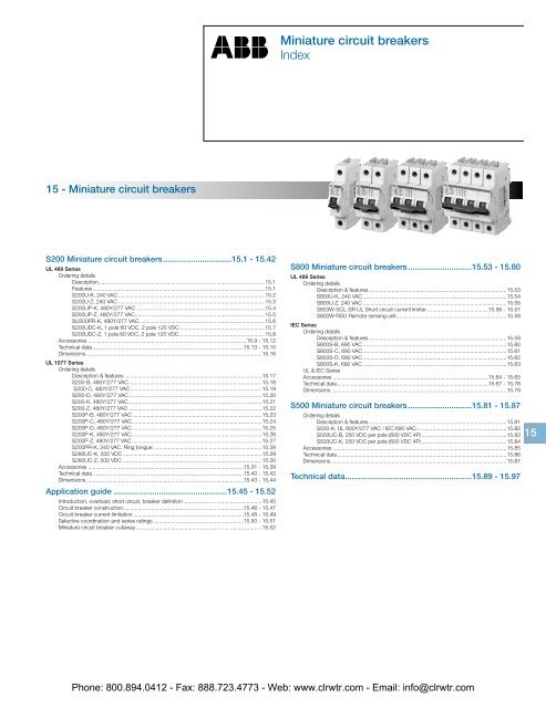
<strong>Miniature</strong> circuit breakers<br />
Index<br />
<strong>Miniature</strong> circuit<br />
breakers<br />
15 - <strong>Miniature</strong> circuit breakers<br />
S200 <strong>Miniature</strong> circuit breakers...............................15.1 - 15.42<br />
UL 489 Series<br />
Ordering details<br />
Description...............................................................................................................15.1<br />
Features...................................................................................................................15.1<br />
S200U-K, 240 VAC..................................................................................................15.2<br />
S200U-Z, 240 VAC..................................................................................................15.3<br />
S200UP-K, 480Y/277 VAC......................................................................................15.4<br />
S200UP-Z, 480Y/277 VAC.......................................................................................15.5<br />
SU200PR-K, 480Y/277 VAC....................................................................................15.6<br />
S200UDC-K, 1 pole 60 VDC, 2 pole 125 VDC.........................................................15.7<br />
S200UDC-Z, 1 pole 60 VDC, 2 pole 125 VDC..........................................................15.8<br />
Accessories..........................................................................................................15.9 - 15.12<br />
Technical data.....................................................................................................15.13 - 15.15<br />
Dimensions.....................................................................................................................15.16<br />
UL 1077 Series<br />
Ordering details<br />
Description & features............................................................................................15.17<br />
S200-B, 480Y/277 VAC.........................................................................................15.18<br />
S200-C, 480Y/277 VAC........................................................................................15.19<br />
S200-D, 480Y/277 VAC.........................................................................................15.20<br />
S200-K, 480Y/277 VAC.........................................................................................15.21<br />
S200-Z, 480Y/277 VAC.........................................................................................15.22<br />
S200P-B, 480Y/277 VAC.......................................................................................15.23<br />
S200P-C, 480Y/277 VAC.......................................................................................15.24<br />
S200P-D, 480Y/277 VAC.......................................................................................15.25<br />
S200P-K, 480Y/277 VAC.......................................................................................15.26<br />
S200P-Z, 480Y/277 VAC.......................................................................................15.27<br />
S200PR-K, 240 VAC, Ring tongue.........................................................................15.28<br />
S280UC-K, 500 VDC.............................................................................................15.29<br />
S280UC-Z, 500 VDC.............................................................................................15.30<br />
Accessories........................................................................................................15.31 - 15.39<br />
Technical data.....................................................................................................15.40 - 15.42<br />
Dimensions.........................................................................................................15.43 - 15.44<br />
Application guide...................................................15.45 - 15.52<br />
Introduction, overload, short circuit, breaker definition.....................................................15.45<br />
<strong>Circuit</strong> breaker construction................................................................................15.46 - 15.47<br />
<strong>Circuit</strong> breaker current limitation..........................................................................15.48 - 15.49<br />
Selective coordination and series ratings.............................................................15.50 - 15.51<br />
<strong>Miniature</strong> circuit breaker cutaway....................................................................................15.52<br />
S800 <strong>Miniature</strong> circuit breakers.............................15.53 - 15.80<br />
UL 489 Series<br />
Ordering details<br />
Description & features............................................................................................15.53<br />
S800U-K, 240 VAC................................................................................................15.54<br />
S800U-Z, 240 VAC................................................................................................15.55<br />
S803W-SCL-SR UL Short circuit current limiter..........................................15.56 - 15.57<br />
S800W-RSU Remote sensing unit.........................................................................15.58<br />
IEC Series<br />
Ordering details<br />
Description & features............................................................................................15.59<br />
S800S-B, 690 VAC................................................................................................15.60<br />
S800S-C, 690 VAC................................................................................................15.61<br />
S800S-D, 690 VAC................................................................................................15.62<br />
S800S-K, 690 VAC................................................................................................15.63<br />
UL & IEC Series<br />
Accessories........................................................................................................15.64 - 15.65<br />
Technical data.....................................................................................................15.67 - 15.78<br />
Dimensions.....................................................................................................................15.79<br />
S500 <strong>Miniature</strong> circuit breakers.............................15.81 - 15.87<br />
Ordering details<br />
Description & features............................................................................................15.81<br />
S500-K, UL 600Y/277 VAC / IEC 690 VAC............................................................15.82<br />
S500UC-B, 250 VDC per pole (600 VDC 4P).........................................................15.83<br />
S500UC-K, 250 VDC per pole (600 VDC 4P).........................................................15.84<br />
Accessories....................................................................................................................15.85<br />
Technical data.................................................................................................................15.86<br />
Dimensions.....................................................................................................................15.87<br />
Technical data.........................................................15.89 - 15.97<br />
15<br />
Phone: 800.894.0412 - Fax: 888.723.4773 - Web: www.clrwtr.com - Email: info@clrwtr.com
S200<br />
UL 489 Series<br />
<strong>Miniature</strong><br />
circuit breakers<br />
S200<br />
S200 UL 489 Series<br />
<strong>Miniature</strong> circuit breakers<br />
Description<br />
The S200 Series miniature circuit breaker offers<br />
a compact solution for protection requirements.<br />
The S200U AND S200UP devices are UL 489<br />
tested current limiting and DIN rail mounted.<br />
The S200U and S200UP is available with<br />
application-specific trip characteristics to<br />
provide maximum circuit protection.<br />
The breakers offer thermal-magnetic trip<br />
protection according to K and Z characteristics.<br />
For the worldwide market, the breakers carry<br />
UL, CSA, IEC, CE and many other agency<br />
approvals and certifications.<br />
Features<br />
• UL current limiting<br />
• Fast breaking time (2.3 – 2.5 ms)<br />
• Bus connection system<br />
• Wide range of accessories<br />
• Available with variable depth handle<br />
mechanism<br />
• CE certified and marked<br />
• DIN rail mounting<br />
• Finger safe terminals<br />
• Multi-function terminals<br />
• Suitable for reverse feed but S200UDC has<br />
polarity<br />
• UL 489 Listed - branch circuit protective<br />
device. UL File #E212323<br />
S200U S200UP SU200PR S200UDC<br />
Amperage 0.2 – 63 0.2 – 25 0.2 – 35A ; 40 – 63A 1 – 63<br />
Voltage 240 VAC 480Y/277VAC 480Y/277 VAC ; 240 VAC 60-125 VDC<br />
Poles 1, 2, 3, 4 1, 2, 3, 4 1, 2, 3, 4 1, 2<br />
Trip characteristics K, Z K, Z K K, Z<br />
Interrupting ratings<br />
Up to 25 kA : IEC 60947-2<br />
10 kA : UL 489<br />
10 kA : CSA 22.2 No. 5<br />
Up to 25 kA : IEC<br />
60947-2<br />
10 kA : UL 489<br />
10 kA : CSA 22.2 No. 5<br />
10kA: UL489<br />
10kA: CSA 22.2 No.5<br />
Auxiliary contacts Yes Yes Yes Yes<br />
Bell alarm Yes Yes Yes Yes<br />
Shunt trip Yes Yes Yes Yes<br />
Bus bar Yes Yes No Yes<br />
14 kA : UL489<br />
14 kA: CSA 22.2 No. 5<br />
15<br />
Phone: 800.894.0412 - Fax: 888.723.4773 - Web: www.clrwtr.com - Email: info@clrwtr.com
<strong>Miniature</strong><br />
circuit breakers<br />
S200<br />
S200U-K, 240 VAC<br />
Branch circuit protection<br />
UL 489, CSA 22.2 No. 5<br />
15<br />
K<br />
S201U-K<br />
S202U-K<br />
No. of<br />
poles<br />
1<br />
2<br />
Rated<br />
current<br />
<strong>Catalog</strong> number<br />
No. of<br />
poles<br />
Rated<br />
current<br />
<strong>Catalog</strong> number<br />
0.2 S201U-K0.2<br />
0.2 S203U-K0.2<br />
0.3 S201U-K0.3 0.3 S203U-K0.3<br />
0.5 S201U-K0.5 0.5 S203U-K0.5<br />
0.75 S201U-K0.75 0.75 S203U-K0.75<br />
1 S201U-K1 1 S203U-K1<br />
1.6 S201U-K1.6 1.6 S203U-K1.6<br />
2 S201U-K2 2 S203U-K2<br />
3 S201U-K3 3 S203U-K3<br />
4 S201U-K4 4 S203U-K4<br />
5 S201U-K5 5 S203U-K5<br />
6 S201U-K6 6 S203U-K6<br />
8 S201U-K8 3<br />
8 S203U-K8<br />
10 S201U-K10 10 S203U-K10<br />
15 S201U-K15 15 S203U-K15<br />
16 S201U-K16 16 S203U-K16<br />
20 S201U-K20 20 S203U-K20<br />
25 S201U-K25 25 S203U-K25<br />
30 S201U-K30 30 S203U-K30<br />
32 S201U-K32 32 S203U-K32<br />
40 S201U-K40 40 S203U-K40<br />
50 S201U-K50 50 S203U-K50<br />
60 S201U-K60 60 S203U-K60<br />
63 S201U-K63 63 S203U-K63<br />
0.2 S202U-K0.2<br />
0.2 S204U-K0.2<br />
0.3 S202U-K0.3 0.3 S204U-K0.3<br />
0.5 S202U-K0.5 0.5 S204U-K0.5<br />
0.75 S202U-K0.75 0.75 S204U-K0.75<br />
1 S202U-K1 1 S204U-K1<br />
1.6 S202U-K1.6 1.6 S204U-K1.6<br />
2 S202U-K2 2 S204U-K2<br />
3 S202U-K3 3 S204U-K3<br />
4 S202U-K4 4 S204U-K4<br />
5 S202U-K5 5 S204U-K5<br />
6 S202U-K6 6 S204U-K6<br />
8 S202U-K8 8 S204U-K8<br />
4<br />
10 S202U-K10 10 S204U-K10<br />
15 S202U-K15 15 S204U-K15<br />
16 S202U-K16 16 S204U-K16<br />
20 S202U-K20 20 S204U-K20<br />
25 S202U-K25 25 S204U-K25<br />
30 S202U-K30 30 S204U-K30<br />
32 S202U-K32 32 S204U-K32<br />
40 S202U-K40 40 S204U-K40<br />
50 S202U-K50 50 S204U-K50<br />
60 S202U-K60 60 S204U-K60<br />
63 S202U-K63 63 S204U-K63<br />
Tripping characteristic K<br />
UL 489<br />
240 VAC<br />
10 kA<br />
S203U-K<br />
Inductive loads<br />
• K Curve<br />
• Designed for allowing higher in-rush<br />
currents during system start up<br />
• Example: motors, transformers<br />
Accessories & technical data<br />
Accessories – See page 15.9 - 15.13<br />
Technical data – See page 15.14 -15.16<br />
S204U-K<br />
Note: This breaker for AC use only<br />
Phone: 800.894.0412 - Fax: 888.723.4773 - Web: www.clrwtr.com - Email: info@clrwtr.com
S200U-Z, 240 VAC<br />
Branch circuit protection<br />
UL 489, CSA 22.2 No. 5<br />
<strong>Miniature</strong><br />
circuit breakers<br />
S200<br />
Z<br />
S201U-Z<br />
S202U-Z<br />
No. of<br />
poles<br />
1<br />
2<br />
Rated<br />
current<br />
<strong>Catalog</strong> number<br />
No. of<br />
poles<br />
Rated<br />
current<br />
<strong>Catalog</strong> number<br />
0.5 S201U-Z0.5<br />
0.5 S203U-Z0.5<br />
1 S201U-Z1 1 S203U-Z1<br />
1.6 S201U-Z1.6 1.6 S203U-Z1.6<br />
2 S201U-Z2 2 S203U-Z2<br />
3 S201U-Z3 3 S203U-Z3<br />
4 S201U-Z4 4 S203U-Z4<br />
5 S201U-Z5 5 S203U-Z5<br />
6 S201U-Z6 6 S203U-Z6<br />
8 S201U-Z8 8 S203U-Z8<br />
10 S201U-Z10 10 S203U-Z10<br />
15 S201U-Z15 3<br />
15 S203U-Z15<br />
16 S201U-Z16 16 S203U-Z16<br />
20 S201U-Z20 20 S203U-Z20<br />
25 S201U-Z25 25 S203U-Z25<br />
30 S201U-Z30 30 S203U-Z30<br />
32 S201U-Z32 32 S203U-Z32<br />
40 S201U-Z40 40 S203U-Z40<br />
50 S201U-Z50 50 S203U-Z50<br />
60 S201U-Z60 60 S203U-Z60<br />
63 S201U-Z63 63 S203U-Z63<br />
0.5 S202U-Z0.5<br />
0.5 S204U-Z0.5<br />
1 S202U-Z1 1 S204U-Z1<br />
1.6 S202U-Z1.6 1.6 S204U-Z1.6<br />
2 S202U-Z2 2 S204U-Z2<br />
3 S202U-Z3 3 S204U-Z3<br />
4 S202U-Z4 4 S204U-Z4<br />
5 S202U-Z5 5 S204U-Z5<br />
6 S202U-Z6 6 S204U-Z6<br />
8 S202U-Z8 8 S204U-Z8<br />
10 S202U-Z10 10 S204U-Z10<br />
15 S202U-Z15 4<br />
15 S204U-Z15<br />
16 S202U-Z16 16 S204U-Z16<br />
20 S202U-Z20 20 S204U-Z20<br />
25 S202U-Z25 25 S204U-Z25<br />
30 S202U-Z30 30 S204U-Z30<br />
32 S202U-Z32 32 S204U-Z32<br />
40 S202U-Z40 40 S204U-Z40<br />
50 S202U-Z50 50 S204U-Z50<br />
60 S202U-Z60 60 S204U-Z60<br />
63 S202U-Z63 63 S204U-Z63<br />
S203U-Z<br />
Tripping characteristic Z<br />
UL 489<br />
240 VAC<br />
10 kA<br />
Resistive loads<br />
• Z Curve<br />
• Designed to provide maximum protection with<br />
a very low short<br />
circuit trip setting<br />
• Example: semiconductors, control circuits<br />
Accessories & technical data<br />
Accessories – See page 15.9 - 15.13<br />
Technical data – See page 15.14 -15.16<br />
15<br />
S204U-Z<br />
Note: This breaker for AC use only<br />
Phone: 800.894.0412 - Fax: 888.723.4773 - Web: www.clrwtr.com - Email: info@clrwtr.com
<strong>Miniature</strong><br />
circuit breakers<br />
S200<br />
S200UP-K, 480Y/277 VAC<br />
Branch circuit protection<br />
UL 489, CSA 22.2 No. 5<br />
K<br />
S201UP-K<br />
No. of<br />
poles<br />
1<br />
2<br />
Rated<br />
current<br />
<strong>Catalog</strong> number<br />
No. of<br />
poles<br />
Rated<br />
current<br />
<strong>Catalog</strong> number<br />
0.2 S201UP-K0.2<br />
0.2 S203UP-K0.2<br />
0.3 S201UP-K0.3 0.3 S203UP-K0.3<br />
0.5 S201UP-K0.5 0.5 S203UP-K0.5<br />
0.75 S201UP-K0.75 0.75 S203UP-K0.75<br />
1 S201UP-K1 1 S203UP-K1<br />
1.6 S201UP-K1.6 1.6 S203UP-K1.6<br />
2 S201UP-K2 2 S203UP-K2<br />
3 S201UP-K3 3 S203UP-K3<br />
4 S201UP-K4 3<br />
4 S203UP-K4<br />
5 S201UP-K5 5 S203UP-K5<br />
6 S201UP-K6 6 S203UP-K6<br />
8 S201UP-K8 8 S203UP-K8<br />
10 S201UP-K10 10 S203UP-K10<br />
15 S201UP-K15 15 S203UP-K15<br />
16 S201UP-K16 16 S203UP-K16<br />
20 S201UP-K20 20 S203UP-K20<br />
25 S201UP-K25 25 S203UP-K25<br />
0.2 S202UP-K0.2<br />
0.2 S204UP-K0.2<br />
0.3 S202UP-K0.3 0.3 S204UP-K0.3<br />
0.5 S202UP-K0.5 0.5 S204UP-K0.5<br />
0.75 S202UP-K0.75 0.75 S204UP-K0.75<br />
1 S202UP-K1 1 S204UP-K1<br />
1.6 S202UP-K1.6 1.6 S204UP-K1.6<br />
2 S202UP-K2 2 S204UP-K2<br />
3 S202UP-K3 3 S204UP-K3<br />
4 S202UP-K4<br />
4<br />
4 S204UP-K4<br />
5 S202UP-K5 5 S204UP-K5<br />
6 S202UP-K6 6 S204UP-K6<br />
8 S202UP-K8 8 S204UP-K8<br />
10 S202UP-K10 10 S204UP-K10<br />
15 S202UP-K15 15 S204UP-K15<br />
16 S202UP-K16 16 S204UP-K16<br />
20 S202UP-K20 20 S204UP-K20<br />
25 S202UP-K25 25 S204UP-K25<br />
S202UP-K<br />
Tripping characteristic K<br />
UL 489<br />
480Y/277 VAC<br />
10 kA<br />
15<br />
Inductive loads<br />
• K Curve<br />
• Designed for allowing higher in-rush currents<br />
during system start up<br />
• Example: motors, transformers<br />
Accessories & technical data<br />
Accessories – See page 15.9 - 15.13<br />
Technical data – See page 15.14 -15.16<br />
S203UP-K<br />
S204UP-K<br />
Note: This breaker for AC use only<br />
Phone: 800.894.0412 - Fax: 888.723.4773 - Web: www.clrwtr.com - Email: info@clrwtr.com
S200UP-Z, 480Y/277 VAC<br />
Branch circuit protection<br />
UL 489, CSA 22.2 No. 5<br />
<strong>Miniature</strong><br />
circuit breakers<br />
S200<br />
Z<br />
S201UP-Z<br />
No. of<br />
poles<br />
1<br />
2<br />
Rated<br />
current<br />
<strong>Catalog</strong> number<br />
No. of<br />
poles<br />
Rated<br />
current<br />
<strong>Catalog</strong> number<br />
0.5 S201UP-Z0.5<br />
0.5 S203UP-Z0.5<br />
1 S201UP-Z1 1 S203UP-Z1<br />
1.6 S201UP-Z1.6 1.6 S203UP-Z1.6<br />
2 S201UP-Z2 2 S203UP-Z2<br />
3 S201UP-Z3 3 S203UP-Z3<br />
4 S201UP-Z4 4 S203UP-Z4<br />
5 S201UP-Z5 5 S203UP-Z5<br />
6 S201UP-Z6 3<br />
6 S203UP-Z6<br />
8 S201UP-Z8 8 S203UP-Z8<br />
10 S201UP-Z10 10 S203UP-Z10<br />
15 S201UP-Z15 15 S203UP-Z15<br />
16 S201UP-Z16 16 S203UP-Z16<br />
20 S201UP-Z20 20 S203UP-Z20<br />
25 S201UP-Z25 25 S203UP-Z25<br />
0.5 S202UP-Z0.5<br />
0.5 S204UP-Z0.5<br />
1 S202UP-Z1 1 S204UP-Z1<br />
1.6 S202UP-Z1.6 1.6 S204UP-Z1.6<br />
2 S202UP-Z2 2 S204UP-Z2<br />
3 S202UP-Z3 3 S204UP-Z3<br />
4 S202UP-Z4 4 S204UP-Z4<br />
5 S202UP-Z5 5 S204UP-Z5<br />
6 S202UP-Z6 4<br />
6 S204UP-Z6<br />
8 S202UP-Z8 8 S204UP-Z8<br />
10 S202UP-Z10 10 S204UP-Z10<br />
15 S202UP-Z15 15 S204UP-Z15<br />
16 S202UP-Z16 16 S204UP-Z16<br />
20 S202UP-Z20 20 S204UP-Z20<br />
25 S202UP-Z25 25 S204UP-Z25<br />
S202UP-Z<br />
Tripping characteristic Z<br />
UL 489<br />
480Y/277 VAC<br />
10 kA<br />
Resistive loads<br />
• Z Curve<br />
• Designed to provide maximum protection with<br />
a very low short circuit trip setting<br />
• Example: semiconductors, control circuits<br />
Accessories & technical data<br />
Accessories – See page 15.9 - 15.13<br />
Technical data – See page 15.14 -15.16<br />
15<br />
S203UP-Z<br />
S204UP-Z<br />
Note: This breaker for AC use only<br />
Phone: 800.894.0412 - Fax: 888.723.4773 - Web: www.clrwtr.com - Email: info@clrwtr.com
15<br />
<strong>Miniature</strong><br />
circuit breakers<br />
S200<br />
K<br />
SU201PR-K0.2<br />
SU202PR-K0.2<br />
SU203PR-K0.2<br />
SU200PR-K, 480Y/277 VAC, Ring tongue<br />
Branch circuit protection<br />
UL489, CSA 22.2 No.5<br />
No. of<br />
poles<br />
1<br />
2<br />
Rated<br />
current<br />
<strong>Catalog</strong> number<br />
0.2 SU201PR-K0.2<br />
No. of<br />
poles<br />
3<br />
Rated<br />
current<br />
<strong>Catalog</strong> number<br />
0.2 SU203PR-K0.2<br />
0.3 SU201PR-K0.3 0.3 SU203PR-K0.3<br />
0.5 SU201PR-K0.5 0.5 SU203PR-K0.5<br />
0.75 SU201PR-K0.75 0.75 SU203PR-K0.75<br />
1 SU201PR-K1 1 SU203PR-K1<br />
1.6 SU201PR-K1.6 1.6 SU203PR-K1.6<br />
2 SU201PR-K2 2 SU203PR-K2<br />
3 SU201PR-K3 3 SU203PR-K3<br />
4 SU201PR-K4 4 SU203PR-K4<br />
5 SU201PR-K5 5 SU203PR-K5<br />
6 SU201PR-K6 6 SU203PR-K6<br />
8 SU201PR-K8 8 SU203PR-K8<br />
10 SU201PR-K10 10 SU203PR-K10<br />
13 SU201PR-K13 13 SU203PR-K13<br />
15 SU201PR-K15 15 SU203PR-K15<br />
16 SU201PR-K16 16 SU203PR-K16<br />
20 SU201PR-K20 20 SU203PR-K20<br />
25 SU201PR-K25 25 SU203PR-K25<br />
30 SU201PR-K30 30 SU203PR-K30<br />
32 SU201PR-K32 32 SU203PR-K32<br />
35 SU201PR-K35 35 SU203PR-K35<br />
40 SU201PR-K40 40 SU203PR-K40<br />
50 SU201PR-K50 50 SU203PR-K50<br />
60 SU201PR-K60 60 SU203PR-K60<br />
63 SU201PR-K63 63 SU203PR-K63<br />
0.2 SU202PR-K0.2<br />
0.2 SU204PR-K0.2<br />
0.3 SU202PR-K0.3 0.3 SU204PR-K0.3<br />
0.5 SU202PR-K0.5 0.5 SU204PR-K0.5<br />
0.75 SU202PR-K0.75 0.75 SU204PR-K0.75<br />
1 SU202PR-K1 1 SU204PR-K1<br />
1.6 SU202PR-K1.6 1.6 SU204PR-K1.6<br />
2 SU202PR-K2 2 SU204PR-K2<br />
3 SU202PR-K3 3 SU204PR-K3<br />
4 SU202PR-K4 4 SU204PR-K4<br />
5 SU202PR-K5 5 SU204PR-K5<br />
6 SU202PR-K6 6 SU204PR-K6<br />
8 SU202PR-K8 8 SU204PR-K8<br />
10 SU202PR-K10 4<br />
10 SU204PR-K10<br />
13 SU202PR-K13 13 SU204PR-K13<br />
15 SU202PR-K15 15 SU204PR-K15<br />
16 SU202PR-K16 16 SU204PR-K16<br />
20 SU202PR-K20 20 SU204PR-K20<br />
25 SU202PR-K25 25 SU204PR-K25<br />
30 SU202PR-K30 30 SU204PR-K30<br />
32 SU202PR-K32 32 SU204PR-K32<br />
35 SU202PR-K35 35 SU204PR-K35<br />
40 SU202PR-K40 40 SU204PR-K40<br />
50 SU202PR-K50 50 SU204PR-K50<br />
60 SU202PR-K60 60 SU204PR-K60<br />
63 SU202PR-K63<br />
K characteristic<br />
63 SU204PR-K63<br />
Tripping characteristic K<br />
UL 489<br />
480Y/277 VAC<br />
10 kA<br />
Inductive loads<br />
• K Curve<br />
• Designed for allowing higher in-rush currents<br />
during system start up<br />
• Example: motors, transformers<br />
Accessories & technical data<br />
Accessories – See page 15.9 - 15.13<br />
Technical data – See page 15.14 -15.16<br />
SU204PR-K0.2<br />
Phone: 800.894.0412 - Fax: 888.723.4773 - Web: www.clrwtr.com - Email: info@clrwtr.com
S200UDC-K, 1 pole 60 VDC, 2 pole 125 VDC<br />
Branch circuit protection<br />
UL 489, CSA 22.2 No. 5<br />
<strong>Miniature</strong><br />
circuit breakers<br />
S200<br />
K<br />
S201UDC-K1<br />
S202UDC-K1<br />
No. of<br />
poles<br />
1<br />
Rated<br />
No. of<br />
Rated<br />
<strong>Catalog</strong> number<br />
current<br />
poles<br />
current<br />
<strong>Catalog</strong> number<br />
1 S201UDC-K1<br />
1 S202UDC-K1<br />
1.6 S201UDC-K1.6 1.6 S202UDC-K1.6<br />
2 S201UDC-K2 2 S202UDC-K2<br />
3 S201UDC-K3 3 S202UDC-K3<br />
4 S201UDC-K4 4 S202UDC-K4<br />
5 S201UDC-K5 5 S202UDC-K5<br />
6 S201UDC-K6 6 S202UDC-K6<br />
8 S201UDC-K8 8 S202UDC-K8<br />
10 S201UDC-K10 10 S202UDC-K10<br />
13 S201UDC-K13 13 S202UDC-K13<br />
15 S201UDC-K15 2<br />
15 S202UDC-K15<br />
16 S201UDC-K16 16 S202UDC-K16<br />
20 S201UDC-K20 20 S202UDC-K20<br />
25 S201UDC-K25 25 S202UDC-K25<br />
30 S201UDC-K30 30 S202UDC-K30<br />
32 S201UDC-K32 32 S202UDC-K32<br />
40 S201UDC-K40 40 S202UDC-K40<br />
50 S201UDC-K50 50 S202UDC-K50<br />
60 S201UDC-K60 60 S202UDC-K60<br />
63 S201UDC-K63 63 S202UDC-K63<br />
NOTE: Standard UL 489 (only DC; please note polarity of device).<br />
Tripping characteristic K<br />
UL 489<br />
480Y/277 VAC<br />
14 kA<br />
Inductive loads<br />
• K Curve<br />
• Designed for allowing higher in-rush currents<br />
during system start up<br />
• Example: motors, transformers<br />
Accessories & technical data<br />
Accessories – See page 15.9 - 15.13<br />
Technical data – See page 15.14 -15.16<br />
Tripping time<br />
Minutes<br />
Seconds<br />
120<br />
60<br />
40<br />
20<br />
10<br />
6<br />
4<br />
2<br />
1<br />
40<br />
20<br />
10<br />
6<br />
4<br />
2<br />
I 1<br />
1<br />
I 2<br />
1<br />
K<br />
I 1 = 1.0 x In I 2 = 1.35 x In ϑ R = 25°C<br />
1<br />
= marginal characteristic<br />
measured in cold status<br />
1<br />
0.6<br />
0.4<br />
0.2<br />
0.1<br />
0.06<br />
0.04<br />
DC<br />
15<br />
0.02<br />
0.01<br />
1 1.5 2 3 4 5 6 8 10 15 20 30<br />
14<br />
Multiple of rated current<br />
25<br />
Phone: 800.894.0412 - Fax: 888.723.4773 - Web: www.clrwtr.com - Email: info@clrwtr.com
Z<br />
<strong>Miniature</strong><br />
circuit breakers<br />
S200<br />
S201UDC-K1<br />
S202UDC-K1<br />
S200UDC-Z, 1 pole 60 VDC, 2 pole 125 VDC<br />
Branch circuit protection<br />
UL 489, CSA 22.2 No. 5<br />
No. of<br />
poles<br />
1<br />
Rated<br />
No. of<br />
Rated<br />
<strong>Catalog</strong> number<br />
current<br />
poles<br />
current<br />
<strong>Catalog</strong> number<br />
1 S201UDC-Z1<br />
1 S202UDC-Z1<br />
1.6 S201UDC-Z1.6 1.6 S202UDC-Z1.6<br />
2 S201UDC-Z2 2 S202UDC-Z2<br />
3 S201UDC-Z3 3 S202UDC-Z3<br />
4 S201UDC-Z4 4 S202UDC-Z4<br />
5 S201UDC-Z5 5 S202UDC-Z5<br />
6 S201UDC-Z6 6 S202UDC-Z6<br />
8 S201UDC-Z8 8 S202UDC-Z8<br />
10 S201UDC-Z10 10 S202UDC-Z10<br />
13 S201UDC-Z13 13 S202UDC-Z13<br />
15 S201UDC-Z15 2<br />
15 S202UDC-Z15<br />
16 S201UDC-Z16 16 S202UDC-Z16<br />
20 S201UDC-Z20 20 S202UDC-Z20<br />
25 S201UDC-Z25 25 S202UDC-Z25<br />
30 S201UDC-Z30 30 S202UDC-Z30<br />
32 S201UDC-Z32 32 S202UDC-Z32<br />
40 S201UDC-Z40 40 S202UDC-Z40<br />
50 S201UDC-Z50 50 S202UDC-Z50<br />
60 S201UDC-Z60 60 S202UDC-Z60<br />
63 S201UDC-Z63 63 S202UDC-Z63<br />
NOTE: Standard UL 489 (only DC; please note polarity of device).<br />
Z<br />
Tripping characteristic Z<br />
UL 489<br />
480Y/277 VAC<br />
14 kA<br />
marginal characteristic<br />
measured in cold status<br />
Resistive loads<br />
• Z Curve<br />
• Designed to provide maximum protection with<br />
a very low short circuit trip setting<br />
• Example: semiconductors, control circuits<br />
Accessories & technical data<br />
Accessories – See page 15.9 - 15.13<br />
Technical data – See page 15.14 -15.16<br />
Tripping time<br />
Minutes<br />
Seconds<br />
15<br />
Multiple of rated current<br />
Phone: 800.894.0412 - Fax: 888.723.4773 - Web: www.clrwtr.com - Email: info@clrwtr.com
Accessories<br />
S200U, S200UP, SU200PR & S200UDC<br />
UL 489, CSA 22.2 No. 5<br />
<strong>Miniature</strong><br />
circuit breakers<br />
S200<br />
Auxiliary contacts<br />
The auxiliary contacts will signal whether the breaker is in the ON or OFF position.<br />
Description<br />
For field mounting: right side<br />
<strong>Catalog</strong> number<br />
S2C-H6RU<br />
Bell alarm<br />
The bell alarm includes a set of contacts that will only signal when the breaker has tripped.<br />
Typically the contacts would be connected to an alarm or bell to signal the operator that an overcurrent trip<br />
has occurred. The bell alarm also includes a test button for testing the alarm contacts without opening the<br />
breaker.<br />
S2C-H6RU<br />
Description<br />
For field mounting: right side<br />
<strong>Catalog</strong> number<br />
S2C-S6RU<br />
Rotary operating mechanism<br />
Allows “through the door” operation.<br />
Description<br />
Handle mechanism<br />
<strong>Catalog</strong> number<br />
S2C-DH<br />
Shunt trip<br />
For remote tripping of breaker, a shunt trip device can be added to the MCB. The solenoid device opens the<br />
breaker after control voltage is applied.<br />
S2C-S6RU<br />
Description<br />
<strong>Catalog</strong> number<br />
For field mounting: right side<br />
S2C-A1U<br />
12…60 VAC/DC<br />
For field mounting: right side<br />
110…415 VAC<br />
S2C-A2U<br />
110…250 VDC<br />
NOTE: For shafts and handles, refer to parts in the MCCB<br />
section.<br />
Possible mounting arrangements of MCB accessories<br />
15<br />
S2C-DH<br />
+ST+H+H+H)<br />
Legend<br />
Auxiliary contact<br />
Bell alarm/Auxiliary contact<br />
H<br />
S/H<br />
+ST+S/H+S/H (H)+S/H (H)<br />
Bell alarm/Auxiliary contact<br />
used as auxiliary contact<br />
S/H (H)<br />
NOTE: Right hand mount accessories cannot be used in<br />
conjunction with S2C-DH, Rotary operating mechanism.<br />
Shunt trip<br />
ST<br />
S2C-A1U<br />
Phone: 800.894.0412 - Fax: 888.723.4773 - Web: www.clrwtr.com - Email: info@clrwtr.com
<strong>Miniature</strong><br />
circuit breakers<br />
S200<br />
Accessories<br />
S200U, S200UP, S200UDC & SU200PR<br />
UL 489, CSA 22.2 No. 5<br />
Connection drawings<br />
Bell alarm S2C-S6RU<br />
In ON and OFF position after hand operation<br />
Auxiliary contact S2C-H6RU<br />
Auxiliary contact in ON position<br />
Shunt trip S2C-A...U<br />
Shunt trip<br />
in OFF<br />
position<br />
S2C-A1U<br />
S2C-A2U<br />
In OFF position after tripping<br />
Auxiliary contact in OFF position<br />
Mounting<br />
Addition of a S2C-H6RU auxiliary contact<br />
15<br />
Addition of a S2C-S6RU bell alarm contact<br />
Addition of a S2C-A..U shunt trip<br />
S200U-UP<br />
S2C-A....U<br />
Phone: 800.894.0412 - Fax: 888.723.4773 - Web: www.clrwtr.com - Email: info@clrwtr.com
Accessories<br />
SU200PR<br />
UL 489, CSA 22.2 No. 5<br />
<strong>Miniature</strong><br />
circuit breakers<br />
S200<br />
SU200PR Accessory overview<br />
H<br />
S<br />
ST<br />
Auxiliary contact S2C-H6RU<br />
Signal contact S2C-S6RU<br />
Shunt trip S2C-A...U<br />
SU200PR Instructions for use<br />
15<br />
Phone: 800.894.0412 - Fax: 888.723.4773 - Web: www.clrwtr.com - Email: info@clrwtr.com
<strong>Miniature</strong><br />
circuit breakers<br />
S200<br />
Accessories<br />
S200U, S200UP & S200UDC<br />
UL 489, CSA 22.2 No. 5<br />
UL approved busbars UL file # E250145<br />
UL 489 busbar cannot be cut.<br />
For<br />
use on:<br />
S200U<br />
S200UP<br />
S201UDC<br />
Amp<br />
rating<br />
80<br />
Number<br />
of poles<br />
6<br />
12<br />
18<br />
Phases<br />
1<br />
1<br />
1<br />
Busbar length<br />
(mm)<br />
103.2<br />
208.8<br />
314.4<br />
<strong>Catalog</strong><br />
number<br />
PS 1/6/16BP<br />
PS 1/12/16BP<br />
PS 1/18/16BP<br />
1 Phase<br />
PS2/6/16 BP<br />
S200U<br />
S200UP<br />
S201UDC<br />
80<br />
6<br />
12<br />
18<br />
2<br />
2<br />
2<br />
103.2<br />
208.8<br />
314.4<br />
PS 2/6/16BP<br />
PS 2/12/16BP<br />
PS 2/18/16BP<br />
S200U<br />
S200UP<br />
S201UDC<br />
80<br />
6<br />
12<br />
18<br />
3<br />
3<br />
3<br />
103.2<br />
208.8<br />
314.4<br />
PS 3/6/16BP<br />
PS 3/12/16BP<br />
PS 3/18/16BP<br />
2 Phase<br />
Busbar tooth covers for BS...BP (UL 489)<br />
Description<br />
Covers three unused poles of busbar<br />
<strong>Catalog</strong> number<br />
BSK-BP<br />
3 Phase<br />
BSK-BP<br />
Feeder terminals for PS...BP (UL 489)<br />
Description<br />
Terminal, insulated with pin contact<br />
Feeder Terminal, single-pole terminal, can be mounted side by side, feed<br />
on the pin of the busbar<br />
<strong>Catalog</strong> number<br />
AST35/15BP<br />
SZ-ESK BP<br />
AST35/15BP<br />
SZ-ESPBP<br />
15<br />
Phone: 800.894.0412 - Fax: 888.723.4773 - Web: www.clrwtr.com - Email: info@clrwtr.com
Technical data<br />
S200U, S200UP, SU200PR & S200UDC<br />
UL 489, CSA 22.2 No. 5<br />
<strong>Miniature</strong><br />
circuit breakers<br />
S200<br />
Technical data S200U S200UP SU200PR S200UDC<br />
Specifications: UL 489, C 22.2 No. 5, IEC 60947-2 UL 489, VDE 0660<br />
UL File-Number: E 212323, UL, Current limiting series ratings E212323, UL<br />
No. of poles: 1, 2, 3 & 4 1, 2<br />
Tripping characteristics: K, Z K K, Z<br />
Rated current: 0.2 (K) 0.5 (Z) ... 63 A 0.2 (K) 0.5 (Z) ... 25 A 0.2 ... 63A 1 - 63 A<br />
Rated voltage:<br />
Single pole: 240VAC<br />
Multi pole: 240VAC<br />
Single pole: 277VAC<br />
Multi pole: 480Y/277VAC<br />
Single pole: 277VAC (35A)<br />
Multi pole: 480Y/277VAC (35A)<br />
1P: 60 V DC<br />
2P:125 V DC 1<br />
Short circuit capacity: 10 kA 14 kA<br />
Frequency: 50/60 Hz 50/60 Hz<br />
Degree of protection: IP 20 IP20, IP40 in enclosure w/cover IP 20<br />
Mounting position: Vertical and horizontal Any Vertical and horizontal<br />
Fixing: 35 mm DIN rail 35 mm DIN rail<br />
Clamps only for Cu: 18-4 AWG (0.75 … 25 mm 2 ) 18-4 AWG (0.75 … 25 mm 2 )<br />
Service life, mech. and at rated<br />
6000 operations (AC)<br />
20,000 operations<br />
load:<br />
1 cycle (1s-ON, 9S-OFF)<br />
20,000 operations<br />
Tightening torque: 25 in. lbs (2.8 Nm) 25 in. lbs (2.8 Nm)<br />
Ambient temperature: – 25 °C … + 55 °C/– 13 °F … + 131 °F<br />
– 25 °C … + 55 °C/– 13 °F …<br />
+ 131 °F<br />
Shock resistance: 30 g at least 2 impacts shock, duration 13 ms 25 g, 2 shocks - 13ms<br />
30 g at least 2 impacts shock,<br />
duration 13 ms<br />
Auxiliary contact S2C-H6RU and S2C-S6RU<br />
Rated current: 10<br />
Rated voltage AC / DC: 24<br />
Contact:<br />
1 pole double throw<br />
Connection capacity mm 2<br />
18 – 14 AWG (0.75…2.5 mm2)<br />
Tightening torque:<br />
11 in.Ibs (1.2 Nm)<br />
Shock resistance acc. to DIN IEC 68-2-6: 5 g, 20 frequency cycles 5...150...5 Hz at 24 VAC/DC, 5 mA auto-reclosing < 10 ms<br />
Mechanical service life:<br />
10,000 operations<br />
Shunt trip Type S2C-A1U S2C-A2U<br />
15<br />
Rated voltage<br />
AC<br />
DC<br />
V<br />
V<br />
12 ... 60<br />
12 ... 60<br />
110 ... 415<br />
110 ... 250<br />
Max. release duration ms < 10 < 10<br />
Min. release voltage<br />
AC<br />
DC<br />
V<br />
V<br />
7<br />
10<br />
55<br />
80<br />
Consumption on release<br />
AC<br />
DC<br />
VA<br />
VA<br />
40 ... 200<br />
40 ... 200<br />
55 ... 210<br />
55 ... 110<br />
Coil resistance Ω 3.7 225<br />
Terminals AWG/mm 2 18…6 / 0.75 – 16 18…6 / 0.75 – 16<br />
Tightening torque in.Ibs/Nm 18 / 2 18 / 2<br />
1 Poles connected in series.<br />
Phone: 800.894.0412 - Fax: 888.723.4773 - Web: www.clrwtr.com - Email: info@clrwtr.com
<strong>Miniature</strong><br />
circuit breakers<br />
S200<br />
Technical data<br />
S200U, S200UP, SU200PR & S200UDC<br />
UL 489, CSA 22.2 No. 5<br />
Internal resistance and power loss<br />
Internal resistance per pole in mz, power loss per pole in W.<br />
Type<br />
Rated<br />
current<br />
Device series<br />
K<br />
Device series<br />
Z<br />
Type<br />
Rated<br />
current<br />
Device series<br />
K<br />
Device series<br />
Z<br />
A mz W mz W<br />
A mz W mz W<br />
S200U<br />
S200UP<br />
0.2 42500 1.7 – –<br />
0.3 20000 1.8 – –<br />
0.5 6340 1.6 10100 2.5<br />
0.75 2500 1.4 – –<br />
1 1400 1.4 2270 2.3<br />
1.6 625 1.6 1100 2.8<br />
2 460 1.8 619 2.5<br />
3 211 1.9 211 1.9<br />
4 163 2.6 163 2.6<br />
6 67 2.4 104 3.7<br />
8 45 2.9 55 3.5<br />
10 19 1.9 21 2.1<br />
13 – – – –<br />
16 8.2 2.1 10.9 2.8<br />
20 7.3 2.9 7.3 2.9<br />
25 5.6 3.5 5.6 3.5<br />
32 4.1 4.2 4.1 4.2<br />
40 4.0 6.4 4.0 6.4<br />
S200UDC<br />
1 1400 1.4 2270 2.3<br />
1.6 625 1.6 1100 2.8<br />
2 460 1.8 619 2.5<br />
3 211 1.9 211 1.9<br />
4 153 2.6 163 2.5<br />
6 67 2.4 104 3,7<br />
8 45 2.9 55 3.5<br />
10 19 1.9 21 2.1<br />
13 – – – –<br />
16 8.2 2.1 10.9 2.8<br />
20 7.3 2.0 7.3 2.9<br />
25 5.6 3.5 5.6 3.5<br />
32 4.1 4.2 4.1 4.2<br />
40 4.0 6.4 4.0 6.4<br />
50 1.2 3.0 1.8 4.4<br />
63 1.3 5.2 1.3 5.2<br />
50 1.2 3.0 1.8 4.4<br />
63 1.3 5.2 1.3 5.2<br />
SU200PR<br />
15<br />
Rated current Internal resistance per pole 1) Power loss per pole 1)<br />
A mΩ W<br />
0.2 25300 1.01<br />
0.3 13700 1.23<br />
0.5 4740 1.19<br />
0.75 2067 1.16<br />
1 1270 1.27<br />
1.5 610 1.56<br />
2 442 1.77<br />
3 140 1.26<br />
4 109 1.75<br />
5 50 1.26<br />
6 54 1.94<br />
8 22 1.41<br />
10 18.2 1.82<br />
13 14.8 2.50<br />
15 8.1 1.83<br />
16 11.1 2.83<br />
20 8.5 3.40<br />
25 5.5 3.43<br />
30 3.8 3.39<br />
32 4.6 4.70<br />
35 3.9 4.76<br />
40 2.8 4.40<br />
50 1.7 4.25<br />
60 1.7 6.18<br />
63 1.9 7.56<br />
4)<br />
Internal resistances and power loss are subject to application-specific and environmentspecific<br />
conditions and are therefore to be considered as typical values.<br />
Phone: 800.894.0412 - Fax: 888.723.4773 - Web: www.clrwtr.com - Email: info@clrwtr.com
Technical data<br />
S200U, S200UP, SU200PR & S200UDC<br />
UL 489, CSA 22.2 No. 5<br />
<strong>Miniature</strong><br />
circuit breakers<br />
S200<br />
Tripping characteristic K (68 °F)<br />
Breaker calibration temperature 68°F<br />
See chart below for temperature DeRating<br />
Tripping characteristic Z (68 °F)<br />
Breaker calibration temperature 68°F<br />
See chart below for temperature DeRating<br />
Temperature derating<br />
Max. operating current values depending on the ambient temperature for a circuit-breaker of characteristics type K and Z<br />
K and Z<br />
Ambient temperature T (°C/°F)<br />
I n (A) – 40/– 40 – 30/– 22 – 20/– 4 – 10/14 0/32 10/50 20/68 30/86 40/104 50/122 60/140 70/158<br />
0.5 0.66 0.64 0.61 0.59 0.56 0.53 0.50 0.47 0.43 0.40 0.35 0.31<br />
1.0 1.32 1.27 1.22 1.17 1.12 1.06 1.00 0.94 0.87 0.79 0.71 0.61<br />
1.6 2.12 2.04 1.96 1.88 1.79 1.70 1.60 1.50 1.39 1.26 1.13 0.98<br />
2.0 2.65 2.55 2.45 2.35 2.24 2.12 2.00 1.87 1.73 1.58 1.41 1.22<br />
3.0 4.0 3.8 3.7 3.5 3.4 3.2 3.0 2.8 2.6 2.4 2.1 1.8<br />
4.0 5.3 5.1 4.9 4.7 4.5 4.2 4.0 3.7 3.5 3.2 2.8 2.4<br />
6.0 7.9 7.6 7.3 7.0 6.7 6.4 6.0 5.6 5.2 4.7 4.2 3.7<br />
8.0 10.8 10.2 9.8 9.4 8.9 8.5 8.0 7.5 6.9 6.3 5.7 4.9<br />
10.0 13.2 12.7 12.2 11.7 11.2 10.6 10.0 9.4 8.7 7.9 7.1 6.1<br />
13.0 17.2 16.6 15.9 15.2 14.5 13.8 13.0 12.2 11.3 10.3 9.2 8.0<br />
16.0 21.2 20.4 19.6 18.8 17.9 17.0 16.0 15.0 13.9 12.6 11.3 9.8<br />
20.0 26.5 25.5 24.5 23.5 22.4 21.2 20.0 18.7 17.3 15.8 14.1 12.2<br />
25.0 33.1 31.9 30.6 29.3 28.0 26.5 25.0 23.4 21.7 19.8 17.7 15.3<br />
32.0 42.3 40.8 39.2 37.5 35.8 33.9 32.0 29.9 27.7 25.3 22.6 19.6<br />
40.0 52.9 51.0 49.0 46.9 44.7 42.4 40.0 37.4 34.6 31.6 28.3 24.5<br />
50.0 66.1 63.7 61.2 58.6 55.9 53.0 50.0 46.8 43.3 39.5 35.4 30.6<br />
63.0 83.3 80.3 77.2 73.9 70.4 66.8 63.0 58.9 54.6 49.8 44.5 38.6<br />
15<br />
Phone: 800.894.0412 - Fax: 888.723.4773 - Web: www.clrwtr.com - Email: info@clrwtr.com
<strong>Miniature</strong><br />
circuit breakers<br />
S200<br />
Approximate dimensions<br />
S200U, S200UP, S200UDC & SU200PR<br />
UL 489, CSA 22.2 No. 5<br />
Approximate dimensions in mm<br />
S200UDC<br />
S200U<br />
S200UP<br />
SU200PR<br />
S2C-H6RU, S2C-S6RU<br />
S2C-A..U<br />
15<br />
Phone: 800.894.0412 - Fax: 888.723.4773 - Web: www.clrwtr.com - Email: info@clrwtr.com
S200 UL 1077 Series<br />
Supplementary protective devices<br />
Description<br />
The S200 UL 1077 Series miniature<br />
supplementary protector offers a compact<br />
solution for protection requirements. The S200<br />
devices are DIN rail mounted.<br />
The S200 is available with application-specific<br />
trip characteristics to provide maximum circuit<br />
protection.<br />
The supplementary protectors offer thermalmagnetic<br />
trip protection according to B, C, D, K<br />
and Z characteristics.<br />
For the worldwide market, the breakers carry<br />
UL, CSA, IEC, CE and many other agency<br />
approvals and certifications.<br />
S200<br />
Supplementary protective devices<br />
UL 1077 Series<br />
<strong>Miniature</strong><br />
circuit breakers<br />
S200<br />
Features<br />
• Energy limiting<br />
• Fast breaking time (2.3 – 2.5 ms)<br />
• Bus connection system<br />
• Wide range of accessories<br />
• Available with variable depth handle<br />
mechanism<br />
• CE certified and marked<br />
• DIN rail mounting<br />
• Finger safe terminals<br />
• Multi-function terminals<br />
• Suitable for reverse feed<br />
• UL1077 Recognized supplemental protective<br />
device. UL file # E76126<br />
S200 S200P S200PR S280UC<br />
Amperage 0.5 – 63 A 0.2 – 63 A 0.2 – 63A 0.2 – 63 A<br />
Voltage 480Y/277 VAC 480Y/277 VAC 240 VAC 250/500 VDC<br />
Poles 1, 2, 3, 4 1, 2, 3, 4 1, 2, 3, 4 1, 2, 3, 4<br />
Trip<br />
characteristics<br />
B, C, D, K B, C, D, K, Z K K, Z<br />
Interrupting<br />
ratings<br />
6 kA : IEC 60898<br />
6 kA : UL 1077<br />
6 kA : CSA 22.2 No. 235<br />
Up to 25kA : IEC 60947-2<br />
10kA : UL 1077<br />
10kA: UL1077<br />
10kA: CSA 22.2 No.235<br />
Auxiliary contacts Yes Yes Yes Yes<br />
Bell alarm Yes Yes Yes Yes<br />
Shunt trip Yes Yes Yes Yes<br />
Undervoltage<br />
release<br />
Yes Yes Yes Yes<br />
Bus bar Yes Yes No Yes<br />
Up to 6kA : IEC 60947-2<br />
10kA : UL 1077<br />
6 kA : CSA 22.2 No. 235<br />
15<br />
Phone: 800.894.0412 - Fax: 888.723.4773 - Web: www.clrwtr.com - Email: info@clrwtr.com
<strong>Miniature</strong><br />
circuit breakers<br />
S200<br />
S200-B, 480Y/277 VAC<br />
Supplemental protectors<br />
UL 1077, CSA 22.2, No. 235<br />
B<br />
S201-B<br />
S202-B<br />
No. of<br />
poles<br />
1<br />
1<br />
+<br />
NA<br />
2<br />
Rated<br />
current<br />
<strong>Catalog</strong> number<br />
No. of<br />
poles<br />
Rated<br />
current<br />
<strong>Catalog</strong> number<br />
6 S201-B6<br />
6 S203-B6<br />
10 S201-B10 10 S203-B10<br />
13 S201-B13 13 S203-B13<br />
16 S201-B16 16 S203-B16<br />
20 S201-B20 20 S203-B20<br />
25 S201-B25 3<br />
25 S203-B25<br />
32 S201-B32 32 S203-B32<br />
40 S201-B40 40 S203-B40<br />
50 S201-B50 50 S203-B50<br />
63 S201-B63 63 S203-B63<br />
6 S201-B6NA<br />
6 S203-B6NA<br />
10 S201-B10NA 10 S203-B10NA<br />
13 S201-B13NA 13 S203-B13NA<br />
16 S201-B16NA 3<br />
16 S203-B16NA<br />
20 S201-B20NA 20 S203-B20NA<br />
25 S201-B25NA +<br />
25 S203-B25NA<br />
32 S201-B32NA 32 S203-B32NA<br />
40 S201-B40NA<br />
NA<br />
40 S203-B40NA<br />
50 S201-B50NA 50 S203-B50NA<br />
63 S201-B63NA 63 S203-B63NA<br />
6 S202-B6<br />
6 S204-B6<br />
10 S202-B10 10 S204-B10<br />
13 S202-B13 13 S204-B13<br />
16 S202-B16 16 S204-B16<br />
20 S202-B20 20 S204-B20<br />
25 S202-B25 4<br />
25 S204-B25<br />
32 S202-B32 32 S204-B32<br />
40 S202-B40 40 S204-B40<br />
50 S202-B50 50 S204-B50<br />
63 S202-B63 63 S204-B63<br />
15<br />
S203-B<br />
Tripping characteristic B<br />
UL 1077<br />
480Y/277VAC<br />
6 kA<br />
Resistive loads<br />
• B Curve<br />
• Designed for use in cable protection<br />
applications<br />
• Example: control circuits, lighting<br />
Accessories & technical data<br />
Accessories – See page 15.31 - 15.34<br />
Technical data – See page 15.35 - 15.36<br />
S204-B<br />
S201-BNA<br />
S203-BNA<br />
Note: Switching neutral is noted by “NA” in the catalog number.<br />
Phone: 800.894.0412 - Fax: 888.723.4773 - Web: www.clrwtr.com - Email: info@clrwtr.com
S200-C, 480Y/277 VAC<br />
Supplemental protectors<br />
UL 1077, CSA 22.2, No. 235<br />
<strong>Miniature</strong><br />
circuit breakers<br />
S200<br />
C<br />
S201-C<br />
S202-C<br />
S203-C<br />
S204-C<br />
No. of<br />
poles<br />
1<br />
1<br />
+<br />
NA<br />
2<br />
Rated<br />
current<br />
<strong>Catalog</strong> number<br />
No. of<br />
poles<br />
Rated<br />
current<br />
<strong>Catalog</strong> number<br />
0.5 S201-C0.5<br />
0.5 S203-C0.5<br />
1 S201-C1 1 S203-C1<br />
1.6 S201-C1.6 1.6 S203-C1.6<br />
2 S201-C2 2 S203-C2<br />
3 S201-C3 3 S203-C3<br />
4 S201-C4 4 S203-C4<br />
6 S201-C6 6 S203-C6<br />
8 S201-C8 8 S203-C8<br />
10 S201-C10 3<br />
10 S203-C10<br />
13 S201-C13 13 S203-C13<br />
16 S201-C16 16 S203-C16<br />
20 S201-C20 20 S203-C20<br />
25 S201-C25 25 S203-C25<br />
32 S201-C32 32 S203-C32<br />
40 S201-C40 40 S203-C40<br />
50 S201-C50 50 S203-C50<br />
63 S201-C63 63 S203-C63<br />
0.5 S201-C0.5NA<br />
0.5 S203-C0.5NA<br />
1 S201-C1NA 1 S203-C1NA<br />
1.6 S201-C1.6NA 1.6 S203-C1.6NA<br />
2 S201-C2NA 2 S203-C2NA<br />
3 S201-C3NA 3 S203-C3NA<br />
4 S201-C4NA 4 S203-C4NA<br />
6 S201-C6NA 3<br />
6 S203-C6NA<br />
8 S201-C8NA<br />
+<br />
8 S203-C8NA<br />
10 S201-C10NA 10 S203-C10NA<br />
13 S201-C13NA NA<br />
13 S203-C13NA<br />
16 S201-C16NA 16 S203-C16NA<br />
20 S201-C20NA 20 S203-C20NA<br />
25 S201-C25NA 25 S203-C25NA<br />
32 S201-C32NA 32 S203-C32NA<br />
40 S201-C40NA 40 S203-C40NA<br />
50 S201-C50NA 50 S203-C50NA<br />
63 S201-C63NA 63 S203-C63NA<br />
0.5 S202-C0.5<br />
0.5 S204-C0.5<br />
1 S202-C1 1 S204-C1<br />
1.6 S202-C1.6 1.6 S204-C1.6<br />
2 S202-C2 2 S204-C2<br />
3 S202-C3 3 S204-C3<br />
4 S202-C4 4 S204-C4<br />
6 S202-C6 6 S204-C6<br />
8 S202-C8 8 S204-C8<br />
10 S202-C10 4<br />
10 S204-C10<br />
13 S202-C13 13 S204-C13<br />
16 S202-C16 16 S204-C16<br />
20 S202-C20 20 S204-C20<br />
25 S202-C25 25 S204-C25<br />
32 S202-C32 32 S204-C32<br />
40 S202-C40 40 S204-C40<br />
50 S202-C50 50 S204-C50<br />
63 S202-C63 63 S204-C63<br />
15<br />
Tripping characteristic C<br />
UL 1077<br />
480Y/277 VAC<br />
6 kA<br />
S201-CNA<br />
Resistive loads<br />
• C Curve<br />
• Designed for use with medium magnetic<br />
start up currents<br />
• Example: lighting, control panels<br />
Accessories & technical data<br />
Accessories – See page 15.31 - 15.34<br />
Technical data – See page 15.35 - 15.36<br />
S203-CNA<br />
Note: Switching neutral is noted by “NA” in the catalog<br />
number.<br />
Phone: 800.894.0412 - Fax: 888.723.4773 - Web: www.clrwtr.com - Email: info@clrwtr.com
<strong>Miniature</strong><br />
circuit breakers<br />
S200<br />
S200-D, 480Y/277 VAC<br />
Supplemental protectors<br />
UL 1077, CSA 22.2, No. 235<br />
15<br />
D<br />
S201-D<br />
S202-D<br />
S203-D<br />
S204-D<br />
No. of<br />
poles<br />
1<br />
1<br />
+<br />
NA<br />
2<br />
Rated<br />
current<br />
Tripping characteristic D<br />
UL 1077<br />
480Y/277 VAC<br />
6 kA<br />
<strong>Catalog</strong> number<br />
No. of<br />
poles<br />
Rated<br />
current<br />
<strong>Catalog</strong> number<br />
0.5 S201-D0.5<br />
0.5 S203-D0.5<br />
1 S201-D1 1 S203-D1<br />
1.6 S201-D1.6 1.6 S203-D1.6<br />
2 S201-D2 2 S203-D2<br />
3 S201-D3 3 S203-D3<br />
4 S201-D4 4 S203-D4<br />
6 S201-D6 6 S203-D6<br />
8 S201-D8 8 S203-D8<br />
10 S201-D10 3<br />
10 S203-D10<br />
13 S201-D13 13 S203-D13<br />
16 S201-D16 16 S203-D16<br />
20 S201-D20 20 S203-D20<br />
25 S201-D25 25 S203-D25<br />
32 S201-D32 32 S203-D32<br />
40 S201-D40 40 S203-D40<br />
50 S201-D50 50 S203-D50<br />
63 S201-D63 63 S203-D63<br />
0.5 S201-D0.5NA<br />
0.5 S203-D0.5NA<br />
1 S201-D1NA 1 S203-D1NA<br />
1.6 S201-D1.6NA 1.6 S203-D1.6NA<br />
2 S201-D2NA 2 S203-D2NA<br />
3 S201-D3NA 3 S203-D3NA<br />
4 S201-D4NA 4 S203-D4NA<br />
6 S201-D6NA 6 S203-D6NA<br />
8 S201-D8NA 3<br />
8 S203-D8NA<br />
10 S201-D10NA +<br />
10 S203-D10NA<br />
13 S201-D13NA 13 S203-D13NA<br />
16 S201-D16NA NA<br />
16 S203-D16NA<br />
20 S201-D20NA 20 S203-D20NA<br />
25 S201-D25NA 25 S203-D25NA<br />
32 S201-D32NA 32 S203-D32NA<br />
40 S201-D40NA 40 S203-D40NA<br />
50 S201-D50NA 50 S203-D50NA<br />
63 S201-D63NA 63 S203-D63NA<br />
0.5 S202-D0.5<br />
0.5 S204-D0.5<br />
1 S202-D1 1 S204-D1<br />
1.6 S202-D1.6 1.6 S204-D1.6<br />
2 S202-D2 2 S204-D2<br />
3 S202-D3 3 S204-D3<br />
4 S202-D4 4 S204-D4<br />
6 S202-D6 6 S204-D6<br />
8 S202-D8 8 S204-D8<br />
10 S202-D10 4<br />
10 S204-D10<br />
13 S202-D13 13 S204-D13<br />
16 S202-D16 16 S204-D16<br />
20 S202-D20 20 S204-D20<br />
25 S202-D25 25 S204-D25<br />
32 S202-D32 32 S204-D32<br />
40 S202-D40 40 S204-D40<br />
50 S202-D50 50 S204-D50<br />
63 S202-D63 63 S204-D63<br />
Inductive loads<br />
• D Curve<br />
• Designed for allowing higher in-rush<br />
currents during system start up<br />
• Example: motors, transformers<br />
S201-DNA<br />
Accessories & technical data<br />
Accessories – See page 15.31 - 15.34<br />
Technical data – See page 15.35 - 15.36<br />
S203-DNA<br />
Note: Switching neutral is noted by “NA” in the catalog<br />
number.<br />
Phone: 800.894.0412 - Fax: 888.723.4773 - Web: www.clrwtr.com - Email: info@clrwtr.com
S200-K, 480Y/277 VAC<br />
Supplemental protectors<br />
UL 1077, CSA 22.2, No. 235<br />
<strong>Miniature</strong><br />
circuit breakers<br />
S200<br />
K<br />
S201-K<br />
S202-K<br />
S203-K<br />
S204-K<br />
No. of<br />
poles<br />
1<br />
1<br />
+<br />
NA<br />
2<br />
Rated<br />
current<br />
No. of<br />
poles<br />
3<br />
Rated<br />
current<br />
<strong>Catalog</strong> number<br />
<strong>Catalog</strong> number<br />
0.5 S201-K0.5<br />
0.5 S203-K0.5<br />
1 S201-K1 1 S203-K1<br />
1.6 S201-K1.6 1.6 S203-K1.6<br />
2 S201-K2 2 S203-K2<br />
3 S201-K3 3 S203-K3<br />
4 S201-K4 4 S203-K4<br />
5 S201-K5 5 S203-K5<br />
6 S201-K6 6 S203-K6<br />
8 S201-K8 8 S203-K8<br />
10 S201-K10 10 S203-K10<br />
13 S201-K13 13 S203-K13<br />
15 S201-K15 15 S203-K15<br />
16 S201-K16 16 S203-K16<br />
20 S201-K20 20 S203-K20<br />
25 S201-K25 25 S203-K25<br />
32 S201-K32 32 S203-K32<br />
40 S201-K40 40 S203-K40<br />
50 S201-K50 50 S203-K50<br />
60 S201-K60 60 S203-K60<br />
63 S201-K63 63 S203-K63<br />
0.5 S201-K0.5NA<br />
0.5 S203-K0.5NA<br />
1 S201-K1NA 1 S203-K1NA<br />
1.6 S201-K1.6NA 1.6 S203-K1.6NA<br />
2 S201-K2NA 2 S203-K2NA<br />
3 S201-K3NA 3 S203-K3NA<br />
4 S201-K4NA 4 S203-K4NA<br />
6 S201-K6NA 3<br />
6 S203-K6NA<br />
8 S201-K8NA 8 S203-K8NA<br />
10 S201-K10NA +<br />
10 S203-K10NA<br />
13 S201-K13NA NA<br />
13 S203-K13NA<br />
16 S201-K16NA 16 S203-K16NA<br />
20 S201-K20NA 20 S203-K20NA<br />
25 S201-K25NA 25 S203-K25NA<br />
32 S201-K32NA 32 S203-K32NA<br />
40 S201-K40NA 40 S203-K40NA<br />
50 S201-K50NA 50 S203-K50NA<br />
63 S201-K63NA 63 S203-K63NA<br />
0.5 S202-K0.5<br />
0.5 S204-K0.5<br />
1 S202-K1 1 S204-K1<br />
1.6 S202-K1.6 1.6 S204-K1.6<br />
2 S202-K2 2 S204-K2<br />
3 S202-K3 3 S204-K3<br />
4 S202-K4 4 S204-K4<br />
5 S202-K5 5 S204-K5<br />
6 S202-K6 6 S204-K6<br />
8 S202-K8 8 S204-K8<br />
10 S202-K10 10 S204-K10<br />
13 S202-K13 4<br />
13 S204-K13<br />
15 S202-K15 15 S204-K15<br />
16 S202-K16 16 S204-K16<br />
20 S202-K20 20 S204-K20<br />
25 S202-K25 25 S204-K25<br />
32 S202-K32 32 S204-K32<br />
40 S202-K40 40 S204-K40<br />
50 S202-K50 50 S204-K50<br />
60 S202-K60 60 S204-K60<br />
63 S202-K63 63 S204-K63<br />
15<br />
Tripping characteristic K<br />
UL 1077<br />
480Y/277 VAC<br />
6 kA<br />
S201-KNA<br />
Inductive loads<br />
• K Curve<br />
• Designed for allowing higher in-rush<br />
currents during system start up<br />
• Example: motors, transformers<br />
Accessories & technical data<br />
Accessories – See page 15.31 - 15.34<br />
Technical data – See page 15.35 - 15.36<br />
S203-KNA<br />
Note: Switching neutral is noted by “NA” in the catalog<br />
number.<br />
Phone: 800.894.0412 - Fax: 888.723.4773 - Web: www.clrwtr.com - Email: info@clrwtr.com
<strong>Miniature</strong><br />
circuit breakers<br />
S200<br />
S200-Z, 480Y/277 VAC<br />
Supplemental protectors<br />
UL 1077, CSA 22.2, No. 235<br />
Z<br />
S201-Z0.5<br />
S202-Z0.5<br />
No. of<br />
poles<br />
1<br />
2<br />
Rated<br />
current<br />
<strong>Catalog</strong> number<br />
No. of<br />
poles<br />
Rated<br />
current<br />
<strong>Catalog</strong> number<br />
0.5 S201-Z0.5<br />
0.5 S203-Z0.5<br />
1 S201-Z1 1 S203-Z1<br />
1.6 S201-Z1.6 1.6 S203-Z1.6<br />
2 S201-Z2 2 S203-Z2<br />
3 S201-Z3 3 S203-Z3<br />
4 S201-Z4 4 S203-Z4<br />
6 S201-Z6 6 S203-Z6<br />
10 S201-Z10 10 S203-Z10<br />
13 S201-Z13 3<br />
13 S203-Z13<br />
16 S201-Z16 16 S203-Z16<br />
20 S201-Z20 20 S203-Z20<br />
25 S201-Z25 25 S203-Z25<br />
32 S201-Z32 32 S203-Z32<br />
40 S201-Z40 40 S203-Z40<br />
50 S201-Z50 50 S203-Z50<br />
63 S201-Z63 63 S203-Z63<br />
0.5 S202-Z0.5<br />
0.5 S204-Z0.5<br />
1 S202-Z1 1 S204-Z1<br />
1.6 S202-Z1.6 1.6 S204-Z1.6<br />
2 S202-Z2 2 S204-Z2<br />
3 S202-Z3 3 S204-Z3<br />
4 S202-Z4 4 S204-Z4<br />
6 S202-Z6 6 S204-Z6<br />
10 S202-Z10 10 S204-Z10<br />
13 S202-Z13<br />
4<br />
13 S204-Z13<br />
16 S202-Z16 16 S204-Z16<br />
20 S202-Z20 20 S204-Z20<br />
25 S202-Z25 25 S204-Z25<br />
32 S202-Z32 32 S204-Z32<br />
40 S202-Z40 40 S204-Z40<br />
50 S202-Z50 50 S204-Z50<br />
63 S202-Z63 63 S204-Z63<br />
15<br />
S203-Z0.5<br />
Tripping characteristic Z<br />
UL 1077<br />
480Y/277VAC<br />
6 kA<br />
Resistive loads<br />
• Z Curve<br />
• Designed to provide maximum protection<br />
with a very low shirt circuit trip setting<br />
• Example: semiconductors<br />
Accessories & technical data<br />
Accessories – See page 15.31 - 15.34<br />
Technical data – See page 15.35 - 15.36<br />
S204-Z0.5<br />
Phone: 800.894.0412 - Fax: 888.723.4773 - Web: www.clrwtr.com - Email: info@clrwtr.com
S200P-B, 480Y/277 VAC<br />
Supplemental protectors<br />
UL 1077, CSA 22.2, No. 235<br />
<strong>Miniature</strong><br />
circuit breakers<br />
S200<br />
B<br />
S210P-B6<br />
No. of<br />
poles<br />
1<br />
2<br />
Rated<br />
No. of<br />
Rated<br />
<strong>Catalog</strong> number<br />
current<br />
poles<br />
current<br />
<strong>Catalog</strong> number<br />
6 S201P-B6<br />
6 S203P-B6<br />
10 S201P-B10 10 S203P-B10<br />
13 S201P-B13 13 S203P-B13<br />
16 S201P-B16 16 S203P-B16<br />
20 S201P-B20 20 S203P-B20<br />
25 S201P-B25 3<br />
25 S203P-B25<br />
32 S201P-B32 32 S203P-B32<br />
40 S201P-B40 40 S203P-B40<br />
50 S201P-B50 50 S203P-B50<br />
63 S201P-B63 63 S203P-B63<br />
6 S202P-B6<br />
6 S204P-B6<br />
10 S202P-B10 10 S204P-B10<br />
13 S202P-B13 13 S204P-B13<br />
16 S202P-B16 16 S204P-B16<br />
20 S202P-B20 20 S204P-B20<br />
25 S202P-B25 4<br />
25 S204P-B25<br />
32 S202P-B32 32 S204P-B32<br />
40 S202P-B40 40 S204P-B40<br />
50 S202P-B50 50 S204P-B50<br />
63 S202P-B63 63 S204P-B63<br />
S210P-B6<br />
Tripping characteristic B<br />
UL 1077<br />
480Y/277 VAC<br />
10 kA<br />
Resistive loads<br />
• B Curve<br />
• Designed for use in cable protection<br />
applications<br />
• Example: Control circuits, lighting<br />
S210P-B6<br />
Accessories & technical data<br />
Accessories – See page 15.31 - 15.34<br />
Technical data – See page 15.35 - 15.36<br />
15<br />
S210P-B6<br />
Phone: 800.894.0412 - Fax: 888.723.4773 - Web: www.clrwtr.com - Email: info@clrwtr.com
<strong>Miniature</strong><br />
circuit breakers<br />
S200<br />
C<br />
S210P-B6<br />
S210P-B6<br />
S210P-B6<br />
S200P-C, 480Y/277 VAC<br />
Supplemental protectors<br />
UL 1077, CSA 22.2, No. 235<br />
No. of<br />
poles<br />
1<br />
2<br />
Rated<br />
No. of<br />
Rated<br />
<strong>Catalog</strong> number<br />
current<br />
poles<br />
current<br />
<strong>Catalog</strong> number<br />
0.5 S201P-C0.5<br />
0.5 S203P-C0.5<br />
1 S201P-C1 1 S203P-C1<br />
1.6 S201P-C1.6 1.6 S203P-C1.6<br />
2 S201P-C2 2 S203P-C2<br />
3 S201P-C3 3 S203P-C3<br />
4 S201P-C4 4 S203P-C4<br />
6 S201P-C6 6 S203P-C6<br />
8 S201P-C8 8 S203P-C8<br />
10 S201P-C10 3<br />
10 S203P-C10<br />
13 S201P-C13 13 S203P-C13<br />
16 S201P-C16 16 S203P-C16<br />
20 S201P-C10 20 S203P-C10<br />
25 S201P-C25 25 S203P-C25<br />
32 S201P-C32 32 S203P-C32<br />
40 S201P-C40 40 S203P-C40<br />
50 S201P-C50 50 S203P-C50<br />
63 S201P-C63 63 S203P-C63<br />
0.5 S202P-C0.5<br />
1 S202P-C1<br />
1.6 S202P-C1.6<br />
2 S202P-C2<br />
3 S202P-C3<br />
4 S202P-C4<br />
6 S202P-C6<br />
8 S202P-C8<br />
10 S202P-C10<br />
13 S202P-C13<br />
16 S202P-C16<br />
20 S202P-C10<br />
25 S202P-C25<br />
32 S202P-C32<br />
40 S202P-C40<br />
50 S202P-C50<br />
63 S202P-C63<br />
15<br />
Tripping characteristic C<br />
UL 1077<br />
480Y/277 VAC<br />
10 kA<br />
Resistive loads<br />
• C Curve<br />
• Designed for use with medium magnetic<br />
start up currents<br />
• Example: Lighting, control panels<br />
Accessories & technical data<br />
Accessories – See page 15.31 - 15.34<br />
Technical data – See page 15.35 - 15.36<br />
Phone: 800.894.0412 - Fax: 888.723.4773 - Web: www.clrwtr.com - Email: info@clrwtr.com
S200P-D, 480Y/277 VAC<br />
Supplemental protectors<br />
UL 1077, CSA 22.2, No. 235<br />
<strong>Miniature</strong><br />
circuit breakers<br />
S200<br />
D<br />
S201P-D0.5<br />
S202P-D0.5<br />
S203P-D0.5<br />
No. of<br />
poles<br />
1<br />
2<br />
Rated<br />
current<br />
<strong>Catalog</strong> number<br />
0.5 S201P-D0.5<br />
No. of<br />
poles<br />
Rated<br />
current<br />
<strong>Catalog</strong> number<br />
0.5 S203P-D0.5<br />
1 S201P-D1 1 S203P-D1<br />
1.6 S201P-D1.6 1.6 S203P-D1.6<br />
2 S201P-D2 2 S203P-D2<br />
3 S201P-D3 3 S203P-D3<br />
4 S201P-D4 4 S203P-D4<br />
6 S201P-D6 6 S203P-D6<br />
8 S201P-D8 8 S203P-D8<br />
10 S201P-D10 3<br />
10 S203P-D10<br />
13 S201P-D13 13 S203P-D13<br />
16 S201P-D16 16 S203P-D16<br />
20 S201P-D10 20 S203P-D10<br />
25 S201P-D25 25 S203P-D25<br />
32 S201P-D32 32 S203P-D32<br />
40 S201P-D40 40 S203P-D40<br />
50 S201P-D50 50 S203P-D50<br />
63 S201P-D63 63 S203P-D63<br />
0.5 S202P-D0.5<br />
1 S202P-D1<br />
1.6 S202P-D1.6<br />
2 S202P-D2<br />
3 S202P-D3<br />
4 S202P-D4<br />
6 S202P-D6<br />
8 S202P-D8<br />
10 S202P-D10<br />
13 S202P-D13<br />
16 S202P-D16<br />
20 S202P-D10<br />
25 S202P-D25<br />
32 S202P-D32<br />
40 S202P-D40<br />
50 S202P-D50<br />
63 S202P-D63<br />
Tripping characteristic D<br />
UL 1077<br />
480Y/277 VAC<br />
10 kA<br />
Inductive loads<br />
• D Curve<br />
• Designed for allowing higher in-rush<br />
currents during system start up<br />
• Example: motors, transformers<br />
15<br />
Accessories & technical data<br />
Accessories – See page 15.31 - 15.34<br />
Technical data – See page 15.35 - 15.36<br />
Phone: 800.894.0412 - Fax: 888.723.4773 - Web: www.clrwtr.com - Email: info@clrwtr.com
<strong>Miniature</strong><br />
circuit breakers<br />
S200<br />
S200P-K, 480Y/277 VAC<br />
Supplemental protectors<br />
UL 1077, CSA 22.2, No. 235<br />
K<br />
S201P-K<br />
S202P-K<br />
No. of<br />
poles<br />
1<br />
2<br />
Rated<br />
current<br />
<strong>Catalog</strong> number<br />
No. of<br />
poles<br />
Rated<br />
current<br />
<strong>Catalog</strong> number<br />
0.2 S201P-K0.2<br />
0.2 S203P-K0.2<br />
0.3 S201P-K0.3 0.3 S203P-K0.3<br />
0.5 S201P-K0.5 0.5 S203P-K0.5<br />
0.75 S201P-K0.75 0.75 S203P-K0.75<br />
1 S201P-K1 1 S203P-K1<br />
1.6 S201P-K1.6 1,6 S203P-K1,6<br />
2 S201P-K2 2 S203P-K2<br />
3 S201P-K3 3 S203P-K3<br />
4 S201P-K4 4 S203P-K4<br />
6 S201P-K6 6 S203P-K6<br />
8 S201P-K8 3<br />
8 S203P-K8<br />
10 S201P-K10 10 S203P-K10<br />
13 S201P-K13 13 S203P-K13<br />
16 S201P-K16 16 S203P-K16<br />
20 S201P-K20 20 S203P-K20<br />
25 S201P-K25 25 S203P-K25<br />
32 S201P-K32 32 S203P-K32<br />
40 S201P-K40 40 S203P-K40<br />
50 S201P-K50 50 S203P-K50<br />
63 S201P-K63 63 S203P-K63<br />
0.2 S202P-K0.2<br />
0.3 S202P-K0.3<br />
0.5 S202P-K0.5<br />
0.75 S202P-K0.75<br />
1 S202P-K1<br />
1.6 S202P-K1,6<br />
2 S202P-K2<br />
3 S202P-K3<br />
4 S202P-K4<br />
6 S202P-K6<br />
8 S202P-K8<br />
10 S202P-K10<br />
13 S202P-K13<br />
16 S202P-K16<br />
20 S202P-K20<br />
25 S202P-K25<br />
32 S202P-K32<br />
40 S202P-K40<br />
50 S202P-K50<br />
63 S202P-K63<br />
15<br />
S203P-K<br />
Tripping characteristic K<br />
UL 1077<br />
480Y/277 VAC<br />
10 kA<br />
Inductive loads<br />
• K Curve<br />
• Designed for allowing higher in-rush<br />
currents during system start up<br />
• Example: motors, transformers<br />
Accessories & technical data<br />
Accessories – See page 15.31 - 15.34<br />
Technical data – See page 15.35 - 15.36<br />
Phone: 800.894.0412 - Fax: 888.723.4773 - Web: www.clrwtr.com - Email: info@clrwtr.com
S200P-Z, 480Y/277 VAC<br />
Supplemental protectors<br />
UL 1077, CSA 22.2, No. 235<br />
<strong>Miniature</strong><br />
circuit breakers<br />
S200<br />
Z<br />
S201P-Z<br />
No. of<br />
poles<br />
1<br />
2<br />
Rated<br />
current<br />
<strong>Catalog</strong> number<br />
No. of<br />
poles<br />
Rated<br />
current<br />
<strong>Catalog</strong> number<br />
0.5 S201P-Z0.5<br />
0.5 S203P-Z0.5<br />
1 S201P-Z1 1 S203P-Z1<br />
1.6 S201P-Z1.6 1.6 S203P-Z1.6<br />
2 S201P-Z2 2 S203P-Z2<br />
3 S201P-Z3 3 S203P-Z3<br />
4 S201P-Z4 4 S203P-Z4<br />
6 S201P-Z6 6 S203P-Z6<br />
8 S201P-Z8 8 S203P-Z8<br />
10 S201P-Z10 3<br />
10 S203P-Z10<br />
16 S201P-Z16 16 S203P-Z16<br />
20 S201P-Z20 20 S203P-Z20<br />
25 S201P-Z25 25 S203P-Z25<br />
32 S201P-Z32 32 S203P-Z32<br />
40 S201P-Z40 40 S203P-Z40<br />
50 S201P-Z50 50 S203P-Z50<br />
63 S201P-Z63 63 S203P-Z63<br />
0.5 S202P-Z0.5<br />
1 S202P-Z1<br />
1.6 S202P-Z1.6<br />
2 S202P-Z2<br />
3 S202P-Z3<br />
4 S202P-Z4<br />
6 S202P-Z6<br />
8 S202P-Z8<br />
10 S202P-Z10<br />
16 S202P-Z16<br />
20 S202P-Z20<br />
25 S202P-Z25<br />
32 S202P-Z32<br />
40 S202P-Z40<br />
50 S202P-Z50<br />
63 S202P-Z63<br />
S202P-Z<br />
Tripping characteristic Z<br />
UL 1077<br />
480Y/277 VAC<br />
10 kA<br />
Resistive loads<br />
• Z Curve<br />
• Designed to provide maximum<br />
protection with a very low short<br />
circuit trip setting<br />
• Example: semiconductors<br />
Accessories & technical data<br />
Accessories – See page 15.31 - 15.34<br />
Technical data – See page 15.35 - 15.36<br />
15<br />
S203P-Z<br />
Phone: 800.894.0412 - Fax: 888.723.4773 - Web: www.clrwtr.com - Email: info@clrwtr.com
15<br />
<strong>Miniature</strong><br />
circuit breakers<br />
S200<br />
K<br />
S201PR-K0.2<br />
S202PR-K0.2<br />
S200PR-K, 240 VAC, Ring tongue<br />
Supplemental protectors<br />
UL1077, CSA 22.2 No. 235<br />
No. of<br />
poles<br />
1<br />
2<br />
Rated<br />
current<br />
<strong>Catalog</strong> number<br />
0.2 S201PR-K0.2<br />
No. of<br />
poles<br />
3<br />
Rated<br />
current<br />
<strong>Catalog</strong> number<br />
0.2 S203PR-K0.2<br />
0.3 S201PR-K0.3 0.3 S203PR-K0.3<br />
0.5 S201PR-K0.5 0.5 S203PR-K0.5<br />
0.75 S201PR-K0.75 0.75 S203PR-K0.75<br />
1 S201PR-K1 1 S203PR-K1<br />
1.6 S201PR-K1.6 1.6 S203PR-K1.6<br />
2 S201PR-K2 2 S203PR-K2<br />
3 S201PR-K3 3 S203PR-K3<br />
4 S201PR-K4 4 S203PR-K4<br />
5 S201PR-K5 5 S203PR-K5<br />
6 S201PR-K6 6 S203PR-K6<br />
8 S201PR-K8 8 S203PR-K8<br />
10 S201PR-K10 10 S203PR-K10<br />
13 S201PR-K13 13 S203PR-K13<br />
15 S201PR-K15 15 S203PR-K15<br />
16 S201PR-K16 16 S203PR-K16<br />
20 S201PR-K20 20 S203PR-K20<br />
25 S201PR-K25 25 S203PR-K25<br />
30 S201PR-K30 30 S203PR-K30<br />
32 S201PR-K32 32 S203PR-K32<br />
35 S201PR-K35 35 S203PR-K35<br />
40 S201PR-K40 40 S203PR-K40<br />
50 S201PR-K50 50 S203PR-K50<br />
60 S201PR-K60 60 S203PR-K60<br />
63 S201PR-K63 63 S203PR-K63<br />
0.2 S202PR-K0.2<br />
0.2 S204PR-K0.2<br />
0.3 S202PR-K0.3 0.3 S204PR-K0.3<br />
0.5 S202PR-K0.5 0.5 S204PR-K0.5<br />
0.75 S202PR-K0.75 0.75 S204PR-K0.75<br />
1 S202PR-K1 1 S204PR-K1<br />
1.6 S202PR-K1.6 1.6 S204PR-K1.6<br />
2 S202PR-K2 2 S204PR-K2<br />
3 S202PR-K3 3 S204PR-K3<br />
4 S202PR-K4 4 S204PR-K4<br />
5 S202PR-K5 5 S204PR-K5<br />
6 S202PR-K6 6 S204PR-K6<br />
8 S202PR-K8 8 S204PR-K8<br />
10 S202PR-K10<br />
4<br />
10 S204PR-K10<br />
13 S202PR-K13 13 S204PR-K13<br />
15 S202PR-K15 15 S204PR-K15<br />
16 S202PR-K16 16 S204PR-K16<br />
20 S202PR-K20 20 S204PR-K20<br />
25 S202PR-K25 25 S204PR-K25<br />
30 S202PR-K30 30 S204PR-K30<br />
32 S202PR-K32 32 S204PR-K32<br />
35 S202PR-K35 35 S204PR-K35<br />
40 S202PR-K40 40 S204PR-K40<br />
50 S202PR-K50 50 S204PR-K50<br />
60 S202PR-K60 60 S204PR-K60<br />
63 S202PR-K63 63 S204PR-K63<br />
S203PR-K0.2<br />
Tripping characteristic K<br />
UL 1077<br />
480Y/277 VAC<br />
10 kA<br />
Inductive loads<br />
• K Curve<br />
• Designed for allowing higher in-rush currents<br />
during system start up<br />
• Example: motors, transformers<br />
Accessories & technical data<br />
Accessories – See page 15.31 - 15.34<br />
Technical data – See page 15.35 - 15.36<br />
S203PR-K0.2<br />
Phone: 800.894.0412 - Fax: 888.723.4773 - Web: www.clrwtr.com - Email: info@clrwtr.com
S280UC-K, 500 VDC<br />
Supplemental protectors<br />
UL 1077, CSA 22.2, No. 235<br />
<strong>Miniature</strong><br />
circuit breakers<br />
S200<br />
K<br />
S281UC-K<br />
S282UC-K<br />
No. of<br />
poles<br />
1<br />
2<br />
Rated<br />
current<br />
<strong>Catalog</strong> number<br />
No. of<br />
poles<br />
Rated<br />
current<br />
<strong>Catalog</strong> number<br />
0,2 S281UC-K0.2<br />
0.2 S283UC-K0.2<br />
0,3 S281UC-K0.3 0.3 S283UC-K0.3<br />
0,5 S281UC-K0.5 0.5 S283UC-K0.5<br />
0,75 S281UC-K0.75 0.75 S283UC-K0.75<br />
1 S281UC-K1 1 S283UC-K1<br />
1,6 S281UC-K1.6 1.6 S283UC-K1.6<br />
2 S281UC-K2 2 S283UC-K2<br />
3 S281UC-K3 3 S283UC-K3<br />
4 S281UC-K4 4 S283UC-K4<br />
6 S281UC-K6 3<br />
6 S283UC-K6<br />
8 S281UC-K8 8 S283UC-K8<br />
10 S281UC-K10 10 S283UC-K10<br />
16 S281UC-K16 16 S283UC-K16<br />
20 S281UC-K20 20 S283UC-K20<br />
25 S281UC-K25 25 S283UC-K25<br />
32 S281UC-K32 32 S283UC-K32<br />
40 S281UC-K40 40 S283UC-K40<br />
50 S281UC-K50 50 S283UC-K50<br />
63 S281UC-K63 63 S283UC-K63<br />
0,2 S282UC-K0.2<br />
0,3 S282UC-K0.3<br />
0,5 S282UC-K0.5<br />
0,75 S282UC-K0.75<br />
1 S282UC-K1<br />
1,6 S282UC-K1.6<br />
2 S282UC-K2<br />
3 S282UC-K3<br />
4 S282UC-K4<br />
6 S282UC-K6<br />
8 S282UC-K8<br />
10 S282UC-K10<br />
16 S282UC-K16<br />
20 S282UC-K20<br />
25 S282UC-K25<br />
32 S282UC-K32<br />
40 S282UC-K40<br />
50 S282UC-K50<br />
63 S282UC-K63<br />
S283UC-K<br />
500 VDC<br />
Two Pole<br />
S201DC<br />
S282UC<br />
3+<br />
4-<br />
Tripping characteristic K<br />
UL 1077<br />
250/500 VDC<br />
10 kA<br />
Inductive loads<br />
• K Curve<br />
• Designed for allowing higher in-rush<br />
currents during system start up<br />
• Example: motors, transformer<br />
Accessories & technical data<br />
Accessories – See page 15.31 - 15.34<br />
Technical data – See page 15.35 - 15.36<br />
Direct current applications<br />
The S280UC differs from standard miniature<br />
circuit breakers in that the UC versions<br />
include a permanent magnet which aids in the<br />
extinguishing of the arc during medium and<br />
high level faults. It is necessary to observe the<br />
correct polarity and current direction when<br />
connecting the UC breakers. Two examples of<br />
correct connection are shown.<br />
Termination points are marked on all UC type<br />
MCBs, points one (1) and four (4) are negative<br />
and points two (2) and three (3) are positive.<br />
15<br />
LOAD<br />
Phone: 800.894.0412 - Fax: 888.723.4773 - Web: www.clrwtr.com - Email: info@clrwtr.com
<strong>Miniature</strong><br />
circuit breakers<br />
S200<br />
S280UC-Z, 500 VDC<br />
Supplemental protectors<br />
UL 1077, CSA 22.2, No. 235<br />
Z<br />
S281UC-Z<br />
No. of<br />
poles<br />
1<br />
2<br />
Rated<br />
current<br />
<strong>Catalog</strong> number<br />
No. of<br />
poles<br />
Rated<br />
current<br />
<strong>Catalog</strong> number<br />
0.5 S281UC-Z0.5<br />
0.5 S283UC-Z0.5<br />
1 S281UC-Z1 1 S283UC-Z1<br />
1.6 S281UC-Z1.6 1.6 S283UC-Z1.6<br />
2 S281UC-Z2 2 S283UC-Z2<br />
3 S281UC-Z3 3 S283UC-Z3<br />
4 S281UC-Z4 4 S283UC-Z4<br />
6 S281UC-Z6 6 S283UC-Z6<br />
8 S281UC-Z8 8 S283UC-Z8<br />
10 S281UC-Z10 3 10 S283UC-Z10<br />
16 S281UC-Z16 16 S283UC-Z16<br />
20 S281UC-Z20 20 S283UC-Z20<br />
25 S281UC-Z25 25 S283UC-Z25<br />
32 S281UC-Z32 32 S283UC-Z32<br />
40 S281UC-Z40 40 S283UC-Z40<br />
50 S281UC-Z50 50 S283UC-Z50<br />
63 S281UC-Z63 63 S283UC-Z63<br />
0.5 S282UC-Z0.5<br />
1 S282UC-Z1<br />
1.6 S282UC-Z1.6<br />
2 S282UC-Z2<br />
3 S282UC-Z3<br />
4 S282UC-Z4<br />
6 S282UC-Z6<br />
8 S282UC-Z8<br />
10 S282UC-Z10<br />
16 S282UC-Z16<br />
20 S282UC-Z20<br />
25 S282UC-Z25<br />
32 S282UC-Z32<br />
40 S282UC-Z40<br />
50 S282UC-Z50<br />
63 S282UC-Z63<br />
S282UC-Z<br />
Tripping characteristic Z<br />
UL 1077<br />
250/500 VDC<br />
10 kA<br />
15<br />
S283UC-Z<br />
Resistive loads<br />
• Z Curve<br />
• Designed to provide maximum<br />
protection with a very low short<br />
circuit trip setting<br />
• Example: semiconductors<br />
Accessories & technical data<br />
Accessories – See page 15.31 - 15.34<br />
Technical data – See page 15.35 - 15.36<br />
Direct current applications<br />
The S280UC differs from standard miniature<br />
circuit breakers in that the UC versions<br />
include a permanent magnet which aids in the<br />
extinguishing of the arc during medium and<br />
high level faults. It is necessary to observe the<br />
correct polarity and current direction when<br />
connecting the UC breakers. Two examples of<br />
correct connection are shown.<br />
S201DC<br />
500 VDC<br />
Two Pole<br />
S282UC<br />
Termination points are marked on all UC type<br />
MCBs, points one (1) and four (4) are negative<br />
and points two (2) and three (3) are positive.<br />
3+<br />
4-<br />
LOAD<br />
Phone: 800.894.0412 - Fax: 888.723.4773 - Web: www.clrwtr.com - Email: info@clrwtr.com
Accessories<br />
S200, S200P & S200PR<br />
UL 1077, CSA 22.2, No. 235<br />
<strong>Miniature</strong><br />
circuit breakers<br />
S200<br />
Auxiliary contacts<br />
The auxiliary contacts will signal whether the breaker is in the ON or OFF position.<br />
Description<br />
For field mounting: right side<br />
<strong>Catalog</strong> number<br />
S2C-H6R<br />
Bell alarm - signal contact<br />
The bell alarm includes a set of contacts that will only signal when the breaker has tripped.<br />
Typically the contacts would be connected to an alarm or bell to signal the operator that an overcurrent trip<br />
has occurred. The bell alarm also includes a test button for testing the alarm contacts without opening the<br />
breaker.<br />
S2C-H6R<br />
Description<br />
<strong>Catalog</strong> number<br />
For field mounting: right side S2C-S/H6R 1<br />
Shunt trip<br />
For remote tripping of breaker, a shunt trip device can be added to the MCB. The solenoid device opens the<br />
breaker after control voltage is applied.<br />
Description<br />
For field mounting: right side<br />
A1-12-60 VAC (12 – 60 VDC)<br />
A2-110-415 VAC (110 – 250 VDC)<br />
<strong>Catalog</strong> number<br />
S2C-A1<br />
S2C-A2<br />
Undervoltage release<br />
When control voltage drops below approximately 50 % of rated voltage, the UVR opens the breaker.<br />
The breaker can not be operated unless proper control voltage is first applied to the UVR coil.<br />
S2C-A<br />
Description<br />
For field mounting: right side<br />
12 VDC<br />
24 VAC/VDC<br />
48 VAC/VDC<br />
110 VAC/VDC<br />
220 VAC/VDC<br />
380 VAC<br />
<strong>Catalog</strong> number<br />
S2C-UA 12<br />
S2C-UA 24<br />
S2C-UA 48<br />
S2C-UA 110<br />
S2C-UA 230<br />
S2C-UA 400<br />
Possible mounting arrangements of MCB accessories<br />
15<br />
S2C-UA<br />
Legend<br />
Auxiliary contact<br />
H<br />
+ST+H+H+H)<br />
+ST+S/H+S/H (H)+S/H (H)<br />
Bell alarm/Auxiliary contact<br />
Bell alarm/Auxiliary contact<br />
used as auxiliary contact<br />
Shunt trip<br />
S/H<br />
S/H (H)<br />
ST<br />
Undervoltage release<br />
UR<br />
SA 1<br />
Locking devices<br />
Description<br />
<strong>Catalog</strong> number<br />
Locking devices, 3 mm<br />
SA1<br />
Padlock with 2 keys<br />
SA2<br />
SA 2<br />
1 Combination bell alarm/auxiliary contact.<br />
Phone: 800.894.0412 - Fax: 888.723.4773 - Web: www.clrwtr.com - Email: info@clrwtr.com
<strong>Miniature</strong><br />
circuit breakers<br />
S200<br />
Accessories<br />
S200PR<br />
UL 1077, CSA 22.2, No. 235<br />
S200PR Accessory overview<br />
H<br />
H-R<br />
S/H<br />
Auxiliary contact S2C-H6R<br />
Auxiliary contact S2C-H6-...R<br />
Signal/Auxiliary contact S2C-S/H6R<br />
S/H (H) Signal/Auxiliary contact S2C-S/H6R<br />
used as auxiliary contact<br />
ST<br />
UR<br />
Shunt trip S2C-A...<br />
Undervoltage release S2C-UA<br />
S200PR Instructions for use<br />
15<br />
Phone: 800.894.0412 - Fax: 888.723.4773 - Web: www.clrwtr.com - Email: info@clrwtr.com
Accessories<br />
S280UC<br />
UL 1077, CSA 22.2, No. 235<br />
<strong>Miniature</strong><br />
circuit breakers<br />
S200<br />
Shunt trips<br />
Function: remote opening of the device when a voltage is applied<br />
Suitable for MCBs S 280 and S 280 UC series.<br />
Description<br />
<strong>Catalog</strong> number<br />
12-60 VAC/VDC shunt trip S2-A1<br />
110-415 VAC and 110-250 VDC shunt trip S2-A2<br />
S2-A1 I<br />
S2-A2 I<br />
C1<br />
C2<br />
S 290 A1<br />
S 290 A2<br />
1 C1<br />
2<br />
C2<br />
1<br />
2<br />
S9-T24, S9-T130, S9-T415<br />
C1 1<br />
C2<br />
2<br />
S2-A1<br />
S2-UA12<br />
1<br />
2<br />
C1<br />
C2<br />
Auxiliary contacts<br />
Function: indication of the position of the device’s contacts<br />
Suitable for MCBs S 280 and S 280 UC series<br />
Signal contacts<br />
Function: indication of the position of the device’s contacts only after the automatic release of the MCBs<br />
and RCBOs due to an overload or a short-circuit<br />
Suitable for MCBs S 280 and S 280 UC series<br />
Description<br />
Auxiliary contact 1 NO + 1 NC (1/2 module)<br />
Auxiliary contact 2 NO (1/2 module)<br />
Auxiliary contact 2 NC (1/2 module)<br />
Auxiliary contact 1 NO + 1 NC (1/2 module) with Faston connections<br />
Auxiliary contact 2 NO (1/2 module) with Faston connections<br />
S5 AL Auxiliary contact 2 NC (1/2 module) with Faston connections<br />
C1 1<br />
Auxiliary contact 2 NO + 1 NC (1/2 module)<br />
Auxiliary contact 1 NO + 2 NC (1/2 module)<br />
Auxiliary contact 3 NO (1/2 module)<br />
C2 2<br />
Installation Auxiliary only on leftcontact 3 NC (1/2 module)<br />
Signal contact (1/2 module)<br />
Signal contact + Auxiliary contact (1/2 module)<br />
<strong>Catalog</strong> number<br />
S2-H11<br />
S2-H20<br />
S2-H02<br />
S2-H11X<br />
S2-H20X<br />
S2-H02X<br />
S2-H21<br />
S2-H12<br />
S2-H30<br />
S2-H03<br />
S2-S<br />
S2-S/H<br />
Undervoltage release<br />
Function: protection of the load in the event of a voltage drop (between 70% and 35% of its rated value);<br />
positive safety (device’s tripping when the voltage is disconnected) emergency stop by means of a button.<br />
Suitable for MCBs S 280 and S 280 UC series.<br />
Description<br />
Undervoltage release 12V DC (1 module)<br />
Undervoltage release 24V AC/DC (1 module)<br />
Undervoltage release 48V AC/DC (1 module)<br />
Undervoltage release 110V AC/DC (1 module)<br />
Undervoltage release 220V AC/DC (1 module)<br />
Undervoltage release 380V AC (1 module)<br />
<strong>Catalog</strong> number<br />
S2-UA12<br />
S2-UA24<br />
S2-UA48<br />
S2-UA110<br />
S2-UA220<br />
S2-UA380<br />
15<br />
S2-H11 S2-H20 S2-H02 S2-H21 S2-H12 S2-H30 S2-H03<br />
S2-h11 X S2-H20 X S2-H02 X<br />
13 21<br />
1<br />
13 23<br />
1<br />
11 21<br />
1<br />
11 23 33<br />
1<br />
11 21 33<br />
1<br />
13 23 33<br />
1<br />
11 21 31<br />
1<br />
14 22<br />
2<br />
14 24<br />
2<br />
12 22<br />
2<br />
12 24 34<br />
2<br />
12 22 34<br />
2<br />
14 24 34<br />
2<br />
12 22 32<br />
2<br />
95<br />
S2-S<br />
Automatic Automatic Manual Manual<br />
opening opening opening opening<br />
1 95 1 95 1 95 1 95 1 95 1<br />
S2-S/H<br />
95 11 95 1<br />
11<br />
Automatic AutomaticManualManual<br />
opening opening opening opening<br />
95 1 11 95 1 11 95 1 11 951<br />
11 1<br />
96 98 2 96 98 296 98 2 96 98 296 98 2 96 98 2<br />
96 98 12 96 14 982<br />
12 1496298<br />
12 96 14 982<br />
12 1496298<br />
12 96 14 98 2 12 14 2<br />
Phone: 800.894.0412 - Fax: 888.723.4773 - Web: www.clrwtr.com - Email: info@clrwtr.com
<strong>Miniature</strong><br />
circuit breakers<br />
S200<br />
Accessories<br />
S280UC<br />
UL 1077, CSA 22.2, No. 235<br />
Hand operated neutral<br />
The hand operated neutral has to be mounted to the left side of the MCB and be snapped on the DIN rail.<br />
It is used for measuring duties where the neutral conductor must be in the open position. Due to the special<br />
design of the handle - when switching ON the MCB – the neutral will make before the MCB is closed.<br />
The S2C - Nt is not to switch with a tool (screw driver).<br />
Hand operated neutral<br />
Description<br />
<strong>Catalog</strong> number<br />
S2-NT<br />
15<br />
Phone: 800.894.0412 - Fax: 888.723.4773 - Web: www.clrwtr.com - Email: info@clrwtr.com
Schemes for combination and technical features<br />
Auxiliary elements for MCBs S 280 series<br />
<strong>Miniature</strong><br />
circuit breakers<br />
S200<br />
Combination between auxiliary elements and S 280<br />
H<br />
S/H<br />
S 280<br />
ST<br />
S<br />
UR<br />
UR<br />
H<br />
S<br />
ST<br />
S/H<br />
S<br />
H<br />
S<br />
UR<br />
ST<br />
Auxiliary contact<br />
Signal contact<br />
Undervoltare release<br />
Shunt trip<br />
15<br />
Technical characteristics of auxiliary and signal contacts<br />
Type S2-H11 I S2-H20 I S2-H02 I S2-H21 S2-H12 S2-H30 S2-H03<br />
S2-H11 X S2-H20 X S2-H02 X<br />
Description 1NO+1NC 2NO 2NC 2NO+1NC 1NO+2NC 3NO 3NC<br />
Alternating Ue [V]••••••••••••••••••••••••••••••• 240 415<br />
current Ie [A]••••••••••••••••••••••••••••••• 6 2<br />
Direct Ue [V]•••••••••••••••••••••••• 24 60 110 250<br />
current Ie [A]•••••••••••••••••••••••• 4 2 1.5 1<br />
Min.operating<br />
voltage [V] 12 a.c.-12 d.c.<br />
Min. operating<br />
current [mA] 12<br />
Terminals [mm 2 ] up to 2x1.5<br />
Dielectric strength [kV] 3<br />
Resistance to short-circuit<br />
at 240 V a.c. [A] 1000 (protected with S 2 breaker characteristic K - 6 A)<br />
Impulse voltage withstand<br />
capacity [kV] 4<br />
Tightening torque [Nm] 0.7<br />
Dimensions (WxDxH) [mm] 8.75x68x90<br />
NB: the auxiliary contacts S2-H11 X, S2-H20 X, S2-H02 X differ from the contacts S2-H11, S2-H20, S2-H02 in that they do not have a terminal to tighten the cable<br />
which is replaced by a bayonet for the Faston connection.<br />
Phone: 800.894.0412 - Fax: 888.723.4773 - Web: www.clrwtr.com - Email: info@clrwtr.com
<strong>Miniature</strong><br />
circuit breakers<br />
S200<br />
Technical features<br />
Auxiliary elements for MCBs S 280 series<br />
15<br />
Technical characteristics of shunt trips<br />
Type S2-A1 S2-A2<br />
Rated voltage<br />
[V]<br />
a.c. 12 - 60 110 - 415<br />
d.c. 12 - 60 110 - 250<br />
Max. release duration [ms]
Accessories<br />
S200 & S200P<br />
UL 1077, CSA 22.2, No. 235 (suitable for cutting)<br />
<strong>Miniature</strong><br />
circuit breakers<br />
S200<br />
1 Phase<br />
For<br />
use on:<br />
S200<br />
S200 P<br />
Amp<br />
rating<br />
63<br />
80<br />
Number<br />
of poles<br />
60<br />
60<br />
Phases<br />
1<br />
1<br />
Busbar length<br />
(mm)<br />
986<br />
986<br />
End cap<br />
catalog number<br />
PS-END0<br />
PS-END0<br />
<strong>Catalog</strong><br />
number<br />
PS1/60SP<br />
PS1/60/16SP<br />
1 Phase<br />
2 Phase<br />
For<br />
use on:<br />
S200<br />
S200 P<br />
Amp<br />
rating<br />
63<br />
80<br />
Number<br />
of poles<br />
58<br />
58<br />
Phases<br />
2<br />
2<br />
Busbar length<br />
(mm)<br />
1035<br />
1035<br />
End cap<br />
catalog number<br />
PS-ENDSP<br />
PS-ENDSP<br />
<strong>Catalog</strong><br />
number<br />
PS2/58SP<br />
PS2/58/16SP<br />
2 Phase<br />
3 Phase<br />
For<br />
use on:<br />
S200<br />
S200 P<br />
Amp<br />
rating<br />
63<br />
80<br />
Number<br />
of poles<br />
60<br />
60<br />
Phases<br />
3<br />
3<br />
Busbar length<br />
(mm)<br />
1065<br />
1065<br />
End cap<br />
catalog number<br />
PSB-ENDSP<br />
PSB-ENDSP<br />
<strong>Catalog</strong><br />
number<br />
PS3/60SP<br />
PS3/60/16SP<br />
3 Phase<br />
4 Phase<br />
For<br />
use on:<br />
Amp<br />
rating<br />
Number<br />
of poles<br />
Phases<br />
Busbar length<br />
(mm)<br />
End cap<br />
catalog number<br />
<strong>Catalog</strong><br />
number<br />
S200 80 60 4 1056 PS-END1 PS4/60/16SP<br />
4 Phase<br />
NOTE<br />
All busbars may be center fed in order<br />
to increase ampacity up to 130 A.<br />
15<br />
NOTE<br />
Busbars may be used on line or<br />
load side of MCBs<br />
Phone: 800.894.0412 - Fax: 888.723.4773 - Web: www.clrwtr.com - Email: info@clrwtr.com
<strong>Miniature</strong><br />
circuit breakers<br />
S200<br />
Accessories<br />
S200 & S200P<br />
UL 1077, CSA 22.2, No. 235<br />
1 Phase with 1 auxiliary<br />
For<br />
use on:<br />
S200 &<br />
S200 P<br />
Amp<br />
rating<br />
63<br />
80<br />
Number<br />
of poles<br />
38<br />
38<br />
Phases<br />
1<br />
1<br />
Busbar length<br />
(mm)<br />
1044<br />
1044<br />
End cap<br />
catalog number<br />
–<br />
–<br />
<strong>Catalog</strong><br />
number<br />
PS1/38H<br />
PS1/38/16H<br />
1 Phase + Aux<br />
2 Phase with 1 auxiliary<br />
For<br />
use on:<br />
S200 &<br />
S200 P<br />
Amp<br />
rating<br />
Number<br />
of poles<br />
Phases<br />
Busbar length<br />
(mm)<br />
End cap<br />
catalog number<br />
<strong>Catalog</strong><br />
number<br />
80 48 2 1065 PS-ENDSP PS2/48/16SP<br />
2 Phase + Aux<br />
3 Phase with 1 auxiliary<br />
For<br />
use on:<br />
S200 &<br />
S200 P<br />
Amp<br />
rating<br />
Number<br />
of poles<br />
Phases<br />
Busbar length<br />
(mm)<br />
End cap<br />
catalog number<br />
<strong>Catalog</strong><br />
number<br />
80 39 3 980 PS-ENDSP PS3/39/16SP<br />
3 Phase + Aux<br />
3 Phase + N, for use with 2 pole-MCBs on 3 phase/4W system<br />
For<br />
use on:<br />
S200 &<br />
S200 P<br />
Amp<br />
rating<br />
Number<br />
of poles<br />
Phases<br />
Busbar length<br />
(mm)<br />
End cap<br />
catalog number<br />
<strong>Catalog</strong><br />
number<br />
80 58 4 1048 PS-END1SP PS4/58/16NSP<br />
3 Phase + N<br />
NOTE<br />
NOTE<br />
15<br />
All busbars may be center fed in order<br />
to increase ampacity up to 130 A.<br />
Busbars may be used on line or<br />
load side of MCBs<br />
Phone: 800.894.0412 - Fax: 888.723.4773 - Web: www.clrwtr.com - Email: info@clrwtr.com
Accessories<br />
S200 & S200P<br />
UL 1077, CSA 22.2, No. 235<br />
<strong>Miniature</strong><br />
circuit breakers<br />
S200<br />
Busbar tooth covers<br />
Covers five unused poles of busbar<br />
Description<br />
<strong>Catalog</strong><br />
number<br />
BSK-SP<br />
BSK-SP<br />
PS2/6/16 SP<br />
Feeder terminals<br />
Description<br />
Insulated with pin contact, 35mm sq.<br />
For side by side mounting; feed on pin of busbar, 50mm sq.<br />
<strong>Catalog</strong><br />
number<br />
AST35/15SP<br />
SZ-ESKSP<br />
AST35/15SP<br />
SZ-ESK SP<br />
15<br />
Phone: 800.894.0412 - Fax: 888.723.4773 - Web: www.clrwtr.com - Email: info@clrwtr.com
<strong>Miniature</strong><br />
circuit breakers<br />
S200<br />
Technical data<br />
S200, S200P, S200PR & S280UC<br />
UL 1077, CSA 22.2, No. 235<br />
Technical data S200 S200P S200PR S280UC<br />
Specifications: UL 1077, CSA C 22.2, VDE 0660, 60898, 60947-2<br />
UL1077, CSA 22.2 No. 235,<br />
IEC 60947-2<br />
UL1077, CSA 22.2, No. 235<br />
UL File-Number: E 76126 UL CL E 76126 UL CL E 76126 UL CL –<br />
No. of poles: 1, 2, 3 & 4 1, 2, 3 & 4 1, 2, 3 & 4 1, 2, 3<br />
Tripping characteristics: B, C, D, K & Z B, C, D, K & Z K K, Z<br />
Rated current: 0.5-63 A 0.2-63 A 0.2-63 A 0.2-63 A<br />
Rated voltage:<br />
Multi pole, 480Y/277 VAC<br />
1 pole, 277 VAC,<br />
Multi pole, 480Y/277 VAC<br />
1 pole, 250 VDC, 230 VAC,<br />
Multipole, 500 VDC, 480 VAC<br />
Short circuit capacity: S200 6kA; S200P 10 kA 10 kA 4.5 kA (10 kA, 60 VD 1P, 125 VDC, 2P<br />
Frequency: 50/60 Hz 50/60 Hz 50/60 Hz<br />
Degree of protection: IP 20 IP 20, IP40 in enclosure w/cover IP 20<br />
Mounting position: Vertical, horizontal Any Any<br />
Fixing:<br />
35mm DIN rail<br />
Clamps only for Cu:<br />
18-4 AWG<br />
Service life, mech. and at rated load:<br />
20,000 operations<br />
6000 ops (AC),<br />
1 cycle (1s -ON, 9s -OFF)<br />
6000 ops (AC/DC),<br />
1 cycle (1s -ON, 9s -OFF)<br />
Tightening torque: 25 in. lbs (2.8 Nm) 17.5 in. lbs (2.5 Nm)<br />
Ambient temperature: – 25°C … – 13°F / 70°C … 158°F -25°C ... +55°C -25°C ... +55°C<br />
Shock resistance:<br />
30 g at least 3 impacts, shock duration<br />
of 11 ms<br />
25g, 2 shocks, 13ms 30g, 3 shocks, 11ms<br />
Auxiliary contact S2C-H6R and Signal contact S2C-S6R for S200, S200P & S200PR<br />
Rated current: 10<br />
Rated voltage AC / DC: 24<br />
Contact:<br />
1 pole, single throw<br />
Connection capacity mm 2<br />
18 – 14 AWG (0.75…2.5)<br />
Tightening torque:<br />
11 in. Ibs (1.2 Nm)<br />
Shock resistance acc. to DIN IEC 68-2-6: 5 g, 20 frequency cycles 5...150...5 Hz at 24 VAC/DC, 5 mA auto-reclosing < 10 ms<br />
Mechanical service life:<br />
10,000 operations<br />
15<br />
Shunt trip S2C-A1 S2C-A2<br />
Rated voltage<br />
AC<br />
DC<br />
12 ... 60 V<br />
12 ... 60 V<br />
110 ... 415 V<br />
110 ... 250 V<br />
Max. release duration < 10 ms < 10 ms<br />
Min. release voltage<br />
AC<br />
DC<br />
7 V<br />
10 V<br />
55 V<br />
80 V<br />
Consumption on release AD<br />
DC<br />
40 ... 200 VA<br />
40 ... 200 VA<br />
55 ... 210 VA<br />
55 ... 110 VA<br />
Coil resistance 3.7 Ω 225 Ω<br />
Terminals 18…6/0.75 – 16 AWG/mm 2 18…6/0.75 – 16 AWG/mm 2<br />
Tightening torque 18/2 in.Ibs/Nm 18/2 in.Ibs/Nm<br />
S2C-UA S2C-UA S2C-UA S2C-UA S2C-UA S2C-UA S2C-UA S2C-UA S2C-UA S2C-UA<br />
Undervoltage release<br />
12 DC 24 AC 24 DC 48 AC 48 DC 110 AC 110 DC 230 AC 230 DC 400 AC<br />
Standards IEC/EN 60947-1<br />
Rated voltage<br />
AC<br />
24 V<br />
48 V<br />
110 V<br />
230 V<br />
400 V<br />
DC 12 V<br />
24 V<br />
48 V<br />
110 V<br />
230 V<br />
Frequency<br />
50 ... 60 Hz<br />
Release trip<br />
0.35 UnOVO 0.7 Un V<br />
Terminals 2 x 16/2 x 1.5 AWG/mm 2<br />
Consumption 0.2 VA 3.6 VA 2 VA 3.6 VA 2.1 VA 3.5 VA 2.2 VA 3.7 VA 2.3 VA 2.4 VA<br />
Resistance to corrosion<br />
constant atmosphere: 23/83 – 40/93 – 55/20; variable atmosphere: 25/95 – 40/93 °C/RH<br />
Protection degree<br />
IPXXB / IP2X<br />
Tightening torque<br />
3.5/0.4 in.Ibs/Nm<br />
Phone: 800.894.0412 - Fax: 888.723.4773 - Web: www.clrwtr.com - Email: info@clrwtr.com
Technical data<br />
S200, S200P & S200PR<br />
UL 1077, CSA 22.2, No. 235<br />
<strong>Miniature</strong><br />
circuit breakers<br />
S200<br />
Internal resistance and power loss<br />
Internal resistance per pole in mz, power loss per pole in W<br />
Type<br />
S200 &<br />
S200P<br />
Rated<br />
current<br />
Device series<br />
B, C, D1<br />
Device series<br />
K<br />
Device series<br />
Z<br />
A mz W mz W mz W<br />
0.5 5500 1.4 6340 1.6 10100 2.5<br />
1 1440 1.4 1550 1.6 2270 2.3<br />
1.6 630 1.6 695 1.8 1100 2.8<br />
2 460 1.8 460 1.9 619 2.5<br />
3 150 1.3 165 1.5 202 1.8<br />
4 110 1.8 120 2.0 149 2.4<br />
6 55 2.0 52 1.9 104 3.7<br />
8 15 1.0 38 2.5 53.9 3.45<br />
10 13.3 1.3 12.6 1.26 17.5 1.7<br />
13 13.3 2.3 12.6 1.26 - -<br />
16 7.0 1.8 7.7 2.0 10.9 2.8<br />
20 6.25 2.5 6.7 2.7 6.0 2.4<br />
25 5.0 3.2 4.6 2.9 4.1 2.6<br />
32 3.6 3.7 3.5 3.6 2.8 2.9<br />
40 3.0 4.8 2.8 4.5 2.5 4.1<br />
50 1.3 3.25 1.25 2.9 1.8 4.4<br />
63 1.2 4.8 0.7 5.2 1.3 5.2<br />
1 Current intensities 0.5 - 4 apply exclusively to C-type trip characteristics<br />
S200PR<br />
Rated current<br />
Internal resistance<br />
per pole 4)<br />
Power loss<br />
per pole 4)<br />
A mΩ W<br />
0.2 25300 1.01<br />
0.3 13700 1.23<br />
0.5 4740 1.19<br />
0.75 2067 1.16<br />
1 1270 1.27<br />
1.5 610 1.56<br />
2 442 1.77<br />
3 140 1.26<br />
4 109 1.75<br />
5 50 1.26<br />
6 54 1.94<br />
8 22 1.41<br />
10 18.2 1.82<br />
13 14.8 2.50<br />
15 8.1 1.83<br />
16 11.1 2.83<br />
20 8.5 3.40<br />
25 5.5 3.43<br />
30 3.8 3.39<br />
32 4.6 4.70<br />
35 3.9 4.76<br />
40 2.8 4.40<br />
50 1.7 4.25<br />
60 1.7 6.18<br />
63 1.9 7.56<br />
Temperature derating<br />
Max operating current depending on the ambient temperature of a circuit breaker characteristics type B, C and D<br />
B, C, D,<br />
K, & Z<br />
Amps<br />
Ambient Temperatures T (Cº/Fº)<br />
-40/-40 -30/-22 -20/-4 -10/14 0/32 10/50 20/68 30/86 40/104 50/122 60/140 70/158<br />
0.67 0.65 0.62 0.60 0.58 0.55 0.53 0.50 0.47 0.44 0.41 0.37<br />
1.33 1.29 1.25 1.20 1.15 1.11 1.05 1.00 0.94 0.88 0.82 0.75<br />
2.13 2.07 2.00 1.92 1.85 1.77 1.69 1.60 1.51 1.41 1.31 1.19<br />
2.67 2.58 2.49 2.40 2.31 2.21 2.11 2.00 1.89 1.76 1.63 1.49<br />
4.0 3.9 3.7 3.6 3.5 3.3 3.2 3.0 2.8 2.6 2.4 2.2<br />
5.3 5.2 5.0 4.8 4.6 4.4 4.2 4.0 3.8 3.5 3.3 3.0<br />
8.0 7.7 7.5 7.2 6.9 6.6 6.3 6.0 5.7 5.3 4.9 4.5<br />
10.7 10.3 10.0 9.6 9.2 8.8 8.4 8.0 7.5 7.1 6.5 6.0<br />
13.3 12.9 12.5 12.0 11.5 11.1 10.5 10.0 9.4 8.8 8.2 7.5<br />
17.3 16.8 16.2 15.6 15.0 14.4 13.7 13.0 12.3 11.5 10.6 9.7<br />
21.3 20.7 20.0 19.2 18.5 17.7 16.9 16.0 15.1 14.1 13.1 11.9<br />
26.7 25.8 24.9 24.0 23.1 22.1 21.1 20.0 18.9 17.6 16.3 14.9<br />
33.3 32.3 31.2 30.0 28.9 27.6 26.4 25.0 23.6 22.0 20.4 18.6<br />
42.7 41.3 39.9 38.5 37.0 35.4 33.7 32.0 30.2 28.2 26.1 23.9<br />
53.3 51.6 49.9 48.1 46.2 44.2 42.2 40.0 37.7 35.3 32.7 29.8<br />
66.7 64.5 62.4 60.1 57.7 55.3 52.7 50.0 47.1 44.1 40.8 37.3<br />
84.0 81.3 78.6 75.7 72.7 69.6 66.4 63.0 59.4 55.6 51.4 47.0<br />
112.6 107.2 102.1 97.2 92.6 88.2 84.0 80.0 76.0 72.2 68.6 65.2<br />
140.7 134.0 127.6 121.6 115.8 110.3 105.0 100.0 95.0 90.3 85.7 81.5<br />
175.9 167.5 159.5 151.9 114.7 137.8 131.3 125.0 118.8 112.8 107.2 101.8<br />
15<br />
Phone: 800.894.0412 - Fax: 888.723.4773 - Web: www.clrwtr.com - Email: info@clrwtr.com
<strong>Miniature</strong><br />
circuit breakers<br />
S200<br />
Technical data<br />
S200 & S200P<br />
UL 1077, CSA 22.2, No. 235<br />
Tripping characteristic B Tripping characteristic C Tripping characteristic D<br />
Tripping characteristic K<br />
Tripping characteristic Z<br />
15<br />
Phone: 800.894.0412 - Fax: 888.723.4773 - Web: www.clrwtr.com - Email: info@clrwtr.com
Approximate dimensions<br />
S200, S200P, S200PR<br />
UL 1077, CSA 22.2, No. 235<br />
<strong>Miniature</strong><br />
circuit breakers<br />
S200<br />
S200, S200P<br />
S200PR<br />
SU200PR Instructions for use<br />
15<br />
Phone: 800.894.0412 - Fax: 888.723.4773 - Web: www.clrwtr.com - Email: info@clrwtr.com
<strong>Miniature</strong><br />
circuit breakers<br />
S200<br />
Approximate dimensions<br />
S280UC, S2C-H6R, S2C-A...U<br />
UL 1077, CSA 22.2, No. 235<br />
S280UC<br />
S2C-H6R, S2C-A... S2C<br />
Addition of S2C-A...U<br />
LS<br />
15<br />
Phone: 800.894.0412 - Fax: 888.723.4773 - Web: www.clrwtr.com - Email: info@clrwtr.com
<strong>Miniature</strong> circuit breaker<br />
Application guide<br />
<strong>Miniature</strong> <strong>Miniature</strong><br />
circuit circuit breakers breakers<br />
Application S200 guide<br />
Introduction<br />
The circuit breaker plays an important role in providing over-current<br />
protection and a disconnect means in electrical networks. Recent<br />
advancements in circuit breaker technology has increased breaker<br />
performance and protection.<br />
Breaker definition<br />
A breaker is a device designed to isolate a circuit during an overcurrent<br />
event without the use of a fusible element. A breaker is a resettable<br />
protective device that protects against two types of overcurrent<br />
situations; Overload and Short <strong>Circuit</strong>.<br />
Overload<br />
A slow and small overcurrent situation that causes the ampacity and<br />
temperature of the circuit to gradually increase over time. This type of<br />
event is characterized by a slight increase in the load (ampacity) on the<br />
circuit and is interrupted by the thermal trip unit of the breaker.<br />
Thermal Example<br />
<strong>ABB</strong> current limiting breaker<br />
Tripping lever<br />
Electro-magnetic protection<br />
Upper<br />
terminal<br />
10A<br />
15A<br />
Operating<br />
mechanism<br />
Thermal<br />
protectionbimetal<br />
Breaker<br />
Light<br />
The light draws more than 10 amps for<br />
an extended period of time creating a<br />
thermal overload.<br />
Operator<br />
Short circuit<br />
A rapid and intense overcurrent situation that causes the ampacity of<br />
the circuit to increase. This type of event is characterized by a dramatic<br />
increase in the load (ampacity) on the circuit and is interrupted by the<br />
magnetic trip unit of the breaker.<br />
Magnetic Example<br />
Arc<br />
chamber<br />
15<br />
10A<br />
Breaker<br />
10A<br />
Light<br />
Space for<br />
identification<br />
marker<br />
Fixed<br />
contact<br />
Moving<br />
contact<br />
The wire connected between the light and<br />
breaker is cut and shorted to ground<br />
creating a short circuit.<br />
Lower terminal<br />
DIN rail holder<br />
Phone: 800.894.0412 - Fax: 888.723.4773 - Web: www.clrwtr.com - Email: info@clrwtr.com
<strong>Miniature</strong><br />
circuit breakers<br />
Application S200guide<br />
<strong>Circuit</strong> breaker construction<br />
Thermal / Magnetic trip units definition<br />
<strong>ABB</strong> Current Limiting <strong>Breakers</strong> use an electromechanical (Thermal /<br />
Magnetic) trip unit to open the breaker contacts during a overcurrent<br />
event. The thermal trip unit is temperature sensitive and the magnetic trip<br />
unit is current sensitive. Both units act independently and mechanically<br />
with the breaker’s trip mechanism to open the breaker’s contacts.<br />
Magnetic trip units (short circuit protection)<br />
The Magnetic trip unit protects against a short circuit. The magnetic trip<br />
unit is comprised of an electromagnet and an armature.<br />
Movable Contact<br />
Armature and Plunger<br />
Magnet Trip Unit<br />
Current Flow During Operation<br />
Magnetic Trip Unit<br />
Thermal Trip Unit<br />
All highlighted components are energized during operation<br />
Overload protection<br />
The thermal trip unit protects against a continuous overload. The thermal<br />
unit is comprised of a bimetal element located behind the circuit breaker<br />
trip bar and is part of the breaker’s current carrying path. When there is<br />
an overload, the increased current flow heats the bimetal causing it to<br />
bend. As the bimetal bends it pulls the trip bar which opens the breaker’s<br />
contacts.<br />
Components of a magnetic trip unit<br />
When there is a short circuit, a high magnitude of current passes through<br />
the coils creating a magnetic field that attracts the movable armature<br />
towards the fixed armature. The hammer trip is pushed against the<br />
movable contact and the contacts are opened. The opening of the<br />
breakers contacts during a short circuit is complete in .5 milli-seconds.<br />
15<br />
The time required for the bimetal to bend and trip the breaker varies<br />
inversely with the current. Because of this, the tripping time becomes<br />
quicker as current increases in magnitude.<br />
Overload protection is applicable to any installation, conductor, or<br />
component which can be subjected to low-magnitude but long-time overcurrents.<br />
Low-magnitude, long-time over-currents can be dangerous<br />
because they reduce the life of the electrical installation, conductor, and<br />
components and if left unchecked could result in fire.<br />
Trip Bar<br />
Operating Mechanism<br />
Thermal Trip Unit<br />
Phone: 800.894.0412 - Fax: 888.723.4773 - Web: www.clrwtr.com - Email: info@clrwtr.com
circuit circuit breakers breakers<br />
<strong>Circuit</strong> breaker construction<br />
<strong>Miniature</strong> <strong>Miniature</strong><br />
S200<br />
Application guide<br />
Arc runners / Arc chutes<br />
The arc runner and arc chute limit and dissipate the arc energy during the<br />
interruption of an overload or short circuit event.<br />
During an overload or short circuit event, the contacts of the breaker<br />
separate and an electrical arc is formed between the contacts through air.<br />
The arc is moved into the arch chute by “running” the arc down the interior<br />
of the breaker along the arc runner. When the arc reaches the arc chute<br />
it is broken into small segmented arcs. The segmented arcs split the<br />
overall energy level into segments less than 25V. Each 25V segment does<br />
not have a high enough energy level to maintain an arc and all energy is<br />
naturally dissipated.<br />
Arc Runner<br />
Arc Chute<br />
Breaker curves<br />
Thermal Trip Unit (region one)<br />
The first sloping region of the breaker curve is a graphical representation<br />
of the tripping characteristics of the thermal trip unit. This portion of the<br />
curve is sloped due to the nature of the thermal trip unit. The trip unit<br />
bends to trip the breaker’s trip bar in conjunction with a rise in amperage<br />
(temperature) over time. As the current on the circuit increases, the<br />
temperature rises, the faster the thermal element will trip.<br />
Example using the curve below: If you had a 10A breaker and the circuit<br />
was producing 30 amps of current, the breaker would trip between 2<br />
seconds and 1 minute. In this example you would find the circuit current<br />
on the bottom of the graph (Multiples of rated current). The first line is 10<br />
amps (10 amp breaker x a multiple of one), the second line is 20 amps<br />
(10 amp breaker x multiple of 2), and the third line is 30 amps (10amp<br />
breaker x multiple of 3). Next you would trace the vertical 30A line up until<br />
it intersects the red portion of the breaker thermal curve. If you follow the<br />
horizontal lines, on both sides of the red curve, to the left you will see that<br />
the breaker can trip as fast as 2 seconds and no slower than 1 minute.<br />
Magnetic Trip Unit (region two)<br />
This region of the breaker curve is the instantaneous trip unit. <strong>ABB</strong>’s<br />
miniature circuit breaker’s instantaneous trip unit interrupts a short circuit<br />
in 2.3 to 2.5 milliseconds. Because of this the curve has no slope and is<br />
graphically represented as a vertical straight line.<br />
Example using the curve above: If you had a 10 amp breaker the magnetic<br />
trip element would interrupt a short circuit between 10 and 30 amps (10<br />
amp breaker x multiple of 2 and 3) in 2.3 to 2.5 milliseconds.<br />
Breaker Contacts (region three)<br />
This region of the curve is the time required for the contacts of the breaker<br />
to begin to separate. The contacts will open in less than .5 milliseconds<br />
and is graphically represented by the bottom vertical portion of the curve.<br />
15<br />
Thermal Trip Unit<br />
(Region One)<br />
Magnetic Trip Unit<br />
(Region Two)<br />
Moving Contacts<br />
(Region Three)<br />
Phone: 800.894.0412 - Fax: 888.723.4773 - Web: www.clrwtr.com - Email: info@clrwtr.com
<strong>Miniature</strong><br />
circuit breakers<br />
Application S200guide<br />
<strong>Circuit</strong> breaker current limitation<br />
15<br />
Current limiting definitions<br />
All <strong>ABB</strong> <strong>Miniature</strong> <strong>Circuit</strong> <strong>Breakers</strong> are UL tested and certified as current<br />
limiting protective devices. Current limiting circuit breakers provide a<br />
higher level of circuit protection than a typical zero point external breakers.<br />
UL AC 60Hz cycle<br />
UL defines an AC cycle as the potential energy of the wave form traveling<br />
from Zero-to-Positive amplitude, Positive-to-Zero amplitude, Zero-to-<br />
Negative amplitude, Negative-to-Zero amplitude 60 times in one second.<br />
One cycle is completed every 16.6 milliseconds.<br />
UL breaker current limiting<br />
UL defines breaker current limitation as a breaker that interrupts and<br />
isolates a fault in less than 1/2 of an AC cycle. 1/2 a cycle is completed in<br />
8.3 milliseconds.<br />
NEC240.2 current limiting<br />
A device that, when interrupting current in its current-limiting range,<br />
reduces the current flowing in the faulted circuit to a magnitude<br />
substantially less than that obtainable in the same circuit if the device were<br />
replaced with a solid conductor having comparable impedance.<br />
IEC 60947-2 current limiting circuit breaker<br />
A circuit breaker with sufficiently short trip time to prevent the short-circuit<br />
current from reaching the peak value which would otherwise be reached.<br />
<strong>ABB</strong> current limiting breakers<br />
<strong>ABB</strong> current limiting breakers can interrupt and isolate a fault in 1/8 of<br />
an AC cycle. The breaker fault interruption is completed in 2.3 to 2.5<br />
milliseconds.<br />
Zero point extinguishing breakers<br />
A typical zero point extinguishing breaker interrupts a fault and does not<br />
isolate the energy. The breaker allows an arc to be present between the<br />
open contacts until the AC wave form crosses zero. When the wave<br />
form crosses zero, the potential energy is zero and the arc (fault) naturally<br />
extinguishes. The arc could be present for up to 8.3 milliseconds.<br />
Current limiting breakers and electrical networks<br />
Current Limitation<br />
When a short-circuit condition occurs, the “ideal” current limiting circuit<br />
breaker opens before the current waveform can reach its full potential<br />
magnitude which occurs at ¼ cycle (4.17ms). <strong>ABB</strong>’s current limiting<br />
breakers can interrupt a fault in about ½ cycle or 2.3ms to 2.5ms.<br />
<strong>ABB</strong>’s current limiting breakers interrupt a short circuit in less than 1/8<br />
cycle and limit the amount of current that can reach a circuit. Limiting<br />
the available current on the circuit provides additional protection against<br />
network, breaker, or bus damage and prevents the tripping of upstream<br />
breakers (selective coordination).<br />
IsqT<br />
The true destructive nature of a short circuit is measured by the time<br />
it is available combined with the peak value of the short circuit. The<br />
IsqT (Amps Squared over Time) value represents the amount of energy<br />
available on a network during a short circuit and is represented by the<br />
shaded area on the graph below.<br />
During a short circuit both magnetic forces and thermal energy combine<br />
to damage devices on the electrical network. The level of thermal energy<br />
and magnetic forces are directly proportional to the square of the current.<br />
The magnetic forces vary as a square of the peak current available and the<br />
thermal energy varies as a square of the RMS (root mean square) current<br />
available. <strong>ABB</strong>’s current limiting breakers will limit the let-through energy<br />
to a fraction (1/100 th ) of the value which is available from the network. By<br />
comparison, a Zero Crossing breaker would let-through approximately 100<br />
times as much destructive energy as the current limiting circuit breaker<br />
[ (100,000A / 10,000A) squared – 100X].<br />
<strong>ABB</strong>’s current limiting breakers limit the short circuit current to a relatively<br />
small magnitude in a extremely short time, which dramatically limits a short<br />
circuit’s destructive energy.<br />
Phone: 800.894.0412 - Fax: 888.723.4773 - Web: www.clrwtr.com - Email: info@clrwtr.com
<strong>Circuit</strong> breaker current limitation<br />
<strong>Miniature</strong> <strong>Miniature</strong><br />
S200<br />
circuit circuit breakers breakers<br />
Application guide<br />
Current limiting and zero crossing breakers<br />
During the initial stages of a short circuit a breaker’s contacts open to<br />
interrupt the circuit. After the contacts open an arc forms in the air<br />
between the contacts on both the current limiting and zero crossing<br />
breaker contacts. What distinguishes a current limiting breaker from a<br />
zero crossing breaker is what each breaker does after an arc is formed<br />
between the open contacts.<br />
Zero crossing example<br />
The test report below details a 20A Zero Point Extinguishing breaker<br />
interrupting a 9kA fault in 9 milliseconds. The total "I Square T" value is<br />
104.0kA.<br />
500<br />
V<br />
10<br />
kA<br />
A current limiting breaker “runs” the arc down the breaker arc runner into<br />
an arc chute that extinguishes the arc.<br />
A zero crossing breaker does not attempt to extinguish the arc. The<br />
breaker is designed to withstand the energy of the arc long enough for<br />
the waveform to cross zero. When the wave form crosses zero the<br />
potential energy is zero and the arc naturally extinguishes itself.<br />
<strong>ABB</strong>’s current limiting breakers interrupt the arc energy in 2.3ms to 2.5ms<br />
(1/8 cycle) and a zero crossing breaker allows the arc to be present for up<br />
to 8.3ms (1/2 cycle). A zero crossing breaker will let through 100 times<br />
as much energy as an <strong>ABB</strong> current limiting breaker.<br />
Current limiting example<br />
The lab test report below details a 20A S200 series current limiting<br />
breaker interrupting a 28kA fault in 1.7 milliseconds. The total “I Square<br />
T” value is 32.0kA.<br />
400<br />
300<br />
200<br />
100<br />
U-BCP L2<br />
100 /div<br />
-100<br />
-200<br />
I-L2<br />
2 k/div<br />
8<br />
6<br />
4<br />
2<br />
-2<br />
-4<br />
-300<br />
-400<br />
-6<br />
-8<br />
Legend<br />
Voltage<br />
Amps<br />
500<br />
V<br />
10<br />
kA<br />
-500<br />
Time A<br />
Time B<br />
-10<br />
0 0.9999 1.9997 2.9996 3.9994 4.9993 5.9991 6.999<br />
499.93 Sample/div<br />
kSample<br />
400<br />
8<br />
15<br />
300<br />
6<br />
200<br />
4<br />
100<br />
2<br />
U-L2<br />
100 /div<br />
I-L2<br />
2 k/div<br />
-100<br />
-2<br />
-200<br />
-4<br />
-300<br />
-400<br />
-6<br />
-8<br />
Legend<br />
Voltage<br />
Amps<br />
-500<br />
Time A<br />
Time B<br />
-10<br />
0 0.9999 1.9997 2.9996 3.9994 4.9993 5.9991 6.999<br />
499.93 Sample/div<br />
kSample<br />
Phone: 800.894.0412 - Fax: 888.723.4773 - Web: www.clrwtr.com - Email: info@clrwtr.com
<strong>Miniature</strong><br />
circuit breakers<br />
Application S200guide<br />
Selective coordination and series ratings<br />
IEC 60497-1 selective coordination definition<br />
Coordination between the operating characteristics of two or more overcurrent<br />
protection devices, so that when an over-current within established<br />
limits occurs, the device designated to operate within those limits trips<br />
whereas the other do not trip.<br />
Main<br />
breaker<br />
Example of no breaker coordination<br />
Selective breaker coordination is not achieved when there is an overload<br />
event at the branch breaker level (MCB1) and both the branch breaker<br />
and main breaker interrupt the circuit (open). When there is no breaker<br />
coordination several circuits lose power that should remain operational<br />
during and after the overload event. The chart below gives a graphical<br />
representation of a down stream branch breaker (B curve) and a main<br />
breaker (A curve) without coordination. There is no separation between<br />
the curves. The branch breaker will react to a fault and the main breaker<br />
will open and de-energize all circuits down stream.<br />
CB1 CB2 CB3 CB4<br />
Short circuit<br />
Example of breaker coordination<br />
When an over-current event occurs at the branch breaker level (CB1), and<br />
the event is within the operating characteristics of the breaker, then the<br />
branch breaker should interrupt the circuit (open) and the main breaker<br />
should remain closed and energized. The chart below gives a graphical<br />
representation of a down stream branch breaker (B curve) and a main<br />
breaker (A curve) with coordination. The separation between the curves<br />
allows the branch breaker to react to the fault and the main breaker<br />
remain closed and energized.<br />
Problems in coordination occur when the branch breaker allows the "I<br />
Square T" value of the short circuit to rise to a level that is in the operating<br />
range of the up-stream main breaker. Proper breaker coordination is<br />
easier to achieve with the use of current limiting breakers at the branch<br />
level.<br />
15<br />
Selective coordination and current limiting breakers<br />
Recent improvements in <strong>ABB</strong> circuit breaker technology has pushed the<br />
performance of breakers to the same level as fuses. The reaction time<br />
and tripping characteristics of current limiting breakers are now on par with<br />
fuses. This allows <strong>ABB</strong> to provide a high level of coordination between<br />
branch breakers and the main. A current limiting branch breaker will limit<br />
the “I Square T” value well below the level of the operating range of the upstream<br />
main breaker.<br />
<strong>ABB</strong>’s current limiting branch breakers can coordinate between the main<br />
breaker up to 35kA.<br />
Selective coordination and zero crossing breakers<br />
Zero crossing breakers do not limit the “I Square T” value. They wait for<br />
the wave form to cross zero and allow a high level of let-through energy<br />
to pass through the system. The “I Square T” value of a zero crossing<br />
breaker is high enough that the main breaker will likely trip during a short<br />
circuit. With zero crossing breakers it is extremely difficult to coordinate<br />
between branch and main breakers.<br />
A typical zero crossing breaker’s coordination level is below 10kA. There<br />
are a few manufactures that have achieved coordination between a<br />
branch zero crossing breaker and the main by slowing the performance<br />
(protection) of the main breaker.<br />
Phone: 800.894.0412 - Fax: 888.723.4773 - Web: www.clrwtr.com - Email: info@clrwtr.com
Selective coordination and series ratings<br />
<strong>Miniature</strong> <strong>Miniature</strong><br />
S200<br />
circuit circuit breakers breakers<br />
Application guide<br />
Series ratings –vs- selective coordination<br />
Selective coordination<br />
Selective coordination is achieved when there is a short circuit on a branch<br />
circuit breaker, the branch breaker opens and isolates the fault, and the<br />
main breaker remains closed. The rating is usually a value above the<br />
“stand alone” interrupting rating of the branch breaker and the “stand<br />
alone” rating of the main breaker.<br />
Example:<br />
65kA rated main breaker<br />
10kA rated branch breaker<br />
Coordination between the two breakers up to 35kA<br />
There can be a short circuit on the branch breaker up to 35kA where the<br />
branch will open (CB1) and the main breaker will remain closed. Although<br />
the branch has a 10kA “stand alone” rating both the breakers work<br />
together to limit the available short circuit to allow the branch (CB1) to<br />
isolate the fault.<br />
Main<br />
breaker<br />
65 kA<br />
Series ratings<br />
Series ratings are different from coordination ratings. Unlike coordination<br />
ratings where the branch opens and the main remains closed, a series<br />
rated combination is one where both the branch and main breakers open<br />
and work together to isolate the fault.<br />
The series rating combination of two breakers is equal to the “stand alone”<br />
interrupting value of the main breaker. This is a result of the main breaker<br />
let-through value being lower than the “stand alone” interrupting value<br />
of the branch breaker. During a short circuit the main breaker will limit<br />
the energy to a level that is below the “stand alone” value of the branch<br />
breaker.<br />
Example:<br />
65kA rated main breaker<br />
10kA rated branch breaker<br />
Series combination rating between the two breakers up to 65kA<br />
There can be a short circuit on the branch breaker up to 65kA where the<br />
branch will open and the main breaker will open. Although the branch<br />
breaker (CB1) has a 10kA “stand alone” rating the main breaker has a letthrough<br />
value below 10kA. If there is a fault up to 65kA on the network<br />
the main breaker will limit the energy to a value less than the rating of the<br />
branch breaker (CB1). Both breakers will trip (no coordination) but the<br />
network can safely withstand a fault of 65kA.<br />
CB1<br />
10 kA<br />
CB2<br />
10 kA<br />
CB3<br />
10 kA<br />
CB4<br />
10 kA<br />
35 kA or 65 kA short circuit<br />
15<br />
Phone: 800.894.0412 - Fax: 888.723.4773 - Web: www.clrwtr.com - Email: info@clrwtr.com
<strong>Miniature</strong><br />
circuit breakers<br />
Application S200guide<br />
<strong>Miniature</strong> circuit breaker cutaway<br />
Tripping lever<br />
Electro-magnetic protection<br />
Upper terminal<br />
Operating<br />
mechanism<br />
Thermal<br />
protection-bimetal<br />
Operator<br />
15<br />
Arc chamber<br />
Space for<br />
identification marker<br />
Fixed contact<br />
Moving contact<br />
Lower terminal<br />
DIN rail clip<br />
Phone: 800.894.0412 - Fax: 888.723.4773 - Web: www.clrwtr.com - Email: info@clrwtr.com
S800 UL 489 Series<br />
High performance circuit breakers<br />
Description<br />
The S800 high performance MCB offers a<br />
compact solution to circuit protection. The<br />
S800 devices are DIN rail mounted. The<br />
S800 is available with application-specific trip<br />
characteristics to provide maximum circuit<br />
protection.<br />
The breakers offer thermal-magnetic<br />
trip protection according to Z and K<br />
characteristics.<br />
For the worldwide market, the breakers<br />
carry CSA, IEC, CE and many other agency<br />
approvals.<br />
Amperage<br />
Voltage<br />
Poles<br />
Trip characteristics<br />
Interrupting ratings<br />
Auxiliary contacts<br />
Bell alarm<br />
Shunt trip<br />
Undervoltage release<br />
Ring tongue<br />
S800<br />
High performance circuit breakers<br />
UL 489 Series<br />
S800U<br />
10 – 100 A<br />
240 VAC<br />
1, 2, 3, 4 poles<br />
Z, K<br />
30kA: UL 489, single pole<br />
50kA: UL 489, multi-pole<br />
Yes<br />
Yes<br />
Yes<br />
Yes<br />
Yes<br />
Features<br />
• Energy limiting<br />
• Fast breaking time (2.3 – 2.5 ms)<br />
• Wide range of accessories<br />
• DIN rail mounting<br />
• Finger safe terminals<br />
• Multi-function terminals<br />
• Ring tongue compatible<br />
• UL489 File # E312425<br />
<strong>Miniature</strong><br />
circuit breakers<br />
S800<br />
15<br />
Phone: 800.894.0412 - Fax: 888.723.4773 - Web: www.clrwtr.com - Email: info@clrwtr.com
<strong>Miniature</strong><br />
circuit breakers<br />
S800<br />
S800U-K, 240 VAC<br />
Branch circuit protection<br />
UL 489<br />
K<br />
S801U-K<br />
No. of<br />
poles<br />
1<br />
2<br />
Rated<br />
current<br />
No. of<br />
poles<br />
3<br />
Rated<br />
current<br />
<strong>Catalog</strong> number<br />
<strong>Catalog</strong> number<br />
10 S801U-K10<br />
10 S803U-K10<br />
15 S801U-K15 15 S803U-K15<br />
20 S801U-K20 20 S803U-K20<br />
25 S801U-K25 25 S803U-K25<br />
30 S801U-K30 30 S803U-K30<br />
40 S801U-K40 40 S803U-K40<br />
50 S801U-K50 50 S803U-K50<br />
60 S801U-K60 60 S803U-K60<br />
70 S801U-K70 70 S803U-K70<br />
80 S801U-K80 80 S803U-K80<br />
90 S801U-K90 90 S803U-K90<br />
100 S801U-K100 100 S803U-K100<br />
10 S802U-K10<br />
10 S804U-K10<br />
15 S802U-K15 15 S804U-K15<br />
20 S802U-K20 20 S804U-K20<br />
25 S802U-K25 25 S804U-K25<br />
30 S802U-K30 30 S804U-K30<br />
40 S802U-K40 40 S804U-K40<br />
50 S802U-K50 4<br />
50 S804U-K50<br />
60 S802U-K60 60 S804U-K60<br />
70 S802U-K70 70 S804U-K70<br />
80 S802U-K80 80 S804U-K80<br />
90 S802U-K90 90 S804U-K90<br />
100 S802U-K100 100 S804U-K100<br />
S802U-K<br />
Tripping characteristic K<br />
UL 489<br />
240 VAC<br />
30 kA, single pole<br />
50 kA, multi-pole<br />
10 000<br />
1000<br />
Resistive loads<br />
• K Curve<br />
• Designed for use in cable protection<br />
applications<br />
• Example: control circuits, lighting<br />
100<br />
Accessories & technical data<br />
Accessories – See page 15.52<br />
Technical data – See page 15.76 - 15.82<br />
10<br />
15<br />
S803U-K<br />
seconds<br />
1<br />
0.1<br />
0.01<br />
1 2 3<br />
10 20 30<br />
multiple of rated current<br />
S804U-K<br />
Phone: 800.894.0412 - Fax: 888.723.4773 - Web: www.clrwtr.com - Email: info@clrwtr.com
S800U-Z, 240 VAC<br />
Branch circuit protection<br />
UL 489<br />
<strong>Miniature</strong><br />
circuit breakers<br />
S800<br />
Z<br />
S801U-Z<br />
No. of<br />
poles<br />
1<br />
2<br />
Rated<br />
No. of<br />
Rated<br />
<strong>Catalog</strong> number<br />
current<br />
poles<br />
current<br />
<strong>Catalog</strong> number<br />
10 S801U-Z10<br />
10 S803U-Z10<br />
15 S801U-Z15 15 S803U-Z15<br />
20 S801U-Z20 20 S803U-Z20<br />
25 S801U-Z25 25 S803U-Z25<br />
30 S801U-Z30 30 S803U-Z30<br />
40 S801U-Z40 40 S803U-Z40<br />
50 S801U-Z50 3 50 S803U-Z50<br />
60 S801U-Z60 60 S803U-Z60<br />
70 S801U-Z70 70 S803U-Z70<br />
80 S801U-Z80 80 S803U-Z80<br />
90 S801U-Z90 90 S803U-Z90<br />
100 S801U-Z100 100 S803U-Z100<br />
10 S802U-Z10<br />
10 S804U-Z10<br />
15 S802U-Z15 15 S804U-Z15<br />
20 S802U-Z20 20 S804U-Z20<br />
25 S802U-Z25 25 S804U-Z25<br />
30 S802U-Z30 30 S804U-Z30<br />
40 S802U-Z40 40 S804U-Z40<br />
50 S802U-Z50 4 50 S804U-Z50<br />
60 S802U-Z60 60 S804U-Z60<br />
70 S802U-Z70 70 S804U-Z70<br />
80 S802U-Z80 80 S804U-Z80<br />
90 S802U-Z90 90 S804U-Z90<br />
100 S802U-Z100 100 S804U-Z100<br />
S802U-Z<br />
Tripping characteristic Z<br />
UL 489<br />
240 VAC<br />
30 kA, single pole<br />
50 kA, multi-pole<br />
10 000<br />
1000<br />
S803U-Z<br />
Resistive loads<br />
• Z Curve<br />
• Designed for use in cable protection<br />
applications<br />
• Example: control circuits, lighting<br />
Accessories & technical data<br />
Accessories – See page 15.52<br />
Technical data – See page 15.76 - 15.82<br />
100<br />
10<br />
15<br />
1<br />
seconds<br />
0.1<br />
S804U-Z<br />
0.01<br />
1 2 3 5 10 20 30<br />
multiple of rated current<br />
Phone: 800.894.0412 - Fax: 888.723.4773 - Web: www.clrwtr.com - Email: info@clrwtr.com
<strong>Miniature</strong><br />
circuit breakers<br />
S800<br />
S803W-SCL-SR UL Short circuit current limiter<br />
Self-resetting<br />
UL version short circuit current limiter, self resetting, 3 pole<br />
Item<br />
32A Self resetting current limiter<br />
63A Self resetting current limiter<br />
100A Self resetting current limiter<br />
<strong>Catalog</strong> number<br />
S803W-SCL32-SR<br />
S803W-SCL63-SR<br />
S803W-SCL100-SR<br />
Technical data<br />
Rated voltage<br />
Short circuit current rating according to UL508, CSA 22.2<br />
600 VAC per UL508<br />
480 VAC 50/60 Hz, 65 kA<br />
600 VAC 50/60 Hz, 65 kA<br />
Approved combinations with motor starter<br />
Downstream devices<br />
Upstream devices<br />
S803W-SCL-SR<br />
S803W-SCL-SR<br />
Self resetting short-circuit limiter<br />
Rated current Ie [A] 32 63 100<br />
MS/MO325<br />
0.1–2.5 ■ ■ ■<br />
4 ■ ■ ■<br />
6.3 ■ ■ ■<br />
9 ■ ■ ■<br />
12.5 ■ ■ ■<br />
16 ■ ■ ■<br />
20 ■ ■<br />
25 ■ ■<br />
MS/MO132<br />
0.1–2.5 ■ ■<br />
4 ■ ■<br />
6.3 ■ ■ ■<br />
10 ■ ■ ■<br />
16 ■ ■ ■<br />
20 ■ ■<br />
15<br />
25 ■ ■<br />
32 ■ ■<br />
– Combinations with S500-K and S500-KM on request<br />
■ Applies for all voltages according to the table below<br />
S803W-SCL-SR<br />
Rated ultimate short-circuit breaking capacity<br />
Short-circuit rating according to UL 508, CSA 22.2<br />
(AC) 50/60 Hz 480 V [kA] 65<br />
(AC) 50/60 Hz 600 V [kA] 65<br />
I cu = I cs according to IEC 60947-2<br />
(AC) 50/60 Hz 240/415 V [kA] 100<br />
(AC) 50/60 Hz 254/440 V [kA] 100<br />
(AC) 50/60 Hz 277/480 V [kA] 65<br />
(AC) 50/60 Hz 289/500 V [kA] 65<br />
(AC) 50/60 Hz 346/600 V [kA] 65<br />
(AC) 50/60 Hz 400/690 V [kA] 50<br />
Phone: 800.894.0412 - Fax: 888.723.4773 - Web: www.clrwtr.com - Email: info@clrwtr.com
S803W-SCL-SR UL508 Short circuit current limiter<br />
Approximate dimensions<br />
<strong>Miniature</strong><br />
circuit breakers<br />
S800<br />
Minimum cable length between S803W-SCL-SR and<br />
downstream devices (Connection has to be short-circuit<br />
proofed acc. to IEC 61439-1)<br />
MS/M0325<br />
MS/M0132<br />
S800<br />
S800-SCL-SR min. length X min. cross section<br />
15<br />
x<br />
32 A 80 mm 6 mm 2<br />
63 A 80 mm 16 mm 2<br />
100/125 A 250 mm 35 mm 2<br />
Phone: 800.894.0412 - Fax: 888.723.4773 - Web: www.clrwtr.com - Email: info@clrwtr.com
<strong>Miniature</strong><br />
circuit breakers<br />
S800<br />
S800W-RSU Remote sensing unit<br />
UL489<br />
Remote switching unit<br />
Item<br />
Remote switching unit S800W-RSU<br />
<strong>Catalog</strong> number<br />
S800W-RSU<br />
S800-RSU cable including plug<br />
Item<br />
3 meter cable 0.5mm2 (AWG20)<br />
inclusing 10 pole Micro Fit 3.0 plug<br />
<strong>Catalog</strong> number<br />
S800-RSU-CP<br />
Key Features<br />
• The remote Switching unit S800W-RSU has a brushless high precision DC motor to ensure fast remote control operation.<br />
S800W-RSU<br />
• Low power consumption<br />
• Short switching times<br />
• The S800W-RSU is mounted on any multipole S800 High Performance MCB<br />
• Installation and wiring can be field installable<br />
• The connection is done by a 10-pole Micro Fit 3.0 (not included in delivery)<br />
• The S800W-RSU can be operated by a standard pushbutton or drive by a PLC<br />
Switching times<br />
• OFF -> ON
S800 IEC Series<br />
High performance circuit breakers<br />
Description<br />
The S800 high performance MCB offers<br />
a compact solution to circuit protection.<br />
The S800 devices are IEC tested current<br />
limiting and DIN rail mounted. The S800<br />
is available with application-specific trip<br />
characteristics to provide maximum circuit<br />
protection.<br />
The breakers offer thermal-magnetic<br />
trip protection according to B, C, D & K<br />
characteristics.<br />
S800<br />
High performance circuit breakers<br />
IEC Series<br />
<strong>Miniature</strong><br />
circuit breakers<br />
S800<br />
For the worldwide market, the breakers<br />
carry CSA, IEC, CE and many other agency<br />
approvals.<br />
Features<br />
S800S<br />
Amperage 10 – 125 A<br />
Voltage 690 VAC<br />
Poles 1, 2, 3, 4<br />
Trip characteristics B, C, D, K<br />
Interrupting ratings 50 kA : IEC<br />
Auxiliary contacts Yes<br />
Bell alarm Yes<br />
Shunt trip Yes<br />
Undervoltage release Yes<br />
Ring tongue Yes<br />
• Current limiting<br />
• Fast breaking time (2.3 – 2.5 ms)<br />
• Wide range of accessories<br />
• DIN rail mounting<br />
• Finger safe terminals<br />
• Multi-function terminals<br />
• Ring tongue compatible<br />
15<br />
Phone: 800.894.0412 - Fax: 888.723.4773 - Web: www.clrwtr.com - Email: info@clrwtr.com
<strong>Miniature</strong><br />
circuit breakers<br />
S800<br />
S800S-B, 690 VAC<br />
IEC<br />
B<br />
S801U-B<br />
No. of<br />
poles<br />
1<br />
2<br />
Rated<br />
current<br />
<strong>Catalog</strong> number<br />
10 S801S-B10<br />
No. of<br />
poles<br />
Rated<br />
current<br />
<strong>Catalog</strong> number<br />
10 S803S-B10<br />
13 S801S-B13 13 S803S-B13<br />
16 S801S-B16 16 S803S-B16<br />
20 S801S-B20 20 S803S-B20<br />
25 S801S-B25 25 S803S-B25<br />
32 S801S-B32 32 S803S-B32<br />
40 S801S-B40 3<br />
40 S803S-B40<br />
50 S801S-B50 50 S803S-B50<br />
63 S801S-B63 63 S803S-B63<br />
80 S801S-B80 80 S803S-B80<br />
100 S801S-B100 100 S803S-B100<br />
125 S801S-B125 125 S803S-B125<br />
10 S802S-B10<br />
10 S804S-B10<br />
13 S802S-B13 13 S804S-B13<br />
16 S802S-B16 16 S804S-B16<br />
20 S802S-B20 20 S804S-B20<br />
25 S802S-B25 25 S804S-B25<br />
32 S802S-B32 32 S804S-B32<br />
40 S802S-B40 4<br />
40 S804S-B40<br />
50 S802S-B50 50 S804S-B50<br />
63 S802S-B63 63 S804S-B63<br />
80 S802S-B80 80 S804S-B80<br />
100 S802S-B100 100 S804S-B100<br />
125 S802S-B125 125 S804S-B125<br />
S802U-B<br />
S803U-B<br />
Tripping characteristic B<br />
IEC<br />
690 VAC<br />
50 kA<br />
Resistive loads<br />
• B Curve<br />
• Designed for use in cable protection<br />
applications<br />
• Example: control circuits, lighting<br />
Accessories & technical data<br />
Accessories – See page 15.52<br />
Technical data – See page 15.76 - 15.82<br />
10 000<br />
1000<br />
100<br />
10<br />
15<br />
1<br />
seconds<br />
0.1<br />
S804U-B<br />
0.01<br />
1 2 3 5 10 20 30<br />
multiple of rated current<br />
Phone: 800.894.0412 - Fax: 888.723.4773 - Web: www.clrwtr.com - Email: info@clrwtr.com
S800S-C, 690 VAC<br />
IEC<br />
<strong>Miniature</strong><br />
circuit breakers<br />
S800<br />
C<br />
S801S-C<br />
No. of<br />
poles<br />
1<br />
2<br />
Rated<br />
current<br />
<strong>Catalog</strong> number<br />
10 S801S-C10<br />
No. of<br />
poles<br />
Rated<br />
current<br />
<strong>Catalog</strong> number<br />
10 S803S-C10<br />
13 S801S-C13 13 S803S-C13<br />
16 S801S-C16 16 S803S-C16<br />
20 S801S-C20 20 S803S-C20<br />
25 S801S-C25 25 S803S-C25<br />
32 S801S-C32 32 S803S-C32<br />
40 S801S-C40 3<br />
40 S803S-C40<br />
50 S801S-C50 50 S803S-C50<br />
63 S801S-C63 63 S803S-C63<br />
80 S801S-C80 80 S803S-C80<br />
100 S801S-C100 100 S803S-C100<br />
125 S801S-C125 125 S803S-C125<br />
10 S802S-C10<br />
10 S804S-C10<br />
13 S802S-C13 13 S804S-C13<br />
16 S802S-C16 16 S804S-C16<br />
20 S802S-C20 20 S804S-C20<br />
25 S802S-C25 25 S804S-C25<br />
32 S802S-C32 32 S804S-C32<br />
40 S802S-C40 4<br />
40 S804S-C40<br />
50 S802S-C50 50 S804S-C50<br />
63 S802S-C63 63 S804S-C63<br />
80 S802S-C80 80 S804S-C80<br />
100 S802S-C100 100 S804S-C100<br />
125 S802S-C125 125 S804S-C125<br />
S802S-C<br />
Tripping characteristic C<br />
IEC<br />
690 VAC<br />
50 kA<br />
10 000<br />
1000<br />
Resistive loads<br />
• C Curve<br />
• Designed for use with medium magnetic<br />
start up currents<br />
• Example: lighting, control panels<br />
100<br />
S803S-C<br />
Accessories & technical data<br />
Accessories – See page 15.52<br />
Technical data – See page 15.76 - 15.82<br />
10<br />
1<br />
15<br />
seconds<br />
0.1<br />
0.01<br />
1 2 3 5 10 20 30<br />
S804S-C<br />
multiple of rated current<br />
Phone: 800.894.0412 - Fax: 888.723.4773 - Web: www.clrwtr.com - Email: info@clrwtr.com
<strong>Miniature</strong><br />
circuit breakers<br />
S800<br />
S800S-D, 690 VAC<br />
IEC<br />
D<br />
S801S-D<br />
No. of<br />
poles<br />
1<br />
2<br />
Rated<br />
current<br />
<strong>Catalog</strong> number<br />
10 S801S-D10<br />
No. of<br />
poles<br />
Rated<br />
current<br />
<strong>Catalog</strong> number<br />
10 S803S-D10<br />
13 S801S-D13 13 S803S-D13<br />
16 S801S-D16 16 S803S-D16<br />
20 S801S-D20 20 S803S-D20<br />
25 S801S-D25 25 S803S-D25<br />
32 S801S-D32 32 S803S-D32<br />
40 S801S-D40 3<br />
40 S803S-D40<br />
50 S801S-D50 50 S803S-D50<br />
63 S801S-D63 63 S803S-D63<br />
80 S801S-D80 80 S803S-D80<br />
100 S801S-D100 100 S803S-D100<br />
125 S801S-D125 125 S803S-D125<br />
10 S802S-D10<br />
10 S804S-D10<br />
13 S802S-D13 13 S804S-D13<br />
16 S802S-D16 16 S804S-D16<br />
20 S802S-D20 20 S804S-D20<br />
25 S802S-D25 25 S804S-D25<br />
32 S802S-D32 32 S804S-D32<br />
40 S802S-D40 4<br />
40 S804S-D40<br />
50 S802S-D50 50 S804S-D50<br />
63 S802S-D63 63 S804S-D63<br />
80 S802S-D80 80 S804S-D80<br />
100 S802S-D100 100 S804S-D100<br />
125 S802S-D125 125 S804S-D125<br />
S802S-D<br />
S803S-D<br />
Tripping characteristic D<br />
IEC<br />
690 VAC<br />
50 kA<br />
Inductive loads<br />
• D Curve<br />
• Designed for allowing higher in-rush<br />
currents during system start up<br />
• Example: motors, transformers<br />
Accessories & technical data<br />
Accessories – See page 15.52<br />
Technical data – See page 15.76 - 15.82<br />
10 000<br />
1000<br />
100<br />
10<br />
15<br />
1<br />
seconds<br />
0.1<br />
0.01<br />
1 2 3<br />
10 20 30<br />
S804S-D<br />
multiple of rated current<br />
Phone: 800.894.0412 - Fax: 888.723.4773 - Web: www.clrwtr.com - Email: info@clrwtr.com
S800S-K, 690 VAC<br />
IEC<br />
<strong>Miniature</strong><br />
circuit breakers<br />
S800<br />
K<br />
S801S-K<br />
No. of<br />
poles<br />
1<br />
2<br />
Rated<br />
current<br />
<strong>Catalog</strong> number<br />
10 S801S-K10<br />
No. of<br />
poles<br />
Rated<br />
current<br />
<strong>Catalog</strong> number<br />
10 S803S-K10<br />
13 S801S-K13 13 S803S-K13<br />
16 S801S-K16 16 S803S-K16<br />
20 S801S-K20 20 S803S-K20<br />
25 S801S-K25 25 S803S-K25<br />
32 S801S-K32 32 S803S-K32<br />
40 S801S-K40 3<br />
40 S803S-K40<br />
50 S801S-K50 50 S803S-K50<br />
63 S801S-K63 63 S803S-K63<br />
80 S801S-K80 80 S803S-K80<br />
100 S801S-K100 100 S803S-K100<br />
125 S801S-K125 125 S803S-K125<br />
10 S802S-K10<br />
10 S804S-K10<br />
13 S802S-K13 13 S804S-K13<br />
16 S802S-K16 16 S804S-K16<br />
20 S802S-K20 20 S804S-K20<br />
25 S802S-K25 25 S804S-K25<br />
32 S802S-K32 32 S804S-K32<br />
40 S802S-K40 4<br />
40 S804S-K40<br />
50 S802S-K50 50 S804S-K50<br />
63 S802S-K63 63 S804S-K63<br />
80 S802S-K80 80 S804S-K80<br />
100 S802S-K100 100 S804S-K100<br />
125 S802S-K125 125 S804S-K125<br />
S802S-K<br />
S803S-K<br />
Tripping characteristic K<br />
IEC<br />
690 VAC<br />
50 kA<br />
Inductive loads<br />
• K Curve<br />
• Designed for allowing higher in-rush<br />
currents during system start up<br />
• Example: motors, transformers<br />
Accessories & technical data<br />
Accessories – See page 15.52<br />
Technical data – See page 15.76 - 15.82<br />
10 000<br />
1000<br />
100<br />
10<br />
1<br />
15<br />
seconds<br />
0.1<br />
S804S-K<br />
0.01<br />
1 2 3<br />
10 20 30<br />
multiple of rated current<br />
Phone: 800.894.0412 - Fax: 888.723.4773 - Web: www.clrwtr.com - Email: info@clrwtr.com
<strong>Miniature</strong><br />
circuit breakers<br />
S800<br />
Accessories<br />
S800U & S800S<br />
UL & IEC<br />
Shunt trip<br />
For remote tripping of breaker, a shunt trip device can be added to the MCB. The device opens the breaker<br />
after control voltage is applied.<br />
Description (for field mounting, left side)<br />
Shunt operation release 24 VAC/DC<br />
Shunt operation release 48...130 VAC/DC<br />
Shunt operation release 110...250 VAC/DC<br />
<strong>Catalog</strong> number<br />
S800-SOR24<br />
S800-SOR130<br />
S800-SOR250<br />
S800-SOR<br />
Undervoltage release<br />
When control voltage drops below approximately 50 % of rated voltage, the UVR opens the breaker.<br />
The breaker can not be operated unless proper control voltage is first applied to the UVR coil.<br />
Description<br />
Under voltage release 24...36 VAC/DC<br />
Under voltage release 48...60 VAC/DC<br />
Under voltage release 110...130 VAC/DC<br />
Under voltage release 220...250 VAC/DC<br />
<strong>Catalog</strong> number<br />
S800-UVR36<br />
S800-UVR60<br />
S800-UVR130<br />
S800-UVR250<br />
S800-UVR<br />
Auxiliary contacts<br />
The auxiliary contacts will signal whether the breaker is in the ON or OFF position.<br />
Auxiliary contact<br />
Description<br />
<strong>Catalog</strong> number<br />
S800-AUX<br />
15<br />
S800-AUX<br />
Bell alarm<br />
The bell alarm includes a set of contacts that will only signal when the breaker has tripped.<br />
Typically the contacts would be connected to an alarm or bell to signal the operator that an overcurrent trip<br />
has occurred. The bell alarm also includes a test button for testing the alarm contacts without opening the<br />
breaker.<br />
Bell alarm<br />
Description<br />
<strong>Catalog</strong> number<br />
S800-AUX/ALT<br />
S800-AUX/ALT<br />
Phone: 800.894.0412 - Fax: 888.723.4773 - Web: www.clrwtr.com - Email: info@clrwtr.com
Accessories<br />
S800U & S800S<br />
UL & IEC<br />
<strong>Miniature</strong><br />
circuit breakers<br />
S800<br />
Ring tongue adaptor<br />
Description<br />
Ring terminal cable connection, 40-125A<br />
<strong>Catalog</strong> number<br />
S800-RT2125<br />
S800-RT2125<br />
Rotary operating mechanism<br />
Allows “through the door” operation.<br />
Handle mechanism<br />
Description<br />
<strong>Catalog</strong> number<br />
S800-RD<br />
S800-RD<br />
Grey rotary handle<br />
Description<br />
<strong>Catalog</strong> number<br />
S800-RHE-H<br />
S800-RHE-H<br />
Red rotary handle<br />
Description<br />
<strong>Catalog</strong> number<br />
S800-RHE-EM<br />
S800-RHE-EM<br />
15<br />
Shaft extension<br />
Description<br />
<strong>Catalog</strong> number<br />
S800-RHE-S<br />
S800-RHE-S<br />
UL Locking device<br />
Description<br />
Padlock not included<br />
<strong>Catalog</strong> number<br />
S800U-PLL<br />
S800U-PLL<br />
Phone: 800.894.0412 - Fax: 888.723.4773 - Web: www.clrwtr.com - Email: info@clrwtr.com
<strong>Miniature</strong><br />
circuit breakers<br />
S800<br />
Technical data<br />
S800U<br />
UL<br />
15<br />
Characteristics<br />
Rated operational current I e<br />
Pole<br />
Rated operational voltage U e compliant to UL 489<br />
(AC)<br />
50/60 Hz<br />
Rated ultimate short-circuit breaking capacity compliant to UL489<br />
(AC) 50/60 Hz 240 V Single-pole<br />
(AC) 50/60 Hz 240 V Multipole<br />
Rated operational voltage U e compliant to IEC 60947-2<br />
(AC)<br />
Rated ultimate short-circuit breaking capacity I cu compliant to IEC 60947-2<br />
(AC) 50/60 Hz 240/415 V Single-pole<br />
(AC) 50/60 Hz 240/415 V Multipole<br />
Rated service short-circuit breaking capacity I cs compliant to IEC 60947-2<br />
(AC) 50/60 Hz 240/415 V Single-pole<br />
(AC) 50/60 Hz 240/415 V Multipole<br />
Connections C u<br />
10...30 A<br />
40...100 A<br />
Rated frequency<br />
Tightening torque<br />
Protection category<br />
Mounting position<br />
Contacts<br />
Permissible ambient temperature<br />
Standards<br />
Approval<br />
[A]<br />
[V]<br />
[kA]<br />
[kA]<br />
[V]<br />
[kA]<br />
[kA]<br />
[kA]<br />
[kA]<br />
[Hz]<br />
[Nm]<br />
[°C]<br />
S800U<br />
K, Z<br />
10...100<br />
1...4<br />
240<br />
30<br />
50<br />
240/415<br />
30<br />
50<br />
25<br />
40<br />
14–2 AWG<br />
8–1 AWG<br />
50/60<br />
3,5 (31 in.lb.)<br />
IP40<br />
(actuating end only)<br />
any<br />
cadmium-free<br />
–25...+60<br />
UL 489<br />
IEC 60947-2<br />
CSA22.2 NO.5-02<br />
cULus<br />
File E312425<br />
Phone: 800.894.0412 - Fax: 888.723.4773 - Web: www.clrwtr.com - Email: info@clrwtr.com
Technical data<br />
S800U<br />
UL<br />
<strong>Miniature</strong><br />
circuit breakers<br />
S800<br />
Typical internal resistances<br />
and power losses at 25°C<br />
ambient temperature<br />
Rated current I n Internal resistance R i Power loss P v<br />
[A]<br />
[mΩ]<br />
[W]<br />
K, Z<br />
K, Z<br />
10<br />
15<br />
20<br />
25<br />
30<br />
40<br />
50<br />
60<br />
70<br />
80<br />
90<br />
100<br />
15.2<br />
12.1<br />
8.7<br />
6.8<br />
3.1<br />
2.3<br />
1.7<br />
1.6<br />
1.0<br />
1.0<br />
0.8<br />
0.8<br />
1.5<br />
2.7<br />
3.5<br />
4.2<br />
2.8<br />
3.7<br />
4.3<br />
5.8<br />
4.9<br />
6.4<br />
6.5<br />
8.3<br />
Influence of ambient<br />
temperature<br />
Devices mounted singly (specifications in A)<br />
S800U-K, -Z<br />
I n [A]<br />
10 °C<br />
15 °C<br />
20 °C<br />
25 °C<br />
30 °C<br />
35 °C<br />
40 °C<br />
45 °C<br />
50 °C<br />
55 °C<br />
60 °C<br />
10<br />
10.9<br />
10.7<br />
10.4<br />
10.0<br />
9.6<br />
9.3<br />
9.0<br />
8.7<br />
8.4<br />
8.0<br />
7.6<br />
15<br />
16.5<br />
16.0<br />
15.6<br />
15.0<br />
14.4<br />
14.0<br />
13.5<br />
13.0<br />
12.6<br />
12.0<br />
11.4<br />
20<br />
25<br />
30<br />
22.0<br />
27.5<br />
33.1<br />
21.4<br />
26.8<br />
32.1<br />
20.8<br />
26.0<br />
31.2<br />
20.0<br />
25.0<br />
30.0<br />
19.2<br />
24.0<br />
28.8<br />
18.6<br />
23.3<br />
27.9<br />
18.0<br />
22.5<br />
27.0<br />
17.4<br />
21.8<br />
26.1<br />
16.8<br />
21.0<br />
25.2<br />
16.0<br />
20.0<br />
24.0<br />
15.2<br />
19.0<br />
22.9<br />
15<br />
40<br />
44.0<br />
42.8<br />
41.6<br />
40.0<br />
38.4<br />
37.2<br />
36.0<br />
34.8<br />
33.6<br />
32.0<br />
30.9<br />
50<br />
55.1<br />
53.5<br />
52.0<br />
50.0<br />
48.0<br />
46.5<br />
45.0<br />
43.5<br />
42.0<br />
40.0<br />
38.3<br />
60<br />
66.2<br />
64.2<br />
62.4<br />
60.0<br />
57.6<br />
55.8<br />
54.0<br />
52.2<br />
50.4<br />
48.0<br />
46.0<br />
70<br />
76.9<br />
74.9<br />
72.8<br />
70.0<br />
67.2<br />
65.1<br />
63.0<br />
60.9<br />
58.8<br />
56.0<br />
53.4<br />
80<br />
88.0<br />
85.6<br />
83.2<br />
80.0<br />
76.8<br />
74.4<br />
72.0<br />
69.6<br />
67.1<br />
64.0<br />
61.6<br />
90<br />
99.1<br />
96.3<br />
93.6<br />
90.0<br />
86.4<br />
83.7<br />
81.0<br />
78.3<br />
75.6<br />
72.0<br />
69.5<br />
100<br />
110.5<br />
107.0<br />
104.0<br />
100.0<br />
96.0<br />
93.0<br />
90.0<br />
87.0<br />
83.8<br />
80.0<br />
77.8<br />
Phone: 800.894.0412 - Fax: 888.723.4773 - Web: www.clrwtr.com - Email: info@clrwtr.com
<strong>Miniature</strong><br />
circuit breakers<br />
S800<br />
Technical data<br />
S800S<br />
IEC<br />
Internal resistance and power loss<br />
Internal resistance per pole in mz, power loss per pole in W<br />
Type<br />
S800S<br />
Rated<br />
current<br />
A<br />
Device series<br />
B C D K<br />
mz<br />
Power loss<br />
B C D K<br />
W<br />
10 15.2 1.5<br />
13 12.1 2.0<br />
16 12.1 3.1<br />
20 8.7 3.5<br />
25 6.8 4.2<br />
32 3.1 3.1<br />
40 2.3 3.7<br />
50 1.7 4.3<br />
63 1.6 6.2<br />
80 1.0 6.4<br />
100 0.8 8.3<br />
125 0.6 9.4<br />
Temperature derating<br />
Max. operating current values depending on the ambient temperature for a circuit-breaker in load circuit of type B, C, D, & K characteristics.<br />
S800S-B, -C, -D<br />
In [A]<br />
10<br />
13<br />
16<br />
20<br />
25<br />
32<br />
40<br />
50<br />
63<br />
80<br />
100<br />
125<br />
10/50<br />
11.2<br />
14.6<br />
17.9<br />
22.4<br />
28.0<br />
35.8<br />
44.8<br />
56.0<br />
70.6<br />
89.6<br />
112.0<br />
140.0<br />
15/59<br />
11.0<br />
14.3<br />
17.6<br />
22.0<br />
27.5<br />
35.2<br />
44.0<br />
55.0<br />
69.3<br />
88.0<br />
110.0<br />
137.5<br />
20/68<br />
10.7<br />
13.9<br />
17.1<br />
21.4<br />
26.8<br />
34.2<br />
42.8<br />
53.5<br />
67.4<br />
85.6<br />
107.0<br />
133.8<br />
25/77<br />
10.4<br />
13.5<br />
16.6<br />
20.8<br />
26.0<br />
33.3<br />
41.6<br />
52.0<br />
65.5<br />
83.2<br />
104.0<br />
130.0<br />
Ambient temperature T (°C/°F)<br />
30/86 35/95 40/104<br />
10.0 9.6 9.3<br />
13.0 12.5 12.1<br />
16.0 15.4 14.9<br />
20.0 19.2 18.6<br />
25.0 24.0 23.3<br />
32.0 30.7 29.8<br />
40.0 38.4 37.2<br />
50.0 48.0 46.5<br />
63.0 60.5 58.6<br />
80.0 76.8 74.4<br />
100.0 96.0 93.0<br />
125.0 120.0 116.3<br />
45/113<br />
9.0<br />
11.7<br />
14.4<br />
18.0<br />
22.5<br />
28.8<br />
36.0<br />
45.0<br />
56.7<br />
72.0<br />
90.0<br />
112.5<br />
50/122<br />
8.7<br />
11.3<br />
13.9<br />
17.4<br />
21.8<br />
27.8<br />
34.8<br />
43.5<br />
54.8<br />
69.6<br />
87.0<br />
108.8<br />
55/131<br />
8.4<br />
10.9<br />
13.4<br />
16.8<br />
21.0<br />
26.9<br />
33.6<br />
42.0<br />
52.9<br />
67.2<br />
84.0<br />
105.0<br />
60/140<br />
8.0<br />
10.4<br />
12.8<br />
16.0<br />
20.0<br />
25.6<br />
32.0<br />
40.0<br />
50.4<br />
64.0<br />
80.0<br />
100.0<br />
15<br />
S800S-K<br />
In [A]<br />
10<br />
13<br />
16<br />
20<br />
25<br />
32<br />
40<br />
50<br />
63<br />
80<br />
100<br />
125<br />
10/50<br />
11.9<br />
15.6<br />
19.1<br />
23.9<br />
29.9<br />
38.2<br />
47.8<br />
59.7<br />
75.3<br />
95.6<br />
119.5<br />
149.4<br />
15/59<br />
11.6<br />
15.1<br />
18.6<br />
23.2<br />
29.1<br />
37.2<br />
46.5<br />
58.1<br />
73.2<br />
93.0<br />
116.2<br />
145.3<br />
20/68<br />
11.2<br />
14.6<br />
17.9<br />
22.4<br />
28.0<br />
35.8<br />
44.8<br />
56.0<br />
70.6<br />
89.6<br />
112.0<br />
140.0<br />
25/77<br />
11.0<br />
14.3<br />
17.6<br />
22.0<br />
27.5<br />
35.2<br />
44.0<br />
55.0<br />
69.3<br />
88.0<br />
110.0<br />
137.5<br />
Ambient temperature T (°C/°F)<br />
30/86<br />
10.7<br />
13.9<br />
17.1<br />
21.4<br />
26.8<br />
34.2<br />
42.8<br />
53.5<br />
67.4<br />
85.6<br />
107.0<br />
133.8<br />
35/95<br />
10.4<br />
13.5<br />
16.6<br />
20.8<br />
26.0<br />
33.3<br />
41.6<br />
52.0<br />
65.5<br />
83.2<br />
104.0<br />
130.0<br />
40/104<br />
10.0<br />
13.0<br />
16.0<br />
20.0<br />
25.0<br />
32.0<br />
40.0<br />
50.0<br />
63.0<br />
80.0<br />
100.0<br />
125.0<br />
45/113<br />
9.6<br />
12.5<br />
15.4<br />
19.2<br />
24.0<br />
30.7<br />
38.4<br />
48.0<br />
60.5<br />
76.8<br />
96.0<br />
120.0<br />
50/122<br />
9.3<br />
12.1<br />
14.9<br />
18.6<br />
23.3<br />
29.8<br />
37.2<br />
46.5<br />
58.6<br />
74.4<br />
93<br />
116.3<br />
55/131<br />
9.0<br />
11.7<br />
14.4<br />
18.0<br />
22.5<br />
28.8<br />
36.0<br />
45.0<br />
56.7<br />
72.0<br />
90.0<br />
112.5<br />
60/140<br />
8.7<br />
11.3<br />
13.9<br />
17.4<br />
21.8<br />
27.8<br />
34.8<br />
43.5<br />
54.8<br />
69.6<br />
87.0<br />
108.8<br />
Phone: 800.894.0412 - Fax: 888.723.4773 - Web: www.clrwtr.com - Email: info@clrwtr.com
Technical data<br />
S800S<br />
IEC<br />
<strong>Miniature</strong><br />
circuit breakers<br />
S800<br />
Tripping Characteristic B Tripping Characteristic C Tripping Characteristic D<br />
10 000<br />
10 000<br />
10 000<br />
1000<br />
1000<br />
1000<br />
100<br />
100<br />
100<br />
10<br />
10<br />
10<br />
1<br />
1<br />
1<br />
seconds<br />
0.1<br />
seconds<br />
0.1<br />
seconds<br />
0.1<br />
0.01<br />
1 2 3 5 10 20 30<br />
0.01<br />
1 2 3 5 10 20 30<br />
0.01<br />
1 2 3<br />
10 20 30<br />
multiple of rated current<br />
multiple of rated current<br />
multiple of rated current<br />
Tripping Characteristic K<br />
Tripping Characteristic Z<br />
10 000<br />
10 000<br />
1000<br />
1000<br />
100<br />
100<br />
15<br />
10<br />
10<br />
1<br />
1<br />
seconds<br />
0.1<br />
seconds<br />
0.1<br />
0.01<br />
1 2 3<br />
10 20 30<br />
0.01<br />
1 2 3 5 10 20 30<br />
multiple of rated current<br />
multiple of rated current<br />
Phone: 800.894.0412 - Fax: 888.723.4773 - Web: www.clrwtr.com - Email: info@clrwtr.com
<strong>Miniature</strong><br />
circuit breakers<br />
S800<br />
Technical data<br />
S800U & S800S<br />
Accessories<br />
Auxiliary contact S800-AUX<br />
S800-AUX<br />
Usage category<br />
AC15 400/2 A-UL<br />
AC15 240/ -UL<br />
DC13 250/0.55 A125 V/1.1A-IEC<br />
DC13 125 V/1.1A<br />
DC13 60 V/2A<br />
DC13 24 V/4A<br />
Continuous thermal current I n<br />
6 A<br />
Rated insulation voltage U i<br />
690 V<br />
Number of contacts 2<br />
Surge U test (1.2/50µs)<br />
6 kV<br />
Degree of protection 3<br />
Function of contact<br />
Changeover contacts<br />
Connection Cu 1 x 2.5 mm 2<br />
2 x 1.5 mm 2<br />
Tightening torque<br />
1 Nm<br />
Ensured contacts during shake test<br />
5g, 20 frequency cycle<br />
acc. to IEC 68-2-6<br />
at 24 VAC/DC, 5mA<br />
brief interrupt<br />
Technical data<br />
S800U & S800S<br />
Accessories<br />
<strong>Miniature</strong><br />
circuit breakers<br />
S800<br />
Combined auxiliary and bell alarm<br />
Usage category<br />
AC15 400/2A-UL<br />
AC15 240/6A-UL<br />
DC13 250/0.55A125V/1.1A-IEC<br />
DC13 125V/1.1A-IEC<br />
DC13 60V/2A<br />
DC13 24V/4A<br />
6 A<br />
690 V<br />
2 (1x AUX, 1 x AUX/ALT)<br />
6 kV<br />
Continuous thermal current I n<br />
Rated insulation voltage U i<br />
Number of contacts<br />
Surge U test (1.2/50µs)<br />
Degree of protection 3<br />
Function of contact<br />
Changeover contacts<br />
Connection Cu 1 x 2.5 mm 2<br />
2 x 1.5 mm 2<br />
Tightening torque<br />
1 Nm<br />
Ensured contacts during shake test<br />
5g, 20 frequency cycle<br />
acc. to IEC 68-2-6<br />
5...150...5Hz<br />
at 24VAC/DC, 5mA<br />
brief interrupt<br />
<strong>Miniature</strong><br />
circuit breakers<br />
S800<br />
Technical data<br />
Backup<br />
S800S - S200 @ 230/400 V<br />
E. S800S<br />
Char.<br />
B, C, D, K<br />
L. Icu [kA] 50<br />
In [A] 25 32 40 50 63 80 100 125<br />
6 50 50 50 50 50 50 50 50<br />
10 50 50 50 50 50 50 50 50<br />
13 50 50 50 50 50 50 50 50<br />
16 50 50 50 50 50 50 50 50<br />
S200 B 6<br />
20 50 50 50 50 50 50 50<br />
25 50 50 50 50 50 50<br />
32 50 50 50 50 50<br />
40 50 50 50 50<br />
50 50 50 50<br />
63 50 50<br />
E. S800S<br />
Char.<br />
B, C, D, K<br />
L. Icu [kA] 50<br />
In [A] 25 32 40 50 63 80 100 125<br />
0.5…6 50 50 50 50 50 50 50 50<br />
8 50 50 50 50 50 50 50 50<br />
10 50 50 50 50 50 50 50 50<br />
13 50 50 50 50 50 50 50 50<br />
16 50 50 50 50 50 50 50 50<br />
S200 C 6 20 50 50 50 50 50 50 50<br />
25 50 50 50 50 50 50<br />
32 50 50 50 50 50<br />
40 50 50 50 50<br />
50 50 50 50<br />
63 50 50<br />
E. S800S<br />
Char.<br />
B, C, D, K<br />
L. Icu [kA] 50<br />
In [A] 25 32 40 50 63 80 100 125<br />
6…16 50 50 50 50 50 50 50 50<br />
25 20 50 50 50 50 50 50 50<br />
25 50 50 50 50 50 50<br />
S200P B<br />
32 50 50 50 50 50<br />
15<br />
40 50 50 50 50<br />
50 50 50 50<br />
63 50 50<br />
E. S800S<br />
Char.<br />
B, C, D, K<br />
L. Icu [kA] 50<br />
In [A] 25 32 40 50 63 80 100 125<br />
0.5…16 50 50 50 50 50 50 50 50<br />
25 20 50 50 50 50 50 50 50<br />
25 50 50 50 50 50 50<br />
S200P C<br />
32 50 50 50 50 50<br />
40 50 50 50 50<br />
15<br />
50 50 50 50<br />
63 50 50<br />
LEGEND<br />
E. = supply side<br />
L. = load side<br />
Back-up limit values are specified in kA<br />
15<br />
Phone: 800.894.0412 - Fax: 888.723.4773 - Web: www.clrwtr.com - Email: info@clrwtr.com
Technical data<br />
Selectivity<br />
S800S - S200 @ 230/400 V<br />
<strong>Miniature</strong><br />
circuit breakers<br />
S800<br />
E. S800S<br />
Char.<br />
B<br />
L. Icu [kA] 50<br />
In [A] 25 32 40 50 63 80 100 125<br />
6 0.4 0.5 0.7 1 1.5 2.6<br />
10 0.4 0.6 0.7 1 1.4<br />
13 0.5 0.7 0.9 1.3<br />
16 0.7 0.9 1.3<br />
20 0.9 1.3<br />
S200 B 6 25 0.9 1.3<br />
32 0.8 1.1<br />
40 0.8 1.1<br />
50 1<br />
63 0.9<br />
E. S800S<br />
Char.<br />
B<br />
L. Icu [kA] 50<br />
In [A] 25 32 40 50 63 80 100 125<br />
0.5 T T T T T T T T<br />
1 3.3 T T T T T T T<br />
1.6 0.6 1.3 T T T T T T<br />
2 0.4 0.7 1.3 T T T T T<br />
3 0.4 0.6 0.7 1.1 2.6 T T<br />
4 0.4 0.6 0.7 1 1.7 3.1 T<br />
6 0.4 0.5 0.7 1 1.5 2.6<br />
8 0.4 0.6 0.7 1 1.4<br />
S200 C 6 10 0.4 0.6 0.7 1 1.4<br />
13 0.5 0.7 0.9 1.3<br />
16 0.7 0.9 1.3<br />
20 0.9 1.3<br />
25 0.9 1.3<br />
32 0.8 1.1<br />
40 0.8 1.1<br />
50 1<br />
63 0.9<br />
E. S800S<br />
Char.<br />
B<br />
L. Icu [kA] 50<br />
In [A] 25 32 40 50 63 80 100 125<br />
0.5 T T T T T T T T<br />
1 0.8 4.5 T T T T T T<br />
1.6 0.5 1 2.3 T T T T T<br />
2 0.3 0.5 0.7 2.3 T T T T<br />
3 0.4 0.5 0.7 1.2 2.5 T T<br />
4 0.4 0.4 0.7 1 1.7 3 T<br />
6 0.6 0.8 1.2 2 3.6<br />
8 0.7 0.9 1.3 2<br />
S200 D 6 10 0.9 1.3 2<br />
13 1 1.5<br />
16 1.5<br />
20<br />
25<br />
32<br />
40<br />
50<br />
63<br />
E. S800S<br />
Char.<br />
B<br />
L. Icu [kA] 50<br />
In [A] 25 32 40 50 63 80 100 125<br />
0.5 T T T T T T T T<br />
1 0.8 5 T T T T T T<br />
1.6 0.5 1 2.1 T T T T T<br />
2 0.3 0.5 0.7 2.1 T T T T<br />
3 0.4 0.5 0.7 1.2 2.5 T T<br />
4 0.4 0.4 0.7 1 1.7 3 T<br />
6 0.6 0.8 1.2 2 3.6<br />
8 0.7 0.9 1.3 2<br />
S200 K 6 10 0.9 1.3 2<br />
13 1 1.5<br />
16 1.5<br />
20<br />
25<br />
32<br />
40<br />
50<br />
63<br />
15<br />
LEGEND<br />
E. = supply side<br />
L. = load side<br />
Back-up limit values are specified in kA<br />
Phone: 800.894.0412 - Fax: 888.723.4773 - Web: www.clrwtr.com - Email: info@clrwtr.com
<strong>Miniature</strong><br />
circuit breakers<br />
S800<br />
Technical data<br />
Selectivity<br />
S800S - S200 @ 230/400 V<br />
15<br />
E. S800S<br />
Char.<br />
C<br />
L. Icu [kA] 50<br />
In [A] 25 32 40 50 63 80 100 125<br />
6 0.4 0.5 0.7 0.9 1.4 2.4 4.8<br />
10 0.3 0.4 0.5 0.7 0.9 1.3 2<br />
13 0.3 0.4 0.5 0.7 0.9 1.3 1.9<br />
16 0.3 0.4 0.5 0.7 0.9 1.3 1.9<br />
20 0.4 0.5 0.7 0.9 1.2 1.8<br />
S200 B 6 25 0.4 0.5 0.7 0.9 1.2 1.8<br />
32 0.5 0.6 0.8 1 1.4<br />
40 0.6 0.8 1 1.4<br />
50 0.7 0.9 1.3<br />
63 0.9 1.2<br />
E. S800S<br />
Char.<br />
C<br />
L. Icu [kA] 50<br />
In [A] 25 32 40 50 63 80 100 125<br />
0.5 T T T T T T T T<br />
1 T T T T T T T T<br />
1.6 0.6 T T T T T T T<br />
2 0.5 1 T T T T T T<br />
3 0.3 0.5 0.7 1.2 2.1 T T T<br />
4 0.3 0.4 0.7 1 1.5 2.6 T T<br />
6 0.4 0.5 0.7 0.9 1.4 2.4 4.8<br />
8 0.3 0.4 0.5 0.7 0.9 1.3 2<br />
S200 C 6 10 0.3 0.4 0.5 0.7 0.9 1.3 2<br />
13 0.3 0.4 0.5 0.7 0.9 1.3 1.9<br />
16 0.3 0.4 0.5 0.7 0.9 1.3 1.9<br />
20 0.4 0.5 0.7 0.9 1.2 1.8<br />
25 0.4 0.5 0.7 0.9 1.2 1.8<br />
32 0.5 0.6 0.8 1 1.4<br />
40 0.6 0.8 1 1.4<br />
50 0.7 0.9 1.3<br />
63 0.9 1.2<br />
E. S800S<br />
Char.<br />
C<br />
L. Icu [kA] 50<br />
S200 D 6<br />
In [A] 25 32 40 50 63 80 100 125<br />
0.5 T T T T T T T T<br />
1 2.1 T T T T T T T<br />
1.6 0.8 2.3 T T T T T T<br />
2 0.4 0.7 2.3 T T T T T<br />
3 0.3 0.5 0.7 1.2 2.2 T T T<br />
4 0.3 0.4 0.7 1 1.4 2.6 T T<br />
6 0.4 0.6 0.8 1.1 1.8 3.2 T<br />
8 0.5 0.7 0.9 1.2 1.8 2.8<br />
10 0.7 0.9 1.2 1.8 2.8<br />
13 0.7 1 1.4 2<br />
16 1 1.4 2<br />
20 1 1.4<br />
25 1.4<br />
32<br />
40<br />
50<br />
63<br />
E. S800S<br />
Char.<br />
C<br />
L. Icu [kA] 50<br />
In [A] 25 32 40 50 63 80 100 125<br />
0.5 T T T T T T T T<br />
1 2.1 T T T T T T T<br />
1.6 0.8 2.3 T T T T T T<br />
2 0.4 0.7 2.3 T T T T T<br />
3 0.3 0.5 0.7 1.2 2.2 T T T<br />
4 0.3 0.4 0.7 1 1.4 2.6 T T<br />
6 0.4 0.6 0.8 1.1 1.8 3.2 T<br />
8 0.5 0.7 0.9 1.2 1.8 2.8<br />
S200 K 6 10 0.7 0.9 1.2 1.8 2.8<br />
13 0.7 1 1.4 2<br />
16 1 1.4 2<br />
20 1 1.4<br />
25 1.4<br />
32<br />
40<br />
50<br />
63<br />
LEGEND<br />
E. = supply side<br />
L. = load side<br />
Back-up limit values are specified in kA<br />
Phone: 800.894.0412 - Fax: 888.723.4773 - Web: www.clrwtr.com - Email: info@clrwtr.com
Technical data<br />
Selectivity<br />
S800S - S200 @ 230/400 V<br />
<strong>Miniature</strong><br />
circuit breakers<br />
S800<br />
E. S800S<br />
Char.<br />
D<br />
L. Icu [kA] 50<br />
In [A] 25 32 40 50 63 80 100 125<br />
6 0.5 1 1.2 2 2.8 T T T<br />
10 0.4 0.6 0.8 1.1 1.4 2.8 3.9 T<br />
13 0.4 0.6 0.8 1.1 1.4 2.5 3.3 T<br />
16 0.6 0.8 1.1 1.4 2.5 3.3 5.6<br />
20 0.8 1.1 1.3 2.3 3 4.7<br />
S200 B 6 25 0.8 1.1 1.3 2.3 3 4.7<br />
32 0.9 1.1 1.9 2.4 3.7<br />
40 1.1 1.9 2.4 3.7<br />
50 1.5 1.9 2.3<br />
63 1.7 2.3<br />
E. S800S<br />
Char.<br />
D<br />
L. Icu [kA] 50<br />
In [A] 25 32 40 50 63 80 100 125<br />
0.5 T T T T T T T T<br />
1 T T T T T T T T<br />
1.6 T T T T T T T T<br />
2 T T T T T T T T<br />
3 0.7 2.2 4.4 T T T T T<br />
4 0.7 1.3 2.2 4.4 T T T T<br />
6 0.5 1 1.2 2 2.8 T T T<br />
8 0.4 0.6 0.8 1.1 1.4 2.8 3.9 T<br />
S200 C 6 10 0.4 0.6 0.8 1.1 1.4 2.8 3.9 T<br />
13 0.4 0.6 0.8 1.1 1.4 2.5 3.3 5.6<br />
16 0.6 0.8 1.1 1.4 2.5 3.3 5.6<br />
20 0.8 1.1 1.3 2.3 3 4.7<br />
25 0.8 1.1 1.3 2.3 3 4.7<br />
32 0.9 1.1 1.9 2.4 3.7<br />
40 1.1 1.9 2.4 3.7<br />
50 1.5 1.9 2.3<br />
63 1.7 2.3<br />
E. S800S<br />
Char.<br />
D<br />
L. Icu [kA] 50<br />
In [A] 25 32 40 50 63 80 100 125<br />
0.5 T T T T T T T T<br />
1 T T T T T T T T<br />
1.6 T T T T T T T T<br />
2 2.3 T T T T T T T<br />
3 0.7 1.3 4.4 T T T T T<br />
4 0.7 1 2.2 4.4 T T T T<br />
6 0.6 0.8 1.5 2.5 3.6 T T T<br />
8 0.5 0.7 1.1 1.5 2 4 5.5 T<br />
S200 D 6 10 0.5 0.7 1.1 1.5 2 4 5.5 T<br />
13 0.6 0.9 1.2 1.5 2.6 3.4 5.2<br />
16 0.9 1.2 1.5 2.6 3.4 5.2<br />
20 0.9 1.1 1.8 2.2 3.2<br />
25 1.1 1.8 2.2 3.2<br />
32 1.7 2 2.9<br />
40 1.9 2.6<br />
50 2.2<br />
63<br />
E. S800S<br />
Char.<br />
D<br />
L. Icu [kA] 50<br />
In [A] 25 32 40 50 63 80 100 125<br />
0.5 T T T T T T T T<br />
1 T T T T T T T T<br />
1.6 T T T T T T T T<br />
2 2.3 T T T T T T T<br />
3 0.7 1.3 4.4 T T T T T<br />
4 0.7 1 2.2 4.4 T T T T<br />
6 0.6 0.8 1.5 2.5 3.6 T T T<br />
8 0.5 0.7 1.1 1.5 2 4 5.5 T<br />
S200 K 6 10 0.5 0.7 1.1 1.5 2 4 5.5 T<br />
13 0.6 0.9 1.2 1.5 2.6 3.4 5.2<br />
16 0.9 1.2 1.5 2.6 3.4 5.2<br />
20 0.9 1.1 1.8 2.2 3.2<br />
25 1.1 1.8 2.2 3.2<br />
32 1.7 2 2.9<br />
40 1.9 2.6<br />
50 2.2<br />
63<br />
LEGEND<br />
E. = supply side<br />
L. = load side<br />
Back-up limit values are specified in kA<br />
15<br />
Phone: 800.894.0412 - Fax: 888.723.4773 - Web: www.clrwtr.com - Email: info@clrwtr.com
<strong>Miniature</strong><br />
circuit breakers<br />
S800<br />
Technical data<br />
Selectivity<br />
S800S - S200 @ 230/400 V<br />
E. S800S<br />
Char.<br />
B<br />
L. Icu [kA] 50<br />
In [A] 25 32 40 50 63 80 100 125<br />
6 0.4 0.5 0.7 1 1.5 2.6<br />
10 0.4 0.6 0.7 1 1.4<br />
13 0.5 0.7 0.9 1.3<br />
25 16 0.7 0.9 1.3<br />
20 0.9 1.3<br />
S200P B<br />
25 0.9 1.3<br />
32 0.8 1.1<br />
40 0.8 1.1<br />
15 50 1<br />
63 0.9<br />
E. S800S<br />
Char.<br />
C<br />
L. Icu [kA] 50<br />
In [A] 25 32 40 50 63 80 100 125<br />
6 0.4 0.5 0.7 1 1.5 2.6<br />
10 0.4 0.6 0.7 1 1.4<br />
13 0.5 0.7 0.9 1.3<br />
25 16 0.7 0.9 1.3<br />
20 0.9 1.3<br />
S200P B<br />
25 0.9 1.3<br />
32 0.8 1.1<br />
40 0.8 1.1<br />
15 50 1<br />
63 0.9<br />
E. S800S<br />
Char.<br />
B<br />
L. Icu [kA] 50<br />
In [A] 25 32 40 50 63 80 100 125<br />
0.5 T T T T T T T T<br />
1 3.3 T T T T T T T<br />
1.6 0.6 1.3 T T T T T T<br />
2 0.4 0.7 1.2 T T T T T<br />
3 0.6 0.7 1.1 2.6 8.8 T<br />
4 0.6 0.7 1 1.7 3.1 7<br />
25 6 0.4 0.5 0.7 1 1.5 2.6<br />
8 0.4 0.6 0.7 1 1.4<br />
S200P C<br />
10 0.4 0.6 0.7 1 1.4<br />
13 0.5 0.7 0.9 1.3<br />
16 0.7 0.9 1.3<br />
20 0.9 1.3<br />
25 0.9 1.3<br />
32 0.8 1.1<br />
40 0.8 1.1<br />
15 50 1<br />
63 0.9<br />
E. S800S<br />
Char.<br />
C<br />
L. Icu [kA] 50<br />
In [A] 25 32 40 50 63 80 100 125<br />
0.5 T T T T T T T T<br />
1 3.3 T T T T T T T<br />
1.6 0.6 1.3 T T T T T T<br />
2 0.4 0.7 1.3 T T T T T<br />
3 0.4 0.6 0.7 1.1 2.6 8.8 T<br />
4 0.4 0.6 0.7 1 1.7 3.1 7<br />
25 6 0.4 0.5 0.7 1 1.5 2.6<br />
8 0.4 0.6 0.7 1 1.4<br />
S200P C<br />
10 0.4 0.6 0.7 1 1.4<br />
13 0.5 0.7 0.9 1.3<br />
16 0.7 0.9 1.3<br />
20 0.9 1.3<br />
25 0.9 1.3<br />
32 0.8 1.1<br />
40 0.8 1.1<br />
15 50 1<br />
63 0.9<br />
15<br />
E. S800S<br />
Char.<br />
B<br />
L. Icu [kA] 50<br />
In [A] 25 32 40 50 63 80 100 125<br />
0.2 T T T T T T T T<br />
0.3 T T T T T T T T<br />
0.5 T T T T T T T T<br />
0.75 T T T T T T T T<br />
1 0.8 5 T T T T T T<br />
1.6 0.5 1 2.3 T T T T T<br />
2 0.3 0.5 0.7 2.1 T T T T<br />
3 0.4 0.5 0.7 1.2 2.5 8.6 T<br />
25 4 0.4 0.4 0.7 1 1.7 3 7.7<br />
6 0.6 0.8 1.2 2 3.6<br />
S200P K<br />
8 0.7 0.9 1.3 2<br />
10 0.9 1.3 2<br />
13 1 1.5<br />
16 1.5<br />
20<br />
25<br />
32<br />
40<br />
15 50<br />
63<br />
E. S800S<br />
Char.<br />
C<br />
L. Icu [kA] 50<br />
In [A] 25 32 40 50 63 80 100 125<br />
0.2 T T T T T T T T<br />
0.3 T T T T T T T T<br />
0.5 T T T T T T T T<br />
0.75 T T T T T T T T<br />
1 0.8 5 T T T T T T<br />
1.6 0.5 1 2.3 T T T T T<br />
2 0.3 0.5 0.7 2.3 T T T T<br />
3 0.4 0.5 0.7 1.2 2.5 8.6 T<br />
25 4 0.4 0.4 0.7 1 1.7 3 7.7<br />
6 0.6 0.8 1.2 2 3.6<br />
S200P K<br />
8 0.7 0.9 1.3 2<br />
10 0.9 1.3 2<br />
13 1 1.5<br />
16 1.5<br />
20<br />
25<br />
32<br />
40<br />
15 50<br />
63<br />
LEGEND<br />
E. = supply side<br />
L. = load side<br />
Back-up limit values are specified in kA<br />
Phone: 800.894.0412 - Fax: 888.723.4773 - Web: www.clrwtr.com - Email: info@clrwtr.com
Technical data<br />
Selectivity<br />
S800S - S200P @ 230/400 V<br />
<strong>Miniature</strong><br />
circuit breakers<br />
S800<br />
E. S800S<br />
Char.<br />
D<br />
L. Icu [kA] 50<br />
In [A] 25 32 40 50 63 80 100 125<br />
6 0.5 1 1.2 2 2.8 9.9 21.3 T<br />
10 0.4 0.6 0.8 1.1 1.4 2.8 3.9 7.4<br />
13 0.4 0.6 0.8 1.1 1.4 2.5 3.3 5.6<br />
25 16 0.6 0.8 1.1 1.4 2.5 3.3 5.6<br />
20 0.8 1.1 1.3 2.3 3 4.7<br />
S200P B<br />
25 0.8 1.1 1.3 2.3 3 4.7<br />
32 0.9 1.1 1.9 2.4 3.7<br />
40 1.1 1.9 2.4 3.7<br />
15 50 1.5 1.9 2.3<br />
63 1.7 2.3<br />
E. S800S<br />
Char.<br />
D<br />
L. Icu [kA] 50<br />
In [A] 25 32 40 50 63 80 100 125<br />
0.5 T T T T T T T T<br />
1 T T T T T T T T<br />
1.6 T T T T T T T T<br />
2 T T T T T T T T<br />
3 0.7 2.2 4.4 T T T T T<br />
4 0.7 1.3 2.2 4.4 7.7 T T T<br />
25 6 0.5 1 1.2 2 2.8 9.9 22 T<br />
8 0.4 0.6 0.8 1.1 1.4 2.8 3.9 7.4<br />
S200P C<br />
10 0.4 0.6 0.8 1.1 1.4 2.8 3.9 7.4<br />
13 0.4 0.6 0.8 1.1 1.4 2.5 3.3 5.6<br />
16 0.6 0.8 1.1 1.4 2.5 3.3 5.6<br />
20 0.8 1.1 1.3 2.3 3 4.7<br />
25 0.8 1.1 1.3 2.3 3 4.7<br />
32 0.9 1.1 1.9 2.4 3.7<br />
40 1.1 1.9 2.4 3.7<br />
15 50 1.5 1.9 2.3<br />
63 1.7 2.3<br />
E. S800S<br />
Char.<br />
D<br />
L. Icu [kA] 50<br />
In [A] 25 32 40 50 63 80 100 125<br />
0.2 T T T T T T T T<br />
0.3 T T T T T T T T<br />
0.5 T T T T T T T T<br />
0.75 T T T T T T T T<br />
1 T T T T T T T T<br />
1.6 T T T T T T T T<br />
2 2.3 T T T T T T T<br />
3 0.7 1.3 4.4 T T T T T<br />
25 4 0.7 1 2.2 4.4 7.7 T T T<br />
6 0.6 0.8 1.5 2.5 3.6 12.1 24.2 T<br />
S200P K<br />
8 0.5 0.7 1.1 1.5 2 4 5.5 9.9<br />
10 0.5 0.7 1.1 1.5 2 4 5.5 9.9<br />
13 0.6 0.9 1.2 1.5 2.6 3.4 5.2<br />
16 0.9 1.2 1.5 2.6 3.4 5.2<br />
20 0.9 1.1 1.8 2.2 3.2<br />
25 1.8 2.2 3.2<br />
32 1.7 2 2.9<br />
40 1.9 2.6<br />
15 50 2.2<br />
63<br />
LEGEND<br />
E. = supply side<br />
L. = load side<br />
Back-up limit values are specified in kA<br />
15<br />
Phone: 800.894.0412 - Fax: 888.723.4773 - Web: www.clrwtr.com - Email: info@clrwtr.com
<strong>Miniature</strong><br />
circuit breakers<br />
S800<br />
Technical data<br />
Selectivity<br />
S800S - S280 @ 230/400 V<br />
E. S800S<br />
Char.<br />
B, C, D, K<br />
L. Icu [kA] 50<br />
In [A] 25 32 40 50 63 80 100 125<br />
10 6 50 50 50 50 50 50 50 50<br />
10 50 50 50 25 20 16 16 16<br />
13 50 50 50 25 20 16 16 16<br />
25 16 50 50 50 25 20 16 16 16<br />
20 50 50 25 20 16 16 16<br />
S280 B<br />
25 50 25 20 16 16 16<br />
32 25 20 16 16 16<br />
15<br />
40 20 16 16 16<br />
50 16 16 16<br />
10<br />
63 16 16<br />
E. S800S<br />
Char.<br />
B, C, D, K<br />
L. Icu [kA] 50<br />
In [A] 25 32 40 50 63 80 100 125<br />
6 50 50 50 50 50 50 50 50<br />
10 50 50 50 50 50 50 50 50<br />
13 50 50 50 50 50 50 50 50<br />
16 50 50 50 50 50 50 50 50<br />
20 50 50 50 50 50 50 50<br />
S400E B 6 25 50 50 50 50 50 50<br />
32 50 50 50 50 50<br />
40 50 50 50 50<br />
50 50 50 50<br />
63 50 50<br />
E. S800S<br />
Char.<br />
B, C, D, K<br />
L. Icu [kA] 50<br />
In [A] 25 32 40 50 63 80 100 125<br />
3 50 50 50 50 50 50 50 50<br />
4 50 50 50 50 50 50 50 50<br />
10<br />
6 50 50 50 50 50 50 50 50<br />
8 50 50 50 25 20 16 16 16<br />
10 50 50 50 25 20 16 16 16<br />
13 50 50 50 25 20 16 16 16<br />
S280 C 25 16 50 50 50 25 20 16 16 16<br />
20 50 50 25 20 16 16 16<br />
25 50 25 20 16 16 16<br />
32 25 20 16 16 16<br />
15<br />
40 20 16 16 16<br />
50 16 16 16<br />
10<br />
63 16 16<br />
E. S800S<br />
Char.<br />
B, C, D, K<br />
L. Icu [kA] 50<br />
In [A] 25 32 40 50 63 80 100 125<br />
0.5…6 50 50 50 50 50 50 50 50<br />
8 50 50 50 50 50 50 50 50<br />
10 50 50 50 50 50 50 50 50<br />
13 50 50 50 50 50 50 50 50<br />
16 50 50 50 50 50 50 50 50<br />
S400E C 6 20 50 50 50 50 50 50 50<br />
25 50 50 50 50 50 50<br />
32 50 50 50 50 50<br />
40 50 50 50 50<br />
50 50 50 50<br />
63 50 50<br />
15<br />
E. S800S<br />
Char.<br />
B, C, D, K<br />
L. Icu [kA] 50<br />
In [A] 25 32 40 50 63 80 100 125<br />
3 50 50 50 50 50 50 50 50<br />
4 50 50 50 50 50 50 50 50<br />
10<br />
6 50 50 50 50 50 50 50 50<br />
8 50 50 50 25 20 16 16 16<br />
10 50 50 50 25 20 16 16 16<br />
13 50 50 50 25 20 16 16 16<br />
S280 K, Z 25 16 50 50 50 25 20 16 16 16<br />
20 50 50 25 20 16 16 16<br />
25 50 25 20 16 16 16<br />
15 32 25 20 16 16 16<br />
40 20 16 16 16<br />
10 50 16 16 16<br />
63 16 16<br />
LEGEND<br />
E. = supply side<br />
L. = load side<br />
Back-up limit values are specified in kA<br />
Phone: 800.894.0412 - Fax: 888.723.4773 - Web: www.clrwtr.com - Email: info@clrwtr.com
Approximate dimensions<br />
S800U & S800S<br />
UL & IEC<br />
<strong>Miniature</strong><br />
circuit breakers<br />
S800<br />
Dimension drawings in mm<br />
S800S & S800U<br />
S800-SOR & S800-UVR<br />
106<br />
6<br />
82.5<br />
26.5<br />
6<br />
82.5<br />
79.5<br />
76.5<br />
76.5<br />
53<br />
46<br />
46<br />
26.5<br />
2CCC413010Z0001<br />
35<br />
45<br />
95<br />
1P 2P 3P 4P<br />
S800-AUX<br />
S800-AUX/ALT<br />
9<br />
6<br />
46<br />
82.5<br />
76.5<br />
9<br />
6<br />
46<br />
82.5<br />
76.5<br />
T<br />
T<br />
35<br />
45<br />
2CCC413017Z0001<br />
95<br />
35<br />
45<br />
95<br />
35<br />
45<br />
95<br />
RT<br />
2CCC413018Z0001<br />
15<br />
S800-RD & S800-RHE<br />
76 81<br />
67<br />
76<br />
48<br />
max. 500mm<br />
Phone: 800.894.0412 - Fax: 888.723.4773 - Web: www.clrwtr.com - Email: info@clrwtr.com
S500 Series<br />
UL 1077<br />
<strong>Miniature</strong><br />
circuit breakers<br />
S500<br />
S500 UL 1077 Series<br />
<strong>Miniature</strong> circuit breakers<br />
Description<br />
The S500 high performance MCB offers<br />
a compact solution to circuit protection.<br />
The S500 devices are UL tested current<br />
limiting and DIN rail mounted. The S500<br />
is available with application-specific trip<br />
characteristics to provide maximum circuit<br />
protection.<br />
The breakers offer thermal-magnetic<br />
trip protection according to B and K<br />
characteristics.<br />
For the worldwide market, the breakers<br />
carry CSA, IEC, CE and many other<br />
agency approvals.<br />
S500<br />
Features<br />
• High breaking capacity<br />
• Fast breaking time (2.3 - 2.5 ms)<br />
• Adjustable trip unit<br />
• DIN rail mounting<br />
• Finger safe terminals<br />
• Multi-functional terminals<br />
• Wide range of accessories<br />
• UL 1077 recognized 600 VAC and<br />
600 VDC versions<br />
• UL1077 AC adjustable K<br />
• UL1077 DC adjustable B, K<br />
• UL File # E167556<br />
• IEC #E60497-2<br />
Amperage 0.1 – 45 A 0.1 – 63 A<br />
Voltage<br />
UL: 600Y/277 VAC<br />
IEC: 690 VAC<br />
Poles 1, 2, 3 1, 2, 3, 4<br />
Trip characteristics K B, K<br />
Interrupting ratings<br />
Up to 30 kA : UL 1077<br />
Up to 30 kA: CSA C22.2<br />
Auxiliary contacts Yes Yes<br />
Bell alarm Yes Yes<br />
Shunt trip No No<br />
Undervoltage release No No<br />
Bus bar Yes Yes<br />
S500UC<br />
UL: 250 VDC per pole (600 VDC for 4P)<br />
IEC: 250 VDC per pole (750 VDC for 4P)<br />
30 kA : UL 1077<br />
30 kA: CSA C22.2<br />
15<br />
Phone: 800.894.0412 - Fax: 888.723.4773 - Web: www.clrwtr.com - Email: info@clrwtr.com
<strong>Miniature</strong><br />
circuit breakers<br />
S500<br />
S500-K, UL 600Y/277 VAC / IEC 690 VAC<br />
Supplemental protection<br />
UL 1077, CSA 22.2, IEC<br />
K<br />
S501-K<br />
S502-K<br />
S503-K<br />
No. of<br />
poles<br />
1<br />
2<br />
Rated<br />
current<br />
0.1 – 0.15 S501-K0.15<br />
<strong>Catalog</strong> number<br />
No. of<br />
poles<br />
Rated<br />
current<br />
0.1 – 0.15 S503-K0.15<br />
<strong>Catalog</strong> number<br />
0.14 – 0.21 S501-K0.21 0.14 – 0.21 S503-K0.21<br />
0.2 – 0.3 S501-K0.3 0.2 – 0.3 S503-K0.3<br />
0.28 – 0.42 S501-K0.42 0.28 – 0.42 S503-K0.42<br />
0.38 – 0.58 S501-K0.58 0.38 – 0.58 S503-K0.58<br />
0.53 – 0.8 S501-K0.8 0.53 – 0.8 S503-K0.8<br />
0.73 – 1.1 S501-K1.1 0.73 – 1.1 S503-K1.1<br />
1 – 1.5 S501-K1.5 1 – 1.5 S503-K1.5<br />
1.4 – 2.1 S501-K2.1 1.4 – 2.1 S503-K2.1<br />
2 – 3 S501-K3 2 – 3 S503-K3<br />
2.8 – 4.2 S501-K4.2 2.8 – 4.2 S503-K4.2<br />
3.8 – 5.8 S501-K5.8 3.8 – 5.8 S503-K5.8<br />
5.3 – 8 S501-K8 5.3 – 8 S503-K8<br />
7.3 – 11 S501-K11 7.3 – 11 S503-K11<br />
10 – 15 S501-K15 10 – 15 S503-K15<br />
14 – 20 S501-K20 14 – 20 S503-K20<br />
18 – 26 S501-K26 18 – 26 S503-K26<br />
23 – 32 S501-K32 23 – 32 S503-K32<br />
29 – 37 S501-K37 29 – 37 S503-K37<br />
34 – 41 S501-K41 34 – 41 S503-K41<br />
38 – 45 S501-K45 38 – 45 S503-K45<br />
0.1 – 0.15 S502-K0.15<br />
0.14 – 0.21 S502-K0.21<br />
0.2 – 0.3 S502-K0.3<br />
0.28 – 0.42 S502-K0.42<br />
0.38 – 0.58 S502-K0.58<br />
0.53 – 0.8 S502-K0.8<br />
0.73 – 1.1 S502-K1.1<br />
1 – 1.5 S502-K1.5<br />
1.4 – 2.1 S502-K2.1<br />
2 – 3 S502-K3<br />
2.8 – 4.2 S502-K4.2<br />
3.8 – 5.8 S502-K5.8<br />
5.3 – 8 S502-K8<br />
7.3 – 11 S502-K11<br />
10 – 15 S502-K15<br />
14 – 20 S502-K20<br />
18 – 26 S502-K26<br />
23 – 32 S502-K32<br />
29 – 37 S502-K37<br />
34 – 41 S502-K41<br />
38 – 45 S502-K45<br />
3<br />
15<br />
Tripping characteristic K<br />
UL 1077<br />
IEC<br />
600 VAC 690 VAC<br />
Up to 30 kA<br />
Up to 30 kA<br />
Inductive loads<br />
• K Curve<br />
• Designed for allowing higher in-rush<br />
currents during system start up<br />
• Example: motors, transformers<br />
Accessories & technical data<br />
Accessories – See page 15.71<br />
Technical data – See page 15.76 - 82<br />
seconds<br />
10,000<br />
5000<br />
1000<br />
500<br />
100<br />
50<br />
10<br />
5<br />
1<br />
0.5<br />
0.1<br />
0.05<br />
AC<br />
0.01<br />
1 2 3 5 8 1012<br />
20 30<br />
multiple of rated current<br />
Phone: 800.894.0412 - Fax: 888.723.4773 - Web: www.clrwtr.com - Email: info@clrwtr.com
S500UC-B, 250 VDC per pole (600 VDC 4P)<br />
UL/IEC (750 VDC 4P)<br />
Supplemental protectors, UL1077, CSA 22.2, IEC<br />
<strong>Miniature</strong><br />
circuit breakers<br />
S500<br />
B<br />
S501UC-B<br />
No. of<br />
poles<br />
1<br />
2<br />
Rated<br />
No. of<br />
Rated<br />
<strong>Catalog</strong> number<br />
current<br />
poles<br />
current<br />
<strong>Catalog</strong> number<br />
6 S501UC-B6<br />
6 S503UC-B6<br />
10 S501UC-B10 10 S503UC-B10<br />
13 S501UC-B13 13 S503UC-B13<br />
16 S501UC-B16 16 S503UC-B16<br />
20 S501UC-B20 20 S503UC-B20<br />
25 S501UC-B25 3<br />
25 S503UC-B25<br />
32 S501UC-B32 32 S503UC-B32<br />
40 S501UC-B40 40 S503UC-B40<br />
50 S501UC-B50 50 S503UC-B50<br />
63 S501UC-B63 63 S503UC-B63<br />
6 S502UC-B6<br />
6 S504UC-B6<br />
10 S502UC-B10 10 S504UC-B10<br />
13 S502UC-B13 13 S504UC-B13<br />
16 S502UC-B16 16 S504UC-B16<br />
20 S502UC-B20 20 S504UC-B20<br />
25 S502UC-B25 4<br />
25 S504UC-B25<br />
32 S502UC-B32 32 S504UC-B32<br />
40 S502UC-B40 40 S504UC-B40<br />
50 S502UC-B50 50 S504UC-B50<br />
63 S502UC-B63 63 S504UC-B63<br />
S502UC-B<br />
S503UC-B<br />
Tripping characteristic B<br />
UL 1077<br />
IEC<br />
250 VDC per pole<br />
(600 VDC 4P)<br />
250 VDC per pole<br />
(750 VDC 4P)<br />
30 kA 30 kA<br />
Inductive loads<br />
• B Curve<br />
• Designed for allowing higher in-rush<br />
currents during system start up<br />
• Example: motors, transformers<br />
Accessories & technical data<br />
Accessories – See page 15.71<br />
Technical data – See page 15.76 - 82<br />
seconds<br />
10,000<br />
5000<br />
1000<br />
500<br />
100<br />
50<br />
10<br />
5<br />
1<br />
0.5<br />
0.1<br />
0.05<br />
0.01<br />
DC<br />
15<br />
1 2 3 5 7 10 20 30<br />
multiple of rated current<br />
S504UC-B<br />
Phone: 800.894.0412 - Fax: 888.723.4773 - Web: www.clrwtr.com - Email: info@clrwtr.com
<strong>Miniature</strong><br />
circuit breakers<br />
S500<br />
S500UC-K, 250 VDC per pole (600 VDC 4P)<br />
UL/IEC (750 VDC 4P)<br />
Supplemental protectors, UL1077, CSA 22.2, IEC<br />
K<br />
S501UC-K<br />
S502UC-K<br />
S503UC-K<br />
No. of<br />
poles<br />
1<br />
2<br />
Rated<br />
current<br />
<strong>Catalog</strong> number<br />
No. of<br />
poles<br />
Rated<br />
current<br />
<strong>Catalog</strong> number<br />
0.1 – 0.15 S501UC-K0.15<br />
0.1 – 0.15 S503UC-K0.15<br />
0.14 – 0.21 S501UC-K0.21 0.14 – 0.21 S503UC-K0.21<br />
0.2 – 0.3 S501UC-K0.3 0.2 – 0.3 S503UC-K0.3<br />
0.28 – 0.42 S501UC-K0.42 0.28 – 0.42 S503UC-K0.42<br />
0.38 – 0.58 S501UC-K0.58 0.38 – 0.58 S503UC-K0.58<br />
0.53 – 0.8 S501UC-K0.8 0.53 – 0.8 S503UC-K0.8<br />
0.73 – 1.1 S501UC-K1.1 0.73 – 1.1 S503UC-K1.1<br />
1 – 1.5 S501UC-K1.5 1 – 1.5 S503UC-K1.5<br />
1.4 – 2.1 S501UC-K2.1 1.4 – 2.1 S503UC-K2.1<br />
2 – 3 S501UC-K3 2 – 3 S503UC-K3<br />
2.8 – 4.2 S501UC-K4.2 3 2.8 – 4.2 S503UC-K4.2<br />
3.8 – 5.8 S501UC-K5.8 3.8 – 5.8 S503UC-K5.8<br />
5.3 – 8 S501UC-K8 5.3 – 8 S503UC-K8<br />
7.3 – 11 S501UC-K11 7.3 – 11 S503UC-K11<br />
10 – 15 S501UC-K15 10 – 15 S503UC-K15<br />
14 – 20 S501UC-K20 14 – 20 S503UC-K20<br />
18 – 26 S501UC-K26 18 – 26 S503UC-K26<br />
23 – 32 S501UC-K32 23 – 32 S503UC-K32<br />
29 – 37 S501UC-K37 29 – 37 S503UC-K37<br />
34 – 41 S501UC-K41 34 – 41 S503UC-K41<br />
38 – 45 S501UC-K45 38 – 45 S503UC-K45<br />
0.1 – 0.15 S502UC-K0.15<br />
0.1 – 0.15 S504UC-K0.15<br />
0.14 – 0.21 S502UC-K0.21 0.14 – 0.21 S504UC-K0.21<br />
0.2 – 0.3 S502UC-K0.3 0.2 – 0.3 S504UC-K0.3<br />
0.28 – 0.42 S502UC-K0.42 0.28 – 0.42 S504UC-K0.42<br />
0.38 – 0.58 S502UC-K0.58 0.38 – 0.58 S504UC-K0.58<br />
0.53 – 0.8 S502UC-K0.8 0.53 – 0.8 S504UC-K0.8<br />
0.73 – 1.1 S502UC-K1.1 0.73 – 1.1 S504UC-K1.1<br />
1 – 1.5 S502UC-K1.5 1 – 1.5 S504UC-K1.5<br />
1.4 – 2.1 S502UC-K2.1 1.4 – 2.1 S504UC-K2.1<br />
2 – 3 S502UC-K3 2 – 3 S504UC-K3<br />
2.8 – 4.2 S502UC-K4.2 2.8 – 4.2 S504UC-K4.2<br />
4<br />
3.8 – 5.8 S502UC-K5.8 3.8 – 5.8 S504UC-K5.8<br />
5.3 – 8 S502UC-K8 5.3 – 8 S504UC-K8<br />
7.3 – 11 S502UC-K11 7.3 – 11 S504UC-K11<br />
10 – 15 S502UC-K15 10 – 15 S504UC-K15<br />
14 – 20 S502UC-K20 14 – 20 S504UC-K20<br />
18 – 26 S502UC-K26 18 – 26 S504UC-K26<br />
23 – 32 S502UC-K32 23 – 32 S504UC-K32<br />
29 – 37 S502UC-K37 29 – 37 S504UC-K37<br />
34 – 41 S502UC-K41 34 – 41 S504UC-K41<br />
38 – 45 S502UC-K45 38 – 45 S504UC-K45<br />
15<br />
Tripping characteristic K<br />
UL 1077<br />
IEC<br />
250 VDC per pole<br />
(600 VDC 4P)<br />
250 VDC per pole<br />
(750 VDC 4P)<br />
30 kA 30 kA<br />
10,000<br />
5000<br />
1000<br />
500<br />
S504UC-K<br />
Inductive loads<br />
• K Curve<br />
• Designed for allowing higher in-rush<br />
currents during system start up<br />
• Example: motors, transformers<br />
Accessories & technical data<br />
Accessories – See page 15.71<br />
Technical data – See page 15.76 - 82<br />
seconds<br />
100<br />
50<br />
10<br />
5<br />
1<br />
0.5<br />
0.1<br />
0.05<br />
DC<br />
0.01<br />
1 2 3 5 10 20 30<br />
multiple of rated current<br />
Phone: 800.894.0412 - Fax: 888.723.4773 - Web: www.clrwtr.com - Email: info@clrwtr.com
Accessories<br />
S500 UL1077<br />
<strong>Miniature</strong><br />
circuit breakers<br />
S500<br />
Auxiliary contacts<br />
The auxiliary contacts will signal whether the breaker is in the ON or OFF position.<br />
For field mounting: left side<br />
Description<br />
<strong>Catalog</strong> number<br />
1 N.O./1 N.C. S500-H11<br />
2 N.O. S500-H20<br />
S500-H11, -H20<br />
Bell alarm<br />
The bell alarm includes a set of contacts that will only signal when the breaker has tripped.<br />
Typically the contacts would be connected to an alarm or bell to signal the operator that an<br />
overcurrent trip has occurred. The bell alarm also includes a test button for testing the alarm<br />
contacts without opening the breaker.<br />
For field mounting: left side<br />
Description<br />
<strong>Catalog</strong> number<br />
1 N.O./1 N.C. S500-S11<br />
2 N.O. S500-S20<br />
S500-S11, -S20<br />
Handle mechanism<br />
Handle mechanism<br />
Description<br />
<strong>Catalog</strong> number<br />
S500-RD3<br />
For use with 1-4 pole S500 MCBs and disconnect switch selector handles with 5mm shafts.<br />
S500-RD3<br />
Power feed terminal - Accepts into 2/0 AWG<br />
S500-K1<br />
Description<br />
Rear mount terminal<br />
Rear mount terminal - Accepts into 2/0 AWG<br />
Description<br />
Accepts 4AWG/25mm<br />
<strong>Catalog</strong> number<br />
S500-K2<br />
<strong>Catalog</strong> number<br />
S500-K1<br />
15<br />
Phone: 800.894.0412 - Fax: 888.723.4773 - Web: www.clrwtr.com - Email: info@clrwtr.com
<strong>Miniature</strong><br />
circuit breakers<br />
S500<br />
Technical data<br />
S500-K & S500UC-B, K<br />
Technical data S500-K S500UC-B, K<br />
Approvals<br />
UL 1077 1077<br />
CSA C22.2 - No. 235 C22.2 - No. 235<br />
Number of poles 1, 2, 3 1, 2, 3, 4<br />
Tripping characteristic K B, K<br />
Rated currents 0.1 to 45 A B: 6 - 63 A; K: 0.15 - 45 A<br />
Rated voltage 480Y/277 VAC, 600Y/346 VAC 250 VDC per pole (600 VDC 4 pole)<br />
Frequency 50/60 Hz 50/60 Hz<br />
Mounting position vertical, horizontal vertical, horizontal<br />
Standard mounting 35mm DIN rail 35mm DIN rail<br />
Clamps only for CU 16 - 4 AWG 16 - 4 AWG<br />
Service life, mechanical at rated load 20,000 20,000<br />
Ambient temperature 40°C... 104°F 40°C... 104°F<br />
Tripping characteristic K<br />
10,000<br />
5000<br />
Tripping characteristic B<br />
10,000<br />
5000<br />
1000<br />
500<br />
1000<br />
500<br />
100<br />
50<br />
100<br />
50<br />
10<br />
5<br />
10<br />
5<br />
15<br />
seconds<br />
1<br />
0.5<br />
0.1<br />
0.05<br />
0.01<br />
AC<br />
DC<br />
seconds<br />
1<br />
0.5<br />
0.1<br />
0.05<br />
0.01<br />
DC<br />
1 2 3 5 8 1012<br />
20 30<br />
multiple of rated current<br />
1 2 3 5 7 10 20 30<br />
multiple of rated current<br />
Phone: 800.894.0412 - Fax: 888.723.4773 - Web: www.clrwtr.com - Email: info@clrwtr.com
Approximate dimensions<br />
S500 & Accessories<br />
<strong>Miniature</strong><br />
circuit breakers<br />
S500<br />
S500<br />
2.95<br />
75<br />
1.97<br />
50<br />
0.98<br />
25<br />
3.64 92.5<br />
1.73 44<br />
3.15<br />
80<br />
2.22<br />
56.5<br />
1.77 45<br />
CL<br />
2.95 75<br />
3.62<br />
92<br />
1.14<br />
29<br />
0.24 6<br />
S500<br />
S500-H11, S500-H20<br />
S500-S11, S500-S20<br />
S500-RD3 Handle mechanism<br />
92<br />
80<br />
12.5 6 56.5<br />
35<br />
45<br />
75<br />
91<br />
15<br />
3.15 80 1.60 40.7<br />
S500 handle mechanism<br />
S500 Front mounting kit<br />
CL<br />
1.81<br />
46<br />
2.91<br />
74<br />
4.41<br />
112<br />
2.00<br />
51<br />
CUT-OUT<br />
" L "<br />
CL<br />
0.24 D<br />
6 D<br />
L + 0.51 13<br />
L<br />
L + 1.02 26<br />
3.31 84<br />
0.31 8<br />
S500 FRONT MOUNT<br />
Phone: 800.894.0412 - Fax: 888.723.4773 - Web: www.clrwtr.com - Email: info@clrwtr.com
<strong>Miniature</strong> circuit breakers<br />
Technical data<br />
<strong>Miniature</strong><br />
circuit breakers<br />
Technical data<br />
<strong>Miniature</strong> circuit breakers<br />
Technical data<br />
S201UP-K S201UP-K S201-B S201P-Z S201PR-K0.2 S201UDC-K1<br />
S501-K<br />
S200<br />
UL489<br />
S200U-K................................................. 15.90<br />
S200U-Z................................................. 15.90<br />
S200UP-K............................................... 15.90<br />
S200UP-Z............................................... 15.90<br />
SU200PR-K............................................ 15.91<br />
S200UDC-K............................................ 15.91<br />
S200UDC-Z............................................ 15.91<br />
UL1077<br />
S200-B.................................................... 15.92<br />
S200-C, D............................................... 15.92<br />
S200-K.................................................... 15.92<br />
S200-Z.................................................... 15.92<br />
S200P-B................................................. 15.93<br />
S200P-C................................................. 15.93<br />
S200P-D................................................. 15.93<br />
S200P-K................................................. 15.93<br />
S200P-Z.................................................. 15.94<br />
S200PR-K............................................... 15.94<br />
S280UC-K............................................... 15.94<br />
S280UC-Z............................................... 15.94<br />
S801U-B<br />
S800<br />
UL489<br />
S800U-K, Z............................................. 15.95<br />
IEC<br />
S800S-B................................................. 15.95<br />
S800S-C................................................. 15.95<br />
S800S-D................................................. 15.95<br />
S800S-K................................................. 15.96<br />
S500<br />
UL1077<br />
S500-K.................................................... 15.97<br />
S500UC-B, K.......................................... 15.97<br />
15<br />
Phone: 800.894.0412 - Fax: 888.723.4773 - Web: www.clrwtr.com - Email: info@clrwtr.com
<strong>Miniature</strong><br />
circuit breakers<br />
Technical data<br />
Technical data<br />
S200U-K, S200U-Z, S200UP-K, S200UP-Z<br />
15<br />
Item S200U-K S200U-Z S200UP-K S200UP-Z<br />
Approvals:<br />
UL 489 489 489 489<br />
CSA C22.2 No. 5 C22.2 No. 5 C22.2 No. 5 C22.2 No. 5<br />
VDE 0660 0660 0660 0660<br />
IEC 898, 60947-2 898, 60947-2 898, 60947-2 898<br />
Number of Poles: 1,2,3,4 1,2,3,4 1,2,3,4 1,2,3,4<br />
Tripping Characteristic: K Z K Z<br />
Rated Currents: 0.2 to 63A 0.2 to 63A 0.2 to 25A 0.2 to 25A<br />
Minimum Operating Voltage: 12V 12V 12V 12V<br />
UL/CSA Rated Voltage<br />
& Interrupting Capacity:<br />
Frequency: 50/60 Hz 50/60 Hz 50/60 Hz 50/60 Hz<br />
120VAC 10kA 10kA 10kA 10kA<br />
240 VAC 10kA 10kA 10kA 10kA<br />
277 VAC — — 10kA 10kA<br />
277/480 VAC — — 10kA 10kA<br />
60VDC 15kA 15kA 15kA 15kA<br />
125VDC 15kA 15kA 15kA 15kA<br />
250VDC — — — —<br />
500VDC — — — —<br />
IEC Rated Voltage<br />
Frequency: 50/60 Hz 50/60 Hz 50/60 Hz 50/60 Hz<br />
Rated Voltage<br />
IEC Single Pole 240/415VAC, 220VDC 240/415VAC, 60VDC 240/415VAC, 220VDC 240/415VAC, 220VDC<br />
IEC Multi-Pole 415VAC, 440VDC 415VAC, 110VDC 415VAC, 440VDC 415VAC, 440VDC<br />
Production Category: IP20 IP20 IP20 IP20<br />
Depth of Unit Per DIN 43880: 68mm/ 2.68 in. 68mm/ 2.68 in. 68mm/ 2.68 in. 68mm/ 2.68 in.<br />
Mounting Position: Vertical / horizontal Vertical / horizontal Vertical / horizontal Vertical / horizontal<br />
Standard Mounting: 35mm DIN rail 35mm DIN rail 35mm DIN rail 35mm DIN rail<br />
Main and Shunt Trip Terminals:<br />
Wire Size 18-4 AWG/.82-21.2mm² 18-4 AWG/.82-21.2mm² 18-4 AWG/.82-21.2mm² 18-4 AWG/.82-21.2mm²<br />
Torque 17.5 in-lbs. / 1.978 Nm 17.5 in-lbs. / 1.978 Nm 17.5 in-lbs. / 1.978 Nm 17.5 in-lbs. / 1.978 Nm<br />
Tool # 2 Posidrive # 2 Posidrive # 2 Posidrive # 2 Posidrive<br />
Accessory Terminals<br />
Wire Size 18-16 AWG/.82-1.3mm² 18-16 AWG/.82-1.3mm² 18-16 AWG/.82-1.3mm² 18-16 AWG/.82-1.3mm²<br />
Torque 4.5 in-lbs./.51nm 4.5 in-lbs./.51nm 4.5 in-lbs./.51nm 4.5 in-lbs./.51nm<br />
Tool # 1 Posidrive # 1 Posidrive # 1 Posidrive # 1 Posidrive<br />
Service Life at Rated Load: No Load 20,000 operations No Load 20,000 operations<br />
Full Load 10,000 operations<br />
No Load 20,000 operations<br />
Full Load 10,000 operations<br />
Ambient Temperatures:<br />
Minimum -25ºC... -13ºF -25ºC... -13ºF -25ºC... -13ºF -25ºC... -13ºF<br />
Maximum 70ºC... 158ºF 70ºC... 158ºF 70ºC... 158ºF 70ºC... 158ºF<br />
Storage Temperatures:<br />
Minimum -40ºC... -40ºF -40ºC... -40ºF -40ºC... -40ºF -40ºC... -40ºF<br />
Maximum 70ºC... 158ºF 70ºC... 158ºF 70ºC... 158ºF 70ºC... 158ºF<br />
No Load 20,000 operations<br />
Full Load 10,000 operations<br />
Shock Resistance:<br />
30g minimum of 2 impacts,<br />
shock duration of 13ms<br />
30g minimum of 2 impacts,<br />
shock duration of 13ms<br />
30g minimum of 2 impacts,<br />
shock duration of 13ms<br />
30g minimum of 2 impacts,<br />
shock duration of 13ms<br />
Vibration Resistance: 5g, 20 cycles, 5 Hz, 150 Hz 5g, 20 cycles, 5 Hz, 150 Hz 5g, 20 cycles, 5 Hz, 150 Hz<br />
@ 0.8 ~ In<br />
5g, 20 cycles, 5 Hz, 150 Hz<br />
@ 0.8 ~ In<br />
Disconnecting Neutral Rating: — — — —<br />
Phone: 800.894.0412 - Fax: 888.723.4773 - Web: www.clrwtr.com - Email: info@clrwtr.com
Technical data<br />
SU200PR-K, S200UDC-K, S200UDC-Z<br />
<strong>Miniature</strong><br />
circuit breakers<br />
Technical data<br />
Item SU200PR-K S200UDC-K S200UDC-Z<br />
Approvals:<br />
UL 489 489 489<br />
CSA CS22.2 No. 5 — —<br />
VDE 0660 0660 0660<br />
IEC 60947-2 — —<br />
Number of Poles: 1,2,3,4 1, 2 1, 2<br />
Tripping Characteristic: K K Z<br />
Rated Currents: 0.2 to 63A 1 to 63A 1 to 63A<br />
Minimum Operating Voltage: 12 VAC — —<br />
UL/CSA Rated Voltage<br />
& Interrupting Capacity:<br />
Frequency: 50/60 Hz 50/60 Hz 50/60 Hz<br />
120VAC 10 kA — —<br />
240 VAC 10 kA — —<br />
277 VAC 10 kA — —<br />
277/480 VAC 10 kA — —<br />
60VDC — 14 kA 14 kA<br />
125VDC — — —<br />
250VDC — — —<br />
500VDC — — —<br />
IEC Rated Voltage<br />
Frequency: 50/60 Hz 50/60 Hz 50/60 Hz<br />
Rated Voltage<br />
IEC Single Pole 240 VAC — —<br />
IEC Multi-Pole 400 VAC — —<br />
Production Category: IP20 IP20 IP20<br />
Depth of Unit Per DIN 43880: 68mm/ 2.68 in. 68mm/ 2.68 in. 68mm/ 2.68 in.<br />
Mounting Position: Any Vertical / horizontal Vertical / horizontal<br />
Standard Mounting: 35mm DIN rail 35mm DIN rail 35mm DIN rail<br />
Main and Shunt Trip Terminals:<br />
Wire Size 18-4 AWG/.82-21.2 mm² 18-4 AWG/.82-21.2 mm² 18-4 AWG/.82-21.2 mm²<br />
Torque 25 in-lbs. / 2.8 Nm 17.5 in-lbs. / 1.978 Nm 17.5 in-lbs. / 1.978 Nm<br />
Tool # 2 Posidrive # 2 Posidrive # 2 Posidrive<br />
Accessory Terminals<br />
Wire Size 18-16 AWG/.82-1.3mm 2 18-16 AWG/.82-1.3mm 2 18-16 AWG/.82-1.3mm 2<br />
Torque 4.5 in-lbs. / .51 Nm 4.5 in-lbs. / .51 Nm 4.5 in-lbs. / .51 Nm<br />
Tool # 1 Posidrive # 1 Posidrive # 1 Posidrive<br />
Service Life at Rated Load:<br />
6000 operations (AC),<br />
1 cycle (1s-ON, 9s-OFF)<br />
Full Load 10,000 operations<br />
Full Load 10,000 operations<br />
Ambient Temperatures:<br />
Minimum -25ºC... -13ºF -25ºC... -13ºF -25ºC... -13ºF<br />
Maximum 55ºC 70ºC... 158ºF 70ºC... 158ºF<br />
Storage Temperatures:<br />
Minimum -40ºC... -40ºF -40ºC... -40ºF -40ºC... -40ºF<br />
Maximum 70ºC... 158ºF 70ºC... 158ºF 70ºC... 158ºF<br />
Shock Resistance:<br />
25g minimum of 2 impacts,<br />
shock duration of 13 ms<br />
30g minimum of 2 impacts,<br />
shock duration of 13 ms<br />
30g minimum of 2 impacts,<br />
shock duration of 13 ms<br />
Vibration Resistance:<br />
5g, 20 cycles, 5-150, 5Hz 5g, 20 cycles, 5 Hz, 150 Hz 5g, 20 cycles, 5 Hz, 150 Hz<br />
with load 0.8in<br />
Disconnecting Neutral Rating: — — —<br />
15<br />
Phone: 800.894.0412 - Fax: 888.723.4773 - Web: www.clrwtr.com - Email: info@clrwtr.com
<strong>Miniature</strong><br />
circuit breakers<br />
Technical data<br />
Technical data<br />
S200-B; S200-C, D; S200-K; S200-Z<br />
15<br />
Item S200-B S200-C, D S200-K S200-Z<br />
Approvals:<br />
UL 1077 1077 1077 1077<br />
CSA C22.2 No. 235 C22.2 No. 235 C22.2 No. 235 C22.2 No. 235<br />
VDE 0641, 0660 0660 0660 0660<br />
IEC 898, 60947-2 898, 60947-2 898, 60947-2 898, 60947-2<br />
Number of Poles: 1,2,3,4, 1+N, 3+N 1,2,3, 1+N, 3+N 1,2,3,4, 1+N, 3+N 1,2,3,4, 1+N, 3+N<br />
Tripping Characteristic: B C, D K K<br />
Rated Currents: 6 to 63A 0.5 to 63A 0.5 to 63A 0.5 to 63A<br />
Minimum Operating Voltage: 12VAC 12VAC 12 V 12 V<br />
UL/CSA Rated Voltage Single pole Multi pole Single pole Multi pole Single pole Multi pole Single pole Multi pole<br />
& Interrupting Capacity:<br />
Frequency: 50/60 Hz 50/60 Hz 50/60 Hz 50/60 Hz<br />
120VAC 10 kA — 10 kA — 10 kA — 10 kA —<br />
240 VAC 6 kA 10 kA 6 kA 10 kA 6 kA 10 kA 6 kA 10 kA<br />
277 VAC 6 kA — 6 kA — 6 kA — 6 kA —<br />
277/480 VAC — 6 kA — 6 kA — 6 kA — 6 kA<br />
60VDC 10 kA 10 kA 10 kA 10 kA 10 kA 10 kA 10 kA 10 kA<br />
125VDC 10 kA 10 kA 10 kA 10 kA 10 kA 10 kA 10 kA 10 kA<br />
250VDC — — — — — — — —<br />
500VDC — — — — — — — —<br />
IEC Rated Voltage<br />
Frequency: 50/60 Hz 50/60 Hz 50/60 Hz 50/60 Hz<br />
Rated Voltage<br />
IEC Single Pole 240/415 VAC, 60 VDC 240/415 VAC, 60 VDC 240/415 VAC, 60 VDC 240/415 VAC, 60 VDC<br />
IEC Multi-Pole 415 VAC, 110 VDC 415 VAC, 110 VDC 415 VAC, 110 VDC 415 VAC, 110 VDC<br />
Production Category: IP20 IP20 IP20 IP20<br />
Depth of Unit Per DIN 43880: 68mm/ 2.68 in. 68mm/ 2.68 in. 68mm/ 2.68 in. 68mm/ 2.68 in.<br />
Mounting Position: Vertical / horizontal Vertical / horizontal Vertical / horizontal Vertical / horizontal<br />
Standard Mounting: 35mm DIN rail 35mm DIN rail 35mm DIN rail 35mm DIN rail<br />
Main and Shunt Trip Terminals:<br />
Wire Size 18-4 AWG/.82-21.2 mm² 18-4 AWG/.82-21.2 mm² 18-4 AWG/.82-21.2 mm² 18-4 AWG/.82-21.2 mm²<br />
Torque 17.5 in-lbs. / 1.978 Nm 17.5 in-lbs. / 1.978 Nm 17.5 in-lbs. / 1.978 Nm 17.5 in-lbs. / 1.978 Nm<br />
Tool # 2 Posidrive # 2 Posidrive # 2 Posidrive # 2 Posidrive<br />
Accessory Terminals<br />
Wire Size 18-16 AWG/.82-1.3 mm² 18-16 AWG/.82-1.3 mm² 18-16 AWG/.82-1.3 mm² 18-16 AWG/.82-1.3 mm²<br />
Torque 4.5 in-lbs./.51 Nm 4.5 in-lbs./.51 Nm 4.5 in-lbs./.51 Nm 4.5 in-lbs./.51 Nm<br />
Tool # 1 Posidrive # 1 Posidrive # 1 Posidrive # 1 Posidrive<br />
Service Life at Rated Load:<br />
No Load 20,000 operations<br />
Full Load 10,000 operations<br />
No Load 20,000 operations<br />
Full Load 10,000 operations<br />
No Load 20,000 operations<br />
Full Load 10,000 operations<br />
No Load 20,000 operations<br />
Full Load 10,000 operations<br />
Ambient Temperatures:<br />
Minimum -25ºC... -13ºF -25ºC... -13ºF -25ºC... -13ºF -25ºC... -13ºF<br />
Maximum 70ºC... 158ºF 70ºC... 158ºF 70ºC... 158ºF 70ºC... 158ºF<br />
Storage Temperatures:<br />
Minimum -40ºC... -40ºF -40ºC... -40ºF -40ºC... -40ºF -40ºC... -40ºF<br />
Maximum 70ºC... 158ºF 70ºC... 158ºF 70ºC... 158ºF 70ºC... 158ºF<br />
Shock Resistance:<br />
30g minimum of 2 impacts,<br />
shock duration of 13 ms<br />
30g minimum of 2 impacts,<br />
shock duration of 13 ms<br />
30g minimum of 2 impacts,<br />
shock duration of 13 ms<br />
30g minimum of 2 impacts,<br />
shock duration of 13 ms<br />
Vibration Resistance: 5g, 20 cycles, 5 Hz, 150 Hz 5g, 20 cycles, 5 Hz, 150 Hz 5g, 20 cycles, 5 Hz, 150 Hz 5g, 20 cycles, 5 Hz, 150 Hz<br />
Disconnecting Neutral Rating: 6 kA switching 6 kA switching 6 kA switching 6 kA switching<br />
Phone: 800.894.0412 - Fax: 888.723.4773 - Web: www.clrwtr.com - Email: info@clrwtr.com
Technical data<br />
S200-P-B; S200P-C; S200P-D; S200P-K<br />
<strong>Miniature</strong><br />
circuit breakers<br />
Technical data<br />
Item S200P-B S200P-C S200P-D S200P-K<br />
Approvals:<br />
UL 1077 1077 1077 1077<br />
CSA C22.2 No. 235 C22.2 No. 235 C22.2 No. 235 —<br />
VDE 0660 0660 0660 0660<br />
IEC 898, 60947-2 898, 60947-2 898, 60947-2 898, 60947-2<br />
Number of Poles: 1,2,3,4, 1+N, 3+N 1,2,3,4, 1+N, 3+N 1,2,3,4, 1+N, 3+N 1,2,3,4, 1+N, 3+N<br />
Tripping Characteristic: K K K K<br />
Rated Currents: 0.5 to 63A 0.5 to 63A 0.5 to 63A 0.2 to 63A<br />
Minimum Operating Voltage: 12 V 12 V 12 V 12 V<br />
UL/CSA Rated Voltage Single pole Multi pole Single pole Multi pole Single pole Multi pole Single pole Multi pole<br />
& Interrupting Capacity:<br />
Frequency: 50/60 Hz 50/60 Hz 50/60 Hz 50/60 Hz<br />
120VAC 10 kA — 10 kA — 10 kA — 10 kA —<br />
240 VAC 6 kA 10 kA 6 kA 10 kA 6 kA 10 kA 10 kA 10 kA<br />
277 VAC 6 kA — 6 kA — 6 kA — 10 kA —<br />
277/480 VAC — 6 kA — 6 kA — 6 kA — 10 kA<br />
60VDC 10 kA 10 kA 10 kA 10 kA 10 kA 10 kA 15 kA 15 kA<br />
125VDC 10 kA 10 kA 10 kA 10 kA 10 kA 10 kA 15 kA 15 kA<br />
250VDC — — — — — — — —<br />
500VDC — — — — — — — —<br />
IEC Rated Voltage<br />
Frequency: 50/60 Hz 50/60 Hz 50/60 Hz 50/60 Hz<br />
Rated Voltage<br />
IEC Single Pole 240/415 VAC, 60 VDC 240/415 VAC, 60 VDC 240/415 VAC, 60 VDC 240/415 VAC, 60 VDC<br />
IEC Multi-Pole 415 VAC, 110 VDC 415 VAC, 110 VDC 415 VAC, 110 VDC 415 VAC, 110 VDC<br />
Production Category: IP20 IP20 IP20 IP20<br />
Depth of Unit Per DIN 43880: 68mm/ 2.68 in. 68mm/ 2.68 in. 68mm/ 2.68 in. 68mm/ 2.68 in.<br />
Mounting Position: Vertical / horizontal Vertical / horizontal Vertical / horizontal Vertical / horizontal<br />
Standard Mounting: 35mm DIN rail 35mm DIN rail 35mm DIN rail 35mm DIN rail<br />
Main and Shunt Trip Terminals:<br />
Wire Size 18-4 AWG/.82-21.2 mm² 18-4 AWG/.82-21.2 mm² 18-4 AWG/.82-21.2 mm² 18-4 AWG/.82-21.2 mm²<br />
Torque 17.5 in-lbs. / 1.978 Nm 17.5 in-lbs. / 1.978 Nm 17.5 in-lbs. / 1.978 Nm 17.5 in-lbs. / 1.978 Nm<br />
Tool # 2 Posidrive # 2 Posidrive # 2 Posidrive # 2 Posidrive<br />
Accessory Terminals<br />
Wire Size 18-16 AWG/.82-1.3 mm² 18-16 AWG/.82-1.3 mm² 18-16 AWG/.82-1.3 mm² 18-16 AWG/.82-1.3 mm²<br />
Torque 4.5 in-lbs./.51 Nm 4.5 in-lbs./.51 Nm 4.5 in-lbs./.51 Nm 4.5 in-lbs./.51 Nm<br />
Tool # 1 Posidrive # 1 Posidrive # 1 Posidrive # 1 Posidrive<br />
Service Life at Rated Load:<br />
No Load 20,000 operations<br />
Full Load 10,000 operations<br />
No Load 20,000 operations<br />
Full Load 10,000 operations<br />
No Load 20,000 operations<br />
Full Load 10,000 operations<br />
No Load 20,000 operations<br />
Full Load 10,000 operations<br />
Ambient Temperatures:<br />
Minimum -25ºC... -13ºF -25ºC... -13ºF -25ºC... -13ºF -25ºC... -13ºF<br />
Maximum 70ºC... 158ºF 70ºC... 158ºF 70ºC... 158ºF 70ºC... 158ºF<br />
Storage Temperatures:<br />
Minimum -40ºC... -40ºF -40ºC... -40ºF -40ºC... -40ºF -40ºC... -40ºF<br />
Maximum 70ºC... 158ºF 70ºC... 158ºF 70ºC... 158ºF 70ºC... 158ºF<br />
Shock Resistance:<br />
30g minimum of 2 impacts,<br />
shock duration of 13 ms<br />
30g minimum of 2 impacts,<br />
shock duration of 13 ms<br />
30g minimum of 2 impacts,<br />
shock duration of 13 ms<br />
30g minimum of 2 impacts,<br />
shock duration of 13 ms<br />
Vibration Resistance: 5g, 20 cycles, 5 Hz, 150 Hz 5g, 20 cycles, 5 Hz, 150 Hz 5g, 20 cycles, 5 Hz, 150 Hz 5g, 20 cycles, 5 Hz, 150 Hz<br />
Disconnecting Neutral Rating: 6 kA switching 6 kA switching 6 kA switching —<br />
15<br />
Phone: 800.894.0412 - Fax: 888.723.4773 - Web: www.clrwtr.com - Email: info@clrwtr.com
<strong>Miniature</strong><br />
circuit breakers<br />
Technical data<br />
Technical data<br />
S200P-Z; S200PR-K; S280UC-K; S280C-Z<br />
15<br />
Item S200P-Z S200PR-K S280UC-K S280UC-Z<br />
Approvals:<br />
UL 1077 489 1077 1077<br />
CSA — CS22.2 No. 5 22.2, No. 235 22.2, No. 235<br />
VDE 0660 0660 0660 0660<br />
IEC 898, 60947-2 60947-2 898, 60947-2 898, 60947-2<br />
Number of Poles: 1,2,3,4 1,2,3,4 1,2,3 1,2,3<br />
Tripping Characteristic: Z K K Z<br />
Rated Currents: 0.5 to 63A 0.2 to 63A 0.2 to 63A 0.5 to 63A<br />
Minimum Operating Voltage: 12 V 12 VAC 12 V 12 V<br />
UL/CSA Rated Voltage Single pole Multi pole Single pole Multi pole Single pole Multi pole<br />
& Interrupting Capacity:<br />
Frequency: 50/60 Hz 50/60 Hz 50/60 Hz 50/60 Hz<br />
120VAC 10 kA — 10 kA 10 kA 10 kA 10 kA —<br />
240 VAC 10 kA 10 kA 10 kA 10 kA 6 kA 10 kA 10 kA<br />
277 VAC 10 kA — 10 kA 10 kA 6 kA 10 kA —<br />
277/480 VAC — — 10 kA — 4.5 kA for 0.2-40 A<br />
5 kA for 50-63 A<br />
— 4.5 kA for 0.2-40 A<br />
5 kA for 50-63 A<br />
60VDC 15 kA 15 kA — 10 kA 10 kA 10 kA 10 kA<br />
125VDC 15 kA 15 kA — 10 kA — 10 kA 10 kA<br />
250VDC — — — 4.5 kA 4.5 kA 4.5 kA 4.5 kA<br />
500VDC — — — — 4.5 kA — 4.5 kA<br />
IEC Rated Voltage<br />
Frequency: 50/60 Hz 50/60 Hz 50/60 Hz 50/60 Hz<br />
Rated Voltage<br />
IEC Single Pole 240/415 VAC, 220 VDC 240 VAC 240/415VAC, 220VDC 240/415VAC, 220VDC<br />
IEC Multi-Pole 415 VAC, 440 VDC 400 VAC 415VAC, 440VDC 415VAC, 440VDC<br />
Production Category: IP20 IP20 IP20 IP20<br />
Depth of Unit Per DIN 43880: 68mm/ 2.68 in. 68mm/ 2.68 in. 68mm/ 2.68 in. 68mm/ 2.68 in.<br />
Mounting Position: Vertical / horizontal Any Vertical / horizontal Vertical / horizontal<br />
Standard Mounting: 35mm DIN rail 35mm DIN rail 35mm DIN rail 35mm DIN rail<br />
Main and Shunt Trip Terminals:<br />
Wire Size 18-4 AWG/.82-21.2 mm² 18-4 AWG/.82-21.2 mm² 18-4 AWG/.82-21.2 mm² for<br />
0.2 - 40A<br />
18-2 AWG for 50 A & above<br />
18-4 AWG/.82-21.2 mm² for<br />
0.5 - 40A<br />
18-2 AWG for 50 A & above<br />
Torque 17.5 in-lbs. / 1.978 Nm 25 in-lbs. / 2.8 Nm 17.5 in-lbs. / 1.978 Nm 17.5 in-lbs. / 1.978 Nm<br />
Tool # 2 Posidrive # 2 Posidrive # 2 Posidrive # 2 Posidrive<br />
Accessory Terminals<br />
Wire Size 18-16 AWG/.82-1.3 mm² 18-16 AWG/.82-1.3 mm² 18-16 AWG/.82-1.3 mm² 18-16 AWG/.82-1.3 mm²<br />
Torque 4.5 in-lbs./.51 Nm 4.5 in-lbs./.51 Nm 4.5 in-lbs./.51 Nm 4.5 in-lbs./.51 Nm<br />
Tool # 1 Posidrive # 1 Posidrive # 1 Posidrive # 1 Posidrive<br />
Service Life at Rated Load:<br />
No Load 20,000 operations<br />
Full Load 10,000 operations<br />
6000 operations (AC),<br />
1 cycle (1s-ON, 9s-OFF)<br />
No Load 20,000 operations<br />
Full Load 10,000 operations<br />
No Load 20,000 operations<br />
Full Load 10,000 operations<br />
Ambient Temperatures:<br />
Minimum -25ºC... -13ºF -25ºC... -13ºF -25ºC... -13ºF -25ºC... -13ºF<br />
Maximum 70ºC... 158ºF 55ºC 70ºC... 158ºF 70ºC... 158ºF<br />
Storage Temperatures:<br />
Minimum -40ºC... -40ºF -40ºC... -40ºF -40ºC... -40ºF -40ºC... -40ºF<br />
Maximum 70ºC... 158ºF 70ºC... 158ºF 70ºC... 158ºF 70ºC... 158ºF<br />
Shock Resistance:<br />
30g minimum of 2 impacts,<br />
shock duration of 13 ms<br />
25gminimum of 2 impacts,<br />
shock duration of 13 ms<br />
30g minimum of 2 impacts,<br />
shock duration of 13 ms<br />
30g minimum of 2 impacts,<br />
shock duration of 13 ms<br />
Vibration Resistance: 5g, 20 cycles, 5 Hz, 150 Hz 5g, 20 cycles, 5-150, 5Hz 5g, 20 cycles, 5 Hz, 150 Hz 5g, 20 cycles, 5 Hz, 150 Hz<br />
with load 0.8in<br />
Disconnecting Neutral Rating: — — — —<br />
Phone: 800.894.0412 - Fax: 888.723.4773 - Web: www.clrwtr.com - Email: info@clrwtr.com
Technical data<br />
S800U-K, Z; S800S-B, S800S-C, S800S-D<br />
<strong>Miniature</strong><br />
circuit breakers<br />
Technical data<br />
Item S800U-K, Z S800S-B S800S-C S800S-D<br />
Approvals:<br />
UL 489, E312425 — — —<br />
CSA 22.2 No. 5.1 — — —<br />
VDE — — — —<br />
IEC 60947-2 60947-2 60947-2 60947-2<br />
Number of Poles: 1,2,3,4 1,2,3,4 1,2,3,4 1,2,3,4<br />
Tripping Characteristic: K B C D<br />
Rated Currents: 10 to 100A 10 to 125A 10 to 125A 10 to 125A<br />
Minimum Operating Voltage: — 400/690VAC 400/690VAC 400/690VAC<br />
UL/CSA Rated Voltage<br />
& Interrupting Capacity:<br />
Frequency: 50/60 Hz 50/60 Hz 50/60 Hz 50/60 Hz<br />
120VAC — — — —<br />
240 VAC 50 kA multi, 30 kA single 50 kA multi, 30 kA single; IEC 50 kA multi, 30 kA single; IEC 50 kA multi, 30 kA single; IEC<br />
277 VAC — — — —<br />
277/480 VAC — — — —<br />
60VDC — — — —<br />
125VDC — — — —<br />
250VDC — — — —<br />
500VDC — — — —<br />
IEC Rated Voltage<br />
Frequency: — 50/60 Hz 50/60 Hz 50/60 Hz<br />
Rated Voltage<br />
IEC Single Pole — 690 VAC 690 VAC 690 VAC<br />
IEC Multi-Pole — — — —<br />
Production Category: IP20 IP20 IP20 IP20<br />
Depth of Unit Per DIN 43880: — — — —<br />
Mounting Position: Vertical / horizontal Vertical / horizontal Vertical / horizontal Vertical / horizontal<br />
Standard Mounting: 35mm DIN rail 35mm DIN rail 35mm DIN rail 35mm DIN rail<br />
Main and Shunt Trip Terminals:<br />
Wire Size 1... 25 1... 25 1... 25 1... 25<br />
Torque 35 in-lbs. / 4 Nm 35 in-lbs. / 4 Nm 35 in-lbs. / 4 Nm 35 in-lbs. / 4 Nm<br />
Tool — — — —<br />
Accessory Terminals<br />
Wire Size 1... 35 1... 35 1... 35 1... 35<br />
Torque 35 in-lbs./4 Nm 35 in-lbs./4 Nm 35 in-lbs./4 Nm 35 in-lbs./4 Nm<br />
Tool — — — —<br />
Service Life at Rated Load: 6,000 operations 6,000 operations 6,000 operations 6,000 operations<br />
Ambient Temperatures:<br />
Minimum -25ºC... -13ºF -25ºC... -13ºF -25ºC... -13ºF -25ºC... -13ºF<br />
Maximum 60ºC... 140ºF 60ºC... 140ºF 60ºC... 140ºF 60ºC... 140ºF<br />
Storage Temperatures:<br />
Minimum -40ºC... -40ºF -40ºC... -40ºF -40ºC... -40ºF -40ºC... -40ºF<br />
Maximum 70ºC... 158ºF 70ºC... 158ºF 70ºC... 158ºF 70ºC... 158ºF<br />
Shock Resistance: — — — —<br />
Vibration Resistance: — — — —<br />
Disconnecting Neutral Rating: — — — —<br />
15<br />
Phone: 800.894.0412 - Fax: 888.723.4773 - Web: www.clrwtr.com - Email: info@clrwtr.com
<strong>Miniature</strong><br />
circuit breakers<br />
Technical data<br />
Technical data<br />
S800S-K<br />
15<br />
Item<br />
S800S-K<br />
Approvals:<br />
UL —<br />
CSA —<br />
VDE —<br />
IEC 60947-2<br />
Number of Poles: 1,2,3,4<br />
Tripping Characteristic:<br />
K<br />
Rated Currents:<br />
10 to 125A<br />
Minimum Operating Voltage:<br />
400/690 VAC<br />
UL/CSA Rated Voltage<br />
& Interrupting Capacity:<br />
Frequency:<br />
50/60 Hz<br />
120VAC —<br />
240 VAC 50 kA multi; 30 kA single; IEC<br />
277 VAC —<br />
277/480 VAC —<br />
60VDC —<br />
125VDC —<br />
250VDC —<br />
500VDC —<br />
IEC Rated Voltage<br />
Frequency:<br />
50/60 Hz<br />
Rated Voltage<br />
IEC Single Pole<br />
690 VAC<br />
IEC Multi-Pole —<br />
Production Category:<br />
IP20<br />
Depth of Unit Per DIN 43880: —<br />
Mounting Position:<br />
Vertical / horizontal<br />
Standard Mounting:<br />
35mm DIN rail<br />
Main and Shunt Trip Terminals:<br />
Wire Size 1... 25<br />
Torque<br />
35 in-lbs. / 4 Nm<br />
Tool —<br />
Accessory Terminals<br />
Wire Size 1... 35<br />
Torque<br />
35 in-lbs./4 Nm<br />
Tool —<br />
Service Life at Rated Load:<br />
6,000 operations<br />
Ambient Temperatures:<br />
Minimum<br />
-25ºC... -13ºF<br />
Maximum 60ºC... 140ºF<br />
Storage Temperatures:<br />
Minimum<br />
-40ºC... -40ºF<br />
Maximum 70ºC... 158ºF<br />
Shock Resistance: —<br />
Vibration Resistance: —<br />
Disconnecting Neutral Rating: —<br />
Phone: 800.894.0412 - Fax: 888.723.4773 - Web: www.clrwtr.com - Email: info@clrwtr.com
Technical data<br />
S500-K, Z; S500UC-B, K<br />
<strong>Miniature</strong><br />
circuit breakers<br />
Technical data<br />
Item<br />
S500-K, Z<br />
Approvals:<br />
UL 1077<br />
CSA C22.2 - No. 235<br />
VDE 0641/6.78<br />
IEC —<br />
No. of poles:<br />
1,2,3, +N, +NA<br />
Tripping characteristic:<br />
K<br />
Rated currents:<br />
0.1 to 45A<br />
Rated voltage:<br />
UL/CSA single pole<br />
277VAC<br />
UL/CSA multi pole<br />
600YVAC<br />
IEC single pole<br />
690VAC<br />
Rated interrupting capacity:<br />
Single pole<br />
Multi-pole<br />
Frequency:<br />
Mounting position:<br />
Standard mounting:<br />
0.15-25A – 30KA/240VAC<br />
14KA/277VAC<br />
26-45A – 18KA/240VAC<br />
14KA/277VAC<br />
0.15-45A – 14KA/480VAC<br />
6KA/600VAC<br />
50/60Hz<br />
Vertical / horizontal<br />
35mm DIN rail<br />
Terminals: 16-4AWG / 1-25mm 2<br />
Service life at rated load:<br />
20,000 operations<br />
Calibration temperature: 40°C<br />
Item<br />
Approvals:<br />
UL<br />
CSA<br />
VDE<br />
No. of poles:<br />
Tripping characteristic:<br />
Rated currents:<br />
Rated voltage:<br />
UL single pole<br />
UL multi pole<br />
IEC multi pole<br />
Rated interrupting capacity:<br />
S500UC-B, K<br />
1077<br />
C22.2<br />
0660<br />
1,2,3, 4<br />
B, K<br />
B: 6 to 63A<br />
K: 0.15 to 45A<br />
277VAC/250VDC<br />
600VAC/600VDC<br />
690VAC/750VDC<br />
B single pole:<br />
6 – 25A 18KA/240VAC 14KA/277VAC 30KA/250VDC<br />
32 – 63A 30KA/240VAC 14KA/277VAC 30KA/250VDC<br />
15<br />
B two-pole:<br />
6 – 63A 14KA/480VAC 6KA/600VAC 30KA/500VDC<br />
B three-pole:<br />
6 – 63A 14KA/480VAC 6KA/600VAC 30KA/600VDC<br />
K single pole:<br />
0.15 – 25A 30KA/240VAC 14KA/277VAC 30KA/250VDC<br />
32 – 45A 18KA/240VAC 14KA/277VAC 30KA/250VDC<br />
K two-pole:<br />
0.15 – 45A 14KA/480VAC 6KA/600VAC 30KA/500VDC<br />
K three-pole:<br />
0.5 – 45A 14KA/480VAC 6KA/600VAC 30KA/600VDC<br />
Frequency:<br />
Mounting position:<br />
Standard mounting:<br />
Terminals:<br />
Service life at rated load:<br />
50/60Hz<br />
Vertical / horizontal<br />
35mm DIN-rail<br />
16-4AWG / 1-25mm 2<br />
20,000 operations<br />
Phone: 800.894.0412 - Fax: 888.723.4773 - Web: www.clrwtr.com - Email: info@clrwtr.com