The design of a propulsion - Schiff & Hafen
The design of a propulsion - Schiff & Hafen The design of a propulsion - Schiff & Hafen
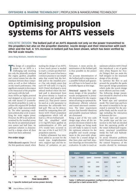
OFFSHORE & MARINE TECHNOLOGY | PROPULSION & MANOEUVRING TECHNOLOGY Optimising propulsion systems for AHTS vessels HOLISTIC DESIGN The bollard pull of an AHTS depends not only on the power transmitted to the propellers but also on the propeller diameter, nozzle design and their interaction with each other and the hull. A 13% increase in bollard pull has been shown, which has been verified by the full scale results. Jens Ring Nielsen, Henrik Marinussen The design of a propulsion system for an AHTS is a challenging task involving not only the physically products like engine, gearbox, propellers and control system but also the interfaces between these components as well as their influence on the vessel’s performance. One significant example in this respect is the interaction of the propeller and nozzle with the hull. Most AHTSs are highly powered and designed as twin screw vessels with ducted CP (controllable pitch) propellers in order to achieve the required BP (bollard pull) and a high manoeuvrability. The other operating conditions seldom play a role in specifying the main engine power. However, the BP is not solely determined by the installed power but also by an optimised propulsion system and hull lines. An optimum solution is characterised by a design where all three items have been addressed. Pre-order stage Hydrodynamic aspects One of the first questions raised, when starting the design of an AHTS, is how much power is needed to reach a certain specified bollard pull. For years it has been a common practise to use simple rules that would link the bollard pull to the installed power. One rule simply states that each HP will yield 13.6 kg [1]. MAN Diesel developed a more refined method where the bollard pull is determined from the power density i.e. based on both power and propeller diameter [2]. That power cannot be used as a sole parameter to determine the achievable bollard pull. This can be demonstrated by comparing three different MAN Diesel propulsion configurations which will all lead to a 90 ton bollard pull. Had the simplified ruled (13.6 kg/HP) been applied an underestimation of 10% and 21% would have occurred in the case of the 8 and 9L27/38 propulsion systems. A further refinement has since been added to account for the nozzle type, length/diameter ratio, support type and the influence of cavitation on performance. A more precise determination of the bollard pull is thus possible in the project stage. An accurate determination of the bollard pull is important as a possible bollard pull guarantee will have to be based on the available figures at this stage. Structural aspects The optimum design of the propeller/ nozzle arrangements is primarily determined by the requirement of having an optimum hydrodynamic efficient solution and sound structural construction. The latter requirement secures that harmful vibrations and possible structural failures are eliminated. Being a part of the very early design stage where all the important decisions related to the nozzle design are being made [2] will make it easier to reach the optimum solution for the propeller and nozzle arrangement in the post-order phase. A basis for a sound design is that lines plan and hull structure drawings are forwarded for evaluation. In order to reach an optimum solution MAN Diesel has introduced a set of guide rules (Data Request for Nozzle Design) that can assist the hull designer in the structural design of the aft ship. To optimize the flow to and around the propeller the guide lines specify design parameters which make the nozzle design more efficient and less costly. The following design parameters should be observed at this stage of the project: Vessel type and operation mode: The vessel type and how the vessel is intended to be operated is essential for the propeller blade and the nozzle design including the interaction in-between the two. Nozzle type and support: The profile type and the connection to the hull are decided from the operating profile of the vessel, bollard pull requirement, structural possibilities inside the hull and hydrodynamic aspects. To avoid vibration problems MAN Diesel recommends that the natural frequency of the nozzles should be minimum Engine Propeller Power Specific Type Power Speed Diameter Density Bollard Pull - - rpm mm kWm 2 kg/HP 7L27/38 2380 150 3300 278 13,9 8L27/38 2720 206 2750 458 12,2 9L27/38 3060 276 2400 676 10,8 Fig. 1: Specific bollard pull versus power density Table 1: Different propulsion configuration giving 90 ton bollard pull for a twin screw AHTS 10 Ship & Offshore | 2010 | N o 2
- Page 2 and 3: Fig. 2: Strut and headbox support 2
- Page 4: Torquemotors Direct Drives from 100
OFFSHORE & MARINE TECHNOLOGY | PROPULSION & MANOEUVRING TECHNOLOGY<br />
Optimising <strong>propulsion</strong><br />
systems for AHTS vessels<br />
HOLISTIC DESIGN <strong>The</strong> bollard pull <strong>of</strong> an AHTS depends not only on the power transmitted to<br />
the propellers but also on the propeller diameter, nozzle <strong>design</strong> and their interaction with each<br />
other and the hull. A 13% increase in bollard pull has been shown, which has been verified by<br />
the full scale results.<br />
Jens Ring Nielsen, Henrik Marinussen<br />
<strong>The</strong> <strong>design</strong> <strong>of</strong> a <strong>propulsion</strong><br />
system for an AHTS is a<br />
challenging task involving<br />
not only the physically products<br />
like engine, gearbox, propellers<br />
and control system but also the<br />
interfaces between these components<br />
as well as their influence<br />
on the vessel’s performance. One<br />
significant example in this respect<br />
is the interaction <strong>of</strong> the propeller<br />
and nozzle with the hull.<br />
Most AHTSs are highly powered<br />
and <strong>design</strong>ed as twin screw vessels<br />
with ducted CP (controllable<br />
pitch) propellers in order to<br />
achieve the required BP (bollard<br />
pull) and a high manoeuvrability.<br />
<strong>The</strong> other operating conditions<br />
seldom play a role in specifying<br />
the main engine power.<br />
However, the BP is not solely determined<br />
by the installed power<br />
but also by an optimised <strong>propulsion</strong><br />
system and hull lines. An<br />
optimum solution is characterised<br />
by a <strong>design</strong> where all three<br />
items have been addressed.<br />
Pre-order stage<br />
Hydrodynamic aspects One <strong>of</strong><br />
the first questions raised, when<br />
starting the <strong>design</strong> <strong>of</strong> an AHTS,<br />
is how much power is needed<br />
to reach a certain specified bollard<br />
pull. For years it has been a<br />
common practise to use simple<br />
rules that would link the bollard<br />
pull to the installed power.<br />
One rule simply states that<br />
each HP will yield 13.6 kg [1].<br />
MAN Diesel developed a more<br />
refined method where the bollard<br />
pull is determined from<br />
the power density i.e. based on<br />
both power and propeller diameter<br />
[2]. That power cannot<br />
be used as a sole parameter to<br />
determine the achievable bollard<br />
pull. This can be demonstrated<br />
by comparing three different<br />
MAN Diesel <strong>propulsion</strong><br />
configurations which will all<br />
lead to a 90 ton bollard pull.<br />
Had the simplified ruled<br />
(13.6 kg/HP) been applied an<br />
underestimation <strong>of</strong> 10% and<br />
21% would have occurred in<br />
the case <strong>of</strong> the 8 and 9L27/38<br />
<strong>propulsion</strong> systems.<br />
A further refinement has since<br />
been added to account for the<br />
nozzle type, length/diameter<br />
ratio, support type and the influence<br />
<strong>of</strong> cavitation on performance.<br />
A more precise determination<br />
<strong>of</strong> the bollard pull<br />
is thus possible in the project<br />
stage.<br />
An accurate determination <strong>of</strong><br />
the bollard pull is important as<br />
a possible bollard pull guarantee<br />
will have to be based on the<br />
available figures at this stage.<br />
Structural aspects <strong>The</strong> optimum<br />
<strong>design</strong> <strong>of</strong> the propeller/<br />
nozzle arrangements is primarily<br />
determined by the requirement<br />
<strong>of</strong> having an optimum hydrodynamic<br />
efficient solution<br />
and sound structural construction.<br />
<strong>The</strong> latter requirement<br />
secures that harmful vibrations<br />
and possible structural failures<br />
are eliminated.<br />
Being a part <strong>of</strong> the very early<br />
<strong>design</strong> stage where all the important<br />
decisions related to the<br />
nozzle <strong>design</strong> are being made<br />
[2] will make it easier to reach<br />
the optimum solution for the<br />
propeller and nozzle arrangement<br />
in the post-order phase.<br />
A basis for a sound <strong>design</strong> is<br />
that lines plan and hull structure<br />
drawings are forwarded for<br />
evaluation. In order to reach an<br />
optimum solution MAN Diesel<br />
has introduced a set <strong>of</strong> guide<br />
rules (Data Request for Nozzle<br />
Design) that can assist the<br />
hull <strong>design</strong>er in the structural<br />
<strong>design</strong> <strong>of</strong> the aft ship.<br />
To optimize the flow to and<br />
around the propeller the guide<br />
lines specify <strong>design</strong> parameters<br />
which make the nozzle <strong>design</strong><br />
more efficient and less costly.<br />
<strong>The</strong> following <strong>design</strong> parameters<br />
should be observed at this<br />
stage <strong>of</strong> the project:<br />
Vessel type and operation<br />
mode: <strong>The</strong> vessel type and how<br />
the vessel is intended to be operated<br />
is essential for the propeller<br />
blade and the nozzle <strong>design</strong><br />
including the interaction<br />
in-between the two.<br />
Nozzle type and support:<br />
<strong>The</strong> pr<strong>of</strong>ile type and the connection<br />
to the hull are decided<br />
from the operating pr<strong>of</strong>ile <strong>of</strong><br />
the vessel, bollard pull requirement,<br />
structural possibilities<br />
inside the hull and hydrodynamic<br />
aspects.<br />
To avoid vibration problems<br />
MAN Diesel recommends that<br />
the natural frequency <strong>of</strong> the<br />
nozzles should be minimum<br />
Engine Propeller Power Specific<br />
Type Power Speed Diameter Density Bollard Pull<br />
- - rpm mm kWm 2 kg/HP<br />
7L27/38 2380 150 3300 278 13,9<br />
8L27/38 2720 206 2750 458 12,2<br />
9L27/38 3060 276 2400 676 10,8<br />
Fig. 1: Specific bollard pull versus power density<br />
Table 1: Different <strong>propulsion</strong> configuration giving 90 ton bollard<br />
pull for a twin screw AHTS<br />
10 Ship & Offshore | 2010 | N o 2
Fig. 2: Strut and headbox support<br />
20% above or below the first<br />
order natural frequency <strong>of</strong> the<br />
propeller blades. <strong>The</strong> stiffness<br />
<strong>of</strong> the nozzle pr<strong>of</strong>ile itself, the<br />
connection type to the hull<br />
and the aft ship stiffness forms<br />
the basis for this evaluation.<br />
A sound <strong>design</strong> is characterised<br />
by having a well distribution<br />
<strong>of</strong> forces and by avoiding<br />
stress raisers. <strong>The</strong> <strong>design</strong> <strong>of</strong> the<br />
top strut and headbox is a special<br />
challenge in this respect.<br />
However, the structural aspects<br />
must always be balanced by<br />
the hydrodynamic requirements.<br />
Post-order stage<br />
<strong>The</strong> detailed <strong>design</strong> usually<br />
takes place after signing the<br />
contract when more information<br />
is available on the hull<br />
lines, engine, gearbox and shaft<br />
arrangement.<br />
<strong>The</strong> items that are usually addressed<br />
are:<br />
Aft ship hull form <strong>design</strong>.<br />
<strong>The</strong> achievable bollard pull depends<br />
on the aft ship lines and<br />
the propeller and shaft arrangement.<br />
In general the water flow<br />
around the hull will follow the<br />
buttock lines. This means the<br />
slope <strong>of</strong> the buttock lines is<br />
<strong>of</strong> great importance as it will<br />
influence the thrust deduction<br />
factor.<br />
t = 1 -<br />
T BP<br />
T P,B<br />
+ T N,B<br />
From the formula it can be seen<br />
that the propeller and nozzle<br />
thrust in behind condition T P,B<br />
and T N,B<br />
is reduced by the thrust<br />
deduction factor t – leading to<br />
a corresponding reduction in<br />
the bollard pull. This reduction<br />
is mainly caused by the suction<br />
<strong>of</strong> the propeller and nozzle on<br />
the adjacent hull surfaces. For<br />
that reason the distance from<br />
where the shaft protrudes from<br />
the hull to the centre <strong>of</strong> the<br />
propeller should be as long as<br />
possible. It is MAN Diesel’s recommendation<br />
to <strong>design</strong> slowly<br />
raising buttock hull lines <strong>of</strong><br />
approximately 17-19 degrees.<br />
<strong>The</strong> overall aim is to keep the<br />
thrust deduction factor to a<br />
minimum. Furthermore, it<br />
must be secured that sufficient<br />
water will be present above the<br />
propeller/nozzle in order to<br />
prevent air suction.<br />
Propeller blade <strong>design</strong>. <strong>The</strong><br />
detailed <strong>design</strong> <strong>of</strong> the propeller<br />
blades will be based on the<br />
different operating conditions<br />
and the results from the model<br />
tests (resistance, self <strong>propulsion</strong><br />
with stock propeller, wake<br />
measurements). <strong>The</strong> blades will<br />
be optimised for the bollard<br />
pull condition and checked<br />
for different other operating<br />
modes (free sailing, towing etc)<br />
to ensure that an overall optimum<br />
<strong>design</strong> has been reached.<br />
<strong>The</strong> final <strong>design</strong> will be based<br />
on a balance between the two<br />
major <strong>design</strong> objectives – efficiency<br />
and cavitation/vibration.<br />
<strong>The</strong> detailed <strong>design</strong> <strong>of</strong> the<br />
Fig 3: Definition <strong>of</strong> tilt and azimuth angles<br />
propeller and nozzle is made<br />
in close cooperation between<br />
the hydrodynamic and structural<br />
engineer. For AHTS the<br />
shape <strong>of</strong> the blades will exhibit<br />
wide chords at the tip (Kaplan<br />
shape) to maximise the bollard<br />
pull.<br />
Nozzle <strong>design</strong>. <strong>The</strong> type <strong>of</strong><br />
nozzle has already been selected<br />
in the pre-order phase<br />
and the detailed <strong>design</strong> <strong>of</strong> the<br />
nozzle will focus on the support<br />
and hull attachments to<br />
minimise the thrust deduction<br />
caused by the interaction effects<br />
with the hull. Compared<br />
to the conventional nozzle<br />
types the AHT nozzle will deliver<br />
more thrust thus making<br />
the <strong>design</strong> details <strong>of</strong> the support<br />
more important in order<br />
to minimise the thrust deduction<br />
factor.<br />
Consequently, only a plant<br />
specific <strong>design</strong>ed propeller and<br />
nozzle including well faired<br />
and structurally sound supports<br />
will result in an optimum<br />
solution. This means that the<br />
propeller and nozzle supplier<br />
needs to be a part <strong>of</strong> the very<br />
early <strong>design</strong> stage as already<br />
underlined in reference [2]. <br />
Ship & Offshore | 2010 | N o 2 11
OFFSHORE & MARINE TECHNOLOGY | PROPULSION & MANOEUVRING TECHNOLOGY<br />
Fig. 4: CFD pressure calculation <strong>of</strong> nozzle and propeller<br />
Fig. 5: Comparison <strong>of</strong> astern bollard pull, AHT versus 19A both<br />
with L/D=0.5<br />
To verify the potential <strong>of</strong> the different <strong>design</strong><br />
alternatives MAN Diesel recommends to<br />
make model test <strong>of</strong> the final <strong>design</strong>ed propeller<br />
and nozzle, including test <strong>of</strong> tilt and<br />
azimuth angles <strong>of</strong> nozzle as well as propeller<br />
direction <strong>of</strong> rotation.<br />
<strong>The</strong> possible improvement that can be<br />
achieved by following this systematic approach<br />
will be exemplified by the following<br />
case study. However, it is important to note<br />
that the more aligning requirements that are<br />
proposed for the nozzle, the more cumbersome<br />
the installation will be. In each case, the<br />
gain obtained in bollard pull by introducing<br />
an additional nozzle alignment requirement<br />
should be carefully judged against the risk <strong>of</strong><br />
possible misalignment during installation.<br />
In any case MAN Diesel recommends choosing<br />
the same supplier for the propeller and<br />
the nozzle to optimise the overall performance.<br />
Latest nozzle development<br />
Since the introduction <strong>of</strong> the AHT nozzle<br />
its range has been extended to include:<br />
longer and shorter nozzles than the<br />
original L/D=0.5 making it possible to select<br />
the most optimum size depending on<br />
cavitation number and propeller load<br />
a simplified and more production version<br />
with a strait inner area at the propeller<br />
zone.<br />
<strong>The</strong> nozzle family was developed using<br />
CFD calculations on a large number <strong>of</strong> systematically<br />
varied nozzle shapes and with<br />
the bollard pull conditions as the prime<br />
optimisation objective.<br />
A major research program was recently undertaken<br />
by MAN Diesel to investigate the<br />
performance <strong>of</strong> ducted propellers including<br />
the influence <strong>of</strong> cavitation. Different<br />
types <strong>of</strong> AHT nozzles and the well known<br />
19A nozzles were tested at SVA Potsdam as<br />
well as in the Free Surface cavitation tunnel<br />
at the University <strong>of</strong> Berlin.<br />
Most propellers – being open or ducted – are<br />
<strong>design</strong>ed with a certain amount <strong>of</strong> cavitation<br />
and if kept within limits the cavitation<br />
will only affect the performance marginally.<br />
However, this is not true for highly loaded<br />
ducted propellers where the present <strong>of</strong> cavitation<br />
reduces especially the nozzle thrust.<br />
One aspect that became clear was the importance<br />
<strong>of</strong> minimising the tip clearance<br />
because the tip vortex would disturb the<br />
flow at the exit <strong>of</strong> the nozzle. However, for<br />
practical reason a certain clearance is necessary<br />
to facilitate the dismantling <strong>of</strong> the<br />
blades inside the nozzle.<br />
An extensive test series was carried out in<br />
both non- and cavitating conditions for the<br />
AHT series <strong>of</strong> nozzle as well as the 19A version.<br />
<strong>The</strong> results can be summarised as:<br />
<strong>The</strong> AHT nozzles showed superior performance<br />
compared to the 19A.<br />
<strong>The</strong> shorter nozzles are more affected<br />
by cavitation than the longer versions.<br />
Air suction from the water surface into<br />
the propeller/nozzle reduces the bollard<br />
pull significantly. <strong>The</strong> risk increases with<br />
diminishing water height above the propeller<br />
and increasing L/D ratios<br />
<strong>The</strong> backing performance <strong>of</strong> the different<br />
nozzles also formed a part <strong>of</strong> the investigation<br />
and clearly showed the superiority <strong>of</strong><br />
Fig. 6: An AHT Ø4030 nozzle ready for dispatch. Leading edge<br />
<strong>of</strong> the nozzle is on the floor.<br />
Fig. 7: Finite Element vibration analysis <strong>of</strong> nozzle including<br />
supports<br />
12 Ship & Offshore | 2010 | N o 2
Torquemotors<br />
Direct Drives from<br />
100 to 150000 Nm<br />
Fig 8: Stepwise improvement in bollard pull for a 120 ton AHTS<br />
the new AHT nozzle family. A 20-25% improvement<br />
<strong>of</strong> the astern thrust was measured<br />
compared to the 19A type.<br />
Case study<br />
<strong>The</strong> case study concerns a series <strong>of</strong> AHTS<br />
vessels <strong>design</strong>ed to deliver a bollard pull<br />
<strong>of</strong> 120 tons with a MAN Diesel <strong>propulsion</strong><br />
system.<br />
<strong>The</strong> initial hull lines developed by the naval<br />
architect displayed steep buttock lines<br />
<strong>of</strong> approx. 25° exceeding the recommended<br />
17- 19°. <strong>The</strong> buttock lines were later reduced<br />
to 23° by lowering the gearbox followed by<br />
a re<strong>design</strong> <strong>of</strong> the aft ship. In addition the<br />
distance between the propeller and where<br />
the shaft protrudes from the hull is short.<br />
Because <strong>of</strong> these unfavourable conditions<br />
the thrust deduction factor ended up being<br />
9.6%.<br />
A comprehensive model testing program<br />
was set up to investigate the possible improvements<br />
from not only using the new<br />
AHT nozzle type but also including other<br />
relevant installation aspects. Apart from<br />
the normal testing with stock propeller the<br />
following were added:<br />
Nozzle supports comprising both a<br />
headbox and a strut solution<br />
Propeller direction <strong>of</strong> rotation<br />
Nozzle types – AHT and 19A<br />
Tilting and azimuthing <strong>of</strong> nozzles.<br />
<strong>The</strong> model testing program was planned in<br />
the sequence as described above and lead<br />
to an increasing improvement <strong>of</strong> the bollard<br />
pull as the testing proceeded.<br />
Especially the testing with the AHTS nozzle<br />
showed a pronounced improvement in<br />
bollard pull.<br />
Varying the azimuth angle <strong>of</strong> the nozzle<br />
only resulted in a marginally improvement<br />
and was for this reason not applied.<br />
Compared to a standard solution a 13%<br />
improvement in bollard was achieved by<br />
following this systematic approach.<br />
<strong>The</strong> full scale testing was conducted as<br />
the vessels were commissioned and at<br />
the time being 5 vessels had their bollard<br />
pull measured. <strong>The</strong> full scale figures are<br />
as measured and not corrected for the<br />
unfavourable conditions at the test site<br />
(limited water depth and current across<br />
tow line) as required in [5]. This type <strong>of</strong><br />
vessel falls into the standard 120 ton category<br />
<strong>of</strong> AHTS’s which up to now have<br />
been characterised by having two 8 cylinder<br />
32cm bore main engines with a<br />
rated power <strong>of</strong> 4,000 kW. Compared to<br />
this industry standard the MAN Diesel<br />
optimised <strong>propulsion</strong> solution can suffice<br />
with only 2x3,285 kW to reach the<br />
required bollard pull.<br />
References:<br />
[1] Oosterveld, M.W.C. (1970). Wake<br />
Adapted Ducted Propellers, Publication<br />
No. 345 NSMB, Wageningen, Netherlands<br />
[2] Nielsen, J. R., Jeppesen R. M. and Lundgren,<br />
E., (2005) Propulsion <strong>of</strong> Offshore<br />
Support Vessels, OSV Conference, Singapore<br />
[3] Jeppesen, R. M., Marinussen, H., (2006)<br />
Latest trends in Offshore Propulsion,<br />
SNAMES Technical talk, Singapore<br />
[4] Minchev, A., Nielsen, J.R., Lundgren, E.,<br />
(2009) Ducted propeller Design and Verification<br />
for Contempoary Offshore Support<br />
Vessels, First international Symposium on<br />
Marine Propulsors, Torndheim, Norway<br />
[5] Boesen, K. (2005). Bollard Pull trials,<br />
Internal MAN Diesel document<br />
<strong>The</strong> authors:<br />
Jens Ring Nielsen (Senior Manager),<br />
Henrik Marinussen,<br />
(Research Engineer, Propulsion R&D),<br />
MAN Diesel SE, Frederikshavn,<br />
Denmark<br />
· powerful and cost<br />
effective<br />
· individually <strong>design</strong>ed,<br />
customizable to your<br />
operation conditions<br />
in the best way<br />
· large sized open inner<br />
diameter for constructive<br />
advantages<br />
· for high peak torque<br />
and noise reduction<br />
Ask for the cost effective<br />
individual <strong>design</strong>ed<br />
drive solutions made by<br />
OSWALD.<br />
See www.oswald.de<br />
for details.<br />
REGELBARE ELEKTROMOTOREN<br />
REGELBARE ELEKTROMOTOREN<br />
Benzstraße 12 . D-63897 Miltenberg<br />
Phone ++49 (0 )93 71 9 71 90<br />
Telefax ++49 (0 )93 71 97 19 50<br />
oswald@oswald.de


