International - Schiff & Hafen
International - Schiff & Hafen
International - Schiff & Hafen

You also want an ePaper? Increase the reach of your titles
YUMPU automatically turns print PDFs into web optimized ePapers that Google loves.
<strong>International</strong><br />
02|09<br />
www.shipandport.com<br />
Improved DGPS navigation<br />
with AIS broadcasts 16<br />
Green engines: Turbo boost<br />
for lower emissions 34<br />
Oil & Gas Exploration:<br />
Dynamic Positioning in ice 62<br />
INTERNATIONAL PUBLICATION<br />
FOR SHIPPING, MARINE AND OFFSHORE TECHNOLOGY
international conference and exhibition on<br />
maritime security and defence hamburg
comment<br />
Dr.-Ing. Silke Sadowski<br />
Editor in Chief<br />
silke.sadowski@dvvmedia.com<br />
Offshore – a booming<br />
global market<br />
The current economic downturn is a crisis in<br />
a completely new dimension with historically<br />
unique symptoms and effects causing unprecedented<br />
perplexity even among economic and financial<br />
experts. Although they are being constantly corrected,<br />
economic forecasts are of little assistance in<br />
charting the course ahead.<br />
The maritime sector has, of course, also not been<br />
spared by this global crisis that arose virtually overnight<br />
and has been impacting all industries.<br />
The next few months will involve multiple challenges<br />
for nearly all segments of the maritime sector,<br />
including ports, shipping lines, shipyards, marine<br />
equipment suppliers and offshore companies.<br />
Nevertheless, the situation is far more differentiated<br />
than in many other industries. It is essential to<br />
make the most of all the opportunities provided by<br />
such a market environment.<br />
The offshore technology area offers high growth<br />
potential despite the present crisis. Energy and<br />
raw material prices, which according to experts<br />
are bound to recover in the medium term in line<br />
with rising global demand, and declining energy<br />
resources on land are promoting a surge in offshore<br />
exploration and production activities. The technical<br />
and commercial basis for such projects is provided<br />
by progress recently achieved in the development of<br />
the necessary innovative technologies as well as the<br />
expected price trend as a result of demand.<br />
Above all, the production of oil and gas with the<br />
increasing deployment of exploration and production<br />
techniques under extreme conditions such as<br />
deepwater and ice is obtaining a key significance.<br />
Oil and gas production volume in deepsea production<br />
is estimated to increase by close on 80%<br />
between 2007 and 2011, corresponding to a 25%<br />
rise in investment in relevant production systems<br />
to US$41 billion. The declining ice thickness in the<br />
Arctic, where according to the latest estimates approx.<br />
22% of global reserves lie, is greatly stimulating<br />
the development of technologies for producing<br />
oil and gas from ice-covered northern waters.<br />
Deepwater technology for deepwater mining and<br />
the production of marine gas hydrates will also be<br />
refined. Although still in different development<br />
phases, both these areas are on the threshold to<br />
industrialisation.<br />
The extreme ambient conditions at water depths of<br />
up to 5000m place high technological and environmental<br />
protection requirements on suppliers of<br />
equipment, systems and services. This area is thus<br />
meanwhile regarded globally as providing some of<br />
the most formidable high-tech challenges with a<br />
correspondingly massive investment requirement.<br />
Another important growth market is utilisation of<br />
ocean renewable energy with offshore wind energy<br />
and hydraulic or tidal power plants.<br />
The offshore sector is a global market, and the<br />
complexity of the projects has led to significantly<br />
changed market structures and international cooperation.<br />
The sophisticated production techniques<br />
require high engineering expertise and technologyintensive<br />
special solutions. It will thus be interesting<br />
to observe the results and innovations presented<br />
at the major trade fairs and congresses in early<br />
summer this year, such as the OTC 2009 Offshore<br />
Technology Conference, the 28th <strong>International</strong><br />
Conference on Ocean, Offshore and Arctic Engineering<br />
(OMAE 2009) and OCEANS2009.<br />
Ship & Port | 2009 | N o 2 3
In Focus<br />
10<br />
Ship &<br />
Port Operation<br />
Port infrastructure<br />
10 Automation of container<br />
terminals<br />
14 New ISO Specification for<br />
containers identification<br />
14 Safe operation<br />
Shipping<br />
14 Cradle solutions for the Atlantic<br />
15 Resolutions for cruising the<br />
Arctic<br />
Regulars<br />
COMMENT ........................... 3<br />
NEwS & FACTS ................... 6<br />
BUYER‘S GUIDE ................ 37<br />
IMPRINT ............................. 67<br />
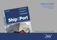
Navigation and Communications<br />
Iridium OpenPort, FleetBroadband and VSAT in particular<br />
are currently competing to be the most efficient systems<br />
for seafaring. Either way, they will change the way we<br />
look at communications at sea.<br />
AIS has long since become part of standard navigation<br />
equipment, but there are innovative ways of further<br />
utilising the technology.<br />
Offshore<br />
Approximately 22% of the world’s undiscovered oil and<br />
gas reserves are estimated to be in the Arctic and<br />
Antarctic regions. Research activities are taking place in<br />
ice-covered waters as well as ever-deeper parts of the<br />
ocean. The technology for this is still in its infancy, yet<br />
advances that would have been unthinkable not long ago<br />
have already been made.<br />
<br />
<br />
<br />
<br />
<br />
<br />
<br />
<br />
<br />
<br />
<br />
<br />
<br />
<br />
<br />
<br />
<br />
<br />
<br />
<br />
<br />
<br />
<br />
<br />
<br />
<br />
<br />
<br />
<br />
<br />
<br />
<br />
<br />
<br />
<br />
<br />
<br />
<br />
<br />
<br />
<br />
<br />
<br />
<br />
<br />
<br />
<br />
<br />
<br />
<br />
<br />
<br />
<br />
<br />
<br />
<br />
<br />
<br />
1741_anz_mtp_newships_183x40.indd 1 09.04.2009 13:52:12<br />
4 Ship & Port | 2009 | N o 2
Content | May 2009<br />
Editorial<br />
Shipbuilding &<br />
Equipment<br />
Navigation<br />
16 Improved DGPS navigation with<br />
AIS broadcasts<br />
18 Innovative search and rescue<br />
transmitter<br />
20 New Integrated Bridge System<br />
22 Responsible ECDIS and INS training<br />
Communication<br />
24 Cost-effective alternative for<br />
satellite communications<br />
26 Latest development in<br />
FleetBroadband and VSAT<br />
Propulsion<br />
30 Flexibility in a small package<br />
34 Turbo boost for lower emissions<br />
30 65<br />
Offshore &<br />
Marine Technology<br />
Offshore oil & gas<br />
46 Improving DP fuel economy and<br />
reducing emissions<br />
50 Hydrodynamics of thruster systems<br />
54 Hydraulic sensor system monitoring<br />
drilling rig components<br />
56 Offshore vessels with 3D product<br />
modelling<br />
59 Automated anchor handling concept<br />
Arctic & ice engineering<br />
60 Multi-functional advanced<br />
research vessel<br />
62 Oil & Gas Exploration:<br />
Dynamic Positioning in ice<br />
64 Neumayer Station III inaugurated<br />
Dear Readers<br />
Today’s maritime exploration activities,<br />
involving great expertise and cutting-edge<br />
technology, are no less exciting than during<br />
the times of Columbus, Magellan and James<br />
Cook. In this issue, we look at exploring the<br />
deep oceans and the polar regions. Working<br />
in such extreme environments is very challenging,<br />
which is reason enough for us to<br />
include several highly interesting articles on<br />
the Arctic and Antarctic as well as deep-sea<br />
offshore technology.<br />
A major challenge when exploring the deep<br />
sea is dynamic positioning (DP), which is<br />
why we look at ways of keeping a vessel<br />
dead steady by means of propulsion in an<br />
environment-friendly and cost-efficient way<br />
(page 46). But is DP also feasible in ice?<br />
Extensive research is being undertaken in<br />
this area, and we look at the design study<br />
of Aurora Borealis on page 60, while the<br />
overall feasibility of DP in ice is discussed<br />
further on page 62, Thruster systems are<br />
crucial for DP, and understanding the hydrodynamics<br />
of these is also important, hence<br />
our analysis on page 50.<br />
A current aspect of navigation and communications<br />
technology is the refinement<br />
of the AIS system. It could be possible to<br />
use AIS base stations for differential GPS<br />
transmissions (page 16), but there is also<br />
an innovative approach that has led to the<br />
development of an AIS Search and Rescue<br />
Transponder (page 18). The positive consequences<br />
of these recent successful test<br />
results are possibly more far-reaching than<br />
the SART itself: phasing out the current<br />
radar SART could lead to no less than the<br />
development of a new type of digital radar<br />
in future.<br />
Here’s wishing you enjoyable reading!<br />
Leon Schulz<br />
M.Sc.<br />
Managing Editor<br />
leon.schulz@dvvmedia.com<br />
Deck equipment<br />
36 Landing safely on a rolling ship<br />
ABBTC_AD_SRV03_185_40sh 25.02.09 14:18 Seite 1<br />
Offshore wind energy<br />
65 Offshore wind park installation<br />
ABB Turbocharging<br />
Quality you can trust.<br />
www.abb.com/turbocharging<br />
Ship & Port | 2009 | N o 2 5
Industry | News & FaCts<br />
Artist’s impression of the Virtu ferry<br />
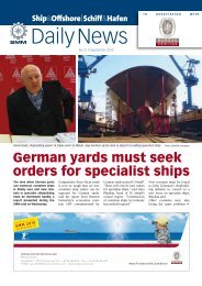
Catamarans for Denmark and Malta<br />
Austal | Henderson based Australian shipyard<br />
Austal has received a major order for two new<br />
ferries for European customers. Its largest ever<br />
catamaran is destined to serve the traffic between<br />
the Danish island Bornholm and Sweden.<br />
The 112.6 m long and 26.20 m wide 1,000 dwt<br />
vessel for Nordic Ferry Services, a joint venture<br />
between Bornholms Traffiken and Clipper<br />
Group, will be designed to carry 1,400 passengers<br />
and 357 cars. Three car decks accessible via<br />
both bow and stern ramps will ensure efficient<br />
transfer of the large vehicle capacity. The catamaran<br />
is scheduled for delivery in 2011.<br />
Following this order, Austal has also received an<br />
order by Maltese operator Virtu Ferries to design<br />
and build a vehicle-passenger catamaran for the<br />
traffic between Malta and Italy. It will have a<br />
length of 106.5 m and a beam of 23.8 m. It is<br />
designed to carry 800 passengers and 230 cars or<br />
45 cars and 342 truck lane metres. Vehicle loading<br />
and unloading will utilise ramps installed<br />
on both the stern and port-side. Four MTU<br />
20V8000M71L main engines of 9,100 kW each<br />
will care for a service speed of appr. 39 knots.<br />
Delivery is scheduled for 2010.<br />
Both ferries will be built in accordance with the<br />
requirements and under the survey of Det Norske<br />
Veritas.<br />
“Ship<br />
Efficiency”<br />
Conference | The 2nd “Ship<br />
Efficiency” conference will be<br />
held in Hamburg on 28-29 September<br />
2009. Organised by the<br />
German Society for Maritime<br />
Technology – STG, this conference<br />
series takes place every two<br />
years, alternating with the maritime<br />
trade fair SMM – Shipbuilding/Machinery<br />
& Marine<br />
Technology in Hamburg.<br />
In an industry characterised by<br />
increasingly keen competition<br />
on a global scale, the key to survival<br />
is designing, building and<br />
operating ships efficiently. An<br />
efficient ship is profitable and<br />
environmentally compatible.<br />
Consequently general topics of<br />
the conference will be:<br />
XX how to improve the efficiency<br />
of shipping operations, and<br />
XX how to increase a ship’s<br />
profitability<br />
The aim of “Ship Efficiency” is to<br />
create a forum where all stakeholders<br />
learn from each other<br />
and return home with fresh ideas<br />
and practical solutions. Information<br />
and registration under:<br />
www.ship-efficiency.org<br />
Turbine supply<br />
agreement<br />
First AHTS to Hartmann Offshore<br />
Offshore wind projects | The<br />
Danish company DONG Energy<br />
and Siemens Energy Sector<br />
recently signed an agreement<br />
for the supply of up to 500 offshore<br />
wind turbines. The wind<br />
turbines to be delivered under<br />
the deal have a total capacity<br />
of up to 1,800 MW and will be<br />
deployed on DONG Energy’s<br />
planned offshore wind farms in<br />
Northern Europe. Permit procedures<br />
and country-specific wind<br />
regime economics will determine<br />
where and when the individual<br />
projects will be built.<br />
The agreement with DONG Energy<br />
is said to be one of the largest<br />
orders in the history of Siemens,<br />
with wind turbines having<br />
a capacity of 3.6 MW, similar to<br />
those at DONG Energy’s Burbo<br />
Banks offshore wind farm.<br />
UOS Atlantis will be managed by United Offshore Support<br />
UOS Atlantis | The 2,922 gt<br />
MOSS 424type Anchor Handling<br />
Tug Supply vessel (AHTS)<br />
UOS Atlantis has recently been<br />
delivered from the Fincantieri<br />
Shipyard in Muggiano, Italy. It<br />
is the first offshore support vessel<br />
ever for the German Hartmann<br />
Group, marking the start<br />
of the Hartmann Group’s operations<br />
in the offshore sector.<br />
During sea trials certified by the<br />
American Bureau of Shipping<br />
(ABS), the UOS Atlantis proved<br />
capable of a bollard pull of<br />
close to 200 t and a maximum<br />
speed of about 17 knots.<br />
The 76.5 m long and 17.5 m<br />
wide vessel has been put into<br />
operation immediately: UOS<br />
Atlantis is awarded to EDT Offshore<br />
Egypt to become part of<br />
BP Egypt’s Mediterranean vessel<br />
fleet and to support BP’s offshore<br />
drilling activities.<br />
Until mid 2010, eleven further<br />
vessels, constructed in the same<br />
way, will be delivered in succession<br />
to Hartmann Offshore.<br />
Commercial management services<br />
for the fleet is provided by<br />
UOS (United Offshore Support).<br />
6 Ship & Port | 2009 | N o 2
Eletson enters gas market<br />
LPG carrier Anafi is the first of a series of four gas tankers<br />
built for Eletson by HMD<br />
LPG carriers | With the delivery<br />
of its first LPG (liquefied petroleum<br />
gas) carrier the Eletson<br />
Corporation, Piräus, Greece,<br />
has entered a new market sector.<br />
Built at Hyundai Mipo<br />
Dockyards (HMD) in Korea,<br />
the ship marks a milestone for<br />
the Greek operator, who owns<br />
and manages one of the world’s<br />
largest fleets of medium and<br />
long range product tankers for<br />
more than four decades.<br />
The Anafi, 22,010 dwt and constructed<br />
to Lloyd’s Register class,<br />
is the first of a series of four LPG<br />
ships being built for Eletson by<br />
HMD. Built to meet high specifications<br />
and exceeding latest<br />
requirements for navigational<br />
safety and environmental requirements,<br />
these ships demonstrate<br />
Eletson’s commitment to<br />
the demanding gas transportation<br />
market. Lloyd’s Register has<br />
worked with Eletson and HMD<br />
at all stages of construction, using<br />
proven design tools covered<br />
by Lloyd’s Register’s ShipRight<br />
procedures for structural detail<br />
analysis and fatigue design assessment.<br />
In addition, a higher<br />
standard of bridge layout and<br />
visibility has been selected - to<br />
the requirements of Lloyd’s Register’s<br />
NAV1 Class Notation.<br />
The Anafi has a length of<br />
165 m, a breadth of 28 m and<br />
a moulded depth of 17.8 m.<br />
The cargo capacity amounts to<br />
35,000 m 3 . The sister vessels to<br />
follow will be Nisyros, Tilos and<br />
Telendos.<br />
XXin brief<br />
WG Columbus | The first<br />
seismic vessel built with an<br />
ULSTEIN X-BOW ® , the WG<br />
Columbus, was recently<br />
delivered to WesternGeco.<br />
She completed her maiden<br />
Atlantic crossing to her first<br />
assignment in the Gulf of<br />
Mexico, sailing smoothly<br />
with a speed of 15 knots<br />
in 55-knot winds and 3- to<br />
4-metre-high waves. The<br />
ULSTEIN SX124 vessel was<br />
built at the Barreras shipyard<br />
in Vigo, Spain.<br />
ABS | The Norwegian Maritime<br />
Directorate (NMD),<br />
has extended its authorization<br />
to class society ABS<br />
to include Mobile Offshore<br />
Drilling Units (MODUs) in its<br />
scope as a Recognized Organization<br />
(RO). This entitles<br />
ABS to class Norwegianflagged<br />
rigs without having<br />
to perform additional safety<br />
equivalencies or a GAP<br />
analysis to meet Norwegian<br />
law.<br />
Stow-away gangway<br />
Brude Safety | A new type of<br />
aluminium gangway has been<br />
launched on the market by the<br />
Norwegian-based Brude Safety<br />
AS. Thanks to its extremely<br />
compact design, it can be integrated<br />
into the door, taking up<br />
virtually no space. The Brude<br />
gangway system consists of a<br />
complete and highly effective<br />
gangway, a coaming, a mounted<br />
door with the telescopic gangway,<br />
a hydraulic unit (HPU), a<br />
control panel and, finally, side<br />
railings, which come up automatically<br />
when the gangway is<br />
extended.<br />
The unit, which is powered by<br />
means of the onboard 230V<br />
system, is manually controlled<br />
via valves positioned in the<br />
vicinity of the gangway. In locked<br />
position, the door fits tightly<br />
against a rubber gasket in<br />
the coaming. The door itself,<br />
which is of steel and hinged to<br />
the coaming, is stiffened and<br />
made as strong as the ship’s<br />
side. It is locked by means of<br />
a hydraulic cylinder, operating<br />
The Brude Safety Gangway<br />
two locking cleats mounted in<br />
the coaming.<br />
When the door is lowered and<br />
placed on the quay, the gangway<br />
has a freefloat function to<br />
absorb the tidewater and swell<br />
movements between the ship<br />
and the quay. As an option, the<br />
gangway is also available with a<br />
swing movement (0-90°) along<br />
the ship’s side.<br />
The Brude Gangway System is<br />
designed and manufactured<br />
in accordance with the latest<br />
SOLAS requirements, the classification<br />
society SeeBg (ISO<br />
5488) and national authority<br />
standards (NS 6249).<br />
Newbuildings<br />
Farstad | CSV Far Samson was<br />
delivered from STX Norway<br />
Offshore AS, Langsten, to<br />
Farstad Construction AS in<br />
Aalesund, subsidiary of Farstad<br />
Shipping. The vessel will commence<br />
on a five years contract<br />
for Saipem U.K Limited after<br />
the final offshore testing. Far<br />
Samson has a length of 121,5 m<br />
and a beam of 26 m. The vessel<br />
is designed for its main purpose<br />
to pull a heavy plough on<br />
the sea bed to bury and cover<br />
oil and gas pipelines into the<br />
sea bed. With a bollard pull of<br />
423 tonnes the vessel is stated<br />
to be the strongest construction<br />
vessel in the world.<br />
PSV Far Serenade was delivered<br />
from STX Norway Offshore AS,<br />
Brevik, to Farstad Shipping subsidiary<br />
Farstad Supply AS. The<br />
vessel has commenced a longterm<br />
contract for Norwegian<br />
StatoilHydro. The hull of Far<br />
Serenade (4,000 dwt) was built<br />
at STX in Romania and outfitted<br />
in Norway. She has a length of<br />
93 m and a beam of 21 m wide.<br />
Ballast water treatment |<br />
Finnish-based Alandia Engineering<br />
OY is to provide<br />
engineering and installation<br />
services for the Hyde<br />
GUARDIAN ballast water<br />
management technology<br />
by Hyde Marine, Inc.<br />
The partnership allows<br />
Hyde to offer its customers<br />
a skilled, high quality<br />
organization to manage<br />
the multi-disciplined task<br />
of installing ballast water<br />
management systems on<br />
existing ships.<br />
ClassNK | Japanese classification<br />
company ClassNK<br />
has released the latest<br />
updated version of “Good<br />
Maintenance Onboard<br />
Ships”. This latest version of<br />
the booklet has been expanded<br />
to incorporate ideas<br />
and comments from port<br />
state control authorities,<br />
shipowners and mariners as<br />
well as extensive data compiled<br />
by the society itself.<br />
The publication provides<br />
checklists that cover every<br />
aspect of statutory requirements<br />
with clear references<br />
to the relevant regulations.<br />
Ship & Port | 2009 | N o 2 7
Industry | News & Facts<br />
XXin brief<br />
Kronios | A joint-venture<br />
has been established between<br />
five companies cooperating<br />
in drinking-water<br />
production. Hatenboer Water,<br />
Minks Kunstoftechniek,<br />
Georg Fischer (GF), Kemper<br />
and Econosto are now approaching<br />
the market jointly<br />
under the name of Kronios<br />
offering total water treatment<br />
systems including R.O.<br />
plants, pipe systems, fittings,<br />
sanitary valves and service.<br />
MacBarge | The testing<br />
capabilities of MacGREGOR’s<br />
offshore equipment manufacturing<br />
site in Kristiansand<br />
(Norway) are expanded by<br />
means of a multi-testbed<br />
barge, which was ordered<br />
in the summer of 2008 and<br />
is now fully operational.<br />
The 76mx 23m MacBarge<br />
is designed to test two<br />
large AHC offshore cranes<br />
simultaneously, as well as<br />
winches, ROV systems and<br />
other subsea load-handling<br />
technology.<br />
New derrick pipelay vessel<br />
The Ulstein DLS-4200 design<br />
Ulstein | Abu Dhabi based<br />
National Petroleum Construction<br />
Company Ltd.<br />
(NPCC) has awarded Dutch<br />
design office Ulstein Sea of<br />
Solutions the Basic Design<br />
contract for their new large<br />
derrick pipelay vessel DLS-<br />
4200. The new 197 m vessel<br />
will be one of the biggest vessels<br />
of its kind, combining<br />
S-lay double joints pipelay<br />
operations with 4200 sT lifting<br />
capacity.<br />
The design of the vessel is a<br />
modified version of the SOC<br />
3000 design of Ulstein Sea<br />
of Solutions (USOS) and<br />
will be equipped with an<br />
Amclyde Model 80 crane.<br />
DLS-4200 is designed to<br />
operate worldwide, but will<br />
initially be equipped with a<br />
mooring system to operate<br />
in the Arabian Gulf and India.<br />
However, a future DP2<br />
upgrade is envisaged and<br />
catered for in the design to<br />
minimise the technical impact<br />
in the future.<br />
The vessel features two fixed<br />
pitch shaft driven main propellers<br />
of 5500 kW each<br />
which will allow for a sailing<br />
speed of 12-13 knots.<br />
For future DP upgrade five<br />
(5) retractable azimuth<br />
thrusters of 3500 kW each<br />
are required.<br />
The Amclyde main crane is capable<br />
of lifting 4200 sT (3800<br />
mT) at a 125 ft radius over<br />
the stern in tie-back mode<br />
and 4200 sT at 95 ft without<br />
tie-back. In full revolving<br />
mode the crane is able to lift<br />
2950 sT (2680 mT) with an<br />
outreach of 135 ft.<br />
CM Hammar | The Hydrostatic<br />
release unit H20 by<br />
Swedish CM Hammar will<br />
feature a new 5 x 10 mm<br />
silver black Holospot®<br />
label in order to better<br />
distinguish the original H20<br />
from fake copies.<br />
Acquisition | Swedenbased<br />
Chris-Marine,<br />
providing high precision<br />
maintenance machines for<br />
diesel engines, has recently<br />
acquired IOP-Marine A/S,<br />
which provides fuel injector<br />
test equipment and hydraulic<br />
power packs. Both companies’<br />
products and methods<br />
are used for low-speed<br />
and medium speed engines.<br />
South Ferry | Blount Boats<br />
of Warren, Rhode Island,<br />
has delivered the vehicular/passenger<br />
ferry M/V<br />
Southside to South Ferry,<br />
Inc., Shelter Island, NY. With<br />
a length of appr. 30.7 m<br />
and a maximum beam<br />
of 12.8 m the vessel can<br />
carry up to 18 vehicles. The<br />
Southside is a sister ship<br />
to the Sunrise built at the<br />
Blount shipyard in 2002.<br />
Industry<br />
Alliance<br />
Global Partnership | A Global<br />
Industry Alliance (GIA) was<br />
launched at the headquarters of<br />
the <strong>International</strong> Maritime Organization<br />
(IMO) in London,<br />
to tackle the threats of marine<br />
bio-invasions caused by the<br />
transfer of plants and animals<br />
in ships’ ballast tanks. The Alliance,<br />
made up of a partnership<br />
between IMO, the United Nations<br />
Development Programme<br />
(UNDP), the Global Environment<br />
Facility (GEF) and the private<br />
corporations APL, BP Shipping,<br />
Daewoo Shipbuilding and<br />
Marine Engineering as well as<br />
Vela Marine <strong>International</strong>, aims<br />
to harness the different skills<br />
and expertise brought by these<br />
groups in order to develop concrete<br />
solutions to this global environmental<br />
hazard. The agreement<br />
was initiated by GloBallast<br />
Partnerships - a joint initiative<br />
by IMO, UNDP and GEF.<br />
Cooperation Wärtsilä/IHIMU<br />
Contra Rotating Propeller<br />
(CRP) system<br />
CRP | Wärtsilä and IHI Marine<br />
United Inc. (IHIMU) from Japan<br />
have concluded a cooperation<br />
agreement under which Contra-<br />
Rotating Propeller (CRP) systems<br />
developed by IHIMU will<br />
be incorporated into Wärtsilä‘s<br />
propulsion solutions for diesel-electric<br />
driven ships. The<br />
agreement covers mainly the<br />
European market, where environmental<br />
regulations on shipping<br />
operations are becoming<br />
increasingly stringent.<br />
Wärtsilä has plans for totally<br />
engineering a highly efficient<br />
propulsion solution incorporating<br />
the IHIMU CRP systems<br />
into a comprehensive plant<br />
that is environmentally sound.<br />
The CRP system will become<br />
an integrated part of Wärtsilä’s<br />
propulsion solution.<br />
According to IHIMU, the CRP<br />
system achieves 10% higher<br />
propulsion efficiency compared<br />
with conventional diesel-electric<br />
propulsion units<br />
and can be used on all vessels<br />
from small ships to large LNG<br />
carriers. This efficiency improvement<br />
translates into fuel<br />
savings, which means reduced<br />
greenhouse gas emissions. The<br />
application of the CRP system<br />
could be extended to include<br />
hybrid (mechanically driven<br />
and electrically driven) propulsion<br />
plants and four-stroke<br />
mechanical systems at a future<br />
stage.<br />
8 Ship & Port | 2009 | N o 2
Yaviré is launched at the San Fernando-Puerto Real shipyard of Navantia<br />
Launch of patrol boat for Venezuela<br />
Navantia | At the San Fernando-<br />
Puerto Real shipyard of publicly-owned<br />
naval shipbuilding<br />
company Navantia the second<br />
of four offshore patrol vessels<br />
(OPV) for the Venezuelan Navy<br />
has recently been launched.<br />
The OPV has a length of 79.9 m,<br />
a width of 11.5 m and the capacity<br />
to displace 1,500 tonnes.<br />
It reaches a maximum speed of<br />
22 knots.<br />
Yaviré is the second vessel in a<br />
series of totally eight ordered by<br />
the Venezuelan Navy in 2005.<br />
She is the second of four patrol<br />
boats for operations in coastal<br />
waters, among others i.e. coastal<br />
surveillance and protection,<br />
protection of maritime traffic,<br />
fire fighting, control of marine<br />
pollution, search and rescue<br />
operations, transport of personnel<br />
and provisions as well<br />
as surface defence and passive<br />
electronic warfare.<br />
The first vessel in that series<br />
was launched in October last<br />
year and will be delivered later<br />
this year. The delivery of Yaviré<br />
is scheduled for the beginning<br />
of 2010.<br />
The second part of the complete<br />
Venezuelan order is constructing<br />
four ocean-going Exclusive<br />
Economic Zone patrol<br />
vessels with a length of 96.6 m<br />
and a displacement of 2,300<br />
tonnes.<br />
Delivery of all vessels is planned<br />
to be completed until mid of<br />
2011.<br />
XXin brief<br />
Greece | At the Hellenic<br />
Technical Committee of<br />
Germanischer Lloyd (GL)<br />
representatives of the Greek<br />
maritime community discussed<br />
technical as well as<br />
operational topics. In a joint<br />
presentation, GL and the National<br />
Technical University of<br />
Athens (NTUA) gave an overview<br />
on a study of a novel<br />
holistic tanker design procedure.<br />
A variety of Aframax<br />
designs was presented.<br />
MAN Diesel SE | The new<br />
MAN Diesel training centre,<br />
PrimeServ Academy, was<br />
inaugurated in Saint-Nazaire,<br />
France. The academy<br />
is the natural evolution of<br />
the Diesel School, which<br />
has received 7,000 trainees<br />
from 125 different countries<br />
over the last 35 years.<br />
The PrimeServ Academy<br />
will also act as support<br />
for the internal training of<br />
new MAN Diesel engineers,<br />
technicians and workers.<br />
Gas powered ferry for Norway<br />
Mobile Offshore Unit Azurite<br />
First FDPSO in operation<br />
Prosafe Production | The MOU<br />
(Mobile Offshore Unit) Azurite<br />
owned by Prosafe Production,<br />
based in Limassol, is now in<br />
operation off the Republic of<br />
Congo. It is deployed for deepwater<br />
development by Murphy<br />
West Africa Ltd.<br />
The Azurite is designed to handle<br />
not only the production<br />
of oil, like a traditional FPSO,<br />
but also production well drilling.<br />
The Floating Drilling Production<br />
Storage Offloading<br />
(FDPSO) unit is equipped with<br />
a modular drilling package that<br />
can be removed and reused<br />
elsewhere when drilling work<br />
is completed. Storage capacity<br />
is 1.4m barrels of oil and process<br />
capacity 60,000 barrels of<br />
fuel per day and 40,000 barrels<br />
of oil. The unit will be spreadmoored<br />
in a water depth of<br />
1,400m. The former VLCC underwent<br />
a conversion at Keppel<br />
Shipyard in Singapore between<br />
2007 and the beginning of this<br />
year. The classification and<br />
verification of Azurite was carried<br />
out by Det Norske Veritas<br />
(DNV).<br />
Lithuania | AB Vakaru Laivu<br />
Gamykla (VLG) subsidiary<br />
company UAB Vakarų laivų<br />
statykla (VLS) and Fiskerstrand<br />
BLRT AS (a joint company of<br />
AB Vakarų Laivų Gamykla and<br />
Fiskerstrand Verft AS) signed a<br />
contract for the construction of<br />
a gas-powered double-ended<br />
ferry.<br />
The vessel is designed to accommodate<br />
120 cars and 250<br />
passengers. It will be built for<br />
the Norwegian company Fosen<br />
Namsos Sjø AS who will deploy<br />
the ferry in one of their<br />
Fjord routes. VLS will work for<br />
the first time with this company,<br />
which operates high-speed<br />
ferry boat routes in Norway.<br />
MM105FE LNG design of Multi Maritime<br />
Fiskerstrand BLRT AS developed<br />
the conception of the<br />
ferry, and the design work was<br />
carried out by the Norwegian<br />
ship design company Multi<br />
Maritime AS. The ferry of the<br />
type MM105FE LNG with appr.<br />
3,000 gt will be 109 m long and<br />
16.8 m wide. It is designed to<br />
travel with a speed of 13 knots.<br />
Det Norske Veritas will classify<br />
the vessel with the notification<br />
1A1, R4, Gas Fuelled, Car Ferry<br />
B, E0.<br />
Construction work will start<br />
in November, either at Western<br />
Shipyard in Klaipeda or at<br />
Fiskerstrand yard in Norway.<br />
Delivery is scheduled for January,<br />
2011.<br />
Ship & Port | 2009 | N o 2 9
Ship & Port Operation | Port infrastructure<br />
Automation of container<br />
terminals<br />
Port productivity | Future terminal operations require higher storage capacity and simultaneously<br />
an increase in the vessel productivity. Whereas the quayside equipment rose the<br />
productivity to new all-time records, the traffic control under the crane, the horizontal transport<br />
and also the increasing demand of storage capacity will build the bottlenecks in the future.<br />
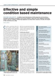
Although automation is sometimes<br />
perceived to be a means<br />
of reducing labour costs, in<br />
general, manpower reductions and<br />
cost savings do not rate as the only<br />
factor in the decision of whether to<br />
automate or not. Advantages in data<br />
security, error prevention, and time<br />
saving in the handling processes are<br />
also determining factors.<br />
As a result of strong competition between<br />
the ports and terminals it is essential<br />
to reduce costs and to improve<br />
the service quality. To satisfy customers’<br />
demand, like short lead times and<br />
high quality products, it is nowadays<br />
necessary to carry out all operations<br />
very fast and efficiently. To meet these<br />
demands, terminals are looking for<br />
new techniques, such as automated<br />
transportation systems and automated<br />
ways of control. Furthermore, there<br />
are many significant industry changes<br />
that influence the development of<br />
terminals, e.g. increasing vessel sizes,<br />
space limitations as well as labour<br />
agreements and labour costs. These<br />
constraints rise the question whether<br />
the terminals will densify operations<br />
to increase the throughput of existing<br />
terminals or if new facilities will replace<br />
or expand existing capabilities.<br />
The terminal of the future, in some<br />
places, must use new technology to<br />
meet these upcoming requirements.<br />
Today, yard equipment and its inability<br />
to keep up with the ship-to-shore<br />
cranes has become the bottleneck<br />
limiting productivity in most termi-<br />
AGV working at CTA Hamburg <br />
10 Ship & Port | 2009 | N o 2
nals. In example a fully automated<br />
terminal faces the problems of quite<br />
different technical performances:<br />
quay cranes up to 60 boxes per hour<br />
(bx/hr), AGV 12 bx/hr, RMG 20 bx/<br />
hr. In other words, it is important to<br />
adjust the performances of the different<br />
technologies involved to provide<br />
an overall efficient system.<br />
Automation at the quayside interface<br />
The berthing time of a vessel is the<br />
main criteria for the productivity of a<br />
terminal. The quay crane (also called<br />
ship-to-shore-crane) is the first equipment<br />
in the sequence. The challenge of<br />
automation of the quay crane can be<br />
split into two parts:<br />
The first part is the handling at the vessel.<br />
Due to problems with positioning<br />
the spreader at the vessel, it is nowadays<br />
not fully automated at any terminal.<br />
There are semi-automated trolleys,<br />
which transport the container to a position<br />
above the vessel automatically and<br />
let the crane operator put the spreader<br />
onto/into the vessel. The speed of the<br />
trolley is limited by the well-being<br />
of the crane driver, who nowadays is<br />
moving with the trolley. In the future<br />
trolley and crane driver cabin may be<br />
decoupled. The driver will control the<br />
trolley only at the quayside and let it<br />
work automatically at the landside.<br />
The second part is the operation at the<br />
transfer area to the transport equipment.<br />
This part is to be automated if<br />
safety regulations allow this. For example,<br />
in Germany it is allowed to operate<br />
under an automatic trolley with<br />
transport equipment, but is forbidden<br />
Active lift AGV <br />
under a manned trolley. For this reason<br />
double trolley cranes often operate<br />
at the quayside. The main trolley<br />
moves the container from the ship to<br />
a platform while a second trolley picks<br />
up the container from the platform<br />
and moves it on shore. The main trolley<br />
is man driven while the second one<br />
works fully automatic.<br />
Special operating topics like twin-lift<br />
(spreader lifts two 20’ containers together),<br />
special spreaders for tandem<br />
40 (spreader lifts two 40’ containers<br />
one over the other or one alongside<br />
the other respectively) or triple spreaders<br />
and others must be provided from<br />
the manufacturers as well as new ideas<br />
for the layout of traffic lanes for the<br />
transport equipment. Loxystem e.g.<br />
developed the RAT twistlock system<br />
which provides the vertical tandem lift<br />
of two 40’ containers during one container<br />
move.<br />
Today the high productivity of quay<br />
cranes is limited by bottlenecks in the<br />
transport system and the control system.<br />
Automation of transfer systems<br />
Transfer systems are container transport<br />
systems between the transfer section<br />
of the quay crane and the stacking<br />
area. Automation of container<br />
transportation offers a high automation<br />
potential and is quite advanced.<br />
The most famous automated transfer<br />
system today is the driverless AGV<br />
(Automated Guided Vehicle). Normally<br />
they are used in combination<br />
with stacking cranes like RMGs and<br />
RTGs. The first AGVs were employed<br />
in the ECT Delta Sealand Terminal<br />
Source: Gottwald Port Technology GmbH<br />
Unmanned straddle carriers at the Port of<br />
Brisbane <br />
Source: www.portbris.com<br />
Rotterdam in 1993. AGVs can find<br />
the optimal way independently and<br />
evade obstacles. Nowadays AGVs can<br />
be considered as proven technology<br />
with positioning accuracy of about<br />
2.5 cm in the transfer areas. The latest<br />
series of AGVs have twin-lift capability,<br />
too. Disadvantages of AGVs are<br />
their dependence on stacking cranes.<br />
Their inability to pick the container<br />
results frequently in queues at the interchange<br />
points. Often AGVs have to<br />
wait for the gantry cranes or vice versa,<br />
which limits the overall productivity.<br />
The active lift AGV is a further development<br />
of the proven AGV technology,<br />
designed to decouple the container<br />
transport and the stacking processes.<br />
The conventional AGV is supplemented<br />
with two electronically operating<br />
platforms to pick-up and drop-off the<br />
containers independent from stacking<br />
equipment in the yard.<br />
Another automatic transfer system is<br />
the ALV (Automated Lifting Vehicle)<br />
which is comparable to a small straddle<br />
carrier but now updated with modern<br />
technology and performance to find<br />
its place in high throughput container<br />
terminals. The ALV works independently<br />
which results in reduced waiting<br />
times for the quay crane as well as for<br />
the stacking equipment in the yard,<br />
i.e. it improves the productivity of the<br />
quay crane and the utilization of buffer<br />
zone under the crane as well as the<br />
Ship & Port | 2009 | N o 2 11
Ship & Port Operation | Port infrastructure<br />
Example for a stack module with twin ASCs handling Source: Gottwald Port Technology GmbH<br />
cycle times and therefore the number<br />
of needed transport devices.<br />
In cooperation with the Australian<br />
stevedoring company Patrick (Patrick<br />
Technology & Systems) Kalmar has<br />
developed and implemented ASCs<br />
(Automated Straddle Carriers) at the<br />
Port of Brisbane (Fisherman Island,<br />
Australia). These automated straddle<br />
carriers operate in “human free areas”<br />
and are fitted with anti-collision<br />
bumpers and laser detection systems.<br />
The robotic equipment relies, instead<br />
of an in-ground tracking system, on<br />
radar and GPS technology. The automated<br />
straddle carriers operate according<br />
to a virtual map that is not<br />
restricted to fixed stacks and linemakings.<br />
Even conventional straddle<br />
carriers can be converted.<br />
The future chances for automated<br />
straddle carriers are very high, because<br />
these systems are more flexible<br />
than AGVs. Especially in Europe automated<br />
straddle carriers will be very<br />
interesting for the future, because a<br />
lot of terminals currently operate with<br />
SCs. So the existing SCs may be converted<br />
to an automation system in the<br />
future. Because no hard wiring and<br />
underground sensors are needed the<br />
ASC can be installed at any terminal<br />
worldwide.<br />
A further approach is the use of a<br />
cassette system, which separates the<br />
buffer and the transport task by using<br />
cassettes and tractors or AGV.<br />
This may become an alternative after<br />
proving its applicability in practice.<br />
The cassette system is dependent on<br />
cassettes, which are detachable steel<br />
platforms. In case of double-stacking<br />
the upper tier is secured by using cellguides<br />
which are part of the cassette<br />
configuration. A cassette is not selfmovable<br />
– it needs to be connected to<br />
a type of manned or un-manned vehicle<br />
for transporting containers. The<br />
PLC-controlled Cassette AGV of TTS<br />
for example is very flexible – there are<br />
no fixed paths given by transponders,<br />
but it is navigated by micro radar and<br />
laser technique.<br />
A further development of TTS is the<br />
IPSI AGV, designed for transportation<br />
of special cassettes. The IPSI AGV<br />
operates in two height levels: Before<br />
collecting a cassette the AGV is lowered<br />
and it can now be positioned<br />
Common structure of an automated terminal <br />
underneath the cassette. For transport<br />
the AVG operates in the higher level:<br />
The cassette is then lifted and the AGV<br />
moves to the given destination were it<br />
is again lowered to drop-off the cassette.<br />
Other technologies like the LMTT<br />
(Linear Motor Transfer Technology) –<br />
which is in principle a rail mounted<br />
terminal transport system – and the<br />
Grid on Rail (GRAIL) system – which<br />
is based on an overhead grid system<br />
of rails – are tested but not yet in operation.<br />
Automation of container storage<br />
systems<br />
The yard offers further possibilities<br />
for automation. Further stacking systems<br />
besides straddle carriers are rubber<br />
tired gantry cranes (RTGs), rail<br />
mounted gantry cranes (RMGs) and<br />
overhead bridge cranes (OBCs).<br />
Full-automation of gantry cranes is<br />
difficult to achieve due to the fact that<br />
trucks are difficult to be accurately<br />
positioned at the truck interface with<br />
respect to the crane. So in most cases<br />
container handling is still done manually.<br />
On the other hand operation<br />
between the legs of the crane is fully<br />
automated. Therefore the automatic<br />
operation area is separated from<br />
workers.<br />
The RTG output grows worldwide. Beside<br />
many offers from ports in Asia,<br />
a big share of new RTGs is going to<br />
Europe. There is a highly visible trend<br />
towards higher stacking RTGs (up to 1<br />
Source: ISL<br />
12 Ship & Port | 2009 | N o 2
over 7-high stacking). Needless to say<br />
that the mobile RTGs are more flexible<br />
in usage than rail mounted equipment.<br />
Yet development of automated<br />
RTGs lags behind due to technical<br />
disadvantages including increased<br />
proneness to vibrations, deformation<br />
of rubber tires, and difficulties of exact<br />
positioning.<br />
RMGs can be built wider and higher<br />
than RTGs. However RMGs offer less<br />
flexibility than RTGs and a lot of<br />
ground work has to be done because<br />
of the rails. In contrary to the RTGs,<br />
RMGs do not face problems with positioning<br />
and possible irregularities<br />
of the tire behaviour. Thus RMG’s<br />
automation is considerably easier to<br />
realise. Currently several automation<br />
systems from different manufacturers<br />
exist.<br />
The new Gottwald ASC (Automated<br />
Stacking Crane) is a portal crane<br />
based on the Gottwald WSG (Wide<br />
Span Gantries) technology. The crane<br />
spans up to eleven densely stacked<br />
container rows and stacks up to five<br />
containers high. This assumes logistically<br />
arrangements of the stacked<br />
containers to shorten the access time.<br />
Two ASC operate fully-automatic on<br />
a container stack using one craneway.<br />
The ASCs are equipped with an anticollision<br />
system, which allows the simultaneous<br />
operation of both ASCs.<br />
An innovation is the new vibrationfree<br />
rigid guiding beam instead of<br />
rope fields which tend to sway. This<br />
increases pick-up and drop-off time<br />
and with this the performance of the<br />
device because of a faster and accurate<br />
beam positioning.<br />
The concept of automated overhead<br />
bridge cranes (OBCs) has been proven<br />
at a 200m long test track at berth<br />
420 in Antwerp’s Churchilldok where<br />
the pilot crane achieved full operational<br />
speed and undertook the interface<br />
handling with shuttle carriers.<br />
OBC systems are more expensive than<br />
RMGs because of the elevated runway.<br />
On the other hand, they permit a high<br />
automation potential in contrast to<br />
the RTG and RMG due to their precise<br />
positioning. They are also designed to<br />
work as fast transportation vehicles. As<br />
a further advantage the OBCs allow vehicles<br />
using the area under the tracks.<br />
OBCs are electrically driven with low<br />
noise and air pollution and offer<br />
therefore lower operation costs. Maintenance<br />
becomes much easier because<br />
of the missing hydraulic parts and a<br />
fewer number of mechanical parts.<br />
The main disadvantage of OBCs can<br />
be seen in the relatively high investment<br />
costs for the elevated runway<br />
and problems with ground subsidence<br />
because of their high weight. At<br />
present automated OBCs are working<br />
at PSA`s Pasir Panjang terminal.<br />
Some ideas of high stack systems<br />
(HSS) follow up a quite different approach<br />
regarding yard stacking. It is<br />
a matter of container warehousing<br />
building which is able to store up to<br />
20~30 stacks in the rack-structure to<br />
minimize storage (for an optimized<br />
used of yard space), air pollution and<br />
dust in the port. A pilot construction<br />
is developed at Busan’s container terminal.<br />
The author:<br />
Dr.-Ing. Holger Schütt,<br />
ISL - Institute of Shipping Economics<br />
and Logistics, Bremen, Germany<br />
schuett@isl.org<br />
POWER<br />
TRANSPORTATION<br />
INDUSTRIAL AUTOMATION<br />
ENVIRONMENTAL MANAGEMENT<br />
<br />
by<br />
Modular Layer 3 Industrial Ethernet Switch Benefits Automation on Ships in Various Ways:<br />
<br />
<br />
<br />
<br />
<br />
POWERGRID EUROPE, COLOGNE<br />
May 26 to 28, 2009 | Hall 7 | Stand F66<br />
MOXA. INDUSTRIAL NETWORKING SOLUTIONS.<br />
EDS-828: Install up to 4 Gigabit Ports and 24 Fast<br />
Ethernet Ports for ultimate flexibility<br />
Moxa Europe GmbH | Einsteinstraße 7 | 85716 Unterschleissheim | Germany<br />
Tel.: +49 89 3700399-28 | E-Mail: Europe@moxa.com | www.moxa.com
Ship & Port Operation | Port infrastructure<br />
New ISO specification for<br />
containers identification<br />
Safe<br />
operation<br />
TRACKING | A new ISO technical<br />
specification will help<br />
to ensure the functioning of<br />
radio frequency identification<br />
(RFID) tags on freight<br />
containers despite the harsh<br />
environments they may be<br />
subjected to during trans-<br />
RFID container tags<br />
port by sea, road and rail.<br />
ISO/TS 10891:2009, Freight<br />
containers – Radio frequency<br />
identification (RFID)<br />
– License plate tag, provides<br />
specifications and test<br />
methods for RFID devices<br />
used for automatic identification<br />
of freight containers<br />
in supply chains.<br />
This tag is a permanently affixed,<br />
read-only tag containing<br />
limited data relating only<br />
to physical identification and<br />
description of the container<br />
to which it is affixed. This tag<br />
is required to last the lifetime<br />
of its associated container.<br />
The purpose of ISO/TS<br />
10891 is to optimise the<br />
efficiency of equipment<br />
control systems including<br />
the optional usage of electronic<br />
seals in conformity<br />
with the ISO 18185 series.<br />
ISO/TS 10891:2009 establishes:<br />
XX A set of requirements for<br />
container tags which allow<br />
the transfer of information<br />
from a container to automatic<br />
processing systems by<br />
electronic means<br />
XX A data coding system for<br />
container identification and<br />
container related information<br />
which resides within a<br />
container tag<br />
XX A data coding system for<br />
the electronic transfer of<br />
both container identification<br />
and container related information<br />
from container tags<br />
to automatic data processing<br />
systems<br />
XX The description of data to<br />
be included in container tags<br />
for transmission to automatic<br />
data processing systems<br />
XX Performance criteria necessary<br />
to ensure consistent and<br />
reliable operation of container<br />
tags within the international<br />
transportation community<br />
XX The physical location of<br />
container tags on containers<br />
XX Features to inhibit malicious<br />
or unintentional alteration<br />
and/or deletion of the<br />
information content of container<br />
tags when installed on<br />
a freight container.<br />
Port equipment | The<br />
Port Equipment Manufacturers<br />
Association (PEMA) and<br />
TT Club have announced<br />
that they will co-operate to<br />
promote best practice in the<br />
safe design and operation of<br />
port equipment worldwide.<br />
The agreement was finalised<br />
at PEMA’s recent AGM in<br />
Amsterdam, where Laurence<br />
Jones, Director of Global<br />
Risk Assessment for the TT<br />
Club, presented the results<br />
of his recent research into<br />
causes of equipment accidents<br />
and loss in the global<br />
port and terminal sector.<br />
The Port Equipment Manufacturers<br />
Association will<br />
now feature TT Club’s research<br />
and advisories and<br />
will work with the Club to<br />
highlight the role of equipment<br />
design and technology<br />
in reducing port accidents<br />
and loss, involving port<br />
equipment, including ship<br />
to shore cranes, straddle carriers,<br />
yard cranes and smaller<br />
mobile equipment.<br />
Cradle solutions for the Atlantic<br />
Langh Ship Cargo Solutions<br />
| Cradle Tween Decks<br />
by Langh Ship Cargo Solutions<br />
are on their way to sail across<br />
the Atlantic Ocean for the first<br />
time. These cradle solutions,<br />
which have been developed for<br />
transportation of big steel coils,<br />
have, up until now, been used<br />
between Northern Finland and<br />
Central Europe. Since the steel<br />
coils have remained undamaged<br />
during the whole nine<br />
years of operation, the same<br />
solution is now to be tested on<br />
a cross Atlantic voyage, meeting<br />
new challenges. M/S Marjatta,<br />
chartered by Ruukki, is on her<br />
way to transport a steel load<br />
from Raahe in Finland to New<br />
Orleans on the south coast of<br />
USA, which takes some three<br />
weeks to complete.<br />
One part of the big steel coils<br />
is transported on the tank<br />
top in Cradle Cassettes, while<br />
another part of the steel coils<br />
is stowed on Cradle Tween<br />
Decks, which are situated in<br />
the upper part of the cargo<br />
hold. As being typical for for<br />
steel loads, the vessel’s centre<br />
of gravity rises and the over<br />
stability decreases. Thanks to<br />
the Cradle Tween Decks it is<br />
claimed to be possible to optimise<br />
the stability of the vessel<br />
to a much higher degree,<br />
compared with loads that are<br />
loaded conventionally, when<br />
it is necessary to stow all the<br />
steel coils on the tank top.<br />
Steel coils for Atlantic shipment<br />
14 Ship & Port | 2009 | N o 2
Ship & Port Operation | shipping<br />
Resolutions for cruising the Arctic<br />
SAFETY | Demand for cruises to remote<br />
regions is driving the regulators to make<br />
certain that passengers, possibly unaware<br />
of some of the inherent dangers in the<br />
Polar areas, must be protected as must the<br />
local environments.<br />
Cruising to the Polar Regions is becoming<br />
increasingly popular with close to 40,000<br />
people heading to the Antarctic during<br />
the November 2008 to March 2009 season<br />
alone, according to many estimates.<br />
Increasing popularity amongst the cruising<br />
public has not necessarily been met<br />
with a regulatory regime that has managed<br />
to keep pace with the growth of the<br />
industry. The risks are high in these isolated<br />
locations not known to be friendly<br />
to ships.<br />
Over the last two seasons there have been<br />
four accidents in the Antarctic, including<br />
one sinking, a collision with an iceberg<br />
and two groundings involving vessels<br />
ranging from around 60 to 300 passenger<br />
capacities. Thankfully, these accidents<br />
have not met with any loss of life.<br />
However, the trend of incidents coupled<br />
with the increase in the number of ships<br />
operating in both Arctic and Antarctic waters<br />
has lead risk assurance businesses and<br />
the <strong>International</strong> Maritime Organization<br />
(IMO) to become increasingly alarmed at<br />
the possible risks and consequences. As a<br />
result, the IMO issued Guidelines on Voyage<br />
Planning For Passenger Ships Operating<br />
In Remote Areas, issued as Resolution<br />
A.999(25).<br />
Those guidelines are in the process of<br />
being updated at the IMO and ratified<br />
by member countries into formal<br />
regulations, though not before at least<br />
mid-2013. Meanwhile, Lloyd’s Register<br />
has turned its attention to advising<br />
ship operators what precautions, both<br />
at design stage and operational measures,<br />
they can take to minimise the risks<br />
to passengers and crew in remote locations.<br />
Those guidelines include the need for<br />
voyage planning for safety of life at sea,<br />
Dawn Princess in Alaska<br />
Cruising safely the Polar regions<br />
safety and efficiency of navigation and<br />
protection of the marine environment.<br />
There is an obligation on ships masters<br />
and deck offers in STCW requirements<br />
and guidance on planning can<br />
be found in IMO Resolution A.983(21)<br />
Guidelines For Voyage Planning to plan<br />
all navigational voyages.<br />
The guidelines, Resolution A.983 (21)<br />
which have been reviewed in March<br />
2009, detail additional factors that need<br />
to be taken into account when planning<br />
a voyage to remote areas in general, and<br />
Arctic or Antarctic waters in particular.<br />
Preparations for Polar voyages should<br />
include:<br />
XX knowledge of ice and ice formations,<br />
XX current information on the extent and<br />
type of ice and icebergs in the vicinity of<br />
the intended route,<br />
XX operational limitations in ice-covered<br />
waters, and availability and use of ice navigators.<br />
Crew also need to be aware of conditions<br />
when it is not safe to enter areas<br />
containing ice or icebergs. They need<br />
to be aware of safe distance to icebergs<br />
and the safe speed in such areas.<br />
Detailed voyage and passage plans for<br />
ships operating in Polar waters should<br />
also include measures to be taken before<br />
entering waters where ice may be<br />
present, e.g. an abandon ship drill and<br />
preparation of special equipment.<br />
Consideration also needs to be given<br />
to safe areas and no-go areas, surveyed<br />
marine corridors, if available, and<br />
contingency plans for emergencies in<br />
areas remote from search and rescue<br />
facilities.<br />
Lloyd’s Register’s winterisation expert<br />
Rob Bridges also points out that cruise<br />
operating companies should aim, if possible,<br />
to prevent crew and passengers<br />
from becoming exposed to the sea and<br />
cold air. When an incident occurs the<br />
emergency response times in some areas<br />
could be five or six days, whereas the<br />
survivability for people in near freezing<br />
water may be minutes. Many of the winterisation<br />
requirements are contained in<br />
MSC/Circ.1056, Guidelines for ships operating<br />
in Arctic ice-covered waters, and<br />
these features may also be applied to<br />
cruise ships operating in the Antarctic.<br />
Protecting the fragile environment of<br />
Polar waters is of equal concern to the<br />
IMO, and in September 2006 it sought<br />
to address the threat of pollution with<br />
the publication of guidelines for ballast<br />
water exchange in the Antarctic Treaty<br />
area (waters south of 60oS) in resolution<br />
MEPC.163(56).<br />
These guidelines are non-mandatory,<br />
but they state that vessels needing to discharge<br />
ballast within the Antarctic Treaty<br />
area should exchange their ballast water<br />
before reaching within the 200 nautical<br />
mile limit of Antarctic shores, in water<br />
at least 200m deep. This only applies to<br />
those tanks that will be discharged. If<br />
this is not possible for operational reasons<br />
then exchange should be undertaken<br />
in waters at least 50 nautical miles<br />
from the nearest land in water at least<br />
200 metres deep.<br />
Ship & Port | 2009 | N o 2 15
Shipbuilding & Equipment | Navigation<br />
Improved DGPS navigation<br />
with AIS broadcasts<br />
PRECISE NAVIGATION | The combination of AIS and beacon technologies can provide an<br />
important layer of redundancy and reliability for safe navigation. The AIS VHF transmissions<br />
can ensure uninterrupted DGPS availability, even under heavy weather or high interference<br />
conditions. Shipboard AIS and GPS equipment can be easily modified to take full advantage<br />
of this enhanced service.<br />
DGPS beacon stations<br />
and networks have<br />
been established<br />
along coastlines in many<br />
parts of the world to enhance<br />
navigation accuracy as well<br />
as ensure the integrity of the<br />
GPS position calculation onboard.<br />
Demand is growing<br />
for extended DGPS correction<br />
service, e.g. to enhance river<br />
navigation. Many authorities<br />
have also established an<br />
Automatic Identification System<br />
(AIS) base station network<br />
along their coastlines<br />
or inland waterways or plan<br />
to do this in the near future.<br />
The beacon broadcasts could<br />
be augmented and extended<br />
by delivering DGPS correction<br />
messages through AIS<br />
coast or river stations and<br />
networks, at the same time<br />
as achieving operational cost<br />
reduction.<br />
to the existing MF signals was<br />
minimal.<br />
The Radio-Technical Commission<br />
for Maritime Services<br />
(RTCM) created a special<br />
committee (SC-104) to propose<br />
standardised messages,<br />
and the first recommendations<br />
were released in 1986.<br />
These included DGPS correction<br />
messages and also<br />
integrity warnings. The latter<br />
are very important, as the onboard<br />
GPS equipment may<br />
otherwise not detect a bad<br />
satellite and continue to use<br />
incorrect GPS position information.<br />
The first commercial beacon<br />
DGPS systems were installed<br />
in Sweden and Finland in<br />
1991. In the following 17<br />
years, more than 400 beacon<br />
DGPS stations have been established<br />
around the world.<br />
The resulting system of national<br />
DGPS beacon stations<br />
and networks, all operating<br />
to the same standards, is a<br />
testimony to international<br />
cooperation at its best. Much<br />
of the credit goes to IALA<br />
(<strong>International</strong> Association<br />
of Marine Aids to Navigation<br />
and Lighthouse Authorities)<br />
for its critical role in organising<br />
and coordinating this important<br />
aid to navigation on<br />
an international scale.<br />
While the DGPS beacon<br />
systems have generally performed<br />
very well, there are<br />
certain limitations. The beacon<br />
signals, broadcasting in<br />
the MF frequency range, are<br />
subject to interference from<br />
lightning and manmade<br />
sources, such as arcing of<br />
sparks from shore-based or<br />
shipboard electrical machinery,<br />
which can disrupt the<br />
signals. This can cause problems<br />
for the ship’s navigation<br />
systems if the vessel depends<br />
on MR broadcasted DGPS as<br />
primary position and speed<br />
sensor. There have been reports<br />
on unwanted step responses<br />
when running on<br />
the autopilot in automatic<br />
track-steering mode.<br />
Many of the older beacon<br />
stations are now nearing the<br />
end of their service life, having<br />
been converted in the<br />
1990s for DGPS broadcasts.<br />
As these sites continue to age,<br />
the risk of occasional outages<br />
for repairs or maintenance<br />
DGPS beacon background<br />
In the early 1990s, raw GPS,<br />
which at that time was still<br />
subject to Selective Availability<br />
(SA) degradation, could<br />
not provide sufficient levels<br />
of accuracy to meet coastal<br />
and port navigation requirements.<br />
Marine radio beacons<br />
represented an attractive medium<br />
for transmitting DGPS<br />
data for various reasons. The<br />
radio beacons were beginning<br />
to lose their primary<br />
intended purpose of radio<br />
direction-finding, as new position-finding<br />
technologies<br />
were being widely deployed.<br />
The shore facilities, approved<br />
frequency bands and maintenance<br />
organisations were already<br />
in place, and the cost of<br />
adding the DGPS broadcasts<br />
Example of National AIS system<br />
16 Ship & Port | 2009 | N o 2
increases. It is therefore desirable<br />
to develop an additional<br />
layer of redundancy<br />
to ensure 100% availability<br />
of DGPS corrections around<br />
the clock, even during periods<br />
of heavy weather or<br />
interference affecting the<br />
MF broadcasts. Various solutions<br />
have been proposed<br />
and tested, including the<br />
use of FM radio subcarrier<br />
broadcasts and Loran-C<br />
transmissions.<br />
This is where AIS comes in,<br />
but first let us take a quick<br />
look at the situation regarding<br />
onboard position<br />
equipment.<br />
DGPS onboard equipment<br />
IMO mandated GPS equipment<br />
in connection with<br />
the amendment to SO-<br />
LAS Chapter V in 2002. A<br />
new and improved GPS<br />
standard was developed<br />
to meet the most stringent<br />
requirements, including<br />
onboard integrity monitoring<br />
(RAIM). Unfortunately,<br />
there was no requirement<br />
in this SOLAS amendment<br />
to replace older and inferior<br />
GPS equipment. This is unfortunate,<br />
because the AIS<br />
equipment was intended to<br />
work with the very best GPS<br />
navigation available. Beacon<br />
receivers are still not mandatory,<br />
not even for SOLAS<br />
category ships. This low-cost<br />
device for preventing accidents<br />
has obviously not<br />
been considered as important<br />
as for instance Voyage<br />
Data Recorders, which were<br />
mandated to help accident<br />
investigators.<br />
AIS<br />
AIS transponders continually<br />
transmit a vessel’s ID,<br />
position, course, speed and<br />
other data to all other nearby<br />
ships and shore authorities<br />
on two common VHF<br />
channels. To accommodate<br />
the large number of messages<br />
on these channels, AIS<br />
has a data communication<br />
scheme called self-organizing<br />
time-division multiple<br />
access (STDMA), which uses<br />
the highly accurate standard<br />
time reference derived from<br />
GPS satellite signals. Class<br />
A AIS transponders are required<br />
for all SOLAS ships<br />
over 300 gross tons. In addition<br />
to this, a new Class B AIS<br />
standard has recently been<br />
adopted to provide a slightly<br />
reduced level of service to<br />
non-SOLAS vessels, such as<br />
commercial fishing boats,<br />
tugs and pleasure yachts.<br />
AIS works<br />
XX in a ship-to-ship mode<br />
for enhanced situation<br />
awareness,<br />
XX in a ship-to-shore mode for<br />
coastal surveillance/VTS ,<br />
XX in a shore-to-ship mode,<br />
where a variety of messages<br />
can be transferred, even<br />
DGPS messages.<br />
Many countries are deploying<br />
automated AIS base<br />
stations ashore to monitor<br />
the movement of vessels in<br />
their adjacent waters and<br />
navigable inland waterways,<br />
typically with a 24/7 monitoring<br />
scheme employing a<br />
2-way messaging system on<br />
two VHF channels (approx<br />
162 MHz). Coastal networks<br />
have been established or<br />
are planned in Europe and<br />
North America as well as<br />
South-East Asia, India, China,<br />
Korea, Japan, South Africa<br />
and several other countries.<br />
Similar networks are<br />
also planned along major<br />
inland waterways. Coastal<br />
AIS coverage will thus soon<br />
match the coverage of the<br />
current population of DGPS<br />
beacon stations.<br />
The AIS standard includes a<br />
message type 17 encapsulating<br />
any RTCM SC-104 message.<br />
It is therefore possible<br />
to use the AIS base station<br />
and shipboard AIS transponder<br />
as a “modem” to<br />
forward the RTCM message<br />
to the GPS receiver onboard.<br />
This will work if the onboard<br />
AIS transponder has<br />
the capability for unpacking<br />
the incoming type 17 messages<br />
and output these on a<br />
serial port in the RTCM SC-<br />
104 format to the navigation<br />
GPS receiver. Some AIS<br />
transponders can already do<br />
this, while others may require<br />
a software upgrade.<br />
The advantages of this would<br />
be that:<br />
XX practically all types of onboard<br />
GPS receivers can<br />
navigate in DGPS mode,<br />
XX integrity warnings can also<br />
be broadcast via AIS,<br />
XX the likelihood for good reception<br />
can be monitored<br />
(i.e., if the base station receives<br />
the signal from the<br />
ship, this most likely receives<br />
the messages from<br />
the base station).<br />
IALA has issued a recommendation<br />
regarding this type of<br />
service, which requires that<br />
the quality of the DGPS corrections<br />
and system integrity<br />
are at least as good as the<br />
current beacon service. This<br />
presupposes that the DGPS<br />
reference station meets stated<br />
requirements for reliability<br />
and availability and that<br />
there is integrity monitoring<br />
of the corrections and the<br />
broadcast itself.<br />
The conclusion is that there<br />
are good reasons for integrating<br />
the modern DGPS<br />
beacon service with the AIS<br />
base station broadcast and<br />
also, if possible, integrating<br />
system monitoring of<br />
the two systems. This would<br />
yield cost savings for the system<br />
provider.<br />
DGPS data can be transmitted<br />
through existing AIS base<br />
stations/transmitters, and in<br />
many cases the existing beacon<br />
sites can be converted<br />
for AIS transmissions. The<br />
beacon reference station control<br />
and integrity monitoring<br />
software can be used to monitor<br />
both systems, resulting<br />
in operational cost savings<br />
for the operator.<br />
Shipboard AIS transponders<br />
can be reprogrammed to convert<br />
the AIS Message 17 data<br />
to RTCM format and then<br />
forward this to the ship’s primary<br />
DGPS navigator.<br />
The author:<br />
Gunnar Mangs,<br />
Saab TransponderTech,<br />
Linköping, Sweden<br />
Ship & Port | 2009 | N o 2 17
Shipbuilding & Equipment | Navigation<br />
Innovative search and rescue<br />
transmitter<br />
AIS-SART | After several years of product development and standardisation work by international<br />
organisations, AIS-SART has been adopted into the GMDSS regulations as an alternative<br />
to Radar-SART as from January 1st 2010.<br />
Technically, the AIS-SART is a Search<br />
and Rescue Transponder (SART)<br />
transmitting AIS signals instead of<br />
the traditional emergency signals on 9<br />
GHz X-Band radar frequencies. The AIS-<br />
SART, working on the 162 MHz VHF<br />
frequencies, is programmed from the<br />
manufacturer with a unique ID code<br />
and receives its position via an internal<br />
AIS SART test message<br />
GPS antenna. This data is combined and<br />
transmitted using the international AIS<br />
channels (AIS A and AIS B) in the maritime<br />
VHF band. The transmitter sends<br />
out a specified pattern. Every minute, a<br />
sequence of 8 messages is transmitted,<br />
each message during a 26 ms time slot.<br />
Four messages are transmitted on channel<br />
A and four on channel B. All eight<br />
messages are transmitted within a total<br />
time frame of 14 seconds, defined to<br />
maximise the probability that at least<br />
one of the transmissions hits while being<br />
on a wave top. Only one of the total<br />
of eight messages has to be received from<br />
time to time to locate the AIS-SART accurately.<br />
Clear distress signal<br />
Anyone who can receive an AIS signal<br />
will also be able to detect an AIS-<br />
SART distress call. The transmission<br />
signal from an AIS-SART consists of<br />
an MMSI-like ID code, the first three<br />
digits being set to “970”. The ID code<br />
consists of a total of 9 digits, while the<br />
AIS-SART uses the remaining 6 digits<br />
to indicate the manufacturer (2 digits)<br />
as well as the unit’s unique serial<br />
number (4 digits).<br />
In addition to the ID code that appears<br />
on the AIS and its connected equipment,<br />
an AIS-SART will also be visualised on<br />
an electronic chart connected to the<br />
onboard AIS transponder. An AIS-SART<br />
will be shown as a circle with a built-in<br />
cross.<br />
Possibly the most impressive and innovative<br />
aspect is that the housing of Jotron’s<br />
AIS-SART, which seems to be the<br />
first launched on the market, is physically<br />
identical to Jotron’s Radar-SART,<br />
the Tron SART20. In other words, its total<br />
height is no more than 251 mm and<br />
weight a mere 450g.<br />
AIS-SART test results<br />
Three different tests have been conducted<br />
by IEC/IALA as part of the process to<br />
define an international standard for AIS-<br />
SART, with Jotron’s AIS-SART being used<br />
as test object during all these tests.<br />
The initial test was undertaken during<br />
the summer of 2008 in Oban, Scotland.<br />
Its purpose was to search for the AIS-<br />
SART using a ship and to determine<br />
the required output power of the unit.<br />
The results showed that it was possible<br />
to detect a precise location from<br />
the AIS-SART at distances of up to 8-10<br />
nautical miles (Nm). Similar results<br />
were obtained using the radar-SART,<br />
with the main difference being that the<br />
AIS-SART considerably simplified the<br />
search thanks to the fact that the position<br />
is plotted directly on the vessel’s<br />
electronic map system, as AIS is a fully<br />
digital system. In addition, only one<br />
single transmission of 26 ms is required<br />
to receive accurately the position on the<br />
map, while a radar-SART requires continuous<br />
updates.<br />
The second test was performed again in<br />
Oban in September 2008. This test was<br />
to determine the range obtainable from<br />
a SAR (Search and Rescue) helicopter, using<br />
a helicopter from the Maritime and<br />
Coastguard Agency (MCA) in the UK.<br />
The results were again as expected, the<br />
signals being picked up from a distance<br />
of between 26 and 40 Nm at flight levels<br />
varying between 300 and 2,500 ft.<br />
The last test was performed outside Key<br />
West, Florida in January 2009. It was carried<br />
out by the US Coast Guard (USCG),<br />
using a C-130 SAR aircraft. The aircraft<br />
flew in on different flight levels at 1,000,<br />
5,000, 10,000 and 20,000 ft and recorded<br />
the maximum range obtainable.<br />
A search for a 406 EPIRB and a radar-<br />
SART was performed at the same time<br />
to verify and compare the results with<br />
the new AIS-SART. The AIS-SARTs were<br />
deployed at different heights above sea<br />
level to account for different operating<br />
scenarios, ranging from a manover-board<br />
unit just above sea level<br />
to a SART mounted on top of a larger<br />
lifeboat. The ranges obtained were between<br />
40 Nm and 132 Nm and were<br />
picked up from an AIS-SART mounted<br />
on a 1m pole.<br />
These range tests, together with previous<br />
tests performed from helicopters and<br />
ships, show that the AIS-SART performs<br />
better than other locating transmitters<br />
The handy AIS SART<br />
18 Ship & Port | 2009 | N o 2
1 Burst every minute with<br />
position update<br />
Channel A<br />
Channel B<br />
14 seconds<br />
8 distress messages of 26 ms each, every 14 seconds<br />
Live test: circles with a built in cross indicating distress<br />
(especially 121.5 Mhz EPIRB and radar-<br />
SART). It can be located from a far better<br />
distance, has position indication with<br />
GPS precision and uses readily available<br />
standard equipment (AIS) automatically<br />
positioning the persons in distress on to<br />
a chart.<br />
There is no doubt that the AIS-SART will<br />
contribute to more effective and less<br />
time-consuming search and rescue operations<br />
in the future and ensure that more<br />
lives can be saved.<br />
Immediate implementation<br />
Interest in Jotron’s new AIS-SART has<br />
been overwhelming, from both the market<br />
and authorities all over the world.<br />
Jotron expects to have a type approved<br />
AIS-SART already in summer 2009. The<br />
AIS-SART will also be implemented in<br />
an appendix to the European Marine<br />
Equipment Directive (MED), probably<br />
in summer 2010.<br />
In the meantime, authorities can issue<br />
national certificates to permit installation<br />
of the AIS-SART as soon as type approved<br />
products are available.<br />
Compendium Marine Engineering<br />
Operation – Monitoring – Maintenance<br />
Editors: Hansheinrich Meier-Peter | Frank Bernhardt<br />
NEW!<br />
After the great success of the German edition now<br />
available in English!<br />
According to the German edition this book represents a compilation of<br />
marine engineering experience. It is based on the research of scientists<br />
and the reports of many field engineers all over the world.<br />
This book is mainly directed towards practising marine engineers,<br />
principally within the marine industry, towards ship operators,<br />
superintendents and surveyors but also towards those in training and<br />
research institutes as well as designers and consultants.<br />
Find out more about this<br />
compendium and order your copy at<br />
www.shipandport.com/cme.<br />
Technical Data: Title: Compendium Marine<br />
Engineering, ISBN 978-3-87743-822-0,<br />
approx. 1100 pages, hardcover<br />
Price: € 98,- (plus postage)<br />
Address: DVV Media Group GmbH l Seehafen<br />
Verlag · Nordkanalstr. 36 · 20097 Hamburg<br />
Germany · Telephone +49 40/237 14 209<br />
E-Mail: service@schiffundhafen.de<br />
Seehafen Verlag
Shipbuilding & Equipment | Navigation<br />
New Integrated Bridge System<br />
Raytheon Anschütz | Every third new ship built today is fitted with an Integrated<br />
Bridge System (IBS). One reason for this noticeable increase is that classification<br />
societies have created special notations for integrated bridges. Additional accident<br />
avoidance safety and superior system functionality as well as professional project<br />
management and service support from only one supplier are other important factors.<br />
IBS suppliers generally put<br />
strong emphasis on customer<br />
advisory service.<br />
For Raytheon Anschütz, customer<br />
service begins in the<br />
early project stage and continues<br />
over the whole lifecycle<br />
of onboard equipment.<br />
Raytheon Anschütz recently<br />
announced its next generation<br />
of Integrated Bridge<br />
Systems, which replaces its<br />
current bridge solution with<br />
more than 600 installations.<br />
Raytheon Anschütz defines<br />
its IBS as a tailor-made system<br />
providing all core components<br />
of navigation with<br />
standardised design, functions<br />
and operation. Each<br />
IBS is customised according<br />
to the vessel’s characteristics,<br />
requirements of classification<br />
societies and owner’s<br />
specifications.<br />
Ergonomics and operating<br />
philosophy<br />
The new bridge system comes<br />
with a new innovative console<br />
design with improvements<br />
in terms of ergonomics<br />
and ease of installation.<br />
Ergonomic considerations<br />
mainly affect three aspects,<br />
according to Raytheon Anschütz:<br />
arrangement of<br />
workplaces, instrumentation<br />
and operability of the<br />
equipment itself. The officer<br />
on duty spends a large part<br />
of his bridge watch at one<br />
central workplace and needs<br />
an all-round view from this<br />
position, if possible without<br />
blind spots. The new multifunctional<br />
concept from<br />
Raytheon Anschütz combines<br />
the functions of the<br />
(Chart) Radar, ECDIS and<br />
Conning into one system.<br />
With the high degree of integration,<br />
all essential navigational<br />
information is accessible<br />
at any workstation<br />
on the integrated bridge.<br />
The new multifunction<br />
systems can be fitted with<br />
wide-screen flat colour<br />
displays. Presentation of<br />
(Chart) Radar, ECDIS and<br />
Conning has been carefully<br />
redesigned in order to obtain<br />
the maximum benefit<br />
from the additional space of<br />
the wide screen, for example<br />
with an increased target area<br />
(PPI) on the radar screen.<br />
Another milestone for ergonomic<br />
bridge design is said<br />
to be a standardised manmachine<br />
interface, leading<br />
to a reduction of operating<br />
controls as well as an avoidance<br />
of screen overload. To<br />
reduce stress for the officer<br />
on duty even further, all operator<br />
controls for (Chart)<br />
Radars, ECDIS, Conning,<br />
Autopilot, Steering and<br />
Gyro Compass follow the<br />
same design and operating<br />
philosophy. Raytheon Anschütz<br />
points out that this<br />
new operating concept for<br />
integrated bridge systems<br />
is possible only because all<br />
core components are developed<br />
and manufactured by<br />
one supplier.<br />
Advanced functionality<br />
Safety on a ship’s integrated<br />
bridge goes hand in hand<br />
with the functionality of<br />
equipment, details of which<br />
are specified by national and<br />
international rules. Further<br />
operational safety can be<br />
achieved with intelligent<br />
functions such as collision<br />
avoidance with Raytheon<br />
Anschütz SeaScout or a<br />
track control system, which<br />
is able to guide a ship fully<br />
automatically along a track<br />
with an accuracy of 25 m.<br />
Several years of experience<br />
with the adaptive autopilot<br />
NP2035 have shown that<br />
this accuracy is maintained<br />
not only on straight route<br />
sections but also during<br />
track change. Track control<br />
proceeds independently<br />
while the officer on duty can<br />
concentrate fully on the traffic.<br />
Shortly before reaching a<br />
waypoint, the system checks<br />
the attentiveness of the officer<br />
on duty by sending out<br />
An artist’s impression of the new generation Integrated Bridge System<br />
20 Ship & Port | 2009 | N o 2
an “Approach Alarm”. If this<br />
alarm is not acknowledged,<br />
the alarm is transferred according<br />
to a determined<br />
procedure. Immediately<br />
before beginning the turning<br />
manoeuvre, the “Wheel<br />
Over Alarm” is given. At this<br />
point, no acknowledgement<br />
is necessary. The turn begins<br />
and the ship is guided<br />
along the curved stretch of<br />
the route to the next track,<br />
heading along the planned<br />
radius.<br />
All radar and ECDIS workstations<br />
can be supplied<br />
with an autopilot operator<br />
unit including an “override<br />
tiller”, which allows for a<br />
manual override of the manoeuvre<br />
at any time.<br />
Positioned in the centre of<br />
the IBS, the conning display<br />
shows all necessary<br />
navigation data from the<br />
track control process such<br />
as Track Deviation, Heading,<br />
Rate-of-Turn, Speed,<br />
Lateral Speed, Rudder Position,<br />
Water Depth, Distance<br />
and Course to the next waypoint,<br />
Wind and Drift. The<br />
graphical presentation of all<br />
relevant data is claimed to<br />
be extremely easy to follow.<br />
Standardized alarms<br />
All system functions and<br />
the satisfactory operation<br />
of all components are continuously<br />
monitored, giving<br />
alarms if necessary. The new<br />
Raytheon Anschütz Bridge<br />
System is equipped with an<br />
integrated and standardised<br />
alarm system with a central<br />
alarm reset in order to reduce<br />
stress on the bridge. Raytheon<br />
Anschütz notes that alerts<br />
are now more easily recognised,<br />
avoiding unnecessary<br />
acknowledgements.<br />
The alarms are said to have<br />
decreased further in line with<br />
the new IMO Performance<br />
Standards for Radars concerning<br />
the automatic association<br />
of AIS and ARPA targets. Future<br />
efforts to establish INS<br />
Performance Standards may<br />
well lead to yet more intelligence<br />
within the alarm management<br />
system.<br />
Wide screen NSC Chart Radar with increased PPI<br />
New IBS with simulation<br />
Satellites as log sensors<br />
Sperry Marine | Apart<br />
from providing an accurate<br />
ship’s position, today’s<br />
GPS system is also precise<br />
enough to give a stable<br />
course and speed reading.<br />
When the European Galileo<br />
satellite project is introduced<br />
in 2013 at the earliest,<br />
a truly redundant satellite<br />
system (GPS/Galileo) might<br />
even be available. Until<br />
then, it remains advisable<br />
to integrate GPS receivers<br />
The Naviknot600<br />
with the traditional compass<br />
and log data sources, as does<br />
the new Naviknot600 from<br />
Sperry Marine.<br />
While the new Naviknot600<br />
Multisensor Speed Logs<br />
could well serve as standalone<br />
devices, their main<br />
feature is that they can be<br />
integrated with other sensors,<br />
such as a single-axis<br />
electromagnetic or Doppler<br />
speed log. The three-way<br />
GPS-electromagnetic-Doppler<br />
combination is claimed<br />
to provide optimal built-in<br />
flexibility and redundancy.<br />
The NAVIKNOT 600 systems<br />
use a twin GPS antenna array<br />
to measure the ship’s heading,<br />
velocity, course and attitude.<br />
The unit’s processor<br />
uses the GPS data, integrated<br />
with output from rate gyros,<br />
to calculate longitudinal and<br />
transverse speed over ground<br />
with an accuracy of ±1 percent<br />
or 0.1 knots, whichever<br />
is greater. In docking mode,<br />
the display presents a diagram<br />
with rate of turn, bow<br />
and stern side-to-side speed<br />
over ground and other useful<br />
data.<br />
Speed log data is shown on<br />
a large, bright, high-resolution<br />
display screen. Various<br />
remote control and digital<br />
and analogue repeater displays<br />
are also available.<br />
Bridge-<br />
Direct<br />
Lilley & Gillie and<br />
DPM (UK) | A new, fully automated,<br />
UKHO and MCA<br />
approved onboard chart<br />
management system, called<br />
“BridgeDirect!”, has been<br />
launched by Lilley & Gillie<br />
and DPM (UK). It provides<br />
mariners with a weekly<br />
transmission of Notices to<br />
Mariners and tracings to enable<br />
onboard charts to be<br />
updated. “BridgeDirect!”<br />
fully integrates with chart<br />
management systems and<br />
ensures that both ship and<br />
shore records are synchronised.<br />
Users only receive<br />
those updates that their vessel<br />
requires, keeping transmission<br />
costs of compressed<br />
e-mails to a minimum. An<br />
audit trail records that all<br />
corrections are received and<br />
applied.<br />
Ship & Port | 2009 | N o 2 21
Shipbuilding & Equipment | Navigation<br />
Responsible ECDIS and INS training<br />
NAVIGATION | Training is becoming<br />
a precondition for safe<br />
operation of vessels and for<br />
crew satisfaction. Since no firm<br />
regulations govern the content<br />
and duration of the ECDIS and<br />
INS training courses, the training<br />
responsibility is mainly left<br />
to the manufacturers and training<br />
providers.<br />
The quality of training has been<br />
developed significantly over the<br />
past few years and it is becoming<br />
a key factor for ship owners.<br />
Lately, <strong>International</strong> Group of<br />
P&I Clubs has raised concern<br />
over the increasing number of<br />
accidents caused by inadequate<br />
training of the crew. Some of<br />
these accidents stemmed from<br />
misuse of ECDIS. ECDIS and<br />
Integrated Navigation Systems<br />
(INS) were originally introduced<br />
to the market to increase<br />
safe operation of vessels, and<br />
Training and assessment<br />
the manufacturers have tried to<br />
constantly improve the user interface.<br />
At the same time, new<br />
technical improvement allows<br />
for introduction of a much<br />
wider range of features and<br />
possibilities in the system operation,<br />
adding new functions<br />
and data presentations to the<br />
user interface.<br />
It is a challenging task to fully<br />
comprehend the concept of<br />
ECDIS and INS, the benefits of<br />
the improved safety and limitation<br />
of such systems. When<br />
sailing with ECDIS and INS,<br />
it requires preparation before<br />
departure (setup and doublechecking<br />
on the whole system<br />
setup). These procedures and<br />
check lists are crucial to avoid<br />
navigators to set a wrong draft<br />
or safety contour as part of the<br />
system setup, or they forget to<br />
check the planned route and<br />
to correct it if necessary before<br />
departure.<br />
Having established a code of<br />
conduct when operating ECDIS<br />
and INS, it is equally important<br />
to teach how to verify the data<br />
provided by the system, when<br />
to trust the system and when<br />
to switch to other means of<br />
navigation. Furthermore, it is<br />
vital to establish procedures<br />
for handling the system in case<br />
of system failure. The troubleshooting<br />
procedure to resolve<br />
the problems in a system and<br />
restore a failed system to the<br />
normal operating mode, while<br />
continuing the voyage, is essential<br />
to safe and efficient navigation.<br />
Last, but not least, legal matters<br />
related to the operation of<br />
a vessel using INS and ECDIS<br />
should be taught. This includes<br />
knowledge of the IMO/SOLAS/<br />
flag state carriage requirements<br />
for ECDIS when operating with<br />
or without paper charts, performance<br />
standards, classification<br />
requirement for the system<br />
concept, location of equipment<br />
and finally the understanding<br />
of the legal aspects of using<br />
ECDIS with official or privately<br />
produced chart material.<br />
It is crucial that manufacturers<br />
provide education at a<br />
high level of quality utilizing<br />
technical knowledge of the<br />
system and share experiences<br />
and ideas with the end users to<br />
the benefit of improving future<br />
INS and ECDIS systems. Only<br />
through sharing of experience<br />
amongst the manufacturers,<br />
the regulating bodies and the<br />
end users, the systems can be<br />
further improved to ensure a<br />
continued development of safe<br />
operation.<br />
Taking the above into the<br />
consideration, FURUNO has<br />
established FURUNO INS<br />
Training Center (INSTC) with<br />
training programmes that fully<br />
comply with the IMO course<br />
models for INS, ECDIS and<br />
BTM training with course duration<br />
of 4 to 5 days, depending<br />
on type of the course. The<br />
purpose of the training centre<br />
is to provide the best possible<br />
training experience to the end<br />
users, and, through the certification<br />
by DNV for the ECDIS<br />
and INS training (INS training<br />
course is to be fully certified by<br />
DNV within 2009), to secure<br />
a high level of quality for the<br />
training provided. In addition,<br />
FURUNO INSTC decided to<br />
make assessment of the trainees<br />
after each training course<br />
to verify to themselves, their<br />
employer (the shipping company)<br />
and to INSTC, that they<br />
had accumulated a satisfactory<br />
level of knowledge during the<br />
course. The trainees will receive<br />
the certificate only if they score<br />
above a certain point in the<br />
practical and theoretical tests<br />
at the end of the course, which<br />
turns FURUNO currently as<br />
the only known training facility<br />
to uphold this policy.<br />
Tracking Systems<br />
VTS Simulation<br />
panama | Vizada and Absolute<br />
Maritime Tracking Systems<br />
have been selected by the<br />
Panama Maritime Authority to<br />
provide long range identification<br />
and tracking (LRIT) for<br />
the more than 8,000 eligible<br />
vessels in Panama’s waters that<br />
must comply with new regulations.<br />
Vizada claims to be among the<br />
few mobile satellite providers<br />
capable of delivering automatic<br />
position reports (APRs) from<br />
the vessel to the LRIT control<br />
centers via the Inmarsat satellite,<br />
through its network of<br />
wholly-owned and operated<br />
mobile satellite teleports.<br />
Vizada says to rely on Absolute<br />
Maritime Tracking Systems to<br />
ensure the crucial link between<br />
Visada’s Inmarsat-C systems<br />
and the Flag Authority.<br />
Maritime Training | Fylde<br />
College’s Fleetwood Nautical<br />
Campus has become the<br />
second British nautical schools<br />
to offer MCA accredited VTS<br />
operator training thanks to<br />
Transas’ addition of its first of<br />
its kind VTS simulation suite in<br />
the UK.<br />
The two Transas Navi-Monitor<br />
workstations are able to monitor<br />
the developing traffic situation<br />
in any simulated exercise<br />
run on the main navigational<br />
bridges on site; a capability<br />
that is required for Fleetwood<br />
to deliver VTS Operator training<br />
to the IALA V103 standard.<br />
A projected visualisation channel<br />
gives the view from the<br />
control tower and completes<br />
the “full mission” effect that<br />
this training establishment has<br />
always strived for.<br />
22 Ship & Port | 2009 | N o 2
Visit our website<br />
www.seatrade-europe.com<br />
for more<br />
information<br />
Cruise l Ferry l Rivercruise l Superyacht Convention<br />
JUST ADD<br />
WATER<br />
everything else is included...<br />
15 – 17 September 2009<br />
Hamburg Messe Fairground, Germany<br />
ports and destinations, world-class shipbuilders<br />
& repairers and marine suppliers...<br />
Europe’s leading meeting point for the cruise, ferry, rivercruise<br />
and superyacht industry.<br />
Organised by<br />
Hamburg Messe und Congress<br />
Seatrade<br />
Principal Sponsor<br />
Hamburg Cruise Center<br />
Sponsors<br />
Deerberg-Systems<br />
Fidelio Cruise<br />
Hobart GmbH<br />
Intercruises<br />
SeaConsult<br />
Supporting Organisations<br />
Cruise Europe<br />
European Cruise Council<br />
IG RiverCruise<br />
Passenger Shipping Association<br />
Verband der Fährschifffahrt und<br />
Fährtouristik e.V.<br />
Verband Deutscher <strong>Schiff</strong>sausrüster<br />
www.seatrade-europe.com<br />
Ship & Port | 2009 | N o 2 23
Shipbuilding & Equipment | Communication<br />
Cost-effective alternative for<br />
satellite communications<br />
IRIDIUM OPENPORT | In 2008, Iridium launched OpenPort, offering higher data<br />
bandwidth and high-quality voice service to its customer. Sea trials with beta units<br />
have just been completed and OpenPort is now ready for its commercial roll-out.<br />
Until not too long ago, the only<br />
choice in marine satellite communications<br />
was Inmarsat. Starting in<br />
2001, Iridium Satellite began challenging<br />
Inmarsat by offering truly global voice and<br />
slow-speed data connections through its<br />
low-earth orbit (LEO) constellation of 66<br />
satellites.<br />
Iridium has steadily posted market share<br />
gains in the maritime satcom sector during<br />
the last few years. At the end of 2008,<br />
Iridium had more than 320,000 subscribers<br />
across all of its commercial and government<br />
markets. The company’s endof-year<br />
financial results were impressive<br />
– revenues up 37 percent and operational<br />
EBITDA (earnings before income tax, depreciation<br />
and amortisation) up 42 percent<br />
over 2007.<br />
With the deployment of Fleet Broadband,<br />
which is now available in all of Inmarsat’s<br />
ocean regions, Inmarsat seemed poised to<br />
recapture its momentum in the marine<br />
marketplace, but then in 2008, Iridium<br />
launched its own higher-bandwidth product,<br />
branded as Iridium OpenPort. Iridium’s<br />
timing, in a sense, is fortuitous, coinciding<br />
with a deep recession in shipping.<br />
The shipping industry is feeling the effects<br />
of the worldwide downturn in trade, and<br />
shipowners are eagerly searching for ways<br />
to trim operating costs. The monthly satellite<br />
communication bill represents a significant<br />
percentage of the monthly cost of<br />
ship operation, and Iridium OpenPort offers<br />
an extremely cost-effective alternative<br />
to Fleet Broadband and other commercial<br />
VSAT service providers, in terms of hardware,<br />
installation and operating costs.<br />
To bring our readers up to date on the Iridium<br />
OpenPort rollout, Ship&Port spoke<br />
with Don Thoma, executive vice president<br />
of Iridium Satellite. Thoma told us that<br />
Iridium successfully completed sea trials<br />
with beta units on a variety of vessel<br />
platforms during 2008 and is now making<br />
commercial deliveries to its service partners.<br />
Iridium has ramped up its production<br />
line to meet the backlog of more than<br />
4,000 orders.<br />
One of the beta testbeds for Iridium Open-<br />
Port was a 1,600 teu containership in the<br />
Peter Döhle <strong>Schiff</strong>ahrts-KG fleet, under a<br />
service agreement with Vizada, which was<br />
one of the first Iridium service partners to<br />
sign up to distribute the Iridium OpenPort<br />
products and service. Vizada worked with<br />
Peter Döhle teams on the installation of<br />
the terminal as well as on follow-up of<br />
service quality throughout the beta testing<br />
stage. Michael Dittmer, fleet IT and communication<br />
coordinator for Peter Döhle,<br />
identified three aspects which led to his interest<br />
in Iridium OpenPort – the antenna<br />
array has no moving parts, Iridium offers<br />
worldwide connectivity, and the service<br />
has low hardware costs. According to Dittmer,<br />
the main objective was to centralise<br />
all IT applications and software on the<br />
boat in order to simplify administration,<br />
help maintain the vessels and better manage<br />
systems on board.<br />
At the completion of the initial beta testing<br />
phase, Dittmer said he was “…very<br />
happy with the service,” which fulfilled<br />
his expectations. He plans to install the<br />
Iridium OpenPort units on more ships in<br />
the near future. “Before implementing this<br />
plan fully we need to wait for the full results<br />
from the tests, but this is definitely<br />
the direction we want to head in, because<br />
The Iridium OpenPort providing 128 kbps<br />
we completely trust the service,” Dittmer<br />
told Ship&Port. When asked about crew<br />
calling, he responded, “The voice quality<br />
is 100 percent perfect, so I have nothing<br />
further to say about that!”<br />
Vizada is also due to propose a number<br />
of Vizada Solutions to complement the<br />
Iridium OpenPort service on board Peter<br />
Döhle ships. Once the terminals are<br />
fully in place, the solutions would include<br />
emailing and data compression software,<br />
crew calling cards, leased lines for data<br />
connections, etc.<br />
Other beta testbeds reported similar results.<br />
One of them was an Argentine Navy<br />
ship, which relied heavily on Iridium<br />
OpenPort during a three-month deployment<br />
to support Antarctic bases during the<br />
Austal summer. The captain noted that the<br />
system was a tremendous boost for crew<br />
morale. The ship established an onboard<br />
“Internet Café,” where the crew could have<br />
access to voice and Internet connections,<br />
which were said to be reliable with much<br />
higher data speed, compared to other<br />
communication options. Many of the crew<br />
enjoyed interfacing with social networks<br />
like Facebook, where they could share the<br />
“Antarctic experience” with their families<br />
24 Ship & Port | 2009 | N o 2
and friends. Prior to Iridium OpenPort,<br />
the ship’s crew was forced to rely on highfrequency<br />
(HF) radio links for telephone<br />
calls, using a phone patch to the PSTN<br />
through a radio station in Ushuaia.<br />
Thoma noted that Iridium OpenPort offers<br />
a unique value proposition of three<br />
independent phone circuits and a separate<br />
data link that can be provisioned for data<br />
rates from 9.6 to 128 kilobits per second,<br />
using an omnidirectional unstabilised<br />
antenna array. The phone lines can all be<br />
used simultaneously without interference,<br />
providing an excellent vehicle for crew calling.<br />
Data rates can easily be adjusted up or<br />
down at any time without making hardware<br />
or software changes, giving the users<br />
options that allow them to balance needs<br />
for speed of data transmission against cost<br />
considerations on a real-time basis.<br />
“The installed cost of an Iridium OpenPort<br />
terminal is much lower than competing<br />
marine satcom systems, and our per-megabyte<br />
prices for data are also substantially<br />
lower than other marine satcom services<br />
on the market today,” said Thoma. “This<br />
means a return on investment measured in<br />
months rather than years.”<br />
The Iridium OpenPort system uses a small,<br />
lightweight unstabilised antenna, which<br />
measures just 9 inches (230 millimeters)<br />
high and 22.5 inches (570 millimeters)<br />
in diameter – about the size of a typical<br />
enclosed small boat radar radome. It has<br />
no moving parts and is therefore virtually<br />
maintenance free.<br />
Thoma noted that Iridium OpenPort can<br />
centralise all IT applications and software<br />
on the ship in order to streamline<br />
administration, help maintain the vessel<br />
and better manage systems and crew<br />
communications. It will facilitate closer<br />
integration of shipboard and shoreside<br />
IT networks and the unit can support<br />
voice, e-mail, fax, weather reporting, data<br />
transfer as well as distress signaling. The<br />
complete integrated solution for ship-toshore<br />
crew calling, e-mail and IP-based<br />
data communications replaces expensive<br />
pay-per-minute billing schemes with a<br />
straightforward, cost-effective pay-permegabyte<br />
plan for data throughput.<br />
Ship&Port also asked Thoma about the<br />
long-term viability of the Iridium satellite<br />
network, especially when considering<br />
the highly publicised network failures of<br />
its fellow LEO provider, Globalstar. He<br />
explained that Iridium’s constellation of<br />
66 operational satellites is backed up by<br />
multiple in-orbit spares and the constellation<br />
is based on a cross-linked architecture,<br />
which gives each satellite four directions<br />
through which to communicate.<br />
This ensures that if an adjoining satellite<br />
happens to fail or a link is unavailable,<br />
the network is still able to relay messages<br />
around the satellite that may be inoperable.<br />
Thoma observed that the recent incident,<br />
in which a non-operational Russian<br />
communication satellite collided with<br />
an operational Iridium satellite in space,<br />
demonstrates the inherent robustness<br />
of the Iridium meshed network. Within<br />
60 hours, Iridium had successfully rerouted<br />
traffic, minimising service disruptions,<br />
and within days the company had<br />
maneuvered one of its multiple orbiting<br />
spare satellites into position to replace<br />
the one destroyed in the crash.<br />
Thoma stated that Iridium is on track to<br />
start deploying Iridium NEXT, its nextgeneration<br />
satellite constellation, in<br />
2014. Two large aerospace companies,<br />
Lockheed Martin and Thales Alenia<br />
Space are competing to be the prime<br />
contractor for the Iridium NEXT program,<br />
and Iridium expects to select the<br />
final partner during the second quarter<br />
of this year. The new satellites will be<br />
fully backward compatible with Iridium<br />
OpenPort and all other Iridium legacy<br />
products.<br />
www.marlink.com<br />
Connecting people and business at sea<br />
www.marlink.com<br />
Ship & Port | 2009 | N o 2 25
Shipbuilding & Equipment | Communication<br />
Latest development in<br />
FleetBroadband and VSAT<br />
SATCOMS | With full global coverage now in place and the introduction of the new FleetBroadband<br />
150 service opening the market considerably, FleetBroadband’s crossover to mainstream<br />
is now well underway, whilst at the same time the potential of VSAT is about to expand greatly.<br />
Changing onboard operations thanks to broadband connectivity<br />
The third Inmarsat I4<br />
satellite was launched<br />
in August 2008 and<br />
following a period of testing,<br />
entered into commercial<br />
service on February 24<br />
2009. It covers the Asia/Pacific<br />
region including Australia<br />
and New Zealand and<br />
went live just as the Fleet-<br />
Broadband equipped Volvo<br />
Ocean Race fleet entered<br />
the coverage area during<br />
the fifth and longest leg of<br />
the Volvo Ocean race 2008-<br />
2009, marking the first true<br />
global availability of broadband<br />
at sea.<br />
One other organisation<br />
committed to FleetBroadband<br />
is A.P. Moller-Maersk,<br />
who last year ordered what<br />
was described as the largest<br />
communications retrofit<br />
ever. 150 of its vessels,<br />
across the Maersk Tankers<br />
and Maersk Supply Service<br />
(MSS) fleet, were upgraded<br />
with SAILOR 500 Fleet-<br />
Broadband solutions by<br />
Thrane & Thrane. The MSS<br />
fleet consists of three types<br />
of vessels: Field and Subsea<br />
Support, Anchor Handling<br />
Tug Supply and Platform<br />
Supply.<br />
One of the reasons that<br />
A.P. Moller-Maersk gave for<br />
choosing FleetBroadband<br />
was that with the small antenna,<br />
they would be able to<br />
outsource the installation to<br />
crewmembers, who where<br />
very keen to get broadband<br />
internet onboard. All the<br />
vessels in the first phase of<br />
the installation program<br />
have received an installation<br />
pack with computer,<br />
LAN Switch, radome, mast,<br />
cables and fittings and so<br />
far very little external assistance<br />
has been required.<br />
Improving Operations<br />
The main driver for Maersk<br />
seeking to retrofit its vessels<br />
with new satcoms was<br />
to provide internet to crew<br />
onboard, ultimately for long<br />
term crew retention. However,<br />
the company has quickly<br />
integrated the system into its<br />
office and systems network<br />
and is starting to realise the<br />
potential of a full IP connection<br />
to vastly improve operational<br />
efficiency.<br />
MSS uses AMOS – Asset<br />
Management Operating System<br />
– for operations, maintenance<br />
and assets lifecycle.<br />
This requires four-six daily<br />
file transfers to fully harness<br />
the software suite’s organisational<br />
benefits, which is<br />
currently achieved using the<br />
Fleet 77 and Inmarsat B terminals<br />
onboard. However,<br />
MSS plans to use FleetBroadband<br />
to make the file transfer<br />
from the servers onboard<br />
the vessels to the servers on<br />
land faster and more cost effective.<br />
FleetBroadband is also<br />
opening up possibilities<br />
for remote diagnostics and<br />
maintenance for the shipboard<br />
systems. For instance,<br />
Dynamic Positioning (DP)<br />
pioneer Kongsberg Maritime<br />
is also using the new system<br />
to connect to its DP systems<br />
onboard MSS vessels for remote<br />
diagnostics. Having<br />
this extra level of support<br />
can provide solutions to<br />
problems or stop them happening<br />
at all.<br />
With this experience, MSS<br />
has decided to extend the<br />
opportunity of remote maintenance<br />
and diagnostics to<br />
all of its equipment partners<br />
and is hoping to enable it<br />
across all critical systems onboard,<br />
including the main<br />
engines, generators, and<br />
the large anchor handling<br />
winches on AHTS vessels.<br />
FleetBroadband 150<br />
FleetBroadband initially offered<br />
two levels of service<br />
that used two different sets<br />
of hardware. FleetBroadband<br />
500 is aimed at deep<br />
sea, heavy users whilst Fleet-<br />
Broadband 250 is aimed at<br />
users with a lower, but still<br />
considerable requirement<br />
for data usage.<br />
At SMM 2008, Inmarsat announced<br />
the introduction of<br />
a new service designed for<br />
vessels with lower airtime<br />
budgets and bandwidth requirements:<br />
FleetBroadband<br />
150. Working closely with<br />
Inmarsat, Thrane & Thrane<br />
has now prepared the hardware<br />
to utilise this new<br />
FleetBroadband service.<br />
The new SAILOR 150 Fleet-<br />
Broadband terminal offers<br />
150kbps IP data and simultaneous<br />
quality voice. The data<br />
speed, price and flexibility of<br />
this entry level solution ensure<br />
that it doesn’t overlap<br />
the core FleetBroadband 250<br />
and 500 offering. However,<br />
it is capable of introducing<br />
the use of IP applications to<br />
vessels that could not previously<br />
afford this, so SAILOR<br />
150 FleetBroadband ensures<br />
that a new class of user can<br />
now benefit from the Fleet-<br />
Broadband service.<br />
FleetBroadband 150 is meant<br />
as an introduction to broadband<br />
for vessels that may<br />
not rely on heavy data traffic<br />
between ship and shore<br />
but whose operation may be<br />
improved if the facility was<br />
available.<br />
VSAT Expansion<br />
Ku-band VSAT is traditionally<br />
for regional and coastal<br />
areas only, and because of<br />
the limited coverage, and<br />
26 Ship & Port | 2009 | N o 2
size and cost restraints, it<br />
has not yet been a viable<br />
alternative to Inmarsat services,<br />
although things may<br />
be starting to change.<br />
There are signs that satellite<br />
operators and service<br />
providers will enhance the<br />
Ku-Band networks over<br />
ocean regions because of a<br />
considerable potential in<br />
the maritime market. Although<br />
many vessels do sail<br />
with VSAT, the market for<br />
merchant shipping is essentially<br />
in its early phase.<br />
The Ku-band coverage over<br />
the oceans will be expanded<br />
and completed over the<br />
next 2-3 years, and when<br />
this happens, VSAT will become<br />
more affordable.<br />
With greater coverage and<br />
less costs, VSAT is set to<br />
have more potential as a<br />
mainstream solution in the<br />
future and Thrane & Thrane<br />
is preparing for this by entering<br />
into this competitive<br />
market place. The company<br />
is launching its first VSAT<br />
solution this year, and although<br />
recognised primarily<br />
as a hardware supplier,<br />
it is taking a different approach<br />
by promising a total<br />
solution.<br />
Hardware procurement,<br />
installation and airtime<br />
are provided in a complete<br />
package in order to widen<br />
the availability of VSAT to<br />
vessels that may be holding<br />
off because of the traditionally<br />
lengthy VSAT<br />
procurement process, extremely<br />
complex installation<br />
or budgetary concerns<br />
over airtime.<br />
Thrane & Thrane has enabled<br />
built in Fleet/Fleet-<br />
Broadband switch over capabilities<br />
in its new VSAT,<br />
meaning that owners of<br />
existing Thrane & Thrane<br />
manufactured Fleet and<br />
FleetBroadband systems can<br />
install a true VSAT upgrade<br />
and benefit from higher<br />
bandwidth and lower airtime<br />
costs while sailing<br />
within VSAT coverage area,<br />
but still ensure satcoms coverage<br />
globally.<br />
Changing onboard operations<br />
Regardless of the service<br />
chosen, in addition to assisting<br />
in crew welfare and<br />
retention, FleetBroadband<br />
and VSAT have huge potential<br />
for changing operations<br />
onboard vessels of all<br />
shape, size and application,<br />
be it vessel and engine telemetry,<br />
ECDIS updating, or<br />
24 hour connectivity. With<br />
a fast, stable data connection,<br />
keeping in touch with<br />
the shore office is much easier,<br />
and planning, reporting<br />
and general organisation of<br />
a job can be much smoother.<br />
As long as the bandwidth is<br />
available there are almost<br />
limitless possibilities.<br />
The author:<br />
Casper Jensen,<br />
Thrane & Thrane A/S,<br />
Lyngby, Denmark<br />
LRIT Data Centre<br />
ABEKING & RASMUSSEN<br />
WINDP K<br />
The SWATH@A&R<br />
Windpark Service Vessels.<br />
CLS | The European Maritime<br />
Safety Agency (EMSA)<br />
has awarded Collecte Localisation<br />
Satellite (CLS)<br />
a contract to provide and<br />
operate the European Union<br />
(EU) LRIT (Long-Range<br />
Identification and Tracking)<br />
Data Centre, as well as<br />
the associated Application<br />
Service Provider (ASP) and<br />
Communication Service<br />
Provider (CSP) functions.<br />
The EMSA LRIT Data Centre<br />
will serve the 27 EU<br />
maritime administrations,<br />
as well as those of Iceland<br />
and Norway, and will also<br />
request reports from non-<br />
EU flag vessels entering EU<br />
coastal waters. The new international<br />
carriage requirements<br />
for (LRIT) came into<br />
effect Jan. 1, 2009.<br />
© composé communication<br />
www.abeking.com<br />
Offshore Technologies<br />
Ship & Port | 2009 | N o 2 27
Shipbuilding & Equipment | Communication<br />
VSAT for yachts<br />
WaveCall | Following Marlink’s acquisition<br />
of the WaveCall brand from Sea<br />
Tel Inc., new services are being launched<br />
for yachts and leisure craft with the aim<br />
of providing affordable and versatile<br />
satellite-based broadband communications<br />
solutions.<br />
WaveCall by Marlink uses the Sea Tel<br />
Ku-band VSAT 4006 antenna system<br />
comprising above-deck and below-deck<br />
equipment, which is claimed to be ideal<br />
for vessels requiring “always-on” satellite<br />
communications. The new Marlink<br />
services translate into increased satellite<br />
capacity in current coverage areas such<br />
as the Caribbean, the Americas and Europe.<br />
They are said to add new coverage<br />
areas to meet customers’ growing need<br />
for high bandwidth in day-to-day business<br />
at sea. One of the new features offered<br />
with WaveCall is Prepaid Calling<br />
Cards, providing better cost control for<br />
vessel owners and crews.<br />
Enhanced tool<br />
bandwidth allocation | A system<br />
upgrade to measure and monitor VSAT<br />
bandwidth utilization with significant<br />
granularity and flexibility has been developed<br />
by UK based network management<br />
company Parallel for SeaMobile<br />
Enterprises. The enhanced web portal is<br />
offered through SeaMobile’s MTN Satellite<br />
Services suite of products. It provides<br />
detailed bandwidth utilization graphs<br />
and reports that can be broken down by<br />
protocol, type of service such as Internet,<br />
corporate data, VoIP, or cellular, by individual<br />
IP address or by application. This<br />
degree of specificity and granularity will<br />
allow ship-owners to better understand<br />
their bandwidth usage.<br />
The new system seamlessly integrates<br />
with MTN’s iDirect infrastructure and the<br />
company’s unique implementation of<br />
Riverbed compression and optimization<br />
technology. Historical data will be stored<br />
for up to three years, with 5 minute resolution<br />
available on all data.<br />
For SeaMobile, this is a major step forward,<br />
following customer demand to carefully<br />
manage and optimize VSAT bandwidth,<br />
which, in deed, is a valuable and limited<br />
resource. In addition to helping identify<br />
usage patterns and potential abuse, the<br />
new system is also said to allow for making<br />
informed decisions regarding strategic<br />
bandwidth allocation and upgrades.<br />
New single channel Iridum PBX<br />
Global Satellite USA | A new intelligent<br />
Iridium PBX called MCG-101 has<br />
been launched by Global Satellite USA.<br />
The system has an intelligent solution<br />
for Iridium satellite phones to operate<br />
as a telephone, Internet gateway, GPS<br />
device, send/receive SMS and attach to<br />
other devices through RS232 or CAN<br />
bus. The MCG-101 is daisy chainable so<br />
that it can connect with multiple simultaneous<br />
communications. Installing the<br />
unit is claimed only to require power, a<br />
Communications onboard AIDA<br />
SatComms | Marlink has announced<br />
a new five year contract with German<br />
cruise company AIDA Cruises, for the<br />
supply of its Sealink satellite communications<br />
system. Sealink will be<br />
provided to five existing cruise vessels<br />
and three planned new builds, the first<br />
of which will be in operation from<br />
spring 2009 with the others in commission<br />
in 2010 and 2011.<br />
Sealink is a full service broadband<br />
satellite solution developed by Marlink<br />
which offers “always-on” voice,<br />
Maritime video streaming<br />
SIM card and an external antenna. To<br />
connect to the internet is said to be as<br />
simple as connecting a computer to the<br />
Ethernet Port.<br />
The MCG-101, weighing 1.9 kg (4lbs)<br />
and measuring 5 cm by 20 cm by 20<br />
cm, utilizes 100% digital technology<br />
and provides clear, true to life audio,<br />
and eliminates internal echo problems.<br />
The MCG-101 includes a standard analogue<br />
telephone RJ11 interface with a<br />
hardware echo canceller.<br />
Internet access and Local Area Network<br />
(LAN) communications.<br />
Operating in the Mediterranean, Northern<br />
Europe, Caribbean and Asia regions<br />
the AIDA vessels will be equipped with<br />
Sealink C-band VSAT technology, providing<br />
bandwidths from 384 kbps to 768<br />
kbps with dedicated SCPC. AIDA Cruises<br />
has the option to move to shared solutions<br />
from Marlink later this spring. The<br />
options are based on either Vipersat multicast<br />
SCPC or IDirect technology, subject<br />
to final testing and requirements.<br />
SATCOM | The appearance of broadband<br />
services in the maritime market<br />
over the last two years has provided<br />
tremendous opportunities for shipping<br />
companies and maritime fleet operators.<br />
Vessels are now in an “always-on”<br />
connection with the internet and corporate<br />
network, permitting constant<br />
monitoring of ships and cargo. The<br />
increased broadband bandwidth also<br />
permits the use of maritime video to<br />
improve fleet operations.<br />
M2sat recently introduced MarineCam,<br />
which is able to stream video and still<br />
images from vessels. The first applications<br />
M2sat sees running over its MarineCam<br />
system are purely commercial,<br />
such as for corporate promotions sending<br />
still images from ships to websites<br />
or allowing customers to follow and<br />
track the transport of their special cargo.<br />
M2sat believes that maritime video will<br />
be increasingly used in future to improve<br />
ship operations, security or the<br />
fighting of crime and piracy or to help<br />
and solve onboard problems more efficiently.<br />
Telemedicine applications for<br />
remote medical assistance and crew<br />
welfare is another application for live<br />
video at sea.<br />
The M2sat MarineCam system is<br />
claimed to be optimised for using existing<br />
onboard satellite equipment like<br />
Inmarsat or VSAT units and can use the<br />
relatively low speed bandwidth of maritime<br />
services (up to 256 kbps) for its<br />
video and still picture transmissions.<br />
All videos and pictures can be viewed<br />
with standard PCs with internet access<br />
on shore, but the shipping company<br />
has full control over who watches<br />
the material and all transmissions are<br />
claimed to be fully secure. Authorised<br />
viewers can select individual ships,<br />
look at saved still pictures or activate<br />
the onboard cameras. They can even<br />
control the onboard camera remotely.<br />
28 Ship & Port | 2009 | N o 1
Shipbuilding & Equipment | Propulsion<br />
Flexibility in a small package<br />
Green Engines | The new Wärtsilä 34DF engine uses the same technology as the larger Wärtsilä<br />
50DF multifuel engine to deliver fuel flexibility on a scale that makes it ideal for gas-fuelled vessels<br />
The Wärtsilä multifuel<br />
concept, as introduced<br />
with the Wärtsilä 50DF<br />
engine a few years back, is<br />
now available in a smaller<br />
package. While the Wärtsilä<br />
50DF engine provided Wärtsilä<br />
with valuable multifuel<br />
experience, it was found that<br />
for some applications, the<br />
17 MW power capacity of<br />
the Wärtsilä 50 DF engine<br />
is too much. Therefore, the<br />
Wärtsilä 34DF engine with a<br />
power range of 2.7 to 9 MW,<br />
has been developed based on<br />
the same technology.<br />
In terms of technology, it is<br />
almost a copy of the Wärtsilä<br />
50DF but on a smaller scale.<br />
It uses the same multifuel<br />
technology, allowing it to<br />
switch fuels during operation<br />
without stopping the engine<br />
and changing valves.<br />
The 50 Hz version of the<br />
Wärtsilä 34DF has a power<br />
output of 450 kW per cylinder.<br />
The engine is available<br />
in 6L (in-line), 9L (in-line),<br />
12V, 16V and 20V cylinder<br />
configurations. In combination<br />
with a generator, the<br />
electric power output ranges<br />
from 2590 kW to 8730 kW.<br />
This makes it suitable for applications<br />
where the Wärtsilä<br />
50DF is too large, and as<br />
The Wärtsilä 6L 34 DF generating set<br />
such, it is a very good complement<br />
to the Wärtsilä 34SG<br />
spark-ignited gas engine and<br />
essentially replaces the Wärtsilä<br />
32DF low-NOx engine.<br />
The multifuel capability has<br />
the following advantages:<br />
1. Good economy: choice of<br />
cheapest fuel on the market.<br />
2. High reliability: back up<br />
fuel available in case of fuel<br />
supply problems.<br />
Since the needed power range<br />
is wide, different cylinder<br />
configurations are available.<br />
The 6L, 9L, and 12V and 16V<br />
cylinder versions, are aimed<br />
at marine applications, and<br />
will be particularly suited<br />
to any vessels that need to<br />
switch to clean natural gas<br />
(LNG).<br />
Electronic control<br />
The Wärtsilä 34DF operates<br />
on the lean burn principle,<br />
whereby the mixture of air<br />
and gas in the cylinder has<br />
more air than is needed for<br />
complete combustion. Lean<br />
combustion reduces peak<br />
temperatures and, therefore,<br />
NOx emissions. It also reduces<br />
heat flow to the walls<br />
of the combustion chamber,<br />
as well as the tendency<br />
for knocking. Because of the<br />
reduced heat loss and likelihood<br />
of knocking, efficiency<br />
is increased and higher<br />
output is attained.<br />
Combustion of the lean airfuel<br />
mixture is initiated by<br />
injecting a small amount of<br />
LFO (pilot fuel) into the cylinder.<br />
The pilot fuel is ignited<br />
in a conventional diesel<br />
process, providing a highenergy<br />
ignition source for<br />
the main fuel charge, which<br />
is a mixture of natural gas<br />
and air. To obtain the best<br />
efficiency and lowest emissions,<br />
the main fuel flow to<br />
each cylinder is individually<br />
controlled to ensure operation<br />
at the correct air-fuel<br />
ratio, and with the correct<br />
amount and timing of pilot<br />
fuel injection.<br />
The engine functions are<br />
controlled by an advanced<br />
automation system that allows<br />
optimum running<br />
conditions to be set, independent<br />
of the ambient<br />
conditions or fuel used. The<br />
electronic control system is<br />
designed to cope with the<br />
demanding task of controlling<br />
the combustion in each<br />
cylinder, and to ensure optimal<br />
performance in terms<br />
of efficiency and emissions,<br />
under all conditions, by<br />
keeping each cylinder within<br />
the operating window.<br />
Stable and well-controlled<br />
combustion also contributes<br />
to less mechanical and<br />
thermal load on the engine<br />
components. All fuel ignition<br />
parameters are controlled<br />
automatically during<br />
operation.<br />
Incorporated into the system<br />
is a cylinder pressure based<br />
control. As this control utilizes<br />
the measurement of cylinder<br />
pressure for combustion<br />
optimization, cylinder<br />
pressure sensors have been<br />
added as standard in each<br />
cylinder. Continuous cylinder<br />
pressure measurement<br />
also contributes to more efficient<br />
engine diagnostics and<br />
improved safety.<br />
Multifuel system<br />
The key technology behind<br />
the Wärtsilä 34DF is the<br />
fueling and ignition system.<br />
The fuel system has been<br />
divided into three: one for<br />
gas, one for backup fuel, and<br />
one for the pilot fuel system,<br />
which acts as an igniter. The<br />
separate connection for the<br />
pilot fuel means that pilot<br />
fuel is always present, regardless<br />
of whether the engine<br />
is running on gas, light<br />
fuel oil (LFO), heavy fuel oil<br />
(HFO), or on liquid biofuel.<br />
The Wärtsilä 34DF can be<br />
started in diesel mode, using<br />
both main diesel and pilot<br />
fuel, or in gas mode. If the<br />
engine is started in diesel<br />
mode, gas admission is activated<br />
when combustion is<br />
stable in all cylinders. When<br />
running the engine in gas<br />
mode, the pilot fuel, which<br />
is always present, amounts<br />
to less than 1% of full-load<br />
fuel consumption. The<br />
amount of pilot fuel is controlled<br />
by the engine control<br />
system. When running the<br />
engine in backup fuel mode,<br />
the pilot is also in use to ensure<br />
nozzle cooling and to<br />
avoid clogging of the injector<br />
tip.<br />
The engine can also be started<br />
without using the backup<br />
fuel system, in which case,<br />
the engine is started on pilot<br />
fuel with gas admission activated.<br />
The synchronization<br />
and loading is achieved on<br />
gas. The pilot fuel consumption<br />
here is the same, namely<br />
less than 1% of full load<br />
fuel consumption.<br />
Gas supply<br />
The natural gas is supplied to<br />
the engine through a gas regulation<br />
unit. The gas is first<br />
30 Ship & Port | 2009 | N o 2
filtered to ensure a clean supply.<br />
The gas pressure, which<br />
depends on engine load, is<br />
controlled by a valve located<br />
in the valve station. At full<br />
load, the gauge pressure before<br />
the engine is 3.9 bar for<br />
a lower heating value LHV of<br />
36 MJ/m. For lower LHV, the<br />
pressure has to be increased.<br />
The system includes the necessary<br />
shut-off and venting<br />
valves to ensure a safe and<br />
reliable gas supply.<br />
On the engine, the gas is<br />
supplied through large<br />
common-rail pipes running<br />
along the engine. Each cylinder<br />
then has an individual<br />
feed pipe to the gas admission<br />
valve on the cylinder<br />
head. Gas pipes on the engine<br />
can have a double-wall<br />
design if required for marine<br />
applications.<br />
Diesel oil supply<br />
The fuel oil supply on the<br />
engine is divided into two<br />
separate systems: one for the<br />
pilot fuel, and the other for<br />
backup fuel.<br />
The pilot fuel is elevated to<br />
the required pressure by a<br />
pump unit. This includes<br />
duplex filters, a pressure<br />
regulator, and an enginedriven<br />
radial piston-type<br />
pump. The high-pressure<br />
pilot fuel is then distributed<br />
through a common-rail<br />
pipe to the injection valve at<br />
each cylinder. The pilot fuel<br />
is injected at a pressure of<br />
approximately 900 bar, and<br />
the timing and duration are<br />
electronically controlled.<br />
The backup fuel is separated<br />
from the pilot fuel system<br />
and is fed to a normal camshaft-driven<br />
injection pump.<br />
From the injection pump,<br />
the high-pressure fuel goes<br />
to a spring-loaded injection<br />
valve of standard design for<br />
a diesel engine.<br />
Injection valve<br />
The Wärtsilä 34DF has a<br />
twin-needle injection valve<br />
with two separate nozzles.<br />
The larger needle and nozzle<br />
are used in diesel mode<br />
for LFO or HFO operation,<br />
and the smaller one for pilot<br />
fuel oil – when the engine is<br />
running in gas mode – and<br />
in backup fuel operation<br />
to ensure nozzle cooling.<br />
The pilot injection is electronically<br />
controlled, and<br />
the main diesel injection<br />
is hydraulically controlled.<br />
The individually controlled<br />
solenoid valve allows optimum<br />
timing and duration<br />
of the pilot fuel injection<br />
into every cylinder when<br />
the engine is running in gas<br />
mode. Since NOx formation<br />
depends greatly on the pilot<br />
fuel amount, this design ensures<br />
very low NOx formation,<br />
while still employing a<br />
stable and reliable ignition<br />
source for the lean air-gas<br />
mixture in the combustion<br />
chamber.<br />
Gas admission valve<br />
Gas is admitted to the cylinders<br />
just before the air inlet<br />
valves. The gas admission<br />
valves are electronically actuated<br />
and controlled by<br />
the engine control system<br />
to give the precise amount<br />
of gas needed to each cylinder.<br />
In this way, the combustion<br />
in each cylinder<br />
can be fully and individually<br />
controlled.<br />
Independent gas admission<br />
ensures the correct air-fuel<br />
ratio and optimal operating<br />
point with respect to efficiency<br />
and emissions. The<br />
gas admission valves have a<br />
short stroke and are made<br />
of specially selected materials,<br />
thus providing low<br />
wear and long maintenance<br />
intervals.<br />
The large gas common-rail pipe running along the engine<br />
Twin-needle injection valve with electronically<br />
operated pilot injection<br />
Injection pump<br />
The engine utilizes the wellproven<br />
mono-block injection<br />
pump, developed by<br />
Wärtsilä. This pump withstands<br />
the high pressures<br />
involved in fuel injection<br />
and has a constant-pressure<br />
relief valve to avoid cavitation.<br />
The fuel pump is ready for<br />
operation at all times so that<br />
the engine can instantaneously<br />
switch over from gas<br />
to fuel oil if necessary. The<br />
plunger is equipped with a<br />
wear-resistant coating.<br />
Pilot pump<br />
The pilot fuel pump is engine-driven.<br />
It receives the<br />
signal for correct outgoing<br />
fuel pressure from the engine<br />
control unit and independently<br />
sets and maintains<br />
the pressure at the required<br />
level. It transmits the prevailing<br />
fuel pressure to the<br />
engine control system. Highpressure<br />
fuel is delivered to<br />
each injection valve through<br />
a common-rail pipe, which<br />
acts as a pressure accumulator<br />
and damper against<br />
pressure pulses in the <br />
Ship & Port | 2009 | N o 2 31
Shipbuilding & Equipment | Propulsion<br />
Gas admission valves for supplying gas to the cylinder<br />
Camshaft driven injection pump for back up fuel<br />
system. The fuel system has<br />
a double-wall design with an<br />
alarm to warn of leakage.<br />
Automatic fuel changeover<br />
In the event of, for example,<br />
a gas supply interruption, the<br />
engine switches from gas to<br />
fuel oil operation at any load<br />
instantaneously and automatically.<br />
Furthermore, the<br />
separate backup fuel system<br />
makes it possible to switch<br />
from LFO to HFO without<br />
load reduction. The pilot fuel<br />
is in operation during HFO<br />
operation to ensure nozzle<br />
cooling, and has a fuel consumption<br />
of less than 1% of<br />
full load fuel consumption.<br />
Switching over to LFO from<br />
HFO operation can also be<br />
done without load reduction.<br />
From LFO to gas operation,<br />
the switch can be made<br />
as described above. This operational<br />
flexibility is the real<br />
advantage of the multifuel<br />
system.<br />
The engine can be switched<br />
automatically from fuel oil<br />
back to gas operation at loads<br />
below 80% of the full load.<br />
The changeover takes place<br />
automatically after the operator’s<br />
command, without load<br />
changes. During the switchover,<br />
which lasts about one<br />
minute, the fuel oil is gradually<br />
substituted by gas.<br />
Air-fuel ratio control<br />
Having the correct air-fuel ratio<br />
under any operating conditions<br />
is essential to optimum<br />
performance and emissions.<br />
For this function, the Wärtsilä<br />
34DF is equipped with<br />
an exhaust gas waste-gate<br />
valve. Part of the exhaust gases<br />
bypasses the turbocharger<br />
through this waste-gate valve.<br />
The valve adjusts the air-fuel<br />
ratio to the correct value, depending<br />
on the varying site<br />
conditions, under high engine<br />
loads.<br />
As regards the engine’s operation,<br />
some extensive validation<br />
tests with the Wärtsilä<br />
50DF on HFO were made<br />
some years ago. In particular,<br />
one interesting problem for<br />
the DF engine to overcome<br />
was the issue of deposits that<br />
build up in the engine after<br />
running for a long time on<br />
HFO. This raised concerns<br />
as to whether this build up<br />
would cause problems during<br />
gas operation. However,<br />
it was found that quite soon<br />
after switching over from LFO<br />
to gas operation, the load<br />
could be increased rapidly<br />
and deposits were burned<br />
out quickly.<br />
Notable technical features<br />
In addition to the multifuel<br />
system, there are a few other<br />
notable technical features.<br />
Lube oil system<br />
Normally, gas engines are<br />
run using lube oils with<br />
lower TBN numbers. Higher<br />
TBN numbers are required<br />
in HFO operation, where the<br />
fuel contains relatively high<br />
amounts of acidifying components.<br />
There was a question<br />
as to whether the lube<br />
oil composition would have<br />
to be changed when switching<br />
from gas to HFO. However,<br />
the engine can run on the<br />
same high TBN lube oil when<br />
operating on gas.<br />
Like the Wärtsilä 50DF, the<br />
Wärtsilä 34DF has an enginedriven<br />
oil pump and can be<br />
provided with either a wet or<br />
dry sump oil system, whereby<br />
the oil is mainly treated<br />
outside the engine. Marine<br />
engines have a dry sump and<br />
power plant engines a wet<br />
sump. On the way to the engine,<br />
the oil passes through<br />
a full-flow automatic backflushing<br />
filter unit with a<br />
safety filter for final protection.<br />
A separate centrifugal<br />
filter cleans the back-flushing<br />
oil and also acts as an indicator<br />
of excessive dirt in the<br />
lubricating oil. A separate<br />
pre-lubricating system is used<br />
before the engine is started to<br />
avoid engine part wear.<br />
Engine cooling<br />
The Wärtsilä 34DF has efficient<br />
coolers, with a flexible<br />
cooling system design that<br />
is optimized for different<br />
applications of the heat, depending<br />
on the coolant temperature.<br />
The cooling system<br />
has two separate circuits –<br />
high-temperature (HT) and<br />
low-temperature (LT). The<br />
HT circuit cools the cylinder<br />
liner and the cylinder head,<br />
while the LT circuit serves the<br />
lubricating oil cooler. The<br />
circuits are also connected<br />
to the respective parts of the<br />
two-stage charge air cooler.<br />
The V-type engines are also<br />
available with an open interface<br />
system, whereby the<br />
cooling circuits can be connected<br />
separately. This makes<br />
optimized heat recovery and<br />
an optimized cooling system<br />
possible. The LT pump<br />
is always in serial connection<br />
with the second stage of<br />
the charge air CA cooler. The<br />
HT pump is always in serial<br />
connection with the jacket<br />
cooling circuit. Both HT and<br />
LT water pumps are enginedriven<br />
as standard, meaning<br />
that no electricity from the<br />
generator is needed to drive<br />
these pumps.<br />
Turbocharger<br />
The Wärtsilä 34DF is<br />
equipped with the modular-built<br />
Spex (single pipe<br />
exhaust) turbo charging system,<br />
which combines the<br />
advantages of both pulse<br />
and constant pressure charging.<br />
The interface between<br />
engine and turbocharger is<br />
streamlined with a minimum<br />
of flow resistance on<br />
both the exhaust and air<br />
sides. High-efficiency turbochargers<br />
with inboard plain<br />
bearings are used, and the<br />
engine lubricating oil system<br />
is used for the turbocharger.<br />
The waste-gate is actuated<br />
electro-pneumatically.<br />
First application<br />
The first application for the<br />
Wärtsilä 34DF engine will<br />
be for the Platform Supply<br />
Vessel (PSV) being built at<br />
the Aker Yards STX facility in<br />
Söviknes, Norway. Wärtsilä<br />
will supply three 6-cylinder<br />
engines that are able to run<br />
on marine diesel oil, heavy<br />
fuel oil or natural gas.<br />
32 Ship & Port | 2009 | N o 2
Cutting costs with<br />
pre-assembly<br />
Caterpillar | Marine<br />
engines are increasingly<br />
dependent on electronic<br />
engine monitoring and<br />
control. MaK Large Engine<br />
Protection/Safety System<br />
(LESS) by Caterpillar can<br />
help reduce the time required<br />
for engine installation,<br />
commissioning and<br />
maintenance.<br />
MaK LESS integrates various<br />
functions for engine<br />
monitoring and control by<br />
using no more than two<br />
small, resiliently mounted<br />
control boxes at the back<br />
of the engine. The first box<br />
contains the engine protection<br />
system, the RPM switch<br />
unit, the start/stop control,<br />
an LED display and a<br />
graphic display. The second<br />
box contains the complete<br />
engine monitoring system<br />
and MODbus data output<br />
to the alarm system. This<br />
box can also be fitted with<br />
an exhaust gas mean value<br />
system as well as control<br />
devices for main and bigend<br />
bearing monitoring.<br />
If the MaK DICARE engine<br />
monitoring and maintenance<br />
system is on board,<br />
CANbus data output to the<br />
DICARE PC will also be<br />
found in the second box.<br />
The LESS technology is<br />
said to have advantages<br />
for the vessel operator and<br />
shipyard as well as for the<br />
engine manufacturer and<br />
commissioning dealer. The<br />
engine manufacturer, in this<br />
case Caterpillar, can adjust,<br />
test and approve all safety<br />
and control features prior<br />
to engine delivery.<br />
At the same time, the shipyard<br />
saves both installation<br />
time and space because there<br />
are no separate electronic<br />
components and less wiring.<br />
Engine commissioning<br />
is claimed to be quick and<br />
easy because pre-tests and<br />
class approvals are effected<br />
at the factory and there is<br />
less scope for wiring mistakes<br />
at the yard. Finally, the<br />
vessel operator benefits from<br />
the integrated protection/<br />
safety system because there<br />
is maximum engine availability<br />
and minimum risk of<br />
failures. If failure nevertheless<br />
occurs, the affected sensor<br />
or actuator is highlighted<br />
in the LESS display for easy<br />
repair or replacement.<br />
MaK LESS is type-approved<br />
by leading Marine Classification<br />
Societies (MCS), including<br />
ABS, BV, DNV, GL<br />
and LR.<br />
MaK Marine Engine with LESS Control Boxes<br />
Ship & Port | 2009 | N o 2 33
Shipbuilding & Equipment | Propulsion<br />
Turbo boost for lower emissions<br />
Green Engines | ABB’s new A100-M/H turbocharger family for medium- and high-speed<br />
engines is designed to meet future demand for higher compressor pressure ratios and lower<br />
engine emissions with single-stage turbocharging<br />
Growing demand for energy, high<br />
fuel costs and stricter emissions<br />
legislation are having an important<br />
influence on diesel and gas engine<br />
development. It goes without saying that<br />
these same factors, plus the ongoing trend<br />
towards higher engine power densities<br />
and higher power output, are also impacting<br />
turbocharger technology: Higher<br />
engine mean effective pressures require<br />
higher turbocharger pressure ratios,<br />
while optimization of combustion technology,<br />
new engine-internal measures<br />
and the focus on exhaust after-treatment<br />
Fig. 1: New-generation A140 turbocharger<br />
systems all influence the development of<br />
modern turbocharging systems. In short,<br />
highly efficient turbocharging systems<br />
are vital for energy-efficient engines.<br />
High compressor pressure ratios are required<br />
today not only to increase the<br />
power output, which was the key aim<br />
in the past, but also because they play a<br />
significant role in emissions reduction.<br />
They are needed, for example, for the<br />
Miller/Atkinson process, which is used<br />
in some form in almost all modern diesel<br />
and gas engines. In diesel engines this<br />
process helps to reduce NOx emissions,<br />
while in gas engines it is used to shift the<br />
point at which knocking begins.<br />
Turbocharger performance<br />
During the past decade engine-builders<br />
have managed a significant increase in<br />
mean engine power output. In the<br />
high-speed engine segment, for example,<br />
the rise has been about 50%,<br />
while specific fuel consumption has<br />
been cut by approximately 10% and<br />
engine emissions could be lowered by<br />
up to 80%. Over the same period, taking<br />
the compressor power at the engine<br />
design point for the given compressor<br />
pressure ratios and flow capacity as a<br />
yardstick, the technical demands made<br />
on the turbocharger’s thermodynamic<br />
and mechanical performance can be<br />
said to have more than doubled.<br />
Figure 2 shows the trend for the mean<br />
effective pressures and the compressor<br />
pressure ratios required by high-speed<br />
diesel and gas engines, the latter typically<br />
requiring higher pressure ratios<br />
than diesel engines due to their higher<br />
control-related system losses and different<br />
fuel management. The next generation<br />
of diesel and gas engines will<br />
fully utilize the considerable potential<br />
of the A100-generation turbochargers.<br />
Full-load pressure ratios of up to<br />
5.8 in continuous operation with aluminium<br />
compressor wheels, at high<br />
efficiencies, set new benchmarks for<br />
power density in turbocharger construction<br />
and take the known limits<br />
of single-stage turbocharging a significant<br />
step further.<br />
From TPS to A100-M/H turbochargers<br />
Ten years after their introduction,<br />
more than 25,000 TPS series turbochargers<br />
are successfully operating<br />
on small medium-speed diesel engines<br />
and large high-speed diesel and<br />
gas engines rated from 500 kW to<br />
3300 kW. While these turbochargers<br />
continue to be the preferred choice<br />
for engine series rated at today’s power<br />
levels, market demand for ever-higher<br />
engine power densities and higher efficiencies,<br />
as well as the need to curb<br />
engine emissions, calls for new engine<br />
concepts and a new generation of turbochargers.<br />
It is for these advanced<br />
engines that ABB has developed the<br />
high-pressure A100-M/H series – the<br />
A100-H series for high-speed engines<br />
and the A100-M radial turbocharger<br />
series for small medium-speed engines<br />
(Fig. 1).<br />
The frame sizes of the A100-M/H series<br />
have the same outer dimensions as the<br />
field-proven TPS turbochargers and, also<br />
like the TPS, have the oil inlet and outlet<br />
ducts integrated in the foot. This ensures<br />
that in the case of further development<br />
of current TPS-turbocharged engine platforms,<br />
these engines can be fitted with<br />
A100 radial turbochargers without having<br />
to make any major changes to the<br />
turbocharger mounting. Development of<br />
a smaller and a larger A100-H frame size<br />
will depend on future market demand.<br />
Design concept<br />
A100 radial turbochargers are of modular<br />
construction with a minimized number<br />
of component parts and are designed to<br />
allow matching to the special requirements<br />
of each diesel and gas engine application.<br />
Different casing materials are<br />
available for different turbine inlet temperatures.<br />
A range of specific design and configuration<br />
features enables the A100-M radial<br />
turbochargers for small medium-speed<br />
engines to also be used with heavy fuel<br />
oil or with pulse turbocharging systems.<br />
Since the exhaust-gas temperatures with<br />
these engines are usually lower than with<br />
high-speed engines, the bearing casings<br />
of A100-M turbochargers can be supplied<br />
with or without water-cooling. Options<br />
include coated nozzle rings and multientry<br />
turbine inlet casings.<br />
Aluminium compressor wheels<br />
For the A100 radial turbocharger ABB developed<br />
a cooling technology that allows<br />
the continued use of aluminium for the<br />
compressor wheels even at such very high<br />
pressure ratios, and without compromis-<br />
Fig. 2: Trends in the turbocharging of<br />
modern high-speed engines<br />
34 Ship & Port | 2009 | N o 2
Fig. 3: Pressure ratio vs volume flow range<br />
for A100 turbochargers at full load<br />
ing the high operational reliability and<br />
long component exchange intervals users<br />
have come to expect with this material.<br />
This has avoided changing to cost-intensive<br />
titanium components.<br />
Cooling with compressor air was shown by<br />
an extensive test program to be the most<br />
efficient solution and also to be the easiest<br />
and least costly for the engine builder to<br />
implement. The concept is already proven<br />
in the field, having been offered for several<br />
years as an optional feature for the<br />
larger ABB TPL..-C turbochargers.<br />
Fig. 4: Compressor map (A140-H)<br />
Fig. 5: Turbine efficiencies, A140-H and<br />
TPS57-F<br />
Containment concept<br />
The A100 casings take full account of the<br />
much higher mechanical demands made<br />
on them. During their design ABB worked<br />
closely with engine-builders to ensure the<br />
same compactness as the TPS as well as<br />
optimum mounting of the turbocharger<br />
on the engine console. The safety of the<br />
containment concept – a vital consideration<br />
in view of the significantly increased<br />
power density – has been confirmed both<br />
numerically and experimentally by turbocharger<br />
containment tests on the test rig.<br />
The stronger shaft required because of the<br />
higher power transmission was also a factor<br />
in the design of the A100 bearing assembly,<br />
which was based on the TPS bearing<br />
technology. On the turbine side the<br />
casing centring concept which has proved<br />
so successful with the TPS..-F has been retained<br />
and ensures safe and efficient turbocharger<br />
operation.<br />
Thermodynamic performance<br />
Three entirely new compressor stages, each<br />
with different compressor wheel blading,<br />
allow the compressor volume flow range of<br />
today’s TPS..-F turbochargers to be covered<br />
by the new A100-M/H turbochargers with<br />
significantly higher pressure ratios (Fig. 3).<br />
The A100 turbocharger features a singlepiece<br />
aluminium compressor wheel. New<br />
high-pressure diffusers and compressor<br />
blading were developed in addition to the<br />
innovative wheel cooling to ensure the<br />
full-load pressure ratios of about 5.8 with<br />
aluminium wheels. A range of compressor<br />
stages is available for every turbocharger<br />
frame size, allowing optimal matching to<br />
every application. The compressor map in<br />
Fig. 4, which is based on measurements<br />
taken on the recently released A140 turbocharger,<br />
shows the high efficiencies, excellent<br />
map widths and more than adequate<br />
overspeed margins achieved. 80% compressor<br />
efficiency is achieved on a typical<br />
generator line for a full-load pressure ratio<br />
of 5.8.<br />
New turbine stages<br />
A new generation of mixed-flow turbines<br />
has been developed for use with the A100<br />
turbochargers in addition to the existing<br />
TPS mixed-flow turbine stage.<br />
A characteristic of this new turbine family is<br />
a larger operating range, allowing the new<br />
compressor stage’s high pressure ratio potential<br />
to be exploited over an even wider<br />
range of application. The turbine’s design<br />
has been optimized in each specific volume<br />
flow range, resulting in the individual<br />
stages exhibiting higher turbine efficiencies<br />
than the current TPS turbine stages. And<br />
additional, flexible sealing has been introduced<br />
to further reduce the bypass flows so<br />
Fig. 6: Turbocharger efficiency of A140-H<br />
with full-load-optimized specification<br />
that flow losses are also lower. This has<br />
allowed, in particular, a substantial improvement<br />
in turbocharging performance<br />
at higher boost pressures (Fig. 5).<br />
Thermodynamic potential<br />
Figure 6 shows the outstanding thermodynamic<br />
potential of the A100 in the case<br />
of a full-load-optimized turbocharger<br />
specification. The comparison with TPS<br />
turbocharger efficiency illustrates well the<br />
performance gain precisely in engine applications<br />
making very high demands on<br />
the achievable compressor pressure ratio,<br />
and therefore the quantum leap the A100<br />
represents in turbocharger development<br />
for single-stage turbocharging of modern<br />
medium-and high-speed engines.<br />
First results on engines<br />
Mid-2007 saw the first A140 prototypes<br />
successfully commissioned on ABB’s test<br />
rigs. This first frame size of the new turbocharger<br />
series successfully completed the<br />
rigorous qualification program and has<br />
been released for series production. Currently,<br />
ABB introduces further sizes of the<br />
A100-M/H to the marketplace.<br />
In the run-up to the series introduction of<br />
the A100, engine test rig trials were carried<br />
out to verify the thermodynamic performance.<br />
The high pressure ratios and efficiencies<br />
that can be achieved with the A100 allowed<br />
the high power densities expected<br />
on the engine side to be clearly demonstrated.<br />
Hundreds of running hours on<br />
the test rig have also confirmed the high<br />
performance level of the A100 in continuous<br />
operation. In the meantime, the first<br />
turbochargers of the new series are taking<br />
part in trials on selected field installations.<br />
Engine trials with further frame sizes are<br />
already successfully under way.<br />
The authors:<br />
Dirk Wunderwald,<br />
Tobias Gwehenberger,<br />
ABB Turbo Systems Ltd,<br />
Baden, Switzerland<br />
Ship & Port | 2009 | N o 2 35
Shipbuilding & Equipment | deck equipment<br />
Landing safely on a rolling ship<br />
Safe landing even under adverse conditions:<br />
Active roll compensation with Rexroth hydraulic controls<br />
ACTIVE ROLL COMPENSA-<br />
TION | The demanding task<br />
to land a helicopter on a ship<br />
deck is facilitated if the ship’s<br />
helicopter deck is equipped<br />
with an active roll compensating<br />
system with hydraulic<br />
controls.<br />
During landing, the helicopter’s<br />
center of gravity is at the<br />
top directly beneath the main<br />
rotor, making it vulnerable to<br />
any side movement. When<br />
the surface of the platform is<br />
slippery due to unfavorable<br />
weather conditions, the helicopter<br />
might slide sideways.<br />
When the platform is dry, the<br />
high friction may cause it to<br />
roll over.<br />
For each ship, regulations<br />
permit helicopter landings<br />
only up to a certain rolling<br />
angle of the ship. In the<br />
North Sea without an Active<br />
Roll Compensated (ARC)<br />
landing platform, this is limited<br />
to two degrees, but even<br />
then, the platform still rolls<br />
several meters from port to<br />
starboard.<br />
To expand the window of operation<br />
at sea, Norwegian TTS<br />
Offshore Handling Equipment<br />
AS has developed a<br />
fully automated ARC landing<br />
platform. The hydraulic control<br />
solution for this system<br />
was developed by TTS OHE<br />
supported by an international<br />
Rexroth team.<br />
Two hydraulic cylinders with<br />
a 4.4 meter stroke placed<br />
beneath the platform move<br />
the 26 x 26 meter sized steel<br />
platform and compensate the<br />
rolling of the ship at a speed<br />
of up to 1.6 m/s. The cylinders<br />
are controlled in real<br />
time by a high-end motion<br />
control MAC-8 and customized<br />
valve blocks. For calculating<br />
the compensation, two<br />
motion reference units constantly<br />
measure the ship’s angle<br />
of dip. Based on this data,<br />
the superior control system<br />
transmits in real time a position<br />
value to the MAC-8. The<br />
motion control synchronizes<br />
the two cylinders via high response<br />
proportional valves<br />
with on board electronics.<br />
The TTS-OHE specification<br />
asked originally for a maximum<br />
deviation of less than<br />
50 millimeters between the<br />
two cylinders. The Rexroth<br />
motion control achieves a<br />
10-fold higher accuracy keeping,<br />
actually the deviation at<br />
5 millimeters.<br />
Roll angle of up to five<br />
d egrees<br />
The design gives safety in<br />
operation highest priority.<br />
TTS-OHE opted for a redundancy<br />
of all critical components<br />
with the exception of<br />
the cylinders. The superior<br />
control system developed by<br />
TTS-OHE can switch jerk free<br />
between the running motion<br />
control and the redundant<br />
electronics. The two MAC-8<br />
motion controls are connected<br />
to the control system<br />
via CANOpen and via<br />
the specified analog voltage<br />
to the valves with on board<br />
electronics. A valve block<br />
on each cylinder with two<br />
customized high response<br />
proportional valves includes<br />
separate locking valves as an<br />
additional safety feature.<br />
Each MAC-8 sends all error<br />
and status information to the<br />
control system, including a<br />
“life”-bit signalizing the status<br />
of the controller. In the<br />
event of an error in the active<br />
motion control, the control<br />
system switches the access<br />
rights to the second Mac-8,<br />
simultaneously including a<br />
signal to the isolator valves<br />
regarding the change. This<br />
happens so fast that the cylinders<br />
have a minimal jerk.<br />
TTS-OHE has already installed<br />
the first ARC platform<br />
on the Ramform Sovereign,<br />
the world’s largest and most<br />
advanced seismic vessel. The<br />
ship, built by Aker Yards, is<br />
102 meters long with a gross<br />
tonnage of 15,000 tons. Directly<br />
after the ship’s launch<br />
in 2008, owner and operator,<br />
Petroleum Geo-Services,<br />
was awarded a contract by a<br />
Brazilian company to undertake<br />
the largest seismic survey<br />
ever in the off-shore oil<br />
and gas industry.<br />
For the commissioning and<br />
adjustment of the ACR system,<br />
Rexroth specialists are<br />
working on board the Ramform<br />
Sovereign together with<br />
the team from TTS-OHE.<br />
The first goal for the project<br />
is to increase the tolerated<br />
dip angle for safe helicopter<br />
landing by 50 per cent from<br />
2 to 3 degrees. The more<br />
ambitious goal: Compensating<br />
even 5-degree angles,<br />
so that helicopters can land<br />
safely on the rolling ship<br />
even when bad weather last<br />
for weeks.<br />
Observation platform solutions for seismic duo<br />
MacGregor | Observation<br />
platforms by MacGregor, specialist<br />
in engineering and service<br />
solutions for the maritime<br />
transportation and offshore<br />
industry, have been delivered<br />
to the first two of six seismic<br />
vessels under construction<br />
for Polarcus at the Drydocks<br />
World – Dubai shipyard in the<br />
United Arab Emirates.<br />
The platforms located at<br />
mooring-deck are mainly used<br />
in mooring operations and are<br />
destined for use on board the<br />
owner’s two Ulstein Design<br />
type SX124 vessels Polarcus Nadia<br />
and Polarcus Naila, which<br />
are planned to enter service by<br />
the end of this year.<br />
Polarcus Nadia and Polarcus<br />
Naila are technically-advanced<br />
3D seismic vessels capable of<br />
towing up to 12 streamers.<br />
They will each feature two<br />
MacGREGOR hydraulicallyoperated<br />
platforms designed<br />
and manufactured to the<br />
shape of the surrounding shell<br />
plating and delivered with<br />
pre-assembled coaming and<br />
ready tested in workshop. In<br />
open position, the platforms<br />
are supported by preventer<br />
stays and designed to carry a<br />
load of 500 kg.<br />
36 Ship & Port | 2009 | N o 2
Ship&Port<br />
Buyer´s Guide<br />
Ship&Port Buyer´s Guide<br />
The Buyers Guide serves as market review and source of supply listing.<br />
Clearly arranged according to references, you find the offers of international<br />
shipbuilding and supporting industry in the following 15 columns.<br />
1 Shipyards 9 Navigation + communication<br />
2 Propulsion plants 10 Alarm + safety equipment<br />
3 Engine components 11 Deck equipment<br />
4 Corrosion protection 12 Construction + consulting<br />
5 Ships´equipment 13 Cargo handling technology<br />
6 Hydraulic + pneumatic 14 Containers<br />
7 On-board power supplies 15 Port construction<br />
8<br />
Measurement<br />
+<br />
control devices<br />
16<br />
Buyer´s Guide<br />
Information<br />
Ship & Port | 2009 | N o 1 37
Ship&Port Buyer´s Guide<br />
2.02 Gears<br />
Shipbuilding & Equipment | XXX<br />
1 Shipyards<br />
1.06 Repairs + conversions<br />
Brückenstraße 25 D-27568 Bremerhaven<br />
Tel. +49(0)471 478-0 Fax +49(0)471 478-280<br />
2<br />
Propulsion<br />
E-mail: info@lloydwerft.com<br />
Repairs and Conversions<br />
Next Buyer’s Guide<br />
September 2009<br />
plants<br />
2.01 Engines<br />
www.lloydwerft.com<br />
REINTJES GmbH<br />
Eugen-Reintjes-Str. 7<br />
D-31785 Hameln<br />
Tel. +49 (0)5151 104-0<br />
Fax +49 (0)5151 104-300<br />
info@reintjes-gears.de www.reintjes-gears.de<br />
Ships' propulsion systems from 250 to 30.000 kW<br />
SCHIFFSDIESELTECHNIK KIEL GmbH<br />
Kieler Str. 177<br />
D-24768 Rendsburg<br />
Tel. +49(0)4331 / 4471 0<br />
Fax +49(0)4331 / 4471 199<br />
www.sdt-kiel.de<br />
ZF - Gears<br />
2.03 Couplings + brakes<br />
KTR Kupplungstechnik GmbH<br />
Rodder Damm 170<br />
D 48432 Rheine<br />
Tel. +49 (0) 59 71 798 0<br />
Fax +49 (0) 59 71 798 698<br />
e-mail: mail@ktr.com<br />
Internet: www.ktr.com<br />
Couplings<br />
Voith Turbo GmbH & Co. KG<br />
Postfach 15 55<br />
D-74555 Crailsheim<br />
Tel. +49 (0)7951 32 - 0<br />
Fax +49 (0)7951 32 500<br />
e-mail: industry@voith.com<br />
Internet: www.voithturbo.com<br />
Turbo couplings, Highly flexible couplings,<br />
Universal joint shafts, Safety couplings<br />
2.04 Shaft + shaft systems<br />
2.05 Propellers<br />
AIR<br />
Fertigung -Technologie GmbH & Co. KG<br />
<br />
Tel: +49 (0) 38 295 – 77 78 10<br />
Fax: +49 (0) 38 295 – 77 78 40<br />
E-Mail: info@air-composite.com<br />
www.air-composite.com<br />
Inline Thruster - The Compact Propulsor<br />
Contur ® -, Vector-, Industrie-Propeller<br />
<br />
<br />
e-mail: pein@piening-propeller.de<br />
Internet: www.piening-propeller.de<br />
Fixed and Controlable Pitch Propellers,<br />
Shaft Gears, Gearboxes<br />
SCHOTTEL-<strong>Schiff</strong>smaschinen GmbH<br />
Kanalstraße 18<br />
D 23970 Wismar<br />
Tel. +49 (0) 3841 / 20 40<br />
Fax +49 (0) 3841 / 20 43 33<br />
www.schottel.de<br />
Controllable-pitch propeller units,<br />
Shaft lines<br />
VA TECH<br />
ESCHER WYSS GmbH<br />
<br />
<br />
e-mail: cpp@vatew.de<br />
Internet: www.escherwysspropellers.com<br />
Controllable Pitch Propellers<br />
Voith Turbo Schneider<br />
Propulsion GmbH & Co. KG<br />
Postfach 20 11<br />
D-89510 Heidenheim/Germany<br />
Tel. <br />
E-Mail: vspmarine@voith.com<br />
www.voithturbo.com/marine<br />
Voith Schneider Propeller<br />
MAN Diesel SE<br />
86224 Augsburg, Germany<br />
<br />
Internet: www.mandiesel.com<br />
4-stroke diesel engines<br />
from 450 to 21.600 kW<br />
SCHIFFSDIESELTECHNIK KIEL GmbH<br />
Kieler Str. 177<br />
D-24768 Rendsburg<br />
Tel. +49(0)4331 / 4471 0<br />
Fax +49(0)4331 / 4471 199<br />
www.sdt-kiel.de<br />
mtu, John Deere,Perkins and Sisu engines<br />
Generating Sets<br />
Zeppelin Power Systems GmbH & Co. KG<br />
<br />
<br />
<br />
Sales- & Servicecenter Bremen:<br />
<br />
<br />
<br />
<br />
MaK and CATERPILLAR diesel engines<br />
from 90 to 16.000 kW<br />
38 II Ship & Port | 2009 | N o 1<br />
<br />
<br />
e-mail: pein@piening-propeller.de<br />
Internet: www.piening-propeller.de<br />
Fixed and Controlable Pitch Propellers,<br />
Shaft Gears, Gearboxes<br />
SCHOTTEL-<strong>Schiff</strong>smaschinen GmbH<br />
Kanalstraße 18<br />
D 23970 Wismar<br />
Tel. +49 (0) 3841 / 20 40<br />
Fax +49 (0) 3841 / 20 43 33<br />
www.schottel.de<br />
Controllable-pitch propeller units,<br />
Shaft lines<br />
SKF Maintenance Services GmbH<br />
<br />
Tel. <br />
E-mail: srs.deutschland@skf.com<br />
Internet: www.skf-maintenance-services.de<br />
Laser Alignment and Machinery<br />
Mounting Solutions<br />
www.shipandport.com<br />
2.06 Rudders +<br />
Rudder systems<br />
HATLAPA<br />
Uetersener Maschinenfabrik GmbH & Co. KG<br />
Tel.: +49 4122 711-0<br />
Fax: +49 4122 711-104<br />
info@hatlapa.de<br />
www.hatlapa.de<br />
Steering Gears, Shaft-Ø von 120 up to 1.000 mm<br />
Rotary vane up to 2.000 kNm<br />
<br />
<br />
e-mail: info@macor-marine.com<br />
Internet: www.macor-marine.com
e-mail: oceangoing@vdvelden.com<br />
www.vdvelden.com<br />
BARKE ® Rudders and COMMANDER Steering Gears<br />
- High-Tech Manoeuvring Equipment -<br />
2.07 Manoeuvring aids<br />
2.12 Diesel service<br />
+ spare parts<br />
Chris-Marine AB<br />
Box 9025<br />
SE-200 39 Malmö, Sweden<br />
Tel: +46 40 671 2600<br />
Fax: +46 40 671 2699<br />
www.chris-marine.com<br />
FOR DIESEL ENGINE MAINTENANCE<br />
TAIKO KIKAI INDUSTRIES CO.,LTD<br />
see NIPPON Diesel Service<br />
YANMAR DIESEL<br />
see NIPPON Diesel Service<br />
Ship&Port Buyer´s Guide<br />
Jastram GmbH & CO. KG<br />
<br />
<br />
e-mail: info@jastram.net<br />
Internet: www.jastram-group.com<br />
Transverse Thrusters,<br />
Azimuth Grid Thrusters<br />
<br />
<br />
e-mail: contact@gold-engine.com<br />
Internet: www.gold-engine.com<br />
Technical Service and Consulting<br />
for marine and power industry<br />
HHM<br />
Hudong Heavy Machinery<br />
see NIPPON Diesel Service<br />
3<br />
Engine<br />
components<br />
3.04 Stuffing boxes<br />
for piston rods<br />
SCHOTTEL GmbH<br />
Mainzer Str. 99<br />
D-56322 Spay/Rhein<br />
Tel. + 49 (0) 2628 / 6 10<br />
Fax + 49 (0) 2628 / 6 13 00<br />
www.schottel.de<br />
Rudderpropellers, Transverse Thrusters,<br />
Pump-Jets<br />
2.09 Exhaust systems<br />
H+H Umwelt- und Industrietechnik GmbH<br />
<br />
D-55595 Hargesheim<br />
Tel. +49 (0)671 92064-10<br />
Fax +49 (0)671 92064-20<br />
E-mail: Herbert.Roemich@HuHGmbH.com<br />
Internet: www.HuHGmbH.com<br />
Catalytic Exhaust Gas Cleaning for<br />
Combustion Engines on Ships<br />
KOBE DIESEL<br />
see NIPPON Diesel Service<br />
MITSUBISHI DIESEL/TURBOCHARGER<br />
see NIPPON Diesel Service<br />
Mares Shipping GmbH<br />
Bei dem Neuen Krahn 2<br />
D-20457 Hamburg<br />
Tel. +49 (0)40 / 37 47 84 0<br />
Fax: +49 (0)40 / 37 47 84 46<br />
www.mares.de<br />
Ship Spare Parts for Diesel Engines,<br />
Compressors, Pumps, Separators etc.<br />
Next Buyer’s Guide<br />
September 2009<br />
POLYVERIX - H. & G. Meister AG<br />
<br />
Tel. +41 - 44 - 431 56 46<br />
Fax +41 - 44 - 431 15 20<br />
e-mail: info@polyverix.ch<br />
Internet: www.polyverix.ch<br />
Gland- & Stuffing Boxes / Piston cooling<br />
parts / various sealing items<br />
3.05 Starters<br />
DÜSTERLOH Fluidtechnik GmbH<br />
Abteilung Pneumatik Starter<br />
Im Vogelsang 105<br />
D-45527 Hattingen<br />
<br />
www.duesterloh.de<br />
Air Starters for Diesel and<br />
Gas Engines up to 9.000 kW<br />
2.10 Special propulsion units<br />
SCHOTTEL GmbH<br />
Mainzer Str. 99<br />
D-56322 Spay/Rhein<br />
Tel. + 49 (0) 2628 / 6 10<br />
Fax + 49 (0) 2628 / 6 13 00<br />
www.schottel.de<br />
Rudderpropellers, Twin-Propellers,<br />
Navigators, Combi-Drives, Pump-Jets<br />
2.11 Water jet propulsion units<br />
MOTOR-SERVICE SWEDEN AB<br />
Mölna Fabriksväg 8<br />
SE-610 72 VAGNHÄRAD<br />
SWEDEN<br />
<br />
www.motor-service.se sales@motor-service.se<br />
WORLDWIDE SPARE PART DELIVERIES<br />
NIPPON Diesel Service<br />
Hermann-Blohm-Strasse 1<br />
D-20457 Hamburg<br />
Tel. +49 (0)40 31 77 10-0<br />
Fax +49 (0)40 31 15 98<br />
www.nds-marine.com<br />
After Sales Service - Spare Parts<br />
Distribution - Technical Assistance<br />
Your Representative for Germany<br />
Austria and Switzerland<br />
Friedemann Stehr<br />
Tel. +49 6621 9682930<br />
E-mail: fs@friedemann-stehr.de<br />
3.06 Turbochargers<br />
ABB Turbocharging<br />
more than 100 service stations world-wide<br />
<br />
Bruggerstrasse 71a, CH-5400 Baden<br />
<br />
www.abb.com/turbocharging<br />
Service for ABB and BBC turbochargers<br />
Original ABB spare parts<br />
SCHOTTEL GmbH<br />
Mainzer Str. 99<br />
D-56322 Spay/Rhein<br />
Tel. + 49 (0) 2628 / 6 10<br />
Fax + 49 (0) 2628 / 6 13 00<br />
www.schottel.de<br />
Pump-Jets for main<br />
and auxiliary propulsion<br />
SCHIFFSDIESELTECHNIK KIEL GmbH<br />
Kieler Str. 177<br />
D-24768 Rendsburg<br />
Tel. 04331 / 4471 0<br />
Fax 04331 / 4471 199<br />
www.sdt-kiel.de<br />
Repairs - Maintenance<br />
on-board service - after sales<br />
KBB Kompressorenbau<br />
Bannewitz GmbH<br />
Windbergstrasse 45<br />
D-01728 Bannewitz<br />
<br />
www.kbb-turbo.de<br />
turbo chargers for diesel and<br />
gas engines from 500 to 8.000 kW<br />
Ship & Port | 2009 | N o 1 III 39
Ship&Port Buyer´s Guide<br />
3.07 Filters<br />
Shipbuilding & Equipment | XXX<br />
BOLL & KIRCH Filterbau GmbH<br />
<br />
<br />
www.bollfilter.de<br />
MAHLE Filtersysteme GmbH<br />
Industriefiltration<br />
Schleifbachweg 45 <br />
<br />
E-mail: industriefiltration@mahle.com<br />
Internet: www.mahle-industriefiltration.com<br />
Automatic, Single and Duplex Filters for lubricating<br />
oil, fuel, hydraulic and waste water<br />
AKO Simplex, Duplex and Back-flushing Filters +<br />
special systems for lubricating oil, fuel and heavy oil<br />
MARINE TECHNIK<br />
Manfred Schmidt GmbH<br />
Postfach 1763<br />
D-27768 Ganderkesee<br />
Tel. <br />
e-mail: office@marine-technik-schmidt.de<br />
Internet: www.marine-technik-schmidt.de<br />
Fuel oil supply modules for diesel engines<br />
„PAPS“ Pulsation Damper<br />
3.10 Preheaters<br />
ELWA GmbH<br />
Postfach 0160<br />
D-82213 Maisach<br />
Tel. +49 (0)8141 22866-0<br />
Fax +49 (0)8141 22866-10<br />
e-mail: sales@elwa.com<br />
Internet: www.elwa.com<br />
Oil and Cooling Water Preheating<br />
4<br />
Corrosion<br />
4.01 Paints<br />
protection<br />
Hempel A/S<br />
<br />
<br />
DENMARK<br />
<br />
www.hempel.com<br />
INNOVATIVE MARINE COATING SYSTEMS FOR<br />
CORROSION AND FOULING PROTECTION<br />
Georg Schünemann GmbH<br />
Buntentorsdeich 1<br />
28201 Bremen<br />
Tel. +49(0)421 55 90 9-0<br />
Fax +49(0)421 55 90 9-40<br />
e-mail: info@sab-bremen.de<br />
Internet: www.sab-bremen.de<br />
Your representative for Eastern Europe<br />
Wladyslaw Jaszowski<br />
PROMARE Sp. z o.o.<br />
Tel.: +48 58 6 64 98 47<br />
Fax: +48 58 6 64 90 69<br />
E-mail: promare@promare.com.pl<br />
<strong>International</strong> Farbenwerke GmbH<br />
AKZO NOBEL<br />
®<br />
<br />
<br />
e-mail: uwe.meier@uk.akzonobel.com<br />
Internet: www.international-marine.com<br />
Marine and Protective Coatings<br />
3.08 Separators<br />
GEA Westfalia Separator Systems GmbH<br />
<br />
<br />
E-mail: ws.systems@geagroup.com<br />
Internet: www.westfalia-separator.com<br />
Treatment plants for fuel and lube oil<br />
Your representative for<br />
Denmark, Finland, Norway and Sweden<br />
ÖRN MARKETING AB<br />
<br />
E-mail: marine.marketing@orn.NU<br />
3.09 Fuel treatment plants<br />
ELWA GmbH<br />
Postfach 0160<br />
D-82213 Maisach<br />
Tel. +49 (0)8141 22866-0<br />
Fax +49 (0)8141 22866-10<br />
e-mail: sales@elwa.com<br />
Internet: www.elwa.com<br />
Viscosity Control Systems EVM 3<br />
Standard Booster Modules<br />
MAHLE Industriefiltration GmbH<br />
<br />
Tel. +49 (0)40 53 00 40 - 0<br />
Fax +49 (0)40 53 00 40 - 24 19 3<br />
E-mail: mahle.nfv@mahle.com<br />
Internet: www.mahle-industriefiltration.com<br />
Fuel Treatment Systems<br />
Filter/ Water Separators<br />
40 IV Ship & Port | 2009 | N o 1<br />
3.12 Indicators<br />
ABB AB<br />
Force Measurement<br />
Tvärleden 2<br />
SE-721 59 Västerås<br />
Sweden<br />
<br />
www.abb.com/pressductor<br />
Cylmate ® Diesel Engine Performance<br />
Monitoring Systems (MIP)<br />
LEHMANN & MICHELS GmbH<br />
Sales & Service Center<br />
<br />
Tel. +49 (0)4101 5880-0<br />
Fax +49 (0)4101 5880-129<br />
e-mail: lemag@lemag.de<br />
www.lemag.de<br />
<br />
<br />
E-mail: sales.maritime@leutert.com<br />
Internet: www.leutert.com<br />
Digital Pressure Indicator Type DPI 2<br />
Engine Indicators System Maihak<br />
<br />
Tel. <br />
www.maridis.de<br />
Maritime Diagnostic & Service<br />
www.shipandport.com<br />
4.02 COATINGS<br />
Steelpaint GmbH · Am Dreistock 9<br />
D-97318 Kitzingen · Tel.: +49 (0) 9321/3704-0<br />
Fax: +49 (0) 9321/3704-40<br />
mail@steelpaint.com · www.steelpaint.com<br />
1-component polyurethane corrosion coating<br />
systems for ports, sheet pilings, bridges,<br />
shipbuilding, ballast tanks.<br />
4.03 Surface treatment<br />
WIWA Wilhelm Wagner GmbH & Co. KG<br />
Gewerbestr. 1-3<br />
<br />
Tel. +49 6441 609-0<br />
Fax +49 6441 609-50<br />
www.wiwa.de<br />
4.05 ANODIC PROTECTION<br />
TILSE Industrie- und <strong>Schiff</strong>stechnik GmbH<br />
<br />
<br />
www.tilse.com<br />
Anti marine growth and corrosion system<br />
MARELCO ®
5 Ships´equipment<br />
5.02 Insulating technology<br />
G.THEODOR FREESE GMBH & CO.KG<br />
Carl-Benz-Str. 29<br />
D-28237 Bremen<br />
<br />
e-mail: contact@gtf-freese.de<br />
Internet: www.gtf-freese.de<br />
insulating ship floors, A-60, A-30<br />
5.03 Air conditioning +<br />
ventilation systems<br />
KLH Montage GmbH<br />
Am Waldrand 10<br />
D 18209 Bad Doberan<br />
Tel. +49 (0)38203 502-0<br />
Fax +49 (0)38203 502 22<br />
e-mail: montage@klh.selckgroup.com<br />
Internet: www.klh-montage.de<br />
Marine Air - conditioning, Ventilation and<br />
Refrigeration<br />
Kurt Lautenschlager GmbH & Co. KG<br />
Heinz-Kerneck-Str. 11<br />
D 28307 Bremen<br />
Tel.: +49(0)421 48548-0<br />
Fax: +49(0)421 48548-59<br />
www.kula.de<br />
The KULA Maritime Division:<br />
Your Partner for the Ship Interior<br />
S&B Beschläge GmbH<br />
Gießerei und Metallwarenfabrik<br />
Illingheimer Str. 10<br />
D-59846 Sundern<br />
+49 (0)2393 1074<br />
info@sub-beschlaege.de<br />
www.sub-beschlaege.de<br />
Ship, boat and yacht hardware<br />
In brass and stainless steel material<br />
G. Schwepper Beschlag GmbH & Co.<br />
Velberter Straße 83<br />
D 42579 Heiligenhaus<br />
Tel. +49 2056 58-55-0<br />
Fax +49 2056 58-55-41<br />
e-mail: schwepper@schwepper.com<br />
www.schwepper.com<br />
Lock and Hardware Concepts<br />
for Ship & Yachtbuilders<br />
Thermopal GmbH<br />
Wurzacher Str. 32<br />
<br />
Tel. <br />
e-mail: info@thermopal.com<br />
Internet: www.thermopal.com<br />
Decorative boards and High Pressure<br />
Laminates for interior applications<br />
5.08 Supply equipment<br />
<br />
Tel. +49 40 413 615 55 11Fax +49 40 413 615 55 19<br />
info@hansawassertechnik.com<br />
www.hansawassertechnik.com<br />
Fresh Water Treatment, Mineralizing<br />
Desinfection, Swimmingpool Water Treatment<br />
5.09 Waste disposal systems<br />
DVZ-SERVICES GmbH<br />
Boschstrasse 9<br />
D-28857 Syke<br />
Tel. +49(0)4242 16938-0<br />
Fax +49(0)4242 16938 99<br />
e-mail: info@dvz-group.de<br />
internet: www.dvz-group.de<br />
Oily Water Seperators, Oil-in-Water - Monitors, Sewage Treatment<br />
Plants, Ballast Water Treatment<br />
5.10 Oil separation<br />
DECKMA HAMBURG GmbH<br />
Kieler Straße 316, D-22525 Hamburg<br />
Tel: +49 (0)40 548876-0<br />
Fax +49 (0)40 548876-10<br />
eMail: post@deckma.com<br />
Internet: www.deckma.com<br />
Ship&Port Buyer´s Guide<br />
15ppm Bilge Alarm, Service + Calibration<br />
5.04 Sanitary equipment<br />
DEBA Systemtechnik GmbH<br />
Gardelegener Str. 18<br />
D 29410 Salzwedel<br />
Tel. +49 (0)3901 83 13-0<br />
Fax +49 (0)3901 83 13 68<br />
www.deba.de<br />
Ready-made bathroom modules – the perfect<br />
solution for ship newbuildings or refittings<br />
5.06 Furniture + interior<br />
fittings<br />
Your representative for<br />
Denmark, Finland, Norway and Sweden<br />
ÖRN MARKETING AB<br />
<br />
E-mail: marine.marketing@orn.NU<br />
5.07 Ship’s Doors + Windows<br />
Budak System<br />
Inhaber: P. Budak<br />
Schallbruch 69<br />
D-42781 Haan<br />
Tel. +49 (0)2129-343460<br />
Fax +49 (0)2129-343465<br />
Email: info@budak-system.de<br />
Internet: www.budak-system.de<br />
DVZ-SERVICES GmbH<br />
Boschstrasse 9<br />
D-28857 Syke<br />
Tel. +49(0)4242 16938-0<br />
Fax +49(0)4242 16938 99<br />
e-mail: info@dvz-group.de<br />
internet: www.dvz-group.de<br />
Oily Water Seperators, Oil-in-Water - Monitors, Sewage Treatment<br />
Plants, Ballast Water Treatment<br />
MAHLE Industriefiltration GmbH<br />
<br />
Tel. +49 (0)40 53 00 40 - 0<br />
Fax +49 (0)40 53 00 40 - 24 19 3<br />
E-mail: mahle.nfv@mahle.com<br />
Internet: www.mahle-industriefiltration.com<br />
G.THEODOR FREESE GMBH & CO.KG<br />
Carl-Benz-Str. 29<br />
D-28237 Bremen<br />
<br />
e-mail: contact@gtf-freese.de<br />
Internet: www.gtf-freese.de<br />
primary deck coverings, floor coverings<br />
Design and Production of Ship's Doors<br />
Steel Doors - Fire Doors - Ship Doors<br />
Podszuck GmbH<br />
<br />
Tel. +49 (0) 431 6 61 11-0<br />
Fax +49 (0) 431 6 61 11-28<br />
www.podszuck.eu<br />
Bilge Water Deoiling Systems acc. MEPC.107(49),<br />
Deoiler 2000 < 5 ppm & Membrane Deoiling Systems<br />
of 0 ppm,Oil Monitors, Oil Treatment Systems<br />
5.11 Ballast Water<br />
Management<br />
<br />
<br />
e-mail: info@gehr-moebel.de<br />
Internet: www.gehr-moebel.de<br />
Cabins + Turnkey Systems<br />
A 30/60 Class hinged and sliding doors<br />
TILSE Industrie- und <strong>Schiff</strong>stechnik GmbH<br />
<br />
<br />
www.tilse.com<br />
FORMGLAS SPEZIAL ® Yacht glazing<br />
bent and plane, with installation<br />
DVZ-BALLAST-SYSTEMS GmbH<br />
Boschstrasse 9<br />
D-28857 Syke<br />
Tel. +49(0)4242 16938-0<br />
Fax +49(0)4242 16938 99<br />
e-mail: info@dvz-group.de<br />
internet: www.dvz-group.de<br />
N.E.I. VOS Venturi Oxygen Stripping<br />
Ballast Water Treatment<br />
Ship & Port | 2009 | N o 1 V41
Ship&Port Buyer´s Guide<br />
6.02 Compressors<br />
Shipbuilding & Equipment | XXX<br />
MAHLE Industriefiltration GmbH<br />
<br />
Tel. +49 (0)40 53 00 40 - 0<br />
Fax +49 (0)40 53 00 40 - 24 19 3<br />
E-mail: mahle.nfv@mahle.com<br />
Internet: www.mahle-industriefiltration.com<br />
Ballast Water Treatment<br />
(Ocean Protection System - OPS)<br />
5.12 Yacht equipment<br />
<br />
<br />
e-mail: info@macor-marine.com<br />
Internet: www.macor-marine.com<br />
<br />
<br />
NORTHERN SHIP TECHNOLOGY<br />
GMBH<br />
Uferstraße 100<br />
D-24106 Kiel<br />
Tel. +49 (0) 431 38549430<br />
Fax +49 (0) 431 38549433<br />
e-mail: info@nst-kiel.de<br />
www.nst-kiel.de<br />
ND<br />
Design, Construction and Production<br />
HATLAPA<br />
Uetersener Maschinenfabrik GmbH & Co. KG<br />
Tel.: +49 4122 711-0<br />
Fax: +49 4122 711-104<br />
info@hatlapa.de<br />
www.hatlapa.de<br />
Water- and air-cooled compressors<br />
Neuenhauser Kompressorenbau GmbH<br />
Hans-Voshaar-Str. 5<br />
D-49828 Neuenhaus<br />
<br />
e-mail: nk@neuenhauser.de<br />
www.neuenhauser.de www.nk-air.com<br />
Air- and water-cooled compressors, air receivers<br />
with valve head, bulk head penetrations<br />
J.P.Sauer & Sohn<br />
Maschinenbau GmbH<br />
<br />
Tel. +49 (0)431 39 40-0<br />
Fax +49 (0)431 39 40-24<br />
e-mail: www.sauersohn.de<br />
Water- and air-cooled compressors<br />
Your representative for<br />
Denmark, Finland, Norway and Sweden<br />
ÖRN MARKETING AB<br />
<br />
E-mail: marine.marketing@orn.NU<br />
6.04 Valves<br />
Schubert & Salzer<br />
Control Systems GmbH<br />
Postfach 10 09 07<br />
D-85009 Ingolstadt<br />
<br />
E-mail: info.cs@schubert-salzer.com<br />
Internet: www.schubert-salzer.com<br />
6.05 Piping systems<br />
aquatherm GmbH<br />
Biggen 5<br />
D-57439 Attendorn<br />
<br />
e-mail: info@aquatherm.de<br />
Internet: www.aquatherm.de<br />
fusiotherm ® piping systems for shipbuilding<br />
- Approval by GL, RINA + BV<br />
EUCARO BUNTMETALL GMBH<br />
<br />
Tel. <br />
E-mail: eucaro@eucaro.de<br />
Internet: www.eucaro.de<br />
Pipes and Fittings<br />
of CuNi10Fe1,6Mn<br />
Straub Werke AG<br />
Straubstrasse 13<br />
CH 7323 Wangs<br />
<br />
E-mail: straub@straub.ch<br />
Internet: www.straub.ch<br />
Pipe coupling with guaranteed quality<br />
STRAUB – the original<br />
www.shipandport.com<br />
6 Hydraulic<br />
+ pneumatic<br />
6.01 Pumps<br />
Körting Hannover AG<br />
Badenstedter Str. 56<br />
D-30453 Hannover<br />
Tel. +49 511 2129-247 <br />
Internet: www.koerting.de<br />
Büro <strong>Schiff</strong>bau: Tel. +49 4173 8887 Fax: +49 4173 6403<br />
e-mail: kulp@koerting.de<br />
<br />
Industriestraße<br />
D-25795 Weddingstedt<br />
Tel. +49 (0)481 903 - 0<br />
Fax +49 (0)481 903 - 90<br />
info@goepfert-ag.com<br />
www.goepfert-ag.com<br />
Valves and fittings for shipbuilding<br />
Ritterhuder Armaturen GmbH & Co.<br />
Armaturenwerk KG<br />
Industriestr. 7-9<br />
D-27711 Osterholz-Scharmbeck<br />
<br />
www.ritag.com<br />
Wafer Type Check Valves,<br />
Wafer Type Duo Check Valves, Special Valves<br />
7<br />
On-board<br />
power<br />
supplies<br />
7.01 Generating sets<br />
KRAL AG<br />
<br />
www.kral.at, e-mail: info@kral.at<br />
Screw Pumps for Marine Applications.<br />
Special Offer: Pump Upgrade Project.<br />
42 VI Ship & Port | 2009 | N o 1<br />
Wilhelm Schley (GmbH & Co.) KG<br />
Valve manufacturer<br />
<br />
<br />
www.wilhelm-schley.com<br />
Reducing valves, Overflow valves, Ejectors,<br />
Safety valves, Shut-off valves, etc.<br />
AIR PRODUCTS AS<br />
P.O.Box 8100 Vaagsbygd<br />
NO-4675 KRISTIANSAND S<br />
NORWAY<br />
<br />
<br />
DRY INERT GAS GENERATOR
SCHIFFSDIESELTECHNIK KIEL GmbH<br />
Kieler Str. 177<br />
D-24768 Rendsburg<br />
Tel. +49 4331 / 4471 0<br />
Fax +49 4331 / 4471 199<br />
www.sdt-kiel.de<br />
Individual generating sets with<br />
mtu, MAN, Deutz, Volvo and other engines<br />
7.06 Cable + Pipe Transits<br />
AIK Flammadur Brandschutz GmbH<br />
Otto-Hahn-Strasse 5<br />
D-34123 Kassel<br />
Phone : +49(0)561-5801-0<br />
Fax : +49(0)561-5801-240<br />
e-mail : info@aik-flammadur.de<br />
8.08 Ship-Management-<br />
Systems<br />
CODie software products e.K.<br />
www.codie-isman.com<br />
Integrated Ship Management System<br />
Safety and Quality Management Maintenance<br />
Ms Logistik Systeme GmbH<br />
<br />
Tel.: +49 381 6731 130<br />
www.msls.de<br />
info@msls.de<br />
Maritime Software Systems<br />
GL ShipManager (Fleet Management Suite)<br />
GL SRA (Shipboard Routing Assistance)<br />
10.02 LIFE-JACKETS<br />
CM Hammar AB<br />
August Barks gata 15<br />
SE-421 32 Västra Frölunda<br />
<br />
www.cmhammar.com<br />
BETTER SOLUTIONS FOR SAFETY AT SEA<br />
Your Representative for Germany<br />
Austria and Switzerland<br />
Friedemann Stehr<br />
Tel. +49 6621 9682930<br />
E-mail: fs@friedemann-stehr.de<br />
Ship&Port Buyer´s Guide<br />
GEAQUELLO® + FLAMMADUR®<br />
Fire protection systems<br />
8<br />
Measurement<br />
+<br />
control devices<br />
8.04 Level measurement<br />
systems<br />
TILSE Industrie- und <strong>Schiff</strong>stechnik GmbH<br />
<br />
<br />
www.tilse.com<br />
pneumatic, electric und el.-pn. tank level gauging<br />
with online transmission<br />
8.05 Flow Measurement<br />
9<br />
Navigation<br />
+<br />
communication<br />
9.04 Navigation systems<br />
<br />
D-27572 Bremerhaven<br />
Tel.: +49 (0)471-483 999 0<br />
Fax: +49 (0)471-483 999 10<br />
e-mail: sales@cassens-plath.de<br />
www.cassens-plath.de<br />
Manufacturers of Nautical Equipment<br />
Next Buyer’s Guide<br />
September 2009<br />
11 Deck equipment<br />
11.01 Cranes<br />
Global Davit GmbH<br />
Graf-Zeppelin-Ring 2<br />
D-27211 Bassum<br />
Tel. +49 (0)4241 93 35 0<br />
Fax +49 (0)4241 93 35 25<br />
e-mail: info@global-davit.de<br />
Internet: www.global-davit.de<br />
Survival- and Deck Equipment<br />
11.02 Winches<br />
KRAL AG<br />
<br />
www.kral.at, e-mail: info@kral.at<br />
Fuel Consumption Measurement for Diesel<br />
Engines and Bunker Meters.<br />
10<br />
Alarm + safety<br />
equipment<br />
8.06 Automation equipment 10.01 Lifeboats + davits<br />
HATLAPA<br />
Uetersener Maschinenfabrik GmbH & Co. KG<br />
Tel.: +49 4122 711-0<br />
Fax: +49 4122 711-104<br />
info@hatlapa.de<br />
www.hatlapa.de<br />
Anchor, mooring, spezial and research winches<br />
Anchor-handling and towing winches<br />
11.03 Lashing +<br />
securing equipment<br />
Schaller Automation GmbH & Co. KG<br />
<br />
<br />
www.schaller.de<br />
VISATRON Oil Mist Detection Systems<br />
against Engine Crankcase Explosions<br />
Global Davit GmbH<br />
Graf-Zeppelin-Ring 2<br />
D-27211 Bassum<br />
Tel. +49 (0)4241 93 35 0<br />
Fax +49 (0)4241 93 35 25<br />
e-mail: info@global-davit.de<br />
Internet: www.global-davit.de<br />
Survival- and Deck Equipment<br />
GERMAN LASHING<br />
Robert Böck GmbH<br />
<br />
Tel. +49 (0)421 17 361-5<br />
Fax: +49 (0)421 17 361-99<br />
E-Mail: info@germanlashing.de<br />
Internet: www.germanlashing.de<br />
Ship & Port | 2009 | N o 1 VII43
Ship&Port Buyer´s Guide<br />
11.04 RoRo facilities 12.03 Classification societies<br />
Shipbuilding & Equipment | XXX<br />
<br />
<br />
e-mail: info@macor-marine.com<br />
Internet: www.macor-marine.com<br />
<br />
<br />
11.05 Hatch covers<br />
<br />
<br />
e-mail: info@macor-marine.com<br />
Internet: www.macor-marine.com<br />
<br />
<br />
11.07 Anchors + Mooring<br />
Equipment<br />
12 Construction<br />
+ consulting<br />
12.01 Consulting engineers<br />
Detlefsen & Lau GmbH<br />
Naval Architects<br />
☎ +49 431 96287 e-mail: info@shipcad.de<br />
Fax +49 431 96266 http: www.shipcad.de<br />
Uferstraße 100<br />
D-24106 Kiel<br />
Tel. +49 (0) 431 3856241<br />
Fax +49 (0) 431 3856245<br />
e-mail: info@northerndesign-kiel.de<br />
www.northerndesign-kiel.de<br />
Engineering office for<br />
Interior Fittings and Equipment<br />
BUREAU VERITAS DEUTSCHLAND<br />
<br />
Tel. +49(0)40 23 62 5 - 0<br />
Fax +49(0)40 23 62 5 - 422<br />
e-mail: info@de.bureauveritas.com<br />
Internet: www.bureauveritas.de<br />
DNV Germany GmbH<br />
<br />
Tel.: <br />
:<br />
<br />
MANAGING RISK<br />
Classification and service beyond class<br />
Germanischer Lloyd Aktiengesellschaft<br />
Vorsetzen 35 · 20459 Hamburg, Germany<br />
Phone +49 40 36149-0 · Fax +49 40 36149-200<br />
headoffice@gl-group.com · www.gl-group.com<br />
<br />
Tel. <br />
E-mail: service@barthels-lueders.com<br />
www.barthels-lueders.com<br />
Anchor Type SPEK (SR), HHP AC 14 (SR), HHP<br />
SN (SR) ...chains up to dia.127mm, B+V Swivel<br />
Cosalt GmbH<br />
Winsbergring 8<br />
D-22525 Hamburg<br />
Tel. +49 (0)40 675096-0<br />
Fax +49 (0)40 675096-11<br />
www.cosalt.de<br />
Wire ropes and mooring equipment<br />
SEACAT-Schmeding<br />
<strong>International</strong> GmbH<br />
<br />
<br />
hamburg@seacat-schmeding.com<br />
www.seacat-schmeding.com<br />
Dipl.-Ing. Wolfgang Schindler GmbH<br />
Ingenieurbüro für <strong>Schiff</strong>bau<br />
<br />
Tel. (04608) 60 95-0<br />
Fax (04608) 60 95-50<br />
e-mail: ibs@ib-schindler.de<br />
<br />
<br />
Dr.-Ing. Walter L. Kuehnlein<br />
<br />
<br />
www.sea2ice.com<br />
Design and concepts for offshore structures<br />
in ice and open waters, evacuation concepts<br />
S.M.I.L.E.<br />
Techn. Büro GmbH<br />
<br />
Tel. +49 (0)431 21080 0<br />
Fax +49 (0)431 21080 29<br />
e-mail: info@smile-consult.de<br />
Internet: www.smile-consult.de<br />
Ship&Port<br />
Germany GmbH<br />
Schellerdamm 2 • D 21079 Hamburg<br />
Tel +49 40 284 193 550 • Fax +49 40 284 193 551<br />
E-mail: hamburg.office@rina.org • www.rina.org<br />
Together for excellence<br />
www.shipandport.com<br />
www.shipandport.com<br />
11.08 Tank cleaning systems<br />
<br />
Tel. +49 40 - 41 91 88 46<br />
Fax +49 40 - 41 91 88 47<br />
e-mail: consulting@mkecb.com<br />
Internet: www.mkecb.com<br />
Single + multi nozzle, programmable tank<br />
cleaning machines, fix mounted or portable<br />
44 VIIIShip & Port | 2009 | N o 1<br />
12.02 Ship model basins<br />
<br />
Tel. +49 (0) 40 69 20 30<br />
Fax +49 (0) 40 69 20 3-345<br />
www.hsva.de<br />
THE HAMBURG SHIP MODEL BASIN<br />
<br />
offers a complete<br />
listing of the<br />
maritime industry.<br />
In the section “Buyer‘s Guide“<br />
a www-link to the<br />
listed companies<br />
gives full details<br />
of their products<br />
and services
13<br />
Cargo handling<br />
technology<br />
13.01 Material handling<br />
equipment<br />
Kalmar Flurförderzeuge Vertriebs GmbH<br />
Reichsbahnstr. 72<br />
D-22525 Hamburg<br />
Tel.: +49 40 547305-0<br />
Fax: +49 40 547305-19<br />
Email: vertrieb@kalmarind.com<br />
Internet: www.kalmarind.de<br />
13.02 CRANES<br />
MacGREGOR (DEU) GmbH<br />
<br />
Phone: +49-40-25444 105<br />
Fax: +49-40-25444 106<br />
e-mail: uwe.schulenburg@macgregor-group.com<br />
Internet: www.macgregor-group.com<br />
Your partner for marine cargo flow<br />
solutions and service<br />
24-Stunden-Service Weltweit<br />
Bohren, Drehen, Fräsen,<br />
Flanschbearbeitung<br />
<br />
T&D In Situ Machining GmbH<br />
An der Bahn 2<br />
D-22844 Norderstedt/HH<br />
☎ +49 40/53 53 22 25<br />
Fax +49 40/53 53 22 26<br />
Email: info@td-insitu.de<br />
Internet: www.td-insitu.com<br />
ORTS GmbH Maschinenfabrik<br />
Schwartauer Strasse 99<br />
D-23611 Sereetz<br />
Tel. +49 451 39 88 50<br />
Fax +49 451 39 23 74<br />
Email: sigvard.orts-jun@orts-gmbh.de<br />
Internet: www.orts-greifer.de<br />
The best link<br />
between ship and shore<br />
14 Containers<br />
Ship&Port Buyer´s Guide<br />
13.03 Grabs<br />
14.03 Container cell systems<br />
Scheuerle Fahrzeugfabrik GmbH<br />
<br />
<br />
www.scheuerle.com<br />
MRS Greifer GmbH<br />
<br />
Tel. +49 7263 91 29 0<br />
Fax +49 7263 91 29 12<br />
e-mail: info@mrs-greifer.de<br />
Internet: www.mrs-greifer.de<br />
Rope Grabs, Hydraulic Grabs,<br />
Motor Grabs with Electro Hydraulic Drive<br />
<br />
<br />
e-mail: info@wader-mcp.de<br />
Internet: www.wader-mcp.de<br />
Turn Key Supply: Cell Guides, Lashing<br />
Bridges, Stanchions, Fixed Equipment etc.<br />
16<br />
Specialisation<br />
<br />
<br />
<br />
<br />
In this categories you can advertise:<br />
<br />
1 Werften<br />
Shipyards<br />
Tersaneler<br />
9<br />
<br />
2 Antriebsanlagen<br />
Propulsion systems<br />
Tahrik tertibatları<br />
10<br />
<br />
3 Motorenkomponenten<br />
Engine Motor bileşenleri<br />
components<br />
<br />
<br />
4 Korrosionsschutz<br />
Corrosion protection<br />
Korozyon koruması<br />
<br />
<br />
5 <strong>Schiff</strong>sausrüstung<br />
Ships´equipment<br />
Gemi<br />
<br />
ekipmanı<br />
<br />
6<br />
Hydraulik & Pneumatik<br />
Hydraulic + pneumatic<br />
Hidrolik & Pnömatik<br />
14 Container<br />
Containers<br />
Konteyner<br />
<br />
<br />
<br />
7 Bordnetze<br />
On-board power supplies<br />
Gemi şebekeleri<br />
<br />
<br />
8<br />
Mess- und Regeltechnik<br />
Measurement + control devices<br />
Ölçüm ve ayar tekniği<br />
16<br />
<br />
Navigation & Kommunikation<br />
Navigation + communication<br />
Navigasyon & Komünikasyon<br />
<br />
<br />
Warn- und Sicherheitsausrüstung<br />
Alarm + safety equipment<br />
Uyarı ve güvenlik ekipmanı<br />
<br />
<br />
11 Decksausrüstung<br />
Deck equipment<br />
Güverte ekipmanı<br />
<br />
<br />
Konstruktion & Consulting<br />
Construction + consulting<br />
Konstrüksiyon & Danışmanlık<br />
12 <br />
<br />
13 Umschlagtechnik<br />
Cargo handling technology<br />
Yükleme-Boşaltma tekniği<br />
<br />
<br />
15 <strong>Hafen</strong>bau<br />
Port construction<br />
Liman inşaatı<br />
<br />
<br />
Buyer´s Guide<br />
Information<br />
Alıcı kılavuzu<br />
<br />
<br />
The Buyer’s Guide provides a market overview and an index of supply<br />
sources. It is clearly organised according to key words. Every entry in the<br />
Buyer’s Guide includes your company logo (4 colour), address and communications<br />
data plus a concise description of product or services offered.<br />
You can book<br />
entries in the<br />
Buyer’s Guide<br />
for three target<br />
regions:<br />
Target<br />
regions<br />
Issues<br />
Price per entry – formats:<br />
Price per entry per issue *<br />
Size I<br />
H 30/W 58<br />
mm<br />
Size II<br />
H 40/W 58<br />
mm<br />
1 Keyword: € 90.– € 120.–<br />
2 Keywords: je € 85.– je € 115.–<br />
3 Keywords: je € 80.– je € 110,.–<br />
4 Keywords: je € 75.– je € 105.–<br />
5 Keywords: je € 70.– je € 100.–<br />
from 6 Keywords: je € 65.– je € 95.–<br />
Europe <strong>International</strong> Select<br />
Germany/<br />
Türkey, Vietnam,<br />
Worldwide<br />
Central Europe<br />
China<br />
January – January<br />
– February<br />
– March –<br />
April – –<br />
– May –<br />
June – –<br />
– – July<br />
September September –<br />
November – November<br />
– December –<br />
Time span and discounts:<br />
Minimum time span for your<br />
booking is one year in one target<br />
region! Each target region<br />
can be booked individually. For<br />
bookings in several regions we<br />
offer the following rebate off the<br />
total price:<br />
Two target regions/year 10%<br />
Three target regions/year 20%<br />
Online: In addition to the printed issues, the Buyers‘ Guide also<br />
appears online. The premium online entry, including an active link,<br />
logo, email and is free of charge for all customers of the Buyer’s Guide<br />
print issue.<br />
<br />
<br />
<br />
Ship & Port | 2009 | N o 1 IX45
OFFSHORE & marine Technology | OFFSHORE OIL & GAS<br />
Improving DP fuel economy<br />
and reducing emissions<br />
Green Dynamic Positioning | Traditionally, Dynamic Positioning (DP) has been designed to<br />
obtain “bulls-eye” station keeping performance in an ever changing environment, which can be<br />
fuel intensive and cause significant wear on the thrusters and machinery. By not aiming for the<br />
bulls-eye, it’s possible to reduce fuel consumption and subsequently emissions by up to 20%,<br />
reducing maintenance costs at the same time.<br />
A<br />
new solution by Kongsberg Maritime,<br />
called GreenDP, emphasizes<br />
keeping the vessel within its defined<br />
operational boundaries, rather than aiming<br />
for the bulls-eye. In deep-water operations,<br />
e.g. drilling, relatively large operational areas<br />
may be permissible.<br />
The new control strategy and the savings<br />
it brings have been verified through detailed<br />
dynamic simulations representing<br />
weather conditions from the North Sea<br />
(typical conditions for a one-year operation).<br />
The 20% fuel reduction is based on<br />
fuel use over the year and the reduction in<br />
CO 2<br />
, NOx and other gasses emitted to the<br />
atmosphere are reduced by approximately<br />
the same amount.<br />
In addition to fuel reduction, the variation<br />
of the power consumption is reduced<br />
tremendously. The standard deviation in<br />
power variations has shown to drop by<br />
more than 50%, and in bad weather conditions<br />
up to as much as 80%. This enables<br />
lower maintenance costs and increased operational<br />
reliability because it reduces wear<br />
and tear and offers more optimal operation<br />
of diesels.<br />
The upper graph in fig. 1a shows positioning<br />
in North direction (m) for Normal DP<br />
and GreenDP ® as function of time (sec) for<br />
exactly the same wind, wave and current<br />
20<br />
0<br />
-20<br />
Fig. 1a: Positioning (m), Red curve: Normal DPGreen curve: GreenDP ®<br />
(typical for North Sea bad weather winter<br />
conditions).<br />
The graph in fig. 1b shows the corresponding<br />
electric power consumption (kW) of<br />
the thrusters. Since the power variations<br />
are much smaller the number of running<br />
generators may be reduced. Hence the diesel<br />
engines may operate more optimal and<br />
significant fuel saving may be obtained.<br />
0 1000 2000 3000 4000 5000 6000 7000<br />
10000<br />
9000<br />
8000<br />
7000<br />
6000<br />
5000<br />
4000<br />
3000<br />
2000<br />
1000<br />
0<br />
0 1000 2000 3000 4000 5000 6000 7000<br />
Time [s ]<br />
Fig. 1b: Power consumption (kW), Red curve:<br />
Normal DP, Green curve: GreenDP ®<br />
The Technology Behind GreenDP<br />
The GreenDP consists of two major components:<br />
XX Environment Compensator,<br />
XX Model Predictive Controller & Position<br />
Predictor<br />
The Environment Compensator is designed<br />
to give a slowly varying thruster<br />
demand compensating for the average<br />
environmental forces. Conceptually the<br />
thrust generated is similar to the traditional<br />
DP-controller, but with much slower<br />
and smoother response. This demand will<br />
maintain the wanted position under average<br />
conditions, but reacts very leisurely to<br />
a changing environment. Thus, keeping<br />
the power consumption more stable and<br />
reducing thruster usage.<br />
The Predictive Controller uses a forecast<br />
of the vessel movement as an input for the<br />
controller. The Predictive Controller demand<br />
acts during stronger changes in the<br />
external forces. The prediction is considered<br />
in conjunction with pre-set position<br />
boundaries. When the prediction indicates<br />
that the boundaries will be broken the controller<br />
reacts swiftly; assuring that the vessel<br />
will stay within the operational area.<br />
While the Environment Compensator is<br />
based on the mature theory of Optimal<br />
Control used in existing and previous DP<br />
systems, the Model Predictive Controller is<br />
based on a modern theory called Non-linear<br />
Model Predictive Control (NMPC). As<br />
the name indicates the NMPC has a predictive<br />
behaviour. By continuously solving an<br />
accurate non-linear dynamic mathematical<br />
model of the DP vessel, the future vessel<br />
behaviour is forecasted. This is the task<br />
of the Position Predictor. The Model Predictive<br />
Control algorithm is much more<br />
complex and time-consuming in computing<br />
than the traditional controller designs<br />
generally used for DP. Especially solving<br />
of the optimisation task of the “best possible”<br />
thrust is time-consuming.<br />
The input to the Environment Compensator<br />
is the measured wind and estimated<br />
current calculated by the DP Kalman Filter,<br />
and a forecast of how the vessel is going<br />
to move, relative to the Wanted Position.<br />
However, due to its nature GreenDP will<br />
not instantaneously react to a wind gust<br />
46 Ship & Port | 2009 | N o 2
The limits of the Working Area and the Operational<br />
Area are fully configurable by the<br />
DP operator, meaning that the technology<br />
is applicable for a wide range of marine<br />
operations.<br />
In order to solve this optimisation, the Position<br />
Predictor is used to find the anticipated<br />
future vessel motion, the Predicted<br />
Trajectory within our prediction horizon<br />
assuming that only the thrust provided by<br />
the Environment Compensator is applied<br />
(see fig. 4).<br />
In fig. 4 the Predicted Trajectory oversteps<br />
both boundaries. The optimiser will then<br />
find the optimal dynamic thrust keeping<br />
the new Predicted Trajectory as close<br />
to the Working Area as possible. Note<br />
that the new Predicted Trajectory will<br />
always overshoot the Working Area<br />
boundary because there is a ‘cost’ associated<br />
with the use of thrusters and<br />
no ‘cost’ of staying inside the Working<br />
Area boundary. On the other hand it<br />
is not necessarily true that the vessel<br />
really will move that far because the<br />
prediction horizon is long and the environment<br />
may improve during this<br />
period.<br />
The optimisation is solved as a so<br />
called Dynamic Quadratic Pro- <br />
Fig. 2: The GreenDP ® Controller<br />
unless the Position Predictor detects that<br />
actions must be taken immediately. Hence<br />
unnecessary sudden thrusting is avoided<br />
and combined with the slower and smoother<br />
thrust delivered, lower fuel use and wear<br />
and tear on the thruster is possible.<br />
Additionally, the power level needed over<br />
time is lower and the number of generators<br />
running can be kept lower. Since the rate of<br />
change in power consumption also is significantly<br />
reduced, generators do not need<br />
to pick up load as quickly.<br />
GreenDP Optimisation<br />
One of the great benefits of the NMPC is<br />
the way of incorporating constraints on the<br />
predicted-, measure-, and estimated variables.<br />
Such constraints are typically defined<br />
by ‘cost’ functions. The objective of the<br />
GreenDP optimisation is to find the smallest<br />
thrust vector which will bring the predicted<br />
vessel trajectory inside (or as close<br />
to the Working Area as possible), where a<br />
‘cost’ is defined for dynamic thruster usage<br />
and for overstepping the different boundaries:<br />
Dynamic Thrust ( ‘high’ cost)<br />
Working Area (‘moderate’ cost moving<br />
outside boundary)<br />
Operational Area (‘very high’ cost moving<br />
outside boundary)<br />
See us at<br />
Stand E02-17<br />
Fig. 3: Predicted trajectory overstepping<br />
Working Area and Operational Area<br />
Ship & Port | 2009 | N o 2 47
OFFSHORE & marine Technology | OFFSHORE OIL & GAS<br />
Position<br />
Position<br />
Predicted<br />
Trajector<br />
yy<br />
Fig. 4: Time series of Predicted Trajectory overstepping boundaries<br />
Predicted<br />
Trajector<br />
fig 5: Predicted Trajectory after optimisation<br />
Fig. 5: Predicted Trajectory after optimisation<br />
gramming problem where the step<br />
response mapping gives the relationship<br />
between applied thrust and vessel<br />
trajectory. The result is indicated in<br />
fig. 5.<br />
After the optimisation is completed,<br />
the sum of the thruster demands from<br />
the Environment Compensator and<br />
the Model Predictive Controller are<br />
Time<br />
Time<br />
Operational<br />
Area<br />
Working<br />
Area<br />
Operational<br />
Area<br />
Working<br />
Area<br />
treated by the Thruster Allocation and applied<br />
to the thrusters.<br />
GreenDP and the Power Management<br />
System<br />
Since GreenDP requires little dynamic<br />
thrust to keep the vessel on location, the<br />
dynamic thrust range can be restricted.<br />
Due to the controller’s predictive nature, it<br />
may start reacting early with a low dynamic<br />
thrust instead of late with higher thrust. As<br />
a consequence the Power Management System<br />
may reserve a certain amount of power<br />
for the thrusters, and the DP will stay within<br />
this limit.<br />
This also implies that automatic start and<br />
stop of generators performed by the Power<br />
Management System can be made more intelligent,<br />
with significantly smaller margins<br />
which will give an additional effect on the<br />
fuel saving. This is illustrated in fig. 6 and 7<br />
showing power consumption and running<br />
capacity (kW) using normal DP and Green-<br />
DP respectively as a function of time.<br />
Normally automatic stop is not used in DP<br />
operations. With a much smoother power<br />
demand, however, the main reasons for increased<br />
power needs are changes in the environment.<br />
Since the environment generally<br />
doesn’t change very quickly and GreenDP<br />
estimates its own power demands, to be reserved<br />
by the Power Management System,<br />
automatic stop may be feasible.<br />
Flexible<br />
GreenDP also support the whole repertoire<br />
of modes and functions of the standard<br />
Kongsberg Maritime K-Pos family of DP<br />
systems. When ‘bull’s eye’ type of control<br />
is needed a simple mode switch will bring<br />
the DP system to work in this manner. The<br />
transfer is smooth and the vessel will stay<br />
on the position where the mode switch was<br />
initiated since the Kalman filter is updated<br />
constantly.<br />
Because GreenDP is incorporated into<br />
Kongsberg Maritime K-Pos DP solution,<br />
making use of this new technology doesn’t<br />
mean a vessel needs to install a whole new<br />
solution. This makes a technology that drives<br />
down costs in both fuel and maintenance,<br />
whilst significantly reducing emissions more<br />
readily available to more vessels.<br />
10000<br />
9000<br />
8000<br />
Capacity<br />
10000<br />
9000<br />
8000<br />
7000<br />
6000<br />
7000<br />
6000<br />
Capacity<br />
5000<br />
5000<br />
4000<br />
4000<br />
3000<br />
2000<br />
1000<br />
Usage<br />
3000<br />
2000<br />
1000<br />
Usage<br />
0<br />
0 1000 2000 3000 4000 5000 6000 7000<br />
Fig. 6: Normal DP Power consumption and running capacity<br />
0<br />
0 1000 2000 3000 4000 5000 6000 7000<br />
Fig. 7: GreenDP Power Consumption and running capacity<br />
48 Ship & Port | 2009 | N o 2
Large seismic research vessels<br />
with electric-propulsion<br />
Artist’s impression of COSL’s new seismic research vessel<br />
Deepwater engineering | China<br />
Oilfield Services Limited (COSL), part of<br />
China National Offshore Oil Corporation<br />
(CNOOC), has ordered two special deepsea<br />
vessels of which one will be used for<br />
deepwater seismic research and the other<br />
for engineering surveys. The vessels will<br />
enhance COSL’s working capabilities in<br />
waters of up to 3,000 meters in depth<br />
and thereby extend its working capability<br />
from exploration activities in coastal<br />
waters to deep-sea activities. Delivery of<br />
both vessels is scheduled for the middle<br />
of 2011.<br />
The seismic research vessel will boast allwelded<br />
and double-hull steel construction,<br />
and will be one of the largest of its<br />
kind with an electrical propulsion system.<br />
It is designed to tow a total of 12 streamer<br />
cables, each 8,000 meters in length. By<br />
organizing the streamers 100 meters apart<br />
from one another, the ship’s overall operating<br />
width will extend to 1,200 meters.<br />
Operating a vessel under towing mode<br />
puts a high amount of strain on the drive<br />
and control technology. For this reason,<br />
the vessel is equipped with twin dieselelectric,<br />
variable-speed propulsion systems<br />
from Siemens, which enable exact<br />
dosing of the propulsion speed – even at<br />
high towing forces. Two sets of controllable<br />
pitch propellers and two streamlined<br />
hanging flap rudders arranged in<br />
the stern ensure precise control. One set<br />
of bow thrusters and one set of retractable<br />
azimuth thrusters will be arranged in the<br />
fore part of the vessel. Further advantages<br />
of the electrical drive system in comparison<br />
to conventional drives are lower noise<br />
levels and better fuel consumption.<br />
The main activities of the deepwater engineering<br />
vessel will be geophysical and<br />
seismic surveys, seabed sampling and<br />
operation of remote operating vehicles.<br />
The vessel will have an all-welded and<br />
double-hull steel construction and will<br />
also be equipped with electrical propulsion<br />
from Siemens.<br />
The Siemens automation system Siship<br />
Imac will take care of all on-board control,<br />
monitoring and alarm tasks. This<br />
means that both research vessels have an<br />
overall integrated solution, which offers<br />
a high degree of reliability, availability<br />
and stability.<br />
New Field Support Vessel (FSV) design<br />
Newbuilding | Wärtsilä has received<br />
a ship design order from the Norwegian<br />
shipping company Sartor Shipping AS.<br />
The order is for two Vik-Sandvik 465<br />
FSV design vessels that will be built at<br />
the Wison Heavy Industry shipyard in<br />
China. Wärtsilä scope of supply also includes<br />
two main engines, gear boxes and<br />
propellers. Sartor Shipping has options<br />
for further newbuildings at the yard. The<br />
vessels are due for delivery in 2010 and<br />
2011.<br />
The design incorporates a hybrid system<br />
that offers considerable fuel savings<br />
compared to a purely diesel mechanical<br />
solution. This is because the available<br />
power can be adjusted to meet the various<br />
demands of the different operations<br />
that this type of vessel will be used for.<br />
The savings will be particularly notable<br />
when operating at lower power loads.<br />
Multi-functionality is an important feature<br />
of this design as the vessels are intended<br />
for use in a multitude of different<br />
tasks. These are likely to include offshore<br />
standby service, emergency towing, oil<br />
spill recovery, ROV (Remotely Operated<br />
Vehicle) operations, fire fighting, tanker<br />
assistance and surface surveillance.<br />
The vessels will have redundant Dynamical<br />
Position system, DP II. The speed of<br />
the vessels will be approximately 15.5<br />
knots. The vessels’ length is 65.9 metres<br />
and the beam 18 metres. They will comply<br />
with the Bureau Veritas (BV) ‘Clean<br />
Ship’ notation for pollution prevention.<br />
The Vik-Sandvik 465 design<br />
Ship & Port | 2009 | N o 2 49
OFFSHORE & marine Technology | OFFSHORE OIL & GAS<br />
Hydrodynamics of thruster systems<br />
Mobile Offshore Drilling Units | Multi-directional steerable thrusters mounted under<br />
the bottom of the ship are needed for dynamic positioning (DP). From a hydrodynamic viewpoint<br />
these are very special operating conditions. The thruster-hull interaction is highly significant<br />
for the actual net thrust.<br />
Resources in ever-deeper<br />
water are gaining in<br />
significance. To explore<br />
them, a large number<br />
of MODUs (Mobile Offshore<br />
Drilling Units) are presently<br />
being built. These drill ships<br />
or semi-submersibles need to<br />
be positioned dynamically in<br />
order to operate in water of<br />
greater depth. In dynamic positioning,<br />
the environmental<br />
forces of current, waves and<br />
wind are counter-balanced by<br />
the use of propeller thrusts.<br />
Computational Fluid Dynamics<br />
(CFD) provides for detailed<br />
insight into flow conditions.<br />
In the underlying method, the<br />
flow-mechanical conservation<br />
equations for mass (continuity<br />
equation) and momentum<br />
(Navier-Stokes equation) are<br />
solved numerically with a finite<br />
volume technique. The<br />
influence of turbulence on the<br />
medium flow variables, such<br />
as velocity and pressure, are<br />
taken into account using a turbulence<br />
model.<br />
Calculating the flow using the<br />
full-scale Reynolds number is<br />
essential for the study of the<br />
thruster-hull interaction. The<br />
simulation of interaction between<br />
thruster and hull only<br />
leads to acceptable convergence<br />
times if the calculation<br />
is carried out in parallel operation.<br />
Open Water<br />
The first step of optimizing a<br />
propulsion system takes place<br />
in free inflow without taking<br />
ship influences into account.<br />
In searching the optimal form<br />
of the blade shapes and nozzles,<br />
an automatic optimization<br />
is used. Starting from<br />
a pre-defined, established<br />
form, the computer looks<br />
via systematic change of geometry<br />
for the best possible<br />
combination of nozzle and<br />
blade shape. An automatic<br />
algorithm first creates the<br />
finite volume net and then<br />
calculates the propulsion parameters<br />
with the CFD-Code<br />
COMET for several hundred<br />
geometry parameter combinations.<br />
The propulsion performance<br />
is compared with<br />
the best previous results.<br />
Next, the computer follows<br />
promising geometric changes<br />
until the best possible result<br />
is found. The final result is<br />
then manually checked and<br />
evaluated for marginal conditions<br />
that the computer may<br />
not know, e.g. from manufacturing<br />
conditions.<br />
In dynamic positioning, forces<br />
in all directions need to<br />
be created, including with inflow<br />
that doesn’t occur axially<br />
to the propeller. Nozzle and<br />
propeller are, for example,<br />
also tested for oblique inflow<br />
(illustration 2). At the same<br />
time, such calculations enable<br />
the definition of necessary azimuth<br />
moments so as to design<br />
the azimuth gears.<br />
Thruster-hull-interactions<br />
For propellers underneath<br />
semi-submersible floating<br />
platforms, the thruster-hull<br />
interaction is of utmost importance.<br />
Pertinent literature<br />
quotes significant loss of<br />
thrust [Lehn 1992]. Semi-submersible<br />
operators report on<br />
up to 50% thrust loss identified<br />
in practice in offshore deployment.<br />
So as to limit these<br />
losses, it is current technological<br />
practice to tilt the nozzle<br />
downwards by approx. 4°.<br />
Tilting the nozzle around a<br />
horizontal propeller brings<br />
about larger gaps between<br />
blade tip and nozzle, which in<br />
turn reduces the efficiency of<br />
the nozzle.<br />
Hydrodynamic research was<br />
undertaken to see which tilt<br />
angle of the propeller axis<br />
minimized the interaction. The<br />
transverse thrust underneath a<br />
semi-submersible is particularly<br />
relevant and determines the<br />
required constructive tilting.<br />
The thruster in the windward<br />
side of the current is aimed<br />
at a transverse angle towards<br />
the two pontoons of the semisubmersible,<br />
and the propeller<br />
wake hits upon the second<br />
pontoon (illustration 3).<br />
A horizontal propeller wake is<br />
averted to tilt slightly upwards<br />
via the so-called Coanda effect,<br />
caused by the interaction<br />
with the hull, and hits at high<br />
speed onto the hull in the current’s<br />
lee. The flow patterns<br />
that lead to the Coanda effect<br />
are dependent on viscosity and<br />
are thus influenced by scale of<br />
simulation. For the first time,<br />
the calculations of this phenomenon<br />
with CFD take place<br />
with Reynolds numbers that<br />
tally with the full-scale vessel.<br />
The results of this calculation<br />
correspond with those losses<br />
that the operators identified in<br />
practice. Voith calculated that<br />
approx. 45% of thrust was<br />
lost for this particular thrust-<br />
Illustration 1: Streamlines in open water at J=0.7<br />
Illustration 2: Flow vectors for oblique inflow thrusters at different rpm<br />
50 Ship & Port | 2009 | N o 2
Illustration 3: Flow vectors and pressure near transverse propeller<br />
under the semi-submersible pontoons with 0° and 8° vertical axis tilt<br />
er operation. [Jürgens 2008]<br />
Further research was conducted<br />
with a step-by-step increase<br />
of the tilt angle for the propeller<br />
and nozzle axis. With increasing<br />
downward tilt, thrust<br />
loss sinks linearly up to a 7°<br />
axis tilt. At an axis tilt of 4°,<br />
more or less comparable with<br />
the level of technology at a<br />
4° tilted nozzle, the losses<br />
amount to approx. 28%. With<br />
an 8° axis tilt, the thrust losses<br />
leap down to approx. 5%.<br />
Wider tilt angles don’t lead to<br />
any further reduction of thrust<br />
loss. Thus the 8° tilted axis is<br />
considered to be optimal in<br />
minimizing the thrust losses<br />
with the Coanda effect.<br />
Modern CFD technology permits<br />
flow details to be visualized.<br />
Of particular interest<br />
are the changes that occur between<br />
7° and 8° of the tilted<br />
axis leading to the termination<br />
of the Coanda effect. The flow<br />
between the hull floor and the<br />
nozzle are magnified in the illustrations<br />
4a and 4b to exemplify<br />
the 7° and 8° tilted axis.<br />
With all tilted angles smaller<br />
than 8°, a vertex appears at the<br />
bilge radius of the pontoons<br />
over the nozzle, as shown in<br />
illustration 4a. At this point,<br />
the propeller wake is averted<br />
to the top, thereby striking the<br />
adjacent pontoon. The pressure<br />
on the other pontoons<br />
is illustrated for various tilted<br />
angles in illustration 3.<br />
Illustration 4a also shows that<br />
at 7° tilted axis, parts of the<br />
nozzle do not contribute to<br />
the thrust. The low pressure,<br />
illustrated in dark blue, does<br />
not extend across the inlet rim<br />
of the nozzle. At a 7° tilted<br />
axis, the top quarter of the<br />
nozzle does not contribute to<br />
thrust generation.<br />
In illustration 4b, the flow is<br />
shown at an 8° tilted angle.<br />
The low pressure at the nozzle<br />
is developed across the entire<br />
dimension and vortexes do not<br />
appear.<br />
Model scale tests<br />
The validation of CFD calculations<br />
occurs with simulation<br />
tests. Voith Turbo runs a circulation<br />
tank in Heidenheim<br />
that is suitable for propulsion<br />
tests. The thruster is attached<br />
securely onto the measuring<br />
frame and circulating water is<br />
flowed through it. In doing so,<br />
unlimited measuring times are<br />
yielded, with which the flow<br />
patterns can be observed. The<br />
flow lines can be visualized easily<br />
and clearly with the use of<br />
colored ink.<br />
To illustrate the interaction of<br />
the propeller tilting angles using<br />
the model, the model installation<br />
was turned by 90°.<br />
Under the now vertical pontoons<br />
of the semi-submersibles,<br />
the thruster axis was thus<br />
changed horizontally.<br />
The model scale tests confirm<br />
the CFD calculations. In<br />
the measuring frame, too, the<br />
Coanda effect can clearly be<br />
seen, as can the considerable<br />
reduction of losses at an 8°<br />
tilted axis.<br />
However, as the CFD numbers<br />
are calculated for a Reynolds<br />
number that applies to a fullscale<br />
vessel, slight variations<br />
may occur, which can be traced<br />
back to the different scaling effects.<br />
To quantify these, Voith Turbo<br />
is planning further CFD calculations<br />
within the scale of the<br />
measured model. Research for<br />
other formations are also in<br />
planning.<br />
Outlook technology<br />
Based on the results of hydrodynamic<br />
research and decades of<br />
service experience, Voith Turbo<br />
is developing a new generation<br />
of Voith Radial Propellers. The<br />
prototype is planned with L-<br />
drive arrangement for 5500 kW<br />
input power. With a propeller<br />
diameter of 4200 mm, a bollard<br />
pull of over 100 t is created<br />
from each of these VRP<br />
42-55s at dynamic positioning.<br />
The 98° gear, which transfers<br />
the torque of the vertical drive<br />
shaft onto the 8° downwardly<br />
tilted propeller axis can be cut<br />
on specific machines at Voith<br />
Turbo. These types of thrusters<br />
are mounted under water onto<br />
the floating vessel.<br />
Literature<br />
[Jürgens 2008] Dirk Jürgens<br />
and others; Dynamic Positioning<br />
Conference October 2008;<br />
Design<br />
of Reliable Thruster Systems;<br />
Houston, Texas, USA<br />
[Lehn 1992]: Erik Lehn; Marintek<br />
AS – DNV Research;<br />
Practical methods for esti-mation<br />
of thrust losses; FPS-2000<br />
Mooring and Positioning, Part<br />
1.6 Dynamic Positioning –<br />
Thruste r Efficiency;<br />
Report No 513003.00.06<br />
The authors:<br />
Torsten Moltrecht,<br />
Dr. Dirk Jürgens,<br />
Voith Turbo Schneider<br />
Propulsion GmbH & Co. KG,<br />
Heidenheim, Germany<br />
Illustration 4a: Vortex at 7° tilted axis<br />
Illustration 4b: Flow course at 8° tilted axis<br />
Ship & Port | 2009 | N o 2 51
OFFSHORE & marine Technology | OFFSHORE OIL & GAS<br />
Eco-friendly vessel for advanced<br />
deep sea operations<br />
OLYMPIC ZEUS | The first<br />
anchor handling and construction<br />
vessel with hybrid<br />
propulsion, the Olympic Zeus,<br />
has been delivered to the shipowner<br />
Olympic Shipping. A<br />
sister vessel, the Olympic Hera,<br />
is to follow later this year.<br />
The ULSTEIN A122 design is<br />
93.8 metres long, 23 metres<br />
wide and 10 metres from main<br />
deck to keel and has a towing<br />
power of some 250 tonnes. It<br />
is the largest anchor handling<br />
vessel of this design ever contracted<br />
at Ulstein Verft. Such<br />
huge dimensions is said to<br />
make the ship very stable and<br />
able to perform subsea operations<br />
in deep waters.<br />
Olympic Shipping is seeing<br />
a market trend from deepsea<br />
operations at depths of<br />
200–300 metres to advanced<br />
subsea operations down to<br />
2,000–3,000 metres. In order<br />
to provide the best services of<br />
the latter category, Olympic<br />
Shipping says it needs stable<br />
ships with major capacities.<br />
Layout of the hybrid propulsion as an X-Ray Illustration<br />
Hybrid for Green operations<br />
The environment has become<br />
an increasingly vital issue in<br />
recent years with major international<br />
focus. Olympic Shipping<br />
believes that taking measures<br />
to develop eco-friendly<br />
solutions aboard ships puts<br />
them into a winning position.<br />
Olympic’s vision is to be<br />
a global player offering more<br />
than steel, providing a broad<br />
expertise in the high end of<br />
the offshore service market by<br />
offering eco-friendly ships for<br />
the future.<br />
The A122 is, for example, the<br />
first vessel of its kind developed<br />
by Ulstein Design with<br />
hybrid propulsion, allowing<br />
the shipowner to do most<br />
types of operations with full<br />
effect, though with 50% less<br />
fuel consumption. The hybrid<br />
system allows the ship<br />
to switch between diesel-mechanical<br />
and diesel-electric<br />
propulsion or to combine the<br />
two for maximal pull and optimum<br />
fuel efficiency. This gives<br />
the ship a huge economic and<br />
environmental edge in their<br />
sphere of operation.<br />
The Olympic Zeus is a multipurpose<br />
vessel equipped for<br />
anchor handling, supply, subsea<br />
and construction operations<br />
in deep waters. She can<br />
be used for sophisticated anchor<br />
handling services as well<br />
as demanding construction<br />
operations where other vessels<br />
lack capacity.<br />
The Olympic Zeus and Olympic<br />
Hera will have enormous<br />
winches with drums three<br />
times the capacity of those on<br />
the two ULSTEIN A101 vessels<br />
Olympic Pegasus and Olympic<br />
Hercules already in service. In<br />
all, there are said only to be<br />
4–5 ships today that can compete<br />
with the Olympic Zeus in<br />
winch capacity. With one large<br />
500-tonne and two 450-tonne<br />
drums, the Rolls-Royce winch<br />
has an enormous capacity.<br />
Ulstein Elektro has also made<br />
extensive equipment deliveries<br />
to the ship, including UL-<br />
STEIN COM®, ULSTEIN IAS®,<br />
switchboards, consoles, motor<br />
control centres (MCC), engine<br />
starters and navigation and<br />
communication equipment as<br />
well as installation. The vessel<br />
is prepared for a 250-tonne offshore<br />
crane and two A-frames<br />
of different types.<br />
The ship has DP2 (dynamic<br />
positioning), a ROV garage<br />
and accommodations for 68<br />
persons.<br />
Powerful offshore vessel<br />
FAR SAMSON | The offshore<br />
vessel Far Samson entered service<br />
with Farstad Shipping of<br />
Norway, following a naming<br />
ceremony in Edinburgh.<br />
Rolls-Royce developed the special<br />
UT 761 CD design, working<br />
closely with the ship owner.<br />
Far Samson has demonstrated a<br />
continuous bollard pull of 423<br />
tonnes using all available power<br />
and more than 377 tonnes<br />
using the main propulsion system.<br />
According to Rolls-Royce,<br />
this turns Far Samson into the<br />
world’s most powerful offshore<br />
vessel.<br />
Far Samson was built by STX<br />
Europe Langsten, Norway, and<br />
incorporates a wide range of<br />
new technology. The vessel is<br />
multifunctional and capable of<br />
carrying out heavy ploughing<br />
operations for pipes and cables<br />
on the seabed, as well as subsea<br />
installation work in ultra deep<br />
water, towing, remote underwater<br />
(ROV) and other challenging<br />
subsea operations. It<br />
can cut trenches in the seabed<br />
in water up to 1,000m deep.<br />
The vessel is 121.5m long with<br />
a 26m beam, gross tonnage of<br />
15,260 with a hull strengthened<br />
to Ice Class 1B, and is capable<br />
of more than 19 knots<br />
at top speed. A Rolls-Royce<br />
propulsion system combining<br />
diesel electric and diesel<br />
mechanical transmission<br />
provides optimal operating<br />
flexibility, fuel economy and<br />
minimum exhaust emissions.<br />
Far Samson is powered by<br />
Rolls-Royce diesel engines,<br />
which meet clean design<br />
class rules and catalytic<br />
converters are also fitted to<br />
the generator sets, giving a<br />
95 per cent nitrogen oxide<br />
(NOx) reduction.<br />
The Rolls-Royce design<br />
Far Samson<br />
52 Ship & Port | 2009 | N o 2
HEMPADUR QUATTRO<br />
A product of forward thinking<br />
Introducing HEMPADUR QUATTRO, the fourth generation of HEMPEL’s range<br />
of renowned universal primers. Thanks to an improved formulation that<br />
blends the high-quality raw materials of both pure and modifi ed epoxies,<br />
HEMPADUR QUATTRO can be applied 365 days a year and delivers superior<br />
corrosion protection.<br />
Find out more at www.hempel.com
OFFSHORE & marine Technology | OFFSHORE OIL & GAS<br />
Hydraulic sensor monitoring<br />
drilling rig components<br />
MEASUREMENT TECHNO-<br />
LOGY | Automatic pressure<br />
monitoring is contributing<br />
to the functional safety of hydraulic<br />
systems even under<br />
difficult operational conditions.<br />
It is also a tool for maintenance<br />
and repair jobs, as it<br />
helps to establish individual<br />
service intervals and thus save<br />
maintenance costs.<br />
The magnitude of the forces occurring<br />
in offshore drilling can<br />
be illustrated by considering<br />
the Weatherford TorkDrive® by<br />
Weatherford Oil Tool GmbH,<br />
a hydraulic system which connects<br />
an already inserted casing<br />
with a new 12-14m long<br />
pipe. The working pressure of<br />
the TorkDrive® totals 210 bar<br />
and the grippers work at up to<br />
280 bar. In order to test new<br />
components, such as valves for<br />
leak tightness, testing is carried<br />
out at 2.5 times normal working<br />
pressure.<br />
New pipe sections are fed to<br />
the drilling rig via a catwalk.<br />
The TorkDrive® operates at up<br />
to 108,800 Nm and, depending<br />
on the type, it can pick up a<br />
load of up to 750 tonnes. This<br />
corresponds to a drilling depth<br />
of between 3,000 and 8,000m<br />
depending on the casing diameter<br />
or individual pipe weight<br />
The ServiceJunior wireless connected to the hydraulics<br />
of the TorkDrive<br />
and output resistance. A 9 5/8”<br />
inch casing at a 4900m drilling<br />
depth thus imposes about 360<br />
tonnes of “pull” on the Tork-<br />
Drive® gripping system.<br />
The spider holds the already<br />
inserted casing. Hydraulically<br />
operated wedges, known<br />
as “slips”, fix the casing directly<br />
on the drilling table.<br />
An equally important consideration<br />
is that the newly<br />
attached drill casing segment<br />
is securely screwed, string by<br />
string. 25,000 Nm is required<br />
to achieve this, even for the<br />
small 6 inch casings. For these<br />
applications, the monitoring<br />
of working pressures must be<br />
totally reliable, because the<br />
specified torques and holding<br />
forces must be achieved<br />
without compromise. It is imperative<br />
to avoid the loss of a<br />
casing at all costs. It goes without<br />
saying that every threaded<br />
connection, and thus also the<br />
actually achieved torque, must<br />
be documented.<br />
Maximum precision and reliability<br />
are also required when<br />
the casing pipes are screwed<br />
together and lowered into the<br />
well for stabilisation. Since at<br />
this stage of the operation the<br />
well is no longer stabilised by<br />
the casing and drilling fluid<br />
and could thus collapse, the<br />
pipes have to be cemented in<br />
immediately. As soon as the<br />
drill hole is brought in, the actual<br />
production pipes are lowered<br />
into this protective pipe.<br />
Monitoring hydraulics<br />
For monitoring hydraulics in<br />
drilling rig equipment such<br />
as spiders or the TorkDrive®,<br />
a Parker SensoControl Junior<br />
Wireless by Parker Hannifin<br />
GmbH is used to supply hydraulic<br />
system pressure development<br />
measurement data independently<br />
of external power<br />
supplies or cable connections<br />
for measurement data transmission.<br />
The instrument transmits the<br />
saved measurement data wirelessly<br />
over a distance of up to<br />
150m to the control room or<br />
to a PC. The battery provides<br />
an operating time of 800<br />
hours.<br />
The ServiceJunior wireless captures<br />
pressure peaks using a<br />
scanning rate of 10 msec (i.e.,<br />
100 values per second). These<br />
are used for alarm and safety<br />
functions, and records are kept<br />
for long-term monitoring. For<br />
this, two settings are available.<br />
In “REC time mode”, measured<br />
values are saved and displayed<br />
as a graph over a defined timeframe,<br />
for example during a<br />
Signs of wear from the TorkDrive grippers<br />
period of 300 seconds 5,000<br />
measured values are compiled<br />
(one value every 10 seconds).<br />
In “REC auto mode”, on the<br />
other hand, the operator sets<br />
an alarm limit, for example<br />
100 bar, and receives the visual<br />
display of the pressure data<br />
graph with the overshoots. The<br />
information is given related to<br />
the timeline.<br />
Setting and operating is carried<br />
out on the ServiceJunior,<br />
or even more conveniently,<br />
via the PC software. Up to 16<br />
measuring instruments can<br />
be connected to a “point to<br />
point” network.<br />
A further advantage is that no<br />
automatic, continuous wireless<br />
transmission of the data<br />
occurs, thereby eliminating<br />
possible loss of data due to<br />
radio interference or outside<br />
EMC disruption. The data<br />
remains safely within the instrument<br />
and is called up via<br />
the JuniorWin software and<br />
saved externally, not until<br />
commanded by the operator.<br />
Transmission errors are also<br />
excluded because there is a<br />
plausibility check via an algorithm.<br />
By comparing measurement<br />
series, dangerous developments<br />
in the hydraulic system<br />
can be recognised promptly to<br />
prevent damage or downtime.<br />
54 Ship & Port | 2009 | N o 2
Wave measurements with<br />
X-Band radar<br />
SAFE NAVIGATION | Many<br />
offshore operations are crucially<br />
dependent on the prevailing<br />
sea state. Especially<br />
for navigation purposes, it<br />
is difficult always to estimate<br />
the sea state correctly, particularly<br />
at night or if there are<br />
crossing wave systems.<br />
The Wave Monitoring System<br />
WaMoS II, which consists<br />
of a high-speed video<br />
digitising (WaMoS II converter)<br />
and a standard industrial<br />
PC, utilises a standard<br />
X-Band radar, normally<br />
used for ship traffic control<br />
to measure ocean waves. The<br />
analogue radar signal of the<br />
sea clutter is digitised and<br />
transferred to the PC for<br />
saving and further processing.<br />
This stripe-like pattern<br />
shows the surface waves<br />
within the field of view of<br />
the radar (up to 3 nautical<br />
miles) with high spatial<br />
and temporal resolution.<br />
Sea state parameters such as<br />
wave heights, wave periods,<br />
wave lengths, wave directions<br />
and surface currents<br />
are calculated from the sea<br />
clutter images in real time.<br />
WaMoS II automatically detects<br />
multi-modal sea states<br />
Example of user interface – statistical wave parameters are<br />
listed on the left, the 2-dimensional and 1-dimensional wave<br />
spectra are in the centre, surface current speed and some<br />
information on the station set up are on the right, and a sea<br />
clutter image is on the bottom left.<br />
and distinguishes between<br />
wind sea and swell.<br />
Routine sea state measurements<br />
are required to enhance<br />
the safety of people,<br />
ships, buildings and the<br />
environment. WaMoS II<br />
can be used on board vessels<br />
to support safe ship<br />
operations, especially under<br />
extreme environmental<br />
conditions. This monitoring<br />
system is a state-of-theart<br />
instrument that is type<br />
approved by Det Norske<br />
Veritas (DNV) and Germanischer<br />
Lloyd (GL) with respect<br />
to accuracy and functionality.<br />
WaMoS II does<br />
not affect the radar performance<br />
from which the<br />
data stream is taken, so the<br />
radar can be used for both<br />
wave measurements and<br />
navigational purposes.<br />
New features are being<br />
continuously developed<br />
for WaMoS II. The latest<br />
research activities involve<br />
measuring high-resolution<br />
currents and mapping the<br />
bathymetry and individual<br />
waves. In particular, the sea<br />
surface elevation maps are<br />
attracting great interest, as<br />
they permit detailed spatial<br />
and temporal studies of the<br />
ocean surface. Spatial wave<br />
features such as crest length<br />
and wave steepness can be<br />
Example of sea surface<br />
elevation map, showing<br />
spatial distributions of individual<br />
waves including max.<br />
wave height<br />
derived directly from the<br />
data. These parameters are<br />
good indicators for identifying<br />
critical sea states.<br />
The occurrence of large<br />
waves and their impact on<br />
vessels is being increasingly<br />
discussed within the shipping<br />
community. The development<br />
of decision support<br />
systems combines the ship<br />
characteristics with available<br />
environmental information<br />
to support safe navigation.<br />
Wave measuring systems<br />
based on X-band radar like<br />
WaMoS II can provide the<br />
actual wave and current<br />
data in real time and thus<br />
a basis for any type of decision<br />
support system.<br />
Digital Oil Field Tool<br />
DEEPWATER MONITO-<br />
RING | A Digital Oil Field Tool<br />
(DOFT) system from Kongsberg<br />
Oil & Gas Technologies<br />
will provide real-time support<br />
and monitoring for field operations<br />
with “look ahead” predictions.<br />
The system is to be<br />
delivered to Petrobras America’s<br />
first deepwater production<br />
facility in the Gulf of Mexico.<br />
Off-line, it will facilitate production<br />
planning and training<br />
in subsea operations. The<br />
system will be installed both<br />
offshore on the Cascade &<br />
Chinook production facility<br />
and onshore at Port Fourchon,<br />
LA, and the PAI Corporate<br />
office in Houston, TX.<br />
The Cascade & Chinook<br />
production facility, an<br />
FPSO, will be located in<br />
the Walker Ridge block of<br />
the Gulf of Mexico, 300 km<br />
(180 miles) south of New<br />
Orleans.<br />
It is the farthest and deepest<br />
2500 m (8,200 ft) development<br />
in the Gulf of Mexico,<br />
in addition to being the<br />
deepest FPSO operation in<br />
the world.<br />
The project will be implemented<br />
by the Kongsberg<br />
office in Houston. The solution<br />
offered is based on the<br />
Kongsberg proprietary software<br />
solution D-SPICE, and<br />
is said to leverage the company’s<br />
experience in providing<br />
Production Management Systems<br />
in deepwater and offshore<br />
production facilities.<br />
Ship & Port | 2009 | N o 2 55
OFFSHORE & marine Technology | OFFSHORE OIL & GAS<br />
Offshore vessels with 3D<br />
product modelling<br />
SHIP DESIGN | Integrated 3D<br />
product modelling in the development<br />
of new offshore vessels<br />
can offer benefits for naval architects,<br />
contractors, shipyards,<br />
owners and operators, making<br />
a considerable contributions<br />
towards cost reductions.<br />
An inclusion of parametrics<br />
means that highly accurate<br />
details result very early on in<br />
a project; thus, key decisions<br />
can be made much earlier than<br />
in the past. It is also easy to<br />
modify plans, should e.g. bulkheads<br />
or machinery positions<br />
be shifted.<br />
By selecting a particular engine<br />
model, for example, with all<br />
connected systems from a data<br />
bank, full details and dimensions<br />
are immediately available,<br />
which can be inserted<br />
into a plan to provide exact<br />
positioning. 3D modeling can<br />
then be employed should subsequent<br />
ships be ordered.<br />
In practice, these techniques<br />
can realise striking economies<br />
when combined efficiently<br />
with the new rules, such as new<br />
probabilistic damage stability:<br />
it is possible, on vessels with<br />
large number of people onboard,<br />
to reduce the number of<br />
bulkheads and tanks quite dramatically,<br />
while the design of a<br />
parametric navigation bridge,<br />
such as the complex ones often<br />
seen on offshore tonnage, takes<br />
The Aoka Mizu<br />
as a 3D model<br />
only six weeks instead of six<br />
months. Deck heights can be<br />
reduced in the lower part of a<br />
hull, the number of staircases<br />
can be cut and steelweight is<br />
less.<br />
All these benefits also enable a<br />
finite element structural model<br />
to be generated directly and at<br />
a very early stage in a project<br />
– even in the very early FEED<br />
phase. 3D modelling also offers<br />
significant benefits when<br />
generating a safety plan for<br />
evacuation, fire systems, and<br />
flood control.<br />
3D modelling can also be<br />
employed when carrying out<br />
health, safety and environmental<br />
(HSE) analyses, HAZID<br />
evaluation, also risk management.<br />
A further aspect for evaluation<br />
by this technique is a<br />
so called dropped object study<br />
(DOS), whereby the damage<br />
resulting from loads accidentally<br />
dropped from cranes onto<br />
topside modules – an important<br />
consideration for offshore<br />
operators – can be assessed.<br />
In the offshore sector, early<br />
3D modelling is considered<br />
by Deltamarin, who has been<br />
working with 3D computer<br />
modelling since the 1980’s, to<br />
be especially appropriate for<br />
dynamically positioned (DP)<br />
vessels, such as those involved<br />
in platform supply, drilling, oil<br />
and gas production, heavy lifts,<br />
pipelaying and subsea support.<br />
For such classes, DP redundancy<br />
is essential to avoid serious<br />
equipment damage or collision<br />
with an adjacent platform. Up<br />
to now, this subject has been<br />
examined very subjectively<br />
but 3D modelling analysis can<br />
yield huge design and system<br />
improvements. Analysis of redundancy<br />
is carried out at the<br />
same time and within the design<br />
process. Later on in the lifecycle<br />
the same 3D models are<br />
also invaluable for training and<br />
maintenance purposes.<br />
Other prime candidates for DP<br />
systems are floating production,<br />
storage and offloading vessels<br />
(FPSOs), also the new breed<br />
of similar ships which can additionally<br />
carry out “drilling”/<br />
Well intervention/work over –<br />
floating production, drilling,<br />
storage and offloading (FPD-<br />
SO) designs.<br />
In the FPDSO sector, Deltamarin<br />
has already completed<br />
an important contract from<br />
the Brazilian offshore service<br />
company Petroserv SA. A very<br />
tight schedule was involved<br />
(3D modelling was invaluable<br />
in this respect) in carrying out<br />
all basic and detail engineering<br />
for the conversion of the<br />
tanker Ragnhild Knutsen into<br />
the FPDSO Dynamic Producer.<br />
Principal alterations involved<br />
the installation of a moonpool<br />
and drilling derrick so that the<br />
ship could work offshore Brazil<br />
for Petrobras. This was Deltamarin’s<br />
first contract for the<br />
expanding Brazilian market.<br />
Recent new engineering tasks<br />
for Deltamarin have included<br />
a contract to modify a jacket<br />
launch barge for China Offshore<br />
Oil Engineering Co (CO-<br />
OEC), where AQWA software<br />
was employed to execute jacket<br />
launch analysis after modification.<br />
In March this year, Deltamarin<br />
won its largest individual<br />
engineering package yet:<br />
for Allseas’ massive combined<br />
installation/decommissioning/<br />
pipelaying ship Pieter Schelte,<br />
which features twin hulls in<br />
foremost part of the hull, dimensions<br />
of 382m x 117m and<br />
accommodation for 577 persons.<br />
The detailed design contract<br />
covers naval architectural,<br />
structural, accommodation and<br />
system engineering (including<br />
piping), as well as electrical<br />
and instrumentation details,<br />
and also the HVAC plant.<br />
Depending on which aspect<br />
of a ship is involved, Deltamarin<br />
and its partners use a wide<br />
range of tools, including AQWA,<br />
Femap Nastran, Tribon, Catia,<br />
Napa and Napa Steel, also class<br />
society packages such as Nauticus,<br />
ShipRight and VeriStar, as<br />
well as computational fluid dynamics<br />
(CFD) software.<br />
The end result is always one<br />
integrated and coordinated<br />
comprehensive product data<br />
model.<br />
The Allseas Pieter Schelte designed by means of a 3D model<br />
56 Ship & Port | 2009 | N o 2
Self installing platforms<br />
offshore West Africa<br />
The MOAB platform offshore<br />
West Africa<br />
MOAB | The 4th Mobile<br />
Offshore Application Barge<br />
(MOAB) platform has been<br />
installed offshore the Republic<br />
of Congo. The water<br />
depth of 55m and the seabed<br />
conditions are ideal for<br />
a suction cans foundation.<br />
Overdick, based in Northern<br />
Germany, designed a 32m by<br />
30m deck, which has been allocated<br />
partly for drilling activities<br />
and partly for production.<br />
In addition to the main<br />
deck, the conductor tower<br />
supports 14 conductors, 8<br />
of them bent to achieve a<br />
greater deviation. Four more<br />
slots are available as a future<br />
option.<br />
Compared with conventional<br />
platforms, the lower<br />
capital expenditure (CAPEX)<br />
and a more flexible project<br />
schedule make the development<br />
of marginal offshore<br />
fields with a MOAB platform<br />
a very attractive proposition.<br />
For this project, the cost optimisation<br />
was enhanced even<br />
more during the construction<br />
tendering phase by engaging<br />
conventional yards and steel<br />
fabricators judged to have<br />
sufficient experience and capabilities.<br />
Prefabrication in Casablanca<br />
To facilitate construction, the<br />
hull and substructure of the<br />
platform have been divided<br />
into modules, all with a maximum<br />
width of no more than<br />
5m.<br />
The pre-fabrication activities<br />
began with the rolling of the<br />
suction cans elements, as these<br />
were the parts to be placed first<br />
during assembly. This operation<br />
was performed at the Casablanca<br />
workshop of DLM, the<br />
fabrication contractor, with a<br />
team of up to 250 employees.<br />
The prefabricated blocks were<br />
then transported by road some<br />
150 km south of Casablanca,<br />
to the harbour of Jorf-Lasfar,<br />
which is normally used to<br />
load phosphates and coal. It<br />
consists of little more than an<br />
extended quay with sufficient<br />
bearing capacity and good access<br />
to the main roads, even<br />
for oversized convoys. All infrastructure<br />
for the temporary<br />
yard in Jorf-Lasfar, where the<br />
rather sizeable structure was<br />
assembled, was created from<br />
scratch. A complete yard based<br />
on portable solutions was set<br />
up and turned operative within<br />
a very short time by the fabrication<br />
contractor.<br />
During the assembly, the hull<br />
was supported at about 4m<br />
height by construction blocks<br />
in order to permit a correct<br />
mating with the substructure<br />
later on. Two mobile cranes<br />
with a capacity of 650t and<br />
200t respectively handled the<br />
platform blocks and sections.<br />
The assembly sequence was<br />
organised in such a way that<br />
it permitted parallel erection<br />
of the hull and substructure.<br />
Trial fitting was performed for<br />
a few components. The platform<br />
crane was installed very<br />
early on its pedestal and used<br />
intensively during the erection<br />
phase.<br />
Once fully assembled in transport<br />
configuration, the complete<br />
MOAB (approx 4,000t)<br />
was loaded out on a submersible<br />
barge by means of<br />
hydraulic multi wheel trailers.<br />
Transport to Congo and installation<br />
One of the main goals with<br />
fabricating the platform in<br />
Morocco was to reduce transport<br />
time and take advantage<br />
of more favourable weather<br />
conditions by avoiding the<br />
route through the Bay of Biscay<br />
during winter. This meant<br />
important savings for the<br />
structural weight of the platform<br />
and seafastening. The<br />
barge could be towed almost<br />
continuously at 9 knots and<br />
reached Congo in less than<br />
20 days at sea.<br />
Arriving at the location near<br />
shore, which had been surveyed<br />
in detail, the barge was<br />
moored at 4 points. After removal<br />
of the seafastening, the<br />
barge’s stern was submerged<br />
and set on the seabed at 20m<br />
water depth, allowing the<br />
MOAB platform to float off.<br />
After wet towing, anchoring<br />
and positioning of the platform<br />
on the field, the substructure<br />
was lowered with the<br />
double jacking system and the<br />
suction cans penetrated the<br />
seabed. The hull was then elevated<br />
out of the water up to<br />
target elevation.<br />
Finally, the platform was structurally<br />
completed by tightening<br />
the hang off systems and<br />
removing the jacking system.<br />
D.I.G.G.<br />
Air Products Dry Inert Gas Generator<br />
• Novel drying, refrigeration and cooling techn.<br />
combined with Air Products combustion<br />
• Fully automatic, energy effi cient and compact<br />
• 10 systems sold in 18 months<br />
Advantages<br />
• 50% size and weight reduction<br />
• 75% annular power reduction<br />
• Fully automatic mode selection, operation and<br />
O2 control<br />
Air Products AS<br />
Tel: +47-3803 9900 • Fax: +47-3810 0120<br />
norway@airproducts.com • www.airproducts.no<br />
Contact: Otto Johnsen, Business Director<br />
Steinar Andersen, Sales Manager<br />
Ship & Port | 2009 | N o 2 57<br />
Air Products - DIGG - 0,25 page.indd 1 2009-03-26 09:34:36
OFFSHORE & marine Technology | OFFSHORE OIL & GAS<br />
Launch and recovery system<br />
Deepwater<br />
operations<br />
Operating a LARS under severe conditions<br />
ROV-HANDLING | Launch and recovery<br />
systems are designed to make critical subsea<br />
operations safe and effective in the<br />
harshest of environments worldwide, expanding<br />
the operational weather window<br />
for robots and tools of all types.<br />
The LARS (Launch and Recovery System)<br />
from MacGregor is claimed to make possible<br />
safe operation of heavy systems in<br />
adverse weather conditions of -20°C to<br />
+40°C and sea states up to HS6 at unlimited<br />
depths (exceeding 6,000 m). The<br />
umbilical winch is equipped with CTS<br />
(constant tension system), which ensures<br />
tension in the umbilical when operating<br />
the A-frame in/out of the hangar. The<br />
standard Hydramarine electrically driven<br />
umbilical has an active heave compensation<br />
system intended to ensure substantially<br />
better performance than conventional<br />
hydraulic winch applications.<br />
The new remotely operated vehicle (ROV)<br />
support vessel Fugro Symphony will feature<br />
two of these systems for subsea load<br />
handling, comprising two overheadmounted<br />
launch and recovery systems<br />
(LARS) and two umbilical winch systems<br />
for delivery to the Norwegian/Dutch company<br />
Fugro Geoteam in May 2010.<br />
MacGregor states that the combination<br />
of the ROV-handling system and active<br />
heave-compensated ROV winch will expand<br />
the vessel’s “weather window” and<br />
ensure operational reliability, accuracy<br />
and precision, which are vital when working<br />
offshore in adverse climatic conditions.<br />
Furthermore, with these systems<br />
installed, the critical splash zone area is<br />
claimed to be secured because the dual<br />
axis dampening technology reduces the<br />
load’s movement at this crucial stage.<br />
MacGregor’s VHSS umbilical spooling<br />
system, which is fitted on the winch, is intended<br />
to ensure the full-diameter bending<br />
radius of the cable, resulting in less<br />
wear and tear and a longer lifespan.<br />
MacGregor | MacGREGOR has<br />
delivered what is said to be the<br />
world’s first subsea knuckle-jib crane<br />
equipped with a system for fibre rope<br />
handling, which will be installed on<br />
the subsea vessel Havila Phoenix. The<br />
250-tonne Hydramarine active heavecompensated<br />
(AHC) offshore crane is<br />
designed with a 250-tonne/3,000 m<br />
single-line winch and is prepared for<br />
a 250-tonne single-line fibre rope.<br />
The new technology for handling<br />
lightweight fibre rope is claimed to<br />
offer several advantages compared<br />
with traditional steel wire rope, especially<br />
when moving further into deeper<br />
and more remote territories. Due<br />
to the neutralisation of the weight<br />
of the fibre rope in the water, much<br />
heavier loads can be handled without<br />
strain to the crane at unlimited<br />
depths. By this, overall safety is said<br />
to be improved thanks to the lighter<br />
equipment, which can still carry out<br />
heavy work operations, even down to<br />
10,000 m with an operational capacity<br />
of up to 600 tonnes.<br />
Special composite 250T wire sheaves<br />
<br />
<br />
<br />
<br />
<br />
<br />
<br />
<br />
<br />
<br />
<br />
<br />
<br />
<br />
<br />
<br />
<br />
<br />
<br />
<br />
<br />
<br />
<br />
<br />
<br />
<br />
<br />
1963_anz_SPI_sea2ice_183x63.indd 1 09.04.2009 10:54:36<br />
58 Ship & Port | 2009 | N o 2
Automated anchor handling concept<br />
New generation<br />
anchor handling<br />
vessel<br />
DEEPwATER ANCHORING | As the offshore<br />
industry continues to move towards<br />
operations in deeper, remote and challenging<br />
waters, there is a need for a new<br />
generation of safer anchor handling vessels<br />
that are self-contained and are able<br />
to perform pre-set anchoring with lightweight<br />
ropes. New solutions are called<br />
for with the increasing regulation of the<br />
industry and the imperative to improve<br />
safety. Steel wire anchor ropes are also<br />
increasingly being replaced by polyester<br />
ropes. There is a vital need for efficient<br />
and safe operation at reduced cost on today’s<br />
offshore anchor handling vessels.<br />
To meet this demand, the Norwegianbased<br />
ODIM has collaborated with STX<br />
Europe in the project One Ship – One<br />
Trip. This partnership has maintained an<br />
active dialogue with leading international<br />
oil companies such as Shell, BP, Petrobras,<br />
StatoilHydro and Aker Exploration.<br />
One outcome of this project is a new anchor<br />
handling concept, the ODIM Smart<br />
AHTS, replacing traditional anchor handling<br />
winches with the ODIM CTCU®<br />
deepwater technology. Combined with<br />
a complete winch system, this can handle<br />
and install what a drilling rig needs<br />
for safe and rapid mooring in all water<br />
depths and seas. New and efficient mooring<br />
methods also aim at reducing fuel<br />
consumption by the rig.<br />
ODIM Smart AHTS is claimed to be<br />
three times as effective as conventional<br />
solutions in terms of capacity, cost-efficiency,<br />
safety and environmental protection.<br />
To meet stability and safety requirements,<br />
the offshore industry is now moving towards<br />
using more synthetic fibre rope for<br />
anchoring as opposed to heavy steel cable.<br />
This can result in huge amounts of<br />
fibre rope on deck that must be handled<br />
correctly and safely.<br />
ODIM sees significant potential in new<br />
solutions for anchor handling vessels<br />
based on the ODIM CTCU® technology<br />
that permits the customer to handle<br />
vast piles of fibre rope for anchorage for<br />
both mooring of FPSOs and deepwater<br />
installations from one vessel only.<br />
The overall efficiencies gained from<br />
the lower weight using fibre rope along<br />
with reduction in equipment requirements<br />
when using the ODIM CTCU®<br />
are claimed to make deep water projects<br />
significantly more cost-efficient. It is<br />
even stated that with storage capacity<br />
for polyester line three times that<br />
of other solutions and a capability for<br />
performing operations at extreme depth<br />
a Smart AHTS solution can perform the<br />
same work as three traditional anchor<br />
handling vessels, depending on the operation<br />
required.<br />
Calculated for a single rig over one year,<br />
utilising the ODIM Smart AHTS concept<br />
could boost value added by US$30-<br />
40 m. Annual emissions should also be<br />
cut by up to 50-100,000 tonnes of carbon<br />
dioxide – corresponding to emissions<br />
of about 15-30,000 cars per year –<br />
and 1-2,000 tonnes of nitrogen oxides.<br />
ODIM believes that the long-term market<br />
potential for anchor handling vessels<br />
indicates a requirement for about<br />
20 ODIM Smart AHTS systems up to<br />
2015.<br />
Ship & Port | 2009 | N o 2 59
OFFSHORE & marine Technology | arctic & ice engineering<br />
Multi-functional advanced<br />
research vessel<br />
AURORA BOREALIS | Wärtsilä Ship Design finished the technical design of the European<br />
research vessel Aurora Borealis dedicated for all season operation in the polar region. In future,<br />
many of the completely new developed solutions for the Aurora Borealis project could be<br />
utilized also for the commercial shipping industry.<br />
The Aurora Borealis is designed to operate in any waters, including polar regions<br />
In terms of ship type, Aurora Borealis<br />
must be classified as a heavy ice breaker,<br />
as a multifunctional research vessel and<br />
as a scientific drilling platform. Aurora Borealis<br />
has been planned and designed for<br />
research operations in the entire Arctic and<br />
in Antarctica, as well as the ice-free oceans<br />
in between, including the warm tropical<br />
zones. The construction is planned for<br />
2012 with commissioning estimated in<br />
2014 with an operational lifetime of 35–40<br />
years. The construction costs are estimated<br />
at 650 million € with 36 million € p.a. as<br />
operational costs.<br />
The most outstanding novelties of this ship<br />
lie within the conception of the propulsion<br />
system with its energy-saving and environmentally<br />
friendly power management as<br />
well as the ability of dynamic positioning<br />
within an ice field and the ideally integrated<br />
multifunctional research facilities. This<br />
applies in particular to heat recovery, power<br />
management, transportation systems on<br />
board, and ice breaking technology with its<br />
associated dynamic positioning.<br />
After several design loops, the total length<br />
was fixed with 200 m with a largest width<br />
of 49 m in lines with the maximum permissible<br />
lock dimensions of the new Panama<br />
Canal. This width turned out to be<br />
the optimum also with respect to best ice<br />
breaking performance. The draft for the<br />
fully equipped ship loaded with 15,000 t<br />
of bunkers and cargo including 2,000 t for<br />
scientific equipment will be max. 13 m.<br />
The light ship draft will be slightly above<br />
11 m. A Tiltrotor aircraft as well as a helicopter<br />
with the respective landing pad and<br />
hangar facilities will be part of the ship’s<br />
equipment.<br />
The large enclosed drill tower will be<br />
equally distinctive for the ship design.<br />
All the drilling works can be done independently<br />
from weather conditions due<br />
to an enclosed tower. The arrangement of<br />
the complete drilling equipment around<br />
the aft moon pool including the working<br />
decks, the drill floor and the drill core handling<br />
have been designed in full compliance<br />
with the requirements of IODP, the<br />
“<strong>International</strong> Ocean Drilling Program”.<br />
120 persons in 88 single and 16 double<br />
cabins, all with own sanitary modules,<br />
are accomodated onboard. All cabins are<br />
located towards the outside of the superstructure<br />
with daylight.<br />
Designed for the Arctic and the Tropics<br />
The design parameters are exceptionally<br />
extensive and complex. Only by setting up<br />
a wide range of model tests for the various<br />
fields of applications the verification and<br />
optimization of the hull form was accomplishable.<br />
Comprehensive model tests have<br />
been executed in ice tank of Aker Arctic<br />
Technology in Helsinki and in the various<br />
facilities of the Hamburgische <strong>Schiff</strong>bau<br />
Versuchsanstalt.<br />
In the polar areas, with air temperatures<br />
down to minus 50°C, regular mild steel as<br />
used for shipbuilding would be too brittle.<br />
The designated special steel with plate<br />
thicknesses up to 70 mm and with substantial<br />
stiffening construction is difficult and<br />
costly to be processed and welded. Furthermore,<br />
many crucial parts of the ship need<br />
to be heated, such as the exposed tanks for<br />
water ballast and fresh water, fuel bunkers<br />
as well as much of the outside deck areas.<br />
The other extreme of working conditions<br />
will be met in the tropical zones with the<br />
difficulties to provide sufficient cooling for<br />
engines, equipment, and crew at sea water<br />
temperatures of 32°C.<br />
At any times, the ship must provide a<br />
steady working platform and allow operations<br />
through the moon pools or to deploy<br />
any kind of equipment over the side and<br />
the stern of the ship.<br />
Unique ice breaking capabilities<br />
For Aurora Borealis a unique hull form has<br />
been designed, enabling the ship to break<br />
ice of up to 2,5 m thickness at a continuous<br />
speed of about 3 knots and to break<br />
through ridges of up to 15 m thickness<br />
by ice ramming. To find her way through<br />
the ice in the most efficient, quickest and<br />
most economic manner, Aurora Borealis is<br />
equipped with various options for ice observation<br />
and monitoring.<br />
Whether in ahead or in astern direction of<br />
driving, the debris of the broken ice should<br />
never block the propulsion and maneuvering<br />
systems as well as the moon pool locking<br />
devices, nor should it cover or damage<br />
the deep sea multi-beam echo-sounders. It<br />
is crucial that the hull form provides suf-<br />
The moon pool on Aurora Borealis<br />
60 Ship & Port | 2009 | N o 2
ficient discharging of the broken ice floes<br />
so that they do not jam on the hull and<br />
generate additional resistance.<br />
Diesel Electric Propulsion<br />
In order to provide the most efficient and<br />
flexible energy supply Aurora Borealis has<br />
been equipped with a diesel-electric power<br />
plant with an electrical capacity of 94 MW.<br />
A tailor-made power management system<br />
controls the power demands and load<br />
distribution of the 8 generator-sets of different<br />
size. The management system will<br />
optimize the power distribution to the respective<br />
generator sets to ensure the most<br />
efficient specific fuel consumption for each<br />
of the selected engines and thus minimize<br />
the fuel demands and costs.<br />
The propulsion system of Aurora Borealis<br />
will be a three propeller arrangement<br />
with ice reinforced fixed pitch propellers<br />
in combination with a centre rudder. Especially<br />
for the very strong multi-year ice conditions<br />
the complete propulsive power can<br />
be activated via the robust propellers and<br />
the protected shaft systems during transit<br />
and research voyages as well as ahead and<br />
astern navigation for ice ramming without<br />
risk of damage to the system. Each of the<br />
three propulsion units can deliver a power<br />
of 27.000 kW.<br />
The MARPOL regulations to be enforced<br />
from 2016 onwards will already be satisfied.<br />
The Diesel-electrical power plant also<br />
serves the advantage of a low noise and<br />
hull vibration, which is critical for many<br />
scientific measurements.<br />
www.make-ad.de<br />
Visit us at NOR-SHIPPING 2009 - Stand No. D05-08<br />
ment the bow of the vessel will be rhythmically<br />
raised and lowered in accordance to<br />
the speed of the ice drift. With this method<br />
the necessary speed for icebreaking is simulated.<br />
This maneuver will be supported by<br />
an active rolling motion. Both these techniques<br />
of pitching and rolling are multiplied<br />
in their effectiveness by the specially<br />
designed hull form.<br />
The author:<br />
Albrecht Delius, Director Operations,<br />
Wärtsilä Ship Design Germany GmbH,<br />
Hamburg, Germany<br />
DP in ice<br />
As a world novelty, dynamic positioning in<br />
drifting ice has been developed to assure<br />
drilling through a moon pool. Even under<br />
severe ice-conditions station keeping is ensured<br />
with the use of heavy-duty and most<br />
robust maneuvering equipment.<br />
In order to facilitate this, the ship had to<br />
be equipped with 6 thrusters with a power<br />
of 4000 kW each in addition to the three<br />
main propulsion units. In regular transit<br />
conditions these thrusters are retracted<br />
inside the hull but on demand they can<br />
be extended on site for maneuvering and<br />
positioning. They can be hauled up for<br />
inspection and repairs into the maintenance<br />
position above, or can be even fully<br />
dismounted through hatches. In retracted<br />
condition one of the forward and one of<br />
the rear units can be used as tunnel thrusters<br />
for maneuvering in ports. It is also possible<br />
to rotate one of the thrusters by 90°<br />
and use it in an emergency case for “take<br />
home” in case the main propulsion units<br />
will not be available for whatever reasons.<br />
In order to determine the required effective<br />
reactive forces there are neither data<br />
nor suitable calculation methods available<br />
Deck Machinery<br />
Compressors<br />
Steering Gears<br />
Offshore Power<br />
With 90 years experience and one of the world´s<br />
leading marine equipment suppliers, we offer<br />
you – capability, reliability, efficiency.<br />
Your clear choice for all sizes of ANCHOR<br />
HANDLING and TOWING WINCHES.<br />
Total support for all your Offshore Towing Vessels.<br />
Uetersener Maschinenfabrik GmbH & Co. KG<br />
info@hatlapa.de<br />
www.hatlapa.de<br />
today. It is especially challenging to ensure<br />
station keeping in large drift ice areas created<br />
by wind and tides when needing to<br />
drill without disturbances 1000 m into<br />
the sediment at 5000 m water depth. This<br />
problem is aggravated by quick changes<br />
in drift directions and speeds and also by<br />
the different ice thicknesses, strengths and<br />
press ice formations. The ship must stay<br />
in position while the ice is slowly drifting<br />
against the hull. In this case the main propulsion<br />
units and the thrusters will work<br />
together to push the ship against the ice.<br />
By a partly automated process of move-<br />
Ship & Port | 2009 | N o 2 61
OFFSHORE & marine Technology | arctic & ice engineering<br />
Oil & gas exploration<br />
Drilling rig (Parker Drilling Rig 257) in<br />
moving ice (North Caspian Sea)<br />
Dynamic Positioning in Ice |<br />
Very recent estimates have defined<br />
the Arctic as a potentially rich source<br />
of oil and gas, with approx. 22% of<br />
the world’s undiscovered reserves.<br />
Oil and gas development will be the<br />
“primary driver” of increased offshore<br />
and marine activities in the Arctic as<br />
a decline in sea ice results in more<br />
access there, as a leading Arctic expert,<br />
Robert Corell, chairman of the<br />
Arctic Climate Impact Assessment at<br />
the H. John Heinz III Center for Science,<br />
Economics and Environment,<br />
said end of March (2009) before a US<br />
House of Representatives committee.<br />
That development likely will come<br />
primarily in the Northwest area of the<br />
Russian Arctic, as well as the Norwegian,<br />
Barents and Kara seas.<br />
Especially, when it comes to exploration<br />
projects in ice covered areas<br />
which are located in deeper water<br />
depths, dynamic positioning for drilling<br />
units would be of great advantage.<br />
Up to now, all exploration operations<br />
in ice covered waters are drilled from<br />
moored structures or structures which<br />
have been grounded at the sea floor in<br />
order to be able to deal with the extreme<br />
high ice loads. Such structures<br />
are able to accept ice loads of more,<br />
sometimes even much more than<br />
10,000 metric tons. These high ice<br />
loads are a result of the ice conditions<br />
in combination with the shape of the<br />
exploration unit, which in general,<br />
need to have larger storage capacities,<br />
as a continuous supply may not be<br />
always granted. It is quite obviously<br />
that dynamic positioning (DP) will<br />
not be an option when it comes to<br />
such high ice loads, as in these cases<br />
a installed propulsion power of Gigawatts<br />
would be required. This is either<br />
not economical nor technical feasible.<br />
Therefore dynamic positioning for exploration<br />
units in ice covered waters<br />
are only imaginable for moderate<br />
ice conditions or in managed or well<br />
managed ice or if, in special cases, the<br />
shape of the exploration unit could<br />
be dramatically modified in order to<br />
have much lower resistance in ice.<br />
Dynamic positioning (DP) for exploration<br />
operations in open waters are<br />
well known and a lot of experience has<br />
been gained during the last decades in<br />
order to make these operations safe<br />
and reliable. But when it comes to DP<br />
in ice, we have/had to learn that this is<br />
quite different compared to dynamic<br />
positioning in open waters. In the following<br />
the main challenges for DP in<br />
ice covered waters are summarized:<br />
XX If moving ice is approaching a vessel,<br />
continuous ice breaking will be<br />
required for DP, there is no possibility<br />
for ramming operations, as<br />
in this case the vessel would not be<br />
able to stay on position. This also<br />
applies for ridges which may embedded<br />
perpendicular or even under<br />
certain angles in the approaching<br />
ice sheet.<br />
XX No (immediate/direct) interaction<br />
between thrust and motion can be<br />
measured, as long as the thrust of<br />
the vessel is lower as the resistance<br />
in ice. In other words the thrust<br />
should be increased to the maximum<br />
by the DP system and after the<br />
vessel reacts it could be reduced.<br />
XX The vessels needs to be orientated<br />
always against the drifting ice with<br />
the bow or the aft end first, as side<br />
motions are very limited or even<br />
not possible at all, depending on<br />
the hull shape. Vessels in ice are not<br />
able to rotate on the spot, like this<br />
would be possible in open waters.<br />
Normally, vessels have to move<br />
forward and backwards in order to<br />
rotate.<br />
XX If the ice movement comes to a<br />
stop, the ice around the entire area<br />
of the vessel needs to be pre-broken<br />
by the vessel itself or by an assisting<br />
ice breaker. Because if the wind<br />
starts to move the ice again, the new<br />
drift direction could be different to<br />
the earlier one. In this case the vessel<br />
could experience very high side<br />
or turning forces.<br />
In summary, firstly, DP in ice covered<br />
waters are much more limited and<br />
power consuming compared to DP<br />
in open waters. Therefore it is quite<br />
obviously that DP will be only used<br />
for much deeper water depths compared<br />
to DP in open waters. Otherwise<br />
a “conventional” mooring system<br />
would be the preferred option.<br />
Secondly, a proper ice management<br />
with an ice breaking support fleet will<br />
be required to support DP in more severe,<br />
to heavy ice conditions.<br />
Finally, it also becomes possible that<br />
new shapes and concepts could be developed<br />
in order to reduce the resistance<br />
of such structures in ice, dramatically.<br />
As DP in ice will be only used<br />
in (very) deep waters, as mentioned<br />
earlier, there are a lot of conceptional<br />
possibilities and opportunities, which<br />
would be absolutely not an option for<br />
conventional ice breaking vessels due<br />
to draft and other limitations.<br />
The author:<br />
Dr. Walter L. Kuehnlein, sea2ice,<br />
Hamburg, Germany,<br />
advice@sea2ice.com<br />
Ice conditions around an exploration<br />
platform<br />
62 Ship & Port | 2009 | N o 2
Ice loading monitoring<br />
at the bridge as a part of a decision support<br />
waters. The goal is said to maintain high<br />
system. The system is now ready to competence levels and updated rules and<br />
be installed for both new buildings and notations so that DNV is able to provide<br />
ships in operation.<br />
owners, yards and oil majors with the<br />
Based on the success of the Ice Load Monitoring<br />
support they need to safeguard their cold<br />
project and the understanding of climate activities.<br />
the risks associated with Arctic operations, The experience from the development<br />
DNV’s conclusion is that technology will and operation of the Ice Load Monitoring<br />
not be a showstopper for conducting safe,<br />
system will be implemented in a new<br />
well-planned ship operations in Arctic DNV Notation securing same standard.<br />
Ship_Port_120x188 06.04.2009 9:52 Uhr Seite 1<br />
tough<br />
Ice loading monitoring is essential in<br />
polar regions<br />
ARCTIC NAVIGATION | A three-year research<br />
project initiated by DNV has led to<br />
the development of an ice load monitoring<br />
system that provides bridge personnel<br />
with real-time information about the actual<br />
ice loads on the ship’s hull and shows<br />
satellite information about the ice integrated<br />
into electronic navigation maps.<br />
Shipping activity in ice-infested waters is<br />
increasing and seasonal variation, combined<br />
with the effects of climate change,<br />
can open up for new business opportunities.<br />
But ship and crew are placed at risk if<br />
the actual ice loads experienced on a voyage<br />
exceed those the ship was designed to<br />
withstand.<br />
DNV is developing technological solutions<br />
to ensure that Arctic operations are<br />
safe and environmentally sound. The<br />
project culminated with the development<br />
of a comprehensive decision support tool<br />
for transiting ice that has been tested over<br />
the last two winter seasons onboard the<br />
Norwegian coast guard vessel KV Svalbard.<br />
The system includes fibre optic sensors<br />
that measure shear strain on the vessel’s<br />
hull and electromagnetic equipment,<br />
which measures the thickness of the ice<br />
at the bow. This information is analysed<br />
and displayed on the bridge. Additionally,<br />
meteorological and satellite data about<br />
the ice is integrated into electronic charts<br />
allowing for optimum route selection.<br />
The project is the first to monitor the actual<br />
ice loads to be presented in real time<br />
Our well-proven rudder systems are the ideal choice for all vessel<br />
types. Rough working conditions ask for a strong, individual<br />
design combined with best possible manoeu vrability. A Becker<br />
Rudder would be your experienced captain’s choice for reliability,<br />
safety and superior manoeuvrability.<br />
Nor-Shipping, Oslo, Norway,<br />
German Pavillon, C05-02,<br />
June 9th-12th, 2009<br />
WWW.BECKER-MARINE-SYSTEMS.COM<br />
friendly<br />
environment<br />
environment-friendly<br />
becker products<br />
Ship & Port | 2009 | N o 2 63
OFFSHORE & marine Technology | arctic & ice engineering<br />
The Neumayer Station III in Antarctica<br />
Neumayer Station III inaugurated<br />
POLAR RESEARCH | After<br />
a solid ten years of work,<br />
including project conception,<br />
environmental impact<br />
study, planning and construction<br />
phases, the new<br />
German polar research facility<br />
of Neumayer Station<br />
III, located 6.5 km south of<br />
the old Neumayer Station,<br />
has commenced its scientific<br />
operation on the Ekström<br />
ice shelf in Dronning Maud<br />
Land in the Antarctic.<br />
The station serves as a base<br />
for scientific observatories<br />
as well as a logistics centre<br />
for inland expeditions and<br />
polar aircraft. Neumayer<br />
Station III was erected during<br />
seven months in two<br />
Antarctic summer seasons<br />
by the Alfred Wegener Station<br />
for Polar and Marine<br />
Research in the Helmholtz<br />
Association.<br />
The station, which is to run<br />
all year round, includes<br />
210 m 2 of laboratory space,<br />
divided into twelve compartments<br />
in all, double the<br />
area of previous stations.<br />
The 15 accommodation areas<br />
provide space for 40 occupants.<br />
Nine persons ensure the<br />
year-round operation of<br />
the station. All inner rooms<br />
of the platform are built as<br />
self-contained units. The<br />
compartmentalised interior<br />
of the station is enclosed<br />
in titanium strength paperthin<br />
protective sheet metal<br />
with energy-retaining polyurethane<br />
supra foam.<br />
The construction project<br />
costing approx. 40 million<br />
Euro was financed by the<br />
German Federal Ministry<br />
of Education and Research<br />
(BMBF) with long-term<br />
funds for polar research and<br />
realised within the context<br />
of the <strong>International</strong> Polar<br />
Year. The station is expected<br />
to have a lifespan of 25-30<br />
years.<br />
This will be the first research<br />
station in the Antarctic to<br />
integrate research, operational<br />
and accommodation<br />
facilities in one building,<br />
situated on a platform<br />
above the snow surface. The<br />
two-storey heated section<br />
of the building is erected on<br />
the 68 m by 24 m platform<br />
within a protective casing.<br />
The platform itself is 6 m<br />
above the snow surface and<br />
moves with the shelf ice<br />
about 200 m annually in<br />
the direction of the open<br />
sea.<br />
The station is supplied with<br />
energy via an intelligently<br />
managed co-generation<br />
system, which regulates the<br />
best utilisation of available<br />
energy. One diesel generator,<br />
producing 160 kW of<br />
electric and 190 kW of thermal<br />
energy with a control<br />
system, can supply total<br />
demand. The excess heat is<br />
used for heating, the snow<br />
melting facility and water<br />
treatment. All in all, three<br />
of these generators work in<br />
alternating operation, while<br />
a fourth generator serves as<br />
stand-by for emergencies. A<br />
fully integrated wind power<br />
plant of 30 kW capacity<br />
provides additional energy.<br />
Four wind power plants<br />
will be added incrementally<br />
in the next few years.<br />
The emergency generators<br />
and block heat and power<br />
plant in this new research<br />
station are protected by a<br />
FOGTEC high pressure water<br />
mist fire fighting system.<br />
XXSpecifications<br />
Total weight<br />
2,300 t<br />
Station containers 100 (decks 1 and 2)<br />
Breadth<br />
Length<br />
Overall height<br />
Height of station<br />
Clear height<br />
underneath<br />
platform<br />
26 m<br />
68 m<br />
29 m<br />
21 m<br />
(from ice surface)<br />
6 m<br />
Useable area 4,473 m²/1,850 m²<br />
air-conditioned<br />
Power supply<br />
Accommodation<br />
Laboratories and<br />
offices<br />
Winter personnel 9<br />
Construction time<br />
Construction<br />
work carried<br />
out by<br />
Building owner<br />
3 diesel generators<br />
(160 kW each), 1<br />
emergency power<br />
supply (160 kW),<br />
1 wind power<br />
plant (30 kW)<br />
15 rooms, 40 beds<br />
12 rooms<br />
7 months<br />
Joint venture<br />
Neumayer III, J.H.<br />
Kramer Stahlbau<br />
and Kaefer<br />
Isoliertechnik<br />
Alfred Wegener<br />
Institute for Polar<br />
and Marine<br />
Research in<br />
the Helmholtz<br />
Association<br />
64 Ship & Port | 2009 | N o 2
OFFSHORE & MARINE TECHNOLOGY | OFFSHORE wIND ENERGy<br />
Offshore wind park installation<br />
DRILLING RIGS | There has<br />
been an increase in offshore<br />
exploration and marine installation<br />
of renewable energy<br />
plants, such as wind<br />
parks. Their foundations are<br />
becoming increasingly demanding<br />
as the parks move<br />
into more challenging areas<br />
from a geological point of<br />
view.<br />
The German company Wirth<br />
is successfully applying the<br />
same drilling technique for<br />
offshore installations that<br />
is used for on-shore installations.<br />
Offshore references<br />
are, for example, the Bahrain<br />
Cause Way, the highway between<br />
Bahrain and Saudi<br />
Arabia with a total bridge<br />
length of 12.5 km, and the<br />
jetty in Ceyhan, Turkey,<br />
where oil arriving from Russia<br />
is pumped into tankers<br />
for shipment to Europe.<br />
There are a wide variety of<br />
methods for ensuring a stable<br />
foundation of offshore<br />
wind parks. In most projects,<br />
the monopile has been successful.<br />
This procedure involves<br />
driving the stand-pipe<br />
into the ground using a hydraulic<br />
hammer or vibrator.<br />
If, however, the required footage<br />
is not reached due to the<br />
geology, a Wirth pile-top rig<br />
can be used. The procedure<br />
used is uncomplicated and<br />
reliable: the rig is set on to the<br />
pile to be founded by means<br />
of a crane. This is done as a<br />
complete unit. The pile top<br />
adapter is the safe connection<br />
between the monopile<br />
and the drilling rig.<br />
This adapter/extension piece<br />
is laid out in such a way that<br />
the complete Bottom-Hole-<br />
Assembly (BHA) – consisting<br />
of rock bit, non-rotating<br />
stabilizer and drill collars –<br />
is placed in it. The required<br />
auxiliary equipment, such as<br />
water pumps to return the<br />
water, is also integrated. By<br />
applying this concept, the<br />
handling of the equipment<br />
has been minimised to one<br />
single lifting procedure. Immediately<br />
after it has been<br />
set down, the drilling rig is<br />
ready and can start its drilling<br />
operation.<br />
The rig is driven by a diesel<br />
hydraulic power pack that<br />
can be placed separately on<br />
the installation vessel, which<br />
is connected to the rig via hydraulic<br />
hoses. The required<br />
compressed air is provided<br />
by a separate compressor.<br />
Calculation models supporting<br />
customers for correctly<br />
selecting the compressor size<br />
are provided by Wirth.<br />
The BHA is then connected to<br />
the drill pipe. The rock bit – its<br />
cutting diameter is identical to<br />
the inner diameter of the pile<br />
– is rotated via the drill pipe,<br />
which is driven by the power<br />
swivel of the drilling rig.<br />
Pull-down is in the first place<br />
effected by the weight of <br />
25 km long Bharain–Saudi Arabia Causeway: 489 piles,<br />
diameters ranging from 3.75 to 4.0 m. Two rigs working in<br />
parallel from jack-up barges each installing four piles per week.<br />
Turkish Ceyhan-oil terminal: vertical and raker piles with<br />
inclination 1:3, drilling diameter up to 1.25 m up to 50 m depth<br />
<br />
<br />
<br />
<br />
<br />
<br />
<br />
<br />
<br />
<br />
<br />
<br />
<br />
<br />
<br />
<br />
<br />
<br />
<br />
<br />
<br />
<br />
<br />
<br />
<br />
<br />
<br />
1946_anz_suh_Oktopus_183x63_engl.indd 1 31.03.2009 16:10:30<br />
Ship & Port | 2009 | N o 2 65
OFFSHORE & marine Technology | offshore wind energy<br />
Complete working unit on the way<br />
to the pre-set stand-pipe. Big-lift of<br />
approximately 250 tons.<br />
Wirth pile-top rig in operation,<br />
drilling diameter 4.5 m<br />
up to a depth of 50 m<br />
Reverse circulation system: in order to<br />
discharge the cuttings only compressed<br />
air and water is required<br />
the BHA itself, but also via a separate hydraulic<br />
pull-down system on the drilling<br />
rig. While drilling, the rock bit cutters<br />
crush the formation to be drilled. The<br />
hardness of this is of minor importance<br />
for the Wirth system; both soft and hard<br />
formations, including embedded boulders,<br />
can be drilled.<br />
The muck discharge is effected by using<br />
the so-called reverse-circulation method,<br />
which has been optimised by Wirth.<br />
Compressed air is injected into the drill<br />
pipe below the water level, inside the<br />
borehole. The compressed air rises inside<br />
the drill pipe, considerably reducing the<br />
density of the flushing. There is thus a<br />
pressure difference between the fluid column<br />
in the borehole and the drill pipe.<br />
Owing to the higher density of the outer<br />
water column, the flushing passes from<br />
the borehole into the entry opening of<br />
the drill bit, rising in the drill pipe. If the<br />
flow speed in the drill pipe makes it possible<br />
to carry solids, the reverse circulation<br />
principle (the “air lift”) can be used<br />
for conveying the muck as well.<br />
The value of the pressure difference<br />
and hence the delivery depends on the<br />
injected air volume per time unit, the<br />
injection depth as well as the delivery<br />
head.<br />
While the implementation itself is not<br />
too difficult and the system is robust,<br />
its theoretical determination is more<br />
complicated. Several empirical and analytical<br />
calculation models have been<br />
developed by Wirth, offering computer<br />
programs with recognized models for<br />
exact calculation of the air-lift drilling<br />
rigs for any depth and diameter.<br />
The jack-up ship Resolution was used in part of the projects for transport,<br />
support during drilling as well as for final installation<br />
Technical data<br />
Lynn & Inner Dowsing<br />
Offshore Wind Park<br />
Burbo Banks<br />
Wind Park<br />
Robin Rigg Offshore<br />
Wind Park<br />
(2 substations)<br />
Rhyl Flats Offshore<br />
Wind Park<br />
Gunfleet Sands I & II<br />
Offshore Wind Parks<br />
Total of turbines 54 25 60 25 48<br />
Capacity per<br />
wind turbine<br />
3.6 MW 3.6 MW 3 MW 3.6 MW 3.6 MW<br />
Water depths 6.3-11.2 m 3.7-7.5 m -0.3-8.7 m 6.5-12.5 m -0.5-10 m<br />
Outer diameter<br />
for the monopiles<br />
Weight of<br />
monopile<br />
4.74 m 4.7 m 4.3 m 4.7 m 4.7 m<br />
199-266 t 195-234 t 195-264 t 193-235 t 225 t<br />
Offshore Wind Park Projects in the North Sea and the Baltic Sea where WIRTH type PBA 936/3000/300 pile top rigs<br />
owned by Dutch Drilling Consultants (DDC) have been utilized successfully<br />
66 Ship & Port | 2009 | N o 2
INTERNATIONAL PUBLICATION<br />
FOR SHIPPING, MARINE AND OFFSHORE TECHNOLOGY<br />
www.shipandport.com<br />
www.dvvmedia.com<br />
XX<br />
ImprInt<br />
PUBLISHER<br />
DVV Media Group GmbH<br />
Postbox 10 16 09, D-20038 Hamburg<br />
Nordkanalstraße 36, D-20097 Hamburg<br />
Phone: +49 (0) 40 2 37 14 - 02<br />
MANAGEMENT<br />
Dr. Dieter Flechsenberger (CEO)<br />
Detlev K. Suchanek (Publishing Director)<br />
Email: detlevk.suchanek@dvvmedia.com<br />
EDITOR (resp.)<br />
Dr.-Ing. Silke Sadowski<br />
Phone: +49 (0) 40 237 14-143<br />
Email: silke.sadowski@dvvmedia.com<br />
MANAGING EDITOR<br />
M.Sc. in Mech.Eng. Leon Schulz<br />
Phone: +356 - 999 184 00<br />
Email: leon.schulz@dvvmedia.com<br />
advisor (Offshore)<br />
Dr.-Ing. Walter L. Kuehnlein<br />
Phone: +49 (0) 40 2261 4633<br />
Email: advice@sea2ice.com<br />
ADVERTISING<br />
Florian Visser<br />
Phone: +49 (0) 40 2 37 14 - 117<br />
Email: florian.visser@dvvmedia.com<br />
SUBSCRIPTION AND DISTRIBUTION<br />
Riccardo di Stefano<br />
Phone: +49 (0) 40 2 37 14 - 101<br />
Email: riccardo.distefano@dvvmedia.com<br />
COPYRIGHT<br />
by DVV Media Group, Hamburg, Germany<br />
ISSN: 1868-1271<br />
XX<br />
Inserts<br />
5 ABB Turbo Systems AG, CH-Baden<br />
27 Abeking & Rasmussen, D-Lemwerder<br />
57 Air Products AS, N-Kristiansand<br />
47 Alfa Laval Tumba AB, S-Tumba<br />
63 Becker Marine Systems GmbH & Co.KG, D-Hamburg<br />
17 Cassens & Plath GmbH, D-Bremerhaven<br />
4,19,U3 DVV Media Group GmbH, D-Hamburg<br />
29 K. Fairs Ltd., ROK-Seoul<br />
U2 Hamburg Messe und Congress GmbH, D-Hamburg<br />
59 C. M. Hammar, S-Västa Frölunda<br />
61 HATLAPA Uetersener Maschinenfabrik GmbH & Co., D-Uetersen<br />
53 Hempel Marine Paints A/S, DK-Lyngby<br />
33 Lehmann & Michels GmbH, D-Rellingen<br />
25 Marlink AS, DK-Lysaker<br />
13 Moxa Europe GmbH, D-Unterschleissheim<br />
65 Oktopus GmbH, D-Hohenwestedt<br />
U4 Overdick GmbH & Co. KG, D-Hamburg<br />
58 sea2ice, D-Hamburg<br />
23 The Seatrade Organisation, UK-Colchester<br />
31 Turbo Cadiz S.L. Pol. Ind. Pelagatos, ES-Chiciana<br />
U1 Wirth Maschinen- & Bohrgeräte-Fabrik GmbH, D-Erkelenz<br />
Ship&Port arrived!<br />
Ship&Port is your advertising medium<br />
to reach the top decision makers within<br />
the worldwide maritime industry!<br />
Ship&Port <strong>International</strong> wins through<br />
8,000 distributed copies and its dedicated<br />
and high standard of editorial quality.<br />
Ask for<br />
our current<br />
mediapack!<br />
More Information needed? Please contact Florian Visser<br />
on +49 40 / 237 14-117 or mail to florian.visser@dvvmedia.com