PC8717 - User Manual

You also want an ePaper? Increase the reach of your titles
YUMPU automatically turns print PDFs into web optimized ePapers that Google loves.
PC 8717<br />
Industrial Panel PC<br />
<strong>User</strong> <strong>Manual</strong><br />
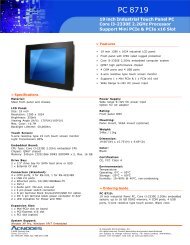
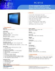
<strong>PC8717</strong>: 17” Industrial Touch Panel PC with<br />
Core i3-2330E 2.2GHz Processor<br />
14628 Central Ave,<br />
Chino, CA 91710<br />
tel:909.597.7588, fax:909.597.1939<br />
© Copyright 2013 Acnodes, Inc.<br />
All rights reserved. Product description and product specifications<br />
are subject to change without notice. For latest product information,<br />
please visit Acnodes’ web site at www.acnodes.com.
Warning!_______________________________<br />
This equipment generates, uses and can radiate radio frequency energy and if not installed and<br />
used in accordance with the instructions manual, it may cause interference to radio<br />
communications.<br />
It has been tested and found to comply with the limits for a Class A computing device pursuant to<br />
FCC Rules, which are designed to provide reasonable protection against such interference when<br />
operated in a commercial environment. Operation of this equipment in a residential area is likely to<br />
cause interference in which case the user at his own expense will be required to take whatever<br />
measures may be required to correct the interference.<br />
Electric Shock Hazard – Do not operate the machine with its back cover removed. There are<br />
dangerous high voltages inside.
Packing List<br />
Accessories (as ticked) included in this package are:<br />
□ AC power cable<br />
□ Driver & manual CD disc<br />
□ Other._<br />
(please specify)<br />
Safety Precautions<br />
Follow the messages below to avoid your systems from damage:<br />
◆ Avoid your system from static electricity on all occasions.<br />
◆ Prevent electric shock. Don’t touch any components of this card when the card is<br />
power-on. Always disconnect power when the system is not in use.<br />
◆ Disconnect power when you change any hardware devices. For instance, when you<br />
connect a jumper or install any cards, a surge of power may damage the electronic<br />
components or the whole system.
Table of Contents<br />
Warning!…………………………………………………………………………….……..….2<br />
Packing List...................................................................................................................3<br />
Safety Precautions........................................................................................................3<br />
Chapter 1<br />
Getting Started<br />
1.1 Specifications………………………………………….………….……...…..7<br />
1.2 Dimensions…………………………………...……………….…………......8<br />
1.3 Brief Description of <strong>PC8717</strong>…………...………………….………………10<br />
Chapter 2<br />
Hardware Installation<br />
2.1 Mainboard Specifications………………………..…………….…………11<br />
2.2 Jumpers Setting and Connectors………………………….……………14<br />
Chapter 3<br />
BIOS Setup<br />
3.1 Operations after POST Screen.............................................................30<br />
3.2 BIOS SETUP UTILITY................................................................30<br />
3.3 System Overview.......................................................................31<br />
3.4 Advanced Settings................................................................... 32<br />
3.5 Chipset Settings................................................................................... 39<br />
3.6 Boot Settings....................................................................................... 48<br />
3.7 Security Settings.................................................................................. 49<br />
3.8 Save & Exit Settings............................................................................ 50<br />
Chapter 4<br />
Installation of Drivers<br />
4.1 Intel Chipset Driver.…………………………...……………………………54<br />
4.2 Intel (R) VGA Chipset Driver..…................…......……………….......…..57
4.3 Intel(R) Network adapter Driver…........…..................................……….62<br />
4.4 Realtek HD Audio Driver Installation………………….…………………66<br />
4.5 Microsoft .NET Framework 3.5 Service.................................................68<br />
Chapter 5<br />
Touch Screen Installation<br />
5.1 Introduction to Touch Screen Controller Board………………………....70<br />
5.2 Windows 2000/XP USB Driver Installation………………….………..….70
Chapter 1<br />
1.1 Specifications<br />
Getting Started<br />
Model No.<br />
Specs PC 8717<br />
System<br />
Processor<br />
System Chipset<br />
System Memory<br />
Storage<br />
External I/O Port<br />
PLP-A717<br />
Support Core i3-2330E 2.2GHz processor<br />
PLP-A719<br />
Intel QM67 PCH<br />
2 x SO-DIMM(204pins) up to 16GB DDRIII 1066/1333MHz FSB<br />
2 x 2.5" SATA HDD space<br />
Onboard<br />
2 x DB9 RS-232 (COM1.2)<br />
1 x DVI-I<br />
1 x HDMI<br />
2 x RJ45 GbE LAN<br />
4 x USB 2.0<br />
1 x Mic-in, Line-Out<br />
1 x DC Power 3 Pin terminal block connector<br />
1 x 2 Pin remote power switch connector<br />
2 x LED indication<br />
--------------------------------------------------------------------------------------------------------<br />
By cable<br />
1 x RS-232 COM4<br />
1 x RS-422/485 default RS-485 COM3<br />
1 x CF slot<br />
1 x Rocker switch for power on/off<br />
1 x 8 Pin terminal block 3 in/out/VCC/Ground for option<br />
Expansion Slots<br />
1 x PCIe x16 or 1 x PCI slot, default 1 x PCIe x16<br />
OS support<br />
Windows XP embedded, Windows embedded standard 7, Windows 7 Pro for<br />
embedded<br />
LCD<br />
Display Type 17”<br />
Max. Resolution<br />
1280X1024<br />
Max. Color 16.7M<br />
Luminance (cd/m2) 350<br />
View Angle 170:160<br />
Backlight Lifetime 50,000 hrs
Touch Screen<br />
Type<br />
Resistive Touch<br />
Light Transmission 80%<br />
Power Supply<br />
Power Input DC 9~32V<br />
Mechanical<br />
Construction<br />
Steel black<br />
IP Rating<br />
Front Panel IP65<br />
Mounting<br />
Panel mount<br />
Dimensions (WxHxD)<br />
17.28” x 13.7” x 4.69”<br />
Environmental<br />
Operating Temperature<br />
Storage Temperature<br />
Storage Humidity<br />
Certificate<br />
0~50 ゚ C<br />
-20~60 ゚ C<br />
10~90% @40 ゚ C non-condensing<br />
CE/FCC Class A
1.2 Dimensions<br />
Figure 1.1 : Dimensions of PC 8717
1.3 Brief Description of PC 8717<br />
The <strong>PC8717</strong> is the fanless and high performance panel-mount industrial panel PC with 17” TFT<br />
LCD. It powered by QM67 chipset and support Core i3-2310M 2.1GHz Processor. The panel PC<br />
has a rich variety of functions and peripherals. It comes with 2 x 2.5-inch hard disk drive and 1 x CF<br />
space for data storage , support DDR3 memory up to 16G, support rich i/O, wide range 9~32V DC<br />
input, and also provide 1 x PCIe x 16 slot, it can ensure simplified connectivity to a variety of external<br />
peripheral devices. The OS supports windows XP embedded, Windows embedded standard 7. The<br />
unit deal for a wide range of applications including digital surveillance, data/image acquisition,<br />
factory automation and industrial applications.<br />
Figure 1.2: Overview of PC 8717
Chapter 2<br />
2.1 Mainboard Specifications<br />
Hardware Installation<br />
Introduction<br />
Figure 2.1: Mainboard Overview
Figure 2.2: Mainboard Dimensions<br />
IPC -M8671 is a Mini-ITX industrial motherboard developed on the basis of Intel QM67,which<br />
provides abundant peripheral interfaces to meet the needs of different customers. Also, it<br />
features dual GbE ports, 6-COM ports and one Mini PCIE configuration. To satisfy the special<br />
needs of high-end customers, ADOtec designed 120Pin PCIe x16 and 40Pin PCIe x1<br />
expansion interface. The product is widely used in various sectors of industrial control.<br />
2.1 Specifications<br />
Specifications<br />
Board Size<br />
CPU Support<br />
Chipset<br />
Memory<br />
Support<br />
170mm x 170mm<br />
Support Socket G2,2nd Gen Intel Core i3/i5/i7 Processor<br />
Intel QM67<br />
2 x SO-DIMM (204pins), up to 8GB DDRIII 800/1066MHz<br />
FSB<br />
Graphics Intel HD Grapics 2000/3000<br />
Super I/O<br />
BIOS<br />
Winbond W83627UHG<br />
AMIBIOS
Storage<br />
Ethernet<br />
USB<br />
Serial<br />
Digital I/O<br />
Battery<br />
Audio<br />
Keyboard<br />
/Mouse<br />
Expansion Bus<br />
Power<br />
Management<br />
Switches and<br />
LED Indicators<br />
4 x SATA Connector<br />
1 x CFAST Slot (option)<br />
2 x PCIe Gbe LAN by Intel 82574L<br />
4 x USB 2.0 stack ports for external<br />
3 x USB 2.0 box Pin header for MIO1<br />
4 x USB 2.0 box Pin header for MIO2<br />
1 x USB 2.0 internal for mini PCIe<br />
1 x RS232/422/485 port, DB9 connector for external (COM1)<br />
pin 9 w/5V/12V/Ring select<br />
1 x RS232 port, DB9 connector for external (COM2)<br />
pin 9 w/5V/12V/Ring select<br />
1 x RS232 header for internal (COM5)<br />
1 x RS232 header for internal (COM6), pin 9 w/5V/12V select<br />
I/O Card TB-522:<br />
1 x 422/485 select header for internal MIO1 (COM3)<br />
1 x RS232 header for internal MIO1 (COM4)<br />
8-bit digital I/O by Pin header by MIO2<br />
4-bit digital Input<br />
4-bit digital Output<br />
Support CR2477 Li battery by 2-pin header<br />
Support CR2032 Li battery (option)<br />
Support Audio via Realtek ALC662 HD audio codec<br />
Support Line-out, MIC by JACK1<br />
Support Line-in, Line-out, MIC by 2x6-pin header<br />
PS2 K/B and Mouse by MIO2<br />
1 x PS/2 keyboard<br />
1 x PS/2 mouse<br />
1 x PCI-express x16 extend by 4x30 pin socket<br />
2 x PCI-express x1 extend by 4x10 pin socket<br />
1 x mini-PCI-express slot<br />
1 x CRT 2x5 Pin Header<br />
1 x 3-pin power input connector (Wide range DC+9V~32V)<br />
1 x ATX Power Input (2x2Pin and 3Pin, option)<br />
DC5V/12V output by 1x4 pin Connectors<br />
Power on/off switch by TB-522 or TB-523<br />
Reset switch by MIO2<br />
Power LED status by MIO2
HDD LED status by MIO2<br />
External I/O<br />
port<br />
Watchdog<br />
Timer<br />
Temperature<br />
Humidity<br />
Power<br />
Consumption<br />
EMI/EMS<br />
2 x COM Ports (COM1/COM2)<br />
4 x USB 2.0 Ports (stack)<br />
2 x RJ45 GbE LAN Ports<br />
1 x DVI-I Port<br />
1 x HDMI Port<br />
1 x Audio Ports (Mic, Line out)<br />
Software programmable 1 – 255 second by Super I/O<br />
Operating: -20℃ to 70℃<br />
Storage: -40℃ to 85℃<br />
10% - 90%, non-condensing, operating<br />
12V/3.80A (Intel i5-2430M 2.4GHz Processor with 4GB<br />
DDR3)<br />
Meet CE/FCC class A<br />
2.2 Jumpers Setting and Connectors<br />
Figure 2.3: Jumpers and Connectors Location-TOP
Figure 2.4: Jumpers and Connectors Location- Bottom<br />
1. RTC1/SRTC1:<br />
(2.0mm Pitch 1X2 Pin Header)CMOS clear jumper, CMOS clear operation will permanently reset old<br />
BIOS settings to factory defaults.<br />
RTC1/SRTC1<br />
Open or<br />
(RTC1Pin1-SRTC1 Pin close)<br />
Close 1-2<br />
CMOS<br />
NORMAL (Default)<br />
Clear CMOS<br />
Procedures of CMOS clear:<br />
a) Turn off the system and unplug the power cord from the power outlet.<br />
b) To clear the CMOS settings, use the jumper cap to close pins1 and 2 for about 3<br />
seconds then reinstall the jumper clip back to pins open.<br />
c) Power on the system again.<br />
d) When entering the POST screen, press the key to enter CMOS Setup<br />
Utility to load optimal defaults.<br />
e) After the above operations, save changes and exit BIOS Setup.<br />
2. BAT1 :<br />
(1.25mm Pitch 1X2 box Pin Header) 3.0V Li battery is embedded to provide power for CMOS.
Pin#<br />
Pin1<br />
Pin2<br />
Signal Name<br />
VBAT<br />
Ground<br />
3. PS_SEL:<br />
(2.0mm Pitch 1X3 Pin Header),ATX Power and AT Power jumper setting.<br />
PS_SEL<br />
Close 1-2<br />
Close 2-3<br />
Mode<br />
ATX Power (Default)<br />
AT Power<br />
4. PS_ON:<br />
(2.0mm Pitch 1X3 Pin Header),ATX Power and Auto Power on jumper setting.<br />
PS_ON<br />
Close 1-2<br />
Close 2-3<br />
Mode<br />
Auto Power on<br />
(Default)<br />
ATX Power<br />
5. DCIN:<br />
(5.08mm Pitch 1x3 Pin Connector),DC9V ~ DC32V System power input connector。<br />
Pin#<br />
Pin1<br />
Pin2<br />
Pin3<br />
Power Input<br />
DC+9V~32V<br />
Ground<br />
FG<br />
6. ATX12V_IN (ATX Power option):<br />
(2x2 Pin Connector),DC12V System power input connector.
Pin#<br />
Pin1<br />
Pin2<br />
Pin3<br />
Pin4<br />
Power input<br />
Ground<br />
Ground<br />
DC+12V<br />
DC+12V<br />
7. ATX (ATX Power option):<br />
(2.0mm Pitch 1X3 box Pin Header), connect PSON and 5VSB and Ground signal,support ATX Power<br />
model. Reserved.<br />
Pin#<br />
Pin1<br />
Pin2<br />
Pin3<br />
Signal Name<br />
ATX PSON<br />
ATX Ground<br />
ATX 5VSB<br />
8. DC_OUT:<br />
(2x2 Pin Connector),DC12V and DC5V System power output connector.<br />
Pin#<br />
Pin1<br />
Pin2<br />
Pin3<br />
Pin4<br />
Power output<br />
DC+12V<br />
Ground<br />
Ground<br />
DC+5V<br />
9. U1:<br />
(Socket G2), installing the 2nd GEN intel Core i3/i5/i7CPU Socket.<br />
10. CPU_FAN1/SYS_FAN1:<br />
(2.54mm Pitch 1x3 Pin Header),Fan connector, cooling fans can be connected directly for use. You<br />
may set the rotation condition of cooling fan in menu of BIOS CMOS Setup.<br />
Pin#<br />
Signal Name
1 Ground<br />
2 VCC<br />
3 Rotation detection<br />
Note:<br />
Output power of cooling fan must be limited under 5W.<br />
11. A-DDR3/B-DDR3:<br />
(SO-DIMM 204Pin socket), DDRIII memory socket, the socket is located at the Top of the board and<br />
supports 204Pin 1.5V DDRIII 1066/1333MHz FSB SO-DIMM memory module up to 16GB.<br />
12. VGA1:<br />
(CRT 2.0mm Pitch 2X5 Pin Header), Video Graphic Array Port, Provide 2x5Pin cable to VGA Port.<br />
Signal Name Pin# Pin# Signal Name<br />
CRT_RED 1 2 Ground<br />
CRT_GREEN 3 4 Ground<br />
CRT_BLUE 5 6 Ground<br />
CRT_H_SYNC 7 8 CRT_DDCDATA<br />
CRT_V_SYNC 9 10 CRT_DDCCLK<br />
13. INVT1:<br />
(2.0mm Pitch 1x6 box Pin Header), Backlight control connector for LVDS1.<br />
Pin# Signal Name<br />
1 +DC12V<br />
2 +DC12V<br />
3 Ground<br />
4 Ground<br />
5 BKLT_EN<br />
6 BKLT_CTRL<br />
Note:<br />
Pin6 is backlight control signal, support DC or PWM mode, mode select at BIOS CMOS menu.
14. LVDS1:<br />
(1.25mm Pitch 2x20 Connector), For 18/24-bit LVDS output connector, Fully supported by Intel<br />
QM67 chipset, the interface features dual channel 18/24-bit output.<br />
Signal Name Pin# Pin# Signal Name<br />
VDD5 2 1 VDD5<br />
Ground 4 3 Ground<br />
VDD33 6 5 VDD33<br />
LB_D0_N 8 7 LA_D0_N<br />
LB_D0_P 10 9 LA_D0_P<br />
Ground 12 11 Ground<br />
LB_D1_N 14 13 LA_D1_N<br />
LA_D1_P 16 15 LA_D1_P<br />
Ground 18 17 Ground<br />
LB_D2_N 20 19 LA_D2_N<br />
LB_D2_P 22 21 LA_D2_P<br />
Ground 24 23 Ground<br />
LB_CLK_N 26 25 LA_CLK_N<br />
LB_CLK_P 28 27 LA_CLK_P<br />
Ground 30 29 Ground<br />
LVDS_DDC_DATA 32 31 LVDS_DOC_CLK<br />
Ground 34 33 Ground<br />
LB_D3_N 36 35 LA_D3_N<br />
LB_D3_P 38 37 LA_D3_P<br />
NC 40 39 NC<br />
15. JP_HDMI:<br />
(2.0mm Pitch 1x2 Pin Header), Reserved.<br />
16. HDMI1:<br />
(HDMI 19P Connector), High Definition Multimedia Interface connector.<br />
17. JP_DVI:<br />
(2.0mm Pitch 1x2 Pin Header), Reserved.<br />
18. DVI-I:<br />
(DVI-I Connector), Digital Visual Interface-Integrated connector.
19. BT1:<br />
POWER on/off Button, They are used to connect power switch button. The two pins are<br />
disconnected under normal condition. You may short them temporarily to realize system<br />
startup & shutdown or awaken the system from sleep state.<br />
20. JP1:<br />
(2.0mm Pitch 2x3 Pin Header),COM1 jumper setting, pin 1~6 are used to select signal out of pin 9<br />
of COM1 port.<br />
JP1 Pin#<br />
Function<br />
Close 1-2 COM1 RI (Ring Indicator) (default)<br />
Close 3-4 COM1 Pin9=+5V (option)<br />
Close 5-6 COM1 Pin9=+12V (option)<br />
21. JP1A:<br />
(2.0mm Pitch 2x10 Pin Header),COM1 jumper setting, it provides selectable RS232 or<br />
RS422 or RS485 serial signal output.<br />
Function<br />
RS232<br />
(Default)<br />
RS422<br />
(option)<br />
RS485<br />
(option)<br />
JP1A Pin#<br />
Close:<br />
Pin1-3, Pin2-4, Pin7-9, Pin8-10, Pin13-14<br />
Close:<br />
Pin3-5, Pin6-8, Pin9-11, Pin10-12, Pin17-18<br />
Close:<br />
Pin3-5, Pin6-8, Pin9-11, Pin10-12, Pin15-16<br />
Pin19-20<br />
22. COM1:<br />
(Type DB9),Rear serial port, standard DB9 Male serial port is provided to make a direct<br />
connection to serial devices.
RS232 (Default):<br />
Pin#<br />
Signal Name<br />
1 DCD# (Data Carrier Detect)<br />
2 RXD (Received Data)<br />
3 TXD (Transmit Data)<br />
4 DTR (Data Terminal Ready)<br />
5 Ground<br />
6 DSR (Data Set Ready)<br />
7 RTS (Request To Send)<br />
8 CTS (Clear To Send)<br />
9 JP1 select Setting (RI/5V/12V)<br />
RS422 (option):<br />
Pin#<br />
1 422_R-<br />
2 422_R+<br />
3 422_T-<br />
4 422_T+<br />
5 Ground<br />
6 NC<br />
7 NC<br />
8 NC<br />
9 NC<br />
Signal Name<br />
RS485 (option):<br />
Pin#<br />
1 NC<br />
2 NC<br />
3 485-<br />
4 485+<br />
5 Ground<br />
6 NC<br />
7 NC<br />
8 NC<br />
9 NC<br />
Signal Name<br />
23. JP2:<br />
(2.0mm Pitch 2x3 Pin Header),COM2 jumper setting, pin 1~6 are used to select signal out of pin 9<br />
of COM2 port.
JP1 Pin#<br />
Function<br />
Close 1-2 COM2 RI (Ring Indicator) (default)<br />
Close 3-4 COM2 Pin9=+5V (option)<br />
Close 5-6 COM2 Pin9=+12V (option)<br />
24. COM2:<br />
(Type DB9),Rear serial port, standard DB9 Male serial port is provided to make a direct<br />
connection to serial devices.<br />
Pin#<br />
Signal Name<br />
1 DCD# (Data Carrier Detect)<br />
2 RXD (Received Data)<br />
3 TXD (Transmit Data)<br />
4 DTR (Data Terminal Ready)<br />
5 Ground<br />
6 DSR (Data Set Ready)<br />
7 RTS (Request To Send)<br />
8 CTS (Clear To Send)<br />
9 JP2 select Setting (RI/5V/12V)<br />
25. COM5:<br />
(2.0mm Pitch 2X5 Pin Header),COM5 Port, standard RS232 ports are provided. They can be used<br />
directly via COM cable connection.<br />
Signal Name Pin# Pin# Signal Name<br />
DCD 1 2 RXD<br />
TXD 3 4 DTR<br />
Ground 5 6 DSR<br />
RTS 7 8 CTS<br />
RI 9 10 NC<br />
26. JP3:<br />
(2.0mm Pitch 1x3 Pin Header) COM6 setting jumper, pin 1~3 are used to select signal out of pin 9<br />
of COM6 port.<br />
JP3 Pin#<br />
Function
Close 1-2 COM6 RI (Ring Indicator) (default)<br />
Close 3-4 COM6 Pin9=+5V (option)<br />
Close 5-6 COM6 Pin9=+12V (option)<br />
27. COM6:<br />
(2.0mm Pitch 2x5 Pin Header), COM6 Port, standard RS232 ports are provided. They can be used<br />
directly via COM cable connection. COM6 port is controlled by pins No.1~3 of JP3,select output<br />
Signal 5V or 12v, For details, please refer to description of JP3.<br />
Signal Name Pin# Pin# Signal Name<br />
DCD 1 2 RXD<br />
TXD 3 4 DTR<br />
Ground 5 6 DSR<br />
RTS 7 8 CTS<br />
JP3select Setting<br />
(RI/5V/12V)<br />
9 10 NC<br />
28. USB_LAN1/USB_LAN2:<br />
USB4/USB5/USB6/USB7:(Double stack USB type A), Rear USB connector, it provides up to 4<br />
USB2.0 ports, speed up to 480Mb/s.<br />
Each USB Type A Receptacle (2 Ports) Current limited value is 1.5A.<br />
If the external USB device current exceeds 1.5A, please separate connectors into different<br />
Receptacle.<br />
LAN1/LAN2: (RJ45 Connector), Rear LAN port, Two standard 10/100/1000M RJ-45 Ethernet ports<br />
are provided. Used Realtek RTL8111D chipset, LINK LED (green) and ACTIVE LED (yellow)<br />
respectively located at the left-hand and right-hand side of the Ethernet port indicate the activity and<br />
transmission state of LAN.
29. JACK1:<br />
(Diameter 3.5mm Double stack Jack), HD Audio port, An onboard Realtek ALC662 codec is used to<br />
provide high quality audio I/O ports. Line Out can be connected to a headphone or amplifier, MIC is<br />
the port for microphone input audio.<br />
30. AUDIO1:<br />
(2.0mm Pitch 2X6 Pin Header), Front Audio, An onboard Realtek ALC662 codec is used to provide<br />
high-quality audio I/O ports. Line Out can be connected to a headphone or amplifier. Line In is used<br />
for the connection of external audio source via a Line in cable. MIC is the port for microphone input<br />
audio.<br />
Signal Name Pin# Pin# Signal Name<br />
SPK_OUTL_P 1 2 SPK_OUTR_P<br />
SPK_OUTL_N 3 4 SPK_OUTR_N<br />
FRONT_JD 5 6 LINE1_JD<br />
LINE_IN_L 7 8 LINE-IN-R<br />
MIC2_IN_L 9 10 MIC2-IN-R<br />
Ground_AUD 11 12 MIC2_JD<br />
31. LED3:<br />
LED STATUS. Green LED for Motherboard Standby Power Good status, Yellow LED for HDD<br />
status.<br />
32. LED2:<br />
LED STATUS. Green LED for Motherboard Standby Power Good status.<br />
33. LED1:<br />
LED STATUS. Green LED for Motherboard Power status,<br />
34. PCIE_16X (option):<br />
(4x30 Pin), Riser Card expansion connector. Can expand support one PCIeX16 or two PCIeX8<br />
Signal.<br />
ASB-M8671T:PCIE_16X connector in the top.<br />
ASB-M8671B:PCIE_16X connector in the Bottom.
35. PCIE1X (option):<br />
(4x10 Pin),Riser Card expansion connector.Can expand support two PCIe Signal.<br />
ASB-M8671T:PCIE1X connector in the top.<br />
ASB-M8671B:PCIE1X connector in the Bottom.<br />
MODEL<br />
ASB-M8671T<br />
ASB-M8671B<br />
PC1E16X / PCIE1X<br />
Top<br />
Bottom<br />
36. M-PCIE1:<br />
(Socket 52Pin),mini PCIe socket, it is located at the top, it supports mini PCIe devices with USB2.0,<br />
SMBUS and PCIe signal. MPCIe card size is 30x30mm or 30x50.95mm.<br />
37. H1/H2:<br />
MPCIE1 SCREW HOLES, H1 for mini PCIE card (30mmx30mm) assemble. H2 for mini PCIE card<br />
(30mmx50.95mm) assemble.<br />
38. BUZZER1:<br />
Onboard buzzer.<br />
39. MIO1:<br />
(DF13-40P Connector),For expand output connector, It provides two RS232 ports or one RS485<br />
port, three USB ports, one power led, one power button, via a dedicated cable connected to<br />
TB-522 MIO1or TB-523 MIO1.<br />
Function Signal Name Pin# Pin# Signal Name Function<br />
COM3<br />
RS422<br />
or<br />
RS485<br />
COM4<br />
USB10<br />
485+ / 422TX+ 2 1 422RX+<br />
485- / 422TX- 4 3 422RX-<br />
3P3V_S0 6 5 Ground<br />
WAN_LED 8 7 NC<br />
5V_S5 10 9 5V_S5<br />
RXD4 12 11 DCD4-<br />
DTR4- 14 13 TXD4<br />
DSR4- 16 15 Ground<br />
CTS4- 18 17 RTS4-<br />
5V_S5 20 19 RI4-<br />
5V_USB_1011 22 21 5V_S5<br />
USB10_N 24 23 USB9_N<br />
USB10_P 26 25 USB9_P<br />
COM3<br />
COM4<br />
USB9
Power<br />
LED<br />
Power<br />
Button<br />
Ground 28 27 Ground<br />
Ground 30 29 Ground<br />
3P3V_S0 32 31 5V_USB_1011<br />
PWR_LED- 34 33 USB11_N<br />
MIO_PSON 36 35 USB11_P<br />
Ground 38 37 Ground<br />
NC 40 39 NC<br />
USB11<br />
40. MIO2:<br />
(DF13-40P Connector),Front panel connector.<br />
Function Signal Name Pin# Pin# Signal Name Function<br />
P_LED+ PWR-LED 2 1 HDD_LED H_LED+<br />
P_LED- Ground 4 3 USB01_OC-<br />
PSON+ MIO_PSON- 6 5 USB23_OC-<br />
PSON- Ground 8 7 RESET RESET+<br />
BUZZER- BUZZER- 10 9 BUZZER+ BUZZER+<br />
GPIO_OUT1 PCH_GPIO68 12 11 PCH_GPIO12 GPIO_IN1<br />
GPIO_OUT2 PCH_GPIO69 14 13 PCH_GPIO15 GPIO_IN2<br />
GPIO_OUT3 PCH_GPIO70 16 15 PCH_GPIO58 GPIO_IN3<br />
GPIO_OUT4 PCH_GPIO71 18 17 PCH_GPIO75 GPIO_IN4<br />
5V_S5_USB 20 19 Ground<br />
PS2_Mouse PS2_MSDATA 22 21 PS2_KBDATA PS2_K/B<br />
PS2_MSCLK 24 23 PS2_KBCLK<br />
5V_S5_USB 26 25 5V_S5_USB<br />
USB3 USB3_N 28 27 USB2_N<br />
USB2<br />
USB3_P 30 29 USB2_P<br />
Ground 32 31 Ground<br />
5V_S5_USB 34 33 5V_S5_USB<br />
USB1 USB1_N 36 35 USB0_N<br />
USB0<br />
USB1_P 38 37 USB0_P<br />
Ground 40 39 Ground<br />
Pin1- Ground: HDD LED, They are used to connect hard disk activity LED. The LED blinks when<br />
the hard disk is reading or writing data.<br />
Pin2- Pin4: POWER LED, They are used to connect power LED. When the system is<br />
powered on or under S0/S1 state, the LED is normally on, when the system is<br />
under S4/S5 state, the LED is off.<br />
Pin3: USB01 OC-, “USB01_OC-“ Signal.<br />
Pin5: USB23 OC-,“USB23_OC-“ Signal.
Pin7- Ground: RESET Button, They are used to connect reset button. The two pins<br />
are disconnected under normal condition. You may short them temporarily to<br />
realize system reset.<br />
Pin6- Pin8: POWER on/off Button, They are used to connect power switch button.<br />
The two pins are disconnected under normal condition. You may short them<br />
temporarily to realize system startup & shutdown or awaken the system from<br />
sleep state.<br />
Pin9- Pin10: BUZZER, They are used to connect an external buzzer.<br />
Pin11~Pin18: GPIO IN/GPIO OUT, General-purpose input/output port, it provides a group of<br />
self-programming interfaces to customers for flexible use.<br />
Pin19~Pin24: PS2 KB/MS, PS/2 keyboard and mouse port, the port can be connected to PS/2<br />
keyboard and mouse via a dedicated cable for direct used.<br />
Pin25~40: USB0/USB1/USB2/USB3, Front USB connector, it provides 4 USB ports via<br />
a dedicated USB cable, speed up to 480Mb/s.<br />
Note:<br />
When connecting LEDs and buzzer and GPIO and USB, pay special attention to the signal polarity.<br />
Make sure that the connector pins have a one-to-one correspondence with chassis wiring, or it<br />
may cause boot up failure.<br />
41. SATA_P1/SATA_P3:<br />
(2.5mm Pitch 1x2 box Pin Header), Two onboard 5V output connectors are reserved to provide<br />
power for SATA devices.<br />
Pin# Signal Name<br />
1 +DC5V<br />
2 Ground<br />
Note:<br />
Output current of the connector must not be above 1A.<br />
42. SATA_P2/SATA_P4:<br />
(2.5mm Pitch 1x4 box Pin Header), Two onboard 5V and 12V output connectors are reserved to<br />
provide power for SATA devices.
Pin# Signal Name<br />
1 +DC5V<br />
2 Ground<br />
3 Ground<br />
4 +DC12V<br />
Note:<br />
Output current of the connector must not be above 1A.<br />
43. SATA1/SATA2/SATA3/SATA4:<br />
(SATA 7P), SATA Connectors, Four SATA connectors are provided,SATA1 and SATA2 transfer<br />
speed up to 6.0Gb/s, SATA3 and SATA4 transfer speed up to 3.0Gb/s,RAID controller supporting<br />
RAID 0/1/5/10.<br />
44. CFAST (option):<br />
(CFAST Card socket), it is located at the bottom of the board and serves as an insert interface for<br />
CFAST card.<br />
45. SIM (option):<br />
(SIM Socket 7Pin), Support SIM Card devices.<br />
46. M_SATA1:<br />
(50.95mmx30mm Socket 52Pin), mSATA socket, it is located at the top, it supports mini PCI-e<br />
devices with LPC bus, B2 mSATA bus for flash disk signal.<br />
47. H3/H4:<br />
M_SATA1 SCREW HOLES,<br />
H3 and H4 for mini MSATA card (50.95mmx30mm Socket 52 Pin) assemble.<br />
48. CPU SCREW HOLES:<br />
CPU FAN SCREW HOLES, Four screw holes for fixed CPU Cooler assemble.<br />
49. TB-525E161:
TB-525E161 connect to ASB-M8671T PCIE_16X connector, PCIE_16X is located at the top,It<br />
provides one PCIE X16 slot.
Chapter 3<br />
BIOS Setup<br />
3.1 Operations after POST Screen<br />
After CMOS discharge or BIOS flashing operation, press [Delete] key to enter CMOS<br />
Setup.<br />
A3<br />
After optimizing and exiting CMOS Setup, the POST screen displayed for the first time is<br />
as follows and includes basic information on BIOS, CPU, memory, and storage devices.<br />
3.2 BIOS SETUP UTILITY<br />
Press [Delete] key to enter BIOS Setup utility during POST, and then a main menu<br />
containing system summary information will appear.<br />
Aptio Setup Utility – Copyright (C) 2010 American Megatrends, Inc.<br />
Main Advanced Chipset Boot Security Save & Exit
BIOS Information<br />
BIOS Vendor<br />
American Megatrends<br />
Choose the system<br />
Default language<br />
Core Version 4.6.4.0<br />
Compliancy UEFI 2.1<br />
Project Version<br />
M8671V01 X64<br />
Build Date and Time 05/21/2012 16:15:28<br />
System Language<br />
[English]<br />
System Date [Sun 07/10/2012]<br />
System Time [00:00:08]<br />
→←: Select Screen<br />
↑↓ : Select Item<br />
Enter: Select<br />
Access Level<br />
Administrator<br />
+/- : Charge Opt. F1<br />
: General Help F2:<br />
Previous Values<br />
F3:Optimized Defaults<br />
F4:Save and Exit<br />
ESC Exit<br />
Version 2.10.1208. Copyright (C) 2010 American Megatrends , Inc.<br />
3.3 System Overview<br />
Main Settings<br />
Aptio Setup Utility – Copyright (C) 2010 American Megatrends, Inc.<br />
Main Advanced Chipset Boot Security Save & Exit<br />
BIOS Information<br />
BIOS Vendor<br />
American Megatrends<br />
Choose the system<br />
Default language<br />
Core Version 4.6.4.0<br />
Compliancy UEFI 2.1<br />
Project Version<br />
M8671V01 X64<br />
Build Date and Time 05/21/2012 16:15:28<br />
System Language<br />
[English]
→←: Select Screen<br />
System Date [Sun 07/10/2012]<br />
↑↓<br />
: Select Item<br />
System Time [00:00:08]<br />
Enter: Select<br />
Access Level<br />
Administrator<br />
+/- : Charge Opt. F1<br />
: General Help F2:<br />
Previous Values<br />
F3:Optimized Defaults<br />
F4:Save and Exit<br />
ESC Exit<br />
Version 2.10.1208. Copyright (C) 2010 American Megatrends , Inc.<br />
System Time:<br />
Set the system time, the time format is:<br />
Hour : 0 to 23<br />
Minute : 0 to 59<br />
Second : 0 to 59<br />
System Date:<br />
Set the system date, the date format is:<br />
Day: Note that the „Day‟ automatically changes when you set the date.<br />
Month: 01 to 12<br />
Date: 01 to 31<br />
Year: 1998 to 2099<br />
3.4 Advanced Settings<br />
Aptio Setup Utility – Copyright (C) 2010 American Megatrends, Inc.<br />
Main Advanced Chipset Boot Security Save & Exit<br />
Legacy OpROM Support<br />
Launch Storage OpROM<br />
Launch Storage OpROM<br />
[Disabled]<br />
[Enabled]<br />
Enable or Disable Boot<br />
Option for Legacy<br />
Network Devices.<br />
►PCI Subsystem Settings<br />
►ACPI Settings<br />
►CPU Configuration<br />
►SATA Configuration<br />
►Thermal Configuration<br />
►PCH-FW Configuration
►USB Configuration<br />
→←: Select Screen<br />
►W83627UHG Super IO Configuration<br />
↑↓<br />
: Select Item<br />
► HW Monitor<br />
►Sandybridge PPM Configuration<br />
Enter: Select<br />
+/- : Charge Opt. F1<br />
: General Help F2:<br />
Previous Values<br />
F3:Optimized Defaults<br />
F4:Save and Exit<br />
ESC Exit<br />
Version 2.10.1208. Copyright (C) 2010 American Megatrends , Inc.<br />
3.4.1 PCI Subsystem Settings<br />
PCI Bus Driver Versio V2.03.00<br />
PCI ROM Priority:<br />
[EFI Compatible ROM]<br />
[Legacy ROM]<br />
PCI Common Settings:<br />
PCI Latency Timer:<br />
[32 PCI Bus Clocks]<br />
[64 PCI Bus Clocks]<br />
[96 PCI Bus Clocks]<br />
[128 PCI Bus Clocks]<br />
[160 PCI Bus Clocks]<br />
[192 PCI Bus Clocks]<br />
[224 PCI Bus Clocks]<br />
[248 PCI Bus Clocks]<br />
VGA Palette Snoop:<br />
[Disabled]<br />
[Enabled]<br />
PERR# Generation:<br />
[Disabled]<br />
[Enabled]<br />
SERR# Generation:<br />
[Disabled]<br />
[Enabled]<br />
PCI Express Device Settings:<br />
Relaxed Ordering:
[Disabled]<br />
[Enabled]<br />
Extended Tag:<br />
[Disabled]<br />
[Enabled]<br />
No Snoop:<br />
[Enabled]<br />
[Disabled]<br />
Maximum Payload:<br />
[Auto]<br />
[128 Bytes]<br />
[256 Bytes]<br />
[512 Bytes]<br />
[1024 Bytes]<br />
[2048 Bytes]<br />
[4096 Bytes]<br />
Maximum Read Request:<br />
[Auto]<br />
[128 Bytes]<br />
[256 Bytes]<br />
[512 Bytes]<br />
[1024 Bytes]<br />
[2048 Bytes]<br />
[4096 Bytes]<br />
PCI Express Link Settings:<br />
ASPM Support:<br />
[Disabled]<br />
[Enabled]<br />
WARNING:Ebabling ASPM may cause some<br />
PCI-E devices to fail<br />
Extended Synch:<br />
[Disabled]<br />
[Enabled]<br />
3.4.2 ACPI Settings<br />
Enable ACPI Auto Configuration:<br />
[Disabled]<br />
[Enabled]<br />
Enable Hibernation:<br />
[Enabled]
[Disabled]<br />
ACPI Sleep State:<br />
[S3 (Suspend to RAM)]<br />
[Suspend Disabled]<br />
[S3 (Suspend to RAM)]<br />
Lock Legacy Resources:<br />
[Disabled]<br />
[Enabled]<br />
3.4.3 CPU Configuration<br />
Socket 0 CPU Information:<br />
Intel(R) Core(TM) i5-2430M CPU @2.40GHz<br />
CPU Signature 206a7<br />
Microcode Patch 25<br />
Max CPU Speed 2400 MHz<br />
Min CPU Speed 800 Mhz<br />
Processor Cores 2<br />
Intel HT Technology Supported<br />
Intel VT-x Technology Supported<br />
L1 Data Cache 32 KB x 2<br />
L1 Code Cache 32 KB x 2<br />
L2 Cache 256 KB x 2<br />
L3 Cache<br />
3072 KB<br />
CPU Speed<br />
64-bit<br />
Hyper-Threading:<br />
2400 MHz<br />
Supported<br />
[Enabled]<br />
[Disabled]<br />
Active Processor Cores<br />
[All]<br />
[1]<br />
Limit CPUID Maximum:<br />
[Disabled]<br />
[Enabled]<br />
Execute Disable Bit:<br />
[Enabled]
Hardware Prefetcher<br />
[Disabled]<br />
[Enabled]<br />
[Disabled]<br />
Adjacent Cache Line Prefetch<br />
[Enabled]<br />
[Disabled]<br />
Intel Virtualization Technology<br />
[Enabled]<br />
[Disabled]<br />
3.4.4 SATA Configuration<br />
SATA Controller(S):<br />
[Enabled]<br />
[Disabled]<br />
SATA Mode Selection:<br />
[IDE]<br />
[AHCI]<br />
[RAID]<br />
SATA Test Mode:<br />
[Disabled]<br />
[Enabled]<br />
Serial ATA Port 0<br />
Software Preserve<br />
Empty<br />
Unknown<br />
Serial ATA Port 1<br />
Software Preserve<br />
Empty<br />
Unknown<br />
Serial ATA Port 2<br />
Software Preserve<br />
Empty<br />
Unknown<br />
Serial ATA Port 3<br />
Software Preserve<br />
Empty<br />
Unknown<br />
Serial ATA Port 4<br />
Software Preserve<br />
Empty<br />
Unknown
Serial ATA Port 5<br />
Software Preserve<br />
Empty<br />
Unknown<br />
3.4.5 Thermal Configuration<br />
Platform Thermal Configuration<br />
3.4.6 PCH-FW Configuration<br />
ME FW Version 0.0.0.0<br />
ME Firmware Mode<br />
ME Firmware Type Full Sku Firmware<br />
ME Firmware SKU Unidentified<br />
ME Firmware Update Configuration<br />
ME FW Image Re-Flash<br />
[Disabled]<br />
[Enabled]<br />
3.4.7 USB Configuration<br />
USB Configuration<br />
USB Devices:<br />
1 keyboard, 2 Hubs<br />
Legacy USB Support:<br />
[Enabled]<br />
[Disabled]<br />
EHCI Hand-off:<br />
[Disabled]<br />
[Enabled]<br />
Port 60/64 Emulation<br />
[Enabled]<br />
[Disabled]<br />
USB hardware delays and time-outs:<br />
USB transfer time-out:<br />
[20 sec]<br />
[10 sec]<br />
[5 sec]<br />
[1 sec]<br />
Device reset time-out:<br />
[20 sec]<br />
[10 sec]
Device power-up delay<br />
[30 sec]<br />
[40 sec]<br />
[Auto]<br />
[<strong>Manual</strong>]<br />
3.4.8 W83627UHG Super IO Configuration<br />
W83627UHG Super IO Configuration<br />
Super IO Chip Winbond W83627UHG<br />
COM1 Configuration<br />
COM2 Configuration<br />
COM3 Configuration<br />
COM4 Configuration<br />
COM5 Configuration<br />
COM6 Configuration<br />
3.4.9 HW Monitor<br />
PC Health Status<br />
System temperature<br />
: +48 C<br />
CPU temperature : +52<br />
CPU Fan Speed : 6000 RPM<br />
VCORE<br />
: +1.145V<br />
+12V : +11.685 V<br />
+3.3V<br />
+1.5V<br />
5VSB<br />
VBAT<br />
: +3.280 V<br />
: +1.520 V<br />
: +5.010 V<br />
: +3.136 V<br />
3.4.10 Sandybridge PPM Configuration<br />
Sandybridge PPM Configuration<br />
EIST<br />
Turbo Mode<br />
CPU C3 Report<br />
[Enabled]<br />
[Disabled]<br />
[Enabled]<br />
[Disabled]<br />
[Enabled]<br />
[Disabled]
CPU C6 report<br />
CPU C7 report<br />
[Enabled]<br />
[Disabled]<br />
[Enabled]<br />
[Disabled]<br />
Long duration power limit 0<br />
Long duration maintained 28<br />
Short duration power limit 0<br />
TCC active offset 0<br />
3.5 Chipset Settings<br />
Aptio Setup Utility – Copyright (C) 2010 American Megatrends, Inc.<br />
Main Advanced Chipset Boot Security Save & Exit<br />
System Agent (SA)<br />
►System Agent (SA) Configuration<br />
►PCH-IO Configuration<br />
Parameters<br />
→←: Select Screen<br />
↑↓<br />
: Select Item<br />
Enter: Select<br />
+/- : Charge Opt. F1<br />
: General Help F2:<br />
Previous Values<br />
F3:Optimized Defaults<br />
F4:Save and Exit<br />
ESC Exit<br />
Version 2.10.1208. Copyright (C) 2010 American Megatrends , Inc.<br />
3.5.1 ► System Agent (SA) Configuration<br />
►PCH-IO Configuration<br />
System Agent (SA) Configuration<br />
System Agent RC Version 1.2.1.0
VT-d Capability<br />
CHAP Device (B0:D7:F0)<br />
Thermal Device (B0:D4:F0)<br />
Enable NB CRID<br />
Unsupported<br />
[Enabled]<br />
[Disabled]<br />
[Disabled]<br />
[Enabled]<br />
[Disabled]<br />
[Enabled]<br />
►Graphics Configuration<br />
IGFX VBIOS Version 2120<br />
IGFX Frequency<br />
650 MHz<br />
Graphics Turbo IMON Current 31<br />
Primary Display<br />
[Auto]<br />
[IGFX]<br />
[PEG]<br />
[PCI]<br />
Internal Graphics<br />
[Auto]<br />
[Disabled]<br />
[Enabled]<br />
GTT Size<br />
[2MB]<br />
[1MB]<br />
Aperture Size<br />
[256MB]<br />
[128MB]<br />
[512MB]<br />
DVMT Pre-allocated<br />
[64MB]<br />
[0MB]<br />
[32MB]<br />
[96MB]<br />
[128MB]<br />
[160MB]<br />
[192MB]<br />
[224MB]<br />
[256MB]
Dvmt Total Gfx Mem<br />
GFX Low Power Mode<br />
[288MB]<br />
[320MB]<br />
[352MB]<br />
[384MB]<br />
[416MB]<br />
[448MB]<br />
[480MB]<br />
[512MB]<br />
[256MB]<br />
[128MB]<br />
[MAX]<br />
[Enabled]<br />
[Disabled]<br />
LCD Control:<br />
Primary IGFX Boot Display<br />
[VBIOS Default]<br />
[CRT]<br />
[DVI]<br />
[LVDS]<br />
HDMI]<br />
LCD Panel Type<br />
[1024 X 768 LVDS1]<br />
[640 X 480 LVDS ]<br />
[800 X 600 LVDS]<br />
[1280 X 1024 LVDS]<br />
[1400X1050(RB) LVDS1]<br />
[1400X1050 LVDS2]<br />
[1600 X 1200 LVDS]<br />
[1366 X 768 LVDS]<br />
[1680 X 1050 LVDS]<br />
[1920 X 1200 LVDS]<br />
[1440 X 900 LVDS]<br />
[1600 X 900 LVDS]<br />
[1024 X 768 LVDS2]<br />
[1280 X 800 LVDS]<br />
[1920 X 1080 LVDS]<br />
[2048 X 1536 LVDS]
SDVD-LFP Panel Type<br />
Panel Scaling<br />
Backlight Control<br />
[VBIOS Default]<br />
[1024 x 768 SDVO-LFP ]<br />
[1080 x1024 SDVO-LFP ]<br />
[1400 x 1050 SDVO-LFP ]<br />
[1600 x 1200 SDVO-LFP ]<br />
[Auto ]<br />
[Off ]<br />
[Force Scaling ]<br />
[PWM Inverted ]<br />
[PWM Normal ]<br />
[GMBus Inverted ]<br />
[GMBus Normal ]<br />
BIA<br />
[Auto ]<br />
[Disabled ]<br />
[Level 1 ]<br />
[Level 2 ]<br />
[Level 3 ]<br />
[Level 4 ]<br />
[Level 5 ]<br />
Spread Spectrum clock chip<br />
[Off ]<br />
[Hardware ]<br />
[Software ]<br />
TV1 Standard<br />
[VBIOS Default]<br />
[NTSC_M]<br />
[NTSC_M_J]<br />
[NTSC_433]<br />
[PAL_B]<br />
[PAL_G]<br />
[PAL_D]<br />
[PAL_H]<br />
[PAL_I]<br />
[PAL_M]<br />
[PAL_N]<br />
[SECAM_L]
]<br />
]<br />
TV2 Standard<br />
[SECAM_B]<br />
[SECAM_D]<br />
[SECAM_G]<br />
[SECAM_H]<br />
[SECAM_K]<br />
[HDTV_STD_SMPTE_240M_1080i59]<br />
[HDTV_STD_SMPTE_240M_1080i60]<br />
[HDTV_STD_SMPTE_295M_1080i50]<br />
[HDTV_STD_SMPTE_295M_1080p50]<br />
[HDTV_STD_SMPTE_296M_720p50]<br />
[HDTV_STD_SMPTE_296M_720p60]<br />
[HDTV_STD_CEAEIA_7702A_480p60<br />
[HDTV_STD_CEAEIA_7702A_480i60]<br />
[VBIOS Default]<br />
[NTSC_M]<br />
[NTSC_M_J]<br />
[NTSC_433]<br />
[PAL_B]<br />
[PAL_G]<br />
[PAL_D]<br />
[PAL_H]<br />
[PAL_I]<br />
[PAL_M]<br />
[PAL_N]<br />
[SECAM_L]<br />
[SECAM_B]<br />
[SECAM_D]<br />
[SECAM_G]<br />
[SECAM_H]<br />
[SECAM_K]<br />
[HDTV_STD_SMPTE_240M_1080i59]<br />
[HDTV_STD_SMPTE_240M_1080i60]<br />
[HDTV_STD_SMPTE_295M_1080i50]<br />
[HDTV_STD_SMPTE_295M_1080p50]<br />
[HDTV_STD_SMPTE_296M_720p50]<br />
[HDTV_STD_SMPTE_296M_720p60]<br />
[HDTV_STD_CEAEIA_7702A_480p60<br />
[HDTV_STD_CEAEIA_7702A_480i60]
ALS Support<br />
Active LFP<br />
Panel Color Depth<br />
[Disabled]<br />
[Enabled]<br />
[Int-LVDS]<br />
[No-LVDS]<br />
[SDVO LVDS]<br />
[eDP Port-A]<br />
[eDP Port-D]<br />
[18 Bit]<br />
[24 Bit]<br />
►DMI Configuration<br />
►NB PCIe Configuration<br />
PEG0<br />
PEG0 – Gen X<br />
[Not Present]<br />
[Auto]<br />
[Gen1]<br />
[Gen2]<br />
PEG1<br />
PEG1 – Gen X<br />
[Not Present]<br />
[Auto]<br />
[Gen1]<br />
[Gen2]<br />
PEG2<br />
PEG2 – Gen X<br />
[Not Present]<br />
[Auto]<br />
[Gen1]<br />
[Gen2]<br />
PEG3<br />
PEG3 – Gen X<br />
[Not Present]<br />
[Auto]<br />
[Gen1]<br />
[Gen2]<br />
Always Enable PEG<br />
[Disabled]<br />
[Enabled]<br />
PEG ASPM<br />
[Disabled]
[Auto]<br />
[ASPM LOs]<br />
[ASPM L1]<br />
[ASPM LOsL1]<br />
ASPM LOs<br />
[Root Port Only]<br />
[Endpoint Port Only]<br />
[Both Root and Endpoint Ports]<br />
De-emphasis Control<br />
[-3.5 dB]<br />
[-6 dB]<br />
►Memory Configuration<br />
Memory RC Version 1.2.10<br />
Memory Frequency<br />
1333 Mhz<br />
Total Memory<br />
2048 MB (DDR3)<br />
DIMM#0<br />
2048 MB (DDR3)<br />
DIMM#1<br />
Not Present<br />
DIMM#2<br />
Not Present<br />
DIMM#3<br />
Not Present<br />
CAS Latency (tCL) 9<br />
Minimum delay time<br />
CAS to RAS (tRPmin) 9<br />
Row Precharge (tRPmin) 9<br />
Active to Precharge (tRPmin) 24<br />
DIMM profile<br />
[Default DIMM profile]<br />
[XMP profile 1]<br />
[XMP profile 2]<br />
Memory Frofile<br />
ECC Support<br />
[Auto]<br />
[1067]<br />
[1333]<br />
[1600]<br />
[1867]<br />
[2133]<br />
[Enabled]
Max TOLUD<br />
NMode Support<br />
Memory Scrambler<br />
RMT Crosser Support<br />
Memory Scrambler<br />
MRC Fast Boot<br />
Force Cold Reset<br />
Scrambler Seed Generation off<br />
Memory Remap<br />
Channel A DIMM Control<br />
[Disabled]<br />
[Dynamic]<br />
[1GB]<br />
[1.25GB]<br />
[1.5GB]<br />
[1.75GB]<br />
[2GB]<br />
[2.25GB]<br />
[2.5GB]<br />
[2.75GB]<br />
[3GB]<br />
[3.25GB]<br />
[Auto]<br />
[1N Mode]<br />
[2N Mode]<br />
[Enabled]<br />
[Disabled]<br />
[Disabled]<br />
[Enabled]<br />
[Enabled]<br />
[Disabled]<br />
[Enabled]<br />
[Disabled]<br />
[Disabled]<br />
[Enabled]<br />
[Enabled]<br />
[Disabled]<br />
[Enabled Both DIMMS]<br />
[Disabled DIMM0]<br />
[Disabled DIMM1]<br />
[Disabled Both DIMMS]
►Memory Thermal Configuration<br />
Memory Thermal Management<br />
PECI Injecred Temperature<br />
EXTTS# via TS-on-Board<br />
EXTTS# via TS-on-DIMM<br />
Virtual Temperature Sensor (VTS)<br />
[Enabled]<br />
[Disabled]<br />
[Disabled]<br />
[Enabled]<br />
[Disabled]<br />
[Enabled]<br />
[Disabled]<br />
[Enabled]<br />
[Disabled]<br />
[Enabled]<br />
►GT-Power Management Control<br />
GT Info<br />
RC6 (Render Standby)<br />
GT overClocking Support<br />
GT2 (0X116)<br />
[Enabled]<br />
[Disabled]<br />
[Disabled]<br />
[Enabled]
3.6 Boot Settings<br />
Aptio Setup Utility – Copyright (C) 2010 American Megatrends, Inc.<br />
Main Advanced Chipset Boot Security Save & Exit<br />
Boot Configuration<br />
Setup Prompt Timeout 1<br />
Number of seconds to<br />
Wait for setup<br />
Bootup Numlock State<br />
Quiet Boot<br />
Fast Boot<br />
Skip VGA<br />
Skip USB<br />
Skip PS2<br />
[On]<br />
[Disabled]<br />
[Enabled]<br />
[Disabled]<br />
[Disabled]<br />
[Disabled]<br />
Activation key.<br />
65535(0xFFFF)means<br />
Indef inite waiting.<br />
CSM16 Module Version 07.68<br />
Gatea20 Active<br />
Option ROM Messages<br />
Interrupt 19 Capture<br />
CSM Support<br />
Boot Option Priorities<br />
Boot Option #1<br />
Hard Drive BBS Priorities<br />
[Upon Request]<br />
[Force BIOS]<br />
[Enabled]<br />
[Enabled]<br />
[SATA PM: Hitachi…]<br />
→←: Select Screen<br />
↑↓ : Select Item<br />
Enter: Select<br />
+/- : Charge Opt. F1<br />
: General Help F2:<br />
Previous Values<br />
F3:Optimized Defaults<br />
F4:Save and Exit<br />
ESC Exit<br />
Version 2.10.1208. Copyright (C) 2010 American Megatrends , Inc.<br />
Setup Prompt Timeout [1]<br />
Bootup Numlock State<br />
[On]<br />
[off]<br />
Quiet Boot<br />
[Enabled]<br />
[Disabled]<br />
CSM16 Module Verison 07.64<br />
Gatea20 Active
Option ROM Messages<br />
Interrupt 19 Capture<br />
[Upon Request]<br />
[Always]<br />
[Force BIOS]<br />
[Keep Current]<br />
[Disabled]<br />
[Enabled]<br />
Boot Override<br />
SATA PM: ST9320423AS<br />
……<br />
Launch EFI Shell from filesystem device<br />
3.7 Security Settings<br />
Aptio Setup Utility – Copyright (C) 2010 American Megatrends, Inc.<br />
Main Advanced Chipset Boot Security Save & Exit<br />
Password Description<br />
Set Administrator<br />
Password<br />
If ONLY the Administrator‟s password is set,<br />
Then this only limits access to Setup and is<br />
Only asked for when entering Setup.<br />
If ONLY the <strong>User</strong>‟s password is set, then this<br />
Is a power on password and must be entered to<br />
Is a power on password and must be entered to<br />
Boot or enter Setup. In Setup the <strong>User</strong> will<br />
Have Administrator rights.<br />
→←: Select Screen<br />
The password length must be 3 to 20 Characters long.<br />
↑↓<br />
: Select Item<br />
Enter: Select<br />
Administrator Password<br />
<strong>User</strong> Password<br />
+/- : Charge Opt. F1<br />
: General Help F2:<br />
Previous Values<br />
F3:Optimized Defaults<br />
F4:Save and Exit<br />
ESC Exit<br />
Version 2.10.1208. Copyright (C) 2010 American Megatrends , Inc.<br />
3.7.1 Administrator Password
3.7.2 <strong>User</strong> Password<br />
Type the password with up to 20 characters and then press Enter‣ key. This will<br />
clear all previously typed CMOS passwords. You will be requested to confirm the<br />
password. Type the password again and press Enter‣ key. You may press Esc‣<br />
key to abandon password entry operation.<br />
To clear the password, just press Enter‣ key when password input window pops up.<br />
A confirmation message will be shown on the screen as to whether the password will<br />
be disabled. You will have direct access to BIOS setup without typing any password<br />
after system reboot once the password is disabled.<br />
Once the password feature is used, you will be requested to type the password each<br />
time you enter BIOS setup. This will prevent unauthorized persons from changing<br />
your system configurations.<br />
Also, the feature is capable of requesting users to enter the password prior to system<br />
boot to control unauthorized access to your computer. <strong>User</strong>s may enable the feature<br />
in Security Option of Advanced BIOS Features. If Security Option is set to System,<br />
you will be requested to enter the password before system boot and when entering<br />
BIOS setup; if Security Option is set to Setup, you will be requested for password for<br />
entering BIOS setup.<br />
3.8 Save & Exit Settings<br />
Aptio Setup Utility – Copyright (C) 2010 American Megatrends, Inc.<br />
Main Advanced Chipset Boot Security Save & Exit<br />
Save Changes and Exit<br />
Discard Changes and Exit<br />
Exit system setup after<br />
Saving the changes.<br />
Save Changes and Reset<br />
Discard Changes and Reset<br />
Save Options<br />
Save Changes<br />
Discard Changes
Restore Defaults<br />
→←: Select Screen<br />
Save user Defaults<br />
↑↓<br />
: Select Item<br />
Restore user Defaults<br />
Enter: Select<br />
+/- : Charge Opt. F1<br />
Boot Override<br />
SATA PM:*** …<br />
Launch EFI Shell from filesystem device<br />
: General Help F2:<br />
Previous Values<br />
F3:Optimized Defaults<br />
F4:Save and Exit<br />
ESC Exit<br />
Version 2.10.1208. Copyright (C) 2010 American Megatrends , Inc.<br />
Save Changes and Exit<br />
Save & Exit Setup save Configuration and exit ?<br />
[Yes]<br />
[No]<br />
Discard Changes and Ext<br />
Exit Without Saving Quit without saving?<br />
[Yes]<br />
[No]<br />
Save Changes and Reset<br />
Save & reset Save Configuration and reset?<br />
[Yes]<br />
[No]<br />
Discard Changes and Reset<br />
Reset Without Saving Reset without saving?<br />
[Yes]<br />
[No]<br />
Save Changes<br />
Save Setup Values Save configuration?<br />
[Yes]<br />
[No]<br />
Discard Changes<br />
Load Previous Values Load Previous Values?<br />
[Yes]<br />
[No]<br />
Restore Defaults<br />
Load Optimized Defaults Load optimized Defaults?<br />
[Yes]<br />
[No]<br />
Save user Defaults<br />
Save Values as <strong>User</strong> Defaults Save configuration?
[Yes]<br />
[No]<br />
Restore user Defaults<br />
Restore <strong>User</strong> Defaults Restore <strong>User</strong> Defaults?<br />
[Yes]<br />
[No]<br />
Launch EFI Shell from filesystem device<br />
WARNING Not Found<br />
[ok]
Chapter 4<br />
Installation of Drivers<br />
This chapter describes the installation procedures for software and drivers under the windows XP. The<br />
software and drivers are included with the motherboard. The contents include Intel QM67 Chipset<br />
Driver, Intel (R) VGA Chipset Driver, Intel (R) Network Adapter, Realtek ALC662 Audio Codec<br />
Driver, Microsoft .NET Framework 3.5 Service, Touch Panel Driver.<br />
Installation instructions are given below.<br />
Important Note:<br />
After installing your Windows operating system (Windows XP), you must install<br />
first the Intel Chipset Software Installation Utility before proceeding with the<br />
installation of drivers.<br />
I
4.1 Intel Chipset Driver<br />
To install the Intel chipset driver, please follow the steps below.<br />
Step 1. Access Industrial Panel PC. Select Intel QM67 Chipset Driver.<br />
Step 2. Click Next to setup program.
Step 3. Read the license agreement. Click Yes to accept the terms of the license agreement.<br />
Step 4. Click Next to continue.
Step 5. Click Next.<br />
Step 6. Select Yes, I want to restart this computer now. Click Finish then remove any installation<br />
media from the drives.
4.2 Intel (R) VGA Chipset Driver<br />
To install the VGA drivers, follow the steps below to proceed with the installation.<br />
Step 1. Select Intel(R) VGA Chipset Driver.<br />
Step 2. Click Yes to continue.
Step 3. Click Next to continue setup program.<br />
Step 4. Read the license agreement. Click Yes to accept the license agreement.
Step 5. Click Next.<br />
Step 6. Click Continue Anyway.
Step 7. Click Continue Anyway.<br />
Step 8. Click Next.
Step 9. Select Yes, I want to restart this computer now. Click Finish.
4.3 Intel(R) Network Adapter Driver<br />
To install the Intel 82574L Network adapter Driver, please follow the steps below.<br />
Step 1. Select Intel(R) Network Adapter.<br />
Step 1. Wait for extracting the files then click Next to continue.<br />
Step 2. Click Next.
Step 3. Read the license agreement. Select I accept the terms in the license agreement then click<br />
Next to continue.<br />
Step 4. Select Drivers, Intel(R) PROSet for Windows* Device Manager, Advanced Network
Services. Click Next to continue.<br />
Step 5. Click Install to begin the installation.<br />
Step 6. Click Finish to compete the installation.
4.4 Realtek HD Audio Driver Installation<br />
To install the Realtek High Definition (HD) Audio driver, please follow the steps below.<br />
Step 1. Select Realtek ALC662 HD Audio Codec Driver from the list.<br />
Step 2. Wait for extracting the files then click Next to continue.
Step 3. Click Next to continue the installation.<br />
Step 4. Select Yes, I want to restart my computer now. then click Finish.
4.5 Microsoft .NET Framework 3.5 Service<br />
To install the Realtek High Definition (HD) Audio driver, please follow the steps below.<br />
Step 1. Select Microsoft .NET Framework 3.5 Service.<br />
Step 2. Select I have read and ACCEPT the terms of the License Agreement. Click Install.<br />
Step 2. Wait for installation.
Step 3. Click Exit to complete the installation.
Chapter 5<br />
Touch Screen Installation<br />
This chapter describes how to install drivers and other software that will allow your PenMount 6000<br />
Controller Board to work with different operating systems.<br />
NOTE: PenMount USB drivers support up to 15 USB controllers.<br />
5.1 Introduction to Touch Screen Controller Board<br />
PenMount 6300 USB control board is a touch screen control board designed for USB interface and<br />
specific for 4, 5, 8-wire touch screens. It is designed with USB interface features with multiple devices<br />
supporting function. PenMount 6300 control board using PenMount 6000 controller that has been<br />
designed for those who may like and all-in-one solution with 10-bit A/D converter built-in to make the<br />
total printed circuit board denser, circuit diagram also designed for 12-bit ADC for optional. There are<br />
two connectors on this board, one connector is for 4, 5, 8-wire touch screen cable (optional), and<br />
another is for 4-pin USB A type cable (optional).<br />
Figure 5.1: Bird’s Eye View of Control Board<br />
5.2 Windows 2000/XP/2003/Vista Universal Driver Installation<br />
for PenMount 6000 Series<br />
Before installing the Windows 2000/XP driver software, you must have the Windows 2000/XP system<br />
installed and running on your computer. You must also have one of the following PenMount 6000<br />
series controller or control boards installed: PM6500, PM6300.<br />
5.2.1 Installing Software<br />
If you have an older version of the PenMount Windows 2000/XP driver installed in your system, please<br />
remove it first. Follow the steps below to install the PenMount DMC6000 Windows 2000/XP driver.
Step 1. Please make sure your PenMount 6000 device had plugged in advance. If your device uses<br />
RS232 interface, please plugged in before the machine is turned on. When the system first detects the<br />
controller board, a screen appears that shows “Unknown Device”. Do not use this hardware wizard.<br />
Press Cancel.<br />
Step 2. Insert the Aplex product CD install setup.exe. the screen below would appear. Se touch panel<br />
driver<br />
Step 3. Click Next to continue.
Step 4. Read the license Agreement. Click I agree to agree the license agreement.<br />
Step 5. Choose the folder in which to install PenMount Windows Universal Driver. Click Install to<br />
start the installation.
Step 6. Wait for installation. Then click Next to continue.<br />
Step 7. Click OK.
Step 8. Click Finish to compete installation.
5.2.2 Software Functions<br />
Upon rebooting, the computer automatically finds the new 6000 controller board. The touch screen is<br />
connected but not calibrated. Follow the procedures below to carry out calibration.<br />
1. After installation, click the PenMount Monitor icon “PM” in the menu bar.<br />
2. When the PenMount Control Panel appears, select a device to “Calibrate.”<br />
PenMount Control Panel<br />
The functions of the PenMount Control Panel are Device, Multiple Monitors, Tools and About,<br />
which are explained in the following sections.<br />
Device<br />
In this window, you can find out that how many devices are detected on your system.<br />
Calibrate<br />
This function offers two ways to calibrate your touch screen. „Standard Calibration‟ adjusts most touch<br />
screens. „Advanced Calibration‟ adjusts aging touch screens.<br />
Standard Calibration<br />
Click this button and arrows appear<br />
pointing to red squares. Use your finger or<br />
stylus to touch the red squares in<br />
sequence. After the fifth red point<br />
calibration is complete. To skip, press<br />
‘ESC’.
Advanced Calibration Advanced Calibration uses 4, 9, 16 or 25<br />
points to effectively calibrate touch panel<br />
linearity of aged touch screens. Click this<br />
button and touch the red squares in<br />
sequence with a stylus. To skip, press<br />
ESC’.<br />
Command Calibration<br />
Command call calibration function. Use<br />
command mode call calibration function,<br />
this can uses Standard, 4, 9, 16 or 25<br />
points to calibrate E.g. Please run ms-dos<br />
prompt or command prompt c:\Program<br />
Files\PenMount Universa Driver\Dmcctrl.exe<br />
-calibration 0 ( Standard Calibration)<br />
Dmcctrl.exe - calibration ($) 0= Standard<br />
Calibration 4=Advanced Calibration 4<br />
9=Advanced Calibration 9 16=Advanced<br />
Calibration 16 25=Advanced Calibration 25<br />
Step 1. Please select a device then click Configure. You can also double click the device too.
Step 2. Click Standard Calibration to start calibration procedure<br />
NOTE: The older the touch screen, the more Advanced Mode calibration points you need for an<br />
accurate calibration. Use a stylus during Advanced Calibration for greater accuracy. Please follow the<br />
step as below:
Step 3. Come back to PenMount Control Panel and select Tools then Click Advanced<br />
Calibration.<br />
Step 4. Select Device to calibrate, then you can start to do “Advanced Calibration”.<br />
NOTE: Recommend to use a stylus during Advanced Calibration for greater accuracy.
Setting
About<br />
This panel displays information about the PenMount controller and driver version.
Multiple Monitors<br />
Multiple Monitors supports two to six touchscreen displays for one system. PenMount<br />
drivers for Windows 2000, XP 32/64bit, and 2003 support Multiple Monitors. This<br />
function supports from two to six touchscreen displays for one system. Each monitor<br />
requires its own PenMount touchscreen control board, either installed inside the displayor<br />
in a central unit. The PenMount control boards must be connected to the computer COM<br />
ports via the RS-232 interface. Driver installation procedures are the same as for a single<br />
monitor. Multiple Monitors supports the following modes:<br />
Windows Extends Monitor Function<br />
Matrox DualHead Multi-Screen Function<br />
nVidia nView Function<br />
NOTE:<br />
The Multiple Monitor function is for use with multiple displays only. Do not use this<br />
function if you have only one touch screen display. Please note once you turn on this<br />
function the rotating function is disabled.<br />
Requirements<br />
Before using the Multiple Monitors function you need the following:<br />
* A display card that supports multiple monitors such as the Matrox, nVidia, ATI, etc.<br />
* (Two or more display cards supported by Windows are also ok.)<br />
* Two or more touchscreens<br />
* Two or more Serial Ports or USB ports.<br />
* Two or more PenMount 6000 control boards such as 6200x, 6202x,6300 or 6500.<br />
* The PenMount Windows Universal Driver (for 2000/XP/2003/VISTA/7).<br />
Before using Multiple Monitors you must have two or more monitors that are in extension<br />
mode. For display cards that support multiple monitors, we suggest you consider Matrox,<br />
nVidia, or ATI cards and inquire about operation and usability issues.<br />
Note: Before you can use multiple monitors you need to map each monitor.<br />
Enable the multiple display function as follows:<br />
Step 1.In PenMount Control Panel, under Multiple Monitors tag, check the “Multiple<br />
Monitor Support” box. Then click “Map Touchscreens” to assign touch controllers to<br />
displays.
Step 2. When the mapping screen message appears, click OK.
Step 3. Touch each screen as it displays Please touch this monitor. Press ‘S’ to skip<br />
Following this sequence and touching each screen is called mapping the touch screens.<br />
Step 4. After the setting procedure is finished, maybe you need to calibrate for each panel and<br />
controller.<br />
NOTES:<br />
1. If you used a single VGA output for multiple monitors, please do not use the Multiple<br />
Monitors function. Just follow the regular procedure for calibration on each of your desktop<br />
monitors.<br />
2. The Rotating function is disabled if you use the Multiple Monitors function.<br />
3. If you change the resolution of display or screen address, you have to redo Map Touch<br />
Screens so the system understands where the displays are.<br />
4. If you more monitor mapping one touch screen, Please press ‘S’ to skip mapping step.<br />
Tools<br />
Draw<br />
Advanced Calibration<br />
Right Button Icon<br />
Tests or demonstrates the PenMount touch<br />
screen operation.<br />
Enable Advanced Calibration function<br />
Enable right button function. The icon can<br />
show on Desktop or System Tray (menu bar).
About<br />
You can see how many devices of PenMount controller that are plugged to your system<br />
PenMount Monitor Menu Icon<br />
The PenMount monitor icon (PM) appears in the menu bar of Windows 2000/XP system when you<br />
turn on PenMount Monitor in PenMount Utilities.
PenMount Monitor has the following function<br />
PenMount Rotating Functions<br />
The PenMount driver for Windows 2000/XP supports several display rotating software packages.<br />
Windows Me/2000/XP support display rotating software packages such as:<br />
• Portrait‟s Pivot Screen Rotation Software<br />
• ATI Display Driver Rotate Function<br />
• nVidia Display Driver Rotate Function<br />
• SMI Display Driver Rotate Function<br />
• Intel 845G/GE Display Driver Rotate Function<br />
Configuring the Rotate Function<br />
1. Install the rotation software package.<br />
2. Choose the rotate function (0°, 90°, 180°, 270°) in the 3rd party software. The calibration screen<br />
appears automatically. Touch this point and rotation is mapped.
NOTE: The Rotate function is disabled if you use Monitor Mapping