Pneumatic duct-temperature controllers - sauter-controls.com sauter ...
Pneumatic duct-temperature controllers - sauter-controls.com sauter ...
Pneumatic duct-temperature controllers - sauter-controls.com sauter ...

Create successful ePaper yourself
Turn your PDF publications into a flip-book with our unique Google optimized e-Paper software.
67.004/1<br />
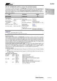
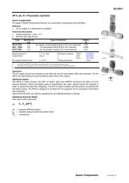
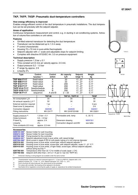
TKP, TKFP, TKSP: <strong>Pneumatic</strong> <strong>duct</strong>-<strong>temperature</strong> <strong>controllers</strong><br />
How energy efficiency is improved<br />
Enables energy-efficient control of the <strong>duct</strong> <strong>temperature</strong> in pneumatic installations. The <strong>duct</strong> <strong>temperature</strong><br />
can be set precisely with the setpoint adjuster.<br />
Areas of application<br />
Continuous <strong>temperature</strong> measurement and control, e.g. in <strong>duct</strong>ing in air-conditioning systems. Activation<br />
of volume flow <strong>controllers</strong> or unit valves.<br />
Features<br />
• Oil-filled external transducer for detecting the <strong>duct</strong> <strong>temperature</strong><br />
• Transducer can be distanced up to 1.5 m away<br />
• P control characteristic<br />
• Housing 72 x 72 mm in pure-white thermoplastic<br />
• Setpoint adjuster with +/- scale and adjustable stops for setpoint limiting<br />
• Complies with directive 97/23/EC Art. 3.3 on pressure equipment<br />
Technical description<br />
• Supply pressure 1.3 bar ± 0.1<br />
• Time constant at 0.5 m/s air velocity approx. 2.5 min.<br />
• Output pressure 0.2 - 1.0 bar<br />
• P range Xp approx. 2 K<br />
• Linearity 2%<br />
Type<br />
Control<br />
function 1)<br />
Control<br />
action<br />
Air capacity<br />
ln/h<br />
Setpoint<br />
range °C<br />
Weight<br />
kg<br />
TKP 80A F117 fixed-value A 33 17...27 0,17<br />
TKP 80B F117 fixed-value B 33 17...27 0,17<br />
TKP 81A F117 fixed-value A 200 17...27 0,17<br />
TKP 81B F117 fixed-value B 200 17...27 0,17<br />
TKFP 81A F117 fixed/schedule A 200 17...27 0,17<br />
TKFP 81B F117 fixed/schedule B 200 17...27 0,17<br />
TKSP 80 F117 sequence A and B 2 × 33 17...27 0,17<br />
TKP 80 TKP 81, TKFP 81 TKSP<br />
Air consumption l n /h 33 20 66<br />
Air exhaust capacity l n /h 2) 50 34 50<br />
External restrictor required 1 pc – 2 pcs<br />
Dead zone X t (sequence) – – 2 K<br />
Connection diagram A02048 A02049 A02051<br />
Fitting instructions MV 23177 MV 23187/23188 MV 23201<br />
Supply pressure 4) 1,3 bar ± 0,1 Permissible amb. temp 0...55 °C<br />
Output pressure<br />
0,2...1,0 bar<br />
P-band X p approx. 2 K Dimension drawing M297351<br />
Linearity 2% Connection diagram and MV see table<br />
Time constants (0.5 m/s) approx. 2,5 min<br />
P<br />
T<br />
Y02128<br />
Xp<br />
Xp<br />
y<br />
y<br />
B<br />
A<br />
Xs xi Xs xi<br />
Xp Xt Xp<br />
y<br />
Xs<br />
sequence: TKSP<br />
xi<br />
B02129a<br />
Accessories<br />
0296724 000* Sensor holder for wall mounting<br />
0303212 000* Sensor holder for <strong>duct</strong> mounting<br />
0297302 000* Fixing bracket for the controller<br />
0228234 001* Setpoint adjustment knob in pure white, with raised bridge<br />
0297354 000* Short screw-in nipple R 1 8 for soft plastic tubing of 4 mm internal diameter<br />
0297416 001 Housing cover in pure white, screw-type, without setpoint adjuster 3)<br />
0297418 032 Housing cover in pure white, screw-type, with setpoint adjuster, scale 17...27 °C 3)<br />
0297419 001 Housing cover in pure white, of light metal, screw-type, without setpoint adjuster,<br />
without airing louvres 3)<br />
0297760 001 Temperature other than 22 °C for middle of scale (span ± 5 K)<br />
0297760 002 Setpoint shift other than ± 6 K or 1 K per 0,1 bar (for TKFP 81)<br />
*) Dimension drawing or wiring diagram are available under the same number<br />
1) ‘Fixed/schedule' requires an external <strong>com</strong>mand signal of 0...1,2 bar (e.g RXP 81). Setpoint shift ± 6 K.<br />
Setpoint increase: 0,6...1,2 bar = 0...+6 K. Setpoint decrease: 0,6...0 bar = 0...–6 K<br />
2) Due to the blow-off noise produced, this value should not be exceeded<br />
3) For orders with controller, the housing will be replaced in the factory<br />
4) See Section 60 on regulations concerning the quality of supply air, especially at low ambient <strong>temperature</strong>s<br />
Sauter Components<br />
7167004003 04
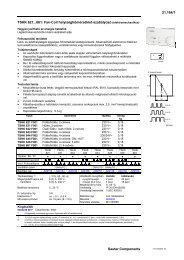
67.004/2 TKP, TKFP, TKSP<br />
Operation<br />
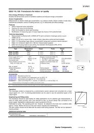
Fixed-value' basic function: TKP 80 & TKP 81<br />
The bimetal sensor, which works on the bleed-off force-balance principle, converts the <strong>temperature</strong><br />
within its P-band into a pneumatic standard signal of 0,2 to 1,0 bar.<br />
Direction of operation A: the output pressure increases as the <strong>temperature</strong> rises.<br />
Direction of operation B: the output pressure decreases as the <strong>temperature</strong> rises.<br />
When the <strong>temperature</strong> is rising, the oil-filled sensor bends and, via the force-balance lever, exerts a<br />
force on the nozzle–ball system. An output pressure – proportional to the force of the lever – builds up<br />
between the external pre-valve and the nozzle–ball system. On the model with direction of operation B,<br />
the nozzle–ball system is on the other side of the lever.<br />
Instead of the external pre-valve, the models with type number 81 have an integrated pre-amplifier for<br />
systems with long lines or for drives with short running times; these require a connection for supply<br />
pressure.<br />
Fixed-value + schedule' extra function: TKFP 81<br />
On this model is a membrane cell below the force-balance lever. When this is pressurised by an external<br />
<strong>com</strong>mand signal, the setpoint X s can be shifted. When the <strong>com</strong>mand signal is 0,6 bar, then control<br />
is performed exactly to the pre-set setpoint. The setpoint elevation works on a <strong>com</strong>mand signal of 0,6<br />
to 1,2 bar = 0 to +6 K; while the setpoint setback works between 0,6 and 0 bar = 0 to –6 K. Models with<br />
this setpoint shift have an ‘F' in the model code and require a connection for <strong>com</strong>mand pressure.<br />
Sequence' extra function: TKSP 80 & TKSP 81<br />
This model has a nozzle–ball system on both sides of the force-balance lever. It requires two external<br />
pre-valves and has two outputs: one each for both directions of operation (A and B). This provides a<br />
sequence curve with the setpoint in the middle of the neutral zone X t . Models with the sequence function<br />
have an additional `S' in the model code.<br />
Key<br />
S = slope, setpoint shift T R = room <strong>temperature</strong><br />
FF = shift starting point, setpoint of the scheduling relay X p = P-band<br />
X S = setpoint X t = dead zone<br />
T A = outside <strong>temperature</strong> p A = output pressure<br />
p W = <strong>com</strong>mand pressure<br />
Sauter Components<br />
7167004003 04
TKP, TKFP, TKSP 67.004/3<br />
Engineering notes<br />
In order to prevent excess noise, the air recovery should be kept to 50 l n /h for the TK . P 80 and 34 l n /h<br />
for the TK . P 81. This means that the maximum number of RLP units that can be connected to each<br />
controller is as follows:-<br />
TK . P 80: either three RLP 10 or 20, or three RLP 100 or 200;<br />
TK . P 81: either two RLP 10 or 20, or two RLP 100 or 200.<br />
On installations with a re-heater that have been equipped with a sequence relay or sequence-reversing<br />
relay (air supplied by the RLP), the air emitted at terminal 6 of the RLP is bled off by the sequence<br />
relay or sequence-reversing relay so that no such noise is caused by the TK . P unit itself.<br />
The maximum air recovery of a sequence relay or sequence-reversing relay is 50 l n /h. For this reason,<br />
no more than three RLP units may be connected to such a relay. If more are connected (to either a<br />
sequence relay or sequence-reversing relay or a TK . P unit), an interface relay XRP 101 must be<br />
used.<br />
Additional details on accessories<br />
0297760 001 Setting limits: middle of scale 15 - 40 °C; end of scale 10 - 45 °C.<br />
Only whole °C values can be used for the special settings.<br />
0297760 002 The <strong>com</strong>mand pressure can be set between 0 and 1,2 bar. The variable setpoint<br />
shift is either 0,5 °C or 0,75 °C per 0,1 bar.<br />
Additional details on models<br />
Housing cover of plastic or metal (see Accessories). Internal setpoint adjustment with end stops and `+<br />
–' scale.<br />
Base plate for snap-on or screw-on housing cover with two Allen-type grub screws (1,5 mm).<br />
Types TKP 81 and TKFP 81 have quantity amplification.<br />
Types TKFP 81 have a connection piece with a membrane for the setpoint shift. Measurement connection<br />
for tube of Ø 1,8 × 3,5 mm.<br />
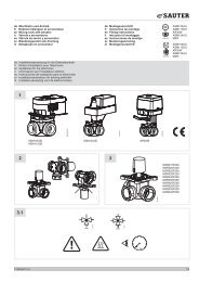
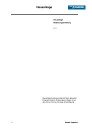
Connection diagrams<br />
Dimension drawing<br />
TKP 80 TKP 81, TKFP 81<br />
TKSP 80<br />
Xs<br />
Xp=2x2K<br />
A<br />
B<br />
Xi<br />
0,2...1,0 bar<br />
2 1<br />
NC<br />
y1<br />
y2<br />
NC<br />
T XP XP<br />
1,3 bar<br />
A02051b<br />
For heating and cooling: use NC valves<br />
(normally closed) (e.g. VK18P or BK18P)<br />
Sauter Components<br />
7167004003 04
67.004/4 TKP, TKFP, TKSP<br />
Accessories<br />
Examples of use<br />
− Addition of a <strong>com</strong>mand variable (outside <strong>temperature</strong>) to several TKFP 81 <strong>duct</strong>-<strong>temperature</strong><br />
<strong>controllers</strong><br />
Printed in Switzerland<br />
Right of amendment reserved<br />
N.B.: A <strong>com</strong>ma between cardinal<br />
numbers denotes a decimal point<br />
© Fr. Sauter AG, CH-4016 Basle<br />
7167004003 04<br />
Sauter Components