1 - sanyo denki europe
1 - sanyo denki europe
1 - sanyo denki europe

You also want an ePaper? Increase the reach of your titles
YUMPU automatically turns print PDFs into web optimized ePapers that Google loves.
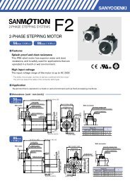
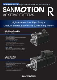
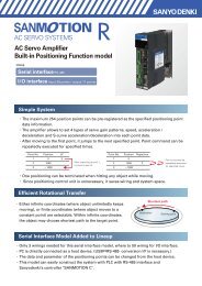
2-PHASE STEPPING SYSTEMS<br />
Ver.1<br />
English
2-phase STEPPING SYSTEMS<br />
F series DRIVER<br />
H series MOTOR<br />
SH series MOTOR<br />
FseriesDRIVER features<br />
1<br />
Low-vibration mode<br />
DC input<br />
Low-Vibration Mode OFF<br />
Low-Vibration Mode ON<br />
Speed variation%<br />
1600<br />
1400<br />
1200<br />
1000<br />
800<br />
600<br />
400<br />
Driver : US1D200P10<br />
Motor : 103H7123-0410<br />
Source voltage : DC24V<br />
Wire current : 2.0A/phase<br />
Division : 2<br />
TG : 11TG7V/1000rpm<br />
Speed variation%<br />
1600<br />
1400<br />
1200<br />
1000<br />
800<br />
600<br />
400<br />
Driver : US1D200P10<br />
Motor : 103H7123-0410<br />
Source voltage : DC24V<br />
Wire current : 2.0A/phase<br />
Division : 2<br />
TG : 11TG7V/1000rpm<br />
200<br />
200<br />
0<br />
0 100 200 300 400 500 600 700 800 900 1000<br />
0<br />
0 100 200 300 400 500 600 700 800 900 1000<br />
pulse/s<br />
pulse/s<br />
2<br />
Compact / Light weight<br />
DC input<br />
Compact<br />
Light weight<br />
2-phase unipolar<br />
Current model<br />
2-phase unipolar<br />
F series<br />
2-phase unipolar<br />
Current model<br />
2-phase unipolar<br />
F series<br />
2-phase bipolar<br />
Current model<br />
2-phase bipolar<br />
F series<br />
2-phase bipolar<br />
Current model<br />
2-phase bipolar<br />
F series<br />
0 50 100 150 200 250 300 350<br />
Volumecm 3 <br />
0 50 100 150 200 250<br />
MASSg<br />
Compliance with international standards<br />
ThestandardspecificationSANMOTIONFseriessteppingdrivercomplieswithULandEN<br />
safety standards.Stepping motors complying with UL and EN standards are available upon<br />
request.<br />
DC input<br />
1
Set model<br />
DC input<br />
Stepping motors with internal drivers<br />
A driver incorporating a motion control function needed for<br />
drivingamotoranda2-phasesteppingmotorwereintegratedintoasingleunit.<br />
Motor flange size<br />
42<br />
Unipolar standardstandard model<br />
ThestandardsetincludesaFseriesdriverandaHorSHseriesmotor.<br />
Bipolar standardstandard model<br />
ThestandardsetincludesaFseriesdriverandaHorSHseriesmotor.<br />
Motor flange size<br />
28<br />
1.10inch 1.65inch 1.97inch 2.20inch 2.36inch<br />
Reduction gear ratios<br />
1<br />
1.8<br />
1<br />
0.9<br />
60<br />
1.65inch 2.36inch<br />
Motor flange size<br />
28<br />
42 56<br />
1.10inch 1.65inch 2.20inch<br />
Reduction gear ratios<br />
1<br />
1.8<br />
1<br />
0.9<br />
42 50 56 60<br />
P.4<br />
P.13<br />
P.14<br />
Dimensions Stepping motor Set model<br />
Stepping Motors with Internal drivers<br />
IC for stepping motor<br />
2
2-phase STEPPING SYSTEMS<br />
F series DRIVER<br />
H series MOTOR<br />
SH series MOTOR<br />
Control method<br />
Howdoyouwanttocontroltheequipment?<br />
TheFseriesoffersthechoiceof3differentcontrolmethods<br />
Program<br />
command<br />
control using<br />
PLC I/O<br />
Network<br />
control<br />
using serial<br />
communication<br />
RS-485<br />
Control using a<br />
pulse generator<br />
Control using a<br />
pulse generator<br />
Drive<br />
Specification<br />
DC input<br />
stepping motors with internal drivers<br />
DC input<br />
unipolar standard<br />
DC input<br />
bipolar standard<br />
Startup via I/O :<br />
Initiate program<br />
containing speed,<br />
acceleration/<br />
deceleration, and travel<br />
distance commands<br />
storedin the driver via<br />
the I/O.<br />
Startup via serial<br />
communication :<br />
Control by sending data<br />
for speed, acceleration/<br />
deceleration, and travel<br />
distance commands via<br />
serial communication.<br />
Motion is generated by pulse input<br />
commands from an upper-level controller.<br />
Motion is generated by pulse input<br />
commands from an upper-level controller.<br />
System configuration diagram<br />
P4<br />
Specifications<br />
P6<br />
Dimensions P5 to 6<br />
System configuration diagram P13 to 14<br />
Setpartnumbernomenclature<br />
P16<br />
Motor specifications P27 to 46<br />
General specifications<br />
P4748<br />
Motor dimension drawing P49 to 51<br />
Driver dimension drawing<br />
P52<br />
System configuration diagram P13 to 14<br />
Setpartnumbernomenclature<br />
P16<br />
Motor specifications P27 to 46<br />
General specifications<br />
P4748<br />
Motordimensiondrawing<br />
P49to51<br />
Driver dimension drawing<br />
P52<br />
3
DC input<br />
Controller<br />
CanbeconnectedtoSANYODENKI or<br />
third-party controllers.<br />
DC<br />
24 V<br />
System configuration<br />
Stepping Motors with Internal drivers<br />
Bundled cable for<br />
input/output signal300 mm<br />
Bundled cable for<br />
DC power350 mm<br />
Switching power<br />
supply<br />
Converts AC power<br />
to DC power<br />
Setupsoftware:SFPAIW-02<br />
Noise filter<br />
Filters out<br />
incoming noise<br />
from power line<br />
Electromagnetic<br />
contactor<br />
Switches driver<br />
power on/off.<br />
Use together with<br />
asurgeprotector.<br />
Molded case<br />
circuit breaker<br />
Protects the power<br />
line. Cuts off circuit<br />
in the event of<br />
overcurrent.<br />
(t)<br />
(r)<br />
Single<br />
phase<br />
AC100 V<br />
to<br />
AC230 V<br />
Dimensions Stepping motor Set model<br />
Stepping Motors with Internal drivers<br />
ICforsteppingmotor<br />
4
8<br />
7<br />
F<br />
N<br />
2<br />
3<br />
4<br />
5<br />
6<br />
0<br />
2-phase STEPPING SYSTEMS<br />
Stepping DC input motor Specifications<br />
Stepping motors with internal drivers<br />
Features<br />
1.Driver and motor are now integrated into a single unit.<br />
A driver incorporating a motion control function needed<br />
for driving a motor and a 2-phase stepping motor were<br />
integrated into a single unit for enabling a more compact<br />
installation space and less wiring.<br />
2.Three types of operation modes can be selected to match<br />
the specific application.<br />
1Control by command pulses<br />
2Program control by general-purpose I/O(Parallel)<br />
3Compliant with RS-485, half-duplex asynchronous<br />
communication<br />
Pulse rate-torque characteristics<br />
<br />
42mm 1.65inch<br />
<br />
60mm 2.36inch<br />
Torque(oz·in.)<br />
80<br />
70<br />
60<br />
50<br />
40<br />
30<br />
Torque (kgf-cm)<br />
6<br />
5<br />
4<br />
3<br />
2<br />
Torque (N-m)<br />
0.6<br />
0.5<br />
0.4<br />
0.3<br />
0.2<br />
DB21M142S-01<br />
E=DC24V<br />
I=Rated current<br />
JL=0.94×10 -4 kgm 2<br />
Torque(oz·in.)<br />
220<br />
200<br />
180<br />
160<br />
140<br />
120<br />
100<br />
80<br />
Torque (kgf-cm)<br />
16<br />
14<br />
12<br />
10<br />
8<br />
6<br />
Torque (N-m)<br />
1.6<br />
1.4<br />
1.2<br />
1.0<br />
0.8<br />
0.6<br />
DB22M162S-01<br />
E=DC24V<br />
I=Rated current<br />
JL=0.94×10 -4 kgm 2<br />
20<br />
60<br />
4<br />
0.4<br />
10<br />
1<br />
0.1<br />
40<br />
20<br />
2<br />
0.2<br />
0<br />
0<br />
0<br />
0.1 1 10 100<br />
Pulse ratekpulse/s<br />
0<br />
0<br />
0<br />
0.1 1 10 100<br />
Pulse ratekpulse/s<br />
DimensionsUnit : mminch<br />
<br />
42mm 1.65inch<br />
CN1:POWER<br />
ManufacturerJST<br />
CONNECTORS02B-PASK-2<br />
<br />
70 +2<br />
0<br />
+.08<br />
2.76 .00<br />
<br />
1.5 0.76.59.03<br />
240.5.94.02<br />
15 <br />
59 +.04<br />
.00<br />
(EFFECTIVE<br />
LENGTH)<br />
<br />
+.0000<br />
.1968<br />
.0005 <br />
-0.013<br />
0.025<br />
0.05<br />
A<br />
42 0.51.65.02<br />
310.251.22.01<br />
2<br />
1<br />
220<br />
<br />
<br />
<br />
<br />
<br />
R3MIN.<br />
5<br />
A<br />
22 -0.05 0<br />
+.000<br />
.87 .002 <br />
1 O<br />
310.251.22.01<br />
42 0.51.65.02<br />
119<br />
4-M30.5<br />
CN2:I/O<br />
ManufacturerJST<br />
NAME<br />
PLATE<br />
TAP DEPTH 4.16MIN.<br />
4.5 0.151.18.01<br />
CONNECTORSM20B-SHLDS-GW-TF<br />
PSW<br />
RSW<br />
DSW<br />
EARTH TERMINAL<br />
M2.5X0.45X4L<br />
9 A<br />
5 6<br />
BCD<br />
E<br />
3 4<br />
0 1 2<br />
5
8<br />
3 4 5<br />
F<br />
0<br />
1<br />
2<br />
3<br />
4<br />
5<br />
6<br />
O<br />
N<br />
Specifications<br />
Basic<br />
specifications<br />
Function<br />
I/O signals<br />
Part numberFlange size DB21M142S-01 42 DB22M162S-01 60<br />
Input sourceNote1<br />
DC24 V 10 <br />
Getaway torqueA 2MAX. 3MAX.<br />
Environment<br />
Protection class<br />
Operation environment<br />
Applied standards<br />
Operating ambient temperature<br />
Note2<br />
Class I<br />
Installation categoryover-voltage category: II,pollutiondegree:2<br />
EN61010-1<br />
0to+40<br />
Conservation temperature -20 to +60<br />
Operating ambient humidity<br />
Conservation humidity<br />
Operation altitude<br />
35 to 85%RHno condensation<br />
10 to 90%RHno condensation<br />
1000 m3280 feetMAX. above sea level<br />
Vibration resistance<br />
Testedunderthefollowingconditions;4.9m/s2,frequencyrange10to55Hz,directionalongX,Y<br />
andZaxes,for2hourseach<br />
Impact resistance Not influenced at NDS-C-0110 standard section 3.2.2 division C .<br />
Withstand voltage<br />
Insulation resistance<br />
Notinfluencedwhen1500VACisappliedbetweenpowerinputterminalandcabinetforone<br />
minute.<br />
10M ohm MIN. when measured with 500V DC megohmmeter between input terminal and cabinet.<br />
MassWeight 0.5kg1.10lbs 0.87kg1.92lbs<br />
Protection function<br />
LED indicator<br />
Command pulse input signalNote3<br />
Power down input signalPD<br />
Step angle setting selection inputEXT<br />
FULL/HALFsettingselectioninputF/H<br />
EMG input signal<br />
Against driver overheat<br />
Alarm monitor<br />
Photo coupler input method, input resistance 220 <br />
Inputsignalvoltage:H =4.0to5.5V,L =0 to0.5V<br />
Photo coupler input method, input resistance 470 <br />
Inputsignalvoltage:H =4.0to5.5V,L =0 to0.5V<br />
Photo coupler input method, input resistance 470 <br />
Inputsignalvoltage:H =4.0to5.5V,L =0 to0.5V<br />
Photo coupler input method, input resistance 470 <br />
Inputsignalvoltage:H =4.0to5.5V,L =0to0.5V<br />
Photo coupler input method, input resistance 470 <br />
Inputsignalvoltage:H =4.0to5.5V,L =0to0.5V<br />
Photo coupler input method, input resistance 220 <br />
BUSY output signal<br />
Inputsignalvoltage:H =4.0to5.5V,L =0 to0.5V<br />
Opencollectoroutputbyphotocoupler<br />
PhaseoriginmonitoroutputsignalMON<br />
Outputsignalstandard:Vceo=30VMAX.,Ic=20mAMAX.<br />
Opencollectoroutputbyphotocoupler<br />
Alarm output signalAL<br />
Outputsignalstandard:Vceo=30VMAX.,Ic=20mAMAX.<br />
1<br />
Notethatthepowervoltagemustnotexceed24VDC+10%(26.4VDC).<br />
2<br />
Ifthedriverisplacedinabox,thetemperatureinsidetheboxmustnotexceedthisspecifiedrange.<br />
3<br />
Themaximuminputfrequencyis250kpulse/s.<br />
<br />
60mm 1.65inch<br />
CN1:POWER<br />
ManufacturerJST<br />
CONNECTORS02B-PASK-2<br />
88 +2 0<br />
<br />
3.46<br />
+.08<br />
.00<br />
<br />
70.25.27.01<br />
1.50.25.06.01<br />
(EFFECTIVE<br />
LENGTH)<br />
0.1<br />
20.60.5.81.02<br />
0<br />
+1 +.04<br />
15 .59 .00<br />
<br />
-0.013 .25 +.000<br />
-.001 <br />
6.35 0<br />
A<br />
0.025<br />
0.075 A<br />
600.52.36.02<br />
47.10.131.85.01<br />
Dimensions Stepping motor Set model<br />
Stepping Motors with Internal drivers<br />
2 1<br />
220<br />
<br />
<br />
<br />
<br />
<br />
R4MIN.<br />
A<br />
38.10.251.5.01<br />
47.10.131.85.01<br />
600.52.36.02<br />
119<br />
9A<br />
6 7<br />
B CD E<br />
1 2<br />
CN2:I/O<br />
ManufacturerJST<br />
CONNECTORSM20B-SHLDS-GW-TF<br />
PS RSW DS EARTH TERMINAL<br />
M2.5X0.45X4L<br />
PLATE<br />
NAME<br />
5.80.15.23.01<br />
<br />
+0.5<br />
44.5 0<br />
+.02<br />
4.18 .00<br />
<br />
IC for stepping motor<br />
6
2-phase STEPPING SYSTEMS<br />
Specifications<br />
Input circuit configuration<br />
Input interface<br />
Input circuit configuration<br />
220<br />
Input signal<br />
Input signal specifications<br />
Negative logic<br />
2μs MIN.<br />
to<br />
Approx. 15 mA<br />
Rotation<br />
to<br />
Pulse duty 50 % MAX.<br />
1μs MAX.<br />
1μs MAX.<br />
Positive logic<br />
1μs MAX.<br />
1μs MAX.<br />
to<br />
Rotation<br />
Approx. 15mA<br />
to<br />
2μs MIN.<br />
Pulse duty 50% MAX.<br />
Timing of the command pulse<br />
2-input modeCW, CCW<br />
50μs MIN.<br />
• The internal photo coupler turns ON within the and,<br />
atitsfallingedgetoOFF,theinternalcircuitmotoris<br />
activated.<br />
• WhenapplyingthepulsetoCW,turnOFFtheCCWside<br />
internal photo coupler.<br />
• WhenapplyingthepulsetoCCW,turnOFFtheCWside<br />
internal photo coupler.<br />
Pulse and direction modeCK, U/D<br />
50μs MIN.<br />
10μs MIN.<br />
• The H levelisinputfor and,atitsrisingedgeto H<br />
level, the internal circuitstepping motoris activated.<br />
•SwitchingtheinputsignalU/Dshouldbeperformed<br />
whiletheinputlevelontheCKsideis L .<br />
7
Input circuit configuration<br />
Input circuit configuration PDEXTF/HEMG<br />
Input signal<br />
Approx. 10mA<br />
Timing of command pulse, step angle selection, and<br />
FULL/HALF selection input signal<br />
Command pulse<br />
100μs MIN.<br />
Output interface<br />
Output circuit configurationBUSYMONAL<br />
Output signal<br />
Mon output<br />
CW pulse<br />
CCW pulse<br />
Mon output<br />
MAX. 20mA<br />
MAX. 30V<br />
Driver<br />
10μs MIN.<br />
When changing the division setting by F/H input signal.<br />
• ShadedareaindicatesinternalphotocouplerON .<br />
• EXT input signal<br />
EXT photo coupler ON enables a function by external<br />
F/H input signal.<br />
EXT photo coupler OFF enables the setting of a<br />
number of micro steps by main unit’s rotaryswitchS.S.<br />
• F/H input signal<br />
F/H photo coupler ON sets HALF step (2-division)<br />
operation.<br />
F/H photo coupler OFF sets FULL step (1-division)<br />
operation.<br />
• Refer to switching EXT and F/H input signal in the<br />
[FULL/HALF input signal, command pulse, and step<br />
angle select].<br />
• When switching the step angle by EXT and F/H input<br />
signal,thephaseoriginLCDmaynotturnONandthe<br />
phaseoriginmonitoroutputmaynotoutputwhenstop.<br />
RefertotheMONoutputinthe[OutputInterface].<br />
• When the motor excitation phase is at the phase origin<br />
(power ON status), the photo coupler is turned ON ,<br />
and the upper D.P of status LED turns on synchronously.<br />
• Output from MON is set to on at every 7.2 degrees of<br />
motor output shaft from phase origin.<br />
Dimensions Stepping motor Set model<br />
Stepping Motors with Internal drivers<br />
Phase origin position<br />
HALF step<br />
Switching to FULL step<br />
by external F/H<br />
FULL step<br />
Stop position at<br />
FULL step<br />
Phase origin position<br />
• When changing the motor division setting by the<br />
external input signal and the rotary switch as shown in<br />
the example below, the motor cannot stop where MON<br />
output signal can be output. Take this into consideration<br />
when using the MON output signal.<br />
Motor shaft<br />
IC for stepping motor<br />
8
2-phase STEPPING SYSTEMS<br />
Specification<br />
WIRING<br />
SpecificationSummaryofInput/OutputSignals(SerialI/Fmode)<br />
Signal<br />
General-purpose<br />
input common<br />
Alarm clear signal<br />
standard<br />
General-purpose<br />
input 1<br />
Emergency stop<br />
input<br />
Reference<br />
Designation<br />
+COM 6<br />
ALMC 6<br />
IN1 6<br />
EMG 6<br />
Origin signal ORG 6<br />
+ direction<br />
overtravel signal<br />
General-purpose<br />
input 2<br />
Emergency stop<br />
input<br />
+OT 7<br />
IN2 7<br />
EMG 7<br />
Origin signal ORG 7<br />
Alarm clear signal ALMC 7<br />
- direction<br />
overtravel signal<br />
General-purpose<br />
input 3<br />
Emergency stop<br />
input<br />
OT 8<br />
IN3 8<br />
EMG 8<br />
Origin signal ORG 8<br />
Alarm clear signal ALMC 8<br />
Pin<br />
Function Summary<br />
Number<br />
Input signal common of the 6 to 9 pins<br />
DC 5V is input.<br />
Recoverable alarms are cleared.<br />
Internal photo coupler off onAlarm clear<br />
This is a general-purpose input signal that can be<br />
used by program driving.<br />
Internal photo coupler onGeneral purpose input 1 on<br />
Internal photo coupler off General purpose input 1 off<br />
The emergency stop signal is input.<br />
Internal photo coupler onNo emergency stop<br />
Internal photo coupler ofEmergency stop<br />
The origin signal used for the return to origin<br />
operation is input.<br />
Internal photo coupler onOrigin signal on<br />
Internal photo coupler offOrigin signal off<br />
An overtravel signal in the + direction is input.<br />
Internal photo coupler on + direction overtravel not<br />
arrived<br />
Internal photo coupler off + direction overtravel<br />
arrived<br />
This is a general-purpose input signal that can be<br />
used by program driving.<br />
Internal photo coupler onGeneral purpose input 2 on<br />
Internal photo coupler off General purpose input 2 off<br />
The emergency stop signal is input.<br />
Internal photo coupler onNo emergency stop<br />
Internal photo coupler offEmergency stop<br />
The origin signal used for the return to origin<br />
operation is input.<br />
Internal photo coupler onOrigin signal on<br />
Internal photo coupler off Origin signal off<br />
Recoverable alarms are cleared.<br />
Internal photo coupler off onAlarm clear<br />
An overtravel signal in the - direction is input.<br />
Internal photo coupler on - direction overtravel not<br />
arrived<br />
Internal photo coupler off- direction overtravel<br />
arrived<br />
This is a general-purpose input signal that can be<br />
used by program driving.<br />
Internal photo coupler onGeneral purpose input 3 on<br />
Internal photo coupler off General purpose input 3 off<br />
emergency stop signal is input.<br />
Internal photo coupler onNo emergency stop<br />
Internal photo coupler offEmergency stop<br />
The origin signal used for the return to origin<br />
operation is input.<br />
Internal photo coupler onOrigin signal on<br />
Internal photo coupler off Origin signal off<br />
Recoverable alarms are cleared.<br />
Internal photo coupler off onAlarm clear<br />
Signal<br />
Emergency stop<br />
signal<br />
General-purpose<br />
input 4c<br />
Reference<br />
Designation<br />
Pin<br />
Number<br />
EMG 9<br />
IN4 9<br />
Origin signal ORG 9<br />
Alarm clear signal ALMC 9<br />
During motor<br />
operation<br />
During program<br />
execution<br />
BUSY 10<br />
PEND 10<br />
Zone signal ZONE 10<br />
During program<br />
execution<br />
During motor<br />
operation<br />
PEND 11<br />
BUSY 11<br />
Zone signal ZONE 11<br />
Alarm output ALM 12<br />
Function Summary<br />
The emergency stop signal is input.<br />
Internal photo coupler onNo emergency stop<br />
Internal photo coupler offEmergency stop<br />
This is a general-purpose input signal that can be<br />
used by program driving.<br />
Internal photo coupler onGeneral purpose input 4 on<br />
Internal photo coupler off General purpose input 4 off<br />
The origin signal used for the return to origin<br />
operation is input.<br />
Internal photo coupler onOrigin signal on<br />
Internal photo coupler off Origin signal off<br />
alarms are cleared.<br />
Internal photo coupler off onAlarm clear<br />
The operation status of the motor is output.<br />
Internal photo coupler onDuring motor operation<br />
Internal photo coupler offDuring motor stop<br />
The execution status of the program is output.<br />
Internal photo coupler onDuring program execution<br />
Internal photo coupler offProgram execution<br />
complete<br />
on when the current position is inside the<br />
coordinates that were set beforehand.<br />
The execution status of the program is output.<br />
Internal photo coupler onDuring program execution<br />
Internal photo coupler offProgram execution<br />
complete<br />
The operation status of the motor is output.<br />
Internal photo coupler onDuring motor operation<br />
Internal photo coupler offDuring motor stop<br />
Turns on when the current position is inside the<br />
coordinates that were set beforehand.<br />
When various alarm circuits operate in the driver, an<br />
external signal is output.<br />
At this time, the stepping motor becomes non excited<br />
status.<br />
Output signal<br />
common<br />
OUT_COM 13 It is for the output signal common.<br />
DATA+ DATA+ 14 It is for the serial signal.<br />
DATA DATA 15 It is for the serial signal.<br />
SpecificationSummaryofInput/OutputSignals(PulsetrainI/Fmode)<br />
Signal<br />
CW pulse input<br />
Standard<br />
Pulse train input<br />
CCW pulse input<br />
Standard<br />
Rotational<br />
direction input<br />
General-purpose<br />
input common<br />
Power down<br />
input<br />
Step angle<br />
select input<br />
Reference<br />
Designation<br />
CW+<br />
CW <br />
CK+<br />
CK <br />
CCW+<br />
CCW <br />
U/D+<br />
U/D <br />
Pin<br />
Number<br />
1<br />
2<br />
1<br />
2<br />
3<br />
4<br />
3<br />
4<br />
+COM 6<br />
PD 6<br />
EXT 7<br />
Function Summary<br />
When 2inputmode ,<br />
InputdrivepulserotatingCWdirection.<br />
When 1inputmode ,<br />
Inputdrivepulsetrainformotorrotation.<br />
When 2inputmode ,<br />
InputdrivepulserotatingCCWdirection.<br />
When 1 input mode ,<br />
Input motor rotational direction signal.<br />
Internal photo coupler ON CW direction<br />
Internal photo coupler OFF CCW direction<br />
Inputsignalcommonofthe6to9pins<br />
DC5V is input.<br />
InputtingPDsignalwillcutoffpower offthe current<br />
flowing to the MotorWith dip switch select, change to<br />
thePowerlowfunctionispossible.<br />
PDinputsignaloninternal photo coupler on<br />
PD function is valid.<br />
PDinputsignaloffinternal photo coupler off<br />
PD function is invalid.<br />
FULL/HALF select input will become valid by inputting<br />
EXT signal.<br />
EXT input signal oninternal photo coupler on<br />
External input signal F/H is valid<br />
EXT input signal offinternal photo coupler off<br />
MainbodyrotaryswitchS.Sisvalid<br />
Signal<br />
FULL/HALF<br />
select input<br />
Emergency<br />
stop<br />
During motor<br />
operation<br />
Phase origin<br />
monitor output<br />
Reference<br />
Designation<br />
Pin<br />
Number<br />
F/H 8<br />
EMG 9<br />
BUSY 10<br />
MON 11<br />
Alarm output ALM 12<br />
Function Summary<br />
When EXT input signal on<br />
internal photo coupler on,<br />
F/H input signal oninternal photo coupler on<br />
HALF step<br />
F/H input signal offinternal photo coupler off<br />
FULL step<br />
The emergency stop signal is input.<br />
Internal photo coupler onNo emergency stop<br />
Internal photo coupler offEmergency stop<br />
The operation status of the motor is output.<br />
Internal photo coupler on<br />
During motor operation<br />
Internal photo coupler off<br />
During motor stop<br />
When the excitation phase is at the originin power onit<br />
turns on.<br />
When FULL step, ON once for 4 pulses, when HALF step,<br />
ON once for 8 pulses.<br />
When alarm circuits actuated inside the Driver, outputs<br />
signals to outside. Then the Stepping motor becomes<br />
unexcited status.<br />
Output signal<br />
OUT_COM 13 It is for the output signal common.<br />
common<br />
As for the Motor rotational direction, CW direction is regard as the clockwise revolution by<br />
viewingtheMotorfromoutputshaftside.<br />
9
Specification Summary of Input/Output Signals (Parallel I/F mode)<br />
Signal<br />
Program drive<br />
Start/Stop<br />
Program pause<br />
General-purpose<br />
input common<br />
Alarm clear<br />
signal<br />
standard<br />
General-purpose<br />
input 1<br />
Program number<br />
selection bit 1<br />
Emergency stop<br />
input<br />
Reference<br />
Designation<br />
START+<br />
START-<br />
PAUSE+<br />
PAUSE-<br />
Pin<br />
Number<br />
1<br />
2<br />
3<br />
4<br />
+COM 6<br />
ALMC 6<br />
IN1 6<br />
B1 6<br />
EMG 6<br />
Origin signal ORG 6<br />
+direction<br />
overtravel signal<br />
General-purpose<br />
input 2<br />
Program number<br />
selection bit 2<br />
Emergency stop<br />
input<br />
+OT 7<br />
IN2 7<br />
B2 7<br />
EMG 7<br />
Origin signal ORG 7<br />
Alarm clear<br />
signal<br />
-direction<br />
overtravel signal<br />
General-purpose<br />
input 3<br />
Program number<br />
selection bit 4<br />
Emergency stop<br />
input<br />
ALMC 7<br />
-OT 8<br />
IN3 8<br />
B4 8<br />
EMG 8<br />
Origin signal ORG 8<br />
Alarm clear<br />
signal<br />
ALMC 8<br />
Function Summary<br />
Commandsthestartandstopofprogramdriving.<br />
Internal photo coupler onProgram driving start<br />
Internal photo coupler offProgram driving stop<br />
WhenSTARTsignalon,apauseinprogramdrivingis<br />
commanded.<br />
Internal photo coupler onProgram driving pause<br />
Internal photo coupler offProgram driving pause<br />
release<br />
Inputsignalcommonofthe6to9pins<br />
DC5V is input.<br />
Recoverablealarmsarecleared.<br />
Internal photo coupler off onAlarm clear<br />
Thisisageneral-purposeinputsignalthatcanbeused<br />
by program driving.<br />
Internal photo coupler onGeneral purpose input 1 on<br />
Internal photo coupler off Generalpurposeinput1off<br />
Theprogramnumberisselectedalongwithotherbits.<br />
Subordinate bit<br />
Internal photo coupler onCorresponding bit 1<br />
Internal photo coupler off Corresponding bit 0<br />
The emergency stop signal is input.<br />
Internal photo coupler onNoemergencystopInternal<br />
photo coupler offEmergency stop<br />
Theoriginsignalusedforthereturntooriginoperation<br />
is input.<br />
Internal photo coupler onOrigin signal on<br />
Internal photo coupler off Origin signal off<br />
An overtravel signal in the + direction is input. Internal<br />
photo coupler on +directionovertravelnotarrived<br />
Internal photo coupler off +directionovertravel<br />
arrived<br />
Thisisageneral-purposeinputsignalthatcanbeused<br />
by program driving.<br />
Internal photo coupler onGeneral purpose input 2 on<br />
Internal photo coupler off Generalpurposeinput2off<br />
Theprogramnumberisselectedalongwithotherbits.<br />
Thesecondbitfromthesubordinate<br />
Internal photo coupler onCorresponding bit 1 Internal<br />
photo coupler off Corresponding bit 0<br />
The emergency stop signal is input.<br />
Internal photo coupler onNoemergencystopInternal<br />
photo coupler offEmergency stop<br />
Theoriginsignalusedforthereturntooriginoperation<br />
is input.<br />
Internal photo coupler onOrigin signal on<br />
Internal photo coupler off Origin signal off<br />
Recoverablealarmsarecleared.<br />
Internal photo coupler off onAlarm clear<br />
An overtravel signal in the - direction is input.<br />
Internal photo coupler on - direction overtravel not<br />
arrived<br />
Internal photo coupler off -directionovertravel<br />
arrived<br />
Thisisageneral-purposeinputsignalthatcanbeused<br />
by program driving.<br />
Internal photo coupler onGeneral purpose input 3 on<br />
Internal photo coupler off Generalpurposeinput3off<br />
Theprogramnumberisselectedalongwithotherbits.<br />
Thethirdbitfromthesubordinate<br />
Internal photo coupler onCorresponding bit 1<br />
Internal photo coupler off Corresponding bit 0<br />
The emergency stop signal is input.<br />
Internal photo coupler onNo emergency stop<br />
Internal photo coupler offEmergency stop<br />
Theoriginsignalusedforthereturntooriginoperation<br />
is input.<br />
Internal photo coupler onOrigin signal on<br />
Internal photo coupler off Origin signal off<br />
Recoverablealarmsarecleared.<br />
Internal photo coupler off onAlarm clear<br />
Signal<br />
Emergency stop<br />
signal<br />
General-purpose<br />
input 4<br />
Program number<br />
selection bit 8<br />
Reference<br />
Designation<br />
Pin<br />
Number<br />
EMG 9<br />
IN4 9<br />
B8 9<br />
Origin signal ORG 9<br />
Alarm clear<br />
signal<br />
During motor<br />
operation<br />
During program<br />
execution<br />
ALMC 9<br />
BUSY 10<br />
PEND 10<br />
Zone signal ZONE 10<br />
During program<br />
execution<br />
During motor<br />
operation<br />
PEND 11<br />
BUSY 11<br />
Zone signal ZONE 11<br />
Alarm output ALM 12<br />
Function Summary<br />
The emergency stop signal is input.<br />
Internal photo coupler onNo emergency stop<br />
Internal photo coupler offEmergency stop<br />
This is a general-purpose input signal that can be used<br />
by program driving.<br />
Internal photo coupler onGeneral purpose input 4 on<br />
Internal photo coupler off General purpose input 4 off<br />
The program number is selected along with other bits.<br />
Thefourthbitfromthesubordinate<br />
Internal photo coupler on Corresponding bit 1<br />
Internal photo coupler off Corresponding bit 0<br />
Theoriginsignalusedforthereturntooriginoperation<br />
is input.<br />
Internal photo coupler onOrigin signal on<br />
Internal photo coupler off Origin signal off<br />
Recoverable alarms are cleared.<br />
Internal photo coupler off onAlarm clear<br />
Theoperationstatusofthemotorisoutput.<br />
Internal photo coupler onDuring motor operation<br />
Internal photo coupler offDuring motor stop<br />
The execution status of the program is output. Internal<br />
photo coupler onDuring program execution<br />
Internal photo coupler offProgram execution<br />
complete<br />
Turns on when the current position is inside the<br />
coordinates that were set beforehand.<br />
The execution status of the program is output.<br />
Internal photo coupler onDuring program execution<br />
Internal photo coupler offProgram execution<br />
complete<br />
Theoperationstatusofthemotorisoutput.<br />
Internal photo coupler onDuring motor operation<br />
Internal photo coupler offDuring motor stop<br />
Turns on when the current position is inside the<br />
coordinates that were set beforehand.<br />
When various alarm circuits operate in the driver, an<br />
external signal is output.<br />
At this time, the stepping motor becomes non excited<br />
status.<br />
Output signal<br />
common<br />
OUT_COM 13 Itisfortheoutputsignalcommon.<br />
DATA+ DATA+ 14 It is for the serial signal.<br />
DATA DATA 15 It is for the serial signal.<br />
External Wiring Diagrams<br />
DC24V<br />
24G<br />
DATA<br />
DATA<br />
GND5G<br />
CWSTART<br />
CWSTART<br />
CCWPAUSE<br />
CCWPAUSE<br />
COM<br />
PDIN1B1<br />
EXTIN2B2<br />
FHIN3B4<br />
IN4B8<br />
BUSYOUT1<br />
MONOUT2<br />
Controller<br />
CN1<br />
1<br />
2<br />
CN2<br />
14<br />
15<br />
20<br />
1<br />
2<br />
3<br />
4<br />
5<br />
6<br />
7<br />
8<br />
9<br />
10<br />
11<br />
Driver<br />
30V 20mA MAX.<br />
24V<br />
24G<br />
Power<br />
Supply<br />
5G<br />
5V<br />
RXD<br />
TXD<br />
DE<br />
2 Phase Stepping Motor<br />
IC for stepping motor Dimensions Stepping motor<br />
Set model<br />
Stepping Motors with Internal drivers<br />
ALM<br />
12<br />
OUT_COM<br />
13<br />
10
2-phase STEPPING SYSTEMS<br />
Specification<br />
SET UP<br />
Function Select Dip Switch<br />
ThefunctionsaccordingtothespecificationcanbeselectedwiththisDipswitch.<br />
Confirm theex-factorysettingasfollows.<br />
OFF<br />
ON<br />
1<br />
F/R<br />
OFF<br />
2 input mode (CW/CCW pulse)<br />
2<br />
LV<br />
OFF<br />
Micro step operation<br />
3<br />
PD<br />
OFF<br />
Power OFF<br />
4<br />
<br />
OFF<br />
Phase origin excitation<br />
5<br />
6<br />
I. SEL<br />
S. SEL<br />
OFF<br />
OFF<br />
Pulse stream I/F mode<br />
For pulse stream I/F mode<br />
1 Input mode selectF/R<br />
Input pulse mode selection<br />
This switch setting is only effective in pulse stream I/F<br />
mode.<br />
F/R Input pulse mode<br />
ON<br />
OFF<br />
1 input modeCK,U/D<br />
2 input modeCW,CCW<br />
2 Low vibration mode selectLV<br />
Low vibration and smooth operation is enabled even by the rough<br />
resolution setting<br />
e.g. 1 division, 2 division.<br />
This switch setting is only effective in pulse stream I/F mode.<br />
For parallel I/F mode and serial I/F mode, this is usually a low<br />
vibration operation.<br />
LV Operation<br />
ON Low vibration operation<br />
OFF Micro step operation<br />
When LV select is ONlow vibration mode, operationalprocessof<br />
driving pulse will be carried out inside the Driver. Therefore, the Motor<br />
movement delays for the time of3.2ms pulse per input pulse. Note that<br />
depending upon the combined Motor, load,driving profile and etc, it may<br />
take a while until the shaft is adjusted when the Motor stops.In parallel<br />
I/F mode and serial I/F mode there is no delay<br />
For parallel I/F mode or serial I/F mode<br />
The communication speed of serial communication is<br />
set.<br />
Switch<br />
F/R<br />
LV<br />
Set value<br />
Communication speed(bps)<br />
9,600 19,200 38,400 115,200<br />
OFF <br />
ON<br />
OFF <br />
ON <br />
OFF <br />
PD<br />
ON <br />
The setting change after the power supply is turned on is invalid.<br />
It does not function as a F/R, LV, and PD.<br />
The communication speed of pulse stream I/F mode is fixed at 9600bps.<br />
11<br />
3 Power down selectPD<br />
Select the Motor winding current value when inputting the power down<br />
signal.This switch setting is only effective in pulse stream I/F mode.<br />
PD Motor winding current<br />
ON Current value by rotary switch STPPower Low<br />
OFF 0APower OFF<br />
PD functionthe setting selected by PD of the function select dip switch<br />
is enabled by PD input signal ONbuilt-in photo coupler ONof Input/<br />
Output signal connectorCN2.Powerdownsignalinputispriortoall<br />
the other current settings except for alarms. The operational status may<br />
not be maintained such as power swing due to output torque drop or<br />
lower operation due to Motor current OFFunexcited Motor.Payextra<br />
attention to the input timing of the power down signal in addition that<br />
the security device should be installed to the machine.<br />
4 Excitation selectEORG<br />
By turning on the EORG, excitation phase when power OFF is saved.<br />
5 , 6 Operation mode selectionI.SEL, S.SEL<br />
The operation mode is selected.<br />
I.SEL S.SEL Operation mode<br />
OFF Pulse stream I/F mode<br />
ON<br />
OFF<br />
ON<br />
Parallel I/F mode<br />
Serial I/F mode<br />
Change the operation mode selection switch after cutting off the driver<br />
spowersupply.
Rotaryswitch(RSW)andthemodechangeswitch(PSW)<br />
For pulse stream I/F mode<br />
When it selects the step angle, the driving current is selected, and stops the<br />
current is selected, set by combining rotary switch (RSW) and mode change<br />
switch (PSW).<br />
1. Step angle select(S.S)<br />
The divisions of the basic step angle (0.9/step) when micro step driving can<br />
be set with this rotary switch.<br />
Gradation 0 1 2 3 4 5 6 7<br />
Partition 1 2 2.5 4 5 8 10 20<br />
Gradation 8 9 A B C D E F<br />
Partition 25 40 50 80 100 125 200 250<br />
Ex-factory setting is at 1 (division 2)<br />
The step angle select switch (S.S) and the number of partitions become invalid by EXT input signal ON<br />
(built-in photo coupler ON) of Input/Output signal connector (CN2).<br />
2. Driving current select(RUN)<br />
The Motor operation current value can be selected with this rotary switch.<br />
Gradation 0 1 2 3 4 5 6 7<br />
Motor 100<br />
current (%) (rated)<br />
95 90 85 80 75 70 65<br />
Gradation 8 9 A B C D E F<br />
Motor<br />
current<br />
(%)<br />
60 55 50 45 40 35 30 25<br />
Ex-factory setting is at 0 (rated value).<br />
When there is a sufficient extra motor torque, lowering the operation current value will be effective in<br />
the lower vibration. The Motor output torque is almost proportional to the current value. When adjusting<br />
the operational torque, confirm the sufficient operation margin and determine the Motor current value.<br />
3. Current Select when Stop (STP)<br />
The motor current value when stop and when power down input signal ON<br />
(power low function is selected by dip switch) can be selected with this rotary<br />
switch.<br />
Gradation 0 1 2 3 4 5 6 7<br />
Motor 100<br />
current (%) (rated)<br />
95 90 85 80 75 70 65<br />
Gradation 8 9 A B C D E F<br />
Motor<br />
current (%)<br />
60 55 50 45 40 35 30 25<br />
Ex-factory setting is set at A (50%).<br />
The current setting when stop by STP becomes valid when the Motor stops (approximately 200ms after<br />
the last pulse input) and when power down input signal<br />
For parallel I/F mode and serial I/F mode<br />
The slave bureau address of serial communications is set with this rotary<br />
switch.<br />
RSW Slave station address (HEX)<br />
0 0<br />
1 1<br />
<br />
<br />
E<br />
E<br />
F<br />
F<br />
Ex-factory setting is set at 0<br />
The slave station address of the pulse stream I/F mode is fixed at 0.<br />
Dimensions Stepping motor Set model<br />
Stepping Motors with Internal drivers<br />
IC for stepping motor<br />
12
2-phase STEPPING SYSTEMS<br />
DC input System configuration<br />
Unipolar standard<br />
A Motor cable<br />
Controller<br />
CanbeconnectedtoSANYODENKI or<br />
third-party controllers.<br />
Standard model :<br />
Hseriesmotor,<br />
SH series motor,<br />
<br />
28mm 1.10inch/<br />
<br />
42mm 1.65inch/<br />
<br />
56mm 2.20inch<br />
Motor<br />
connector<br />
DC power<br />
connector<br />
I/O signal connector<br />
DC power cable<br />
I/O signal cable<br />
Switching power<br />
supply<br />
Noise filter<br />
Electromagnetic<br />
contactor<br />
Molded case<br />
circuit breaker<br />
DC<br />
24V/36V<br />
(t)<br />
(r)<br />
Single<br />
phase<br />
AC100V<br />
to<br />
AC230V<br />
Converts AC power<br />
to DC power<br />
Filters out<br />
incoming noise<br />
from power line<br />
Switches driver<br />
power on/off.<br />
Use together with<br />
asurgeprotector.<br />
Protects the power<br />
line.Cutsoffcircuit<br />
in the event of<br />
overcurrent.<br />
Bundled cable( 42mm motors only)<br />
A Motor cable<br />
<br />
42mm 1.65inch<br />
5001.64 feetMIN.<br />
Pin No.<br />
1<br />
2<br />
3<br />
4<br />
5<br />
6<br />
Lead wire color<br />
White<br />
Orange<br />
Blue<br />
Yellow<br />
Red<br />
Black<br />
JST<br />
2<br />
3 4 5 6<br />
Lead wire<br />
Housing<br />
Pin<br />
UL1430 AWG26<br />
HER-6 BLACKJ.S.T Mfg.Co.,Ltd<br />
SEH-001T-P0.6J.S.T Mfg.Co.,Ltd<br />
13
2-phase STEPPING SYSTEMS<br />
DC input<br />
Standard model :<br />
Hseriesmotor,<br />
SH series motor,<br />
<br />
28mm 1.10inch/<br />
<br />
42mm 1.65inch/<br />
<br />
50mm 1.97inch/<br />
<br />
56mm 2.20inch/<br />
<br />
60mm 2.36inch<br />
System configuration<br />
Bipolar standard<br />
A Motor cable<br />
Motor<br />
connector<br />
Controller<br />
Can be connected to SANYO DENKI or<br />
third-party controllers.<br />
Set model Stepping Motors with Internal drivers<br />
DC power<br />
connector<br />
I/O signal connector<br />
DC power cable<br />
DC<br />
24V/36V<br />
Switching power<br />
supply<br />
Converts AC power<br />
to DC power<br />
Noise filter<br />
Filters out<br />
incoming noise<br />
from power line<br />
I/O signal cable<br />
Electromagnetic<br />
contactor<br />
Switches driver<br />
power on/off.<br />
Use together with<br />
asurgeprotector.<br />
Molded case<br />
circuit breaker<br />
Protects the power<br />
line. Cuts off circuit<br />
in the event of<br />
overcurrent.<br />
(t)<br />
(r)<br />
Single<br />
phase<br />
AC100V<br />
to<br />
AC230V<br />
Dimensions Stepping motor<br />
Bundled cable( 42mm motors only)<br />
A Motor cable<br />
<br />
42mm 1.65inch<br />
Pin No.<br />
1<br />
2<br />
3<br />
4<br />
5<br />
6<br />
Lead wire color<br />
Blue<br />
<br />
Orange<br />
Yellow<br />
<br />
Red<br />
Lead wire<br />
Housing<br />
Pin<br />
JST<br />
2<br />
3 4 5 6<br />
5001.64 feetMIN.<br />
UL1430 AWG26<br />
HER-6 BLACKJ.S.T Mfg.Co.,Ltd<br />
SEH-001T-P0.6J.S.T Mfg.Co.,Ltd<br />
<br />
60mm 2.36inch<br />
Pin No.<br />
4<br />
3<br />
2<br />
1<br />
5001.64 feetMIN.<br />
Lead wire color<br />
Yellow<br />
Red<br />
Blue<br />
Orange<br />
Lead wire UL1430 AWG22<br />
Housing VER-4NJ.S.T Mfg.Co.,Ltd<br />
Pin<br />
SVH-21T-P1.1J.S.T Mfg.Co.,Ltd<br />
IC for stepping motor<br />
14
2-phase STEPPING SYSTEMS<br />
DC input<br />
Part numbering convention<br />
The following set part number specifies a system with an F series unipolar drivertype code : US1D200P10<br />
and a single shaft H series motortype code : 103H7121-0440, 56 mm 2.20 inchsquare flange, and<br />
41.8 mm1.65 inchmotor length.<br />
D U 1 6 H 71 1 S<br />
Stepping motor shaft spec<br />
S : Single shaft<br />
D : Double shaft<br />
Stepping motor total length<br />
Stepping motor flange size<br />
Code<br />
<br />
28mm 1.10inch 42mm 1.65inch 50mm 1.97inch 56mm 2.20inch 60mm 2.36inch<br />
Type Motor length Type Motor length Type Motor length Type Motor length Type Motor length<br />
code :mminch code :mminch code :mminch code :mminch code :mminch<br />
1 3205 311.25 5205 331.30 6701 39.81.57 7121 41.81.65 7821 44.81.76<br />
2 5208 391.54 6703 51.32.02 7123 53.82.12 7822 53.82.12<br />
3 7126 75.82.89 7823 85.83.38<br />
4 5210 481.89<br />
6 3215 50.31.98<br />
Stepping motor flange size<br />
32 : 28mm 1.10inch 71 : 56mm 2.20inch<br />
52 : 42mm 1.65inch 78 : 60mm 2.36inch<br />
Stepping motor series name<br />
H : H series<br />
S : SH series<br />
Rated current specification<br />
4 : 1A/phase5 : 1.2A/phase6 : 2A/phase<br />
Model<br />
Driver Specification<br />
U : 2-phase unipolar B : 2-phase bipolar<br />
Power specification<br />
D:DC<br />
15
Combinationlistof2-phaseunipolardriver<br />
System type<br />
Standard<br />
model<br />
Basic Setpartnumber<br />
Motor model number<br />
Motor flange size<br />
Rated current<br />
step angle Single shaft Double shaft Single shaft Double shaft<br />
<br />
1.8 DU14H321S DU14H321D 103H3205-5270 103H3205-5230 1A<br />
28mm 1.10inch<br />
1.8 DU14H326S DU14H326D 103H3215-5270 103H3215-5230 1A<br />
<br />
42mm 1.65inch<br />
<br />
56mm 2.20inch<br />
1.8 DU15H521S DU15H521D 103H5205-0440 103H5205-0410 1.2A<br />
1.8 DU15H522S DU15H522D 103H5208-0440 103H5208-0410 1.2A<br />
1.8 DU15H524S DU15H524D 103H5210-0440 103H5210-0410 1.2A<br />
0.9 DU15S141S DU15S141D SH1421-0441 SH1421-0411 1.2A<br />
0.9 DU15S142S DU15S142D SH1422-0441 SH1422-0411 1.2A<br />
0.9 DU15S144S DU15S144D SH1424-0441 SH1424-0411 1.2A<br />
1.8 DU16H711S DU16H711D 103H7121-0440 103H7121-0410 2A<br />
1.8 DU16H713S DU16H713D 103H7123-0440 103H7123-0410 2A<br />
1.8 DU16H716S DU16H716D 103H7126-0440 103H7126-0410 2A<br />
Combinationlistof2-phasebipolardriver<br />
System type<br />
Standard<br />
model<br />
Basic Set part number<br />
Motor model number<br />
Motor flange size<br />
Rated current<br />
step angle Single shaft Double shaft Single shaft Double shaft<br />
<br />
1.8 DB14H321S DB14H321D 103H3205-5770 103H3205-5730 1A<br />
28mm 1.10inch<br />
1.8 DB14H326S DB14H326D 103H3215-5770 103H3215-5730 1A<br />
<br />
42mm 1.65inch<br />
<br />
50mm 1.97inch<br />
<br />
56mm 2.20inch<br />
1.8 DB14H521S DB14H521D 103H5205-5240 103H5205-5210 1A<br />
1.8 DB14H522S DB14H522D 103H5208-5240 103H5208-5210 1A<br />
1.8 DB14H524S DB14H524D 103H5210-5240 103H5210-5210 1A<br />
0.9 DB16S141S DB16S141D SH1421-5241 SH1421-5211 2A<br />
0.9 DB16S142S DB16S142D SH1422-5241 SH1422-5211 2A<br />
0.9 DB16S144S DB16S144D SH1424-5241 SH1424-5211 2A<br />
1.8 DB16H671S DB16H671D 103H6701-5040 103H6701-5010 2A<br />
1.8 DB16H672S DB16H672D 103H6703-5040 103H6703-5010 2A<br />
1.8 DB16H711S DB16H711D 103H7121-5740 103H7121-5710 2A<br />
1.8 DB16H713S DB16H713D 103H7123-5740 103H7123-5710 2A<br />
1.8 DB16H716S DB16H716D 103H7126-5740 103H7126-5710 2A<br />
1.8 DB16H781S DB16H781D 103H7821-5740 103H7821-5710 2A<br />
1.8 DB16H782S DB16H782D 103H7822-5740 103H7822-5710 2A<br />
<br />
60mm 2.36inch 1.8 DB16H783S DB16H783D 103H7823-5740 103H7823-5710 2A<br />
0.9 DB16S161S DB16S161D SH1601-5240 SH1601-5210 2A<br />
0.9 DB16S162S DB16S162D SH1602-5240 SH1602-5210 2A<br />
IC for stepping motor Dimensions Stepping motor<br />
Set model Stepping Motors with Internal drivers<br />
16
2-phase STEPPING SYSTEMS<br />
DC input<br />
Specifications<br />
Standard model<br />
Fseriesdriver+HorSHseriesmotor<br />
Unipolar<br />
Motor flange size<br />
Size<br />
Set part<br />
number<br />
Motor flange size<br />
<br />
28mm1.10inch/1.8<br />
Motor length 31mm1.25inch 50.3mm1.98inch<br />
Single shaft DU14H321S DU14H326S<br />
Double shaft DU14H321D DU14H326D<br />
Holding torque Nmozin 0.032 .53 0. 2 . <br />
Rotor inertia 10 -4 kgm 2 ozin 2 0.00 0.05 0.01 0.0 <br />
MassWeight kglbs 0.110.2 0.20. <br />
Allowable thrust load Nlbs 30. 30. <br />
Allowable radial load Note1 Nlbs 2 2 <br />
Note1Whenloadisappliedat1/3lengthfromoutputshaftedge.<br />
28 42 56<br />
1.10inch 1.65inch<br />
2.20inch<br />
DC24V<br />
7<br />
6<br />
5<br />
4<br />
3<br />
2<br />
1<br />
Torqueozin<br />
Torquekgfcm<br />
0<br />
0.5<br />
0.4<br />
0.3<br />
0.2<br />
0.1<br />
0<br />
TorqueNm<br />
0.05<br />
10<br />
9<br />
0.04<br />
8<br />
7<br />
0.03<br />
6<br />
5<br />
0.02<br />
4<br />
3<br />
0.01<br />
2<br />
1<br />
0<br />
0<br />
0.1 1<br />
fs fs<br />
10 100<br />
Source currentA<br />
Torqueozin<br />
14<br />
12<br />
10<br />
8<br />
6<br />
4<br />
2<br />
0<br />
Torquekgfcm<br />
1.0<br />
0.8<br />
0.6<br />
0.4<br />
0.2<br />
0<br />
TorqueNm<br />
0.1<br />
10<br />
9<br />
0.08<br />
8<br />
7<br />
0.06<br />
6<br />
5<br />
0.04<br />
4<br />
3<br />
0.02<br />
2<br />
1<br />
0<br />
0<br />
<br />
0.1 1 10 100<br />
Source currentA<br />
1-division<br />
2-division<br />
Pulse ratekpulse/s<br />
100 1000 2000 3000 5000<br />
10 100 1000 2000 3000 5000<br />
1-division<br />
2-division<br />
Pulse ratekpulse/s<br />
100 1000 2000 3000 5000<br />
10 100 1000 200030005000<br />
Number of rotationsmin -1 <br />
Number of rotationsmin -1 <br />
Operating current:<br />
3A/phase<br />
Pull-out torque<br />
Source current (load applied)<br />
Source current (no load)<br />
1-division fs Fs:Maximum self-start<br />
2-division fs frequency when not loaded<br />
1-division<br />
2-division<br />
DC36V<br />
7<br />
6<br />
5<br />
4<br />
3<br />
2<br />
1<br />
Torqueozin<br />
Torquekgfcm<br />
0<br />
0.5<br />
0.4<br />
0.3<br />
0.2<br />
0.1<br />
0<br />
TorqueNm<br />
1-division<br />
2-division<br />
0.05<br />
10<br />
9<br />
0.04<br />
8<br />
7<br />
0.03<br />
6<br />
5<br />
0.02<br />
4<br />
3<br />
0.01<br />
2<br />
1<br />
0<br />
0<br />
0.1 1<br />
fs fs<br />
10 100<br />
Pulse ratekpulse/s<br />
100 1000 2000 3000 5000<br />
10 20 50 100 200 500<br />
Number of rotationsmin -1 <br />
Source currentA<br />
Torqueozin<br />
14<br />
12<br />
10<br />
8<br />
6<br />
4<br />
2<br />
0<br />
Torquekgfcm<br />
1.0<br />
0.8<br />
0.6<br />
0.4<br />
0.2<br />
0<br />
TorqueNm<br />
1-division<br />
2-division<br />
0.1<br />
10<br />
9<br />
0.08<br />
8<br />
7<br />
0.06<br />
6<br />
5<br />
0.04<br />
4<br />
3<br />
0.02<br />
2<br />
1<br />
0<br />
0<br />
fs fs<br />
0.1 1 10 100<br />
Pulse ratekpulse/s<br />
100 1000 2000 3000 5000<br />
10 100 1000 2000 30005000<br />
Number of rotationsmin -1 <br />
Source currentA<br />
Size<br />
Motor flange size <br />
42mm1.65inch/0.9 <br />
56mm2.20inch/1.8<br />
Motor length 48mm1.89inch 41.8mm1.65inch 53.8mm2.12inch 75.8mm2.98inch<br />
Set part Single shaft DU15S144S DU16H711S DU16H713S DU16H716S<br />
number Double shaft DU15S144D DU16H711D DU16H713D DU16H716D<br />
Holding torque Nmozin 0.3955.23 0.3955.23 0.83117.5 1.27179.8<br />
Rotor inertia 10 -4 kgm 2 ozin 2 0.0890.487 0.10.55 0.211.15 0.361.97<br />
MassWeight kglbs 0.380.84 0.471.04 0.631.39 0.982.16<br />
Allowable thrust load Nlbs 102.25 153.37 153.37 153.37<br />
Allowable radial load Note1 Nlbs 306 7115 7115 7115<br />
Note1Whenloadisappliedat1/3lengthfromoutputshaftedge.<br />
DC24V<br />
Torqueozin<br />
70<br />
60<br />
50<br />
40<br />
30<br />
20<br />
10<br />
0<br />
Torquekgfcm<br />
5<br />
4<br />
3<br />
2<br />
1<br />
0<br />
TorqueNm<br />
0.5<br />
10<br />
9<br />
0.4<br />
8<br />
7<br />
0.3<br />
6<br />
5<br />
0.2<br />
4<br />
3<br />
0.1<br />
2<br />
1<br />
0<br />
0<br />
fs fs<br />
0.1 1 10 100<br />
Source currentA<br />
Torqueozin<br />
140<br />
120<br />
100<br />
80<br />
60<br />
40<br />
20<br />
0<br />
Torquekgfcm<br />
10<br />
8<br />
6<br />
4<br />
2<br />
0<br />
TorqueNm<br />
1.0<br />
10<br />
9<br />
0.8<br />
8<br />
7<br />
0.6<br />
6<br />
5<br />
0.4<br />
4<br />
3<br />
0.2<br />
2<br />
1<br />
0<br />
0<br />
fs fs<br />
0.1 1 10 100<br />
Source currentA<br />
Torqueozin<br />
280<br />
240<br />
200<br />
160<br />
120<br />
80<br />
40<br />
0<br />
Torquekgfcm<br />
20<br />
16<br />
12<br />
8<br />
4<br />
0<br />
TorqueNm<br />
2.0<br />
10<br />
9<br />
1.6<br />
8<br />
7<br />
1.2<br />
6<br />
5<br />
0.8<br />
4<br />
3<br />
0.4<br />
2<br />
1<br />
0<br />
0<br />
fs<br />
0.1 1 10 100<br />
Source currentA<br />
1-division<br />
2-division<br />
Pulse ratekpulse/s<br />
100 1000 2000 3000 5000<br />
10 100 1000 2000 3000 5000<br />
Number of rotationsmin -1 <br />
1-division<br />
2-division<br />
Pulse ratekpulse/s<br />
100<br />
1000<br />
2000<br />
3000 5000<br />
10 100 1000 2000 30005000<br />
Number of rotationsmin -1 <br />
1-division<br />
2-division<br />
Pulse ratekpulse/s<br />
10 100<br />
1000 20003000 5000<br />
10 100 1000 2000 3000 5000<br />
Number of rotationsmin -1 <br />
1-division<br />
2-division<br />
Pulse ratekpulse/s<br />
100 1000 2000 3000 5000<br />
10 100<br />
1000 2000 3000 5000<br />
Number of rotationsmin -1 <br />
Operating current:<br />
3A/phase<br />
Pull-out torque<br />
Source current (load applied)<br />
Source current (no load)<br />
1-division fs Fs:Maximum self-start<br />
2-division fs frequency when not loaded<br />
1-division<br />
2-division<br />
DC36V<br />
Torqueozin<br />
70<br />
60<br />
50<br />
40<br />
30<br />
20<br />
10<br />
0<br />
Torquekgfcm<br />
5<br />
4<br />
3<br />
2<br />
1<br />
0<br />
TorqueNm<br />
1-division<br />
2-division<br />
0.5<br />
10<br />
9<br />
0.4<br />
8<br />
7<br />
0.3<br />
6<br />
5<br />
0.2<br />
4<br />
3<br />
0.1<br />
2<br />
1<br />
0<br />
0<br />
fs fs<br />
0.1 1 10 100<br />
Pulse ratekpulse/s<br />
100 1000 2000 3000 5000<br />
10 100 1000<br />
2000 3000 5000<br />
Number of rotationsmin -1 <br />
Source currentA<br />
Torqueozin<br />
70<br />
60<br />
50<br />
40<br />
30<br />
20<br />
10<br />
0<br />
Torquekgfcm<br />
5<br />
4<br />
3<br />
2<br />
1<br />
0<br />
TorqueNm<br />
1-division<br />
2-division<br />
0.5<br />
10<br />
9<br />
0.4<br />
8<br />
7<br />
0.3<br />
6<br />
5<br />
0.2<br />
4<br />
3<br />
0.1<br />
2<br />
1<br />
0<br />
0<br />
fs fs<br />
0.1 1 10 100<br />
Pulse ratekpulse/s<br />
100<br />
10 100 1000<br />
1000 2000 3000 5000<br />
2000 3000 5000<br />
Number of rotationsmin -1 <br />
Source currentA<br />
Torqueozin<br />
140<br />
120<br />
100<br />
80<br />
60<br />
40<br />
20<br />
0<br />
Torquekgfcm<br />
10<br />
8<br />
6<br />
4<br />
2<br />
0<br />
TorqueNm<br />
1-division<br />
2-division<br />
1.0<br />
10<br />
9<br />
0.8<br />
8<br />
7<br />
0.6<br />
6<br />
5<br />
0.4<br />
4<br />
3<br />
0.2<br />
2<br />
1<br />
0<br />
0<br />
fs fs<br />
0.1 1 10 100<br />
Pulse ratekpulse/s<br />
10 100 1000 2000 3000 5000<br />
10 100 1000 2000 3000 5000<br />
Number of rotationsmin -1 <br />
Source currentA<br />
Torqueozin<br />
280<br />
240<br />
200<br />
160<br />
120<br />
80<br />
40<br />
0<br />
Torquekgfcm<br />
20<br />
16<br />
12<br />
8<br />
4<br />
0<br />
TorqueNm<br />
1-division<br />
2-division<br />
2.0<br />
10<br />
9<br />
1.6<br />
8<br />
7<br />
1.2<br />
6<br />
5<br />
0.8<br />
4<br />
3<br />
0.4<br />
2<br />
1<br />
0<br />
0<br />
fs fs<br />
0.1 1 10 100<br />
Pulse ratekpulse/s<br />
100 1000 3000 2000 5000<br />
10 100 1000 2000 3000 5000<br />
Number of rotationsmin -1 <br />
Source currentA<br />
17
Torqueozin<br />
Torqueozin<br />
70<br />
60<br />
50<br />
40<br />
30<br />
20<br />
10<br />
0<br />
70<br />
60<br />
50<br />
40<br />
30<br />
20<br />
10<br />
0<br />
Torquekgfcm<br />
5<br />
4<br />
3<br />
2<br />
1<br />
0<br />
<br />
42mm1.65inch/1.8<br />
33mm1.30inch 39mm1.54inch 48mm1.89inch<br />
TorqueNm<br />
1-division<br />
2-division<br />
Torquekgfcm<br />
5<br />
4<br />
3<br />
2<br />
1<br />
0<br />
TorqueNm<br />
1-division<br />
2-division<br />
DU15H521S DU15H522S DU15H524S<br />
DU15H521D DU15H522D DU15H524D<br />
0.228.32 0.342.48 0.3752.39<br />
0.0360.20 0.0560.31 0.0720.34<br />
0.230.51 0.290.64 0.370.82<br />
102.25 102.25 102.25<br />
306 306 306<br />
0.5<br />
10<br />
9<br />
0.4<br />
8<br />
7<br />
0.3<br />
6<br />
5<br />
0.2<br />
4<br />
3<br />
0.1<br />
2<br />
1<br />
0<br />
0<br />
fs fs<br />
0.1 1 10 100<br />
Pulse ratekpulse/s<br />
100 1000 2000 3000 5000<br />
100 1000 2000 3000 5000<br />
Number of rotationsmin -1 <br />
Source currentA<br />
0.5<br />
10<br />
9<br />
0.4<br />
8<br />
7<br />
0.3<br />
6<br />
5<br />
0.2<br />
4<br />
3<br />
0.1<br />
2<br />
1<br />
0<br />
0<br />
fs fs<br />
0.1 1 10 100<br />
Pulse ratekpulse/s<br />
100 1000 2000 30005000<br />
100 1000 2000 3000 5000<br />
Number of rotationsmin -1 <br />
Source currentA<br />
Torqueozin<br />
Torqueozin<br />
70<br />
60<br />
50<br />
40<br />
30<br />
20<br />
10<br />
0<br />
70<br />
60<br />
50<br />
40<br />
30<br />
20<br />
10<br />
0<br />
Torquekgfcm<br />
5<br />
4<br />
3<br />
2<br />
1<br />
0<br />
TorqueNm<br />
1-division<br />
2-division<br />
Torquekgfcm<br />
5<br />
4<br />
3<br />
2<br />
1<br />
0<br />
TorqueNm<br />
1-division<br />
2-division<br />
0.5<br />
10<br />
9<br />
0.4<br />
8<br />
7<br />
0.3<br />
6<br />
5<br />
0.2<br />
4<br />
3<br />
0.1<br />
2<br />
1<br />
0<br />
0<br />
fs fs<br />
0.1 1 10 100<br />
Pulse ratekpulse/s<br />
100 1000 2000 3000 5000<br />
100 1000 2000 3000 5000<br />
Number of rotationsmin -1 <br />
Source currentA<br />
Torqueozin<br />
Torqueozin<br />
70<br />
60<br />
50<br />
40<br />
30<br />
20<br />
10<br />
0<br />
70<br />
60<br />
50<br />
40<br />
30<br />
20<br />
10<br />
0<br />
Torquekgfcm<br />
5<br />
4<br />
3<br />
2<br />
1<br />
0<br />
TorqueNm<br />
1-division<br />
2-division<br />
Torquekgfcm<br />
5<br />
4<br />
3<br />
2<br />
1<br />
0<br />
TorqueNm<br />
1-division<br />
2-division<br />
0.5<br />
10<br />
9<br />
0.4<br />
8<br />
7<br />
0.3<br />
6<br />
5<br />
0.2<br />
4<br />
3<br />
0.1<br />
2<br />
1<br />
0<br />
0<br />
fs fs<br />
0.1 1 10 100<br />
Pulse ratekpulse/s<br />
100 1000 2000 3000 5000<br />
100 1000 2000 3000 5000<br />
Number of rotationsmin -1 <br />
Source currentA<br />
Torqueozin<br />
Torqueozin<br />
70<br />
60<br />
50<br />
40<br />
30<br />
20<br />
10<br />
0<br />
70<br />
60<br />
50<br />
40<br />
30<br />
20<br />
10<br />
0<br />
Torquekgfcm<br />
5<br />
4<br />
3<br />
2<br />
1<br />
0<br />
TorqueNm<br />
1-division<br />
2-division<br />
Torquekgfcm<br />
5<br />
4<br />
3<br />
2<br />
1<br />
0<br />
TorqueNm<br />
1-division<br />
2-division<br />
<br />
42mm1.65inch/0.9<br />
33mm1.30inch<br />
DU15S141S<br />
DU15S141D<br />
0.228.32<br />
0.0440.24<br />
0.240.53<br />
102.25<br />
306<br />
0.5<br />
10<br />
9<br />
0.4<br />
8<br />
7<br />
0.3<br />
6<br />
5<br />
0.2<br />
4<br />
3<br />
0.1<br />
2<br />
1<br />
0<br />
0<br />
fs fs<br />
0.1 1 10 100<br />
Pulse ratekpulse/s<br />
100 1000 3000 2000 5000<br />
10 100 1000 2000 3000 5000<br />
Number of rotationsmin -1 <br />
Source currentA<br />
0.5<br />
10<br />
9<br />
0.4<br />
8<br />
7<br />
0.3<br />
6<br />
5<br />
0.2<br />
4<br />
3<br />
0.1<br />
2<br />
1<br />
0<br />
0<br />
fs<br />
0.1 1<br />
fs<br />
10 100<br />
Pulse ratekpulse/s<br />
100 1000 2000 3000 5000<br />
10 100 1000 2000 3000 5000<br />
Number of rotationsmin -1 <br />
Source currentA<br />
Torqueozin<br />
Torqueozin<br />
70<br />
60<br />
50<br />
40<br />
30<br />
20<br />
10<br />
0<br />
70<br />
60<br />
50<br />
40<br />
30<br />
20<br />
10<br />
0<br />
Torquekgfcm<br />
5<br />
4<br />
3<br />
2<br />
1<br />
0<br />
TorqueNm<br />
1-division<br />
2-division<br />
Torquekgfcm<br />
5<br />
4<br />
3<br />
2<br />
1<br />
0<br />
39mm1.54inch<br />
TorqueNm<br />
1-division<br />
2-division<br />
DU15S142S<br />
DU15S142D<br />
0.2941.07<br />
0.0660.361<br />
0.290.64<br />
102.25<br />
306<br />
0.5<br />
10<br />
9<br />
0.4<br />
8<br />
7<br />
0.3<br />
6<br />
5<br />
0.2<br />
4<br />
3<br />
0.1<br />
2<br />
1<br />
0<br />
0<br />
fs fs<br />
0.1 1 10 100<br />
Pulse ratekpulse/s<br />
100 1000 2000 3000 5000<br />
10 100 1000 2000 3000 5000<br />
Number of rotationsmin -1 <br />
Source currentA<br />
IC for stepping motor Dimensions Stepping motor<br />
Set model Stepping Motors with Internal drivers<br />
18
2-phase STEPPING SYSTEMS<br />
DC input<br />
Specifications<br />
Standard model<br />
Fseriesdriver+HorSHseriesmotor<br />
Bipolar<br />
Motor flange size<br />
28 42 50<br />
56 60<br />
1.10inch 1.65inch 1.97inch 2.20inch 2.36inch<br />
Size<br />
Set part<br />
number<br />
Motor flange size<br />
<br />
28mm 1.10inch/1.8<br />
Motor length 31mm1.25inch 50.3mm1.98inch<br />
Single shaft DB14H321S DB14H326S<br />
Double shaft DB14H321D DB14H326D<br />
Holding torque Nmozin 0.04 6. 0 0.114.16<br />
Rotor inertia 10 -4 kgm 2 ozin 2 0.00 0.05 0.0160.0 <br />
MassWeight kglbs 0.110.24 0.20.44<br />
Allowable thrust load Nlbs 30.6 30.6 <br />
Allowable radial load Note1 Nlbs 42 42 <br />
Note1Whenloadisappliedat1/3lengthfromoutputshaftedge.<br />
DC24V<br />
Torqueozin<br />
14<br />
12<br />
10<br />
8<br />
6<br />
4<br />
2<br />
0<br />
Torquekgfcm<br />
1.0<br />
0.8<br />
0.6<br />
0.4<br />
0.2<br />
0<br />
TorqueNm<br />
0.1<br />
10<br />
9<br />
0.08<br />
8<br />
7<br />
0.06<br />
6<br />
5<br />
0.04<br />
4<br />
3<br />
0.02<br />
2<br />
1<br />
0<br />
0<br />
fs fs<br />
0.1 1 10 100<br />
Source currentA<br />
Torqueozin<br />
28<br />
24<br />
20<br />
16<br />
12<br />
8<br />
4<br />
0<br />
Torquekgfcm<br />
2.0<br />
1.6<br />
1.2<br />
0.8<br />
0.4<br />
0<br />
TorqueNm<br />
0.2<br />
10<br />
9<br />
0.16<br />
8<br />
7<br />
0.12<br />
6<br />
5<br />
0.08<br />
4<br />
3<br />
0.04<br />
2<br />
1<br />
0<br />
0<br />
fs fs<br />
0.1 1 10 100<br />
Source currentA<br />
1-division<br />
2-division<br />
Pulse ratekpulse/s<br />
100<br />
1000 2000 3000 5000<br />
10 100 1000 2000 3000 5000<br />
1-division<br />
2-division<br />
Pulse ratekpulse/s<br />
100<br />
1000 2000 3000 5000<br />
10 100 1000 2000 3000 5000<br />
Number of rotationsmin -1 <br />
Number of rotationsmin -1 <br />
Operating current:<br />
3A/phase<br />
Pull-out torque<br />
Source current (load applied)<br />
Source current (no load)<br />
1-division fs Fs:Maximum self-start<br />
2-division fs frequency when not loaded<br />
1-division<br />
2-division<br />
DC36V<br />
Torqueozin<br />
14<br />
12<br />
10<br />
8<br />
6<br />
4<br />
2<br />
0<br />
Torquekgfcm<br />
1.0<br />
0.8<br />
0.6<br />
0.4<br />
0.2<br />
0<br />
TorqueNm<br />
1-division<br />
2-division<br />
0.1<br />
10<br />
9<br />
0.08<br />
8<br />
7<br />
0.06<br />
6<br />
5<br />
0.04<br />
4<br />
3<br />
0.02<br />
2<br />
1<br />
0<br />
0<br />
fs fs<br />
0.1 1 10 100<br />
Pulse ratekpulse/s<br />
100<br />
1000 2000 3000 5000<br />
10 100 1000 2000 3000 5000<br />
Number of rotationsmin -1 <br />
Source currentA<br />
Torqueozin<br />
28<br />
24<br />
20<br />
16<br />
12<br />
8<br />
4<br />
0<br />
Torquekgfcm<br />
2.0<br />
1.6<br />
1.2<br />
0.8<br />
0.4<br />
0<br />
TorqueNm<br />
1-division<br />
2-division<br />
0.2<br />
10<br />
9<br />
0.16<br />
8<br />
7<br />
0.12<br />
6<br />
5<br />
0.08<br />
4<br />
3<br />
0.04<br />
2<br />
1<br />
0<br />
0<br />
fs fs<br />
0.1 1 10 100<br />
Pulse ratekpulse/s<br />
100<br />
1000 2000 3000 5000<br />
10 100 1000 2000 3000 5000<br />
Number of rotationsmin -1 <br />
Source currentA<br />
Size<br />
Motor flange size <br />
42mm1.65inch/0.9 <br />
50mm1.97inch/1.8 <br />
56mm2.20inch/1.8<br />
Motor length 48mm1.89inch 39.8mm1.57inch 51.3mm2.02inch 41.8mm1.65inch<br />
Set part Single shaft DB16S144S DB16H671S DB16H672S DB16H711S<br />
number Double shaft DB16S144D DB16H671D DB16H672D DB16H711D<br />
Holding torque Nmozin 0.4867.97 0.2839.6 0.4969.4 0.3955.2<br />
Rotor inertia 10 -4 kgm 2 ozin 2 0.0890.487 0.0570.31 0.1180.65 0.10.55<br />
MassWeight kglbs 0.380.84 0.350.77 0.51.10 0.471.04<br />
Allowable thrust load Nlbs 102.25 153.37 153.37 153.37<br />
Allowable radial load Note1 Nlbs 306 9922 9922 7115<br />
Note1Whenloadisappliedat1/3lengthfromoutputshaftedge.<br />
DC24V<br />
Torqueozin<br />
140<br />
120<br />
100<br />
80<br />
60<br />
40<br />
20<br />
0<br />
Torquekgfcm<br />
10<br />
8<br />
6<br />
4<br />
2<br />
0<br />
TorqueNm<br />
1.0<br />
10<br />
9<br />
0.8<br />
8<br />
7<br />
0.6<br />
6<br />
5<br />
0.4<br />
4<br />
3<br />
0.2<br />
2<br />
1<br />
0<br />
0<br />
0.1 1 10 100<br />
Source currentA<br />
Torqueozin<br />
70<br />
60<br />
50<br />
40<br />
30<br />
20<br />
10<br />
0<br />
Torquekgfcm<br />
5<br />
4<br />
3<br />
2<br />
1<br />
0<br />
TorqueNm<br />
0.5<br />
10<br />
9<br />
0.4<br />
8<br />
7<br />
0.3<br />
6<br />
5<br />
0.2<br />
4<br />
3<br />
0.1<br />
2<br />
1<br />
0<br />
0<br />
fs fs<br />
0.1 1 10 100<br />
Source currentA<br />
Torqueozin<br />
140<br />
120<br />
100<br />
80<br />
60<br />
40<br />
20<br />
0<br />
Torquekgfcm<br />
10<br />
8<br />
6<br />
4<br />
2<br />
0<br />
TorqueNm<br />
1.0<br />
10<br />
9<br />
0.8<br />
8<br />
7<br />
0.6<br />
6<br />
5<br />
0.4<br />
4<br />
3<br />
0.2<br />
2<br />
1<br />
0<br />
0<br />
fs fs<br />
0.1 1 10 100<br />
Source currentA<br />
1-division<br />
2-division<br />
Pulse ratekpulse/s<br />
10 100 1000 20003000 5000<br />
10 100 1000 2000 3000 5000<br />
1-division<br />
2-division<br />
Pulse ratekpulse/s<br />
100 1000<br />
2000<br />
3000 5000<br />
10 100 1000 2000 3000 5000<br />
1-division<br />
2-division<br />
Pulse ratekpulse/s<br />
10 100 1000<br />
2000<br />
3000 5000<br />
10 100 1000 2000 3000 5000<br />
1-division<br />
2-division<br />
Pulse ratekpulse/s<br />
10 100 1000<br />
2000<br />
3000 5000<br />
10 100 1000 2000 3000 5000<br />
Number of rotationsmin -1 <br />
Number of rotationsmin -1 <br />
Number of rotationsmin -1 <br />
Number of rotationsmin -1 <br />
Operating current:<br />
3A/phase<br />
Pull-out torque<br />
Source current (load applied)<br />
Source current (no load)<br />
1-division fs Fs:Maximum self-start<br />
2-division fs frequency when not loaded<br />
1-division<br />
2-division<br />
DC36V<br />
Torqueozin<br />
140<br />
120<br />
100<br />
80<br />
60<br />
40<br />
20<br />
0<br />
Torquekgfcm<br />
10<br />
8<br />
6<br />
4<br />
2<br />
0<br />
TorqueNm<br />
1-division<br />
2-division<br />
1.0<br />
10<br />
9<br />
0.8<br />
8<br />
7<br />
0.6<br />
6<br />
5<br />
0.4<br />
4<br />
3<br />
0.2<br />
2<br />
1<br />
0<br />
0<br />
0.1 1 10 100<br />
Pulse ratekpulse/s<br />
10 100 1000 20003000 5000<br />
10 100 1000 2000 3000 5000<br />
Number of rotationsmin -1 <br />
Source currentA<br />
Torqueozin<br />
70<br />
60<br />
50<br />
40<br />
30<br />
20<br />
10<br />
0<br />
Torquekgfcm<br />
5<br />
4<br />
3<br />
2<br />
1<br />
0<br />
TorqueNm<br />
1-division<br />
2-division<br />
0.5<br />
10<br />
9<br />
0.4<br />
8<br />
7<br />
0.3<br />
6<br />
5<br />
0.2<br />
4<br />
3<br />
0.1<br />
2<br />
1<br />
0<br />
0<br />
fs fs<br />
0.1 1 10 100<br />
Pulse ratekpulse/s<br />
100 1000<br />
2000<br />
3000 5000<br />
10 100 1000 2000 3000 5000<br />
Number of rotationsmin -1 <br />
Source currentA<br />
Torqueozin<br />
140<br />
120<br />
100<br />
80<br />
60<br />
40<br />
20<br />
0<br />
Torquekgfcm<br />
10<br />
8<br />
6<br />
4<br />
2<br />
0<br />
TorqueNm<br />
1-division<br />
2-division<br />
1.0<br />
10<br />
9<br />
0.8<br />
8<br />
7<br />
0.6<br />
6<br />
5<br />
0.4<br />
4<br />
3<br />
0.2<br />
2<br />
1<br />
0<br />
0<br />
fs fs<br />
0.1 1 10 100<br />
Pulse ratekpulse/s<br />
10 100 1000<br />
2000<br />
3000 5000<br />
10 100 1000 2000 3000 5000<br />
Number of rotationsmin -1 <br />
Source currentA<br />
19
Torqueozin<br />
Torqueozin<br />
Torqueozin<br />
Torqueozin<br />
70<br />
60<br />
50<br />
40<br />
30<br />
20<br />
10<br />
0<br />
70<br />
60<br />
50<br />
40<br />
30<br />
20<br />
10<br />
0<br />
280<br />
240<br />
200<br />
160<br />
120<br />
80<br />
40<br />
0<br />
280<br />
240<br />
200<br />
160<br />
120<br />
80<br />
40<br />
0<br />
Torquekgfcm<br />
5<br />
4<br />
3<br />
2<br />
1<br />
0<br />
<br />
42mm1.65inch/1.8<br />
33mm1.30inch 39mm1.54inch 48mm1.89inch<br />
1-division<br />
2-division<br />
Torquekgfcm<br />
5<br />
4<br />
3<br />
2<br />
1<br />
0<br />
DB14H521S DB14H522S DB14H524S<br />
DB14H521D DB14H522D DB14H524D<br />
0.26537.53 0.3955.23 0.5172.22<br />
0.0360.20 0.0560.31 0.0720.34<br />
0.230.51 0.290.64 0.370.82<br />
102.25 102.25 102.25<br />
306 306 306<br />
TorqueNm<br />
TorqueNm<br />
1-division<br />
2-division<br />
Torquekgfcm<br />
0.5<br />
10<br />
9<br />
0.4<br />
8<br />
7<br />
0.3<br />
6<br />
5<br />
0.2<br />
4<br />
3<br />
0.1<br />
2<br />
1<br />
0<br />
0<br />
fs fs<br />
0.1 1 10 100<br />
Pulse ratekpulse/s<br />
100<br />
1000 2000 3000 5000<br />
10 100 1000 2000 3000 5000<br />
Number of rotationsmin -1 <br />
Source currentA<br />
Torqueozin<br />
Torqueozin<br />
70<br />
60<br />
50<br />
40<br />
30<br />
20<br />
10<br />
0<br />
70<br />
60<br />
50<br />
40<br />
30<br />
20<br />
10<br />
0<br />
Torquekgfcm<br />
5<br />
4<br />
3<br />
2<br />
1<br />
0<br />
TorqueNm<br />
1-division<br />
2-division<br />
Torquekgfcm<br />
5<br />
4<br />
3<br />
2<br />
1<br />
0<br />
TorqueNm<br />
1-division<br />
2-division<br />
<br />
56mm 2.20inch/1.8<br />
0.5<br />
10<br />
9<br />
0.4<br />
8<br />
7<br />
0.3<br />
6<br />
5<br />
0.2<br />
4<br />
3<br />
0.1<br />
2<br />
1<br />
0<br />
0<br />
fs fs<br />
0.1 1 10 100<br />
Pulse ratekpulse/s<br />
100<br />
1000 2000 3000 5000<br />
10 100 1000 2000 3000 5000<br />
Number of rotationsmin -1 <br />
Source currentA<br />
Torqueozin<br />
Torqueozin<br />
140<br />
120<br />
100<br />
80<br />
60<br />
40<br />
20<br />
0<br />
140<br />
120<br />
100<br />
80<br />
60<br />
40<br />
20<br />
0<br />
Torquekgfcm<br />
10<br />
8<br />
6<br />
4<br />
2<br />
0<br />
TorqueNm<br />
1-division<br />
2-division<br />
Torquekgfcm<br />
10<br />
8<br />
6<br />
4<br />
2<br />
0<br />
TorqueNm<br />
1-division<br />
2-division<br />
1.0<br />
10<br />
9<br />
0.8<br />
8<br />
7<br />
0.6<br />
6<br />
5<br />
0.4<br />
4<br />
3<br />
0.2<br />
2<br />
1<br />
0<br />
0<br />
fs fs<br />
0.1 1 10 100<br />
Pulse ratekpulse/s<br />
10 100 1000 2000 3000 5000<br />
10 100 1000 2000 3000 5000<br />
Number of rotationsmin -1 <br />
Source currentA<br />
Torqueozin<br />
Torqueozin<br />
70<br />
60<br />
50<br />
40<br />
30<br />
20<br />
10<br />
0<br />
70<br />
60<br />
50<br />
40<br />
30<br />
20<br />
10<br />
0<br />
Torquekgfcm<br />
5<br />
4<br />
3<br />
2<br />
1<br />
0<br />
TorqueNm<br />
1-division<br />
2-division<br />
Torquekgfcm<br />
5<br />
4<br />
3<br />
2<br />
1<br />
0<br />
TorqueNm<br />
1-division<br />
2-division<br />
0.5<br />
10<br />
9<br />
0.4<br />
8<br />
7<br />
0.3<br />
6<br />
5<br />
0.2<br />
4<br />
3<br />
0.1<br />
2<br />
1<br />
0<br />
0<br />
fs fs<br />
0.1 1 10 100<br />
Pulse ratekpulse/s<br />
100 1000<br />
2000 3000 5000<br />
10 100 1000 2000 3000 5000<br />
Number of rotationsmin -1 <br />
Source currentA<br />
0.5<br />
10<br />
9<br />
0.4<br />
8<br />
7<br />
0.3<br />
6<br />
5<br />
0.2<br />
4<br />
3<br />
0.1<br />
2<br />
1<br />
0<br />
0<br />
fs fs<br />
0.1 1 10 100<br />
Pulse ratekpulse/s<br />
100 1000<br />
2000 3000 5000<br />
10 100 1000 2000 3000 5000<br />
Number of rotationsmin -1 <br />
<br />
60mm2.36inch/1.8<br />
Source currentA<br />
Torqueozin<br />
Torqueozin<br />
70<br />
60<br />
50<br />
40<br />
30<br />
20<br />
10<br />
0<br />
70<br />
60<br />
50<br />
40<br />
30<br />
20<br />
10<br />
0<br />
Torquekgfcm<br />
5<br />
4<br />
3<br />
2<br />
1<br />
0<br />
TorqueNm<br />
1-division<br />
2-division<br />
Torquekgfcm<br />
5<br />
4<br />
3<br />
2<br />
1<br />
0<br />
TorqueNm<br />
1-division<br />
2-division<br />
0.5<br />
10<br />
9<br />
0.4<br />
8<br />
7<br />
0.3<br />
6<br />
5<br />
0.2<br />
4<br />
3<br />
0.1<br />
2<br />
1<br />
0<br />
0<br />
fs fs<br />
0.1 1 10 100<br />
Pulse ratekpulse/s<br />
100 1000<br />
2000 3000 5000<br />
10 100 1000 2000 3000 5000<br />
Number of rotationsmin -1 <br />
Source currentA<br />
0.5<br />
10<br />
9<br />
0.4<br />
8<br />
7<br />
0.3<br />
6<br />
5<br />
0.2<br />
4<br />
3<br />
0.1<br />
2<br />
1<br />
0<br />
0<br />
fs fs<br />
0.1 1 10 100<br />
Pulse ratekpulse/s<br />
100 1000<br />
2000 3000 5000<br />
10 100 1000 2000 3000 5000<br />
Number of rotationsmin -1 <br />
53.8mm2.12inch 75.8mm2.98inch 44.8mm1.76inch 53.8mm2.12inch 85.8mm3.38inch<br />
20<br />
16<br />
12<br />
8<br />
4<br />
0<br />
TorqueNm<br />
1-division<br />
2-division<br />
Torquekgfcm<br />
20<br />
16<br />
12<br />
8<br />
4<br />
0<br />
TorqueNm<br />
DB16H713S DB16H716S DB16H781S DB16H782S DB16H783S<br />
DB16H713D DB16H716D DB16H781D DB16H782D DB16H783D<br />
0.83117.5 1.27179.8 0.88124.6 1.37194.0 2.7382.3<br />
0.211.15 0.361.97 0.2751.50 0.42.19 0.844.59<br />
0.651.43 0.982.16 0.61.32 0.771.70 1.342.95<br />
153.37 153.37 153.37 153.37 153.37<br />
7115 7115 9521 9521 9521<br />
2.0<br />
10<br />
9<br />
1.6<br />
8<br />
7<br />
1.2<br />
6<br />
5<br />
0.8<br />
4<br />
3<br />
0.4<br />
2<br />
1<br />
0<br />
0<br />
fs fs<br />
0.1 1 10 100<br />
Pulse ratekpulse/s<br />
100 1000<br />
2000<br />
3000 5000<br />
10 100 1000 2000 3000 5000<br />
Number of rotationsmin -1 <br />
Source currentA<br />
2.0<br />
10<br />
9<br />
1.6<br />
8<br />
7<br />
1.2<br />
6<br />
5<br />
0.8<br />
4<br />
3<br />
0.4<br />
2<br />
1<br />
0<br />
0<br />
fs fs<br />
0.1 1 10 100<br />
Source currentA<br />
Torqueozin<br />
Torqueozin<br />
280<br />
240<br />
200<br />
160<br />
120<br />
80<br />
40<br />
0<br />
280<br />
240<br />
200<br />
160<br />
120<br />
80<br />
40<br />
0<br />
Torquekgfcm<br />
20<br />
16<br />
12<br />
8<br />
4<br />
0<br />
TorqueNm<br />
1-division<br />
2-division<br />
Torquekgfcm<br />
20<br />
16<br />
12<br />
8<br />
4<br />
0<br />
TorqueNm<br />
2.0<br />
10<br />
9<br />
1.6<br />
8<br />
7<br />
1.2<br />
6<br />
5<br />
0.8<br />
4<br />
3<br />
0.4<br />
2<br />
1<br />
0<br />
0<br />
fs fs<br />
0.1 1 10 100<br />
Pulse ratekpulse/s<br />
100 1000<br />
2000<br />
3000 5000<br />
10 100 1000 2000 3000 5000<br />
Number of rotationsmin -1 <br />
Source currentA<br />
2.0<br />
10<br />
9<br />
1.6<br />
8<br />
7<br />
1.2<br />
6<br />
5<br />
0.8<br />
4<br />
3<br />
0.4<br />
2<br />
1<br />
0<br />
0<br />
fs fs<br />
0.1 1 10 100<br />
Source currentA<br />
Torqueozin<br />
Torqueozin<br />
280<br />
240<br />
200<br />
160<br />
120<br />
80<br />
40<br />
0<br />
280<br />
240<br />
200<br />
160<br />
120<br />
80<br />
40<br />
0<br />
Torquekgfcm<br />
20<br />
16<br />
12<br />
8<br />
4<br />
0<br />
TorqueNm<br />
1-division<br />
2-division<br />
Torquekgfcm<br />
20<br />
16<br />
12<br />
8<br />
4<br />
0<br />
TorqueNm<br />
<br />
42mm1.65inch/0.9<br />
33mm1.30inch<br />
DB16S141S<br />
DB16S141D<br />
0.2332.57<br />
0.0440.24<br />
0.240.53<br />
102.25<br />
306<br />
2.0<br />
10<br />
9<br />
1.6<br />
8<br />
7<br />
1.2<br />
6<br />
5<br />
0.8<br />
4<br />
3<br />
0.4<br />
2<br />
1<br />
0<br />
0<br />
fs fs<br />
0.1 1 10 100<br />
Pulse ratekpulse/s<br />
100 1000<br />
2000<br />
3000 5000<br />
10 100 1000 2000 3000 5000<br />
Number of rotationsmin -1 <br />
Source currentA<br />
2.0<br />
10<br />
9<br />
1.6<br />
8<br />
7<br />
1.2<br />
6<br />
5<br />
0.8<br />
4<br />
3<br />
0.4<br />
2<br />
1<br />
0<br />
0<br />
fs fs<br />
0.1 1 10 100<br />
Source currentA<br />
Torqueozin<br />
Torqueozin<br />
700<br />
600<br />
500<br />
400<br />
300<br />
200<br />
100<br />
0<br />
700<br />
600<br />
500<br />
400<br />
300<br />
200<br />
100<br />
0<br />
Torquekgfcm<br />
50<br />
40<br />
30<br />
20<br />
10<br />
0<br />
TorqueNm<br />
1-division<br />
2-division<br />
Torquekgfcm<br />
39mm1.54inch<br />
50<br />
40<br />
30<br />
20<br />
10<br />
0<br />
DB16S142S<br />
DB16S142D<br />
0.3448.15<br />
0.0660.361<br />
0.290.64<br />
102.25<br />
306<br />
TorqueNm<br />
Source currentA<br />
5<br />
10<br />
9<br />
4<br />
8<br />
7<br />
3<br />
6<br />
5<br />
2<br />
4<br />
3<br />
1<br />
2<br />
1<br />
0<br />
0<br />
fs fs<br />
0.1 1 10 100<br />
Pulse ratekpulse/s<br />
100 1000<br />
2000<br />
3000 5000<br />
10 100 1000 2000 3000 5000<br />
Number of rotationsmin -1 <br />
Source currentA<br />
5<br />
10<br />
9<br />
4<br />
8<br />
7<br />
3<br />
6<br />
5<br />
2<br />
4<br />
3<br />
1<br />
2<br />
1<br />
0<br />
0<br />
fs fs<br />
0.1 1 10 100<br />
Source currentA<br />
IC for stepping motor Dimensions Stepping motor<br />
Set model Stepping Motors with Internal drivers<br />
Pulse ratekpulse/s<br />
1-division<br />
100 1000 2000 3000 5000<br />
2-division<br />
10 100 1000 2000 3000 5000<br />
Pulse ratekpulse/s<br />
1-division<br />
100 1000 2000 3000 5000<br />
2-division<br />
10 100 1000 2000 3000 5000<br />
Pulse ratekpulse/s<br />
1-division<br />
100 1000 2000 3000 5000<br />
2-division<br />
10 100 1000 2000 3000 5000<br />
Pulse ratekpulse/s<br />
1-division<br />
100 1000 2000 3000 5000<br />
2-division<br />
10 100 1000 2000 3000 5000<br />
Pulse ratekpulse/s<br />
1-division<br />
100 1000 2000 3000 5000<br />
2-division<br />
10 100 1000 2000 3000 5000<br />
Number of rotationsmin -1 <br />
Number of rotationsmin -1 <br />
Number of rotationsmin -1 <br />
Number of rotationsmin -1 <br />
Number of rotationsmin -1 <br />
20
2-phase STEPPING SYSTEMS<br />
DC input<br />
Specifications<br />
Size<br />
Set part<br />
number<br />
Motor flange size<br />
<br />
60mm2.36inch/0.9<br />
Motor length 42mm16.54inch 54mm21.26inch<br />
Single shaft DB16S161S DB16S162S<br />
Double shaft DB16S161D DB16S162D<br />
Holding torque Nmozin 0.6997.71 1.28181.26<br />
Rotor inertia 10 -4 kgm 2 ozin 2 0.241.312 0.42.187<br />
MassWeight kglbs 0.551.21 0.81.76<br />
Allowable thrust load Nlbs 153.37 153.37<br />
Allowable radial load Note1 Nlbs 7918 7918<br />
Note1Whenloadisappliedat1/3lengthfromoutputshaftedge.<br />
DC24V<br />
Torqueozin<br />
140<br />
120<br />
100<br />
80<br />
60<br />
40<br />
20<br />
0<br />
Torquekgfcm<br />
10<br />
8<br />
6<br />
4<br />
2<br />
0<br />
TorqueNm<br />
1.0<br />
10<br />
9<br />
0.8<br />
8<br />
7<br />
0.6<br />
6<br />
5<br />
0.4<br />
4<br />
3<br />
0.2<br />
2<br />
1<br />
0<br />
0<br />
fs fs<br />
0.1 1 10 100<br />
Source currentA<br />
Torqueozin<br />
280<br />
240<br />
200<br />
160<br />
120<br />
80<br />
40<br />
0<br />
Torquekgfcm<br />
20<br />
16<br />
12<br />
8<br />
4<br />
0<br />
TorqueNm<br />
2.0<br />
10<br />
9<br />
1.6<br />
8<br />
7<br />
1.2<br />
6<br />
5<br />
0.8<br />
4<br />
3<br />
0.4<br />
2<br />
1<br />
0<br />
0<br />
fs fs<br />
0.1 1 10 100<br />
Source currentA<br />
1-division<br />
2-division<br />
Pulse ratekpulse/s<br />
10 100<br />
1000 20003000 5000<br />
10 100 1000 2000 3000 5000<br />
1-division<br />
2-division<br />
Pulse ratekpulse/s<br />
10 100<br />
1000 20003000 5000<br />
10 100 1000 2000 3000 5000<br />
Number of rotationsmin -1 <br />
Number of rotationsmin -1 <br />
Operating current:<br />
3A/phase<br />
Pull-out torque<br />
Source current (load applied)<br />
Source current (no load)<br />
1-division fs Fs:Maximum self-start<br />
2-division fs frequency when not loaded<br />
1-division<br />
2-division<br />
DC36V<br />
Torqueozin<br />
140<br />
120<br />
100<br />
80<br />
60<br />
40<br />
20<br />
0<br />
Torquekgfcm<br />
10<br />
8<br />
6<br />
4<br />
2<br />
0<br />
TorqueNm<br />
1-division<br />
2-division<br />
1.0<br />
10<br />
9<br />
0.8<br />
8<br />
7<br />
0.6<br />
6<br />
5<br />
0.4<br />
4<br />
3<br />
0.2<br />
2<br />
1<br />
0<br />
0<br />
fs fs<br />
0.1 1 10 100<br />
Pulse ratekpulse/s<br />
10 100 1000 20003000 5000<br />
10 100 1000 2000 3000 5000<br />
Number of rotationsmin -1 <br />
Source currentA<br />
Torqueozin<br />
280<br />
240<br />
200<br />
160<br />
120<br />
80<br />
40<br />
0<br />
Torquekgfcm<br />
20<br />
16<br />
12<br />
8<br />
4<br />
0<br />
TorqueNm<br />
1-division<br />
2-division<br />
2.0<br />
10<br />
9<br />
1.6<br />
8<br />
7<br />
1.2<br />
6<br />
5<br />
0.8<br />
4<br />
3<br />
0.4<br />
2<br />
1<br />
0<br />
0<br />
fs fs<br />
0.1 1 10 100<br />
Pulse ratekpulse/s<br />
100<br />
10 100<br />
1000 2000 3000 5000<br />
1000 20003000 5000<br />
Number of rotationsmin -1 <br />
Source currentA<br />
21
Specifications of Drivers<br />
Unipolar<br />
Model number<br />
US1D200P10<br />
Basic Input source<br />
DC24 V / 36 V 10 <br />
specifications Source current<br />
3A<br />
Environment Protection class Class III<br />
Operation environment Installation categoryover-voltage category: I, pollution degree : 2<br />
Applied standards<br />
EN61010-1UL508C<br />
Ambient operation temperature 0to+50<br />
Conservation temperature -20 to +70<br />
Operating ambient humidity 35 to 85% RHno condensation<br />
Conservation humidity<br />
10 to 90% RHno condensation<br />
Operation altitude<br />
1000 m3280 feetor less above sea level<br />
Vibration resistance<br />
Tested under the following conditions; 4.9 m/s 2 , frequency range 10 to 55Hz, direction along X, Y and Z<br />
axes, for 2 hours each<br />
Impact resistance Not influenced at NDS-C-0110 standard section 3.2.2 division C .<br />
Withstand voltage<br />
Not influenced when 1500 V AC is applied between power input terminal and cabinet for one minute.<br />
Insulation resistance<br />
10 M MIN. when measured with 500V DC megohmmeter between input terminal and cabinet.<br />
MassWeight<br />
0.08 kg0.18 lbs<br />
Functions Selection functions Step angle, Pulse input mode, Step current, Operating current.<br />
Protection functions<br />
Open phase protection<br />
LED indication<br />
Power monitor, alarm<br />
I/O signals Command pulse input signal Photo-coupler input system, input resistance : 220 <br />
input-signal H level : 4.0 to 5.5 V, input-signal L level : 0 to 0.5 V<br />
Maximum input frequency : 35 kpulse/s<br />
Poweer down input signal<br />
Photo-coupler input system, input resistance : 220 <br />
input-signal H level : 4.0 to 5.5V, input-signal L level : 0 to 0.5 V<br />
Phase origin monitor output signal<br />
From the photo coupler by the open collector output<br />
Output specification : Vceo = 40 V MAX., Ic = 10 mA MAX.<br />
Rotation monitor output signal<br />
From the photo coupler by the open collector output<br />
Output specification : Vceo = 40 V MAX., Ic = 10 mA MAX.<br />
Bipolar<br />
Model number<br />
BS1D200P10<br />
Basic Input source<br />
DC24 V / 36 V 10 <br />
specifications Source current<br />
3A<br />
Environment Protection class Class III<br />
Operation environment Installation categoryover-voltage category: I, pollution degree : 2<br />
Applied standards<br />
EN61010-1UL508C<br />
Ambient operation temperature 0to+50<br />
Conservation temperature -20 to +70<br />
Operating ambient humidity 35 to 85% RHno condensation<br />
Conservation humidity<br />
10 to 90% RHno condensation<br />
Operation altitude<br />
1000 m3280 feetor less above sea level<br />
Vibration resistance<br />
Tested under the following conditions; 4.9m/s 2 , frequency range 10 to 55Hz, direction along X, Y and Z<br />
axes, for 2 hours each<br />
Impact resistance Not influenced at NDS-C-0110 standard section 3.2.2 division C .<br />
Withstand voltage<br />
Not influenced when 1500 V AC is applied between power input terminal and cabinet for one minute.<br />
Insulation resistance<br />
10 M MIN. when measured with 500 V DC megohmmeter between input terminal and cabinet.<br />
MassWeight<br />
0.08 kg0.18 lbs<br />
Functions Selection functions Step angle, Pulse input mode, Step current, Operating current.<br />
Protection functions<br />
Open phase protection<br />
LED indication<br />
Power monitor, alarm<br />
I/O signals Command pulse input signal Photo-coupler input system, input resistance : 220 <br />
input-signal H level : 4.0 to 5.5 V, input-signal L level : 0 to 0.5 V<br />
Maximum input frequency : 150 kpulse/s<br />
Poweer down input signal<br />
Photo-coupler input system, input resistance : 220 <br />
input-signal H level : 4.0 to 5.5V, input-signal L level : 0 to 0.5 V<br />
Phase origin monitor output signal<br />
From the photo coupler by the open collector output<br />
Output specification : Vceo = 40 V MAX., Ic = 10 mA MAX.<br />
Rotation monitor output signal<br />
From the photo coupler by the open collector output<br />
Output specification : Vceo = 40 V MAX., Ic = 10 mA MAX.<br />
IC for stepping motor Dimensions Stepping motor<br />
Set model Stepping Motors with Internal drivers<br />
22
2-phase STEPPING SYSTEMS<br />
DC input Specifications<br />
Operation, Connection, and Function<br />
Each section name of the drivers<br />
Unipolar<br />
1 Power supply connectorCN3<br />
Connectthemaincircuitpowersupply.<br />
7<br />
3<br />
5<br />
2 I/O signal connectorCN1<br />
ConnecttheI/Osignal.<br />
3 LEDforpowersupplymonitorPOW<br />
Litupwhenthemaincircuitpowersupplyisconnected.<br />
4 Function selection DIP switchpack<br />
Selectthefunctiondependingonyourspecification.<br />
4<br />
5 DrivingcurrentselectionswitchRUN<br />
Youcanselectthevalueofthemotorcurrentwhendriving.<br />
1 2 6<br />
6 LEDforalarmdisplayALM<br />
Litwhenanalarmisgenerated.<br />
7 Motor connectorCN2<br />
Connect the motor spowerline.<br />
Bipolar<br />
1 Power supply connectorCN3<br />
Connectthemaincircuitpowersupply.<br />
7<br />
3<br />
5<br />
2 I/O signal connectorCN1<br />
ConnecttheI/Osignal.<br />
3 LEDforpowersupplymonitorPOW<br />
Litupwhenthemaincircuitpowersupplyisconnected.<br />
4 Function selection DIP switchpack<br />
Selectthefunctiondependingonyourspecification.<br />
4<br />
5 DrivingcurrentselectionswitchRUN<br />
Youcanselectthevalueofthemotorcurrentwhendriving.<br />
1<br />
2<br />
6<br />
6 LEDforalarmdisplayALM<br />
Litwhenanalarmisgenerated.<br />
7 Motor connectorCN2<br />
Connect the motor spowerline.<br />
SpecificationsummaryofCN1I/Osignal<br />
Signal name<br />
CN1 Pin<br />
number<br />
CW pulse input 1<br />
standard<br />
2<br />
Pulse column input<br />
CCW pulse input<br />
standard<br />
Rotation direction<br />
input<br />
Power down input<br />
Phase origin<br />
monitor output<br />
Alarm output<br />
1<br />
2<br />
3<br />
4<br />
3<br />
4<br />
5<br />
6<br />
7<br />
8<br />
9<br />
10<br />
Function<br />
When using 2-input mode<br />
DrivepulsefortheCWdirectionrotationisinput.<br />
When using Pulseanddirectionmode<br />
Drivepulsetrainforthesteppingmotorrotationis<br />
input.<br />
When using 2-input mode<br />
Drive pulse for the CCW direction rotation is input.<br />
Therotationdirectionsignalofsteppingmotoris<br />
input for the Pulseanddirectionmode.<br />
Internal photocoupler ONCW direction<br />
Internal photocoupler OFFCCW direction<br />
InputtingthePDsignalcutsOFFthecurrentflowing<br />
through the stepping motor.<br />
IinternalphotocouplerONPD function enabled<br />
Iinternal photocoupler OFFPD function disabled<br />
It is turned ON when the excitation phase is at the<br />
originin the state when the power is turned ON<br />
It is turned ON once per 10 pulses when setting to<br />
HALF step.<br />
It is turned ON once per 20 pulses when setting to<br />
FULL step.<br />
Thesignalisexternallyoutputwhenoneofseveral<br />
alarmcircuitsoperatesinthePMdriver.Atthistime,<br />
thesteppingmotorisintheunexcitedstate.<br />
TheCWrotationdirectionofsteppingmotormeanstheclockwisedirectionrotationas<br />
viewedfromtheoutputshaftsideflange side. The CCW rotation direction means the<br />
counterclockwisedirectionrotationasviewedfromtheoutputshaftsideflange side.<br />
23
4<br />
Input circuit configurationCW and CCW Pulse input<br />
Functions can be selected according to the specification with<br />
the dip switch.<br />
Check that the ex-factory settings are as follows.<br />
EX1<br />
EX2<br />
EX3<br />
F/R<br />
ACD1<br />
ACD2<br />
LV<br />
EORG<br />
OFF<br />
ON<br />
OFF<br />
OFF Partition number: 8<br />
OFF<br />
OFF<br />
OFF<br />
OFF<br />
OFF<br />
OFF<br />
Input method 2 (CW/CCW pulse input)<br />
Stopping current: 40% of driving current<br />
Micro step operation<br />
Phase origin<br />
Step angle selectEX1EX2EX3<br />
Select the partition number of the basic step angle.<br />
EX1 EX2 EX3 Partition number<br />
ON ON ON 1-division<br />
OFF ON OFF 2-division<br />
ON OFF OFF 4-division<br />
OFF OFF OFF 8-division<br />
OFF OFF ON 16-division<br />
Input method selectF/R<br />
Selects input pulse type<br />
F/R<br />
ON<br />
OFF<br />
Inputpulsetype<br />
1 inputPluse&direction<br />
2 inputCW, CCW<br />
Current selection when stoppingACD1ACD2<br />
Select the current value of the motor when stopping.<br />
ACD2 ACD1 Current value of the motor<br />
ON ON 100% of driving current<br />
ON OFF 60% of driving current<br />
OFF ON 50% of driving current<br />
OFF OFF 40% of driving current<br />
ByturningontheEORG,excitationphasewhenpowerOFFwillbe<br />
saved.Therefore,therewillbenoshaftdisplacementwhenturning<br />
the power ON.<br />
Set model Stepping Motors with Internal drivers<br />
Low-vibration mode selectLV<br />
Provides low-vibration, smooth operation even if<br />
resolution is rough1-division, 2-division, etc<br />
2 7 External wiring diagram<br />
Unipolar<br />
CW pulse input<br />
CCW pulse input<br />
Power down input<br />
Phase origin monitor<br />
output<br />
Alarm output<br />
CN1<br />
1<br />
2<br />
3<br />
4<br />
5<br />
6<br />
7<br />
8<br />
9<br />
10<br />
CN2<br />
1<br />
2<br />
3<br />
4<br />
5<br />
6<br />
White<br />
Black<br />
Orange<br />
Blue<br />
Red<br />
Yellow<br />
M<br />
LV<br />
ON<br />
OFF<br />
Bipolar<br />
Operation<br />
Auto-micro function<br />
Micro-step<br />
Excitation selectEORG<br />
The excitation phase when the power supply is<br />
turned on is selected.<br />
EORG Original excitation phase<br />
ON Excitation phase at power shut off<br />
OFF Phase origin<br />
ByturningontheEORG,excitationphasewhenpowerOFFwillbe<br />
saved.Therefore,therewillbenoshaftdisplacementwhenturning<br />
the power ON.<br />
CW pulse input<br />
CCW pulse input<br />
Power down input<br />
Phase origin monitor<br />
output<br />
Alarm output<br />
CN1<br />
1<br />
2<br />
3<br />
4<br />
5<br />
6<br />
7<br />
8<br />
9<br />
10<br />
CN2<br />
1<br />
2<br />
3<br />
4<br />
Orange<br />
Blue<br />
Red<br />
Yellow<br />
M<br />
Dimensions Stepping motor<br />
CN3<br />
CN3<br />
DC24V/36V<br />
DC24G/36G<br />
1<br />
2<br />
DC24V/36V<br />
DC24G/36G<br />
1<br />
2<br />
Applicable Wire Sizes<br />
Part Wire size Allowable wire length<br />
For power supply AWG22(0.3 mm 2 ) 2mMAX.<br />
For input/output<br />
signal<br />
AWG24(0.2 mm 2 )toAWG22(0.3mm 2 ) 2mMAX.<br />
For motor AWG22(0.3 mm 2 ) 3mMAX.<br />
IC for stepping motor<br />
24
2-phase STEPPING SYSTEMS<br />
Specifications<br />
Input circuit configuration of CWCK, CCWU/D<br />
• Pulse duty 50% MAX.<br />
+5V<br />
Input signal<br />
R<br />
1(3)<br />
2(4)<br />
220<br />
1000pF<br />
Driver<br />
• Maximum input frequency:150kpulse/s<br />
•Whenthecrestvalueoftheinputsignalexceeds5V,<br />
usetheexternallimitresistanceRtolimittheinput<br />
current to approximately 15mA.<br />
Inputsignalspecifications<br />
Photo coupler type<br />
3s MIN.<br />
4.0 to 5.5V<br />
90%<br />
50%<br />
Rotation<br />
0 to 0.5V<br />
10%<br />
1s MAX.<br />
1s MAX.<br />
Timing of the command pulse<br />
2-input modeCW, CCW<br />
ON<br />
OFF<br />
ON<br />
OFF<br />
• Shaded area indicates internal photo coupler ON . Internal circuitmotor<br />
starts operating at leading edge of the photo coupler ON .<br />
• To apply pulse to CW, set CCW side internal photo coupler to OFF .<br />
• To apply pulse to CCW, set CW side internal photo coupler to OFF .<br />
50s <br />
1 input typeCW, CCW<br />
ON<br />
OFF<br />
ON<br />
50s <br />
10s <br />
• Shaded area indicates internal photo coupler ON . Internal circuitmotor<br />
starts operating at leading edge of CK side photo coupler ON.<br />
• Switching of U/D input signal must be done while CK side internal photo<br />
coupler is OFF.<br />
OFF<br />
25
Input circuit configuration of PD<br />
+5V<br />
Input signal<br />
R<br />
MON output<br />
5<br />
6<br />
220<br />
1000pF<br />
Driver<br />
Output signal configuration of MON, AL<br />
7(9)<br />
8(10)<br />
CW pulse<br />
CCW pulse<br />
Mon output<br />
MAX. 10 mA<br />
MAX. 40 V<br />
Driver<br />
• When the crest value of the input signal exceeds 5V,<br />
usetheexternallimitresistanceRtolimittheinput<br />
current to approximately 15mA.<br />
• Photo coupler at phase origin of motor excitation is set<br />
to ON .setting when number of divisions is 2<br />
• Output from MON is set to on at every 7.2 degrees of<br />
motor output shaft from phase origin.<br />
Dimensions Stepping motor<br />
Set model<br />
Stepping Motors with Internal drivers<br />
IC for stepping motor<br />
26
2-phase STEPPING SYSTEMS<br />
Stepping motor<br />
Specifications<br />
2-phasesteppingmotor<br />
42mm sq.1.65inch sq.<br />
SH142 <br />
0.9/step<br />
Unipolar winding<br />
Model<br />
Holding torque at 2-phase<br />
energization<br />
Rated current Wiring resistance Winding inductance Rotor inertia MassWeight<br />
Single shaft Double shafts [NmozinMIN.] A/phase /phase mH/phase [10 -4 kgm ozin 2 2 ] [kgIbs]<br />
SH1421-0441 -0411 0.2028.32 1.2 2.7 3.2 0.0440.241 0.240.53<br />
SH1422-0441 -0411 0.2941.07 1.2 3.1 5.3 0.0660.361 0.290.64<br />
SH1424-0441 -0411 0.3955.23 1.2 3.5 5.3 0.0890.487 0.380.84<br />
Pulse rate-torque characteristics<br />
SH1421-04 <br />
Torqueozin<br />
70<br />
60<br />
50<br />
40<br />
30<br />
20<br />
10<br />
0<br />
Torquekgfcm<br />
5<br />
4<br />
3<br />
2<br />
1<br />
0<br />
TorqueNm<br />
0.5<br />
0.4<br />
0.3<br />
0.2<br />
0.1<br />
Pull-out torque at JL1<br />
0<br />
0.1 1 10 100<br />
Pulse ratekpulse/s<br />
100<br />
1000 2000 3000 5000<br />
Number of rotationsmin -1 <br />
Sanyo constant current circuit<br />
Sourcevoltage:DC24Voperatingcurrent:1.2A/phase,<br />
2-phase energizationfull-step<br />
JL1 =0.94x10 -4 kgm 2 5.14 ozin 2 Use the rubber coupling<br />
SH1422-04 <br />
Torqueozin<br />
70<br />
60<br />
50<br />
40<br />
30<br />
20<br />
10<br />
0<br />
Torquekgfcm<br />
5<br />
4<br />
3<br />
2<br />
1<br />
0<br />
TorqueNm<br />
0.5<br />
0.4<br />
0.3<br />
0.2<br />
0.1<br />
Pull-out torque at JL1<br />
0<br />
0.1 1 10 100<br />
Pulse ratekpulse/s<br />
100<br />
1000 2000 3000 5000<br />
Number of rotationsmin -1 <br />
Sanyo constant current circuit<br />
Source voltage : DC24Voperating current : 1.2A/phase,<br />
2-phase energizationfull-step<br />
JL1 =0.94x10 -4 kgm 2 5.14 ozin 2 Use the rubber coupling<br />
SH1424-04 <br />
Torqueozin<br />
70<br />
60<br />
50<br />
40<br />
30<br />
20<br />
10<br />
0<br />
Torquekgfcm<br />
5<br />
4<br />
3<br />
2<br />
1<br />
0<br />
TorqueNm<br />
0.5<br />
0.4<br />
0.3<br />
0.2<br />
0.1<br />
Pull-out torque at JL1<br />
0<br />
0.1 1 10 100<br />
Pulse ratekpulse/s<br />
100<br />
1000 2000 3000 5000<br />
Number of rotationsmin -1 <br />
Sanyo constant current circuit<br />
Sourcevoltage:DC24Voperatingcurrent:1.2A/phase,<br />
2-phase energizationfull-step<br />
JL1 =0.94x10 -4 kgm 2 5.14 ozin 2 Use the rubber coupling<br />
27
Unipolar winding<br />
2-phasesteppingmotor<br />
60mm sq.2.36inch sq.<br />
SH160 <br />
0.9/step<br />
Model<br />
Holding torque at 2-phase<br />
energization<br />
Rated current Wiring resistance Winding inductance Rotor inertia MassWeight<br />
Single shaft Double shafts [NmozinMIN.] A/phase /phase mH/phase [10 -4 kgm ozin 2 2 ] [kgIbs]<br />
SH1601-0440 -0410 0.6997.71 2 1.2 3.5 0.241.312 0.551.21<br />
SH1602-0440 -0410 1.28181.26 2 1.65 6.1 0.42.187 0.81.76<br />
SH1603-0440 -0410 2.15304.47 2 2.3 8.8 0.754.101 1.22.64<br />
Pulse rate-torque characteristics<br />
SH1601-04 SH1602-04 SH1603-04 <br />
140<br />
120<br />
100<br />
80<br />
60<br />
40<br />
20<br />
Torqueozin<br />
0<br />
Torquekgfcm<br />
10<br />
8<br />
6<br />
4<br />
2<br />
TorqueNm<br />
1.0<br />
0.8<br />
0.6<br />
0.4<br />
0.2<br />
Pull-out torque at JL1<br />
0 0<br />
0.1 1 10 100<br />
Pulse ratekpulse/s<br />
100<br />
1000 2000 3000 5000<br />
Number of rotationsmin -1 <br />
Sanyo constant current circuit<br />
Sourcevoltage:DC24Voperatingcurrent:2A/phase,<br />
2-phase energizationfull-step<br />
JL1 =0.94x10 -4 kgm 2 5.14 ozin 2 use the rubber coupling<br />
280<br />
240<br />
200<br />
160<br />
120<br />
80<br />
40<br />
0<br />
20<br />
16<br />
12<br />
8<br />
4<br />
2.0<br />
1.6<br />
1.2<br />
0.8<br />
0.4<br />
Pull-out torque at JL1<br />
0 0<br />
0.1 1 10 100<br />
Pulse ratekpulse/s<br />
100<br />
1000 2000 3000 5000<br />
Number of rotationsmin -1 <br />
Dimensions Stepping motor Set model<br />
Stepping Motors with Internal drivers<br />
IC for stepping motor<br />
Torqueozin<br />
Torquekgfcm<br />
TorqueNm<br />
Sanyo constant current circuit<br />
Source voltage : DC24Voperatingcurrent:2A/phase,<br />
2-phase energizationfull-step<br />
JL2 =2.6x10 -4 kgm 2 14.22 ozin 2 use the rubber coupling<br />
Torqueozin<br />
560<br />
480<br />
400<br />
320<br />
240<br />
160<br />
80<br />
0<br />
Torquekgfcm<br />
40<br />
32<br />
24<br />
16<br />
8<br />
TorqueNm<br />
4.0<br />
3.2<br />
2.4<br />
1.6<br />
0.8<br />
Pull-out torque at JL1<br />
0 0<br />
0.1 1 10 100<br />
Pulse ratekpulse/s<br />
100<br />
1000 2000 3000 5000<br />
Number of rotationsmin -1 <br />
Sanyo constant current circuit<br />
Source voltage : DC24Voperating current : 2A/phase,<br />
2-phase energizationfull-step<br />
JL3 =7.2x10 -4 kgm 2 39.37 ozin 2 use the rubber coupling<br />
28
2-phase STEPPING SYSTEMS<br />
Stepping motor<br />
Specifications<br />
2-phasesteppingmotor<br />
28mmsq.1.10inch sq.<br />
103H32 <br />
1.8/step<br />
Unipolar windingconnector type<br />
Model<br />
Holding torque at 2-phase<br />
energization<br />
Rated current Wiring resistance Winding inductance Rotor inertia MassWeight<br />
Single shaft Double shafts [NmozinMIN.] A/phase /phase mH/phase [10 -4 kgm ozin 2 2 ] [kgIbs]<br />
103H3205-5040 -5010 00.324.53 0.25 40 9.1 0.0090.05 0.110.24<br />
103H3205-5140 -5110 00.324.53 0.5 9.4 2.4 0.0090.05 0.110.24<br />
103H3215-5140 -5110 00.628.78 0.5 11 3.1 0.0160.09 0.20.44<br />
103H3215-5240 -5210 00.628.78 1 2.6 0.8 0.0160.09 0.20.44<br />
Unipolar windinglead wire type<br />
Model<br />
Holding torque at 2-phase<br />
energization<br />
Rated current Wiring resistance Winding inductance Rotor inertia MassWeight<br />
Single shaft Double shafts [NmozinMIN.] A/phase /phase mH/phase [10 -4 kgm ozin 2 2 ] [kgIbs]<br />
103H3205-5070 -5030 00.324.53 0.25 40 9.1 0.0090.05 0.110.24<br />
103H3205-5170 -5130 00.324.53 0.5 9.4 2.4 0.0090.05 0.110.24<br />
103H3215-5170 -5130 00.628.78 0.5 11 3.1 0.0160.09 0.20.44<br />
103H3215-5270 -5230 00.628.78 1 2.6 0.8 0.0160.09 0.20.44<br />
Bipolar winding<br />
Model<br />
Holding torque at 2-phase<br />
energization<br />
Rated current Wiring resistance Winding inductance Rotor inertia MassWeight<br />
Single shaft Double shafts [NmozinMIN.] A/phase /phase mH/phase [10 -4 kgm ozin 2 2 ] [kgIbs]<br />
103H3205-5570 -5530 0.0486.80 0.25 38.3 19.5 0.0090.05 0.110.24<br />
103H3205-5670 -5630 0.0517.22 0.5 10.4 6.2 0.0090.05 0.110.24<br />
103H3205-5770 -5730 0.0517.22 1 2.5 1.6 0.0090.05 0.110.24<br />
103H3215-5570 -5530 0.0912.74 0.25 51.8 30.7 0.0160.09 0.20.44<br />
103H3215-5670 -5630 0.0912.74 0.5 12.5 8 0.0160.09 0.20.44<br />
103H3215-5770 -5730 0.114.16 1 3.5 2.3 0.0160.09 0.20.44<br />
Pulse rate-torque characteristics<br />
29<br />
103H3205-50 <br />
Torqueozin<br />
7<br />
6<br />
5<br />
4<br />
3<br />
2<br />
1<br />
0<br />
Torquekgfcm<br />
0.5<br />
0.4<br />
0.3<br />
0.2<br />
0.1<br />
0<br />
TorqueNm<br />
0.05<br />
0.04<br />
0.03<br />
0.02<br />
Pull-out torque at JL1<br />
0.01<br />
Starting<br />
torque at JL2<br />
0<br />
0.1 1 10 100<br />
Pulse ratekpulse/s<br />
100<br />
1000 2000 3000 5000<br />
Number of rotationsmin -1 <br />
Sanyo constant current circuit<br />
Sourcevoltage:DC24Voperatingcurrent:0.25A/phase,<br />
2-phase energizationfull-step<br />
JL1 =0.01x10 -4 kgm 2 0.05 ozin 2 pulley balancer method<br />
JL2 =0.01x10 -4 kgm 2 0.05 ozin 2 pulley balancer method<br />
103H3205-51 <br />
Torqueozin<br />
7<br />
6<br />
5<br />
4<br />
3<br />
2<br />
1<br />
0<br />
Torquekgfcm<br />
0.5<br />
0.4<br />
0.3<br />
0.2<br />
0.1<br />
0<br />
TorqueNm<br />
0.05<br />
0.04<br />
0.03<br />
0.02<br />
Pull-out torque at JL1<br />
0.01<br />
Starting<br />
torque at JL2<br />
0<br />
0.1 1 10 100<br />
Pulse ratekpulse/s<br />
100<br />
1000 2000 3000 5000<br />
Number of rotationsmin -1 <br />
Sanyo constant current circuit<br />
Source voltage : DC24Voperating current : 0.5A/phase,<br />
2-phase energizationfull-step<br />
JL1 =0.01x10 -4 kgm 2 0.05 ozin 2 pulley balancer method<br />
JL2 =0.01x10 -4 kgm 2 0.05 ozin 2 pulley balancer method<br />
103H3215-51 <br />
Torqueozin<br />
14<br />
12<br />
10<br />
8<br />
6<br />
4<br />
2<br />
0<br />
Torquekgfcm<br />
1.0<br />
0.8<br />
0.6<br />
0.4<br />
0.2<br />
0<br />
TorqueNm<br />
0.1<br />
0.08<br />
0.06<br />
0.04<br />
0.02<br />
Pull-out torque at JL1<br />
Starting<br />
torque at JL2<br />
0<br />
0.1 1 10 100<br />
Pulse ratekpulse/s<br />
100<br />
1000 2000 3000 5000<br />
Number of rotationsmin -1 <br />
Sanyo constant current circuit<br />
Sourcevoltage:DC24Voperatingcurrent:0.5A/phase,<br />
2-phase energizationfull-step<br />
JL1 =0.01x10 -4 kgm 2 0.05 ozin 2 pulley balancer method<br />
JL2 =0.01x10 -4 kgm 2 0.05 ozin 2 pulley balancer method
103H3215-52 <br />
Torqueozin<br />
103H3205-57 <br />
103H3215-57 <br />
Torqueozin<br />
14<br />
12<br />
10<br />
8<br />
6<br />
4<br />
2<br />
0<br />
14<br />
12<br />
10<br />
8<br />
6<br />
4<br />
2<br />
0<br />
Torquekgfcm<br />
Torquekgfcm<br />
1.0<br />
0.8<br />
0.6<br />
0.4<br />
0.2<br />
0<br />
1.0<br />
0.8<br />
0.6<br />
0.4<br />
0.2<br />
0<br />
TorqueNm<br />
TorqueNm<br />
0.1<br />
0.08<br />
0.06<br />
0.04<br />
0.02<br />
0.1<br />
0.08<br />
0.06<br />
0.04<br />
0.02<br />
Starting<br />
torque at JL2<br />
Pull-out torque at JL1<br />
Starting<br />
torque at JL2<br />
0<br />
0.1 1 10 100<br />
Pulse ratekpulse/s<br />
100<br />
1000 2000 3000 5000<br />
Number of rotationsmin -1 <br />
Sanyo constant current circuit<br />
Sourcevoltage:DC24Voperatingcurrent:1A/phase,<br />
2-phase energizationfull-step<br />
JL1 =0.01x10 -4 kgm 2 0.05 ozin 2 pulley balancer method<br />
JL2 =0.01x10 -4 kgm 2 0.05 ozin 2 pulley balancer method<br />
Torqueozin<br />
14<br />
12<br />
10<br />
8<br />
6<br />
4<br />
2<br />
0<br />
Torquekgfcm<br />
1.0<br />
0.8<br />
0.6<br />
0.4<br />
0.2<br />
0<br />
TorqueNm<br />
0.1<br />
0.08<br />
0.06<br />
0.04<br />
Pull-out torque at JL1<br />
0.02<br />
Starting<br />
torque at JL2<br />
0<br />
0.1 1 10 100<br />
Pulse ratekpulse/s<br />
100<br />
1000 2000 3000 5000<br />
Number of rotationsmin -1 <br />
Sanyo constant current circuit<br />
Sourcevoltage:DC24Voperatingcurrent:1A/phase,<br />
2-phase energizationfull-step<br />
JL1 =0.01x10 -4 kgm 2 0.05 ozin 2 pulley balancer method<br />
JL2 =0.01x10 -4 kgm 2 0.05 ozin 2 pulley balancer method<br />
Pull-out torque at JL1<br />
0<br />
0.1 1 10 100<br />
Pulse ratekpulse/s<br />
100<br />
1000 2000 3000 5000<br />
Number of rotationsmin -1 <br />
Sanyo constant current circuit<br />
Sourcevoltage:DC24Voperatingcurrent:1A/phase,<br />
2-phase energizationfull-step<br />
JL1 =0.01x10 -4 kgm 2 0.05 ozin 2 pulley balancer method<br />
JL2 =0.01x10 -4 kgm 2 0.05 ozin 2 pulley balancer method<br />
103H3205-55 <br />
Torqueozin<br />
103H3215-55 <br />
Torqueozin<br />
14<br />
12<br />
10<br />
8<br />
6<br />
4<br />
2<br />
0<br />
14<br />
12<br />
10<br />
8<br />
6<br />
4<br />
2<br />
0<br />
Torquekgfcm<br />
Torquekgfcm<br />
1.0<br />
0.8<br />
0.6<br />
0.4<br />
0.2<br />
0<br />
1.0<br />
0.8<br />
0.6<br />
0.4<br />
0.2<br />
0<br />
TorqueNm<br />
TorqueNm<br />
0.1<br />
0.08<br />
0.06<br />
0.04<br />
0.02<br />
Starting<br />
torque at JL2<br />
0<br />
0.1 1 10 100<br />
Pulse ratekpulse/s<br />
100<br />
1000 2000 3000 5000<br />
Number of rotationsmin -1 <br />
0.1<br />
0.08<br />
0.06<br />
0.04<br />
Dimensions Stepping motor Set model<br />
Stepping Motors with Internal drivers<br />
IC for stepping motor<br />
0.02<br />
Starting<br />
torque at JL2<br />
Pull-out torque at JL1<br />
Sanyo constant current circuit<br />
Source voltage : DC24Voperatingcurrent:0.25A/phase,<br />
2-phase energizationfull-step<br />
JL1 =0.01x10 -4 kgm 2 0.05 ozin 2 pulley balancer method<br />
JL2 =0.01x10 -4 kgm 2 0.05 ozin 2 pulley balancer method<br />
Pull-out torque at JL1<br />
0<br />
0.1 1 10 100<br />
Pulse ratekpulse/s<br />
100<br />
1000 2000 3000 5000<br />
Number of rotationsmin -1 <br />
Sanyo constant current circuit<br />
Source voltage : DC24Voperatingcurrent:0.25A/phase,<br />
2-phase energizationfull-step<br />
JL1 =0.01x10 -4 kgm 2 0.05 ozin 2 pulley balancer method<br />
JL2 =0.01x10 -4 kgm 2 0.05 ozin 2 pulley balancer method<br />
103H3205-56 <br />
Torqueozin<br />
103-H3215-56 <br />
Torqueozin<br />
14<br />
12<br />
10<br />
8<br />
6<br />
4<br />
2<br />
0<br />
14<br />
12<br />
10<br />
8<br />
6<br />
4<br />
2<br />
0<br />
Torquekgfcm<br />
Torquekgfcm<br />
1.0<br />
0.8<br />
0.6<br />
0.4<br />
0.2<br />
0<br />
1.0<br />
0.8<br />
0.6<br />
0.4<br />
0.2<br />
0<br />
TorqueNm<br />
TorqueNm<br />
0.1<br />
0.08<br />
0.06<br />
0.04<br />
0.02<br />
Starting<br />
torque at JL2<br />
0<br />
0.1 1 10 100<br />
Pulse ratekpulse/s<br />
100<br />
1000 2000 3000 5000<br />
Number of rotationsmin -1 <br />
0.1<br />
0.08<br />
0.06<br />
0.04<br />
0.02<br />
Starting<br />
torque at JL2<br />
Pull-out torque at JL1<br />
Sanyo constant current circuit<br />
Source voltage : DC24Voperating current : 0.5A/phase,<br />
2-phase energizationfull-step<br />
JL1 =0.01x10 -4 kgm 2 0.05 ozin 2 pulley balancer method<br />
JL2 =0.01x10 -4 kgm 2 0.05 ozin 2 pulley balancer method<br />
Pull-out torque at JL1<br />
0<br />
0.1 1 10 100<br />
Pulse ratekpulse/s<br />
100<br />
1000 2000 3000 5000<br />
Number of rotationsmin -1 <br />
Sanyo constant current circuit<br />
Source voltage : DC24Voperating current : 0.5A/phase,<br />
2-phase energizationfull-step<br />
JL1 =0.01x10 -4 kgm 2 0.05 ozin 2 pulley balancer method<br />
JL2 =0.01x10 -4 kgm 2 0.05 ozin 2 pulley balancer method<br />
30
2-phase STEPPING SYSTEMS<br />
Stepping motor<br />
Specifications<br />
2-phasesteppingmotor<br />
42mm sq.1.65inch sq.<br />
103H52 <br />
1.8/step<br />
Unipolar winding<br />
Model<br />
Holding torque at 2-phase<br />
energization<br />
Rated current Wiring resistance Winding inductance Rotor inertia MassWeight<br />
Single shaft Double shafts [NmozinMIN.] A/phase /phase mH/phase [10 -4 kgm ozin 2 2 ] [kgIbs]<br />
103H5205-0440 -0410 0.228.32 1.2 2.4 2.3 0.0360.20 0.230.51<br />
103H5208-0440 -0410 0.342.48 1.2 2.9 3.4 0.0560.31 0.290.64<br />
103H5209-0440 -0410 0.3245.31 1.2 3 3.9 0.0620.34 0.310.68<br />
103H5210-0440 -0410 0.3752.39 1.2 3.3 3.4 0.0740.40 0.370.82<br />
Bipolar winding<br />
Model<br />
Holding torque at 2-phase<br />
energization<br />
Rated current Wiring resistance Winding inductance Rotor inertia MassWeight<br />
Single shaft Double shafts [NmozinMIN.] A/phase /phase mH/phase [10 -4 kgm ozin 2 2 ] [kgIbs]<br />
103H5205-5040 -5010 0.2332.57 0.25 54 78 0.0360.20 0.230.51<br />
103H5205-5140 -5110 0.2535.40 0.5 13.4 23.4 0.0360.20 0.230.51<br />
103H5205-5240 -5210 0.26537.53 1 3.4 6.5 0.0360.20 0.230.51<br />
103H5208-5040 -5010 0.3549.56 0.25 66 116 0.0560.31 0.30.66<br />
103H5208-5140 -5110 0.3853.81 0.5 16.5 34 0.0560.31 0.30.66<br />
103H5208-5240 -5210 0.3955.23 1 4.1 9.5 0.0560.31 0.30.66<br />
103H5209-5040 -5010 0.3853.81 0.25 71.4 132 0.0620.34 0.310.68<br />
103H5209-5140 -5110 0.4158.06 0.5 18.2 39 0.0620.34 0.310.68<br />
103H5209-5240 -5210 0.42560.18 1 4.4 11 0.0620.34 0.310.68<br />
103H5210-5040 -5010 0.46565.85 0.25 80 123.3 0.0740.40 0.370.82<br />
103H5210-5140 -5110 0.4969.39 0.5 20 35 0.0740.40 0.370.82<br />
103H5210-5240 -5210 0.5172.22 1 4.8 9.5 0.0740.40 0.370.82<br />
Pulse rate-torque characteristics<br />
103H5205-04 <br />
103H5208-04 <br />
103H5209-04 <br />
103H5210-04 <br />
70<br />
5<br />
0.5<br />
70<br />
5<br />
0.5<br />
70<br />
5<br />
0.5<br />
70<br />
5<br />
0.5<br />
60<br />
4<br />
0.4<br />
60<br />
4<br />
0.4<br />
60<br />
4<br />
0.4<br />
60<br />
4<br />
0.4<br />
Torqueozin<br />
50<br />
3 0.3<br />
40<br />
Pull-out torque at JL1<br />
30<br />
2 0.2<br />
Torquekgfcm<br />
TorqueNm<br />
20<br />
1 0.1<br />
Starting torque<br />
10<br />
at JL2<br />
0 0 0<br />
0.1 1 10 100<br />
Pulse ratekpulse/s<br />
Torqueozin<br />
50<br />
40<br />
30<br />
20<br />
10<br />
0<br />
Torquekgfcm<br />
TorqueNm<br />
3 0.3<br />
Pull-out torque at JL1<br />
2 0.2<br />
Starting torque<br />
at JL2<br />
1 0.1<br />
0 0<br />
0.1 1 10 100<br />
Pulse ratekpulse/s<br />
Torqueozin<br />
50<br />
3 0.3<br />
40<br />
Pull-out torque at JL1<br />
30<br />
2 0.2<br />
Torquekgfcm<br />
TorqueNm<br />
20<br />
1 0.1<br />
Starting torque<br />
10<br />
at JL2<br />
0 0 0<br />
0.1 1 10 100<br />
Pulse ratekpulse/s<br />
Torqueozin<br />
50<br />
40<br />
30<br />
20<br />
10<br />
0<br />
Torquekgfcm<br />
TorqueNm<br />
3 0.3<br />
Pull-out torque at JL1<br />
2 0.2<br />
Starting torque<br />
at JL2<br />
1 0.1<br />
0 0<br />
0.1 1 10 100<br />
Pulse ratekpulse/s<br />
100<br />
1000 2000 3000 5000<br />
Number of rotationsmin -1 <br />
100<br />
1000 2000 3000 5000<br />
Number of rotationsmin -1 <br />
100<br />
1000 2000 3000 5000<br />
Number of rotationsmin -1 <br />
100<br />
1000 2000 3000 5000<br />
Number of rotationsmin -1 <br />
Sanyoconstantcurrentcircuit<br />
Source voltage : DC24Voperating current : 1.2A/phase,<br />
2-phase energizationfull-step<br />
JL1 =0.94x10 -4 kgm 2 5.14 ozin 2 use the rubber coupling<br />
JL2 =0.8x10 -4 kgm 2 4.37 ozin 2 use the direct coupling<br />
Sanyo constant current circuit<br />
Source voltage : DC24Voperating current : 1.2A/phase,<br />
2-phase energizationfull-step<br />
JL1 =0.94x10 -4 kgm 2 5.14 ozin 2 use the rubber coupling<br />
JL2 =0.8x10 -4 kgm 2 4.37 ozin 2 use the direct coupling<br />
Sanyo constant current circuit<br />
Source voltage : DC24Voperating current : 1.2A/phase,<br />
2-phase energizationfull-step<br />
JL1 =0.94x10 -4 kgm 2 5.14 ozin 2 use the rubber coupling<br />
JL2 =0.8x10 -4 kgm 2 4.37 ozin 2 use the direct coupling<br />
Sanyo constant current circuit<br />
Source voltage : DC24Voperating current : 1.2A/phase,<br />
2-phase energizationfull-step<br />
JL1 =0.94x10 -4 kgm 2 5.14 ozin 2 use the rubber coupling<br />
JL2 =0.8x10 -4 kgm 2 4.37 ozin 2 use the direct coupling<br />
31
103H5205-50 <br />
Torqueozin<br />
70<br />
60<br />
50<br />
40<br />
30<br />
20<br />
10<br />
0<br />
Torquekgfcm<br />
5<br />
4<br />
3<br />
2<br />
1<br />
0<br />
TorqueNm<br />
0.5<br />
0.4<br />
0.3<br />
0.2<br />
0.1<br />
Starting<br />
torque at<br />
JL2<br />
0<br />
0.1 1 10 100<br />
100<br />
103H5208-50 <br />
103H5209-50 <br />
Pull-out torque at JL1<br />
Pulse ratekpulse/s<br />
1000 2000 3000 5000<br />
Number of rotationsmin -1 <br />
Sanyo constant current circuit<br />
Source voltage : DC24Voperating current : 0.25A/phase,<br />
2-phase energizationfull-step<br />
JL1 =0.94x10 -4 kgm 2 5.14 ozin 2 use the rubber coupling<br />
JL2 =0.8x10 -4 kgm 2 4.37 ozin 2 use the direct coupling<br />
Torqueozin<br />
70<br />
60<br />
50<br />
40<br />
30<br />
20<br />
10<br />
0<br />
Torquekgfcm<br />
5<br />
4<br />
3<br />
2<br />
1<br />
0<br />
TorqueNm<br />
0.5<br />
0.4<br />
0.3<br />
0.2<br />
0.1<br />
Starting<br />
torque at<br />
Pull-out torque at JL1<br />
JL2<br />
0<br />
0.1 1 10 100<br />
100<br />
Pulse ratekpulse/s<br />
1000 2000 3000 5000<br />
Number of rotationsmin -1 <br />
Sanyo constant current circuit<br />
Source voltage : DC24Voperating current : 0.25A/phase,<br />
2-phase energizationfull-step<br />
JL1 =0.94x10 -4 kgm 2 5.14 ozin 2 use the rubber coupling<br />
JL2 =0.8x10 -4 kgm 2 4.37 ozin 2 use the direct coupling<br />
103H5205-51 <br />
Torqueozin<br />
Sanyoconstantcurrentcircuit<br />
Source voltage : DC24Voperatingcurrent:0.5A/phase,<br />
2-phase energizationfull-step<br />
JL1 =0.94x10 -4 kgm 2 5.14 ozin 2 use the rubber coupling<br />
JL2 =0.8x10 -4 kgm 2 4.37 ozin 2 use the direct coupling<br />
103H5208-51 <br />
Torqueozin<br />
Sanyoconstantcurrentcircuit<br />
Source voltage : DC24Voperatingcurrent:0.5A/phase,<br />
2-phase energizationfull-step<br />
JL1 =0.94x10 -4 kgm 2 5.14 ozin 2 use the rubber coupling<br />
JL2 =0.8x10 -4 kgm 2 4.37 ozin 2 use the direct coupling<br />
103H5209-51 <br />
Torqueozin<br />
70<br />
60<br />
50<br />
40<br />
30<br />
20<br />
10<br />
0<br />
70<br />
60<br />
50<br />
40<br />
30<br />
20<br />
10<br />
0<br />
70<br />
60<br />
50<br />
40<br />
30<br />
20<br />
10<br />
0<br />
Torquekgfcm<br />
Torquekgfcm<br />
Torquekgfcm<br />
5<br />
4<br />
3<br />
2<br />
1<br />
0<br />
5<br />
4<br />
3<br />
2<br />
1<br />
0<br />
5<br />
4<br />
3<br />
2<br />
1<br />
0<br />
TorqueNm<br />
TorqueNm<br />
TorqueNm<br />
0.5<br />
0.4<br />
0.3<br />
0.2<br />
0.1<br />
0.5<br />
0.4<br />
0.3<br />
0.2<br />
0.1<br />
Starting<br />
torque at<br />
JL2<br />
0<br />
0.1 1 10 100<br />
0.5<br />
0.4<br />
0.3<br />
0.2<br />
0.1<br />
Starting<br />
torque at<br />
JL2<br />
0<br />
0.1 1 10 100<br />
100<br />
100<br />
Starting<br />
torque at<br />
Pull-out torque at JL1<br />
Pulse ratekpulse/s<br />
1000 2000 3000 5000<br />
Number of rotationsmin -1 <br />
JL2<br />
0<br />
0.1 1 10 100<br />
100<br />
Pull-out torque at JL1<br />
Pulse ratekpulse/s<br />
1000 2000 3000 5000<br />
Number of rotationsmin -1 <br />
Pull-out torque at JL1<br />
Pulse ratekpulse/s<br />
1000 2000 3000 5000<br />
Number of rotationsmin -1 <br />
Sanyoconstantcurrentcircuit<br />
Source voltage : DC24Voperatingcurrent:0.5A/phase,<br />
2-phase energizationfull-step<br />
JL1 =0.94x10 -4 kgm 2 5.14 ozin 2 use the rubber coupling<br />
JL2 =0.8x10 -4 kgm 2 4.37 ozin 2 use the direct coupling<br />
103H5205-52 <br />
Torqueozin<br />
Sanyo constant current circuit<br />
Source voltage : DC24Voperating current : 1A/phase,<br />
2-phase energizationfull-step<br />
JL1 =0.94x10 -4 kgm 2 5.14 ozin 2 use the rubber coupling<br />
JL2 =0.8x10 -4 kgm 2 4.37 ozin 2 use the direct coupling<br />
103H5208-52 <br />
Torqueozin<br />
Sanyo constant current circuit<br />
Source voltage : DC24Voperating current : 1A/phase,<br />
2-phase energizationfull-step<br />
JL1 =0.94x10 -4 kgm 2 5.14 ozin 2 use the rubber coupling<br />
JL2 =0.8x10 -4 kgm 2 4.37 ozin 2 use the direct coupling<br />
103H5209-52 <br />
Torqueozin<br />
70<br />
60<br />
50<br />
40<br />
30<br />
20<br />
10<br />
0<br />
70<br />
60<br />
50<br />
40<br />
30<br />
20<br />
10<br />
0<br />
70<br />
60<br />
50<br />
40<br />
30<br />
20<br />
10<br />
0<br />
Torquekgfcm<br />
Torquekgfcm<br />
Torquekgfcm<br />
5<br />
4<br />
3<br />
2<br />
1<br />
0<br />
5<br />
4<br />
3<br />
2<br />
1<br />
0<br />
5<br />
4<br />
3<br />
2<br />
1<br />
0<br />
TorqueNm<br />
TorqueNm<br />
TorqueNm<br />
0.5<br />
0.4<br />
0.3<br />
0.2<br />
0.1<br />
JL2<br />
0<br />
0.1 1 10 100<br />
0.5<br />
0.4<br />
0.3<br />
0.2<br />
0.1<br />
0.5<br />
0.4<br />
0.3<br />
0.2<br />
0.1<br />
Starting<br />
torque at<br />
100<br />
Starting<br />
torque at<br />
0<br />
0.1 1 10 100<br />
100<br />
1000 2000 3000 5000<br />
Number of rotationsmin -1 <br />
Starting<br />
torque at<br />
JL2<br />
Pull-out torque at JL1<br />
Pulse ratekpulse/s<br />
JL2<br />
0<br />
0.1 1 10 100<br />
100<br />
Pull-out torque at JL1<br />
Pulse ratekpulse/s<br />
1000 2000 3000 5000<br />
Number of rotationsmin -1 <br />
Pull-out torque at JL1<br />
Pulse ratekpulse/s<br />
1000 2000 3000 5000<br />
Number of rotationsmin -1 <br />
Sanyo constant current circuit<br />
Source voltage : DC24Voperating current : 1A/phase,<br />
2-phase energizationfull-step<br />
JL1 =0.94x10 -4 kgm 2 5.14 ozin 2 use the rubber coupling<br />
JL2 =0.8x10 -4 kgm 2 4.37 ozin 2 use the direct coupling<br />
Dimensions Stepping motor Set model<br />
Stepping Motors with Internal drivers<br />
103H5210-50 <br />
Torqueozin<br />
70<br />
60<br />
50<br />
40<br />
30<br />
20<br />
10<br />
0<br />
Torquekgfcm<br />
5<br />
4<br />
3<br />
2<br />
1<br />
0<br />
TorqueNm<br />
0.5<br />
0.4<br />
0.3<br />
0.2<br />
0.1<br />
Starting<br />
torque at<br />
JL2<br />
0<br />
0.1 1 10 100<br />
100<br />
Pull-out torque at JL1<br />
Pulse ratekpulse/s<br />
1000 2000 3000 5000<br />
Number of rotationsmin -1 <br />
Sanyo constant current circuit<br />
Source voltage : DC24Voperating current : 0.25A/phase,<br />
2-phase energizationfull-step<br />
JL1 =0.94x10 -4 kgm 2 5.14 ozin 2 use the rubber coupling<br />
JL2 =0.8x10 -4 kgm 2 4.37 ozin 2 use the direct coupling<br />
103H5210-51 <br />
Torqueozin<br />
70<br />
60<br />
50<br />
40<br />
30<br />
20<br />
10<br />
0<br />
Torquekgfcm<br />
5<br />
4<br />
3<br />
2<br />
1<br />
0<br />
TorqueNm<br />
0.5<br />
0.4<br />
0.3<br />
0.2<br />
0.1<br />
Starting<br />
torque at<br />
JL2<br />
0<br />
0.1 1 10 100<br />
100<br />
Pull-out torque at JL1<br />
Pulse ratekpulse/s<br />
1000 2000 3000 5000<br />
Number of rotationsmin -1 <br />
Sanyoconstantcurrentcircuit<br />
Source voltage : DC24Voperatingcurrent:0.5A/phase,<br />
2-phase energizationfull-step<br />
JL1 =0.94x10 -4 kgm 2 5.14 ozin 2 use the rubber coupling<br />
JL2 =0.8x10 -4 kgm 2 4.37 ozin 2 use the direct coupling<br />
103H5210-52 <br />
Torqueozin<br />
70<br />
60<br />
50<br />
40<br />
30<br />
20<br />
10<br />
0<br />
Torquekgfcm<br />
5<br />
4<br />
3<br />
2<br />
1<br />
0<br />
TorqueNm<br />
0.5<br />
0.4<br />
0.3<br />
0.2<br />
0.1<br />
Starting<br />
torque at<br />
JL2<br />
0<br />
0.1 1 10 100<br />
100<br />
Pull-out torque at JL1<br />
Pulse ratekpulse/s<br />
1000 2000 3000 5000<br />
Number of rotationsmin -1 <br />
Sanyo constant current circuit<br />
Source voltage : DC24Voperating current : 1A/phase,<br />
2-phase energizationfull-step<br />
JL1 =0.94x10 -4 kgm 2 5.14 ozin 2 use the rubber coupling<br />
JL2 =0.8x10 -4 kgm 2 4.37 ozin 2 use the direct coupling<br />
IC for stepping motor<br />
32
2-phase STEPPING SYSTEMS<br />
Stepping motor<br />
Specifications<br />
2-phasesteppingmotor<br />
50mm sq.1.97inch sq.<br />
103H670 <br />
1.8/step<br />
Unipolar winding<br />
Model<br />
Holding torque at 2-phase<br />
energization<br />
Rated current Wiring resistance Winding inductance Rotor inertia MassWeight<br />
Single shaft Double shafts [NmozinMIN.] A/phase /phase mH/phase [10 -4 kgm ozin 2 2 ] [kgIbs]<br />
103H6701-0140 -0110 0.2839.6 1 4.3 6.8 0.0570.31 0.350.77<br />
103H6701-0440 -0410 0.2839.6 2 1.1 1.6 0.0570.31 0.350.77<br />
103H6701-0740 -0710 0.2839.6 3 0.6 0.7 0.0570.31 0.350.77<br />
103H6703-0140 -0110 0.4969.4 1 6 13 0.1180.65 0.51.10<br />
103H6703-0440 -0410 0.4969.4 2 1.6 3.2 0.1180.65 0.51.10<br />
103H6703-0740 -0710 0.4969.4 3 0.83 1.4 0.1180.65 0.51.10<br />
103H6704-0140 -0110 0.5375.1 1 6.5 16.5 0.140.77 0.551.21<br />
103H6704-0440 -0410 0.5273.6 2 1.7 3.8 0.140.77 0.551.21<br />
103H6704-0740 -0710 0.5375.1 3 0.9 1.7 0.140.77 0.551.21<br />
Bipolar winding<br />
Holding torque at 2-phase<br />
Model<br />
Rated current Wiring resistance Winding inductance Rotor inertia MassWeight<br />
energization<br />
Single shaft Double shafts [NmozinMIN.] A/phase /phase mH/phase [10 -4 kgm ozin 2 2 ] [kgIbs]<br />
103H6704-5040 -5010 0.5273.6 2 0.9 3.8 0.140.77 0.551.21<br />
Pulse rate-torque characteristics<br />
103H6701-01 <br />
Torqueozin<br />
70<br />
60<br />
50<br />
40<br />
30<br />
20<br />
10<br />
0<br />
Torquekgfcm<br />
5<br />
4<br />
3<br />
2<br />
1<br />
0<br />
TorqueNm<br />
0.5<br />
0.4<br />
0.3<br />
0.2<br />
0.1<br />
Starting torque<br />
at JL2<br />
0<br />
0.1 1 10 100<br />
100<br />
Pull-out torque at JL1<br />
Pulse ratekpulse/s<br />
1000 2000 3000 5000<br />
Number of rotationsmin -1 <br />
Sanyoconstantcurrentcircuit<br />
Source voltage : DC24Voperating current : 1A/phase,<br />
2-phase energizationfull-step<br />
JL1 =0.94x10 -4 kgm 2 5.14 ozin 2 use the rubber coupling<br />
JL2 =0.8x10 -4 kgm 2 4.37 ozin 2 use the direct coupling<br />
103H6701-04 <br />
Torqueozin<br />
70<br />
60<br />
50<br />
40<br />
30<br />
20<br />
10<br />
0<br />
Torquekgfcm<br />
5<br />
4<br />
3<br />
2<br />
1<br />
0<br />
TorqueNm<br />
0.5<br />
0.4<br />
0.3<br />
0.2<br />
0.1<br />
Starting torque<br />
at JL2<br />
0<br />
0.1 1 10 100<br />
100<br />
Pull-out torque at JL1<br />
Pulse ratekpulse/s<br />
1000 2000 3000 5000<br />
Number of rotationsmin -1 <br />
Sanyoconstantcurrentcircuit<br />
Sourcevoltage:DC24Voperatingcurrent:2A/phase,<br />
2-phase energizationfull-step<br />
JL1 =0.94x10 -4 kgm 2 5.14 ozin 2 use the rubber coupling<br />
JL2 =0.8x10 -4 kgm 2 4.37 ozin 2 use the direct coupling<br />
103H6701-07 <br />
Torqueozin<br />
70<br />
60<br />
50<br />
40<br />
30<br />
20<br />
10<br />
0<br />
Torquekgfcm<br />
5<br />
4<br />
3<br />
2<br />
1<br />
0<br />
TorqueNm<br />
0.5<br />
0.4<br />
0.3<br />
0.2<br />
0.1<br />
Starting torque<br />
at JL2<br />
0<br />
0.1 1 10 100<br />
100<br />
Pull-out torque at JL1<br />
Pulse ratekpulse/s<br />
1000 2000 3000 5000<br />
Number of rotationsmin -1 <br />
Sanyoconstantcurrentcircuit<br />
Source voltage : DC24Voperating current : 3A/phase,<br />
2-phase energizationfull-step<br />
JL1 =0.94x10 -4 kgm 2 5.14 ozin 2 use the rubber coupling<br />
JL2 =0.8x10 -4 kgm 2 4.37 ozin 2 use the direct coupling<br />
103H6703-01 <br />
70 5<br />
0.5<br />
103H6703-04 <br />
70 5<br />
0.5<br />
103H6703-07 <br />
70 5<br />
0.5<br />
60<br />
4<br />
0.4<br />
60<br />
4<br />
0.4<br />
60<br />
4<br />
0.4<br />
Torqueozin<br />
50<br />
40<br />
30<br />
20<br />
10<br />
Torquekgfcm<br />
3<br />
2<br />
1<br />
TorqueNm<br />
0.3<br />
0.2<br />
0.1<br />
Starting<br />
torque at<br />
JL2<br />
Pull-out torque at JL1<br />
Torqueozin<br />
50<br />
40<br />
30<br />
20<br />
10<br />
Torquekgfcm<br />
3<br />
2<br />
1<br />
TorqueNm<br />
0.3<br />
0.2<br />
0.1<br />
Starting torque<br />
at JL2<br />
Pull-out torque at JL1<br />
Torqueozin<br />
50<br />
40<br />
30<br />
20<br />
10<br />
Torquekgfcm<br />
3<br />
2<br />
1<br />
TorqueNm<br />
0.3<br />
0.2<br />
0.1<br />
Starting torque<br />
at JL2<br />
Pull-out torque at JL1<br />
0<br />
0<br />
0<br />
0.1 1 10 100<br />
Pulse ratekpulse/s<br />
0<br />
0<br />
0<br />
0.1 1 10 100<br />
Pulse ratekpulse/s<br />
0<br />
0<br />
0<br />
0.1 1 10 100<br />
Pulse ratekpulse/s<br />
100<br />
1000 2000 3000 5000<br />
Number of rotationsmin -1 <br />
100<br />
1000 2000 3000 5000<br />
Number of rotationsmin -1 <br />
100<br />
1000 2000 3000 5000<br />
Number of rotationsmin -1 <br />
33<br />
Sanyoconstantcurrentcircuit<br />
Source voltage : DC24Voperating current : 1A/phase,<br />
2-phase energizationfull-step<br />
JL1 =0.94x10 -4 kgm 2 5.14 ozin 2 use the rubber coupling<br />
JL2 =0.8x10 -4 kgm 2 4.37 ozin 2 use the direct coupling<br />
Sanyoconstantcurrentcircuit<br />
Sourcevoltage:DC24Voperatingcurrent:2A/phase,<br />
2-phase energizationfull-step<br />
JL1 =0.94x10 -4 kgm 2 5.14 ozin 2 use the rubber coupling<br />
JL2 =0.8x10 -4 kgm 2 4.37 ozin 2 use the direct coupling<br />
Sanyoconstantcurrentcircuit<br />
Source voltage : DC24Voperating current : 3A/phase,<br />
2-phase energizationfull-step<br />
JL1 =0.94x10 -4 kgm 2 5.14 ozin 2 use the rubber coupling<br />
JL2 =0.8x10 -4 kgm 2 4.37 ozin 2 use the direct coupling
103H6704-01 <br />
Torqueozin<br />
103H6704-50 <br />
Torqueozin<br />
140<br />
120<br />
100<br />
80<br />
60<br />
40<br />
20<br />
0<br />
140<br />
120<br />
100<br />
80<br />
60<br />
40<br />
20<br />
0<br />
Torquekgfcm<br />
Torquekgfcm<br />
10<br />
8<br />
6<br />
4<br />
2<br />
10<br />
8<br />
6<br />
4<br />
2<br />
TorqueNm<br />
TorqueNm<br />
1.0<br />
0.8<br />
0.6<br />
0.4<br />
0.2<br />
1.0<br />
0.8<br />
0.6<br />
0.4<br />
0.2<br />
Starting<br />
torque at<br />
0 0 JL2<br />
0.1 1 10 100<br />
100<br />
Starting<br />
torque at<br />
JL2<br />
0 0<br />
0.1 1 10 100<br />
Pulse ratekpulse/s<br />
100<br />
Pull-out torque at JL1<br />
Pulse ratekpulse/s<br />
1000 2000 3000 5000<br />
Number of rotationsmin -1 <br />
Sanyo constant current circuit<br />
Source voltage : DC24Voperating current : 1A/phase,<br />
2-phase energizationfull-step<br />
JL1 =0.94x10 -4 kgm 2 5.14 ozin 2 use the rubber coupling<br />
JL2 =0.8x10 -4 kgm 2 4.37 ozin 2 use the direct coupling<br />
Pull-out torque at JL1<br />
1000 2000 3000 5000<br />
Number of rotationsmin -1 <br />
Sanyo constant current circuit<br />
Source voltage : DC24Voperating current : 2A/phase,<br />
2-phase energizationfull-step<br />
JL1 =0.94x10 -4 kgm 2 5.14 ozin 2 use the rubber coupling<br />
JL2 =0.14x10 -4 kgm 2 0.77 ozin 2 pulley balancer method<br />
103H6704-04 <br />
Torqueozin<br />
140<br />
120<br />
100<br />
80<br />
60<br />
40<br />
20<br />
0<br />
Torquekgfcm<br />
10<br />
8<br />
6<br />
4<br />
2<br />
TorqueNm<br />
1.0<br />
0.8<br />
0.6<br />
0.4<br />
0.2<br />
Starting<br />
torque at<br />
JL2<br />
0 0<br />
0.1 1 10 100<br />
Pulse ratekpulse/s<br />
100<br />
Pull-out torque at JL1<br />
Dimensions Stepping motor Set model<br />
Stepping Motors with Internal drivers<br />
IC for stepping motor<br />
1000 2000 3000 5000<br />
Number of rotationsmin -1 <br />
Sanyoconstantcurrentcircuit<br />
Source voltage : DC24Voperatingcurrent:2A/phase,<br />
2-phase energizationfull-step<br />
JL1 =0.94x10 -4 kgm 2 5.14 ozin 2 use the rubber coupling<br />
JL2 =0.8x10 -4 kgm 2 4.37 ozin 2 use the direct coupling<br />
103H6704-07 <br />
Torqueozin<br />
140<br />
120<br />
100<br />
80<br />
60<br />
40<br />
20<br />
0<br />
Torquekgfcm<br />
10<br />
8<br />
6<br />
4<br />
2<br />
TorqueNm<br />
1.0<br />
0.8<br />
0.6<br />
0.4<br />
0.2<br />
Starting torque<br />
at JL2<br />
0 0<br />
0.1 1 10 100<br />
100<br />
Pull-out torque at JL1<br />
Pulse ratekpulse/s<br />
1000 2000 3000 5000<br />
Number of rotationsmin -1 <br />
Sanyo constant current circuit<br />
Source voltage : DC24Voperating current : 3A/phase,<br />
2-phase energizationfull-step<br />
JL1 =0.94x10 -4 kgm 2 5.14 ozin 2 use the rubber coupling<br />
JL2 =0.8x10 -4 kgm 2 4.37 ozin 2 use the direct coupling<br />
34
2-phase STEPPING SYSTEMS<br />
Stepping motor<br />
Specifications<br />
2-phasesteppingmotor<br />
56mm sq.2.20inch sq.<br />
103H712 <br />
1.8/step<br />
Unipolar winding<br />
Model<br />
Holding torque at 2-phase<br />
energization<br />
Rated current Wiring resistance Winding inductance Rotor inertia MassWeight<br />
Single shaft Double shafts [NmozinMIN.] A/phase /phase mH/phase [10 -4 kgm ozin 2 2 ] [kgIbs]<br />
103H7121-0140 -0110 0.3955.2 1 4.8 8 0.10.55 0.471.04<br />
103H7121-0440 -0410 0.3955.2 2 1.25 1.9 0.10.55 0.471.04<br />
103H7121-0740 -0710 0.3955.2 3 0.6 0.8 0.10.55 0.471.04<br />
103H7123-0140 -0110 0.83117. 1 6.7 15 0.211.15 0.651.43<br />
103H7123-0440 -0410 0.83117.5 2 1.6 3.8 0.211.15 0.651.43<br />
103H7123-0740 -0710 0.78110.5 3 0.77 1.58 0.211.15 0.651.43<br />
103H7124-0140 -0110 0.98138.8 1 7 12.5 0.2451.34 0.81.76<br />
103H7124-0440 -0410 0.98138.8 2 1.7 3.1 0.2451.34 0.81.76<br />
103H7124-0740 -0710 0.98138.8 3 0.74 1.4 0.2451.34 0.81.76<br />
103H7126-0140 -0110 1.27179.8 1 8.6 19 0.361.97 0.982.16<br />
103H7126-0440 -0410 1.27179.8 2 2 4.5 0.361.97 0.982.16<br />
103H7126-0740 -0710 1.27179.8 3 0.9 2.2 0.361.97 0.982.16<br />
Bipolar winding<br />
Model<br />
Holding torque at 2-phase<br />
energization<br />
Rated current Wiring resistance Winding inductance Rotor inertia MassWeight<br />
Single shaft Double shafts [NmozinMIN.] A/phase /phase mH/phase [10 -4 kgm ozin 2 2 ] [kgIbs]<br />
103H7121-5640 -5610 0.5577.9 1 4.3 14.5 0.10.55 0.471.04<br />
103H7121-5740 -5710 0.5577.9 2 1.1 3.7 0.10.55 0.471.04<br />
103H7121-5840 -5810 0.5577.9 3 0.54 1.74 0.10.55 0.471.04<br />
103H7123-5640 -5610 1.0141.6 1 5.7 29.4 0.211.15 0.651.43<br />
103H7123-5740 -5710 1.0141.6 2 1.5 7.5 0.211.15 0.651.43<br />
103H7123-5840 -5810 1.0141.6 3 0.7 3.5 0.211.15 0.651.43<br />
103H7126-5640 -5610 1.6226.6 1 7.7 34.6 0.361.97 0.982.16<br />
103H7126-5740 -5710 1.6226.6 2 2 9.1 0.361.97 0.982.16<br />
103H7126-5840 -5810 1.6226.6 3 0.94 4 0.361.97 0.982.16<br />
103H7128-5640 -5610 2283.2 1 8.9 40.1 0.492.68 1.32.87<br />
103H7128-5740 -5710 2283.2 2 2.3 10.4 0.492.68 1.32.87<br />
103H7128-5840 -5810 2283.2 3 1.03 4.3 0.492.68 1.32.87<br />
35
Pulse rate-torque characteristics<br />
103H7121-01 <br />
Torqueozin<br />
70<br />
60<br />
50<br />
40<br />
30<br />
20<br />
10<br />
0<br />
Starting torque<br />
at JL2<br />
0<br />
0.1 1 10 100<br />
100<br />
103H7123-01 <br />
Torqueozin<br />
140<br />
120<br />
100<br />
80<br />
60<br />
40<br />
20<br />
0<br />
Torquekgfcm<br />
Torquekgfcm<br />
5<br />
4<br />
3<br />
2<br />
1<br />
0<br />
10<br />
8<br />
6<br />
4<br />
2<br />
TorqueNm<br />
TorqueNm<br />
0.5<br />
0.4<br />
0.3<br />
0.2<br />
0.1<br />
1.0<br />
0.8<br />
0.6<br />
0.4<br />
0.2<br />
Starting<br />
torque at<br />
103H7124-01 <br />
Pull-out torque at JL1<br />
Pulse ratekpulse/s<br />
1000 2000 3000 5000<br />
Number of rotationsmin -1 <br />
Sanyo constant current circuit<br />
Source voltage : DC24Voperating current : 1A/phase,<br />
2-phase energizationfull-step<br />
JL1 =0.94x10 -4 kgm 2 5.14 ozin 2 use the rubber coupling<br />
JL2 =0.8x10 -4 kgm 2 4.37 ozin 2 use the direct coupling<br />
JL2<br />
0 0<br />
0.1 1 10 100<br />
Pulse ratekpulse/s<br />
100<br />
Pull-out torque at JL1<br />
1000 2000 3000 5000<br />
Number of rotationsmin -1 <br />
Sanyo constant current circuit<br />
Source voltage : DC24Voperating current : 1A/phase,<br />
2-phase energizationfull-step<br />
JL1 =0.94x10 -4 kgm 2 5.14 ozin 2 use the rubber coupling<br />
JL2 =0.8x10 -4 kgm 2 4.37 ozin 2 use the direct coupling<br />
Torqueozin<br />
140<br />
120<br />
100<br />
80<br />
60<br />
40<br />
20<br />
0<br />
Torquekgfcm<br />
10<br />
8<br />
6<br />
4<br />
2<br />
TorqueNm<br />
1.0<br />
0.8<br />
0.6<br />
0.4<br />
0.2<br />
JL2<br />
0 0<br />
0.1 1 10 100<br />
Pulse ratekpulse/s<br />
100<br />
Pull-out torque at JL1<br />
Starting<br />
torque at<br />
1000 2000 3000 5000<br />
Number of rotationsmin -1 <br />
Sanyo constant current circuit<br />
Source voltage : DC24Voperating current : 1A/phase,<br />
2-phase energizationfull-step<br />
JL1 =2.6x10 -4 kgm 2 14.22 ozin 2 use the rubber coupling<br />
JL2 =2.6x10 -4 kgm 2 14.22 ozin 2 use the direct coupling<br />
103H7121-04 <br />
103H7123-04 <br />
103H7124-04 <br />
103H7121-07 <br />
103H7123-07 <br />
Dimensions Stepping motor Set model<br />
Stepping Motors with Internal drivers<br />
IC for stepping motor<br />
Torqueozin<br />
Torqueozin<br />
70<br />
60<br />
50<br />
40<br />
30<br />
20<br />
10<br />
0<br />
140<br />
120<br />
100<br />
80<br />
60<br />
40<br />
20<br />
0<br />
Torquekgfcm<br />
Torquekgfcm<br />
5<br />
4<br />
3<br />
2<br />
1<br />
0<br />
10<br />
8<br />
6<br />
4<br />
2<br />
TorqueNm<br />
TorqueNm<br />
0.5<br />
0.4<br />
0.3<br />
0.2<br />
0.1<br />
0<br />
0.1 1 10 100<br />
1.0<br />
0.8<br />
0.6<br />
0.4<br />
0.2<br />
100<br />
Starting torque<br />
at JL2<br />
Pull-out torque at JL1<br />
Pulse ratekpulse/s<br />
1000 2000 3000 5000<br />
Number of rotationsmin -1 <br />
Sanyoconstantcurrentcircuit<br />
Source voltage : DC24Voperatingcurrent:2A/phase,<br />
2-phase energizationfull-step<br />
JL1 =0.94x10 -4 kgm 2 5.14 ozin 2 use the rubber coupling<br />
JL2 =0.8x10 -4 kgm 2 4.37 ozin 2 use the direct coupling<br />
JL2<br />
0 0<br />
0.1 1 10 100<br />
Pulse ratekpulse/s<br />
100<br />
Starting<br />
torque at<br />
Pull-out torque at JL1<br />
1000 2000 3000 5000<br />
Number of rotationsmin -1 <br />
Sanyoconstantcurrentcircuit<br />
Source voltage : DC24Voperatingcurrent:2A/phase,<br />
2-phase energizationfull-step<br />
JL1 =0.94x10 -4 kgm 2 5.14 ozin 2 use the rubber coupling<br />
JL2 =0.8x10 -4 kgm 2 4.37 ozin 2 use the direct coupling<br />
Torqueozin<br />
140<br />
120<br />
100<br />
80<br />
60<br />
40<br />
20<br />
0<br />
Torquekgfcm<br />
10<br />
8<br />
6<br />
4<br />
TorqueNm<br />
1.0<br />
0.8<br />
0.6<br />
0.4<br />
2 0.2<br />
Starting torque<br />
at JL2<br />
0 0<br />
0.1 1 10 100<br />
100<br />
Pull-out torque at JL1<br />
Pulse ratekpulse/s<br />
1000 2000 3000 5000<br />
Number of rotationsmin -1 <br />
Sanyoconstantcurrentcircuit<br />
Source voltage : DC24Voperatingcurrent:2A/phase,<br />
2-phase energizationfull-step<br />
JL1 =2.6x10 -4 kgm 2 14.22 ozin 2 use the rubber coupling<br />
JL2 =2.6x10 -4 kgm 2 14.22 ozin 2 use the direct coupling<br />
Torqueozin<br />
Torqueozin<br />
70<br />
60<br />
50<br />
40<br />
30<br />
20<br />
10<br />
0<br />
140<br />
120<br />
100<br />
80<br />
60<br />
40<br />
20<br />
0<br />
Torquekgfcm<br />
Torquekgfcm<br />
5<br />
4<br />
3<br />
2<br />
1<br />
0<br />
10<br />
8<br />
6<br />
4<br />
2<br />
TorqueNm<br />
TorqueNm<br />
0.5<br />
0.4<br />
0.3<br />
0.2<br />
0.1<br />
Starting torque<br />
at JL2<br />
0<br />
0.1 1 10 100<br />
1.0<br />
0.8<br />
0.6<br />
0.4<br />
0.2<br />
100<br />
100<br />
Pull-out torque at JL1<br />
Pulse ratekpulse/s<br />
1000 2000 3000 5000<br />
Number of rotationsmin -1 <br />
Sanyo constant current circuit<br />
Source voltage : DC24Voperating current : 3A/phase,<br />
2-phase energizationfull-step<br />
JL1 =0.94x10 -4 kgm 2 5.14 ozin 2 use the rubber coupling<br />
JL2 =0.8x10 -4 kgm 2 4.37 ozin 2 use the direct coupling<br />
Pull-out torque at JL1<br />
Starting torque<br />
at JL2<br />
0 0<br />
0.1 1 10 100<br />
103H7124-07 <br />
Torqueozin<br />
140<br />
120<br />
100<br />
80<br />
60<br />
40<br />
20<br />
0<br />
Torquekgfcm<br />
10<br />
8<br />
6<br />
4<br />
2<br />
TorqueNm<br />
1.0<br />
0.8<br />
0.6<br />
0.4<br />
0.2<br />
100<br />
Pulse ratekpulse/s<br />
1000 2000 3000 5000<br />
Number of rotationsmin -1 <br />
Sanyo constant current circuit<br />
Source voltage : DC24Voperating current : 3A/phase,<br />
2-phase energizationfull-step<br />
JL1 =0.94x10 -4 kgm 2 5.14 ozin 2 use the rubber coupling<br />
JL2 =0.8x10 -4 kgm 2 4.37 ozin 2 use the direct coupling<br />
Starting torque<br />
at JL2<br />
0 0<br />
0.1 1 10 100<br />
Pulse ratekpulse/s<br />
Pull-out torque at JL1<br />
1000 2000 3000 5000<br />
Number of rotationsmin -1 <br />
Sanyo constant current circuit<br />
Source voltage : DC24Voperating current : 3A/phase,<br />
2-phase energizationfull-step<br />
JL1 =2.6x10 -4 kgm 2 14.22 ozin 2 use the rubber coupling<br />
JL2 =2.6x10 -4 kgm 2 14.22 ozin 2 use the direct coupling<br />
36
2-phase STEPPING SYSTEMS<br />
Stepping motor<br />
Specifications<br />
2-phasesteppingmotor<br />
56mm sq.2.20inch sq.<br />
Pulse rate-torque characteristics<br />
103H7126-01 <br />
20<br />
2.0<br />
280<br />
103H7126-04 <br />
20<br />
2.0<br />
280<br />
103H7126-07 <br />
20<br />
2.0<br />
280<br />
240<br />
16<br />
1.6<br />
240<br />
16<br />
1.6<br />
240<br />
16<br />
1.6<br />
Torqueozin<br />
200<br />
160<br />
120<br />
80<br />
40<br />
0<br />
Torquekgfcm<br />
12<br />
8<br />
4<br />
TorqueNm<br />
1.2<br />
0.8<br />
0.4<br />
Starting<br />
torque at<br />
JL2<br />
0 0<br />
0.1 1 10 100<br />
100<br />
Pull-out torque at JL1<br />
Pulse ratekpulse/s<br />
1000 2000 3000 5000<br />
Number of rotationsmin -1 <br />
Sanyoconstantcurrentcircuit<br />
Source voltage : DC24Voperating current : 1A/phase,<br />
2-phase energizationfull-step<br />
JL1 =2.6x10 -4 kgm 2 14.22 ozin 2 use the rubber coupling<br />
JL2 =2.6x10 -4 kgm 2 14.22 ozin 2 use the direct coupling<br />
Torqueozin<br />
200<br />
160<br />
120<br />
80<br />
40<br />
0<br />
Torquekgfcm<br />
12<br />
8<br />
4<br />
TorqueNm<br />
1.2<br />
0.8<br />
0.4<br />
0 0<br />
JL2<br />
0.1 1 10 100<br />
Pulse ratekpulse/s<br />
100<br />
Pull-out torque at JL1<br />
Starting<br />
torque at<br />
1000 2000 3000 5000<br />
Number of rotationsmin -1 <br />
Sanyoconstantcurrentcircuit<br />
Sourcevoltage:DC24Voperatingcurrent:2A/phase,<br />
2-phase energizationfull-step<br />
JL1 =2.6x10 -4 kgm 2 14.22 ozin 2 use the rubber coupling<br />
JL2 =2.6x10 -4 kgm 2 14.22 ozin 2 use the direct coupling<br />
Torqueozin<br />
200<br />
160<br />
120<br />
80<br />
40<br />
0<br />
Torquekgfcm<br />
12<br />
8<br />
TorqueNm<br />
1.2<br />
0.8<br />
4 0.4<br />
Starting torque<br />
at JL2<br />
0 0<br />
0.1 1 10 100<br />
100<br />
Pull-out torque at JL1<br />
Pulse ratekpulse/s<br />
1000 2000 3000 5000<br />
Number of rotationsmin -1 <br />
Sanyoconstantcurrentcircuit<br />
Source voltage : DC24Voperating current : 3A/phase,<br />
2-phase energizationfull-step<br />
JL1 =2.6x10 -4 kgm 2 14.22 ozin 2 use the rubber coupling<br />
JL2 =2.6x10 -4 kgm 2 14.22 ozin 2 use the direct coupling<br />
103H7121-56 <br />
10<br />
1.0<br />
140<br />
103H7121-57 <br />
10<br />
1.0<br />
140<br />
103H7121-58 <br />
10<br />
1.0<br />
140<br />
120<br />
8<br />
0.8<br />
120<br />
8<br />
0.8<br />
120<br />
8<br />
0.8<br />
Torqueozin<br />
100<br />
80<br />
60<br />
40<br />
20<br />
0<br />
Torquekgfcm<br />
6<br />
4<br />
2<br />
TorqueNm<br />
0.6<br />
0.4<br />
0.2<br />
Starting<br />
torque at<br />
JL2<br />
0 0<br />
0.1 1 10 100<br />
100<br />
Pull-out torque at JL1<br />
Pulse ratekpulse/s<br />
1000 2000 3000 5000<br />
Number of rotationsmin -1 <br />
Sanyoconstantcurrentcircuit<br />
Source voltage : DC24Voperating current : 1A/phase,<br />
2-phase energizationfull-step<br />
JL1 =0.94x10 -4 kgm 2 5.14 ozin 2 use the rubber coupling<br />
JL2 =0.8x10 -4 kgm 2 4.37 ozin 2 use the direct coupling<br />
Torqueozin<br />
100<br />
80<br />
60<br />
40<br />
20<br />
0<br />
Torquekgfcm<br />
6<br />
4<br />
2<br />
TorqueNm<br />
0.6<br />
0.4<br />
0.2<br />
JL2<br />
0 0<br />
0.1 1 10 100<br />
Pulse ratekpulse/s<br />
100<br />
Starting<br />
torque at<br />
Pull-out torque at JL1<br />
1000 2000 3000 5000<br />
Number of rotationsmin -1 <br />
Sanyoconstantcurrentcircuit<br />
Sourcevoltage:DC24Voperatingcurrent:2A/phase,<br />
2-phase energizationfull-step<br />
JL1 =0.94x10 -4 kgm 2 5.14 ozin 2 use the rubber coupling<br />
JL2 =0.8x10 -4 kgm 2 4.37 ozin 2 use the direct coupling<br />
Torqueozin<br />
100<br />
80<br />
60<br />
40<br />
20<br />
0<br />
Torquekgfcm<br />
6<br />
4<br />
TorqueNm<br />
0.6<br />
0.4<br />
2 0.2<br />
Starting torque<br />
at JL2<br />
0 0<br />
0.1 1 10 100<br />
100<br />
Pull-out torque at JL1<br />
Pulse ratekpulse/s<br />
1000 2000 3000 5000<br />
Number of rotationsmin -1 <br />
Sanyoconstantcurrentcircuit<br />
Source voltage : DC24Voperating current : 3A/phase,<br />
2-phase energizationfull-step<br />
JL1 =0.94x10 -4 kgm 2 5.14 ozin 2 use the rubber coupling<br />
JL2 =0.8x10 -4 kgm 2 4.37 ozin 2 use the direct coupling<br />
37
103H7123-56 <br />
Torqueozin<br />
280<br />
240<br />
200<br />
160<br />
120<br />
80<br />
40<br />
0<br />
Torquekgfcm<br />
20<br />
16<br />
12<br />
8<br />
4<br />
TorqueNm<br />
2.0<br />
1.6<br />
1.2<br />
0.8<br />
0.4<br />
Starting<br />
torque at<br />
0 0 JL2<br />
0.1 1 10 100<br />
100<br />
Pull-out torque at JL1<br />
Pulse ratekpulse/s<br />
1000 2000 3000 5000<br />
Number of rotationsmin -1 <br />
Sanyo constant current circuit<br />
Source voltage : DC24Voperating current : 1A/phase,<br />
2-phase energizationfull-step<br />
JL1 =2.6x10 -4 kgm 2 14.22 ozin 2 use the rubber coupling<br />
JL2 =2.6x10 -4 kgm 2 14.22 ozin 2 use the direct coupling<br />
103H7126-56 <br />
Torqueozin<br />
280<br />
240<br />
200<br />
160<br />
120<br />
80<br />
40<br />
0<br />
Torquekgfcm<br />
20<br />
16<br />
12<br />
8<br />
4<br />
TorqueNm<br />
2.0<br />
1.6<br />
1.2<br />
0.8<br />
0.4<br />
Starting<br />
torque at<br />
0 0<br />
JL2<br />
0.1 1 10 100<br />
Pulse ratekpulse/s<br />
100<br />
Pull-out torque at JL1<br />
1000 2000 3000 5000<br />
Number of rotationsmin -1 <br />
Sanyo constant current circuit<br />
Source voltage : DC24Voperating current : 1A/phase,<br />
2-phase energizationfull-step<br />
JL1 =2.6x10 -4 kgm 2 14.22 ozin 2 use the rubber coupling<br />
JL2 =2.6x10 -4 kgm 2 14.22 ozin 2 use the direct coupling<br />
103H7123-57 <br />
Torqueozin<br />
280<br />
240<br />
200<br />
160<br />
120<br />
80<br />
40<br />
0<br />
Torquekgfcm<br />
20<br />
16<br />
12<br />
8<br />
4<br />
TorqueNm<br />
2.0<br />
1.6<br />
1.2<br />
0.8<br />
0.4<br />
0 0<br />
JL2<br />
0.1 1 10 100<br />
Pulse ratekpulse/s<br />
100<br />
Pull-out torque at JL1<br />
Starting<br />
torque at<br />
103H7126-57 <br />
Torqueozin<br />
280<br />
240<br />
200<br />
160<br />
120<br />
80<br />
40<br />
0<br />
Torquekgfcm<br />
20<br />
16<br />
12<br />
8<br />
4<br />
TorqueNm<br />
2.0<br />
1.6<br />
1.2<br />
0.8<br />
0.4<br />
Starting<br />
torque at<br />
1000 2000 3000 5000<br />
Number of rotationsmin -1 <br />
0 0<br />
JL2<br />
0.1 1 10 100<br />
Pulse ratekpulse/s<br />
100<br />
Pull-out torque at JL1<br />
1000 2000 3000 5000<br />
Number of rotationsmin -1 <br />
103H7123-58 <br />
Torqueozin<br />
280<br />
240<br />
200<br />
160<br />
120<br />
80<br />
40<br />
0<br />
Torquekgfcm<br />
20<br />
16<br />
12<br />
8<br />
4<br />
TorqueNm<br />
2.0<br />
1.6<br />
1.2<br />
0.8<br />
0.4<br />
JL2<br />
0 0<br />
0.1 1 10 100<br />
Pulse ratekpulse/s<br />
100<br />
Pull-out torque at JL1<br />
Starting<br />
torque at<br />
103H7126-58 <br />
103H7128-56 103H7128-57 103H7128-58 <br />
Torqueozin<br />
700<br />
600<br />
500<br />
400<br />
300<br />
200<br />
100<br />
0<br />
Torquekgfcm<br />
50<br />
40<br />
30<br />
20<br />
10<br />
0<br />
TorqueNm<br />
5.0<br />
4.0<br />
3.0<br />
2.0<br />
1.0<br />
Starting<br />
torque at<br />
Pull-out torque at JL1<br />
JL2<br />
0<br />
0.1 1 10 100<br />
100<br />
Pulse ratekpulse/s<br />
1000 2000 3000 5000<br />
Number of rotationsmin -1 <br />
Sanyo constant current circuit<br />
Source voltage : DC24Voperating current : 1A/phase,<br />
2-phase energizationfull-step<br />
JL1 =7.4x10 -4 kgm 2 40.46 ozin 2 use the rubber coupling<br />
JL2 =7.4x10 -4 kgm 2 40.46 ozin 2 use the direct coupling<br />
Sanyoconstantcurrentcircuit<br />
Source voltage : DC24Voperatingcurrent:2A/phase,<br />
2-phase energizationfull-step<br />
JL1 =2.6x10 -4 kgm 2 14.22 ozin 2 use the rubber coupling<br />
JL2 =2.6x10 -4 kgm 2 14.22 ozin 2 use the direct coupling<br />
Sanyoconstantcurrentcircuit<br />
Source voltage : DC24Voperatingcurrent:2A/phase,<br />
2-phase energizationfull-step<br />
JL1 =2.6x10 -4 kgm 2 14.22 ozin 2 use the rubber coupling<br />
JL2 =2.6x10 -4 kgm 2 14.22 ozin 2 use the direct coupling<br />
Torqueozin<br />
700<br />
600<br />
500<br />
400<br />
300<br />
200<br />
100<br />
0<br />
Torquekgfcm<br />
50<br />
40<br />
30<br />
20<br />
10<br />
0<br />
TorqueNm<br />
5.0<br />
4.0<br />
3.0<br />
1000 2000 3000 5000<br />
Number of rotationsmin -1 <br />
Dimensions Stepping motor Set model<br />
Stepping Motors with Internal drivers<br />
IC for stepping motor<br />
2.0<br />
1.0<br />
0<br />
JL2<br />
0.1 1 10 100<br />
100<br />
Starting<br />
torque at<br />
Pull-out torque at JL1<br />
Pulse ratekpulse/s<br />
1000 2000 3000 5000<br />
Number of rotationsmin -1 <br />
Sanyoconstantcurrentcircuit<br />
Source voltage : DC24Voperatingcurrent:2A/phase,<br />
2-phase energizationfull-step<br />
JL1 =7.4x10 -4 kgm 2 40.46 ozin 2 use the rubber coupling<br />
JL2 =7.4x10 -4 kgm 2 40.46 ozin 2 use the direct coupling<br />
Sanyo constant current circuit<br />
Source voltage : DC24Voperating current : 3A/phase,<br />
2-phase energizationfull-step<br />
JL1 =2.6x10 -4 kgm 2 14.22 ozin 2 use the rubber coupling<br />
JL2 =2.6x10 -4 kgm 2 14.22 ozin 2 use the direct coupling<br />
Torqueozin<br />
Torqueozin<br />
280<br />
240<br />
200<br />
160<br />
120<br />
80<br />
40<br />
0<br />
700<br />
600<br />
500<br />
400<br />
300<br />
200<br />
100<br />
0<br />
Torquekgfcm<br />
Torquekgfcm<br />
20<br />
16<br />
12<br />
8<br />
4<br />
TorqueNm<br />
2.0<br />
1.6<br />
1.2<br />
0.8<br />
0.4<br />
JL2<br />
0 0<br />
0.1 1 10 100<br />
Pulse ratekpulse/s<br />
50<br />
40<br />
30<br />
20<br />
10<br />
0<br />
TorqueNm<br />
5.0<br />
4.0<br />
3.0<br />
2.0<br />
1.0<br />
100<br />
Pull-out torque at JL1<br />
Starting<br />
torque at<br />
1000 2000 3000 5000<br />
Number of rotationsmin -1 <br />
Sanyo constant current circuit<br />
Source voltage : DC24Voperating current : 3A/phase,<br />
2-phase energizationfull-step<br />
JL1 =2.6x10 -4 kgm 2 14.22 ozin 2 use the rubber coupling<br />
JL2 =2.6x10 -4 kgm 2 14.22 ozin 2 use the direct coupling<br />
0<br />
JL2<br />
0.1 1 10 100<br />
100<br />
Starting<br />
torque at<br />
Pull-out torque at JL1<br />
Pulse ratekpulse/s<br />
1000 2000 3000 5000<br />
Number of rotationsmin -1 <br />
Sanyo constant current circuit<br />
Source voltage : DC24Voperating current : 3A/phase,<br />
2-phase energizationfull-step<br />
JL1 =7.4x10 -4 kgm 2 40.46 ozin 2 use the rubber coupling<br />
JL2 =7.4x10 -4 kgm 2 40.46 ozin 2 use the direct coupling<br />
38
2-phase STEPPING SYSTEMS<br />
Stepping motor<br />
Specifications<br />
2-phasesteppingmotor<br />
60mm sq.2.36inch sq.<br />
103H782 <br />
1.8/step<br />
Unipolar winding<br />
Model<br />
Holding torque at 2-phase<br />
energization<br />
Rated current Wiring resistance Winding inductance Rotor inertia MassWeight<br />
Single shaft Double shafts [NmozinMIN.] A/phase /phase mH/phase [10 -4 kgm ozin 2 2 ] [kgIbs]<br />
103H7821-0140 -0110 0.78110.5 1 5.7 8.3 0.2751.50 0.61.32<br />
103H7821-0440 -0410 0.78110.5 2 1.5 2 0.2751.50 0.61.32<br />
103H7821-0740 -0710 0.78110.5 3 0.68 0.8 0.2751.50 0.61.32<br />
103H7822-0140 -0110 1.17165.7 1 6.9 14 0.42.19 0.771.70<br />
103H7822-0440 -0410 1.17165.7 2 1.8 3.6 0.42.19 0.771.70<br />
103H7822-0740 -0710 1.17165.7 3 0.8 1.38 0.42.19 0.771.70<br />
103H7823-0140 -0110 2.1297.4 1 10 21.7 0.844.59 1.342.95<br />
103H7823-0440 -0410 2.1297.4 2 2.7 5.6 0.844.59 1.342.95<br />
103H7823-0740 -0710 2.1297.4 3 1.25 2.4 0.844.59 1.342.95<br />
Bipolar winding<br />
Model<br />
Holding torque at 2-phase<br />
energization<br />
Rated current Wiring resistance Winding inductance Rotor inertia MassWeight<br />
Single shaft Double shafts [NmozinMIN.] A/phase /phase mH/phase [10 -4 kgm ozin 2 2 ] [kgIbs]<br />
103H7821-1740 -1710 0.88124.6 4 0.35 0.8 0.2751.50 0.61.32<br />
103H7822-1740 -1710 1.37194.0 4 0.43 1.38 0.42.19 0.771.70<br />
103H7823-1740 -1710 2.7382.3 4 0.65 2.4 0.844.59 1.342.95<br />
Pulse rate-torque characteristics<br />
103H7821-01 103H7821-04 103H7821-07 <br />
10<br />
1.0<br />
10<br />
1.0<br />
10<br />
1.0<br />
140<br />
140<br />
140<br />
120<br />
8<br />
0.8<br />
120<br />
8<br />
0.8<br />
120<br />
8<br />
0.8<br />
39<br />
Torqueozin<br />
100<br />
80<br />
60<br />
40<br />
20<br />
0<br />
Torquekgfcm<br />
6<br />
4<br />
2<br />
TorqueNm<br />
0.6<br />
0.4<br />
0.2<br />
JL2<br />
0 0<br />
0.1 1 10 100<br />
Pulse ratekpulse/s<br />
100<br />
Starting<br />
torque at<br />
Pull-out torque at JL1<br />
1000 2000 3000 5000<br />
Number of rotationsmin -1 <br />
Sanyoconstantcurrentcircuit<br />
Source voltage : DC24Voperating current : 1A/phase,<br />
2-phase energizationfull-step<br />
JL1 =0.94x10 -4 kgm 2 5.14 ozin 2 use the rubber coupling<br />
JL2 =0.8x10 -4 kgm 2 4.37 ozin 2 use the direct coupling<br />
Torqueozin<br />
100<br />
80<br />
60<br />
40<br />
20<br />
0<br />
Torquekgfcm<br />
6<br />
4<br />
TorqueNm<br />
0.6<br />
0.4<br />
2 0.2<br />
Starting torque<br />
at JL2<br />
0 0<br />
0.1 1 10 100<br />
100<br />
Pull-out torque at JL1<br />
Pulse ratekpulse/s<br />
1000 2000 3000 5000<br />
Number of rotationsmin -1 <br />
Sanyoconstantcurrentcircuit<br />
Sourcevoltage:DC24Voperatingcurrent:2A/phase,<br />
2-phase energizationfull-step<br />
JL1 =0.94x10 -4 kgm 2 5.14 ozin 2 use the rubber coupling<br />
JL2 =0.8x10 -4 kgm 2 4.37 ozin 2 use the direct coupling<br />
Torqueozin<br />
100<br />
80<br />
60<br />
40<br />
20<br />
0<br />
Torquekgfcm<br />
6<br />
4<br />
TorqueNm<br />
0.6<br />
0.4<br />
2 0.2<br />
Starting torque<br />
at JL2<br />
0 0<br />
0.1 1 10 100<br />
100<br />
Pulse ratekpulse/s<br />
Pull-out torque at JL1<br />
1000 2000 3000 5000<br />
Number of rotationsmin -1 <br />
Sanyoconstantcurrentcircuit<br />
Source voltage : DC24Voperating current : 3A/phase,<br />
2-phase energizationfull-step<br />
JL1 =0.94x10 -4 kgm 2 5.14 ozin 2 use the rubber coupling<br />
JL2 =0.8x10 -4 kgm 2 4.37 ozin 2 use the direct coupling
103H7822-01 103H7822-04 103H7822-07 <br />
Torqueozin<br />
280<br />
240<br />
200<br />
160<br />
120<br />
80<br />
40<br />
0<br />
Torquekgfcm<br />
20<br />
16<br />
12<br />
8<br />
4<br />
TorqueNm<br />
2.0<br />
1.6<br />
1.2<br />
0.8<br />
0.4<br />
JL2<br />
0 0<br />
0.1 1 10 100<br />
100<br />
103H7823-01 <br />
103H7821-17 <br />
Pull-out torque at JL1<br />
Starting<br />
torque at<br />
Pulse ratekpulse/s<br />
1000 2000 3000 5000<br />
Number of rotationsmin -1 <br />
Sanyo constant current circuit<br />
Source voltage : DC24Voperating current : 1A/phase,<br />
2-phase energizationfull-step<br />
JL1 =7.4x10 -4 kgm 2 40.46 ozin 2 use the rubber coupling<br />
JL2 =7.4x10 -4 kgm 2 40.46 ozin 2 use the direct coupling<br />
Torqueozin<br />
280<br />
240<br />
200<br />
160<br />
120<br />
80<br />
40<br />
0<br />
Torquekgfcm<br />
20<br />
16<br />
12<br />
8<br />
4<br />
TorqueNm<br />
2.0<br />
1.6<br />
1.2<br />
0.8<br />
0.4<br />
0 0<br />
JL2<br />
0.1 1 10 100<br />
100<br />
Pull-out torque at JL1<br />
Starting<br />
torque at<br />
Pulse ratekpulse/s<br />
1000 2000 3000 5000<br />
Number of rotationsmin -1 <br />
Sanyo constant current circuit<br />
Source voltage : DC24Voperating current : 1A/phase,<br />
2-phase energizationfull-step<br />
JL1 =7.4x10 -4 kgm 2 40.46 ozin 2 use the rubber coupling<br />
JL2 =7.4x10 -4 kgm 2 40.46 ozin 2 use the direct coupling<br />
Torqueozin<br />
140<br />
120<br />
100<br />
80<br />
60<br />
40<br />
20<br />
0<br />
Torquekgfcm<br />
10<br />
8<br />
6<br />
4<br />
2<br />
TorqueNm<br />
1.0<br />
0.8<br />
0.6<br />
0.4<br />
0.2<br />
0 0<br />
0.1 1 10 100<br />
100<br />
Pull-out torque at JL1<br />
Pulse ratekpulse/s<br />
1000 2000 3000 5000<br />
Number of rotationsmin -1 <br />
Sanyo constant current circuit<br />
Source voltage : AC100Voperatingcurrent:4A/phase,<br />
2-phase energizationfull-step<br />
JL1 =2.6x10 -4 kgm 2 14.22 ozin 2 use the rubber coupling<br />
Torqueozin<br />
280<br />
240<br />
200<br />
160<br />
120<br />
80<br />
40<br />
0<br />
Torquekgfcm<br />
20<br />
16<br />
12<br />
8<br />
4<br />
TorqueNm<br />
2.0<br />
1.6<br />
1.2<br />
0.8<br />
0.4<br />
Starting<br />
torque at<br />
JL2<br />
0 0<br />
0.1 1 10 100<br />
Pulse ratekpulse/s<br />
100<br />
103H7823-04 <br />
103H7822-17 <br />
Pull-out torque at JL1<br />
1000 2000 3000 5000<br />
Number of rotationsmin -1 <br />
Sanyoconstantcurrentcircuit<br />
Source voltage : DC24Voperatingcurrent:2A/phase,<br />
2-phase energizationfull-step<br />
JL1 =7.4x10 -4 kgm 2 40.46 ozin 2 use the rubber coupling<br />
JL2 =7.4x10 -4 kgm 2 40.46 ozin 2 use the direct coupling<br />
Torqueozin<br />
280<br />
240<br />
200<br />
160<br />
120<br />
80<br />
40<br />
0<br />
Torquekgfcm<br />
20<br />
16<br />
12<br />
8<br />
4<br />
TorqueNm<br />
2.0<br />
1.6<br />
1.2<br />
0.8<br />
0.4<br />
JL2<br />
0 0<br />
0.1 1 10 100<br />
Pulse ratekpulse/s<br />
100<br />
Starting<br />
torque at<br />
Pull-out torque at JL1<br />
1000 2000 3000 5000<br />
Number of rotationsmin -1 <br />
Sanyoconstantcurrentcircuit<br />
Source voltage : DC24Voperatingcurrent:2A/phase,<br />
2-phase energizationfull-step<br />
JL1 =7.4x10 -4 kgm 2 40.46 ozin 2 use the rubber coupling<br />
JL2 =7.4x10 -4 kgm 2 40.46 ozin 2 use the direct coupling<br />
Torqueozin<br />
280<br />
240<br />
200<br />
160<br />
120<br />
80<br />
40<br />
0<br />
Torquekgfcm<br />
20<br />
16<br />
12<br />
8<br />
4<br />
TorqueNm<br />
2.0<br />
1.6<br />
1.2<br />
0.8<br />
0.4<br />
0 0<br />
0.1 1 10 100<br />
100<br />
Pull-out torque at JL1<br />
Pulse ratekpulse/s<br />
1000 2000 3000 5000<br />
Number of rotationsmin -1 <br />
Sanyoconstantcurrentcircuit<br />
Source voltage : AC100Voperating current : 4A/phase,<br />
2-phase energizationfull-step<br />
JL1 =2.6x10 -4 kgm 2 14.22 ozin 2 use the rubber coupling<br />
Torqueozin<br />
103H7823-07 <br />
Torqueozin<br />
103H7823-17 <br />
Torqueozin<br />
280<br />
240<br />
200<br />
160<br />
120<br />
80<br />
40<br />
0<br />
280<br />
240<br />
200<br />
160<br />
120<br />
Dimensions Stepping motor Set model<br />
Stepping Motors with Internal drivers<br />
IC for stepping motor<br />
80<br />
40<br />
0<br />
700<br />
600<br />
500<br />
400<br />
300<br />
200<br />
100<br />
0<br />
Torquekgfcm<br />
Torquekgfcm<br />
Torquekgfcm<br />
20<br />
16<br />
12<br />
8<br />
4<br />
TorqueNm<br />
2.0<br />
1.6<br />
1.2<br />
0.8<br />
0.4<br />
Starting torque<br />
at JL2<br />
0 0<br />
0.1 1 10 100<br />
20<br />
16<br />
12<br />
8<br />
4<br />
TorqueNm<br />
2.0<br />
1.6<br />
1.2<br />
0.8<br />
0.4<br />
100<br />
100<br />
Pull-out torque at JL1<br />
Pulse ratekpulse/s<br />
1000 2000 3000 5000<br />
Number of rotationsmin -1 <br />
Sanyo constant current circuit<br />
Source voltage : DC24Voperating current : 3A/phase,<br />
2-phase energizationfull-step<br />
JL1 =7.4x10 -4 kgm 2 40.46 ozin 2 use the rubber coupling<br />
JL2 =7.4x10 -4 kgm 2 40.46 ozin 2 use the direct coupling<br />
Pull-out torque at JL1<br />
Starting torque<br />
at JL2<br />
0 0<br />
0.1 1 10 100<br />
50<br />
40<br />
30<br />
20<br />
10<br />
0<br />
TorqueNm<br />
5.0<br />
4.0<br />
3.0<br />
2.0<br />
1.0<br />
Pulse ratekpulse/s<br />
1000 2000 3000 5000<br />
Number of rotationsmin -1 <br />
Sanyo constant current circuit<br />
Source voltage : DC24Voperating current : 3A/phase,<br />
2-phase energizationfull-step<br />
JL1 =7.4x10 -4 kgm 2 40.46 ozin 2 use the rubber coupling<br />
JL2 =7.4x10 -4 kgm 2 40.46 ozin 2 use the direct coupling<br />
0<br />
0.1 1 10 100<br />
100<br />
Pull-out torque at JL1<br />
Pulse ratekpulse/s<br />
1000 2000 3000 5000<br />
Number of rotationsmin -1 <br />
Sanyo constant current circuit<br />
Source voltage : AC100Voperating current : 4A/phase,<br />
2-phase energizationfull-step<br />
JL1 =7.4x10 -4 kgm 2 40.46 ozin 2 use the rubber coupling<br />
40
2-phase STEPPING SYSTEMS<br />
Stepping motor<br />
Specifications<br />
2-phasesteppingmotor<br />
86mm sq.3.39inch sq.<br />
SH286 /SM286 <br />
1.8/step<br />
Unipolar winding<br />
Model<br />
Holding torque at 2-phase<br />
energization<br />
Rated current Wiring resistance Winding inductance Rotor inertia MassWeight<br />
Single shaft Double shafts [NmozinMIN.] A/phase /phase mH/phase [10 -4 kgm ozin 2 2 ] [kgIbs]<br />
SH2861-0441 -0411 2.5354 2 2.3 8.0 1.488.09 1.753.92<br />
SH2862-0441 -0911 4.8679.7 2 3.2 13.0 316.4 2.96.5<br />
SH2863-0441 -0411 6.6934.6 2 4.0 16.6 4.524.6 4.08.96<br />
Bipolar winding<br />
Model<br />
Holding torque at 2-phase<br />
energization<br />
Rated current Wiring resistance Winding inductance Rotor inertia MassWeight<br />
Single shaft Double shafts [NmozinMIN.] A/phase /phase mH/phase [10 -4 kgm ozin 2 2 ] [kgIbs]<br />
SM2861-5051 -5021 3.3467.3 2 2.2 15 1.488.09 1.753.92<br />
SM2861-5151 -5121 3.3467.3 4 0.56 3.7 1.488.09 1.753.92<br />
SM2861-5251 -5221 3.3467.3 6 0.29 1.7 1.488.09 1.753.92<br />
SM2862-5051 -5021 6.4906.3 2 3.2 25 316.4 2.96.5<br />
SM2862-5151 -5121 6.4906.3 4 0.83 6.4 316.4 2.96.5<br />
SM2862-5251 -5221 6.4906.3 6 0.36 2.8 316.4 2.96.5<br />
SM2863-5051 -5021 91274.4 2 4 32 4.524.6 48.96<br />
SM2863-5151 -5121 91274.4 4 1 7.9 4.524.6 48.96<br />
SM2863-5251 -5221 91274.4 6 0.46 3.8 4.524.6 48.96<br />
41
Pulse rate-torque characteristics<br />
SH2861-04 SH2862-04 SH2863-04<br />
Torqueozin<br />
280<br />
240<br />
200<br />
160<br />
120<br />
80<br />
40<br />
0<br />
Torquekgfcm<br />
20<br />
16<br />
12<br />
8<br />
4<br />
TorqueNm<br />
2.0<br />
1.6<br />
1.2<br />
0.8<br />
0.4<br />
fs<br />
0 0<br />
0.1 1 10 100<br />
100<br />
Pull-out torque at JL1<br />
Pulse ratekpulse/s<br />
1000 2000 3000 5000<br />
Number of rotationsmin -1 <br />
Sanyo constant current circuit<br />
Sourcevoltage:DC100Voperatingcurrent:4A/phase,<br />
2-phase energizationfull-step<br />
JL1 =15.3x10 -4 kgm 2 83.65 ozin 2 use the rubber coupling<br />
Torqueozin<br />
700<br />
600<br />
500<br />
400<br />
300<br />
200<br />
100<br />
0<br />
Torquekgfcm<br />
50<br />
40<br />
30<br />
20<br />
10<br />
0<br />
TorqueNm<br />
5.0<br />
4.0<br />
3.0<br />
2.0<br />
1.0<br />
fs<br />
0<br />
0.1 1 10 100<br />
1000 2000 3000 5000<br />
Number of rotationsmin -1 <br />
SM2861-50 SM2861-51 SM2861-52 <br />
Torqueozin<br />
560<br />
480<br />
400<br />
320<br />
240<br />
160<br />
80<br />
0<br />
Torquekgfcm<br />
40<br />
32<br />
24<br />
16<br />
8<br />
TorqueNm<br />
4.0<br />
3.2<br />
2.4<br />
1.6<br />
0.8<br />
Starting torque<br />
at JL2<br />
0 0<br />
0.1 1 10 100<br />
100<br />
Pull-out torque at JL1<br />
Pulse ratekpulse/s<br />
1000 2000 3000 5000<br />
Number of rotationsmin -1 <br />
Sanyo constant current circuit<br />
Sourcevoltage:DC100Voperatingcurrent:2A/phase,<br />
2-phase energizationfull-step<br />
JL1 =7.4x10 -4 kgm 2 40.46 ozin 2 use the rubber coupling<br />
SM2862-50 <br />
Torqueozin<br />
1400<br />
1200<br />
1000<br />
800<br />
600<br />
400<br />
200<br />
0<br />
Torquekgfcm<br />
100<br />
80<br />
60<br />
40<br />
20<br />
TorqueNm<br />
10<br />
8<br />
6<br />
4<br />
2<br />
0 0<br />
0.1 1 10 100<br />
100<br />
Pull-out torque at JL1<br />
Pulse ratekpulse/s<br />
1000 2000 3000 5000<br />
Number of rotationsmin -1 <br />
Sanyo constant current circuit<br />
Sourcevoltage:DC100Voperatingcurrent:2A/phase,<br />
2-phase energizationfull-step<br />
JL1 =7.4x10 -4 kgm 2 40.46 ozin 2 use the rubber coupling<br />
Torqueozin<br />
560<br />
480<br />
400<br />
320<br />
240<br />
160<br />
80<br />
0<br />
Torquekgfcm<br />
40<br />
32<br />
24<br />
16<br />
8<br />
TorqueNm<br />
4.0<br />
3.2<br />
2.4<br />
1.6<br />
0.8<br />
100<br />
Pull-out torque at JL1<br />
Pulse ratekpulse/s<br />
Sanyo constant current circuit<br />
Source voltage : DC100Voperating current : 2A/phase,<br />
2-phase energizationfull-step<br />
JL1 =15.3x10 -4 kgm 2 83.65 ozin 2 use the rubber coupling<br />
0 0<br />
0.1 1 10 100<br />
100<br />
SM2862-51 <br />
Pull-out torque at JL1<br />
Pulse ratekpulse/s<br />
1000 2000 3000 5000<br />
Number of rotationsmin -1 <br />
Sanyo constant current circuit<br />
Source voltage : DC100Voperating current : 4A/phase,<br />
2-phase energizationfull-step<br />
JL1 =7.4x10 -4 kgm 2 40.46 ozin 2 use the rubber coupling<br />
Torqueozin<br />
1400<br />
1200<br />
1000<br />
800<br />
600<br />
400<br />
200<br />
0<br />
Torquekgfcm<br />
100<br />
80<br />
60<br />
40<br />
20<br />
TorqueNm<br />
10<br />
8<br />
6<br />
4<br />
2<br />
0 0<br />
0.1 1 10 100<br />
Pulse ratekpulse/s<br />
100<br />
Pull-out torque at JL1<br />
1000 2000 3000 5000<br />
Number of rotationsmin -1 <br />
Sanyo constant current circuit<br />
Source voltage : DC100Voperating current : 4A/phase,<br />
2-phase energizationfull-step<br />
JL1 =7.4x10 -4 kgm 2 40.46 ozin 2 use the rubber coupling<br />
Torqueozin<br />
Torqueozin<br />
700<br />
600<br />
500<br />
400<br />
300<br />
200<br />
100<br />
0<br />
560<br />
480<br />
400<br />
320<br />
240<br />
160<br />
80<br />
0<br />
Torquekgfcm<br />
Torquekgfcm<br />
50<br />
40<br />
30<br />
20<br />
10<br />
0<br />
40<br />
32<br />
24<br />
16<br />
8<br />
TorqueNm<br />
TorqueNm<br />
5.0<br />
4.0<br />
3.0<br />
2.0<br />
1.0<br />
fs<br />
0<br />
0.1 1 10 100<br />
4.0<br />
3.2<br />
2.4<br />
1.6<br />
0.8<br />
100<br />
Pull-out torque at JL1<br />
Pulse ratekpulse/s<br />
1000 2000 3000 5000<br />
Number of rotationsmin -1 <br />
Sanyo constant current circuit<br />
Source voltage : DC100Voperating current : 4A/phase,<br />
2-phase energizationfull-step<br />
JL1 =15.3x10 -4 kgm 2 83.65 ozin 2 use the rubber coupling<br />
0 0<br />
0.1 1 10 100<br />
100<br />
SM2862-52 <br />
Torqueozin<br />
1400<br />
1200<br />
1000<br />
800<br />
600<br />
400<br />
200<br />
0<br />
Torquekgfcm<br />
100<br />
80<br />
60<br />
40<br />
20<br />
TorqueNm<br />
10<br />
8<br />
6<br />
4<br />
2<br />
Pull-out torque at JL1<br />
Pulse ratekpulse/s<br />
1000 2000 3000 5000<br />
Number of rotationsmin -1 <br />
Sanyo constant current circuit<br />
Source voltage : DC100Voperating current : 6A/phase,<br />
2-phase energizationfull-step<br />
JL1 =15.3x10 -4 kgm 2 83.65 ozin 2 use the rubber coupling<br />
0 0<br />
0.1 1 10 100<br />
Pulse ratekpulse/s<br />
100<br />
Pull-out torque at JL1<br />
1000 2000 3000 5000<br />
Number of rotationsmin -1 <br />
Sanyo constant current circuit<br />
Source voltage : DC100Voperating current : 6A/phase,<br />
2-phase energizationfull-step<br />
JL1 =15.3x10 -4 kgm 2 83.65 ozin 2 use the rubber coupling<br />
Dimensions Stepping motor Set model<br />
Stepping Motors with Internal drivers<br />
SM2863-50 <br />
100<br />
10<br />
1400<br />
SM2863-51 <br />
100<br />
10<br />
1400<br />
SM2863-52 <br />
100<br />
10<br />
1400<br />
1200<br />
1000<br />
Torqueozin<br />
800<br />
600<br />
Torquekgfcm<br />
80<br />
60<br />
40<br />
TorqueNm<br />
8<br />
6<br />
4<br />
Pull-out torque at JL1<br />
400<br />
20 2<br />
200<br />
0 0 0<br />
0.1 1 10 100<br />
Pulse ratekpulse/s<br />
100<br />
1000 2000 3000 5000<br />
Number of rotationsmin -1 <br />
1200<br />
80 8<br />
Pull-out torque at JL1<br />
Torqueozin<br />
1000<br />
800<br />
600<br />
Torquekgfcm<br />
60<br />
40<br />
TorqueNm<br />
6<br />
4<br />
400<br />
20 2<br />
200<br />
0 0 0<br />
0.1 1 10 100<br />
Pulse ratekpulse/s<br />
100<br />
1000 2000 3000 5000<br />
Number of rotationsmin -1 <br />
1200<br />
1000<br />
Torqueozin<br />
800<br />
600<br />
400<br />
200<br />
0<br />
Torquekgfcm<br />
80<br />
60<br />
40<br />
TorqueNm<br />
8<br />
6<br />
4<br />
20 2<br />
Pull-out torque at JL1<br />
0 0<br />
0.1 1 10 100<br />
Pulse ratekpulse/s<br />
100<br />
1000 2000 3000 5000<br />
Number of rotationsmin -1 <br />
IC for stepping motor<br />
Sanyo constant current circuit<br />
Sourcevoltage:DC100Voperatingcurrent:2A/phase,<br />
2-phase energizationfull-step<br />
JL1 =7.4x10 -4 kgm 2 40.46 ozin 2 use the rubber coupling<br />
Sanyo constant current circuit<br />
Source voltage : DC100Voperating current : 4A/phase,<br />
2-phase energizationfull-step<br />
JL1 =7.4x10 -4 kgm 2 40.46 ozin 2 use the rubber coupling<br />
Sanyo constant current circuit<br />
Source voltage : DC100Voperating current : 6A/phase,<br />
2-phase energizationfull-step<br />
JL1 =15.3x10 -4 kgm 2 83.65 ozin 2 use the rubber coupling<br />
42
2-phase STEPPING SYSTEMS<br />
Stepping motor<br />
Specifications<br />
2-phasesteppingmotor<br />
106mm cir.4.17inch cir.<br />
103H8922 <br />
1.8/step<br />
Unipolar winding<br />
Model<br />
Holding torque at 2-phase<br />
energization<br />
Rated current Wiring resistance Winding inductance Rotor inertia MassWeight<br />
Single shaft Double shafts [NmozinMIN.] A/phase /phase mH/phase [10 -4 kgm ozin 2 2 ] [kgIbs]<br />
103H89222-0941 -0911 10.81529.4 4 0.98 6.3 14.679.83 7.516.53<br />
103H89223-0941 -0911 15.52194.9 4 1.4 9.7 22120.28 10.523.15<br />
Bipolar winding<br />
Model<br />
Holding torque at 2-phase<br />
energization<br />
Rated current Wiring resistance Winding inductance Rotor inertia MassWeight<br />
Single shaft Double shafts [NmozinMIN.] A/phase /phase mH/phase [10 -4 kgm ozin 2 2 ] [kgIbs]<br />
103H89222-5241 -5211 13.21869.2 6 0.45 5.4 14.679.83 7.516.53<br />
103H89223-5241 -5211 192690.5 6 0.63 8 22120.28 10.523.15<br />
Pulse rate-torque characteristics<br />
103H89222-09 <br />
100<br />
10<br />
1400<br />
103H89223-09 <br />
200<br />
20<br />
2800<br />
103H89222-52 <br />
200<br />
20<br />
2800<br />
1200<br />
80<br />
8<br />
2400<br />
160<br />
16<br />
2400<br />
160<br />
16<br />
Torqueozin<br />
1000<br />
800<br />
600<br />
400<br />
200<br />
Torquekgfcm<br />
60<br />
40<br />
TorqueNm<br />
6<br />
4<br />
20 2<br />
Pull-out torque at JL1<br />
Torqueozin<br />
2000<br />
1600<br />
1200<br />
Torquekgfcm<br />
120<br />
80<br />
TorqueNm<br />
12<br />
8<br />
800<br />
40 4<br />
400<br />
Pull-out torque at JL1<br />
Torqueozin<br />
2000<br />
1600<br />
1200<br />
Torquekgfcm<br />
120<br />
80<br />
TorqueNm<br />
12<br />
8<br />
800<br />
40 4<br />
400<br />
Starting<br />
torque at<br />
JL2<br />
Pull-out torque at JL1<br />
0<br />
0 0<br />
<br />
Pulse ratekpulse/s<br />
0<br />
0 0<br />
<br />
Pulse ratekpulse/s<br />
0<br />
0 0<br />
<br />
Pulse ratekpulse/s<br />
<br />
<br />
Number of rotationsmin -1 <br />
<br />
<br />
Number of rotationsmin -1 <br />
<br />
<br />
Number of rotationsmin -1 <br />
Sanyoconstantcurrentcircuit<br />
Source voltage : AC100Voperatingcurrent:4A/phase,<br />
2-phase energizationfull-step<br />
JL1 =43x10 -4 kgm 2 235.10 ozin 2 use the rubber coupling<br />
Sanyoconstantcurrentcircuit<br />
Sourcevoltage:AC100Voperating current : 4A/phase,<br />
2-phase energizationfull-step<br />
JL1 =43x10 -4 kgm 2 235.10 ozin 2 use the rubber coupling<br />
Sanyoconstantcurrentcircuit<br />
Source voltage : AC100Voperating current : 6A/phase,<br />
2-phase energizationfull-step<br />
JL1 =43x10 -4 kgm 2 235.10 ozin 2 use the rubber coupling<br />
JL2 =43x10 -4 kgm 2 235.10 ozin 2 use the rubber coupling<br />
103H89223-52 <br />
200<br />
20<br />
2800<br />
2400<br />
160<br />
16<br />
Torqueozin<br />
2000<br />
1600<br />
1200<br />
Torquekgfcm<br />
120<br />
80<br />
TorqueNm<br />
12<br />
8<br />
800<br />
40 4<br />
400<br />
Starting<br />
torque at<br />
JL2<br />
Pull-out torque at JL1<br />
0<br />
0 0<br />
<br />
Pulse ratekpulse/s<br />
<br />
<br />
Number of rotationsmin -1 <br />
43<br />
Sanyoconstantcurrentcircuit<br />
Source voltage : AC100Voperatingcurrent:6A/phase,<br />
2-phase energizationfull-step<br />
JL1 =43x10 -4 kgm 2 235.10 ozin 2 use the rubber coupling<br />
JL2 =43x10 -4 kgm 2 235.10 ozin 2 use the rubber coupling
Unipolar winding<br />
2-phasesteppingmotor<br />
56mm sq.2.20inch sq.<br />
103H712 <br />
Conforming to the CE marking<br />
1.8/step<br />
Model<br />
Holding torque at 2-phase<br />
energization<br />
Rated current Wiring resistance Winding inductance Rotor inertia MassWeight<br />
Single shaft Double shafts [NmozinMIN.] A/phase /phase mH/phase [10 -4 kgm ozin 2 2 ] [kgIbs]<br />
103H7121-6140 -6110 0.3955.2 1 4.8 8 0.10.55 0.471.04<br />
103H7121-6740 -6710 0.3955.2 3 0.6 0.8 0.10.55 0.471.04<br />
103H7123-6140 -6110 0.83117.5 1 6.7 15 0.211.15 0.651.43<br />
103H7123-6740 -6710 0.78110.5 3 0.77 1.58 0.211.15 0.651.43<br />
103H7126-6140 -6110 1.27179.8 1 8.6 19 0.361.97 0.982.16<br />
103H7126-6740 -6710 1.27179.8 3 0.9 2.2 0.361.97 0.982.16<br />
Pulse rate-torque characteristics<br />
103H7121-61 103H7121-67 103H7123-61 <br />
Torqueozin<br />
70<br />
60<br />
50<br />
40<br />
30<br />
20<br />
10<br />
0<br />
Torquekgfcm<br />
5<br />
4<br />
3<br />
2<br />
1<br />
0<br />
TorqueNm<br />
0.5<br />
0.4<br />
0.3<br />
0.2<br />
0.1<br />
Starting torque<br />
at JL2<br />
0<br />
0.1 1 10 100<br />
100<br />
Pull-out torque at JL1<br />
Pulse ratekpulse/s<br />
1000 2000 3000 5000<br />
Number of rotationsmin -1 <br />
Sanyo constant current circuit<br />
Source voltage : DC24Voperating current : 1A/phase,<br />
2-phase energizationfull-step<br />
JL1 =0.94x10 -4 kgm 2 5.14 ozin 2 use the rubber coupling<br />
JL2 =0.8x10 -4 kgm 2 4.37 ozin 2 use the direct coupling<br />
Torqueozin<br />
70<br />
60<br />
50<br />
40<br />
30<br />
20<br />
10<br />
0<br />
Torquekgfcm<br />
5<br />
4<br />
3<br />
2<br />
1<br />
0<br />
TorqueNm<br />
0.5<br />
0.4<br />
0.3<br />
0.2<br />
0.1<br />
Starting torque<br />
at JL2<br />
0<br />
0.1 1 10 100<br />
100<br />
Pull-out torque at JL1<br />
Pulse ratekpulse/s<br />
1000 2000 3000 5000<br />
Number of rotationsmin -1 <br />
Sanyoconstantcurrentcircuit<br />
Source voltage : DC24Voperatingcurrent:3A/phase,<br />
2-phase energizationfull-step<br />
JL1 =0.94x10 -4 kgm 2 5.14 ozin 2 use the rubber coupling<br />
JL2 =0.8x10 -4 kgm 2 4.37 ozin 2 use the direct coupling<br />
Torqueozin<br />
140<br />
120<br />
100<br />
80<br />
60<br />
40<br />
20<br />
0<br />
Torquekgfcm<br />
10<br />
8<br />
6<br />
4<br />
2<br />
TorqueNm<br />
1.0<br />
0.8<br />
0.6<br />
0.4<br />
0.2<br />
Starting<br />
torque at<br />
JL2<br />
0 0<br />
0.1 1 10 100<br />
Pulse ratekpulse/s<br />
100<br />
Pull-out torque at JL1<br />
1000 2000 3000 5000<br />
Number of rotationsmin -1 <br />
Sanyo constant current circuit<br />
Source voltage : DC24Voperating current : 1A/phase,<br />
2-phase energizationfull-step<br />
JL1 =0.94x10 -4 kgm 2 5.14 ozin 2 use the rubber coupling<br />
JL2 =0.8x10 -4 kgm 2 4.37 ozin 2 use the direct coupling<br />
Dimensions Stepping motor Set model<br />
Stepping Motors with Internal drivers<br />
103H7123-67 103H7126-61 103H7126-67 <br />
10<br />
1.0<br />
20<br />
2.0<br />
20<br />
2.0<br />
140<br />
280<br />
280<br />
Torqueozin<br />
120<br />
100<br />
80<br />
60<br />
40<br />
20<br />
0<br />
Torquekgfcm<br />
8<br />
6<br />
4<br />
TorqueNm<br />
0.8<br />
0.6<br />
0.4<br />
2 0.2<br />
Starting torque<br />
at JL2<br />
0 0<br />
0.1 1 10 100<br />
100<br />
Pull-out torque at JL1<br />
Pulse ratekpulse/s<br />
1000 2000 3000 5000<br />
Number of rotationsmin -1 <br />
Sanyo constant current circuit<br />
Source voltage : DC24Voperating current : 3A/phase,<br />
2-phase energizationfull-step<br />
JL1 =0.94x10 -4 kgm 2 5.14 ozin 2 use the rubber coupling<br />
JL2 =0.8x10 -4 kgm 2 4.37 ozin 2 use the direct coupling<br />
Torqueozin<br />
240<br />
200<br />
160<br />
120<br />
80<br />
40<br />
0<br />
Torquekgfcm<br />
16<br />
12<br />
8<br />
4<br />
TorqueNm<br />
1.6<br />
1.2<br />
0.8<br />
0.4<br />
Starting<br />
torque at<br />
0 0 JL2<br />
0.1 1 10 100<br />
100<br />
Pull-out torque at JL1<br />
Pulse ratekpulse/s<br />
1000 2000 3000 5000<br />
Number of rotationsmin -1 <br />
Sanyoconstantcurrentcircuit<br />
Source voltage : DC24Voperatingcurrent:1A/phase,<br />
2-phase energizationfull-step<br />
JL1 =2.6x10 -4 kgm 2 14.22 ozin 2 use the rubber coupling<br />
JL2 =2.6x10 -4 kgm 2 14.22 ozin 2 use the direct coupling<br />
Torqueozin<br />
240<br />
200<br />
160<br />
120<br />
80<br />
40<br />
0<br />
Torquekgfcm<br />
16<br />
12<br />
8<br />
TorqueNm<br />
1.6<br />
1.2<br />
0.8<br />
4 0.4<br />
Starting torque<br />
at JL2<br />
0 0<br />
0.1 1 10 100<br />
100<br />
Pull-out torque at JL1<br />
Pulse ratekpulse/s<br />
1000 2000 3000 5000<br />
Number of rotationsmin -1 <br />
Sanyo constant current circuit<br />
Source voltage : DC24Voperating current : 3A/phase,<br />
2-phase energizationfull-step<br />
JL1 =2.6x10 -4 kgm 2 14.22 ozin 2 use the rubber coupling<br />
JL2 =2.6x10 -4 kgm 2 14.22 ozin 2 use the direct coupling<br />
IC for stepping motor<br />
44
2-phase STEPPING SYSTEMS<br />
Stepping motor<br />
Specifications<br />
2-phasesteppingmotor<br />
86mm cir.3.39inch cir.<br />
103H822 <br />
Conforming to the CE marking<br />
1.8/step<br />
Bipolar winding<br />
Model<br />
Holding torque at 2-phase<br />
energization<br />
Rated current Wiring resistance Winding inductance Rotor inertia MassWeight<br />
Single shaft Double shafts [NmozinMIN.] A/phase /phase mH/phase [10 -4 kgm ozin 2 2 ] [kgIbs]<br />
103H8221-6240 -6210 2.74388.0 6 0.3 1.65 1.457.93 1.53.31<br />
103H8222-6340 -6310 5.09720.8 6 0.35 2.7 2.915.86 2.55.51<br />
103H8223-6340 -6310 7.441053.6 6 0.45 3.4 4.424.06 3.57.72<br />
Pulse rate-torque characteristics<br />
103H8221-62 103H8222-63 103H8223-63 <br />
700 50<br />
5.0<br />
700 50<br />
5.0<br />
100<br />
10<br />
1400<br />
Pull-out torque at JL1<br />
600<br />
40 4.0<br />
600<br />
40 4.0<br />
1200<br />
80 8<br />
Torqueozin<br />
500<br />
400<br />
300<br />
200<br />
100<br />
0<br />
Torquekgfcm<br />
30<br />
20<br />
10<br />
0<br />
TorqueNm<br />
3.0<br />
2.0<br />
1.0<br />
Starting torque<br />
at JL2<br />
0<br />
0.1 1 10 100<br />
100<br />
Pull-out torque at JL1<br />
Pulse ratekpulse/s<br />
1000 2000 3000 5000<br />
Number of rotationsmin -1 <br />
Sanyoconstantcurrentcircuit<br />
Source voltage : AC100Voperatingcurrent:6A/phase,<br />
2-phase energizationfull-step<br />
JL1 =7.4x10 -4 kgm 2 40.46 ozin 2 use the rubber coupling<br />
JL2 =7.4x10 -4 kgm 2 40.46 ozin 2 use the direct coupling<br />
Torqueozin<br />
500<br />
400<br />
300<br />
200<br />
100<br />
0<br />
Torquekgfcm<br />
30<br />
20<br />
10<br />
0<br />
TorqueNm<br />
3.0<br />
2.0<br />
1.0<br />
0<br />
0.1 1 10 100<br />
100<br />
Starting torque<br />
at JL2<br />
Pulse ratekpulse/s<br />
1000 2000 3000 5000<br />
Number of rotationsmin -1 <br />
Sanyo constant current circuit<br />
Source voltage : AC100Voperating current : 6A/phase,<br />
2-phase energizationfull-step<br />
JL1 =15.3x10 -4 kgm 2 83.65 ozin 2 use the rubber coupling<br />
JL2 =15.3x10 -4 kgm 2 83.65 ozin 2 use the direct coupling<br />
Torqueozin<br />
1000<br />
800<br />
600<br />
400<br />
200<br />
0<br />
Torquekgfcm<br />
60<br />
40<br />
TorqueNm<br />
6<br />
4<br />
20 2<br />
Starting torque<br />
at JL2<br />
0 0<br />
0.1 1 10 100<br />
100<br />
Pull-out torque at JL1<br />
Pulse ratekpulse/s<br />
1000 2000 3000 5000<br />
Number of rotationsmin -1 <br />
Sanyo constant current circuit<br />
Source voltage : AC100Voperatingcurrent:6A/phase,<br />
2-phase energizationfull-step<br />
JL1 =43x10 -4 kgm 2 235.10 ozin 2 use the rubber coupling<br />
JL2 =43x10 -4 kgm 2 235.10 ozin 2 use the direct coupling<br />
45
Bipolar winding<br />
103H89222-63 <br />
2800<br />
2400<br />
2000<br />
1600<br />
1200<br />
800<br />
400<br />
0<br />
200<br />
160<br />
120<br />
80<br />
20<br />
16<br />
12<br />
8<br />
40 4<br />
Starting torque<br />
at JL2<br />
0 0<br />
0.1 1 10 100<br />
100<br />
Pull-out torque at JL1<br />
Pulse ratekpulse/s<br />
1000 2000 3000 5000<br />
Number of rotationsmin -1 <br />
2-phasesteppingmotor<br />
106mm cir.4.17inch cir.<br />
103H8922 <br />
Conforming to the CE marking<br />
1.8/step<br />
Model<br />
Holding torque at 2-phase<br />
energization<br />
Rated current Wiring resistance Winding inductance Rotor inertia MassWeight<br />
Single shaft Double shafts [NmozinMIN.] A/phase /phase mH/phase [10 -4 kgm ozin 2 2 ] [kgIbs]<br />
103H89222-6341 -6311 13.21869.2 6 0.45 5.4 14.679.83 7.516.53<br />
103H89223-6341 -6311 192690.5 6 0.63 8 22120.28 10.523.15<br />
Pulse rate-torque characteristics<br />
Torqueozin<br />
Torquekgfcm<br />
103H89223-63 <br />
Dimensions Stepping motor Set model<br />
Stepping Motors with Internal drivers<br />
IC for stepping motor<br />
TorqueNm<br />
Sanyo constant current circuit<br />
Source voltage : AC100Voperating current : 6A/phase,<br />
2-phase energizationfull-step<br />
JL1 =43x10 -4 kgm 2 235.10 ozin 2 use the rubber coupling<br />
JL2 =43x10 -4 kgm 2 235.10 ozin 2 use the direct coupling<br />
Torqueozin<br />
2800<br />
2400<br />
2000<br />
1600<br />
1200<br />
800<br />
400<br />
0<br />
Torquekgfcm<br />
200<br />
160<br />
120<br />
80<br />
40<br />
TorqueNm<br />
20<br />
16<br />
12<br />
8<br />
4<br />
0 0<br />
0.1 1 10 100<br />
100<br />
Starting<br />
torque at<br />
JL2<br />
Pull-out torque at JL1<br />
Pulse ratekpulse/s<br />
1000 2000 3000 5000<br />
Number of rotationsmin -1 <br />
Sanyo constant current circuit<br />
Source voltage : AC100Voperating current : 6A/phase,<br />
2-phase energizationfull-step<br />
JL1 =43x10 -4 kgm 2 235.10 ozin 2 use the rubber coupling<br />
JL2 =43x10 -4 kgm 2 235.10 ozin 2 use the direct coupling<br />
46
2-phase STEPPING SYSTEMS<br />
Stepping motor Specifications<br />
Standard models<br />
Motor type<br />
Model number<br />
Insulation class<br />
Withstand voltage<br />
Insulation resistance<br />
Vibration resistance<br />
Impact resistance<br />
Operating ambient temperature<br />
Operating ambient humidity<br />
H series motor<br />
103H32 /103H52 /103H67 /103H71 <br />
Class B130<br />
<br />
28 1.10inch 42 1.65inchAC500V 50/60Hz for 1 minute, 50 1.97inch 56 2.20inch 60 2.36inch AC1000V<br />
50/60Hz for 1 minute<br />
100M ohm MIN. against DC500V<br />
Amplitude : 1.52mmp-p, 147m/s 2 ,frequencyrange:10to55Hz,sweeptime:5minutes,numberofsweepis12timeseachin<br />
theX,YandZdirections.<br />
Acceleration : 98m/s 2 ,holdingtime:11ms,half-wavesinewave3timesineachdirectionofX,Y,andZaxes,18timesintotal.<br />
-10 to 50<br />
90%MAX. : 40 MAX.,57%MAX.:50 MAX., 35%MAX. : 60 MAX.no condensation<br />
Motor type<br />
SH series motor<br />
Motor model number SH353 ,SH142 ,SH160 ,SH286 ,<br />
Insulation class<br />
Class B130<br />
Withstand voltage<br />
<br />
35 1.38inch 42 1.65inch AC500V 50/60Hz for 1 minute, 60 2.36inch AC1000V 50/60Hz for 1 minute<br />
Insulation resistance<br />
100M ohm MIN. against DC500V<br />
Vibration resistance<br />
Amplitude : 1.52mmp-p, 147m/s 2 ,frequencyrange:10to55Hz,sweeptime:5minutes,numberofsweepis12timeseachin<br />
theX,YandZdirections.<br />
Impact resistance<br />
Acceleration : 98m/s 2 ,holdingtime:11ms,half-wavesinewave3timesineachdirectionofX,Y,andZaxes,18timesintotal.<br />
Operating ambient temperature -10 to 50<br />
Operating ambient humidity 90%MAX. : 40 MAX.,57%MAX.:50 MAX.,35%MAX.:60 MAX.no condensation<br />
Motortype<br />
Model number<br />
Type<br />
Insulation class<br />
Operation altitude<br />
Withstand voltage<br />
Insulation resistance<br />
Protection grade<br />
Vibration resistance<br />
Impact resistance<br />
Ambient operation temperature<br />
Ambientoperationhumidity<br />
SMseriesmotor<br />
SM286<br />
S1continuous operation<br />
Class F+155C <br />
1000m3280 feetMAX above sea level<br />
<br />
86mm 3.39inch: AC1500V 50/60Hz for 1 minute<br />
100M ohm MIN. against DC500V<br />
IP40<br />
Amplitudeof1.52mm0.06inchP-Patfrequencyrange10to500Hzfor15minutessweeptimealongX,Y,andZaxesfor12times.<br />
490m/s 2 ofaccelerationfor11mswithhalf-sinewaveapplyingthreetimesforX,Y,andZaxeseach,18timesintotal.<br />
-10to+50C<br />
90%MAX.atlessthan40C,57%MAX.atlessthan50C ,35%MAX.at60Cno condensation<br />
Allowableradial/thrustload<br />
Thrust load<br />
Radial load<br />
Frange size<br />
Model number<br />
Distance from end of shaft : mminch<br />
Thrust load<br />
0 50.20 100.39 150.59<br />
NIbs<br />
Radial load : Nlbs<br />
<br />
28mm 1.10inch 103H32 306 398 5311 8418 30.67<br />
<br />
35mm 1.38inch SH353 408 5011 6715 9822 102.25<br />
<br />
42mm 1.65inch<br />
103H52 <br />
103-59 224 265 337 4610 102.25<br />
SH142 <br />
<br />
50mm 1.97inch 103H670 7115 8719 11525 16737 153.37<br />
103H712 5211 6514 8519 12327 153.37<br />
<br />
56mm 2.20inch<br />
103H7126 8519 10523 13831 20044 153.37<br />
56mm 2.20inch 103-77 7517 9221 12127 17640 153.37<br />
<br />
60mm 2.36inch<br />
103H782 <br />
SH160 <br />
7015 8719 11425 16537 204.50<br />
<br />
86mm 3.39inch<br />
SM286 <br />
SH286 <br />
16737 19343 22951 28062 6013.488<br />
86mm 3.39inch 103H822 16737 19343 22951 28062 6013.488<br />
106mm 4.17inch 103H8922 32172 35780 40190 458102 10022.48<br />
CE marked models<br />
Model Number 103H712 103H822 103H8922 <br />
Rated voltage 12-200VDC 12-300VDC<br />
Applied standardsLow voltage<br />
diretive<br />
EN60034-1,IEC34-5(EN60034-5),EN60204-1,EN60950,EN61010-1<br />
Operation type<br />
S1continuous rating<br />
Protection grade<br />
IP43<br />
Device category<br />
Class I<br />
Operationenvironment<br />
Pollutiondegree2<br />
Insulation classI<br />
Class B130<br />
Insulationresistance<br />
Notlessthan100M between winding and frame by DC500V megger or normal temperture and humidity.<br />
Withstand voltage<br />
Withoutabnormalitywhenapplying50/60Hz,1600VAC1500V AC for 103H712 for 1minuteleakage current 10mAbetween<br />
winding and frame at nomal temperature and humidity.<br />
Ambient operation temperature -10to+50C<br />
Ambientoperationhumidity 90%MAX.atlessthan40C,57%MAX.atlessthan50C ,35%MAX.at60Cno condensation<br />
Windingtemperaturerise<br />
80KMAX.BasedonSanyoDenkistandard<br />
Note 1When load is applied at 1/3 length from output shaft edge.<br />
47
Internal Wiring and Rotation Direction<br />
<br />
103H32 <br />
Internal wire connection<br />
( ) connector pin number<br />
(4) Orange<br />
(6) White<br />
(2) Blue<br />
103H52 <br />
(2)<br />
(1)<br />
(3)<br />
Red Black Yellow<br />
(5) (1) (3)<br />
Internal wire connection<br />
( ) connector pin number<br />
103H782 <br />
(2)<br />
(1)<br />
(3)<br />
(5) (6) (4)<br />
Internal wire connection<br />
( ) connector pin number<br />
Orange<br />
White<br />
Blue<br />
Red<br />
(4) (6) (5)<br />
Other than 103H32 103H52 103H782 <br />
Internal wire connection<br />
Black<br />
Yellow<br />
Direction of motor rotate<br />
The output shaft shall rotate clockwise as seen from the shaft side,<br />
when excited by DC in the following order.<br />
Lead wire color, connector type pin number<br />
White<br />
Lead wire<br />
Red Blue Yellow Orange<br />
& black<br />
Connector 1.65<br />
2 3 4<br />
1 <br />
2 <br />
3 <br />
<br />
4 <br />
<br />
Exciting<br />
order<br />
Direction of motor rotate<br />
The output shaft shall rotate clockwise as seen from the shaft side,<br />
when excited by DC in the following order.<br />
Exciting<br />
order<br />
Connector type pin number<br />
1.65<br />
3 4 2<br />
1 <br />
2 <br />
3 <br />
<br />
4 <br />
<br />
Direction of motor rotate<br />
The output shaft shall rotate clockwise as seen from the shaft side,<br />
when excited by DC in the following order.<br />
Exciting<br />
order<br />
Connector type pin number<br />
1.64<br />
3 5 2<br />
1 <br />
2 <br />
3 <br />
<br />
4 <br />
<br />
Direction of motor rotate<br />
The output shaft shall rotate clockwise as seen from the shaft side,<br />
when excited by DC in the following order.<br />
Exciting<br />
order<br />
1<br />
2<br />
3<br />
4<br />
Lead wire color<br />
White<br />
&black<br />
<br />
<br />
<br />
<br />
Red<br />
<br />
<br />
Blue<br />
<br />
<br />
Yellow<br />
<br />
<br />
Orange<br />
<br />
<br />
Dimensions Stepping motor Set model<br />
Stepping Motors with Internal drivers<br />
Bipolar winding<br />
Internal wire connection<br />
,( )connectorpinnumber<br />
3(1)Orange<br />
1(2)Blue<br />
Red Yellow<br />
(3) (4)<br />
6 4<br />
Direction of motor rotate<br />
The output shaft shall rotate clockwise as seen from the shaft side,<br />
when excited by DC in the following order.<br />
Connector Exciting order<br />
Lead wire<br />
1<br />
2<br />
3<br />
4<br />
103H782 <br />
Lead wire color, connector type pin number<br />
White<br />
&black<br />
–<br />
+<br />
+<br />
–<br />
Blue<br />
–<br />
–<br />
+<br />
+<br />
Yellow<br />
+<br />
–<br />
–<br />
+<br />
Orange<br />
+<br />
+<br />
–<br />
–<br />
3<br />
2<br />
4<br />
1<br />
IC for stepping motor<br />
48
2-phase STEPPING SYSTEMS<br />
Dimensions<br />
MotorsUnit: mminch<br />
<br />
28mm 1.10inch<br />
<br />
42mm 1.65inch<br />
10±1<br />
8.5(.33)<br />
MAX.<br />
31±0.8 20±0.5<br />
(.39±.039) (1.25±.031) (.79±.02)<br />
A<br />
0.013<br />
ø5-0.013<br />
.00003<br />
(ø.1968-.0005)<br />
19.5(.76)MIN.<br />
2<br />
(.079)<br />
Connector type<br />
0.013<br />
ø5-0.013<br />
.00003<br />
(ø.1968-.0005)<br />
0.05<br />
ø22-0.05<br />
.0003<br />
(ø.87-.002)<br />
B<br />
28±0.5<br />
(1.10±.02)<br />
4-23±0.25<br />
(4-.91±.01)<br />
18(.71) MAX.<br />
Pin No.<br />
1. . 6<br />
6.5(.26) MAX.<br />
4-M2.6 x0.45<br />
Effective tapping depth 3.2(.13) MIN.<br />
A<br />
B<br />
Lead wire type<br />
0.013<br />
ø5-0.013<br />
A<br />
.00003<br />
(ø.1968-.0005)<br />
151 L0.5 240.5<br />
(.59.04) (L.02) (.94.02)<br />
11(.44)<br />
MAX.<br />
1.50.76<br />
28(1.1)MIN. (.59.03)<br />
0.013<br />
ø5-0.013<br />
0.05<br />
ø22-0.05<br />
.00003<br />
(ø.1968-.0005)<br />
.0003<br />
(ø.87-.002)<br />
B<br />
Connector type<br />
420.25<br />
(1.65.01)<br />
4-310.25<br />
(4-1.22.01)<br />
27(1.06) MAX.<br />
Pin No.<br />
1 · · · 6<br />
7(.28) MAX.<br />
4-M3 x0.5<br />
Effective tapping depth depth 4(.16) MIN.<br />
( )<br />
A<br />
1.5<br />
(.06)<br />
5<br />
(.2)<br />
B<br />
<br />
Lead wire type<br />
Unipolar<br />
Bipolar<br />
Set part number Motor model number<br />
Motor length :<br />
mminch<br />
Cable type<br />
DU14H321 103H3205-52 0 311.25 Lead wire<br />
DU14H326 103H3215-52 0 50.31.98 Lead wire<br />
103H3205-50 0 311.25 Lead wire<br />
103H3205-51 0 311.25 Lead wire<br />
103H3215-51 0 50.31.98 Lead wire<br />
103H3215-52 0 50.31.98 Lead wire<br />
103H3205-50 0 311.25 Connector<br />
103H3205-51 0 311.25 Connector<br />
103H3215-51 0 50.31.98 Connector<br />
103H3215-52 0 50.31.98 Connector<br />
DB14H321 103H3205-57 0 311.25 Lead wire<br />
DB14H326 103H3215-57 0 50.31.98 Lead wire<br />
103H3205-55 0 311.25 Lead wire<br />
103H3205-56 0 311.25 Lead wire<br />
103H3205-57 0 311.25 Lead wire<br />
103H3215-55 0 50.31.98 Lead wire<br />
103H3215-56 0 50.31.98 Lead wire<br />
103H3215-57 0 50.31.98 Lead wire<br />
Unipolar<br />
Bipolar<br />
Set part number Motor model number<br />
Motor length :<br />
mminch<br />
Cable type<br />
DU15H521 103H5205-04 0 331.25 Connector<br />
DU15H522 103H5208-04 0 391.54 Connector<br />
DU15H524 103H5210-04 0 481.89 Connector<br />
DU15S141 SH1421-04 1 331.25 Lead wire<br />
DU15S142 SH1422-04 1 391.54 Lead wire<br />
DU15S144 SH1424-04 1 481.89 Lead wire<br />
103H5209-04 0 411.61 Connector<br />
DB14H521 103H5205-52 0 331.25 Lead wire<br />
DB14H522 103H5208-52 0 391.54 Lead wire<br />
DB14H524 103H5210-52 0 481.89 Lead wire<br />
DB16H141 SH1421-52 1 331.25 Lead wire<br />
DB15H142 SH1422-52 1 391.54 Lead wire<br />
DB15H144 SH1424-52 1 481.89 Lead wire<br />
103H5205-50 0 331.25 Lead wire<br />
103H5205-51 0 331.25 Lead wire<br />
103H5208-50 0 391.54 Lead wire<br />
103H5208-51 0 391.54 Lead wire<br />
103H5209-50 0 411.61 Lead wire<br />
103H5209-51 0 411.61 Lead wire<br />
103H5209-52 0 411.61 Lead wire<br />
103H5210-50 0 481.89 Lead wire<br />
103H5210-51 0 481.89 Lead wire<br />
<br />
50mm 1.97inch<br />
Lead wire UL3266 AWG22<br />
15.51<br />
L0.8<br />
20.60.5<br />
(.61.04) (L.03) (.81.02)<br />
305(12) MIN.<br />
1.5<br />
(.06)<br />
5<br />
(.2)<br />
500.5<br />
(1.97.02)<br />
4-410.13<br />
(4-1.61.005)<br />
25(.98)MAX.<br />
0.000<br />
ø6.35-0.013<br />
.00000<br />
(ø.25-.0005)<br />
0.000<br />
ø36-0.039<br />
0.000<br />
ø6.35-0.013<br />
.00000<br />
(ø.25-.0005)<br />
.0000<br />
(ø1.42-.002)<br />
6(.24)MAX.<br />
+0.5<br />
4-ø4.5 0.5<br />
+.02<br />
(4-ø.18 .00)<br />
Lead wire type<br />
Unipolar<br />
Bipolar<br />
Set part number Motor model number<br />
Motor length :<br />
mminch<br />
Cable type<br />
103H6701-01 0 39.81.57 Lead wire<br />
103H6701-04 0 39.81.57 Lead wire<br />
103H6701-07 0 39.81.57 Lead wire<br />
103H6703-01 0 51.32.02 Lead wire<br />
103H6703-04 0 51.32.02 Lead wire<br />
103H6703-07 0 51.32.02 Lead wire<br />
103H6704-01 0 55.82.20 Lead wire<br />
103H6704-04 0 55.82.20 Lead wire<br />
103H6704-07 0 55.82.20 Lead wire<br />
DB16H671 103H6701-50 0 39.81.57 Lead wire<br />
DB15H672 103H6703-50 0 51.32.02 Lead wire<br />
103H6704-50 0 55.82.20 Lead wire<br />
Motor shaft specification code<br />
Motor shaft spec Set type code Motor type code<br />
Single shaft S 7<br />
Double shafts D 3<br />
Motor shaft specification code<br />
Motor shaft spec Motor type code<br />
Single shaft 4<br />
Double shafts 1<br />
49
56mm 2.20inch<br />
15.51<br />
(.61.04)<br />
0.000<br />
ø6.35-0.013<br />
.00000<br />
(ø.25-.0005)<br />
305(12)MIN.<br />
Unipolar<br />
Bipolar<br />
Lead wire UL1430 AWG22<br />
L0.8<br />
(L.03)<br />
20.60.5<br />
5 (.81.02)<br />
(.20)<br />
1.5<br />
(.06)<br />
0.000<br />
ø6.35-0.013<br />
ø38.10.025<br />
.00000<br />
(ø.25-.0005)<br />
(ø1.50.001)<br />
Lead wire type<br />
560.5<br />
(2.20.02)<br />
4-47.140.13<br />
(4-1.86.0005)<br />
26(1.02) MAX.<br />
8(.31)MAX.<br />
+0.5<br />
4-ø4.5 0.0<br />
+.02<br />
(4-ø.18 .00 )<br />
Set part number Motor model number<br />
Motor length :<br />
mminch<br />
Cable type<br />
DU16H711 103H7121-04 0 41.81.65 Lead wire<br />
DU16H713 103H7123-04 0 53.82.12 Lead wire<br />
DU16H716 103H7126-04 0 75.82.98 Lead wire<br />
103H7121-01 0 41.81.65 Lead wire<br />
103H7121-07 0 41.81.65 Lead wire<br />
103H7123-01 0 53.82.12 Lead wire<br />
103H7123-07 0 53.82.12 Lead wire<br />
103H7124-01 0 53.82.12 Lead wire<br />
103H7124-04 0 53.82.12 Lead wire<br />
103H7124-07 0 53.82.12 Lead wire<br />
103H7126-01 0 75.82.98 Lead wire<br />
103H7126-07 0 75.82.98 Lead wire<br />
103H7121-61 0 41.81.65 Lead wireCE<br />
103H7121-67 0 41.81.65 Lead wireCE<br />
103H7123-61 0 53.82.12 Lead wireCE<br />
103H7123-67 0 53.82.12 Lead wireCE<br />
103H7126-61 0 75.82.98 Lead wireCE<br />
103H7126-67 0 75.82.98 Lead wireCE<br />
DB16H711 103H7121-57 0 41.81.65 Lead wire<br />
DB16H713 103H7123-57 0 53.82.12 Lead wire<br />
DB16H716 103H7126-57 0 75.82.98 Lead wire<br />
103H7121-56 0 41.81.65 Lead wire<br />
103H7121-58 0 41.81.65 Lead wire<br />
103H7123-56 0 53.82.12 Lead wire<br />
103H7123-58 0 53.82.12 Lead wire<br />
103H7126-56 0 75.82.98 Lead wire<br />
103H7126-58 0 75.82.98 Lead wire<br />
103H7128-56 0 94.83.73 Lead wire<br />
103H7128-57 0 94.83.73 Lead wire<br />
103H7128-58 0 94.83.73 Lead wire<br />
<br />
60mm 2.36inch<br />
15.51<br />
L0.8<br />
20.60.5<br />
(.61.04) (L.03)<br />
7<br />
(.81.02)<br />
(.28)<br />
+1<br />
15+0<br />
+.04<br />
(.59+.00 )<br />
(effective length)<br />
0.000<br />
ø8-0.015<br />
.00000<br />
(ø.315-.0006)<br />
A<br />
S<br />
S<br />
R4 MIN.<br />
(R.157MIN.)<br />
Unipolar<br />
Bipolar<br />
+1<br />
15+0<br />
+.04<br />
(.59+.00 )<br />
(effective length)<br />
S<br />
S<br />
R4 MIN.<br />
(R.157MIN.)<br />
0.000<br />
ø8-0.015<br />
0.000<br />
ø36-0.039<br />
.0000<br />
(ø1.42-.002)<br />
.00000<br />
(ø.315-.0006)<br />
1.5<br />
(.06)<br />
B<br />
Connector type<br />
600.5<br />
(2.36.02)<br />
4-500.13<br />
(4-1.97.005)<br />
33(1.30) MAX.<br />
Pin No.<br />
1 · · · 6<br />
12(.47) MAX.<br />
+0.5<br />
4-ø4.5+0.0<br />
+.02<br />
(4-ø.18+.00).0<br />
Set part number Motor model number<br />
Motor length :<br />
mminch<br />
Cable type<br />
103H7821-01 0 44.81.76 Lead wire<br />
103H7821-04 0 44.81.76 Lead wire<br />
103H7821-07 0 44.81.76 Lead wire<br />
103H7822-01 0 53.82.12 Lead wire<br />
103H7822-04 0 53.82.12 Lead wire<br />
103H7822-07 0 53.82.12 Lead wire<br />
103H7823-01 0 85.83.38 Lead wire<br />
103H7823-04 0 85.83.38 Lead wire<br />
103H7823-07 0 85.83.38 Lead wire<br />
SH1601-04 0 44.81.76 Lead wire<br />
SH1602-04 0 53.82.12 Lead wire<br />
SH1603-04 0 85.83.38 Lead wire<br />
DB16H781 103H7821-57 0 44.81.76 Lead wire<br />
DB16H782 103H7822-57 0 53.82.12 Lead wire<br />
DB16H783 103H7823-57 0 85.83.38 Lead wire<br />
DB16S161 SH1601-52 0 44.81.76 Lead wire<br />
DB16S162 SH1602-52 0 53.82.12 Lead wire<br />
103H7821-17 0 44.81.76 Lead wire<br />
103H7822-17 0 53.82.12 Lead wire<br />
103H7823-17 0 85.83.38 Lead wire<br />
A<br />
B<br />
Lead wire type<br />
Dimensions Stepping motor Set model<br />
Stepping Motors with Internal drivers<br />
Motor shaft specification code<br />
Motor shaft spec Set type code Motor type code<br />
Single shaft S 4<br />
Double shafts D 1<br />
IC for stepping motor<br />
50
2-phase STEPPING SYSTEMS<br />
Dimensions<br />
MotorsUnit: mminch<br />
<br />
86mm 3.39inch<br />
<br />
86mm 3.39inch<br />
+1 +0.4<br />
25 0(.91 0 )<br />
(Effective length)<br />
14 0<br />
-0.018<br />
0<br />
(.55 -0.001 )<br />
30±1(1.18±.04)<br />
A<br />
S<br />
S<br />
R4(R.16)MIN.<br />
Lead wire:<br />
UL3398 CSA AWG22<br />
L±1(L±0.4)<br />
1.5±0.25.06±0.1<br />
30±0.5(1.18±0.1)<br />
8±0.5(.31±0.1)<br />
+1 +0.4<br />
25 0(.91 0 )<br />
(Effective length)<br />
S<br />
14 -0.018<br />
0<br />
0<br />
(.55 -0.001 )<br />
S<br />
R4(R.16)MIN.<br />
73.025±0.025<br />
(2.875±0.001)<br />
13±0.15<br />
(.5118±0.059)<br />
90°<br />
13±0.15<br />
(.5118±0.059)<br />
Cross section<br />
S-S<br />
B<br />
85.5±0.5 (3.366±0.2)<br />
69.6±0.25(2.74±0.1)<br />
27(1.06)MAX.<br />
12(.47)MAX.<br />
69.6±0.25(2.74±0.1)<br />
85.5±0.5(3.366±0.2)<br />
A(CE)<br />
B(CE)<br />
UL vinyl tube<br />
305(12) MIN.<br />
ø860.5<br />
(ø3.4.02)<br />
25020<br />
(9.8.8)<br />
Lead wire UL1430 AWG18<br />
281 L0.8<br />
300.5<br />
(1.10 .04) (L.03) (1.2.02)<br />
1.52<br />
(.06) 4.83<br />
(.19)<br />
27.50.5<br />
(1.08.02)<br />
S<br />
S<br />
25<br />
(.98)<br />
ø73.0250.025<br />
(ø2.9.001)<br />
82.550.5<br />
(3.25.02)<br />
4-69.60.2<br />
(4-2.74.008)<br />
Grounding terminal<br />
M4×0.7×6L<br />
4-5.6±0.2<br />
(4-.2205±.0079)<br />
0.000<br />
ø9.5-0.013<br />
.00000<br />
(ø.374-.0005)<br />
Grounding terminal<br />
M4x0.7x6L<br />
0.000<br />
ø12-0.018<br />
.00000<br />
(ø.4724-.0007)<br />
+0.5<br />
4-ø5.35+0.0<br />
+.02<br />
(4-ø.2+.00 )<br />
Lead wire type<br />
CE type<br />
Lead wire type<br />
Unipolar<br />
Bipolar<br />
Set part number Motor model number<br />
Motor length :<br />
mminch<br />
Cable type<br />
SH2861-04 1 662.6 Lead wire<br />
SH2862-04 1 96.53.8 Lead wire<br />
SH2863-04 1 1275 Lead wire<br />
SM2861-50 1 662.6 Lead wireCE<br />
SM2861-51 1 662.6 Lead wireCE<br />
SM2861-52 1 662.6 Lead wireCE<br />
SM2862-50 1 96.53.8 Lead wireCE<br />
SM2862-51 1 96.53.8 Lead wireCE<br />
SM2862-52 1 96.53.8 Lead wireCE<br />
SM2863-50 1 1275 Lead wireCE<br />
SM2863-51 1 1275 Lead wireCE<br />
SM2863-52 1 1275 Lead wireCE<br />
Bipolar<br />
Set part number Motor model number<br />
Motor length :<br />
mminch<br />
Cable type<br />
103H8221-62 0 623.31 Lead wireCE<br />
103H8222-63 0 92.25.51 Lead wireCE<br />
103H8223-63 0 125.97.72 Lead wireCE<br />
<br />
106mm 4.17inch<br />
Lead wire UL1430 AWG18<br />
305(12) MIN.<br />
281<br />
L1 350.5<br />
(1.10.04) (L.04)<br />
8.6<br />
(.34)<br />
(1.38.02)<br />
1.52<br />
+1<br />
(.06) 30.5 0<br />
A<br />
+.04<br />
(1.2 .00 )<br />
B<br />
106.40.5<br />
(4.2.002)<br />
4-88.90.25<br />
(4-3.5.001)<br />
A(CE)<br />
ø106.41<br />
(ø4.2.04)<br />
0.000<br />
ø12.7-0.018<br />
.00000<br />
(ø.5-.0007)<br />
S<br />
S<br />
0.000<br />
ø16-0.018<br />
.00000<br />
(ø.63-.0007) ø55.5240.05<br />
(ø2.19.002)<br />
+0.5<br />
4-ø6.9 0.0<br />
+.02<br />
(4-ø.27 .00 )<br />
B(CE)<br />
Unipolar<br />
Bipolar<br />
Lead wire type<br />
CE type<br />
Motor length :<br />
Set part number Motor model number<br />
Cable type<br />
mminch<br />
103H89222-09 1 163.36.4 Lead wire<br />
103H89223-09 1 221.38.7 Lead wire<br />
103H89222-52 1 163.36.4 Lead wire<br />
103H89223-52 1 221.38.7 Lead wireCE<br />
103H89222-63 1 163.36.4 Lead wireCE<br />
103H89223-63 1 221.38.7 Lead wire<br />
Motor shaft specification code<br />
Motor shaft spec Motor type code<br />
Single shaft 4<br />
Double shafts 1<br />
Motor shaft specification code<br />
Motor shaft spec Motor type code<br />
Single shaft 5<br />
Double shafts 2<br />
51
2-phase STEPPING SYSTEMS<br />
Dimensions<br />
DriversCETÜVULUnit: mminch<br />
Safety standards<br />
driver<br />
UL<br />
CE<br />
TÜV<br />
SM series motor(UL/CE),H series motor(CE)<br />
UL<br />
CE<br />
Acquired standards File No. Standard part<br />
UL<br />
UL for Canada<br />
E179775<br />
UL508C<br />
Directives Category Name Standard part<br />
Low-voltage<br />
directives<br />
EN50178<br />
Emission<br />
Terminal disturbance voltage<br />
EN55011-A<br />
Electromagnetic radiation disturbance EN55011-A<br />
ESDElectrostatic discharge<br />
EN61000-4-2<br />
RSRadio-frequency amplitude<br />
EMC<br />
EN61000-4-3<br />
modulated electromagnetic field<br />
directives<br />
Immunity Fast transionts<br />
EN61000-4-4<br />
Surges<br />
EN61000-4-6<br />
CSRadio-frequency common mode EN61000-4-5<br />
Voltage dips, Voltage interruptions EN61000-4-11<br />
Acquired standards<br />
UL<br />
UL for Canada<br />
Standard category<br />
Low-voltage directives<br />
File No.<br />
E208878<br />
Standard part<br />
EN-60034-1<br />
IEC34-5<br />
(EN-60034-5)<br />
EMCcharacteristicsmayvarydependingontheconfigurationoftheusers control panel, which contains<br />
thedriverorsteppingmotor,orthearrangementandwiringofotherelectricaldevices.<br />
PartsforEMCnoisesuppressionlikenoisefiltersandtroidaltypeferritecoresmayberequireddepending<br />
on circumstances.<br />
ValidationtestofFseriesdriverhasbeenperformedforlow-voltageEMCdirectivesatTÜVTÜV product<br />
serviceforself-declarationofCEmarking.<br />
Dimensions Stepping motor Set model<br />
Stepping Motors with Internal drivers<br />
IC for stepping motor<br />
52
2-phase STEPPING SYSTEMS<br />
IC for stepping motor Specifications<br />
UniversalcontrollerICforthe2-phasesteppingmotordrive<br />
PMM8713PT<br />
Characteristics<br />
Universalcontroller: Thefollowing3typesofenergizationmodecanbeselectedbyswitchingattheenergizationmodeswitching<br />
terminal<br />
1EX/1-2EX/2EX<br />
Source voltage : Vcc = 4.5 to 5.5V<br />
High output current : 24mA MIN.sink, source<br />
Highnoisemargin: Schmitttriggercircuitisincorporatedfortheallinputterminals.<br />
2 types of pulse input : 2 input modeCW,CCWinputmode<br />
Pulse and direction modeCK,U/Dinputmode<br />
Excited status<br />
verificationmonitor: Outputsthemonitorsignalofthecontrollerstatus.<br />
Maximum RatingTa=25<br />
Recommended Operating ConditionsTa=-20 to 85<br />
Item Symbol Rating Unit<br />
Source voltage VCC -0.3to7 V<br />
Output H level IOH -35<br />
current n L level IOL 35<br />
mA<br />
Output H level IOH<br />
current CO,EM L level IOL<br />
A<br />
Input voltage VIN -0.3toVCC +0.3 V<br />
Input current IIN 10 mA<br />
operating current Topr -20 to 85 <br />
Conservation temperature Tstg -40 to 125 <br />
Item<br />
Symbol<br />
Rating<br />
MIN. Standard MAX.<br />
Unit<br />
Source voltage VCC 4.5 5.5 V<br />
H level IOH -24 mA<br />
L level IOL 24 <br />
Output<br />
current n<br />
Output<br />
current CO,EM<br />
H level IOH -2 mA<br />
L level IOL 2 <br />
Input voltage VIN 0 VCC V<br />
DimensionsUnit : mminch<br />
Pin No. Name Function<br />
1. CU InputpulseUPclockinput<br />
2. CD Input pulse DOWN clock input<br />
3. CK Input pulse clock input<br />
4. U/D Rotation direction conversion<br />
5. EA<br />
energizationmodeswitching<br />
input<br />
6. EB<br />
energizationmodeswitching<br />
input<br />
7. C<br />
energizationmodeswitching<br />
input<br />
8. VSS GND<br />
9. R Reset input<br />
10. 4 4output<br />
11. 3 3output<br />
12. 2 2output<br />
13. 1 1output<br />
14. EM energization monitor output<br />
15. CO Inputpulsemonitoroutput<br />
16. VCC 4.5to5.5V<br />
1.53(.06)TYP<br />
19.75(.78)MAX.<br />
19.250.2<br />
(.76.008)<br />
2.54(.1)TYP<br />
0.4(.016)<br />
0.6(.024)<br />
6.2(.24)<br />
6.6(.26)<br />
4.45(.17)MAX.<br />
0.51(.02)MIN.<br />
2.9(.11)MIN.<br />
0.20(.008)<br />
0.35(.014)<br />
7.62(.3)TYP<br />
0~15˚<br />
53
Electrical Characteristics<br />
Direct current characteristicsTa = -20 to 85<br />
Item<br />
Symbol<br />
Condition<br />
Standard value<br />
VCC[V] MIN. Standard MAX.<br />
Unit<br />
Input H level VIH 5 3.5 V<br />
voltage L level VIL 5 1.5<br />
VH=5VVL=0V<br />
H level VOH 5<br />
Output<br />
IOH=0<br />
4.9 V<br />
voltage<br />
VH=5VVL=0V<br />
L level VOL 5<br />
IOH=0<br />
0.1<br />
VH=5VVL=0V<br />
Output H level IOH 5<br />
-24 mA<br />
VOUT=2.4V<br />
current<br />
VH=5VVL=0V<br />
1to 4 L level IOL 5<br />
24 <br />
VOUT=0.4V<br />
VH=5VVL=0V<br />
Output H level IOH 5<br />
-2 mA<br />
VOUT=2.4V<br />
current<br />
VH=5VVL=0V<br />
CO, EM L level IOL 5<br />
2 <br />
VOUT=0.4V<br />
Input current I 5 10 A<br />
Static current<br />
consumption<br />
ICC 5 VH=5VVL=0V 1 mA<br />
Measured waveforms on switching time scale<br />
Input modes and rotation direction<br />
Input mode<br />
2inputmodeCW,<br />
CCW<br />
C U<br />
C D<br />
C K<br />
1 to 4<br />
C K<br />
UD<br />
Function Table<br />
Input<br />
Rotation<br />
CU CD CK U D direction<br />
L L L CW<br />
Switching characteristicsTa = -20 to 85<br />
Item<br />
MAX. clock<br />
frequency<br />
MIN. width of clock<br />
pulse<br />
MIN. width of reset<br />
pulse<br />
Time delay<br />
from clock input<br />
to output<br />
Symbol<br />
fMAX 5<br />
tWL,<br />
tWH<br />
tWR 5<br />
tpd 5<br />
Set time tSET 5<br />
Holding time tHOLD 5<br />
90% 90%<br />
50%<br />
50% 50%<br />
10% 10%<br />
tr<br />
10%<br />
tr<br />
90%<br />
t WH<br />
90%<br />
10%<br />
1f<br />
L L L CCW<br />
90%<br />
50%<br />
50%<br />
10%<br />
tf<br />
tf<br />
t HOLD<br />
tpd<br />
t WL<br />
t SET<br />
Energization modes<br />
Excitation<br />
mode<br />
50%<br />
tr or tf<br />
50%<br />
Condition<br />
Standard value<br />
VCC[V]a MIN. Standard MAX.<br />
Unit<br />
tr tf 20ns,<br />
CL 50pF<br />
1 MHZ<br />
5<br />
tr tf 20ns,<br />
CL 50pF<br />
500 ns<br />
tr tf 20ns,<br />
CL 50pF<br />
1000 ns<br />
tr tf 20ns,<br />
CL 50pF<br />
tr tf 20ns,<br />
CL 50pF<br />
tr tf 20ns,<br />
CL 50pF<br />
Input<br />
R EA EB C<br />
1 EX H H L H<br />
1-2EX H H H H<br />
2 EX H L L H<br />
2000 ns<br />
0 ns<br />
250 ns<br />
Dimensions Stepping motor Set model<br />
Stepping Motors with Internal drivers<br />
Pulse and direction<br />
modeCK, U/D<br />
L L H CW<br />
L L L CCW<br />
IC for stepping motor<br />
54
2-phase STEPPING SYSTEMS<br />
IC for stepping motor Specifications<br />
UniversalcontrollerICforthe2-phasesteppingmotordrive<br />
PMM8713PT<br />
Energization Sequence<br />
1EX<br />
Pulse 0Reset 1 2 3 4<br />
Face<br />
1 1 0 0 0 1<br />
2 0 1 0 0 0<br />
3 0 0 1 0 0<br />
4 0 0 0 1 0<br />
EM 0 0 0 0 0<br />
UP<br />
DOWN<br />
2EX<br />
Pulse 0Reset 1 2 3 4<br />
Face<br />
1 1 1 0 0 1<br />
2 0 1 1 0 0<br />
3 0 0 1 1 0<br />
4 1 0 0 1 1<br />
EM 1 1 1 1 1<br />
UP<br />
DOWN<br />
1-2EX<br />
Pulse 0Reset 1 2 3 4 5 6 7 8<br />
Face<br />
1 1 1 1 0 0 0 0 0 1<br />
2 0 0 1 1 1 0 0 0 0<br />
3 0 0 0 0 1 1 1 0 0<br />
4 1 0 0 0 0 0 1 1 1<br />
EM 1 0 1 0 1 0 1 0 1<br />
UP<br />
DOWN<br />
Reset after changing the energization mode.<br />
Input Pulse Monitor<br />
CU<br />
Input<br />
CD<br />
CK<br />
Output<br />
CO<br />
Example of Application CircuitBipolar wiring motor<br />
Combined with the power hybrid IC<br />
24V<br />
+<br />
P.GND<br />
5V<br />
+<br />
GND<br />
Driving input<br />
Energization mode setting<br />
5V<br />
Reset input<br />
GND<br />
1<br />
2<br />
3<br />
4<br />
5<br />
6<br />
7<br />
9<br />
16<br />
8<br />
14<br />
15<br />
13<br />
12<br />
11<br />
10<br />
13<br />
9 11 15 19 8<br />
10<br />
External output<br />
12<br />
14<br />
4<br />
18<br />
25<br />
3<br />
5<br />
24<br />
5V<br />
6<br />
23<br />
22 26 21 7<br />
20<br />
Stepping motor<br />
PMM8713PT<br />
2 1<br />
PMM2101<br />
GND<br />
Energization mode setting<br />
Pin No. Terminal symbol Input level Motor operation<br />
H<br />
1-2EX<br />
5,6 EA, EB<br />
L<br />
2EX<br />
GND<br />
GND<br />
5V<br />
ThenormalinitialresetmaynotbeperformedduringunstableVCCafterturningthepowerON.For<br />
reliable resetting, hold the R terminal9-pinat the L leveltilltheVCCbecomesstable.<br />
4.5V<br />
Vcc (16-pin)<br />
1.5V MAX.<br />
CV<br />
R (9-pin)<br />
55<br />
PowerhybridIC:Refertopage47forthePMM2101specifications.<br />
RefertothePMM8713PTOperationManualforotherapplicationcircuitexamples.
2-phase STEPPING SYSTEMS<br />
ICforsteppingmotor<br />
Characteristics<br />
HICforthe2-phasesteppingmotor<br />
PMM2101<br />
FullStep/HalfStep<br />
Bipolar<br />
Enableshighspeedandhightorqueoperationbyusingbipolarconstantcurrentswitchingmethod.<br />
Enablescompactdrivingcircuitconfigurationwithfewofexternallyattachedparts.<br />
Theoverheatprotectioncircuitisincorporatedtoassistthesafetydesign.<br />
Maximum RatingTc=25<br />
Item Symbol Rated value Unit<br />
Source voltage-1 VCC1 8to60 V<br />
Source voltage-2 VCC2 0to7 V<br />
Output current IO 1.4 A<br />
Allowable loss PT 35Tc 25 W<br />
Thermal<br />
resistance<br />
Junction<br />
temperature<br />
Conservation<br />
temperature<br />
jc 3.57 W<br />
ja 25 W<br />
Tjmax 150 <br />
Tstg -40 150 <br />
DimensionsUnit : mminch<br />
Pin No. Name Function<br />
1. VCC2 Powerterminalforcontrollersection<br />
2. ENA A Enable input terminal<br />
3. 1 Arm drive input<br />
4. 2 Arm drive input<br />
5. CR A One shot time constant setting terminal<br />
6. Vref A Motor current setting terminal<br />
7. LG A GND<br />
8. VCC1 A Motor driver power terminal<br />
9. VSA Motor current detection terminal<br />
10. M1 Motor output<br />
11. RS A Detection resistor connecting terminal<br />
12. M2 Motor output<br />
13. PG P.GND<br />
14. M3 Motor output<br />
15. RS B Detection resistor connecting terminal<br />
16. NC <br />
17. NC <br />
18. M4 Motor output<br />
19. VS B Motor current detection terminal<br />
20. VCC1 B Motor driver power terminal<br />
21. LG B GND<br />
22. Vref B Motor current setting terminal<br />
23. CRB Oneshottimeconstantsettingterminal<br />
24. 3 Arm drive input<br />
25. 4 Arm drive input<br />
26. ENA B Enable terminal<br />
27. AL Overheat alarm output terminal<br />
Recommended Operating ConditionsTc=25<br />
Item Symbol Rated value Unit<br />
Source voltage-1 VCC1 10 to 50 V<br />
Source voltage-2 VCC2 4.75 to 5.25 V<br />
Output current IO 1.0 A<br />
Oscillator<br />
frequency<br />
FC 20 to 27 kHz<br />
Operation<br />
temperature<br />
TC -25 to 85 <br />
1<br />
(.04)<br />
Control No.<br />
and Lot No.<br />
1.27<br />
(.05)<br />
8<br />
3.5<br />
(.14) (.31)<br />
400.3<br />
(1.57.01)<br />
250.2<br />
(.98.008)<br />
ø3.30.2<br />
(ø.13.008)<br />
PMM2101<br />
1 27<br />
26x1.27=33.02<br />
(26x.05=1.3)<br />
Operational truth value table<br />
3.80.2<br />
1 (.15.008)<br />
(.04)<br />
3.30.2(.13.008)<br />
90.2(.35.008)<br />
130.3(.51.011)<br />
+0.2<br />
0.6 – 0.05<br />
+.008<br />
(.02 – .002 )<br />
0.25<br />
(.01)<br />
4.50.5<br />
(.178.02)<br />
40.3<br />
(.16.012)<br />
30.2 1.50.2<br />
(.12.008) (.06.06)<br />
2.54<br />
3.4<br />
(.1) (.13)<br />
ENA A(ENA B) 1( 3) 2( 4) M1(M3) M2(M4)<br />
L L L OFF OFF<br />
L L H L H<br />
L H L H L<br />
L H H OFF OFF<br />
H OFF OFF<br />
Dimensions Stepping motor Set model<br />
Stepping Motors with Internal drivers<br />
IC for stepping motor<br />
56
2-phase STEPPING SYSTEMS<br />
IC for stepping motor Specifications<br />
HICforthe2-phasesteppingmotor<br />
PMM2101 FullStep/HalfStep<br />
Electrical CharacteristicsTa=25<br />
Item Symbol Condition<br />
Rating<br />
MIN. Standard MAX.<br />
Unit<br />
"H"level input voltage VIH VCC2 5V 2.7 VCC2 V<br />
"L"level input voltage VIL VCC2 5V 0 1.0 V<br />
"H"level input current IIH VCC2 5VVI 5V 10 A<br />
"L"level input current IIL VCC2 5VVI 0V -50 A<br />
Reference voltage (Vref) input current Iref VCC2 5VVref 0V -10 A<br />
Current detection (Vs) input current IS VCC2 5VVS 0V -10 A<br />
ForwarddirectionvoltageofFETdiod VF IF 1A 1.3 1.5 V<br />
High output saturating voltage Vce (sat)H IC 1A 1.0 1.4 V<br />
Low output saturating voltage Vce (sat)L IC 1A 1.0 1.3 V<br />
Low output saturating voltage<br />
IR<br />
VCC1 60VVOUT 0V 10 A<br />
VOUT 60VVRS 0V 10 A<br />
Power current to controller section ICC2 VCC2 =5Vduring circuit operation 75 mA<br />
Alarmterminalcurrent Ialm VCC2 5VValm 0.5V 2 mA<br />
Overheat alarm operating temperature 125 <br />
Overheat protection stop temperature 150 <br />
Overheat Alarm Output<br />
Theoverheatprotectioncircuitoutputsanalarmsignalat+125 attheinternaljunctionintheIC,andactivatesmotor excitation OFF<br />
at +150 .<br />
VCC2(+5V)<br />
TransistorONduringalarming<br />
External pull-up resistor<br />
VceON: 0.5VMAX.<br />
27-pin<br />
(approximate 10kW)<br />
lalm : 2mA MAX.<br />
Thealarmingsignaloutputandoverheatprotectioncircuit<br />
Open collector output<br />
recover automatically when the temperature lowers.<br />
PMM2101<br />
Example of Application Circuit<br />
24V<br />
+<br />
C5<br />
P.GND<br />
5V<br />
Driving input<br />
Energization mode setting<br />
5V<br />
Reset input<br />
+<br />
GND<br />
1<br />
2<br />
3<br />
4<br />
5<br />
6<br />
7<br />
9<br />
16<br />
GND<br />
8<br />
14<br />
15<br />
13<br />
12<br />
11<br />
10<br />
PMM8713PT R5<br />
2 1<br />
C1<br />
R1<br />
R3<br />
R2<br />
R4<br />
C2<br />
13 20<br />
9 11 15 19 8<br />
10<br />
External output<br />
12<br />
14<br />
4<br />
18<br />
25<br />
3<br />
5<br />
24<br />
5V<br />
6<br />
23<br />
22 26 21 7<br />
R7<br />
C3<br />
R8<br />
C4<br />
D1~D4<br />
Orange<br />
Blue<br />
Red<br />
Yellow<br />
Stepping motor<br />
R6<br />
PMM2101<br />
GND<br />
GND<br />
GND<br />
5V<br />
Refertopage53forthePMM8713PTspecifications.<br />
Recommended circuit constants for PMM2101<br />
57<br />
Applicable Constant Applicable Constant<br />
R1,R2 5W0.68 C1, C2 1000pF<br />
R3,R4 1 4W3.9k C3, C4 3300pF<br />
R7,R8 1 4W15k C5 330 F<br />
DetermineontheR5andR6constantsreferringtotheVrefoutput<br />
current characteristics.<br />
DetermineonD1toD4.<br />
Peak reverse voltage 100V<br />
Output current 1A<br />
Reverserecoverytime 100ns<br />
Output current (A)<br />
V ref–Output current characteristics<br />
1.2<br />
1.0<br />
0.8<br />
0.6<br />
0.4<br />
0.2<br />
0.0<br />
0.1 0.2 0.3 0.4 0.5 0.6 0.7 0.8 0.9<br />
V ref Voltage (V)
2-phase STEPPING SYSTEMS<br />
ICforsteppingmotor Specifications<br />
Characteristics<br />
Maximum RatingTc=25<br />
HICforthe2-phasesteppingmotor<br />
PMM2301<br />
Micro Step<br />
Unipolar<br />
Sinewavedrivenmicro-stepdriver.<br />
Thecurrentdetectionresistorisincorporated.<br />
MOSFET is used for the power driving circuit to reduce heating.<br />
Totallypackagedtoreducepartsfortheperipheralcircuit.<br />
Enablesselectionfromthe5variousexcitationmodesbytheexternalbitsignal.<br />
Item Symbol Condition Rated value Unit<br />
Source voltage-1 VCC1 MAX. VCC2 0V 52 V<br />
Source voltage-2 VCC2 MAX. Withnosignal 7 V<br />
Input voltage Vin MAX. Logic input terminal 7 V<br />
Phase current IOH MAX. 0.5sec, 1pulse, VCC1 applied 4 A<br />
Operating<br />
temperature on TC MAX. 105 <br />
PCB<br />
Junction<br />
temperature<br />
Tj MAX. 150 <br />
Conservation<br />
temperature<br />
Tstg -40 to 125 <br />
Dimensionsunit: mminch<br />
Pin No. Terminal name<br />
1. B<br />
2. B<br />
3. P.GND A<br />
4. P.GND B<br />
5. A<br />
6. A<br />
7. VCC2<br />
8. Vref<br />
9. Mode 1<br />
10. Mode 2<br />
11. Mode 3<br />
Pin No. Terminal name<br />
12. VCC2<br />
13. VCC2<br />
14. Clock<br />
15. CW CCW<br />
16. Reset<br />
17. Return<br />
18. Enable<br />
19. M0I<br />
20. M01<br />
21. M02<br />
22. GND<br />
Recommended Operating ConditionsTa=25<br />
Item Symbol Condition Rated value Unit<br />
Source voltage-1 VCC1 With signal 10 to 45 V<br />
Source voltage-2 VCC2 With signal 5.0 5 V<br />
Input voltage VIH 0toVCC2 V<br />
Phase current IOH Duty 50 3 A<br />
Clock frequency Clock DC to 50 kHz<br />
Withstand voltage of<br />
phase driver<br />
VDSS 100 V<br />
5.6<br />
(.22)<br />
2–3.6<br />
(2–.14)<br />
1<br />
[9]<br />
(.35)<br />
67<br />
(2.64)<br />
60<br />
(2.36)<br />
PMM2301<br />
21x2=42<br />
(21x.08=1.68)<br />
22<br />
11(.43)<br />
16(.63)<br />
+0.2<br />
0.5–0.05<br />
+.008<br />
25.5<br />
(1.00)<br />
4 1<br />
(.16) (.04)<br />
9<br />
(.35)<br />
(.02–.002 ) 2.9<br />
(.11)<br />
+0.2<br />
0.4–0.05<br />
+.008<br />
(.016–.002 )<br />
Dimensions Stepping motor Set model<br />
Stepping Motors with Internal drivers<br />
Each Terminal Function<br />
Terminal name Function Functioning condition<br />
Vref Motor current setting input <br />
Clock<br />
Motor driving pulse input<br />
Mode3= H level : Operates at rising edge<br />
Mode3= L level : Operates at rising and falling edges<br />
CW / CCW<br />
Motor rotation direction setting input<br />
H level = CW rotation<br />
L level = CCW rotation<br />
Reset System reset Reset "L"<br />
Return Forcedreturntophaseorigin ForcedshifttotheoriginofthepresentenergizationphasewithReturn= H<br />
Enable Power OFF input Enable "L"<br />
M0I Phaseoriginmonitoroutput L leveloutputatthephaseorigin.<br />
M01M02 Monitoroutputonphaseenergizationstatus Outputslevelsignalonthepresentphaseenergizationstatus.<br />
Phase<br />
coordinate<br />
A phase B phase A phase B phase<br />
M01 H L L H<br />
M02 L H L H<br />
IC for stepping motor<br />
58
2-phase STEPPING SYSTEMS<br />
IC for stepping motor Specifications<br />
HICforthe2-phasesteppingmotor<br />
PMM2301 Micro Step<br />
Energization Mode Table<br />
Input condition<br />
Energization 1 step angle Number of basic<br />
Mode1 Mode2 Mode3 mode degree angle division<br />
L L H 2EX 1.8 1/1<br />
H L H 1-2EX 0.9 1/2<br />
L H H W1-2EX 0.45 1/4<br />
H H H 2W1-2EX 0.225 1/8<br />
H H L 4W1-2EX 0.1125 1/16<br />
ConditionedontheMode3=L,onepulseoperationisperformedateveryrisingandfallingedgeoftheclockpulse.Accordingly,the<br />
operationbecomesunstableifthedrivingpulsedutyratiodeviatesfrom50%.<br />
Electrical CharacteristicsTc=25Vcc1=24VVcc2=5V<br />
Item Symbol Condition<br />
Rating<br />
MIN. Standard MAX.<br />
Unit<br />
VCC2 Power current ICCO Enable = L 4.5 15 mA<br />
Effective output current Ioave EachphaseR/L=3.5 /3.8mH, Vref = 0.6V 0.45 0.50 0.55 A<br />
Forward direction voltage<br />
of FET diode<br />
Vdf If 1A 1.2 1.8 V<br />
Output saturating voltage Vsat RL=7.5I 3.0A 1.4 2.6 V<br />
H level input voltage VIH 9to11,14to18pins 4.0 V<br />
L level input voltage VIL 9to11,14to18pins 1.0 V<br />
Input current IIL 9to11,14to18pins=GNDlevel,Pull-upresistor20k 125 250 510 A<br />
Vref input voltage Vr 8-pin 0 VCC2 2 V<br />
Vref input curren Ir 8-pin 1 A<br />
H leveloutputvoltage<br />
VOH 19to21pinsI=3mA,I=-3mA 2.4 V<br />
M0IM01M02<br />
L leveloutputvoltage<br />
VOL 19to21pinsI=3mA,I=-3mA 0.4 V<br />
M0IM01M02<br />
PWM frequency FC 37 47 57 kHz<br />
Example of Application Circuit<br />
V CC2(5V)<br />
PMM2301<br />
V CC1<br />
7<br />
19<br />
10 to 45 V<br />
12<br />
20<br />
External output<br />
Energization mode setting<br />
Clook<br />
13<br />
9<br />
10<br />
11<br />
14<br />
21<br />
6<br />
5<br />
2<br />
1<br />
Orange<br />
Blue<br />
Red<br />
Yellow<br />
White<br />
Black<br />
+<br />
C1<br />
CW/CCW<br />
Reset<br />
Return<br />
15<br />
16<br />
17<br />
3<br />
Stepping motor<br />
Endde<br />
18<br />
4<br />
+<br />
R1<br />
V ref<br />
8 22<br />
P.GND<br />
C2<br />
R2<br />
GND<br />
Recommended circuit constants<br />
C1<br />
C2<br />
100 Forover 10 F<br />
DetermineontheR1andR2constantsbasedontheVrefvoltagecalculatedfromthefollowingformula.<br />
VrefV= MotorcurrentadjustedvalueA/phasex 0.6<br />
59
Safety Consideration<br />
The drivers and stepping motors are the products designed to be used for the general industrial devices.<br />
When using those, pay enough attention to the following points.<br />
Read thoroughly the Operation Manual prior to placement, assembly and/or operation in order to use the product properly.<br />
Refrain from modifying or processing the product in any way.<br />
Consult with the distributor or professional experts for placement or maintenance services of the product.<br />
In case of the following uses of the product, contact with us for the special care required to the operation, maintenance and<br />
management such as multiplexing the system, installing an emergency electric generator set, or so forth.<br />
1Use for the medical devices concerned with a fatal accident.<br />
2Use for trains, elevators, and so forth that are likely to cause an accident resulting in injury, damage or death.<br />
3Use in the computer system highly influential to the social life or the public systems.<br />
4Use in other devices highly influential to maintaining the human safety or the public functions.<br />
In addition to the above, consult with us for use in such a vibration environment as automobile or transportation.<br />
Read the Operation Manual thoroughly prior to the use (placement, operation, maintenance and inspection) to put the product<br />
in use properly.<br />
Make yourself knowledgeable and familiarize with the devices, safety issues and cautions before handling the product.<br />
After reading the Operation Manual or the like, keep it in the place where the users can refer to whenever necessary.<br />
Indication byWarning Labelon the product<br />
Either or all of the following indications are given by the Warning Labels depending on the type of the driver or stepping motor.<br />
This label is stuck near the high voltage part such as the electrically charged or cover-protected<br />
section, warning that the place where it is likely to cause an electric shock.<br />
This label is stuck on the place where the driver or stepping motor body should be easily<br />
acknowledged, warning that it is likely to cause burns from high temperature.<br />
<br />
<br />
Use proper<br />
grounding<br />
techniques.<br />
<br />
WARNING<br />
<br />
May Cause<br />
electric shock<br />
This label is stuck near the GND terminals of the driver or stepping motor for which grounding is<br />
required, suggesting that the terminals should be actually grounded.<br />
This label is stuck for the driver or stepping motor to which the power source is applied in the voltage<br />
exceeding the safety standard, drawing attention against the electric shock.<br />
Safety ranks of the cautions<br />
Following four ranks are provided.<br />
DANGER<br />
Improper operations or use is most likely to result in serious injury or death.<br />
CAUTION<br />
PROHIBITED<br />
Improper operations or use is likely to result in average or minor injury, or in property damage.<br />
In spite of the cautions with the CAUTION CAUTION label, it may cause serious results. Either<br />
the contents of the labels is describing important cautions to be followed inevitably.<br />
Indicates what shall not be done.<br />
COMPULSORY<br />
Indicates what shall be done.<br />
60
DANGER<br />
General matters<br />
1. Do not use the product in an explosive, flammable or corrosive atmosphere, watery<br />
place or near a combustible material. Doing so may cause injury or fire.<br />
2. Have a person with expert knowledge for performing the transportation,<br />
placement, wiring, operation, maintenance or inspection of the product.<br />
Without such knowledge, it may cause an electric shock, injury or fire.<br />
3. Do not work for wiring, maintenance servicing or inspection with the electric<br />
power on. Perform either of those five minutes after turning the power off,<br />
or otherwise, it may cause an electric shock.<br />
4. When the protective functions of the product is activated, turn the power off<br />
immediately and eliminate the cause. If continuing the operation without<br />
eliminating the cause, the product may operate improperly and cause injury<br />
or a breakdown of the system devices.<br />
5. Stepping motor may run out of order at the operating and stopping<br />
occasions, depending on the magnitude of the load. Put the product into use<br />
after confirming with the adequate trial test operation in the maximum load<br />
conditions that the product performs reliable operation. Doing otherwise<br />
may cause a breakdown of the system. (Should the product run out of order<br />
in the use to drive upward/downward, it may cause a fall of the load.)<br />
6. Do not touch the internal parts of the driver. Doing so may cause an electric<br />
shock.<br />
Wiring<br />
7. Do not connect the stepping motor directly with the commercial power<br />
outlet. Doing so may cause an electric shock, injury or fire. The power shall<br />
be supplied to the stepping motor through the driving circuit.<br />
8. Use the electric power source within the rated input voltage. Using<br />
otherwise may cause fire or an electric shock.<br />
9. Connect the driver and stepping motor to the ground. Using without<br />
grounding may cause an electric shock.<br />
10. Do not harm, forcibly put a stress, or load a heavy article on the cable or get<br />
it caught between the articles. Doing so may cause an electric shock.<br />
11. Perform wiring with the power cable as instructed by the wiring diagram or<br />
the Operation Manual. Doing otherwise may cause an electric shock or fire.<br />
Operation<br />
12. Be sure not to touch the rotating part of the stepping motor during its<br />
operation. Touching it may cause injury.<br />
13. Neither reach or touch the electric terminals while electric power is on.<br />
Doing so may cause an electric shock.<br />
14. Never disconnect any of the connectors while electric power is on. Doing so may<br />
cause an electric shock and corruption.<br />
General matters<br />
1. Prior to placement, operation, maintenance servicing or inspection, be sure<br />
to read the Operation Manual and follow the instructions to perform those.<br />
Failure to follow the instructions may cause an electric shock, injury or fire.<br />
2. Do not use the driver or the stepping motor outside the specified conditions.<br />
Doing so may cause an electric shock, injury or fire.<br />
3. Do not insert a finger or a thing into the opening of the product. Doing so may cause<br />
an electric shock, injury or fire.<br />
4. Do not use the damaged driver or stepping motor. Doing so may cause<br />
injury, fire or the like.<br />
5. Use the driver and stepping motor in the designated combination. Using<br />
otherwise may cause fire or a trouble.<br />
6. Be careful that the temperature rises in the operating driver, stepping motor<br />
or peripheral devices. Failure to be careful may cause a burn.<br />
Unpacking<br />
7. Unpack while confirming the ceiling. Failure to do so may cause injury.<br />
8. Confirm if the product is the one having been ordered. Installing an incorrect<br />
product may cause a breakdown.<br />
Wiring<br />
9. Do not perform measurement of the insulation resistance or withstand<br />
insulation voltage of the product. Doing so may cause a breakdown. Instead,<br />
contact with us for such inspection.<br />
10. Perform wiring conforming to the technical standards of electric facility or<br />
the internal rule. Doing otherwise may cause burning or fire.<br />
11. Ensure that wiring has been correctly done. Operating without correct<br />
wiring may cause the stepping motor to run out of control and result in<br />
injury.<br />
12. Take insulation process for the attached condenser or the external resistance<br />
connection terminals. Failure to do so may cause an electric shock.<br />
Placement<br />
13. Do not climb or attach a heavy article on the product. Doing so may cause<br />
injury.<br />
14. Neither block nor stuff the aspiration/exhaust vent with a foreign particle.<br />
Doing so may cause fire.<br />
15. Follow the instructions for the direction to place. Failure to do so may cause<br />
a trouble.<br />
16. Keep a distance as instructed by the Operation Manual for the driver from<br />
the inner surface of the control console or other devices. Failure to do so<br />
may cause a trouble.<br />
17. Place the product with a great care so as to prevent from the danger such as<br />
a tumble or a turnover.<br />
CAUTION<br />
18. Mount the product on an incombustible material such as metal. Doing<br />
otherwise may cause fire.<br />
19. Confirm the rotating direction before connecting with the mechanical<br />
device. Failure to do so may cause injury or a breakdown.<br />
20. Do not touch the motor output spindle (including the key slot and gears) with a bare<br />
hand. Doing so may cause injury.<br />
Operation<br />
21. The stepping motor is not equipped with any protective device. Take<br />
protective measures using an over-current protective relay, a ground fault<br />
interrupter, a protective device from excess temperature, and an emergency<br />
stopping device. Failure to do so may cause injury or fire.<br />
22. Do not touch the product for a period after the power is on or has been turned<br />
off, since the driver and stepping motor remain in the high temperature. Doing<br />
so may cause burns. Especially the temperature rises considerably of the<br />
stepping motor depending on the operating conditions. Use the motor on the<br />
condition so that its surface temperature becomes 100°C or under.<br />
23. Stop the operation immediately when an emergency occurs. Failure to do so may<br />
cause an electric shock, injury or fire.<br />
24. Do not change adjustment to an extreme, for such a change results in the unstable<br />
operation. Doing so may cause injury.<br />
25. When conducting the trial operation, make the stepping motor fixed firmly, and<br />
confirm the operation by disconnecting with the mechanical system before<br />
connecting with it. Failure to do so may cause injury.<br />
26. When the alarm has been activated, eliminate the cause and ensure the<br />
safety to resume operation. Failure to do so may cause injury.<br />
27. When the electric power recovers after the momentary interruption, do not<br />
approach the devices because the system may re-start operation by itself.<br />
(Set the system so as to secure the safety even when it re-start on such<br />
occasion.) Failure to do so may cause injury.<br />
28. Confirm that the electric power supply is all proper conforming to the<br />
specifications. Failure to do so may cause a trouble.<br />
29. The brake mechanism of the motor with the electro-magnetic brake is to<br />
hold the movable section and the motor position. Do not use it as a safety<br />
measure, or doing so may cause the breakdown of the system.<br />
30. Fix the key firmly when operating the motor with key individually. Failure to<br />
do so may cause injury.<br />
Maintenance services<br />
31. Be careful when performing maintenance services or inspection about the<br />
temperature which rises highly in the driver and stepping motor frame.<br />
Failure to do so may cause burns.<br />
32. It is recommended to replace the electrolytic condenser of the driver with a<br />
new one for securing the preventive measure after using for 5 years, the<br />
expected life in the average 40°C. The expected life of the fuse is 10 years<br />
in the average 40°C. Thus, the periodical replacement is recommended.<br />
33. Contact with us for repair. If the product is disassembled by the user, it may<br />
put it out of action.<br />
Transportation<br />
34. Handle the product with care during transportation so as to prevent from the<br />
danger such as a tumble or a turnover.<br />
35. Do not hold with the cable or the motor spindle. Doing so may cause a<br />
trouble or injury.<br />
Retirement<br />
36. When scrapping the driver or stepping motor, treat it for the general<br />
industrial waste.<br />
PROHIBITED<br />
Storage<br />
1. Avoid the place exposed to rain or water drops, or in an environment with<br />
hazardous gas or liquid for storing the product. Failure to do so may cause a<br />
trouble.<br />
Maintenance services<br />
2. Do not assemble or repair the product. Doing so may cause fire or an<br />
electric shock.<br />
General matters<br />
3. Do not remove the rating plate.<br />
COMPULSORY<br />
Storage<br />
1. Store the product within the specified conservation temperature and<br />
humidity in the place not exposed to the sun beam.<br />
2. If the driver has been stored for a long period (3 years or longer for a guide),<br />
consult with us. The capacitance may have decreased with the electrolytic<br />
condenser due to the long period storage, and it may cause a trouble.<br />
Operation<br />
3. Install an external emergency stop circuit to turn the power off for the<br />
instant halt of operation.<br />
4. Put the product into operation in the specified ambient temperature and<br />
humidity.<br />
Transportation<br />
5. Excess loading of the product on the carrier may cause the load to fall in<br />
pieces. Follow the instructions given outside the package.<br />
61
Inquiry Check Sheet<br />
Please provide the following information when placing an order or making an inquiry.<br />
Also feel free to include any questions that require our attention.<br />
Company Name:<br />
Date:<br />
Department:<br />
To contact us:<br />
Telephone : Phone: +81 3 3917 5157<br />
Fax: Fax: +81 3 3917 0643<br />
1) Application:<br />
2) Name of Machinery:<br />
3) Number of Units:<br />
Name of target equipment<br />
Name of servo axis<br />
Current condition of above axis<br />
Positioning accuracy<br />
Operation pattern<br />
Equipment name, category (transport, processing, test, other)<br />
Axis name, axial mechanism (horizontal/vertical), brake mechanism (yes/no)<br />
Moving Distance<br />
Reference formula:<br />
Acceleration<br />
G<br />
[m/s 2 ]<br />
[1G=9.8,m/s 2 ),1(m/s 2 )0.1G]<br />
Feeding Speed V [m/s] [ (m/s 2 )=V(m/sec) t1(sec)]<br />
Feeding Speed<br />
[D(m)=V(m/sec) (t1+t2)(sec)]<br />
Moving Distance<br />
[m/sec]<br />
(Stroke)<br />
t1 t2 t3 Time[sec]<br />
Mechanism<br />
Ball-screw/screw-rotation type (horizontal), ball-screw/nut-rotation type (horizontal),<br />
rack and pinion (horizontal), belt/chain (horizontal), rotary table, roll feed, instability<br />
WT (table mass) kg WL (work mass) kg WA (mass of other drive parts) kg<br />
WR (rack mass) kg WB (belt/chain mass) kg WC (counterbalance mass) kg<br />
Fa (external force in axial direction) N Fb (ball-screw preload) N T (roll pushing force) N<br />
Dr1 (drive-side roll diameter) mm Dr2 (follower-side roll diameter) mm<br />
Lr1 (drive-side roll length) mm Lr2 (follower-side roll length) mm G (reduction ratio)<br />
JG (speed-reducer inertia) kg.m 2 JC (coupling inertia) kg.m 2<br />
Mechanical structure<br />
JN (nut inertia) kg.m 2 JO (other motor-axis conversion inertia) kg.m 2<br />
Db (ball-screw diameter) mm Lb (ball-screw axial length) mm Pb (ball-screw lead) mm<br />
Dp (pinion/pulley diameter) mm Lp (pinion axial length) mm Tp (pulley thickness) mm<br />
Dt (table diameter) mm Dh (table-support diameter) mm LW (load shift from axis) mm<br />
Ds (table shaft diameter) mm Ls (table shaft length) mm<br />
(specific gravity of ball-screw/pinion/pulley/table-shaft material) kg/cm 3<br />
(friction coefficient between sheet and sliding-surface/support-section/roll) 1 (specific gravity of roll-1 material) kg/cm 3<br />
2 (specific gravity of roll-2 material) kg/cm 3 (internal friction coefficient of preload nut)<br />
(mechanical efficiency) JL (load inertia of motor-axis conversion) kg.m 2<br />
TF (friction torque of motor axis conversion) N . m TU (imbalance torque of motor axis conversion) N . m<br />
Speed reducer<br />
Sensor type<br />
Input format<br />
Upper-level equipment (controller)<br />
Usage environment and other requirements<br />
Estimated production<br />
Development schedule<br />
Various measures<br />
Customer-provided ( / ); Sanyo standard (planet/spur/no-backlash-planet:: / ); other ( / )<br />
Sensor type specified ( yes / no )<br />
Yes: ( incremental , optical absolute , optical absolute [resolver absolute with incremental function] )<br />
Resolution ( )<br />
Position , speed, torque, communications ( SERCOS / CAN / DeviceNet ) other ( )<br />
Sequencer , laptop , customer-developed product , Sanyo-provided , other ( )<br />
Cutting , clean-room use , anti-dust measures , other ( )<br />
Single product: ( ) units/month ( ) units/year<br />
Prototype period: ( )Year ( )Month Production period: ( )Year ( )Month<br />
Related documentation ( already submitted ; send later by mail ) Visit/PR desired ( yes / no ) Meeting desired ( yes / no )<br />
Miscellaneous<br />
(questions, pending problems,<br />
unresolved issues, etc.)<br />
62
Cautions<br />
Precautions For Adoption<br />
Cautions<br />
Failure to follow the precautions on the right may cause<br />
moderate injury and property damage, or in some<br />
circumstances, could lead to a serious accident.<br />
Always follow all listed precautions.<br />
For any question or inquiry regarding the above,contact our Sales Department.<br />
http://www.<strong>sanyo</strong><strong>denki</strong>.com<br />
1-15-1, Kita-Otsuka, Toshima-ku, Tokyo 170-8451, Japan<br />
Phone: +81 3 3917 5157<br />
468 Amapola Avenue Torrance, CA 90501 U.S.A.<br />
Phone: +1 310 783 5400<br />
P.A. Paris Nord ll 48 Allee des Erables-VILLEPINTE BP.57286 F-95958 ROISSY CDG Cedex France<br />
Phone: +33 1 48 63 26 61<br />
Frankfurter Strasse 63-69 65760 Eschborn Germany<br />
Phone: +49 6196 76113 0<br />
9F 5-2, Sunwha-dong Jung-gu Seoul, 100-130, Korea<br />
Phone: +82 2 773 5623<br />
Room 2116, Bldg B, FAR EAST INTERNATIONAL PLAZA, No.317 XianXia Rd., Shanghai 200051 China<br />
Phone: +86 21 6235 1107<br />
Room 1208, 12F, No.96 Chung Shan N, Rd., Sec.2, Taipei 104, Taiwan, R.O.C.<br />
Phone: +886 2 2511 3938<br />
Room 2305, 23/F, South Tower, Concordia Plaza, 1 Science Museum Rd., TST East, Kowloon, Hong Kong<br />
Phone: +852 2312 6250<br />
10 Hoe Chiang Road #14-03A/04 Keppel Towers Singapore 089315<br />
Phone: +65 6223 1071<br />
CATALOG No. 832-2 ’07.3.C