SANMOTION F2 2-phase stepper motor and driver
SANMOTION F2 2-phase stepper motor and driver
SANMOTION F2 2-phase stepper motor and driver

You also want an ePaper? Increase the reach of your titles
YUMPU automatically turns print PDFs into web optimized ePapers that Google loves.
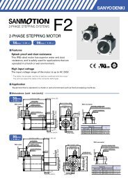
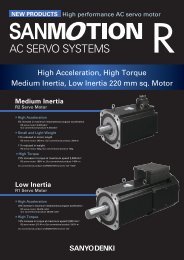
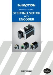
2-PHASE STEPPING SYSTEMS<br />
Ver.5
DC Input Set Models<br />
DC Input Drivers<br />
Stepping Motors<br />
Motor size: 14 mm sq. (0.55 inch sq.) to<br />
86 mm sq. (3.39 inch sq.), 106 mm (4.17 inch)<br />
Stepping Motors with Integrated DriversIP65 Splash <strong>and</strong> Dust Proof Stepping Motors<br />
Stepping Motors for Vacuum EnvironmentsSynchronous Motors
Contents<br />
Features P.4<br />
Lineup P.5<br />
Lineup Details P.6<br />
DC Input Set Models P.8<br />
System Configuration Diagram P.8<br />
Set Model Numbering Convention P.9<br />
Set Model Configuration P.10<br />
Unipolar Models Specifications P.11<br />
Bipolar Models Specifications P.14<br />
Driver Specifications P.19<br />
Driver Controls <strong>and</strong> Connectors P.20<br />
Connections <strong>and</strong> Signals P.21<br />
Stepping Motors P.24<br />
Stepping Motors with Integrated Drivers P.58<br />
IP65 Splash <strong>and</strong> Dust Proof Stepping Motors P.65<br />
Stepping Motors for Vacuum Environments P.68<br />
Synchronous Motors P.68<br />
Dimensions P.69<br />
Safety Considerations P.77
<strong>SANMOTION</strong> <strong>F2</strong> is a 2-<strong>phase</strong> stepping system that provides precise positioning with easy control.<br />
The typical basic step angle is 1.8, <strong>and</strong> accurate control is provided by pulse signals.<br />
Host Devices<br />
Driver<br />
Moter<br />
Motor Option<br />
Various types<br />
of gears<br />
Encoder<br />
PLC<br />
Pulse signal<br />
Brake<br />
Features<br />
Small <strong>driver</strong> <strong>and</strong> <strong>motor</strong>, yet high torque.<br />
Fast response provides shorter system cycle time for repetitive operations.<br />
Holding torque maintains the stop position when engaging power.<br />
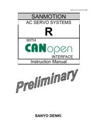
Low-vibration mode<br />
Smooth driving is achieved even with one-division (full-step) <strong>and</strong> two-division (half-step) coarse resolution<br />
settings. Vibrations are suppressed without control system restrictions.<br />
1600<br />
Low-Vibration Mode OFF<br />
1600<br />
Low-Vibration Mode ON<br />
Speed variation%<br />
1200<br />
800<br />
400<br />
Speed variation%<br />
1200<br />
800<br />
400<br />
0 200 400 600 800 1000<br />
Pulse/s<br />
0 200 400 600 800 1000<br />
Pulse/s<br />
Micro-step driving system<br />
Five 1.8basic step angle resolutions can be selected from 1 to 16 divisions (1.8to 0.1125per pulse).<br />
This enables a smooth operation with low vibration.<br />
Safety st<strong>and</strong>ards<br />
The <strong>SANMOTION</strong> <strong>F2</strong> drive complies with CE (EN st<strong>and</strong>ards) <strong>and</strong> UL st<strong>and</strong>ard specifications.<br />
4
Lineup<br />
Convenient set models consist of a DC-powered <strong>driver</strong> <strong>and</strong> <strong>motor</strong>.<br />
Aside from the set models it is also possible to select stepping <strong>motor</strong>s separately.<br />
We also provide a selection of stepping <strong>motor</strong>s with integrated <strong>driver</strong>s as well as models with IP65 Ingress Protection ratings.<br />
Customized stepping <strong>motor</strong>s for vacuum environments <strong>and</strong> synchronous <strong>motor</strong>s are also available.<br />
Set Models<br />
DC input<br />
Unipolar<br />
These set models consist of a DC-powered <strong>driver</strong> <strong>and</strong> <strong>motor</strong>.<br />
The <strong>motor</strong> winding specification is unipolar.<br />
Motor size:<br />
28 mm sq. (1.10 inch sq.) / 42 mm sq. (1.65 inch sq.) / 56 mm sq.(2.20 inch sq.)<br />
Bipolar<br />
These set models consist of a DC-powered <strong>driver</strong> <strong>and</strong> <strong>motor</strong>.<br />
The <strong>motor</strong> winding specification is bipolar.<br />
Motor size:<br />
28 mm sq. (1.10 inch sq.) / 42 mm sq.(1.65 inch sq.) / 50 mm sq (1.97 inch sq.) /<br />
56 mm sq. (2.20 inch sq.) / 60 mm sq. (2.36 inch sq.)<br />
Stepping Motors<br />
High-torque stepping <strong>motor</strong>s. Select from among a broad<br />
lineup of products from an ultra-compact 14 mm sq. (0.55<br />
inch sq.) <strong>motor</strong> size, to a thin 11.4 mm (0.45 inch) <strong>motor</strong> -<br />
the shortest <strong>motor</strong> length.<br />
A separate <strong>driver</strong> is required.<br />
Motor size:<br />
14 mm sq. (0.55 inch sq.) / 28 mm sq. (1.10 inch sq.) /<br />
35 mm sq. (1.38 inch sq.) / 42 mm sq. (1.65 inch sq.) /<br />
50 mm sq. (1.97 inch sq.) / 56 mm sq. (2.20 inch sq.) /<br />
60 mm sq. (2.36 inch sq.) / 86 mm sq.<br />
(3.39 inch sq., CE <strong>and</strong> UL models are available.) /<br />
<br />
106 mm ( 4.17 inch)<br />
Stepping Motors with Integrated Drivers<br />
These <strong>motor</strong>s include integrated <strong>driver</strong>s. This reduces<br />
mounting space requirements <strong>and</strong> wiring complexity.<br />
Three separate control modes: pulse train control, general<br />
purpose I/O (parallel interface), <strong>and</strong> RS-485 compliant<br />
serial communications can be selected.<br />
Motor size:<br />
42 mm sq. (1.65 inch sq.) /<br />
60 mm sq. (2.36 inch sq.)<br />
IP65 Splash <strong>and</strong> Dust Proof Stepping Motors<br />
These IP65 rated <strong>motor</strong>s* have superior water <strong>and</strong> dust<br />
resistance, <strong>and</strong> can be safely utilized in harsh or wet<br />
environments such as in food processing machines.<br />
The input voltage range of the <strong>motor</strong>s is<br />
up to AC 250 V.<br />
Except for the shaft <strong>and</strong> the cable end.<br />
A separate <strong>driver</strong> is required.<br />
Motor size:<br />
56 mm sq. (2.20 inch sq.) /<br />
86 mm sq. (3.39 inch sq.)<br />
Stepping Motors for Vacuum Environments Customized Products<br />
We can customize <strong>motor</strong>s for use in low to ultrahigh<br />
vacuum environments to suit your system requirements.<br />
A separate <strong>driver</strong> is required.<br />
Synchronous Motors Customized Products<br />
Synchronous <strong>motor</strong>s rotate at a<br />
constant speed in proportion to the AC<br />
power frequency. They operate on the<br />
commercial (AC) power supply.<br />
5
Features <strong>and</strong> Lineup<br />
Lineup Details<br />
Set Models Page P.8 <br />
DC input set models<br />
Unipolar<br />
DC input set models<br />
Bipolar<br />
Series<br />
Input source DC 24V/36V DC 24V/36V<br />
Number of divisions 124816 124816<br />
Stepangle<br />
Motors with 1.8<br />
basic step angle<br />
Motors with 0.9<br />
basic step angle<br />
Corresponding <strong>motor</strong> sizes<br />
1.8to 0.1125/ pulse<br />
0.9to 0.05625/ pulse<br />
28 mm sq. (1.10 in sq.) /<br />
42 mm sq. (1.65 in sq.) /<br />
56 mm sq. (2.20 in sq.)<br />
1.8to 0.1125/ pulse<br />
0.9to 0.05625/ pulse<br />
28 mm sq. (1.10 in sq.) /<br />
42 mm sq. (1.65 in sq.) /<br />
50 mm sq. (1.97 in sq.) /<br />
56 mm sq. (2.20 in sq.) /<br />
60 mm sq. (2.36 in sq.)<br />
Control method Pulse inputOpen loop Pulse inputOpen loop<br />
Set model accessories<br />
Page<br />
Driver, Motor,<br />
Cable with connector<br />
(Supplied only with connector-type <strong>motor</strong>s)<br />
Driver, Motor,<br />
Cable with connector<br />
(Supplied only with connector-type <strong>motor</strong>s)<br />
System Configuration<br />
Diagram<br />
P.8 P.8<br />
Set Model<br />
Configuration<br />
P.10 P.10<br />
Diagram<br />
Specifications /<br />
Characteristics<br />
P.11 to 13 P.14 to 18<br />
Diagram<br />
Driver Specifications /<br />
Safety St<strong>and</strong>ards<br />
P.19 P.19<br />
Motor Specifications P.57 P.57<br />
Dimensions P.69 to 75 P.69 to 75<br />
6
Stepping Motors Page P.24 <br />
Basic<br />
step<br />
angle<br />
Motor size<br />
Holding torque<br />
Nm (ozin)<br />
Model number<br />
Page<br />
Specifications /<br />
Characteristics diagram<br />
Dimensions<br />
0.9 42 mm sq. (1.65 in sq.) 0.2 to 0.48 (28.3 to 68.0) SH142 - 1 P.29 to 30 P.70<br />
0.9 60 mm sq. (2.36 in sq.) 0.57 to 2.15 (80.7 to 304) SH160 - 0 P.42 to 43 P.71<br />
1.8 14 mm sq. (0.55 in sq.) 0.0065 (0.92) SH2141-55 1 P.24 P.69<br />
1.8 28 mm sq. (1.10 in sq.) 0.055 to 0.145 (7.79 to 20.5) SH228 -5 1 P.25 to 26 P.69<br />
1.8 35 mm sq. (1.38 in sq.) 0.12 to 0.23 (17.0 to 32.6) SH35 -12U 0 P.27 P.69<br />
1.8<br />
42 mm sq. (1.65 in sq.)<br />
Slim form<br />
0.083 to 0.186 (11.8 to 26.3) SS242 -50 1 P.28 P.69<br />
1.8 42 mm sq. (1.65 in sq.) 0.2 to 0.51 (28.3 to 72.2) 103H52 - 0 P.31 to 33 P.69 to 70<br />
1.8 50 mm sq. (1.97 in sq.) 0.28 to 0.53 (39.7 to 75.1) 103H670 - 0 P.34 to 36 P.70<br />
1.8<br />
50 mm sq. (1.97 in sq.)<br />
Slim form<br />
0.1 to 0.215 (14.2 to 30.4) SS250 -80 0 P.37 P.70<br />
1.8 56 mm sq. (2.20 in sq.) 0.39 to 2.0 (55.2 to 283) 103H712 - 0 P.38 to 41 P.71<br />
1.8 60 mm sq. (2.36 in sq.) 0.78 to 2.7 (110 to 382) 103H782 - 0 P.44 to 47 P.72<br />
1.8<br />
86 mm sq. 3.39 in sq., CE <strong>and</strong><br />
UL models are available.<br />
2.5 to 9 (358 to 1270)<br />
SH286 - 1<br />
SM286 - <br />
P.48 to 51 P.73<br />
1.8 106 mm ( 4.17 in) 10.8 to 19 (1530 to 2690) 103H8922 - 1 P.52 P.74<br />
1.8<br />
56 mm sq. (2.20 in sq., CE<br />
Model)<br />
0.39 to 1.27 (55.2 to 179.8) 103H712 -6 0 P.53 P.73<br />
1.8 86 mm 3.39 in, CE Model) 2.74 to 7.44 (388 to 1053.6) 103H822 -6 0 P.54 P.74<br />
1.8 106 mm ( 4.17 in, CE Model) 13.2 to 19 (1869.2 to 2690.5) 103H8922 -63 1 P.55 P.74<br />
Contact us for available encoders, gears <strong>and</strong> <strong>motor</strong>s with brakes.<br />
Stepping Motors with Integrated Drivers Page P.58 <br />
Motor size<br />
Input<br />
source<br />
Interfaces<br />
Model number<br />
Page<br />
Specifications /<br />
Characteristics diagram<br />
Dimensions<br />
Pulse input<br />
42 mm sq. (1.65 in sq.)<br />
DB21M142S-01 P.59 P.75<br />
General-purpose I/O(Parallel)<br />
DC24V<br />
Serial communications (compliant<br />
60 mm sq. (1.65 in sq.) DB22M162S-01 P.59 P.75<br />
with RS-485)<br />
IP65 Splash <strong>and</strong> Dust Proof Stepping Motors Page P.65 <br />
Basic<br />
step<br />
angle<br />
Motor size<br />
Holding torque<br />
Nm (ozin)<br />
Safety st<strong>and</strong>ards<br />
Model number<br />
Page<br />
Specifications /<br />
Characteristics diagram<br />
Dimensions<br />
1.8<br />
56 mm sq.<br />
(2.20 in sq.)<br />
1 to 1.7<br />
(141.6 to 240.7)<br />
CE Model SP256 T-5 0 P.66 P.76<br />
CEUL Model SP256 -5 60 P.66 P.76<br />
1.8<br />
86 mm sq.<br />
(3.39 in sq.)<br />
6.4 to 9<br />
(906.3 to 1274.5)<br />
CE Model SP286 T-5 0 P.67 P.76<br />
CEUL Model SP286 -5 60 P.67 P.76<br />
Stepping Motors for Vacuum Environments Customized Products Page P.68<br />
We can customize <strong>motor</strong>s for use in low to ultra-high vacuum environments to suit your system requirements.<br />
We can h<strong>and</strong>le a wide range of pressures for low, high <strong>and</strong> ultrahigh vacuums.<br />
Synchronous Motors Customized Products Page P.68<br />
Synchronous <strong>motor</strong>s rotate at a constant speed in proportion to the AC power frequency. They operate on the commercial (AC)<br />
power supply.<br />
7
DC Input Set Models<br />
DC Input Set Models<br />
UnipolarBipolar<br />
Set Model Configuration P.10<br />
Specifications / Characteristics Diagram P.11 to 18<br />
Motor Specifications P.57 Driver Specifications P.19<br />
Motor Dimensions P.69 to 72<br />
Driver Dimensions P.75<br />
Features<br />
These are convenient sets of DC-powered <strong>driver</strong>s <strong>and</strong><br />
<strong>motor</strong>s.<br />
Select from two types of set models: with either unipolar or<br />
bipolar <strong>motor</strong> windings.<br />
Set model configuration items<br />
Driver<br />
Unipolar Model numberUS1D200P10 Input sourceDC24V/36V<br />
Bipolar Model numberBS1D200P10 Input sourceDC24V/36V<br />
Motor<br />
Unipolar Motor size: 28 mm sq. (1.10 inch sq.), 42 mm sq.<br />
(1.65 inch sq.), 56 mm sq. (2.20 inch sq.)<br />
Bipolar Motor size: 28 mm sq. (1.10 inch sq.), 42 mm sq.<br />
(1.65 inch sq.), 50 mm sq. (1.97 inch sq.),<br />
56 mm sq. (2.20 inch sq.), 60 mm sq.<br />
(2.36 inch sq.)<br />
Cable with connector *Supplied only with connector-type <strong>motor</strong>s<br />
Instruction manuals can be downloaded from our website.<br />
System Configuration Diagram<br />
Cable with connector<br />
*Supplied only with connector-type <strong>motor</strong>s.<br />
Driver<br />
Photo: US1D200P10<br />
Host Devices<br />
PLC<br />
Pulse signal<br />
Motor<br />
Encoder (option)<br />
Brake (option)<br />
Gear (option)<br />
DC24V/36V<br />
Switching<br />
power supply<br />
Noise filter<br />
Electromagnetic<br />
contractor<br />
Molded case<br />
circuit breaker<br />
Single Phase<br />
AC100V to 230V<br />
Converts AC power<br />
to DC power.<br />
Filters out incoming<br />
noise from power<br />
line.<br />
Switches <strong>driver</strong><br />
power on/off.<br />
Use together with a<br />
surge protector.<br />
Protects the power<br />
line. Cuts off circuit<br />
in the event of<br />
overcurrent.<br />
8
Set Model Numbering Convention<br />
Here is the set model number for a DC-powered unipolar <strong>driver</strong> (Model No. US1D200P10) <strong>and</strong> <strong>motor</strong> (Model No.<br />
103H7121-0440). Motor size is 56 mm sq. (2.20 in sq.), <strong>and</strong> <strong>motor</strong> length is 41.8 mm (1.65 in.), single-shaft.<br />
D U 1 6 H 71 1 S<br />
DC Input Set Models<br />
Stepping Motors<br />
Stepping <strong>motor</strong> shaft specification<br />
S : Single shaft<br />
D : Dual shaft<br />
Stepping Motors with<br />
Integrated Drivers<br />
Stepping <strong>motor</strong> total length<br />
Code<br />
Stepping <strong>motor</strong> size<br />
28 mm sq.<br />
1.10 in sq.<br />
Type<br />
code<br />
Motor<br />
length :<br />
mmin<br />
42 mm sq.<br />
1.65 in sq.<br />
Type<br />
code<br />
Stepping <strong>motor</strong> size<br />
Basic step angle<br />
28 : 28 mm sq. (1.10 inch sq.) 1.8<br />
52 : 42 mm sq. (1.65 inch sq.) 1.8<br />
14 : 42 mm sq. (1.65 inch sq.) 0.9<br />
67 : 50 mm sq. (1.97 inch sq.) 1.8<br />
71 : 56 mm sq. (2.20 inch sq.) 1.8<br />
78 : 60 mm sq. (2.36 inch sq.) 1.8<br />
16 : 60 mm sq. (2.36 inch sq.) 0.9<br />
Stepping <strong>motor</strong> series name<br />
H : H series<br />
S : SH series<br />
Motor<br />
length :<br />
mmin<br />
Type<br />
code<br />
Motor<br />
length :<br />
mmin<br />
50 mm sq.<br />
1.97 in sq.<br />
Type<br />
code<br />
Motor<br />
length :<br />
mmin<br />
56 mm sq.<br />
2.20 in sq.<br />
Type<br />
code<br />
Motor<br />
length :<br />
mmin<br />
60 mm sq.<br />
2.36 in sq.<br />
Type<br />
code<br />
Motor<br />
length :<br />
mmin<br />
Type<br />
code<br />
Motor<br />
length :<br />
mmin<br />
1 SH2281 321.26 103H5205 331.30 SH1421 331.30 103H6701 39.81.57 103H7121 41.81.65 103H7821 44.81.76 SH1601 421.65<br />
2 103H5208 391.54 SH1422 391.54 103H7822 53.82.12 SH1602 542.12<br />
3 103H6703 51.32.02 103H7123 53.82.12 103H7823 85.83.38<br />
4 103H5210 481.89 SH1424 481.89<br />
5 SH2285 51.52.03<br />
6 103H7126 75.82.89<br />
IP65 Splash <strong>and</strong> Dust<br />
Proof Stepping Motors<br />
Synchronous Motors Stepping Motors for<br />
Vacuum Environments<br />
Rated current specification<br />
4 : 1 A / <strong>phase</strong> 5 : 1.2 A / <strong>phase</strong> 6 : 2 A / <strong>phase</strong><br />
Dimensions<br />
Model<br />
Driver specification<br />
U : Unipolar B : Bipolar<br />
D : DC input<br />
9
DC Input Set Models<br />
Set Model Configuration This is a set comprising a <strong>driver</strong>, <strong>motor</strong> <strong>and</strong> cable with <strong>motor</strong> connector.<br />
Unipolar Bundled <strong>driver</strong> model numberUS1D200P10<br />
Motor<br />
size<br />
28 <br />
sq.<br />
42 <br />
sq.<br />
56 <br />
sq.<br />
Single shaft<br />
Set model<br />
number<br />
Set configuration items<br />
Motor model<br />
number<br />
Dual shaft<br />
Set model<br />
Cable with <strong>motor</strong><br />
number<br />
connector model number<br />
Set configuration items<br />
Motor model<br />
number<br />
Cable with <strong>motor</strong><br />
connector model number<br />
Basic<br />
step<br />
angle<br />
Rated<br />
current<br />
(A/<strong>phase</strong>)<br />
Page<br />
DU14S281S SH2281-5271 DU14S281D SH2281-5231 1.8 1 P.11 P.69<br />
DU14S285S SH2285-5271 DU14S285D SH2285-5231 1.8 1 P.11 P.69<br />
DU15H521S 103H5205-0440 4835710-1 DU15H521D 103H5205-0410 4835710-1 1.8 1.2 P.11 P.69<br />
DU15H522S 103H5208-0440 4835710-1 DU15H522D 103H5208-0410 4835710-1 1.8 1.2 P.11 P.69<br />
DU15H524S 103H5210-0440 4835710-1 DU15H524D 103H5210-0410 4835710-1 1.8 1.2 P.12 P.69<br />
DU15S141S SH1421-0441 DU15S141D SH1421-0411 0.9 1.2 P.12 P.70<br />
DU15S142S SH1422-0441 DU15S142D SH1422-0411 0.9 1.2 P.12 P.70<br />
DU15S144S SH1424-0441 DU15S144D SH1424-0411 0.9 1.2 P.12 P.70<br />
DU16H711S 103H7121-0440 DU16H711D 103H7121-0410 1.8 2 P.13 P.71<br />
DU16H713S 103H7123-0440 DU16H713D 103H7123-0410 1.8 2 P.13 P.71<br />
DU16H716S 103H7126-0440 DU16H716D 103H7126-0410 1.8 2 P.13 P.71<br />
Cable with <strong>motor</strong> connector *Supplied only with connector-type <strong>motor</strong>s<br />
Bundled cable (Unipolar 42 mm sq. (1.65 inch sq.) <strong>motor</strong>s only, model number: 4835710-1)<br />
Maker: J.S.T Mfg.Co.,Ltd<br />
Housing: EHR-6 Black<br />
Pin: SEH-001T-P0.6<br />
Pin No. Lead wire color<br />
6 Black<br />
5 Red<br />
4 Yellow<br />
3 Blue<br />
2 Orange<br />
1 White<br />
500 (1.64 feet) MIN.<br />
Lead wire: UL1430 AWG26<br />
Bipolar Bundled <strong>driver</strong> model numberBS1D200P10<br />
Motor<br />
size<br />
28 <br />
sq.<br />
42 <br />
sq.<br />
50 <br />
sq.<br />
56 <br />
sq.<br />
60 <br />
sq.<br />
Single shaft<br />
Set model<br />
number<br />
Set configuration items<br />
Motor model<br />
number<br />
Cable with <strong>motor</strong><br />
connector model number<br />
Dual shaft<br />
Set model<br />
number<br />
Set configuration items<br />
Motor model<br />
number<br />
Cable with <strong>motor</strong><br />
connector model number<br />
Basic<br />
step<br />
angle<br />
Rated<br />
current<br />
(A/<strong>phase</strong>)<br />
Page<br />
Specifications<br />
Dimensions<br />
Specifications<br />
Dimensions<br />
DB14S281S SH2281-5771 DB14S281D SH2281-5731 1.8 1 P.14 P.69<br />
DB14S285S SH2285-5771 DB14S285D SH2285-5731 1.8 1 P.14 P.69<br />
DB14H521S 103H5205-5240 DB14H521D 103H5205-5210 1.8 1 P.14 P.70<br />
DB14H522S 103H5208-5240 DB14H522D 103H5208-5210 1.8 1 P.14 P.70<br />
DB14H524S 103H5210-5240 DB14H524D 103H5210-5210 1.8 1 P.15 P.70<br />
DB16S141S SH1421-5241 DB16S141D SH1421-5211 0.9 2 P.15 P.70<br />
DB16S142S SH1422-5241 DB16S142D SH1422-5211 0.9 2 P.15 P.70<br />
DB16S144S SH1424-5241 DB16S144D SH1424-5211 0.9 2 P.15 P.70<br />
DB16H671S 103H6701-5040 DB16H671D 103H6701-5010 1.8 2 P.16 P.70<br />
DB16H673S 103H6703-5040 DB16H673D 103H6703-5010 1.8 2 P.16 P.70<br />
DB16H711S 103H7121-5740 DB16H711D 103H7121-5710 1.8 2 P.16 P.71<br />
DB16H713S 103H7123-5740 DB16H713D 103H7123-5710 1.8 2 P.16 P.71<br />
DB16H716S 103H7126-5740 DB16H716D 103H7126-5710 1.8 2 P.17 P.71<br />
DB16H781S 103H7821-5740 4837961-1 DB16H781D 103H7821-5710 4837961-1 1.8 2 P.17 P.72<br />
DB16H782S 103H7822-5740 4837961-1 DB16H782D 103H7822-5710 4837961-1 1.8 2 P.17 P.72<br />
DB16H783S 103H7823-5740 4837961-1 DB16H783D 103H7823-5710 4837961-1 1.8 2 P.17 P.72<br />
DB16S161S SH1601-5240 DB16S161D SH1601-5210 0.9 2 P.18 P.71<br />
DB16S162S SH1602-5240 DB16S162D SH1602-5210 0.9 2 P.18 P.71<br />
Cable with <strong>motor</strong> connector *Supplied only with connector-type <strong>motor</strong>s<br />
Bundled cable (Bipolar 60 mm sq. (2.36 inch sq.) <strong>motor</strong>s only, model number: 4837961-1)<br />
10<br />
Maker: J.S.T Mfg.Co.,Ltd<br />
Housing: VHR-4N<br />
Pin: SVH-21T-P1.1<br />
Pin No.<br />
4<br />
3<br />
2<br />
1<br />
Lead wire color<br />
Yellow<br />
Red<br />
Blue<br />
Orange<br />
500 (1.64 feet) MIN.<br />
Lead wire: UL1430 AWG22
Unipolar DC input <strong>driver</strong> (Model No.: US1D200P10) + Motor<br />
Size<br />
Motor size 28 mm sq. (1.10 in sq.) / Basic step angle 1.8 42 mm sq. (1.65 in sq.) / Basic step angle 1.8<br />
Motor length 32 mm (1.26 in) 51.5 mm (2.03 in) 33 mm (1.30 in) 39 mm (1.89 in)<br />
Single Set model number DU14S281S DU14S285S DU15H521S DU15H522S<br />
shaft Configuration item: <strong>motor</strong> number SH2281-5271 SH2285-5271 103H5205-0440 103H5208-0440<br />
Dual Set model number DU14S281D DU14S285D DU15H521D DU15H522D<br />
shaft Configuration item: <strong>motor</strong> number SH2281-5231 SH2285-5231 103H5205-0410 103H5208-0410<br />
Holding torque Nmozin 0.055 7.79 0.115 16.28 0.2 28.32 0.3 42.48<br />
Rotor inertia 10 -4 kgm 2 ozin 2 0.01 0.05 0.022 0.12 0.036 0.20 0.056 0.31<br />
Rated current A/<strong>phase</strong> 1 1 1.2 1.2<br />
Motor mass *1 kglbs 0.11 0.24 0.2 0.44 0.23 0.51 0.29 0.64<br />
Allowable thrust load N lbs 3 0.67 3 0.67 10 2.25 10 2.25<br />
Allowable radial load *2 N lbs 42 9.44 49 11.02 30 6 30 6<br />
*1 Driver mass P.19<br />
*2 When load is applied at 1/3 length from output shaft edge.<br />
DC Input Set Models<br />
Stepping Motors<br />
Characteristics diagram<br />
DU14S281S<br />
DU14S281D<br />
DU14S285S<br />
DU14S285D<br />
DU15H521S<br />
DU15H521D<br />
DU15H522S<br />
DU15H522D<br />
With rubber coupling Pull-out torque Full step Half step fs : Maximum self-start frequency when not loaded Full step Half step<br />
Source current (no load) Full step Half step<br />
Source current (load applied) Full step Half step<br />
DC24V<br />
DC36V<br />
14 0.1<br />
10<br />
0.1<br />
10<br />
14<br />
9<br />
9<br />
12<br />
0.08<br />
8<br />
12<br />
0.08<br />
8<br />
Pull-out torque<br />
10<br />
7<br />
10<br />
Pull-out torque<br />
7<br />
8<br />
0.06<br />
6<br />
0.06<br />
6<br />
8<br />
5<br />
5<br />
6 0.04<br />
4<br />
6 0.04<br />
4<br />
4<br />
3<br />
4<br />
3<br />
0.02<br />
Source current<br />
2<br />
0.02<br />
2<br />
2<br />
Source current<br />
1<br />
2<br />
1<br />
0 0<br />
0.1 1 10 100 0 0 0<br />
0.1 1 10 100 0<br />
Pulse rate kpulse/s<br />
Pulse rate kpulse/s<br />
Full step<br />
Full step<br />
100 1000 2000 3000 5000<br />
Half step<br />
Half step<br />
Torque ozin.<br />
Torque ozin.<br />
Torqueozin.<br />
Torqueozin.<br />
28<br />
24<br />
20<br />
16<br />
12<br />
8<br />
4<br />
0<br />
Torque Nm<br />
Torque Nm<br />
100 1000 2000 3000 5000<br />
100 1000 2000 3000 5000<br />
Number of rotations min 1 <br />
DC24V<br />
0.2<br />
10<br />
9<br />
0.16<br />
Pull-out torque<br />
8<br />
7<br />
0.12<br />
6<br />
5<br />
0.08<br />
4<br />
3<br />
0.04<br />
Source current<br />
2<br />
0<br />
0.1 1 10<br />
Pulse rate kpulse/s<br />
1<br />
100 0<br />
100 1000 2000 3000 5000<br />
100 1000 2000 3000 5000<br />
Number of rotations min 1 <br />
Full step<br />
Half step<br />
70<br />
60<br />
50<br />
40<br />
30<br />
20<br />
10<br />
0<br />
Torque Nm<br />
Full step<br />
Half step<br />
70<br />
60<br />
50<br />
40<br />
30<br />
20<br />
10<br />
0<br />
Torque Nm<br />
Full step<br />
Half step<br />
DC24V<br />
0.5<br />
10<br />
9<br />
0.4<br />
8<br />
7<br />
0.3<br />
6<br />
Pull-out torque<br />
5<br />
0.2<br />
4<br />
3<br />
0.1<br />
Source current<br />
2<br />
0<br />
0.1 1 10<br />
Pulse rate kpulse/s<br />
1<br />
100 0<br />
100 1000 2000 3000 5000<br />
100 1000 2000 3000 5000<br />
Number of rotations min 1 <br />
DC24V<br />
0.5<br />
10<br />
9<br />
0.4<br />
8<br />
Pull-out torque<br />
7<br />
0.3<br />
6<br />
5<br />
0.2<br />
4<br />
3<br />
0.1 Source current<br />
2<br />
0<br />
0.1 1 10<br />
Pulse rate kpulse/s<br />
1<br />
100 0<br />
100 1000 2000 3000 5000<br />
100 1000 2000 3000 5000<br />
Number of rotations min 1 <br />
System Configuration Diagram P.8 Set Model Configuration P.10 Motor Dimensions P.69 to 72 Driver Dimensions P.75<br />
The data are measured under the trial conditions of SANYO DENKI. Driving torque may vary according to actual machine precision.<br />
Source current <br />
Source current <br />
Source current <br />
Source current <br />
Torque ozin.<br />
Torque ozin.<br />
Torqueozin.<br />
Torqueozin.<br />
28<br />
24<br />
20<br />
16<br />
12<br />
8<br />
4<br />
0<br />
Torque Nm<br />
Torque Nm<br />
100 1000 2000 3000 5000<br />
Number of rotations min 1 <br />
DC36V<br />
0.2<br />
10<br />
9<br />
0.16<br />
Pull-out torque<br />
8<br />
7<br />
0.12<br />
6<br />
5<br />
0.08<br />
4<br />
3<br />
0.04<br />
Source current<br />
2<br />
0<br />
0.1 1 10<br />
Pulse rate kpulse/s<br />
1<br />
100 0<br />
100 1000 2000 3000 5000<br />
100 1000 2000 3000 5000<br />
Number of rotations min 1 <br />
Full step<br />
Half step<br />
70<br />
60<br />
50<br />
40<br />
30<br />
20<br />
10<br />
0<br />
Torque Nm<br />
Full step<br />
Half step<br />
70<br />
60<br />
50<br />
40<br />
30<br />
20<br />
10<br />
0<br />
Torque Nm<br />
Full step<br />
Half step<br />
DC36V<br />
0.5<br />
10<br />
9<br />
0.4<br />
8<br />
7<br />
0.3<br />
6<br />
Pull-out torque<br />
5<br />
0.2<br />
4<br />
3<br />
0.1<br />
Source current<br />
2<br />
0<br />
0.1 1 10<br />
Pulse rate kpulse/s<br />
1<br />
100 0<br />
100 1000 2000 3000 5000<br />
100 1000 2000 3000 5000<br />
Number of rotations min 1 <br />
DC36V<br />
0.5<br />
10<br />
9<br />
0.4<br />
8<br />
Pull-out torque<br />
7<br />
0.3<br />
6<br />
5<br />
0.2<br />
4<br />
3<br />
0.1<br />
Source current<br />
2<br />
0<br />
0.1 1 10<br />
Pulse rate kpulse/s<br />
1<br />
100 0<br />
100 1000 2000 3000 5000<br />
100 1000 2000 3000 5000<br />
Number of rotations min 1 <br />
Source current <br />
Source current <br />
Source current <br />
Source current <br />
11<br />
Stepping Motors with<br />
Integrated Drivers<br />
IP65 Splash <strong>and</strong> Dust<br />
Proof Stepping Motors<br />
Synchronous Motors Stepping Motors for<br />
Vacuum Environments<br />
Dimensions
DC Input Set Models<br />
Unipolar DC input <strong>driver</strong> (Model No.: US1D200P10) + Motor<br />
Size<br />
Motor size 42 mm sq. (1.65 in sq.) / Basic step angle 1.8 42 mm sq. (1.65 in sq.) / Basic step angle 0.9<br />
Motor length 48 mm (1.89 in) 33 mm (1.30 in) 39 mm (1.54 in) 48 mm (1.89 in)<br />
Single Set model number DU15H524S DU15S141S DU15S142S DU15S144S<br />
shaft Configuration item: <strong>motor</strong> number 103H5210-0440 SH1421-0441 SH1422-0441 SH1424-0441<br />
Dual Set model number DU15H524D DU15S141D DU15S142D DU15S144D<br />
shaft Configuration item: <strong>motor</strong> number 103H5210-0410 SH1421-0411 SH1422-0411 SH1424-0411<br />
Holding torque Nmozin 0.37 52.39 0.2 28.32 0.29 41.07 0.39 55.23<br />
Rotor inertia 10 -4 kgm 2 ozin 2 0.074 0.40 0.044 0.24 0.066 0.361 0.089 0.487<br />
Rated current A/<strong>phase</strong> 1.2 1.2 1.2 1.2<br />
Motor mass *1 kglbs 0.37 0.82 0.24 0.53 0.29 0.64 0.38 0.84<br />
Allowable thrust load N lbs 10 2.25 10 2.25 10 2.25 10 2.25<br />
Allowable radial load *2 N lbs 30 6 30 6 30 6 30 6<br />
*1 Driver mass P.19<br />
*2 When load is applied at 1/3 length from output shaft edge.<br />
12<br />
Characteristics diagram<br />
DU15H524S<br />
DU15H524D<br />
DU15S141S<br />
DU15S141D<br />
DU15S142S<br />
DU15S142D<br />
DU15S144S<br />
DU15S144D<br />
With rubber coupling Pull-out torque Full step Half step fs : Maximum self-start frequency when not loaded Full step Half step<br />
Source current (no load) Full step Half step<br />
Source current (load applied) Full step Half step<br />
DC24V<br />
DC36V<br />
Torqueozin.<br />
Torqueozin.<br />
Torqueozin.<br />
Torqueozin.<br />
70<br />
60<br />
50<br />
40<br />
30<br />
20<br />
10<br />
0<br />
Torque Nm<br />
Full step<br />
Half step<br />
Torque Nm<br />
0.5<br />
10<br />
9<br />
0.4<br />
Pull-out torque<br />
8<br />
7<br />
0.3<br />
6<br />
5<br />
0.2<br />
4<br />
3<br />
0.1<br />
Source current<br />
2<br />
0<br />
0.1 1 10<br />
Pulse rate kpulse/s<br />
1<br />
100 0<br />
100 1000 2000 3000 5000<br />
100 1000 2000 3000 5000<br />
Number of rotations min 1 <br />
DC24V<br />
70 0.5<br />
10<br />
9<br />
60<br />
0.4<br />
8<br />
50<br />
7<br />
40<br />
0.3 Pull-out torque<br />
6<br />
5<br />
30 0.2<br />
4<br />
20<br />
3<br />
0.1<br />
Source current<br />
2<br />
10<br />
1<br />
0 0<br />
0.1 1 10 100 0<br />
Pulse rate kpulse/s<br />
Full step<br />
100 1000 2000 3000 5000<br />
Half step<br />
100 1000 2000 3000 5000<br />
Number of rotations min 1 <br />
70<br />
60<br />
50<br />
40<br />
30<br />
20<br />
10<br />
0<br />
Torque Nm<br />
Full step<br />
Half step<br />
Torque Nm<br />
DC24V<br />
0.5<br />
10<br />
9<br />
0.4 Pull-out torque<br />
8<br />
7<br />
0.3<br />
6<br />
5<br />
0.2<br />
4<br />
3<br />
0.1<br />
Source current<br />
2<br />
0<br />
0.1 1 10<br />
Pulse rate kpulse/s<br />
1<br />
100 0<br />
100 1000 2000 3000 5000<br />
100 1000 2000 3000 5000<br />
Number of rotations min 1 <br />
DC24V<br />
0.5<br />
70<br />
10<br />
9<br />
60<br />
0.4 Pull-out torque<br />
8<br />
50<br />
7<br />
40<br />
0.3<br />
6<br />
5<br />
30 0.2<br />
4<br />
20<br />
3<br />
Source current<br />
0.1<br />
2<br />
10<br />
1<br />
0 0<br />
0.1 1 10 100 0<br />
Pulse rate kpulse/s<br />
Full step<br />
100 1000 2000 3000 5000<br />
Half step<br />
100 1000 2000 3000 5000<br />
Source current <br />
Torqueozin.<br />
70<br />
60<br />
50<br />
40<br />
30<br />
20<br />
10<br />
0<br />
Torque Nm<br />
Full step<br />
Half step<br />
Number of rotations min 1 <br />
System Configuration Diagram P.8 Set Model Configuration P.10 Motor Dimensions P.69 to 72 Driver Dimensions P.75<br />
The data are measured under the trial conditions of SANYO DENKI. Driving torque may vary according to actual machine precision.<br />
Source current <br />
Source current <br />
Source current <br />
Torqueozin.<br />
Torqueozin.<br />
Torqueozin.<br />
Torque Nm<br />
0.5<br />
10<br />
9<br />
0.4<br />
Pull-out torque<br />
8<br />
7<br />
0.3<br />
6<br />
5<br />
0.2<br />
4<br />
3<br />
0.1 Source current<br />
2<br />
0<br />
0.1 1 10<br />
Pulse rate kpulse/s<br />
1<br />
100 0<br />
DC36V<br />
100 1000 2000 3000 5000<br />
100 1000 2000 3000 5000<br />
Number of rotations min 1 <br />
DC36V<br />
70 0.5<br />
10<br />
9<br />
60<br />
0.4<br />
8<br />
50<br />
7<br />
40<br />
0.3 Pull-out torque<br />
6<br />
5<br />
30 0.2<br />
4<br />
20<br />
3<br />
0.1 Source current<br />
2<br />
10<br />
1<br />
0 0<br />
0.1 1 10 100 0<br />
Pulse rate kpulse/s<br />
Full step<br />
100 1000 2000 3000 5000<br />
Half step<br />
100 1000 2000 3000 5000<br />
Number of rotations min 1 <br />
70<br />
60<br />
50<br />
40<br />
30<br />
20<br />
10<br />
0<br />
Torque Nm<br />
Full step<br />
Half step<br />
70<br />
60<br />
50<br />
40<br />
30<br />
20<br />
10<br />
0<br />
Torque Nm<br />
Full step<br />
Half step<br />
0.5<br />
10<br />
9<br />
0.4<br />
8<br />
Pull-out torque<br />
7<br />
0.3<br />
6<br />
5<br />
0.2<br />
4<br />
3<br />
0.1 Source current<br />
2<br />
0<br />
0.1 1 10<br />
1<br />
100 0<br />
Pulse rate kpulse/s<br />
100 1000 2000 3000 5000<br />
100 1000 2000 3000 5000<br />
Number of rotations min 1 <br />
DC36V<br />
0.5<br />
10<br />
9<br />
0.4 Pull-out torque<br />
8<br />
7<br />
0.3<br />
6<br />
5<br />
0.2<br />
4<br />
3<br />
0.1 Source current<br />
2<br />
0<br />
0.1 1 10<br />
1<br />
100 0<br />
Pulse rate kpulse/s<br />
100 1000 2000 3000 5000<br />
100 1000 2000 3000 5000<br />
Number of rotations min 1 <br />
Source current <br />
Source current <br />
Source current <br />
Source current
Size<br />
Motor size 56 mm sq. (2.20 in sq.) / Basic step angle 1.8<br />
Motor length 41.8 mm (1.65 in) 53.8 mm (2.12 in) 75.8 mm (2.98 in)<br />
Single Set model number DU16H711S DU16H713S DU16H716S<br />
shaft Configuration item: <strong>motor</strong> number 103H7121-0440 103H7123-0440 103H7126-0440<br />
Dual Set model number DU16H711D DU16H713D DU16H716D<br />
shaft Configuration item: <strong>motor</strong> number 103H7121-0410 103H7123-0410 103H7126-0410<br />
Holding torque Nmozin 0.39 (55.23) 0.83 (117.5) 1.27 (179.8)<br />
Rotor inertia 10 -4 kgm 2 ozin 2 0.1 (0.55) 0.21 (1.15) 0.36 (1.97)<br />
Rated current A/<strong>phase</strong> 2 2 2<br />
Motor mass *1 kglbs 0.47 (1.04) 0.65 (1.43) 0.98 (2.16)<br />
Allowable thrust load N lbs 15 (3.37) 15 (3.37) 15 (3.37)<br />
Allowable radial load *2 N lbs 71 (15) 71 (15) 71 (15)<br />
*1 Driver mass P.19<br />
*2 When load is applied at 1/3 length from output shaft edge.<br />
Characteristics diagram<br />
With rubber coupling Pull-out torque Full step Half step fs : Maximum self-start frequency when not loaded Full step Half step<br />
Source current (no load) Full step Half step<br />
Source current (load applied) Full step Half step<br />
DU16H711S<br />
DC24V<br />
DC36V<br />
70 0.5<br />
10<br />
0.5<br />
10<br />
DU16H711D<br />
70<br />
9<br />
9<br />
60<br />
0.4<br />
8<br />
60<br />
0.4<br />
8<br />
Pull-out torque<br />
50<br />
7<br />
50<br />
Pull-out torque<br />
7<br />
0.3<br />
6<br />
40<br />
0.3<br />
6<br />
40<br />
5<br />
5<br />
30 0.2<br />
4<br />
30 0.2<br />
4<br />
20<br />
Source current<br />
3<br />
20<br />
Source current<br />
3<br />
0.1<br />
2<br />
0.1<br />
2<br />
10<br />
10<br />
1<br />
1<br />
0 0<br />
0.1 1 10 100 0 0 0<br />
0.1 1 10 100 0<br />
Pulse rate kpulse/s<br />
Pulse rate kpulse/s<br />
Full step<br />
Full step<br />
100 1000 2000 3000 5000<br />
100 1000 2000 3000 5000<br />
Half step<br />
Half step<br />
100 1000 2000 3000 5000<br />
100 1000 2000 3000 5000<br />
Number of rotations min 1 <br />
Number of rotations min 1 <br />
DU16H713S<br />
DC24V<br />
DC36V<br />
1.0<br />
10<br />
DU16H713D<br />
140<br />
1.0<br />
10<br />
140<br />
Pull-out torque<br />
9<br />
Pull-out torque<br />
9<br />
120<br />
0.8<br />
8<br />
120<br />
0.8<br />
8<br />
100<br />
7<br />
100<br />
7<br />
0.6<br />
6<br />
80<br />
0.6<br />
6<br />
80<br />
5<br />
5<br />
60 0.4<br />
4<br />
60 0.4<br />
4<br />
40<br />
Source current<br />
3<br />
40<br />
Source current<br />
3<br />
0.2<br />
2<br />
0.2<br />
2<br />
20<br />
1<br />
20<br />
1<br />
0 0<br />
0.1 1 10 100 0 0 0<br />
0.1 1 10 100 0<br />
Pulse rate kpulse/s<br />
Pulse rate kpulse/s<br />
Full step<br />
Full step<br />
100 1000 2000 3000 5000<br />
100 1000 2000 3000 5000<br />
Half step<br />
Half step<br />
100 1000 2000 3000 5000<br />
100 1000 2000 3000 5000<br />
Number of rotations min 1 <br />
Number of rotations min 1 <br />
DU16H716S<br />
DU16H716D<br />
Torqueozin.<br />
Torque ozin.<br />
Torque Nm<br />
Torque Nm<br />
DC24V<br />
280 2.0<br />
10<br />
9<br />
1.6 Pull-out torque<br />
8<br />
200<br />
7<br />
160<br />
1.2<br />
6<br />
5<br />
120 0.8<br />
4<br />
Source current<br />
80<br />
3<br />
0.4<br />
2<br />
40<br />
1<br />
0 0<br />
0.1 1 10 100 0<br />
Pulse rate kpulse/s<br />
Full step<br />
100 1000 2000 3000 5000<br />
Half step<br />
100 1000 2000 3000 5000<br />
Number of rotations min 1 <br />
Torque ozin.240<br />
Torque Nm<br />
Source current <br />
Source current <br />
Source current <br />
Torqueozin.<br />
Torque ozin.<br />
Torque Nm<br />
Torque Nm<br />
DC36V<br />
280 2.0<br />
10<br />
9<br />
1.6 Pull-out torque<br />
8<br />
200<br />
7<br />
160<br />
1.2<br />
6<br />
5<br />
120 0.8<br />
4<br />
80<br />
Source current<br />
3<br />
0.4<br />
2<br />
40<br />
1<br />
0 0<br />
0.1 1 10 100 0<br />
Pulse rate kpulse/s<br />
Full step<br />
100 1000 2000 3000 5000<br />
Half step<br />
100 1000 2000 3000 5000<br />
Number of rotations min 1 <br />
Torque ozin.240<br />
Torque Nm<br />
Source current <br />
Source current <br />
Source current <br />
DC Input Set Models<br />
Stepping Motors<br />
Stepping Motors with<br />
Integrated Drivers<br />
IP65 Splash <strong>and</strong> Dust<br />
Proof Stepping Motors<br />
Synchronous Motors Stepping Motors for<br />
Vacuum Environments<br />
Dimensions<br />
System Configuration Diagram P.8 Set Model Configuration P.10 Motor Dimensions P.69 to 72 Driver Dimensions P.75<br />
The data are measured under the trial conditions of SANYO DENKI. Driving torque may vary according to actual machine precision.<br />
13
DC Input Set Models<br />
Bipolar DC input <strong>driver</strong> (Model No.: BS1D200P10) + Motor<br />
Size<br />
Motor size 28 mm sq. (1.10 in sq.) / Basic step angle1.8 42 mm sq. (1.65 in sq.) / Basic step angle1.8<br />
Motor length 32 mm (1.26 in) 51.5 mm (2.03 in) 33 mm (1.30 in) 39 mm (1.54 in)<br />
Single Set model number DB14S281S DB14S285S DB14H521S DB14H522S<br />
shaft Configuration item: <strong>motor</strong> number SH2281-5771 SH2285-5771 103H5205-5240 103H5208-5240<br />
Dual Set model number DB14S281D DB14S285D DB14H521D DB14H522D<br />
shaft Configuration item: <strong>motor</strong> number SH2281-5731 SH2285-5731 103H5205-5210 103H5208-5210<br />
Holding torque Nmozin 0.07 (9.91) 0.145 (20.53) 0.265 (37.53) 0.39 (55.23)<br />
Rotor inertia 10 -4 kgm 2 ozin 2 0.01 (0.05) 0.022 (0.12) 0.036 (0.20) 0.056 (0.31)<br />
Rated current A/<strong>phase</strong> 1 1 1 1<br />
Motor mass *1 kglbs 0.11 (0.24) 0.2 (0.44) 0.23 (0.51) 0.29 (0.64)<br />
Allowable thrust load N lbs 3 (0.67) 3 (0.67) 10 (2.25) 10 (2.25)<br />
Allowable radial load *2 N lbs 42 (9.44) 49 (9.44) 30 (6) 30 (6)<br />
*1 Driver mass P.19<br />
*2 When load is applied at 1/3 length from output shaft edge.<br />
14<br />
Characteristics diagram<br />
DB14S281S<br />
DB14S281D<br />
DB14S285S<br />
DB14S285D<br />
DB14H521S<br />
DB14H521D<br />
DB14H522S<br />
DB14H522D<br />
With rubber coupling Pull-out torque Full step Half step fs : Maximum self-start frequency when not loaded Full step Half step<br />
Source current (no load) Full step Half step<br />
Source current (load applied) Full step Half step<br />
DC24V<br />
DC36V<br />
Torque ozin.<br />
Torque ozin.<br />
Torqueozin.<br />
Torqueozin.<br />
14<br />
12<br />
10<br />
8<br />
6<br />
4<br />
2<br />
0<br />
Torque Nm<br />
0.1<br />
10<br />
9<br />
8<br />
7<br />
6<br />
Pull-out torque<br />
5<br />
4<br />
3<br />
Source current<br />
2<br />
1<br />
0<br />
0.1 1 10 100 0<br />
Pulse rate kpulse/s<br />
0.08<br />
0.06<br />
0.04<br />
0.02<br />
Full step<br />
Half step<br />
28<br />
24<br />
20<br />
16<br />
12<br />
8<br />
4<br />
0<br />
Torque Nm<br />
100 1000 2000 3000 5000<br />
100 1000 2000 3000 5000<br />
Number of rotations min 1 <br />
DC24V<br />
0.2<br />
10<br />
9<br />
0.16<br />
8<br />
7<br />
0.12<br />
6<br />
Pull-out torque<br />
5<br />
0.08<br />
4<br />
3<br />
0.04 Source current<br />
2<br />
0<br />
0.1 1 10<br />
Pulse rate kpulse/s<br />
1<br />
100 0<br />
100 1000 2000 3000 5000<br />
100 1000 2000 3000 5000<br />
Number of rotations min 1 <br />
Full step<br />
Half step<br />
70<br />
60<br />
50<br />
40<br />
30<br />
20<br />
10<br />
0<br />
Torque Nm<br />
Full step<br />
Half step<br />
70<br />
60<br />
50<br />
40<br />
30<br />
20<br />
10<br />
0<br />
Torque Nm<br />
Full step<br />
Half step<br />
DC24V<br />
0.5<br />
10<br />
9<br />
0.4<br />
8<br />
Pull-out torque<br />
7<br />
0.3<br />
6<br />
5<br />
0.2<br />
4<br />
3<br />
0.1 Source current<br />
2<br />
0<br />
0.1 1 10<br />
1<br />
100 0<br />
Pulse rate kpulse/s<br />
100 1000 2000 3000 5000<br />
100 1000 2000 3000 5000<br />
Number of rotations min 1 <br />
DC24V<br />
0.5<br />
Pull-out torque<br />
0.4<br />
10<br />
9<br />
8<br />
7<br />
0.3<br />
6<br />
5<br />
0.2<br />
4<br />
3<br />
0.1 Source current<br />
2<br />
0<br />
0.1 1 10<br />
Pulse rate kpulse/s<br />
1<br />
100 0<br />
100 1000 2000 3000 5000<br />
100 1000 2000 3000 5000<br />
Source current <br />
Torque ozin.<br />
14<br />
12<br />
10<br />
8<br />
6<br />
4<br />
2<br />
0<br />
Torque Nm<br />
0.1<br />
10<br />
9<br />
0.08<br />
8<br />
7<br />
0.06<br />
6<br />
Pull-out torque<br />
5<br />
0.04<br />
4<br />
3<br />
0.02<br />
2<br />
Source current<br />
1<br />
0<br />
0.1 1 10 100 0<br />
Pulse rate kpulse/s<br />
Full step<br />
Half step<br />
Number of rotations min 1 <br />
System Configuration Diagram P.8 Set Model Configuration P.10 Motor Dimensions P.69 to 72 Driver Dimensions P.75<br />
The data are measured under the trial conditions of SANYO DENKI. Driving torque may vary according to actual machine precision.<br />
Source current <br />
Source current <br />
Source current <br />
Torque ozin.<br />
Torqueozin.<br />
Torqueozin.<br />
28<br />
24<br />
20<br />
16<br />
12<br />
8<br />
4<br />
0<br />
Torque Nm<br />
100 1000 2000 3000 5000<br />
100 1000 2000 3000 5000<br />
Number of rotations min 1 <br />
DC36V<br />
0.2<br />
10<br />
9<br />
0.16<br />
8<br />
7<br />
0.12<br />
6<br />
Pull-out torque<br />
5<br />
0.08<br />
4<br />
3<br />
0.04<br />
Source current<br />
2<br />
0<br />
0.1 1 10<br />
Pulse rate kpulse/s<br />
1<br />
100 0<br />
100 1000 2000 3000 5000<br />
100 1000 2000 3000 5000<br />
Number of rotations min 1 <br />
Full step<br />
Half step<br />
70<br />
60<br />
50<br />
40<br />
30<br />
20<br />
10<br />
0<br />
Torque Nm<br />
Full step<br />
Half step<br />
70<br />
60<br />
50<br />
40<br />
30<br />
20<br />
10<br />
0<br />
Torque Nm<br />
Full step<br />
Half step<br />
DC36V<br />
0.5<br />
10<br />
9<br />
0.4<br />
8<br />
Pull-out torque<br />
7<br />
0.3<br />
6<br />
5<br />
0.2<br />
4<br />
3<br />
0.1 Source current<br />
2<br />
0<br />
0.1 1 10<br />
Pulse rate kpulse/s<br />
1<br />
100 0<br />
100 1000 2000 3000 5000<br />
100 1000 2000 3000 5000<br />
Number of rotations min 1 <br />
Source current <br />
Source current <br />
Source current <br />
Source current
Size<br />
Motor size 42 mm sq. (1.65 in sq.) / Basic step angle1.8 42 mm sq. (1.65 in sq.) / Basic step angle 0.9<br />
Motor length 48 mm (1.89 in) 33 mm (1.30 in) 39 mm (1.54 in) 48 mm (1.89 in)<br />
Single Set model number DB14H524S DB16S141S DB16S142S DB16S144S<br />
shaft Configuration item: <strong>motor</strong> number 103H5210-5240 SH1421-5241 SH1422-5241 SH1424-5241<br />
Dual Set model number DB14H524D DB16S141D DB16S142D DB16S144D<br />
shaft Configuration item: <strong>motor</strong> number 103H5210-5210 SH1421-5211 SH1422-5211 SH1424-5211<br />
Holding torque Nmozin 0.51 (72.22) 0.23 (32.57) 0.34 (48.15) 0.48 (67.97)<br />
Rotor inertia 10 -4 kgm 2 ozin 2 0.074 (0.40) 0.044 (0.24) 0.066 (0.361) 0.089 (0.487)<br />
Rated current A/<strong>phase</strong> 1 2 2 2<br />
Motor mass *1 kglbs 0.37 (0.82) 0.24 (0.53) 0.29 (0.64) 0.38 (0.84)<br />
Allowable thrust load N lbs 10 (2.25) 10 (2.25) 10 (2.25) 10 (2.25)<br />
Allowable radial load *2 N lbs 30 (6) 30 (6) 30 (6) 30 (6)<br />
*1 Driver mass P.19<br />
*2 When load is applied at 1/3 length from output shaft edge.<br />
DC Input Set Models<br />
Stepping Motors<br />
Characteristics diagram<br />
With rubber coupling Pull-out torque Full step Half step fs : Maximum self-start frequency when not loaded Full step Half step<br />
Source current (no load) Full step Half step<br />
Source current (load applied) Full step Half step<br />
DB14H524S<br />
DC24V<br />
DC36V<br />
1.0<br />
10<br />
140<br />
1.0<br />
10<br />
DB14H524D<br />
140<br />
9<br />
9<br />
120 0.8<br />
8<br />
120<br />
0.8<br />
8<br />
100<br />
Pull-out torque<br />
7<br />
100<br />
Pull-out torque<br />
7<br />
0.6<br />
6<br />
0.6<br />
6<br />
80<br />
80<br />
5<br />
5<br />
60 0.4<br />
4<br />
60 0.4<br />
4<br />
40<br />
3<br />
40<br />
3<br />
0.2 Source current<br />
2<br />
0.2 Source current<br />
2<br />
20<br />
1<br />
20<br />
1<br />
0 0<br />
0.1 1 10 100 0 0 0<br />
0.1 1 10 100 0<br />
Pulse rate kpulse/s<br />
Pulse rate kpulse/s<br />
Full step<br />
Full step<br />
100 1000 2000 3000 5000<br />
100 1000 2000 3000 5000<br />
Half step<br />
Half step<br />
100 1000 2000 3000 5000<br />
100 1000 2000 3000 5000<br />
Number of rotations min 1 <br />
Number of rotations min 1 <br />
DB16S141S<br />
DC24V<br />
DC36V<br />
0.5<br />
10<br />
DB16S141D<br />
70<br />
0.5<br />
10<br />
70<br />
9<br />
9<br />
60<br />
0.4<br />
8<br />
60<br />
0.4<br />
8<br />
50<br />
7<br />
50<br />
7<br />
Pull-out torque<br />
Pull-out torque<br />
0.3<br />
6<br />
40<br />
0.3<br />
6<br />
40<br />
5<br />
5<br />
30 0.2<br />
4<br />
30 0.2<br />
4<br />
20<br />
3<br />
20<br />
3<br />
0.1<br />
Source current<br />
2<br />
0.1<br />
Source current<br />
2<br />
10<br />
1<br />
10<br />
1<br />
0 0<br />
0.1 1 10 100 0 0 0<br />
0.1 1 10 100 0 Pulse rate kpulse/s<br />
Pulse rate kpulse/s<br />
Full step<br />
Full step<br />
100 1000 2000 3000 5000<br />
100 1000 2000 3000 5000<br />
Half step<br />
Half step<br />
100 1000 2000 3000 5000<br />
100 1000 2000 3000 5000<br />
Number of rotations min 1 <br />
Number of rotations min 1 <br />
DB16S142S<br />
DB16S142D<br />
DB16S144S<br />
DB16S144D<br />
Torque ozin.<br />
Torqueozin.<br />
Torqueozin.<br />
70<br />
60<br />
50<br />
40<br />
30<br />
20<br />
10<br />
0<br />
Torque Nm<br />
Torque Nm<br />
Torque Nm<br />
Full step<br />
Half step<br />
Torque Nm<br />
DC24V<br />
0.5<br />
10<br />
9<br />
0.4 Pull-out torque<br />
8<br />
7<br />
0.3<br />
6<br />
5<br />
0.2<br />
4<br />
3<br />
0.1 Source current<br />
2<br />
0<br />
0.1 1 10<br />
Pulse rate kpulse/s<br />
1<br />
100 0<br />
100 1000 2000 3000 5000<br />
100 1000 2000 3000 5000<br />
Number of rotations min 1 <br />
DC24V<br />
140 1.0<br />
10<br />
9<br />
120<br />
0.8<br />
8<br />
100<br />
7<br />
80<br />
0.6 Pull-out torque<br />
6<br />
5<br />
60 0.4<br />
4<br />
40<br />
3<br />
0.2 Source current<br />
2<br />
20<br />
1<br />
0 0<br />
0.1 1 10 100 0 Pulse rate kpulse/s<br />
Full step<br />
100 1000 2000 3000 5000<br />
Half step<br />
100 1000 2000 3000 5000<br />
Number of rotations min 1 <br />
Torque ozin.<br />
System Configuration Diagram P.8 Set Model Configuration P.10 Motor Dimensions P.69 to 72 Driver Dimensions P.75<br />
The data are measured under the trial conditions of SANYO DENKI. Driving torque may vary according to actual machine precision.<br />
Source current <br />
Source current <br />
Source current <br />
Source current <br />
Torque ozin.<br />
Torqueozin.<br />
Torqueozin.<br />
Torque ozin.<br />
70<br />
60<br />
50<br />
40<br />
30<br />
20<br />
10<br />
0<br />
Torque Nm<br />
Torque Nm<br />
Torque Nm<br />
Full step<br />
Half step<br />
DC36V<br />
0.5<br />
10<br />
9<br />
0.4<br />
Pull-out torque<br />
8<br />
7<br />
0.3<br />
6<br />
5<br />
0.2<br />
4<br />
3<br />
0.1<br />
Source current<br />
2<br />
0<br />
0.1 1 10<br />
Pulse rate kpulse/s<br />
1<br />
100 0<br />
100 1000 2000 3000 5000<br />
100 1000 2000 3000 5000<br />
Number of rotations min 1 <br />
DC36V<br />
1.0<br />
10<br />
140<br />
9<br />
120 0.8<br />
8<br />
100<br />
7<br />
Pull-out torque<br />
0.6<br />
6<br />
80<br />
5<br />
60 0.4<br />
4<br />
40<br />
3<br />
0.2<br />
Source current<br />
2<br />
20<br />
1<br />
0 0<br />
0.1 1 10 100 0<br />
Pulse rate kpulse/s<br />
Full step<br />
100 1000 2000 3000 5000<br />
Half step<br />
100 1000 2000 3000 5000<br />
Number of rotations min 1 <br />
Torque Nm<br />
Source current <br />
Source current <br />
Source current <br />
Source current <br />
15<br />
Stepping Motors with<br />
Integrated Drivers<br />
IP65 Splash <strong>and</strong> Dust<br />
Proof Stepping Motors<br />
Synchronous Motors Stepping Motors for<br />
Vacuum Environments<br />
Dimensions
DC Input Set Models<br />
Bipolar DC input <strong>driver</strong> (Model No.: BS1D200P10) + Motor<br />
Size<br />
Motor size 50 mm sq. (1.97 in sq.) / Basic step angle 1.8 56 mm sq. (2.20 in sq.) / Basic step angle 1.8<br />
Motor length 39.8 mm (1.57 in) 51.3 mm (2.02 in) 41.8 mm (1.65 in) 53.8 mm (2.12 in)<br />
Single Set model number DB16H671S DB16H673S DB16H711S DB16H713S<br />
shaft Configuration item: <strong>motor</strong> number 103H6701-5040 103H6703-5040 103H7121-5740 103H7123-5740<br />
Dual Set model number DB16H671D DB16H673D DB16H711D DB16H713D<br />
shaft Configuration item: <strong>motor</strong> number 103H6701-5010 103H6703-5010 103H7121-5710 103H7123-5710<br />
Holding torque Nmozin 0.28 (39.6) 0.49 (69.4) 0.55 (77.9) 1.0 (141.6)<br />
Rotor inertia 10 -4 kgm 2 ozin 2 0.057 (0.31) 0.118 (0.65) 0.1 (0.55) 0.21 (1.15)<br />
Rated current A/<strong>phase</strong> 2 2 2 2<br />
Motor mass *1 kglbs 0.35 (0.77) 0.5 (1.10) 0.47 (1.04) 0.65 (1.43)<br />
Allowable thrust load N lbs 15 (3.37) 15 (3.37) 15 (3.37) 15 (3.37)<br />
Allowable radial load *2 N lbs 99 (22) 99 (22) 71 (15) 71 (15)<br />
*1 Driver mass P.19<br />
*2 When load is applied at 1/3 length from output shaft edge.<br />
16<br />
Characteristics diagram<br />
DB16H671S<br />
DB16H671D<br />
DB16H673S<br />
DB16H673D<br />
DB16H711S<br />
DB16H711D<br />
DB16H713S<br />
DB16H713D<br />
With rubber coupling Pull-out torque Full step Half step fs : Maximum self-start frequency when not loaded Full step Half step<br />
Source current (no load) Full step Half step<br />
Source current (load applied) Full step Half step<br />
DC24V<br />
DC36V<br />
Torqueozin.<br />
Torque ozin.<br />
Torque ozin.<br />
70<br />
60<br />
50<br />
40<br />
30<br />
20<br />
10<br />
0<br />
Torque Nm<br />
Full step<br />
Half step<br />
0.5<br />
10<br />
9<br />
0.4<br />
8<br />
Pull-out torque<br />
7<br />
0.3<br />
6<br />
5<br />
0.2<br />
4<br />
3<br />
Source current<br />
0.1<br />
2<br />
1<br />
0<br />
0.1 1 10 100 0 Pulse rate kpulse/s<br />
100 1000 2000 3000 5000<br />
100 1000 2000 3000 5000<br />
Number of rotations min 1 <br />
DC24V<br />
1.0<br />
10<br />
140<br />
9<br />
120 0.8<br />
8<br />
100<br />
7<br />
80<br />
0.6<br />
Pull-out torque<br />
6<br />
5<br />
60 0.4<br />
4<br />
40<br />
3<br />
Source current<br />
0.2<br />
2<br />
20<br />
1<br />
0 0<br />
0.1 1 10 100 0<br />
Pulse rate kpulse/s<br />
Full step<br />
100 1000 2000 3000 5000<br />
Half step<br />
100 1000 2000 3000 5000<br />
Number of rotations min 1 <br />
140<br />
120<br />
100<br />
80<br />
60<br />
40<br />
20<br />
0<br />
Torque Nm<br />
Torque Nm<br />
Full step<br />
Half step<br />
280<br />
ozin.240<br />
Torque<br />
Torque Nm<br />
200<br />
160<br />
120<br />
80<br />
40<br />
0<br />
Full step<br />
Half step<br />
DC24V<br />
1.0<br />
10<br />
9<br />
0.8<br />
8<br />
7<br />
0.6<br />
Pull-out torque<br />
6<br />
5<br />
0.4<br />
4<br />
3<br />
0.2 Source current<br />
2<br />
0<br />
0.1 1 10<br />
Pulse rate kpulse/s<br />
1<br />
100 0<br />
100 1000 2000 3000 5000<br />
100 1000 2000 3000 5000<br />
Number of rotations min 1 <br />
DC24V<br />
2.0<br />
10<br />
9<br />
1.6<br />
8<br />
7<br />
Pull-out torque<br />
1.2<br />
6<br />
5<br />
0.8<br />
4<br />
3<br />
0.4<br />
Source current<br />
2<br />
0<br />
0.1 1 10<br />
Pulse rate kpulse/s<br />
1<br />
100 0<br />
100 1000 2000 3000 5000<br />
100 1000 2000 3000 5000<br />
Source current <br />
Torqueozin.<br />
70<br />
60<br />
50<br />
40<br />
30<br />
20<br />
10<br />
0<br />
Torque Nm<br />
Full step<br />
Half step<br />
Number of rotations min 1 <br />
System Configuration Diagram P.8 Set Model Configuration P.10 Motor Dimensions P.69 to 72 Driver Dimensions P.75<br />
The data are measured under the trial conditions of SANYO DENKI. Driving torque may vary according to actual machine precision.<br />
Source current <br />
Source current <br />
Source current <br />
Torque ozin.<br />
Torque ozin.<br />
0.5<br />
10<br />
9<br />
0.4<br />
8<br />
Pull-out torque<br />
7<br />
0.3<br />
6<br />
5<br />
0.2<br />
4<br />
3<br />
Source current<br />
0.1<br />
2<br />
1<br />
0<br />
0.1 1 10 100 0<br />
Pulse rate kpulse/s<br />
100 1000 2000 3000 5000<br />
100 1000 2000 3000 5000<br />
Number of rotations min 1 <br />
DC36V<br />
1.0<br />
10<br />
140<br />
9<br />
120<br />
0.8<br />
8<br />
100<br />
Pull-out torque<br />
7<br />
0.6<br />
6<br />
80<br />
5<br />
60 0.4<br />
4<br />
40<br />
3<br />
Source current<br />
0.2<br />
2<br />
20<br />
1<br />
0 0<br />
0.1 1 10 100 0<br />
Pulse rate kpulse/s<br />
Full step<br />
100 1000 2000 3000 5000<br />
Half step<br />
100 1000 2000 3000 5000<br />
Number of rotations min 1 <br />
140<br />
120<br />
100<br />
80<br />
60<br />
40<br />
20<br />
0<br />
Torque Nm<br />
Torque Nm<br />
Full step<br />
Half step<br />
280<br />
ozin.240<br />
Torque<br />
Torque Nm<br />
200<br />
160<br />
120<br />
80<br />
40<br />
0<br />
Full step<br />
Half step<br />
DC36V<br />
1.0<br />
10<br />
9<br />
0.8<br />
8<br />
7<br />
Pull-out torque<br />
0.6<br />
6<br />
5<br />
0.4<br />
4<br />
3<br />
0.2 Source current<br />
2<br />
0<br />
0.1 1 10<br />
Pulse rate kpulse/s<br />
1<br />
100 0<br />
100 1000 2000 3000 5000<br />
100 1000 2000 3000 5000<br />
Number of rotations min 1 <br />
DC36V<br />
2.0<br />
10<br />
9<br />
1.6<br />
8<br />
7<br />
Pull-out torque<br />
1.2<br />
6<br />
5<br />
0.8<br />
4<br />
3<br />
0.4<br />
Source current<br />
2<br />
0<br />
0.1 1 10<br />
Pulse rate kpulse/s<br />
1<br />
100 0<br />
100 1000 2000 3000 5000<br />
100 1000 2000 3000 5000<br />
Number of rotations min 1 <br />
Source current <br />
Source current <br />
Source current <br />
Source current
Size<br />
Motor size 56 mm sq. (2.20 in sq.) / Basic step angle 1.8 60 mm sq. (2.36 in sq.) / Basic step angle 1.8<br />
Motor length 75.8 mm 2.98 in 44.8 mm 1.76 in 53.8 mm 2.12 in 85.8 mm 3.38 in<br />
Single Set model number DB16H716S DB16H781S DB16H782S DB16H783S<br />
shaft Configuration item: <strong>motor</strong> number 103H7126-5740 103H7821-5740 103H7822-5740 103H7823-5740<br />
Dual Set model number DB16H716D DB16H781D DB16H782D DB16H783D<br />
shaft Configuration item: <strong>motor</strong> number 103H7126-5710 103H7821-5710 103H7822-5710 103H7823-5710<br />
Holding torque Nmozin 1.6 226.6 0.88 124.6 1.37 194.0 2.7 382.3<br />
Rotor inertia 10 -4 kgm 2 ozin 2 0.36 1.97 0.275 1.50 0.4 2.19 0.84 4.59<br />
Rated current A/<strong>phase</strong> 2 2 2 2<br />
Motor mass *1 kglbs 0.98 2.16 0.6 1.32 0.77 1.70 1.34 2.95<br />
Allowable thrust load N lbs 15 3.37 15 3.37 15 3.37 15 3.37<br />
Allowable radial load *2 N lbs 71 15 95 21 95 21 95 21<br />
*1 Driver mass P.19<br />
*2 When load is applied at 1/3 length from output shaft edge.<br />
DC Input Set Models<br />
Stepping Motors<br />
Characteristics diagram<br />
With rubber coupling Pull-out torque Full step Half step fs : Maximum self-start frequency when not loaded Full step Half step<br />
Source current (no load) Full step Half step<br />
Source current (load applied) Full step Half step<br />
DB16H716S<br />
DC24V<br />
DC36V<br />
2.0<br />
10<br />
280<br />
2.0<br />
10<br />
DB16H716D<br />
280<br />
Pull-out torque<br />
9<br />
Pull-out torque<br />
9<br />
1.6<br />
8<br />
1.6<br />
8<br />
200<br />
7<br />
200<br />
7<br />
1.2<br />
6<br />
1.2<br />
6<br />
160<br />
5<br />
160<br />
5<br />
120 0.8<br />
4<br />
120 0.8<br />
4<br />
80<br />
3<br />
3<br />
Source current<br />
80<br />
Source current<br />
0.4<br />
2<br />
0.4<br />
2<br />
40<br />
1<br />
40<br />
1<br />
0 0<br />
0.1 1 10 100 0 0 0<br />
0.1 1 10 100 0<br />
Pulse rate kpulse/s<br />
Pulse rate kpulse/s<br />
Full step<br />
Full step<br />
100 1000 2000 3000 5000<br />
100 1000 2000 3000 5000<br />
Half step<br />
Half step<br />
100 1000 2000 3000 5000<br />
100 1000 2000 3000 5000<br />
Number of rotations min 1 <br />
Number of rotations min 1 <br />
DB16H781S<br />
DC24V<br />
DC36V<br />
2.0<br />
10<br />
DB16H781D<br />
280<br />
2.0<br />
10<br />
280<br />
9<br />
9<br />
1.6<br />
8<br />
1.6<br />
8<br />
200<br />
7<br />
200<br />
7<br />
1.2<br />
6<br />
Pull-out torque<br />
Pull-out torque<br />
1.2<br />
6<br />
160<br />
5<br />
160<br />
5<br />
120 0.8<br />
4<br />
120 0.8<br />
4<br />
80<br />
3<br />
Source current<br />
80<br />
3<br />
Source current<br />
0.4<br />
2<br />
0.4<br />
2<br />
40<br />
1<br />
40<br />
1<br />
0 0<br />
0.1 1 10 100 0 0 0<br />
0.1 1 10 100 0<br />
Pulse rate kpulse/s<br />
Pulse rate kpulse/s<br />
Full step<br />
Full step<br />
100 1000 2000 3000 5000<br />
100 1000 2000 3000 5000<br />
Half step<br />
Half step<br />
100 1000 2000 3000 5000<br />
100 1000 2000 3000 5000<br />
Number of rotations min 1 <br />
Number of rotations min 1 <br />
DB16H782S<br />
DB16H782D<br />
DB16H783S<br />
DB16H783D<br />
Torque ozin.240<br />
Torque ozin.240<br />
280<br />
Torque Nm<br />
Torque Nm<br />
ozin.240<br />
Torque<br />
Torque Nm<br />
Torque ozin.<br />
200<br />
160<br />
120<br />
80<br />
40<br />
0<br />
Full step<br />
Half step<br />
Torque Nm<br />
DC24V<br />
2.0<br />
10<br />
9<br />
1.6<br />
Pull-out torque<br />
8<br />
7<br />
1.2<br />
6<br />
5<br />
0.8<br />
4<br />
Source current<br />
3<br />
0.4<br />
2<br />
0<br />
0.1 1 10<br />
1<br />
100 0<br />
Pulse rate kpulse/s<br />
100 1000 2000 3000 5000<br />
100 1000 2000 3000 5000<br />
Number of rotations min 1 <br />
DC24V<br />
5<br />
700<br />
10<br />
9<br />
600 4<br />
8<br />
500<br />
7<br />
400<br />
3<br />
Pull-out torque<br />
6<br />
5<br />
300 2<br />
4<br />
Source<br />
200<br />
3<br />
current<br />
1<br />
2<br />
100<br />
1<br />
0 0<br />
0.1 1 10 100 0<br />
Pulse rate kpulse/s<br />
Full step<br />
Half step<br />
100 1000 2000 3000 5000<br />
100 1000 2000 3000 5000<br />
Number of rotations min 1 <br />
System Configuration Diagram P.8 Set Model Configuration P.10 Motor Dimensions P.69 to 72 Driver Dimensions P.75<br />
The data are measured under the trial conditions of SANYO DENKI. Driving torque may vary according to actual machine precision.<br />
Source current <br />
Source current <br />
Source current <br />
Source current <br />
Torque ozin.240<br />
Torque ozin.240<br />
280<br />
Torque Nm<br />
Torque Nm<br />
ozin.240<br />
Torque<br />
Torque Nm<br />
Torque ozin.<br />
200<br />
160<br />
120<br />
80<br />
40<br />
0<br />
Full step<br />
Half step<br />
Torque Nm<br />
DC36V<br />
2.0<br />
10<br />
9<br />
Pull-out torque<br />
1.6<br />
8<br />
7<br />
1.2<br />
6<br />
5<br />
0.8<br />
4<br />
Source current<br />
3<br />
0.4<br />
2<br />
1<br />
0<br />
0.1 1 10 100 0<br />
Pulse rate kpulse/s<br />
100 1000 2000 3000 5000<br />
100 1000 2000 3000 5000<br />
Number of rotations min 1 <br />
DC36V<br />
5<br />
700<br />
10<br />
9<br />
600 4<br />
8<br />
500<br />
7<br />
Pull-out torque<br />
3<br />
6<br />
400<br />
5<br />
300 2<br />
4<br />
200<br />
3<br />
Source current<br />
1<br />
2<br />
100<br />
1<br />
0 0<br />
0.1 1 10 100 0<br />
Pulse rate kpulse/s<br />
Full step<br />
Half step<br />
100 1000 2000 3000 5000<br />
100 1000 2000 3000 5000<br />
Number of rotations min 1 <br />
Source current <br />
Source current <br />
Source current <br />
Source current <br />
17<br />
Stepping Motors with<br />
Integrated Drivers<br />
IP65 Splash <strong>and</strong> Dust<br />
Proof Stepping Motors<br />
Synchronous Motors Stepping Motors for<br />
Vacuum Environments<br />
Dimensions
DC Input Set Models<br />
Bipolar DC input <strong>driver</strong> (Model No.: BS1D200P10) + Motor<br />
Size<br />
Motor size 60 mm sq. (2.36 in sq.) / Basic step angle 0.9<br />
Motor length 42 mm 16.54 in 54 mm 21.26 in<br />
Single Set model number DB16S161S DB16S162S<br />
shaft Configuration item: <strong>motor</strong> number SH1601-5240 SH1602-5240<br />
Dual Set model number DB16S161D DB16S162D<br />
shaft Configuration item: <strong>motor</strong> number SH1601-5210 SH1602-5210<br />
Holding torque Nmozin 0.69 97.71 1.28 181.26<br />
Rotor inertia 10 -4 kgm 2 ozin 2 0.24 1.312 0.4 2.187<br />
Rated current A/<strong>phase</strong> 2 2<br />
Motor mass *1 kglbs 0.55 1.21 0.8 1.76<br />
Allowable thrust load N lbs 15 3.37 15 3.37<br />
Allowable radial load *2 N lbs 79 18 79 18<br />
*1 Driver mass P.19<br />
*2 When load is applied at 1/3 length from output shaft edge.<br />
Characteristics diagram<br />
DB16S161S<br />
DB16S161D<br />
DB16S162S<br />
DB16S162D<br />
With rubber coupling Pull-out torque Full step Half step fs : Maximum self-start frequency when not loaded Full step Half step<br />
Source current (no load) Full step Half step<br />
Source current (load applied) Full step Half step<br />
DC24V<br />
DC36V<br />
1.0<br />
10<br />
140<br />
1.0<br />
10<br />
140<br />
Pull-out torque<br />
9<br />
Pull-out torque<br />
9<br />
120<br />
0.8<br />
8<br />
120<br />
0.8<br />
8<br />
100<br />
7<br />
100<br />
7<br />
80<br />
0.6<br />
6<br />
0.6<br />
6<br />
80<br />
5<br />
5<br />
60 0.4<br />
4<br />
60 0.4<br />
4<br />
40<br />
3<br />
3<br />
Source current<br />
40<br />
0.2<br />
2<br />
0.2 Source current<br />
2<br />
20<br />
1<br />
20<br />
1<br />
0 0<br />
0.1 1 10 100 0 0 0<br />
0.1 1 10 100 0<br />
Pulse rate kpulse/s<br />
Pulse rate kpulse/s<br />
Full step<br />
Full step<br />
100 1000 2000 3000 5000<br />
100 1000 2000 3000 5000<br />
Half step<br />
Half step<br />
100 1000 2000 3000 5000<br />
100 1000 2000 3000 5000<br />
Number of rotations min 1 <br />
Number of rotations min 1 <br />
DC24V<br />
DC36V<br />
280<br />
2.0<br />
10<br />
2.0<br />
10<br />
280<br />
9<br />
9<br />
1.6 Pull-out torque<br />
8<br />
1.6<br />
Pull-out torque<br />
8<br />
200<br />
7<br />
200<br />
7<br />
160<br />
1.2<br />
6<br />
1.2<br />
6<br />
5<br />
160<br />
5<br />
120 0.8<br />
4<br />
120 0.8<br />
4<br />
80<br />
Source current<br />
3<br />
80<br />
Source current<br />
3<br />
0.4<br />
2<br />
0.4<br />
2<br />
40<br />
1<br />
40<br />
1<br />
0 0<br />
0.1 1 10 100 0 0 0<br />
0.1 1 10 100 0<br />
Pulse rate kpulse/s<br />
Pulse rate kpulse/s<br />
Full step<br />
Full step<br />
100 1000 2000 3000 5000<br />
100 1000 2000 3000 5000<br />
Half step<br />
Half step<br />
100 1000 2000 3000 5000<br />
100 1000 2000 3000 5000<br />
Number of rotations min 1 <br />
Number of rotations min 1 <br />
Torque ozin.<br />
Torque ozin.240<br />
Torque Nm<br />
Torque Nm<br />
Source current <br />
Source current <br />
Torque ozin.<br />
Torque ozin.240<br />
Torque Nm<br />
Torque Nm<br />
Source current <br />
Source current <br />
18<br />
System Configuration Diagram P.8 Set Model Configuration P.10 Motor Dimensions P.69 to 72 Driver Dimensions P.75<br />
The data are measured under the trial conditions of SANYO DENKI. Driving torque may vary according to actual machine precision.
Driver specifications Motor Specifications P.57<br />
General Specifications<br />
Unipolar<br />
Bipolar<br />
Model number US1D200P10 BS1D200P10<br />
Input source<br />
DC24 V/36 V 10 <br />
Source current 3 A<br />
DC Input Set Models<br />
Basic specifications<br />
Environment<br />
Protection class<br />
Operation<br />
environment<br />
Ambient operation<br />
temperature<br />
Conservation<br />
temperature<br />
Operating ambient<br />
humidity<br />
Conservation<br />
humidity<br />
Class <br />
Installation categoryover-voltage category: , pollution degree : 2<br />
0 to 50<br />
20 to 70<br />
35 to 85% RHno condensation<br />
10 to 90% RHno condensation<br />
Operation altitude 1000 m3281 feetor less above sea level<br />
Vibration<br />
resistance<br />
Tested under the following conditions: 5 m/s 2 frequency range 10 to 55Hz, direction along X, Y <strong>and</strong> Z axes,<br />
for 2 hours each<br />
Stepping Motors<br />
Stepping Motors with<br />
Integrated Drivers<br />
Functions<br />
I/O signals<br />
Impact resistance<br />
Not influenced at NDS-C-0110 st<strong>and</strong>ard section 3.2.2 divisionC.<br />
Withst<strong>and</strong> voltage Not influenced when 0.5 kV AC is applied between power input terminal <strong>and</strong> cabinet for one minute.<br />
Insulation<br />
resistance<br />
MassWeight<br />
Selection functions<br />
Protection functions<br />
LED indication<br />
Comm<strong>and</strong> pulse input<br />
signal<br />
Poweer down input<br />
signal<br />
Phase origin monitor<br />
output signal<br />
Rotation monitor<br />
output signal<br />
Safety st<strong>and</strong>ards<br />
CE<br />
TÜV<br />
UL<br />
10 M MIN. when measured with 500V DC megohmmeter between input terminal <strong>and</strong> cabinet.<br />
0.09 kg 0.20 lbs<br />
Step angle, Pulse input mode, Low vibration mode, Step current, Operating current, Original excitation<br />
<strong>phase</strong><br />
Open <strong>phase</strong> protection, Main circuit power source voltage decrease<br />
Power monitor, alarm display<br />
Photocoupler input system, input resistance : 220 <br />
input-signalHlevel : 4.0 to 5.5 V, input-signalLlevel : 0 to 0.5 V<br />
Maximum input frequency : 150 kpulse/s<br />
Photocoupler input system, input resistance : 220 <br />
input-signalHlevel : 4.0 to 5.5V, input-signalLlevel : 0 to 0.5 V<br />
From the photocoupler by the open collector output<br />
Output specification : Vceo = 40 V MAX., Ic = 10 mA MAX.<br />
From the photocoupler by the open collector output<br />
Output specification : Vceo = 40 V MAX., Ic = 10 mA MAX.<br />
Directives Category St<strong>and</strong>ard cord Name<br />
Low-voltage directives EN61010-1 <br />
EMC directives<br />
Emission<br />
Immunity<br />
EN55011-A<br />
EN55011-A<br />
EN61000-4-2<br />
EN61000-4-3<br />
EN61000-4-4<br />
EN61000-4-6<br />
Acquired st<strong>and</strong>ards St<strong>and</strong>ard part File No.<br />
UL<br />
UL for Canada<br />
UL508C E179775<br />
Terminal disturbance voltage<br />
Electromagnetic radiation disturbance<br />
ESDElectrostatic discharge<br />
RSRadio-frequency amplitude modulated electromagnetic field<br />
Fast transients / burst<br />
Conducted disturbances<br />
IP65 Splash <strong>and</strong> Dust<br />
Proof Stepping Motors<br />
Synchronous Motors Stepping Motors for<br />
Vacuum Environments<br />
Dimensions<br />
EMC characteristics may vary depending on the configuration of the users control panel, which contains the <strong>driver</strong> or stepping <strong>motor</strong>, or<br />
the arrangement <strong>and</strong> wiring of other electrical devices.<br />
Parts for EMC noise suppression like noise filters <strong>and</strong> toroidal type ferrite cores may be required depending on circumstances.<br />
Validation test of <strong>driver</strong> has been performed for low-voltage EMC directives at TÜVTÜV product servicefor self-declaration of CE<br />
marking.<br />
19
DC Input Set Models<br />
Driver Controls <strong>and</strong> Connectors<br />
Unipolar<br />
Bipolar<br />
3<br />
3<br />
6<br />
1<br />
6<br />
1<br />
2<br />
2<br />
7 5 4<br />
7<br />
5<br />
4<br />
20<br />
1 Operating current selection switch RUN<br />
The value of the <strong>motor</strong> current can be set when operating.<br />
Dial 0 1 2 3 4 5 6 7<br />
Stepping <strong>motor</strong><br />
currentA<br />
2.0 1.9 1.8 1.7 1.6 1.5 1.4 1.3<br />
Dial 8 9 A B C D E F<br />
Stepping <strong>motor</strong><br />
currentA<br />
1.2 1.1 1.0 0.9 0.8 0.7 0.6 0.5<br />
The factory setting is F (0.5A).<br />
Select the current after checking the rated current of the combination<br />
<strong>motor</strong>.<br />
2 Function selection DIP switchpack<br />
Select the function depending on your specification.<br />
Factory settings<br />
OFF ON<br />
EX1<br />
EX2<br />
OFF<br />
OFF Partition number: 8<br />
EX3<br />
F/R<br />
OFF<br />
OFF Input method 2 (CW/CCW pulse input)<br />
ACD1<br />
OFF<br />
Stopping current: 40% of driving current<br />
ACD2<br />
LV<br />
OFF<br />
OFF Micro step operation<br />
EORG<br />
OFF Phase origin<br />
1Step angle select EX1, EX2, EX3<br />
Select the partition number of the basic step angle.<br />
EX1 EX2 EX3 Partition number<br />
ON ON ON 1-division<br />
OFF ON OFF 2-division<br />
ON OFF OFF 4-division<br />
OFF OFF OFF 8-division<br />
OFF OFF ON 16-division<br />
2Input method selectF/R<br />
Select input pulse type.<br />
F/R<br />
ON<br />
OFF<br />
Input pulse type<br />
1 inputCK, U/D<br />
2 inputCW, CCW<br />
3Current selection when stopping ACD1, ACD2<br />
Select the current value of the <strong>motor</strong> when stopping.<br />
ACD2 ACD1 Current value of the <strong>motor</strong><br />
ON ON 100% of driving current<br />
ON OFF 60% of driving current<br />
OFF ON 50% of driving current<br />
OFF OFF 40% of driving current<br />
Initial configuration of factory shipment is set to 40% of rated value.<br />
Driver <strong>and</strong> <strong>motor</strong> should be operated at around 50% of rated value to<br />
reduce heat.<br />
4Low-vibration mode selectLV<br />
Provides low-vibration, smooth operation even if<br />
resolution is coarse1-division, 2-division, etc).<br />
LV<br />
ON<br />
OFF<br />
Operation<br />
Auto-micro function<br />
Micro-step<br />
5Excitation selectEORG<br />
The excitation <strong>phase</strong> when the power supply is engaged is<br />
selected.<br />
EORG Original excitation <strong>phase</strong><br />
ON Excitation <strong>phase</strong> at power shut off<br />
OFF Phase origin<br />
By turning on the EORG, excitation <strong>phase</strong> when power OFF will be<br />
saved. Therefore, there will be no shaft displacement when turning the<br />
power ON.<br />
3 LED for power supply monitorPOW<br />
Lit up when the main circuit power supply is connected.<br />
4 LED for alarm display ALM<br />
Lights in the following conditions:<br />
Motor cable is broken.<br />
Switching element in <strong>driver</strong> is faulty.<br />
The main circuit voltage is out of specifications range (DC19V MAX.).<br />
When ALMis displayed, the winding current of the stepping <strong>motor</strong> is<br />
cut off <strong>and</strong> it is in a non-excitationstate. At the same time, an output<br />
signal (photocoupler ON) is transmitted from the alarm output terminal<br />
(AL) to an external source. When the alarm circuit is operating, this<br />
state is maintained until it is reset by switching on the power supply<br />
again. When an alarm condition has occurred, please take corrective<br />
actions to rectify the cause of the alarm before switching on the power<br />
supply again.<br />
5 I/O signal terminal blockCN1<br />
Connect the I/O signal.<br />
6 Motor terminal block CN2<br />
Connect the <strong>motor</strong>s power line.<br />
7 Power supply terminal block CN3<br />
Connect the main circuit power supply.
Connections <strong>and</strong> Signals<br />
External wiring diagram<br />
Unipolar Bipolar<br />
CW Pulse input (CW)<br />
CCW Pulse input (CCW)<br />
Power down input (PD)<br />
Phase origin monitor<br />
output (MON)<br />
Alarm output (AL)<br />
DC24V/36V<br />
DC24G/36G<br />
Applicable wire sizes<br />
Part Wire Sizes Allowable wire length<br />
For power supply AWG220.3 mm 2 2 m MAX.<br />
For input/output signal AWG240.2 mm 2 to AWG220.3 mm 2 2 m MAX.<br />
For <strong>motor</strong> AWG220.3 mm 2 Under 3 m<br />
Specification summary of input/output signals<br />
Signal<br />
CW pulse input (CW)<br />
(St<strong>and</strong>ard)<br />
Pulse train input (CK)<br />
CCW pulse input (CCW)<br />
(St<strong>and</strong>ard)<br />
Rotational direction<br />
input (U/D)<br />
Power down input (PD)<br />
Phase origin monitor<br />
output (MON)<br />
Alarm output (AL)<br />
CN1 Pin<br />
Number<br />
1<br />
2<br />
1<br />
2<br />
3<br />
4<br />
3<br />
4<br />
5<br />
6<br />
7<br />
8<br />
9<br />
10<br />
Driver<br />
CN1<br />
1<br />
2<br />
3<br />
4<br />
5<br />
6<br />
7<br />
8<br />
9<br />
10<br />
CN3<br />
1<br />
2<br />
CN2<br />
1<br />
2<br />
3<br />
4<br />
5<br />
6<br />
White<br />
Black<br />
Orange<br />
Blue<br />
Red<br />
Yellow<br />
Function summary<br />
M<br />
CW Pulse input (CW)<br />
CCW Pulse input (CCW)<br />
Power down input (PD)<br />
Phase origin monitor<br />
output (MON)<br />
Alarm output (AL)<br />
DC24V/36V<br />
DC24G/36G<br />
Orange<br />
Blue<br />
Red<br />
Yellow<br />
When "2 input mode",<br />
Input drive pulse rotating CW direction.<br />
When "1 input mode",<br />
Input drive pulse train for <strong>motor</strong> rotation.<br />
When "2 input mode",<br />
Input drive pulse rotating CCW direction.<br />
When "1 input mode",<br />
Input <strong>motor</strong> rotational direction signal.<br />
Internal photocoupler ON CW direction<br />
Internal photocoupler OFF CCW direction<br />
Inputting PD signal will cut off power offthe current flowing to the <strong>motor</strong> With dip switch select,<br />
change to the Power low function is possible.<br />
PD input signal on internal photocoupler on PD function is valid.<br />
PD input signal off internal photocoupler off PD function is invalid.<br />
When the excitation <strong>phase</strong> is at the origin in power onit turns on.<br />
When FULL step, ON once for 4 pulses,<br />
when HALF step, ON once for 8 pulses.<br />
When alarm circuits actuated inside the <strong>driver</strong>, outputs signals to outside. Then the stepping <strong>motor</strong><br />
becomes unexcited status.<br />
As for the Motor rotational direction, CW direction is regarded as the clockwise revolution, <strong>and</strong> CCW direction is regarded as the counterclockwise revolution by viewing<br />
the <strong>motor</strong> from output shaft side.<br />
CN1<br />
1<br />
2<br />
3<br />
4<br />
5<br />
6<br />
7<br />
8<br />
9<br />
10<br />
CN3<br />
1<br />
2<br />
Driver<br />
CN2<br />
1<br />
2<br />
3<br />
4<br />
M<br />
DC Input Set Models<br />
Stepping Motors<br />
Stepping Motors with<br />
Integrated Drivers<br />
IP65 Splash <strong>and</strong> Dust<br />
Proof Stepping Motors<br />
Synchronous Motors Stepping Motors for<br />
Vacuum Environments<br />
Dimensions<br />
21
DC Input Set Models<br />
Circuit Configuration of Pulse Input CW (CK), CCW (U/D)<br />
Input signal specifications<br />
+5V<br />
1(3)<br />
220<br />
Photocoupler type<br />
Input signal<br />
R<br />
2(4)<br />
1000pF<br />
Driver<br />
4.0 to 5.5V<br />
3s MIN.<br />
90%<br />
• Pulse duty 50% MAX.<br />
• Maximum input frequency:150kpulse/s<br />
• When the crest value of the input signal exceeds 5V, use<br />
the external limit resistance R to limit the input current to<br />
approximately 15mA.<br />
Rotation<br />
0 to 0.5V<br />
50%<br />
10%<br />
1s MAX.<br />
1s MAX.<br />
Timing of the comm<strong>and</strong> pulse<br />
2 input modeCW, CCW<br />
CW<br />
CCW<br />
ON<br />
OFF<br />
ON<br />
OFF<br />
50s MIN.<br />
• Shaded area indicates internal photocoupler ON. Internal circuit<br />
<strong>motor</strong>starts operating at leading edge of the photocoupler ON.<br />
• To apply pulse to CW, set CCW side internal photocoupler to OFF.<br />
• To apply pulse to CCW, set CW side internal photocoupler to OFF.<br />
1 input mode (CK, U/D)<br />
ON<br />
CK OFF<br />
50s MIN.<br />
ON<br />
10s MIN.<br />
• Shaded area indicates internal photocoupler ON. Internal circuit<br />
<strong>motor</strong>starts operating at leading edge of CK side photocoupler ON.<br />
• Switching of U/D input signal must be done while CK side internal<br />
photocoupler isOFF.<br />
U/D<br />
OFF<br />
22
Input Circuit Configuration of Power Down Input (PD)<br />
+5V<br />
Input signal<br />
R<br />
5<br />
6<br />
220<br />
1000pF<br />
Driver<br />
• When the crest value of the input signal exceeds 5V, use the external<br />
limit resistance R to limit the input current to approximately 15mA.<br />
Output Signal Configuration of Phase Origin Monitor<br />
Output (MON) <strong>and</strong> Alarm Output (AL)<br />
DC Input Set Models<br />
Stepping Motors<br />
7(9)<br />
8(10)<br />
MAX. 10mA<br />
MAX. 40V<br />
Driver<br />
Stepping Motors with<br />
Integrated Drivers<br />
MON output<br />
CW pulse<br />
CCW pulse<br />
MON output<br />
• Photocoupler is set to ONat <strong>phase</strong> origin of <strong>motor</strong> excitation. setting<br />
when number of divisions is 2<br />
• MON output is taken at every 7.2 degrees of <strong>motor</strong> output shaft from<br />
<strong>phase</strong> origin.<br />
IP65 Splash <strong>and</strong> Dust<br />
Proof Stepping Motors<br />
Dimensions<br />
Synchronous Motors Stepping Motors for<br />
Vacuum Environments<br />
23
Stepping Motors<br />
Stepping Motors<br />
Allowable LoadInternal WiringRotation Direction P.56<br />
General Specifications P.57<br />
Motor Dimensions P.69 to 74<br />
14 mm sq.0.55 inch sq.<br />
1.8/step<br />
Bipolar windingLead wire type<br />
Bipolar windingLead wire type<br />
Model number<br />
Holding torque at<br />
Rated current Wiring Winding<br />
Mass<br />
Rotor inertia<br />
2-<strong>phase</strong> energization<br />
resistance inductance<br />
(Weight)<br />
Single shaft Dual shaft [NmozinMIN.] A/<strong>phase</strong> /<strong>phase</strong> mH/<strong>phase</strong> [10 -4 kgm 2 (ozin 2 )] [kg (Ibs)]<br />
SH2141-5541 SH2141-5511 0.0065 (0.92) 0.3 21 4.2 0.00058 (0.0032) 0.028 (0.062)<br />
Characteristics diagram<br />
SH2141-5541<br />
SH2141-5511<br />
Torque ozin.<br />
1400<br />
1200<br />
1000<br />
800<br />
600<br />
400<br />
200<br />
0<br />
Torque Nm<br />
10<br />
8<br />
6<br />
4<br />
2<br />
Pull-out torque at JL<br />
0<br />
0.1 1 fs 10 100<br />
Pulse rate kpulse/s<br />
100 1000 2000 3000<br />
Number of rotations min 1 <br />
Constant current circuit<br />
Source voltage : DC24VOperating current : 0.3A/<strong>phase</strong>,<br />
2-<strong>phase</strong> energization (full-step)<br />
JL=[0.01 10 -4 kgm 2 (1.80 ozin 2 ) pulley balancer method]<br />
fs: Maximum self-start frequency when not loaded<br />
24<br />
Allowable LoadInternal WiringRotation Direction P.56 General Specifications P.57 Motor Dimensions P.69 The data are measured under the trial conditions of SANYO DENKI.<br />
Driving torque may vary according to actual machine precision.
28 mm sq.1.10 inch sq.<br />
1.8/step<br />
Unipolar windingLead wire type<br />
Bipolar windingLead wire type P.26<br />
DC Input Set Models<br />
Unipolar windingLead wire type<br />
Model number<br />
Holding torque at<br />
Rated current Wiring Winding<br />
Mass<br />
Rotor inertia<br />
2-<strong>phase</strong> energization<br />
resistance inductance<br />
(Weight)<br />
Single shaft Dual shaft [NmozinMIN.] A/<strong>phase</strong> /<strong>phase</strong> mH/<strong>phase</strong> [10 -4 kgm 2 (ozin 2 )] [kg (Ibs)]<br />
SH2281-5171 SH2281-5131 0.055 7.79 0.5 10.5 3.7 0.01 0.05 0.11 0.24<br />
SH2281-5271 SH2281-5231 0.055 7.79 1 2.85 1 0.01 0.05 0.11 0.24<br />
SH2285-5171 SH2285-5131 0.115 16.28 0.5 17 7 0.022 0.12 0.2 0.44<br />
SH2285-5271 SH2285-5231 0.115 16.28 1 4.1 1.9 0.022 0.12 0.2 0.44<br />
Characteristics diagram<br />
SH2281-5171<br />
SH2281-5131<br />
SH2285-5171<br />
SH2285-5131<br />
Torque ozin.<br />
0<br />
0<br />
0.1 1 fs 10 100<br />
Pulse rate kpulse/s<br />
100<br />
1000 2000 3000 5000<br />
Number of rotations min 1 <br />
Constant current circuit<br />
Source voltage : DC24VOperating current : 0.5A/<strong>phase</strong>,<br />
2-<strong>phase</strong> energization (full-step)<br />
JL=[0.01 10 -4 kgm 2 (1.80 ozin 2 ) pulley balancer method]<br />
fs: Maximum self-start frequency when not loaded<br />
Torque ozin.<br />
14<br />
12<br />
10<br />
8<br />
6<br />
4<br />
2<br />
28<br />
24<br />
20<br />
16<br />
12<br />
8<br />
4<br />
0<br />
Torque Nm<br />
Torque Nm<br />
0.1<br />
0.08<br />
0.06<br />
0.04<br />
0.02<br />
0.2<br />
0.16<br />
0.12<br />
0.08<br />
0.04<br />
Pull-out torque at JL<br />
Pull-out torque at JL<br />
0<br />
0.1 1 fs<br />
10 100<br />
Pulse rate kpulse/s<br />
100<br />
1000 2000 3000 5000<br />
Number of rotations min 1 <br />
Constant current circuit<br />
Source voltage : DC24VOperating current : 0.5A/<strong>phase</strong>,<br />
2-<strong>phase</strong> energization (full-step)<br />
JL=[0.01 10 -4 kgm 2 (1.80 ozin 2 ) pulley balancer method]<br />
fs: Maximum self-start frequency when not loaded<br />
SH2281-5271<br />
SH2281-5231<br />
SH2285-5271<br />
SH2285-5231<br />
Torque ozin.<br />
Constant current circuit<br />
Source voltage : DC24VOperating current : 1A/<strong>phase</strong>,<br />
2-<strong>phase</strong> energization (full-step)<br />
JL=[0.01 10 -4 kgm 2 (1.80 ozin 2 ) pulley balancer method]<br />
fs: Maximum self-start frequency when not loaded<br />
Torque ozin.<br />
14<br />
12<br />
10<br />
8<br />
6<br />
4<br />
2<br />
0<br />
28<br />
24<br />
20<br />
16<br />
12<br />
8<br />
4<br />
0<br />
Torque Nm<br />
Torque Nm<br />
0.1<br />
0.08<br />
0.06<br />
0.04<br />
0.02<br />
0.16<br />
0.12<br />
0.08<br />
0.04<br />
Pull-out torque at JL<br />
0<br />
0.1 1 fs 10 100<br />
Pulse rate kpulse/s<br />
100<br />
1000 2000 3000 5000<br />
Number of rotations min 1 <br />
0.2<br />
Pull-out torque at JL<br />
0<br />
0.1 1 fs 10 100<br />
Pulse rate kpulse/s<br />
Constant current circuit<br />
Source voltage : DC24VOperating current : 1A/<strong>phase</strong>,<br />
2-<strong>phase</strong> energization (full-step)<br />
JL=[0.01 10 -4 kgm 2 (1.80 ozin 2 ) pulley balancer method]<br />
fs: Maximum self-start frequency when not loaded<br />
Stepping Motors<br />
Stepping Motors with<br />
Integrated Drivers<br />
Dimensions<br />
100<br />
1000 2000 3000 5000<br />
Number of rotations min 1 <br />
IP65 Splash <strong>and</strong> Dust<br />
Proof Stepping Motors<br />
Synchronous Motors Stepping Motors for<br />
Vacuum Environments<br />
Allowable LoadInternal WiringRotation Direction P.56 General Specifications P.57 Motor Dimensions P.69 The data are measured under the trial conditions of SANYO DENKI.<br />
25<br />
Driving torque may vary according to actual machine precision.
Stepping Motors<br />
28 mm sq.1.10 inch sq.<br />
1.8/step<br />
Unipolar windingLead wire type P.25<br />
Bipolar windingLead wire type<br />
Bipolar windingLead wire type<br />
Model number<br />
Holding torque at<br />
Rated current Wiring Winding<br />
Mass<br />
Rotor inertia<br />
2-<strong>phase</strong> energization<br />
resistance inductance<br />
(Weight)<br />
Single shaft Dual shaft [NmozinMIN.] A/<strong>phase</strong> /<strong>phase</strong> mH/<strong>phase</strong> [10 -4 kgm 2 (ozin 2 )] [kg (Ibs)]<br />
SH2281-5671 SH2281-5631 0.07 9.91 0.5 10.5 7.2 0.01 0.05 0.11 0.24<br />
SH2281-5771 SH2281-5731 0.07 9.91 1 2.6 1.85 0.01 0.05 0.11 0.24<br />
SH2285-5671 SH2285-5631 0.145 20.53 0.5 15 13.5 0.022 0.12 0.2 0.44<br />
SH2285-5771 SH2285-5731 0.145 20.53 1 3.75 3.4 0.022 0.12 0.2 0.44<br />
Characteristics diagram<br />
SH2281-5671<br />
SH2281-5631<br />
Torque ozin.<br />
14<br />
12<br />
10<br />
8<br />
6<br />
4<br />
2<br />
0<br />
Torque Nm<br />
0.1<br />
0.08<br />
0.06<br />
0.04<br />
0.02<br />
Pull-out torque at JL<br />
0<br />
0.1 1 fs 10 100<br />
Pulse rate kpulse/s<br />
100<br />
1000 2000 3000 5000<br />
Number of rotations min 1 <br />
Constant current circuit<br />
Source voltage : DC24VOperating current : 0.5A/<strong>phase</strong>,<br />
2-<strong>phase</strong> energization (full-step)<br />
JL=[0.01 10 -4 kgm 2 (1.80 ozin 2 ) pulley balancer method]<br />
fs: Maximum self-start frequency when not loaded<br />
SH2281-5771<br />
SH2281-5731<br />
Torque ozin.<br />
14<br />
12<br />
10<br />
8<br />
6<br />
4<br />
2<br />
0<br />
Torque Nm<br />
0.1<br />
0.08<br />
0.06<br />
0.04<br />
0.02<br />
Pull-out torque at JL<br />
0<br />
0.1 1 fs 10 100<br />
Pulse rate kpulse/s<br />
100<br />
1000 2000 3000 5000<br />
Number of rotations min 1 <br />
Constant current circuit<br />
Source voltage : DC24VOperating current : 1A/<strong>phase</strong>,<br />
2-<strong>phase</strong> energization (full-step)<br />
JL=[0.01 10 -4 kgm 2 (1.80 ozin 2 ) pulley balancer method]<br />
fs: Maximum self-start frequency when not loaded<br />
SH2285-5671<br />
SH2285-5631<br />
Torque ozin.<br />
28<br />
24<br />
20<br />
16<br />
12<br />
8<br />
4<br />
0<br />
Torque Nm<br />
0.2<br />
0.16<br />
0.12<br />
0.08<br />
0.04<br />
Pull-out torque at JL<br />
0<br />
0.1 1 fs<br />
10 100<br />
Pulse rate kpulse/s<br />
SH2285-5771<br />
SH2285-5731<br />
Torque ozin.<br />
28<br />
24<br />
20<br />
16<br />
12<br />
8<br />
4<br />
0<br />
Torque Nm<br />
0.2<br />
0.16<br />
0.12<br />
0.08<br />
0.04<br />
Pull-out torque at JL<br />
0<br />
0.1 1 fs 10 100<br />
Pulse rate kpulse/s<br />
100<br />
1000 2000 3000 5000<br />
Number of rotations min 1 <br />
100<br />
1000 2000 3000 5000<br />
Number of rotations min 1 <br />
Constant current circuit<br />
Source voltage : DC24VOperating current : 0.5A/<strong>phase</strong>,<br />
2-<strong>phase</strong> energization (full-step)<br />
JL=[0.01 10 -4 kgm 2 (1.80 ozin 2 ) pulley balancer method]<br />
fs: Maximum self-start frequency when not loaded<br />
Constant current circuit<br />
Source voltage : DC24VOperating current : 1A/<strong>phase</strong>,<br />
2-<strong>phase</strong> energization (full-step)<br />
JL=[0.01 10 -4 kgm 2 (1.80 ozin 2 ) pulley balancer method]<br />
fs: Maximum self-start frequency when not loaded<br />
26<br />
Allowable LoadInternal WiringRotation Direction P.56 General Specifications P.57 Motor Dimensions P.69 The data are measured under the trial conditions of SANYO DENKI.<br />
Driving torque may vary according to actual machine precision.
35 mm sq.1.38 inch sq.<br />
1.8/step<br />
Unipolar windingLead wire type<br />
DC Input Set Models<br />
Unipolar windingLead wire type<br />
Model number<br />
Holding torque at<br />
Rated current Wiring Winding<br />
Mass<br />
Rotor inertia<br />
2-<strong>phase</strong> energization<br />
resistance inductance<br />
(Weight)<br />
Single shaft Dual shaft [NmozinMIN.] A/<strong>phase</strong> /<strong>phase</strong> mH/<strong>phase</strong> [10 -4 kgm 2 (ozin 2 )] [kg (Ibs)]<br />
SH3533-12U40 SH3533-12U10 0.12 16.99 1.2 2.4 1.3 0.02 1.09 0.17 0.37<br />
SH3537-12U40 SH3537-12U10 0.15 21.24 1.2 2.7 2 0.025 1.37 0.2 0.44<br />
SH3552-12U40 SH3552-12U10 0.23 32.57 1.2 3.4 2.8 0.043 2.35 0.3 0.66<br />
Characteristics diagram<br />
SH3533-12U40<br />
SH3533-12U10<br />
Torque ozin.<br />
28<br />
24<br />
20<br />
16<br />
12<br />
8<br />
4<br />
0<br />
Torque Nm<br />
0.2<br />
0.16<br />
0.12<br />
0.08<br />
0.04<br />
Pull-out torque at JL<br />
0<br />
0.1 1 fs 10 100<br />
Pulse rate kpulse/s<br />
100 1000 2000 3000 5000<br />
Number of rotations min 1 <br />
SH3537-12U40<br />
SH3537-12U10<br />
Stepping Motors<br />
Stepping Motors with<br />
Integrated Drivers<br />
IP65 Splash <strong>and</strong> Dust<br />
Proof Stepping Motors<br />
SH3552-12U40<br />
SH3552-12U10<br />
Constant current circuit<br />
Source voltage : DC24VOperating current : 1.2A/<strong>phase</strong>,<br />
2-<strong>phase</strong> energization (full-step)<br />
JL=[0.33 10 -4 kgm 2 (1.80 ozin 2 ) use the rubber coupling]<br />
fs: Maximum self-start frequency when not loaded<br />
Constant current circuit<br />
Source voltage : DC24VOperating current : 1.2A/<strong>phase</strong>,<br />
2-<strong>phase</strong> energization (full-step)<br />
JL=[0.94 10 -4 kgm 2 (5.14 ozin 2 ) use the rubber coupling]<br />
fs: Maximum self-start frequency when not loaded<br />
Constant current circuit<br />
Source voltage : DC24VOperating current : 1.2A/<strong>phase</strong>,<br />
2-<strong>phase</strong> energization (full-step)<br />
JL=[0.33 10 -4 kgm 2 (1.80 ozin 2 ) use the rubber coupling]<br />
fs: Maximum self-start frequency when not loaded<br />
Synchronous Motors Stepping Motors for<br />
Vacuum Environments<br />
Dimensions<br />
Torque ozin.<br />
28<br />
24<br />
20<br />
16<br />
12<br />
8<br />
4<br />
0<br />
Torque Nm<br />
0.2<br />
0.16<br />
0.12<br />
0.08<br />
0.04<br />
Pull-out torque at JL<br />
0<br />
0.1 1 fs 10 100<br />
Pulse rate kpulse/s<br />
100 1000 2000 3000 5000<br />
Number of rotations min 1 <br />
Torqueozin.<br />
70<br />
60<br />
50<br />
40<br />
30<br />
20<br />
10<br />
0<br />
Torque Nm<br />
0.5<br />
0.4<br />
0.3<br />
0.2<br />
0.1<br />
Pull-out torque at JL<br />
0<br />
0.1 1 fs 10 100<br />
Pulse rate kpulse/s<br />
100 1000 2000 3000 5000<br />
Number of rotations min 1 <br />
Allowable LoadInternal WiringRotation Direction P.56 General Specifications P.57 Motor Dimensions P.69 The data are measured under the trial conditions of SANYO DENKI.<br />
Driving torque may vary according to actual machine precision.<br />
27
Stepping Motors<br />
42 mm sq.1.65 inch sq.<br />
1.8/step Slim form<br />
Bipolar windingLead wire type<br />
Bipolar windingLead wire type<br />
Model number<br />
Holding torque at<br />
Rated current Wiring Winding<br />
Mass<br />
Rotor inertia<br />
2-<strong>phase</strong> energization<br />
resistance inductance<br />
(Weight)<br />
Single shaft Dual shaft [NmozinMIN.] A/<strong>phase</strong> /<strong>phase</strong> mH/<strong>phase</strong> [10 -4 kgm 2 (ozin 2 )] [kg (Ibs)]<br />
SS2421-5041 SS2421-5011 0.083 11.75 1 3.5 1.2 0.015 0.082 0.07 0.15<br />
SS2422-5041 SS2422-5011 0.186 26.33 1 5.4 2.9 0.028 0.153 0.14 0.31<br />
Characteristics diagram<br />
SS2421-5041<br />
SS2421-5011<br />
Torque ozin.<br />
14<br />
12<br />
10<br />
8<br />
6<br />
4<br />
2<br />
0<br />
Torque Nm<br />
0.10<br />
0.08<br />
0.06<br />
0.04<br />
0.02<br />
Pull-out torque at JL<br />
0<br />
0.1 1 fs 10 100<br />
Pulse rate kpulse/s<br />
100 1000 2000 3000<br />
Number of rotations min 1 <br />
Constant current circuit<br />
Source voltage : DC24VOperating current : 1A/<strong>phase</strong>,<br />
2-<strong>phase</strong> energization (full-step)<br />
JL=[0.33 10 -4 kgm 2 (1.80 ozin 2 ) use the rubber coupling]<br />
fs: Maximum self-start frequency when not loaded<br />
SS2422-5041<br />
SS2422-5011<br />
Torque ozin.<br />
28<br />
24<br />
20<br />
16<br />
12<br />
8<br />
4<br />
0<br />
Torque Nm<br />
0.20<br />
0.15<br />
0.10<br />
0.05<br />
Pull-out torque at JL<br />
0<br />
0.1 1 fs<br />
10 100<br />
Pulse rate kpulse/s<br />
100 1000 2000 3000<br />
Number of rotations min 1 <br />
Constant current circuit<br />
Source voltage : DC24VOperating current : 1A/<strong>phase</strong>,<br />
2-<strong>phase</strong> energization (full-step)<br />
JL=[0.33 10 -4 kgm 2 (1.80 ozin 2 ) use the rubber coupling]<br />
fs: Maximum self-start frequency when not loaded<br />
28<br />
Allowable LoadInternal WiringRotation Direction P.56 General Specifications P.57 Motor Dimensions P.69 The data are measured under the trial conditions of SANYO DENKI.<br />
Driving torque may vary according to actual machine precision.
42 mm sq.1.65 inch sq.<br />
0.9/step<br />
Unipolar windingLead wire type<br />
Bipolar windingLead wire type P.30<br />
DC Input Set Models<br />
Unipolar windingLead wire type<br />
Model number<br />
Holding torque at<br />
Rated current Wiring Winding<br />
Mass<br />
Rotor inertia<br />
2-<strong>phase</strong> energization<br />
resistance inductance<br />
(Weight)<br />
Single shaft Dual shaft [NmozinMIN.] A/<strong>phase</strong> /<strong>phase</strong> mH/<strong>phase</strong> [10 -4 kgm 2 (ozin 2 )] [kg (Ibs)]<br />
SH1421-0441 SH1421-0411 0.20 28.32 1.2 2.7 3.2 0.044 0.241 0.24 0.53<br />
SH1422-0441 SH1422-0411 0.29 41.07 1.2 3.1 5.3 0.066 0.361 0.29 0.64<br />
SH1424-0441 SH1424-0411 0.39 55.23 1.2 3.5 5.3 0.089 0.487 0.38 0.84<br />
Characteristics diagram<br />
SH1421-0441<br />
SH1421-0411<br />
Torqueozin.<br />
70<br />
60<br />
50<br />
40<br />
30<br />
20<br />
10<br />
0<br />
Torque Nm<br />
0.5<br />
0.4<br />
0.3<br />
0.2<br />
0.1<br />
Pull-out torque at JL<br />
0<br />
0.1 1 fs 10 100<br />
Pulse rate kpulse/s<br />
100<br />
1000 2000 3000 5000<br />
Number of rotations min 1 <br />
SH1422-0441<br />
SH1422-0411<br />
Torqueozin.<br />
Stepping Motors<br />
Stepping Motors with<br />
Integrated Drivers<br />
IP65 Splash <strong>and</strong> Dust<br />
Proof Stepping Motors<br />
SH1424-0441<br />
SH1424-0411<br />
70<br />
60<br />
50<br />
40<br />
30<br />
20<br />
10<br />
0<br />
Torque Nm<br />
0.5<br />
0.4<br />
0.3<br />
0.2<br />
0.1<br />
Pull-out torque at JL<br />
0<br />
0.1 1 fs 10 100<br />
Pulse rate kpulse/s<br />
100<br />
1000 2000 3000 5000<br />
Number of rotations min 1 <br />
Constant current circuit<br />
Source voltage : DC24VOperating current : 1.2A/<strong>phase</strong>,<br />
2-<strong>phase</strong> energization (full-step)<br />
JL=[0.94 10 -4 kgm 2 (5.14 ozin 2 ) use the rubber coupling]<br />
fs: Maximum self-start frequency when not loaded<br />
Torqueozin.<br />
70<br />
60<br />
50<br />
40<br />
30<br />
20<br />
10<br />
0<br />
Torque Nm<br />
0.5<br />
0.4<br />
0.3<br />
0.2<br />
0.1<br />
Constant current circuit<br />
Source voltage : DC24VOperating current : 1.2A/<strong>phase</strong>,<br />
2-<strong>phase</strong> energization (full-step)<br />
JL=[0.94 10 -4 kgm 2 (5.14 ozin 2 ) use the rubber coupling]<br />
fs: Maximum self-start frequency when not loaded<br />
Constant current circuit<br />
Source voltage : DC24VOperating current : 1.2A/<strong>phase</strong>,<br />
2-<strong>phase</strong> energization (full-step)<br />
JL=[0.94 10 -4 kgm 2 (5.14 ozin 2 ) use the rubber coupling]<br />
fs: Maximum self-start frequency when not loaded<br />
Dimensions<br />
Pull-out torque at JL<br />
0<br />
0.1 1 fs 10 100<br />
Pulse rate kpulse/s<br />
100<br />
1000 2000 3000 5000<br />
Number of rotations min 1 <br />
Synchronous Motors Stepping Motors for<br />
Vacuum Environments<br />
Allowable LoadInternal WiringRotation Direction P.56 General Specifications P.57 Motor Dimensions P.70 The data are measured under the trial conditions of SANYO DENKI.<br />
29<br />
Driving torque may vary according to actual machine precision.
Stepping Motors<br />
42 mm sq.1.65 inch sq.<br />
0.9/step<br />
Unipolar windingLead wire type P.29<br />
Bipolar windingLead wire type<br />
Bipolar windingLead wire type<br />
Model number<br />
Holding torque at<br />
Rated current Wiring Winding<br />
Mass<br />
Rotor inertia<br />
2-<strong>phase</strong> energization<br />
resistance inductance<br />
(Weight)<br />
Single shaft Dual shaft [NmozinMIN.] A/<strong>phase</strong> /<strong>phase</strong> mH/<strong>phase</strong> [10 -4 kgm 2 (ozin 2 )] [kg (Ibs)]<br />
SH1421-5041 SH1421-5011 0.23 32.5 1 3.3 8.0 0.044 0.24 0.24 0.53<br />
SH1421-5241 SH1421-5211 0.23 32.5 2 0.85 2.1 0.044 0.24 0.24 0.53<br />
SH1422-5041 SH1422-5011 0.34 48.1 1 4.0 14.0 0.066 0.36 0.29 0.64<br />
SH1422-5241 SH1422-5211 0.34 48.1 2 1.05 3.6 0.066 0.36 0.29 0.64<br />
SH1424-5041 SH1424-5011 0.48 67.9 1 4.7 15.0 0.089 0.49 0.38 0.84<br />
SH1424-5241 SH1424-5211 0.48 67.9 2 1.25 3.75 0.089 0.49 0.38 0.84<br />
Characteristics diagram<br />
SH1421-5041<br />
SH1421-5011<br />
Torqueozin.<br />
70<br />
60<br />
50<br />
40<br />
30<br />
20<br />
10<br />
0<br />
Torque Nm<br />
0.5<br />
0.4<br />
0.3<br />
0.2<br />
0.1<br />
Pull-out torque at JL<br />
0<br />
0.1 1 fs 10 100<br />
Pulse rate kpulse/s<br />
100<br />
1000 2000 3000 5000<br />
Number of rotations min 1 <br />
Constant current circuit<br />
Source voltage : DC24VOperating current : 1A/<strong>phase</strong>,<br />
2-<strong>phase</strong> energization (full-step)<br />
JL=[0.94 10 -4 kgm 2 (5.14 ozin 2 ) use the rubber coupling]<br />
fs: Maximum self-start frequency when not loaded<br />
SH1421-5241<br />
SH1421-5211<br />
Torqueozin.<br />
70<br />
60<br />
50<br />
40<br />
30<br />
20<br />
10<br />
0<br />
Torque Nm<br />
0.5<br />
0.4<br />
0.3<br />
0.2<br />
0.1<br />
Pull-out torque at JL<br />
0<br />
0.1 1 fs 10 100<br />
Pulse rate kpulse/s<br />
100<br />
1000 2000 3000 5000<br />
Number of rotations min 1 <br />
Constant current circuit<br />
Source voltage : DC24VOperating current : 2A/<strong>phase</strong>,<br />
2-<strong>phase</strong> energization (full-step)<br />
JL=[0.94 10 -4 kgm 2 (5.14 ozin 2 ) use the rubber coupling]<br />
fs: Maximum self-start frequency when not loaded<br />
SH1422-5041<br />
SH1422-5011<br />
Torqueozin.<br />
70<br />
60<br />
50<br />
40<br />
30<br />
20<br />
10<br />
0<br />
Torque Nm<br />
0.5<br />
0.4<br />
0.3<br />
0.2<br />
0.1<br />
Pull-out torque at JL<br />
0<br />
0.1 1 fs<br />
10 100<br />
Pulse rate kpulse/s<br />
SH1422-5241<br />
SH1422-5211<br />
Torqueozin.<br />
70<br />
60<br />
50<br />
40<br />
30<br />
20<br />
10<br />
0<br />
Torque Nm<br />
0.5<br />
0.4<br />
0.3<br />
0.2<br />
0.1<br />
Pull-out torque at JL<br />
0<br />
0.1 1 fs 10 100<br />
Pulse rate kpulse/s<br />
100<br />
1000 2000 3000 5000<br />
Number of rotations min 1 <br />
100<br />
1000 2000 3000 5000<br />
Number of rotations min 1 <br />
Constant current circuit<br />
Source voltage : DC24VOperating current : 1A/<strong>phase</strong>,<br />
2-<strong>phase</strong> energization (full-step)<br />
JL=[0.94 10 -4 kgm 2 (5.14 ozin 2 ) use the rubber coupling]<br />
fs: Maximum self-start frequency when not loaded<br />
Constant current circuit<br />
Source voltage : DC24VOperating current : 2A/<strong>phase</strong>,<br />
2-<strong>phase</strong> energization (full-step)<br />
JL=[0.94 10 -4 kgm 2 (5.14 ozin 2 ) use the rubber coupling]<br />
fs: Maximum self-start frequency when not loaded<br />
SH1424-5041<br />
SH1424-5011<br />
Torqueozin.<br />
70<br />
60<br />
50<br />
40<br />
30<br />
20<br />
10<br />
0<br />
Torque Nm<br />
0.5<br />
0.4<br />
0.3<br />
0.2<br />
0.1<br />
Pull-out torque at JL<br />
0<br />
0.1 1 fs<br />
10 100<br />
Pulse rate kpulse/s<br />
SH1424-5241<br />
SH1424-5211<br />
Torqueozin.<br />
70<br />
60<br />
50<br />
40<br />
30<br />
20<br />
10<br />
0<br />
Torque Nm<br />
0.5<br />
0.4<br />
0.3<br />
0.2<br />
0.1<br />
Pull-out torque at JL<br />
0<br />
0.1 1 fs 10 100<br />
Pulse rate kpulse/s<br />
100<br />
1000 2000 3000 5000<br />
Number of rotations min 1 <br />
100<br />
10002000 3000 5000<br />
Number of rotations min 1 <br />
Constant current circuit<br />
Source voltage : DC24VOperating current : 1A/<strong>phase</strong>,<br />
2-<strong>phase</strong> energization (full-step)<br />
JL=[0.94 10 -4 kgm 2 (5.14 ozin 2 ) use the rubber coupling]<br />
fs: Maximum self-start frequency when not loaded<br />
Constant current circuit<br />
Source voltage : DC24VOperating current : 2A/<strong>phase</strong>,<br />
2-<strong>phase</strong> energization (full-step)<br />
JL=[0.94 10 -4 kgm 2 (5.14 ozin 2 ) use the rubber coupling]<br />
fs: Maximum self-start frequency when not loaded<br />
30<br />
Allowable LoadInternal WiringRotation Direction P.56 General Specifications P.57 Motor Dimensions P.70 The data are measured under the trial conditions of SANYO DENKI.<br />
Driving torque may vary according to actual machine precision.
42 mm sq.1.65 inch sq.<br />
1.8/step<br />
Unipolar windingConnector type<br />
Bipolar windingLead wire type P.32<br />
DC Input Set Models<br />
Unipolar windingConnector type<br />
Model number<br />
Holding torque at<br />
Rated current Wiring Winding<br />
Mass<br />
Rotor inertia<br />
2-<strong>phase</strong> energization<br />
resistance inductance<br />
(Weight)<br />
Single shaft Dual shaft [NmozinMIN.] A/<strong>phase</strong> /<strong>phase</strong> mH/<strong>phase</strong> [10 -4 kgm 2 (ozin 2 )] [kg (Ibs)]<br />
103H5205-0440 103H5205-0410 0.2 28.32 1.2 2.4 2.3 0.036 0.20 0.23 0.51<br />
103H5208-0440 103H5208-0410 0.3 42.48 1.2 2.9 3.4 0.056 0.31 0.29 0.64<br />
103H5209-0440 103H5209-0410 0.32 45.31 1.2 3 3.9 0.062 0.34 0.31 0.68<br />
103H5210-0440 103H5210-0410 0.37 52.39 1.2 3.3 3.4 0.074 0.40 0.37 0.82<br />
Motor cableModel No.4835710-1<br />
Characteristics diagram<br />
103H5205-0440<br />
103H5205-0410<br />
Torqueozin.<br />
70<br />
60<br />
50<br />
40<br />
30<br />
20<br />
10<br />
0<br />
Torque Nm<br />
0.5<br />
0.4<br />
0.3<br />
0.2<br />
0.1<br />
Pull-out torque at JL<br />
0<br />
0.1 1 fs 10 100<br />
Pulse rate kpulse/s<br />
100<br />
1000 2000 3000 5000<br />
Number of rotations min 1 <br />
103H5208-0440<br />
103H5208-0410<br />
Torque ozin.<br />
70<br />
60<br />
50<br />
40<br />
30<br />
20<br />
10<br />
0<br />
Torque Nm<br />
0.5<br />
0.4<br />
0.3<br />
0.2<br />
0.1<br />
Pull-out torque at JL<br />
0<br />
0.1 1 fs 10 100<br />
Pulse rate kpulse/s<br />
100<br />
1000 2000 30005000<br />
Number of rotations min 1 <br />
Stepping Motors<br />
Stepping Motors with<br />
Integrated Drivers<br />
IP65 Splash <strong>and</strong> Dust<br />
Proof Stepping Motors<br />
103H5209-0440<br />
103H5209-0410<br />
Constant current circuit<br />
Source voltage : DC24VOperating current : 1.2A/<strong>phase</strong>,<br />
2-<strong>phase</strong> energization (full-step)<br />
JL=[0.94 10 -4 kgm 2 (5.14 ozin 2 ) use the rubber coupling]<br />
fs: Maximum self-start frequency when not loaded<br />
Torqueozin.<br />
70<br />
60<br />
50<br />
40<br />
30<br />
20<br />
10<br />
0<br />
Torque Nm<br />
0.5<br />
0.4<br />
0.3<br />
0.2<br />
0.1<br />
Pull-out torque at JL<br />
0<br />
0.1 1 fs 10 100<br />
Pulse rate kpulse/s<br />
100<br />
1000 2000 3000 5000<br />
Number of rotations min 1 <br />
Constant current circuit<br />
Source voltage : DC24VOperating current : 1.2A/<strong>phase</strong>,<br />
2-<strong>phase</strong> energization (full-step)<br />
JL=[0.94 10 -4 kgm 2 (5.14 ozin 2 ) use the rubber coupling]<br />
fs: Maximum self-start frequency when not loaded<br />
103H5210-0440<br />
103H5210-0410<br />
Constant current circuit<br />
Source voltage : DC24VOperating current : 1.2A/<strong>phase</strong>,<br />
2-<strong>phase</strong> energization (full-step)<br />
JL=[0.94 10 -4 kgm 2 (5.14 ozin 2 ) use the rubber coupling]<br />
fs: Maximum self-start frequency when not loaded<br />
Torqueozin.<br />
70<br />
60<br />
50<br />
40<br />
30<br />
20<br />
10<br />
0<br />
Torque Nm<br />
0.5<br />
0.4<br />
0.3<br />
Constant current circuit<br />
Source voltage : DC24VOperating current : 1.2A/<strong>phase</strong>,<br />
2-<strong>phase</strong> energization (full-step)<br />
JL=[0.94 10 -4 kgm 2 (5.14 ozin 2 ) use the rubber coupling]<br />
fs: Maximum self-start frequency when not loaded<br />
Synchronous Motors Stepping Motors for<br />
Vacuum Environments<br />
Dimensions<br />
0.2<br />
0.1<br />
Pull-out torque at JL<br />
0<br />
0.1 1 fs 10 100<br />
Pulse rate kpulse/s<br />
100<br />
1000 2000 3000 5000<br />
Number of rotations min 1 <br />
Allowable LoadInternal WiringRotation Direction P.56 General Specifications P.57 Motor Dimensions P.69 The data are measured under the trial conditions of SANYO DENKI.<br />
31<br />
Driving torque may vary according to actual machine precision.
Stepping Motors<br />
42 mm sq.1.65 inch sq.<br />
1.8/step<br />
Unipolar windingConnector type P.31<br />
Bipolar windingLead wire type<br />
Bipolar windingLead wire type<br />
Model number<br />
Holding torque at<br />
Rated current Wiring Winding<br />
Mass<br />
Rotor inertia<br />
2-<strong>phase</strong> energization<br />
resistance inductance<br />
(Weight)<br />
Single shaft Dual shaft [NmozinMIN.] A/<strong>phase</strong> /<strong>phase</strong> mH/<strong>phase</strong> [10 -4 kgm 2 (ozin 2 )] [kg (Ibs)]<br />
103H5205-5040 103H5205-5010 0.23 32.57 0.25 54 78 0.036 0.20 0.23 0.51<br />
103H5205-5140 103H5205-5110 0.25 35.40 0.5 13.4 23.4 0.036 0.20 0.23 0.51<br />
103H5205-5240 103H5205-5210 0.265 37.53 1 3.4 6.5 0.036 0.20 0.23 0.51<br />
103H5208-5040 103H5208-5010 0.35 49.56 0.25 66 116 0.056 0.31 0.29 0.64<br />
103H5208-5140 103H5208-5110 0.38 53.81 0.5 16.5 34 0.056 0.31 0.29 0.64<br />
103H5208-5240 103H5208-5210 0.39 55.23 1 4.1 9.5 0.056 0.31 0.29 0.64<br />
103H5209-5040 103H5209-5010 0.38 53.81 0.25 71.4 133 0.062 0.34 0.31 0.68<br />
103H5209-5140 103H5209-5110 0.41 58.06 0.5 18.2 39 0.062 0.34 0.31 0.68<br />
103H5209-5240 103H5209-5210 0.425 60.18 1 4.4 11 0.062 0.34 0.31 0.68<br />
103H5210-5040 103H5210-5010 0.465 65.85 0.25 80 123.3 0.074 0.40 0.37 0.82<br />
103H5210-5140 103H5210-5110 0.49 69.39 0.5 20 35 0.074 0.40 0.37 0.82<br />
103H5210-5240 103H5210-5210 0.51 72.22 1 4.8 9.5 0.074 0.40 0.37 0.82<br />
Characteristics diagram<br />
103H5205-5040<br />
103H5205-5010<br />
Torqueozin.<br />
70<br />
60<br />
50<br />
40<br />
30<br />
20<br />
10<br />
0<br />
Torque Nm<br />
0.5<br />
0.4<br />
0.3<br />
0.2<br />
0.1<br />
Pull-out torque at JL<br />
0<br />
0.1 fs 1 10 100<br />
Pulse rate kpulse/s<br />
100<br />
1000 2000 3000 5000<br />
Number of rotations min 1 <br />
Constant current circuit<br />
Source voltage : DC24VOperating current : 0.25A/<strong>phase</strong>,<br />
2-<strong>phase</strong> energization (full-step)<br />
JL=[0.94 10 -4 kgm 2 (5.14 ozin 2 ) use the rubber coupling]<br />
fs: Maximum self-start frequency when not loaded<br />
103H5205-5140<br />
103H5205-5110<br />
Torqueozin.<br />
70<br />
60<br />
50<br />
40<br />
30<br />
20<br />
10<br />
0<br />
Torque Nm<br />
0.5<br />
0.4<br />
0.3<br />
0.2<br />
0.1<br />
Pull-out torque at JL<br />
0<br />
0.1 1 fs<br />
10 100<br />
Pulse rate kpulse/s<br />
100<br />
1000 2000 3000 5000<br />
Number of rotations min 1 <br />
Constant current circuit<br />
Source voltage : DC24VOperating current : 0.5A/<strong>phase</strong>,<br />
2-<strong>phase</strong> energization (full-step)<br />
JL=[0.94 10 -4 kgm 2 (5.14 ozin 2 ) use the rubber coupling]<br />
fs: Maximum self-start frequency when not loaded<br />
103H5205-5240<br />
103H5205-5210<br />
Torqueozin.<br />
70<br />
60<br />
50<br />
40<br />
30<br />
20<br />
10<br />
0<br />
Torque Nm<br />
0.5<br />
0.4<br />
0.3<br />
0.2<br />
0.1<br />
Pull-out torque at JL<br />
0<br />
0.1 1 fs 10 100<br />
Pulse rate kpulse/s<br />
103H5208-5040<br />
103H5208-5010<br />
Torqueozin.<br />
70<br />
60<br />
50<br />
40<br />
30<br />
20<br />
10<br />
0<br />
Torque Nm<br />
0.5<br />
0.4<br />
0.3<br />
0.2<br />
0.1<br />
Pull-out torque at JL<br />
0<br />
0.1 fs 1 10 100<br />
Pulse rate kpulse/s<br />
100<br />
1000 2000 3000 5000<br />
Number of rotations min 1 <br />
100<br />
1000 2000 3000 5000<br />
Number of rotations min 1 <br />
Constant current circuit<br />
Source voltage : DC24VOperating current : 1A/<strong>phase</strong>,<br />
2-<strong>phase</strong> energization (full-step)<br />
JL=[0.94 10 -4 kgm 2 (5.14 ozin 2 ) use the rubber coupling]<br />
fs: Maximum self-start frequency when not loaded<br />
Constant current circuit<br />
Source voltage : DC24VOperating current : 0.25A/<strong>phase</strong>,<br />
2-<strong>phase</strong> energization (full-step)<br />
JL=[0.94 10 -4 kgm 2 (5.14 ozin 2 ) use the rubber coupling]<br />
fs: Maximum self-start frequency when not loaded<br />
32<br />
Allowable LoadInternal WiringRotation Direction P.56 General Specifications P.57 Motor Dimensions P.70 The data are measured under the trial conditions of SANYO DENKI.<br />
Driving torque may vary according to actual machine precision.
Characteristics diagram<br />
103H5208-5140<br />
103H5208-5110<br />
Torqueozin.<br />
70<br />
60<br />
50<br />
40<br />
30<br />
20<br />
10<br />
0<br />
Torque Nm<br />
0.5<br />
0.4<br />
0.3<br />
0.2<br />
0.1<br />
Pull-out torque at JL<br />
0<br />
0.1 1 fs<br />
10 100<br />
Pulse rate kpulse/s<br />
100<br />
1000 2000 3000 5000<br />
Number of rotations min 1 <br />
Constant current circuit<br />
Source voltage : DC24VOperating current : 0.5A/<strong>phase</strong>,<br />
2-<strong>phase</strong> energization (full-step)<br />
JL=[0.94 10 -4 kgm 2 (5.14 ozin 2 ) use the rubber coupling]<br />
fs: Maximum self-start frequency when not loaded<br />
103H5208-5240<br />
103H5208-5210<br />
Torqueozin.<br />
70<br />
60<br />
50<br />
40<br />
30<br />
20<br />
10<br />
0<br />
Torque Nm<br />
0.5<br />
0.4<br />
0.3<br />
0.2<br />
0.1<br />
Pull-out torque at JL<br />
0<br />
0.1 1 fs<br />
10 100<br />
Pulse rate kpulse/s<br />
100<br />
1000 2000 3000 5000<br />
Number of rotations min 1 <br />
Constant current circuit<br />
Source voltage : DC24VOperating current : 1A/<strong>phase</strong>,<br />
2-<strong>phase</strong> energization (full-step)<br />
JL=[0.94 10 -4 kgm 2 (5.14 ozin 2 ) use the rubber coupling]<br />
fs: Maximum self-start frequency when not loaded<br />
DC Input Set Models<br />
Stepping Motors<br />
103H5209-5040<br />
103H5209-5010<br />
103H5209-5240<br />
103H5209-5210<br />
103H5210-5140<br />
103H5210-5110<br />
Torqueozin.<br />
70<br />
60<br />
50<br />
40<br />
30<br />
20<br />
10<br />
0<br />
Torque Nm<br />
0.5<br />
0.4<br />
0.3<br />
0.2<br />
0.1<br />
Pull-out torque at JL<br />
0<br />
0.1 fs 1 10 100<br />
Pulse rate kpulse/s<br />
100<br />
1000 2000 3000 5000<br />
Number of rotations min 1 <br />
Constant current circuit<br />
Source voltage : DC24VOperating current : 0.25A/<strong>phase</strong>,<br />
2-<strong>phase</strong> energization (full-step)<br />
JL=[0.94 10 -4 kgm 2 (5.14 ozin 2 ) use the rubber coupling]<br />
fs: Maximum self-start frequency when not loaded<br />
Torqueozin.<br />
70<br />
60<br />
50<br />
40<br />
30<br />
20<br />
10<br />
0<br />
Torque Nm<br />
0.5<br />
0.4<br />
0.3<br />
0.2<br />
0.1<br />
Pull-out torque at JL<br />
0<br />
0.1 1 fs<br />
10 100<br />
Pulse rate kpulse/s<br />
100<br />
1000 2000 3000 5000<br />
Number of rotations min 1 <br />
Constant current circuit<br />
Source voltage : DC24VOperating current : 1A/<strong>phase</strong>,<br />
2-<strong>phase</strong> energization (full-step)<br />
JL=[0.94 10 -4 kgm 2 (5.14 ozin 2 ) use the rubber coupling]<br />
fs: Maximum self-start frequency when not loaded<br />
Torqueozin.<br />
70<br />
60<br />
50<br />
40<br />
30<br />
20<br />
10<br />
0<br />
Torque Nm<br />
0.5<br />
0.4<br />
0.3<br />
0.2<br />
0.1<br />
Pull-out torque at JL<br />
0<br />
0.1 fs 1 10 100<br />
Pulse rate kpulse/s<br />
103H5209-5140<br />
103H5209-5110<br />
103H5210-5040<br />
103H5210-5010<br />
103H5210-5240<br />
103H5210-5210<br />
Torqueozin.<br />
70<br />
60<br />
50<br />
40<br />
30<br />
20<br />
10<br />
0<br />
Torque Nm<br />
0.5<br />
0.4<br />
0.3<br />
0.2<br />
0.1<br />
Pull-out torque at JL<br />
0<br />
0.1 fs 1 10 100<br />
Pulse rate kpulse/s<br />
100<br />
1000 2000 3000 5000<br />
Number of rotations min 1 <br />
Constant current circuit<br />
Source voltage : DC24VOperating current : 0.5A/<strong>phase</strong>,<br />
2-<strong>phase</strong> energization (full-step)<br />
JL=[0.94 10 -4 kgm 2 (5.14 ozin 2 ) use the rubber coupling]<br />
fs: Maximum self-start frequency when not loaded<br />
Torqueozin.<br />
70<br />
60<br />
50<br />
40<br />
30<br />
20<br />
10<br />
0<br />
Torque Nm<br />
0.5<br />
0.4<br />
0.3<br />
0.2<br />
0.1<br />
Pull-out torque at JL<br />
0<br />
0.1 fs 1 10 100<br />
Pulse rate kpulse/s<br />
100<br />
1000 2000 3000 5000<br />
Number of rotations min 1 <br />
Constant current circuit<br />
Source voltage : DC24VOperating current : 0.25A/<strong>phase</strong>,<br />
2-<strong>phase</strong> energization (full-step)<br />
JL=[0.94 10 -4 kgm 2 (5.14 ozin 2 ) use the rubber coupling]<br />
fs: Maximum self-start frequency when not loaded<br />
Torqueozin.<br />
70<br />
60<br />
50<br />
40<br />
30<br />
20<br />
10<br />
0<br />
Torque Nm<br />
0.5<br />
0.4<br />
0.3<br />
0.2<br />
0.1<br />
Pull-out torque at JL<br />
0<br />
0.1 1 fs<br />
10 100<br />
Pulse rate kpulse/s<br />
Stepping Motors with<br />
Integrated Drivers<br />
IP65 Splash <strong>and</strong> Dust<br />
Proof Stepping Motors<br />
Synchronous Motors Stepping Motors for<br />
Vacuum Environments<br />
Dimensions<br />
100<br />
1000 2000 3000 5000<br />
Number of rotations min 1 <br />
100<br />
1000 2000 30005000<br />
Number of rotations min 1 <br />
Constant current circuit<br />
Source voltage : DC24VOperating current : 0.5A/<strong>phase</strong>,<br />
2-<strong>phase</strong> energization (full-step)<br />
JL=[0.94 10 -4 kgm 2 (5.14 ozin 2 ) use the rubber coupling]<br />
fs: Maximum self-start frequency when not loaded<br />
Constant current circuit<br />
Source voltage : DC24VOperating current : 1A/<strong>phase</strong>,<br />
2-<strong>phase</strong> energization (full-step)<br />
JL=[0.94 10 -4 kgm 2 (5.14 ozin 2 ) use the rubber coupling]<br />
fs: Maximum self-start frequency when not loaded<br />
Allowable LoadInternal WiringRotation Direction P.56 General Specifications P.57 Motor Dimensions P.70 The data are measured under the trial conditions of SANYO DENKI.<br />
33<br />
Driving torque may vary according to actual machine precision.
Stepping Motors<br />
50 mm sq.1.97 inch sq.<br />
1.8/step<br />
Unipolar windingLead wire type<br />
Bipolar windingLead wire type P.36<br />
Unipolar windingLead wire type<br />
Model number<br />
Holding torque at<br />
Rated current Wiring Winding<br />
Mass<br />
Rotor inertia<br />
2-<strong>phase</strong> energization<br />
resistance inductance<br />
(Weight)<br />
Single shaft Dual shaft [NmozinMIN.] A/<strong>phase</strong> /<strong>phase</strong> mH/<strong>phase</strong> [10 -4 kgm 2 (ozin 2 )] [kg (Ibs)]<br />
103H6701-0140 103H6701-0110 0.28 39.6 1 4.3 6.8 0.057 0.31 0.35 0.77<br />
103H6701-0440 103H6701-0410 0.28 39.6 2 1.1 1.6 0.057 0.31 0.35 0.77<br />
103H6701-0740 103H6701-0710 0.28 39.6 3 0.6 0.7 0.057 0.31 0.35 0.77<br />
103H6703-0140 103H6703-0110 0.49 69.4 1 6 13 0.118 0.65 0.5 1.10<br />
103H6703-0440 103H6703-0410 0.49 69.4 2 1.6 3.2 0.118 0.65 0.5 1.10<br />
103H6703-0740 103H6703-0710 0.49 69.4 3 0.83 1.4 0.118 0.65 0.5 1.10<br />
103H6704-0140 103H6704-0110 0.53 75.1 1 6.5 16.5 0.14 0.77 0.55 1.21<br />
103H6704-0440 103H6704-0410 0.52 73.6 2 1.7 3.8 0.14 0.77 0.55 1.21<br />
103H6704-0740 103H6704-0710 0.53 75.1 3 0.9 1.7 0.14 0.77 0.55 1.21<br />
Characteristics diagram<br />
103H6701-0140<br />
103H6701-0110<br />
Torqueozin.<br />
70<br />
60<br />
50<br />
40<br />
30<br />
20<br />
10<br />
0<br />
Torque Nm<br />
0.5<br />
0.4<br />
0.3<br />
0.2<br />
0.1<br />
Pull-out torque at JL<br />
0<br />
0.1 1 fs<br />
10 100<br />
Pulse rate kpulse/s<br />
100<br />
1000 2000 3000 5000<br />
Number of rotations min 1 <br />
Constant current circuit<br />
Source voltage : DC24VOperating current : 1A/<strong>phase</strong>,<br />
2-<strong>phase</strong> energization (full-step)<br />
JL=[0.94 10 -4 kgm 2 (5.14 ozin 2 ) use the rubber coupling]<br />
fs: Maximum self-start frequency when not loaded<br />
103H6701-0440<br />
103H6701-0410<br />
Torqueozin.<br />
70<br />
60<br />
50<br />
40<br />
30<br />
20<br />
10<br />
0<br />
Torque Nm<br />
0.5<br />
0.4<br />
0.3<br />
0.2<br />
0.1<br />
Pull-out torque at JL<br />
0<br />
0.1 1 fs<br />
10 100<br />
Pulse rate kpulse/s<br />
100<br />
1000 2000 3000 5000<br />
Number of rotations min 1 <br />
Constant current circuit<br />
Source voltage : DC24VOperating current : 2A/<strong>phase</strong>,<br />
2-<strong>phase</strong> energization (full-step)<br />
JL=[0.94 10 -4 kgm 2 (5.14 ozin 2 ) use the rubber coupling]<br />
fs: Maximum self-start frequency when not loaded<br />
103H6701-0740<br />
103H6701-0710<br />
Torqueozin.<br />
70<br />
60<br />
50<br />
40<br />
30<br />
20<br />
10<br />
0<br />
Torque Nm<br />
0.5<br />
0.4<br />
0.3<br />
0.2<br />
0.1<br />
Pull-out torque at JL<br />
0<br />
0.1 1 fs<br />
10 100<br />
Pulse rate kpulse/s<br />
103H6703-0140<br />
103H6703-0110<br />
Torqueozin.<br />
70<br />
60<br />
50<br />
40<br />
30<br />
20<br />
10<br />
0<br />
Torque Nm<br />
0.5<br />
0.4<br />
0.3<br />
0.2<br />
0.1<br />
Pull-out torque at JL<br />
0<br />
0.1 1 fs<br />
10 100<br />
Pulse rate kpulse/s<br />
100<br />
1000 2000 3000 5000<br />
Number of rotations min 1 <br />
100<br />
1000 2000 3000 5000<br />
Number of rotations min 1 <br />
Constant current circuit<br />
Source voltage : DC24VOperating current : 3A/<strong>phase</strong>,<br />
2-<strong>phase</strong> energization (full-step)<br />
JL=[0.94 10 -4 kgm 2 (5.14 ozin 2 ) use the rubber coupling]<br />
fs: Maximum self-start frequency when not loaded<br />
Constant current circuit<br />
Source voltage : DC24VOperating current : 1A/<strong>phase</strong>,<br />
2-<strong>phase</strong> energization (full-step)<br />
JL=[0.94 10 -4 kgm 2 (5.14 ozin 2 ) use the rubber coupling]<br />
fs: Maximum self-start frequency when not loaded<br />
34<br />
Allowable LoadInternal WiringRotation Direction P.56 General Specifications P.57 Motor Dimensions P.70 The data are measured under the trial conditions of SANYO DENKI.<br />
Driving torque may vary according to actual machine precision.
Characteristics diagram<br />
103H6703-0440<br />
103H6703-0410<br />
Torqueozin.<br />
70<br />
60<br />
50<br />
40<br />
30<br />
20<br />
10<br />
0<br />
Torque Nm<br />
0.5<br />
0.4<br />
0.3<br />
0.2<br />
0.1<br />
Pull-out torque at JL<br />
0<br />
0.1 1 fs<br />
10 100<br />
Pulse rate kpulse/s<br />
100<br />
1000 2000 3000 5000<br />
Number of rotations min 1 <br />
Constant current circuit<br />
Source voltage : DC24VOperating current : 2A/<strong>phase</strong>,<br />
2-<strong>phase</strong> energization (full-step)<br />
JL=[0.94 10 -4 kgm 2 (5.14 ozin 2 ) use the rubber coupling]<br />
fs: Maximum self-start frequency when not loaded<br />
103H6703-0740<br />
103H6703-0710<br />
Torqueozin.<br />
70<br />
60<br />
50<br />
40<br />
30<br />
20<br />
10<br />
0<br />
Torque Nm<br />
0.5<br />
0.4<br />
0.3<br />
0.2<br />
0.1<br />
Pull-out torque at JL<br />
Constant current circuit<br />
Source voltage : DC24VOperating current : 3A/<strong>phase</strong>,<br />
2-<strong>phase</strong> energization (full-step)<br />
JL=[0.94 10 -4 kgm 2 (5.14 ozin 2 ) use the rubber coupling]<br />
fs: Maximum self-start frequency when not loaded<br />
DC Input Set Models<br />
Stepping Motors<br />
103H6704-0140<br />
103H6704-0110<br />
103H6704-0740<br />
103H6704-0710<br />
0<br />
Constant current circuit<br />
Source voltage : DC24VOperating current : 1A/<strong>phase</strong>,<br />
2-<strong>phase</strong> energization (full-step)<br />
JL=[0.94 10 -4 kgm 2 (5.14 ozin 2 ) use the rubber coupling]<br />
fs: Maximum self-start frequency when not loaded<br />
Constant current circuit<br />
Source voltage : DC24VOperating current : 3A/<strong>phase</strong>,<br />
2-<strong>phase</strong> energization (full-step)<br />
JL=[0.94 10 -4 kgm 2 (5.14 ozin 2 ) use the rubber coupling]<br />
fs: Maximum self-start frequency when not loaded<br />
103H6704-0440<br />
103H6704-0410<br />
Constant current circuit<br />
Source voltage : DC24VOperating current : 2A/<strong>phase</strong>,<br />
2-<strong>phase</strong> energization (full-step)<br />
JL=[0.94 10 -4 kgm 2 (5.14 ozin 2 ) use the rubber coupling]<br />
fs: Maximum self-start frequency when not loaded<br />
Stepping Motors with<br />
Integrated Drivers<br />
IP65 Splash <strong>and</strong> Dust<br />
Proof Stepping Motors<br />
Synchronous Motors Stepping Motors for<br />
Vacuum Environments<br />
Dimensions<br />
0<br />
0.1 1 fs<br />
10 100<br />
Pulse rate kpulse/s<br />
100<br />
1000 2000 3000 5000<br />
Number of rotations min 1 <br />
Torque ozin.<br />
Torque ozin.<br />
140<br />
120<br />
100<br />
80<br />
60<br />
40<br />
20<br />
140<br />
120<br />
100<br />
80<br />
60<br />
40<br />
20<br />
0<br />
Torque Nm<br />
Torque Nm<br />
1.0<br />
0.8<br />
0.6<br />
0.4<br />
0.2<br />
Pull-out torque at JL<br />
0<br />
0.1 1 fs<br />
10 100<br />
Pulse rate kpulse/s<br />
1.0<br />
0.8<br />
0.6<br />
0.4<br />
0.2<br />
100<br />
1000 2000 3000 5000<br />
Number of rotations min 1 <br />
Pull-out torque at JL<br />
0<br />
0.1 1 fs<br />
10 100<br />
Pulse rate kpulse/s<br />
100<br />
1000 2000 30005000<br />
Number of rotations min 1 <br />
Torque ozin.<br />
140<br />
120<br />
100<br />
80<br />
60<br />
40<br />
20<br />
0<br />
Torque Nm<br />
1.0<br />
0.8<br />
0.6<br />
0.4<br />
0.2<br />
Pull-out torque at JL<br />
0<br />
0.1 1 fs<br />
10 100<br />
Pulse rate kpulse/s<br />
100<br />
1000 2000 3000 5000<br />
Number of rotations min 1 <br />
Allowable LoadInternal WiringRotation Direction P.56 General Specifications P.57 Motor Dimensions P.70 The data are measured under the trial conditions of SANYO DENKI.<br />
35<br />
Driving torque may vary according to actual machine precision.
Stepping Motors<br />
50 mm sq.1.97 inch sq.<br />
1.8/step<br />
Unipolar windingLead wire type P.34<br />
Bipolar windingLead wire type<br />
Bipolar windingLead wire type<br />
Model number<br />
Holding torque at<br />
Rated current Wiring Winding<br />
Mass<br />
Rotor inertia<br />
2-<strong>phase</strong> energization<br />
resistance inductance<br />
(Weight)<br />
Single shaft Dual shaft [NmozinMIN.] A/<strong>phase</strong> /<strong>phase</strong> mH/<strong>phase</strong> [10 -4 kgm 2 (ozin 2 )] [kg (Ibs)]<br />
103H6701-5040 103H6701-5010 0.28 39.6 2 0.6 1.6 0.057 0.31 0.35 0.77<br />
103H6703-5040 103H6703-5010 0.49 69.4 2 0.8 3.2 0.118 0.65 0.5 1.10<br />
103H6704-5040 103H6704-5010 0.52 73.6 2 0.9 3.8 0.14 0.77 0.55 1.21<br />
Characteristics diagram<br />
103H6701-5040<br />
103H6701-5010<br />
Torqueozin.<br />
70<br />
60<br />
50<br />
40<br />
30<br />
20<br />
10<br />
0<br />
Torque Nm<br />
0.5<br />
0.4<br />
0.3<br />
0.2<br />
0.1<br />
Pull-out torque at JL<br />
0<br />
0.1 1 fs<br />
10 100<br />
Pulse rate kpulse/s<br />
100<br />
1000 2000 30005000<br />
Number of rotations min 1 <br />
Constant current circuit<br />
Source voltage : DC24VOperating current : 2A/<strong>phase</strong>,<br />
2-<strong>phase</strong> energization (full-step)<br />
JL=[0.94 10 -4 kgm 2 (5.14 ozin 2 ) use the rubber coupling]<br />
fs: Maximum self-start frequency when not loaded<br />
103H6703-5040<br />
103H6703-5010<br />
Torque ozin.<br />
140<br />
120<br />
100<br />
80<br />
60<br />
40<br />
20<br />
0<br />
Torque Nm<br />
1<br />
0.8<br />
0.6<br />
0.4<br />
0.2<br />
Pull-out torque at JL<br />
0<br />
0.1 1 fs<br />
10 100<br />
Pulse rate kpulse/s<br />
100<br />
1000 2000 3000 5000<br />
Number of rotations min 1 <br />
Constant current circuit<br />
Source voltage : DC24VOperating current : 2A/<strong>phase</strong>,<br />
2-<strong>phase</strong> energization (full-step)<br />
JL=[0.94 10 -4 kgm 2 (5.14 ozin 2 ) use the rubber coupling]<br />
fs: Maximum self-start frequency when not loaded<br />
103H6704-5040<br />
103H6704-5010<br />
Torque ozin.<br />
140<br />
120<br />
100<br />
80<br />
60<br />
40<br />
20<br />
0<br />
Torque Nm<br />
1<br />
0.8<br />
0.6<br />
0.4<br />
0.2<br />
Pull-out torque at JL<br />
0<br />
0.1 1 fs<br />
10 100<br />
Pulse rate kpulse/s<br />
100<br />
1000 2000 3000 5000<br />
Number of rotations min 1 <br />
Constant current circuit<br />
Source voltage : DC24VOperating current : 2A/<strong>phase</strong>,<br />
2-<strong>phase</strong> energization (full-step)<br />
JL=[0.94 10 -4 kgm 2 (5.14 ozin 2 ) use the rubber coupling]<br />
fs: Maximum self-start frequency when not loaded<br />
36<br />
Allowable LoadInternal WiringRotation Direction P.56 General Specifications P.57 Motor Dimensions P.70 The data are measured under the trial conditions of SANYO DENKI.<br />
Driving torque may vary according to actual machine precision.
50 mm sq.1.97 inch sq.<br />
1.8/step Slim form<br />
Bipolar windingLead wire type<br />
DC Input Set Models<br />
Bipolar windingLead wire type<br />
Model number<br />
Holding torque at<br />
Rated current Wiring Winding<br />
Mass<br />
Rotor inertia<br />
2-<strong>phase</strong> energization<br />
resistance inductance<br />
(Weight)<br />
Single shaft Dual shaft [NmozinMIN.] A/<strong>phase</strong> /<strong>phase</strong> mH/<strong>phase</strong> [10 -4 kgm 2 (ozin 2 )] [kg (Ibs)]<br />
SS2501-8040 SS2501-8010 0.1 14.16 1 4.5 2 0.026 0.142 0.09 0.20<br />
SS2502-8040 SS2502-8010 0.215 30.44 1 5.9 3.2 0.049 0.268 0.15 0.33<br />
Stepping Motors<br />
Characteristics diagram<br />
SS2501-8040<br />
SS2501-8010<br />
Torque ozin.<br />
14<br />
12<br />
10<br />
8<br />
6<br />
4<br />
2<br />
0<br />
Torque Nm<br />
0.10<br />
0.08<br />
0.06<br />
0.04<br />
0.02<br />
Pull-out torque at JL<br />
0<br />
0.1 1 fs<br />
10 100<br />
Pulse rate kpulse/s<br />
100 1000 2000 3000<br />
Number of rotations min 1 <br />
SS2502-8040<br />
SS2502-8010<br />
Torque ozin.<br />
28<br />
24<br />
20<br />
16<br />
12<br />
8<br />
4<br />
0<br />
Torque Nm<br />
0.20<br />
0.15<br />
0.10<br />
0.05<br />
Pull-out torque at JL<br />
0<br />
0.1 1 fs 10 100<br />
Pulse rate kpulse/s<br />
Stepping Motors with<br />
Integrated Drivers<br />
IP65 Splash <strong>and</strong> Dust<br />
Proof Stepping Motors<br />
Constant current circuit<br />
Source voltage : DC24Voperating current : 1A/<strong>phase</strong>,<br />
2-<strong>phase</strong> energizationfull-step<br />
JL=[0.01 10 -4 kgm 2 (1.80 ozin 2 ) pulley balancer method]<br />
fs: Maximum self-start frequency when not loaded<br />
Constant current circuit<br />
Source voltage : DC24Voperating current : 1A/<strong>phase</strong>,<br />
2-<strong>phase</strong> energizationfull-step<br />
JL=[0.01 10 -4 kgm 2 (1.80 ozin 2 ) pulley balancer method]<br />
fs: Maximum self-start frequency when not loaded<br />
Synchronous Motors Stepping Motors for<br />
Vacuum Environments<br />
Dimensions<br />
100 1000 2000 3000<br />
Number of rotations min 1 <br />
Allowable LoadInternal WiringRotation Direction P.56 General Specifications P.57 Motor Dimensions P.70 The data are measured under the trial conditions of SANYO DENKI.<br />
37<br />
Driving torque may vary according to actual machine precision.
Stepping Motors<br />
56 mm sq.2.20 inch sq.<br />
1.8/step<br />
Unipolar windingLead wire type<br />
Bipolar windingLead wire type P.40<br />
Unipolar windingLead wire type<br />
Model number<br />
Holding torque at<br />
Rated current Wiring Winding<br />
Mass<br />
Rotor inertia<br />
2-<strong>phase</strong> energization<br />
resistance inductance<br />
(Weight)<br />
Single shaft Dual shaft [NmozinMIN.] A/<strong>phase</strong> /<strong>phase</strong> mH/<strong>phase</strong> [10 -4 kgm 2 (ozin 2 )] [kg (Ibs)]<br />
103H7121-0140 103H7121-0110 0.39 55.2 1 4.8 8 0.1 0.55 0.47 1.04<br />
103H7121-0440 103H7121-0410 0.39 55.2 2 1.25 1.9 0.1 0.55 0.47 1.04<br />
103H7121-0740 103H7121-0710 0.39 55.2 3 0.6 0.8 0.1 0.55 0.47 1.04<br />
103H7123-0140 103H7123-0110 0.83 117.5 1 6.7 15 0.21 1.15 0.65 1.43<br />
103H7123-0440 103H7123-0410 0.83 117.5 2 1.6 3.8 0.21 1.15 0.65 1.43<br />
103H7123-0740 103H7123-0710 0.78 110.5 3 0.77 1.58 0.21 1.15 0.65 1.43<br />
103H7124-0140 103H7124-0110 0.98 138.8 1 7 14.5 0.245 1.34 0.8 1.76<br />
103H7124-0440 103H7124-0410 0.98 138.8 2 1.7 3.1 0.245 1.34 0.8 1.76<br />
103H7124-0740 103H7124-0710 0.98 138.8 3 0.74 1.4 0.245 1.34 0.8 1.76<br />
103H7126-0140 103H7126-0110 1.27 179.8 1 8.6 19 0.36 1.97 0.98 2.16<br />
103H7126-0440 103H7126-0410 1.27 179.8 2 2 4.5 0.36 1.97 0.98 2.16<br />
103H7126-0740 103H7126-0710 1.27 179.8 3 0.9 2.2 0.36 1.97 0.98 2.16<br />
Characteristics diagram<br />
103H7121-0140<br />
103H7121-0110<br />
Torqueozin.<br />
70<br />
60<br />
50<br />
40<br />
30<br />
20<br />
10<br />
0<br />
Torque Nm<br />
0.5<br />
0.4<br />
0.3<br />
0.2<br />
0.1<br />
Pull-out torque at JL<br />
0<br />
0.1 1 fs<br />
10 100<br />
Pulse rate kpulse/s<br />
100<br />
1000 2000 3000 5000<br />
Number of rotations min 1 <br />
Constant current circuit<br />
Source voltage : DC24VOperating current : 1A/<strong>phase</strong>,<br />
2-<strong>phase</strong> energization (full-step)<br />
JL=[0.94 10 -4 kgm 2 (5.14 ozin 2 ) use the rubber coupling]<br />
fs: Maximum self-start frequency when not loaded<br />
103H7121-0440<br />
103H7121-0410<br />
Torqueozin.<br />
70<br />
60<br />
50<br />
40<br />
30<br />
20<br />
10<br />
0<br />
Torque Nm<br />
0.5<br />
0.4<br />
0.3<br />
0.2<br />
0.1<br />
Pull-out torque at JL<br />
0<br />
0.1 1 fs<br />
10 100<br />
Pulse rate kpulse/s<br />
100<br />
1000 2000 3000 5000<br />
Number of rotations min 1 <br />
Constant current circuit<br />
Source voltage : DC24VOperating current : 2A/<strong>phase</strong>,<br />
2-<strong>phase</strong> energization (full-step)<br />
JL=[0.94 10 -4 kgm 2 (5.14 ozin 2 ) use the rubber coupling]<br />
fs: Maximum self-start frequency when not loaded<br />
103H7121-0740<br />
103H7121-0710<br />
Torqueozin.<br />
70<br />
60<br />
50<br />
40<br />
30<br />
20<br />
10<br />
0<br />
Torque Nm<br />
0.5<br />
0.4<br />
0.3<br />
0.2<br />
0.1<br />
Pull-out torque at JL<br />
0<br />
0.1 1 fs<br />
10 100<br />
Pulse rate kpulse/s<br />
103H7123-0140<br />
103H7123-0110<br />
Torque ozin.<br />
140<br />
120<br />
100<br />
80<br />
60<br />
40<br />
20<br />
0<br />
Torque Nm<br />
1.0<br />
0.8<br />
0.6<br />
0.4<br />
0.2<br />
Pull-out torque at JL<br />
0<br />
0.1 1 fs<br />
10 100<br />
Pulse rate kpulse/s<br />
100<br />
1000 2000 3000 5000<br />
Number of rotations min 1 <br />
100<br />
1000 2000 3000 5000<br />
Number of rotations min 1 <br />
Constant current circuit<br />
Source voltage : DC24VOperating current : 3A/<strong>phase</strong>,<br />
2-<strong>phase</strong> energization (full-step)<br />
JL=[0.94 10 -4 kgm 2 (5.14 ozin 2 ) use the rubber coupling]<br />
fs: Maximum self-start frequency when not loaded<br />
Constant current circuit<br />
Source voltage : DC24VOperating current : 1A/<strong>phase</strong>,<br />
2-<strong>phase</strong> energization (full-step)<br />
JL=[0.94 10 -4 kgm 2 (5.14 ozin 2 ) use the rubber coupling]<br />
fs: Maximum self-start frequency when not loaded<br />
38<br />
Allowable LoadInternal WiringRotation Direction P.56 General Specifications P.57 Motor Dimensions P.71 The data are measured under the trial conditions of SANYO DENKI.<br />
Driving torque may vary according to actual machine precision.
Characteristics diagram<br />
103H7123-0440<br />
103H7123-0410<br />
Torque ozin.<br />
140<br />
120<br />
100<br />
80<br />
60<br />
40<br />
20<br />
0<br />
Torque Nm<br />
1.0<br />
0.8<br />
0.6<br />
0.4<br />
0.2<br />
Pull-out torque at JL<br />
0<br />
0.1 1 fs<br />
10 100<br />
Pulse rate kpulse/s<br />
100<br />
10002000 3000 5000<br />
Number of rotations min 1 <br />
Constant current circuit<br />
Source voltage : DC24VOperating current : 2A/<strong>phase</strong>,<br />
2-<strong>phase</strong> energization (full-step)<br />
JL=[0.94 10 -4 kgm 2 (5.14 ozin 2 ) use the rubber coupling]<br />
fs: Maximum self-start frequency when not loaded<br />
103H7123-0740<br />
103H7123-0710<br />
Torque ozin.<br />
140<br />
120<br />
100<br />
80<br />
60<br />
40<br />
20<br />
0<br />
Torque Nm<br />
1.0<br />
0.8<br />
0.6<br />
0.4<br />
0.2<br />
Pull-out torque at JL<br />
0<br />
0.1 1 fs<br />
10 100<br />
Pulse rate kpulse/s<br />
100<br />
1000 20003000 5000<br />
Number of rotations min 1 <br />
Constant current circuit<br />
Source voltage : DC24VOperating current : 3A/<strong>phase</strong>,<br />
2-<strong>phase</strong> energization (full-step)<br />
JL=[0.94 10 -4 kgm 2 (5.14 ozin 2 ) use the rubber coupling]<br />
fs: Maximum self-start frequency when not loaded<br />
DC Input Set Models<br />
Stepping Motors<br />
103H7124-0140<br />
103H7124-0110<br />
103H7124-0740<br />
103H7124-0710<br />
103H7126-0440<br />
103H7126-0410<br />
Torque ozin.<br />
140<br />
120<br />
100<br />
80<br />
60<br />
40<br />
20<br />
0<br />
Torque Nm<br />
1.0<br />
0.8<br />
0.6<br />
0.4<br />
0.2<br />
Pull-out torque at JL<br />
0<br />
0.1 fs 1 10 100<br />
Pulse rate kpulse/s<br />
100<br />
10002000 3000 5000<br />
Number of rotations min 1 <br />
Constant current circuit<br />
Source voltage : DC24VOperating current : 1A/<strong>phase</strong>,<br />
2-<strong>phase</strong> energization (full-step)<br />
JL=[2.6 10 -4 kgm 2 (14.22 ozin 2 ) use the rubber coupling]<br />
fs: Maximum self-start frequency when not loaded<br />
Torque ozin.<br />
140<br />
120<br />
100<br />
80<br />
60<br />
40<br />
20<br />
0<br />
Torque Nm<br />
1.0<br />
0.8<br />
0.6<br />
0.4<br />
0.2<br />
Pull-out torque at JL<br />
0<br />
0.1 1 fs<br />
10 100<br />
Pulse rate kpulse/s<br />
100<br />
1000 200030005000<br />
Number of rotations min 1 <br />
Constant current circuit<br />
Source voltage : DC24VOperating current : 3A/<strong>phase</strong>,<br />
2-<strong>phase</strong> energization (full-step)<br />
JL=[2.6 10 -4 kgm 2 (14.22 ozin 2 ) use the rubber coupling]<br />
fs: Maximum self-start frequency when not loaded<br />
Torque ozin.<br />
280<br />
240<br />
200<br />
160<br />
120<br />
80<br />
40<br />
0<br />
Torque Nm<br />
2<br />
1.6<br />
1.2<br />
0.8<br />
0.4<br />
Pull-out torque at JL<br />
0<br />
0.1 1 fs<br />
10 100<br />
Pulse rate kpulse/s<br />
103H7124-0440<br />
103H7124-0410<br />
103H7126-0140<br />
103H7126-0110<br />
103H7126-0740<br />
103H7126-0710<br />
Torque ozin.<br />
140<br />
120<br />
100<br />
80<br />
60<br />
40<br />
20<br />
0<br />
Torque Nm<br />
1.0<br />
0.8<br />
0.6<br />
0.4<br />
0.2<br />
Pull-out torque at JL<br />
0<br />
0.1 1 fs<br />
10 100<br />
Pulse rate kpulse/s<br />
100<br />
1000 2000 3000 5000<br />
Number of rotations min 1 <br />
Constant current circuit<br />
Source voltage : DC24VOperating current : 2A/<strong>phase</strong>,<br />
2-<strong>phase</strong> energization (full-step)<br />
JL=[2.6 10 -4 kgm 2 (14.22 ozin 2 ) use the rubber coupling]<br />
fs: Maximum self-start frequency when not loaded<br />
Torque ozin.<br />
280<br />
240<br />
200<br />
160<br />
120<br />
80<br />
40<br />
0<br />
Torque Nm<br />
2<br />
1.6<br />
1.2<br />
0.8<br />
0.4<br />
Pull-out torque at JL<br />
0<br />
0.1 1 fs<br />
10 100<br />
Pulse rate kpulse/s<br />
100<br />
1000 20003000 5000<br />
Number of rotations min 1 <br />
Constant current circuit<br />
Source voltage : DC24VOperating current : 1A/<strong>phase</strong>,<br />
2-<strong>phase</strong> energization (full-step)<br />
JL=[2.6 10 -4 kgm 2 (14.22 ozin 2 ) use the rubber coupling]<br />
fs: Maximum self-start frequency when not loaded<br />
Torque ozin.<br />
280<br />
240<br />
200<br />
160<br />
120<br />
80<br />
40<br />
0<br />
Torque Nm<br />
2<br />
1.6<br />
1.2<br />
0.8<br />
0.4<br />
Pull-out torque at JL<br />
0<br />
0.1 1 fs<br />
10 100<br />
Pulse rate kpulse/s<br />
Stepping Motors with<br />
Integrated Drivers<br />
IP65 Splash <strong>and</strong> Dust<br />
Proof Stepping Motors<br />
Synchronous Motors Stepping Motors for<br />
Vacuum Environments<br />
Dimensions<br />
100<br />
1000 20003000 5000<br />
Number of rotations min 1 <br />
100<br />
1000 2000 3000 5000<br />
Number of rotations min 1 <br />
Constant current circuit<br />
Source voltage : DC24VOperating current : 2A/<strong>phase</strong>,<br />
2-<strong>phase</strong> energization (full-step)<br />
JL=[2.6 10 -4 kgm 2 (14.22 ozin 2 ) use the rubber coupling]<br />
fs: Maximum self-start frequency when not loaded<br />
Constant current circuit<br />
Source voltage : DC24VOperating current : 3A/<strong>phase</strong>,<br />
2-<strong>phase</strong> energization (full-step)<br />
JL=[2.6 10 -4 kgm 2 (14.22 ozin 2 ) use the rubber coupling]<br />
fs: Maximum self-start frequency when not loaded<br />
Allowable LoadInternal WiringRotation Direction P.56 General Specifications P.57 Motor Dimensions P.71 The data are measured under the trial conditions of SANYO DENKI.<br />
39<br />
Driving torque may vary according to actual machine precision.
Stepping Motors<br />
56 mm sq.2.20 inch sq.<br />
1.8/step<br />
Unipolar windingLead wire type P.38<br />
Bipolar windingLead wire type<br />
Bipolar windingLead wire type<br />
Model number<br />
Holding torque at<br />
Rated current Wiring Winding<br />
Mass<br />
Rotor inertia<br />
2-<strong>phase</strong> energization<br />
resistance inductance<br />
(Weight)<br />
Single shaft Dual shaft [NmozinMIN.] A/<strong>phase</strong> /<strong>phase</strong> mH/<strong>phase</strong> [10 -4 kgm 2 (ozin 2 )] [kg (Ibs)]<br />
103H7121-5640 103H7121-5610 0.55 77.9 1 4.3 14.5 0.1 0.55 0.47 1.04<br />
103H7121-5740 103H7121-5710 0.55 77.9 2 1.1 3.7 0.1 0.55 0.47 1.04<br />
103H7121-5840 103H7121-5810 0.55 77.9 3 0.54 1.74 0.1 0.55 0.47 1.04<br />
103H7123-5640 103H7123-5610 1.0 141.6 1 5.7 29.4 0.21 1.15 0.65 1.43<br />
103H7123-5740 103H7123-5710 1.0 141.6 2 1.5 7.5 0.21 1.15 0.65 1.43<br />
103H7123-5840 103H7123-5810 1.0 141.6 3 0.7 3.5 0.21 1.15 0.65 1.43<br />
103H7126-5640 103H7126-5610 1.6 226.6 1 7.7 34.6 0.36 1.97 0.98 2.16<br />
103H7126-5740 103H7126-5710 1.6 226.6 2 2 9.1 0.36 1.97 0.98 2.16<br />
103H7126-5840 103H7126-5810 1.6 226.6 3 0.94 4 0.36 1.97 0.98 2.16<br />
103H7128-5640 103H7128-5610 2.0 283.2 1 8.9 40.1 0.49 2.68 1.3 2.87<br />
103H7128-5740 103H7128-5710 2.0 283.2 2 2.3 10.4 0.49 2.68 1.3 2.87<br />
103H7128-5840 103H7128-5810 2.0 283.2 3 1.03 4.3 0.49 2.68 1.3 2.87<br />
Characteristics diagram<br />
103H7121-5640<br />
103H7121-5610<br />
Torque ozin.<br />
140<br />
120<br />
100<br />
80<br />
60<br />
40<br />
20<br />
0<br />
Torque Nm<br />
1.0<br />
0.8<br />
0.6<br />
0.4<br />
0.2<br />
Pull-out torque at JL<br />
0<br />
0.1 1 fs<br />
10 100<br />
Pulse rate kpulse/s<br />
100<br />
10002000 3000 5000<br />
Number of rotations min 1 <br />
Constant current circuit<br />
Source voltage : DC24VOperating current : 1A/<strong>phase</strong>,<br />
2-<strong>phase</strong> energization (full-step)<br />
JL=[0.94 10 -4 kgm 2 (5.14 ozin 2 ) use the rubber coupling]<br />
fs: Maximum self-start frequency when not loaded<br />
103H7121-5740<br />
103H7121-5710<br />
Torque ozin.<br />
140<br />
120<br />
100<br />
80<br />
60<br />
40<br />
20<br />
0<br />
Torque Nm<br />
1.0<br />
0.8<br />
0.6<br />
0.4<br />
0.2<br />
Pull-out torque at JL<br />
0<br />
0.1 1 fs<br />
10 100<br />
Pulse rate kpulse/s<br />
100<br />
1000 2000 3000 5000<br />
Number of rotations min 1 <br />
Constant current circuit<br />
Source voltage : DC24VOperating current : 2A/<strong>phase</strong>,<br />
2-<strong>phase</strong> energization (full-step)<br />
JL=[0.94 10 -4 kgm 2 (5.14 ozin 2 ) use the rubber coupling]<br />
fs: Maximum self-start frequency when not loaded<br />
103H7121-5840<br />
103H7121-5810<br />
Torque ozin.<br />
140<br />
120<br />
100<br />
80<br />
60<br />
40<br />
20<br />
0<br />
Torque Nm<br />
1.0<br />
0.8<br />
0.6<br />
0.4<br />
0.2<br />
Pull-out torque at JL<br />
0<br />
0.1 1 fs<br />
10 100<br />
Pulse rate kpulse/s<br />
103H7123-5640<br />
103H7123-5610<br />
Torque ozin.<br />
280<br />
240<br />
200<br />
160<br />
120<br />
80<br />
40<br />
0<br />
Torque Nm<br />
2.0<br />
1.6<br />
1.2<br />
0.8<br />
0.4<br />
Pull-out torque at JL<br />
0<br />
0.1 fs 1 10 100<br />
Pulse rate kpulse/s<br />
100<br />
1000 2000 3000 5000<br />
Number of rotations min 1 <br />
100<br />
1000 20003000 5000<br />
Number of rotations min 1 <br />
Constant current circuit<br />
Source voltage : DC24VOperating current : 3A/<strong>phase</strong>,<br />
2-<strong>phase</strong> energization (full-step)<br />
JL=[0.94 10 -4 kgm 2 (5.14 ozin 2 ) use the rubber coupling]<br />
fs: Maximum self-start frequency when not loaded<br />
Constant current circuit<br />
Source voltage : DC24VOperating current : 1A/<strong>phase</strong>,<br />
2-<strong>phase</strong> energization (full-step)<br />
JL=[2.6 10 -4 kgm 2 (14.22 ozin 2 ) use the rubber coupling]<br />
fs: Maximum self-start frequency when not loaded<br />
40<br />
Allowable LoadInternal WiringRotation Direction P.56 General Specifications P.57 Motor Dimensions P.71 The data are measured under the trial conditions of SANYO DENKI.<br />
Driving torque may vary according to actual machine precision.
Characteristics diagram<br />
103H7123-5740<br />
103H7123-5710<br />
Torque ozin.<br />
280<br />
240<br />
200<br />
160<br />
120<br />
80<br />
40<br />
0<br />
Torque Nm<br />
2.0<br />
1.6<br />
1.2<br />
0.8<br />
0.4<br />
Pull-out torque at JL<br />
0<br />
0.1 1 fs<br />
10 100<br />
Pulse rate kpulse/s<br />
100<br />
1000 2000 30005000<br />
Number of rotations min 1 <br />
Constant current circuit<br />
Source voltage : DC24Voperating current : 2A/<strong>phase</strong>,<br />
2-<strong>phase</strong> energizationfull-step<br />
JL=[2.6 10 -4 kgm 2 (14.22 ozin 2 ) use the rubber coupling]<br />
fs: Maximum self-start frequency when not loaded<br />
103H7123-5840<br />
103H7123-5810<br />
Torque ozin.<br />
280<br />
240<br />
200<br />
160<br />
120<br />
80<br />
40<br />
0<br />
Torque Nm<br />
2.0<br />
1.6<br />
1.2<br />
0.8<br />
0.4<br />
Pull-out torque at JL<br />
0<br />
0.1 1 fs<br />
10 100<br />
Pulse rate kpulse/s<br />
100<br />
1000 20003000 5000<br />
Number of rotations min 1 <br />
Constant current circuit<br />
Source voltage : DC24VOperating current : 3A/<strong>phase</strong>,<br />
2-<strong>phase</strong> energization (full-step)<br />
JL=[2.6 10 -4 kgm 2 (14.22 ozin 2 ) use the rubber coupling]<br />
fs: Maximum self-start frequency when not loaded<br />
DC Input Set Models<br />
Stepping Motors<br />
103H7126-5640<br />
103H7126-5610<br />
103H7126-5840<br />
103H7126-5810<br />
103H7128-5740<br />
103H7128-5710<br />
Torque ozin.<br />
280<br />
240<br />
200<br />
160<br />
120<br />
80<br />
40<br />
0<br />
Torque Nm<br />
2.0<br />
1.6<br />
1.2<br />
0.8<br />
0.4<br />
Pull-out torque at JL<br />
0<br />
0.1 fs 1 10 100<br />
Pulse rate kpulse/s<br />
100<br />
10002000 3000 5000<br />
Number of rotations min 1 <br />
Constant current circuit<br />
Source voltage : DC24VOperating current : 1A/<strong>phase</strong>,<br />
2-<strong>phase</strong> energization (full-step)<br />
JL=[2.6 10 -4 kgm 2 (14.22 ozin 2 ) use the rubber coupling]<br />
fs: Maximum self-start frequency when not loaded<br />
Torque ozin.<br />
280<br />
240<br />
200<br />
160<br />
120<br />
80<br />
40<br />
0<br />
Torque Nm<br />
2.0<br />
1.6<br />
1.2<br />
0.8<br />
0.4<br />
Pull-out torque at JL<br />
0<br />
0.1 1 fs<br />
10 100<br />
Pulse rate kpulse/s<br />
100<br />
1000 2000 30005000<br />
Number of rotations min 1 <br />
Constant current circuit<br />
Source voltage : DC24VOperating current : 3A/<strong>phase</strong>,<br />
2-<strong>phase</strong> energization (full-step)<br />
JL=[2.6 10 -4 kgm 2 (14.22 ozin 2 ) use the rubber coupling]<br />
fs: Maximum self-start frequency when not loaded<br />
Torque ozin.<br />
700<br />
600<br />
500<br />
400<br />
300<br />
200<br />
100<br />
0<br />
Torque Nm<br />
5.0<br />
4.0<br />
3.0<br />
2.0<br />
1.0<br />
Pull-out torque at JL<br />
0<br />
0.1 fs 1 10 100<br />
Pulse rate kpulse/s<br />
103H7126-5740<br />
103H7126-5710<br />
103H7128-5640<br />
103H7128-5610<br />
103H7128-5840<br />
103H7128-5810<br />
Torque ozin.<br />
280<br />
240<br />
200<br />
160<br />
120<br />
80<br />
40<br />
0<br />
Torque Nm<br />
2.0<br />
1.6<br />
1.2<br />
0.8<br />
0.4<br />
Pull-out torque at JL<br />
0<br />
0.1 1 fs<br />
10 100<br />
Pulse rate kpulse/s<br />
100<br />
1000 2000 30005000<br />
Number of rotations min 1 <br />
Constant current circuit<br />
Source voltage : DC24VOperating current : 2A/<strong>phase</strong>,<br />
2-<strong>phase</strong> energization (full-step)<br />
JL=[2.6 10 -4 kgm 2 (14.22 ozin 2 ) use the rubber coupling]<br />
fs: Maximum self-start frequency when not loaded<br />
Torque ozin.<br />
700<br />
600<br />
500<br />
400<br />
300<br />
200<br />
100<br />
0<br />
Torque Nm<br />
5.0<br />
4.0<br />
3.0<br />
2.0<br />
1.0<br />
Pull-out torque at JL<br />
0<br />
0.1 fs 1 10 100<br />
Pulse rate kpulse/s<br />
100<br />
1000 20003000 5000<br />
Number of rotations min 1 <br />
Constant current circuit<br />
Source voltage : DC24VOperating current : 1A/<strong>phase</strong>,<br />
2-<strong>phase</strong> energization (full-step)<br />
[JL=7.4 10 -4 kgm 2 (40.46 ozin 2 ) use the rubber coupling]<br />
fs: Maximum self-start frequency when not loaded<br />
Torque ozin.<br />
700<br />
600<br />
500<br />
400<br />
300<br />
200<br />
100<br />
0<br />
Torque Nm<br />
5.0<br />
4.0<br />
3.0<br />
2.0<br />
1.0<br />
Pull-out torque at JL<br />
0<br />
0.1 1 fs<br />
10 100<br />
Pulse rate kpulse/s<br />
Stepping Motors with<br />
Integrated Drivers<br />
IP65 Splash <strong>and</strong> Dust<br />
Proof Stepping Motors<br />
Synchronous Motors Stepping Motors for<br />
Vacuum Environments<br />
Dimensions<br />
100<br />
1000 2000 3000 5000<br />
Number of rotations min 1 <br />
100<br />
100020003000 5000<br />
Number of rotations min 1 <br />
Constant current circuit<br />
Source voltage : DC24VOperating current : 2A/<strong>phase</strong>,<br />
2-<strong>phase</strong> energization (full-step)<br />
[JL=7.4 10 -4 kgm 2 (40.46 ozin 2 ) use the rubber coupling]<br />
fs: Maximum self-start frequency when not loaded<br />
Constant current circuit<br />
Source voltage : DC24VOperating current : 3A/<strong>phase</strong>,<br />
2-<strong>phase</strong> energization (full-step)<br />
[JL=7.4 10- 4k gm2 (40.46 ozin2) use the rubber coupling]<br />
fs: Maximum self-start frequency when not loaded<br />
Allowable LoadInternal WiringRotation Direction P.56 General Specifications P.57 Motor Dimensions P.71 The data are measured under the trial conditions of SANYO DENKI.<br />
41<br />
Driving torque may vary according to actual machine precision.
Stepping Motors<br />
60 mm sq.2.36 inch sq.<br />
0.9/step<br />
Unipolar windingLead wire type<br />
Bipolar windingLead wire type<br />
Unipolar windingLead wire type<br />
Model number<br />
Holding torque at<br />
Rated current Wiring Winding<br />
Mass<br />
Rotor inertia<br />
2-<strong>phase</strong> energization<br />
resistance inductance<br />
(Weight)<br />
Single shaft Dual shaft [Nm ozinMIN.] A/<strong>phase</strong> /<strong>phase</strong> mH/<strong>phase</strong> [10 -4 kgm 2 (ozin 2 )] [kg (Ibs)]<br />
SH1601-0440 SH1601-0410 0.57 80.71 2 1.35 2 0.24 1.312 0.55 1.21<br />
SH1602-0440 SH1602-0410 1.1 155.77 2 1.8 3.5 0.4 2.187 0.8 1.76<br />
SH1603-0440 SH1603-0410 1.7 240.74 2 2.3 4.5 0.75 4.101 1.2 2.64<br />
Characteristics diagram<br />
SH1601-0440<br />
SH1601-0410<br />
Torque ozin.<br />
140<br />
120<br />
100<br />
80<br />
60<br />
40<br />
20<br />
0<br />
Torque Nm<br />
1.0<br />
0.8<br />
0.6<br />
0.4<br />
0.2<br />
Pull-out torque at JL<br />
0<br />
0.1 1 fs<br />
10 100<br />
Pulse rate kpulse/s<br />
100<br />
100020003000 5000<br />
Number of rotations min 1 <br />
Constant current circuit<br />
Source voltage : DC24VOperating current : 2A/<strong>phase</strong>,<br />
2-<strong>phase</strong> energization (full-step)<br />
JL=[0.94 10 -4 kgm 2 (5.14 ozin 2 ) use the rubber coupling]<br />
fs: Maximum self-start frequency when not loaded<br />
SH1602-0440<br />
SH1602-0410<br />
Torque ozin.<br />
280<br />
240<br />
200<br />
160<br />
120<br />
80<br />
40<br />
0<br />
Torque Nm<br />
2.0<br />
1.6<br />
1.2<br />
0.8<br />
0.4<br />
Pull-out torque at JL<br />
0<br />
0.1 1 fs<br />
10 100<br />
Pulse rate kpulse/s<br />
100<br />
1000 2000 3000 5000<br />
Number of rotations min 1 <br />
Constant current circuit<br />
Source voltage : DC24VOperating current : 2A/<strong>phase</strong>,<br />
2-<strong>phase</strong> energization (full-step)<br />
JL=[2.6 10 -4 kgm 2 (14.22 ozin 2 ) use the rubber coupling]<br />
fs: Maximum self-start frequency when not loaded<br />
SH1603-0440<br />
SH1603-0410<br />
Torque ozin.<br />
280<br />
240<br />
200<br />
160<br />
120<br />
80<br />
40<br />
0<br />
Torque Nm<br />
2.0<br />
1.6<br />
1.2<br />
0.8<br />
0.4<br />
Pull-out torque at JL<br />
0<br />
0.1 1 fs<br />
10 100<br />
Pulse rate kpulse/s<br />
100<br />
1000 2000 3000 5000<br />
Number of rotations min 1 <br />
Constant current circuit<br />
Source voltage : DC24VOperating current : 2A/<strong>phase</strong>,<br />
2-<strong>phase</strong> energization (full-step)<br />
[JL=7.4 10 -4 kgm 2 (40.46 ozin 2 ) use the rubber coupling]<br />
fs: Maximum self-start frequency when not loaded<br />
42<br />
Allowable LoadInternal WiringRotation Direction P.56 General Specifications P.57 Motor Dimensions P.71 The data are measured under the trial conditions of SANYO DENKI.<br />
Driving torque may vary according to actual machine precision.
Dimensions<br />
DC Input Set Models<br />
Bipolar windingLead wire type<br />
Model number<br />
Holding torque at<br />
Rated current Wiring Winding<br />
Mass<br />
Rotor inertia<br />
2-<strong>phase</strong> energization<br />
resistance inductance<br />
(Weight)<br />
Single shaft Dual shaft [NmozinMIN.] A/<strong>phase</strong> /<strong>phase</strong> mH/<strong>phase</strong> [10 -4 kgm 2 (ozin 2 )] [kg (Ibs)]<br />
SH1601-5240 SH1601-5210 0.69 97.7 2 1.2 3.5 0.24 1.31 0.55 1.21<br />
SH1602-5240 SH1602-5210 1.28 181.2 2 1.65 6.1 0.4 2.19 0.8 1.76<br />
SH1603-5240 SH1603-5210 2.15 304.4 2 2.3 8.8 0.75 4.10 1.2 2.65<br />
Characteristics diagram<br />
SH1601-5240<br />
SH1601-5210<br />
Torque ozin.<br />
140<br />
120<br />
100<br />
80<br />
60<br />
40<br />
20<br />
0<br />
Torque Nm<br />
1.0<br />
0.8<br />
0.6<br />
0.4<br />
0.2<br />
Pull-out torque at JL<br />
0<br />
0.1 1 fs<br />
10 100<br />
Pulse rate kpulse/s<br />
100<br />
1000 2000 30005000<br />
Number of rotations min 1 <br />
SH1602-5240<br />
SH1602-5210<br />
Torque ozin.<br />
280<br />
240<br />
200<br />
160<br />
120<br />
80<br />
40<br />
0<br />
Torque Nm<br />
2.0<br />
1.6<br />
1.2<br />
0.8<br />
Stepping Motors<br />
Stepping Motors with<br />
Integrated Drivers<br />
IP65 Splash <strong>and</strong> Dust<br />
Proof Stepping Motors<br />
Synchronous Motors Stepping Motors for<br />
Vacuum Environments<br />
0.4<br />
Pull-out torque at JL<br />
0<br />
0.1 1 fs<br />
10 100<br />
Pulse rate kpulse/s<br />
100<br />
10002000 30005000<br />
Number of rotations min 1 <br />
SH1603-5240<br />
SH1603-5210<br />
Constant current circuit<br />
Source voltage : DC24VOperating current : 2A/<strong>phase</strong>,<br />
2-<strong>phase</strong> energization (full-step)<br />
JL=[0.94 10 -4 kgm 2 (5.14 ozin 2 ) use the rubber coupling]<br />
fs: Maximum self-start frequency when not loaded<br />
Torque ozin.<br />
560<br />
480<br />
400<br />
320<br />
240<br />
160<br />
80<br />
0<br />
Torque Nm<br />
4.0<br />
3.2<br />
2.4<br />
1.6<br />
0.8<br />
Pull-out torque at JL<br />
0<br />
0.1 fs 1 10 100<br />
Pulse rate kpulse/s<br />
100<br />
10002000 3000 5000<br />
Number of rotations min 1 <br />
Constant current circuit<br />
Source voltage : DC24VOperating current : 2A/<strong>phase</strong>,<br />
2-<strong>phase</strong> energization (full-step)<br />
[JL=7.4 10 -4 kgm 2 (40.46 ozin 2 ) use the rubber coupling]<br />
fs: Maximum self-start frequency when not loaded<br />
Constant current circuit<br />
Source voltage : DC24VOperating current : 2A/<strong>phase</strong>,<br />
2-<strong>phase</strong> energization (full-step)<br />
JL=[2.6 10 -4 kgm 2 (14.22 ozin 2 ) use the rubber coupling]<br />
fs: Maximum self-start frequency when not loaded<br />
Allowable LoadInternal WiringRotation Direction P.56 General Specifications P.57 Motor Dimensions P.71 The data are measured under the trial conditions of SANYO DENKI.<br />
43<br />
Driving torque may vary according to actual machine precision.
Stepping Motors<br />
60 mm sq.2.36 inch sq.<br />
1.8/step<br />
Unipolar windingConnector type<br />
Unipolar windingLead wire type Dimensions for attaching NEMA23 are interchangeable (47.14 mm-pitch)<br />
Bipolar windingConnector type P.46<br />
Bipolar windingLead wire type Dimensions for attaching NEMA23 are interchangeable (47.14 mm-pitch) P.46<br />
Unipolar windingConnector type<br />
Model number<br />
Holding torque at<br />
Rated current Wiring Winding<br />
Mass<br />
Rotor inertia<br />
2-<strong>phase</strong> energization<br />
resistance inductance<br />
(Weight)<br />
Single shaft Dual shaft [NmozinMIN.] A/<strong>phase</strong> /<strong>phase</strong> mH/<strong>phase</strong> [10 -4 kgm 2 (ozin 2 )] [kg (Ibs)]<br />
103H7821-0140 103H7821-0110 0.78 110.5 1 5.7 8.3 0.275 1.50 0.6 1.32<br />
103H7821-0440 103H7821-0410 0.78 110.5 2 1.5 2 0.275 1.50 0.6 1.32<br />
103H7821-0740 103H7821-0710 0.78 110.5 3 0.68 0.8 0.275 1.50 0.6 1.32<br />
103H7822-0140 103H7822-0110 1.17 165.7 1 6.9 14 0.4 2.19 0.77 1.70<br />
103H7822-0440 103H7822-0410 1.17 165.7 2 1.8 3.6 0.4 2.19 0.77 1.70<br />
103H7822-0740 103H7822-0710 1.17 165.7 3 0.8 1.38 0.4 2.19 0.77 1.70<br />
103H7823-0140 103H7823-0110 2.1 297.4 1 10 21.7 0.84 4.59 1.34 2.95<br />
103H7823-0440 103H7823-0410 2.1 297.4 2 2.7 5.6 0.84 4.59 1.34 2.95<br />
103H7823-0740 103H7823-0710 2.1 297.4 3 1.25 2.4 0.84 4.59 1.34 2.95<br />
Motor cableModel No. 4837798-1<br />
Unipolar windingLead wire type Dimensions for attaching NEMA23 are interchangeable (47.14 mm-pitch)<br />
Model number<br />
Holding torque at<br />
Rated current Wiring Winding<br />
Mass<br />
Rotor inertia<br />
2-<strong>phase</strong> energization<br />
resistance inductance<br />
(Weight)<br />
Single shaft Dual shaft [NmozinMIN.] A/<strong>phase</strong> /<strong>phase</strong> mH/<strong>phase</strong> [10 -4 kgm 2 (ozin 2 )] [kg (Ibs)]<br />
103H7821-0160 103H7821-0130 0.78 110.5 1 5.7 8.3 0.275 1.50 0.6 1.32<br />
103H7821-0460 103H7821-0430 0.78 110.5 2 1.5 2 0.275 1.50 0.6 1.32<br />
103H7821-0760 103H7821-0730 0.78 110.5 3 0.68 0.8 0.275 1.50 0.6 1.32<br />
103H7822-0160 103H7822-0130 1.17 165.7 1 6.9 14 0.4 2.19 0.77 1.70<br />
103H7822-0460 103H7822-0430 1.17 165.7 2 1.8 3.6 0.4 2.19 0.77 1.70<br />
103H7822-0760 103H7822-0730 1.17 165.7 3 0.8 1.38 0.4 2.19 0.77 1.70<br />
103H7823-0160 103H7823-0130 2.1 297.4 1 10 21.7 0.84 4.59 1.34 2.95<br />
103H7823-0460 103H7823-0430 2.1 297.4 2 2.7 5.6 0.84 4.59 1.34 2.95<br />
103H7823-0760 103H7823-0730 2.1 297.4 3 1.25 2.4 0.84 4.59 1.34 2.95<br />
Characteristics diagram<br />
103H7821-0140<br />
103H7821-0110<br />
103H7821-0160<br />
103H7821-0130<br />
Torque ozin.<br />
140<br />
120<br />
100<br />
80<br />
60<br />
40<br />
20<br />
0<br />
Torque Nm<br />
1.0<br />
0.8<br />
0.6<br />
0.4<br />
0.2<br />
Pull-out torque at JL<br />
0<br />
0.1 1 fs<br />
10 100<br />
Pulse rate kpulse/s<br />
100<br />
1000 2000 3000 5000<br />
Number of rotations min 1 <br />
Constant current circuit<br />
Source voltage : DC24VOperating current : 1A/<strong>phase</strong>,<br />
2-<strong>phase</strong> energization (full-step)<br />
JL=[0.94 10 -4 kgm 2 (5.14 ozin 2 ) use the rubber coupling]<br />
fs: Maximum self-start frequency when not loaded<br />
103H7821-0440<br />
103H7821-0410<br />
103H7821-0460<br />
103H7821-0430<br />
Torque ozin.<br />
140<br />
120<br />
100<br />
80<br />
60<br />
40<br />
20<br />
0<br />
Torque Nm<br />
1.0<br />
0.8<br />
0.6<br />
0.4<br />
0.2<br />
Pull-out torque at JL<br />
0<br />
0.1 1 fs<br />
10 100<br />
Pulse rate kpulse/s<br />
100<br />
1000 2000 3000 5000<br />
Number of rotations min 1 <br />
Constant current circuit<br />
Source voltage : DC24VOperating current : 2A/<strong>phase</strong>,<br />
2-<strong>phase</strong> energization (full-step)<br />
JL=[0.94 10 -4 kgm 2 (5.14 ozin 2 ) use the rubber coupling]<br />
fs: Maximum self-start frequency when not loaded<br />
44<br />
Allowable LoadInternal WiringRotation Direction P.56 General Specifications P.57 Motor Dimensions P.72 The data are measured under the trial conditions of SANYO DENKI.<br />
Driving torque may vary according to actual machine precision.
Characteristics diagram<br />
103H7821-0740<br />
103H7821-0710<br />
103H7821-0760<br />
103H7821-0730<br />
Torque ozin.<br />
140<br />
120<br />
100<br />
80<br />
60<br />
40<br />
20<br />
0<br />
Torque Nm<br />
1.0<br />
0.8<br />
0.6<br />
0.4<br />
0.2<br />
Pull-out torque at JL<br />
0<br />
0.1 1 fs<br />
10 100<br />
Pulse rate kpulse/s<br />
100<br />
1000 20003000 5000<br />
Number of rotations min 1 <br />
Constant current circuit<br />
Source voltage : DC24VOperating current : 3A/<strong>phase</strong>,<br />
2-<strong>phase</strong> energization (full-step)<br />
JL=[0.94 10 -4 kgm 2 (5.14 ozin 2 ) use the rubber coupling]<br />
fs: Maximum self-start frequency when not loaded<br />
103H7822-0140<br />
103H7822-0110<br />
103H7822-0160<br />
103H7822-0130<br />
Torque ozin.<br />
280<br />
240<br />
200<br />
160<br />
120<br />
80<br />
40<br />
0<br />
Torque Nm<br />
2<br />
1.6<br />
1.2<br />
0.8<br />
0.4<br />
Pull-out torque at JL<br />
0<br />
0.1 fs 1 10 100<br />
Pulse rate kpulse/s<br />
100<br />
100020003000 5000<br />
Number of rotations min 1 <br />
Constant current circuit<br />
Source voltage : DC24VOperating current : 1A/<strong>phase</strong>,<br />
2-<strong>phase</strong> energization (full-step)<br />
[JL=7.4 10 -4 kgm 2 (40.46 ozin 2 ) use the rubber coupling]<br />
fs: Maximum self-start frequency when not loaded<br />
DC Input Set Models<br />
Stepping Motors<br />
103H7822-0440<br />
103H7822-0410<br />
103H7822-0460<br />
103H7822-0430<br />
103H7823-0140<br />
103H7823-0110<br />
103H7823-0160<br />
103H7823-0130<br />
103H7823-0740<br />
103H7823-0710<br />
103H7823-0760<br />
103H7823-0730<br />
Torque ozin.<br />
Constant current circuit<br />
Source voltage : DC24VOperating current : 2A/<strong>phase</strong>,<br />
2-<strong>phase</strong> energization (full-step)<br />
[JL=7.4 10 -4 kgm 2 (40.46 ozin 2 ) use the rubber coupling]<br />
fs: Maximum self-start frequency when not loaded<br />
Torque ozin.<br />
280<br />
240<br />
200<br />
160<br />
120<br />
80<br />
40<br />
0<br />
280<br />
240<br />
200<br />
160<br />
120<br />
80<br />
40<br />
0<br />
Torque Nm<br />
Torque Nm<br />
2<br />
1.6<br />
1.2<br />
0.8<br />
0.4<br />
0<br />
0.1 1 fs<br />
10 100<br />
Pulse rate kpulse/s<br />
100<br />
1000 2000 30005000<br />
Number of rotations min 1 <br />
2<br />
1.6<br />
1.2<br />
0.8<br />
0.4<br />
Pull-out torque at JL<br />
Pull-out torque at JL<br />
0<br />
0.1 fs 1 10 100<br />
Pulse rate kpulse/s<br />
100<br />
1000 20003000 5000<br />
Number of rotations min 1 <br />
Constant current circuit<br />
Source voltage : DC24VOperating current : 1A/<strong>phase</strong>,<br />
2-<strong>phase</strong> energization (full-step)<br />
[JL=7.4 10 -4 kgm 2 (40.46 ozin 2 ) use the rubber coupling]<br />
fs: Maximum self-start frequency when not loaded<br />
Torque ozin.<br />
280<br />
240<br />
200<br />
160<br />
120<br />
80<br />
40<br />
0<br />
Torque Nm<br />
2<br />
1.6<br />
1.2<br />
0.8<br />
0.4<br />
Pull-out torque at JL<br />
0<br />
0.1 1 fs<br />
10 100<br />
Pulse rate kpulse/s<br />
103H7822-0740<br />
103H7822-0710<br />
103H7822-0760<br />
103H7822-0730<br />
103H7823-0440<br />
103H7823-0410<br />
103H7823-0460<br />
103H7823-0430<br />
Torque ozin.<br />
Constant current circuit<br />
Source voltage : DC24VOperating current : 3A/<strong>phase</strong>,<br />
2-<strong>phase</strong> energization (full-step)<br />
[JL=7.4 10 -4 kgm 2 (40.46 ozin 2 ) use the rubber coupling]<br />
fs: Maximum self-start frequency when not loaded<br />
Torque ozin.<br />
280<br />
240<br />
200<br />
160<br />
120<br />
80<br />
40<br />
0<br />
280<br />
240<br />
200<br />
160<br />
120<br />
80<br />
40<br />
0<br />
Torque Nm<br />
Torque Nm<br />
2<br />
1.6<br />
1.2<br />
0.8<br />
0.4<br />
0<br />
0.1 1 fs<br />
10 100<br />
Pulse rate kpulse/s<br />
100<br />
1000 200030005000<br />
Number of rotations min 1 <br />
2<br />
1.6<br />
1.2<br />
0.8<br />
0.4<br />
Pull-out torque at JL<br />
Pull-out torque at JL<br />
0<br />
0.1 fs 1 10 100<br />
Pulse rate kpulse/s<br />
100<br />
1000 2000 3000 5000<br />
Number of rotations min 1 <br />
Constant current circuit<br />
Source voltage : DC24VOperating current : 2A/<strong>phase</strong>,<br />
2-<strong>phase</strong> energization (full-step)<br />
[JL=7.4 10 -4 kgm 2 (40.46 ozin 2 ) use the rubber coupling]<br />
fs: Maximum self-start frequency when not loaded<br />
Stepping Motors with<br />
Integrated Drivers<br />
IP65 Splash <strong>and</strong> Dust<br />
Proof Stepping Motors<br />
Synchronous Motors Stepping Motors for<br />
Vacuum Environments<br />
Dimensions<br />
100<br />
1000 2000 3000 5000<br />
Number of rotations min 1 <br />
Constant current circuit<br />
Source voltage : DC24VOperating current : 3A/<strong>phase</strong>,<br />
2-<strong>phase</strong> energization (full-step)<br />
[JL=7.4 10 -4 kgm 2 (40.46 ozin 2 ) use the rubber coupling]<br />
fs: Maximum self-start frequency when not loaded<br />
Allowable LoadInternal WiringRotation Direction P.56 General Specifications P.57 Motor Dimensions P.72 The data are measured under the trial conditions of SANYO DENKI.<br />
45<br />
Driving torque may vary according to actual machine precision.
Stepping Motors<br />
60 mm sq.2.36 inch sq.<br />
1.8/step<br />
Unipolar windingConnector type P.44<br />
Unipolar windingLead wire type Dimensions for attaching NEMA23 are interchangeable (47.14 mm-pitch) P.44<br />
Bipolar windingConnector type<br />
Bipolar windingLead wire type Dimensions for attaching NEMA23 are interchangeable (47.14 mm-pitch)<br />
Bipolar windingConnector type<br />
Model number<br />
Holding torque at<br />
Rated current Wiring Winding<br />
Mass<br />
Rotor inertia<br />
2-<strong>phase</strong> energization<br />
resistance inductance<br />
(Weight)<br />
Single shaft Dual shaft [NmozinMIN.] A/<strong>phase</strong> /<strong>phase</strong> mH/<strong>phase</strong> [10 -4 kgm 2 (ozin 2 )] [kg (Ibs)]<br />
103H7821-5740 103H7821-5710 0.88 124.6 2 1.27 3.3 0.275 1.50 0.6 1.32<br />
103H7821-1740 103H7821-1710 0.88 124.6 4 0.35 0.8 0.275 1.50 0.6 1.32<br />
103H7822-5740 103H7822-5710 1.37 194.0 2 1.55 5.5 0.4 2.19 0.77 1.70<br />
103H7822-1740 103H7822-1710 1.37 194.0 4 0.43 1.38 0.4 2.19 0.77 1.70<br />
103H7823-5740 103H7823-5710 2.7 382.3 2 2.4 9.5 0.84 4.59 1.34 2.95<br />
103H7823-1740 103H7823-1710 2.7 382.3 4 0.65 2.4 0.84 4.59 1.34 2.95<br />
Motor cableModel No. 4837961-1<br />
Bipolar windingLead wire type Dimensions for attaching NEMA23 are interchangeable (47.14 mm-pitch)<br />
Model number<br />
Holding torque at<br />
Rated current Wiring Winding<br />
Mass<br />
Rotor inertia<br />
2-<strong>phase</strong> energization<br />
resistance inductance<br />
(Weight)<br />
Single shaft Dual shaft [NmozinMIN.] A/<strong>phase</strong> /<strong>phase</strong> mH/<strong>phase</strong> [10 -4 kgm 2 (ozin 2 )] [kg (Ibs)]<br />
103H7821-5760 103H7821-5730 0.88 124.6 2 1.27 3.3 0.275 1.50 0.6 1.32<br />
103H7821-1760 103H7821-1730 0.88 124.6 4 0.35 0.8 0.275 1.50 0.6 1.32<br />
103H7822-5760 103H7822-5730 1.37 194.0 2 1.55 5.5 0.4 2.19 0.77 1.70<br />
103H7822-1760 103H7822-1730 1.37 194.0 4 0.43 1.38 0.4 2.19 0.77 1.70<br />
103H7823-5760 103H7823-5730 2.7 382.3 2 2.4 9.5 0.84 4.59 1.34 2.95<br />
103H7823-1760 103H7823-1730 2.7 382.3 4 0.65 2.4 0.84 4.59 1.34 2.95<br />
Characteristics diagram<br />
103H7821-5740<br />
103H7821-5710<br />
103H7821-5760<br />
103H7821-5730<br />
Torque ozin.<br />
280<br />
240<br />
200<br />
160<br />
120<br />
80<br />
40<br />
0<br />
Torque Nm<br />
2<br />
1.6<br />
1.2<br />
0.8<br />
0.4<br />
Pull-out torque at JL<br />
0<br />
0.1 1 fs<br />
10 100<br />
Pulse rate kpulse/s<br />
100<br />
1000 20003000 5000<br />
Number of rotations min 1 <br />
Constant current circuit<br />
Source voltage : DC24VOperating current : 2A/<strong>phase</strong>,<br />
2-<strong>phase</strong> energization (full-step)<br />
JL=[2.6 10 -4 kgm 2 (14.22 ozin 2 ) use the rubber coupling]<br />
fs: Maximum self-start frequency when not loaded<br />
103H7821-1740<br />
103H7821-1710<br />
103H7821-1760<br />
103H7821-1730<br />
Torque ozin.<br />
140<br />
120<br />
100<br />
80<br />
60<br />
40<br />
20<br />
0<br />
Torque Nm<br />
1<br />
0.8<br />
0.6<br />
0.4<br />
0.2<br />
Pull-out torque at JL<br />
0<br />
0.1 1 fs<br />
10 100<br />
Pulse rate kpulse/s<br />
100<br />
1000 2000 3000 5000<br />
Number of rotations min 1 <br />
Constant current circuit<br />
Source voltage : AC100Voperating current : 4A/<strong>phase</strong>,<br />
2-<strong>phase</strong> energizationfull-step<br />
JL=[2.6 10 -4 kgm 2 (14.22 ozin 2 ) use the rubber coupling]<br />
fs: Maximum self-start frequency when not loaded<br />
103H7822-5740<br />
103H7822-5710<br />
103H7822-5760<br />
103H7822-5730<br />
Torque ozin.<br />
280<br />
240<br />
200<br />
160<br />
120<br />
80<br />
40<br />
0<br />
Torque Nm<br />
2<br />
1.6<br />
1.2<br />
0.8<br />
0.4<br />
Pull-out torque at JL<br />
0<br />
0.1 1 fs<br />
10 100<br />
Pulse rate kpulse/s<br />
103H7822-1740<br />
103H7822-1710<br />
103H7822-1760<br />
103H7822-1730<br />
Torque ozin.<br />
280<br />
240<br />
200<br />
160<br />
120<br />
80<br />
40<br />
0<br />
Torque Nm<br />
2<br />
1.6<br />
1.2<br />
0.8<br />
0.4<br />
Pull-out torque at JL<br />
0<br />
0.1 1 fs<br />
10 100<br />
Pulse rate kpulse/s<br />
100<br />
1000 2000 3000 5000<br />
Number of rotations min 1 <br />
100<br />
1000 2000 30005000<br />
Number of rotations min 1 <br />
Constant current circuit<br />
Source voltage : DC24VOperating current : 2A/<strong>phase</strong>,<br />
2-<strong>phase</strong> energization (full-step)<br />
JL=[2.6 10 -4 kgm 2 (14.22 ozin 2 ) use the rubber coupling]<br />
fs: Maximum self-start frequency when not loaded<br />
Constant current circuit<br />
Source voltage : AC100Voperating current : 4A/<strong>phase</strong>,<br />
2-<strong>phase</strong> energizationfull-step<br />
JL=[2.6 10 -4 kgm 2 (14.22 ozin 2 ) use the rubber coupling]<br />
fs: Maximum self-start frequency when not loaded<br />
46<br />
Allowable LoadInternal WiringRotation Direction P.56 General Specifications P.57 Motor Dimensions P.72 The data are measured under the trial conditions of SANYO DENKI.<br />
Driving torque may vary according to actual machine precision.
Characteristics diagram<br />
103H7823-5740<br />
103H7823-5710<br />
103H7823-5760<br />
103H7823-5730<br />
Torque ozin.<br />
700<br />
600<br />
500<br />
400<br />
300<br />
200<br />
100<br />
0<br />
Torque Nm<br />
5<br />
4<br />
3<br />
2<br />
1<br />
Constant current circuit<br />
Source voltage : DC24VOperating current : 2A/<strong>phase</strong>,<br />
2-<strong>phase</strong> energization (full-step)<br />
[JL=7.4 10 -4 kgm 2 (40.46 ozin 2 ) use the rubber coupling]<br />
fs: Maximum self-start frequency when not loaded<br />
103H7823-1740<br />
103H7823-1710<br />
103H7823-1760<br />
103H7823-1730<br />
Constant current circuit<br />
Source voltage : AC100Voperating current : 4A/<strong>phase</strong>,<br />
2-<strong>phase</strong> energizationfull-step<br />
[JL=7.4 10 -4 kgm 2 (40.46 ozin 2 ) use the rubber coupling]<br />
fs: Maximum self-start frequency when not loaded<br />
DC Input Set Models<br />
Stepping Motors<br />
Dimensions<br />
Synchronous Motors Stepping Motors for<br />
Vacuum Environments<br />
IP65 Splash <strong>and</strong> Dust<br />
Proof Stepping Motors<br />
Stepping Motors with<br />
Integrated Drivers<br />
Pull-out torque at JL<br />
0<br />
0.1 fs 1 10 100<br />
Pulse rate kpulse/s<br />
100<br />
1000 2000 3000 5000<br />
Number of rotations min 1 <br />
Torque ozin.<br />
700<br />
600<br />
500<br />
400<br />
300<br />
200<br />
100<br />
0<br />
Torque Nm<br />
5<br />
4<br />
3<br />
2<br />
1<br />
Pull-out torque at JL<br />
0<br />
0.1 1 fs<br />
10 100<br />
Pulse rate kpulse/s<br />
100<br />
1000 20003000 5000<br />
Number of rotations min 1 <br />
Allowable LoadInternal WiringRotation Direction P.56 General Specifications P.57 Motor Dimensions P.72 The data are measured under the trial conditions of SANYO DENKI.<br />
47<br />
Driving torque may vary according to actual machine precision.
Stepping Motors<br />
86 mm sq.3.39 inch sq.<br />
1.8/step<br />
Unipolar windingLead wire type<br />
Unipolar windingLead wire type CEUL model<br />
Bipolar windingLead wire type P.50<br />
Bipolar windingLead wire type CEUL model P.50<br />
Bipolar windingTerminal block type CEUL model P.50<br />
Unipolar windingLead wire type<br />
Model number<br />
Holding torque at<br />
Rated current Wiring Winding<br />
Mass<br />
Rotor inertia<br />
2-<strong>phase</strong> energization<br />
resistance inductance<br />
(Weight)<br />
Single shaft Dual shaft [NmozinMIN.] A/<strong>phase</strong> /<strong>phase</strong> mH/<strong>phase</strong> [10 -4 kgm 2 (ozin 2 )] [kg (Ibs)]<br />
SH2861-0441 SH2861-0411 2.5 354 2 2.3 8.0 1.48 8.09 1.75 3.92<br />
SH2861-0941 SH2861-0911 2.5 354 4 0.6 2.0 1.48 8.09 1.75 3.92<br />
SH2862-0441 SH2862-0411 4.7 665.6 2 3.2 13.0 3.0 16.4 2.9 6.5<br />
SH2862-0941 SH2862-0911 4.7 665.6 4 0.85 3.4 3.0 16.4 2.9 6.5<br />
SH2863-0441 SH2863-0411 6.7 948.8 2 4.0 17.0 4.5 24.6 4.0 8.96<br />
SH2863-0941 SH2863-0911 6.7 948.8 4 0.9 4.2 4.5 24.6 4.0 8.96<br />
Unipolar windingLead wire type CEUL model<br />
Model number<br />
Holding torque at<br />
Rated current Wiring Winding<br />
Mass<br />
Rotor inertia<br />
2-<strong>phase</strong> energization<br />
resistance inductance<br />
(Weight)<br />
Single shaft Dual shaft [NmozinMIN.] A/<strong>phase</strong> /<strong>phase</strong> mH/<strong>phase</strong> [10 -4 kgm 2 (ozin 2 )] [kg (Ibs)]<br />
SM2861-0451 SM2861-0421 2.5 354 2 2.3 8.0 1.48 8.09 1.75 3.92<br />
SM2861-0951 SM2861-0921 2.5 354 4 0.6 2.0 1.48 8.09 1.75 3.92<br />
SM2862-0451 SM2862-0421 4.7 665.6 2 3.2 13.0 3.0 16.4 2.9 6.5<br />
SM2862-0951 SM2862-0921 4.7 665.6 4 0.85 3.4 3.0 16.4 2.9 6.5<br />
SM2863-0451 SM2863-0421 6.7 948.8 2 4.0 17.0 4.5 24.6 4.0 8.96<br />
SM2863-0951 SM2863-0921 6.7 948.8 4 0.9 4.2 4.5 24.6 4.0 8.96<br />
Characteristics diagram<br />
SH2861-0441<br />
SH2861-0411<br />
SM2861-0451<br />
SM2861-0421<br />
Torque ozin.<br />
280<br />
240<br />
200<br />
160<br />
120<br />
80<br />
40<br />
0<br />
Torque Nm<br />
2.0<br />
1.5<br />
1.0<br />
0.5<br />
Pull-out torque at JL<br />
0<br />
0.1 fs 1 10 100<br />
Pulse rate kpulse/s<br />
100<br />
1000 2000 3000 5000<br />
Number of rotations min 1 <br />
Constant current circuit<br />
Source voltage : AC100Voperating current : 2A/<strong>phase</strong>,<br />
2-<strong>phase</strong> energizationfull-step<br />
[JL=7.4 10 -4 kgm 2 (40.46 ozin 2 ) use the rubber coupling]<br />
fs: Maximum self-start frequency when not loaded<br />
SH2861-0941<br />
SH2861-0911<br />
SM2861-0951<br />
SM2861-0921<br />
Torque ozin.<br />
280<br />
240<br />
200<br />
160<br />
120<br />
80<br />
40<br />
0<br />
Torque Nm<br />
2.0<br />
1.6<br />
1.2<br />
0.8<br />
0.4<br />
Pull-out torque at JL<br />
0<br />
0.1 fs 1 10 100<br />
Pulse rate kpulse/s<br />
100<br />
1000 2000 3000 5000<br />
Number of rotations min 1 <br />
Constant current circuit<br />
Source voltage : AC100Voperating current : 4A/<strong>phase</strong>,<br />
2-<strong>phase</strong> energizationfull-step<br />
[JL=7.4 10 -4 kgm 2 (40.46 ozin 2 ) use the rubber coupling]<br />
fs: Maximum self-start frequency when not loaded<br />
SH2862-0441<br />
SH2862-0411<br />
SM2862-0451<br />
SM2862-0421<br />
Torque ozin.<br />
700<br />
600<br />
500<br />
400<br />
300<br />
200<br />
100<br />
0<br />
Torque Nm<br />
5<br />
4<br />
3<br />
2<br />
1<br />
Pull-out torque at JL<br />
0<br />
0.1 fs 1 10 100<br />
Pulse rate kpulse/s<br />
SH2862-0941<br />
SH2862-0911<br />
SM2862-0951<br />
SM2862-0921<br />
Torque ozin.<br />
700<br />
600<br />
500<br />
400<br />
300<br />
200<br />
100<br />
0<br />
Torque Nm<br />
5<br />
4<br />
3<br />
2<br />
1<br />
Pull-out torque at JL<br />
0<br />
0.1 fs 1 10 100<br />
Pulse rate kpulse/s<br />
100<br />
1000 2000 3000 5000<br />
Number of rotations min 1 <br />
100<br />
1000 2000 3000 5000<br />
Number of rotations min 1 <br />
Constant current circuit<br />
Source voltage : AC100Voperating current : 2A/<strong>phase</strong>,<br />
2-<strong>phase</strong> energizationfull-step<br />
JL=[15.3 10 -4 kgm 2 (83.65 ozin 2 ) use the rubber coupling]<br />
fs: Maximum self-start frequency when not loaded<br />
Constant current circuit<br />
Source voltage : AC100Voperating current : 4A/<strong>phase</strong>,<br />
2-<strong>phase</strong> energizationfull-step<br />
JL=[15.3 10 -4 kgm 2 (83.65 ozin 2 ) use the rubber coupling]<br />
fs: Maximum self-start frequency when not loaded<br />
48<br />
Allowable LoadInternal WiringRotation Direction P.56 General Specifications P.57 Motor Dimensions P.73 The data are measured under the trial conditions of SANYO DENKI.<br />
Driving torque may vary according to actual machine precision.
Characteristics diagram<br />
SH2863-0441<br />
SH2863-0411<br />
SM2863-0451<br />
SM2863-0421<br />
Torque ozin.<br />
700<br />
600<br />
500<br />
400<br />
300<br />
200<br />
100<br />
0<br />
Torque Nm<br />
5<br />
4<br />
3<br />
Constant current circuit<br />
Source voltage : AC100Voperating current : 2A/<strong>phase</strong>,<br />
2-<strong>phase</strong> energizationfull-step<br />
JL=[15.3 10 -4 kgm 2 (83.65 ozin 2 ) use the rubber coupling]<br />
fs: Maximum self-start frequency when not loaded<br />
SH2863-0941<br />
SH2863-0911<br />
SM2863-0951<br />
SM2863-0921<br />
Constant current circuit<br />
Source voltage : AC100Voperating current : 4A/<strong>phase</strong>,<br />
2-<strong>phase</strong> energizationfull-step<br />
JL=[15.3 10 -4 kgm 2 (83.65 ozin 2 ) use the rubber coupling]<br />
fs: Maximum self-start frequency when not loaded<br />
DC Input Set Models<br />
Stepping Motors<br />
Dimensions<br />
Synchronous Motors Stepping Motors for<br />
Vacuum Environments<br />
IP65 Splash <strong>and</strong> Dust<br />
Proof Stepping Motors<br />
Stepping Motors with<br />
Integrated Drivers<br />
2<br />
1<br />
Pull-out torque at JL<br />
0<br />
0.1 fs 1 10 100<br />
Pulse rate kpulse/s<br />
100<br />
1000 2000 3000 5000<br />
Number of rotations min 1 <br />
Torque ozin.<br />
700<br />
600<br />
500<br />
400<br />
300<br />
200<br />
100<br />
0<br />
Torque Nm<br />
5<br />
4<br />
3<br />
2<br />
1<br />
Pull-out torque at JL<br />
0<br />
0.1 fs 1 10 100<br />
Pulse rate kpulse/s<br />
100<br />
1000 2000 3000 5000<br />
Number of rotations min 1 <br />
Allowable LoadInternal WiringRotation Direction P.56 General Specifications P.57 Motor Dimensions P.73 The data are measured under the trial conditions of SANYO DENKI.<br />
49<br />
Driving torque may vary according to actual machine precision.
Stepping Motors<br />
86 mm sq.3.39 inch sq.<br />
1.8/step<br />
Unipolar windingLead wire type P.48<br />
Unipolar windingLead wire type CEUL model P.48<br />
Bipolar windingLead wire type<br />
Bipolar windingLead wire type CEUL model<br />
Bipolar windingTerminal block type CEUL model<br />
Bipolar windingLead wire type<br />
Model number<br />
Holding torque at<br />
Rated current Wiring Winding<br />
Mass<br />
Rotor inertia<br />
2-<strong>phase</strong> energization<br />
resistance inductance<br />
(Weight)<br />
Single shaft Dual shaft [NmozinMIN.] A/<strong>phase</strong> /<strong>phase</strong> mH/<strong>phase</strong> [10 -4 kgm 2 (ozin 2 )] [kg (Ibs)]<br />
SH2861-5041 SH2861-5011 3.3 467.3 2 2.2 15 1.48 8.09 1.75 3.92<br />
SH2861-5141 SH2861-5111 3.3 467.3 4 0.56 3.7 1.48 8.09 1.75 3.92<br />
SH2861-5241 SH2861-5211 3.3 467.3 6 0.29 1.7 1.48 8.09 1.75 3.92<br />
SH2862-5041 SH2862-5011 6.4 906.3 2 3.2 25 3.0 16.4 2.9 6.5<br />
SH2862-5141 SH2862-5111 6.4 906.3 4 0.83 6.4 3.0 16.4 2.9 6.5<br />
SH2862-5241 SH2862-5211 6.4 906.3 6 0.36 2.8 3.0 16.4 2.9 6.5<br />
SH2863-5041 SH2863-5011 9 1274.4 2 4.0 32 4.5 24.6 4.0 8.96<br />
SH2863-5141 SH2863-5111 9 1274.4 4 1.0 7.9 4.5 24.6 4.0 8.96<br />
SH2863-5241 SH2863-5211 9 1274.4 6 0.46 3.8 4.5 24.6 4.0 8.96<br />
Bipolar windingLead wire type CEUL model<br />
Model number<br />
Holding torque at<br />
Rated current Wiring Winding<br />
Mass<br />
Rotor inertia<br />
2-<strong>phase</strong> energization<br />
resistance inductance<br />
(Weight)<br />
Single shaft Dual shaft [NmozinMIN.] A/<strong>phase</strong> /<strong>phase</strong> mH/<strong>phase</strong> [10 -4 kgm 2 (ozin 2 )] [kg (Ibs)]<br />
SM2861-5051 SM2861-5021 3.3 467.3 2 2.2 15 1.48 8.09 1.75 3.92<br />
SM2861-5151 SM2861-5121 3.3 467.3 4 0.56 3.7 1.48 8.09 1.75 3.92<br />
SM2861-5251 SM2861-5221 3.3 467.3 6 0.29 1.7 1.48 8.09 1.75 3.92<br />
SM2862-5051 SM2862-5021 6.4 906.3 2 3.2 25 3.0 16.4 2.9 6.5<br />
SM2862-5151 SM2862-5121 6.4 906.3 4 0.83 6.4 3.0 16.4 2.9 6.5<br />
SM2862-5251 SM2862-5221 6.4 906.3 6 0.36 2.8 3.0 16.4 2.9 6.5<br />
SM2863-5051 SM2863-5021 9 1274.4 2 4.0 32 4.5 24.6 4.0 8.96<br />
SM2863-5151 SM2863-5121 9 1274.4 4 1.0 7.9 4.5 24.6 4.0 8.96<br />
SM2863-5251 SM2863-5221 9 1274.4 6 0.46 3.8 4.5 24.6 4.0 8.96<br />
Bipolar windingTerminal block type CEUL model<br />
Model number<br />
Holding torque at<br />
Rated current Wiring Winding<br />
Mass<br />
Rotor inertia<br />
2-<strong>phase</strong> energization<br />
resistance inductance<br />
(Weight)<br />
Single shaft [NmozinMIN.] A/<strong>phase</strong> /<strong>phase</strong> mH/<strong>phase</strong> [10 -4 kgm 2 (ozin 2 )] [kg (Ibs)]<br />
SM2861-5066 3.3 467.3 2 2.03 15 1.48 8.09 1.9 4.19<br />
SM2861-5166 3.3 467.3 4 0.52 3.7 1.48 8.09 1.9 4.19<br />
SM2861-5266 3.3 467.3 6 0.27 1.7 1.48 8.09 1.9 4.19<br />
SM2862-5066 6.4 906.3 2 3.08 25 3.0 16.4 3.05 6.72<br />
SM2862-5166 6.4 906.3 4 0.79 6.4 3.0 16.4 3.05 6.72<br />
SM2862-5266 6.4 906.3 6 0.33 2.8 3.0 16.4 3.05 6.72<br />
SM2863-5066 9 1274.4 2 3.83 32 4.5 24.6 4.15 9.15<br />
SM2863-5166 9 1274.4 4 0.96 7.9 4.5 24.6 4.15 9.15<br />
SM2863-5266 9 1274.4 6 0.48 3.8 4.5 24.6 4.15 9.15<br />
Characteristics diagram<br />
SH2861-5041<br />
SH2861-5011<br />
SM2861-5051<br />
SM2861-5021<br />
SM2861-5066<br />
Torque ozin.<br />
560<br />
480<br />
400<br />
320<br />
240<br />
160<br />
80<br />
0<br />
Torque Nm<br />
4<br />
3<br />
2<br />
1<br />
Pull-out torque at JL<br />
0<br />
0.1 1 fs<br />
10 100<br />
Pulse rate kpulse/s<br />
SH2861-5141<br />
SH2861-5111<br />
SM2861-5151<br />
SM2861-5121<br />
SM2861-5166<br />
Torque ozin.<br />
560<br />
480<br />
400<br />
320<br />
240<br />
160<br />
80<br />
0<br />
Torque Nm<br />
4<br />
3<br />
Pull-out torque at JL<br />
2<br />
1<br />
0<br />
0.1 1 fs<br />
10 100<br />
Pulse rate kpulse/s<br />
100<br />
1000 2000 3000 5000<br />
Number of rotations min 1 <br />
100<br />
1000 2000 3000 5000<br />
Number of rotations min 1 <br />
Constant current circuit<br />
Source voltage : AC100Voperating current : 2A/<strong>phase</strong>,<br />
2-<strong>phase</strong> energizationfull-step<br />
[JL=15.3 10 -4 kgm 2 (83.65 ozin 2 ) use the rubber coupling]<br />
fs: Maximum self-start frequency when not loaded<br />
Constant current circuit<br />
Source voltage : AC100Voperating current : 4A/<strong>phase</strong>,<br />
2-<strong>phase</strong> energizationfull-step<br />
[JL=15.3 10 -4 kgm 2 (83.65 ozin 2 ) use the rubber coupling]<br />
fs: Maximum self-start frequency when not loaded<br />
50<br />
Allowable LoadInternal WiringRotation Direction P.56 General Specifications P.57 Motor Dimensions P.73 The data are measured under the trial conditions of SANYO DENKI.<br />
Driving torque may vary according to actual machine precision.
Characteristics diagram<br />
SH2861-5241<br />
SH2861-5211<br />
SM2861-5251<br />
SM2861-5221<br />
SM2861-5266<br />
Torque ozin.<br />
560<br />
480<br />
400<br />
320<br />
240<br />
160<br />
80<br />
0<br />
Torque Nm<br />
4<br />
3<br />
2<br />
1<br />
Pull-out torque at JL<br />
0<br />
0.1 1 fs<br />
10 100<br />
Pulse rate kpulse/s<br />
100<br />
1000 2000 3000 5000<br />
Number of rotations min 1 <br />
Constant current circuit<br />
Source voltage : AC100Voperating current : 6A/<strong>phase</strong>,<br />
2-<strong>phase</strong> energizationfull-step<br />
JL=[15.3 10 -4 kgm 2 (83.65 ozin 2 ) use the rubber coupling]<br />
fs: Maximum self-start frequency when not loaded<br />
SH2862-5041<br />
SH2862-5011<br />
SM2862-5051<br />
SM2862-5021<br />
SM2862-5066<br />
Torque ozin.<br />
1400<br />
1200<br />
1000<br />
800<br />
600<br />
400<br />
200<br />
0<br />
Torque Nm<br />
10<br />
8<br />
6<br />
4<br />
2<br />
Pull-out torque at JL<br />
0<br />
0.1 1 fs<br />
10 100<br />
Pulse rate kpulse/s<br />
100<br />
1000 2000 3000 5000<br />
Number of rotations min 1 <br />
Constant current circuit<br />
Source voltage : AC100Voperating current : 2A/<strong>phase</strong>,<br />
2-<strong>phase</strong> energizationfull-step<br />
JL=[15.3 10 -4 kgm 2 (83.65 ozin 2 ) use the rubber coupling]<br />
fs: Maximum self-start frequency when not loaded<br />
DC Input Set Models<br />
Stepping Motors<br />
SH2862-5141<br />
SH2862-5111<br />
SM2862-5151<br />
SM2862-5121<br />
SM2862-5166<br />
SH2863-5041<br />
SH2863-5011<br />
SM2863-5051<br />
SM2863-5021<br />
SM2863-5066<br />
SH2863-5241<br />
SH2863-5211<br />
SM2863-5251<br />
SM2863-5221<br />
SM2863-5266<br />
Torque ozin.<br />
1400<br />
1200<br />
1000<br />
800<br />
600<br />
400<br />
200<br />
0<br />
Torque Nm<br />
10<br />
8<br />
6<br />
4<br />
2<br />
Pull-out torque at JL<br />
0<br />
0.1 1 fs<br />
10 100<br />
Pulse rate kpulse/s<br />
100<br />
1000 2000 3000 5000<br />
Number of rotations min 1 <br />
Constant current circuit<br />
Source voltage : AC100Voperating current : 4A/<strong>phase</strong>,<br />
2-<strong>phase</strong> energizationfull-step<br />
JL=[15.3 10 -4 kgm 2 (83.65 ozin 2 ) use the rubber coupling]<br />
fs: Maximum self-start frequency when not loaded<br />
Torque ozin.<br />
1400<br />
1200<br />
1000<br />
800<br />
600<br />
400<br />
200<br />
0<br />
Torque Nm<br />
10<br />
8<br />
6<br />
4<br />
2<br />
Pull-out torque at JL<br />
0<br />
0.1 fs 1 10 100<br />
Pulse rate kpulse/s<br />
100<br />
1000 2000 3000 5000<br />
Number of rotations min 1 <br />
Constant current circuit<br />
Source voltage : AC100Voperating current : 2A/<strong>phase</strong>,<br />
2-<strong>phase</strong> energizationfull-step<br />
JL=[44 10 -4 kgm 2 (240.56 ozin 2 ) use the rubber coupling]<br />
fs: Maximum self-start frequency when not loaded<br />
Torque ozin.<br />
1400<br />
1200<br />
1000<br />
800<br />
600<br />
400<br />
200<br />
0<br />
Torque Nm<br />
10<br />
8<br />
6<br />
4<br />
2<br />
Pull-out torque at JL<br />
0<br />
0.1 1 fs<br />
10 100<br />
Pulse rate kpulse/s<br />
SH2862-5241<br />
SH2862-5211<br />
SM2862-5251<br />
SM2862-5221<br />
SM2862-5266<br />
SH2863-5141<br />
SH2863-5111<br />
SM2863-5151<br />
SM2863-5121<br />
SM2863-5166<br />
Torque ozin.<br />
1400<br />
1200<br />
1000<br />
800<br />
600<br />
400<br />
200<br />
0<br />
Torque Nm<br />
10<br />
8<br />
6<br />
4<br />
2<br />
Pull-out torque at JL<br />
0<br />
0.1 1 fs<br />
10 100<br />
Pulse rate kpulse/s<br />
100<br />
1000 2000 3000 5000<br />
Number of rotations min 1 <br />
Constant current circuit<br />
Source voltage : AC100Voperating current : 6A/<strong>phase</strong>,<br />
2-<strong>phase</strong> energizationfull-step<br />
JL=[15.3 10 -4 kgm 2 (83.65 ozin 2 ) use the rubber coupling]<br />
fs: Maximum self-start frequency when not loaded<br />
Torque ozin.<br />
1400<br />
1200<br />
1000<br />
800<br />
600<br />
400<br />
200<br />
0<br />
Torque Nm<br />
10<br />
8<br />
6<br />
4<br />
2<br />
Pull-out torque at JL<br />
0<br />
0.1 fs 1 10 100<br />
Pulse rate kpulse/s<br />
100<br />
1000 2000 3000 5000<br />
Number of rotations min 1 <br />
Constant current circuit<br />
Source voltage : AC100Voperating current : 4A/<strong>phase</strong>,<br />
2-<strong>phase</strong> energizationfull-step<br />
JL=[44 10 -4 kgm 2 (240.56 ozin 2 ) use the rubber coupling]<br />
fs: Maximum self-start frequency when not loaded<br />
Stepping Motors with<br />
Integrated Drivers<br />
IP65 Splash <strong>and</strong> Dust<br />
Proof Stepping Motors<br />
Synchronous Motors Stepping Motors for<br />
Vacuum Environments<br />
Dimensions<br />
100<br />
1000 2000 3000 5000<br />
Number of rotations min 1 <br />
Constant current circuit<br />
Source voltage : AC100Voperating current : 6A/<strong>phase</strong>,<br />
2-<strong>phase</strong> energizationfull-step<br />
JL=[44 10 -4 kgm 2 (240.56 ozin 2 ) use the rubber coupling]<br />
fs: Maximum self-start frequency when not loaded<br />
Allowable LoadInternal WiringRotation Direction P.56 General Specifications P.57 Motor Dimensions P.73 The data are measured under the trial conditions of SANYO DENKI.<br />
51<br />
Driving torque may vary according to actual machine precision.
Stepping Motors<br />
<br />
106 mm 4.17 inch<br />
1.8/step<br />
Unipolar windingLead wire type<br />
Bipolar windingLead wire type<br />
Unipolar windingLead wire type<br />
Model number<br />
Holding torque at<br />
Rated current Wiring Winding<br />
Mass<br />
Rotor inertia<br />
2-<strong>phase</strong> energization<br />
resistance inductance<br />
(Weight)<br />
Single shaft Dual shaft [NmozinMIN.] A/<strong>phase</strong> /<strong>phase</strong> mH/<strong>phase</strong> [10 -4 kgm 2 (ozin 2 )] [kg (Ibs)]<br />
103H89222-0941 103H89222-0911 10.8 1529.4 4 0.98 6.3 14.6 79.83 7.5 16.53<br />
103H89223-0941 103H89223-0911 15.5 2194.9 4 1.4 9.7 22 120.28 10.5 23.15<br />
Bipolar windingLead wire type<br />
Model number<br />
Holding torque at<br />
Rated current Wiring Winding<br />
Mass<br />
Rotor inertia<br />
2-<strong>phase</strong> energization<br />
resistance inductance<br />
(Weight)<br />
Single shaft Dual shaft [NmozinMIN.] A/<strong>phase</strong> /<strong>phase</strong> mH/<strong>phase</strong> [10 -4 kgm 2 (ozin 2 )] [kg (Ibs)]<br />
103H89222-5241 103H89222-5211 13.2 1869.2 6 0.45 5.4 14.6 79.83 7.5 16.53<br />
103H89223-5241 103H89223-5211 19 2690.5 6 0.63 8 22 120.28 10.5 23.15<br />
Characteristics diagram<br />
103H89222-0941<br />
103H89222-0911<br />
Torque ozin.<br />
1400<br />
1200<br />
1000<br />
800<br />
600<br />
400<br />
200<br />
0<br />
Torque Nm<br />
10<br />
8<br />
6<br />
4<br />
2<br />
Pull-out torque at JL<br />
0<br />
0.1 fs 1 10 100<br />
Pulse rate kpulse/s<br />
100<br />
1000 2000 3000 5000<br />
Number of rotations min 1 <br />
Constant current circuit<br />
Source voltage : AC100Voperating current : 4A/<strong>phase</strong>,<br />
2-<strong>phase</strong> energizationfull-step<br />
JL=[44 10 -4 kgm 2 (240.56 ozin 2 ) use the rubber coupling]<br />
fs: Maximum self-start frequency when not loaded<br />
103H89223-0941<br />
103H89223-0911<br />
Torque ozin.<br />
2800<br />
2400<br />
2000<br />
1600<br />
1200<br />
800<br />
400<br />
0<br />
Torque Nm<br />
20<br />
16<br />
12<br />
8<br />
4<br />
Pull-out torque at JL<br />
0<br />
0.1 fs 1 10 100<br />
Pulse rate kpulse/s<br />
100<br />
1000200030005000<br />
Number of rotations min 1 <br />
Constant current circuit<br />
Source voltage : AC100Voperating current : 4A/<strong>phase</strong>,<br />
2-<strong>phase</strong> energizationfull-step<br />
JL=[44 10 -4 kgm 2 (240.56 ozin 2 ) use the rubber coupling]<br />
fs: Maximum self-start frequency when not loaded<br />
103H89222-5241<br />
103H89222-5211<br />
Torque ozin.<br />
2800<br />
2400<br />
2000<br />
1600<br />
1200<br />
800<br />
400<br />
0<br />
Torque Nm<br />
20<br />
16<br />
12<br />
8<br />
4<br />
0<br />
0.1 fs 1 10 100<br />
Pulse rate kpulse/s<br />
20<br />
Pull-out torque at JL<br />
100<br />
1000 2000 3000 5000<br />
Number of rotations min 1 <br />
Constant current circuit<br />
Source voltage : AC100Voperating current : 6A/<strong>phase</strong>,<br />
2-<strong>phase</strong> energizationfull-step<br />
JL=[44 10 -4 kgm 2 (240.56 ozin 2 ) use the rubber coupling]<br />
fs: Maximum self-start frequency when not loaded<br />
103H89223-5241<br />
103H89223-5211<br />
Torque ozin.<br />
2800<br />
2400<br />
2000<br />
1600<br />
1200<br />
800<br />
400<br />
0<br />
Torque Nm<br />
20<br />
16<br />
12<br />
8<br />
4<br />
Pull-out torque at JL<br />
0<br />
0.1 fs 1 10 100<br />
Pulse rate kpulse/s<br />
100<br />
1000 2000 3000 5000<br />
Number of rotations min 1 <br />
Constant current circuit<br />
Source voltage : AC100Voperating current : 6A/<strong>phase</strong>,<br />
2-<strong>phase</strong> energizationfull-step<br />
JL=[44 10 -4 kgm 2 (240.56 ozin 2 ) use the rubber coupling]<br />
fs: Maximum self-start frequency when not loaded<br />
52<br />
Allowable LoadInternal WiringRotation Direction P.56 General Specifications P.57 Motor Dimensions P.74 The data are measured under the trial conditions of SANYO DENKI.<br />
Driving torque may vary according to actual machine precision.
56 mm sq. (2.20 inch sq.)<br />
1.8/step<br />
Unipolar windingCE Model<br />
DC Input Set Models<br />
Unipolar windingCE Model<br />
Model number<br />
Holding torque at<br />
Rated current Wiring Winding<br />
Mass<br />
Rotor inertia<br />
2-<strong>phase</strong> energization<br />
resistance inductance<br />
(Weight)<br />
Single shaft Dual shaft [NmozinMIN.] A/<strong>phase</strong> /<strong>phase</strong> mH/<strong>phase</strong> [10 -4 kgm 2 (ozin 2 )] [kg (Ibs)]<br />
103H7121-6140 103H7121-6110 0.39 55.2 1 4.8 8 0.1 0.55 0.47 1.04<br />
103H7121-6740 103H7121-6710 0.39 55.2 3 0.6 0.8 0.1 0.55 0.47 1.04<br />
103H7123-6140 103H7123-6110 0.83 117.5 1 6.7 15 0.21 1.15 0.65 1.43<br />
103H7123-6740 103H7123-6710 0.78 110.5 3 0.77 1.58 0.21 1.15 0.65 1.43<br />
103H7126-6140 103H7126-6110 1.27 179.8 1 8.6 19 0.36 1.97 0.98 2.16<br />
103H7126-6740 103H7126-6710 1.27 179.8 3 0.9 2.2 0.36 1.97 0.98 2.16<br />
Characteristics diagram<br />
103H7121-6140<br />
103H7121-6110<br />
103H7123-6140<br />
103H7123-6110<br />
Torqueozin.<br />
Torque ozin.<br />
70<br />
60<br />
50<br />
40<br />
30<br />
20<br />
10<br />
140<br />
120<br />
100<br />
80<br />
60<br />
40<br />
20<br />
0<br />
0<br />
Torque Nm<br />
Torque Nm<br />
1.0<br />
0.8<br />
0.6<br />
0.4<br />
0.2<br />
0.5<br />
0.4<br />
0.3<br />
0.2<br />
0.1<br />
Pull-out torque at JL<br />
0<br />
0.1 1 fs<br />
10 100<br />
Pulse rate kpulse/s<br />
100<br />
1000 2000 3000 5000<br />
Number of rotations min 1 <br />
Constant current circuit<br />
Source voltage : DC24VOperating current : 1A/<strong>phase</strong>,<br />
2-<strong>phase</strong> energization (full-step)<br />
JL=[0.94 10 -4 kgm 2 (5.14 ozin 2 ) use the rubber coupling]<br />
fs: Maximum self-start frequency when not loaded<br />
103H7121-6740<br />
103H7121-6710<br />
103H7123-6740<br />
103H7123-6710<br />
Torqueozin.<br />
Torque ozin.<br />
70<br />
60<br />
50<br />
40<br />
30<br />
20<br />
10<br />
0<br />
140<br />
120<br />
100<br />
80<br />
60<br />
40<br />
20<br />
0<br />
Torque Nm<br />
Torque Nm<br />
0.5<br />
0.4<br />
0.3<br />
0.2<br />
0.1<br />
Pull-out torque at JL<br />
0<br />
0.1 1 fs<br />
10 100<br />
Pulse rate kpulse/s<br />
100<br />
1000 2000 3000 5000<br />
Number of rotations min 1 <br />
Constant current circuit<br />
Source voltage : DC24VOperating current : 3A/<strong>phase</strong>,<br />
2-<strong>phase</strong> energization (full-step)<br />
JL=[0.94 10 -4 kgm 2 (5.14 ozin 2 ) use the rubber coupling]<br />
fs: Maximum self-start frequency when not loaded<br />
1.0<br />
0.8<br />
0.6<br />
0.4<br />
0.2<br />
Pull-out torque at JL<br />
0<br />
0.1 1 fs<br />
10 100<br />
Pulse rate kpulse/s<br />
100<br />
1000 20003000 5000<br />
Number of rotations min 1 <br />
Constant current circuit<br />
Source voltage : DC24VOperating current : 3A/<strong>phase</strong>,<br />
2-<strong>phase</strong> energization (full-step)<br />
JL=[0.94 10 -4 kgm 2 (5.14 ozin 2 ) use the rubber coupling]<br />
fs: Maximum self-start frequency when not loaded<br />
Stepping Motors<br />
Stepping Motors with<br />
Integrated Drivers<br />
IP65 Splash <strong>and</strong> Dust<br />
Proof Stepping Motors<br />
Synchronous Motors Stepping Motors for<br />
Vacuum Environments<br />
103H7126-6140<br />
103H7126-6110<br />
Torque ozin.<br />
280<br />
240<br />
200<br />
160<br />
120<br />
80<br />
40<br />
0<br />
Torque Nm<br />
2<br />
1.6<br />
1.2<br />
0.8<br />
0.4<br />
Pull-out torque at JL<br />
0<br />
0.1 1 fs<br />
10 100<br />
Pulse rate kpulse/s<br />
103H7126-6740<br />
103H7126-6710<br />
Torque ozin.<br />
280<br />
240<br />
200<br />
160<br />
120<br />
80<br />
40<br />
0<br />
Torque Nm<br />
2<br />
1.6<br />
1.2<br />
0.8<br />
0.4<br />
Pull-out torque at JL<br />
0<br />
0.1 1 fs<br />
10 100<br />
Pulse rate kpulse/s<br />
Dimensions<br />
100<br />
1000 20003000 5000<br />
Number of rotations min 1 <br />
100<br />
1000 2000 3000 5000<br />
Number of rotations min 1 <br />
Constant current circuit<br />
Source voltage : DC24VOperating current : 1A/<strong>phase</strong>,<br />
2-<strong>phase</strong> energization (full-step)<br />
JL=[2.6 10 -4 kgm 2 (14.22 ozin 2 ) use the rubber coupling]<br />
fs: Maximum self-start frequency when not loaded<br />
Constant current circuit<br />
Source voltage : DC24VOperating current : 3A/<strong>phase</strong>,<br />
2-<strong>phase</strong> energization (full-step)<br />
JL=[2.6 10 -4 kgm 2 (14.22 ozin 2 ) use the rubber coupling]<br />
fs: Maximum self-start frequency when not loaded<br />
Allowable LoadInternal WiringRotation Direction P.56 General Specifications P.57 Motor Dimensions P.73 The data are measured under the trial conditions of SANYO DENKI.<br />
Driving torque may vary according to actual machine precision.<br />
53
Stepping Motors<br />
<br />
86 mm 3.39 inch<br />
1.8/step<br />
Bipolar windingCE Model<br />
Bipolar windingCE Model<br />
Model number<br />
Holding torque at<br />
Rated current Wiring Winding<br />
Mass<br />
Rotor inertia<br />
2-<strong>phase</strong> energization<br />
resistance inductance<br />
(Weight)<br />
Single shaft Dual shaft [NmozinMIN.] A/<strong>phase</strong> /<strong>phase</strong> mH/<strong>phase</strong> [10 -4 kgm 2 (ozin 2 )] [kg (Ibs)]<br />
103H8221-6240 103H8221-6210 2.74 388 6 0.3 1.65 1.45 7.93 1.5 3.31<br />
103H8222-6340 103H8222-6310 5.09 720.8 6 0.35 2.7 2.9 15.86 2.5 5.51<br />
103H8223-6340 103H8223-6310 7.44 1053.6 6 0.45 3.4 4.4 24.06 3.5 7.72<br />
Characteristics diagram<br />
103H8221-6240<br />
103H8221-6210<br />
Torque ozin.<br />
700<br />
600<br />
500<br />
400<br />
300<br />
200<br />
100<br />
0<br />
Torque Nm<br />
5<br />
4<br />
3<br />
2<br />
1<br />
Pull-out torque at JL<br />
0<br />
0.1 1 fs<br />
10 100<br />
Pulse rate kpulse/s<br />
100<br />
1000 2000 3000 5000<br />
Number of rotations min 1 <br />
Constant current circuit<br />
Source voltage : AC100Voperating current : 6A/<strong>phase</strong>,<br />
2-<strong>phase</strong> energizationfull-step<br />
[JL=7.4 10 -4 kgm 2 (40.46 ozin 2 ) use the rubber coupling]<br />
fs: Maximum self-start frequency when not loaded<br />
103H8222-6340<br />
103H8222-6310<br />
Torque ozin.<br />
700<br />
600<br />
500<br />
400<br />
300<br />
200<br />
100<br />
0<br />
Torque Nm<br />
5<br />
4<br />
3<br />
2<br />
1<br />
Pull-out torque at JL<br />
0<br />
0.1 1 fs<br />
10 100<br />
Pulse rate kpulse/s<br />
100<br />
1000 2000 3000 5000<br />
Number of rotations min 1 <br />
Constant current circuit<br />
Source voltage : AC100Voperating current : 6A/<strong>phase</strong>,<br />
2-<strong>phase</strong> energizationfull-step<br />
JL=[15.3 10 -4 kgm 2 (83.65 ozin 2 ) use the rubber coupling]<br />
fs: Maximum self-start frequency when not loaded<br />
103H8223-6340<br />
103H8223-6310<br />
Torque ozin.<br />
1400<br />
1200<br />
1000<br />
800<br />
600<br />
400<br />
200<br />
0<br />
Torque Nm<br />
10<br />
8<br />
6<br />
4<br />
2<br />
Pull-out torque at JL<br />
0<br />
0.1 1 fs<br />
10 100<br />
Pulse rate kpulse/s<br />
100<br />
1000 2000 3000 5000<br />
Number of rotations min 1 <br />
Constant current circuit<br />
Source voltage : AC100Voperating current : 6A/<strong>phase</strong>,<br />
2-<strong>phase</strong> energizationfull-step<br />
JL=[44 10 -4 kgm 2 (240.56 ozin 2 ) use the rubber coupling]<br />
fs: Maximum self-start frequency when not loaded<br />
54<br />
Allowable LoadInternal WiringRotation Direction P.56 General Specifications P.57 Motor Dimensions P.74 The data are measured under the trial conditions of SANYO DENKI.<br />
Driving torque may vary according to actual machine precision.
106 mm 4.17 inch<br />
1.8/step<br />
Bipolar windingCE Model<br />
DC Input Set Models<br />
Bipolar windingCE Model<br />
Model number<br />
Holding torque at<br />
Rated current Wiring Winding<br />
Mass<br />
Rotor inertia<br />
2-<strong>phase</strong> energization<br />
resistance inductance<br />
(Weight)<br />
Single shaft Dual shaft [NmozinMIN.] A/<strong>phase</strong> /<strong>phase</strong> mH/<strong>phase</strong> [10 -4 kgm 2 (ozin 2 )] [kg (Ibs)]<br />
103H89222-6341 103H89222-6311 13.2 1869.2 6 0.45 5.4 14.6 79.83 7.5 16.53<br />
103H89223-6341 103H89223-6311 19 2690.5 6 0.63 8 22 120.28 10.5 23.15<br />
Stepping Motors<br />
Characteristics diagram<br />
103H89222-6341<br />
103H89222-6311<br />
Torque ozin.<br />
2800<br />
2400<br />
2000<br />
1600<br />
1200<br />
800<br />
400<br />
0<br />
Torque Nm<br />
20<br />
16<br />
12<br />
8<br />
4<br />
0<br />
0.1 fs 1 10 100<br />
Pulse rate kpulse/s<br />
20<br />
Pull-out torque at JL<br />
100<br />
1000 2000 3000 5000<br />
Number of rotations min 1 <br />
Constant current circuit<br />
Source voltage : AC100Voperating current : 6A/<strong>phase</strong>,<br />
2-<strong>phase</strong> energizationfull-step<br />
JL=[44 10 -4 kgm 2 (240.56 ozin 2 ) use the rubber coupling]<br />
fs: Maximum self-start frequency when not loaded<br />
103H89223-6341<br />
103H89223-6311<br />
Torque ozin.<br />
2800<br />
2400<br />
2000<br />
1600<br />
1200<br />
800<br />
400<br />
0<br />
Torque Nm<br />
20<br />
16<br />
12<br />
8<br />
4<br />
Pull-out torque at JL<br />
0<br />
0.1 fs 1 10 100<br />
Pulse rate kpulse/s<br />
100<br />
1000 2000 3000 5000<br />
Number of rotations min 1 <br />
Constant current circuit<br />
Source voltage : AC100Voperating current : 6A/<strong>phase</strong>,<br />
2-<strong>phase</strong> energizationfull-step<br />
JL=[44 10 -4 kgm 2 (240.56 ozin 2 ) use the rubber coupling]<br />
fs: Maximum self-start frequency when not loaded<br />
Stepping Motors with<br />
Integrated Drivers<br />
IP65 Splash <strong>and</strong> Dust<br />
Proof Stepping Motors<br />
Synchronous Motors Stepping Motors for<br />
Vacuum Environments<br />
Dimensions<br />
Allowable LoadInternal WiringRotation Direction P.56 General Specifications P.57 Motor Dimensions P.74 The data are measured under the trial conditions of SANYO DENKI.<br />
Driving torque may vary according to actual machine precision.<br />
55
Stepping Motors<br />
Allowable Radial / Thrust Load<br />
Radial load<br />
Thrust<br />
load<br />
Flange size<br />
Distance from end of shaft : mmin<br />
Model<br />
Thrust load<br />
0 5 10 15<br />
number<br />
NIbs<br />
Radial load : Nlbs<br />
14 mm sq. 0.55 in sq. SH2141 10 2.25 11 2.47 13 2.92 - 0.7 0.16<br />
28 mm sq.1.10 in sq. SH228 42 9 48 10 56 12 66 14 3 0.67<br />
35 mm sq.1.38 in sq. SH353 40 8 50 11 67 15 98 22 10 2.25<br />
103H52 <br />
42 mm sq.1.65 in sq.<br />
SH142 <br />
22 4 26 5 33 7 46 10 10 2.25<br />
50 mm sq.1.97 in sq. 103H670 71 15 87 19 115 25 167 37 15 3.37<br />
103H712 52 11 65 14 85 19 123 27 15 3.37<br />
56 mm sq.2.20 in sq.<br />
103H7128 85 19 105 23 138 31 200 44 15 3.37<br />
60 mm sq.2.36 in sq. 103H782 20 4.50<br />
70 15 87 19 114 25 165 37<br />
SH160 <br />
15 3.37<br />
86 mm sq.3.39 in sq. SM286 <br />
SH286 <br />
167 37 193 43 229 51 280 62 60 13.488<br />
86 mm sq.3.39 in sq. 103H822 191 43 234 53 301 68 421 95 60 13.488<br />
<br />
106 mm 4.17 in 103H8922 321 72 356 79 401 90 457 101 100 22.48<br />
Internal Wiring <strong>and</strong> Rotation Direction<br />
Unipolar winding<br />
103H52 Connector type<br />
Internal wire connection<br />
( ) connector pin number<br />
2<br />
1<br />
3<br />
564<br />
103H782 Connector type<br />
Internal wire connection<br />
( ) connector pin number<br />
2<br />
1<br />
3<br />
Lead wire type<br />
Orange<br />
White<br />
Blue<br />
465<br />
Internal wire connection<br />
Red Black<br />
Yellow<br />
Direction of <strong>motor</strong> rotation<br />
The output shaft shall rotate clockwise as seen from the shaft side, when excited by DC in the following order.<br />
Exciting<br />
order<br />
Connector pin number<br />
1.6 5 3 4 2<br />
1 <br />
2 <br />
3 <br />
4 <br />
Direction of <strong>motor</strong> rotation<br />
The output shaft shall rotate clockwise as seen from the shaft side, when excited by DC in the following order.<br />
Exciting<br />
order<br />
Connector pin number<br />
1.6 4 3 5 2<br />
1 <br />
2 <br />
3 <br />
4 <br />
Direction of <strong>motor</strong> rotation<br />
The output shaft shall rotate clockwise as seen from the shaft side, when excited by DC in the following order.<br />
Exciting<br />
order<br />
Lead wire color<br />
White & black Red Blue Yellow Orange<br />
1 <br />
2 <br />
3 <br />
4 <br />
56<br />
Bipolar winding<br />
Connector type<br />
Internal wire connection<br />
( ) connector pin number, terminal block number<br />
1<br />
2<br />
3 4<br />
Lead wire type<br />
Internal wire connection<br />
Orange<br />
Blue<br />
Red Yellow<br />
Direction of <strong>motor</strong> rotation<br />
The output shaft shall rotate clockwise as seen from the shaft side, when excited by DC in the following order.<br />
Exciting<br />
order<br />
Connector pin number, terminal block number<br />
3 2 4 1<br />
1 <br />
2 <br />
3 <br />
4 <br />
Direction of <strong>motor</strong> rotation<br />
The output shaft shall rotate clockwise as seen from the shaft side, when excited by DC in the following order.<br />
Exciting<br />
order<br />
Lead wire color<br />
Red Blue Yellow Orange<br />
1 <br />
2 <br />
3 <br />
4
General Specifications<br />
Motor model number SH2141 SH228 SH353 SS242 SH142 103H52 SS250 103H67 103H712 <br />
Type<br />
<br />
Operating ambient temperature 10 to 50<br />
Conversation temperature 20 to 65<br />
Operating ambient humidity 20 to 90 RH (no condensation)<br />
Conversation humidity 5 to 95 RH (no condensation)<br />
Operation altitude 1000m (3280 feet) MAX above sea level<br />
Vibration resistance Vibration frequency 10 to 500 Hz, total amplitude 1.52 mm (10 to 70 Hz), vibration acceleration 147m/s2 (70 to 500<br />
Hz), sweep time 15 min/cycle, 12 sweeps in each X, Y <strong>and</strong> Z direction.<br />
Impact resistance 490m/s 2 of acceleration for 11 ms with half-sine wave applying three times for X, Y, <strong>and</strong> Z axes each, 18 times in total.<br />
Insulation class Class B (+130 )<br />
At normal temperature <strong>and</strong><br />
At normal temperature <strong>and</strong> humidity, no failure with 500 V AC @50/60 Hz applied for humidity, no failure with 1000 V AC<br />
Withst<strong>and</strong> voltage<br />
one minute between <strong>motor</strong> winding <strong>and</strong> frame.<br />
@50/60 Hz applied for one minute<br />
between <strong>motor</strong> winding <strong>and</strong> frame.<br />
Insulation resistance At normal temperature <strong>and</strong> humidity, not less then 100M between winding <strong>and</strong> frame by DC500V megger.<br />
Protection grade IP40<br />
Winding temperature rise 80K MAX. (Based on Sanyo Denki st<strong>and</strong>ard)<br />
Static angle error 0.09 0.054 0.09<br />
Axial play *1<br />
0.075 mm 0.075 mm<br />
(0.003 in) (0.003 in)<br />
MAX. MAX.<br />
(load: 0.35N (load: 1.5N<br />
(0.08 lbs)) (0.34 lbs))<br />
0.075 mm<br />
(0.003 in)<br />
MAX.<br />
(load: 5N<br />
(1.12 lbs))<br />
0.075 mm<br />
(0.003 in)<br />
MAX.<br />
(load: 4N<br />
(0.9 lbs))<br />
0.075 mm<br />
(0.003 in)<br />
MAX.<br />
(load: 5N<br />
(1.12 lbs))<br />
0.075 mm<br />
(0.003 in)<br />
(load: 5N<br />
(1.12 lbs))<br />
0.075 mm<br />
(0.003 in)<br />
MAX.<br />
(load: 4N<br />
(0.9 lbs))<br />
0.075 mm<br />
(0.003 in)<br />
(load: 10N<br />
(2.25 lbs))<br />
0.075 mm<br />
(0.003 in)<br />
(load: 10N<br />
(2.25 lbs))<br />
Radial play *2 0.025 mm (0.001 in) MAX. (load: 5N (1.12 lbs))<br />
Shaft runout 0.025 mm (0.001 in)<br />
Concentricity of mounting 0.05 mm 0.05 mm 0.075 mm 0.075 mm 0.05 mm 0.05 mm 0.075 mm 0.075 mm 0.075 mm<br />
pilot relative to shaft ( 0.002 in) ( 0.002 in) ( 0.003 in) ( 0.003 in) ( 0.002 in) ( 0.002 in) ( 0.003 in) ( 0.003 in) ( 0.003 in)<br />
Squareness of mounting 0.1 mm 0.1 mm 0.1 mm 0.1 mm 0.1 mm 0.1 mm 0.1 mm 0.075 mm 0.075 mm<br />
surface relative to shaft (0.004 in) (0.004 in) (0.004 in) (0.004 in) (0.004 in) (0.004 in) (0.004 in) (0.003 in) (0.003 in)<br />
103H712 -6 0 103H822 -6 0 103H8922 -63 1<br />
Motor model number SH160 103H78 SH286 103H8922 SM286 <br />
CE Model<br />
CE Model<br />
CE Model<br />
Type S1 (continuous operation)<br />
Operating ambient temperature 10 to 50 10 to 40<br />
Conversation temperature 20 to 65 20 to 60<br />
Operating ambient humidity 20 to 90 RH (no condensation)<br />
95%MAX. : 40 MAX., 57%MAX. : 50 MAX.,<br />
Conversation humidity 5 to 95 RH (no condensation)<br />
35%MAX. : 60 MAX. (no condensation)<br />
Operation altitude 1000m (3280 feet) MAX above sea level<br />
Vibration resistance<br />
Vibration frequency 10 to 500 Hz, total amplitude 1.52 mm (10 to 70 Hz), vibration acceleration 147m/s2 (70 to<br />
500 Hz), sweep time 15 min/cycle, 12 sweeps in each X, Y <strong>and</strong> Z direction.<br />
Impact resistance 490m/s 2 of acceleration for 11 ms with half-sine wave applying three times for X, Y <strong>and</strong> Z axes each, 18 times in total.<br />
Class F<br />
Insulation class Class B (+130 )<br />
Class B (+130 )<br />
(+155 )<br />
At normal temperature <strong>and</strong> humidity,<br />
no failure with 1000 V AC @50/60 At normal temperature <strong>and</strong> humidity, no failure with 1500 V AC @50/60 Hz<br />
Withst<strong>and</strong> voltage<br />
Hz applied for one minute between applied for one minute between <strong>motor</strong> winding <strong>and</strong> frame.<br />
<strong>motor</strong> winding <strong>and</strong> frame.<br />
Insulation resistance At normal temperature <strong>and</strong> humidity, not less then 100M between winding <strong>and</strong> frame by DC500V megger.<br />
Protection grade IP40 IP43<br />
Winding temperature rise 80K MAX. (Based on Sanyo Denki st<strong>and</strong>ard)<br />
Static angle error 0.054 0.09<br />
Axial play *1 0.075 mm (0.003 in) MAX. (load: 10N (2.25 lbs))<br />
Radial play *2<br />
0.025 mm<br />
(0.001 in)<br />
(load: 5N<br />
(1.12 lbs))<br />
0.025 mm<br />
(0.001 in)<br />
(load: 5N<br />
(1.12 lbs))<br />
0.025 mm<br />
(0.001 in)<br />
(load: 5N<br />
(1.12 lbs))<br />
Shaft runout 0.025 mm (0.001 in)<br />
Concentricity of mounting<br />
0.075 mm ( 0.003 in)<br />
pilot relative to shaft<br />
Squareness of mounting 0.1 mm 0.075 mm 0.15 mm<br />
surface relative to shaft (0.004 in) (0.003 in) (0.006 in)<br />
0.025 mm<br />
(0.001 in)<br />
(load: 10N<br />
(2.25 lbs))<br />
0.1 mm<br />
(0.004 in)<br />
0.025 mm<br />
(0.001 in)<br />
(load: 5N<br />
(1.12 lbs))<br />
0.15 mm<br />
(0.006 in)<br />
*1 Axial play: Shaft displacement under axial load.<br />
*2 Radial play: Shaft displacement under radial load applied 1/3rd of the length from the end of the shaft.<br />
0.025 mm<br />
(0.001 in)<br />
(load: 5N<br />
(1.12 lbs))<br />
0.075 mm<br />
(0.003 in)<br />
0.025 mm<br />
(0.001 in)<br />
(load: 5N<br />
(1.12 lbs))<br />
0.1 mm<br />
(0.004 in)<br />
0.025 mm<br />
(0.001 in)<br />
(load: 10N<br />
(2.25 lbs))<br />
0.1 mm<br />
(0.004 in)<br />
DC Input Set Models<br />
Stepping Motors<br />
Stepping Motors with<br />
Integrated Drivers<br />
IP65 Splash <strong>and</strong> Dust<br />
Proof Stepping Motors<br />
Synchronous Motors Stepping Motors for<br />
Vacuum Environments<br />
Dimensions<br />
Safety st<strong>and</strong>ards<br />
Model Number: SM286 CEUL marked models<br />
CE St<strong>and</strong>ard category St<strong>and</strong>ard part<br />
(TÜV) Low-voltage directives<br />
EN60034-1EN60034-5<br />
Acquired st<strong>and</strong>ards St<strong>and</strong>ard part File No.<br />
UL UL<br />
UL for Canada<br />
UL1004-1 E179832<br />
Model Number: 103H712 -6 0103H822 -6 0103H8922 -63 1 CE marked model<br />
CE<br />
(TÜV)<br />
St<strong>and</strong>ard category<br />
Low-voltage directives<br />
St<strong>and</strong>ard part<br />
EN60034-1EN60034-5<br />
57
Stepping Motors with Integrated Drivers<br />
Stepping Motors with Integrated Drivers Dimensions P.75<br />
Features<br />
1. Driver <strong>and</strong> <strong>motor</strong> are now integrated into a single unit.<br />
A <strong>driver</strong> incorporating a motion control function needed<br />
for driving a <strong>motor</strong> <strong>and</strong> a 2-<strong>phase</strong> stepping <strong>motor</strong> were<br />
integrated into a single unit, enabling a more compact<br />
installation space <strong>and</strong> less wiring.<br />
2. Three types of operation modes can be selected to<br />
match the specific application.<br />
1Pulse train interface mode:<br />
Control by comm<strong>and</strong> pulses<br />
2Parallel interface mode:<br />
Program control by general-purpose I/O(Parallel)<br />
3Serial interface mode:<br />
Compliant with RS-485, half-duplex asynchronous<br />
communication<br />
System Configuration Diagram<br />
Host Devices<br />
PLC<br />
Bundled cable for<br />
input/output signal300 mm<br />
Bundled cable for<br />
DC power350 mm<br />
DC24V<br />
Switching<br />
power supply<br />
Noise filter<br />
Electromagnetic<br />
contractor<br />
Molded case<br />
circuit breaker<br />
Single Phase<br />
AC100V to 230V<br />
Converts AC power<br />
to DC power.<br />
Filters out incoming<br />
noise from power<br />
line.<br />
Switches <strong>driver</strong><br />
power on/off.<br />
Use together with a<br />
surge protector.<br />
Protects the power<br />
line.<br />
Cuts off circuit in the<br />
event of overcurrent.<br />
58
Specifications<br />
Model number DB21M142S-01 DB22M162S-01<br />
Motor size 42 mm sq. (1.65 in sq.) 60 mm sq. (2.36 in sq.)<br />
Input source *1<br />
DC24V 10<br />
Source current (A) 2 MAX. 3 MAX.<br />
Protection class<br />
Class <br />
Operation environment Installation category (over-voltage category) : , pollution degree : 2<br />
Operating ambient temperature *2 0 to 40<br />
Conservation temperature 20 to 60<br />
Operating ambient humidity 35 to 85%RH (no condensation)<br />
Conservation humidity 10 to 90%RH (no condensation)<br />
Operation altitude 1000 m (3280 feet) MAX. above sea level<br />
Vibration resistance<br />
Tested under the following conditions ; 100m/s 2 , frequency range 10 to 2000Hz, direction along X, Y<br />
<strong>and</strong> Z axes, for 2 hours each<br />
Impact resistance Not influenced at NDS-C-0110 st<strong>and</strong>ard section 3.2.2 divisionC.<br />
Withst<strong>and</strong> voltage Not influenced when 500V AC is applied between power input terminal <strong>and</strong> cabinet for one minute.<br />
Insulation resistance 10 M MIN. when measured with 500V DC megohmmeter between input terminal <strong>and</strong> cabinet.<br />
Mass (Weight) 0.5kg (1.10 lbs) 0.87kg (1.92 lbs)<br />
Protection function<br />
Against <strong>driver</strong> overheat<br />
Basic specifications<br />
Function<br />
Environment<br />
LED indicator<br />
Alarm monitor<br />
Comm<strong>and</strong> pulse input signal *3 Photocoupler input method, input resistance 220 Input signal voltage : H= 4.0 to 5.5V, L= 0 to 0.5V<br />
Power down input signal (PD) Photocoupler input method, input resistance 470 Input signal voltage : H= 4.0 to 5.5V, L= 0 to 0.5V<br />
Step angle setting selection input (EXT) Photocoupler input method, input resistance 470 Input signal voltage : H= 4.0 to 5.5V, L= 0 to 0.5V<br />
FULL/HALF setting selection input (F/H) Photocoupler input method, input resistance 470 Input signal voltage : H= 4.0 to 5.5V, L= 0 to 0.5V<br />
EMG input signal Photocoupler input method, input resistance 470 Input signal voltage : H= 4.0 to 5.5V, L= 0 to 0.5V<br />
BUSY output signal Open collector output by photocoupler Output signal st<strong>and</strong>ard : Vceo = 30V MAX., Ic = 20mA MAX.<br />
Phase origin monitor output signal (MON) Open collector output by photocoupler Output signal st<strong>and</strong>ard : Vceo = 30V MAX., Ic = 20mA MAX.<br />
Alarm output signal (AL) Open collector output by photocoupler Output signal st<strong>and</strong>ard : Vceo = 30V MAX., Ic = 20mA MAX.<br />
*1 Note that the power voltage must not exceed 24VDC + 10% (26.4VDC).<br />
*2 If the <strong>driver</strong> is placed in a box, the temperature inside the box must not exceed this specified range.<br />
*3 The maximum input frequency is 250k pulse/s.<br />
I/O signals<br />
Safety st<strong>and</strong>ards<br />
CE<br />
(TÜV)<br />
UL<br />
Directives Category Name<br />
St<strong>and</strong>ard part<br />
DB21M142S-01 DB22M162S-01<br />
EN60034-1 EN60034-1<br />
Low-voltage<br />
<br />
EN60034-5 EN60034-5<br />
directives<br />
EN61010-1 EN61010-1<br />
Emission<br />
Terminal disturbance voltage EN55011-A EN61000-6-4<br />
Electromagnetic radiation disturbance EN55011-A EN61000-6-4<br />
EMC<br />
ESD (Electrostatic discharge) EN61000-4-2 EN61000-4-2<br />
directives<br />
RS (Radio-frequency amplitude modulated electromagnetic field) EN61000-4-3 EN61000-4-3<br />
Immunity<br />
Fast transients / burst EN61000-4-4 EN61000-4-4<br />
Conducted disturbances EN61000-4-6 EN61000-4-6<br />
Acquired st<strong>and</strong>ards St<strong>and</strong>ard part File No.<br />
UL<br />
UL for Canada<br />
UL508C<br />
E179775<br />
EMC characteristics may vary depending on the configuration of the users control panel, which contains the <strong>driver</strong> or stepping <strong>motor</strong>, or<br />
the arrangement <strong>and</strong> wiring of other electrical devices.<br />
Parts for EMC noise suppression like noise filters <strong>and</strong> toroidal type ferrite cores may be required depending on circumstances.<br />
Validation test of <strong>driver</strong> has been performed for low-voltage EMC directives at TÜVTÜV product servicefor self-declaration of CE marking.<br />
Characteristics diagram<br />
DB21M142S-01<br />
Torqueozin.<br />
70<br />
60<br />
50<br />
40<br />
30<br />
20<br />
10<br />
0<br />
Torque Nm<br />
0.5<br />
0.4<br />
0.3<br />
0.2<br />
0.1<br />
0<br />
0<br />
0.1 1 fs<br />
10 100<br />
Pulse rate kpulse/s<br />
Constant current circuit<br />
Source voltage : DC24VOperating current : 2A/<strong>phase</strong>,<br />
2-<strong>phase</strong> energization (full-step)<br />
JL=[0.94 10 -4 kgm 2 (5.14 ozin 2 ) use the rubber coupling]<br />
Pull-out torque Source current (no load) Source current (load applied)<br />
2<br />
1.6<br />
1.2<br />
0.8<br />
0.4<br />
Source current <br />
DB22M162S-01<br />
Constant current circuit<br />
Source voltage : DC24VOperating current : 3A/<strong>phase</strong>,<br />
2-<strong>phase</strong> energization (full-step)<br />
JL=[2.6 10 -4 kgm 2 (14.22 ozin 2 ) use the rubber coupling]<br />
The data are measured under the trial conditions of SANYO DENKI. Driving torque may vary according to actual machine precision.<br />
Torque ozin.<br />
280<br />
240<br />
200<br />
160<br />
120<br />
80<br />
40<br />
0<br />
Torque Nm<br />
2<br />
1.6<br />
1.2<br />
0.8<br />
0.4<br />
0<br />
0<br />
0.1 1 fs<br />
10 100<br />
Pulse rate kpulse/s<br />
4<br />
3.2<br />
2.4<br />
1.6<br />
0.8<br />
Source current <br />
DC Input Set Models<br />
Stepping Motors<br />
59<br />
Stepping Motors with<br />
Integrated Drivers<br />
IP65 Splash <strong>and</strong> Dust<br />
Proof Stepping Motors<br />
Synchronous Motors Stepping Motors for<br />
Vacuum Environments<br />
Dimensions
Stepping Motors with Integrated Drivers<br />
Input Circuit Configuration (CW, CCW)<br />
<br />
220<br />
Input signal<br />
<br />
Input signal specifications<br />
Negative logic<br />
Positive logic<br />
2s MIN.<br />
4.0 to 5.5V<br />
90<br />
50<br />
Rotation<br />
10<br />
0 to 0.5V<br />
1s MAX. 1s MAX.<br />
5V <br />
Approx. 15 mA<br />
<br />
*Pulse duty 50% MAX.<br />
1s MAX. 1s MAX.<br />
4.0 to 5.5V<br />
90<br />
Rotation<br />
50<br />
10<br />
0 to 0.5V<br />
2s MIN.<br />
<br />
Approx. 15mA<br />
<br />
*Pulse duty 50% MAX.<br />
Timing of the comm<strong>and</strong> pulse<br />
2-input mode (CW, CCW)<br />
CW<br />
CCW<br />
50s MIN.<br />
• Shaded area indicates internal photocoupler ON. Internal circuit <strong>motor</strong><br />
starts operating at leading edge of the photocoupler ON.<br />
• To apply pulse to CW, set CCW side internal photocoupler to OFF.<br />
• To apply pulse to CCW, set CW side internal photocoupler to OFF.<br />
Pulse <strong>and</strong> direction mode (CK, U/D)<br />
CK<br />
50s MIN.<br />
100s MIN.<br />
• Shaded area indicates internal photocoupler ON. Internal circuit <strong>motor</strong><br />
starts operating at leading edge of CK side photocoupler ON.<br />
• Switching of U/D input signal must be done while CK side internal<br />
photocoupler isOFF.<br />
U/D<br />
Input Circuit Configuration (PD, EXT, F/H, EMG)<br />
<br />
Input signal<br />
470<br />
Approx. 10mA<br />
<br />
Timing of comm<strong>and</strong> pulse, step angle selection, <strong>and</strong><br />
FULL/HALF selection input signal<br />
Comm<strong>and</strong> pulse<br />
100s MIN.<br />
EXT, F/H<br />
10s MIN.<br />
• Shaded area indicates internal photocoupler ON.<br />
• EXT input signal<br />
EXT photocoupler ONenables a function by external F/H input signal.<br />
EXT photocoupler OFFenables the setting of a number of micro steps by<br />
main unit's rotary switch S.S.<br />
• F/H input signal<br />
F/H photocoupler ONsets HALF step (2-division) operation.<br />
F/H photocoupler OFFsets FULL step (1-division) operation.<br />
• Refer to switching EXT <strong>and</strong> F/H input signal in the [FULL/HALF input signal,<br />
comm<strong>and</strong> pulse, <strong>and</strong> step angle select].<br />
• When switching the step angle by EXT <strong>and</strong> F/H input signal, the <strong>phase</strong> origin<br />
LCD may not turn ON <strong>and</strong> the <strong>phase</strong> origin monitor output may not output<br />
when stop.<br />
Refer to the MON output in the [Output Interface].<br />
60
Output Interface (BUSY, MON, AL)<br />
MAX. Ic<br />
• MAX. Ic current: 20mA<br />
Output signal MAX. 30V<br />
DC Input Set Models<br />
Driver<br />
MON output<br />
CW pulse<br />
CCW pulse<br />
MON output<br />
When changing the division setting by F/H input signal.<br />
Phase origin<br />
position<br />
Motor shaft 0˚<br />
HALF<br />
step<br />
Switching to FULL step<br />
by external F/H<br />
FULL step<br />
Stop position at<br />
FULL step<br />
Connections <strong>and</strong> Signals<br />
External wiring diagram<br />
Phase origin<br />
position<br />
7.2˚<br />
• When the <strong>motor</strong> excitation <strong>phase</strong> is at the <strong>phase</strong> origin (power<br />
ON status), the photocoupler is turned ON, <strong>and</strong> the upper D.P of<br />
status LED turns on synchronously.<br />
• MON output is taken at every 3.6 degrees of <strong>motor</strong> output shaft<br />
from <strong>phase</strong> origin.<br />
• When changing the <strong>motor</strong> division setting by the external input<br />
signal <strong>and</strong> the rotary switch as shown in the example below, the<br />
<strong>motor</strong> cannot stop where MON output signal can be output. Take<br />
this into consideration when using the MON output signal.<br />
Stepping Motors<br />
Stepping Motors with<br />
Integrated Drivers<br />
IP65 Splash <strong>and</strong> Dust<br />
Proof Stepping Motors<br />
Controller<br />
DC24V<br />
24G<br />
DATA<br />
DATA<br />
GND5G<br />
CWSTART<br />
CWSTART<br />
CCWPAUSE<br />
CCWPAUSE<br />
COM<br />
PDIN1B1<br />
CN1<br />
1<br />
2<br />
CN2<br />
14<br />
15<br />
20<br />
1<br />
2<br />
3<br />
4<br />
5<br />
6<br />
Driver<br />
24V<br />
24G<br />
Power<br />
Supply<br />
RXD<br />
TXD<br />
DE<br />
5G<br />
5V<br />
2-<strong>phase</strong><br />
Stepping<br />
Motor<br />
Synchronous Motors Stepping Motors for<br />
Vacuum Environments<br />
EXTIN2B2<br />
7<br />
FHIN3B4<br />
IN4B8<br />
BUSYOUT1<br />
8<br />
9<br />
10<br />
30V 20mA<br />
MAX.<br />
Dimensions<br />
MONOUT2<br />
11<br />
ALM<br />
12<br />
OUT_COM<br />
13<br />
61
Stepping Motors with Integrated Drivers<br />
Wiring<br />
Specification summary of input/output signals (Parallel I/F mode)<br />
Signal<br />
Program drive<br />
Start/Stop<br />
Program pause<br />
Generalpurpose<br />
input<br />
common<br />
Alarm<br />
clear signal<br />
(st<strong>and</strong>ard)<br />
Generalpurpose<br />
input 1<br />
Program<br />
number<br />
selection bit 1<br />
Emergency stop<br />
input<br />
Reference<br />
Designation<br />
START <br />
START <br />
PAUSE <br />
PAUSE <br />
Pin<br />
Function Summary<br />
Number<br />
1<br />
2<br />
3<br />
4<br />
COM 5<br />
ALMC 6<br />
IN1 6<br />
B1 6<br />
EMG 6<br />
Origin signal ORG 6<br />
direction<br />
overtravel<br />
signal<br />
Generalpurpose<br />
input 2<br />
Program<br />
number<br />
selection bit 2<br />
Emergency stop<br />
input<br />
OT 7<br />
IN2 7<br />
B2 7<br />
EMG 7<br />
Origin signal ORG 7<br />
Alarm clear<br />
signal<br />
direction<br />
overtravel<br />
signal<br />
Generalpurpose<br />
input 3<br />
Program<br />
number<br />
selection bit 4<br />
Emergency stop<br />
input<br />
ALMC 7<br />
OT 8<br />
IN3 8<br />
B4 8<br />
EMG 8<br />
Comm<strong>and</strong>s the start <strong>and</strong> stop of program<br />
driving.<br />
Internal photocoupler on<br />
Program driving start<br />
Internal photocoupler off<br />
Program driving stop<br />
When START signal on, a pause in program<br />
driving is comm<strong>and</strong>ed.<br />
Internal photocoupler on<br />
Program driving pause<br />
Internal photocoupler off<br />
Program driving pause release<br />
Input signal common of the 6 to 9 pins<br />
DC5V is input.<br />
Recoverable alarms are cleared.<br />
Internal photocoupler off onAlarm clear<br />
This is a general-purpose input signal that can<br />
be used by program driving.<br />
Internal photocoupler on<br />
General purpose input 1 on<br />
Internal photocoupler off<br />
General purpose input 1 off<br />
The program number is selected along with<br />
other bits. Subordinate bit<br />
Internal photocoupler onCorresponding bit 1<br />
Internal photocoupler offCorresponding bit 0<br />
The emergency stop signal is input.<br />
Internal photocoupler onNo emergency stop<br />
Internal photocoupler offEmergency stop<br />
The origin signal used for the return to origin<br />
operation is input.<br />
Internal photocoupler onOrigin signal on<br />
Internal photocoupler offOrigin signal off<br />
An overtravel signal in the direction is input.<br />
Internal photocoupler on<br />
direction overtravel not arrived<br />
Internal photocoupler off<br />
direction overtravel arrived<br />
This is a general-purpose input signal that can<br />
be used by program driving.<br />
Internal photocoupler on<br />
General purpose input 2 on<br />
Internal photocoupler off<br />
General purpose input 2 off<br />
The program number is selected along with<br />
other bits. The second bit from the subordinate<br />
Internal photocoupler onCorresponding bit 1<br />
Internal photocoupler offCorresponding bit 0<br />
The emergency stop signal is input.<br />
Internal photocoupler onNo emergency stop<br />
Internal photocoupler offEmergency stop<br />
The origin signal used for the return to origin<br />
operation is input.<br />
Internal photocoupler onOrigin signal on<br />
Internal photocoupler offOrigin signal off<br />
Recoverable alarms are cleared.<br />
Internal photocoupler off onAlarm clear<br />
An overtravel signal in the direction is input.<br />
Internal photocoupler on<br />
direction overtravel not arrived<br />
Internal photocoupler off<br />
direction overtravel arrived<br />
This is a general-purpose input signal that can<br />
be used by program driving.<br />
Internal photocoupler on<br />
General purpose input 3 on<br />
Internal photocoupler off<br />
General purpose input 3 off<br />
The program number is selected along with<br />
other bits. The third bit from the subordinate<br />
Internal photocoupler onCorresponding bit 1<br />
Internal photocoupler offCorresponding bit 0<br />
The emergency stop signal is input.<br />
Internal photocoupler onNo emergency stop<br />
Internal photocoupler offEmergency stop<br />
Signal<br />
Reference<br />
Designation<br />
Origin signal ORG 8<br />
Alarm clear<br />
signal<br />
Emergency stop<br />
signal<br />
Generalpurpose<br />
input 4<br />
Program<br />
number<br />
selection bit 8<br />
ALMC 8<br />
EMG 9<br />
IN4 9<br />
B8 9<br />
Origin signal ORG 9<br />
Alarm clear<br />
signal<br />
During <strong>motor</strong><br />
operation<br />
During program<br />
execution<br />
ALMC 9<br />
BUSY 10<br />
PEND 10<br />
Zone signal ZONE 10<br />
During program<br />
execution<br />
During <strong>motor</strong><br />
operation<br />
PEND 11<br />
BUSY 11<br />
Zone signal ZONE 11<br />
Alarm output ALM 12<br />
Output signal<br />
common<br />
OUT_<br />
COM<br />
Pin<br />
Function Summary<br />
Number<br />
The origin signal used for the return to origin<br />
operation is input.<br />
Internal photocoupler onOrigin signal on<br />
Internal photocoupler offOrigin signal off<br />
Recoverable alarms are cleared.<br />
Internal photocoupler off onAlarm clear<br />
The emergency stop signal is input.<br />
Internal photocoupler on<br />
No emergency stop<br />
Internal photocoupler off<br />
Emergency stop<br />
This is a general-purpose input signal that can<br />
be used by program driving.<br />
Internal photocoupler on<br />
General purpose input 4 on<br />
Internal photocoupler off<br />
General purpose input 4 off<br />
The program number is selected along with<br />
other bits. The fourth bit from the subordinate<br />
Internal photocoupler onCorresponding bit 1<br />
Internal photocoupler offCorresponding bit 0<br />
The origin signal used for the return to origin<br />
operation is input.<br />
Internal photocoupler onOrigin signal on<br />
Internal photocoupler offOrigin signal off<br />
Recoverable alarms are cleared.<br />
Internal photocoupler off onAlarm clear<br />
The operation status of the <strong>motor</strong> is output.<br />
Internal photocoupler on<br />
During <strong>motor</strong> operation<br />
Internal photocoupler off<br />
During <strong>motor</strong> stop<br />
The execution status of the program is output.<br />
Internal photocoupler on<br />
During program execution<br />
Internal photocoupler off<br />
Program execution complete<br />
Turns on when the current position is inside the<br />
coordinates that were set beforeh<strong>and</strong>.<br />
The execution status of the program is output.<br />
Internal photocoupler on<br />
During program execution<br />
Internal photocoupler off<br />
Program execution complete<br />
The operation status of the <strong>motor</strong> is output.<br />
Internal photocoupler on<br />
During <strong>motor</strong> operation<br />
Internal photocoupler off<br />
During <strong>motor</strong> stop<br />
Turns on when the current position is inside the<br />
coordinates that were set beforeh<strong>and</strong>.<br />
When various alarm circuits operate in the<br />
<strong>driver</strong>, an external signal is output.<br />
At this time, the stepping <strong>motor</strong> becomes non<br />
excited status.<br />
13 It is for the output signal common.<br />
DATA DATA 14 It is for the serial signal.<br />
DATA DATA 15 It is for the serial signal.<br />
62
Specification summary of input/output signals<br />
(Serial I/F mode)<br />
Signal<br />
General-purpose<br />
input common<br />
Alarm clear signal<br />
(st<strong>and</strong>ard)<br />
Generalpurpose<br />
input 1<br />
Emergency stop<br />
input<br />
Reference<br />
Designation<br />
COM 5<br />
ALMC 6<br />
IN1 6<br />
EMG 6<br />
Origin signal ORG 6<br />
+ direction<br />
overtravel<br />
signal<br />
Generalpurpose<br />
input 2<br />
Emergency stop<br />
input<br />
OT 7<br />
IN2 7<br />
EMG 7<br />
Origin signal ORG 7<br />
Alarm clear<br />
signal<br />
direction<br />
overtravel<br />
signal<br />
Generalpurpose<br />
input 3<br />
Emergency stop<br />
input<br />
ALMC 7<br />
OT 8<br />
IN3 8<br />
EMG 8<br />
Origin signal ORG 8<br />
Alarm clear<br />
signal<br />
Emergency stop<br />
signal<br />
Generalpurpose<br />
input<br />
4c<br />
ALMC 8<br />
EMG 9<br />
IN4 9<br />
Origin signal ORG 9<br />
Alarm clear<br />
signal<br />
During <strong>motor</strong><br />
operation<br />
During program<br />
execution<br />
ALMC 9<br />
BUSY 10<br />
PEND 10<br />
Pin<br />
Function Summary<br />
Number<br />
Input signal common of the 6 to 9 pins<br />
DC 5V is input.<br />
Recoverable alarms are cleared.<br />
Internal photocoupler off onAlarm clear<br />
This is a general-purpose input signal that can<br />
be used by program driving.<br />
Internal photocoupler on<br />
General purpose input 1 on<br />
Internal photocoupler off<br />
General purpose input 1 off<br />
The emergency stop signal is input.<br />
Internal photocoupler onNo emergency stop<br />
Internal photocoupler ofEmergency stop<br />
The origin signal used for the return to origin<br />
operation is input.<br />
Internal photocoupler onOrigin signal on<br />
Internal photocoupler offOrigin signal off<br />
An overtravel signal in the direction is input.<br />
Internal photocoupler on<br />
direction overtravel not arrived<br />
Internal photocoupler off<br />
direction overtravel arrived<br />
This is a general-purpose input signal that can<br />
be used by program driving.<br />
Internal photocoupler on<br />
General purpose input 2 on<br />
Internal photocoupler off<br />
General purpose input 2 off<br />
The emergency stop signal is input.<br />
Internal photocoupler onNo emergency stop<br />
Internal photocoupler offEmergency stop<br />
The origin signal used for the return to origin<br />
operation is input.<br />
Internal photocoupler onOrigin signal on<br />
Internal photocoupler offOrigin signal off<br />
Recoverable alarms are cleared.<br />
Internal photocoupler off onAlarm clear<br />
An overtravel signal in the direction is input.<br />
Internal photocoupler on<br />
direction overtravel not arrived<br />
Internal photocoupler off<br />
direction overtravel arrived<br />
This is a general-purpose input signal that can<br />
be used by program driving.<br />
Internal photocoupler on<br />
General purpose input 3 on<br />
Internal photocoupler off<br />
General purpose input 3 off<br />
emergency stop signal is input.<br />
Internal photocoupler onNo emergency stop<br />
Internal photocoupler offEmergency stop<br />
The origin signal used for the return to origin<br />
operation is input.<br />
Internal photocoupler onOrigin signal on<br />
Internal photocoupler offOrigin signal off<br />
Recoverable alarms are cleared.<br />
Internal photocoupler off onAlarm clear<br />
The emergency stop signal is input.<br />
Internal photocoupler onNo emergency stop<br />
Internal photocoupler offEmergency stop<br />
This is a general-purpose input signal that can<br />
be used by program driving.<br />
Internal photocoupler on<br />
General purpose input 4 on<br />
Internal photocoupler off<br />
General purpose input 4 off<br />
The origin signal used for the return to origin<br />
operation is input.<br />
Internal photocoupler onOrigin signal on<br />
Internal photocoupler offOrigin signal off<br />
alarms are cleared.<br />
Internal photocoupler off onAlarm clear<br />
The operation status of the <strong>motor</strong> is output.<br />
Internal photocoupler onDuring <strong>motor</strong> operation<br />
Internal photocoupler offDuring <strong>motor</strong> stop<br />
The execution status of the program is output.<br />
Internal photocoupler on<br />
During program execution<br />
Internal photocoupler off<br />
Program execution complete<br />
Signal<br />
Signal<br />
CW pulse input<br />
(St<strong>and</strong>ard)<br />
Pulse train input<br />
CCW pulse input<br />
(St<strong>and</strong>ard)<br />
Rotational<br />
direction input<br />
General-purpose<br />
input common<br />
Power down<br />
input<br />
Step angle<br />
select input<br />
FULL/HALF<br />
select input<br />
Reference<br />
Designation<br />
CW <br />
CW <br />
CK<br />
CK<br />
CCW <br />
CCW <br />
U D <br />
U D <br />
Pin<br />
Function Summary<br />
Number<br />
1<br />
2<br />
1<br />
2<br />
3<br />
4<br />
3<br />
4<br />
COM 5<br />
PD 6<br />
EXT 7<br />
F H 8<br />
9 Reserved<br />
During <strong>motor</strong><br />
operation<br />
Phase origin<br />
monitor output<br />
BUSY 10<br />
MON 11<br />
Alarm output ALM 12<br />
Output signal<br />
common<br />
Reference<br />
Designation<br />
Zone signal ZONE 10<br />
During program<br />
execution<br />
During <strong>motor</strong><br />
operation<br />
PEND 11<br />
BUSY 11<br />
Zone signal ZONE 11<br />
Alarm output ALM 12<br />
Output signal<br />
common<br />
OUT_<br />
COM<br />
Specification summary of input/output signals<br />
(Pulse train I/F mode)<br />
OUT_<br />
COM<br />
Pin<br />
Function Summary<br />
Number<br />
on when the current position is inside the<br />
coordinates that were set beforeh<strong>and</strong>.<br />
The execution status of the program is output.<br />
Internal photocoupler on<br />
During program execution<br />
Internal photocoupler off<br />
Program execution complete<br />
The operation status of the <strong>motor</strong> is output.<br />
Internal photocoupler onDuring <strong>motor</strong> operation<br />
Internal photocoupler offDuring <strong>motor</strong> stop<br />
Turns on when the current position is inside the<br />
coordinates that were set beforeh<strong>and</strong>.<br />
When various alarm circuits operate in the<br />
<strong>driver</strong>, an external signal is output.<br />
At this time, the stepping <strong>motor</strong> becomes non<br />
excited status.<br />
13 It is for the output signal common.<br />
DATA DATA 14 It is for the serial signal.<br />
DATA DATA 15 It is for the serial signal.<br />
When 2 input mode,<br />
Input drive pulse rotating CW direction.<br />
When 1 input mode,<br />
Input drive pulse train for <strong>motor</strong> rotation.<br />
When 2 input mode,<br />
Input drive pulse rotating CCW direction.<br />
When 1 input mode,<br />
Input <strong>motor</strong> rotational direction signal.<br />
Internal photocoupler ONCW direction<br />
Internal photocoupler OFFCCW direction<br />
Input signal common of the 6 to 9 pins<br />
DC5V is input.<br />
Inputting PD signal will cut off (power off) the<br />
current flowing to the Motor (With dip switch<br />
select, change to the Power low function is<br />
possible).<br />
PD input signal on (internal photocoupler on)<br />
PD function is valid.<br />
PD input signal off (internal photocoupler off)<br />
PD function is invalid.<br />
FULL/HALF select input will become valid by<br />
inputting EXT signal.<br />
EXT input signal on (internal photocoupler on)<br />
External input signal F/H is valid<br />
EXT input signal off (internal photocoupler off)<br />
Main body rotary switch S.S is valid<br />
When EXT input signal on (internal photocoupler on),<br />
F/H input signal on (internal photocoupler on)<br />
HALF step<br />
F/H input signal off (internal photocoupler off)<br />
FULL step<br />
The operation status of the <strong>motor</strong> is output.<br />
Internal photocoupler on<br />
During <strong>motor</strong> operation<br />
Internal photocoupler off<br />
During <strong>motor</strong> stop<br />
When the excitation <strong>phase</strong> is at the origin (in<br />
power on) it turns on.<br />
When FULL step, ON once for 4 pulses, when<br />
HALF step, ON once for 8 pulses.<br />
When alarm circuits actuated inside the Driver,<br />
outputs signals to outside. Then the Stepping<br />
<strong>motor</strong> becomes unexcited status.<br />
13 It is for the output signal common.<br />
* As for the Motor rotational direction, CW direction is regard as the clockwise<br />
revolution, <strong>and</strong> CCW direction is regard as the counterclockwise revolution<br />
when viewing the Motor from output shaft side.<br />
DC Input Set Models<br />
Stepping Motors<br />
63<br />
Stepping Motors with<br />
Integrated Drivers<br />
IP65 Splash <strong>and</strong> Dust<br />
Proof Stepping Motors<br />
Synchronous Motors Stepping Motors for<br />
Vacuum Environments<br />
Dimensions
Stepping Motors with Integrated Drivers<br />
Set Up<br />
Function select dip switch<br />
The functions according to the specification can be selected<br />
with this Dip switch.<br />
Confirm the ex-factory setting as follows.<br />
For parallel I/F mode or serial I/F mode<br />
The communication speed of serial communication is set.<br />
Switch<br />
F/R<br />
LV<br />
PD<br />
Set value<br />
OFF<br />
ON<br />
OFF<br />
ON<br />
OFF<br />
ON<br />
Communication speed (bps)<br />
9,600 19,200 38,400<br />
* The setting change after the power supply is turned on is invalid. It does not<br />
function as a F/R, LV, <strong>and</strong> PD.<br />
* The communication speed of pulse stream I/F mode is fixed at 9600bps.<br />
For pulse stream I/F mode<br />
1 Input mode select (F/R)<br />
Input pulse mode selection<br />
This switch setting is only effective in pulse stream I/F mode.<br />
F/R<br />
ON<br />
OFF<br />
OFF<br />
1 F/R<br />
2 LV<br />
3 PD<br />
4 Reserved<br />
5 I. SEL<br />
6 S. SEL<br />
Input pulse mode<br />
1 input mode (CK,U/D)<br />
2 input mode (CW,CCW)<br />
2 Low vibration mode select (LV)<br />
Low vibration <strong>and</strong> smooth operation are enabled even during<br />
coarse resolution settings (e.g. 1 division, 2 division).<br />
This switch setting is only effective in pulse stream I/F mode.<br />
For parallel I/F mode <strong>and</strong> serial I/F mode, this is usually a low<br />
vibration operation.<br />
LV Operation<br />
ON Low vibration operation<br />
OFF Micro step operation<br />
* When LV select is ON (low vibration mode), operational process of driving pulse<br />
will be carried out inside the Driver. Therefore, the Motor movement delays for<br />
the time of 3.2ms pulse per input pulse. Note that depending upon the combined<br />
Motor, load, driving profile etc., it may take a while until the shaft is adjusted<br />
when the Motor stops. (In parallel I/F mode <strong>and</strong> serial I/F mode there is no delay)<br />
3 Power down select (PD)<br />
Select the Motor winding current value when inputting the<br />
power down signal. This switch setting is only effective in<br />
pulse stream I/F mode.<br />
PD Motor winding current<br />
ON Current value by rotary switch STP (Power Low)<br />
OFF 0A (Power OFF)<br />
* PD function (the setting selected by PD of the function select dip switch) is<br />
enabled by PD input signal ON (built-in photocoupler ON) of Input/Output signal<br />
connector (CN2). Power down signal input is prior to all the other current settings<br />
except for alarms. The operational status may not be maintained such as power<br />
swing due to output torque drop or lower operation due to Motor current OFF<br />
(unexcited Motor).<br />
Pay extra attention to the input timing of the power down signal <strong>and</strong> also install<br />
security devices to the machine.<br />
4 Reserved<br />
* Do not turn ON this switch.<br />
ON<br />
OFF<br />
OFF<br />
OFF<br />
OFF<br />
OFF<br />
OFF<br />
2 input mode (CW/CCW pulse)<br />
Micro step operation<br />
Power OFF<br />
Not available.<br />
Do not turn ON.<br />
Pulse stream I/F mode<br />
5 , 6 Operation mode selection (I.SEL, S.SEL)<br />
The operation mode is selected.<br />
I.SEL S.SEL Operation mode<br />
OFF Pulse stream I/F mode<br />
OFF Parallel I/F mode<br />
ON<br />
ON Serial I/F mode<br />
* Change the operation mode selection switch after cutting off the <strong>driver</strong>'s power supply.<br />
Rotary switch (RSW) <strong>and</strong> the mode change<br />
switch (PSW)<br />
For pulse stream I/F mode<br />
The combination of rotary switch (RSW) <strong>and</strong> mode change<br />
switch (PSW) select the step angle, driving current <strong>and</strong> stop<br />
the current.<br />
1. Step angle select (S.S)<br />
The divisions of the basic step angle (0.9/step) during micro<br />
step driving can be set.<br />
Gradation 0 1 2 3 4 5 6 7<br />
Partition 1 2 2.5 4 5 8 10 20<br />
Gradation 8 9 A B C D E F<br />
Partition 25 40 50 80 100 125 200 250<br />
Initial setting is at gradation 1 (division 2)<br />
* The step angle select switch (S.S) <strong>and</strong> the number of partitions become invalid<br />
by EXT input signal ON (built-in photocoupler ON) of Input/Output signal<br />
connector (CN2).<br />
2. Driving current select (RUN)<br />
The Motor operation current value can be selected.<br />
Gradation 0 1 2 3 4 5 6 7<br />
Motor<br />
current (%)<br />
100<br />
(rated)<br />
95 90 85 80 75 70 65<br />
Gradation 8 9 A B C D E F<br />
Motor<br />
current (%)<br />
60 55 50 45 40 35 30 25<br />
Initial setting is at gradation 0 (<strong>motor</strong> current 100%, rated).<br />
* When there is a sufficient extra <strong>motor</strong> torque, lowering the operation current<br />
value will be effective in the lower vibration. The Motor output torque is almost<br />
proportional to the current value. When adjusting the operational torque,<br />
confirm the sufficient operation margin <strong>and</strong> determine the Motor current value.<br />
3. Current Select when Stop (STP)<br />
The <strong>motor</strong> current value when, stopped <strong>and</strong> when power<br />
down input signal ON (power low function is selected by dip<br />
switch) can be selected.<br />
Gradation 0 1 2 3 4 5 6 7<br />
Motor<br />
current (%)<br />
100<br />
(rated)<br />
95 90 85 80 75 70 65<br />
Gradation 8 9 A B C D E F<br />
Motor<br />
current (%)<br />
60 55 50 45 40 35 30 25<br />
Initial setting is set at gradation A (<strong>motor</strong> current 50%).<br />
* The current setting when stop by STP becomes valid when the Motor stops<br />
(approximately 200ms after the last pulse input) <strong>and</strong> when power down input signal<br />
Output torque is approximately proportional to <strong>motor</strong> current.<br />
Pay attention to output torque when stopping <strong>motor</strong> (especially when dropping<br />
Z-axis workload).<br />
* If <strong>motor</strong> output torque is unconstrained, <strong>motor</strong>/<strong>driver</strong> heating can be suppressed<br />
by selecting appropriate drive current <strong>and</strong> stopping current settings.<br />
For parallel I/F mode <strong>and</strong> serial I/F mode<br />
The slave bureau address of serial communications can be set.<br />
RSW Slave station address (HEX)<br />
0 0<br />
1 1<br />
: :<br />
E<br />
E<br />
F<br />
F<br />
Initial setting is set at 0<br />
* The slave station address of the pulse stream I/F mode is fixed at 0.<br />
64
IP65 Splash <strong>and</strong> Dust Proof Stepping Motors<br />
Cable type<br />
CE Model<br />
CE/UL Model<br />
Features<br />
These IP65 rated <strong>motor</strong>s* have superior water <strong>and</strong> dust<br />
resistance, <strong>and</strong> can be safely utilized in harsh or wet<br />
environments such as in food processing machines.<br />
Except for the shaft <strong>and</strong> the cable end.<br />
The input voltage range of the <strong>motor</strong>s is up to AC 250 V.<br />
Brake, encoder, <strong>and</strong> oil seal can be combined.<br />
Safety st<strong>and</strong>ards<br />
The CE model (Cable or Connector type) <strong>and</strong> the CE/UL model<br />
(Cable type) are available.<br />
DC Input Set Models<br />
Stepping Motors<br />
Stepping Motors with<br />
Integrated Drivers<br />
56 mm sq. (2.20 in sq.) 86 mm sq. (3.39 in sq.)<br />
CE Model CE/UL Model CE Model CE/UL Model<br />
Motor model number SP256 T-5 0 SP256 -5 60 SP286 T-5 0 SP286 -5 60<br />
Type<br />
S1 (continuous operation)<br />
Operating ambient<br />
temperature<br />
10 to 40<br />
Conversation temperature 20 to 60<br />
Operating ambient<br />
humidity<br />
95%MAX. : 40 MAX., 57%MAX. : 50 MAX.<br />
35%MAX. : 60 MAX. (no condensation)<br />
Conversation humidity<br />
Operation altitude 1000m (3280 feet) MAX above sea level<br />
Vibration frequency 10 to 500 Hz, total amplitude 1.52 mm (10 to 70 Hz),<br />
Vibration resistance vibration acceleration 147m/s 2 (70 to 500 Hz), sweep time 15 min/cycle,<br />
12 sweeps in each X, Y <strong>and</strong> Z direction.<br />
Impact resistance<br />
500m/s 2 of acceleration for 11 ms with half-sine wave applying three<br />
times for X, Y <strong>and</strong> Z axes each, 18 times in total.<br />
Insulation class Class F (+155 )<br />
Withst<strong>and</strong> voltage<br />
At normal temperature <strong>and</strong> humidity, no failure with 1500 V AC<br />
@50/60 Hz applied for one minute between <strong>motor</strong> winding <strong>and</strong> frame.<br />
Insulation resistance<br />
At normal temperature <strong>and</strong> humidity, not less then 100M between<br />
winding <strong>and</strong> frame by DC500V megger.<br />
Protection grade IP65 (Except for the shaft <strong>and</strong> the cable end)<br />
Winding temperature rise 100K MAX. (Based on Sanyo Denki st<strong>and</strong>ard)<br />
Static angle error 0.054 0.09<br />
Axial play<br />
0.075 mm (0.003 in) MAX. (load: 10N (2.25 lbs))<br />
Radial play<br />
0.025 mm (0.001 in) MAX. (load: 5N (1.12 lbs))<br />
Shaft runout<br />
0.025 mm (0.001 in)<br />
Concentricity of mounting<br />
<br />
pilot relative to shaft<br />
0.075 mm ( 0.003 in)<br />
Squareness of mounting 0.1 mm<br />
0.1 mm 0.15 mm<br />
0.15 mm<br />
surface relative to shaft (0.004 in) (0.004 in) (0.006 in) (0.006 in)<br />
Safety st<strong>and</strong>ards<br />
CE<br />
UL<br />
Connector type<br />
CE Model<br />
Specifications<br />
St<strong>and</strong>ard category<br />
St<strong>and</strong>ard code<br />
Low-voltage directives EN60034-1EN60034-5<br />
Acquired st<strong>and</strong>ards St<strong>and</strong>ard code File No.<br />
UL<br />
UL1004-1<br />
UL for Canadac-UL UL1004-6<br />
E179832<br />
Model No. differs when the <strong>motor</strong> is equipped with a brake or oil seal.<br />
Model No. <strong>and</strong> vibration resistence levels differ when the <strong>motor</strong> is equipped with a brake or oil seal.<br />
Internal wiring <strong>and</strong><br />
rotation direction<br />
Bipolar winding<br />
Internal wire connection<br />
: connector pin number<br />
1Orange<br />
Direction of <strong>motor</strong> rotation<br />
The output shaft shall rotate<br />
clockwise as seen from the shaft<br />
side, when excited by DC in the<br />
following order.<br />
Lead wire color Red Blue Yellow Orange<br />
Connector pin<br />
3 2 4 1<br />
number<br />
Exciting<br />
order<br />
2Blue<br />
Red<br />
3<br />
Yellow<br />
4<br />
1 <br />
2 <br />
3 <br />
4 <br />
65<br />
IP65 Splash <strong>and</strong> Dust<br />
Proof Stepping Motors<br />
Synchronous Motors Stepping Motors for<br />
Vacuum Environments<br />
Dimensions
IP65 Splash <strong>and</strong> Dust Proof Stepping Motors<br />
56 mm sq. (2.20 inch sq.)<br />
1.8/step<br />
Bipolar winding<br />
Holding torque Rated Winding Winding<br />
Safety Model number<br />
at 2-<strong>phase</strong> energization current resistance inductance Rotor inertia Mass<br />
(Weight)<br />
st<strong>and</strong>ards<br />
Cable type Connector type [Nm (ozin) MIN.] A/<strong>phase</strong> /<strong>phase</strong> mH/<strong>phase</strong> [10 -4 kgm 2 (ozin 2 )] [kg (lbs)]<br />
SP2563T-5060 SP2563T-5000 1 (141.6) 1 5.7 29 0.21 (1.15) 0.9 (2)<br />
SP2563T-5160 SP2563T-5100 1 (141.6) 2 1.5 7.3 0.21 (1.15) 0.9 (2)<br />
CE Model<br />
SP2563T-5260 SP2563T-5200 1 (141.6) 3 0.7 3.4 0.21 (1.15) 0.9 (2)<br />
SP2566T-5060 SP2566T-5000 1.7 (240.7) 1 7.7 35.4 0.36 (1.97) 1.2 (2.65)<br />
SP2566T-5160 SP2566T-5100 1.7 (240.7) 2 2 9.2 0.36 (1.97) 1.2 (2.65)<br />
SP2566T-5260 SP2566T-5200 1.7 (240.7) 3 0.94 4.4 0.36 (1.97) 1.2 (2.65)<br />
SP2563-5060 1 (141.6) 1 5.8 29 0.21 (1.15) 0.9 (2)<br />
SP2563-5160 1 (141.6) 2 1.5 7.3 0.21 (1.15) 0.9 (2)<br />
CE/UL SP2563-5260 1 (141.6) 3 0.75 3.4 0.21 (1.15) 0.9 (2)<br />
Model SP2566-5060 1.7 (240.7) 1 7.8 35.4 0.36 (1.97) 1.2 (2.65)<br />
SP2566-5160 1.7 (240.7) 2 2 9.2 0.36 (1.97) 1.2 (2.65)<br />
SP2566-5260 1.7 (240.7) 3 1 4.4 0.36 (1.97) 1.2 (2.65)<br />
The Model No., rotor inertia <strong>and</strong> mass differ when the <strong>motor</strong> is equipped with brake, encoder or oil seal.<br />
Characteristics diagram<br />
SP2563T-50 <br />
SP2563-5060<br />
SP2563T-52 <br />
SP2563-5260<br />
Torque ozin.<br />
280<br />
240<br />
200<br />
160<br />
120<br />
80<br />
40<br />
Torque Nm<br />
2<br />
1.5<br />
1<br />
0.5<br />
Pull-out torque at JL<br />
0 0<br />
0.1 1 fs<br />
10 100<br />
Pulse rate kpulse/s<br />
100 1000 2000 3000 5000<br />
Number of rotations min 1 <br />
Constant current circuit<br />
Source voltage : AC100Voperating current : 1A/<strong>phase</strong>,<br />
2-<strong>phase</strong> energizationfull-step<br />
JL=[2.6 10 -4 kgm 2 (14.22 ozin 2 ) use the rubber coupling]<br />
fs: Maximum self-start frequency when not loaded<br />
280<br />
2<br />
240<br />
1.5<br />
200<br />
160<br />
1<br />
120<br />
Pull-out torque at JL<br />
80 0.5<br />
40<br />
0 0<br />
0.1 1 fs 10 100<br />
Pulse rate kpulse/s<br />
100 1000 2000 3000 5000<br />
Number of rotations min 1 <br />
Constant current circuit<br />
Source voltage : AC100Voperating current : 3A/<strong>phase</strong>,<br />
2-<strong>phase</strong> energizationfull-step<br />
JL=[2.6 10 -4 kgm 2 (14.22 ozin 2 ) use the rubber coupling]<br />
fs: Maximum self-start frequency when not loaded<br />
Torque ozin.<br />
Torque Nm<br />
SP2563T-51 <br />
SP2563-5160<br />
SP2566T-50 <br />
SP2566-5060<br />
280<br />
2<br />
240<br />
1.5<br />
200<br />
160<br />
1<br />
120<br />
Pull-out torque at JL<br />
80 0.5<br />
40<br />
0 0<br />
0.1 1 fs<br />
10 100<br />
Pulse rate kpulse/s<br />
100 1000 2000 3000 5000<br />
Number of rotations min 1 <br />
Constant current circuit<br />
Source voltage : AC100Voperating current : 2A/<strong>phase</strong>,<br />
2-<strong>phase</strong> energizationfull-step<br />
JL=[2.6 10 -4 kgm 2 (14.22 ozin 2 ) use the rubber coupling]<br />
fs: Maximum self-start frequency when not loaded<br />
Torque ozin.<br />
Torque Nm<br />
280<br />
2<br />
240<br />
1.5<br />
200<br />
160<br />
1<br />
120<br />
Pull-out torque at JL<br />
80 0.5<br />
40<br />
0 0<br />
0.1 1 fs<br />
10 100<br />
Pulse rate kpulse/s<br />
100 1000 2000 3000 5000<br />
Number of rotations min 1 <br />
Constant current circuit<br />
Source voltage : AC100Voperating current : 1A/<strong>phase</strong>,<br />
2-<strong>phase</strong> energizationfull-step<br />
JL=[7.4 10 -4 kgm 2 (40.46 ozin 2 ) use the rubber coupling]<br />
fs: Maximum self-start frequency when not loaded<br />
Torque ozin.<br />
Torque Nm<br />
SP2566T-51 <br />
SP2566-5160<br />
Torque ozin.<br />
280<br />
240<br />
200<br />
160<br />
120<br />
80<br />
40<br />
0<br />
Torque Nm<br />
2<br />
1.5<br />
1<br />
0.5<br />
Pull-out torque at JL<br />
0<br />
0.1 1 fs<br />
10 100<br />
Pulse rate kpulse/s<br />
100 1000 2000 3000 5000<br />
SP2566T-52 <br />
SP2566-5260<br />
Torque ozin.<br />
280<br />
240<br />
200<br />
160<br />
120<br />
80<br />
40<br />
0<br />
0<br />
0.1<br />
2<br />
Pull-out torque at JL<br />
1.5<br />
1<br />
0.5<br />
1 fs<br />
10 100<br />
Pulse rate kpulse/s<br />
100 1000 2000 3000 5000<br />
66<br />
Number of rotations min 1 <br />
Constant current circuit<br />
Source voltage : AC100Voperating current : 2A/<strong>phase</strong>,<br />
2-<strong>phase</strong> energizationfull-step<br />
JL=[7.4 10 -4 kgm 2 (40.46 ozin 2 ) use the rubber coupling]<br />
fs: Maximum self-start frequency when not loaded<br />
Number of rotations min 1 <br />
Constant current circuit<br />
Source voltage : AC100Voperating current : 3A/<strong>phase</strong>,<br />
2-<strong>phase</strong> energizationfull-step<br />
JL=[7.4 10 -4 kgm 2 (40.46 ozin 2 ) use the rubber coupling]<br />
fs: Maximum self-start frequency when not loaded
86 mm sq.3.39 inch sq.<br />
1.8/step<br />
Bipolar winding<br />
DC Input Set Models<br />
Safety<br />
st<strong>and</strong>ards<br />
CE Model<br />
CE/UL<br />
Model<br />
Model number<br />
Holding torque Rated Winding Winding<br />
at 2-<strong>phase</strong> energization current resistance inductance Rotor inertia Mass<br />
(Weight)<br />
Cable type Connector type [Nm (ozin) MIN.] A/<strong>phase</strong> /<strong>phase</strong> mH/<strong>phase</strong> [10 -4 kgm 2 (ozin 2 )] [kg (lbs)]<br />
SP2862T-5060 SP2862T-5000 6.4 (906.3) 2 3.2 25 3 (16.4) 3.1 (6.8)<br />
SP2862T-5160 SP2862T-5100 6.4 (906.3) 4 0.83 6.4 3 (16.4) 3.1 (6.8)<br />
SP2862T-5260 6.4 (906.3) 6 0.36 2.8 3 (16.4) 3.1 (6.8)<br />
SP2863T-5060 SP2863T-5000 9 (1274.5) 2 4 32 4.5 (24.6) 4.2 (9.3)<br />
SP2863T-5160 SP2863T-5100 9 (1274.5) 4 1 7.9 4.5 (24.6) 4.2 (9.3)<br />
SP2863T-5260 9 (1274.5) 6 0.46 3.8 4.5 (24.6) 4.2 (9.3)<br />
SP2862-5060 6.4 (906.3) 2 3.2 25 3 (16.4) 3.1 (6.8)<br />
SP2862-5160 6.4 (906.3) 4 0.85 6.4 3 (16.4) 3.1 (6.8)<br />
SP2862-5260 6.4 (906.3) 6 0.41 2.8 3 (16.4) 3.1 (6.8)<br />
SP2863-5060 9 (1274.5) 2 4 32 4.5 (24.6) 4.2 (9.3)<br />
SP2863-5160 9 (1274.5) 4 1.05 7.9 4.5 (24.6) 4.2 (9.3)<br />
SP2863-5260 9 (1274.5) 6 0.53 3.8 4.5 (24.6) 4.2 (9.3)<br />
The Model No., rotor inertia <strong>and</strong> mass differ when the <strong>motor</strong> is equipped with brake, encoder or oil seal.<br />
The rated current of the <strong>motor</strong> with the connector is 4A or less.<br />
Characteristics diagram<br />
SP2862T-50 <br />
SP2862-5060<br />
SP2862T-5260<br />
SP2862-5260<br />
SP2863T-51 <br />
SP2863-5160<br />
Torque ozin.<br />
Torque ozin.<br />
Torque ozin.<br />
1400<br />
1200<br />
1000<br />
800<br />
600<br />
400<br />
200<br />
1400<br />
1400<br />
1200<br />
1000<br />
800<br />
600<br />
400<br />
200<br />
Torque Nm<br />
Torque Nm<br />
Torque Nm<br />
10<br />
8<br />
6<br />
4<br />
2<br />
10<br />
10<br />
8<br />
6<br />
4<br />
2<br />
Pull-out torque at JL<br />
0 0<br />
0.1<br />
1 fs<br />
10 100<br />
Pulse rate kpulse/s<br />
100 1000 2000 3000 5000<br />
Number of rotations min 1 <br />
Constant current circuit<br />
Source voltage : AC100Voperating current : 2A/<strong>phase</strong>,<br />
2-<strong>phase</strong> energizationfull-step<br />
JL=[15.3 10 -4 kgm 2 (83.65 ozin 2 ) use the rubber coupling]<br />
fs: Maximum self-start frequency when not loaded<br />
1200 8<br />
1000<br />
800<br />
6<br />
Pull-out torque at JL<br />
600 4<br />
400<br />
2<br />
200<br />
0 0<br />
0.1<br />
1 fs<br />
10 100<br />
Pulse rate kpulse/s<br />
100 1000 2000 3000 5000<br />
Number of rotations min 1 <br />
Constant current circuit<br />
Source voltage : AC100Voperating current : 6A/<strong>phase</strong>,<br />
2-<strong>phase</strong> energizationfull-step<br />
JL=[15.3 10 -4 kgm 2 (83.65 ozin 2 ) use the rubber coupling]<br />
fs: Maximum self-start frequency when not loaded<br />
Pull-out torque at JL<br />
0 0<br />
0.1<br />
1 fs<br />
10 100<br />
Pulse rate kpulse/s<br />
100 1000 2000 3000 5000<br />
Number of rotations min 1 <br />
Constant current circuit<br />
Source voltage : AC100Voperating current : 4A/<strong>phase</strong>,<br />
2-<strong>phase</strong> energizationfull-step<br />
JL=[44 10 -4 kgm 2 (240.56 ozin 2 ) use the rubber coupling]<br />
fs: Maximum self-start frequency when not loaded<br />
SP2862T-51 <br />
SP2862-5160<br />
SP2863T-50 <br />
SP2863-5060<br />
SP2863T-5260<br />
SP2863-5260<br />
Torque ozin.<br />
Torque ozin.<br />
Torque ozin.<br />
1400<br />
1200<br />
1000<br />
800<br />
600<br />
400<br />
200<br />
1400<br />
1200<br />
1000<br />
800<br />
600<br />
400<br />
200<br />
1400<br />
Torque Nm<br />
Torque Nm<br />
Torque Nm<br />
10<br />
8<br />
6<br />
4<br />
2<br />
10<br />
8<br />
6<br />
4<br />
2<br />
10<br />
Pull-out torque at JL<br />
0 0<br />
0.1<br />
1 fs<br />
10 100<br />
Pulse rate kpulse/s<br />
100 1000 2000 3000 5000<br />
Number of rotations min 1 <br />
Constant current circuit<br />
Source voltage : AC100Voperating current : 4A/<strong>phase</strong>,<br />
2-<strong>phase</strong> energizationfull-step<br />
JL=[15.3 10 -4 kgm 2 (83.65 ozin 2 ) use the rubber coupling]<br />
fs: Maximum self-start frequency when not loaded<br />
Pull-out torque at JL<br />
0 0<br />
0.1<br />
1 fs<br />
10 100<br />
Pulse rate kpulse/s<br />
100 1000 2000 3000 5000<br />
Number of rotations min 1 <br />
Constant current circuit<br />
Source voltage : AC100Voperating current : 2A/<strong>phase</strong>,<br />
2-<strong>phase</strong> energizationfull-step<br />
JL=[44 10 -4 kgm 2 (240.56 ozin 2 ) use the rubber coupling]<br />
fs: Maximum self-start frequency when not loaded<br />
1200 8<br />
1000<br />
800<br />
6<br />
Pull-out torque at JL<br />
600 4<br />
400<br />
2<br />
200<br />
0 0<br />
0.1<br />
1 fs<br />
10 100<br />
Pulse rate kpulse/s<br />
100 1000 2000 3000 5000<br />
Number of rotations min 1 <br />
Constant current circuit<br />
Source voltage : AC100Voperating current : 6A/<strong>phase</strong>,<br />
2-<strong>phase</strong> energizationfull-step<br />
JL=[44 10 -4 kgm 2 (240.56 ozin 2 ) use the rubber coupling]<br />
fs: Maximum self-start frequency when not loaded<br />
Stepping Motors<br />
67<br />
Stepping Motors with<br />
Integrated Drivers<br />
IP65 Splash <strong>and</strong> Dust<br />
Proof Stepping Motors<br />
Synchronous Motors Stepping Motors for<br />
Vacuum Environments<br />
Dimensions
Stepping Motors for Vacuum Environments<br />
Stepping Motors for Vacuum Environments Customized Products<br />
Features<br />
These stepping <strong>motor</strong>s can be driven in a vacuum environment<br />
without requiring a vacuum feedthrough. Use as vacuumcompatible<br />
actuators while retaining the stepping <strong>motor</strong><br />
benefits of easy high-precision open-loop control.<br />
We can customize for a wide range of environment pressures,<br />
from low to ultra-high vacuums.<br />
Available baked at 200 .<br />
Size is similar to that of typical stepping <strong>motor</strong>s.<br />
Intended Operating Pressure<br />
Low Medium High Ultra-High<br />
vacuum vacuum vacuum vacuum<br />
10 5 10 4 10 3 10 2 10 1 1 10 -1 10 -2 10 -3 10 -4 10 -5 10 -6 10 -7 10 -8 [Pa]<br />
Applications<br />
Ideal for the following applications. Contact us to discuss your particular application environment needs.<br />
Semiconductor manufacturing equipment<br />
Satellite robotics<br />
Electron microscopes<br />
Large-scale research facilities such as accelerators, synchrotron radiation analysis equipment, etc.<br />
Motor size<br />
42 mm sq. (1.65 inch sq.) to 106 mm ( 4.17 inch)<br />
Synchronous Motors Customized Products<br />
Features<br />
These <strong>motor</strong>s always maintain a constant speed under<br />
variable load <strong>and</strong> voltage conditions, rotating in step with the<br />
frequency of the power supply. This eliminates <strong>motor</strong> slip.<br />
Provides high torque at ultraslow speeds with gearless<br />
construction.<br />
Allows for simplification by connecting directly to the<br />
commercial (AC) power supply, eliminating the need for a<br />
<strong>driver</strong> circuit.<br />
Applications<br />
Ideal for the following applications. Contact us to discuss<br />
your particular application environment needs.<br />
Conveyor drives<br />
Printers<br />
Cryopumps<br />
Cryocoolers<br />
Switchgears<br />
68<br />
Motor size<br />
56 mm sq. (2.20 inch sq.) to 106 mm ( 4.17 inch)
Stepping <strong>motor</strong>s [Unit: mm (inch)]<br />
14 mm sq. (0.55 inch sq.) 28 mm sq. (1.10 inch sq.)<br />
.0000<br />
( .17 -.0005 )<br />
4 -0.013<br />
0<br />
Bipolar<br />
35 mm sq. (1.65 inch sq.)<br />
.0000<br />
( .1968 -.0005 )<br />
5 -0.013<br />
0<br />
Lead wire: UL1007 AWG26<br />
151 L1<br />
(.59.04) (2.05.04)<br />
9(.35) 21(.827) MIN.<br />
MAX.<br />
20.25<br />
(.08.01)<br />
300(11.81)MIN.<br />
200.5<br />
(.79.02)<br />
0<br />
5-0.013<br />
.0000<br />
( .1968 -.0005 )<br />
0<br />
22-0.05<br />
4-M30.5<br />
Effective tapping<br />
depth 4(.16) MIN.<br />
35.6(1.40) only<br />
stator part<br />
.0000<br />
( .8661 -.0019 )<br />
350.5<br />
( 1.38.02)<br />
290.25<br />
(1.14.01)<br />
260.25<br />
(1.02.01)<br />
22(.87)<br />
MAX.<br />
260.25<br />
(1.02.01) 5(.20) MAX.<br />
290.25<br />
(1.14.01)<br />
Unipolar<br />
Set model number Motor model number Motor length<br />
Single shaft Dual shaft Single shaft Dual shaft (L)<br />
SH3533-12U40 SH3533-12U10 33 (1.25)<br />
SH3537-12U40 SH3537-12U10 37 (1.54)<br />
SH3552-12U40 SH3552-12U10 52 (1.89)<br />
42 mm sq. (1.65 inch sq.)<br />
300 MIN.<br />
(11.8MIN.)<br />
Bipolar<br />
101<br />
(.39.4)<br />
300 MIN.<br />
(11.81 MIN.)<br />
N.P<br />
Lead wire: UL1007 AWG26<br />
51<br />
(.20.04)<br />
5 -0.013<br />
0<br />
L0.8<br />
(L.3)<br />
Lead wire:<br />
UL3265<br />
AWG28<br />
.0000<br />
( .1968 -.0005 )<br />
1.50.76<br />
(.06.3)<br />
L0.5<br />
(L.02)<br />
1.70.3<br />
(0.070.01)<br />
150.5<br />
(.59.2)<br />
70.5<br />
(.28.02)<br />
22 -0.05<br />
0<br />
.0000<br />
( .8661 -.0019 )<br />
.0<br />
( .43 -.02 )<br />
5 -0.013<br />
0<br />
.0000<br />
( .1968 -.0005 )<br />
2-M30.5<br />
420.5<br />
( 1.65.020)<br />
2-310.3<br />
(2-1.22.012)<br />
24 MAX.<br />
(.94MAX.)<br />
5 MAX.<br />
(.20MAX.)<br />
Set model number Motor model number Motor length<br />
Single shaft Dual shaft Single shaft Dual shaft (L)<br />
SS2421-5041 SS2421-5011 11.6 (.457)<br />
SS2422-5041 SS2422-5011 18.6 (.732)<br />
4 -0.013<br />
0<br />
11 -0.05<br />
0<br />
.0000<br />
( .17 -.0005 )<br />
140.5<br />
( .55.2)<br />
2-11.50.2<br />
(2-.45.008)<br />
2-M20.4<br />
Effective tapping<br />
depth 3.2(.13) MIN.<br />
Set model number Motor model number Motor length<br />
Single shaft Dual shaft Single shaft Dual shaft (L)<br />
SH2141-5541 SH2141-5511 30 (1.18)<br />
100.8<br />
(.39.4)<br />
0.013<br />
5-0.013<br />
.0000<br />
( .1968 -.0005 )<br />
4.50.15<br />
(.1771.059)<br />
Cross section S-S<br />
0.013<br />
5-0.013<br />
151<br />
(.59.04)<br />
.0000<br />
( .1968 -.0005 )<br />
11(.44)<br />
MIN.<br />
300 MIN.<br />
(11.81MIN.)<br />
S<br />
S<br />
L0.5<br />
(L.02)<br />
1.50.76<br />
(.59.03)<br />
28(1.1)<br />
MIN.<br />
Lead wire: UL3265 AWG28<br />
4-M2.50.45<br />
Effective tapping<br />
depth 3.2(.13) MIN.<br />
L0.8<br />
L.3<br />
1.50.76<br />
(.06.3)<br />
42 mm sq. (1.65 inch sq.)<br />
240.5<br />
(.94.02)<br />
0.013<br />
5-0.013<br />
150.5<br />
(.59.2)<br />
0.05<br />
22-0.05<br />
.0000<br />
( .1968 -.0005 )<br />
+1<br />
10 0<br />
+.04<br />
.39 .00<br />
( )<br />
0.013<br />
5-0.013<br />
R3 MIN.<br />
(R.12 MIN.)<br />
.000<br />
( ..87 -.002 )<br />
.0000<br />
( .1968 -.0005 )<br />
0.13<br />
22-0.05<br />
.0000<br />
( .8661 -.0019 )<br />
4.50.15<br />
(.1771.059)<br />
420.25<br />
( 1.65.01)<br />
4-310.25<br />
(4-1.22.01)<br />
27(1.06)<br />
MAX.<br />
Pin No.<br />
16<br />
280.5<br />
( 1.10.2)<br />
4230.25<br />
(4-.91.01)<br />
Note: A unipolar <strong>motor</strong> is illustrated; bipolar <strong>motor</strong>s have four lead wires.<br />
Unipolar<br />
Set model number Motor model number Motor length<br />
Single shaft Dual shaft Single shaft Dual shaft (L)<br />
SH2281-5171 SH2281-5131 32 (1.26)<br />
DU14S281S DU14S281D SH2281-5271 SH2281-5231 32 (1.26)<br />
SH2285-5171 SH2285-5131 51.5 (2.03)<br />
DU14S285S DU14S285D SH2285-5271 SH2285-5231 51.5 (2.03)<br />
Bipolar<br />
Set model number Motor model number Motor length<br />
Single shaft Dual shaft Single shaft Dual shaft (L)<br />
SH2281-5671 SH2281-5631 32 (1.26)<br />
DB14S281S DB14S281D SH2281-5771 SH2281-5731 32 (1.26)<br />
SH2285-5671 SH2285-5631 51.5 (2.03)<br />
DB14S285S DB14S285D SH2285-5771 SH2285-5731 51.5 (2.03)<br />
7(.28) MAX.<br />
4-M30.5<br />
Effective tapping depth<br />
depth 4(.16) MIN.<br />
Unipolar<br />
Set model number Motor model number Motor length<br />
Single shaft Dual shaft Single shaft Dual shaft (L)<br />
DU15H521S DU15H521D 103H5205-0440 103H5205-0410 33 (1.25)<br />
DU15H522S DU15H522D 103H5208-0440 103H5208-0410 39 (1.54)<br />
103H5209-0440 103H5209-0410 41 (1.61)<br />
DU15H524S DU15H524D 103H5210-0440 103H5210-0410 48 (1.89)<br />
Motor cable Model number: 4835710-1<br />
Maker: J.S.T Mfg.Co.,Ltd<br />
Housing: EHR-6 Black<br />
Pin: SEH-001T-P0.6<br />
Pin No. Lead wire color<br />
6 Black<br />
5 Red<br />
4 Yellow<br />
3 Blue<br />
2 Orange<br />
1 White<br />
500 (1.64 feet) MIN.<br />
Lead wire: UL1430 AWG26<br />
This <strong>driver</strong>-<strong>motor</strong> cable is for <strong>motor</strong> model numbers 103H52-04.<br />
DC Input Set Models<br />
Stepping Motors<br />
Stepping Motors with<br />
Integrated Drivers<br />
IP65 Splash <strong>and</strong> Dust<br />
Proof Stepping Motors<br />
Synchronous Motors Stepping Motors for<br />
Vacuum Environments<br />
Dimensions<br />
69
Dimensions<br />
Stepping <strong>motor</strong>s [Unit: mm (inch)]<br />
42 mm sq. (1.65 inch sq.)<br />
300 MIN.<br />
(11.81 MIN.)<br />
0<br />
6 MAX.<br />
(.24MAX.)<br />
151<br />
(.591.04)<br />
5-0.013<br />
.0000<br />
( .197 -.0005 )<br />
Lead wire: UL1430 AWG26<br />
L0.5 240.5<br />
(L.02) (.94.02)<br />
24 MAX.<br />
(.94MAX.)<br />
1.50.76<br />
(.06.03)<br />
+1<br />
15 0<br />
+.04<br />
.59 .00<br />
( )<br />
.0000<br />
( .197 -.0005 )<br />
4-M3 0.5<br />
Effective tapping<br />
depth 4 (.16) MIN.<br />
0<br />
5-0.013<br />
0<br />
-0.05<br />
22<br />
R3 MIN.<br />
(R.12MIN.)<br />
.000<br />
( .866 -.002 )<br />
420.25<br />
( 1.65.01)<br />
4-310.25<br />
(4-1.22.01)<br />
18 MAX.<br />
(.71 MAX.)<br />
4.50.15<br />
(.177.006)<br />
5 MAX.<br />
(.20 MAX.)<br />
Bipolar<br />
Set model number Motor model number Motor length<br />
Single shaft Dual shaft Single shaft Dual shaft (L)<br />
103H5205-5040 103H5205-5010 33 (1.25)<br />
103H5205-5140 103H5205-5110 33 (1.25)<br />
DB14H521S DB14H521D 103H5205-5240 103H5205-5210 33 (1.25)<br />
103H5208-5040 103H5208-5010 39 (1.54)<br />
103H5208-5140 103H5208-5110 39 (1.54)<br />
DB14H522S DB14H522D 103H5208-5240 103H5208-5210 39 (1.54)<br />
103H5209-5040 103H5209-5010 41 (1.61)<br />
103H5209-5140 103H5209-5110 41 (1.61)<br />
103H5209-5240 103H5209-5210 41 (1.61)<br />
103H5210-5040 103H5210-5010 48 (1.89)<br />
103H5210-5140 103H5210-5110 48 (1.89)<br />
DB14H524S DB14H524D 103H5210-5240 103H5210-5210 48 (1.89)<br />
42 mm sq. (1.65 inch sq.)<br />
151<br />
(.59.04)<br />
0<br />
5-0.013<br />
.0000<br />
( .1968 -.0005 )<br />
300 MIN.<br />
(11.81 MIN.)<br />
S<br />
S<br />
4.50.15<br />
(.1771.0059)<br />
Cross section S-S<br />
Unipolar<br />
Lead wire:<br />
UL3385 AWG24<br />
L0.8 240.5<br />
(L.02) (.94.02)<br />
1.50.76<br />
(.06.03)<br />
+1<br />
15 0<br />
+.04<br />
.59 .00<br />
( )<br />
0<br />
5-0.013<br />
4-M30.5<br />
Effective tapping<br />
depth 4 (.16) MIN.<br />
.0000<br />
( .1968 -.0005 )<br />
0<br />
22-0.05<br />
R3 MIN.<br />
(R.12MIN.)<br />
.0000<br />
( .8661 -.0019 )<br />
4.50.15<br />
(.1771.0059)<br />
420.25<br />
( 1.65.01)<br />
4-310.25<br />
(4-1.22.01)<br />
Note: A bipolar <strong>motor</strong> is illustrated; unipolar <strong>motor</strong>s have six lead wires.<br />
Set model number Motor model number Motor length<br />
Single shaft Dual shaft Single shaft Dual shaft (L)<br />
DU15S141S DU15S141D SH1421-0441 SH1421-0411 33 (1.25)<br />
DU15S142S DU15S142D SH1422-0441 SH1422-0411 39 (1.54)<br />
DU15S144S DU15S144D SH1424-0441 SH1424-0411 48 (1.89)<br />
Bipolar<br />
Set model number Motor model number Motor length<br />
Single shaft Dual shaft Single shaft Dual shaft (L)<br />
SH1421-5041 SH1421-5011 33 (1.25)<br />
DB16S141S DB16S141D SH1421-5241 SH1421-5211 33 (1.25)<br />
SH1422-5041 SH1422-5011 39 (1.54)<br />
DB16S142S DB16S142D SH1422-5241 SH1422-5211 39 (1.54)<br />
SH1424-5041 SH1424-5011 48 (1.89)<br />
DB16S144S DB16S144D SH1424-5241 SH1424-5211 48 (1.89)<br />
50 mm sq. (1.97 inch sq.)<br />
50 mm sq. (1.97 inch sq.)<br />
300 MIN.<br />
(11.81 MIN.)<br />
Lead wire: UL1007 AWG26<br />
4-M2.50.45<br />
51<br />
L0.3<br />
(.20.04) (L.012)<br />
50.3<br />
(0.20.012)<br />
0<br />
5-0.013<br />
.0000<br />
( .1968 -.0005 )<br />
0<br />
5-0.013<br />
.0000<br />
( .1968 -.0005 )<br />
500.5<br />
( 1.97.020)<br />
4-410.3<br />
(4-1.61.012)<br />
20 MAX.<br />
(.79MAX.)<br />
6 MAX.<br />
(.24MAX.)<br />
15.51<br />
(.61.04)<br />
L0.8<br />
(L.03)<br />
305 (12) MIN.<br />
Lead wire: UL3266 AWG22<br />
1.50.25<br />
(.06.01)<br />
50.25<br />
(.2.01)<br />
20.60.5<br />
(.81.02)<br />
500.5<br />
( 1.97.02)<br />
4-410.13<br />
(4-1.61.005)<br />
25 (.98) MAX.<br />
N.P<br />
66.50.025<br />
(2.618.001)<br />
Bipolar<br />
Set model number Motor model number Motor length<br />
Single shaft Dual shaft Single shaft Dual shaft (L)<br />
SS2501-8040 SS2501-8010 11.4 (.43)<br />
SS2502-8040 SS2502-8010 16.4 (.63)<br />
0.000<br />
6.35-0.013<br />
.0000<br />
( .25 -.0005 )<br />
0000<br />
6.35-0.013<br />
0.000<br />
36-0.039<br />
.0000<br />
( .25 -.0005 )<br />
.000<br />
( 1.42 -.002 )<br />
+0.5<br />
4-4.5 0.5<br />
+.02<br />
4-.18 .00<br />
( )<br />
6 (.24) MAX.<br />
Note: A unipolar <strong>motor</strong> is illustrated; bipolar <strong>motor</strong>s have four lead wires.<br />
Unipolar<br />
Set model number Motor model number Motor length<br />
Single shaft Dual shaft Single shaft Dual shaft (L)<br />
103H6701-0140 103H6701-0110 39.8 (1.57)<br />
103H6701-0440 103H6701-0410 39.8 (1.57)<br />
103H6701-0740 103H6701-0710 39.8 (1.57)<br />
103H6703-0140 103H6703-0110 51.3 (2.02)<br />
103H6703-0440 103H6703-0410 51.3 (2.02)<br />
103H6703-0740 103H6703-0710 51.3 (2.02)<br />
103H6704-0140 103H6704-0110 55.8 (2.20)<br />
103H6704-0440 103H6704-0410 55.8 (2.20)<br />
103H6704-0740 103H6704-0710 55.8 (2.20)<br />
Bipolar<br />
Set model number Motor model number Motor length<br />
Single shaft Dual shaft Single shaft Dual shaft (L)<br />
DB16H671S DB16H671D 103H6701-5040 103H6701-5010 39.8 (1.57)<br />
DB16H673S DB16H673D 103H6703-5040 103H6703-5010 51.3 (2.02)<br />
103H6704-5040 103H6704-5010 55.8 (2.20)<br />
70
56 mm sq. (2.20 inch sq.)<br />
15.51<br />
(.61.04)<br />
0000<br />
6.35-0.013<br />
.0000<br />
( .25 -.0005 )<br />
Unipolar<br />
305 (12) MIN.<br />
Lead wire: UL1430103H7121, 103H7124, 103H7126<br />
UL3266103H7123, AWG22<br />
50.25<br />
(.20.01)<br />
1.50.25<br />
(.06.01)<br />
L0.8<br />
(L.03)<br />
20.60.5<br />
(.81.02)<br />
0000<br />
6.35-0.013<br />
.0000<br />
( .25 -.0005 )<br />
38.10.025<br />
(1.50.001)<br />
560.5<br />
( 2.20.02)<br />
4-47.140.13<br />
(4-1.86.0005)<br />
26 (1.02)<br />
MAX.<br />
+0.5<br />
4-4.50.0<br />
+.02<br />
4-.18 .00<br />
( )<br />
Set model number Motor model number Motor length<br />
Single shaft Dual shaft Single shaft Dual shaft (L)<br />
103H7121-0140 103H7121-0110 41.8 (1.65)<br />
DU16H711S DU16H711D 103H7121-0440 103H7121-0410 41.8 (1.65)<br />
103H7121-0740 103H7121-0710 41.8 (1.65)<br />
103H7123-0140 103H7123-0110 53.8 (2.12)<br />
DU16H713S DU16H713D 103H7123-0440 103H7123-0410 53.8 (2.12)<br />
103H7123-0740 103H7123-0710 53.8 (2.12)<br />
103H7124-0140 103H7124-0110 63.8 (2.51)<br />
103H7124-0440 103H7124-0410 63.8 (2.51)<br />
103H7124-0740 103H7124-0710 63.8 (2.51)<br />
103H7126-0140 103H7126-0110 75.8 (2.98)<br />
DU16H716S DU16H716D 103H7126-0440 103H7126-0410 75.8 (2.98)<br />
103H7126-0740 103H7126-0710 75.8 (2.98)<br />
60 mm sq. (2.36 inch sq.)<br />
15.51<br />
(.61.04)<br />
600.5<br />
(2.36.02)<br />
D<br />
Unipolar<br />
L0.8<br />
(L.03)<br />
70.25<br />
.2755.0098<br />
1.50.25<br />
(.06.0098)<br />
N.P<br />
20.60.5<br />
(.810.2)<br />
D<br />
305 MIN.<br />
(12.01 MIN.)<br />
38.10.025<br />
(1.5.0009)<br />
600.5<br />
2.36.02<br />
4-47.140.13<br />
(1.86.0051)<br />
Set model number Motor model number Motor<br />
length<br />
Single shaft Dual shaft Single shaft Dual shaft<br />
(L)<br />
Bipolar<br />
8 (.31) MAX.<br />
Lead wire<br />
UL3385<br />
AWG22<br />
+0.5<br />
4-4.5 0<br />
+.02<br />
4-.18 .00<br />
( )<br />
Note: A unipolar <strong>motor</strong> is illustrated; bipolar <strong>motor</strong>s have four lead wires.<br />
SH1601-0440 SH1601-0410 42 (1.65)<br />
SH1602-0440 SH1602-0410 54 (2.13)<br />
SH1603-0440 SH1603-0410 76 (2.99)<br />
Set model number Motor model number Motor<br />
Single shaft Dual shaft Single shaft Dual shaft<br />
length<br />
(L)<br />
DB16S161S DB16S161D SH1601-5240 SH1601-5210 42 (1.65)<br />
DB16S162S DB16S162D SH1602-5240 SH1602-5210 54 (2.13)<br />
SH1603-5240 SH1603-5210 76 (2.99)<br />
Shaft diameter<br />
(D)<br />
56 mm sq. (2.20 inch sq.)<br />
305 MIN.<br />
(12.01MIN.)<br />
N.P<br />
6.35 -0.013 0<br />
( .25 -.0005)<br />
.0000<br />
6.35 -0.013 0<br />
( .25 -.0005)<br />
.0000<br />
8 -0.015 0<br />
( .31 -.0006)<br />
.0000<br />
Shaft diameter<br />
(D)<br />
6.35 -0.013 0<br />
( .25 -.0005)<br />
.0000<br />
6.35 -0.013 0<br />
( .25 -.0005)<br />
.0000<br />
8 -0.015 0<br />
( .31 -.0006)<br />
.0000<br />
5.80.15<br />
(0.22.0005)<br />
Lead wireUL1430 AWG22<br />
15.51<br />
(.61.04)<br />
8 MAX.<br />
(.31MAX.)<br />
+1<br />
15 0<br />
+.04<br />
.00<br />
L0.8<br />
(L.03)<br />
32.2 MIN.<br />
(1.27MIN.)<br />
20.60.5<br />
(.81.02)<br />
1.50.25<br />
(.06.01)<br />
50.25 +1<br />
15 0<br />
.59 (.20.1)<br />
+.04<br />
.59 .00<br />
( )<br />
560.5<br />
( 2.2.02)<br />
0<br />
6.35-0.013<br />
.0000<br />
( .25 -.0005 )<br />
R4 MIN.<br />
(R.16 MIN.)<br />
R4 MIN.<br />
(R.16 MIN.)<br />
38.10.025<br />
(1.50.001)<br />
560.5<br />
( 2.2.02)<br />
4-47.140.13<br />
(4-1.86.01)<br />
26 MAX.<br />
(1.02MAX.)<br />
Bipolar<br />
Set model number Motor model number Motor<br />
length<br />
Single shaft Dual shaft Single shaft Dual shaft<br />
(L)<br />
103H7121-5640 103H7121-5610 41.8<br />
(1.65)<br />
DB16H711S DB16H711D 103H7121-5740 103H7121-5710 41.8<br />
(1.65)<br />
103H7121-5840 103H7121-5810 41.8<br />
(1.65)<br />
103H7123-5640 103H7123-5610 53.8<br />
(2.12)<br />
DB16H713S DB16H713D 103H7123-5740 103H7123-5710 53.8<br />
(2.12)<br />
103H7123-5840 103H7123-5810 53.8<br />
(2.12)<br />
103H7126-5640 103H7126-5610 75.8<br />
(2.98)<br />
DB16H716S DB16H716D 103H7126-5740 103H7126-5710 75.8<br />
(2.98)<br />
103H7126-5840 103H7126-5810 75.8<br />
(2.98)<br />
103H7128-5640 103H7128-5610 94.8<br />
(3.73)<br />
103H7128-5740 103H7128-5710 94.8<br />
(3.73)<br />
103H7128-5840 103H7128-5810 94.8<br />
(3.73)<br />
0<br />
( )<br />
D-0.013<br />
.0000<br />
( D -.0005 )<br />
8 MAX.<br />
(.31 MAX.)<br />
T0.15<br />
(T.006)<br />
+0.5<br />
4-4.5 0<br />
+.02<br />
4-.18 .00<br />
Shaft<br />
diameter<br />
(D)<br />
( )<br />
Dcut<br />
thickness<br />
(T)<br />
6.35 5.8<br />
( 0.25) (0.23)<br />
6.35 5.8<br />
( 0.25) (0.23)<br />
6.35 5.8<br />
( 0.25) (0.23)<br />
6.35 5.8<br />
( 0.25) (0.23)<br />
6.35 5.8<br />
( 0.25) (0.23)<br />
6.35 5.8<br />
( 0.25) (0.23)<br />
6.35 5.8<br />
( 0.25) (0.23)<br />
6.35 5.8<br />
( 0.25) (0.23)<br />
6.35 5.8<br />
( 0.25) (0.23)<br />
8 7.5<br />
( 0.31) (0.30)<br />
8 7.5<br />
( 0.31) (0.30)<br />
8 7.5<br />
( 0.31) (0.30)<br />
DC Input Set Models<br />
Stepping Motors<br />
Stepping Motors with<br />
Integrated Drivers<br />
IP65 Splash <strong>and</strong> Dust<br />
Proof Stepping Motors<br />
Synchronous Motors Stepping Motors for<br />
Vacuum Environments<br />
Dimensions<br />
71
Dimensions<br />
Stepping <strong>motor</strong>s [Unit: mm (inch)]<br />
60 mm sq. (2.36 inch sq.)<br />
7.50.1<br />
(.29.003)<br />
15.51<br />
(.61.04)<br />
7.50.1<br />
(.29.003)<br />
L0.8 20.60.5<br />
(L.031) (.81.02)<br />
600.5<br />
( 2.36.019)<br />
70.75<br />
+1 +.04<br />
15 0 (.59<br />
.00)<br />
4-500.13<br />
(.27.029)<br />
(EFFECTIVE LENGTH) (4-1.96.005)<br />
11 MAX.<br />
1.50.25<br />
33 MAX.<br />
(.06.009)<br />
(1.29 MAX.)<br />
+1<br />
15 0<br />
+.04<br />
.59 .00<br />
(EFFECTIVE LENGTH)<br />
8 -0.015<br />
0<br />
.000<br />
( .31 -.005 )<br />
( )<br />
R4 MIN.<br />
(R.16MIN.)<br />
R4 MIN.<br />
(R.16MIN.)<br />
8 -0.015<br />
0<br />
.000<br />
( .31 -.005 )<br />
36 -0.039<br />
0<br />
.000<br />
( .31 -.005 )<br />
7.50.1<br />
(.29.003)<br />
7.50.1<br />
(.29.003)<br />
4-4.5 +.5<br />
.0<br />
+.02<br />
4-.18 .00<br />
( )<br />
CONNECTOR<br />
Unipolar: B6PVH<br />
Bipolar: B4PVH<br />
12 MAX.<br />
(.47 MAX.)<br />
Unipolar<br />
Set model number Motor model number Motor length<br />
Single shaft Dual shaft Single shaft Dual shaft (L)<br />
103H7821-0140 103H7821-0110 44.8 (1.76)<br />
103H7821-0440 103H7821-0410 44.8 (1.76)<br />
103H7821-0740 103H7821-0710 44.8 (1.76)<br />
103H7822-0140 103H7822-0110 53.8 (2.12)<br />
103H7822-0440 103H7822-0410 53.8 (2.12)<br />
103H7822-0740 103H7822-0710 53.8 (2.12)<br />
103H7823-0140 103H7823-0110 85.8 (3.38)<br />
103H7823-0440 103H7823-0410 85.8 (3.38)<br />
103H7823-0740 103H7823-0710 85.8 (3.38)<br />
Bipolar<br />
Note: A bipolar <strong>motor</strong> is illustrated.<br />
Set model number Motor model number Motor length<br />
Single shaft Dual shaft Single shaft Dual shaft (L)<br />
DB16H781S DB16H781D 103H7821-5740 103H7821-5710 44.8 (1.76)<br />
DB16H782S DB16H782D 103H7822-5740 103H7822-5710 53.8 (2.12)<br />
DB16H783S DB16H783D 103H7823-5740 103H7823-5710 85.8 (3.38)<br />
103H7821-1740 103H7821-1710 44.8 (1.76)<br />
103H7822-1740 103H7822-1710 53.8 (2.12)<br />
103H7823-1740 103H7823-1710 85.8 (3.38)<br />
60 mm sq. (2.36 inch sq.)<br />
(Dimensions for attaching NEMA23 are interchangeable)<br />
N.P<br />
Note: A unipolar <strong>motor</strong> is illustrated; bipolar <strong>motor</strong>s have four lead wires.<br />
Unipolar<br />
Set model number Motor model number Motor length<br />
Single shaft Dual shaft Single shaft Dual shaft (L)<br />
103H7821-0160 103H7821-0130 43.5 (1.71)<br />
103H7821-0460 103H7821-0430 43.5 (1.71)<br />
103H7821-0760 103H7821-0730 43.5 (1.71)<br />
103H7822-0160 103H7822-0130 52.5 (2.07)<br />
103H7822-0460 103H7822-0430 52.5 (2.07)<br />
103H7822-0760 103H7822-0730 52.5 (2.07)<br />
103H7823-0160 103H7823-0130 84.5 (3.33)<br />
103H7823-0460 103H7823-0430 84.5 (3.33)<br />
103H7823-0760 103H7823-0730 84.5 (3.33)<br />
Bipolar<br />
15.51<br />
(.61.04)<br />
+1<br />
15 0<br />
+.04<br />
(.59<br />
.00)<br />
(EFFECTIVE LENGTH)<br />
7.50.1<br />
7.50.1<br />
(.29.003)<br />
0<br />
8 -0.015<br />
.0000<br />
( .31 -.0005 )<br />
L1<br />
(L.04)<br />
305MIN.<br />
(12.01MIN.)<br />
R4 MIN.<br />
(R.16 MIN.)<br />
Lead Wire: UL1430 AWG22<br />
70.25<br />
(.27.01)<br />
20.60.5<br />
(.81.02)<br />
1.50.25<br />
(.06.01)<br />
+1<br />
15 0<br />
+.04<br />
(.59<br />
.00)<br />
R4 MIN.<br />
(R.16 MIN.)<br />
(EFFECTIVE LENGTH)<br />
+0.5<br />
4-4.50<br />
+.2<br />
4-.18 .0<br />
Set model number Motor model number Motor length<br />
Single shaft Dual shaft Single shaft Dual shaft (L)<br />
103H7821-5760 103H7821-5730 43.5 (1.71)<br />
103H7821-1760 103H7821-1730 43.5 (1.71)<br />
103H7822-5760 103H7822-5730 52.5 (2.07)<br />
103H7822-1760 103H7822-1730 52.5 (2.07)<br />
103H7823-5760 103H7823-5730 84.5 (3.33)<br />
103H7823-1760 103H7823-1730 84.5 (3.33)<br />
0<br />
8 -0.015<br />
( )<br />
38.10.025<br />
(1.5.001)<br />
.0000<br />
( .31 -.0005 )<br />
7.50.1 (.29.003)<br />
600.5<br />
( 2.36.2)<br />
4-47.140.13<br />
(4-1.86.0051)<br />
25 MAX.<br />
(.98MAX.)<br />
7.50.1<br />
(.29.003)<br />
6 MAX. (.16MAX.)<br />
Motor cable Unipolar Model number: 4837798-1<br />
Maker: J.S.T Mfg.Co.,Ltd<br />
Housing: VHR-6N<br />
Pin: SVH-21T-P1.1<br />
Pin No.<br />
6<br />
5<br />
4<br />
3<br />
2<br />
1<br />
Lead wire color<br />
Black<br />
Yellow<br />
Red<br />
Blue<br />
Orange<br />
White<br />
5001.64feetMIN.<br />
Lead Wire UL1430 AWG22<br />
Motor cable Bipolar Model number: 4837961-1<br />
Maker: J.S.T Mfg.Co.,Ltd<br />
Housing: VHR-4N<br />
Pin: SVH-21T-P1.1<br />
Pin No.<br />
4<br />
3<br />
2<br />
1<br />
Lead wire color<br />
Yellow<br />
Red<br />
Blue<br />
Orange<br />
500 (1.64 feet) MIN.<br />
Lead wire: UL1430 AWG22<br />
72
86 mm sq. (3.39 inch sq.)<br />
301<br />
(1.18.04)<br />
+1 Effective<br />
25 0 ( length )<br />
+.04<br />
(.91<br />
.00)<br />
14 -0.018<br />
0<br />
.000<br />
( .55 -.001 )<br />
Unipolar<br />
Set model number Motor model number Motor length<br />
Single shaft Dual shaft Single shaft Dual shaft (L)<br />
SH2861-0441 SH2861-0411 66 (2.6)<br />
SH2861-0941 SH2861-0911 66 (2.6)<br />
SH2862-0441 SH2862-0411 96.5 (3.8)<br />
SH2862-0941 SH2862-0911 96.5 (3.8)<br />
SH2863-0441 SH2863-0411 127 (5)<br />
SH2863-0941 SH2863-0911 127 (5)<br />
Bipolar<br />
305MIN. (12.01MIN.)<br />
S<br />
S<br />
R4 (R.16)<br />
MIN.<br />
L1<br />
(L.04)<br />
80.5<br />
(.31.1)<br />
Lead wire: UL3266 AWG22<br />
R4 (R.16)<br />
MIN.<br />
1.50.25 (.06.01)<br />
300.5<br />
(1.18.02)<br />
+1<br />
25 0 (Effective length)<br />
+.04<br />
(.91<br />
.00)<br />
130.15<br />
(.5118.059)<br />
S<br />
S<br />
Cross section<br />
S-S<br />
14 -0.018<br />
0<br />
73.0250.025<br />
(2.875.001)<br />
.000<br />
( .55 -.001 )<br />
130.15<br />
(.5118.059)<br />
85.50.5<br />
( 3.366.02)<br />
4-69.60.25<br />
(4-2.74.01)<br />
4-5.60.2<br />
(4-.2205.0079)<br />
Note: A bipolar <strong>motor</strong> is illustrated; unipolar <strong>motor</strong>s have six lead wires.<br />
Set model number Motor model number Motor length<br />
Single shaft Dual shaft Single shaft Dual shaft (L)<br />
SH2861-5041 SH2861-5011 66 (2.6)<br />
SH2861-5141 SH2861-5111 66 (2.6)<br />
SH2861-5241 SH2861-5211 66 (2.6)<br />
SH2862-5041 SH2862-5011 96.5 (3.8)<br />
SH2862-5141 SH2862-5111 96.5 (3.8)<br />
SH2862-5241 SH2862-5211 96.5 (3.8)<br />
SH2863-5041 SH2863-5011 127 (5)<br />
SH2863-5141 SH2863-5111 127 (5)<br />
SH2863-5241 SH2863-5211 127 (5)<br />
86 mm sq. (3.39 inch sq.) CEUL Model<br />
Earth Terminal<br />
M40.76L<br />
Cable Gr<strong>and</strong><br />
Skintop S11<br />
4<br />
3<br />
2<br />
1<br />
Terminal No.<br />
Terminal Screw<br />
M38L<br />
Terminal Block<br />
Sheet Packing<br />
25(.98)<br />
MAX.<br />
L1.5<br />
(L.06)<br />
32(1.26)MAX.<br />
80.5<br />
(.31.02)<br />
R4 (R.16)<br />
MIN.<br />
Bipolar terminal block type CEUL Model<br />
Set model number Motor model number Motor length<br />
Single shaft Dual shaft Single shaft Dual shaft (L)<br />
SM2861-5066 97.9 (3.9)<br />
SM2861-5166 97.9 (3.9)<br />
SM2861-5266 97.9 (3.9)<br />
SM2862-5066 128.4 (5.1)<br />
SM2862-5166 128.4 (5.1)<br />
SM2862-5266 128.4 (5.1)<br />
SM2863-5066 158.8 (6.3)<br />
SM2863-5166 158.8 (6.3)<br />
SM2863-5266 158.8 (6.3)<br />
S<br />
S<br />
90<br />
1.50.25 (.06.01)<br />
300.5<br />
(1.18.02)<br />
+1 +.04<br />
25 0( .98 .00)<br />
(Effective length)<br />
0<br />
14-0.018<br />
73.0250.025<br />
(2.88.0010)<br />
.000<br />
( .55 -.001 )<br />
90<br />
130.15<br />
(.512.006)<br />
85.50.5<br />
( 3.37.02)<br />
4-69.60.25<br />
(2.74.01)<br />
4-5.60.2<br />
(4-.22.008)<br />
130.15<br />
(.512.006)<br />
Cross section S-S<br />
86 mm sq. (3.39 inch sq.) CEUL Model<br />
301<br />
(1.18.04)<br />
23MAX.<br />
+1<br />
(0.91MAX.)<br />
25 0<br />
+.04<br />
(.91<br />
.00 )<br />
(Effective length)<br />
S<br />
14 -0.018<br />
0<br />
.000<br />
( .55 -.001 )<br />
L1<br />
(L.04)<br />
305MIN.<br />
(12.01<br />
MIN.)<br />
R4(R.16)<br />
MIN.<br />
Unipolar CEUL Model<br />
Set model number Motor model number Motor length<br />
Single shaft Dual shaft Single shaft Dual shaft (L)<br />
SM2861-0451 SM2861-0421 66 (2.6)<br />
SM2861-0951 SM2861-0921 66 (2.6)<br />
SM2862-0451 SM2862-0421 96.5 (3.8)<br />
SM2862-0951 SM2862-0921 96.5 (3.8)<br />
SM2863-0451 SM2863-0421 127 (5)<br />
SM2863-0951 SM2863-0921 127 (5)<br />
Bipolar CEUL Model<br />
S<br />
(50 (1.97))<br />
GND Terminal<br />
M40.76L<br />
1.50.25 (.06.01)<br />
300.5 (1.18.02)<br />
80.5 (.31.1)<br />
+1 +.04<br />
25 0( .91 .00 )<br />
(Effective length)<br />
130.15<br />
(.5118.059)<br />
S<br />
S<br />
R4(R.16)<br />
MIN.<br />
Lead wire: UL3398 AWG22<br />
Cable: UL2517<br />
14 -0.018<br />
0<br />
73.0250.025<br />
(2.875.001)<br />
.000<br />
( .55 -.001 )<br />
130.15<br />
(.5118.059)<br />
85.50.5<br />
( 3.366.02)<br />
4-69.60.25<br />
(4-2.74.01)<br />
27 MAX.<br />
(1.06 MAX.)<br />
4-5.60.2<br />
(4-.22.008)<br />
Set model number Motor model number Motor length<br />
Single shaft Dual shaft Single shaft Dual shaft (L)<br />
SM2861-5051 SM2861-5021 66 (2.6)<br />
SM2861-5151 SM2861-5121 66 (2.6)<br />
SM2861-5251 SM2861-5221 66 (2.6)<br />
SM2862-5051 SM2862-5021 96.5 (3.8)<br />
SM2862-5151 SM2862-5121 96.5 (3.8)<br />
SM2862-5251 SM2862-5221 96.5 (3.8)<br />
SM2863-5051 SM2863-5021 127 (5)<br />
SM2863-5151 SM2863-5121 127 (5)<br />
SM2863-5251 SM2863-5221 127 (5)<br />
90<br />
Cross section<br />
S-S<br />
56 mm sq. (2.20 inch sq.) CE Model<br />
0<br />
6.35 -0.013<br />
.0000<br />
( .25 -.0005 )<br />
15.51<br />
(.61.04)<br />
305MIN.<br />
(12.01MIN.)<br />
Unipolar CE Model<br />
Lead wire: UL1430 AWG22<br />
L0.8<br />
(L.03)<br />
50.25<br />
(.2.01)<br />
1.50.25<br />
(.06.01)<br />
0<br />
6.35 -0.013<br />
.0000<br />
( .25 -.0005 )<br />
38.10.025<br />
(1.5.001)<br />
20.60.5<br />
(.81.02)<br />
Set model number Motor model number Motor length<br />
Single shaft Dual shaft Single shaft Dual shaft (L)<br />
103H7121-6140 103H7121-6110 41.8 (1.65)<br />
103H7121-6740 103H7121-6710 41.8 (1.65)<br />
103H7123-6140 103H7123-6110 53.8 (2.12)<br />
103H7123-6740 103H7123-6710 53.8 (2.12)<br />
103H7126-6140 103H7126-6110 75.8 (2.98)<br />
103H7126-6740 103H7126-6710 75.8 (2.98)<br />
12 MAX. (.47 MAX.)<br />
+0.5<br />
4-4.5 0<br />
+.02<br />
( 4-.18 .00)<br />
560.5<br />
( 2.20.02)<br />
4-47.140.13<br />
(4-1.86.0051)<br />
11 MAX.<br />
(.44 MAX.)<br />
DC Input Set Models<br />
Stepping Motors<br />
Stepping Motors with<br />
Integrated Drivers<br />
IP65 Splash <strong>and</strong> Dust<br />
Proof Stepping Motors<br />
Synchronous Motors Stepping Motors for<br />
Vacuum Environments<br />
Dimensions<br />
73
Dimensions<br />
Stepping <strong>motor</strong>s [Unit: mm (inch)]<br />
<br />
86 mm ( 3.39 inch) CE Model<br />
<br />
106 mm ( 4.17 inch)<br />
UL vinyl tube<br />
305MIN.<br />
(12.01MIN.)<br />
25020<br />
(9.8.8)<br />
85.850.51<br />
(ø3.38.02)<br />
0<br />
9.5 -0.013<br />
.0000<br />
( .374 -.0005 )<br />
281<br />
(1.10 .04)<br />
GND terminal<br />
M40.76L<br />
Lead wire: UL1430 AWG18<br />
L0.8<br />
(L.03)<br />
1.52 (.06)<br />
4.83 (.19)<br />
27.50.5 (1.08.02)<br />
(25) (.98)<br />
S<br />
S<br />
300.5 (1.38.02)<br />
73.0250.025<br />
(ø2.9.001)<br />
0<br />
12 -0.018<br />
.0000<br />
( .4724 -.0007 )<br />
0.00<br />
4-0.03<br />
Parallel key 4425<br />
(.1575.1575.984)<br />
.0000<br />
( .1575 -.0001 )<br />
4 (.1575)<br />
2.5 (.1)<br />
Cross section S-S<br />
82.550.51<br />
( 3.25.02)<br />
4-69.60.2<br />
(4-2.74.008)<br />
+0.5<br />
4-5.35+0.0<br />
+.02<br />
4-.2 .00<br />
( )<br />
281<br />
(1.10 .04)<br />
305MIN.<br />
(12.01MIN.)<br />
106.41<br />
(ø4.2.04)<br />
0000<br />
12.7 -0.018<br />
A<br />
.0000<br />
( .5 -.0007 )<br />
Lead wire: UL1430 AWG18<br />
L1<br />
(L.04)<br />
8.60.25<br />
(.34.01)<br />
1.520.25<br />
(.06.01)<br />
0<br />
5 -0.03<br />
.000<br />
(.197<br />
-.002 )<br />
S<br />
S<br />
0000<br />
16-0.018<br />
350.5<br />
(1.38.02)<br />
+1<br />
28 0<br />
+.04<br />
1.1 .00<br />
( )<br />
.0000<br />
( .63 -.0007 )<br />
3 +0.1<br />
0<br />
+.004<br />
.118 -.000<br />
( )<br />
Cross section S-S<br />
B<br />
55.5240.05<br />
(2.19.002)<br />
106.40.5<br />
( 4.2.02)<br />
4-88.90.25<br />
(4-3.5.001)<br />
+0.5<br />
4-6.9 0.0<br />
+.02<br />
4-.27 .00<br />
( )<br />
A<br />
B<br />
CE Model<br />
Bipolar CE Model<br />
Set model number Motor model number Motor length<br />
Single shaft Dual shaft Single shaft Dual shaft (L)<br />
103H8221-6240 103H8221-6210 62 (3.31)<br />
103H8222-6340 103H8222-6310 92.2 (5.51)<br />
103H8223-6340 103H8223-6310 125.9 (7.72)<br />
Unipolar<br />
Set model number Motor model number Motor length<br />
Single shaft Dual shaft Single shaft Dual shaft (L)<br />
103H89222-0941 103H89222-0911 163.3 (6.4)<br />
103H89223-0941 103H89223-0911 221.3 (8.7)<br />
Bipolar<br />
Set model number Motor model number Motor length<br />
Single shaft Dual shaft Single shaft Dual shaft (L)<br />
103H89222-5241 103H89222-5211 163.3 (6.4)<br />
103H89223-5241 103H89223-5211 221.3 (8.7)<br />
Bipolar CE Model<br />
Set model number Motor model number Motor length<br />
Single shaft Dual shaft Single shaft Dual shaft (L)<br />
103H89222-6341 103H89222-6311 163.3 (6.4)<br />
103H89223-6341 103H89223-6311 221.3 (8.7)<br />
74
E<br />
F<br />
2<br />
3<br />
4<br />
5<br />
6<br />
8<br />
7<br />
B C D<br />
8<br />
7<br />
6<br />
2<br />
B C D E<br />
3 4 5<br />
F<br />
N<br />
5<br />
4<br />
3<br />
C<br />
ON<br />
0<br />
1<br />
2<br />
3<br />
4<br />
5<br />
6<br />
O<br />
N<br />
Stepping Drivers [Unit: mm (inch)]<br />
29 (1.14)<br />
DC Input Set Models<br />
1<br />
POW<br />
56 (2.2)<br />
25 (.98)<br />
1<br />
CN2<br />
F1<br />
CN3<br />
1<br />
RUN<br />
6<br />
1 2<br />
7<br />
8<br />
0<br />
9 AB<br />
DE F<br />
1<br />
CN1<br />
ALM<br />
1 2 3 4 5 6 7 8<br />
E1<br />
E2<br />
E3<br />
FR<br />
ACD1<br />
ACD2<br />
LV<br />
EORG<br />
2-3.5 (2-.14)<br />
Stepping Motors<br />
2 (.08)<br />
5 (.2)<br />
5 (.2) 54 (2.13)<br />
64 (2.52)<br />
Stepping Motors with Integrated Drivers [Unit: mm (inch)]<br />
42 mm sq. (1.65 inch sq.)<br />
Stepping Motors with<br />
Integrated Drivers<br />
9 A<br />
5 6<br />
2<br />
3 4<br />
0 1<br />
1<br />
220<br />
119<br />
PSW RSW<br />
1<br />
1 O<br />
CN1:POWER<br />
Manufacturer: JST<br />
CONNECTOR: S02B-PASK-2<br />
CN2: I/O<br />
Manufacturer: JST<br />
DSW<br />
CONNECTOR: SM20B-SHLDS-GW-TF<br />
60 mm sq. (2.36 inch sq.)<br />
2<br />
220<br />
CN1: POWER<br />
Manufacturer: JST<br />
CONNECTOR: S02B-PASK-2<br />
70 +2 0<br />
+.08<br />
2.76 .00<br />
( )<br />
1.50.76<br />
(.59.03)<br />
GND terminal<br />
M2.50.454L<br />
88 +2 0<br />
+.08<br />
3.46 .00<br />
70.25<br />
(.27.01)<br />
1.50.25<br />
(.06.01)<br />
( )<br />
240.5<br />
(.94.02)<br />
15 +1 0<br />
+.04<br />
( 59 .00)<br />
(EFFECTIVE<br />
LENGTH)<br />
5 -0.013<br />
0<br />
R3 (R.12)<br />
MIN.<br />
.0000<br />
( .1968 -.0005 )<br />
22 -0.05<br />
0<br />
.000<br />
( .87 -.002 )<br />
4-M30.5<br />
TAP DEPTH 4.16MIN.<br />
20.60.5<br />
(.81.02)<br />
( )<br />
15 +1 +.04<br />
0 59 .00<br />
(EFFECTIVE LENGTH)<br />
38.1.025<br />
(1.5.01)<br />
420.5<br />
( 1.65.02)<br />
4-310.25<br />
(4-1.22.01)<br />
600.5<br />
( 2.36.02)<br />
4-47.10.13<br />
(4-1.85.01)<br />
4.50.15<br />
(1.18.01)<br />
IP65 Splash <strong>and</strong> Dust<br />
Proof Stepping Motors<br />
Synchronous Motors Stepping Motors for<br />
Vacuum Environments<br />
Dimensions<br />
119<br />
PSW RSW DSW<br />
9A<br />
1 2<br />
CN2: I/O<br />
Manufacturer: JST<br />
CONNECTOR: SM20B-SHLDS-GW-TF<br />
R4 (R.16)<br />
MIN.<br />
GND terminal<br />
M2.50.454L<br />
0<br />
6.350.013<br />
.000<br />
( .25 -.001 )<br />
5.80.15<br />
(.23.01)<br />
4-4.5 +0.5<br />
0<br />
+.02<br />
4-.18 .00<br />
( )<br />
75
Dimensions<br />
IP65 Splash <strong>and</strong> Dust Proof Stepping Motors [Unit: mm (inch)]<br />
56 mm sq. (2.20 inch sq.)<br />
Cable type<br />
CE Model<br />
CEUL Model<br />
CE Model: 305MIN (12.01MIN)<br />
CEUL Model: 70030 (27.561.18)<br />
36MAX.<br />
(1.42MAX)<br />
L1.5 (L.06)<br />
Lead wire<br />
UL3398 AWG22<br />
Cable UL2517<br />
300V 105 Black<br />
Screw for GND terminal<br />
M30.5<br />
50.25<br />
(.20.01)<br />
20.60.5<br />
(.81.02)<br />
1.50.25<br />
(.06.01)<br />
6.35 -0.013<br />
0<br />
38.10.025<br />
(1.50.001)<br />
15 +1 0 (Effective length)<br />
+.04<br />
.59 .00<br />
( )<br />
.0000<br />
( .25 -.0005 )<br />
561<br />
( 2.20.039)<br />
4-47.140.13<br />
(4-1.86.005)<br />
5.80.15<br />
(.23.006)<br />
+0.5<br />
44.5 0<br />
+.02<br />
4.18 .00<br />
( )<br />
Safety<br />
st<strong>and</strong>ards<br />
CE Model<br />
CEUL Model<br />
Connector type<br />
CE Model<br />
23MAX.<br />
(.91MAX)<br />
Model number<br />
Cable type<br />
Motor connector<br />
M12 connector Male socket<br />
Connector type<br />
Screw for GND terminal<br />
M30.5<br />
Motor length<br />
(L)<br />
SP2563T-5 60 SP2563T-5 00 80 (3.15)<br />
SP2566T-5 60 SP2566T-5 00 102 (4.02)<br />
SP2563-5 60 80 (3.15)<br />
SP2566-5 60 102 (4.02)<br />
86 mm sq. (3.39 inch sq.)<br />
Cable type<br />
CE Model<br />
CEUL Model<br />
CE Model: 305MIN (12.01MIN)<br />
CEUL Model: 70030 (27.561.18)<br />
36MAX.<br />
(1.42MAX)<br />
L1.5 (L.06)<br />
Lead wire<br />
UL3398 AWG22<br />
Cable UL2517<br />
300V 105 Black<br />
Screw for GND terminal<br />
M40.7<br />
80.5<br />
(.31.02)<br />
300.5<br />
(1.18.02)<br />
1.50.25<br />
(.06.01)<br />
.0000<br />
( .55 -.0007 )<br />
25 +1 0 (Effective length)<br />
+.04<br />
.98 .00<br />
( )<br />
14 -0.018<br />
0<br />
73.0250.025<br />
(2.88.001)<br />
130.15<br />
(.51.006)<br />
861<br />
( 3.39.039)<br />
4-69.60.25<br />
(4-2.74.010)<br />
130.15<br />
(.51.006)<br />
45.60.2<br />
(4.22.008)<br />
Safety<br />
st<strong>and</strong>ards<br />
CE Model<br />
CEUL Model<br />
Connector type<br />
CE Model<br />
23MAX.<br />
(.91MAX)<br />
Model number<br />
Cable type<br />
Motor connector<br />
M12 connector Male socket<br />
Screw for GND terminal<br />
M40.7<br />
Connector type<br />
Motor length<br />
(L)<br />
SP2862T-5 60 SP2862T-5 00 120 (4.72)<br />
SP2863T-5 60 SP2863T-5 00 150 (5.91)<br />
SP2862-5 60 120 (4.72)<br />
SP2863-5 60 150 (5.91)<br />
76
Safety Consideration<br />
Drivers <strong>and</strong> stepping <strong>motor</strong>s are products designed to be used for the general industrial devices.<br />
When using them, pay sufficient attention to the following points.<br />
Read the Operation Manual throughly prior to placement, assembly <strong>and</strong>/or operation in order to use the product properly.<br />
Refrain from modifying or processing the product in any way.<br />
Consult with the distributor or professional experts for placement or maintenance services of the product.<br />
In case of the following uses of the product, contact us for the special care required to the operation, maintenance <strong>and</strong> management<br />
such as multiplexing the system, installing an emergency electric generator set, or so forth.<br />
Use for the medical devices concerned with a fatal accident .<br />
Use for trains, elevators, <strong>and</strong> so forth that are likely to cause an accident resulting in injury, damage or death.<br />
Use in computer systems that could have a great effect on society or public systems.<br />
Use in other devices highly influential to maintaining the human safety or the public functions.<br />
In addition to the above, consult with us for use in such a vibration environment as automobile or transportation.<br />
Make yourself knowledgeable <strong>and</strong> familiarize with the devices, safety issues <strong>and</strong> cautions before h<strong>and</strong>ling the product.<br />
Indication byWarning Labelon the Product<br />
Either or all of the following indications are expressed by the Warning Labels depending on the type of <strong>driver</strong> or stepping <strong>motor</strong>.<br />
This label is affixed near high voltage parts such as the electrically charged or cover-protected<br />
section, warning of the places where it is likely to cause an electric shock.<br />
DC Input Set Models<br />
Stepping Motors<br />
Stepping Motors with<br />
Integrated Drivers<br />
This label is affixed near the place where the <strong>driver</strong> or stepping <strong>motor</strong> body should be easily<br />
acknowledged, warning that it is likely to cause burns from high temperature.<br />
This label is affixed near the GND terminals of the <strong>driver</strong> or stepping <strong>motor</strong>s for which grounding is<br />
required, suggesting that the terminals should be well grounded.<br />
This label is affixed for the <strong>driver</strong> or stepping <strong>motor</strong> to which the power source is applied in the voltage<br />
exceeding the safety st<strong>and</strong>ard, drawing attention to the risk of the electric shock.<br />
Safety ranks of the cautions<br />
Following four ranks are provided.<br />
Improper operations or use is most likely to result in serious injury or death.<br />
Improper operations or use is likely to result in average or minor injury, or in property damage.<br />
In spite of the cautions with the CAUTION label, it may cause serious results.<br />
Either the contents of the labels is describing important cautions to be followed inevitably.<br />
IP65 Splash <strong>and</strong> Dust<br />
Proof Stepping Motors<br />
Synchronous Motors Stepping Motors for<br />
Vacuum Environments<br />
Indicates what must not be done.<br />
Indicates what must be done.<br />
Dimensions<br />
77
78<br />
General matters <br />
1. Do not use the product in an explosive, flammable or corrosive<br />
atmosphere, watery place or near a combustible material. Doing<br />
so may cause injury or fire.<br />
2. Have a person with expert knowledge for performing the<br />
transportation, placement, wiring, operation, maintenance or<br />
inspection of the product.<br />
Without such knowledge, it may cause an electric shock, injury or fire.<br />
3. Do not work for wiring, maintenance servicing or inspection with<br />
the electric power on. Perform either of those five minutes after<br />
turning the power off, or otherwise, it may cause an electric shock.<br />
4. When the protective functions of the product is activated, turn the<br />
power off mmediately <strong>and</strong> eliminate the cause. If continuing the<br />
operation without eliminating the cause, the product may operate<br />
improperly <strong>and</strong> cause injury or a breakdown of the system devices.<br />
5. Stepping <strong>motor</strong> may run out of order at the operating <strong>and</strong> stopping<br />
occasions, depending on the magnitude of the load. Put the product<br />
into use after confirming with the adequate trial test operation in<br />
the maximum load conditions that the product performs reliable<br />
operation. Doing otherwise may cause a breakdown of the system.<br />
(Should the product run out of order in the use to drive upward/<br />
downward, it may cause a fall of the load.)<br />
6. Do not touch the internal parts of the <strong>driver</strong>. Doing so may cause an<br />
electric shock.<br />
Wiring <br />
7. Do not connect the stepping <strong>motor</strong> directly with the commercial power<br />
outlet. Doing so may cause an electric shock, injury or fire. The power<br />
shall be supplied to the stepping <strong>motor</strong> through the driving circuit.<br />
8. Use the electric power source within the rated input voltage.<br />
Using otherwise may cause fire or an electric shock.<br />
9. Connect the <strong>driver</strong> <strong>and</strong> stepping <strong>motor</strong> to the ground. Using<br />
without grounding may cause an electric shock.<br />
10. Do not harm, forcibly put a stress, or load a heavy article on the cable or<br />
get it caught between the articles. Doing so may cause an electric shock.<br />
11. Perform wiring with the power cable as instructed by the wiring<br />
diagram or the Operation Manual. Doing otherwise may cause an<br />
electric shock or fire.<br />
Operation <br />
12. Be sure not to touch the rotating part of the stepping <strong>motor</strong> during<br />
its operation. Touching it may cause injury.<br />
13. Neither reach or touch the electric terminals while electric power is on.<br />
Doing so may cause an electric shock.<br />
14. Never disconnect any of the connectors while electric power is on.<br />
Doing so may cause an electric shock <strong>and</strong> corruption.<br />
General matters <br />
1. Prior to placement, operation, maintenance servicing or inspection, be sure<br />
to read the Operation Manual <strong>and</strong> follow the instructions to perform those.<br />
Failure to follow the instructions may cause an electric shock, injury or fire.<br />
2. Do not use the <strong>driver</strong> or the stepping <strong>motor</strong> outside the specified<br />
conditions.<br />
Doing so may cause an electric shock, injury or fire.<br />
3. Do not insert a finger or a thing into the opening of the product.<br />
Doing so may cause an electric shock, injury or fire.<br />
4. Do not use the damaged <strong>driver</strong> or stepping <strong>motor</strong>. Doing so may<br />
cause injury, fire or the like.<br />
5. Use the <strong>driver</strong> <strong>and</strong> stepping <strong>motor</strong> in the designated combination.<br />
Using otherwise may cause fire or a trouble.<br />
6. Be careful that the temperature rises in the operating <strong>driver</strong>,<br />
stepping <strong>motor</strong> or peripheral devices. Failure to be careful may<br />
cause a burn.<br />
Unpacking <br />
7. Unpack while confirming the ceiling. Failure to do so may cause injury.<br />
8. Confirm if the product is the one having been ordered. Installing<br />
an incorrect product may cause a breakdown.<br />
Wiring <br />
9. Do not perform measurement of the insulation resistance or<br />
withst<strong>and</strong> insulation voltage of the product. Doing so may cause a<br />
breakdown. Instead, contact with us for such inspection.<br />
10. Perform wiring conforming to the technical st<strong>and</strong>ards of electric<br />
facility or the internal rule. Doing otherwise may cause burning or<br />
fire.<br />
11. Ensure that wiring has been correctly done. Operating without<br />
correct wiring may cause the stepping <strong>motor</strong> to run out of control<br />
<strong>and</strong> result in injury.<br />
12. Take insulation process for the attached condenser or the external<br />
resistance connection terminals. Failure to do so may cause an<br />
electric shock.<br />
Placement <br />
13. Do not climb or attach a heavy article on the product. Doing so may<br />
cause injury.<br />
14. Neither block nor stuff the aspiration/exhaust vent with a foreign particle.<br />
Doing so may cause fire.<br />
15. Follow the instructions for the direction to place. Failure to do so<br />
may cause a trouble.<br />
16. Keep a distance as instructed by the Operation Manual for the<br />
<strong>driver</strong> from the inner surface of the control console or other<br />
devices. Failure to do so may cause a trouble.<br />
17. Place the product with a great care so as to prevent from the<br />
danger such as a tumble or a turnover.<br />
18. Mount the product on an incombustible material such as metal.<br />
Doing otherwise may cause fire.<br />
19. Confirm the rotating direction before connecting with the mechanical<br />
device. Failure to do so may cause injury or a breakdown.<br />
20. Do not touch the <strong>motor</strong> output spindle (including the key slot <strong>and</strong><br />
gears) with a bare h<strong>and</strong>. Doing so may cause injury.<br />
Operation <br />
21. The stepping <strong>motor</strong> is not equipped with any protective device.<br />
Takeprotective measures using an over-current protective relay, a ground<br />
fault interrupter, a protective device from excess temperature, <strong>and</strong> an<br />
emergency stopping device. Failure to do so may cause injury or fire.<br />
22. Do not touch the product for a period after the power is on or has<br />
been turned off, since the <strong>driver</strong> <strong>and</strong> stepping <strong>motor</strong> remain in<br />
the high temperature. Doing so may cause burns. Especially the<br />
temperature rises considerably of the stepping <strong>motor</strong> depending on<br />
the operating conditions. Use the <strong>motor</strong> on the condition so that its<br />
surface temperature becomes 100C or under.<br />
23. Stop the operation immediately when an emergency occurs.<br />
Failure to do so may cause an electric shock, injury or fire.<br />
24. Do not change adjustment to an extreme, for such a change results<br />
in the unstable operation. Doing so may cause injury.<br />
25. When conducting the trial operation, make the stepping <strong>motor</strong> fixed<br />
firmly, <strong>and</strong> confirm the operation by disconnecting with the mechanical<br />
system before connecting with it. Failure to do so may cause injury.<br />
26. When the alarm has been activated, eliminate the cause <strong>and</strong> ensure<br />
the safety to resume operation. Failure to do so may cause injury.<br />
27. When the electric power recovers after the momentary interruption, do not<br />
approach the devices because the system may re-start operation by itself.<br />
(Set the system so as to secure the safety even when it re-start on<br />
such occasion.) Failure to do so may cause injury.<br />
28. Confirm that the electric power supply is all proper conforming to<br />
the specifications. Failure to do so may cause a trouble.<br />
29. The brake mechanism of the <strong>motor</strong> with the electro-magnetic brake is<br />
to hold the movable section <strong>and</strong> the <strong>motor</strong> position. Do not use it as a<br />
safety measure, or doing so may cause the breakdown of the system.<br />
30. Fix the key firmly when operating the <strong>motor</strong> with key individually.<br />
Failure to do so may cause injury.<br />
Maintenance services <br />
31. Be careful when performing maintenance services or inspection about the<br />
temperature which rises highly in the <strong>driver</strong> <strong>and</strong> stepping <strong>motor</strong> frame.<br />
Failure to do so may cause burns.<br />
32. It is recommended to replace the electrolytic condenser of the <strong>driver</strong> with<br />
a new one for securing the preventive measure after using for 5 years, the<br />
expected life in the average 40C. The expected life of the fuse is 10 years<br />
in the average 40C. Thus, the periodical replacement is recommended.<br />
33. Contact with us for repair. If the product is disassembled by the<br />
user, it may put it out of action.<br />
Transportation <br />
34. H<strong>and</strong>le the product with care during transportation so as to prevent<br />
from the danger such as a tumble or a turnover.<br />
35. Do not hold with the cable or the <strong>motor</strong> spindle. Doing so may<br />
cause a trouble or injury.<br />
Retirement <br />
36. When scrapping the <strong>driver</strong> or stepping <strong>motor</strong>, treat it for the general<br />
industrial waste.<br />
PROHIBITED<br />
Storage <br />
1. Avoid the place exposed to rain or water drops, or in an<br />
environment with hazardous gas or liquid for storing the product.<br />
Failure to do so may cause a trouble.<br />
Maintenance services <br />
2. Do not assemble or repair the product. Doing so may cause<br />
fire or an electric shock.<br />
General matters <br />
3. Do not remove the rating plate.<br />
COMPULSORY<br />
Storage <br />
1. Store the product within the specified conservation temperature<br />
<strong>and</strong> humidity in the place not exposed to the sun beam.<br />
2. If the <strong>driver</strong> has been stored for a long period (3 years or<br />
longer for a guide), consult with us. The capacitance may have<br />
decreased with the electrolytic condenser due to the long period<br />
storage, <strong>and</strong> it may cause a trouble.<br />
Operation <br />
3. Install an external emergency stop circuit to turn the power off<br />
for the instant halt of operation.<br />
4. Put the product into operation in the specified ambient<br />
temperature <strong>and</strong> humidity.<br />
Transportation <br />
5. Excess loading of the product on the carrier may cause the load to<br />
fall in pieces. Follow the instructions given outside the package.
Inquiry Check Sheet<br />
For more information regarding any products or services described herein,<br />
please contact your nearest office listed on the back of this catalog.<br />
To SANYO DENKI Co., LTD.<br />
Date<br />
Company:<br />
Department:<br />
Name:<br />
Tel:FAX:<br />
E-mail:<br />
Item<br />
Contents<br />
❶ Name of target equipment Equipment name, category (transport, processing, test, other)<br />
➋ Name of servo axis Axis name, axial mechanism (horizontal/vertical), brake mechanism (yes/no)<br />
➌ Current condition of above axis Manufacturer Name ( ) Series Name ( ) Motor Capacity ( ) Hydraulic, Mechanical, or New System ( )<br />
➍ Positioning accuracy ±mm±m<br />
➎<br />
Operation pattern<br />
Feeding<br />
Speed<br />
[m/sec]<br />
AccelerationG[m/s 2 ]<br />
Feeding Speed[m/s]<br />
Moving Distance[m]<br />
(Stroke)<br />
Reference formula<br />
1G=9.8[m/s 2 ], 1[m/s 2 ]0.1G<br />
[m/s 2 ]V[m/sec]÷t1[sec]<br />
D[m]V[m/sec]×(t1+t2)[sec]<br />
Time<br />
➏<br />
➐<br />
Mechanism<br />
Mechanical structure<br />
Ball-screw/screw-rotation type (horizontal), ball-screw/nut-rotation type (horizontal),<br />
rack <strong>and</strong> pinion (horizontal), belt/chain (horizontal), rotary table, roll feed, instability<br />
WTtable mass kg WLwork mass kg WAmass of other drive parts kg<br />
WRrack mass kg WBbelt/chain mass kg WCcounterbalance mass kg<br />
Faexternal force axial direction N Fbball-screw preload N Troll pushing force N<br />
Dr1drive-side roll diameter mm Dr2follower-side roll diameter mm<br />
Lr1drive-side roll length mm Lr2follower-side roll length mm Greduction ratio<br />
JGspeed-reducer inertia kgm 2 JCcoupling inertia kgm 2<br />
JNnut inertia kgm 2 JOother <strong>motor</strong>-axis conversion inertia kgm 2<br />
Dbball-screw diameter mm Lbball-screw axial length mm Pbball -screw leadmm<br />
Dppinion/pulley diameter mm Lppinion axial length mm tppully thickness mm<br />
Dttable diameter mm Dhtable-support diameter mm LWload shift from axis mm<br />
Dstable shaft diameter mm Lstable shaft length mm<br />
specific gravity of ball-screw/pinion/pulley/table-shaft material kgcm 3<br />
friction coefficient between sheet <strong>and</strong> sliding surface/support-section/roll 1specific gravity of roll-1 material kgcm 3<br />
2specific gravity of roll-2 material kgcm 3 internal friction coefficient of preload nut<br />
mechanical efficiency JLload inertia of <strong>motor</strong>-axis conversion kgm 2<br />
TFfriction torque of <strong>motor</strong> axis conversion Nm Tuimbalance torque of <strong>motor</strong> axis conversion Nm<br />
➑ Speed reducer Customer-provided ()Sanyo Denki st<strong>and</strong>ard(planet/spur/no-backlash-planet) other()<br />
➒<br />
Encoder type<br />
Encoder type specified ( yes / no )<br />
Yes: (Wiring saving incremental encoder, battery backup absolute encoder, absolute encoder for<br />
incremental system, batteryless absolute encoder)<br />
Resolution<br />
❿ Input format Position, velocity, torque, other ( )<br />
⓫ Host equipment (controller) Sequencer, laptop, customer-developed product, Sanyo Denki-provided, other ( )<br />
⓬ Usage environment <strong>and</strong> other requirements Cutting, clean-room use, anti-dust measures, other ( )<br />
⓭ Estimated production Single product: ( ) units/month ( ) units/year<br />
⓮ Development schedule Prototype period: () Year () Month Production period: () Year () Month<br />
⓯<br />
Various measures Related documentation ( already submitted / send later by mail) Visit/PR desired ( yes / no ) Meeting desired ( yes / no )<br />
⓰<br />
Miscellaneous<br />
(questions, pending problems,<br />
unresolved issues, etc.)<br />
79
Precautions For Adoption<br />
Failure to follow the precautions on the right may cause<br />
moderate injury <strong>and</strong> property damage, or in some<br />
circumstances,could lead to a serious accident.<br />
Always follow all listed precautions.<br />
For any question or inquiry regarding the above, contact our Sales Department.<br />
CATALOG No. S0832B013 ’13.10.IT