DC SERVO SYSTEMS - sanyo denki web catalogue
DC SERVO SYSTEMS - sanyo denki web catalogue
DC SERVO SYSTEMS - sanyo denki web catalogue

Create successful ePaper yourself
Turn your PDF publications into a flip-book with our unique Google optimized e-Paper software.
Ver.3
Simplified Setup Process for Optimum<br />
Operating Conditions<br />
Auto-Tuning<br />
A new auto-tuning algorithm improves system response by<br />
providing functions such as inertia identification, 5 autotuning<br />
modes, 30 levels of response, and parameter setting<br />
auto-save.<br />
Test Function (JOG)<br />
On-board JOG operation function is available for testing<br />
servo motor and servo amplifier connection without the<br />
need to connect to host device.<br />
Capable of JOG operation<br />
without connecting<br />
to host device<br />
Velocity command<br />
value<br />
Tuning start<br />
Detected velocity value<br />
Setup Software is required.<br />
Conformance to Overseas Standards<br />
Our standard servo amplifier has attained the UL, c-UL and<br />
EN standards. You can also employ servo motors that have<br />
attained the EN standards.<br />
All-in-One Control<br />
Configurable parameters allow you to switch between<br />
control modes for torgue, position or velocity.<br />
Position<br />
or<br />
Velocity<br />
Torque<br />
control<br />
<br />
<br />
Flat<br />
Ascending<br />
1
Setup Software<br />
The setup software allows you to set parameters, view<br />
graphical displays of monitored position, velocity or torque<br />
waveforms, and perform system analysis.<br />
Multiaxial Monitor Function<br />
The setup software allows up to 15 servo amplifiers to be<br />
monitored.<br />
Features and<br />
Functions<br />
System<br />
Configuration<br />
Model Number<br />
Nomencalture<br />
Parameter settings Position, velocity,<br />
torque waveforms<br />
Daisy chain up to 15 units<br />
Standard<br />
Specifications<br />
*<br />
*Use optional cable<br />
AL-00490833-01 for PC connection<br />
*<br />
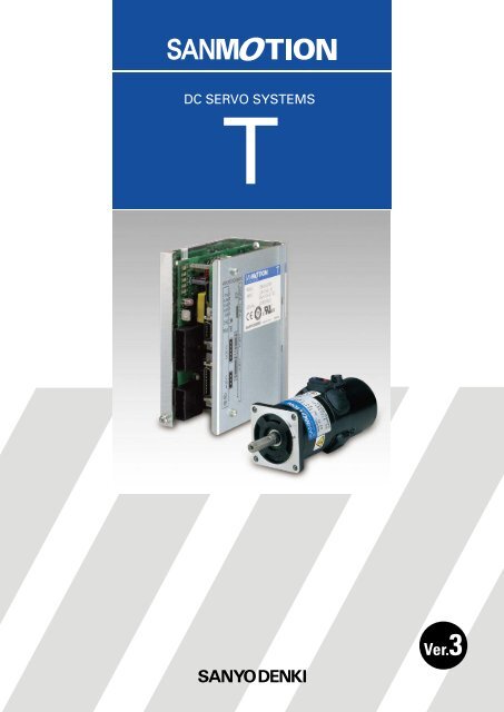
<strong>DC</strong> <strong>SERVO</strong> <strong>SYSTEMS</strong><br />
*Use optional cable<br />
For PC connection<br />
AC <strong>SERVO</strong> <strong>SYSTEMS</strong><br />
Maximum<br />
15 units<br />
Dimensions External Wiring<br />
Diagram<br />
Setup Software<br />
Protection Code IP43<br />
Protection code is IP43 for all models.<br />
Optional<br />
Equipment<br />
Water<br />
Dust<br />
IP43<br />
Shaft feedthrough and cable end are excluded.<br />
2
Improved Systems Precision and Shortened Cycle Time<br />
High Response<br />
A 4th-order notch filter reduces phase delay to suppress<br />
mechanical resonance and improve velocity response of<br />
equipment.<br />
Vibration-damping Control<br />
With feed-forward vibration suppression control, vibrations<br />
at the processing point and base of a machine can be<br />
suppressed through simple tuning procedures. Up to 4<br />
types of vibration control frequencies can be selected.<br />
Position deviation during stop<br />
With vibration suppression control<br />
Without vibration suppression control<br />
10<br />
Gain (dB)<br />
0<br />
-10<br />
-20<br />
With vibration<br />
suppression control<br />
Without vibration<br />
suppression control<br />
100ms/div<br />
-30<br />
-40<br />
1<br />
5 10 50 100 500 1000<br />
Frequency (Hz)<br />
17-bit absolute encoder is required.<br />
Shorter Position Settling Time<br />
A new algorithm drastically shortens positioning settling<br />
time for equipment.<br />
Disturbance Suppression<br />
It is possible to control impacts from other axes in case<br />
of multiaxial constitution, by using the new disturbance<br />
observer with extended applicable frequency.<br />
Disturbance observer function ON<br />
Oscillation waveform<br />
of direct drive section<br />
Disturbance<br />
Position deviation<br />
Disturbance observer function OFF<br />
Oscillation waveform<br />
of direct drive section<br />
Position complete signal<br />
Settling time (0ms)<br />
Disturbance<br />
Example of positioning settling time<br />
in highly rigid machinery<br />
5ms/div<br />
17-bit encoder is required.<br />
3
Curtailed Running Cost<br />
High Resolution<br />
Control suitable for the high-resolution incremental<br />
encoder and absolute encoder can be performed.<br />
30% Reduction in Power Loss<br />
A low-power loss module has been employed to reduce the<br />
power loss in the main circuit by 30%.<br />
Features and<br />
Functions<br />
Model Number<br />
Nomencalture<br />
Maximum Resolution 1048576 divisions<br />
Reduction rate of power loss<br />
100%<br />
90%<br />
80%<br />
70%<br />
60%<br />
50%<br />
40%<br />
30%<br />
20%<br />
10%<br />
0%<br />
Current model<br />
SANMOTION T<br />
System<br />
Configuration<br />
Standard<br />
Specifications<br />
Optional<br />
Equipment<br />
Setup Software<br />
Dimensions External Wiring<br />
Diagram<br />
4
Servo Motor Standard Model Number List<br />
Rated Output<br />
23W<br />
40W<br />
60W<br />
110W<br />
200W<br />
300W<br />
400W<br />
500W<br />
Outer diameter<br />
of motor<br />
41mm<br />
41mm<br />
41mm<br />
51mm<br />
51mm<br />
76mm<br />
76mm<br />
87.5mm<br />
87.5mm<br />
Encoder<br />
Tachometer<br />
generator<br />
Winding<br />
specifications<br />
Model No.<br />
<br />
T402-011<br />
<br />
With<br />
T402T-011<br />
Incremental encoder (PP031) 1000P/R 24VSystem T402-011EL8<br />
<br />
Incremental encoder (PP031) 1000P/R<br />
<br />
Incremental encoder (PP031) 1000P/R<br />
<br />
Incremental encoder (PP031) 1000P/R<br />
T404-011<br />
With<br />
T404T-011<br />
<br />
75VSystem T404-012<br />
With<br />
T404T-012<br />
24VSystem T404-011EL8<br />
<br />
75VSystem T404-012EL8<br />
<br />
With<br />
<br />
<br />
With<br />
<br />
24VSystem T406-011<br />
75VSystem T406-012<br />
24VSystem<br />
75VSystem<br />
24VSystem<br />
75VSystem<br />
T406T-011<br />
T406T-012<br />
T406-011EL8<br />
T406-012EL8<br />
24VSystem T506-011<br />
75VSystem T506-012<br />
24VSystem<br />
75VSystem<br />
24VSystem<br />
75VSystem<br />
T506T-011<br />
T506T-012<br />
T506-011EL8<br />
T506-012EL8<br />
<br />
T511-012<br />
<br />
With 75VSystem T511T-012<br />
Incremental encoder (PP031) 1000P/R T511-012EL8<br />
<br />
T720-012<br />
<br />
With 75VSystem T720T-012<br />
Incremental encoder (PP031) 1000P/R T720-012EL8<br />
<br />
T730-012<br />
<br />
With 75VSystem T730T-012<br />
Incremental encoder (PP031) 1000P/R T730-012EL8<br />
<br />
T840-012<br />
<br />
With 75VSystem T840T-012<br />
Incremental encoder (PP031) 1000P/R T840-012EL8<br />
<br />
T850-012<br />
<br />
With 75VSystem T850T-012<br />
Incremental encoder (PP031) 1000P/R T850-012EL8<br />
For specifications on other model, please contact us.<br />
5
Servo Amplifier Standard Model Number List<br />
Main power Control power Control system Amp. capacity Detector Model No.<br />
20A Incremental encoder TS1A02AA<br />
Features and<br />
Functions<br />
Pulse train,Speed,<br />
Torque<br />
25A Incremental encoder TS1AA2AA<br />
30A Incremental encoder TS1A03AA<br />
Model Number<br />
Nomencalture<br />
<strong>DC</strong>140V<br />
Speed,Torque<br />
20A<br />
Tachometer generator (Motor model T4)<br />
Tachometer generator (Motor model T5)<br />
TS1A02AN<br />
TS1A02AP<br />
25A Tachometer generator(Motor model T5,T7) TS1AA2AP<br />
System<br />
Configuration<br />
<strong>DC</strong>24V<br />
<strong>DC</strong>50V<br />
Pulse train,Speed,<br />
Torque<br />
Speed,Torque<br />
30A Tachometer generator (Motor model T8) TS1A03AP<br />
20A Incremental encoder TS1B02AA<br />
25A Incremental encoder TS1BA2AA<br />
20A Tachometer generator (Motor model T4) TS1B02AN<br />
25A<br />
Tachometer generator (Motor model T4)<br />
Tachometer generator (Motor model T5)<br />
TS1BA2AN<br />
TS1BA2AP<br />
For specifications on other model, please contact us.<br />
Standard<br />
Specifications<br />
Dimensions External Wiring<br />
Diagram<br />
Power unit<br />
Output capacity<br />
5A<br />
10A<br />
15A<br />
Model No.<br />
TS1PA0500<br />
TS1PA1000<br />
TS1PA1500<br />
Setup Software<br />
Optional<br />
Equipment<br />
6
Servo Motor / Power Unit Model Number Nomenclature<br />
Servo Motor<br />
Example : The model number is as follows when 200W rated output, 76mm outer diameter,<br />
incremental encoder (1000P/R), a brake, tachometer generator, gear (1/15 gear ratio),<br />
and 75V series voltage specification are selected for "SANMOTION T" servo motor:<br />
T7 20 B T G6 01 2 EL8<br />
U<br />
Model<br />
Outer diameter<br />
of motor<br />
T4 41 mm<br />
T5 51 mm<br />
T7 76 mm<br />
T8 87.5 mm<br />
Brake<br />
B Equipped<br />
None Not equipped<br />
Specification identification<br />
01 Standard<br />
(W/O oil seal)<br />
Other Option<br />
None Standard<br />
UUL<br />
Tachometer generator<br />
T Equipped<br />
None Not equipped<br />
Winding specifications<br />
1 24V series<br />
2 75V series<br />
Rated output<br />
02 23W<br />
04 40W<br />
06 60W<br />
11 110W<br />
20 200W<br />
30 300W<br />
40 400W<br />
50 500W<br />
Gear<br />
Motor model Model No. Gear ratio<br />
GA 1/12.5<br />
T4<br />
GB 1/25<br />
model<br />
T5<br />
model<br />
T7<br />
model<br />
GC<br />
G1<br />
G2<br />
G3<br />
G4<br />
G6<br />
G7<br />
G8<br />
1/50<br />
1/15<br />
1/30<br />
1/60<br />
1/90<br />
1/15<br />
1/30<br />
1/60<br />
G9 1/90<br />
Incremental Encoder<br />
Line driver output<br />
Output<br />
Model No. pulse number<br />
EL8<br />
EL0<br />
E59<br />
EAL8<br />
EAL0<br />
EA59<br />
EA51<br />
EA53<br />
1000<br />
2000<br />
2500<br />
1000<br />
2000<br />
2500<br />
5000<br />
10000<br />
No indication: No encoder<br />
Encoder type<br />
PP031<br />
PP031T<br />
Quick response<br />
specifications<br />
Absolute encoder<br />
Model No. Number of bits<br />
A12 17<br />
A22 20<br />
Baud rate<br />
2.5Mbps<br />
2.5Mbps<br />
T4 type can be equipped with either tacho-generator or<br />
encoder only. It cannot be equipped with brake oil seal.<br />
Motors with a rated output of 23W, 40W, and 60W support<br />
the 24V winding specification.<br />
Power Unit<br />
TS1 P A 10 00<br />
TS1 series<br />
Unit structure type<br />
Power Unit<br />
Output capacity<br />
05 5A<br />
10 10A<br />
15 15A<br />
Input voltage Note)<br />
100V AC or 35V AC<br />
(for common use)<br />
Individual specification<br />
Standard product<br />
Note) Supply AC100V if the motor<br />
winding specification is 75V<br />
series and supply AC35V if<br />
it is 24V series.<br />
7
Servo Amplifier Model Number Nomenclature<br />
Servo Amplifier<br />
Example: The model number is as follows when "SANMOTION T "series servo amplifier with input voltage<br />
of <strong>DC</strong>140V, 20A capacity, and incremental encoder (1000P/R).<br />
Features and<br />
Functions<br />
TS1 A 02<br />
A<br />
A<br />
Model Number<br />
Nomencalture<br />
TS1 series<br />
Input voltage<br />
A<strong>DC</strong> 140V<br />
B<strong>DC</strong> 50V<br />
1 Compatible servo motor type Note)<br />
Amp. capacity<br />
02 20A<br />
A2 25A<br />
03 30A<br />
Input voltage-140V <strong>DC</strong><br />
Type of Amplifier. Type of Motor Factory settings<br />
T404-012 √<br />
TS1A02A<br />
T406-012<br />
T506-012<br />
T511-012 √<br />
TS1AA2A<br />
T720-012<br />
T730-012<br />
TS1A03A<br />
T840-012 √<br />
T850-012<br />
Motor structure type<br />
Rotary motor<br />
Control unit hardware type Note)<br />
A Incremental encoder (Line driver output only)<br />
F Absolute Encoder<br />
N Tacometer generator (Motor model T4)<br />
P Tacometer generator (Motor model T5,T7,T8)<br />
Note) Tacho-generators have not attained international<br />
standards (UL, c-UL and EN Standards).<br />
Input voltage-50V <strong>DC</strong><br />
Type of Amplifier. Type of Motor Factory settings<br />
TS1B02A T402-011 √<br />
System<br />
Configuration<br />
Standard<br />
Specifications<br />
Dimensions External Wiring<br />
Diagram<br />
Setup Software<br />
Optional<br />
Equipment<br />
2 Compatible encoder type Note) Incremental encoder<br />
Format Divisions per rotation [P/R] Addreviation Hard type. Factory settings<br />
Optical 1000 INC-E √<br />
Optical 2000 INC-E <br />
Optical 2500 INC-E <br />
Absolute encoder<br />
Format Transmission format Divisions per rotation [P/R] Multiple rotation Addreviation Hard type. Remarks Factory settings<br />
Optical<br />
Half duplex start-stop<br />
synchronization 2.5M<br />
17bit 16bit PA035C-2.5MH √<br />
3 Compatible tacometer generator<br />
Motor Model Tacometer generator Model Hard type<br />
T4 3V / 1000min -1 N<br />
T5, T7, T8 7V / 1000min -1 P<br />
4 Interface for control section Note)<br />
Control type<br />
Velocity control type<br />
Torque control type<br />
Position control type<br />
Velocity - Torque switch type<br />
Position - Torque switch type<br />
Position - Velocity switch type<br />
Internal velocity control type<br />
Factory settings<br />
√<br />
NotePlease change the compatible servo motor, compatible encoder and the interface for control section using the set-up software.<br />
8
System Configuration<br />
Control power supply:<br />
<strong>DC</strong>24V output<br />
Circuit Breaker (MCCB)<br />
Noise Filter<br />
Electromagnetic Contactor<br />
Power unit:<br />
<strong>DC</strong>140V output<br />
Main<br />
power<br />
supply<br />
AC100V<br />
50/60Hz<br />
Cuts off power in the case of<br />
an overload, to protect the<br />
power line.<br />
Protects the power line<br />
from external noise, and<br />
from noise generated<br />
by the servo amplifier.<br />
Switches servo power on<br />
and off. Requires installation<br />
of a surge protector.<br />
Brake Power<br />
Required for use when the<br />
servo motor is equipped<br />
with a brake.<br />
9
C<br />
N<br />
5<br />
CN5<br />
AL-00490833-01<br />
Setup Software<br />
Parameter<br />
configuration and<br />
monitoring is possible<br />
via communication<br />
with a PC.<br />
Model Number<br />
Nomencalture<br />
System<br />
Configuration<br />
C<br />
N<br />
3<br />
C<br />
N<br />
4<br />
C<br />
N<br />
2<br />
C<br />
N<br />
1<br />
CN2<br />
CN1<br />
Host Devices<br />
SANYO DENKI's host devices<br />
permit communication with<br />
third-party products.<br />
Standard<br />
Specifications<br />
Dimensions External Wiring<br />
Diagram<br />
Optional<br />
Equipment<br />
Features and<br />
Functions<br />
Setup Software<br />
Wiring required for brake.<br />
10
TS1 Specification T <br />
Servo amplifier Servo motor<br />
Applicable amplifier model No. TS1B02AA TS1A02AA<br />
Motor Model No.<br />
T402-011EL8<br />
T404-012EL8<br />
Condition Symbol Unit (SI)<br />
Servo amplifier Input power(Control circuit) <strong>DC</strong>24V+10, -15%<br />
Servo amplifier Input power(Main circuit) <strong>DC</strong>50V+10, -15% <strong>DC</strong>140V+10, -15%<br />
Amplifier operation temperature and humidity<br />
Temperature: 0 to 55Humidity: Maximum 90% (no condensation)<br />
Power capacity(Rated) kVA 0.2 0.2<br />
Amplifier mass kg 0.45<br />
Rated output P R W 23 40<br />
Rated speed N R min -1 3000<br />
Maximum speed N max min -1 3000<br />
Rated torque T R Nm 0.061 0.080<br />
Continuous stall torque T S Nm 0.070 0.120<br />
Instantaneous maximum stall torque T PS Nm 0.206 0.319<br />
Rated armature voltage E R V 20 72<br />
Rated armature current I R A 1.9 1.0<br />
Continuous stall armature current I S A 1.9 0.9<br />
Instantaneous maximum stall armature current I P A 4.9 2.1<br />
Torque constant K T Nm/A 0.047 0.174<br />
Voltage constant per phase K E V/kmin -1 4.9 18.2<br />
Phase resistance R a 3.2 18.6<br />
Rated power rate O R kW/s 1.2 2.1<br />
Electrical time constant t C ms 0.35 0.35<br />
Mechanical time constant t m ms 7.1 4.8<br />
Load inertia J L kgm 2 (GD 2 /4) 0.16 10 -4 0.27 10 -4<br />
Encoder pulse number (output circuit system) P/R 1000(Line driver)<br />
Rotor inertia (including sensor) J M kgm 2 (GD 2 /4) 0.055 10 -4 0.092 10 -4<br />
Motor mass (including sensor) kg 0.55 0.65<br />
Break-holding torque T B Nm <br />
Break excitation voltage V B V <br />
Break excitation current I B A <br />
Break inertia J B kgm 2 (GD 2 /4) <br />
Break mass kg <br />
Motor operation temperature and humidity<br />
Temperature: 0 to 40Humidity: Maximum 90% (no condensation)<br />
mark indicates a typical value after temperature increased and saturated<br />
in the combination with the standard amplifier<br />
mark indicates a typical value when the winding temperature is at 25.<br />
Amp. +Motor Characteristic curve<br />
Torque (Nm)<br />
0.4<br />
0.3<br />
0.2<br />
Instantaneous domain<br />
0.1<br />
Continuous domain<br />
0 1000 2000 3000<br />
Speed (min -1 )<br />
Torque (N ∙ m)<br />
0.4<br />
0.3<br />
0.2 Instantaneous domain<br />
0.1<br />
Continuous domain<br />
0 1000 2000 3000<br />
Speed (min -1 )<br />
11
TS1A02AA<br />
TS1AA2AA<br />
T406-012EL8 T506-012EL8 T511-012EL8 T720-012EL8<br />
<strong>DC</strong>24V+10, -15%<br />
<strong>DC</strong>140V+10, -15%<br />
Temperature: 0 to 55Humidity: Maximum 90% (no condensation)<br />
0.3 0.3 0.4 0.6<br />
0.45<br />
60 60 110 200<br />
3000<br />
3000<br />
0.137 0.156 0.270 0.605<br />
0.175 0.192 0.358 0.658<br />
0.441 0.441 0.784 1.47<br />
70 75 75 80<br />
1.4 1.2 2.0 3.4<br />
1.4 1.3 2.2 3.7<br />
2.9 2.8 4.5 7.7<br />
0.177 0.183 0.21 0.23<br />
18.5 19.1 21.8 24.2<br />
11.8 12.1 5.1 2.8<br />
3.2 1.7 3.2 2.7<br />
0.37 0.47 0.63 1.1<br />
4.1 7.4 4.3 7.8<br />
0.34 10 -4 0.68 10 -4 1.13 10 -4 4.43 10 -4<br />
1000(Line driver)<br />
0.116 10 -4 0.228 10 -4 0.378 10 -4 1.478 10 -4<br />
0.75 0.9 1.2 2.05<br />
0.29 1.47<br />
90 90<br />
0.06 0.11<br />
0.01 10 -4 0.09 10 -4<br />
0.26 0.59<br />
Temperature: 0 to 40Humidity: Maximum 90% (no condensation)<br />
Features and<br />
Functions<br />
Model Number<br />
Nomencalture<br />
System<br />
Configuration<br />
Standard<br />
Specifications<br />
Dimensions External Wiring<br />
Diagram<br />
Setup Software<br />
Optional<br />
Equipment<br />
0.4<br />
0.4<br />
0.8<br />
2.0<br />
Torque (N ∙ m)<br />
0.3<br />
0.2<br />
Instantaneous domain<br />
Torque (N ∙ m)<br />
0.3<br />
0.2<br />
Instantaneous domain<br />
Torque (N ∙ m)<br />
0.6<br />
0.4<br />
Instantaneous domain<br />
Torque (N ∙ m)<br />
1.5<br />
1.0<br />
Instantaneous domain<br />
0.1<br />
Continuous domain<br />
0.1<br />
Continuous domain<br />
0.2<br />
Continuous domain<br />
0.5<br />
Continuous domain<br />
0 1000 2000 3000<br />
Speed (min -1 )<br />
0 1000 2000 3000<br />
Speed (min -1 )<br />
0 1000 2000 3000<br />
Speed (min -1 )<br />
0 1000 2000 3000<br />
Speed (min -1 )<br />
12
TS1 Specification T <br />
Servo amplifier Servo motor<br />
Applicable amplifier model No. TS1AA2AA TS1A03AA<br />
Motor Model No.<br />
Condition Symbol Unit (SI)<br />
T730-012EL8<br />
T840-012EL8<br />
Servo amplifier Input power(Control circuit) <strong>DC</strong>24V+10, -15%<br />
Servo amplifier Input power(Main circuit) <strong>DC</strong>140V+10, -15%<br />
Amplifier operation temperature and humidity<br />
Temperature: 0 to 55Humidity: Maximum 90% (no condensation)<br />
Power capacity(Rated) kVA 0.9 1.0<br />
Amplifier mass kg 0.45 0.65<br />
Rated output P R W 300 400<br />
Rated speed N R min -1 2500<br />
Maximum speed N max min -1 2500<br />
Rated torque T R Nm 1.00 1.66<br />
Continuous stall torque T S Nm 1.05 1.70<br />
Instantaneous maximum stall torque T PS Nm 2.45 3.72<br />
Rated armature voltage E R V 75 85<br />
Rated armature current I R A 5.2 5.8<br />
Continuous stall armature current I S A 5.5 6<br />
Instantaneous maximum stall armature current I P A 10.9 13.7<br />
Torque constant K T Nm/A 0.273 0.31<br />
Voltage constant per phase K E V/kmin -1 28.6 32.9<br />
Phase resistance R a 1.1 0.95<br />
Rated power rate O R kW/s 5.1 5.0<br />
Electrical time constant t C ms 1.5 2.0<br />
Mechanical time constant t m ms 4.0 5.2<br />
Load inertia J L kgm 2 (GD 2 /4) 8.12 10 -4 15 10 -4<br />
Encoder pulse number (output circuit system) P/R 1000(Line driver)<br />
Rotor inertia (including sensor) J M kgm 2 (GD 2 /4) 2.708 10 -4 5.008 10 -4<br />
Motor mass (including sensor) kg 2.75 3.65<br />
Break-holding torque T B Nm 1.47 1.96<br />
Break excitation voltage V B V 90 90<br />
Break excitation current I B A 0.11 0.11<br />
Break inertia J B kgm 2 (GD 2 /4) 0.09 10 -4 0.2 10 -4<br />
Break mass kg 0.59 0.79<br />
Motor operation temperature and humidity<br />
mark indicates a typical value after temperature increased and saturated<br />
in the combination with the standard amplifier<br />
mark indicates a typical value when the winding temperature is at 25.<br />
Temperature: 0 to 40Humidity: Maximum 90% (no condensation)<br />
Amp. +Motor Characteristic curve<br />
Torque (N ∙ m)<br />
2.0<br />
1.5<br />
1.0<br />
0.5<br />
Instantaneous domain<br />
Continuous domain<br />
Torque (N ∙ m)<br />
4.0<br />
3.0<br />
2.0<br />
1.0<br />
Instantaneous domain<br />
Continuous domain<br />
0 1000 2000 3000<br />
Speed (min -1 )<br />
0 1000 2000 3000<br />
Speed (min -1 )<br />
13
TS1A03AA<br />
T850-012EL8<br />
<strong>DC</strong>24V+10, -15%<br />
<strong>DC</strong>140V+10, -15%<br />
The same as the left<br />
1.3<br />
0.65<br />
500<br />
2500<br />
2500<br />
1.76<br />
1.90<br />
4.21<br />
80<br />
7.6<br />
7.6<br />
17.6<br />
0.287<br />
30<br />
0.56<br />
6.4<br />
1.9<br />
4.1<br />
18 10 -4<br />
1000(Line driver)<br />
6.008 10 -4<br />
4.25<br />
1.96<br />
90<br />
0.11<br />
0.2 10 -4<br />
0.79<br />
The same as the left<br />
Power Unit specifications<br />
Applicable Power unit model No. Unit TS1PA05 TS1PA10 TS1PA15<br />
Power unit Input voltage V AC100V +10%,-15% or AC35V +10%,-15%<br />
Power unit rated output current A 5 10 15<br />
Power unit operation temperature and humidity<br />
Temperature: 0 to 55Humidity: Maximum 90% (no condensation)<br />
Power capacity(Rated) at AC100V input KVA 1.4 2.8 4.2<br />
Power unit weight Kg 0.70 0.75 0.80<br />
Features and<br />
Functions<br />
Model Number<br />
Nomencalture<br />
System<br />
Configuration<br />
Standard<br />
Specifications<br />
Dimensions External Wiring<br />
Diagram<br />
Setup Software<br />
Optional<br />
Equipment<br />
4.0<br />
Torque (N ∙ m)<br />
3.0<br />
2.0<br />
Instantaneous domain<br />
1.0<br />
Continuous domain<br />
0 1000 2000 3000<br />
Speed (min -1 )<br />
14
Specification<br />
Servo motor<br />
Model<br />
Condition Symbol Unit (SI)<br />
T402-011 T404-012<br />
Rated output PR W 23 40<br />
Rated armature voltage VR V 20 72<br />
Rated torque TR Nm 0.074 0.13<br />
Rated armature current IR A 1.9 1.0<br />
Rated rotating speed NR min 1 3000<br />
Continuous stall torque TS Nm 0.08 0.14<br />
Instantaneous maximum torque TPN Nm 0.42 0.76<br />
Stall armature current IS A 1.9 0.9<br />
Instantaneous maximum armature current IPN A 10 4.7<br />
Maximum rotating speed Nmax min 1 5000<br />
Friction torque Tf Nm 0.015 0.019<br />
Rated power rate QR kW/S 1.2 2.1<br />
Instantaneous maximum angular acceleration P rad/s 2 89.410 3 90.510 3<br />
Viscous braking constant Fd Nm/min 1 0.00310 3 0.00610 3<br />
Torque constant KT Nm/A 0.047 0.174<br />
Voltage constant KE V/min 1 4.910 3 18.210 3<br />
Rotor inertia JM kgm 2 0.004710 3 0.008410 3<br />
Armature winding resistance Ra 3.2 18.6<br />
Armature inductance Ja mH 1.1 6.6<br />
Mechanical time constant tm ms 7.1 4.8<br />
Electrical time constant te ms 0.35 0.35<br />
Thermal time constant t min 15 20<br />
Thermal resistance R K/W 4.9 3.6<br />
Heatup limit K 105<br />
Mass W/M kg 0.3 0.4<br />
Coefficient of voltage generated KEG V/min 1 310 3 10<br />
Effective (rms) ripple s 2<br />
Peak-to-peak ripple s 5<br />
Linearity L 1<br />
Armature winding resistance Ri 37<br />
Armature inductance Li mH 5<br />
Minimum load resistance RL k 10<br />
Rotor inertia JTG kgm 2 0.001110 3<br />
Mass WT kg 0.09<br />
Holding torque TB Nm <br />
Voltage VB V <strong>DC</strong> <br />
Current IB A <br />
Resistance RB <br />
Inertia JB kgm 2 <br />
Mass WB kg <br />
Optical encoder pulse number<br />
Open collector 200 500 1000 P /R<br />
Line driver 1000 2000 2500 5000 10000 P /R<br />
Gear 1/12.5 1/25 1/50<br />
Oil seal<br />
<br />
Motor<br />
Tachogenerator<br />
Holding brake<br />
Note 1) The mark * in the Conditioncolumn is a value that applies when the ambient temperature<br />
and armature winding temperature are 25 .The mark * is a value that applies<br />
when the temperature has risen to the limit.<br />
2) The figures in the above table apply when a smooth <strong>DC</strong> power supply is used at an ambient<br />
temperature of no more than 40 .<br />
3) The characteristics of the tachogenerator are based on the use of a test circuit illustrated<br />
below.<br />
TG<br />
10k<br />
10k<br />
0.1F<br />
4) The values in the above table were measured when a specific device was mounted on<br />
an aluminum plate. T4 type, T5 type (200mm Height 200mm width 12mm thick), and<br />
T7 and T8 type (305mm Height 305mm width 12mm thick).<br />
5) No encoder can be installed on a T4 type equipped with a tachogenerator.<br />
6) Do not use a holding brake for quick braking.<br />
7) The T404 and T406 series are compatible with products having a rated voltage ER of 24V.<br />
8) The brake can be of the 24V type (optional).<br />
Motor Characteristic curve<br />
Current la<br />
(A)<br />
10<br />
8<br />
6<br />
4<br />
2<br />
0<br />
Speed N<br />
(min -1 )<br />
5000<br />
4000<br />
3000<br />
2000<br />
1000<br />
0<br />
0 0.2 0.4<br />
Continuous-operation domain<br />
Speed N (V=20V)<br />
Speed N(V=10V)<br />
Current la<br />
Instantaneous-operation domain<br />
Repeated-operation domain<br />
TorqueT (Nm)<br />
Current la<br />
(A)<br />
5<br />
4<br />
3<br />
2<br />
1<br />
0<br />
Speed N<br />
(min -1 )<br />
5000<br />
4000<br />
3000<br />
2000<br />
1000<br />
0<br />
0 0.2 0.4 0.6<br />
Continuous-operation domain<br />
Speed N(V=72V)<br />
Speed N (V=36V)<br />
TorqueT (Nm)<br />
Current la<br />
Repeated-operation domain<br />
Instantaneous-operation domain<br />
15
T406-012 T506-012 T511-012 T720-012<br />
60 60 110 200<br />
70 75 80<br />
0.19 0.19 0.34 0.64<br />
1.4 1.2 2.0 3.4<br />
3000 3000 3000<br />
0.20 0.24 0.42 0.77<br />
1.2 1.8 3.4 5.4<br />
1.4 1.3 2.2 3.7<br />
7.6 10 18 25<br />
5000 5000 5000<br />
0.020 0.02 0.022 0.04<br />
3.2 1.7 3.2 2.7<br />
11110 3 81.810 3 91.910 3 36.710 3<br />
0.00810 3 0.00910 3 0.01310 3 0.02010 3<br />
0.177 0.183 0.21 0.23<br />
18.510 3 19.110 3 21.810 3 24.210 3<br />
0.010810 3 0.02210 3 0.03710 3 0.14710 3<br />
11.8 12.1 5.1 2.8<br />
4.4 5.7 3.2 3.0<br />
4.1 7.4 4.3 7.8<br />
0.37 0.47 0.63 1.1<br />
25 20 30 30<br />
3.0 2.8 2.4 1.2<br />
105 105 105<br />
0.5 0.65 0.95 1.8<br />
310 3 10<br />
710 3 10<br />
2 1<br />
5 3<br />
1<br />
37 26<br />
5 4.1<br />
10<br />
0.001110 3 0.01210 3<br />
0.09 0.26 0.35<br />
0.29 1.47<br />
90 90<br />
0.06 0.11<br />
1600 820<br />
0.00110 3 0.00910 3<br />
0.26 0.59<br />
Features and<br />
Functions<br />
Model Number<br />
Nomencalture<br />
System<br />
Configuration<br />
Standard<br />
Specifications<br />
Dimensions External Wiring<br />
Diagram<br />
Setup Software<br />
Optional<br />
Equipment<br />
200 500 1000 P /R<br />
1000 2000 2500 5000 10000 P /R<br />
1/12.5 1/25 1/50 1/15 1/30 1/60 1/90<br />
<br />
Installable<br />
Current la Speed N<br />
(A) (min -1 )<br />
Current la Speed N<br />
(A) (min -1 )<br />
Current la Speed N<br />
(A) (min -1 )<br />
Current la Speed N<br />
(A) (min -1 )<br />
10<br />
5000<br />
25<br />
5000<br />
25<br />
5000<br />
50<br />
5000<br />
8<br />
4000<br />
20<br />
4000<br />
20<br />
4000<br />
40<br />
4000<br />
6<br />
4<br />
3000<br />
2000<br />
Continuous-operation domain<br />
Speed N(V=70V)<br />
Current la<br />
Instantaneous-operation domain<br />
15<br />
10<br />
3000<br />
2000<br />
Continuous-operation domain<br />
Speed N (V=75V)<br />
Speed N (V=37.5V)<br />
Instantaneous-operation domain<br />
Current la<br />
15<br />
10<br />
3000<br />
2000<br />
Continuous-operation domain<br />
Speed N (V=75V)<br />
Current la<br />
Instantaneous-operation domain<br />
30<br />
20<br />
3000<br />
2000<br />
Continuous-operation domain<br />
Instantaneous-operation domain<br />
Speed N (V=80V)<br />
Current la<br />
2<br />
1000<br />
Repeated-operation domain<br />
5<br />
1000<br />
5<br />
1000<br />
10<br />
1000<br />
0<br />
Speed N (V=35V)<br />
0<br />
0 0.5 1.0<br />
0<br />
0<br />
Repeated-operation domain<br />
0 0.5 1.0 1.5<br />
0<br />
Speed N (V=37.5V)<br />
Repeated-operation domain<br />
0<br />
0 1 2 3<br />
0<br />
Speed N (V=40)<br />
Repeated-operation domain<br />
0<br />
0 2 4<br />
TorqueT (Nm)<br />
TorqueT (Nm)<br />
TorqueT (Nm)<br />
TorqueT (Nm)<br />
16
Specification<br />
Servo motor<br />
Model<br />
Condition Symbol Unit (SI)<br />
T730-012 T840-012<br />
Rated output PR W 300 400<br />
Rated armature voltage VR V 75 85<br />
Rated torque TR Nm 1.18 1.57<br />
Rated armature current IR A 5.2 5.8<br />
Rated rotating speed NR min 1 2500<br />
Continuous stall torque TS Nm 1.43 1.70<br />
Instantaneous maximum torque TPN Nm 9.8 12.0<br />
Stall armature current IS A 5.5 6.0<br />
Instantaneous maximum armature current IPN A 40 40<br />
Maximum rotating speed Nmax min 1 4000 4000<br />
Friction torque Tf Nm 0.05 0.06<br />
Rated power rate QR kW/S 5.1 5.0<br />
Instantaneous maximum angular acceleration P rad/s 2 38.410 3 2410 3<br />
Viscous braking constant Fd Nm/min 1 0.03910 3 0.04510 3<br />
Torque constant KT Nm/A 0.273 0.314<br />
Voltage constant KE V/min 1 28.610 3 32.910 3<br />
Rotor inertia JM kgm 2 0.27010 3 0.5010 3<br />
Armature winding resistance Ra 1.1 0.95<br />
Armature inductance Ja mH 1.6 1.9<br />
Mechanical time constant tm ms 4.0 5.2<br />
Electrical time constant te ms 1.5 2.0<br />
Thermal time constant t min 30 30<br />
Thermal resistance R K/W 1.2 1.1<br />
Heatup limit K 105 105<br />
Mass W/M kg 2.5 3.4<br />
Coefficient of voltage generated KEG V/min 1 710 3 10<br />
Effective (rms) ripple s 1<br />
Peak-to-peak ripple s 3<br />
Linearity L 1<br />
Armature winding resistance Ri 26<br />
Armature inductance Li mH 4.1<br />
Minimum load resistance RL k 10<br />
Rotor inertia JTG kgm 2 0.01210 3<br />
Mass WT kg 0.35 0.45<br />
Holding torque TB Nm 1.47 1.96<br />
Voltage VB V <strong>DC</strong> 90 90<br />
Current IB A 0.11 0.11<br />
Resistance RB 820 820<br />
Inertia JB kgm 2 0.00910 3 0.0210 3<br />
Mass WB kg 0.59 0.79<br />
Optical encoder pulse number<br />
Open collector 200 500 1000 P /R<br />
Line driver 1000 2000 2500 5000 10000 P /R<br />
Gear 1/15 1/30 1/60 1/90<br />
Oil seal<br />
Installable<br />
Motor<br />
Tachogenerator<br />
Holding brake<br />
Note 1) The mark * in the Conditioncolumn is a value that applies when the ambient temperature<br />
and armature winding temperature are 25 .The mark * is a value that applies<br />
when the temperature has risen to the limit.<br />
2) The figures in the above table apply when a smooth <strong>DC</strong> power supply is used at an ambient<br />
temperature of no more than 40 .<br />
3) The characteristics of the tachogenerator are based on the use of a test circuit illustrated<br />
below.<br />
TG<br />
10k<br />
10k<br />
0.1F<br />
4) The values in the above table were measured when a specific device was mounted on<br />
an aluminum plate. T4 type, T5 type (200mm Height 200mm width 12mm thick), and<br />
T7 and T8 type (305mm Height 305mm width 12mm thick).<br />
5) No encoder can be installed on a T4 type equipped with a tachogenerator.<br />
6) Do not use a holding brake for quick braking.<br />
7) The T404 and T406 series are compatible with products having a rated voltage ER of 24V.<br />
8) The brake can be of the 24V type (optional).<br />
Motor Characteristic curve<br />
Current la Speed N<br />
(A) (min -1 )<br />
40 4000<br />
30 3000<br />
20 2000<br />
10 1000<br />
Continuous-operation domain<br />
Instantaneous-operation domain<br />
Speed N (V=75V)<br />
Speed N (V=37.5)<br />
Current la<br />
Repeated-operation domain<br />
0 0<br />
0 5 10<br />
TorqueT (Nm)<br />
Current la Speed N<br />
(A) (min -1 )<br />
80 4000<br />
60 3000<br />
40 2000<br />
20 1000<br />
0 0<br />
0 5 10<br />
Continuous-operation domain<br />
Instantaneous-operation domain<br />
Speed N (V=85V)<br />
Repeated-operation domain<br />
Speed N (V=42.5)<br />
Current la<br />
TorqueT (Nm)<br />
17
T850-012<br />
Connection method<br />
Motor Ground Tachogenerator Brake<br />
Features and<br />
Functions<br />
500<br />
80<br />
1.96<br />
7.6<br />
2500<br />
2.16<br />
16.7<br />
7.6<br />
62<br />
3000<br />
0.07<br />
6.4<br />
27.810 3<br />
0.05810 3<br />
0.287<br />
30.010 3<br />
0.6010 3<br />
0.56<br />
1.1<br />
4.1<br />
1.9<br />
40<br />
1.0<br />
105<br />
4.0<br />
710 3 10<br />
1<br />
3<br />
1<br />
26<br />
4.1<br />
10<br />
0.01210 3<br />
0.45<br />
1.96<br />
90<br />
0.11<br />
820<br />
0.0210 3<br />
0.79<br />
200 500 1000 P /R<br />
1000 2000 2500 5000 10000 P /R<br />
1/15 1/30 1/60 1/90<br />
Installable<br />
Current la Speed N<br />
(A) (min -1 )<br />
80 4000<br />
(Red)<br />
(Blue) (Green/Yellow) (Blue) (Red) (Orange) (Orange)<br />
How to run the motor<br />
Counterclockwise as viewed from the output axis when (red) + (blue) -<br />
Tachogenerator polarity<br />
(Red) + (blue) - in counterclockwise rotation as viewed from the output axis<br />
Common specifications<br />
Rating<br />
Heat resistance class<br />
Excitation system<br />
Insulation resistance<br />
Dielectric strength<br />
Rotation method<br />
Ambient temperature<br />
Humidity<br />
Paint color<br />
Protection system<br />
Lead wire length<br />
Gear Rating<br />
Continuous ("S1")<br />
F (Type A for UL-compliance models)<br />
Permanent magnet<br />
10M or more (with a 500 V<strong>DC</strong> megger)<br />
50Hz, 1,500 VAC (600V for 24V and TG types,<br />
1 minute (but do not perform an insulation<br />
test between the system and encoder.)<br />
Normal/reverse rotations possible<br />
0 to 40 C<br />
20 to 90% RH (non-condensing)<br />
Black<br />
Fully closed (IP43)<br />
1000mm<br />
Model No. Motor nameplate<br />
marking<br />
GA GB GC<br />
Gear model G6-12 G6-25 G6-50<br />
Reductionratio (nominal) 1/12.5 1/25 1/50<br />
Reduction ratio (detailed) 1/12.5 1/25 1/50<br />
Rated torque TRG Nm 0.5 1.0 2.0<br />
Instantaneous TPG Nm 1.5 3.0 6.0<br />
Mass WG kg 0.4<br />
Applicable motor<br />
T4 model<br />
G6 gear<br />
Model No. Motor nameplate<br />
marking<br />
G1 G2 G3 G4<br />
Gear model G8-15 G8-30 G8-60 G8-90<br />
Reduction ratio (nominal) 1/15 1/30 1/60 1/90<br />
Reduction ratio (detailed) 1/15.004 1/31.155 1/60.227 1/89.588<br />
Rated torque TRG Nm 1.0 2.0 4.0 4.0<br />
Instantaneous TPG Nm 3.0 6.0 12.0 12.0<br />
Mass WG kg 0.6<br />
Applicable motor<br />
T5 model<br />
G8 gear<br />
Model Number<br />
Nomencalture<br />
System<br />
Configuration<br />
Standard<br />
Specifications<br />
Dimensions External Wiring<br />
Diagram<br />
Setup Software<br />
Optional<br />
Equipment<br />
60<br />
40<br />
20<br />
3000<br />
2000<br />
1000<br />
Continuous-operation domain<br />
Speed N (V=40V)<br />
Current la<br />
Speed N (V=80V)<br />
Instantaneous-operation domain<br />
Repeated-operation domain<br />
Model No.<br />
Motor nameplate<br />
G6 G7 G8 G9<br />
marking<br />
Gear model G10-15 G10-30 G10-60 G10-90<br />
Reduction ratio (nominal) 1/15 1/30 1/60 1/90<br />
Reduction ratio (detailed) 1/15.303 1/30.066 1/60.132 1/90.198<br />
Rated torque TRG Nm 3.8 7.5 15.0 15.0<br />
Instantaneous TPG Nm 12.0 23.0 45.0 45.0<br />
Mass WG kg 1.5<br />
Applicable motor<br />
T7 model<br />
G10 gear<br />
0<br />
0<br />
0 5 10 15<br />
TorqueT (Nm)<br />
Note 1) Do not apply any value exceeding the appropriate rated torque or instantaneous maximum torque.<br />
2) Applying a value exceeding the appropriate instantaneous maximum torque causes an abnormal thrust load,<br />
perhaps resulting in affecting the encoder and other equipment.<br />
18
Encoder specifications<br />
Standard specifications<br />
Encoder type PP031T(Quick response specifications) PP031<br />
Applicable motor type Unit T4T5T7T8 model T4T5T7T8 model<br />
Output pulse number P/R<br />
1000 1024 1250 2000 2048 2500<br />
4000 4096 5000 8000 8192 10000<br />
200 500 1000 200 500 1000 2000 2500<br />
Rotating disk Slit number 500 512 625 200 500 1000 200 500 1000 2000 2500<br />
Multiplication number 2 4 8 16 1<br />
Output circuit system Line driver Open collector Line driver<br />
Channel number 3 3<br />
Input voltage V.<strong>DC</strong> 510 510<br />
Power demand mA 160max 70max 160max<br />
Output circuit voltage V.<strong>DC</strong><br />
VOH=2.4min,VOL=0.5max<br />
30max<br />
VOH=2.4min,VOL=0.5max<br />
at l0=20mA<br />
(When output transistor off)<br />
at l0=20mA<br />
Output circuit current mA 20max 20max 20max<br />
Response frequency kHz 0 to 800 0 to 300 0 to 300<br />
Pulse duty cycle T1=1/2T01/8T0<br />
Output mutual phase difference R1 to Rn=10 to 50% T2 to 5=1/4T01/8T0<br />
Flutter T0maxT0min/T00.08<br />
Working temperature 10 to 85(at encoder atmosphere) 10 to 85(at encoder atmosphere)<br />
Light emitting element Infrared light emitting diode Infrared light emitting diode<br />
Light receiving element Photo IC Photo diode<br />
Inertia kgm 2 0.0000810 -3 200 P/R0.0000310 -3 <br />
500100020002500 P/R 0.0000810 -3<br />
Weight kg 0.25 0.25<br />
External leads<br />
Lead color Open collector Line driver<br />
Red +<strong>DC</strong>5V +<strong>DC</strong>5V<br />
Black GND0V GND0V<br />
Shield Case earth Case earth<br />
Blue A channel output A channel output<br />
Brown A channel output<br />
Green B channel output B channel output<br />
Purple B channel output<br />
White C channel output<br />
Yellow C channel output C channel output<br />
Notice<br />
1) Never apply shock in the thrust direction when handling the encoder.<br />
2) Do not test encoder insulation resistance and dielectric strength to avoid<br />
damaging the electronic circuits.<br />
3) With respect to line connection for the open collector type, among the colored lead<br />
wires,<br />
the brown, purple and white lead wires have not been connected.<br />
Output waveform<br />
Open collector output<br />
(When the encoder rotates counterclockwise<br />
viewed from the motor output shaft side)<br />
T1<br />
T0Note<br />
Output waveformPP031T Quick<br />
response specifications<br />
Line driver output<br />
(when rotating in a counterclockwise direction<br />
viewed from the motor output axis)<br />
A channel<br />
<br />
A channel<br />
B channel<br />
<br />
B channel<br />
C channel<br />
<br />
C channel<br />
(1pulse/1rotation)<br />
Line driver output<br />
(When the encoder rotates counterclockwise<br />
viewed from the motor output shaft side)<br />
T1<br />
Rn R1 R2 R3 R4 R5 R6 R7 R8 R9<br />
Output cross-phase difference: Rn (n=1 to pulse number x 4)<br />
(Indicate the output cross-phase difference in percentage terms assuming<br />
360 degrees/pulse number to be 100%.)<br />
T0Note<br />
A channel<br />
T0<br />
A channel<br />
A channel<br />
T0<br />
B channel<br />
T2 T3 T4 T5<br />
B channel<br />
B channel<br />
C channel<br />
(1pulse/1rotation)<br />
T6 = T0 0.4T0<br />
T2 T3 T4 T5<br />
C channel<br />
C channel<br />
T6 = T0 0.4T0<br />
(1pulse/1rotation)<br />
Notice)" T0" is the average value of each cycle during one<br />
encoder rotation at a constant speed.<br />
T0360-degree electrical angle.<br />
19
Characteristics of overload duty cycle<br />
When repeatedly driving "SANMOTION T"<br />
under an overload as illustrated in the righthand<br />
figure, calculate the operable time tR<br />
on the basis of the characteristic curve of<br />
overload duty cycle.<br />
tR<br />
tF<br />
TSContinuous stall torque<br />
TLLoad torque<br />
tRLoad time (minutes)<br />
tFRest time (minutes)<br />
Features and<br />
Functions<br />
Model Number<br />
Nomencalture<br />
TL<br />
Armature current<br />
Load factor 100 100<br />
Stall armature current<br />
TS<br />
tR<br />
Load time factor, %ED100<br />
tRtF<br />
<br />
100<br />
Rest time tFtR I<br />
%ED<br />
Typical calculationsV850-012<br />
Supposing that the load factor is 150% and the<br />
percentage of ED is 40%, the load time tR = 3 (minutes),<br />
from the characteristic curve of overload duty cycle.<br />
Therefore,<br />
100 100<br />
Rest time tFtR I3<br />
I 4.5(minutes)<br />
%ED 40<br />
This means that, if you run the system at an overload of<br />
150% with regard to the continuous stall torque for three<br />
minutes, you need a rest time of 4.5 minutes.<br />
System<br />
Configuration<br />
Standard<br />
Specifications<br />
Load factor(%)<br />
300<br />
T402<br />
10% duty<br />
250<br />
20%<br />
200<br />
30%<br />
40%<br />
150 50%<br />
60%<br />
100<br />
0.1 0.5 1 5 10 50 100<br />
Load time tR (min.)<br />
T406<br />
Load factor(%)<br />
300<br />
T404,T506<br />
10% duty<br />
250<br />
20%<br />
200<br />
30%<br />
40%<br />
150 50%<br />
60%<br />
100<br />
0.1 0.5 1 5 10 50 100<br />
Load time tR (min.)<br />
T511,T720,T730,T840<br />
Dimensions External Wiring<br />
Diagram<br />
Setup Software<br />
Optional<br />
Equipment<br />
Load factor(%)<br />
300<br />
10% duty<br />
250<br />
20%<br />
Load factor(%)<br />
300<br />
250<br />
10% duty<br />
20%<br />
200<br />
30%<br />
200<br />
30%<br />
150<br />
40%<br />
50%<br />
150<br />
40%<br />
50%<br />
60%<br />
100<br />
0.1 0.5 1 5 10 50 100<br />
Load time tR (min.)<br />
60%<br />
100<br />
0.1 0.5 1 5 10 50 100<br />
Load time tR (min.)<br />
T850<br />
Load factor(%)<br />
10% duty<br />
300<br />
250<br />
20%<br />
200<br />
150<br />
30%<br />
40%<br />
50%<br />
60%<br />
100<br />
0.1 0.5 1 5 10 50 100<br />
Load time tR (min.)<br />
20
External Wiring Diagram<br />
Position command Type<br />
HousingDK-3100S-05R<br />
Contact DK-3RECLLP1-100<br />
HousingDK-3100S-03R<br />
Contact DK-3RECLLP1-100<br />
Main circuit<br />
power supply<br />
100V AC<br />
NFB<br />
50/60Hz<br />
NOTE 7<br />
User unit<br />
Control circuit power supply<br />
24V <strong>DC</strong> +<strong>DC</strong><br />
NOTE 9<br />
-<strong>DC</strong><br />
MC<br />
Power +<strong>DC</strong><br />
Supply<br />
Unit -<strong>DC</strong><br />
NOTE 9<br />
Start ready Start ready<br />
ON OFF<br />
MC<br />
MC Emergency<br />
stop<br />
System error<br />
Line driver<br />
HD26C31 Corresponding<br />
Position command pulse input<br />
Forward<br />
revolution<br />
pulse<br />
Backward<br />
revolution<br />
pulse<br />
NOTE 5<br />
NOTE 8<br />
Deviation clear<br />
NOTE 6<br />
SG<br />
SG<br />
<strong>DC</strong>5V24V<br />
CN3<br />
1<br />
+<strong>DC</strong><br />
2<br />
24V <strong>DC</strong><br />
-<strong>DC</strong><br />
3<br />
+<strong>DC</strong><br />
4<br />
140V <strong>DC</strong><br />
-<strong>DC</strong><br />
5<br />
CN1<br />
+5 +5<br />
16 F-PC<br />
SG<br />
17 F-PC<br />
15 SG<br />
+5 +5<br />
SG<br />
18 R-PC<br />
SG<br />
19 R-PC<br />
20 SG<br />
SG<br />
SG<br />
CONT-COM1<br />
1<br />
2 CONT1<br />
<strong>SERVO</strong> AMPLIFIER<br />
Line driver<br />
HD26C31<br />
Corresponding<br />
Line driver<br />
HD26C31<br />
Corresponding<br />
CN4<br />
1<br />
MA<br />
2<br />
MB<br />
3<br />
CN2<br />
NOTE 2<br />
A 21<br />
A 22<br />
B 23<br />
B 24<br />
C 25<br />
C 26<br />
NOTE 3 Blue(Black)<br />
Red(White)<br />
Green(Yellow)<br />
SH<br />
NOTE 4 SH<br />
Plug10114-3000PE<br />
Shell10314-52A0-008<br />
A<br />
A<br />
B<br />
B<br />
C<br />
C<br />
NOTE 6<br />
<strong>DC</strong>5V,<br />
<strong>DC</strong>12V24V<br />
Encoder division signal output<br />
<strong>SERVO</strong> MOTOR<br />
M<br />
Encoder<br />
Orange<br />
Orange<br />
RY1<br />
90V<br />
(24V)<br />
Holding brake<br />
(for the type with a brake only)<br />
Note 1) For the parts marked ,use a twisted<br />
pair shielded cable.<br />
Note 2) For a cable clamp method, can do shield<br />
connection by clamping a drain line.<br />
Note 3) Connection of the motor side is different<br />
by specifications of a motor.<br />
Note 4) For how to wire the encoder<br />
connector,refer to the encoder wiring<br />
diagram.<br />
Note 5) Refer to the following figure when<br />
connecting the command pulse input to<br />
the open collector output.<br />
General-purpose input<br />
Velocity loop<br />
propotional<br />
control<br />
Servo ON<br />
3<br />
4<br />
5<br />
CONT2<br />
CONT-COM2<br />
CONT3<br />
OUT1<br />
OUT2<br />
7<br />
8<br />
Start ready<br />
complete output<br />
Deviation<br />
zero output<br />
Forward<br />
revolution<br />
pulse<br />
Backward<br />
revolution<br />
pulse<br />
16<br />
15<br />
18<br />
20<br />
Alarm Reset<br />
SH<br />
6<br />
CONT4<br />
OUT-COM3 9<br />
OUT3 10<br />
OUT4 11<br />
OUT5 12<br />
OUT-COM4 13<br />
Output COMMON<br />
ALM4<br />
ALM2<br />
ALM1<br />
Alarm<br />
code<br />
output<br />
Output COMMON<br />
General purpose output<br />
Note 6)<br />
Note 7)<br />
Note 8)<br />
Note 9)<br />
Your are required to prepare the power.<br />
Either of the inputs can be selected.<br />
We recommend that a UL-approved earth<br />
leakage breaker be used that complies<br />
with IEC or EN standard.<br />
Make sure to connect the differential<br />
input SG. If not connected,malfunction or<br />
breakage may result due to noise.<br />
A power supply for control power please<br />
use a power supply that insulated double<br />
or reinforced from a primary power<br />
supply of 100V or 200V.<br />
SH<br />
NOTE 2<br />
Plug10126-3000PE<br />
Shell10326-52A0-008<br />
Velocity command/Torque command Type<br />
HousingDK-3100S-05R<br />
Contact DK-3RECLLP1-100<br />
HousingDK-3100S-03R<br />
Contact DK-3RECLLP1-100<br />
Main circuit<br />
power supply<br />
100V AC<br />
50/60Hz<br />
NFB<br />
NOTE 6<br />
Velocity command/<br />
Torque command input<br />
General-purpose input<br />
User unit<br />
Control circuit power supply<br />
24V <strong>DC</strong> +<strong>DC</strong><br />
NOTE 7<br />
-<strong>DC</strong><br />
MC<br />
Power +<strong>DC</strong><br />
Supply<br />
Unit -<strong>DC</strong><br />
NOTE 7<br />
Start ready<br />
Start ready<br />
ON<br />
OFF<br />
MC<br />
MC Emergency<br />
System error stop<br />
VCMD/TCMD<br />
SG<br />
SG<br />
Deviation clear CLR<br />
Velocity loop<br />
propotional<br />
control PCON<br />
Servo ON SON<br />
Alarm Reset RST<br />
NOTE 5<br />
<strong>DC</strong>5V24V<br />
SH<br />
CN3<br />
1<br />
+<strong>DC</strong><br />
2<br />
24V <strong>DC</strong><br />
-<strong>DC</strong><br />
3<br />
+<strong>DC</strong><br />
4<br />
140V <strong>DC</strong><br />
-<strong>DC</strong><br />
5<br />
CN1<br />
V-REF<br />
14 /T-REF<br />
15 SG<br />
20 SG<br />
SG<br />
1 CONT-COM1<br />
2 CONT1<br />
3 CONT2<br />
4 CONT-COM2<br />
5 CONT3<br />
6 CONT4<br />
SG<br />
<strong>SERVO</strong> AMPLIFIER<br />
-<br />
+<br />
Line driver<br />
HD26C31 Corresponding<br />
OUT1<br />
OUT2<br />
OUT3<br />
MA<br />
MB<br />
A<br />
A<br />
B<br />
B<br />
C<br />
C<br />
OUT-COM3<br />
CN4<br />
1<br />
2<br />
3<br />
CN2<br />
OUT4 11<br />
SH<br />
NOTE 4<br />
Plug10114-3000PE<br />
NOTE 2 Shell10314-52A0-008<br />
21<br />
22<br />
23<br />
24<br />
25<br />
26<br />
7<br />
8<br />
9<br />
10<br />
NOTE 3<br />
Blue(Black)<br />
Red(White)<br />
Green(Yellow)<br />
A<br />
A<br />
B<br />
B<br />
C<br />
C<br />
NOTE 6<br />
<strong>DC</strong>5V,<br />
<strong>DC</strong>12V24V<br />
SH<br />
Start ready<br />
complete output<br />
Low speed<br />
output<br />
Encoder division signal output<br />
Output COMMON<br />
ALM4<br />
ALM2<br />
Alarm<br />
code<br />
output<br />
<strong>SERVO</strong> MOTOR<br />
General-purpose output<br />
M<br />
Encoder<br />
Orange<br />
RY1<br />
90V<br />
Orange<br />
(24V)<br />
Holding brake<br />
(for the type with a brake only)<br />
Note 1) For the parts marked ,use a twisted<br />
pair shielded cable.<br />
Note 2) For a cable clamp method, can do shield<br />
connection by clamping a drain line.<br />
Note 3) Connection of the motor side is different<br />
by specifications of a motor.<br />
Note 4) For how to wire the encoder<br />
connector,refer to the encoder wiring<br />
diagram.<br />
Note 5) Your are required to prepare the power.<br />
Either of the inputs can be selected.<br />
Note 6) We recommend that a UL-approved earth<br />
leakage breaker be used that complies<br />
with IEC or EN standard.<br />
Note 7) A power supply for control power please<br />
use a power supply that insulated double<br />
or reinforced from a primary power<br />
supply of 100V or 200V.<br />
OUT5<br />
12<br />
ALM1<br />
OUT-COM4<br />
13<br />
Output COMMON<br />
SH<br />
NOTE 2<br />
21<br />
Plug10126-3000PE<br />
Shell10326-52A0-008
Power Unit / Encoder / Tacometer generator Wiring Diagram<br />
Power Unit<br />
Housing:DK-3100D-06R<br />
Contact:DK-3RECLLP1-100<br />
Power Supply<br />
AC 100V<br />
50/60Hz<br />
or<br />
AC 35V<br />
50/60Hz<br />
User Unit<br />
MC<br />
CN1<br />
1A<br />
1B<br />
2A<br />
2B<br />
3A<br />
3B<br />
L1<br />
L2<br />
POWER UNIT<br />
CN2<br />
1A<br />
P<br />
1B<br />
N<br />
2A<br />
P<br />
2B<br />
N<br />
3A<br />
P<br />
3B<br />
N<br />
4A<br />
P<br />
4B<br />
N<br />
5A<br />
P<br />
5B<br />
N<br />
6A<br />
P<br />
6B<br />
N<br />
Housing:DK-3100D-12R<br />
Contact:DK-3RECLLP1-100<br />
Connect to Servo Amplifier<br />
<strong>DC</strong>1(axis #1)<br />
<strong>DC</strong>2(axis #2)<br />
<strong>DC</strong>3(axis #3)<br />
<strong>DC</strong>4(axis #4)<br />
<strong>DC</strong>5(axis #5)<br />
<strong>DC</strong>6(axis #6)<br />
Features and<br />
Functions<br />
Model Number<br />
Nomencalture<br />
System<br />
Configuration<br />
Encoder<br />
Incremental encoder Lead wire type<br />
TS1 series<br />
<strong>SERVO</strong> AMPLIFIER<br />
Note2+<strong>DC</strong> 5V<br />
Note2GND(0V)<br />
HousingVHR-2N<br />
ContactSVH-21T-P1.1<br />
CN2<br />
A channel input<br />
A channel input<br />
B channel input<br />
B channel input<br />
C channel input<br />
C channel input<br />
1<br />
2<br />
3<br />
4<br />
5<br />
6<br />
7<br />
8<br />
11<br />
12<br />
13<br />
14<br />
R2<br />
2<br />
R1<br />
1<br />
Note1<br />
CN3<br />
Regenerative Resistor<br />
Note1<br />
Note1When regeneration process is necessary.<br />
Encoder : Incremental encoder<br />
Blue<br />
A channel output<br />
Brown<br />
A channel output<br />
Green<br />
B channel output<br />
Violet<br />
B channel output<br />
White<br />
C channel output<br />
Yellow<br />
C channel output<br />
Red<br />
+<strong>DC</strong> 5V<br />
Black<br />
GND(0V)<br />
FGShield<br />
T series<br />
<strong>SERVO</strong> MOTOR<br />
Optical<br />
encoder<br />
Standard<br />
Specifications<br />
Dimensions External Wiring<br />
Diagram<br />
Setup Software<br />
Optional<br />
Equipment<br />
Note2<br />
Plug10114-3000PE,<br />
Shell10314-52A0-008<br />
Note 1) For the parts marked ,use a twisted pair shielded cable.<br />
Note 2) The encoder power connection differs depending on the cable length.Refer to the following table.<br />
Encoder cable length<br />
<strong>DC</strong> 5V wiring<br />
GND (0V) wiring<br />
5m or less 10m or less 20m or less<br />
13-pin connection<br />
14-pin connection<br />
11- and 13-pin connection<br />
12- and 14-pin connection<br />
(7 and 11 pins need not be connected<br />
(6 and 12 pins need not be connected<br />
(7 pin need not be connected<br />
(8 pin need not be connected<br />
7-,11- and 13-pin connection<br />
8-,12- and 14-pin connection<br />
Tacometer generator<br />
Tacometer generator<br />
TS1 series<br />
<strong>SERVO</strong> AMPLIFIER<br />
T series<br />
<strong>SERVO</strong> MOTOR<br />
CN2<br />
Tacometer generator<br />
TG<br />
TG<br />
3<br />
4<br />
Red<br />
Blue<br />
TG<br />
Plug10114-3000PE,<br />
Shell10314-52A0-008<br />
22
TS1 Servo Motor Tdimensions<br />
<br />
Servo motors<br />
G<br />
4-LZ<br />
T<br />
T<br />
QK<br />
LR<br />
Motor lead<br />
(L1)<br />
LL<br />
Ground conductor<br />
LA<br />
T4 and T5 types<br />
LE<br />
LG<br />
LC<br />
W<br />
QA<br />
Q<br />
QK<br />
NP<br />
U<br />
T<br />
LB<br />
S<br />
D<br />
M tap, Depth LT<br />
T7 and T8 types<br />
Unit : mm<br />
Model LL LG L1 LA LB LE LC G LZ LR D S Q QA QK W T U M LT<br />
T402 55<br />
42<br />
<br />
<br />
T404 69 5 55 48 0.2<br />
34-0.025<br />
7-0.009<br />
2 56 42 3.5 24 0.5 41<br />
34-0.025<br />
7-0.009<br />
20 15 w/ 2 slots,6.5 <br />
T406 82 68 <br />
T506 81<br />
67<br />
34-0.025<br />
7-0.009<br />
<br />
<br />
5 60 0.3<br />
2.5 69 54 4.5 24 0.5 51<br />
20<br />
15 w/ 2 slots,6.5<br />
T511 101 87 50-0.025<br />
7-0.009<br />
<br />
T720 100.5<br />
8<br />
83<br />
T730 124.5 107<br />
T840 134 113<br />
8<br />
T850 149 128<br />
90 0.3<br />
100 0.3<br />
34-0.025<br />
70-0.030<br />
34-0.025<br />
80-0.030<br />
3 100 76 5.5 30 0.8 76<br />
14-0.009<br />
14-0.011<br />
3 112 88 6.6 35 0.8 87.5 16-0.011<br />
16-0.011<br />
25 2 20 5 5 2 M5 8<br />
30 2 25 5 5 2 M6 10<br />
Encoder-equipped servo motors<br />
G<br />
4-LZ<br />
LA<br />
T<br />
T<br />
QK<br />
T4 and T5 types<br />
LR<br />
LE<br />
Motor lead<br />
LG<br />
(L1)<br />
LL<br />
Ground<br />
conductor<br />
(L2)<br />
Encoder lead wire<br />
LC<br />
W<br />
QA<br />
Q<br />
QK<br />
NP<br />
U<br />
T<br />
LB<br />
S<br />
D<br />
M tap, Depth LT<br />
T7 and T8 types<br />
Model LL LG L1 L2 LA LB LE LC G LZ LR D S Q QA QK W T U M LT<br />
T402 83<br />
42<br />
<br />
<br />
T404 96 5 55 18 48 0.2<br />
34-0.025<br />
7-0.009<br />
2 56 42 3.5 24 0.5 41<br />
34-0.025<br />
7-0.009<br />
20 15 w/ 2 slots,6.5 <br />
T406 109 68 <br />
T506 110.5 67<br />
34-0.025<br />
7-0.009<br />
<br />
<br />
5<br />
22 60 0.3<br />
2.5 69 54 4.5 24 0.5 51<br />
20<br />
15 w/ 2 slots,6.5<br />
T511 130.5 87 50-0.025<br />
7-0.009<br />
<br />
T720 134.5 83<br />
8<br />
T730 159 107<br />
T840 166 113<br />
8<br />
T850 181 128<br />
36 90 0.3<br />
38 100 0.3<br />
34-0.025<br />
70-0.030<br />
34-0.025<br />
80-0.030<br />
3 100 76 5.5 30 0.8 76<br />
14-0.009<br />
14-0.011<br />
3 112 88 6.6 35 0.8 87.5 16-0.011<br />
16-0.011<br />
Unit : mm<br />
25 2 20 5 5 2 M5 8<br />
30 2 25 5 5 2 M6 10<br />
23
Tachometer generator-equipped servo motors<br />
G<br />
4-LZ<br />
LA<br />
T<br />
T<br />
QK<br />
T4T5 types<br />
LR<br />
LE<br />
Motor lead<br />
LG<br />
(L1)<br />
LL<br />
(L2)<br />
Ground conductor<br />
Techometer generator lead wir<br />
Features and<br />
Functions<br />
LC<br />
W<br />
U<br />
T<br />
LB<br />
S<br />
QA<br />
Q<br />
QK<br />
NP<br />
D<br />
Model Number<br />
Nomencalture<br />
M tap, Depth LT<br />
T7 and T8 types<br />
System<br />
Configuration<br />
Brake-equipped servo motors<br />
Unit : mm<br />
Model LL LG L1 L2 LA LB LE LC G LZ LR D S Q QA QK W T U M LT<br />
T402 87.5 42<br />
<br />
<br />
T404 98 5 55 18 48 0.2<br />
34-0.025<br />
7-0.009<br />
2 56 42 3.5 24 0.5 41<br />
34-0.025<br />
7-0.009<br />
20 15 w/ 2 slots,6.5 <br />
T406 111 68 <br />
T506 124.5 67<br />
34-0.025<br />
7-0.009<br />
<br />
<br />
5<br />
22 60 0.3<br />
2.5 69 54 4.5 24 0.5 51<br />
20<br />
15 w/ 2 slots,6.5<br />
T511 144.5 87 50-0.025<br />
7-0.009<br />
<br />
T720 148.5 83<br />
8<br />
T730 172.5 107<br />
T840 183 113<br />
8<br />
T850 198 128<br />
36 90 0.3<br />
38 100 0.3<br />
34-0.025<br />
70-0.030<br />
34-0.025<br />
80-0.030<br />
3 100 76 5.5 30 0.8 76<br />
3 112 88 6.6 35 0.8 87.5<br />
14-0.009<br />
14-0.011<br />
16-0.011<br />
16-0.011<br />
25 2 20 5 5 2 M5 8<br />
30 2 25 5 5 2 M6 10<br />
Standard<br />
Specifications<br />
Dimensions External Wiring<br />
Diagram<br />
Setup Software<br />
G<br />
4-LZ<br />
LA<br />
T<br />
T<br />
T5 types<br />
QK<br />
LR<br />
LE<br />
LG<br />
Motor lead<br />
(L1)<br />
LL<br />
(L2)<br />
Ground conductor<br />
Brake lead wire<br />
Optional<br />
Equipment<br />
LC<br />
W<br />
QA<br />
Q<br />
QK<br />
NP<br />
U<br />
T<br />
LB<br />
S<br />
D<br />
M tap, Depth LT<br />
T7 and T8 types<br />
Model LL LG L1 L2 LA LB LE LC G LZ LR D S Q QA QK W T U M LT<br />
T506 118<br />
67<br />
34-0.025<br />
7-0.009<br />
<br />
<br />
5<br />
36 60 0.3<br />
2.5 69 54 4.5 24 0.5 51<br />
20<br />
15 w/ 2 slots,6.5<br />
T511 144.5 87 50-0.025<br />
7-0.009<br />
<br />
T720 138.5 83<br />
8<br />
T730 162.5 107<br />
T840 169.5 113<br />
8<br />
T850 184.5 128<br />
40 90 0.3<br />
40 100 0.3<br />
34-0.025<br />
70-0.030<br />
34-0.025<br />
80-0.030<br />
3 100 76 5.5 30 0.8 76<br />
14-0.009<br />
14-0.011<br />
3 112 88 6.6 35 0.8 87.5 16-0.011<br />
16-0.011<br />
Unit : mm<br />
25 2 20 5 5 2 M5 8<br />
30 2 25 5 5 2 M6 10<br />
24
Servo Motor dimensions<br />
Encoder brake-equipped servo motors<br />
G<br />
4-LZ<br />
T<br />
T<br />
QK<br />
LR<br />
Motor lead<br />
(L1)<br />
LL<br />
(L2)<br />
Ground<br />
conductor<br />
(L3)<br />
Brake lead wire<br />
Encoder<br />
lead wire<br />
LA<br />
T5 types<br />
LE<br />
LG<br />
LC<br />
W<br />
QA<br />
Q<br />
QK<br />
NP<br />
U<br />
T<br />
LB<br />
S<br />
D<br />
M tap, Depth LT<br />
T7 and T8 types<br />
Model LL LG L1 L2 L3 LA LB LE LC G LZ LR D S Q QA QK W T U M LT<br />
T506 147 67<br />
5<br />
36 22 60 0.3 34-0.025<br />
7-0.009<br />
<br />
<br />
2.5 69 54 4.5 24 0.5 51<br />
20 15 w/ 2 slots,6.5<br />
T511 167 87 50-0.025<br />
7-0.009<br />
<br />
T720 172.5<br />
8<br />
83<br />
T730 196.5 107<br />
T840 203 113<br />
8<br />
T850 218 128<br />
38 35 90 0.3 34-0.025<br />
70-0.030<br />
40 35 100 0.3 34-0.025<br />
80-0.030<br />
3 100 76 5.5 30 0.8 76<br />
14-0.009<br />
14-0.011<br />
3 112 88 6.6 35 0.8 87.5 16-0.011<br />
16-0.011<br />
Unit : mm<br />
25 2 20 5 5 2 M5 8<br />
30 2 25 5 5 2 M6 8<br />
Tachometer generator brake-equipped servo motors<br />
G<br />
4-LZ<br />
LA<br />
T<br />
T<br />
T5 types<br />
QK<br />
LR<br />
LE<br />
LG<br />
Motor lead<br />
(L1)<br />
LL<br />
(L2)<br />
Ground<br />
conductor<br />
(L3)<br />
Techometer generator<br />
lead wire<br />
Brake lead<br />
wire<br />
LC<br />
W<br />
QA<br />
Q<br />
QK<br />
NP<br />
U<br />
T<br />
LB<br />
S<br />
D<br />
M tap, Depth LT<br />
T7 and T8 types<br />
Model LL LG L1 L2 L3 LA LB LE LC G LZ LR D S Q QA QK W T U M LT<br />
T506 161 67<br />
5<br />
38 42 60 0.3 34-0.025<br />
7-0.009<br />
<br />
<br />
2.5 69 54 4.5 24 0.5 51<br />
20 15 w/ 2 slots,6.5<br />
T511 181 87 50-0.025<br />
7-0.009<br />
<br />
T720 186.5<br />
8<br />
83<br />
T730 210.5 107<br />
T840 219.5 113<br />
8<br />
T850 234.5 128<br />
40 44 90 0.3 34-0.025<br />
70-0.030<br />
38 44 100 0.3 34-0.025<br />
80-0.030<br />
3 100 76 5.5 30 0.8 76<br />
14-0.009<br />
14-0.011<br />
3 112 88 6.6 35 0.8 87.5 16-0.011<br />
16-0.011<br />
Unit : mm<br />
25 2 20 5 5 2 M5 8<br />
30 2 25 5 5 2 M6 8<br />
25
Encoder tachometer generator-equipped servo motors<br />
G<br />
4-LZ<br />
LA<br />
LC<br />
T<br />
T<br />
T5 types<br />
QK<br />
W<br />
QA<br />
LR<br />
LE<br />
Q<br />
QK<br />
Motor lead<br />
(L1)<br />
LG<br />
NP<br />
LL<br />
(L2)<br />
Ground<br />
conductor<br />
(L3)<br />
Techometer generator<br />
lead wire<br />
Encoder<br />
lead wire<br />
Features and<br />
Functions<br />
Model Number<br />
Nomencalture<br />
M tap, Depth LT<br />
U<br />
T<br />
T7 and T8 types<br />
LB<br />
S<br />
D<br />
System<br />
Configuration<br />
Model LL LG L1 L2 L3 LA LB LE LC G LZ LR D S Q QA QK W T U M LT<br />
T506 153.5 67<br />
5<br />
38 27 60 0.3 34-0.025<br />
7-0.009<br />
<br />
<br />
2.5 69 54 4.5 24 0.5 51<br />
20 15 w/ 2 slots,6.5<br />
T511 173.5 87 50-0.025<br />
7-0.009<br />
<br />
T720 182<br />
8<br />
83<br />
T730 206 107<br />
T840 216 113<br />
8<br />
T850 223.5 128<br />
38 40 90 0.3 34-0.025<br />
70-0.030<br />
38 42 100 0.3 34-0.025<br />
80-0.030<br />
3 100 76 5.5 30 0.8 76<br />
14-0.009<br />
14-0.011<br />
3 112 88 6.6 35 0.8 87.5 16-0.011<br />
16-0.011<br />
Unit : mm<br />
25 2 20 5 5 2 M5 8<br />
30 2 25 5 5 2 M6 8<br />
Standard<br />
Specifications<br />
Dimensions External Wiring<br />
Diagram<br />
Encoder tachometer generator brake-equipped servo motors<br />
Setup Software<br />
G<br />
4-LZ<br />
LA<br />
T<br />
T<br />
T5 types<br />
QK<br />
LR<br />
LE<br />
LG<br />
Motor lead<br />
(L1)<br />
LL<br />
(L2)<br />
Ground<br />
conductor<br />
(L3)<br />
(L4)<br />
Techometer generator<br />
lead wire<br />
Brake lead wire<br />
Encoder<br />
lead wire<br />
Optional<br />
Equipment<br />
LC<br />
W<br />
QA<br />
Q<br />
QK<br />
NP<br />
U<br />
T<br />
LB<br />
S<br />
D<br />
M tap, Depth LT<br />
T7 and T8 types<br />
Model LL LG L1 L2 L3 L4 LA LB LE LC G LZ LR D S Q QA QK W T U M LT<br />
T506 190 67<br />
34-0.025<br />
5 38 42 22 60 0.3<br />
50-0.025 2.5 69 54 4.5 24 0.5 51 7-0.009 <br />
<br />
20 15 w/ 2 slots,6.5<br />
T511 210 87 7-0.009 <br />
T720 220<br />
8<br />
83<br />
T730 246 107<br />
T840 253.5 113<br />
8<br />
T850 268.5 128<br />
38 44 35 90 0.3<br />
38 44 35 100 0.3<br />
34-0.025<br />
70-0.030<br />
34-0.025<br />
80-0.030<br />
3 100 76 5.5 30 0.8 76<br />
14-0.009<br />
14-0.011<br />
3 112 88 6.6 35 0.8 87.5 16-0.011<br />
16-0.011<br />
Unit : mm<br />
25 2 20 5 5 2 M5 8<br />
30 2 25 5 5 2 M6 8<br />
26
Gear dimensions<br />
Dimensions of a typical gear for T4<br />
Unit : mm<br />
60<br />
320.5 47<br />
4 4.5<br />
700.3<br />
180.5<br />
80.015<br />
0<br />
27<br />
12<br />
A<br />
5<br />
10<br />
A<br />
Cross section A-A<br />
7<br />
Dimensions of a typical gear for T5<br />
82<br />
4 6.6<br />
940.3<br />
2<br />
26.51 51<br />
5 17<br />
16<br />
440.025<br />
0<br />
120.018<br />
0<br />
A<br />
A<br />
0.024<br />
40.012<br />
15<br />
Cross section A-A<br />
0<br />
1.50.2<br />
4<br />
Dimensions of a typical gear for T7<br />
100<br />
4 6.6<br />
1200.3<br />
0<br />
0<br />
400.025<br />
150.018<br />
2<br />
321 78<br />
3 17<br />
20<br />
A<br />
A<br />
0.024<br />
50.012<br />
20<br />
Cross section A-A<br />
0<br />
20.2<br />
5<br />
27
Servo Amplifier / Power Unit Dimensions<br />
Servo amplifier<br />
Unit : mm<br />
TS1 02 /TS1 A2 <br />
5<br />
Features and<br />
Functions<br />
Direction of<br />
installation UP<br />
2ø5<br />
50<br />
25<br />
4<br />
60 90<br />
Model Number<br />
Nomencalture<br />
System<br />
Configuration<br />
Ground M4<br />
terminal Standard<br />
Specifications<br />
TS1 03 <br />
Optional<br />
Equipment<br />
Setup Software<br />
112<br />
120<br />
5<br />
<br />
Direction of<br />
installation UP<br />
75 60<br />
90<br />
2ø5<br />
25.5<br />
Dimensions External Wiring<br />
Diagram<br />
112<br />
120<br />
4<br />
Ground M4<br />
terminal Power Unit<br />
Direction of<br />
<br />
installation<br />
UP <br />
60 120<br />
40 10<br />
5<br />
11.5<br />
1.6<br />
120<br />
133<br />
143<br />
CN3<br />
4ø5<br />
Ground M4<br />
terminal 28
Setup Software<br />
(1) Setup Software Start-up Screen (2) Main Screen<br />
(3) Parameter Configuration Screen<br />
Configuration of General Parameters:<br />
Enables parameter loading, saving, etc., via PC connection<br />
Configuration of Motor Parameters:<br />
Combined motors can be configured via PC connection<br />
(4) Monitor Functions<br />
Monitor Display:<br />
Observe Operation and Input/Output signal status<br />
Multi-monitor Display:<br />
Simultaneous monitoring of operational status of multiple<br />
servo amplifiers networked to a PC.<br />
Alarm Record Display:<br />
(Current and past alarm occurrence can be checked.)<br />
29
(5) Test Run and Adjustment Function<br />
Speed Jogging:<br />
Simplifies motor operation and the issuing<br />
of velocity commands from a PC<br />
Pulse Feed Jogging:<br />
Simplifies motor operation and the entering of<br />
distance and travel speed data from a PC<br />
Automatic Notch Filter Tuning:<br />
Configures the appropriate notch filter settings<br />
(6) Trace Operation<br />
System<br />
Configuration<br />
Standard<br />
Specifications<br />
System Analysis:<br />
Analyzes servo system frequency characteristics<br />
Optional<br />
Equipment<br />
Dimensions External Wiring<br />
Diagram<br />
Setup Software<br />
Model Number<br />
Nomencalture<br />
Features and<br />
Functions<br />
Graphically displays servo motor speed,<br />
current, and internal status<br />
30
Optional Equipment<br />
PC Interface Cable<br />
Unit : mm<br />
9<br />
2850<br />
Cable<br />
CN1<br />
Model No.: AL-00490833-01<br />
A note regarding RS-232C communications:<br />
The user must provide a PC for computer interface.<br />
Parameter settings may require adjustment.<br />
1<br />
PC side<br />
Amp side<br />
Connector list (For Amplifier)<br />
Single<br />
connector<br />
Standard<br />
set<br />
Contents Model number Manufacturer Manufacturers model number<br />
CN1Plug and housing AL-00608709 Sumitomo 3M Ltd./Molex Ltd.<br />
10126-3000PE + 10326-52A0-008/<br />
54306-2619 + 54331-0261<br />
CN2Plug and housing AL-00608710 Sumitomo 3M Ltd./Molex Ltd.<br />
10114-3000PE + 10314-52A0-008/<br />
54306-1419 + 54331-0141<br />
CN3Housing and contact AL-00608711<br />
DDK Ltd./<br />
DK-3100S-05R + DK-3RECLLP1-100/<br />
Tyco Electronics AMP K.K. 1-178288-5 + 1-175218-2<br />
CN4Housing and contact AL-00608712<br />
DDK Ltd./<br />
DK-3100S-03R + DK-3RECLLP1-100/<br />
Tyco Electronics AMP K.K. 1-178288-3 + 1-175218-2<br />
10126-3000PE + 10326-52A0-008/<br />
CN1,2Plug and housing<br />
Sumitomo 3M Ltd./Molex Ltd.<br />
10114-3000PE + 10314-52A0-008/<br />
54306-2619 + 54331-0261<br />
AL-00608713<br />
54306-1419 + 54331-0141<br />
DK-3100S-05R + DK-3RECLLP1-100/<br />
CN3,4Housing and contact<br />
DDK Ltd./<br />
DK-3100S-03R + DK-3RECLLP1-100/<br />
Tyco Electronics AMP K.K. 1-178288-5 + 1-175218-2<br />
1-178288-3 + 1-175218-2<br />
Note1CN1,2 Sumitomo 3M company product and Molex company product are standardized goods.<br />
Note2CN3,4 DDK company product and Tyco electronics AMP company product are standardized goods.<br />
* Hand crimp tool for contacts can be used for both.<br />
Connector list (For Power Unit)<br />
Single<br />
connector<br />
Standard<br />
set<br />
Contents Model number Manufacturer Manufacturers model number<br />
CN1Housing and contact AL-00632983<br />
DDK Ltd./<br />
DK-3100D-06R + DK-3RECLLP1-100/<br />
Tyco Electronics AMP K.K. 178289-3 + 1-175218-2<br />
CN2Housing and contact AL-00632984<br />
DDK Ltd./<br />
DK-3100D-12R + DK-3RECLLP1-100/<br />
Tyco Electronics AMP K.K. 178289-6 + 1-175218-2<br />
CN3Housing and contact AL-00632985 J.S.T Mfg Co Ltd. VHR-2N + SVH-21T-P1.1<br />
DK-3100D-06R + DK-3RECLLP1-100/<br />
CN1,2Housing and contact<br />
DDK Ltd./<br />
DK-3100D-12R + DK-3RECLLP1-100/<br />
AL-00632986<br />
Tyco Electronics AMP K.K. 178289-3 + 1-175218-2<br />
178289-6 + 1-175218-2<br />
CN3Housing and contact J.S.T Mfg Co Ltd. VHR-2N + SVH-21T-P1.1<br />
Note1CN1,2DDK company product and Tyco electronics AMP company product are standardized goods.<br />
*Hand crimp tool for contacts can be used for both.<br />
Note2Standard set(AL-00632986) is attached to the Power Unit.<br />
Brush (Maintenance components)<br />
Applicable motor<br />
For T4 model motor<br />
For T5 model motor<br />
For T7 model motor<br />
For T8 model motor<br />
For T4 model tachometer generator-equipped motor<br />
For T5 model tachometer generator-equipped motor<br />
For T7 and T8model tachometer generator-equipped motor<br />
Model number<br />
S441898-1A-02<br />
S441899-1A-02<br />
S442425-1A-02<br />
S442427-1A-02<br />
B-5143024-1<br />
S30407-1B-85<br />
S30402-1B-85<br />
Regenerative Resistor<br />
Regenerative powerPM Model number Resistance Allowable powerPRO Thermostat<br />
10W Max. REGIST-080W50B 50 10W<br />
30W Max. REGIST-120W50B 50 30W<br />
contact<br />
REGIST-220W50B<br />
50 <br />
Less than 55W<br />
55W<br />
REGIST-220W20B<br />
20 <br />
55W Min.<br />
Please contact us<br />
External Regenerative Resistor Dimensions<br />
Unit: mm<br />
REGIST-080W50B REGIST-120W50B REGIST-220W20B, REGIST-220W50B<br />
132<br />
122<br />
100<br />
300<br />
270<br />
6<br />
4.3<br />
6<br />
182 300<br />
172<br />
270<br />
150<br />
4.3<br />
6<br />
6<br />
230 300<br />
220<br />
270<br />
200<br />
4.3<br />
6<br />
6<br />
44<br />
26<br />
20<br />
42<br />
23.5<br />
4.3<br />
60<br />
42.7<br />
1<br />
Silicon Rubber Glass-braided Wire<br />
AWG20 0.5mm 2 , White (Thermostat)<br />
Silicon Rubber Glass-braided Wire<br />
AWG18 0.75mm 2 , Black<br />
20<br />
1.2 4.3<br />
Silicon Rubber Glass-braided Wire<br />
AWG20 0.5mm 2 , White (Thermostat)<br />
Silicon Rubber Glass-braided Wire<br />
AWG18 0.75mm 2 , Black<br />
20<br />
1.2 4.3<br />
Silicon Rubber Glass-braided Wire<br />
AWG20 0.5mm 2 , White (Thermostat)<br />
Silicon Rubber Glass-braided Wire<br />
AWG18 0.75mm 2 , Black<br />
Mass : 0.19kg Mass : 0.24kg Mass : 0.44kg<br />
31
Optional<br />
Equipment<br />
Setup Software<br />
Dimensions External Wiring<br />
Diagram<br />
Standard<br />
Specifications<br />
System<br />
Configuration<br />
Model Number<br />
Nomencalture<br />
Features and<br />
Functions<br />
32
Inquiry Check Sheet<br />
Please provide the following infomation when placing an order or making an inquiry.<br />
Also feel free to include any questions that require our attention.<br />
Company Name :<br />
Depatrtment :<br />
Telephone :<br />
Fax :<br />
Date :<br />
To contact us :<br />
Phone : +81 3 3917 4141<br />
FAX : +81 3 5394 3427<br />
1) Application :<br />
2) Name of Machinery :<br />
3) Number of Units :<br />
Item<br />
Contents<br />
1 Name of target equipment Equipment name, category (transport, processing, test, other)<br />
2 Name of servo axis Axis name, axial mechanism (horizontal/vertical), brake mechanism (yes/no)<br />
3 Current condition of above axis Manufacturer Name ( ) Series Name ( ) Motor Capacity ( ) Hydraulic, Mechanical, or New System ( )<br />
4 Positioning accuracy ±mm±m<br />
5 Operation pattern<br />
Feeding<br />
Speed<br />
[m/sec]<br />
AccelerationG[m/s 2 ]<br />
Feeding Speed[m/s]<br />
Moving Distance[m]<br />
(Stroke)<br />
Reference formula<br />
1G=9.8[m/s 2 ]1[m/s 2 ]0.1G<br />
[m/s 2 ]V[m/sec]÷t1[sec]<br />
D[m]V[m/sec]×(t1+t2)[sec]<br />
Time<br />
6 Mechanism<br />
Ball-screw/screw-rotation type (horizontal), ball-screw/nut-rotation type (horizontal),<br />
rack and pinion (horizontal), belt/chain (horizontal), rotary table, roll feed, instability<br />
WTtable mass kg WLwork mass kg WAmass of other drive parts kg<br />
WRrack mass kg WBbelt/chain mass kg WCcounterbalance mass kg<br />
Faexternal force axial direction N Fbball-screw preload N Troll pushing force N<br />
Dr1drive-side roll diameter mm Dr2follower-side roll diameter mm<br />
Lr1drive-side roll length mm Lr2follower-side roll length mm Greduction ratio<br />
7 Mechanical structure<br />
JGspeed-reducer inertia kgm 2 JCcoupling inertia kgm 2<br />
JNnut inertia kgm 2 JOother motor-axis conversion inertia kgm 2<br />
Dbball-screw diameter mm Lbball-screw axial length mm Pbball -screw leadmm<br />
Dppinion/pulley diameter mm Lppinion axial length mm tppully thickness mm<br />
Dttable diameter mm Dhtable-support dianeter mm LWload shift from axis mm<br />
Dstable shaft diameter mm Lstable shaft length mm<br />
specific gravity of ball-screw/pinion/pulley/table-shaft material kgcm 3<br />
friction coefficient between sheet and shiliding-surface/support-section/roll 1specific gravity of roll-1 material kgcm 3<br />
2specific gravity of roll-2 material kgcm 3 internal friction coefficient of preload nut<br />
mechanical efficiency JLload inertia of motor-axis conversion kgm 2<br />
TFfriction torque of motor axis conversion Nm Tuimbalance torque of motor axis conversion Nm<br />
8 Speed reducer Customer-provided ()Sanyo <strong>denki</strong> standard(planet/spur/no-backlash-planet) other()<br />
9 Types of detector<br />
Encoder type specified ( yes / no )<br />
Yes:(incremental encoder, absolute encoder)<br />
Resolution<br />
Tachometer generator<br />
0 Input format Position , velocity , torque , other ( )<br />
A Host equipment (controller) Sequencer , laptop , customer-developed product , Sanyo dennki-provided , other ( )<br />
B Usage environment and other requirements Cutting , clean-room use , anti-dust measures , other ( )<br />
C Estimated production Single product: ( ) units/mouth ( ) units/year<br />
D Development schedule Prototype period: () Year () Month Production period: () Year () Month<br />
E<br />
F<br />
Various measures Related documentation ( already submitted; send later by mail) Visit/PR desired ( yes / no ) Meeting desired ( yes / no )<br />
Miscellaneous<br />
(questions, pending problems,<br />
unresolved issues, etc.)<br />
34
Precautions For Adoption<br />
Cautions<br />
Failure to follow the precautions on the right may cause<br />
moderate injury and property damage, or in some<br />
circumstances,could lead to a serious accident.<br />
Always follow all listed precautions.<br />
For any question or inquiry regarding the above, contact our Sales Department.<br />
http://www.<strong>sanyo</strong><strong>denki</strong>.com<br />
1-15-1, Kita-Otsuka, Toshima-ku, Tokyo 170-8451, Japan<br />
Phone: +81 3 3917 5157<br />
468 Amapola Avenue Torrance, CA 90501 U.S.A.<br />
Phone: +1 310 783 5400<br />
P.A. Paris Nord II 48 Allee des Erables-VILLEPINTE BP.57286 F-95958 ROISSY CDG Cedex France<br />
Phone: +33 1 48 63 26 61<br />
Frankfurter Strasse 63-69 65760 Eschborn Germany<br />
Phone: +49 6196 76113 0<br />
9F 5-2, Sunwha-dong Jung-gu Seoul, 100-130, Korea<br />
Phone: +82 2 773 5623<br />
Phone: +86 21 6235 1107<br />
Room 1208,12F, No.96 Chung Shan N, Rd., Sec.2, Taipei 104, Taiwan, R.O.C.<br />
Phone: +886 2 2511 3938<br />
Room 2305, 23/F, South Tower, Concordia Plaza, 1 Science Museum Rd., TST East, Kowloon, Hong Kong<br />
Phone: +852 2312 6250<br />
10 Hoe Chiang Road #14-03A/04 Keppel Towers Singapore 089315<br />
Phone: +65 6223 1071<br />
The names of companies and/or their products specified in this <strong>catalogue</strong> are the trade names, and/or trademarks and/or registered trademarks of such respective companies.<br />
Remarks : Specifications Are Subject To Change Without Notice.<br />
CATALOG NO. 767-7 ’09.12.N