5-PHASE STEPPING SYSTEMS - sanyo denki europe
5-PHASE STEPPING SYSTEMS - sanyo denki europe
5-PHASE STEPPING SYSTEMS - sanyo denki europe

You also want an ePaper? Increase the reach of your titles
YUMPU automatically turns print PDFs into web optimized ePapers that Google loves.
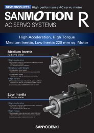
5-<strong>PHASE</strong> <strong>STEPPING</strong> <strong>SYSTEMS</strong><br />
Ver.5
AC input Set modelMicro step<br />
DC input Set modelMicro step, full step / half step<br />
AC input Driver<br />
DC input Driver<br />
Stepping Motor<br />
28mm sq. to 60mm sq. , 60mm to 106mm<br />
Linear Actuator Stepping Motor,<br />
Stepping Motor for vacuum environment
Index<br />
Features P. 4<br />
Line Up P. 5<br />
Lineup Details P. 6<br />
AC input Set modelMicro step P. 8<br />
System Configuration P. 8<br />
Model number convention P. 9<br />
Set Model Configuration P. 10<br />
Optional Accessories P. 11<br />
Specifications Standard model P. 12<br />
Specifications CE / UL model P. 15<br />
Specifications Low-backlash gear model P. 18<br />
Specifications Harmonic gear model P. 23<br />
Specifications Electromagnetic brake model P. 25<br />
Motor specifications P. 28<br />
Driver specifications P. 29<br />
Driver Controls and Connectors P. 30<br />
Connections and Signals P. 31<br />
DC input Set modelMicro step P. 34<br />
System Configuration P. 34<br />
Model number convention P. 35<br />
Set Model Configuration P. 36<br />
Optional Accessories P. 37<br />
Specifications Standard model P. 38<br />
Specifications Low-backlash gear model P. 41<br />
Specifications Spur gear model P. 46<br />
Specifications Harmonic gear model P. 48<br />
Specifications Electromagnetic brake model P. 51<br />
Motor specifications P. 53<br />
Driver specifications P. 54<br />
Driver Controls and Connectors P. 55<br />
Connections and Signals P. 56<br />
DC input Set modelFull/half step P. 60<br />
System Configuration P. 60<br />
Model number convention P. 61<br />
Set Model Configuration P. 62<br />
Specifications Standard model P. 63<br />
Specifications Low-backlash gear model P. 66<br />
Specifications Spur gear model P. 71<br />
Specifications Harmonic gear model P. 73<br />
Specifications Electromagnetic brake model P. 76<br />
Motor specifications P. 78<br />
Driver specifications P. 79<br />
Driver Controls and Connectors P. 80<br />
Connections and Signals P. 81<br />
Stepping Motor P. 84<br />
Linear Actuator Stepping Motor P. 95<br />
Stepping Motor for vacuum environment P. 96<br />
Dimensions P. 97<br />
Safety Consideration P. 107<br />
3
SANMOTION F5 is a five-phase stepping system that provides precise positioning with simple control.<br />
The typical basic step angle is 0.72, precisely controlled by pulse signals.<br />
Host Devices<br />
Driver<br />
Motor<br />
PLC, etc<br />
Pulse signal<br />
Optional<br />
Accessories<br />
Gear<br />
Electromagnetic<br />
brake<br />
Encoder<br />
Features<br />
Small driver and motor, yet high torque.<br />
Fast response provides shorter system cycle time for repetitive operations.<br />
Holding torque maintains the stop position when turning on power. Electromagnetic brake<br />
models maintain position even with power off.<br />
Automicro function<br />
For DC input, only specific model (micro-step)<br />
Smooth drive is provided even with coarse resolution of one division (full-step) or two (half-step) settings.<br />
Vibration suppression is executed internally and independently from the controller.<br />
Microstepping system<br />
For DC input, only specific model (micro-step)<br />
Multiples of the 0.72basic step angle resolution can be set in 16 steps from 1 to 250 divisions. (0.72to 0.00288/ pulse)<br />
Provides smooth drive with low vibration.<br />
Safety standards<br />
All SANMOTION F5 drivers are specified according to standards, and comply with<br />
UL and CE (EN standards).<br />
You can select driver/motor sets that comply UL and CE standards.<br />
4
Line up<br />
Motor/driver sets are conveniently available in either AC or DC models.<br />
DC models include micro-step and full-/half-step drivers.<br />
Beside the set models, stepping motors can be purchased independently.<br />
The product line includes linear actuator stepping motors with straight line drives, and vacuum-compatible stepping<br />
motors.<br />
Set model<br />
AC input (Micro step)<br />
Standard model<br />
This is the basic model AC driver/motor<br />
set.<br />
Motor size<br />
42mm sq. (1.65inch sq.)/60mm sq. (2.36inch sq.)/<br />
<br />
86mm ( 3.39inch)/ 106mm ( 4.17inch)<br />
DC input (42mm sq. (1.65inch sq.)/60mm sq. (2.36inch sq.))<br />
Standard model<br />
This is the basic model DC driver/motor<br />
set.<br />
Motor size<br />
28mm sq. (1.10inch sq.)/42mm sq. (1.65inch sq.)/<br />
60mm sq. (2.36inch sq.)/ 86mm ( 3.39inch)<br />
CE / UL model<br />
This model motor/driver set complies<br />
with CE and UL standards.<br />
Motor size<br />
42mm sq. (1.65inch sq.)/60mm sq. (2.36inch sq.)/<br />
<br />
86mm ( 3.39inch)/ 106mm ( 4.17inch)<br />
Low-backlash gear model<br />
This set employs low backlash conically<br />
hobbed gears to engage the output stage<br />
of the speed reduction mechanism.<br />
Motor size42mm sq. (1.65inch sq.)/60mm sq.<br />
(2.36inch sq.)/ 86mm ( 3.39inch)<br />
Reduction gear ratios1:3.6 / 1:7.2 / 1:10 / 1:20 / 1:30 / 1:36<br />
Harmonic gear model<br />
This model employs harmonic gears for<br />
up to 1:100 resolution.<br />
Motor size42mm sq. (1.65inch sq.)/60mm sq.<br />
(2.36inch sq.)/ 86mm ( 3.39inch)<br />
Reduction gear ratios1:30 / 1:50 / 1:100<br />
Electromagnetic brake model<br />
This set utilizes a non-excitation<br />
electromagnetic brake to maintain<br />
position in vertical load applications<br />
and hold load even during power off.<br />
Motor size42mm sq. (1.65inch sq.)/60mm sq.<br />
(2.36inch sq.)/ 86mm ( 3.39inch)<br />
Low-backlash gear model<br />
This set employs low backlash conically<br />
hobbed gears to engage the output stage<br />
of the speed reduction mechanism.<br />
Motor size42mm sq. (1.65inch sq.)/60mm sq.<br />
(2.36inch sq.)/ 86mm ( 3.39inch)<br />
Reduction gear ratios1:3.6 / 1:7.2 / 1:10 / 1:20 / 1:30 / 1:36<br />
Spur gear model<br />
This set employs a spur gear in the<br />
speed reduction mechanism.<br />
Motor size28mm sq. (1.10inch sq.)<br />
Reduction gear ratios1:3.6 / 1:7.2 / 1:10 /<br />
1:20 / 1:30 / 1:50<br />
Harmonic gear model<br />
This model employs harmonic gears for<br />
up to 1:100 resolution.<br />
Motor size28mm sq. (1.10inch sq.)/42mm sq.<br />
(1.65inch sq.)/60mm sq. (2.36inch sq.)/ 86mm<br />
( 3.39inch)<br />
Reduction gear ratios1:30 / 1:50 / 1:100<br />
Electromagnetic brake model<br />
This set utilizes a non-excitation<br />
electromagnetic brake to maintain<br />
position in vertical load applications<br />
and hold load even during power off.<br />
Motor size42mm sq. (1.65inch sq.)/60mm sq.<br />
(2.36inch sq.)/ 86mm ( 3.39inch)<br />
Stepping Motor<br />
When ordering a motor only, select from<br />
a variety of motor sizes.<br />
Separate driver is required.<br />
Motor size<br />
28mm sq. (1.10inch sq.)/<br />
39mm sq. (1.54inch sq.)/<br />
42mm sq. (1.65inch sq.)/<br />
50mm sq. (1.97inch sq.)/<br />
60mm sq. (2.36inch sq.)/<br />
<br />
60mm ( 2.36inch)/<br />
<br />
86mm ( 3.39inch)/ 106mm ( 4.17inch)<br />
Linear Actuator<br />
Stepping Motor<br />
This motor employs an integrated ball<br />
screw for linear motion.<br />
Separate driver is required.<br />
Motor size<br />
42mm sq. (1.65inch sq.)/<br />
60mm sq. (2.36inch sq.)<br />
Stepping motor for vacuum<br />
environment<br />
This motor is customized for use<br />
in systems operating in vacuum<br />
environments.<br />
Separate driver is required.<br />
5
Features and Line up<br />
Lineup Details<br />
Set modelP.8 -<br />
AC input Set model<br />
Micro step<br />
DC input Set model<br />
Micro step<br />
DC input Set model<br />
Full / half step<br />
Series<br />
Power supply Single phase AC100V to 230V DC24V/48V DC24V/36V<br />
Number of divisions 1 to 250<br />
Basic step angle<br />
0.72to 0.00288/pulse<br />
5-phase mode1 to 250<br />
2-phase mode0.4 to 102.4<br />
5-phase mode<br />
0.72to 0.00288/pulse<br />
2-phase mode<br />
1.8to 0.00703125/pulse<br />
1 (Full step),<br />
2 (Half step)<br />
0.72to 0.36/pulse<br />
Stepping motor connection<br />
method pentagon connection New pentagon connection New pentagon connection<br />
Model<br />
types and<br />
corresponding<br />
motor sizes<br />
(reduction<br />
ratios in<br />
parentheses)<br />
Standard<br />
CEUL<br />
Low-backlash gear<br />
model<br />
Spur gear model<br />
Harmonic gear<br />
model<br />
42mm sq. (1.65inch sq.)/60mm sq.<br />
(2.36inch sq.)/ 86mm ( 3.39inch)/<br />
<br />
106mm ( 4.17inch)<br />
42mm sq. (1.65inch sq.)/60mm sq.<br />
(2.36inch sq.)/ 86mm ( 3.39inch)/<br />
<br />
106mm ( 4.17inch)<br />
42mm sq.(1.65inch sq.)/60mm sq.<br />
(2.36inch sq.)/ 86mm ( 3.39inch)<br />
(1:3.6 / 1:7.2 / 1:10 / 1:20 / 1:30 / 1:36)<br />
<br />
42mm sq. (1.65inch sq.)/60mm sq.<br />
(2.36inch sq.)/ 86mm ( 3.39inch)<br />
(1:30 / 1:50 / 1:100)<br />
28mm sq. (1.10inch sq.)/42mm sq.<br />
(1.65inch sq.)/60mm sq. (2.36inch<br />
sq.)/ 86mm ( 3.39inch)<br />
<br />
42mm sq. (1.65inch sq.)/60mm sq.<br />
(2.36inch sq.)/ 86mm ( 3.39inch)<br />
(1:3.6 / 1:7.2 / 1:10 / 1:20 / 1:30 / 1:36)<br />
28mm sq. (1.10inch sq.)<br />
(1:3.6 / 1:7.2 / 1:10 / 1:20 / 1:30 / 1:50)<br />
28mm sq. (1.10inch sq.)/42mm sq.<br />
(1.65inch sq.)/60mm sq. (2.36inch<br />
sq.)/ 86mm ( 3.39inch)<br />
(1:30 / 1:50 / 1:100)<br />
42mm sq. (1.65inch sq.)/ 42mm sq. (1.65inch sq.)/ 42mm sq. (1.65inch sq.)/<br />
Electromagnetic<br />
60mm sq. (2.36inch sq.)/ 60mm sq. (2.36inch sq.)/ 60mm sq. (2.36inch sq.)/<br />
brake model<br />
<br />
86mm ( 3.39inch)<br />
<br />
86mm ( 3.39inch)<br />
<br />
86mm ( 3.39inch)<br />
Control method Pulse inputOpen loop Pulse inputOpen loop Pulse inputOpen loop<br />
Set model configuration items<br />
Optional Accessories<br />
Page<br />
System<br />
Configuration<br />
Set Model<br />
Configuration<br />
Specifications and<br />
Characteristics<br />
DriverMotorConnector<br />
AC power cable (1 to 10m)<br />
Motor cable (1 to 10m)<br />
I/O signal cable (1 to 2m)<br />
DriverMotor<br />
DC power cable (1m)<br />
Motor cable (1m)<br />
I/O signal cable (1m)<br />
Regeneration resistor<br />
P.8 P.34 P.60<br />
P.10 P.36 P.62<br />
DriverMotor<br />
P.12 to 27 P.38 to 52 P.63 to 77<br />
Motor specifications<br />
Driver specifications<br />
P.28 to 29 P.53 to 54 P.78 to 79<br />
Safety standards<br />
Dimensions P.97 to 105 P.97 to 105 P.97 to 105<br />
Our stepping motors generally support one of two connection methods, called "Pentagon" and "New Pentagon."<br />
See each motor's specifications for details.<br />
<br />
6
Stepping MotorP.84 -<br />
Connection Method: Pentagon<br />
Basic step<br />
angle<br />
Motor size<br />
Holding torque<br />
(Nm)<br />
Model Number<br />
Page<br />
Specifications and<br />
Characteristics<br />
Dimensions<br />
0.36 39mm sq. (1.54inch sq.) 0.078 to 0.167 103-45 -70 0 P.84 P.97<br />
0.45 60mm ( 2.36inch) 0.91 103-7566-70 1 P.85 P.99<br />
0.72 28mm sq. (1.10inch sq.) 0.041 to 0.085 SH528 - 0 1 P.86 P.97<br />
0.72 42mm sq. (1.65inch sq.) 0.127 to 0.255 103H55 -70 0 P.87 P.97<br />
0.72 50mm sq. (1.97inch sq.) 0.225 to 0.39 103H650 - 0 1 P.88 P.98<br />
0.72 60mm sq. (2.36inch sq.) 0.65 to 1.86 103H785 - 0 1 P.89 P.98<br />
0.72 60mm ( 2.36inch) 0.46 to 1.568 103H752 - 0 1 P.90 P.99<br />
0.72 86mm ( 3.39inch) 2.06 to 6.17 103H858 - 0 1 P.91 P.99<br />
0.72 106mm ( 4.17inch) 10.8 to 16 103H8958 - 0 1 P.92 P.100<br />
Linear Actuator Stepping MotorP.95 -<br />
Connection Method: New Pentagon<br />
Motor size<br />
42mm sq.<br />
(1.65inch sq.)<br />
60mm sq.<br />
(2.36inch sq.)<br />
Brake<br />
Rated current<br />
(A/phase)<br />
Thrust<br />
(N)<br />
Speed<br />
(mm/s)<br />
Model number<br />
Page<br />
Specifications and<br />
Characteristics<br />
Dimensions<br />
Without 0.75 370 48 SL5421-7241 P.95 P.106<br />
With 0.75 370 48 SL5421-72XB41 P.95 P.106<br />
Without 1.4 450 64 SL5601-8241 P.95 P.106<br />
With 1.4 450 64 SL5601-82XB41 P.95 P.106<br />
Stepping motor for vacuum environmentP.96<br />
This motor is customized for use in systems operating in vacuum environments.<br />
Supports wide pressure range for low, high and ultra-high vacuums.<br />
Encoder-equipped motors are available upon request.<br />
7
AC input Set modelMicro step<br />
AC input Set model<br />
Micro step<br />
Set Model Configuration P.10<br />
SpecificationsCharacteristics P.12 to 27<br />
Motor specifications P.28Driver specifications P.29<br />
Motor dimensions P.97 to 104Driver dimensions P.105<br />
Features<br />
The auto-micro function provides low vibration and smooth<br />
drive even with coarse resolution setting of one or two divisions<br />
(full-/half-step), and supports micro steps of 250 divisions.<br />
Status and alarms are displayed instantly on the driver's<br />
two-digit alphanumeric LEDs.<br />
Set model configuration items<br />
Driver<br />
Model numberFS1W075P00<br />
Power supplySingle phase AC100V to 230V<br />
Motor<br />
CE/UL models comply with the respective safety standards.<br />
Motor size 42mm sq. (1.65inch sq.), 60mm sq. (2.36inch sq.),<br />
<br />
86mm ( 3.39inch), 106mm ( 4.17inch)<br />
Connector<br />
Power supply, Input/output signal, Motor<br />
System configuration<br />
Instruction manuals can be downloaded from our website.<br />
Cables for motor power and input/output signals (with connectors) are<br />
sold as options.<br />
Motor<br />
End-cap side<br />
Electromagnetic brake<br />
Encoderoption<br />
Driver<br />
Host Devices<br />
PLC, etc.<br />
Motor connector<br />
Set model configuration items<br />
Pulse signal<br />
Flange side<br />
Low-backlash gear<br />
Harmonic gear<br />
Motor cable<br />
Optional Accessories<br />
I/O signal<br />
cable<br />
Optional<br />
Accessories<br />
Brake power source<br />
DC24V<br />
Required for brakeequipped<br />
stepping<br />
motor models.<br />
Power connector<br />
(Set model configuration items)<br />
Power supply cable<br />
Optional Accessories<br />
I/O signal connector<br />
Set model configuration items<br />
AC power<br />
Single phase<br />
100V to 230V<br />
Molded case<br />
circuit breaker<br />
Electromagnetic<br />
contactor<br />
Noise filter<br />
8<br />
Protects the power<br />
line.<br />
Cuts off circuit in the<br />
event of overcurrent.<br />
Switches driver<br />
power on/off.<br />
Use together with a<br />
surge protector.<br />
Filters out incoming<br />
noise from power<br />
line.
Model number convention<br />
Example: The model number of the set with an AC driver and motor model 103F7851-70CXA4 is composed as follows.<br />
This motor is specified as 60mm sq. (2.36inch sq.) and 92mm (3,62inch) long (motor + gear), single shaft, with<br />
low backlash gears.<br />
AC input Set model<br />
Micro step<br />
FS<br />
F 78 1 S - CX 3.6<br />
Gear ratio<br />
3.6 to 100<br />
CXLow-backlash gear model<br />
HXHarmonic gear model<br />
XBElectromagnetic brake model<br />
DC input Set model<br />
Micro step<br />
DC input Set model<br />
Full / half step<br />
Stepping motor shaft spec.<br />
SSingle shaftDDouble shaft<br />
Stepping motor total length (Applies to standard and CE/UL models. See the<br />
Dimensions pages for models equipped with gears and electromagnetic brakes.)<br />
Stepping Motor<br />
Code<br />
Motor size<br />
42mm sq. (1.65inch sq.) 60mm sq. (2.36inch sq.) <br />
86mm ( 3.39inch) <br />
106mm ( 4.17inch)<br />
Motor model<br />
number<br />
Motor length :<br />
mm(inch)<br />
Motor model<br />
number<br />
Motor length :<br />
mm(inch)<br />
Motor model<br />
number<br />
Motor length :<br />
mm(inch)<br />
Motor model<br />
number<br />
Motor length :<br />
mm(inch)<br />
1 1035505 34 (1.34) 1037851 46.5 (1.83) 1038581 62.15 (2.45)<br />
2 1035508 40 (1.57) 1037852 55 (2.17) 1038582 92.2 (3.63) 10389582 163.3 (6.43)<br />
3 1037853 87.5 (3.44) 1038583 125.85 (4.95) 10389583 221.3 (8.71)<br />
4 1035510 49 (1.93)<br />
Replace the box character depicted in the motor model number with 'M' for CE/UL models, and 'F' for<br />
others.<br />
Linear Actuator<br />
Stepping Motor<br />
Stepping motor size<br />
5542mm sq. (1.65inch sq.)85 86mm ( 3.39inch)<br />
7860mm sq. (2.36inch sq.)89 106mm ( 4.17inch)<br />
Stepping Motor Types<br />
FStandard, with gear, and with electromagnetic brake<br />
MCE/UL compliant<br />
Stepping motor for<br />
vacuum environment<br />
FSAC input<br />
Dimensions<br />
9
AC input Set modelMicro step<br />
Set Model ConfigurationThis is a set comprising a driver, motor and connectors.<br />
AC Input Driver Model No.FS1W075P00<br />
Model<br />
Standard model<br />
CE / UL model<br />
Low-backlash gear model<br />
Harmonic gear<br />
model<br />
Electromagnetic brake<br />
model<br />
Motor<br />
size<br />
42mm sq.<br />
(1.65inch sq.)<br />
60mm sq.<br />
(2.36inch sq.)<br />
<br />
86mm<br />
( 3.39inch)<br />
<br />
106mm<br />
( 4.17inch)<br />
42mm sq.<br />
(1.65inch sq.)<br />
60mm sq.<br />
(2.36inch sq.)<br />
<br />
86mm<br />
( 3.39inch)<br />
<br />
106mm<br />
( 4.17inch)<br />
42mm sq.<br />
(1.65inch sq.)<br />
60mm sq.<br />
(2.36inch sq.)<br />
<br />
86mm<br />
( 3.39inch)<br />
42mm sq.<br />
(1.65inch sq.)<br />
60mm sq.<br />
(2.36inch sq.)<br />
<br />
86mm<br />
( 3.39inch)<br />
42mm sq.<br />
(1.65inch sq.)<br />
60mm sq.<br />
(2.36inch sq.)<br />
<br />
86mm<br />
( 3.39inch)<br />
Single shaft<br />
Double shaft<br />
Basic step angle0.72Rated current0.75A/phase<br />
Set model<br />
number<br />
Set model configuration items<br />
Set model configuration items<br />
Set model<br />
Motor model Connector number Motor model Connector Specificationsions<br />
Dimen-<br />
number<br />
number (note)<br />
number<br />
number (note)<br />
FSF551S 103F5505-7041 PM-AP-065 FSF551D 103F5505-7011 PM-AP-065 P.12 P.97<br />
FSF552S 103F5508-7041 PM-AP-065 FSF552D 103F5508-7011 PM-AP-065 P.12 P.97<br />
FSF554S 103F5510-7041 PM-AP-065 FSF554D 103F5510-7011 PM-AP-065 P.12 P.97<br />
FSF781S 103F7851-7041 PM-AP-064 FSF781D 103F7851-7011 PM-AP-064 P.12 P.98<br />
FSF782S 103F7852-7041 PM-AP-064 FSF782D 103F7852-7011 PM-AP-064 P.13 P.98<br />
FSF783S 103F7853-7041 PM-AP-064 FSF783D 103F7853-7011 PM-AP-064 P.13 P.98<br />
FSF851S 103F8581-7041 PM-AP-064 FSF851D 103F8581-7011 PM-AP-064 P.13 P.99<br />
FSF852S 103F8582-7041 PM-AP-064 FSF852D 103F8582-7011 PM-AP-064 P.13 P.99<br />
FSF853S 103F8583-7041 PM-AP-064 FSF853D 103F8583-7011 PM-AP-064 P.14 P.99<br />
FSF892S 103F89582-7041 PM-AP-063 FSF892D 103F89582-7011 PM-AP-063 P.14 P.100<br />
FSF893S 103F89583-7041 PM-AP-063 FSF893D 103F89583-7011 PM-AP-063 P.14 P.100<br />
FSM551S 103M5505-7041 PM-AP-065 FSM551D 103M5505-7011 PM-AP-065 P.15 P.97<br />
FSM552S 103M5508-7041 PM-AP-065 FSM552D 103M5508-7011 PM-AP-065 P.15 P.97<br />
FSM554S 103M5510-7041 PM-AP-065 FSM554D 103M5510-7011 PM-AP-065 P.15 P.97<br />
FSM781S 103M7851-7041 PM-AP-064 FSM781D 103M7851-7011 PM-AP-064 P.15 P.98<br />
FSM782S 103M7852-7041 PM-AP-064 FSM782D 103M7852-7011 PM-AP-064 P.16 P.98<br />
FSM783S 103M7853-7041 PM-AP-064 FSM783D 103M7853-7011 PM-AP-064 P.16 P.98<br />
FSM851S 103M8581-7041 PM-AP-064 FSM851D 103M8581-7011 PM-AP-064 P.16 P.99<br />
FSM852S 103M8582-7041 PM-AP-064 FSM852D 103M8582-7011 PM-AP-064 P.16 P.99<br />
FSM853S 103M8583-7041 PM-AP-064 FSM853D 103M8583-7011 PM-AP-064 P.17 P.99<br />
FSM892S 103M89582-7041 PM-AP-063 FSM892D 103M89582-7011 PM-AP-063 P.17 P.100<br />
FSM893S 103M89583-7041 PM-AP-063 FSM893D 103M89583-7011 PM-AP-063 P.17 P.100<br />
FSF551S-CX3.6 103F5505-70CXA4 PM-AP-065 FSF551D-CX3.6 103F5505-70CXA1 PM-AP-065 P.18 P.101<br />
FSF551S-CX7.2 103F5505-70CXB4 PM-AP-065 FSF551D-CX7.2 103F5505-70CXB1 PM-AP-065 P.18 P.101<br />
FSF551S-CX10 103F5505-70CXE4 PM-AP-065 FSF551D-CX10 103F5505-70CXE1 PM-AP-065 P.18 P.101<br />
FSF551S-CX20 103F5505-70CXG4 PM-AP-065 FSF551D-CX20 103F5505-70CXG1 PM-AP-065 P.18 P.101<br />
FSF551S-CX30 103F5505-70CXJ4 PM-AP-065 FSF551D-CX30 103F5505-70CXJ1 PM-AP-065 P.19 P.101<br />
FSF551S-CX36 103F5505-70CXK4 PM-AP-065 FSF551D-CX36 103F5505-70CXK1 PM-AP-065 P.19 P.101<br />
FSF781S-CX3.6 103F7851-70CXA4 PM-AP-064 FSF781D-CX3.6 103F7851-70CXA1 PM-AP-064 P.19 P.101<br />
FSF781S-CX7.2 103F7851-70CXB4 PM-AP-064 FSF781D-CX7.2 103F7851-70CXB1 PM-AP-064 P.19 P.101<br />
FSF781S-CX10 103F7851-70CXE4 PM-AP-064 FSF781D-CX10 103F7851-70CXE1 PM-AP-064 P.20 P.101<br />
FSF781S-CX20 103F7851-70CXG4 PM-AP-064 FSF781D-CX20 103F7851-70CXG1 PM-AP-064 P.20 P.101<br />
FSF781S-CX30 103F7851-70CXJ4 PM-AP-064 FSF781D-CX30 103F7851-70CXJ1 PM-AP-064 P.20 P.101<br />
FSF781S-CX36 103F7851-70CXK4 PM-AP-064 FSF781D-CX36 103F7851-70CXK1 PM-AP-064 P.20 P.101<br />
FSF851S-CX3.6 103F8581-70CXA4 PM-AP-064 FSF851D-CX3.6 103F8581-70CXA1 PM-AP-064 P.21 P.101<br />
FSF851S-CX7.2 103F8581-70CXB4 PM-AP-064 FSF851D-CX7.2 103F8581-70CXB1 PM-AP-064 P.21 P.101<br />
FSF851S-CX10 103F8581-70CXE4 PM-AP-064 FSF851D-CX10 103F8581-70CXE1 PM-AP-064 P.21 P.101<br />
FSF851S-CX20 103F8581-70CXG4 PM-AP-064 FSF851D-CX20 103F8581-70CXG1 PM-AP-064 P.21 P.101<br />
FSF851S-CX30 103F8581-70CXJ4 PM-AP-064 FSF851D-CX30 103F8581-70CXJ1 PM-AP-064 P.22 P.101<br />
FSF851S-CX36 103F8581-70CXK4 PM-AP-064 FSF851D-CX36 103F8581-70CXK1 PM-AP-064 P.22 P.101<br />
FSF551S-HX30 103F5505-70HXJ5 PM-AP-065 FSF551D-HX30 103F5505-70HXJ2 PM-AP-065 P.23 P.102<br />
FSF551S-HX50 103F5505-70HXL5 PM-AP-065 FSF551D-HX50 103F5505-70HXL2 PM-AP-065 P.23 P.102<br />
FSF551S-HX100 103F5505-70HXM5 PM-AP-065 FSF551D-HX100 103F5505-70HXM2 PM-AP-065 P.23 P.102<br />
FSF781S-HX50 103F7851-70HXL4 PM-AP-064 FSF781D-HX50 103F7851-70HXL1 PM-AP-064 P.23 P.103<br />
FSF781S-HX100 103F7851-70HXM4 PM-AP-064 FSF781D-HX100 103F7851-70HXM1 PM-AP-064 P.24 P.103<br />
FSF851S-HX50 103F8581-70HXL4 PM-AP-064 FSF851D-HX50 103F8581-70HXL1 PM-AP-064 P.24 P.103<br />
FSF851S-HX100 103F8581-70HXM4 PM-AP-064 FSF851D-HX100 103F8581-70HXM1 PM-AP-064 P.24 P.103<br />
FSF551S-XB 103F5505-70XB41 PM-AP-065 P.25 P.104<br />
FSF552S-XB 103F5508-70XB41 PM-AP-065 P.25 P.104<br />
FSF554S-XB 103F5510-70XB41 PM-AP-065 P.25 P.104<br />
FSF781S-XB 103F7851-70XB41 PM-AP-064 P.25 P.104<br />
FSF782S-XB 103F7852-70XB41 PM-AP-064 P.26 P.104<br />
FSF783S-XB 103F7853-70XB41 PM-AP-064 P.26 P.104<br />
FSF851S-XB 103F8581-70XB41 PM-AP-064 P.26 P.104<br />
FSF852S-XB 103F8582-70XB41 PM-AP-064 P.26 P.104<br />
FSF853S-XB 103F8583-70XB41 PM-AP-064 P.27 P.104<br />
Page<br />
(Note) : A set of connectors (for power, and input/output signals) for the driver and motor are included in each set configuration.<br />
Connector<br />
number<br />
PM-AP-065<br />
Driver connector set model<br />
number<br />
Motor connector<br />
model number<br />
4835758-1<br />
PM-AP-064 PM-AP-078<br />
4837994-1<br />
PM-AP-063 4838971-1<br />
10
Connector Set - Housing/Contact List<br />
Driver connector set model<br />
number<br />
PM-AP-078<br />
Motor connector model<br />
number<br />
Optional Accessories<br />
Cables have connector at driver end.<br />
Connector type<br />
Housing model number<br />
(Manufacturer)<br />
Contact model number<br />
(Manufacturer)<br />
power connector 1-178128-2AMP 1-175218-5AMP<br />
I/O signal connector<br />
Housing model number<br />
(Manufacturer)<br />
10314-52A0-008<br />
3M<br />
Contact model number<br />
(Manufacturer)<br />
10114-3000PE<br />
3M<br />
Applicable motor sizes<br />
4835758-1 1-178128-6AMP 1-175216-5AMP 42mm sq. (1.65inch sq.)<br />
4837994-1 1-178128-6AMP 1-175217-5AMP 60mm sq. (2.36inch sq.), 86mm ( 3.39inch)<br />
4838971-1 1-178128-6AMP 1-175218-5AMP <br />
106mm ( 4.17inch)<br />
AC input Set model<br />
Micro step<br />
DC input Set model<br />
Micro step<br />
DC input Set model<br />
Full / half step<br />
Power cable<br />
Motor cable<br />
Cable length<br />
L<br />
10m<br />
5m<br />
3m<br />
1m<br />
Model number<br />
PM-C03P1000-05<br />
PM-C03P0500-05<br />
PM-C03P0300-05<br />
PM-C03P0100-05<br />
Cable length<br />
L<br />
10m<br />
5m<br />
3m<br />
1m<br />
Model number<br />
PM-C06M1000-11<br />
PM-C06M0500-11<br />
PM-C06M0300-11<br />
PM-C06M0100-11<br />
Stepping Motor<br />
+50<br />
L -0<br />
+50<br />
L -0<br />
Lead wire<br />
600V vinyl cab tire cable<br />
3-core AWG161.25mm 2 <br />
Housing<br />
1-178128-2AMP<br />
Contact<br />
1-175218-5AMP<br />
Round-type crimp contact 1.25M4J.S.T. Mfg Co.<br />
Cables 10m (32.81 feet) or longer are available upon request.<br />
I/O signal cable<br />
Cable length<br />
L<br />
2m<br />
1m<br />
Model number<br />
PM-C14S0200-03<br />
PM-C14S0100-03<br />
Lead wire<br />
600V vinyl cab tire cable<br />
6-core AWG180.75mm 2 <br />
Housing<br />
1-178128-6AMP<br />
Contact<br />
1-175218-5AMP<br />
Round-type crimp contact 1.25M4J.S.T. Mfg Co.<br />
Cables 10m (32.81 feet) or longer are available upon request.<br />
Linear Actuator<br />
Stepping Motor<br />
+50<br />
L -0<br />
Dimensions<br />
Stepping motor for<br />
vacuum environment<br />
Lead wire<br />
Shell<br />
Plug<br />
7-pair PVC shielded cable<br />
AWG280.08mm 2 <br />
10314-52A0-0083M<br />
10114-3000PE3M<br />
11
AC input Set modelMicro step<br />
Standard model AC input DriverModel numberFS1W075P00 Standard motor<br />
Basic step angle0.72Rated current0.75A/phase<br />
Motor size 42mm sq. (1.65inch sq.) 60mm sq. (2.36inch sq.)<br />
Motor length 34mm (1.34inch) 40mm (1.57inch) 49mm (1.93inch) 46.5mm (1.83inch)<br />
Single Set ordering model no. FSF551S FSF552S FSF554S FSF781S<br />
shaft Corresponding motor model number 103F5505-7041 103F5508-7041 103F5510-7041 103F7851-7041<br />
Double Set ordering model no. FSF551D FSF552D FSF554D FSF781D<br />
shaft Corresponding motor model number 103F5505-7011 103F5508-7011 103F5510-7011 103F7851-7011<br />
Holding torque Nm (OZin) 0.13 (18.41) 0.18 (25.49) 0.26 (36.82) 0.6 (85.0)<br />
Rotor inertia (OZin 2 ) 0.03 (0.16) 0.053 (0.29) 0.065 (0.36) 0.275 (1.50)<br />
Motor mass (Note1) kg (lbs) 0.23 (0.50) 0.28 (0.62) 0.37 (0.81) 0.6 (1.32)<br />
Allowable thrust load N (lbs) 10 (2.25) 10 (2.25) 10 (2.25) 20 (4.5)<br />
Allowable radial load (Note2) N (lbs) 35 (8.75) 35 (8.75) 35 (8.75) 80 (18)<br />
(Note1) Driver mass P.29<br />
(Note2) When load is applied at 1/3 length from output shaft edge.<br />
Characteristics<br />
Operating current0.75/phase<br />
Use the rubber coupling<br />
FSF551S<br />
FSF551D<br />
Torqueozin.<br />
70<br />
60<br />
50<br />
40<br />
30<br />
20<br />
10<br />
0<br />
Torque Nm<br />
Full step<br />
Half step<br />
Pull-out torque Full step Half step fs : Maximum self-start frequency when not loaded Full step Half step<br />
Source current (no load) Full step Half step<br />
Source current (load applied) Full step Half step<br />
AC100V<br />
AC200V<br />
0.5<br />
10<br />
70 0.5<br />
10<br />
9<br />
9<br />
0.4<br />
8<br />
60<br />
0.4<br />
8<br />
7<br />
50<br />
7<br />
0.3<br />
6<br />
0.3<br />
6<br />
40<br />
Pull-out torque<br />
5<br />
Pull-out torque<br />
5<br />
0.2<br />
4<br />
30 0.2<br />
4<br />
3<br />
20<br />
3<br />
0.1<br />
2<br />
0.1<br />
2<br />
Source current<br />
1<br />
10<br />
Source current<br />
1<br />
0<br />
0<br />
0 0<br />
0.1 1 10 100<br />
0.1 1 10 100 0<br />
Pulse rate kpulse/s<br />
Pulse rate kpulse/s<br />
Full step<br />
100 1000 2000 3000 5000<br />
100 1000 2000 3000 5000<br />
Half step<br />
10 100 1000 2000 3000 5000<br />
10 100 1000 2000 3000 5000<br />
Number of rotations min 1 <br />
Number of rotations min 1 <br />
Source current <br />
Torqueozin.<br />
Torque Nm<br />
Source current <br />
FSF552S<br />
FSF552D<br />
FSF554S<br />
FSF554D<br />
Torqueozin.<br />
Torqueozin.<br />
AC100V<br />
70 0.5<br />
10<br />
9<br />
60<br />
0.4<br />
8<br />
50<br />
7<br />
40<br />
0.3<br />
Pull-out torque<br />
6<br />
5<br />
30 0.2<br />
4<br />
20<br />
3<br />
10<br />
0.1<br />
Source current<br />
2<br />
1<br />
0 0<br />
0.1 1 10 100<br />
0<br />
Pulse rate kpulse/s<br />
Full step<br />
100 1000 2000 3000 5000<br />
Half step<br />
10 100 1000 2000 3000 5000<br />
Number of rotations min 1 <br />
Torque Nm<br />
AC100V<br />
70 0.5<br />
10<br />
9<br />
60<br />
0.4<br />
8<br />
Pull-out torque<br />
50<br />
7<br />
40<br />
0.3<br />
6<br />
5<br />
30 0.2<br />
4<br />
20<br />
3<br />
0.1<br />
Source current<br />
2<br />
10<br />
1<br />
0 0<br />
0.1 1 10 100 0<br />
Pulse rate kpulse/s<br />
Full step<br />
100 1000 2000 3000 5000<br />
Half step<br />
10 100 1000 2000 3000 5000<br />
Number of rotations min 1 <br />
Torque Nm<br />
Source current <br />
Source current <br />
Torqueozin.<br />
Torqueozin.<br />
AC200V<br />
70 0.5<br />
10<br />
9<br />
60<br />
0.4<br />
8<br />
50<br />
7<br />
40<br />
0.3<br />
Pull-out torque<br />
6<br />
5<br />
30 0.2<br />
4<br />
20<br />
3<br />
0.1<br />
2<br />
10<br />
Source current<br />
1<br />
0 0<br />
0.1 1 10 100 0<br />
Pulse rate kpulse/s<br />
Full step<br />
100 1000 2000 3000 5000<br />
Half step<br />
10 100 1000 2000 3000 5000<br />
Number of rotations min 1 <br />
Torque Nm<br />
AC200V<br />
70 0.5<br />
10<br />
9<br />
60<br />
0.4<br />
8<br />
Pull-out torque<br />
50<br />
7<br />
40<br />
0.3<br />
6<br />
5<br />
30 0.2<br />
4<br />
20<br />
3<br />
0.1<br />
2<br />
10<br />
Source current<br />
1<br />
0 0<br />
0.1 1 10 100 0<br />
Pulse rate kpulse/s<br />
Full step<br />
100 1000 2000 3000 5000<br />
Half step<br />
10 100 1000 2000 3000 5000<br />
Number of rotations min 1 <br />
Torque Nm<br />
Source current <br />
Source current <br />
12<br />
FSF781S<br />
FSF781D<br />
Torque ozin.<br />
AC100V<br />
140 1.0<br />
10<br />
9<br />
120<br />
0.8<br />
Pull-out torque<br />
8<br />
100<br />
7<br />
80<br />
0.6<br />
6<br />
5<br />
60 0.4<br />
4<br />
40<br />
3<br />
0.2<br />
Source current<br />
2<br />
20<br />
1<br />
0 0<br />
0.1 1 10 100 0<br />
Pulse rate kpulse/s<br />
Full step<br />
100 1000 2000 3000 5000<br />
Half step<br />
Torque Nm<br />
10 100 1000 2000 3000 5000<br />
Number of rotations min 1 <br />
Number of rotations min 1 <br />
System configuration P.8Set Model Configuration P.10Motor dimensions P.97 to 100Driver dimensions P.105The data are measured under the drive condition of<br />
our company. The drive torque may very depending on the accuracy of customer -side equipment.<br />
Source current <br />
Torque ozin.<br />
AC200V<br />
140 1.0<br />
10<br />
9<br />
120<br />
0.8<br />
Pull-out torque<br />
8<br />
100<br />
7<br />
80<br />
0.6<br />
6<br />
5<br />
60 0.4<br />
4<br />
40<br />
3<br />
0.2<br />
2<br />
20<br />
Source current<br />
1<br />
0 0<br />
0.1 1 10 100 0<br />
Pulse rate kpulse/s<br />
Full step<br />
100 1000 2000 3000 5000<br />
Half step<br />
Torque Nm<br />
10 100 1000 2000 3000 5000<br />
Source current
Motor size 60mm sq. (2.36inch sq.) <br />
86mm ( 3.39inch)<br />
Motor length 55mm (2.17inch) 87.5mm (3.45inch) 62.15mm (2.47inch) 92.2mm (3.63inch)<br />
Single Set ordering model no. FSF782S FSF783S FSF851S FSF852S<br />
shaft Corresponding motor model number 103F7852-7041 103F7853-7041 103F8581-7041 103F8582-7041<br />
Double Set ordering model no. FSF782D FSF783D FSF851D FSF852D<br />
shaft Corresponding motor model number 103F7852-7011 103F7853-7011 103F8581-7011 103F8582-7011<br />
Holding torque Nm (OZin) 0.93 (131.7) 1.79 (253.5) 2.06 (291.7) 4.02 (569.3)<br />
Rotor inertia 10 -4 kgm 2 (OZin 2 ) 0.4 (2.19) 0.84 (4.60) 1.45 (7.93) 2.9 (15.86)<br />
Motor mass (Note1) kg (lbs) 0.78 (1.72) 1.36 (3.0) 1.5 (3.3) 2.5 (5.5)<br />
Allowable thrust load N (lbs) 20 (4.5) 20 (4.5) 60 (13.5) 60 (13.5)<br />
Allowable radial load (Note2) N (lbs) 80 (18) 80 (18) 220 (49.5) 220 (49.5)<br />
(Note1) Driver mass P.29<br />
(Note2) When load is applied at 1/3 length from output shaft edge.<br />
Characteristics<br />
Operating current0.75/phase<br />
Use the rubber coupling<br />
FSF782S<br />
FSF782D<br />
FSF783S<br />
FSF783D<br />
Torque ozin.<br />
200<br />
150<br />
100<br />
Torque Nm<br />
Pull-out torque Full step Half step fs : Maximum self-start frequency when not loaded Full step Half step<br />
Source current (no load) Full step Half step<br />
Source current (load applied) Full step Half step<br />
AC100V<br />
AC200V<br />
2.0<br />
10<br />
2.0<br />
10<br />
9<br />
9<br />
1.6<br />
8<br />
1.6<br />
8<br />
7<br />
200<br />
7<br />
1.2<br />
Pull-out torque<br />
6<br />
1.2<br />
Pull-out torque<br />
6<br />
5<br />
150<br />
5<br />
0.8<br />
4<br />
0.8<br />
4<br />
100<br />
3<br />
3<br />
50 0.4<br />
Source current<br />
2<br />
1<br />
0 0<br />
0.1 1 10 100 0<br />
Pulse rate kpulse/s<br />
Full step<br />
100 1000 2000 3000 5000<br />
Half step<br />
10 100 1000 2000 3000 5000<br />
Number of rotations min 1 <br />
Torque ozin.250<br />
AC100V<br />
700 5<br />
10<br />
9<br />
600<br />
4<br />
8<br />
500<br />
7<br />
3<br />
6<br />
400<br />
5<br />
Pull-out torque<br />
300 2<br />
4<br />
200<br />
3<br />
1 Source current<br />
2<br />
100<br />
1<br />
0 0<br />
0.1 1 10 100 0<br />
Pulse rate kpulse/s<br />
Full step<br />
100 1000 2000 3000 5000<br />
Half step<br />
10<br />
100 1000 2000 3000 5000<br />
Number of rotations min 1 <br />
Torque Nm<br />
Source current <br />
Source current <br />
Torque ozin.<br />
Torque Nm<br />
50 0.4<br />
2<br />
Source current<br />
1<br />
0 0<br />
0.1 1 10 100 0<br />
Pulse rate kpulse/s<br />
Full step<br />
100 1000 2000 3000 5000<br />
Half step<br />
10 100 1000 2000 3000 5000<br />
Number of rotations min 1 <br />
Torque ozin.250<br />
AC200V<br />
700 5<br />
10<br />
9<br />
600<br />
4<br />
8<br />
500<br />
7<br />
400<br />
3<br />
6<br />
Pull-out torque<br />
5<br />
300 2<br />
4<br />
200<br />
3<br />
1<br />
Source current<br />
2<br />
100<br />
1<br />
0 0<br />
0.1 1 10 100 0<br />
Pulse rate kpulse/s<br />
Full step<br />
100 1000 2000 3000 5000<br />
Half step<br />
10 100 1000 2000 3000 5000<br />
Number of rotations min 1 <br />
Torque Nm<br />
Source current <br />
Source current <br />
AC input Set model<br />
Micro step<br />
DC input Set model<br />
Micro step<br />
DC input Set model<br />
Full / half step<br />
Stepping Motor<br />
Linear Actuator<br />
Stepping Motor<br />
FSF851S<br />
FSF851D<br />
FSF852S<br />
FSF852D<br />
Torque ozin.<br />
Torque ozin.<br />
AC100V<br />
700 5<br />
10<br />
9<br />
600<br />
4<br />
8<br />
500<br />
7<br />
400<br />
3<br />
6<br />
Pull-out torque<br />
5<br />
300 2<br />
4<br />
200<br />
3<br />
1 Source current<br />
2<br />
100<br />
1<br />
0 0<br />
0.1 1 10 100 0<br />
Pulse rate kpulse/s<br />
Full step<br />
100 1000 2000 3000 5000<br />
Half step<br />
10 100 1000 20003000 5000<br />
Number of rotations min 1 <br />
Torque Nm<br />
AC100V<br />
700 5<br />
10<br />
Pull-out torque<br />
9<br />
600<br />
4<br />
8<br />
500<br />
7<br />
400<br />
3<br />
6<br />
5<br />
300 2<br />
4<br />
200<br />
3<br />
Source current<br />
1<br />
2<br />
100<br />
1<br />
0 0<br />
0.1 1 10 100 0<br />
Pulse rate kpulse/s<br />
Full step<br />
100 1000 2000 3000 5000<br />
Half step<br />
Torque Nm<br />
10 100 1000 2000 3000 5000<br />
Number of rotations min 1 <br />
Number of rotations min 1 <br />
System configuration P.8Set Model Configuration P.10Motor dimensions P.97 to 100Driver dimensions P.105The data are measured under the drive condition of<br />
our company. The drive torque may very depending on the accuracy of customer -side equipment.<br />
Source current <br />
Source current <br />
Torque ozin.<br />
Torque ozin.<br />
AC200V<br />
700 5<br />
10<br />
9<br />
600<br />
4<br />
8<br />
500<br />
7<br />
400<br />
3 Pull-out torque<br />
6<br />
5<br />
300 2<br />
4<br />
200<br />
3<br />
1 Source current<br />
2<br />
100<br />
1<br />
0 0<br />
0.1 1 10 100 0<br />
Pulse rate kpulse/s<br />
Full step<br />
100 1000 2000 3000 5000<br />
Half step<br />
10 100 1000 2000 3000 5000<br />
Number of rotations min 1 <br />
Torque Nm<br />
AC200V<br />
700<br />
5<br />
10<br />
Pull-out torque<br />
9<br />
600<br />
4<br />
8<br />
500<br />
7<br />
400<br />
3<br />
6<br />
5<br />
300<br />
2<br />
4<br />
200<br />
3<br />
Source current<br />
1<br />
2<br />
100<br />
1<br />
0<br />
0<br />
0<br />
0.1 1 10 100<br />
Pulse rate kpulse/s<br />
Full step<br />
100 1000 2000 3000 5000<br />
Half step<br />
10 100 10002000 3000 5000<br />
Torque Nm<br />
Source current <br />
Source current <br />
13<br />
Stepping motor for<br />
vacuum environment<br />
Dimensions
AC input Set modelMicro step<br />
Standard model AC input DriverModel numberFS1W075P00 Standard motor<br />
Basic step angle0.72Rated current0.75A/phase<br />
Motor size <br />
86mm ( 3.39inch) <br />
106mm ( 4.17inch)<br />
Motor length 125.85mm (4.95inch) 163.3mm (6.43inch) 221.3mm (8.71inch)<br />
Single Set ordering model no. FSF853S FSF892S FSF893S<br />
shaft Corresponding motor model number 103F8583-7041 103F89582-7041 103F89583-7041<br />
Double Set ordering model no. FSF853D FSF892D FSF893D<br />
shaft Corresponding motor model number 103F8583-7011 103F89582-7011 103F89583-7011<br />
Holding torque Nm (OZin) 6.17 (873.7) 10.8 (1529.4) 16 (2265.7)<br />
Rotor inertia 10 -4 kgm 2 (OZin 2 ) 4.4 (24.06) 14.6 (79.83) 22 (120.28)<br />
Motor mass (Note1) kg (lbs) 3.5 (7.7) 7.5 (16.5) 10.5 (23.1)<br />
Allowable thrust load N (lbs) 60 (13.5) 100 (22.5) 100 (22.5)<br />
Allowable radial load (Note2) N (lbs) 220 (49.5) 360 (81) 360 (81)<br />
(Note1) Driver mass P.29<br />
(Note2) When load is applied at 1/3 length from output shaft edge.<br />
Characteristics<br />
FSF853S<br />
FSF853D<br />
Operating current0.75/phase<br />
Use the rubber coupling<br />
Torque ozin.<br />
1400<br />
1200<br />
1000<br />
800<br />
600<br />
400<br />
200<br />
0<br />
Torque Nm<br />
Full step<br />
Half step<br />
Pull-out torque Full step Half step fs : Maximum self-start frequency when not loaded Full step Half step<br />
Source current (no load) Full step Half step<br />
Source current (load applied) Full step Half step<br />
AC100V<br />
AC200V<br />
10<br />
10<br />
10<br />
10<br />
1400<br />
9<br />
9<br />
8<br />
8<br />
1200<br />
8<br />
8<br />
Pull-out torque<br />
Pull-out torque<br />
7<br />
1000<br />
7<br />
6<br />
6<br />
6<br />
6<br />
800<br />
5<br />
5<br />
4<br />
4<br />
600 4<br />
4<br />
Source current<br />
3<br />
400<br />
3<br />
2<br />
2<br />
Source current<br />
2<br />
2<br />
1<br />
200<br />
1<br />
0<br />
0.1 1 10 100 0 0 0<br />
0.1 1 10 100 0<br />
Pulse rate kpulse/s<br />
Pulse rate kpulse/s<br />
Full step<br />
100 1000 2000 3000 5000<br />
100 1000 2000 3000 5000<br />
Half step<br />
10 100 1000 2000 3000 5000<br />
10 100 1000 2000 3000 5000<br />
Number of rotations min 1 <br />
Number of rotations min 1 <br />
Source current <br />
Torque ozin.<br />
Torque Nm<br />
Source current <br />
FSF892S<br />
FSF892D<br />
FSF893S<br />
FSF893D<br />
AC100V<br />
20<br />
10<br />
9<br />
16 Pull-out torque<br />
8<br />
2000<br />
7<br />
1500<br />
12<br />
6<br />
5<br />
1000<br />
8<br />
Source current<br />
4<br />
3<br />
550 4<br />
2<br />
1<br />
0 0<br />
0.1 1 10 100 0<br />
Pulse rate kpulse/s<br />
Full step<br />
100 1000 2000 3000 5000<br />
Half step<br />
10 100 1000 2000 3000 5000<br />
Number of rotations min 1 <br />
Torque ozin.2500<br />
Torque Nm<br />
ozin.2500<br />
Torque<br />
Torque Nm<br />
2000<br />
1500<br />
1000<br />
550<br />
0<br />
Full step<br />
Half step<br />
AC100V<br />
20<br />
10<br />
9<br />
16<br />
8<br />
Pull-out torque<br />
7<br />
12<br />
6<br />
5<br />
8<br />
4<br />
Source current<br />
3<br />
4<br />
2<br />
0<br />
0.1 1 10<br />
Pulse rate kpulse/s<br />
1<br />
100 0<br />
100 1000 2000 3000 5000<br />
10 100<br />
1000 2000 3000 5000<br />
Number of rotations min 1 <br />
Source current <br />
Source current <br />
AC200V<br />
20<br />
10<br />
9<br />
16 Pull-out torque<br />
8<br />
2000<br />
7<br />
1500<br />
12<br />
6<br />
5<br />
1000<br />
8<br />
4<br />
Source current<br />
3<br />
550 4<br />
2<br />
1<br />
0 0<br />
0.1 1 10 100 0<br />
Pulse rate kpulse/s<br />
Full step<br />
100 1000 2000 3000 5000<br />
Half step<br />
10 100<br />
1000 2000 3000 5000<br />
Number of rotations min 1 <br />
ozin.2500<br />
Torque<br />
Torque Nm<br />
AC200V<br />
20<br />
10<br />
Pull-out torque<br />
9<br />
16<br />
8<br />
2000<br />
7<br />
12<br />
6<br />
1500<br />
5<br />
1000<br />
8<br />
4<br />
Source current<br />
3<br />
550 4<br />
2<br />
1<br />
0 0<br />
0.1 1 10 100 0<br />
Pulse rate kpulse/s<br />
Full step<br />
100 1000 2000 3000 5000<br />
Half step<br />
10 100<br />
1000 2000 3000 5000<br />
Number of rotations min 1 <br />
Torque ozin.2500<br />
Torque Nm<br />
Source current <br />
Source current <br />
14<br />
System configuration P.8Set Model Configuration P.10Motor dimensions P.97 to 100Driver dimensions P.105The data are measured under the drive condition of<br />
our company. The drive torque may very depending on the accuracy of customer -side equipment.
CE / UL model AC input DriverModel numberFS1W075P00 CE/UL Compliant Motor<br />
Basic step angle0.72Rated current0.75A/phase<br />
Motor size 42mm sq. (1.65inch sq.) 60mm sq.(2.36inch sq.)<br />
Motor length 34mm (1.34inch) 40mm (1.57inch) 49mm (1.93inch) 46.5mm (1.83inch)<br />
Single Set ordering model no. FSM551S FSM552S FSM554S FSM781S<br />
shaft Corresponding motor model number 103M5505-7041 103M5508-7041 103M5510-7041 103M7851-7041<br />
Double Set ordering model no. FSM551D FSM552D FSM554D FSM781D<br />
shaft Corresponding motor model number 103M5505-7011 103M5508-7011 103M5510-7011 103M7851-7011<br />
Holding torque Nm (OZin) 0.13 (18.41) 0.18 (25.49) 0.26 (36.82) 0.6 (85.0)<br />
Rotor inertia 10 -4 kgm 2 (OZin 2 ) 0.03 (0.16) 0.053 (0.29) 0.065 (0.36) 0.275 (1.50)<br />
Motor mass (Note1) kg (lbs) 0.23 (0.51) 0.28 (0.62) 0.37 (0.81) 0.6 (1.32)<br />
Allowable thrust load N (lbs) 10 (2.25) 10 (2.25) 10 (2.25) 20 (4.5)<br />
Allowable radial load (Note2) N (lbs) 35 (8.75) 35 (8.75) 35 (8.75) 80 (18)<br />
(Note1) Driver mass P.29<br />
(Note2) When load is applied at 1/3 length from output shaft edge.<br />
Characteristics<br />
FSM551S<br />
FSM551D<br />
FSM552S<br />
FSM552D<br />
Operating current0.75/phase<br />
Use the rubber coupling<br />
Torqueozin.<br />
Torqueozin.<br />
Pull-out torque Full step Half step fs : Maximum self-start frequency when not loaded Full step Half step<br />
Source current (no load) Full step Half step<br />
Source current (load applied) Full step Half step<br />
AC100V<br />
AC200V<br />
70 0.5<br />
10<br />
70 0.5<br />
10<br />
9<br />
9<br />
60<br />
0.4<br />
8<br />
60<br />
0.4<br />
8<br />
50<br />
7<br />
50<br />
7<br />
0.3<br />
6<br />
40<br />
0.3<br />
6<br />
40<br />
Pull-out torque<br />
5<br />
Pull-out torque<br />
5<br />
30 0.2<br />
4<br />
30 0.2<br />
4<br />
20<br />
3<br />
20<br />
3<br />
0.1<br />
2<br />
0.1<br />
2<br />
10<br />
Source current<br />
1<br />
10<br />
Source current<br />
1<br />
0 0<br />
0<br />
0 0<br />
0.1 1 10 100<br />
0.1 1 10 100 0<br />
Pulse rate kpulse/s<br />
Pulse rate kpulse/s<br />
Full step<br />
Full step<br />
100 1000 2000 3000 5000<br />
100 1000 2000 3000 5000<br />
Half step<br />
Half step<br />
10 100 1000 2000 3000 5000<br />
10 100 1000 2000 3000 5000<br />
Number of rotations min 1 <br />
Number of rotations min 1 <br />
Torque Nm<br />
AC100V<br />
70 0.5<br />
10<br />
9<br />
60<br />
0.4<br />
8<br />
50<br />
7<br />
40<br />
0.3<br />
Pull-out torque<br />
6<br />
5<br />
30 0.2<br />
4<br />
20<br />
3<br />
10<br />
0.1<br />
Source current<br />
2<br />
1<br />
0 0<br />
0.1 1 10 100<br />
0<br />
Pulse rate kpulse/s<br />
Full step<br />
100 1000 2000 3000 5000<br />
Half step<br />
10 100 1000 2000 3000 5000<br />
Number of rotations min 1 <br />
Torque Nm<br />
Source current <br />
Source current <br />
Torqueozin.<br />
Torqueozin.<br />
Torque Nm<br />
AC200V<br />
70 0.5<br />
10<br />
9<br />
60<br />
0.4<br />
8<br />
50<br />
7<br />
40<br />
0.3<br />
Pull-out torque<br />
6<br />
5<br />
30 0.2<br />
4<br />
20<br />
3<br />
0.1<br />
2<br />
10<br />
Source current<br />
1<br />
0 0<br />
0.1 1 10 100 0<br />
Pulse rate kpulse/s<br />
Full step<br />
100 1000 2000 3000 5000<br />
Half step<br />
10 100 1000 2000 3000 5000<br />
Number of rotations min 1 <br />
Torque Nm<br />
Source current <br />
Source current <br />
AC input Set model<br />
Micro step<br />
DC input Set model<br />
Micro step<br />
DC input Set model<br />
Full / half step<br />
Stepping Motor<br />
Linear Actuator<br />
Stepping Motor<br />
FSM554S<br />
FSM554D<br />
FSM781S<br />
FSM781D<br />
Torqueozin.<br />
Torque ozin.<br />
AC100V<br />
70 0.5<br />
10<br />
9<br />
60<br />
0.4<br />
8<br />
Pull-out torque<br />
50<br />
7<br />
40<br />
0.3<br />
6<br />
5<br />
30 0.2<br />
4<br />
20<br />
3<br />
0.1<br />
Source current<br />
2<br />
10<br />
1<br />
0 0<br />
0.1 1 10 100 0<br />
Pulse rate kpulse/s<br />
Full step<br />
100 1000 2000 3000 5000<br />
Half step<br />
10 100 1000 2000 3000 5000<br />
Number of rotations min 1 <br />
Torque Nm<br />
AC100V<br />
140 1.0<br />
10<br />
9<br />
120<br />
0.8<br />
Pull-out torque<br />
8<br />
100<br />
7<br />
80<br />
0.6<br />
6<br />
5<br />
60 0.4<br />
4<br />
40<br />
3<br />
0.2<br />
Source current<br />
2<br />
20<br />
1<br />
0 0<br />
0.1 1 10 100 0<br />
Pulse rate kpulse/s<br />
Full step<br />
100 1000 2000 3000 5000<br />
Half step<br />
10 100 1000 2000 3000 5000<br />
Number of rotations min 1 <br />
Torque Nm<br />
System configuration P.8Set Model Configuration P.10Motor dimensions P.97 to 100Driver dimensions P.105The data are measured under the drive condition of<br />
our company. The drive torque may very depending on the accuracy of customer -side equipment.<br />
Source current <br />
Source current <br />
Torqueozin.<br />
Torque ozin.<br />
AC200V<br />
70 0.5<br />
10<br />
9<br />
60<br />
0.4<br />
8<br />
Pull-out torque<br />
50<br />
7<br />
40<br />
0.3<br />
6<br />
5<br />
30 0.2<br />
4<br />
20<br />
3<br />
0.1<br />
2<br />
10<br />
Source current<br />
1<br />
0 0<br />
0.1 1 10 100 0<br />
Pulse rate kpulse/s<br />
Full step<br />
100 1000 2000 3000 5000<br />
Half step<br />
10 100 1000 2000 3000 5000<br />
Number of rotations min 1 <br />
Torque Nm<br />
AC200V<br />
140 1.0<br />
10<br />
9<br />
120<br />
0.8<br />
Pull-out torque<br />
8<br />
100<br />
7<br />
80<br />
0.6<br />
6<br />
5<br />
60 0.4<br />
4<br />
40<br />
3<br />
0.2<br />
2<br />
20<br />
Source current<br />
1<br />
0 0<br />
0.1 1 10 100 0<br />
Pulse rate kpulse/s<br />
Full step<br />
100 1000 2000 3000 5000<br />
Half step<br />
10 100 1000 2000 3000 5000<br />
Number of rotations min 1 <br />
Torque Nm<br />
Source current <br />
Source current <br />
15<br />
Stepping motor for<br />
vacuum environment<br />
Dimensions
AC input Set modelMicro step<br />
CE / UL model AC input DriverModel numberFS1W075P00 CE/UL Compliant Motor<br />
Basic step angle0.72Rated current0.75A/phase<br />
Motor size 60mm sq. (2.36inch sq.) <br />
86mm ( 3.39inch)<br />
Motor length 55mm (2.17inch) 87.5mm (3.44inch) 62.15mm (2.47inch) 92.2mm (3.63inch)<br />
Single Set ordering model no. FSM782S FSM783S FSM851S FSM852S<br />
shaft Corresponding motor model number 103M7852-7041 103M7853-7041 103M8581-7041 103M8582-7041<br />
Double Set ordering model no. FSM782D FSM783D FSM851D FSM852D<br />
shaft Corresponding motor model number 103M7852-7011 103M7853-7011 103M8581-7011 103M8582-7011<br />
Holding torque Nm (OZin) 0.93 (131.7) 1.79 (253.5) 2.06 (291.7) 4.02 (569.3)<br />
Rotor inertia 10 -4 kgm 2 (OZin 2 ) 0.4 (2.19) 0.84 (4.59) 1.45 (7.93) 2.9 (15.86)<br />
Motor mass (Note1) kg (lbs) 0.78 (1.72) 1.36 (3.0) 1.5 (3.3) 2.5 (5.5)<br />
Allowable thrust load N (lbs) 20 (4.5) 20 (4.5) 60 (13.5) 60 (13.5)<br />
Allowable radial load (Note2) N (lbs) 80 (18) 80 (18) 220 (49.5) 220 (49.5)<br />
(Note1) Driver mass P.29<br />
(Note2) When load is applied at 1/3 length from output shaft edge.<br />
Characteristics<br />
FSM782S<br />
FSM782D<br />
Operating current0.75/phase<br />
Use the rubber coupling<br />
200<br />
150<br />
100<br />
Torque Nm<br />
Pull-out torque Full step Half step fs : Maximum self-start frequency when not loaded Full step Half step<br />
Source current (no load) Full step Half step<br />
Source current (load applied) Full step Half step<br />
AC100V<br />
AC200V<br />
2.0<br />
10<br />
2.0<br />
10<br />
9<br />
9<br />
1.6<br />
8<br />
1.6<br />
8<br />
7<br />
200<br />
7<br />
1.2<br />
Pull-out torque<br />
6<br />
1.2<br />
Pull-out torque<br />
6<br />
5<br />
150<br />
5<br />
0.8<br />
4<br />
0.8<br />
4<br />
100<br />
3<br />
3<br />
50 0.4<br />
Source current<br />
2<br />
1<br />
0 0<br />
0.1 1 10 100 0<br />
Pulse rate kpulse/s<br />
Full step<br />
100 1000 2000 3000 5000<br />
Half step<br />
10 100 1000 2000 3000 5000<br />
Number of rotations min 1 <br />
Torque ozin.250<br />
Source current <br />
Torque Nm<br />
50 0.4<br />
2<br />
Source current<br />
1<br />
0 0<br />
0.1 1 10 100 0<br />
Pulse rate kpulse/s<br />
Full step<br />
100 1000 2000 3000 5000<br />
Half step<br />
10 100 1000 2000 3000 5000<br />
Number of rotations min 1 <br />
Torque ozin.250<br />
Source current <br />
FSM783S<br />
FSM783D<br />
FSM851S<br />
FSM851D<br />
Torque ozin.<br />
Torque ozin.<br />
AC100V<br />
700 5<br />
10<br />
9<br />
600<br />
4<br />
8<br />
500<br />
7<br />
3<br />
6<br />
400<br />
5<br />
Pull-out torque<br />
300 2<br />
4<br />
200<br />
3<br />
1 Source current<br />
2<br />
100<br />
1<br />
0 0<br />
0.1 1 10 100 0<br />
Pulse rate kpulse/s<br />
Full step<br />
100 1000 2000 3000 5000<br />
Half step<br />
10<br />
100 1000 2000 3000 5000<br />
Number of rotations min 1 <br />
Torque Nm<br />
AC100V<br />
700 5<br />
10<br />
9<br />
600<br />
4<br />
8<br />
500<br />
7<br />
400<br />
3<br />
6<br />
Pull-out torque<br />
5<br />
300 2<br />
4<br />
200<br />
3<br />
1 Source current<br />
2<br />
100<br />
1<br />
0 0<br />
0.1 1 10 100 0<br />
Pulse rate kpulse/s<br />
Full step<br />
100 1000 2000 3000 5000<br />
Half step<br />
10 100 1000 20003000 5000<br />
Number of rotations min 1 <br />
Torque Nm<br />
Source current <br />
Source current <br />
Torque ozin.<br />
Torque ozin.<br />
AC200V<br />
700 5<br />
10<br />
9<br />
600<br />
4<br />
8<br />
500<br />
7<br />
400<br />
3<br />
6<br />
Pull-out torque<br />
5<br />
300 2<br />
4<br />
200<br />
3<br />
1<br />
Source current<br />
2<br />
100<br />
1<br />
0 0<br />
0.1 1 10 100 0<br />
Pulse rate kpulse/s<br />
Full step<br />
100 1000 2000 3000 5000<br />
Half step<br />
10 100 1000 2000 3000 5000<br />
Number of rotations min 1 <br />
Torque Nm<br />
AC200V<br />
700 5<br />
10<br />
9<br />
600<br />
4<br />
8<br />
500<br />
7<br />
400<br />
3 Pull-out torque<br />
6<br />
5<br />
300 2<br />
4<br />
200<br />
3<br />
1 Source current<br />
2<br />
100<br />
1<br />
0 0<br />
0.1 1 10 100 0<br />
Pulse rate kpulse/s<br />
Full step<br />
100 1000 2000 3000 5000<br />
Half step<br />
10 100 1000 2000 3000 5000<br />
Number of rotations min 1 <br />
Torque Nm<br />
Source current <br />
Source current <br />
16<br />
FSM852S<br />
FSM852D<br />
Torque ozin.<br />
AC100V<br />
700 5<br />
10<br />
Pull-out torque<br />
9<br />
600<br />
4<br />
8<br />
500<br />
7<br />
400<br />
3<br />
6<br />
5<br />
300 2<br />
4<br />
200<br />
3<br />
Source current<br />
1<br />
2<br />
100<br />
1<br />
0 0<br />
0.1 1 10 100 0<br />
Pulse rate kpulse/s<br />
Full step<br />
100 1000 2000 3000 5000<br />
Half step<br />
10 100 1000 2000 3000 5000<br />
Number of rotations min 1 <br />
Torque Nm<br />
System configuration P.8Set Model Configuration P.10Motor dimensions P.97 to 100Driver dimensions P.105The data are measured under the drive condition of<br />
our company. The drive torque may very depending on the accuracy of customer -side equipment.<br />
Source current <br />
Torque ozin.<br />
AC200V<br />
700<br />
5<br />
10<br />
Pull-out torque<br />
9<br />
600<br />
4<br />
8<br />
500<br />
7<br />
400<br />
3<br />
6<br />
5<br />
300<br />
2<br />
4<br />
200<br />
3<br />
Source current<br />
1<br />
2<br />
100<br />
1<br />
0<br />
0<br />
0<br />
0.1 1 10 100<br />
Pulse rate kpulse/s<br />
Full step<br />
100 1000 2000 3000 5000<br />
Half step<br />
10 100 10002000 3000 5000<br />
Number of rotations min 1 <br />
Torque Nm<br />
Source current
Motor size <br />
86mm ( 3.39inch) <br />
106mm ( 4.17inch)<br />
Motor length 125.85mm (4.95inch) 163.3mm (6.43inch) 221.3mm (8.71inch)<br />
Single Set ordering model no. FSM853S FSM892S FSM893S<br />
shaft Corresponding motor model number 103M8583-7041 103M89582-7041 103M89583-7041<br />
Double Set ordering model no. FSM853D FSM892D FSM893D<br />
shaft Corresponding motor model number 103M8583-7011 103M89582-7011 103M89583-7011<br />
Holding torque Nm (OZin) 6.17 (873.7) 10.8 (1529.4) 16 (2265.7)<br />
Rotor inertia 10 -4 kgm 2 (OZin 2 ) 4.4 (24.06) 14.6 (79.83) 22 (120.18)<br />
Motor mass (Note1) kg (lbs) 3.5 (7.7) 7.5 (16.5) 10.5 (23.1)<br />
Allowable thrust load N (lbs) 60 (13.5) 100 (22.5) 100 (22.5)<br />
Allowable radial load (Note2) N (lbs) 220 (49.5) 360 (81) 360 (81)<br />
(Note1) Driver mass P.29<br />
(Note2) When load is applied at 1/3 length from output shaft edge.<br />
Characteristics<br />
FSM853S<br />
FSM853D<br />
FSM892S<br />
FSM892D<br />
Operating current0.75/phase<br />
Use the rubber coupling<br />
Torque ozin.<br />
1400<br />
1200<br />
1000<br />
800<br />
600<br />
400<br />
200<br />
0<br />
Full step<br />
Half step<br />
Pull-out torque Full step Half step fs : Maximum self-start frequency when not loaded Full step Half step<br />
Source current (no load) Full step Half step<br />
Source current (load applied) Full step Half step<br />
AC100V<br />
AC200V<br />
10<br />
10<br />
10<br />
10<br />
1400<br />
9<br />
9<br />
8<br />
8<br />
1200<br />
8<br />
8<br />
Pull-out torque<br />
Pull-out torque<br />
7<br />
1000<br />
7<br />
6<br />
6<br />
6<br />
6<br />
800<br />
5<br />
5<br />
4<br />
4<br />
600 4<br />
4<br />
Source current<br />
3<br />
400<br />
3<br />
2<br />
2<br />
Source current<br />
2<br />
2<br />
1<br />
200<br />
1<br />
0<br />
0.1 1 10 100 0 0 0<br />
0.1 1 10 100 0<br />
Pulse rate kpulse/s<br />
Pulse rate kpulse/s<br />
Full step<br />
100 1000 2000 3000 5000<br />
100 1000 2000 3000 5000<br />
Half step<br />
10 100 1000 2000 3000 5000<br />
10 100 1000 2000 3000 5000<br />
Number of rotations min 1 <br />
Number of rotations min 1 <br />
AC100V<br />
20<br />
10<br />
9<br />
16 Pull-out torque<br />
8<br />
2000<br />
7<br />
1500<br />
12<br />
6<br />
5<br />
1000<br />
8<br />
Source current<br />
4<br />
3<br />
550 4<br />
2<br />
1<br />
0 0<br />
0.1 1 10 100 0<br />
Pulse rate kpulse/s<br />
Full step<br />
100 1000 2000 3000 5000<br />
Half step<br />
10 100 1000 2000 3000 5000<br />
Number of rotations min 1 <br />
Torque ozin.2500<br />
Torque Nm<br />
Torque Nm<br />
Source current <br />
Source current <br />
Torque ozin.<br />
Torque Nm<br />
AC200V<br />
20<br />
10<br />
9<br />
16 Pull-out torque<br />
8<br />
2000<br />
7<br />
1500<br />
12<br />
6<br />
5<br />
1000<br />
8<br />
4<br />
Source current<br />
3<br />
550 4<br />
2<br />
1<br />
0 0<br />
0.1 1 10 100 0<br />
Pulse rate kpulse/s<br />
Full step<br />
100 1000 2000 3000 5000<br />
Half step<br />
10 100<br />
1000 2000 3000 5000<br />
Number of rotations min 1 <br />
ozin.2500<br />
Torque<br />
Torque Nm<br />
Source current <br />
Source current <br />
AC input Set model<br />
Micro step<br />
DC input Set model<br />
Micro step<br />
DC input Set model<br />
Full / half step<br />
Stepping Motor<br />
Linear Actuator<br />
Stepping Motor<br />
FSM893S<br />
FSM893D<br />
ozin.2500<br />
Torque<br />
Torque Nm<br />
2000<br />
1500<br />
1000<br />
550<br />
0<br />
Full step<br />
Half step<br />
AC100V<br />
20<br />
10<br />
9<br />
16<br />
8<br />
Pull-out torque<br />
7<br />
12<br />
6<br />
5<br />
8<br />
4<br />
Source current<br />
3<br />
4<br />
2<br />
0<br />
0.1 1 10<br />
Pulse rate kpulse/s<br />
1<br />
100 0<br />
100 1000 2000 3000 5000<br />
10 100<br />
1000 2000 3000 5000<br />
Number of rotations min 1 <br />
Source current <br />
AC200V<br />
20<br />
10<br />
Pull-out torque<br />
9<br />
16<br />
8<br />
2000<br />
7<br />
12<br />
6<br />
1500<br />
5<br />
1000<br />
8<br />
4<br />
Source current<br />
3<br />
550 4<br />
2<br />
1<br />
0 0<br />
0.1 1 10 100 0<br />
Pulse rate kpulse/s<br />
Full step<br />
100 1000 2000 3000 5000<br />
Half step<br />
10 100<br />
1000 2000 3000 5000<br />
Number of rotations min 1 <br />
Torque ozin.2500<br />
Torque Nm<br />
Source current <br />
Stepping motor for<br />
vacuum environment<br />
Dimensions<br />
System configuration P.8Set Model Configuration P.10Motor dimensions P.97 to 100Driver dimensions P.105The data are measured under the drive condition of<br />
our company. The drive torque may very depending on the accuracy of customer -side equipment.<br />
17
AC input Set modelMicro step<br />
18<br />
Low-backlash gear model AC input DriverModel numberFS1W075P00 Motor with low-backlash gear<br />
Rated current0.75A/phase<br />
Motor size<br />
42mm sq. (1.65inch sq.)<br />
Motor + gear length 64.5mm (2.54inch) 64.5mm (2.54inch) 64.5mm (2.54inch) 64.5mm (2.54inch)<br />
Single Set ordering model no. FSF551S-CX3.6 FSF551S-CX7.2 FSF551S-CX10 FSF551S-CX20<br />
shaft Corresponding motor model number 103F5505-70CXA4 103F5505-70CXB4 103F5505-70CXE4 103F5505-70CXG4<br />
Double Set ordering model no. FSF551D-CX3.6 FSF551D-CX7.2 FSF551D-CX10 FSF551D-CX20<br />
shaft Corresponding motor model number 103F5505-70CXA1 103F5505-70CXB1 103F5505-70CXE1 103F5505-70CXG1<br />
Allowable torque Nm (OZin) 0.343 (48.6) 0.686 (97.1) 0.98 (138.8) 1.47 (208.2)<br />
Rotor inertia 10 -4 kgm 2 (OZin 2 ) 0.03 (0.16) 0.03 (0.16) 0.03 (0.16) 0.03 (0.16)<br />
Basic step angle DEG 0.2 0.1 0.072 0.036<br />
Gear ratio - 13.6 17.2 110 120<br />
Backlash DEG 0.6 0.4 0.35 0.25<br />
Allowable speed min -1 500 250 180 90<br />
Motor mass (Note1) kg (lbs) 0.36 (0.79) 0.36 (0.79) 0.36 (0.79) 0.36 (0.79)<br />
Allowable thrust load N (lbs) 15 (3.38) 15 (3.38) 15 (3.38) 15 (3.38)<br />
Allowable radial load (Note2) N (lbs) 20 (4.5) 20 (4.5) 20 (4.5) 20 (4.5)<br />
Directions of motor rotation and gear output shaft are the same for models with reduction ratio 1 : 3.6, 1 : 7.2 and 1 : 10 opposite for reduction ratio 1 : 20, 1 : 30, and 1 : 36.<br />
(Note1) Driver mass P.29<br />
(Note2) When load is applied at 1/3 length from output shaft edge.<br />
Characteristics<br />
Operating current0.75/phase<br />
Use the rubber coupling<br />
FSF551S-CX3.6<br />
FSF551D-CX3.6<br />
FSF551S-CX7.2<br />
FSF551D-CX7.2<br />
FSF551S-CX10<br />
FSF551D-CX10<br />
FSF551S-CX20<br />
FSF551D-CX20<br />
Torqueozin.<br />
Torque ozin.<br />
70<br />
60<br />
50<br />
40<br />
30<br />
20<br />
10<br />
0<br />
Torque Nm<br />
Full step<br />
Half step<br />
140<br />
120<br />
100<br />
80<br />
60<br />
40<br />
20<br />
0<br />
Torque Nm<br />
Full step<br />
Half step<br />
Allowable torque Full step Half step<br />
Source current (no load) Full step Half step<br />
AC100V<br />
0.5<br />
10<br />
9<br />
0.4<br />
Allowable torque<br />
8<br />
7<br />
0.3<br />
6<br />
5<br />
0.2<br />
4<br />
3<br />
0.1<br />
Source current<br />
2<br />
0<br />
0.1 1 10<br />
Pulse rate kpulse/s<br />
1<br />
100 0<br />
5 10 20 50 100 200 500<br />
2 5 10 20 50 100 200 500<br />
Number of rotations min 1 <br />
AC100V<br />
1.0<br />
10<br />
9<br />
0.8<br />
Allowable torque<br />
8<br />
7<br />
0.6<br />
6<br />
5<br />
0.4<br />
4<br />
3<br />
0.2<br />
2<br />
Source current<br />
1<br />
0<br />
0.1 1 10 100 0<br />
Pulse rate kpulse/s<br />
2 5 10 20 50 100 250<br />
1 2 5 10 20 50 100 250<br />
Number of rotations min 1 <br />
AC100V<br />
2.0<br />
10<br />
9<br />
1.6<br />
8<br />
200<br />
7<br />
150<br />
1.2<br />
Allowable torque<br />
6<br />
5<br />
100<br />
0.8<br />
4<br />
3<br />
50 0.4<br />
2<br />
Source current<br />
1<br />
0 0<br />
0.1 1 10 100 0<br />
Pulse rate kpulse/s<br />
Full step<br />
2 5 10 20 50 100 180<br />
Half step<br />
1 2 5 10 20 50 100 180<br />
Number of rotations min 1 <br />
AC100V<br />
2.0<br />
10<br />
9<br />
1.6<br />
Allowable torque<br />
8<br />
200<br />
7<br />
1.2<br />
6<br />
150<br />
5<br />
100<br />
0.8<br />
4<br />
3<br />
50 0.4<br />
2<br />
Source current<br />
1<br />
0 0<br />
0.1 1 10 100 0<br />
Pulse rate kpulse/s<br />
Torque ozin.250<br />
Torque Nm<br />
ozin.250<br />
Torque<br />
Torque Nm<br />
Full step<br />
Half step<br />
1 2 5 10 20 50 90<br />
1 2 5 10 20 50 90<br />
Number of rotations min 1 <br />
Source current (load applied) Full step Half step<br />
AC200V<br />
70 0.5<br />
10<br />
9<br />
60<br />
0.4<br />
Allowable torque<br />
8<br />
50<br />
7<br />
40<br />
0.3<br />
6<br />
5<br />
30 0.2<br />
4<br />
20<br />
3<br />
0.1<br />
2<br />
10<br />
Source current<br />
1<br />
0 0<br />
0.1 1 10 100 0<br />
Pulse rate kpulse/s<br />
Full step<br />
5 10 20 50 100 200 500<br />
Half step<br />
2 5 10 20 50 100 200 500<br />
Number of rotations min 1 <br />
AC200V<br />
140 1.0<br />
10<br />
9<br />
120 0.8<br />
Allowable torque<br />
8<br />
100<br />
7<br />
80<br />
0.6<br />
6<br />
5<br />
60 0.4<br />
4<br />
40<br />
3<br />
0.2<br />
2<br />
20<br />
Source current<br />
1<br />
0 0<br />
0.1 1 10 100 0<br />
Pulse rate kpulse/s<br />
Full step<br />
2 5 10 20 50 100 250<br />
Half step<br />
1 2 5 10 20 50 100 250<br />
Number of rotations min 1 <br />
AC200V<br />
2.0<br />
10<br />
9<br />
1.6<br />
8<br />
200<br />
7<br />
1.2<br />
Allowable torque<br />
6<br />
150<br />
5<br />
100<br />
0.8<br />
4<br />
3<br />
50 0.4<br />
2<br />
Source current<br />
1<br />
0 0<br />
0.1 1 10 100 0<br />
Pulse rate kpulse/s<br />
Full step<br />
2 5 10 20 50 100 180<br />
Half step<br />
1 2 5 10 20 50 100 180<br />
Number of rotations min 1 <br />
AC200V<br />
2.0<br />
10<br />
9<br />
1.6<br />
Allowable torque<br />
8<br />
200<br />
7<br />
1.2<br />
6<br />
150<br />
5<br />
100<br />
0.8<br />
4<br />
3<br />
50 0.4<br />
2<br />
Source current<br />
1<br />
0 0<br />
0.1 1 10 100 0<br />
Pulse rate kpulse/s<br />
Full step<br />
1 2 5 10 20 50 90<br />
Half step<br />
1 2 5 10 20 50 90<br />
Number of rotations min 1 <br />
In motor+gear models, the gears may be damaged if allowable torque is exceeded. When selecting a motor, ensure that its allowable torque will not be exceeded.<br />
System configuration P.8Set Model Configuration P.10Motor dimensions P.101Driver dimensions P.105The data are measured under the drive condition of our<br />
company. The drive torque may very depending on the accuracy of customer -side equipment.<br />
Source current <br />
Source current <br />
Source current <br />
Source current <br />
Torqueozin.<br />
Torque ozin.<br />
Torque ozin.250<br />
Torque Nm<br />
Torque Nm<br />
Torque Nm<br />
ozin.250<br />
Torque<br />
Torque Nm<br />
Source current <br />
Source current <br />
Source current <br />
Source current
Motor size 42mm sq. (1.65inch sq.) 60mm sq. (2.36inch sq.)<br />
Motor + gear length 64.5mm (2.54inch) 64.5mm (2.54inch) 92mm (3.62inch) 92mm (3.62inch)<br />
Single Set ordering model no. FSF551S-CX30 FSF551S-CX36 FSF781S-CX3.6 FSF781S-CX7.2<br />
shaft Corresponding motor model number 103F5505-70CXJ4 103F5505-70CXK4 103F7851-70CXA4 103F7851-70CXB4<br />
Double Set ordering model no. FSF551D-CX30 FSF551D-CX36 FSF781D-CX3.6 FSF781D-CX7.2<br />
shaft Corresponding motor model number 103F5505-70CXJ1 103F5505-70CXK1 103F7851-70CXA1 103F7851-70CXB1<br />
Allowable torque Nm (OZin) 1.47 (208.2) 1.47 (208.2) 1.25 (177.0) 2.5 (354.0)<br />
Rotor inertia 10 -4 kgm 2 (OZin 2 ) 0.03 (0.16) 0.03 (0.16) 0.275 (1.5) 0.275 (1.5)<br />
Basic step angle DEG 0.024 0.02 0.2 0.1<br />
Gear ratio - 130 136 13.6 17.2<br />
Backlash DEG 0.25 0.25 0.55 0.25<br />
Allowable speed min -1 60 50 500 250<br />
Motor mass (Note1) kg (lbs) 0.36 (0.79) 0.36 (0.79) 0.97 (2.13) 0.97 (2.13)<br />
Allowable thrust load N (lbs) 15 (3.38) 15 (3.38) 30 (6.75) 30 (6.75)<br />
Allowable radial load (Note2) N (lbs) 20 (4.5) 20 (4.5) 100 (22.5) 100 (22.5)<br />
The directions of motor rotation and gear output axle rotation for 42 mm models are the same for 1:3.6, 1:7.2 and 1:10 reduction ratios, and opposite for 1:20, 1:30 and 1:36 reduction ratios.<br />
For 60 mm models, rotation directions are the same for 1:3.6 and 1:7.2 reduction ratios, and opposite for 1:10, 1:20, 1:30 and 1:36 reduction ratios.<br />
(Note1) Driver mass P.29<br />
(Note2) When load is applied at 1/3 length from output shaft edge.<br />
Characteristics<br />
FSF551S-CX30<br />
FSF551D-CX30<br />
FSF551S-CX36<br />
FSF551D-CX36<br />
FSF781S-CX3.6<br />
FSF781D-CX3.6<br />
FSF781S-CX7.2<br />
FSF781D-CX7.2<br />
Operating current0.75/phase<br />
Use the rubber coupling<br />
200<br />
150<br />
100<br />
Torque ozin.250<br />
50<br />
0<br />
Torque Nm<br />
Full step<br />
Half step<br />
200<br />
150<br />
100<br />
Torque ozin.250<br />
50<br />
0<br />
Torque Nm<br />
Full step<br />
Half step<br />
ozin.250<br />
Torque<br />
Torque Nm<br />
Torque ozin.<br />
Allowable torque Full step Half step<br />
Source current (no load) Full step Half step<br />
AC100V<br />
2.0<br />
10<br />
9<br />
1.6<br />
Allowable torque<br />
8<br />
7<br />
1.2<br />
6<br />
5<br />
0.8<br />
4<br />
3<br />
0.4<br />
2<br />
Source current<br />
1<br />
0<br />
0.1 1 10 100 0<br />
Pulse rate kpulse/s<br />
1 2 5 10 20 60<br />
1 2 5 10 20 60<br />
Number of rotations min 1 <br />
AC100V<br />
2.0<br />
10<br />
9<br />
1.6<br />
Allowable torque<br />
8<br />
7<br />
1.2<br />
6<br />
5<br />
0.8<br />
4<br />
3<br />
0.4<br />
2<br />
Source current<br />
1<br />
0<br />
0.1 1 10 100 0<br />
Pulse rate kpulse/s<br />
1 2 5 10 20 50<br />
1 2 5 10 20 50<br />
Number of rotations min 1 <br />
AC100V<br />
2.0<br />
10<br />
9<br />
1.6<br />
8<br />
200<br />
Allowable torque<br />
7<br />
150<br />
1.2<br />
6<br />
5<br />
100<br />
0.8<br />
4<br />
3<br />
50 0.4<br />
Source current<br />
2<br />
1<br />
0 0<br />
0.1 1 10 100 0<br />
Pulse rate kpulse/s<br />
Full step<br />
5 10 20 50 100 200 500<br />
Half step<br />
2 5 10 20 50 100 200 500<br />
Number of rotations min 1 <br />
AC100V<br />
700<br />
5<br />
10<br />
9<br />
600 4<br />
8<br />
500<br />
7<br />
400<br />
3<br />
Allowable torque<br />
6<br />
5<br />
300 2<br />
4<br />
3<br />
200<br />
1<br />
Source current<br />
2<br />
100<br />
1<br />
0 0<br />
0.1 1 10 100 0<br />
Pulse rate kpulse/s<br />
Full step<br />
2 5 10 20 50 100 250<br />
Half step<br />
1 2 5 10 20 50 100 250<br />
Number of rotations min 1 <br />
Torque Nm<br />
Source current (load applied) Full step Half step<br />
AC200V<br />
2.0<br />
10<br />
9<br />
1.6<br />
Allowable torque<br />
8<br />
200<br />
7<br />
1.2<br />
6<br />
150<br />
5<br />
100<br />
0.8<br />
4<br />
3<br />
50 0.4<br />
2<br />
Source current<br />
1<br />
0 0<br />
0.1 1 10 100 0<br />
Pulse rate kpulse/s<br />
Full step<br />
1 2 5 10 20 60<br />
Half step<br />
1 2 5 10 20 60<br />
Number of rotations min 1 <br />
AC200V<br />
2.0<br />
10<br />
9<br />
1.6<br />
Allowable torque<br />
8<br />
200<br />
7<br />
1.2<br />
6<br />
150<br />
5<br />
100<br />
0.8<br />
4<br />
3<br />
50 0.4<br />
2<br />
Source current<br />
1<br />
0 0<br />
0.1 1 10 100 0<br />
Pulse rate kpulse/s<br />
Full step<br />
1 2 5 10 20 50<br />
Half step<br />
1 2 5 10 20 50<br />
Number of rotations min 1 <br />
AC200V<br />
2.0<br />
10<br />
9<br />
1.6<br />
8<br />
200<br />
Allowable torque<br />
7<br />
1.2<br />
6<br />
150<br />
5<br />
100<br />
0.8<br />
4<br />
3<br />
50 0.4<br />
2<br />
Source current<br />
1<br />
0 0<br />
0.1 1 10 100 0<br />
Pulse rate kpulse/s<br />
Full step<br />
5 10 20 50 100 200 500<br />
Half step<br />
2 5 10 20 50 100 200 500<br />
Number of rotations min 1 <br />
AC200V<br />
700<br />
5<br />
10<br />
9<br />
600 4<br />
8<br />
500<br />
7<br />
400<br />
3<br />
Allowable torque<br />
6<br />
5<br />
300 2<br />
4<br />
3<br />
200<br />
1<br />
2<br />
100<br />
Source current<br />
1<br />
0 0<br />
0.1 1 10 100 0<br />
Pulse rate kpulse/s<br />
Full step<br />
2 5 10 20 50 100 250<br />
Half step<br />
1 2 5 10 20 50 100 250<br />
Number of rotations min 1 <br />
In motor+gear models, the gears may be damaged if allowable torque is exceeded. When selecting a motor, ensure that its allowable torque will not be exceeded.<br />
System configuration P.8Set Model Configuration P.10Motor dimensions P.101Driver dimensions P.105The data are measured under the drive condition of our<br />
company. The drive torque may very depending on the accuracy of customer -side equipment.<br />
Source current <br />
Source current <br />
Source current <br />
Source current <br />
ozin.250<br />
Torque<br />
Torque Nm<br />
ozin.250<br />
Torque<br />
Torque Nm<br />
ozin.250<br />
Torque<br />
Torque Nm<br />
Torque ozin.<br />
Torque Nm<br />
Source current <br />
Source current <br />
Source current <br />
Source current <br />
19<br />
AC input Set model<br />
Micro step<br />
DC input Set model<br />
Micro step<br />
DC input Set model<br />
Full / half step<br />
Stepping Motor<br />
Linear Actuator<br />
Stepping Motor<br />
Stepping motor for<br />
vacuum environment<br />
Dimensions
AC input Set modelMicro step<br />
20<br />
Low-backlash gear model AC input DriverModel numberFS1W075P00 Motor with low-backlash gear<br />
Rated current0.75A/phase<br />
Motor size<br />
60mm sq. (2.36inch sq.)<br />
Motor + gear length 92mm (3.62inch) 92mm (3.62inch) 92mm (3.62inch) 92mm (3.62inch)<br />
Single Set ordering model no. FSF781S-CX10 FSF781S-CX20 FSF781S-CX30 FSF781S-CX36<br />
shaft Corresponding motor model number 103F7851-70CXE4 103F7851-70CXG4 103F7851-70CXJ4 103F7851-70CXK4<br />
Double Set ordering model no. FSF781D-CX10 FSF781D-CX20 FSF781D-CX30 FSF781D-CX36<br />
shaft Corresponding motor model number 103F7851-70CXE1 103F7851-70CXG1 103F7851-70CXJ1 103F7851-70CXK1<br />
Allowable torque Nm (OZin) 3 (424.8) 3.5 (495.6) 4 (566.4) 4 (566.4)<br />
Rotor inertia 10 -4 kgm 2 (OZin 2 ) 0.275 (1.5) 0.275 (1.5) 0.275 (1.5) 0.275 (1.5)<br />
Basic step angle DEG 0.072 0.036 0.024 0.02<br />
Gear ratio - 110 120 130 136<br />
Backlash DEG 0.25 0.17 0.17 0.17<br />
Allowable speed min -1 180 90 60 50<br />
Motor mass (Note1) kg (lbs) 0.97 (2.13) 0.97 (2.13) 0.97 (2.13) 0.97 (2.13)<br />
Allowable thrust load N (lbs) 30 (6.75) 30 (6.75) 30 (6.75) 30 (6.75)<br />
Allowable radial load (Note2) N (lbs) 100 (22.5) 100 (22.5) 100 (22.5) 100 (22.5)<br />
The directions of motor rotation and gear output axle rotation are the same for models with reduction ratio 1:3.6 and 1:7.2 reduction ratios, and opposite for 1:10, 1:20, 1:30 and 1:36 reduction ratios.<br />
(Note1) Driver mass P.29<br />
(Note2) When load is applied at 1/3 length from output shaft edge.<br />
Characteristics<br />
FSF781S-CX10<br />
FSF781D-CX10<br />
FSF781S-CX20<br />
FSF781D-CX20<br />
FSF781S-CX30<br />
FSF781D-CX30<br />
FSF781S-CX36<br />
FSF781D-CX36<br />
Operating current0.75/phase<br />
Use the rubber coupling<br />
Allowable torque Full step Half step<br />
Source current (no load) Full step Half step<br />
AC100V<br />
700 5<br />
10<br />
9<br />
600<br />
4<br />
8<br />
500<br />
Allowable torque<br />
7<br />
400<br />
3<br />
6<br />
5<br />
300 2<br />
4<br />
200<br />
3<br />
1<br />
2<br />
100<br />
Source current<br />
1<br />
0 0<br />
0.1 1 10 100 0<br />
Pulse rate kpulse/s<br />
Full step<br />
2 5 10 20 50 100 180<br />
Half step<br />
1 2 5 10 20 50 100 180<br />
Number of rotations min 1 <br />
AC100V<br />
5<br />
10<br />
700<br />
9<br />
600<br />
4<br />
Allowable torque<br />
8<br />
500<br />
7<br />
3<br />
6<br />
400<br />
5<br />
300 2<br />
4<br />
200<br />
3<br />
1<br />
Source current<br />
2<br />
100<br />
1<br />
0 0<br />
0.1 1 10 100 0<br />
Pulse rate kpulse/s<br />
Full step<br />
1 2 5 10 20 50 90<br />
Half step<br />
1 2 5 10 20 50 90<br />
Number of rotations min 1 <br />
AC100V<br />
5<br />
10<br />
700<br />
Allowable torque<br />
9<br />
600<br />
4<br />
8<br />
500<br />
7<br />
400<br />
3<br />
6<br />
5<br />
300 2<br />
4<br />
200<br />
3<br />
1<br />
Source current<br />
2<br />
100<br />
1<br />
0 0<br />
0.1 1 10 100 0<br />
Pulse rate kpulse/s<br />
Full step<br />
1 2 5 10 20 60<br />
Half step<br />
1 2 5 10 20 60<br />
Number of rotations min 1 <br />
AC100V<br />
5<br />
10<br />
700<br />
Allowable torque<br />
9<br />
600<br />
4<br />
8<br />
500<br />
7<br />
400<br />
3<br />
6<br />
5<br />
300 2<br />
4<br />
200<br />
3<br />
1<br />
Source current<br />
2<br />
100<br />
1<br />
0 0<br />
0.1 1 10 100 0<br />
Pulse rate kpulse/s<br />
Full step<br />
1 2 5 10 20 50<br />
Half step<br />
1 2 5 10 20 50<br />
Number of rotations min 1 <br />
Torque ozin.<br />
Torque ozin.<br />
Torque ozin.<br />
Torque ozin.<br />
Torque Nm<br />
Torque Nm<br />
Torque Nm <br />
Torque Nm<br />
Source current (load applied) Full step Half step<br />
AC200V<br />
700 5<br />
10<br />
9<br />
600<br />
4<br />
8<br />
500<br />
Allowable torque<br />
7<br />
400<br />
3<br />
6<br />
5<br />
300 2<br />
4<br />
200<br />
3<br />
1<br />
2<br />
100<br />
Source current<br />
1<br />
0 0<br />
0.1 1 10 100 0<br />
Pulse rate kpulse/s<br />
Full step<br />
2 5 10 20 50 100 180<br />
Half step<br />
1 2 5 10 20 50 100 180<br />
Number of rotations min 1 <br />
AC200V<br />
700 5<br />
10<br />
9<br />
600<br />
4<br />
Allowable torque<br />
8<br />
500<br />
7<br />
400<br />
3<br />
6<br />
5<br />
300 2<br />
4<br />
200<br />
3<br />
1<br />
2<br />
100<br />
Source current<br />
1<br />
0 0<br />
0.1 1 10 100 0<br />
Pulse rate kpulse/s<br />
Full step<br />
1 2 5 10 20 50 90<br />
Half step<br />
1 2 5 10 20 50 90<br />
Number of rotations min 1 <br />
AC200V<br />
5<br />
10<br />
700<br />
Allowable torque<br />
9<br />
600<br />
4<br />
8<br />
500<br />
7<br />
400<br />
3<br />
6<br />
5<br />
300 2<br />
4<br />
200<br />
3<br />
1<br />
2<br />
100<br />
Source current<br />
1<br />
0 0<br />
0.1 1 10 100 0<br />
Pulse rate kpulse/s<br />
Full step<br />
1 2 5 10 20 60<br />
Half step<br />
1 2 5 10 20 60<br />
Number of rotations min 1 <br />
AC200V<br />
5<br />
10<br />
700<br />
Allowable torque<br />
9<br />
600<br />
4<br />
8<br />
500<br />
7<br />
400<br />
3<br />
6<br />
5<br />
300 2<br />
4<br />
200<br />
3<br />
1<br />
2<br />
100<br />
Source current<br />
1<br />
0 0<br />
0.1 1 10 100 0<br />
Pulse rate kpulse/s<br />
Full step<br />
1 2 5 10 20 50<br />
Half step<br />
1 2 5 10 20 50<br />
Number of rotations min 1 <br />
In motor+gear models, the gears may be damaged if allowable torque is exceeded. When selecting a motor, ensure that its allowable torque will not be exceeded.<br />
System configuration P.8Set Model Configuration P.10Motor dimensions P.101Driver dimensions P.105The data are measured under the drive condition of our<br />
company. The drive torque may very depending on the accuracy of customer -side equipment.<br />
Source current <br />
Source current <br />
Source current <br />
Source current <br />
Torque ozin.<br />
Torque ozin.<br />
Torque ozin.<br />
Torque ozin.<br />
Torque Nm<br />
Torque Nm<br />
Torque Nm<br />
Torque Nm<br />
Source current <br />
Source current <br />
Source current <br />
Source current
Motor size<br />
Motor + gear length 127.3mm (5.01inch) 127.3mm (5.01inch) 127.3mm (5.01inch) 127.3mm (5.01inch)<br />
Single Set ordering model no. FSF851S-CX3.6 FSF851S-CX7.2 FSF851S-CX10 FSF851S-CX20<br />
shaft Corresponding motor model number 103F8581-70CXA4 103F8581-70CXB4 103F8581-70CXE4 103F8581-70CXG4<br />
Double Set ordering model no. FSF851D-CX3.6 FSF851D-CX7.2 FSF851D-CX10 FSF851D-CX20<br />
shaft Corresponding motor model number 103F8581-70CXA1 103F8581-70CXB1 103F8581-70CXE1 103F8581-70CXG1<br />
Allowable torque Nm (OZin) 4.5 (637.2) 9 (1274.5) 9 (1274.5) 12 (1699.3)<br />
Rotor inertia 10 -4 kgm 2 (OZin 2 ) 1.45 (7.93) 1.45 (7.93) 1.45 (7.93) 1.45 (7.93)<br />
Basic step angle DEG 0.2 0.1 0.072 0.036<br />
Gear ratio - 13.6 17.2 110 120<br />
Backlash DEG 0.35 0.22 0.22 0.15<br />
Allowable speed min -1 500 250 180 90<br />
Motor mass (Note1) kg (lbs) 2.7 (5.94) 2.7 (5.94) 2.7 (5.94) 2.7 (5.94)<br />
Allowable thrust load N (lbs) 60 (13.5) 60 (13.5) 60 (13.5) 60 (13.5)<br />
Allowable radial load (Note2) N (lbs) 300 (67.5) 300 (67.5) 300 (67.5) 300 (67.5)<br />
The directions of motor rotation and gear output axle rotation are the same for models with reduction ratio 1:3.6 and 1:7.2 reduction ratios, and opposite for 1:10, 1:20, 1:30 and 1:36 reduction ratios.<br />
(Note1) Driver mass P.29<br />
(Note2) When load is applied at 1/3 length from output shaft edge.<br />
<br />
86mm ( 3.39inch)<br />
AC input Set model<br />
Micro step<br />
DC input Set model<br />
Micro step<br />
Characteristics<br />
FSF851S-CX3.6<br />
FSF851D-CX3.6<br />
FSF851S-CX7.2<br />
FSF851D-CX7.2<br />
FSF851S-CX10<br />
FSF851D-CX10<br />
FSF851S-CX20<br />
FSF851D-CX20<br />
Operating current0.75/phase<br />
Use the rubber coupling<br />
Allowable torque Full step Half step<br />
Source current (no load) Full step Half step<br />
AC100V<br />
700 5<br />
10<br />
9<br />
600<br />
4<br />
Allowable torque<br />
8<br />
500<br />
7<br />
400<br />
3<br />
6<br />
5<br />
300 2<br />
4<br />
200<br />
3<br />
Source current<br />
1<br />
2<br />
100<br />
1<br />
0 0<br />
0.1 1 10 100 0<br />
Pulse rate kpulse/s<br />
Full step<br />
5 10 20 50 100 200 500<br />
Half step<br />
2 5 10 20 50 100 200 500<br />
Number of rotations min 1 <br />
AC100V<br />
10<br />
10<br />
1400<br />
9<br />
1200<br />
8 Allowable torque<br />
8<br />
1000<br />
7<br />
6<br />
6<br />
800<br />
5<br />
600 4<br />
4<br />
400<br />
3<br />
Source current<br />
2<br />
2<br />
200<br />
1<br />
0 0<br />
0.1 1 10 100 0<br />
Pulse rate kpulse/s<br />
Full step<br />
2 5 10 20 50 100 250<br />
Half step<br />
1 2 5 10 20 50 100 250<br />
Number of rotations min 1 <br />
AC100V<br />
1400 10<br />
10<br />
9<br />
1200<br />
8 Allowable torque<br />
8<br />
1000<br />
7<br />
800<br />
6<br />
6<br />
5<br />
600 4<br />
4<br />
400<br />
3<br />
Source current<br />
2<br />
2<br />
200<br />
1<br />
0 0<br />
0.1 1 10 100 0<br />
Pulse rate kpulse/s<br />
Full step<br />
2 5 10 20 50 100 180<br />
Half step<br />
1 2 5 10 20 50 100 180<br />
Number of rotations min 1 <br />
AC100V<br />
20<br />
10<br />
9<br />
16<br />
8<br />
2000<br />
Allowable torque<br />
7<br />
1500<br />
12<br />
6<br />
5<br />
1000<br />
8<br />
4<br />
3<br />
Torque ozin.<br />
Torque ozin.<br />
Torque ozin.<br />
Torque Nm<br />
Torque Nm<br />
Torque Nm<br />
ozin.2500<br />
Torque<br />
Torque Nm<br />
550 4<br />
Source current<br />
2<br />
1<br />
0 0<br />
0.1 1 10 100 0<br />
Pulse rate kpulse/s<br />
Full step<br />
1 2 5 10 20 50 90<br />
Half step<br />
1 2 5 10 20 50 90<br />
Number of rotations min 1 <br />
In motor+gear models, the gears may be damaged if allowable torque is exceeded. When selecting a motor, ensure that its allowable torque will not be exceeded.<br />
System configuration P.8Set Model Configuration P.10Motor dimensions P.101Driver dimensions P.105The data are measured under the drive condition of our<br />
company. The drive torque may very depending on the accuracy of customer -side equipment.<br />
Source current <br />
Source current <br />
Source current <br />
Source current <br />
Torque ozin.<br />
Torque ozin.<br />
Torque ozin.<br />
Source current (load applied) Full step Half step<br />
AC200V<br />
700 5<br />
10<br />
9<br />
600<br />
4 Allowable torque<br />
8<br />
500<br />
7<br />
400<br />
3<br />
6<br />
5<br />
300 2<br />
4<br />
200<br />
3<br />
1 Source current<br />
2<br />
100<br />
1<br />
0 0<br />
0.1 1 10 100 0<br />
Pulse rate kpulse/s<br />
Full step<br />
5 10 20 50 100 200 500<br />
Half step<br />
2 5 10 20 50 100 200 500<br />
Number of rotations min 1 <br />
AC200V<br />
1400 10<br />
10<br />
9<br />
1200<br />
8 Allowable torque<br />
8<br />
1000<br />
7<br />
800<br />
6<br />
6<br />
5<br />
600 4<br />
4<br />
400<br />
3<br />
2<br />
Source current<br />
2<br />
200<br />
1<br />
0 0<br />
0.1 1 10 100 0<br />
Pulse rate kpulse/s<br />
Full step<br />
2 5 10 20 50 100 250<br />
Half step<br />
1400<br />
1200<br />
1000<br />
800<br />
600<br />
400<br />
200<br />
0<br />
Torque Nm<br />
Torque Nm<br />
Torque Nm<br />
Full step<br />
Half step<br />
Torque Nm<br />
1 2 5 10 20 50 100 250<br />
Number of rotations min 1 <br />
AC200V<br />
10<br />
10<br />
9<br />
8 Allowable torque<br />
8<br />
7<br />
6<br />
6<br />
5<br />
4<br />
4<br />
3<br />
2<br />
Source current<br />
2<br />
0<br />
0.1 1 10<br />
Pulse rate kpulse/s<br />
1<br />
100 0<br />
2 5 10 20 50 100 180<br />
1 2 5 10 20 50 100 180<br />
Number of rotations min 1 <br />
AC200V<br />
20<br />
10<br />
9<br />
16<br />
8<br />
2000<br />
Allowable torque<br />
7<br />
1500<br />
12<br />
6<br />
5<br />
1000<br />
8<br />
4<br />
3<br />
550 4<br />
Source current<br />
2<br />
1<br />
0 0<br />
0.1 1 10 100 0<br />
Pulse rate kpulse/s<br />
Full step<br />
1 2 5 10 20 50 90<br />
Half step<br />
1 2 5 10 20 50 90<br />
Number of rotations min 1 <br />
Torque ozin.2500<br />
Source current <br />
Source current <br />
Source current <br />
Source current <br />
21<br />
DC input Set model<br />
Full / half step<br />
Stepping Motor<br />
Linear Actuator<br />
Stepping Motor<br />
Stepping motor for<br />
vacuum environment<br />
Dimensions
AC input Set modelMicro step<br />
Low-backlash gear model AC input DriverModel numberFS1W075P00 Motor with low-backlash gear<br />
Rated current0.75A/phase<br />
Motor size<br />
<br />
86mm ( 3.39inch)<br />
Motor + gear length 127.3mm (5.01inch) 127.3mm (5.01inch)<br />
Single Set ordering model no. FSF851S-CX30 FSF851S-CX36<br />
shaft Corresponding motor model number 103F8581-70CXJ4 103F8581-70CXK4<br />
Double Set ordering model no. FSF851D-CX30 FSF851D-CX36<br />
shaft Corresponding motor model number 103F8581-70CXJ1 103F8581-70CXK1<br />
Allowable torque Nm (OZin) 12 (1699.3) 12 (1699.3)<br />
Rotor inertia 10 -4 kgm 2 (OZin 2 ) 1.45 (7.93) 1.45 (7.93)<br />
Basic step angle DEG 0.024 0.02<br />
Gear ratio - 130 136<br />
Backlash DEG 0.15 0.15<br />
Allowable speed min -1 60 50<br />
Motor mass (Note1) kg (lbs) 2.7 (5.94) 2.7 (5.94)<br />
Allowable thrust load N (lbs) 60 (13.5) 60 (13.5)<br />
Allowable radial load (Note2) N (lbs) 300 (67.5) 300 (67.5)<br />
The directions of motor rotation and gear output axle rotation are the same for models with reduction ratio 1:3.6 and 1:7.2 reduction ratios, and opposite for 1:10, 1:20, 1:30 and 1:36 reduction ratios.<br />
(Note1) Driver mass P.29<br />
(Note2) When load is applied at 1/3 length from output shaft edge.<br />
Characteristics<br />
FSF851S-CX30<br />
FSF851D-CX30<br />
FSF851S-CX36<br />
FSF851D-CX36<br />
Operating current0.75/phase<br />
Use the rubber coupling<br />
2000<br />
1500<br />
1000<br />
Torque ozin.2500<br />
550<br />
0<br />
Torque Nm<br />
Full step<br />
Half step<br />
ozin.2500<br />
Torque<br />
Torque Nm<br />
2000<br />
1500<br />
1000<br />
Allowable torque Full step Half step<br />
Source current (no load) Full step Half step<br />
AC100V<br />
20<br />
10<br />
9<br />
16<br />
8<br />
Allowable torque<br />
7<br />
12<br />
6<br />
5<br />
8<br />
4<br />
3<br />
4<br />
Source current<br />
2<br />
0<br />
0.1 1 10<br />
Pulse rate kpulse/s<br />
1<br />
100 0<br />
1 2 5 10 20 60<br />
1 2 5 10 20 60<br />
Number of rotations min 1 <br />
AC100V<br />
20<br />
10<br />
9<br />
16<br />
8<br />
Allowable torque<br />
7<br />
12<br />
6<br />
5<br />
8<br />
4<br />
3<br />
550 4<br />
Source current<br />
2<br />
1<br />
0 0<br />
0.1 1 10 100 0<br />
Pulse rate kpulse/s<br />
Full step<br />
1 2 5 10 20 50<br />
Half step<br />
1 2 5 10 20 50<br />
Number of rotations min 1 <br />
Source current <br />
Source current <br />
Source current (load applied) Full step Half step<br />
AC200V<br />
20<br />
10<br />
9<br />
16<br />
8<br />
2000<br />
Allowable torque<br />
7<br />
12<br />
6<br />
1500<br />
5<br />
1000<br />
8<br />
4<br />
3<br />
550 4<br />
Source current<br />
2<br />
1<br />
0 0<br />
0.1 1 10 100 0<br />
Pulse rate kpulse/s<br />
Full step<br />
1 2 5 10 20 60<br />
Half step<br />
1 2 5 10 20 60<br />
Number of rotations min 1 <br />
AC200V<br />
20<br />
10<br />
9<br />
16<br />
8<br />
2000<br />
Allowable torque<br />
7<br />
12<br />
6<br />
1500<br />
5<br />
1000<br />
8<br />
4<br />
3<br />
550 4<br />
Source current<br />
2<br />
1<br />
0 0<br />
0.1 1 10 100 0<br />
Pulse rate kpulse/s<br />
Full step<br />
1 2 5 10 20 50<br />
Half step<br />
1 2 5 10 20 50<br />
Number of rotations min 1 <br />
Torque ozin.2500<br />
Torque Nm<br />
ozin.2500<br />
Torque<br />
Torque Nm<br />
Source current <br />
Source current <br />
22<br />
In motor+gear models, the gears may be damaged if allowable torque is exceeded. When selecting a motor, ensure that its allowable torque will not be exceeded.<br />
System configuration P.8Set Model Configuration P.10Motor dimensions P.101Driver dimensions P.105The data are measured under the drive condition of our<br />
company. The drive torque may very depending on the accuracy of customer -side equipment.
Harmonic gear model AC input DriverModel numberFS1W075P00 Harmonic gear motor<br />
Rated current0.75A/phase<br />
Motor size 42mm sq. (1.65inch sq.) 60mm sq. (2.36inch sq.)<br />
Motor + gear length 73.5 (2.89inch) 73.5 (2.89inch) 73.5 (2.89inch) 113.5mm (4.47inch)<br />
Single Set ordering model no. FSF551S-HX30 FSF551S-HX50 FSF551S-HX100 FSF781S-HX50<br />
shaft Corresponding motor model number 103F5505-70HXJ5 103F5505-70HXL5 103F5505-70HXM5 103F7851-70HXL4<br />
Double Set ordering model no. FSF551D-HX30 FSF551D-HX50 FSF551D-HX100 FSF781D-HX50<br />
shaft Corresponding motor model number 103F5505-70HXJ2 103F5505-70HXL2 103F5505-70HXM2 103F7851-70HXL1<br />
Allowable torque Nm (OZin) 2.2 (311.5) 3.5 (495.6) 5 (708.1) 5.5 (778.8)<br />
Momentary allowable torque Nm (OZin) 4.5 (637.3) 8.3 (1175.4) 11 (1557.7) 14 (1982.6)<br />
Rotor inertia 10 -4 kgm 2 (OZin 2 ) 0.042 (0.23) 0.042 (0.23) 0.042 (0.23) 0.31 (1.695)<br />
Basic step angle DEG 0.024 0.0144 0.0072 0.0144<br />
Gear ratio - 1:30 150 1100 150<br />
Hysteresis loss Minute 3.6 2.4 2.4 -<br />
Lost motion Minute - - - 0.4 to 3 0.28Nm (3.965ozin)<br />
Allowable speed min -1 116 70 35 70<br />
Motor mass (Note1) kg (lbs) 0.43 (0.94) 0.43 (0.94) 0.43 (0.94) 1.2 (2.64)<br />
Allowable thrust load N (lbs) 1150 (258.75) 1150 (258.75) 1150 (258.75) 400 (90)<br />
Allowable radial load (Note2) N (lbs) 275 (61.88) 275 (61.88) 275 (61.88) 360 (81)<br />
Note: The gear output shaft rotates in the opposite direction. (Note1) Driver mass P.29 (Note2) When load is applied at 1/3 length from output shaft edge.<br />
Characteristics<br />
Operating current0.75/phase<br />
Use the rubber coupling<br />
FSF551S-HX30<br />
FSF551D-HX30<br />
FSF551S-HX50<br />
FSF551D-HX50<br />
FSF551S-HX100<br />
FSF551D-HX100<br />
FSF781S-HX50<br />
FSF781D-HX50<br />
Torque ozin.<br />
Torque Nm<br />
Torque Nm<br />
Momentary allowable torque Full step Half step Allowable torque Full step Half step<br />
Source current (load applied) Full step Half step Source current (no load) Full step Half step<br />
AC200V<br />
AC100V<br />
5<br />
10<br />
700<br />
9<br />
600<br />
4<br />
8<br />
Momentary allowable torque<br />
500<br />
7<br />
400<br />
3<br />
6<br />
Allowable torque<br />
5<br />
300 2<br />
4<br />
200<br />
3<br />
1<br />
2<br />
100<br />
Source current<br />
1<br />
0 0<br />
0.1 1 10 100 0<br />
Pulse rate kpulse/s<br />
Full step<br />
1 2 5 10 20 50 116<br />
Half step<br />
1 2 5 10 20 50 116<br />
Number of rotations min 1 <br />
AC100V<br />
1400 10<br />
10<br />
9<br />
1200<br />
8<br />
8<br />
1000<br />
Momentary allowable torque<br />
7<br />
800<br />
6<br />
6<br />
5<br />
600 4<br />
Allowable torque<br />
4<br />
400<br />
3<br />
2<br />
2<br />
200<br />
Source current<br />
1<br />
0 0<br />
0.1 1 10 100 0<br />
Pulse rate kpulse/s<br />
Full step<br />
1 2 5 10 20 70<br />
Half step<br />
1 2 5 10 20 70<br />
Number of rotations min 1 <br />
AC100V<br />
20<br />
10<br />
9<br />
16<br />
8<br />
2000<br />
7<br />
Momentary allowable torque<br />
12<br />
6<br />
1500<br />
5<br />
1000<br />
8<br />
4<br />
Allowable torque<br />
3<br />
550 4<br />
2<br />
Source current<br />
1<br />
0 0<br />
0.1 1 10 100 0<br />
Pulse rate kpulse/s<br />
Full step<br />
1 2 5 10 20 35<br />
Half step<br />
1 2 5 10 20 35<br />
Number of rotations min 1 <br />
AC100V<br />
20<br />
10<br />
9<br />
16 Momentary allowable torque<br />
8<br />
2000<br />
7<br />
1500<br />
12<br />
6<br />
5<br />
1000<br />
8<br />
4<br />
Allowable torque<br />
3<br />
550 4<br />
Source current<br />
2<br />
1<br />
0 0<br />
0.1 1 10 100 0<br />
Pulse rate kpulse/s<br />
Full step<br />
1 2 5 10 20 70<br />
Half step<br />
1 2 5 10 20 70<br />
Number of rotations min 1 <br />
Torque ozin.<br />
ozin.2500<br />
Torque<br />
Torque Nm<br />
Torque ozin.2500<br />
Torque Nm<br />
In motor+gear models, the gears may be damaged if allowable torque is exceeded. When selecting a motor, ensure that its momentary allowable torque will not be exceeded.<br />
System configuration P.8Set Model Configuration P.10Motor dimensions P.102 to 103Driver dimensions P.105The data are measured under the drive condition of<br />
our company. The drive torque may very depending on the accuracy of customer -side equipment.<br />
Source current <br />
Source current <br />
Source current <br />
Source current <br />
Torque ozin.<br />
5<br />
10<br />
700<br />
9<br />
600<br />
4<br />
8<br />
Momentary allowable torque<br />
500<br />
7<br />
400<br />
3<br />
6<br />
Allowable torque<br />
5<br />
300 2<br />
4<br />
200<br />
3<br />
1<br />
2<br />
100<br />
Source current<br />
1<br />
0 0<br />
0.1 1 10 100 0<br />
Pulse rate kpulse/s<br />
Full step<br />
1 2 5 10 20 50 116<br />
Half step<br />
1 2 5 10 20 50 116<br />
Number of rotations min 1 <br />
AC200V<br />
1400 10<br />
10<br />
9<br />
1200<br />
8<br />
8<br />
1000<br />
Momentary allowable torque<br />
7<br />
800<br />
6<br />
6<br />
5<br />
600 4<br />
Allowable torque<br />
4<br />
400<br />
3<br />
2<br />
2<br />
200<br />
Source current<br />
1<br />
0 0<br />
0.1 1 10 100 0<br />
Pulse rate kpulse/s<br />
Full step<br />
1 2 5 10 20 70<br />
Half step<br />
1 2 5 10 20 70<br />
Number of rotations min 1 <br />
AC200V<br />
20<br />
10<br />
9<br />
16<br />
8<br />
2000<br />
7<br />
Momentary allowable torque<br />
12<br />
6<br />
1500<br />
5<br />
1000<br />
8<br />
4<br />
Allowable torque<br />
3<br />
550 4<br />
2<br />
Source current<br />
1<br />
0 0<br />
0.1 1 10 100 0<br />
Pulse rate kpulse/s<br />
Full step<br />
1 2 5 10 20 35<br />
Half step<br />
1 2 5 10 20 35<br />
Number of rotations min 1 <br />
AC200V<br />
20<br />
10<br />
9<br />
16 Momentary allowable torque<br />
8<br />
2000<br />
7<br />
1500<br />
12<br />
6<br />
5<br />
1000<br />
8<br />
4<br />
Allowable torque<br />
3<br />
550 4<br />
2<br />
Source current<br />
1<br />
0 0<br />
0.1 1 10 100 0<br />
Pulse rate kpulse/s<br />
Full step<br />
1 2 5 10 20 70<br />
Half step<br />
1 2 5 10 20 70<br />
Number of rotations min 1 <br />
Torque ozin.<br />
Torque ozin.2500<br />
Torque ozin.2500<br />
Torque Nm<br />
Torque Nm<br />
Torque Nm<br />
Torque Nm<br />
Source current <br />
Source current <br />
Source current <br />
Source current <br />
23<br />
AC input Set model<br />
Micro step<br />
DC input Set model<br />
Micro step<br />
DC input Set model<br />
Full / half step<br />
Stepping Motor<br />
Linear Actuator<br />
Stepping Motor<br />
Stepping motor for<br />
vacuum environment<br />
Dimensions
AC input Set modelMicro step<br />
Harmonic gear model AC input DriverModel numberFS1W075P00 Harmonic gear motor<br />
Rated current0.75A/phase<br />
Motor size 60mm sq. (2.36inch sq.) <br />
86mm ( 3.39inch)<br />
Motor + gear length 113.5mm (4.47inch) 144.15mm (5.68inch) 144.15mm (5.68inch)<br />
Single Set ordering model no. FSF781S-HX100 FSF851S-HX50 FSF851S-HX100<br />
shaft Corresponding motor model number 103F7851-70HXM4 103F8581-70HXL4 103F8581-70HXM4<br />
Double Set ordering model no. FSF781D-HX100 FSF851D-HX50 FSF851D-HX100<br />
shaft Corresponding motor model number 103F7851-70HXM1 103F8581-70HXL1 103F8581-70HXM1<br />
Allowable torque Nm (OZin) 8 (1132.9) 25 (3540.2) 40 (5664.3)<br />
Momentary allowable torque Nm (OZin) 20 (2832.2) 34 (4814.8) 59 (8355.1)<br />
Rotor inertia 10 -4 kgm 2 (OZin 2 ) 0.31 (1.695) 1.65 (9.021) 1.65 (9.021)<br />
Basic step angle DEG 0.0072 0.0144 0.0072<br />
Gear ratio - 1100 150 1100<br />
Hysteresis loss Minute - - -<br />
Lost motion Minute 0.4 to 1.5 0.4Nm (56.645ozin) 0.4 to 3 1Nm (141.612ozin) 0.4 to 3 1.2Nm (169.934ozin)<br />
Allowable speed min -1 35 70 35<br />
Motor mass (Note1) kg (lbs) 1.2 (2.64) 3.3 (7.26) 3.3 (7.26)<br />
Allowable thrust load N (lbs) 400 (90) 1400 (315) 1400 (315)<br />
Allowable radial load (Note2) N (lbs) 360 (81) 1380 (310.5) 1380 (310.5)<br />
Note: The gear output shaft rotates in the opposite direction. (Note1) Driver mass P.29 (Note2) When load is applied at 1/3 length from output shaft edge.<br />
Characteristics<br />
FSF781S-HX100<br />
FSF781D-HX100<br />
FSF851S-HX50<br />
FSF851D-HX50<br />
FSF851S-HX100<br />
FSF851D-HX100<br />
Operating current0.75/phase<br />
Use the rubber coupling<br />
Torque ozin.<br />
Torque ozin.<br />
Torque ozin.<br />
7000<br />
6000<br />
5000<br />
4000<br />
3000<br />
2000<br />
1000<br />
0<br />
7000<br />
6000<br />
5000<br />
4000<br />
3000<br />
2000<br />
1000<br />
0<br />
Torque Nm<br />
Full step<br />
Half step<br />
Torque Nm<br />
Full step<br />
Half step<br />
14000<br />
12000<br />
10000<br />
8000<br />
6000<br />
4000<br />
2000<br />
0<br />
Momentary allowable torque Full step Half step Allowable torque Full step Half step<br />
Source current (load applied) Full step Half step Source current (no load) Full step Half step<br />
AC100V<br />
AC200V<br />
50<br />
10<br />
50<br />
10<br />
7000<br />
9<br />
9<br />
40<br />
8<br />
6000<br />
40<br />
8<br />
7<br />
5000<br />
7<br />
30<br />
6<br />
30<br />
6<br />
4000<br />
Momentary allowable torque<br />
5<br />
Momentary allowable torque<br />
5<br />
20<br />
4<br />
3000 20<br />
4<br />
3<br />
Allowable torque<br />
2000<br />
3<br />
Allowable torque<br />
10<br />
2<br />
10<br />
2<br />
Source current<br />
1<br />
1000<br />
Source current<br />
1<br />
0<br />
0.1 1 10 100 0 0 0<br />
0.1 1 10 100 0<br />
Pulse rate kpulse/s<br />
Pulse rate kpulse/s<br />
Full step<br />
1 2 5 10 20 35<br />
1 2 5 10 20 35<br />
Half step<br />
1 2 5 10 20 35<br />
1 2 5 10 20 35<br />
Number of rotations min 1 <br />
Number of rotations min 1 <br />
AC100V<br />
AC200V<br />
50<br />
10<br />
50<br />
10<br />
7000<br />
9<br />
9<br />
40<br />
8<br />
6000 40<br />
8<br />
Momentary allowable torque<br />
Momentary allowable torque<br />
7<br />
5000<br />
7<br />
30<br />
Allowable torque<br />
6<br />
30<br />
6<br />
4000<br />
Allowable torque<br />
5<br />
5<br />
20<br />
4<br />
3000 20<br />
4<br />
10<br />
Source current<br />
3<br />
2000<br />
3<br />
2<br />
10<br />
2<br />
1<br />
1000<br />
Source current<br />
1<br />
0<br />
0<br />
0 0<br />
0<br />
0.1 1 10 100<br />
0.1 1 10 100<br />
Pulse rate kpulse/s<br />
Pulse rate kpulse/s<br />
Full step<br />
1 2 5 10 20 70<br />
1 2 5 10 20 70<br />
Half step<br />
1 2 5 10 20 70<br />
1 2 5 10 20 70<br />
Number of rotations min 1 <br />
Number of rotations min 1 <br />
AC100V<br />
AC200V<br />
100<br />
10<br />
100<br />
10<br />
14000<br />
9<br />
9<br />
80<br />
8<br />
12000<br />
80<br />
8<br />
7<br />
Momentary allowable torque<br />
10000<br />
Momentary allowable torque<br />
7<br />
60<br />
6<br />
6<br />
8000<br />
60<br />
5<br />
5<br />
Allowable torque<br />
Allowable torque<br />
40<br />
4<br />
6000 40<br />
4<br />
20<br />
Source current<br />
3<br />
4000<br />
3<br />
2<br />
20<br />
2<br />
1<br />
2000<br />
Source current<br />
1<br />
0<br />
0<br />
0 0<br />
0<br />
0.1 1 10 100<br />
0.1 1 10 100<br />
Pulse rate kpulse/s<br />
Pulse rate kpulse/s<br />
Full step<br />
1 2 5 10 20 35<br />
1 2 5 10 20 35<br />
Half step<br />
1 2 5 10 20 35<br />
1 2 5 10 20 35<br />
Number of rotations min 1 <br />
Number of rotations min 1 <br />
Torque Nm<br />
Full step<br />
Half step<br />
Source current <br />
Source current <br />
Source current <br />
Torque ozin.<br />
Torque ozin.<br />
Torque ozin.<br />
Torque Nm<br />
Torque Nm<br />
Torque Nm<br />
Source current <br />
Source current <br />
Source current <br />
24<br />
In motor+gear models, the gears may be damaged if allowable torque is exceeded. When selecting a motor, ensure that its momentary allowable torque will not be exceeded.<br />
System configuration P.8Set Model Configuration P.10Motor dimensions P.102 to 103Driver dimensions P.105The data are measured under the drive condition of<br />
our company. The drive torque may very depending on the accuracy of customer -side equipment.
Electromagnetic brake model AC input DriverModel numberFS1W075P00 Electromagnetic brake motor<br />
Basic step angle0.72Rated current0.75A/phase<br />
Motor size 42mm sq. (1.65 inch sq.) 60mm sq. (2.36inch sq.)<br />
Motor + brake length 64.5mm (2.54inch) 70.5mm (2.78inch) 79.5mm (3.13inch) 85.8mm (3.38inch)<br />
Set ordering model no. FSF551S-XB FSF552S-XB FSF554S-XB FSF781S-XB<br />
Corresponding motor model number 103F5505-70XB41 103F5508-70XB41 103F5510-70XB41 103F7851-70XB41<br />
Holding torque Nm (OZin) 0.13 (8.4) 0.18 (25.49) 0.26 (36.82) 0.6 (85.0)<br />
Rotor inertia 10 -4 kgm 2 (OZin 2 ) 0.045 (0.246) 0.068 (0.372) 0.08 (0.437) 0.43 (2.351)<br />
Motor mass (Note1) kg (lbs) 0.38 (0.84) 0.43 (0.95) 0.52 (1.14) 0.94 (2.07)<br />
Allowable thrust load N (lbs) 10 (2.25) 10 (2.25) 10 (2.25) 20 (4.5)<br />
Allowable radial load (Note2) N (lbs) 35 (8.75) 35 (8.75) 35 (8.75) 80 (18)<br />
Brake type - No excitation actuating type No excitation actuating type No excitation actuating type No excitation actuating type<br />
Electromagnetic<br />
brake<br />
Power supply input V DC24V 5% DC24V 5% DC24V 5% DC24V 5%<br />
Excitation current A 0.08 0.08 0.08 0.25<br />
Power consumption W 2 2 2 6<br />
Static friction torque Nm (OZin) 0.3 (42.48) 0.3 (42.48) 0.3 (42.48) 0.8 (113.29)<br />
Brake operating time ms 20 20 20 20<br />
Brake release time ms 30 30 30 30<br />
(Note1) Driver mass P.29<br />
(Note2) When load is applied at 1/3 length from output shaft edge.<br />
AC input Set model<br />
Micro step<br />
DC input Set model<br />
Micro step<br />
Characteristics<br />
Operating current0.75/phase<br />
Use the rubber coupling<br />
FSF551S-XB<br />
FSF552S-XB<br />
FSF554S-XB<br />
FSF781S-XB<br />
Torqueozin.<br />
Torqueozin.<br />
Torqueozin.<br />
Torque ozin.<br />
70<br />
60<br />
50<br />
40<br />
30<br />
20<br />
10<br />
0<br />
Full step<br />
Half step<br />
70<br />
60<br />
50<br />
40<br />
30<br />
20<br />
10<br />
0<br />
Torque Nm<br />
Torque Nm<br />
Full step<br />
Half step<br />
70<br />
60<br />
50<br />
40<br />
30<br />
20<br />
10<br />
0<br />
Torque Nm<br />
Full step<br />
Half step<br />
140<br />
120<br />
100<br />
80<br />
60<br />
40<br />
20<br />
0<br />
Torque Nm<br />
Full step<br />
Half step<br />
Pull-out torque Full step Half step fs : Maximum self-start frequency when not loaded Full step Half step<br />
Source current (no load) Full step Half step<br />
Source current (load applied) Full step Half step<br />
AC100V<br />
AC200V<br />
0.5<br />
10<br />
70 0.5<br />
10<br />
9<br />
9<br />
0.4<br />
8<br />
60<br />
0.4<br />
8<br />
7<br />
50<br />
7<br />
0.3<br />
6<br />
0.3<br />
6<br />
40<br />
5<br />
Pull-out torque<br />
5<br />
0.2 Pull-out torque<br />
4<br />
30 0.2<br />
4<br />
3<br />
20<br />
3<br />
0.1<br />
2<br />
0.1<br />
2<br />
Source current<br />
1<br />
10<br />
Source current<br />
1<br />
0<br />
0.1 1 10 100 0 0 0<br />
0.1 1 10 100 0<br />
Pulse rate kpulse/s<br />
Pulse rate kpulse/s<br />
Full step<br />
100 1000 2000 3000 5000<br />
100 1000 2000 3000 5000<br />
Half step<br />
10 100 1000 2000 3000 5000<br />
10 100 1000 2000 3000 5000<br />
Number of rotations min 1 <br />
Number of rotations min 1 <br />
AC100V<br />
AC200V<br />
0.5<br />
10<br />
70 0.5<br />
10<br />
9<br />
9<br />
0.4<br />
8<br />
60<br />
0.4<br />
8<br />
7<br />
50<br />
7<br />
0.3<br />
6<br />
0.3<br />
6<br />
Pull-out torque<br />
40<br />
5<br />
Pull-out torque<br />
5<br />
0.2<br />
4<br />
30 0.2<br />
4<br />
3<br />
20<br />
3<br />
0.1<br />
2<br />
Source current<br />
0.1<br />
2<br />
1<br />
10<br />
Source current<br />
1<br />
0<br />
0.1 1 10 100 0 0 0<br />
0.1 1 10 100 0<br />
Pulse rate kpulse/s<br />
Pulse rate kpulse/s<br />
Full step<br />
100 1000 2000 3000 5000<br />
100 1000 2000 3000 5000<br />
Half step<br />
10 100 1000 2000 3000 5000<br />
10 100 1000 2000 3000 5000<br />
Number of rotations min 1 <br />
Number of rotations min 1 <br />
AC100V<br />
AC200V<br />
0.5<br />
10<br />
70 0.5<br />
10<br />
9<br />
9<br />
0.4<br />
8<br />
60<br />
0.4<br />
8<br />
Pull-out torque<br />
7<br />
50<br />
Pull-out torque<br />
7<br />
0.3<br />
6<br />
0.3<br />
6<br />
40<br />
5<br />
5<br />
0.2<br />
4<br />
30 0.2<br />
4<br />
3<br />
20<br />
3<br />
0.1<br />
2<br />
0.1<br />
2<br />
Source current<br />
1<br />
10<br />
Source current<br />
1<br />
0<br />
0 0<br />
0.1 1 10 100 0 0.1 1 10 100 0<br />
Pulse rate kpulse/s<br />
Pulse rate kpulse/s<br />
Full step<br />
100 1000 2000 3000 5000<br />
100 1000 2000 3000 5000<br />
Half step<br />
10 100 1000 2000 3000 5000<br />
10 100 1000 2000 3000 5000<br />
Number of rotations min 1 <br />
Number of rotations min 1 <br />
AC100V<br />
AC200V<br />
1.0<br />
10<br />
1.0<br />
10<br />
140<br />
9<br />
9<br />
0.8<br />
Pull-out torque<br />
8<br />
120<br />
0.8<br />
Pull-out torque<br />
8<br />
7<br />
100<br />
7<br />
0.6<br />
6<br />
0.6<br />
6<br />
80<br />
5<br />
5<br />
0.4<br />
4<br />
60 0.4<br />
4<br />
3<br />
40<br />
3<br />
0.2<br />
Source current<br />
2<br />
0.2<br />
2<br />
1<br />
20<br />
Source current<br />
1<br />
0<br />
0.1 1 10 100 0 0 0<br />
0.1 1 10 100 0<br />
Pulse rate kpulse/s<br />
Pulse rate kpulse/s<br />
Full step<br />
100 1000 2000 3000 5000<br />
100 1000 2000 3000 5000<br />
Half step<br />
10 100 1000 2000 3000 5000<br />
10 100 1000 2000 3000 5000<br />
Number of rotations min 1 <br />
Number of rotations min 1 <br />
The electromagnetic brake only works when the motor is stopped, and cannot be used for braking.<br />
System configuration P.8Set Model Configuration P.10Motor dimensions P.104Driver dimensions P.105The data are measured under the drive condition of our<br />
company. The drive torque may very depending on the accuracy of customer -side equipment.<br />
Source current <br />
Source current <br />
Source current <br />
Source current <br />
Torqueozin.<br />
Torqueozin.<br />
Torqueozin.<br />
Torque ozin.<br />
Torque Nm<br />
Torque Nm<br />
Torque Nm<br />
Torque Nm<br />
Source current <br />
Source current <br />
Source current <br />
Source current <br />
25<br />
DC input Set model<br />
Full / half step<br />
Stepping Motor<br />
Linear Actuator<br />
Stepping Motor<br />
Stepping motor for<br />
vacuum environment<br />
Dimensions
AC input Set modelMicro step<br />
26<br />
Electromagnetic brake model AC input DriverModel numberFS1W075P00 Electromagnetic brake motor<br />
Basic step angle0.72Rated current0.75A/phase<br />
Motor size 60mm sq. (2.36inch sq.) <br />
86mm ( 3.39inch)<br />
Motor + brake length 94.5mm (3.72inch) 126.7mm (4.99inch) 116.7mm (4.59inch) 146.8mm (5.78inch)<br />
Set ordering model no. FSF782S-XB FSF783S-XB FSF851S-XB FSF852S-XB<br />
Corresponding motor model number 103F7852-70XB41 103F7853-70XB41 103F8581-70XB41 103F8582-70XB41<br />
Holding torque Nm (OZin) 0.93 (131.7) 1.79 (253.5) 2.06 (291.7) 4.02 (569.3)<br />
Rotor inertia 10 -4 kgm 2 (OZin 2 ) 0.56 (3.062) 1 (5.468) 2.24 (12.247) 3.69 (20.175)<br />
Motor mass (Note1) kg (lbs) 1.12 (2.46) 1.7 (3.74) 3.5 (7.7) 4.5 (9.9)<br />
Allowable thrust load N (lbs) 20 (4.5) 20 (4.5) 60 (13.5) 60 (13.5)<br />
Allowable radial load (Note2) N (lbs) 80 (18) 80 (18) 220 (49.5) 220 (49.5)<br />
Brake type - No excitation actuating type No excitation actuating type No excitation actuating type No excitation actuating type<br />
Electromagnetic<br />
brake<br />
Power supply input V DC24V 5% DC24V 5% DC24V 5% DC24V 5%<br />
Excitation current A 0.25 0.25 0.42 0.42<br />
Power consumption W 6 6 10 10<br />
Static friction torque Nm (OZin) 0.8 (113.29) 0.8 (113.29) 5 (708) 5 (708)<br />
Brake operating time ms 20 20 20 20<br />
Brake release time ms 30 30 50 50<br />
(Note1) Driver mass P.29<br />
(Note2) When load is applied at 1/3 length from output shaft edge.<br />
Characteristics<br />
Operating current0.75/phase<br />
Use the rubber coupling<br />
FSF782S-XB<br />
FSF783S-XB<br />
FSF851S-XB<br />
FSF852S-XB<br />
Torque ozin.<br />
Torque ozin.<br />
Torque ozin.<br />
200<br />
150<br />
100<br />
Torque ozin.250<br />
50<br />
0<br />
Full step<br />
Half step<br />
700<br />
600<br />
500<br />
400<br />
300<br />
200<br />
100<br />
0<br />
Torque Nm<br />
Torque Nm<br />
Full step<br />
Half step<br />
700<br />
600<br />
500<br />
400<br />
300<br />
200<br />
100<br />
0<br />
Torque Nm<br />
Full step<br />
Half step<br />
700<br />
600<br />
500<br />
400<br />
300<br />
200<br />
Torque Nm<br />
Pull-out torque Full step Half step fs : Maximum self-start frequency when not loaded Full step Half step<br />
Source current (no load) Full step Half step<br />
Source current (load applied) Full step Half step<br />
AC100V<br />
AC200V<br />
2.0<br />
10<br />
2.0<br />
10<br />
9<br />
9<br />
1.6<br />
8<br />
1.6<br />
8<br />
7<br />
200<br />
7<br />
1.2 Pull-out torque<br />
6<br />
1.2 Pull-out torque<br />
6<br />
5<br />
150<br />
5<br />
0.8<br />
4<br />
0.8<br />
4<br />
100<br />
3<br />
3<br />
0.4 Source current<br />
2<br />
50 0.4<br />
2<br />
Source current<br />
1<br />
1<br />
0<br />
0.1 1 10 100 0 0 0<br />
0.1 1 10 100 0<br />
Pulse rate kpulse/s<br />
Pulse rate kpulse/s<br />
Full step<br />
100 1000 2000 3000 5000<br />
100 1000 2000 3000 5000<br />
Half step<br />
10 100 1000 2000 3000 5000<br />
10 100 1000 2000 3000 5000<br />
Number of rotations min 1 <br />
Number of rotations min 1 <br />
5<br />
AC100V<br />
AC200V<br />
10<br />
5<br />
10<br />
700<br />
9<br />
9<br />
4<br />
8<br />
600<br />
4<br />
8<br />
7<br />
500<br />
7<br />
3<br />
6<br />
3<br />
6<br />
400<br />
5<br />
5<br />
Pull-out torque<br />
Pull-out torque<br />
2<br />
4<br />
300 2<br />
4<br />
3<br />
200<br />
3<br />
1 Source current<br />
2<br />
1<br />
100<br />
0<br />
0.1 1 10 100 0 0<br />
Pulse rate kpulse/s<br />
100 1000 2000 3000 5000<br />
10<br />
100 1000 2000 3000 5000<br />
Number of rotations min 1 <br />
AC100V<br />
5<br />
10<br />
9<br />
4<br />
8<br />
7<br />
3<br />
6<br />
Pull-out torque<br />
5<br />
2<br />
4<br />
3<br />
1 Source current<br />
2<br />
0<br />
0.1 1 10<br />
Pulse rate kpulse/s<br />
1<br />
100 0<br />
100 1000 2000 3000 5000<br />
10 100 1000 2000 3000 5000<br />
Number of rotations min 1 <br />
AC100V<br />
5<br />
10<br />
Pull-out torque<br />
9<br />
4<br />
8<br />
7<br />
3<br />
6<br />
5<br />
2<br />
4<br />
3<br />
Source current<br />
1<br />
2<br />
100<br />
1<br />
0 0<br />
0.1 1 10 100 0<br />
Pulse rate kpulse/s<br />
Full step<br />
100 1000 2000 3000 5000<br />
Half step<br />
10 100 1000 2000 3000 5000<br />
Number of rotations min 1 <br />
The electromagnetic brake only works when the motor is stopped, and cannot be used for braking.<br />
System configuration P.8Set Model Configuration P.10Motor dimensions P.104Driver dimensions P.105The data are measured under the drive condition of our<br />
company. The drive torque may very depending on the accuracy of customer -side equipment.<br />
Source current <br />
Source current <br />
Source current <br />
Source current <br />
ozin.250<br />
Torque<br />
Torque Nm<br />
Torque ozin.<br />
Torque ozin.<br />
Torque ozin.<br />
Torque Nm<br />
Full step<br />
Half step<br />
700<br />
600<br />
500<br />
400<br />
300<br />
200<br />
100<br />
0<br />
Full step<br />
Half step<br />
700<br />
600<br />
500<br />
400<br />
300<br />
200<br />
100<br />
0<br />
Torque Nm<br />
Torque Nm<br />
Full step<br />
Half step<br />
1 Source current<br />
2<br />
0<br />
0.1 1 10<br />
1<br />
100 0<br />
Pulse rate kpulse/s<br />
100 1000 2000 3000 5000<br />
10 100 1000 2000 3000 5000<br />
Number of rotations min 1 <br />
AC200V<br />
5<br />
10<br />
9<br />
4<br />
8<br />
7<br />
3 Pull-out torque<br />
6<br />
5<br />
2<br />
4<br />
3<br />
1 Source current<br />
2<br />
0<br />
0.1 1 10<br />
Pulse rate kpulse/s<br />
1<br />
100 0<br />
100 1000 2000 3000 5000<br />
10 100 1000 2000 3000 5000<br />
Number of rotations min 1 <br />
AC200V<br />
5<br />
10<br />
Pull-out torque<br />
9<br />
4<br />
8<br />
7<br />
3<br />
6<br />
5<br />
2<br />
4<br />
3<br />
Source current<br />
1<br />
2<br />
1<br />
0<br />
0<br />
0.1 1 10 100<br />
Pulse rate kpulse/s<br />
100 1000 2000 3000 5000<br />
10 100 10002000 3000 5000<br />
Number of rotations min 1 <br />
Source current <br />
Source current <br />
Source current <br />
Source current
Motor size<br />
Motor + brake length<br />
180.4mm (7.10inch)<br />
Set ordering model no.<br />
FSF853S-XB<br />
Corresponding motor model number<br />
103F8583-70XB41<br />
Holding torque Nm (OZin) 6.17 (873.7)<br />
Rotor inertia 10 -4 kgm 2 (OZin 2 ) 5.19 (28.376)<br />
Motor mass (Note1) kg (lbs) 5.5 (12.1)<br />
Allowable thrust load N (lbs) 60 (13.5)<br />
Allowable radial load (Note2) N (lbs) 220 (49.5)<br />
Brake type - No excitation actuating type<br />
Power supply input V DC24V 5%<br />
Excitation current A 0.42<br />
Power consumption W 10<br />
Static friction torque Nm (OZin) 5 (708)<br />
Brake operating time ms 20<br />
Brake release time ms 50<br />
Electromagnetic<br />
brake<br />
(Note1) Driver mass P.29<br />
(Note2) When load is applied at 1/3 length from output shaft edge.<br />
Characteristics<br />
FSF853S-XB<br />
Operating current0.75/phase<br />
Use the rubber coupling<br />
1400<br />
1200<br />
1000<br />
800<br />
600<br />
400<br />
200<br />
0<br />
Full step<br />
Half step<br />
<br />
86mm ( 3.39inch)<br />
Pull-out torque Full step Half step fs : Maximum self-start frequency when not loaded Full step Half step<br />
Source current (no load) Full step Half step<br />
Source current (load applied) Full step Half step<br />
AC100V<br />
AC200V<br />
10<br />
10<br />
10<br />
10<br />
1400<br />
9<br />
9<br />
8<br />
8<br />
1200<br />
8<br />
8<br />
Pull-out torque<br />
Pull-out torque<br />
7<br />
1000<br />
7<br />
6<br />
6<br />
6<br />
6<br />
800<br />
5<br />
5<br />
4<br />
4<br />
600 4<br />
4<br />
Source current<br />
3<br />
400<br />
3<br />
2<br />
2<br />
Source current<br />
2<br />
2<br />
1<br />
200<br />
1<br />
0<br />
0.1 1 10 100 0 0 0<br />
0.1 1 10 100 0<br />
Pulse rate kpulse/s<br />
Pulse rate kpulse/s<br />
Full step<br />
100 1000 2000 3000 5000<br />
100 1000 2000 3000 5000<br />
Half step<br />
10 100 1000 2000 3000 5000<br />
10 100 1000 2000 3000 5000<br />
Number of rotations min 1 <br />
Number of rotations min 1 <br />
AC input Set model<br />
Micro step<br />
DC input Set model<br />
Micro step<br />
DC input Set model<br />
Full / half step<br />
Stepping Motor<br />
Dimensions<br />
Stepping motor for<br />
vacuum environment<br />
Linear Actuator<br />
Stepping Motor<br />
Torque ozin.<br />
Torque Nm<br />
Source current <br />
Torque ozin.<br />
Torque Nm<br />
Source current <br />
The electromagnetic brake only works when the motor is stopped, and cannot be used for braking.<br />
System configuration P.8Set Model Configuration P.10Motor dimensions P.104Driver dimensions P.105The data are measured under the drive condition of our<br />
company. The drive torque may very depending on the accuracy of customer -side equipment.<br />
27
AC input Set modelMicro step<br />
Motor specifications<br />
General specifications<br />
Model number<br />
103F55 <br />
103F785 <br />
103F858 <br />
103F8958 <br />
103M55 103M785 <br />
103M858 <br />
103M8958 <br />
Specification type S1 (continuous operation)<br />
Ambient operation<br />
temperature<br />
10 to 50 (0 to 40 for harmonic gear model) 10 to 40<br />
Storage temperature 20 to 65<br />
20 to 60<br />
Ambient operation<br />
20 to 90 RH (no condensation)<br />
humidity<br />
95 RH Max.: Under 40, 57 RH Max.: Under 50,<br />
35 RH Max.: Under 60 (no condensation)<br />
Storage humidity 5 to 95 RH (no condensation)<br />
Operation altitude 1000 m (3280 feet) MAX. above sea level 1000 m (3280 feet) MAX. above sea level<br />
Vibration resistance<br />
Vibration frequency 10 to 500 Hz, total amplitude 1.52 mm (10 to 70 Hz), vibration acceleration 147 m/s2 (70 to<br />
500 Hz), sweep time 15 min/cycle, 12 sweeps in each X, Y and Z direction.<br />
Impact resistance 490m/s 2 of acceleration for 11 ms with half-sine wave applying three times for X, Y, and Z axes each, 18 times in total.<br />
Insulation class Class B ( 130 ) Class B ( 130 ) [UL class A ( 105 )]<br />
Withstand voltage At normal ambient temperature and humidity, no failure with 1500 V AC @50/60 Hz applied for one minute between motor winding and frame.<br />
Insulation resistance<br />
Protection grade<br />
Wiringtemperature<br />
increase<br />
Axial play (Note1)<br />
Radial play (Note2)<br />
At normal ambient temperature and humidity, 100 Mohm or more on megger with 500 V DC between motor winding and frame.<br />
IP40<br />
80K MAX. (Based on Sanyo Denki standard)<br />
0.075mm (0.002952inch)<br />
MAX., Load 4.4N (1lbs)<br />
0.075mm (0.002952inch)<br />
MAX., Load 9N (2lbs)<br />
0.025mm (0.00098inch) MAX., Load 4.4N (1lbs)<br />
0.075mm (0.002952inch)<br />
MAX., Load 9N (2lbs)<br />
80K MAX. (Based on Sanyo Denki standard)<br />
0.075mm (0.002952inch)<br />
MAX., Load 9N (2lbs)<br />
0.025mm (0.00098inch)MAX.,<br />
Load 4.4N (1lbs)<br />
0.075mm (0.002952inch)<br />
MAX., Load 9N (2lbs)<br />
0.025mm (0.00098inch)<br />
MAX., Load 4.4N (1lbs)<br />
Shaft runout 0.025mm 0.025mm 0.05mm 0.025mm 0.05mm<br />
Inserted part concentricity<br />
0.05mm<br />
against shaft<br />
0.075mm 0.075mm 0.075mm 0.075mm<br />
Fitted surface angularity<br />
0.1mm<br />
against shaft<br />
0.1mm 0.1mm 0.1mm 0.1mm<br />
(Note1) Axial play: Shaft displacement under axial load.<br />
(Note2) Radial play: Shaft displacement under radial load applied 1/3rd of the length from the end of the shaft.<br />
Safety standardsType code103M55 /103M785 /103M858 /103M8958 (CE / UL model)<br />
CE<br />
Directives<br />
Standard part<br />
Low-voltage directives EN-60034-1, IEC34-5, (EN-60034-5)<br />
Acquired standards Standard part File No.<br />
UL UL<br />
UL for Canada (c-UL)<br />
UL1004, UL2111 E208878<br />
Internal wire connection<br />
Connection Method: Pentagon<br />
Black<br />
Blue<br />
Red<br />
Yellow<br />
Orange<br />
Direction of motor rotate<br />
The direction of motor rotate is counterclockwise when viewed from the output shaft side at the direct current energization in the following<br />
order.<br />
This is an instance of the standard model, the electromagnetic brake model and the CE / UL model.<br />
As for some of the models with the gear, the direction of motor rotation is different, please make inquiries.<br />
28<br />
Color of<br />
leads<br />
Exciting order<br />
1 2 3 4 5 6 7 8 9 10<br />
Black <br />
Red <br />
Orange <br />
Yellow <br />
Blue
Driver specifications<br />
General specifications<br />
Basic specifications<br />
Functions<br />
Signal<br />
Model number<br />
Power supply<br />
Source current<br />
Protection<br />
class<br />
Environment<br />
Operation<br />
environment<br />
Ambient operation<br />
temperature<br />
Storage<br />
temperature<br />
Ambient operation<br />
humidity<br />
Storage<br />
humidity<br />
Operation<br />
altitude<br />
Vibration<br />
resistance<br />
Impact<br />
resistance<br />
Withstand<br />
voltage<br />
Insulation<br />
resistance<br />
Mass<br />
Protection functions<br />
FS1W075P00<br />
Single phase AC100V to 230V 10 15%50/60Hz<br />
4A Max.<br />
Class <br />
Installation category (over-voltage category) (CE)Pollution level2<br />
0 to 50<br />
20 to 70<br />
35 to 85%RH (no condensation)<br />
10 to 90%RH (no condensation)<br />
1000 m (3280 feet) MAX. above sea level<br />
Tested under the following conditions ; 5m/s 2 , frequency range 10 to 55Hz, direction along X, Y and Z axes, for 2 hours each<br />
Not influenced at NDS-C-0110 standard section 3.2.2 divisionC.<br />
Not influenced when 1500V AC is applied between power input terminal and cabinet for one minute.<br />
10M ohm MIN. when measured with 500V DC megohmmeter between input terminal and cabinet.<br />
0.8kg<br />
Driver overheating, main circuit power supply error, and over-current<br />
Electric power monitor, phase origin monitor, pulse monitor, alarm indications (overcurrent, overheating<br />
LED indication protection, supply under- and overvoltage, hardware fault, motor disconnection or non-standard motor<br />
connection)<br />
Input signal Photo-coupler input system ; input resistance: 220 ; input-signalHlevel : 4.0 to 5.5V ; input-signalLlevel : 0 to 0.5V<br />
Output signal From the photo coupler by the open collector output Output specification : Vceo = 30V MAX., Ic = 5mA<br />
Safety standards<br />
CE<br />
(TÜV)<br />
UL<br />
Directives Category Standard part Name<br />
Low-voltage directives EN50178 <br />
EMC directives<br />
Acquired standards<br />
UL<br />
UL for Canada (c-UL)<br />
Emission<br />
Immunity<br />
EN55011-A<br />
EN55011-A<br />
Terminal disturbance voltage<br />
Electromagnetic radiation disturbance<br />
EN61000-4-2 ESD (Electrostatic discharge)<br />
EN61000-4-3 RS (Radio-frequency amplitude modulated electromagnetic field)<br />
EN61000-4-4 Fast transionts<br />
EN61000-4-6 Surges<br />
EN61000-4-5 CS (Radio-frequency common mode)<br />
EN61000-4-11 Voltage dips, Voltage interruptions<br />
Standard part File No.<br />
UL508C<br />
E179775<br />
EMC characteristics may vary depending on the configuration of the users control panel, which contains the driver or stepping motor, or<br />
the arrangement and wiring of other electrical devices.<br />
Validation test of driver has been performed for low-voltage EMC directives at TUV (TUV SUD Japan) for self-declaration of CE marking.<br />
AC input Set model<br />
Micro step<br />
DC input Set model<br />
Micro step<br />
DC input Set model<br />
Full / half step<br />
Stepping Motor<br />
Linear Actuator<br />
Stepping Motor<br />
Stepping motor for<br />
vacuum environment<br />
Dimensions<br />
29
AC input Set modelMicro step<br />
Driver Controls and Connectors<br />
2-digit LED indication<br />
Indication<br />
Description<br />
Internal power is established.<br />
Status<br />
Excitation phase is origin status at<br />
power on.<br />
Command pulse is under status at<br />
input.<br />
Display switch<br />
Alarm history of 10 previous<br />
alarms can be displayed on<br />
2-digit LED.<br />
Alarm<br />
Over-current<br />
Overheat<br />
Low voltage power<br />
Over-voltage power<br />
1 Step angle selection switch<br />
2 Current selection switch<br />
3 0-speed current<br />
adjustment switch<br />
to<br />
Hardware fault<br />
Motor is not connected or motor<br />
that is not in compliance with<br />
standards is connected.<br />
4 Function selection DIP<br />
switch<br />
Motor interface connector<br />
Power connector<br />
Earth<br />
5 Input/output signal<br />
interface connector<br />
1 Step angle selection switch (S.S)<br />
Basic step angle divisor (up to 250 divisions).<br />
Indication 0 1 2 3 4 5 6 7<br />
Number of divisions 1 2 2.5 4 5 8 10 20<br />
Indication 8 9 A B C D E F<br />
Number of divisions 25 40 50 80 100 125 200 250<br />
Initial configuration of factory shipment is set to 1 (Half steps).<br />
2 Operation current selection switch (RUN)<br />
Motor current during operation can be selected from 100 to 25%.<br />
Indication 0 1 2 3 4 5 6 7<br />
Motor current<br />
(%)<br />
100<br />
(Rated value)<br />
95 90 85 80 75 70 65<br />
Indication 8 9 A B C D E F<br />
Motor<br />
current(%)<br />
60 55 50 45 40 35 30 25<br />
Initial configuration of factory shipment is set to 0 (rated value).<br />
3 Current adjustment at operation halt switch (STP)<br />
Motor current at 0-speed can be selected from 100 to 25%.<br />
Indication 0 1 2 3 4 5 6 7<br />
Motor current<br />
(%)<br />
100<br />
(Rated value)<br />
95 90 85 80 75 70 65<br />
Indication 8 9 A B C D E F<br />
Motor current<br />
(%)<br />
60 55 50 45 40 35 30 25<br />
Initial configuration of factory shipment is set to A (50% of rated value).<br />
Driver and motor should be operated at around 50% of rated value to reduce heat.<br />
5 Input/output signal interface connector<br />
This connector is for host system connection.<br />
The driver-side connector is 10214-52A2JL (Sumitomo 3M).<br />
4 Function selection DIP switch<br />
Selects an appropriate function for specification.<br />
Factory default settings<br />
OFF ON<br />
F/R<br />
OFFInput method select<br />
LV<br />
OFFLow-vibration mode select<br />
PD<br />
OFFPower down select<br />
EORG<br />
OFFExcitation select<br />
Input method select (F/R)<br />
Selects input pulse type.<br />
F/R<br />
ON<br />
OFF<br />
LV<br />
ON<br />
OFF<br />
Input pulse type<br />
1 input (CK,U/D)<br />
2 input (CW,CCW)<br />
Low-vibration mode select (LV)<br />
Low-vibration and smooth drive even with coarse resolution of<br />
one or two divisions (full-/half-step) settings.<br />
PD<br />
ON<br />
OFF<br />
Operation<br />
Auto-micro function<br />
Micro-step<br />
Power down select (PD)<br />
Selects current for power down signal input.<br />
Motor current<br />
Current by rotary switch STP (power low)<br />
0A (power off)<br />
Excitation select (EORG)<br />
The excitation phasse when the power supply is turned on is selected.<br />
EORG<br />
ON<br />
OFF<br />
Original excitation phase<br />
Excitation phase at power shut off<br />
Phase origin<br />
By turning on the EORG, excitation phase when power OFF will be saved.<br />
Therefore, there will be no shaft displacement when turning the power ON.<br />
6 4 2<br />
PD- CCWU/D CWCK<br />
7 5 3 1<br />
Reserved<br />
PD CCWU/D CWCK<br />
13 11 9<br />
ALcollector MONcollector EXT<br />
14 12 10 8<br />
ALemitter MONemitter F / H Input common<br />
Terminal arrangement of CN3 connector<br />
30
Connections and Signals<br />
External wiring diagram<br />
Pulse input CWCK<br />
Pulse input CCWU/D<br />
Power down input PD<br />
Orange<br />
Orange<br />
Gray<br />
Gray<br />
White<br />
White<br />
Input common<br />
Yellow/Pink<br />
Step angle selection input EXT<br />
Yellow <br />
CN3<br />
1<br />
2<br />
3<br />
4<br />
5<br />
6<br />
8<br />
9<br />
Driver<br />
Marking : 1 red<br />
<br />
marking / pitch<br />
Marking : 1 black<br />
<br />
marking / pitch<br />
Marking : 2 red<br />
<br />
markings / pitch<br />
Marking : 2 black<br />
<br />
markings / pitch<br />
Marking size<br />
width 1mm<br />
space1mm<br />
pitch12mm<br />
AC input Set model<br />
Micro step<br />
DC input Set model<br />
Micro step<br />
Full/half selection input F/H<br />
Phase origin monitor output MON<br />
Alarm output AL<br />
Pink<br />
AC100230V +10%<br />
-15%<br />
Orange<br />
Orange<br />
Gray<br />
Gray<br />
10<br />
11<br />
12<br />
13<br />
14<br />
CN1<br />
1<br />
2<br />
AC<br />
AC<br />
CN2<br />
1<br />
Black<br />
2<br />
Red<br />
Orange<br />
3<br />
Yellow<br />
4<br />
Blue<br />
5<br />
6<br />
Motor<br />
DC input Set model<br />
Full / half step<br />
Applicable wire sizes<br />
Motor size 42mm sq. (1.65inch sq.) 60mm sq. (2.36inch sq.) <br />
86mm ( 3.39inch) <br />
106mm ( 4.17inch)<br />
Power supply AWG18 (0.75mm 2 ) Min.<br />
Input/output<br />
signal<br />
AWG24 (0.2mm 2 ) to 30 (0.05mm 2 ) (twisted pairs in bundle shield)<br />
Motor AWG26 (0.15mm 2 ) Min. AWG22 (0.3mm 2 ) Min. AWG22 (0.3mm 2 ) Min. AWG18 (0.75mm 2 ) Min.<br />
Earth<br />
AWG18 (0.75mm 2 ) Min.<br />
Specification summary of CN3 I/O signal<br />
Signal name<br />
CW pulse input<br />
(standard)<br />
Pulse column<br />
input<br />
CCW pulse input<br />
(standard)<br />
Rotation<br />
direction<br />
input<br />
Power down<br />
input<br />
Step-angle<br />
selection input<br />
FULL/HALF<br />
selection input<br />
Phase origin<br />
monitor output<br />
Alarm output<br />
CN3 Pin<br />
number<br />
1<br />
2<br />
1<br />
2<br />
3<br />
4<br />
3<br />
4<br />
5<br />
6<br />
8<br />
9<br />
8<br />
10<br />
11<br />
12<br />
13<br />
14<br />
Function<br />
When using2-input mode<br />
Drive pulse for the CW direction rotation is input.<br />
When usingPulse and direction mode<br />
Drive pulse train for the stepping motor rotation is input.<br />
When using2-input mode<br />
Drive pulse for the CCW direction rotation is input.<br />
The rotation direction signal of stepping motor is input for thePulse and direction mode.<br />
Internal photocoupler ON CW direction<br />
Internal photocoupler OFF CCW direction<br />
Inputting the PD signal cuts OFF the current flowing through the stepping motor (turns OFF the power).<br />
(The power down input can be changed to the power low function by selecting dipswitches.)<br />
PD input signal ON (internal photocoupler ON) PD function enabled<br />
PD input signal OFF (internal photocoupler OFF) PD function disabled<br />
Apply EXT signal to enable full-/half-step selection (input).<br />
EXT input signal ON (internal photocoupler ON) full/half external input signal enabled.<br />
EXT input signal OFF (internal photocoupler OFF) rotary switch SS enabled.<br />
When the EXT input signal is ON (internal photocoupler ON).<br />
F/H input signal ON (internal photocoupler ON) HALF step<br />
F/H input signal OFF (internal photocoupler OFF) FULL step<br />
It is turned ON when the excitation phase is at the origin (in the state when the power is turned ON)<br />
It is turned ON once per 10 pulses when setting to HALF step.<br />
It is turned ON once per 20 pulses when setting to FULL step.<br />
When an alarm circuit in the driver is tripped, an external signal is output (photocopuler ON).<br />
At this time, the stepping motor is de-energized.<br />
(Note) The CW rotation direction of stepping motor means the clockwise direction rotation as viewed from the output shaft side (ange side).<br />
The CCW rotation direction means the counterclockwise direction rotation as viewed from the output shaft side (ange side).<br />
Stepping Motor<br />
Linear Actuator<br />
Stepping Motor<br />
Stepping motor for<br />
vacuum environment<br />
Dimensions<br />
31
AC input Set modelMicro step<br />
Input circuit configuration of CW (CK), CCW (U/D)<br />
• Pulse duty 50% MAX.<br />
+5V<br />
1(3)<br />
220<br />
• Maximum input frequency: 250kpulse/s<br />
• When the crest value of the input signal exceeds 5V,<br />
Input signal<br />
R<br />
2(4)<br />
1000pF<br />
4.7k<br />
Driver<br />
• use the external limit resistance R to limit the input current to approximately<br />
15mA.<br />
Input signal specification<br />
Photo coupler<br />
4.0 to 5.5V<br />
2μsec. MIN.<br />
90<br />
Circuit operation<br />
50<br />
0 to 0.5V<br />
10<br />
1μsec. MAX.<br />
1μsec. MAX.<br />
Timing of command pulse<br />
2 input type (CW,CCW)<br />
ON<br />
• The shaded regions in the diagram indicate when the internal photocoupler<br />
CW<br />
CCW<br />
OFF<br />
ON<br />
OFF<br />
is ON. The internal circuit (motor) is active at the rising edge of the<br />
photocoupler pulses.<br />
• To apply pulse to CW, set CCW side internal photo coupler toOFF.<br />
• To apply pulse to CCW, set CW side internal photo coupler toOFF.<br />
50s . MIN.<br />
1 input type (CK, U/D)<br />
ON<br />
• The shaded regions in the diagram indicate when the internal photocoupler<br />
CK<br />
U/D<br />
OFF<br />
ON<br />
OFF<br />
50s . MIN.<br />
10s . MIN.<br />
is ON. The internal circuit (motor) is active at the rising edge of the CK-side<br />
photocoupler pulses.<br />
• Switching of U/D input signal must be done while CK side internal photo<br />
coupler isOFF.<br />
32
Input circuit configuration of PD, EXT, F/H<br />
• If the peak value exceedes 5V, set the input current to approx. 15mA using<br />
220<br />
the external limit resistance R.<br />
+5V<br />
1000pF<br />
Input signal<br />
R<br />
Driver<br />
Output signal configuration of MON, AL<br />
AC input Set model<br />
Micro step<br />
DC input Set model<br />
Micro step<br />
MAX. 5mA<br />
Output signal MAX. 30V<br />
Driver<br />
MON output<br />
CW<br />
CCW<br />
NON output<br />
Ex.) Setting when number of division is 1 (full step)<br />
• Photo coupler at phase origin of motor excitation (status at power on) is set<br />
toON.<br />
• Output from MON is set to on at every 7.2 degrees of motor output shaft<br />
from phase origin.<br />
DC input Set model<br />
Full / half step<br />
Stepping Motor<br />
Dimensions<br />
Stepping motor for<br />
vacuum environment<br />
Linear Actuator<br />
Stepping Motor<br />
33
DC input Set modelMicro step<br />
DC input Set model<br />
Micro step<br />
Set Model Configuration P.36<br />
SpecificationsCharacteristics P.38 to 52<br />
Motor specifications P.53Driver specifications P.54<br />
Motor dimensions P.97 to 104Driver dimensions P.105<br />
Features<br />
The auto-micro function provides low vibration and smooth drive<br />
even with coarse resolution setting of one or two divisions (full-/<br />
half-step), and supports micro steps of 250 divisions.<br />
High precision current detection reduces speed fluctuations by<br />
50% compared with former model. <br />
Model No.: F5PAE140P100. Our conventional product Model No.: PMDPC1S3P01<br />
Set model configuration items<br />
Driver<br />
Model numberF5PAE140P100Power supplyDC24V/48V<br />
Motor<br />
Motor size 28mm sq. (1.10inch sq.), 42mm sq. (1.65inch sq.),<br />
60mm sq. (2.36inch sq.), 86mm. ( 3.39inch)<br />
Cables with connectors<br />
Power supply, Input/output signal, Motor (1m each)<br />
Instruction manuals can be downloaded from our website.<br />
System configuration<br />
Motor<br />
End cap side<br />
Electromagnetic brake<br />
Encoder (option)<br />
Host Devices<br />
PLC, etc.<br />
I/O signal cable (Set model configuration items)<br />
Flange side<br />
Spur gear<br />
Low-backlash gear<br />
Harmonic gear<br />
Brake power source<br />
DC24V<br />
Required for brakeequipped<br />
stepping<br />
motor models.<br />
Motor cable<br />
(Set model<br />
configuration items)<br />
Driver<br />
Pulse signal<br />
Regeneration resistor<br />
Model number FFE-01<br />
(Optional<br />
Accessories)<br />
Connect the regenerative resistor<br />
when there is a risk that the supply<br />
voltage could exceed 60 V DC due<br />
to the motor's back emf.<br />
Power supply cable<br />
(Set model configuration items)<br />
AC power<br />
source<br />
Single phase<br />
100V to 230V<br />
Molded case<br />
circuit breaker<br />
Electromagnetic<br />
contactor<br />
Noise filter<br />
Switching<br />
power supply<br />
DC power source<br />
24V/48V<br />
Protects the power line.<br />
Cuts off circuit in the<br />
event of overcurrent.<br />
Switches driver power<br />
on/off. Use together<br />
with a surge protector.<br />
Filters out incoming<br />
noise from power line.<br />
Converts AC power to<br />
DC power.<br />
34
Model number convention<br />
Example: The model number of the set with a DC input micro-step driver and motor model 103F7851-82CXA4 is<br />
composed as follows. This motor is specified as 60mm sq. (2.36inch sq.) and 92mm (3,62inch) long (motor +<br />
gear), single shaft, with low backlash gears.<br />
AC input Set model<br />
Micro step<br />
FA<br />
F 78 1 S<br />
-<br />
CX<br />
3.6<br />
Gear ratio<br />
3.6 to 100<br />
DC input Set model<br />
Micro step<br />
CXLow-backlash gear model<br />
GXSpur gear model<br />
HXHarmonic gear model<br />
XBElectromagnetic brake model<br />
DC input Set model<br />
Full / half step<br />
Stepping motor shaft spec<br />
SSingle shaftDDouble shaft<br />
Stepping motor total length (This is the standard model case. See the dimensions<br />
page for models with gears and electromagnetic brake.)<br />
Stepping Motor<br />
Code<br />
Motor size<br />
28mm sq. (1.10inch sq.) 42mm sq. (1.65inch sq.) 60mm sq. (2.36inch sq.) <br />
86mm ( 3.39inch )<br />
Motor model Motor length : Motor model Motor length : Motor model Motor length : Motor model Motor length :<br />
number mminch number mminch number mminch number mminch<br />
1 SH5281 32 (1.26) 103F5505 34 (1.34) 103F7851 46.5 (1.83) 103F8581 62.15 (2.45)<br />
2 103F5508 40 (1.57) 103F7852 55 (2.17) 103F8582 92.2 (3.63)<br />
3 103F7853 87.5 (3.44)<br />
4 103F5510 49 (1.93)<br />
5 SH5285 51.5 (2.03)<br />
Linear Actuator<br />
Stepping Motor<br />
Stepping motor size<br />
5228mm sq. (1.10inch sq.)7860mm sq. (2.36inch sq.)<br />
5542mm sq. (1.65inch sq.)85 86mm ( 3.39inch sq.)<br />
Stepping motor series name<br />
FFSH series motor<br />
Stepping motor for<br />
vacuum environment<br />
FADC input DC24V/48V microstep<br />
Dimensions<br />
35
DC input Set modelMicro step<br />
Set Model ConfigurationEach set consists of a driver, motor, and cables with connectors<br />
DC input driver Model No.F5PAE140P100<br />
Model<br />
Standard model<br />
Low-backlash gear model<br />
Spur gear<br />
model<br />
Harmonic<br />
gear model<br />
Electromagnetic<br />
brake model<br />
Motor<br />
size<br />
28mm sq.<br />
(1.10inch sq.)<br />
42mm sq.<br />
(1.65inch sq.)<br />
60mm sq.<br />
(2.36inch sq.)<br />
<br />
86mm<br />
( 3.39inch)<br />
42mm sq.<br />
(1.65inch sq.)<br />
60mm sq.<br />
(2.36inch sq.)<br />
<br />
86mm<br />
( 3.39inch)<br />
28mm sq.<br />
(1.10inch sq.)<br />
28mm sq.<br />
(1.10inch sq.)<br />
42mm sq.<br />
(1.65inch sq.)<br />
60mm sq.<br />
(2.36inch sq.)<br />
<br />
86mm<br />
( 3.39inch)<br />
42mm sq.<br />
(1.65inch sq.)<br />
60mm sq.<br />
(2.36inch sq.)<br />
<br />
86mm<br />
( 3.39inch)<br />
Single shaft<br />
Set model<br />
configuration items<br />
Double shaft<br />
Set model<br />
configuration items<br />
Basic step angle/0.72<br />
Rated<br />
current<br />
(A/phase)<br />
Set model number<br />
Set model number<br />
Specificationsions<br />
Dimen-<br />
Motor model number<br />
Motor model number<br />
FAF521S SH5281-7241 FAF521D SH5281-7211 0.75 P.38 P.97<br />
FAF525S SH5285-7241 FAF525D SH5285-7211 0.75 P.38 P.97<br />
FAF551S 103F5505-8241 FAF551D 103F5505-8211 1.4 P.38 P.97<br />
FAF552S 103F5508-8241 FAF552D 103F5508-8211 1.4 P.38 P.97<br />
FAF554S 103F5510-8241 FAF554D 103F5510-8211 1.4 P.39 P.97<br />
FAF781S 103F7851-8241 FAF781D 103F7851-8211 1.4 P.39 P.98<br />
FAF782S 103F7852-8241 FAF782D 103F7852-8211 1.4 P.39 P.98<br />
FAF783S 103F7853-8241 FAF783D 103F7853-8211 1.4 P.39 P.98<br />
FAF851S 103F8581-8241 FAF851D 103F8581-8211 1.4 P.40 P.99<br />
FAF852S 103F8582-8241 FAF852D 103F8582-8211 1.4 P.40 P.99<br />
FAF551S-CX3.6 103F5505-82CXA4 FAF551D-CX3.6 103F5505-82CXA1 1.4 P.41 P.101<br />
FAF551S-CX7.2 103F5505-82CXB4 FAF551D-CX7.2 103F5505-82CXB1 1.4 P.41 P.101<br />
FAF551S-CX10 103F5505-82CXE4 FAF551D-CX10 103F5505-82CXE1 1.4 P.41 P.101<br />
FAF551S-CX20 103F5505-82CXG4 FAF551D-CX20 103F5505-82CXG1 1.4 P.41 P.101<br />
FAF551S-CX30 103F5505-82CXJ4 FAF551D-CX30 103F5505-82CXJ1 1.4 P.42 P.101<br />
FAF551S-CX36 103F5505-82CXK4 FAF551D-CX36 103F5505-82CXK1 1.4 P.42 P.101<br />
FAF781S-CX3.6 103F7851-82CXA4 FAF781D-CX3.6 103F7851-82CXA1 1.4 P.42 P.101<br />
FAF781S-CX7.2 103F7851-82CXB4 FAF781D-CX7.2 103F7851-82CXB1 1.4 P.42 P.101<br />
FAF781S-CX10 103F7851-82CXE4 FAF781D-CX10 103F7851-82CXE1 1.4 P.43 P.101<br />
FAF781S-CX20 103F7851-82CXG4 FAF781D-CX20 103F7851-82CXG1 1.4 P.43 P.101<br />
FAF781S-CX30 103F7851-82CXJ4 FAF781D-CX30 103F7851-82CXJ1 1.4 P.43 P.101<br />
FAF781S-CX36 103F7851-82CXK4 FAF781D-CX36 103F7851-82CXK1 1.4 P.43 P.101<br />
FAF851S-CX3.6 103F8581-82CXA4 FAF851D-CX3.6 103F8581-82CXA1 1.4 P.44 P.101<br />
FAF851S-CX7.2 103F8581-82CXB4 FAF851D-CX7.2 103F8581-82CXB1 1.4 P.44 P.101<br />
FAF851S-CX10 103F8581-82CXE4 FAF851D-CX10 103F8581-82CXE1 1.4 P.44 P.101<br />
FAF851S-CX20 103F8581-82CXG4 FAF851D-CX20 103F8581-82CXG1 1.4 P.44 P.101<br />
FAF851S-CX30 103F8581-82CXJ4 FAF851D-CX30 103F8581-82CXJ1 1.4 P.45 P.101<br />
FAF851S-CX36 103F8581-82CXK4 FAF851D-CX36 103F8581-82CXK1 1.4 P.45 P.101<br />
FAF521S-GX3.6 SH5281-72GXA4 FAF521D-GX3.6 SH5281-72GXA1 0.75 P.46 P.102<br />
FAF521S-GX7.2 SH5281-72GXB4 FAF521D-GX7.2 SH5281-72GXB1 0.75 P.46 P.102<br />
FAF521S-GX10 SH5281-72GXE4 FAF521D-GX10 SH5281-72GXE1 0.75 P.46 P.102<br />
FAF521S-GX20 SH5281-72GXG4 FAF521D-GX20 SH5281-72GXG1 0.75 P.46 P.102<br />
FAF521S-GX30 SH5281-72GXJ4 FAF521D-GX30 SH5281-72GXJ1 0.75 P.47 P.102<br />
FAF521S-GX50 SH5281-72GXL4 FAF521D-GX50 SH5281-72GXL1 0.75 P.47 P.102<br />
FAF521S-HX50 SH5281-72HXL4 FAF521D-HX50 SH5281-72HXL1 0.75 P.48 P.102<br />
FAF521S-HX100 SH5281-72HXM4 FAF521D-HX100 SH5281-72HXM1 0.75 P.48 P.102<br />
FAF551S-HX30 103F5505-82HXJ5 FAF551D-HX30 103F5505-82HXJ2 1.4 P.48 P.102<br />
FAF551S-HX50 103F5505-82HXL5 FAF551D-HX50 103F5505-82HXL2 1.4 P.48 P.102<br />
FAF551S-HX100 103F5505-82HXM5 FAF551D-HX100 103F5505-82HXM2 1.4 P.49 P.102<br />
FAF781S-HX50 103F7851-82HXL4 FAF781D-HX50 103F7851-82HXL1 1.4 P.49 P.103<br />
FAF781S-HX100 103F7851-82HXM4 FAF781D-HX100 103F7851-82HXM1 1.4 P.49 P.103<br />
FAF851S-HX50 103F8581-82HXL4 FAF851D-HX50 103F8581-82HXL1 1.4 P.49 P.103<br />
FAF851S-HX100 103F8581-82HXM4 FAF851D-HX100 103F8581-82HXM1 1.4 P.50 P.103<br />
FAF551S-XB 103F5505-82XB41 1.4 P.51 P.104<br />
FAF552S-XB 103F5508-82XB41 1.4 P.51 P.104<br />
FAF554S-XB 103F5510-82XB41 1.4 P.51 P.104<br />
FAF781S-XB 103F7851-82XB41 1.4 P.51 P.104<br />
FAF782S-XB 103F7852-82XB41 1.4 P.52 P.104<br />
FAF783S-XB 103F7853-82XB41 1.4 P.52 P.104<br />
FAF851S-XB 103F8581-82XB41 1.4 P.52 P.104<br />
FAF852S-XB 103F8582-82XB41 1.4 P.52 P.104<br />
Page<br />
36
Cables with connectorsIncluded in all DC input sets (micro-step)<br />
Power supply cable (Model number : FC3P0010A)<br />
Pin number Color<br />
1 White<br />
2 Black<br />
1 2<br />
UL1430 AWG18<br />
300V,105<br />
Stepping Motor Extension Cable (Model number : FC3M0010A)<br />
Pin number Color<br />
1 Blue<br />
2 Red<br />
3 Orange<br />
4 Green<br />
5 Black<br />
I/O signal cable (Model numberFC3S0010A)<br />
Pin number Color<br />
1<br />
2<br />
3<br />
4<br />
5<br />
6<br />
Blue<br />
7<br />
8<br />
9<br />
10<br />
11<br />
12<br />
Optional Accessories<br />
Regeneration resistor<br />
Use when main supply voltage could exceed 60 V DC.<br />
1 5<br />
1 12<br />
UL1430 AWG18<br />
300V,105<br />
UL1430 AWG22<br />
300V,105<br />
1m<br />
1m<br />
1m<br />
AC input Set model<br />
Micro step<br />
DC input Set model<br />
Micro step<br />
DC input Set model<br />
Full / half step<br />
Stepping Motor<br />
Linear Actuator<br />
Stepping Motor<br />
101<br />
221<br />
5.20.5<br />
Resistance wiring - UL certified<br />
No.1330 AWG20(white)<br />
Aluminum caset0.6<br />
2-81<br />
2-35010<br />
39.40.8<br />
Stepping motor for<br />
vacuum environment<br />
4-3.50.3<br />
MICRON<br />
701.2<br />
550.5<br />
310.5<br />
401<br />
Dimensions<br />
Model number<br />
FFE-01<br />
Rated current 60W (with installed in aluminum heatsink 210 x 120 x t2)<br />
Nominal resistance (Nominal standard resistance value) 20 <br />
Resistance value allowable tolerance 5%<br />
Insulation resistance<br />
100M or over at DC500V megohm (between conductive part of cord and aluminum case)<br />
Withstand voltage<br />
AC2000V, for 1 minute (between conductive part of cord and aluminum case)<br />
Instantaneous load tolerance<br />
580J [The amount of energy that resistor can consume for 1 minute (only once).]<br />
Accessory<br />
Terminal box Model No. FK-MC0,5/2-ST2,5 (PHONENIX CONTACT GmbH & Co. KG)<br />
37
DC input Set modelMicro step<br />
Standard model DC input DriverModel numberF5PAE140P100 Standard motor<br />
Basic step angle0.72Rated current28mm sq. (1.10inch sq.) Motor 0.75A/phase42mm sq. (1.65inch sq.) to 86mm ( 3.39inch) Motor 1.4A/phase<br />
Motor size 28mm sq. (1.10inch sq.) 42mm sq. (1.65inch sq.)<br />
Motor length 32mm (1.26inch) 51.5mm (2.03inch) 34mm (1.34inch) 40mm (1.57inch)<br />
Single Set ordering model no. FAF521S FAF525S FAF551S FAF552S<br />
shaft Corresponding motor model number SH5281-7241 SH5285-7241 103F5505-8241 103F5508-8241<br />
Double Set ordering model no. FAF521D FAF525D FAF551D FAF552D<br />
shaft Corresponding motor model number SH5281-7211 SH5285-7211 103F5505-8211 103F5508-8211<br />
Holding torque Nm (OZin) 0.041 (5.81) 0.078 (11.05) 0.13 (18.41) 0.18 (25.49)<br />
Rotor inertia 10 -4 kgm 2 (OZin 2 ) 0.01 (0.05) 0.022 (0.09) 0.03 (0.16) 0.053 (0.29)<br />
Motor mass (Note1) kg (lbs) 0.11 (0.22) 0.2 (0.44) 0.23 (0.50) 0.28 (0.62)<br />
Allowable thrust load N (lbs) 3 (0.68) 3 (0.68) 10 (2.25) 10 (2.25)<br />
Allowable radial load (Note2) N (lbs) 47 (10.57) 53 (11.91) 35 (8.75) 35 (8.75)<br />
(Note1) Driver mass P.54<br />
(Note2) When load is applied at 1/3 length from output shaft edge.<br />
Characteristics<br />
Use the rubber coupling Allowable torque Full step Half step<br />
Source current (no load) Full step Half step<br />
FAF521S<br />
DC24V<br />
0.06<br />
10<br />
FAF521D<br />
8<br />
9<br />
Pull-out torque<br />
8<br />
Operating current0.75A/phase<br />
0.048<br />
6<br />
7<br />
0.036<br />
6<br />
5<br />
4<br />
0.024<br />
4<br />
3<br />
2<br />
0.012<br />
2<br />
Source current<br />
1<br />
0 0 0<br />
0.1 1 10 100<br />
Pulse rate kpulse/s<br />
Full step<br />
100 1000 2000 30005000<br />
Half step<br />
10 100<br />
1000 2000 3000 5000<br />
Number of rotations min 1 <br />
Torque ozin.<br />
Torque Nm<br />
Source current <br />
fs : Maximum self-start frequency when not loaded Full step Half step<br />
Source current (load applied) Full step Half step<br />
DC48V<br />
0.06<br />
10<br />
8<br />
Pull-out torque<br />
9<br />
0.048<br />
8<br />
6<br />
7<br />
0.036<br />
6<br />
4<br />
5<br />
0.024<br />
4<br />
3<br />
2<br />
0.012<br />
2<br />
Source current<br />
1<br />
0 0 0.1 1 10<br />
0 100<br />
Pulse rate kpulse/s<br />
Full step<br />
100 1000 2000 3000 5000<br />
Half step<br />
10 100<br />
1000 2000 3000 5000<br />
Number of rotations min 1 <br />
Torque ozin.<br />
Torque Nm<br />
Source current <br />
FAF525S<br />
FAF525D<br />
Operating current0.75A/phase<br />
FAF551S<br />
FAF551D<br />
Operating current1.4A/phase<br />
Torqueozin.<br />
Torqueozin.<br />
DC24V<br />
10<br />
14 0.1<br />
9<br />
12<br />
0.08<br />
8<br />
10<br />
7<br />
0.06 Pull-out torque<br />
6<br />
8<br />
5<br />
6 0.04<br />
4<br />
4<br />
3<br />
0.02<br />
2<br />
2<br />
Source current<br />
1<br />
0 0<br />
0.1<br />
1 10 100 0<br />
Pulse rate kpulse/s<br />
Full step<br />
100 1000 2000 3000 5000<br />
Half step<br />
10<br />
100 1000 2000 3000 5000<br />
Number of rotations min 1 <br />
Torque Nm<br />
DC24V<br />
0.2<br />
10<br />
25<br />
Pull-out torque<br />
9<br />
0.16<br />
8<br />
20<br />
7<br />
0.12<br />
6<br />
15<br />
5<br />
10<br />
0.08<br />
4<br />
3<br />
5 0.04<br />
Source current<br />
2<br />
1<br />
0 0<br />
0.1 1<br />
10 100 0<br />
Pulse rate kpulse/s<br />
Full step<br />
100 1000 2000 3000 5000<br />
Half step<br />
10 100<br />
1000 2000 3000 5000<br />
Number of rotations min 1 <br />
Torque Nm<br />
Source current <br />
Source current <br />
Torqueozin.<br />
Torqueozin.<br />
DC48V<br />
14 0.1<br />
10<br />
9<br />
12<br />
0.08<br />
8<br />
10<br />
7<br />
8<br />
0.06 Pull-out torque<br />
6<br />
5<br />
6 0.04<br />
4<br />
4<br />
3<br />
0.02<br />
2<br />
2<br />
Source current<br />
1<br />
0 0<br />
0.1 1<br />
10 100 0<br />
Pulse rate kpulse/s<br />
Full step<br />
100 1000 2000 3000 5000<br />
Half step<br />
10 100<br />
1000 2000 3000 5000<br />
Number of rotations min 1 <br />
25<br />
20<br />
15<br />
10<br />
5<br />
0<br />
Torque Nm<br />
Torque Nm<br />
Full step<br />
Half step<br />
DC48V<br />
0.2<br />
10<br />
9<br />
Pull-out torque<br />
0.16<br />
8<br />
7<br />
0.12<br />
6<br />
5<br />
0.08<br />
4<br />
3<br />
0.04<br />
2<br />
Source current<br />
1<br />
0 0<br />
0.1 1 10 100<br />
Pulse rate kpulse/s<br />
100 1000 2000 3000 5000<br />
10 100<br />
1000 2000 3000 5000<br />
Number of rotations min 1 <br />
Source current <br />
Source current <br />
38<br />
FAF552S<br />
FAF552D<br />
Operating current1.4A/phase<br />
Torque ozin.<br />
40<br />
35<br />
30<br />
25<br />
20<br />
15<br />
10<br />
5<br />
0<br />
Torque Nm<br />
Full step<br />
Half step<br />
DC24V<br />
0.3<br />
10<br />
9<br />
0.24<br />
8<br />
Pull-out torque<br />
7<br />
0.18<br />
6<br />
5<br />
0.12<br />
4<br />
3<br />
0.06<br />
2<br />
Source current<br />
1<br />
0 0<br />
0.1 1 10 100<br />
Pulse rate kpulse/s<br />
100 1000 2000 3000 5000<br />
10 100<br />
1000 2000 3000 5000<br />
Number of rotations min 1 <br />
System configuration P.34Set Model Configuration P.36Motor dimensions P.97 to P.100Driver dimensions P.105The data are measured under the drive condition of<br />
our company. The drive torque may very depending on the accuracy of customer -side equipment.<br />
Source current <br />
Torque ozin.<br />
40<br />
35<br />
30<br />
25<br />
20<br />
15<br />
10<br />
5<br />
0<br />
Torque Nm<br />
Full step<br />
Half step<br />
DC48V<br />
0.3<br />
10<br />
9<br />
0.24<br />
8<br />
Pull-out torque<br />
7<br />
0.18<br />
6<br />
5<br />
0.12<br />
4<br />
3<br />
0.06<br />
2<br />
Source current<br />
1<br />
0 0.1 1 10<br />
0 100<br />
Pulse rate kpulse/s<br />
100 1000 2000 3000 5000<br />
10 100<br />
1000 2000 3000 5000<br />
Number of rotations min 1 <br />
Source current
Motor size 42mm sq. (1.65inch sq.) 60mm sq. (2.36inch sq.)<br />
Motor length 49mm (1.93inch) 46.5mm (1.83inch) 55mm (2.17inch) 87.5mm (3.45inch)<br />
Single Set ordering model no. FAF554S FAF781S FAF782S FAF783S<br />
shaft Corresponding motor model number 103F5510-8241 103F7851-8241 103F7852-8241 103F7853-8241<br />
Double Set ordering model no. FAF554D FAF781D FAF782D FAF783D<br />
shaft Corresponding motor model number 103F5510-8211 103F7851-8211 103F7852-8211 103F7853-8211<br />
Holding torque Nm (OZin) 0.25 (35.4) 0.55 (77.9) 0.87 (123.2) 1.67 (236.5)<br />
Rotor inertia 10 -4 kgm 2 (OZin 2 ) 0.065 (0.36) 0.275 (1.50) 0.4 (2.19) 0.84 (4.59)<br />
Motor mass (Note1) kg (lbs) 0.37 (0.81) 0.6 (1.32) 0.78 (1.72) 1.36 (3.0)<br />
Allowable thrust load N (lbs) 10 (2.25) 20 (4.5) 20 (4.5) 20 (4.5)<br />
Allowable radial load (Note2) N (lbs) 35 (8.75) 80 (18) 80 (18) 80 (18)<br />
(Note1) Driver mass P.54<br />
(Note2) When load is applied at 1/3 length from output shaft edge.<br />
Characteristics<br />
FAF554S<br />
FAF554D<br />
FAF781S<br />
FAF781D<br />
Operating current1.4/phase Pull-out torque Full step Half step fs : Maximum self-start frequency when not loaded Full step Half step<br />
Use the rubber coupling Source current (no load) Full step Half step<br />
Source current (load applied) Full step Half step<br />
DC24V<br />
DC48V<br />
Torqueozin.<br />
Torque ozin.<br />
70<br />
60<br />
50<br />
40<br />
30<br />
20<br />
10<br />
0<br />
Torque Nm<br />
Full step<br />
Half step<br />
140<br />
120<br />
100<br />
80<br />
60<br />
40<br />
20<br />
0<br />
Torque Nm<br />
Full step<br />
Half step<br />
0.5<br />
10<br />
9<br />
0.4<br />
8<br />
Pull-out torque<br />
7<br />
0.3<br />
6<br />
5<br />
0.2<br />
4<br />
3<br />
0.1<br />
2<br />
Source current<br />
1<br />
0 0<br />
0.1 1 10 100<br />
Pulse rate kpulse/s<br />
100 1000 2000 3000 5000<br />
10 100<br />
1000 2000 3000 5000<br />
Number of rotations min 1 <br />
DC24V<br />
1<br />
10<br />
9<br />
0.8<br />
8<br />
Pull-out torque<br />
7<br />
0.6<br />
6<br />
5<br />
0.4<br />
4<br />
3<br />
0.2 Source current<br />
2<br />
1<br />
0 0.1 1 10<br />
0 100<br />
Pulse rate kpulse/s<br />
100 1000 2000 3000 5000<br />
10 100<br />
1000 2000 3000 5000<br />
Number of rotations min 1 <br />
Source current <br />
Source current <br />
Torqueozin.<br />
Torque ozin.<br />
70<br />
60<br />
50<br />
40<br />
30<br />
20<br />
10<br />
0<br />
Torque Nm<br />
Full step<br />
Half step<br />
140<br />
120<br />
100<br />
80<br />
60<br />
40<br />
20<br />
0<br />
Torque Nm<br />
Full step<br />
Half step<br />
0.5<br />
10<br />
9<br />
0.4<br />
8<br />
Pull-out torque<br />
7<br />
0.3<br />
6<br />
5<br />
0.2<br />
4<br />
3<br />
0.1<br />
2<br />
Source current<br />
1<br />
0 0<br />
0.1 1 10 100<br />
Pulse rate kpulse/s<br />
100 1000 2000 3000 5000<br />
10 100<br />
1000 2000 3000 5000<br />
Number of rotations min 1 <br />
DC48V<br />
1<br />
10<br />
9<br />
0.8<br />
8<br />
Pull-out torque<br />
7<br />
0.6<br />
6<br />
5<br />
0.4<br />
4<br />
3<br />
0.2<br />
2<br />
Source current<br />
1<br />
0 0.1 1 10<br />
0 100<br />
Pulse rate kpulse/s<br />
100 1000 2000 3000 5000<br />
10 100<br />
1000 2000 3000 5000<br />
Number of rotations min 1 <br />
Source current <br />
Source current <br />
AC input Set model<br />
Micro step<br />
DC input Set model<br />
Micro step<br />
DC input Set model<br />
Full / half step<br />
Stepping Motor<br />
Linear Actuator<br />
Stepping Motor<br />
FAF782S<br />
FAF782D<br />
FAF783S<br />
FAF783D<br />
Torque ozin.<br />
140<br />
120<br />
100<br />
80<br />
60<br />
40<br />
20<br />
0<br />
Torque Nm<br />
Full step<br />
Half step<br />
200<br />
150<br />
100<br />
Torque ozin.250<br />
50<br />
0<br />
Torque Nm<br />
Full step<br />
Half step<br />
DC24V<br />
1<br />
10<br />
9<br />
0.8<br />
8<br />
Pull-out torque<br />
7<br />
0.6<br />
6<br />
5<br />
0.4<br />
4<br />
3<br />
0.2 Source current<br />
2<br />
1<br />
0 0.1 1 10<br />
0 100<br />
Pulse rate kpulse/s<br />
100 1000 2000 3000 5000<br />
10 100<br />
1000 2000 3000 5000<br />
Number of rotations min 1 <br />
DC24V<br />
2<br />
10<br />
9<br />
1.6<br />
8<br />
Pull-out torque<br />
7<br />
1.2<br />
6<br />
5<br />
0.8<br />
4<br />
3<br />
0.4<br />
Source current<br />
2<br />
1<br />
0 0.1 1 10<br />
0 100<br />
Pulse rate kpulse/s<br />
100 1000 2000 3000 5000<br />
10 100<br />
1000 2000 3000 5000<br />
Number of rotations min 1 <br />
System configuration P.34Set Model Configuration P.36Motor dimensions P.97 to P.100Driver dimensions P.105The data are measured under the drive condition of<br />
our company. The drive torque may very depending on the accuracy of customer -side equipment.<br />
Source current <br />
Source current <br />
Torque ozin.<br />
DC48V<br />
140 1<br />
10<br />
9<br />
120<br />
0.8<br />
8<br />
100<br />
Pull-out torque<br />
7<br />
80<br />
0.6<br />
6<br />
5<br />
60 0.4<br />
4<br />
40<br />
3<br />
0.2 Source current<br />
2<br />
20<br />
1<br />
0 0<br />
0.1 1 10 100 0<br />
Pulse rate kpulse/s<br />
Full step<br />
100 1000 2000 3000 5000<br />
Half step<br />
10 100<br />
1000 2000 3000 5000<br />
Number of rotations min 1 <br />
200<br />
150<br />
100<br />
Torque ozin.250<br />
50<br />
0<br />
Torque Nm<br />
Torque Nm<br />
Full step<br />
Half step<br />
DC48V<br />
2<br />
10<br />
9<br />
1.6<br />
8<br />
Pull-out torque<br />
7<br />
1.2<br />
6<br />
5<br />
0.8<br />
4<br />
3<br />
0.4 Source current<br />
2<br />
1<br />
0 0.1 1 10<br />
0 100<br />
Pulse rate kpulse/s<br />
100 1000 2000 3000 5000<br />
10 100<br />
1000 2000 3000 5000<br />
Number of rotations min 1 <br />
Source current <br />
Source current <br />
39<br />
Stepping motor for<br />
vacuum environment<br />
Dimensions
DC input Set modelMicro step<br />
Standard model DC input DriverModel numberF5PAE140P100 Standard motor<br />
Basic step angle0.72Rated current28mm sq. (1.10inch sq.) Motor 0.75A/phase42mm sq.(1.65inch sq.) to 86mm( 3.39inch) Motor 1.4A/phase<br />
Motor size<br />
<br />
86mm ( 3.39inch)<br />
Motor length 62.15mm (2.47inch) 92.2mm (3.63inch)<br />
Single Set ordering model no. FAF851S FAF852S<br />
shaft Corresponding motor model number 103F8581-8241 103F8582-8241<br />
Double Set ordering model no. FAF851D FAF852D<br />
shaft Corresponding motor model number 103F8581-8211 103F8582-8211<br />
Holding torque Nm (OZin) 2 (283.2) 4.02 (569.3)<br />
Rotor inertia 10 -4 kgm 2 (OZin 2 ) 1.45 (7.93) 2.9 (15.86)<br />
Motor mass (Note1) kg (lbs) 1.5 (3.3) 2.5 (5.5)<br />
Allowable thrust load N (lbs) 60 (13.5) 60 (13.5)<br />
Allowable radial load (Note2) N (lbs) 220 (49.5) 220 (49.5)<br />
(Note1) Driver mass P.54<br />
(Note2) When load is applied at 1/3 length from output shaft edge.<br />
Characteristics<br />
FAF851S<br />
FAF851D<br />
FAF852S<br />
FAF852D<br />
Operating current1.4/phase Pull-out torque Full step Half step fs : Maximum self-start frequency when not loaded Full step Half step<br />
Use the rubber coupling Source current (no load) Full step Half step<br />
Source current (load applied) Full step Half step<br />
DC24V<br />
DC48V<br />
Torque ozin.<br />
Torque ozin.<br />
350<br />
300<br />
250<br />
200<br />
150<br />
100<br />
50<br />
0<br />
Torque Nm<br />
Full step<br />
Half step<br />
700<br />
600<br />
500<br />
400<br />
300<br />
200<br />
100<br />
0<br />
Torque Nm<br />
Full step<br />
Half step<br />
2.5<br />
10<br />
9<br />
2<br />
8<br />
Pull-out torque<br />
7<br />
1.5<br />
6<br />
5<br />
1<br />
4<br />
3<br />
0.5<br />
Source current<br />
2<br />
1<br />
0 0.1 1 10<br />
0 100<br />
5<br />
4<br />
3<br />
2<br />
1<br />
Pulse rate kpulse/s<br />
100 1000 2000 3000 5000<br />
10 100<br />
1000 2000 3000 5000<br />
Number of rotations min 1 <br />
DC24V<br />
Pull-out torque<br />
Source current<br />
0 0.1 1 10 100<br />
0<br />
10<br />
9<br />
8<br />
7<br />
6<br />
5<br />
4<br />
3<br />
2<br />
1<br />
Pulse rate kpulse/s<br />
100 1000 2000 3000 5000<br />
10 100<br />
1000 2000 3000 5000<br />
Number of rotations min 1 <br />
Source current <br />
Source current <br />
Torque ozin.<br />
Torque ozin.<br />
350<br />
300<br />
250<br />
200<br />
150<br />
100<br />
50<br />
0<br />
Torque Nm<br />
2.5<br />
2<br />
1.5<br />
1<br />
0.5<br />
Full step<br />
Half step<br />
700<br />
600<br />
500<br />
400<br />
300<br />
200<br />
100<br />
0<br />
Torque Nm<br />
Full step<br />
Half step<br />
Pull-out torque<br />
Source current<br />
0 0.1 1 10 100<br />
0<br />
5<br />
4<br />
3<br />
2<br />
1<br />
Pulse rate kpulse/s<br />
10<br />
9<br />
8<br />
7<br />
6<br />
5<br />
4<br />
3<br />
2<br />
1<br />
100 1000 2000 3000 5000<br />
10 100<br />
1000 2000 3000 5000<br />
Number of rotations min 1 <br />
DC48V<br />
Pull-out torque<br />
Source current<br />
0 0.1 1 10 100<br />
0<br />
Pulse rate kpulse/s<br />
10<br />
9<br />
8<br />
7<br />
6<br />
5<br />
4<br />
3<br />
2<br />
1<br />
100 1000 2000 3000 5000<br />
10 100<br />
1000 2000 3000 5000<br />
Number of rotations min 1 <br />
Source current <br />
Source current <br />
40<br />
System configuration P.34Set Model Configuration P.36Motor dimensions P.97 to P.100Driver dimensions P.105The data are measured under the drive condition of<br />
our company. The drive torque may very depending on the accuracy of customer -side equipment.
Low-backlash gear model DC input DriverModel numberF5PAE140P100 Motor with low-backlash gear<br />
Rated current1.4A/phase<br />
Motor size<br />
42mm sq. (1.65inch sq.)<br />
Motor + gear length 64.5mm (2.54inch) 64.5mm (2.54inch) 64.5mm (2.54inch) 64.5mm (2.54inch)<br />
Single Set ordering model no. FAF551S-CX3.6 FAF551S-CX7.2 FAF551S-CX10 FAF551S-CX20<br />
shaft Corresponding motor model number 103F5505-82CXA4 103F5505-82CXB4 103F5505-82CXE4 103F5505-82CXG4<br />
Double Set ordering model no. FAF551D-CX3.6 FAF551D-CX7.2 FAF551D-CX10 FAF551D-CX20<br />
shaft Corresponding motor model number 103F5505-82CXA1 103F5505-82CXB1 103F5505-82CXE1 103F5505-82CXG1<br />
Allowable torque Nm (OZin) 0.343 (48.6) 0.686 (97.1) 0.98 (138.8) 1.47 (208.2)<br />
Rotor inertia 10 -4 kgm 2 (OZin 2 ) 0.03 (0.16) 0.03 (0.16) 0.03 (0.16) 0.03 (0.16)<br />
Basic step angle DEG 0.2 0.1 0.072 0.036<br />
Gear ratio - 13.6 17.2 110 120<br />
Backlash DEG 0.6 0.4 0.35 0.25<br />
Allowable speed min -1 500 250 180 90<br />
Motor mass (Note1) kg (lbs) 0.36 (0.79) 0.36 (0.79) 0.36 (0.79) 0.36 (0.79)<br />
Allowable thrust load N (lbs) 15 (3.38) 15 (3.38) 15 (3.38) 15 (3.38)<br />
Allowable radial load (Note2) N (lbs) 20 (4.5) 20 (4.5) 20 (4.5) 20 (4.5)<br />
Directions of motor rotation and gear output shaft are the same for models with reduction ratio 1 : 3.6, 1 : 7.2 and 1 : 10 opposite for reduction ratio 1 : 20, 1 : 30, and 1 : 36.<br />
(Note1) Driver mass P.54<br />
(Note2) When load is applied at 1/3 length from output shaft edge.<br />
AC input Set model<br />
Micro step<br />
DC input Set model<br />
Micro step<br />
Characteristics<br />
FAF551S-CX3.6<br />
FAF551D-CX3.6<br />
FAF551S-CX7.2<br />
FAF551D-CX7.2<br />
FAF551S-CX10<br />
FAF551D-CX10<br />
FAF551S-CX20<br />
FAF551D-CX20<br />
Operating current1.4/phase Allowable torque Full step Half step<br />
Use the rubber coupling Source current (no load) Full step Half step<br />
Source current (load applied) Full step Half step<br />
DC24V<br />
DC48V<br />
Torqueozin.<br />
Torque ozin.<br />
70<br />
60<br />
50<br />
40<br />
30<br />
20<br />
10<br />
0<br />
Torque Nm<br />
Full step<br />
Half step<br />
140<br />
120<br />
100<br />
80<br />
60<br />
40<br />
20<br />
0<br />
Torque Nm<br />
0.5<br />
10<br />
9<br />
0.4<br />
Allowable torque<br />
8<br />
7<br />
0.3<br />
6<br />
5<br />
0.2<br />
4<br />
3<br />
0.1<br />
Source current<br />
2<br />
1<br />
0 0.1 1 10<br />
0 100<br />
Pulse rate kpulse/s<br />
5 10 20 50 100 200 500<br />
2 5 10 20 50 100 200 500<br />
Number of rotations min 1 <br />
DC24V<br />
1<br />
0.8<br />
0.6<br />
0.4<br />
0.2<br />
Allowable torque<br />
Source current<br />
0 0.1 1 10 100<br />
0<br />
Pulse rate kpulse/s<br />
Full step<br />
2 5 10 20 50 100 250<br />
Half step<br />
1 2 5 10 20 50 100 250<br />
Number of rotations min 1 <br />
DC24V<br />
2<br />
200<br />
150<br />
100<br />
Torque ozin.250<br />
50<br />
0<br />
Torque Nm<br />
Full step<br />
Half step<br />
200<br />
150<br />
100<br />
Torque ozin.250<br />
50<br />
0<br />
Torque Nm<br />
In motor+gear models, the gears may be damaged if allowable torque is exceeded. When selecting a motor, ensure that its allowable torque will not be exceeded.<br />
System configuration P.34Set Model Configuration P.36Motor dimensions P.101Driver dimensions P.105The data are measured under the drive condition of our<br />
company. The drive torque may very depending on the accuracy of customer -side equipment.<br />
10<br />
9<br />
8<br />
7<br />
6<br />
5<br />
4<br />
3<br />
2<br />
1<br />
10<br />
9<br />
1.6<br />
8<br />
7<br />
1.2<br />
Allowable torque<br />
6<br />
5<br />
0.8<br />
4<br />
3<br />
0.4<br />
2<br />
Source current<br />
1<br />
0 0.1 1 10<br />
0 100<br />
Pulse rate kpulse/s<br />
2 5 10 20 50 100 180<br />
1 2 5 10 20 50 100 180<br />
Number of rotations min 1 <br />
DC24V<br />
2<br />
1.6<br />
1.2<br />
0.8<br />
0.4<br />
Full step<br />
Half step<br />
Allowable torque<br />
Source current<br />
0 0.1 1 10 100<br />
0<br />
Pulse rate kpulse/s<br />
1 2 5 10 20 50 90<br />
1 2 5 10 20 50 90<br />
Number of rotations min 1 <br />
10<br />
9<br />
8<br />
7<br />
6<br />
5<br />
4<br />
3<br />
2<br />
1<br />
Source current <br />
Source current <br />
Source current <br />
Source current <br />
Torqueozin.<br />
Torque ozin.<br />
70<br />
60<br />
50<br />
40<br />
30<br />
20<br />
10<br />
0<br />
Torque Nm<br />
Full step<br />
Half step<br />
140<br />
120<br />
100<br />
80<br />
60<br />
40<br />
20<br />
0<br />
Torque Nm<br />
0.5<br />
10<br />
9<br />
0.4<br />
Allowable torque<br />
8<br />
7<br />
0.3<br />
6<br />
5<br />
0.2<br />
4<br />
3<br />
0.1<br />
2<br />
Source current<br />
1<br />
0 0.1 1 10<br />
0 100<br />
Pulse rate kpulse/s<br />
5 10 20 50 100 200 500<br />
2 5 10 20 50 100 200 500<br />
Number of rotations min 1 <br />
DC48V<br />
1<br />
10<br />
9<br />
0.8<br />
Allowable torque<br />
8<br />
7<br />
0.6<br />
6<br />
5<br />
0.4<br />
4<br />
3<br />
0.2<br />
2<br />
Source current<br />
1<br />
0 0.1 1 10<br />
0 100<br />
Pulse rate kpulse/s<br />
Full step<br />
2 5 10 20 50 100 250<br />
Half step<br />
1 2 5 10 20 50 100 250<br />
Number of rotations min 1 <br />
DC48V<br />
2<br />
200<br />
150<br />
100<br />
Torque ozin.250<br />
50<br />
0<br />
Torque Nm<br />
Full step<br />
Half step<br />
200<br />
150<br />
100<br />
Torque ozin.250<br />
50<br />
0<br />
Torque Nm<br />
Full step<br />
Half step<br />
10<br />
9<br />
1.6<br />
8<br />
7<br />
1.2<br />
Allowable torque<br />
6<br />
5<br />
0.8<br />
4<br />
3<br />
0.4<br />
2<br />
Source current<br />
1<br />
0 0.1 1 10<br />
0 100<br />
Pulse rate kpulse/s<br />
2 5 10 20 50 100 180<br />
1 2 5 10 20 50 100 180<br />
Number of rotations min 1 <br />
DC48V<br />
2<br />
10<br />
9<br />
1.6<br />
Allowable torque<br />
8<br />
7<br />
1.2<br />
6<br />
5<br />
0.8<br />
4<br />
3<br />
0.4<br />
2<br />
Source current<br />
1<br />
0 0.1 1 10<br />
0 100<br />
Pulse rate kpulse/s<br />
1 2 5 10 20 50 90<br />
1 2 5 10 20 50 90<br />
Number of rotations min 1 <br />
Source current <br />
Source current <br />
Source current <br />
Source current <br />
41<br />
DC input Set model<br />
Full / half step<br />
Stepping Motor<br />
Linear Actuator<br />
Stepping Motor<br />
Stepping motor for<br />
vacuum environment<br />
Dimensions
DC input Set modelMicro step<br />
42<br />
Low-backlash gear model DC input DriverModel numberF5PAE140P100 Motor with low-backlash gear<br />
Rated current1.4A/phase<br />
Motor size 42mm sq. (1.65inch sq.) 60mm sq. (2.36inch sq.)<br />
Motor + gear length 64.5mm (2.54inch) 64.5mm (2.54inch) 92mm (3.62inch) 92mm (3.62inch)<br />
Single Set ordering model no. FAF551S-CX30 FAF551S-CX36 FAF781S-CX3.6 FAF781S-CX7.2<br />
shaft Corresponding motor model number 103F5505-82CXJ4 103F5505-82CXK4 103F7851-82CXA4 103F7851-82CXB4<br />
Double Set ordering model no. FAF551D-CX30 FAF551D-CX36 FAF781D-CX3.6 FAF781D-CX7.2<br />
shaft Corresponding motor model number 103F5505-82CXJ1 103F5505-82CXK1 103F7851-82CXA1 103F7851-82CXB1<br />
Allowable torque Nm (OZin) 1.47 (208.2) 1.47 (208.2) 1.25 (177.0) 2.5 (354.0)<br />
Rotor inertia 10 -4 kgm 2 (OZin 2 ) 0.03 (0.16) 0.03 (0.16) 0.275 (1.5) 0.275 (1.5)<br />
Basic step angle DEG 0.024 0.02 0.2 0.1<br />
Gear ratio - 130 136 13.6 17.2<br />
Backlash DEG 0.25 0.25 0.55 0.25<br />
Allowable speed min -1 60 50 500 250<br />
Motor mass (Note1) kg (lbs) 0.36 (0.79) 0.36 (0.79) 0.97 (2.13) 0.97 (2.13)<br />
Allowable thrust load N (lbs) 15 (3.38) 15 (3.38) 30 (6.75) 30 (6.75)<br />
Allowable radial load (Note2) N (lbs) 20 (4.5) 20 (4.5) 100 (22.5) 100 (22.5)<br />
The directions of motor rotation and gear output axle rotation for 42 mm models are the same for 1:3.6, 1:7.2 and 1:10 reduction ratios, and opposite for 1:20, 1:30 and 1:36 reduction ratios. For 60 mm models,<br />
rotation directions are the same for 1:3.6 and 1:7.2 reduction ratios, and opposite for 1:10, 1:20, 1:30 and 1:36 reduction ratios.<br />
(Note1) Driver mass P.54<br />
(Note2) When load is applied at 1/3 length from output shaft edge.<br />
Characteristics<br />
FAF551S-CX30<br />
FAF551D-CX30<br />
FAF551S-CX36<br />
FAF551D-CX36<br />
FAF781S-CX3.6<br />
FAF781D-CX3.6<br />
FAF781S-CX7.2<br />
FAF781D-CX7.2<br />
Operating current1.4/phase Allowable torque Full step Half step<br />
Use the rubber coupling Source current (no load) Full step Half step<br />
Source current (load applied) Full step Half step<br />
DC24V<br />
DC48V<br />
Torque ozin.<br />
200<br />
150<br />
100<br />
Torque ozin.250<br />
50<br />
0<br />
Torque Nm<br />
Full step<br />
Half step<br />
200<br />
150<br />
100<br />
Torque ozin.250<br />
50<br />
0<br />
Full step<br />
Half step<br />
200<br />
150<br />
100<br />
Torque ozin.250<br />
50<br />
0<br />
Torque Nm<br />
Torque Nm<br />
Full step<br />
Half step<br />
2<br />
10<br />
9<br />
1.6<br />
Allowable torque<br />
8<br />
7<br />
1.2<br />
6<br />
5<br />
0.8<br />
4<br />
3<br />
0.4<br />
Source current<br />
2<br />
1<br />
0 0.1 1 10<br />
0 100<br />
Pulse rate kpulse/s<br />
1 2 5 10 20 60<br />
1 2 5 10 20 60<br />
Number of rotations min 1 <br />
DC24V<br />
2<br />
1.6<br />
1.2<br />
0.8<br />
Allowable torque<br />
0.4<br />
2<br />
Source current<br />
1<br />
0 0.1 1 10<br />
0 100<br />
Pulse rate kpulse/s<br />
1 2 5 10 20 50<br />
1 2 5 10 20 50<br />
Number of rotations min 1 <br />
DC24V<br />
2<br />
10<br />
9<br />
1.6<br />
8<br />
Allowable torque<br />
7<br />
1.2<br />
6<br />
5<br />
0.8<br />
4<br />
3<br />
0.4 Source current<br />
2<br />
1<br />
0 0.1 1 10<br />
0 100<br />
Pulse rate kpulse/s<br />
5 10 20 50 100 200 500<br />
2 5 10 20 50 100 200 500<br />
Number of rotations min 1 <br />
DC24V<br />
5<br />
In motor+gear models, the gears may be damaged if allowable torque is exceeded. When selecting a motor, ensure that its allowable torque will not be exceeded.<br />
System configuration P.34Set Model Configuration P.36Motor dimensions P.101Driver dimensions P.105The data are measured under the drive condition of our<br />
company. The drive torque may very depending on the accuracy of customer -side equipment.<br />
10<br />
9<br />
8<br />
7<br />
6<br />
5<br />
4<br />
3<br />
700<br />
10<br />
9<br />
600 4<br />
8<br />
500<br />
7<br />
400<br />
3 Allowable torque<br />
6<br />
5<br />
300 2<br />
4<br />
200<br />
3<br />
100<br />
1<br />
Source current<br />
2<br />
1<br />
0 0 0.1 1 10<br />
0 100<br />
Pulse rate kpulse/s<br />
Full step<br />
2 5 10 20 50 100 250<br />
Half step<br />
1 2 5 10 20 50 100 250<br />
Number of rotations min 1 <br />
Torque Nm<br />
Source current <br />
Source current <br />
Source current <br />
Source current <br />
Torque ozin.<br />
200<br />
150<br />
100<br />
Torque ozin.250<br />
50<br />
0<br />
Torque Nm<br />
Full step<br />
Half step<br />
200<br />
150<br />
100<br />
Torque ozin.250<br />
50<br />
0<br />
Torque Nm<br />
Full step<br />
Half step<br />
200<br />
150<br />
100<br />
Torque ozin.250<br />
50<br />
0<br />
Torque Nm<br />
Full step<br />
Half step<br />
2<br />
10<br />
9<br />
1.6<br />
Allowable torque<br />
8<br />
7<br />
1.2<br />
6<br />
5<br />
0.8<br />
4<br />
3<br />
0.4<br />
2<br />
Source current<br />
1<br />
0 0.1 1 10<br />
0 100<br />
Pulse rate kpulse/s<br />
1 2 5 10 20 60<br />
1 2 5 10 20 60<br />
Number of rotations min 1 <br />
DC48V<br />
2<br />
10<br />
9<br />
1.6<br />
Allowable torque<br />
8<br />
7<br />
1.2<br />
6<br />
5<br />
0.8<br />
4<br />
3<br />
0.4<br />
2<br />
Source current<br />
1<br />
0 0.1 1 10<br />
0 100<br />
Pulse rate kpulse/s<br />
1 2 5 10 20 50<br />
1 2 5 10 20 50<br />
Number of rotations min 1 <br />
DC48V<br />
2<br />
10<br />
9<br />
1.6<br />
8<br />
Allowable torque<br />
7<br />
1.2<br />
6<br />
5<br />
0.8<br />
4<br />
3<br />
0.4<br />
2<br />
Source current<br />
1<br />
0 0<br />
0.1 1 10 100<br />
Pulse rate kpulse/s<br />
5 10 20 50 100 200 500<br />
2 5 10 20 50 100 200 500<br />
Number of rotations min 1 <br />
DC48V<br />
5<br />
700<br />
10<br />
9<br />
600<br />
4<br />
8<br />
500<br />
7<br />
400<br />
3<br />
Allowable torque<br />
6<br />
5<br />
300 2<br />
4<br />
200<br />
3<br />
100<br />
1<br />
2<br />
Source current<br />
1<br />
0 0 0.1 1 10<br />
0 100<br />
Pulse rate kpulse/s<br />
Full step<br />
2 5 10 20 50 100 250<br />
Half step<br />
1 2 5 10 20 50 100 250<br />
Number of rotations min 1 <br />
Torque Nm<br />
Source current <br />
Source current <br />
Source current <br />
Source current
60mm sq. (2.36inch sq.)<br />
Motor size<br />
Motor + gear length 92mm (3.62inch) 92mm (3.62inch) 92mm (3.62inch) 92mm (3.62inch)<br />
Single Set ordering model no. FAF781S-CX10 FAF781S-CX20 FAF781S-CX30 FAF781S-CX36<br />
shaft Corresponding motor model number 103F7851-82CXE4 103F7851-82CXG4 103F7851-82CXJ4 103F7851-82CXK4<br />
Double Set ordering model no. FAF781D-CX10 FAF781D-CX20 FAF781D-CX30 FAF781D-CX36<br />
shaft Corresponding motor model number 103F7851-82CXE1 103F7851-82CXG1 103F7851-82CXJ1 103F7851-82CXK1<br />
Allowable torque Nm (OZin) 3 (424.8) 3.5 (495.6) 4 (566.4) 4 (566.4)<br />
Rotor inertia 10 -4 kgm 2 (OZin 2 ) 0.275 (1.5) 0.275 (1.5) 0.275 (1.5) 0.275 (1.5)<br />
Basic step angle DEG 0.072 0.036 0.024 0.02<br />
Gear ratio - 110 120 130 136<br />
Backlash DEG 0.25 0.17 0.17 0.17<br />
Allowable speed min -1 180 90 60 50<br />
Motor mass (Note1) kg (lbs) 0.97 (2.13) 0.97 (2.13) 0.97 (2.13) 0.97 (2.13)<br />
Allowable thrust load N (lbs) 30 (6.75) 30 (6.75) 30 (6.75) 30 (6.75)<br />
Allowable radial load (Note2) N (lbs) 100 (22.5) 100 (22.5) 100 (22.5) 100 (22.5)<br />
The directions of motor rotation and gear output axle rotation are the same for models with reduction ratio 1:3.6 and 1:7.2 reduction ratios, and opposite for 1:10, 1:20, 1:30 and 1:36 reduction ratios.<br />
(Note1) Driver mass P.54<br />
(Note2) When load is applied at 1/3 length from output shaft edge.<br />
AC input Set model<br />
Micro step<br />
DC input Set model<br />
Micro step<br />
Characteristics<br />
FAF781S-CX10<br />
FAF781D-CX10<br />
FAF781S-CX20<br />
FAF781D-CX20<br />
FAF781S-CX30<br />
FAF781D-CX30<br />
FAF781S-CX36<br />
FAF781D-CX36<br />
Operating current1.4/phase Allowable torque Full step Half step<br />
Use the rubber coupling Source current (no load) Full step Half step<br />
Source current (load applied) Full step Half step<br />
DC24V<br />
DC48V<br />
Torque ozin.<br />
Torque ozin.<br />
Torque ozin.<br />
Torque ozin.<br />
700<br />
600<br />
500<br />
400<br />
300<br />
200<br />
100<br />
0<br />
Torque Nm<br />
Full step<br />
Half step<br />
700<br />
600<br />
500<br />
400<br />
300<br />
200<br />
100<br />
0<br />
Torque Nm<br />
Full step<br />
Half step<br />
700<br />
600<br />
500<br />
400<br />
300<br />
200<br />
100<br />
0<br />
Torque Nm<br />
Full step<br />
Half step<br />
700<br />
600<br />
500<br />
400<br />
300<br />
200<br />
100<br />
0<br />
Torque Nm<br />
Full step<br />
Half step<br />
5<br />
10<br />
9<br />
4<br />
8<br />
Allowable torque<br />
7<br />
3<br />
6<br />
5<br />
2<br />
4<br />
3<br />
1<br />
2<br />
Source current<br />
1<br />
0 0<br />
0.1 1 10 100<br />
Pulse rate kpulse/s<br />
2 5 10 20 50 100 180<br />
1 2 5 10 20 50 100 180<br />
Number of rotations min 1 <br />
DC24V<br />
5<br />
10<br />
9<br />
4 Allowable torque<br />
8<br />
7<br />
3<br />
6<br />
5<br />
2<br />
4<br />
3<br />
1<br />
2<br />
Source current<br />
1<br />
0 0.1 1 10<br />
0 100<br />
Pulse rate kpulse/s<br />
1 2 5 10 20 50 90<br />
1 2 5 10 20 50 90<br />
Number of rotations min 1 <br />
DC24V<br />
5<br />
10<br />
Allowable torque<br />
9<br />
4<br />
8<br />
7<br />
3<br />
6<br />
5<br />
2<br />
4<br />
3<br />
1<br />
Source current<br />
2<br />
1<br />
0 0<br />
0.1 1 10 100<br />
Pulse rate kpulse/s<br />
1 2 5 10 20 60<br />
1 2 5 10 20 60<br />
Number of rotations min 1 <br />
DC24V<br />
5<br />
Allowable torque<br />
4<br />
10<br />
9<br />
8<br />
7<br />
3<br />
6<br />
5<br />
2<br />
4<br />
3<br />
1<br />
2<br />
Source current<br />
1<br />
0 0<br />
0.1 1 10 100<br />
Pulse rate kpulse/s<br />
1 2 5 10 20 50<br />
1 2 5 10 20 50<br />
Number of rotations min 1 <br />
In motor+gear models, the gears may be damaged if allowable torque is exceeded. When selecting a motor, ensure that its allowable torque will not be exceeded.<br />
System configuration P.34Set Model Configuration P.36Motor dimensions P.101Driver dimensions P.105The data are measured under the drive condition of our<br />
company. The drive torque may very depending on the accuracy of customer -side equipment.<br />
Source current <br />
Source current <br />
Source current <br />
Source current <br />
Torque ozin.<br />
Torque ozin.<br />
Torque ozin.<br />
Torque ozin.<br />
700<br />
600<br />
500<br />
400<br />
300<br />
200<br />
100<br />
0<br />
Torque Nm<br />
Full step<br />
Half step<br />
700<br />
600<br />
500<br />
400<br />
300<br />
200<br />
100<br />
0<br />
Torque Nm<br />
Full step<br />
Half step<br />
700<br />
600<br />
500<br />
400<br />
300<br />
200<br />
100<br />
0<br />
Torque Nm<br />
Full step<br />
Half step<br />
700<br />
600<br />
500<br />
400<br />
300<br />
200<br />
100<br />
0<br />
Torque Nm<br />
Full step<br />
Half step<br />
5<br />
10<br />
9<br />
4<br />
8<br />
Allowable torque<br />
7<br />
3<br />
6<br />
5<br />
2<br />
4<br />
3<br />
1<br />
2<br />
Source current<br />
1<br />
0 0<br />
0.1 1 10 100<br />
Pulse rate kpulse/s<br />
2 5 10 20 50 100 180<br />
1 2 5 10 20 50 100 180<br />
Number of rotations min 1 <br />
DC48V<br />
5<br />
10<br />
9<br />
4<br />
Allowable torque<br />
8<br />
7<br />
3<br />
6<br />
5<br />
2<br />
4<br />
3<br />
1<br />
2<br />
Source current<br />
1<br />
0 0.1 1 10<br />
0 100<br />
Pulse rate kpulse/s<br />
1 2 5 10 20 50 90<br />
1 2 5 10 20 50 90<br />
Number of rotations min 1 <br />
DC48V<br />
5<br />
10<br />
9<br />
Allowable torque<br />
4<br />
8<br />
7<br />
3<br />
6<br />
5<br />
2<br />
4<br />
3<br />
1<br />
2<br />
Source current<br />
1<br />
0 0<br />
0.1 1 10 100<br />
Pulse rate kpulse/s<br />
1 2 5 10 20 60<br />
1 2 5 10 20 60<br />
Number of rotations min 1 <br />
DC48V<br />
5<br />
10<br />
Allowable torque<br />
9<br />
4<br />
8<br />
7<br />
3<br />
6<br />
5<br />
2<br />
4<br />
3<br />
1<br />
2<br />
Source current<br />
1<br />
0 0<br />
0.1 1 10 100<br />
Pulse rate kpulse/s<br />
1 2 5 10 20 50<br />
1 2 5 10 20 50<br />
Number of rotations min 1 <br />
Source current <br />
Source current <br />
Source current <br />
Source current <br />
43<br />
DC input Set model<br />
Full / half step<br />
Stepping Motor<br />
Linear Actuator<br />
Stepping Motor<br />
Stepping motor for<br />
vacuum environment<br />
Dimensions
DC input Set modelMicro step<br />
44<br />
Low-backlash gear model DC input DriverModel numberF5PAE140P100 Motor with low-backlash gear<br />
Rated current1.4A/phase<br />
Motor size<br />
<br />
86mm ( 3.39inch)<br />
Motor + gear length 127.3mm (5.01inch) 127.3mm (5.01inch) 127.3mm (5.01inch) 127.3mm (5.01inch)<br />
Single Set ordering model no. FAF851S-CX3.6 FAF851S-CX7.2 FAF851S-CX10 FAF851S-CX20<br />
shaft Corresponding motor model number 103F8581-82CXA4 103F8581-82CXB4 103F8581-82CXE4 103F8581-82CXG4<br />
Double Set ordering model no. FAF851D-CX3.6 FAF851D-CX7.2 FAF851D-CX10 FAF851D-CX20<br />
shaft Corresponding motor model number 103F8581-82CXA1 103F8581-82CXB1 103F8581-82CXE1 103F8581-82CXG1<br />
Allowable torque Nm (OZin) 4.5 (637.2) 9 (1274.5) 9 (1274.5) 12 (1699.3)<br />
Rotor inertia 10 -4 kgm 2 (OZin 2 ) 1.45 (7.93) 1.45 (7.93) 1.45 (7.93) 1.45 (7.93)<br />
Basic step angle DEG 0.2 0.1 0.072 0.036<br />
Gear ratio - 13.6 17.2 110 120<br />
Backlash DEG 0.35 0.22 0.22 0.15<br />
Allowable speed min -1 500 250 180 90<br />
Motor mass (Note1) kg (lbs) 2.7 (5.94) 2.7 (5.94) 2.7 (5.94) 2.7 (5.94)<br />
Allowable thrust load N (lbs) 60 (13.5) 60 (13.5) 60 (13.5) 60 (13.5)<br />
Allowable radial load (Note2) N (lbs) 300 (67.5) 300 (67.5) 300 (67.5) 300 (67.5)<br />
The directions of motor rotation and gear output axle rotation are the same for models with reduction ratio 1:3.6 and 1:7.2 reduction ratios, and opposite for 1:10, 1:20, 1:30 and 1:36 reduction ratios.<br />
(Note1) Driver mass P.54<br />
(Note2) When load is applied at 1/3 length from output shaft edge.<br />
Characteristics<br />
FAF851S-CX3.6<br />
FAF851D-CX3.6<br />
FAF851S-CX7.2<br />
FAF851D-CX7.2<br />
FAF851S-CX10<br />
FAF851D-CX10<br />
FAF851S-CX20<br />
FAF851D-CX20<br />
Operating current1.4/phase Allowable torque Full step Half step<br />
Use the rubber coupling Source current (no load) Full step Half step<br />
Source current (load applied) Full step Half step<br />
DC24V<br />
DC48V<br />
Torque ozin.<br />
Torque ozin.<br />
Torque ozin.<br />
700<br />
600<br />
500<br />
400<br />
300<br />
200<br />
100<br />
0<br />
Torque Nm<br />
Full step<br />
Half step<br />
1400<br />
1200<br />
1000<br />
800<br />
600<br />
400<br />
200<br />
0<br />
Torque Nm<br />
Full step<br />
Half step<br />
1400<br />
1200<br />
1000<br />
800<br />
600<br />
400<br />
200<br />
0<br />
Torque Nm<br />
Full step<br />
Half step<br />
2000<br />
1500<br />
1000<br />
Torque ozin.2500<br />
550<br />
0<br />
Torque Nm<br />
Full step<br />
Half step<br />
5<br />
10<br />
9<br />
4 Allowable torque<br />
8<br />
7<br />
3<br />
6<br />
5<br />
2<br />
4<br />
3<br />
1 Source current<br />
2<br />
1<br />
0 0.1 1 10<br />
0 100<br />
Pulse rate kpulse/s<br />
5 10 20 50 100 200 500<br />
2 5 10 20 50 100 200 500<br />
Number of rotations min 1 <br />
DC24V<br />
10<br />
10<br />
9<br />
8 Allowable torque<br />
8<br />
7<br />
6<br />
6<br />
5<br />
4<br />
4<br />
3<br />
2 Source current<br />
2<br />
1<br />
0 0.1 1 10<br />
0 100<br />
Pulse rate kpulse/s<br />
2 5 10 20 50 100 250<br />
1 2 5 10 20 50 100 250<br />
Number of rotations min 1 <br />
DC24V<br />
10<br />
10<br />
9<br />
8 Allowable torque<br />
8<br />
7<br />
6<br />
6<br />
5<br />
4<br />
4<br />
3<br />
2 Source current<br />
2<br />
1<br />
0 0.1 1 10<br />
0 100<br />
Pulse rate kpulse/s<br />
2 5 10 20 50 100 180<br />
1 2 5 10 20 50 100 180<br />
Number of rotations min 1 <br />
DC24V<br />
20<br />
10<br />
9<br />
16<br />
8<br />
Allowable torque<br />
7<br />
12<br />
6<br />
5<br />
8<br />
4<br />
3<br />
4 Source current<br />
2<br />
1<br />
0 0.1 1 10<br />
0 100<br />
Pulse rate kpulse/s<br />
1 2 5 10 20 50 90<br />
1 2 5 10 20 50 90<br />
Number of rotations min 1 <br />
In motor+gear models, the gears may be damaged if allowable torque is exceeded. When selecting a motor, ensure that its allowable torque will not be exceeded.<br />
System configuration P.34Set Model Configuration P.36Motor dimensions P.101Driver dimensions P.105The data are measured under the drive condition of our<br />
company. The drive torque may very depending on the accuracy of customer -side equipment.<br />
Source current <br />
Source current <br />
Source current <br />
Source current <br />
Torque ozin.<br />
Torque ozin.<br />
Torque ozin.<br />
700<br />
600<br />
500<br />
400<br />
300<br />
200<br />
100<br />
0<br />
Torque Nm<br />
Full step<br />
Half step<br />
1400<br />
1200<br />
1000<br />
800<br />
600<br />
400<br />
200<br />
0<br />
Torque Nm<br />
Full step<br />
Half step<br />
1400<br />
1200<br />
1000<br />
800<br />
600<br />
400<br />
200<br />
0<br />
Torque Nm<br />
Full step<br />
Half step<br />
2000<br />
1500<br />
1000<br />
Torque ozin.2500<br />
550<br />
0<br />
Torque Nm<br />
Full step<br />
Half step<br />
5<br />
10<br />
9<br />
4 Allowable torque<br />
8<br />
7<br />
3<br />
6<br />
5<br />
2<br />
4<br />
3<br />
1<br />
Source current<br />
2<br />
1<br />
0 0.1 1 10<br />
0 100<br />
Pulse rate kpulse/s<br />
5 10 20 50 100 200 500<br />
2 5 10 20 50 100 200 500<br />
Number of rotations min 1 <br />
DC48V<br />
10<br />
10<br />
9<br />
8 Allowable torque<br />
8<br />
7<br />
6<br />
6<br />
5<br />
4<br />
4<br />
3<br />
Source current<br />
2<br />
2<br />
1<br />
0 0.1 1 10<br />
0 100<br />
Pulse rate kpulse/s<br />
2 5 10 20 50 100 250<br />
1 2 5 10 20 50 100 250<br />
Number of rotations min 1 <br />
DC48V<br />
10<br />
10<br />
9<br />
8 Allowable torque<br />
8<br />
7<br />
6<br />
6<br />
5<br />
4<br />
4<br />
3<br />
Source current<br />
2<br />
2<br />
1<br />
0 0<br />
0.1 1 10 100<br />
Pulse rate kpulse/s<br />
2 5 10 20 50 100 180<br />
1 2 5 10 20 50 100 180<br />
Number of rotations min 1 <br />
DC48V<br />
20<br />
16<br />
12<br />
8<br />
4<br />
Allowable torque<br />
Source current<br />
0 0.1 1 10 100<br />
0<br />
Pulse rate kpulse/s<br />
1 2 5 10 20 50 90<br />
1 2 5 10 20 50 90<br />
Number of rotations min 1 <br />
10<br />
9<br />
8<br />
7<br />
6<br />
5<br />
4<br />
3<br />
2<br />
1<br />
Source current <br />
Source current <br />
Source current <br />
Source current
Motor size<br />
Motor + gear length 127.3mm (5.01inch) 127.3mm (5.01inch)<br />
Single Set ordering model no. FAF851S-CX30 FAF851S-CX36<br />
shaft Corresponding motor model number 103F8581-82CXJ4 103F8581-82CXK4<br />
Double Set ordering model no. FAF851D-CX30 FAF851D-CX36<br />
shaft Corresponding motor model number 103F8581-82CXJ1 103F8581-82CXK1<br />
Allowable torque Nm (OZin) 12 (1699.3) 12 (1699.3)<br />
Rotor inertia 10 -4 kgm 2 (OZin 2 ) 1.45 (7.93) 1.45 (7.93)<br />
Basic step angle DEG 0.024 0.02<br />
Gear ratio - 130 136<br />
Backlash DEG 0.15 0.15<br />
Allowable speed min -1 60 50<br />
Motor mass (Note1) kg (lbs) 2.7 (5.94) 2.7 (5.94)<br />
Allowable thrust load N (lbs) 60 (13.5) 60 (13.5)<br />
Allowable radial load (Note2) N (lbs) 300 (67.5) 300 (67.5)<br />
The directions of motor rotation and gear output axle rotation are the same for models with reduction ratio 1:3.6 and 1:7.2 reduction ratios, and opposite for 1:10, 1:20, 1:30 and 1:36 reduction ratios.<br />
(Note1) Driver mass P.54<br />
(Note2) When load is applied at 1/3 length from output shaft edge.<br />
Characteristics<br />
FAF851S-CX30<br />
FAF851D-CX30<br />
FAF851S-CX36<br />
FAF851D-CX36<br />
2000<br />
1500<br />
1000<br />
0<br />
Full step<br />
Half step<br />
<br />
86mm ( 3.39inch)<br />
Operating current1.4/phase Allowable torque Full step Half step<br />
Use the rubber coupling Source current (no load) Full step Half step<br />
Source current (load applied) Full step Half step<br />
DC24V<br />
DC48V<br />
Torque ozin.2500<br />
550<br />
2000<br />
1500<br />
1000<br />
Torque ozin.2500<br />
550<br />
0<br />
Torque Nm<br />
Torque Nm<br />
Full step<br />
Half step<br />
20<br />
10<br />
9<br />
16<br />
8<br />
Allowable torque<br />
7<br />
12<br />
6<br />
5<br />
8<br />
4<br />
3<br />
4 Source current<br />
2<br />
1<br />
0 0.1 1 10<br />
0 100<br />
Pulse rate kpulse/s<br />
1 2 5 10 20 60<br />
1 2 5 10 20 60<br />
Number of rotations min 1 <br />
DC24V<br />
20<br />
10<br />
9<br />
16<br />
8<br />
Allowable torque<br />
7<br />
12<br />
6<br />
5<br />
8<br />
4<br />
3<br />
4 Source current<br />
2<br />
1<br />
0 0.1 1 10<br />
0 100<br />
Pulse rate kpulse/s<br />
1 2 5 10 20 50<br />
1 2 5 10 20 50<br />
Number of rotations min 1 <br />
Source current <br />
Source current <br />
2000<br />
1500<br />
1000<br />
Torque ozin.2500<br />
AC input Set model<br />
Micro step<br />
DC input Set model<br />
Micro step<br />
DC input Set model<br />
Full / half step<br />
Stepping Motor<br />
Linear Actuator<br />
Stepping Motor<br />
Dimensions<br />
Stepping motor for<br />
vacuum environment<br />
550<br />
0<br />
Torque Nm<br />
Full step<br />
Half step<br />
2000<br />
1500<br />
1000<br />
Torque ozin.2500<br />
550<br />
0<br />
Torque Nm<br />
Full step<br />
Half step<br />
20<br />
10<br />
9<br />
16<br />
8<br />
Allowable torque<br />
7<br />
12<br />
6<br />
5<br />
8<br />
4<br />
3<br />
Source current<br />
4<br />
2<br />
1<br />
0 0<br />
0.1 1 10 100<br />
Pulse rate kpulse/s<br />
1 2 5 10 20 60<br />
1 2 5 10 20 60<br />
Number of rotations min 1 <br />
DC48V<br />
20<br />
16<br />
12<br />
8<br />
4<br />
Allowable torque<br />
Source current<br />
0 0.1 1 10 100<br />
0<br />
Pulse rate kpulse/s<br />
1 2 5 10 20 50<br />
1 2 5 10 20 50<br />
Number of rotations min 1 <br />
10<br />
9<br />
8<br />
7<br />
6<br />
5<br />
4<br />
3<br />
2<br />
1<br />
Source current <br />
Source current <br />
In motor+gear models, the gears may be damaged if allowable torque is exceeded. When selecting a motor, ensure that its allowable torque will not be exceeded.<br />
System configuration P.34Set Model Configuration P.36Motor dimensions P.101Driver dimensions P.105The data are measured under the drive condition of our<br />
company. The drive torque may very depending on the accuracy of customer -side equipment.<br />
45
DC input Set modelMicro step<br />
46<br />
Spur gear model DC input DriverModel numberF5PAE140P100 Motor with spur gear<br />
Rated current0.75A/phase<br />
Motor size<br />
28mm sq. (1.10inch sq.)<br />
Motor + gear length 61.5mm (2.42inch) 61.5mm (2.42inch) 61.5mm (2.42inch) 61.5mm (2.42inch)<br />
Single Set ordering model no. FAF521S-GX3.6 FAF521S-GX7.2 FAF521S-GX10 FAF521S-GX20<br />
shaft Corresponding motor model number SH5281-72GXA4 SH5281-72GXB4 SH5281-72GXE4 SH5281-72GXG4<br />
Double Set ordering model no. FAF521D-GX3.6 FAF521D-GX7.2 FAF521D-GX10 FAF521D-GX20<br />
shaft Corresponding motor model number SH5281-72GXA1 SH5281-72GXB1 SH5281-72GXE1 SH5281-72GXG1<br />
Allowable torque Nm (OZin) 0.1 (14.16) 0.15 (21.24) 0.2 (28.32) 0.35 (49.6)<br />
Rotor inertia 10 -4 kgm 2 (OZin 2 ) 0.01 (0.05) 0.01 (0.05) 0.01 (0.05) 0.01 (0.05)<br />
Basic step angle DEG 0.2 0.1 0.072 0.036<br />
Gear ratio - 13.6 17.2 110 120<br />
Backlash DEG 2 2 2 1.5<br />
Allowable speed min -1 800 400 300 150<br />
Motor mass (Note1) kg (lbs) 0.17 (0.37) 0.17 (0.37) 0.17 (0.37) 0.17 (0.37)<br />
Allowable thrust load N (lbs) 10 (2.25) 10 (2.25) 10 (2.25) 10 (2.25)<br />
Allowable radial load (Note2) N (lbs) 15 (3.38) 15 (3.38) 15 (3.38) 15 (3.38)<br />
The directions of motor rotation and gear output axle rotation are the same for models with reduction ratio 1:3.6, 1:7.2, 1:20, 1:30 and 1:50 reduction ratios, and opposite for 1:10 reduction ratios.<br />
(Note1) Driver mass P.54<br />
(Note2) When load is applied at 1/3 length from output shaft edge.<br />
Characteristics<br />
Operating current0.75/phase<br />
Use the rubber coupling<br />
FAF521S-GX3.6<br />
FAF521D-GX3.6<br />
FAF521S-GX7.2<br />
FAF521D-GX7.2<br />
FAF521S-GX10<br />
FAF521D-GX10<br />
FAF521S-GX20<br />
FAF521D-GX20<br />
Torque ozin.<br />
Torque ozin.<br />
Torqueozin.<br />
Torqueozin.<br />
25<br />
20<br />
15<br />
10<br />
5<br />
0<br />
Torque Nm<br />
Full step<br />
Half step<br />
25<br />
20<br />
15<br />
10<br />
5<br />
0<br />
Torque Nm<br />
Allowable torque Full step Half step<br />
Source current (no load) Full step Half step<br />
DC24V<br />
0.2<br />
10<br />
9<br />
0.16<br />
8<br />
7<br />
0.12<br />
Allowable torque<br />
6<br />
5<br />
0.08<br />
4<br />
3<br />
0.04<br />
2<br />
Source current<br />
1<br />
0 0.1 1 10<br />
0 100<br />
Pulse rate kpulse/s<br />
5 10 20 50 100 200 500 800<br />
2 5 10 20 50 100 200 500 800<br />
Number of rotations min 1 <br />
DC24V<br />
0.2<br />
10<br />
9<br />
0.16<br />
Allowable torque<br />
8<br />
7<br />
0.12<br />
6<br />
5<br />
0.08<br />
4<br />
3<br />
0.04<br />
2<br />
Source current<br />
1<br />
0 0.1 1 10<br />
0 100<br />
Pulse rate kpulse/s<br />
2 5 10 20 50 100 200 400<br />
1 2 5 10 20 50 100 200 400<br />
Number of rotations min 1 <br />
DC24V<br />
0.5<br />
Full step<br />
Half step<br />
70<br />
60<br />
50<br />
40<br />
30<br />
20<br />
10<br />
0<br />
Torque Nm<br />
Full step<br />
Half step<br />
70<br />
60<br />
50<br />
40<br />
30<br />
20<br />
10<br />
0<br />
Torque Nm<br />
Full step<br />
Half step<br />
10<br />
9<br />
0.4<br />
8<br />
7<br />
0.3<br />
6<br />
Allowable torque<br />
5<br />
0.2<br />
4<br />
3<br />
0.1<br />
2<br />
Source current<br />
1<br />
0 0.1 1 10<br />
0 100<br />
Pulse rate kpulse/s<br />
2 5 10 20 50 100 200 300<br />
1 2 5 10 20 50 100 200 300<br />
Number of rotations min 1 <br />
DC24V<br />
0.5<br />
10<br />
9<br />
0.4<br />
Allowable torque<br />
8<br />
7<br />
0.3<br />
6<br />
5<br />
0.2<br />
4<br />
3<br />
0.1<br />
2<br />
Source current<br />
1<br />
0 0.1 1 10<br />
0 100<br />
Pulse rate kpulse/s<br />
1 2 5 10 20 50 100 150<br />
1 2 5 10 20 50 100 150<br />
Number of rotations min 1 <br />
In motor+gear models, the gears may be damaged if allowable torque is exceeded. When selecting a motor, ensure that its allowable torque will not be exceeded.<br />
System configuration P.34Set Model Configuration P.36Motor dimensions P.102Driver dimensions P.105The data are measured under the drive condition of our<br />
company. The drive torque may very depending on the accuracy of customer -side equipment.<br />
Source current <br />
Source current <br />
Source current <br />
Source current <br />
Source current (load applied) Full step Half step<br />
DC48V<br />
0.2<br />
10<br />
25<br />
9<br />
0.16<br />
8<br />
20<br />
7<br />
15<br />
0.12<br />
Allowable torque<br />
6<br />
5<br />
10<br />
0.08<br />
4<br />
3<br />
5 0.04<br />
2<br />
Source current<br />
1<br />
0 0 0.1 1 10<br />
0 100<br />
Pulse rate kpulse/s<br />
Full step<br />
5 10 20 50 100 200 500 800<br />
Half step<br />
2 5 10 20 50 100 200 500 800<br />
Number of rotations min 1 <br />
DC48V<br />
0.2<br />
10<br />
25<br />
9<br />
Allowable torque<br />
0.16<br />
8<br />
20<br />
7<br />
0.12<br />
6<br />
15<br />
5<br />
10<br />
0.08<br />
4<br />
3<br />
5 0.04<br />
2<br />
Source current<br />
1<br />
0 0 0.1 1 10<br />
0 100<br />
Pulse rate kpulse/s<br />
Full step<br />
2 5 10 20 50 100 200 400<br />
Half step<br />
1 2 5 10 20 50 100 200 400<br />
Number of rotations min 1 <br />
DC48V<br />
70 0.5<br />
10<br />
9<br />
60<br />
0.4<br />
8<br />
50<br />
7<br />
0.3<br />
6<br />
40<br />
Allowable torque<br />
5<br />
30 0.2<br />
4<br />
20<br />
3<br />
10<br />
0.1<br />
2<br />
Source current<br />
1<br />
0 0 0.1 1 10<br />
0 100<br />
Pulse rate kpulse/s<br />
Full step<br />
2 5 10 20 50 100 200 300<br />
Half step<br />
1 2 5 10 20 50 100 200 300<br />
Number of rotations min 1 <br />
DC48V<br />
70<br />
0.5<br />
10<br />
9<br />
60 0.4<br />
Allowable torque<br />
8<br />
50<br />
7<br />
40<br />
0.3<br />
6<br />
5<br />
30 0.2<br />
4<br />
20<br />
3<br />
10<br />
0.1<br />
2<br />
Source current<br />
1<br />
0 0 0.1 1 10<br />
0 100<br />
Pulse rate kpulse/s<br />
Full step<br />
1 2 5 10 20 50 100 150<br />
Half step<br />
1 2 5 10 20 50 100 150<br />
Number of rotations min 1 <br />
Torque ozin.<br />
Torque ozin.<br />
Torqueozin.<br />
Torqueozin.<br />
Torque Nm<br />
Torque Nm<br />
Torque Nm<br />
Torque Nm<br />
Source current <br />
Source current <br />
Source current <br />
Source current
28mm sq. (1.10inch sq.)<br />
Motor size<br />
Motor + gear length 61.5mm (2.42inch) 61.5mm (2.42inch)<br />
Single Set ordering model no. FAF521S-GX30 FAF521S-GX50<br />
shaft Corresponding motor model number SH5281-72GXJ4 SH5281-72GXL4<br />
Double Set ordering model no. FAF521D-GX30 FAF521D-GX50<br />
shaft Corresponding motor model number SH5281-72GXJ1 SH5281-72GXL1<br />
Allowable torque Nm (OZin) 0.5 (70.80) 0.5 (70.80)<br />
Rotor inertia 10 -4 kgm 2 (OZin 2 ) 0.01 (0.05) 0.01 (0.05)<br />
Basic step angle DEG 0.024 0.0144<br />
Gear ratio - 130 150<br />
Backlash DEG 1.5 1.5<br />
Allowable speed min -1 100 60<br />
Motor mass (Note1) kg (lbs) 0.17 (0.37) 0.17 (0.37)<br />
Allowable thrust load N (lbs) 10 (2.25) 10 (2.25)<br />
Allowable radial load (Note2) N (lbs) 15 (3.38) 15 (3.38)<br />
The directions of motor rotation and gear output axle rotation are the same for models with reduction ratio 1:3.6, 1:7.2, 1:20, 1:30 and 1:50 reduction ratios, and opposite for 1:10 reduction ratios.<br />
(Note1) Driver mass P.54<br />
(Note2) When load is applied at 1/3 length from output shaft edge.<br />
AC input Set model<br />
Micro step<br />
DC input Set model<br />
Micro step<br />
Characteristics<br />
Operating current0.75/phase<br />
Use the rubber coupling<br />
FAF521S-GX30<br />
FAF521D-GX30<br />
FAF521S-GX50<br />
FAF521D-GX50<br />
Torque ozin.<br />
Torque ozin.<br />
140<br />
120<br />
100<br />
80<br />
60<br />
40<br />
20<br />
0<br />
Full step<br />
Half step<br />
DC input Set model<br />
Full / half step<br />
Stepping Motor<br />
Linear Actuator<br />
Stepping Motor<br />
Stepping motor for<br />
vacuum environment<br />
Dimensions<br />
140<br />
120<br />
100<br />
80<br />
60<br />
40<br />
20<br />
0<br />
Torque Nm<br />
Torque Nm<br />
Full step<br />
Half step<br />
Allowable torque Full step Half step<br />
Source current (no load) Full step Half step<br />
DC24V<br />
1<br />
10<br />
9<br />
0.8<br />
8<br />
7<br />
0.6<br />
Allowable torque<br />
6<br />
5<br />
0.4<br />
4<br />
3<br />
0.2<br />
2<br />
Source current<br />
1<br />
0 0.1 1 10<br />
0 100<br />
Pulse rate kpulse/s<br />
1 2 5 10 20 50 100<br />
1 2 5 10 20 50 100<br />
Number of rotations min 1 <br />
DC24V<br />
1<br />
10<br />
9<br />
0.8<br />
8<br />
7<br />
0.6<br />
Allowable torque<br />
6<br />
5<br />
0.4<br />
4<br />
3<br />
0.2<br />
2<br />
Source current<br />
1<br />
0 0.1 1 10<br />
0 100<br />
Pulse rate kpulse/s<br />
1 2 5 10 20 60<br />
1 2 5 10 20 60<br />
Number of rotations min 1 <br />
Source current <br />
Source current <br />
Source current (load applied) Full step Half step<br />
DC48V<br />
140<br />
1<br />
10<br />
9<br />
120 0.8<br />
8<br />
100<br />
7<br />
80<br />
0.6<br />
Allowable torque<br />
6<br />
5<br />
60 0.4<br />
4<br />
40<br />
3<br />
20<br />
0.2<br />
2<br />
Source current<br />
1<br />
0 0 0.1 1 10<br />
0 100<br />
Pulse rate kpulse/s<br />
Full step<br />
1 2 5 10 20 50 100<br />
Half step<br />
1 2 5 10 20 50 100<br />
Number of rotations min 1 <br />
DC48V<br />
140<br />
1<br />
10<br />
9<br />
120 0.8<br />
8<br />
100<br />
7<br />
80<br />
0.6<br />
Allowable torque<br />
6<br />
5<br />
60 0.4<br />
4<br />
40<br />
3<br />
20<br />
0.2<br />
2<br />
Source current<br />
1<br />
0 0 0.1 1 10<br />
0 100<br />
Pulse rate kpulse/s<br />
Full step<br />
1 2 5 10 20 60<br />
Half step<br />
1 2 5 10 20 60<br />
Number of rotations min 1 <br />
Torque ozin.<br />
Torque ozin.<br />
Torque Nm<br />
Torque Nm<br />
Source current <br />
Source current <br />
In motor+gear models, the gears may be damaged if allowable torque is exceeded. When selecting a motor, ensure that its allowable torque will not be exceeded.<br />
System configuration P.34Set Model Configuration P.36Motor dimensions P.102Driver dimensions P.105The data are measured under the drive condition of our<br />
company. The drive torque may very depending on the accuracy of customer -side equipment.<br />
47
DC input Set modelMicro step<br />
48<br />
Harmonic gear model DC input DriverModel numberF5PAE140P100 Harmonic gear motor<br />
Rated current28mm sq. (1.10inch sq.) Motor 0.75A/phase42mm sq. (1.65inch sq.) to 86mm( 3.39inch) Motor 1.4A/phase<br />
Motor size 28mm sq. (1.10inch sq.) 42mm sq. (1.65inch sq.)<br />
Motor + gear length 70.7mm (2.78inch) 70.7mm (2.78inch) 73.5 (2.89inch) 73.5 (2.89inch)<br />
Single Set ordering model no. FAF521S-HX50 FAF521S-HX100 FAF551S-HX30 FAF551S-HX50<br />
shaft Corresponding motor model number SH5281-72HXL4 SH5281-72HXM4 103F5505-82HXJ5 103F5505-82HXL5<br />
Double Set ordering model no. FAF521D-HX50 FAF521D-HX100 FAF551D-HX30 FAF551D-HX50<br />
shaft Corresponding motor model number SH5281-72HXL1 SH5281-72HXM1 103F5505-82HXJ2 103F5505-82HXL2<br />
Allowable torque Nm (OZin) 1.5 (212.4) 2 (283.2) 2.2 (311.547) 3.5 (495.643)<br />
Momentary allowable torque Nm (OZin) 2.6 (368.2) 3.6 (509.8) 4.5 (637.3) 8.3 (1175.4)<br />
Rotor inertia 10 -4 kgm 2 (OZin 2 ) 0.013 (0.066) 0.013 (0.066) 0.042 (0.23) 0.042 (0.23)<br />
Basic step angle DEG 0.0144 0.0072 0.024 0.0144<br />
Gear ratio - 150 1100 130 150<br />
Hysteresis loss Minute - - 3.6 2.4<br />
Lost motion Minute 0.4 to 3 ( 0.06Nm) (0.85ozin) 0.4 to 3 ( 0.08Nm) (1.133ozin) - -<br />
Allowable speed min -1 70 35 116 70<br />
Motor mass (Note1) kg (lbs) 0.22 (0.48) 0.22 (0.48) 0.43 (0.94) 0.43 (0.94)<br />
Allowable thrust load N (lbs) 100 (22.5) 100 (22.5) 1150 (258.75) 1150 (258.75)<br />
Allowable radial load (Note2) N (lbs) 160 (36) 160 (36) 275 (61.88) 275 (61.88)<br />
Direction of gear output shaft are the opposite. (Note1) Driver mass P.54 (Note2) When load is applied at 1/3 length from shaft edge.<br />
Characteristics<br />
Use the rubber coupling Momentary allowable torque Full step Half step<br />
Allowable torque Full step Half step<br />
Source current (load applied) Full step Half step Source current (no load) Full step Half step<br />
FAF521S-HX50<br />
DC24V<br />
DC48V<br />
5<br />
10<br />
5<br />
10<br />
FAF521D-HX50<br />
700<br />
9<br />
700<br />
9<br />
Operating current0.75A/phase<br />
600 4<br />
8<br />
600 4<br />
8<br />
500<br />
7<br />
500<br />
7<br />
5<br />
5<br />
Momentary allowable torque<br />
Momentary allowable torque<br />
300 2<br />
4<br />
300 2<br />
4<br />
400<br />
3<br />
6<br />
400<br />
3<br />
6<br />
200<br />
3<br />
200<br />
3<br />
1<br />
Allowable torque<br />
2<br />
1<br />
Allowable torque<br />
2<br />
100<br />
Source current<br />
1<br />
100<br />
Source current<br />
1<br />
0 0 0.1 1 10<br />
0 100<br />
0 0 0.1 1 10<br />
0 100<br />
Pulse rate kpulse/s<br />
Pulse rate kpulse/s<br />
Full step<br />
Full step<br />
1 2 5 10 20 70<br />
1 2 5 10 20 70<br />
Half step<br />
Half step<br />
1 2 5 10 20 70<br />
1 2 5 10 20 70<br />
Number of rotations min 1 <br />
Number of rotations min 1 <br />
FAF521S-HX100<br />
DC24V<br />
DC48V<br />
5<br />
10<br />
10<br />
FAF521D-HX100<br />
700<br />
700<br />
5<br />
9<br />
9<br />
Operating current0.75A/phase<br />
600 4<br />
8<br />
600<br />
Momentary allowable torque<br />
4 Momentary allowable torque<br />
8<br />
500<br />
7<br />
500<br />
7<br />
3<br />
6<br />
3<br />
6<br />
400<br />
400<br />
5<br />
Allowable torque<br />
Allowable torque<br />
5<br />
300 2<br />
4<br />
300 2<br />
4<br />
200<br />
3<br />
200<br />
3<br />
1<br />
2<br />
1<br />
2<br />
100<br />
Source current<br />
1<br />
100<br />
Source current<br />
1<br />
0 0 0.1 1 10<br />
0 100<br />
0 0 0.1 1 10<br />
0 100<br />
Pulse rate kpulse/s<br />
Pulse rate kpulse/s<br />
Full step<br />
Full step<br />
1 2 5 10 20 35<br />
1 2 5 10 20 35<br />
Half step<br />
Half step<br />
1 2 5 10 20 35<br />
1 2 5 10 20 35<br />
Number of rotations min 1 <br />
Number of rotations min 1 <br />
FAF551S-HX30<br />
DC24V<br />
DC48V<br />
5<br />
10<br />
10<br />
FAF551D-HX30<br />
700<br />
700<br />
5<br />
9<br />
9<br />
Operating current1.4A/phase<br />
600 4<br />
8<br />
600 4<br />
Momentary allowable torque<br />
Momentary allowable torque<br />
8<br />
500<br />
7<br />
500<br />
7<br />
400<br />
3<br />
6<br />
3<br />
6<br />
400<br />
Allowable torque<br />
5<br />
Allowable torque<br />
5<br />
300 2<br />
4<br />
300 2<br />
4<br />
200<br />
3<br />
200<br />
3<br />
1<br />
2<br />
1<br />
2<br />
100<br />
Source current<br />
1<br />
100<br />
Source current<br />
1<br />
0 0 0.1 1 10<br />
0 100<br />
0 0 0.1 1 10<br />
0 100<br />
Pulse rate kpulse/s<br />
Pulse rate kpulse/s<br />
Full step<br />
Full step<br />
1 2 5 10 20 50 116<br />
1 2 5 10 20 50 116<br />
Half step<br />
Half step<br />
1 2 5 10 20 50 116<br />
1 2 5 10 20 50 116<br />
Number of rotations min 1 <br />
Number of rotations min 1 <br />
FAF551S-HX50<br />
DC24V<br />
DC48V<br />
10<br />
10<br />
10<br />
10<br />
FAF551D-HX50<br />
1400<br />
9<br />
1400<br />
9<br />
Operating current1.4A/phase<br />
1200 8<br />
8<br />
1200 8<br />
8<br />
1000<br />
Momentary allowable torque<br />
7<br />
1000<br />
Momentary allowable torque<br />
7<br />
800<br />
6<br />
6<br />
5<br />
5<br />
6<br />
800<br />
6<br />
600 4<br />
Allowable torque<br />
4<br />
600 4<br />
Allowable torque<br />
4<br />
400<br />
3<br />
400<br />
3<br />
200<br />
2<br />
2<br />
2<br />
Source current<br />
2<br />
1<br />
200<br />
Source current<br />
1<br />
0 0 0.1 1 10<br />
0 100<br />
0 0 0.1 1 10<br />
0 100<br />
Pulse rate kpulse/s<br />
Pulse rate kpulse/s<br />
Full step<br />
Full step<br />
1 2 5 10 20 70<br />
1 2 5 10 20 70<br />
Half step<br />
Half step<br />
1 2 5 10 20 70<br />
1 2 5 10 20 70<br />
Number of rotations min 1 <br />
Number of rotations min 1 <br />
Torque ozin.<br />
Torque ozin.<br />
Torque ozin.<br />
Torque ozin.<br />
Torque Nm<br />
Torque Nm<br />
Torque Nm<br />
Torque Nm<br />
In motor+gear models, the gears may be damaged if allowable torque is exceeded. When selecting a motor, ensure that its momentary allowable torque will not be exceeded.<br />
System configuration P.34Set Model Configuration P.36Motor dimensions P.102 to 103Driver dimensions P.105The data are measured under the drive condition of<br />
our company. The drive torque may very depending on the accuracy of customer -side equipment.<br />
Source current <br />
Source current <br />
Source current <br />
Source current <br />
Torque ozin.<br />
Torque ozin.<br />
Torque ozin.<br />
Torque ozin.<br />
Torque Nm<br />
Torque Nm<br />
Torque Nm<br />
Torque Nm<br />
Source current <br />
Source current <br />
Source current <br />
Source current
Motor size 42mm sq. (1.65inch sq.) 60mm sq. (2.36inch sq.) <br />
86mm ( 3.39inch)<br />
Motor + gear length 73.5 (2.89inch) 113.5mm (4.47inch) 113.5mm (4.47inch) 144.15mm (5.68inch)<br />
Single Set ordering model no. FAF551S-HX100 FAF781S-HX50 FAF781S-HX100 FAF851S-HX50<br />
shaft Corresponding motor model number 103F5505-82HXM5 103F7851-82HXL4 103F7851-82HXM4 103F8581-82HXL4<br />
Double Set ordering model no. FAF551D-HX100 FAF781D-HX50 FAF781D-HX100 FAF851D-HX50<br />
shaft Corresponding motor model number 103F5505-82HXM2 103F7851-82HXL1 103F7851-82HXM1 103F8581-82HXL1<br />
Allowable torque Nm (OZin) 5 (708.061) 5.5 (778.8) 8 (1132.9) 25 (3540.2)<br />
Momentary allowable torque Nm (OZin) 11 (1557.7) 14 (1982.6) 20 (2832.2) 34 (4814.8)<br />
Rotor inertia 10 -4 kgm 2 (OZin 2 ) 0.0042 (0.02) 0.31 (1.695) 0.31 (1.695) 1.65 (9.02)<br />
Basic step angle DEG 0.0072 0.0144 0.0072 0.0144<br />
Gear ratio - 1100 150 1100 150<br />
Hysteresis loss Minute 2.4 - - -<br />
Lost motion Minute - 0.4 to 3 ( 0.28Nm) (3.965ozin) 0.4 to 3 ( 0.4Nm) (56.645ozin) 0.4 to 3 ( 1Nm) (141.612ozin)<br />
Allowable speed min -1 35 70 35 70<br />
Motor mass (Note1) kg (lbs) 0.43 (0.92) 1.2 (2.64) 1.2 (2.64) 3.3 (7.26)<br />
Allowable thrust load N (lbs) 1150 (258.75) 400 (90) 400 (90) 1400 (315)<br />
Allowable radial load (Note2) N (lbs) 275 (61.88) 360 (81) 360 (81) 1380 (310.5)<br />
Direction of gear output shaft are the opposite. (Note1) Driver mass P.54 (Note2) When load is applied at 1/3 length from shaft edge.<br />
Characteristics<br />
Operating current1.4/phase<br />
Use the rubber coupling<br />
FAF551S-HX100<br />
FAF551D-HX100<br />
FAF781S-HX50<br />
FAF781D-HX50<br />
FAF781S-HX100<br />
FAF781D-HX100<br />
FAF851S-HX50<br />
FAF851D-HX50<br />
Torque ozin.<br />
Torque ozin.<br />
2000<br />
1500<br />
1000<br />
Torque ozin.2500<br />
550<br />
0<br />
Torque Nm<br />
Full step<br />
Half step<br />
2000<br />
1500<br />
1000<br />
Torque ozin.2500<br />
550<br />
0<br />
Full step<br />
Half step<br />
7000<br />
6000<br />
5000<br />
4000<br />
3000<br />
2000<br />
1000<br />
0<br />
Torque Nm<br />
Torque Nm<br />
Full step<br />
Half step<br />
Torque Nm<br />
DC24V<br />
Momentary allowable torque Full step Half step Allowable torque Full step Half step<br />
Source current (load applied) Full step Half step Source current (no load) Full step Half step<br />
DC48V<br />
20<br />
10<br />
9<br />
16<br />
8<br />
7<br />
Momentary allowable torque<br />
12<br />
6<br />
5<br />
8<br />
4<br />
Allowable torque<br />
3<br />
4<br />
2<br />
Source current<br />
1<br />
0 0<br />
0.1 1 10 100<br />
Pulse rate kpulse/s<br />
1 2 5 10 20 35<br />
1 2 5 10 20 35<br />
Number of rotations min 1 <br />
DC24V<br />
20<br />
16<br />
12<br />
Momentary allowable torque<br />
8<br />
Allowable torque<br />
4<br />
2<br />
Source current<br />
1<br />
0 0.1 1 10<br />
0 100<br />
Pulse rate kpulse/s<br />
1 2 5 10 20 70<br />
1 2 5 10 20 70<br />
Number of rotations min 1 <br />
DC24V<br />
50<br />
10<br />
9<br />
40<br />
8<br />
7<br />
30<br />
6<br />
Momentary allowable torque<br />
5<br />
20<br />
4<br />
Allowable torque<br />
3<br />
10<br />
2<br />
Source current<br />
1<br />
0 0.1 1 10<br />
0 100<br />
Pulse rate kpulse/s<br />
1 2 5 10 20 35<br />
1 2 5 10 20 35<br />
Number of rotations min 1 <br />
DC24V<br />
50<br />
Full step<br />
Half step<br />
20<br />
10<br />
9<br />
16<br />
8<br />
7<br />
Momentary allowable torque<br />
12<br />
6<br />
5<br />
8<br />
4<br />
Allowable torque<br />
3<br />
4<br />
2<br />
Source current<br />
1<br />
0 0.1 1 10<br />
0 100<br />
Pulse rate kpulse/s<br />
1 2 5 10 20 35<br />
1 2 5 10 20 35<br />
Number of rotations min 1 <br />
DC48V<br />
20<br />
In motor+gear models, the gears may be damaged if allowable torque is exceeded. When selecting a motor, ensure that its momentary allowable torque will not be exceeded.<br />
System configuration P.34Set Model Configuration P.36Motor dimensions P.102 to 103Driver dimensions P.105The data are measured under the drive condition of<br />
our company. The drive torque may very depending on the accuracy of customer -side equipment.<br />
10<br />
9<br />
8<br />
7<br />
6<br />
5<br />
4<br />
3<br />
7000<br />
10<br />
9<br />
6000 40<br />
8<br />
Momentary allowable torque<br />
5000<br />
7<br />
4000<br />
30 Allowable torque<br />
6<br />
5<br />
3000 20<br />
4<br />
2000<br />
3<br />
1000<br />
10 Source current<br />
2<br />
1<br />
0 0 0.1 1 10<br />
0 100<br />
Pulse rate kpulse/s<br />
Full step<br />
1 2 5 10 20 70<br />
Half step<br />
1 2 5 10 20 70<br />
Number of rotations min 1 <br />
Source current <br />
Source current <br />
Source current <br />
Source current <br />
Torque ozin.<br />
Torque ozin.<br />
2000<br />
1500<br />
1000<br />
Torque ozin.2500<br />
550<br />
0<br />
2000<br />
1500<br />
1000<br />
Torque ozin.2500<br />
550<br />
0<br />
7000<br />
6000<br />
5000<br />
4000<br />
3000<br />
2000<br />
1000<br />
0<br />
Torque Nm<br />
Torque Nm<br />
Full step<br />
Half step<br />
Torque Nm<br />
16<br />
12<br />
8<br />
Full step<br />
Half step<br />
7000<br />
6000<br />
5000<br />
4000<br />
3000<br />
2000<br />
1000<br />
0<br />
Torque Nm<br />
Full step<br />
Half step<br />
Momentary allowable torque<br />
Allowable torque<br />
10<br />
9<br />
8<br />
7<br />
6<br />
5<br />
4<br />
3<br />
2<br />
1<br />
4<br />
Source current<br />
0 0.1 1 10<br />
0 100<br />
Pulse rate kpulse/s<br />
1 2 5 10 20 70<br />
1 2 5 10 20 70<br />
Number of rotations min 1 <br />
DC48V<br />
50<br />
10<br />
9<br />
40<br />
8<br />
7<br />
30<br />
6<br />
Momentary allowable torque<br />
5<br />
20<br />
4<br />
Allowable torque<br />
3<br />
10<br />
2<br />
Source current<br />
1<br />
0 0.1 1 10<br />
0 100<br />
Pulse rate kpulse/s<br />
1 2 5 10 20 35<br />
1 2 5 10 20 35<br />
Number of rotations min 1 <br />
DC48V<br />
50<br />
10<br />
9<br />
40<br />
8<br />
Momentary allowable torque<br />
7<br />
30 Allowable torque<br />
6<br />
5<br />
20<br />
4<br />
3<br />
10<br />
2<br />
Source current<br />
1<br />
0 0<br />
0.1 1 10 100<br />
Pulse rate kpulse/s<br />
1 2 5 10 20 70<br />
1 2 5 10 20 70<br />
Number of rotations min 1 <br />
Source current <br />
Source current <br />
Source current <br />
Source current <br />
49<br />
AC input Set model<br />
Micro step<br />
DC input Set model<br />
Micro step<br />
DC input Set model<br />
Full / half step<br />
Stepping Motor<br />
Linear Actuator<br />
Stepping Motor<br />
Stepping motor for<br />
vacuum environment<br />
Dimensions
DC input Set modelMicro step<br />
Harmonic gear model DC input DriverModel numberF5PAE140P100 Harmonic gear motor<br />
Rated current28mm sq. (1.10inch sq.) Motor 0.75A/phase42mm sq. (1.65inch sq.) to 86mm( 3.39inch) Motor 1.4A/phase<br />
Motor size<br />
<br />
86mm ( 3.39inch)<br />
Motor + gear length<br />
144.15mm (5.68inch)<br />
Single Set ordering model no.<br />
FAF851S-HX100<br />
shaft Corresponding motor model number 103F8581-82HXM4<br />
Double Set ordering model no.<br />
FAF851D-HX100<br />
shaft Corresponding motor model number 103F8581-82HXM1<br />
Allowable torque Nm (OZin) 41 (5805.9)<br />
Momentary allowable torque Nm (OZin) 59 (8355.1)<br />
Rotor inertia 10 -4 kgm 2 (OZin 2 ) 1.65 (9.02)<br />
Basic step angle DEG 0.0072<br />
Gear ratio - 1100<br />
Hysteresis loss Minute -<br />
Lost motion Minute 0.4 to 3 ( 1.2Nm) (169.934ozin)<br />
Allowable speed min -1 35<br />
Motor mass (Note1) kg (lbs) 3.3 (7.26)<br />
Allowable thrust load N (lbs) 1400 (315)<br />
Allowable radial load (Note2) N (lbs) 1380 (310.5)<br />
Direction of gear output shaft are the opposite. (Note1) Driver mass P.54 (Note2) When load is applied at 1/3 length from shaft edge.<br />
Characteristics<br />
Operating current1.4/phase<br />
Use the rubber coupling<br />
FAF851S-HX100<br />
FAF851D-HX100<br />
Torque ozin.<br />
Momentary allowable torque Full step Half step Allowable torque Full step Half step<br />
Source current (load applied) Full step Half step Source current (no load) Full step Half step<br />
DC48V<br />
DC24V<br />
10<br />
14000<br />
100<br />
9<br />
12000 80<br />
8<br />
10000<br />
Momentary allowable torque<br />
7<br />
60<br />
6<br />
8000<br />
Allowable torque<br />
5<br />
6000 40<br />
4<br />
4000<br />
3<br />
2000<br />
20 Source current<br />
2<br />
1<br />
0 0 0.1 1 10<br />
0 100<br />
Pulse rate kpulse/s<br />
Full step<br />
1 2 5 10 20 35<br />
Half step<br />
1 2 5 10 20 35<br />
Number of rotations min 1 <br />
Torque Nm<br />
Source current <br />
Torque ozin.<br />
14000<br />
12000<br />
10000<br />
8000<br />
6000<br />
4000<br />
2000<br />
0<br />
Torque Nm<br />
Full step<br />
Half step<br />
100<br />
10<br />
9<br />
80<br />
8<br />
Momentary allowable torque<br />
7<br />
60<br />
6<br />
5<br />
Allowable torque<br />
40<br />
4<br />
3<br />
20<br />
2<br />
Source current<br />
1<br />
0 0<br />
0.1 1 10 100<br />
Pulse rate kpulse/s<br />
1 2 5 10 20 35<br />
1 2 5 10 20 35<br />
Number of rotations min 1 <br />
Source current <br />
50<br />
In motor+gear models, the gears may be damaged if allowable torque is exceeded. When selecting a motor, ensure that its momentary allowable torque will not be exceeded.<br />
System configuration P.34Set Model Configuration P.36Motor dimensions P.102 to 103Driver dimensions P.105The data are measured under the drive condition of<br />
our company. The drive torque may very depending on the accuracy of customer -side equipment.
Electromagnetic brake model DC input DriverModel numberF5PAE140P100 Electromagnetic brake motor<br />
Basic step angle0.72Rated current1.4A/phase<br />
Motor size 42mm sq. (1.65inch sq.) 60mm sq.(2.36inch sq.)<br />
Motor length 64.5mm (2.54inch) 70.5mm (2.78inch) 79.5mm (3.13inch) 85.8mm (3.38inch)<br />
Set ordering model no. FAF551S-XB FAF552S-XB FAF554S-XB FAF781S-XB<br />
Corresponding motor model number 103F5505-82XB41 103F5508-82XB41 103F5510-82XB41 103F7851-82XB41<br />
Holding torque Nm (OZin) 0.13 (8.4) 0.18 (25.49) 0.25 (35.4) 0.55 (77.9)<br />
Rotor inertia 10 -4 kgm 2 (OZin 2 ) 0.045 (0.25) 0.068 (0.37) 0.08 (0.44) 0.43 (2.35)<br />
Motor mass (Note1) kg (lbs) 0.38 (0.84) 0.43 (0.95) 0.52 (1.14) 0.94 (2.07)<br />
Allowable thrust load N (lbs) 10 (2.25) 10 (2.25) 10 (2.25) 20 (4.5)<br />
Allowable radial load (Note2) N (lbs) 35 (8.75) 35 (8.75) 35 (8.75) 80 (18)<br />
Brake type - No excitation actuating type No excitation actuating type No excitation actuating type No excitation actuating type<br />
Electromagnetic<br />
brake<br />
Power supply input V DC24V 5% DC24V 5% DC24V 5% DC24V 5%<br />
Excitation current A 0.08 0.08 0.08 0.25<br />
Power consumption W 2 2 2 6<br />
Static friction torque Nm (OZin) 0.3 (42.48) 0.3 (42.48) 0.3 (42.48) 0.8 (113.29)<br />
Brake operating time ms 20 20 20 20<br />
Brake release time ms 30 30 30 30<br />
(Note1) Driver mass P.54<br />
(Note2) When load is applied at 1/3 length from output shaft edge.<br />
AC input Set model<br />
Micro step<br />
DC input Set model<br />
Micro step<br />
Characteristics<br />
FAF551S-XB<br />
FAF552S-XB<br />
FAF554S-XB<br />
FAF781S-XB<br />
Operating current1.4/phase Pull-out torque Full step Half step fs : Maximum self-start frequency when not loaded Full step Half step<br />
Use the rubber coupling Source current (no load) Full step Half step<br />
Source current (load applied) Full step Half step<br />
DC24V<br />
DC48V<br />
Torqueozin.<br />
Torque ozin.<br />
Torqueozin.<br />
Torque ozin.<br />
25<br />
20<br />
15<br />
10<br />
5<br />
0<br />
Torque Nm<br />
Full step<br />
Half step<br />
40<br />
35<br />
30<br />
25<br />
20<br />
15<br />
10<br />
5<br />
0<br />
Torque Nm<br />
0.2<br />
10<br />
Pull-out torque<br />
9<br />
0.16<br />
8<br />
7<br />
0.12<br />
6<br />
5<br />
0.08<br />
4<br />
3<br />
0.04<br />
Source current<br />
2<br />
0<br />
0.1 1<br />
10<br />
Pulse rate kpulse/s<br />
1<br />
100 0<br />
100 1000 2000 3000 5000<br />
10 100<br />
1000 2000 3000 5000<br />
Number of rotations min 1 <br />
DC24V<br />
0.3<br />
10<br />
9<br />
0.24<br />
8<br />
Pull-out torque<br />
7<br />
0.18<br />
6<br />
5<br />
0.12<br />
4<br />
3<br />
0.06<br />
2<br />
Source current<br />
1<br />
0 0<br />
0.1 1 10 100<br />
Pulse rate kpulse/s<br />
Full step<br />
100 1000 2000 3000 5000<br />
Half step<br />
10 100<br />
1000 2000 3000 5000<br />
Number of rotations min 1 <br />
DC24V<br />
70<br />
0.5<br />
10<br />
9<br />
60 0.4<br />
8<br />
50<br />
Pull-out torque<br />
7<br />
40<br />
0.3<br />
6<br />
5<br />
30 0.2<br />
4<br />
20<br />
3<br />
10<br />
0.1<br />
2<br />
Source current<br />
1<br />
0 0 0.1 1 10<br />
0 100<br />
Torque Nm<br />
Full step<br />
Half step<br />
140<br />
120<br />
100<br />
80<br />
60<br />
40<br />
20<br />
0<br />
Torque Nm<br />
1<br />
0.8<br />
0.6<br />
0.4<br />
0.2<br />
Full step<br />
Half step<br />
Pulse rate kpulse/s<br />
100 1000 2000 3000 5000<br />
10 100<br />
1000 2000 3000 5000<br />
Number of rotations min 1 <br />
DC24V<br />
Pull-out torque<br />
Source current<br />
0 0.1 1 10 100<br />
0<br />
Pulse rate kpulse/s<br />
The electromagnetic brake only works when the motor is stopped, and cannot be used for braking.<br />
System configuration P.34Set Model Configuration P.36Motor dimensions P.104Driver dimensions P.105The data are measured under the drive condition of our<br />
company. The drive torque may very depending on the accuracy of customer -side equipment.<br />
10<br />
9<br />
8<br />
7<br />
6<br />
5<br />
4<br />
3<br />
2<br />
1<br />
100 1000 2000 3000 5000<br />
10 100<br />
1000 2000 3000 5000<br />
Number of rotations min 1 <br />
Source current <br />
Source current <br />
Source current <br />
Source current <br />
Torqueozin.<br />
Torque ozin.<br />
Torqueozin.<br />
Torque ozin.<br />
25<br />
20<br />
15<br />
10<br />
5<br />
0<br />
Torque Nm<br />
0.2<br />
10<br />
9<br />
Pull-out torque<br />
0.16<br />
8<br />
7<br />
0.12<br />
6<br />
5<br />
0.08<br />
4<br />
3<br />
0.04<br />
2<br />
Source current<br />
1<br />
0 0<br />
0.1 1 10 100<br />
Full step<br />
Half step<br />
40<br />
35<br />
30<br />
25<br />
20<br />
15<br />
10<br />
5<br />
0<br />
Torque Nm<br />
Pulse rate kpulse/s<br />
100 1000 2000 3000 5000<br />
10 100<br />
1000 2000 3000 5000<br />
Number of rotations min 1 <br />
DC48V<br />
0.3<br />
10<br />
9<br />
0.24<br />
8<br />
Pull-out torque<br />
7<br />
0.18<br />
6<br />
5<br />
0.12<br />
4<br />
3<br />
0.06<br />
2<br />
Source current<br />
1<br />
0 0.1 1 10<br />
0 100<br />
Pulse rate kpulse/s<br />
Full step<br />
100 1000 2000 3000 5000<br />
Half step<br />
10 100<br />
1000 2000 3000 5000<br />
Number of rotations min 1 <br />
DC48V<br />
70<br />
0.5<br />
10<br />
9<br />
60 0.4<br />
8<br />
50<br />
Pull-out torque<br />
7<br />
40<br />
0.3<br />
6<br />
5<br />
30 0.2<br />
4<br />
20<br />
3<br />
10<br />
0.1<br />
2<br />
Source current<br />
1<br />
0 0 0.1 1 10<br />
0 100<br />
Torque Nm<br />
Full step<br />
Half step<br />
140<br />
120<br />
100<br />
80<br />
60<br />
40<br />
20<br />
0<br />
Torque Nm<br />
Full step<br />
Half step<br />
Pulse rate kpulse/s<br />
100 1000 2000 3000 5000<br />
10 100<br />
1000 2000 3000 5000<br />
Number of rotations min 1 <br />
DC48V<br />
1<br />
10<br />
9<br />
0.8<br />
8<br />
Pull-out torque<br />
7<br />
0.6<br />
6<br />
5<br />
0.4<br />
4<br />
3<br />
0.2<br />
2<br />
Source current<br />
1<br />
0 0.1 1 10<br />
0 100<br />
Pulse rate kpulse/s<br />
100 1000 2000 3000 5000<br />
10 100<br />
1000 2000 3000 5000<br />
Number of rotations min 1 <br />
Source current <br />
Source current <br />
Source current <br />
Source current <br />
51<br />
DC input Set model<br />
Full / half step<br />
Stepping Motor<br />
Linear Actuator<br />
Stepping Motor<br />
Stepping motor for<br />
vacuum environment<br />
Dimensions
DC input Set modelMicro step<br />
52<br />
Electromagnetic brake model DC input DriverModel numberF5PAE140P100 Electromagnetic brake motor<br />
Basic step angle0.72Rated current1.4A/phase<br />
Motor size 60mm sq. (2.36inch sq.) <br />
86mm ( 3.39inch)<br />
Motor length 94.5mm (3.72inch) 126.7mm (4.99inch) 116.7mm (4.59inch) 146.8mm (5.78inch)<br />
Set ordering model no. FAF782S-XB FAF783S-XB FAF851S-XB FAF852S-XB<br />
Corresponding motor model number 103F7852-82XB41 103F7853-82XB41 103F8581-82XB41 103F8582-82XB41<br />
Holding torque Nm (OZin) 0.87 (123.2) 1.67 (236.5) 2 (283.2) 4.02 (569.3)<br />
Rotor inertia 10 -4 kgm 2 (OZin 2 ) 0.56 (3.06) 1 (5.47) 2.24 (12.25) 3.69 (20.18)<br />
Motor mass (Note1) kg (lbs) 1.12 (2.46) 1.7 (3.74) 3.5 (7.7) 4.5 (9.9)<br />
Allowable thrust load N (lbs) 20 (4.5) 20 (4.5) 60 (13.5) 60 (13.5)<br />
Allowable radial load (Note2) N (lbs) 80 (18) 80 (18) 220 (49.5) 220 (49.5)<br />
Brake type - No excitation actuating type No excitation actuating type No excitation actuating type No excitation actuating type<br />
Electromagnetic<br />
brake<br />
Power supply input V DC24V 5% DC24V 5% DC24V 5% DC24V 5%<br />
Excitation current A 0.25 0.25 0.42 0.42<br />
Power consumption W 6 6 10 10<br />
Static friction torque Nm (OZin) 0.8 (113.29) 0.8 (113.29) 5 (708.061) 5 (708.061)<br />
Brake operating time ms 20 20 20 20<br />
Brake release time ms 30 30 50 50<br />
(Note1) Driver mass P.54<br />
(Note2) When load is applied at 1/3 length from output shaft edge.<br />
Characteristics<br />
FAF782S-XB<br />
FAF783S-XB<br />
FAF851S-XB<br />
FAF852S-XB<br />
Operating current1.4/phase Pull-out torque Full step Half step fs : Maximum self-start frequency when not loaded Full step Half step<br />
Use the rubber coupling Source current (no load) Full step Half step<br />
Source current (load applied) Full step Half step<br />
DC24V<br />
DC48V<br />
140 1<br />
10<br />
1<br />
10<br />
140<br />
9<br />
9<br />
120<br />
0.8<br />
8<br />
120<br />
0.8<br />
8<br />
Pull-out torque<br />
100<br />
7<br />
Pull-out torque<br />
100<br />
7<br />
80<br />
0.6<br />
6<br />
0.6<br />
6<br />
80<br />
5<br />
5<br />
60 0.4<br />
4<br />
60 0.4<br />
4<br />
40<br />
3<br />
40<br />
3<br />
0.2 Source current<br />
2<br />
0.2 Source current<br />
2<br />
20<br />
1<br />
20<br />
1<br />
0 0 0<br />
0 0<br />
0.1 1 10 100 0.1 1 10 100 0<br />
Pulse rate kpulse/s<br />
Pulse rate kpulse/s<br />
Torque ozin.<br />
Torque ozin.<br />
Torque ozin.<br />
Torque Nm<br />
Full step<br />
Half step<br />
200<br />
150<br />
100<br />
Torque ozin.250<br />
50<br />
0<br />
Torque Nm<br />
2<br />
1.6<br />
1.2<br />
0.8<br />
0.4<br />
Full step<br />
Half step<br />
350<br />
300<br />
250<br />
200<br />
150<br />
100<br />
50<br />
0<br />
Torque Nm<br />
Full step<br />
Half step<br />
700<br />
600<br />
500<br />
400<br />
300<br />
200<br />
100<br />
0<br />
Torque Nm<br />
Full step<br />
Half step<br />
100 1000 2000 3000 5000<br />
10 100<br />
1000 2000 3000 5000<br />
Number of rotations min 1 <br />
DC24V<br />
Pull-out torque<br />
Source current<br />
0 0.1 1 10 100<br />
0<br />
Pulse rate kpulse/s<br />
The electromagnetic brake only works when the motor is stopped, and cannot be used for braking.<br />
System configuration P.34Set Model Configuration P.36Motor dimensions P.104Driver dimensions P.105The data are measured under the drive condition of our<br />
company. The drive torque may very depending on the accuracy of customer -side equipment.<br />
10<br />
9<br />
8<br />
7<br />
6<br />
5<br />
4<br />
3<br />
2<br />
1<br />
100 1000 2000 3000 5000<br />
10 100<br />
1000 2000 3000 5000<br />
Number of rotations min 1 <br />
DC24V<br />
2.5<br />
10<br />
9<br />
2<br />
8<br />
Pull-out torque<br />
7<br />
1.5<br />
6<br />
5<br />
1<br />
4<br />
3<br />
0.5<br />
Source current<br />
2<br />
1<br />
0 0.1 1 10<br />
0 100<br />
5<br />
4<br />
3<br />
2<br />
1<br />
Pulse rate kpulse/s<br />
100 1000 2000 3000 5000<br />
10 100<br />
1000 2000 3000 5000<br />
Number of rotations min 1 <br />
DC24V<br />
Pull-out torque<br />
Source current<br />
0 0.1 1 10 100<br />
0<br />
10<br />
9<br />
8<br />
7<br />
6<br />
5<br />
4<br />
3<br />
2<br />
1<br />
Pulse rate kpulse/s<br />
100 1000 2000 3000 5000<br />
10 100<br />
1000 2000 3000 5000<br />
Number of rotations min 1 <br />
Source current <br />
Source current <br />
Source current <br />
Source current <br />
Torque ozin.<br />
Torque ozin.<br />
Torque ozin.<br />
Torque Nm<br />
Full step<br />
Half step<br />
200<br />
150<br />
100<br />
Torque ozin.250<br />
50<br />
0<br />
Torque Nm<br />
2<br />
1.6<br />
1.2<br />
0.8<br />
0.4<br />
Full step<br />
Half step<br />
350<br />
300<br />
250<br />
200<br />
150<br />
100<br />
50<br />
0<br />
Torque Nm<br />
2.5<br />
1.5<br />
0.5<br />
Full step<br />
Half step<br />
700<br />
600<br />
500<br />
400<br />
300<br />
200<br />
100<br />
0<br />
Torque Nm<br />
100 1000 2000 3000 5000<br />
10 100<br />
1000 2000 3000 5000<br />
Number of rotations min 1 <br />
DC48V<br />
Pull-out torque<br />
Source current<br />
0 0.1 1 10 100<br />
0<br />
2<br />
1<br />
Full step<br />
Half step<br />
Pulse rate kpulse/s<br />
10<br />
9<br />
8<br />
7<br />
6<br />
5<br />
4<br />
3<br />
2<br />
1<br />
100 1000 2000 3000 5000<br />
10 100<br />
1000 2000 3000 5000<br />
Number of rotations min 1 <br />
DC48V<br />
Pull-out torque<br />
Source current<br />
0 0.1 1 10 100<br />
0<br />
5<br />
4<br />
3<br />
2<br />
1<br />
Pulse rate kpulse/s<br />
10<br />
9<br />
8<br />
7<br />
6<br />
5<br />
4<br />
3<br />
2<br />
1<br />
100 1000 2000 3000 5000<br />
10 100<br />
1000 2000 3000 5000<br />
Number of rotations min 1 <br />
DC48V<br />
Pull-out torque<br />
Source current<br />
0 0.1 1 10 100<br />
0<br />
Pulse rate kpulse/s<br />
10<br />
9<br />
8<br />
7<br />
6<br />
5<br />
4<br />
3<br />
2<br />
1<br />
100 1000 2000 3000 5000<br />
10 100<br />
1000 2000 3000 5000<br />
Number of rotations min 1 <br />
Source current <br />
Source current <br />
Source current <br />
Source current
Motor specifications<br />
General specifications<br />
Model number SH528 103F55 103F785 103F858 <br />
Ambient operation temperature 10 to 50 (0 to 40 for harmonic gear model)<br />
Storage temperature 20 to 65<br />
Ambient operation humidity 20 to 90 RH (no condensation)<br />
Storage humidity 5 to 95 RH (no condensation)<br />
Operation altitude 1000 m (3280 feet) MAX. above sea level<br />
Vibration resistance<br />
Vibration frequency 10 to 500 Hz, total amplitude 1.52 mm (10 to 70 Hz), vibration acceleration 147 m/s 2 (70 to<br />
500 Hz), sweep time 15 min/cycle, 12 sweeps in each X, Y and Z direction.<br />
Impact resistance 490m/s 2 of acceleration for 11 ms with half-sine wave applying three times for X, Y, and Z axes each, 18 times in total.<br />
Insulation class Class B ( 130 )<br />
Withstand voltage<br />
At normal temperature and humidity, no failure with<br />
500 V AC @50/60 Hz applied for one minute between<br />
motor winding and frame.<br />
At normal ambient temperature and humidity, no<br />
failure with 1500 V AC @50/60 Hz applied for one<br />
minute between motor winding and frame.<br />
Insulation resistance<br />
At normal ambient temperature and humidity, 100 Mohm or more on megger with 500 V DC between<br />
motor winding and frame.<br />
Protection grade IP40<br />
Wiringtemperature increase 80K MAX. (Based on Sanyo Denki standard)<br />
Axial play (Note1) 0.075mm (0.002952inch) MAX., Load 4.4N (1lbs) 0.075mm (0.002952inch) MAX., Load 9N (2lbs)<br />
Radial play (Note2)<br />
0.025mm (0.00098inch) MAX., Load 4.4N (1lbs)<br />
Shaft runout<br />
0.025mm<br />
Inserted part concentricity<br />
0.05mm<br />
against shaft<br />
0.075mm<br />
Fitted surface angularity<br />
against shaft<br />
0.1mm<br />
0.1mm<br />
(Note1) Axial play: Shaft displacement under axial load.<br />
(Note2) Radial play: Shaft displacement under radial load applied 1/3rd of the length from the end of the shaft.<br />
AC input Set model<br />
Micro step<br />
DC input Set model<br />
Micro step<br />
DC input Set model<br />
Full / half step<br />
Stepping Motor<br />
Internal wire connection<br />
Connection Method: New Pentagon<br />
Blue<br />
Black<br />
Red<br />
Linear Actuator<br />
Stepping Motor<br />
Green<br />
Orange<br />
Direction of motor rotate<br />
The direction of motor rotate is clockwise when viewed from the output shaft side at the direct current energization in the following order.<br />
This is an instance of the standard model and the electromagnetic brake model.<br />
As for some of the models with the gear, the direction of motor rotation is different, please make inquiries.<br />
Stepping motor for<br />
vacuum environment<br />
Color of<br />
leads<br />
Exciting order<br />
1 2 3 4 5 6 7 8 9 10<br />
Blue <br />
Red <br />
Orange <br />
Green <br />
Black <br />
Dimensions<br />
53
DC input Set modelMicro step<br />
Driver specifications<br />
General specifications<br />
Basic specifications<br />
Functions<br />
Model number<br />
Main circuit power<br />
Main circuit power<br />
supply current<br />
Environment<br />
Protection class<br />
Operation<br />
environment<br />
F5PAE140P100<br />
DC24V/48V 10% (Note1)<br />
3A<br />
Class <br />
Installation category (over-voltage category) (CE)Pollution level2<br />
Ambient operation<br />
0 to 50<br />
temperature<br />
Storage<br />
20 to 70<br />
temperature<br />
Ambient operation<br />
35 to 85%RH (no condensation)<br />
humidity<br />
Storage humidity 10 to 90%RH (no condensation)<br />
Operation altitude 1000 m (3280 feet) MAX. above sea level<br />
Vibration resistance Tested under the following conditions ; 5m/s2 , frequency range 10 to 55Hz, direction along X, Y and Z<br />
axes, for 2 hours each<br />
Impact resistance 20m/s 2<br />
Withstand voltage Not influenced when 1500V AC is applied between power input terminal and cabinet for one minute.<br />
Insulation resistance 10M ohm MIN. when measured with 500V DC megohmmeter between input terminal and cabinet.<br />
Mass<br />
0.23kg<br />
Selection function<br />
Pulse-input method (single signal input/ simultaneous signal input), low-vibration drive/ micro-step drive), resolution<br />
(2-phase mode/ 5-phase mode), output signal (phase origin monitor/ alarm), operating current, step-angle<br />
Protection functions Overcurrent protection<br />
LED indication<br />
Auto-Current-Down<br />
canceling input signal<br />
Step-angle selection<br />
input<br />
Monitoring power supply, displaying alarm(main power supply under- and overvoltage, regenerative<br />
fault, overcurrent fault, hardware fault)<br />
Photo-coupler input system ; input resistance: 330 ;<br />
input-signalHlevel : 4.5 to 5.5V ; input-signalLlevel : 0 to 0.5V<br />
Photo-coupler input system ; input resistance: 330 ;<br />
input-signalHlevel : 4.5 to 5.5V ; input-signalLlevel : 0 to 0.5V<br />
I/O signals<br />
Command pulse input<br />
signal<br />
Power down input<br />
signal<br />
Input signal/Output<br />
signal<br />
Photocoupler-input method, input resistance: 330 <br />
Input signal voltage Level H: 4.5 to 5.5V Level L: 0 to 0.5V<br />
Provided that voltage between Level H to L shall be 4.5V or over.<br />
Maximum input frequency: 400kpulse/s<br />
Photo-coupler input system ; input resistance: 330 ;<br />
input-signalHlevel : 4.5 to 5.5V ; input-signalLlevel : 0 to 0.5V<br />
Open collector output via photocoupler<br />
Output signal standard Vceo: 30V or less (Note2)<br />
Ic: 5mA or less<br />
Vce (sat): 1.0V or less<br />
54<br />
(Note1) Use either DC24V 10% or DC48V 10% for main circuit power supply. Make sure never exceed DC60V, even if power supply voltage increases due to counterelectromotive<br />
force after misstep occurs. If there are any possibilities of exceeding DC60V, connect optional regenerative resistor. Regenerative resistor use is<br />
recommended if you operate with 60mm sq. (2.36inch sq.) or 86mm ( 3.39inch) motor.<br />
(Note2) Make sure the voltage used for output signal is DC5V or over.<br />
Safety standards<br />
CE<br />
(TÜV)<br />
UL<br />
Directives Category Standard part Name<br />
Low-voltage directives EN61800-5-1 <br />
EMC directives<br />
Acquired standards<br />
UL<br />
UL for Canada (c-UL)<br />
Emission<br />
Immunity<br />
EN61000-6-4<br />
EN61000-6-4<br />
EN61000-4-2<br />
EN61000-4-3<br />
EN61000-4-4<br />
EN61000-4-5<br />
EN61000-4-6<br />
Standard part File No.<br />
UL508C<br />
Conducted emissions test<br />
Electromagnetic radiation disturbance<br />
ESD (Electrostatic discharge)<br />
RS (Radio-frequency amplitude modulated electromagnetic field)<br />
Fast transionts<br />
CS (Radio-frequency common mode)<br />
Surges<br />
E179775<br />
EMC characteristics may vary depending on the configuration of the users control panel, which contains the driver or stepping motor, or<br />
the arrangement and wiring of other electrical devices.<br />
Validation test of driver has been performed for low-voltage EMC directives at TUV (TUV SUD Japan) for self-declaration of CE marking.
Driver Controls and Connectors<br />
2 Function selection DIP<br />
switch (DSW1)<br />
1 Current selection<br />
switch (RUN)<br />
3 Step angle selection<br />
switch (SS1, SS2)<br />
Connector for regeneration<br />
resistor (CN4)<br />
Optional Accessories<br />
AC input Set model<br />
Micro step<br />
DC input Set model<br />
Micro step<br />
Input/output signal interface connector (CN2)<br />
Motor interface connector (CN3)<br />
1 Current selection switch (RUN)<br />
Rotary switch selects motor operating current.<br />
Dial 0 1 2 3 4 5 6 7<br />
Stepping motor current (A) 1.4 1.35 1.3 1.25 1.2 1.15 1.1 1.05<br />
Dial 8 9 A B C D E F<br />
Stepping motor current (A) 1.0 0.95 0.9 0.85 0.8 0.75 0.7 0.65<br />
The factory default value is F(0.65A).<br />
Please check the rated current of the motor to be combined before selecting the operation current.<br />
If there are sufficient margin of motor torque, decreasing operating current value becomes<br />
effective for vibration reduction. Motor output torque is approximately proportional to current.<br />
Make sure to confirm there are sufficient operation margin before determining motor<br />
current value to adjust operating current.<br />
2 Function selection DIP switch (DSW1)<br />
Selects the function according to application method.<br />
Factory default settings<br />
F/R 1<br />
LV 2<br />
DSEL 3<br />
MODE1 4<br />
SP1 5<br />
SP2 6<br />
SP3 7<br />
MODE2 8<br />
ON<br />
OFF 2-input mode ( CW, CCW pulse-input method)<br />
OFF Micro-step<br />
OFF 5-phase mode<br />
OFF Phase origin monitor output<br />
OFF<br />
Settings vary depending on motors to be connected.<br />
Perform setting for motor you use first by confirming the [table of setting for motors<br />
to be connected] below.<br />
Reservation (Don't turn it ON)<br />
Perform setting for motor to be connected first.<br />
Make sure to turn off power supply of the driver when changing setting s of<br />
function selection DIP switch.<br />
[Table of setting for motors to be connected]<br />
SP1 SP2 SP3 Motor to be connected<br />
OFF OFF OFF<br />
SH5281-72 SH5285-72 <br />
103F5505-82 <br />
OFF OFF ON 103F5508-82 <br />
OFF ON OFF 103F5510-82 <br />
OFF ON ON 103F7851-82 <br />
ON OFF OFF 103F7852-82 <br />
ON OFF ON 103F7853-82 103F8581-82 <br />
ON ON OFF 103F8582-82 <br />
1. Pulse inputting method selection (F/R)<br />
Pulse inputting method can be selected:<br />
F/R<br />
ON<br />
OFF<br />
Pulse input method<br />
1 input (CK, U/D)<br />
2 input (CW, CCW)<br />
2. Low-vibration mode select (LV)<br />
Provides low-vibration, smooth operation even if resolution is rough (1-division, 2-division, etc)<br />
LV<br />
Operation<br />
ON<br />
Low-vibration drive<br />
OFF<br />
Micro-step<br />
3. Resolution selection (DSEL)<br />
Mode of step-angle selection switch (SS1, SS2) can be selected:<br />
DSEL<br />
Resolution mode<br />
2-phase mode: Operation as normal 2-phase stepping system<br />
ON<br />
at 1.8to 0.00703125-step angle is available.<br />
5-phase mode: Operation as normal 5-phase stepping system at<br />
OFF<br />
0.72to 0.00288-step angle is available.<br />
5 Alarm LED<br />
(ALM)<br />
4 Power LED<br />
(POW)<br />
Power connector (CN1)<br />
4. Output signal selection (MODE1)<br />
Output signal can be selected:<br />
MODE1<br />
Output signal<br />
ON<br />
Alarm output<br />
OFF<br />
Phase origin monitor output<br />
5 to 7. Motor selection (SP1, SP2, SP3)<br />
Perform setting for motor you use first by confirming the [table of<br />
setting for motors to be connected].<br />
8. (MODE2)<br />
Do not turn ON this switch.<br />
3 Step angle selection switch (SS1, SS2)<br />
Division number of primary step angle for stepping motor<br />
can be selected by means of this rotary switch.<br />
After selecting 2- or 5-phase mode by function selection DIP switch 3 (DSEL), set<br />
the step angle selection switches for the desired step angle.<br />
5-Phase Mode:<br />
DSW1 function selection DIP switch 3 = OFF<br />
SS1,SS2<br />
Number of<br />
divisions<br />
Resolution<br />
Basic step<br />
angle<br />
2-Phase Mode:<br />
DSW1 function selection DIP switch 3 = ON<br />
SS1,SS2<br />
Number of<br />
divisions<br />
Resolution<br />
Basic step<br />
angle<br />
0 1 500 0.72 0 0.4 200 1.8<br />
1 2 1000 0.36 1 0.8 400 0.9<br />
2 2.5 1250 0.288 2 1.6 800 0.45<br />
3 4 2000 0.18 3 2 1000 0.36<br />
4 5 2500 0.144 4 3.2 1600 0.225<br />
5 8 4000 0.09 5 4 2000 0.18<br />
6 10 5000 0.072 6 6.4 3200 0.1125<br />
7 20 10000 0.036 7 10 5000 0.072<br />
8 25 12500 0.0288 8 12.8 6400 0.05625<br />
9 40 20000 0.018 9 20 10000 0.036<br />
A 50 25000 0.0144 A 25.6 12800 0.028125<br />
B 80 40000 0.009 B 40 20000 0.018<br />
C 100 50000 0.0072 C 50 25000 0.0144<br />
D 125 62500 0.00576 D 51.2 25600 0.0140625<br />
E 200 100000 0.0036 E 100 50000 0.0072<br />
F 250 125000 0.00288 F 102.4 51200 0.00703125<br />
Factory default setting: SS1 = 1 and SS2 = 0<br />
Set the step angle selection input (DSEL) to select SS1 or SS2, then set the rotary switch.<br />
4 Power LED (POW)<br />
Lights when control and main circuits are energized.<br />
5 Alarm LED (ALM)<br />
Flashes to indicate alarm events.<br />
Indication<br />
Explanation<br />
ALMrepeats single-flashing. Main power supply voltage drop (Detected when excitation is on.)<br />
ALMrepeats double-flashing. Overvoltage of main power supply (Detected when motor stops.)<br />
ALMrepeats triple-flashing. Regeneration error (Detected when motor is operating.)<br />
ALMrepeats quadruple-flashing. Overcurrent error<br />
ALMrepeats five-times-flashing. Hardware error<br />
When alarm activated, stepping motor winding current is interrupted and then<br />
the state becomes not-excitedat the same time that LED ALMflahes.<br />
When DSW1: MODE1is set to ON, signal is output outward from alarm output<br />
terminal (AL). (Photocoupler is turned on.)<br />
This state is maintained until the power supply is turned off. Please re-turn on the<br />
power supply after eliminating alarm cause.<br />
55<br />
DC input Set model<br />
Full / half step<br />
Stepping Motor<br />
Linear Actuator<br />
Stepping Motor<br />
Stepping motor for<br />
vacuum environment<br />
Dimensions
DC input Set modelMicro step<br />
Connections and Signals<br />
External wiring diagram<br />
Phase origin monitor output MON<br />
Auto-Current-Down canceling input ACDOFF<br />
Step angle selection input SSEL<br />
CN2<br />
1<br />
2<br />
3<br />
4<br />
5<br />
6<br />
Driver<br />
CN3<br />
1<br />
2<br />
3 Motor<br />
4<br />
5<br />
Blue<br />
Red<br />
Orange<br />
Green<br />
Black<br />
CW pulse input CW<br />
CCW pulse input CCW<br />
Power down input PD<br />
7<br />
8<br />
9<br />
10<br />
11<br />
12<br />
CN4<br />
1<br />
2<br />
Regeneration<br />
resistor<br />
Model NoFFE-01<br />
Connect the regenerative resistor<br />
when there is a risk that the supply<br />
voltage could exceed 60 V DC due<br />
to the motor's back emf.<br />
CN1<br />
DC24V/48V<br />
1<br />
DC24G/48G<br />
2<br />
Applicable wire sizes<br />
Part Applicable wire Insulation diameter Wiring length<br />
Power supply AWG20 (0.5mm 2 ) to AWG18 (0.75mm 2 ) 1.7 to 3.0mm Less than 3m<br />
Input/output<br />
signal<br />
AWG24 (0.2mm 2 ) to AWG22 (0.3mm 2 ) 1.15 to 1.8mm Less than 3m<br />
Motor AWG20 (0.5mm 2 ) to AWG18 (0.75mm 2 ) 1.7 to 3.0mm 10m max.<br />
When bundling wire together or running wires through duct, take reduction rate of each wire allowable current into consideration. When ambient temperature is relatively<br />
high, wire product lifetime is reduced due to heat deterioration. In this case, please use Heat resistant Indoor PVC (HIV).<br />
Specification summary of CN2 I/O signal<br />
Signal name<br />
Phase origin<br />
monitor output<br />
(standard)<br />
Alarm output<br />
Auto-Current-<br />
Down canceling<br />
input<br />
Step angle<br />
selection input<br />
CW pulse input<br />
(standard)<br />
Pulse column<br />
input<br />
CCW pulse input<br />
(standard)<br />
Rotation<br />
direction<br />
input<br />
Power down<br />
input<br />
CN2 Pin<br />
number<br />
1<br />
2<br />
1<br />
2<br />
3<br />
4<br />
5<br />
6<br />
7<br />
8<br />
7<br />
8<br />
9<br />
10<br />
9<br />
10<br />
11<br />
12<br />
Function<br />
DSW1 MODE1=OFF<br />
Photocoupler is turned on when excitation phase is the origin (the state power supply is turned on).<br />
DSW1 MODE1=ON<br />
Photocoupler is turned on when the driver is in the state of alarm being activated.<br />
Inputting this signal (internal photpcoupler is turned on) disables Auto-Current-Down function.<br />
Division numbers can be switched via SSEL-signal.<br />
Internal photocoupler is OFF Setting via rotary switch SS1 enabled<br />
Internal photocoupler is ON Setting via rotary switch SS2 enabled<br />
When using2-input mode<br />
Drive pulse for the CW direction rotation is input.<br />
When usingPulse and direction mode<br />
Drive pulse train for the stepping motor rotation is input.<br />
When using2-input mode<br />
Drive pulse for the CCW direction rotation is input.<br />
The rotation direction signal of stepping motor is input for the Pulse and direction mode.<br />
Internal photocoupler ON CW direction<br />
Internal photocoupler OFF CCW direction<br />
Inputting this signal (internal photocoupler is turned on) shuts off the current carried to motor.<br />
The CW rotation direction of stepping motor means the clockwise direction rotation as viewed from the output shaft side (ange side).<br />
The CCW rotation direction means the counterclockwise direction rotation as viewed from the output shaft side (ange side).<br />
56
Input circuit configuration of CW (CK), CCW (U/D)<br />
• Pulse duty 50% MAX.<br />
330 3.3k<br />
• Maximum input frequency: 400kpulse/s<br />
+5V<br />
• When crest value of input signal exceeds 5V, add external limiting resistor R<br />
1000pF<br />
so that input current becomes approximately 10mA.<br />
Input signal<br />
(Consider photocoupler forward voltage: 1.5V)<br />
R<br />
Driver<br />
Input signal specification<br />
Photo coupler<br />
1sec. MIN.<br />
4.5V to 5.5V<br />
H<br />
OFF 90%<br />
AC input Set model<br />
Micro step<br />
DC input Set model<br />
Micro step<br />
Circuit operation<br />
L<br />
0V to 0.5V<br />
ON<br />
1sec. MAX.<br />
50%<br />
10%<br />
1sec. MAX.<br />
4.5V or over<br />
DC input Set model<br />
Full / half step<br />
Timing of command pulse<br />
Power input<br />
ON<br />
OFF<br />
(Note 1)<br />
Within 0.2s<br />
5s or over<br />
(Note 2)<br />
Stepping Motor<br />
When using<br />
2-input mode<br />
CW pulse<br />
input<br />
CCW pulse<br />
input<br />
ON<br />
OFF<br />
ON<br />
OFF<br />
0.5s min.<br />
(Note 3)<br />
10s. MIN.<br />
Linear Actuator<br />
Stepping Motor<br />
When using<br />
Pulse and<br />
direction mode<br />
Pulse column<br />
input<br />
Rotation<br />
direction input<br />
Power down input<br />
ON<br />
OFF<br />
ON<br />
OFF<br />
ON<br />
OFF<br />
10s. MIN.<br />
CW<br />
Excitation<br />
ON<br />
(Note 3)<br />
10s. MIN.<br />
CCW<br />
(Note 4)<br />
Excitation<br />
OFF<br />
5ms min.<br />
Stepping motor for<br />
vacuum environment<br />
500s. MIN.<br />
Step angle selection input<br />
ON<br />
OFF<br />
SS1-setting enabled<br />
SS2-setting enabled<br />
Dimensions<br />
• The frequency of the power ON/OFF of the driver shall be 5 times/hour or less and 30 times/day or less.<br />
• indicates ON of photocoupler emitting side.<br />
• When operating in double-input method, and then inputting pulse into CW, set CCW-side to OFF.<br />
When inputting pulse into CCW, set CW-side to OFF.<br />
• For input mode 1, CK should be off when switching input signal U/D.<br />
(Note1) The time for the power supply to be established shall be within 0.2 seconds.<br />
(Note2) Re-turning on the power supply shall be at intervals of more than 5 seconds.<br />
(Note3) 10 s or moreshown above is response time within driver internal circuit, so set the time such that motor can response.<br />
(Note4) Input power-down input signal in the state motor has been settled.<br />
57
DC input Set modelMicro step<br />
Input circuit configuration of ACDOFF, SSEL, PD<br />
+5V<br />
Input signal<br />
330<br />
1.8k<br />
• When crest value of input signal exceeds 5V, add external limiting resistor R<br />
so that input current becomes approximately 10mA.<br />
(Consider photocoupler forward voltage: 1.5V)<br />
R<br />
Driver<br />
Output signal configuration of MON, AL<br />
5mA max.<br />
30V max.<br />
Driver<br />
MON output<br />
CW<br />
CCW<br />
NON output<br />
Example: 5-phase, full-division (Full Step)<br />
• Photo coupler at phase origin of motor excitation (status at power on) is set<br />
toON<br />
• Inputting pulse turns on photocoupler every 7.2of motor output axis from<br />
phase origin.<br />
• Set command frequency to 50kpulse/s or less to use phase origin monitor.<br />
• Perform switching of division number via step-angle selection input<br />
signal (SSEL) with phase origin monitor output turned on and motor being<br />
stopped.<br />
• Switching division number at the point other than excitation origin may<br />
cause that phase origin monitor output is not correctly output.<br />
58
Dimensions<br />
Stepping motor for<br />
vacuum environment<br />
Linear Actuator<br />
Stepping Motor<br />
Stepping Motor<br />
DC input Set model<br />
Full / half step<br />
DC input Set model<br />
Micro step<br />
AC input Set model<br />
Micro step<br />
59
DC input Set modelFull / half step<br />
DC input Set model<br />
Full / half step<br />
Set Model Configuration P.62<br />
SpecificationsCharacteristics P.63 to 77<br />
Motor specifications P.78Driver specifications P.79<br />
Motor dimensions P.97 to 104Driver dimensions P.105<br />
Features<br />
This DC driver and stepping motor set supports full- and<br />
half-step selection.<br />
Set model configuration items<br />
Driver<br />
Model numberFS1D140P10Power supplyDC24V/36V<br />
Motor<br />
Motor sise : 28mm sq. (1.10inch sq.),<br />
42mm sq. (1.65inch sq.), 60mm sq. (2.36inch sq.),<br />
<br />
86mm ( 3.39inch)<br />
Instruction manuals can be downloaded from our website.<br />
Prepare the cable according to the applicable wire sizes on P.81.<br />
System configuration<br />
Motor<br />
End cap side<br />
Electromagnetic brake<br />
Encoder (option)<br />
Host Devices<br />
PLC, etc.<br />
Driver<br />
Pulse signal<br />
Flange side<br />
Spur gear<br />
Low-backlash gear<br />
Harmonic gear<br />
Motor cable<br />
I/O signal<br />
cable<br />
Brake power source<br />
DC24V<br />
Required for brakeequipped<br />
stepping<br />
motor models.<br />
Power supply cable<br />
AC power<br />
source<br />
Single phase<br />
100V to 230V<br />
Molded case<br />
circuit breaker<br />
Electromagnetic<br />
contactor<br />
Noise filter<br />
Switching<br />
power supply<br />
DC power source<br />
24V/36V<br />
Protects the power line.<br />
Cuts off circuit in the<br />
event of overcurrent.<br />
Switches driver power<br />
on/off. Use together<br />
with a surge protector.<br />
Filters out incoming<br />
noise from power line.<br />
Converts AC power<br />
to DC power.<br />
60
Model number convention<br />
Example: The model number of the set with a DC driver and motor model 103F7851-82CXA4 is composed as follows.<br />
This motor is specified as 60mm sq. (2.36inch sq.) and 92mm (3,62inch) long (motor + gear), single shaft, with<br />
low back-lash gears.<br />
AC input Set model<br />
Micro step<br />
FD<br />
F 78 1 S<br />
-<br />
CX<br />
3.6<br />
Gear ratio<br />
3.6 to 100<br />
DC input Set model<br />
Micro step<br />
CXLow-backlash gear model<br />
GXSpur gear model<br />
HXHarmonic gear model<br />
XBElectromagnetic brake model<br />
DC input Set model<br />
Full / half step<br />
Stepping motor shaft spec<br />
SSingle shaftDDouble shaft<br />
Stepping motor total length (This is the standard model case. See the dimensions<br />
page for models with gears and electromagnetic brake.)<br />
Stepping Motor<br />
Code<br />
Motor size<br />
28mm sq. (1.10inch sq.) 42mm sq. (1.65inch sq.) 60mm sq. (2.36inch sq.) <br />
86mm ( 3.39inch)<br />
Motor model Motor length : Motor model Motor length : Motor model Motor length : Motor model Motor length :<br />
number mm (inch) number mm (inch) number mm (inch) number mm (inch)<br />
1 SH5281 32 (1.26) 103F5505 34 (1.34) 103F7851 46.5 (1.83) 103F8581 62.2 (2.45)<br />
2 103F5508 40 (1.57) 103F7852 55 (2.17) 103F8582 92.2(3.63)<br />
3 103F7853 87.5 (3.44)<br />
4 103F5510 49 (1.93)<br />
5 SH5285 51.5 (2.03)<br />
Linear Actuator<br />
Stepping Motor<br />
Stepping motor size<br />
5228mm sq. (1.10inch sq.)7860mm sq. (2.36inch sq.)<br />
5542mm sq. (1.65inch sq.)85 86mm ( 3.39inch)<br />
Stepping motor series name<br />
FFSH series motor<br />
Stepping motor for<br />
vacuum environment<br />
FDDCinput DC24/36V Full/half step<br />
Dimensions<br />
61
DC input Set modelFull / half step<br />
Set Model ConfigurationThis is a set comprising a driver and motor.<br />
DC input driver Model No.FS1D140P10<br />
Model<br />
Standard model<br />
Low-backlash gear model<br />
Spur gear<br />
model<br />
Harmonic<br />
gear model<br />
Electromagnetic<br />
brake model<br />
Motor<br />
size<br />
28mm sq.<br />
(1.10inch sq.)<br />
42mm sq.<br />
(1.65inch sq.)<br />
60mm sq.<br />
(2.36inch sq.)<br />
<br />
86mm<br />
( 3.39inch)<br />
42mm sq.<br />
(1.65inch sq.)<br />
60mm sq.<br />
(2.36inch sq.)<br />
<br />
86mm<br />
( 3.39inch)<br />
28mm sq.<br />
(1.10inch sq.)<br />
28mm sq.<br />
(1.10inch sq.)<br />
42mm sq.<br />
(1.65inch sq.)<br />
60mm sq.<br />
(2.36inch sq.)<br />
<br />
86mm<br />
( 3.39inch)<br />
42mm sq.<br />
(1.65inch sq.)<br />
60mm sq.<br />
(2.36inch sq.)<br />
<br />
86mm<br />
( 3.39inch)<br />
Basic step angle/0.72<br />
Single shaft<br />
Double shaft<br />
Rated Page<br />
Set accessories<br />
Set accessories<br />
current<br />
Set model number<br />
Set model number<br />
Motor model number<br />
Motor model number (A/phase)<br />
Specificationsions<br />
Dimen-<br />
FDF521S SH5281-7241 FDF521D SH5281-7211 0.75 P.63 P.97<br />
FDF525S SH5285-7241 FDF525D SH5285-7211 0.75 P.63 P.97<br />
FDF551S 103F5505-8241 FDF551D 103F5505-8211 1.4 P.63 P.97<br />
FDF552S 103F5508-8241 FDF552D 103F5508-8211 1.4 P.63 P.97<br />
FDF554S 103F5510-8241 FDF554D 103F5510-8211 1.4 P.64 P.97<br />
FDF781S 103F7851-8241 FDF781D 103F7851-8211 1.4 P.64 P.98<br />
FDF782S 103F7852-8241 FDF782D 103F7852-8211 1.4 P.64 P.98<br />
FDF783S 103F7853-8241 FDF783D 103F7853-8211 1.4 P.64 P.98<br />
FDF851S 103F8581-8241 FDF851D 103F8581-8211 1.4 P.65 P.99<br />
FDF852S 103F8582-8241 FDF852D 103F8582-8211 1.4 P.65 P.99<br />
FDF551S-CX3.6 103F5505-82CXA4 FDF551D-CX3.6 103F5505-82CXA1 1.4 P.66 P.101<br />
FDF551S-CX7.2 103F5505-82CXB4 FDF551D-CX7.2 103F5505-82CXB1 1.4 P.66 P.101<br />
FDF551S-CX10 103F5505-82CXE4 FDF551D-CX10 103F5505-82CXE1 1.4 P.66 P.101<br />
FDF551S-CX20 103F5505-82CXG4 FDF551D-CX20 103F5505-82CXG1 1.4 P.66 P.101<br />
FDF551S-CX30 103F5505-82CXJ4 FDF551D-CX30 103F5505-82CXJ1 1.4 P.67 P.101<br />
FDF551S-CX36 103F5505-82CXK4 FDF551D-CX36 103F5505-82CXK1 1.4 P.67 P.101<br />
FDF781S-CX3.6 103F7851-82CXA4 FDF781D-CX3.6 103F7851-82CXA1 1.4 P.67 P.101<br />
FDF781S-CX7.2 103F7851-82CXB4 FDF781D-CX7.2 103F7851-82CXB1 1.4 P.67 P.101<br />
FDF781S-CX10 103F7851-82CXE4 FDF781D-CX10 103F7851-82CXE1 1.4 P.68 P.101<br />
FDF781S-CX20 103F7851-82CXG4 FDF781D-CX20 103F7851-82CXG1 1.4 P.68 P.101<br />
FDF781S-CX30 103F7851-82CXJ4 FDF781D-CX30 103F7851-82CXJ1 1.4 P.68 P.101<br />
FDF781S-CX36 103F7851-82CXK4 FDF781D-CX36 103F7851-82CXK1 1.4 P.68 P.101<br />
FDF851S-CX3.6 103F8581-82CXA4 FDF851D-CX3.6 103F8581-82CXA1 1.4 P.69 P.101<br />
FDF851S-CX7.2 103F8581-82CXB4 FDF851D-CX7.2 103F8581-82CXB1 1.4 P.69 P.101<br />
FDF851S-CX10 103F8581-82CXE4 FDF851D-CX10 103F8581-82CXE1 1.4 P.69 P.101<br />
FDF851S-CX20 103F8581-82CXG4 FDF851D-CX20 103F8581-82CXG1 1.4 P.69 P.101<br />
FDF851S-CX30 103F8581-82CXJ4 FDF851D-CX30 103F8581-82CXJ1 1.4 P.70 P.101<br />
FDF851S-CX36 103F8581-82CXK4 FDF851D-CX36 103F8581-82CXK1 1.4 P.70 P.101<br />
FDF521S-GX3.6 SH5281-72GXA4 FDF521D-GX3.6 SH5281-72GXA1 0.75 P.71 P.102<br />
FDF521S-GX7.2 SH5281-72GXB4 FDF521D-GX7.2 SH5281-72GXB1 0.75 P.71 P.102<br />
FDF521S-GX10 SH5281-72GXE4 FDF521D-GX10 SH5281-72GXE1 0.75 P.71 P.102<br />
FDF521S-GX20 SH5281-72GXG4 FDF521D-GX20 SH5281-72GXG1 0.75 P.71 P.102<br />
FDF521S-GX30 SH5281-72GXJ4 FDF521D-GX30 SH5281-72GXJ1 0.75 P.72 P.102<br />
FDF521S-GX50 SH5281-72GXL4 FDF521D-GX50 SH5281-72GXL1 0.75 P.72 P.102<br />
FDF521S-HX50 SH5281-72HXL4 FDF521D-HX50 SH5281-72HXL1 0.75 P.73 P.102<br />
FDF521S-HX100 SH5281-72HXM4 FDF521D-HX100 SH5281-72HXM1 0.75 P.73 P.102<br />
FDF551S-HX30 103F5505-82HXJ5 FDF551D-HX30 103F5505-82HXJ2 1.4 P.73 P.102<br />
FDF551S-HX50 103F5505-82HXL5 FDF551D-HX50 103F5505-82HXL2 1.4 P.73 P.102<br />
FDF551S-HX100 103F5505-82HXM5 FDF551D-HX100 103F5505-82HXM2 1.4 P.74 P.102<br />
FDF781S-HX50 103F7851-82HXL4 FDF781D-HX50 103F7851-82HXL1 1.4 P.74 P.103<br />
FDF781S-HX100 103F7851-82HXM4 FDF781D-HX100 103F7851-82HXM1 1.4 P.74 P.103<br />
FDF851S-HX50 103F8581-82HXL4 FDF851D-HX50 103F8581-82HXL1 1.4 P.74 P.103<br />
FDF851S-HX100 103F8581-82HXM4 FDF851D-HX100 103F8581-82HXM1 1.4 P.75 P.103<br />
FDF551S-XB 103F5505-82XB41 1.4 P.76 P.104<br />
FDF552S-XB 103F5508-82XB41 1.4 P.76 P.104<br />
FDF554S-XB 103F5510-82XB41 1.4 P.76 P.104<br />
FDF781S-XB 103F7851-82XB41 1.4 P.76 P.104<br />
FDF782S-XB 103F7852-82XB41 1.4 P.77 P.104<br />
FDF783S-XB 103F7853-82XB41 1.4 P.77 P.104<br />
FDF851S-XB 103F8581-82XB41 1.4 P.77 P.104<br />
FDF852S-XB 103F8582-82XB41 1.4 P.77 P.104<br />
62
Standard model DC input DriverModel numberFS1D140P10 Standard motor<br />
Basic step angle0.72Rated current28mm sq. (1.10inch sq.) Motor 0.75A/phase42mm sq. (1.65inch sq.) to 86mm( 3.39inch) Motor 1.4A/phase<br />
Motor size 28mm sq. (1.10inch sq.) 42mm sq. (1.65inch sq.)<br />
Motor length 32mm (1.26inch) 51.5mm (2.03inch) 34mm (1.34inch) 40mm (1.57inch)<br />
Single Set ordering model no. FDF521S FDF525S FDF551S FDF552S<br />
shaft Corresponding motor model number SH5281-7241 SH5285-7241 103F5505-8241 103F5508-8241<br />
Double Set ordering model no. FDF521D FDF525D FDF551D FDF552D<br />
shaft Corresponding motor model number SH5281-7211 SH5285-7211 103F5505-8211 103F5508-8211<br />
Holding torque Nm (OZin) 0.041 (5.81) 0.078 (11.05) 0.13 (18.41) 0.18 (25.49)<br />
Rotor inertia 10 -4 kgm 2 (OZin 2 ) 0.01 (0.05) 0.022 (0.09) 0.03 (0.16) 0.053 (0.29)<br />
Motor mass (Note1) kg (lbs) 0.11 (0.22) 0.2 (0.44) 0.23 (0.50) 0.28 (0.62)<br />
Allowable thrust load N (lbs) 3 (0.68) 3 (0.68) 10 (2.25) 10 (2.25)<br />
Allowable radial load (Note2) N (lbs) 42 (9.44) 53 (11.91) 35 (8.75) 35 (8.75)<br />
(Note1) Driver mass P.79<br />
(Note2) When load is applied at 1/3 length from output shaft edge.<br />
Characteristics<br />
Use the rubber coupling Allowable torque Full step Half step<br />
Source current (no load) Full step Half step<br />
FDF521S<br />
DC24V<br />
0.1<br />
10<br />
FDF521D<br />
14<br />
9<br />
Operating current0.75A/phase<br />
12<br />
0.08<br />
8<br />
10<br />
7<br />
Pull-out torque<br />
5<br />
8<br />
0.06<br />
6<br />
6 0.04<br />
4<br />
4<br />
3<br />
0.02<br />
Source current<br />
2<br />
2<br />
1<br />
0 0<br />
0.1 1 10 100 0<br />
Pulse rate kpulse/s<br />
Full step<br />
100 1000 2000 30005000<br />
Half step<br />
10 100<br />
1000 2000 3000 5000<br />
Number of rotations min 1 <br />
FDF525S<br />
FDF525D<br />
Operating current0.75A/phase<br />
Torque ozin.<br />
Torque ozin.<br />
Torque Nm<br />
DC24V<br />
0.2<br />
10<br />
25<br />
9<br />
0.16<br />
8<br />
20<br />
7<br />
15<br />
0.12<br />
Pull-out torque<br />
6<br />
5<br />
10<br />
0.08<br />
4<br />
3<br />
5 0.04<br />
Source current<br />
2<br />
1<br />
0 0<br />
0.1 1 10 100 0<br />
Pulse rate kpulse/s<br />
Full step<br />
100 1000 2000 3000 5000<br />
Half step<br />
10<br />
100 1000 2000 3000 5000<br />
Number of rotations min 1 <br />
Torque Nm<br />
Source current <br />
Source current <br />
fs : Maximum self-start frequency when not loaded Full step Half step<br />
Source current (load applied) Full step Half step<br />
DC36V<br />
14 0.1<br />
10<br />
9<br />
12<br />
0.08<br />
8<br />
10<br />
7<br />
Pull-out torque<br />
0.06<br />
6<br />
8<br />
5<br />
6 0.04<br />
4<br />
4<br />
3<br />
0.02<br />
Source current<br />
2<br />
2<br />
1<br />
0 0<br />
0.1 1 10 100 0<br />
Pulse rate kpulse/s<br />
Full step<br />
100 1000 2000 3000 5000<br />
Half step<br />
10 100<br />
1000 2000 3000 5000<br />
Number of rotations min 1 <br />
Torque ozin.<br />
Torque ozin.<br />
Torque Nm<br />
DC36V<br />
0.2<br />
10<br />
25<br />
9<br />
0.16<br />
8<br />
20<br />
7<br />
0.12<br />
Pull-out torque<br />
6<br />
15<br />
5<br />
10<br />
0.08<br />
4<br />
3<br />
5 0.04<br />
Source current<br />
2<br />
1<br />
0 0<br />
0.1 1 10 100 0<br />
Pulse rate kpulse/s<br />
Full step<br />
100 1000 2000 3000 5000<br />
Half step<br />
10 100<br />
1000 2000 3000 5000<br />
Number of rotations min 1 <br />
Torque Nm<br />
Source current <br />
Source current <br />
AC input Set model<br />
Micro step<br />
DC input Set model<br />
Micro step<br />
DC input Set model<br />
Full / half step<br />
Stepping Motor<br />
Linear Actuator<br />
Stepping Motor<br />
FDF551S<br />
FDF551D<br />
Operating current1.4A/phase<br />
FDF552S<br />
FDF552D<br />
Operating current1.4A/phase<br />
Torque ozin.<br />
Torqueozin.<br />
DC24V<br />
0.2<br />
10<br />
25<br />
9<br />
Pull-out torque<br />
0.16<br />
8<br />
20<br />
7<br />
0.12<br />
6<br />
15<br />
5<br />
10<br />
0.08<br />
4<br />
3<br />
5 0.04<br />
2<br />
Source current<br />
1<br />
0 0<br />
0.1 1 10 100 0<br />
Pulse rate kpulse/s<br />
Full step<br />
100 1000 2000 3000 5000<br />
Half step<br />
10 100<br />
1000 2000 3000 5000<br />
Number of rotations min 1 <br />
Torque Nm<br />
DC24V<br />
70 0.5<br />
10<br />
9<br />
60<br />
0.4<br />
8<br />
50<br />
7<br />
0.3<br />
6<br />
40<br />
Pull-out torque<br />
5<br />
30 0.2<br />
4<br />
20<br />
3<br />
0.1<br />
2<br />
10<br />
Source current<br />
1<br />
0 0<br />
0.1 1 10 100 0<br />
Pulse rate kpulse/s<br />
Full step<br />
100 1000 2000 3000 5000<br />
Half step<br />
10 100<br />
1000 2000 3000 5000<br />
Number of rotations min 1 <br />
Torque Nm<br />
System configuration P.60Set Model Configuration P.62Motor dimensions P.97 to 100Driver dimensions P.105The data are measured under the drive condition of<br />
our company. The drive torque may very depending on the accuracy of customer -side equipment.<br />
Source current <br />
Source current <br />
Torque ozin.<br />
Torqueozin.<br />
DC36V<br />
0.2<br />
10<br />
25<br />
Pull-out torque<br />
9<br />
0.16<br />
8<br />
20<br />
7<br />
0.12<br />
6<br />
15<br />
5<br />
10<br />
0.08<br />
4<br />
3<br />
5 0.04<br />
2<br />
Source current<br />
1<br />
0 0<br />
0.1 1 10 100 0<br />
Pulse rate kpulse/s<br />
Full step<br />
100 1000 2000 3000 5000<br />
Half step<br />
10 100<br />
1000 2000 3000 5000<br />
Number of rotations min 1 <br />
Torque Nm<br />
DC36V<br />
70 0.5<br />
10<br />
9<br />
60<br />
0.4<br />
8<br />
50<br />
7<br />
40<br />
0.3<br />
Pull-out torque<br />
6<br />
5<br />
30 0.2<br />
4<br />
20<br />
3<br />
0.1<br />
2<br />
10<br />
Source current<br />
1<br />
0 0<br />
0.1 1 10 100 0<br />
Pulse rate kpulse/s<br />
Full step<br />
100 1000 2000 3000 5000<br />
Half step<br />
10 100<br />
1000 2000 3000 5000<br />
Number of rotations min 1 <br />
Torque Nm<br />
Source current <br />
Source current <br />
63<br />
Stepping motor for<br />
vacuum environment<br />
Dimensions
DC input Set modelFull / half step<br />
Standard model DC input DriverModel numberFS1D140P10 Standard motor<br />
Basic step angle0.72Rated current28mm sq. (1.10inch sq.) Motor 0.75A/phase42mm sq. (1.65inch sq.) to 86mm( 3.39inch) Motor 1.4A/phase<br />
Motor size 42mm sq. (1.65inch sq.) 60mm sq. (2.36inch sq.)<br />
Motor length 49mm (1.93inch) 46.5mm (1.83inch) 55mm (2.17inch) 87.5mm (3.45inch)<br />
Single Set ordering model no. FDF554S FDF781S FDF782S FDF783S<br />
shaft Corresponding motor model number 103F5510-8241 103F7851-8241 103F7852-8241 103F7853-8241<br />
Double Set ordering model no. FDF554D FDF781D FDF782D FDF783D<br />
shaft Corresponding motor model number 103F5510-8211 103F7851-8211 103F7852-8211 103F7853-8211<br />
Holding torque Nm (OZin) 0.25 (35.4) 0.55 (77.9) 0.87 (123.2) 1.67 (236.5)<br />
Rotor inertia 10 -4 kgm 2 (OZin 2 ) 0.065 (0.36) 0.275 (1.50) 0.4 (2.19) 0.84 (4.59)<br />
Motor mass (Note1) kg (lbs) 0.37 (0.81) 0.6 (1.32) 0.78 (1.72) 1.36 (3.0)<br />
Allowable thrust load N (lbs) 10 (2.25) 20 (4.5) 20 (4.5) 20 (4.5)<br />
Allowable radial load (Note2) N (lbs) 35 (8.75) 80 (18) 80 (18) 80 (18)<br />
(Note1) Driver mass P.79<br />
(Note2) When load is applied at 1/3 length from output shaft edge.<br />
Characteristics<br />
FDF554S<br />
FDF554D<br />
Operating current1.4/phase Pull-out torque Full step Half step fs : Maximum self-start frequency when not loaded Full step Half step<br />
Use the rubber coupling Source current (no load) Full step Half step<br />
Source current (load applied) Full step Half step<br />
DC24V<br />
DC36V<br />
Torqueozin.<br />
70 0.5<br />
10<br />
9<br />
60<br />
0.4<br />
8<br />
50<br />
7<br />
40<br />
0.3<br />
Pull-out torque<br />
6<br />
5<br />
30 0.2<br />
4<br />
20<br />
3<br />
0.1<br />
Source current<br />
2<br />
10<br />
1<br />
0 0<br />
0.1 1 10 100 0<br />
Pulse rate kpulse/s<br />
Full step<br />
100 1000 2000 3000 5000<br />
Half step<br />
10 100<br />
1000 2000 3000 5000<br />
Number of rotations min 1 <br />
Torque Nm<br />
Source current <br />
Torqueozin.<br />
70 0.5<br />
10<br />
9<br />
60<br />
0.4<br />
8<br />
50<br />
Pull-out torque<br />
7<br />
0.3<br />
6<br />
40<br />
5<br />
30 0.2<br />
4<br />
20<br />
3<br />
0.1<br />
2<br />
10<br />
Source current<br />
1<br />
0 0<br />
0.1 1 10 100 0<br />
Pulse rate kpulse/s<br />
Full step<br />
100 1000 2000 3000 5000<br />
Half step<br />
10 100<br />
1000 2000 3000 5000<br />
Number of rotations min 1 <br />
Torque Nm<br />
Source current <br />
FDF781S<br />
FDF781D<br />
FDF782S<br />
FDF782D<br />
Torque ozin.<br />
DC24V<br />
140 1<br />
10<br />
9<br />
120<br />
0.8<br />
8<br />
100<br />
Pull-out torque<br />
7<br />
80<br />
0.6<br />
6<br />
5<br />
60 0.4<br />
4<br />
40<br />
3<br />
0.2 Source current<br />
2<br />
20<br />
1<br />
0 0<br />
0.1 1 10 100 0<br />
Pulse rate kpulse/s<br />
Full step<br />
100 1000 2000 3000 5000<br />
Half step<br />
10 100<br />
1000 2000 3000 5000<br />
Number of rotations min 1 <br />
Torque Nm<br />
ozin.250<br />
Torque<br />
Torque Nm<br />
200<br />
150<br />
100<br />
50<br />
0<br />
Full step<br />
Half step<br />
DC24V<br />
2<br />
10<br />
9<br />
1.6<br />
8<br />
7<br />
1.2<br />
6<br />
Pull-out torque<br />
5<br />
0.8<br />
4<br />
3<br />
0.4 Source current<br />
2<br />
0<br />
0.1 1 10<br />
Pulse rate kpulse/s<br />
1<br />
100 0<br />
100 1000 2000 3000 5000<br />
10 100<br />
1000 2000 3000 5000<br />
Number of rotations min 1 <br />
Source current <br />
Source current <br />
Torque ozin.<br />
DC36V<br />
140 1<br />
10<br />
9<br />
120<br />
0.8<br />
8<br />
100<br />
Pull-out torque<br />
7<br />
80<br />
0.6<br />
6<br />
5<br />
60 0.4<br />
4<br />
40<br />
3<br />
0.2 Source current<br />
2<br />
20<br />
1<br />
0 0<br />
0.1 1 10 100 0<br />
Pulse rate kpulse/s<br />
Full step<br />
100 1000 2000 3000 5000<br />
Half step<br />
10 100<br />
1000 2000 3000 5000<br />
Number of rotations min 1 <br />
Torque Nm<br />
ozin.250<br />
Torque<br />
Torque Nm<br />
200<br />
150<br />
100<br />
50<br />
0<br />
Full step<br />
Half step<br />
DC36V<br />
2<br />
10<br />
9<br />
1.6<br />
8<br />
7<br />
1.2<br />
6<br />
Pull-out torque<br />
5<br />
0.8<br />
4<br />
3<br />
0.4 Source current<br />
2<br />
0<br />
0.1 1 10<br />
Pulse rate kpulse/s<br />
1<br />
100 0<br />
100 1000 2000 3000 5000<br />
10 100<br />
1000 2000 3000 5000<br />
Number of rotations min 1 <br />
Source current <br />
Source current <br />
64<br />
FDF783S<br />
FDF783D<br />
ozin.250<br />
Torque<br />
Torque Nm<br />
200<br />
150<br />
100<br />
50<br />
0<br />
Full step<br />
Half step<br />
DC24V<br />
2<br />
10<br />
9<br />
1.6 Pull-out torque<br />
8<br />
7<br />
1.2<br />
6<br />
5<br />
0.8<br />
4<br />
Source current<br />
3<br />
0.4<br />
2<br />
0<br />
0.1 1 10<br />
Pulse rate kpulse/s<br />
1<br />
100 0<br />
100 1000 2000 3000 5000<br />
10 100<br />
1000 2000 3000 5000<br />
Number of rotations min 1 <br />
System configuration P.60Set Model Configuration P.62Motor dimensions P.97 to 100Driver dimensions P.105The data are measured under the drive condition of<br />
our company. The drive torque may very depending on the accuracy of customer -side equipment.<br />
Source current <br />
ozin.250<br />
Torque<br />
Torque Nm<br />
200<br />
150<br />
100<br />
50<br />
0<br />
Full step<br />
Half step<br />
DC36V<br />
2<br />
10<br />
9<br />
1.6 Pull-out torque<br />
8<br />
7<br />
1.2<br />
6<br />
5<br />
0.8<br />
4<br />
3<br />
0.4 Source current<br />
2<br />
0<br />
0.1 1 10<br />
Pulse rate kpulse/s<br />
1<br />
100 0<br />
100 1000 2000 3000 5000<br />
10 100<br />
1000 2000 3000 5000<br />
Number of rotations min 1 <br />
Source current
Motor size<br />
<br />
86mm ( 3.39inch)<br />
Motor length 62.15mm (2.47inch) 92.2mm (3.63inch)<br />
Single Set ordering model no. FDF851S FDF852S<br />
shaft Corresponding motor model number 103F8581-8241 103F8582-8241<br />
Double Set ordering model no. FDF851D FDF852D<br />
shaft Corresponding motor model number 103F8581-8211 103F8582-8211<br />
Holding torque Nm (OZin) 2 (283.2) 4.02 (569.3)<br />
Rotor inertia 10 -4 kgm 2 (OZin 2 ) 1.45 (7.93) 2.9 (15.86)<br />
Motor mass (Note1) kg (lbs) 1.5 (3.3) 2.5 (5.5)<br />
Allowable thrust load N (lbs) 60 (13.5) 60 (13.5)<br />
Allowable radial load (Note2) N (lbs) 220 (49.5) 220 (49.5)<br />
(Note1) Driver mass P.79<br />
(Note2) When load is applied at 1/3 length from output shaft edge.<br />
Characteristics<br />
FDF851S<br />
FDF851D<br />
FDF852S<br />
FDF852D<br />
Operating current1.4/phase Pull-out torque Full step Half step fs : Maximum self-start frequency when not loaded Full step Half step<br />
Use the rubber coupling Source current (load applied) Full step Half step<br />
Source current (no load) Full step Half step<br />
DC24V<br />
700 5<br />
10<br />
9<br />
600<br />
4<br />
8<br />
500<br />
7<br />
400<br />
3<br />
6<br />
Pull-out torque<br />
5<br />
300 2<br />
4<br />
200<br />
3<br />
Source current<br />
1<br />
2<br />
100<br />
1<br />
0 0<br />
0.1 1 10 100 0<br />
Pulse rate kpulse/s<br />
Full step<br />
100 1000 2000 3000 5000<br />
Half step<br />
10 100<br />
1000 2000 3000 5000<br />
Number of rotations min 1 <br />
AC input Set model<br />
Micro step<br />
DC input Set model<br />
Micro step<br />
DC input Set model<br />
Full / half step<br />
Stepping Motor<br />
Linear Actuator<br />
Stepping Motor<br />
Dimensions<br />
Stepping motor for<br />
vacuum environment<br />
Torque ozin.<br />
Torque ozin.<br />
Torque Nm<br />
DC24V<br />
5<br />
10<br />
700<br />
Pull-out torque<br />
9<br />
600<br />
4<br />
8<br />
500<br />
7<br />
400<br />
3<br />
6<br />
5<br />
300 2<br />
4<br />
200<br />
3<br />
Source current<br />
1<br />
2<br />
100<br />
1<br />
0 0<br />
0.1 1 10 100 0<br />
Pulse rate kpulse/s<br />
Full step<br />
100 1000 2000 3000 5000<br />
Half step 10 100 1000 2000 3000 5000<br />
Number of rotations min 1 <br />
Torque Nm<br />
Source current <br />
Source current <br />
Torque ozin.<br />
Torque ozin.<br />
DC36V<br />
700 5<br />
10<br />
9<br />
600<br />
4<br />
8<br />
500<br />
7<br />
400<br />
3<br />
6<br />
Pull-out torque<br />
5<br />
300 2<br />
4<br />
200<br />
3<br />
1<br />
Source current<br />
2<br />
100<br />
1<br />
0 0<br />
0.1 1 10 100 0<br />
Pulse rate kpulse/s<br />
Full step<br />
100 1000 2000 3000 5000<br />
Half step<br />
10 100<br />
1000 2000 3000 5000<br />
Number of rotations min 1 <br />
Torque Nm<br />
DC36V<br />
700 5<br />
10<br />
Pull-out torque<br />
9<br />
600<br />
4<br />
8<br />
500<br />
7<br />
400<br />
3<br />
6<br />
5<br />
300 2<br />
4<br />
200<br />
3<br />
Source current<br />
1<br />
2<br />
100<br />
1<br />
0 0<br />
0.1 1 10 100 0<br />
Pulse rate kpulse/s<br />
Full step<br />
100 1000 2000 3000 5000<br />
Half step<br />
10 100<br />
1000 2000 3000 5000<br />
Number of rotations min 1 <br />
Torque Nm<br />
Source current <br />
Source current <br />
System configuration P.60Set Model Configuration P.62Motor dimensions P.97 to 100Driver dimensions P.105The data are measured under the drive condition of<br />
our company. The drive torque may very depending on the accuracy of customer -side equipment.<br />
65
DC input Set modelFull / half step<br />
66<br />
Low-backlash gear model DC input DriverModel numberF5PAE140P100 Motor with low-backlash gear<br />
Rated current1.4A/phase<br />
Motor size<br />
42mm sq. (1.65inch sq.)<br />
Motor + gear length 64.5mm (2.54inch) 64.5mm (2.54inch) 64.5mm (2.54inch) 64.5mm (2.54inch)<br />
Single Set ordering model no. FDF551S-CX3.6 FDF551S-CX7.2 FDF551S-CX10 FDF551S-CX20<br />
shaft Corresponding motor model number 103F5505-82CXA4 103F5505-82CXB4 103F5505-82CXE4 103F5505-82CXG4<br />
Double Set ordering model no. FDF551D-CX3.6 FDF551D-CX7.2 FDF551D-CX10 FDF551D-CX20<br />
shaft Corresponding motor model number 103F5505-82CXA1 103F5505-82CXB1 103F5505-82CXE1 103F5505-82CXG1<br />
Allowable torque Nm (OZin) 0.343 (48.6) 0.686 (97.1) 0.98 (138.8) 1.47 (208.2)<br />
Rotor inertia 10 -4 kgm 2 (OZin 2 ) 0.03 (0.16) 0.03 (0.16) 0.03 (0.16) 0.03 (0.16)<br />
Basic step angle DEG 0.2 0.1 0.072 0.036<br />
Gear ratio - 13.6 17.2 110 120<br />
Backlash DEG 0.6 0.4 0.35 0.25<br />
Allowable speed min -1 500 250 180 90<br />
Motor mass (Note1) kg (lbs) 0.36 (0.79) 0.36 (0.79) 0.36 (0.79) 0.36 (0.79)<br />
Allowable thrust load N (lbs) 15 (3.38) 15 (3.38) 15 (3.38) 15 (3.38)<br />
Allowable radial load (Note2) N (lbs) 20 (4.5) 20 (4.5) 20 (4.5) 20 (4.5)<br />
Directions of motor rotation and gear output shaft are the same for models with reduction ratio 1 : 3.6, 1 : 7.2 and 1 : 10 opposite for reduction ratio 1 : 20, 1 : 30, and 1 : 36.<br />
(Note1) Driver mass P.79<br />
(Note2) When load is applied at 1/3 length from output shaft edge.<br />
Characteristics<br />
FDF551S-CX3.6<br />
FDF551D-CX3.6<br />
FDF551S-CX7.2<br />
FDF551D-CX7.2<br />
FDF551S-CX10<br />
FDF551D-CX10<br />
FDF551S-CX20<br />
FDF551D-CX20<br />
Operating current1.4/phase Allowable torque Full step Half step<br />
Use the rubber coupling Source current (no load) Full step Half step<br />
Source current (load applied) Full step Half step<br />
Torqueozin.<br />
Torque ozin.<br />
70<br />
60<br />
50<br />
40<br />
30<br />
20<br />
10<br />
0<br />
Torque Nm<br />
Full step<br />
Half step<br />
140<br />
120<br />
100<br />
80<br />
60<br />
40<br />
20<br />
0<br />
Torque Nm<br />
Full step<br />
Half step<br />
ozin.250<br />
Torque<br />
Torque Nm<br />
200<br />
150<br />
100<br />
50<br />
0<br />
Full step<br />
Half step<br />
ozin.250<br />
Torque<br />
Torque Nm<br />
200<br />
150<br />
100<br />
50<br />
0<br />
Full step<br />
Half step<br />
DC24V<br />
0.5<br />
10<br />
9<br />
0.4<br />
Allowable torque<br />
8<br />
7<br />
0.3<br />
6<br />
5<br />
0.2<br />
4<br />
3<br />
0.1<br />
2<br />
Source current<br />
1<br />
0<br />
0.1 1 10 100 0<br />
Pulse rate kpulse/s<br />
5 10 20 50 100 200 500<br />
2 5 10 20 50 100 200 500<br />
Number of rotations min 1 <br />
DC24V<br />
1.0<br />
10<br />
9<br />
0.8<br />
Allowable torque<br />
8<br />
7<br />
0.6<br />
6<br />
5<br />
0.4<br />
4<br />
3<br />
0.2<br />
2<br />
Source current<br />
1<br />
0<br />
0.1 1 10 100 0<br />
Pulse rate kpulse/s<br />
2 5 10 20 50 100 250<br />
1 2 5 10 20 50 100 250<br />
Number of rotations min 1 <br />
DC24V<br />
2<br />
10<br />
9<br />
1.6<br />
8<br />
7<br />
1.2<br />
Allowable torque<br />
6<br />
5<br />
0.8<br />
4<br />
3<br />
0.4<br />
2<br />
Source current<br />
1<br />
0<br />
0.1 1 10 100 0<br />
Pulse rate kpulse/s<br />
2 5 10 20 50 100 180<br />
1 2 5 10 20 50 100 180<br />
Number of rotations min 1 <br />
DC24V<br />
2<br />
10<br />
9<br />
1.6<br />
Allowable torque<br />
8<br />
7<br />
1.2<br />
6<br />
5<br />
0.8<br />
4<br />
3<br />
0.4<br />
2<br />
Source current<br />
1<br />
0<br />
0.1 1 10 100 0<br />
Pulse rate kpulse/s<br />
1 2 5 10 20 50 90<br />
1 2 5 10 20 50 90<br />
Number of rotations min 1 <br />
In motor+gear models, the gears may be damaged if allowable torque is exceeded. When selecting a motor, ensure that its allowable torque will not be exceeded.<br />
System configuration P.60Set Model Configuration P.62Motor dimensions P.101Driver dimensions P.105The data are measured under the drive condition of our<br />
company. The drive torque may very depending on the accuracy of customer -side equipment.<br />
Source current <br />
Source current <br />
Source current <br />
Source current <br />
Torqueozin.<br />
Torque ozin.<br />
70<br />
60<br />
50<br />
40<br />
30<br />
20<br />
10<br />
0<br />
Torque Nm<br />
Full step<br />
Half step<br />
140<br />
120<br />
100<br />
80<br />
60<br />
40<br />
20<br />
0<br />
Torque Nm<br />
Full step<br />
Half step<br />
ozin.250<br />
Torque<br />
Torque Nm<br />
200<br />
150<br />
100<br />
50<br />
0<br />
Full step<br />
Half step<br />
ozin.250<br />
Torque<br />
Torque Nm<br />
200<br />
150<br />
100<br />
50<br />
0<br />
Full step<br />
Half step<br />
DC36V<br />
0.5<br />
10<br />
9<br />
0.4<br />
Allowable torque<br />
8<br />
7<br />
0.3<br />
6<br />
5<br />
0.2<br />
4<br />
3<br />
0.1<br />
2<br />
Source current<br />
1<br />
0<br />
0.1 1 10 100 0<br />
Pulse rate kpulse/s<br />
5 10 20 50 100 200 500<br />
2 5 10 20 50 100 200 500<br />
Number of rotations min 1 <br />
DC36V<br />
1.0<br />
10<br />
9<br />
0.8<br />
Allowable torque<br />
8<br />
7<br />
0.6<br />
6<br />
5<br />
0.4<br />
4<br />
3<br />
0.2<br />
2<br />
Source current<br />
1<br />
0<br />
0.1 1 10 100 0<br />
Pulse rate kpulse/s<br />
2 5 10 20 50 100 250<br />
1 2 5 10 20 50 100 250<br />
Number of rotations min 1 <br />
DC36V<br />
2<br />
10<br />
9<br />
1.6<br />
8<br />
7<br />
1.2<br />
Allowable torque<br />
6<br />
5<br />
0.8<br />
4<br />
3<br />
0.4<br />
2<br />
Source current<br />
1<br />
0<br />
0.1 1 10 100 0<br />
Pulse rate kpulse/s<br />
2 5 10 20 50 100 180<br />
1 2 5 10 20 50 100 180<br />
Number of rotations min 1 <br />
DC36V<br />
2<br />
10<br />
9<br />
1.6<br />
Allowable torque<br />
8<br />
7<br />
1.2<br />
6<br />
5<br />
0.8<br />
4<br />
3<br />
0.4<br />
2<br />
Source current<br />
1<br />
0<br />
0.1 1 10 100 0<br />
Pulse rate kpulse/s<br />
1 2 5 10 20 50 90<br />
1 2 5 10 20 50 90<br />
Number of rotations min 1 <br />
Source current <br />
Source current <br />
Source current <br />
Source current
Motor size 42mm sq. (1.65inch sq.) 60mm sq. (2.36inch sq.)<br />
Motor + gear length 64.5mm (2.54inch) 64.5mm (2.54inch) 92mm (3.62inch) 92mm (3.62nch)<br />
Single Set ordering model no. FDF551S-CX30 FDF551S-CX36 FDF781S-CX3.6 FDF781S-CX7.2<br />
shaft Corresponding motor model number 103F5505-82CXJ4 103F5505-82CXK4 103F7851-82CXA4 103F7851-82CXB4<br />
Double Set ordering model no. FDF551D-CX30 FDF551D-CX36 FDF781D-CX3.6 FDF781D-CX7.2<br />
shaft Corresponding motor model number 103F5505-82CXJ1 103F5505-82CXK1 103F7851-82CXA1 103F7851-82CXB1<br />
Allowable torque Nm (OZin) 1.47 (208.2) 1.47 (208.2) 1.25 (177.0) 2.5 (354.0)<br />
Rotor inertia 10 -4 kgm 2 (OZin 2 ) 0.03 (0.16) 0.03 (0.16) 0.275 (1.5) 0.275 (1.5)<br />
Basic step angle DEG 0.024 0.02 0.2 0.1<br />
Gear ratio - 130 136 13.6 17.2<br />
Backlash DEG 0.25 0.25 0.55 0.25<br />
Allowable speed min -1 60 50 500 250<br />
Motor mass (Note1) kg (lbs) 0.36 (0.79) 0.36 (0.79) 0.97 (2.13) 0.97 (2.13)<br />
Allowable thrust load N (lbs) 15 (3.38) 15 (3.38) 30 (6.75) 30 (6.75)<br />
Allowable radial load (Note2) N (lbs) 20 (4.5) 20 (4.5) 100 (22.5) 100 (22.5)<br />
The directions of motor rotation and gear output axle rotation for 42 mm models are the same for 1:3.6, 1:7.2 and 1:10 reduction ratios, and opposite for 1:20, 1:30 and 1:36 reduction ratios.<br />
For 60 mm models, rotation directions are the same for 1:3.6 and 1:7.2 reduction ratios, and opposite for 1:10, 1:20, 1:30 and 1:36 reduction ratios.<br />
(Note1) Driver mass P.79<br />
(Note2) When load is applied at 1/3 length from output shaft edge.<br />
Characteristics<br />
FDF551S-CX30<br />
FDF551D-CX30<br />
FDF551S-CX36<br />
FDF551D-CX36<br />
FDF781S-CX3.6<br />
FDF781D-CX3.6<br />
FDF781S-CX7.2<br />
FDF781D-CX7.2<br />
Operating current1.4/phase Allowable torque Full step Half step<br />
Use the rubber coupling Source current (no load) Full step Half step<br />
Source current (load applied) Full step Half step<br />
200<br />
150<br />
100<br />
Torque ozin.250<br />
50<br />
0<br />
Torque Nm<br />
Full step<br />
Half step<br />
ozin.250<br />
Torque<br />
Torque Nm<br />
200<br />
150<br />
100<br />
50<br />
0<br />
Full step<br />
Half step<br />
ozin.250<br />
Torque<br />
Torque Nm<br />
Torque ozin.<br />
200<br />
150<br />
100<br />
50<br />
0<br />
Full step<br />
Half step<br />
700<br />
600<br />
500<br />
400<br />
300<br />
200<br />
100<br />
0<br />
Torque Nm<br />
Full step<br />
Half step<br />
DC24V<br />
2<br />
10<br />
9<br />
1.6<br />
Allowable torque<br />
8<br />
7<br />
1.2<br />
6<br />
5<br />
0.8<br />
4<br />
3<br />
0.4<br />
2<br />
Source current<br />
1<br />
0<br />
0.1 1 10 100 0<br />
Pulse rate kpulse/s<br />
1 2 5 10 20 60<br />
1 2 5 10 20 60<br />
Number of rotations min 1 <br />
DC24V<br />
2<br />
10<br />
9<br />
1.6<br />
Allowable torque<br />
8<br />
7<br />
1.2<br />
6<br />
5<br />
0.8<br />
4<br />
3<br />
0.4<br />
2<br />
Source current<br />
1<br />
0<br />
0.1 1 10 100 0<br />
Pulse rate kpulse/s<br />
1 2 5 10 20 50<br />
1 2 5 10 20 50<br />
Number of rotations min 1 <br />
DC24V<br />
2<br />
10<br />
9<br />
1.6<br />
8<br />
Allowable torque<br />
7<br />
1.2<br />
6<br />
5<br />
0.8<br />
4<br />
3<br />
0.4 Source current<br />
2<br />
0<br />
0.1 1 10<br />
Pulse rate kpulse/s<br />
1<br />
100 0<br />
5 10 20 50 100 200 500<br />
2 5 10 20 50 100 200 500<br />
Number of rotations min 1 <br />
DC24V<br />
5<br />
10<br />
9<br />
4<br />
8<br />
7<br />
3 Allowable torque<br />
6<br />
5<br />
2<br />
4<br />
3<br />
1 Source current<br />
2<br />
0<br />
0.1 1 10<br />
Pulse rate kpulse/s<br />
1<br />
100 0<br />
2 5 10 20 50 100 250<br />
1 2 5 10 20 50 100 250<br />
Number of rotations min 1 <br />
In motor+gear models, the gears may be damaged if allowable torque is exceeded. When selecting a motor, ensure that its allowable torque will not be exceeded.<br />
System configuration P.60Set Model Configuration P.62Motor dimensions P.101Driver dimensions P.105The data are measured under the drive condition of our<br />
company. The drive torque may very depending on the accuracy of customer -side equipment.<br />
Source current <br />
Source current <br />
Source current <br />
Source current <br />
ozin.250<br />
Torque<br />
Torque Nm<br />
200<br />
150<br />
100<br />
50<br />
0<br />
Full step<br />
Half step<br />
ozin.250<br />
Torque<br />
Torque Nm<br />
200<br />
150<br />
100<br />
50<br />
0<br />
Full step<br />
Half step<br />
ozin.250<br />
Torque<br />
Torque Nm<br />
Torque ozin.<br />
200<br />
150<br />
100<br />
50<br />
0<br />
Full step<br />
Half step<br />
700<br />
600<br />
500<br />
400<br />
300<br />
200<br />
100<br />
0<br />
Torque Nm<br />
Full step<br />
Half step<br />
DC36V<br />
2<br />
10<br />
9<br />
1.6<br />
Allowable torque<br />
8<br />
7<br />
1.2<br />
6<br />
5<br />
0.8<br />
4<br />
3<br />
0.4<br />
2<br />
Source current<br />
1<br />
0<br />
0.1 1 10 100 0<br />
Pulse rate kpulse/s<br />
1 2 5 10 20 60<br />
1 2 5 10 20 60<br />
Number of rotations min 1 <br />
DC36V<br />
2<br />
10<br />
9<br />
1.6<br />
Allowable torque<br />
8<br />
7<br />
1.2<br />
6<br />
5<br />
0.8<br />
4<br />
3<br />
0.4<br />
2<br />
Source current<br />
1<br />
0<br />
0.1 1 10 100 0<br />
Pulse rate kpulse/s<br />
1 2 5 10 20 50<br />
1 2 5 10 20 50<br />
Number of rotations min 1 <br />
DC36V<br />
2<br />
10<br />
9<br />
1.6<br />
8<br />
Allowable torque<br />
7<br />
1.2<br />
6<br />
5<br />
0.8<br />
4<br />
3<br />
0.4<br />
Source current<br />
2<br />
0<br />
0.1 1 10<br />
Pulse rate kpulse/s<br />
1<br />
100 0<br />
5 10 20 50 100 200 500<br />
2 5 10 20 50 100 200 500<br />
Number of rotations min 1 <br />
DC36V<br />
5<br />
10<br />
9<br />
4<br />
8<br />
7<br />
3 Allowable torque<br />
6<br />
5<br />
2<br />
4<br />
3<br />
1<br />
Source current<br />
2<br />
0<br />
0.1 1 10<br />
Pulse rate kpulse/s<br />
1<br />
100 0<br />
2 5 10 20 50 100 250<br />
1 2 5 10 20 50 100 250<br />
Number of rotations min 1 <br />
Source current <br />
Source current <br />
Source current <br />
Source current <br />
67<br />
AC input Set model<br />
Micro step<br />
DC input Set model<br />
Micro step<br />
DC input Set model<br />
Full / half step<br />
Stepping Motor<br />
Linear Actuator<br />
Stepping Motor<br />
Stepping motor for<br />
vacuum environment<br />
Dimensions
DC input Set modelFull / half step<br />
68<br />
Low-backlash gear model DC input DriverModel numberFS1D140P10 Motor with low-backlash gear<br />
Rated current1.4A/phase<br />
Motor size<br />
60mm sq. (2.36inch sq.)<br />
Motor + gear length 92mm (3.62inch) 92mm (3.62inch) 92mm (3.62inch) 92mm (3.62inch)<br />
Single Set ordering model no. FDF781S-CX10 FDF781S-CX20 FDF781S-CX30 FDF781S-CX36<br />
shaft Corresponding motor model number 103F7851-82CXE4 103F7851-82CXG4 103F7851-82CXJ4 103F7851-82CXK4<br />
Double Set ordering model no. FDF781D-CX10 FDF781D-CX20 FDF781D-CX30 FDF781D-CX36<br />
shaft Corresponding motor model number 103F7851-82CXE1 103F7851-82CXG1 103F7851-82CXJ1 103F7851-82CXK1<br />
Allowable torque Nm (OZin) 3 (424.8) 3.5 (495.6) 4 (566.4) 4 (566.4)<br />
Rotor inertia 10 -4 kgm 2 (OZin 2 ) 0.275 (1.5) 0.275 (1.5) 0.275 (1.5) 0.275 (1.5)<br />
Basic step angle DEG 0.072 0.036 0.024 0.02<br />
Gear ratio - 110 120 130 136<br />
Backlash DEG 0.25 0.17 0.17 0.17<br />
Allowable speed min -1 180 90 60 50<br />
Motor mass (Note1) kg (lbs) 0.97 (2.13) 0.97 (2.13) 0.97 (2.13) 0.97 (2.13)<br />
Allowable thrust load N (lbs) 30 (6.75) 30 (6.75) 30 (6.75) 30 (6.75)<br />
Allowable radial load (Note2) N (lbs) 100 (22.5) 100 (22.5) 100 (22.5) 100 (22.5)<br />
The directions of motor rotation and gear output axle rotation are the same for models with reduction ratio 1:3.6 and 1:7.2 reduction ratios, and opposite for 1:10, 1:20, 1:30 and 1:36 reduction ratios.<br />
(Note1) Driver mass P.79<br />
(Note2) When load is applied at 1/3 length from output shaft edge.<br />
Characteristics<br />
FDF781S-CX10<br />
FDF781D-CX10<br />
FDF781S-CX20<br />
FDF781D-CX20<br />
FDF781S-CX30<br />
FDF781D-CX30<br />
FDF781S-CX36<br />
FDF781D-CX36<br />
Operating current1.4/phase Allowable torque Full step Half step<br />
Use the rubber coupling Source current (no load) Full step Half step<br />
Source current (load applied) Full step Half step<br />
Torque ozin.<br />
Torque ozin.<br />
Torque ozin.<br />
Torque ozin.<br />
700<br />
600<br />
500<br />
400<br />
300<br />
200<br />
100<br />
0<br />
Torque Nm<br />
Full step<br />
Half step<br />
700<br />
600<br />
500<br />
400<br />
300<br />
200<br />
100<br />
0<br />
Torque Nm<br />
Full step<br />
Half step<br />
700<br />
600<br />
500<br />
400<br />
300<br />
200<br />
100<br />
0<br />
Torque Nm<br />
Full step<br />
Half step<br />
Torque Nm<br />
DC24V<br />
5<br />
10<br />
9<br />
4<br />
8<br />
Allowable torque<br />
7<br />
3<br />
6<br />
5<br />
2<br />
4<br />
3<br />
1<br />
Source current<br />
2<br />
0<br />
0.1 1 10<br />
Pulse rate kpulse/s<br />
1<br />
100 0<br />
2 5 10 20 50 100 180<br />
1 2 5 10 20 50 100 180<br />
Number of rotations min 1 <br />
DC24V<br />
5<br />
10<br />
9<br />
4 Allowable torque<br />
8<br />
7<br />
3<br />
6<br />
5<br />
2<br />
4<br />
3<br />
1<br />
Source current<br />
2<br />
0<br />
0.1 1 10<br />
Pulse rate kpulse/s<br />
1<br />
100 0<br />
1 2 5 10 20 50 90<br />
1 2 5 10 20 50 90<br />
Number of rotations min 1 <br />
DC24V<br />
5<br />
Allowable torque<br />
4<br />
10<br />
9<br />
8<br />
7<br />
3<br />
6<br />
5<br />
2<br />
4<br />
3<br />
1<br />
Source current<br />
2<br />
0<br />
0.1 1 10<br />
Pulse rate kpulse/s<br />
1<br />
100 0<br />
1 2 5 10 20 60<br />
1 2 5 10 20 60<br />
Number of rotations min 1 <br />
DC24V<br />
5<br />
10<br />
700<br />
Allowable torque<br />
9<br />
600<br />
4<br />
8<br />
500<br />
7<br />
400<br />
3<br />
6<br />
5<br />
300 2<br />
4<br />
200<br />
3<br />
1<br />
Source current<br />
2<br />
100<br />
1<br />
0 0<br />
0.1 1 10 100 0<br />
Pulse rate kpulse/s<br />
Full step<br />
1 2 5 10 20 50<br />
Half step<br />
1 2 5 10 20 50<br />
Number of rotations min 1 <br />
In motor+gear models, the gears may be damaged if allowable torque is exceeded. When selecting a motor, ensure that its allowable torque will not be exceeded.<br />
System configuration P.60Set Model Configuration P.62Motor dimensions P.101Driver dimensions P.105The data are measured under the drive condition of our<br />
company. The drive torque may very depending on the accuracy of customer -side equipment.<br />
Source current <br />
Source current <br />
Source current <br />
Source current <br />
Torque ozin.<br />
Torque ozin.<br />
Torque ozin.<br />
Torque ozin.<br />
700<br />
600<br />
500<br />
400<br />
300<br />
200<br />
100<br />
0<br />
Torque Nm<br />
Full step<br />
Half step<br />
700<br />
600<br />
500<br />
400<br />
300<br />
200<br />
100<br />
0<br />
Torque Nm<br />
Full step<br />
Half step<br />
700<br />
600<br />
500<br />
400<br />
300<br />
200<br />
100<br />
0<br />
Torque Nm<br />
Full step<br />
Half step<br />
Torque Nm<br />
DC36V<br />
5<br />
10<br />
9<br />
4<br />
8<br />
Allowable torque<br />
7<br />
3<br />
6<br />
5<br />
2<br />
4<br />
3<br />
1<br />
Source current<br />
2<br />
0<br />
0.1 1 10<br />
Pulse rate kpulse/s<br />
1<br />
100 0<br />
2 5 10 20 50 100 180<br />
1 2 5 10 20 50 100 180<br />
Number of rotations min 1 <br />
DC36V<br />
5<br />
10<br />
9<br />
4 Allowable torque<br />
8<br />
7<br />
3<br />
6<br />
5<br />
2<br />
4<br />
3<br />
1<br />
Source current<br />
2<br />
0<br />
0.1 1 10<br />
Pulse rate kpulse/s<br />
1<br />
100 0<br />
1 2 5 10 20 50 90<br />
1 2 5 10 20 50 90<br />
Number of rotations min 1 <br />
DC36V<br />
5<br />
10<br />
Allowable torque<br />
9<br />
4<br />
8<br />
7<br />
3<br />
6<br />
5<br />
2<br />
4<br />
3<br />
1<br />
Source current<br />
2<br />
0<br />
0.1 1 10<br />
Pulse rate kpulse/s<br />
1<br />
100 0<br />
1 2 5 10 20 60<br />
1 2 5 10 20 60<br />
Number of rotations min 1 <br />
DC36V<br />
5<br />
10<br />
700<br />
Allowable torque<br />
9<br />
600<br />
4<br />
8<br />
500<br />
7<br />
400<br />
3<br />
6<br />
5<br />
300 2<br />
4<br />
200<br />
3<br />
1<br />
Source current<br />
2<br />
100<br />
1<br />
0 0<br />
0.1 1 10 100 0<br />
Pulse rate kpulse/s<br />
Full step<br />
1 2 5 10 20 50<br />
Half step<br />
1 2 5 10 20 50<br />
Number of rotations min 1 <br />
Source current <br />
Source current <br />
Source current <br />
Source current
Motor size<br />
Motor + gear length 127.3mm (5.01inch) 127.3mm (5.01inch) 127.3mm (5.01inch) 127.3mm (5.01inch)<br />
Single Set ordering model no. FDF851S-CX3.6 FDF851S-CX7.2 FDF851S-CX10 FDF851S-CX20<br />
shaft Corresponding motor model number 103F8581-82CXA4 103F8581-82CXB4 103F8581-82CXE4 103F8581-82CXG4<br />
Double Set ordering model no. FDF851D-CX3.6 FDF851D-CX7.2 FDF851D-CX10 FDF851D-CX20<br />
shaft Corresponding motor model number 103F8581-82CXA1 103F8581-82CXB1 103F8581-82CXE1 103F8581-82CXG1<br />
Allowable torque Nm (OZin) 4.5 (637.2) 9 (1274.5) 9 (1274.5) 12 (1699.3)<br />
Rotor inertia 10 -4 kgm 2 (OZin 2 ) 1.45 (7.93) 1.45 (7.93) 1.45 (7.93) 1.45 (7.93)<br />
Basic step angle DEG 0.2 0.1 0.072 0.036<br />
Gear ratio - 13.6 17.2 110 120<br />
Backlash DEG 0.35 0.22 0.22 0.15<br />
Allowable speed min -1 500 250 180 90<br />
Motor mass (Note1) kg (lbs) 2.7 (5.94) 2.7 (5.94) 2.7 (5.94) 2.7 (5.94)<br />
Allowable thrust load N (lbs) 60 (13.5) 60 (13.5) 60 (13.5) 60 (13.5)<br />
Allowable radial load (Note2) N (lbs) 300 (67.5) 300 (67.5) 300 (67.5) 300 (67.5)<br />
The directions of motor rotation and gear output axle rotation are the same for models with reduction ratio 1:3.6 and 1:7.2 reduction ratios, and opposite for 1:10, 1:20, 1:30 and 1:36 reduction ratios.<br />
(Note1) Driver mass P.79<br />
(Note2) When load is applied at 1/3 length from output shaft edge.<br />
<br />
86mm ( 3.39inch)<br />
AC input Set model<br />
Micro step<br />
DC input Set model<br />
Micro step<br />
Characteristics<br />
FDF851S-CX3.6<br />
FDF851D-CX3.6<br />
FDF851S-CX7.2<br />
FDF851D-CX7.2<br />
FDF851S-CX10<br />
FDF851D-CX10<br />
FDF851S-CX20<br />
FDF851D-CX20<br />
Operating current1.4/phase Allowable torque Full step Half step<br />
Use the rubber coupling Source current (no load) Full step Half step<br />
Source current (load applied) Full step Half step<br />
DC24V<br />
DC36V<br />
Torque ozin.<br />
Torque ozin.<br />
Torque ozin.<br />
700<br />
600<br />
500<br />
400<br />
300<br />
200<br />
100<br />
0<br />
Torque Nm<br />
Full step<br />
Half step<br />
1400<br />
1200<br />
1000<br />
800<br />
600<br />
400<br />
200<br />
0<br />
Torque Nm<br />
Full step<br />
Half step<br />
1400<br />
1200<br />
1000<br />
800<br />
600<br />
400<br />
200<br />
0<br />
Torque Nm<br />
Full step<br />
Half step<br />
Torque Nm<br />
5<br />
10<br />
9<br />
4 Allowable torque<br />
8<br />
7<br />
3<br />
6<br />
5<br />
2<br />
4<br />
3<br />
1<br />
Source current<br />
2<br />
0<br />
0.1 1 10<br />
Pulse rate kpulse/s<br />
1<br />
100 0<br />
5 10 20 50 100 200 500<br />
2 5 10 20 50 100 200 500<br />
Number of rotations min 1 <br />
DC24V<br />
10<br />
10<br />
9<br />
8 Allowable torque<br />
8<br />
7<br />
6<br />
6<br />
5<br />
4<br />
4<br />
3<br />
Source current<br />
2<br />
2<br />
0<br />
0.1 1 10<br />
Pulse rate kpulse/s<br />
1<br />
100 0<br />
2 5 10 20 50 100 250<br />
1 2 5 10 20 50 100 250<br />
Number of rotations min 1 <br />
DC24V<br />
10<br />
10<br />
9<br />
8 Allowable torque<br />
8<br />
7<br />
6<br />
6<br />
5<br />
4<br />
4<br />
3<br />
2<br />
Source current<br />
2<br />
0<br />
0.1 1 10<br />
Pulse rate kpulse/s<br />
1<br />
100 0<br />
2 5 10 20 50 100 180<br />
1 2 5 10 20 50 100 180<br />
Number of rotations min 1 <br />
DC24V<br />
20<br />
10<br />
9<br />
16<br />
8<br />
2000<br />
Allowable torque<br />
7<br />
12<br />
6<br />
1500<br />
5<br />
1000<br />
8<br />
4<br />
3<br />
550 4<br />
Source current<br />
2<br />
1<br />
0 0<br />
0.1 1 10 100 0<br />
Pulse rate kpulse/s<br />
Full step<br />
1 2 5 10 20 50 90<br />
Half step<br />
1 2 5 10 20 50 90<br />
Number of rotations min 1 <br />
Torque ozin.2500<br />
In motor+gear models, the gears may be damaged if allowable torque is exceeded. When selecting a motor, ensure that its allowable torque will not be exceeded.<br />
System configuration P.60Set Model Configuration P.62Motor dimensions P.101Driver dimensions P.105The data are measured under the drive condition of our<br />
company. The drive torque may very depending on the accuracy of customer -side equipment.<br />
Source current <br />
Source current <br />
Source current <br />
Source current <br />
Torque ozin.<br />
Torque ozin.<br />
Torque ozin.<br />
700<br />
600<br />
500<br />
400<br />
300<br />
200<br />
100<br />
0<br />
Torque Nm<br />
Full step<br />
Half step<br />
1400<br />
1200<br />
1000<br />
800<br />
600<br />
400<br />
200<br />
0<br />
Torque Nm<br />
Full step<br />
Half step<br />
1400<br />
1200<br />
1000<br />
800<br />
600<br />
400<br />
200<br />
0<br />
Torque Nm<br />
Full step<br />
Half step<br />
ozin.2500<br />
Torque<br />
Torque Nm<br />
2000<br />
1500<br />
1000<br />
550<br />
0<br />
Full step<br />
Half step<br />
5<br />
10<br />
9<br />
4 Allowable torque<br />
8<br />
7<br />
3<br />
6<br />
5<br />
2<br />
4<br />
3<br />
1<br />
Source current<br />
2<br />
0<br />
0.1 1 10<br />
Pulse rate kpulse/s<br />
1<br />
100 0<br />
5 10 20 50 100 200 500<br />
2 5 10 20 50 100 200 500<br />
Number of rotations min 1 <br />
DC36V<br />
10<br />
10<br />
9<br />
8 Allowable torque<br />
8<br />
7<br />
6<br />
6<br />
5<br />
4<br />
4<br />
3<br />
2<br />
Source current<br />
2<br />
0<br />
0.1 1 10<br />
Pulse rate kpulse/s<br />
1<br />
100 0<br />
2 5 10 20 50 100 250<br />
1 2 5 10 20 50 100 250<br />
Number of rotations min 1 <br />
DC36V<br />
10<br />
10<br />
9<br />
8 Allowable torque<br />
8<br />
7<br />
6<br />
6<br />
5<br />
4<br />
4<br />
3<br />
2 Source current<br />
2<br />
0<br />
0.1 1 10<br />
Pulse rate kpulse/s<br />
1<br />
100 0<br />
2 5 10 20 50 100 180<br />
1 2 5 10 20 50 100 180<br />
Number of rotations min 1 <br />
DC36V<br />
20<br />
10<br />
9<br />
16<br />
8<br />
Allowable torque<br />
7<br />
12<br />
6<br />
5<br />
8<br />
4<br />
3<br />
4<br />
Source current<br />
2<br />
0<br />
0.1 1 10<br />
Pulse rate kpulse/s<br />
1<br />
100 0<br />
1 2 5 10 20 50 90<br />
1 2 5 10 20 50 90<br />
Number of rotations min 1 <br />
Source current <br />
Source current <br />
Source current <br />
Source current <br />
69<br />
DC input Set model<br />
Full / half step<br />
Stepping Motor<br />
Linear Actuator<br />
Stepping Motor<br />
Stepping motor for<br />
vacuum environment<br />
Dimensions
DC input Set modelFull / half step<br />
Low-backlash gear model DC input DriverModel numberFS1D140P10 Motor with low-backlash gear<br />
Rated current1.4A/phase<br />
Motor size<br />
<br />
86mm ( 3.39inch)<br />
Motor + gear length 127.3mm (5.01inch) 127.3mm (5.01inch)<br />
Single Set ordering model no. FDF851S-CX30 FDF851S-CX36<br />
shaft Corresponding motor model number 103F8581-82CXJ4 103F8581-82CXK4<br />
Double Set ordering model no. FDF851D-CX30 FDF851D-CX36<br />
shaft Corresponding motor model number 103F8581-82CXJ1 103F8581-82CXK1<br />
Allowable torque Nm (OZin) 12 (1699.3) 12 (1699.3)<br />
Rotor inertia 10 -4 kgm 2 (OZin 2 ) 1.45 (7.93) 1.45 (7.93)<br />
Basic step angle DEG 0.024 0.02<br />
Gear ratio - 130 136<br />
Backlash DEG 0.15 0.15<br />
Allowable speed min -1 60 50<br />
Motor mass (Note1) kg (lbs) 2.7 (5.94) 2.7 (5.94)<br />
Allowable thrust load N (lbs) 60 (13.5) 60 (13.5)<br />
Allowable radial load (Note2) N (lbs) 300 (67.5) 300 (67.5)<br />
The directions of motor rotation and gear output axle rotation are the same for models with reduction ratio 1:3.6 and 1:7.2 reduction ratios, and opposite for 1:10, 1:20, 1:30 and 1:36 reduction ratios.<br />
(Note1) Driver mass P.79<br />
(Note2) When load is applied at 1/3 length from output shaft edge.<br />
Characteristics<br />
FDF851S-CX30<br />
FDF851D-CX30<br />
FDF851S-CX36<br />
FDF851D-CX36<br />
Operating current1.4/phase Allowable torque Full step Half step<br />
Use the rubber coupling Source current (no load) Full step Half step<br />
Source current (load applied) Full step Half step<br />
DC24V<br />
DC36V<br />
2000<br />
1500<br />
1000<br />
Torque ozin.2500<br />
550<br />
0<br />
Torque Nm<br />
Full step<br />
Half step<br />
ozin.2500<br />
Torque<br />
Torque Nm<br />
2000<br />
1500<br />
1000<br />
550<br />
0<br />
Full step<br />
Half step<br />
20<br />
10<br />
9<br />
16<br />
8<br />
Allowable torque<br />
7<br />
12<br />
6<br />
5<br />
8<br />
4<br />
3<br />
4<br />
Source current<br />
2<br />
0<br />
0.1 1 10<br />
Pulse rate kpulse/s<br />
1<br />
100 0<br />
1 2 5 10 20 60<br />
1 2 5 10 20 60<br />
Number of rotations min 1 <br />
DC24V<br />
20<br />
10<br />
9<br />
16<br />
8<br />
Allowable torque<br />
7<br />
12<br />
6<br />
5<br />
8<br />
4<br />
3<br />
4<br />
Source current<br />
2<br />
0<br />
0.1 1 10<br />
Pulse rate kpulse/s<br />
1<br />
100 0<br />
1 2 5 10 20 50<br />
1 2 5 10 20 50<br />
Number of rotations min 1 <br />
Source current <br />
Source current <br />
ozin.2500<br />
Torque<br />
Torque Nm<br />
2000<br />
1500<br />
1000<br />
550<br />
0<br />
Full step<br />
Half step<br />
ozin.2500<br />
Torque<br />
Torque Nm<br />
2000<br />
1500<br />
1000<br />
550<br />
0<br />
Full step<br />
Half step<br />
20<br />
10<br />
9<br />
16<br />
8<br />
Allowable torque<br />
7<br />
12<br />
6<br />
5<br />
8<br />
4<br />
3<br />
4<br />
Source current<br />
2<br />
0<br />
0.1 1 10<br />
Pulse rate kpulse/s<br />
1<br />
100 0<br />
1 2 5 10 20 60<br />
1 2 5 10 20 60<br />
Number of rotations min 1 <br />
DC36V<br />
20<br />
10<br />
9<br />
16<br />
8<br />
Allowable torque<br />
7<br />
12<br />
6<br />
5<br />
8<br />
4<br />
3<br />
4<br />
Source current<br />
2<br />
0<br />
0.1 1 10<br />
Pulse rate kpulse/s<br />
1<br />
100 0<br />
1 2 5 10 20 50<br />
1 2 5 10 20 50<br />
Number of rotations min 1 <br />
Source current <br />
Source current <br />
70<br />
In motor+gear models, the gears may be damaged if allowable torque is exceeded. When selecting a motor, ensure that its allowable torque will not be exceeded.<br />
System configuration P.60Set Model Configuration P.62Motor dimensions P.101Driver dimensions P.105The data are measured under the drive condition of our<br />
company. The drive torque may very depending on the accuracy of customer -side equipment.
Spur gear model DC input DriverModel numberFS1D140P10 Motor with spur gear<br />
Rated current0.75A/phase<br />
Motor size<br />
28mm sq. (1.10inch sq.)<br />
Motor + gear length 61.5mm (2.42inch) 61.5mm (2.42inch) 61.5mm (2.42inch) 61.5mm (2.42inch)<br />
Single Set ordering model no. FDF521S-GX3.6 FDF521S-GX7.2 FDF521S-GX10 FDF521S-GX20<br />
shaft Corresponding motor model number SH5281-72GXA4 SH5281-72GXB4 SH5281-72GXE4 SH5281-72GXG4<br />
Double Set ordering model no. FDF521D-GX3.6 FDF521D-GX7.2 FDF521D-GX10 FDF521D-GX20<br />
shaft Corresponding motor model number SH5281-72GXA1 SH5281-72GXB1 SH5281-72GXE1 SH5281-72GXG1<br />
Allowable torque Nm (OZin) 0.1 (14.16) 0.15 (21.24) 0.2 (28.32) 0.35 (49.6)<br />
Rotor inertia 10 -4 kgm 2 (OZin 2 ) 0.01 (0.05) 0.01 (0.05) 0.01 (0.05) 0.01 (0.05)<br />
Basic step angle DEG 0.2 0.1 0.072 0.036<br />
Gear ratio - 13.6 17.2 110 120<br />
Backlash DEG 2 2 2 1.5<br />
Allowable speed min -1 800 400 300 150<br />
Motor mass (Note1) kg (lbs) 0.17 (0.37) 0.17 (0.37) 0.17 (0.37) 0.17 (0.37)<br />
Allowable thrust load N (lbs) 10 (2.25) 10 (2.25) 10 (2.25) 10 (2.25)<br />
Allowable radial load (Note2) N (lbs) 15 (3.38) 15 (3.38) 15 (3.38) 15 (3.38)<br />
The directions of motor rotation and gear output axle rotation are the same for models with reduction ratio 1:3.6, 1:7.2, 1:20, 1:30 and 1:50 reduction ratios, and opposite for 1:10 reduction ratios.<br />
(Note1) Driver mass P.79<br />
(Note2) When load is applied at 1/3 length from output shaft edge.<br />
AC input Set model<br />
Micro step<br />
DC input Set model<br />
Micro step<br />
Characteristics<br />
Operating current0.75/phase<br />
Use the rubber coupling<br />
FDF521S-GX3.6<br />
FDF521D-GX3.6<br />
FDF521S-GX7.2<br />
FDF521D-GX7.2<br />
FDF521S-GX10<br />
FDF521D-GX10<br />
FDF521S-GX20<br />
FDF521D-GX20<br />
Torque ozin.<br />
Torque ozin.<br />
Torqueozin.<br />
Torqueozin.<br />
25<br />
20<br />
15<br />
10<br />
5<br />
0<br />
Torque Nm<br />
Allowable torque Full step Half step<br />
Source current (no load) Full step Half step<br />
DC24V<br />
0.2<br />
10<br />
9<br />
0.16<br />
8<br />
7<br />
0.12<br />
Allowable torque<br />
6<br />
5<br />
0.08<br />
4<br />
3<br />
0.04<br />
Source current<br />
2<br />
0<br />
0.1 1 10<br />
1<br />
100 0<br />
Pulse rate kpulse/s<br />
5 10 20 50 100 200 500 800<br />
2 5 10 20 50 100 200 500800<br />
Number of rotations min 1 <br />
DC24V<br />
0.2<br />
10<br />
9<br />
0.16<br />
Allowable torque<br />
8<br />
7<br />
0.12<br />
6<br />
5<br />
0.08<br />
4<br />
3<br />
0.04<br />
Source current<br />
2<br />
0<br />
0.1 1 10<br />
1<br />
100 0<br />
Pulse rate kpulse/s<br />
2 5 10 20 50 100 200 400<br />
1 2 5 10 20 50 100 200 400<br />
Number of rotations min 1 <br />
DC24V<br />
0.5<br />
Full step<br />
Half step<br />
25<br />
20<br />
15<br />
10<br />
5<br />
0<br />
Torque Nm<br />
Full step<br />
Half step<br />
70<br />
60<br />
50<br />
40<br />
30<br />
20<br />
10<br />
0<br />
Torque Nm<br />
Full step<br />
Half step<br />
Torque Nm<br />
10<br />
9<br />
0.4<br />
8<br />
7<br />
0.3<br />
6<br />
Allowable torque<br />
5<br />
0.2<br />
4<br />
3<br />
0.1<br />
Source current<br />
2<br />
0<br />
0.1 1 10<br />
1<br />
100 0<br />
Pulse rate kpulse/s<br />
2 5 10 20 50 100 200 500<br />
1 2 5 10 20 50 100 200 300<br />
Number of rotations min 1 <br />
DC24V<br />
0.5<br />
70<br />
10<br />
9<br />
60<br />
0.4<br />
Allowable torque<br />
8<br />
50<br />
7<br />
40<br />
0.3<br />
6<br />
5<br />
30 0.2<br />
4<br />
20<br />
3<br />
0.1<br />
Source current<br />
2<br />
10<br />
1<br />
0 0<br />
0.1 1 10 100 0<br />
Pulse rate kpulse/s<br />
Full step<br />
1 2 5 10 20 50 100 150<br />
Half step<br />
1 2 5 10 20 50 100 150<br />
Number of rotations min 1 <br />
Source current (load applied) Full step Half step<br />
DC36V<br />
0.2<br />
10<br />
25<br />
9<br />
0.16<br />
8<br />
20<br />
7<br />
0.12<br />
Allowable torque<br />
6<br />
15<br />
5<br />
10<br />
0.08<br />
4<br />
3<br />
5 0.04<br />
Source current<br />
2<br />
0 0<br />
0.1 1 10<br />
1<br />
100 0<br />
Pulse rate kpulse/s<br />
Full step<br />
5 10 20 50 100 200 500 800<br />
Half step<br />
2 5 10 20 50 100 200 500 800<br />
Number of rotations min 1 <br />
DC36V<br />
0.2<br />
10<br />
25<br />
9<br />
0.16<br />
Allowable torque<br />
8<br />
20<br />
7<br />
0.12<br />
6<br />
15<br />
5<br />
10<br />
0.08<br />
4<br />
3<br />
5 0.04<br />
Source current<br />
2<br />
0 0<br />
0.1 1 10<br />
1<br />
100 0<br />
Pulse rate kpulse/s<br />
Full step<br />
2 5 10 20 50 100 200 400<br />
Half step<br />
2 5 10 20 50 100 200 400<br />
Number of rotations min 1 <br />
DC36V<br />
70 0.5<br />
10<br />
9<br />
60<br />
0.4<br />
8<br />
50<br />
7<br />
0.3<br />
6<br />
40<br />
Allowable torque<br />
5<br />
30 0.2<br />
4<br />
20<br />
3<br />
0.1<br />
Source current<br />
2<br />
10<br />
1<br />
0 0<br />
0.1 1 10 100 0<br />
Pulse rate kpulse/s<br />
Full step<br />
2 5 10 20 50 100 200 500<br />
Half step<br />
1 2 5 10 20 50 100 200 300<br />
Number of rotations min 1 <br />
DC36V<br />
70 0.5<br />
10<br />
9<br />
60<br />
0.4<br />
Allowable torque<br />
8<br />
50<br />
7<br />
40<br />
0.3<br />
6<br />
5<br />
30 0.2<br />
4<br />
20<br />
3<br />
0.1<br />
Source current<br />
2<br />
10<br />
1<br />
0 0<br />
0.1 1 10 100 0<br />
Pulse rate kpulse/s<br />
Full step<br />
1 2 5 10 20 50 100 150<br />
Half step<br />
1 2 5 10 20 50 100 150<br />
Number of rotations min 1 <br />
In motor+gear models, the gears may be damaged if allowable torque is exceeded. When selecting a motor, ensure that its allowable torque will not be exceeded.<br />
System configuration P.60Set Model Configuration P.62Motor dimensions P.102Driver dimensions P.105The data are measured under the drive condition of our<br />
company. The drive torque may very depending on the accuracy of customer -side equipment.<br />
Source current <br />
Source current <br />
Source current <br />
Source current <br />
Torque ozin.<br />
Torque ozin.<br />
Torqueozin.<br />
Torqueozin.<br />
Torque Nm<br />
Torque Nm<br />
Torque Nm<br />
Torque Nm<br />
Source current <br />
Source current <br />
Source current <br />
Source current <br />
71<br />
DC input Set model<br />
Full / half step<br />
Stepping Motor<br />
Linear Actuator<br />
Stepping Motor<br />
Stepping motor for<br />
vacuum environment<br />
Dimensions
DC input Set modelFull / half step<br />
Spur gear model DC input DriverModel numberFS1D140P10 Motor with spur gear<br />
Rated current0.75A/phase<br />
Motor size<br />
28mm sq. (1.10inch sq.)<br />
Motor + gear length 61.5mm (2.42inch) 61.5mm (2.42inch)<br />
Single Set ordering model no. FDF521S-GX30 FDF521S-GX50<br />
shaft Corresponding motor model number SH5281-72GXJ4 SH5281-72GXL4<br />
Double Set ordering model no. FDF521D-GX30 FDF521D-GX50<br />
shaft Corresponding motor model number SH5281-72GXJ1 SH5281-72GXL1<br />
Allowable torque Nm (OZin) 0.5 (70.80) 0.5 (70.80)<br />
Rotor inertia 10 -4 kgm 2 (OZin 2 ) 0.01 (0.05) 0.01 (0.05)<br />
Basic step angle DEG 0.024 0.0144<br />
Gear ratio - 130 150<br />
Backlash DEG 1.5 1.5<br />
Allowable speed min -1 100 60<br />
Motor mass (Note1) kg (lbs) 0.17 (0.37) 0.17 (0.37)<br />
Allowable thrust load N (lbs) 10 (2.25) 10 (2.25)<br />
Allowable radial load (Note2) N (lbs) 15 (3.38) 15 (3.38)<br />
The directions of motor rotation and gear output axle rotation are the same for models with reduction ratio 1:3.6, 1:7.2, 1:20, 1:30 and 1:50 reduction ratios, and opposite for 1:10 reduction ratios.<br />
(Note1) Driver mass P.79<br />
(Note2) When load is applied at 1/3 length from output shaft edge.<br />
Characteristics<br />
Operating current0.75/phase<br />
Use the rubber coupling<br />
FDF521S-GX30<br />
FDF521D-GX30<br />
FDF521S-GX50<br />
FDF521D-GX50<br />
Allowable torque Full step Half step<br />
Source current (no load) Full step Half step<br />
DC24V<br />
140<br />
1<br />
10<br />
9<br />
120 0.8<br />
8<br />
100<br />
7<br />
80<br />
0.6<br />
Allowable torque<br />
6<br />
5<br />
60 0.4<br />
4<br />
40<br />
3<br />
0.2<br />
Source current<br />
2<br />
20<br />
1<br />
0 0<br />
0.1 1 10 100 0<br />
Pulse rate kpulse/s<br />
Full step<br />
1 2 5 10 20 50 100<br />
Half step<br />
1 2 5 10 20 50 100<br />
Number of rotations min 1 <br />
DC24V<br />
140<br />
1<br />
10<br />
9<br />
120 0.8<br />
8<br />
100<br />
7<br />
80<br />
0.6<br />
Allowable torque<br />
6<br />
5<br />
60 0.4<br />
4<br />
40<br />
3<br />
0.2<br />
Source current<br />
2<br />
20<br />
1<br />
0 0<br />
0.1 1 10 100 0<br />
Pulse rate kpulse/s<br />
Full step<br />
10 20 50 100 200 500<br />
Half step<br />
1 2 5 10 20 60<br />
Number of rotations min 1 <br />
Torque ozin.<br />
Torque ozin.<br />
Torque Nm<br />
Torque Nm<br />
Source current <br />
Source current <br />
Torque ozin.<br />
Torque ozin.<br />
Source current (load applied) Full step Half step<br />
DC36V<br />
140<br />
1<br />
10<br />
9<br />
120 0.8<br />
8<br />
100<br />
7<br />
80<br />
0.6<br />
Allowable torque<br />
6<br />
5<br />
60 0.4<br />
4<br />
40<br />
3<br />
0.2<br />
Source current<br />
2<br />
20<br />
1<br />
0 0<br />
0.1 1 10 100 0<br />
Pulse rate kpulse/s<br />
Full step<br />
1 2 5 10 20 50 100<br />
Half step<br />
1 2 5 10 20 50 100<br />
Number of rotations min 1 <br />
DC36V<br />
140<br />
1<br />
10<br />
9<br />
120 0.8<br />
8<br />
100<br />
7<br />
80<br />
0.6<br />
Allowable torque<br />
6<br />
5<br />
60 0.4<br />
4<br />
40<br />
3<br />
0.2<br />
Source current<br />
2<br />
20<br />
1<br />
0 0<br />
0.1 1 10 100 0<br />
Pulse rate kpulse/s<br />
Full step<br />
1 2 5 10 20 60<br />
Half step<br />
1 2 5 10 20 60<br />
Number of rotations min 1 <br />
Torque Nm<br />
Torque Nm<br />
Source current <br />
Source current <br />
72<br />
In motor+gear models, the gears may be damaged if allowable torque is exceeded. When selecting a motor, ensure that its allowable torque will not be exceeded.<br />
System configuration P.60Set Model Configuration P.62Motor dimensions P.102Driver dimensions P.105The data are measured under the drive condition of our<br />
company. The drive torque may very depending on the accuracy of customer -side equipment.
Harmonic gear model DC input DriverModel numberFS1D140P10 Harmonic gear motor<br />
Rated current28mm sq.(1.10inch sq.) Motor 0.75A/phase42mm sq. (1.65inch sq.) to 86mm ( 3.39inch) Motor 1.4A/phase<br />
Motor size 28mm sq. (1.10inch sq.) 42mm sq. (1.65inch sq.)<br />
Motor + gear length 70.7mm (2.78inch) 70.7mm (2.78inch) 73.5 (2.78inch) 73.5 (2.78inch)<br />
Single Set ordering model no. FDF521S-HX50 FDF521S-HX100 FDF551S-HX30 FDF551S-HX50<br />
shaft Corresponding motor model number SH5281-72HXL4 SH5281-72HXM4 103F5505-82HXJ5 103F5505-82HXL5<br />
Double Set ordering model no. FDF521D-HX50 FDF521D-HX100 FDF551D-HX30 FDF551D-HX50<br />
shaft Corresponding motor model number SH5281-72HXL1 SH5281-72HXM1 103F5505-82HXJ2 103F5505-82HXL2<br />
Allowable torque Nm (OZin) 1.5 (212.4) 2 (283.2) 2.2 (311.547) 3.5 (495.643)<br />
Momentary allowable torque Nm (OZin) 2.7 (382.4) 3.6 (509.8) 4.5 (637.3) 8.3 (1175.4)<br />
Rotor inertia 10 -4 kgm 2 (OZin 2 ) 0.013 (0.066) 0.013 (0.066) 0.042 (0.23) 0.042 (0.23)<br />
Basic step angle DEG 0.0144 0.0072 0.024 0.0144<br />
Gear ratio - 150 1100 130 150<br />
Hysteresis loss Minute - - 3.6 2.4<br />
Lost motion Minute 0.4 to 3 0.06Nm (0.85ozin) 0.4 to 3 0.08Nm(1.133ozin) - -<br />
Allowable speed min -1 70 35 116 70<br />
Motor mass (Note1) kg (lbs) 0.22 (0.48) 0.22 (0.48) 0.43 (0.94) 0.43 (0.94)<br />
Allowable thrust load N (lbs) 100 (22.5) 100 (22.5) 1150 (258.75) 1150 (258.75)<br />
Allowable radial load (Note2) N (lbs) 160 (36) 160 (36) 275 (61.88) 275 (61.88)<br />
Direction of gear output shaft are the opposite. (Note1) Driver mass P.79 (Note2) When load is applied at 1/3 length from output shaft edge.<br />
Characteristics<br />
Use the rubber coupling Momentary allowable torque Full step Half step<br />
Allowable torque Full step Half step<br />
Source current (load applied) Full step Half step Source current (no load) Full step Half step<br />
FDF521S-HX50<br />
DC24V<br />
DC36V<br />
5<br />
10<br />
5<br />
10<br />
FDF521D-HX50<br />
700<br />
9<br />
700<br />
9<br />
Operating current0.75A/phase<br />
600 4<br />
8<br />
600 4<br />
8<br />
500<br />
7<br />
500<br />
7<br />
5<br />
Momentary allowable torque<br />
5<br />
300<br />
Momentary allowable torque<br />
2<br />
4<br />
300 2<br />
4<br />
400<br />
3<br />
6<br />
400<br />
3<br />
6<br />
200<br />
3<br />
Allowable torque<br />
200<br />
3<br />
1<br />
Source current<br />
2<br />
1<br />
Allowable torque<br />
Source current<br />
2<br />
100<br />
1<br />
100<br />
1<br />
0 0<br />
0.1 1 10 100 0 0 0<br />
0.1 1 10 100 0<br />
Pulse rate kpulse/s<br />
Pulse rate kpulse/s<br />
Full step<br />
Full step<br />
1 2 5 10 20 70<br />
1 2 5 10 20 70<br />
Half step<br />
Half step<br />
1 2 5 10 20 70<br />
1 2 5 10 20 70<br />
Number of rotations min 1 <br />
Number of rotations min 1 <br />
FDF521S-HX100<br />
DC24V<br />
DC36V<br />
5<br />
10<br />
5<br />
10<br />
FDF521D-HX100<br />
700<br />
700<br />
9<br />
9<br />
Operating current0.75A/phase<br />
600 4<br />
8<br />
600 4 Momentary allowable torque<br />
8<br />
Momentary allowable torque<br />
500<br />
7<br />
500<br />
7<br />
3<br />
6<br />
3<br />
6<br />
400<br />
400<br />
Allowable torque<br />
5<br />
Allowable torque<br />
5<br />
300 2<br />
4<br />
300 2<br />
4<br />
200<br />
3<br />
200<br />
3<br />
1<br />
Source current<br />
2<br />
1<br />
Source current<br />
2<br />
100<br />
1<br />
100<br />
1<br />
0 0<br />
0.1 1 10 100 0 0 0<br />
0.1 1 10 100 0<br />
Pulse rate kpulse/s<br />
Pulse rate kpulse/s<br />
Full step<br />
Full step<br />
1 2 5 10 20 35<br />
1 2 5 10 20 35<br />
Half step<br />
Half step<br />
1 2 5 10 20 35<br />
1 2 5 10 20 35<br />
Number of rotations min 1 <br />
Number of rotations min 1 <br />
FDF551S-HX30<br />
DC24V<br />
DC36V<br />
5<br />
10<br />
FDF551D-HX30<br />
700<br />
5<br />
10<br />
700<br />
9<br />
9<br />
Operating current1.4A/phase<br />
600<br />
4<br />
8<br />
600<br />
4 Momentary allowable torque<br />
8<br />
Momentary allowable torque<br />
500<br />
7<br />
500<br />
7<br />
400<br />
3<br />
6<br />
3<br />
6<br />
Allowable torque<br />
400<br />
5<br />
Allowable torque<br />
5<br />
300 2<br />
4<br />
300 2<br />
4<br />
200<br />
3<br />
200<br />
3<br />
1<br />
2<br />
1<br />
2<br />
100<br />
Source current<br />
1<br />
100<br />
Source current<br />
1<br />
0 0<br />
0.1 1 10 100 0 0 0<br />
0.1 1 10 100 0<br />
Pulse rate kpulse/s<br />
Pulse rate kpulse/s<br />
Full step<br />
Full step<br />
1 2 5 10 20 50 116<br />
1 2 5 10 20 50 116<br />
Half step<br />
Half step<br />
1 2 5 10 20 50 116<br />
1 2 5 10 20 50 116<br />
Number of rotations min 1 <br />
Number of rotations min 1 <br />
FDF551S-HX50<br />
DC24V<br />
DC36V<br />
10<br />
10<br />
FDF551D-HX50<br />
1400 10<br />
9<br />
1400 10<br />
9<br />
Operating current1.4A/phase<br />
1200<br />
8<br />
8<br />
1200<br />
8<br />
8<br />
1000<br />
Momentary allowable torque<br />
7<br />
1000<br />
Momentary allowable torque<br />
7<br />
6<br />
6<br />
5<br />
5<br />
800<br />
6<br />
800<br />
6<br />
600 4<br />
Allowable torque<br />
4<br />
600 4<br />
Allowable torque<br />
4<br />
400<br />
3<br />
400<br />
3<br />
2<br />
2<br />
2<br />
2<br />
200<br />
Source current<br />
1<br />
200<br />
Source current<br />
1<br />
0 0<br />
0.1 1 10 100 0 0 0<br />
0.1 1 10 100 0<br />
Pulse rate kpulse/s<br />
Pulse rate kpulse/s<br />
Full step<br />
Full step<br />
1 2 5 10 20 70<br />
1 2 5 10 20 70<br />
Half step<br />
Half step<br />
1 2 5 10 20 70<br />
1 2 5 10 20 70<br />
Number of rotations min 1 <br />
Number of rotations min 1 <br />
Torque ozin.<br />
Torque ozin.<br />
Torque ozin.<br />
Torque ozin.<br />
Torque Nm<br />
Torque Nm<br />
Torque Nm<br />
Torque Nm<br />
In motor+gear models, the gears may be damaged if allowable torque is exceeded. When selecting a motor, ensure that its momentary allowable torque will not be exceeded.<br />
System configuration P.60Set Model Configuration P.62Motor dimensions P.102 to 103Driver dimensions P.105The data are measured under the drive condition of<br />
our company. The drive torque may very depending on the accuracy of customer -side equipment.<br />
Source current <br />
Source current <br />
Source current <br />
Source current <br />
Torque ozin.<br />
Torque ozin.<br />
Torque ozin.<br />
Torque ozin.<br />
Torque Nm<br />
Torque Nm<br />
Torque Nm<br />
Torque Nm<br />
Source current <br />
Source current <br />
Source current <br />
Source current <br />
73<br />
AC input Set model<br />
Micro step<br />
DC input Set model<br />
Micro step<br />
DC input Set model<br />
Full / half step<br />
Stepping Motor<br />
Linear Actuator<br />
Stepping Motor<br />
Stepping motor for<br />
vacuum environment<br />
Dimensions
DC input Set modelFull / half step<br />
74<br />
Harmonic gear model DC input DriverModel numberFS1D140P10 Harmonic gear motor<br />
Rated current28mm sq. (1.10inch sq.) Motor 0.75A/phase42mm sq. (1.65inch sq.) to 86mm ( 3.39inch) Motor 1.4A/phase<br />
Motor size 42mm sq. (1.65inch sq.) 60mm sq. (2.36inch sq.) <br />
86mm ( 3.39inch)<br />
Motor + gear length 73.5 113.5mm (XXXinch) 113.5mm (XXXinch) 144.15mm (XXXinch)<br />
Single Set ordering model no. FDF551S-HX100 FDF781S-HX50 FDF781S-HX100 FDF851S-HX50<br />
shaft Corresponding motor model number 103F5505-82HXM5 103F7851-82HXL4 103F7851-82HXM4 103F8581-82HXL4<br />
Double Set ordering model no. FDF551D-HX100 FDF781D-HX50 FDF781D-HX100 FDF851D-HX50<br />
shaft Corresponding motor model number 103F5505-82HXM2 103F7851-82HXL1 103F7851-82HXM1 103F8581-82HXL1<br />
Allowable torque Nm (OZin) 5 (708.061) 5.5 (778.8) 8 (1132.9) 25 (3540.2)<br />
Momentary allowable torque Nm (OZin) 11 (1557.7) 14 (1982.6) 20 (2832.2) 34 (4814.8)<br />
Rotor inertia 10 -4 kgm 2 (OZin 2 ) 0.0042 (0.02) 0.31 (1.695) 0.31 (1.695) 1.65 (9.02)<br />
Basic step angle DEG 0.0072 0.0144 0.0072 0.0144<br />
Gear ratio - 1100 150 1100 150<br />
Hysteresis loss Minute 2.4 - - -<br />
Lost motion Minute - 0.4 to 3 0.28Nm (3.965ozin) 0.4 to 3 0.4Nm (56.645ozin) 0.4 to 3 1Nm (141.612ozin)<br />
Allowable speed min -1 35 70 35 70<br />
Motor mass (Note1) kg (lbs) 0.42 (0.92) 1.2 (2.64) 1.2 (2.64) 3.3 (7.26)<br />
Allowable thrust load N (lbs) 1150 (258.75) 400 (90) 400 (90) 1400 (315)<br />
Allowable radial load (Note2) N (lbs) 275 (61.88) 360 (81) 360 (81) 1380 (310.5)<br />
Direction of gear output shaft are the opposite. (Note1) Driver mass P.79 (Note2) When load is applied at 1/3 length from output shaft edge.<br />
Characteristics<br />
Operating current1.4/phase<br />
Use the rubber coupling<br />
FDF551S-HX100<br />
FDF551D-HX100<br />
FDF781S-HX50<br />
FDF781D-HX50<br />
FDF781S-HX100<br />
FDF781D-HX100<br />
FDF851S-HX50<br />
FDF851D-HX50<br />
ozin.2500<br />
Torque<br />
Torque Nm<br />
2000<br />
1500<br />
1000<br />
550<br />
0<br />
Full step<br />
Half step<br />
ozin.2500<br />
Torque<br />
Torque Nm<br />
Torque ozin.<br />
Torque ozin.<br />
2000<br />
1500<br />
1000<br />
550<br />
0<br />
Full step<br />
Half step<br />
7000<br />
6000<br />
5000<br />
4000<br />
3000<br />
2000<br />
1000<br />
0<br />
Torque Nm<br />
Full step<br />
Half step<br />
7000<br />
6000<br />
5000<br />
4000<br />
3000<br />
2000<br />
1000<br />
0<br />
Torque Nm<br />
DC24V<br />
Momentary allowable torque Full step Half step Allowable torque Full step Half step<br />
Source current (load applied) Full step Half step Source current (no load) Full step Half step<br />
20<br />
10<br />
9<br />
16<br />
8<br />
7<br />
12<br />
Momentary allowable torque<br />
6<br />
5<br />
8<br />
4<br />
Allowable torque<br />
3<br />
4<br />
2<br />
Source current<br />
1<br />
0<br />
0.1 1 10 100 0<br />
Pulse rate kpulse/s<br />
1 2 5 10 20 35<br />
1 2 5 10 20 35<br />
Number of rotations min 1 <br />
DC24V<br />
20<br />
10<br />
9<br />
16 Momentary allowable torque<br />
8<br />
7<br />
12<br />
6<br />
5<br />
8<br />
4<br />
Allowable torque<br />
3<br />
4<br />
Source current<br />
2<br />
1<br />
0<br />
0.1 1 10 100 0<br />
Pulse rate kpulse/s<br />
1 2 5 10 20 70<br />
1 2 5 10 20 70<br />
Number of rotations min 1 <br />
DC24V<br />
50<br />
10<br />
9<br />
40<br />
8<br />
7<br />
30<br />
6<br />
Momentary allowable torque<br />
5<br />
20<br />
4<br />
3<br />
10<br />
Allowable torque<br />
2<br />
Source current<br />
0<br />
0.1 1 10<br />
1<br />
100 0<br />
Pulse rate kpulse/s<br />
1 2 5 10 20 35<br />
1 2 5 10 20 35<br />
Number of rotations min 1 <br />
DC24V<br />
50<br />
40<br />
30<br />
20<br />
10<br />
Full step<br />
Half step<br />
Momentary allowable torque<br />
Allowable torque<br />
Source current<br />
0<br />
0.1 1 10 100<br />
Pulse rate kpulse/s<br />
1 2 5 10 20 70<br />
1 2 5 10 20 70<br />
Number of rotations min 1 <br />
In motor+gear models, the gears may be damaged if allowable torque is exceeded. When selecting a motor, ensure that its momentary allowable torque will not be exceeded.<br />
System configuration P.60Set Model Configuration P.62Motor dimensions P.102 to 103Driver dimensions P.105The data are measured under the drive condition of<br />
our company. The drive torque may very depending on the accuracy of customer -side equipment.<br />
10<br />
9<br />
8<br />
7<br />
6<br />
5<br />
4<br />
3<br />
2<br />
1<br />
0<br />
Source current <br />
Source current <br />
Source current <br />
Source current <br />
2000<br />
1500<br />
1000<br />
Torque ozin.2500<br />
550<br />
0<br />
Torque Nm<br />
Full step<br />
Half step<br />
ozin.2500<br />
Torque<br />
Torque Nm<br />
Torque ozin.<br />
Torque ozin.<br />
2000<br />
1500<br />
1000<br />
550<br />
0<br />
Full step<br />
Half step<br />
7000<br />
6000<br />
5000<br />
4000<br />
3000<br />
2000<br />
1000<br />
0<br />
Torque Nm<br />
Full step<br />
Half step<br />
7000<br />
6000<br />
5000<br />
4000<br />
3000<br />
2000<br />
1000<br />
0<br />
Torque Nm<br />
DC36V<br />
20<br />
10<br />
9<br />
16<br />
8<br />
7<br />
12<br />
Momentary allowable torque<br />
6<br />
5<br />
8<br />
4<br />
Allowable torque<br />
3<br />
4<br />
2<br />
Source current<br />
0<br />
0.1 1 10<br />
1<br />
100 0<br />
Pulse rate kpulse/s<br />
1 2 5 10 20 35<br />
1 2 5 10 20 35<br />
Number of rotations min 1 <br />
DC36V<br />
20<br />
10<br />
9<br />
16 Momentary allowable torque<br />
8<br />
7<br />
12<br />
6<br />
5<br />
8<br />
Allowable torque<br />
4<br />
3<br />
4<br />
Source current<br />
2<br />
0<br />
0.1 1 10<br />
1<br />
100 0<br />
Pulse rate kpulse/s<br />
1 2 5 10 20 70<br />
1 2 5 10 20 70<br />
Number of rotations min 1 <br />
DC36V<br />
50<br />
10<br />
9<br />
40<br />
8<br />
7<br />
30<br />
6<br />
Momentary allowable torque<br />
5<br />
20<br />
4<br />
3<br />
10<br />
Allowable torque<br />
2<br />
Source current<br />
0<br />
0.1 1 10<br />
1<br />
100 0<br />
Pulse rate kpulse/s<br />
1 2 5 10 20 35<br />
1 2 5 10 20 35<br />
Number of rotations min 1 <br />
DC36V<br />
50<br />
40<br />
30<br />
20<br />
10<br />
Full step<br />
Half step<br />
Momentary allowable torque<br />
Allowable torque<br />
Source current<br />
0<br />
0.1 1 10 100<br />
Pulse rate kpulse/s<br />
1 2 5 10 20 70<br />
1 2 5 10 20 70<br />
Number of rotations min 1 <br />
10<br />
9<br />
8<br />
7<br />
6<br />
5<br />
4<br />
3<br />
2<br />
1<br />
0<br />
Source current <br />
Source current <br />
Source current <br />
Source current
Motor size<br />
Motor + gear length<br />
144.15mm (5.68inch)<br />
Single Set ordering model no.<br />
FDF851S-HX100<br />
shaft Corresponding motor model number 103F8581-82HXM4<br />
Double Set ordering model no.<br />
FDF851D-HX100<br />
shaft Corresponding motor model number 103F8581-82HXM1<br />
Allowable torque Nm (OZin) 41 (5805.9)<br />
Momentary allowable torque Nm (OZin) 59 (8355.1)<br />
Rotor inertia 10 -4 kgm 2 (OZin 2 ) 1.65 (9.02)<br />
Basic step angle DEG 0.0072<br />
Gear ratio - 1100<br />
Hysteresis loss Minute -<br />
Lost motion Minute 0.4 to 3 1.2Nm (169.934ozin)<br />
Allowable speed min -1 35<br />
Motor mass (Note1) kg (lbs) 3.3 (7.26)<br />
Allowable thrust load N (lbs) 1400 (315)<br />
Allowable radial load (Note2) N (lbs) 1380 (310.5)<br />
Direction of gear output shaft are the opposite. (Note1) Driver mass P.79 (Note2) When load is applied at 1/3 length from output shaft edge.<br />
Characteristics<br />
Operating current1.4/phase<br />
Use the rubber coupling<br />
FDF851S-HX100<br />
FDF851D-HX100<br />
Torque ozin.<br />
14000<br />
12000<br />
10000<br />
8000<br />
6000<br />
4000<br />
2000<br />
0<br />
Torque Nm<br />
100<br />
<br />
86mm ( 3.39inch)<br />
80<br />
60<br />
40<br />
20<br />
Full step<br />
Half step<br />
DC24V<br />
Momentary allowable torque Full step Half step Allowable torque Full step Half step<br />
Source current (load applied) Full step Half step Source current (no load) Full step Half step<br />
Momentary allowable torque<br />
Allowable torque<br />
Source current<br />
0<br />
0.1 1 10 100<br />
Pulse rate kpulse/s<br />
1 2 5 10 20 35<br />
1 2 5 10 20 35<br />
Number of rotations min 1 <br />
10<br />
9<br />
8<br />
7<br />
6<br />
5<br />
4<br />
3<br />
2<br />
1<br />
0<br />
Source current <br />
DC36V<br />
AC input Set model<br />
Micro step<br />
DC input Set model<br />
Micro step<br />
DC input Set model<br />
Full / half step<br />
Stepping Motor<br />
Dimensions<br />
Stepping motor for<br />
vacuum environment<br />
Linear Actuator<br />
Stepping Motor<br />
Torque ozin.<br />
14000<br />
12000<br />
10000<br />
8000<br />
6000<br />
4000<br />
2000<br />
0<br />
Torque Nm<br />
100<br />
80<br />
60<br />
40<br />
20<br />
Full step<br />
Half step<br />
Momentary allowable torque<br />
Allowable torque<br />
Source current<br />
0<br />
0.1 1 10 100<br />
Pulse rate kpulse/s<br />
1 2 5 10 20 35<br />
1 2 5 10 20 35<br />
Number of rotations min 1 <br />
10<br />
9<br />
8<br />
7<br />
6<br />
5<br />
4<br />
3<br />
2<br />
1<br />
0<br />
Source current <br />
In motor+gear models, the gears may be damaged if allowable torque is exceeded. When selecting a motor, ensure that its momentary allowable torque will not be exceeded.<br />
System configuration P.60Set Model Configuration P.62Motor dimensions P.102 to 103Driver dimensions P.105The data are measured under the drive condition of<br />
our company. The drive torque may very depending on the accuracy of customer -side equipment.<br />
75
DC input Set modelFull / half step<br />
76<br />
Electromagnetic brake model DC input DriverModel numberFS1D140P10 Electromagnetic brake motor<br />
Basic step angle0.72Rated current1.4A/phase<br />
Motor size 42mm sq. (1.65inch sq.) 60mm sq. (3.39inch sq.)<br />
Motor + brake length 64.5mm 70.5mm 79.5mm 85.8mm<br />
Set ordering model no. FDF551S-XB FDF552S-XB FDF554S-XB FDF781S-XB<br />
Corresponding motor model number 103F5505-82XB41 103F5508-82XB41 103F5510-82XB41 103F7851-82XB41<br />
Holding torque Nm (OZin) 0.13 (8.4) 0.18 (25.49) 0.25 (35.4) 0.55 (77.88)<br />
Rotor inertia 10 -4 kgm 2 (OZin 2 ) 0.045 (0.25) 0.068 (0.37) 0.08 (0.44) 0.43 (2.35)<br />
Motor mass (Note1) kg (lbs) 0.38 (0.84) 0.43 (0.95) 0.52 (1.14) 0.94 (2.07)<br />
Allowable thrust load N (lbs) 10 (2.25) 10 (2.25) 10 (2.25) 20 (4.5)<br />
Allowable radial load (Note2) N (lbs) 35 (8.75) 35 (8.75) 35 (8.75) 80 (18)<br />
Brake type - No excitation actuating type No excitation actuating type No excitation actuating type No excitation actuating type<br />
Electromagnetic<br />
brake<br />
Power supply input V DC24V 5% DC24V 5% DC24V 5% DC24V 5%<br />
Excitation current A 0.08 0.08 0.08 0.25<br />
Power consumption W 2 2 2 6<br />
Static friction torque Nm (OZin) 0.3 (42.48) 0.3 (42.48) 0.3 (42.48) 0.8 (113.29)<br />
Brake operating time ms 20 20 20 20<br />
Brake release time ms 30 30 30 30<br />
(Note1) Driver mass P.79<br />
(Note2) When load is applied at 1/3 length from output shaft edge.<br />
Characteristics<br />
FDF551S-XB<br />
FDF552S-XB<br />
FDF554S-XB<br />
FDF781S-XB<br />
Operating current1.4/phase Pull-out torque Full step Half step fs : Maximum self-start frequency when not loaded Full step Half step<br />
Use the rubber coupling Source current (no load) Full step Half step<br />
Source current (load applied) Full step Half step<br />
DC24V<br />
DC36V<br />
Torque ozin.<br />
Torqueozin.<br />
Torqueozin.<br />
Torque ozin.<br />
25<br />
20<br />
15<br />
10<br />
5<br />
0<br />
Torque Nm<br />
0.2<br />
10<br />
9<br />
Pull-out torque<br />
0.16<br />
8<br />
7<br />
0.12<br />
6<br />
5<br />
0.08<br />
4<br />
3<br />
0.04<br />
2<br />
Source current<br />
1<br />
0<br />
0.1 1 10 100 0<br />
Pulse rate kpulse/s<br />
Full step<br />
Half step<br />
70<br />
60<br />
50<br />
40<br />
30<br />
20<br />
10<br />
0<br />
Torque Nm<br />
Full step<br />
Half step<br />
70<br />
60<br />
50<br />
40<br />
30<br />
20<br />
10<br />
0<br />
Torque Nm<br />
100 1000 2000 3000 5000<br />
10 100<br />
1000 2000 3000 5000<br />
Number of rotations min 1 <br />
DC24V<br />
0.5<br />
10<br />
9<br />
0.4<br />
8<br />
7<br />
0.3<br />
6<br />
Pull-out torque<br />
5<br />
0.2<br />
4<br />
3<br />
0.1<br />
2<br />
Source current<br />
1<br />
0<br />
0.1 1 10 100 0<br />
Pulse rate kpulse/s<br />
0.5<br />
0.4<br />
0.3<br />
0.2<br />
0.1<br />
Full step<br />
Half step<br />
Torque Nm<br />
100 1000 2000 3000 5000<br />
10 100<br />
1000 2000 3000 5000<br />
Number of rotations min 1 <br />
DC24V<br />
10<br />
9<br />
8<br />
7<br />
Pull-out torque<br />
6<br />
5<br />
4<br />
3<br />
Source current<br />
2<br />
1<br />
0<br />
0.1 1 10 100 0<br />
Pulse rate kpulse/s<br />
100 1000 2000 3000 5000<br />
10 100<br />
1000 2000 3000 5000<br />
Number of rotations min 1 <br />
DC24V<br />
1<br />
10<br />
140<br />
9<br />
120<br />
0.8<br />
8<br />
100<br />
Pull-out torque<br />
7<br />
80<br />
0.6<br />
6<br />
5<br />
60 0.4<br />
4<br />
40<br />
3<br />
0.2 Source current<br />
2<br />
20<br />
1<br />
0 0<br />
0.1 1 10 100 0<br />
Pulse rate kpulse/s<br />
Full step<br />
100 1000 2000 3000 5000<br />
Half step<br />
10 100<br />
1000 2000 3000 5000<br />
Number of rotations min 1 <br />
The electromagnetic brake only works when the motor is stopped, and cannot be used for braking.<br />
System configuration P.60Set Model Configuration P.62Motor dimensions P.104Driver dimensions P.105The data are measured under the drive condition of our<br />
company. The drive torque may very depending on the accuracy of customer -side equipment.<br />
Source current <br />
Source current <br />
Source current <br />
Source current <br />
Torque ozin.<br />
Torqueozin.<br />
Torqueozin.<br />
Torque ozin.<br />
25<br />
20<br />
15<br />
10<br />
5<br />
0<br />
70<br />
60<br />
50<br />
40<br />
30<br />
20<br />
10<br />
0<br />
Torque Nm<br />
Torque Nm<br />
0.2<br />
10<br />
Pull-out torque<br />
9<br />
0.16<br />
8<br />
7<br />
0.12<br />
6<br />
5<br />
0.08<br />
4<br />
3<br />
0.04<br />
2<br />
Source current<br />
1<br />
0<br />
0.1 1 10 100 0<br />
Pulse rate kpulse/s<br />
Full step<br />
Half step<br />
Full step<br />
Half step<br />
70<br />
60<br />
50<br />
40<br />
30<br />
20<br />
10<br />
0<br />
Torque Nm<br />
Full step<br />
Half step<br />
Torque Nm<br />
100 1000 2000 3000 5000<br />
1000<br />
10 100<br />
2000 3000 5000<br />
Number of rotations min 1 <br />
DC36V<br />
0.5<br />
10<br />
9<br />
0.4<br />
8<br />
7<br />
0.3<br />
6<br />
Pull-out torque<br />
5<br />
0.2<br />
4<br />
3<br />
0.1<br />
2<br />
Source current<br />
1<br />
0<br />
0.1 1 10 100 0<br />
Pulse rate kpulse/s<br />
100 1000 2000 3000 5000<br />
10 100<br />
1000 2000 3000 5000<br />
Number of rotations min 1 <br />
DC36V<br />
0.5<br />
10<br />
9<br />
0.4<br />
8<br />
Pull-out torque<br />
7<br />
0.3<br />
6<br />
5<br />
0.2<br />
4<br />
3<br />
0.1<br />
Source current<br />
2<br />
0<br />
0.1 1 10<br />
Pulse rate kpulse/s<br />
1<br />
100 0<br />
100 1000 2000 3000 5000<br />
10 100<br />
1000 2000 3000 5000<br />
Number of rotations min 1 <br />
DC36V<br />
1<br />
10<br />
140<br />
9<br />
120<br />
0.8<br />
8<br />
100<br />
Pull-out torque<br />
7<br />
80<br />
0.6<br />
6<br />
5<br />
60 0.4<br />
4<br />
40<br />
3<br />
0.2 Source current<br />
2<br />
20<br />
1<br />
0 0<br />
0.1 1 10 100 0<br />
Pulse rate kpulse/s<br />
Full step<br />
100 1000 2000 3000 5000<br />
Half step<br />
10 100<br />
1000 2000 3000 5000<br />
Number of rotations min 1 <br />
Source current <br />
Source current <br />
Source current <br />
Source current
Motor size 60mm sq. (2.36inch sq.) <br />
86mm ( 3.39inch)<br />
Motor + brake length 94.5mm 126.7mm 116.7mm 146.8mm<br />
Set ordering model no. FDF782S-XB FDF783S-XB FDF851S-XB FDF852S-XB<br />
Corresponding motor model number 103F7852-82XB41 103F7853-82XB41 103F8581-82XB41 103F8582-82XB41<br />
Holding torque Nm (OZin) 0.87 (123.19) 1.67 (236.5) 2 (283.2) 4.02 (569.3)<br />
Rotor inertia 10 -4 kgm 2 (OZin 2 ) 0.56 (3.06) 1 (5.47) 2.24 (12.25) 3.69 (20.18)<br />
Motor mass (Note1) kg (lbs) 1.12 (2.46) 1.7 (3.74) 3.5 (7.7) 4.5 (9.9)<br />
Allowable thrust load N (lbs) 20 (4.5) 20 (4.5) 60 (13.5) 60 (13.5)<br />
Allowable radial load (Note2) N (lbs) 80 (18) 80 (18) 220 (49.5) 220 (49.5)<br />
Brake type - No excitation actuating type No excitation actuating type No excitation actuating type No excitation actuating type<br />
Electromagnetic<br />
brake<br />
Power supply input V DC24V 5% DC24V 5% DC24V 5% DC24V 5%<br />
Excitation current A 0.25 0.25 0.42 0.42<br />
Power consumption W 6 6 10 10<br />
Static friction torque Nm (OZin) 0.8 (113.29) 0.8 (113.29) 5 (708.061) 5 (708.061)<br />
Brake operating time ms 20 20 20 20<br />
Brake release time ms 30 30 50 50<br />
(Note1) Driver mass P.79<br />
(Note2) When load is applied at 1/3 length from output shaft edge.<br />
AC input Set model<br />
Micro step<br />
DC input Set model<br />
Micro step<br />
Characteristics<br />
FDF782S-XB<br />
FDF783S-XB<br />
FDF851S-XB<br />
FDF852S-XB<br />
Operating current1.4/phase Pull-out torque Full step Half step fs : Maximum self-start frequency when not loaded Full step Half step<br />
Use the rubber coupling Source current (no load) Full step Half step<br />
Source current (load applied) Full step Half step<br />
DC24V<br />
DC36V<br />
200<br />
150<br />
100<br />
Torque ozin.250<br />
50<br />
0<br />
Torque Nm<br />
Full step<br />
Half step<br />
ozin.250<br />
Torque<br />
Torque Nm<br />
Torque ozin.<br />
Torque ozin.<br />
200<br />
150<br />
100<br />
50<br />
0<br />
Full step<br />
Half step<br />
700<br />
600<br />
500<br />
400<br />
300<br />
200<br />
100<br />
0<br />
Torque Nm<br />
Full step<br />
Half step<br />
Torque Nm<br />
2<br />
10<br />
9<br />
1.6<br />
8<br />
7<br />
1.2<br />
6<br />
Pull-out torque<br />
5<br />
0.8<br />
4<br />
3<br />
0.4 Source current<br />
2<br />
0<br />
0.1 1 10<br />
Pulse rate kpulse/s<br />
1<br />
100 0<br />
100 1000 2000 3000 5000<br />
10 100<br />
1000 2000 3000 5000<br />
Number of rotations min 1 <br />
DC24V<br />
2<br />
10<br />
9<br />
1.6 Pull-out torque<br />
8<br />
7<br />
1.2<br />
6<br />
5<br />
0.8<br />
4<br />
Source current<br />
3<br />
0.4<br />
2<br />
0<br />
0.1 1 10<br />
Pulse rate kpulse/s<br />
1<br />
100 0<br />
100 1000 2000 3000 5000<br />
10 100<br />
1000 2000 3000 5000<br />
Number of rotations min 1 <br />
DC24V<br />
5<br />
10<br />
9<br />
4<br />
8<br />
7<br />
3<br />
6<br />
Pull-out torque<br />
5<br />
2<br />
4<br />
3<br />
Source current<br />
1<br />
2<br />
1<br />
0<br />
0.1 1 10 100 0<br />
Pulse rate kpulse/s<br />
100 1000 2000 3000 5000<br />
10 100<br />
1000 2000 3000 5000<br />
Number of rotations min 1 <br />
DC24V<br />
5<br />
10<br />
700<br />
Pull-out torque<br />
9<br />
600<br />
4<br />
8<br />
500<br />
7<br />
400<br />
3<br />
6<br />
5<br />
300 2<br />
4<br />
200<br />
3<br />
Source current<br />
1<br />
2<br />
100<br />
1<br />
0 0<br />
0.1 1 10 100 0<br />
Pulse rate kpulse/s<br />
Full step<br />
100 1000 2000 3000 5000<br />
Half step 10 100 1000 2000 3000 5000<br />
Number of rotations min 1 <br />
The electromagnetic brake only works when the motor is stopped, and cannot be used for braking.<br />
System configuration P.60Set Model Configuration P.62Motor dimensions P.104Driver dimensions P.105The data are measured under the drive condition of our<br />
company. The drive torque may very depending on the accuracy of customer -side equipment.<br />
Source current <br />
Source current <br />
Source current <br />
Source current <br />
ozin.250<br />
Torque<br />
Torque Nm<br />
200<br />
150<br />
100<br />
50<br />
0<br />
Full step<br />
Half step<br />
ozin.250<br />
Torque<br />
Torque Nm<br />
Torque ozin.<br />
Torque ozin.<br />
200<br />
150<br />
100<br />
50<br />
0<br />
Full step<br />
Half step<br />
700<br />
600<br />
500<br />
400<br />
300<br />
200<br />
100<br />
0<br />
Torque Nm<br />
Full step<br />
Half step<br />
700<br />
600<br />
500<br />
400<br />
300<br />
200<br />
100<br />
0<br />
Torque Nm<br />
Full step<br />
Half step<br />
2<br />
10<br />
9<br />
1.6<br />
8<br />
7<br />
1.2<br />
6<br />
Pull-out torque<br />
5<br />
0.8<br />
4<br />
3<br />
0.4 Source current<br />
2<br />
0<br />
0.1 1 10<br />
Pulse rate kpulse/s<br />
1<br />
100 0<br />
100 1000 2000 3000 5000<br />
10 100<br />
1000 2000 3000 5000<br />
Number of rotations min 1 <br />
DC36V<br />
2<br />
10<br />
9<br />
1.6 Pull-out torque<br />
8<br />
7<br />
1.2<br />
6<br />
5<br />
0.8<br />
4<br />
3<br />
0.4 Source current<br />
2<br />
0<br />
0.1 1 10<br />
Pulse rate kpulse/s<br />
1<br />
100 0<br />
100 1000 2000 3000 5000<br />
10 100<br />
1000 2000 3000 5000<br />
Number of rotations min 1 <br />
DC36V<br />
5<br />
10<br />
9<br />
4<br />
8<br />
7<br />
3<br />
6<br />
Pull-out torque<br />
5<br />
2<br />
4<br />
3<br />
1<br />
Source current<br />
2<br />
0<br />
0.1 1 10<br />
Pulse rate kpulse/s<br />
1<br />
100 0<br />
100 1000 2000 3000 5000<br />
10 100<br />
1000 2000 3000 5000<br />
Number of rotations min 1 <br />
DC36V<br />
5<br />
10<br />
Pull-out torque<br />
9<br />
4<br />
8<br />
7<br />
3<br />
6<br />
5<br />
2<br />
4<br />
3<br />
Source current<br />
1<br />
2<br />
1<br />
0<br />
0.1 1 10 100 0<br />
Pulse rate kpulse/s<br />
100 1000 2000 3000 5000<br />
10 100<br />
1000 2000 3000 5000<br />
Number of rotations min 1 <br />
Source current <br />
Source current <br />
Source current <br />
Source current <br />
77<br />
DC input Set model<br />
Full / half step<br />
Stepping Motor<br />
Linear Actuator<br />
Stepping Motor<br />
Stepping motor for<br />
vacuum environment<br />
Dimensions
DC input Set modelFull / half step<br />
Motor specifications<br />
General specifications<br />
Model number SH528 103F55 103F785 103F858 <br />
Ambient operation temperature 10 to 50 (0 to 40 for harmonic gear model)<br />
Storage temperature 20 to 65<br />
Ambient operation humidity 20 to 90 RH (no condensation)<br />
Storage humidity 5 to 95 RH (no condensation)<br />
Operation altitude 1000 m (3280 feet) MAX. above sea level<br />
Vibration resistance<br />
Vibration frequency 10 to 500 Hz, total amplitude 1.52 mm (10 to 70 Hz), vibration acceleration 147 m/s 2 (70<br />
to 500 Hz), sweep time 15 min/cycle, 12 sweeps in each X, Y and Z direction.<br />
Impact resistance 490m/s 2 of acceleration for 11 ms with half-sine wave applying three times for X, Y, and Z axes each, 18 times in total.<br />
Insulation class Class B ( 130 )<br />
Withstand voltage<br />
At normal ambient temperature and humidity, no<br />
failure with 500 V AC @50/60 Hz applied for one<br />
minute between motor winding and frame.<br />
At normal ambient temperature and humidity, no<br />
failure with 1500 V AC @50/60 Hz applied for one<br />
minute between motor winding and frame.<br />
Insulation resistance<br />
At normal ambient temperature and humidity, 100 Mohm or more on megger with 500 V DC between<br />
motor winding and frame.<br />
Protection grade IP40<br />
Wiringtemperature increase 80K MAX. (Based on Sanyo Denki standard)<br />
Axial play (Note1) 0.075mm (0.002952inch) MAX., Load 4.4N (1lbs) 0.075mm (0.002952inch) MAX., Load 9N (2lbs)<br />
Radial play (Note2)<br />
0.025mm (0.00098inch) MAX., Load 4.4N (1lbs)<br />
Shaft runout<br />
0.025mm (0.00098inch)<br />
Inserted part concentricity<br />
against shaft<br />
0.05mm ( 0.00197inch)<br />
0.075mm ( 0.00295inch)<br />
Fitted surface angularity<br />
against shaft<br />
0.1mm (0.00394inch)<br />
0.1mm (0.00394inch)<br />
(Note1) Axial play: Shaft displacement under axial load.<br />
(Note2) Radial play: Shaft displacement under radial load applied 1/3rd of the length from the end of the shaft.<br />
Internal wire connection<br />
Connection Method: New Pentagon<br />
Blue<br />
Black<br />
Red<br />
Green<br />
Orange<br />
Direction of motor rotate<br />
The direction of motor rotate is clockwise when viewed from the output shaft side at the direct current energization in the following order.<br />
This is an instance of the standard model and the electromagnetic brake model.<br />
As for some of the models with the gear, the direction of motor rotation is different, please make inquiries.<br />
Color of<br />
leads<br />
Exciting order<br />
1 2 3 4 5 6 7 8 9 10<br />
Blue <br />
Red <br />
Orange <br />
Green <br />
Black <br />
78
Driver specifications<br />
General specifications<br />
Basic specifications<br />
Model number<br />
Power supply<br />
Source current<br />
Protection class<br />
Operation<br />
environment<br />
Environment<br />
Ambient operation<br />
temperature<br />
Storage<br />
temperature<br />
Ambient operation<br />
humidity<br />
Storage humidity<br />
FS1D140P10<br />
DC24V/36V 10<br />
3A<br />
Class <br />
Installation category (over-voltage category) (CE)Pollution level : 2<br />
0 to 50<br />
20 to 70<br />
35 to 85 RH (no condensation)<br />
10 to 90 RH (no condensation)<br />
Operation altitude 1000 m (3280 feet) or less above sea level<br />
Vibration<br />
resistance<br />
Impact resistance<br />
Tested under the following conditions ; 5m/s 2 , frequency range 10 to 55Hz, direction along X, Y and Z<br />
axes, for 2 hours each<br />
Not influenced at NDS-C-0110 standard section 3.2.2 divisionC.<br />
AC input Set model<br />
Micro step<br />
DC input Set model<br />
Micro step<br />
DC input Set model<br />
Full / half step<br />
Withstand voltage Not influenced when 500V AC is applied between power input terminal and cabinet for one minute.<br />
Functions<br />
I/O signals<br />
Insulation<br />
resistance<br />
Mass<br />
Selection function<br />
Protection functions<br />
LED indication<br />
Command pulse input<br />
signal<br />
10M ohm MIN. when measured with 500V DC megohmmeter between input terminal and cabinet.<br />
0.1kg<br />
Step angle, pulse input method, step current, non-operating current, and operating current<br />
Open phase protection, Voltage reduction in the main circuit power<br />
Power monitor, alarm (motor cable fault, switching element fault, main circuit voltage out of specified range)<br />
Photo-coupler input system ; input resistance: 220 ; input-signalHlevel : 4.0 to 5.5V ; input-signalL<br />
level : 0 to 0.5V, MAX. input frequency : 35kpulse/s<br />
Power down input signal Photo-coupler input system ; input resistance: 220 ; input-signalHlevel : 4.0 to 5.5V ; input-signalLlevel : 0 to 0.5V<br />
Input signal<br />
Output signal<br />
Safety standards<br />
CE<br />
(TÜV)<br />
UL<br />
Open collector output by photo coupler, output signal standard, Vceo = 40V MAX., Ic = 10 mA MAX.<br />
Open collector output by photo coupler, output signal standard, Vceo = 40V MAX., Ic = 10 mA MAX.<br />
Directives Category Standard part Name<br />
Low-voltage directives EN61010-1 <br />
EMC directives<br />
Acquired standards<br />
UL<br />
UL for Canada (c-UL)<br />
Emission<br />
Immunity<br />
EN55011-A<br />
EN55011-A<br />
EN61000-4-2<br />
EN61000-4-3<br />
EN61000-4-4<br />
EN61000-4-6<br />
Standard part File No.<br />
UL508C<br />
Terminal disturbance voltage<br />
Electromagnetic radiation disturbance<br />
ESD (Electrostatic discharge)<br />
RS (Radio-frequency amplitude modulated electromagnetic field)<br />
Fast transionts<br />
Surges<br />
E179775<br />
EMC characteristics may vary depending on the configuration of the users control panel, which contains the driver or stepping motor, or<br />
the arrangement and wiring of other electrical devices.<br />
Validation test of driver has been performed for low-voltage EMC directives at TUV (TUV SUD Japan) for self-declaration of CE marking.<br />
Stepping Motor<br />
Linear Actuator<br />
Stepping Motor<br />
Stepping motor for<br />
vacuum environment<br />
Dimensions<br />
79
DC input Set modelFull / half step<br />
Driver Controls and Connectors<br />
3 Power LED (POW)<br />
Motr connection terminal<br />
block (CN2)<br />
1 Current selection<br />
switch(RUN)<br />
2 Function selection DIP switch<br />
4 Alarm LED (ALM)<br />
Power supply connection<br />
terminal block (CN3)<br />
I/O signal connection terminal<br />
block (CN1)<br />
1 Current selection switch (RUN)<br />
Enable to select operating current value to stepping motor.<br />
Indication 0 1 2 3 4 5 6 7<br />
Stepping motor current (A) 1.4 1.35 1.3 1.25 1.2 1.15 1.1 1.05<br />
Indication 8 9 A B C D E F<br />
Stepping motor current (A) 1.0 0.95 0.9 0.85 0.8 0.75 0.7 0.65<br />
The factory default value is F(0.65A).<br />
Please check the rated current of the motor to be combined before selecting the<br />
operation current.<br />
2 Function selection DIP switch<br />
Selects an appropriate function for specification.<br />
Factory default settings<br />
OFF ON<br />
EX<br />
OFF<br />
F/R<br />
OFF<br />
ACD1<br />
OFF<br />
ACD2<br />
OFF<br />
EORG<br />
OFF<br />
Half step<br />
2-input mode ( CW, CCW pulse-input method)<br />
Stopping current : 40% of driving current<br />
Phase origin<br />
3 Power LED (POW)<br />
Lights up when main circuit power supply is switched on.<br />
Indication<br />
Explanation<br />
POWis displayed. Main circuit power supply is switched on.<br />
4 Alarm LED (ALM)<br />
Lights up during alarm conditions.<br />
Indication<br />
Explanation<br />
Motor cable is broken, or switching element in driver is faulty.<br />
ALMis displayed. The main circuit voltage is out of specifications range<br />
(Less than DC19V).<br />
When ALMis displayed, the winding current of the stepping motor is cut off and<br />
it is in a non-excitationstate. At the same time, an output signal (photocoupler<br />
ON) is transmitted from the alarm output terminal (AL) to an external source. When<br />
the alarm circuit is operating, this state is maintained until it is reset by switching<br />
on the power supply again. When an alarm condition has occurred, please take<br />
corrective actions to rectify the cause of the alarm before switching on the power<br />
supply again.<br />
MODE<br />
SPARE<br />
SPARE<br />
OFF<br />
OFF<br />
OFF<br />
Reservation : Don't turn it ON.<br />
Step angle selection (EX)<br />
Selects the basic step angle.<br />
EX<br />
ON<br />
OFF<br />
Exciting mode<br />
Full step (0.72/pulse)<br />
Half step (0.36/pulse)<br />
Input method select (F/R)<br />
Selects input pulse type.<br />
F/R<br />
ON<br />
OFF<br />
Input pulse type<br />
1 input (CK, U/D)<br />
2 input (CW, CCW)<br />
Current adjustment at operation halt (ACD1, ACD2)<br />
Selects the value of the motor current during stand-still.<br />
ACD2 ACD1 Motor current<br />
ON ON 100% of driving current<br />
ON OFF 60% of driving current<br />
OFF ON 50% of driving current<br />
OFF OFF 40% of driving current<br />
Initial configuration of factory shipment is set to 40% of rated value.<br />
Driver and motor should be operated at around 50% of rated value to reduce heat.<br />
Excitation select (EORG)<br />
The excitation phasse when the power supply is turned on is selected.<br />
EORG<br />
ON<br />
OFF<br />
Original excitation phase<br />
Excitation phase at power shut off<br />
Phase origin<br />
By turning on the EORG, excitation phase when power OFF will be saved.<br />
Therefore, there will be no shaft displacement when turning the power ON.<br />
80
Connections and Signals<br />
External wiring diagram<br />
Pulse input CWCK<br />
Pulse input CCWU/D<br />
Power down input PD<br />
Phase origin monitor output MON<br />
CN1<br />
1<br />
2<br />
3<br />
4<br />
5<br />
6<br />
7<br />
8<br />
Driver<br />
CN2<br />
1<br />
2<br />
3<br />
4<br />
5<br />
Blue<br />
Red<br />
Orange<br />
Green<br />
Black<br />
Motor<br />
AC input Set model<br />
Micro step<br />
DC input Set model<br />
Micro step<br />
Alarm output AL<br />
DC24V/36V<br />
9<br />
10<br />
CN3<br />
1<br />
DC input Set model<br />
Full / half step<br />
DC24G/36G<br />
2<br />
Applicable wire sizes<br />
Part size Allowable wire length<br />
Power supply AWG22 (0.3mm 2 ) 2m max.<br />
Input/output signal AWG24 (0.2mm 2 ) to AWG22 (0.3mm 2 ) 2m max.<br />
Motor AWG22 (0.3mm 2 ) Less than 3m<br />
When bundling wire together or running wires through duct, take reduction rate of each wire allowable current into consideration.<br />
When ambient temperature is relatively high, wire product lifetime is reduced due to heat deterioration.<br />
In this case, please use Heat resistant Indoor PVC (HIV).<br />
Specification summary of CN1 I/O signal<br />
Signal name<br />
CW pulse input<br />
(standard)<br />
Pulse column input<br />
CCW pulse input<br />
(standard)<br />
Rotation direction<br />
input<br />
Power down input<br />
Phase origin monitor<br />
output<br />
Alarm output<br />
CN1 Pin number Function<br />
1 When using2-input mode<br />
2 Drive pulse for the CW direction rotation is input.<br />
1 When usingPulse and direction mode<br />
2 Drive pulse train for the stepping motor rotation is input.<br />
3 When using2-input mode<br />
4 Drive pulse for the CCW direction rotation is input.<br />
3<br />
4<br />
5<br />
6<br />
7<br />
8<br />
9<br />
10<br />
The rotation direction signal of stepping motor is input for thePulse and direction mode.<br />
Internal photocoupler ON CW direction<br />
Internal photocoupler OFF CCW direction<br />
Inputting the PD signal cuts OFF the current flowing through the stepping motor.<br />
Iinternal photocoupler ON PD function enabled<br />
Iinternal photocoupler OFF PD function disabled<br />
It is turned ON when the excitation phase is at the origin (in the state when the power is turned ON)<br />
It is turned ON once per 10 pulses when setting to HALF step.<br />
It is turned ON once per 20 pulses when setting to FULL step.<br />
The signal is externally output (photocoupler ON) when one of several alarm circuits operates in the PM driver.<br />
At this time,the stepping motor is in the unexcited state.<br />
The CW rotation direction of stepping motor means the clockwise direction rotation as viewed from the output shaft side (ange side).<br />
The CCW rotation direction means the counterclockwise direction rotation as viewed from the output shaft side (ange side).<br />
Stepping Motor<br />
Linear Actuator<br />
Stepping Motor<br />
Stepping motor for<br />
vacuum environment<br />
Dimensions<br />
81
DC input Set modelFull / half step<br />
Input circuit configuration of CW (CK), CCW (U/D)<br />
• Pulse duty 50% MAX.<br />
+5V<br />
1(3)<br />
220<br />
• Maximum input frequency: 35kpulse/s<br />
• When the crest value of the input signal exceeds 5V, use the external limit<br />
Input signal<br />
2(4)<br />
1000pF<br />
resistance R to limit the input current to approximately 15mA.<br />
R<br />
Driver<br />
Input signal specification<br />
Photo coupler<br />
3sec. MIN.<br />
4.0 to 5.5V<br />
Circuit operation<br />
90<br />
50<br />
0 to 0.5V<br />
10<br />
1sec. MAX.<br />
1sec. MAX.<br />
Timing of command pulse<br />
2 input type (CW, CCW)<br />
ON<br />
CW<br />
CCW<br />
OFF<br />
ON<br />
OFF<br />
• The shaded regions in the diagram indicate when the internal photocoupler<br />
is ON. The internal circuit (motor) is active at the rising edge of the<br />
photocoupler pulses.<br />
• To apply pulse to CW, set CCW side internal photo coupler toOFF.<br />
50s . MIN.<br />
• To apply pulse to CCW, set CW side internal photo coupler toOFF.<br />
1 input type (CK, U/D)<br />
ON<br />
CK<br />
OFF<br />
ON<br />
50s . MIN.<br />
10s . MIN.<br />
• The shaded regions in the diagram indicate when the internal photocoupler<br />
is ON. The internal circuit (motor) is active at the rising edge of the CK-side<br />
photocoupler pulses.<br />
U/D<br />
OFF<br />
• Switching of U/D input signal must be done while CK side internal photo<br />
coupler isOFF.<br />
82
Input circuit configuration of PD<br />
• If the peak value exceedes 5V, set the input current to approx. 15mA using<br />
5 220<br />
the external limit resistance R.<br />
+5V<br />
1000pF<br />
Input signal 6<br />
R<br />
Driver<br />
Output signal configuration of MON, AL<br />
AC input Set model<br />
Micro step<br />
DC input Set model<br />
Micro step<br />
79<br />
Output signal<br />
810<br />
MAX. 10mA<br />
MAX. 40V<br />
Driver<br />
DC input Set model<br />
Full / half step<br />
MON output<br />
CW<br />
CCW<br />
NON output<br />
• Photo coupler at phase origin of motor excitation (status at power on) is set<br />
toON<br />
• Output from MON is set to on at every 7.2 degrees of motor output shaft<br />
from phase origin.<br />
Stepping Motor<br />
Ex.) Setting when number of division is 1 (full step)<br />
Dimensions<br />
Stepping motor for<br />
vacuum environment<br />
Linear Actuator<br />
Stepping Motor<br />
83
Stepping Motor<br />
Stepping Motor<br />
Allowable load/Internal wire connection/Direction of<br />
motor rotate P.93General specifications P.94<br />
Motor dimensions P.97 to 100<br />
39mm sq. (1.54inch sq.)<br />
0.36/step<br />
Motor with leads<br />
Model number<br />
Holding torque at<br />
Rated current Wiring Winding<br />
5-phase energization<br />
resistance inductance<br />
Rotor inertia MassWeight<br />
Single shaft Double shaft [Nm ozinMIN.] A/phase /phase mH/phase [ 10 -4 kgm 2 (ozin 2 )] kg (lbs)<br />
103-4505-7040 103-4505-7010 0.078 (11.05) 0.75 2 1.97 0.0182 (0.10) 0.17 (0.37)<br />
103-4507-7040 103-4507-7010 0.108 (15.29) 0.75 2.35 3.8 0.024 (0.13) 0.2 (0.44)<br />
103-4510-7040 103-4510-7010 0.167 (23.65) 0.75 3 6.2 0.036 (0.20) 0.3 (0.66)<br />
Characteristics<br />
103-4505-7040<br />
103-4505-7010<br />
Torque ozin.<br />
14<br />
12<br />
10<br />
8<br />
6<br />
4<br />
2<br />
0<br />
Torque Nm<br />
0.1<br />
0.08<br />
0.06<br />
0.04<br />
0.02<br />
Pull-out torque at JL1<br />
0<br />
0.1 1 fs 10<br />
100<br />
Pulse rate kpulse/s<br />
10 100<br />
1000 2000 3000 5000<br />
Number of rotations min 1 <br />
Constant current circuit<br />
Source voltageDC24Voperating current0.75A/phase<br />
5-phase excitationfull step<br />
JL1= [0.33 10 -4 kgm 2 1.80 ozin 2 use the rubber coupling]<br />
fs: Maximum self - start frequency when not loaded<br />
103-4507-7040<br />
103-4507-7010<br />
Torque ozin.<br />
25<br />
20<br />
15<br />
10<br />
5<br />
0<br />
Torque Nm<br />
0.2<br />
0.16<br />
0.12<br />
0.08<br />
0.04<br />
Pull-out torque at JL1<br />
0<br />
0.1 1 fs 10<br />
100<br />
Pulse rate kpulse/s<br />
10 100<br />
1000 2000 3000 5000<br />
Number of rotations min 1 <br />
Constant current circuit<br />
Source voltageDC24Voperating current0.75A/phase<br />
5-phase excitationfull step<br />
JL1= [0.33 10 -4 kgm 2 (1.80 ozin 2 ) use the rubber coupling]<br />
fs: Maximum self - start frequency when not loaded<br />
103-4510-7040<br />
103-4510-7010<br />
Torqueozin.<br />
70<br />
60<br />
50<br />
40<br />
30<br />
20<br />
10<br />
0<br />
Torque Nm<br />
0.5<br />
0.4<br />
0.3<br />
Pull-out torque at JL1<br />
0.2<br />
0.1<br />
0<br />
0.1 1 fs 10<br />
100<br />
Pulse rate kpulse/s<br />
10 100<br />
1000 2000 3000 5000<br />
Number of rotations min 1 <br />
Constant current circuit<br />
Source voltageDC24Voperating current0.75A/phase<br />
5-phase excitationfull step<br />
JL1= [0.94 10 -4 kgm 2 5.14 ozin 2 use the rubber coupling]<br />
fs: Maximum self - start frequency when not loaded<br />
84<br />
Allowable load/Internal wire connection/Direction of motor rotate P.93General specifications P.94Motor dimensions P.97The data are measured under the drive condition<br />
of our company. The drive torque may very depending on the accuracy of customer -side equipment.
60mm ( 2.36inch)<br />
AC input Set model<br />
Micro step<br />
Characteristics<br />
0.45/step<br />
Motor with leads<br />
Holding torque at<br />
Model number<br />
Rated current Wiring Winding<br />
Rotor inertia MassWeight<br />
5-phase energization<br />
resistance inductance<br />
Single shaft Double shaft [Nm ozinMIN.] A/phase /phase mH/phase [ 10 -4 kgm 2 (ozin 2 )] kg (lbs)<br />
103-7566-7041 103-7566-7011 0.91 (128.9) 0.75 4.8 23 0.235 (1.28) 1.1 (2.43)<br />
103-7566-7041<br />
103-7566-7011<br />
Torque ozin.<br />
250<br />
200<br />
150<br />
100<br />
50<br />
0<br />
Torque Nm<br />
2.0<br />
1.6<br />
1.2<br />
0.8<br />
0.4<br />
Pull-out torque at JL1<br />
0<br />
0.1 1 fs 10<br />
100<br />
Pulse rate kpulse/s<br />
10 100<br />
1000 2000 3000 5000<br />
Number of rotations min 1 <br />
Constant current circuit<br />
Source voltageAC100Voperating current0.75A/phase<br />
5-phase excitationfull step<br />
JL1= [2.6 10 -4 kgm 2 14.22 ozin 2 use the rubber coupling]<br />
fs: Maximum self - start frequency when not loaded<br />
Dimensions<br />
DC input Set model<br />
Micro step<br />
DC input Set model<br />
Full / half step<br />
Stepping Motor<br />
Linear Actuator<br />
Stepping Motor<br />
Stepping motor for<br />
vacuum environment<br />
Allowable load/Internal wire connection/Direction of motor rotate P.93General specifications P.94Motor dimensions P.99The data are measured under the drive condition<br />
of our company. The drive torque may very depending on the accuracy of customer -side equipment.<br />
85
Stepping Motor<br />
28mm sq. (1.10inch sq.)<br />
0.72/step<br />
Motor with leads<br />
Model number<br />
Holding torque at<br />
Rated current Wiring Winding<br />
5-phase energization<br />
resistance inductance<br />
Rotor inertia MassWeight<br />
Single shaft Double shaft [Nm ozinMIN.] A/phase /phase mH/phase [ 10 -4 kgm 2 (ozin 2 )] kg (lbs)<br />
SH5281-3041 SH5281-3011 0.045 (6.37) 0.35 4.5 2.7 0.01 (0.05) 0.11 (0.24)<br />
SH5281-7041 SH5281-7011 0.041 (5.81) 0.75 1.05 0.44 0.01 (0.05) 0.11 (0.24)<br />
SH5285-3041 SH5285-3011 0.085 (12.04) 0.35 5 3.5 0.022 (0.12) 0.2 (0.44)<br />
SH5285-7041 SH5285-7011 0.078 (11.05) 0.75 1.15 0.64 0.022 (0.12) 0.2 (0.44)<br />
Characteristics<br />
SH5281-3041<br />
SH5281-3011<br />
Torque ozin.<br />
14<br />
12<br />
10<br />
8<br />
6<br />
4<br />
2<br />
0<br />
Torque Nm<br />
0.1<br />
0.08<br />
0.06<br />
0.04<br />
0.02<br />
Pull-out torque at JL<br />
0<br />
0.1 1 fs 10<br />
100<br />
Pulse rate kpulse/s<br />
100 1000 2000 3000 5000<br />
Number of rotations min 1 <br />
Constant current circuit<br />
Source voltageDC12Voperating current0.35A/phase<br />
5-phase excitationfull step<br />
J L = [0.01 10 -4 kgm 2 0.05 ozin 2 pulley balancer system]<br />
fs: Maximum self - start frequency when not loaded<br />
SH5281-7041<br />
SH5281-7011<br />
Torque ozin.<br />
14<br />
12<br />
10<br />
8<br />
6<br />
4<br />
2<br />
0<br />
Torque Nm<br />
0.1<br />
0.08<br />
0.06<br />
0.04<br />
0.02<br />
Pull-out torque at JL<br />
0<br />
0.1 1 fs 10<br />
100<br />
Pulse rate kpulse/s<br />
100 1000 2000 3000 5000<br />
Number of rotations min 1 <br />
Constant current circuit<br />
Source voltageDC24Voperating current0.75A/phase<br />
5-phase excitationfull step<br />
J L = [0.01 10 -4 kgm 2 0.05 ozin 2 pulley balancer system]<br />
fs: Maximum self - start frequency when not loaded<br />
SH5285-3041<br />
SH5285-3011<br />
Torque ozin.<br />
25<br />
20<br />
15<br />
10<br />
5<br />
Torque Nm<br />
0.2<br />
0.16<br />
0.12<br />
0.08<br />
0.04<br />
Pull-out torque at JL<br />
SH5285-7041<br />
SH5285-7011<br />
Torque ozin.<br />
25<br />
20<br />
15<br />
10<br />
5<br />
Torque Nm<br />
0.2<br />
0.16<br />
0.12<br />
0.08<br />
0.04<br />
Pull-out torque at JL<br />
0<br />
0<br />
0.1 1 fs 10<br />
100<br />
Pulse rate kpulse/s<br />
100 1000 2000 3000 5000<br />
Number of rotations min 1 <br />
0<br />
0<br />
0.1 1 fs 10<br />
100<br />
Pulse rate kpulse/s<br />
100 1000 2000 3000 5000<br />
Number of rotations min 1 <br />
Constant current circuit<br />
Source voltageDC12Voperating current0.35A/phase<br />
5-phase excitationfull step<br />
J L = [0.01 10 -4 kgm 2 0.05 ozin 2 pulley balancer system]<br />
fs: Maximum self - start frequency when not loaded<br />
Constant current circuit<br />
Source voltageDC24Voperating current0.75A/phase<br />
5-phase excitationfull step<br />
J L = [0.01 10 -4 kgm 2 0.05 ozin 2 pulley balancer system]<br />
fs: Maximum self - start frequency when not loaded<br />
86<br />
Allowable load/Internal wire connection/Direction of motor rotate P.93General specifications P.94Motor dimensions P.97The data are measured under the drive condition<br />
of our company. The drive torque may very depending on the accuracy of customer -side equipment.
42mm sq. (1.65inch sq.)<br />
0.72/step<br />
Motor with leads<br />
AC input Set model<br />
Micro step<br />
Model number<br />
Holding torque at<br />
Rated current Wiring Winding<br />
5-phase energization<br />
resistance inductance<br />
Rotor inertia MassWeight<br />
Single shaft Double shaft [Nm ozinMIN.] A/phase /phase mH/phase [ 10 -4 kgm 2 (ozin 2 )] kg (lbs)<br />
103H5505-7040 103H5505-7010 0.127 (17.98) 0.75 1.45 1.2 0.03 (0.16) 0.23 (0.50)<br />
103H5508-7040 103H5508-7010 0.176 (24.92) 0.75 1.6 1.8 0.053 (0.29) 0.28 (0.62)<br />
103H5510-7040 103H5510-7010 0.255 (36.11) 0.75 2.2 2.2 0.065 (0.36) 0.37 (0.82)<br />
DC input Set model<br />
Micro step<br />
Characteristics<br />
103H5505-7040<br />
103H5505-7010<br />
Torque ozin.<br />
25<br />
20<br />
15<br />
10<br />
5<br />
0<br />
Torque Nm<br />
0.2<br />
0.16<br />
0.12<br />
0.08<br />
0.04<br />
Pull-out torque at JL1<br />
0<br />
0.1 1 fs 10<br />
100<br />
Pulse rate kpulse/s<br />
100 1000 2000 3000 5000<br />
Number of rotations min 1 <br />
103H5508-7040<br />
103H5508-7010<br />
Torque ozin.<br />
25<br />
20<br />
15<br />
10<br />
5<br />
0<br />
DC input Set model<br />
Full / half step<br />
Stepping Motor<br />
103H5510-7040<br />
103H5510-7010<br />
Constant current circuit<br />
Source voltageDC24Voperating current0.75A/phase<br />
5-phase excitationfull step<br />
JL1= [0.94 10 -4 kgm 2 5.14 ozin 2 use the rubber coupling]<br />
fs: Maximum self - start frequency when not loaded<br />
Constant current circuit<br />
Source voltageDC24Voperating current0.75A/phase<br />
5-phase excitationfull step<br />
JL1= [0.94 10 -4 kgm 2 5.14 ozin 2 use the rubber coupling]<br />
fs: Maximum self - start frequency when not loaded<br />
Constant current circuit<br />
Source voltageDC24Voperating current0.75A/phase<br />
5-phase excitationfull step<br />
JL1= [0.94 10 -4 kgm 2 5.14 ozin 2 use the rubber coupling]<br />
fs: Maximum self - start frequency when not loaded<br />
Linear Actuator<br />
Stepping Motor<br />
Stepping motor for<br />
vacuum environment<br />
Dimensions<br />
Torque Nm<br />
0.2<br />
0.16<br />
0.12<br />
0.08<br />
0.04<br />
Pull-out torque at JL1<br />
0<br />
0.1 1 fs 10<br />
100<br />
Pulse rate kpulse/s<br />
100 1000 2000 3000 5000<br />
Number of rotations min 1 <br />
Torqueozin.<br />
70<br />
60<br />
50<br />
40<br />
30<br />
20<br />
10<br />
0<br />
Torque Nm<br />
0.5<br />
0.4<br />
0.3<br />
0.2<br />
0.1<br />
Pull-out torque at JL1<br />
0<br />
0.1 1 fs 10<br />
100<br />
Pulse rate kpulse/s<br />
100 1000 2000 3000 5000<br />
Number of rotations min 1 <br />
Allowable load/Internal wire connection/Direction of motor rotate P.93General specifications P.94Motor dimensions P.97The data are measured under the drive condition<br />
of our company. The drive torque may very depending on the accuracy of customer -side equipment.<br />
87
Stepping Motor<br />
50mm sq. (1.97inch sq.)<br />
0.72/step<br />
Motor with leads<br />
Model number<br />
Holding torque at<br />
Rated current Wiring Winding<br />
5-phase energization<br />
resistance inductance<br />
Rotor inertia MassWeight<br />
Single shaft Double shaft [Nm ozinMIN.] A/phase /phase mH/phase [ 10 -4 kgm 2 (ozin 2 )] kg (lbs)<br />
103H6500-7041 103H6500-7011 0.235 (33.28) 0.75 2 4 0.057 (0.31) 0.38 (0.84)<br />
103H6500-8041 103H6500-8011 0.225 (31.86) 1.5 0.47 0.85 0.057 (0.31) 0.38 (0.84)<br />
103H6501-7041 103H6501-7011 0.39 (55.23) 0.75 2.6 5.6 0.105 (0.57) 0.44 (0.97)<br />
103H6501-8041 103H6501-8011 0.39 (55.23) 1.5 0.65 1.45 0.105 (0.57) 0.44 (0.97)<br />
Characteristics<br />
103H6500-7041<br />
103H6500-7011<br />
Torqueozin.<br />
70<br />
60<br />
50<br />
40<br />
30<br />
20<br />
10<br />
0<br />
Torque Nm<br />
0.5<br />
0.4<br />
0.3<br />
0.2<br />
0.1<br />
Pull-out torque at JL1<br />
0<br />
0.1 1 fs 10 100<br />
Pulse rate kpulse/s<br />
100 1000 2000 3000 5000<br />
Number of rotations min 1 <br />
Constant current circuit<br />
Source voltageDC24Voperating current0.75A/phase<br />
5-phase excitationfull step<br />
JL1= [0.94 10 -4 kgm 2 5.14 ozin 2 use the rubber coupling]<br />
fs: Maximum self - start frequency when not loaded<br />
103H6500-8041<br />
103H6500-8011<br />
Torqueozin.<br />
70<br />
60<br />
50<br />
40<br />
30<br />
20<br />
10<br />
0<br />
Torque Nm<br />
0.5<br />
0.4<br />
0.3<br />
0.2<br />
0.1<br />
Pull-out torque at JL1<br />
0<br />
0.1 1 fs 10<br />
100<br />
Pulse rate kpulse/s<br />
100 1000 2000 3000 5000<br />
Number of rotations min 1 <br />
Constant current circuit<br />
Source voltageAC100Voperating current1.5A/phase<br />
5-phase excitationfull step<br />
JL1= [0.94 10 -4 kgm 2 5.14 ozin 2 use the rubber coupling]<br />
fs: Maximum self - start frequency when not loaded<br />
103H6501-7041<br />
103H6501-7011<br />
Torque ozin.<br />
140<br />
120<br />
100<br />
80<br />
60<br />
40<br />
20<br />
0<br />
Torque Nm<br />
1.0<br />
0.8<br />
0.6<br />
0.4<br />
0.2<br />
Pull-out torque at JL1<br />
0<br />
0.1 1 fs 10<br />
100<br />
Pulse rate kpulse/s<br />
100 1000 2000 3000 5000<br />
Number of rotations min 1 <br />
103H6501-8041<br />
103H6501-8011<br />
Torque ozin.<br />
140<br />
120<br />
100<br />
80<br />
60<br />
40<br />
20<br />
0<br />
Torque Nm<br />
1.0<br />
0.8<br />
0.6<br />
0.4<br />
0.2<br />
Pull-out torque at JL1<br />
0<br />
0.1 1 fs 10<br />
100<br />
Pulse rate kpulse/s<br />
100 1000 2000 3000 5000<br />
Number of rotations min 1 <br />
Constant current circuit<br />
Source voltageDC24Voperating current0.75A/phase<br />
5-phase excitationfull step<br />
JL1= [0.94 10 -4 kgm 2 5.14 ozin 2 use the rubber coupling]<br />
fs: Maximum self - start frequency when not loaded<br />
Constant current circuit<br />
Source voltageAC100Voperating current1.5A/phase<br />
5-phase excitationfull step<br />
JL1= [0.94 10 -4 kgm 2 5.14 ozin 2 use the rubber coupling]<br />
fs: Maximum self - start frequency when not loaded<br />
88<br />
Allowable load/Internal wire connection/Direction of motor rotate P.93General specifications P.94Motor dimensions P.98The data are measured under the drive condition<br />
of our company. The drive torque may very depending on the accuracy of customer -side equipment.
60mm sq. (2.36inch sq.)<br />
0.72/step<br />
Motor with connector<br />
AC input Set model<br />
Micro step<br />
Model number<br />
Holding torque at<br />
Rated current Wiring Winding<br />
5-phase energization<br />
resistance inductance<br />
Rotor inertia MassWeight<br />
Single shaft Double shaft [Nm ozinMIN.] A/phase /phase mH/phase [ 10 -4 kgm 2 (ozin 2 )] kg (lbs)<br />
103H7851-7051 103H7851-7021 0.65 (92.0) 0.75 2.75 4.75 0.275 (1.50) 0.6 (1.32)<br />
103H7851-8051 103H7851-8021 0.65 (92.0) 1.5 0.64 1.2 0.275 (1.50) 0.6 (1.32)<br />
103H7852-7051 103H7852-7021 0.98 (138.8) 0.75 3.4 7.75 0.4 (2.19) 0.78 (1.72)<br />
103H7852-8051 103H7852-8021 0.98 (138.8) 1.5 0.8 2 0.4 (2.19) 0.78 (1.72)<br />
103H7853-7051 103H7853-7021 1.86 (263.4) 0.75 5.5 15 0.84 (4.59) 1.36 (3.00)<br />
103H7853-8051 103H7853-8021 1.86 (263.4) 1.5 1.28 3.85 0.84 (4.59) 1.36 (3.00)<br />
Optional Accessories : motor cable model number4837847-1<br />
Characteristics<br />
103H7851-7051<br />
103H7851-7021<br />
103H7852-7051<br />
103H7852-7021<br />
Torque ozin.<br />
140<br />
120<br />
100<br />
80<br />
60<br />
40<br />
20<br />
0<br />
Torque Nm<br />
1.0<br />
0.8<br />
0.6<br />
0.4<br />
0.2<br />
Pull-out torque at JL1<br />
0<br />
0.1 1 fs 10<br />
100<br />
Pulse rate kpulse/s<br />
100 1000 2000 3000 5000<br />
Number of rotations min 1 <br />
Constant current circuit<br />
Source voltageAC100Voperating current0.75A/phase<br />
5-phase excitationfull step<br />
JL1= [0.94 10 -4 kgm 2 5.15 ozin 2 use the rubber coupling]<br />
fs: Maximum self - start frequency when not loaded<br />
Torque ozin.<br />
250<br />
200<br />
150<br />
100<br />
50<br />
0<br />
Torque Nm<br />
2.0<br />
1.6<br />
1.2<br />
0.8<br />
0.4<br />
Pull-out torque at JL1<br />
0<br />
0.1 1 fs 10<br />
100<br />
Pulse rate kpulse/s<br />
100 1000 2000 3000 5000<br />
Number of rotations min 1 <br />
Constant current circuit<br />
Source voltageAC100Voperating current0.75A/phase<br />
5-phase excitationfull step<br />
JL1= [2.6 10 -4 kgm 2 40.46 ozin 2 use the rubber coupling]<br />
fs: Maximum self - start frequency when not loaded<br />
103H7851-8051<br />
103H7851-8021<br />
103H7852-8051<br />
103H7852-8021<br />
Torque ozin.<br />
140<br />
120<br />
100<br />
80<br />
60<br />
40<br />
20<br />
0<br />
Torque Nm<br />
1.0<br />
0.8<br />
0.6<br />
0.4<br />
0.2<br />
Pull-out torque at JL1<br />
0<br />
0.1 1 fs 10<br />
100<br />
Pulse rate kpulse/s<br />
100 1000 2000 3000 5000<br />
Number of rotations min 1 <br />
Constant current circuit<br />
Source voltageAC100Voperating current1.5A/phase<br />
5-phase excitationfull step<br />
JL1= [2.6 10 -4 kgm 2 40.46 ozin 2 use the rubber coupling]<br />
fs: Maximum self - start frequency when not loaded<br />
Torque ozin.<br />
250<br />
200<br />
150<br />
100<br />
50<br />
0<br />
Torque Nm<br />
2.0<br />
1.6<br />
1.2<br />
0.8<br />
0.4<br />
Pull-out torque at JL1<br />
0<br />
0.1 1 fs 10<br />
100<br />
Pulse rate kpulse/s<br />
100 1000 2000 3000 5000<br />
Number of rotations min 1 <br />
Constant current circuit<br />
Source voltageAC100Voperating current1.5A/phase<br />
5-phase excitationfull step<br />
JL1= [2.6 10 -4 kgm 2 5.14 ozin 2 use the rubber coupling]<br />
fs: Maximum self - start frequency when not loaded<br />
DC input Set model<br />
Micro step<br />
DC input Set model<br />
Full / half step<br />
Stepping Motor<br />
Linear Actuator<br />
Stepping Motor<br />
Stepping motor for<br />
vacuum environment<br />
103H7853-7051<br />
103H7853-7021<br />
Torque ozin.<br />
700<br />
600<br />
500<br />
400<br />
300<br />
200<br />
100<br />
0<br />
Torque Nm<br />
5.0<br />
4.0<br />
3.0<br />
2.0<br />
1.0<br />
Pull-out torque at JL1<br />
0<br />
0.1 1 fs 10<br />
100<br />
Pulse rate kpulse/s<br />
100 1000 2000 3000 5000<br />
Number of rotations min 1 <br />
103H7853-8051<br />
103H7853-8021<br />
Torque ozin.<br />
700<br />
600<br />
500<br />
400<br />
300<br />
200<br />
100<br />
0<br />
Torque Nm<br />
5.0<br />
4.0<br />
3.0<br />
2.0<br />
1.0<br />
Pull-out torque at JL1<br />
0<br />
0.1 1 fs 10<br />
100<br />
Pulse rate kpulse/s<br />
100 1000 2000 3000 5000<br />
Number of rotations min 1 <br />
Dimensions<br />
Constant current circuit<br />
Source voltageAC100Voperating current0.75A/phase<br />
5-phase excitationfull step<br />
JL1= [7.4 10 -4 kgm 2 14.22 ozin 2 use the rubber coupling]<br />
fs: Maximum self - start frequency when not loaded<br />
Constant current circuit<br />
Source voltageAC100Voperating current1.5A/phase<br />
5-phase excitationfull step<br />
JL1= [7.4 10 -4 kgm 2 40.46 ozin 2 use the rubber coupling]<br />
fs: Maximum self - start frequency when not loaded<br />
Allowable load/Internal wire connection/Direction of motor rotate P.93General specifications P.94Motor dimensions P.98The data are measured under the drive condition<br />
of our company. The drive torque may very depending on the accuracy of customer -side equipment.<br />
89
Stepping Motor<br />
<br />
60mm ( 2.36inch)<br />
0.72/step<br />
Motor with leads<br />
Model number<br />
Holding torque at<br />
Rated current Wiring Winding<br />
5-phase energization<br />
resistance inductance<br />
Rotor inertia MassWeight<br />
Single shaft Double shaft [Nm ozinMIN.] A/phase /phase mH/phase [ 10 -4 kgm 2 (ozin 2 )] kg (lbs)<br />
103H7521-7051 103H7521-7021 0.46 (65.1) 0.75 2.4 4.3 0.148 (0.81) 0.51 (1.12)<br />
103H7521-8051 103H7521-8021 0.46 (65.1) 1.5 0.6 1.1 0.148 (0.81) 0.51 (1.12)<br />
103H7522-7051 103H7522-7021 0.735 (104.1) 0.75 3.3 7.5 0.18 (0.98) 0.6 (1.32)<br />
103H7522-8051 103H7522-8021 0.735 (104.1) 1.5 0.75 2 0.18 (0.98) 0.6 (1.32)<br />
103H7523-7051 103H7523-7021 1.568 (222.0) 0.75 5.2 21 0.423 (2.31) 1.1 (2.43)<br />
103H7523-8051 103H7523-8021 1.568 (222.0) 1.5 1.4 5.4 0.423 (2.31) 1.1 (2.43)<br />
Characteristics<br />
103H7521-7051<br />
103H7521-7021<br />
Torque ozin.<br />
140<br />
120<br />
100<br />
80<br />
60<br />
40<br />
20<br />
0<br />
Torque Nm<br />
1.0<br />
0.8<br />
0.6<br />
0.4<br />
0.2<br />
Pull-out torque at JL1<br />
0<br />
0.1 1 fs 10<br />
100<br />
Pulse rate kpulse/s<br />
100 1000 2000 3000 5000<br />
Number of rotations min 1 <br />
Constant current circuit<br />
Source voltageDC24Voperating current0.75A/phase<br />
5-phase excitationfull step<br />
JL1= [0.94 10 -4 kgm 2 5.14 ozin 2 use the rubber coupling]<br />
fs: Maximum self - start frequency when not loaded<br />
103H7521-8051<br />
103H7521-8021<br />
Torque ozin.<br />
140<br />
120<br />
100<br />
80<br />
60<br />
40<br />
20<br />
0<br />
Torque Nm<br />
1.0<br />
0.8<br />
0.6<br />
0.4<br />
0.2<br />
Pull-out torque at JL1<br />
0<br />
0.1 1 fs 10<br />
100<br />
Pulse rate kpulse/s<br />
100 1000 2000 3000 5000<br />
Number of rotations min 1 <br />
Constant current circuit<br />
Source voltageAC100Voperating current1.5A/phase<br />
5-phase excitationfull step<br />
JL1= [0.94 10 -4 kgm 2 5.14 ozin 2 use the rubber coupling]<br />
fs: Maximum self - start frequency when not loaded<br />
103H7522-7051<br />
103H7522-7021<br />
Torque ozin.<br />
140<br />
120<br />
100<br />
80<br />
60<br />
40<br />
20<br />
0<br />
Torque Nm<br />
1.0<br />
0.8<br />
0.6<br />
0.4<br />
0.2<br />
Pull-out torque at JL1<br />
0<br />
0.1 1 fs 10<br />
100<br />
Pulse rate kpulse/s<br />
103H7522-8051<br />
103H7522-8021<br />
Torque ozin.<br />
140<br />
120<br />
100<br />
80<br />
60<br />
40<br />
20<br />
0<br />
Torque Nm<br />
1.0<br />
0.8<br />
0.6<br />
0.4<br />
0.2<br />
Pull-out torque at JL1<br />
0<br />
0.1 1 fs 10<br />
100<br />
Pulse rate kpulse/s<br />
100 1000 2000 3000 5000<br />
Number of rotations min 1 <br />
100 1000 2000 3000 5000<br />
Number of rotations min 1 <br />
Constant current circuit<br />
Source voltageDC24Voperating current0.75A/phase<br />
5-phase excitationfull step<br />
JL1= [0.94 10 -4 kgm 2 14.22 ozin 2 use the rubber<br />
coupling]<br />
fs: Maximum self - start frequency when not loaded<br />
Constant current circuit<br />
Source voltageAC100Voperating current1.5A/phase<br />
5-phase excitationfull step<br />
JL1= [2.6 10 -4 kgm 2 14.22 ozin 2 use the rubber coupling]<br />
fs: Maximum self - start frequency when not loaded<br />
103H7523-7051<br />
103H7523-7021<br />
Torque ozin.<br />
250<br />
200<br />
150<br />
100<br />
50<br />
Torque Nm<br />
2.0<br />
1.6<br />
1.2<br />
0.8<br />
0.4<br />
Pull-out torque at JL1<br />
103H7523-8051<br />
103H7523-8021<br />
Torque ozin.<br />
250<br />
200<br />
150<br />
100<br />
50<br />
Torque Nm<br />
2.0<br />
1.6<br />
1.2<br />
0.8<br />
0.4<br />
Pull-out torque at JL1<br />
0<br />
0<br />
0.1 1 fs 10<br />
100<br />
Pulse rate kpulse/s<br />
0<br />
0<br />
0.1 1 fs 10<br />
100<br />
Pulse rate kpulse/s<br />
100 1000 2000 3000 5000<br />
Number of rotations min 1 <br />
100 1000 2000 3000 5000<br />
Number of rotations min 1 <br />
Constant current circuit<br />
Source voltageDC24Voperating current0.75A/phase<br />
5-phase excitationfull step<br />
JL1= [2.6 10 -4 Kgm 2 40.46 ozin 2 use the rubber coupling]<br />
fs: Maximum self - start frequency when not loaded<br />
Constant current circuit<br />
Source voltageAC100Voperating current1.5A/phase<br />
5-phase excitationfull step<br />
JL1= [7.4 10 -4 Kgm 2 40.46 ozin 2 use the rubber coupling]<br />
fs: Maximum self - start frequency when not loaded<br />
90<br />
Allowable load/Internal wire connection/Direction of motor rotate P.93General specifications P.94Motor dimensions P.99The data are measured under the drive condition<br />
of our company. The drive torque may very depending on the accuracy of customer -side equipment.
86mm ( 3.39inch)<br />
0.72/step<br />
Motor with leads<br />
AC input Set model<br />
Micro step<br />
Model number<br />
Holding torque at<br />
Rated current Wiring Winding<br />
5-phase energization<br />
resistance inductance<br />
Rotor inertia MassWeight<br />
Single shaft Double shaft [Nm ozinMIN.] A/phase /phase mH/phase [ 10 -4 kgm 2 (ozin 2 )] kg (lbs)<br />
103H8581-7041 103H8581-7011 2.06 (291.7) 0.75 5.7 25 1.45 (7.93) 1.5 (3.31)<br />
103H8581-8041 103H8581-8011 2.06 (291.7) 1.5 1.5 5.6 1.45 (7.93) 1.5 (3.31)<br />
103H8582-7041 103H8582-7011 4.02 (569.3) 0.75 8.6 41 2.9 (15.86) 2.5 (5.51)<br />
103H8582-8041 103H8582-8011 4.02 (569.3) 1.5 2 10.6 2.9 (15.86) 2.5 (5.51)<br />
103H8583-7041 103H8583-7011 6.17 (873.7) 0.75 10.5 59 4.4 (24.06) 3.5 (7.72)<br />
103H8583-8041 103H8583-8011 6.17 (873.7) 1.5 2.5 15 4.4 (24.06) 3.5 (7.72)<br />
Characteristics<br />
103H8581-7041<br />
103H8581-7011<br />
103H8582-7041<br />
103H8582-7011<br />
Torque ozin.<br />
700<br />
600<br />
500<br />
400<br />
300<br />
200<br />
100<br />
0<br />
Torque Nm<br />
5.0<br />
4.0<br />
3.0<br />
2.0<br />
1.0<br />
Pull-out torque at JL1<br />
0<br />
0.1 1 fs 10 100<br />
Pulse rate kpulse/s<br />
100 1000 2000 3000 5000<br />
Number of rotations min 1 <br />
Constant current circuit<br />
Source voltageAC100Voperating current0.75A/phase<br />
5-phase excitationfull step<br />
JL1= [7.4 10 -4 kgm 2 40.46 ozin 2 use the rubber coupling]<br />
fs: Maximum self - start frequency when not loaded<br />
Torque ozin.<br />
1400<br />
1200<br />
1000<br />
800<br />
600<br />
400<br />
200<br />
0<br />
Torque Nm<br />
10.0<br />
8.0<br />
6.0<br />
4.0<br />
2.0<br />
Pull-out torque at JL1<br />
0<br />
0.1 1 fs 10<br />
Pulse rate kpulse/s<br />
100<br />
100 1000 2000 3000 5000<br />
Number of rotations min 1 <br />
Constant current circuit<br />
Source voltageAC100Voperating current0.75A/phase<br />
5-phase excitationfull step<br />
JL1= [15.3 10 -4 kgm 2 83.65 ozin 2 use the rubber<br />
coupling]<br />
fs: Maximum self - start frequency when not loaded<br />
103H8581-8041<br />
103H8581-8011<br />
103H8582-8041<br />
103H8582-8011<br />
Torque ozin.<br />
700<br />
600<br />
500<br />
400<br />
300<br />
200<br />
100<br />
0<br />
Torque Nm<br />
5.0<br />
4.0<br />
3.0<br />
2.0<br />
1.0<br />
Pull-out torque at JL1<br />
0<br />
0.1 1 fs 10<br />
100<br />
Pulse rate kpulse/s<br />
100 1000 2000 3000 5000<br />
Number of rotations min 1 <br />
Constant current circuit<br />
Source voltageAC100Voperating current1.5A/phase<br />
5-phase excitationfull step<br />
JL1= [7.4 10 -4 kgm 2 40.46 ozin 2 use the rubber coupling]<br />
fs: Maximum self - start frequency when not loaded<br />
Torque ozin.<br />
1400<br />
1200<br />
1000<br />
800<br />
600<br />
400<br />
200<br />
0<br />
Torque Nm<br />
10.0<br />
8.0<br />
6.0<br />
4.0<br />
2.0<br />
Pull-out torque at JL1<br />
0<br />
0.1 1 fs 10<br />
100<br />
Pulse rate kpulse/s<br />
100 1000 2000 3000 5000<br />
Number of rotations min 1 <br />
Constant current circuit<br />
Source voltageAC100Voperating current1.5A/phase<br />
5-phase excitationfull step<br />
JL1= [15.3 10 -4 kgm 2 83.65 ozin 2 use the rubber<br />
coupling]<br />
fs: Maximum self - start frequency when not loaded<br />
DC input Set model<br />
Micro step<br />
DC input Set model<br />
Full / half step<br />
Stepping Motor<br />
Linear Actuator<br />
Stepping Motor<br />
Stepping motor for<br />
vacuum environment<br />
103H8583-7041<br />
103H8583-7011<br />
Torque ozin.<br />
1400<br />
1200<br />
1000<br />
800<br />
600<br />
400<br />
200<br />
0<br />
Torque Nm<br />
10.0<br />
8.0<br />
6.0<br />
4.0<br />
2.0<br />
Pull-out torque at JL1<br />
0<br />
0.1 1 fs 10 100<br />
Pulse rate kpulse/s<br />
103H8583-8041<br />
103H8583-8011<br />
Torque ozin.<br />
1400<br />
1200<br />
1000<br />
800<br />
600<br />
400<br />
200<br />
0<br />
Torque Nm<br />
10.0<br />
8.0<br />
6.0<br />
4.0<br />
2.0<br />
Pull-out torque at JL1<br />
0<br />
0.1 1 fs 10 100<br />
Pulse rate kpulse/s<br />
Dimensions<br />
100 1000 2000 3000 5000<br />
Number of rotations min 1 <br />
100 1000 2000 3000 5000<br />
Number of rotations min 1 <br />
Constant current circuit<br />
Source voltageAC100Voperating current0.75A/phase<br />
5-phase excitationfull step<br />
JL1= [43 10 -4 kgm 2 235.10 ozin 2 use the rubber coupling]<br />
fs: Maximum self - start frequency when not loaded<br />
Constant current circuit<br />
Source voltageAC100Voperating current1.5A/phase<br />
5-phase excitationfull step<br />
JL1= [43 10 -4 kgm 2 235.10 ozin 2 use the rubber coupling]<br />
fs: Maximum self - start frequency when not loaded<br />
Allowable load/Internal wire connection/Direction of motor rotate P.93General specifications P.94Motor dimensions P.99The data are measured under the drive condition<br />
of our company. The drive torque may very depending on the accuracy of customer -side equipment.<br />
91
Stepping Motor<br />
<br />
106mm ( 4.17inch)<br />
0.72/step<br />
Motor with leads<br />
Holding torque at Rated Wiring Winding<br />
Model number<br />
Rotor inertia MassWeight<br />
5-phase energization current resistance inductance<br />
Single shaft Double shaft [Nm ozinMIN.] A/phase /phase mH/phase [ 10 -4 kgm 2 (ozin 2 )] kg (lbs)<br />
103H89582-7041 103H89582-7011 10.8 (1529.4) 0.75 9 90 14.6 (79.83) 7.5 (16.53)<br />
103H89582-8041 103H89582-8011 10.8 (1529.4) 1.5 2 26 14.6 (79.83) 7.5 (16.53)<br />
103H89583-7041 103H89583-7011 16 (2265.7) 0.75 12.5 125 22 (120.28) 10.5 (23.15)<br />
103H89583-8041 103H89583-8011 16 (2265.7) 1.5 2.9 33.4 22 (120.28) 10.5 (23.15)<br />
Characteristics<br />
103H89582-7041<br />
103H89582-7011<br />
Torque ozin.<br />
2500<br />
2000<br />
1500<br />
1000<br />
500<br />
0<br />
Torque Nm<br />
20.0<br />
16.0<br />
12.0<br />
8.0<br />
4.0<br />
Pull-out torque at JL1<br />
0<br />
0.1 1 fs 10 100<br />
Pulse rate kpulse/s<br />
100 1000 2000 3000 5000<br />
Number of rotations min 1 <br />
Constant current circuit<br />
Source voltageAC100Voperating current0.75A/phase<br />
5-phase excitationfull step<br />
JL1= [43 10 -4 kgm 2 235.10 ozin 2 use the rubber coupling]<br />
fs: Maximum self - start frequency when not loaded<br />
103H89582-8041<br />
103H89582-8011<br />
Torque ozin.<br />
2500<br />
2000<br />
1500<br />
1000<br />
500<br />
0<br />
Torque Nm<br />
20.0<br />
16.0<br />
12.0<br />
8.0<br />
4.0<br />
Pull-out torque at JL1<br />
0<br />
0.1 1 fs 10 100<br />
Pulse rate kpulse/s<br />
100 1000 2000 3000 5000<br />
Number of rotations min 1 <br />
Constant current circuit<br />
Source voltageAC100Voperating current1.5A/phase<br />
5-phase excitationfull step<br />
JL1= [43 10 -4 kgm 2 235.10 ozin 2 use the rubber coupling]<br />
fs: Maximum self - start frequency when not loaded<br />
103H89583-7041<br />
103H89583-7011<br />
Torque ozin.<br />
2500<br />
2000<br />
1500<br />
1000<br />
500<br />
0<br />
Torque Nm<br />
20.0<br />
16.0<br />
12.0<br />
8.0<br />
4.0<br />
Pull-out torque at JL1<br />
0<br />
0.1 fs 1<br />
10 100<br />
Pulse rate kpulse/s<br />
100 1000 2000 3000 5000<br />
Number of rotations min 1 <br />
Constant current circuit<br />
Source voltageAC100Voperating current0.75A/phase<br />
5-phase excitationfull step<br />
JL1= [43 10 -4 kgm 2 235.10 ozin 2 use the rubber coupling]<br />
fs: Maximum self - start frequency when not loaded<br />
103H89583-8041<br />
103H89583-8011<br />
Torque ozin.<br />
2500<br />
2000<br />
1500<br />
1000<br />
500<br />
0<br />
Torque Nm<br />
20.0<br />
16.0<br />
12.0<br />
8.0<br />
4.0<br />
Pull-out torque at JL1<br />
0<br />
0.1 1 fs 10 100<br />
Pulse rate kpulse/s<br />
100 1000 2000 3000 5000<br />
Number of rotations min 1 <br />
Constant current circuit<br />
Source voltageAC100Voperating current1.5A/phase<br />
5-phase excitationfull step<br />
JL1= [43 10 -4 kgm 2 235.10 ozin 2 use the rubber coupling]<br />
fs: Maximum self - start frequency when not loaded<br />
92<br />
Allowable load/Internal wire connection/Direction of motor rotate P.93General specifications P.94Motor dimensions P.100The data are measured under the drive condition<br />
of our company. The drive torque may very depending on the accuracy of customer -side equipment.
Allowable radial / thrust load<br />
Radial load<br />
AC input Set model<br />
Micro step<br />
Thrust load<br />
Motor size Model number unit<br />
28mm sq.<br />
(1.10 inch sq.)<br />
39mm sq.<br />
(1.54 inch sq.)<br />
42mm sq.<br />
(1.65 inch sq.)<br />
50mm sq.<br />
(1.97 inch sq.)<br />
60mm sq.<br />
(2.36inch sq.)<br />
<br />
60mm<br />
( 2.36 inch)<br />
<br />
86mm<br />
( 3.39 inch)<br />
<br />
106mm<br />
( 4.17 inch)<br />
SH528 - 0 1<br />
103-45 -70 0<br />
103H55 -70 0<br />
103F55 <br />
103H650 - 0 1<br />
103H785 - 0 1<br />
103F78 <br />
103M78 <br />
103-7566-70 1<br />
103H752 - 0 1<br />
103H858 -6 0<br />
103F85 <br />
103M85 <br />
103H8958 -6 0<br />
103F895 <br />
103M895 <br />
Distance from end of shaft : mminch<br />
0 5 (0.2) 10 (2.25) 15 (3.38)<br />
Radial load<br />
N 42 47 53 3<br />
lbs 9 10 11 0.67<br />
N 26 33 42 60 10<br />
lbs 5 7 9 13 2.25<br />
N 29 36 49 52 10<br />
lbs 6 8 11 11 2.25<br />
N 71 87 115 167 15<br />
lbs 15 19 25 37 3.37<br />
N 70 87 114 165 20<br />
lbs 15 19 25 37 4.5<br />
N 62 75 94 127 20<br />
lbs 13 16 21 28 4.5<br />
N 68 85 113 166 15<br />
lbs 15 19 25 37 3.37<br />
N 94 116 153 222 15<br />
lbs 21 26 34 49 3.37<br />
N 191 234 301 421 60<br />
lbs 42 52 67 94 13<br />
N 350 424 535 726 60<br />
lbs 78 95 120 163 13<br />
N 321 356 401 457 100<br />
lbs 72 80 90 102 22<br />
Internal wire connection and direction of motor rotate<br />
Internal wire connection<br />
Connector pin numbers in parentheses ( ).<br />
Connection Method: Pentagon<br />
Blue(5)<br />
Black(1)<br />
Red(4)<br />
Direction of motor rotate<br />
Thrust load<br />
The direction of motor rotate is counterclockwise when viewed from the output shaft side<br />
at the direct current energization in the following order.<br />
As for some of the models with the gear, the direction of motor rotation is different, please make inquiries.<br />
Type<br />
Color<br />
of<br />
leads<br />
Exciting order<br />
1 2 3 4 5 6 7 8 9 10<br />
Black<br />
1 <br />
Red 4 <br />
Connector<br />
Orange 3 <br />
pin No.<br />
Yellow 2 <br />
Blue 5 <br />
DC input Set model<br />
Micro step<br />
DC input Set model<br />
Full / half step<br />
Stepping Motor<br />
Linear Actuator<br />
Stepping Motor<br />
Stepping motor for<br />
vacuum environment<br />
Dimensions<br />
Yellow(2)<br />
Orange(3)<br />
93
Stepping Motor<br />
General specifications<br />
Model number SH528 103H55 103H650 103H752 103H785 103H858 103H8958 103-45 103-7566<br />
Ambient<br />
operation 10 to 50<br />
temperature<br />
Storage<br />
temperature<br />
20 to 65<br />
Ambient<br />
operation 20 to 90 RHno condensation<br />
humidity<br />
Storage<br />
humidity<br />
5 to 95 RHno condensation<br />
Operation<br />
altitude<br />
1000 m3280 feetMAX. above sea level<br />
Vibration<br />
resistance<br />
Vibration frequency 10 to 500 Hz, total amplitude 1.52 mm (10 to 70 Hz), vibration acceleration 147 m/s 2 (70 to 500<br />
Hz), sweep time 15 min/cycle, 12 sweeps in each X, Y and Z direction.<br />
Impact<br />
resistance<br />
490m/s 2 of acceleration for 11 ms with half-sine wave applying three times for X, Y, and Z axes each, 18 times in<br />
total.<br />
Insulation class Class B 130<br />
Withstand<br />
voltage<br />
At normal ambient temperature and humidity, no failure with 1000 V AC @50/60 Hz applied for one minute between<br />
motor winding and frame (500 V AC for models SH528 . 103H55 , and 103-45 ).<br />
Insulation<br />
resistance<br />
At normal ambient temperature and humidity, 100 Mohm or more on megger with 500 V DC between motor<br />
winding and frame.<br />
Protection<br />
grade<br />
IP40<br />
Wiringtemperature<br />
increase<br />
80K MAX.Based on Sanyo Denki standard<br />
Standing angle<br />
error<br />
0.09 0.09 0.09 0.09 0.09 0.09 0.09 0.04 0.09<br />
0.075mm 0.075mm 0.075mm 0.075mm 0.075mm 0.075mm 0.075mm 0.075mm 0.075mm<br />
Axial play (Note1) 0.002952inch 0.002952inch 0.002952inch 0.002952inch 0.002952inch 0.002952inch 0.002952inch 0.002952inch 0.002952inch<br />
MAX., Load MAX., Load MAX., Load 9N MAX., Load 9N MAX., Load 9N MAX., Load 9N MAX., Load 9N MAX., Load MAX., Load 9N<br />
4.4N1lbs 4.4N1lbs 2lbs<br />
2lbs<br />
2lbs<br />
2lbs<br />
2lbs 4.4N1lbs 2lbs<br />
Radial play (Note2) 0.025mm0.00098inchMAX., Load 4.4N1lbs<br />
Shaft runout<br />
Inserted part<br />
concentricity<br />
against<br />
shaft<br />
Fitted surface<br />
angularity<br />
against<br />
shaft<br />
0.025mm (0.00098inch)<br />
0.05mm<br />
(0.00196inch)<br />
0.025mm<br />
(0.00098inch)<br />
0.05mm 0.05mm 0.075mm 0.075mm 0.075mm 0.075mm 0.075mm 0.05mm 0.075mm<br />
( 0.00197inch) ( 0.00197inch) ( 0.00295inch) ( 0.00295inch) ( 0.00295inch) ( 0.00295inch) ( 0.00295inch) ( 0.00197inch) ( 0.00295inch)<br />
0.1mm<br />
(0.00394inch)<br />
0.1mm<br />
(0.00394inch)<br />
0.075mm<br />
(0.00295inch)<br />
0.075mm<br />
(0.00295inch)<br />
0.075mm<br />
(0.00295inch)<br />
(Note1) Axial play: Shaft displacement under axial load.<br />
(Note2) Radial play: Shaft displacement under radial load applied 1/3rd of the length from the end of the shaft.<br />
0.075mm<br />
(0.00295inch)<br />
0.075mm<br />
(0.00295inch)<br />
0.075mm<br />
(0.00295inch)<br />
0.075mm<br />
(0.00295inch)<br />
94
Linear Actuator Stepping Motor<br />
Linear Actuator Stepping Motor Dimensions P.106<br />
Features<br />
System Miniaturization<br />
This product incorporates a ball screw inside the stepping motor to<br />
make it compact. This allows equipment size to be reduced.<br />
Large Thrust<br />
Long Stroke Length<br />
Application<br />
Semiconductor manufacturing equipment, general<br />
industrial machinery, machine tools application and<br />
transport equipment.<br />
AC input Set model<br />
Micro step<br />
DC input Set model<br />
Micro step<br />
DC input Set model<br />
Full / half step<br />
Specifications<br />
Set Model number SL5421-7241 SL5421-72XB41 SL5601-8241 SL5601-82XB41<br />
Brake Without With Without With<br />
Motor size 42mm (1.65inch) 60mm (2.36inch)<br />
Rated current 0.75A/phase 1.4A/phase<br />
Stroke 50mm (1.97inch) 80mm (3.14inch)<br />
Thrust 370N 450N<br />
Brake retention Without 370N Without 450N<br />
Speed 48mm/s 64mm/s<br />
Resolution 0.004mm (0.0001inch) 0.008mm (0.0002inch)<br />
Positioning repeatability<br />
0.02mm<br />
Lost motion<br />
0.1mm (0.00394inch)<br />
Mass 0.65kg 0.8kg 1.4kg 1.7kg<br />
Standard combined stepping driver model FS1D140P10 (Specifications P.79)<br />
Stepping Motor<br />
Linear Actuator<br />
Stepping Motor<br />
Connection Method: New Pentagon<br />
Characteristics<br />
Set model numberSL5421-72 <br />
800<br />
700<br />
Set model numberSL5601-82 <br />
800<br />
700<br />
Stepping motor for<br />
vacuum environment<br />
600<br />
600<br />
Thrust ()<br />
500<br />
400<br />
300<br />
Thrust ()<br />
500<br />
400<br />
300<br />
Dimensions<br />
200<br />
200<br />
100<br />
100<br />
0<br />
0 10 20 30 40 50 60 70 80 90<br />
Speed (mm/s)<br />
Drive condition<br />
DriverFS1D140P10<br />
Source current24 VDC<br />
Excitation current0.75 A/phase<br />
Excitation mode : 4-phase excitation (Full step)<br />
0<br />
0 10 20 30 40 50 60 70 80 90<br />
Speed (mm/s)<br />
Drive condition<br />
DriverFS1D140P10<br />
Source current24 VDC<br />
Excitation current1.4 A/phase<br />
Excitation mode : 4-phase excitation (Full step)<br />
95
Stepping motor for vacuum environment<br />
Stepping motor for vacuum environment Customized Products<br />
Features<br />
This stepping motor can operate within a vacuum environment<br />
without requiring an introducer. It can be used as an actuator<br />
in a vacuum environment while maintaining its stepping<br />
capabilities for precise control with a simple open loop.<br />
Customizable stepping motor for a wide range of pressure<br />
environments from low to ultra-high vacuums.<br />
Avaliable baked at 200C.<br />
Size is almost the same as normal stepping motors.<br />
Intended Operating Pressure<br />
medium<br />
low vacuum vacuum<br />
10 5 10 4 10 3 10 2 10 1 1<br />
10 -1<br />
high vacuum<br />
10 -2 10 -3 10 -4<br />
10 -5<br />
ultra-high<br />
vacuum<br />
10 -6 10 -7 10 -8 [Pa]<br />
Application<br />
Ideal for the following applications. Contact us to discuss your particular application environment needs.<br />
Semiconductor manufacturing equipment<br />
Satellite robotics<br />
Electron microscopes<br />
Major research facilities such as particle accelerators and radiation analysis systems.<br />
Motor size<br />
39mm sq.(1.54inch sq.) to 106mm( 4.17inch)<br />
96
Dimensions<br />
Stepping motor dimensions[Unit : mm (inch)]<br />
Set model configuration motor (standard model / CEUL model)Stepping Motor<br />
28mm sq. (1.10inch sq.)<br />
+1<br />
10 0<br />
+.04<br />
(.39 .00 )<br />
Effective length<br />
42mm sq. (1.65inch sq.)<br />
151<br />
(.59.04)<br />
+1<br />
15 +0<br />
+.04<br />
(.59 .00 )<br />
Effective length<br />
Mseries<br />
motor only<br />
( )<br />
0.000<br />
5 0.013<br />
.0000<br />
( )<br />
0.000<br />
5 0.013<br />
.0000<br />
.1968 .0005<br />
.1968 .0005<br />
R3 MIN.<br />
(R.12MIN.)<br />
100.8<br />
(.39.03)<br />
R3 MIN.<br />
(R.12MIN.)<br />
S<br />
S<br />
S<br />
S<br />
300MIN.<br />
(11.81 MIN.)<br />
Lead wire UL3266 AWG26<br />
L1<br />
(L.04)<br />
300 MIN.<br />
(11.81 MIN.)<br />
Lead wire UL3265 AWG28<br />
L0.8<br />
(L.03)<br />
1.50.76<br />
R3 MIN.<br />
(R.12MIN.)<br />
R3 MIN.<br />
(R.12MIN.)<br />
150.5<br />
(.59.02)<br />
200.5<br />
(.79.02)<br />
1.50.76<br />
(.06)<br />
+1<br />
15 +0<br />
+.04<br />
(.59 .00 )<br />
Effective length<br />
S<br />
S<br />
S<br />
S<br />
( )<br />
0.000<br />
5 0.013<br />
.0000<br />
+1<br />
10 0<br />
+.04<br />
(.39 .00 )<br />
Effective length<br />
( )<br />
0.000<br />
5 0.013<br />
.0000<br />
.1968 .0005<br />
.1968 .0005<br />
( )<br />
0.000<br />
22 0.013<br />
.0000<br />
( )<br />
0.00<br />
22 0.05<br />
.0000<br />
.8661 .0019<br />
.8661 .0019<br />
280.5<br />
( 1.10.02)<br />
4-230.25<br />
(4-.91.01)<br />
420.25<br />
( 1.65.01)<br />
4 310.25<br />
(41.22.01)<br />
4-M30.5<br />
Cross section SS<br />
Effective tapping<br />
depth 4 (.16)MIN.<br />
4-M2.50.45<br />
Effective tapping<br />
depth 3.2(.13)MIN.<br />
4.50.15<br />
(.1771.0059)<br />
Cross section S-S<br />
Set model number Motor model number Motor length (L)<br />
[mm(inch)]<br />
Single shaft Double shaft Single shaft Double shaft<br />
FAF521S<br />
FDF521S<br />
FAF525S<br />
FDF525S<br />
FAF521D<br />
FDF521D<br />
FAF525D<br />
FDF525D<br />
SH5281-7241 SH5281-7211 32 (1.26)<br />
SH5285-7241 SH5285-7211 51.5 (2.03)<br />
SH5281-3041 SH5281-3011<br />
SH5281-7041 SH5281-7011<br />
SH5285-3041 SH5285-3011<br />
SH5285-7041 SH5285-7011<br />
32 (1.26)<br />
51.5 (2.03)<br />
4.50.15<br />
(.1771.0059)<br />
Set model number Motor model number Motor length (L)<br />
Single shaft Double shaft Single shaft Double shaft [mm(inch)]<br />
FSF551S FSF551D 103F5505-7041 103F5505-7011<br />
FSM551S FSM551D 103M5505-7041 103M5505-7011<br />
34 (1.34)<br />
FSF552S FSF552D 103F5508-7041 103F5508-7011<br />
FSM552S FSM552D 103M5508-7041 103M5508-7011<br />
40 (1.57)<br />
FSF554S FSF554D 103F5510-7041 103F5510-7011<br />
FSM554S FSM554D 103M5510-7041 103M5510-7011<br />
49 (1.93)<br />
FAF551S<br />
FDF551S<br />
FAF552S<br />
FDF552S<br />
FAF554S<br />
FDF554S<br />
FAF551D<br />
FDF551D<br />
FAF552D<br />
FDF552D<br />
FAF554D<br />
FDF554D<br />
103F5505-8241 103F5505-8211 34 (1.34)<br />
103F5508-8241 103F5508-8211 40 (1.57)<br />
103F5510-8241 103F5510-8211 49 (1.93)<br />
39mm sq. (1.54inch sq.)<br />
100.8<br />
(.39.03)<br />
Lead wire UL1007 CSA AWG26<br />
151 L0.5 200.5<br />
(.59.04) (L.0196) (.7874.0196)<br />
6 MAX.<br />
25 MIN.<br />
(.2362 MAX.) (.9842 MIN.)<br />
1.50.76<br />
0.000<br />
5 0.013<br />
200 MIN.<br />
(7.87 MIN.)<br />
0<br />
5 0.013<br />
.0000<br />
( .1968 0.005 )<br />
Set model number<br />
.0000<br />
( )<br />
.1968 .0005<br />
D<br />
+1<br />
15 0<br />
+.04<br />
.59 .00<br />
( )<br />
R3 MIN.<br />
(R.12MIN.)<br />
Set model number<br />
L0.8<br />
(L.03)<br />
300MIN.<br />
(11.81 MIN.)<br />
R3 MIN.<br />
(R.12MIN.)<br />
240.5<br />
(.95.02)<br />
20.76<br />
(.08)<br />
Motor model number<br />
Single shaft Double shaft<br />
+1<br />
15 0<br />
+.04<br />
( )<br />
Lead wire UL3266 AWG28<br />
0<br />
61.5<br />
(.24.06)<br />
(.059.0299)<br />
4-M3X0.5<br />
.59<br />
Effective tapping<br />
.00<br />
depth 4 (.16)MIN.<br />
( )<br />
( )<br />
5 0.013<br />
.0000<br />
.1968 0.005<br />
0<br />
22 0.05<br />
.0000<br />
( )<br />
0.000<br />
5 0.013<br />
.0000<br />
.1968 .0005<br />
0<br />
22 -0.05<br />
.8661 .0019<br />
.0000<br />
( .8661 0.019 )<br />
Motor model number<br />
Single shaft Double shaft<br />
39.5 MAX.<br />
( 1.56 MAX.)<br />
4-310.25<br />
(4-1.22.01)<br />
2 M30.5<br />
420.25<br />
( 1.653.0098)<br />
Motor length (L)<br />
[mm(inch)]<br />
103-4505-7040 103-4505-7010 31 (1.22)<br />
103-4507-7040 103-4507-7010 35.2 (1.39)<br />
103-4510-7040 103-4510-7010 44.3 (1.74)<br />
4 310.25<br />
(4 1.220.0098)<br />
18 MAX.<br />
(.7086 MAX.)<br />
5 MAX.<br />
(.1968 MAX.)<br />
4.50.15<br />
(.1771.0059)<br />
Motor length (L)<br />
[mm(inch)]<br />
103H5505-7040 103H5505-7010 33 (1.3)<br />
103H5508-7040 103H5508-7010 39 (1.54)<br />
103H5510-7040 103H5510-7010 48 (1.89)<br />
AC input Set model<br />
Micro step<br />
DC input Set model<br />
Micro step<br />
DC input Set model<br />
Full / half step<br />
Stepping Motor<br />
Linear Actuator<br />
Stepping Motor<br />
Stepping motor for<br />
vacuum environment<br />
Dimensions<br />
97
Dimensions<br />
Stepping motor dimensions[Unit : mm (inch)]<br />
Set model configuration motor (standard model / CEUL model)Stepping Motor<br />
50mm sq. (1.97inch sq.)<br />
15.51<br />
(.6102.04)<br />
8 MAX.<br />
(.3149MAX.)<br />
1<br />
15 +0<br />
+.04<br />
( )<br />
.59 .00<br />
Effective length<br />
0.000<br />
6 0.012<br />
.0000<br />
( .24 .0004 )<br />
S<br />
S<br />
39.80.8<br />
(1.57.003)<br />
28.5MIN.<br />
(1.122MIN.)<br />
305MIN. 12.0MIN.<br />
R4 MIN.<br />
(R.16MIN.)<br />
R4 MIN.<br />
(R.16MIN.)<br />
20.60.5<br />
(.8110.0196)<br />
5.50.2<br />
(0.220.008)<br />
Lead Wire UL1430 AWG24<br />
Cross section S-S<br />
1.50.25<br />
(0.06.0098)<br />
5.10.25<br />
(0.20.0098)<br />
1<br />
15 + 0<br />
+.04<br />
(.59 .00 )<br />
Effective length<br />
S<br />
S<br />
0.000<br />
( )<br />
6 0.012<br />
.0000<br />
.0000<br />
( )<br />
.24 .0004<br />
0<br />
36 -0.039<br />
1.417 .0015<br />
500.5<br />
( 1.970.02)<br />
29MAX.<br />
(1.14MAX)<br />
+ 0.5<br />
4 4.5+ 0<br />
+.02<br />
( 4.18 .00)<br />
4-410.13<br />
(4-1.610.02)<br />
6MAX<br />
(.24MAX)<br />
15.51<br />
(.6102.04)<br />
8 MAX.<br />
(.3149MAX.)<br />
1<br />
15 +0<br />
+.04<br />
( )<br />
.59 .00<br />
Effective length<br />
0.000<br />
6 0.012<br />
.0000<br />
( .24 .0004 )<br />
S<br />
S<br />
48.80.8<br />
(1.9210.031)<br />
37.5MIN.<br />
(1.476MIN.)<br />
305MIN. 12.0MIN.<br />
R4 MIN.<br />
(R.16MIN.)<br />
R4 MIN.<br />
(R.16MIN.)<br />
20.60.5<br />
(.8110.0196)<br />
Lead Wire<br />
UL1430 AWG24<br />
1.50.25<br />
(0.06.0098)<br />
50.25<br />
(0.20.0098)<br />
1<br />
15 + 0<br />
+.04<br />
(.59 .00 )<br />
Effective length<br />
S<br />
S<br />
0.000<br />
( )<br />
6 0.012<br />
.0000<br />
.24 .0004<br />
36 -0.039<br />
1.417 .0015<br />
0<br />
.0000<br />
( )<br />
Cross section S-S<br />
500.5<br />
( 1.970.02)<br />
4-410.13<br />
(4-1.610.02)<br />
29MAX.<br />
(1.14MAX)<br />
4<br />
5.50.2<br />
(0.220.008)<br />
0.5<br />
4.5 0<br />
+.02<br />
( 4.18 .00)<br />
6MAX<br />
(.24MAX)<br />
Set model number<br />
Motor model number<br />
Single shaft Double shaft<br />
103H6500-7041 103H6500-7011<br />
103H6500-8041 103H6500-8011<br />
Set model number<br />
Motor model number<br />
Single shaft Double shaft<br />
103H6501-7041 103H6501-7011<br />
103H6501-8041 103H6501-8011<br />
60mm sq. (2.36inch sq.)<br />
0.000<br />
8 0.015<br />
211<br />
(.83.04)<br />
+1<br />
20 +0<br />
+.04<br />
( )<br />
.79 .00<br />
Effective length<br />
M-series<br />
motor only<br />
.0000<br />
( .3149 .0005 )<br />
S<br />
S<br />
Lead Wire UL3266 AWG22<br />
L1 240.5<br />
(L.04) (.95.02)<br />
70.25<br />
(.28.0098)<br />
1.50.25<br />
(.06.0098)<br />
+1<br />
20 +0<br />
305 MIN.<br />
(12.01 MIN.)<br />
R4 MIN.<br />
(R.16MIN.)<br />
R4 MIN.<br />
(R.16MIN.)<br />
+.04<br />
.79 .00<br />
Effective length<br />
S<br />
S<br />
0.000<br />
8 0.015<br />
( )<br />
.0000<br />
( )<br />
.3149 .0005<br />
0.000<br />
36 0.039<br />
.0000<br />
( )<br />
1.4173 .0015<br />
600.5<br />
( 2.36.02)<br />
4 500.13<br />
(41.97.005)<br />
+0.5<br />
4 4.5 +0.0<br />
+.02<br />
( )<br />
4 .18 .00<br />
7.50.1<br />
(.2952.0039)<br />
90<br />
7.50.1<br />
(.2952.0039)<br />
Cross<br />
section S-S<br />
15.51<br />
(.6102.04)<br />
+1<br />
15 0<br />
+.04<br />
(.59 .00 )<br />
Effective<br />
length<br />
600.5<br />
(2.362.0196)<br />
8 -0.015<br />
0<br />
.0000<br />
( )<br />
.3149 .0005<br />
S<br />
S<br />
L0.8<br />
(L.0314)<br />
11 MAX.<br />
(.4330 MAX.)<br />
8 -0.015<br />
0<br />
20.60.5<br />
(.8110.0196)<br />
70.25<br />
(.2755.0098)<br />
1.50.25<br />
(.0590.0098)<br />
+1<br />
15 0<br />
+.04<br />
(.59 .00 )<br />
Effective length<br />
S<br />
S<br />
.0000<br />
( )<br />
.3149 .0005<br />
36 -0.039<br />
1.417 .0015<br />
0<br />
.0000<br />
( )<br />
7.50.1<br />
(.2952.0039)<br />
<br />
600.5<br />
( 2.362.0196)<br />
4500.13<br />
(1.968.0051)<br />
33 MAX.<br />
(1.299 MAX.)<br />
1 5<br />
7.50.1<br />
(.2952.0039)<br />
Cross section S-S<br />
12 MAX.<br />
(.4724 MAX.)<br />
+0.5<br />
4-4.5 0<br />
+.02<br />
( 4 -.18 .00 )<br />
Set model number Motor model number Motor length (L)<br />
Single shaft Double shaft Single shaft Double shaft [mm(inch)]<br />
FSF781S FSF781D 103F7851-7041 103F7851-7011<br />
FSM781S FSM781D 103M7851-7041 103M7851-7011<br />
46.5 (1.83)<br />
FSF782S FSF782D 103F7852-7041 103F7852-7011<br />
FSM782S FSM782D 103M7852-7041 103M7852-7011<br />
55 (2.17)<br />
FSF783S FSF783D 103F7853-7041 103F7853-7011<br />
FSM783S FSM783D 103M7853-7041 103M7853-7011<br />
87.5 (3.44)<br />
FAF781S<br />
FDF781S<br />
FAF782S<br />
FDF782S<br />
FAF783S<br />
FDF783S<br />
FAF781D<br />
FDF781D<br />
FAF782D<br />
FDF782D<br />
FAF783D<br />
FDF783D<br />
103F7851-8241 103F7851-8211 46.5 (1.83)<br />
103F7852-8241 103F7852-8211 55 (2.17)<br />
103F7853-8241 103F7853-8211 87.5 (3.44)<br />
Set model number<br />
<br />
<br />
<br />
Motor model number<br />
Single shaft Double shaft<br />
103H7851-7051<br />
103H7851-8051<br />
103H7852-7051<br />
103H7852-8051<br />
103H7853-7051<br />
103H7853-8051<br />
Motor cableModel No. : 4837847-1<br />
103H7851-7021<br />
103H7851-8021<br />
103H7852-7021<br />
103H7852-8021<br />
103H7853-7021<br />
103H7853-8021<br />
500 or more<br />
Motor length (L)<br />
[mm(inch)]<br />
44.8 (1.76)<br />
53.8 (2.1)<br />
85.8 (3.38)<br />
Lead wire color Lead wire color<br />
5 Blue<br />
4 Red<br />
3 Orange<br />
2 Yellow<br />
1 Black<br />
Manufacturer: JST<br />
Housing: VHR-5N<br />
Terminal: SVH-21T-P1.1<br />
Lead wire UL1430 AWG22<br />
Cable for model number103H785-01 motor (between motor and driver)<br />
98
Set model configuration motor (standard model / CEUL model)Stepping Motor<br />
<br />
60mm ( 2.36inch)<br />
AC input Set model<br />
Micro step<br />
15.50.5<br />
(.61.02)<br />
1<br />
150<br />
+.04<br />
(.59 .00 )<br />
Effective length<br />
305MIN.<br />
(12.01MIN.)<br />
Lead Wire UL1430 AWG24<br />
82.50.8<br />
200.51<br />
(3.25.031) (.79.020)<br />
50.25<br />
(.20.0098)<br />
1.50.25<br />
(.06.0098)<br />
1<br />
150<br />
+.04<br />
(.59 .00 )<br />
Effective length<br />
5.50.2<br />
(.22.008)<br />
Cross section S-S<br />
600.5<br />
( 2.362.196)<br />
4-500.13<br />
(4-1.97.005)<br />
15.50.5<br />
(.6102.02)<br />
4 MAX.<br />
(.1574 MAX.)<br />
8 MAX.<br />
(.3149MAX.)<br />
L0.8<br />
(L.03)<br />
305 MIN<br />
(1LMIN.)<br />
Lead wire UL 1430 CSA AWG24<br />
20.60.5<br />
(.811.02)<br />
1.50.25<br />
(.059.01)<br />
50.25<br />
(.1968.01)<br />
33.5 MIN.<br />
(1.318MIN.)<br />
600.5<br />
( 2.362.02)<br />
4500.13<br />
(1.968.0051)<br />
29 MAX.<br />
(1.141MAX.)<br />
DC input Set model<br />
Micro step<br />
600.5<br />
0.000<br />
( )<br />
6 0.012<br />
.0000<br />
.24 .0004<br />
S<br />
S<br />
R4 MIN.<br />
(R.16MIN.)<br />
Motor model number<br />
Set model number<br />
Single shaft Double shaft<br />
103-7566-7041 103-7566-7011<br />
0.000<br />
R4 MIN.<br />
(R.16MIN.)<br />
S<br />
S<br />
( )<br />
6 0.012<br />
.0000<br />
.24 .0004<br />
0.000<br />
( )<br />
36 0.039<br />
.0000<br />
1.417 .0015<br />
0.5<br />
4 4.5 0<br />
.02<br />
( )<br />
4 .18 .00<br />
600.5<br />
(2.362.02)<br />
( )<br />
0.000<br />
8 -0.015<br />
.0000<br />
.3149 -.00059<br />
Set model number<br />
<br />
<br />
<br />
S<br />
S<br />
90<br />
7.50.15<br />
(.2952.0059)<br />
S<br />
S<br />
7.50.15<br />
(.2952.0059)<br />
0.000<br />
8 0.015<br />
Cross section S-S<br />
Motor model number<br />
Single shaft Double shaft<br />
103H7521-7051<br />
103H7521-8051<br />
103H7522-7051<br />
103H7522-8051<br />
103H7523-7051<br />
103H7523-8051<br />
.0000<br />
( .3149 -.00059 )<br />
( )<br />
0.000<br />
36 0.039<br />
.0000<br />
1.417 .0015<br />
103H7521-7021<br />
103H7521-8021<br />
103H7522-7021<br />
103H7522-8021<br />
103H7523-7021<br />
103H7523-8021<br />
+0.50<br />
44.5 0<br />
4.1771 .0000<br />
+.0196<br />
( )<br />
Motor length (L)<br />
[mm(inch)]<br />
44.8 (1.76)<br />
53.8 (2.1)<br />
85.8 (3.38)<br />
DC input Set model<br />
Full / half step<br />
Stepping Motor<br />
<br />
86mm ( 3.39inch)<br />
UL vinyl tube<br />
M-series<br />
motor only<br />
+1<br />
25 +0<br />
+.04<br />
(.98 .00 )<br />
Effective length<br />
860.51<br />
321<br />
(1.26.04)<br />
S<br />
S<br />
R4 MIN.<br />
(R.16 MIN.)<br />
( )<br />
0.000<br />
14 0.018<br />
.0000<br />
.5511 .0007<br />
Lead wire UL1430 AWG22<br />
L0.8<br />
(L.03)<br />
305MIN.<br />
(12.01 MIN.)<br />
R4 MIN.<br />
(R.16 MIN.)<br />
S<br />
S<br />
370.5<br />
(1.46.02)<br />
7.50.5<br />
(.30.02)<br />
2.50.25<br />
(.10.0098)<br />
+1<br />
25 +0<br />
+.04<br />
(.98 .00 )<br />
Effective length<br />
( )<br />
0.000<br />
14 0.018<br />
.0000<br />
.5511 .0007<br />
( )<br />
0.000<br />
60 0.046<br />
.0000<br />
2.3622 .0018<br />
860.51<br />
(3.39.2)<br />
<br />
850.51<br />
( 3.35.02)<br />
4 700.13<br />
(42.76.01)<br />
+0.50<br />
45.5 0<br />
+.02<br />
( )<br />
4.22 .00<br />
90<br />
130.15<br />
(.5118.0059)<br />
130.15<br />
(.5118.0059)<br />
Cross<br />
section S-S<br />
Set model number Motor model number Motor length (L)<br />
Single shaft Single shaft Single shaft Double shaft [mm(inch)]<br />
FSF851S FSF851D 103F8581-7041 103F8581-7011<br />
FSM851S FSM851D 103M8581-7041 103M8581-7011<br />
62.15 (2.47)<br />
FSF852S FSF852D 103F8582-7041 103F8582-7011<br />
FSM852S FSM852D 103M8582-7041 103M8582-7011<br />
92.2 (3.63)<br />
FSF853S FSF853D 103F8583-7041 103F8583-7011<br />
FSM853S FSM853D 103M8583-7041 103M8583-7011<br />
125.85 (4.95)<br />
FAF851S<br />
FDF851S<br />
FAF852S<br />
FDF852S<br />
FAF851D<br />
FDF851D<br />
FAF852D<br />
FDF852D<br />
103F8581-8241 103F8581-8211 62.15 (2.47)<br />
103F8582-8241 103F8582-8211 92.2 (3.63)<br />
860.51<br />
(3.385.02)<br />
281<br />
(1.102.04)<br />
305MIN.<br />
(12.01MIN.)<br />
( )<br />
0.000<br />
9.5 0.009<br />
.0000<br />
.3740 .0003<br />
Set model number<br />
L0.8 300.5<br />
(L.03) (1.181.02)<br />
7.50.25<br />
(.2952.0098)<br />
2.50.25<br />
(.0984.0098)<br />
<br />
<br />
<br />
Lead Wire UL1430 CSA AWG22<br />
S<br />
S<br />
0<br />
27 0<br />
+1<br />
.00<br />
( 1.062 +.04<br />
0<br />
60 -0.046<br />
.0000<br />
( )<br />
12 -0.018<br />
.4724 .0003<br />
)<br />
.0000<br />
( 2.362 .0018 )<br />
860.51<br />
(3.385.02)<br />
<br />
850.51<br />
( 3.346.02)<br />
4700.13<br />
(42.755.0051)<br />
Motor model number<br />
Single shaft Double shaft<br />
103H8581-7041<br />
103H8581-8041<br />
103H8582-7041<br />
103H8582-8041<br />
103H8583-7041<br />
103H8583-8041<br />
103H8581-7011<br />
103H8581-8011<br />
103H8582-7011<br />
103H8582-8011<br />
103H8583-7011<br />
103H8583-8011<br />
+0.5<br />
4-5.5 0<br />
+.0196<br />
4-.2165 .0000<br />
( )<br />
.0000<br />
( )<br />
0<br />
4 -0.03<br />
.0157 -.0011<br />
+0.1<br />
2.5 0<br />
+.0039<br />
(.0984 .0000)<br />
Cross section S-S<br />
Motor length (L)<br />
[mm(inch)]<br />
62.15 (2.47)<br />
92.2 (3.63)<br />
125.85 (4.95)<br />
Linear Actuator<br />
Stepping Motor<br />
Stepping motor for<br />
vacuum environment<br />
Dimensions<br />
99
Dimensions<br />
Stepping motor dimensions[Unit : mm (inch)]<br />
Set model configuration motor (Standard model / CEUL model)Stepping motor<br />
<br />
106mm ( 4.17inch)<br />
281<br />
(1.10.04)<br />
UL vinyl<br />
tube<br />
M-series<br />
motor<br />
only<br />
106.41<br />
(4.19.04)<br />
0.000<br />
12.7 0.018<br />
.0000<br />
( .5000 .0007 )<br />
305 MIN.<br />
(12.01 MIN.)<br />
Lead wire UL1430 AWG18<br />
L1<br />
(L.04)<br />
20.25<br />
(.08.0098)<br />
140.25<br />
(.55.0098)<br />
S<br />
S<br />
0.000<br />
350.5<br />
(1.38.02)<br />
28<br />
(1.10)<br />
0.00<br />
56 0.03<br />
( )<br />
16 0.018<br />
.0000<br />
.0000<br />
( 2.2047 .0011 )<br />
.6299 .0007<br />
<br />
106.40.5<br />
( 4.19.02)<br />
4 890.13<br />
(43.50.005)<br />
+0.50<br />
48.5 0<br />
+.02<br />
( )<br />
4.33 .00<br />
.0000<br />
( )<br />
0.00<br />
5 0.03<br />
.1968 .0011<br />
3<br />
(.12)<br />
Parallel<br />
key<br />
5<br />
(.20)<br />
Cross section S-S<br />
( )<br />
+10<br />
106.4 -0.5<br />
+.04<br />
281<br />
(1.102.04)<br />
4.188 .0000<br />
12.7 -0.018<br />
0<br />
.0000<br />
( )<br />
.5 .0007<br />
305MIN.<br />
(12.01MIN.)<br />
Lead wire UL1430 CSA AWG18<br />
L1 350.5<br />
(L.04) (1.377.02)<br />
140.25<br />
20.25<br />
(.5511.01) (.0787.01)<br />
28 -0.21<br />
(1.10 -.0082)<br />
S<br />
S<br />
Parallel key<br />
(Bundled with motor)<br />
+1<br />
30.50<br />
+.04<br />
1.200 .0<br />
0<br />
16 -0.018<br />
( )<br />
0<br />
5 -0.03<br />
.0000<br />
( )<br />
.6299 .0007<br />
56 -0.03<br />
0<br />
0<br />
5 -0.03<br />
.0000<br />
( )<br />
.1958 -.0011<br />
.0000<br />
( )<br />
.1958 -.0011<br />
.0000<br />
( )<br />
2.204 .0011<br />
<br />
106.40.5<br />
( 4.188.02)<br />
4890.13<br />
(43.503.0051)<br />
+0.50<br />
48.5 0<br />
+.0196<br />
4.3346 .0000<br />
0<br />
( )<br />
0<br />
5 -0.03<br />
.0000<br />
( )<br />
.1958 -.0011<br />
+0.1<br />
3 0<br />
+.0157<br />
.1181 .0000<br />
( )<br />
Cross section S-S<br />
Set model number Motor model number Motor length (L)<br />
Single shaft Double shaft Single shaft Double shaft [mm(inch)]<br />
FSF892S FSF892D 103F89582-7041 103F89582-7011<br />
FSM892S FSM892D 103M89582-7041 103M89582-7011<br />
163.3 (6.43)<br />
FSF893S FSF893D 103F89583-7041 103F89583-7011<br />
FSM893S FSM893D 103M89583-7041 103M89583-7011<br />
221.3 (8.71)<br />
Set model number<br />
<br />
<br />
Motor model number<br />
Single shaft Double shaft<br />
103H89582-7041<br />
103H89582-8041<br />
103H89583-7041<br />
103H89583-8041<br />
103H89582-7011<br />
103H89582-8011<br />
103H89583-7011<br />
103H89583-8011<br />
Motor length (L)<br />
[mm(inch)]<br />
163.3 (6.43)<br />
221.3 (8.71)<br />
100
Set model configuration motor (Low-backlash gear model)<br />
42mm sq. (1.65inch sq.) 60mm sq. (2.36inch sq.)<br />
151<br />
(.59.04)<br />
+1<br />
15 +0<br />
+.04<br />
(.59 .00 )<br />
Effective length<br />
4.50.15<br />
(.1771.0059)<br />
Cross<br />
section S-S<br />
.0000<br />
( )<br />
0.000<br />
5 0.013<br />
.1968 .0005<br />
R3 MIN.<br />
(R.12MIN.)<br />
S<br />
S<br />
64.51<br />
(2.54.04)<br />
300 MIN.<br />
(11.81 MIN.)<br />
Set model number<br />
Motor model number<br />
Single shaft Double shaft Single shaft Double shaft<br />
F F551S-CX3.6 F F551D-CX3.6 103F5505- CXA4 103F5505- CXA1<br />
F F551S-CX7.2 F F551D-CX7.2 103F5505- CXB4 103F5505- CXB1<br />
F F551S-CX10 F F551D-CX10 103F5505- CXE4 103F5505- CXE1<br />
F F551S-CX20 F F551D-CX20 103F5505- CXG4 103F5505- CXG1<br />
F F551S-CX30 F F551D-CX30 103F5505- CXJ4 103F5505- CXJ1<br />
F F551S-CX36 F F551D-CX36 103F5505- CXK4 103F5505- CXK1<br />
For '' in the set model numbers, 'S' denotes AC input, 'A' denotes DC input microstep,<br />
and 'D' denotes DC input Full/Half-step.<br />
For '' in the motor model numbers, '70' denotes AC input, and '82' denotes DC<br />
input.<br />
<br />
86mm ( 3.39inch)<br />
Lead Wire UL3266 AWG26<br />
R4MIN.<br />
(R.16MIN.)<br />
200.5<br />
(.79.02)<br />
30.5<br />
(.12.02)<br />
+1<br />
12 +0<br />
+.04<br />
(.47 .00 )<br />
Effective length<br />
( )<br />
.0000<br />
( )<br />
0.000<br />
6 0.012<br />
.0000<br />
.2362 .0004<br />
0.000<br />
18 0.025<br />
.7086 .0009<br />
80.5<br />
(.31.02)<br />
+0.5<br />
<br />
42 1.5<br />
+.02<br />
( <br />
1.65 .06)<br />
4-310.2<br />
(4-1.22.01)<br />
5.50.1<br />
(.2165.0039)<br />
4-M40.7<br />
Effective tapping<br />
depth 8(.31) MIN.<br />
90<br />
7.50.1<br />
(.2952.0039)<br />
211<br />
(.83.04)<br />
+1<br />
20 +0<br />
+.04<br />
(.79 .00 )<br />
Effective length<br />
7.50.1<br />
(.2952.0039)<br />
S<br />
S<br />
Cross<br />
section S-S<br />
( )<br />
0.000<br />
8 0.015<br />
.0000<br />
.3149 .0005<br />
R4 MIN.<br />
(R.16 MIN.)<br />
921.5<br />
(3.62.06)<br />
305 MIN.<br />
(12.01MIN.)<br />
Lead wire UL3266 AWG22<br />
R4 MIN.<br />
(R.16 MIN.)<br />
320.5<br />
(1.26.02)<br />
30.5<br />
(.12.02)<br />
+1<br />
12 +0<br />
+.04<br />
(.47 .00 )<br />
Effective<br />
length<br />
( )<br />
0.000<br />
8 0.015<br />
.0000<br />
Set model number<br />
Motor model number<br />
Single shaft Double shaft Single shaft Double shaft<br />
F F781S-CX3.6 F F781D-CX3.6 103F7851- CXA4 103F7851- CXA1<br />
F F781S-CX7.2 F F781D-CX7.2 103F7851- CXB4 103F7851- CXB1<br />
F F781S-CX10 F F781D-CX10 103F7851- CXE4 103F7851- CXE1<br />
F F781S-CX20 F F781D-CX20 103F7851- CXG4 103F7851- CXG1<br />
F F781S-CX30 F F781D-CX30 103F7851- CXJ4 103F7851- CXJ1<br />
F F781S-CX36 F F781D-CX36 103F7851- CXK4 103F7851- CXK1<br />
For '' in the set model numbers, 'S' denotes AC input, 'A' denotes DC input microstep,<br />
and 'D' denotes DC input Full/Half-step.<br />
For '' in the motor model numbers, '70' denotes AC input, and '82' denotes DC<br />
input.<br />
.3149 .0005<br />
100.5<br />
(.55.02)<br />
( )<br />
0.00 0<br />
24 0.025<br />
.0000<br />
.9448 .0009<br />
<br />
600.7<br />
( 2.36.03)<br />
4 49.50.2<br />
(41.95.01)<br />
70.15<br />
(.2756.0059)<br />
4-M40.7<br />
Effective tapping<br />
depth 8(.31) MIN.<br />
AC input Set model<br />
Micro step<br />
DC input Set model<br />
Micro step<br />
DC input Set model<br />
Full / half step<br />
Stepping Motor<br />
Lead wire UL1430 AWG22<br />
130.1<br />
(.5118.0039)<br />
Cross sectionT-T<br />
90<br />
130.1<br />
(.5118.0039)<br />
305 MIN.<br />
(12.01 MIN.)<br />
860.5<br />
(3.39.02)<br />
UL vinyl tube<br />
321<br />
(1.26.04)<br />
+.04<br />
( )<br />
+1<br />
25 +0 .98 .00<br />
Effective length<br />
.0000<br />
( )<br />
0.000<br />
14 0.018<br />
.5511 .0007<br />
+1<br />
25 +0<br />
+.04<br />
.98 .00<br />
S<br />
S<br />
Set model number<br />
Motor model number<br />
Single shaft Double shaft Single shaft Double shaft<br />
F F851S-CX3.6 F F851D-CX3.6 103F8581- CXA4 103F8581- CXA1<br />
F F851S-CX7.2 F F851D-CX7.2 103F8581- CXB4 103F8581- CXB1<br />
F F851S-CX10 F F851D-CX10 103F8581- CXE4 103F8581- CXE1<br />
F F851S-CX20 F F851D-CX20 103F8581- CXG4 103F8581- CXG1<br />
F F851S-CX30 F F851D-CX30 103F8581- CXJ4 103F8581- CXJ1<br />
F F851S-CX36 F F851D-CX36 103F8581- CXK4 103F8581- CXK1<br />
For '' in the set model numbers, 'S' denotes AC input, 'A' denotes DC input microstep,<br />
and 'D' denotes DC input Full/Half-step.<br />
For '' in the motor model numbers, '70' denotes AC input, and '82' denotes DC<br />
input.<br />
T<br />
T<br />
R4 MIN.<br />
(R.16MIN.)<br />
127.31.5<br />
(5.01.06)<br />
30.5<br />
(.12.02)<br />
321<br />
(1.26.04)<br />
( )<br />
0.000<br />
( )<br />
12 0.018<br />
.0000<br />
.4724 .0007<br />
0.000<br />
36 0.025<br />
.0000<br />
1.4173 .0009<br />
180.5<br />
(.71.02)<br />
( )<br />
901<br />
( 3.54.04)<br />
4 73.60.2<br />
(42.90.01)<br />
0.00<br />
4 0.03<br />
.0000<br />
(.1574 .0011 )<br />
4-M81.25<br />
Effective tapping<br />
depth 15(.59) MIN.<br />
+0.1<br />
2.5 +0.0<br />
+.0039<br />
(.0984 .0000)<br />
Cross section S-S<br />
0.0<br />
25 0.2<br />
.0000<br />
0.00<br />
4 0.03<br />
.0000<br />
.1574 .0011<br />
(.9842 .0078 ) ( )<br />
0.00<br />
4 0.03<br />
.0000<br />
(.1574 .0011 )<br />
Parallel key<br />
(Bundled with motor)<br />
Linear Actuator<br />
Stepping Motor<br />
Stepping motor for<br />
vacuum environment<br />
Dimensions<br />
101
Dimensions<br />
Stepping motor dimensions[Unit : mm (inch)]<br />
Set model configuration motor (Spur gear model)<br />
28mm sq. (1.10inch sq.)<br />
+1<br />
10 0<br />
+.03<br />
(.39 .00 )<br />
Effective length<br />
100.8<br />
(.39.03)<br />
S<br />
Lead wire UL3265 AWG28<br />
300 MIN.<br />
(11.81 MIN.)<br />
61.51.5<br />
(2.42.06)<br />
20.5<br />
(.78.02)<br />
201<br />
(.79.04)<br />
+1<br />
12 0<br />
+.04<br />
(.47 .00 )<br />
Effective<br />
length<br />
S<br />
0.000<br />
5 0.012<br />
.0000<br />
( .1968 .0004 )<br />
0.000<br />
11 0.025<br />
.0000<br />
( )<br />
.4330 .0009<br />
60.5<br />
(.24.02)<br />
280.5<br />
( 1.10.02)<br />
4230.25<br />
(4.91.01)<br />
4-M2.50.45<br />
Effective tapping<br />
depth 3.5(.14) MIN.<br />
4.50.15<br />
(.1771.0059)<br />
.0000<br />
( )<br />
0.000<br />
5 0.013<br />
.1968 .0005<br />
S<br />
R3 MIN.<br />
(R.12 MIN.)<br />
S<br />
R4 MIN.<br />
(R.16 MIN.)<br />
Cross section S-S<br />
Set model number<br />
Motor model number<br />
Single shaft Double shaft Single shaft Double shaft<br />
FAF521S-GX3.6<br />
FDF521S-GX3.6<br />
FAF521S-GX7.2<br />
FDF521S-GX7.2<br />
FAF521S-GX10<br />
FDF521S-GX10<br />
FAF521S-GX20<br />
FDF521S-GX20<br />
FAF521S-GX30<br />
FDF521S-GX30<br />
FAF521S-GX50<br />
FDF521S-GX50<br />
FAF521D-GX3.6<br />
FDF521D-GX3.6<br />
FAF521D-GX7.2<br />
FDF521D-GX7.2<br />
FAF521D-GX10<br />
FDF521D-GX10<br />
FAF521D-GX20<br />
FDF521D-GX20<br />
FAF521D-GX30<br />
FDF521D-GX30<br />
FAF521D-GX50<br />
FDF521D-GX50<br />
SH5281-72GXA4<br />
SH5281-72GXB4<br />
SH5281-72GXE4<br />
SH5281-72GXG4<br />
SH5281-72GXJ4<br />
SH5281-72GXL4<br />
SH5281-72GXA1<br />
SH5281-72GXB1<br />
SH5281-72GXE1<br />
SH5281-72GXG1<br />
SH5281-72GXJ1<br />
SH5281-72GXL1<br />
Set model configuration motor (Harmonic gear model)<br />
28mm sq. (1.10inch sq.)<br />
+1<br />
10 0<br />
+.04<br />
(.39 .00 )<br />
Effective length<br />
4.50.15<br />
(.1771.0059)<br />
Cross section S-S<br />
0.000<br />
5 0.013<br />
100.8<br />
(.39.03)<br />
.0000<br />
( )<br />
.1968 .0005<br />
S<br />
S<br />
Lead wire UL3265 AWG28<br />
70.71<br />
(2.78.04)<br />
150.5<br />
(.59.0019)<br />
300 MIN.<br />
(11.81 MIN.)<br />
R3 MIN.<br />
(R.12 MIN.)<br />
1.50.5<br />
(.59.0019)<br />
60.5<br />
(.23.0019)<br />
231<br />
(.91.04)<br />
210.5<br />
(.83.02)<br />
+1<br />
16 0<br />
T<br />
T<br />
+.04<br />
( )<br />
0.00<br />
8 0.09<br />
.63 .00<br />
Effective length<br />
.0000<br />
( 1.417 .0003 )<br />
120.2<br />
(.47.0007)<br />
0.000<br />
28.4 0.021<br />
.0000<br />
( 1.1181 .0008 )<br />
330.5<br />
( 1.30.02)<br />
43.5<br />
(4.14)<br />
380.3<br />
(1.50.01)<br />
90<br />
7.50.15<br />
(.2952.0059)<br />
7.50.15<br />
(.2952.0059)<br />
Cross section T-T<br />
102<br />
Set model number<br />
Motor model number<br />
Single shaft Double shaft Single shaft Double shaft<br />
FAF521S-HX50<br />
FDF521S-HX50<br />
FAF521S-HX100<br />
FDF521S-HX100<br />
4.50.15<br />
(.1771.0059)<br />
Cross section S-S<br />
FAF521D-HX50<br />
FDF521D-HX50<br />
FAF521D-HX100<br />
FDF521D-HX100<br />
42mm sq. (1.65inch sq.)<br />
+1<br />
15 0<br />
+.04<br />
(.59 .00 )<br />
Effective length<br />
0.000<br />
5 0.013<br />
.0000<br />
( )<br />
151<br />
(.59.04)<br />
.1968 .0005<br />
SH5281-72HXL4<br />
SH5281-72HXM4<br />
300MIN.<br />
(11.81 MIN.)<br />
R3 MIN.<br />
(R.12MIN.)<br />
SH5281-72HXL1<br />
SH5281-72HXM1<br />
Lead wire UL3266 AWG26<br />
73.51<br />
(2.89.04)<br />
20.2<br />
(.08.008)<br />
70.2<br />
(.28.008)<br />
(18)<br />
(.71)<br />
0.000<br />
251<br />
(.98.04)<br />
22.50.2<br />
(.89.008)<br />
( )<br />
10 0.009<br />
.0000<br />
Set model number<br />
Motor model number<br />
Single shaft Double shaft Single shaft Double shaft<br />
FSF551S-HX30 FSF551D-HX30 103F5505-70HXJ5 103F5505-70HXJ2<br />
FAF551S-HX30<br />
FDF551S-HX30<br />
FAF551D-HX30<br />
FDF551D-HX30<br />
103F5505-82HXJ5 103F5505-82HXJ2<br />
FSF551S-HX50 FSF551D-HX50 103F5505-70HXL5 103F5505-70HXL2<br />
FAF551S-HX50<br />
FDF551S-HX50<br />
FAF551D-HX50<br />
FDF551D-HX50<br />
103F5505-82HXL5 103F5505-82HXL2<br />
FSF551S-HX100 FSF551D-HX100 103F5505-70HXM5 103F5505-70HXM2<br />
FAF551S-HX100<br />
FDF551S-HX100<br />
FAF551D-HX100<br />
FDF551D-HX100<br />
103F5505-82HXM5<br />
.3937 .0003<br />
103F5505-82HXM2<br />
26.5MAX.<br />
(1.04MIN.)<br />
0.000<br />
37.6 0.025<br />
.0000<br />
( )<br />
1.4803 .0009<br />
480.5<br />
(1.89.02)<br />
0.004<br />
( )<br />
3 0.029<br />
.0001<br />
.12 .0011<br />
420.5<br />
( 1.65.02)<br />
+0.1<br />
1.8 0<br />
+.004<br />
( )<br />
.07 0<br />
20.50.5<br />
(.81.02)<br />
4 4.50.2<br />
(4 .14.01)<br />
(1.2)<br />
(.05)<br />
0<br />
18 0.18<br />
.0000<br />
( )<br />
.7086 .0070<br />
0<br />
3 0.025<br />
.0000<br />
( )<br />
.1181 .0090<br />
0<br />
3 0.025<br />
.0000<br />
( )<br />
.1181 .0009<br />
Specication of key
Set model configuration motor (Harmonic gear model)<br />
60mm sq. (2.36inch sq.)<br />
7.50.1<br />
(.2952.0039)<br />
Cross section S-S<br />
7.50.1<br />
(.2952.0039)<br />
211<br />
(.83.04)<br />
+1<br />
20 0<br />
+.04<br />
(.79 .00 )<br />
Effective length<br />
0.000<br />
8 0.015<br />
.0000<br />
( )<br />
.3149 .0005<br />
113.51.5<br />
(4.47.06)<br />
305 MIN.<br />
(12.01 MIN.)<br />
R4 MIN.<br />
(R.16 MIN.)<br />
Lead wire UL3266 AWG22<br />
2.5<br />
(.10)<br />
10<br />
(.39)<br />
20<br />
(.79)<br />
Set model number<br />
Motor model number<br />
Single shaft Double shaft Single shaft Double shaft<br />
FSF781S-HX50 FSF781D-HX50 103F7851-70HXL4 103F7851-70HXL1<br />
FAF781S-HX50<br />
FDF781S-HX50<br />
FAF781D-HX50<br />
FDF781D-HX50<br />
103F7851-82HXL4 103F7851-82HXL1<br />
FSF781S-HX100 FSF781D-HX100 103F7851-70HXM4 103F7851-70HXM1<br />
FAF781S-HX100<br />
FDF781S-HX100<br />
FAF781D-HX100<br />
FDF781D-HX100<br />
103F7851-82HXM4<br />
Key<br />
103F7851-82HXM1<br />
280.5<br />
(1.10.02)<br />
.0000<br />
( )<br />
0.000<br />
12 0.011<br />
.4724 .0004<br />
0.00<br />
54 0.03<br />
700.05<br />
(2.76.0019)<br />
.0000<br />
( )<br />
2.1259 .0011<br />
600.7<br />
( 2.36.03)<br />
45.5<br />
(4.22)<br />
0.0<br />
9.5 0.1<br />
.0000<br />
( )<br />
.3740 .0039<br />
1.6<br />
(.06)<br />
Specication of key<br />
0. 0<br />
20 0.21<br />
.0000<br />
( )<br />
.7874 .0082<br />
0 .0<br />
4 0.03<br />
.0000<br />
( )<br />
0 .0<br />
4 0.03<br />
.1574 .0011<br />
.0000<br />
( )<br />
AC input Set model<br />
Micro step<br />
DC input Set model<br />
Micro step<br />
DC input Set model<br />
Full / half step<br />
<br />
86mm ( 3.39inch)<br />
130.15<br />
(.5118.0039)<br />
Cross section S-S<br />
Lead wire UL1430 AWG22<br />
UL vinyl tube<br />
321<br />
(1.26.04)<br />
Stepping Motor<br />
Linear Actuator<br />
Stepping Motor<br />
Stepping motor for<br />
vacuum environment<br />
Dimensions<br />
.1574 .0011<br />
130.15<br />
(.5118.0039)<br />
305 MIN.<br />
(12.01 MIN.)<br />
860.5<br />
(3.39.02)<br />
+1<br />
25 0 .98 .00<br />
Effective length<br />
0.000<br />
14 0.018<br />
+.04<br />
( )<br />
( )<br />
.0000<br />
.5511 .0007<br />
R4 MIN.<br />
(R.16 MIN.)<br />
144.151.5<br />
(5.68.06)<br />
12<br />
(.47)<br />
400.5<br />
3 (1.57.02)<br />
(.12) (30) (1.18)<br />
(28) (1.10)<br />
(25) (.98)<br />
Key<br />
50<br />
(1.97)<br />
.0000<br />
( )<br />
0.000<br />
18 0.018<br />
.7086 .0007<br />
Set model number<br />
Motor model number<br />
Single shaft Double shaft Single shaft Double shaft<br />
FSF851S-HX50 FSF851D-HX50 103F8581-70HXL4 103F8581-70HXL1<br />
FAF851S-HX50<br />
FDF851S-HX50<br />
FAF851D-HX50<br />
FDF851D-HX50<br />
103F8581-82HXL4 103F8581-82HXL1<br />
FSF851S-HX100 FSF851D-HX100 103F8581-70HXM4 103F8581-70HXM1<br />
FAF851S-HX100<br />
FDF851S-HX100<br />
FAF851D-HX100<br />
FDF851D-HX100<br />
103F8581-82HXM4<br />
103F8581-82HXM1<br />
0.000<br />
83 0.035<br />
1040.3<br />
(4.09.01)<br />
.0000<br />
( )<br />
3.2677 .0013<br />
900.3<br />
( 3.54.01)<br />
0.0<br />
14.5 0.1<br />
( )<br />
.0000<br />
.5708 .0039<br />
49.20.2<br />
(4.36.0078)<br />
0 0<br />
25 0.2<br />
.0000<br />
( )<br />
.9842 .0078<br />
Parallel key<br />
0 .0<br />
6 0.03<br />
.0000<br />
( )<br />
.2362 .0011<br />
.0000<br />
( )<br />
0 .0<br />
6 0.03<br />
.2362 .0011<br />
103
Dimensions<br />
Stepping motor dimensions[Unit : mm (inch)]<br />
Set model configuration motor (Electromagnetic brake model)<br />
42mm sq. (1.65inch sq.) 60mm sq. (2.36inch sq.)<br />
Brake lead wire<br />
UL3266 AWG26<br />
L1<br />
(L.04)<br />
300 MIN.<br />
(11.81 MIN.)<br />
300 MIN.<br />
(11.81 MIN.)<br />
R3 MIN.<br />
(R.12 MIN.)<br />
Lead wire<br />
UL3266 AWG26<br />
200.5<br />
(.79.02)<br />
<br />
420.25<br />
( 1.65.01)<br />
1.50.76<br />
(.6.029)<br />
4 310.25<br />
(41.22.01)<br />
20 +0<br />
+1<br />
15 0<br />
+.04<br />
(.79 .00 )<br />
+.04<br />
(.59 .00 )<br />
(Effective length)<br />
(Effective length)<br />
4.50.15<br />
S<br />
S<br />
(.1771.0059)<br />
Cross section S-S<br />
S<br />
S<br />
.0000<br />
( )<br />
( )<br />
0.000<br />
5 0.013<br />
.1968 .0005<br />
0.00<br />
22 0.05<br />
.0000<br />
.8661 .0019<br />
4-M30.5<br />
Effective tapping<br />
depth 4(.16) MIN.<br />
Brake lead wire UL1430 AWG22<br />
Lead wire UL3266 AWG22<br />
300 MIN.<br />
(11.81 MIN.)<br />
L1<br />
(L.04)<br />
305 MIN.<br />
(12.01 MIN.)<br />
R4 MIN.<br />
(R.16 MIN.)<br />
240.5<br />
(.94.02)<br />
70.25<br />
(.28.0098)<br />
1.50.25<br />
(.06.0098)<br />
+1<br />
0.000<br />
8 0.015<br />
.0000<br />
( )<br />
.3149 .0005<br />
0.000<br />
36 0.039<br />
.0000<br />
( 1.4173 .0015 )<br />
<br />
600.5<br />
( 2.36.02)<br />
4 500.13<br />
(41.97.01)<br />
+0.50<br />
44.5 0<br />
+.02<br />
( )<br />
4.18 .00<br />
90<br />
7.50.1<br />
(.2952.0039)<br />
7.50.1<br />
(.2952.0039)<br />
Cross<br />
section S-S<br />
Set model number Motor model number Motor + brake length (L)<br />
FSF551S-XB<br />
103F5505-70XB41<br />
FAF551S-XB<br />
64.5 (2.54)<br />
103F5505-82XB41<br />
FDF551S-XB<br />
FSF552S-XB<br />
103F5508-70XB41<br />
FAF552S-XB<br />
70.5 (2.78)<br />
103F5508-82XB41<br />
FDF552S-XB<br />
FSF554S-XB<br />
103F5510-70XB41<br />
FAF554S-XB<br />
79.5 (3.13)<br />
103F5510-82XB41<br />
FDF554S-XB<br />
Set model number Motor model number Motor + brake length (L)<br />
FSF781S-XB<br />
103F7851-70XB41<br />
FAF781S-XB<br />
85.8 (3.38)<br />
103F7851-82XB41<br />
FDF781S-XB<br />
FSF782S-XB<br />
103F7852-70XB41<br />
FAF782S-XB<br />
94.5 (3.72)<br />
103F7852-82XB41<br />
FDF782S-XB<br />
FSF783S-XB<br />
103F7853-70XB41<br />
FAF783S-XB<br />
126.7 (4.99)<br />
103F7853-82XB41<br />
FDF783S-XB<br />
<br />
86mm (3.39inch)<br />
UL vinyl tube<br />
305 MIN.<br />
(12.01 MIN.)<br />
Brake lead wire UL3266 AWG22<br />
Lead wire UL1430 AWG22<br />
L0.8<br />
(L.03)<br />
305 MIN.<br />
(12.01 MIN.)<br />
S<br />
370.5<br />
(1.46.02)<br />
7.50.5<br />
(.03.02)<br />
2.50.25<br />
(.10.0098)<br />
+1<br />
25 +0<br />
+.04<br />
(.98 .00 )<br />
(Effective length)<br />
860.51<br />
(3.39.02)<br />
<br />
850.51<br />
( 3.35.02)<br />
4 700.13<br />
(42.76.01)<br />
130.15<br />
90(.5118.0059)<br />
R4 MIN.<br />
(R.16 MIN.)<br />
S<br />
0.000<br />
14 0.018<br />
( )<br />
.0000<br />
.5511 .0007<br />
.0000<br />
( )<br />
0.000<br />
60 0.046<br />
2.3622 .0018<br />
+0.50<br />
45.5 0<br />
+.02<br />
( )<br />
4.22 .00<br />
130.15<br />
(.5118.0059)<br />
Cross<br />
section S-S<br />
Set model number Motor model number Motor + brake length (L)<br />
FSF851S-XB<br />
103F8581-70XB41<br />
FAF851S-XB<br />
116.7 (4.59)<br />
103F8581-82XB41<br />
FDF851S-XB<br />
FSF852S-XB<br />
103F8582-70XB41<br />
FAF852S-XB<br />
146.8 (5.78)<br />
103F8582-82XB41<br />
FDF852S-XB<br />
FSF853S-XB 103F8583-70XB41 180.4 (7.10)<br />
104
Stepping motor dimensions[Unit : mm (inch)]<br />
Set model configuration driver (AC input microstep)<br />
5<br />
(.20)<br />
7.5<br />
(.30)<br />
56 (2.20)<br />
20<br />
(.79)<br />
5 (.20)<br />
10<br />
(.39)<br />
120<br />
(4.72)<br />
4<br />
(.16) 15<br />
(.59)<br />
9<br />
(.35)<br />
160 (6.30)<br />
150 (5.91)<br />
140<br />
(5.51)<br />
105<br />
(4.13)<br />
27.5<br />
(1.08)<br />
DC input Set model<br />
Micro step<br />
AC input Set model<br />
Micro step<br />
(5)<br />
(.20)<br />
5<br />
(.20)<br />
(10)<br />
(.39)<br />
2-M4 X 0.7<br />
(for rear mounting)<br />
DC input Set model<br />
Full / half step<br />
Set model configuration driver (DC input microstep)<br />
28 (1.12)<br />
118<br />
2410Elongated (4.72)<br />
Mounting holes<br />
Stepping Motor<br />
3 (.12)<br />
75 (3)<br />
62 (2.48)<br />
4<br />
(.16)<br />
Linear Actuator<br />
Stepping Motor<br />
Set model configuration driver (DC input full / half step)<br />
Stepping motor for<br />
vacuum environment<br />
37<br />
(1.46)<br />
2-3.5 (2-.14)<br />
5<br />
(.2)<br />
25 (.98)<br />
Dimensions<br />
56 (2.2)<br />
2-4 (2-.16)<br />
Mounting holes<br />
14<br />
(.56)<br />
87 (3.48)<br />
2<br />
(.08)<br />
5<br />
(.2)<br />
54 (2.12)<br />
64 (2.52)<br />
105
Dimensions<br />
Linear Actuator Stepping Motor dimensions[Unit : mm (inch)]<br />
Dimensions for models with electromagnetic brake.<br />
42mm sq. (1.65inch sq.)<br />
300<br />
(11.811)<br />
MIN.<br />
Brake lead wire<br />
UL3266 AWG22<br />
8 (.32)<br />
2 (.08)<br />
20 (.8)<br />
50 (2) (Stroke)<br />
6 (.24)<br />
300<br />
(11.811)<br />
MIN.<br />
Motor lead wire<br />
UL3266<br />
AWG26<br />
8<br />
18<br />
0<br />
25-0.033<br />
310.3<br />
(1.24.12)<br />
421<br />
(1.68.04)<br />
L<br />
14<br />
(.56)<br />
60mm sq. (2.36inch sq.)<br />
20<br />
(.8)<br />
8<br />
(.32)<br />
M40.7<br />
Effective tapping<br />
depth 10 (.4) MAX.<br />
6(.24)<br />
310.3<br />
(1.24.12)<br />
421<br />
(1.68.04)<br />
4-4.5 (4-.18)<br />
Set model number Brake<br />
Motor + blake length<br />
(L) mm (inch)<br />
SL5421-7241 Without 87 2 (3.48 .08)<br />
SL5421-72XB41 With 117 2 (4.68 .08)<br />
60 (24) MAX.<br />
Brake lead wire<br />
UL3266 AWG22<br />
24.5 (.98)<br />
1.5 (.6)<br />
10<br />
(.4) 8 (.32)<br />
80 (3.2) (Stroke)<br />
60 (24) MAX.<br />
Motor lead wire<br />
UL3266<br />
AWG22<br />
4-5.5 (4-.22)<br />
26<br />
(1.04)<br />
0<br />
36-0.039<br />
0<br />
(1.44-.015)<br />
500.3 (2.12)<br />
601 (2.4.4)<br />
135.62 (5.4233.08 )<br />
14<br />
(.56)<br />
14 (.56)<br />
M81.25<br />
Effective tapping<br />
depth 15 (.6) MAX.<br />
12 (.48)<br />
500.3 (2.12)<br />
601 (2.4.4)<br />
Set model number<br />
SL5601-8241<br />
SL5601-82XB41<br />
Brake<br />
Without<br />
With<br />
106
Safety Consideration<br />
The drivers and stepping motors are the products designed to be used for the general industrial devices.<br />
When using those, pay enough attention to the following points.<br />
Read the instructions carefully before installation and assembly, to ensure correct usage. Manuals can be downloaded from our<br />
website.<br />
Refrain from modifying or processing the product in any way.<br />
Consult with the distributor or professional experts for placement or maintenance services of the product.<br />
In case of the following uses of the product, contact with us for the special care required to the operation, maintenance and<br />
management such as multiplexing the system, installing an emergency electric generator set, or so forth.<br />
Use for the medical devices concerned with a fatal accident.<br />
Use for trains, elevators, and so forth that are likely to cause an accident resulting in injury, damage or death.<br />
Use in the computer system highly influential to the social life or the public systems.<br />
Use in other devices highly influential to maintaining the human safety or the public functions.<br />
In addition to the above, consult with us for use in such a vibration environment as automobile or transportation.<br />
Make yourself knowledgeable and familiarize with the devices, safety issues and cautions before handling the product.<br />
Indication byWarning Labelon the product<br />
Either or all of the following indications are given by the Warning Labels depending on the type of the driver or stepping motor.<br />
This label is stuck near the high voltage part such as the electrically charged or cover-protected section, warning that the<br />
place where it is likely to cause an electric shock.<br />
This label is stuck near the GND terminals of the driver or stepping motor for which grounding is required, suggesting that the<br />
terminals should be actually grounded.<br />
This label is stuck for the driver or stepping motor to which the power source is applied in the voltage exceeding the safety<br />
standard, drawing attention against the electric shock.<br />
Safety ranks of the cautions<br />
Following four ranks are provided.<br />
Improper operations or use is most likely to result in serious injury or death.<br />
Improper operations or use is likely to result in average or minor injury, or in property damage.<br />
In spite of the cautions with the label, it may cause serious results.<br />
Either the contents of the labels is describing important cautions to be followed inevitably.<br />
Indicates what shall not be done.<br />
Indicates what shall be done.<br />
107
1. Do not use the product in an explosive, flammable or corrosive<br />
atmosphere, watery place or near a combustible material. Doing so<br />
may cause injury or fire.<br />
2. Have a person with expert knowledge for performing the transportation<br />
,placement,wiring, operation, maintenance or inspection of the product.<br />
Without such knowledge, it may cause an electric shock, injury or fire.<br />
3. Do not work for wiring, maintenance servicing or inspection with the<br />
electric power on. Perform either of those five minutes after turning<br />
the power off, or otherwise, it may cause an electric shock.<br />
4. When the protective functions of the product is activated, turn the power<br />
off immediately and eliminate the cause. If continuing the operation<br />
without eliminating the cause, the product may operate improperly and<br />
cause injury or a breakdown of the system devices.<br />
5. Stepping motor may run out of order at the operating and stopping<br />
occasions, depending on the magnitude of the load. Put the product<br />
into use after confirming with the adequate trial test operation in the<br />
maximum load conditions that the product performs reliable operation.<br />
Doing otherwise may cause a breakdown of the system. (Should the<br />
product run out of order in the use to drive upward/downward, it may<br />
cause a fall of the load.)<br />
6. Do not touch the internal parts of the driver. Doing so may cause an<br />
electric shock.<br />
<br />
7. Do not connect the stepping motor directly with the commercial power<br />
outlet. Doing so may cause an electric shock, injury or fire. The power<br />
shall be supplied to the stepping motor through the driving circuit.<br />
8. Use the electric power source within the rated input voltage. Using<br />
otherwise may cause fire or an electric shock.<br />
9. Connect the driver and stepping motor to the ground. Using without<br />
grounding may cause an electric shock.<br />
10. Do not harm, forcibly put a stress, or load a heavy article on the cable or<br />
get it caught between the articles. Doing so may cause an electric shock.<br />
11. Perform wiring with the power cable as instructed by the wiring<br />
diagram or the Operation Manual. Doing otherwise may cause an<br />
electric shock or fire.<br />
<br />
12. Be sure not to touch the rotating part of the stepping motor during its<br />
operation. Touching it may cause injury.<br />
13. Neither reach or touch the electric terminals while electric power is on.<br />
Doing so may cause an electric shock.<br />
14. Never disconnect any of the connectors while electric power is on. Doing<br />
so may cause an electric shock and corruption.<br />
<br />
1. Prior to placement, operation, maintenance servicing or inspection, be sure<br />
to read the Operation Manual and follow the instructions to perform those.<br />
Failure to follow the instructions may cause an electric shock, injury or fire.<br />
2. Do not use the driver or the stepping motor outside the specified<br />
conditions.<br />
Doing so may cause an electric shock, injury or fire.<br />
3. Do not insert a finger or a thing into the opening of the product. Doing<br />
so may cause an electric shock, injury or fire.<br />
4. Do not use the damaged driver or stepping motor. Doing so may cause<br />
injury, fire or the like.<br />
5. Use the driver and stepping motor in the designated combination. Using<br />
otherwise may cause fire or a trouble.<br />
6. Be careful that the temperature rises in the operating driver, stepping<br />
motor or peripheral devices. Failure to be careful may cause a burn.<br />
<br />
7. Unpack while confirming the ceiling. Failure to do so may cause injury.<br />
8. Confirm if the product is the one having been ordered. Installing an<br />
incorrect product may cause a breakdown.<br />
<br />
9. Do not perform measurement of the insulation resistance or withstand<br />
insulation voltage of the product. Doing so may cause a breakdown.<br />
Instead, contact with us for such inspection.<br />
10. Perform wiring conforming to the technical standards of electric facility<br />
or the internal rule. Doing otherwise may cause burning or fire.<br />
11. Ensure that wiring has been correctly done. Operating without correct wiring<br />
may cause the stepping motor to run out of control and result in injury.<br />
12. Take insulation process for the attached condenser or the external resistance<br />
connection terminals. Failure to do so may cause an electric shock.<br />
<br />
13. Do not climb or attach a heavy article on the product. Doing so may cause injury.<br />
14. Neither block nor stuff the aspiration/exhaust vent with a foreign particle.<br />
Doing so may cause fire.<br />
15. Follow the instructions for the direction to place. Failure to do so may<br />
cause a trouble.<br />
16. Keep a distance as instructed by the Operation Manual for the driver from<br />
the inner surface of the control console or other devices. Failure to do so<br />
may cause a trouble.<br />
17. Place the product with a great care so as to prevent from the danger such<br />
as a tumble or a turnover.<br />
18. Mount the product on an incombustible material such as metal. Doing<br />
otherwise may cause fire.<br />
19. Confirm the rotating direction before connecting with the mechanical<br />
device. Failure to do so may cause injury or a breakdown.<br />
20. Do not touch the motor output spindle (including the key slot and gears)<br />
with a bare hand. Doing so may cause injury.<br />
<br />
21. The stepping motor is not equipped with any protective device. Take<br />
protective measures using an over-current protective relay, a ground<br />
fault interrupter, a protective device from excess temperature, and an<br />
emergency stopping device. Failure to do so may cause injury or fire.<br />
22. Do not touch the product for a period after the power is on or has been turned<br />
off, since the driver and stepping motor remain in the high temperature. Doing<br />
so may cause burns. Especially the temperature rises considerably of the<br />
stepping motor depending on the operating conditions. Use the motor on the<br />
condition so that its surface temperature becomes 100C or under<br />
23. Stop the operation immediately when an emergency occurs. Failure to<br />
do so may cause an electric shock, injury or fire.<br />
24. Do not change adjustment to an extreme, for such a change results in the<br />
unstable operation. Doing so may cause injury.<br />
25. When conducting the trial operation, make the stepping motor fixed<br />
firmly, and confirm the operation by disconnecting with the mechanical<br />
system before connecting with it. Failure to do so may cause injury.<br />
26. When the alarm has been activated, eliminate the cause and ensure the<br />
safety to resume operation. Failure to do so may cause injury.<br />
27. When the electric power recovers after the momentary interruption, do<br />
not approach the devices because the system may re-start operation by<br />
itself. (Set the system so as to secure the safety even when it re-start on<br />
such occasion.) Failure to do so may cause injury.<br />
28. Confirm that the electric power supply is all proper conforming to the<br />
specifications. Failure to do so may cause a trouble.<br />
29. The brake mechanism of the motor with the electro-magnetic brake is to<br />
hold the movable section and the motor position. Do not use it as a safety<br />
measure, or doing so may cause the breakdown of the system.<br />
30. Fix the key firmly when operating the motor with key individually.<br />
Failure to do so may cause injury.<br />
<br />
31. Be careful when performing maintenance services or inspection about<br />
the temperature which rises highly in the driver and stepping motor<br />
frame. Failure to do so may cause burns.<br />
32. It is recommended to replace the electrolytic condenser of the driver<br />
with a new one for securing the preventive measure after using for 5<br />
years, the expected life in the average 40C. The expected life of the<br />
fuse and cooling fan motor is 10 years in the average 40C. Thus, the<br />
periodical replacement is recommended.<br />
33. Contact with us for repair. If the product is disassembled by the user,<br />
it may put it out of action.<br />
<br />
34. Handle the product with care during transportation so as to prevent from<br />
the danger such as a tumble or a turnover.<br />
35. Do not hold with the cable or the motor spindle. Doing so may cause a<br />
trouble or injury.<br />
<br />
36. When scrapping the driver or stepping motor, treat it for the general<br />
industrial waste.<br />
PROHIBITED<br />
<br />
1. Avoid the place exposed to rain or water drops, or in an environment with<br />
hazardous gas or liquid for storing the product. Failure to do so may cause<br />
a trouble.<br />
<br />
2. Do not assemble or repair the product. Doing so may cause fire or an<br />
electric shock.<br />
<br />
3. Do not remove the rating plate.<br />
COMPULSORY<br />
<br />
1. Store the product within the specified conservation temperature and<br />
humidity in the place not exposed to the sun beam.<br />
2. If the driver has been stored for a long period (3 years or longer for a guide),<br />
consult with us. The capacitance may have decreased with the electrolytic<br />
condenser due to the long period storage, and it may cause a trouble.<br />
<br />
3. Install an external emergency stop circuit to turn the power off for the<br />
instant halt of operation.<br />
4. Put the product into operation in the specified ambient temperature and<br />
humidity.<br />
<br />
5. Excess loading of the product on the carrier may cause the load to fall in<br />
pieces. Follow the instructions given outside the package.<br />
108
Inquiry Check Sheet<br />
For more information regarding any products or services described here in,<br />
please contact your nearest office listed on the back of this catalog.<br />
To SANYO DENKI Co.,LTD.<br />
Date<br />
Company:<br />
Department:<br />
Name:<br />
Tel:FAX:<br />
E-mail:<br />
Item<br />
Contents<br />
❶ Name of target equipment Equipment name, category (transport, processing, test, other)<br />
❷ Name of servo axis Axis name, axial mechanism (horizontal/vertical), brake mechanism (yes/no)<br />
❸ Current condition of above axis Manufacturer Name ( ) Series Name ( ) Motor Capacity ( ) Hydraulic, Mechanical, or New System ( )<br />
❹ Positioning accuracy ±mm±m<br />
❺<br />
Operation pattern<br />
Feeding<br />
Speed<br />
[m/sec]<br />
AccelerationG[m/s 2 ]<br />
Feeding Speed[m/s]<br />
Moving Distance[m]<br />
(Stroke)<br />
Reference formula<br />
1G=9.8[m/s 2 ]1[m/s 2 ]0.1G<br />
[m/s 2 ]V[m/sec]÷t1[sec]<br />
D[m]V[m/sec]×(t1+t2)[sec]<br />
Time<br />
❻<br />
❼<br />
Mechanism<br />
Mechanical structure<br />
Ball-screw/screw-rotation type (horizontal/vertical), ball-screw/nut-rotation type (horizontal/vertical),<br />
rack and pinion (horizontal/vertical), belt/chain (horizontal/vertical), rotary table, roll feed, other<br />
WTtable mass kg WLwork mass kg WAmass of other drive parts kg<br />
WRrack mass kg WBbelt/chain mass kg WCcounterbalance mass kg<br />
Faexternal force axial direction N Fbball-screw preload N Troll pushing force N<br />
Dr1drive-side roll diameter mm Dr2follower-side roll diameter mm<br />
Lr1drive-side roll length mm Lr2follower-side roll length mm Greduction ratio<br />
JGspeed-reducer inertia kgm 2 JCcoupling inertia kgm 2<br />
JNnut inertia kgm 2 JOother motor-axis conversion inertia kgm 2<br />
Dbball-screw diameter mm Lbball-screw axial length mm Pbball -screw leadmm<br />
Dppinion/pulley diameter mm Lppinion axial length mm tppully thickness mm<br />
Dttable diameter mm Dhtable-support dianeter mm LWload shift from axis mm<br />
Dstable shaft diameter mm Lstable shaft length mm<br />
specific gravity of ball-screw/pinion/pulley/table-shaft material kgcm 3<br />
friction coefficient between sheet and shiliding-surface/support-section/roll 1specific gravity of roll-1 material kgcm 3<br />
2specific gravity of roll-2 material kgcm 3 internal friction coefficient of preload nut<br />
mechanical efficiency JLload inertia of motor-axis conversion kgm 2<br />
TFfriction torque of motor axis conversion Nm Tuimbalance torque of motor axis conversion Nm<br />
❽ Speed reducer Customer-provided ()Sanyo <strong>denki</strong> standard(planet/spur/no-backlash-planet) other()<br />
❾<br />
Encoder type<br />
Encoder type specified ( yes / no )<br />
Yes:(Wiring saving incremental encoder, battery backup absolute encoder, absolute encoder for<br />
incremental system, battery-less absolute encoder)<br />
Resolution<br />
❿ Input format Position , velocity , torque , other ( )<br />
⓫ Host equipment (controller) Sequencer , laptop , customer-developed product , Sanyo dennki-provided , other ( )<br />
⓬ Usage environment and other requirements Cutting , clean-room use , anti-dust measures , other ( )<br />
⓭ Estimated production Single product: ( ) units/mouth ( ) units/year<br />
⓮ Development schedule Prototype period: () Year () Month Production period: () Year () Month<br />
⓯<br />
⓰<br />
Various measures Related documentation ( already submitted; send later by mail) Visit/PR desired ( yes / no ) Meeting desired ( yes / no )<br />
Miscellaneous<br />
(questions, pending problems,<br />
unresolved issues, etc.)<br />
109
110<br />
MEMO
MEMO
Cautions<br />
Precautions For Adoption<br />
Failure to follow the precautions on the right may cause<br />
moderate injury and property damage, or in some<br />
circumstances, could lead to a serious accident.<br />
Always follow all listed precautions.<br />
For any question or inquiry regarding the above, contact our Sales Department.<br />
CATALOG No. S0834B010 ’13.7.IT