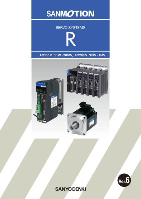
SanMotion R Servo Systems
SanMotion R Servo Systems
SanMotion R Servo Systems

Create successful ePaper yourself
Turn your PDF publications into a flip-book with our unique Google optimized e-Paper software.
AC100 V 30 W-200 W, AC 200 V 30 W-1kW<br />
Ver.6
Input voltageAC100 V, 200 V<br />
<strong>Servo</strong> amplifier<br />
Amp. capacity<br />
5A30A50A<br />
R2 <strong>Servo</strong> motor<br />
Flange size<br />
40mm60mm80mm86mm<br />
Rated output<br />
30W50W100W200W400W750W1.0kW
Index<br />
Features and Functions P. 3<br />
Standard Model Number List P. 7<br />
Model Number Nomenclature P. 10<br />
System Configuration P. 13<br />
Standard Specifications<br />
Encoder Wiring Diagram P. 15<br />
External Wiring Diagram P. 20<br />
Dimensions P. 24<br />
Setup Software P. 28<br />
<strong>Servo</strong> Amplifier built-in<br />
positioning functionP. 30<br />
Optional EquipmentP. 31<br />
Discontinued Models and<br />
Replacement Models P. 34
Easy Set-up for Optimal Operation<br />
Auto-Tuning<br />
A new auto-tuning algorithm improves system<br />
response by providing functions such as inertia<br />
identification, 5 auto-tuning modes, 30 levels of<br />
response, and parameter setting auto-save.<br />
Small Compact <strong>Servo</strong>motors<br />
Motor size and volume is reduced by as much as 30%<br />
and 25% respectively compared to current models.<br />
The world's smallest high torque high performance<br />
servomotor. (as of Sept 2006)<br />
Velocity command<br />
value<br />
Tuning start<br />
Detected velocity value<br />
30% reduction<br />
Multi-Axis <strong>Servo</strong> Amplifier<br />
6-axis model can reduce installation width by up to<br />
42% compared to six single-axis models.Power loss is<br />
reduced by up to 20% compared to current single-axis<br />
models.<br />
Protection code IP67<br />
Protection code is IP67 for all models.<br />
IP67<br />
Water<br />
Dust<br />
*Shaft feedthrough and cable end are excluded.<br />
All-in-One Control<br />
Configurable parameters allow you to switch between<br />
control modes for torque, position or velocity.<br />
Power Supply Harmonic Suppression<br />
Equipped with DC reactor connection terminals as<br />
standard feature for supressing power supply<br />
harmonics.<br />
Position<br />
or<br />
Velocity<br />
Torque<br />
control<br />
<br />
<br />
Flat<br />
Ascending<br />
*Uniaxial servo amplifier only<br />
3
5-digit LED Display, Built-in Operator<br />
Parameter setting, monitoring and alarm tracing can<br />
be easily done using the built-in operator.<br />
Test Function (JOG)<br />
On-board JOG operation function is available for<br />
testing motor and amplifier connection without the<br />
need to connect to host device.<br />
Capable of JOG operation<br />
without connecting to host<br />
device<br />
Standard<br />
Specifications<br />
Features and<br />
Functions<br />
Model Number<br />
Nomencalture<br />
System<br />
Configuration<br />
*Multi-axis is done through a personal computer.<br />
Setup Software<br />
The setup software allows you to set parameters,<br />
view graphical displays of monitored position,<br />
velocity or torque waveforms, and perform system<br />
analysis.<br />
Parameter settings Position, velocity,<br />
torque waveforms<br />
Multiaxial Monitor Function<br />
The setup software allows up to 15 amplifiers to be<br />
monitored. (Single axis only)<br />
Daisy chain up to 15 units<br />
Dimensions External Wiring<br />
Diagram<br />
Setup Software<br />
*<br />
RS232C<br />
Maximum<br />
15 units<br />
Optional<br />
Equipment<br />
* Use optional cable<br />
AL-00490833-01 for PC<br />
connection<br />
*PC connection cable is optional<br />
Built-in Regeneration Resistor<br />
It is possible to choose whether to equip regenerative<br />
resistance or not. If the regenerative resistance<br />
capability is insufficient, it is possible to use an<br />
external regenerative resistance unit.<br />
Built-in<br />
Regeneration<br />
Resistor<br />
Built-in Dynamic Brake<br />
A built-in dynamic brake provides emergency stop<br />
capability. The six kinds of motion sequences for the<br />
dynamic brake can be selected by parameter setting.<br />
Rotation speed<br />
(min-1 )<br />
Controlled<br />
state Dynamic braking state<br />
Time(s)<br />
External regenerative<br />
resistor unit (Option)<br />
4
Improved Precision and Reduced Cycle Time<br />
High Response<br />
A 4th-order notch filter reduces phase delay to<br />
suppress mechanical resonance and improve velocity<br />
response of equipment.<br />
Shorter Position Settling Time<br />
A new algorithm drastically shortens positioning<br />
settling time for equipment.<br />
10<br />
0<br />
Position deviation<br />
Gain (dB)<br />
-10<br />
-20<br />
-30<br />
Position complete signal<br />
Settling time (0ms)<br />
-40<br />
1<br />
5 10 50 100 500 1000 1800<br />
Frequency (Hz)<br />
Example of positioning settling time<br />
in highly rigid machinery<br />
5ms/div<br />
Vibration Suppression Control<br />
With feed-forward vibration suppression control,<br />
vibrations at the processing point and base of a<br />
machine can be suppressed through simple tuning<br />
procedures. Up to 4 types of vibration control<br />
frequencies can be selected.<br />
Position deviation during stop<br />
Disturbance Suppression<br />
It is possible to control impacts from other axes in<br />
case of multiaxial constitution, by using the new<br />
disturbance observer with extended applicable<br />
frequency.<br />
With vibration suppression control<br />
Without vibration suppression control<br />
Disturbance observer function ON<br />
Disturbance observer function OFF<br />
Oscillation waveform<br />
of direct drive section<br />
Oscillation waveform<br />
of direct drive section<br />
With vibration<br />
suppression control<br />
Without vibration<br />
suppression control<br />
100ms/div<br />
Disturbance<br />
Disturbance<br />
Expanded Power Range<br />
Maximum instantaneous stall torque is improved by<br />
5% to 26%, and maximum rotation speed is increased<br />
from 5000min -1 to 6000min -1 compared to current<br />
models.<br />
Command Follow-up Control<br />
Performance of the positioning doubled in comparison<br />
with current models by adoption of new positioning<br />
control algorithm and new speed control algorithm.<br />
And position deviation0 is achieved.<br />
Position command<br />
Increased torque<br />
R motor<br />
Torque (N)<br />
Current model<br />
Increased rotation Speed<br />
Position deviation<br />
0 1000 2000 3000 4000 5000 6000 7000<br />
Rotation Speed (min -1 )<br />
20ms/div<br />
5
Reduced Running<br />
Costs<br />
Low Cogging Torque<br />
20% Reduction in Power Loss<br />
Features and<br />
Functions<br />
Using our proprietary technology, the motor's low<br />
cogging torque delivers smooth rotation that is ideal<br />
for high precision processes and vibration-sensitive<br />
conveyor applications.<br />
R motor<br />
Current model<br />
High Resolution<br />
Comparison of cogging torque waveforms<br />
(*Image)<br />
Support for encoders up to 17 bit (131,072 divisions) is<br />
available for high resolution control.<br />
An energy conserving power module reduces main<br />
circuit power loss by up to 20%.<br />
100%<br />
90%<br />
80%<br />
70%<br />
60%<br />
50%<br />
40%<br />
30%<br />
20%<br />
10%<br />
0%<br />
Current model SANMOTION R<br />
50A<br />
Model Number<br />
Nomencalture<br />
System<br />
Configuration<br />
Standard<br />
Specifications<br />
Dimensions External Wiring<br />
Diagram<br />
High Resolution 17bit(131,072 divisions) Absolute Encoder<br />
Power loss reduction (%)<br />
Optional<br />
Equipment<br />
Setup Software<br />
6
<strong>Servo</strong> Motor Standard Model Number List<br />
200V System<br />
Power Voltage Encoder models Rated Output Motor Flange Size Holding Brake CE·UL Model No.<br />
R2AA04003FXP00<br />
30W<br />
40mm sq.<br />
Standard R2AA04003FXP00M<br />
yes24V R2AA04003FCP00<br />
yes24V Standard R2AA04003FCP00M<br />
R2AA04005FXP00<br />
50W<br />
40mm sq.<br />
Standard R2AA04005FXP00M<br />
yes24V R2AA04005FCP00<br />
yes24V Standard R2AA04005FCP00M<br />
40mm sq.<br />
R2AA04010FXP00<br />
Standard R2AA04010FXP00M<br />
R2AA06010FXP00<br />
100W<br />
Standard R2AA06010FXP00M<br />
60mm sq.<br />
yes24V R2AA06010FCP00<br />
yes24V Standard R2AA06010FCP00M<br />
R2AA06020FXP00<br />
Standard R2AA06020FXP00M<br />
60mm sq.<br />
Battery backup method<br />
yes24V R2AA06020FCP00<br />
absolute encoder 200W<br />
yes24V Standard R2AA06020FCP00M<br />
R2AA08020FXP00<br />
PA035C<br />
Standard R2AA08020FXP00M<br />
80mm sq.<br />
yes24V R2AA08020FCP00<br />
yes24V Standard R2AA08020FCP00M<br />
60mm sq.<br />
R2AA06040FXP00<br />
Standard R2AA06040FXP00M<br />
R2AA08040FXP00<br />
400W<br />
Standard R2AA08040FXP00M<br />
80mm sq.<br />
yes24V R2AA08040FCP00<br />
yes24V Standard R2AA08040FCP00M<br />
R2AA08075FXP00<br />
750W<br />
80mm sq.<br />
Standard R2AA08075FXP00M<br />
yes24V R2AA08075FCP00<br />
yes24V Standard R2AA08075FCP00M<br />
R2AAB8100FXP00<br />
1000W<br />
86mm sq.<br />
Standard R2AAB8100FXP00M<br />
yes24V R2AAB8100FCP00<br />
200V<br />
yes24V Standard R2AAB8100FCP00M<br />
R2AA04003FXH00<br />
30W<br />
40mm sq.<br />
Standard R2AA04003FXH00M<br />
yes24V R2AA04003FCH00<br />
yes24V Standard R2AA04003FCH00M<br />
R2AA04005FXH00<br />
50W<br />
40mm sq.<br />
Standard R2AA04005FXH00M<br />
yes24V R2AA04005FCH00<br />
yes24V Standard R2AA04005FCH00M<br />
40mm sq.<br />
R2AA04010FXH00<br />
Standard R2AA04010FXH00M<br />
R2AA06010FXH00<br />
100W<br />
Standard R2AA06010FXH00M<br />
60mm sq.<br />
yes24V R2AA06010FCH00<br />
yes24V Standard R2AA06010FCH00M<br />
R2AA06020FXH00<br />
Standard R2AA06020FXH00M<br />
60mm sq.<br />
yes24V <br />
Absolute encoder for<br />
R2AA06020FCH00<br />
yes24V Standard R2AA06020FCH00M<br />
incremental System 200W<br />
R2AA08020FXH00<br />
PA035S<br />
Standard R2AA08020FXH00M<br />
80mm sq.<br />
yes24V R2AA08020FCH00<br />
yes24V Standard R2AA08020FCH00M<br />
60mm sq.<br />
R2AA06040FXH00<br />
Standard R2AA06040FXH00M<br />
R2AA08040FXH00<br />
400W<br />
Standard R2AA08040FXH00M<br />
80mm sq.<br />
yes24V R2AA08040FCH00<br />
yes24V Standard R2AA08040FCH00M<br />
R2AA08075FXH00<br />
750W<br />
80mm sq.<br />
Standard R2AA08075FXH00M<br />
yes24V R2AA08075FCH00<br />
yes24V Standard R2AA08075FCH00M<br />
R2AAB8100FXH00<br />
1000W<br />
86mm sq.<br />
Standard R2AAB8100FXH00M<br />
yes24V R2AAB8100FCH00<br />
yes24V Standard R2AAB8100FCH00M<br />
For specifications on other model, please contact us.<br />
7
<strong>Servo</strong> Amplifier Standard Model Number List<br />
200V System<br />
Type Main Power Control Power Encoder Type<br />
CANopen<br />
Interface<br />
specifications<br />
Built-in<br />
positioning<br />
function<br />
model<br />
AC200VSystem<br />
AC200VSystem<br />
DC24V<br />
AC200VSystem<br />
DC24V<br />
AC200VSystem AC200VSystem<br />
Wire-saving incremental encoder,<br />
Battery backup method absolute<br />
encoder<br />
Wire-saving incremental encoder,<br />
Battery backup method absolute<br />
encoder<br />
Selectable<br />
Output<br />
NPN<br />
PNP<br />
NPN<br />
Internal Registration Amplifier<br />
Resistor<br />
Capacity<br />
Model No.<br />
15A RS1A01AL<br />
<br />
30A RS1A03AL<br />
50A RS1L05AL<br />
15A RS1L01AL<br />
With<br />
30A RS1L03AL<br />
50A RS1A05AL<br />
15A RS1J01AL<br />
<br />
30A RS1J03AL<br />
50A RS1J05AL<br />
15A RS1K01AL<br />
With<br />
30A RS1K03AL<br />
50A RS1K05AL<br />
15A RS1A01AU<br />
<br />
30A RS1A03AU<br />
50A RS1L05AU<br />
15A RS1L01AU<br />
With<br />
30A RS1L03AU<br />
50A RS1A05AU<br />
15A RS1J01AU<br />
<br />
30A RS1J03AU<br />
50A RS1J05AU<br />
15A RS1K01AU<br />
With<br />
30A RS1K03AU<br />
50A RS1K05AU<br />
15A RS1A01AC<br />
<br />
30A RS1A03AC<br />
50A RS1L05AC<br />
15A RS1L01AC<br />
With<br />
30A RS1L03AC<br />
50A RS1A05AC<br />
For specifications on other model, please contact us.<br />
Features and<br />
Functions<br />
Model Number<br />
Nomencalture<br />
System<br />
Configuration<br />
Standard<br />
Specifications<br />
Dimensions External Wiring<br />
Diagram<br />
Multi-Axis <strong>Servo</strong> System Amplifier Unit<br />
Type Power Input Encoder Type<br />
Pulse train<br />
interface<br />
DC280V<br />
Battery backup method<br />
absolute encoder<br />
Selectable<br />
Output<br />
NPN<br />
Amplifier<br />
Capacity<br />
15A<br />
30A<br />
Model No.<br />
RR1A01AAB00<br />
RR1A03AAB00<br />
Setup Software<br />
Multi-Axis <strong>Servo</strong> System Power Unit<br />
Type Power Input Internal Registration Resistor Model No.<br />
Pulse train<br />
interface<br />
AC200V With RRPAA00<br />
Optional<br />
Equipment<br />
Multi-Axis <strong>Servo</strong> System Motherboard<br />
Power Input<br />
AC200V<br />
Number of Slots<br />
Model No.<br />
(based on a 15A unit)<br />
4 RRMA400<br />
6 RRMA600<br />
8 RRMA800<br />
8
<strong>Servo</strong> Motor Standard Model Number List<br />
100V System<br />
Power Voltage Encoder models Rated Output Motor Flange Size Holding Brake CE·UL Model No.<br />
yes(24V) R2EA04003FCP00<br />
30W<br />
40mm sq.<br />
yes(24V) Standard R2EA04003FCP00M<br />
R2EA04003FXP00<br />
Standard R2EA04003FXP00M<br />
yes(24V) R2EA04005FCP00<br />
50W<br />
40mm sq.<br />
yes(24V) Standard R2EA04005FCP00M<br />
R2EA04005FXP00<br />
Standard R2EA04005FXP00M<br />
Battery backup method<br />
yes(24V) R2EA04008FCP00<br />
absolute encoder 80W<br />
40mm sq.<br />
yes(24V) Standard R2EA04008FCP00M<br />
R2EA04008FXP00<br />
PA035C<br />
Standard R2EA04008FXP00M<br />
yes(24V) R2EA06010FCP00<br />
100W<br />
60mm sq.<br />
yes(24V) Standard R2EA06010FCP00M<br />
R2EA06010FXP00<br />
Standard R2EA06010FXP00M<br />
yes(24V) R2EA06020FCP00<br />
200W<br />
60mm sq.<br />
yes(24V) Standard R2EA06020FCP00M<br />
R2EA06020FXP00<br />
100V<br />
Standard R2EA06020FXP00M<br />
yes(24V) R2EA04003FCH00<br />
30W<br />
40mm sq.<br />
yes(24V) Standard R2EA04003FCH00M<br />
R2EA04003FXH00<br />
Standard R2EA04003FXH00M<br />
yes(24V) R2EA04005FCH00<br />
50W<br />
40mm sq.<br />
yes(24V) Standard R2EA04005FCH00M<br />
R2EA04005FXH00<br />
Standard R2EA04005FXH00M<br />
Absolute encoder for<br />
yes(24V) R2EA04008FCH00<br />
incremental System 80W<br />
40mm sq.<br />
yes(24V) Standard R2EA04008FCH00M<br />
R2EA04008FXH00<br />
PA035S<br />
Standard R2EA04008FXH00M<br />
yes(24V) R2EA06010FCH00<br />
100W<br />
60mm sq.<br />
yes(24V) Standard R2EA06010FCH00M<br />
R2EA06010FXH00<br />
Standard R2EA06010FXH00M<br />
yes(24V) R2EA06020FCH00<br />
200W<br />
60mm sq.<br />
yes(24V) Standard R2EA06020FCH00M<br />
R2EA06020FXH00<br />
Standard R2EA06020FXH00M<br />
<strong>Servo</strong> Amplifier Standard Model Number List<br />
100V System<br />
For specifications on other model, please contact us.<br />
Type Main Power Control Power Encoder Type<br />
Built-in<br />
positioning<br />
function<br />
model<br />
AC100VSystem<br />
AC100VSystem<br />
Wire-saving incremental encoder,<br />
Battery backup method absolute<br />
encoder<br />
Selectable<br />
Output<br />
NPN<br />
Internal Registration Amplifier<br />
Model No.<br />
Resistor<br />
Capacity<br />
15A RS1N01AC<br />
With<br />
30A RS1N03AC<br />
15A RS1E01AC<br />
<br />
30A RS1E03AC<br />
For specifications on other model, please contact us.<br />
Multi-Axis <strong>Servo</strong> System Amplifier Unit<br />
Type Power Input Encoder Type<br />
Selectable<br />
Output<br />
Amplifier<br />
Capacity<br />
Model No.<br />
Pulse train<br />
interface<br />
DC140V<br />
Battery backup method<br />
absolute encoder<br />
NPN<br />
15A<br />
30A<br />
RR1E01AAB00<br />
RR1E03AAB00<br />
Multi-Axis <strong>Servo</strong> System Power Unit<br />
Type Power Input Internal Registration Resistor Model No.<br />
Pulse train<br />
interface<br />
AC100V With RRPEA00<br />
Multi-Axis <strong>Servo</strong> System Motherboard<br />
Power Input<br />
AC100V<br />
Number of Slots<br />
Model No.<br />
(based on a 15A unit)<br />
4 RRME400<br />
6 RRME600<br />
8 RRME800<br />
9
<strong>Servo</strong> Motor Model Number Nomenclature<br />
<strong>Servo</strong> Motor<br />
Example: The following model number defines a "R2" servomotor with 60mm flange size, 200W rated output,<br />
6000min -1 maximum rotation speed, 24V brake, and an absolute encoder (131,072 divisions/<br />
rotation),UL/CE approval and reduction ratio 1/3.(Planetary gear)<br />
Features and<br />
Functions<br />
R<br />
R Series<br />
2 AA 06 020 F C P 00 M A<br />
Specification<br />
00Standard<br />
01With oil seal<br />
Model Number<br />
Nomencalture<br />
System<br />
Configuration<br />
<br />
Motor Type<br />
<br />
Middle inertia<br />
Supply Voltage<br />
200V Motor<br />
100V Motor<br />
Flange Size<br />
04 40mm<br />
06 60mm<br />
08 80mm<br />
B8 86mm<br />
Rated Output<br />
003 30W<br />
005 50W<br />
010 100W<br />
020 200W<br />
040 400W<br />
075 750W<br />
100 1kW<br />
A reduction in the rating might be needed if an oil seal<br />
and Brake is attached. Please consult with us about the details.<br />
Holding Brake<br />
XWithout Brake<br />
BWith Brake90V DC<br />
CWith Brake24V DC<br />
Maximum Rotation Speed<br />
6000min -1<br />
Symbol<br />
A<br />
B<br />
C<br />
D<br />
E<br />
S<br />
T<br />
U<br />
V<br />
Reducer type<br />
Planetary<br />
gear<br />
Backlashless<br />
planetary<br />
gear<br />
Please consult with us about the<br />
combination for the decelerator.<br />
Standard Identification<br />
M CE and UL<br />
0 Without standard<br />
but with gear<br />
Reduction ratio<br />
1/3<br />
1/5<br />
1/9<br />
1/15<br />
1/25<br />
1/5<br />
1/11<br />
1/21<br />
1/33<br />
Encoder Type<br />
P Battery backup method absolute encoderPA035C<br />
H Absolute encoder for incremental SystemPA035S<br />
WAbsolute encoder without batteryRA035C<br />
S Wire-saving incremental encoderPP031T<br />
Standard<br />
Specifications<br />
Dimensions External Wiring<br />
Diagram<br />
Setup Software<br />
Optional<br />
Equipment<br />
Encoder Specification<br />
Model<br />
Partition number /<br />
rotation<br />
Multiple Rotations<br />
Remarks<br />
PA035C<br />
PA035S<br />
131072(17bit) 65536(16bit) Battery backup method Absolute encoder<br />
131072(17bit) Absolute encoder for Incremental system<br />
RA035C<br />
131072(17bit)<br />
65536(16bit)<br />
Absolute encoder without battery<br />
PP031T<br />
8000(2000P/R)<br />
<br />
Wire-saving incremental encoder<br />
Maximum 40000(Partition number/ rotation)<br />
Conformance to Overseas Standards<br />
Our standard servo amplifier has attained the international<br />
standards (UL, c-UL and EN Standards).<br />
You can also employ servo motors that have attained the<br />
international standards (UL, c-UL and EN Standards).<br />
10
<strong>Servo</strong> Amplifier Model Number Nomenclature<br />
<strong>Servo</strong> Amplifier with CANopen<br />
Example: The model number shown below is "R" Series <strong>Servo</strong> Amplifier with 200V AC input voltage and 15A<br />
amplifier capacity.<br />
RS1<br />
A 01<br />
A<br />
L<br />
R Series<br />
Single-Axis <strong>Servo</strong><br />
Amplifier<br />
Model<br />
L<br />
A<br />
A<br />
L<br />
N<br />
E<br />
K<br />
J<br />
AC200V<br />
AC100V<br />
AMP. Capacity<br />
01 15A<br />
03 30A<br />
05 50A<br />
Power Input, Internal Registration Setting<br />
Control Power<br />
Input Voltage<br />
DC24V<br />
Power Input,<br />
Input Voltage<br />
AC200V<br />
AC100V<br />
AC200V<br />
Motor Type<br />
Rotary Motor<br />
Internal Registration<br />
Resistor<br />
W<br />
W/O<br />
W<br />
W/O<br />
W<br />
W/O<br />
W<br />
W/O<br />
AMP. Capacity<br />
15A,30A<br />
15A,30A<br />
50A<br />
50A<br />
15A,30A<br />
15A,30A<br />
15A,30A,50A<br />
15A,30A,50A<br />
Interface Type<br />
Interface SpecificationCAN open I/F<br />
Encoder SpecificationAbsolute encoder,<br />
Wire-saving incremental encoder<br />
L NPN Output<br />
UPNP Output<br />
*The motor parameters need to be set for the amplifier for use. Use the setup software.<br />
Single-Axis <strong>Servo</strong> Amplifier built-in Positioning Function model<br />
Example: The model number shown below is "R" Series <strong>Servo</strong> Amplifier with 200V AC input voltage<br />
(Main Power and Control Power) and 15A amplifier capacity.<br />
RS1<br />
A 01<br />
A<br />
C<br />
R Series<br />
Single-Axis <strong>Servo</strong><br />
Amplifier<br />
Amp. capacity<br />
01 15A<br />
03 30A<br />
05 50A<br />
Motor Type<br />
Rotary Motor<br />
Power Input, Internal Registration Setting<br />
Model<br />
L<br />
A<br />
A<br />
L<br />
N<br />
E<br />
Input Voltage Internal Registration Resistor<br />
W<br />
W/O<br />
AC200V<br />
W<br />
W/O<br />
W<br />
AC100V<br />
W/O<br />
Amp. capacity<br />
15A,30A<br />
15A,30A<br />
50A<br />
50A<br />
15A,30A<br />
15A,30A<br />
Interface Type<br />
CBuilt-in Positioning Function Model<br />
FBuilt-in positioning function model<br />
with serial interface<br />
*The motor parameters need to be set for the amplifier for use. Use the setup software.<br />
11
Multi-Axis <strong>Servo</strong> Amplifier<br />
Example: The model number shown below is a 4-axis "R" series multiaxis servo amplifier configuration<br />
with 200V AC input voltage, 4 units of 15A amplifiers, and pulse train interface.<br />
Amplifier Unit RR1A01AAB00 4 units<br />
Power Unit RRPAA00 1 unit<br />
Motherboard RRMA400 1 unit<br />
Features and<br />
Functions<br />
Model Number<br />
Nomencalture<br />
Amplifier Unit<br />
RR1 A 01 A A B 00<br />
System<br />
Configuration<br />
R Series<br />
Multi-Axis <strong>Servo</strong> System<br />
Amplifier Unit<br />
Amp. capacity<br />
01 15A<br />
03 30A<br />
Control Hardware Type<br />
Pulse train interface<br />
Specification<br />
Standard<br />
Standard<br />
Specifications<br />
Power Unit<br />
Power Input<br />
ADC280V<br />
EDC140V<br />
RRP A A 00<br />
R Series<br />
Multi-Axis <strong>Servo</strong> System<br />
Power Unit<br />
Motherboard<br />
Power Input<br />
AAC200V<br />
EAC100V<br />
RRM A 4 00<br />
Motor Type<br />
Rotary Motor<br />
Control Hardware Type<br />
Pulse train interface<br />
Encoder Combination Description<br />
Absolute encoder<br />
*The motor parameters need to be set for the amplifier for use. Use the setup software.<br />
Specification<br />
Standard<br />
Dimensions External Wiring<br />
Diagram<br />
Setup Software<br />
Optional<br />
Equipment<br />
R Series<br />
Multi-Axis <strong>Servo</strong> System<br />
Motherboard<br />
Power Input<br />
AAC200V<br />
EAC100V<br />
Number of Slots<br />
44 Slots<br />
66 Slots<br />
88 Slots<br />
Amplifier Unit 15A:Use of 1 slot per 1 unit<br />
Amplifier Unit 30A:Use of 2 slots per 1 unit<br />
Specification<br />
Standard<br />
12
System Configuration<br />
Single-Axis <strong>Servo</strong> Amplifier<br />
Noise Filter<br />
Electromagnetic Contactor<br />
Model No.: AL-00494635-01<br />
Lithium battery<br />
Attached to prevent<br />
external noise from the<br />
power source line.<br />
Switches servo power on and<br />
off. Installation of a surge<br />
protector is required.<br />
Create the protective circuit.<br />
Model No.: AL-00490833-01<br />
When using the unit with an<br />
absolute system, mount the<br />
optional battery inside the<br />
digital operator cover.<br />
Circuit Breaker(MCCBM)<br />
DC Reactor<br />
PC<br />
Setup<br />
Software<br />
Parameter<br />
configuration<br />
and monitoring<br />
is possible via<br />
communication<br />
with a PC.<br />
Cuts off power in the case<br />
of an overload, to protect<br />
the power line.<br />
Suppresses power harmonics.<br />
Remove the short bar between<br />
DL1-DL2 and connect this here,<br />
when needed for high<br />
frequency waves.<br />
CN1<br />
Host Devices<br />
T S R<br />
External Regenerative Resistor<br />
PLC<br />
Use as necessary, for example<br />
when operating loads with<br />
large inertia.<br />
CN2<br />
For special operations, such as<br />
high frequency applications<br />
that require greater power<br />
dissipation than that provided<br />
by the servo amplifier’s<br />
internal regenerative resistor.<br />
Brake Power<br />
Wiring required for brake.<br />
Required for use when the<br />
servo motor is equipped<br />
with a brake.<br />
CANopen<br />
Host Devices<br />
Dedicated controller<br />
PC and PLC are available<br />
as the host device.<br />
*Communication Profile: DS-301<br />
Device Profile: DSP-402 compliance<br />
13
Multi-Axis <strong>Servo</strong> Amplifier<br />
Noise Filter<br />
Attached to prevent<br />
external noise from the<br />
power source line.<br />
Circuit Breaker(MCCB)<br />
Cuts off power in the case<br />
of an overload, to protect<br />
the power line.<br />
T<br />
S<br />
R<br />
Lithium battery<br />
When using the unit with<br />
an absolute system,<br />
connect the battery to<br />
CN5.<br />
Setup Software<br />
Parameter configuration<br />
and monitoring is possible<br />
via communication with a<br />
PC.<br />
Model No.: AL-00490833-01<br />
Host Devices<br />
PLC<br />
Features and<br />
Functions<br />
Model Number<br />
Nomencalture<br />
System<br />
Configuration<br />
Electromagnetic Contactor<br />
Standard<br />
Specifications<br />
Switches servo power on and<br />
off. Installation of a surge<br />
protector is required.<br />
Create the protective circuit.<br />
External Regenerative Resistor<br />
Use as necessary, for example<br />
when operating loads with<br />
large inertia.<br />
Dimensions External Wiring<br />
Diagram<br />
For special operations, such as<br />
high frequency applications<br />
that require greater power<br />
dissipation than that provided<br />
by the servo amplifier’s<br />
internal regenerative resistor.<br />
Setup Software<br />
DC Reactor<br />
Optional<br />
Equipment<br />
Suppresses power harmonics.<br />
Remove the short bar between<br />
DL1-DL2 and connect this here,<br />
when needed for high<br />
frequency waves.<br />
Brake Power<br />
Wiring required for brake.<br />
Required for use when the<br />
servo motor is equipped<br />
with a brake.<br />
14
Standard Specifications<br />
R2<br />
<strong>Servo</strong> Motor<br />
200V System<br />
Capacity<br />
40mm sq. to 86mm sq.<br />
30W to 1000W<br />
Features<br />
High Efficiency and Low<br />
Ripple (Medium Inertia)<br />
Motor Model and Flange Size in mm<br />
Status Symbol Unit<br />
R2AA04003F<br />
40<br />
R2AA04005F<br />
40<br />
R2AA04010F<br />
40<br />
Rated Output PR W 30 50 100<br />
Rated Speed NR min -1 3000<br />
Maximum Speed Nmax min -1 6000<br />
Rated Torque TR Nm 0.098 0.159 0.318<br />
Continuous Torque at Stall TS Nm 0.108 0.167 0.318<br />
Peak Torque at Stall TP Nm 0.37 0.59 1.18<br />
Rated Armature Current IR Arms 0.51 0.67 0.81<br />
Armature Current at Stall IS Arms 0.56 0.69 0.81<br />
Peak Armature Current at Stall IP Arms 2.15 2.8 3.3<br />
Torque Constant KT NmArms 0.201 0.246 0.424<br />
Voltage Constant Per Phase K E mVmin -1 7 8.6 14.8<br />
Phase Resistance R 12 9 9.3<br />
Rated Power Rate Q R kWs 3.9 6.7 16<br />
Electrical Time Constant te ms 0.55 0.67 0.82<br />
Mechanical Time Constant (Not including Encoder) tm ms 2.2 1.7 0.97<br />
Rotor Moment of Inertia (Not including Encoder) JM 10 -4 kgm 2 GD 2 4 0.0247 0.0376 0.0627<br />
Rotor Moment of Inertia (Encoder) JS 10 -4 kgm 2 GD 2 4 0.0033 (Note 3)<br />
Mass including Encoder WE kg 0.35 0.39 0.51<br />
Brake Static Friction Torque TB Nm 0.32 MIN.<br />
Brake Rated Voltage VB V DC90V DC24V 10<br />
Brake Rated Current IB A 0.07 0.27<br />
Rotor Moment of Inertia (Brake) JB 10 -4 kgm 2 GD 2 4 0.0078<br />
Brake Mass W kg 0.27<br />
Motor Operating Temp, Rel. Humidity<br />
Amplifier Model Single-Axis<br />
Amplifier Model Multi-Axis<br />
Operating Temperature: 0 to 40C, Relative Humidity: 90% Maximum, no condensation<br />
RS1A01A<br />
RR1A01AAB00<br />
Amplifier Power Supply AC200V to 230V 10, 15% 50/60Hz 3Hz (Note 2)<br />
Amp. Operating Temp. and RH<br />
Operating Temperature: 0 to 55C (Note1), Relative Humidity: 90% Maximum, no condensation<br />
Rated power supply kVA 0.2 0.4<br />
Amplifier Mass Weight[Single / CAN / Multi] (Note4) kg 0.9 1.0 0.48<br />
Motor Dwgs P24<br />
:Indicates a typical value<br />
after warm-up and thermal<br />
stabilization, together with<br />
a standard amplifier.<br />
:Indicates a typical<br />
value when the winding<br />
temperature is 20.<br />
Note 1) The multi-axis type <strong>Servo</strong> amplifier has an ambient<br />
operating temperature of 0 to 40. The operating<br />
temperature with forced air cooling is 0 to 55.<br />
Note 2) In case of the amplifier for CANopen, there is also<br />
control power source DC24V type.<br />
Note 3) This is a instance with the battery-backup method<br />
absolute encoder PA035.<br />
For the following encoders, please make inquiries:<br />
Absolute encoder without battery RA035C <br />
Red. Wiring Incremental Encoder PP031T <br />
Note 4) The weight in the multi-axial specifications is of amplifier<br />
unit only.<br />
* For models with oil seal or brake, reduction in rated value<br />
may become necessary.<br />
Torque [N m]<br />
0.5<br />
0.4<br />
0.3<br />
0.2<br />
0.1<br />
0<br />
0 1000 2000 3000 4000 5000 6000 7000<br />
Speed [min -1 ]<br />
Torque [N m]<br />
0.8<br />
0.6<br />
0.4<br />
0.2<br />
0<br />
0 1000 2000 3000 4000 5000 6000 7000<br />
Speed [min -1 ]<br />
Torque [N m]<br />
1.5<br />
1<br />
0.5<br />
0<br />
0 1000 2000 3000 4000 5000 6000 7000<br />
Speed [min -1 ]<br />
Encoder Wiring Diagram<br />
Single-Axis <strong>Servo</strong> Amplifier<br />
Note25V<br />
Note2 0V<br />
SERVO AMPLIFIER<br />
CN2<br />
ES<br />
ES<br />
EBAT<br />
EBAT<br />
13<br />
14<br />
1<br />
2<br />
9<br />
10<br />
11<br />
12<br />
17<br />
18<br />
19<br />
20<br />
Note1<br />
Note3<br />
Brown<br />
ES<br />
Blue<br />
ES<br />
Pink<br />
EBAT<br />
Purple Note4<br />
EBAT<br />
Red 5V<br />
Black 0V<br />
FGShielded<br />
SERVO MOTOR<br />
Encoder<br />
Battery backup method absolute encoder [ PA035C ]<br />
Absolute encoder for incremental system [ PA035S ]<br />
Absolute encoder without battery [ RA035C ]<br />
Note 1) Use a twisted-pair shielded cable.<br />
Note 2) Encoder power connections depend on encoder cable length. See the following<br />
Encoder cable length<br />
+5V DC Wiring<br />
0V DC Wiring<br />
10m MAX. 25m MAX. 40m MAX.<br />
Connect pin 19<br />
(Do not connect pins12,17)<br />
Connect pin 20<br />
(Do not connect pins11,18)<br />
Connect pin 17,19<br />
(Do not connect pins12)<br />
Connect pin 18,20<br />
(Do not connect pins11)<br />
Connect pin 12,17,19<br />
Connect pin 11,18,20<br />
Note 3) Use a Awg24 0.2mm 2 encoder cable<br />
Note 4) When the Absolute encoder for incremental system or absolute encoder<br />
without battery is used, battery lines (EBAT+, EBAT-) are not required.<br />
Multi-Axis <strong>Servo</strong> AmplifierWiring diagram page17<br />
Plug:10120-3000PE<br />
Shell:10320-52A0-008<br />
15
R2AA06010F<br />
60<br />
R2AA06020F<br />
60<br />
R2AA06040F<br />
60<br />
R2AA08020F<br />
80<br />
R2AA08040F<br />
80<br />
R2AA08075F<br />
80<br />
R2AAB8100F<br />
86<br />
100 200 400 200 400 750 1000<br />
3000<br />
6000<br />
0.318 0.637 1.27 0.637 1.27 2.39 3.18<br />
0.353 0.686 1.37 0.686 1.37 2.55 3.92<br />
1.13 2.2 4.8 2.2 4.4 8.5 14.3<br />
0.86 1.5 2.8 1.5 2.6 4.6 6.0<br />
0.86 1.6 2.8 1.5 2.6 4.6 6.8<br />
3.5 5.6 10.8 4.8 8.9 15.5 25.7<br />
0.375 0.476 0.524 0.516 0.559 0.559 0.582<br />
13.1 16.6 18.3 18.0 19.5 19.5 20.3<br />
4.8 2.7 1.36 2.3 0.93 0.4 0.44<br />
8.6 19 39 8 16 31 42<br />
2.0 2.6 3.2 2.2 2.5 3.0 4.3<br />
1.2 0.78 0.61 1.3 0.93 0.70 0.93<br />
0.117 0.219 0.412 0.52 1.04 1.82 2.38<br />
0.0033 (Note 3)<br />
0.71 0.96 1.4 1.3 1.7 2.7 3.6<br />
0.36 MIN. 1.37 MIN. 2.55 MIN. 3.92 MIN.<br />
DC90V DC24V 10<br />
0.07 0.27 0.11 0.32 0.12 0.37 0.30 0.09<br />
0.060 0.060 0.25 0.34<br />
0.34 0.37 0.89 0.84<br />
Operating Temperature: 0 to 40C, Relative Humidity: 90% Maximum, no condensation<br />
RS1A01A RS1A03A RS1A01A RS1A03A RS1A05A<br />
RR1A01AAB00 RR1A03AAB00 RR1A01AAB00 RR1A03AAB00 <br />
AC200V to 230V 10, 15% 50/60Hz 3Hz (Note 2)<br />
Operating Temperature: 0 to 55C Note, Relative Humidity: 90% Maximum, no condensation<br />
0.4 0.8 1.0 0.8 1.0 1.7 2.5<br />
0.9 1.0 0.48 1.0 1.1 0.77 0.9 1.0 0.48 1.0 1.1 0.77 2.2 2.3 –<br />
Features and<br />
Functions<br />
Model Number<br />
Nomencalture<br />
System<br />
Configuration<br />
Standard<br />
Specifications<br />
Dimensions External Wiring<br />
Diagram<br />
Setup Software<br />
1.5<br />
3<br />
6<br />
3<br />
6<br />
10<br />
15<br />
Torque [N m]<br />
1<br />
0.5<br />
Torque [N m]<br />
2<br />
1<br />
Torque [N m]<br />
5<br />
4<br />
3<br />
2<br />
Torque [N m]<br />
2<br />
1<br />
Torque [N m]<br />
5<br />
4<br />
3<br />
2<br />
Torque [N m]<br />
8<br />
6<br />
4<br />
Torque [N m]<br />
10<br />
5<br />
Optional<br />
Equipment<br />
1<br />
1<br />
2<br />
0<br />
0 1000 2000 3000 4000 5000 6000 7000<br />
Speed [min -1 ]<br />
0<br />
0 1000 2000 3000 4000 5000 6000 7000<br />
Speed [min -1 ]<br />
0<br />
0 1000 2000 3000 4000 5000 6000 7000<br />
Speed [min -1 ]<br />
0<br />
0 1000 2000 3000 4000 5000 6000 7000<br />
Speed [min -1 ]<br />
0<br />
0 1000 2000 3000 4000 5000 6000 7000<br />
Speed [min -1 ]<br />
0<br />
0 1000 2000 3000 4000 5000 6000 7000<br />
Speed [min -1 ]<br />
0<br />
0 1000 2000 3000 4000 5000 6000 7000<br />
Speed [min -1 ]<br />
Single-Axis <strong>Servo</strong> Amplifier<br />
SERVO AMPLIFIER<br />
SERVO MOTOR<br />
Wire-saving incremental encoder [ PP031T ]<br />
Note 2) DC 5V<br />
Note 2) GND(0V)<br />
CN2<br />
Aor U channel input<br />
Aor U channel input<br />
Bor V channel input<br />
Bor V channel input<br />
Cor W channel input<br />
Cor W channel input<br />
3<br />
4<br />
5<br />
6<br />
7<br />
8<br />
9<br />
10<br />
11<br />
12<br />
16<br />
17<br />
18<br />
19<br />
20<br />
Note 1)<br />
Note 3)<br />
Blue<br />
Brown<br />
Green<br />
Purple<br />
White<br />
Yellow<br />
Red<br />
Black<br />
Note 3)<br />
Incremental encoder<br />
Aor U channel output<br />
Aor U channel output<br />
Bor V channel output<br />
Bor V channel output<br />
Cor W channel output<br />
Cor W channel output<br />
DC 5V<br />
GND(0V)<br />
FG(Shielded)<br />
Note 1) Use a twisted-pair shielded cable.<br />
Note 2) Encoder power connections depend on encoder cable length. See the following<br />
Encoder cable length<br />
+5V DC Wiring<br />
0V DC Wiring<br />
Note 3)<br />
5m MAX. 10m MAX. 20m MAX.<br />
30m MAX.<br />
Connect pin 19<br />
(Do not connect pins 9,12,17)<br />
Connect pin 20<br />
(Do not connect pins10,11,16,18)<br />
Connect pin 17,19<br />
(Do not connect pins 9,12)<br />
Connect pin 18,20<br />
(Do not connect pins 10,11,16)<br />
Use a Awg24 0.2mm 2 encoder cable<br />
Connect pin 12,17,19<br />
(Do not connect pins 9)<br />
9,12,17,19 Connect pin<br />
Connect pin 11,18,20<br />
(Do not connect pins 10,16)<br />
10,11,16,18,20Connect pin<br />
Plug : 10120-3000PE<br />
Shell : 10320-52A0-008<br />
16
Standard Specifications<br />
R2<br />
<strong>Servo</strong> Motor<br />
100V System<br />
Capacity<br />
40mm sq. to 60mm sq.<br />
30W to 200W<br />
5 models<br />
Features<br />
High Efficiency and Low<br />
Ripple (Medium Inertia)<br />
Motor Model and Flange Size in mm<br />
Status Symbol Unit<br />
R2EA04003F<br />
40<br />
R2EA04005F<br />
40<br />
Rated Output PR W 30 50<br />
Rated Speed NR min -1 3000<br />
Maximum Speed Nmax min -1 6000<br />
Rated Torque TR Nm 0.098 0.159<br />
Continuous Torque at Stall TS Nm 0.108 0.167<br />
Peak Torque at Stall TP Nm 0.37 0.59<br />
Rated Armature Current IR Arms 0.94 1.2<br />
Armature Current at Stall IS Arms 1.0 1.3<br />
Peak Armature Current at Stall IP Arms 3.7 4.9<br />
Torque Constant KT NmArms 0.116 10% 0.142 10%<br />
Voltage Constant Per Phase K E mVmin -1 4.04 10% 4.97 10%<br />
Phase Resistance R 4 3<br />
Rated Power Rate Q R kWs 3.9 6.7<br />
Electrical Time Constant te ms 0.55 0.67<br />
Mechanical Time Constant (Not including Encoder) tm ms 2.2 1.7<br />
Rotor Moment of Inertia (Not including Encoder) JM 10 -4 kgm 2 GD 2 4 0.0247 0.0376<br />
Rotor Moment of Inertia (Encoder) JS 10 -4 kgm 2 GD 2 4 0.0033 (Note 2)<br />
Mass including Encoder WE kg 0.35 0.39<br />
Brake Static Friction Torque TB Nm 0.32 MIN.<br />
Brake Rated Voltage VB V DC90V DC24V 10<br />
Brake Rated Current IB A 0.07 0.27<br />
Rotor Moment of Inertia (Brake) JB 10 -4 kgm 2 GD 2 4 0.0078<br />
Brake Mass W kg 0.27<br />
Motor Operating Temp, Rel. Humidity<br />
Amplifier Model Single-Axis<br />
Amplifier Model Multi-Axis<br />
Amplifier Power Supply<br />
Amp. Operating Temp. and RH<br />
Operating Temperature: 0 to 40C, Relative Humidity: 90% Maximum, no condensation<br />
RS1E01A<br />
RR1E01AAB<br />
AC100V to 115V 10 1550/60Hz 3Hz<br />
Operating Temperature: 0 to 55C (Note1), Relative Humidity: 90% Maximum, no condensation<br />
Rated power supply kVA 0.2<br />
Amplifier Mass Weight[Single / Multi] kg 0.9 0.48<br />
Motor Dwgs P24<br />
:Indicates a typical value<br />
after warm-up and thermal<br />
stabilization, together with<br />
a standard amplifier.<br />
:Indicates a typical<br />
value when the winding<br />
temperature is 20.<br />
Note 1) The multi-axis type <strong>Servo</strong> amplifier has an ambient<br />
operating temperature of 0 to 40. The operating<br />
temperature with forced air cooling is 0 to 55.<br />
Note 2) This is a instance with the battery-backup method<br />
absolute encoder PA035.<br />
For the following encoders, please make inquiries:<br />
Absolute encoder without battery RA035C <br />
Red. Wiring Incremental Encoder PP031T <br />
Note 3) The weight in the multi-axial specifications is of amplifier<br />
unit only.<br />
* For models with oil seal or brake, reduction in rated value<br />
may become necessary.<br />
Torque [N m]<br />
0.5<br />
0.4<br />
0.3<br />
0.2<br />
0.1<br />
0<br />
0 1000 2000 3000 4000 5000 6000 7000<br />
Speed [min -1 ]<br />
Torque [N m]<br />
0.8<br />
0.6<br />
0.4<br />
0.2<br />
0<br />
0 1000 2000 3000 4000 5000 6000 7000<br />
Speed [min -1 ]<br />
Encoder Wiring Diagram<br />
Multi-Axis <strong>Servo</strong> Amplifier<br />
SERVO AMPLIFIER<br />
SERVO MOTOR<br />
Battery backup method absolute encoder [ PA035C ]<br />
Plug:36320-0100JL<br />
Shell:36310-3200-008<br />
1<br />
2<br />
3<br />
4<br />
5<br />
6<br />
7<br />
8<br />
9<br />
10<br />
Note 2)<br />
Note 1)<br />
Red<br />
Black<br />
Brown<br />
Blue<br />
Pink<br />
Purple<br />
Note 3)<br />
+5<br />
0V<br />
Encoder<br />
+5V<br />
0V<br />
+5V<br />
0V<br />
N.C.<br />
N.C.<br />
ES+<br />
ES-<br />
EBAT+<br />
EBAT-<br />
ES+<br />
ES-<br />
EBAT+<br />
EBAT-<br />
FGShielded<br />
Note 1)<br />
Note 2)<br />
Note 3)<br />
Note 4)<br />
Use a twisted-pair shielded cable.<br />
The sheathed shield wire should be connected to the metal case (ground) on CN2 side,<br />
before connecting to ground on encoder side.<br />
Color symbols shown on the diagram for signal lines on encoder side refer to lead-wire<br />
type sensors.<br />
The allowable connection distance between amplifier and encoder varies according to<br />
the diameter(impedence) of the electric wire of the cable used. The power voltage<br />
specification for encoders is 5V±5%. If the cable is too long, the voltage on encoder side<br />
may fall below 5V.Measure the voltage on encoder side to ensure that the cable used is<br />
within specification limits.<br />
For the following encoders, please make inquiries:<br />
Absolute encoder without battery RA035C <br />
17
R2EA04008F<br />
40<br />
R2EA06010F<br />
60<br />
R2EA06020F<br />
60<br />
80 100 200 W<br />
Unit<br />
3000 min -1<br />
6000 min -1<br />
0.255 0.318 0.637 Nm<br />
0.255 0.318 0.686 Nm<br />
0.86 1.0 2.2 Nm<br />
1.3 1.7 3.1 Arms<br />
1.3 1.7 3.2 Arms<br />
4.5 5.6 11.9 Arms<br />
0.221 10% 0.206 10% 0.224 10% NmArms<br />
7.7 10% 7.2 10% 7.82 10% mVmin -1<br />
2.9 1.5 0.6 <br />
10 8.6 19 kWs<br />
0.81 1.9 2.6 ms<br />
0.98 1.2 0.79 ms<br />
0.0627 0.117 0.219 10 -4 kgm 2 GD 2 4<br />
0.0033 (Note 2) 10 -4 kgm 2 GD 2 4<br />
0.51 0.71 0.76 kg<br />
0.32 MIN. 0.36 MIN. 1.37 MIN. Nm<br />
DC90V DC24V 10<br />
0.07 0.27 0.07 0.27 0.11 0.32 A<br />
0.0078 0.06 10 -4 kgm 2 GD 2 4<br />
0.27 0.34 0.39 kg<br />
Operating Temperature: 0 to 40C, Relative Humidity: 90% Maximum, no condensation<br />
RS1E01A<br />
RS1E03A<br />
RR1E01AAB<br />
RR1E03AAB<br />
AC100V to 115V 10, 15% 50/60Hz 3Hz<br />
Operating Temperature: 0 to 55C (Note1), Relative Humidity: 90% Maximum, no condensation<br />
0.4 0.5 0.8 kVA<br />
0.9 0.48 1.0 0.77 kg<br />
V<br />
Features and<br />
Functions<br />
Model Number<br />
Nomencalture<br />
System<br />
Configuration<br />
Standard<br />
Specifications<br />
Dimensions External Wiring<br />
Diagram<br />
Setup Software<br />
1.5<br />
1.5<br />
3<br />
Torque [N m]<br />
1<br />
0.5<br />
Torque [N m]<br />
1<br />
0.5<br />
Torque [N m]<br />
2<br />
1<br />
Optional<br />
Equipment<br />
0<br />
0 1000 2000 3000 4000 5000 6000 7000<br />
Speed [min -1 ]<br />
0<br />
0 1000 2000 3000 4000 5000 6000 7000<br />
Speed [min -1 ]<br />
0<br />
0 1000 2000 3000 4000 5000 6000 7000<br />
Speed [min -1 ]<br />
18
General Specifications<br />
CANopen Interface specifications<br />
Fieldbus specifications<br />
Bus Connection, Medium<br />
CAN-Standard ISO-11898 (High-speed CAN)<br />
Fieldbus<br />
CANopen<br />
Communication Profile CiA DS301 Version 4.02<br />
Device Profile CiA DSP402 (CANopen device profile for drive and motion control) Version 2.0<br />
Bit Rate 1Mbps, 800kbps, 500kbps(default setting), 250kbps, 125kbps, 50kbps , 20kbps , 10kbps (Selectable by R-Setup Software )<br />
Max. nodes per segment 1 to 127 (Selectable by Double 16-position Rotary Switch or R-Setup Software )<br />
RJ-45 type Modular connector (2 ports)<br />
- Pin 1 CAN_Hhigh bus line<br />
Connector<br />
- Pin 2 CAN_Llow bus line<br />
- Pin 3,7 CAN_GNDGround<br />
- Pin 6 CAN_SHIELDCable Shield<br />
- Pin 5 Terminator(120 ohm; if necessary, attach a jumper between Pin1 and Pin5)<br />
Transceiver<br />
ISO-11898 compliant high-speed transceiver<br />
Max. Bus Length<br />
25m ( for 1Mbps)<br />
Communication Objects<br />
SDO (Service Data Object)<br />
EMCY (Emergency)<br />
SYNC (Synchronization Object)<br />
PDO (Process Data Object)<br />
NMT (Network Management)<br />
Heartbeat<br />
PDO Transfer Modes Synchronous transmission Asynchronous transmission<br />
Mode of Operation<br />
Homing Mode (h.m)<br />
Profile Velocity Mode (p.v)<br />
Profile Torque Mode (t.q)<br />
Profile Position Mode (p.p)<br />
Interpolated Position Mode (i.p)<br />
PNP output<br />
NPN output<br />
<strong>Servo</strong> amplifier<br />
Host unit<br />
<strong>Servo</strong> amplifier<br />
Host unit<br />
Out Power<br />
DC24V<br />
Out Power<br />
50mA max<br />
Out 1~8<br />
Out 1~8<br />
Out Common<br />
Maximum current<br />
DC5V .......... 10mA<br />
DC12 to 15V ..... 30mA<br />
DC24V .......... 50mA<br />
The output port counts are differentdepending on the specification.<br />
The output port counts are different depending on the specification.<br />
Single-Axis <strong>Servo</strong> Amplifier built-in positioning function serial interface model<br />
Item Content Default value Remark<br />
Protocol Modbus-RTU Binary mode fixed (ASCII mode is un-corresponding)<br />
Interface RS-4851N N=Maximum is 32 (Note)<br />
Band rate (bps) 4800, 9600, 19200, 38400, 57600, 115200 115200 Set with the setup software or the rotary switch on the front of the amplifier.<br />
Start bit 1 1 Fixed<br />
Data length (bit) 8 8 Fixed<br />
Parity None, even/odd number even<br />
Stop bit 1, 2 1<br />
Set with the setup software.<br />
Electric specification<br />
Based on RS-485 (half duplex<br />
Based on RS-485 (half duplex<br />
communication)<br />
communication)<br />
Fixed<br />
Connector RJ-45 <br />
Note) Based on the specifications for a typical RS-485 physical layer (distance, terminating resistance), the number of servo amplifiers (or other slave<br />
devices) that can be connected to a single segment is a maximum of 31 axes (with no repeater). However, with this servo amplifier, the standard<br />
product can have a maximum of 8 axes connected. Please contact us if connecting 9 axes or more.<br />
19
-<br />
External Wiring Diagram<br />
Single-Axis <strong>Servo</strong> Amplifier with CANopen<br />
Contorol Power DC24V<br />
Power<br />
supply 3<br />
200 to 230V<br />
50/60Hz<br />
DC24V<br />
Note 10)<br />
24V<br />
24G<br />
MC<br />
User unit<br />
Start Start<br />
ready ready<br />
ON OFF<br />
MC<br />
MC<br />
Emergency<br />
System<br />
error<br />
stop<br />
Note 11)<br />
CNA<br />
CNB<br />
1<br />
2<br />
T<br />
S<br />
R<br />
Features and<br />
Functions<br />
Model Number<br />
Nomencalture<br />
Contorol Power AC200V<br />
Power<br />
supply 3<br />
200 to 230V<br />
50/60Hz<br />
Note 10)<br />
Battery input<br />
MC<br />
CAN_L<br />
Terminator<br />
GND<br />
GND<br />
CAN_H<br />
CAN_L<br />
Terminator<br />
GND<br />
GND<br />
Note 8)<br />
DC5V to 24V<br />
User unit<br />
Start Start<br />
ready ready<br />
ON OFF<br />
MC<br />
MC<br />
Emergency<br />
System<br />
error<br />
stop<br />
CAN_H<br />
Lithium battery<br />
DC3.6V<br />
Note 11)<br />
SH<br />
Combination of<br />
Plug:TM21P-88P<br />
SH<br />
Combination of<br />
Plug:TM21P-88P<br />
CN1<br />
CNA<br />
CN3<br />
1<br />
2<br />
5<br />
3<br />
7<br />
CN4<br />
1<br />
2<br />
1<br />
2<br />
8<br />
9<br />
3<br />
5<br />
3<br />
7<br />
T<br />
S<br />
R<br />
t<br />
r<br />
Note 12)<br />
SG<br />
BTP-I<br />
BTN-I<br />
CONT<br />
-COM<br />
CONT1<br />
Note 2)<br />
Note 3)<br />
Note 4)<br />
1/4W 120<br />
CNB<br />
CAN<br />
TRANCEIVER<br />
DL1<br />
DL2<br />
P<br />
RB1<br />
+<br />
RB2<br />
SERVO AMPLIFIER<br />
Regenerative<br />
resistor<br />
NPN Output<br />
CN2<br />
OUT-PWR<br />
OUT1<br />
OUT2<br />
W<br />
V<br />
U<br />
Note 7)<br />
OUT-COM<br />
CNC<br />
14<br />
6<br />
13<br />
7<br />
Note 6)<br />
SH<br />
Note 5)<br />
Green<br />
(Green/Yellow)<br />
Encoder connector<br />
Note 8)<br />
DC5V,<br />
DC12V<br />
24V<br />
Black<br />
White<br />
Red<br />
SH<br />
SH<br />
Combination of<br />
Note 5) Plug : 10120-3000PE,<br />
Shell : 10320-52A0-008<br />
General-purpose output<br />
SERVO<br />
MOTOR<br />
Encoder<br />
Orange<br />
(Yellow)<br />
Orange<br />
(Yellow)<br />
PNP Output<br />
RY1<br />
OUT-PWR<br />
OUT1<br />
OUT2<br />
90V<br />
(24V)<br />
Holding brake<br />
(for the type with<br />
a brake only)<br />
14<br />
6<br />
13<br />
SH<br />
Note 5)<br />
Note 8)<br />
DC24V<br />
General-purpose output<br />
System<br />
Configuration<br />
Standard<br />
Specifications<br />
Dimensions External Wiring<br />
Diagram<br />
Setup Software<br />
General-purpose output<br />
10 CONT2<br />
4 CONT3<br />
11 CONT4<br />
Note 1) For the parts markde , use a twisted pair shielded cable.<br />
Note 2) Connect a regenerative resistor between terminals RB1-RB2.<br />
When using an external regenerative resistor,<br />
first remove the internal regenerative resistor wiring between<br />
terminals RB1 and RB2, and then connect an external<br />
regenerative resistor between terminals RB1-RB2.<br />
Note 3) The DL1 and DL2 terminals are for connecting a DC reactor.<br />
If a DC reactor is not used, short the DL1 and DL2<br />
terminals using the short bar supplied.<br />
Optional<br />
Equipment<br />
5 CONT7<br />
Note 4) The terminal and the P terminal are for maintenance<br />
(high-voltage circuit).<br />
12 CONT8<br />
Note 5) Refer to the Instruction Manual for instructions on the shielding<br />
process.<br />
Combination of<br />
Plug : 10114-3000PE<br />
Shell : 10314-52A0-008<br />
Note 6) The motor-side connection depends on the motor specification.<br />
The red, white, black green and orange markings are<br />
for use with lead type motor power line and brake line.<br />
Refer to the motor specifications for cannon plug type connections.<br />
Note 7) Refer to the encoder connection diagram regarding<br />
the encoder connector wiring.<br />
Note 8) Power should be supplied by the user.<br />
Either of the inputs can be selected.<br />
Note 9) R,S,T,t,r,,P,DL1,DL2,RB1,RB2,U,V,W are high-voltage circuits,<br />
all other lines are low-voltage. Ensure sufficient<br />
distance between the high- and low-voltage circuits.<br />
Note 10) It is recommended to use a ground fault interrupter conforming<br />
to the UL, IEC and EN standards.<br />
Note 11) Do not wire the S phase for a single-phase power amplifier.<br />
Note 12) Insert RJ45 connector to which 1pin(CAN_H) and<br />
5pin(Terminator) are short-circuited in CN3 or CN4<br />
when the terminator is necessary.<br />
20
P<br />
External Wiring Diagram<br />
Single-Axis <strong>Servo</strong> Amplifier built-in positioning function model<br />
1-phase(100V AC)<br />
User Unit<br />
1-phase(200V AC)<br />
User Unit<br />
1-phase<br />
AC power<br />
100 to 115V<br />
5060Hz<br />
Note10<br />
MC<br />
1-phase<br />
AC power<br />
200 to 230V<br />
50/60Hz<br />
Note 10)<br />
MC<br />
Operation Prep.<br />
ON Operation Prep.<br />
OFF<br />
MC<br />
MC Emergency<br />
Stop<br />
System Error<br />
Operation Prep.<br />
ON Operation Prep.<br />
OFF<br />
MC<br />
MC Emergency<br />
Stop<br />
System Error<br />
3-phase(200V AC)<br />
3-phase<br />
AC power<br />
200 to 230V<br />
50/60Hz<br />
Note 10)<br />
MC<br />
User Unit<br />
Operation Prep.<br />
Operation Prep.<br />
ON<br />
OFF<br />
MC<br />
MC<br />
Emergency<br />
System Error<br />
Stop<br />
External power source for output (+24V)<br />
Power ON ready (A-RDY)<br />
NC ready (NCRDY)<br />
Note 8)<br />
CNA<br />
Note 11)<br />
CN1<br />
1<br />
2<br />
50<br />
3<br />
T<br />
S<br />
R<br />
t<br />
r<br />
Note 2)<br />
Note 3)<br />
Note 4)<br />
CNB<br />
<br />
DL1<br />
DL2<br />
RB1<br />
RB2<br />
<br />
SERVO AMPLIFIER<br />
Note 2)<br />
Regenerative<br />
resistor<br />
CN2<br />
Note 7)<br />
CNC<br />
W<br />
V<br />
U<br />
Note 6)<br />
Black<br />
White<br />
Red<br />
Green<br />
(Green/Yellow)<br />
Encoder connector<br />
SH<br />
SH<br />
Plug : 10120-3000PE<br />
Note 5) Shell : 10320-52A0-008<br />
SERVO MOTOR<br />
Encoder<br />
Orange<br />
RY1<br />
(Yellow)<br />
Orange<br />
90V<br />
(Yellow)<br />
(24V)<br />
Holding brake<br />
(for the type with<br />
a brake only)<br />
Holding brake excitation timing output (HBON)<br />
4<br />
Error output (Err)<br />
5<br />
External operation effective (EXT)<br />
6<br />
While operation (MOVE)<br />
7<br />
Positioning complete (PFIN)<br />
8<br />
In-position (INPS)<br />
9<br />
Homing complete (ZFIN)<br />
10<br />
OUT(1)<br />
11<br />
General-purpose output<br />
OUT(2)<br />
OUT(3)<br />
OUT(4)<br />
OUT(5)<br />
OUT(6)<br />
OUT(7)<br />
12<br />
13<br />
14<br />
15<br />
16<br />
17<br />
OUT(8)<br />
Common for output external power (24G)<br />
External power source for input (+24G)<br />
Slow down before Home (SDN)<br />
Over travel (+0T)<br />
Over travel (-0T)<br />
External data setting (E_STR)<br />
External Error (EXT_E)<br />
Start (RUN)<br />
Homing start (ZRT)<br />
Note 8)<br />
18<br />
24<br />
25<br />
26<br />
19<br />
20<br />
21<br />
22<br />
23<br />
27<br />
28<br />
Manual feeding (+JOG)<br />
Manual feeding (-JOG)<br />
Over ride (OVRID)/Manual high speed (RAP)<br />
Alarm reset (ARST)<br />
Cancel (CACL)<br />
<strong>Servo</strong> ON (S-ON)<br />
Output selection 1 (SEL1)<br />
Output selection 2 (SEL2)<br />
Output selection 3 (SEL3)<br />
1 step feeding (+1step)<br />
1 step feeding (-1step)<br />
Interruption start (I_RUN)<br />
MFIN (MFIN)<br />
IN(1)<br />
IN(2)<br />
Point specification<br />
IN(4)<br />
IN(8)<br />
IN(16)<br />
IN(32)<br />
IN(64)<br />
IN(128)<br />
29<br />
30<br />
31<br />
32<br />
33<br />
34<br />
35<br />
36<br />
37<br />
38<br />
39<br />
40<br />
41<br />
42<br />
43<br />
44<br />
45<br />
46<br />
47<br />
48<br />
49<br />
Note 1) For the parts marked , use a shielded cable.<br />
Note 2) Connect regenerative resistor between RB1 and RB2 terminals.<br />
When using external regenerative resistor, terminals. When using<br />
Note 1) For external the parts regenerative marked , resistor, use a shielded connect cable. it between RB1 and RB2<br />
terminals after removing the wiring of built-in regenerative resistor.<br />
Note 2) Connect regenerative resistor between RB1 and RB2 terminals.<br />
Note 3) When The DL1 using and external DL2 terminals regenerative are resistor, for connecting terminals. a When DC reactor. using<br />
external<br />
If a DC<br />
regenerative<br />
reactor is not<br />
resistor,<br />
used,<br />
connect<br />
short the<br />
it between<br />
DL1 and<br />
RB1<br />
DL2<br />
and RB2<br />
terminals after removing the wiring of built-in regenerative resistor.<br />
terminals using the short bar supplied.<br />
Note 3) The DL1 and DL2 terminals are for connecting a DC reactor.<br />
Note 4) If The a DC reactor terminal is not and used, the P short terminal the DL1 are and for DL2 maintenance<br />
terminals using the short bar supplied.<br />
Note 5) Refer to the Instruction Manual for instructions on the shielding<br />
Note 4) The process. terminal and the P terminal are for maintenance<br />
Note 5) 6) Refer The motor-side the Instruction connection Manual depends for instructions the on motor the shielding specification.<br />
process. The red, white, black green and orange markings are<br />
for use with lead type motor power line and brake line.<br />
Note 6) The motor-side connection depends on the motor specification.<br />
The<br />
Refer<br />
red,<br />
to<br />
white,<br />
the motor<br />
black green<br />
specifications<br />
and orange<br />
for<br />
markings<br />
cannon<br />
are<br />
plug type connections.<br />
for use with lead type motor power line and brake line.<br />
Note 7)<br />
Refer to to the the motor encoder specifications connection for cannon diagram plug regarding type connections.<br />
the encoder connector wiring.<br />
Note 7) Refer to the encoder connection diagram regarding<br />
Note 8) the Power encoder should connector be supplied wiring. by the user.<br />
Either of the inputs can be selected.<br />
Note 8) Power should be supplied by the user.<br />
Either of the inputs can be selected.<br />
Note 9) R,S,T,t,r, ,P,DL1,DL2,RB1,RB2,U,V,W are high-voltage circuits,<br />
Note 9) R,S,T,t,r,<br />
all other<br />
,P,DL1,DL2,RB1,RB2,U,V,W lines are low-voltage. Ensure<br />
are high-voltage<br />
sufficient<br />
circuits,<br />
all distance other lines between are low-voltage. the high- Ensure and low-voltage sufficient circuits.<br />
distance between the high- and low-voltage circuits.<br />
Note 10) It is recommended to use a ground fault interrupter conforming<br />
Note 10) It to is the recommended UL, IEC and to EN use standards.<br />
a ground fault interrupter conforming<br />
to the UL, IEC and EN standards.<br />
Note 11) Do not wire the S phase for a single-phase power amplifier.<br />
Note 11) Do not wire the S phase for a single-phase power amplifier.<br />
Plug : 10150-3000PE<br />
Shell : 10350-52A0-008<br />
21
Single-Axis <strong>Servo</strong> Amplifier built-in positioning function serial interface model<br />
1-phase(100V AC)<br />
1-phase(200V AC)<br />
User Unit<br />
User Unit<br />
Features and<br />
Functions<br />
1-phase<br />
AC power<br />
100 to 115V<br />
50/60Hz<br />
Note10<br />
MC<br />
Operation Prep. Operation Prep.<br />
ON OFF<br />
MC<br />
MC Emergency<br />
System Error<br />
Stop<br />
1-phase<br />
AC power<br />
200 to 230V<br />
50/60Hz<br />
Note 10)<br />
MC<br />
Operation Prep. Operation Prep.<br />
ON OFF<br />
MC<br />
MC Emergency<br />
Stop<br />
System Error<br />
Model Number<br />
Nomencalture<br />
3-phase(200V AC)<br />
User Unit<br />
Note 2)<br />
Note 3)<br />
Note 4)<br />
CNB<br />
Regenerative<br />
resistor<br />
System<br />
Configuration<br />
3-phase<br />
AC power<br />
200 to 230V<br />
50/60Hz<br />
Note10<br />
Operation Prep.<br />
ON<br />
MC<br />
MC<br />
MC<br />
System Error<br />
Operation Prep.<br />
OFF<br />
B/B'<br />
A/A'<br />
GND<br />
B/B'<br />
A/A'<br />
GND<br />
Emergency<br />
Stop<br />
CN3<br />
SH<br />
Combination<br />
Plug: TM21P-88P or equivalent<br />
Hirose<br />
Note 1)<br />
Note 1)<br />
Note 11)<br />
CN4<br />
CNA<br />
4<br />
5<br />
8<br />
4<br />
5<br />
8<br />
T<br />
S<br />
R<br />
t<br />
r<br />
SW2<br />
DL1<br />
DL2<br />
P<br />
RB1<br />
RB2<br />
SERVO AMPLIFIER<br />
1/4W 120<br />
+<br />
RS-485<br />
TRANCEIVER<br />
W<br />
V<br />
U<br />
CN2<br />
Note 7)<br />
CNC<br />
Note 5)<br />
Green<br />
(Green/Yellow)<br />
Encoder connector<br />
SH<br />
Note 6)<br />
Black<br />
White<br />
Red<br />
SH<br />
<br />
Plug : 10120-3000PE,<br />
Shell : 10320-52A0-008<br />
3M<br />
SERVO MOTOR<br />
Encoder<br />
Orange<br />
(Yellow)<br />
Orange<br />
(Yellow)<br />
Holding brake<br />
(for the type with<br />
a brake only)<br />
RY1<br />
90V<br />
(24V)<br />
Standard<br />
Specifications<br />
Dimensions External Wiring<br />
Diagram<br />
Setup Software<br />
DC24V<br />
SH<br />
Combination<br />
Plug: TM21P-88P or equivalent<br />
Note 8)<br />
Hirose<br />
CN1<br />
1<br />
2<br />
CONT1<br />
SG<br />
CONT-COM<br />
OUT-PWR 9<br />
OUT1 7<br />
OUT2 8<br />
Note 8)<br />
DC24V<br />
General-purpose output<br />
Optional<br />
Equipment<br />
General-purpose input<br />
3<br />
CONT2<br />
OUT-COM<br />
6<br />
SH<br />
4<br />
CONT3<br />
Note 1) For the parts marked , use a shielded cable.<br />
SH<br />
5<br />
CONT4<br />
Note 2)<br />
Note 3)<br />
Connect regenerative resistor between RB1 and RB2 terminals.<br />
The DL1 terminal and DL2 terminal are terminals to connect to<br />
the DC reactor. When a DC reactor is not used, short-circuit between<br />
DL1 and DL2 terminals with the supplied short-circuit bar.<br />
Note 4) The terminal<br />
and the P terminal are for maintenance<br />
Combination<br />
Plug kit: MUF-PK10K-X or equivalent<br />
J.S.T.Mfg.CO.,LTD<br />
Note 5)<br />
Note 6)<br />
Note 7)<br />
Note 8)<br />
Refer to the Instruction Manual for instructions on the shielding<br />
process.<br />
The motor-side connection depends on the motor specification.<br />
The red, white, black green and orange markings are<br />
for use with lead type motor power line and brake line.<br />
Refer to the motor specifications for cannon plug type connections.<br />
Refer to the encoder connection diagram regarding<br />
the encoder connector wiring.<br />
Power should be supplied by the user.<br />
Either of the inputs can be selected.<br />
Note 9) R,S,T,t,r, ,P,DL1,DL2,RB1,RB2,U,V,W are high-voltage circuits,<br />
all other lines are low-voltage. Ensure sufficient<br />
distance between the high- and low-voltage circuits.<br />
Note 10) It is recommended to use a ground fault interrupter conforming<br />
to the UL, IEC and EN standards.<br />
Note 11)<br />
Do not wire the S phase for a single-phase power amplifier.<br />
22
External Wiring Diagram<br />
Multi-Axis <strong>Servo</strong> Amplifier<br />
3-phase(200V AC)<br />
1-phase(100V AC)<br />
User Unit<br />
3-phase<br />
AC power<br />
200 to 230V<br />
50 / 60Hz<br />
Note 10 )<br />
MC Emergency<br />
System Error Stop<br />
Note 11)<br />
CNA<br />
r<br />
t<br />
R<br />
S<br />
T<br />
Internal Regeneration<br />
Resistor<br />
POWER UNIT<br />
User Unit<br />
1-phase<br />
AC power<br />
100 to 115V<br />
5060Hz<br />
Note10<br />
MC<br />
Operation Prep.<br />
Operation Prep. OFF<br />
ON<br />
Operation Prep.<br />
ON<br />
MC<br />
Operation Prep.<br />
OFF<br />
Note 2)<br />
Note 3)<br />
CNB<br />
RB2<br />
RB1<br />
P<br />
DL2<br />
DL1<br />
Emergency<br />
System Error Stop<br />
MC<br />
Line Driver Note 1)<br />
Normal<br />
Rotation <br />
Pulse<br />
Note 4)<br />
CN1A<br />
3<br />
4<br />
+5<br />
F-PC1<br />
F-PC1<br />
+5<br />
+5<br />
+5<br />
Line Receiver<br />
26C32<br />
Corresponding<br />
+5<br />
+5<br />
+5<br />
F-PC4<br />
F-PC4<br />
+5<br />
CN1B<br />
3<br />
4<br />
Note 1) Line Driver<br />
Normal<br />
Rotation <br />
Pulse<br />
Reverse<br />
Rotation <br />
Pulse<br />
Normal<br />
Rotation <br />
Pulse<br />
5<br />
6<br />
7<br />
8<br />
R-PC1<br />
R-PC1<br />
+5<br />
F-PC2<br />
F-PC2<br />
+5<br />
+5<br />
SG<br />
+5<br />
SG<br />
SG<br />
+5<br />
SG<br />
+5<br />
R-PC4<br />
R-PC4<br />
+5<br />
F-PC5<br />
F-PC5<br />
+5<br />
5<br />
6<br />
7<br />
8<br />
Reverse<br />
Rotation <br />
Pulse<br />
Normal<br />
Rotation <br />
Pulse<br />
Reverse<br />
Rotation <br />
Pulse<br />
Normal<br />
Rotation <br />
Pulse<br />
9<br />
10<br />
11<br />
12<br />
R-PC2<br />
R-PC2<br />
+5<br />
F-PC3<br />
F-PC3<br />
+5<br />
+5<br />
SG<br />
+5<br />
SG<br />
SG<br />
+5<br />
SG<br />
+5<br />
R-PC5<br />
R-PC5<br />
+5<br />
F-PC6<br />
F-PC6<br />
+5<br />
9<br />
10<br />
11<br />
12<br />
Reverse<br />
Rotation <br />
Pulse<br />
Normal<br />
Rotation <br />
Pulse<br />
Reverse<br />
Rotation <br />
Pulse<br />
Note 12)<br />
Note 8)<br />
DC5V to 24V<br />
13 R-PC3<br />
14 R-PC3<br />
151841 SG<br />
SG<br />
454647 CONT-COM<br />
26 CONT1<br />
SG<br />
SG<br />
SG<br />
SG<br />
R-PC6 13<br />
R-PC6 14<br />
SG 151841<br />
SG<br />
CONT-COM 454647<br />
CONT16 26<br />
Note 8)<br />
DC5V to 24V<br />
Reverse<br />
Rotation<br />
Pulse<br />
Note 12)<br />
<br />
27<br />
CONT2<br />
CONT17<br />
27<br />
28<br />
CONT3<br />
CONT18<br />
28<br />
38<br />
CONT13<br />
CONT28<br />
38<br />
39<br />
CONT14<br />
CONT29<br />
39<br />
General-purpose I/O<br />
DC5VDC12 to 24V<br />
40 CONT15<br />
484950 OUT-POW<br />
19 OUT1<br />
20 OUT2<br />
CONT30 40<br />
OUT-POW 484950<br />
OUT7 19<br />
OUT8 20<br />
DC5VDC12 to 24V<br />
General-purpose I/O<br />
21<br />
OUT3<br />
OUT9<br />
21<br />
23<br />
24<br />
OUT5<br />
OUT6<br />
OUT11<br />
OUT12<br />
23<br />
24<br />
25<br />
ALM1<br />
ALM2<br />
25<br />
General-purpose I/O<br />
Monitor<br />
Output<br />
DC 3.6V<br />
Lithium Battery<br />
Note 13)<br />
MON1<br />
MON2<br />
SG<br />
Note 8)DC12V to 24V<br />
Note 1)<br />
Plug: 36320-0100JL<br />
Shell: 36310-3200-008<br />
Note 1)<br />
55100-0670<br />
SH<br />
424344<br />
Plug: 10150-3000PE.<br />
Shell: 10350-52A0-008<br />
1<br />
2<br />
CN6<br />
12<br />
3<br />
4<br />
5<br />
6<br />
7<br />
8<br />
9<br />
10<br />
CN1<br />
3<br />
4<br />
1<br />
OUT-COM<br />
BATP-1<br />
BATN-1<br />
CH1<br />
CH2<br />
SG<br />
SG<br />
AO<br />
AO<br />
BO<br />
BO<br />
CO<br />
CO<br />
PS<br />
PS<br />
IN1<br />
IN2<br />
OUT1<br />
SG<br />
2 OUT2<br />
5 COM<br />
Note 5)<br />
AMP UNIT Axis1<br />
AMP UNIT Axis2<br />
OUT-COM<br />
BATP-2<br />
BATN-2<br />
Note 5)<br />
BATP<br />
BATN<br />
U<br />
V<br />
W<br />
424344<br />
1<br />
2<br />
CN5<br />
2<br />
1<br />
DC 3.6V<br />
Lithium Battery<br />
Note 13)<br />
DC 3.6V<br />
Lithium Battery<br />
Plug: 10150-3000PE.<br />
Shell: 10350-52A0-008<br />
Note 13)<br />
CNC<br />
Note 6)<br />
Red<br />
White<br />
Black<br />
Green<br />
Note 7) Encoder<br />
CN2 Connector<br />
SH<br />
Plug: 36320-0100JL<br />
Shell: 36310-3200-008<br />
Note 1) For the parts markde , use a shielded cable.<br />
Note 2) Connect a regenerative resistor between terminals<br />
Relay for releasing<br />
RB1 - RB2.When using an external regenerative resistor,<br />
Holding<br />
Orange<br />
Brake<br />
first remove the internal regenerative resistor wiring<br />
(yellow)<br />
between terminals RB1 and RB2, and then connect an<br />
external regenerative resistor between terminals RB1 - RB2.<br />
Orange<br />
Note 3) Terminals DL1 and DL2 are dedicated for connecting<br />
(yellow)<br />
DC reactors. If a harmonic suppression reactor is not in use,<br />
create a short circuit between DL1 and DL2 terminals with<br />
the attached shorting bar.<br />
Note 4) The and P terminals (high-voltage circuit) are reserved<br />
for maintenance. Do not wire these terminals.<br />
Note 5) Refer to the Instruction Manual for instructions on the<br />
shielding process.<br />
Note 6) Motor connection specifics may vary depending on the<br />
motor specifications. Lead-type motor power and brake<br />
wires are shown as red, white, black, green, and orange.<br />
When using a cannon plug, cannect it according to the<br />
motor specifications.<br />
Note 7) For wiriting of the encoder connectors, refer to the encoder<br />
wiring diagram.<br />
Note 8) The user must supply the external power supply.<br />
Note 9) R, S, T, r, t, , P, DL2, RB1, RB2, U, V, W are<br />
high-voltage circuits; all other signal lines are low-voltage<br />
circuits. When wiring, maintain sufficient distance between<br />
high-voltage and low-voltage circuits.<br />
Note 10) Installation of a UL compliant and IEC / EN compliant<br />
earth leakage circuit braker is recommended.<br />
Note 11) When wiring the single-phase power supply, do not wire<br />
the S-phase to the amplifier.<br />
Note 12) Always connect the SG (signal ground) between devices<br />
when using differential operation input signals.<br />
Note 13) The internal battery power is common for all units.<br />
tttPlease connect to either CN1A, CN1B or CN5<br />
when using an absolute encoder.<br />
23
<strong>Servo</strong> Motor Dimensions Unit : mm<br />
(LH)<br />
LC<br />
LZ<br />
LA<br />
0.07 M<br />
0.02<br />
0.06 M<br />
LR<br />
Q<br />
LE<br />
LG<br />
LL1<br />
Features and<br />
Functions<br />
LB<br />
S<br />
M<br />
KL<br />
Model Number<br />
Nomencalture<br />
Oil seal<br />
(Option) Note1<br />
QE Tapping<br />
Depth LT<br />
1100100<br />
(50)<br />
D1<br />
1100100<br />
(50)<br />
D2<br />
1100100<br />
(50)<br />
D3<br />
System<br />
Configuration<br />
Motor cable (for mounting)<br />
(For Power and Ground)<br />
Brake cable (for mounting)<br />
Note 2<br />
Shield cable (for mounting)<br />
(For Encoder)<br />
R2 <strong>Servo</strong> Motor High Efficiency and Low Ripple Medium Inertia<br />
*This is shown dimension for motor with brake<br />
Standard<br />
Specifications<br />
MODEL<br />
R2A04003 <br />
R2A04005 <br />
R2EA04008 <br />
R2AA04010 <br />
R2A06010 <br />
R2A06020 <br />
R2AA08020 <br />
R2AA06040 <br />
R2AA08040 <br />
R2AA08075 <br />
R2AAB8100 <br />
Battery backup method<br />
absolute encoder<br />
W/out oil seal With oil sealNote 1<br />
W/out brake With brake W/out brake With brake<br />
LL LL LL LL LG KL LA LB LE LH LC LZ LR<br />
51.5<br />
56.5<br />
72<br />
58.5<br />
69.5<br />
66.3<br />
95.5<br />
78.3<br />
107.3<br />
137<br />
87.5<br />
92.5<br />
108<br />
82.5<br />
97.5<br />
102<br />
123.5<br />
114<br />
143<br />
163<br />
56.5<br />
61.5<br />
77<br />
65.5<br />
76.5<br />
73.3<br />
102.5<br />
85.3<br />
114.3<br />
137<br />
92.5<br />
97.5<br />
113<br />
89.5<br />
104.5<br />
109<br />
130.5<br />
121<br />
150<br />
163<br />
5<br />
6<br />
8<br />
6<br />
8<br />
8<br />
35.4<br />
44.6<br />
54.4<br />
44.6<br />
54.4<br />
59.4<br />
46<br />
70<br />
90<br />
70<br />
90<br />
100<br />
00-0.000<br />
30-0.021<br />
00-0.000<br />
50-0.025<br />
00-0.000<br />
70-0.030<br />
00-0.000<br />
50-0.025<br />
00-0.000<br />
70-0.030<br />
00-0<br />
80-0.030<br />
2.5<br />
3<br />
3<br />
3<br />
56<br />
82<br />
108<br />
82<br />
108<br />
115.5<br />
40<br />
60<br />
80<br />
60<br />
80<br />
86<br />
2-ø4.5<br />
4-ø5.5<br />
4-ø6.6<br />
4-ø5.5<br />
4-ø6.6<br />
4-ø6.6<br />
25<br />
25<br />
30<br />
40<br />
35<br />
Dimensions External Wiring<br />
Diagram<br />
Setup Software<br />
Optional<br />
Equipment<br />
MODEL S Q QE LT D1 D2 D3<br />
R2A04003<br />
R2A04005<br />
<br />
<br />
0<br />
06-0.008<br />
R2EA04008<br />
R2AA04010<br />
<br />
<br />
<br />
0<br />
08-0.009<br />
20<br />
R2A06010 <br />
0<br />
08-0.009<br />
<br />
6 5 5<br />
R2A06020 <br />
R2AA08020<br />
R2AA06040<br />
<br />
<br />
0<br />
14-0.011<br />
25<br />
M5 12<br />
R2AA08040<br />
R2AA08075<br />
R2AAB8100<br />
<br />
<br />
<br />
M5 12<br />
0<br />
16-0.011 35<br />
0<br />
16-0.011 30 M5 12<br />
Note 1: The total length of the motor varies when an oil seal is necessary. (Excluding 86mm sq.)<br />
Note 2: Brake connectors (cables) are not supplied for models without brakes.<br />
Note 3: A reduction in the rating might be needed if an oil seal and Brake is attached.Please consult with us about the details.<br />
For the following encoders, please make inquiries:<br />
Absolute encoder without battery RA035C <br />
Red. Wiring Incremental Encoder PP031T <br />
24
AC SERVO SYSTEMS<br />
AC SERVO SYSTEMS<br />
AC SERVO SYSTEMS<br />
CNA<br />
T<br />
S<br />
R<br />
t<br />
r<br />
CNB<br />
<br />
DL1<br />
DL2<br />
P<br />
RB1<br />
RB2<br />
CNC<br />
W<br />
V<br />
U<br />
CHARGE<br />
RUN<br />
ERR<br />
RS1A05AL<br />
POWER<br />
CN3<br />
CN4<br />
C<br />
N<br />
1<br />
C<br />
N<br />
2<br />
RB1<br />
RB2<br />
PC<br />
AC SERVO SYSTEMS<br />
AC SERVO SYSTEMS<br />
CHARGE<br />
POWER<br />
<strong>Servo</strong> Amplifier Dimensions Unit : mm<br />
Single-Axis <strong>Servo</strong> Amplifier with CANopen (Power control AC200V)<br />
RS1A01A 15A<br />
RS1A03A 30A<br />
5<br />
Screw M4<br />
5<br />
Screw M4<br />
60<br />
(27)<br />
(70) 130<br />
(24)<br />
135.5<br />
4<br />
5)<br />
48 7<br />
5<br />
60<br />
(27)<br />
(70)<br />
(24)<br />
130<br />
135.5<br />
4<br />
5)<br />
48 7<br />
5<br />
168<br />
160<br />
168<br />
Cooling<br />
fan<br />
160<br />
5<br />
Wind<br />
direction<br />
5<br />
RS1A05A 50A<br />
5<br />
Screw M4<br />
168<br />
90<br />
(27)<br />
(70)<br />
(24)<br />
130<br />
135.5<br />
4<br />
160 5<br />
80<br />
5<br />
Cooling fan<br />
Wind direction<br />
5<br />
Single-Axis <strong>Servo</strong> Amplifier with CANopen (Power control DC24V)<br />
RS1J01A 15A<br />
5<br />
Screw M4<br />
RS1J03A 30A<br />
5<br />
Screw M4<br />
60<br />
(70)<br />
(24)<br />
(27)<br />
130<br />
135.5<br />
4<br />
5)<br />
48 7<br />
5<br />
60<br />
(27)<br />
(70)<br />
(24)<br />
130<br />
135.5<br />
4<br />
5)<br />
48<br />
7<br />
5<br />
168<br />
160<br />
168<br />
Cooling<br />
fan<br />
160<br />
5<br />
Wind<br />
direction<br />
5<br />
25
AC SERVO SYSTEMS<br />
AC SERVO SYSTEMS<br />
CNA<br />
T<br />
S<br />
R<br />
<br />
P<br />
RB1<br />
RB2<br />
CNB<br />
24V<br />
0V<br />
CNC<br />
W<br />
V<br />
U<br />
CHARGE<br />
RUN<br />
ERR<br />
AC SERVO SYSTEMS<br />
MODE<br />
T<br />
S<br />
R<br />
t<br />
r<br />
<br />
DL1<br />
DL2<br />
P<br />
RB1<br />
RB2<br />
W<br />
V<br />
U<br />
<br />
<br />
CHARGE<br />
C<br />
N<br />
B<br />
C<br />
N<br />
A<br />
C<br />
N<br />
C<br />
RS1J05AL<br />
POWER<br />
CN3<br />
CN4<br />
C<br />
1 N<br />
RS1A05A*<br />
WR/<br />
POWER<br />
P<br />
C<br />
C<br />
N<br />
1<br />
C<br />
N<br />
2<br />
RB1<br />
RB2<br />
PC<br />
AC SERVO SYSTEMS<br />
CHARGE<br />
POWER<br />
P<br />
C<br />
<strong>Servo</strong> Amplifier Dimensions Unit : mm<br />
Single-Axis <strong>Servo</strong> Amplifier with CANopen (Power control DC24V)<br />
RS1J05A 50A<br />
Model Number<br />
Nomencalture<br />
Features and<br />
Functions<br />
5<br />
Screw M4<br />
168<br />
90<br />
(27)<br />
(70)<br />
(24)<br />
130<br />
135.5<br />
4<br />
160 5<br />
80<br />
5<br />
Cooling fan<br />
Wind direction<br />
System<br />
Configuration<br />
2 NC<br />
5<br />
Standard<br />
Specifications<br />
Single-Axis <strong>Servo</strong> Amplifier built-in positioning function model<br />
RS1 01A 15A<br />
RS1 03A 30A<br />
5<br />
Screw M4 5<br />
Screw M4<br />
Dimensions External Wiring<br />
Diagram<br />
45<br />
(27)<br />
(70)<br />
(24)<br />
130<br />
135.5<br />
4<br />
33 7<br />
5<br />
50<br />
(70) 130<br />
(24)<br />
135.5<br />
(27)<br />
4<br />
38 7<br />
5<br />
Setup Software<br />
168<br />
160<br />
168<br />
Cooling<br />
fan<br />
160<br />
Optional<br />
Equipment<br />
Wind<br />
direction<br />
5<br />
5<br />
RS1 05A 50A<br />
5<br />
Screw M4<br />
168<br />
90<br />
(27)<br />
(70)<br />
(24)<br />
130<br />
135.5<br />
4<br />
160 5<br />
80<br />
5<br />
Cooling fan<br />
Wind direction<br />
5<br />
26
<strong>Servo</strong> Amplifier Dimensions Unit : mm<br />
Multi-Axis Sever Amplifier<br />
Amplifier Unit<br />
RR1A01AAB00 (15A)<br />
RR1A03AAB00 (30A)<br />
(70)<br />
(140.7)<br />
30 122.8<br />
8<br />
6<br />
5<br />
(70)<br />
(140.7)<br />
60 122.8<br />
8<br />
6 30<br />
2 5<br />
130<br />
120<br />
130<br />
120<br />
5<br />
5<br />
Power Unit<br />
RRPAA00<br />
Motherboard<br />
130<br />
120<br />
60<br />
(100)<br />
(140.7)<br />
122.8<br />
4<br />
7.5<br />
5<br />
45<br />
2 5<br />
A<br />
B<br />
26<br />
6 27.2<br />
5<br />
150<br />
5<br />
160<br />
130 15<br />
15<br />
3<br />
2<br />
1<br />
No.<br />
RRMA800<br />
RRMA600<br />
RRMA400<br />
Model No.<br />
8<br />
6<br />
4<br />
Number of Slots<br />
300<br />
240<br />
180<br />
A<br />
250<br />
190<br />
130<br />
B<br />
Supported size<br />
System Dimensions<br />
A<br />
25 B<br />
26<br />
25<br />
6<br />
5 150<br />
5<br />
160<br />
25<br />
15 120<br />
(100)<br />
150<br />
3<br />
2<br />
1<br />
No.<br />
8<br />
6<br />
4<br />
Number of Slots<br />
300<br />
240<br />
180<br />
A<br />
250<br />
190<br />
130<br />
B<br />
Supported size<br />
27
Setup Software<br />
(1) Setup Software Start-up Screen (2) Main Screen<br />
System<br />
Configuration<br />
Model Number<br />
Nomencalture<br />
Features and<br />
Functions<br />
(3) Parameter Configuration Screen<br />
Standard<br />
Specifications<br />
Dimensions External Wiring<br />
Diagram<br />
a. Configuration of General Parameters : Enables<br />
parameter loading, saving, etc., via PC connection<br />
(4) Monitor Functions<br />
b. Configuration of Motor Parameters : Combined motors<br />
can be configured via PC connection<br />
Setup Software<br />
Optional<br />
Equipment<br />
a. Monitor Display : Observe Operation and Input/<br />
Output signal status<br />
b. Multi-monitor Display : Simultaneous monitoring of<br />
operational status of multiple<br />
c. Alarm Record Display : Current and past alarm<br />
occurrence can be checked.<br />
28
Setup Software<br />
(5) Test Run and Adjustment Function<br />
a. Speed Jog : Simplifies motor operation and<br />
the issuing of speed commands from a PC<br />
b. Pulse Forward Jog : Simplifies motor<br />
operation and the entering of distance and<br />
travel speed data from a PC<br />
c. Auto Notch Filter Tuning : Configures the<br />
appropriate notch filter settings<br />
d. System Analysis : Analyzes servo system frequency<br />
characteristics<br />
(6) Operation Trace Function<br />
Graphically displays servo motor speed, current,<br />
and internal status<br />
Built-in Positioning Function model Screen<br />
Point Data Setup<br />
Test Run<br />
29
Pass Point 1 Move to Point 2 Move to Point 3<br />
<strong>Servo</strong> Amplifier built-in positioning function<br />
General Specifications<br />
Positioning<br />
Function<br />
Input and<br />
Output<br />
Control Shaft Count<br />
Single Shaft<br />
Register Point Count Configurable up to 254 points (P000 to P253)<br />
Maximum No. of Commands From -2,147,483,648 to +2,147,483,647<br />
Command Unit<br />
Either mm or pulse is acceptable<br />
Fast-forward Speed<br />
2,147,483.647mm/sec (0.001mm/when“ pulse” is selected)<br />
Acceleration and Deceleration Automatic acceleration and deceleration (straight and S switch)<br />
Point Data Setup<br />
Numerical input via PC, and setup by teaching<br />
Travel Point Number Setup Parallel 8 bits (binary code)<br />
Torque limit<br />
0 to 510% (at 100% rating), but less than instantaneous maximum stall current<br />
Software Limit<br />
Exists<br />
Travel Mode<br />
Zero Return, Manual (JOG, 1Step), and Point-specified Travel<br />
Zone Signal<br />
Maximum of 8 zones<br />
Sequence Input Signals<br />
Sequence Output Signals<br />
<strong>Servo</strong> ON, alarm reset, start up, zero return, manual, override/manual high-speed, cancel, deceleration before<br />
origin, external error, over-travel, external data setup1 step forward, interrupt activated, output selection,<br />
MFIN, point specified input<br />
NC ready, holding brake timing, error, external operation enabled, running, positioning completion,<br />
in-position output, zero return completion, general output (8 bits)<br />
Features and<br />
Functions<br />
Model Number<br />
Nomencalture<br />
System<br />
Configuration<br />
Standard<br />
Specifications<br />
Sample operations of the <strong>Servo</strong> Amplifer built-in positioning function model<br />
By starting up Point 1, Points 2 and 3 will be executed consecutively.<br />
Point Data Setup<br />
Enables configuration and saving of parameters, and the<br />
reading of point data from a PC.<br />
Mode 1: [01]= Positioning Operation enabled;<br />
Mode 2: [00]= Final Travel, [01]= Continue to next Point Number<br />
Gear Change: Stop / Continue: [1]= Consecutive Gear Shift Operation<br />
Optional<br />
Equipment<br />
Dimensions External Wiring<br />
Diagram<br />
Setup Software<br />
PLC<br />
OT Sensor Deceleration Signal<br />
Sensor<br />
+OT Sensor<br />
Starting Coordinates: Start-up Point 001 (P001) as 0.0<br />
P001:100.0 P002:150.0P003:180.0<br />
Motor Speed<br />
Point Input<br />
Point 1 (P001) ON only<br />
CN1-42<br />
0.0 100.0 200.0<br />
ON<br />
OFF<br />
Coordinate<br />
Start-up Signal Input<br />
CN1-27<br />
Running Output<br />
CN1-7<br />
ON<br />
OFF<br />
ON<br />
OFF<br />
Positioning Completion Signal<br />
CN1-8<br />
ON<br />
OFF<br />
30
Optional Equipment<br />
PC Interface Cable [Unit: mm]<br />
9<br />
1<br />
PC Side<br />
2850<br />
Cable<br />
Mounting Hardware [Unit: mm] * Supported For only Single-axis amplifier.<br />
5<br />
5<br />
188<br />
CN1<br />
Amp side<br />
Model No.:AL-00490833-01<br />
Mass:0.14kg<br />
A note regarding RS-232C communications:<br />
The user must provide s PC for computer interface.<br />
Parameter settings may require adijustment.<br />
2<br />
Lithium battery [Unit: mm]<br />
120<br />
47<br />
45<br />
25<br />
5<br />
45<br />
25<br />
52<br />
15A 30A Rear Side<br />
10<br />
Connector<br />
Lead Wire Red<br />
Pin 1<br />
Lead Wire Black<br />
Pin 2<br />
50ARear Side<br />
6<br />
5<br />
5<br />
74.5<br />
50 24.5<br />
198<br />
188<br />
14.5<br />
17MAX.<br />
Lithium battery<br />
Model No AL-00494635-01<br />
Mass : 0.02kg<br />
2<br />
For mounting on the rear side of the amplifer<br />
Model No.:AL-00582791-01<br />
Applicable Amplifiers:RS101<br />
Applicable Amplifiers:RS103<br />
Material:SPCC<br />
10<br />
188<br />
198<br />
10<br />
2<br />
120<br />
52<br />
45<br />
25<br />
5<br />
5<br />
188<br />
198<br />
For mounting on the front side of the amplifer<br />
Model No.:AL-00582788-01 Material:SPCC<br />
Applicable Amplifiers:RS101<br />
For mounting on the front side of the amplifer<br />
Model No.:AL-00582789-01 Material:SPCC<br />
Applicable Amplifiers:RS103<br />
188<br />
198<br />
120<br />
7<br />
62<br />
50<br />
For mounting on the rear side of the amplifer<br />
Model No.:AL-00582792-01<br />
Applicable Amplifiers:RS105<br />
Material:SPCC<br />
15A Front Side<br />
30A Front Side<br />
50A Front Side<br />
65<br />
50<br />
2 5<br />
5<br />
For mounting on the front side of the amplifer<br />
Model No.:AL-00582790-01 Material:SPCC<br />
Applicable Amplifiers:RS105<br />
Model No. AL-00582791-01 AL-00582792-01 AL-00582788-01 AL-00582789-01 AL-00582790-01<br />
Contents<br />
Mounting Bracket : 1<br />
Screws : 2<br />
Mounting Bracket : 1<br />
Screws : 2<br />
Mounting Bracket : 1<br />
Screws : 6<br />
Mounting Bracket : 1<br />
Screws : 6<br />
Mounting Bracket : 1<br />
Screws : 6<br />
31
External Regenerative Resistor Dimensions [Unit: mm]<br />
132<br />
122<br />
100<br />
300<br />
4.3<br />
6<br />
182 300<br />
172<br />
270<br />
150<br />
4.3<br />
6<br />
6<br />
Features and<br />
Functions<br />
20<br />
44<br />
26<br />
1<br />
4.3<br />
6<br />
270<br />
Silicon Rubber Glass-braided Wire AWG20 0.5mm 2 , White<br />
(Thermostat)<br />
Silicon Rubber Glass-braided Wire AWG18 0.75mm 2 , Black<br />
42<br />
20<br />
23.5<br />
1.2 4.3<br />
Silicon Rubber Glass-braided Wire AWG20 0.5mm 2 , White<br />
(Thermostat)<br />
Silicon Rubber Glass-braided Wire AWG18 0.75mm 2 , Black<br />
Model Number<br />
Nomencalture<br />
System<br />
Configuration<br />
Mass : 0.19kg<br />
Mass : 0.24kg<br />
Model No.<br />
Thermostat<br />
1 REGIST-080W100B Normal close<br />
2 REGIST-080W50B Normal close<br />
Model No.<br />
Thermostat<br />
1 REGIST-120W100B Normal close<br />
2 REGIST-120W50B Normal close<br />
Standard<br />
Specifications<br />
60<br />
20<br />
42.7<br />
1.2 4.3<br />
230 300<br />
220<br />
270<br />
200<br />
6<br />
4.3<br />
6<br />
Silicon Rubber Glass-braided Wire AWG20 0.5mm 2 , White<br />
(Thermostat)<br />
Silicon Rubber Glass-braided Wire AWG18 0.75mm 2 , Black<br />
4.5<br />
Thermostat<br />
Read wire AWG24 0.2mm 2 White<br />
350<br />
250<br />
234<br />
3<br />
8<br />
2-M3<br />
700<br />
24.5<br />
Ground Mark<br />
60<br />
35<br />
80<br />
Dimensions External Wiring<br />
Diagram<br />
Setup Software<br />
Solderless terminal (for M5)<br />
Mass : 0.44kg<br />
Read wire AWG14 2mm 2 White<br />
Mass : 1.5kg<br />
Optional<br />
Equipment<br />
Model No.<br />
Thermostat<br />
1 REGIST-220W20B Normal close<br />
2 REGIST-220W50B Normal close<br />
3 REGIST-220W100B Normal close<br />
Model No.<br />
Thermostat<br />
1 REGIST-500CW20B Normal close<br />
2 REGIST-500CW10B Normal close<br />
Connectors for Single-Axis <strong>Servo</strong> Amplifier Connections 200V AC Input Type<br />
Usage Contents Model No. Manufacturer Manufacturer's Part No.<br />
Single<br />
Connectors<br />
Connector Sets<br />
CN1Plug, Housing AL - 00385594<br />
10150-3000PE+10350-52A0-008<br />
Sumitomo 3M<br />
CN2Plug, Housing AL - 00385596 10120-3000PE+10320-52A0-008<br />
CNAPlug AL - 00329461-01<br />
MSTB2.5/5-STF-5.08<br />
CNBPlugAccessory AL - Y0000988-01 Phoenix Contact<br />
IC2.5/6-STF-5.08<br />
CNCPlug AL - 00329458-01 IC2.5/3-STF-5.08<br />
CN1,CN2Plug, Housing<br />
CNA,CNCPlug<br />
AL - 00393603<br />
Sumitomo 3M<br />
Phoenix Contact<br />
CN1,CN2Plug, Housing AL - 00292309 Sumitomo 3M<br />
10150-3000PE+10350-52A0-008<br />
10120-3000PE+10320-52A0-008<br />
MSTB2.5/5-STF-5.08<br />
IC2.5/3-STF-5.08<br />
10150-3000PE+10350-52A0-008<br />
10120-3000PE+10320-52A0-008<br />
32
Optional Equipment<br />
Connectors for <strong>Servo</strong> Amplifier with CANopen<br />
Main Power : 200V AC, Control Power : 1 200V AC<br />
Single Connectors<br />
Connector Sets<br />
Single Connectors<br />
Connector Sets<br />
Connectors for Single-Axis <strong>Servo</strong> Amplifier Connections 100V AC Input Type<br />
Single Connectors<br />
Connector Sets<br />
Contents Model No. Manufacturer Manufacturer's Part No.<br />
CN1Plug, Housing AL - 00608710<br />
10114-3000PE+10314-52A0-008<br />
Sumitomo 3M<br />
CN2Plug, Housing AL - 00385596 10120-3000PE+10320-52A0-008<br />
CNAPlug AL - 00329461-01<br />
MSTB2.5/5-STF-5.08<br />
CNBPlugAccessory AL - Y0000988-01 Phoenix Contact<br />
IC2.5/6-STF-5.08<br />
CNCPlug AL - 00329458-01 IC2.5/3-STF-5.08<br />
10114-3000PE+10314-52A0-008<br />
CN1,CN2Plug, Housing<br />
Sumitomo 3M<br />
10120-3000PE+10320-52A0-008<br />
AL - 00661731<br />
CNA,CNCPlug<br />
Phoenix Contact<br />
MSTB2.5/6-STF-5.08<br />
IC2.5/3-STF-5.08<br />
CN1,CN2Plug, Housing AL - 00661729 Sumitomo 3M<br />
10114-3000PE+10314-52A0-008<br />
10120-3000PE+10320-52A0-008<br />
Main Power : 200V AC, Control Power : 24V DC<br />
Contents Model No. Manufacturer Manufacturer's Part No.<br />
CN1Plug, Housing AL - 00608710<br />
10114-3000PE+10314-52A0-008<br />
Sumitomo 3M<br />
CN2Plug, Housing AL - 00385596 10120-3000PE+10320-52A0-008<br />
CNAPlug AL - Y0000988-02<br />
IC2.5/7-STF-5.08<br />
CNBPlug AL - 00329460-01 Phoenix Contact<br />
MSTB2.5/2-STF-5.08<br />
CNCPlug AL - 00329458-01 IC2.5/3-STF-5.08<br />
10114-3000PE+10314-52A0-008<br />
CN1,CN2Plug, Housing<br />
Sumitomo 3M<br />
10120-3000PE+10320-52A0-008<br />
AL - 00667184<br />
MSTB2.5/7-STF-5.08<br />
CNA,CNB,CNCPlug<br />
Phoenix Contact<br />
MSTB2.5/2-STF-5.08<br />
IC2.5/3-STF-5.08<br />
CN1,CN2Plug, Housing AL - 00661729 Sumitomo 3M<br />
10114 - 3000PE+10314-52A0-008<br />
10120 - 3000PE+10320-52A0-008<br />
Contents Model No. Manufacturer Manufacturer's Part No.<br />
CN1Plug, Housing AL - 00385594<br />
10150-3000PE+10350-52A0-008<br />
Sumitomo 3M<br />
CN2Plug, Housing AL - 00385596 10120-3000PE+10320-52A0-008<br />
CNAPlug AL - 00329461-02<br />
MSTB2.5/4-STF-5.08<br />
CNBPlugAccessory AL - Y0000988-01 Phoenix Contact<br />
IC2.5/6-STF-5.08<br />
CNCPlug AL - 00329458-01 IC2.5/3-STF-5.08<br />
10150-3000PE+10350-52A0-008<br />
CN1,CN2Plug, Housing<br />
Sumitomo 3M<br />
10120-3000PE+10320-52A0-008<br />
AL - 00492384<br />
CNA,CNCPlug<br />
Phoenix Contact<br />
MSTB2.5/4-STF-5.08<br />
IC2.5/3-STF-5.08<br />
CN1,CN2Plug, Housing AL - 00292309 Sumitomo 3M<br />
10150-3000PE+10350-52A0-008<br />
10120-3000PE+10320-52A0-008<br />
Connectors for single-axis servo amplifier built-in positioning function serial interface model<br />
Contents Model No. Manufacturer Manufacturer's Part No.<br />
Single Connectors CN1Plug, Housing AL-Y0004290-02 J.S.T.Mfg.CO.,LTD MUF-PK10K-X<br />
CN2, CNA, CNB, and CNC are the same as the connectors for the <strong>Servo</strong> Amplifier built-in positioning function model above.<br />
Connectors for Multi-Axis <strong>Servo</strong> Amplifier Connections<br />
Single Connectors<br />
Connector Sets<br />
Amplifier<br />
Unit<br />
Power<br />
Unit<br />
Amplifier<br />
Unit<br />
Power<br />
Unit<br />
Contents Model No. Manufacturer Manufacturer's Part No.<br />
CN1Plug, Housing AL - Y0003305-01 Molex 55100-0670<br />
CN2Plug, Housing<br />
36310-3200-008<br />
AL - 00632607 Sumitomo 3M<br />
CN6Plug, Housing<br />
36210-0100PL<br />
CNCPlug<br />
CNAPlug<br />
AL - 00632604<br />
AL - 00632600 J.S.T.Mfg.CO.,LTD<br />
04JFAT-SBXGF-IJ-FATOT<br />
05JFAT-SBXGF-IJ-FATOT<br />
CNBPlugAccessory AL - 00632602 06JFAT-SBXGF-IJ-FATOT<br />
CN1APlug, Housing<br />
10150-3000PE<br />
AL - 00385594 Sumitomo 3M<br />
CN1BPlug, Housing<br />
10350-52A0-008<br />
CN1,CN2Plug, Housing<br />
CN6,CNCPlug<br />
AL - 00632611<br />
CNAPlug<br />
Sumitomo<br />
AL - 00632609<br />
CN1A,CN1BPlug, Housing<br />
J.S.T.Mfg.CO.,LTD 04JFAT-SBXGF-I<br />
Molex 55100-0670<br />
Sumitomo 3M<br />
3M<br />
J.S.T.Mfg.CO.,LTD<br />
36310-3200-008<br />
36210-0100PL<br />
10150-3000PE<br />
10350-52A0-008<br />
05JFAT-SBXGF-I<br />
33
Discontinued Models and Replacement Models<br />
Models discontinued in this catalog and replacement models are listed below.<br />
Please contact us for a catalog of replacement models.<br />
Features and<br />
Functions<br />
<strong>Servo</strong> amplifier<br />
Discontinued model Replacement model Encoder type<br />
Type Power Model No. Model No. Motor encoder External motor encoder<br />
RS2A01A0AL0 Serial encoder <br />
RS1A01AA<br />
RS2A01A2AL0 Serial encoder Pulse encoder<br />
RS2A01A8AL0 Pulse encoder <br />
RS2A03A0AL0 Serial encoder <br />
RS1A03AA<br />
RS2A03A2AL0 Serial encoder Pulse encoder<br />
RS2A03A8AL0 Pulse encoder <br />
RS2A05A0AA0 Serial encoder <br />
RS1A05AA<br />
RS2A05A2AA0 Serial encoder Pulse encoder<br />
RS2A05A8AA0 Pulse encoder <br />
RS2A01A0AA0 Serial encoder <br />
RS1L01AA<br />
RS2A01A2AA0 Serial encoder Pulse encoder<br />
RS2A01A8AA0 Pulse encoder <br />
RS2A03A0AA0 Serial encoder <br />
RS1L03AA<br />
RS2A03A2AA0 Serial encoder Pulse encoder<br />
RS2A03A8AA0 Pulse encoder <br />
RS2A05A0AL0 Serial encoder <br />
RS1L05AA<br />
RS2A05A2AL0 Serial encoder Pulse encoder<br />
RS2A05A8AL0 Pulse encoder <br />
RS2A01A0BL0 Serial encoder <br />
RS1A01AB<br />
RS2A01A2BL0 Serial encoder Pulse encoder<br />
AC200V System<br />
RS2A01A8BL0 Pulse encoder <br />
RS2A03A0BL0 Serial encoder <br />
RS1A03AB<br />
RS2A03A2BL0 Serial encoder Pulse encoder<br />
RS2A03A8BL0 Pulse encoder <br />
RS2A05A0BA0 Serial encoder <br />
RS1A05AB<br />
RS2A05A2BA0 Serial encoder Pulse encoder<br />
RS2A05A8BA0 Pulse encoder <br />
RS2A01A0BA0 Serial encoder <br />
RS1L01AB<br />
RS2A01A2BA0 Serial encoder Pulse encoder<br />
RS2A01A8BA0 Pulse encoder <br />
RS2A03A0BA0 Serial encoder <br />
RS1L03AB<br />
RS2A03A2BA0 Serial encoder Pulse encoder<br />
RS2A03A8BA0 Pulse encoder <br />
RS2A05A0BL0 Serial encoder <br />
Single-Axis <strong>Servo</strong> Amplifier<br />
RS1L05AB<br />
RS2A05A2BL0 Serial encoder Pulse encoder<br />
(Analog/Pulse input type)<br />
RS2A05A8BL0 Pulse encoder <br />
RS1A01AT RS2A01AAAL0 Pulse encoder Pulse encoder<br />
RS1A03AT RS2A03AAAL0 Pulse encoder Pulse encoder<br />
RS1A05AT RS2A05AAAA0 Pulse encoder Pulse encoder<br />
RS1L01AT RS2A01AAAA0 Pulse encoder Pulse encoder<br />
RS1L03AT RS2A03AAAA0 Pulse encoder Pulse encoder<br />
RS1L05AT RS2A05AAAL0 Pulse encoder Pulse encoder<br />
RS2E01A0AA0 Serial encoder <br />
RS1N01AA<br />
RS2E01A2AA0 Serial encoder Pulse encoder<br />
RS2E01A8AA0 Pulse encoder <br />
RS2E03A0AA0 Serial encoder <br />
RS1N03AA<br />
RS2E03A2AA0 Serial encoder Pulse encoder<br />
RS2E03A8AA0 Pulse encoder <br />
RS2E01A0AL0 Serial encoder <br />
RS1E01AA<br />
RS2E01A2AL0 Serial encoder Pulse encoder<br />
RS2E01A8AL0 Pulse encoder <br />
RS2E03A0AL0 Serial encoder <br />
RS1E03AA<br />
RS2E03A2AL0 Serial encoder Pulse encoder<br />
RS2E03A8AL0 Pulse encoder <br />
RS2E01A0BA0 Serial encoder <br />
AC100V System<br />
RS1N01AB<br />
RS2E01A2BA0 Serial encoder Pulse encoder<br />
RS2E01A8BA0 Pulse encoder <br />
RS2E03A0BA0 Serial encoder <br />
RS1N03AB<br />
RS2E03A2BA0 Serial encoder Pulse encoder<br />
RS2E03A8BA0 Pulse encoder <br />
RS2E01A0BL0 Serial encoder <br />
RS1E01AB<br />
RS2E01A2BL0 Serial encoder Pulse encoder<br />
RS2E01A8BL0 Pulse encoder <br />
RS2E03A0BL0 Serial encoder <br />
RS1E03AB<br />
RS2E03A2BL0 Serial encoder Pulse encoder<br />
RS2E03A8BL0 Pulse encoder <br />
RS1N01AT RS2E01AAAA0 Pulse encoder Pulse encoder<br />
RS1N03AT RS2E03AAAA0 Pulse encoder Pulse encoder<br />
RS1E01AT RS2E01AAAL0 Pulse encoder Pulse encoder<br />
RS1E03AT RS2E03AAAL0 Pulse encoder Pulse encoder<br />
* The discontinued products have the same hardware regardless of the motor encoder or external encoder of the combination motor, but the<br />
replacement products have different product model numbers depending on the motor encoder or external encoder of the combination motor.<br />
34<br />
Model Number<br />
Nomencalture<br />
System<br />
Configuration<br />
Standard<br />
Specifications<br />
Dimensions External Wiring<br />
Diagram<br />
Setup Software<br />
Optional<br />
Equipment
Inquiry Check Sheet<br />
For more information regarding any products or services described here in,<br />
please contact your nearest office listed on the back of this catalog.<br />
To SANYO DENKI Co.,LTD.<br />
Date<br />
Company:<br />
Department:<br />
Name:<br />
Tel:FAX:<br />
E-mail:<br />
Item<br />
Contents<br />
❶ Name of target equipment Equipment name, category (transport, processing, test, other)<br />
❷ Name of servo axis Axis name, axial mechanism (horizontal/vertical), brake mechanism (yes/no)<br />
❸ Current condition of above axis Manufacturer Name ( ) Series Name ( ) Motor Capacity ( ) Hydraulic, Mechanical, or New System ( )<br />
❹ Positioning accuracy ±mm±m<br />
❺<br />
Operation pattern<br />
Feeding<br />
Speed<br />
[m/sec]<br />
AccelerationG[m/s 2 ]<br />
Feeding Speed[m/s]<br />
Moving Distance[m]<br />
(Stroke)<br />
Reference formula<br />
1G=9.8[m/s 2 ]1[m/s 2 ]0.1G<br />
[m/s 2 ]V[m/sec]÷t1[sec]<br />
D[m]V[m/sec]×(t1+t2)[sec]<br />
Time<br />
❻<br />
❼<br />
Mechanism<br />
Mechanical structure<br />
Ball-screw/screw-rotation type (horizontal/vertical), ball-screw/nut-rotation type (horizontal/vertical),<br />
rack and pinion (horizontal/vertical), belt/chain (horizontal/vertical), rotary table, roll feed, other<br />
WTtable mass kg WLwork mass kg WAmass of other drive parts kg<br />
WRrack mass kg WBbelt/chain mass kg WCcounterbalance mass kg<br />
Faexternal force axial direction N Fbball-screw preload N Troll pushing force N<br />
Dr1drive-side roll diameter mm Dr2follower-side roll diameter mm<br />
Lr1drive-side roll length mm Lr2follower-side roll length mm Greduction ratio<br />
JGspeed-reducer inertia kgm 2 JCcoupling inertia kgm 2<br />
JNnut inertia kgm 2 JOother motor-axis conversion inertia kgm 2<br />
Dbball-screw diameter mm Lbball-screw axial length mm Pbball -screw leadmm<br />
Dppinion/pulley diameter mm Lppinion axial length mm tppully thickness mm<br />
Dttable diameter mm Dhtable-support dianeter mm LWload shift from axis mm<br />
Dstable shaft diameter mm Lstable shaft length mm<br />
specific gravity of ball-screw/pinion/pulley/table-shaft material kgcm 3<br />
friction coefficient between sheet and shiliding-surface/support-section/roll 1specific gravity of roll-1 material kgcm 3<br />
2specific gravity of roll-2 material kgcm 3 internal friction coefficient of preload nut<br />
mechanical efficiency JLload inertia of motor-axis conversion kgm 2<br />
TFfriction torque of motor axis conversion Nm Tuimbalance torque of motor axis conversion Nm<br />
❽ Speed reducer Customer-provided ()Sanyo denki standard(planet/spur/no-backlash-planet) other()<br />
❾<br />
Encoder type<br />
Encoder type specified ( yes / no )<br />
Yes:(Wiring saving incremental encoder, battery backup absolute encoder, absolute encoder for<br />
incremental system, battery-less absolute encoder)<br />
Resolution<br />
❿ Input format Position , velocity , torque , other ( )<br />
⓫ Host equipment (controller) Sequencer , laptop , customer-developed product , Sanyo dennki-provided , other ( )<br />
⓬ Usage environment and other requirements Cutting , clean-room use , anti-dust measures , other ( )<br />
⓭ Estimated production Single product: ( ) units/mouth ( ) units/year<br />
⓮ Development schedule Prototype period: () Year () Month Production period: () Year () Month<br />
⓯<br />
⓰<br />
Various measures Related documentation ( already submitted; send later by mail) Visit/PR desired ( yes / no ) Meeting desired ( yes / no )<br />
Miscellaneous<br />
(questions, pending problems,<br />
unresolved issues, etc.)<br />
35
MEMO<br />
36
MEMO<br />
37
MEMO<br />
38
ECO PRODUCTS<br />
ECO PRODUCTS are designed with the goal<br />
of lessening nevironmental impact, from<br />
product development to disposal.<br />
Precautions For Adoption<br />
Cautions<br />
Failure to follow the precautions on the right may cause<br />
moderate injury and property damage, or in some<br />
circumstances,could lead to a serious accident.<br />
Always follow all listed precautions.<br />
For any question or inquiry regarding the above, contact our Sales Department.<br />
http://www.sanyodenki.com<br />
CATALOG NO. 839-12 ’10.8.IT