


Create successful ePaper yourself
Turn your PDF publications into a flip-book with our unique Google optimized e-Paper software.
Pulse Train Input Interface <br />
4.2 Input / Output Signal Functions<br />
4.2.1 CN1 Input signal functions<br />
1Input with Fixed Functions<br />
Pin No Name Logic selection Function outline<br />
1,2 CCW<br />
Pulse<br />
Pulse<br />
Fixed Pulse input method is selected by setting Command 11h-DAT2.<br />
DAT20input method) CCW direction input.<br />
DAT21input methodPulse input.<br />
3,4 CW<br />
Pulse<br />
<br />
Direction<br />
Fixed Pulse input method is selected by setting Command 11h-DAT2.<br />
DAT20input methodCW direction input.<br />
DAT21input methodDirection switch signal.<br />
The following are the rotational directions when 1 input method is selected.<br />
Photo coupler ONCW direction<br />
Photo coupler OFFCCW direction<br />
Rotational directions are when looking from the output shaft side of the motor.<br />
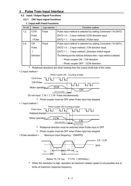
2 input method<br />
Photo coupler ON Counting at edge<br />
CCW Pulse<br />
CW Pulse<br />
Motor operation CCW<br />
More than 2ms<br />
Do not input Pulse simultaneously.<br />
Photo coupler must be OFF when Pulse input has stopped.<br />
1 input method<br />
Photo coupler ON Counting at edge<br />
Pulse input<br />
Rotational direction<br />
Motor operation<br />
CCW<br />
More than 2ms<br />
CW<br />
CW<br />
More than 2ms<br />
Rotational direction must be switched when Pulse input is OFF.<br />
Photo coupler must be OFF when Pulse input has stopped.<br />
Pulse waveform Maximum input frequency250kPPS<br />
3.05.5V<br />
50<br />
T3<br />
T1<br />
T2<br />
T4<br />
Below T3T4:1µs T1=T2 50Duty<br />
When the resolution is high, operation at maximum rotation speed is not possible due to<br />
limits of maximum response frequency.<br />
<br />
42


