SANMOTION R Medium Capacity (200VAC, 750W to 15kW)
SANMOTION R Medium Capacity (200VAC, 750W to 15kW)
SANMOTION R Medium Capacity (200VAC, 750W to 15kW)

You also want an ePaper? Increase the reach of your titles
YUMPU automatically turns print PDFs into web optimized ePapers that Google loves.
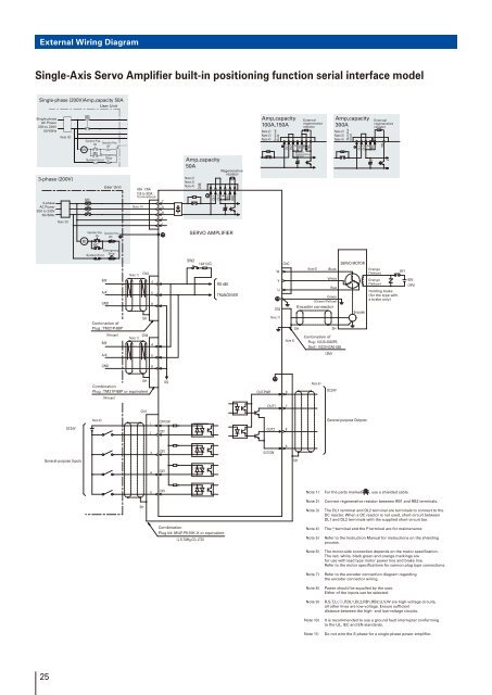
External Wiring Diagram<br />
Single-Axis Servo Amplifier built-in positioning function serial interface model<br />
Single-phase (200V)Amp,capacity 50A<br />
User Unit<br />
Single-phase<br />
AC Power<br />
200 <strong>to</strong> 230V<br />
5060Hz<br />
Note 10<br />
3-phase (200V)<br />
3-phase<br />
AC Power<br />
200 <strong>to</strong> 230V<br />
5060Hz<br />
Note 10<br />
MC<br />
Operation Prep.<br />
Operation Prep.<br />
ON<br />
OFF<br />
MC<br />
MC<br />
Emergency<br />
S<strong>to</strong>p<br />
System Error<br />
MC<br />
User Unit<br />
50A : CNA<br />
100 <strong>to</strong> 300A :<br />
Terminalblock<br />
Note 11<br />
T<br />
S<br />
R<br />
t<br />
r<br />
Amp,capacity<br />
50A<br />
Note 2<br />
Note 3<br />
Note 4<br />
CNB<br />
DL1<br />
DL2<br />
Regenerative<br />
resis<strong>to</strong>r<br />
P<br />
RB1<br />
RB2<br />
+<br />
Amp,capacity<br />
100A150A<br />
Note 2<br />
Note 3<br />
Note 4<br />
Terminal<br />
block<br />
−<br />
DL1<br />
DL2<br />
P<br />
RB1<br />
RB4<br />
RB2<br />
Built-in<br />
regenerative<br />
resis<strong>to</strong>r<br />
+<br />
External<br />
regenerative<br />
resis<strong>to</strong>r<br />
Amp,capacity<br />
300A<br />
Note 2<br />
Note 3<br />
Note 4<br />
Terminal<br />
block<br />
−<br />
DL1<br />
DL2<br />
P<br />
RB1<br />
+<br />
External<br />
regenerative<br />
resis<strong>to</strong>r<br />
RB2<br />
Operation Prep. Operation Prep.<br />
ON OFF<br />
MC<br />
MC<br />
SERVO AMPLIFIER<br />
Emergency<br />
S<strong>to</strong>p<br />
System Error<br />
B/B'<br />
A/A'<br />
GND<br />
Conbination of<br />
Plug : TM21P-88P<br />
Note 1 CN3<br />
SH<br />
4<br />
5<br />
8<br />
SW2<br />
1/4W 120<br />
RS-485<br />
TRANCEIVER<br />
CNC<br />
W<br />
V<br />
U<br />
CN2<br />
Note 7<br />
SH<br />
Note 6<br />
Black<br />
White<br />
Red<br />
Green<br />
(Green/Yellow)<br />
Encoder connec<strong>to</strong>r<br />
SH<br />
SERVO MOTOR<br />
Encoder<br />
Orange<br />
(Yellow)<br />
Orange<br />
(Yellow)<br />
Holding brake<br />
(for the type with<br />
a brake only)<br />
RY1<br />
90V<br />
(24V)<br />
B/B'<br />
A/A'<br />
Hirose<br />
CN4<br />
Note 1<br />
4<br />
5<br />
Note 5<br />
Conbination of<br />
Plug : 10120-3000PE,<br />
Shell : 10320-52A0-008<br />
3M<br />
GND<br />
8<br />
SH<br />
Combination<br />
Plug : TM21P-88P or equivalent<br />
Hirose<br />
SG<br />
OUT-PWR 9<br />
Note 8<br />
DC24V<br />
CN1<br />
OUT1 7<br />
DC24V<br />
Note 8<br />
1<br />
2<br />
CONT-COM<br />
CONT1<br />
OUT2 8<br />
General-purpose Outputs<br />
3<br />
CONT2<br />
OUT-COM<br />
6<br />
General-purpose Inputs<br />
SH<br />
4<br />
CONT3<br />
5<br />
CONT4<br />
Note 1) For the parts marked , use a shielded cable.<br />
SH<br />
Combination<br />
Plug kit: MUF-PK10K-X or equivalent<br />
J.S.T.Mfg.CO.,LTD<br />
Note 2)<br />
Note 3)<br />
Connect regenerative resis<strong>to</strong>r between RB1 and RB2 terminals.<br />
The DL1 terminal and DL2 terminal are terminals <strong>to</strong> connect <strong>to</strong> the<br />
DC reac<strong>to</strong>r. When a DC reac<strong>to</strong>r is not used, short-circuit between<br />
DL1 and DL2 terminals with the supplied short-circuit bar.<br />
Note 4) The terminal and the P terminal are for maintenance<br />
Note 5) Refer <strong>to</strong> the Instruction Manual for instructions on the shielding<br />
process.<br />
Note 6)<br />
Note 7)<br />
Note 8)<br />
The mo<strong>to</strong>r-side connection depends on the mo<strong>to</strong>r specification.<br />
The red, white, black green and orange markings are<br />
for use with lead type mo<strong>to</strong>r power line and brake line.<br />
Refer <strong>to</strong> the mo<strong>to</strong>r specifications for cannon plug type connections.<br />
Refer <strong>to</strong> the encoder connection diagram regarding<br />
the encoder connec<strong>to</strong>r wiring.<br />
Power should be supplied by the user.<br />
Either of the inputs can be selected.<br />
Note 9) R,S,T,t,r, ,P,DL1,DL2,RB1,RB2,U,V,W are high-voltage circuits,<br />
all other lines are low-voltage. Ensure sufficient<br />
distance between the high- and low-voltage circuits.<br />
Note 10)<br />
Note 11)<br />
It is recommended <strong>to</strong> use a ground fault interrupter conforming<br />
<strong>to</strong> the UL, IEC and EN standards.<br />
Do not wire the S phase for a single-phase power amplifier.<br />
25