Super High Resolution UTP Dome Camera SUD-2080User Guide
Super High Resolution UTP Dome Camera SUD-2080User Guide
Super High Resolution UTP Dome Camera SUD-2080User Guide

You also want an ePaper? Increase the reach of your titles
YUMPU automatically turns print PDFs into web optimized ePapers that Google loves.
<strong>Super</strong> <strong>High</strong> <strong>Resolution</strong> <strong>UTP</strong> <strong>Dome</strong> <strong>Camera</strong> <strong>SUD</strong>-2080 User <strong>Guide</strong><br />
Before installing and operating this product,<br />
please read this manual thoroughly.<br />
ENGLISH
Before operating the camera, confirm the camera model and correct<br />
input power voltage. To help you understand this manual thoroughly,<br />
we'll introduce our model description.<br />
n <strong>SUD</strong>-2080 SERIES<br />
• NTSC MODEL<br />
<strong>SUD</strong>-2080N<br />
• PAL MODEL<br />
<strong>SUD</strong>-2080P<br />
n MODEL DESCRIPTION<br />
• <strong>SUD</strong>-2080X _<br />
The lightning flash with an arrowhead symbol, within an equilateral triangle is<br />
intended to alert the user to the presence of uninsulated “dangerous voltage”<br />
within the product's enclosure that may be of sufficient magnitude to constitute<br />
a risk of electric shock to persons.<br />
• SIGNAL SYSTEM<br />
N → NTSC MODEL<br />
P → PAL MODEL<br />
SIGNAL SYSTEM<br />
The exclamation point within an equilateral triangle is intended to alert the user<br />
to the presence of important operating and maintenance (servicing) instructions<br />
in the literature accompanying the appliance.<br />
INFORMATION -This equipment has been tested and found to comply with<br />
limits for a Class A digital device, pursuant to part 15 of the FCC Rules. These<br />
limits are designed to provide reasonable protection against harmful<br />
interference when the equipment is operated in a commercial environment.<br />
This equipment generates, uses, and can radiate radio frequency energy and,<br />
if not installed and used in accordance with the instruction manual, may<br />
cause harmful interference to radio communications.<br />
Operation of this equipment in a residential area is likely to cause harmful<br />
interference in which case the user will be required to correct the interference<br />
at his own expense.<br />
WARNING - Changes or modifications not expressly approved by the<br />
manufacturer could void the user's authority to operate the equipment.<br />
WARNING -To prevent electric shock and risk of fire hazards:<br />
◆ Do NOT use power sources other than that specified.<br />
◆ Do NOT expose this appliance to rain or moisture.<br />
This installation should be made by a qualified service person and<br />
should conform to all local codes.
Contents<br />
Features<br />
• Features………………………………………………………………… 5<br />
• Warnings & Cautions…………………………………………………… 6<br />
• Precautions …………………………………………………………… 7<br />
• Components and Accessories… ……………………………………… 9<br />
• Overview………………………………………………………………… 9<br />
• Installation……………………………………………………………… 11<br />
■ Installation… ………………………………………………………………… 11…<br />
■ Adjust the panning, tilting and rotate mechanism while checking the position on the monitor… 13…<br />
■ Adjusting varifocal lens zoom and focus…………………………………… 14…<br />
■ System Diagram……………………………………………………………… 15…<br />
■ RJ-45 Connector Schematic Diagram……………………………………… 17<br />
■ Using Coaxial Communications…………………………………………… 18<br />
• Operating Your <strong>Camera</strong>………………………………………………… 19<br />
■ Menu Configuration… ……………………………………………………… 19…<br />
■ Menu Setup………………………………………………………………… 19…<br />
… … · LENS………………………………………………………………………… 20…<br />
… … · EXPOSURE……………………………………………………………………21…<br />
… … · White Bal (White Balance)… ……………………………………………… 23…<br />
… … · SSDR (Samsung <strong>Super</strong> Dynamic Range)… ……………………………… 24…<br />
… … · BACKLIGHT… ……………………………………………………………… 24…<br />
… … · SSNR3… …………………………………………………………………… 26…<br />
… … · DAY/NIGHT………………………………………………………………… 27…<br />
… … · SPECIAL…………………………………………………………………… 28<br />
… … · EXIT… ……………………………………………………………………… 34<br />
• Troubleshooting………………………………………………………… 35<br />
• Specifications…………………………………………………………… 36<br />
• Dimension… …………………………………………………………… 37<br />
<strong>High</strong> <strong>Resolution</strong><br />
By adopting a diagonal 6mm(1/3") 410,000 (NTSC)<br />
pixel, 470,000(PAL) pixel SONY CCD, the camera<br />
produces clear picture quality with a horizontal<br />
resolution of 600 TV lines in color and a horizontal<br />
resolution of 700 TV lines in B/W mode.<br />
Excellent Sensitivity<br />
The built-in high sensitivity COLOR CCD produces<br />
a clear image.<br />
- Color : 0.15Lux(50IRE, @F1.2), 0.0003LUX<br />
(SENS-UP, x512)<br />
- B/W : 0.001Lux(50IRE, @F1.2), 0.000002LUX<br />
(SENS-UP, x512)<br />
SSNR3 (Samsung <strong>Super</strong> Noise<br />
Reduction) Function<br />
The high-performance W-V DSP chip effectively<br />
removes low-light gain noise and afterimage to<br />
provide clear images even in dark environments.<br />
DAY&NIGHT(ICR)<br />
This camera has a function that automatically<br />
selects the mode that is appropriate for daytime<br />
or night-time conditions.<br />
The COLOR mode operates in daytime<br />
conditions to provide optimum colors, and B/W<br />
mode operates in night-time conditions to<br />
enhance the definition of the image.<br />
Motion Detection<br />
Since the camera detects motion without any<br />
additional external sensor, you can monitor<br />
activity more efficient.<br />
<strong>UTP</strong> TX<br />
One <strong>UTP</strong> cable transmits power for the camera,<br />
video signals and RS-485 data; installation is easy<br />
and clean. (TIA/EIA-568B)<br />
SSDR<br />
(Samsung <strong>Super</strong> Dynamic Range)<br />
For images with high contrast between bright<br />
and dark areas from difficult lighting<br />
conditions such as backlighting, this camera<br />
selectively illuminates darker areas while<br />
retaining the same light level for brighter<br />
areas to even out the overall brightness.<br />
DIS (Digital Image Stabilizer)<br />
The DIS function compensates for any camera<br />
movement, to produce more stable pictures.<br />
Communication<br />
RS-485 and Coaxial communication methods are<br />
supported.<br />
- RS-485 Communications : STW1, STW2,<br />
PELCO-D, PELCO-P, BOSCH, HONEYWELL, VICON,<br />
PANASONIC.<br />
- Coaxial Communications : Pelco Coaxitron<br />
Miscellaneous Functions<br />
HLC(<strong>High</strong> Light Compensation), SENS-UP, FLIP<br />
(H/V-REV), D-ZOOM, SHARPNESS and PRIVACY<br />
functions are provided.<br />
OSD<br />
The camera’s OSD is complimented by 18 languages.<br />
- NTSC : English, Korean, Japanese, Spanish, French,<br />
Portuguese, Taiwanese<br />
- PAL : English, Chinese, German, Italian, French,<br />
Spanish, Russian, Czech, Polish, Romanian,<br />
Serbian, Swedish, Danish, Turkish, Portuguese<br />
COLOR DOME CAMERA<br />
4 User <strong>Guide</strong><br />
COLOR DOME CAMERA 5 User <strong>Guide</strong>
Samsung Techwin cares for the environment at all product<br />
manufacturing stages to preserve the environment, and is taking a<br />
number of steps to provide customers with more environmentfriendly<br />
products.The Eco mark represents Samsung Techwin’s will<br />
to create environment-friendly products, and indicates that the<br />
product satisfies the EU RoHS Directive.<br />
Warnings & Cautions<br />
This information is provided to ensure your safety and to prevent any losses, financial or<br />
otherwise. Please read it carefully and use the product accordingly.<br />
* For product inquiries, please contact the retail shop where you bought the camera. The use of equipment such as<br />
an aerial ladder while providing after-sales service shall be at your expense.<br />
* Separate the power plug during a thunder storm.<br />
* This product is support equipment for surveillance system. Therefore, we can't compensate for material loss and/or<br />
personal injuries by robbery, fire, natural disaster or other such events.<br />
Warning/Attention/Special Mark Messages<br />
Do not install under extreme<br />
temperature conditions.<br />
Use only under temperature conditions between<br />
-10°C and +50°C. Provide good ventilation<br />
when using in high temperature conditions.<br />
Do not install under unstable<br />
lighting conditions.<br />
Precautions<br />
Do not install in high humidity<br />
environment.<br />
May lower image quality.<br />
Avoid touching the camera lens.<br />
Ignoring this information may<br />
result in material loss and/or<br />
serious personal injuries including<br />
death.<br />
Ignoring this information may<br />
result in material loss and/or a<br />
slight injuries.<br />
Indicates “Never Allowed.”<br />
Indicates “No Disassembling.”<br />
Severe lighting changes or flickering may<br />
hinder normal camera operation.<br />
The lens is the most important component<br />
of the camera. Be careful not to smear it<br />
with fingerprints.<br />
Do not drop the camera or subject it<br />
to physical shock.<br />
Never keep the camera face to<br />
strong light directly.<br />
May cause a product malfunction.<br />
May damage the CCD.<br />
COLOR DOME CAMERA<br />
6 User <strong>Guide</strong><br />
COLOR DOME CAMERA 7 User <strong>Guide</strong>
Precautions<br />
Components and Accessories<br />
Do not expose the camera to<br />
radioactivity.<br />
Do not expose the camera to rain or<br />
other types of liquids.<br />
❶<br />
2 3<br />
4<br />
5<br />
6<br />
If exposed to radioactivity, the CCD will fail.<br />
When connecting cables, be sure to<br />
read the instructions carefully and<br />
follow each step as instructed.<br />
May cause a product malfunction.Wipe dry any<br />
liquids. Liquids may contain minerals that are<br />
corrosive to electronic components.<br />
❶ <strong>Super</strong> <strong>High</strong> <strong>Resolution</strong> <strong>UTP</strong> <strong>Dome</strong> <strong>Camera</strong> <strong>SUD</strong>-2080<br />
2 Instruction Manual<br />
3 M4 Tapping Screw 4EA 4 M4 Machine Screw 4EA 5 Adapter plate<br />
6 Installation Video Output Cable<br />
❿ 1 2<br />
3<br />
Overview<br />
❿<br />
Failure to do so may result in critical<br />
system damage.<br />
Notes<br />
• Exposure to a spotlight or an object emitting strong light may cause smear or<br />
blooming.<br />
• Ensure that the power source complies with normal specifications before<br />
supplying it to the camera.<br />
6<br />
7<br />
8<br />
4<br />
5<br />
COLOR DOME CAMERA<br />
8 User <strong>Guide</strong><br />
COLOR DOME CAMERA 9 User <strong>Guide</strong>
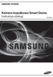
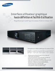
Overview<br />
Installation<br />
Pan Bracket : control panning angle of camera.<br />
Rotate Body : control rotating angle of camera.<br />
x3.6 Vari-focal Lens Module : 2.8 ~ 10.0mm(F1.2).<br />
Video Output Terminal to Monitor<br />
Function Setup switch : Display the menu on the screen and move the cursor to four<br />
directions to confirm status or after changing a selected item.<br />
<strong>UTP</strong> Cable : For supplying AC 24V / AC28V power to the camera and transmitting video<br />
signals.<br />
Video Output Jack : Video signals are output through this port. Connect this port to the<br />
Video IN port of a monitor.<br />
Power input terminal : If the <strong>UTP</strong> cable cannot be connected for power supply (distance<br />
over 300m(1000ft), for example), this cable is used instead for connecting DC 12V / AC<br />
24V power to the camera.<br />
<strong>Dome</strong> Cover<br />
Shield Case<br />
Installation<br />
Notes<br />
• The installation should be done by qualified service personnel or sytem installers.<br />
• If the ceiling material is not strong enough to hold the installation screws, the camera<br />
may fall off. Reinforce the ceiling as needed.<br />
1) Separate the dome cover by rotating anti-clockwise.<br />
2) Separate the shield case by pulling from the camera body.<br />
Latch<br />
Locking direction<br />
* To install the dome cover on the camera<br />
body, turn the latches in locking direction<br />
as shown in the figure 1.<br />
[Figure 1]<br />
Main Body<br />
(<strong>Camera</strong>)<br />
Shield Case<br />
Unlocking direction<br />
(Anti-clockwise)<br />
Locking direction<br />
(Clockwise)<br />
<strong>Dome</strong> cover<br />
COLOR DOME CAMERA<br />
10 User <strong>Guide</strong><br />
COLOR DOME CAMERA 11 User <strong>Guide</strong>
Installation<br />
When installing on a adapter plate<br />
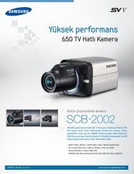
Adjust the panning, tilting and rotate mechanism while checking the position on the monitor<br />
An arrow for installing directions<br />
Adapter plate<br />
M4 tapping<br />
screw (provided)<br />
1) Place the bracket provided on the installation<br />
surface and fix it with the M4 tapping screws<br />
(provided).<br />
2) When placing the camera body on the plate,<br />
insert the plate pin into the mounting hole on<br />
the body as shown in figure 2 and fix it by<br />
turning clockwise.<br />
3) When placing the camera body on the plate,<br />
make sure the camera cables pass through their<br />
respective designated holes.(When placing the<br />
cable through its side, thread it through the<br />
hole at the bottom.)<br />
4) After installation and adjustment of the camera<br />
are complete, secure the dome cover by turning<br />
it clockwise.<br />
Pan Base<br />
170˚<br />
-170˚<br />
145˚<br />
195˚<br />
73˚<br />
Tilt Base<br />
Rotate Base<br />
CAMERA<br />
<strong>Dome</strong> cover<br />
Unlocking<br />
direction<br />
Notes<br />
Locking<br />
direction<br />
Unlocking direction<br />
[Figure 2]<br />
Plate pin<br />
Locking direction<br />
• Please locate an arrow on bracket for installing direction that you wish to observe<br />
Area and then fix it with the M4 tapping screws.<br />
1) You can adjust camera to any direction by using Pan, Tilt, Rotate mechanism.<br />
• Pan Bracket moves by 170° in each direction or 340° on the whole.<br />
• Tilt Body covers 73° in each direction or 146° in total.<br />
• The angle range of the Rotate Body is the same as that of the Pan Bracket. But one<br />
direction range is 195° and another is 145°<br />
2) Methods of adjustment<br />
• The case of wall installation<br />
1 After mounting the camera on a wall, adjusting the panning angle so that the camera can<br />
face the direction to monitor when tilted.<br />
2 Adjust the tilting angle by rotating the tilt base.<br />
3 Loosen the rotate base hold screw and adjust rotate base for the best view.<br />
4 Tighten the rotate base hold screw.<br />
• The case of ceiling installation<br />
1 After mounting the camera on a ceiling, adjusting the panning angle to the correct viewing<br />
position by rotating the pan base.<br />
2 Adjust the tilting angle by rotating the tilt base.<br />
3 Loosen the rotate base hold screw and adjust rotate base for the best view.<br />
4 Tighten the rotate base hold screw.<br />
COLOR DOME CAMERA<br />
12 User <strong>Guide</strong><br />
COLOR DOME CAMERA 13 User <strong>Guide</strong>
CH1 CH2 CH3 CH4<br />
Installation<br />
Adjusting varifocal lens zoom and focus<br />
1) Unlock the zoom (focus) handle by turning anti-clockwise.<br />
2) Adjust the zoom (focus) by moving the handle to WIDE(FAR) or TELE(NEAR).<br />
3) After adjustment, tighten the zoom (or the focus) handle, taking care that the adjusted<br />
position does not change.<br />
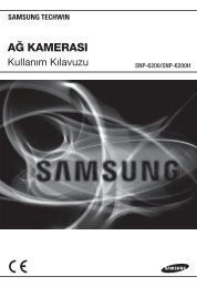
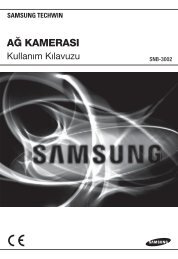
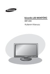
System Diagram<br />
<strong>UTP</strong> Power Supply Link Setup<br />
1. <strong>SUD</strong>-2080 → 4Ch Power Supply → 4Ch Receiver → DVR/Monitor/Controller<br />
The maximum power transmission distance for the camera is 300m(1000ft), and the<br />
distance between the camera and the 4ch Receiver cannot exceed 900m(3000ft).<br />
RS-485<br />
VIDEO<br />
Focus Handle<br />
Zoom Handle<br />
SPU-400T<br />
300m(1000ft) or Less<br />
SPU-400R<br />
SCC-3100A<br />
<strong>SUD</strong>-2080<br />
900m(3000ft) or Less<br />
<strong>UTP</strong> CABLE<br />
BNC CABLE<br />
RS-485<br />
2. <strong>UTP</strong> Receiver Link Setup(Additional Power input is needed)<br />
<strong>SUD</strong>-2080 → 1Ch Passive Receiver → DVR → Monitor<br />
300m(1000ft) or Less<br />
1Ch Passive Receiver<br />
COLOR DOME CAMERA<br />
14 User <strong>Guide</strong><br />
COLOR DOME CAMERA 15 User <strong>Guide</strong>
Installation<br />
Notes<br />
• Using the product with third-party <strong>UTP</strong> peripherals may result in degradation of product<br />
function and performance.<br />
• Attenuation and distortion in signal may occur if the maximum transmission distance is<br />
exceeded. Please note that depending on the installation environment/condition, the<br />
signal may become attenuated and distorted and cause the camera to function<br />
incorrectly even when the transmission distance is within the maximum.<br />
• If using RS-485 communication please use the STW1, STW2, PELCO-D, PELCO-P, BOSCH,<br />
HONEYWELL, VICON and PANASONIC Protocol.<br />
• If you are using the 1Ch Passive Receiver system setup, please connect the adapter<br />
(AC 24V or DC 12V) directly to the camera.<br />
<strong>UTP</strong> CABLE<br />
The camera uses <strong>UTP</strong> cable for transmitting video signals, power and transferring RS-485 control<br />
data.(TIA/EIA-568B)<br />
No. Line Color <strong>Camera</strong> to Power Supply Power Supply to Receiver<br />
1 White+Orange VIDEO (+)<br />
VIDEO (+) / RS-485 (+)<br />
CH1<br />
2 Orange VIDEO (-) VIDEO (-) / RS-485 (-)<br />
3 White+Green RS485 (+)<br />
VIDEO (+) / RS-485 (+)<br />
CH2<br />
4 Blue POWER (-) VIDEO (-) / RS-485 (-)<br />
5 White+Blue POWER (+)<br />
VIDEO (+) / RS-485 (+)<br />
CH3<br />
6 Green RS485 (-) VIDEO (-) / RS-485 (-)<br />
7 White+Brown POWER (+)<br />
VIDEO (+) / RS-485 (+)<br />
CH4<br />
8 Brown POWER (-) VIDEO (-) / RS-485 (-)<br />
RJ-45 Connector Schematic Diagram<br />
Copper Connector<br />
<strong>UTP</strong> Coating<br />
No. Line Color <strong>Camera</strong> to Power Supply Power Supply to Receiver<br />
1 White+Orange VIDEO (+)<br />
VIDEO (+) / RS-485 (+)<br />
CH1<br />
2 Orange VIDEO (-) VIDEO (-) / RS-485 (-)<br />
3 White+Green RS485 (+)<br />
VIDEO (+) / RS-485 (+)<br />
CH2<br />
4 Blue POWER (-) VIDEO (-) / RS-485 (-)<br />
5 White+Blue POWER (+)<br />
VIDEO (+) / RS-485 (+)<br />
CH3<br />
6 Green RS485 (-) VIDEO (-) / RS-485 (-)<br />
7 White+Brown POWER (+)<br />
VIDEO (+) / RS-485 (+)<br />
CH4<br />
8 Brown POWER (-) VIDEO (-) / RS-485 (-)<br />
The <strong>SUD</strong>-2080 uses <strong>UTP</strong> cable to receive its power (AC24V/AC28V) from the Power Supply.<br />
Therefore, a separate adapter is not required. Please refer to the RJ-45 Connector Schematic<br />
Diagram.<br />
1 8<br />
8 1<br />
COLOR DOME CAMERA<br />
16 User <strong>Guide</strong><br />
COLOR DOME CAMERA 17 User <strong>Guide</strong>
DVD<br />
Installation<br />
Operating Your <strong>Camera</strong><br />
Using Coaxial Communications<br />
• Coaxial Communications System<br />
• OSD Control method<br />
DVR<br />
CAMERA DVR CONTROLLER<br />
SET MENU/ENTER OSD KEY<br />
UP UP KEY JOYSTICK UP<br />
DOWN DOWN KEY JOYSTICK DOWN<br />
LEFT LEFT KEY JOYSTICK LEFT<br />
RIGHT RIGHT KEY JOYSTICK RIGHT<br />
• : BNC<br />
• ---- : RS-485<br />
• Video Cable<br />
The camera's video output port is connected to the monitor with a BNC coaxial<br />
cable, shown below : If the distance between the camera and the monitor<br />
exceeds the recommended maximum, please use an auxiliary video amp.<br />
Menu Configuration<br />
LENS<br />
EXPOSURE<br />
WHITE BAL<br />
●DC<br />
MAIN SETUP<br />
●BRIGHTNESS ●SHUTTER ●AGC<br />
●SENS-UP<br />
●RETURN<br />
●ATW ●OUTDOOR ●INDOOR<br />
●MANUAL<br />
SSDR ●OFF ●ON<br />
●AWC→SET<br />
BACKLIGHT ●OFF ●BLC ●HLC<br />
SSNR3 ●ON ●OFF<br />
DAY/NIGHT ●AUTO ●COLOR ●B/W<br />
SPECIAL<br />
●IMAGE ADJ ●MONITOR ●CAM TITLE<br />
●SYNC ●MOTION DET ●PRIVACY<br />
●COMM ADJ ●LANGUAGE ●RETURN<br />
EXIT ●SAVE ●NOT SAVE ●RESET<br />
Distance<br />
300m<br />
450m<br />
600m<br />
Recommended Cable Specification<br />
3C2V(RG-59/U)<br />
5C2V(RG-6/U)<br />
7C2V(RG-11/U)<br />
Menu Setup<br />
Use the Function Setup switch within the camera.<br />
Function Setup switch<br />
Notes<br />
• It is recommended that pure copper coax cable is used and not copper coated<br />
steel, as this will cause issues with the communication over the coaxial cable.<br />
COLOR DOME CAMERA<br />
18 User <strong>Guide</strong><br />
COLOR DOME CAMERA 19 User <strong>Guide</strong>
Operating Your <strong>Camera</strong><br />
1. Press the Function Setup switch.<br />
• Main setup menu is displayed on the monitor screen.<br />
Select the function using<br />
the Function Setup switch.<br />
MAIN SETUP<br />
1.LENS DC<br />
2.EXPOSURE<br />
3.WHITE BAL<br />
ATW<br />
4.SSDR<br />
OFF<br />
5.BACKLIGHT<br />
OFF<br />
6.SSNR3 ON<br />
7.DAY/NIGHT AUTO<br />
8.SPECIAL<br />
9.EXIT<br />
SAVE<br />
2. Select a desired function using the Function Setup switch.<br />
• Place the cursor over a desired item.<br />
3. Set up a selected item by using the Function Setup switch.<br />
4. To finish the setting, select ‘EXIT’ and press the Function Setup switch.<br />
Notes<br />
Change the status using<br />
the Function Setup switch.<br />
• An item with the icon also has sub menus. To select a sub menu, select an item with<br />
the icon and press the Function Setup switch.<br />
• An item with the - - - icon is unavailable due to function settings.<br />
LENS<br />
Using this function, you can control the screen brightness.<br />
1. When the SETUP menu screen is displayed, select‘LENS’by using the Function<br />
Setup switch so that the arrow indicates‘LENS’.<br />
MAIN SETUP<br />
1.LENS DC<br />
2.EXPOSURE<br />
2. The Lens mode has sub menu site as listed below.<br />
- BRIGHTNESS : Adjusts the video brightness.<br />
- FOCUS ADJ : To adjust the DC lens focus correctly, you must activate the Focus<br />
Settings mode. To a Activate the Focus Settings mode, adjust the lens<br />
focus, and then deactivate the settings mode.<br />
You can adjust the minimum shutter and maximum value of ESC shutter mode.<br />
EXPOSURE<br />
MAIN SETUP<br />
1.LENS DC<br />
2.EXPOSURE<br />
3.WHITE BAL ATW<br />
1. When the SETUP menu screen is displayed, select 'EXPOSURE’ by using the Function<br />
Setup switch so that the arrow indicates 'EXPOSURE’.<br />
2. Select a desired mode using the Function Setup switch.<br />
EXPOSURE SETUP<br />
1.BRIGHTNESS 25<br />
2.SHUTTER ---<br />
3.AGC<br />
HIGH<br />
4.SENS-UP<br />
OFF<br />
5.RETURN<br />
SHUTTER : You can select the shutter.<br />
- --- : Shutter speed is fixed at 1/60sec(1/50sec).<br />
- ESC : Select this to control the shutter speed automatically. If ESC is selected,<br />
the shutter speed is automatically controlled depending on the ambient<br />
illumination of the subject.<br />
- MANUAL : You can control shutter speed manually.<br />
(NTSC MODEL : 1/60sec~1/120,000sec, PAL MODEL : 1/50sec~1/120,000sec)<br />
- A.FLK : Select this when you experience picture flicker, this happen when there<br />
is a clash with the installed lighting frequency.<br />
COLOR DOME CAMERA<br />
20 User <strong>Guide</strong><br />
COLOR DOME CAMERA 21 User <strong>Guide</strong>
Operating Your <strong>Camera</strong><br />
Notes<br />
• Set the shutter mode to --- if color rolling occurs.<br />
• When the SHUTTER is set to ESC after selecting the Internal Synchronization Type, the<br />
picture may become unstable if the camera faces a bright fluorescent light. Therefore,<br />
take care when choosing the installation position.<br />
• When the SHUTTER is set to MANUAL or A.FLK mode, SENS-UP will be disabled.<br />
AGC(AUTO GAIN CONTROL) : The higher the gain level, the brighter the screen - but<br />
the higher the noise.<br />
- HIGH : Allows automatic gain control from 5.3dB to 37dB.<br />
- OFF : Deactivates the AGC function.<br />
- LOW : Allows automatic gain control from 5.3dB to 32dB.<br />
SENS-UP : When it is night or dark, the camera automatically detects the light level<br />
and maintains a clear picture if this mode is activated.<br />
- OFF : Deactivates the SENS-UP function.<br />
- AUTO : Activates the SENS-UP function.<br />
Notes<br />
• If you set the Function Setup switch to ‘AUTO’ mode, You can adjust the brightness by<br />
increasing or decreasing the shutter speed. (x2 ~ x512)<br />
• Note that the higher the zoom level, the brighter the screen, but the more likely it is that an<br />
after-image will appear.<br />
• Although Noise, Spots, and Whitish symptoms may occur in SENS-UP operation when the<br />
zoom level is increased, this is normal.<br />
RETURN : Select this to save the changes in the EXPOSURE menu and return to the<br />
SETUP menu.<br />
White Bal (White Balance)<br />
Use the White Balance function to adjust the screen color.<br />
1. When the SETUP menu screen is displayed, select ‘White Bal’ by using the Function<br />
Setup switch so that the arrow indicates ‘White Bal’ .<br />
2. Select a desired mode using the Function Setup switch.<br />
MAIN SETUP<br />
1.LENS DC<br />
2.EXPOSURE<br />
3.WHITE BAL<br />
ATW<br />
4.SSDR<br />
OFF<br />
※ Select one of the following 5 modes, as appropriate for your purpose.<br />
ATW : Select this when the color temperature is between 1,700˚K and<br />
11,000˚K.<br />
OUTDOOR : Select this when the color temperature is between 1,700˚K and<br />
11,000˚K. (sodium light inclusion)<br />
INDOOR : Select this when the color temperature is between 4,500˚K and<br />
8,500˚K.<br />
MANUAL : Select this to fine-tune White Balance manually. Set White Balance<br />
first by using the ATW or AWC mode. After that switch to MANUAL<br />
mode, fine-tune the White Balance and the Function Setup switch.<br />
AWC →SET : To find the optimal luminance level for the current environment, point<br />
the camera towards a sheet of white paper and press the Function<br />
Setup switch. If the environment changes, readjust it.<br />
Notes<br />
• White Balance may not work properly under the following conditions. In this case select<br />
the AWC mode.<br />
❶ When the color temperature of the environment surrounding the subject is out of the<br />
control range (e.g. clear sky or sunset).<br />
2 When the ambient illumination of the subject is dim.<br />
3 If the camera is directed towards a fluorescent light or is installed in a place where<br />
illumination changes dramatically, the White Balance operation may become unstable.<br />
COLOR DOME CAMERA<br />
22 User <strong>Guide</strong><br />
COLOR DOME CAMERA 23 User <strong>Guide</strong>
Operating Your <strong>Camera</strong><br />
SSDR (Samsung <strong>Super</strong> Dynamic Range)<br />
SSDR illuminates darker areas of an image while retaining the same light level for brighter<br />
areas to even out the overall brightness of images with high contrast between bright and<br />
dark areas.<br />
MAIN SETUP<br />
1.LENS DC<br />
2.EXPOSURE<br />
3.WHITE BAL<br />
ATW<br />
4.SSDR<br />
OFF<br />
5.BACKLIGHT<br />
OFF<br />
1. When the SETUP menu screen is displayed, select ‘SSDR’ by using the Function Setup<br />
switch so that the arrow indicates ‘SSDR’.<br />
2. Use the Function Setup switch to change the SSDR level in the sub menu according to<br />
the contrast between bright and dark areas.<br />
BACKLIGHT<br />
SSDR ON<br />
SSDR OFF<br />
The <strong>SUD</strong>-2080 is designed so that it delivers a distinctive subject and background at the<br />
same time, even when the subject is in backlight, by adopting a function of the proprietary<br />
W-V DSP chip.<br />
1. When the SETUP menu screen is displayed, select ‘BACKLIGHT’ by using the Function<br />
Setup switch so that the arrow indicates ‘BACKLIGHT’.<br />
MAIN SETUP<br />
1.LENS DC<br />
2.EXPOSURE<br />
3.WHITE BAL<br />
ATW<br />
4.SSDR<br />
OFF<br />
5.BACKLIGHT<br />
OFF<br />
6.SSNR3 ON<br />
2. Select a desired mode using the Function Setup switch depending on the camera purpose.<br />
OFF : Not being used<br />
BLC : Enables a user to select a desired area on a picture and view that area more clearly.<br />
- LEVEL : Adjust level of the BLC function.<br />
- TOP/BOTTOM/LEFT/RIGHT : Adjust the area to be enhanced.<br />
HLC (<strong>High</strong> Light Compensation) : <br />
If the scene contains extremely bright light areas such as; from car headlight, the<br />
light can mask out much of the on-screen detail.<br />
- LEVEL : Adjust level of the HLC function.<br />
- LIMIT : Enable to change the operating condition.<br />
- MASK COLOR/TONE : Change the color / brightness of the masking area.<br />
(Black, Red, Blue, Cyan, Magenta)<br />
- TOP/BOTTOM/LEFT/RIGHT : Adjust the area to be enhanced.<br />
3. Select a desired mode using the Function Setup switch.<br />
Select ‘BLC’ to adjust the area to be<br />
enhanced then adjust the level.<br />
HLC : Enable the user to change the level,<br />
limit, mask color/tone and area.<br />
COLOR DOME CAMERA<br />
24 User <strong>Guide</strong><br />
COLOR DOME CAMERA 25 User <strong>Guide</strong>
Operating Your <strong>Camera</strong><br />
Notes<br />
• Because there can be a difference in the effectiveness of HLC according to the amount of<br />
light area in the screen, optimize the installation angle for the best HLC performance.<br />
• When dark, the HLC is only activated when a bright light exceeding a specific size. (In<br />
NIGHT ONLY mode.)<br />
• The HLC is not activated in day light or when bright light is not present at night. (In NIGHT<br />
ONLY mode.)<br />
Notes<br />
• You cannot set the SSNR3 to ‘ON’ or ‘OFF’ when the AGC mode of the EXPOSURE menu is<br />
‘OFF’.<br />
• When adjusting the noise reduction level in the SSNR3 mode, remember that the higher<br />
the level set, the more the noise level will be reduced, as will the brightness of the image.<br />
SSNR3<br />
This function reduces the background noise in a low luminance environment.<br />
1. When the SETUP menu screen is displayed, select ‘SSNR3’ by using the Function Setup<br />
switch so that the arrow indicates ‘SSNR3’ .<br />
MAIN SETUP<br />
1.LENS DC<br />
2.EXPOSURE<br />
3.WHITE BAL<br />
ATW<br />
4.SSDR<br />
OFF<br />
5.BACKLIGHT<br />
OFF<br />
6.SSNR3 ON<br />
7.DAY/NIGHT AUTO<br />
2. Select a desired mode using the Function Setup switch.<br />
ON : Activates SSNR3 so that noise is reduced.<br />
OFF : Deactivates SSNR3. Noise is not reduced.<br />
3. Set the SSNR3 mode to ‘ON’ and press the Function Setup switch. Then you can adjust<br />
the noise reduction level.<br />
DAY/NIGHT<br />
You can display pictures in color or in black and white.<br />
1. When the SETUP menu screen is displayed, select ‘DAY/NIGHT’ by using the Function<br />
Setup switch so that the arrow indicates ‘DAY/NIGHT’.<br />
MAIN SETUP<br />
1.LENS DC<br />
2.EXPOSURE<br />
3.WHITE BAL<br />
ATW<br />
4.SSDR<br />
OFF<br />
5.BACKLIGHT<br />
OFF<br />
6.SSNR3 ON<br />
7.DAY/NIGHT AUTO<br />
8.SPECIAL<br />
2. Select a desired mode using the Function Setup switch according to the picture display<br />
you want.<br />
AUTO : The mode is switched to ’Color‘ in a normal<br />
environment, but switches to ’B/W‘ mode<br />
when ambient illumination is low. To set up<br />
the switching time for AUTO mode, press the<br />
Function Setup switch.<br />
You can turn on or off the burst signal on<br />
B/W mode.<br />
COLOR DOME CAMERA<br />
26 User <strong>Guide</strong><br />
COLOR DOME CAMERA 27 User <strong>Guide</strong>
Operating Your <strong>Camera</strong><br />
- DURATION : You can select brightness of illumination about changing the day/night mode.<br />
- DWELL TIME : You can select the duration time about changing the day/night mode. …<br />
→3s, 5s, 7s, 10s, 15s, 20s, 30s, 40, 60s<br />
COLOR : The picture is always displayed in color.<br />
B/W : The picture is always displayed in black and white.<br />
You can turn on or off the burst signal on B/W mode.<br />
Notes<br />
• When AGC in the EXPOSURE menu is 'OFF', '---' mode operates as selecting 'AUTO' mode<br />
cannot be selected.<br />
2. Select a desired mode using the Function Setup switch.<br />
SPECIAL<br />
1. IMAGE ADJ<br />
2. MONITOR LCD<br />
3. CAM TITLE OFF<br />
4. SYNC INT<br />
5. MOTION DET OFF<br />
6. PRIVACY OFF<br />
7. COMM ADJ<br />
8. LANGUAGE ENGLISH<br />
9. RETURN<br />
IMAGE ADJ :<br />
1) When the SPECIAL menu screen is displayed, select ‘IMAGE ADJ’ by using the<br />
Function Setup switch so that the arrow indicates ’IMAGE ADJ‘.<br />
2) Select a desired mode using the Function Setup switch.<br />
SPECIAL<br />
1. When the SETUP menu screen is displayed, select ‘SPECIAL’ by using the Function Setup<br />
switch so that the arrow indicates ‘SPECIAL’.<br />
MAIN SETUP<br />
1.LENS DC<br />
2.EXPOSURE<br />
3.WHITE BAL<br />
ATW<br />
4.SSDR<br />
OFF<br />
5.BACKLIGHT<br />
OFF<br />
6.SSNR3 ON<br />
7.DAY/NIGHT AUTO<br />
8.SPECIAL<br />
IMAGE SETUP<br />
1. V-REV OFF<br />
2. H-REV OFF<br />
3. D-ZOOM OFF<br />
4. DIS OFF<br />
5. FONT COLOR WHITE<br />
6. SHARPNESS ON<br />
7. RETURN<br />
• V-REV : You can flip the picture vertically on the screen.<br />
• H-REV : You can flip the picture horizontally on the screen.<br />
• D-ZOOM : You can use a digital zoom of x1 ~ x16.<br />
• DIS (Digital Image Stabilizer) : This function mitigates any picture movement due to<br />
external factors such as wind.<br />
• FONT COLOR : You can change the OSD font color. (White, Yellow, Green, Red, Blue)<br />
• SHARPNESS : As you increase this value, the picture outline becomes stronger and<br />
COLOR DOME CAMERA<br />
28 User <strong>Guide</strong><br />
COLOR DOME CAMERA 29 User <strong>Guide</strong>
Operating Your <strong>Camera</strong><br />
• RETURN<br />
Notes<br />
clearer. Adjust this value appropriately depending on the sharpness of<br />
the picture.<br />
: Select this to save the settings for the IMAGE ADJ menu and to return<br />
to the SPECIAL menu.<br />
• When the V-REV or H-REV mode is enabled, the text on the screen does not flip.<br />
• If you increase the SHARPNESS level too high, the picture may become distorted or<br />
noise may appear.<br />
• As the DIS function uses the digital zoom, the camera's resolution will decrease.<br />
• DIS doesn’t operate when background illumination is too low.<br />
• DIS doesn’t operate when object pattern is monotonic as like sky or white wall.<br />
Monitor : Please change the settings value of video<br />
appropriate to your monitor.<br />
- LCD : Please select this menu item when using an<br />
LCD monitor.<br />
You can change the gamma, PED level and<br />
color gain in the sub menus.<br />
- USER : Please use this menu item when using a monitor<br />
other than standard ones. You can change the gamma, PED level, and color gain in<br />
the sub menus.<br />
- CRT : Please select this menu item when using a CRT monitor. You can change the PED<br />
level, color gain in the sub menus.<br />
CAM TITLE : If you enter a title, the title will appear on the monitor.<br />
1) If the SPECIAL menu screen is displayed, use the Function Setup switch so that the<br />
arrow indicates ‘CAM TITLE’.<br />
2) Set it to ‘ON’ by using the Function Setup<br />
switch.<br />
3) Press the Function Setup switch.<br />
4) Use the Function Setup switch to move<br />
to a desired letter and select the letter by<br />
pressing the Function Setup switch.<br />
Repeat this to enter multiple letters. You<br />
can enter up to 15 letters.<br />
<br />
CAMERA TITLE SETUP<br />
ABCDEFGHIJKLM<br />
NOPQRSTUVWXYZ<br />
abcdefghijklm<br />
nopqrstuvwxyz<br />
-.0123456789<br />
←→CLR POS END<br />
5) Enter a title, move the cursor to ‘POS’ and press<br />
the Function Setup switch. The entered title<br />
appears on the screen. Select the position to<br />
display the title on the screen by using the<br />
Function Setup switch and press the Function<br />
Setup switch. When the position is determined,<br />
select ‘END’ and press the Function Setup<br />
switch to return to the SPECIAL menu.<br />
Notes<br />
FRONT DOOR<br />
• When the CAM TITLE menu is ‘OFF’, no title will be displayed on the monitor screen even<br />
if you enter one.<br />
• Only English is available in this mode.<br />
• If you move the cursor to CLR and press the Function Setup switch, all the letters are<br />
deleted. To edit a letter, change the cursor to the bottom left arrow and press the<br />
Function Setup switch. Move the cursor over the letter to be edited, move the cursor to<br />
the letter to be inserted and then press the Function Setup switch.<br />
SYNC : In areas where the supply is at 60Hz(NTSC),<br />
50Hz(PAL), you can synchronize the output<br />
phase of multiple cameras using the power<br />
synchronization function (Line-Lock) without<br />
using a synchronization signal generator.<br />
- INT : Internal Synchronization Type<br />
- L/L : Power Synchronization Type, Line-lock<br />
• Press the Function Setup switch.<br />
• You can select a desired phase from 0 to 359 when select 'phase'.<br />
Notes<br />
• When using AC power at 60Hz(NTSC), 50Hz(PAL) frequency, you can use the L/L<br />
type synchronization.<br />
• When the power is DC 12V, the SYNC menu is fixed to the ‘INT’ mode.<br />
• When using RJ-45 Connector, you can't use the L/L type synchronization.<br />
COLOR DOME CAMERA<br />
30 User <strong>Guide</strong><br />
COLOR DOME CAMERA 31 User <strong>Guide</strong>
Operating Your <strong>Camera</strong><br />
MOTION DET : <br />
This product has a feature that allows you to observe<br />
movement of objects in 8 different areas on the<br />
screen, and the words 'MOTION DETECTED' appear<br />
on the screen when movement is detected.<br />
You can monitor activity more efficient.<br />
1) When the SPECIAL menu screen is displayed, press the Function Setup switch so<br />
that the arrow indicates‘MOTION DET’.<br />
2) Set up the mode using the Function Setup switch.<br />
- SENSITIVITY : You can select up to 8 MD areas. When SENSITIVITY number is high,<br />
motion detection sensitivity is increased to recognize even small<br />
movement.<br />
- AREA MODE : Determines whether to use the MD area selected in SENSITIVITY.<br />
- SEL POS : Determines which of the 4 vertices of each MD area is to be used.<br />
- XPOS : Determines the coordinate of the horizontal axis for SEL POS.<br />
- YPOS : Determines the coordinate of the vertical axis for SEL POS.<br />
- FILL→SET : Fills in a selected MD area. The color of filling is sequentially selected<br />
as brown, orange, blue, cyan, green, yellow, magenta and red.<br />
- RETURN : Select this to save the MOTION DET menu settings and return to the<br />
SPECIAL menu.<br />
PRIVACY : Mask an area you want to hide on the screen.<br />
PRIVACY AREA SETUP<br />
1. AREA AREA1<br />
2. MODE OFF<br />
3. MASK COLOR GREEN<br />
4. MASK TONE 1<br />
5. TOP 39<br />
6. BOTTOM 79<br />
7. LEFT 13<br />
8. RIGHT 52<br />
9. RETURN<br />
1) When the SPECIAL menu screen is displayed, press the Function Setup switch so that<br />
the arrow indicates ‘PRIVACY’.<br />
2) Set up the mode using the Function Setup switch.<br />
- AREA : You can select up to 12 PRIVACY areas.<br />
- MODE : Determines whether to use the area selected in the AREA.<br />
- MASK COLOR :Determine area color. You can select Green, Red, Blue, Black, White,<br />
Gray.<br />
- MASK TONE : Adjust the brightness of MASK COLOR.<br />
- TOP/BOTTOM/LEFT/RIGHT : Adjust the size and position of the selected area.<br />
- RETURN : Select this to save the PRIVACY menu settings and return to the<br />
SPECIAL menu.<br />
<br />
COMM ADJ (Communication Adjustment) :<br />
This function sets up the camera communication status when controlling the<br />
camera through an external control device.<br />
1) When the SPECIAL menu screen is displayed, press the Function Setup switch so<br />
that the arrow indicates ‘COMM ADJ’.<br />
2) Set up the mode using the Function Setup switch.<br />
- CAM ID : Determines the camera's identification<br />
number (between 0 and 255).<br />
- BAUD RATE : You can select 2400/4800/9600/19200/<br />
38400/57600 bps.<br />
- UART MODE : You can select NONE, EVEN or ODD for<br />
the parity bits.<br />
- RET PKT : Determines whether to send a command<br />
back to the controller device when a<br />
communication control command is sent to the camera.<br />
- DISP ID : Display camera title on top left corner of the screen.<br />
- PROTOCOL : Select the communication PROTOCOL.<br />
(STW1, STW2, PELCO-D, PELCO-P, BOSCH, HONEYWELL, VICON and PANASONIC)<br />
- RETURN : Select this to save the PRIVACY menu settings and return to the SPECIAL<br />
menu.<br />
* Initial value of communication adjustment<br />
Item <strong>Camera</strong> ID BAUD RATE UART MODE PET PKT<br />
Initial value 1 9600 8-NONE-1 ENABLE<br />
COLOR DOME CAMERA<br />
32 User <strong>Guide</strong><br />
COLOR DOME CAMERA 33 User <strong>Guide</strong>
Operating Your <strong>Camera</strong><br />
Troubleshooting<br />
EXIT<br />
Notes<br />
• As below, the names of protocol have been changed.<br />
- STW(SPD) → STW1<br />
- SEC → STW2<br />
LANGUAGE : You can select the menu language according to your requirements.<br />
RETURN<br />
: Select this to save the SPECIAL menu settings and return to the MAIN<br />
SETUP menu.<br />
Select a desired EXIT mode using the Function Setup switch depending on the camera<br />
purpose.<br />
- SAVE : Save the current settings and exit the MAIN SETUP menu.<br />
- NOT SAVE : Do not save the current settings and exit the MAIN SETUP menu.<br />
- RESET : Resets the camera settings to the factory defaults. Communication,<br />
Language and Monitor settings are not initialized.<br />
If you have trouble operating your camera, refer to the following table.<br />
If the guidelines do not enable you to solve the problem, contact an authorized technician.<br />
● Nothing appears on the screen.<br />
▶ Check that the power cord and line connection between the camera and monitor are<br />
properly connected.<br />
▶ Check that you have properly connected <strong>UTP</strong> cable or BNC cable to the camera.<br />
▶ Check the pin arrangement for the <strong>UTP</strong> cable. (TIA/EIA-568B)<br />
● The image on the screen is dim.<br />
▶ Is lens stained with dirt? Clean your lens with soft, clean cloth.<br />
▶ Set the monitor to the proper condition.<br />
▶ If the camera is exposed to very strong light, change the camera position.<br />
● The image on the screen is dark.<br />
▶ Adjust the contrast feature of the monitor.<br />
▶ If you have an intermediate device, set the 75Ω / Hi-z properly.<br />
● The camera is not working properly, and the surface of the camera is hot.<br />
▶ Check that you have properly connected the camera to an appropriate power source.<br />
● The SENS-UP function does not work.<br />
▶ Check that AGC of EXPOSURE SETUP menu is ‘OFF’.<br />
▶ Check that SHUTTER of EXPOSURE SETUP menu is ‘A.FLK’ or ‘MANUAL’.<br />
● The Motion Detection function does not work.<br />
▶ Check that MOTION DET of SPECIAL SETUP menu is ‘OFF’.<br />
● Color is not correct.<br />
▶ Check the setting of WHITE BAL SETUP menu.<br />
● The screen flickers continually.<br />
▶ Ensure the camera is not pointing towards the sun.<br />
● When coaxial communication is not available.<br />
▶ Make sure that the camera and monitor are installed within the recommended distance.<br />
▶ Use the video amplifier equivalent to coaxitron if the recommended installation distance is exceeded.<br />
● Picture is distorted.<br />
▶ Check the length of the <strong>UTP</strong> cable (900m(3000ft) or less).<br />
● The camera does not work, and the video feed from the camera is not being<br />
received.<br />
▶ Check the Power Supply to see whether the connection status and pin arrangement for<br />
the camera's <strong>UTP</strong> cable and the <strong>Camera</strong> Input <strong>UTP</strong> cable are normal.<br />
COLOR DOME CAMERA<br />
34 User <strong>Guide</strong><br />
COLOR DOME CAMERA 35 User <strong>Guide</strong>
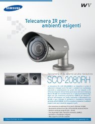
Specifications<br />
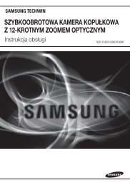
Dimension<br />
<strong>SUD</strong>-2080N<br />
<strong>SUD</strong>-2080P<br />
ELECTRICAL<br />
Input Voltage<br />
AC 24V ±10% / AC 28V ±10% / DC12V±10%<br />
Power Consumption Max 3.5W<br />
VIDEO<br />
Imaging Device<br />
1/3 inch, Diagonal 6mm <strong>Super</strong> HAD CCD<br />
Total / Effective Pixels 811(H) x 508(V) / 768(H) x 494(V) 795(H) x 596(V) / 752(H) x 582(V)<br />
Scanning System<br />
2:1 Interlace<br />
Synchronization<br />
Internal / Line-Lock<br />
Frequency H : 15.734KHz / V : 59.94Hz H: 15.625KHz / V: 50.00Hz<br />
Horizontal <strong>Resolution</strong><br />
COLOR : 600TVL, B/W : 700TVL<br />
Min. Illumination<br />
COLOR : 0.15 Lux (50IRE, @F1.2), 0.0003Lux (SENS-UP, x512)<br />
B/W : 0.001Lux (50IRE, @F1.2), 0.000002Lux (SENS-UP, x512)<br />
S/N (Y Signal)<br />
52dB (Weight ON, AGC OFF)<br />
Video Output<br />
CVBS : 1.0Vp-p, 75Ω composite<br />
<strong>UTP</strong><br />
Built-in <strong>UTP</strong> TX (Maximum transmission length 900m(3000ft)) : Balanced differential signal 100Ω<br />
LENS<br />
Zoom Ratio /<br />
3.6x (Manual) / 2.8 ~ 10.0mm (F1.2)<br />
Angular Field of View<br />
H : 94.4°(Wide) ~ 28°(Tele) / V : 69.2°(Wide) ~ 21°(Tele)<br />
Pan / Tilt / Rotate Range 0° ~ 340° / 0° ~ 146° / 0° ~ 340°<br />
OPERATIONAL<br />
Electronic Shutter Speed 1/60sec~1/120ksec 1/50sec ~ 1/120ksec<br />
NTSC : English, Korean, Japanese, Spanish, French, Portuguese, Taiwanese<br />
ON Screen Display<br />
PAL : English, Chinese, German, Italian, French, Spanish, Russian, Czech, Polish,<br />
Romanian, Serbian, Swedish, Danish, Turkish, Portuguese<br />
SSDR<br />
ON / OFF (Level adjustable)<br />
Backlight Compensation<br />
BLC / HLC / OFF<br />
Day & Night<br />
COLOR / BW / AUTO (ICR)<br />
Gain Control<br />
LOW / HIGH / OFF<br />
White Balance<br />
ATW / Outdoor / Indoor / Manual / AWC (1,700°K ~ 11,000°K)<br />
SENS-UP (frame Integration) AUTO / OFF (Selectable x2 ~ x512)<br />
Motion Detection<br />
ON / OFF (8 Programmable zones)<br />
Privacy Masking<br />
ON / OFF (12 Programmable zones)<br />
3D Noise Filter (SSNRIII)<br />
ON / OFF (Level adjustable)<br />
Digital Zoom ON / OFF (x1 ~ x16)<br />
<strong>Camera</strong> Title<br />
ON / OFF (Display 15 Characters)<br />
Sharpness<br />
ON / OFF (Level adjustable)<br />
Flip / Mirror<br />
ON / OFF<br />
Coaxial Communication<br />
Pelco Coaxitron<br />
RS-485 Communication<br />
STW1, STW2, PELCO-D, PELCO-P, BOSCH, HONEYWELL, VICON, PANASONIC<br />
ENVIRONMENTAL<br />
Operating Temperature / Humidity -10°C ~ +50°C / 30% ~ 80% RH<br />
MECHANICAL<br />
Dimension / Weight<br />
Ø141.2 x 105.5mm / 520g<br />
※ The specification for this product may change without prior notice for product improvement.<br />
※ This specification is based on a transmission distance of 500 meters; in cases of long-distance<br />
transmissions, some degradation in picture quality may occur depending on the operating environment.<br />
R48<br />
Ø141.2<br />
108mm<br />
105.5mm<br />
COLOR DOME CAMERA<br />
36 User <strong>Guide</strong><br />
COLOR DOME CAMERA 37 User <strong>Guide</strong>
DECLARATION OF CONFORMITY<br />
MEMO<br />
Application of Council Directive(s) 2004 / 108 / EC<br />
Manufacturer's Name<br />
SAMSUNG TECHWIN CO., LTD<br />
Manufacturer's Address<br />
SAMSUNG TECHWIN CO., LTD<br />
42, SUNGJU-DONG CHANGWON-CITY,<br />
KYUNGNAM, KOREA, 641-716<br />
European Representative Name<br />
European Representative Address<br />
Equipment Type/Environment CCTV <strong>Camera</strong><br />
Model Name<br />
<strong>SUD</strong>-2080P<br />
Beginning Serial NO.<br />
C10SA010007<br />
Year of Manufacture 2010.01.01<br />
Conformance to EN 55022 : 2006<br />
EN 50130-4 : 2003<br />
We, the undersigned, hereby declare that the equipment specified above conforms<br />
to the above Directive(s).<br />
Manufacturer SAMSUNG TECHWIN CO., LTD Legal Representative in Europe<br />
Signature<br />
Signature<br />
Full Name BONJENG GU Full Name<br />
Position QUALITY CONTROL MANAGER Position<br />
Place CHANGWON, KOREA Place<br />
Date 2010.01.01 Date<br />
COLOR DOME CAMERA<br />
38 User <strong>Guide</strong><br />
COLOR DOME CAMERA 39 User <strong>Guide</strong>
SALES NETWORK<br />
• SAMSUNG TECHWIN CO., LTD.<br />
145-3, Sangdaewon 1-dong, Jungwon-gu, Seongnam-si Gyeonggi-do, Korea, 462-703<br />
TEL : +82-31-740-8151~8 FAX : +82-31-740-8145<br />
• SAMSUNG TECHWIN AMERICA Inc.<br />
1480 Charles Willard St, Carson, CA 90746, UNITED STATES<br />
Tol Free : +1-877-213-1222 FAX : +1-310-632-2195<br />
www.samsungcctvusa.com<br />
www.samsungtechwin.com<br />
www.samsungcctv.com<br />
• SAMSUNG TECHWIN EUROPE CO., LTD.<br />
Samsung House, 1000 Hillswood Drive, Hillswood Business<br />
Park Chertsey, Surrey, UNITED KINGDOM KT16 OPS<br />
TEL : +44-1932-45-5300 FAX : +44-1932-45-5325<br />
P/No. : Z6806-1117-01A<br />
VAN 09.12