Download the Stage 5H English User Manual in PDF format - Samson
Download the Stage 5H English User Manual in PDF format - Samson
Download the Stage 5H English User Manual in PDF format - Samson

Create successful ePaper yourself
Turn your PDF publications into a flip-book with our unique Google optimized e-Paper software.
Table of Contents<br />
Introduction . . . . . . . . . . . . . . . . . . . . . . . . . . . . . . . . . . . . . . . . . . 1<br />
Guided Tour - SR5 Front Panel . . . . . . . . . . . . . . . . . . . . . . . . . 2<br />
Guided Tour - SR5 Rear Panel . . . . . . . . . . . . . . . . . . . . . . . . . . 3<br />
Guided Tour - HT5 . . . . . . . . . . . . . . . . . . . . . . . . . . . . . . . . . . . . . 4<br />
Sett<strong>in</strong>g Up and Us<strong>in</strong>g Your <strong>Stage</strong> 5 Series System . . . . 5 - 6<br />
Specifications . . . . . . . . . . . . . . . . . . . . . . . . . . . . . . . . . . . . . . . . . 8<br />
Copyright 2005 - 2007, <strong>Samson</strong> Technologies Corp.<br />
Pr<strong>in</strong>ted October, 2007 v1.0<br />
<strong>Samson</strong> Technologies Corp.<br />
45 Gilp<strong>in</strong> Avenue<br />
Hauppauge, New York 11788-8816<br />
Phone: 1-800-3-SAMSON (1-800-372-6766)<br />
Fax: 631-784-2201<br />
www.samsontech.com
Introduction<br />
Congratulations on purchas<strong>in</strong>g <strong>the</strong> <strong>Samson</strong> <strong>Stage</strong> 5 Series Wireless System! Although this product<br />
is designed for easy operation, we suggest you first take some time to go through <strong>the</strong>se pages so<br />
you can fully understand how we’ve implemented a number of unique features.<br />
Every wireless system consists of at least two components—a transmitter and a receiver, both<br />
of which must be tuned to <strong>the</strong> same channel (that is, <strong>the</strong> same radio frequency) <strong>in</strong> order to<br />
operate correctly.* The <strong>Samson</strong> <strong>Stage</strong> 5 Series system you have purchased operates <strong>in</strong> <strong>the</strong> 174.6<br />
- 213.2 MHz frequency range and conta<strong>in</strong>s a SR5 receiver as well as a HT5 hand-held microphone<br />
transmitter. The HT5 hand-held microphone transmitter is equipped with <strong>the</strong> <strong>Samson</strong> H5 dynamic<br />
microphone element, and thanks to <strong>the</strong> unidirectional pick up pattern, feedback problems are<br />
greatly reduced.<br />
* Your receiver and transmitter have been factory preset to utilize <strong>the</strong> same channel.<br />
The SR5 receiver provided with <strong>the</strong> STAGE 5 Series wireless system utilizes crystal controlled, PLL<br />
(Phase Lock Loop), S<strong>in</strong>gle Conversion Superheterodyne circuity for clear and reliable reception.<br />
The antenna has been specially designed and tuned for <strong>the</strong> specified frequency band. F<strong>in</strong>ally, <strong>the</strong><br />
provision of a noise reduction circuit produces crystal-clear sound with m<strong>in</strong>imized background<br />
noise and hiss.<br />
In this manual, you’ll f<strong>in</strong>d a detailed description of <strong>the</strong> features of your <strong>Stage</strong> 5 Series system, as<br />
well as a guided tour through all components, step-by-step <strong>in</strong>structions for sett<strong>in</strong>g up and us<strong>in</strong>g<br />
your system and full specifications. If your <strong>Stage</strong> 5 Series system was purchased <strong>in</strong> <strong>the</strong> United<br />
States, you’ll also f<strong>in</strong>d a warranty card enclosed—don’t forget to fill it out and mail it! This will<br />
enable you to receive onl<strong>in</strong>e technical support and will allow us to send you updated <strong>in</strong><strong>format</strong>ion<br />
about o<strong>the</strong>r <strong>Samson</strong> products <strong>in</strong> <strong>the</strong> future. If your <strong>Stage</strong> 5 Series system was purchased outside of<br />
<strong>the</strong> United States, please contact your local distributor for warranty details.<br />
About <strong>Samson</strong> Technologies<br />
<strong>Samson</strong> began 26 years ago as an audio technology company design<strong>in</strong>g wireless microphone<br />
systems. Today, we are an <strong>in</strong>dustry leader with three brands: <strong>Samson</strong>, Hartke and Zoom. Over 350<br />
products designed and distributed by <strong>Samson</strong> are sold <strong>in</strong> 106 countries. They are preferred by <strong>the</strong><br />
most talented record<strong>in</strong>g artists and performers throughout <strong>the</strong> world.<br />
To see our complete l<strong>in</strong>e of audio products, visit us on <strong>the</strong> web at www.samsontech.com.<br />
SPECIAL NOTE for U.S. purchasers: Should your <strong>Stage</strong> 5 Series system ever require servic<strong>in</strong>g,<br />
a Return Authorization number (RA) is necessary. Without this number, <strong>the</strong> unit will not be<br />
accepted. Please call <strong>Samson</strong> at 1-800-372-6766 for a Return Authorization number prior to<br />
shipp<strong>in</strong>g your unit. Please reta<strong>in</strong> <strong>the</strong> orig<strong>in</strong>al pack<strong>in</strong>g materials and, if possible, return <strong>the</strong> unit <strong>in</strong><br />
its orig<strong>in</strong>al carton and pack<strong>in</strong>g materials. If your <strong>Stage</strong> 5 Series system was purchased outside of<br />
<strong>the</strong> United States, contact your local distributor for servic<strong>in</strong>g <strong>in</strong><strong>format</strong>ion.
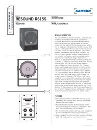
Guided Tour - SR5 Front Panel<br />
1: Antenna - The antenna mount<strong>in</strong>g allows full rotation for optimum placement. In normal<br />
operation, <strong>the</strong> antenna should be placed <strong>in</strong> a vertical position. It also can be folded <strong>in</strong>ward for<br />
convenience when transport<strong>in</strong>g <strong>the</strong> SR5. See <strong>the</strong> “Sett<strong>in</strong>g Up and Us<strong>in</strong>g Your <strong>Stage</strong> 5 Series<br />
System” section on page 5 <strong>in</strong> this manual for more <strong>in</strong><strong>format</strong>ion about antenna position<strong>in</strong>g.<br />
2: Volume control - This knob sets <strong>the</strong> level of <strong>the</strong> audio signal be<strong>in</strong>g output through both <strong>the</strong><br />
balanced and unbalanced output jacks on <strong>the</strong> rear panel. Reference level is obta<strong>in</strong>ed when <strong>the</strong><br />
knob is turned fully clockwise.<br />
3: Audio Meter - This “ladder” display (similar to <strong>the</strong> VU bar meter used on audio devices)<br />
<strong>in</strong>dicates <strong>the</strong> strength of <strong>the</strong> <strong>in</strong>com<strong>in</strong>g audio signal. When <strong>the</strong> “0” segment is lit, <strong>the</strong> <strong>in</strong>com<strong>in</strong>g<br />
signal is optimized at unity ga<strong>in</strong>; when <strong>the</strong> “+6” segment is lit, <strong>the</strong> signal is overload<strong>in</strong>g. When<br />
only <strong>the</strong> left-most “-20” segment is lit, <strong>the</strong> <strong>in</strong>com<strong>in</strong>g signal is at just 10% of optimum strength. If<br />
no segments are lit, little or no signal is be<strong>in</strong>g received. See <strong>the</strong> “Sett<strong>in</strong>g Up and Us<strong>in</strong>g Your <strong>Stage</strong><br />
5 Series System” section on page 5 <strong>in</strong> this manual for more <strong>in</strong><strong>format</strong>ion.<br />
4: Squelch control - This control determ<strong>in</strong>es <strong>the</strong> maximum range of <strong>the</strong> SR5 before audio signal<br />
dropout. Although it can be adjusted us<strong>in</strong>g <strong>the</strong> supplied plastic screwdriver, it should normally<br />
be left at its factory sett<strong>in</strong>g. See <strong>the</strong> “Sett<strong>in</strong>g Up and Us<strong>in</strong>g Your <strong>Stage</strong> 5 Series System” section<br />
on page 5 <strong>in</strong> this manual for more <strong>in</strong><strong>format</strong>ion.<br />
5: “TX” LED - Lights when carrier signal of sufficient strength is be<strong>in</strong>g received by <strong>the</strong> SR5.<br />
6: RF Meter - This “ladder” display (similar to <strong>the</strong> VU bar meter used on audio devices) <strong>in</strong>dicates<br />
<strong>the</strong> strength of <strong>the</strong> <strong>in</strong>com<strong>in</strong>g radio signal. When <strong>the</strong> “100%” segment is lit, <strong>the</strong> <strong>in</strong>com<strong>in</strong>g RF<br />
signal is fully modulated and at optimum strength. When only <strong>the</strong> second most left-most “10%”<br />
segment is lit, <strong>the</strong> <strong>in</strong>com<strong>in</strong>g signal is at just 10% of optimum strength. If no segments are lit, little<br />
or no signal is be<strong>in</strong>g received. See <strong>the</strong> “Sett<strong>in</strong>g Up and Us<strong>in</strong>g Your <strong>Stage</strong> 5 Series System” section<br />
on page 5 <strong>in</strong> this manual for more <strong>in</strong><strong>format</strong>ion.<br />
7: Power switch - Use this to turn <strong>the</strong> SR5 power on and off.
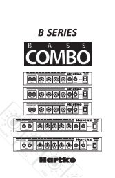
Guided Tour - SR5 Rear Panel<br />
1: DC <strong>in</strong>put - Connect <strong>the</strong> supplied 12 volt, 500 mA power adapter here, us<strong>in</strong>g <strong>the</strong> stra<strong>in</strong> relief<br />
as shown <strong>in</strong> <strong>the</strong> illustration below. WARNING: The substitution of any o<strong>the</strong>r k<strong>in</strong>d of power<br />
adapter can cause severe damage to <strong>the</strong> SR5 and will void your warranty.<br />
Us<strong>in</strong>g <strong>the</strong> stra<strong>in</strong> relief: Ga<strong>the</strong>r up a loop of wire and pass it through <strong>the</strong> stra<strong>in</strong> relief,<br />
<strong>the</strong>n pass <strong>the</strong> adapter plug through <strong>the</strong> loop <strong>in</strong> order to create a knot.<br />
2: Balanced output* - Use this electronically balanced low impedance (600 Ohm) XLR jack<br />
when connect<strong>in</strong>g <strong>the</strong> SR5 to professional (+4) audio equipment. P<strong>in</strong> wir<strong>in</strong>g is as follows: P<strong>in</strong> 1<br />
ground (shield), P<strong>in</strong> 2 high (hot), and P<strong>in</strong> 3 low (cold).<br />
3: Audio Output Level switch - Sets <strong>the</strong> audio output level attenuation of <strong>the</strong> balanced output<br />
(see #2 above) to -20 dBm (l<strong>in</strong>e level) or -40 dBm (mic level). See <strong>the</strong> “Sett<strong>in</strong>g Up and Us<strong>in</strong>g Your<br />
<strong>Stage</strong> 5 Series System” section on page 5 <strong>in</strong> this manual for more <strong>in</strong><strong>format</strong>ion.<br />
4: Unbalanced output* - Use this unbalanced high impedance (5K Ohm) 1/4" jack when<br />
connect<strong>in</strong>g <strong>the</strong> SR5 to consumer (-10) audio equipment. Wir<strong>in</strong>g is as follows: tip hot, sleeve<br />
ground.<br />
* If required, both <strong>the</strong> unbalanced and balanced outputs can be used simultaneously.
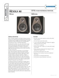
Guided Tour - HT5<br />
1: Audio on-off switch - When set to <strong>the</strong> “on”<br />
position, audio signal is transmitted. When set to<br />
<strong>the</strong> “off” position, <strong>the</strong> audio signal is muted. Because<br />
<strong>the</strong> carrier signal rema<strong>in</strong>s dur<strong>in</strong>g mut<strong>in</strong>g, no “pop” or<br />
“thud” will be heard. Note that turn<strong>in</strong>g this off does<br />
not turn off <strong>the</strong> transmitter power—it is simply a<br />
way to temporarily mute <strong>the</strong> transmission of audio<br />
signal. If you don’t plan on us<strong>in</strong>g <strong>the</strong> HT5 for extended<br />
periods, turn off its power by us<strong>in</strong>g <strong>the</strong> power on-off<br />
switch (see #3 below).<br />
2: Battery level meter - This set of three multicolor<br />
LEDs <strong>in</strong>dicates relative battery power, <strong>in</strong>dicat<strong>in</strong>g<br />
whe<strong>the</strong>r <strong>the</strong> <strong>in</strong>stalled battery is at low (red), mid<br />
(yellow) or high (green) strength. One or more of<br />
<strong>the</strong>se will light whenever <strong>the</strong> HT5 is powered on (see<br />
#3 below). When all three are lit, <strong>the</strong> battery is at<br />
maximum strength. When only <strong>the</strong> red “low” <strong>in</strong>dicator<br />
lights, RF performance is degraded and <strong>the</strong> battery<br />
needs to be replaced.<br />
3: Power on-off switch* - Use this to turn <strong>the</strong> HT5 on<br />
or off (to conserve battery power, be sure to leave it off<br />
when not <strong>in</strong> use).<br />
4: Ga<strong>in</strong> control (trimpot) - This <strong>in</strong>put sensitivity<br />
control has been factory preset to provide optimum<br />
level for <strong>the</strong> particular microphone capsule provided with your <strong>Stage</strong> 5 Series system and so we<br />
recommend that this not be adjusted manually. If necessary, however, you can use <strong>the</strong> supplied<br />
plastic screwdriver to raise or lower <strong>the</strong> <strong>in</strong>put level. See <strong>the</strong> “Sett<strong>in</strong>g Up and Us<strong>in</strong>g Your <strong>Stage</strong><br />
5 Series System” section on page 5 <strong>in</strong> this manual for more <strong>in</strong><strong>format</strong>ion.<br />
5: Battery holder - Insert a standard 9-volt alkal<strong>in</strong>e battery here, be<strong>in</strong>g sure to observe <strong>the</strong><br />
plus and m<strong>in</strong>us polarity mark<strong>in</strong>gs shown. We recommend <strong>the</strong> Duracell MN 1604 type battery.<br />
Although rechargeable Ni-Cad batteries can be used, <strong>the</strong>y do not supply adequate current for<br />
more than four hours. WARNING: Do not <strong>in</strong>sert <strong>the</strong> battery backwards; do<strong>in</strong>g so can cause severe<br />
damage to <strong>the</strong> HT5 and will void your warranty.<br />
* Be sure to mute <strong>the</strong> audio signal at your external mixer or amplifier before turn<strong>in</strong>g transmitter power<br />
on or off, or an audible pop may result.
Sett<strong>in</strong>g Up and Us<strong>in</strong>g Your<br />
<strong>Stage</strong> 5 Series System<br />
The basic procedure for sett<strong>in</strong>g up and us<strong>in</strong>g your <strong>Stage</strong> 5 Series Wireless System takes only a<br />
few m<strong>in</strong>utes:<br />
1. For <strong>the</strong> <strong>Stage</strong> 5 Series system to work correctly, both <strong>the</strong> receiver and transmitter must be set<br />
to <strong>the</strong> same channel. Remove all pack<strong>in</strong>g materials (save <strong>the</strong>m <strong>in</strong> case of need for future service)<br />
and check to make sure that <strong>the</strong> supplied receiver and transmitter are set to <strong>the</strong> same channel.<br />
If <strong>the</strong>se channels do not match, contact your <strong>Samson</strong> Technical Support at 1-800-372-6766.<br />
2. Physically place <strong>the</strong> receiver where it will be used (<strong>the</strong> general rule of thumb is to ma<strong>in</strong>ta<strong>in</strong><br />
“l<strong>in</strong>e of sight” between <strong>the</strong> receiver and transmitter so that <strong>the</strong> person us<strong>in</strong>g or wear<strong>in</strong>g <strong>the</strong><br />
transmitter can see <strong>the</strong> receiver). ‐ Extend <strong>the</strong> antenna and place it <strong>in</strong> a vertical position.<br />
3. Make sure <strong>the</strong> Power on-off switch <strong>in</strong> your HT5 handheld transmitter is set to “Off.”<br />
4. On <strong>the</strong> HT5 handheld transmitter, unscrew <strong>the</strong> bottom section of <strong>the</strong> microphone by turn<strong>in</strong>g<br />
it counterclockwise and <strong>the</strong>n slide it off.<br />
5. Place a fresh 9-volt alkal<strong>in</strong>e battery <strong>in</strong> <strong>the</strong> transmitter battery holder, tak<strong>in</strong>g care to observe<br />
<strong>the</strong> polarity mark<strong>in</strong>gs. Replace <strong>the</strong> bottom section of <strong>the</strong> HT5 handheld microphone by slid<strong>in</strong>g<br />
it on and <strong>the</strong>n screw<strong>in</strong>g it back on. Leave <strong>the</strong> transmitter off for <strong>the</strong> moment.<br />
6. Make <strong>the</strong> physical cable connection between <strong>the</strong> SR5 output jack and <strong>the</strong> l<strong>in</strong>e audio <strong>in</strong>put of<br />
your amplifier or mixer us<strong>in</strong>g <strong>the</strong> <strong>in</strong>cluded 1/4-<strong>in</strong>ch cable. If you are connect<strong>in</strong>g to a professional<br />
mixer you can use <strong>the</strong> balanced XLR jack (with an optional XLR mic cable), be sure to set <strong>the</strong><br />
receiver rear panel Audio Output Level switch correctly. If required, both <strong>the</strong> balanced and<br />
unbalanced outputs can be used simultaneously. Leave your amplifier (and/or mixer) off at this<br />
time.<br />
7. Turn <strong>the</strong> Volume knob on <strong>the</strong> SR5 completely counterclockwise. Us<strong>in</strong>g <strong>the</strong> stra<strong>in</strong> relief,<br />
connect <strong>the</strong> supplied AC adapter to <strong>the</strong> DC Input on <strong>the</strong> rear panel of <strong>the</strong> SR5, <strong>the</strong>n plug <strong>the</strong><br />
adapter <strong>in</strong>to any standard AC outlet. Press <strong>the</strong> front panel Power switch to turn on <strong>the</strong> SR5; <strong>the</strong><br />
green “Power” LED will light up, but all o<strong>the</strong>r front panel LEDs will rema<strong>in</strong> unlit<br />
8. Turn on <strong>the</strong> power to <strong>the</strong> HT5 transmitter (us<strong>in</strong>g its Power on-off switch); all three Battery<br />
strength LEDs will light if <strong>the</strong> battery is sufficiently strong. At this po<strong>in</strong>t, <strong>the</strong> RF Meter on <strong>the</strong><br />
front panel of <strong>the</strong> receiver will light.<br />
9. Now it’s time to set <strong>the</strong> audio levels. Turn on your connected amplifier and/or mixer but<br />
keep its volume all <strong>the</strong> way down. Next, make sure that your HT5 transmitter is unmuted by<br />
sett<strong>in</strong>g its Audio switch to “On.” Then set <strong>the</strong> Volume knob on <strong>the</strong> SR5 fully counterclockwise.<br />
Speak or s<strong>in</strong>g <strong>in</strong>to <strong>the</strong> mic at a normal performance level while observ<strong>in</strong>g <strong>the</strong> SR5 front panel<br />
Audio Meter. If <strong>the</strong> “0” (unity ga<strong>in</strong>) segment is light<strong>in</strong>g steadily, with just occasional higher<br />
excursions, <strong>the</strong> audio level is correctly set. If not, use <strong>the</strong> supplied plastic screwdriver to slowly<br />
adjust <strong>the</strong> HT5 Ga<strong>in</strong> control (trimpot) until <strong>the</strong> SR5 Audio Meter “0” (unity ga<strong>in</strong>) segment lights<br />
steadily (with occasional higher excursions). Then slowly raise <strong>the</strong> SR5 Volume knob to <strong>the</strong> 2<br />
o’clock position (unity ga<strong>in</strong>) and, f<strong>in</strong>ally, set <strong>the</strong> volume of your amplifier/mixer until <strong>the</strong> desired<br />
level is reached.<br />
Bear <strong>in</strong> m<strong>in</strong>d also that <strong>the</strong> HT<strong>5H</strong> microphone is unidirectional which means it picks up sound<br />
from <strong>the</strong> front of <strong>the</strong> mic and rejects sound from <strong>the</strong> rear. This will help reduce <strong>the</strong> chance of<br />
feedback. In general, you can avoid feedback by tak<strong>in</strong>g care not to use any microphone directly<br />
<strong>in</strong> front of a PA speaker (if this is unavoidable, try us<strong>in</strong>g an equalizer to attenuate those high- or<br />
mid-range frequencies which are caus<strong>in</strong>g <strong>the</strong> feedback “squeal<strong>in</strong>g”).<br />
10. If you hear distortion at <strong>the</strong> desired volume level (or if <strong>the</strong> “+6” segment LED <strong>in</strong> <strong>the</strong><br />
Audio Meter is light<strong>in</strong>g frequently), first check that <strong>the</strong> SR5 rear panel Audio Output Level switch<br />
is set correctly. Next, make sure that <strong>the</strong> ga<strong>in</strong> structure of your audio system is correctly set
Sett<strong>in</strong>g Up and Us<strong>in</strong>g Your<br />
<strong>Stage</strong> 5 Series System<br />
(consult <strong>the</strong> owners manual of your mixer and/or amplifier for details). If you still hear distortion,<br />
do <strong>the</strong> follow<strong>in</strong>g:<br />
• The HT5 transmitter's Ga<strong>in</strong> control has been factory preset to provide optimum level for <strong>the</strong><br />
particular microphone model be<strong>in</strong>g used and so no adjustment should be necessary. Any<br />
distortion present should <strong>the</strong>refore simply be a matter of <strong>the</strong> microphone be<strong>in</strong>g too close to<br />
<strong>the</strong> mouth; try mov<strong>in</strong>g it fur<strong>the</strong>r away. If this does not solve <strong>the</strong> problem, use <strong>the</strong> supplied<br />
plastic screwdriver to turn <strong>the</strong> Ga<strong>in</strong> control (trimpot) on <strong>the</strong> HT5 slowly counterclockwise until<br />
<strong>the</strong> distortion disappears.<br />
Note that, follow<strong>in</strong>g this setup procedure, you can always lower <strong>the</strong> Volume knob of <strong>the</strong> SR5 <strong>in</strong><br />
order to fur<strong>the</strong>r attenuate <strong>the</strong> output signal if necessary.<br />
11. Conversely, if you hear a weak, noisy signal at <strong>the</strong> desired volume level (and with <strong>the</strong> Volume<br />
control of <strong>the</strong> receiver turned fully clockwise), aga<strong>in</strong> make sure that <strong>the</strong> SR5 rear panel Audio<br />
Output Level switch is set correctly and that <strong>the</strong> ga<strong>in</strong> structure of your audio system is correctly<br />
set. If it is and <strong>the</strong> signal com<strong>in</strong>g from <strong>the</strong> SR5 is still weak and/or noisy, do <strong>the</strong> follow<strong>in</strong>g:<br />
• The HT5 transmitter's Ga<strong>in</strong> control has been factory preset to provide optimum level for <strong>the</strong><br />
particular microphone model be<strong>in</strong>g used and so no adjustment should be necessary. Any<br />
weakness of signal should <strong>the</strong>refore simply be a matter of <strong>the</strong> microphone be<strong>in</strong>g too far from<br />
<strong>the</strong> mouth; try mov<strong>in</strong>g it closer. If this does not solve <strong>the</strong> problem, use <strong>the</strong> supplied plastic<br />
screwdriver to turn <strong>the</strong> Ga<strong>in</strong> control (trimpot) on <strong>the</strong> HT5 slowly clockwise until <strong>the</strong> signal<br />
reaches an acceptable level.<br />
12. Temporarily turn down <strong>the</strong> level of your mixer/amplifier system and turn off <strong>the</strong> power to<br />
your transmitter, leav<strong>in</strong>g <strong>the</strong> SR5 on. Then restore <strong>the</strong> previously set level of your mixer/amplifier.<br />
With <strong>the</strong> transmitter off, <strong>the</strong> receiver output should be totally silent—if it is, skip ahead to <strong>the</strong><br />
next step. If it isn’t (that is, if you hear some noise), you may need to adjust <strong>the</strong> receiver’s front<br />
panel Squelch control. When <strong>the</strong> Squelch control is at its m<strong>in</strong>imum sett<strong>in</strong>g, <strong>the</strong> <strong>Stage</strong> 5 Series<br />
system always provides maximum range without dropout; however, depend<strong>in</strong>g upon <strong>the</strong><br />
particular environment your system is used <strong>in</strong>, you may need to reduce that range somewhat <strong>in</strong><br />
order to elim<strong>in</strong>ate band noise or <strong>in</strong>terference when <strong>the</strong> transmitter is turned off. To do so, use<br />
<strong>the</strong> provided screwdriver to rotate <strong>the</strong> Squelch control completely counterclockwise (to <strong>the</strong> “M<strong>in</strong>”<br />
position), <strong>the</strong>n slowly turn it clockwise until <strong>the</strong> noise disappears. If no noise is present at any<br />
position, leave it at its fully counterclockwise “M<strong>in</strong>” position (so as to have <strong>the</strong> greatest overall<br />
range available).<br />
13. When first sett<strong>in</strong>g up <strong>the</strong> <strong>Stage</strong> 5 Series System <strong>in</strong> a new environment, it’s always a good idea<br />
to do a walkaround <strong>in</strong> order to make sure that coverage is provided for your entire performance<br />
area. Accord<strong>in</strong>gly, turn down <strong>the</strong> level of your audio system and turn on both <strong>the</strong> transmitter<br />
and receiver. Then, with <strong>the</strong> transmitter unmuted, restore <strong>the</strong> level of your audio system and<br />
while speak<strong>in</strong>g or s<strong>in</strong>g<strong>in</strong>g, walk through <strong>the</strong> entire area that will need to be covered. As you do<br />
so, <strong>the</strong> “TX” LED on <strong>the</strong> front panel of <strong>the</strong> SR5 should always rema<strong>in</strong> lit. Always try to m<strong>in</strong>imize<br />
<strong>the</strong> distance between transmitter and receiver as much as possible so that <strong>the</strong> strongest<br />
possible signal is received from all planned transmission po<strong>in</strong>ts. In fixed <strong>in</strong>stallations such as<br />
A/V or corporate conference rooms or for extended range applications (where <strong>the</strong> transmitter<br />
and receiver are more than 150 feet apart), it may be desirable to angle <strong>the</strong> receiver antenna<br />
differently from its vertical position or to <strong>in</strong>stall <strong>the</strong> receiver <strong>in</strong> <strong>the</strong> same room as <strong>the</strong> transmitters<br />
(and, if necessary, to extend <strong>the</strong> wir<strong>in</strong>g to remote audio equipment).<br />
If you have followed all <strong>the</strong> steps above and are experienc<strong>in</strong>g difficulties, contact your local<br />
distributor or, if purchased <strong>in</strong> <strong>the</strong> United States, call <strong>Samson</strong> Technical Support (1-800-372-6766)<br />
between 9 AM and 5 PM EST.
Specifications<br />
Transmitter HT5<br />
Transmission Mode<br />
Frequency modulation, 80KF3E, 15 kHz peak deviation<br />
Frequency Range<br />
173.80 MHz to 213.20 MHz, 25 frequencies<br />
OSC System<br />
Crystal controlled, x12 multiplication<br />
RF Power<br />
20 mW (USA models), 10 mW [(2 mW ERP) European / UK models)]<br />
Operat<strong>in</strong>g Range<br />
300 ft.<br />
Frequency Stability<br />
± 10 ppm<br />
Approvals Complies with ETS 300 422 and FCC Part 74<br />
Radiat<strong>in</strong>g Harmonic and Spurious Emission<br />
Below limits of applicable regulations<br />
Antenna Type<br />
Internal<br />
Audio Frequency Response<br />
40 Hz to 15 kHz ±3 dB<br />
Pre-Emphasis<br />
50 µSec<br />
Noise Reduction System<br />
NE571 based compandor<br />
Signal To Noise Ratio<br />
> 100 dB<br />
Maximum Input Level<br />
0 dBv (ST5), -20 dBv (VH3)<br />
T.H.D.<br />
< 1% @ 1 kHz<br />
Current Consumption<br />
34 mA (typical)<br />
Battery Life (MN1604 9-volt alkal<strong>in</strong>e)<br />
6 hours (typical)<br />
Operat<strong>in</strong>g Temperature<br />
-10 to +55 degrees C<br />
Controls<br />
Power On/Off, Audio On/Off, Level Control (Trimpot)<br />
LED Indicator<br />
Battery high/medium/low<br />
Dimensions<br />
37 (W) x 233 (H) mm (1.46 x 9.17 <strong>in</strong>.)<br />
Weight<br />
200 grams • 7.1 oz.<br />
SR5 Reciever :<br />
Receiv<strong>in</strong>g System<br />
Frequency Range<br />
Band A (European / UK models)<br />
Band B (European / UK models)<br />
Receiv<strong>in</strong>g Mode<br />
Sensitivity<br />
Selectivity<br />
Squelch Sensitivity<br />
Intermediate Frequency<br />
Local Oscillator System<br />
Noise Reduction System<br />
De-emphasis<br />
Signal To Noise Ratio<br />
Audio Frequency Response<br />
T.H.D.<br />
Audio Output Levels<br />
Audio Output Impedance<br />
Antennas<br />
Operat<strong>in</strong>g Temperature<br />
Controls<br />
LED Indicators<br />
SR5<br />
Power Requirement<br />
Dimensions (W x H x D, without antenna)<br />
Weight (<strong>in</strong>clud<strong>in</strong>g antenna)<br />
S<strong>in</strong>gle conversion Superheterodyne<br />
173.80 MHz to 213.20 MHz, 25 frequencies<br />
160.10 to 177.90 MHz<br />
189.10 to 210.10 MHz<br />
80KF3E<br />
< 3 µV for 20 dB SINAD, < 10 µV for 50 dB S/N<br />
120 kHz BW, nom<strong>in</strong>al @ -6 dB, ± 300 kHz (adj CH), -75 dB<br />
3 µV to 250 µV adjustable<br />
10.7 MHz<br />
Crystal controlled<br />
NE571 based compandor<br />
50 µsec.<br />
> 100 dB (IHF-A) l<strong>in</strong>e out, > 90 dB (IHF-A), mic out<br />
40 Hz to 15 kHz ±3 dB<br />
< 1% @ 1 kHz<br />
-10dB unbalanced (1/4" phone connector),<br />
-20 dBm / -40 dBm balanced (XLR connector)<br />
5 kΩ unbalanced, 600 Ω balanced<br />
1/4 wavelength telescopic<br />
-10 to +55 degrees C<br />
Volume, Squelch, Power<br />
TX On / AF Level (6 LEDs) / RF Level (6 LEDs)<br />
12 Volts DC, 100 mA typical (110 mA max.), AC adapter supplied<br />
216 x 44 x 116 mm (8.5 x 1.75 x 4.6 <strong>in</strong>.)<br />
20 g • 0.75 lb<br />
Specifications are subject to change without notice.
Declaration of Conformity<br />
Date of issue: 10/07/2004<br />
Equipment: Wireless Microphone System<br />
Model #: Receivers: SR5, SR55 Transmitters: HT5, ST5<br />
Class: <strong>Samson</strong> <strong>Stage</strong> 5 and 55 Series - 174MHz to 216MHz<br />
Manufacturer:<br />
Address:<br />
SAMSON TECHNOLOGIES CORPORATION<br />
575 Underhill Boulevard, Syosset, New York 11791 USA<br />
This is to certify that <strong>the</strong> aforementioned equipment is <strong>in</strong> conformity with <strong>the</strong> essential requirements<br />
and o<strong>the</strong>r relevant requirements of <strong>the</strong> R&TTE Directive (1999/5/EC)<br />
Applicable Standards<br />
EN 60065:2002<br />
EN 301489-9 v1.2.1 (2000-08)<br />
EN 300 422-2 V1.2.2<br />
Title<br />
Audio, video and similar electronic apparatus - Safety requirements<br />
Electromagnetic compatability and Radio spectrum Matters;(ERM) - Part 9:<br />
Specific conditions for wireless microphones<br />
Electromagnetic compatibility and Radio spectrum Matters (ERM);<br />
Wireless microphones <strong>in</strong> <strong>the</strong> 25 MHz to 3 GHz frequency range; Part 2:<br />
Harmonized EN under article 3.2 of <strong>the</strong> R&TTE Directive. Notified Body not<br />
required.<br />
Signed on behalf of <strong>the</strong> manufacturer:<br />
Name:<br />
Title:<br />
Douglas Bryant<br />
President<br />
Signed on behalf of <strong>the</strong> representative:<br />
Name:<br />
Title:<br />
Address:<br />
Address:
FCC Rules and Regulations<br />
<strong>Samson</strong> wireless systems are type accepted under FCC<br />
rules parts 90, 74 and 15.<br />
Licens<strong>in</strong>g of <strong>Samson</strong> equipment is <strong>the</strong> user’s responsibility<br />
and licensability depends on <strong>the</strong> user’s classification,<br />
application and frequency selected.<br />
This device complies with RSS-210 of<br />
Industry & Science Canada.<br />
Operation is subject to <strong>the</strong> follow<strong>in</strong>g two conditions:<br />
(1) this device may not cause harmful <strong>in</strong>terference and (2)<br />
this device must accept any <strong>in</strong>terference received, <strong>in</strong>clud<strong>in</strong>g<br />
<strong>in</strong>terference that may cause<br />
undesired operation.
<strong>Samson</strong> Technologies Corp.<br />
45 Gilp<strong>in</strong> Avenue<br />
Hauppauge, New York 11788-8816<br />
Phone: 1-800-3-SAMSON (1-800-372-6766)<br />
Fax: 631-784-2201<br />
www.samsontech.com<br />
<strong>Stage</strong><strong>5H</strong>_om_ v1