4 - Hofmann Megaplan
4 - Hofmann Megaplan
4 - Hofmann Megaplan

You also want an ePaper? Increase the reach of your titles
YUMPU automatically turns print PDFs into web optimized ePapers that Google loves.
0121- 1<br />
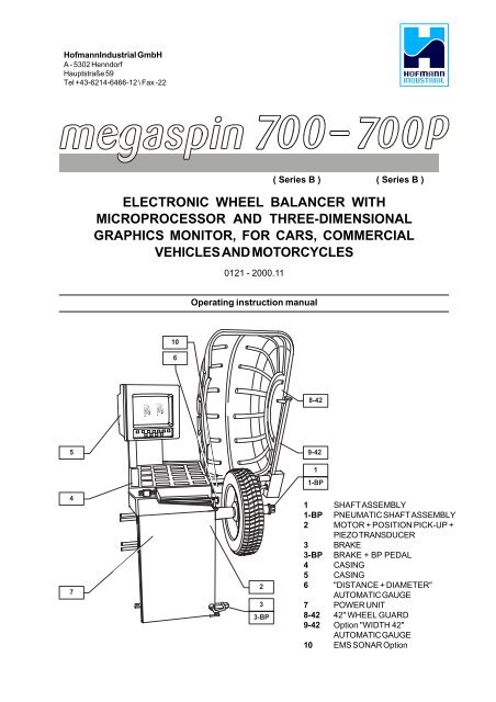
<strong>Hofmann</strong>Industrial GmbH<br />
A - 5302 Henndorf<br />
Hauptstraße 59<br />
Tel +43-6214-6466-12 \ Fax -22<br />
7 7<br />
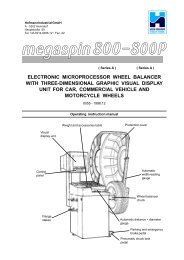
ELECTRONIC WHEEL BALANCER WITH<br />
MICROPROCESSOR AND THREE-DIMENSIONAL<br />
GRAPHICS MONITOR, FOR CARS, COMMERCIAL<br />
VEHICLES AND MOTORCYCLES<br />
0121 - 2000.11<br />
( Series B ) ( Series B )<br />
Operating instruction manual<br />
10<br />
6<br />
8-42<br />
5<br />
9-42<br />
4<br />
7<br />
2<br />
3<br />
3-BP<br />
1<br />
1-BP<br />
1 SHAFT ASSEMBLY<br />
1-BP PNEUMATIC SHAFT ASSEMBLY<br />
2 MOTOR + POSITION PICK-UP +<br />
PIEZO TRANSDUCER<br />
3 BRAKE<br />
3-BP BRAKE + BP PEDAL<br />
4 CASING<br />
5 CASING<br />
6 "DISTANCE + DIAMETER"<br />
AUTOMATIC GAUGE<br />
7 POWER UNIT<br />
8-42 42" WHEEL GUARD<br />
9-42 Option "WIDTH 42"<br />
AUTOMATIC GAUGE<br />
10 EMS SONAR Option
2 - 0121<br />
CONTENTS<br />
page<br />
1 - GENERAL .................................................................................................................................................................................... 5<br />
1.1 - GENERAL SAFETY RECOMMENDATIONS ................................................................................................................ 5<br />
1.1.1 - STANDARD SAFETY DEVICES ............................................................................................................................... 5<br />
1.2 - FIELD OF APPLICATION ............................................................................................................................................. 5<br />
1.3 - OVERALL DIMENSIONS ............................................................................................................................................. 5<br />
1.4 - SPECIFICATION ........................................................................................................................................................... 6<br />
2 - HANDLING AND HOISTING ........................................................................................................................................................ 6<br />
3 - COMMISSIONING ....................................................................................................................................................................... 7<br />
3.1 - ANCHORING ................................................................................................................................................................ 7<br />
3.2 - ELECTRICAL CONNECTION ........................................................................................................................................ 7<br />
3.3 - PNEUMATIC CONNECTION (Version P) ...................................................................................................................... 7<br />
3.4 - EXTRA SAFETY DEVICES (VERSION P) .................................................................................................................. 7<br />
3.5 - ADAPTER MOUNTING ................................................................................................................................................. 7<br />
3.6 - GUARD MOUNTING AND ADJUSTMENT ..................................................................................................................... 7<br />
3.7 - SPACER WD ................................................................................................................................................................ 8<br />
4 - CONTROLS AND COMPONENTS ............................................................................................................................................. 8<br />
4.1 - BRAKE PEDAL ............................................................................................................................................................ 8<br />
4.2 - PNEUMATIC LOCKING PEDAL (Version P) ................................................................................................................. 8<br />
4.3- AUTOMATIC DISTANCE AND DIAMETER GAUGE ....................................................................................................... 8<br />
4.4 - AUTOMATIC WIDTH GAUGE (OPTION) ...................................................................................................................... 9<br />
4.5 - AUTOMATIC WHEEL POSITIONING ............................................................................................................................. 9<br />
4.6 - CLOCK CONTROL ....................................................................................................................................................... 9<br />
4.7 - KEYBOARD ................................................................................................................................................................. 9<br />
5 - INDICATIONS AND USE OF THE WHEEL BALANCER ........................................................................................................... 10<br />
5.1 - INITIAL SCREEN ......................................................................................................................................................... 10<br />
5.1.2 - SCREEN-SAVE SCREEN ........................................................................................................................................ 10<br />
5.2 - MENU ACCESS DIAGRAM ....................................................................................................................................... 11<br />
5.3 - PRESETTING OF WHEEL DIMENSIONS ..................................................................................................................... 12<br />
5.3.1 - AUTOMATIC PRESETTING ..................................................................................................................................... 12<br />
5.3.2 - TO CALL MEMORIZED MEASUREMENTS .............................................................................................................. 14<br />
5.3.3 - MANUAL PRESETTING (Use only in special cases or for checking) .................................................................. 15<br />
5.4 - USER CONTROL ........................................................................................................................................................ 18<br />
5.4.1 - USER MEMORIZATION ........................................................................................................................................... 18<br />
5.4.2 - TO CALL USER ...................................................................................................................................................... 18<br />
5.5 - RESULT OF MEASUREMENT ..................................................................................................................................... 19<br />
5.5.1 - INDICATION OF EXACT CORRECTION WEIGHT POSITION ................................................................................... 20<br />
5.5.2 - "SPLIT" CONTROL .................................................................................................................................................. 21<br />
5.5.3 - UNBALANCE OPTIMIZATION ................................................................................................................................. 22<br />
5.5.4 - ALU AND STATIC MODES ..................................................................................................................................... 22<br />
5.5.5 - TO CANCEL STATIC UNBALANCE ........................................................................................................................ 23<br />
5.6 - STATISTICS ............................................................................................................................................................... 24<br />
5.7 - ECCENTRICITY MEASUREMENT (OPTIONAL) .......................................................................................................... 24<br />
6 - SETUP ....................................................................................................................................................................................... 25<br />
6.1 - LANGUAGE ............................................................................................................................................................... 25<br />
6.2 - UNIT OF UNBALANCE MEASUREMENT .................................................................................................................... 25<br />
6.3 - UNBALANCE DISPLAY THRESHOLD ....................................................................................................................... 25<br />
6.4 - UNBALANCE DISPLAY PITCH ................................................................................................................................... 25<br />
6.5 - SPIN WITH GUARD CLOSED ..................................................................................................................................... 25<br />
6.6 - SCREEN-SAVER TIME ............................................................................................................................................... 25<br />
6.7 - VISUAL ECCENTRICITY CHECK ................................................................................................................................ 25<br />
6.8 - ACOUSTIC SIGNAL ................................................................................................................................................... 25<br />
6.9 - CLOCK SETTING ....................................................................................................................................................... 25<br />
FOR SPECIALIZED PERSONNEL ONLY<br />
7 - SPECIAL CALIBRATIONS AND FUNCTIONS ......................................................................................................................... 26<br />
7.1 - ENABLING OF WIDTH MEASUREMENT ..................................................................................................................... 26<br />
7.2 - PRESETTING THE CUSTOMER AND USER NAME ..................................................................................................... 26<br />
7.3 - ENABLING OF ECCENTRICITY MEASUREMENT ....................................................................................................... 26<br />
7.4 - CALIBRATIONS ......................................................................................................................................................... 26<br />
7.4.1 - GAUGE CALIBRATION ........................................................................................................................................... 26<br />
7.4.2 - ADAPTER ECCENTRICITY CORRECTION ............................................................................................................... 27<br />
7.4.3 - WHEEL BALANCER CALIBRATION ....................................................................................................................... 27<br />
7.4.4 - MACHINE SELF-TEST ............................................................................................................................................. 27<br />
7.4.4.1 - TO CHECK THE ENCODER .................................................................................................................................. 27<br />
8 - ERRORS .................................................................................................................................................................................... 28<br />
9 - ROUTINE MAINTENANCE ........................................................................................................................................................ 29<br />
9.1 - SCHEDULED MAINTENANCE ..................................................................................................................................... 29<br />
9.2 - TO REPLACE THE FUSES ......................................................................................................................................... 29<br />
9.3 - ADAPTER END-PIECE, SPINDLE P ............................................................................................................................. 29<br />
- EXPLODED DRAWINGS OF WHEEL BALANCER<br />
- DECLARATION OF CONFORMITY CE
0121- 3
4 - 0121
0121- 5<br />
1 - GENERAL<br />
1.1 - GENERAL SAFETY RECOMMENDATIONS<br />
- The balancing machine should only be used by duly authorized and trained personnel.<br />
- The balancing machine should not be used for purposes other than those described in the instruction<br />
manual.<br />
- Under no way should the balancing machine be modified except for those modifications made explicitly<br />
by the manufacturer.<br />
- Never remove the safety devices. Any work on the machine should only be carried out by duly<br />
authorized specialist personnel.<br />
- Do not use strong jets of compressed air for cleaning.<br />
- Use alcohol to clean plastic panels or shelves (AVOID LIQUIDS CONTAINING SOLVENTS).<br />
- Before starting the wheel balancing cycle, make sure that the wheel is securely locked on the adapter.<br />
- The machine operator should not wear clothes with flapping edges. Make sure that unauthorized<br />
personnel do not approach the balancing machine during the work cycle.<br />
- Avoid placing counterweights or other objects in the base which could impair the correct operation<br />
of the balancing machine.<br />
1.1.1 - STANDARD SAFETY DEVICES<br />
- STOP push button for stopping the wheel under emergency conditions.<br />
- The safety guard of high impact plastic is with shape and size designed to prevent risk of<br />
counterweights from flying out in any direction except towards the floor.<br />
- A microswitch prevents starting the machine if the guard is not lowered and stops the wheel whenever<br />
the guard is raised.<br />
1.2 - FIELD OF APPLICATION<br />
The machine is designed for balancing car or motorcycle wheels weighing less than 65 kg.<br />
It can be operated within a temperature range of 0° to +45°C.<br />
It is also possible to measure the geometric radial run-out of the wheels (option).<br />
1.3 - OVERALL DIMENSIONS<br />
Fig. 1
6 - 0121<br />
1.4 - SPECIFICATION<br />
Weight with guard (excluding adapter) ........... 138 kg version 700 standard<br />
..................................................................... 159 kg version 700P pneumatic locking<br />
Single phase power supply ........................... 115 - 230 V 50-60 Hz<br />
Protection class ............................................ IP 54<br />
Max. power consumption .............................. 1100 W<br />
Monitor .......................................................... SVGA 15"<br />
Balancing speed ........................................... approx. 180 r.p.m.<br />
Cycle time for average wheel (14 kg) ............ 6 seconds<br />
Balancing accuracy ...................................... 1 gram<br />
Position resolution ......................................... ± 1.4°<br />
Average noise level ....................................... < 70 dB(A)<br />
Distance rim - machine ................................. 0 - 285 mm<br />
Rim width setting range ................................. 1.5" to 20" or 40 to 510 mm<br />
Diameter setting range .................................. 10 to 24" or 265 to 615 mm<br />
Total wheel diameter within guard ................. 1067 mm (42")<br />
Total wheel width within guard ....................... 500 mm<br />
Max. wheel weight ......................................... 65 kg<br />
Min/max. compressed air pressure ............... 7 to 10 kg/cm 2<br />
approx. 0.7 to 1MPa<br />
approx. 7 to 10 BAR<br />
approx. 100 to 145PSI<br />
2 - HANDLING AND HOISTING<br />
N.B. DO NOT HOIST THE MACHINE USING OTHER LIFTING POINTS<br />
Fig. 2<br />
Fig. 3
0121- 7<br />
3 - COMMISSIONING<br />
3.1 - ANCHORING<br />
The machine can be operated on any flat non-resilient floor.<br />
Make sure that the machine rests solely on the three support points provided (fig. 3).<br />
If possible, it is advisable to anchor to the floor using relative mounting feet (see fig. 3)<br />
3.2 - ELECTRICAL CONNECTION<br />
The machine is supplied with a single phase mains cable plus earth (ground).<br />
The supply voltage (and mains frequency) is given on the machine nameplate. It may not be changed.<br />
Connection to the mains should always be made by expert personnel.<br />
The machine should not be started up without proper earth (ground) connection.<br />
Connection to the mains should be through a slow acting safety switch rated at 4A amp (230V) or 10A amp<br />
(115V) .<br />
3.3 - PNEUMATIC CONNECTION (Version P)<br />
For operation of the spindle with pneumatic locking (constant thrust air springs), connect the balancing<br />
machine to the compressed air main: relative connection fitting is located at the rear of the machine. At<br />
least 7 kg/cm 2 (approx. 0.7 MPa; approx. 7 BAR; approx. 100 PSI) is required for correct operation of the<br />
unlocking device.<br />
3.4 - EXTRA SAFETY DEVICES (VERSION P)<br />
- Wheel always locked even when there is pressure failure during the balancing cycle.<br />
- Rotary block wheel retainer which, in the event of accidental pressing of the pneumatic locking<br />
pedal during the balancing cycle, avoids risk of the wheel slipping from the adapter.<br />
Always actuate the unlocking control pedal with the machine stationary in order to avoid stress<br />
and abnormal wear on the adapter.<br />
3.5 - ADAPTER MOUNTING<br />
The balancing machine is supplied complete with cone adapter for fastening wheels with central bore.<br />
Other optional adapters can be mounted:<br />
Fig. 4<br />
A<br />
B<br />
Fig. 4A<br />
A<br />
B<br />
Standard<br />
a) Back-off screw B and remove threaded end-piece A.<br />
b) Fit the new adapter.<br />
Pneumatic spindle a)<br />
Unscrew rod B.<br />
b) Unscrew end-piece A.<br />
c) Fit the new adapter.<br />
Fully unscrew rod B to remove<br />
the wheel, in the event of a<br />
pressure break.<br />
3.6 - GUARD MOUNTING AND ADJUSTMENT<br />
a) Fasten the components to the base as illustrated in specific exploded drawing .<br />
b) The position of the wheel guard when closed can be adjusted with relative screw accessible at the back.<br />
Correct position is the one shown in fig. 1.<br />
c) Check that the microswitch is held down when the guard is closed.<br />
d) Adjust the angular position of microswitch control.
8 - 0121<br />
3.7 - SPACER WD (option)<br />
When balancing very wide wheels (9”), the tyre<br />
may touch the casing of the balancing machine.<br />
Also it might not be possible, to position the<br />
gauge into the rim. To enlarge the distance of<br />
the rim, you should use the option WD/DC. Fit<br />
spacer WD on the adapter body, and secure it<br />
with the standard issue nuts. When centring the<br />
wheel with the cone on the inside, fit the other<br />
cone as a spacer to obtain spring thrust.<br />
Spring<br />
SPACER WD<br />
Spacer cone<br />
Centering cone<br />
4 - CONTROLS AND COMPONENTS<br />
Fig. 5<br />
4.1 - BRAKE PEDAL<br />
This pedal allows the operator to hold the<br />
wheel when fitting the counterweights. It<br />
must not be actuated during the<br />
measuring cycle.<br />
Fig. 6<br />
4.2 - PNEUMATIC LOCKING<br />
PEDAL (Version P)<br />
This pedal allows releasing the device<br />
fastening the wheel on the adapter. Do<br />
not actuate this pedal during the<br />
machine cycle and/or when adapters<br />
other than the standard cone adapter<br />
are mounted.<br />
The pedal has two fixed positions:<br />
UP to release, DOWN to clamp the<br />
wheel.<br />
4.3- AUTOMATIC DISTANCE AND DIAMETER GAUGE<br />
This gauge allows measurement of the distance of the wheel from the machine and the wheel diameter at<br />
the point of application of the counterweight.<br />
It also allows correct positioning of the counterweights inside rim by using the specific function (see 5.5.1)<br />
which allows reading, on the monitor, the position used for the measurement inside the rim (For calibration,<br />
see 7.4.1).
0121- 9<br />
4.4 - AUTOMATIC WIDTH GAUGE (OPTION)<br />
This gauge allows measuring the rim of the wheel to be balanced in the point of application of the<br />
counterweight (see 5.3.1).<br />
4.5 - AUTOMATIC WHEEL POSITIONING<br />
At the end of the spin, the wheel is positioned according to the unbalance on the outside or else according<br />
to the static unbalance (when selected).<br />
Accuracy is ±20 degrees.<br />
4.6 - CLOCK CONTROL<br />
The balancing machine is provided with a clock whose back-up time, when the machine is switched off, is<br />
approx. 1 month. If the machine lies idle for a long period, when re-switching on for the first time, check the<br />
time and reset it if necessary (see 6.9).<br />
4.7 - KEYBOARD<br />
Fig. 7<br />
FUNCTION KEYS: they immediately select function indicated on the<br />
monitor<br />
Selection of special<br />
functions<br />
Confirm<br />
Starts<br />
measuring<br />
cycle<br />
Interrupts<br />
machine cycle<br />
NB:<br />
- Press the buttons with the fingers only: never use the counterweight pincers or<br />
other pointed objects.<br />
- When the beep signal is enabled (see section 6.8), pressing of any push button is<br />
accompanied by a "beep".
10 - 0121<br />
5 - INDICATIONS AND USE OF THE WHEEL BALANCER<br />
The monitor shows several information and suggests various alternative ways of use to the operator.<br />
This is done through various "screens".<br />
5.1 - INITIAL SCREEN<br />
END<br />
Buttons enabled<br />
MENU : main functions screen (see 5.2)<br />
: type of correction (see 5.5.4)<br />
: balancing spin (see 5.5)<br />
Dimensions gauge: when extracted, the Dimensions screen is selected (see 5.3).<br />
If the machine remains on the initial screen for a certain amount of time without being used, the system is<br />
automatically switched to a screen-save. Striking of any key, movement of the wheel of distance + diameter<br />
gauge will cause automatic switching from the screen-save menu to the initial screen.<br />
From the screen-save, the automatic start actuated by the guard is not available for safety reasons.<br />
5.1.2 SCREEN-SAVE SCREEN<br />
N.B.: Name of the wheel balancer's owner. Can be preset via the monitor (see Section 7.2)<br />
HOFMANNINDUSTRIAL<br />
GmbH<br />
Hauptstraße, 59<br />
A-5302 HENNDORF - AUSTRIA
0121- 11<br />
5.2 - MENU ACCESS DIAGRAM<br />
N.B. : - The symbol " ... " indicates the presence of a further menu.<br />
- To return to the previous menu, press button<br />
HOME<br />
STOP<br />
- To return to the initial screen, press buttonMENU<br />
Machine parameters set-up<br />
Language<br />
Unit of unbalance measurement<br />
Unbalance display threshold<br />
Unbalance display pitch<br />
Spin with guard closing<br />
Screen-saver time<br />
Next<br />
MENU<br />
B<br />
A<br />
user<br />
control<br />
(5.4)<br />
Call user<br />
Save user<br />
Optimization<br />
Dimensions<br />
Statistics<br />
Set-up<br />
Special functions<br />
Cancel<br />
G<br />
Cancel<br />
C<br />
D<br />
PASSWORD : + + +<br />
RESERVED FOR EXPERT PERSONNEL<br />
Machine parameters set-up<br />
Special functions<br />
Visual eccentricity check<br />
Beep signal<br />
Clock settings<br />
selections<br />
user control<br />
Width measurement<br />
Adhesive weight dispenser<br />
Eccentricity measurement<br />
Customer's personal data<br />
Users' names<br />
Calibration<br />
Previous<br />
Cancel<br />
E<br />
Cancel<br />
Calibrations<br />
F<br />
Potentiometer<br />
Adhesive weight dispenser<br />
Eccentricity correction<br />
Wheel balancer self-calibration<br />
Calibrations<br />
Distance<br />
Diameter<br />
Width<br />
Wheel balancer self test<br />
Cancel<br />
Cancel
12 - 0121<br />
5.3 - PRESETTING OF WHEEL DIMENSIONS<br />
5.3.1 AUTOMATIC PRESETTING<br />
The screen appears upon extracting the distance + diameter gauge.<br />
The indication "dimension acquired" is given by the symbol of the correction weight which changes from blue<br />
to red.<br />
- Standard wheels: Using the special handle, move the tip of the gauge against the rim in one of the positions<br />
A/B shown in fig. 8 and wait for the weight symbol in the screen to pass from blue to red.<br />
N.B. Always use the round part of the striking surface.<br />
When the acoustic beep is enabled (see section 6.8), acquisition of the dimensions is accompanied by a "beep".<br />
Fig. 8<br />
The above calibration is required for the ALU, 1, 2, 3, 4, CTS,<br />
Static and Dynamic modes.<br />
- Return the gauge to position 0.<br />
- The current width value, which can be changed manually,<br />
appears at the bottom of the screen.<br />
POS. A<br />
POS. B
0121- 13<br />
- Preset the nominal width, which is normally stamped on the<br />
rim, or else measure the width "b" with the calliper gauge<br />
(standard accessory).<br />
- Press button to switch to manual setting of all wheel dimensions.<br />
- Press button to return to the Measurement screen.<br />
"AUTOMATIC WIDTH" OPTION<br />
- Move the gauges simultaneously into measuring position.<br />
For distance + diameter gauge, see fig. 8.<br />
Fig. 8B WIDTH gauge<br />
During gauge movement, the symbols appear in movement on the display (see fig.8C/8D) indicating that<br />
the gauges are not steady.<br />
- Hold the gauges still in position for approx. 2 sec.<br />
- Successful memorization is given by the change in colour of the correction weights which passes from<br />
blue to red.<br />
- Return the gauges to rest position.<br />
N.B. - If the symbols of fig. 8C/8D remain on the display, it means that relative measuring gauge is not in<br />
rest position.<br />
- The two measurements (distance + diameter and width) can be made at different moments. In this<br />
case first make the (distance + diameter) measurement. Correct position of the gauge tips is<br />
essential for accurate measurement. Incorrect measurement of the distance entails incorrect width<br />
measurement. Check that the data calculated with the nominal width stamped on the rim (errors up<br />
to 1/2" do not normally cause appreciable residues).<br />
Fig. 8D<br />
Fig. 8C
14 - 0121<br />
- Wheel ALU-M (correction on the inside for two balancing planes with direct calibration)<br />
After measurement made on inside FI, as illustrated in fig. 9, move the gauge out further to memorize the<br />
data regarding the outside FE. Select position A or B in fig. 8 as required and hold the position for at least<br />
2 seconds. The counterweight symbols change colour.<br />
When the acoustic beep is enabled (see section 6.8), acquisition of the dimensions is accompanied by a "beep".<br />
Fig. 9 (ALU M)<br />
FI<br />
FE<br />
Should the difference between the set diameters exceed 2 inches, the wheel balancer automatically reverts<br />
to ALU-3M. In this case, be careful to correctly apply the weights since in ALU 3M the inner side has a clip<br />
instead of an adhesive weight.<br />
Fig. 9A (ALU 3M)<br />
FI<br />
dI<br />
dE<br />
FE<br />
N.B. Manually modifying dl automatically forces dE=0.8 x dl.<br />
Remember to update dE by measuring the real diameter.<br />
The following buttons are enabled:<br />
Selection of Manual dimensions setting screen<br />
/ HOME<br />
STOP<br />
Return to Initial screen<br />
Balancing spin<br />
5.3.2 TO CALL MEMORIZED MEASUREMENTS<br />
\ \ \ Press button with your name, then:<br />
- by pressing the measured values (5.4) are called, without taking into<br />
account of other measurements made in the meantime.<br />
- when is pressed, the currently preset dimensions are saved.
0121- 15<br />
5.3.3 - MANUAL PRESETTING (Use only in special cases or for checking)<br />
If necessary, the dimensions can be inserted or edited in manual mode as follows:<br />
- press MENU + or else press from the Dimensions screen in automatic mode (which<br />
can be reached by pulling out the distance + diameter gauge).<br />
- press to select the dimension to be preset (highlighted in red).<br />
- press / to preset the required value.<br />
- press to change unit of measurement.<br />
- press to set the dimensions for the ALUM correction mode.<br />
Definition of dimensions:<br />
= DIAMETER : Preset the nominal diameter stamped on the rim.<br />
= WIDTH: Preset the nominal width indicated on the rim.<br />
= DISTANCE: Preset the distance in cm of the wheel from the machine.<br />
Fig. 10
16 - 0121<br />
- Wheel ALU M or ALU 3M:<br />
Even in ALUM or ALU 3M correction mode, the dimensions can be input or modified manually using the<br />
buttons shown on screen in accordance with the technical data displayed.<br />
Go to initial screen (5.1) Then press.<br />
2<br />
5<br />
: type of correction<br />
: ALU M<br />
+ 4<br />
For a better understanding of the screen contents, refer to the following outline:<br />
Fig. 10A (ALU M)<br />
14 mm<br />
Distance reading
0121- 17<br />
To go to the ALU 3M manual dimension setting screen, press:<br />
2<br />
: type of correction<br />
4<br />
: ALU 3M<br />
+<br />
4<br />
For a better understanding of the screen contents, refer to the following outline:<br />
Fig. 10B (ALU 3M)<br />
14 mm<br />
Distance reading<br />
- To return to the normal wheel dimension setting screen, press the button .
18 - 0121<br />
5.4 - USER CONTROL<br />
The wheel balancer can be used simultaneously by 4 different users who, through a simple sequence, can<br />
Save user<br />
Cancel<br />
memorize their work condition and call it when needed. The users' names can be memorized (7.2).<br />
5.4.1 - USER MEMORIZATION<br />
- Preset the dimensions correctly according to the procedures already described in sections 5.3.1 and<br />
5.3.3.<br />
- Press MENU ; the "MENU" window appears on the monitor.<br />
- Press ; a window appears with the list of available USERS. The current user is displayed in red.<br />
- Press the number corresponding to the required USER. The system returns to the initial screen automatically.<br />
5.4.2 - TO CALL USER<br />
- Perform a measuring spin with any dimensions.<br />
- Press button MENU ; the "MENU" window appears on the screen.<br />
- Press , a window appears with the list of available USERS. The current user is displayed in red.<br />
- Press the number corresponding to the required USER. The system automatically returns to the initial screen<br />
with recalculation of the unbalance values on the basis of the effective dimensions of the USER called.<br />
- Alternatively, proceed as described in section 5.3.2.<br />
N.B. :<br />
- The dimensions memorized as USER are lost when the machine is switched off.<br />
- The USER control is also valid for the ALU-M dimensions.<br />
- The current USER is always displayed in the Measurements and Dimensions screens.
0121- 19<br />
5.5 - RESULT OF MEASUREMENT<br />
End<br />
After performing a balancing spin, the unbalance values are displayed as well as arrows useful for positioning<br />
the point of application of the correction weight. After positioning the wheel, apply the weight in the 12 o'clock<br />
position. When the acoustic beep is enabled (see section 6.8), reaching of the correction position is indicated<br />
by a "beep".<br />
If the unbalance is less than the chosen threshold value, the "OK " message appears instead of the unbalance<br />
value to indicate, on that particular side, the wheel is in tolerance; the residual unbalance can be displayed by<br />
pressing button<br />
with an accuracy of 0.5 g (0.1 oz).<br />
The following buttons are enabled:<br />
Display of residual unbalance<br />
Selection of correction mode (ALU1, ALU2, ALU3, ALU 3M, ALUM, STATIC, ALU4, CTS,<br />
DYNAMIC). When the mode is changed, the unbalance values are recalculated automatically on<br />
the basis of the previous spin (5.5.4).<br />
Eccentricity measurement graph (optional). The symbol appearing above the button changes to<br />
red if the eccentricity is excessive.<br />
Split control for splitting of unbalance over presettable components (5.5.2). Button only enabled in<br />
STATIC or ALU M correction.<br />
Indication of the longitudinal position of the unbalance (5.5.1.) is enabled<br />
MENU For selection of special functions<br />
Balancing spin.<br />
N.B. : If the machine remains on this screen without being used for more than the time preset in the<br />
Setup parameters (6), the screen automatically returns to the screen-save.
20 - 0121<br />
5.5.1 - INDICATION OF EXACT CORRECTION WEIGHT POSITION<br />
It is recommended to always use this function when correcting the unbalance through adhesive weights:<br />
ALU S, ALU 1, ALU 3, ALU 3M, ALU M.<br />
In all cases this function allows cancelling approximations in the mounting of counterweights with<br />
consequent reduction of the residual unbalance.<br />
- Press button from the Measurements screen.<br />
- Pull out the rim distance+diameter gauge in position A or B in fig. 8. Approach of the weight to the<br />
correction position is indicated by a moving coloured arrow [ ].<br />
- When a fixed arrow [ ], is reached, rotate the wheel to correction position (FI or FE) and apply the<br />
counterweight in the 6 o'clock position.<br />
When the acoustic beep is enabled (see section 6.8), reaching of a fixed arrow [<br />
"beep".<br />
], is indicated by a
0121- 21<br />
5.5.2 - "SPLIT" CONTROL<br />
The SPLIT function is only possible in the case of static unbalance, ALU 3M or ALU-M on the outside. It<br />
serves for concealing any stick-on unbalance correction weights behind the rim spokes.<br />
TO PRESET THE NUMBER OF RIM SPOKES<br />
- From the STATIC, ALU 3M or ALU-M measurement screen, press ;<br />
- A window appears on the display indicating the currently preset number of spokes.<br />
- Set the required number of spokes in the range 3 to 12 by pressing and<br />
- Press to confirm the presetting.<br />
- Bring a spoke to the 12 o'clock position.<br />
- Press ; the Measurement Screen reappears with the unbalance values already split.<br />
The ALU-M unbalances on the inside do not vary while as regards the STATIC and ALU-M unbalances on the<br />
outside two weights appear for the same side:<br />
- Gradually turn the wheel until an unbalance value appears.<br />
- Apply an adhesive weight of the value indicated on the screen for the outside or STATIC, behind the<br />
spoke in the 12 o'clock position.<br />
- Again turn the wheel until a new unbalance value appears.<br />
- Apply an adhesive weight of the value indicated on the screen for the outside or STATIC, behind the<br />
spoke in the 12 o'clock position.<br />
- Perform a spin to check for correct wheel balancing.<br />
N.B. : - When SPLIT is enabled, the icon<br />
appears to the left of the screen..<br />
- When the position repeat function (see 5.5.1) is enabled, the weight application position is rephased<br />
in the 6 o'clock position.
22 - 0121<br />
5.5.3 - UNBALANCE OPTIMIZATION<br />
UNBALANCE OPTIMIZATION<br />
CAUTION!! The previous spin should have been performed with the<br />
currently mounted wheel.<br />
Indicate the rim-adapter position with a reference mark in order to<br />
remount the rim on the adapter in the same position.<br />
Remove the wheel from the wheel balancer.<br />
Turn the tyre on the rim by 180°.<br />
Remount the wheel on the wheel balancer positioning the reference<br />
mark of the rim with that of the adapter.<br />
Close the guard and press the (START) push button.<br />
Cancel<br />
The symbol<br />
is displayed automatically for static unbalance exceeding 30 grams (1.1 oz). The program<br />
allows reducing the total unbalance of the wheel by compensating, when possible, the unbalance of the tyre with<br />
that of the rim. It requires two spins with rotation of the tyre on the rim in the second spin.<br />
Press MENU +<br />
after a first spin and follow the instructions appearing on the monitor.<br />
5.5.4 - ALU AND STATIC MODES<br />
From the Measurement screen, press button<br />
: a window with the possible modes appears.<br />
Select the type required through the numeric keys. The return to the Measurement screen with the recalculated<br />
values is automatic. A symbol always appears at the top of the screen indicating the enabled weight application<br />
position.<br />
TYPE OF CORRECTION<br />
TYPE OF CORRECTION<br />
DYNAMIC<br />
STATIC<br />
MORE<br />
PREVIOUS
0121- 23<br />
STANDARD<br />
Balancing of steel or light alloy rims with application of clip-on weights<br />
on the rim edges.<br />
STATIC<br />
The STATIC mode is necessary for motorcycle wheels or when it is not<br />
possible to place the counterweights on both sides of the rim.<br />
ALU-1<br />
Balancing of light alloy rims with application of adhesive weights on the<br />
rim shoulders.<br />
12/13 mm<br />
adapter surface<br />
ALU-2<br />
Balancing of alloy rims with hidden application of the adhesive weight<br />
on the outside. The position of the outside weight is fixed.<br />
ALU-3 Combined application: clip-on weight inside and hidden adhesive<br />
weight<br />
on the outside (Mercedes). Outside weight position is the same<br />
as ALU- 2.<br />
ALU-4<br />
Combined application: clip-on weight the outside and hidden adhesive<br />
weight inside<br />
CTS<br />
ALU M<br />
Special balancing with snap-in adhesive weights between the edge of<br />
the tyre and rim, for both sides.<br />
Balancing of light alloy rims with hidden application of adhesive<br />
weights.<br />
The weight positions can be set on screen for both sides.<br />
ALU 3M Combined application as for ALU 3.<br />
The weight positions can be set on screen for both sides.<br />
5.5.5 - MINISTAT - TO CANCEL STATIC UNBALANCE<br />
This function can be selected from the Setup screen. It serves for optimizing the residual unbalance by correcting<br />
a wheel with standard counterweights in steps of 5 grams (1/4 oz.).<br />
Thanks to this particular function, the position and best correction value are calculated in order to cancel the<br />
static unbalance: the main cause of the vibrations which can be felt inside the car.
24 - 0121<br />
5.6 - STATISTICS<br />
DAILY N° OF SPINS:<br />
This indicates the number of spins made after switching<br />
on of the machine. Such parameter is reset automatically<br />
when the machine is switched off.<br />
TOTAL N° OF SPINS:<br />
This indicates the number of spins made since the last<br />
resetting of such counter. This parameter remains<br />
memorized when the machine is switched off.<br />
The following buttons are enabled:<br />
: for resetting the daily number of spins.<br />
: for resetting the total number of spins.<br />
Requires correct setting of a password.<br />
Statistics<br />
Daily N° of spins<br />
Total N° of spins<br />
Reset daily spins<br />
Reset total spins<br />
Cancel<br />
HOME<br />
STOP<br />
: to return to previous screen (MENU).<br />
MENU : to return to the Measurements screen.<br />
5.7 - ECCENTRICITY MEASUREMENT (OPTIONAL)<br />
The much enlarged figures show the outer tyre<br />
surface and axis of wheel rotation.<br />
Fig. A shows measurement of the total Peak-to-Peak<br />
eccentricity defined as maximum radial deviation of the<br />
tyre surface.<br />
Fig. A<br />
Epp<br />
Fig. B<br />
E1h<br />
Fig. B shows measurement of the eccentricity of the 1st<br />
harmonic, i.e. the eccentricity of that circle which<br />
"recopies" the tyre shape, by averaging the local deviations<br />
of the tyre from the round shape.<br />
Obviously the P.P. measurement is normally greater than<br />
that of the 1st harmonic. Tyre manufacturers normally supply two different tolerances for the two eccentricities.<br />
At the end of the balancing spin it is possible to automatically measure the eccentricity of the tyre through the<br />
SONAR sensor installed on the guard. The sensor should be positioned by hand in front of the tyre tread.<br />
GRAPH 1 - (yellow)<br />
GRAPH 2 - (red)<br />
For 1st harmonic, the<br />
maximum deviation<br />
usually should not<br />
exceed 1,2 mm. In the<br />
latest software the<br />
sysmbol above button<br />
no. 4 changes to red<br />
as soon as this value is<br />
too high.<br />
GRAPH 1:<br />
GRAPH 2:<br />
represents the actual Peal-to-Peak eccentricity.<br />
represents the eccentricity of the 1st harmonic. For a wheel to be in optimum conditions, such graph<br />
should approach a straight line.<br />
When the wheel is moved, the cursor on the screen indicates the current value with the phase referred to the<br />
correction point.
0121- 25<br />
6 - SETUP<br />
(see 5.2 - diagram showing access to the menus)<br />
The Setup screen provides the user with many possibilities required for presetting the machine according<br />
to his own requirements. Such settings remain unaltered even when the machine is switched off.<br />
The following buttons are enabled:<br />
HOME<br />
STOP<br />
: return to previous window<br />
MENU : return to Measurement screen<br />
from to : for selection of the parameter.<br />
6.1 - LANGUAGE<br />
This function allows selecting the language to be used for displaying descriptive and diagnostic messages<br />
regarding machine operation.<br />
6.2 - UNIT OF UNBALANCE MEASUREMENT<br />
It is possible to select whether to display the unbalance values expressed in grams or ounces.<br />
6.3 - UNBALANCE DISPLAY THRESHOLD<br />
This consists of the unbalance threshold below which the wording "OK" appears on the screen at the end of<br />
the spin instead of the unbalance; the presettable values vary according to the unit of measurement selected.<br />
6.4 - UNBALANCE DISPLAY PITCH- MINISTAT<br />
This represents the display pitch of the unbalance and varies according to the unit of measurement<br />
selected. The selection "5 g" (1/4 oz) enables display of the correction values on both sides such as to<br />
bring the static unbalance to 0 (theoretical). It is recommended to preset this function as standard use of<br />
the machine as it improves the balancing quality. The computer makes a complex calculation which allows<br />
cancelling the residual static unbalance by varying the value and position of the counterweights fixed in<br />
steps of 5 grams (1/4 oz).(MINISTAT).<br />
6.5 - SPIN WITH GUARD CLOSED<br />
When "ON" is selected the automatic start of the spin is enabled upon closing the guard.<br />
6.6 - SCREEN-SAVER TIME<br />
When the machine remains unused for longer than the time preset with this function, the processor<br />
automatically returns to the Initial screen. Preset the time in seconds.<br />
6.7 - VISUAL ECCENTRICITY CHECK<br />
At the end of the spin, when the measured unbalance values reappear on the screen, it is possible to open<br />
the guard for a visual check to see if the wheel is eccentric or not while the wheel is gradually dropping in<br />
speed. On the other hand, if the guard is left closed, the machine completes the normal positioning.<br />
6.8 - ACOUSTIC SIGNAL<br />
When "ON" is selected, an acoustic signal (beep) is given in the following cases:<br />
- when any button is pressed;<br />
- when dimensions are acquired in automatic mode<br />
- upon reaching the correct angular weight application position, in the Measurements screen;<br />
- upon reaching the correct weight application distance, in the Position repeat screen.<br />
6.9 - CLOCK SETTING<br />
This function allows correct setting of the time. Follow the instructions on the monitor.
26 - 0121<br />
- WARNING -<br />
7 - SPECIAL CALIBRATIONS AND FUNCTIONS<br />
(See access diagram 5.2)<br />
In order to gain access to the "Reserved Calibrations and functions" it is necessary to enter a password.<br />
Any incorrect operation within the functions described below could impair the operation of the wheel<br />
balancing machine. Unauthorized use will cause cancellation of the warranty on the machine.<br />
7.1 - ENABLING OF WIDTH MEASUREMENT<br />
This function enables/disables automatic width measurement with contact device. Select:<br />
- OFF in the case of machine with manual width measurement;<br />
- TOUCH for machine with automatic width measurement (OPTION)<br />
7.2 - PRESETTING THE CUSTOMER AND USER NAME<br />
The machine can be customized by presetting:<br />
a) The name appearing on the Initial screen (screen-save).<br />
b) The name of 4 different machine users ( USER NAME).<br />
An "ideal" keyboard appears on the monitor with the set of characters available for composition of the<br />
wordings. The Customer's name consists of three lines, each max. 30 characters.<br />
The USER NAME consists of a wording max. 15 characters.<br />
7.3 - ENABLING OF ECCENTRICITY MEASUREMENT<br />
This enables/disables measurement of tyre eccentricity during the unbalance measuring spin.<br />
7.4 - CALIBRATIONS<br />
When<br />
is pressed from the Special Functions menu, access is gained to the Calibration menu.<br />
7.4.1 - GAUGE CALIBRATION<br />
Select the gauge to be calibrated and follow the instructions appearing on the monitor.<br />
N.B.:<br />
- In the diameter gauge calibration it is highly important to position the gauge correctly as shown in figure 8.
0121- 27<br />
7.4.2 - ADAPTER ECCENTRICITY CORRECTION<br />
This function allows electronic compensation of the systematic balancing error due, for example, to an<br />
eccentric adapter. It is not able to compensate for errors due to worn adapters or adapters with a certain<br />
amount of play.<br />
Never use this function unless advised by specialist personnel. Follow the instructions on the monitor.<br />
When the Eccentricity Correction is enabled, the icon<br />
appears at the bottom of the screen.<br />
7.4.3 - WHEEL BALANCER CALIBRATION<br />
For calibration of the machine, proceed as follows:<br />
- Mount an iron wheel of average size; example 6" x 14" (± 1"). It does not have to be perfectly balanced.<br />
- Preset the wheel dimensions with GREAT CARE.<br />
- Follow the instructions appearing on the monitor.<br />
7.4.4 - MACHINE SELF-TEST<br />
An automatic self-diagnostics cycle is provided for easier trouble shooting. At the end of the self-diagnostics<br />
cycle, several parameters are displayed which are useful for the Technical Service Department in order to identify<br />
machine faults.<br />
HOME<br />
STOP<br />
Returns to previous menu.<br />
7.4.4.1 - TO CHECK THE ENCODER<br />
When the spindle is rotated:<br />
- the angular position "POS" should vary from 0 to 128;<br />
- the wording "UP" should appear when rotated clockwise and "DOWN" when rotated in the opposite<br />
direction.<br />
Encoder check<br />
M1335 - H700 v.1.00<br />
Widht<br />
Check for correct operation<br />
of the diameter gauge; the<br />
number increases when the<br />
gauge is rotated outwards<br />
Check for correct<br />
operation of the<br />
distance gauge; the<br />
number increases<br />
when the gauge is<br />
pulled out.<br />
Check of the eccentricity<br />
sonar (option): the number<br />
decreases when a surface is<br />
approached to the sonar<br />
Check of the width sonar: the<br />
number decreases when a<br />
surface is approached to the<br />
sonar<br />
In the event of failure or faulty operation of the wheel balancing machine, notify the Technical Service of all the<br />
parameters displayed.
28 - 0121<br />
8 - ERRORS<br />
ERROR N°<br />
Guard open<br />
ERRORS<br />
MEANING<br />
1 No rotation signal. Could be due to a faulty position transducer, or to the motor failing to<br />
start, or to something preventing the wheel from turning.<br />
2 During the measurement spins, wheel speed had dropped below 60 r.p.m. Check<br />
encoder functioning (see 7.4.4.1) and repeat the spin.<br />
3 Error in the mathematical calculations, most probably caused by incorrect carrying out<br />
of the self-calibration. Repeat the self-calibration. Wheel unbalance too high.<br />
4 Motor turning in opposite direction.<br />
5 Guard open before start of spin.<br />
7/8/9 Fault in the machine setup parameters.<br />
Check for correctness of the basic setup parameters and repeat the machine<br />
calibration. Contact Technical Service.<br />
11 Speed too high for the measurement.<br />
12/13/14 Overflow of counters used for the measurement. Check encoder functioning (see 7.4.4.1)<br />
Contact Technical Service.<br />
15/16/17/18 Contact Technical Service.<br />
20 Wheel stopped before having positioned it.<br />
30 Error in handling the clock on the screen.<br />
40 to 53 Error in handling the graphs regarding eccentricity measurement.
0121- 29<br />
9 - ROUTINE MAINTENANCE<br />
9.1 - SCHEDULED MAINTENANCE<br />
Switch off the machine from the mains before carrying out any operation.<br />
9.2 - TO REPLACE THE FUSES<br />
Remove the weight holder shelf to gain access to the power supply board where the 4 fuses are<br />
located (see Exploded Drawings). If fuses require replacement, use ones of the same<br />
current rating. If the fault persists, contact Technical Service.<br />
9.3 - ADAPTER END-PIECE, SPINDLE P<br />
- Keep the internal felt ring constantly lubricated.<br />
NONE OF THE OTHER MACHINE PARTS REQUIRE MAINTENANCE.