Instructions for use I - Hofmann Megaplan
Instructions for use I - Hofmann Megaplan
Instructions for use I - Hofmann Megaplan

You also want an ePaper? Increase the reach of your titles
YUMPU automatically turns print PDFs into web optimized ePapers that Google loves.
3.3 - PNEUMATIC CONNECTION (P version)<br />
For the operation of the spindle with pneumatic locking, (constant thrust gas springs) connect the machine<br />
to the compressed air mains. The connection Þ tting is on the rear of the machine. At least 7 kg/cm²<br />
(~0.7Mpa; ~ 7 BAR; ~ 100 PSI) are required <strong>for</strong> the correct operation of the locking device.<br />
3.4 - FURTHER SAFETY DEVICES (P version)<br />
- The wheel is always locked also in the event of insufÞ cient pressure during the balancing cycle.<br />
- A wheel check device with rotating block which prevents the wheel <strong>for</strong> slipping off the adapter in<br />
the event of accidental pressure on the wheel locking footswitch during the cycle. Always actuate the<br />
unlocking footswitch when the machine is stationary in order to avoid stress and abnormal wear on<br />
the adapter.<br />
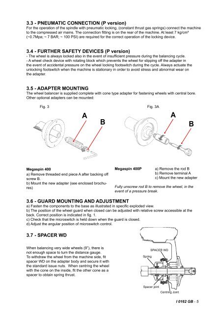
3.5 - ADAPTER MOUNTING<br />
The wheel balancer is supplied complete with cone type adapter <strong>for</strong> fastening wheels with central bore.<br />
Other optional adapters can be mounted:<br />
Fig. 3<br />
A<br />
B<br />
Fig. 3A<br />
A<br />
B<br />
Megaspin 400<br />
a) Remove threaded end piece A after backing off<br />
screw B.<br />
b) Mount the new adapter (see enclosed brochures)<br />
Megaspin 400P<br />
a) Remove the rod B<br />
b) Remove terminal A<br />
c) Mount the new adapter<br />
Fully unscrew rod B to remove the wheel, in the<br />
event of a pressure break.<br />
3.6 - GUARD MOUNTING AND ADJUSTMENT<br />
a) Fasten the components to the base as illustrated in speciÞ c exploded view.<br />
b) The position of the wheel guard when closed can be adjusted with relative screw accessible at the<br />
back. Correct position is indicated in Þ g. 1.<br />
c) Check that the microswitch is held down when the guard is closed.<br />
d) Adjust the angular position of microswitch control.<br />
3.7 - SPACER WD<br />
When balancing very wide wheels (9”), there is<br />
not enough space to turn the distance gauge.<br />
To withdraw the wheel from the machine side, Þ t<br />
spacer WD on the adapter body and secure it with<br />
the standard issue nuts. When centring the wheel<br />
with the cone on the inside, Þ t the other cone as a<br />
spacer to obtain spring thrust.<br />
Spring<br />
SPACER WD<br />
Spacer joint<br />
Centring Joint<br />
I 0162 GB - 5