electronic microprocessor wheel balancer with three-dimensional ...
electronic microprocessor wheel balancer with three-dimensional ... electronic microprocessor wheel balancer with three-dimensional ...
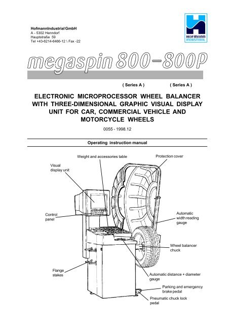
0055 - 1 HofmannIndustrial GmbH A - 5302 Henndorf Hauptstraße 59 Tel +43-6214-6466-12 \ Fax -22 ELECTRONIC MICROPROCESSOR WHEEL BALANCER WITH THREE-DIMENSIONAL GRAPHIC VISUAL DISPLAY UNIT FOR CAR, COMMERCIAL VEHICLE AND MOTORCYCLE WHEELS 0055 - 1998.12 ( Series A ) ( Series A ) Operating instruction manual Weight and accessories table Protection cover Visual display unit Control panel Automatic width reading gauge Wheel balancer chuck Flange stakes Automatic distance + diameter gauge Parking and emergency brake pedal Pneumatic chuck lock pedal
- Page 2 and 3: 2 - 0055 CONTENTS page 1- GENERAL D
- Page 4 and 5: 4 - 0055 Note: Due to international
- Page 6 and 7: 6 - 0055 1.4 - TECHNICAL DETAILS We
- Page 8 and 9: 8 - 0055 4.1 - BRAKE PEDAL Fig. 5 4
- Page 10 and 11: 10 - 0055 5 - WHEEL BALANCER INDICA
- Page 12 and 13: 12 - 0055 5.3 - SETTING THE WHEEL D
- Page 14 and 15: 14 - 0055 Fig. 8D Fig. 8C Manual En
- Page 16 and 17: 16 - 0055 5.4 - USER MANAGEMENT Use
- Page 18 and 19: 18 - 0055 5.5.1 - INDICATION OF EXA
- Page 20 and 21: 20 - 0055 5.5.3 - UNBALANCE OPTIMIS
- Page 22 and 23: 22 - 0055 5.7 - RUN-OUT MEASUREMENT
- Page 24 and 25: 24 - 0055 - ATTENTION - 7 - CALIBRA
- Page 26 and 27: 26 - 0055 8 - ERRORS Opened guard E
- Page 28: EG-Konformitäts-Erklärung Declara
0055 - 1<br />
HofmannIndustrial GmbH<br />
A - 5302 Henndorf<br />
Hauptstraße 59<br />
Tel +43-6214-6466-12 \ Fax -22<br />
ELECTRONIC MICROPROCESSOR WHEEL BALANCER<br />
WITH THREE-DIMENSIONAL GRAPHIC VISUAL DISPLAY<br />
UNIT FOR CAR, COMMERCIAL VEHICLE AND<br />
MOTORCYCLE WHEELS<br />
0055 - 1998.12<br />
( Series A ) ( Series A )<br />
Operating instruction manual<br />
Weight and accessories table<br />
Protection cover<br />
Visual<br />
display unit<br />
Control<br />
panel<br />
Automatic<br />
width reading<br />
gauge<br />
Wheel <strong>balancer</strong><br />
chuck<br />
Flange<br />
stakes<br />
Automatic distance + diameter<br />
gauge<br />
Parking and emergency<br />
brake pedal<br />
Pneumatic chuck lock<br />
pedal
2 - 0055<br />
CONTENTS<br />
page<br />
1- GENERAL DETAILS ..................................................................................................................................................................... 5<br />
1.1 - GENERAL SAFETY PRECAUTIONS ........................................................................................................................... 5<br />
1.1.1 - STANDARD SAFETY DEVICES ............................................................................................................................... 5<br />
1.2 - FIELD OF USE ............................................................................................................................................................. 5<br />
1.3 - OVERALL DIMENSIONS ............................................................................................................................................. 5<br />
1.4 - TECHNICAL DETAILS ................................................................................................................................................. 6<br />
2 - HANDLING, LIFTING ................................................................................................................................................................. 6<br />
3 - SETTING UP ................................................................................................................................................................................ 7<br />
3.1 - SECURING .................................................................................................................................................................. 7<br />
3.2 - POWER CONNECTIONS ............................................................................................................................................. 7<br />
3.3 - PNEUMATIC CONNECTIONS (Model P) ...................................................................................................................... 7<br />
3.4 - FURTHER SAFETY DEVICES (MODEL P) .................................................................................................................. 7<br />
3.5 - FITTING THE FLANGE ................................................................................................................................................. 7<br />
3.6 - FITTING AND ADJUSTING THE PROTECTION COVER (Table 4 - Exploded drawings) ............................................... 7<br />
4 - CONTROLS AND COMPONENTS ............................................................................................................................................... 8<br />
4.1 - BRAKE PEDAL ............................................................................................................................................................ 8<br />
4.2 - PNEUMATIC LOCKING PEDAL (Model P) ................................................................................................................... 8<br />
4.3 - DISTANCE AND DIAMETER MEASUREMENT GAUGE ............................................................................................. 8<br />
4.4 - WIDTH MEASUREMENT GAUGE ............................................................................................................................... 8<br />
4.5 - AUTOMATIC WHEEL POSITIONING ........................................................................................................................... 8<br />
4.6 - CLOCK MANAGEMENT ............................................................................................................................................... 8<br />
4.7 - KEYBOARD ................................................................................................................................................................. 9<br />
5 - WHEEL BALANCER INDICATIONS AND OPERATION ............................................................................................................ 10<br />
5.1 - INITIAL FRAME .......................................................................................................................................................... 10<br />
5.1.2 - SCREEN SAVER FRAME ...................................................................................................................................... 10<br />
5.2 - MENU ACCESS DIAGRAM ....................................................................................................................................... 11<br />
5.3 - SETTING THE WHEEL DIMENSIONS ....................................................................................................................... 12<br />
5.3.1 AUTOMATIC SETTING .............................................................................................................................................. 12<br />
5.3.2 - RETRIEVING STORED MEASUREMENTS ............................................................................................................ 14<br />
5.3.3 - MANUAL SETTING ................................................................................................................................................. 15<br />
5.4 - USER MANAGEMENT ............................................................................................................................................... 16<br />
5.4.1 - USER STORAGE .................................................................................................................................................... 16<br />
5.4.2 - USER RETRIEVAL .................................................................................................................................................. 16<br />
5.5 - 5.4 MEASUREMENT RESULT ................................................................................................................................... 17<br />
5.5.1 - INDICATION OF EXACT POSITION OF CORRECTION WEIGHTS ......................................................................... 18<br />
5.5.2 - "SPLIT" MANAGEMENT ......................................................................................................................................... 19<br />
5.5.3 - IMBALANCE OPTIMISATION .................................................................................................................................. 20<br />
5.5.4 - ALU AND STATIC MODE ........................................................................................................................................ 20<br />
5.5.5 - CORRECTING STATIC IMBALANCE ...................................................................................................................... 21<br />
5.6 - STATISTICS ............................................................................................................................................................... 21<br />
5.7 - RUN-OUT MEASUREMENT (OPTIONAL) .................................................................................................................. 22<br />
6 - SETUP ....................................................................................................................................................................................... 23<br />
6.1 - LANGUAGE ............................................................................................................................................................... 23<br />
6.2 - IMBALANCE MEASUREMENT UNIT ......................................................................................................................... 23<br />
6.3 - IMBALANCE DISPLAY THRESHOLD ........................................................................................................................ 23<br />
6.4 - IMBALANCE DISPLAY STEP ................................................................................................................................... 23<br />
6.5 - SPIN WITH COVER CLOSED .................................................................................................................................... 23<br />
6.6 - SCREEN-SAVER TIME .............................................................................................................................................. 23<br />
6.7 - VISUAL RUN-OUT CHECK ........................................................................................................................................ 23<br />
6.8 - ACOUSTIC ALARM .................................................................................................................................................... 23<br />
6.9 - SETTING THE CLOCK ............................................................................................................................................... 23<br />
FOR EXPERT ENGINEERS ONLY<br />
7 - CALIBRATION AND SPECIAL FUNCTIONS ............................................................................................................................ 24<br />
7.1 - WIDTH MEASUREMENT ENGAGEMENT ................................................................................................................. 24<br />
7.2 - SETTING CUSTOMER AND USER NAME ................................................................................................................ 24<br />
7.3 - RUN-OUT MEASUREMENT ENGAGEMENT ............................................................................................................. 24<br />
7.4 - CALIBRATIONS .......................................................................................................................................................... 24<br />
7.4.1 - GAUGE CALIBRATION .......................................................................................................................................... 24<br />
7.4.2 - FLANGE RUN-OUT CORRECTION ......................................................................................................................... 25<br />
7.4.3 - WHEEL BALANCER CALIBRATION ....................................................................................................................... 25<br />
7.4.4 - SELF-DIAGNOSIS ................................................................................................................................................... 25<br />
7.4.4.1 - ENCODER CONTROL .......................................................................................................................................... 25<br />
8 - ERRORS .................................................................................................................................................................................... 26<br />
9 - ROUTINE MAINTENANCE ......................................................................................................................................................... 27<br />
9.1 - SCHEDULED MAINTENANCE ................................................................................................................................... 27<br />
9.2 - REPLACING THE PROTECTION FUSES .................................................................................................................. 27<br />
- WHEEL BALANCER EXPLODED DRAWINGS<br />
- EC DECLARATION OF CONFORMITY
0055 - 3
4 - 0055<br />
Note: Due to international agreements this machine may not be sold in the following countries:<br />
France, Germany, Italy, USA
0055 - 5<br />
1 - GENERAL DETAILS<br />
1.1 - GENERAL SAFETY PRECAUTIONS<br />
- The <strong>wheel</strong> <strong>balancer</strong> must only be used by authorised and adequately trained personnel.<br />
- The <strong>wheel</strong> <strong>balancer</strong> must not be used for purposes other than those indicated in the manual<br />
- The <strong>wheel</strong> <strong>balancer</strong> must not be modified in any way, excepting modifications explicitly approved by<br />
the manufacturer<br />
- The safety devices must not be removed. Any job carried out on the machine must only be done by<br />
skilled and authorised personnel.<br />
- Avoid cleaning <strong>with</strong> strong jets of compressed air.<br />
- To clean plastic panels or surfaces use alcohol (AVOID LIQUIDS CONTAINING SOLVENTS)<br />
- Before starting the balancing cycle, make sure the <strong>wheel</strong> is correctly secured to the flange.<br />
- The machine operator must not wear loose clothing: Unauthorised persons must not come near the<br />
<strong>wheel</strong> <strong>balancer</strong> during the operating cycle.<br />
- Avoid placing objects in the machine bed that could jeopardise correct <strong>wheel</strong> <strong>balancer</strong> operation.<br />
1.1.1 - STANDARD SAFETY DEVICES<br />
- STOP button for stopping the <strong>wheel</strong> in emergencies<br />
- Highly-resistant, shockproof plastic protection cover; specially designed to prevent counterweights<br />
from flying upwards and hitting the operator.<br />
- A microswitch prevents the machine from being started if the cover is not lowered and stops the motor<br />
when the cover is raised.<br />
1.2 - FIELD OF USE<br />
The <strong>wheel</strong> <strong>balancer</strong> is suitable for balancing car or motor-cycle <strong>wheel</strong>s weighing under 65 kg.<br />
It can be used at temperatures between -10° + 45° C.<br />
It is able to measure radial geometric deformity (run-out) (Optional)<br />
1.3 - OVERALL DIMENSIONS<br />
Fig. 1
6 - 0055<br />
1.4 - TECHNICAL DETAILS<br />
Weight <strong>with</strong> cover (excluding flange)............. 138 kg model 800<br />
..................................................................... 159 kg model 800P<br />
Single-phase power supply ........................... 115-230 V 50-60 Hz<br />
Insulation class ............................................. IP 54<br />
Max. power input ........................................... 500 W<br />
Monitor .......................................................... SVGA 14"<br />
Balancing speed ........................................... - 180 min1<br />
Cycle time for average <strong>wheel</strong> (14 kg) ............ 6 seconds<br />
Balancing precision ...................................... 1 gram<br />
Position resolution ......................................... ± 1.4 °<br />
Mean noise level ........................................... < 70 dB (A)<br />
Rim - machine distance ................................ 0 - 285 mm<br />
Settable rim width .......................................... 1.5" ÷ 20" or 40 ÷ 510 mm<br />
Settable diameter .......................................... 10" ÷ 24" or 265 ÷ 615 mm<br />
Total diameter of <strong>wheel</strong> <strong>with</strong>in cover .............. 1067 mm (42")<br />
Total width of <strong>wheel</strong> <strong>with</strong>in cover ................... 500 mm<br />
Max. <strong>wheel</strong> weight ......................................... 65 kg<br />
Min/max compressed-air pressure ................ 7 ÷ 10 kg/cm 2<br />
~ 0.7 ÷ 1 Mpa;<br />
~ 7 ÷ 10 BAR;<br />
~ 100 ÷ 145 PSI.<br />
2 - HANDLING, LIFTING<br />
NOTE: DO NOT RAISE THE WHEEL BALANCER USING DIFFERENT LIFTING POINTS<br />
Fig. 2<br />
Fig. 3
0055 - 7<br />
3 - SETTING UP<br />
3.1 - SECURING<br />
The machine can operate on any flat non-elastic surface.<br />
Makes sure only the 2 support points (fig. 3) actually touch the floor.<br />
If possible, we recommend securing the machine to the floor by means of the feet (see figure 3).<br />
3.2 - POWER CONNECTIONS<br />
The machine features a single phase and earth lead.<br />
The power voltage (and mains frequency) is shown on the machine identification plate and cannot be<br />
changed.<br />
Mains connection must be done by expert personnel.<br />
The machine must not be started until it is properly earthed<br />
Connection to the power mains must be made using a slow-acting safety switch set at 2A (230V) or 4A<br />
(115V).<br />
3.3 - PNEUMATIC CONNECTIONS (Model P)<br />
To set up operation of the pneumatic clamping chuck (constant thrust gas-operated spring), connect the<br />
<strong>wheel</strong> <strong>balancer</strong> to the compressed-air system. The connection fitting is on the rear of the <strong>wheel</strong> <strong>balancer</strong>.<br />
At least 7 kg per sq cm (~ 7 MPa; ~ 7 BAR; ~ 100 PSI) are needed to ensure correct operation of the<br />
release mechanism.<br />
3.4 - FURTHER SAFETY DEVICES (MODEL P)<br />
- Wheel always locked even in the event of a pressure break during the balancing cycle<br />
- Rotating-block <strong>wheel</strong> clamping device to prevent the <strong>wheel</strong> coming off the flange in the event of<br />
the pneumatic clamping pedal being accidentally pressed during the balancing cycle<br />
Always operate the release control pedal when the machine is at a standstill, thereby preventing<br />
abnormal flange stress and wear.<br />
3.5 - FITTING THE FLANGE<br />
The <strong>wheel</strong> <strong>balancer</strong> features a cone flange for securing <strong>wheel</strong>s <strong>with</strong> centre hole. Other optional flanges can<br />
be fitted:<br />
Fig. 4<br />
A<br />
B<br />
Fig. 4A<br />
A<br />
B<br />
800 a) Remove the threaded end section A after removing<br />
screw B.<br />
b) Fit the new flange<br />
800P<br />
a) Unscrew rod B<br />
b) Unscrew end section A<br />
c) Fit the new flange<br />
3.6 - FITTING AND ADJUSTING THE PROTECTION COVER (Table 4 - Exploded drawings)<br />
a) Secure the components to the bed as described in exploded table 4.<br />
b) The position of the closed cover can be adjusted by means of the screw accessible from the rear. The<br />
correct position is shown in Fig. 1<br />
c) Make sure the microswitch is pressed when the cover is closed.<br />
d) Adjust the angular position of the microswitch control (item 403).
8 - 0055<br />
4.1 - BRAKE PEDAL<br />
Fig. 5<br />
4 - CONTROLS AND COMPONENTS<br />
This enables the operator to hold the <strong>wheel</strong> fast during<br />
counterweight fitting. This must not be operated<br />
during the measurement cycle.<br />
4.2 - PNEUMATIC LOCKING PEDAL (Model P)<br />
Fig. 6<br />
For releasing the <strong>wheel</strong> on the flange. Do not operate<br />
during machine cycle and/or when flanges different to<br />
standard-cone flanges are fitted.<br />
4.3 - DISTANCE AND DIAMETER MEASUREMENT GAUGE<br />
For measuring the distance and the diameter of the <strong>wheel</strong> at the point where the counterweight is fitted.<br />
The same gauge can be used to correctly position the counterweights inside, using the specific function<br />
(see 5.5.1) for visual display-reading the position used for measurement, inside the rim. (For calibration,<br />
see 7.4.1)<br />
4.4 - WIDTH MEASUREMENT GAUGE (OPTION)<br />
For measuring the width of the <strong>wheel</strong> to be balanced at the counterweight fitting point.<br />
(See para. 5.3.1)<br />
4.5 - AUTOMATIC WHEEL POSITIONING<br />
At the end of the spin, the <strong>wheel</strong> is positioned in line <strong>with</strong> the unbalance on the outer sidewall or on the<br />
static (when selected)<br />
Positioning is automatically disabled in the case of <strong>wheel</strong>s below 13" in diameter.<br />
Precision is ± 20 degrees for <strong>wheel</strong>s weighing up to 25 kg<br />
4.6 - CLOCK MANAGEMENT<br />
The <strong>wheel</strong> <strong>balancer</strong> features a clock having an operating-autonomy, <strong>with</strong> the machine off, of about one<br />
month. In the event of the machine being shut off for long periods, when first starting this up, check and, if<br />
necessary, reset the time (see 6.9).
0055 - 9<br />
4.7 - KEYBOARD<br />
Fig. 7<br />
Function keys: for immediate selection of functions shown on screen<br />
Special functions<br />
selection<br />
Confirm<br />
Measurement<br />
cycle start<br />
Machine cycle stop<br />
Note:<br />
Only press the keys <strong>with</strong> fingers; do not use counterweight pliers or other<br />
pointed tools.
10 - 0055<br />
5 - WHEEL BALANCER INDICATIONS AND OPERATION<br />
The screen provides and shows various details, as well as numerous operating options for the operator.<br />
Such information is split into "frames" or "display pages".<br />
5.1 - INITIAL FRAME<br />
Enabled keys<br />
MENU : main functions frame (see 5.2)<br />
: type of correction (see 5.5.4)<br />
: balancing spin (see 5.5)<br />
Dimensions gauge: when this is pulled out, the dimensions frame is selected (see 5.3)<br />
If the machine stays on the initial frame for a time which can be set on the visual display unit <strong>with</strong>out being used,<br />
this will automatically switch to a screen saver. If any key is touched or the <strong>wheel</strong> or distance+diameter gauge<br />
are moved, the screen will automatically switch back to the initial frame. Automatic protection-cover start is not<br />
possible from screen saver for safety reasons.<br />
Note: Name of <strong>wheel</strong> <strong>balancer</strong> owner. This can be set on the visual-display unit (See para. 7.2)<br />
5.1.2 SCREEN SAVER FRAME
0055 - 11<br />
5.2 - MENU ACCESS DIAGRAM<br />
Note:<br />
- the symbol " ... " indicates the presence of another menu<br />
- to return to the previous menu, press key<br />
HOME<br />
STOP<br />
- to return to initial frame press key<br />
MENU<br />
MACHINE PARAMETER SET-UP<br />
Language<br />
English<br />
Unbalance measurement unit<br />
Unbalance visual. threshold<br />
Unbalance visual. step<br />
Spin <strong>with</strong> protection cover closed<br />
Screen saver time<br />
MENU<br />
B<br />
A<br />
User<br />
control<br />
(5.4)<br />
User reference<br />
User save<br />
Optimization<br />
Dimensions<br />
Statistics<br />
Set-up<br />
Special functions<br />
Cancel<br />
Next<br />
G<br />
Cancel<br />
MACHINE PARAMETER SET-UP<br />
Run-out visual check<br />
Acoustic signal<br />
selection<br />
C<br />
D<br />
PASSWORD : + + +<br />
FOR EXPERT PERSONNEL ONLY<br />
SPECIAL FUNCTIONS SELECTIONS<br />
Width measurement<br />
Adhesive weight dispenser<br />
Run-out measurement<br />
Clock setting<br />
user<br />
management<br />
General customer details<br />
User names<br />
Settings<br />
Previous<br />
Cancel<br />
E<br />
Cancel<br />
SETTINGS<br />
Distance<br />
Diameter<br />
Width<br />
F<br />
SETTINGS<br />
Potentiometers<br />
Adhesive weight dispenser<br />
Run-out correction<br />
Wheel-<strong>balancer</strong> self-calibration<br />
Wheel <strong>balancer</strong> self-test<br />
Cancel<br />
Cancel
12 - 0055<br />
5.3 - SETTING THE WHEEL DIMENSIONS<br />
5.3.1 AUTOMATIC SETTING<br />
Manual End<br />
The display page appears showing the distance+diameter measurement gauge.<br />
The "acquired dimension" indication is indicated by the symbol of the correction weight changing from blue to red.<br />
- Standard <strong>wheel</strong>s: Using the special grip, move the end of the gauge against the rim, push the gripper upwards<br />
and wait for the weight symbol on the screen to change from blue to red.<br />
In the case of acoustic signal enabled (see 6.8), dimension acquisition is indicated by a "beep".<br />
Fig. 8<br />
The calibration thus made is required for ALU 1,2,3,4 CTS, Static and Dynamic modes.<br />
Manual setting can be made using the buttons as described at 5.3.3<br />
- Press button to switch to manual width setting:<br />
Select<br />
Unit<br />
End
0055 - 13<br />
- Set the nominal width, normally indicated on the rim, or<br />
determine the width "b" <strong>with</strong> the caliper provided.<br />
- Press button to return to the measurement frame<br />
"AUTOMATIC WIDTH" OPTION<br />
- Move both gauges to measuring position as shown below:<br />
Fig. 8A<br />
DISTANCE+DIAMETER gauge<br />
Fig. 8B<br />
WIDTH gauge<br />
During movement, the symbols of the screen (see fig. 8C/8D) move to show that the gauges are not stable.<br />
- Keep the gauges still in position for about 2 seconds<br />
- Data storage is indicated by the colour of the correction weights which passes from blue to red.<br />
- Return the gauges to idle position.<br />
N.B. - If the symbols in fig. 8C/8D remain on the screen, this means that at least the relevant<br />
measurement gauge is not in idle position.<br />
- The two measurements (distance+diameter and width) can be made at different times. In this case,<br />
first of all determine (distance + diameter). The correct position of the gauge prods is most<br />
important for precise measurement. Wrong distance measurement means wrong width<br />
measurement; compare the calculated measurement <strong>with</strong> the nominal width shown on the rim,<br />
(errors up to ½" do not normally cause substantial problems).
14 - 0055<br />
Fig. 8D<br />
Fig. 8C<br />
Manual End<br />
- ALU-M <strong>wheel</strong> (correction from inside for two balancing levels <strong>with</strong> direct calibration)<br />
After measuring the inner sidewall FI, as shown in fig. 9, further remove the gauge to store the data of the<br />
outer sidewall FE. Note: Once the positions have been achieved, always push the calipers upwards and<br />
hold these still for at least 2 seconds. The counterweight symbols will change colour.<br />
In the event of an acoustic signal being engaged (see 6.8), data acquisition is accompanied by a "beep".<br />
Fig. 9<br />
The enabled buttons are:<br />
Manual dimension setting frame selection<br />
/ HOME<br />
STOP<br />
Return to initial frame.<br />
Balancing spin<br />
5.3.2 RETRIEVING STORED MEASUREMENTS<br />
\ \ \ Press the name button and then:<br />
- press to retrieve stored measurements (5.4), ignoring other measurements<br />
made in the meantime.<br />
- press to save the currently set dimensions
0055 - 15<br />
5.3.3 - MANUAL SETTING (Only use in special cases or for checking)<br />
Unit<br />
If necessary, dimensions can be entered or changed manually as follows:<br />
- press MENU + or press from automatic dimensions frame (accessible by pulling out<br />
the distance + diameter gauge);<br />
- press to select the dimension to be set (displayed in red);<br />
- press / to set the desired value;<br />
- press to change the unit of measurement.<br />
Definition of dimensions:<br />
= DIAMETER : Set the nominal diameter indicated on the rim.<br />
= WIDTH : Set the nominal width shown on the rim<br />
= DISTANCE : With gauge idle, determine the distance in cm of the machine <strong>wheel</strong>. Set the<br />
value removing 1.5 cm.<br />
Fig. 10
16 - 0055<br />
5.4 - USER MANAGEMENT<br />
User save<br />
Cancel<br />
The <strong>wheel</strong> <strong>balancer</strong> can be used at the same time by 4 different users who, by means of a simple<br />
sequence can store their work condition and retrieve this in case of need. The names of the users can be<br />
stored (7.2)<br />
5.4.1 - USER STORAGE<br />
- Correctly set the dimensions as already described at paragraphs 5.3.1 and 5.3.3<br />
- Press MENU ; the "MENU" window will appear on the screen<br />
- Press ; the window will display a list of available USERS. The current USER is indicated in red.<br />
- Press the number indicating the desired USER. The system will automatically return to the initial frame.<br />
5.4.2 - USER RETRIEVAL<br />
- Make a measurement spin <strong>with</strong> any dimensions<br />
- Press the MENU button ; the "MENU" window will appear on the screen<br />
- Press , the window will display a list of available USERS. The current USER is indicated in red.<br />
- Press the number indicating the desired USER. The system will automatically return to the initial frame <strong>with</strong><br />
recalculation of the unbalance values based on the actual dimensions of the retrieved USER.<br />
- Alternatively, proceed as indicated at paragraph 5.3.2<br />
N.B. :<br />
- the dimensions stored as USER are lost when the machine is switched off;<br />
- USER management is also valid for ALU-M dimensions;<br />
- the current USER is always displayed on the measurement and dimension frames
0055 - 17<br />
5.5 - MEASUREMENT RESULT<br />
Fine<br />
After making a balancing spin, the unbalance values are displayed along <strong>with</strong> arrows useful for positioning at<br />
the point of application of the correction weight. After positioning the <strong>wheel</strong>, fit the weight upwards along the<br />
vertical.<br />
In the event of minor unbalance of the set threshold value, instead of the unbalance value, "OK" is displayed<br />
to indicate that, on that sidewall, the <strong>wheel</strong> is <strong>with</strong>in tolerance levels; by pressing<br />
can be displayed, <strong>with</strong> a precision of 0.5 g (0.1 oz).<br />
, the outstanding value<br />
The enabled buttons are:<br />
Outstanding balance display<br />
Correction procedure selection (DYNAMIC, STATIC, ALU1, ALU2, ALU3, ALU4, CTS). By<br />
changing procedure, the automatic recalculation occurs of the unbalance values in accordance<br />
<strong>with</strong> the previous spin (5.5.4).<br />
Run-out measurement graph (optional)<br />
Imbalance division management on settable components (5.5.2). Button only enabled <strong>with</strong><br />
STATIC or ALU M correction.<br />
Longitudinal unbalance position (5.5.1) enabled<br />
MENU<br />
Selection of special functions<br />
Balancing spin<br />
N.B.: If the machine stays in this frame <strong>with</strong>out being used for longer than the time set in the Setup<br />
parameters (6), the frame automatically returns to screen-saver.
18 - 0055<br />
5.5.1 - INDICATION OF EXACT POSITION OF CORRECTION WEIGHTS<br />
It is always best to use this function for correcting unbalance using adhesive weights: ALU 1, ALU 2, ALU<br />
3, ALU M.<br />
This function is designed to cancel any approximation in fitting counterweights, <strong>with</strong> consequent reduction<br />
of outstanding unbalance.<br />
- Press button on the measurement panel<br />
- Remove the distance+diameter gauge. Movement of the weight towards the correction position is<br />
indicated by a coloured arrow that moves [ ].<br />
- Once a fixed arrow [ ] has been reached, turn the <strong>wheel</strong> to correction position (FI or FE) and fit the<br />
counterweight, turning the clamp upwards until this attaches to the <strong>wheel</strong>.<br />
In the event of the acoustic alarm being engaged (see 6.8), when a fixed arrow [<br />
"beep" is heard.<br />
] is reached, a<br />
Fig. 11
0055 - 19<br />
5.5.2 - "SPLIT" MANAGEMENT<br />
SPLIT is only possible in the case of outer sidewall static or ALU-M unbalance. Its purpose is to hide any<br />
unbalance correction adhesive weights behind the spokes of the rim.<br />
input<br />
SETTING THE NUMBER OF RIM SPOKES<br />
- Press on the STATIC or ALU-M measurement panel;<br />
- - A window will appear on the screen indicating the number of spokes currently set<br />
- Set the number of desired spokes in a range between 3-12 by means of button and<br />
- press to confirm the setting<br />
- Move a spoke upwards along the vertical<br />
- press ;the measurement panel will reappear on the screen <strong>with</strong> the unbalance figures already split up.<br />
The inner sidewall ALU-M unbalance does not vary, while for the outer sidewall STATIC and ALU-M unbalance,<br />
two weights appear for the same sidewall:<br />
- slowly turn the <strong>wheel</strong> until an unbalance figure appears;<br />
- fit an adhesive weight of the displayed value, for the outer sidewall or STATIC, behind the spoke uppermost<br />
along the vertical;<br />
- again turn the <strong>wheel</strong> until a new unbalance value appears;<br />
- fit an adhesive weight of the displayed value, for the outer sidewall or STATIC, behind the spoke uppermost<br />
along the vertical;<br />
- make a spin to check correct <strong>wheel</strong> balance.<br />
Note: if SPLIT is engaged, the icon<br />
will appear in the lower part of the screen.
20 - 0055<br />
5.5.3 - UNBALANCE OPTIMISATION<br />
UNBALANCE OPTIMISATION<br />
IMPORTANT!!! The previous spin must have been made<br />
<strong>with</strong> the currently fitted <strong>wheel</strong>s.<br />
Make a reference mark to indicate the rim-flange position<br />
in order to refit the rim on the flange in the same position.<br />
Remove the <strong>wheel</strong> from the <strong>wheel</strong> <strong>balancer</strong>.<br />
Turn the tyre by 180° on the rim.<br />
Refit the <strong>wheel</strong> on the <strong>wheel</strong> <strong>balancer</strong> so the rim and<br />
flange references coincide.<br />
Close the cover and press (START)<br />
End<br />
The symbol<br />
is automatically displayed for static unbalance over 30 grams (1.1 oz). The program allows<br />
reducing total <strong>wheel</strong> unbalance, offsetting, whenever possible, the tyre unbalance <strong>with</strong> that of the rim. Two spins<br />
are required <strong>with</strong> rotation of the tyre on the rim at the second spin.<br />
Press MENU +<br />
after making the first spin and follow the instructions that appear on the screen.<br />
5.5.4 - ALU AND STATIC MODE<br />
Press button<br />
: on the measurement panel: a window will appear on the screen showing the mode options.<br />
Select the type required by means of the numeric buttons. Return to measurement panel <strong>with</strong> recalculated figures<br />
is automatic. The upper section of the screen always shows a symbol indicating the enabled fitting position of<br />
the weights.<br />
TYPE OF CORRECTION<br />
Static<br />
Dynamic
0055 - 21<br />
NORMAL<br />
Balancing steel or light-alloy rims <strong>with</strong> the fitting of weights <strong>with</strong> clips<br />
on the rim edges<br />
STATIC<br />
STATIC correction is required in the case of motorcycle <strong>wheel</strong>s or when<br />
it is not possible to fit counterweights on the two sides of the rim<br />
ALU - 1<br />
Balancing of light-alloy rims <strong>with</strong> the fitting of adhesive weights on the<br />
shoulder of the rims.<br />
12/13 mm<br />
support table<br />
ALU - 2<br />
ALU - 3<br />
ALU - 4<br />
Balancing of light-alloy rims <strong>with</strong> hidden fitting of outer adhesive weight.<br />
The position of the outer weight is fixed.<br />
Combined balancing: clip weight on inner sidewall and hidden adhesive<br />
weight on outer sidewall (Mercedes). The position of the outer weight<br />
is the same as ALU - 2.<br />
Combined balancing: adhesive weight on outer sidewall, clip weight on<br />
inner sidewall.<br />
CTS<br />
Special balancing <strong>with</strong> clip-in adhesive weights between the edge of the<br />
tyre and the rim, for both sidewalls.<br />
5.5.5 - CORRECTING STATIC UNBALANCE<br />
Selected from set-up, this optimizes the outstanding unbalance, correcting a <strong>wheel</strong> <strong>with</strong> standard counterweights<br />
5 grams at a time (1/4 ounces).<br />
Thanks to this special function, the position and best correction value is calculated so as to correct static<br />
unbalance, which is the biggest cause of vibrations felt inside the vehicle.<br />
5.6 - STATISTICS<br />
NUMBER OF DAILY SPINS:<br />
this indicates the number of spins made since the<br />
<strong>wheel</strong> <strong>balancer</strong> was started up. This parameter is<br />
automatically reset when the machine is turned off.<br />
NUMBER OF TOTAL SPINS:<br />
this indicates the number of spins made since the<br />
last counter reset. This parameter remains stored in<br />
the memory even when the machine is turned off.<br />
The enabled buttons are:<br />
: for resetting the number of daily spins<br />
: for resetting the number of total spins.<br />
Requires the correct setting of a password;<br />
STATISTICS<br />
Number of daily spins<br />
Number of total spins<br />
Daily spin reset<br />
Total spin reset<br />
Cancel<br />
HOME<br />
STOP<br />
: to return to previous frame (MENU);<br />
MENU : to return to measurement panel.
22 - 0055<br />
5.7 - RUN-OUT MEASUREMENT (OPTIONAL)<br />
The figures indicate the, much amplified, outer surface of the tyre and the <strong>wheel</strong> rotation axis.<br />
Fig. A shows total Peak-Peak run-out<br />
measurement, defined as maximum radial<br />
deviation of the tyre surface.<br />
Fig. B shows the 1st harmonic run-out<br />
measurement, or the run-out of the rim that<br />
"recopies" the shape of the tyre, mediating the<br />
local deviations of the tyre from round shape.<br />
Fig. A<br />
Epp<br />
Fig. B<br />
E1h<br />
Obviously, the P.P. measurement is normally<br />
greater than the 1st harmonic. Tyre manufacturers normally provide two different tolerances for the two<br />
run-outs.<br />
After making a balancing spin, the measurement of the tyre run-out can be made automatically by means<br />
of the SONAR sensor on the cover. The sensor must be manually positioned in front of the tread.<br />
RUN OUT<br />
Max./Min.<br />
GRAPH 1 - (yellow)<br />
GRAPH 2 - (red)<br />
1st harmonic<br />
Position<br />
End<br />
GRAPH 1<br />
GRAPH 2<br />
: represents the real Peak-Peak run-out<br />
: represents the first harmonic run-out. For a <strong>wheel</strong> in good condition, this graph should appear<br />
almost as a straight line.<br />
By moving the <strong>wheel</strong>, the cursor indicates current value, <strong>with</strong> the phase referring to the<br />
correction point.<br />
For 1st harmonic, the maximum deviation usually should not<br />
exceed 1,2 mm. In the latest software the sysmbol above button<br />
no. 4 changes to red as soon as this value is too high.
0055 - 23<br />
6 - SETUP<br />
(See 5.2 - Menu access diagram)<br />
The Setup frame provides the user <strong>with</strong> numerous options for setting the machine according to his needs.<br />
All the settings remain unaltered even when the machine is switched off.<br />
The enabled buttons are :<br />
HOME<br />
STOP<br />
: return to previous window<br />
MENU : go to measurement frame;<br />
from to : to select parameter<br />
6.1 - LANGUAGE<br />
Permits selecting the language to be used for displaying description and diagnostic messages relating to<br />
machine operation.<br />
6.2 - UNBALANCE MEASUREMENT UNIT<br />
Imbalances can be expressed in either grams or ounces<br />
6.3 - UNBALANCE DISPLAY THRESHOLD<br />
This is the unbalance threshold under which, at the end of the spin the message "OK" appears on the screen<br />
instead of the unbalance value; the values which can be set vary according to the selected measurement unit.<br />
6.4 - UNBALANCE DISPLAY STEP<br />
Represents the unbalance display step and varies according to the selected measurement unit. The choice 5<br />
g" (1/4 oz) enables the display of the correction values on the two sidewalls so as to bring the value of static<br />
unbalance to 0 (theoretical). This function is best set when the machine is used in standard mode as the balancing<br />
quality is improved. The computer performs a complex calculation whereby the static residue is cancelled by<br />
changing the value and position of the fixed value counterweights 5 grams at a time (1/4 ounces).<br />
6.5 - SPIN WITH COVER CLOSED<br />
By selecting "ON", the automatic spin start is engaged when the cover is closed.<br />
6.6 - SCREEN-SAVER TIME<br />
When the machine has not been used for longer than the time set in this function, the computer automatically<br />
returns to the initial frame. Set this time in seconds.<br />
6.7 - VISUAL RUN-OUT CHECK<br />
At the end of the spin, when the measured unbalance values re-appear on the screen, the cover can be opened<br />
to visually check the <strong>wheel</strong> run-out while the <strong>wheel</strong> gradually loses speed. If, on the other hand, the cover is left<br />
closed, the machine completes normal positioning.<br />
6.8 - ACOUSTIC ALARM<br />
By selecting "ON", an acoustic alarm is enabled (beep) in the following cases:<br />
- whenever a button is pressed;<br />
- when dimensions are acquired automatically;<br />
- when the correct weight application angular position is achieved, in the measurement frame;<br />
- when the correct weight application angular position is achieved, in the position repeater.<br />
6.9 - SETTING THE CLOCK<br />
For correctly setting the time. Follow the instructions shown on the screen.
24 - 0055<br />
- ATTENTION -<br />
7 - CALIBRATION AND SPECIAL FUNCTIONS<br />
(see access diagram 5.2)<br />
In order to access the "Settings and special functions", a password must be entered.<br />
Any wrong operation <strong>with</strong>in the functions shown below could damage <strong>wheel</strong> <strong>balancer</strong> operation.<br />
Unauthorised use will invalidate the machine warranty.<br />
7.1 - WIDTH MEASUREMENT ENGAGEMENT<br />
Engages/disengages automatic width measurement by means of a contact device. Select:<br />
- OFF in the case of machine <strong>with</strong> manual width measurement;<br />
- TOUCH in the case of machine <strong>with</strong> automatic width measurement (OPTIONAL).<br />
7.2 - SETTING CUSTOMER AND USER NAME<br />
The machine can be customised by setting:<br />
a) The name to appear in the initial frame (screen-saver).<br />
b) The name of 4 different <strong>wheel</strong> <strong>balancer</strong> users (USER NAME)<br />
The screen will show an "ideal" keyboard <strong>with</strong> the set of characters available for writing messages.<br />
The customer's name consists of 3 lines of at most 30 characters each.<br />
User names have at most 15 characters each.<br />
7.3 - RUN-OUT MEASUREMENT ENGAGEMENT<br />
Engages/disengages tyre run-out measurement during the unbalance measurement spin<br />
7.4 - CALIBRATIONS<br />
By pressing<br />
from the special functions menu, the calibration menu can be accessed<br />
7.4.1- GAUGE CALIBRATION<br />
Select the gauge to be calibrated and follow the instructions on the screen.<br />
Note:<br />
- when calibrating the diameter gauge, it is most important to position the gauge correctly as shown in<br />
figure 8.
0055 - 25<br />
7.4.2 - FLANGE RUN-OUT CORRECTION<br />
This <strong>electronic</strong>ally compensates any systematic balancing error due, for instance, to flange run-out. It is<br />
not able to compensate for worn flanges or <strong>with</strong> play.<br />
Do not use unless advised to do so by skilled personnel. Follow the instructions shown on the screen.<br />
When this function is engaged, the icon<br />
appears in the lower part of the screen.<br />
7.4.3 - WHEEL BALANCER CALIBRATION<br />
To calibrate the machine, proceed as follows:<br />
- Mount an iron <strong>wheel</strong> of average size, example 6''x14'' (±1''). It does not have to be perfectly balanced.<br />
- VERY CAREFULLY set the <strong>wheel</strong> dimensions<br />
- Follow the instructions on the screen<br />
7.4.4 - SELF-DIAGNOSIS<br />
This automatic self-diagnosis cycle facilitates troubleshooting. At the end of the self-diagnosis, numerous<br />
parameters are indicated which are useful to the after-sales service for finding machine faults.<br />
HOME<br />
STOP<br />
Return to previous menu<br />
7.4.4.1 - ENCODER CONTROL<br />
In turning the chuck must:<br />
- change the angular position "POS" from 0 to 128;<br />
- cause the "UP" message to appear by turning the <strong>wheel</strong> clockwise and the "DOWN" message to appear<br />
by turning the <strong>wheel</strong> in the other direction<br />
Encoder control<br />
Diameter gauge function<br />
control: the number increases<br />
by turning the gauge outwards<br />
Distance gauge<br />
function control: the<br />
number increases when<br />
the gauge is removed.<br />
Run-out sonar control (optional):<br />
the number drops when<br />
a surface is moved near the<br />
sonar<br />
End<br />
Width gauge function control:<br />
the number drops when the<br />
gauge is moved near the flange<br />
In the event of a <strong>wheel</strong> <strong>balancer</strong> fault or malfunction, notify all displayed parameters to the After-sales service.
26 - 0055<br />
8 - ERRORS<br />
Opened guard<br />
ERROR<br />
MEANING<br />
1 No rotation signal. This could be due to a faulty position transducer, to the motor not<br />
having started or to something stopping the <strong>wheel</strong> from turning.<br />
2 During spin, the speed drops below 60 1/min. Repeat the spin.<br />
3 Mathematical calculation error, very likely caused by incorrect self-calibration. Repeat<br />
self-calibration. Wheel unbalances too high.<br />
4 Motor turning in wrong direction.<br />
5 Protection cover open before start of spin<br />
7/8/9 Machine setup parameter error.<br />
Check basic setting parameters are correct and repeat <strong>wheel</strong> <strong>balancer</strong> calibration.<br />
Contact after-sales service.<br />
11 Speed too high for reading<br />
12/13/14 Reading counter overflow. Contact the after-sales service<br />
15/16/17/18 Contact the after-sales service<br />
20 Wheel stops before having positioned<br />
30 Screen clock management error<br />
40÷53 Run-out measurement graph management error.
0055 - 27<br />
9 - ROUTINE MAINTENANCE<br />
9.1 - SCHEDULED MAINTENANCE<br />
Before performing any maintenance operation, interrupt power to the machine<br />
9.2 - REPLACING THE PROTECTION FUSES<br />
Accessible by removing the weight carrying table, the power and power supply board features 4 protection<br />
fuses (see exploded Tables, Item 317). In the event of these having to be replaced, fuses of identical<br />
current carrying capacity must be used. If the fault reoccurs, contact the after-sales service.<br />
THE OTHER MACHINE PARTS REQUIRE NO MAINTENANCE
EG-Konformitäts-Erklärung<br />
Declaration of Conformity<br />
Déclaration de Conformité<br />
The Company / Hiermit bescheinigt das Unternehmen / La Maison<br />
HofmannIndustrial GMBH<br />
Hauptstraße 59<br />
A-5302 Henndorf<br />
here<strong>with</strong> declares conformity of the Products /erklärt hiermit die Konformität desProdukts / déclare par la présente la<br />
conformité du Produit / Declare la conformidad del Producto/erklærrer hermed overensstemmelse for<br />
produktet/Försäkrar härmed överensstämmelse för produkten:<br />
Balancer -Auswuchtmaschine -<br />
Equilibreuse - Balanceadora - Hjul<strong>balancer</strong>ingsmaskine - Balanseringsmaskin<br />
Tipo - Nr. di serie / Type - Serial Number / Typ - Fabriknummer, usw / Type - Numero de série / Tipo - Numero de<br />
fabricacion/ af typen / Typ-Serienummer<br />
megaspin 800 - 800P<br />
Manufacturing List Number-Erstellungsliste nummer-Numéro de liste de construction<br />
Numero de fabricacion-Fremstillingslistenummeret- Tillverkningsnummer<br />
A/B/C<br />
900M800B2/6 - 905M800B2/6<br />
<strong>with</strong> applicable regulations below / mit folgenden einschlägigen Bestimmungen /<br />
selon les normes ci-dessous / con directivas subaplicables/i henhold til folgende direktiver/med följande direktiv:<br />
D.P.R. Nr. 459, from 24 July 1996<br />
EC Directive / EG Richtlinie / Directive CEE / Directivas CE/EOF Direktivet/EEG direktiv<br />
98/37/CEE - 73/23/CEE - 93/68/CEE - 89/336/CEE<br />
Applied Armonized Standards / Angewendete Harmonisierte Normen /<br />
Normes Harmonisées Appliquées / Normas Aplicadas en Conformidad/Folgende harmoniserede standarder/följande harmoniserade<br />
standarder<br />
EN 292-1 EN 292-2 EN 294 EN 349<br />
EN 418 EN 457 EN 60204-1 EN 60439-1<br />
EN 50081-1 EN 50082-1 EN 50081-2 EN 50082-2<br />
Date / Datum / Date / Fecha/Dato/Datum<br />
Signature / Unterschrift /Signature/Firma/Underskrift<br />
20/ 0 4 / 9 9 HOFMANN INDUSTRIAL<br />
Dipl.Wirt.-Ing. Peter Dau


