TCM Critical Service Bulletin CSB 99-6A
TCM Critical Service Bulletin CSB 99-6A
TCM Critical Service Bulletin CSB 99-6A

You also want an ePaper? Increase the reach of your titles
YUMPU automatically turns print PDFs into web optimized ePapers that Google loves.
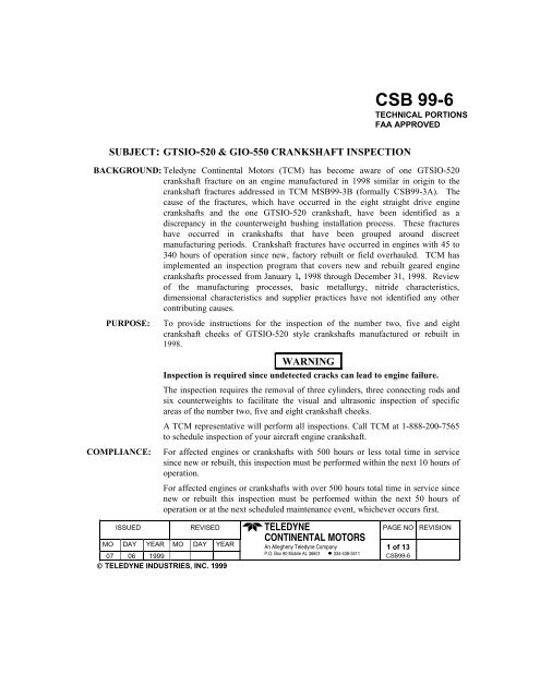
SUBJECT: GTSIO-520 & GIO-550 CRANKSHAFT INSPECTION<br />
BACKGROUND: Teledyne Continental Motors (<strong>TCM</strong>) has become aware of one GTSIO-520<br />
crankshaft fracture on an engine manufactured in 1<strong>99</strong>8 similar in origin to the<br />
crankshaft fractures addressed in <strong>TCM</strong> MSB<strong>99</strong>-3B (formally <strong>CSB</strong><strong>99</strong>-3A). The<br />
cause of the fractures, which have occurred in the eight straight drive engine<br />
crankshafts and the one GTSIO-520 crankshaft, have been identified as a<br />
discrepancy in the counterweight bushing installation process. These fractures<br />
have occurred in crankshafts that have been grouped around discreet<br />
manufacturing periods. Crankshaft fractures have occurred in engines with 45 to<br />
340 hours of operation since new, factory rebuilt or field overhauled. <strong>TCM</strong> has<br />
implemented an inspection program that covers new and rebuilt geared engine<br />
crankshafts processed from January 1, 1<strong>99</strong>8 through December 31, 1<strong>99</strong>8. Review<br />
of the manufacturing processes, basic metallurgy, nitride characteristics,<br />
dimensional characteristics and supplier practices have not identified any other<br />
contributing causes.<br />
PURPOSE:<br />
COMPLIANCE:<br />
To provide instructions for the inspection of the number two, five and eight<br />
crankshaft cheeks of GTSIO-520 style crankshafts manufactured or rebuilt in<br />
1<strong>99</strong>8.<br />
WARNING<br />
Inspection is required since undetected cracks can lead to engine failure.<br />
The inspection requires the removal of three cylinders, three connecting rods and<br />
six counterweights to facilitate the visual and ultrasonic inspection of specific<br />
areas of the number two, five and eight crankshaft cheeks.<br />
A <strong>TCM</strong> representative will perform all inspections. Call <strong>TCM</strong> at 1-888-200-7565<br />
to schedule inspection of your aircraft engine crankshaft.<br />
For affected engines or crankshafts with 500 hours or less total time in service<br />
since new or rebuilt, this inspection must be performed within the next 10 hours of<br />
operation.<br />
For affected engines or crankshafts with over 500 hours total time in service since<br />
new or rebuilt this inspection must be performed within the next 50 hours of<br />
operation or at the next scheduled maintenance event, whichever occurs first.<br />
ISSUED REVISED PAGE NO REVISION<br />
MO DAY YEAR MO DAY YEAR<br />
TELEDYNE<br />
CONTINENTAL MOTORS<br />
An Allegheny Teledyne Company<br />
1 of 13<br />
07 06 1<strong>99</strong>9<br />
P.O. Box 90 Mobile AL 36601 334-438-3411<br />
<strong>CSB</strong><strong>99</strong>-6<br />
TELEDYNE INDUSTRIES, INC. 1<strong>99</strong>9<br />
<strong>CSB</strong> <strong>99</strong>-6<br />
TECHNICAL PORTIONS<br />
FAA APPROVED
Uninstalled service spare crankshafts of the affected serial number range must be<br />
inspected prior to installation in any engine in accordance with DETAILED<br />
INSPECTION, Section C, of this bulletin.<br />
ENGINES<br />
AFFECTED:<br />
Your engine is subject to this <strong>CSB</strong> if either of the following criteria is<br />
satisfied.<br />
1. Your engine is a <strong>TCM</strong> GTSIO-520-C, D, F, G, H, K, L, M, N or GIO-550-A<br />
series New or Rebuilt engine and the engine crankshaft was processed by <strong>TCM</strong><br />
during calendar year 1<strong>99</strong>8. Specific engine models and serial numbers are<br />
provided in the following table “AFFECTED ENGINE MODEL AND<br />
SERIAL NUMBERS”. This listing includes engines assembled in 1<strong>99</strong>9<br />
utilizing crankshaft processed during calendar year 1<strong>99</strong>8.<br />
2. Your engine is a <strong>TCM</strong> GTSIO-520-C, D, F, G, H, K, L, M, N or GIO-550-A<br />
series engine that had a 1<strong>99</strong>8 <strong>TCM</strong> manufactured new crankshaft installed<br />
during field overhaul or repair. See “CRANKSHAFT SERIAL NUMBER<br />
IDENTIFICATION” on page three (3) for means of identifying affected<br />
crankshafts.<br />
Note: Rebuilt engines assembled utilizing rebuilt crankshafts processed between January 1, 1<strong>99</strong>8<br />
and December 31, 1<strong>99</strong>8 may not contain the “98” identification as a part of the crankshaft<br />
serial number. These affected engines are identified by engine model and engine serial<br />
number in the following tabular listing and must comply with this <strong>Critical</strong> <strong>Service</strong><br />
<strong>Bulletin</strong>.<br />
AFFECTED ENGINE MODELS and SERIAL NUMBERS<br />
ENGINE MODEL SERIAL NUMBER<br />
GTSIO-520-D 219475 thru 219477<br />
GTSIO-520-H 267476 thru 267490<br />
267492 thru 2674<strong>99</strong><br />
607111, 607112,<br />
817501 thru 817504, 817512<br />
GTSIO-520-L 292307 thru 292318<br />
292320 thru 292331<br />
292333, 292336 thru 292366,<br />
292368, 292369,<br />
292371 thru 292380<br />
ISSUED REVISED PAGE NO REVISION<br />
MO DAY YEAR MO DAY YEAR<br />
TELEDYNE<br />
CONTINENTAL MOTORS<br />
An Allegheny Teledyne Company<br />
2 of 13<br />
07 06 1<strong>99</strong>9<br />
P.O. Box 90 Mobile AL 36601 334-438-3411<br />
<strong>CSB</strong><strong>99</strong>-6<br />
TELEDYNE INDUSTRIES, INC. 1<strong>99</strong>9
GTSIO-520-M 613083, 810618 thru 810625,<br />
810627 thru 810632,<br />
810634 thru 810644,<br />
810646 thru 810649, 810651,<br />
810652, 810657 thru 810666,<br />
810668 thru 810672, 810674<br />
GTSIO-520-N 808311, 808315, 808316,<br />
808318 thru 808320,<br />
808323 thru 808328,<br />
808330 thru 808332, 808334,<br />
808336 thru 808339, 808340,<br />
808343<br />
Note: If your engine has recently had a crankshaft installed that may have been manufactured from<br />
January 1, 1<strong>99</strong>8 through December 31, 1<strong>99</strong>8, the crankshaft serial number must be verified to<br />
determine if this inspection procedure applies. Review engine logbook or maintenance records<br />
for the crankshaft serial number installed in your engine. If you are not able to determine the<br />
serial number of the crankshaft installed in your engine, you must removed the number 2<br />
cylinder from the engine. Crankshaft serial numbers are located on the number two<br />
crankshaft cheek.<br />
CRANKSHAFT SERIAL NUMBER IDENTIFICATION<br />
Crankshaft serial numbers incorporate a manufacturing date. Crankshafts produced in 1<strong>99</strong>8 may be identified<br />
as follows:<br />
Code:<br />
Month Day Year Sequence Denotes Crankshaft<br />
AXX98XXN<br />
All crankshafts with serial numbers beginning with the letters A through L (Jan. through Dec.) in the first<br />
position and the year code 98 in the fourth and fifth position are affected.<br />
ISSUED REVISED PAGE NO REVISION<br />
MO DAY YEAR MO DAY YEAR<br />
TELEDYNE<br />
CONTINENTAL MOTORS<br />
An Allegheny Teledyne Company<br />
3 of 13<br />
07 06 1<strong>99</strong>9<br />
P.O. Box 90 Mobile AL 36601 334-438-3411<br />
<strong>CSB</strong><strong>99</strong>-6<br />
TELEDYNE INDUSTRIES, INC. 1<strong>99</strong>9
GENERAL INFORMATION:<br />
INSPECTION OF NEW AND REBUILT<br />
AFFECTED ENGINES AND ENGINES THAT<br />
HAVE BEEN OVERHAULED OR REPAIRED<br />
UTILIZING THE SERIAL NUMBERED<br />
CRANKSHAFTS SPECIFIED IN THIS<br />
CRITICAL SERVICE BULLETIN.<br />
WARNING<br />
The inspection required by this service<br />
bulletin is intended to detect conditions which<br />
if present and left uncorrected can result in<br />
engine failure.<br />
PRE-INSPECTION:<br />
1. a. Turn the master switch Off.<br />
b. Turn magneto switches Off.<br />
c. Close the throttle.<br />
d. Place mixture control in the Idle Cutoff<br />
position.<br />
e. Disconnect the aircraft battery.<br />
2. Remove the engine cowling in accordance with<br />
the aircraft manufacturer's maintenance manual<br />
to gain access to the engine.<br />
3. Disconnect all spark plug leads from spark plugs<br />
to prevent engine firing.<br />
4. Disconnect and remove the starter motor from<br />
the starter adapter. This will facilitate turning<br />
the engine through by hand.<br />
5. Remove engine baffling and engine mounted<br />
equipment, as required, to facilitate removal of<br />
cylinders number one, three and five.<br />
Note: The alternator does not require removal.<br />
Remove cylinders number one, three and five in<br />
accordance with the applicable engine maintenance<br />
manual, overhaul manual or aircraft manufacturer's<br />
maintenance manual. Remove the cylinder only far<br />
enough to expose the piston pin. Push the piston<br />
pin out of the connecting rod bushing only far<br />
enough to release the piston and piston pin from<br />
ISSUED REVISED PAGE NO REVISION<br />
MO DAY YEAR MO DAY YEAR<br />
the connecting rod, leaving the piston in the<br />
cylinder.<br />
6. The number one, three and five connecting rods<br />
will have to be removed to perform the<br />
inspection.<br />
Note: Place a clean shop towel through the<br />
cylinder opening below the crankshaft to catch any<br />
items that may be dropped.<br />
TELEDYNE<br />
CONTINENTAL MOTORS<br />
An Allegheny Teledyne Company<br />
WARNING<br />
Anything dropped in the engine must be<br />
removed.<br />
7. Position the connecting rod to be removed<br />
(number one, three or five) at or near top center.<br />
See Figure 1.<br />
Note: Connecting rod nuts may be secured with<br />
cotter pins or they may have Spiralock nuts, which<br />
do not have cotter pins. When removing Spiralock<br />
nuts, you may find it necessary to tighten the nut<br />
slightly to release the self-locking feature. The<br />
Spiralock nuts removed to facilitate this inspection<br />
may be reinstalled provided there is no mechanical<br />
damage to the nut threads and the nut flats are not<br />
rounded.<br />
8. Remove, if utilized, the connecting rod nut cotter<br />
pins and discard them. Remove the connecting<br />
rod nuts.<br />
9. Carefully separate the connecting rod from the<br />
connecting rod cap. Support the connecting rod<br />
cap while removing the connecting rod from the<br />
crankshaft. Repeat this procedure for the other<br />
connecting rods. Connecting rod bearing inserts<br />
do not require replacement unless damaged.<br />
10. Position the crankshaft so that the rearward (aft)<br />
snap rings and plates of each counterweight can<br />
be removed. Using a pair of snap ring pliers,<br />
remove and discard the two snap rings. Remove<br />
the two retaining plates. See Figure 2. Do not<br />
discard retaining plates, they will be reinstalled<br />
in their original location after completing the<br />
inspection. Place masking tape or an equivalent<br />
adhesive tape over the counterweight pin bores<br />
4 of 13<br />
07 06 1<strong>99</strong>9<br />
P.O. Box 90 Mobile AL 36601 334-438-3411<br />
<strong>CSB</strong><strong>99</strong>-6<br />
TELEDYNE INDUSTRIES, INC. 1<strong>99</strong>9
so that the counterweight pins will not exit the<br />
counterweight as the crankshaft is rotated during<br />
the visual and ultrasonic inspection. Document<br />
the location of the removed counterweight<br />
retaining plates. They must be reinstalled in the<br />
location from which they were removed<br />
Note: Counterweights will not clear the crankcase<br />
and cannot be removed from the engine.<br />
CAUTION<br />
Use caution when turning crankshaft with a loose<br />
counterweight.<br />
DETAILED INSPECTION:<br />
A. VISUAL INSPECTION:<br />
1. Rotate the crankshaft so that the crankshaft<br />
cheek to be inspected is positioned as shown in<br />
Figure 4. The crankshaft connecting rod journal<br />
will be at the 8 o’clock position and the<br />
counterweight hanger blades will be at the 11<br />
o’clock and 5 o’clock positions.<br />
2. Using a retrieval magnet, remove the<br />
counterweight pins on the crankshaft cheek to be<br />
inspected. Document the location of the<br />
removed counterweight pins. They must be<br />
reinstalled in the location from which they were<br />
removed. See Figure 3.<br />
3. Position counterweights as shown in Figure 4.<br />
4. Using a soft shop towel dampened with solvent,<br />
remove any surface residue from the aft side of<br />
crankshaft cheek being inspected. The outboard<br />
area at the edge of crankshaft cheek next to the<br />
counterweight is the area to be inspected<br />
5. Using a flashlight and mirror or a borescope<br />
visually inspect the aft side of the number two<br />
crankshaft cheek for indications of a crack or<br />
mechanical damage. The inspection area is<br />
between the counterweight blade bushing holes<br />
at the chamfered edge of blade shoulder on both<br />
sides of the crankshaft cheek aft face. See Figure<br />
4.<br />
6. If visual inspection reveals a crack the engine<br />
must be removed from service until repaired or<br />
replaced.<br />
7. If the visual inspection does not clearly reveal a<br />
crack, perform an ultrasonic inspection of the aft<br />
side of the number two crankshaft cheek in<br />
accordance with Section “B” ULTRASONIC<br />
INSPECTION.<br />
8. Reinstall the number 2 crankshaft cheek<br />
counterweights and install the counterweight<br />
pins in their original location. Place masking<br />
tape over the counterweight pin holes before<br />
rotating the crankshaft to inspect the number 5<br />
and 8 crankshaft cheeks.<br />
9. Repeat steps 1 (one) through 8 (eight) for<br />
crankshaft cheeks five and eight.<br />
B. ULTRASONIC INSPECTION:<br />
The ultrasonic inspection must be performed in<br />
accordance with <strong>TCM</strong> procedure MHS 244.<br />
This procedure must be accomplished utilizing the<br />
test equipment specified in MHS 244. Personnel<br />
performing the ultrasonic inspection must meet the<br />
training and experience requirements specified in<br />
<strong>TCM</strong> MHS-244. Deviations from this procedure<br />
must be approved in writing from <strong>TCM</strong>. If a crack or<br />
a crack indication is detected during this inspection,<br />
the engine must be removed from service until<br />
repaired or replaced.<br />
C. SERVICE SPARE CRANKSHAFTS:<br />
1. Uninstalled service spare crankshafts must have<br />
the visual and ultrasonic inspections performed<br />
in accordance with sections A and B of this<br />
<strong>Critical</strong> <strong>Service</strong> <strong>Bulletin</strong>. Additionally, perform<br />
a magnaflux inspection in accordance with<br />
ASTM E 1444. The wet continuous method<br />
utilizing full wave rectified alternating current<br />
and fluorescent particles is required.<br />
2. Crankshafts meeting the inspection criteria in<br />
“C” part 1 must be identified by highlighting the<br />
crankshaft serial number with white Dykem.<br />
3. Complete and sign a FAA approved maintenance<br />
release document indicating compliance with<br />
<strong>CSB</strong> <strong>99</strong>-6.<br />
RETURN TO SERVICE:<br />
1. Ensure that no debris is left in the engine<br />
interior.<br />
TELEDYNE<br />
CONTINENTAL MOTORS<br />
ISSUED REVISED PAGE NO REVISION<br />
MO DAY YEAR MO DAY YEAR<br />
An Allegheny Teledyne Company<br />
5 of 13<br />
07 06 1<strong>99</strong>9 P.O. Box 90 Mobile AL 36601 334-438-3411 <strong>CSB</strong><strong>99</strong>-6<br />
TELEDYNE INDUSTRIES, INC. 1<strong>99</strong>9
WARNING<br />
Failure to remove all debris from the engine<br />
interior can result in engine damage and<br />
possible failure.<br />
2. Install the counterweight pins and retainers in<br />
the exact locations from which they were<br />
removed.<br />
CAUTION<br />
The snap rings and retainer plates must be installed<br />
as shown in Figure 5.<br />
3. Visually and dimensionally inspect all snap rings<br />
to insure the snap ring is correctly installed and<br />
fully seated in its groove. See Figure 5.<br />
4. Drain the engine oil into an approved container.<br />
5. Apply 50-weight Aviation grade oil to the<br />
number one, three and five crankshaft connecting<br />
rod journals and bearing inserts.<br />
6. Install the number one, three and five connecting<br />
rods, with bearing inserts in place, on their<br />
respective crankshaft connecting rod journal.<br />
Ensure that the connecting rod and cap position<br />
numbers match each other and are facing up<br />
when installed.<br />
7. Lubricate the threads of the connecting rod bolts<br />
and nuts with clean 50-weight aviation grade oil<br />
and thread the nuts onto the bolts.<br />
Note: Spiralock nuts are self locking fasteners and<br />
thread freely onto the connecting rod bolt.<br />
9. Torque connecting rod nuts to the torque value<br />
specified in Table 1.<br />
a. For connecting rods using P/N 654490 selflocking<br />
connecting rod nut (Spiralock nut),<br />
torque to the value specified in Table 1.<br />
b. For connecting rods using P/N 631554<br />
castellated nut and P/N631794 bolt, initially<br />
torque nut to the specified low limit in Table<br />
1 (from <strong>TCM</strong> <strong>Service</strong> <strong>Bulletin</strong> SB96-7B). If<br />
the cotter pin hole in the bolt and the<br />
castellations of the nut do not align, set the<br />
torque wrench to the specified maximum<br />
torque limit and continue to torque the nut<br />
until the castellations align or the specified<br />
maximum torque limit is reached. If the<br />
specified maximum torque limit is reached<br />
before the castellations align with the cotter<br />
pin hole in the bolt, the nut will have to be<br />
removed and a new nut installed and torqued<br />
as specified above.<br />
10. Install new cotter pin in each nut and secure by<br />
seating the cotter pin head in nut castellations<br />
and bending one leg of the cotter pin up over the<br />
con-rod bolt and back toward the head of the<br />
cotter pin. Trim leg so that its end is centered<br />
with the center of the bolt diameter. Bend the<br />
other leg down and trim it so that its end is mid<br />
way between the nut base and the nut<br />
castellation. See Figure 6<br />
11. Prior to installing number one, three and five<br />
cylinders, ensure that the engine interior is free<br />
of any debris and tools.<br />
12. Install a new cylinder base “O” ring on each<br />
cylinder.<br />
13. Lubricate the exposed portion of the piston and<br />
piston pin on each cylinder with clean 50-weight<br />
aviation oil.<br />
14. With the aid of an assistant, install number one,<br />
three and five cylinders in accordance with the<br />
<strong>TCM</strong> Maintenance Manual, Overhaul Manual<br />
and <strong>Service</strong> <strong>Bulletin</strong>s.<br />
15. Lubricate all cylinder deck stud threads, through<br />
bolt threads and nuts with clean 50 weight<br />
engine oil prior to installation and torquing.<br />
16. Torque cylinder deck stud nuts and through bolt<br />
nuts to the value specified in Table 2 following<br />
the torque sequence shown in Figure 7.<br />
CAUTION<br />
Proper cylinder installation requires a multiple step<br />
torquing process. Cylinder base stud threads,<br />
through bolt threads and nuts must be lubricated<br />
with clean 50-weight aviation oil.<br />
a. Torque cylinder base nuts to 1/2 of the<br />
specified torque value for the fastener.<br />
b. Torque the cylinder through bolt nuts and<br />
cylinder base stud nuts to the specified<br />
torque value for the cylinder base stud nuts.<br />
Through bolt nuts must be torqued on both<br />
sides of the engine.<br />
TELEDYNE<br />
CONTINENTAL MOTORS<br />
ISSUED REVISED PAGE NO REVISION<br />
MO DAY YEAR MO DAY YEAR<br />
An Allegheny Teledyne Company<br />
6 of 13<br />
07 06 1<strong>99</strong>9 P.O. Box 90 Mobile AL 36601 334-438-3411 <strong>CSB</strong><strong>99</strong>-6<br />
TELEDYNE INDUSTRIES, INC. 1<strong>99</strong>9
WARNING<br />
Failure to torque through bolt nuts on both<br />
sides of the engine can result in a loss of main<br />
bearing crush, main bearing shift and engine<br />
failure.<br />
c. Torque through bolt nuts on both sides of the<br />
engine to the specified value for the fastener.<br />
d. On engines which incorporate the 7 th<br />
cylinder deck stud, lubricate threads and<br />
install the 7 th stud cylinder bracket and<br />
conical stud nut. Torque the stud nut to the<br />
value specified for the fastener. See Table 2.<br />
There is no 7 th stud installed forward of<br />
number five cylinder.<br />
Note: Through bolt nuts P/N’s 634505 and 649496<br />
have been superseded by nut P/N 652541.<br />
Nut P/N 634505 is a flanged 6 point (hex) nut<br />
requiring a torque value of 690-710 inch pounds.<br />
Nut P/N 649496 is a flanged 6 point (hex) nut<br />
requiring a torque value of 790-810. Nut P/N<br />
652541 is a flanged 12-point nut requiring a torque<br />
value of 790-810 inch lbs. At engine overhaul all<br />
P/N 634505 and 649496 flanged through bolt nuts<br />
must be replaced with P/N 652541 flanged 12 point<br />
nuts. If replacing P/N 634505 or 649496 nuts in less<br />
than a complete set prior to engine overhaul torque<br />
nut P/N 652541 to the required value of the original<br />
fastener (P/N 634505 or 649496).<br />
17. Reinstall all engine components and baffles<br />
removed to facilitate this inspection in<br />
accordance with the aircraft manufacturer’s<br />
maintenance manual.<br />
18. Remove and replace the engine oil filter. Torque<br />
filter to the specified value and safety wire.<br />
19. Reinstall the oil sump drain plug with a new<br />
gasket. Torque drain plug to the specified torque<br />
value and safety wire. On engines equipped with<br />
an oil sump quick drain, close and secure the<br />
quick drain in accordance with the applicable<br />
instructions.<br />
20. <strong>Service</strong> the engine with the correct type, grade<br />
and quantity of oil.<br />
21. Install ignition leads on the proper spark plugs<br />
and screw on. Torque the ignition lead coupling<br />
nuts to 110 to 120 inch pounds.<br />
22. Perform a complete engine ground run up and<br />
ensure the engine meets the manufacturer’s<br />
specified operating limits.<br />
23. Thoroughly inspect the engine for oil and fuel<br />
leaks, broken, missing or loose hardware.<br />
24. Correct all discrepancies prior to returning the<br />
engine and aircraft to service.<br />
25. Make a logbook entry indicating compliance<br />
with this inspection. The entry must include the<br />
crankshaft serial number.<br />
WARRANTY<br />
<strong>TCM</strong> will allow 26 man-hours of labor per<br />
engine to comply with this service bulletin.<br />
Warranty claims for labor and material used to<br />
comply with this <strong>Critical</strong> <strong>Service</strong> <strong>Bulletin</strong> must<br />
be submitted to:<br />
Teledyne Continental Motors<br />
P.O. Box 90<br />
Mobile, Al. 36601<br />
Attn.: Warranty Administration <strong>CSB</strong><strong>99</strong>-6<br />
All warranty claims must have a copy of the<br />
repair work order attached. Failure to attach a<br />
copy of the repair work order will delay the<br />
processing of your warranty claim.<br />
TELEDYNE<br />
CONTINENTAL MOTORS<br />
ISSUED REVISED PAGE NO REVISION<br />
MO DAY YEAR MO DAY YEAR<br />
An Allegheny Teledyne Company<br />
7 of 13<br />
07 06 1<strong>99</strong>9 P.O. Box 90 Mobile AL 36601 334-438-3411 <strong>CSB</strong><strong>99</strong>-6<br />
TELEDYNE INDUSTRIES, INC. 1<strong>99</strong>9
FIGURE 1<br />
CONNECTING ROD IN POSITION TO REMOVE COTTER PIN, NUTS AND ROD<br />
FIGURE 2<br />
COUNTERWEIGHT RETAINING PLATE REMOVAL<br />
TELEDYNE<br />
CONTINENTAL MOTORS<br />
ISSUED REVISED PAGE NO REVISION<br />
MO DAY YEAR MO DAY YEAR<br />
An Allegheny Teledyne Company<br />
8 of 13<br />
07 06 1<strong>99</strong>9 P.O. Box 90 Mobile AL 36601 334-438-3411 <strong>CSB</strong><strong>99</strong>-6<br />
TELEDYNE INDUSTRIES, INC. 1<strong>99</strong>9
FIGURE 3<br />
REMOVING COUNTERWEIGHT PINS<br />
ISSUED REVISED PAGE NO REVISION<br />
MO DAY YEAR MO DAY YEAR<br />
TELEDYNE<br />
CONTINENTAL MOTORS<br />
An Allegheny Teledyne Company<br />
9 of 13<br />
07 06 1<strong>99</strong>9 P.O. Box 90 Mobile AL 36601 334-438-3411 <strong>CSB</strong><strong>99</strong>-6<br />
TELEDYNE INDUSTRIES, INC. 1<strong>99</strong>9
Inspect area on aft<br />
side of crankshaft<br />
cheek between<br />
counterweight<br />
bushing holes at<br />
chamfered edge of<br />
blade shoulder on<br />
both sides.<br />
FIGURE 4<br />
COUNTERWEIGHTS POSITIONED FOR VISUAL AND ULTRASONIC INSPECTION<br />
(VISUALLY INSPECT CIRCLED AREA FOR CRACK INDICATIONS)<br />
ISSUED REVISED PAGE NO REVISION<br />
MO DAY YEAR MO DAY YEAR<br />
TELEDYNE<br />
CONTINENTAL MOTORS<br />
An Allegheny Teledyne Company<br />
10 of 13<br />
07 06 1<strong>99</strong>9 P.O. Box 90 Mobile AL 36601 334-438-3411 <strong>CSB</strong><strong>99</strong>-6<br />
TELEDYNE INDUSTRIES, INC. 1<strong>99</strong>9
FIGURE 5<br />
COUNTERWEIGHT RETAINER PLATE AND SNAP RING INSTALLATION<br />
Note:<br />
Use an inspection mirror and flashlight to verify that the entire circumference of each snap ring<br />
is fully seated in the counterweight snap ring groove.<br />
ISSUED REVISED PAGE NO REVISION<br />
MO DAY YEAR MO DAY YEAR<br />
TELEDYNE<br />
CONTINENTAL MOTORS<br />
An Allegheny Teledyne Company<br />
11 of 13<br />
07 06 1<strong>99</strong>9 P.O. Box 90 Mobile AL 36601 334-438-3411 <strong>CSB</strong><strong>99</strong>-6<br />
TELEDYNE INDUSTRIES, INC. 1<strong>99</strong>9
TABLE 1<br />
CONNECTING ROD BOLT TORQUE VALUES<br />
SIZE FASTENER TORQUE VALUE MODELS AFFECTED<br />
IN/LB. FT/LB.<br />
.44-28<br />
7/16-28<br />
.44-20<br />
7/16-20<br />
Nut-Connecting Rod (rod<br />
P/N 646474, bolt P/N<br />
631794 nut 631554)<br />
Nut-Connecting rod<br />
Spiralock (12 Point Nut P/N<br />
654490 with bolt<br />
P/N 654068)<br />
550-575 45.8-47.9<br />
690-710 57.5-59.2<br />
GTSIO-520 series engines<br />
GIO-550, GTSIO-520 series<br />
engines<br />
Note: P/N 631794 bolt has been superseded by P/N 654068 bolt. P/N 631554 nut has been superseded<br />
by P/N 654490. P/N 654068 bolt and P/N 654490 nut must go into service together. Do not intermix<br />
nuts and bolts.<br />
Bend one leg of cotter pin<br />
up and back toward cotter<br />
pin head. Trim leg so that it<br />
ends in the center of the<br />
bolts diameter.<br />
Seat head of cotter pin<br />
into nut castellations.<br />
Bend the other leg down<br />
toward the nuts base and<br />
trim leg so that it ends half<br />
the distance between the<br />
bottom of the nut<br />
castellation and nut base.<br />
FIGURE 6<br />
COTTER PIN INSTALLTION<br />
ISSUED REVISED PAGE NO REVISION<br />
MO DAY YEAR MO DAY YEAR<br />
FIGURE 7<br />
TELEDYNE<br />
CONTINENTAL MOTORS<br />
An Allegheny Teledyne Company<br />
12 of 13<br />
07 06 1<strong>99</strong>9 P.O. Box 90 Mobile AL 36601 334-438-3411 <strong>CSB</strong><strong>99</strong>-6<br />
TELEDYNE INDUSTRIES, INC. 1<strong>99</strong>9
CYLINDER STUD NUT AND THROUGH BOLT NUT TORQUE SEQUENCE<br />
21 23<br />
17<br />
19<br />
1<br />
5 7<br />
3<br />
9<br />
13 15<br />
11<br />
20<br />
24 22<br />
* * *<br />
25<br />
18 4 2 12 10<br />
28<br />
8 6 16 14<br />
LEFT CRANKCASE<br />
29 31<br />
25<br />
27<br />
9<br />
13 15<br />
11<br />
1<br />
5 7<br />
3<br />
17<br />
28<br />
32 30<br />
* *<br />
26 12 10 4<br />
16 14<br />
8 6<br />
2<br />
20<br />
RIGHT CRANKCASE<br />
DESIGNATES CRANKCASE CYLINDER HOLD DOWN THROUGH BOLTS.<br />
ALL CYLINDER BASE STUD THREADS AND NUTS AND ALL THROUGH<br />
BOLT THREADS & NUTS MUST BE LUBRICATED WITH CLEAN 50 WT<br />
AVIATION OIL AND TORQUED TO THE SPECIFIED VALUE IN TABLE 2.<br />
GTSIO-520 SERIES CYLINDER TORQUE SEQUENCE<br />
* TORQUE<br />
7TH STUD<br />
NUT LAST<br />
TABLE 2<br />
CYLINDER BASE STUD NUT AND THROUGH BOLT NUT TORQUE VALUES<br />
SIZE FASTENER TORQUE VALUE MODELS AFFECTED<br />
IN/LB. FT/LB.<br />
.44-20 Nut-Cyl. to crankcase<br />
studs.(includes 7th stud)<br />
.50-20 Nut-Thru bolt at cad plated<br />
washer<br />
.50-20 Nut-6 Point-Thru bolt at<br />
cylinder flange<br />
(P/N 634505 .33 in. high)<br />
Nut-12 Point-Thru bolt at<br />
.50-20 cylinder flange<br />
(P/N 652541)<br />
490-510 40.8-42.5 All models (except TSIOL-550)<br />
615-635 51.2-52.9<br />
IO-346, O-470, IO-470,<br />
TSIO-470, GIO-470, IO-520,<br />
L/TSIO-520, GTSIO-520,<br />
IO-550, TSIO-550, GIO-550<br />
690-710 57.5-59.2 IO-346, All 470, 520, 550,<br />
(Except TSIOL-550)<br />
790-810 65.8-67.5 IO-346, All 470, 520 & 550.<br />
ISSUED REVISED PAGE NO REVISION<br />
MO DAY YEAR MO DAY YEAR<br />
TELEDYNE<br />
CONTINENTAL MOTORS<br />
An Allegheny Teledyne Company<br />
13 of 13<br />
07 06 1<strong>99</strong>9 P.O. Box 90 Mobile AL 36601 334-438-3411 <strong>CSB</strong><strong>99</strong>-6<br />
TELEDYNE INDUSTRIES, INC. 1<strong>99</strong>9