Ceiling Cassette Air Conditioner SVC MANUAL ... - Jordans Manuals
Ceiling Cassette Air Conditioner SVC MANUAL ... - Jordans Manuals
Ceiling Cassette Air Conditioner SVC MANUAL ... - Jordans Manuals

You also want an ePaper? Increase the reach of your titles
YUMPU automatically turns print PDFs into web optimized ePapers that Google loves.
Internal Use Only<br />
http://biz.lgservice.com<br />
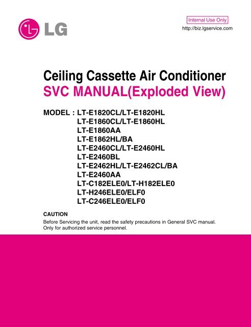
<strong>Ceiling</strong> <strong>Cassette</strong> <strong>Air</strong> <strong>Conditioner</strong><br />
<strong>SVC</strong> <strong>MANUAL</strong>(Exploded View)<br />
MODEL : LT-E1820CL/LT-E1820HL<br />
LT-E1860CL/LT-E1860HL<br />
LT-E1860AA<br />
LT-E1862HL/BA<br />
LT-E2460CL/LT-E2460HL<br />
LT-E2460BL<br />
LT-E2462HL/LT-E2462CL/BA<br />
LT-E2460AA<br />
LT-C182ELE0/LT-H182ELE0<br />
LT-H246ELE0/ELF0<br />
LT-C246ELE0/ELF0<br />
CAUTION<br />
Before Servicing the unit, read the safety precautions in General <strong>SVC</strong> manual.<br />
Only for authorized service personnel.
Contents<br />
Functions .................................................................................................................................3<br />
Product Specifications (Cooling & Heating) ..........................................................................7<br />
Dimensions ..............................................................................................................................9<br />
Refrigeration Cycle Diagram ................................................................................................12<br />
Wiring Diagram ......................................................................................................................14<br />
Operation Details ...................................................................................................................17<br />
Installation of Indoor, Outdoor Unit .....................................................................................20<br />
Cycle .......................................................................................................................................38<br />
Cycle Troubleshooting Guide ...............................................................................................41<br />
Electronic Parts Troubleshooting Guide .............................................................................42<br />
Electronic Control Device .....................................................................................................45<br />
Schematic Digram ..................................................................................................................46<br />
Exploded View ........................................................................................................................47<br />
Copyright ©2008 LG Electronics. Inc. All right reserved.<br />
Only for training and service purposes<br />
- 2 -<br />
LGE Internal Use Only
Functions<br />
Indoor Unit<br />
Operation ON/OFF by Remote controller<br />
Sensing the Room Temperature<br />
• Room temperature sensor. (Thermistor)<br />
Room temperature control<br />
Starting Current Control<br />
Time Delay Safety Control<br />
Indoor Fan Speed Control<br />
Soft Dry Operation Mode<br />
<strong>Air</strong>flow Direction Control<br />
• Maintains the room temperature in accordance with the Setting Temp.<br />
• Indoor fan is delayed for 5 seconds at the starting.<br />
• Restarting is inhibited for approx. 3 minutes.<br />
• Jet, High, Med, Low<br />
• Intermittent operation of fan at low speed.<br />
• The louver can be set at swing up and down automatically.<br />
Auto Restart<br />
• Although the air-conditioner is turned off by a power failure, it is restarted automatically<br />
previous operation mode after power supply.<br />
• The setting temperature and desired operation mode are automatically<br />
set by fuzzy<br />
Auto Operation(Auto Change Over)<br />
logic.<br />
Deice (defrost) control (Heating)<br />
Hot-start Control (Heating)<br />
Compact and light design<br />
Low noise<br />
Long life filter<br />
• Both the indoor and outdoor fan stops during defrosting.<br />
• Hot start after defrost ends.<br />
• The indoor fan stops until the evaporator piping temperature<br />
will be reached at 28°C.<br />
• To install a unit is very convenient because of smaller size<br />
than textile. ( 600 x 600 )<br />
• The most advanced low-noise design.<br />
• The adoption of turbo fan and round type heat exchanger<br />
give the quietest operation.<br />
• Long life wrinkle(type) and washable and anti-bacteria filter<br />
is adopted.<br />
Plasma <strong>Air</strong> Purifying Filter(2HL Only)<br />
High head Drain pump<br />
High-<strong>Ceiling</strong> corresponding Function<br />
Central Control(Optional)<br />
Group Control(Optional Wiring)<br />
Elevation Grille (Optional)<br />
• Built-in drain pump automatically drains water.<br />
• A standard drain-head height of up to 700mm is possible.<br />
• According to the height of ceiling, the RPM of indoor fan<br />
motor is selected to increase air reaching distance.<br />
• It is operating individually or totally by central control function.<br />
• Each controller can control 16 units and 8 controllers can be<br />
connected.<br />
• It operates maximum 16 units by only one wired remote controller<br />
and each unit starts sequentially to prevent overcurrent.<br />
• Auto Elevation Grille is automatically down to height of max 3m.<br />
So it enables to install the indoor unit at high celling space and<br />
Auto Elevation Grille makes you clean the filter easily.<br />
Copyright ©2008 LG Electronics. Inc. All right reserved.<br />
Only for training and service purposes<br />
- 3 -<br />
LGE Internal Use Only
Remote Controller<br />
Operation ON/OFF<br />
Operation Mode Selection<br />
(Cooling<br />
model only)<br />
(Heating<br />
model only)<br />
Cooling Operation Mode ( ) Soft Dry Operation Mode ( )<br />
Heating Operation Mode ( ) Auto Operation Mode ( )<br />
Fan Speed Selection<br />
LO<br />
MED<br />
(Low) (Med) (High)<br />
HI JET AUTO<br />
Room Temperature Display<br />
: High:39°C ↔ LOW:11°C<br />
Temperature Setting<br />
Cooling<br />
Down to 18°C<br />
Up to 30°C<br />
Heating<br />
Down to 16°C<br />
Up to 30°C<br />
Setting the Timer<br />
Timer<br />
Cancel<br />
Weekly Program<br />
Program<br />
Week<br />
Holiday<br />
SET/CLR<br />
: Fan Operates without cooling & heating<br />
Hour<br />
Min<br />
Fan Operation Mode<br />
Copyright ©2008 LG Electronics. Inc. All right reserved.<br />
Only for training and service purposes<br />
- 4 -<br />
LGE Internal Use Only
■ ELEVATION GRILL (REMOTE CONTROLLER_Accessory)<br />
Signal transmitter<br />
Ascend<br />
Descend<br />
• Main Components of Lift Grill<br />
➀ Lift grill front panel assembly<br />
➁ Bolts for installation (4 EA, P/No. 3A00255K)<br />
➂ Instruction manual<br />
➃ Remote Controller for lift grill<br />
Stop<br />
• How to Use Remote Controller<br />
As for operation of Remote Controller, use it by directing the transmitter<br />
part of Remote Controller to the receiver part of front panel<br />
directly under front panel.<br />
• Do not drop it down or into water. Or else there is worry about<br />
trouble failure.<br />
• Do not press hard the Remote Controller button with nail (ballpoint<br />
pen or other sharp substance). Or else there is worry<br />
about trouble failure.<br />
• In case when obstacle such as curtain hides the signal reception<br />
part of receiver in between the space interval, Remote Controller<br />
operation is infeasible.<br />
Copyright ©2008 LG Electronics. Inc. All right reserved.<br />
Only for training and service purposes<br />
- 5 -<br />
LGE Internal Use Only
• How to Operate the Lift Grill<br />
• Always stop the air conditioner operation for safety before operating lift grill.<br />
• Take heed _ there is worry about dust fall etc. when suction grill descends.<br />
• In case when the set automatic stop distance goes wrong, check the set value of operation panel and confirm<br />
if there is neither obstacle nor mankind.<br />
• When you are not to remove obstacle, stop the operation before touching the obstacle.<br />
1. Stop the <strong>Air</strong> <strong>Conditioner</strong> Operation<br />
Automatic Stop Distance of Grill<br />
2. Descend the Suction Grill<br />
- Depress the down button( ).<br />
Then suction grill descends and stops automatically at a certain<br />
distance.<br />
- You may stop it at wanted distance point by depressing the stop button<br />
( ) when descending.<br />
3. Raise the Suction Grill<br />
- Depress the up button( ).<br />
Then suction grill goes up and enters into the front panel.<br />
Automatic stop distance<br />
4. Stop the Suction Grill during Rising<br />
- Depress the stop button( ).<br />
Make use of this when you want to stop it at your wished position.<br />
<strong>Ceiling</strong> height<br />
Low<br />
Medium<br />
(Height: 3~4 m)<br />
High<br />
Automatic stop distance 1.5±0.5 m 2.5±0.5 m 3.5±0.5 m<br />
✳ If you want to change automatic distance setting,<br />
consult with your sale agency.<br />
Copyright ©2008 LG Electronics. Inc. All right reserved.<br />
Only for training and service purposes<br />
- 6 -<br />
LGE Internal Use Only
Product Specifications (Cooling & Heating)<br />
Model<br />
Power Supply<br />
ø, V, Hz<br />
Capacity Cooling kcal/h(W)<br />
Btu/h<br />
Heating<br />
kcal/h(W)<br />
Btu/h<br />
Input Cooling W<br />
Heating<br />
W<br />
Running Current Cooling A<br />
Heating<br />
A<br />
Starting Current Cooling A<br />
Heating<br />
A<br />
E.E.R<br />
kcal/h(W)<br />
C.O.P<br />
W/W<br />
<strong>Air</strong> Circulation Indoor m 3 /min<br />
Outdoor<br />
m 3 /min<br />
Moisture Removal<br />
l / h<br />
<strong>Air</strong>-Flow Direction Control<br />
Heating Operation Mode<br />
Fan Speeds (steps)<br />
Auto Operation (Changeover)<br />
Forced Operation<br />
Jet Cool<br />
Soft Dry Operation<br />
Timer Delay Safety Function<br />
Feature<br />
<strong>Air</strong> Deflection (Way)<br />
Self Diagnosis<br />
Hot start<br />
Auto Restart<br />
<strong>Air</strong> refresh (Hole)<br />
High <strong>Ceiling</strong><br />
Group Control (Optional wiring)<br />
Central Control<br />
Wired remote controller (with weekly Program)<br />
Plasma A/Cleaner<br />
Refrigerant(R-22) Charge<br />
g<br />
Dimensions Indoor mm<br />
(W x D x H) Panel mm<br />
Outdoor<br />
mm<br />
Net Weight Indoor kg<br />
Outdoor<br />
kg<br />
Main Power Cord AWG#:P*mm 2<br />
Connection Cable AWG#:P*mm 2<br />
Service Valve Liquid (inch)<br />
Gas<br />
(inch)<br />
Installation Pipe Length (m)<br />
Elevation<br />
(m)<br />
Insulation(material/thickness)<br />
Drain Hose(I.D/O.D)<br />
mm<br />
LT-E2460AA LT-E1860CL LT-E1860HL LT-E1862HL<br />
LT-E1862BA<br />
1, 220-240, 50<br />
4,536(5,274)<br />
18,000<br />
-<br />
-<br />
1,900<br />
-<br />
9.5<br />
-<br />
53<br />
-<br />
2.39<br />
-<br />
13<br />
50<br />
1.9<br />
O<br />
X<br />
4<br />
O<br />
O<br />
O<br />
O<br />
O<br />
4<br />
O<br />
X<br />
O<br />
O<br />
O<br />
O<br />
Optional<br />
O<br />
O<br />
1,900<br />
570 x 570 x 269<br />
670 x 670 x 30<br />
870 x 655 x 320<br />
19(16.5+2.5)<br />
60<br />
14:3*2.5<br />
18:4*0.75<br />
1/4(6.35mm)<br />
5/8(15.88mm)<br />
50<br />
30<br />
FoamPE/5mm<br />
ø25/32<br />
1, 220-240, 50<br />
4,536(5,274)<br />
18,000<br />
-<br />
-<br />
1,900<br />
-<br />
9.5<br />
-<br />
53<br />
-<br />
2.39<br />
-<br />
13<br />
50<br />
1.9<br />
O<br />
X<br />
4<br />
O<br />
O<br />
O<br />
O<br />
O<br />
4<br />
O<br />
X<br />
O<br />
O<br />
O<br />
O<br />
Optional<br />
O<br />
X<br />
1,900<br />
570 x 570 x 269<br />
670 x 670 x 30<br />
870 x 655 x 320<br />
19(16.5+2.5)<br />
60<br />
14:3*2.5<br />
18:4*0.75<br />
1/4(6.35mm)<br />
5/8(15.88mm)<br />
50<br />
30<br />
FoamPE/5mm<br />
ø25/32<br />
1, 220-240, 50<br />
4,536(5,274)<br />
18,000<br />
4,536(5,274)<br />
18,000<br />
2,050<br />
1,850<br />
9.5<br />
9.0<br />
53<br />
53<br />
2.21<br />
2.85<br />
13<br />
50<br />
1.9<br />
O<br />
O<br />
4<br />
O<br />
O<br />
O<br />
O<br />
O<br />
4<br />
O<br />
O<br />
O<br />
O<br />
O<br />
O<br />
Optional<br />
O<br />
X<br />
1,800<br />
570 x 570 x 269<br />
670 x 670 x 30<br />
870 x 655 x 320<br />
19(16.5+2.5)<br />
61<br />
14:3*2.5<br />
18:6*0.75<br />
1/4(6.35mm)<br />
5/8(15.88mm)<br />
50<br />
30<br />
FoamPE/5mm<br />
ø25/32<br />
1, 220-240, 50<br />
4,536(5,274)<br />
18,000<br />
4,536(5,274)<br />
18,000<br />
2,050<br />
1,850<br />
9.5<br />
9.0<br />
53<br />
53<br />
2.21<br />
2.85<br />
13<br />
50<br />
1.9<br />
O<br />
O<br />
4<br />
O<br />
O<br />
O<br />
O<br />
O<br />
4<br />
O<br />
O<br />
O<br />
O<br />
O<br />
O<br />
Optional<br />
O<br />
O<br />
1,800<br />
570 x 570 x 269<br />
670 x 670 x 30<br />
870 x 655 x 320<br />
19(16.5+2.5)<br />
61<br />
14:3*2.5<br />
18:6*0.75<br />
1/4(6.35mm)<br />
5/8(15.88mm)<br />
50<br />
30<br />
FoamPE/5mm<br />
ø25/32<br />
LT-E1820CL<br />
LT-C182ELE0<br />
1, 220, 60<br />
4,536(5,274)<br />
18,000<br />
-<br />
-<br />
1,970<br />
-<br />
9<br />
-<br />
53<br />
-<br />
2.30<br />
-<br />
13<br />
50<br />
1.9<br />
O<br />
X<br />
4<br />
O<br />
O<br />
O<br />
O<br />
O<br />
4<br />
O<br />
X<br />
O<br />
O<br />
O<br />
O<br />
Optional<br />
O<br />
X<br />
1,050<br />
570 x 570 x 269<br />
670 x 670 x 30<br />
870 x 655 x 320<br />
19<br />
60<br />
14:3*2.5<br />
18:4*0.75<br />
1/4(6.35mm)<br />
5/8(15.88mm)<br />
50<br />
30<br />
FoamPE/5mm<br />
ø25/32<br />
LT-E1820HL<br />
LT-H182ELE0<br />
1, 220, 60<br />
4,536(5,274)<br />
18,000<br />
4,536(5,274)<br />
18,000<br />
1,900<br />
1,900<br />
8.8<br />
8.8<br />
53<br />
53<br />
2.39<br />
2.78<br />
13<br />
50<br />
1.9<br />
O<br />
O<br />
4<br />
O<br />
O<br />
O<br />
O<br />
O<br />
4<br />
O<br />
O<br />
O<br />
O<br />
O<br />
O<br />
Optional<br />
O<br />
X<br />
1,910<br />
570 x 570 x 269<br />
670 x 670 x 30<br />
870 x 655 x 320<br />
19<br />
61<br />
14:3*2.5<br />
18:6*0.75<br />
1/4(6.35mm)<br />
5/8(15.88mm)<br />
50<br />
30<br />
FoamPE/5mm<br />
ø25/32<br />
Copyright ©2008 LG Electronics. Inc. All right reserved.<br />
Only for training and service purposes<br />
- 7 -<br />
LGE Internal Use Only
Model<br />
Power Supply<br />
ø, V, Hz<br />
Capacity Cooling kcal/h(W)<br />
Btu/h<br />
Heating<br />
kcal/h(W)<br />
Btu/h<br />
Input Cooling W<br />
Heating<br />
W<br />
Running Current Cooling A<br />
Heating<br />
A<br />
Starting Current Cooling A<br />
Heating<br />
A<br />
E.E.R<br />
kcal/h(W)<br />
C.O.P<br />
W/W<br />
<strong>Air</strong> Circulation Indoor m 3 /min<br />
Outdoor<br />
m 3 /min<br />
Moisture Removal<br />
l / h<br />
<strong>Air</strong>-Flow Direction Control<br />
Heating Operation Mode<br />
Fan Speeds (steps)<br />
Auto Operation (Changeover)<br />
Forced Operation<br />
Jet Cool<br />
Soft Dry Operation<br />
Timer Delay Safety Function<br />
Feature<br />
<strong>Air</strong> Deflection (Way)<br />
Self Diagnosis<br />
Hot start<br />
Auto Restart<br />
<strong>Air</strong> refresh (Hole)<br />
High <strong>Ceiling</strong><br />
Group Control (Optional wiring)<br />
Central Control<br />
Wired remote controller (with weekly Program)<br />
Plasma A/Cleaner<br />
Refrigerant(R-22) Charge<br />
g<br />
Dimensions Indoor mm<br />
(W x D x H) Panel mm<br />
Outdoor<br />
mm<br />
Net Weight Indoor kg<br />
Outdoor<br />
kg<br />
Main Power Cord AWG#:P*mm 2<br />
Connection Cable AWG#:P*mm 2<br />
Service Valve Liquid (inch)<br />
Gas<br />
(inch)<br />
Installation Pipe Length (m)<br />
Elevation<br />
(m)<br />
Insulation(material/thickness)<br />
Drain Hose(I.D/O.D)<br />
mm<br />
LT-E2460CL<br />
LT-C246ELE0<br />
1, 220-240, 50<br />
5,871(6,827)<br />
23,300<br />
-<br />
-<br />
2,600<br />
-<br />
13.5<br />
-<br />
62<br />
-<br />
2.26<br />
-<br />
15.5<br />
50<br />
2.9<br />
O<br />
X<br />
4<br />
O<br />
O<br />
O<br />
O<br />
O<br />
4<br />
O<br />
X<br />
O<br />
O<br />
O<br />
O<br />
Optional<br />
O<br />
X<br />
1,900<br />
570 x 570 x 269<br />
670 x 670 x 30<br />
870 x 655 x 320<br />
19(16.5+2.5)<br />
61<br />
14:3*2.5<br />
18:4*0.75<br />
1/4(6.35mm)<br />
5/8(15.88mm)<br />
50<br />
30<br />
FoamPE/5mm<br />
ø25/32<br />
LT-E2460HL LT-E2460BL LT-E2462HL/BL<br />
LT-H246ELE0/ELF0<br />
1, 220-240, 50<br />
5,871(6,827)<br />
23,300<br />
5,922(6,886)<br />
23,500<br />
2,600<br />
2,600<br />
13.5<br />
13.5<br />
62<br />
60<br />
2.26<br />
2.65<br />
15.5<br />
50<br />
2.9<br />
O<br />
O<br />
4<br />
O<br />
O<br />
O<br />
O<br />
O<br />
4<br />
O<br />
O<br />
O<br />
O<br />
O<br />
O<br />
Optional<br />
O<br />
X<br />
1,900<br />
570 x 570 x 269<br />
670 x 670 x 30<br />
870 x 655 x 320<br />
19(16.5+2.5)<br />
62<br />
14:3*2.5<br />
18:6*0.75<br />
1/4(6.35mm)<br />
5/8(15.88mm)<br />
50<br />
30<br />
FoamPE/5mm<br />
ø25/32<br />
1, 220-240, 50<br />
5,871(6,827)<br />
23,300<br />
5,922(6,886)<br />
23,500<br />
2,600<br />
2,600<br />
13.5<br />
13.5<br />
62<br />
60<br />
2.26<br />
2.65<br />
15.5<br />
50<br />
2.9<br />
O<br />
O<br />
4<br />
O<br />
O<br />
O<br />
O<br />
O<br />
4<br />
O<br />
O<br />
O<br />
O<br />
O<br />
O<br />
Optional<br />
O<br />
O<br />
1,900<br />
570 x 570 x 269<br />
670 x 670 x 30<br />
870 x 655 x 320<br />
19(16.5+2.5)<br />
62<br />
14:3*2.5<br />
18:6*0.75<br />
1/4(6.35mm)<br />
5/8(15.88mm)<br />
50<br />
30<br />
FoamPE/5mm<br />
ø25/32<br />
LT-E2462CL<br />
LT-E2460AA<br />
1, 220-240, 50<br />
5,871(6,827)<br />
23,300<br />
-<br />
-<br />
2,600<br />
-<br />
13.5<br />
-<br />
62<br />
-<br />
2.26<br />
-<br />
15.5<br />
50<br />
2.9<br />
O<br />
X<br />
4<br />
O<br />
O<br />
O<br />
O<br />
O<br />
4<br />
O<br />
X<br />
O<br />
O<br />
O<br />
O<br />
Optional<br />
O<br />
O<br />
1,900<br />
570 x 570 x 269<br />
670 x 670 x 30<br />
870 x 655 x 320<br />
19(16.5+2.5)<br />
61<br />
14:3*2.5<br />
18:6*0.75<br />
1/4(6.35mm)<br />
5/8(15.88mm)<br />
50<br />
30<br />
FoamPE/5mm<br />
ø25/32<br />
Copyright ©2008 LG Electronics. Inc. All right reserved.<br />
Only for training and service purposes<br />
- 8 -<br />
LGE Internal Use Only
CLOSE OPEN OPEN CLOSE<br />
Dimensions<br />
(1) Indoor Unit<br />
670<br />
269<br />
670<br />
670<br />
570<br />
670<br />
521<br />
55<br />
570<br />
450<br />
40<br />
269<br />
120.4 30<br />
90<br />
110 110<br />
90<br />
52<br />
160<br />
190.5<br />
Copyright ©2008 LG Electronics. Inc. All right reserved.<br />
Only for training and service purposes<br />
- 9 -<br />
LGE Internal Use Only
LT-H***ELE0<br />
LT-H***FLE0<br />
LT-H***DLE0<br />
W<br />
H<br />
D<br />
(unit : mm)<br />
DIM<br />
Model<br />
Unit<br />
LT-H***ELE0 LT-H***FLE0 LT-H***DLE0<br />
W mm 670 850 950<br />
H mm 90 90 90<br />
D mm 670 850 950<br />
Copyright ©2008 LG Electronics. Inc. All right reserved.<br />
Only for training and service purposes<br />
- 10 -<br />
LGE Internal Use Only
(2) Outdoor Unit<br />
W<br />
L5 L4<br />
L3<br />
D<br />
L2<br />
L7 L6<br />
L8 L9<br />
L1<br />
L11<br />
L10<br />
Gas side<br />
3-way valve<br />
Liquid side<br />
3-way valve<br />
DIM<br />
MODEL<br />
All Models<br />
W mm 870<br />
H mm 655<br />
D mm 320<br />
L1 mm 370<br />
L2 mm 25<br />
L3 mm 340<br />
L4 mm 630<br />
L5 mm 25<br />
L6 mm 546<br />
L7 mm 162<br />
L8 mm 162<br />
L9 mm 54<br />
L10 mm 74.5<br />
L11 mm 79<br />
Copyright ©2008 LG Electronics. Inc. All right reserved.<br />
Only for training and service purposes<br />
- 11 -<br />
LGE Internal Use Only
Refrigeration Cycle Diagram<br />
• HEAT PUMP<br />
INDOOR UNIT<br />
OUTDOOR UNIT<br />
ACCUM.<br />
H/EX<br />
CAPI A<br />
H/EX<br />
Liquid Gas Side<br />
VALVE REVERSING<br />
CAPI C1<br />
Heating<br />
Cooring<br />
CAPI C2<br />
(<br />
COMPRESSOR<br />
Liquid Gas Side<br />
CAPI B<br />
Capacity<br />
Pipe Size<br />
GAS<br />
LIQUID<br />
Length (m)<br />
Rated<br />
Max.<br />
Elevation (m)<br />
Rated<br />
Max.<br />
* Additional<br />
refrigerant<br />
(g/m)<br />
18K 5/8" 1/4" 7.5 50 5 30 25<br />
24K 5/8" 1/4" 7.5 50 5 30 30<br />
• Rated performance for refrigerant line length of: 7.5m<br />
• If 18K Capacity is installed at a distance of 15m, 187.5g of refrigerant<br />
should be added ....................................................(15-7.5)x25g<br />
Copyright ©2008 LG Electronics. Inc. All right reserved.<br />
Only for training and service purposes<br />
- 12 -<br />
LGE Internal Use Only
• COOLING ONLY<br />
INDOOR UNIT<br />
OUTDOOR UNIT<br />
H/EX<br />
CAPI A<br />
H/EX<br />
Gas Side<br />
COMPRESSOR<br />
ACCUM.<br />
CAPI C1<br />
CAPI C2<br />
Liquid Side<br />
CAPI B<br />
Capacity<br />
Pipe Size<br />
GAS<br />
LIQUID<br />
Length (m)<br />
Rated<br />
Max.<br />
Elevation (m)<br />
Rated<br />
Max.<br />
* Additional<br />
refrigerant<br />
(g/m)<br />
18K 5/8" 1/4" 7.5 50 5 30 25<br />
24K 5/8" 1/4" 7.5 50 5 30 30<br />
• Rated performance for refrigerant line length of: 7.5m<br />
• If 18K Capacity is installed at a distance of 15m, 187.5g of refrigerant<br />
should be added ....................................................(15-7.5)x25g<br />
Copyright ©2008 LG Electronics. Inc. All right reserved.<br />
Only for training and service purposes<br />
- 13 -<br />
LGE Internal Use Only
Wiring Diagram<br />
• HEAT PUMP<br />
Model No.: LT-E1862HL/ LT-E1862BA/ LT-E2462HL<br />
LT-E2462BA/ LT-E2460BL/ LT-H182ELEO/LT-H246ELE0/LT-H246ELF0<br />
OUTDOOR WIRING DIAGRAM<br />
INDOOR WIRING DIAGRAM<br />
BR<br />
FUSE 5A<br />
BR<br />
R<br />
COMP S<br />
BL<br />
FUSE 5A<br />
BL<br />
C<br />
POWER<br />
RELAY<br />
POWER<br />
INPUT<br />
GN/YL<br />
BL<br />
RD<br />
BR<br />
4<br />
2<br />
BR<br />
BL<br />
CAPACITOR<br />
H C F<br />
8<br />
6<br />
BL<br />
BL<br />
1<br />
0<br />
GN/YL<br />
RD<br />
YL<br />
OR<br />
BK<br />
TO INDOOR UNIT<br />
REVERSING<br />
VALVE<br />
BK<br />
FAN<br />
MOTOR<br />
BK<br />
TB2<br />
1(L) 2(N) 3(L) 4(N) 5 6 7 8<br />
TERMINAL<br />
BLOCK<br />
TO OUTDOOR UNIT<br />
3(L) 4(N) 5 6 7<br />
TERMINAL<br />
BLOCK<br />
BR<br />
BL<br />
GN/YL<br />
RD<br />
BK<br />
YL<br />
DOOR S/W<br />
FUSE T3.15A<br />
COMP<br />
BK<br />
RD<br />
WH<br />
BR<br />
INDOOR<br />
MOTOR<br />
YL<br />
BK<br />
OR<br />
H.V. ASSY<br />
OUT FAN<br />
4 WAY<br />
RD<br />
BK<br />
GN/YL<br />
DRAIN<br />
PUMP<br />
BL<br />
AIR<br />
CLEANER<br />
BL<br />
STEP<br />
MOTOR<br />
CN - DISP<br />
TEMP.<br />
THERMISTOR<br />
DISPLAY PCB<br />
Only for LT-Exxx2HL<br />
PIPE<br />
THERMISTOR<br />
FLOAT S/W<br />
REMOTE<br />
CONTROL<br />
LT-E2460HL(Australia only)<br />
OUTDOOR WIRING DIAGRAM<br />
BR<br />
FUSE 5A<br />
BR<br />
R<br />
COMP S<br />
BL<br />
FUSE 5A<br />
C<br />
BL<br />
POWER<br />
RELAY<br />
POWER<br />
INPUT<br />
GN/YL<br />
RD<br />
BR<br />
4<br />
2<br />
YL<br />
BR<br />
BL<br />
8<br />
6<br />
BL<br />
BL<br />
CAPACITOR<br />
H C F<br />
BL<br />
S/CAPACITOR<br />
BL<br />
1<br />
0<br />
WH<br />
3 3<br />
4 4<br />
RY- RY-<br />
COMP S/CAPA<br />
CN-POWER<br />
GN/YL<br />
RD<br />
TO INDOOR UNIT<br />
YL<br />
YL<br />
OR<br />
BK<br />
REVERSING<br />
VALVE<br />
BK<br />
FAN<br />
MOTOR<br />
BK<br />
TB2<br />
1(L) 2(N) 3(L) 4(N) 5 6 7 8<br />
TERMINAL<br />
BLOCK<br />
3854A20119A<br />
Copyright ©2008 LG Electronics. Inc. All right reserved.<br />
Only for training and service purposes<br />
- 14 -<br />
LGE Internal Use Only
• HEAT PUMP<br />
Model No.: LT-E1860HL/ LT-E2460HL/<br />
OUTDOOR WIRING DIAGRAM<br />
INDOOR WIRING DIAGRAM<br />
BR<br />
INDOOR<br />
MOTOR<br />
YL<br />
BK<br />
OR<br />
GN/YL<br />
DRAIN<br />
PUMP<br />
BL<br />
BL<br />
STEP<br />
MOTOR<br />
TEMP.<br />
THERMISTOR<br />
TO OUTDOOR UNIT<br />
3(L) 4(N) 5 6 7<br />
BR<br />
BL<br />
GN/YL<br />
RD<br />
BK<br />
YL<br />
FUSE T3.15A<br />
BK<br />
RD<br />
COMP<br />
WH<br />
OUT FAN<br />
4 WAY<br />
CN - DISP<br />
PIPE<br />
THERMISTOR<br />
FLOAT S/W<br />
REMOTE<br />
CONTROL<br />
TERMINAL<br />
BLOCK<br />
DOOR S/W<br />
H.V. ASSY<br />
RD<br />
BK<br />
AIR<br />
CLEANER<br />
DISPLAY PCB<br />
Only for LT-Exxx2HL<br />
Copyright ©2008 LG Electronics. Inc. All right reserved.<br />
Only for training and service purposes<br />
- 15 -<br />
LGE Internal Use Only
• COOLING ONLY<br />
Model No.: LT-E1860CL/LT-E1860AA/LT-C182ELE0<br />
OUTDOOR WIRING DIAGRAM<br />
INDOOR WIRING DIAGRAM<br />
BR<br />
INDOOR<br />
MOTOR<br />
YL<br />
BK<br />
OR<br />
GN/YL<br />
DRAIN<br />
PUMP<br />
BL<br />
BL<br />
STEP<br />
MOTOR<br />
TEMP.<br />
THERMISTOR<br />
TO OUTDOOR UNIT<br />
3(L) 4(N) 5 6 7<br />
BR<br />
BL<br />
GN/YL<br />
RD<br />
FUSE T3.15A<br />
COMP<br />
CN - DISP<br />
PIPE<br />
THERMISTOR<br />
FLOAT S/W<br />
REMOTE<br />
CONTROL<br />
TERMINAL<br />
BLOCK<br />
DISPLAY PCB<br />
Model No.: LT-E2460CL/LT-E2462CL/LT-E2460AA/LT-C246ELE0<br />
OUTDOOR WIRING DIAGRAM<br />
INDOOR WIRING DIAGRAM<br />
BR<br />
FUSE 5A<br />
BR<br />
R<br />
COMP S<br />
BL<br />
FUSE 5A<br />
BL<br />
C<br />
POWER<br />
RELAY<br />
GN/YL<br />
BL<br />
RD<br />
BR<br />
4<br />
2<br />
BR<br />
BL<br />
CAPACITOR<br />
H C F<br />
8<br />
6<br />
BL<br />
BL<br />
1<br />
0<br />
GN/YL<br />
RD<br />
YL<br />
OR<br />
BK<br />
FAN<br />
MOTOR<br />
TB2<br />
1(L) 2(N) 3(L) 4(N) 5 6 7 8<br />
POWER<br />
INPUT<br />
TO INDOOR UNIT<br />
BK<br />
TERMINAL<br />
BLOCK<br />
TO OUTDOOR UNIT<br />
3(L) 4(N) 5 6 7<br />
TERMINAL<br />
BLOCK<br />
BR<br />
BL<br />
GN/YL<br />
RD<br />
YL<br />
DOOR S/W<br />
FUSE T3.15A<br />
COMP<br />
RD<br />
BK<br />
WH<br />
BR<br />
INDOOR<br />
MOTOR<br />
YL<br />
BK<br />
OR<br />
H.V. ASSY<br />
OUT FAN<br />
RD<br />
BK<br />
GN/YL<br />
DRAIN<br />
PUMP<br />
BL<br />
BL<br />
AIR<br />
CLEANER<br />
STEP<br />
MOTOR<br />
LT-E 2HL ONLY<br />
***<br />
CN - DISP<br />
TEMP.<br />
THERMISTOR<br />
DISPLAY PCB<br />
PIPE<br />
THERMISTOR<br />
FLOAT S/W<br />
REMOTE<br />
CONTROL<br />
Copyright ©2008 LG Electronics. Inc. All right reserved.<br />
Only for training and service purposes<br />
- 16 -<br />
LGE Internal Use Only
■ ELEVATION GRILL WIRING DIAGRAM (INDOOR)<br />
LT-H***DLE0/LT-C***DLE0<br />
LT-H***ELE0/LT-C***ELE0<br />
LT-H***FLE0/LT-C***FLE0<br />
Copyright ©2008 LG Electronics. Inc. All right reserved.<br />
Only for training and service purposes<br />
- 17 -<br />
LGE Internal Use Only
Operation Details<br />
(1) The function of main control<br />
1. Time Delay Safety Control<br />
• 3min The compressor is ceased for 3minutes to balance the pressure in the refrigeration cycle.<br />
(Protection of compressor)<br />
• 5sec Vertical air flow direction control louvers open in 5 seconds to prevent noise between louvers and wind.<br />
• 30sec The 4-way valve is ceased for 30sec. to prevent the refrigerant-gas abnormal noise when the Heating<br />
operation is OFF or switched to the other operation mode while compress is off.<br />
While compressor is running, it takes 3~5 seconds to switch.<br />
2. Auto Swing Control<br />
• This function is to swing the louver up and down automatically.<br />
3. <strong>Air</strong>-Filter Checking Control<br />
• 'Filter' will display in the remote controller display and main body display when an air-filter is polluted. Then clean<br />
the air-filter for reference to Owners Manual.<br />
4. Soft-Dry Operation<br />
• The indoor fan speed is automatically set to the low, so the shift of the indoor fan speed is impossible because of<br />
already being set to the best speed for Dry Operation by Micom Control.<br />
5. Cooling Mode Operation<br />
• When selecting the Cooling( ) Mode Operation, the unit will operate according to the setting by the remote controller<br />
and the operation diagram is as following<br />
Intake <strong>Air</strong> temp.<br />
SET TEMP.+0.5°C<br />
(COMP. ON)<br />
SET TEMP. -0.5°C<br />
(COMP. OFF) More than More than<br />
3 minutes 3 minutes<br />
Selecting Selecting Selecting<br />
INDOOR FAN Low Low<br />
fan speed fan speed fan speed<br />
COMPRESSOR ON OFF ON OFF ON<br />
Copyright ©2008 LG Electronics. Inc. All right reserved.<br />
Only for training and service purposes<br />
- 18 -<br />
LGE Internal Use Only
6. Heating Mode Operation<br />
The unit will operate according to the setting by the remote controller and the operation diagram is shown as follows.<br />
Intake <strong>Air</strong> temp.<br />
minimum 3min<br />
Setting temp.+3°C<br />
(Compressor OFF)<br />
A<br />
B<br />
A<br />
Setting temp.<br />
(Compressor ON)<br />
1min<br />
minimum<br />
10sec.<br />
minimum<br />
1min.<br />
minimum<br />
10sec.<br />
INDOOR FAN<br />
(Hot Start)<br />
Selected<br />
Low<br />
Low OFF Low<br />
Selecting fan<br />
Low OFF<br />
OFF<br />
Fan Speed<br />
speed<br />
COMPRESSOR ON OFF ON OFF<br />
A point; While the indoor Heat-Exchanger temperature is higher than 40°C fan operates at low speed, when<br />
it becomes lower than 40˚C fan stops.<br />
B point; When the indoor Heat-Exchanger temperature is higher than 42°C, fan operates at selected fan<br />
speed, when it becomes lower than 39°C, the fan operates at low speed.<br />
7. Hot-Start Control<br />
• The indoor fan stops until the evaporator piping temperature reaches to 25°C.<br />
• If the evaporator piping temperature drops below 22°C, indoor fan stops again.<br />
• The operation diagram is as follows.<br />
PIPING<br />
TEMPERATURE<br />
25°C<br />
1min<br />
22°C<br />
INDOOR FAN<br />
OFF<br />
LOW<br />
Selected<br />
fan speed<br />
COMPRESSOR<br />
ON<br />
Copyright ©2008 LG Electronics. Inc. All right reserved.<br />
Only for training and service purposes<br />
- 19 -<br />
LGE Internal Use Only
8. Defrost Control (18k, 24k)<br />
• While in heating mode operation in order to protect the evaporator pipe of the outdoor unit from freezing, reversed to<br />
cooling cycle to defrost the evaporator pipe of the outdoor unit.<br />
• Defrost control is available 45 min. later since heating mode operation started, and it will not prolong over 10 min.<br />
• Defrost control is carried out according to the following priority order while in heating mode operation.<br />
1st priority : Defrost control is carried out according to the indoor pipe temp 60 min. later since heating mode operation<br />
started.<br />
2nd priority : The temp differences between the indoor pipe temp and the intake air temp 25 min. later(∆T1) and 45<br />
min. later (∆T2) since heating mode operation started are measured, then defrost control is carried out<br />
according to the dirrerence (∆T=∆T1-∆T2)<br />
3rd priority : Defrost control is carried out according to the temp difference (E=TE1-TE2) between the indoor pipe<br />
temperatures of 25 min later(TE1) and 45 min later (TE2) after heating mode operation started.<br />
• When the indoor pipe temp is 41°C or above, defrost control is not carried out even if the condition is one of the<br />
defrost conditions above.<br />
• While in defrost control, the compressor is on and the indoor fan, the outdoor fan, and the 4 way valve are off.<br />
The outdoor<br />
piping Temp.<br />
12°C OFF<br />
More than 45 minutes<br />
of heating operation<br />
Within<br />
9min. 45sec.<br />
More than 45 minutes<br />
of heating operation<br />
More than 10 min.<br />
running of compressor<br />
-6°C ON<br />
HOT-<br />
START<br />
INDOOR FAN<br />
ON<br />
OFF<br />
ON<br />
COMPRESSOR<br />
ON<br />
4-WAY VALVE<br />
ON<br />
OFF<br />
ON<br />
9. Self-diagnosis Function<br />
• 'CHECK' will flash in the remote controller display when a problem occurs.<br />
• Correct the (fault messages) as shown in the table below before restarting operation.<br />
• During the normal operation 'CHECK' won't be displayed in the remote controller.<br />
Remote controller LCD<br />
CH 01<br />
CH 02<br />
CH 03<br />
CH 04<br />
FAULT MESSAGES<br />
Indoor room temperature thermistor error<br />
Indoor piping thermistor error<br />
Indoor main body / Remote controller unit communication error<br />
Water level float switch error<br />
Copyright ©2008 LG Electronics. Inc. All right reserved.<br />
Only for training and service purposes<br />
- 20 -<br />
LGE Internal Use Only
Installation of Indoor, Outdoor Unit<br />
1. Selection of the best location<br />
1) Indoor unit<br />
• There should not be any heat source or steam<br />
near the unit.<br />
• There should not be any obstacles to the air circulation.<br />
• A place where air circulation in the room will be<br />
good.<br />
• A place where drainage can be easily obtained.<br />
• A place where noise prevention is taken into consideration.<br />
• Do not install the unit near the door way.<br />
• Ensure the spaces indicated by arrows from the<br />
wall, ceiling, or other obstacles.<br />
• The indoor unit must have the maintenance<br />
space around.<br />
<strong>Ceiling</strong><br />
<strong>Ceiling</strong> Board<br />
50 or<br />
more<br />
100<br />
or more<br />
Above 250<br />
330 or less<br />
Floor<br />
30 or more<br />
<strong>Ceiling</strong> Board<br />
50 or<br />
more<br />
Unit:cm<br />
30 or less<br />
2) Outdoor unit<br />
• If an awning is built over the unit to prevent direct<br />
sunlight or rain exposure, be careful that heat<br />
radiation from the condenser is not restricted.<br />
• There should not be any animals or plants which<br />
could be affected by hot air discharged.<br />
• Ensure the spaces indicated by arrows from the<br />
wall, ceiling, fence or other obstacles.<br />
More than<br />
30cm<br />
Fence or<br />
obstacles<br />
Sunroof<br />
More than<br />
30cm<br />
More than 50cm<br />
More than 70cm<br />
3) Piping length and the elevation<br />
CAPACITY<br />
Pipe Size<br />
GAS<br />
LIQUID<br />
Length A (m)<br />
Rated<br />
Max.<br />
Elevation B (m)<br />
Rated<br />
Max.<br />
18K Btu/h 5/8" 1/4" 7.5 50 5 30 25<br />
24K Btu/h 5/8" 1/4" 7.5 50 5 30 30<br />
• Rated performance for refrigerant piping length: 7.5m<br />
• If 18K Model is installed at a distance of 15m, 187.5g of<br />
refrigerant should be added (15-7.5)x25g<br />
* Additional<br />
refrigerant<br />
(g/m)<br />
Indoor unit<br />
B<br />
A<br />
Outdoor unit<br />
Copyright ©2008 LG Electronics. Inc. All right reserved.<br />
Only for training and service purposes<br />
- 21 -<br />
LGE Internal Use Only
2. <strong>Ceiling</strong> opening dimensions and hanging bolt location<br />
• The dimensions of cardboard for installing are the<br />
same as those of the ceiling opening dimensions.<br />
600 (<strong>Ceiling</strong> opening)<br />
39.5<br />
521(Hanging bolt) 39.5<br />
<strong>Ceiling</strong><br />
CAUTION<br />
Level gauge<br />
• This air-conditioner uses a drain pump.<br />
• Install the unit horizontally using a level gauge.<br />
• During the installation, be careful not to damage<br />
electric wires.<br />
570 Unit size<br />
570 Unit size<br />
450 (Hanging bolt) 75<br />
75<br />
600 (<strong>Ceiling</strong> opening)<br />
Unit:mm<br />
• Select and mark the position for fixing bolts and piping hole.<br />
• Decide the position for fixing bolts slightly tilted to the drain<br />
direction after considering the direction of drain hose.<br />
• Drill the hole for anchor bolt on the wall.<br />
<strong>Ceiling</strong> board<br />
NOTE:<br />
• Avoid the following installation location.<br />
1. Such places as restaurants and kitchen where considerable amount of oil steam and flour is generated.<br />
These may cause heat exchange efficiency reduction, or water drops, drain pump mal-function.<br />
In these cases, take the following actions;<br />
• Make sure that ventilation fan is enough to cover all noxious gases from this place.<br />
• Ensure enough distance from the cooking room to install the air conditioner in such a place where it may<br />
not suck oily steam.<br />
<strong>Air</strong> conditioner<br />
Take enough<br />
distance<br />
Cooking table<br />
Use the ventilation fan<br />
for smoke-collecting<br />
hood with sufficient<br />
capacity.<br />
2. Avoid installng air conditioner in such places where cooking oil or iron powder is generated.<br />
3. Avoid places where inflammable gas is generated.<br />
4. Avoid place where noxious gas is generated.<br />
5. Avoid places near high frequency generators.<br />
Copyright ©2008 LG Electronics. Inc. All right reserved.<br />
Only for training and service purposes<br />
- 22 -<br />
LGE Internal Use Only
3. The Indoor Unit Installation<br />
<strong>Ceiling</strong><br />
Hanging bolt<br />
(W3/8 or M10)<br />
Nut<br />
(W3/8 or M10)<br />
Spring washer<br />
(M10)<br />
Keep the length of the bolt<br />
from the bracket to 40mm<br />
Flat washer for M10<br />
(accessory)<br />
<strong>Ceiling</strong> board<br />
<strong>Air</strong> <strong>Conditioner</strong> body<br />
150mm<br />
<strong>Ceiling</strong> board<br />
Flat washer for M10<br />
(accessory)<br />
Nut<br />
(W3/8 or M10)<br />
Cardboard<br />
for installation<br />
Adjust the same height<br />
Set screw of<br />
cardboard (4 pieces)<br />
Open the ceiling board<br />
along the outer edge of the<br />
paper model<br />
• The following parts are local purchasing.<br />
Hanging Bolt - W 3/8 or M10<br />
Nut<br />
- W 3/8 or M10<br />
Spring Washer - M10<br />
Plate Washer - M10<br />
CAUTION<br />
• Tighten the nut and bolt to prevent the unit from<br />
falling off.<br />
• Drill the piping hole on the wall slightly tilted to the<br />
outdoor side using a Ø 70 hole-core drill.<br />
Indoor<br />
Wall<br />
Outdoor<br />
5~7mm<br />
4. Remote Controller Installation<br />
• Although the room temperature sensor is in the indoor unit, the remote controller should be installed<br />
in such places away from direct sunlight and high humidity.<br />
Installation of the remote controller<br />
• Select places that are not splashed with water.<br />
• Select control position after discussion with customer.<br />
• The room temperature sensor is built in the indoor unit.<br />
• This remote controller is equipped with liquid crystal display. If this position is higher or lower, display is difficult<br />
to see.(The standard height is 1.2 ~ 1.5m high)<br />
Routing of the remote controller cord<br />
• Keep the remote controller cord away from the refrigerant piping and the drain piping.<br />
• To protect the remote controller cord from electrical noise, place the cord at least 5cm away from other power<br />
cables (audio equipment, television set, etc.)<br />
• If the remote controller cord is secured to the wall, provide a trap at the top of the cord to prevent water<br />
droplets from running to the controller.<br />
Copyright ©2008 LG Electronics. Inc. All right reserved.<br />
Only for training and service purposes<br />
- 23 -<br />
LGE Internal Use Only
WIRED REMOTE CONTROL INSTALLATION<br />
DISASSEMBLING<br />
Front case<br />
• Separate the under plate from Remote control box.<br />
The lower part<br />
Lever carefully<br />
the box open<br />
using a screw<br />
driver, etc.<br />
Remote control<br />
box body<br />
• Fix the under plate on the wall<br />
Face of wall<br />
Under plate<br />
• Fix the cord clamps on the wall by ø 3 tapping<br />
screws (accessory).<br />
• Fix the remote control cord.<br />
Cord clamp<br />
(accessory)<br />
Screw (accessory)<br />
ELECTRICAL WIRING<br />
(Main board)<br />
CN REMO<br />
Remote controller<br />
REMOTE CONTROL PREPARATION(OPTIONAL)<br />
HOW TO MOUNT ON A WALL<br />
Make sure that wire and teminal<br />
numbers are matched on unit side and<br />
remote controller side.<br />
The maximum length of the cord is 100m.<br />
If the length of the cord exceeds 50m,<br />
use a wire size greater than 0.5mm 2 .<br />
HOW TO INSERT BATTERIES<br />
Remove the battery cover from the remote controller.<br />
• Pull out the cover according to the arrow direction.<br />
Insert the two batteries.<br />
• Be sure that the (+) and (-) directions are correct.<br />
• Be sure that both batteries are new.<br />
Re-attach the cover.<br />
• Slide it back into position.<br />
• Do not use rechargeable batteries,<br />
such batteries different from standard<br />
dry cells in shape, dimensions, and<br />
performance.<br />
• Remove the batteries from the remote<br />
controller if the air conditioner is not<br />
going to be used for long time.<br />
Copyright ©2008 LG Electronics. Inc. All right reserved.<br />
Only for training and service purposes<br />
- 24 -<br />
LGE Internal Use Only
5. Wiring Connection<br />
• Open the control box cover and connect the Remote controller cord and Indoor power wires.<br />
Indoor<br />
power cord<br />
Remote<br />
controller<br />
cord<br />
Control box cover<br />
Control box cover<br />
fitting screw(2 units)<br />
[<strong>Air</strong> inlet side view]<br />
• Heat Pump Model<br />
Terminal Block of Indoor Unit<br />
Terminal Block of Outdoor Unit<br />
3(L) 4(N) 5 6 7 1(L) 2(N) 3(L) 4(N) 5 6 7 8<br />
Power Cord<br />
• Cooling Model<br />
Terminal Block of Indoor Unit<br />
Terminal Block of Outdoor Unit<br />
3(L) 4(N) 5 6 7 1(L) 2(N) 3(L) 4(N) 5 6 7 8<br />
Power Cord<br />
The power cord connected to the outdoor unit should be complied<br />
with the following specifications (Rubber insulation, type H05RN-F<br />
approved by HAR or SAA).<br />
CAUTION<br />
The connecting cable connected to the indoor and outdoor unit should<br />
be complied with the following specifications (Rubber insulation,<br />
type H05RN-F approved by HAR or SAA).<br />
8.5mm<br />
GN/YL<br />
NORMAL<br />
CROSS-SECTIONAL<br />
AREA 2.5mm<br />
7.5mm<br />
GN/YL<br />
NORMAL<br />
CROSS-SECTIONAL<br />
AREA 0.75mm<br />
20mm<br />
If the supply cord is damaged, it must be replaced by a special cord or assembly available from the manufacturer<br />
or its service agent.<br />
20mm<br />
WARNING<br />
Make sure that the screws of the terminal are free from looseness.<br />
Copyright ©2008 LG Electronics. Inc. All right reserved.<br />
Only for training and service purposes<br />
- 25 -<br />
LGE Internal Use Only
ELECTRICAL WIRING<br />
1. All wiring must comply with LOCAL REGULATIONS.<br />
2. Select a power source that is capable of supplying the current required by the air conditioner.<br />
3. Feed the power source to the unit via a distribution switch board designed for this purpose.<br />
4. The terminal screws inside the control box may be loose due to vibration during transport.<br />
Check the screws for loose connection.<br />
(Running the air conditioner with loose connection can overload and damage electrical components.)<br />
5. Always ground the air conditioner with a grounding wire and connector to meet the LOCAL REGULATION.<br />
Main power source<br />
Circuit Breaker<br />
Use circuit breaker or time delay fuse.<br />
Switch box<br />
Refrigerant pipe<br />
CONNECTING THE CABLE TO OUTDOOR UNIT<br />
1. Remove the Cover control from the unit by loosening a<br />
screw.<br />
Connect the wires to the terminals on the control<br />
board individually as following.<br />
2. Secure the cable onto the control board with the holder<br />
(clamper).<br />
3. Refix the cover control to the original position with the<br />
screw.<br />
4. Use a recongnized circuit breaker 20A(18K, 24K)<br />
between the power source and the unit. A disconnection<br />
device to adequately disconnect all supply lines<br />
must be fitted.<br />
Outdoor unit<br />
Terminal block<br />
Over 5mm<br />
Holder for<br />
power supply<br />
cord<br />
Cover control<br />
Holder for<br />
connecting<br />
cable<br />
Power supply<br />
cord<br />
Connecting<br />
cable<br />
Copyright ©2008 LG Electronics. Inc. All right reserved.<br />
Only for training and service purposes<br />
- 26 -<br />
LGE Internal Use Only
6. Connecting Pipes to the Indoor Unit<br />
• Preparation of Piping<br />
Main cause of gas leakage is defect in flaring work. Carry out correct flaring work in the following procedure.<br />
1) Cutting the pipes and the cable.<br />
■ Use the accessory piping kit or the pipes purchased<br />
locally.<br />
■ Measure the distance between the indoor and the outdoor<br />
unit.<br />
■ Cut the pipes a little longer than measured distance.<br />
■ Cut the cable 1.5m longer than the pipe length.<br />
Copper<br />
tube 90° Slanted Uneven Rough<br />
2) Burrs removal<br />
■ Completely remove all burrs from the cut cross section<br />
of pipe/tube.<br />
■ Put the end of the copper tube/pipe to downward direction<br />
as you remove burrs in order to avoid to let burrs<br />
drop in the tubing.<br />
Point down<br />
Pipe<br />
Reamer<br />
3) Putting nut on<br />
■ Remove flare nuts attached to indoor and outdoor units,<br />
than put them on pipe/tube having completed burr<br />
removal.<br />
(Not possible to put them on after flaring work)<br />
Copper tube<br />
Flare nut<br />
4) Flaring work<br />
■ Carry out flaring work using flaring tool as shown below.<br />
Outside diameter<br />
A<br />
mm inch mm<br />
Ø6.35 1/4 0.5~0.8<br />
Bar<br />
"A"<br />
Bar<br />
Handle<br />
Yoke<br />
Cone<br />
Ø15.88 5/8 0.8~1.0<br />
Firmly hold copper tube in a bar(or die) as indicated<br />
dimension in the table above.<br />
Copper pipe<br />
Clamp handle<br />
Red arrow mark<br />
5) Check<br />
■ Compare the flared work with figure below.<br />
■ If flare is noted to be defective, cut off the flared section<br />
and do flaring work again.<br />
Smooth all round<br />
Inside is shining without scratches<br />
= Improper flaring =<br />
Even length<br />
all round<br />
Inclined<br />
Surface Cracked Uneven<br />
damaged thickness<br />
Copyright ©2008 LG Electronics. Inc. All right reserved.<br />
Only for training and service purposes<br />
- 27 -<br />
LGE Internal Use Only
Piping Connection<br />
1. Form the piping according to its routing. Avoid bending<br />
and bending back the same piping point more<br />
than three times. (This will result in hardening of<br />
pipe.)<br />
2. After deforming the piping, align centers of the union<br />
fitting of the indoor unit and the piping, and tighten<br />
them firmly with wrenches.<br />
3. Connect pipe to the service valve or ball valve which<br />
is located below the outdoor unit.<br />
4. After completing the piping connection, be sure to<br />
check if there is gas leakage in indoor and outdoor<br />
connection.<br />
Outdoor<br />
unit<br />
Liquid side<br />
Gas side<br />
Flare connection<br />
Indoor<br />
unit<br />
Flare connection<br />
Vacuum drying<br />
After completing the piping connection, execute vacuum<br />
drying for the connecting piping and the indoor unit.<br />
The vacuum drying must be carried out using the service<br />
ports of both the liquid and gas side valves.<br />
Model Liquid side piping Gas side piping<br />
18K, 24K Btu/h Ø 6.35mm Ø15.88mm<br />
CAUTION<br />
Use two wrenches and tighten with regular torque.<br />
Ø6.35mm<br />
Ø9.52mm<br />
Ø12.7mm<br />
Ø15.88mm<br />
Ø19.05mm<br />
Flare nut fastening torque<br />
1.8kg . m<br />
4.0kg . m<br />
5.5kg . m<br />
6.6kg . m<br />
6.6kg . m<br />
Union<br />
Copyright ©2008 LG Electronics. Inc. All right reserved.<br />
Only for training and service purposes<br />
- 28 -<br />
LGE Internal Use Only
7. Installation of Decoration Panel<br />
The decoration panel has its installation<br />
direction.<br />
Before installing the decoration panel,<br />
always remove the paper template.<br />
1. Temporarily fix two decoration panel fixing screws (hexagon M5 screw) on the unit body. (Tighten by<br />
amount 10mm in length.)<br />
The fixing screws (hexagon M5 screw) are included the indoor unit box.<br />
2. Remove the air inlet grille from the decoration panel. (Remove the hook for the air inlet grille cord.)<br />
3. Hook the decoration panel key hole ( ) on the screws fixed in step above, and slide the panel so<br />
that the screws reach the key hole edge.<br />
4. Retighten completely two temporarily fixed screws and other two screws. (Total 4 screws)<br />
5. Connect the louver motor connector and display connector.<br />
6. After tightening these screws, install the air inlet grille (including the air filter).<br />
<strong>Air</strong> conditioner unit<br />
Piping side<br />
Decoration panel fixing screws<br />
(hexagon M5 screws)<br />
Temporally fitting at 2 places<br />
(Tightening about 10mm)<br />
Inlet Louver Grille motor<br />
Control box cover<br />
Decoration panel<br />
Key holes<br />
Display<br />
Lead wire for<br />
louver motor and<br />
display<br />
Decoration panel fixing screws<br />
(Hexagon M5 screw)<br />
CAUTION<br />
Inlet Grille<br />
Install certainly the decoration panel.<br />
Cool air leakage causes sweating.<br />
Water drops fall.<br />
Good example<br />
<strong>Air</strong> conditioner<br />
unit<br />
Bad example<br />
<strong>Air</strong><br />
<strong>Air</strong> conditioner unit<br />
Cool air leakage<br />
(no good)<br />
<strong>Ceiling</strong><br />
board<br />
Decoration panel<br />
Fit the insulator (this part) and<br />
be careful for cool air leakage<br />
<strong>Ceiling</strong><br />
board<br />
Decoration<br />
panel<br />
Copyright ©2008 LG Electronics. Inc. All right reserved.<br />
Only for training and service purposes<br />
- 29 -<br />
LGE Internal Use Only
8. Installation of Decoration Panel(Elevation Grille)<br />
The decoration panel has its installation<br />
direction.<br />
Before installing the decoration panel,<br />
always remove the paper template.<br />
1. Temporarily fix two decoration panel fixing screws (hexagon M5 screw) on the unit body. (Tighten by<br />
amount 10mm in length.)<br />
The fixing screws (hexagon M5 screw) are included unit box.<br />
2. Remove the air inlet grille from the decoration panel. (Remove the hook for the air inlet grille cord.)<br />
3. Hook the decoration panel key hole ( ) on the screws fixed in step above, and slide the panel so<br />
that the screws reach the key hole edge.<br />
4. Retighten completely two temporarily fixed screws and other two screws. (Total 4 screws)<br />
5. Connect the louver motor connector display connector, elevation grille connector and power supply connector<br />
6. After tightening these screws, install the air inlet grille (including the air filter).<br />
<strong>Air</strong> conditioner unit<br />
Piping side<br />
Decoration panel fixing screws<br />
(hexagon M5 screws)<br />
Temporally fitting at 2 places<br />
(Tightening about 10mm)<br />
Inlet Louver Grille motor<br />
Decoration panel<br />
Control box cover<br />
Key holes<br />
Display<br />
Decoration panel fixing screws<br />
(Hexagon M5 screw)<br />
Inlet grille<br />
Copyright ©2008 LG Electronics. Inc. All right reserved.<br />
Only for training and service purposes<br />
- 30 -<br />
LGE Internal Use Only
• Don't lay any material upon suction grill.<br />
• Suction grill comprises 2 strands of wire. If any substance is placed on it then balance may be destroyed so that<br />
the substance would drop down and cause a breakage or damage. Also the matter may cause trouble owing to<br />
which the grill would not be correctly inserted at front panel.<br />
• Don't shake suction grill. Or else there is worry that it may collide with adjacent material and the suction grill fall<br />
down.<br />
• Don't pull suction grill. Don't draw out suction grill irrationally. Or else there is worry that lift grill drive part is<br />
damaged and suction grill might drop down.<br />
• Don't place obstacle in lift passage of lift grill.<br />
When suction grill descends, it automatically stops at a certain distance.<br />
If there is any obstacle in lift passage, suction grill might drop down and there may be caused trouble failure of lift grill drive part.<br />
• Turn off the air conditioner operation button before operating the lift grill.<br />
Always stop the air conditioner operation for safety when suction grill descends.<br />
• Don't damage lift rope by a sharp material. Or else there is worry about suction grill dropping because of rope<br />
cutoff.<br />
Copyright ©2008 LG Electronics. Inc. All right reserved.<br />
Only for training and service purposes<br />
- 31 -<br />
LGE Internal Use Only
9. Indoor Unit Drain Piping<br />
• Drain piping must have down-slope (1/50 to 1/100): be sure<br />
not to provide up-and-down slope to prevent reversal flow.<br />
• During drain piping connection, be careful not to exert extra<br />
force on the drain port on the indoor unit.<br />
• The outside diameter of the drain connection on the indoor<br />
unit is 32mm.<br />
Piping material: Polyvinyl chloride pipe VP-25<br />
and pipe fittings<br />
• Be sure to install heat insulation on the drain piping.<br />
Heat insulation material: Polyethylene foam with<br />
thickness more than 8 mm.<br />
Drain test<br />
Pipe clamp<br />
Indoor unit<br />
Maintenance<br />
drain port<br />
Upward<br />
routing<br />
not allowed<br />
1/50~1/100<br />
MAX 700mm<br />
The air conditioner uses a drain pump to drain water.<br />
Use the following procedure to test the drain pump operation:<br />
Feed water<br />
Drain Pump<br />
Drain pan<br />
CAUTION<br />
Flexible drain hose<br />
(accessory)<br />
Main<br />
drain pipe<br />
Drain<br />
port Glue the joint<br />
Drain hose connection<br />
Use the clip (accessory)<br />
The supplied flexible drain hose should not be curved,<br />
neither screwed. The curved or screwed hose may<br />
cause a leakage of water.<br />
CAUTION<br />
• Connect the main drain pipe to the exterior<br />
and leave it provisionally until the test<br />
comes to an end.<br />
• Feed water to the flexible drain hose and<br />
check the piping for leakage.<br />
• Be sure to check the drain pump for normal<br />
operating and noise when electrical wiring<br />
is complete.<br />
• When the test is complete, connect the<br />
flexible drain hose to the drain port on the<br />
indoor unit.<br />
Flexible drain hose<br />
Flexible drain hose<br />
1/50~1/100<br />
MAX 700mm<br />
After the confirmation of the above conditions, prepare the wiring as follows:<br />
Flexible drain hose<br />
1) Never fail to have an individual power specialized for the air conditioner. As for the method of wiring, be guided by the<br />
circuit diagram pasted on the inside of control box cover.<br />
2) Provide a circuit breaker switch between power source and the unit.<br />
3) The screw which fasten the wiring in the casing of electrical fittings are liable to come loose from vibrations to which the<br />
unit is subjected during the course of transportation. Check them and make sure that they are all tightly fastened. (If they<br />
are loose, it could give rise to burn-out of the wires.)<br />
4) Specification of power source<br />
5) Confirm that electrical capacity is sufficient.<br />
6) Be sure that the starting voltage is maintained at more than 90 percent of the rated voltage marked on the name plate.<br />
7) Confirm that the cable thickness is as specified in the power sources specification.<br />
(Particularly note the relation between cable length and thickness.)<br />
8) Never fail to equip a leakage breaker where it is wet or moist.<br />
9) The following troubles would be caused by voltage drop-down.<br />
• Vibration of a magnetic switch, damage on the contact point there of, fuse breaking, disturbance to the normal function of a<br />
overload protection device.<br />
• Proper starting power is not given to the compressor.<br />
Copyright ©2008 LG Electronics. Inc. All right reserved.<br />
Only for training and service purposes<br />
- 32 -<br />
LGE Internal Use Only
HEAT INSULATION<br />
1. Use the heat insulation material for the refrigerant piping which has an excellent heat-resistance (over 120°C).<br />
2. Precautions in high humidity circumstance:<br />
This air conditioner has been tested according to the<br />
"KS Standard Conditions with Mist" and confirmed<br />
that there is not any default. However, if it is operated<br />
for a long time in high humid atmosphere (dew point<br />
temperature: more than 23°C), water drops are liable<br />
to fall. In this case, add heat insulation material<br />
according to the following procedure:<br />
• Heat insulation material to be prepared... Adiabatic<br />
glass wool with thickness 10 to 20mm.<br />
Indoor unit<br />
Fastening band<br />
(accessory)<br />
Refrigerant piping<br />
Thermal insulator<br />
(accessory)<br />
• Stick glass wool on all air conditioners that are located in ceiling atmosphere.<br />
• In addition to the normal heat insulation (thickness: more than 8mm) for refrigerant piping (gas piping: thick piping)<br />
and drain piping, add further 10mm to 30mm thickness material.<br />
FORM THE PIPINGS<br />
1. Wrap the connecting portion of indoor unit with<br />
the Insulation material and secure it with two<br />
Plastic Bands. (for the right pipings)<br />
•If you want to connect an additional drain hose, the<br />
end of the drain-outlet should keep distance from<br />
the ground. (Do not dip it into water, and fix it on the<br />
wall to avoid swinging in the wind.)<br />
In case of the Outdoor unit being installed<br />
below position of the Indoor unit.<br />
Seal a small opening<br />
around the pipings<br />
with gum type sealer.<br />
Drain hose<br />
Taping<br />
2. Tape the Pipings, drain hose and Connecting<br />
Cable from bottom to top.<br />
3. Form the pipings gathered by taping along the<br />
exterior wall and fix it onto the wall by saddle or<br />
equivalent.<br />
Plastic Band<br />
Pipings<br />
Connecting<br />
cable<br />
Power supply<br />
cord<br />
Trap is required to prevent water from entering<br />
into electrical parts.<br />
Copyright ©2008 LG Electronics. Inc. All right reserved.<br />
Only for training and service purposes<br />
- 33 -<br />
LGE Internal Use Only
In case of the Outdoor Unit being installed<br />
above position of the Indoor Unit.<br />
2. Tape the Pipings and Connecting cable from bottom<br />
to top.<br />
Seal a small opening<br />
around the pipings<br />
with gum type sealer.<br />
Trap<br />
3. Form the pipings gathered by taping along the<br />
exterior wall, and make the trap prevent water<br />
from entering into the room.<br />
4. Fix the pipings onto the wall by saddle or equivalent.<br />
Test running<br />
1) PRECAUTIONS IN TEST RUN<br />
• The initial power supply must provide at least 90% of the rated voltage.<br />
Otherwise, the air conditioner should not be operated.<br />
For test run, carry out the cooling operation first even during winter season. If heating operation is<br />
Caution carried out first, it leads to the trouble of compressor.<br />
Carry out the test run more than 5 minutes without stopping.<br />
(Test run will be cancelled 18 minutes later automatically)<br />
• The test run is started by pressing the room temperature checking button and down timer button for 3 seconds<br />
at the same time.<br />
• To cancel the test run, press any button.<br />
CHECK THE FOLLOWING ITEMS WHEN INSTALLATION IS COMPLETE<br />
• After completing work, be sure to measure and record trial run properties, and store measured data, etc.<br />
• Measuring data are room temperature, outside temperature, suction temperature, blow out temperature,<br />
air velocity, air volume, voltage, current, presence of abnormal vibration and noise, operating pressure, piping<br />
temperature.<br />
• As to the structure and appearance, check following items.<br />
❏ Is the circulation of air adequate?<br />
❏ Is the drainage OK?<br />
❏ Is the heat insulation complete<br />
(refrigerant and drain piping)?<br />
❏ Is there any leakage of refrigerant?<br />
❏ Does the romote controller works properly?<br />
❏ Is there any error on wiring?<br />
❏ Aren't terminal screws loosened?<br />
M4......118N.cm{12kgf.cm} M5......196N.cm{20kgf.cm}<br />
M6......245N.cm{25kgf.cm} M8......588N.cm{60kgf.cm}<br />
Copyright ©2008 LG Electronics. Inc. All right reserved.<br />
Only for training and service purposes<br />
- 34 -<br />
LGE Internal Use Only
2) Connection of power supply<br />
1. Connect the power supply cord to the independent<br />
power supply.<br />
• Circuit breaker is required.<br />
2. Operate the unit for fifteen minutes or more.<br />
3) Evaluation of the performance<br />
1. Measure the temperature of the intake and discharge<br />
air.<br />
2. Ensure the difference between the intake temperature<br />
and the discharge one is more than 8°C (Cooling)<br />
or reversely (Heating).<br />
Thermometer<br />
CAUTION<br />
After the confirmation of the above conditions, prepare the wiring as follows:<br />
1) Never fail to have an individual power specialized for the air conditioner. As for the method of<br />
wiring, be guided by the circuit diagram pasted on the inside of control box cover.<br />
2) Provide a circuit breaker switch between power source and the unit.<br />
3) The screw which fasten the wiring in the casing of electrical fittings are liable to come loose from<br />
vibrations to which the unit is subjected during the course of transportation. Check them and<br />
make sure that they are all tightly fastened. (If they are loose, it could give rise to burn-out of the<br />
wires.)<br />
4) Specification of power source<br />
5) Confirm that electrical capacity is sufficient.<br />
6) Be sure that the starting voltage is maintained at more than 90 percent of the rated voltage marked<br />
on the name plate.<br />
7) Confirm that the cable thickness is as specified in the power sources specification.<br />
(Particularly note the relation between cable length and thickness.)<br />
8) Never fail to equip a leakage breaker where it is wet or moist.<br />
9) The following troubles would be caused by voltage drop-down.<br />
• Vibration of a magnetic switch, damage on the contact point there of, fuse breaking, disturbance to the normal<br />
function of a overload protection device.<br />
• Proper starting power is not given to the compressor.<br />
HAND OVER<br />
Teach the customer the operation and maintenance procedures, using the operation manual (air filter cleaning,<br />
temperature control, etc.).<br />
Copyright ©2008 LG Electronics. Inc. All right reserved.<br />
Only for training and service purposes<br />
- 35 -<br />
LGE Internal Use Only
Optional Operation<br />
1) Two Thermistor System<br />
(1) Open the rear cover of the wired remote-controller to set the mode.<br />
(2) Select one of three selectable modes as follows.<br />
• Position 1:<br />
The room temperature is controlled by the thermistor of the main body.<br />
• Position 2:<br />
The room themperature is controlled by the thermistor of the wired remote-controller, control the<br />
temperature according to the position of wired remote-controller.<br />
• Position 3:<br />
The room temperature is controlled by lower temperature between the temperature of main body and of<br />
remote-controller sensor.<br />
(3) Move the slide switch to set position.<br />
Room Temp. sensor<br />
Slide switch for 2 Thermistor<br />
TH<br />
R13H R12H OP5R16H OP4<br />
CO1H<br />
Position 2<br />
Position 1<br />
Position 3<br />
REMO<br />
MAIN<br />
2TH<br />
R14H<br />
OP3 OP2 OP1<br />
R19H<br />
SW TH<br />
R11H<br />
REMO<br />
MAIN<br />
2TH<br />
OP7<br />
R18H<br />
R17H<br />
OP6<br />
LO<br />
STAND<br />
HI<br />
R03S<br />
C070 R04S<br />
R01S<br />
R15H<br />
SW<br />
HIGH<br />
R02S<br />
Slide switch for ceiling height<br />
(4) Close the rear cover and check if it works normally.<br />
CAUTION<br />
• Select the position after counselling with a customer.<br />
• In case of cooling mode, room temperature is controlled by the main body sensor.<br />
• To control the room temperature by a wired remote controller, install controller(room temp. sensor) to sense<br />
the temperature more accurately.<br />
• Maunfactured in the position 3.<br />
Copyright ©2008 LG Electronics. Inc. All right reserved.<br />
Only for training and service purposes<br />
- 36 -<br />
LGE Internal Use Only
2) Adjusting air volume to the height of ceiling<br />
You can choose the RPM(or air volume) of indoor motor according to the height of ceiling to supply the comfortable<br />
atmosphere to consumers.<br />
Procedure<br />
1. Choose the selectable position in the table after measuring the height of ceiling.<br />
<strong>Ceiling</strong> height Mode of slide switch Change of air volume Remark<br />
more than 3.3m High <strong>Ceiling</strong> Increasing<br />
Maunfactured in standard<br />
mode<br />
2.7~3.3m Standard -<br />
less than 2.7m Low <strong>Ceiling</strong> Decreasing<br />
2. In the case of changing the height as "high" or "low", open the rear cover of the wired remote-controller.<br />
3. Move the slide switch to the set position.<br />
Slide switch for 2 Thermistor<br />
Low ceiling<br />
Standard<br />
(Default)<br />
High <strong>Ceiling</strong><br />
Lo<br />
STAND<br />
Hi<br />
TH<br />
R14H<br />
OP3 OP2 OP1<br />
R19H<br />
SW TH<br />
R11H<br />
REMO<br />
MAIN<br />
2TH<br />
OP7<br />
R18H<br />
R17H<br />
OP6<br />
R13H R12H OP5R16H OP4<br />
CO1H<br />
R15H<br />
Slide switch for ceiling height<br />
LO<br />
STAND<br />
HI<br />
SW HIGH<br />
C070 R04S<br />
R02S<br />
R03S<br />
R01S<br />
4. Close the rear cover and check if it works nomally.<br />
NOTICE<br />
Wiring Diagram for Heat pump<br />
OUTDOOR WIRING DIAGRAM<br />
INDOOR WIRING DIAGRAM<br />
BR<br />
FUSE 5A<br />
BR<br />
R<br />
COMP S<br />
BL<br />
FUSE 5A<br />
BL<br />
C<br />
POWER<br />
RELAY<br />
POWER<br />
INPUT<br />
GN/YL<br />
BL<br />
RD<br />
BR<br />
4<br />
2<br />
BR<br />
BL<br />
CAPACITOR<br />
H<br />
8<br />
6<br />
BL<br />
BL<br />
C<br />
1<br />
0<br />
F<br />
GN/YL<br />
RD<br />
YL<br />
OR<br />
BK<br />
TO INDOOR UNIT<br />
REVERSING<br />
VALVE<br />
BK<br />
FAN<br />
MOTOR<br />
BK<br />
TB2<br />
1(L) 2(N) 3(L) 4(N) 5 6 7 8<br />
TERMINAL<br />
BLOCK<br />
TO OUTDOOR UNIT<br />
3(L) 4(N) 5 6 7<br />
TERMINAL<br />
BLOCK<br />
BR<br />
BL<br />
GN/YL<br />
RD<br />
BK<br />
YL<br />
FUSE T3.15A<br />
DOOR S/W<br />
COMP<br />
BK<br />
RD<br />
WH<br />
BR<br />
INDOOR<br />
MOTOR<br />
YL<br />
BK<br />
OR<br />
(OPTION)<br />
H.V. ASSY<br />
OUT FAN<br />
4 WAY<br />
RD<br />
BK<br />
GN/YL<br />
DRAIN<br />
PUMP<br />
BL<br />
BL<br />
AIR<br />
CLEANER<br />
STEP<br />
MOTOR<br />
CN - DISP<br />
TEMP.<br />
THERMISTOR<br />
DISPLAY PCB<br />
PIPE<br />
THERMISTOR<br />
FLOAT S/W<br />
REMOTE<br />
CONTROL<br />
Copyright ©2008 LG Electronics. Inc. All right reserved.<br />
Only for training and service purposes<br />
- 37 -<br />
LGE Internal Use Only
AUTO SWING OPERATION SET TEMP FAN SPEED SUB FUNCTION<br />
Room Temp<br />
HI AUTO Heater Preheat<br />
MED JET Defrost Humidify<br />
LO<br />
Filter Out door<br />
Time ZONE 1 2 3 4<br />
Timer Operation unit<br />
Program set<br />
On Off<br />
Set no. Time 01 03 05 07 09 11 13 15 17 19 21 23<br />
3) Group Control(Optional Wiring)<br />
It operates maximum 16 Units by only one Wired Remote Controller,<br />
and each Unit starts sequentially to prevent overcurrent.<br />
Main PCB<br />
RED(12V)<br />
YL(SIGNAL)<br />
BR(GND)<br />
Indoor Unit 1<br />
Terminal(Local Supply)<br />
Block<br />
Connector<br />
RED(12V)<br />
YL(SIGNAL)<br />
BR(GND)<br />
Main PCB<br />
#1<br />
YL(SIGNAL)<br />
BR(GND)<br />
Indoor Unit 2<br />
Terminal(Local Supply)<br />
Block<br />
Connector<br />
YL(SIGNAL)<br />
BR(GND)<br />
Main PCB<br />
#2<br />
....<br />
YL(SIGNAL)<br />
BR(GND)<br />
Indoor Unit 16<br />
Terminal(Local Supply)<br />
Block<br />
Connector<br />
YL(SIGNAL)<br />
BR(GND)<br />
Main PCB<br />
#16<br />
....<br />
Connecting Cable(Local Supply)<br />
Slide Switch2<br />
Wired Remote Controller<br />
(Standard)<br />
Single<br />
Group<br />
Remote<br />
Controller<br />
PCB<br />
• Using the supplied Wired Remote Controller, wire<br />
them like above.<br />
• Move slide switch 2 to "Group" position.<br />
• Ensure that the color of wire.<br />
CAUTION<br />
• Be careful not to exchange the color of wires.<br />
• The maximum length of connecting wire should be below 200m(25Ω) on connecting each units.<br />
• Use a wire more than 0.5mm 2<br />
NOTICE<br />
]Wiring Diagram for Cooling only<br />
OUTDOOR WIRING DIAGRAM<br />
INDOOR WIRING DIAGRAM<br />
BR<br />
FUSE 5A<br />
BR<br />
R<br />
COMP S<br />
BL<br />
FUSE 5A<br />
BL<br />
C<br />
POWER<br />
RELAY<br />
POWER<br />
INPUT<br />
GN/YL<br />
BL<br />
RD<br />
BR<br />
4<br />
2<br />
BR<br />
BL<br />
CAPACITOR<br />
H<br />
8<br />
6<br />
BL<br />
BL<br />
C<br />
1<br />
0<br />
F<br />
GN/YL<br />
RD<br />
TO INDOOR UNIT<br />
YL<br />
OR<br />
BK<br />
FAN<br />
MOTOR<br />
BK<br />
TB2<br />
1(L) 2(N) 3(L) 4(N) 5 6 7 8<br />
TERMINAL<br />
BLOCK<br />
TO OUTDOOR UNIT<br />
3(L) 4(N) 5 6 7<br />
TERMINAL<br />
BLOCK<br />
BR<br />
BL<br />
GN/YL<br />
RD<br />
FUSE T3.15A<br />
COMP<br />
BR<br />
INDOOR<br />
MOTOR<br />
YL<br />
BK<br />
OR<br />
GN/YL<br />
DRAIN<br />
PUMP<br />
BL<br />
BL<br />
STEP<br />
MOTOR<br />
CN - DISP<br />
TEMP.<br />
THERMISTOR<br />
DISPLAY PCB<br />
PIPE<br />
THERMISTOR<br />
FLOAT S/W<br />
REMOTE<br />
CONTROL<br />
Copyright ©2008 LG Electronics. Inc. All right reserved.<br />
Only for training and service purposes<br />
- 38 -<br />
LGE Internal Use Only
Cycle<br />
1. Installation (Connecting the piping between indoor and outdoor unit)<br />
Indoor unit<br />
Liquid side<br />
3-Way<br />
valve<br />
Outdoor unit<br />
Gas side<br />
Gas cylinder<br />
3-Way<br />
valve<br />
R22<br />
Lo<br />
Purge the air<br />
• Installation<br />
(1) Connect the piping between the indoor and outdoor<br />
unit firmly.<br />
– Incorrect connection may cause the leakage and<br />
incomplete vacuuming.<br />
(2) Attach the charging hose (manifold gage) to the<br />
service port.<br />
– Charging hose is necessary to check the pressure<br />
and to inject N2 for leakage test.<br />
– The valve of charging hose must be closed before<br />
being connected.<br />
(3) Inject the 100~300g N2 through the charging hose<br />
opening the valve.<br />
(4) Check the joint part using a gas detector or soapy<br />
water for leakage.<br />
– On checking, the service valve of main service port<br />
must be closed, this test is only for checking whether<br />
pipe connection is OK or not.<br />
(5) If there is no leakage, discharge N2 in piping completely<br />
into tank for retrieving.<br />
– Completely discharge is needed for vacuuming.<br />
– If leakage is found, please fasten the joint more tightly.<br />
(6) After closing the valve of charging hose, disconnect<br />
the tank and connect the vacuum pump to<br />
charging hose and open the valve again for vacuuming.<br />
(7) Turn on the vacuum pump until the pressure drops<br />
below 0 kg/cm 2 .<br />
(8) After vacuuming, disconnect the vacuum pump and<br />
open the spindle of service port (liquid-side) slightly<br />
for 30 sec and then open the spindle of service<br />
port (gas side) with hexagonal wrench.<br />
(9) Open the liquid side completely first and then the<br />
gas side fully in order.<br />
Copyright ©2008 LG Electronics. Inc. All right reserved.<br />
Only for training and service purposes
2. Disconnection (on moving)<br />
Indoor unit<br />
Liquid side<br />
Closed<br />
2-Way<br />
valve<br />
Outdoor unit<br />
Retrieving Tank<br />
Gas side<br />
3-Way<br />
valve<br />
Closed<br />
Lo<br />
• Disconnection<br />
(1) Attach the charging hose (manifold gage) to<br />
the service port.<br />
– Connect the manifold gage once to the service<br />
port not stopping. Stopping in the middle of<br />
process may cause the leakage.<br />
(6) Disconnect the piping between indoor and<br />
outdoor unit and then put on service cap to<br />
the service port.<br />
(2) Purge the air in hose into special device such<br />
as retrieving tank opening the valve of charging-<br />
hose (gas side) slightly and then close it<br />
tightly.<br />
(3) Operate the air conditioner for 10~15 min until<br />
cycle is stabilized.<br />
(4) Close the spindle of service port (liquid sidehigh<br />
pressure) and wait till pressure of gas<br />
side (low pressure) drops below 0 kgf/cm 2 .<br />
(5) After the needle of gage indicates below<br />
0 kgf/cm 2 , close the valve of gas side quickly<br />
and turn off the power.<br />
Copyright ©2008 LG Electronics. Inc. All right reserved.<br />
Only for training and service purposes<br />
- 40 -<br />
LGE Internal Use Only
3. Gas Charging<br />
(After Evacuation)<br />
Indoor unit<br />
Liquid side<br />
2-Way<br />
valve<br />
Open<br />
Outdoor unit<br />
Gas side<br />
Charging<br />
cylinder<br />
Check valve<br />
3-Way<br />
valve<br />
Open<br />
Lo<br />
(1)<br />
OPEN<br />
CLOSE<br />
• Procedure<br />
(1) Connect the charge hose to the charging<br />
cylinder.<br />
– Connect the charge hose which you dis-connected<br />
from the vacuum pump to the valve at<br />
the bottom of the cylinder.<br />
– If you are using a gas cylinder, also use a scale<br />
and reverse the cylinder so that the system can<br />
be charged in liquid state.<br />
(2) Purge the air from the charge hose.<br />
– Open the valve at the bottom of the cylinder<br />
and press the check valve on the charge set to<br />
purge the air. (Be careful of the liquid refrigerant).<br />
The procedure is the same if using a gas<br />
cylinder.<br />
(3) Open the valve (Lo side on the charge set and<br />
charge the system with liquid refrigerant.<br />
– If the system can not be charged with the specified<br />
amount of refrigerant, it can be charged<br />
with a little at a time (approximately 150g each<br />
time) while operating the air conditioner in the<br />
cooling cycle; however, one time is not sufficient,<br />
wait approximately 1 minute and then<br />
repeat the procedure.<br />
\<br />
This is different from previous procedures.<br />
Because you are charging with liquid refrigerant<br />
from the gas side, absolutely do not attempt to<br />
charge with larger amounts of liquid refrigerant<br />
while operating the air conditioner.<br />
(4) Immediately disconnect the charge hose from<br />
the 3-way valve’s service port.<br />
– Stopping partway will allow the gas to be discharged.<br />
– If the system has been charged with liquid<br />
refrigerant while operating the air conditioner,<br />
turn off the air conditioner before disconnecting<br />
the hose.<br />
(5) Mount the valve stem nuts and the service<br />
port nut.<br />
– Use torque wrench to tighten the service port<br />
nut to a torque of 1.8 kg.m.<br />
– Be sure to check for gas leakage.<br />
Copyright ©2008 LG Electronics. Inc. All right reserved.<br />
Only for training and service purposes<br />
- 41 -<br />
LGE Internal Use Only
Cycle Troubleshooting Guide<br />
Trouble analysis<br />
1. Check temperature difference between intake and discharge air and operating current.<br />
Temp. difference : approx. 0°C<br />
Current<br />
: less than 80% of<br />
rated current<br />
All amount of refrigerant leaked out<br />
Check refrigeration cycle<br />
Temp. Difference<br />
Temp. difference : approx. 8°C<br />
Current<br />
: less than 80% of<br />
rated current<br />
Refrigerant leakege<br />
Clog of refrigeration cycle<br />
Defective compressor<br />
Operating Current<br />
Temp. difference : less than 8°C<br />
Current<br />
: over the rated<br />
current<br />
Excessive amount of refrigerant<br />
Temp. difference : over 8°C<br />
Normal<br />
Notice :<br />
Temperature difference between intake and discharge air depends on room air humidity. When the room air<br />
humidity is relativery higher, temperature difference is smaller. When the room air humidity is relatively lower temperature<br />
difference is larger.<br />
2. Check temperature and pressure of refrigeration cycle.<br />
Suction pressure Temperature<br />
(Compared with (Compared with Cause of Trouble Description<br />
the normal value) the normal value)<br />
Higher<br />
High<br />
Defective compressor<br />
Defective 4-way reverse valve<br />
Current is low<br />
Excessive amount of<br />
High pressure does not quickly<br />
Normal refrigerant rise at the beginning of<br />
operation<br />
Insufficient amount of<br />
Lower Higher refrigerant (Leakage)<br />
Clogging<br />
Current is low<br />
Current is low<br />
Notice :<br />
1. The suction pressure is usually 4.5~6.0 kg/cm 2 G at normal condition.<br />
2. The temperature can be measured by attaching the thermometer to the low pressure tubing and wrap it with<br />
putty.<br />
Copyright ©2008 LG Electronics. Inc. All right reserved.<br />
Only for training and service purposes<br />
- 42 -<br />
LGE Internal Use Only
Electronic Parts Troubleshooting Guide<br />
Possible Trouble 1<br />
: The unit does not operate.<br />
Is the input voltage<br />
AC230V?<br />
NO<br />
Check the FUSE<br />
and the wiring diagram.<br />
YES<br />
Is the input voltage<br />
of IC03D about DC12V?<br />
NO<br />
Check the main P.C.B<br />
pattern.<br />
YES<br />
Is the output voltage<br />
of IC03D DC5V?<br />
YES<br />
NO<br />
Exchange IC03D.<br />
Is the PIN 49,58 of<br />
MICOM. DC5V?<br />
NO<br />
Check the<br />
5V P.C.B pattern.<br />
YES<br />
Exchange MICOM.<br />
Copyright ©2008 LG Electronics. Inc. All right reserved.<br />
Only for training and service purposes<br />
- 43 -<br />
LGE Internal Use Only
Possible Trouble 2<br />
: The indoor fan does not operate.<br />
Is it the HOT<br />
START mode?<br />
NO<br />
YES<br />
It is normal operation.<br />
Is IC01M operated<br />
normally?<br />
YES<br />
NO<br />
Exchange IC01M.<br />
Is the each Relay<br />
any problem?<br />
NO<br />
YES<br />
Exchange Relay.<br />
Check the fan motor<br />
and connector.(CN-MOTOR)<br />
Possible Trouble 3<br />
: Ineffective Heating<br />
Is it Heating Mode?<br />
NO<br />
Adjust operation mode.<br />
YES<br />
Does the temperature<br />
set all right?<br />
NO<br />
Adjust set temperature.<br />
YES<br />
Is IC01M operated<br />
normally?<br />
YES<br />
NO<br />
Change IC01M.<br />
Is 4way-valve operated?<br />
NO<br />
Check RY-4Way.<br />
YES<br />
Check the connector.<br />
(CN-OUT)<br />
Copyright ©2008 LG Electronics. Inc. All right reserved.<br />
Only for training and service purposes<br />
- 44 -<br />
LGE Internal Use Only
Possible Trouble 4<br />
: Auto <strong>Air</strong> direction louver does not operate.<br />
Is IC01M operated<br />
normally?<br />
YES<br />
NO<br />
Exchange IC01M.<br />
Check the motor and<br />
connector.<br />
(CN-LOUVER)<br />
Possible Trouble 5<br />
: Wired remote controller does not operate.<br />
Is the LCD operated<br />
normally?<br />
NO<br />
YES<br />
Check the parts of<br />
communication.<br />
Is the terminal of wired<br />
Remocon T2 DC12V?<br />
YES<br />
NO<br />
Connector CN-Remo, and<br />
terminals of wired<br />
Remocon exactly.<br />
Is the pin 39, 40 of<br />
Micom DC 5V?<br />
YES<br />
NO<br />
Check the wired Remocon<br />
PCB and DC 12V pattern.<br />
Change the wired Remocon.<br />
Copyright ©2008 LG Electronics. Inc. All right reserved.<br />
Only for training and service purposes<br />
- 45 -<br />
LGE Internal Use Only
Electronic control device<br />
■ MAIN P.C.B ASM<br />
Copyright ©2008 LG Electronics. Inc. All right reserved.<br />
Only for training and service purposes<br />
- 46 -<br />
LGE Internal Use Only
DC310V<br />
NF01J R01J D01D<br />
250V/ ZNR01J 22mH/3A 1M,1/2W 1N4007<br />
T3.15A,3A INR14D561K<br />
1 2<br />
NTC01D<br />
ZD01D<br />
NF<br />
10D-9<br />
P6KE200A<br />
3 4<br />
AC_N<br />
C01J C02J<br />
D02D<br />
100nF 100nF<br />
C01D<br />
UF4005<br />
SIGNAL<br />
275V 275V<br />
10uF/<br />
M_RTX<br />
400V<br />
IC01D<br />
RY-COMP<br />
TNY255P<br />
AC_L<br />
3,7,8<br />
IC02M<br />
DC 12V KID65004AF<br />
DC 12V<br />
STEP M<br />
STEP M5<br />
MED<br />
D/PUMP<br />
RY-D/PUMP<br />
STEP M<br />
STEP M2<br />
STEP M<br />
STEP M3<br />
NF02M<br />
LOUVER<br />
SSR<br />
NF01M<br />
NF01M<br />
HIGH<br />
1 1<br />
LOW<br />
2 2<br />
ZNR01M<br />
3 3<br />
IC01M<br />
KID65004AF<br />
DC 12V<br />
FREQ<br />
50/60Hz<br />
REMO<br />
REMO<br />
C02L<br />
681<br />
BZ01E<br />
PHASE<br />
R02A 10K<br />
5V<br />
KIA7036P<br />
Vout<br />
GND<br />
PRE AMP<br />
TFMS-2380B<br />
Force<br />
SW<br />
DISPLAY<br />
Vcc LED1<br />
LED2<br />
LED3<br />
LED4<br />
1 1<br />
7<br />
2<br />
3<br />
4<br />
5<br />
6<br />
4<br />
5<br />
6<br />
7<br />
2<br />
3<br />
5V<br />
5V<br />
REMO<br />
OSC01B<br />
8.00MHZ<br />
GND<br />
NC<br />
NC<br />
RESET<br />
XIN<br />
XOUT<br />
LED1<br />
LED2<br />
LED3<br />
LED4<br />
LOUVER<br />
FLOAT<br />
C02F<br />
C01F<br />
1 1<br />
103<br />
103<br />
2 2<br />
C05D<br />
681<br />
S/Trans<br />
1 6,7<br />
D<br />
IC02D(TLP521)<br />
EN<br />
TNY<br />
255P<br />
BP<br />
S<br />
C03D<br />
ZD02D<br />
103<br />
11V<br />
C04D<br />
103/250VA<br />
1<br />
2<br />
3<br />
4<br />
5<br />
6<br />
7<br />
8<br />
9<br />
10<br />
11<br />
12<br />
13<br />
14<br />
15<br />
16<br />
17<br />
18<br />
19<br />
20<br />
21<br />
22<br />
23<br />
24<br />
25<br />
26<br />
27<br />
28<br />
29<br />
30<br />
31<br />
32<br />
P76<br />
P77<br />
P00<br />
P01<br />
P02<br />
P03<br />
P04<br />
P05<br />
P06<br />
P07<br />
P10(INT0)<br />
P11(INT1)<br />
P12(INT2/TC1)<br />
P13(DVO)<br />
P14(PPG)<br />
P15(TC2)<br />
P16<br />
P17<br />
P20(INT5/STOP)<br />
TEST<br />
P21(XTIN)<br />
P22(XTOUT)<br />
RESET<br />
XIN<br />
XOUT<br />
VSS<br />
P30<br />
P31<br />
P32<br />
P33<br />
P34<br />
P35<br />
P75<br />
P74<br />
P73<br />
P72<br />
P71<br />
P70<br />
VDD<br />
(AIN7)/P67<br />
(AIN6)/P66<br />
(AIN5)/P65<br />
(AIN4)/P64<br />
(AIN3)/P63<br />
(AIN2)/P62<br />
(AIN1)/P61<br />
(AIN0)/P60<br />
VARF<br />
VASS<br />
P54<br />
P53<br />
(PWM/PDO)/P52<br />
(INT4/TC4)/P51<br />
(INT3/TC3)/P50<br />
(SO2)/P47<br />
(SI2)/P46<br />
(SCK2)/P45<br />
(SO1)/P44<br />
(SI1)/P43<br />
(SCK)/P42<br />
NC<br />
NC<br />
NC<br />
NC<br />
64<br />
63<br />
62<br />
61<br />
60<br />
59<br />
58<br />
57<br />
56<br />
55<br />
54<br />
53<br />
52<br />
51<br />
50<br />
49<br />
48<br />
47<br />
46<br />
45<br />
44<br />
43<br />
42<br />
41<br />
40<br />
39<br />
38<br />
37<br />
36<br />
35<br />
34<br />
33<br />
IC02M<br />
KID65004AF<br />
DC 12V<br />
HEATER<br />
4WAY<br />
OUTFAN<br />
A/C<br />
COMP<br />
STEP M4<br />
STEP M<br />
5V<br />
OPTION6<br />
OPTION5<br />
OPTION4<br />
OPTION3<br />
OPTION2<br />
PIPE TH<br />
ROOM TH<br />
OPTION 1<br />
SB3<br />
SB2<br />
SB1<br />
SB0<br />
CC RX<br />
CC TX<br />
TX<br />
RX<br />
TX<br />
RX<br />
CN-REMO<br />
3<br />
2<br />
1<br />
3<br />
2<br />
1<br />
CN-PIPE<br />
CN-ROOM<br />
1<br />
3<br />
1<br />
3<br />
1<br />
2<br />
3<br />
+<br />
3<br />
5<br />
2<br />
4<br />
1<br />
1 3 1 3<br />
1 3 1 3<br />
CN-POWER<br />
2 2<br />
1 1<br />
3 3<br />
LIVE<br />
NEUTRAL<br />
CN-D/PUMP<br />
Drain<br />
Motor<br />
CN-MOTOR2<br />
FAN<br />
MOTOR<br />
R02E<br />
20<br />
IC01A<br />
3.6V<br />
C01A C02A<br />
3.3uF 102<br />
/50V<br />
R01E<br />
1K<br />
R01A 1K<br />
R03L 1K<br />
R04L 1K<br />
R05L 1K<br />
R06L 1K<br />
CN-DISP<br />
R01L<br />
10K<br />
R02L 1K<br />
R01B<br />
1.0M<br />
5V<br />
R02F<br />
R01F<br />
1K<br />
1K<br />
CN-FLOAT<br />
12V<br />
L01D<br />
D03D<br />
3.3uH<br />
UF5402<br />
R04D<br />
C06D<br />
39<br />
470uF/35V<br />
4,5<br />
C07D<br />
330uF/35V<br />
R03D<br />
150<br />
IC03D C09D<br />
KID78L05BP 220uF/50V<br />
I O<br />
7805<br />
G<br />
C08D<br />
C10D<br />
104<br />
103<br />
C11D<br />
223/1KV<br />
C12D<br />
103/1KV<br />
5V<br />
S_B3<br />
GND<br />
S_B2<br />
S_B1<br />
S_B0<br />
RX<br />
TX<br />
RX<br />
TX<br />
5V<br />
5V<br />
Q01K<br />
KRA104M<br />
5V<br />
12V<br />
R01K<br />
1K<br />
C01K<br />
102<br />
Q02K<br />
KRC104M<br />
C02K<br />
102<br />
R08H<br />
12.1K<br />
1%<br />
R07H<br />
12.1K<br />
1%<br />
R05H R03H<br />
12.1K 12.1K<br />
1% 1%<br />
R06H R04H<br />
12.1K 12.1K<br />
1% 1%<br />
R02H<br />
6.2K<br />
1%<br />
5V<br />
R01H<br />
12.1K<br />
1%<br />
OR6 OR5 OR4 OR3 OR2 OR1 C02H C01H<br />
103 103<br />
10K*6<br />
1/10W<br />
5V<br />
AC_L<br />
IC01C<br />
R03C<br />
10K<br />
R04C<br />
4.7K<br />
R02C<br />
1K<br />
R05C<br />
1K<br />
AC_N<br />
R01C<br />
200K/2W<br />
Q04K<br />
KRA104M<br />
C01C<br />
103<br />
C03K<br />
102<br />
D02K<br />
DAN212K<br />
CN-CC<br />
5V<br />
R06C<br />
10K<br />
50/60Hz<br />
Q01C<br />
1<br />
2<br />
3<br />
4<br />
5<br />
6<br />
7<br />
8<br />
9<br />
Schematic Digram<br />
R06T<br />
R01T<br />
R02T<br />
R03T<br />
R04T<br />
R05T<br />
12V<br />
Q03K<br />
KRC104M<br />
5V<br />
S B0<br />
S B1<br />
S_B2<br />
S_B3<br />
L01K<br />
100nH<br />
R02K<br />
4.7K<br />
C04K<br />
104<br />
C05K<br />
C06K<br />
103<br />
12V<br />
5V<br />
DC12V<br />
Signal<br />
GND<br />
Copyright ©2008 LG Electronics. Inc. All right reserved.<br />
Only for training and service purposes<br />
- 47 -<br />
LGE Internal Use Only
Exploded View<br />
1. Indoor Unit<br />
266090<br />
249951<br />
268711B<br />
159830<br />
354212<br />
352118<br />
35211A<br />
263230A<br />
158591<br />
266010<br />
330870<br />
Copyright ©2008 LG Electronics. Inc. All right reserved.<br />
Only for training and service purposes<br />
- 48 -<br />
LGE Internal Use Only
Accessory : Front Panel<br />
130411<br />
W0CZZA<br />
349600<br />
346810<br />
359012<br />
146811<br />
268711A<br />
140570<br />
152312<br />
135800<br />
130911B<br />
135303<br />
137211<br />
352150A<br />
130911A<br />
Accessory<br />
267110A<br />
Option<br />
267110B<br />
352150B<br />
Copyright ©2008 LG Electronics. Inc. All right reserved.<br />
Only for training and service purposes<br />
- 49 -<br />
LGE Internal Use Only
Elevation Grille<br />
137211<br />
W4811-1<br />
146812-1<br />
W4811-2 146812-2<br />
750830<br />
249951<br />
668713<br />
268712<br />
146811<br />
266011-2<br />
266011-2<br />
146811<br />
152312<br />
267110<br />
435310<br />
Copyright ©2008 LG Electronics. Inc. All right reserved.<br />
Only for training and service purposes<br />
- 50 -<br />
LGE Internal Use Only
2. Outdoor Unit<br />
435301<br />
435512<br />
349480<br />
437210<br />
559010<br />
447910<br />
430411<br />
554031<br />
549610<br />
546810<br />
550140<br />
552113<br />
W6920<br />
W0CZZB<br />
561410<br />
554160<br />
552202<br />
437212<br />
435511<br />
649950<br />
552203A<br />
552203B<br />
Copyright ©2008 LG Electronics. Inc. All right reserved.<br />
Only for training and service purposes<br />
- 51 -<br />
LGE Internal Use Only
P/NO : 3828A20048D JUNE, 2008