- Page 1 and 2:
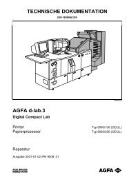
TECHNICAL DOCUMENTATION DD+18060022
- Page 3 and 4:
List of Registers Edition Register
- Page 5 and 6:
Repair Introduction Contents Use of
- Page 9 and 10:
Repair Introduction Use of the Tech
- Page 11 and 12:
Repair Introduction Legal Situation
- Page 13 and 14:
Repair Introduction Handling Photoc
- Page 15 and 16:
Repair Introduction All photographi
- Page 17 and 18:
Repair Introduction Storage Chemica
- Page 19 and 20:
Repair Basic Machine Contents Major
- Page 23 and 24:
Repair Basic Machine Major Assembly
- Page 25 and 26:
Repair Basic Machine Electrical Str
- Page 27 and 28:
Repair Basic Machine Description Al
- Page 29 and 30:
Repair Basic Machine Names of Assem
- Page 31 and 32:
Repair Basic Machine Assembly group
- Page 33 and 34:
Basic Machine Repair Signals dlab13
- Page 35 and 36:
Repair Basic Machine Connection Pri
- Page 37 and 38:
Repair Basic Machine Connections Fi
- Page 39 and 40:
Repair Basic Machine RH Magazine Dr
- Page 41 and 42:
Repair Basic Machine Sheet Gear SG
- Page 43 and 44:
Repair Basic Machine Lane Distribut
- Page 45 and 46:
Repair Basic Machine Mains Connecti
- Page 47 and 48:
Repair Basic Machine Connections AG
- Page 49 and 50:
Repair Basic Machine Power Supply (
- Page 51 and 52:
Basic Machine Repair 55A-PWD (2/5)
- Page 53 and 54:
Basic Machine Repair 55A-PWD (4/5)
- Page 55 and 56:
Basic Machine Repair 55P-CNR 2.34 2
- Page 57 and 58:
Basic Machine Repair 55P-IRC (1/2)
- Page 59 and 60:
Basic Machine Repair 55P-MDV (1/4)
- Page 61 and 62:
Basic Machine Repair 55P-MDV (3/4)
- Page 63 and 64:
Basic Machine Repair 55P-SSR • 2.
- Page 65:
Diagnosis / Troubleshooting Repair
- Page 69 and 70:
Diagnosis / Troubleshooting Repair
- Page 71 and 72:
Diagnosis / Troubleshooting Repair
- Page 73 and 74:
Diagnosis / Troubleshooting Repair
- Page 75 and 76:
Diagnosis / Troubleshooting Repair
- Page 77 and 78:
Diagnosis / Troubleshooting Repair
- Page 79 and 80:
Diagnosis / Troubleshooting Repair
- Page 81 and 82:
Diagnosis / Troubleshooting Repair
- Page 83 and 84:
Diagnosis / Troubleshooting Repair
- Page 85 and 86:
Scanner Repair Functional Descripti
- Page 87:
Scanner Repair ■ 4.iv 2001-01-02
- Page 91 and 92:
Repair Scanner Block Circuit Diagra
- Page 93 and 94:
Repair Scanner Image Recording dlab
- Page 95 and 96:
Repair Scanner Scanner Motherboard:
- Page 97 and 98:
Repair Scanner Driver Sensor Board
- Page 99 and 100:
Repair Scanner Driver Sensor Board:
- Page 101 and 102:
Repair Scanner FD/SD Output Stage d
- Page 103 and 104:
Repair Scanner FL Controller: LEDs
- Page 105 and 106:
Repair Scanner Algorithm/Interface
- Page 107 and 108:
Repair Scanner CG Controller dlab08
- Page 109 and 110:
Repair Scanner CCD Board dlabr084e
- Page 111 and 112:
Repair Scanner Prescanner dlab091e
- Page 115 and 116:
Repair Scanner Signal Lists Descrip
- Page 117 and 118:
Repair Scanner Mirror Box MB No. De
- Page 119 and 120:
Repair Scanner Activation of Motors
- Page 123 and 124:
Repair Scanner Functional Descripti
- Page 125 and 126:
Repair Scanner Scanner Optic dlab14
- Page 127 and 128:
Repair Scanner Main Scan Cycle Filt
- Page 129 and 130:
Repair Scanner Filter Wheel LH_MO01
- Page 131 and 132:
Repair Scanner The motor is energis
- Page 133 and 134:
Repair Scanner Auxiliary Shutter (D
- Page 135 and 136:
Repair Scanner Position Auxiliary D
- Page 137 and 138:
Repair Scanner Amplifiers, function
- Page 139 and 140:
Repair Scanner Lenses − Fixed foc
- Page 141 and 142:
Repair Scanner Functions and Proper
- Page 143 and 144:
Repair Scanner Film Drive NC_MO01 T
- Page 145 and 146:
Repair Scanner Control The Motherbo
- Page 147 and 148:
Repair Scanner FD/SD Output Stage (
- Page 149 and 150:
Repair Scanner Functions: − Contr
- Page 151 and 152:
Repair Scanner The TFS is not perfo
- Page 153 and 154:
Repair Scanner CG Controller (CCD G
- Page 155 and 156:
Repair Scanner Driver Sensor Board
- Page 157 and 158:
Repair Scanner I 2 C Bus The 2-Bit
- Page 161 and 162:
Repair Scanner Repair / Adjustments
- Page 163 and 164:
Repair Scanner Shutter Toothed belt
- Page 165 and 166:
Repair Scanner − Check the belt d
- Page 167 and 168:
Repair Scanner 2-Film Feeder Dismou
- Page 169 and 170:
Repair Scanner Installing the Feede
- Page 171 and 172:
Repair Scanner Feeder rocker Feeler
- Page 173 and 174:
Repair Scanner − Light sensor act
- Page 175 and 176:
Repair Scanner Changing the Lifting
- Page 177 and 178:
Repair Scanner 1a Cover plate A 1b
- Page 179 and 180:
Repair Scanner Changing the Light S
- Page 181 and 182:
Repair Scanner Replacing the Zoom /
- Page 183 and 184:
Repair Scanner Precanner Adjustment
- Page 185 and 186:
Repair Scanner Remove the following
- Page 187 and 188:
Repair Scanner Scanner Calibration
- Page 189 and 190:
Repair Scanner White Balance A whit
- Page 191 and 192:
Repair Scanner Moment of Execution
- Page 193 and 194:
Repair Main-PC Contents Overview ..
- Page 197 and 198:
Repair Main-PC Overview Main-PC dla
- Page 199 and 200:
Repair Main-PC Drives Drives (drive
- Page 201 and 202:
Repair Main-PC PC Mainboard Connect
- Page 203 and 204:
Repair Main-PC BIOS Settings AWARD
- Page 205 and 206:
Repair Main-PC Operating System Win
- Page 207 and 208:
Repair Main-PC Repair Removal of th
- Page 209 and 210:
Repair Printer Contents General Ove
- Page 211 and 212:
Repair Printer Removal, Installatio
- Page 215 and 216:
Repair General Overview Sensors and
- Page 217 and 218:
Printer Repair Electrical Structure
- Page 219 and 220:
Printer Repair Voltages on the d-la
- Page 221:
Printer Repair ■ 6.1.8 2001-01-02
- Page 225 and 226:
Printer Repair Printer Mainboard PF
- Page 227 and 228:
Printer Repair Paper Magazine RH MR
- Page 229 and 230:
Printer Repair Transport Unit TU /
- Page 231 and 232:
Printer Repair Laser Module LA Some
- Page 233 and 234:
Printer Repair Sheet Transfer ST Pr
- Page 235 and 236:
Printer Repair ST 3: SPI - Interfac
- Page 237 and 238:
Printer Repair ST 7: SPI - Interfac
- Page 239 and 240:
Printer Repair ST 26: CAN - Interfa
- Page 241 and 242:
Printer Repair Printer Mainboard, C
- Page 243 and 244:
Printer Repair ST17 Trailing cable
- Page 245 and 246:
Printer Repair PE_GS01, Connector A
- Page 247 and 248:
Printer Repair ST11 DC motor supply
- Page 249:
Printer Repair ST29 Pin connector s
- Page 253 and 254:
Printer Repair Paper Transport and
- Page 255 and 256:
Printer Repair Behaviour upon Print
- Page 257 and 258:
Printer Repair Sheet Rotation / She
- Page 259 and 260:
Printer Repair Roller Exit, Part 1
- Page 261 and 262:
Printer Repair Flowcharts, Lane Dis
- Page 263 and 264:
Printer Repair Sheet Distribution -
- Page 265 and 266:
Printer Repair Sheet Transfer to Pa
- Page 267 and 268:
Printer Repair Functional Descripti
- Page 269 and 270:
Printer Repair 4. Begin Off Line (B
- Page 271 and 272:
Printer Repair The following modes
- Page 273 and 274:
Printer Repair 17. Calculation The
- Page 275 and 276:
Printer Repair PF_GS01 - Technical
- Page 277 and 278:
Printer Repair Magazine Drive MD ML
- Page 279 and 280:
Printer Repair − The paper transp
- Page 281 and 282:
Printer Repair ML_GS02 / MR_GS02 an
- Page 283 and 284:
Printer Repair Layout dlabr205 Volt
- Page 285 and 286:
Printer Repair Transport Unit TU Fu
- Page 287 and 288:
Printer Repair Voltages + 5V Logic
- Page 289 and 290:
Printer Repair Laser Module Warning
- Page 291 and 292:
Printer Repair Connection of the po
- Page 293 and 294:
Printer Repair PE_GS01, Layout dlab
- Page 295 and 296:
Printer Repair Circuit Diagram dlab
- Page 297 and 298:
Printer Repair Laser Remote After t
- Page 299 and 300:
Printer Repair Test Points MP1 +5 +
- Page 301 and 302:
Printer Repair LA_GS05 - Red Laser
- Page 303 and 304:
Printer Repair Lane Distributor LD
- Page 305 and 306:
Printer Repair LD_GS01 - Lane Distr
- Page 307 and 308:
Printer Repair RD_GS01 - Back Print
- Page 309 and 310:
Printer Repair Laser Module (LA) Th
- Page 311 and 312:
Printer Repair Laser Sources Laser
- Page 313 and 314:
Printer Repair There are 2 methods
- Page 315 and 316:
Printer Repair − Enter new values
- Page 317:
Printer Repair − Define the pixel
- Page 321 and 322:
Printer Repair Mainboard Replacemen
- Page 323 and 324:
Printer Repair − Determine the op
- Page 325 and 326:
Printer Repair Download XILINKS (pr
- Page 327 and 328:
Printer Repair Loading setup values
- Page 329 and 330:
Printer Repair − Print a test pri
- Page 331 and 332:
Printer Repair Hexagon socket screw
- Page 333 and 334:
Printer Repair Replacing the Magazi
- Page 335 and 336:
Printer Repair Replacing the Cutter
- Page 337 and 338:
Printer Repair Replacing the Switch
- Page 339 and 340:
Printer Repair Replacing the Motor
- Page 341 and 342:
Printer Repair Replacing the Pressu
- Page 343 and 344:
Printer Repair Sheet Bridge SB, rep
- Page 345 and 346:
Printer Repair Replacing the Sync D
- Page 347 and 348:
Printer Repair Transport Unit TU, r
- Page 349 and 350:
Printer Repair Toothed Belt Adjust
- Page 351 and 352:
Printer Repair Replacing the Turnta
- Page 353 and 354:
Printer Repair Replacing the Motor
- Page 355 and 356:
Printer Repair − Fastening of the
- Page 357 and 358:
Printer Repair Replacing the Light
- Page 359 and 360:
Printer Repair Replacing the Set of
- Page 361 and 362:
Printer Repair Replacing the Set of
- Page 363 and 364:
Printer Repair Replacing the comple
- Page 365 and 366:
Printer Repair Replacing the Laser
- Page 367 and 368:
Printer Repair Caution! Use only th
- Page 369 and 370:
Printer Repair − The tip of the p
- Page 371 and 372:
Printer Repair Replacing the AOM Am
- Page 373 and 374:
Printer Repair Lane Distributor LD,
- Page 375 and 376:
Printer Repair Replacing the LD_GS0
- Page 377 and 378:
Printer Repair Replacing toothed Be
- Page 379 and 380:
Printer Repair Readjust the print h
- Page 381 and 382:
Printer Repair Sheet Transfer ST, r
- Page 383 and 384:
Printer Repair ■ 6.4.64 2001-01-0
- Page 385:
Paper Processor Repair ■ 7.ii 200
- Page 389 and 390:
Repair Paper Processor Block Circui
- Page 393 and 394:
Repair Paper Processor Signal Lists
- Page 395 and 396:
Repair Paper Processor Paper Exit P
- Page 397 and 398:
Repair Paper Processor Connections
- Page 401 and 402:
Repair Paper Processor Functional D
- Page 403 and 404:
Repair Paper Processor Electrical S
- Page 405 and 406:
Repair Paper Processor Paper Proces
- Page 407 and 408:
Repair Paper Processor AC/DC Power
- Page 409 and 410: Repair Paper Processor AC Power Sup
- Page 411 and 412: Repair Paper Processor Densitometer
- Page 415 and 416: Repair Paper Processor Repair Repla
- Page 417 and 418: Repair Paper Processor Replacing Pr
- Page 419 and 420: Repair Paper Processor Temperature
- Page 421 and 422: Repair Software Contents Software S
- Page 425 and 426: Repair Software Software Structure
- Page 427 and 428: Repair Software Software Structure
- Page 429 and 430: Repair Maintenance Contents Mainten
- Page 433 and 434: Repair Maintenance Maintenance Sche
- Page 435 and 436: Repair Maintenance Maintenance Jobs
- Page 437 and 438: Repair Maintenance Negative Mask: L
- Page 439 and 440: Repair Maintenance Paper Processor
- Page 441 and 442: Repair Maintenance Cleaning the Eva
- Page 443 and 444: Repair Maintenance Paper Magazine A
- Page 445 and 446: Repair Maintenance Consumables / Cl
- Page 447 and 448: Repair General Data and Information
- Page 451 and 452: Repair General Data and Information
- Page 453 and 454: Repair General Data and Information
- Page 455 and 456: Repair General Data and Information
- Page 457 and 458: Repair General Data and Information
- Page 459: Repair General Data and Information
- Page 463 and 464: Repair Index Index A Additional Air
- Page 465 and 466: Repair Index S (cont.) Service Func