AGFA d-lab.3 Digital Compact Lab
AGFA d-lab.3 Digital Compact Lab AGFA d-lab.3 Digital Compact Lab
Repair Printer Adjust the belt tension − Turn the tensioning screws (1) at the ends of the belt bridge (accessible through the holes) ccw until it can be felt that the belt is not in mesh any more. From this point, turn cw until no spring force is felt any more. Do not check on the outer rollers as they have a larger diameter. − Count the turns between the two positions (approx. 6) and turn ccw half the number of turns dlabr298 AGFA d-lab.3 2001-01-02 /PN 9009 6.4.41
Printer Repair Replacing the Set of Belts at the top Set of belts at the top 9.8060.PEC0.0 Replacement required: Belts and rollers damaged by a paper jam Removal/installation in case of scratches caused by the edge of the slit. Allan keys 3 and 4 Screwdriver Do not slacken the eccentric of the toggle upon the removal, do not shift the actuators. In this case, reliable functioning would not be ensured any more! Removal − Pull out the PE − Remove the top guide plate − Push in the piston on the actuator PE_MO03 (1) (stiff!) − Remove the sensor holder (above 4) with sensor PE_LS02 − Detach the tension spring (4) − Open the circlip (2) − Remove the toggle (3) − Detach the cable from the cable holder − Remove the sensor plate (6): Unscrew 2 screws at the front, remove the plate to the front − Unscrew 2 screws (below the cable collar) on the set of belts (5) and pull out the assembly group with the plate (cable holder) towards the front − Removal because of scratches: Check the front edge of the part, if necessary pull it off a little and clean it dlabr256 Installation: Put a sheet of photographic paper 20x30 over the print roller, clamp the sheet on the left side under the set of belts: Absolutely necessary, otherwise the belts may slip off the belt rollers when the assembly group is mounted! 6.4.42 2001-01-02 /PN 9009 AGFA d-lab.3
- Page 309 and 310: Printer Repair Laser Module (LA) Th
- Page 311 and 312: Printer Repair Laser Sources Laser
- Page 313 and 314: Printer Repair There are 2 methods
- Page 315 and 316: Printer Repair − Enter new values
- Page 317: Printer Repair − Define the pixel
- Page 321 and 322: Printer Repair Mainboard Replacemen
- Page 323 and 324: Printer Repair − Determine the op
- Page 325 and 326: Printer Repair Download XILINKS (pr
- Page 327 and 328: Printer Repair Loading setup values
- Page 329 and 330: Printer Repair − Print a test pri
- Page 331 and 332: Printer Repair Hexagon socket screw
- Page 333 and 334: Printer Repair Replacing the Magazi
- Page 335 and 336: Printer Repair Replacing the Cutter
- Page 337 and 338: Printer Repair Replacing the Switch
- Page 339 and 340: Printer Repair Replacing the Motor
- Page 341 and 342: Printer Repair Replacing the Pressu
- Page 343 and 344: Printer Repair Sheet Bridge SB, rep
- Page 345 and 346: Printer Repair Replacing the Sync D
- Page 347 and 348: Printer Repair Transport Unit TU, r
- Page 349 and 350: Printer Repair Toothed Belt Adjust
- Page 351 and 352: Printer Repair Replacing the Turnta
- Page 353 and 354: Printer Repair Replacing the Motor
- Page 355 and 356: Printer Repair − Fastening of the
- Page 357 and 358: Printer Repair Replacing the Light
- Page 359: Printer Repair Replacing the Set of
- Page 363 and 364: Printer Repair Replacing the comple
- Page 365 and 366: Printer Repair Replacing the Laser
- Page 367 and 368: Printer Repair Caution! Use only th
- Page 369 and 370: Printer Repair − The tip of the p
- Page 371 and 372: Printer Repair Replacing the AOM Am
- Page 373 and 374: Printer Repair Lane Distributor LD,
- Page 375 and 376: Printer Repair Replacing the LD_GS0
- Page 377 and 378: Printer Repair Replacing toothed Be
- Page 379 and 380: Printer Repair Readjust the print h
- Page 381 and 382: Printer Repair Sheet Transfer ST, r
- Page 383 and 384: Printer Repair ■ 6.4.64 2001-01-0
- Page 385: Paper Processor Repair ■ 7.ii 200
- Page 389 and 390: Repair Paper Processor Block Circui
- Page 393 and 394: Repair Paper Processor Signal Lists
- Page 395 and 396: Repair Paper Processor Paper Exit P
- Page 397 and 398: Repair Paper Processor Connections
- Page 401 and 402: Repair Paper Processor Functional D
- Page 403 and 404: Repair Paper Processor Electrical S
- Page 405 and 406: Repair Paper Processor Paper Proces
- Page 407 and 408: Repair Paper Processor AC/DC Power
- Page 409 and 410: Repair Paper Processor AC Power Sup
Printer<br />
Repair<br />
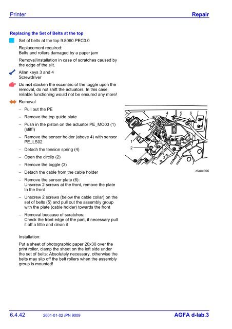
Replacing the Set of Belts at the top<br />
Set of belts at the top 9.8060.PEC0.0<br />
Replacement required:<br />
Belts and rollers damaged by a paper jam<br />
Removal/installation in case of scratches caused by<br />
the edge of the slit.<br />
Allan keys 3 and 4<br />
Screwdriver<br />
Do not slacken the eccentric of the toggle upon the<br />
removal, do not shift the actuators. In this case,<br />
reliable functioning would not be ensured any more!<br />
Removal<br />
− Pull out the PE<br />
− Remove the top guide plate<br />
− Push in the piston on the actuator PE_MO03 (1)<br />
(stiff!)<br />
− Remove the sensor holder (above 4) with sensor<br />
PE_LS02<br />
− Detach the tension spring (4)<br />
− Open the circlip (2)<br />
− Remove the toggle (3)<br />
− Detach the cable from the cable holder<br />
− Remove the sensor plate (6):<br />
Unscrew 2 screws at the front, remove the plate<br />
to the front<br />
− Unscrew 2 screws (below the cable collar) on the<br />
set of belts (5) and pull out the assembly group<br />
with the plate (cable holder) towards the front<br />
− Removal because of scratches:<br />
Check the front edge of the part, if necessary pull<br />
it off a little and clean it<br />
dlabr256<br />
Installation:<br />
Put a sheet of photographic paper 20x30 over the<br />
print roller, clamp the sheet on the left side under<br />
the set of belts: Absolutely necessary, otherwise the<br />
belts may slip off the belt rollers when the assembly<br />
group is mounted!<br />
6.4.42 2001-01-02 /PN 9009 <strong>AGFA</strong> d-<strong>lab.3</strong>


