AGFA d-lab.3 Digital Compact Lab
AGFA d-lab.3 Digital Compact Lab AGFA d-lab.3 Digital Compact Lab
Repair Printer Replacing / adjusting the toothed Belt (Switching Lug) − Replace the toothed belt Adjustment of the lateral guide elements (required when the toothed belt has to be replaced): − Slacken the screws − Fasten the lateral guide elements directly on the edge of the supporting plate − Tighten the screws − The adjustment is performed in the Service program. dlabr216 Light Sensor TU_LS07 Fork light sensor TU_LS07 defective (Home position sheet centring) Replace TU_LS07 (1): − Disconnect the connector Redefine the Setup value for the light sensor: − The adjustment is assisted by the Service program dlabr217 AGFA d-lab.3 2001-01-02 /PN 9009 6.4.29
Printer Repair Toothed Belt Adjust the belt tension in such a way that the belt can easily be pushed to and fro on the gear at the belt turning point. Caution! The motor shaft may be overstressed and may break if the belt is too tight. dlabr216 6.4.30 2001-01-02 /PN 9009 AGFA d-lab.3
- Page 297 and 298: Printer Repair Laser Remote After t
- Page 299 and 300: Printer Repair Test Points MP1 +5 +
- Page 301 and 302: Printer Repair LA_GS05 - Red Laser
- Page 303 and 304: Printer Repair Lane Distributor LD
- Page 305 and 306: Printer Repair LD_GS01 - Lane Distr
- Page 307 and 308: Printer Repair RD_GS01 - Back Print
- Page 309 and 310: Printer Repair Laser Module (LA) Th
- Page 311 and 312: Printer Repair Laser Sources Laser
- Page 313 and 314: Printer Repair There are 2 methods
- Page 315 and 316: Printer Repair − Enter new values
- Page 317: Printer Repair − Define the pixel
- Page 321 and 322: Printer Repair Mainboard Replacemen
- Page 323 and 324: Printer Repair − Determine the op
- Page 325 and 326: Printer Repair Download XILINKS (pr
- Page 327 and 328: Printer Repair Loading setup values
- Page 329 and 330: Printer Repair − Print a test pri
- Page 331 and 332: Printer Repair Hexagon socket screw
- Page 333 and 334: Printer Repair Replacing the Magazi
- Page 335 and 336: Printer Repair Replacing the Cutter
- Page 337 and 338: Printer Repair Replacing the Switch
- Page 339 and 340: Printer Repair Replacing the Motor
- Page 341 and 342: Printer Repair Replacing the Pressu
- Page 343 and 344: Printer Repair Sheet Bridge SB, rep
- Page 345 and 346: Printer Repair Replacing the Sync D
- Page 347: Printer Repair Transport Unit TU, r
- Page 351 and 352: Printer Repair Replacing the Turnta
- Page 353 and 354: Printer Repair Replacing the Motor
- Page 355 and 356: Printer Repair − Fastening of the
- Page 357 and 358: Printer Repair Replacing the Light
- Page 359 and 360: Printer Repair Replacing the Set of
- Page 361 and 362: Printer Repair Replacing the Set of
- Page 363 and 364: Printer Repair Replacing the comple
- Page 365 and 366: Printer Repair Replacing the Laser
- Page 367 and 368: Printer Repair Caution! Use only th
- Page 369 and 370: Printer Repair − The tip of the p
- Page 371 and 372: Printer Repair Replacing the AOM Am
- Page 373 and 374: Printer Repair Lane Distributor LD,
- Page 375 and 376: Printer Repair Replacing the LD_GS0
- Page 377 and 378: Printer Repair Replacing toothed Be
- Page 379 and 380: Printer Repair Readjust the print h
- Page 381 and 382: Printer Repair Sheet Transfer ST, r
- Page 383 and 384: Printer Repair ■ 6.4.64 2001-01-0
- Page 385: Paper Processor Repair ■ 7.ii 200
- Page 389 and 390: Repair Paper Processor Block Circui
- Page 393 and 394: Repair Paper Processor Signal Lists
- Page 395 and 396: Repair Paper Processor Paper Exit P
- Page 397 and 398: Repair Paper Processor Connections
Repair<br />
Printer<br />
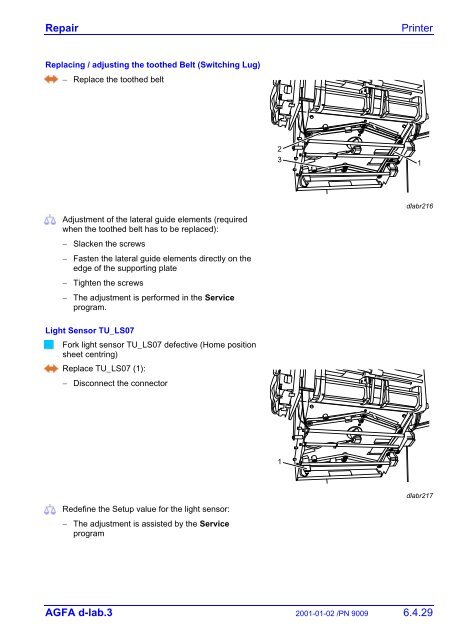
Replacing / adjusting the toothed Belt (Switching Lug)<br />
− Replace the toothed belt<br />
Adjustment of the lateral guide elements (required<br />
when the toothed belt has to be replaced):<br />
− Slacken the screws<br />
− Fasten the lateral guide elements directly on the<br />
edge of the supporting plate<br />
− Tighten the screws<br />
− The adjustment is performed in the Service<br />
program.<br />
dlabr216<br />
Light Sensor TU_LS07<br />
Fork light sensor TU_LS07 defective (Home position<br />
sheet centring)<br />
Replace TU_LS07 (1):<br />
− Disconnect the connector<br />
Redefine the Setup value for the light sensor:<br />
− The adjustment is assisted by the Service<br />
program<br />
dlabr217<br />
<strong>AGFA</strong> d-<strong>lab.3</strong> 2001-01-02 /PN 9009 6.4.29


