
You also want an ePaper? Increase the reach of your titles
YUMPU automatically turns print PDFs into web optimized ePapers that Google loves.
TECHNICAL DOCUMENTATION<br />
DD+18060022D0<br />
dlabr000<br />
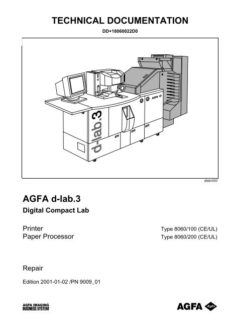
<strong>AGFA</strong> d-<strong>lab.3</strong><br />
<strong>Digital</strong> <strong>Compact</strong> <strong>Lab</strong><br />
Printer<br />
Paper Processor<br />
Type 8060/100 (CE/UL)<br />
Type 8060/200 (CE/UL)<br />
Repair<br />
Edition 2001-01-02 /PN 9009_01
© 2001 Agfa-Gevaert AG. All rights reserved.<br />
No part of this documentation is allowed to be copied or transferred by any means or<br />
for any purpose without prior written autorisation by Agfa-Gevaert AG.<br />
All rights of design<br />
modifications and alterations of designations or<br />
indications of the scope of delivery reserved.<br />
Printed in Germany on<br />
paper made without chlorine.
List of Registers<br />
Edition<br />
Register<br />
Introduction...................................................................... 2001-01-02.................. 1<br />
Basic Machine ................................................................. 2001-01-02.................. 2<br />
Diagnosis / Troubleshooting ............................................ 2001-01-02.................. 3<br />
Scanner ........................................................................... 2001-01-02.................. 4<br />
Main-PC........................................................................... 2001-01-02.................. 5<br />
Printer .............................................................................. 2001-01-02.................. 6<br />
Paper Processor .............................................................. 2001-01-02.................. 7<br />
Software........................................................................... 2001-01-02.................. 8<br />
Maintenance .................................................................... 2001-01-02.................. 9<br />
General Data and Information.......................................... 2001-01-02................ 10<br />
Index................................................................................ 2001-01-02................ 11<br />
Preinstallation / Installation .............................................. 2001-02-15................ 12
leere Seite<br />
leere Seite
Repair<br />
Introduction<br />
Contents<br />
Use of the Technical Documentation ....................................................................................................... 1.1<br />
Structure................................................................................................................................................ 1.1<br />
Symbols................................................................................................................................................. 1.2<br />
Text Styles............................................................................................................................................. 1.2<br />
Safety Instructions................................................................................................................................. 1.2<br />
Legal Situation............................................................................................................................................ 1.3<br />
Copyright ............................................................................................................................................... 1.3<br />
Safety Prescriptions .............................................................................................................................. 1.3<br />
General ....................................................................................................................................... 1.3<br />
For the Operation........................................................................................................................ 1.4<br />
For Service / Repair Work .......................................................................................................... 1.4<br />
For the Disposal of the machine .................................................................................................1.4<br />
Handling Photochemicals ......................................................................................................................... 1.5<br />
Legal Regulations.................................................................................................................................. 1.5<br />
Disposal................................................................................................................................................. 1.5<br />
Spent Processing Solutions ........................................................................................................ 1.5<br />
Liquid Residues........................................................................................................................... 1.6<br />
Chemical Containers................................................................................................................... 1.6<br />
Safety Precautions ................................................................................................................................ 1.6<br />
Use of the Laser Beam............................................................................................................................... 1.8<br />
Storage ........................................................................................................................................................ 1.9<br />
Chemicals ............................................................................................................................................. 1.9<br />
Photographic Paper............................................................................................................................... 1.9<br />
<strong>AGFA</strong> d-<strong>lab.3</strong> 2001-01-02 /PN 9009 1.i
Introduction<br />
Repair<br />
■<br />
1.ii 2001-01-02 /PN 9009 <strong>AGFA</strong> d-<strong>lab.3</strong>
Repair<br />
Introduction<br />
Use of the Technical Documentation<br />
Structure<br />
The complete documentation is included in the<br />
scope of delivery of the machine<br />
Folder Customer Operator Technician Information<br />
Operation Use of the documentation<br />
✘<br />
Safety precautions<br />
Machine settings<br />
Production<br />
Maintenance (regular jobs to maintain the<br />
operation and keep the machine in good<br />
working order)<br />
Repair Diagnosis and repair of electronic /<br />
✘<br />
mechanical parts and complete<br />
assemblies<br />
Removal, installation, adjustment of<br />
single parts / complete assemblies<br />
Maintenance carried out by technicians<br />
(yearly, every two years)<br />
Circuit and reference diagrams: Signal<br />
tracing<br />
Spare parts list<br />
✘ ✘<br />
Finding a machine part and its part<br />
number<br />
Preinstallation<br />
(booklet)<br />
Installation<br />
(booklet)<br />
✘<br />
✘<br />
Preinstallation actions<br />
Installation performed by an Agfa<br />
technician<br />
<strong>AGFA</strong> d-<strong>lab.3</strong> 2001-01-02 /PN 9009 1.1
Introduction<br />
Repair<br />
Symbols<br />
The symbols that are used have the following<br />
meaning:<br />
− General description<br />
− Operating steps<br />
− Prerequisite<br />
− Note<br />
− Safety instructions<br />
− Reference to another chapter<br />
− Tools and measuring means<br />
Text Styles<br />
The following text parts are highlighted in bold<br />
letters / italic letters in the technical<br />
documentation:<br />
1. Screen designations, e.g.:<br />
Example: Pressing OK will validate the<br />
displayed text and the Input screen is<br />
closed.<br />
2. Designations of buttons, e.g.:<br />
Strike Reorder to handle reorders<br />
3. Reference to other text parts in the technical<br />
documentation is indicated in italic letters,<br />
e.g.:<br />
See also the section Menu overview and<br />
Screen structure on the following pages.<br />
Safety Instructions<br />
The words Caution and Warning in the<br />
documentation and on the machine labels<br />
indicate the following risks:<br />
Caution!<br />
Low risk.<br />
Potentially dangerous situation. May cause<br />
minor injuries to persons or damage to property.<br />
Warning!<br />
Average risk.<br />
Possible danger. May cause severe injuries to<br />
persons and death.<br />
1.2 2001-01-02 /PN 9009 <strong>AGFA</strong> d-<strong>lab.3</strong>
Repair<br />
Introduction<br />
Legal Situation<br />
The operation of the machines is ruled by the<br />
appropriate regulations for the place of installation<br />
in force in the country concerned.<br />
This technical documentation includes a EU<br />
conformity explanation (CE) about the<br />
harmonised standards that apply.<br />
Caution!<br />
The following safety regulations, warnings and<br />
instructions on machine labels must be<br />
observed by all means.<br />
The non-observance may be dangerous for<br />
persons, equipment and buildings: injuries,<br />
electric shocks, fire.<br />
The manufacturer and the service will not<br />
assume any responsibilities for accidents and<br />
damages resulting from incorrect operation.<br />
Copyright<br />
Copies of photographs, negatives and other<br />
pictures must not be made without the<br />
permission of the author. Under normal<br />
conditions, the Copyright is the property of the<br />
photographer. The one who orders the copy is<br />
not always the author of the material.<br />
Safety Prescriptions<br />
General<br />
Warning and instructions on machine stickers<br />
must be strictly observed.<br />
Safety devices:<br />
− Do not bypass or make inoperative built-in<br />
safety devices.<br />
− Do not modify presettings on safety<br />
components.<br />
− Replace fuses that have blown only by the<br />
same type of fuse: Value, switch-off<br />
characteristics.<br />
− Never modify the electrical switching circuit.<br />
<strong>AGFA</strong> d-<strong>lab.3</strong> 2001-01-02 /PN 9009 1.3
Introduction<br />
Repair<br />
For the Operation<br />
Do not operate the machine without the covers<br />
and panels. Persons who open or remove<br />
covers expose themselves to dangerous<br />
voltages or run other risks.<br />
Do not cover or block the venting openings in<br />
the housing: This may lead to overheating of<br />
single components.<br />
No objects or liquids should get into the<br />
machine through the venting openings: This<br />
may cause fire or electric shocks.<br />
Do not squeeze the power cable and install it in<br />
such a way that no one can step on the cable.<br />
Avoid excessive generation of dust as this may<br />
damage the components in the machine.<br />
For Service / Repair Work<br />
− Please respect the local safety precautions<br />
− Be sure to switch off the machine before<br />
service and repair jobs are performed<br />
− The machine is equipped with high-voltage<br />
carrying and fragile components. For this<br />
reason, the following jobs must only be<br />
performed by authorised service technicians:<br />
− Repairs on electrical components<br />
− Maintenance jobs / removal of parts and<br />
covers not described in this documentation<br />
− Use original Agfa spare parts: Only these parts<br />
have been tested for their safety and usability<br />
− When replacing electrical components:<br />
Observe the data given in the circuit and wiring<br />
diagrams.<br />
− At the end of all service / maintenance jobs:<br />
Check the general function of the machine as<br />
well as the correct condition of the safety<br />
devices.<br />
Disposal<br />
The machine must be disposed of as industrial<br />
waste.<br />
1.4 2001-01-02 /PN 9009 <strong>AGFA</strong> d-<strong>lab.3</strong>
Repair<br />
Introduction<br />
Handling Photochemicals<br />
Legal Regulations<br />
The machine is subject to the legal regulations<br />
about water:<br />
− Photochemicals are not allowed to be drained<br />
off into the public sewage system.<br />
− It must be checked whether residual<br />
substances can be avoided, reduced or<br />
recycled.<br />
− All photographic solutions as well as plastic<br />
containers holding harmful residues are<br />
considered to be special waste.<br />
− When storing spent processing solutions, it<br />
must be made sure that no waters are polluted,<br />
e.g. by unintentional leakage.<br />
The regulations about the handling and correct<br />
disposal of chemistry are different in each country.<br />
Information about the regulations in force can be<br />
obtained from:<br />
− The country’s authorities in charge<br />
− The nearest Agfa subsidiary<br />
Disposal<br />
Spent Processing Solutions<br />
The processing solutions used are usually only<br />
slightly water endangering (Water endangering<br />
class 1). For this reason, these solutions can be<br />
stored in commercial containers for<br />
photochemicals until their final disposal.<br />
For larger tanks, a conformity certificate is<br />
usually required.<br />
<strong>AGFA</strong> d-<strong>lab.3</strong> 2001-01-02 /PN 9009 1.5
Introduction<br />
Repair<br />
Liquid Residues<br />
All solutions that cannot be reused or that do not<br />
contain recyclable substances (film developer) are<br />
to be disposed of as special waste.<br />
Argentiferous solutions, in contrast, are liquid<br />
residual substances that can be used for silver<br />
recovery. For this reason, they should be<br />
collected separately from the other solutions.<br />
The disposal of argentiferous solutions should be<br />
ensured by fixing bath recycling firms that are<br />
normally also authorised to dispose of nonargentiferous<br />
solutions.<br />
For tank cleaning, cleaning agents based on<br />
peroxides are recommended. If these substances<br />
are used as prescribed, the local regulations<br />
about the draining of waste water are kept. This<br />
means that the cleaning and rinsing water of the<br />
tank cleaning can be drained into the public<br />
sewage system.<br />
Chemical Containers<br />
Rinse them with water used for the preparation<br />
of the solutions and provide for their recycling.<br />
Safety Precautions for the Handling of Chemicals<br />
Caution!<br />
The work with the machine involves the handling<br />
of slightly poisonous, irritating and etching<br />
substances. The user (employer)<br />
− has to elaborate operation instructions for the<br />
handling of dangerous substances and<br />
− provide for the instruction of his staff at least<br />
once a year.<br />
− Apart from this, the user must ensure sufficient<br />
aeration. The air in industrial workrooms should<br />
be exchanged at least eight to ten times per<br />
hour.<br />
1.6 2001-01-02 /PN 9009 <strong>AGFA</strong> d-<strong>lab.3</strong>
Repair<br />
Introduction<br />
All photographic developers contain substances<br />
which may irritate the skin, the mucous membrane<br />
and the eyes and which may cause allergic skin<br />
reactions affecting very sensitive persons. For this<br />
reason, avoid long or repeated skin contact,<br />
especially with developer solutions.<br />
For all jobs where photographic processing<br />
solutions may splash, e.g. preparing and filling in<br />
chemical solutions, cleaning processing racks<br />
etc.:<br />
− Wear protective gloves and change them every<br />
day, if possible; rinse all solutions that get on<br />
the skin with plenty of running water<br />
− Wear industrial glasses: If in spite of this,<br />
splashes do get into your eyes, wash them<br />
immediately with plenty of water, pulling apart<br />
the eyelids. Consult an oculist!<br />
Store chemicals and processing solutions in a<br />
safe place.<br />
<strong>AGFA</strong> d-<strong>lab.3</strong> 2001-01-02 /PN 9009 1.7
Introduction<br />
Repair<br />
Use of the Laser Beam<br />
The d-<strong>lab.3</strong> is equipped with an Argon ion laser of<br />
class 3B.<br />
In order to prevent damages caused by the laser<br />
beam, the latter is capsulated in the machine so<br />
that the whole machine can be classified Laser<br />
class 1.<br />
The laser beam cannot hit the operator when the<br />
d-<strong>lab.3</strong> is operated normally, even not when the<br />
machine doors are open.<br />
The laser and the laser module are identified by<br />
appropriate machine stickers.<br />
Warning!<br />
A laser beam of class 3B may be accessible after<br />
the removal of covers.<br />
Be sure to keep the mechanical laser shutter on<br />
the fibre coupling closed when working on the<br />
laser.<br />
Looking directly into lasers of class 3B is<br />
dangerous and can always hurt the eyes.<br />
Make sure during maintenance and repair work<br />
that the laser beam is not reflected by parts or<br />
tools and gets into the eyes.<br />
1.8 2001-01-02 /PN 9009 <strong>AGFA</strong> d-<strong>lab.3</strong>
Repair<br />
Introduction<br />
Storage<br />
Chemicals<br />
The chemicals should be stored and prepared<br />
according to the manufacturer’s information and<br />
advice.<br />
Photographic Paper<br />
All Color papers must always be stored in a cool<br />
and dry place.<br />
The best storage temperature is between +2 ºC<br />
and +10 ºC.<br />
Opened packages have to be stored at a<br />
relative humidity of 50-60%.<br />
Storage at 20 ºC over several days is possible<br />
without problems.<br />
Storage temperatures above 30 ºC should be<br />
avoided because they will cause visible<br />
alterations after only a few days.<br />
<strong>AGFA</strong> d-<strong>lab.3</strong> 2001-01-02 /PN 9009 1.9
Introduction<br />
Repair<br />
■<br />
1.10 2001-01-02 /PN 9009 <strong>AGFA</strong> d-<strong>lab.3</strong>
Repair<br />
Basic Machine<br />
Contents<br />
Major Assembly Groups ............................................................................................................................ 2.1<br />
Mechanical Structure............................................................................................................................. 2.2<br />
Electrical Structure ................................................................................................................................ 2.3<br />
Additional Air / Exhaust Air.................................................................................................................... 2.4<br />
Description.................................................................................................................................................. 2.5<br />
Allocation of Assembly Groups and Parts Functions ............................................................................ 2.5<br />
Scanner, PC, Printer ................................................................................................................... 2.5<br />
Paper Processor ......................................................................................................................... 2.6<br />
Names of Assembly Groups and Shortcuts ..........................................................................................2.7<br />
Parts Functions ................................................................................................................................... 2.11<br />
Signals....................................................................................................................................................... 2.12<br />
Circuit Diagrams - Scanner ..................................................................................................................... 2.13<br />
Connections Print Engine PE (1).... 2.1.8061.3003.0.......................................................................... 2.13<br />
Connection Print Engine PE (2) ..... 2.1.8061.3003.0.......................................................................... 2.14<br />
Connection Print Engine PE (3) ..... 2.1.8061.3003.0.......................................................................... 2.15<br />
Connections Film Feeder, Negative Carrier, Mirror Box FF-NC-MB.... 2.1.8061.3003.0.................... 2.16<br />
Circuit Diagrams - Printer........................................................................................................................ 2.17<br />
Printer Mainboard PF ..................... 2.1.8060.5003.0.......................................................................... 2.17<br />
RH Magazine Drive MR.................. 2.1.8060.5003.0..........................................................................2.18<br />
LH Magazine Drive ML................... 2.1.8060.5003.0..........................................................................2.19<br />
Sheet Gear SG............................... 2.1.8060.5003.0.......................................................................... 2.20<br />
Print Engine PE .............................. 2.1.8060.5003.0.......................................................................... 2.21<br />
Lane Distributor LD ........................ 2.1.8060.5003.0.......................................................................... 2.22<br />
Transport Unit TU........................... 2.1.8060.5003.0.......................................................................... 2.23<br />
Mains Connection and Power Supply.................................................................................................. 2.24<br />
<strong>AGFA</strong> d-<strong>lab.3</strong> 2001-01-02 /PN 9009 2.i
Basic Machine<br />
Repair<br />
Circuit Diagrams - Paper Processor .......................................................................................................2.25<br />
General Circuit Diagram ......................................................................................................................2.25<br />
Connections.........................................................................................................................................2.26<br />
Power Supply (AC) ..............................................................................................................................2.27<br />
Power Supply (DC) ..............................................................................................................................2.28<br />
55A-PWD (1/5) ....................................................................................................................................2.29<br />
55A-PWD (2/5) ....................................................................................................................................2.30<br />
55A-PWD (3/5) ....................................................................................................................................2.31<br />
55A-PWD (4/5) ....................................................................................................................................2.32<br />
55A-PWD (5/5) ....................................................................................................................................2.33<br />
55P-CNR .............................................................................................................................................2.34<br />
55P-CPU .............................................................................................................................................2.35<br />
55P-IRC (1/2) ......................................................................................................................................2.36<br />
55P-IRC (2/2) ......................................................................................................................................2.37<br />
55P-MDV (1/4).....................................................................................................................................2.38<br />
55P-MDV (2/4).....................................................................................................................................2.39<br />
55P-MDV (3/4).....................................................................................................................................2.40<br />
55P-MDV (4/4).....................................................................................................................................2.41<br />
55P-SSR..............................................................................................................................................2.42<br />
■<br />
2.ii 2001-01-02 /PN 9009 <strong>AGFA</strong> d-<strong>lab.3</strong>
Repair<br />
Basic Machine<br />
Major Assembly Groups<br />
dlabr003<br />
A<br />
Scanner<br />
B<br />
Main-PC<br />
C<br />
Printer<br />
D<br />
Paper Processor<br />
- Light<br />
- Image processing<br />
- Paper cutting<br />
- Paper development<br />
- Filtering<br />
- General control<br />
- Paper transport<br />
- Paper drying<br />
- Mirror Box<br />
- Timer function<br />
- Paper exposure<br />
- Order sorting<br />
- Film transport<br />
- Prescanner<br />
- Lens + CCD<br />
- Electronic<br />
<strong>AGFA</strong> d-<strong>lab.3</strong> 2001-01-02 /PN 9009 2.1
Basic Machine<br />
Repair<br />
Mechanical Structure<br />
dlabr218<br />
1 Print engine PE (exposure unit)<br />
2 Touch screen<br />
3 Processing racks<br />
4 Shifter (print chuter)<br />
5 Densitometer measuring head<br />
6 Sorter<br />
7 Infra-red predryer + dryer<br />
8 Replenisher tanks<br />
9 Drain cocks<br />
10 Lane distributor LD<br />
11 Cutter units CA + paper turnaround<br />
12 Paper transport TU<br />
13 Paper magazines<br />
2.2 2001-01-02 /PN 9009 <strong>AGFA</strong> d-<strong>lab.3</strong>
Repair<br />
Basic Machine<br />
Electrical Structure<br />
dlabr001<br />
1 Main-PC<br />
2 Driver sensor board<br />
3 Scanner motherboard with 6 plug-in boards<br />
4 Prescanner electronic<br />
5 Densitometer electronic<br />
6 Motor driver board<br />
7 Paper Processor control<br />
8 Paper Processor power supply unit<br />
9 Lane distributor control<br />
10 Back printer control<br />
11 CCD and Zoom electronic<br />
12 Paper magazine control<br />
13 Control Switching Gear + Paper Cutter Units CA<br />
14 Paper transport control<br />
15 Printer Mainboard<br />
16 Printer power supply unit + Power Monitor PCB<br />
17 Laser power supply unit<br />
18 Blue-Green Laser (beam generation)<br />
19 Control Print Engine PE<br />
20 Laser module (beam processing)<br />
21 Monitor (Touch Screen)<br />
22 Laser electronic<br />
23 Red Laser diode<br />
<strong>AGFA</strong> d-<strong>lab.3</strong> 2001-01-02 /PN 9009 2.3
Basic Machine<br />
Repair<br />
Additional Air / Exhaust Air<br />
The wet section of the Paper Processor is<br />
encapsulated; for this reason, warm air is only<br />
produced in the Printer part; see exhaust air of the<br />
laser (5).<br />
An adapter pipe end (hose dia. 125 mm) is available<br />
for the connection to an air exhaust system:<br />
Type 8060/370, ABC-Code 5GVP2<br />
dlabr154<br />
1 Additional air: Printer power supply unit<br />
2 Exhaust air: Laser and Printer power supply unit<br />
3 Additional air: Laser<br />
4 Additional air: Printer<br />
5 Exhaust Air: Laser<br />
6 Exhaust Air: Printer<br />
2.4 2001-01-02 /PN 9009 <strong>AGFA</strong> d-<strong>lab.3</strong>
Repair<br />
Basic Machine<br />
Description<br />
Allocation of Assembly Groups and Parts Functions<br />
Scanner, PC, Printer<br />
Sensors / loads; e.g.: TU_LS07<br />
− 1 st and 2 nd pos.: Assembly group<br />
− 3 rd pos.: Underline<br />
− 4 th and 5 th pos.: Function of the part<br />
− Current number in the assembly group<br />
Printed circuits; e.g.: MD_GS35<br />
− 1 st and 2 nd pos.: Assembly group<br />
− 3 rd pos.: Underline<br />
− 4 th and 5 th pos.: Function of the part<br />
− Current number in the assembly group<br />
See also the two following lists:<br />
1. Name of assembly groups and shortcuts<br />
2. Parts functions<br />
Cables, e.g.:<br />
KAXX<br />
8.8060.XXXX.X<br />
LD_GSXX:STXX<br />
Cable designation<br />
Cable reference number<br />
Address consisting of:<br />
- Functional assembly group<br />
- Function of the part<br />
- Connector designation<br />
The designations of the printed circuits on the<br />
board are not concerned by these agreements:<br />
8.8060.XXXX.X Part number of the board<br />
STXX<br />
Connector<br />
<strong>AGFA</strong> d-<strong>lab.3</strong> 2001-01-02 /PN 9009 2.5
Basic Machine<br />
Repair<br />
Paper Processor<br />
The usual designations are kept in the Paper<br />
Processor, e.g.:<br />
MO1PRP<br />
− 1st and 2 nd pos.: Function of the part<br />
− 3 rd pos.: Current number in the assembly group<br />
− 4 th position: Always P for Paper Processor<br />
− 5th and 6 th position: designation of the<br />
assembly group in which the part is located<br />
See the following lists:<br />
1. Names of assembly groups and shortcuts<br />
2. Parts functions<br />
2.6 2001-01-02 /PN 9009 <strong>AGFA</strong> d-<strong>lab.3</strong>
Repair<br />
Basic Machine<br />
Names of Assembly Groups and Shortcuts<br />
Shortcut<br />
BK<br />
CA<br />
CF<br />
CG<br />
CL<br />
CT<br />
CU<br />
DH<br />
DR<br />
DS<br />
EK<br />
ET<br />
FE<br />
FF<br />
FT<br />
FW<br />
IR<br />
LA<br />
LD<br />
LG<br />
LH<br />
LS<br />
LU<br />
MB<br />
MD<br />
MF<br />
MK<br />
ML<br />
MR<br />
NC<br />
NM<br />
PC<br />
PD<br />
PE<br />
PF<br />
Assembly group (English)<br />
Block assy<br />
Paper Cutter + Switching Gear<br />
Cartridge Feeder<br />
CCD-Group<br />
Cleaner<br />
Chemical Temperature<br />
Paper Cutter<br />
Dryer Heater<br />
Dryer<br />
Dust Shutter<br />
External Keyboard<br />
Effluent Tank<br />
Film Exit<br />
Film Feeder<br />
Film Take Up<br />
Filter Wheel<br />
Infra Red Heater<br />
Laser Module<br />
Lane Distributor<br />
Lens Group<br />
Lamp House<br />
Lane Shifter<br />
Laser Unit<br />
Mirror Box<br />
Magazine Drive<br />
Main Frame<br />
Magazine Lock<br />
Paper Magazine, left<br />
Paper Magazine, right<br />
Negative Carrier<br />
Negative Mask<br />
PC<br />
Processor Drive<br />
Print Engine<br />
Printer Frame<br />
<strong>AGFA</strong> d-<strong>lab.3</strong> 2001-01-02 /PN 9009 2.7
Basic Machine<br />
Repair<br />
Shortcut<br />
PO<br />
PO<br />
PP<br />
PP<br />
PR<br />
1)<br />
1)<br />
1)<br />
1)<br />
Assembly group (English)<br />
Power Module<br />
(Power Monitor + Printer Power Supply)<br />
Paper Outlet<br />
Printer Parts<br />
Paper Processor<br />
Printer<br />
PW<br />
RD<br />
RD<br />
RP<br />
RT<br />
RW<br />
SB<br />
SC<br />
SF<br />
SG<br />
SH<br />
SL<br />
SM<br />
SO<br />
SP<br />
SR<br />
ST<br />
SU<br />
SX<br />
TD<br />
TK<br />
TU<br />
ZH<br />
1)<br />
1)<br />
Power Supply Unit<br />
Back Printer<br />
Replenishment Mixer<br />
Replenishment Pump<br />
Replenisher Tank<br />
Replenishment Water<br />
Sheet Bridge<br />
Scanner<br />
Scanner Frame<br />
Switching Gear<br />
Shutter<br />
Single Lens<br />
Slide Mask<br />
Sorter<br />
Scanner Parts<br />
Sheet Stocker<br />
Sheet Transfer<br />
Shutter<br />
Strip Box<br />
Twin Drum Engine<br />
Tank<br />
Transport Unit<br />
Zoom Holder<br />
1)<br />
The shortcuts PO, PP and RD exist twice. But<br />
this should not cause confusion, owing to the<br />
different functions of these assembly groups.<br />
2.8 2001-01-02 /PN 9009 <strong>AGFA</strong> d-<strong>lab.3</strong>
Repair<br />
Basic Machine<br />
Assembly groups, position in d-<strong>lab.3</strong><br />
PO<br />
LS<br />
CG<br />
MD<br />
IC<br />
FL<br />
ET<br />
FD<br />
LD<br />
TK<br />
PD<br />
CT<br />
IR<br />
DH<br />
DR<br />
LH<br />
CT<br />
CT<br />
PP<br />
PP<br />
HP<br />
SO<br />
MB<br />
SL<br />
PP<br />
FF<br />
LG<br />
CC<br />
CF<br />
SC<br />
NM<br />
NC<br />
ST<br />
LD<br />
RP<br />
RD<br />
RD<br />
RW<br />
RD<br />
RT<br />
RT<br />
RT<br />
LA<br />
TU<br />
RD<br />
PE<br />
SB<br />
LU<br />
HP<br />
SR<br />
SG<br />
MR<br />
VO<br />
LU<br />
PO<br />
ML<br />
dlabr244.eps<br />
<strong>AGFA</strong> d-<strong>lab.3</strong> 2001-01-02 /PN 9009 2.9
Repair<br />
Basic Machine<br />
Parts<br />
Shortcut<br />
FA<br />
FS<br />
HT<br />
HS<br />
LS<br />
MS<br />
MO<br />
TH<br />
Assembly group (English)<br />
Fan<br />
Float Sensor<br />
Heater<br />
Heat Sensor<br />
Light Sensor<br />
MicroSwitch<br />
Motor<br />
Thermostat<br />
Certain positions in the descriptions of the sensors<br />
and loads indicate the function of a part:<br />
− 4 th and 5 th position for Scanner, PC, Printer<br />
− 1 st and 2 nd position for Paper Processor<br />
The lists of the loads and sensors are connected<br />
to the major assembly groups: See Signal lists in<br />
the sub-registers:<br />
− 4.2 Scanner<br />
− 6.2 Printer<br />
− 7.2 Paper Processor<br />
<strong>AGFA</strong> d-<strong>lab.3</strong> 2001-01-02 /PN 9009 2.11
Basic Machine<br />
Repair<br />
Signals<br />
dlab132e<br />
2.12 2001-01-02 /PN 9009 <strong>AGFA</strong> d-<strong>lab.3</strong>
Repair<br />
Basic Machine<br />
Circuit Diagrams - Scanner<br />
Connections Print Engine PE (1) 1.8061.3003.0<br />
<strong>AGFA</strong> d-<strong>lab.3</strong> 2001-01-02 /PN 9009 2.13
Repair<br />
Basic Machine<br />
Connection Print Engine PE (2) 1.8061.3003.0<br />
<strong>AGFA</strong> d-<strong>lab.3</strong> 2001-01-02 /PN 9009 2.14
Repair<br />
Basic Machine<br />
Connection Print Engine PE (3) 1.8061.3003.0<br />
<strong>AGFA</strong> d-<strong>lab.3</strong> 2001-01-02 /PN 9009 2.15
Repair<br />
Basic Machine<br />
Connections Film Feeder, Negative Carrier, Mirror Box FF-NC-MB 1.8061.3003.0<br />
<strong>AGFA</strong> d-<strong>lab.3</strong> 2001-01-02 /PN 9009 2.16
Repair<br />
Basic Machine<br />
Circuit Diagrams - Printer<br />
Printer Mainboard PF 1.8060.5003.0<br />
<strong>AGFA</strong> d-<strong>lab.3</strong> 2001-01-02 /PN 9009 2.17
Repair<br />
Basic Machine<br />
RH Magazine Drive MR 1.8060.5003.0<br />
<strong>AGFA</strong> d-<strong>lab.3</strong> 2001-01-02 /PN 9009 2.18
Repair<br />
Basic Machine<br />
LH Magazine Drive ML 1.8060.5003.0<br />
<strong>AGFA</strong> d-<strong>lab.3</strong> 2001-01-02 /PN 9009 2.19
Repair<br />
Basic Machine<br />
Sheet Gear SG 1.8060.5003.0<br />
<strong>AGFA</strong> d-<strong>lab.3</strong> 2001-01-02 /PN 9009 2.20
Repair<br />
Basic Machine<br />
Print Engine PE 1.8060.5003.0<br />
<strong>AGFA</strong> d-<strong>lab.3</strong> 2001-01-02 /PN 9009 2.21
Repair<br />
Basic Machine<br />
Lane Distributor LD 1.8060.5003.0<br />
<strong>AGFA</strong> d-<strong>lab.3</strong> 2001-01-02 /PN 9009 2.22
Repair<br />
Basic Machine<br />
Transport Unit TU 1.8060.5003.0<br />
<strong>AGFA</strong> d-<strong>lab.3</strong> 2001-01-02 /PN 9009 2.23
Repair<br />
Basic Machine<br />
Mains Connection and Power Supply<br />
dlabr136d<br />
<strong>AGFA</strong> d-<strong>lab.3</strong> 2001-01-02 /PN 9009 2.24
Repair<br />
Basic Machine<br />
Circuit Diagrams - Paper Processor<br />
General Circuit Diagram<br />
<strong>AGFA</strong> d-<strong>lab.3</strong> 2001-01-02 /PN 9009 2.25
Repair<br />
Basic Machine<br />
Connections<br />
<strong>AGFA</strong> d-<strong>lab.3</strong> 2001-01-02 /PN 9009 2.26
Repair<br />
Basic Machine<br />
Power Supply (AC)<br />
<strong>AGFA</strong> d-<strong>lab.3</strong> 2001-01-02 /PN 9009 2.27
Repair<br />
Basic Machine<br />
Power Supply (DC)<br />
<strong>AGFA</strong> d-<strong>lab.3</strong> 2001-01-02 /PN 9009 2.28
Repair<br />
Basic Machine<br />
55A-PWD (1/5)<br />
<strong>AGFA</strong> d-<strong>lab.3</strong> 2001-01-02 /PN 9009 2.29
Basic Machine<br />
Repair<br />
55A-PWD (2/5)<br />
2.30 2001-01-02 /PN 9009 <strong>AGFA</strong> d-<strong>lab.3</strong>
Repair<br />
Basic Machine<br />
55A-PWD (3/5)<br />
<strong>AGFA</strong> d-<strong>lab.3</strong> 2001-01-02 /PN 9009 2.31
Basic Machine<br />
Repair<br />
55A-PWD (4/5)<br />
2.32 2001-01-02 /PN 9009 <strong>AGFA</strong> d-<strong>lab.3</strong>
Repair<br />
Basic Machine<br />
55A-PWD (5/5)<br />
<strong>AGFA</strong> d-<strong>lab.3</strong> 2001-01-02 /PN 9009 2.33
Basic Machine<br />
Repair<br />
55P-CNR<br />
2.34 2001-01-02 /PN 9009 <strong>AGFA</strong> d-<strong>lab.3</strong>
Repair<br />
Basic Machine<br />
55P-CPU<br />
<strong>AGFA</strong> d-<strong>lab.3</strong> 2001-01-02 /PN 9009 2.35
Basic Machine<br />
Repair<br />
55P-IRC (1/2)<br />
2.36 2001-01-02 /PN 9009 <strong>AGFA</strong> d-<strong>lab.3</strong>
Repair<br />
Basic Machine<br />
55P-IRC (2/2)<br />
<strong>AGFA</strong> d-<strong>lab.3</strong> 2001-01-02 /PN 9009 2.37
Basic Machine<br />
Repair<br />
55P-MDV (1/4)<br />
2.38 2001-01-02 /PN 9009 <strong>AGFA</strong> d-<strong>lab.3</strong>
Repair<br />
Basic Machine<br />
55P-MDV (2/4)<br />
<strong>AGFA</strong> d-<strong>lab.3</strong> 2001-01-02 /PN 9009 2.39
Basic Machine<br />
Repair<br />
55P-MDV (3/4)<br />
2.40 2001-01-02 /PN 9009 <strong>AGFA</strong> d-<strong>lab.3</strong>
Repair<br />
Basic Machine<br />
55P-MDV (4/4)<br />
<strong>AGFA</strong> d-<strong>lab.3</strong> 2001-01-02 /PN 9009 2.41
Basic Machine<br />
Repair<br />
55P-SSR<br />
•<br />
2.42 2001-01-02 /PN 9009 <strong>AGFA</strong> d-<strong>lab.3</strong>
Repair<br />
Diagnosis / Troubleshooting<br />
Contents<br />
Service Functions ...................................................................................................................................... 3.1<br />
Access................................................................................................................................................... 3.1<br />
Log Files................................................................................................................................................ 3.2<br />
Scripts ................................................................................................................................................... 3.3<br />
Commands............................................................................................................................................ 3.3<br />
Remote Diagnosis with the RDS System................................................................................................. 3.4<br />
Script Language Daisy............................................................................................................................... 3.5<br />
Conversions .......................................................................................................................................... 3.6<br />
Key Words............................................................................................................................................. 3.6<br />
Grammar............................................................................................................................................... 3.6<br />
Commands.......................................................................................................................................... 3.10<br />
msgbox ..................................................................................................................................... 3.10<br />
wait............................................................................................................................................ 3.10<br />
include....................................................................................................................................... 3.10<br />
trace .......................................................................................................................................... 3.10<br />
cmd, answer, comment, var_read, var_ask_int........................................................................ 3.11<br />
var_ask_string........................................................................................................................... 3.11<br />
MiniCalc - calc........................................................................................................................... 3.12<br />
String Allocation – var_set ........................................................................................................ 3.12<br />
Example of a Script................................................................................................................... 3.13<br />
Exiting the Service Mode......................................................................................................................... 3.15<br />
<strong>AGFA</strong> d-<strong>lab.3</strong> 2001-01-02 /PN 9009 3.i
Diagnosis / Troubleshooting<br />
Repair<br />
■<br />
3.ii 2001-01-02 /PN 9009 <strong>AGFA</strong> d-<strong>lab.3</strong>
Repair<br />
Diagnosis / Troubleshooting<br />
Service Functions<br />
Access<br />
The Service Functions are only accessible when the<br />
user logging in has the right of access.<br />
All menus and functions are accessible in the<br />
service mode (unlimited right of access).<br />
− Call-up of the main menu line:<br />
Test<br />
Service<br />
The service operator interface is displayed<br />
(language: English).<br />
Service functions:<br />
− Configuration<br />
− Software Information<br />
− Firmware Download<br />
− Firmware Version<br />
− Logfiles<br />
− Scripts<br />
− Commands<br />
− Film Drive<br />
− Paper Processor<br />
− Printer<br />
− Image Processor<br />
− Timer board<br />
− Software<br />
A touch screen, a mouse and a keyboard are<br />
used for the input and output of all servicerelevant<br />
data.<br />
<strong>AGFA</strong> d-<strong>lab.3</strong> 2001-01-02 /PN 9009 3.1
Diagnosis / Troubleshooting<br />
Repair<br />
Log Files<br />
Command and data strings can be recorded during<br />
the operation and saved in Log files for the analysis<br />
of malfunctions. They are saved on the hard disk or<br />
on external storage media and can be called up on<br />
the machine or transmitted via remote data<br />
transmission.<br />
Logbooks:<br />
− Communication:<br />
Communication between Main and Subs<br />
− Error:<br />
Error and time span between errors<br />
− Service call:<br />
The technician has to confirm his service call<br />
(repair and preventive maintenance) in this<br />
Logbook. The time elapsed since the last service<br />
call is calculated automatically.<br />
− Modifications:<br />
− Repairs are entered in this Logbook by the<br />
technician.<br />
− PCBs with version number coding and new<br />
Software versions are entered automatically.<br />
− Extensive conversion kits are entered<br />
automatically from a diskette.<br />
− Single exchange parts and small conversion<br />
kits are entered by the technician.<br />
− Versions:<br />
New Software and version numbers of boards<br />
are entered in addition in this Logbook.<br />
− Laser:<br />
Check of the beam capacity and entry in this<br />
Logbook. If the limit value is reached, an<br />
message to replace will appear.<br />
3.2 2001-01-02 /PN 9009 <strong>AGFA</strong> d-<strong>lab.3</strong>
Repair<br />
Diagnosis / Troubleshooting<br />
Scripts<br />
The Script language daisy developed for the d-<strong>lab.3</strong><br />
will be used to create test routines. The directory<br />
Scripts contains ready test routines to activate and<br />
check sensors and loads. For this reason, the<br />
modification / recreation of scripts should only be<br />
necessary in exceptional cases.<br />
See Script language daisy in this register.<br />
Commands<br />
For the analysis of the Log files, i.e. the command<br />
execution recorded there, an overall knowledge of<br />
the commands is required.<br />
The transmission of commands and replies<br />
requires a special protocol based on telegrams.<br />
<strong>AGFA</strong> d-<strong>lab.3</strong> 2001-01-02 /PN 9009 3.3
Diagnosis / Troubleshooting<br />
Repair<br />
Remote Diagnosis with the RDS System<br />
The RDS functions (Remote Diagnose Service)<br />
integrated in the machine shortens service calls or<br />
eliminates them altogether:<br />
Defective Hardware and operating errors can be<br />
recognised by means of the RDS.<br />
For this reason, the d-<strong>lab.3</strong> can be linked with the<br />
PC of a service organisation via a network, remote<br />
data transmission or the Internet. This PC can be<br />
used to monitor, analyse, call up and edit data:<br />
Data can be checked in remote Offline mode:<br />
− Production statistics<br />
− Customer and machine data<br />
− MBL and PBL values<br />
− Measuring values of the chemical test strips<br />
− Configuration files<br />
− Software versions<br />
− Indices of the installed Hardware<br />
− Log files<br />
− Monitoring of the machine functions<br />
The remote control of the machine is possible in<br />
remote Online mode (activation of production<br />
procedures).<br />
Defective Hardware and operating errors can be<br />
recognised by means of the RDS.<br />
3.4 2001-01-02 /PN 9009 <strong>AGFA</strong> d-<strong>lab.3</strong>
Repair<br />
Diagnosis / Troubleshooting<br />
Script Language Daisy<br />
The script language daisy can be used to program<br />
own test routines (scripts) in addition to the existing<br />
scripts.<br />
service_gui1<br />
service_gui2<br />
<strong>AGFA</strong> d-<strong>lab.3</strong> 2001-01-02 /PN 9009 3.5
Diagnosis / Troubleshooting<br />
Repair<br />
Conversions<br />
− italics<br />
for non-terminal symbols<br />
− Non-proportional fond bold<br />
for key words and characters<br />
− Comments begin with a // and are valid up to the<br />
end of the line<br />
Key Words<br />
Letter fonts:<br />
Capital and small letters are not checked (case<br />
insensitive).<br />
answer ask_int ask_string calc<br />
dump end_loop include loop msgbox<br />
parameter_file set timeout trace<br />
trace_file trace_var<br />
Grammar<br />
daisy<br />
: EOF<br />
| expr_list EOF<br />
expr_list<br />
: expression NL<br />
| expression NL expr_list<br />
expression<br />
: answer<br />
| cmd<br />
| comment<br />
| dump<br />
| include<br />
| loop_head expr_list loop_tail<br />
| msgbox var<br />
| parameter_file file<br />
| timeout int<br />
| trace<br />
| trace_file file<br />
| wait<br />
| var_ask<br />
| var_calc<br />
| var_read<br />
| var_set<br />
3.6 2001-01-02 /PN 9009 <strong>AGFA</strong> d-<strong>lab.3</strong>
Repair<br />
Diagnosis / Troubleshooting<br />
loop_head : loop int NL<br />
| 4 int NL<br />
loop_tail<br />
: end_loop<br />
| 5<br />
wait<br />
: wait int<br />
| 6 int<br />
include<br />
: include file<br />
| 9 file<br />
trace<br />
: trace rest_of_line<br />
| trace_var var<br />
| 8 rest_of_line<br />
cmd<br />
: cmd string reg_string<br />
| 1 string reg_string<br />
answer<br />
: answer reg_string<br />
| answer reg_string int<br />
comment<br />
: # rest_of_line<br />
| 0 rest_of_line<br />
var_read<br />
: read_int var<br />
| read_string var<br />
var_set<br />
: set var assignop<br />
var_set_expr<br />
var_set_expr<br />
: var_set_expr addop var_st<br />
| var_st<br />
var_st<br />
: q_string<br />
| string<br />
| var<br />
| var vs int<br />
<strong>AGFA</strong> d-<strong>lab.3</strong> 2001-01-02 /PN 9009 3.7
Diagnosis / Troubleshooting<br />
Repair<br />
var_ask<br />
: ask_string var var<br />
| ask_string var var int<br />
| ask_int var var<br />
| ask_int var var int<br />
| ask_int var var int int int<br />
var_calc<br />
: calc var assignop expr<br />
expr<br />
: expr addsubop term<br />
| term<br />
term<br />
: term mulop factor<br />
| factor<br />
factor<br />
: po expr pc<br />
| int<br />
| var<br />
int<br />
: digit<br />
| digit int<br />
reg_string<br />
: string<br />
| reg_expr<br />
| reg_expr reg_string<br />
| string reg_string<br />
reg_expr<br />
: var vs int vs<br />
| wildcard<br />
q_string<br />
: q char_seq q<br />
| string<br />
string<br />
: daisy_char<br />
| daisy_char string<br />
char_seq<br />
: char<br />
| char char_seq<br />
var<br />
: vid int<br />
3.8 2001-01-02 /PN 9009 <strong>AGFA</strong> d-<strong>lab.3</strong>
Repair<br />
Diagnosis / Troubleshooting<br />
//<br />
// terminal symbols<br />
//<br />
addop : +<br />
addsubop : addop<br />
| subop<br />
assignop : =<br />
char<br />
: each element of the character<br />
string except NL and "<br />
daisy_char<br />
digit<br />
EOF<br />
file<br />
mulop<br />
: ASCII characters ranging<br />
0x2b (+) – 0x5f(_)<br />
: one of<br />
0 1 2 3 4 5 6 7 8 9<br />
: End of file<br />
: A valid file name<br />
: one of<br />
* /<br />
NL<br />
: Line separator,<br />
\n and \r\n are accepted<br />
pc : )<br />
po : (<br />
q : "<br />
subop : -<br />
vid : $<br />
vs : !<br />
wildcard : %<br />
<strong>AGFA</strong> d-<strong>lab.3</strong> 2001-01-02 /PN 9009 3.9
Diagnosis / Troubleshooting<br />
Repair<br />
Commands<br />
msgbox<br />
Msgbox var<br />
Creation of a message box with the text of variables.<br />
The message box comprises two push buttons: Ok and Cancel.<br />
After pressing Cancel, the Script is terminated, otherwise it is continued.<br />
Example:<br />
calc $1 = 4 * 5<br />
set $2 = "PP Result: " + OK + " " + $1<br />
msgbox $2<br />
wait<br />
wait int<br />
The program run is stopped for ms.<br />
Example:<br />
Wait 1000<br />
include<br />
Include file<br />
The indicated file is included in the Script, recursive including being trapped.<br />
Example:<br />
include q:\dlabscripts\a.txt<br />
trace<br />
trace rest_of_line<br />
trace var<br />
8 rest_of_line<br />
The variable or the String are output in the Trace window and the Tracefile is<br />
output<br />
Example:<br />
trace_var $1<br />
trace hello world, it is 11:20 now<br />
3.10 2001-01-02 /PN 9009 <strong>AGFA</strong> d-<strong>lab.3</strong>
Repair<br />
Diagnosis / Troubleshooting<br />
cmd, answer, comment, var_read, var_ask_int<br />
ask_int var text len min max<br />
User input, a dialogue appears for the entry of numeric values.<br />
var and text are variables, len, min and max are optional<br />
Integers.<br />
Example:<br />
set $1 = "Please enter a digit number:"<br />
ask_int $3 $1 2 10 80<br />
set $1 = "The variable $3 has the value: " + $3<br />
msgbox $1<br />
var_ask_string<br />
ask_string var text len<br />
User input, a dialogue appears for the entry of the character string<br />
value.<br />
var and text are variables, len, min and max are optional<br />
Integers.<br />
Example:<br />
set $1 = "Please enter a character string:"<br />
ask_string $3 $1 6<br />
set $1 = "The variable $3 has the value: " + $3<br />
msgbox $1<br />
<strong>AGFA</strong> d-<strong>lab.3</strong> 2001-01-02 /PN 9009 3.11
Diagnosis / Troubleshooting<br />
Repair<br />
MiniCalc - calc<br />
MiniCalc is an Interpreter to calculate numeric<br />
expressions. The basic calculation operations (+ -<br />
* /), the allocation (=) and the setting into brackets<br />
((4+7)*8) of expressions are supported. The result<br />
must be allocated to a variable, variables and<br />
Integers are admissible as operands.<br />
Syntax:<br />
calc var = expr<br />
Example:<br />
calc $1 = 10<br />
calc $2 = 90<br />
calc $3= ($1 * $2 + 100 - 200) / 2<br />
set $4 = "($1 * $2 + 100 - 200) / 2 = " + $3<br />
msgbox $4<br />
String Allocation – var_set<br />
Example:<br />
calc $1 = 4 * 10<br />
set $2 = "ipv" + $1<br />
msgbox $2<br />
# variable are indicated with leading zeros<br />
set $2 = "ipv" + $1!6<br />
msgbox $2<br />
3.12 2001-01-02 /PN 9009 <strong>AGFA</strong> d-<strong>lab.3</strong>
Repair<br />
Diagnosis / Troubleshooting<br />
Example of a Script<br />
#<br />
# timeout for scriptfile<br />
#<br />
#timeout 50000<br />
# send command to IP<br />
#<br />
cmd IP IASCAN3072204801<br />
#<br />
# wait max. 1 second for the answer and extract the last 8<br />
# characters in the variable $3<br />
#<br />
answer IASCAN$3!8! 1000<br />
#<br />
# shows the last 8 characters<br />
#<br />
set $2 = "the last 8 characters of the answer: " + $3<br />
set $2 = $2 + ". Is this answer ok ?"<br />
#msgbox $2<br />
set $2 = "Please enter a two-digit number:"<br />
ask_int $2 $2 1 1 4<br />
msgbox $2<br />
cmd IP IASCAN30722048$2!2!<br />
calc $1 = 0<br />
loop 10<br />
# loopcounter<br />
calc $1 = $1 + 1<br />
# send command to IP<br />
#<br />
cmd IP IASCAN3072204801<br />
#<br />
# wait max. 1 second for the answer and extract the last 8<br />
# characters in the variable $3 3000<br />
#<br />
answer IASCAN$3!8!<br />
<strong>AGFA</strong> d-<strong>lab.3</strong> 2001-01-02 /PN 9009 3.13
Diagnosis / Troubleshooting<br />
Repair<br />
# build trace string<br />
set $2 = "loop " + $1 + "answer: " + $3<br />
# write trace message<br />
trace_var $2<br />
# wait 3 seconds<br />
wait 3000<br />
end_loop<br />
set $4 = "release frame, command: IFSCAN " + $3!8<br />
trace_var $4<br />
cmd IP IFSCAN$3!8!<br />
wait 3000<br />
3.14 2001-01-02 /PN 9009 <strong>AGFA</strong> d-<strong>lab.3</strong>
Repair<br />
Diagnosis / Troubleshooting<br />
Exiting the Service Mode<br />
After the service mode has been exited, a Reset is<br />
performed for all assembly groups.<br />
The start screen of the d-<strong>lab.3</strong> user interface is<br />
displayed.<br />
Caution!<br />
The service technician has to make sure that the<br />
assembly groups are not in error conditions which<br />
cannot be recognised by the Software during the<br />
Reset.<br />
002<br />
<strong>AGFA</strong> d-<strong>lab.3</strong> 2001-01-02 /PN 9009 3.15
Diagnosis / Troubleshooting<br />
Repair<br />
■<br />
3.16 2001-01-02 /PN 9009 <strong>AGFA</strong> d-<strong>lab.3</strong>
Repair<br />
Scanner<br />
Contents<br />
General Overview .................................................................................................................................... 4.1.1<br />
Sensors / Loads in the Scanner ......................................................................................................... 4.1.1<br />
Block Circuit Diagrams........................................................................................................................... 4.1.3<br />
Scanner, Data / Signals...................................................................................................................... 4.1.3<br />
General Scanner Control.................................................................................................................... 4.1.4<br />
Image Recording................................................................................................................................ 4.1.5<br />
Scanner Motherboard......................................................................................................................... 4.1.6<br />
Driver Sensor Board........................................................................................................................... 4.1.9<br />
LH Output Stage............................................................................................................................... 4.1.12<br />
FD/SD Output Stage ........................................................................................................................ 4.1.13<br />
FL Controller..................................................................................................................................... 4.1.14<br />
Algorithm/Interface Board ................................................................................................................ 4.1.16<br />
APS Magnetic Decoder .................................................................................................................... 4.1.18<br />
CG Controller ................................................................................................................................... 4.1.19<br />
CCD Board....................................................................................................................................... 4.1.21<br />
Image Data....................................................................................................................................... 4.1.22<br />
Prescanner....................................................................................................................................... 4.1.23<br />
Signal Lists .............................................................................................................................................. 4.2.1<br />
Description / Abbreviations of Assembly Groups ............................................................................... 4.2.1<br />
Scanner SC / Scanner Parts SP ........................................................................................................ 4.2.2<br />
Lamphouse LH................................................................................................................................... 4.2.2<br />
Mirror Box MB .................................................................................................................................... 4.2.3<br />
Lens Group LG................................................................................................................................... 4.2.3<br />
Film Feeder FF................................................................................................................................... 4.2.3<br />
Negative Carrier NC........................................................................................................................... 4.2.4<br />
Prescanner SC................................................................................................................................... 4.2.4<br />
CCD Group CG .................................................................................................................................. 4.2.4<br />
Other Sensors .................................................................................................................................... 4.2.4<br />
Activation of Motors and Loads............................................................................................................. 4.2.5<br />
Stepper Motor Data............................................................................................................................ 4.2.5<br />
<strong>AGFA</strong> d-<strong>lab.3</strong> 2001-01-02 /PN 9009 4.i
Scanner<br />
Repair<br />
Functional Description............................................................................................................................4.3.1<br />
Mechanical Structure / Electrical Structure.........................................................................................4.3.1<br />
Components .......................................................................................................................................4.3.2<br />
ON and Film Stop Key........................................................................................................................4.3.2<br />
Scanner Optic.....................................................................................................................................4.3.3<br />
Functional Description............................................................................................................................4.3.4<br />
After the Insertion of a Film ................................................................................................................4.3.4<br />
Exposure Path ....................................................................................................................................4.3.4<br />
Main Scan Cycle.................................................................................................................................4.3.5<br />
Functions and Properties of the Components in the Exposure Path ................................................4.3.6<br />
Lamphouse.........................................................................................................................................4.3.6<br />
Halogen Lamp ....................................................................................................................................4.3.6<br />
Filters..................................................................................................................................................4.3.6<br />
Light Shutter LH_MO03 / CG_MO03..................................................................................................4.3.9<br />
Mirror Box .........................................................................................................................................4.3.10<br />
Auxiliary Shutter (Dust shutter / frosted glass) .................................................................................4.3.11<br />
Negative Mask..................................................................................................................................4.3.12<br />
Prescanner / Scanner.......................................................................................................................4.3.14<br />
Lenses ..............................................................................................................................................4.3.17<br />
CCD (Main Scan) .............................................................................................................................4.3.18<br />
Functions and Properties of the Components of the Film Drive ......................................................4.3.19<br />
Position of the Feeders FF_MO01 ...................................................................................................4.3.19<br />
Film Transport in the Feeder FF_MO02...........................................................................................4.3.20<br />
Position of the Film Drive Roller FF_MO04......................................................................................4.3.20<br />
Position of the Gear FF_MO03.........................................................................................................4.3.20<br />
Film Drive NC_MO01 .......................................................................................................................4.3.21<br />
Magnet Negative Pressure NC_MG01 .............................................................................................4.3.21<br />
Scanner Carriage SC_MO01............................................................................................................4.3.21<br />
4.ii 2001-01-02 /PN 9009 <strong>AGFA</strong> d-<strong>lab.3</strong>
Repair<br />
Scanner<br />
Control.................................................................................................................................................... 4.3.23<br />
Scanner Motherboard....................................................................................................................... 4.3.23<br />
LH Output Stage............................................................................................................................... 4.3.24<br />
FD/SD Output Stage (Film drive / Scanner drive) ............................................................................ 4.3.25<br />
FL Controller..................................................................................................................................... 4.3.25<br />
Algorithm/Interface Controller .......................................................................................................... 4.3.28<br />
APS Magnetic Decoder .................................................................................................................... 4.3.30<br />
CG Controller (CCD Group Controller) ............................................................................................ 4.3.31<br />
CG_GS01 - CCD Board ................................................................................................................... 4.3.32<br />
Driver Sensor Board......................................................................................................................... 4.3.33<br />
Bus Systems and Interfaces................................................................................................................. 4.3.34<br />
CAN Bus........................................................................................................................................... 4.3.34<br />
LVDS ................................................................................................................................................ 4.3.34<br />
RS232 .............................................................................................................................................. 4.3.34<br />
Ethernet............................................................................................................................................ 4.3.34<br />
I 2 C Bus ............................................................................................................................................. 4.3.35<br />
Repair / Adjustments............................................................................................................................... 4.4.1<br />
KG Segment....................................................................................................................................... 4.4.1<br />
Shutter................................................................................................................................................ 4.4.3<br />
Filter Wheel ........................................................................................................................................ 4.4.4<br />
Dust Shutter ....................................................................................................................................... 4.4.6<br />
2-Film Feeder..................................................................................................................................... 4.4.7<br />
Negative Carrier ............................................................................................................................... 4.4.14<br />
Replacing the Zoom / Fixed Focus Lens..........................................................................................4.4.21<br />
Replacing the Boards ....................................................................................................................... 4.4.22<br />
Precanner Adjustment...................................................................................................................... 4.4.23<br />
Prescanner Adjustment with Film..................................................................................................... 4.4.24<br />
Scanner Calibration.......................................................................................................................... 4.4.27<br />
Prescanner Calibration..................................................................................................................... 4.4.30<br />
<strong>AGFA</strong> d-<strong>lab.3</strong> 2001-01-02 /PN 9009 4.iii
Scanner<br />
Repair<br />
■<br />
4.iv 2001-01-02 /PN 9009 <strong>AGFA</strong> d-<strong>lab.3</strong>
Repair<br />
Scanner<br />
General Overview<br />
Sensors / Loads in the Scanner<br />
Lamphouse (LH)<br />
LH_LS01 Initialisation filter wheel<br />
LH_LS02 Initialisation KG filter paddles<br />
LH_LS03 Initialisation light shutter CLOSED<br />
LH_MO01 Filter wheel drive<br />
LH_MO02 KG filter paddles<br />
LH_MO03 Wheel light shutter drive<br />
LH_MS01 Monitoring lamphouse opening<br />
LH_FA01 Cooling of the filter group<br />
LH_FA02 Cooling of the el. rack<br />
LH_LA01 Scanner light 250W / 24V<br />
LH_GS01 Flow sensor<br />
Mirror Box (MB)<br />
MB_MO01 Mirror box motor (frosted glass flap)<br />
MB_LS01 Position monitoring of the mirror box motor<br />
Film Feeder (FF)<br />
FF_LS01 Feeder zero position monitoring<br />
FF_LS02 Detection: Film in Feeder<br />
FF_LS04 Detection: Film in front of rocker<br />
FF_LS05 Detection: Rocker up<br />
FF_LS06 Detection: Rocker down<br />
FF_LS07 Detection: Film driver roller up<br />
FF_LS08 Detection: Film driver roller down<br />
FF_MO01 Feeder motor (film width adjustment)<br />
FF_MO02 Film transport in Feeder<br />
FF_MO03 Rocker movement<br />
FF_MO04 Film driver roller position<br />
Film Feeder (FF)<br />
NC_LS01 -<br />
NC_LS06 Film mask coding<br />
NC_LS07 Position monitoring auxiliary drive LHS<br />
NC_LS08 Position monitoring auxiliary drive RHS<br />
NC_MO01 Film drive<br />
NC_MO02 Position motor auxiliary drive LHS<br />
NC_MO03 Position motor auxiliary drive RHS<br />
NC_MG01 Negative pressure solenoid<br />
Prescanner (SC)<br />
SC_LS01 Scanner sledge zero position monitoring<br />
SC_MO01 Scanner sledge motor<br />
Dust Shutter (DS) (prototypes)<br />
DS_LS01 Initialisation auxiliary shutter<br />
DS_MO01 Auxiliary shutter motor<br />
CCD Group (CG)<br />
CG_MO01 Zoom: Rotation of the chip through 90°<br />
CG_FA01 Cooling CCD<br />
dlabr188<br />
<strong>AGFA</strong> d-<strong>lab.3</strong> 2001-01-02 /PN 9009 4.1.1
Repair<br />
Scanner<br />
Block Circuit Diagrams<br />
Scanner, Data / Signals<br />
dlabr090<br />
<strong>AGFA</strong>d-<strong>lab.3</strong> 2001-01-02 /PN 9009 4.1.3
Scanner<br />
Repair<br />
General Scanner Control<br />
dlabr044<br />
1 Scanner lamp 9 Film pressure<br />
2 Shutter + LS-Signal for T interrupt 10 Lens + CCD image recording (Zoom + Controller / fixed focus lens)<br />
3 Filter wheel colour 11 Dust shutter<br />
4 Filter wheel brightness / shutter 12 Video preamplifier (on CCD)<br />
5 Frosted glass of mirror box 13 CCD fan<br />
6 Film Feeder 14 Prescanner, SC-Controller<br />
7 Negative carrier 15 Lamphouse fan<br />
8 Film 16 Video A/D converter (on CG-Controller)<br />
4.1.4 2001-01-02 /PN 9009 <strong>AGFA</strong> d-<strong>lab.3</strong>
Repair<br />
Scanner<br />
Image Recording<br />
dlabr042<br />
<strong>AGFA</strong>d-<strong>lab.3</strong> 2001-01-02 /PN 9009 4.1.5
Scanner<br />
Repair<br />
Scanner Motherboard<br />
LH<br />
FD/SD<br />
FL<br />
A/I<br />
APS<br />
CG<br />
LH Output stage<br />
FD/SD Output stage<br />
FL Controller<br />
Algorithm/Interface Board<br />
APS Magnetic decoder<br />
CG Controller<br />
dlab045e<br />
4.1.6 2001-01-02 /PN 9009 <strong>AGFA</strong> d-<strong>lab.3</strong>
Repair<br />
Scanner<br />
Scanner Motherboard: LEDs<br />
LED Sensor Function ON when<br />
D1 LH_LS01 Light sensor for Zero Positioning Filter wheel Light sensor open<br />
D2 LH_LS02 Light sensor for Zero Positioning KG-Filter Light sensor open<br />
D3 LH_LS03 Light sensor for Zero Positioning Shutter Light sensor open<br />
D4 LH_LS04 (not used) —<br />
D7 DS_LS01 Light sensor for Zero Positioning Dust Shutter Light sensor open<br />
LH_LS05<br />
D8 — Service PC Timer (not used) —<br />
D9 — Sensor Service switch on (S3)<br />
<strong>AGFA</strong>d-<strong>lab.3</strong> 2001-01-02 /PN 9009 4.1.7
Scanner<br />
Repair<br />
Scanner Motherboard: Connection of the Loads, Sensors, Boards<br />
dlab080e<br />
4.1.8 2001-01-02 /PN 9009 <strong>AGFA</strong> d-<strong>lab.3</strong>
Repair<br />
Scanner<br />
Driver Sensor Board<br />
dlabr047<br />
<strong>AGFA</strong>d-<strong>lab.3</strong> 2001-01-02 /PN 9009 4.1.9
Scanner<br />
Repair<br />
Driver Sensor Board: LEDs<br />
LED Sensor Function ON when<br />
D4 MB_LS01 Light sensor for mirror box Mirror box pushed in<br />
D8 FF_LS05 Light sensor for gear position Gear up<br />
D9 FF_LS06 Light sensor for gear position Gear down<br />
D11 FF-LS01 Zero position feeder width Light sensor open<br />
D12 FF_LS07 Position Feeder auxiliary drive Feeder auxiliary drive up<br />
D13 FF_LS08 Position Feeder auxiliary drive Feeder auxiliary drive down<br />
D14 NC_LS07 Left auxiliary drive Light sensor open<br />
D15 NC_LS08 Right auxiliary drive Light sensor open<br />
D16 NC_LS01<br />
D17 NC_LS02<br />
D18 NC_LS03 Negative carrier Light sensor open<br />
D19 NC_LS04<br />
D20 NC_LS05<br />
D21 NC_LS06<br />
D25 FF_LS04 Film detection Film in front of gear<br />
D26 FF_LS02 Film detection Film in Feeder<br />
D27 SC_LS01 Zero position prescanner carriage Light sensor open<br />
D30 MB_MO01 Frosted glass Frosted glass up<br />
D31 FF_MO04<br />
D32 FF_MO03<br />
D33 NC_MO03<br />
D34 NC_MO02<br />
D35 NC_MG01<br />
D37 FF_MO01_DIR<br />
D38 FF_MO01_CLK<br />
D39 FF_MO02_DIR<br />
D40 FF_MO02_CLK<br />
D41 FF_MO01_ENA<br />
D42 FF_MO02_ENA<br />
4.1.10 2001-01-02 /PN 9009 <strong>AGFA</strong> d-<strong>lab.3</strong>
Repair<br />
Scanner<br />
Driver Sensor Board: Connection of the Loads, Sensors<br />
dlabr043<br />
<strong>AGFA</strong>d-<strong>lab.3</strong> 2001-01-02 /PN 9009 4.1.11
Scanner<br />
Repair<br />
LH Output Stage<br />
dlabr067<br />
LH Output Stage: LEDs<br />
LED Sensor LED Sensor LED Sensor<br />
D10 LH_MO01_IO D17 LH_MO03_I1 D24 LH_MO04_IO<br />
D11 LH_MO01_I1 D18 LH_MO02_IO D25 MS2_OUT<br />
D12 LH_MO01_DIR D19 LH_MO02_I1 D26 MS2_IN<br />
D13 LH_MO01_CLK D20 LH_MO02_DIR D27 CG_MO01_DIR<br />
D14 LH_MO03_CLK D21 LH_MO02_CLK D28 LH_MO04_I1<br />
D15 LH_MO03_DIR D22 LH_MO04_CLK D29 CG_MO01_BUSY<br />
D16 LH_MO03_IO D23 LH_MO04_DIR<br />
4.1.12 2001-01-02 /PN 9009 <strong>AGFA</strong> d-<strong>lab.3</strong>
Repair<br />
Scanner<br />
FD/SD Output Stage<br />
dlabr085<br />
LED FD/SD Output Stage<br />
D1<br />
TEMP_ERR<br />
LED Film Advance Master<br />
D9<br />
Reset<br />
<strong>AGFA</strong>d-<strong>lab.3</strong> 2001-01-02 /PN 9009 4.1.13
Scanner<br />
Repair<br />
FL Controller<br />
dlab081e<br />
4.1.14 2001-01-02 /PN 9009 <strong>AGFA</strong> d-<strong>lab.3</strong>
Repair<br />
Scanner<br />
FL Controller: LEDs<br />
LED<br />
D1<br />
D2<br />
D3<br />
D4<br />
D5<br />
D6<br />
D7<br />
D8<br />
D9/STATUS<br />
D38/TX<br />
D39/TX<br />
D40/RX<br />
D40/RX<br />
Function<br />
Software internal<br />
Software internal<br />
without function<br />
without function<br />
without function<br />
flashes, when a stepper motor runs in PWM mode<br />
flashes, when a stepper motor runs in CC mode<br />
flashes, when film advance is active;<br />
if LED does not flash, the software has crashed<br />
on, when film advance not in Reset<br />
CAN<br />
RS232<br />
CAN<br />
RS232<br />
<strong>AGFA</strong>d-<strong>lab.3</strong> 2001-01-02 /PN 9009 4.1.15
Scanner<br />
Repair<br />
Algorithm/Interface Board<br />
dlab082e<br />
4.1.16 2001-01-02 /PN 9009 <strong>AGFA</strong> d-<strong>lab.3</strong>
Repair<br />
Scanner<br />
Algorithm/Interface Board: LEDs<br />
LED<br />
D1<br />
D2<br />
D3<br />
D4<br />
D5<br />
D6<br />
D7<br />
D8<br />
D9/STATUS<br />
D10/TX<br />
D11/RX<br />
D12/LNK<br />
D13/SEL<br />
D14/RX<br />
D15/TX<br />
Function<br />
Software internal (Watchdog)<br />
Software internal<br />
flashes while motor moves during film positioning<br />
flashes during interrupt, when prescanner can receive data<br />
flashes when controller active;<br />
if LED does not flash, the software has crashed<br />
ON when controller not in Reset<br />
Ethernet<br />
Ethernet<br />
Ethernet Link = cable connected<br />
Ethernet<br />
CAN<br />
CAN<br />
<strong>AGFA</strong>d-<strong>lab.3</strong> 2001-01-02 /PN 9009 4.1.17
Scanner<br />
Repair<br />
APS Magnetic Decoder<br />
ST1<br />
I²C<br />
EEPROM<br />
I²C Bus<br />
CAN<br />
PCA82C250<br />
CAN Bus<br />
A<br />
D<br />
8<br />
Microcontroller<br />
SAB 163CS<br />
FIFO<br />
SM_CLK<br />
Microcontroller<br />
SAB 167CS<br />
FILM_IN<br />
PERFO<br />
A<br />
D<br />
8<br />
Microcontroller<br />
SAB 163CS<br />
FIFO<br />
ST6<br />
Bootstrap<br />
Logic<br />
Reset<br />
Logic<br />
APS-Magnetic decoder: LEDs<br />
LED Function<br />
D11 Fast flashing: Slow running light:<br />
D12 Magnetic data being processed Waiting for data<br />
D13<br />
D14 Flashes for successful evaluation of the<br />
magnetic data (per frame)<br />
D7 Fast flashing: Slow running light:<br />
D8 Magnetic data being processed verarbeitet Waiting for data<br />
D9<br />
D10<br />
D31<br />
D32<br />
D33<br />
D34<br />
D40<br />
D29<br />
D27<br />
D35<br />
D36<br />
D37<br />
Flashes for successful evaluation of the<br />
magnetic data (per frame)<br />
Heartbeat<br />
Fifo<br />
CAN<br />
CAN<br />
CAN<br />
hw_spec_007<br />
4.1.18 2001-01-02 /PN 9009 <strong>AGFA</strong> d-<strong>lab.3</strong>
Repair<br />
Scanner<br />
CG Controller<br />
dlab083e<br />
<strong>AGFA</strong>d-<strong>lab.3</strong> 2001-01-02 /PN 9009 4.1.19
Scanner<br />
Repair<br />
CG-Controller: LEDs<br />
LED<br />
D1<br />
D2<br />
D3<br />
D4<br />
D5<br />
D6<br />
D7<br />
D8<br />
D9<br />
D10<br />
D11<br />
D12<br />
D13<br />
D14<br />
D15<br />
D16<br />
D17<br />
D18<br />
D19/RxD<br />
D20/TxD<br />
D21<br />
D22/+3.3<br />
D23/+5A<br />
Function<br />
Heartbeat: flashes (approx. every second), when film advance is active.<br />
If LED does not flash, the software has crashed<br />
Software internal<br />
on when FPGA not in Reset<br />
on when Controller not in Reset<br />
CAN<br />
CAN<br />
3.3 V<br />
5 V<br />
4.1.20 2001-01-02 /PN 9009 <strong>AGFA</strong> d-<strong>lab.3</strong>
Repair<br />
Scanner<br />
CCD Board<br />
dlabr084e<br />
<strong>AGFA</strong>d-<strong>lab.3</strong> 2001-01-02 /PN 9009 4.1.21
Scanner<br />
Repair<br />
Image Data<br />
CCD resolution:<br />
2 K x 3 K = 6.000.000 pixel<br />
The image data is transmitted analogue to the CG<br />
board and are digitised there by means of<br />
Correlated Double Sampling:<br />
Each pixel is digitised twice (dark and bright value).<br />
The dark value is subtracted from the bright value.<br />
The CCD is output from 4 quadrants, allowing a<br />
higher speed.<br />
Resolution of the AD converter:<br />
12 Bit = 4.096 steps<br />
Speed of the AD converter:<br />
The output of a complete image takes about<br />
180 ms.<br />
dlab121e<br />
The lens and the CCD are adjusted fixedly with<br />
respect to each other:<br />
Always replace the two units together in the field!<br />
4.1.22 2001-01-02 /PN 9009 <strong>AGFA</strong> d-<strong>lab.3</strong>
Repair<br />
Scanner<br />
Prescanner<br />
dlab091e<br />
<strong>AGFA</strong>d-<strong>lab.3</strong> 2001-01-02 /PN 9009 4.1.23
Scanner<br />
Repair<br />
■<br />
4.1.24 2001-01-02 /PN 9009 <strong>AGFA</strong> d-<strong>lab.3</strong>
Repair<br />
Scanner<br />
Signal Lists<br />
Description / Abbreviations of Assembly Groups<br />
Abbreviation<br />
BK<br />
CF<br />
CG<br />
CL<br />
CU<br />
DS<br />
EK<br />
FE<br />
FF<br />
FT<br />
FW<br />
LG<br />
LH<br />
MB<br />
NC<br />
NM<br />
SC<br />
SF<br />
SH<br />
SL<br />
SM<br />
SP<br />
ZH<br />
Assembly Groups<br />
Block assy<br />
Cartridge Feeder<br />
CCD-Group<br />
Cleaner<br />
Paper Cutter<br />
Dust Shutter<br />
External Keyboard<br />
Film Exit<br />
Film Feeder<br />
Film Take Up<br />
Filter Wheel<br />
Lens Group<br />
Lamp House<br />
Mirror Box<br />
Negative Carrier<br />
Negative Mask<br />
Scanner<br />
Scanner Frame<br />
Shutter<br />
Single Lens<br />
Slide Mask<br />
Scanner Parts<br />
Zoom Holder<br />
The abbreviations of sensors and loads indicate<br />
their assembly group, e.g.:<br />
MB_MO01 = Mirror box motor<br />
See Allocation of Assembly Groups and Parts<br />
Functions, register 2<br />
<strong>AGFA</strong> d-<strong>lab.3</strong> 2001-01-02 /PN 9009 4.2.1
Scanner<br />
Repair<br />
Scanner SC / Scanner Parts SP<br />
No. Designation Task Control<br />
SC_LS01 Light sensor Zero position Scanner carriage FL-Controller<br />
SC_MO01 Stepper motor 5 Ph. Motor scanner carriage,<br />
FL-Controller<br />
U = 24V, Iph = 0,75A<br />
SP_FA02 Fan Cooling E-Insertion, U = 24V (not switched) —<br />
Lamphouse LH<br />
Mechanically split up into the modules LA (Lamphouse) and FG (Filter group)<br />
No. Designation Task Control<br />
LH_LS01 Fork light sensor Filter wheel initialisation FL-Controller<br />
LH_LS02 Fork light sensor Initialisation KG filter paddle FL-Controller<br />
LH_LS03 Fork light sensor Light shutter initialisation – CLOSED CG- Controller<br />
LH_LS05 Fork light sensor Initialisation wheel auxiliary shutter FL- Controller<br />
LH_MO01 2PH-Stepper 1,8° Filter wheel drive =><br />
FL-Controller<br />
fmax = 3,5 kHz, Iph = 3,4 A, U = 36V<br />
Half step<br />
LH_MO02 2PH-Stepper 1,8° KG Filter paddle =><br />
FL-Controller<br />
fmax = 3,5 kHz, Iph = ?, U = 36V<br />
Half step values<br />
LH_MO03 2PH-Stepper 1,8° Wheel light shutter drive =><br />
FL-Controller<br />
fmax = 4,0 kHz, Iph = 3,5A,<br />
Half step<br />
U = 36V<br />
LH_MS01 Interlock switch Lamphouse opening control for lamp change —<br />
(risk of glare)<br />
LH_MS02 Interlock switch Filter wheel motor, switch off the segment motor —<br />
to clean the filter !<br />
LH_FA01 Fan Filter group cooling<br />
—<br />
U = 24V (not switched)<br />
LH_LA01 Halogen lamp Scanner light 250W / 24V —<br />
DS_MO01 2PH-Stepper 1,8° Wheel auxiliary shutter (located above lens, but FL-Controller<br />
functionally belonging here) corresponds to PIKO<br />
frosted glass!<br />
U = 36V , Iph = 1,7 Amax.<br />
DS_LS01 Fork light sensor Initialisation wheel auxiliary shutter (functionally<br />
belonging here)<br />
—<br />
4.2.2 2001-01-02 /PN 9009 <strong>AGFA</strong> d-<strong>lab.3</strong>
Repair<br />
Scanner<br />
Mirror Box MB<br />
No. Designation Task Control<br />
MB_MO01 DC motor Mirror box motor (frosted glass flap),<br />
FL-Controller<br />
U = 12V<br />
MB_LS01 Fork light sensor Position monitoring of mirror box motor (frosted FL-Controller<br />
glass flap)<br />
MB_COD — Mirror box coding Driver Sensor<br />
MB_DONE — Signal from Hardware that the motor was stopped Driver Sensor<br />
MB_OK — Signal that the mirror box has been pushed in Driver Sensor<br />
Lens Group LG<br />
No. Designation Task Control<br />
LG_HS01 Temperature Temp. compensation for fixed focus lens sensor CG-Controller<br />
sensor<br />
on CCD Controller<br />
Film Feeder FF<br />
No. Designation Task Control<br />
FF_LS01 Fork light sensor Feeder zero position monitoring (Init. Feeder FL-Controller<br />
motor)<br />
FF_LS02 Reflex-LS3 Detection whether film in Feeder FL-Controller<br />
FF_LS04 Reflex-LS3 Detection whether film in front of gear FL-Controller<br />
FF_LS05 Fork light sensor Detection gear up FL-Controller<br />
FF_LS06 Fork light sensor Detection gear down FL-Controller<br />
FF_LS07 Fork light sensor Detection film drive roller up FL-Controller<br />
FF_LS08 Fork light sensor Detection film drive roller down FL-Controller<br />
FF_MO01 2PH-Stepper 1,8° Feeder motor (film width adjustment)<br />
FL-Controller<br />
U = 24V, Iph= 0,9A<br />
FF_MO02 2PH-Stepper 1,8° Film transport into Feeder, U = 24V, Iph= 0,9A FL-Controller<br />
FF_MO03 DC motor Movement / Position of gear, Un = 12V FL-Controller<br />
FF_MO04 DC motor Position of film drive roller, Un = 12V FL-Controller<br />
<strong>AGFA</strong> d-<strong>lab.3</strong> 2001-01-02 /PN 9009 4.2.3
Scanner<br />
Repair<br />
Negative Carrier NC<br />
No. Designation Task Control<br />
NC_LS01- Fork light sensor Negative carrier coding FL-Controller<br />
NC_LS06<br />
NC_LS07 Fork light sensor Position monitoring auxiliary drive LHS FL-Controller<br />
NC_LS08 Fork light sensor Position monitoring auxiliary drive RHS FL-Controller<br />
NC_MG01 Lifting magnet Magnet negative pressure FL-Contr, U = 24V FL-Controller<br />
NC_MO01 Stepper motor 5 Ph. Film drive, U = 24V, Iph = 0,95A FL-Controller<br />
NC_MO02 DC motor Position motor auxiliary drive LHS, U = 12V FL-Controller<br />
NC_MO02_<br />
DONE<br />
— Signal from hardware that motor has been<br />
stopped<br />
NC_MO03 DC motor Position motor auxiliary drive RHS, U = 12V FL-Controller<br />
NC_MO03_<br />
DONE<br />
— Signal from hardware that motor has been<br />
stopped<br />
Prescanner SC<br />
No. Designation Task Control<br />
SC_LS01 Fork light sensor Zero position monitoring Scanner carriage FL-Controller<br />
SC_MO01 Stepper motor 5 Ph. Scanner carriage motor, U = 24V, Iph = 0,75A FL-Controller<br />
CCD Group CG<br />
No. Designation Task Control<br />
CG_MO01 Motor Zoom: Chip rotation 90° CG-Controller<br />
CG_FA01 Fan Cooling CCD (not switched) CG-Controller<br />
Other Sensors<br />
No. Designation Task<br />
FILM_NOTAUS<br />
FILM_FWD<br />
FILM_REW<br />
general keys Emergecy OFF switch<br />
Film transport (advance)<br />
Film transport (backward)<br />
TEMP_ERR — Temperature control of the drivers for the stepper motors for film<br />
advance and scanner on FD/SD output stage<br />
4.2.4 2001-01-02 /PN 9009 <strong>AGFA</strong> d-<strong>lab.3</strong>
Repair<br />
Scanner<br />
Activation of Motors and Loads<br />
Stepper Motor Data<br />
Name Designation Motor type,<br />
angle<br />
Operating<br />
mode<br />
Rated<br />
voltage<br />
[V]<br />
Starting/<br />
breaking<br />
current<br />
[A]<br />
Running<br />
current<br />
[A]<br />
DS_MO01 Auxiliary shutter 2PH, 1.8° Half step 24 1,7 1,4 0,3<br />
0,9°<br />
FF_MO01 Feeder motor 2PH, 1.8° Full step 24 0,9<br />
FF_MO02 Film transport in 2PH, 1.8° Full step 24 0,9<br />
Feeder<br />
LH_MO01 Filter wheel 2PH, 1,8° Half step 32 – 40 3,4 3,2 0,3<br />
0,9° (24)<br />
LH_MO02 KG filter 2PH, 1.8° Half step 32 – 40 2,0 2,0 1,0<br />
0,9° (24)<br />
LH_MO03 Light shutter 2PH, 1,8° Half step 32 – 40 3,9 3,0 1,0<br />
0,9° (24)<br />
NC_MO01 Film drive 5PH, 0.72° Full step 0,95<br />
SC_MO01 Scanner carriage 5PH, 0.72° Full step 0,75<br />
Stop<br />
current<br />
[A]<br />
Direction of rotation / transport (cw turning) (3)<br />
Name Control, output Direction of rotation<br />
stage (1)<br />
with DIR=High (2)<br />
DS_MO01 FL, LH LHS OPEN-CLOSED frosted glass<br />
FF_MO01 FL, DS — Feeder closes<br />
FF_MO02 FL, DS — Film moving out of the Feeder<br />
LH_MO01 FL, LH LHS R-Neg, R-Dia, G-Neg, G-Dia, ....<br />
LH_MO02 FL, LH LHS Filter is turned out<br />
LH_MO03 CG, LH LHS See separate description<br />
NC_MO01 FL, FD/SD RHS Film transported to the right<br />
SC_MO01 FL, FD/SD RHS Scanner pushed into the light path<br />
(1) FL FL Controller<br />
GG GC Controller<br />
LH LH Output Stage<br />
DS Driver/Sensor-Board<br />
FD/SD FD/SD Output Stage<br />
(2) The direction for DIR=High is defined when looking<br />
on the turning motor shaft.<br />
(3) The direction of rotation / transport refers to a cw<br />
turning motor.<br />
<strong>AGFA</strong> d-<strong>lab.3</strong> 2001-01-02 /PN 9009 4.2.5
Scanner<br />
Repair<br />
■<br />
4.2.6 2001-01-02 /PN 9009 <strong>AGFA</strong> d-<strong>lab.3</strong>
Repair<br />
Scanner<br />
Functional Description<br />
Mechanical Structure / Electrical Structure<br />
The Scanner assembly groups are exchangeable<br />
thanks to clearly defined mechanical and electrical<br />
interfaces.<br />
1<br />
SK01 LH<br />
SK02 FD/SD<br />
SK03 FL<br />
SK04 A/I<br />
SK05 APS<br />
SK06 CG<br />
Mechanical structure:<br />
1 Film Feeder<br />
2 Lamphouse<br />
3 Filter<br />
4 Mirror box<br />
5 Film Take Up<br />
6 Negative carrier<br />
7 Prescanner<br />
8 Fan for film advance electronic<br />
9 CCD fan<br />
10 CCD<br />
11 Print chuter<br />
12 Zoom / fixed focus lens<br />
dlab143<br />
Electrical structure:<br />
1 Motherboard with<br />
LH Output Stage<br />
FD/SD Output Stage<br />
FL Controller<br />
A/I Board<br />
APS Magnetic Decoder<br />
CG Controller<br />
2 Driver Sensor Board<br />
3 SC_GS01 Prescanner Board<br />
4 ZO_GS01 Zoom Board<br />
5 CG_GS01 CCD Board<br />
4<br />
5<br />
2<br />
3<br />
dlabr144<br />
<strong>AGFA</strong> d-<strong>lab.3</strong> 2001-01-02 /PN 9009 4.3.1
Scanner<br />
Repair<br />
Components<br />
− Control (motherboard with PCBs) and<br />
light source / lamphouse (1)<br />
− Exposure filter (2)<br />
− Mirror box (3)<br />
− Film advance<br />
− Film Feeder (4)<br />
− Negative carrier (5)<br />
− Prescanner (6)<br />
− Film advance electronic<br />
− CCD fan (7) and CCD (8):<br />
The air is sucked in through the film chuter (9)<br />
and guided to the electronic through the fan.<br />
− Zoom (10)<br />
− Fan (11) for film advance electronic<br />
Film advance: see also Functions and Properties of<br />
the Components of the Film Drive in this register<br />
dlabr018<br />
ON and Film Stop Key<br />
− ON key (1)<br />
− TIMER lamp (2)<br />
− Film stop key (3)<br />
dlabr1778<br />
4.3.2 2001-01-02 /PN 9009 <strong>AGFA</strong> d-<strong>lab.3</strong>
Repair<br />
Scanner<br />
Scanner Optic<br />
dlab149e<br />
<strong>AGFA</strong> d-<strong>lab.3</strong> 2001-01-02 /PN 9009 4.3.3
Scanner<br />
Repair<br />
Functional Description<br />
After the Insertion of a Film<br />
− The film is caught by the transport roller TR3 in<br />
the Film Feeder.<br />
− The Prescanner moves into the negative mask<br />
and performs the calibration:<br />
Brightness and colour measurement of the<br />
printing lamp light<br />
− The Prescanner scans the film; the TFS and the<br />
exposure parameters are defined.<br />
− The film is scanned after the CCD calibration:<br />
The exposure data is calculated and exposed by<br />
the exposure unit.<br />
Exposure Path<br />
− Prescan to define the APL (automatic<br />
positioning logic) and TFS values<br />
− Infrared scan to define the film grain,<br />
scratches and fluffs (on CCD area)<br />
− The adjustment of the negative size to the<br />
CCD chip size is done by the Zoom or fixed<br />
focus lens.<br />
− Main scan by means of CDD with a resolution<br />
of 2.048x3.064 pixels<br />
dalbr133<br />
1 Lamp<br />
2 Exposure filters<br />
3 Mirror box<br />
4 Film advance<br />
5 Lens<br />
6 CCD area<br />
4.3.4 2001-01-02 /PN 9009 <strong>AGFA</strong> d-<strong>lab.3</strong>
Repair<br />
Scanner<br />
Main Scan Cycle<br />
Filter<br />
wheel in R<br />
Scan pos.<br />
Fully close light shutter<br />
Slip<br />
correction<br />
Close negative<br />
pressure<br />
Open<br />
dust<br />
shutter<br />
Red scan<br />
Exposure<br />
red at 70 ms<br />
pixel exposure<br />
time<br />
Filter wheel in<br />
G Scan position<br />
Output<br />
red image<br />
Green scan<br />
Exposure<br />
green at 100 ms<br />
pixel exposure<br />
time<br />
Filter wheel in<br />
B Scan pos.<br />
Output<br />
green<br />
image<br />
Blue scan<br />
Exposure<br />
blue at 220 ms<br />
pixel exposure<br />
time<br />
Filter wheel in<br />
IR Scan pos.<br />
Move out<br />
KG filter<br />
Output<br />
blue<br />
image<br />
Filter wheel in<br />
Prescan pos.<br />
Move in<br />
KG filter<br />
Output<br />
IR image<br />
IR Scan<br />
Exposure<br />
IR at 60 ms<br />
pixel exposure<br />
time<br />
Close<br />
dust<br />
shutter<br />
Terminate Scan<br />
Open negative<br />
pressure<br />
Fully open<br />
light shutter<br />
Film transport<br />
next frame<br />
dlabfe11<br />
<strong>AGFA</strong> d-<strong>lab.3</strong> 2001-01-02 /PN 9009 4.3.5
Scanner<br />
Repair<br />
Functions and Properties of the Components in the Exposure Path<br />
Lamphouse<br />
− KG5+IR-UV: Cold glass and IR absorption for<br />
heat filtering<br />
− RG850 for Infrared Scan<br />
− Light dimmer (Mask filter)<br />
− Light shutter<br />
− Exposure filter wheel with 8 positions:<br />
red, green, blue always for frame and slide, light<br />
dimmer, free<br />
Halogen Lamp<br />
The lamp is subject to warming up and ageing<br />
effects. The Prescanner is used instead of a<br />
sensor to measure the lamp brightness<br />
(calibration measurement of each film).<br />
Filters<br />
The lamp drift is compensated by the white<br />
balance in comparison with the RGB colour filters<br />
and the calibration of the Prescanner (only<br />
negative, no slide).<br />
The RG850 filter for the IR-Scan has also to be<br />
calibrated. As the KG5 filter is always in the light<br />
path upon the RGB Scan, it is always calibrated<br />
automatically as well.<br />
Colour Filter Wheel: 50% Filter<br />
For the fast mirror box 135, the 50% filter in the<br />
colour filter wheel has to be moved in for the<br />
Prescan; also for the calibration of the Prescanner<br />
in order to prevent thermal overload of the film<br />
(Fading).<br />
The 50% filter itself need not be calibrated.<br />
4.3.6 2001-01-02 /PN 9009 <strong>AGFA</strong> d-<strong>lab.3</strong>
Repair<br />
Scanner<br />
Filter Wheel LH_MO01<br />
The filter wheel stepper motor is connected to the<br />
filter wheel by a toothed belt. The filter wheel can<br />
hold eight filters (in cw order):<br />
1. free<br />
2. RED-Negative<br />
3. RED-Slide<br />
4. GREEN-Negative<br />
5. GREEN-Slide<br />
6. BLUE-Negative<br />
7. BLUE-Slide<br />
8. Light dimmer<br />
The zero position is reached with light sensor<br />
LH_LS01.<br />
The motor is energised by different currents via<br />
LH_MO01_I0 and LH_MO01_I1:<br />
A<br />
B<br />
Arrow<br />
dlabr153<br />
Zero position (position for the 1 st exposure)<br />
Initialisation position (Position LH_LS01)<br />
Direction of rotation<br />
I0 0 1 0 1<br />
I1 0 0 1 1<br />
Current 100% 72% 38% 0%<br />
The motor runs in half step mode:<br />
− Step angle 1,8°<br />
− Transmission of 3:1.<br />
The filter wheel is turned through 0.3° per step.<br />
150 steps must be performed between the filters.<br />
− Direction of rotation of the filter with a cw turning<br />
motor: RED-Negative, RED-Slide, GREEN-<br />
Negative, etc.<br />
− Zero position of the light sensor with a cw turning<br />
motor: 6° before the RED-Negative filter<br />
− Clock: Indicated by LH_MO01_CLK<br />
− Direction: Can be selected by LH_MO01_DIR<br />
− When the lamphouse opens, the stepper motor is<br />
switched off.<br />
<strong>AGFA</strong> d-<strong>lab.3</strong> 2001-01-02 /PN 9009 4.3.7
Scanner<br />
Repair<br />
KG Filter Wheel LH_MO02<br />
The KG filter wheel consists of two paddles:<br />
− The 1 st paddle (A) is linked rigidly with the motor<br />
shaft by a toothed belt.<br />
− The 2 nd paddle (B) is fastened on the motor shaft<br />
and can be turned.<br />
Both arms are linked by a spring which presses the<br />
KG5+IR-IV filter against the stop.<br />
The paddles can be pushed into the light path up to<br />
a stop, the light sensor LH_LS02 being covered.<br />
This is the starting position (KG+IR-UV filter in the<br />
light path).<br />
When the paddles are moved out of the light path<br />
by one filter position, the RG850 filter is in the light<br />
path. This filter is used for the Infrared Scan.<br />
When the filter is moved into the light path from the<br />
initial position, the first paddle moves (with the light<br />
dimmer) into the light path against the spring<br />
mechanism. In this position, two filters are in the<br />
light path: The KG+IR-UV filter and the light dimmer.<br />
Filter Positions<br />
When the filter is out of the light path, the light<br />
sensor is uncovered. When the KG+IR-UV filters is<br />
moved in, the light sensor (2) is covered. If the<br />
motor continues to turn, the KG5-IR+UV filter is<br />
pressed against the stop (1) by a spring, the light<br />
dimmer is moved in.<br />
A 1st paddle<br />
B 2nd paddle<br />
1 RG850-filter (IR-Scan)<br />
2 Stop<br />
3 Motor shaft<br />
4 Mask filter<br />
5 KG5+IR-UV filter<br />
dlabr021<br />
Filter<br />
moved out<br />
RG850 filter<br />
moved in<br />
KG5+IR-UV filter<br />
moved in<br />
(initial position)<br />
KG5+IR-UV and light<br />
dimmer moved in<br />
dlabr022/dlabr023<br />
4.3.8 2001-01-02 /PN 9009 <strong>AGFA</strong> d-<strong>lab.3</strong>
Repair<br />
Scanner<br />
The motor is energised by different currents via<br />
LH_MO02_I0 and LH_MO02_I1:<br />
I0 0 1 0 1<br />
I1 0 0 1 1<br />
Current 100% 72% 38% 0%<br />
The clock for the motor is defined by<br />
LH_MO02_CLK, the direction is selected via<br />
LH_MO02_DIR.<br />
When the lamphouse is opened, the stepper motor<br />
is switched off.<br />
Settings<br />
− KG: KG5 and UV-IR blocking for colour scans<br />
− RG: RG850 + IR band for IR Scans<br />
− KG + 20%: Calibration for shutter damping<br />
Light Shutter LH_MO03 / CG_MO03<br />
The exposure is executed by a rotating disk (light<br />
shutter / Shutter). The two wings cover the light<br />
path. The cutout (72°) releases the light path (2)<br />
during an exposure.<br />
The light shutter is driven by stepper motor<br />
LH_MO03.<br />
The light sensor LH_LS03 (1) opens just before the<br />
shutter completely opens the light path from the<br />
CLOSED position.<br />
The motor is energised by different currents via<br />
LH_MO03_I0 and LH_MO03_I1. The clock for the<br />
motor is defined by LH_MO03_CLK and the<br />
direction is selected by LH_MO03_DIR.<br />
The motor has a step angle of 1,8°. As the motor is<br />
operated in half steps, the actual step angle is 0,9°.<br />
dlabr024<br />
1 Light sensor LH_LS03<br />
2 Light path<br />
Arrow Direction of rotation of a cw turning motor<br />
(looking on the shaft)<br />
<strong>AGFA</strong> d-<strong>lab.3</strong> 2001-01-02 /PN 9009 4.3.9
Scanner<br />
Repair<br />
Mirror Box<br />
The mirror box influences the overall brightness<br />
and the illumination.<br />
The two mirror boxes can be changed any<br />
number of times. When a mirror box is changed, a<br />
complete initialisation including a calibration is<br />
performed.<br />
Mirror Box Versions<br />
− Fast for size 135 and smaller<br />
(small light transmission, hence faster)<br />
− Slow for sizes as of 4.5x6<br />
(large light transmission, hence slower)<br />
Mirror Box Motor MB_MO01<br />
Motor MB_MO01 can be used to fold an additional<br />
frosted glass in the light path. A control disk is<br />
fastened to the motor that covers the light sensor<br />
with varying segments.<br />
The motor position is defined by the light sensor<br />
MB_LS01. On the basis of the run times, the<br />
Software determines in which position the motor<br />
is.<br />
The motor stops automatically at a dark-light<br />
transition of the light sensor (signal MB_DONE).<br />
When the motor is switched back on, it moves<br />
automatically to the next position. The position<br />
can be defined by the varying length of the<br />
segments.<br />
It must be observed that the motor continues<br />
turning up to 30°.<br />
dlabr020<br />
4.3.10 2001-01-02 /PN 9009 <strong>AGFA</strong> d-<strong>lab.3</strong>
Repair<br />
Scanner<br />
Auxiliary Shutter (Dust shutter / frosted glass)<br />
Only in prototype, omitted in mass production<br />
The shutter consists of a sector disk with 2 sectors.<br />
One sector is open, the other one comprises a<br />
pinhole plate with a defined transmission.<br />
Auxiliary Shutter Motor DS_MO01<br />
The auxiliary shutter covers the lens and serves as<br />
additional frosted glass for the pixel correction of the<br />
CCD.<br />
The auxiliary shutter consists of a paddle (directly<br />
linked with the stepper motor) with 2 filter sets. The<br />
frosted glass is mounted in one of them, the other<br />
one is fitted with a dark glass.<br />
The auxiliary shutter is driven by the stepper motor<br />
DS_MO01. It can take three positions:<br />
− Open (A)<br />
− Dark (B), initial position<br />
(closed, dust protection)<br />
− Frosted glass (C)<br />
Light sensor DS_LS01 is used for the zero<br />
positioning of the shutter in home position (B). This<br />
means that is opens when the dark field covers the<br />
light path.<br />
Stops prevent the auxiliary shutter from moving<br />
beyond the indicated positions.<br />
The filters are 28,8° apart. At a step angle of 0,9°<br />
(half step) this corresponds to 32 steps of the<br />
stepper motor DS_MO01.<br />
The motor is operated by different currents via<br />
DS_MO01_I0 and DS_MO01_I1:<br />
dlabr026<br />
1 Light sensor DS_LS01<br />
2 Frosted glass PIKO<br />
3 Dark field<br />
4 Light path<br />
Arrow Direction of rotation of the cw turning motor<br />
(looking on the shaft)<br />
I0 0 1 0 1<br />
I1 0 0 1 1<br />
Current 100% 72% 38% 0%<br />
The motor clock is given via DS_MO01_CLK, the<br />
direction, via DS_MO01_DIR.<br />
<strong>AGFA</strong> d-<strong>lab.3</strong> 2001-01-02 /PN 9009 4.3.11
Scanner<br />
Repair<br />
Negative Mask<br />
Negative Mask Versions<br />
− 135 frame<br />
− APS<br />
− Rollfilm 120 (4,5x6, 6x6, 6x7, 6x9)<br />
− Slide 135 (small APS slide, no large sizes)<br />
Negative Masks Coding<br />
Position of the light sensors when the negative<br />
carrier is removed and turned:<br />
NC_LS01 NC_LS02 NC_LS03 NC_LS04 NC_LS05 NC_LS06<br />
dlabr120<br />
Negative mask NC_LS01 NC_LS02 NC_LS03 NC_LS04 NC_LS05 NC_LS06<br />
None 0 0 0 0 0 0<br />
135 FF (full frame) 1 1 1 1 1 1<br />
135 P (Panorama) 1 1 1 0 0 1<br />
135 HF (half frame) 1 1 1 0 0 0<br />
135 Hi Vision 1 1 1 1 0 1<br />
135 Fileprint 1 1 1 1 1 0<br />
135 with glass 1 1 1 0 1 0<br />
APS without magnetic reader 1 1 0 1 1 0<br />
APS with magnetic reader 0 1 0 1 1 0<br />
APS PIE mask 0 1 0 0 1 1<br />
110 (Pocket) 1 1 1 0 1 1<br />
120 6*4,5 1 1 0 1 1 1<br />
120 6*6 1 0 1 1 1 1<br />
120 6*7 1 0 0 1 1 1<br />
120 6*8 0 1 1 1 1 1<br />
120 6*9 0 1 0 1 1 1<br />
Slide not inserted => slide mask 0 0 0 1 0 1<br />
Slide inserted => slide mask 0 0 0 1 1 1<br />
4.3.12 2001-01-02 /PN 9009 <strong>AGFA</strong> d-<strong>lab.3</strong>
Repair<br />
Scanner<br />
Position Auxiliary Drive LHS NC_MO02 / Position Auxiliary Drive RHS NC_MO03<br />
The auxiliary drives are positioned by DC motors:<br />
− NC_MO02 Auxiliary drive LHS<br />
− NC_MO03 Auxiliary drive RHS<br />
A control disk is used for the positioning of the<br />
auxiliary drives which activates and deactivates a<br />
light sensor (1) as a function of the angle:<br />
− NC_LS07 Auxiliary drive LHS<br />
− NC_LS08 Auxiliary drive RHS<br />
Upon the initialisation, the initial position must be<br />
found by means of the following signals:<br />
− NC_LS07 / NC_MO02_DONE LHS<br />
− NC_LS08 / NC_MO03_DONE RHS dlabr027<br />
The frosted glass turns in the indicated direction. In<br />
the figure, the auxiliary drive is in the bottom<br />
position.<br />
It must be observed that the motor continues turning<br />
approx. 30° when lowered. When lifted, the motor<br />
must press against a spring and therefore does not<br />
afterrun so much.<br />
The DC motor is switched off automatically by the<br />
Hardware at the dark/bright transition (DONE signal<br />
going to High).<br />
Upon the initialisation, the current position can be<br />
defined by time measurements on the light<br />
sensor (1).<br />
<strong>AGFA</strong> d-<strong>lab.3</strong> 2001-01-02 /PN 9009 4.3.13
Scanner<br />
Repair<br />
Prescanner / Scanner<br />
− Transport, positioning (APL = automatic<br />
positioning logic, slip correction) and exposure of<br />
the inserted film for the Prescan and the main<br />
scan<br />
− Definition of the film and negative-specific<br />
exposure data (TFS) as well as of the exposure<br />
time for the main scan by the Prescanner<br />
− Digitising of the frames for the main scan by the<br />
CCD (exposure of the frame on the CCD)<br />
− The Prescanner is used to define the specific<br />
properties of the film prior to the main scan, like<br />
position and colour / density values of each<br />
individual frame / slide.<br />
− On this basis, a digital image of the frame / slide<br />
is created by the CCD unit (Main-Scan) and sent<br />
to the Main PC for image processing (image<br />
processing board).<br />
Prescanner<br />
Structure:<br />
The Prescanner has a density line and three colour<br />
lines fitted with photodiodes. Each colour line is<br />
1 mm wide and is 8 mm away from the other colour<br />
lines. The width of the density line is reduced by a<br />
shutter in the paper filter (ensures higher optical<br />
resolution).<br />
The structure of the lines for RGB is identical:<br />
They consist of 32 photodiodes, the first four and<br />
the last four being switched in pairs. This way, there<br />
are 24 individually addressable photodiodes that can<br />
be used as a function of the film size.<br />
The line for the density consists of 32 photodiodes<br />
switched in groups (as a function of the film size).<br />
The photodiodes are connected to amplifiers after<br />
they have been switched together which have the<br />
following functions:<br />
4.3.14 2001-01-02 /PN 9009 <strong>AGFA</strong> d-<strong>lab.3</strong>
Repair<br />
Scanner<br />
Amplifiers, functions:<br />
− Setting the optimum amplification for the check of<br />
the photodiodes. For optimum utilisation of the<br />
modulation of the AD converter, the amplification<br />
factor for the current / voltage conversion can be<br />
modified.<br />
− Converting the current of the photodiodes into a<br />
voltage.<br />
Only the current of a photodiode is proportional<br />
to the infalling light. For this reason, the light<br />
must be measured here. The AD converter<br />
switched behind can only measure voltages.<br />
The amplification of the current/voltage converter is<br />
adjustable by the film drive processor.<br />
Functions:<br />
− The Prescanner is used to analyse the frames<br />
prior to the actual exposure and main scan<br />
procedure in the d-<strong>lab.3</strong>:<br />
For the Prescan, the Prescanner is moved into<br />
the light path and the film is passed over the<br />
Prescanner. For single frames, the Prescanner is<br />
put under the stationary frame. The film is<br />
digitised at low resolution while the colour and<br />
density values of the entire film including the<br />
border are collected.<br />
− The digitised data is transmitted to the FL<br />
Controller where the required integration times<br />
are found for each colour depending on:<br />
− the density of the individual frame<br />
− the colour corrections as a function of the film<br />
mask<br />
− the colour corrections as a function of a<br />
general colour cast on the film, e.g. on<br />
artificial light shots<br />
− Reading the DX code<br />
− Detecting the image boundaries for the<br />
subsequent image positioning<br />
− Exact image positioning during the film transport<br />
<strong>AGFA</strong> d-<strong>lab.3</strong> 2001-01-02 /PN 9009 4.3.15
Scanner<br />
Repair<br />
The Prescanner collects the following data:<br />
− Brightness of the colours RGB<br />
− Density of the frame<br />
− Perforation<br />
− DX coding<br />
This data is edited and made available for the<br />
following actions and algorithms:<br />
− APL (Automatic Position Logic)<br />
− Slip correction<br />
− TFS (Total Film Scanning)<br />
− DX coding<br />
− Lamp brightness monitoring<br />
4.3.16 2001-01-02 /PN 9009 <strong>AGFA</strong> d-<strong>lab.3</strong>
Repair<br />
Scanner<br />
Lenses<br />
− Fixed focal length for film sizes 135 and smaller<br />
− Zoom for all sizes<br />
The Zoom lens has a rotating chip structure<br />
because of the 120 size (4,5x6). The CCD is<br />
turned when the negative carrier is changed.<br />
The lens is only changed by the service.<br />
A lens change implies a complete initialisation as<br />
is the case upon switch-on.<br />
Zoom / Fixed Focus Lens and CCD (Main-Scan)<br />
The lens is used to show the negative image in such<br />
a way that it can be reproduced on the CCD with a<br />
slight lack of coverage of the size.<br />
To reproduce a 120 frame 4,5 x 6, the CCD is<br />
turned through 90° by a motor.<br />
The sharp reproduction of the frame on the CCD is<br />
ensured by the Autofocus function of the Zoom.<br />
Three colour extracts of the frame are projected on<br />
the monochrome CCD by means of the exposure<br />
filters.<br />
The board on which the CCD is mounted prepares<br />
the analogue signals for the AD converter of the CG<br />
Controller (CCD group) on the Motherboard.<br />
For quicker availability of the image data, the CCD<br />
is divided into 4 quadrants which are read out<br />
concurrently.<br />
The Zoom electronic mounted on the side of the<br />
Zoom has been matched to the corresponding<br />
Zoom and cannot be replaced separately.<br />
The CCD with 2048x3072 pixels (on the CD board)<br />
used to capture the images is directly connected to<br />
the Zoom. The Zoom and the CCD form a unit and<br />
must be replaced together.<br />
<strong>AGFA</strong> d-<strong>lab.3</strong> 2001-01-02 /PN 9009 4.3.17
Scanner<br />
Repair<br />
CCD (Main Scan)<br />
CCD Rotation with 4,5x6 Negatives CG_MO01<br />
This DC motor turns the CCD through 90°.<br />
The feedback signal CG_MO01_BUSY remains<br />
active until the motor is switched off.<br />
If the level is changed by CG_MO01, the motor<br />
turns in the other direction.<br />
The motor is automatically switched off when it<br />
hits a stop and the current rises. A special<br />
mechanism makes sure that the motor is not<br />
switched off by the higher starting current when<br />
it starts running.<br />
4.3.18 2001-01-02 /PN 9009 <strong>AGFA</strong> d-<strong>lab.3</strong>
Repair<br />
Scanner<br />
Functions and Properties of the Components of the Film Drive<br />
dlabr142<br />
1 Film advance incl. Film Feeder + Film mask 8 Fan for film advance electronic<br />
2 Film Feeder 9 Dust/auxiliary shutter<br />
3 Lamphouse 10 Zoom / fixed focus lens<br />
4 Exposure filters 11 CCD fan<br />
5 Mirror box 12 CCD (Main Scan)<br />
6 Film mask 13 Film chute<br />
7 Prescanner<br />
Position of the Feeders FF_MO01<br />
The Feeder motor opens the jaws in the Film<br />
Feeder. The motor has a step angle of 1,8°.<br />
− The zero position can be defined by the light<br />
sensor FF_LS01. It turns on when the Feeder is<br />
closed. The light sensor lights up when the<br />
Feeder is closed.<br />
The Feeder closes when the motor is turning cw.<br />
− The motor is energised by FF_MO01_ENA<br />
− FF_MO01_DIR indicates the direction<br />
− FF_MO01_CLK clocks the motor<br />
<strong>AGFA</strong> d-<strong>lab.3</strong> 2001-01-02 /PN 9009 4.3.19
Scanner<br />
Repair<br />
Film Transport in the Feeder FF_MO02<br />
The motor FF_MO02 draws the film into the Feeder<br />
and transports it to the gear.<br />
The motor has a step angle of 1,8°. The<br />
transmission to the drive is 1:1.<br />
When the motor is turning cw, the film is exited from<br />
the Feeder.<br />
− Light sensor FF_LS02 recognises whether a film<br />
has been inserted in the Feeder<br />
− Light sensor FF_LS04 recognises whether the<br />
film is in front of the gear<br />
− FF_MO02_ENA energises the motor<br />
− FF_MO02_DIR indicates the direction<br />
− FF_MO02_CLK clocks the motor<br />
Position of the Film Drive Roller FF_MO04<br />
This DC motor positions the film drive roller in the<br />
Feeder.<br />
The light sensors FF_LS07 and FF_LS08 indicate<br />
the top and bottom position of the gear.<br />
The motor remains switched on until the film drive<br />
roller has reached its end position.<br />
Position of the Gear FF_MO03<br />
This DC motor positions the gear.<br />
The light sensors FF_LS05 and FF_LS06 indicate<br />
the top and bottom position of the gear.<br />
The motor remains switched on until the gear has<br />
reached its end position.<br />
4.3.20 2001-01-02 /PN 9009 <strong>AGFA</strong> d-<strong>lab.3</strong>
Repair<br />
Scanner<br />
Film Drive NC_MO01<br />
The stepper motor NC_MO01 transports the film<br />
from the gear to the negative mask and further on.<br />
The motor has a step angle of 0,72°. The film is<br />
advanced 125µm per step.<br />
The film position is monitored by the Scanner.<br />
The motor is operated with different currents via<br />
NC_MO01_I0 and NC_MO01_I1.<br />
The clock for the motor is defined by<br />
NC_MO01_CLK; the direction is selected by<br />
NC_MO01_DIR.<br />
A High level on DIR makes the motor turn cw,<br />
looking on the shaft.<br />
Magnet Negative Pressure NC_MG01<br />
The magnet NC_MG01 holds the frame in the<br />
negative mask.<br />
Scanner Carriage SC_MO01<br />
The stepper motor SC_MO01 moves the<br />
Prescanner. The motor has a step angle of 0,72°.<br />
The zero position can be reached by means of<br />
light sensor SC_LS01.<br />
The Scanner is in home position when it is not in<br />
the light path. In this position, the light sensor is<br />
closed.<br />
When the motor is turning cw (when looking on<br />
the motor shaft), the Scanner is moved into the<br />
light path.<br />
The motor is energised by different currents via<br />
SC_MO01_I0 and SC_MO01_I1.<br />
The clock for the motor is defined by<br />
SC_MO01_CLK; the direction is selected by<br />
SC_MO01_DIR.<br />
A High level on DIR makes the motor turn cw,<br />
looking on the shaft.<br />
<strong>AGFA</strong> d-<strong>lab.3</strong> 2001-01-02 /PN 9009 4.3.21
Scanner<br />
Repair<br />
Concept of the CCD Signal Processing<br />
In order to improve the noise distance, the so-called<br />
CDS method (Correlated Double Sampling) is used:<br />
There is not only the actual pixel value for each<br />
pixel, but also a dark reference which takes into<br />
account local differences of the PRNU. PRNU are<br />
pixel-dependent voltage differences which do not<br />
depend on the time and the light.<br />
The two signals are found by a special CDS chip<br />
which exists separately for each quadrant of the<br />
CCD chip. The difference between these two signals<br />
is the output signal.<br />
The CCD chip comprises 6 additional lines per<br />
quadrant whose pixels are not active electrically.<br />
The average value of their contents serves as<br />
parameter to check the temperature or the dark<br />
current.<br />
Frosted Glass for Pixel Correction (Piko)<br />
A frosted glass is mounted in addition in the mobile<br />
pallet of the auxiliary shutter (dust shutter for the<br />
lens).<br />
− It is used for the calculation of the parameters<br />
needed for the multiplicative pixel correction.<br />
− It should ensure an optimum homogeneous and<br />
dustfree illumination.<br />
4.3.22 2001-01-02 /PN 9009 <strong>AGFA</strong> d-<strong>lab.3</strong>
Repair<br />
Scanner<br />
Control<br />
The Motherboard links the various Scanner<br />
components: It holds a number of single boards<br />
which are connected to external components.<br />
Apart from this, the Motherboard provides the<br />
interfaces for a number of external components.<br />
The Main-PC controls the Scanner Hardware. The<br />
commands are sent to an FL Controller via an<br />
RS232 interface which transmits them via a CAN-<br />
Bus, or processes them itself, as required.<br />
Most of the components can output board-specific<br />
data via an I 2 C-Bus, e.g. version numbers.<br />
See Block circuit diagram Scanner Hardware in<br />
Register 4.1.<br />
Scanner Motherboard<br />
− The Motherboard can receive other boards.<br />
− The Motherboard distributes the load and sensor<br />
signals to the plug-in boards.<br />
− The power supply for the entire Hardware is<br />
connected to the Motherboard and filtered before<br />
it is made available to the boards, sensors and<br />
loads.<br />
− The Motherboard ensures the filtering of the<br />
signals and, if required, also the power supply for<br />
sensors that are directly connected to the<br />
Motherboard.<br />
− The Motherboard has an interface to the Main-<br />
PC (RS232) and a connection for the CAN-Bus.<br />
See Motherboard and LEDs in Register 4.1.<br />
<strong>AGFA</strong> d-<strong>lab.3</strong> 2001-01-02 /PN 9009 4.3.23
Scanner<br />
Repair<br />
Power Supply<br />
The various components are energised via the<br />
Motherboard. The current comes from the power<br />
supply unit of the Printer energies by the power<br />
connection of the Paper Processor.<br />
Connecting voltages<br />
Voltage max. current Remark<br />
+5V 10A Switching power supply unit<br />
+15V 3A Linear regulation<br />
-15V 3A Linear regulation<br />
+24V 6A, temporarily 10A Switching power supply unit<br />
+36V 6A, 8A for 200 ms Switching power supply unit<br />
LH Output Stage<br />
The LH output stage is located in the lamphouse.<br />
The motors are driven by the<br />
LH output stage:<br />
− LH_MO1<br />
− LH_MO2<br />
− LH_MO3<br />
− LH_MO4<br />
− CG_MO01<br />
Stepper motor filter wheel<br />
Stepper motor filter wheel paddle<br />
Stepper motor shutter<br />
Stepper motor auxiliary shutter<br />
DC motor to turn the CCD<br />
The signals for the stepper motors LH_MO01 and<br />
LH_MO02 are switched off in addition via<br />
LH_MS2_IN. This signal generates the lamphouse<br />
opening for cleaning / changing a lamp.<br />
See Driver Sensor Board and LEDs in Register<br />
4.1.<br />
4.3.24 2001-01-02 /PN 9009 <strong>AGFA</strong> d-<strong>lab.3</strong>
Repair<br />
Scanner<br />
FD/SD Output Stage (Film drive / Scanner drive)<br />
The FD/SD output stage is a pure driver board of<br />
the stepper motors for the film advance and the<br />
Scanner carriage. The motors are 5-phase<br />
motors. PLDs are used for the activation that have<br />
to be programmed. The two connectors ST2 and<br />
ST3 are provided for the programming.<br />
The driver board gets the control signals via the<br />
Motherboard. The motor signals are also<br />
transmitted via the Motherboard.<br />
If the output stages get too hot, the driver board<br />
sends an error signal through the line TEMP_ERR<br />
that can be processed by the FL Controller.<br />
See FD/SD Output Stage and LEDs in<br />
Register 4.1<br />
FL Controller<br />
− This is the central control processor for the<br />
Scanner Hardware with an interface to the Main-<br />
PC (connection via RS232).<br />
− The commands received by the Main-PC are<br />
either transmitted to other components via the<br />
CAN-Bus, or they are processed by the FL<br />
Controller itself.<br />
− Control of motors, loads and sensors of the film<br />
advance. The status of the motors and the film<br />
can be checked by means of various sensors,<br />
mainly light sensors.<br />
− Control of the Prescanner. The TFS data is<br />
transmitted to the Main-PC (Ethernet). To ensure<br />
a clock-synchronous operation of the Prescanner<br />
and the film advance or Scanner motor, these<br />
clocks are divided and alternately sent to the<br />
Prescanner.<br />
− Monitoring of the voltages (by means of the AD<br />
converter of C167) and the temperature of the<br />
Scanner Hardware<br />
− Master for CAN-Bus and I 2 C-Bus<br />
See FL Controller and LEDs in Register 4.1.<br />
<strong>AGFA</strong> d-<strong>lab.3</strong> 2001-01-02 /PN 9009 4.3.25
Scanner<br />
Repair<br />
Properties:<br />
− SAB 167CR as Microcontroller<br />
− 1Mbyte Flash to store codes and data (externally<br />
programmable by means of a Bootstrap logic)<br />
− 1Mbyte SRAM for data<br />
− 1Mbyte additional Flash (only equipped as an<br />
option) for special data<br />
− Bootstrap logic to program the Microcontroller<br />
from a PC (via RS232)<br />
− 1 SIO establishing the connection to the Main-PC<br />
(2 nd SIO is an option)<br />
− CAN-interface for the communication with other<br />
components of the SC Hardware<br />
− Temperature sensor (approximate measurement)<br />
− <strong>Digital</strong> inputs/outputs to control the loads and<br />
check the sensors<br />
− Analogue inputs to measure / control external<br />
voltages / temperature<br />
− I²C-EEPROM to store board-specific data, e.g.<br />
board numbers<br />
MAIN function:<br />
In the MAIN function, the following actions are<br />
performed:<br />
− Updating the status registers for the sensors<br />
− Execution of State machines for certain<br />
procedures (initialisation, exposure, etc.)<br />
− Interpretation of telegrams from the Main-PC<br />
− Editing telegrams<br />
− to the Main-PC<br />
− for the CAN-Bus<br />
− Transformation of messages from CAN-Bus to<br />
telegrams on the Main-PC<br />
− Performance of commands of the Main-PC<br />
− Check of certain statuses (doors, temperatures)<br />
4.3.26 2001-01-02 /PN 9009 <strong>AGFA</strong> d-<strong>lab.3</strong>
Repair<br />
Scanner<br />
Functions:<br />
− Control of stepper motors (film drive, Scanner<br />
carriage, filter wheel, KG filter, auxiliary shutter,<br />
Feeder motor, film transport in the Feeder)<br />
− Control of the DC motors (gear, position of film<br />
drive roller, mirror box motor, position of the<br />
auxiliary drive left/right)<br />
− Control of fans (negative cooling)<br />
− Control of the magnet for the negative pressure<br />
− Control of the Feeder<br />
− Control of the film drive (film pulled in, film<br />
positioned, APL)<br />
− Voltage monitoring<br />
− Temperature monitoring (on the FL Controller<br />
and the output stages for the stepper motors)<br />
− Monitoring of the temperature switch<br />
− Monitoring of the sensors<br />
− Check of the Film mask coding<br />
− Control and monitoring of the mirror box (type of<br />
mirror box, move in frosted glass)<br />
− Assessment of keys<br />
<strong>AGFA</strong> d-<strong>lab.3</strong> 2001-01-02 /PN 9009 4.3.27
Scanner<br />
Repair<br />
Algorithm/Interface Controller<br />
Functions:<br />
− Activation of the Prescanner and adjustment of<br />
the stepper motor clocks for the Prescanner<br />
− Assessment of the data for the APL (Automatic<br />
positioning logic) and slip correction<br />
− Calculation / performance of the slip correction<br />
− Entry of the TFS data from the Prescanner<br />
− Scanner configuration<br />
− Interface to the APS magnetic decoder<br />
(Assessment of the DX coding)<br />
− Transfer of the TFS data to the Main-PC<br />
(Ethernet)<br />
The A/I Controller processes the following data<br />
flows:<br />
− Data from the Prescanner via special interface<br />
and FIFO<br />
− Data from the APS magnetic decoder via the<br />
CAN-Bus<br />
− Data to the Main PC via the Ethernet<br />
This data is needed for the following functions :<br />
− Calibration of the Prescanner<br />
− Entry of the reference data for single frames and<br />
for a film (brightness adjustment)<br />
− Monitoring of the lamp light<br />
− Entry of the Prescan data<br />
− Normalisation of the Prescan data with the<br />
reference data (brightness adjustment)<br />
− Resorting of the Prescan data for the transfer to<br />
the Main PC<br />
− Calculation of the APL<br />
− Slip monitoring<br />
− Transfer of the APS magnetic data to the Main<br />
PC via the Ethernet<br />
− Positioning of the Prescanner<br />
4.3.28 2001-01-02 /PN 9009 <strong>AGFA</strong> d-<strong>lab.3</strong>
Repair<br />
Scanner<br />
The TFS is not performed on the algorithm board,<br />
but on the PC (see previous section FL Controller)<br />
See Algorithm/interface board and LEDs in<br />
Register 4.1.<br />
Properties:<br />
− SAB 167CR as Microcontroller<br />
− 1Mbyte Flash to store codes and data (externally<br />
programmable by means of a Bootstrap logic)<br />
− 1Mbyte SRAM for data<br />
− Bootstrap logic to program the Microcontroller<br />
from a PC (RS232)<br />
− CAN-interface for the communication with other<br />
components of the SC Hardware<br />
− I²C-EEPROM to store board-specific data, e.g.<br />
board numbers.<br />
− LEDs to show the internal statuses<br />
− Selection of the clocks for the Prescanner.<br />
By means of a selector logic, the clocks of the<br />
film advance or Scanner motor can be sent to the<br />
Prescanner undivided or divided in two. This<br />
allows the Prescanner to synchronise with the<br />
film or carriage movement.<br />
− Ethernet Controller (10 MBit) for fast data<br />
transfer to the Main-PC<br />
<strong>AGFA</strong> d-<strong>lab.3</strong> 2001-01-02 /PN 9009 4.3.29
Scanner<br />
Repair<br />
APS Magnetic Decoder<br />
The APS magnetic decoder uses the data of the<br />
magnetic track of an APS film and processes<br />
them. The data is transmitted to the<br />
algorithm/interface board for further assessment.<br />
Coding on APS films:<br />
− 2 magnetic tracks on which the operator can<br />
save data by means of the APS camera<br />
− 2 magnetic tracks on which the photofinisher can<br />
alter or add product-specific data<br />
− Film-specific information can be saved in the film<br />
tip area<br />
− Data that only holds for one frame (picture title,<br />
aspect ratio, exposure data) is recorded in the<br />
so-called negative data area<br />
See APS Magnetic Decoder and LEDs in<br />
Register 4.1.<br />
Superior data for Photofinishing<br />
Magnetic image data for Photofinishing<br />
Optical image data of the manufacturer<br />
Magnetic camera image data (customer entries,<br />
e.g. size)<br />
Optical camera image data (customer entries, e.g.<br />
size)<br />
• Panorama<br />
•• Classic<br />
__ High Vision<br />
Superior optical data of the camera (exposure<br />
conditions, e.g. flash)<br />
Superior magnetic data of the camera (exposure<br />
conditions, e.g. flash)<br />
Superior optical data of the manufacturer<br />
4.3.30 2001-01-02 /PN 9009 <strong>AGFA</strong> d-<strong>lab.3</strong>
Repair<br />
Scanner<br />
CG Controller (CCD Group Controller)<br />
− Control of the exposure by way of loads / sensors<br />
(e.g. turning CCD, shutter motor)<br />
− Black value corrections (control of the voltage for<br />
the SW balance for CCD)<br />
− Dark and light current measurements<br />
− Preprocessing of the image data of the CCD<br />
(Digitising of the image data)<br />
− Transfer of the image data: After the AD<br />
conversion, the image data is preprocessed in<br />
the FPGA (Field Programmable Gate Array),<br />
multiplexed 4:1 and transmitted to the image<br />
processing card (VIPS) in the Main-PC in the via<br />
an LVDS interface.<br />
− Setting the clock phase for the AD conversion<br />
See CG Controller and LEDs in Register 4.2.<br />
Properties:<br />
− SAB 167CR as Microcontroller<br />
− 1Mbyte Flash to store codes and data (externally<br />
programmable by means of a Bootstrap logic).<br />
The Flash also holds the programming of the<br />
FPGA.<br />
− 1Mbyte SRAM for data<br />
− CAN-Bus for the communication with other<br />
components of the SC-Hardware<br />
− <strong>Digital</strong> inputs/outputs to control the loads and<br />
check the sensors<br />
− FPGA (freely programmable logic): Control of the<br />
CCD and preprocessing of the image by the CCD<br />
− Four fast AD converters with a 12 Bit resolution<br />
for the image signals from the four quadrants of<br />
the CCD<br />
− Transmission of the image data to the Main-PC<br />
via multiplexed LVDS lines<br />
− Transmission of the control signals to the CCD<br />
board via differential lines<br />
− D/A converter for the adjustment of the black<br />
value on the CCD<br />
− I²C-EEPROM to store board-specific data, e.g.<br />
board numbers<br />
<strong>AGFA</strong> d-<strong>lab.3</strong> 2001-01-02 /PN 9009 4.3.31
Scanner<br />
Repair<br />
CG_GS01 - CCD Board<br />
− CG_GS01 is linked rigidly with the lens<br />
− Monochrome CCD chip<br />
− Processing of the control signals (level<br />
conversion) for the CCD<br />
− Adjustment of the image signals<br />
(preamplification) of the CCD for the AD<br />
converter on the CG Controller<br />
− Setting of the voltages for the black value<br />
balance<br />
The level of the current supply of the CCD with<br />
respect to GND is shifted by means of the SW<br />
balance so that an easy activation of the video<br />
preamplifiers is possible. The analogue data is<br />
transmitted to the CG Controller.<br />
The CCD board gets the following control signals<br />
from the CG Controller:<br />
− Clock (10MHz)<br />
− vertical and horizontal synch signals<br />
− special signals for the output of the CCD lines<br />
Differential line pairs ensure an almost troublefree<br />
transmission.<br />
The dark current of the CCD can be balanced by<br />
means of a black value balance of the CG<br />
Controller.<br />
To get optimum conditions for the preamplification<br />
of the image signals, the whole power supply of the<br />
CCD can be shifted. This is achieved via the input of<br />
the black value balance.<br />
See CCD board and LEDs in Register 4.1.<br />
4.3.32 2001-01-02 /PN 9009 <strong>AGFA</strong> d-<strong>lab.3</strong>
Repair<br />
Scanner<br />
Driver Sensor Board<br />
The driver sensor board is located above the film<br />
advance, behind the mirror box.<br />
All loads and sensors of the film drive are<br />
connected here (except the Prescanner).<br />
See Driver Sensor Board and LEDs in Register<br />
4.1.<br />
<strong>AGFA</strong> d-<strong>lab.3</strong> 2001-01-02 /PN 9009 4.3.33
Scanner<br />
Repair<br />
Bus Systems and Interfaces<br />
CAN Bus<br />
The CAN Bus is used for the internal<br />
communication of the Scanner Hardware.<br />
The following units are connected to the CAN Bus:<br />
− FL Controller as Master<br />
− Algorithm/interface board<br />
− CG Controller<br />
− APS Cartridge Feeder<br />
− Zoom (Lens Group)<br />
The ID of the CAN nodes is set in the Software and<br />
not by way of DIP switches.<br />
The Software protocol is specified in Register 8<br />
Software.<br />
LVDS<br />
Interface (differential line pairs) between the CG<br />
Controller and the image processing board in the<br />
Main PC.<br />
RS232<br />
Serial interface between the Motherboard and the<br />
Main PC.<br />
Ethernet<br />
There are 2 network boards with a transmission<br />
speed of 10 MBit/sec and 100 MBit/sec in the<br />
Main PC.<br />
The 10 MBit board is used for the data transfer<br />
between the algorithm/interface board and the<br />
image processing board (VIPS) in the Main PC.<br />
The 100 MBit board connects the d-<strong>lab.3</strong> to an<br />
external network.<br />
4.3.34 2001-01-02 /PN 9009 <strong>AGFA</strong> d-<strong>lab.3</strong>
Repair<br />
Scanner<br />
I 2 C Bus<br />
The 2-Bit bus on the Motherboard links all boards<br />
of the Scanner on which Hardware and Software<br />
conditions are checked. There is an EEPROM on<br />
each one of these boards.<br />
The version number coding of the board is<br />
checked on the I 2 C-Bus.<br />
Version Number Coding of the Boards in the Film Advance<br />
To facilitate the maintenance and troubleshooting,<br />
the development status of the larger boards is<br />
recognised while the d-<strong>lab.3</strong> is running and is<br />
reported to the Main-PC.<br />
− When the Layout / the component equipment is<br />
changed, an Index is counted up on the board<br />
concerned so that the current machine<br />
configuration can be recognised in case of<br />
problems.<br />
− The version number is saved in the serial<br />
EEPROM X24C02.<br />
− The EPROM’s of all new boards are linked by a<br />
2-Bit-Bus (I 2 C-Bus) on the Motherboard.<br />
− The FL Controller can address each EEPROM<br />
individually and check the version number via this<br />
Bus during operation.<br />
<strong>AGFA</strong> d-<strong>lab.3</strong> 2001-01-02 /PN 9009 4.3.35
Scanner<br />
Repair<br />
■<br />
4.3.36 2001-01-02 /PN 9009 <strong>AGFA</strong> d-<strong>lab.3</strong>
Repair<br />
Scanner<br />
Repair / Adjustments<br />
KG Segment<br />
1 IR filter (golden shining side up)<br />
2 Belt<br />
3 Light dimmer<br />
4 KG5 glass<br />
5 UV/IR filter, swivelling<br />
Toothed belt adjustment:<br />
Belt tension 110 Hz ± 10%<br />
Meter<br />
F = 1,2 ± 0,1 N<br />
with 2 mm deflection<br />
(see Fig. on the next page)<br />
The steel core ends of the belt are opposite the<br />
test point<br />
Belt tension meter or meter<br />
Calliper gauge<br />
− Check the belt tension with a belt tension meter<br />
dlabr219<br />
dlabr220<br />
1 Toothed belt<br />
2 Steel core cut<br />
3 Measuring head (frequency measurement on the<br />
other side of the steel core ends)<br />
<strong>AGFA</strong> d-<strong>lab.3</strong> 2001-01-02 /PN 9009 4.4.1
Scanner<br />
Repair<br />
− Check the belt deflection<br />
dlabr221<br />
1 Toothed belt<br />
2 Steel core cut<br />
4.4.2 2001-01-02 /PN 9009 <strong>AGFA</strong> d-<strong>lab.3</strong>
Repair<br />
Scanner<br />
Shutter<br />
Toothed belt:<br />
Visual check: Must not brush<br />
Toothed belt pulley on the motor:<br />
Starting torque of the clamp<br />
1,8 Nm ± 0,1 Nm<br />
Toothed belt pulleys (visual check)<br />
In alignment<br />
Height mismatch ≤ 1 mm<br />
Toothed belt:<br />
Belt tension 191 Hz ± 10%<br />
Alternative F = 1,1 ± 0,1 N<br />
with 2 mm deflection<br />
Belt tension meter or meter<br />
Calliper gauge<br />
− Check the belt tension with a belt tension meter<br />
− Check the belt deflection<br />
dlabr222<br />
1 Toothed belt<br />
2 Steel core cut<br />
3 Markings (must point towards each other)<br />
4 Measuring head<br />
dlabr223<br />
1 Toothed belt<br />
2 Steel core cut<br />
3 Markings (must point towards each other)<br />
<strong>AGFA</strong> d-<strong>lab.3</strong> 2001-01-02 /PN 9009 4.4.3
Scanner<br />
Repair<br />
Filter Wheel<br />
Replacing the Filter Wheel<br />
Screwdriver<br />
− Unscrew 4 screws (see arrow)<br />
− Disconnect the cable<br />
− Remove the filter wheel and mount it again<br />
Toothed belt:<br />
Belt tension<br />
Alternative<br />
150 - 190 Hz<br />
F = 3,2 ± 0,3 N<br />
with 2 mm deflection<br />
(= belt thickness)<br />
dlabr059<br />
Belt tension meter or meter<br />
Calliper gauge<br />
− Check the belt tension with a belt tension meter<br />
1 Toothed belt<br />
2 Steel core cut<br />
3 Markings (must point towards each other)<br />
4 Measuring head<br />
5 Cast cutout<br />
6 Filter wheel<br />
dlabr224<br />
4.4.4 2001-01-02 /PN 9009 <strong>AGFA</strong> d-<strong>lab.3</strong>
Repair<br />
Scanner<br />
− Check the belt deflection<br />
1 Toothed belt<br />
2 Steel core cut<br />
3 Markings (must point towards each other)<br />
4 Cast cutout<br />
5 Filter wheel<br />
dlabr225<br />
Replacing single Exposure Filters<br />
Caution!<br />
Be sure to switch off the lamp, otherwise the prism<br />
glass will burn.<br />
− Lock the lamp opening mechanism with the<br />
black lever.<br />
− Slightly lift the filter cover (1) and pull it off to<br />
the front (2): The exposure filter wheel is accessible<br />
− Turn the filter wheel until the desired filter is accessible.<br />
Confusion is not possible, thanks to<br />
the fool-proof shape of each individual filter and<br />
the filter holder.<br />
− Visual check<br />
− The spring must jam the filter safely (no gap<br />
between the spring and the glass filter)<br />
− The spring ends must rest safely against the<br />
inner stop (spring locking; the spring is<br />
slightly pretensioned towards the inside)<br />
dlabr058<br />
dlabr060<br />
<strong>AGFA</strong> d-<strong>lab.3</strong> 2001-01-02 /PN 9009 4.4.5
Scanner<br />
Repair<br />
Replacing the Filter Motor / the Light Sensor<br />
Toothed belt pulley motor:<br />
Clamping tool<br />
Starting torque 1,8 Nm ± 0,1 Nm<br />
Light sensor:<br />
Axial distance to filter wheel (visual check)<br />
> 0,5 mm<br />
Toothed Belt Pulleys, Adjustment<br />
Toothed belt pulleys:<br />
Aligned<br />
Height mismatch ≤ 1 mm<br />
The belt must not brush<br />
Dust Shutter<br />
Omitted in mass production<br />
Light sensor:<br />
− The paddle must not brush:<br />
A Paddle centred between the base and cover<br />
plate and parallel<br />
B Paddle brushes on the sliding foil; parallel<br />
alignment with the base plate<br />
C Paddle not at an angle on the motor shaft or<br />
sagging; unparalleled alignment with respect<br />
to the base plate; the paddle only brushes<br />
on the sliding foil at the end of the swivel<br />
area<br />
− Light sensor position<br />
Move the paddle in home position (initialisation)<br />
Offset adjustment by the Software; no light sensor<br />
adjustment required.<br />
1 Paddle<br />
2 Sliding foil<br />
3 Cover plate<br />
4 Base plate<br />
dlabr226<br />
4.4.6 2001-01-02 /PN 9009 <strong>AGFA</strong> d-<strong>lab.3</strong>
Repair<br />
Scanner<br />
2-Film Feeder<br />
Dismounting the 2-Film Feeder<br />
Short screwdriver<br />
− Unscrew the screw and<br />
− Pull out the cover to the front<br />
− Dismount the 2-Film Feeder:<br />
It is fastened on the negative carrier with 3<br />
screws.<br />
− Remove the screws (1)<br />
− Lift the Feeder up and off<br />
1<br />
dlabr190<br />
1<br />
dlabr191<br />
All units are easily accessible after the Feeder has<br />
been removed. For this reason, the removal and<br />
installation are not described in detail here.<br />
<strong>AGFA</strong> d-<strong>lab.3</strong> 2001-01-02 /PN 9009 4.4.7
Scanner<br />
Repair<br />
Film Guide, coarse Adjustment<br />
An adjustment becomes necessary when the gear<br />
position on the shafts changes, e.g. after the replacement<br />
of the toothed belt.<br />
− Unscrew the cover plate<br />
− Remove gear B and turn the stop ring to the<br />
RH end of shaft B<br />
− Detach skid A from shaft A (grub screws)<br />
− Hold shaft A tight and turn gear A until the<br />
threadless end of the shaft is just reaching<br />
2 mm out of the associated bush. The shoulder<br />
of gear A must not slip out of its hole!<br />
− Push skid A to the middle up to the stop and<br />
fasten it on shaft A<br />
− Turn gear A approx. half a ccw turn<br />
− Detach skid B from shaft B (grub screws)<br />
− Push skid B out up to the stop<br />
− Relocate shaft B until the threadless end of the<br />
shaft is just reaching 2 mm out of the associated<br />
bush<br />
1A Skid A 1B Skid B<br />
2A Shaft A 2B Shaft B<br />
3A Gear A 3B Gear B<br />
4 Stop ring<br />
5 Cover plate<br />
6 Lug<br />
dlabr245<br />
− Fasten skid B again on shaft B so that the shaft<br />
extends 2 mm and the skid is completely at the<br />
outer edge<br />
− Push skid B to skid A, hold them tight<br />
− Turn the stop ring until skid B starts moving to<br />
the right<br />
− Put on gear B<br />
− Screw on the cover plate<br />
− Move the Feeder in position 120 and in zero<br />
position:<br />
In none of the two positions should the threadless<br />
end of a shaft reach into the associated<br />
bush (overtravel 0,5 - 1,8 mm).<br />
− If necessary, repeat the coarse adjustment<br />
4.4.8 2001-01-02 /PN 9009 <strong>AGFA</strong> d-<strong>lab.3</strong>
Repair<br />
Scanner<br />
Installing the Feeder<br />
− Lift the top film transport roller<br />
− Put the Feeder on the negative carrier on a<br />
slant from above, inserting the film exit flap<br />
between the top and bottom film transport<br />
roller.<br />
− Screw on the Feeder<br />
Film Guide, Adjustment<br />
− Position (alignment) of the Feeder skids with<br />
respect to the negative mask 135FF:<br />
Feeder skids adjusted to the film transport<br />
width in the negative mask; adjustment including<br />
the slant of the skids<br />
∆x = 0 ± 0,3 mm (metal gauge 35)<br />
− Close the driver to the gauge width<br />
− Detach the Feeder skids from the shaft<br />
− Push them manually towards the inserted<br />
metal gauge 135 and jam them<br />
− Fasten the skids<br />
∆x is the widest distance between the metal<br />
gauge and the left or right Feeder skid<br />
− Open and close the skids several times<br />
electrically and check the dimension<br />
1 Negative mask 135F<br />
2 Feeder<br />
3 Gauge<br />
dlabr233<br />
Film guide widths of the Feeder:<br />
135 35,15 - 35,65 mm<br />
110 16,00 - 16,50 mm<br />
120 62,20 - 62,70 mm<br />
IX240 24,05 - 24,55 mm<br />
<strong>AGFA</strong> d-<strong>lab.3</strong> 2001-01-02 /PN 9009 4.4.9
Scanner<br />
Repair<br />
Detection of the Film Transport Width<br />
Zero position gauge<br />
− Insert the zero position gauge<br />
− Turn the toothed belt wheel to close the Feeder<br />
skids until the gauge 135 is jammed (zero position)<br />
− Slacken the light sensor actuator and pull it out<br />
of the light sensor<br />
− Push the actuator back into the light sensor until<br />
the latter lights<br />
− Fasten the actuator again<br />
− Open the skids to size 120 (Service)<br />
− Move the skids back into home position<br />
− The gauge must fit again with a play of<br />
±0,1 mm, correct if necessary, or repeat the<br />
adjustment<br />
In home position, the skids are asymmetric with<br />
respect to the optical axis.<br />
1 Light sensor actuator<br />
dlabr246<br />
2-Film Feeder, Adjustments<br />
Meter<br />
Toothed belt tension, width adjustment:<br />
Force F = 1,5 - 2,5 N with a<br />
Path ∆x = 2 mm<br />
Toothed belt tension, additional drive:<br />
Force F = 2-3 N with a<br />
Path ∆x = 2 mm<br />
dlabr227<br />
4.4.10 2001-01-02 /PN 9009 <strong>AGFA</strong> d-<strong>lab.3</strong>
Repair<br />
Scanner<br />
Feeder rocker<br />
Feeler gauge<br />
− Feeder rocker (visual check)<br />
Swivel area smooth moving<br />
Move the rocker up and down in the service<br />
mode.<br />
− Position rocker up<br />
Height between film skid in negative carrier 135<br />
and bottom rocker edge<br />
x =≥ 1,5 mm<br />
− Position rocker down<br />
Height between film skid in negative carrier 135<br />
and top rocker edge<br />
min.<br />
max.<br />
x =≥ 1,0 mm<br />
The bottom rocker edge must not<br />
be under the stopping slant<br />
1 Negative mask<br />
2 Feeder rocker<br />
dlabr228<br />
− Rollers in the rocker (visual check):<br />
− Free moving (not brushing anywhere)<br />
− Rubber rings not damaged<br />
1 Negative mask<br />
2 Negative mask, stopping slant<br />
dlabr229<br />
<strong>AGFA</strong> d-<strong>lab.3</strong> 2001-01-02 /PN 9009 4.4.11
Scanner<br />
Repair<br />
Additional drive:<br />
− Pressure force of the counter roller in closed<br />
condition, measured under spring load when<br />
the air gap between the rollers disappears<br />
(before the rollers are lifted)<br />
7 - 9 N (meter)<br />
− Film tractive force; drive active, force to stop<br />
the film while the drive is running<br />
F ≥ 2,0 N (test leader, spring balance)<br />
Light sensors FF_LS02 and FF_ LS04:<br />
− Height of the light sensors<br />
Distance between varnished surface on<br />
Feeder cast part and front surface of reflected<br />
light sensor<br />
FF_LS02 and FF_LS04<br />
x = 8,5 ± 0,5 mm (calliper gauge)<br />
dlabr231<br />
Adjustment of the Feeder:<br />
− x direction:<br />
Distance between the upper FF rocker and the<br />
negative carrier 135FF<br />
∆x = 0,5 ± 0,1 mm (feeler gauge)<br />
− Operate the rocker manually:<br />
Dimension at the narrowest point ∆x<br />
dlabr232<br />
1 Negative mask<br />
2 Feeder rocker<br />
4.4.12 2001-01-02 /PN 9009 <strong>AGFA</strong> d-<strong>lab.3</strong>
Repair<br />
Scanner<br />
− Light sensor actuator:<br />
15 ± 0,1 mm after the adjustment with the<br />
metal gauge (15 mm wide)<br />
Adjust the Feeder and move it into zero position<br />
(distance 15 mm, move the driver in closed direction<br />
of the skids)<br />
− Detach the light sensor actuator and move it<br />
into the light sensor from the outside until<br />
the latter responds<br />
− Fasten the light sensor actuator<br />
− After opening the skids to size 120 and<br />
closing them again to zero position, the dimension<br />
between the skids must be again<br />
15 ± 0,1 mm.<br />
− If necessary, correct the light sensor actuator<br />
1 Light sensor actuator<br />
2 Gauge<br />
dlabr234<br />
<strong>AGFA</strong> d-<strong>lab.3</strong> 2001-01-02 /PN 9009 4.4.13
Scanner<br />
Repair<br />
Negative Carrier<br />
Removing the Negative Carrier<br />
Some parts, e.g. the film drive and rocker motors,<br />
are only accessible after removal of the negative<br />
carrier.<br />
Screwdriver<br />
Caution!<br />
Do not unscrew the red lacquer-sealed banjo<br />
bolts.<br />
− Unscrew the marked screws (arrows)<br />
− Lift off the negative carrier<br />
#negcar01<br />
1 Banjo bolt: Do not touch!<br />
2 Active film exit<br />
4.4.14 2001-01-02 /PN 9009 <strong>AGFA</strong> d-<strong>lab.3</strong>
Repair<br />
Scanner<br />
Changing the Lifting Magnet, toothed Belt and auxiliary Drive Shaft<br />
Allen key<br />
Screwdriver<br />
Lifting magnet:<br />
− Unscrew the marked screws (grub screws)<br />
− Pull off the magnet<br />
Belt:<br />
− Pull off the additional gear incl. the armature<br />
plate<br />
− Change the belt<br />
Auxiliary drive shaft:<br />
− Unscrew the holder (3 screws)<br />
− Pull out the shaft; the bearings can be removed<br />
after the lock washer has been removed<br />
− Mind the correct position of the holder when<br />
mounting it again (see Figure)<br />
dlabr247<br />
1 Magnet<br />
2 Armature plate<br />
3 Gear<br />
4 Holder<br />
5 Auxiliary drive shaft<br />
6 Lock washer<br />
<strong>AGFA</strong> d-<strong>lab.3</strong> 2001-01-02 /PN 9009 4.4.15
Scanner<br />
Repair<br />
Working on the Rockers<br />
The removal and installation of the two rocker<br />
motors and eccentric blocks are identical<br />
− Unscrew the cover plate incl. the light sensor<br />
− Pull out the motor<br />
− Remove the lock washer on the eccentric block<br />
Caution!<br />
Do not dismantle the eccentric block, only replace<br />
it as a complete unit.<br />
− Pull out the eccentric block:<br />
The preceding gear need not be removed; only<br />
rocker shaft A has to be pulled out a little.<br />
− Dismounting the rocker:<br />
− Remove the lock washer from the rocker eccentric<br />
− Pull out rocker shaft B:<br />
Mind the washers; note down the position<br />
− Remove the lock washer in the rocker<br />
Caution!<br />
Do not try to detach the rocker eccentric from the<br />
rocker.<br />
− Pull off the rocker with the eccentric<br />
See Figure on the next page<br />
4.4.16 2001-01-02 /PN 9009 <strong>AGFA</strong> d-<strong>lab.3</strong>
Repair<br />
Scanner<br />
1a Cover plate A 1b Cover plate B<br />
2a Motor A 2b Motor B<br />
3a Eccentric block A 3b Eccentric block B<br />
4a Rocker shaft A 4b Rocker shaft B<br />
5a Rocker 5b Rocker eccentric<br />
dlabr251<br />
<strong>AGFA</strong> d-<strong>lab.3</strong> 2001-01-02 /PN 9009 4.4.17
Scanner<br />
Repair<br />
Mounting the rocker:<br />
− Remove the guide plates<br />
− Remove the bottom rubber roller:<br />
− Jam the shaft: Push a pin or a hexagon key<br />
through the hole in the motor shaft<br />
− Unscrew the marked screw<br />
− Pull off the roller<br />
− Push the rocker with the inserted spring a few<br />
mm on the shaft; for the spring position see<br />
Figure below<br />
− Turn the rocker until it sits on the motor shaft<br />
(eccentric hangs down)<br />
− Turn the spring until the long leg is on the<br />
rocker: The leg moves away from the rubber<br />
roller towards the motor shaft.<br />
− Push the rocker incl. spring completely on the<br />
shaft: The short leg of the spring slides into the<br />
recess on the shaft.<br />
− Turn the rocker against the spring tension until<br />
it rests on the negative carrier (eccentric is also<br />
in contact)<br />
− Fasten the bottom rubber roller again on the<br />
motor shaft<br />
− Put the lock washer in the rocker<br />
− Screw the blades on the negative carrier<br />
1 Blades<br />
2 Motor shaft<br />
3 Bottom rubber roller<br />
4 Rocker<br />
dlabr252<br />
4.4.18 2001-01-02 /PN 9009 <strong>AGFA</strong> d-<strong>lab.3</strong>
Repair<br />
Scanner<br />
Changing the Light Sensors for the Negative Carrier Coding<br />
− Press down the snap locks of the light sensor<br />
holder a little and push the unit to the back<br />
− Lift off the light sensor<br />
dlabr249<br />
1 Light sensor holder with light sensor<br />
2 Cover plate<br />
3 Locking knob<br />
Changing the Negative Carrier Lock<br />
Caution!<br />
Change only the complete lock.<br />
− Change:<br />
− Unscrew the cover plate (2 screws)<br />
− Remove the lock<br />
− Installation:<br />
Mind the correct position of the locking knob<br />
(see Figure above)<br />
<strong>AGFA</strong> d-<strong>lab.3</strong> 2001-01-02 /PN 9009 4.4.19
Scanner<br />
Repair<br />
Negative Carrier, Adjustments<br />
Belt tension:<br />
F = 1 N results in a<br />
2 - 3 mm deflection or<br />
160 ± 20 Hz<br />
1 Tensioning roller<br />
dlabr235<br />
Meter or belt tension meter<br />
Pressure force of the counter rollers in closed<br />
condition, measured under spring load when the<br />
air gap between the rollers disappears (before the<br />
rollers are lifted):<br />
left (TR4) 7 - 9 N<br />
right (TR5) 7 -10 N<br />
Meter<br />
Film tractive force per drive, always one drive active,<br />
force to stop the film while the drive is running:<br />
F ≥ 5,0 N always for TR4 / TR5<br />
Test leader, spring balance<br />
4.4.20 2001-01-02 /PN 9009 <strong>AGFA</strong> d-<strong>lab.3</strong>
Repair<br />
Scanner<br />
Replacing the Zoom / Fixed Focus Lens<br />
Screwdriver<br />
− Dismount the fan (2 screws)<br />
− Remove the film chuter (4 screws)<br />
dlabr113<br />
− Carefully turn the CCD cw through 90º by hand:<br />
The connectors are then accessible<br />
− Remove 2 connectors<br />
− Remove the Zoom / the fixed focus lens<br />
(4 screws, see arrows)<br />
dlabr114<br />
dlabr189<br />
<strong>AGFA</strong> d-<strong>lab.3</strong> 2001-01-02 /PN 9009 4.4.21
Scanner<br />
Repair<br />
Replacing the Boards<br />
− Remove the cover (1)<br />
For better access, the complete Motherboard<br />
with the boards can be lifted approx. 10 cm and<br />
locked:<br />
− Push in the locking tongue<br />
− Pull the locking lever in the lamphouse to the<br />
front<br />
− Remove the board:<br />
Hold the board only by the handles provided for<br />
this.<br />
dlabr002<br />
038a<br />
4.4.22 2001-01-02 /PN 9009 <strong>AGFA</strong> d-<strong>lab.3</strong>
Repair<br />
Scanner<br />
Precanner Adjustment<br />
The sledge motor is directly accessible, the<br />
toothed belt and the scanner sledge, after the<br />
negative carrier has been removed.<br />
Reference value for the toothed belt tension:<br />
with approx. 2,5N the deflection is 3 mm<br />
All measuring cells are located directly on the<br />
scanner board. The board can be removed without<br />
problems from the scanner sledge and put back.<br />
dlabr250<br />
1 Scanner tray<br />
2 Sledge motor<br />
3 Toothed belt<br />
4 Scanner sledge<br />
5 Scanner board<br />
<strong>AGFA</strong> d-<strong>lab.3</strong> 2001-01-02 /PN 9009 4.4.23
Scanner<br />
Repair<br />
Prescanner Adjustment with Film<br />
− Mirror box pushed in<br />
− Lamp switched on<br />
− Prescanner adjustment film available<br />
When the lamp switch is operated and the machine<br />
is switched on, the lamp holder must not be<br />
moved out as otherwise the exposure filters will<br />
burn.<br />
The adjustment film ETN is used to measure the<br />
two tracks of the DX code simultaneously.<br />
Definitions:<br />
V front near the operator<br />
H back away from the operator<br />
XX No. of DX codes read at the front<br />
YY No. of DX codes read at the back<br />
Do not cut the adjustment film into pieces as otherwise<br />
no exact measurement is possible!<br />
The display does no longer show the measured<br />
average signal amplitude, but the absolute number<br />
of DX codes read.<br />
DX Reading<br />
Open the LOG file and check the DX values<br />
4.4.24 2001-01-02 /PN 9009 <strong>AGFA</strong> d-<strong>lab.3</strong>
Repair<br />
Scanner<br />
Remove the following parts / covers:<br />
1. Negative carrier<br />
2. Mirror box<br />
3. Film supply + Film Feeder<br />
4. Lamphouse lid<br />
5. Air filter cover<br />
6. Front cover (grey):<br />
lift a little at the back (arrow 1) and then pull it<br />
off to the front (arrow 2), see Figure below<br />
7. PC cover<br />
8. Film Take Up<br />
dlabr174<br />
Allen key, short<br />
− Push the scanner sledge to the left:<br />
Take the paper filter (1) and push it to the left<br />
up to the stop<br />
− Slacken 3 scanner tray fastening screws (2)<br />
with the Allen key<br />
dlabr058<br />
dlabr172<br />
<strong>AGFA</strong> d-<strong>lab.3</strong> 2001-01-02 /PN 9009 4.4.25
Scanner<br />
Repair<br />
− 2 mm Allen key long (approx. 23 cm)<br />
− Open the front door<br />
− Adjust the scanner:<br />
The screw can be reached through the hole (1)<br />
with the long Allen key<br />
If the Prescanner can only be set in tolerance<br />
when the scanner tray is at the back stop, the<br />
cone shaft unit (single frame positioning) must be<br />
replaced.<br />
As this unit is adjusted as a complete unit, it can<br />
only be replaced completely (part no. on demand).<br />
dlabr171<br />
dlabr248<br />
Adjustment Film, Scope of Delivery<br />
Pcs. Designation Part no.<br />
1 Test film with 2 DX tracks CM+9.8506.9931.1<br />
1 Allen key CM+9.9999.1036.0<br />
1 Instruction<br />
The attached Allen key cannot be used for the<br />
adjustment of the d-<strong>lab.3</strong>.<br />
4.4.26 2001-01-02 /PN 9009 <strong>AGFA</strong> d-<strong>lab.3</strong>
Repair<br />
Scanner<br />
Scanner Calibration<br />
The following calibration procedures are performed<br />
automatically when required. It is not necessary<br />
that a technician or the operator intervenes.<br />
The Scanner contains several optical elements<br />
which are calibrated automatically.<br />
− Replacement of the light sensors in the lamphouse:<br />
The film drive software automatically finds the<br />
exact positions of the 3 light sensors in the<br />
lamphouse and the light sensor of the KG segments<br />
when the corresponding routines are<br />
called up. The positions are stored internally in<br />
an EEPROM.<br />
− White balance:<br />
Red, green, blue scan without a film to check<br />
the balance.<br />
Brightness changes, above all of the lamp<br />
brightness, are compensated.<br />
− CCD pixel correction<br />
Calibration Procedures, Correlations<br />
Performed upon:<br />
Calibration<br />
Pixel<br />
correction<br />
White<br />
balance<br />
IR adjustment<br />
Shutter<br />
damping<br />
Prescan<br />
Switch-on X X X X X<br />
Lamp change X X X X<br />
Mirror box inserted X X X X<br />
Negative carrier inserted (X) X X X<br />
Prescanner calibrated X X<br />
CCD dark reference defined X X X<br />
− X:<br />
The calibrations marked by an X must be performed<br />
when the corresponding component is<br />
modified.<br />
− (X):<br />
Required when a negative carrier is inserted for<br />
a different frame size.<br />
<strong>AGFA</strong> d-<strong>lab.3</strong> 2001-01-02 /PN 9009 4.4.27
Scanner<br />
Repair<br />
Order of Calibration Procedures<br />
− Pixel correction<br />
− Dark<br />
− Bright<br />
− White balance (filter / lamp calibration)<br />
− Prescanner<br />
− RGB<br />
− IR<br />
− Shutter damping<br />
− Zoom lens<br />
Pixel Correction (Piko)<br />
This calibration ensures that the CCD chip is<br />
standardised and supplies the same signals for all<br />
pixels. Only then can the CCD be used as tool for<br />
other calibrations, e.g. for the white balance.<br />
The pixel correction is always performed when<br />
modifications are carried out on the light path<br />
which have an impact on the spacial light distribution<br />
on the CCD (e.g. lamp change, cleaning of<br />
filters and other optical components) or when the<br />
electrical properties of the chip themselves change<br />
(e.g. due to temperature).<br />
Compulsory pixel correction:<br />
− At the first switch-over to a larger size<br />
− After the installation of the mirror box<br />
− After the lamp has been moved in, even if it<br />
was not changed.<br />
− After the change of the negative mask<br />
Blemish correction:<br />
Here, defective CCD pixels are found.<br />
4.4.28 2001-01-02 /PN 9009 <strong>AGFA</strong> d-<strong>lab.3</strong>
Repair<br />
Scanner<br />
White Balance<br />
A white balance is performed when<br />
− the light quantity on the CCD absolute and in its<br />
spectral composition has changed<br />
− a pixel correction has been performed since the<br />
last white balance<br />
The white balance ensures that an image signal of<br />
4.095 means "white without a film". On this basis,<br />
an appropriate exposure time can be controlled as<br />
a function of the film mask and the film density.<br />
The lamp brightness is monitored for each film by<br />
the Prescanner.<br />
The overall calibration of the Prescanner is performed<br />
by force when the mirror box or the lamp is<br />
changed. Otherwise for each film when an overdrive<br />
of a photocell is recognised.<br />
<strong>AGFA</strong> d-<strong>lab.3</strong> 2001-01-02 /PN 9009 4.4.29
Scanner<br />
Repair<br />
Prescanner Calibration<br />
Calibration Methods<br />
No. Calibration Remark<br />
1 Finding the zero position Position in which the light sensor responds (Prescanner<br />
moves to the left)<br />
2 Finding the print position Scanner keeps on moving until the density array is<br />
exactly under the right perforation (maximum light)<br />
3 Finding the Scan position Scanner keeps on moving until the density array is<br />
exactly under the left perforation<br />
4 Setting the amplification factors for<br />
the colour arrays for the negative<br />
scan<br />
5 Finding the amplification factors for<br />
the colour arrays to define the lamp<br />
brightness<br />
6 Setting the amplification factors for<br />
density, DX, Perfo<br />
7 Measuring the light without a film<br />
(bright alignment)<br />
The amplification factors are adjusted until no photodiode<br />
is overdriving. The mask factor is switched off<br />
(on 1). Illumination with white light (no IR).<br />
The amplification setting is calculated on the basis of<br />
the setting of the amplification factors for the colour<br />
arrays for the negative scan in such a way that the<br />
photodiodes are driven to half output. This amplification<br />
setting is kept up to the next white balance of the<br />
Main Scanner. The measurement of the lamp brightness<br />
serves to trigger a white balance of the Main<br />
Scanner.<br />
The amplification factors are adjusted until no photodiode<br />
is overdriving. In contrast to the colour arrays,<br />
the mask factor is adjusted as well. Light adjustment<br />
as above.<br />
The resulting values for all photodiodes are used as<br />
reference for the Scan.<br />
8 Measuring the lamp brightness No actual calibration of the Prescanner, but described<br />
here as it is necessary as Trigger for the white balance<br />
of the Main Scanner.<br />
Along with the amplification factors defined before<br />
(half full-scale deflection) the Prescanner moves in<br />
scanning position without a film with white light (no<br />
IR). While it is moving, the measuring values are integrated<br />
for each colour over a fixed path.<br />
If the deviation from the last measuring value is too<br />
important (spectral or in terms of brightness), a new<br />
white balance of the Main Scanner is performed.<br />
If the deviation is small, the measuring values are<br />
used for the correction of the integration times.<br />
Not calibrated<br />
Mask factor (component tolerance, depending on the<br />
selected amplification) and dark Offset<br />
4.4.30 2001-01-02 /PN 9009 <strong>AGFA</strong> d-<strong>lab.3</strong>
Repair<br />
Scanner<br />
Moment of Execution of the Calibration Methods<br />
Moment<br />
New start<br />
Mirror box change<br />
Negative carrier change<br />
Insertion of a film strip<br />
(prior to the Prescan)<br />
Start of the exposure of<br />
single frames<br />
Calibration method<br />
Finding the zero position<br />
Finding the print position<br />
Finding the Scan position<br />
Setting the amplification factors for the colour arrays:<br />
Negative scan and determination of the lamp brightness<br />
Setting the amplification factors for density, DX, Perfo;<br />
Measurement of the light quantity as reference<br />
Measuring the lamp brightness<br />
Setting the amplification factors for the colour arrays for the negative<br />
scan<br />
Measuring the light without a film (bright adjustment)<br />
Measuring the lamp brightness<br />
Setting the amplification factors for the colour arrays for the negative<br />
scan<br />
Measuring the light without a film (bright adjustment)<br />
<strong>AGFA</strong> d-<strong>lab.3</strong> 2001-01-02 /PN 9009 4.4.31
Scanner<br />
Repair<br />
■<br />
4.4.32 2001-01-02 /PN 9009 <strong>AGFA</strong> d-<strong>lab.3</strong>
Repair<br />
Main-PC<br />
Contents<br />
Overview ..................................................................................................................................................... 5.1<br />
Main-PC ................................................................................................................................................ 5.1<br />
Interfaces / Connections ....................................................................................................................... 5.1<br />
Drives .................................................................................................................................................... 5.3<br />
Hard Disk .............................................................................................................................................. 5.3<br />
Graphic Card......................................................................................................................................... 5.3<br />
Ethernet Boards .................................................................................................................................... 5.3<br />
PC-Mainboard ....................................................................................................................................... 5.4<br />
Timer Board .......................................................................................................................................... 5.6<br />
Image Processing Board (VIPS) ........................................................................................................... 5.6<br />
BIOS Settings........................................................................................................................................ 5.7<br />
Jumper Settings of the Drives ............................................................................................................... 5.8<br />
Operating System.................................................................................................................................. 5.9<br />
Radio Shielding ..................................................................................................................................... 5.9<br />
Functional Description ............................................................................................................................ 5.10<br />
Repair ........................................................................................................................................................ 5.11<br />
Removal of the PC .............................................................................................................................. 5.11<br />
<strong>AGFA</strong> d-<strong>lab.3</strong> 2001-01-02 /PN 9009 5.i
Main-PC<br />
Repair<br />
■<br />
5.ii 2001-01-02 /PN 9009 <strong>AGFA</strong> d-<strong>lab.3</strong>
Repair<br />
Main-PC<br />
Overview<br />
Main-PC<br />
dlabr014<br />
Interfaces / Connections<br />
dlabr287<br />
1 Machine sticker 1 Power supply 8 Network 2<br />
2 AC Input 9 Network 1<br />
3 Printer 10 Graphic card<br />
4 Scanner 11 Parallel Port<br />
5 PCMCIA Controller 12 Keyboard<br />
6 Timer board 13 Mouse<br />
7 Image processing<br />
<strong>AGFA</strong> d-<strong>lab.3</strong> 2001-01-02 /PN 9009 5.1
Main-PC<br />
Repair<br />
Serial Interfaces / 8-port SIO (RS232)<br />
ST01<br />
ST02<br />
ST03<br />
ST04<br />
ST05<br />
ST06<br />
ST07<br />
ST08<br />
ST09<br />
3 wires<br />
7 wires<br />
7 wires<br />
3 wires<br />
3 wires<br />
7 wires<br />
3 wires<br />
3 wires<br />
8-port SIO<br />
dlabr046<br />
label_2<br />
Plug / Cable Port#-COM Port# -board Registry Module<br />
ST01 / KA204 — — — goes to Scanner Motherboard Bu09<br />
ST02 COM4 Extern7 MO Modem<br />
ST03 COM5 Extern6 BC Bar code reader<br />
ST04 COM6 Extern5 PC Pricing unit (PRU)<br />
ST05 / KA05 COM7 Extern1 PP Paper Processor<br />
ST06 COM8 Extern8 Touch Screen<br />
ST07 / KA41 COM9 Extern2 PR Printer<br />
ST08 COM10 Extern4 DM External Densitometer<br />
ST09 — — — goes to PC (8-port SIO, RS232)<br />
— COM1 PC internal TI Timer board<br />
— COM3 PC internal FL Film advance<br />
5.2 2001-01-02 /PN 9009 <strong>AGFA</strong> d-<strong>lab.3</strong>
Repair<br />
Main-PC<br />
Drives<br />
Drives (drive letter):<br />
1. Hard disk<br />
− 1. Partition (C)<br />
− 2. Partition (D)<br />
2. CD-ROM (E)<br />
3. ZIP Drive (F)<br />
4. PCM-CIA rack for memory cards<br />
− Rack 1 (G *)<br />
− Rack 2 (H *)<br />
5. 3,5“ Disk drive (A)<br />
* Drive letters cannot be allocated permanently.<br />
The first Slot occupied gets the letter.<br />
dlabr108<br />
Hard Disk<br />
Harddisk with 2 partitions:<br />
C:\ 2 GB NTFS NT 4.0 / SP6<br />
D:\ max. GB NTFS<br />
Graphic Card<br />
Resolution: 1.024x768 Pixel<br />
Image recurrence frequency: >75Hz<br />
Ethernet Boards<br />
− 10 Mbit/s Internal use<br />
− 100 Mbit/s Connection for external network<br />
<strong>AGFA</strong> d-<strong>lab.3</strong> 2001-01-02 /PN 9009 5.3
Main-PC<br />
Repair<br />
PC-Mainboard<br />
Set the Jumpers in accordance with the internal<br />
speed of the processor (preset for Pentium II,<br />
450 MHz):<br />
CPU BUS Frequency Multiple Frequency CPU:PCI<br />
Intel<br />
Freq. Mult. BUS F FS0 FS1 FS2 FS3 BF0 BF1 BF2 BF3 MS0 MS1<br />
CPU Model MHz<br />
MHz<br />
Pentium III 733 5,5x 133 [1-2] [1-2] [1-2] [1-2] [1-2] [1-2] [1-2] [2-3] [2-3] [1-2]<br />
Pentium III 667 5,0x 133 [1-2] [1-2] [1-2] [1-2] [2-3] [1-2] [1-2] [2-3] [2-3] [1-2]<br />
Pentium III 700 7,0x 100 [1-2] [1-2] [1-2] [2-3] [1-2] [1-2] [1-2] [2-3] [1-2] [2-3]<br />
Pentium III 650 6,5x 100 [1-2] [1-2] [1-2] [2-3] [1-2] [1-2] [1-2] [2-3] [1-2] [2-3]<br />
Pentium III 600 6,0x 100 [1-2] [1-2] [1-2] [2-3] [2-3] [1-2] [1-2] [2-3] [1-2] [2-3]<br />
Pentium III 550 5,5x 100 [1-2] [1-2] [1-2] [2-3] [1-2] [1-2] [1-2] [2-3] [1-2] [2-3]<br />
Pentium III 500 5,0x 100 [1-2] [1-2] [1-2] [2-3] [2-3] [1-2] [1-2] [2-3] [1-2] [2-3]<br />
Pentium II / III 450 4,5x 100 [1-2] [1-2] [1-2] [2-3] [1-2] [2-3] [1-2] [2-3] [1-2] [2-3]<br />
dlab192e<br />
5.4 2001-01-02 /PN 9009 <strong>AGFA</strong> d-<strong>lab.3</strong>
Repair<br />
Main-PC<br />
PC Mainboard Connections<br />
CPU_FAN<br />
CHA_FAN<br />
JTCPU<br />
Wake on LAN<br />
Panel Connector<br />
to CPU – cooling fan<br />
to front fan<br />
temperature sensor for the<br />
sensor for the CPU,<br />
measuring point (see fig.<br />
below)<br />
to Timer board<br />
ATX Power Switch to<br />
Timerboard (see fig. right)<br />
dlabr253<br />
Temperature sensor on heat sink: Test point (1)<br />
dlabr281<br />
<strong>AGFA</strong> d-<strong>lab.3</strong> 2001-01-02 /PN 9009 5.5
Main-PC<br />
Repair<br />
Timer Board<br />
PCI-Slot #3<br />
The Timer board is connected to the Mainboard by<br />
2 cables:<br />
− Cable 1 (A) supplies the Timer board with the<br />
Standby voltage of +5 V<br />
− Cable 2 (B) switches on the PC<br />
The operating voltage of +5 V is sent to the Timer<br />
board via the ISA or PCI rack, or else via ST08<br />
(Pin 3 +5 Volt, Pin 4 GND).<br />
The d-<strong>lab.3</strong> is switched on step by step via<br />
ST01 - ST06.<br />
dlab285<br />
Image Processing Board (VIPS)<br />
− 200 MHz<br />
− 2 Texas Instruments DSP Processors<br />
− 512 MByte<br />
The image processing board is supplied by +5 V via<br />
a Y cable.<br />
dlabr286<br />
1 Printer<br />
2 Scanner<br />
5.6 2001-01-02 /PN 9009 <strong>AGFA</strong> d-<strong>lab.3</strong>
Repair<br />
Main-PC<br />
BIOS Settings<br />
AWARD Bios Version<br />
− ASUS P3V133 BIOS Revision 1002<br />
Main<br />
− Supervisor Password<br />
− Halt on<br />
on request<br />
all, but keyboard<br />
Advanced - Chip Configuration<br />
Advanced - I/O Device Configuration<br />
− Serial Port 2<br />
Disabled<br />
Advanced - PCI Configuration<br />
− Slot 1 IRQ 11<br />
− Slot 2 IRQ 10<br />
− Slot 3 IRQ 9<br />
− Slot 4 IRQ<br />
NA<br />
Advanced - PCI Configuration - PCI / PNP ISA IRQ Resource Exclusion<br />
− IRQ 3 Used By ISA No/ICU COM 2<br />
− IRQ 4 Used By ISA No/ICU COM 1<br />
− IRQ 5 Used By ISA Yes Multi I/O board<br />
− IRQ 7 Used By ISA No/ICU Parallel Port<br />
− IRQ 9 Used By ISA No/ICU Network board 2<br />
− IRQ 10 Used By ISA Yes VIPS board<br />
− IRQ 11 Used By ISA No/ICU Network board 1<br />
− IRQ 12 Used By ISA No/ICU PS/2 Mouse<br />
− IRQ 14 Used By ISA No/ICU IDE 1<br />
− IRQ 15 Used By ISA No/ICU IDE 2<br />
Advanced - Shadow Configuration<br />
Power<br />
− Power Savings<br />
Power - Up Control<br />
Power - Hardware Monitor<br />
Boot<br />
− 1 DIE Hard Drive<br />
− 2 ATAPI CD-ROM<br />
− 3 Removable Device<br />
− 4 Other Boot Device<br />
Type of hard disc<br />
CD-ROM drive<br />
Legacy Floppy<br />
None<br />
<strong>AGFA</strong> d-<strong>lab.3</strong> 2001-01-02 /PN 9009 5.7
Main-PC<br />
Repair<br />
Jumper Settings of the Drives<br />
Hard disk:<br />
Master active, 10 GB<br />
Jumper settings<br />
The Jumpers allow the selection of the following<br />
options (architecture with 16 logic heads):<br />
MASTER active<br />
SLAVE active<br />
Cable select<br />
SLAVE Present<br />
Reserved<br />
Pin designation<br />
A-B and G-H<br />
A-B and C-D<br />
A-B and E-F<br />
E-F and G-H<br />
I<br />
1 Jumper block<br />
2 AT I/F Connector<br />
3 Pin 1 (on Power Connector)<br />
4 Pin A<br />
dlabr282<br />
CD-ROM (Master)<br />
dlabr283<br />
ZIP Drive (Slave)<br />
1 Jumper block<br />
2 Slave (Drive 1, factory setting)<br />
3 Cable Select<br />
4 Master (Drive D)<br />
5 reserved (do not use!)<br />
dlabr284<br />
5.8 2001-01-02 /PN 9009 <strong>AGFA</strong> d-<strong>lab.3</strong>
Repair<br />
Main-PC<br />
Operating System<br />
Windows NT 4.0 / SP6<br />
Radio Shielding<br />
EN 55022 Class B<br />
<strong>AGFA</strong> d-<strong>lab.3</strong> 2001-01-02 /PN 9009 5.9
Main-PC<br />
Repair<br />
Functional Description<br />
The d-<strong>lab.3</strong> is supplied with a quasi industrial PC. It<br />
is located at the back of the Scanner area.<br />
The Main-PC<br />
− functions together with the d-<strong>lab.3</strong> Main Software<br />
as central control unit for the operation and the<br />
service.<br />
− controls via the Main Software the interaction of<br />
the major assembly groups: Scanner, Printer and<br />
Paper Processor.<br />
− calculates the images to be exposed by the Laser<br />
(the image processing card is located in the<br />
Main-PC).<br />
− serves as input device for digital files (format:<br />
jpg) to be printed, from CD, Zip, disk or PCM-CIA<br />
− controls the monitor (graphic card)<br />
− has an integrated Timer for the control of the<br />
machine (Timer card)<br />
dlabr014<br />
5.10 2001-01-02 /PN 9009 <strong>AGFA</strong> d-<strong>lab.3</strong>
Repair<br />
Main-PC<br />
Repair<br />
Removal of the PC<br />
− Remove the cover (1)<br />
− Upon the first removal:<br />
Loosen the PC fastening screws (2) and (3)<br />
− Pull out the PC, disconnect it and take it out<br />
− Installation in reverse order<br />
dlabr254<br />
<strong>AGFA</strong> d-<strong>lab.3</strong> 2001-01-02 /PN 9009 5.11
Main-PC<br />
Repair<br />
■<br />
5.12 2001-01-02 /PN 9009 <strong>AGFA</strong> d-<strong>lab.3</strong>
Repair<br />
Printer<br />
Contents<br />
General Overview ....................................................................................................................................6.1.1<br />
Sensors and Loads in the Printer.......................................................................................................6.1.1<br />
Mechanical Structure .........................................................................................................................6.1.3<br />
Electrical Structure.............................................................................................................................6.1.4<br />
Paper Magazine Control ....................................................................................................................6.1.7<br />
Designations / List of Signals ................................................................................................................6.2.1<br />
Main Assembly Groups......................................................................................................................6.2.1<br />
Printer Mainboard PF.........................................................................................................................6.2.2<br />
Paper Magazine LH ML .....................................................................................................................6.2.3<br />
Paper Magazine RH MR ....................................................................................................................6.2.4<br />
Sheet Gear SG...................................................................................................................................6.2.5<br />
Transport Unit TU / Sheet Bridge SB.................................................................................................6.2.6<br />
Print Engine PE..................................................................................................................................6.2.7<br />
Laser Module LA................................................................................................................................6.2.8<br />
Laser Unit LU .....................................................................................................................................6.2.8<br />
Lane Distributor LD ............................................................................................................................6.2.9<br />
Sheet Transfer ST............................................................................................................................6.2.10<br />
Printer Mainboard (Printer Mainboard L8.8060.2000.B)..................................................................6.2.11<br />
Printer Mainboard, Connector Allocation .........................................................................................6.2.18<br />
PE_GS01, Connector Assignment...................................................................................................6.2.22<br />
Functional Description ...........................................................................................................................6.3.1<br />
Major Assembly Groups.....................................................................................................................6.3.1<br />
Paper Transport and Exposure..........................................................................................................6.3.2<br />
Switch-on and Reset Behaviour of the Printer...................................................................................6.3.3<br />
Flowcharts, Transport Unit.................................................................................................................6.3.5<br />
Flowcharts, Lane Distributor / Sheet Transfer .................................................................................6.3.10<br />
PF_GS01 – Printer Mainboard..............................................................................................................6.3.15<br />
Functional Description, general .......................................................................................................6.3.15<br />
Functional Description, Image Processing ......................................................................................6.3.16<br />
PF_GS01 - Technical Data ..............................................................................................................6.3.24<br />
Magazine Drive MD................................................................................................................................6.3.26<br />
ML_GS01_GS – LH Magazine Drive MR_GS01_GS - RH Magazine Drive ..................................6.3.26<br />
ML_GS02 / MR_GS02 and ML_GS05 /MR_GS05 (Magazine Coding, Locking Detection;<br />
left / right) .........................................................................................................................................6.3.30<br />
<strong>AGFA</strong> d-lab3 2001-01-02 /PN 9009 6.i
Printer<br />
Repair<br />
Switching Gear SG ................................................................................................................................6.3.31<br />
SG_GS01 – Switching Gear Control................................................................................................6.3.31<br />
Sheet Stocker SR...................................................................................................................................6.3.33<br />
Sheet Bridge SB.....................................................................................................................................6.3.33<br />
Transport Unit TU ..................................................................................................................................6.3.34<br />
Functional Description......................................................................................................................6.3.34<br />
TU_GS01 (Transport Unit Control)...................................................................................................6.3.35<br />
Print Engine PE......................................................................................................................................6.3.37<br />
Functional Description......................................................................................................................6.3.37<br />
Laser Module....................................................................................................................................6.3.38<br />
PE_GS01..........................................................................................................................................6.3.39<br />
PO_GS01 (L8.8060.2200.) - Power Monitor ....................................................................................6.3.45<br />
LA_GS01 – Distributor Board...........................................................................................................6.3.49<br />
LA_GS05 – Red Laser Diode...........................................................................................................6.3.50<br />
LA_GS07 - Polygonal Drive .............................................................................................................6.3.50<br />
LA_BE04 – AOM Amplifier, blue LA_BE04 – AOM Amplifier, green ...............................................6.3.51<br />
Lane Distributor LD / Sheet Transfer ST .............................................................................................6.3.52<br />
Functional Description......................................................................................................................6.3.52<br />
LD Parameters: Paper Widths / Distribution ....................................................................................6.3.53<br />
LD_GS01 - Lane Distributor Control ................................................................................................6.3.54<br />
RD_GS01 - Back Printer Control......................................................................................................6.3.56<br />
Laser Fundamentals..............................................................................................................................6.3.57<br />
Colour Laser Scanner (Beam generation, Beam processing, Beam deflection) .............................6.3.57<br />
Laser Module (LA)............................................................................................................................6.3.58<br />
Setting the Pixel Coverage ...................................................................................................................6.3.61<br />
6.ii 2001-01-02 /PN 9009 <strong>AGFA</strong> d-<strong>lab.3</strong>
Repair<br />
Printer<br />
Removal, Installation, Adjustment ........................................................................................................6.4.1<br />
Mainboard Replacement (PF_GS01), Edition 3 ................................................................................6.4.2<br />
Replacing the Printer Power Supply Unit.........................................................................................6.4.11<br />
Replacing / adjusting the Guide Rails of the Paper Magazines, Replacing Light Sensor<br />
ML/MR_LS08 (locking detection).....................................................................................................6.4.13<br />
Replacing the Magazine Drive ML/MR ............................................................................................6.4.14<br />
Replacing the Cutter Unit CU...........................................................................................................6.4.16<br />
Replacing the Switching Gear SG ...................................................................................................6.4.18<br />
Sheet Bridge SB, replacing Parts ....................................................................................................6.4.24<br />
Transport Unit TU, replacing Parts ..................................................................................................6.4.28<br />
Print Engine PE, replacing Parts......................................................................................................6.4.33<br />
Replacing the Laser Module / Laser ................................................................................................6.4.45<br />
Lane Distributor LD, replacing Parts ................................................................................................6.4.54<br />
Sheet Transfer ST, replacing Parts..................................................................................................6.4.62<br />
<strong>AGFA</strong> d-lab3 2001-01-02 /PN 9009 6.iii
Printer<br />
Repair<br />
■<br />
6.iv 2001-01-02 /PN 9009 <strong>AGFA</strong> d-<strong>lab.3</strong>
Repair<br />
General Overview<br />
Sensors and Loads in the Printer<br />
Transport unit<br />
Loads:<br />
TU_MO01 Drive takeover section (stepper motor) TU1<br />
TU_MO02 Drive transfer section (stepper motor) TU1<br />
TU_MO03 Drive sheet rotation (stepper motor)<br />
TU_MO04 Drive sheet centring (stepper motor)<br />
TU_MO05 Drive takeover section (stepper motor) TU2<br />
TU_MO06 Drive transfer section (stepper motor) TU2<br />
TU_MO07 Roller lift-off takeover section (linear actuator) TU1<br />
TU_MO08 Roller lift-off transfer section (linear actuator) TU1<br />
TU_MO09 Pressure plate lift-off (linear actuator)<br />
TU_MO10 Roller lift-off takeover section (linear actuator) TU2<br />
TU_MO11 Roller lift-off transfer section (linear actuator) TU2<br />
TU_MO12 Roller lift-off transfer section TU2<br />
TU_MO13 Roller lift-off takeover section TU2<br />
TU_MO21 Sheet flap drive<br />
SB_MO01 Stepper motor sheet flap (on steering roller)<br />
Sensors:<br />
TU_LS01 to TU_LS06 Transport unit light sensors<br />
TU_LS07 Fork light sensor for Home position sheet centring<br />
Sheet transfer ST<br />
Loads / Sensors:<br />
ST_MO01 Drive for sheet transfer, two lanes<br />
ST_LS01/02 free + time constant = ST free<br />
Printer<br />
Exposure unit<br />
Loads:<br />
PE_MO01 Print roller drive (stepper motor)<br />
PE_MO02 Inlet and outlet roller drive (geared DC motor)<br />
PE_MO03 Flap drive (linear drive)<br />
Sensors:<br />
PE_LS01 Light sensor in front of print roller<br />
PE_LS02 Flap control (fork light sensor)<br />
PE_LS03 Light sensor behind print roller<br />
PE_LS04 Speed control of PE_MO02<br />
PE_LS05 Sensor sheet pick-up, BOP sensor<br />
(transmitter/receiver LS)<br />
PE_LS06 Sensor exposure start BOL sensor<br />
(Laser receiver part)<br />
PE_LS07 Paper detection inlet PE (reflected light sensor)<br />
PE_LS08 Print roller rotation control (reflected light sensor)<br />
Paper supply<br />
Paper detection:<br />
ML_LS07 / MR_LS07 / SG_LS21 / SG_LS41 /<br />
SG_LS01 / SG_LS02 /SG_LS03 / SG_LS04<br />
Splice detection :<br />
SG_LS22 / SG_LS42<br />
Lane distributor LD<br />
Loads:<br />
LD_MO01 Drive for LD takeover<br />
LD_MO02 Drive for upright distribution<br />
LD_MO03 Drive for horizontal distribution<br />
LD_MO04 Drive for LD exit<br />
LD_MO05 Drive for back printer<br />
Sensors:<br />
LD_LS01 Signal for back printer<br />
LD_LS02 STOP LD_MO01, parking before distribution<br />
LD_LS03 Paper width 102 (shift yes/no)<br />
LD_LS04 Reference distribution<br />
LD_LS05 STOP LD_MO02, sheet in position<br />
LD_LS06 Check distribution free yes/no<br />
LD_LS07/08 Paper supply distribution free (from a length of 176)<br />
LD_LS10 STOP control strip threading<br />
LD_LS11 Control strip yes/no<br />
dlabr122<br />
<strong>AGFA</strong> d-<strong>lab.3</strong> 2001-01-02 /PN 9009 6.1.1
Repair<br />
Printer<br />
Mechanical Structure<br />
dlabr061<br />
1 Lamphouse LH 11 Magazine drive MD (ML)<br />
2 Sheet transfer ST 12 Laser power supply unit<br />
3 Zoom / CCD 13 Power supply PW<br />
4 Lane distributor LD 14 Laser (Fibre)<br />
5 Back printer RD 15 Print engine PE<br />
6 Control strip box SX 16 Laser module<br />
7 Sheet bridge SB 17 Paper transport and exposure<br />
8 Magazine drive MD (MR) 18 Transport unit TU<br />
9 Cutter unit CU 19 Film chuter<br />
10 Sheet gear SG 20 Sheet stocker SR<br />
<strong>AGFA</strong> d-<strong>lab.3</strong> 2001-01-02 /PN 9009 6.1.3
Printer<br />
Repair<br />
Electrical Structure<br />
dlabr051<br />
1 Lane distributor control 10 Laser power supply<br />
2 Back printer control 11 Blue-Green Laser (beam generation)<br />
3 CCD and Zoom electronic 12 Laser module (beam processing)<br />
4 Paper magazine drive RHS 13 Laser electronic<br />
5 Paper transport control 14 Red Laser diode<br />
6 Printer Mainboard PF_GS01 (complete Printer control)<br />
7 Paper magazine drive LHS<br />
8 Printer power supply<br />
9 Power monitor PO_GS01<br />
6.1.4 2001-01-02 /PN 9009 <strong>AGFA</strong> d-<strong>lab.3</strong>
Repair<br />
Printer<br />
Voltage Distribution in the Printer<br />
dlabe148<br />
<strong>AGFA</strong> d-<strong>lab.3</strong> 2001-01-02 /PN 9009 6.1.5
Printer<br />
Repair<br />
Voltages on the d-<strong>lab.3</strong><br />
24 V switchable measurable Voltage for Printer and Scanner<br />
(switched together !)<br />
36 V switchable measurable Voltage for Printer and Scanner<br />
(switched together!)<br />
28 V not switchable measurable AOM – voltage<br />
22,8<br />
V<br />
switchable and<br />
interruptible on<br />
primary side by<br />
Interlock switch<br />
measurable<br />
Scanner lamp voltage<br />
5 V not switchable measurable Scanner – Microcontroller voltage<br />
± 15<br />
V<br />
not switchable measurable Scanner and red Laser diode<br />
(switched together!)<br />
6,5 V not switchable measurable 5 V Printer – Microcontroller voltage<br />
± 9 V not switchable measurable Analogue voltage<br />
Laser Remote<br />
input<br />
(switchable)<br />
Laser Remote<br />
input<br />
(switchable)<br />
can be<br />
checked via<br />
SPI Power<br />
module<br />
can be<br />
checked via<br />
SPI Power<br />
module<br />
Unloading circuit on the Laser:<br />
− after switch-on approx. 20 min until a stable status is<br />
reached<br />
− after switch-off approx. 5 min for the fan afterrun<br />
Circuit of the Standby mode:<br />
− after activation and switch-back approx. 3 min until a<br />
stable status is reached<br />
Available test points result from the descriptions<br />
of the individual printed circuits.<br />
see Register 6.3<br />
6.1.6 2001-01-02 /PN 9009 <strong>AGFA</strong> d-<strong>lab.3</strong>
Repair<br />
Printer<br />
Paper Magazine Control<br />
dlabe139<br />
SG<br />
MK<br />
SU<br />
ML<br />
MR<br />
Sheet gear SG<br />
Paper magazine lock MK<br />
Shutter SU<br />
Paper magazine drive left ML<br />
Paper magazine drive right MR<br />
<strong>AGFA</strong> d-<strong>lab.3</strong> 2001-01-02 /PN 9009 6.1.7
Printer<br />
Repair<br />
■<br />
6.1.8 2001-01-02 /PN 9009 <strong>AGFA</strong> d-<strong>lab.3</strong>
Repair<br />
Printer<br />
Designations / List of Signals<br />
Main Assembly Groups<br />
BK<br />
CU<br />
LD<br />
LA<br />
LU<br />
MD<br />
MK<br />
ML<br />
MR<br />
PE<br />
PF<br />
PO<br />
PP<br />
PR<br />
RD<br />
SB<br />
SG<br />
SR<br />
ST<br />
SU<br />
SX<br />
TU<br />
Block assy<br />
Paper Cutter<br />
Lane Distributor<br />
Laser Module<br />
Laser Unit<br />
Magazine Drive<br />
Magazine Lock<br />
Paper Magazine Left<br />
Paper Magazine Right<br />
Print Engine<br />
Printer Frame<br />
Power Module<br />
(Power Monitor + Printer Power Supply)<br />
Printer Parts<br />
Printer<br />
Back Printer<br />
Sheet Bridge (transfer SG → TU)<br />
Sheet Gear (transfer ML/MR → SB)<br />
Sheet Stocker<br />
Sheet Transfer (transfer ST → Paper Processor)<br />
Shutter<br />
Strip box<br />
Transport unit<br />
The loads and sensors are allocated to the<br />
assembly groups by means of shortcuts, e.g.:<br />
PE_GS01 = printed circuit in the print engine<br />
For more detailed explanations see Names of<br />
components / Allocation of assembly groups and<br />
parts functions in Register 2.<br />
<strong>AGFA</strong> d-<strong>lab.3</strong> 2001-01-02 /PN 9009 6.2.1
Printer<br />
Repair<br />
Printer Mainboard PF<br />
Printed circuit Part number Function<br />
PF_GS01 8.8060.2000. Printer Mainboard; SPI Mainboard for Printer section<br />
PO_GS01 8.8060.2200. Power Monitor; monitoring and control of the voltage supply (incl.<br />
laser)<br />
Motor Part number Function<br />
PF_MO01 — Fan, printer frame<br />
Power supply Part number Function<br />
PF_BE01 7.8060.PWA1. Printer power supply unit<br />
Microswitch Part number Function<br />
PF_MS01 — Switch for front door<br />
PF_MS02 — Switch for Print Engine<br />
6.2.2 2001-01-02 /PN 9009 <strong>AGFA</strong> d-<strong>lab.3</strong>
Repair<br />
Printer<br />
Paper Magazine LH ML<br />
Printed circuit Part number Function assigned to<br />
ML_GS01 8.8060.2150. Magazine control RH / LH Distributor board<br />
ML_GS02 — Magazine coding ML_LS01 to ML_LS06<br />
ML_GS03 50A-SN4 Paper detection SU ML_LS07<br />
ML_GS04 50A-LED Magazine change ML_LA01, ML_LA02<br />
ML_GS05 — Magazine lock detection ML_LS08<br />
Light sensor Type Function on Printed Circuit<br />
ML_LS01 Reflex-LS Sensor 1 magazine coding LH ML_GS02<br />
ML_LS02 Reflex-LS Sensor 2 magazine coding LH ML_GS02<br />
ML_LS03 Reflex-LS Sensor 3 magazine coding LH ML_GS02<br />
ML_LS04 Reflex-LS Sensor 4 magazine coding LH ML_GS02<br />
ML_LS05 Reflex-LS Sensor 5 magazine coding LH ML_GS02<br />
ML_LS06 Reflex-LS Sensor 6 magazine coding LH ML_GS02<br />
ML_LS07 Reflex-LS Sensor paper detection shutter LH ML_GS03<br />
ML_LS08 Fork light sensor Sensor magazine lock detection LH ML_GS05<br />
LED Type Function on Printed Circuit<br />
ML_LA01 LED indication LED magazine control LH ML_GS04<br />
Motor Type Function<br />
ML_MO01 Stepper motor Drive paper transport magazine LH<br />
ML_MO02 Stepper motor Drive magazine core LH<br />
Magnet Type Function<br />
ML_MG01 Magnetic coupling Coupling roller set of magazine LH<br />
ML_MG02 Magnetic coupling Coupling roller set of cutter LH<br />
<strong>AGFA</strong> d-<strong>lab.3</strong> 2001-01-02 /PN 9009 6.2.3
Printer<br />
Repair<br />
Paper Magazine RH MR<br />
Printed circuit Part number Function assigned to<br />
MR_GS01 8.8060.2150. Magazine control RH / LH Distributor board<br />
MR_GS02 — Magazine coding MR_LS01 to MR_LS06<br />
MR_GS03 50A-SN4 Paper detection-SU MR_LS07<br />
MR_GS04 50A-LED Magazine change MR_LA01, MR_LA02<br />
MR_GS05 — Magazine lock detection MR_LS08<br />
Light sensor Type Function on Printed Circuit<br />
MR_LS01 Reflex-LS Sensor 1 magazine coding RH MR_GS02<br />
MR_LS02 Reflex-LS Sensor 2 magazine coding RH MR_GS02<br />
MR_LS03 Reflex-LS Sensor 3 magazine coding RH MR_GS02<br />
MR_LS04 Reflex-LS Sensor 4 magazine coding RH MR_GS02<br />
MR_LS05 Reflex-LS Sensor 5 magazine coding RH MR_GS02<br />
MR_LS06 Reflex-LS Sensor 6 magazine coding RH MR_GS02<br />
MR_LS07 Reflex-LS Sensor paper detection shutter RH MR_GS03<br />
MR_LS08 Fork light sensor Sensor magazine lock detection RH MR_GS05<br />
LED Type Function on Printed Circuit<br />
MR_LA01 LED indication LED magazine control RH MR_GS04<br />
Motor Type Function<br />
MR_MO01 Stepper motor Drive paper transport magazine RH<br />
MR_MO02 Stepper motor Drive magazine core RH<br />
Magnet Type Function<br />
MR_MG01 Magnetic coupling Coupling roller set of magazine LH<br />
MR_MG02 Magnetic coupling Coupling roller set of cutter LH<br />
6.2.4 2001-01-02 /PN 9009 <strong>AGFA</strong> d-<strong>lab.3</strong>
Repair<br />
Printer<br />
Sheet Gear SG<br />
Printed circuit Part number Function assigned to<br />
SG_GS01 8.8060.2070. CU-SG-control SG_LS05, SG_LS06<br />
SG_GS02 8.8060.2180. SG-distributor Distributor board<br />
SG_GS03 8.8060.2130. Reflex sensor_3 SG_LS01<br />
SG_GS04 8.8060.2120. Reflex sensor_2 SG_LS02<br />
SG_GS05 8.8060.2120. Reflex sensor_2 SG_LS03<br />
SG_GS06 8.8060.2130. Reflex sensor_3 SG_LS04<br />
SG_GS07 52A-SN1-B Cutter position LH SG_LS23, SG_LS24<br />
SG_GS08 50A-SN3 Paper detection cutter LH SG_LS21, SG_LS22<br />
SG_GS09 52A-SN1-A Cutter position RH SG_LS43, SG_LS44<br />
SG_GS10 50A-SN3 Paper detection cutter RH SG_LS41, SG_LS42<br />
Light sensor Type Function on Printed Circuit<br />
SG_LS01 Reflex LS Paper detection magazine RH SG_GS03<br />
SG_LS02 Reflex LS Paper detection magazine LH SG_GS04<br />
SG_LS03 Reflex LS Remaining length detection for SG_GS05<br />
magazine LH<br />
SG_LS04 Reflex LS Remaining length detection for SG_GS06<br />
magazine RH<br />
SG_LS05 — CU-SG-control SG_GS01<br />
SG_LS06 — CU-SG-control SG_GS01<br />
SG_LS21 Reflex LS Paper detection cutter LH SG_GS08<br />
SG_LS22 Reflex LS Splice detection LH SG_GS08<br />
SG_LS23 Fork light sensor Home position cutter LH SG_GS07<br />
SG_LS24 Fork light sensor End of cut, cutter LH SG_GS07<br />
SG_LS41 Reflex LS Paper detection cutter RH SG_GS10<br />
SG_LS42 Reflex LS Splice detection RH SG_GS10<br />
SG_LS43 Fork light sensor Home position cutter RH SG_GS09<br />
SG_LS44 Fork light sensor End of cut, cutter RH SG_GS09<br />
Motor Type Function<br />
SG_MO01 Stepper motor Drive paper transport gear<br />
SG_MO02 Stepper motor Drive gear position<br />
SG_MO05 Fan Fan paper supply<br />
SG_MO21 DC motor Drive cutter LH<br />
SG_MO41 DC motor Drive cutter RH<br />
<strong>AGFA</strong> d-<strong>lab.3</strong> 2001-01-02 /PN 9009 6.2.5
Printer<br />
Repair<br />
Transport Unit TU / Sheet Bridge SB<br />
The Sheet Bridge (SB) is a part of the Transport<br />
Unit (TU), and therefore assigned to it.<br />
Printed circuit Part number Function assigned to<br />
TU_GS01 8.8060.2030. TU-Distributor Distributor board<br />
TU_GS02 8.8060.2110. Reflex sensor_1 TU_LS01<br />
TU_GS03 8.8060.2110. Reflex sensor_1 TU_LS02<br />
TU_GS04 8.8060.2110. Reflex sensor_1 TU_LS03<br />
TU_GS05 8.8060.2110. Reflex sensor_1 TU_LS05<br />
TU_GS06 8.8060.2110. Reflex sensor_1 TU_LS06<br />
Light sensor Type Function on Printed Circuit<br />
TU_LS01 Reflex LS Inlet takeover section TU1:<br />
TU_GS02<br />
Paper detection before 1st roller set<br />
TU_LS02 Reflex LS Exit takeover section TU1:<br />
TU_GS03<br />
Paper detection after turntable, before last<br />
roller set<br />
TU_LS03 Reflex LS Inlet takeover section TU1:<br />
TU_GS04<br />
Paper detection after sheet centring<br />
TU_LS05 Reflex LS Inlet takeover section TU2:<br />
TU_GS05<br />
Paper detection after Print Engine<br />
TU_LS06 Reflex LS Exit takeover section TU2:<br />
TU_GS06<br />
Paper detection at transfer TU to LD after last<br />
roller set<br />
TU_LS07 Fork light sensor Home position sheet centring —<br />
Motor Type Function<br />
TU_MO01 Stepper motor Drive takeover section TU1 – from SG to TU<br />
8.8888.8888.<br />
TU_MO02 Stepper motor Drive transfer section TU1 – from TU to PE<br />
TU_MO03 Stepper motor Drive sheet rotation<br />
TU_MO04 Stepper motor Drive sheet centring<br />
TU_MO05 Stepper motor Drive takeover section TU2 – from PE to TU<br />
TU_MO06 Stepper motor Drive transfer section TU2 – from TU to LD<br />
TU_MO07 Linear actuator Roller lift-off takeover section TU1<br />
TU_MO08 Linear actuator Roller lift-off transfer section TU1<br />
TU_MO09 Linear actuator Turntable lift-off<br />
TU_MO10 Linear actuator Roller lift-off takeover section TU2<br />
TU_MO11 Linear actuator Roller lift-off transfer section TU2<br />
TU_MO12 Linear actuator Roller lift-off transfer section TU2<br />
TU_MO13 Linear actuator Roller lift-off takeover section TU1<br />
TU_MO21 Stepper motor Drive sheet bridge<br />
SB_MO01 Stepper motor Drive sheet bridge guide roller (in TU)<br />
6.2.6 2001-01-02 /PN 9009 <strong>AGFA</strong> d-<strong>lab.3</strong>
Repair<br />
Printer<br />
Print Engine PE<br />
Printed circuit Part number Function assigned to<br />
PE_GS01 8.8060.2170. PE distributor Distributor board<br />
PE_GS02 8.8060.2050. BOL: Laser detection PE_LS06<br />
PE_GS03 8.8060.2060. BOP: Sheet detection PE_LS05<br />
PE_GS04 8.8060.2110. Reflex sensor_1 PE_LS01<br />
PE_GS05 8.8060.2110. Reflex sensor_1 PE_LS03<br />
PE_GS06 8.8060.2110. Reflex sensor_1 PE_LS07<br />
Light sensor Type Function on Printed Circuit<br />
PE_LS01 Reflex LS LS before printing roller PE_GS04<br />
PE_LS02 Fork light sensor LS for flap control actuator —<br />
PE_LS03 Reflex LS LS after printing roller PE_GS05<br />
PE_LS04 Fork light sensor Speed control for PE_MO02 —<br />
PE_LS05 Transmitter/receiver LS Sensor sheet pick-up (BOP) PE_GS03<br />
PE_LS06 Laser receiver part Sensor exposure start (BOL) PE_GS02<br />
PE_LS07 Reflected light LS Paper detection inlet PE PE_GS06<br />
Motor Type Function<br />
PE_MO01 Stepper motor<br />
Drive printing roller<br />
8.8060.4800.<br />
PE_MO02 DC motor Drive feed and exit roller PE<br />
PE_MO03 Linear actuator Flap control on PE<br />
<strong>AGFA</strong> d-<strong>lab.3</strong> 2001-01-02 /PN 9009 6.2.7
Printer<br />
Repair<br />
Laser Module LA<br />
Some sensors and loads (see *) cannot be replaced<br />
individually. In case of a defect, replace Laser<br />
module (colour laser recorder 4.4150.1000.)<br />
Printed circuit Part number Function<br />
LA_GS01 * 8.8060.2090. LFB-distributor (LFB = Laser-Feedback)<br />
LA_GS02 * 8.8060.2080. LFB, monitor diode red<br />
LA_GS03 * 8.8060.2080. LFB, monitor diode green<br />
LA_GS04 * 8.8060.2080. LFB, monitor diode blue<br />
LA_GS05 * 8.8394.5880. Voltage regulator LD/MOD;<br />
Voltage regulation laser module<br />
LA_GS06 * 8.8394.5800. L/D-modulator analogue<br />
LA_GS07 * — Polygon drive<br />
LA_GS08 * 8.8060.2080 LFB, monitor diode total<br />
Motor Type Function<br />
LA_MO01 * Stepper motor Drive polarisation filter red<br />
LA_MO02 * Stepper motor Drive polarisation filter green<br />
LA_MO03 * Stepper motor Drive polarisation filter blue<br />
LA_MO04 * Stepper motor Polygon drive<br />
Magnet Type Function<br />
LA_MG01 — Shutter<br />
AOM Type Function<br />
LA_BE04 — AOM amplifier, blue<br />
LA_BE04 — AOM amplifier, green<br />
Laser Unit LU<br />
Diverse Part number Function<br />
LU_BE01 7.8060.LUC1. Laser power supply<br />
LU_BE02 7.8060.LUD0. Laser<br />
6.2.8 2001-01-02 /PN 9009 <strong>AGFA</strong> d-<strong>lab.3</strong>
Repair<br />
Printer<br />
Lane Distributor LD<br />
Printed circuit Part number Function assigned to<br />
LD_GS01 8.8060.2100. LD-distributor Distributor board<br />
LD_GS02 8.8060.2110. Reflex sensor_1 LD_LS08<br />
LD_GS03 8.8060.2110. Reflex sensor_1 LD_LS07<br />
LD_GS04 8.8060.2110. Reflex sensor_1 LD_LS06<br />
LD_GS05 8.8060.2110. Reflex sensor_1 LD_LS05<br />
LD_GS06 8.8060.2110. Reflex sensor_1 LD_LS03<br />
LD_GS07 8.8060.2110. Reflex sensor_1 LD_LS02<br />
LD_GS08 8.8060.2110. Reflex sensor_1 LD_LS10<br />
LD_GS09 8.8060.2110. Reflex sensor_1 LD_LS01<br />
Light sensor Type Function on Printed Circuit<br />
LD_LS01 Reflex LS Paper detection back printer LD_GS09<br />
LD_LS02 Reflex LS Parking position before distribution LD_GS07<br />
LD_LS03 Reflex LS Check of paper width before distribution LD_GS06<br />
LD_LS04 Fork light sensor Reference position horizontal distribution —<br />
LD_LS05 Reflex LS Paper detection after distribution - back LD_GS05<br />
LD_LS06 Reflex LS Paper detection after distribution - front LD_GS04<br />
LD_LS07 Reflex LS Paper detection exit LD back LD_GS03<br />
LD_LS08 Reflex LS Paper detection exit LD front LD_GS02<br />
LD_LS10 Reflex LS Threading stop control strip LD_GS08<br />
Motor Type Function<br />
LD_MO01 Stepper motor Drive takeover section LD<br />
LD_MO02 Stepper motor Drive distribution vertical<br />
LD_MO03 Stepper motor Drive distribution horizontal<br />
LD_MO04 Stepper motor Drive exit station, 2 lanes, separately controllable by magnetic<br />
coupling<br />
LD_MO05 Stepper motor Drive back printer<br />
Magnet Type Function<br />
LD_MG01 Magnetic coupling Magnetic coupling in exit station LD<br />
<strong>AGFA</strong> d-<strong>lab.3</strong> 2001-01-02 /PN 9009 6.2.9
Printer<br />
Repair<br />
Sheet Transfer ST<br />
Printed circuit Part number Function assigned to<br />
ST_GS01 50A-SN2A Paper detection LD_LS11, LD_LS12<br />
ST_GS02 — — —<br />
Light sensor Type Function on Printed Circuit<br />
LD_LS11 Reflex LS Paper detection<br />
LS before sheet transfer (back)<br />
LD_LS12 Reflex LS Paper detection > 152 mm;<br />
LS before sheet transfer (front)<br />
ST_GS01<br />
ST_GS01<br />
6.2.10 2001-01-02 /PN 9009 <strong>AGFA</strong> d-<strong>lab.3</strong>
Repair<br />
Printer<br />
Printer Mainboard (Printer Mainboard L8.8060.2000.B)<br />
Connector Assignment<br />
ST 1: SPI – Interface reserve<br />
PIN Signal name Comment I/O<br />
1 GND GNB reference potential O<br />
2 /RESET_SPI Interface RESET O<br />
3 + 6,5 V Source voltage O<br />
4 + 6,5 V Source voltage O<br />
5 + SDO Data output + O<br />
6 - SDO Data output - O<br />
7 + SDI Data input + I<br />
8 - SDI Data input - I<br />
9 + CLK Clock signal + O<br />
10 - CLK Clock signal - O<br />
11 + SS Chip select + O<br />
12 - SS Chip select - O<br />
13 + INT Operator prompting + I<br />
14 - INT Operator prompting - I<br />
15 GND Reference potential GND O<br />
16 GND Reference potential GND O<br />
ST 2: SPI – Interface reserve<br />
PIN Signal name Comment I/O<br />
1 GND Reference potential GND O<br />
2 /RESET_SPI Interface RESET O<br />
3 + 6,5 V Source voltage O<br />
4 + 6,5 V Source voltage O<br />
5 + SDO Data output + O<br />
6 - SDO Data output - O<br />
7 + SDI Data input + I<br />
8 - SDI Data input - I<br />
9 + CLK Clock signal + O<br />
10 - CLK Clock signal - O<br />
11 + SS Chip select + O<br />
12 - SS Chip select - O<br />
13 + INT Operator prompting + I<br />
14 - INT Operator prompting - I<br />
15 GND Reference potential GND O<br />
16 GND Reference potential GND O<br />
<strong>AGFA</strong> d-<strong>lab.3</strong> 2001-01-02 /PN 9009 6.2.11
Printer<br />
Repair<br />
ST 3: SPI – Interface MR<br />
PIN Signal name Comment I/O<br />
1 GND Reference potential GND O<br />
2 /RESET_SPI Interface RESET O<br />
3 + 6,5 V Source voltage O<br />
4 + 6,5 V Source voltage O<br />
5 + SDO Data output + O<br />
6 - SDO Data output - O<br />
7 + SDI Data input + I<br />
8 - SDI Data input - I<br />
9 + CLK Clock signal + O<br />
10 - CLK Clock signal - O<br />
11 + SS Chip select + O<br />
12 - SS Chip select - O<br />
13 + INT Operator prompting + I<br />
14 - INT Operator prompting - I<br />
15 GND Reference potential GND O<br />
16 GND Reference potential GND O<br />
ST 4: SPI – Interface ML<br />
PIN Signal name Comment I/O<br />
1 GND Reference potential GND O<br />
2 /RESET_SPI Interface RESET O<br />
3 + 6,5 V Source voltage O<br />
4 + 6,5 V Source voltage O<br />
5 + SDO Data output + O<br />
6 - SDO Data output - O<br />
7 + SDI Data input + I<br />
8 - SDI Data input - I<br />
9 + CLK Clock signal + O<br />
10 - CLK Clock signal - O<br />
11 + SS Chip select + O<br />
12 - SS Chip select - O<br />
13 + INT Operator prompting + I<br />
14 - INT Operator prompting - I<br />
15 GND Reference potential GND O<br />
16 GND Reference potential GND O<br />
6.2.12 2001-01-02 /PN 9009 <strong>AGFA</strong> d-<strong>lab.3</strong>
Repair<br />
Printer<br />
ST 5: SPI – Interface TU<br />
PIN Signal name Comment I/O<br />
1 GND Reference potential GND O<br />
2 /RESET_SPI Interface RESET O<br />
3 + 6,5 V Source voltage O<br />
4 + 6,5 V Source voltage O<br />
5 + SDO Data output + O<br />
6 - SDO Data output - O<br />
7 + SDI Data input + I<br />
8 - SDI Data input - I<br />
9 + CLK Clock signal + O<br />
10 - CLK Clock signal - O<br />
11 + SS Chip select + O<br />
12 - SS Chip select - O<br />
13 + INT Operator prompting + I<br />
14 - INT Operator prompting - I<br />
15 GND Reference potential GND O<br />
16 GND Reference potential GND O<br />
ST 6: SPI – Interface PO<br />
PIN Signal name Comment I/O<br />
1 GND Reference potential GND O<br />
2 /RESET_SPI Interface RESET O<br />
3 + 6,5 V Source voltage O<br />
4 + 6,5 V Source voltage O<br />
5 + SDO Data output + O<br />
6 - SDO Data output - O<br />
7 + SDI Data input + I<br />
8 - SDI Data input - I<br />
9 + CLK Clock signal + O<br />
10 - CLK Clock signal - O<br />
11 + SS Chip select + O<br />
12 - SS Chip select - O<br />
13 + INT Operator prompting + I<br />
14 - INT Operator prompting - I<br />
15 GND Reference potential GND O<br />
16 GND Reference potential GND O<br />
<strong>AGFA</strong> d-<strong>lab.3</strong> 2001-01-02 /PN 9009 6.2.13
Printer<br />
Repair<br />
ST 7: SPI – Interface SG<br />
PIN Signal name Comment I/O<br />
1 GND Reference potential GND O<br />
2 /RESET_SPI Interface RESET O<br />
3 + 6,5 V Source voltage O<br />
4 + 6,5 V Source voltage O<br />
5 + SDO Data output + O<br />
6 - SDO Data output - O<br />
7 + SDI Data input + I<br />
8 - SDI Data input - I<br />
9 + CLK Clock signal + O<br />
10 - CLK Clock signal - O<br />
11 + SS Chip select + O<br />
12 - SS Chip select - O<br />
13 + INT Operator prompting + I<br />
14 - INT Operator prompting - I<br />
15 GND Reference potential GND O<br />
16 GND Reference potential GND O<br />
ST 8: SPI – Interface LD<br />
PIN Signal name Comment I/O<br />
1 GND Reference potential GND O<br />
2 /RESET_SPI Interface RESET O<br />
3 + 6,5 V Source voltage O<br />
4 + 6,5 V Source voltage O<br />
5 + SDO Data output + O<br />
6 - SDO Data output - O<br />
7 + SDI Data input + I<br />
8 - SDI Data input - I<br />
9 + CLK Clock signal + O<br />
10 - CLK Clock signal - O<br />
11 + SS Chip select + O<br />
12 - SS Chip select - O<br />
13 + INT Operator prompting + I<br />
14 - INT Operator prompting - I<br />
15 GND Reference potential GND O<br />
16 GND Reference potential GND O<br />
17 CANH CAN – HIGH O<br />
18 CANL CAN - LOW O<br />
19 GND Reference potential GND O<br />
20 GND Reference potential GND O<br />
6.2.14 2001-01-02 /PN 9009 <strong>AGFA</strong> d-<strong>lab.3</strong>
Repair<br />
Printer<br />
ST 9: SPI – Interface PE<br />
PIN Signal name Comment I/O<br />
1 GND Reference potential GND O<br />
2 /RESET_SPI Interface RESET O<br />
3 + 6,5 V Source voltage O<br />
4 + 6,5 V Source voltage O<br />
5 + SDO Data output + O<br />
6 - SDO Data output - O<br />
7 + SDI Data input + I<br />
8 - SDI Data input - I<br />
9 + CLK Clock signal + O<br />
10 - CLK Clock signal - O<br />
11 + SS Chip select + O<br />
12 - SS Chip select - O<br />
13 + INT Operator prompting + I<br />
14 - INT Operator prompting - I<br />
15 GND Reference potential GND O<br />
16 GND Reference potential GND O<br />
ST 19: External programming voltage<br />
PIN Signal name Comment I/O<br />
1 VPP External programming voltage I<br />
2 GND Reference potential GND O<br />
ST 20: External RESET<br />
PIN Signal name Comment I/O<br />
1 /EXT_RESET External RESET I<br />
2 GND Reference potential GND O<br />
ST 23: Control Interface<br />
PIN Signal name Comment I/O<br />
1 GND Reference potential GND O<br />
2 RXD RS 232 Data input I<br />
3 TXD RS 232 Data output O<br />
<strong>AGFA</strong> d-<strong>lab.3</strong> 2001-01-02 /PN 9009 6.2.15
Printer<br />
Repair<br />
ST 26: CAN – Interface<br />
PIN Signal name Comment I/O<br />
1 GND Reference potential GND O<br />
2 CANH CAN – HIGH I/O<br />
3 CANL CAN – LOW I/O<br />
4 GND Reference potential GND O<br />
The connectors ST 21, ST 22,ST 24 and ST 28<br />
have no significance.<br />
Their use does not make sense at present.<br />
ST 31: ISP– Programming connector<br />
PIN Signal name Comment I/O<br />
1 ISPCLK Programming clock O<br />
2 MODE Mode line O<br />
3 ISPDI Prog. data O<br />
4 ISPSDO Read data O<br />
5 ISPEN Enable O<br />
6 ISPRES Reset O<br />
7 + 5 Operating voltage +5 V I<br />
8 GND Reference potential GND I<br />
Jumper Assignment and LED<br />
D 1 = LED_ROT ><br />
Lights when an SPI module has logged in an<br />
Interrupt<br />
J 1 = nc<br />
J 2 = nc<br />
J 4 = nc<br />
J 5 = nc<br />
J 6 = plugged in<br />
ISPEN is passive<br />
Vacant<br />
Not plugged in, CPU works in<br />
normal mode<br />
All displays are passive<br />
CAN termination resistance<br />
active<br />
Test Points<br />
MP 3<br />
MP 4<br />
MP 23<br />
= +5 V<br />
= GND<br />
= Not used (no significance)<br />
6.2.16 2001-01-02 /PN 9009 <strong>AGFA</strong> d-<strong>lab.3</strong>
Repair<br />
Printer<br />
Printer Controller, Structure<br />
XILINX<br />
progr.<br />
Decoder<br />
isp LSI<br />
1032E-70LT<br />
LED - Monitor<br />
D0 - D15<br />
CS<br />
D 0 - D15<br />
P 3.0 - P 3.7<br />
A 0 - A 11<br />
SPI 1<br />
SPI -<br />
Interface<br />
SSC<br />
High - Speed Synchronous Serial Interface<br />
/RD ; /WR<br />
/RESET<br />
SPI 12<br />
CLK<br />
CLK1<br />
CLK2<br />
CLK3<br />
/RESET<br />
/RES<br />
Taktgenerator<br />
CLK 39,32 MHz<br />
CLK 1 19,66 MHz<br />
CLK 2 9,83 MHz<br />
CLK 3 4,91 MHz<br />
RESET<br />
WDT<br />
UB-NMI<br />
CLK 1<br />
/RESET<br />
/NMI<br />
P 3<br />
P 3<br />
µC<br />
C 167 CR<br />
P 1; P 4<br />
P 0<br />
Steuerl.<br />
Adr.<br />
Daten<br />
Adr.<br />
Daten<br />
Decoder<br />
A12 - A19<br />
CS4<br />
isp LSI<br />
1032E-70LT<br />
A12 - A19<br />
CS0 - CS3<br />
CS<br />
HW_ADR 1<br />
bis<br />
HW_ ADR 15<br />
Steuerl.<br />
CAN<br />
CAN-Interface<br />
P 4.5 - P 4.6<br />
RS 232/1<br />
RS 232/2<br />
RS 232/3<br />
RS 232 Interface<br />
P 3.10 - P 3.11<br />
Steuerl.<br />
Adr.<br />
Daten<br />
CS<br />
Flash - Memory<br />
AM 29 F 040<br />
512 k x 8<br />
Flash - Memory<br />
AM 29 F 040<br />
512 k x 8<br />
Flash - Memory<br />
AM 29 F 040<br />
512 k x 8<br />
Flash - Memory<br />
AM 29 F 040<br />
512 k x 8<br />
Bank 1<br />
CS 0<br />
Bank 3<br />
CS 2<br />
INT 0 - 4<br />
P 2.0 - P 2.7<br />
PORT 2<br />
INT 5,6 - SPI<br />
INT 7 - RS 232<br />
16<br />
SRAM<br />
HM 628512<br />
128 k x 8<br />
SRAM<br />
HM 628512<br />
128 k x 8<br />
Bank 2<br />
CS 1<br />
P 7.0 - P 7.7<br />
PORT 7<br />
8<br />
SRAM<br />
HM 628512<br />
128 k x 8<br />
SRAM<br />
HM 628512<br />
128 k x 8<br />
Bank 4<br />
CS 3<br />
P 5.0 - P 5.15<br />
INT 1 ( Timer )<br />
PORT 5<br />
nur Input<br />
P 5.13<br />
16<br />
P 6.5 - P 6.7<br />
PORT 6<br />
reserviert<br />
3<br />
P 8.0 - P 8.7<br />
PORT 8<br />
8<br />
main_con.skd<br />
<strong>AGFA</strong> d-<strong>lab.3</strong> 2001-01-02 /PN 9009 6.2.17
Printer<br />
Repair<br />
Printer Mainboard, Connector Allocation<br />
Bu 1<br />
Middle contact<br />
Housing<br />
Bu 2<br />
Middle contact<br />
Housing<br />
Bu 3<br />
Middle contact<br />
Housing<br />
Video output voltage red channel<br />
0... 600 mV<br />
analogue GND<br />
Video output voltage blue channel<br />
0... 600 mV<br />
analogue GND<br />
Video output voltage green channel<br />
0... 600 mV<br />
analogue GND<br />
Bu 4<br />
LVDS Interface<br />
1 GND<br />
2 GND<br />
3 n.c.<br />
4 AFULL+ + differential Output FIFO-Flag almost full<br />
5 AFULL- – differential Output FIFO-Flag almost full<br />
6 RXCLKIN+ + differential Input Channel Link Receiver Clock<br />
7 RXCLKIN- – differential Input Channel Link Receiver Clock<br />
8 GND<br />
9 Reserve Output (CM2)<br />
10 GND<br />
11 Reserve Input (CM1)<br />
12 RXIN0+ + differential Input Channel Link Receiver data channel 0<br />
13 RXIN0- – differential Input Channel Link Receiver data channel 0<br />
14 B_START+ + differential Output image start (not used)<br />
15 B_START- – differential Output image start (not used)<br />
16 n.c.<br />
17 GND<br />
18 Reserve Output (CM3)<br />
19 GND<br />
20 RXIN2+ + differential Input Channel Link Receiver data channel 2<br />
21 RXIN2- – differential Input Channel Link Receiver data channel 2<br />
22 RXIN1+ + differential Input Channel Link Receiver data channel 1<br />
22 RXIN1- – differential Input Channel Link Receiver data channel 1<br />
24 Reserve Input (CM0)<br />
25 GND<br />
26 GND<br />
ST10<br />
Middle contact<br />
Housing<br />
ST11<br />
Middle contact<br />
Housing<br />
Input measuring voltage laser energy green channel<br />
(0...) 1,87... 2,07V<br />
analogue GND<br />
Input measuring voltage laser energy blue channel<br />
(0...) 1,87... 2,07V<br />
analogue GND<br />
6.2.18 2001-01-02 /PN 9009 <strong>AGFA</strong> d-<strong>lab.3</strong>
Repair<br />
Printer<br />
ST13 Test plug FIFO Operation: n.c<br />
1 PIXB0 Pixel data blue data bit 0<br />
2 PIXB1 Pixel data blue data bit 1<br />
3 PIXB2 Pixel data blue data bit 2<br />
4 PIXB3 Pixel data blue data bit 3<br />
5 PIXB4 Pixel data blue data bit 4<br />
6 PIXB5 Pixel data blue data bit 5<br />
7 PIXB6 Pixel data blue data bit 6<br />
8 PIXB7 Pixel data blue data bit 7<br />
9 PIXB8 Pixel data blue data bit 8<br />
10 PIXB9 Pixel data blue data bit 9<br />
ST14 Test plug FIFO Operation: n.c<br />
1 PIXG0 Pixel data green data bit 0<br />
2 PIXG1 Pixel data green data bit 1<br />
3 PIXG2 Pixel data green data bit 2<br />
4 PIXG3 Pixel data green data bit 3<br />
5 PIXG4 Pixel data green data bit 4<br />
6 PIXG5 Pixel data green data bit 5<br />
7 FIFOCLR FIFO clear<br />
8 FIFOCLK FIFO read clock<br />
9 FIFORD FIFO read enable<br />
10 DARK Dark signal for the red laser diode control<br />
ST15 Test plug FIFO Operation: n.c<br />
1 PIXG6 Pixel data green data bit 6<br />
2 PIXG7 Pixel data green data bit 7<br />
3 PIXG8 Pixel data green data bit 8<br />
4 PIXG9 Pixel data green data bit 9<br />
5 PIXR0 Pixel data red data bit 0<br />
6 PIXR1 Pixel data red data bit 1<br />
7 PIXR2 Pixel data red data bit 2<br />
8 PIXR3 Pixel data red data bit 3<br />
9 PIXR4 Pixel data red data bit 4<br />
10 PIXR5 Pixel data red data bit 5<br />
ST16 Test plug FIFO Operation: n.c<br />
1 PIXR6 Pixel data red data bit 6<br />
2 PIXR7 Pixel data red data bit 7<br />
3 PIXR8 Pixel data red data bit 8<br />
4 PIXR9 Pixel data red data bit 9<br />
5 ZEILENSYNCHRON Line end detection<br />
6 BILDSYNCHRON Image end detection<br />
7 FE FIFO empty<br />
8 FAF FIFO almost full<br />
9 FF FIFO full<br />
10 BILDSTART<br />
<strong>AGFA</strong> d-<strong>lab.3</strong> 2001-01-02 /PN 9009 6.2.19
Printer<br />
Repair<br />
ST17 Trailing cable to the print engine<br />
1 GND<br />
2 GND<br />
3 +BOL + differential Input BOL<br />
4 -BOL – differential Input BOL<br />
5 GND<br />
6 GND<br />
7 +BOP + differential Input BOP<br />
8 -BOP – differential Input BOP<br />
9 +FSS + differential Input Facet sync signal<br />
10 -FSS + differential Input Facetted sync signal<br />
11 +DARK + differential Output Dark signal<br />
12 -DARK – differential Output Dark signal<br />
13 GND<br />
14 GND<br />
ST18 Trailing cable to the LFB distributor<br />
1 +9PM analogue Source voltage +9V<br />
2 AGND_PM AGND_K<br />
3 +DOUTM + differential, serial data output<br />
4 -DOUTM – differential, serial data output<br />
5 +9PM analogue Source voltage +9V<br />
6 AGND_PM AGND_K<br />
7 +DINM + differential, serial data input ADC<br />
8 -DINM – differential, serial data input ADC<br />
9 RGND_PM GND<br />
10 RGND_PM GND<br />
11 -/CS-DAC – differential Output Chip select DAC<br />
12 +/CS-DAC + differential Output Chip select DAC<br />
13 -/CS-ADC – differential Output Chip select ADC<br />
14 +/CS-ADC + differential Output Chip select ADC<br />
15 AGND_PM AGND_K<br />
16 -9PM analogue Source voltage -9V<br />
17 +SCLK + differential Output Serial clock<br />
18 -SCLK – differential Output Serial clock<br />
19 AGND_PM AGND_K<br />
20 -9PM analogue Source voltage -9V<br />
ST25 Analogue Source voltage<br />
1 +9V<br />
2 0V_A (analogue GND)<br />
3 0V_A (analogue GND)<br />
4 -9V<br />
6.2.20 2001-01-02 /PN 9009 <strong>AGFA</strong> d-<strong>lab.3</strong>
Repair<br />
Printer<br />
ST29 Logic Source voltage<br />
1 +6,5V<br />
2 +6,5V<br />
3 +6,5V<br />
4 GND (digital GND)<br />
5 GND (digital GND)<br />
6 GND (digital GND)<br />
ST30 FPGA Boundary Scan Operation: n.c<br />
1 BSCAN-TDI Test Data Input<br />
2 BSCAN-TCK Test Clock<br />
3 BSCAN-TMS Test Mode Select<br />
4 BSCAN-TDO Test Data Output<br />
5 /INITX Bi-directional signal, low during the stabilisation of the<br />
operating voltage and clearing of the configuration<br />
memory as Input held low FPGA in wait state prior to<br />
the configuration start<br />
6 n.c.<br />
ST32 FPGA Down Load Operation: n.c<br />
1 +5V<br />
2 GND<br />
3 CCLK Clock input<br />
4 DONE bi-directional signal, as Output shows the status of the<br />
initialisation, as Input delays the global Logic reset and<br />
the Output enable<br />
5 DIN Data input<br />
6 /PROG initialises the configuration process<br />
7 /INITX bi-directional signal, low during the stabilisation of the<br />
operating voltage and clearing of the configuration<br />
memory as Input held low FPGA in wait state prior to<br />
the configuration start<br />
8 RSTX Reset FPGA logic<br />
ST 33<br />
ST 34<br />
Test point for EOL signal<br />
Test point for Picture work<br />
ST 35 Read back FPGA Operation: n.c.<br />
1 GND<br />
2 TRIG Trigger<br />
3 RBT Read back trigger<br />
4 RBD Read back date<br />
XS 1 Screen LVDS cable Operation: n.c<br />
XS 2<br />
Screen cable LFB distributor<br />
<strong>AGFA</strong> d-<strong>lab.3</strong> 2001-01-02 /PN 9009 6.2.21
Printer<br />
Repair<br />
PE_GS01, Connector Assignment<br />
ST1 SPI-Interface<br />
1 GND Logic GND of the Printer<br />
2 /RESET Reset input for the Controller<br />
3 +6,5V Logic - Source voltage<br />
4 +6,5V<br />
5 +IN SPI-Input<br />
6 –IN<br />
7 +OUT SPI-Output<br />
8 –OUT<br />
9 +CLK SPI-CLK-Input<br />
10 –CLK<br />
11 +SS Slave-Select- Input<br />
12 –SS<br />
13 +INT Interrupt request Output<br />
14 –INT<br />
15 GND Logic GND of the Printer<br />
16 GND<br />
ST2 Programming connector<br />
1 +5V Programmer power supply<br />
2 /SS Slave-Select<br />
3 nc<br />
4 MOSI SPI-Input<br />
5 PROG Programming signal<br />
6 MISO SPI-Output<br />
7 GND<br />
8 SCK SPI-PROG clock<br />
9 GND<br />
10 RESET<br />
ST3 RS232- Monitor (test plug)<br />
1 GND<br />
2 TXD Output<br />
3 RXD Input<br />
6.2.22 2001-01-02 /PN 9009 <strong>AGFA</strong> d-<strong>lab.3</strong>
Repair<br />
Printer<br />
ST5 RS422 – Connection to the Printer Mainboard<br />
1 GND<br />
2 GND<br />
3 +BOL Begin of Line – Signal Output<br />
4 –BOL<br />
5 GND<br />
6 GND<br />
7 +BOP Begin of Paper – Signal Output<br />
8 –BOP<br />
9 +FSS Facet sync – Signal Output<br />
10 ..<br />
11 +DARK<br />
12 –DARK<br />
13 GND<br />
14 GND<br />
ST6 PE_LS6 (Begin of Line-Sensor)<br />
1 +6,5V Source voltage<br />
2 +BOL Signal<br />
3 GND<br />
4 –BOL Signal<br />
ST7 2-Ph-Stepper motor polarisation filter red<br />
1 W1A<br />
2 W1E<br />
3 W2A<br />
4 W2E<br />
ST8 2-Ph-Stepper motor polarisation filter green<br />
1 W1A<br />
2 W1E<br />
3 W2A<br />
4 W2E<br />
ST9 2-Ph-Stepper motor polarisation filter blue<br />
1 W1A<br />
2 W1E<br />
3 W2A<br />
4 W2E<br />
ST10 2-Ph-Actuator flap drive<br />
1 W1A<br />
2 W1E<br />
3 W2A<br />
4 W2E<br />
<strong>AGFA</strong> d-<strong>lab.3</strong> 2001-01-02 /PN 9009 6.2.23
Printer<br />
Repair<br />
ST11 DC motor supply and exit roller drive<br />
1 V+<br />
2 V-<br />
ST12 PE-LS7 Reflected light sensor print roller rotation control<br />
1 +5V<br />
2 Signal input<br />
3 GND<br />
4 GND<br />
ST13 PE-LS4 Fork light sensor Speed – Sensor supply and exit roller<br />
1 +5V<br />
2 GND<br />
3 Signal input<br />
ST14 PE_LS2 Fork light sensor flap (not used)<br />
1 +5V<br />
2 GND<br />
3 Signal input<br />
ST15 PE_LS5 BOP sensor<br />
1 +5V<br />
2 Signal input (Frequency)<br />
3 GND<br />
4 nc<br />
ST17 PE_LS1 LS in front of print roller<br />
1 +5V<br />
2 Signal input<br />
3 GND<br />
4 GND switched to LED switch-off<br />
ST18 PE_LS3 LS behind print roller<br />
1 +5V<br />
2 Signal input<br />
3 GND<br />
4 GND<br />
ST19 Connection for polygonal drive<br />
1 +24V supply voltage<br />
2 PGND<br />
3 LOCKED Feedback „f_END reached“<br />
4 START/STOP ON/OFF of the polygonal drive<br />
5 PGND<br />
6 /INDEX Index pulse from the polygonal drive at every rotation<br />
7 nc<br />
8 F_POLY Generator frequency for polygonal drive<br />
6.2.24 2001-01-02 /PN 9009 <strong>AGFA</strong> d-<strong>lab.3</strong>
Repair<br />
Printer<br />
ST20 Operating voltage supply for analogue voltage<br />
1 +9V<br />
2 AGND<br />
3 –9V<br />
4 AGND<br />
ST21 Connection to the red laser diode triggering (will be modified)<br />
1 +9V Supply voltage<br />
2 AGND<br />
3 -9V Supply voltage<br />
4 AGND<br />
5 nc<br />
6 LAS_OK Feedback<br />
ST22 PE_LS7 LS at input PE<br />
1 +5V<br />
2 Signal input<br />
3 GND<br />
4 GND switched to LED switch-off<br />
ST23 2-Ph stepper motor print roller<br />
1 W1A Winding switched parallel<br />
2 W2A<br />
3 W1E<br />
4 W2E<br />
5 W3A<br />
6 W4A<br />
7 W3E<br />
8 W4E<br />
ST24 Power voltage supply<br />
1 +36V, max. 2A<br />
2 GND f. 36V<br />
3 +24V, max. 3A<br />
4 GND f. 24V<br />
ST27 Shutter connection (always linked with 24V)<br />
1 +24V<br />
2 PGND<br />
ST28 Spare sensor not mounted<br />
1 +5V<br />
2 Signal input<br />
3 GND<br />
4 Nc<br />
<strong>AGFA</strong> d-<strong>lab.3</strong> 2001-01-02 /PN 9009 6.2.25
Printer<br />
Repair<br />
ST29 Pin connector strip as test pins<br />
1 +5V<br />
2 GND<br />
3 PE_LS2<br />
4 LASD_OK<br />
5 PE_LS4<br />
6 PE_LS3<br />
7 PE_LS1<br />
8 PE_LS8<br />
9 PE_LS7<br />
10 f_BOP<br />
ST30 LED heater<br />
1 +24V, max. 2A<br />
2 PGND<br />
■<br />
6.2.26 2001-01-02 /PN 9009 <strong>AGFA</strong> d-<strong>lab.3</strong>
Repair<br />
Printer<br />
Functional Description<br />
Major Assembly Groups<br />
dlabr061<br />
1 Lamphouse LH 11 Magazine drive MD (ML)<br />
2 Sheet transfer ST 12 Laser power supply unit<br />
3 Zoom / CCD 13 Power supply PW<br />
4 Lane distributor LD 14 Laser (Fibre)<br />
5 Back printer RD 15 Print engine PE<br />
6 Control strip box SX 16 Laser module<br />
7 Sheet bridge SB 17 Paper transport and exposure<br />
8 Magazine drive MD (MR) 18 Transport unit TU<br />
9 Cutter unit CU 19 Film chuter<br />
10 Sheet gear SG 20 Sheet stocker SR<br />
<strong>AGFA</strong> d-<strong>lab.3</strong> 2001-01-02 /PN 9009 6.3.1
Printer<br />
Repair<br />
Paper Transport and Exposure<br />
− The print size is cut immediately after the paper<br />
has been extracted from the magazine (CU).<br />
− The single prints are advanced by means of a<br />
sheet gear (SG) which allows free selection of<br />
access to the magazines.<br />
− The sheet bridge (SB) feeds the single sheet into<br />
the transport unit (TU).<br />
− When the paper is drawn out of the RH<br />
magazine, the sheet is transported into the sheet<br />
stocker (SR) by the sheet rocker (SR) after the<br />
stop.<br />
When the rocker has changed position, the sheet<br />
is fed into the TU via the sheet bridge.<br />
− In the transport unit (TU) the sheet is turned (if<br />
required), centred and advanced to the print<br />
roller in the print engine (PE).<br />
− The paper is exposed in the print engine. The<br />
complete Laser module (LM) with the guide<br />
mirror sits on the print engine.<br />
− The exposed sheets are transmitted to the lane<br />
distributor (LD) in the exit area of the transport<br />
unit (TU). In the lane distributor, the following<br />
operations are performed:<br />
− Back print (2 lines)<br />
− Distribution of the exposed single sheets on<br />
2 lanes or<br />
− Mismatch compensation for larger sizes<br />
(required because of the difference between<br />
the centred advance in the Printer and in the<br />
Paper Processor)<br />
− The sheet transfer (ST) advances the sheets in<br />
pairs or offset to the Paper Processor.<br />
The Printer frame carrying the above assembly<br />
groups comprises in addition the Scanner, the<br />
power supply with all associated printed circuits<br />
(GS) and the wiring. The frame ensures the<br />
required light-tightness.<br />
All assembly groups are accessible from the front<br />
or from the left side through the doors.<br />
6.3.2 2001-01-02 /PN 9009 <strong>AGFA</strong> d-<strong>lab.3</strong>
Repair<br />
Printer<br />
Switch-on and Reset Behaviour of the Printer<br />
Switch-on Behaviour of the Machine<br />
− Main switch (1) on the Paper Processor ON<br />
− Mains voltage present on the Main-PC<br />
− Main-PC in Sleep mode (Timer plug-in unit in<br />
operation)<br />
− Printer and Scanner unit dead<br />
dlabr125<br />
The Timer switches on the Main-PC in<br />
accordance with the preset switch-on time<br />
1 Main switch<br />
2 RCD device<br />
The operating and user systems are booted<br />
The mains voltage for the Paper Processor and<br />
the power supply unit of the Printer / Scanner (via<br />
interface RS232) is switched on<br />
All secondary voltages (except the 24V/36V<br />
motor, laser, lamp voltage) are switched on<br />
The booting on the Printer Mainboard is started;<br />
all registers are initialised<br />
The FPGA is loaded (freely programmable logic<br />
circuit)<br />
Command interface to the Main-PC available<br />
Initialisation of the SPI interface (prerequisite:<br />
Reset by the Printer-µC on P4.4 inactive)<br />
The power voltages are switched on by a<br />
command of the Main-PC via the Printer<br />
Mainboard<br />
Check of the status of the motor voltages by the<br />
AVR Controller on the SPI interfaces<br />
<strong>AGFA</strong> d-<strong>lab.3</strong> 2001-01-02 /PN 9009 6.3.3
Printer<br />
Repair<br />
Behaviour upon Printer Shut-down<br />
− The Main-PC triggers a command to switch off<br />
the power voltages<br />
− The AVR Controllers supply a voltage failure<br />
message<br />
− The Main-PC switches off the supply voltage of<br />
the power supply unit<br />
Reset of the Main PC<br />
A Reset sent by the Main PC to the Printer µC can<br />
be generated via a separate line. This Reset also<br />
resets the AVR Controllers, i.e. all motors are<br />
stopped.<br />
The AVR Controller in the power monitor is not<br />
reset automatically and can thus remain in the old<br />
switching status.<br />
6.3.4 2001-01-02 /PN 9009 <strong>AGFA</strong> d-<strong>lab.3</strong>
Repair<br />
Printer<br />
Flowcharts, Transport Unit<br />
Paper Feed (Magazines, Rocker, Bridge)<br />
SG_LS02<br />
free<br />
yes<br />
LH magazine<br />
Which<br />
magazine?<br />
RH magazine<br />
Switch rocker<br />
Switch rocker<br />
TU_LS01<br />
free<br />
TU_LS01<br />
free<br />
Remove paper from magazine<br />
Cut paper<br />
Rewind paper<br />
Remove paper from magazine<br />
Cut paper<br />
Rewind paper<br />
Switch rocker<br />
Transport up to TU_LS01<br />
dlabrfe01<br />
<strong>AGFA</strong> d-<strong>lab.3</strong> 2001-01-02 /PN 9009 6.3.5
Printer<br />
Repair<br />
Sheet Rotation / Sheet Centring<br />
no<br />
Sheet
Repair<br />
Printer<br />
Roller Feed<br />
Paper in<br />
TU_LS04 and<br />
sheet centring<br />
ready<br />
yes<br />
PE_LS01<br />
free<br />
yes<br />
Transport up to PE_LS01<br />
Timer<br />
run down and<br />
image data<br />
confirmed<br />
yes<br />
Put on sheet<br />
Open TU_TR02<br />
Start Timer<br />
dlabfe03<br />
<strong>AGFA</strong> d-<strong>lab.3</strong> 2001-01-02 /PN 9009 6.3.7
Printer<br />
Repair<br />
Roller Exit, Part 1<br />
Paper<br />
in PE_LS03<br />
and roller exit<br />
Part 1<br />
ready<br />
yes<br />
Open TU_TR04<br />
no<br />
Sheet
Repair<br />
Printer<br />
Roller Exit, Part 2<br />
TU_LS06<br />
free and<br />
roller exit Part 1<br />
ready<br />
yes<br />
Close TU_TR05<br />
Transport up to TU_LS06<br />
dlabfe05<br />
<strong>AGFA</strong> d-<strong>lab.3</strong> 2001-01-02 /PN 9009 6.3.9
Printer<br />
Repair<br />
Flowcharts, Lane Distributor / Sheet Transfer<br />
Distributor Feed<br />
LD_LS02<br />
free<br />
yes<br />
Transport up to LD_LS02<br />
Control of paper width with<br />
LD_LS03<br />
dlabfe06<br />
6.3.10 2001-01-02 /PN 9009 <strong>AGFA</strong> d-<strong>lab.3</strong>
Repair<br />
Printer<br />
Back Print<br />
Paper in<br />
LD_LS01<br />
yes<br />
Load lead<br />
Enable step pulses<br />
Print<br />
position<br />
reached<br />
yes<br />
Print test<br />
Disable step pulses<br />
dlabfe07<br />
<strong>AGFA</strong> d-<strong>lab.3</strong> 2001-01-02 /PN 9009 6.3.11
Printer<br />
Repair<br />
Sheet Distribution – Two Sheets Side by Side, one Lane<br />
LD_LS05<br />
and LD_LS06<br />
free<br />
yes<br />
Move distributor to the right<br />
Transport up to LD_LS06<br />
left/one lane<br />
Distributor<br />
right<br />
no<br />
LD_LS07<br />
and LD_LS08<br />
free<br />
yes<br />
Centre sheet<br />
Distribute sheet<br />
Transport up to<br />
LD_LS07<br />
LD_LS02<br />
free<br />
yes<br />
Distribute sheet<br />
LD_LS07<br />
and LD_LS08<br />
free<br />
Transport up to LD_LS07<br />
LD_LS08<br />
free<br />
yes<br />
Transport up to LD_LS08<br />
no<br />
Sheet
Repair<br />
Printer<br />
Sheet Transfer to Paper Processor – Two Sheets Side by Side, one Lane<br />
Distributor<br />
ready<br />
yes<br />
no<br />
Transport up to ST_LS01/02<br />
Paper in<br />
ST_LS01 or<br />
ST_LS02<br />
yes<br />
Transfer<br />
ready<br />
Transport up to Paper Processor<br />
Transfer to Paper Processor with Vpp<br />
Vpp = Highest speed<br />
dlabfe09<br />
<strong>AGFA</strong> d-<strong>lab.3</strong> 2001-01-02 /PN 9009 6.3.13
Printer<br />
Repair<br />
Sheet Transfer to Paper Processor – Two Sheets offset<br />
Paper in<br />
ST_LS01 or<br />
ST_LS02<br />
yes<br />
Transport up to Paper Processor<br />
Transfer to Paper Processor with Vpp<br />
Vpp = Highest speed<br />
dlabfe10<br />
6.3.14 2001-01-02 /PN 9009 <strong>AGFA</strong> d-<strong>lab.3</strong>
Repair<br />
Printer<br />
PF_GS01 – Printer Mainboard<br />
Functional Description, general<br />
PF_GS01 (8.8060.2000)<br />
Functions:<br />
1. Image data processing<br />
2. Printer control<br />
In detail:<br />
− Transformation of the serial image data stream<br />
(input) to the 3 parallel currents RGB: serial clock<br />
40 MHz<br />
− Data buffering in the FIFO:<br />
1,2 pixel lines for an image width of 8,5 Inch<br />
− Facet correction for each one of the 18 facets for<br />
RGB: < 1%<br />
− Correction Laser noise: ± 4%<br />
− Correction Laser drift<br />
− LUT calculation<br />
− Pixel delay: up to 16 pixels<br />
− Pixel shift in 1/8 pixel steps<br />
− Definition of the line beginning by means of the<br />
register value<br />
− Pixel register for text exposures<br />
− LUT calculation: Adjustment of the densityproportional<br />
image data to the sensitivity of the<br />
paper, taking into account the transfer<br />
characteristics of AOM, Polygon, corrections<br />
dlabr135<br />
<strong>AGFA</strong> d-<strong>lab.3</strong> 2001-01-02 /PN 9009 6.3.15
Printer<br />
Repair<br />
Functional Description, Image Processing<br />
General Task<br />
This part of the printed circuit has the task to<br />
transfer the serial image data stream coming from<br />
the image processing to three parallel data pipelines<br />
(RGB), include various correction mechanisms in<br />
the calculation and make available three analogue<br />
signals whose amplitude and timing are adjusted to<br />
the output medium of the print engine. The<br />
description below follows the signal stream.<br />
LVDS Interface<br />
The image data coming from the image processing<br />
unit is transmitted to the Printer Mainboard via the<br />
LVDS interface by serial transmission.<br />
1. The LVDS Channel Link Receiver DS 90CR284<br />
can receive serial data on 5 line pairs (4 data +<br />
1 clock pair) and convert it to a 28-bit parallel<br />
data word. Four line pairs on the Printer<br />
Mainboard (3 data + 1 clock pair) are used for<br />
the serial transmission and converted to an<br />
18-bit data word (16 Bit pixel data + 2 Bit control<br />
data for the Low and High part). A pixel date<br />
(32 Bit) is composed of two time-multiplex<br />
transmitted 16-bit data words (Low + High part).<br />
The serial clock frequency is 40 Mhz.<br />
2. The differential driver sends the FIFO status<br />
(FAF) via the LVDS interface.<br />
Sync FIFO<br />
The data paralleled by the Channel Link Receiver is<br />
entered in a FIFO. The FIFO is used to buffer and<br />
synchronise the image data for the subsequent<br />
image processing units. It is read with the pixel<br />
clock under Pipeline control. The FIFO consists of<br />
four circuits (each one organised 4096 x 9 Bit) which<br />
are circuited to 4096 x 32 Bit.<br />
For an image width of 8,5 inch, 1,2 pixel lines can<br />
be buffered so that the Retrace time can be used for<br />
the data transfer – reduction of the data rate.<br />
6.3.16 2001-01-02 /PN 9009 <strong>AGFA</strong> d-<strong>lab.3</strong>
Repair<br />
Printer<br />
FPGA<br />
FPGA (Field Programmable Gate Array ): After the<br />
supply voltage has been applied, its function must<br />
be loaded which is done by the Microcontroller (µC),<br />
allowing Updates in the field.<br />
The FPGA represents the central processing unit for<br />
the data pipeline in which the process control, the<br />
pixel processing, error corrections, service modes,<br />
the communication with the µC are implemented.<br />
Communication of the Microcontroller with the<br />
modules is via a<br />
13-bit wide internal data bus. Address, data and<br />
control signals from the µC are latched with the<br />
master clock (60,9 MHz).<br />
FPGA Module:<br />
1. Address decoder<br />
It decodes the synchronised controller addresses<br />
and generates select signals for the individual<br />
modules.<br />
2. Address generator<br />
It minimises the signal lines to the µC (7 instead<br />
of 18 address lines). When a certain field is<br />
addressed, the generator is active. The<br />
addresses for the external LUT red, green, blue<br />
and the internal RAM and ROM are formed. The<br />
µC has only one address for each memory bank.<br />
To address the memory cells of a number n of a<br />
bank, the µC must call the bank address n times,<br />
e.g. 2 18 times when reading or writing an LUT<br />
page of a colour. The address is incremented by<br />
1 at every computer access. The internal address<br />
counter must be cleared by a command prior to<br />
every new memory bank access.<br />
3. Image detector<br />
It stores the 8 low order Bits of the first pixel of<br />
each image in an internal register which can be<br />
read by the µC during the time until the next<br />
image is output and which holds an image<br />
number between 1 and 99.<br />
<strong>AGFA</strong> d-<strong>lab.3</strong> 2001-01-02 /PN 9009 6.3.17
Printer<br />
Repair<br />
4. Begin Off Line (BOL-Module)<br />
It is controlled by the Pipeline control. At the end<br />
of an exposure line, the 4 highest order Bits of<br />
the red pixel bus are separated from the DAC by<br />
the module-internal logic and replaced by the<br />
4 Bit register data and a clock is generated for<br />
the red DAC. This results in an analogue voltage<br />
selectable in 16 steps by the Software and used<br />
to trigger the red laser so that a BOL pulse can<br />
be generated. Apart from this, the initialisation<br />
prerequisites for the triggering of the red laser<br />
diode (Laser off BOL register = 0h, Dark<br />
active) as well as the laser enable/disable control<br />
are materialised in this module after the supply<br />
voltage has been applied.<br />
5. Facet correction<br />
The facet correction is used to compensate minor<br />
colour-dependent differences (
Repair<br />
Printer<br />
Owing to the freely programmable limits, there<br />
is a window comparator for each colour whose<br />
window can be shifted within a certain range<br />
and whose window width is variable. From the<br />
counted errors conclusions can be drawn about<br />
the drift direction which can be compensated by<br />
readjusting the laser energy between the<br />
images as well as about the noise amplitude.<br />
7. LUT address multiplexers<br />
The LUT address multiplexers (RGB) send the<br />
pixel data resulting from the calculation (Laser<br />
enable) or the address generator (Laser disable<br />
and µC access) to the LUT addresses in<br />
accordance with the operating mode. For this,<br />
appropriate control signals are generated for<br />
the LUTs (Chipselect, Output enable, Write<br />
enable) and the LUT data multiplexers (Read<br />
enable, Write enable).<br />
8. LUT data multiplexers<br />
The LUT data multiplexers (RGB) control the bidirectional<br />
Input/Output of the FPGA on the<br />
LUT data lines for the reading or writing. When<br />
the µC is writing, the data is sent from the<br />
internal data bus to the LUT data lines of the<br />
corresponding colour. When the µC reads a<br />
LUT, the data of this LUT is switched to the<br />
internal data bus.<br />
9. LUT Switch<br />
The Printer Mainboard holds memories for two<br />
LUT´s for each colour. The Software switchover<br />
between the two LUT´s happens in this<br />
module. Apart from this, the border exposure is<br />
set until the end of an image.<br />
10. Mode<br />
In this module, the various operating modes of<br />
the data pipeline are set. The Software writes a<br />
7-bit date into the mode register. A mode is set<br />
as a function of the Pipeline control and the<br />
date in the mode register.<br />
<strong>AGFA</strong> d-<strong>lab.3</strong> 2001-01-02 /PN 9009 6.3.19
Printer<br />
Repair<br />
The following modes are available:<br />
Printer mode dyn. Laser noise correction on<br />
Printer mode dyn. Laser noise correction off<br />
Register mode 1<br />
Data is taken from the three colour registers and output after the signal<br />
BOL with the loaded line length until mode 0000 is set.<br />
Register mode 2 Data is taken from the three colour registers and output at the next BOL<br />
with the loaded line length until mode 0000 is set, every second pixel<br />
being blanked.<br />
Register mode 3 Data is taken from the three colour registers and output at the next BOL<br />
with the loaded line length until mode 0000 is set, always two pixels are<br />
unblanked and two pixels are blanked.<br />
Register mode 4 Data is taken from the three colour registers and output at the next BOL<br />
with the loaded line length until mode 0000 is set, always 256 pixels are<br />
unblanked and 256 pixels are blanked.<br />
Register mode 5 Data is taken from the three colour registers and output quasi statically<br />
without a signal BOL.<br />
FIFO data read by µC<br />
Red channel on max. intensity<br />
Switching of the red laser triggering in the static or dynamic mode<br />
11. Pipeline control<br />
Central control for the data pipeline.<br />
It generates clocks and control signals for the<br />
internal modules and external units (FIFO, LUT,<br />
Latch, DAC, ADC).<br />
It controls the process of a pixel line:<br />
BOL detection = line start start line exposure<br />
end line exposure Retrace (EOL, Dark) <br />
line end, red laser set to BOL value.<br />
A 16-bit counter linked with comparators<br />
generates the control signals for the<br />
corresponding phase. Fixedly programmed<br />
comparators exist for the Retrace and the line<br />
end. The comparators for the start and end of<br />
the line exposure are programmable. They are<br />
used to define the image width and image<br />
position. Other modules for the image start and<br />
end detection, the dark signal generation and a<br />
logic for the facet address generation and<br />
synchronisation have been integrated.<br />
12. Pixel delay<br />
A pixel delay module has been implemented for<br />
each of the three colours (RGB). These<br />
modules are in the data pipeline and allow the<br />
delay of the pixel data of each colour by entire<br />
pixel clocks independent of each other. The<br />
delay can be programmed between 1 and<br />
16 pixels.<br />
6.3.20 2001-01-02 /PN 9009 <strong>AGFA</strong> d-<strong>lab.3</strong>
Repair<br />
Printer<br />
13. Pixel shift<br />
In the Pixel shift module, three independent<br />
clocks are generated for the red, green and<br />
blue DAC. A Software-programmable shift<br />
register exists for each colour. The shift<br />
registers allow the shift of the DAC-Clocks at a<br />
resolution of 1/8 pixel clock, i.e. an adjustment<br />
of the pixel coverage of the three colours is<br />
possible in steps of 1/8 pixels.<br />
14. Red correction<br />
The red correction comprises an 8-bit wide<br />
register that can be loaded by the Software.<br />
The content of the register is calculated in the<br />
calculation module in the same way as the<br />
noise correction of grn/blu. Hence, a fine<br />
adjustment of the red channel by ± 4% is<br />
possible.<br />
15. Service<br />
In the service module, the 32-bit wide pixel data<br />
is divided to the three channels (RGB).<br />
Depending on the selected operation mode and<br />
the status of the Pipeline control, the pixel data<br />
is put on the data pipeline or sent to the µC<br />
data bus by the FIFO or the registers. Three<br />
implemented 10-bit registers, one for each<br />
colour, enable the Software to save any pixel<br />
value for each colour which can be used for the<br />
internal test image generation or the horizontal<br />
image border exposure (see 10. Mode).<br />
16. Status<br />
In the status module, the different Pipeline<br />
conditions are assessed and error messages<br />
are generated. The µC can check the status.<br />
Some of the signals are indicated in addition by<br />
LEDs on the Mainboard.<br />
The following conditions can be checked and<br />
are indicated:<br />
Status Display Data bit LED<br />
FIFO empty FIFO Flag direct D0 none<br />
FIFO almost full FIFO Flag direct D1 D37 yellow<br />
FIFO full FIFO Flag direct D2 none<br />
End Of Line (EOL) Line retrace D3 D33 yellow<br />
Work Image output D4 D34 yellow<br />
Image Error Image data line unequal exposure line D5 D4 red<br />
Facet synch. Facet counter asynchronous D6 D3 red<br />
Laser status Laser enable/disable D7 none<br />
FIFO-Empty-Latch Saved FIFO empty during exposure (Error) D8 D36 yellow<br />
FIFO-Full-Latch Saved FIFO full during exposure (Error) D9 D38 yellow<br />
<strong>AGFA</strong> d-<strong>lab.3</strong> 2001-01-02 /PN 9009 6.3.21
Printer<br />
Repair<br />
17. Calculation<br />
The noise correction values for green and blue<br />
and the value of the red correction are<br />
calculated with the facet correction values<br />
separately for each colour. As these are small<br />
percentage values, the errors are simply added.<br />
The result is one Byte for each colour that is<br />
limited to FFh in the addition with carryover. In<br />
the mode „Noise correction off“ a fixed value<br />
corresponding to an error of 0 % is added with<br />
the facet correction values instead of the noise<br />
data and red correction. The 8-bit correction<br />
values are used along with the 10-bit pixel data<br />
to form an 18-bit address for each colour for the<br />
following LUTs.<br />
18. Version<br />
Here, a rereadable version number of the FPGA<br />
program is stored.<br />
19. Red laser<br />
There are two different trigger circuits for the<br />
red laser diode at present:<br />
- Only dynamic triggering<br />
- Dynamic and static triggering (Default)<br />
The appropriate triggering can be selected by<br />
the Software. The required control signals for<br />
the red laser are generated.<br />
Look Up Table (LUT)<br />
In the LUTs the density-proportional image data is<br />
adjusted to the output medium while the<br />
characteristics of the lasers and the transfer<br />
characteristics of the actuators are taken into<br />
account. The Printer Mainboard holds two SRAM<br />
banks 256k x 16 for each colour.<br />
It is possible to save LUT data for two paper types<br />
at the same time. The density-proportional pixel<br />
data coming from the FPGA and carrying a<br />
correction value form an 18-bit LUT-address for<br />
each colour. The addressed memory cell holds the<br />
12-bit wide result from the transformation of the<br />
density-proportional pixel data with the paper<br />
characteristic (conversion into performanceproportional<br />
data), the following multiplication with<br />
the reciprocal correction data and subsequent<br />
transformation of the AOM characteristic.<br />
6.3.22 2001-01-02 /PN 9009 <strong>AGFA</strong> d-<strong>lab.3</strong>
Repair<br />
Printer<br />
Latch<br />
The LUTs are topped by a 16-bit Latch for each<br />
colour. The Latches are used to synchronise and<br />
buffer the asynchronous LUT data with the pixel<br />
clock.<br />
<strong>Digital</strong> Analogue Converter (DAC)<br />
The DAC converts the 12-bit wide image date into<br />
an analogue current between 0 and 20 mA as a<br />
function of its clock. The Printer Mainboard holds a<br />
DAC for each colour whose clock can be controlled<br />
independent of the others (see 4.13. Pixel shift).<br />
Current/Voltage Conversion & 50 Ohm Line Adjustment<br />
The output currents are transformed to analogue<br />
voltages which are amplified by operational<br />
amplifiers and ride on the cables with 50 ohms<br />
(RGB). The voltage amplitude is 0... 600mV.<br />
Level Adjustment & Amplification<br />
The circuit filters out the noise part of the energy of<br />
the green and blue laser channels measured by the<br />
monitor diode and amplifies the total noise<br />
amplitude by a factor 10.<br />
High Speed Analogue-<strong>Digital</strong> Converter (ADC)<br />
The 2-channel ADC converts the amplified noise<br />
signals of the green and blue laser channel to one<br />
Byte each. Digitising is in real time for each colour,<br />
i.e. at every pixel clock. The digital values are<br />
validated in the FPGA for the calculation.<br />
<strong>AGFA</strong> d-<strong>lab.3</strong> 2001-01-02 /PN 9009 6.3.23
Printer<br />
Repair<br />
PF_GS01 - Technical Data<br />
Layout<br />
dlabr179<br />
Voltages PF_GS01<br />
+ 5V Logic supply<br />
+ 6,5 V Logic source voltage<br />
+ 9V Supply voltage<br />
– 9V Supply voltage<br />
6.3.24 2001-01-02 /PN 9009 <strong>AGFA</strong> d-<strong>lab.3</strong>
Repair<br />
Printer<br />
Jumpers<br />
J1 not plugged in<br />
J2 not plugged in<br />
J3 plugged in Main clock for data pipeline (60,929170 MHz)<br />
J4 not plugged in<br />
J5 not plugged in The Jumper must not remain plugged in during normal operation!<br />
Only for the LEDs active, the operating conditions can be checked<br />
service: plugged in<br />
J6 plugged in CAN-termination resistor active<br />
LED Display<br />
D1 LED red Lights when the Reset line on the SPI Interface is active<br />
D2 LED red Initialisation FPGA (signal/INITX in the SP)<br />
D3 LED red Polygon facet not synchronous<br />
D4 LED red Picture error<br />
D33 LED yellow End of line (EOL), during Lineretrace<br />
D34 LED yellow Picture work, lights during the image output<br />
D35 LED yellow no significance<br />
D36 LED yellow FIFO empty latch<br />
lights when a communication error occurs with the LVDS interface<br />
D37 LED yellow FIFO almost full<br />
D38 LED yellow FIFO full latch, communication error with the LVDS interface<br />
Test Points<br />
MP3 +5V<br />
MP4 GND GND against +5V<br />
MP7 +5V (digital)<br />
MP8 +3,3V(digital)<br />
MP9<br />
Video output voltage Red channel<br />
MP10<br />
Video analogue GND<br />
MP11<br />
Video output voltage Blue channel<br />
MP12<br />
Video output voltage Green channel<br />
MP13<br />
Measuring voltage laser energy Green channel<br />
MP14<br />
DC-compensated amplified noise voltage Green channel (0...1,2...2,4V)<br />
MP15<br />
Measuring voltage laser voltage Blue channel<br />
MP16<br />
DC-compensated amplified noise voltage Blue channel (0...1,2...2,4V)<br />
MP23<br />
Not used<br />
ST33<br />
Test point for EOL signal<br />
ST34<br />
Test point for Picture Work<br />
Connector Allocation<br />
see Printer Mainboard in register 6.2<br />
<strong>AGFA</strong> d-<strong>lab.3</strong> 2001-01-02 /PN 9009 6.3.25
Printer<br />
Repair<br />
Magazine Drive MD<br />
ML_GS01_GS – LH Magazine Drive<br />
MR_GS01_GS - RH Magazine Drive<br />
Functional Description<br />
MD = Magazine Drive<br />
ML_GS01_GS – Magazine Drive 8.8060.2150.<br />
MR_GS01_GS - Magazine Drive 8.8060.2150.<br />
Drive of the Paper magazines:<br />
− Paper Magazine (ML)<br />
− Paper Magazine (MR)<br />
The central control unit SPI (Serial Peripheral<br />
Interface) comprises the following functional<br />
assembly groups:<br />
− DC/DC converter to supply the +5 V operating<br />
voltage<br />
− Voltage monitoring of the +36 V and +24 V power<br />
voltages<br />
− RS232 interface to output the test displays of the<br />
AVR module with the following settings:<br />
− Transfer rate = 19,2 kBaud<br />
− Data bits = 8<br />
− Stop bits = 1<br />
− Parity = None<br />
− Protocol = Xon / Xoff<br />
− RESET generator to link the various RESET<br />
sources.<br />
− Clock generator 8 MHz<br />
− The SPI interface drivers with a transfer rate of<br />
1Mbit/s.<br />
6.3.26 2001-01-02 /PN 9009 <strong>AGFA</strong> d-<strong>lab.3</strong>
Repair<br />
Printer<br />
Paper Magazine Coding<br />
Slide closed<br />
■ Slide open<br />
PATTERN<br />
PAPER SIZE<br />
1 2 3 4 5 6<br />
3.25 inch (82 mm) • • <br />
3.50 inch (89 mm) • • •<br />
3.75 inch (95 mm) • • •<br />
4.00 inch (102 mm) • • • <br />
4.75 inch (120 mm) • • • GLOSSY •<br />
5.00 inch (127 mm) • • MATTE ••<br />
6.00 inch (152 mm) • CUSTOM1 •<br />
6.50 inch (165 mm) • • CUSTOM2 <br />
7.00 inch (178 mm) • •<br />
8.00 inch (203 mm) • •<br />
8.25 inch (210 mm) • <br />
Magazine Drive, Functional Assembly Groups<br />
− Sensor signal for the measuring length (PSG,<br />
NSG): It is sent directly by the SPI module sheet<br />
gear SG_GS01 and defines the<br />
distances between two sensors for which a step<br />
number is defined. This step number is made<br />
available for the calculation of the winding core.<br />
− Magazine Lock that holds the magazine and<br />
sends a signal via LS08 when a magazine has<br />
been put in.<br />
− The magazine change indication informs the<br />
operator when to change a magazine. LED_RT<br />
active = magazine change not allowed!<br />
− The Shutter assembly group is mechanically<br />
coupled to the magazine and sends a signal via<br />
LS07 when paper has been transported out of<br />
the magazine.<br />
− The magazine coding encompasses the<br />
reflected light sensors LS01 to LS06. These<br />
sensors are used to detect the paper type and<br />
the format after the magazine has been put in.<br />
The format is set by the mechanical slides on the<br />
magazine.<br />
− Drive of the magazine core: The motor MO02 is<br />
driven directly by the AVR Controller. It is<br />
responsible for the formation of a paper loop in<br />
the magazine. The loop must be large enough so<br />
that a maximum paper size can be supplied<br />
quickly and at any time by motor1.<br />
<strong>AGFA</strong> d-<strong>lab.3</strong> 2001-01-02 /PN 9009 6.3.27
Printer<br />
Repair<br />
− The paper transport drive MO01 and the<br />
magnetic couplings MG01 and MG02 together<br />
form a functional assembly group. They advance<br />
the photographic paper from the paper loop in<br />
the magazine to the sheet gear assembly group<br />
for further handling.<br />
− The assembly groups of the RH paper magazine<br />
(MR) and the LH paper magazine (ML) only differ<br />
by their mechanical structure.<br />
See also PORT allocation in Register 6.2<br />
Position<br />
ML_GS01 / MR_GS01 are screwed directly to the<br />
magazine drive assy left / right (8.8060.MD01. /<br />
MD02.).<br />
The assembly group must be dismounted to change<br />
the GS.<br />
Layout<br />
dlabr204<br />
6.3.28 2001-01-02 /PN 9009 <strong>AGFA</strong> d-<strong>lab.3</strong>
Repair<br />
Printer<br />
Voltages<br />
+ 5V Logic supply<br />
+ 6,5V Logic source voltage<br />
+ 24V Supply voltage<br />
+ 36V Power voltage supply<br />
Jumper<br />
J1<br />
not plugged in<br />
Only for the service:<br />
plugged in<br />
Activation of the display LEDs, operating conditions can be checked<br />
LED Display<br />
D12 LED green Lights when logic voltage +5V is present<br />
D22 LED red Lights when Reset of the GS is active;<br />
Reset can be triggered manually with S2<br />
D13 LED yellow Only for development work; is active when the AVR Controller is<br />
triggered via an external programming unit<br />
Test Points<br />
MP1 + 5V<br />
MP2 GND GND against +5V<br />
MP3 not used<br />
MP4 not used<br />
MP5 not used<br />
<strong>AGFA</strong> d-<strong>lab.3</strong> 2001-01-02 /PN 9009 6.3.29
Printer<br />
Repair<br />
ML_GS02 / MR_GS02 and ML_GS05 /MR_GS05<br />
(Magazine Coding, Locking Detection; left / right)<br />
Positions<br />
Two printed circuits per magazine compartment:<br />
− Mx_GS02 in the support (magazine coding<br />
detection)<br />
− Mx_GS05 lateral, turned to the Shutter<br />
(locking detection)<br />
6.3.30 2001-01-02 /PN 9009 <strong>AGFA</strong> d-<strong>lab.3</strong>
Repair<br />
Printer<br />
Switching Gear SG<br />
SG_GS01 – Switching Gear Control<br />
Functional Description<br />
SG = Switching Gear<br />
Magazine drive:<br />
SG_GS01 sends the sensor signal for the<br />
measuring length (PSG, NSG) that defines the<br />
distance between two sensors for which a step<br />
number is found. It is needed for the calculation of<br />
the winding core.<br />
Position<br />
SG_GS01 is located on the fan assembly group<br />
below the assembly group SG (1).<br />
1<br />
The electrical connection is interrupted when the<br />
fan assembly group is removed.<br />
dlabr146<br />
<strong>AGFA</strong> d-<strong>lab.3</strong> 2001-01-02 /PN 9009 6.3.31
Printer<br />
Repair<br />
Layout<br />
dlabr205<br />
Voltages<br />
+ 5V Logic supply<br />
+ 24V Supply voltage<br />
+ 36V Power voltage supply<br />
Jumper<br />
J1<br />
not plugged in<br />
Only for service:<br />
plugged in<br />
Activation of the display LEDs, operating conditions can be checked<br />
LED Display<br />
D1 LED red Lights when SPI Controller is Reset<br />
D12 LED green Lights when +5V supply voltage is applied<br />
6.3.32 2001-01-02 /PN 9009 <strong>AGFA</strong> d-<strong>lab.3</strong>
Repair<br />
Printer<br />
Sheet Stocker SR<br />
SR = Sheet Stocker<br />
Sheet buffer (see Arrow) for paper from the RH<br />
paper magazine:<br />
After the cut, the paper is transported into the single<br />
sheet buffer and then by the sheet gear to the print<br />
engine on the same path as the paper from the LH<br />
paper magazine.<br />
dlabr007<br />
Sheet Bridge SB<br />
SB = Sheet Bridge<br />
The sheet bridge (1) is part of the transport unit<br />
(TU). It cannot be removed separately.<br />
dlabr110<br />
<strong>AGFA</strong> d-<strong>lab.3</strong> 2001-01-02 /PN 9009 6.3.33
Printer<br />
Repair<br />
Transport Unit TU<br />
Functional Description<br />
TU = Transport Unit<br />
The transport unit located in the centre of the<br />
paper drive has the following functions:<br />
− Sheet transport from the sheet bridge (SB) to the<br />
print engine (PE)<br />
− Sheet rotation through 90º for horizontally cut<br />
sizes<br />
− Sheet centring in the middle and parallel to the<br />
paper advance direction<br />
− Smooth transfer of the sheet to the print engine<br />
and smooth taking over of the sheet by the print<br />
engine<br />
− Advance of the sheet to the lane distributor (LD)<br />
Prerequisites:<br />
− Paper widths 3,25" - 12"<br />
− Shortest sheet length<br />
− before the rotation 3,25"<br />
− after the rotation 4,75"<br />
− Longest length to be handled 18"<br />
− Largest size to be turned 5x7" (13x18)<br />
dlabr068<br />
See also Block circuit diagram of the transport unit<br />
in Register 6.2 and Flowcharts / Transport unit in<br />
this Register.<br />
Parameter TU: Clock Time<br />
For a productivity of 1.700 prints of the size<br />
10 cm x 15 cm, a clock time of 1,89 s/sheet results.<br />
6.3.34 2001-01-02 /PN 9009 <strong>AGFA</strong> d-<strong>lab.3</strong>
Repair<br />
Printer<br />
TU_GS01 (Transport Unit Control)<br />
Functional Description<br />
Particularity:<br />
The primary logic and the power electronic are<br />
electrically separated.<br />
− Control of the TU assembly group<br />
− Communication with the Printer Mainboard<br />
PF_GS01<br />
Position: Behind the front cover of the TU<br />
dlabr068<br />
Layout<br />
dlabr206<br />
<strong>AGFA</strong> d-<strong>lab.3</strong> 2001-01-02 /PN 9009 6.3.35
Printer<br />
Repair<br />
Voltages<br />
+ 5V Logic supply<br />
+ 36V Power voltage supply<br />
Jumper<br />
ST3<br />
not plugged in<br />
Only for Service:<br />
plugged in<br />
Activation of the display LEDs, operating conditions can be checked<br />
LED Display<br />
D2 LED green Lights when logic voltage +5V is applied on the microcontroller (is in<br />
Hardware Reset) switching part<br />
D51 LED red Lights when logic voltage +5V is applied on the microcontroller (is in<br />
Hardware Reset) switching part<br />
Connectors<br />
ST1<br />
ST5<br />
ST24<br />
ST27<br />
assigned<br />
assigned<br />
assigned<br />
assigned<br />
6.3.36 2001-01-02 /PN 9009 <strong>AGFA</strong> d-<strong>lab.3</strong>
Repair<br />
Printer<br />
Print Engine PE<br />
Functional Description<br />
PE = Print engine<br />
− Smooth taking over of the single sheets from the<br />
transport unit TU<br />
− Exposure transport and exposure control<br />
− Transfer of the exposed single sheet to the<br />
transport unit<br />
Major assembly groups:<br />
− Supporting frame with oscillation stabilisers (1)<br />
− Laser module with guide mirror (2)<br />
− Exposure roller (3)<br />
− Belt assembly group (4)<br />
− Flaps (5)<br />
Laser module:<br />
− LA_GS01 LFB distributor (1)<br />
− LA_GS06 Red Laser diode (2)<br />
− PE_GS01 PE distributor (3)<br />
− LA_GS07 Polygonal drive (4)<br />
− LA_BE04 AOM (5)<br />
− LA_BE04 AOM (6)<br />
dlabr076<br />
dlabrx48<br />
<strong>AGFA</strong> d-<strong>lab.3</strong> 2001-01-02 /PN 9009 6.3.37
Printer<br />
Repair<br />
Laser Module<br />
Warning<br />
The cover plate must never ever be opened.<br />
dlabr158<br />
1 Laser diode (rot)<br />
2 Monitor diode (measures beam intensity)<br />
3 Polygon<br />
4 Postscan<br />
5 Image plane<br />
6 Laserbeam of the Argon ion laser<br />
7 Polarisation filter<br />
8 AOM (blue, green)<br />
9 Laser beam<br />
dlabr175<br />
6.3.38 2001-01-02 /PN 9009 <strong>AGFA</strong> d-<strong>lab.3</strong>
Repair<br />
Printer<br />
PE_GS01<br />
Functional Description<br />
The printed circuit PE_GS01 (L8060.2170.)<br />
− controls all functions of the print engine assembly<br />
group (PE) and the Laser module (LM) and<br />
− reports the corresponding sensor conditions<br />
For this, the commands on the SPI interface in the<br />
microcontroller are checked and the corresponding<br />
actions are initiated.<br />
The SPI interface implemented in the Controller is<br />
triggered by differential drivers (RS422).<br />
Polarisation filter output stages:<br />
The Controller controls the stepper motor output<br />
stages on ST7, ST8 and ST9 by applying the<br />
appropriate winding phases for the half step<br />
operation to a shift register. The windings are<br />
switched dead during the sleep phase.<br />
Flap activation:<br />
The output stage on ST10 for the flap is triggered by<br />
an additional Controller with run-up ramps.<br />
This sub-controller functions with the program of the<br />
flap control when there is zero potential on the input<br />
of the Pins 17,18,19.<br />
Print roller activation:<br />
The output stage on ST23 for the print roller is<br />
controlled by the Controller during the startup curve<br />
and is then switched to a clock defined by the quartz<br />
oscillator MC7 (2,33472MHz / 2 9 = 4,560 kHz). It<br />
works in half-step mode.<br />
1 Printed circuit PE_GS01<br />
dlabrb48<br />
<strong>AGFA</strong> d-<strong>lab.3</strong> 2001-01-02 /PN 9009 6.3.39
Printer<br />
Repair<br />
Connection of the polygon control:<br />
The polygon drive on the Laser module receives<br />
through ST19:<br />
− the supply voltage of 24V<br />
− an On/Off signal and<br />
− a feedback signal: Required speed reached<br />
The polygon frequency is provided by the quartz<br />
oscillator MC6 (1,43332MHz / 2 10 = 1,3997kHz) via<br />
ST19.<br />
Feed and exit roller drive (ST11):<br />
It is controlled by an electronic potentiometer set by<br />
the Controller. The corresponding actual parameter<br />
is recorded by the Controller via ST13 as rotation<br />
period of the roller. The control voltage of the 24V<br />
motor varies between 8 and 14V.<br />
Sensor signals:<br />
The signals of the connected light sensors are<br />
directly sent to the Controller. They can be traced<br />
on the male connector strip ST29.<br />
Sheet tip sensor PE_LS05 (2):<br />
The sheet tip sensor supplies via ST15 a frequency<br />
that is proportional to the light reflected by the<br />
paper. The duration of the period is checked by the<br />
Controller and serves to generate the signal BOP on<br />
ST5.<br />
Exposure start sensor PE_LS06 (1):<br />
Connection of the Laser diode control: On ST5, a<br />
differential facet sync signal is applied and a DARK<br />
signal for the Laser diode triggering is received. The<br />
generated BOP signal and the beginning-of-line<br />
signal from ST6 are sent differentially through ST5.<br />
The activation of the red Laser diode is supplied by<br />
an analogue voltage of ±9V through ST21 which is<br />
sent to the printed circuit through ST 20.<br />
1 Polygon control<br />
dlabrc48<br />
dlabr097<br />
dlabr098<br />
6.3.40 2001-01-02 /PN 9009 <strong>AGFA</strong> d-<strong>lab.3</strong>
Repair<br />
Printer<br />
Operating Voltage Supply<br />
The printed circuit E_GS01 gets its supply voltage<br />
through the SPI interface ST1 as source voltage of<br />
+6,5V. This voltage is stabilised to +5V by a linear<br />
regulator and supplies the Controller and the light<br />
sensors.<br />
The power voltages +24V and +36V are supplied<br />
through ST24. These voltages are led to circuit that<br />
serves as current limitation when the module is<br />
plugged under power.<br />
− The +24V are used to energise the feed and exit<br />
roller drive (DC motor) and the polygon drive.<br />
− The 36V supplies all stepper motor drives. This<br />
voltage is also used to derive via a switching<br />
regulator an additional +5V for the output stage<br />
supply, the supply of the sub- controller and the<br />
shift register.<br />
This way, the power unit is electrically separated by<br />
the logic part of the Controller and by this of the<br />
whore Printer. The signal transmission is ensured by<br />
corresponding optocouplers.<br />
A comparator circuit provides for a status signal of<br />
the three supply voltages.<br />
Controller Firmware Update<br />
In addition to the provided Update option via the SPI<br />
interface, the Controller can be programmed<br />
separately via ST2. The sub-controller can only be<br />
programmed on-board by means of a suitable PIN-<br />
Adapter.<br />
Debug Connection<br />
A non real time-capable RS232 monitor output is<br />
available on ST3 for Debut purposes.<br />
<strong>AGFA</strong> d-<strong>lab.3</strong> 2001-01-02 /PN 9009 6.3.41
Printer<br />
Repair<br />
PE_GS01, Layout<br />
dlabr201<br />
Voltages<br />
+ 5V Logic supply<br />
+ 6,5V Logic source voltage<br />
+ 9V Supply voltage<br />
– 9V Supply voltage<br />
+ 24V Supply voltage<br />
+ 36V Power voltage supply<br />
Jumpers<br />
ST25 not plugged in<br />
Only for service: Activation of the display LEDs, operating conditions can be checked<br />
plugged in<br />
ST3<br />
RS232 monitor for Debug purposes (19200,N,1)<br />
ST29<br />
Pin connector as test pins for sensor signals<br />
11 +5V<br />
12 GND<br />
13 PE_LS2<br />
14 LASD_OK<br />
15 PE_LS4<br />
16 PE_LS3<br />
17 PE_LS1<br />
18 PE_LS8<br />
19 PE_LS7<br />
20 f_BOP Output frequency of the BOP sensor approx. 100 Hz without paper,<br />
1 KHz with paper; a significant difference is important because the<br />
thresholds change dynamically<br />
6.3.42 2001-01-02 /PN 9009 <strong>AGFA</strong> d-<strong>lab.3</strong>
Repair<br />
Printer<br />
LED Display<br />
The contacts on ST25 must be plugged in<br />
(= LED enable)<br />
The status is displayed when the assembly group<br />
is initialised (from left to right).<br />
Power ok<br />
Reset<br />
BOP<br />
SV-SPI<br />
Lights when the supply voltages 24V, 36V and 5V on Power GND are ok<br />
Lights when the Reset line on the SPI Interface is active<br />
Lights when no paper is in front of the BOP sensor on the print roller (result of the<br />
assessment of the frequency f_BOP)<br />
Lights when the logic supply 5V of the logic source voltage 6,5V is ensured via the SPI<br />
interface<br />
Test Points<br />
MP1 +5V +5V logic supply of the 6,5V via the SPI Interface<br />
MP2 GND GND against +5V<br />
MP4 Steps Stepper motor clocks for the actuator of the flap control<br />
MP6 P5V Master frequency for the polygonal drive 1,399kHz<br />
MP7 P5V Logic supply 5V derived from 36V<br />
MP8 PGND GND against P5V<br />
MP9 — not used<br />
MP10 BOP BOP-Signal: low when no paper in front of the sensor<br />
MP11 BOL BOL-Signal: positive pulse of approx. 33µs always at the beginning of the line<br />
Connector Assignment<br />
see PE_GS01, connector assignment in<br />
register 6.2<br />
<strong>AGFA</strong> d-<strong>lab.3</strong> 2001-01-02 /PN 9009 6.3.43
Printer<br />
Repair<br />
Circuit Diagram<br />
dlabe137<br />
6.3.44 2001-01-02 /PN 9009 <strong>AGFA</strong> d-<strong>lab.3</strong>
Repair<br />
Printer<br />
PO_GS01 (L8.8060.2200.) - Power Monitor<br />
Functional Description<br />
PO_GS01: L8.8060.2200.<br />
− Control and monitoring of the current supply of<br />
the Printer section<br />
− Control and monitoring of the Laser via the SPI<br />
command interface.<br />
All output voltages are A/D converted and can be<br />
checked. For this, the commands are checked at<br />
the SPI interface in the Microcontroller and the<br />
corresponding actions are initiated.<br />
The SPI interface implemented in the Controller is<br />
activated via differential drivers (RS422).<br />
dlabr034<br />
Remote Power Supply<br />
After the Reset of the Controller, the power<br />
voltages (24V, 36V, 22,5V) are switched off. They<br />
can be switched by the SPI command.<br />
All available output voltages of the power supply<br />
unit are checked at the Remote connection, are<br />
level-converted and are sent to the 11-input 10-Bit<br />
A/D converter.<br />
A simple instrumentation amplification circuit and<br />
their 2-pole measurement ensures that no<br />
inadmissible GND loops occur.<br />
The measuring values are constantly recorded in<br />
a program loop and compared to the reference<br />
values set by commands. The result of the<br />
monitoring is shown by the LEDs which light when<br />
the corresponding voltage is in the required range.<br />
<strong>AGFA</strong> d-<strong>lab.3</strong> 2001-01-02 /PN 9009 6.3.45
Printer<br />
Repair<br />
Laser Remote<br />
After the Reset of the Controller, the Laser is<br />
switched off. It can be switched on, off and in<br />
Standby by the SPI command.<br />
The Laser current and the Laser power are<br />
constantly recorded by the A/D converter and the<br />
result is available in the Controller for the check<br />
by commands.<br />
The reference value of the Laser power can be<br />
set by the Controller by means of an electronic<br />
potentiometer. The last current value is stored in<br />
an EEPROM and is immediately available after<br />
switch-on.<br />
Debug Connection<br />
Debug connection: A non real-time capable<br />
RS232 monitor output is available on ST3 for<br />
Debug purposes. It also supplies the measuring<br />
values of all voltages following a special SPI<br />
command.<br />
Layout<br />
dlabr202<br />
6.3.46 2001-01-02 /PN 9009 <strong>AGFA</strong> d-<strong>lab.3</strong>
Repair<br />
Printer<br />
Voltages<br />
+ 5V Logic supply<br />
+6,5V Logic source voltage<br />
+9V Supply voltage Printer<br />
- 9V Supply voltage Printer<br />
+ 15V Supply voltage Scanner<br />
- 15V Supply voltage Scanner<br />
+22,8V Lamp voltage Scanner<br />
+24V Supply voltage<br />
+ 36V Power voltage supply<br />
Jumpers<br />
Normal condition For the service: Jumper plugged in:<br />
J1 22,8V_ON Not plugged in 22,8V lamp voltage switched on when the LOCK switch is<br />
connected to the lamp (independent of the Software)<br />
J2 24V_ON Not plugged in 24V power voltage switched on (independent of the<br />
Software)<br />
J3 36V_ON Not plugged in 36V power voltage switched on (independent of the<br />
Software)<br />
J4 LAS_ON Not plugged in Laser switched on (independent of the Software)<br />
LED Display<br />
On PO_GS01 at the top, from left to right<br />
D23 +24V_AOM Lights when AOM amplifier_supply in tolerance<br />
D22 +22,8V Lights when voltage in tolerance<br />
D21 C_LAS_ON Lights when Laser current ≥ 3A<br />
D20 L2 No function<br />
D19 L1 No function<br />
D29 +6,5V Lights when source voltage for 5V logic supply of the Printer in tolerance<br />
D28 +36VP Lights when power supply of the Printer in tolerance<br />
D27 +24VP Lights when power supply of the Printer in tolerance<br />
D26 +5V Lights when logic voltage in tolerance<br />
D25 -15V Lights when analogue voltage of the Scanner in tolerance<br />
D24 +15V Lights when analogue voltage of the Scanner in tolerance<br />
D18 -9V Lights when analogue voltage of the Printer in tolerance<br />
D17 +9V Lights when analogue voltage of the Printer in tolerance<br />
<strong>AGFA</strong> d-<strong>lab.3</strong> 2001-01-02 /PN 9009 6.3.47
Printer<br />
Repair<br />
Test Points<br />
MP1 +5 +5V logic supply derived from the +6,5V<br />
MP2 GND GND against +5V<br />
MP3 5VP +5V logic supply on potential of the laser power supply; tapped via the<br />
DC_DC converter from the above 5V<br />
MP4 PGND GND against +5VP<br />
MP5 PR Measuring value of the laser power to the A/D converter = 1/2 of the value<br />
of the laser power supply (measured against PGND)<br />
MP6 CR Measuring value of the laser current to the A/D converter = double value<br />
of the laser power supply (measured against PGND)<br />
Circuit Diagram<br />
dlabe138<br />
6.3.48 2001-01-02 /PN 9009 <strong>AGFA</strong> d-<strong>lab.3</strong>
Repair<br />
Printer<br />
LA_GS01 – Distributor Board<br />
Functional Description<br />
LA_GS01: L8.8060.2090.<br />
− Distributor board with voltage generation<br />
− Distributes the colour signals coming from the<br />
Printer control board PF_GS01. These signals<br />
are used to modulate the AOMs.<br />
dlabrf48<br />
Layout<br />
dlabr169<br />
<strong>AGFA</strong> d-<strong>lab.3</strong> 2001-01-02 /PN 9009 6.3.49
Printer<br />
Repair<br />
LA_GS05 – Red Laser Diode<br />
Functional Description<br />
− Generates the red laser beam<br />
− Ensures a constant temperature for the laser<br />
diode (temperature compensation generated on<br />
the board)<br />
dlabrg48<br />
LA_GS07 - Polygonal Drive<br />
Functional Description<br />
LA_GS07 controls/monitors the polygonal rotation.<br />
The rotation speed must be constant so that the<br />
prints are exposed without distortion.<br />
dlabrc48<br />
6.3.50 2001-01-02 /PN 9009 <strong>AGFA</strong> d-<strong>lab.3</strong>
Repair<br />
Printer<br />
LA_BE04 – AOM Amplifier, blue<br />
LA_BE04 – AOM Amplifier, green<br />
The intensity of the laser beam is influenced for<br />
each pixel in the acousto-optical modulators (AOM)<br />
as a function of the colour information:<br />
− AOM, blue (2)<br />
− AOM, green (1)<br />
dlabrd48<br />
1 AOM amplifier, green LA_BE04<br />
2 AOM amplifier, blue LA_BE04<br />
3 Red Laser diode LA_GS02<br />
<strong>AGFA</strong> d-<strong>lab.3</strong> 2001-01-02 /PN 9009 6.3.51
Printer<br />
Repair<br />
Lane Distributor LD / Sheet Transfer ST<br />
Functional Description<br />
LD = Lane Distributor<br />
ST = Sheet Transfer<br />
The lane distributor ensures the following<br />
functions:<br />
− Transport of the exposed prints from the<br />
transport unit to the Paper Processor (advance to<br />
the Sheet Transfer)<br />
− Back print<br />
− Support of the control strip box and transport of<br />
the control strip to the Paper Processor<br />
− Compensation of the mismatch between the<br />
Printer and the Paper Processor section<br />
dlabr079<br />
1 Sheet Transfer ST<br />
2 Lane Distribution<br />
3 Control strip box<br />
4 Back printer<br />
5 Transport Unit TU<br />
6 Sheet take-over from the TU<br />
7 Sheet transfer to ST<br />
dlabr176<br />
6.3.52 2001-01-02 /PN 9009 <strong>AGFA</strong> d-<strong>lab.3</strong>
Repair<br />
Printer<br />
Sheet Transfer ST<br />
The sheet transfer ST takes the sheet from the lane<br />
distributor and transports it into the DEV tank of the<br />
Paper Processor.<br />
The transfer of the exposed prints from the lane<br />
distributor to the Paper Processor is performed as a<br />
function of the paper width and length:<br />
dlabr062<br />
2 lanes 1 lane<br />
Prints aligned on front Prints offset<br />
edge<br />
Paper width max. 102 mm max. 102 mm > 102 mm<br />
Paper length max. 178 mm > 178 mm max. 256 mm<br />
See also Flowcharts Lane distributor in this<br />
Register<br />
LD Parameters: Paper Widths / Distribution<br />
The middle of the lane distributor is 40 mm closer to<br />
the Printer front edge than the middle of the Paper<br />
Processor.<br />
Paper widths in Inch 2 lanes +Y (to the back) -Y (to the front)<br />
3,25 X 120 0<br />
3,5 X 120 0<br />
3,75 X 120 0<br />
4 X 120 0<br />
4,75 40 -<br />
5 40 -<br />
6 40 -<br />
6,5 40 -<br />
7 40 -<br />
8 40 -<br />
8,25 40 -<br />
3,5 control strip - 95<br />
<strong>AGFA</strong> d-<strong>lab.3</strong> 2001-01-02 /PN 9009 6.3.53
Printer<br />
Repair<br />
LD_GS01 - Lane Distributor Control<br />
Functional Description<br />
LD_GS01: 8.8060.2100.<br />
− Control of the lane distributor assembly groups<br />
(LD)<br />
− Control of the sheet transfer stepper motor (ST) /<br />
Paper Processor<br />
− Communication with the Printer Mainboard<br />
PF_GS01<br />
Position<br />
Lane Distributor, rear side<br />
dlabr118<br />
6.3.54 2001-01-02 /PN 9009 <strong>AGFA</strong> d-<strong>lab.3</strong>
Repair<br />
Printer<br />
Layout<br />
dlabr203<br />
Voltages<br />
+ 5V Logic supply<br />
+ 6,5V Logic source voltage<br />
+ 24V Supply voltage (required for the output stage of the magnetic coupling)<br />
+ 36V Power voltage supply<br />
Jumpers<br />
J1<br />
Not plugged in<br />
Only for Service: Activation of the display LEDs, operating conditions can be checked<br />
plugged in<br />
J3 Not plugged in (no function)<br />
LED Display<br />
D2 LED red Lights when the SPI Controller is Reset<br />
D54 LED green Lights when +5V supply voltage is applied<br />
Test Points<br />
MP1<br />
GND<br />
MP2 PGND GND against 5V derived from the +36V supply voltage<br />
<strong>AGFA</strong> d-<strong>lab.3</strong> 2001-01-02 /PN 9009 6.3.55
Printer<br />
Repair<br />
RD_GS01 - Back Printer Control<br />
Position<br />
Lane Distributor, bottom<br />
dlabr119<br />
6.3.56 2001-01-02 /PN 9009 <strong>AGFA</strong> d-<strong>lab.3</strong>
Repair<br />
Printer<br />
Laser Fundamentals<br />
Colour Laser Scanner (Beam generation, Beam processing, Beam deflection)<br />
Beam<br />
Beam processing<br />
Beam deflection<br />
generation<br />
←--------------------------------Pre-Scan ---------------------------------------------------------→←-Post-Scan--→<br />
1 Blue channel AOM.b AOM Blue<br />
2 Green channel AOM.g AOM Green<br />
3 Red channel AR.gb Ar-Ion laser, air-cooled, green+blue (514 mm + 458 nm)<br />
4 LED BK.gb Beam combination Blue R, Green T<br />
5 Polygon mirror BK.rgb Beam combination Red R, Green/ Blue T<br />
6 Postscan lens White channel BSP.b Beam splitter Blue<br />
7 Photopaper BSP.g Beam splitter Green<br />
8 Prescan lens green/blue channel BSP.r Beam splitter Red<br />
Int.b Polarisation filter<br />
LD.r Laser diode Red (685 nm)<br />
LK.gb Coupling fibre bundle<br />
PD.b Regulating photodiode Blue<br />
PD.g Regulating photodiode Green<br />
PD.r Regulating photodiode Red<br />
dlabr028<br />
<strong>AGFA</strong> d-<strong>lab.3</strong> 2001-01-02 /PN 9009 6.3.57
Printer<br />
Repair<br />
Laser Module (LA)<br />
The colour laser scanner is used to expose in the<br />
Raster scan digital image data on special laser<br />
paper by means of 3 Laser beams (red, green,<br />
blue).<br />
Main components of the laser tube:<br />
− glass bulb filled with gas<br />
(on the d-<strong>lab.3</strong> Argon)<br />
− 2 mirrors<br />
(the front one is partially transparent, the rear<br />
one is opaque)<br />
− H.V. electrodes to ignite (Ionisation) the gas<br />
1 Mirror (rear)<br />
2 High voltage generation + electrode<br />
3 Coupling + mirror (front)<br />
4 Laser beam<br />
5 Discharge<br />
dlabr147<br />
Beam Generation<br />
The electrons are excited by the applied high<br />
voltage to jump to a higher energy level. When<br />
the gas is discharged at the change to a lower<br />
energy level, light photons are generated which hit<br />
the mirrors, are reflected there and hit other<br />
charged atoms. The atoms that are hit release<br />
several light photons and this phenomenon<br />
continues (principle of a chain reaction).<br />
If the light amplifier in the active medium exceeds<br />
the losses of the waves reflected to and fro<br />
between the mirrors, the laser starts oscillating at<br />
a wave length which is characteristic for the laser<br />
material, producing a stationary wave field<br />
between the mirrors. One of the mirrors is faintly<br />
transparent to outcouple the laser beam from the<br />
resonator.<br />
Many laser materials, like Argon, can supply the<br />
amplification for a large number of different light<br />
frequencies. The Argon ion laser of the d-<strong>lab.3</strong><br />
produces the blue (458 nm) and green (514 nm)<br />
beams which are available for the colour laser<br />
bundle at the coupling point. The fibre bundle<br />
guides the laser beams into the optical module<br />
where they are separated and focused in bundles<br />
by lens systems.<br />
6.3.58 2001-01-02 /PN 9009 <strong>AGFA</strong> d-<strong>lab.3</strong>
Repair<br />
Printer<br />
Intensity of the Laser Beam / AOM<br />
The intensity of the beams is influenced by the<br />
acousto-optical modulators (AOM) for each pixel<br />
as a function of the colour information.<br />
In the AOM a crystal in the blue/green light path of<br />
the laser is oscillated by a frequency. Depending<br />
on the amplitude of the oscillation, the crystal<br />
becomes more or less translucent and by this<br />
changes the intensity of the laser beam.<br />
The intensity of the red laser diode is regulated<br />
directly by the preceding electronic.<br />
dlabrd48<br />
1 AOM LA_BE04<br />
2 AOM LA_BE04<br />
3 Red Laser diode LA_GS06<br />
Polarisation Filters<br />
The maximum density is set by means of the<br />
polarisation filters.<br />
The polarisation filters are controlled by stepper<br />
motors.<br />
Beam Focusing<br />
The beams are focused by partially transparent<br />
mirrors and are projected on the paper by the<br />
rotating polygonal mirror and a guide mirror.<br />
Start of Exposure<br />
The sheet front edge detection is defined by the<br />
sensor BOP (2), the exposure start, by the sensor<br />
BOL (1).<br />
dlabr097<br />
<strong>AGFA</strong> d-<strong>lab.3</strong> 2001-01-02 /PN 9009 6.3.59
Printer<br />
Repair<br />
Laser Sources<br />
Laser sources Wave length Power in the image<br />
plane<br />
Power at the<br />
monitor diode<br />
Red channel (Laser diode) 680,0 nm 850 µW ± 5% 264 µW ± 5%<br />
Green channel (Argon laser) 514,5 nm 320 µW ± 5% 550 µW ± 5%<br />
Blue channel (Argon laser) 458,0 nm 125 µW ± 5% 900 µW ± 5%<br />
Modulation<br />
All channels can be regulated by polarisation filters (setting accuracy<br />
1,5% in the entire dynamic range.<br />
Red channel<br />
Direct current modulation of the Laser diode, definition of the time/time<br />
period (ref. BOL) for the suppression to calibrate the Feedback diode.<br />
Input signal 0-0,6 V on 50Ω<br />
Green and Blue channel<br />
Analogue AOM, input signal 0-0,6 V on 50Ω<br />
Laser Drift<br />
Gas lasers emit in general only a small<br />
percentage of their power as light, the major part<br />
is transformed to heat.<br />
Caution!<br />
The air exhaustion of the laser exhaust air at the<br />
back of the machine (5) must not be hindered<br />
because the service life of the laser tube drops if it<br />
gets too hot!<br />
6<br />
5<br />
4<br />
3<br />
1<br />
2<br />
dlabr154<br />
6.3.60 2001-01-02 /PN 9009 <strong>AGFA</strong> d-<strong>lab.3</strong>
Repair<br />
Printer<br />
Setting the Pixel Coverage<br />
The three lasers Red, Green, Blue produce three<br />
pixels of the colours Cyan, Magenta, Yellow on<br />
the paper.<br />
Requirement:<br />
The three pixels are centred on top of each other:<br />
tolerance: 1 / 8 pixel width offset with respect to<br />
each other.<br />
Experience has shown that exceeded tolerances<br />
are judged very differently. In general, deviations<br />
of more than one pixel width are regarded as<br />
quality deterioration on prints from digital sources<br />
(graphics, letters, fine lines). On prints from films,<br />
deviations of about one pixel width are not visible<br />
so often.<br />
Adjustable:<br />
The service technician can adjust the pixel<br />
position in scanning direction, i.e. each colour can<br />
be shifted at a right angle to the paper transport<br />
direction.<br />
Not adjustable:<br />
The pixel position parallel to the paper transport<br />
direction cannot be adjusted in the field; this<br />
adjustment is only possible in the factory.<br />
If deviations occur in this direction, the colour<br />
laser scanner has to be replaced!<br />
Warning!<br />
Never open colour laser scanners!<br />
Risk of injuries caused by laser beams!<br />
Adjusting the Pixel Coverage<br />
Prerequisites:<br />
− Printer started<br />
− At least one paper magazine in the Printer<br />
− Paper data loaded for the inserted paper<br />
− PPL in tolerance<br />
Magnifying glass with a 10-fold magnification<br />
Keyboard<br />
Mouse<br />
<strong>AGFA</strong> d-<strong>lab.3</strong> 2001-01-02 /PN 9009 6.3.61
Printer<br />
Repair<br />
There are 2 methods to set the pixel coverage of<br />
the 3 colours in Fast Scan direction:<br />
1. Approximate, pixelwise shift by means of the<br />
Pixel delay<br />
2. Fine shift of the colours with respect to each<br />
other with the Pixel shift in 1 / 8 pixel steps<br />
Pixels can only be shifted to the left.<br />
The pixel at the far left serves as reference for the<br />
adjustment and the other pixels are shifted to the<br />
left.<br />
− Print the test print TESTPRINT01.ARP<br />
− Assess the print, check pixel coverage faults<br />
− Set the pixel shift or delay<br />
− Repeat these adjustments until all 3 colours are<br />
centred on each other.<br />
Pixel Delay<br />
Increasing the value of one colour will shift the<br />
output of this colour to the left (holding up the<br />
beginning of the print). Values between 0 and 15<br />
are admissible.<br />
Pixel Shift<br />
The position of the colours Red, Green, Blue are<br />
described by a sequence of 4 cyclically connected<br />
ones and zeros. If one colour is to be shifted to the<br />
left by 1 / 8 pixel, the ones and the zeros must be<br />
moved to the right.<br />
The 8 values to be entered in the pixel shift are<br />
calculated by adding the 3-Bit combination of<br />
the three colours.<br />
The colours are shifted by shifting the ones to the<br />
right. The ones that are pushed out on the right side<br />
are added again on the left side (cyclical rotation).<br />
There are always 4 ones or 4 zeros together. 7 / 8<br />
pixels at max. can be shifted to the left.<br />
If 8 / 8 pixels are shifted, the initial status is obtained<br />
again.<br />
Starting position (presetting):<br />
R: 0 0 0 0 1 1 1 1 (2 0 )<br />
G: 0 0 0 0 1 1 1 1 (2 1 )<br />
B: 0 0 0 0 1 1 1 1 (2 2 )<br />
Entry: 0 0 0 0 7 7 7 7<br />
6.3.62 2001-01-02 /PN 9009 <strong>AGFA</strong> d-<strong>lab.3</strong>
Repair<br />
Printer<br />
Example:<br />
Red<br />
1 / 8 pixel to the left<br />
Green<br />
3 / 8 pixels to the left<br />
Blue remains unchanged<br />
Test of the correctness of this example:<br />
For Red 4 connected ones (and zeros), for Green 4<br />
connected zeros, for Blue 4 connected ones. All<br />
colours are described by 4 ones and 4 zeros.<br />
Incomplete quick test:<br />
The total of all digit numbers to be entered is 28.<br />
R: 1 0 0 0 0 1 1 1 (2 0 )<br />
G: 1 1 1 0 0 0 0 1 (2 1 )<br />
B: 0 0 0 0 1 1 1 1 (2 2 )<br />
Entry: 3 2 2 0 4 5 5 7<br />
Saving the new Values<br />
The Setup values for the pixel shift and the pixel<br />
delay are saved on the Mainboard PR_GS01.<br />
Checking the current Setup values<br />
− Call up in the Service Script:<br />
Script Files\scripts_dlab\setup_dat\<br />
pr_vers_setup.txt<br />
− Run the Script<br />
The Info window shows the current values (of the<br />
example) after Setup – values HAS (Byte):<br />
:<br />
PIXEL-Delay : 00 (RT), 00 (GN), 00(BL)<br />
PIXEL-Shift (hex) : 03, 02, 02, 00, 04, 05, 05, 07<br />
:<br />
:<br />
Editing the Setup values<br />
− Call up in the Service Script:<br />
Script Files\scripts_dlab\setup_dat\<br />
setup_init_pr_00117.txt<br />
This Init file exists in 2 versions<br />
− Default<br />
setup_init_pr_00000.txt<br />
− Printer-specific with SN<br />
setup_init_pr_00XXX.txt<br />
This version must contain the same Setup<br />
values that were found with the sample script;<br />
if not, the sampled values must be entered<br />
here.<br />
<strong>AGFA</strong> d-<strong>lab.3</strong> 2001-01-02 /PN 9009 6.3.63
Printer<br />
Repair<br />
− Enter new values directly into the Script at<br />
position X after ....<br />
Admissible setting range:<br />
Delay 0 ... 15<br />
Shift 0 ... 7<br />
########## Beginning of the Editing range #############<br />
:<br />
:<br />
# Pixeldelay RT (0 ...15)<br />
calc $ has_b_02 = X<br />
# Pixeldelay GN (0 ...15)<br />
calc $ has_b_02 = X<br />
# Pixeldelay BL (0 ...15)<br />
calc $ has_b_02 = X<br />
# Pixelshift 1 (0...7)<br />
calc $ has_b_05 = X<br />
# Pixelshift 2 (0...7)<br />
calc $ has_b_05 = X<br />
:<br />
:<br />
# Pixelshift 8 (0...7)<br />
calc $ has_b_05 = X<br />
− Run the Script<br />
A confirmation is requested for every modified<br />
Setup value.<br />
Caution!<br />
Stop the procedure if modified values (old => new)<br />
are displayed that should not be modified.<br />
Check the output of the values of file<br />
pr_vers_setup.txt and enter them in<br />
setup_init_pr_00XXX.txt.<br />
− Close Service<br />
− Close the d-<strong>lab.3</strong> program:<br />
Press the Windows key or + <br />
Double-click on Watchdog<br />
Close the Watchdog by clicking on X<br />
− Start the d-<strong>lab.3</strong> program again:<br />
Click on the d-<strong>lab.3</strong> icon on the Desktop.<br />
Only then will the modified Setup values become<br />
effective.<br />
− Check the modified values for pixel delay and<br />
pixel shift with TESTPRINT01.ARP<br />
6.3.64 2001-01-02 /PN 9009 <strong>AGFA</strong> d-<strong>lab.3</strong>
Repair<br />
Printer<br />
Quick Version to define the Pixel Delay and the Pixel Shift<br />
No backup function<br />
The above setting is an iterative process. To prevent<br />
the repeated starting and closing of the d-<strong>lab.3</strong><br />
program, a temporary Script can be used for the<br />
adjustment. Afterwards the new values have to be<br />
entered in the file setup_init_pr_00XXX.txt.<br />
− Set PBL in tolerance<br />
− Start Service<br />
− Check the current Setup values:<br />
Script Files\scripts_dlab\setup_dat\<br />
pr_vers_setup.txt<br />
− Note down Delay and Shift<br />
The shift value that is output is the result of the<br />
added 3-Bit combination of Red, Green, Blue.<br />
This result must be calculated back to the 3 single<br />
colours by subtraction (see Pixel shift).<br />
Example:<br />
Shift 32204557<br />
− Script Files\scripts_dlab\<br />
scripts_printer\data_la\<br />
pixelshift_and_pixeldelay.txt<br />
Run the Script and enter Delay and Shift in the<br />
interrogation windows.<br />
Example:<br />
Delay Red 0, Green 2, Blue 0<br />
Shift Red 10000111<br />
Green 11100001<br />
Blue 00001111<br />
− Script Files\scripts_dlab\setup_dat\<br />
testprint.txt<br />
Print the test print TESTPRINT01.ARP<br />
− Assess the print, check pixel coverage faults<br />
<strong>AGFA</strong> d-<strong>lab.3</strong> 2001-01-02 /PN 9009 6.3.65
Printer<br />
Repair<br />
− Define the pixel shift or delay and enter the new<br />
values.<br />
Script Files\scripts_dlab\<br />
scripts_printer\data_la\<br />
pixelshift_and_pixeldelay.txt<br />
Example: Blue must move 3/8 pixels to the left<br />
Delay Red 0, Green 2, Blue 0<br />
Shift Red 10000111<br />
Green 11100001<br />
Blue 11100001<br />
− Print the test print TESTPRINT01.ARP Script<br />
Files\scipts_dlab\setup_dat\<br />
testprint.txt<br />
For identification, the corresponding correction<br />
should be entered as back print.<br />
− The adjustment is repeated until all 3 colours are<br />
centred on each other:<br />
− Then enter the values found:<br />
Script Files\scipts_dlab\setup_dat\<br />
setup_init_pr_00XXX.txt<br />
− Run the Script.<br />
A confirmation is requested for every modified<br />
Setup value.<br />
− Close Service<br />
− Close the d-<strong>lab.3</strong> program:<br />
Press the Windows key or + <br />
Double-click on Watchdog<br />
Close the Watchdog by clicking on X<br />
− Start the d-<strong>lab.3</strong> program again:<br />
Click on the d-<strong>lab.3</strong> icon on the Desktop.<br />
Only then will the modified Setup values become<br />
effective.<br />
− Check the modified values for pixel delay and<br />
pixel shift with TESTPRINT01.ARP<br />
■<br />
6.3.66 2001-01-02 /PN 9009 <strong>AGFA</strong> d-<strong>lab.3</strong>
Repair<br />
Printer<br />
Removal, Installation, Adjustment<br />
The repair instructions describe the individual<br />
assembly groups in the order of the paper advance.<br />
The following data / worksteps are stated for each<br />
part to be replaced:<br />
Cause for the replacement<br />
Required tool<br />
Prerequisites (if necessary)<br />
These worksteps have to be carried out prior<br />
to the removal.<br />
Removal / Installation<br />
Install the assembly groups in reverse order.<br />
The installation is only described separately<br />
if the removal instructions are not detailed<br />
enough.<br />
Adjustment (if necessary)<br />
<strong>AGFA</strong> d-<strong>lab.3</strong> 2001-01-02 /PN 9009 6.4.1
Printer<br />
Repair<br />
Mainboard Replacement (PF_GS01), Edition 3<br />
Allan key, size 3<br />
Open-end wrench, size 6<br />
The PCB PF_GS01 (1) is located behind the front<br />
panel<br />
− Switch off the Printer<br />
− To open the front door open first the upper door<br />
of the print engine<br />
− Press the button (see arrow), to open the front<br />
panel<br />
dlab2135<br />
Replacement is required in the following cases:<br />
− Communication problems with the Main<br />
Computer (read out of hardware and software<br />
versions is no longer possible).<br />
− Communication problems with the Printer<br />
assemblies (cables have been tested and were<br />
OK).<br />
The error symptoms could be similar to those<br />
generated by other units.<br />
A clear indication for problems on the Printer<br />
Mainboard is simultaneous lighting of all segments<br />
in the segment display (88).<br />
In order to check this jumper J5 must be plugged in.<br />
For the testing of the Mainboard there is a script<br />
available:<br />
scripts for service/initialisierung/<br />
pr_board_selftest.txt<br />
dlab2101<br />
6.4.2 2001-01-02 /PN 9009 <strong>AGFA</strong> d-<strong>lab.3</strong>
Repair<br />
Printer<br />
− There may be different versions of the Printer<br />
Mainboard (GS01) in the d-lab:<br />
L8.8060.2000.X only for d-<strong>lab.3</strong><br />
(X stands for a letter, no LED display)<br />
- L8.8060.2000.0 only for d-<strong>lab.3</strong><br />
- L8.8060.2340.0/1 only for d-lab.2<br />
- L8.8060.2340.2 for d-lab.2/3 and net-lab.12<br />
How this depends on the software is described in<br />
the section Software Transmission.<br />
Save setup values (if still possible)<br />
Usually it will not be possible any more to read out<br />
the setup values.<br />
Setup values are stored in the following locations:<br />
− In the folder C:\DLAB\D-lab Version\ Logfiles,<br />
File: printer_setup_protokoll.txt<br />
− Diskette enclosed with the shipment,<br />
File: printer_setup_write.txt<br />
Attention:<br />
The original setup values have probably been<br />
changed since production start at the customers’.<br />
This was necessary if assemblies were replaced or<br />
machine parameters were optimized. If the data,<br />
changed meanwhile, have not been saved the two<br />
files still contain the original data, i.e. as they were<br />
at the time of shipment.<br />
If saving is still possible then:<br />
− Change in the program to Service GUI<br />
− Execute the script scripts for<br />
service/setup/<br />
printer_setup_backup.txt. The script<br />
printer_setup_write.txt<br />
is automatically created and saved in the same<br />
script folder. The file contains all setup values of<br />
the Printer and the AOM LUT.<br />
This script is used to restore the setup values<br />
after replacement of the GS01.<br />
<strong>AGFA</strong> d-<strong>lab.3</strong> 2001-01-02 /PN 9009 6.4.3
Printer<br />
Repair<br />
− Determine the operation times of the gas laser:<br />
Execute the following script in the Service GUI :<br />
Scripts for service\printer\laser\<br />
statistic_laser.txt<br />
Note values (number of ignition and<br />
burning time)<br />
− Document the reasons for the Printer Mainboard<br />
replacement by print examples if necessary.<br />
− Start the script Scripts for service/<br />
initialisation/Shut_down_d-lab to<br />
switch off the power supply to the Mainboard.<br />
If the execution of scripts is no longer possible<br />
due to defects, switch off the machine.<br />
Replacing the Printer Mainboard<br />
− Wear the antistatic wrist strap and ground it to<br />
protect the components.<br />
− Push the Printer Mainboard with it holder to the<br />
left, to do so loosen the Allan screws (1).<br />
− Unplug the connections on the PCB:<br />
For plug 10 a size 6 open-end wrench must be<br />
used.<br />
− Disengage the 6 cams, replace the PF_GS01<br />
and engage the new PCB again in the 6 cams.<br />
− Plug the connections back in<br />
Attention: Do not turn plug 10 too far.<br />
− Fasten the holder of the Mainboard by means of<br />
four Allan screws.<br />
Check the jumper setting:<br />
J1 - not plugged in<br />
J2 - not plugged in<br />
J3 - plugged in (J1...J3 exists only on Mainboard<br />
8.8060.2000.X)<br />
J4 not plugged in (BOOT)<br />
J5 not plugged in<br />
(LED_ON, segment display on)<br />
J6 plugged in (R_CAN)<br />
dlab2102<br />
6.4.4 2001-01-02 /PN 9009 <strong>AGFA</strong> d-<strong>lab.3</strong>
Repair<br />
Printer<br />
Transmit software and setup values to the<br />
Printer Mainboard (in this sequence)<br />
− Switch on voltages:<br />
Switch on d-lab, or execute the script Script<br />
for service/initialisation/<br />
start_up_d-lab.txt<br />
Check the software on the Printer Mainboard<br />
The following software elements are stored on the<br />
Printer Mainboard, and in case of PCB replacement<br />
they must be updated:<br />
− Firmware Printer Mainboard (prhp.hex)<br />
− Firmware XILINXS (prxi.hex)<br />
− And further:<br />
Firmware Printer – Bootloader (bl.hex).<br />
This file is not replaced during the update.<br />
− SETUP parameters of the Printer assemblies<br />
On spare PCBs from stock there is usually an<br />
unknown firmware version (also see Important<br />
note, next page).<br />
The setup values do not correspond either to the<br />
repaired machine. (Usually default values)<br />
Therefore a software check for the new Printer<br />
Mainboard must be made:<br />
− Check via Service / Firmware Version.<br />
− Compare the displayed result with the required<br />
version of the software package present in the<br />
machine:<br />
The firmware belonging to a certain software<br />
package can be determined subsequently.<br />
− Activate the Windows Explorer (via Watchdog)<br />
− Open the file label.txt. Path:<br />
C:\SoftwareVersion/PR/Install/<br />
PR_Vxxx-y/label.txt<br />
Information from <strong>Lab</strong>el.txt:<br />
Here HP stands for prhp.hex and XI for prxi.hex<br />
<strong>AGFA</strong> d-<strong>lab.3</strong> 2001-01-02 /PN 9009 6.4.5
Printer<br />
Repair<br />
Download XILINKS (prxi)<br />
(by experience rarely necessary, takes about 5 min)<br />
− Service<br />
− Firmware Download<br />
− LASER PRINTER*PR<br />
− xilinx pixel pipeline<br />
− Search file under<br />
− C:\Dlab\Dlabxxxx\Pr\Install\<br />
Pr_Vxxx-y (see Note below)<br />
− prxi.hex<br />
− Path and file name are displayed in the upper<br />
window after clicking Open<br />
− Select download<br />
After a few seconds a window opens:<br />
Downloading Printer<br />
After the download an automatic reset is executed,<br />
the voltages remain on.<br />
Note:<br />
y stands for 6,7,Z.<br />
The main software packages also include the<br />
different software versions for the different types of<br />
the Printer Mainboard in the folder<br />
SystemversionXXXXX/pr/install.<br />
Always change to the respective path:<br />
− V xxxxxx-6<br />
for d-<strong>lab.3</strong> with Mainboard 8.8060.2000.X<br />
(X = letter, PCB has no LED indication, only old<br />
machines)<br />
− V xxxxxx-7<br />
for all other d-<strong>lab.3</strong>, (PCB has an LED indication)<br />
− V xxxxxx-Z<br />
for all d-lab.2 and net-lab.12<br />
6.4.6 2001-01-02 /PN 9009 <strong>AGFA</strong> d-<strong>lab.3</strong>
Repair<br />
Printer<br />
Download Firmware (prhp.hex)<br />
(if necessary, takes about 30 min)<br />
This applies to all downloads:<br />
By all means do not interrupt the download<br />
otherwise it cannot be repeated!<br />
Important note:<br />
With the introduction of the main software 7.50x the<br />
firmware structure of the Mainboard changed as<br />
well.<br />
A wrong download would make the board useless.<br />
And in another case if a further update is required a<br />
download of firmware would no longer be possible.<br />
Therefore consider the following information:<br />
− If with Service\ Firmware Version a firmware<br />
< 1.04.xx was determined on the replaced<br />
Mainboard, load prhp_kombi.hex.<br />
− If the determined firmware on the replaced<br />
Mainboard is 1.04 and higher load prhp.hex.<br />
− Enter the following path in the Service GUI:<br />
− Firmware Download<br />
− LASER PRINTER*PR<br />
− HP printer main software+++<br />
− Search file under<br />
− C:\Dlab\Dlabxxxx\Pr\Install\<br />
Pr_Vxxx-y<br />
− prhp.hex (bzw.prhp_kombi.hex)<br />
− Path and file name are displayed in the upper<br />
window after clicking Open<br />
− Select download<br />
After a few seconds a window opens:<br />
Downloading Printer<br />
Once the window closes again the software<br />
download was successful.<br />
<strong>AGFA</strong> d-<strong>lab.3</strong> 2001-01-02 /PN 9009 6.4.7
Printer<br />
Repair<br />
Loading setup values (with AOM LUT)<br />
− If the data of the diskette enclosed in the<br />
shipment are to be loaded, copy the file<br />
printer_setup_write.txt first with the<br />
Windows Explorer to the folder Scripts/Scripts for<br />
Service.<br />
− Change to Service-GUI/Scripts/<br />
scripts for service/setup/<br />
printer_setup_write.txt<br />
− Start the script with Execute<br />
− At the end of the script answer the prompt Save<br />
with YES<br />
Attention!<br />
This script loads the AOM LUT determined with the<br />
removed PCB. If the PCB replacement was<br />
somehow connected with a trigger problem of the<br />
red laser, and/or the AOM green and blue, the AOM<br />
characteristic curves must be determined again (see<br />
respective paragraph).<br />
If the setup values are no longer available they can<br />
be ordered again through the service from the<br />
manufacturer by specifying the machine number.<br />
(usually the following file has been saved there:<br />
printer_setup_write.txt)<br />
6.4.8 2001-01-02 /PN 9009 <strong>AGFA</strong> d-<strong>lab.3</strong>
Repair<br />
Printer<br />
Adjustment of the video voltages:<br />
− Adjustment of the video voltages must be made<br />
prior to the determination of AOM characteristic<br />
curves.<br />
− Execute script Scripts/scripts for<br />
service/<br />
printer/laser/register_mode_on.txt<br />
(Answer the prompt – Switch OFF dynamic noise<br />
reduction of laser? – with YES)<br />
− Accept the suggested values (0,0,0,0,100,5000)<br />
− Connect the Multimeter at the respective point<br />
and the plug housing (GND) (Illustration lower<br />
circles)<br />
− Adjust the video voltages with the respective<br />
controls (Illustration upper circles)<br />
− Adjust the following values:<br />
red 390mV +/- 30mV<br />
green, blue 365mV +/- 30mV<br />
− Execute the script Scripts/scripts for<br />
service/<br />
printer/laser/register_mode_on.txt.<br />
(Answer the prompt – Switch OFF dynamic noise<br />
reduction of laser? – with YES)<br />
Final check and tests<br />
Checking the software versions:<br />
− Check the firmware version in the Service GUI,<br />
compare as explained in the procedure above.<br />
Check the setup values:<br />
− Start the script Scripts/scripts for<br />
service/setup/<br />
printer_setup_backup.txt.<br />
<strong>AGFA</strong> d-<strong>lab.3</strong> 2001-01-02 /PN 9009 6.4.9
Printer<br />
Repair<br />
− Print a test print.<br />
To do so execute Scripts/Scripts for<br />
service/<br />
testprints/X-print.txt.<br />
Evaluate the parameter (BOL, pixel shift, center<br />
of laser line...) and correct if necessary. (In case<br />
of correction save the SETUP values again.)<br />
− Verify that jumper J5 of the Printer Mainboard is<br />
open (risk of light reflection).<br />
− For safety execute script scripts for<br />
service/initialisierung/<br />
pr_board_selftest.txt again.<br />
− Run a communication test between the Printer<br />
Mainboard and the VIPS Board by executing the<br />
script:<br />
Script Files/scripts_Printer/<br />
printer_general/test lvds short.txt<br />
Message at the end:<br />
Test ready /0 Error(s), LVDS-Interface o.K.<br />
− After end of this script the machine program must<br />
be started again with the ON button.<br />
− Statistics values laser:<br />
After replacement of the Printer Mainboard the<br />
runtime statistics of the laser must be started<br />
again. To do so execute the script:<br />
Scripts for service\printer\laser<br />
statistic_laser.txt<br />
Answer the questions with YES so the values for<br />
the gas laser are reset to zero. Counting of the<br />
number of ignitions and operating hours starts<br />
again.<br />
6.4.10 2001-01-02 /PN 9009 <strong>AGFA</strong> d-<strong>lab.3</strong>
Repair<br />
Printer<br />
Replacing the Printer Power Supply Unit<br />
Replacement required:<br />
− Power supply unit defective<br />
− Fuse defective<br />
If the fuse is defective, replace the complete<br />
power supply unit.<br />
dlabr103<br />
The manufacturer warrants only full functionality on<br />
condition that the power supply unit has been<br />
revised in the manufacturer’s plant.<br />
1 <strong>Lab</strong>el (see Fig. below)<br />
2 PO_GS01<br />
Sticker<br />
dlabr104<br />
<strong>AGFA</strong> d-<strong>lab.3</strong> 2001-01-02 /PN 9009 6.4.11
Printer<br />
Repair<br />
Hexagon socket screwdriver 4,0<br />
Open the bottom side cover:<br />
− Open the LH paper magazine door<br />
− Push the button (1) to open the side cover<br />
− Remove the power supply unit:<br />
4 screws (1)<br />
dlabr029<br />
dlabr215<br />
6.4.12 2001-01-02 /PN 9009 <strong>AGFA</strong> d-<strong>lab.3</strong>
Repair<br />
Printer<br />
Replacing / adjusting the Guide Rails of the Paper Magazines,<br />
Replacing Light Sensor ML/MR_LS08 (locking detection)<br />
Replacement required:<br />
− Top / bottom guide rail damaged<br />
− Locking detection ML/MR_LS08<br />
defective<br />
Screwdriver<br />
− Remove the guide rail (4 screws)<br />
− Replace the light sensor:<br />
ML/MR_LS08 is accessible after the top guide rail<br />
has been removed.<br />
Readjust the guide rails:<br />
− Mount the right and left paper magazine fastening<br />
(Magazine Lock); do not tighten the screws<br />
− Mount the paper magazine<br />
− Adjust the guide rails in such a way that the<br />
magazine locks exactly into the drive<br />
− Tighten the screws, lacquer-seal them when<br />
necessary<br />
<strong>AGFA</strong> d-<strong>lab.3</strong> 2001-01-02 /PN 9009 6.4.13
Printer<br />
Repair<br />
Replacing the Magazine Drive ML/MR<br />
The magazine drive ensures 2 functions:<br />
1. Driving the paper magazine<br />
2. Driving the cutter unit<br />
Replacement required:<br />
The paper magazine drive or the cutter drive do not<br />
function.<br />
Cross tip screwdriver<br />
Allan key<br />
− Remove the paper magazine<br />
− Unscrew the RH (1) or the LH cutter unit (2),<br />
2 screws<br />
− Remove the detection of the paper magazine<br />
coding (2) (2 screws; disconnect 2 cables)<br />
− Disconnect the connector (3) on the magazine<br />
drive<br />
− Disconnect the connection between the drive unit<br />
and the voltage connector<br />
− MR: pull the assembly group to the right<br />
− ML: pull the assembly group to the left<br />
− Take out the RH drive unit toward the front<br />
Caution!<br />
Do not pull the LH drive unit straight to the front!<br />
− Move the assembly group to the front first with<br />
the right side and then with the left side<br />
1 Cutter unit<br />
dlabr030<br />
dlabr100<br />
6.4.14 2001-01-02 /PN 9009 <strong>AGFA</strong> d-<strong>lab.3</strong>
Repair<br />
Printer<br />
Replacing the Light Sensors of the Magazine Drive MD<br />
Light sensor defective:<br />
1. LH magazine drive<br />
− ML_LS01-06 Magazine coding<br />
− ML_LS07 Paper detection Shutter<br />
− ML_LS08 Locking detection<br />
2. RH magazine drive<br />
− MR_LS01-06 Magazine coding<br />
− MR_LS07 Paper detection Shutter<br />
− MR_LS08 Locking detection<br />
Hexagon socket screwdriver<br />
Cross tip screwdriver<br />
− If the light sensors are defective, replace GS<br />
(printed circuit):<br />
ML/MR_LS01-06 ML/MR_GS02<br />
ML/MR_LS07 ML/MR_GS03<br />
ML/MR_LS08 ML/MR_GS05<br />
<strong>AGFA</strong> d-<strong>lab.3</strong> 2001-01-02 /PN 9009 6.4.15
Printer<br />
Repair<br />
Replacing the Cutter Unit CU<br />
Cutter unit defective<br />
Cross tip screwdriver<br />
Allan key<br />
Removal:<br />
− Remove the paper magazine<br />
− Dismount the cutter unit (1)<br />
(2 screws, see next fig.):<br />
− Remove the detection of the paper magazine<br />
coding (2 screws)<br />
− Disconnect the connector (3)<br />
− Pull the drive unit a little to the other side to<br />
interrupt the connection to the voltage<br />
connector, turn it and remove it to the front<br />
− Remove the cutter unit: Unscrew 2 screws<br />
− RHS (1)<br />
− LHS (2)<br />
1 LH paper magazine compartment<br />
dlabr100<br />
Installation:<br />
− Push in the cutter unit up to the holding point<br />
− Check that the connector has locked in<br />
− Give the handle of the cutter unit a vigorous push<br />
until the unit locks in at the end stop.<br />
− If this is not possible, check whether the guide lug<br />
finger is deformed.<br />
dlabr030<br />
6.4.16 2001-01-02 /PN 9009 <strong>AGFA</strong> d-<strong>lab.3</strong>
Repair<br />
Printer<br />
Replacing the Light Sensors in the Cutter Unit CU<br />
Light sensor defective:<br />
1. LH cutter<br />
− SG_LS23 Detection home position cutter<br />
SG_LS24 Detection cutter cutting end<br />
− SG_LS21 Paper detection cutter<br />
SG_LS22 Splice detection<br />
2. RH cutter<br />
− SG_LS43 Detection home position cutter<br />
SG_LS44 Detection cutter cutting end<br />
− SG_LS41 Paper detection cutter<br />
SG_LS42 Splice detection<br />
Allan key<br />
Cross tip screwdriver<br />
− Remove the cutter unit<br />
− If the light sensors are defective, replace GS<br />
(printed circuit):<br />
Light sensors defective<br />
SG_LS21/22<br />
SG_LS23/24<br />
SG_LS41/42<br />
SG_LS43/44<br />
Replace GS<br />
SG_GS08<br />
SG_GS07<br />
SG_GS10<br />
SG_G09<br />
<strong>AGFA</strong> d-<strong>lab.3</strong> 2001-01-02 /PN 9009 6.4.17
Printer<br />
Repair<br />
Replacing the Switching Gear SG<br />
Replacement required:<br />
The ML/MR → Sheet Bridge (SB) transfer does not<br />
work<br />
The assembly group has to be removed from the<br />
Printer for all jobs on the SG.<br />
Allan key<br />
Removal:<br />
− Remove Switching Gear (1):<br />
Pull the left bracket vigorously as the assembly<br />
group is very tight in the guide.<br />
Installation:<br />
− When mounting the assembly group, make sure<br />
that the guides lock under the pins with the<br />
springs.<br />
− The connector for the SG is located on the fan<br />
assembly group<br />
1<br />
d<br />
labr146<br />
Replacing the Printed Circuit SG_GS02<br />
Replacement required:<br />
If the SG_GS02 is defective, the paper cannot be<br />
turned round any more.<br />
Allan key 2,5<br />
Back of SG_GS02:<br />
Unscrew 3 Allan screws 2,5<br />
Caution!<br />
Mind the code disk .SGBE of the motor upon the<br />
removal / installation!<br />
6.4.18 2001-01-02 /PN 9009 <strong>AGFA</strong> d-<strong>lab.3</strong>
Repair<br />
Printer<br />
Replacing the Motor SG_MO01<br />
Replacement required:<br />
If the motor is defective, the paper does not pass<br />
any more through the SG.<br />
The motor can only be replaced together with the<br />
sync disk.<br />
Allan key 2,0<br />
Allan key 3,0 angled<br />
Ball head screwdriver 3,0<br />
Dynamometer<br />
Removal:<br />
− Unscrew the .SGAJ cover:<br />
3 Allan screws 2,0<br />
− Cut the cable ties and unscrew the motor<br />
Installation:<br />
− Adjust the correct belt tension by shifting the<br />
motor<br />
− Screw on the motor very tight, using the angled<br />
screwdriver!<br />
Caution!<br />
When mounting the .SGAJ cover, make sure that a<br />
lock washer and a washer are used on each screw.<br />
If this is not done, the screw may damage the cable.<br />
Measure the belt tension with the dynamometer:<br />
1,0 N<br />
<strong>AGFA</strong> d-<strong>lab.3</strong> 2001-01-02 /PN 9009 6.4.19
Printer<br />
Repair<br />
Replacing the Motor SG_MO02<br />
Replacement required:<br />
If the motor is defective, the rocker does not move<br />
any more.<br />
Allan key 2,5<br />
Removal:<br />
− Open the circlip (on coupling .SGAS)<br />
− Unscrew the motor through the holes in the<br />
holding plate<br />
− Remove the motor with the code disk and the<br />
crank<br />
− Dismount the motor, the code disk and the crank<br />
Installation:<br />
− Installation in reverse order<br />
− The parts cannot be mixed up when they are<br />
mounted.<br />
The slide bearings between the crank and the<br />
coupling must point to the inside to the motor!<br />
Replacing the toothed Belt<br />
Replacement required:<br />
Toothed belt torn or damaged<br />
Allan key 3,0 angled<br />
Ball head screwdriver 3,0<br />
Dynamometer<br />
− Unscrew the motor SG_MO01 so that the belt<br />
tension slackens<br />
− Change the belt and screw down the motor<br />
Measure the belt tension with the dynamometer:<br />
1,0 N<br />
6.4.20 2001-01-02 /PN 9009 <strong>AGFA</strong> d-<strong>lab.3</strong>
Repair<br />
Printer<br />
Replacing the Transport Roller .SG11<br />
Replacement required:<br />
Transport roller damaged<br />
Allan keys 2,0 and 3,0<br />
Dynamometer<br />
Flat pliers<br />
− Remove the cover of the SG_GS04:<br />
Slacken 4 Allan screws<br />
− Remove the complete SG_GS04 with the GS<br />
support:<br />
− Remove one screw each on the left and on the<br />
right side of the GS<br />
− Disconnect the cable!<br />
− Unscrew the red handwheel<br />
− Unscrew the motor SG_MO01 so that the belt<br />
tension slackens; remove the belt<br />
− Unscrew the sync disk .SGKK and pull it off the<br />
shaft<br />
− Remove the pin from the shaft<br />
− Remove the circlip and the washer; pull out the<br />
ball bearing<br />
Other side:<br />
− Remove the circlip, pressure spring, washer<br />
− Pull out the ball bearing<br />
− Open the coupling (secured with a circlip)<br />
− Hang out the springs on the counter pressure<br />
roller .SGAQ<br />
− Use the pliers to detach the spring from the<br />
plate on the side of the motor SG_MO01<br />
− On the other side, the spring can be detached<br />
from the shaft<br />
− Remove the shaft with the transport roller<br />
Caution<br />
Make absolutely sure that the washer is between the<br />
ball bearing and the spring, otherwise the spring<br />
brushes directly on the bearing!<br />
Measure the belt tension with the dynamometer:<br />
1,0 N<br />
<strong>AGFA</strong> d-<strong>lab.3</strong> 2001-01-02 /PN 9009 6.4.21
Printer<br />
Repair<br />
Replacing the Pressure Roller .SGAG / Torsion Spring .SGKC<br />
Replacement required:<br />
− Pressure roller damaged<br />
− If the cut is not accurate, the torsion springs must<br />
be replaced to ensure the prescribed pressure<br />
force.<br />
Flat pliers<br />
Screwdriver<br />
Dynamometer 100 N<br />
− Hang out the springs on the counter pressure<br />
roller .SGAQ<br />
− Use the pliers to detach the spring from the<br />
plate on the side of the motor SG_MO01<br />
− On the other side, the spring can be detached<br />
from the shaft<br />
− Open the circlips and take out the shaft with the<br />
pressure roller<br />
− Remove the circlip and the washer in front of the<br />
pressure roller<br />
− Pull the pressure roller with the bearings off the<br />
shaft<br />
Pressure force of the pressure roller: 74+/-4N<br />
6.4.22 2001-01-02 /PN 9009 <strong>AGFA</strong> d-<strong>lab.3</strong>
Repair<br />
Printer<br />
Replacing the Light Sensors of the Switching Gear SG<br />
Light sensor defective:<br />
− SG_LS01 Paper detection, magazine RHS<br />
− SG_LS02 Paper detection, magazine LHS<br />
− SG_LS03 Remaining length detection, LHS<br />
− SG_LS04 Remaining length detection, RHS<br />
− SG_LS05 CU-SG-control<br />
− SG_LS06 CU-SG-control<br />
All other light sensors of the switching gear<br />
(SG_LS21-24 and SG_LS41-44) are located on the<br />
printed circuit in the Cutter Unit.<br />
To replace these light sensors, see<br />
Replace the light sensors in the cutter unit CU,<br />
earlier in register 6.4.<br />
Allen keys 2,5 angled and straight<br />
Watchmaker screwdriver<br />
− If the light sensors are defective, replace GS<br />
(printed circuit):<br />
SG_LS01 SG_GS03 (see below)<br />
SG_LS02 SG_GS04<br />
SG_LS03 SG_GS05<br />
SG_LS04 SG_GS06<br />
SG_LS05/06 SG_GS01<br />
Special case SG_LS01:<br />
Removal:<br />
The SG_GS03 can only be removed completed with<br />
the holding plate!<br />
− Turn up the guide plate .SGAF to get access to<br />
the screws.<br />
− Remove the cable FK 23 after the GS has been<br />
removed – use a screwdriver!<br />
Installation:<br />
When mounting the GS, make sure that all cables<br />
are flat inside the assembly group without loops.<br />
Extending cables may be torn off when the GS is<br />
installed in the Printer!<br />
<strong>AGFA</strong> d-<strong>lab.3</strong> 2001-01-02 /PN 9009 6.4.23
Printer<br />
Repair<br />
Sheet Bridge SB, replacing Parts<br />
The following repairs may become necessary in<br />
the Sheet Bridge area:<br />
− Replacement of the sync disk and the outer<br />
toothed belt<br />
− Replacement of the sync disk and the inside<br />
toothed belt<br />
− Replacement of the transport rollers<br />
− Replacement of the pressure rollers<br />
− Replacement of the toothed belts<br />
− Replacement of the coupling wheel<br />
Allan key 3,0<br />
dlabr008<br />
− Open the locking (1) of the transport unit TU (red<br />
fastening screw)<br />
− Pull out the TU towards you<br />
− Remove the top part of the SB:<br />
Slacken 4 Allan screws 3,0<br />
− 2 screws are accessible through the hole in<br />
the top plate<br />
− All 4 screws are secured from below and<br />
therefore cannot get lost<br />
dlaba009<br />
6.4.24 2001-01-02 /PN 9009 <strong>AGFA</strong> d-<strong>lab.3</strong>
Repair<br />
Printer<br />
Replacing the Sync Disks 7.8060.TUBH. / outer Toothed Belt 7.0389.6121.<br />
Dynamometer<br />
Seeger circlip ring pliers 3 – 10 mm ∅<br />
− Remove the Seeger circlip ring<br />
− Replace the sync disks (1) and (3):<br />
The collar of the sync disks must be alternately<br />
on the belts. Risk of confusion!<br />
− Adjust the belt tension (2) by shifting the<br />
tensioning plate:<br />
The screw heads (4) to fasten the tensioning<br />
plate must not be on the belt side!<br />
dlabr207<br />
Measure the belt tension in position (2):<br />
1 Sync disk, flange out<br />
2 Test point of the belt tension<br />
3 Sync disk, flange in<br />
4 Screw head not on the belt side<br />
− Deflection of the toothed belt: 1,7 mm<br />
− Test load: 1,0 N<br />
<strong>AGFA</strong> d-<strong>lab.3</strong> 2001-01-02 /PN 9009 6.4.25
Printer<br />
Repair<br />
Replacing the Sync Disks 7.8060.TUBH. / inside Toothed Belt 7.0389.6119.<br />
Allan key 3,0<br />
Dynamometer<br />
Seeger circlip ring pliers 3 – 10 mm ∅<br />
− Remove the Seeger circlip ring<br />
− Replace the sync disks (1) and (2):<br />
The collar of the sync disks must be alternately<br />
on the belts. Risk of confusion!<br />
− Adjust the belt tension (3) by shifting the<br />
tensioning plate:<br />
The screw heads to fasten the tensioning plate<br />
must not be on the belt side!<br />
dlabr208<br />
Measure the belt tension in position (3):<br />
1 Sync disk, flange out<br />
2 Sync disk, flange in<br />
3 Test point of the belt tension<br />
4 Seeger circlip ring<br />
− Deflection of the toothed belt: 1,2 mm<br />
− Test load: 1,0 N<br />
Replacing the Transport Rollers<br />
Allan key 3,0<br />
Seeger circlip ring pliers<br />
Dynamometer<br />
− Remove the sync disk<br />
− Remove the circlip from the ball bearing<br />
− Remove the transport shaft and pull out the<br />
transport roller<br />
If necessary, replace also the freewheel and the ball<br />
bearings when replacing the transport roller.<br />
Measure the belt tension in the indicated position<br />
(longest side):<br />
− Deflection of the toothed belt: 1,2 mm<br />
− Test load: 1,0 N<br />
6.4.26 2001-01-02 /PN 9009 <strong>AGFA</strong> d-<strong>lab.3</strong>
Repair<br />
Printer<br />
Replacing the Pressure Rollers<br />
Screwdriver<br />
Removal:<br />
− Open the circlips and remove the assembly group<br />
Installation:<br />
− Observe the exact position of the torsion spring<br />
when installing the assembly group!<br />
− If necessary, compare it with the mounting<br />
position in the transport unit (TU).<br />
1 Spring under the shaft<br />
2 Shaft plugged through the spring turns<br />
3 Spring rests on the shaft (behind circlip)<br />
dlabr209<br />
Replacing the Sheet Turnaround<br />
Removal:<br />
− Hold the sheet turnaround on both rods (1) and<br />
pull it out<br />
− Remove the printed circuit:<br />
It is attached to the pins in the sheet bridge.<br />
dlaba111<br />
Installation:<br />
− When mounting the sheet turnaround, push the<br />
belt back into the reference position<br />
dlaba112<br />
<strong>AGFA</strong> d-<strong>lab.3</strong> 2001-01-02 /PN 9009 6.4.27
Printer<br />
Repair<br />
Transport Unit TU, replacing Parts<br />
− Open the locking (1) of the TU (red fastening<br />
screw)<br />
− Pull out the TU towards you<br />
− The transport unit has to be removed for some<br />
repair jobs: Remove 2 screws each (1) from the<br />
two telescopic rails<br />
dlaba009<br />
dlabr110<br />
6.4.28 2001-01-02 /PN 9009 <strong>AGFA</strong> d-<strong>lab.3</strong>
Repair<br />
Printer<br />
Replacing / adjusting the toothed Belt (Switching Lug)<br />
− Replace the toothed belt<br />
Adjustment of the lateral guide elements (required<br />
when the toothed belt has to be replaced):<br />
− Slacken the screws<br />
− Fasten the lateral guide elements directly on the<br />
edge of the supporting plate<br />
− Tighten the screws<br />
− The adjustment is performed in the Service<br />
program.<br />
dlabr216<br />
Light Sensor TU_LS07<br />
Fork light sensor TU_LS07 defective (Home position<br />
sheet centring)<br />
Replace TU_LS07 (1):<br />
− Disconnect the connector<br />
Redefine the Setup value for the light sensor:<br />
− The adjustment is assisted by the Service<br />
program<br />
dlabr217<br />
<strong>AGFA</strong> d-<strong>lab.3</strong> 2001-01-02 /PN 9009 6.4.29
Printer<br />
Repair<br />
Toothed Belt<br />
Adjust the belt tension in such a way that the belt<br />
can easily be pushed to and fro on the gear at the<br />
belt turning point.<br />
Caution!<br />
The motor shaft may be overstressed and may<br />
break if the belt is too tight.<br />
dlabr216<br />
6.4.30 2001-01-02 /PN 9009 <strong>AGFA</strong> d-<strong>lab.3</strong>
Repair<br />
Printer<br />
Replacing the Centring Finger on the Sheet Centring Unit<br />
Allan keys 2,5 and 3,0<br />
Removal:<br />
− Pull out the TU<br />
− Unlock the bottom unit and fold it down<br />
− Disconnect the connectors from TU_MO11 and<br />
TU_LS07 (directly on the component, not on the<br />
printed circuit)<br />
− Unscrew the sheet centring unit .TUA0<br />
− Unscrew the rails with the centring fingers<br />
(2 Allan screws 2,5):<br />
− LH side guide 8.8060.TU27.<br />
with spring-loaded centring fingers<br />
− RH side guide 8.8060.TU28.<br />
with fixed centring fingers<br />
The centring rail with the fixed centring fingers is<br />
always located on the side of motor TU_MO04.<br />
Installation:<br />
Be sure to keep the order!<br />
− Push in the guides (1)<br />
− Put the centring rail with the fixed centring fingers<br />
(2) on the guides, push it against the stop (4) and<br />
screw it on<br />
− Put the centring rail with the spring-loaded<br />
centring fingers (3) on the guides, push it against<br />
the stop (4) and screw it on<br />
− Open and close the sheet centring unit by hand<br />
to check the correct stop:<br />
The centring rail must always be on the stop, the<br />
guide must never be at the end of the chamfered<br />
slit.<br />
− When mounting the sheet centring unit .TUA0,<br />
make sure that the assembly group is accurately<br />
inserted in the centring bolts, otherwise no<br />
correct sheet centring is guaranteed.<br />
If additional toothed belts or the motor TU_MO04<br />
are replaced, the belt tension must be adjusted<br />
before the centring rails are mounted.<br />
1 Guides<br />
2 Centring rail with fixed centring fingers<br />
3 Centring rail with mobile centring fingers<br />
4 Stop<br />
dlabr212<br />
<strong>AGFA</strong> d-<strong>lab.3</strong> 2001-01-02 /PN 9009 6.4.31
Printer<br />
Repair<br />
Replacing the Turntable<br />
Replacement required:<br />
In case of damage<br />
The turntable must be replaced together with the<br />
turntable shaft as the parts are lacquer-sealed!<br />
Allan key 3,0<br />
Seeger circlip ring pliers<br />
Removal:<br />
− Pull out the TU<br />
− Unlock the bottom unit and fold it down<br />
− Unscrew the cover of the printed circuit and<br />
disconnect all cables to drive unit 1:<br />
ST 6, 9, 10, 17, 21, 22, 23, 25<br />
− Tilt away the complete printed circuit with the<br />
carrier plate; unscrew 2 screws<br />
− Unscrew drive unit 1 and remove it towards<br />
the bottom: 5 screws (1) at the front, 3 screws<br />
at the back<br />
− Open the Seeger circlip ring and strip off the sync<br />
disk with the toothed belt<br />
Installation:<br />
Make sure that the assembly group is put exactly in<br />
the recesses when mounted, otherwise no correct<br />
paper transport can be guaranteed.<br />
1 Fastening screw (1st of 5 front)<br />
dlabr213<br />
Check the toothed belt tension<br />
6.4.32 2001-01-02 /PN 9009 <strong>AGFA</strong> d-<strong>lab.3</strong>
Repair<br />
Printer<br />
Print Engine PE, replacing Parts<br />
Replacing the Motor PE_MO01<br />
Replacement required:<br />
Motor defective<br />
Allan keys 2,5 and 3<br />
Removal:<br />
− Pull out the PE<br />
− Remove the rear cover plate<br />
− Remove the sensor PE_LS05 (BOP), integrated<br />
on PE_GS03,<br />
− Disconnect the connector of the motor (in the top<br />
frame)<br />
− Open the fastening of the clutch for the motor<br />
shaft (on the side of the motor)<br />
− Dismount the motor: Unscrew 4 Allan screws<br />
Caution!<br />
The rear screw is difficult to access. Do not damage<br />
the belt underneath; cover it if necessary.<br />
Motor PE_MO01: Printing roller drive<br />
dlabr096<br />
Installation:<br />
− Insert the new motor:<br />
Do not damage the belt (cover it)<br />
− Screw on the motor<br />
− Fasten the clutch<br />
− Install the cable and connect it<br />
− Mount the sensor<br />
− Mount the plate<br />
Test the function in the Service program<br />
<strong>AGFA</strong> d-<strong>lab.3</strong> 2001-01-02 /PN 9009 6.4.33
Printer<br />
Repair<br />
Replacing the Motor PE_MO02<br />
Replacement required:<br />
Motor defective<br />
Allan keys 1,5 and 3<br />
Screwdriver<br />
Removal:<br />
− Pull out the PE<br />
− Disconnect the cable of MO02 (at the bottom;<br />
brown)<br />
− Disconnect the sensor cable from PE_LS04<br />
− Unscrew the Allan screw 1,5 on the motor side of<br />
the clutch<br />
− Remove the motor plate with the motor and the<br />
sensor from the vibration absorbers:<br />
Unscrew 3 Allan screws<br />
− Detach the motor from the motor plate:<br />
4 slotted countersunk head screws<br />
Installation:<br />
1 Motor PE_MO02: Drive feed and exit roller PE<br />
2 Gearing<br />
dlabr099<br />
− Change the motor<br />
− Mount the motor plate:<br />
Mind the location of the vibration absorbers and<br />
the clutch; screw in the screws tight up to the<br />
stop (sleeve and rubber buffer)<br />
− Connect the motor and sensor cables<br />
Adjustment:<br />
Test the function in the Service program<br />
6.4.34 2001-01-02 /PN 9009 <strong>AGFA</strong> d-<strong>lab.3</strong>
Repair<br />
Printer<br />
Replacing the Gearing<br />
Replacement required:<br />
Leaking oil, synchronisation problems caused by the<br />
gearing<br />
Allan keys 2,5 and 3 and 4<br />
if available, a second person to help<br />
Removal:<br />
− Pull out the PE<br />
− Unscrew the rear plate with the venting slits on<br />
the exposure slit<br />
− Open the bottom set of belts<br />
− Open the fastening of the gear coupling for the<br />
print roller: 2 Allan screws<br />
− Close the bottom set of belts again<br />
− Disconnect the motor cable (in the top frame) and<br />
remove the motor<br />
− Unscrew 3 fastening screws (vibration absorbing)<br />
outside the gearing<br />
− Remove the gearing with the motor plate and the<br />
motor PE_MO02<br />
Call a second person to help: If the gearing slips out<br />
of its bearing with the roller, the RH bearing of the<br />
roller may get damaged (loss of the accurate<br />
running properties).<br />
The closed belt bridge supports the print roller only<br />
to a limited extent.<br />
dlabr099<br />
1 Motor PE_MO02: Drive feed and exit roller PE<br />
2 Gearing<br />
− On the gearing side, open the fastening of the<br />
clutch for the motor MO02 (in dismounted<br />
condition)<br />
− Remove the motor plate with the motor from the<br />
gearing: 3 x vibration absorbers<br />
Installation:<br />
− Link the new gearing with the motor, fasten the<br />
clutch<br />
− Mount the complete unit, carefully insert the roller<br />
drive shaft and lock it with screws<br />
− Screw down 3 screws of the suspension points<br />
until the sleeves in the rubber buffers feel<br />
resistance<br />
<strong>AGFA</strong> d-<strong>lab.3</strong> 2001-01-02 /PN 9009 6.4.35
Printer<br />
Repair<br />
− Fastening of the clutch for the shaft<br />
− Thread the motor cable and link it<br />
− Mount the rear plate<br />
Check the function in the Service program<br />
Replacing the Motor PE_MO03<br />
Replacement required:<br />
Motor defective<br />
The flap control on the exposure slit does not move<br />
any more<br />
Allan key 4<br />
Service cables L9.8060.9001.1 and L9.8060.9002.1<br />
Removal:<br />
− Pull out the PE<br />
− Detach the spring (4)<br />
− Disconnect the connector (2) of MO03 (1)<br />
− Unscrew MO03 and remove it:<br />
2 fastening screws (5)<br />
Installation:<br />
− Screw on the new motor:<br />
Make sure that it does not rest on the holding<br />
plate cutout (distortion)<br />
The spring is attached again only after the check /<br />
adjustment.<br />
− Connect the service cable<br />
− Call up the service program and execute:<br />
Scripts/Scripts_printer/data_pe/klappe_ini.txt<br />
− Check the actuator function by means of Scripts:<br />
klappe_auf.txt and klappe_zu.txt<br />
In position "Flap open " (not init) push up the<br />
toggle without the spring. The actuator piston<br />
must not touch the toggle yet in this position<br />
(approx. 1/10 distance); if necessary, shift the<br />
holder of MO03 as appropriate by means of the<br />
screws (6).<br />
− Hang in the spring<br />
1 PE_MO03: Flap control<br />
2 Connector<br />
3 Toggle<br />
4 Spring<br />
5 Fastening screws<br />
6 Motor holder fastening screws<br />
dlabr197<br />
6.4.36 2001-01-02 /PN 9009 <strong>AGFA</strong> d-<strong>lab.3</strong>
Repair<br />
Printer<br />
Replacing the Light Sensors PE_LS05 (BOP)<br />
Replacement required:<br />
Light sensor (integrated on PE_GS03; sensor sheet<br />
tip; transmitter/receiver LS) defective<br />
Allan key 3<br />
Cross tip screwdriver<br />
Service cables L9.8060.9001.1 and L9.8060.9002.1<br />
Removal:<br />
− Pull out the PE<br />
− Remove the rear cover plate<br />
− Remove the holder with the sensor (2)<br />
− Disconnect the cable from PE_GS03<br />
− Unscrew PE_GS02 from the holder<br />
Installation:<br />
− Mount a new GS<br />
− Connect the cable<br />
− Mount the sensor with the holder<br />
− Mount the cover plate<br />
dlabr097<br />
1. Check the adjustment sensor<br />
− Connect the service cable<br />
− Call up the service program and execute:<br />
Scripts\printer\data_pe\<br />
Lichtschranken\pe_ls05-begin of<br />
paper-sensor.txt<br />
− No. of cycles 0: The sensor is constantly<br />
checked<br />
− Enter the paper at PE at the bottom, mind the<br />
display in the field Information<br />
− The sensor function is OK when the message<br />
BOP see Paper is displayed<br />
2. Check BOP on the print<br />
(Script for this in preparation)<br />
<strong>AGFA</strong> d-<strong>lab.3</strong> 2001-01-02 /PN 9009 6.4.37
Printer<br />
Repair<br />
Replacing the Light Sensors PE_LS06 (BOL)<br />
Replacement required:<br />
Light sensor (integrated on PE_GS02; sensor<br />
exposure start; Laser receiver part) defective<br />
Allan key 3<br />
Service cables L9.8060.9001.1 and L9.8060.9002.1<br />
Removal:<br />
− Pull out the PE<br />
− Remove the rear cover plate<br />
− Disconnect the cable from PE_GS02 (1)<br />
− Remove 4 Allan screws on the outside of the GS<br />
support, see (1) in the fig. below<br />
− Remove the GS support with the PE_GS02<br />
through the opening in the cast part<br />
− Unscrew PE_GS02 from the GS support<br />
dlabr097<br />
Installation:<br />
− Mount a new GS on the GS support<br />
− Put back the complete unit (receiver opposite the<br />
mirror) and fasten it to the cast housing<br />
− Connect the cable<br />
− Mount the cover plate<br />
1. Check the adjustment sensor<br />
Link the service cable, start the machine<br />
Observe the LED on the GS: When voltage is<br />
applied, this LED lights red; when the laser is<br />
switched on (part of the red laser is uncoupled via<br />
the mirror), the LED must turn off. It remains off<br />
during the whole operation. If the LED does not<br />
turn off (the latest when the print roller starts), the<br />
mirror position is not correct.<br />
Correction of the position by shifting the GS<br />
support in its screw-down holes. The machine<br />
can be started without the service cable, but this<br />
makes the shifting of the GS plate more difficult.<br />
2. Check the parameters of the laser array middle<br />
in the Service program (Script for this in<br />
preparation)<br />
dlabr098<br />
6.4.38 2001-01-02 /PN 9009 <strong>AGFA</strong> d-<strong>lab.3</strong>
Repair<br />
Printer<br />
Replacing the Light Sensors PE_LS01/02/03/04/07/08<br />
Replacement required:<br />
Light sensor defective<br />
PE_LS01 LS before printing roller<br />
(on PE_GS04)<br />
PE_LS02 Flap control (fork light sensor)<br />
PE_LS03 LS behind printing roller<br />
(on PE_GS05)<br />
PE_LS04 Speed control for motor PE_MO02<br />
PE_LS07 Paper detection inlet PE<br />
(on PE_GS06)<br />
PE_LS08 Printing roller rotation control dlabr299<br />
<strong>AGFA</strong> d-<strong>lab.3</strong> 2001-01-02 /PN 9009 6.4.39
Printer<br />
Repair<br />
Replacing the Set of Belts at the bottom<br />
Replacement required:<br />
Belts or rollers damaged by a paper jam<br />
Allan keys 3 and 4<br />
Screwdriver<br />
Spanners 13 and 9<br />
Removal:<br />
− Pull out the PE<br />
− Open the set of belts<br />
− Remove the locking lever on the left side:<br />
Remove the safety spring (1)<br />
− Remove the sensor holder (2) with sensor<br />
PE_LS02<br />
− Detach the spring (3) on the actuator<br />
− Open the circlip (4) on the toggle, push in<br />
actuator piston<br />
− Remove the toggle (5)<br />
− Dismount the sensor PE_GS03 (6) with the<br />
holder<br />
− Unscrew the Allan screws (7) (key size 13) on<br />
both sides of the cast frame:<br />
The set of belts only hangs on 1 supporting screw<br />
(8) on either side<br />
− Remove the supporting screw on the right side,<br />
only slacken it on the left side until the set of belts<br />
is free<br />
− Remove the set of belts<br />
dlabr289<br />
Installation:<br />
− Put the new set of belts in the supporting screws<br />
first, tighten the screws<br />
− Mount 2 Allan screws on either side<br />
− Check the belt mounting position<br />
− Mount sensor PE_GS03<br />
− Mount the toggle:<br />
Do not unscrew the eccentric screw (lacquersealed,<br />
specific gap dimension)!<br />
− Mount the sensor holder with sensor PE_LS02<br />
− Hang in the spring<br />
− Mount the locking lever<br />
− Close the set of belts<br />
dlabr290<br />
6.4.40 2001-01-02 /PN 9009 <strong>AGFA</strong> d-<strong>lab.3</strong>
Repair<br />
Printer<br />
Adjust the belt tension<br />
− Turn the tensioning screws (1) at the ends of the<br />
belt bridge (accessible through the holes) ccw<br />
until it can be felt that the belt is not in mesh any<br />
more. From this point, turn cw until no spring<br />
force is felt any more.<br />
Do not check on the outer rollers as they have a<br />
larger diameter.<br />
− Count the turns between the two positions<br />
(approx. 6) and turn ccw half the number of turns<br />
dlabr298<br />
<strong>AGFA</strong> d-<strong>lab.3</strong> 2001-01-02 /PN 9009 6.4.41
Printer<br />
Repair<br />
Replacing the Set of Belts at the top<br />
Set of belts at the top 9.8060.PEC0.0<br />
Replacement required:<br />
Belts and rollers damaged by a paper jam<br />
Removal/installation in case of scratches caused by<br />
the edge of the slit.<br />
Allan keys 3 and 4<br />
Screwdriver<br />
Do not slacken the eccentric of the toggle upon the<br />
removal, do not shift the actuators. In this case,<br />
reliable functioning would not be ensured any more!<br />
Removal<br />
− Pull out the PE<br />
− Remove the top guide plate<br />
− Push in the piston on the actuator PE_MO03 (1)<br />
(stiff!)<br />
− Remove the sensor holder (above 4) with sensor<br />
PE_LS02<br />
− Detach the tension spring (4)<br />
− Open the circlip (2)<br />
− Remove the toggle (3)<br />
− Detach the cable from the cable holder<br />
− Remove the sensor plate (6):<br />
Unscrew 2 screws at the front, remove the plate<br />
to the front<br />
− Unscrew 2 screws (below the cable collar) on the<br />
set of belts (5) and pull out the assembly group<br />
with the plate (cable holder) towards the front<br />
− Removal because of scratches:<br />
Check the front edge of the part, if necessary pull<br />
it off a little and clean it<br />
dlabr256<br />
Installation:<br />
Put a sheet of photographic paper 20x30 over the<br />
print roller, clamp the sheet on the left side under<br />
the set of belts: Absolutely necessary, otherwise the<br />
belts may slip off the belt rollers when the assembly<br />
group is mounted!<br />
6.4.42 2001-01-02 /PN 9009 <strong>AGFA</strong> d-<strong>lab.3</strong>
Repair<br />
Printer<br />
− Move the set of belts to the back as far as<br />
possible (supporting it with your right hand,<br />
removed guide plate) and lower it:<br />
− The ball pins lock into the guide holes at the<br />
back<br />
− At the front, the pin must be in the plate (cable<br />
holder)<br />
− Fasten the plate and by this the whole assembly<br />
group<br />
− Check the correct belt position, if necessary, turn<br />
the belts to position them correctly<br />
− Mount the sensor plate and screw it on without<br />
shifting the belts off the rollers!<br />
− Mount the toggle:<br />
Push the bottom set of belts together a little to<br />
make the insertion easier and ensure that it locks<br />
correctly in the toggle.<br />
− Mount the sensor PE_LS02<br />
− Click in the cable<br />
− Mount the cover plate<br />
− Mount the guide plate<br />
− Remove the photographic paper from the print<br />
roller, drive the print roller by turning the clutch.<br />
Never pull out the sheet because of the belt<br />
pressure! The belts may be relocated.<br />
The belt tension is set in the same way as on the<br />
bottom set of rollers.<br />
As the rear screw is not accessible, it should be<br />
checked before mounting a new assembly group<br />
that the two clamping screws lift the rail with the<br />
rollers off the side parts by approx. 2-3 turns.<br />
<strong>AGFA</strong> d-<strong>lab.3</strong> 2001-01-02 /PN 9009 6.4.43
Printer<br />
Repair<br />
Replacing the complete Print Engine PE<br />
Replacement required:<br />
Printing roller damaged<br />
A second person is needed to replace the Print<br />
Engine as it weights approx. 50 kg.<br />
− Disconnect the Laser cable from the Laser:<br />
− Pull out the PE<br />
− Pull out the TU if necessary<br />
− Unscrew the cover from the Laser<br />
− Unscrew the locking screws on the cable<br />
− Strip off the Laser cable<br />
− Disconnect the power supply cable from the<br />
power supply unit<br />
− Disconnect the data cable from the SPI-GS<br />
− Remove the cable from the drag chain<br />
− Unscrew 4 fastening screws each on the<br />
telescopic rails:<br />
Push the PE in the machine, pushing the<br />
mounting hole of the telescopic rail over the 3 rd<br />
and then over the 4 th screw.<br />
− Hold the PE on the inner frame and lift it out, or<br />
push a mounting table under the PE so that the<br />
PE can sit on it<br />
− Push in the telescopic rails<br />
Height-adjust the TU, see Print Engine: Checking<br />
the Height Dimension in Register 10<br />
Make sure after the installation that the two cables<br />
on the laser diode lock correctly in the holder.<br />
dlabr145<br />
6.4.44 2001-01-02 /PN 9009 <strong>AGFA</strong> d-<strong>lab.3</strong>
Repair<br />
Printer<br />
Replacing the Laser Module / Laser<br />
Warning!<br />
A laser beam of class 3B may be accessible after<br />
the removal of covers.<br />
Be sure to keep the mechanical laser shutter on<br />
the fibre coupling closed when working on the<br />
laser.<br />
Looking directly into lasers of class 3B is<br />
dangerous and can always hurt the eyes.<br />
Make sure during maintenance and repair work that<br />
the laser beam is not reflected into the eyes by parts<br />
or tools.<br />
Caution!<br />
The assembly group should never be opened. The<br />
Laser fibre cable is rigidly coupled with the Laser<br />
module. It must only be disconnected on the laser<br />
head itself.<br />
The following parts can be replaced:<br />
− Laser module 4.4150.1000<br />
− Laser<br />
7.8060.LUD0<br />
− Laser power supply unit 7.8060.LUC1<br />
− PE_GS01 (3) Distributor board 8.8060.2170<br />
− LA_GS07 Polygon drive (4) 7.4150.1558<br />
− LA_BE04 AOM green (5) 8.4150.1330<br />
− LA_BE04 AOM blue (6) 8.4150.1330<br />
Not replaceable:<br />
− LA_GS06 (1)<br />
− LA_GS05 (2)<br />
dlabrx48<br />
<strong>AGFA</strong> d-<strong>lab.3</strong> 2001-01-02 /PN 9009 6.4.45
Printer<br />
Repair<br />
Replacing the Laser Module<br />
Cross tip screwdriver<br />
Allan keys 5,0 and 3,0<br />
− Disconnect the Laser cable from the Laser:<br />
− Pull out the PE<br />
− Pull out the TU and remove it<br />
− Unscrew the Laser cover<br />
− Unscrew the locking screws on the cable<br />
− Strip off the cable<br />
− Remove the cable from the drag chain<br />
− Take off the mirror cover:<br />
4 Allan screws<br />
− Disconnect the connectors<br />
− Unscrew the fastening screws on the Laser<br />
module: 4 Allan screws<br />
− Disconnect the connectors<br />
− Lift the Laser module up and out, holding it by the<br />
handles<br />
1 Carrier frame<br />
2 Laser module<br />
dlabr076<br />
6.4.46 2001-01-02 /PN 9009 <strong>AGFA</strong> d-<strong>lab.3</strong>
Repair<br />
Printer<br />
Replacing the Laser Head and adjusting the Fibre Coupling<br />
The Fibre can not be uncoupled from the module,<br />
but only from the Laser head.<br />
Purpose of the adjustment:<br />
Optimising the laser capacity by adjusting the fibre<br />
coupling on the laser head.<br />
Elements of the adjustment unit:<br />
− Fibre holder (1): Tube into which the fibre end is<br />
put<br />
− Adjustment screws (2):<br />
4 knurled screws, Allan screws (size 2)<br />
Always 2 screws are used for the horizontal and<br />
the vertical direction. The screws are locked with<br />
spring-loaded knurled nuts. The lock nuts should<br />
be tightened slightly for the adjustment so that<br />
the adjustment screws are pretensioned.<br />
Caution: Fine thread<br />
− Pressure screws (3):<br />
2 screws with a flat head and a spring-loaded<br />
Nylon tip are used for the fastening of the fibre in<br />
the adjustment unit. The screw on the laser side<br />
holds the fibre holder in the adjusted lateral<br />
position, the screw on the exit side fastens the<br />
lengthwise position of the fibre holder.<br />
− Fastening ring (4, no fig.) for the polarisation<br />
adjustment (must not be unscrewed!)<br />
− Allan screw (5), size 2<br />
dlabr107<br />
dlabr155<br />
<strong>AGFA</strong> d-<strong>lab.3</strong> 2001-01-02 /PN 9009 6.4.47
Printer<br />
Repair<br />
Caution!<br />
Use only the rear black screw (3) on the fibre<br />
coupling to remove / insert the fibres upon the<br />
replacement of the laser or the laser module.<br />
If the 4 knurled screws (2) are slackened, the<br />
preadjustment (transmission of at least 40%) of the<br />
fibres is not given any more and the fibre<br />
transmission may be zero.<br />
Caution!<br />
The laser must be switched off when the fibre is<br />
replaced as otherwise laser radiation may occur.<br />
dlabx157<br />
Laser replacement:<br />
− Switch off the laser on the laser power supply unit<br />
dlabr105<br />
6.4.48 2001-01-02 /PN 9009 <strong>AGFA</strong> d-<strong>lab.3</strong>
Repair<br />
Printer<br />
Fibre (1)<br />
General view<br />
Front view<br />
dlabr107<br />
Top plan view<br />
dlabr157<br />
dlabr155<br />
Power meter (e.g. Ophir Nova with filter or monitor<br />
diode in the laser scanning module)<br />
2 Allan keys, size 2<br />
− Completely unscrew the small Allan screw (5)<br />
− Slacken the pressure screw on the laser side until<br />
the fibre can be pulled out<br />
− Slacken the pressure screw on the exit side until<br />
the fibre holder can be pulled out<br />
− Put the fibre in the fibre holder in such a way that<br />
the pin on the fastening ring (4, no fig.) fits in the<br />
corresponding recess in the fibre holder<br />
− Mount the fibre holder with the fibre in the new<br />
laser<br />
− Tighten the pressure screws:<br />
1. Up to the stop position<br />
2. Slacken one turn<br />
dlabr156<br />
<strong>AGFA</strong> d-<strong>lab.3</strong> 2001-01-02 /PN 9009 6.4.49
Printer<br />
Repair<br />
− The tip of the pressure screw on the exit side<br />
must engage in the nut of the fibre holder<br />
− Tighten the Allan screw (5) again<br />
− Switch on the laser<br />
Allan key size 2<br />
Adjustment of the vertical and horizontal position of<br />
the fibre:<br />
− Unscrew the lock nuts<br />
− Adjust the adjustment screws on the exit side in<br />
such a way that the maximum power of the laser<br />
light transmitted through the fibre is reached<br />
(check with the monitor diode)<br />
− Find the optimum fibre position by horizontal and<br />
vertical parallel shifting of the fibre:<br />
Optimise the adjustment of the two planes<br />
separately (check by means of the voltage on the<br />
monitor diode). For this, shift the fibres in one<br />
plane by means of the adjustment screws<br />
alternately on the laser side and on the exit side<br />
until the maximum transmission is reached.<br />
Caution!<br />
Make absolutely sure that the maximum possible<br />
transmission is reached as otherwise power<br />
fluctuations may occur due to temperature drifts.<br />
Tighten the lock nuts:<br />
The voltage value must not change.<br />
6.4.50 2001-01-02 /PN 9009 <strong>AGFA</strong> d-<strong>lab.3</strong>
Repair<br />
Printer<br />
Replacing the Laser Power Supply Unit<br />
Allan key 3,0<br />
Dismount the laser power supply unit:<br />
− Disconnect the cables:<br />
1. Power cable for the laser 220 V on the right<br />
side of the Printer power supply unit<br />
(2 screws)<br />
2. Cable on the power supply unit<br />
3. Remote on PO_GS01<br />
− Unscrew the laser power supply unit (4 screws)<br />
and remove it<br />
dlabr170<br />
Replacing LA_GS01 LFB-Distributor<br />
LFB = Laser Feedback<br />
− Remove LA_GS01 (1):<br />
The GS is held at the back in 2 holders and is<br />
only locked in at the front.<br />
dlabrf48<br />
Replacing LA_GS07 Polygon Drive<br />
− Remove the GS: 4 screws<br />
Make sure that the screws do not fall into the<br />
printing roller!<br />
dlabrc48<br />
<strong>AGFA</strong> d-<strong>lab.3</strong> 2001-01-02 /PN 9009 6.4.51
Printer<br />
Repair<br />
Replacing the AOM Amplifier<br />
AOM = acoustooptical Modulator<br />
Replacement required:<br />
AOM defective<br />
The d-<strong>lab.3</strong> is equipped with an AOM amplifier each<br />
for the blue and the green laser beam:<br />
− LA_BE04 (1), blue<br />
− LA_BE04 (2), green<br />
Watchmaker screwdriver<br />
Allan key<br />
Replacement:<br />
− Pull out the PE<br />
− Draw the power plug<br />
− Unscrew the top screw (3), slacken the bottoms<br />
screw; do not disconnect the data cable (4)<br />
− Remove the AOM, disconnect the data cable (4)<br />
− LA_BE04 (1)<br />
− LA_BE04 (2)<br />
− Connect the new AOM to the data cable and the<br />
power supply:<br />
Adjust the AOM before screwing it down.<br />
− Find a new characteristic curve (adjustment by<br />
means of the Service program):<br />
For this, move an additional monitor diode into<br />
the light path<br />
− Screw down the AOM<br />
− Restart the d-<strong>lab.3</strong><br />
dlabre48<br />
dlabr173<br />
6.4.52 2001-01-02 /PN 9009 <strong>AGFA</strong> d-<strong>lab.3</strong>
Repair<br />
Printer<br />
Adjustment of the AOM Driver Electronic<br />
Adjust the potentiometers:<br />
− Bias Offset<br />
− Power<br />
− Move the 4 th monitor diode into the light path<br />
(green or blue) for the following adjustments and<br />
the recalibration<br />
− At 0 V input voltage, adjust the Bias such that the<br />
laser power is minimum<br />
− At 0,6 V input voltage, maximise the power with<br />
the potentiometer and turn it back approx. 5%<br />
− Recalibration in the Service program<br />
<strong>AGFA</strong> d-<strong>lab.3</strong> 2001-01-02 /PN 9009 6.4.53
Printer<br />
Repair<br />
Lane Distributor LD, replacing Parts<br />
− Pull the lane distributor to the front on the<br />
telescopic rails<br />
− If required (for some components), dismount the<br />
lane distributor:<br />
− Screw 4 bolts into the lane distributor from<br />
below so that it can be deposited correctly<br />
− Lift the lane distributor off the telescopic rails<br />
dlabr039<br />
Replacing the Motors LD_MO01 to LD_MO05<br />
Replacement required:<br />
Motor defective<br />
LD_MO01: Drive takeover section LD<br />
LD_MO02 Drive sheet distribution vertical<br />
LD_MO03 Drive sheet distribution horizontal<br />
LD_MO04 Drive exit station, 2 lanes<br />
LD_MO05 Drive back printer<br />
Position MO01 to MO04: See Fig. on the next page<br />
Allan key 3<br />
Dynamometer<br />
Service cables L9.8060.9001.1 and L9.8060.9002.1<br />
Removal:<br />
− Disconnect the motor connecting cables<br />
− Unscrew the motors 01, 02, 04;<br />
Slacken motor 03 first: Open the two belt<br />
tensioners on the opposite side<br />
− Remove the sync disk (circlip)<br />
Installation:<br />
− Mount the sync disk on the new motor<br />
− Mount the new motor<br />
− Connect the cables<br />
6.4.54 2001-01-02 /PN 9009 <strong>AGFA</strong> d-<strong>lab.3</strong>
Repair<br />
Printer<br />
Adjust the belt tension:<br />
− Push the motor in tensioning direction (except<br />
MO03) and fasten it at the following tensioning<br />
torque (the weight of the motors has been<br />
considered):<br />
− Motor 01<br />
− Motor 02<br />
− Motor 03<br />
35 N<br />
6 N<br />
6 N<br />
− Motor MO04 is only mounted:<br />
The belt tension is set on the clamping pieces on<br />
the opposite side. Both belts (5) and (6) for MO03<br />
must be tensioned at 27 N.<br />
− Functional check of the motors with the Scripts:<br />
MO01.txt, MO02.txt, MO03test.txt, MO04.txt<br />
Connect the service cable and call up the above<br />
Script under:<br />
Scripts/scripts_printer/data_ld/motors<br />
− The cycle number to be entered in the Scripts<br />
defines the number of possible new starts at one<br />
call. The motor is running permanently until<br />
STOP is pressed.<br />
− In the Script MO03text.txt the sledge is held in<br />
the middle after an initialisation. After the value to<br />
be measured has been confirmed, the motor runs<br />
permanently with short halts until the operator<br />
presses the STOP key.<br />
dlabr291<br />
1 Belt tensioner<br />
R1 16 N<br />
R3 12 N<br />
<strong>AGFA</strong> d-<strong>lab.3</strong> 2001-01-02 /PN 9009 6.4.55
Printer<br />
Repair<br />
Replacing the LD_GS01 (Lane Distributor Control)<br />
Replacement required:<br />
Faults due to a defective GS<br />
Allan key 2,5<br />
Removal:<br />
− Check the program version prior to the removal:<br />
Run Script and note down the version for<br />
prld.hex:<br />
Scripts/scripts_dlab/pr_vers_setup.txt<br />
− Remove the cover (3):<br />
− Slacken the screw (2)<br />
− Remove the screws (1)<br />
− Remove LD_GS01:<br />
Unscrew 4 screws (1) and remove the printed<br />
circuit towards the top (the printed circuit is only<br />
attached at the bottom)<br />
dlabr117<br />
Installation:<br />
− Mount the new GS:<br />
Installation in reverse order<br />
dlabr118<br />
Check:<br />
− Run the Script again, compare the version<br />
− If the version differs, load the appropriate file of<br />
the Software package with Service GUI /<br />
firmware_download<br />
6.4.56 2001-01-02 /PN 9009 <strong>AGFA</strong> d-<strong>lab.3</strong>
Repair<br />
Printer<br />
Replacing Light Sensors<br />
Replacement required:<br />
LS defective<br />
LS<br />
LS01<br />
LS02<br />
LS04<br />
LS05<br />
LS06<br />
LS07<br />
LS08<br />
LS10<br />
on LD_GS:<br />
GS09<br />
GS07<br />
without GS<br />
GS05<br />
GS04<br />
GS03<br />
GS02<br />
GS08<br />
Allan keys 2,5 and 4<br />
Cross tip screwdriver<br />
Removal:<br />
− Remove the GS with the defective LS:<br />
Disconnect the connector<br />
− For GS04, GS05, GS07, GS08, unlock the<br />
guide plate and the rear guide before.<br />
− For GS09 dismount the printer first.<br />
Installation:<br />
− Mount a new LS, connect the connector<br />
− For GS07 first unscrew the lateral screws used to<br />
fasten the guide plate so as not to damage the<br />
paper guide when moved in<br />
dlabr297<br />
Check:<br />
− Check the light sensors in the service program:<br />
Scripts/scriptes_printer/data_ld/<br />
ld_lichtschranken/ld_lsxx.txt<br />
− Start the Script: Status off/on is displayed<br />
− When the LS is covered, O.K. must be pushed<br />
again and the new status is displayed<br />
<strong>AGFA</strong> d-<strong>lab.3</strong> 2001-01-02 /PN 9009 6.4.57
Printer<br />
Repair<br />
Replacing toothed Belts<br />
Replacement required:<br />
Toothed belt damaged<br />
Allan keys 3 and 2,5<br />
Dynamometer<br />
Removal:<br />
− Unscrew the clamping piece or the motor for the<br />
respective belt, for the belts (5) and (6) open in<br />
addition the connection to the distributor slider<br />
− Remove the belts<br />
Installation:<br />
− Mount new belts<br />
− For the belts (5) and (6) make the connection to<br />
the slider again<br />
Adjust the belt tension:<br />
− The setting values described already under<br />
Changing the motor hold for the belts on the<br />
motors:<br />
− Motor 01 35 N<br />
− Motor 02 6 N<br />
− Motor 03 6 N<br />
− Motor 04 only mounted<br />
− Tension both belts (5 and 6) for MO03 at 27 N.<br />
− Setting values for the other belts:<br />
− R3<br />
12 N<br />
− R1<br />
16 N<br />
dlabr291<br />
6.4.58 2001-01-02 /PN 9009 <strong>AGFA</strong> d-<strong>lab.3</strong>
Repair<br />
Printer<br />
Back Printer, replacing the Print Head<br />
Replacement required:<br />
Back Printer defective<br />
Allan keys 4; 2; 2,5 and 1,5<br />
Cross tip screwdriver<br />
Service cables L9.8060.9001.1 and L9.8060.9002.1<br />
Removal:<br />
− Replace the complete printer<br />
− Disconnect the cable to the GS<br />
FK29, KA107<br />
− Unscrew 2 Allan screws on either side<br />
− Remove the assembly group to the bottom<br />
− Replace the print head<br />
− Remove the ink ribbon cartridge (1)<br />
− Disconnect the flat cable<br />
− Unscrew 2 cross tip screws<br />
− Remove the print head (2)<br />
− Replace the printer belt drive motor (3)<br />
− Remove the ink ribbon cartridge<br />
− Disconnect the motor connections<br />
− Remove the driver on the belt drive (screwed<br />
on with an Allan screw)<br />
− Unscrew 4 Allan screws<br />
− Remove the motor<br />
dalbr134<br />
Installation:<br />
− Always in reverse direction<br />
1 Back printer ink ribbon magazine<br />
2 Print head paper feed<br />
3 Drive motor<br />
Check the print quality:<br />
− Connect the service cable<br />
− Call up the following Script under Service:<br />
Scripts/scripts_printer/data_ld/4x6fast.txt,<br />
D102x152.txt, D203x305.txt<br />
<strong>AGFA</strong> d-<strong>lab.3</strong> 2001-01-02 /PN 9009 6.4.59
Printer<br />
Repair<br />
Readjust the print head counter plate:<br />
− Unscrew the stud bolts far enough so that the<br />
print head counter plate is fully on the top paper<br />
guide (up) when the two fastening screws are<br />
screwed on<br />
− Turn the stud bolts to the stop with respect to the<br />
top paper guide<br />
− Slacken the fastening screws<br />
Screw in the 4 stud bolts 0,5 turn<br />
The print head counter plate must have a distance<br />
of > 0,4 mm with respect to the bottom paper guide.<br />
Replacing RD_GS01 Back Printer Control<br />
Replacement required:<br />
Faults due to a defective GS<br />
Removal:<br />
− Check the program version prior to the removal:<br />
Run Script and note down the version for<br />
prrd.hex:<br />
Scripts/scripts_dlab/pr_vers_setup.txt<br />
− Disconnect all connectors from RD_GS01<br />
− Pull RD_GS01 off the 4 clamping pieces<br />
Installation:<br />
− Mount the new GS<br />
− Connect the connector<br />
dlabr119<br />
Check:<br />
− Run Script again, compare the version<br />
− If the version differs, load the appropriate file of<br />
the Software package with Service GUI /<br />
firmware_download<br />
6.4.60 2001-01-02 /PN 9009 <strong>AGFA</strong> d-<strong>lab.3</strong>
Repair<br />
Printer<br />
Functional Check after the Replacement of Parts<br />
If parts are replaced on an assembly group which<br />
also influence the paper transport, a functional test<br />
with paper should be performed in the Service<br />
program.<br />
For this, the assembly group has to be pulled out<br />
and operated via the service cables.<br />
There are other Scripts available, besides the<br />
indicated ones:<br />
Scripts/scripts_printer/data_ld/allgemein/4x6slow.txt<br />
Scripts/scripts_printer/data_ld/allgemein/dplfast.txt<br />
Scripts/scripts_printer/data_ld/allgemein/ldls_prf.txt<br />
Scripts/scripts_printer/data_ld/allgemein/LD_vers.txt<br />
Scripts/scripts_printer/data_ld/allgemein/kontrollstreifen<br />
/cfast_go.txt<br />
Scripts/scripts_printer/data_ld/allgemein/kontrollstreifen<br />
/cslow_go.txt<br />
Scripts/scripts_printer/data_ld/motore/MO04kupl.txt<br />
Size 4x6 slow, without pressure, roller<br />
adjustment<br />
Size 4x6 with pressure by LD<br />
Light sensor test<br />
Version check LD and RSD<br />
Control strip test, quick<br />
Control strip test, slow<br />
Test magnetic clutch<br />
<strong>AGFA</strong> d-<strong>lab.3</strong> 2001-01-02 /PN 9009 6.4.61
Printer<br />
Repair<br />
Sheet Transfer ST, replacing Parts<br />
− Slacken 1 screw (1)<br />
− Pull ST to the front<br />
dlabr062<br />
Replacing the Motor ST_MO01<br />
Replacement required:<br />
Motor defective<br />
Allan key 1,5<br />
Removal:<br />
− Dismount the hand wheel (1):<br />
2 Allan screws on the shaft<br />
− Unscrew the metal bracket with handle (2)<br />
− Disconnect the connector (3)<br />
− Detach the motor from the clutch / the sync disk<br />
(4):<br />
2 Allan screws<br />
− Slacken the belt by unscrewing the motor plate:<br />
2 tensioning screw, 1 screw inside<br />
− Remove the motor plate<br />
− Unscrew the motor from the motor plate<br />
Installation:<br />
In reverse order<br />
− Tension the belt by shifting the motor plate<br />
− Install the assembly group and check the motor<br />
function in the Service program:<br />
Scripts/scripts_printer/data_ld/ST sheet<br />
Transfer<br />
dlabr293<br />
6.4.62 2001-01-02 /PN 9009 <strong>AGFA</strong> d-<strong>lab.3</strong>
Repair<br />
Printer<br />
Replacing the toothed Belt<br />
Replacement required:<br />
Belt defective<br />
Allan key 1,5<br />
Cross tip screwdriver<br />
Removal:<br />
− Work steps as described under Replace motor<br />
ST_MO01 on the previous page<br />
− In addition:<br />
− Open the belt tensioner (1)<br />
− Remove the belt to be replaced<br />
Installation:<br />
− In reverse order<br />
Tension the belt:<br />
− Shift the motor plate and the belt tensioner<br />
dlabr294<br />
Replacing the flat Belts<br />
Replacement required:<br />
Belt defective<br />
Cross tip screwdriver<br />
Removal:<br />
− Unscrew the belt tensioner (1) of the larger<br />
toothed belt<br />
− Detach the spring (2) of the top guide shaft<br />
− Remove 3 circlips (3) from the guide roller and<br />
the large transport roller on the connector side (if<br />
necessary, unscrew the connector holder)<br />
− Remove the bearings of all 4 shafts and push the<br />
shafts towards the motor<br />
− Remove the flat belts (4)<br />
Installation:<br />
− Thread new toothed belts<br />
− Mount in reverse order<br />
− Tension the toothed belts, hang in the springs<br />
− Functional check: The belts run between the<br />
spacer rollers of the guide shafts<br />
dlabr295<br />
<strong>AGFA</strong> d-<strong>lab.3</strong> 2001-01-02 /PN 9009 6.4.63
Printer<br />
Repair<br />
■<br />
6.4.64 2001-01-02 /PN 9009 <strong>AGFA</strong> d-<strong>lab.3</strong>
Repair<br />
Paper Processor<br />
Contents<br />
General Overview .................................................................................................................................... 7.1.1<br />
Sensors and Loads in the Paper Processor....................................................................................... 7.1.1<br />
Block Circuit Diagrams........................................................................................................................... 7.1.3<br />
General System.................................................................................................................................. 7.1.3<br />
PCBs .................................................................................................................................................. 7.1.4<br />
Signal Lists .............................................................................................................................................. 7.2.1<br />
Sensors / Loads ................................................................................................................................. 7.2.1<br />
Overview of the Connectors............................................................................................................... 7.2.4<br />
Functional Description ........................................................................................................................... 7.3.1<br />
Mechanical Structure.......................................................................................................................... 7.3.1<br />
Electrical Structure ............................................................................................................................. 7.3.3<br />
Paper Processor Control.................................................................................................................... 7.3.5<br />
AC/DC Power Supply ......................................................................................................................... 7.3.7<br />
Other PCBs ...................................................................................................................................... 7.3.10<br />
Repair ....................................................................................................................................................... 7.4.1<br />
Replacement of the Densitometer...................................................................................................... 7.4.1<br />
Replacing Printed Circuits .................................................................................................................. 7.4.3<br />
Replacing Relays ............................................................................................................................... 7.4.4<br />
Temperature Switch Dryer ................................................................................................................. 7.4.5<br />
<strong>AGFA</strong> d-<strong>lab.3</strong> 2001-01-02 /PN 9009 7.i
Paper Processor<br />
Repair<br />
■<br />
7.ii 2001-01-02 /PN 9009 <strong>AGFA</strong> d-<strong>lab.3</strong>
Repair<br />
Paper Processor<br />
General Overview<br />
Sensors and Loads in the Paper Processor<br />
Processor Block (PP)<br />
FA1PPP<br />
Cooling fan for DEV<br />
FA2PPP, FA3PPP Cooling fan for BF<br />
FA4PPP<br />
Cooling fan for STB<br />
FA5PPP<br />
Cooling fan for Processor block<br />
FA6PPP<br />
Cooling fan for transport motor<br />
FA7PPP<br />
Cooling fan for DEV circulation pump<br />
FS1PET - FS3PET Level switch effluent tanks<br />
FS1PRT - FS3PRT Level switch replenishment tanks<br />
FS1PRW<br />
Level switch water replenishment tanks<br />
FS2PRW<br />
Level switch evaporation measuring tanks<br />
FS1PTK - FS5PTK Level switch temperature control tanks<br />
HS1PCT - HS3PCT Temperature sensors control tanks<br />
HT1PCT<br />
Heater DEV<br />
HT2PCT<br />
Heater BF<br />
HT3PCT - HT5PCT Heater STB<br />
LS1PRD<br />
Mixer motor rotation control<br />
MO1PPD<br />
Main drive<br />
MO1PPP<br />
Circulation pump for DEV<br />
MO2PPP<br />
Circulation pump for BF<br />
MO3PPP - MO5PPP Circulation pump for STB1-3<br />
MO1PRD<br />
Replenisher Mixer<br />
MO1PRP<br />
Replenisher pump DEV<br />
MO2PRP<br />
Replenisher pump BF<br />
MO3PRP<br />
Replenisher pump STB<br />
MO1PRW<br />
Pump DEV water replenishment<br />
MO2PRW<br />
Pump BF water replenishment<br />
MO3PRW<br />
Pump STB 3 water replenishment<br />
MO4PRW<br />
Water pump evaporation compensation tank<br />
MO6PRW<br />
Pump STB 2 water replenishment<br />
MO7PRW<br />
Pump STB 1 water replenishment<br />
MS1PTK<br />
Switch of the Processor cover<br />
MS2PTK<br />
Switch of the BF replenisher tank cover<br />
MS3PTK<br />
Processor drive interrupt, when MS1PTK activated<br />
MS4PTK<br />
Switch of the DEV replenisher tank cover<br />
MS5PTK<br />
Switch of the STB replenisher tank cover<br />
Dryer (DH)<br />
LS1PDH Dryer fan control FA1PDH<br />
FA1PDH Dryer fan<br />
FA2PDH Dryer cooling fan<br />
FA3PDH Cooling fan for dryer block<br />
FA4PDH Cooling fan for FA1PIR<br />
FA5PDH Cooling fan for FA2PIR<br />
FU1PDH Temp fuse<br />
HS1PDR Temp sensor dryer<br />
HT1PDH Dryer heater 1<br />
HT2PDH Dryer heater 2<br />
MS1PDH Dryer cover switch<br />
MS2PDH Dryer interrupt when MS1PDH is actuated<br />
TH1PDH Thermostat<br />
IR dryer (IR)<br />
HT1PIR IR dryer top<br />
HT2PIR IR dryer bottom<br />
FA1PIR Dryer fan top<br />
FA2PIR Dryer fan bottom<br />
LS1PIR Dryer fan control FA1PIR<br />
LS2PIR Paper detection<br />
LS3PIR Paper detection<br />
LS4PIR Paper detection<br />
LS5PIR Paper detection<br />
LS6PIR IR dryer control<br />
LSAPIR Dryer fan control FA2PIR<br />
TH1PIR Thermostat<br />
Paper output (PO)<br />
FA1PPO Cooling fan of the densitometer<br />
LS1PPO Paper detection 1<br />
LS2PPO Paper detection 2<br />
LS3PPO Paper detection 3<br />
LS4PPO Paper detection 4<br />
MG1PPO Pressure solenoid of the densitometer<br />
MO1PPO Drive paper exit 1<br />
MO2PPO Drive paper exit 2<br />
MG2PPO Transport direction switch-over<br />
Lane Shifter (LS)<br />
LS1PLS Detection Lane Shifter in reference position<br />
LS2PLS Detection flap in reference position<br />
MO1PLS Lane Shifter drive motor<br />
MO2PLS Flap movement<br />
Sorter (SO)<br />
LS1PSO Detection Sorter in reference position<br />
MO1PSO Sorter drive<br />
MS1PSO Sorter closed detection<br />
dlabr12<br />
<strong>AGFA</strong> d-<strong>lab.3</strong> 2001-01-02 /PN 9009 7.1.1
Repair<br />
Paper Processor<br />
Block Circuit Diagrams<br />
General System<br />
dlabr030<br />
<strong>AGFA</strong> d-<strong>lab.3</strong> 2001-01-02 /PN 9009 7.1.3
Paper Processor<br />
Repair<br />
PCBs<br />
55P-CPU<br />
dlabr170<br />
■<br />
7.1.4 2001-01-02 /PN 9009 <strong>AGFA</strong> d-<strong>lab.3</strong>
Repair<br />
Paper Processor<br />
Signal Lists<br />
Sensors / Loads<br />
Paper Processor Block (PP)<br />
Designation<br />
Function<br />
FA1PPP<br />
Cooling fan for DEV<br />
FA2PPP, FA3PPP Cooling fan for BF<br />
FA4PPP<br />
Cooling fan for STB<br />
FA5PPP<br />
Cooling fan for Processor block<br />
FA6PPP<br />
Cooling fan for transport motor<br />
FA7PPP<br />
Cooling fan for DEV circulation pump<br />
FS1PET - FS3PET Level switch of the effluent tanks<br />
FS1PRT - FS3PRT Level switch of the replenisher tanks<br />
FS1PRW<br />
Level switch of the water replenishing tanks<br />
FS2PRW<br />
Level switch of the evaporation measurement water tank<br />
FS1PTK - FS5PTK Level switch of the temperature control tanks<br />
HS1PCT - HS3PCT Temperature sensor of the control tanks<br />
HT1PCT<br />
Heater DEV<br />
HT2PCT<br />
Heater BF<br />
HT3PCT - HT5PCT Heaters STB<br />
LS1PRD<br />
Turning monitoring of the mixer motor<br />
MO1PPD<br />
Main drive<br />
MO1PPP<br />
Circulation pump for DEV<br />
MO2PPP<br />
Circulation pump for BF<br />
MO3PPP - MO5PPP Circulation pump for STB tanks 1-3<br />
MO1PRD<br />
Replenisher mixer<br />
MO1PRP<br />
Replenishing pump DEV<br />
MO2PRP<br />
Replenishing pump BF<br />
MO3PRP<br />
Replenishing pump STB<br />
MO1PRW<br />
Pump of the water replenishment DEV<br />
MO2PRW<br />
Pump of the water replenishment BF<br />
MO3PRW Pump of the water replenishment STB 3<br />
MO4PRW<br />
Water pump of the evaporation measuring tank<br />
MO6PRW Pump of the water replenishment STB 2<br />
MO7PRW Pump of the water replenishment STB 1<br />
MS1PTK<br />
Switch for the Processor cover<br />
MS2PTK<br />
Switch for the cover of the BF replenisher tank<br />
MS3PTK<br />
Interrupt of the Processor drive when MS1PTK is operated<br />
MS4PTK<br />
Switch for the cover of the DEV replenisher tank<br />
MS5PTK<br />
Switch for the cover of the STB replenisher tank<br />
<strong>AGFA</strong> d-<strong>lab.3</strong> 2001-01-02 /PN 9009 7.2.1
Paper Processor<br />
Repair<br />
Dryer DH<br />
Designation<br />
Function<br />
LS1PDH Dryer fan monitoring FA1PDH<br />
FA1PDH Dryer fan<br />
FA2PDH Cooling fan for the dryer<br />
FA3PDH Cooling fan for the dryer block<br />
FA4PDH Cooling fan for FA1PIR<br />
FA5PDH Cooling fan for FA2PIR<br />
FU1PDH Temp fuse<br />
HS1PDR Temp sensor dryer<br />
HT1PDH Dryer heater 1<br />
HT2PDH Dryer heater 2<br />
MS1PDH Switch for the dryer cover<br />
MS2PDH Interrupt of the dryer drive when MS1PDH is operated<br />
TH1PDH Thermostat<br />
IR Dryer IR<br />
Designation<br />
HT1PIR<br />
HT2PIR<br />
FA1PIR<br />
FA2PIR<br />
LS1PIR<br />
LS2PIR<br />
LS3PIR<br />
LS4PIR<br />
LS5PIR<br />
LS6PIR<br />
LSAPIR<br />
TH1PIR<br />
Function<br />
IR dryer up<br />
IR dryer down<br />
Dryer fan up<br />
Dryer fan down<br />
Dryer fan monitoring FA1PIR<br />
Paper detection<br />
Paper detection<br />
Paper detection<br />
Paper detection<br />
IR dryer monitoring<br />
Dryer fan monitoring FA2PIR<br />
Thermostat<br />
7.2.2 2001-01-02 /PN 9009 <strong>AGFA</strong> d-<strong>lab.3</strong>
Repair<br />
Paper Processor<br />
Paper Exit PO<br />
Designation<br />
Function<br />
FA1PPO Cooling fan for densitometer<br />
LS1PPO Paper detection 1<br />
LS2PPO Paper detection 2<br />
LS3PPO Paper detection 3<br />
LS4PPO Paper detection 4<br />
MG1PPO Pressure magnet of the integrated densitometer<br />
MO1PPO Drive paper output 1<br />
MO2PPO Drive paper output 2<br />
MG2PPO Transport direction change-over<br />
Lane Shifter LS<br />
Designation<br />
LS1PLS<br />
LS2PLS<br />
MO1PLS<br />
MO2PLS<br />
Function<br />
Detection Lane Shifter in reference position<br />
Detection flap in reference position<br />
Lane Shifter drive motor<br />
Flap movement<br />
Sorter SO<br />
Designation<br />
LS1PSO<br />
MO1PSO<br />
MS1PSO<br />
Function<br />
Detection Sorter in reference position<br />
Sorter drive<br />
Detection Sorter closed<br />
<strong>AGFA</strong> d-<strong>lab.3</strong> 2001-01-02 /PN 9009 7.2.3
Paper Processor<br />
Repair<br />
Overview of the Connectors<br />
Source<br />
0701..<br />
Destination Connector Description<br />
CN 1 Fan FA1AMF<br />
55A-PWF CN 2 Pilot +8 V<br />
CN 2 55A-CPU CN 3<br />
55P-SSR<br />
CN 3 DC power supply Power supply units<br />
CN 4 Vacuum pump VP1AVC 100V<br />
Socket outlet<br />
200V<br />
CN 5 55P-CPU CN 7<br />
CN 6 SSR 2 Dryer fan<br />
Dryer heater<br />
SSR 3<br />
IRC CN 9<br />
CN 7 DC power supply SSRs, relay control<br />
CN 8 DC power supply 200 V<br />
CN 9 55A-MDV CN 1 +5 V, +8 V Pilot<br />
52A-MAD CN 1<br />
55A-CPU CN 1<br />
CN 10 <strong>AGFA</strong> CN 1, CN 3 +5 V, +/- 15 V,<br />
22,8 V Lamp voltage<br />
Sens line lamp<br />
Lamp thermostat<br />
CN 11 52A-MAD CN 1, 2 PA +24 V, PB +36 V<br />
55A-IFB CN 9 +24 V<br />
<strong>AGFA</strong> CN 2 FD +24 V<br />
CN 12 55P-MDV CN 2<br />
55P-IRC CN 14<br />
CN 14 Thermostat dryer<br />
55P-IRC CN 12 + 24 V<br />
55P-MDV CN 3<br />
CN 15 <strong>AGFA</strong> CN 7 200 V (switch-off of the print lamp when the cover is<br />
removed)<br />
CN 16 55A-IFB CN 18<br />
7.2.4 2001-01-02 /PN 9009 <strong>AGFA</strong> d-<strong>lab.3</strong>
Repair<br />
Paper Processor<br />
Connections of GS 55A-CNR (Distributor Board)<br />
Connector Sensors Function<br />
CN1 FS1PTK Level switch of the DEV temperature control tank<br />
CN4 FS2PTK Level switch of the BF temperature control tank<br />
CN8 FS3PTK Level switch of the STB1 temperature control tank<br />
CN11 FS4PTK Level switch of the STB2 temperature control tank<br />
CN14 FS5PTK Level switch of the STB3 temperature control tank<br />
CN18 FS1PRW Level switch of the water replenishment tank<br />
CN20 FS2PRW Level switch of the water evaporation measurement tank<br />
CN2 FS1PRT Level switch of the DEV replenishment tank<br />
CN5 FS2PRT Level switch of the BF replenishment tank<br />
CN9 FS3PRT Level switch of the STB replenishment tank<br />
CN12 FS1PET Level switch of the DEV effluent tank<br />
CN15 FS2PET Level switch of the BF effluent tank<br />
CN17 FS3PET Level switch of the STB effluent tank<br />
CN19 MS4PTK Cover switch of the DEV replenishment tank<br />
CN21 MS2PTK Cover switch of the BF replenishment tank<br />
CN3 MS5PTK Cover switch of the STB replenishment tank<br />
CN6 MS1PTK Cover switch of the Processor<br />
CN10 MS1PDH Cover switch of the dryer<br />
CN16 FS1AST Level switch of the ASTOR system (not used)<br />
CN22 HS1PCT Temperature sensor of the DEV control tank<br />
CN24 HS2PCT Temperature sensor of the BF control tank<br />
CN25 HS3PCT Temperature sensor of the STB control tank<br />
<strong>AGFA</strong> d-<strong>lab.3</strong> 2001-01-02 /PN 9009 7.2.5
Paper Processor<br />
Repair<br />
■<br />
7.2.6 2001-01-02 /PN 9009 <strong>AGFA</strong> d-<strong>lab.3</strong>
Repair<br />
Paper Processor<br />
Functional Description<br />
Mechanical Structure<br />
The assembly groups of the Paper Processor are<br />
exchangeable thanks to clearly defined mechanical<br />
and electrical interfaces.<br />
dlabr041<br />
1 Processor tanks / racks: DEV, BF, STB1-3 13 Water replenishment tank<br />
2 Outlet Unit 14 Water replenishment: DEV, BF, STB3<br />
3 Shifter 15 Water replenishment measuring tank<br />
4 Preheating (IR heater) 16 Temperature control tanks (heater / temperature sensor)<br />
5 Dryer 17 Effluent tank: DEV, BF, STB<br />
6 Circulation pumps: DEV, BF, STB1-3 18 Fan<br />
7 Replenishing pumps: DEV, BF, STB 19 Mixer motor (replenisher tanks)<br />
8 Water replenishment: STB2, STB1 20 Dryer fan<br />
9 Main power supply unit 1) 21 Dryer rack<br />
10 Replenisher tanks: DEV, BF, STB 22 Dryer heater<br />
11 Effluent tank (valve): DEV, BF, STB 23 Main drive motor of the Paper Processor<br />
12 Processor tank (valve): DEV, BF, STB1-3<br />
1)<br />
AC supply transformer / 56A-FUR / 55A-PWF<br />
RY relay (1, 2, 3), SSR relay (2)<br />
DC supply PS1, 55A-PWD, RY relay (4)<br />
<strong>AGFA</strong> d-<strong>lab.3</strong> 2001-01-02 /PN 9009 7.3.1
Paper Processor<br />
Repair<br />
Switches<br />
1 Main switch<br />
2 RCD device<br />
dlabr125<br />
7.3.2 2001-01-02 /PN 9009 <strong>AGFA</strong> d-<strong>lab.3</strong>
Repair<br />
Paper Processor<br />
Electrical Structure<br />
PCBs / Power Supply<br />
dlabr160<br />
1 ⎯ Densitometer board 2)<br />
2 55P-MDV Driver board for<br />
- Motors<br />
- Lane Shifter<br />
- Outlet Unit<br />
- Pressure solenoid of the densitometer measuring head<br />
- 24V DC fan<br />
3 SSR2 Activation of the dryer fan (connection on CL8) 1)<br />
4 SSR3 Activation of the IR dryer 1)<br />
5 56P-SDR Control of the water replenishment<br />
6 55P-CPU Main processor of the Paper Processor<br />
7 55P-IRC Control of the IR dryer (IR heater / IR dryer fan)<br />
8 55P-SSR Board with the Solid State Relays for the activation of the<br />
- Solution heaters<br />
- Pumps<br />
- Main drive motor<br />
- AC motor 3)<br />
9 55A-PWD Voltage control<br />
10 ⎯ Power supply<br />
11 56A-FUR Fuse board<br />
1) Both Solid State Relays are behind the 55P-CPU<br />
2) Replace the densitometer board only together with the measuring head<br />
3) The SSR for the dryer heater (SSR1) is located in the AC power supply<br />
A<br />
B<br />
Paper Processor electronic<br />
AC/DC power supply<br />
<strong>AGFA</strong> d-<strong>lab.3</strong> 2001-01-02 /PN 9009 7.3.3
Paper Processor<br />
Repair<br />
Fuses<br />
dlabr164<br />
1 CP2, CP3, CP4<br />
CP1<br />
Safety cut-outs for the Printer<br />
Safety cut out main transformer<br />
2 F4-F6 Fine-wire fuse for the Paper Processor<br />
7.3.4 2001-01-02 /PN 9009 <strong>AGFA</strong> d-<strong>lab.3</strong>
Repair<br />
Paper Processor<br />
Paper Processor Control<br />
1 55P-CPU<br />
2 56P-SDR<br />
3 55P-IRC<br />
4 55P-SSR<br />
dlabr016<br />
55P-CPU<br />
LEDs on 55P-CPU<br />
LED no..<br />
D1<br />
D2<br />
55P-CPU<br />
Fast flashing (100 ms): download in process<br />
Slow flashing (1 s): normal operation<br />
Dryer ON/OFF<br />
DIP switches on 55P-CPU<br />
DIP switch 55P-CPU<br />
1 normal operation<br />
2 normal operation<br />
3 normal operation<br />
4 deleting the Flash-ROMs<br />
<strong>AGFA</strong> d-<strong>lab.3</strong> 2001-01-02 /PN 9009 7.3.5
Paper Processor<br />
Repair<br />
55P-SSR<br />
Fuses and LEDs:<br />
Fuse SSR no. Load LED<br />
F1 (250 V/2,5 A) U1 DEV heater HT1PCT D1<br />
F2 (250 V/2,5 A) U2 BF heater HT2PCT D2<br />
F3 (250 V/2,5 A) U3 STB 1 heater HT3PCT<br />
F4 (250 V/2,5 A) U4 STB 2 heater HT4PCT D3<br />
F5 (250 V/2,5 A) U5 STB 3 heater HT5PCT<br />
F6 (250 V/5 A) U6 Main drive motor MO1PPD<br />
F7 (250 V/2,5 A) U7 Driver motor of the sorter MO1PSO<br />
F8 (250 V/2,5 A) U8 Circulation pumps DEV, BF and STB MO1PPP<br />
:<br />
:<br />
MO5PPP<br />
F9 (250 V/1 A) U9 DEV replenishing pump MO1PRP<br />
U10 BF replenishing pump MO2PRP<br />
U11 STB replenishing pump MO3PRP<br />
F10 (250 V/2 A) U16 Mixer of replenishment chemicals (CW) MO1PRD<br />
U17 Mixer of replenishment chemicals (ACW) MO1PRD<br />
F11 (250 V/5A) U 18 not used<br />
F12 (250 V/1 A) U12 DEV water replenishing pump MO1PRW<br />
U13 BF water replenishing pump MO2PRW<br />
U14 STB water replenishing pump MO3PRW<br />
U15 Water replenishing pump of the<br />
measuring tanks<br />
U19 ASTOR pump (not used)<br />
7.3.6 2001-01-02 /PN 9009 <strong>AGFA</strong> d-<strong>lab.3</strong>
Repair<br />
Paper Processor<br />
AC/DC Power Supply<br />
1 Cover Paper Processor control<br />
2 Main switch<br />
3 RCD device<br />
4 AC power supply<br />
5 DC power supply<br />
6 Remove screws to open the cover<br />
dlabr165<br />
If necessary, the AC and DC power supply can be<br />
removed separately.<br />
DC Power Supply<br />
1 Power supply PS1<br />
- 24 V Power supply Scanner<br />
- 5 V Main power supply Printer<br />
- 5,2 V Densitometer power supply -<br />
24 V / 8 V Pilot power supply (Timer)<br />
2 55A-PWD<br />
dlabr166<br />
55A-PWD<br />
LEDs on 55A-PWD<br />
LED<br />
Function<br />
CD +5 V LED ON: faultless<br />
PA 24 V LED OFF: fault<br />
PB 36 V<br />
PB 36 V overvoltage LED ON: Supply voltage too high<br />
LED OFF: Supply voltage correct<br />
<strong>AGFA</strong> d-<strong>lab.3</strong> 2001-01-02 /PN 9009 7.3.7
Paper Processor<br />
Repair<br />
55A-PWD<br />
DC/DC converter to generate the supply voltage<br />
(±12V) of the AD converter of the 55P-CPU (temperature<br />
measurement). The test pins +12 V and<br />
-12 V for the check of the AD converter supply<br />
voltage are located on the 55P-CPU.<br />
dlabr300<br />
7.3.8 2001-01-02 /PN 9009 <strong>AGFA</strong> d-<strong>lab.3</strong>
Repair<br />
Paper Processor<br />
AC Power Supply<br />
AC power supply:<br />
1 55A-FUR Fuse board<br />
2 RY1 Relay AC 200 V / AC 100 V<br />
3 RY2 Relay AC 200 V / AC 100 V<br />
4 RY3 Relay AC 200 V / AC 100 V<br />
5 Main transformer 100 V power supply<br />
6 SSR1 Dryer heater 200 V On/Off<br />
7 SSR4 Main transformer On/Off<br />
8 CP 1 (10A) Fuse of the primary winding<br />
of the main transformer<br />
dlabr301<br />
55A-FUR<br />
Fuses on 55A-FUR<br />
Fuses max. current Use<br />
F1 T 2A Voltage control (mains) of GS 55A-PWF<br />
F2 T 2A Vacuum pump AC 100 V<br />
F3 T 5A Socket outlet AC 200 V<br />
F4 T 6,3A IR heater AC 200 V<br />
F5 T 6,3A IR heater AC 200 V<br />
F6 T 5A Fan-heater AC 200 V<br />
F7, F8, F9 T 6,3A not used<br />
<strong>AGFA</strong> d-<strong>lab.3</strong> 2001-01-02 /PN 9009 7.3.9
Paper Processor<br />
Repair<br />
Other PCBs<br />
55P-MDV<br />
55P-MDV (1)<br />
dlabr168<br />
Densitometer Board<br />
Densitometer board (1)<br />
dlabr167<br />
7.3.10 2001-01-02 /PN 9009 <strong>AGFA</strong> d-<strong>lab.3</strong>
Repair<br />
Paper Processor<br />
Densitometer, integrated<br />
The integrated densitometer should allow an<br />
automatic Setup routine for MBL, PBL and CBL.<br />
The routine is repeated upon the Auto-Setup until<br />
the test print values are in tolerance with the aim<br />
densities.<br />
The measuring values are compatible with those of<br />
the DENS1, provided the calibration has been<br />
performed with the same measuring plate.<br />
Procedure:<br />
A zeroing to D=0,10 in Y, M, C is performed<br />
immediately before each measurement. For this, the<br />
measuring head is pressed on the reference plate.<br />
The actual measuring procedure is triggered by the<br />
paper tip of the test print. The measuring head is<br />
pressed on the test print, the measuring lamp is<br />
switched on after 1 s and the preceding black/white<br />
pattern is expected (only for MBL, PBL, CBL) prior<br />
to the test print. If the pattern is not recognised after<br />
15 s the latest, an error message is displayed.<br />
After the correct detection of the preceding pattern,<br />
the measuring phase starts. One measurement<br />
each is performed in cycles every 20 ms for Y, M, C<br />
until the end of the measuring field is reached. The<br />
maximum value is calculated for each colour.<br />
Measuring values differing by more than 0,4 from<br />
the maximum value are eliminated; the remaining<br />
values are used to calculate the mean value.<br />
After the measurement, the measuring lamp is<br />
switched off and the measuring head is lifted.<br />
An error message appears if the measuring lamp<br />
fails.<br />
dlabr069<br />
Climatic Conditions Densitometer<br />
Temperature min. 20 ºC max. 20 ºC<br />
Relative humidity min. 15%<br />
Standby max. 85% at 35 ºC 90% at 30 ºC<br />
Operation max. 30% at 60 ºC<br />
<strong>AGFA</strong> d-<strong>lab.3</strong> 2001-01-02 /PN 9009 7.3.11
Paper Processor<br />
Repair<br />
7-Segment Display<br />
Calibration:<br />
A Measuring phase calibration<br />
d Calculation phase calibration<br />
- Wait until the measuring head is lifted<br />
Test print MBL, PBL, CBL:<br />
- Standby mode<br />
- After receipt of the Paper Top signal<br />
(LS1PPO/LS2PPO have detected the test<br />
print)<br />
0 After a lead time of 1 s<br />
2 After detected black/white length<br />
3 After detected minimum white length (10 mm)<br />
F Measuring phase<br />
- End of measurement, check<br />
Test print:<br />
- After receipt of the Paper Top signal<br />
(LS1PPO/LS2PPO have detected the test<br />
print)<br />
1..C Detected field number in Hex code (see Table<br />
below)<br />
- Wait until LS1PPO/LS2PPO are free again<br />
Field<br />
number<br />
Hex<br />
code<br />
Code<br />
(test print)<br />
12 C M<br />
11 B L<br />
10 A K<br />
9 9 J<br />
8 8 I<br />
7 7 H<br />
6 6 G<br />
5 5 F<br />
4 4 E<br />
3 3 D<br />
2 2 C<br />
1 1 B<br />
0 0 A<br />
■<br />
7.3.12 2001-01-02 /PN 9009 <strong>AGFA</strong> d-<strong>lab.3</strong>
Repair<br />
Paper Processor<br />
Repair<br />
Replacement of the Densitometer<br />
Order no. 8506/600<br />
ABC-Code B9GPC<br />
Replacement of the densitometer:<br />
− Densitometer lamp defective<br />
− Electronic defective<br />
− Internal calculation error in the densitometer<br />
As the measuring head and the processor board<br />
are tuned, they must only be replaced together.<br />
See also Procedure between customers and the<br />
Agfa subsidiary in this register<br />
Uncovering the Densitometer board<br />
− Remove the covers from the dryer in the given<br />
order / direction<br />
dens17<br />
− Unscrew the cover of the densitometer board<br />
dens18<br />
<strong>AGFA</strong> d-<strong>lab.3</strong> 2001-01-02 /PN 9009 7.4.1
Paper Processor<br />
Repair<br />
Procedure between Customers and the Agfa Subsidiary<br />
Return of the complete densitometer:<br />
− Control board (1) and<br />
− Measuring head (2)<br />
75% of the new price are credited for the returned<br />
densitometer. So, the customer has to pay 25% of<br />
the new price for the replacement densitometer.<br />
dlabr161<br />
7.4.2 2001-01-02 /PN 9009 <strong>AGFA</strong> d-<strong>lab.3</strong>
Repair<br />
Paper Processor<br />
Replacing Printed Circuits<br />
1. 55P-MDV<br />
2. Densitometer board<br />
PP electronic<br />
1. 56P-SSR<br />
2. 55P-CPU<br />
3. 55P-IRC<br />
4. 55P-SSR<br />
In the DC power supply:<br />
1. 55A-FUR<br />
2. 55A-PWD<br />
In the AC power supply:<br />
1. Fuse board<br />
<strong>AGFA</strong> d-<strong>lab.3</strong> 2001-01-02 /PN 9009 7.4.3
Paper Processor<br />
Repair<br />
Replacing Relays<br />
Dismount the AC power supply:<br />
− Remove 2 fastening screws (1)<br />
− Unscrew the cables: (2) turn cw<br />
− Pull the cables approx. 10 cm inside<br />
− Disconnect 4 connectors<br />
− Pull the unit approx. 10 cm to the front:<br />
Run the cables on the left side behind the unit<br />
Mind the cables on the left side when pushing in<br />
the unit: Run the cables again to the front and put<br />
them on the unit.<br />
7.4.4 2001-01-02 /PN 9009 <strong>AGFA</strong> d-<strong>lab.3</strong>
Repair<br />
Paper Processor<br />
Temperature Switch Dryer<br />
Reset the temperature switch dryer:<br />
Press (1)<br />
dlabr124<br />
<strong>AGFA</strong> d-<strong>lab.3</strong> 2001-01-02 /PN 9009 7.4.5
Paper Processor<br />
Repair<br />
■<br />
7.4.6 2001-01-02 /PN 9009 <strong>AGFA</strong> d-<strong>lab.3</strong>
Repair<br />
Software<br />
Contents<br />
Software Structure ..................................................................................................................................... 8.1<br />
Hardware Connection............................................................................................................................ 8.1<br />
Software Levels..................................................................................................................................... 8.2<br />
Software Structure of the Controller...................................................................................................... 8.3<br />
FL Controller ............................................................................................................................... 8.3<br />
Algorithms/Interface Controller ................................................................................................... 8.3<br />
CG Controller .............................................................................................................................. 8.3<br />
Image Management .............................................................................................................................. 8.4<br />
<strong>AGFA</strong> d-<strong>lab.3</strong> 2001-01-02 /PN 9009 8.i
Software<br />
Repair<br />
■<br />
8.ii 2001-01-02 /PN 9009 <strong>AGFA</strong> d-<strong>lab.3</strong>
Repair<br />
Software<br />
Software Structure<br />
The Main-PC controls all higher-ranking procedures.<br />
The Software responsible for the Hardware ensures<br />
the direct connection to the individual components<br />
of the Hardware, like loads and sensors.<br />
Hardware Connection<br />
rep140e<br />
<strong>AGFA</strong> d-<strong>lab.3</strong> 2001-01-02 /PN 9009 8.1
Software<br />
Repair<br />
Software Levels<br />
The Software is split up into 4 levels in charge of<br />
special functions:<br />
1. Hardware functions:<br />
Hardware-related functions operating only<br />
one sensor or load. This also includes the<br />
initialisation of registers.<br />
2. Basic functions:<br />
Functions combining several Hardware<br />
functions. This includes initialisation functions<br />
and certain Hardware-related procedures,<br />
e.g. the execution of an exposure.<br />
3. Dispatcher or Main:<br />
Distributes the commands sent by the Main-<br />
PC to basic or Hardware functions.<br />
4. Interface:<br />
Software for the communication via a RS232<br />
interface or the CAN-Bus. This also includes the<br />
respect of certain error handling protocols.<br />
8.2 2001-01-02 /PN 9009 <strong>AGFA</strong> d-<strong>lab.3</strong>
Repair<br />
Software<br />
Software Structure of the Controller<br />
The CG Controller and the FL Controller have to<br />
perform different functions. For this reason, the<br />
Software structure is different, above all as<br />
concerns the Interface and the Dispatcher.<br />
FL Controller<br />
Several functions have to be performed at the<br />
same time:<br />
− Interpreting arriving telegrams and responding to<br />
them<br />
− Sending CAN commands and assessing /<br />
transmitting the related acknowledgements<br />
− Performing basic functions simultaneously for<br />
several loads<br />
The Software on the FL Controller checks<br />
conditions in an endless cycle, responds to events<br />
and triggers the required action. This main loop<br />
(main function) runs through within 1-2 ms.<br />
Time-dependent actions are executed in<br />
Interrupts:<br />
− Response to telegrams from the RS232 interface<br />
− Response to telegrams from the CAN-Bus<br />
− Output of telegrams<br />
− Control of the motors via the PWM or CC mode<br />
Algorithms/Interface Controller<br />
Like the FL-Controller, commands are received<br />
and performed in a main loop. Besides this,<br />
Interrupt routines are running for time-dependent<br />
actions.<br />
CG Controller<br />
The CG Controller receives commands, confirms<br />
and executes them sequentially.<br />
After receipt of a telegram from the CAN-Bus, an<br />
appropriate function is called up by the Dispatcher.<br />
After it has been executed, a feedback message is<br />
sent via the CAN-Bus.<br />
Only the motors are controlled in Interrupts.<br />
<strong>AGFA</strong> d-<strong>lab.3</strong> 2001-01-02 /PN 9009 8.3
Software<br />
Repair<br />
Image Management<br />
Order 501 Order 500 Order 499<br />
dlabr141<br />
8.4 2001-01-02 /PN 9009 <strong>AGFA</strong> d-<strong>lab.3</strong><br />
■
Repair<br />
Maintenance<br />
Contents<br />
Maintenance Schedule and Maintenance Intervals ................................................................................ 9.1<br />
Maintenance Jobs performed by the Service Technician, yearly.......................................................... 9.3<br />
Whole Machine ..................................................................................................................................... 9.3<br />
Clean the inside Compartments..................................................................................................9.3<br />
Lubricate the plastic Gears ......................................................................................................... 9.3<br />
Scanner ................................................................................................................................................. 9.4<br />
Oil the Scanner Carriage ............................................................................................................ 9.4<br />
Negative Carrier: Lubricate the toothed Belts / Shafts (if required) ............................................ 9.4<br />
Negative Carrier: Clean the Roller Sets...................................................................................... 9.4<br />
Negative Mask: Lubricate the Pawl / the Holes (if required) ....................................................... 9.5<br />
Optical Area, clean...................................................................................................................... 9.5<br />
Transport Unit and Lane Distributor............................................................................................ 9.6<br />
Paper Processor ................................................................................................................................... 9.7<br />
Whole Machine ........................................................................................................................... 9.7<br />
Processing Racks ....................................................................................................................... 9.7<br />
Wet Section................................................................................................................................. 9.8<br />
Automatic Water Replenishment ................................................................................................ 9.8<br />
Cleaning the Evaporation Measuring Recipient.......................................................................... 9.9<br />
Dryer Rack .................................................................................................................................. 9.9<br />
Transport Belt ............................................................................................................................. 9.9<br />
Print Chute (if required)............................................................................................................... 9.9<br />
Inlet Rollers in front of the IR Dryer........................................................................................... 9.10<br />
IR Dryer (if required) ................................................................................................................. 9.10<br />
Outlet Unit ................................................................................................................................. 9.10<br />
Densitometer Area (Outlet Unit)................................................................................................9.10<br />
Paper Magazine Area left and right........................................................................................... 9.11<br />
Maintenance Jobs performed by the Service Technician, every 2 Years........................................... 9.12<br />
Replace the Laser ............................................................................................................................... 9.12<br />
End of the Maintenance Jobs.................................................................................................................. 9.12<br />
Check the Machine Functions............................................................................................................. 9.12<br />
Consumables / Cleaning Agents / Lubricants / Tools .......................................................................... 9.13<br />
Consumables ...................................................................................................................................... 9.13<br />
Cleaning Agents .................................................................................................................................. 9.13<br />
Lubricants............................................................................................................................................ 9.14<br />
Tools.................................................................................................................................................... 9.14<br />
<strong>AGFA</strong> d-<strong>lab.3</strong> 2001-01-02 /PN 9009 9.i
Maintenance<br />
Repair<br />
■<br />
9.ii 2001-01-02 /PN 9009 <strong>AGFA</strong> d-<strong>lab.3</strong>
Repair<br />
Maintenance<br />
Maintenance Schedule and Maintenance Intervals<br />
yearly<br />
x<br />
x<br />
x<br />
x<br />
x<br />
x<br />
x<br />
x<br />
x<br />
x<br />
x<br />
x<br />
x<br />
x<br />
x<br />
x<br />
x<br />
x<br />
x<br />
x<br />
x<br />
x<br />
x<br />
x<br />
x<br />
x<br />
x<br />
x<br />
x<br />
x<br />
x<br />
x<br />
x<br />
x<br />
x<br />
x<br />
x<br />
x<br />
every<br />
2 years<br />
Technician required<br />
Entire machine<br />
Clean the inner compartments<br />
Clean and grease all chains, gears and bearings<br />
Scanner<br />
Oil the scanner carriage<br />
Negative carrier: lubricate the toothed belt and the shafts<br />
Negative carrier: clean 2 roller sets<br />
Negative mask: lubricate the pawl / the holes in the bearing plate<br />
Optical area<br />
Clean the lamphouse area<br />
Clean the exposure filters<br />
Check / replace the mirror<br />
Check / replace the prism disk (mirror box)<br />
Clean the mirror box inside<br />
Clean the paper filter on the scanner carriage<br />
Clean the Zoom lens<br />
Printer: Transport Unit and Lane Distributor<br />
Check / replace the plastic bearings at the motor<br />
Check / replace the springs<br />
Toothed belt drive: Check / adjust the tension<br />
Clean the shifter shafts<br />
Clean the side plates<br />
Grease the bearing points<br />
Clean the rubber rollers<br />
Paper Processor, general<br />
Clean and grease all chains, gears, bearings<br />
Check circulation pumps, replenishing pumps, fans, hose fittings for tight<br />
seating/correct functioning<br />
Wet section, processing racks<br />
Clean the racks, check for smooth movement<br />
Check the slide bearings, roller shafts, springs, gears<br />
Check the backlash of the spring rollers;<br />
if necessary replace the bottom rollers and squeeze rollers<br />
Replace all sponge rubber rollers (squeeze area)<br />
Clean the bearing points and remove all crystals<br />
Lubricate the shaft bearing points<br />
Wet section, general<br />
Check the replenisher valves and replace them if necessary<br />
If required: Replace the circulation pumps<br />
Lubricate the mixer of chemistry<br />
<strong>AGFA</strong> d-<strong>lab.3</strong> 2001-01-02 /PN 9009 9.1
Maintenance<br />
Repair<br />
yearly<br />
x<br />
x<br />
x<br />
x<br />
x<br />
x<br />
x<br />
x<br />
x<br />
x<br />
x<br />
x<br />
x<br />
x<br />
x<br />
x<br />
x<br />
x<br />
x<br />
x<br />
x<br />
x<br />
x<br />
x<br />
x<br />
x<br />
x<br />
x<br />
x<br />
x<br />
x<br />
x<br />
x<br />
every<br />
2 years<br />
Technician required<br />
Automatic water replenishment / Evaporation measuring recipient<br />
Clean the water tank and remove lime deposits, if necessary<br />
Clean evaporation measuring recipient<br />
Dryer rack<br />
Check the foam plastic rollers, replace if necessary<br />
Clean the removable rollers and the goffered plate<br />
Clean the large plastic roller<br />
Check the bearing blocks and replace them if necessary<br />
Check the chain tension, retention if necessary<br />
Lubricate the continuous drive chain<br />
Lubricate the (outer) gears<br />
Transport belt<br />
Check the transport belt, retention if necessary<br />
Print chute<br />
If required lubricate the gears and<br />
the bearing points of the rocker<br />
Inlet roller in front of the IR dryer<br />
Clean the inlet roller<br />
Lubricate the gears<br />
IR dryer<br />
Clean the rollers<br />
Clean and lubricate the continuous chain<br />
Clean and lubricate the plastic gears<br />
Outlet Unit<br />
Clean the Outlet Unit<br />
Check the rollers, if necessary, lubricate the plastic bearings and the bearing<br />
points of the mobile guide elements<br />
Replace the plastic gears if they are worn, otherwise lubricate them<br />
Densi area in the Outlet Unit<br />
Clean the densitometer area and the densitometer head<br />
Check the pressure mechanism<br />
Paper magazine area left and right<br />
Check the coupling, replace if necessary<br />
Check the closing lever<br />
Laser<br />
x x Replace the laser<br />
x<br />
End of the maintenance jobs<br />
x<br />
Check the machine functions<br />
x<br />
Check the perfect condition of the safety devices<br />
9.2 2001-01-02 /PN 9009 <strong>AGFA</strong> d-<strong>lab.3</strong>
Repair<br />
Maintenance<br />
Maintenance Jobs performed by the Service Technician, yearly<br />
Maintenance by the service technician:<br />
once a year:<br />
− Replacement of expendable parts<br />
− Preventive replacement of parts<br />
− Greasing / lubrication of parts<br />
The Safety prescriptions on all machine stickers<br />
and in register 1 of this folder must be observed.<br />
Whole Machine<br />
Clean the inside Compartments<br />
− Remove the covers<br />
− Blow out the inside compartments including the<br />
air shafts<br />
− Clean the suction area of the cooling fans:<br />
− Grid<br />
− Fan blades<br />
− Cooling ribs of the heat exchanger<br />
Lubricate the plastic Gears<br />
Plastic gears:<br />
Lubricate the plastic gears with Klüberplex if they<br />
are noisy<br />
<strong>AGFA</strong> d-<strong>lab.3</strong> 2001-01-02 /PN 9009 9.3
Maintenance<br />
Repair<br />
Scanner<br />
Oil the Scanner Carriage<br />
Oil the shaft on both sides of the 2 sinter bearings<br />
(1) with Constant OY 220, moving the<br />
scanner carriage to and fro<br />
dlabr161<br />
Negative Carrier: Lubricate the toothed Belts / Shafts (if required)<br />
Remove the negative carrier (4 screws)<br />
Unscrew the film supply<br />
Lubricate the toothed belt inside with Isoflex<br />
Topas NB 52<br />
Lubricate the shafts with Isoflex Topas NB 52<br />
Caution!<br />
Do not touch the red lacquered screw - bottom<br />
centre. Remove only the safety washers, push the<br />
little rollers to the front as shown in the magnified<br />
illustrations and grease the shafts.<br />
sp02<br />
Negative Carrier: Clean the Roller Sets<br />
Clean the 2 roller sets TR4 and TR5 and<br />
replace them if necessary<br />
− Replace the roller with ball bearings:<br />
CM+7.8506.5015.1 x 2<br />
CM+7.0371.0072.1 x 2<br />
dlabr066<br />
9.4 2001-01-02 /PN 9009 <strong>AGFA</strong> d-<strong>lab.3</strong>
Repair<br />
Maintenance<br />
Negative Mask: Lubricate the Pawl / the Holes (if required)<br />
Lubricate the pawl and the holes in the bearing<br />
plate with Isoflex Topas NB 52<br />
sp04<br />
Optical Area, clean<br />
Caution!<br />
Be sure to switch off the lamp as otherwise the<br />
prism disk will burn.<br />
When cleaning the fragile glasses of the exposure<br />
filters with an optic cleaning cloth, slightly support<br />
the filter paddles from below as otherwise they<br />
might break.<br />
Carefully clean the lamphouse area (blow it<br />
out).<br />
Use optic pads for the following cleaning jobs.<br />
Clean the exposure filters<br />
Check the guide mirrors for damage and<br />
replace them if necessary<br />
Check the prism disk on the mirror box for dark<br />
spots (overheating) and replace it if<br />
necessary<br />
Open the frosted glass in the mirror box in the<br />
service mode (by means of the mirror box<br />
motor M01MB): Blow out the mirror box or<br />
clean it very carefully with optic pads<br />
Use optic pads for the following cleaning jobs.<br />
Open the shutter in the service mode<br />
(DS_MO01)<br />
Clean the paper filter on the scanner carriage<br />
Clean the viewing mirror<br />
Clean the top class of the Zoom lens<br />
Exit the service mode:<br />
This automatically resets the dust shutter (only<br />
in prototypes; will be omitted)<br />
dlabr060<br />
<strong>AGFA</strong> d-<strong>lab.3</strong> 2001-01-02 /PN 9009 9.5
Maintenance<br />
Repair<br />
Transport Unit and Lane Distributor<br />
Check the plastic bearings of the motor and replace<br />
them if necessary<br />
Check the springs and replace them if<br />
necessary<br />
Check the tension of the toothed belt and adjust<br />
if necessary<br />
Clean the shafts and apply a very thin film of<br />
Constant OY 220<br />
Clean the slide plates with Agfa Cleaner<br />
Grease the bearing points with Constant OY<br />
220<br />
Clean the rubber roller with Lixtop plastic cleaner<br />
dlabr068<br />
dlabr079<br />
9.6 2001-01-02 /PN 9009 <strong>AGFA</strong> d-<strong>lab.3</strong>
Repair<br />
Maintenance<br />
Paper Processor<br />
Whole Machine<br />
− Clean all chains, gears and bearings and grease<br />
them with Klübersynth<br />
Processing Racks<br />
Clean the racks and check them for smooth<br />
movement (25-60 Ncm)<br />
On all racks including the squeegee unit over<br />
the STB3 rack:<br />
Check the gears, roller shafts, slide bearings<br />
and springs for damage / wear and replace<br />
them if necessary<br />
Check the position of the slide bearings: The<br />
nipple points to the inside (see figure)<br />
− Two squeeze rollers are the most critical points<br />
in all racks (see arrows in figure above). The<br />
stress is the strongest in the CD racks because<br />
they are very close to the liquid level:<br />
− Check the backlash of the squeeze rollers<br />
with <strong>AGFA</strong> Prestige paper or similar<br />
− If necessary, replace the bottom rollers<br />
(P3-E5146) and the squeeze rollers<br />
(P3-86682)<br />
− Replace all sponge rubber rollers for STB in the<br />
squeegee area<br />
− Clean the bearing points and remove the crystals<br />
in this area<br />
− To protect the dry running bearing points (above<br />
the liquid level) from the penetration of chemistry<br />
(crystals) and keep the rack torque small<br />
at the same time, the chemical-resistant<br />
Klüberplex (sealing grease) is recommended:<br />
Apply an evenly thin film on the shaft bearing<br />
points (take out the bearings and grease the inside).<br />
roll_02<br />
<strong>AGFA</strong> d-<strong>lab.3</strong> 2001-01-02 /PN 9009 9.7
Maintenance<br />
Repair<br />
After mounting the unit, a small amount of the<br />
same grease can be applied to the rack inside<br />
while the rack is turned by hand in order to produce<br />
an even covering film (see arrow)<br />
sp14<br />
Wet Section<br />
If required replace the replenishment valves<br />
and the bellows of the pumps:<br />
CL+P4-3805(1/1) bellow<br />
CL+P4-1119(4/1) valve (PDM)<br />
CL+P4-6110(2/1) valve for STB (Teflon, lasts<br />
longer)<br />
If required (running noise) convert the pump:<br />
Pump type MD6<br />
Mixer of chemistry: Lubricate all belt<br />
turnaround pulleys and belt tensioners with<br />
Constant OY 220<br />
sp17<br />
Automatic Water Replenishment<br />
Depending on the water hardness, lime may deposit<br />
in the tray and/or on the floater switches and<br />
impair the correct functioning of the water supply<br />
(evaporation compensation).<br />
Carefully remove lime residues from the water<br />
tanks, especially from the tank inside borders<br />
as the water creeps out there through the lime<br />
rests (capillary effect). As a result,<br />
the tank is emptied prematurely<br />
the water replenishment is increased<br />
the tank chemistry is diluted<br />
Clean the floater switches: They must move<br />
freely as otherwise the automatic water replenishment<br />
does not function correctly.<br />
sp31<br />
9.8 2001-01-02 /PN 9009 <strong>AGFA</strong> d-<strong>lab.3</strong>
Repair<br />
Maintenance<br />
Cleaning the Evaporation Measuring Recipient<br />
Open the replenisher tank lid<br />
Check the black evaporation measuring recipient<br />
(see arrow) for lime deposits, remove<br />
the deposits, if any<br />
dlabr015<br />
Dryer Rack<br />
Remove the dryer rack<br />
Check the foam plastic rollers for wear and replace<br />
them if necessary<br />
Thoroughly clean the large plastic roller underneath<br />
the removable rollers<br />
Check the bearing blocks and replace them if<br />
necessary<br />
Check the gears and replace them if necessary<br />
Check the chain tension and tension it if necessary<br />
Lubricate the continuous drive chain with<br />
Klübersynth<br />
Lubricate alle outer gears with Klüberplex 302B002<br />
Transport Belt<br />
Check the transport belt and retention it, if required<br />
Print Chute (if required)<br />
Lubricate the rocker gears with Klüberplex, the<br />
bearing points of the rocker with Constant OY<br />
220<br />
sp09<br />
<strong>AGFA</strong> d-<strong>lab.3</strong> 2001-01-02 /PN 9009 9.9
Maintenance<br />
Repair<br />
Inlet Rollers in front of the IR Dryer<br />
Clean the inlet rollers<br />
Lubricate the gears with Klüberplex<br />
IR Dryer (if required)<br />
Move the sorter aside<br />
Remove the dryer cover: turn the screws 90º<br />
with a coin<br />
Disconnect the cable from the IR dryer (1)<br />
Loosen the knurled screw (2) of the IR dryer<br />
and remove the IR dryer<br />
Loosen 2 knurled screws (3) and take the<br />
insertion out of the IR dryer<br />
Clean the rollers:<br />
the inside light rubber rollers<br />
the black inlet and outlet rollers<br />
Clean the continuous chain and lubricate with<br />
Klübersynth<br />
Clean the plastic gears and lubricate with<br />
Klüberplex<br />
dlabr064<br />
Outlet Unit<br />
Remove the top cover of the Outlet Unit<br />
Clean the Outlet Unit<br />
Check the rollers for smooth movement and if<br />
necessary lubricate the plastic bearings and the<br />
bearing points of the mobile guide elements<br />
with Constant OY 220<br />
Replace the plastic gears if they are worn;<br />
otherwise lubricate with Klüberplex<br />
Densitometer Area (Outlet Unit)<br />
Clean the densitometer area of the Outlet Unit<br />
Carefully clean the densitometer head (Q-Tips)<br />
Check the pressure mechanism for smooth<br />
movement<br />
9.10 2001-01-02 /PN 9009 <strong>AGFA</strong> d-<strong>lab.3</strong>
Repair<br />
Maintenance<br />
Paper Magazine Area left and right<br />
Coupling (1): visual check, replace if necessary<br />
Check the locking lever (2): The actuator roller<br />
should not slant<br />
dlabr159<br />
<strong>AGFA</strong> d-<strong>lab.3</strong> 2001-01-02 /PN 9009 9.11
Maintenance<br />
Repair<br />
Maintenance Jobs performed by the Service Technician, every 2 Years<br />
Replace the Laser<br />
When the performance of the laser declines, a<br />
message on the screen informs the operator that<br />
the laser has to be replaced in a certain<br />
time.<br />
Caution!<br />
Replace the Laser by all means, otherwise the<br />
production quality will fall off.<br />
Replacement of the Laser: see Laser module / Laser,<br />
register 6.4 (Printer, Repair)<br />
End of the Maintenance Jobs<br />
Check the Machine Functions<br />
Check all functions of the machine as well as the<br />
perfect condition of the safety devices.<br />
9.12 2001-01-02 /PN 9009 <strong>AGFA</strong> d-<strong>lab.3</strong>
Repair<br />
Maintenance<br />
Consumables / Cleaning Agents / Lubricants / Tools<br />
Consumables<br />
Chemistry<br />
CD<br />
BX<br />
SB<br />
Tank kit<br />
Order no.<br />
5FPKS<br />
5FPLU<br />
5FPMW<br />
5FFYK<br />
Paper<br />
Order no.<br />
10,2 5FM4L<br />
12,7 5FM5N<br />
15,2 5FM6P<br />
20,3 5FM8T<br />
Air filter<br />
Lamp house<br />
CCD<br />
Cutter area<br />
Paper Processor (1)<br />
Paper Processor (2)<br />
Paper Processor (3)<br />
Order no.<br />
CM+7.8061.LHL4.0<br />
CM+7.8061.FEL2.0<br />
CM+7.0431.7225.0<br />
CL+P3-E0898<br />
CL+P4-3812<br />
CL+P4-3812<br />
Chemical filters + Test strips<br />
Order no.<br />
Chemical filters CD, BX, SB1, SB2, SB3 92GP5<br />
Test strips —<br />
Other<br />
Order no.<br />
Farbband Rückseitendrucker 102-01-0003<br />
Kopierlampe<br />
YMHSY<br />
Cleaning Agents<br />
Part number Designation Use<br />
CM+9.9999.9231.0 Lixtop plastic cleaner Panel parts<br />
CM+9.9999.9274.0 Compressed air spray Dust removal<br />
CG+078047-0003 Optic Pads Optical parts<br />
CP+G-003T Agfa Cleaner Prevents static charges<br />
CM+8.8506.1330.0 Cleaning strips (3 pcs) Cleaning the APS negative mask<br />
CM+8.8506.1320.0 Cleaning strips (3 pcs) +<br />
Isopropanol bottle (empty)<br />
Cleaning the APS negative mask<br />
<strong>AGFA</strong> d-<strong>lab.3</strong> 2001-01-02 /PN 9009 9.13
Maintenance<br />
Repair<br />
Lubricants<br />
Part number Designation Use<br />
CM+9.9999.9001.0 Never Seez Panelling parts: Ideal to loosen tight moving parts<br />
(alternative: graphitic agent)<br />
CM+9.9999.9247.0 Isoflex Topas NB 52 Dust removal: Heavy-duty lubricant, limited compatibility<br />
with plastic<br />
CM+9.9999.9271.0 Constant OY 220 Optical parts: Synthetic oil, universal applications,<br />
also for sinter and slide bearings<br />
CM+9.9999.9280.0 Klüberplex BE 31-503 Antistatic treatment: To oil heavy-duty friction<br />
points (chains)<br />
CM+9.9999.9281.0 Klübersynth GEM 4-460 Multifunctional oil: Special agent for heavily<br />
stressed slide surfaces (chains)<br />
Manufacturers<br />
Agfa offers these lubricants in Germany. If it is not<br />
possible to get them through Agfa in other countries,<br />
please contact directly the manufacturer's<br />
agency in your country.<br />
Product<br />
Never Seez<br />
Isoflex Topas NB 52<br />
Constant OY 220<br />
Klüberplex BE 31-503<br />
Klübersynth GEM 4-460<br />
Agfa Cleaner<br />
Manufacturer<br />
Varybond Chemie AG<br />
Klüber Lubrication<br />
Klüber Lubrication<br />
Klüber Lubrication<br />
Klüber Lubrication<br />
Agfa-Gevaert AG<br />
Tools<br />
Fork wrench<br />
Set of Allen keys with a ball head 2-8 mm<br />
Set of Allen keys 3 mm,<br />
250 mm long for the scanner adjustment<br />
Magnifying glass<br />
■<br />
9.14 2001-01-02 /PN 9009 <strong>AGFA</strong> d-<strong>lab.3</strong>
Repair<br />
General Data and Information<br />
Contents<br />
Technical Data .......................................................................................................................................... 10.1<br />
d-<strong>lab.3</strong> General System....................................................................................................................... 10.1<br />
Main-PC .............................................................................................................................................. 10.3<br />
Prescanner / Scanner ......................................................................................................................... 10.3<br />
Printer.................................................................................................................................................. 10.4<br />
Paper Processor ................................................................................................................................. 10.5<br />
Densitometer............................................................................................................................. 10.6<br />
Standardisation / Screws..................................................................................................................... 10.7<br />
Optional Accessories .......................................................................................................................... 10.8<br />
Consumables ...................................................................................................................................... 10.9<br />
Glossary .................................................................................................................................................. 10.11<br />
<strong>AGFA</strong> d-<strong>lab.3</strong> 2001-01-02 /PN 9009 10.i
General Data and Information<br />
Repair<br />
■<br />
10.ii 2001-01-02 /PN 9009 <strong>AGFA</strong> d-<strong>lab.3</strong>
Repair<br />
General Data and Information<br />
Technical Data<br />
d-<strong>lab.3</strong> General System<br />
Ambient conditions for test<br />
and operation<br />
− Ambient conditions for storage / transport:<br />
Temperature -50 °C to +60 °C<br />
Relative humidity 15% to 90%<br />
− Test conditions:<br />
Temperature +15 °C to +35 °C<br />
Relative humidity 15% to 90%<br />
− Ambient conditions for operation:<br />
Room temperature +15 °C to +35 °C<br />
Relative humidity 15% to 85%<br />
− Maximum ambient brightness:<br />
Printer / Paper Processor 10.000 Lux<br />
Paper magazines<br />
20.000 Lux<br />
Approval − Europe: EN 60950, EN 60204, EN 50082-1, EN 50081<br />
− USA / Canada: UL 122, C22.2 No. 950-M89(+D3),<br />
FCC 47 Part 15-A-C,<br />
FCC 47 Part 15-A-R<br />
Dimensions<br />
− Width PA + PP without<br />
Sorter extension: 2.260 mm<br />
− Depth: 770 mm<br />
− Height:<br />
1.730 mm<br />
− Weight:<br />
empty approx. 895 kg<br />
filled approx. 1.032 kg<br />
Electrical requirements − Installation<br />
V 200/210/230-240 1N~ V 400 3N~ 208 3~<br />
A xxx/xxx/20 A 15 xxx<br />
50/60 Hz<br />
− Datasheet<br />
1N~ 200-240 V<br />
3N~ 400 V<br />
3~ 208 V<br />
Max. 4,4 KVA<br />
50 / 60 Hz<br />
− Input voltage range: ± 10%<br />
Film and negative sizes Film size Negative size<br />
110 negatives<br />
135 negatives Full frame, half frame, Panorama (colour and B/W)<br />
135 slides Colour<br />
IX240 negatives Classic, HighVision, Panorama (colour and B/W)<br />
120 negatives 6x4,5 cm to 6x9 cm<br />
<strong>AGFA</strong> d-<strong>lab.3</strong> 2001-01-02 /PN 9009 10.1
General Data and Informations<br />
Repair<br />
Floor space for operation /<br />
service<br />
General<br />
− Right side 600 mm<br />
− Left side 1.100 mm<br />
− Front<br />
900 mm<br />
− Minimum distance to the wall:<br />
for operation 150 mm<br />
for service 600 mm<br />
<strong>Digital</strong> Minilab to print negative films, slides and images from digital<br />
sources and save digital data on digital storage media.<br />
− TFS Prescanner and high-power Main Scanner<br />
− Single sheet Printer with a digital exposure system (Laser)<br />
− Scanner and Printer integrated in one chassis<br />
− Paper Processor with Agfa-specific laser paper chemistry<br />
Interfaces<br />
− Ethernet for the data exchange and the connection of the external<br />
workstation or a lab network<br />
− External densitometer<br />
− Modem<br />
− <strong>Lab</strong>el printer for pricing<br />
Main control<br />
− Integrated Pentium-PC for the main control of the d-<strong>lab.3</strong><br />
− NT operating system<br />
− Integrated disk drive, CD-ROM, Zip<br />
− Touch screen monitor as user interface<br />
Noise level<br />
58 dB(A) Standby<br />
65 dB(A) Print mode<br />
68 dB(A) Print mode with Sorter<br />
Optional accessories − Additional table for a larger working area<br />
− External label printer for pricing<br />
− Masks for the different negative sizes and slides<br />
− Options for other print processing functions<br />
Print sizes Minimum: 82 mm x 117 mm (3,25" x 4,75") 4,75" paper<br />
Maximum: 210 mm x 305 mm (8,25" x 12") 8,25" paper<br />
Production capacity 1.700 prints/hour (eff., including Indexprint) under the following<br />
conditions:<br />
− Film size 135-24, 24 normally exposed negatives<br />
− Print size 102x152 mm<br />
− 152 mm paper width<br />
Service cycle − Frequency: 6 months (probably)<br />
− Time input: 0,5 days (probably)<br />
10.2 2000-01-02 /PN 9009 <strong>AGFA</strong> d-<strong>lab.3</strong>
Repair<br />
General Data and Information<br />
Main-PC<br />
Drives − Diskette<br />
− Zip<br />
− CD<br />
− PCM-CIA (rack for memory cards)<br />
Graphic card − Resolution: 1.024x768 pixels<br />
− Image recurrence frequency: >75Hz<br />
Hard disk capacity<br />
≥ 10 GByte<br />
Image processing card To generate the digital images<br />
Network card 1<br />
100 Mbit/sec for external network connection<br />
Network card 2<br />
10 Mbit/sec for internal communication<br />
Operating system Windows NT ≥ 4.0<br />
Timer board<br />
to control the switch-on and switch-off procedures<br />
Prescanner / Scanner<br />
Filter − Optimised filter set for negative films<br />
− Optimised filter set for slides (optional)<br />
Resolution for negative size − Prescanner: approx. 500 pixels per colour<br />
135<br />
− Main Scanner: approx. 6.000.000 pixels per colour<br />
Sensor type − Monochrome CCD sensor 2k x 3k pixels<br />
<strong>AGFA</strong> d-<strong>lab.3</strong> 2001-01-02 /PN 9009 10.3
General Data and Informations<br />
Repair<br />
Printer<br />
Laser recorder<br />
− Exposure by a Laser recorder<br />
− Paper transport speed<br />
− Laser wavelength:<br />
Blue<br />
Green<br />
Red<br />
100 mm/s<br />
458 nm<br />
514 nm<br />
680 nm<br />
− Scanning width 8,25"<br />
− Resolution<br />
400 dpi<br />
Paper magazines − Paper length 176 m<br />
Paper transport<br />
− Paper width<br />
3¼ - 8¼ Inch<br />
− Single-sheet transport on one lane, paper cut prior to the<br />
exposure,<br />
distance between 2 single sheets 25 mm<br />
− 2 paper magazines<br />
− Sheet rotation<br />
− Sheet centring<br />
− Lane distributor to supply 2 lanes in the Paper Processor<br />
10.4 2000-01-02 /PN 9009 <strong>AGFA</strong> d-<strong>lab.3</strong>
Repair<br />
General Data and Information<br />
Paper Processor<br />
Floor space − Width: 770 mm (Processor)<br />
Floor space for operation /<br />
service<br />
Process capacity<br />
Processor type<br />
− Length:<br />
1.102 mm (without the Sorter extension)<br />
− Height:<br />
1.732 mm<br />
− Right side: 600 mm<br />
− Distance to the wall: 150 mm / 600 mm<br />
− 1.700 prints/hr<br />
− Two-lane stand-alone Paper Processor<br />
− Replenishing system<br />
− Rinse<br />
− 1 CD, 1 BX and 3 SB tanks<br />
− Integrated print sorter<br />
15 order buckets<br />
All print sizes can be sorted and deposited.<br />
− Integrated densitometer<br />
Process specifications<br />
Solution CD BX SB<br />
Process time (in sec.) 27 27 3 x 18<br />
Temperature (in ºC) 40 35 3 x 35<br />
Replenishment rate (ml/m²) 90 120 240<br />
Tank<br />
− Automatic mixing for the replenishment<br />
− Automatic water replenishment<br />
Tank capacity in litres CD BX SB<br />
Processing tank 18,4 18,4 3 x 13,2<br />
Replenisher tank 10 10 20<br />
Effluent tank 5 5 5<br />
Transport system<br />
− Two-lane transport by means of rollers<br />
− Single sheet:<br />
Minimum length<br />
117 mm<br />
Maximum width<br />
210 mm<br />
− Lane distributor:<br />
2 lanes up to 102 mm<br />
1 lane up to 210 mm<br />
− Transport speed: 2.969 mm/min (50/60 Hz)<br />
Dryer<br />
− Preheating by means of an IR dryer<br />
− Main heater with hot air<br />
<strong>AGFA</strong> d-<strong>lab.3</strong> 2001-01-02 /PN 9009 10.5
General Data and Informations<br />
Repair<br />
Densitometer<br />
Calibration Automatic prior to every measurement to D=0,10 (Y, M, C)<br />
Data rate 1.200 Baud: Print mode / factory-set<br />
(Jumper 1 and 2 not set)<br />
9.600 Baud: Test mode<br />
Interfaces<br />
Connector 3 (data interface acc. to RS232)<br />
Type: Sub-D 9 poles<br />
Jumper settings Jumper position Mode Baud rate<br />
Normal 1.200<br />
Machine selection<br />
Measuring characteristics<br />
Transport speed<br />
Normal: The Jumpers have no impact<br />
on the densitometer function in this<br />
position<br />
Do not set! Only for the assembly !<br />
Densitometer may get damaged<br />
1.200<br />
Selection by means of soldering bridge Br1:<br />
Br1 open<br />
When Br1 is open, the transport speed can be selected with Br2<br />
Measuring range<br />
Reflection D=0,00 to 2,55 (minus the basic density)<br />
Measuring accuracy under the particular climatic conditions<br />
− Linearity, reproducibility:<br />
- to density 1,30 ± D=0,01<br />
- to density 2,00 ± D=0,02<br />
- to density 2,55 ± D=0,03<br />
Selection by means of soldering bridge Br2 (Br1 must be open):<br />
Br2 short-circuited V = 1.400 mm/min d-<strong>lab.3</strong> Process<br />
—<br />
10.6 2000-01-02 /PN 9009 <strong>AGFA</strong> d-<strong>lab.3</strong>
Repair<br />
General Data and Information<br />
Standardisation / Screws<br />
Flat head screws<br />
DIN 912 (inside the machine)<br />
− Thread: M3, M4, M6, M8<br />
− Length: 5, 8, 12, 16 mm<br />
− Surface: Zn<br />
Recessed countersunk head screws DIN 965<br />
− Thread: M3, M4<br />
− Length: 4, 6, 10 mm<br />
− Surface: Zn<br />
Cross recessed countersunk head<br />
screws<br />
DIN 7985 (fastenings visible on the outside of the machine)<br />
− Thread: M4<br />
− Length: 10 mm<br />
− Surface: Zn<br />
<strong>AGFA</strong> d-<strong>lab.3</strong> 2001-01-02 /PN 9009 10.7
General Data and Informations<br />
Repair<br />
Optional Accessories<br />
Type Order no.<br />
Additional paper magazines 8508/115 5BQVM<br />
Film mask 135H 8506/136 B72N5<br />
Film mask 135P 8506/137 B72O7<br />
Film mask 135HV 8506/138 B72PA<br />
Film mask 110 8506/139 B72QC<br />
Mirror box 120 8508/131 5AB7C<br />
Film mask 120 6x4,5 *** 8506/165 B72TJ<br />
Film mask 120 6x6 *** 8506/166 B72UL<br />
Film mask 120 6x7 *** 8506/167 B72VN<br />
Film mask 120 6x8 *** 8506/168 B72WP<br />
Film mask 120 6x9 *** 8506/169 B72XR<br />
Smart Media Card Adapter 9975/213 5DSFF<br />
<strong>Compact</strong> Flash Card Adapter 9975/214 5DSGH<br />
Air exhaustion adapter 125 mm 8060/350 5GVP2<br />
* Universal lens delivered instead of the standard lens (8060/305, 5FLMF)<br />
** LCD monitor delivered instead of the CRT monitor (8060/340, 5FLOK)<br />
*** Only in combination with the universal lens<br />
10.8 2000-01-02 /PN 9009 <strong>AGFA</strong> d-<strong>lab.3</strong>
Repair<br />
General Data and Information<br />
Consumables<br />
Chemistry<br />
CD<br />
BX<br />
SB<br />
Tank kit<br />
Order no.<br />
5FPKS<br />
5FPLU<br />
5FPMW<br />
5FFYK<br />
Paper<br />
Order no.<br />
10,2 5FM4L<br />
12,7 5FM5N<br />
15,2 5FM6P<br />
20,3 5FM8T<br />
Air filter<br />
Lamp house<br />
CCD<br />
Cutter area<br />
Paper Processor (1)<br />
Paper Processor (2)<br />
Paper Processor (3)<br />
Order no.<br />
CM+7.8061.LHL4.0<br />
CM+7.8061.FEL2.0<br />
CM+7.0431.7225.0<br />
CL+P3-E0898<br />
CL+P4-3812<br />
CL+P4-3812<br />
Chemical filters + Test strips<br />
Order no.<br />
Chemical filters CD, BX, SB1, SB2, SB3 92GP5<br />
Test strips —<br />
Other<br />
Order no.<br />
Farbband Rückseitendrucker 102-01-0003<br />
Kopierlampe<br />
YMHSY<br />
<strong>AGFA</strong> d-<strong>lab.3</strong> 2001-01-02 /PN 9009 10.9
General Data and Informations<br />
Repair<br />
10.10 2000-01-02 /PN 9009 <strong>AGFA</strong> d-<strong>lab.3</strong>
Repair<br />
General Data and Information<br />
Glossary<br />
Acousto-optic<br />
AOM amplifier<br />
(acoustooptical<br />
Modulator)<br />
AVR Controller<br />
Banding<br />
Blemish<br />
BOL (begin of line)<br />
BOP (begin of paper)<br />
CC Mode<br />
(capture compare)<br />
CDS process<br />
(Correlated Double<br />
Sampling)<br />
Colour gradations<br />
Checks the interactions between high-frequency Ultrasonic and Hypersonic<br />
waves and electromagnetic waves. The occurring refractive and diffractive<br />
effects are used for the construction of light deflectors, light modulators, light<br />
switches and other acousto-optical components.<br />
The d-<strong>lab.3</strong> features an AOM amplifier each for the blue and the green<br />
Laser beam.<br />
Upon a replacement, the characteristic curve has to be recreated<br />
(adjustment assisted by the service program). To create the characteristic<br />
curve, the service technician moves an additional monitor diode into the light<br />
path.<br />
Controller circuit (AVR = registered trademark)<br />
Caused by variations of the transport speed; cause: Irregular running of the<br />
motor, bumps against the exposure unit.<br />
Most clearly visible for the human eye at 0,7lp/mm<br />
Those pixels are considered as Blemish whose correction data exceeds the<br />
available storage range.<br />
Start of exposure<br />
Paper tip detection<br />
Interrupt routine (FL-Controller) for the motor control:<br />
A counter is active in the CC mode that triggers an Interrupt after a given<br />
time. The Port Pin must then be set explicitly in the Interrupt (see also PWM<br />
mode).<br />
Motors: Feeder motor (film width), film transport in the Feeder, Scanner<br />
sledge<br />
Improves the noise distance by means of the CDS method: Each pixel not<br />
only holds the actual pixel value, but also has a Dark Reference which<br />
accounts for local differences of the PRNU. The output signal is used to form<br />
the difference between these two signals.<br />
The two signals are found by a special CDS chip which exists separately for<br />
each quadrant.<br />
The CCD chip contains 6 additional arrays for each quadrant whose pixels<br />
are not active electrically. The average value of their content can be used as<br />
parameter to check the temperature and the dark current (Trigger to repeat<br />
the pixel correction in case the given tolerances are exceeded).<br />
1.024 gradations per colour<br />
Gradations per pixel = RxGxB = 1024x1024x1024 = 1.073.824<br />
DFÜ<br />
Remove data transmission for RDS (Remote Diagnose Service)<br />
Density gradations 1.024<br />
min. density 0,1<br />
max. density 2,1<br />
Differences are easier to discern for the human eye at low densities than at<br />
high densities.<br />
Laser power curve: Smallest gradations for lower densities.<br />
dpi (dots per inch)<br />
FAF (FIFO almost full)<br />
Resolution of digital images<br />
Buffer for the image data (FIFO) almost full<br />
<strong>AGFA</strong> d-<strong>lab.3</strong> 2001-01-02 /PN 9009 10.11
General Data and Informations<br />
Repair<br />
FIFO (first in, first out)<br />
FPGA (field<br />
programmable gate<br />
array)<br />
GUI (graphic user<br />
interface)<br />
Laser<br />
Laser diode<br />
Laser pixel size<br />
LFB<br />
LUT (look up table)<br />
LVDS Interface<br />
Piko<br />
Polarisation filter<br />
Polygon<br />
PRNU<br />
PWM mode<br />
(pulse width<br />
modulation)<br />
RS232<br />
SPI Module<br />
UM<br />
Buffer for image data<br />
After the AD conversion, the image data is preprocessed in the FPGA,<br />
multiplexed (4:1) and sent to the image processing card in the Main-PC.<br />
Operator surface<br />
English shortcut for Light amplification by stimulated emission of radiation<br />
A semiconductor diode working in the near Infrared range in which the<br />
recombination of electrons and spaces at the p-n transition between a p and<br />
an n-conductive semiconductor material is used to generate and amplify light<br />
(see Semiconductor laser).<br />
0,06325 mm<br />
Laser Feedback<br />
The adjustment of the density-proportional image data to the paper to be<br />
exposed is performed in the LUTs, taking into account the laser properties and<br />
the transmission characteristic curves of the AOM amplifier.<br />
The memory of the Printer Mainboard can save LUTs for 2 paper types at the<br />
same time.<br />
Image data interface (differential pairs of lines) between the CG-Controller and<br />
the image processing board in the Main-PC.<br />
The pixel correction (Piko) is used to level the individual pixels of the CCD<br />
chip so that the black value (dark current) and the white value (sensitivity)<br />
are identical / reproducible for the subsequent signal processing.<br />
Light filter to alter the intensity of the spectral composition by using the<br />
polarisation condition of the light<br />
Rotating mirror to deflect the beam into the exposure unit PE<br />
CCD pixels: The dark current rises beyond a constant but pixel-dependent<br />
dark current rate linear with the scanning time. Owing to the sampling<br />
process, additional pixel-dependent voltage differences occur which are not<br />
time- and light-dependent (so-called PRNU).<br />
Interrupt routine (FL-Controller) for the motor control:<br />
The Controller can generate PWM by itself. In this case, the Controller gets an<br />
Interrupt whenever a new pulse is generated. However, not all IO-Pins of the<br />
Controller can be operated in this mode. The other Ports have to be controlled<br />
in the CC mode.<br />
Motors (FL-Controller): Filter wheel negative, KG filter paddles, wheel of the<br />
auxiliary shutter, film drive<br />
Motor (CG Controller): Shutter<br />
Serial interface between the Motherboard and the Main PC.<br />
The SPI module (Serial Peripheral Interface) controls the magazine drive.<br />
<strong>Digital</strong> Mask<br />
■<br />
10.12 2000-01-02 /PN 9009 <strong>AGFA</strong> d-<strong>lab.3</strong>
Repair<br />
Index<br />
Index<br />
A<br />
Additional Air / Exhaust Air .....................................2.4<br />
Algorithm/Interface Board..................................4.1.16<br />
Algorithm/Interface Controller............................4.3.28<br />
Ambient conditions for test and operation............10.1<br />
AOM...................................................................6.3.59<br />
AOM Amplifier....................................................6.3.51<br />
AOM Amplifier, replacing...................................6.4.52<br />
Approval................................................................10.1<br />
APS Magnetic Decoder .........................4.1.18, 4.3.30<br />
Assembly Groups ...................................................2.7<br />
Assembly Groups, allocation..................................2.5<br />
Assembly Groups, Scanner.................................4.2.1<br />
Auxiliary Shutter.................................................4.3.11<br />
B<br />
Back Printer, replacing the Print Head ..............6.4.59<br />
BIOS Settings .........................................................5.7<br />
Block Circuit Diagrams, Paper Processor ...........7.1.3<br />
Block Circuit Diagrams, Scanner.........................4.1.3<br />
Boards, replacing...............................................4.4.22<br />
C<br />
Calibration, Prescanner.....................................4.4.30<br />
Calibration, Scanner ..........................................4.4.27<br />
CAN Bus ............................................................4.3.34<br />
CCD ...................................................................4.3.18<br />
CCD Board ........................................................4.1.21<br />
CCD Group CG, signal list...................................4.2.4<br />
CCD Signal Processing.....................................4.3.22<br />
CG Controller.........................................4.1.19, 4.3.31<br />
Chemical containers ...............................................1.6<br />
Chemicals, storage.................................................1.9<br />
Circuit Diagrams ...................................................2.13<br />
Cleaning agents....................................................9.13<br />
Cleaning agents, tank cleaning ..............................1.6<br />
Commands .............................................................3.3<br />
Components, Scanner.........................................4.3.2<br />
Connectors, Paper Processor .............................7.2.4<br />
Consumables...............................................9.13, 10.9<br />
Copyright ................................................................1.3<br />
D<br />
Densitometer ........................................................10.6<br />
Densitometer, integrated ...................................7.3.11<br />
Densitometer, replacement .................................7.4.1<br />
Dimensions...........................................................10.1<br />
Disposal ..................................................................1.4<br />
Disposal, liquid residues.........................................1.6<br />
Disposal, spent processing solutions .....................1.5<br />
Driver Sensor Board ............................................4.1.9<br />
Drives.............................................................5.3, 10.3<br />
Drives, jumper settings ...........................................5.8<br />
Dryer .....................................................................10.5<br />
Dryer DH, signal list.............................................7.2.2<br />
Dust Shutter, repair .............................................4.4.6<br />
E<br />
Electrical requirements .........................................10.1<br />
Electrical Structure, basic machine ........................2.3<br />
Electrical Structure, Paper Processor .................7.3.3<br />
Electrical structure, Printer ..................................6.1.4<br />
Electrical Structure, Scanner...............................4.3.1<br />
End of the Maintenance Jobs...............................9.12<br />
Ethernet .............................................................4.3.34<br />
Ethernet Boards......................................................5.3<br />
Exposure Filters, replacing ..................................4.4.5<br />
Exposure Path ...........................................4.3.4, 4.3.6<br />
F<br />
FD/SD Output Stage..............................4.1.13, 4.3.25<br />
Film and negative sizes ........................................10.1<br />
Film Drive, components.....................................4.3.19<br />
Film Feeder FF, signal list ...................................4.2.3<br />
Film Guide, Adjustment .......................................4.4.9<br />
Film Guide, coarse Adjustment ...........................4.4.8<br />
Film stop key........................................................4.3.2<br />
Filter Wheel, replacing.........................................4.4.4<br />
FL Controller ..........................................4.1.14, 4.3.25<br />
Floor space ...........................................................10.5<br />
Floor space for operation / service .......................10.2<br />
Flow chart, main scan................................4.3.4, 4.3.5<br />
Flowcharts, Printer...............................................6.3.5<br />
G<br />
Glossary..............................................................10.11<br />
Graphic card .........................................................10.3<br />
Graphic Card ..........................................................5.3<br />
Guide Rails of the Paper Magazines, replacing 6.4.13<br />
H<br />
Hard disk.................................................................5.3<br />
I<br />
I 2 C Bus...............................................................4.3.35<br />
Image processing board .........................................5.6<br />
Image processing card .........................................10.3<br />
Interfaces ..............................................................10.2<br />
IR Dryer IR, signal list..........................................7.2.2<br />
K<br />
KG Filter Wheel ...................................................4.3.8<br />
KG Segment, repair.............................................4.4.1<br />
L<br />
Lamphouse LH, signal list ...................................4.2.2<br />
Lane Distributor Control.....................................6.3.54<br />
Lane Distributor LD............................................6.3.52<br />
Lane Distributor LD, List of Signals .....................6.2.9<br />
Lane Distributor LD, replacing Parts .................6.4.54<br />
Lane Shifter LS, signal list ...................................7.2.3<br />
Laser beam, safety precautions .............................1.8<br />
Laser Diode, red ................................................6.3.50<br />
<strong>AGFA</strong> d-<strong>lab.3</strong> 2001-01-02 /PN 9009 11.1
Index<br />
Repair<br />
L (cont.)<br />
Laser Fundamentals ......................................... 6.3.57<br />
Laser Module .................................................... 6.3.38<br />
Laser Module / Laser, replacing ....................... 6.4.45<br />
Laser Module LA, List of Signals ........................ 6.2.8<br />
Laser Power Supply Unit, replacing.................. 6.4.51<br />
Laser recorder...................................................... 10.4<br />
Laser Unit LU, List of Signals ............................. 6.2.8<br />
Legal situation........................................................ 1.3<br />
Lens Group LG, signal list .................................. 4.2.3<br />
Lenses............................................................... 4.3.17<br />
LH Output Stage ................................... 4.1.12, 4.3.24<br />
Log files.................................................................. 3.3<br />
Log Files................................................................. 3.2<br />
Lubricants ............................................................ 9.14<br />
LVDS................................................................. 4.3.34<br />
M<br />
Magazine Drive MD .......................................... 6.3.26<br />
Magazine Drive ML/MR, replacing.................... 6.4.14<br />
Main control ......................................................... 10.2<br />
Main PC, Interfaces / Connections ........................ 5.1<br />
Main switch ......................................................... 7.3.2<br />
Main-PC ................................................................. 5.1<br />
Maintenance schedule........................................... 9.1<br />
Major assembly groups.......................................... 2.1<br />
Major assembly groups, Printer .......................... 6.3.1<br />
Mechanical structure, basic machine .................... 2.2<br />
Mechanical Structure, Paper Processor ............. 7.3.1<br />
Mechanical structure, Printer .............................. 6.1.3<br />
Mechanical Structure, Scanner........................... 4.3.1<br />
Mirror Box.......................................................... 4.3.10<br />
Mirror Box MB, signal list .................................... 4.2.3<br />
N<br />
Negative Carrier NC, signal list........................... 4.2.4<br />
Negative Carrier, Adjustments.......................... 4.4.20<br />
Negative Carrier, repair..................................... 4.4.14<br />
Negative Carrier: Lubricate the toothed<br />
Belts / Shafts...................................................... 9.4<br />
Negative Mask .................................................. 4.3.12<br />
Negative Masks Coding.................................... 4.3.12<br />
Network card........................................................ 10.3<br />
Noise level............................................................ 10.2<br />
O<br />
ON key ................................................................ 4.3.2<br />
Operating system................................................. 10.3<br />
Operating System .................................................. 5.9<br />
Optional Accessories ........................................... 10.8<br />
Options................................................................. 10.2<br />
P<br />
Paper Exit PO, signal list .................................... 7.2.3<br />
Paper Magazine Control ..................................... 6.1.7<br />
Paper Magazine, List of Signals ............... 6.2.3, 6.2.4<br />
Paper Processor Block, signal lists..................... 7.2.1<br />
Paper Processor Control .................................... 7.3.5<br />
Paper transport .................................................... 10.4<br />
P (cont.)<br />
Parts Functions .................................................... 2.11<br />
PC Mainboard Connections................................... 5.5<br />
PCBs, Paper Processor...................................... 7.3.3<br />
PC-Mainboard........................................................ 5.4<br />
PE_GS01, Connector Assignment ................... 6.2.22<br />
PF_GS01, replacing............................................ 6.4.2<br />
Photochemicals, Legal regulations .........................1.5<br />
Photographic paper, storage ................................. 1.9<br />
Pixel Correction................................................. 4.3.22<br />
Pixel Correction (Piko) ...................................... 4.4.28<br />
Pixel coverage, setting...................................... 6.3.61<br />
Pixel delay......................................................... 6.3.62<br />
Pixel delay / Pixel shift (quick version).............. 6.3.65<br />
Pixel shift........................................................... 6.3.62<br />
Polygonal Drive................................................. 6.3.50<br />
Power Monitor................................................... 6.3.45<br />
Precanner Adjustment ...................................... 4.4.23<br />
Prescanner............................................ 4.1.23, 4.3.14<br />
Prescanner SC, signal list................................... 4.2.4<br />
Print Engine PE................................................. 6.3.37<br />
Print Engine PE, List of Signals .......................... 6.2.7<br />
Print Engine PE, replacement........................... 6.4.44<br />
Print Engine PE, replacing Parts ...................... 6.4.33<br />
Print sizes............................................................. 10.2<br />
Printer Mainboard ................................. 6.2.11, 6.3.15<br />
Printer Mainboard PF, List of Signals ................. 6.2.2<br />
Printer Mainboard, Connector Allocation.......... 6.2.18<br />
Printer Mainboard, Technical Data ................... 6.3.24<br />
Process capacity.................................................. 10.5<br />
Process specifications ......................................... 10.5<br />
Processor type ..................................................... 10.5<br />
Production capacity.............................................. 10.2<br />
R<br />
Radio Shielding...................................................... 5.9<br />
RCD device......................................................... 7.3.2<br />
RDS functions ........................................................ 3.4<br />
Remote Diagnosis.................................................. 3.4<br />
Replacing the cutter Unit CU ............................ 6.4.16<br />
Replacing the Printer power supply unit ........... 6.4.11<br />
Resolution, main scan......................................... 4.3.4<br />
RS232 ............................................................... 4.3.34<br />
S<br />
Safety devices........................................................ 1.3<br />
Safety Instructions ................................................. 1.2<br />
Safety precautions for the handling of chemicals .. 1.6<br />
Safety Prescriptions ............................................... 1.3<br />
Scanner Carriage, oiling ........................................ 9.4<br />
Scanner Motherboard ............................. 4.1.6, 4.3.23<br />
Scanner SC, signal list........................................ 4.2.2<br />
Script Language daisy ........................................... 3.5<br />
Scripts .................................................................... 3.3<br />
Sensors / loads (list) scanner ............................. 4.2.1<br />
Sensors / Loads (lists), Paper Processor ........... 7.2.1<br />
Sensors / Loads in the Scanner.......................... 4.1.1<br />
Sensors and Loads, Paper Processor................ 7.1.1<br />
Sensors and Loads, Printer ................................ 6.2.1<br />
11.2 2001-01-02 /PN 9009 <strong>AGFA</strong> d-<strong>lab.3</strong>
Repair<br />
Index<br />
S (cont.)<br />
Service Functions ...................................................3.1<br />
Service, every 2 Years .........................................9.12<br />
Service, yearly ........................................................9.3<br />
Sheet Bridge SB ................................................6.3.33<br />
Sheet Bridge SB, List of Signals..........................6.2.6<br />
Sheet Bridge SB, replacing Parts......................6.4.24<br />
Sheet Gear SG, List of Signals............................6.2.5<br />
Sheet Stocker SR ..............................................6.3.33<br />
Sheet Transfer ST .............................................6.3.52<br />
Sheet Transfer ST, List of Signals.....................6.2.10<br />
Sheet Transfer ST, replacing Parts ...................6.4.62<br />
Shutter, repair......................................................4.4.3<br />
Signals ..................................................................2.12<br />
Silver recovery........................................................1.6<br />
Software Structure..................................................8.1<br />
Sorter SO, signal list............................................7.2.3<br />
Standardisation / Screws......................................10.7<br />
Stepper Motor, Scanner ......................................4.2.5<br />
Switching Gear SG ............................................6.3.31<br />
Switching Gear SG, replacing ...........................6.4.18<br />
Symbols ..................................................................1.2<br />
T<br />
Tank capacity........................................................10.5<br />
Technical Data......................................................10.1<br />
Technical Documentation, structure.......................1.1<br />
Technical Documentation, use ...............................1.1<br />
Temperature Switch Dryer...................................7.4.5<br />
Text Styles ..............................................................1.2<br />
Timer board ...................................................5.6, 10.3<br />
Tools, Service Technician ....................................9.14<br />
Transport system..................................................10.5<br />
Transport Unit TU ..............................................6.3.34<br />
Transport Unit TU, List of Signals........................6.2.6<br />
Transport Unit TU, replacing Parts....................6.4.28<br />
W<br />
Water endangering class 1.....................................1.5<br />
Water Replenishment .............................................9.8<br />
Z<br />
Zoom / Fixed Focus Lens, replacing .................4.4.21<br />
<strong>AGFA</strong> d-<strong>lab.3</strong> 2001-01-02 /PN 9009 11.3
Index<br />
Repair<br />
■<br />
11.4 2001-01-02 /PN 9009 <strong>AGFA</strong> d-<strong>lab.3</strong>