d-lab.1 family Repair - Saal Digital Fotoservice GmbH
d-lab.1 family Repair - Saal Digital Fotoservice GmbH
d-lab.1 family Repair - Saal Digital Fotoservice GmbH

Create successful ePaper yourself
Turn your PDF publications into a flip-book with our unique Google optimized e-Paper software.
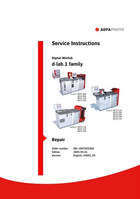
Service Instructions<br />
<strong>Digital</strong> Minilab<br />
d-<strong>lab.1</strong> <strong>family</strong><br />
<strong>Repair</strong><br />
Order number DD+18070022D0<br />
Edition 2005-05-01<br />
Version English, 03002_05
List of Chapters<br />
Edition<br />
Chapter<br />
Contents..................................................................2005-05-01 ...................0<br />
General ....................................................................2005-05-01 ...................1<br />
Basic Machine.......................................................2005-05-01 ...................2<br />
Software ..................................................................2005-05-01 ...................3<br />
Service / Diagnosis.............................................2005-05-01 ...................4<br />
Power Supply.........................................................2005-05-01 ...................5<br />
Computer System ................................................2005-05-01 ...................6<br />
Film Processor.......................................................2005-05-01 ...................7<br />
Scanner....................................................................2005-05-01 ...................8<br />
Printer ......................................................................2005-05-01 ...................9<br />
Paper Processor....................................................2005-05-01 ................10<br />
Maintenance..........................................................2005-05-01 ................11<br />
Index.........................................................................2005-05-01 ................12<br />
Preinstallation / Installation...........................2005-05-01 ................13
Modification History<br />
Version Edition Modifications<br />
03002_00 2004-01-02 Start Version<br />
03002_01 2004-04-01 Update<br />
03002_02 2004-06-01 Four Machine Variants<br />
New Software Version<br />
03002_03 2004-07-30 Modified Maintenance Kit (yearly)<br />
New Maintenance Kit (every second year)<br />
Updated chapters do to new software versions 8.00x<br />
03002_04 2004-12-15 Updated chapters due to new software versions 9.00x<br />
03002_05 2005-05-01 Twelve Machine Variants<br />
Published in compliance with EN 55022 (valid in EU):<br />
Warning!<br />
The equipment complies with the limits for a Class A device. Operation of the equipment<br />
in residential areas may cause radio interference in which case the user at his own<br />
expense will be requested to take whatever measures may be required to correct the<br />
interference.<br />
© 2005 AgfaPhoto <strong>GmbH</strong>. All rights reserved.<br />
No part of these instructions may be reproduced, copied, or transmitted in any form or by<br />
any means without prior written permission by AgfaPhoto <strong>GmbH</strong>.<br />
AgfaPhoto is used under license of Agfa-Gevaert AG.
d-<strong>lab.1</strong> <strong>family</strong>: <strong>Repair</strong><br />
Contents<br />
Contents<br />
1 General .............................................................................................................................1-1<br />
1.1 Available Documentation...........................................................................................................................................1-1<br />
1.2 <strong>Repair</strong>.................................................................................................................................................................................1-1<br />
1.2.1 Guideline for the Technician.................................................................................................................1-2<br />
1.2.2 Means of Representation........................................................................................................................1-3<br />
1.2.2.1 Text Styles and Symbols...............................................................................................1-3<br />
1.2.2.2 Safety Notes......................................................................................................................1-3<br />
1.3 Machine ............................................................................................................................................................................1-4<br />
1.3.1 Standards and Rules.................................................................................................................................1-4<br />
1.3.2 CE Symbol ....................................................................................................................................................1-4<br />
1.3.3 Use ..................................................................................................................................................................1-5<br />
1.3.3.1 Purpose................................................................................................................................1-5<br />
1.3.3.2 Appropriate Use................................................................................................................1-5<br />
1.3.3.3 Inappropriate Use............................................................................................................1-5<br />
1.4 Manufacturer...................................................................................................................................................................1-6<br />
1.4.1 Warranty........................................................................................................................................................1-6<br />
1.4.2 Exclusion of Liability.................................................................................................................................1-6<br />
1.4.3 Manufacturer Information ......................................................................................................................1-6<br />
1.5 Legal Situation ...............................................................................................................................................................1-7<br />
1.5.1 Safety Notes ................................................................................................................................................1-7<br />
1.5.1.1 Terms for Users.................................................................................................................1-7<br />
1.5.1.2 General................................................................................................................................1-8<br />
1.5.1.3 Installation.........................................................................................................................1-8<br />
1.5.1.4 Transport.............................................................................................................................1-8<br />
1.5.1.5 Operation............................................................................................................................1-9<br />
1.5.1.6 Service / <strong>Repair</strong>s ..........................................................................................................1-10<br />
1.5.1.7 Warnings and Information Labels on the Machine .........................................1-11<br />
1.6 Handling of Processing Chemicals......................................................................................................................1-14<br />
1.6.1 Safety Instructions .................................................................................................................................1-14<br />
2 Basic Machines..................................................................................................................2-1<br />
2.1 Versions.............................................................................................................................................................................2-1<br />
2.2 Versions (Illustrations).................................................................................................................................................2-1<br />
2.2.1 d-<strong>lab.1</strong> with Film Processor ...................................................................................................................2-1<br />
2.2.2 d-<strong>lab.1</strong>s..........................................................................................................................................................2-2<br />
2.2.3 net<strong>lab.1</strong> .........................................................................................................................................................2-3<br />
2.2.4 Overview (Table).........................................................................................................................................2-4<br />
2.3 Complete Machine .......................................................................................................................................................2-5<br />
2.3.1 Main Components.....................................................................................................................................2-5<br />
2.3.2 Components ................................................................................................................................................2-7<br />
2.4 List of Machine Parts ...................................................................................................................................................2-8<br />
3 Software............................................................................................................................3-1<br />
3.1 Software installation....................................................................................................................................................3-1<br />
3.1.1 Save customer settings and data base..............................................................................................3-1<br />
3.1.2 Installation of the Operating System MPU......................................................................................3-2<br />
3.1.3 First Installation of the d-<strong>lab.1</strong> Main Software...............................................................................3-4<br />
3.1.4 Update of the Operating System MPU ..............................................................................................3-9<br />
3.2 Error Messages ............................................................................................................................................................3-12<br />
3.2.1 Film Processor (FP), only d-<strong>lab.1</strong>with Film Processor ...............................................................3-13<br />
3.2.2 Scanner (SC) .............................................................................................................................................3-24<br />
3.2.3 Print Engine (PE) / Exposure Controller (EC)................................................................................3-37<br />
3.2.4 Paper Advance (PA)................................................................................................................................3-42<br />
3.2.5 Paper Processor (PP)..............................................................................................................................3-45<br />
3.2.6 Timer (TI) ....................................................................................................................................................3-55<br />
AgfaPhoto 2005-05-01 / PN 03002_05 0-i
Contents<br />
d-<strong>lab.1</strong> <strong>family</strong>: <strong>Repair</strong><br />
3.2.7 Messages (Custom Errors) ................................................................................................................... 3-56<br />
3.2.7.1 Film Prozessor (FP), only d-<strong>lab.1</strong> allrounder....................................................... 3-56<br />
3.2.7.2 Scanner (SC)...................................................................................................................3-56<br />
3.2.7.3 Exposure Controller (EC)............................................................................................ 3-56<br />
3.2.7.4 Paper Advance (PA) ..................................................................................................... 3-57<br />
3.2.7.5 Paper Processor (PP) ................................................................................................... 3-57<br />
3.2.7.6 IP / IPP............................................................................................................................. 3-58<br />
3.2.7.7 Software........................................................................................................................... 3-60<br />
3.2.7.8 Timer................................................................................................................................. 3-61<br />
3.2.8 Messages (Custom Info)....................................................................................................................... 3-62<br />
3.3 Production Statistics (Clickrate)........................................................................................................................... 3-65<br />
3.3.1 Recorded Data ......................................................................................................................................... 3-65<br />
3.3.2 Type of Saving ......................................................................................................................................... 3-65<br />
3.3.3 Export of Data .......................................................................................................................................... 3-65<br />
3.3.4 Fetching Data........................................................................................................................................... 3-66<br />
3.3.5 Installation and Deinstallation of the Software Clickrate ...................................................... 3-66<br />
3.3.6 Additional Tools supplied by AgfaPhoto........................................................................................ 3-66<br />
3.3.6.1 ClickrateReport.mdb ................................................................................................... 3-66<br />
3.3.6.2 ClickrateChecker.exe .................................................................................................. 3-66<br />
4 Service / Diagnosis............................................................................................................ 4-1<br />
4.1 Scripts................................................................................................................................................................................4-1<br />
4.1.1 Overview of the Script Folder ...............................................................................................................4-1<br />
4.2 Scripts for Service (Folder).........................................................................................................................................4-2<br />
4.2.1 Exposure Controller ..................................................................................................................................4-2<br />
4.2.2 Film Processor ............................................................................................................................................4-4<br />
4.2.3 General..........................................................................................................................................................4-6<br />
4.2.4 Initialization ................................................................................................................................................4-7<br />
4.2.5 Paper Advance (Paper Drive).................................................................................................................4-8<br />
4.2.6 Paper Processor....................................................................................................................................... 4-12<br />
4.2.7 Scanner ...................................................................................................................................................... 4-15<br />
4.2.8 Setup........................................................................................................................................................... 4-20<br />
4.3 Passwords...................................................................................................................................................................... 4-22<br />
4.4 Remote Diagnosis via Modem.............................................................................................................................. 4-23<br />
4.4.1 Netsupport Manager for the d-lab ................................................................................................... 4-24<br />
4.4.1.1 Prerequisites ..................................................................................................................4-24<br />
4.4.1.2 Setup in the d-lab ........................................................................................................ 4-24<br />
4.4.1.3 Deactivate Timer Card Watchdog ON for Remote Access via Modem.... 4-29<br />
4.5 Log Views and Log Levels....................................................................................................................................... 4-30<br />
4.6 Watchdog...................................................................................................................................................................... 4-32<br />
4.6.1 Introduction.............................................................................................................................................. 4-32<br />
4.6.2 Operation and User Interface............................................................................................................. 4-32<br />
4.6.2.1 Overview.......................................................................................................................... 4-32<br />
4.6.2.2 Startup screen ............................................................................................................... 4-33<br />
4.6.2.3 Standard operator interface...................................................................................... 4-36<br />
4.6.3 Extended operator interface............................................................................................................... 4-37<br />
4.6.4 Keyboard Hooks ...................................................................................................................................... 4-39<br />
4.6.5 System Logbook...................................................................................................................................... 4-40<br />
4.6.5.1 Change of Log settings during operation............................................................ 4-41<br />
4.6.5.2 Browsing through the Logbook............................................................................... 4-41<br />
4.6.5.3 Overview of the existing filter functions............................................................. 4-42<br />
4.6.5.4 Display of the software versions ............................................................................ 4-43<br />
4.6.5.5 Registration codes....................................................................................................... 4-44<br />
4.6.6 Structure of the Software .................................................................................................................... 4-47<br />
4.6.6.1 Interface interprocess communication................................................................ 4-48<br />
4.6.6.2 Interface to the Timer card....................................................................................... 4-49<br />
0-ii 2005-05-01 / PN 03002_05 AgfaPhoto
d-<strong>lab.1</strong> <strong>family</strong>: <strong>Repair</strong><br />
Contents<br />
4.6.7 Sequence diagram..................................................................................................................................4-50<br />
4.6.7.1 d-<strong>lab.1</strong> startup ...............................................................................................................4-50<br />
4.6.7.2 Watch function..............................................................................................................4-50<br />
4.6.7.3 d-<strong>lab.1</strong> Shutdown .........................................................................................................4-51<br />
4.7 MC Data.........................................................................................................................................................................4-53<br />
4.7.1 Modify and save MC Data ...................................................................................................................4-53<br />
4.7.2 FP MC Data Lists (only d-<strong>lab.1</strong> allrounder)..................................................................................4-54<br />
4.7.3 PA MC Data List ......................................................................................................................................4-57<br />
4.7.4 PP MC Data List ......................................................................................................................................4-59<br />
5 Power Supply Units and PCBs .............................................................................................5-1<br />
5.1 Power Supply Units – Overview ..............................................................................................................................5-1<br />
5.2 Power Supply System..................................................................................................................................................5-2<br />
5.2.1 Power ON Sequence.................................................................................................................................5-2<br />
5.3 Main Power Supply.......................................................................................................................................................5-4<br />
5.3.1 Components of the Main Power Supply ...........................................................................................5-6<br />
5.3.2 Connections – Overview.........................................................................................................................5-7<br />
5.3.3 Fuses...............................................................................................................................................................5-8<br />
5.3.3.1 Fuses on AC Main Power Supply...............................................................................5-8<br />
5.3.3.2 Fuses on 90A-FUS............................................................................................................5-8<br />
5.3.3.3 Fuses on 90A-LPS............................................................................................................5-8<br />
5.3.4 Command of the Power Supply Units................................................................................................5-9<br />
5.3.4.1 Connection diagram: Activation of Power Supply PS1..................................5-10<br />
5.3.4.2 Connection diagram: Activation of Power Supply PS2..................................5-10<br />
5.3.4.3 Connection diagram: Activation of Power Supply PS3..................................5-11<br />
5.3.5 PCB 90A-LPS ............................................................................................................................................5-12<br />
5.3.6 Adjustment of the Power Supply Units ..........................................................................................5-13<br />
5.3.7 Connection diagrams: Pilot voltages..............................................................................................5-14<br />
5.3.7.1 Connection diagram +8V (PL) pilot voltage.......................................................5-14<br />
5.3.7.2 Connection diagram +24V (PL) pilot voltage ....................................................5-14<br />
5.3.8 Connection diagrams: Power Supply Units Paper Advance (PA) and<br />
Paper Processor (PP)..............................................................................................................................5-15<br />
5.3.8.1 Connection diagram +5V (CD) voltage ................................................................5-15<br />
5.3.8.2 Connection diagram +36V (PB) voltage..............................................................5-15<br />
5.3.8.3 Connection diagram +24V (PC) voltage..............................................................5-16<br />
5.3.8.4 Connection diagram +24V (PA) voltage..............................................................5-16<br />
5.3.9 Connection diagrams: Power Supply Units Scanner (SC), Print Engine (PE)<br />
and Densitometer...................................................................................................................................5-17<br />
5.3.9.1 Connection diagram +6.5V (AD) voltage.............................................................5-17<br />
5.3.9.2 Connection diagram –15V (AA) voltage..............................................................5-18<br />
5.3.9.3 Connection diagram +18V (AA) voltage..............................................................5-18<br />
5.3.9.4 Connection diagram +24V (FD) voltage ..............................................................5-19<br />
5.4 Film Processor Power Supply (only d-<strong>lab.1</strong> with Film Processor) ............................................................5-20<br />
5.4.1 Components of the Film Processor Power Supply.....................................................................5-21<br />
5.4.2 Connections – Overview......................................................................................................................5-21<br />
5.4.3 Fuses............................................................................................................................................................5-22<br />
5.4.3.1 Fuses on 90P-SSR.........................................................................................................5-22<br />
5.4.4 Command of the Film Processor Power Supply Unit ................................................................5-22<br />
5.5 PCBs ................................................................................................................................................................................5-23<br />
5.5.1 Functions of the most important PCBs ..........................................................................................5-23<br />
5.5.2 Diagram: PCBs of the Paper Processor (PP), Paper Advance (PA) and Film<br />
Processor (FP)...........................................................................................................................................5-24<br />
5.5.3 Functions: LEDs and DIP Switches of the CPU PCBs ................................................................5-25<br />
5.5.3.1 LEDs...................................................................................................................................5-25<br />
5.5.3.2 DIP Switches..................................................................................................................5-25<br />
5.5.3.3 Replacing CPU PCBs ...................................................................................................5-26<br />
AgfaPhoto 2005-05-01 / PN 03002_05 0-iii
Contents<br />
d-<strong>lab.1</strong> <strong>family</strong>: <strong>Repair</strong><br />
6 Computer System .............................................................................................................. 6-1<br />
6.1 Version dependent Computer Systems ................................................................................................................6-1<br />
6.2 General Data...................................................................................................................................................................6-2<br />
6.2.1 Room conditions........................................................................................................................................6-2<br />
6.2.2 Power distribution and power supply of the components.........................................................6-2<br />
6.2.3 Power distribution and power supply of the components.........................................................6-2<br />
6.2.4 Network settings .......................................................................................................................................6-3<br />
6.2.5 Settings and Registry entries................................................................................................................6-3<br />
6.2.6 Product Security and Certificates........................................................................................................6-4<br />
6.3 Functional Description of the Main Processor Unit (MPU)............................................................................6-5<br />
6.3.1 Signal Diagram MPU................................................................................................................................6-6<br />
6.3.2 ON / OFF and Reset of the Computer System ...............................................................................6-8<br />
6.3.3 Interfaces / Connections........................................................................................................................6-9<br />
6.3.3.1 Serial Interfaces / 4-fach SIO (RS232)................................................................. 6-11<br />
6.3.4 Drives.......................................................................................................................................................... 6-12<br />
6.3.4.1 Dismounting the MPU drive..................................................................................... 6-12<br />
6.3.4.2 Jumper settings of the drive .................................................................................... 6-12<br />
6.3.5 Graphic card ............................................................................................................................................. 6-12<br />
6.3.6 Ethernet cards.......................................................................................................................................... 6-12<br />
6.3.7 Drive Module............................................................................................................................................ 6-13<br />
6.3.7.1 Power Supply for Drive Module.............................................................................. 6-13<br />
6.3.7.2 Card Reader (optional)................................................................................................ 6-14<br />
6.3.8 MPU Mainboard ...................................................................................................................................... 6-14<br />
6.3.8.1 MPU Mainboard connections .................................................................................. 6-15<br />
6.3.9 Operating System................................................................................................................................... 6-16<br />
6.3.10 Bios Settings ............................................................................................................................................ 6-16<br />
6.3.11 Touch Screen calibration..................................................................................................................... 6-22<br />
6.4 Functional Description of the Image Processor System (IPU)................................................................... 6-23<br />
6.4.1 Signal Diagram IPU ............................................................................................................................... 6-23<br />
6.4.2 Interfaces / Connections..................................................................................................................... 6-24<br />
6.4.2.1 Serial interface Timer board..................................................................................... 6-25<br />
6.4.3 Drives.......................................................................................................................................................... 6-28<br />
6.4.3.1 Dismounting the IPU drives..................................................................................... 6-28<br />
6.4.3.2 Jumper settings on the drives................................................................................. 6-28<br />
6.4.4 Graphic Card............................................................................................................................................. 6-29<br />
6.4.5 LVDS Card.................................................................................................................................................. 6-29<br />
6.4.6 Ethernet Card ........................................................................................................................................... 6-29<br />
6.4.7 IPU Mainboard......................................................................................................................................... 6-30<br />
6.4.7.1 IP Mainboard connections........................................................................................ 6-30<br />
6.4.8 Operating System................................................................................................................................... 6-31<br />
6.4.9 Bios Settings ............................................................................................................................................ 6-31<br />
6.5 Troubleshooting.......................................................................................................................................................... 6-36<br />
6.5.1 IPU does not start................................................................................................................................... 6-36<br />
6.5.1.1 Startup sequence of Computer system................................................................ 6-36<br />
6.5.1.2 Particularities during IPU software installation................................................ 6-38<br />
6.5.1.3 IP function test ............................................................................................................. 6-38<br />
6.5.1.4 Possible failures during IPU startup or operation ............................................ 6-41<br />
6.5.1.5 Possible failures during IPU startup...................................................................... 6-42<br />
6.5.1.6 Forced software installation of IPU ....................................................................... 6-44<br />
6.5.1.7 Manual start of IPU or MPU ..................................................................................... 6-45<br />
6.5.1.8 Connection diagram: Computer System ............................................................. 6-46<br />
6.5.1.9 Computer System Startup timing chart............................................................... 6-47<br />
6.6 Tools for Computer System Check ...................................................................................................................... 6-48<br />
6.6.1 COMTool .................................................................................................................................................... 6-48<br />
6.6.2 Drives.......................................................................................................................................................... 6-50<br />
6.6.3 LAN Test..................................................................................................................................................... 6-51<br />
0-iv 2005-05-01 / PN 03002_05 AgfaPhoto
d-<strong>lab.1</strong> <strong>family</strong>: <strong>Repair</strong><br />
Contents<br />
6.6.4 PuTTY...........................................................................................................................................................6-52<br />
6.6.5 Flash MPU with current BIOS and current settings...................................................................6-53<br />
6.6.6 Flash IPU with current BIOS and current settings......................................................................6-54<br />
6.6.7 HGST DFT Drive Fitness Test...............................................................................................................6-55<br />
6.6.8 Description of DFT Codes ....................................................................................................................6-67<br />
6.6.9 HGST Drive Feature Tool ......................................................................................................................6-68<br />
6.7 Maxtor Power Max Drivetest..................................................................................................................................6-71<br />
6.7.1 Memorytest...............................................................................................................................................6-71<br />
6.7.2 Boot OS for advanced tests.................................................................................................................6-72<br />
6.7.2.1 IntelPro DiagnosticTool .............................................................................................6-73<br />
6.8 Dismount the Computer System..........................................................................................................................6-78<br />
6.9 Installation of the Card Reader.............................................................................................................................6-79<br />
6.9.1 Hardware Installation............................................................................................................................6-80<br />
7 Film Processor ...................................................................................................................7-1<br />
7.1 Functional description.................................................................................................................................................7-1<br />
7.2 Assembly Groups in the Film Processor ...............................................................................................................7-1<br />
7.2.1 Location.........................................................................................................................................................7-1<br />
7.2.2 Designation and shortcuts .....................................................................................................................7-1<br />
7.3 Actuators and Sensors in the Film Processor .....................................................................................................7-2<br />
7.3.1 Designation and Shortcuts.....................................................................................................................7-3<br />
7.3.2 Funktion of the parts................................................................................................................................7-3<br />
7.3.3 Actuators and Sensors List.....................................................................................................................7-4<br />
7.4 Components of the Film Processor.........................................................................................................................7-9<br />
7.4.1 Main Drive....................................................................................................................................................7-9<br />
7.4.1.1 Checking the main drive ..............................................................................................7-9<br />
7.4.1.2 Replacing the main drive motor................................................................................7-9<br />
7.4.1.3 Lubricating the chains and sprocket gears.........................................................7-10<br />
7.4.2 Gear for Frequency Adjustment.........................................................................................................7-10<br />
7.4.2.1 Replacing the Gear 50 / 60 Hz...............................................................................7-10<br />
7.4.3 Loading Unit .............................................................................................................................................7-11<br />
7.4.3.1 Sensors.............................................................................................................................7-11<br />
7.4.3.2 Actuators..........................................................................................................................7-12<br />
7.4.4 Leader Cutter............................................................................................................................................7-13<br />
7.4.4.1 Function...........................................................................................................................7-13<br />
7.4.4.2 Actuators and Sensors................................................................................................7-13<br />
7.4.4.3 Motor positions (half steps)......................................................................................7-14<br />
7.4.5 Processing Racks ....................................................................................................................................7-15<br />
7.4.5.1 Replacing parts .............................................................................................................7-15<br />
7.4.6 Docking ......................................................................................................................................................7-17<br />
7.4.6.1 Actuators and Sensors................................................................................................7-18<br />
7.4.6.2 Replacing parts .............................................................................................................7-20<br />
7.4.7 Replenisher tanks...................................................................................................................................7-25<br />
7.4.7.1 Replacing parts .............................................................................................................7-25<br />
7.4.8 Effluent tanks...........................................................................................................................................7-26<br />
7.4.8.1 Checking parts...............................................................................................................7-26<br />
8 Scanner .............................................................................................................................8-1<br />
8.1 Designation of Assembly Groups and Shortcuts ...............................................................................................8-1<br />
8.2 Actuators and Sensors.................................................................................................................................................8-2<br />
8.2.1 General overview.......................................................................................................................................8-2<br />
8.2.2 Camera Module CM..................................................................................................................................8-3<br />
8.2.3 Lighting Module LM .................................................................................................................................8-3<br />
8.2.4 Scanner Frame SF......................................................................................................................................8-4<br />
8.2.5 Cartridge Feeder CF ..................................................................................................................................8-4<br />
8.2.6 Film Feeder FF.............................................................................................................................................8-5<br />
8.2.7 Film Supply FS............................................................................................................................................8-5<br />
8.2.8 Main Board MB...........................................................................................................................................8-6<br />
AgfaPhoto 2005-05-01 / PN 03002_05 0-v
Contents<br />
d-<strong>lab.1</strong> <strong>family</strong>: <strong>Repair</strong><br />
8.3 Functional Description................................................................................................................................................8-7<br />
8.3.1 Scanner data and signal paths.............................................................................................................8-7<br />
8.3.2 Integration into the global system.....................................................................................................8-8<br />
8.3.3 Driver Sensor Board (DS, SF_GS01)....................................................................................................8-9<br />
8.3.4 Scanner Motherboard ........................................................................................................................... 8-10<br />
9 Printer............................................................................................................................... 9-1<br />
9.1 Assembly Groups in the Printer...............................................................................................................................9-1<br />
9.1.1 Location ........................................................................................................................................................9-1<br />
9.1.2 Designation and shortcuts.....................................................................................................................9-1<br />
9.1.3 Designation and Shortcuts ....................................................................................................................9-2<br />
9.1.4 Funktion of the parts................................................................................................................................9-2<br />
9.2 Actuators and Sensors in the Exposure Unit.......................................................................................................9-3<br />
9.3 Exchange of the Print Engine ...................................................................................................................................9-4<br />
9.3.1 Demounting.................................................................................................................................................9-4<br />
9.3.2 Mounting......................................................................................................................................................9-5<br />
9.3.3 Copying correction files..........................................................................................................................9-6<br />
9.3.4 Calibrating the machine.........................................................................................................................9-6<br />
9.4 Actuators and Sensors in the Paper Advance (PA) ...........................................................................................9-7<br />
9.4.1 Actuators and Sensors Diagram...........................................................................................................9-7<br />
9.4.2 Actuators and Sensors List.....................................................................................................................9-8<br />
9.5 Paper Advance Sequence........................................................................................................................................ 9-12<br />
9.6 Components of the Paper Advance..................................................................................................................... 9-15<br />
9.6.1 Paper magazine drives ......................................................................................................................... 9-15<br />
9.6.1.1 Actuators ......................................................................................................................... 9-15<br />
9.6.1.2 Sensors............................................................................................................................. 9-16<br />
9.6.2 Transport Unit TU.................................................................................................................................... 9-17<br />
9.6.2.1 Actuators / Sensors..................................................................................................... 9-17<br />
9.6.2.2 Troubleshooting TU ..................................................................................................... 9-18<br />
9.6.2.3 Adjustment of paper transport and cut length ................................................. 9-20<br />
9.6.3 Auxiliary Paper Drive............................................................................................................................. 9-21<br />
9.6.3.1 Actuators / Sensors..................................................................................................... 9-21<br />
9.6.4 Exposure Unit........................................................................................................................................... 9-22<br />
9.6.4.1 Exposure table 55A-0102.......................................................................................... 9-22<br />
9.6.4.2 LED Exposure Unit........................................................................................................ 9-22<br />
9.6.4.3 Troubleshooting............................................................................................................ 9-23<br />
9.6.5 Lane Distributor LD................................................................................................................................ 9-24<br />
9.6.5.1 Actuators and Sensors................................................................................................ 9-24<br />
9.6.5.2 Troubleshooting LD ..................................................................................................... 9-26<br />
9.6.6 Back Printer.............................................................................................................................................. 9-27<br />
9.6.6.1 Actuators and Sensors................................................................................................ 9-27<br />
9.6.6.2 Back Printer Adjustment ........................................................................................... 9-28<br />
9.6.7 Shutter........................................................................................................................................................ 9-30<br />
9.6.7.1 Actuator ........................................................................................................................... 9-30<br />
10 Paper Processor............................................................................................................... 10-1<br />
10.1 Functional description.............................................................................................................................................. 10-1<br />
10.2 Assembly Groups in the Paper Processor.......................................................................................................... 10-1<br />
10.2.1 Location ..................................................................................................................................................... 10-1<br />
10.2.2 Designations and shortcuts................................................................................................................ 10-1<br />
10.3 Actuators and Sensors in the Paper Processor................................................................................................ 10-2<br />
10.3.1 Designation and Shortcuts ................................................................................................................. 10-3<br />
10.3.2 Funktion of the parts............................................................................................................................. 10-3<br />
10.3.3 Actuators and Sensors List.................................................................................................................. 10-4<br />
10.4 Components of the Paper Processor................................................................................................................... 10-9<br />
10.4.1 Switches..................................................................................................................................................... 10-9<br />
10.4.2 Main Drive................................................................................................................................................. 10-9<br />
10.4.2.1 Checking the main drive........................................................................................... 10-9<br />
10.4.2.2 Replacing the main Drive Motor..........................................................................10-10<br />
0-vi 2005-05-01 / PN 03002_05 AgfaPhoto
d-<strong>lab.1</strong> <strong>family</strong>: <strong>Repair</strong><br />
Contents<br />
10.4.3 Gear for Frequency Adjustment...................................................................................................... 10-10<br />
10.4.3.1 Replacing the Gear 50 / 60 Hz............................................................................ 10-10<br />
10.4.4 Processing Racks ................................................................................................................................. 10-11<br />
10.4.4.1 Replace worn parts................................................................................................... 10-11<br />
10.4.5 Rack drive and torque limiter ......................................................................................................... 10-12<br />
10.4.5.1 Replacing parts .......................................................................................................... 10-12<br />
10.4.6 Replenisher tanks................................................................................................................................ 10-13<br />
10.4.6.1 Replacing parts .......................................................................................................... 10-13<br />
10.4.7 Effluent tanks........................................................................................................................................ 10-14<br />
10.4.7.1 Checking parts............................................................................................................ 10-14<br />
10.4.8 Water Replenishment Tank ............................................................................................................. 10-15<br />
10.4.8.1 Functional description............................................................................................. 10-15<br />
10.4.9 Docking Station.................................................................................................................................... 10-16<br />
10.4.9.1 Functional description............................................................................................. 10-16<br />
10.4.9.2 Actuators and Sensors............................................................................................. 10-17<br />
10.4.9.3 Flow charts................................................................................................................... 10-20<br />
10.4.9.4 Timing............................................................................................................................ 10-25<br />
10.4.9.5 Troubleshooting ......................................................................................................... 10-26<br />
10.4.10 Dryer......................................................................................................................................................... 10-30<br />
10.4.10.1 Functional description............................................................................................. 10-30<br />
10.4.10.2 Temperature sensors dryer..................................................................................... 10-30<br />
10.4.11 Paper Exit................................................................................................................................................ 10-31<br />
10.4.11.1 Functional description............................................................................................. 10-31<br />
10.4.12 Densitometer......................................................................................................................................... 10-34<br />
10.4.12.1 Functional description............................................................................................. 10-34<br />
10.4.12.2 Technical Data............................................................................................................ 10-34<br />
10.4.12.3 Climatic conditions................................................................................................... 10-35<br />
10.4.12.4 Measuring characteristics...................................................................................... 10-35<br />
10.4.12.5 Zeroing .......................................................................................................................... 10-35<br />
10.4.12.6 Data rate (RS 232 Connection) ............................................................................ 10-35<br />
10.4.12.7 Interfaces......................................................................................................................10-35<br />
10.4.12.8 Jumper positions........................................................................................................ 10-36<br />
10.4.12.9 Measurement.............................................................................................................. 10-36<br />
10.4.12.10 MBL, PBL Test print .................................................................................................. 10-36<br />
10.4.12.11 Block circuit diagram of the 5.5 V power supply.......................................... 10-37<br />
10.4.12.12 7-Segment display.................................................................................................... 10-37<br />
10.4.12.13 Data output for MBL and PBL test print ........................................................... 10-38<br />
10.4.12.14 Densitometer Error Messages............................................................................... 10-38<br />
10.4.12.15 Generally valid Error Codes (independent of the machine or<br />
process) ......................................................................................................................... 10-41<br />
10.4.12.16 Error Codes specified for Process Control ........................................................ 10-41<br />
10.4.12.17 Error Codes specific for Grey Wedge Measurement..................................... 10-42<br />
10.4.12.18 Error Codes specific for FLASH Programming ................................................. 10-42<br />
10.4.12.19 Densitometer Types.................................................................................................. 10-43<br />
10.4.12.20 Sudden Density Change in the Print caused by the Densitometer........ 10-44<br />
10.4.12.21 Densi Error Messages when measuring the Test Print................................ 10-47<br />
10.4.12.22 Error: Densitometer communication time out ............................................... 10-48<br />
10.4.13 Lane Shifter LS...................................................................................................................................... 10-49<br />
10.4.13.1 Functional description............................................................................................. 10-49<br />
10.4.14 Sorter SO................................................................................................................................................. 10-50<br />
10.4.14.1 Functional description............................................................................................. 10-50<br />
10.4.14.2 Troubleshooting ......................................................................................................... 10-51<br />
11 Maintenance....................................................................................................................11-1<br />
11.1 Purpose ..........................................................................................................................................................................11-1<br />
11.2 Safety Prescriptions...................................................................................................................................................11-1<br />
11.3 To all Service Engineers...........................................................................................................................................11-2<br />
AgfaPhoto 2005-05-01 / PN 03002_05 0-vii
Contents<br />
d-<strong>lab.1</strong> <strong>family</strong>: <strong>Repair</strong><br />
11.4 Maintenance Kits (wearing Parts)........................................................................................................................ 11-3<br />
11.4.1 Kit for Maintenance – Yearly............................................................................................................. 11-3<br />
11.4.2 Kit for Maintenance – Every Second Year .................................................................................... 11-4<br />
11.5 Lubricants and Cleaning Agents........................................................................................................................... 11-5<br />
11.6 Special Tool.................................................................................................................................................................. 11-5<br />
11.7 Overview: Maintenance Jobs to be performed by the Service Engineer............................................... 11-6<br />
11.7.1 General machine .................................................................................................................................... 11-6<br />
11.7.2 All Paper magazines.............................................................................................................................. 11-6<br />
11.7.3 Paper magazine compartment left and right .............................................................................. 11-6<br />
11.7.4 Film Processor (FP)................................................................................................................................. 11-6<br />
11.7.5 Computer System (CS).......................................................................................................................... 11-7<br />
11.7.6 Scanner (SC) ............................................................................................................................................. 11-7<br />
11.7.7 Paper Advance (PA)................................................................................................................................ 11-7<br />
11.7.8 Paper Processor (PP).............................................................................................................................. 11-8<br />
11.7.9 End of the Maintenance Work (Machine ON).............................................................................. 11-9<br />
11.8 Overview: Maintenance Jobs to be performed by the Customer...........................................................11-10<br />
11.9 General machine......................................................................................................................................................11-11<br />
11.9.1 Cleaning the inside compartments...............................................................................................11-11<br />
11.10 Cleaning the Paper Magazines inside..............................................................................................................11-11<br />
11.11 Checking the Paper Magazine Compartments.............................................................................................11-11<br />
11.12 Film Processor (FP) (d-<strong>lab.1</strong> allrounder)...........................................................................................................11-12<br />
11.12.1 FP: Cleaning and checking the film loading units and the film magazines..................11-12<br />
11.12.2 FP: Lubricating the main drive chain and the motor gear, cleaning and<br />
lubricating the dryer............................................................................................................................11-12<br />
11.12.3 FP: Squeegee unit, replace worn parts if required...................................................................11-13<br />
11.12.4 FP: Cleaning the racks and replacing worn parts if required...............................................11-14<br />
11.12.5 FP: Cleaning the processing tanks.................................................................................................11-15<br />
11.12.6 FP: Servicing hoses, valves, circulation pumps.........................................................................11-16<br />
11.12.7 FP: Servicing the replenisher pumps ............................................................................................11-16<br />
11.12.8 FP: Servicing the Docking System.................................................................................................11-17<br />
11.12.8.1 Nozzle sets and Opener...........................................................................................11-17<br />
11.12.8.2 Locking mechanism of the docking door..........................................................11-21<br />
11.12.9 FP: Cleaning and lubricating the Leader cutter........................................................................11-22<br />
11.13 Computer System ....................................................................................................................................................11-23<br />
11.14 Scanner (SC)...............................................................................................................................................................11-24<br />
11.14.1 SC: Negative mask support, replacing worn parts if required .............................................11-24<br />
11.14.2 SC: Cleaning the Cartridge Feeder.................................................................................................11-24<br />
11.14.3 SC: Lubricating all negative masks (if required).......................................................................11-25<br />
11.15 Paper Transport (PA)................................................................................................................................................11-26<br />
11.15.1 PA: Cleaning the Print Engine.........................................................................................................11-26<br />
11.15.2 PA: Cleaning the cutter units ..........................................................................................................11-26<br />
11.15.3 PA: Servicing the Lane Distributor.................................................................................................11-27<br />
11.15.4 PA: Cleaning the back printer head...............................................................................................11-27<br />
11.16 Paper Processor (PP) ...............................................................................................................................................11-28<br />
11.16.1 Paper Processor – Important note.................................................................................................11-28<br />
11.16.2 PP: Cleaning the gears and bearings............................................................................................11-28<br />
11.16.3 PP: Checking / replacing the gear for frequency adjustment (every second year).....11-29<br />
11.16.4 PP: Crossovers, replace worn parts if required ..........................................................................11-29<br />
11.16.5 Cleaning / servicing the squeegee unit......................................................................................11-30<br />
11.16.6 PP: Racks, replace worn parts if required....................................................................................11-31<br />
11.16.7 PP: Cleaning the processing tanks................................................................................................11-32<br />
11.16.8 PP: Servicing hoses, valves, pumps...............................................................................................11-32<br />
11.16.9 PP: Cleaning the water tank ............................................................................................................11-33<br />
11.16.10 PP: Servicing the replenisher pumps............................................................................................11-33<br />
11.16.10.1 PP: Replacing the poppet valves of the replenisher and water<br />
pumps if required .......................................................................................................11-34<br />
0-viii 2005-05-01 / PN 03002_05 AgfaPhoto
d-<strong>lab.1</strong> <strong>family</strong>: <strong>Repair</strong><br />
Contents<br />
11.16.11 PP: Cleaning the Docking System ................................................................................................ 11-35<br />
11.16.11.1 Locking mechanism of the docking door......................................................... 11-39<br />
11.16.12 PP: Cleaning the dryer rack ............................................................................................................. 11-40<br />
11.16.13 PP: Dryer rack, replace worn parts if required, lubricate the chain.................................. 11-40<br />
11.16.14 PP: Cleaning and checking the densitometer.......................................................................... 11-41<br />
11.16.15 PP: Cleaning the Sorter..................................................................................................................... 11-41<br />
11.17 Switching on the machine................................................................................................................................... 11-42<br />
11.17.1 FP/PP: Checking the circulation pumps (running noise) ..................................................... 11-42<br />
11.17.2 FP/PP: Calibrating the water pumps............................................................................................ 11-42<br />
11.17.3 Functional check of the machine.................................................................................................. 11-42<br />
11.17.4 Eliminate ghost effects (if required) ............................................................................................. 11-42<br />
12 Index...............................................................................................................................12-1<br />
AgfaPhoto 2005-05-01 / PN 03002_05 0-ix
Contents<br />
d-<strong>lab.1</strong> <strong>family</strong>: <strong>Repair</strong><br />
■<br />
0-x 2005-05-01 / PN 03002_05 AgfaPhoto
d-<strong>lab.1</strong> <strong>family</strong>: <strong>Repair</strong><br />
General<br />
1 General<br />
1.1 Available Documentation<br />
Available documentation, see Table.<br />
The customer receives the Preinstallation Instructions when he orders the machine.<br />
The Operation folder includes a CD with the available documentation (with the exception<br />
of the circuit diagrams. The Operation Manual – Installation and Operation – are included<br />
with the machine shipment. All other parts can be ordered from AgfaPhoto.<br />
The Operating Instructions must be kept around the machine to ensure that all users have<br />
access to them.<br />
Instructions Folder / Booklet Owner Operator Technician<br />
Preinstallation Preinstallation (booklet) x<br />
Operating Instructions Operation<br />
x<br />
Installation (booklet)<br />
x<br />
Service Instructions <strong>Repair</strong><br />
x<br />
Spare Parts List x x<br />
Circuit Diagrams<br />
x<br />
1.2 <strong>Repair</strong><br />
The Operation Manual is useful for safe and appropriate working on the machine and with<br />
the machine. Perfect and safe operation of the product requires careful observation of the<br />
Operation Manual and the contained safety instructions. Therefore it must always be<br />
complete and in good condition for easy reading.<br />
All persons working on the machine and with the machine must<br />
– have read and understood the Operation Manual before they switch on the machine<br />
for the first time.<br />
– have the Operation Manual at hand when they work on the machine.<br />
– observe all information and instructions of the Operation Manual.<br />
AgfaPhoto 2005-05-01 / PN 03002_05 1-1
General<br />
d-<strong>lab.1</strong> <strong>family</strong>: <strong>Repair</strong><br />
1.2.1 Guideline for the Technician<br />
Instructions<br />
Preinstallation<br />
Installation<br />
<strong>Repair</strong><br />
Information<br />
The owner takes care of the listed preinstallation measures and returns the checklist to<br />
AgfaPhoto no later than two weeks prior to the installation date.<br />
This document describes the transport to the installation site, as well as the installation<br />
and implementation of the machine.<br />
Appendix: Declaration of Conformity<br />
The declaration of conformity is the first sheet in the Operation folder.<br />
This document includes all important information to ensure correct operation by a<br />
technician:<br />
Chapter 1:<br />
Notes on the <strong>Repair</strong> Manual, legal notes, safety notes, transport and storage.<br />
Chapter 2:<br />
Introduction of the basic machine, components, functions and controls of the machine,<br />
help function and information.<br />
Chapter 3:<br />
Installation of the main software; list of error messages with error codes<br />
Chapter 4:<br />
Description of the service functions and the error diagnosis<br />
Chapter 5:<br />
Description of the power supply<br />
Chapter 6:<br />
Description of the Computer System<br />
Chapter 7:<br />
Description of the Film Processor<br />
Chapter 8:<br />
Description of the Scanner<br />
Chapter 9:<br />
Description of the Printer<br />
Chapter 10:<br />
Description of the Paper Processor<br />
Chapter 11:<br />
Description of the required maintenance routines on the machine<br />
Chapter 12:<br />
Index<br />
Chapter 13:<br />
Preinstallation (booklet) und Installation (booklet)<br />
1-2 2005-05-01 / PN 03002_05 AgfaPhoto
d-<strong>lab.1</strong> <strong>family</strong>: <strong>Repair</strong><br />
General<br />
1.2.2 Means of Representation<br />
1.2.2.1 Text Styles and Symbols<br />
The following text passages are emphasized by bold print, italic print or the type face<br />
Courier New:<br />
– Button designations<br />
Example: Press Service to call up the service functions<br />
– Reference s<br />
Italic print is used for reference to Registers or paragraphs<br />
Example: See 1.2.2.1 Text Styles and Symbols<br />
– Program code<br />
Courier New is used for commands and script names in the service functions<br />
This symbol describes an action to be carried out.<br />
If an action requires further secondary steps this symbol has been used.<br />
CAUTION!<br />
This symbol described Safety instructions<br />
Note<br />
This symbol describes notes and hints for more efficient work routines on the machine.<br />
1.2.2.2 Safety Notes<br />
The words CAUTION and WARNING in the documentation and on the machine labels<br />
indicate the following risks:<br />
CAUTION!<br />
This indicates a potential danger which may result in minor personal injuries or<br />
property damage.<br />
WARNING!<br />
Indicates a possible risk involved with a product which in case of non-observance<br />
may result in severe personal injuries or even death.<br />
AgfaPhoto 2005-05-01 / PN 03002_05 1-3
General<br />
d-<strong>lab.1</strong> <strong>family</strong>: <strong>Repair</strong><br />
1.3 Machine<br />
1.3.1 Standards and Rules<br />
The machine is in compliance with the requirements of the standards and rules listed<br />
below:<br />
98/37/EG:<br />
Machine Directives<br />
73/23/EWG:<br />
Directive for Low Voltage<br />
89/336/EWG:<br />
Electromagnetic Compatibility (according to modifications 91/ 263/EEC and 2/31/EEC).<br />
EN 60950:<br />
Safety of Information Technology Equipment<br />
EN 60825-1:<br />
Safety of Laser Equipment<br />
EN 55022:<br />
Information Technology Equipment – Radio interference – Limits and Methods of<br />
Measurements<br />
EN 55024:<br />
Information Technology Equipment – Immunity Standard - Limits and Methods of<br />
Measurements<br />
EN 61000-6-2:<br />
Electromagnetic Compatibility (EMC) - Part 6-2: Basic Standard<br />
Immunity Standard for Industrial Areas (IEC 61000-6-2:1999, modified)<br />
EN 61000-3-2:<br />
Electromagnetic Compatibility (EMC) - Part 3-2: Limit Values<br />
Limit Values for Harmonic Emissions (IEC 61000-3-2:2000, modified)<br />
EN 61000-3-3:<br />
Electromagnetic Compatibility (EMC) - Part 3-3: Limit Values<br />
Limit values for voltage changes, voltage fluctuations and flicker in public low voltage<br />
supply networks for equipment with a current ≤ 16 A per conductor, which are not subject<br />
to any special connection conditions.<br />
(IEC 61000-3-3:1994 + A1:2001)<br />
1.3.2 CE Symbol<br />
The CE symbol describes the conformity of the machine with the requirements of the EG<br />
Directives 89/336/EWG and 73/23/EWG (see Standards and rules).<br />
If further devices are to be connected to the digital minilab, these devices, too, must<br />
meet the requirements of the relevant EG directives.<br />
The machine is a Class A equipment A (EN 55022). This equipment may cause radio<br />
disturbances in residential areas. In this case the user may be required to initiate<br />
respective measures to eliminate such disturbances and pay for these measures.<br />
1-4 2005-05-01 / PN 03002_05 AgfaPhoto
d-<strong>lab.1</strong> <strong>family</strong>: <strong>Repair</strong><br />
General<br />
1.3.3 Use<br />
1.3.3.1 Purpose<br />
The digital minilab has been designed exclusively for the purpose of printing negatives,<br />
slides, and digital images on photographic paper and for saving image files on storage<br />
media.<br />
1.3.3.2 Appropriate Use<br />
The product corresponds to the state of the art and is operationally reliable. If the product<br />
is not used correctly or for its intended purpose this may result in risks and danger.<br />
Only strict adherence to all instructions and specifications of this Operation manual<br />
assures the intended use of the machine.<br />
For safety reasons it is not permitted to maker conversions and modifications of the<br />
product without proper authorization.<br />
The machine must only be operated with the recommended consumables and the defined<br />
conditions for use (see Technical Specifications).<br />
Any other user of the machine may result in damage on the machine and further<br />
even to personal injuries and property damage!<br />
1.3.3.3 Inappropriate Use<br />
Inappropriate use (misuse) will be:<br />
– any application not corresponding to the afore mentioned appropriate use or use<br />
outside the specifications<br />
– non-observance of the instructions in the manuals<br />
– non-observance of the safety instructions<br />
– operation of the machine in a non-operative condition<br />
(regarding function and/or safety)<br />
AgfaPhoto 2005-05-01 / PN 03002_05 1-5
General<br />
d-<strong>lab.1</strong> <strong>family</strong>: <strong>Repair</strong><br />
1.4 Manufacturer<br />
1.4.1 Warranty<br />
AgfaPhoto will not be liable for personal injuries and property damage caused by mistakes<br />
or omissions of the information provided in this manual.<br />
AgfaPhoto will not be liable for damage caused by inappropriate use, non-observance of<br />
safety and maintenance instructions, or by unauthorized modifications.<br />
Guaranty regulations are up to the countries. For information refer to the sales contract or<br />
the warranty certificate.<br />
1.4.2 Exclusion of Liability<br />
In principle the applying conditions are the AgfaPhoto general conditions of sale and<br />
delivery. The owner will receive these the latest at the time of the conclusion of a<br />
contract.<br />
All information, data, and notes in this Operation Manual are current as of the date of<br />
printing. All rights reserved to change technical specifications as a result of further<br />
developments on the machine. Therefore claims for modifications or additions on<br />
delivered equipment based on the data, illustrations, and descriptions herein will not be<br />
accepted.<br />
AgfaPhoto tested the contents of this Operation Manual regarding the correspondence<br />
with the described hardware and software. As deviations cannot be excluded, AgfaPhoto<br />
will not guarantee complete correspondence. Necessary corrections will be made in<br />
follow-up editions.<br />
AgfaPhoto will not be liable for damages and interferences resulting from:<br />
– non-observance of the Operation Manual<br />
– mistakes by the user<br />
– inappropriate working on the machine and with the machine<br />
– use of non-original wear parts, spare parts and accessories as well as the use of nonoriginal<br />
consumables<br />
– unauthorized conversions and modification on the machine by the owner or the<br />
owner’s staff<br />
1.4.3 Manufacturer Information<br />
AgfaPhoto <strong>GmbH</strong><br />
PO Box 900151<br />
D- 81536 Munich, Germany<br />
1-6 2005-05-01 / PN 03002_05 AgfaPhoto
d-<strong>lab.1</strong> <strong>family</strong>: <strong>Repair</strong><br />
General<br />
1.5 Legal Situation<br />
The operation of the machines is ruled by the appropriate regulations for the place of<br />
installation in force in the country concerned.<br />
This Operation Manual includes an EU Conformity Declaration (CE) about the applying<br />
harmonized standards (see Appendix).<br />
CAUTION!<br />
The following safety regulations, warnings and instructions on machine labels<br />
must be observed by all means.<br />
The non-observance may be dangerous for persons, equipment and buildings:<br />
injuries, electric shocks, fire.<br />
Note:<br />
The manufacturer and the service will not assume any responsibilities for accidents and<br />
damage resulting from inappropriate operation.<br />
1.5.1 Safety Notes<br />
1.5.1.1 Terms for Users<br />
The Owner is any actual person or juristic person, who uses the machine or has<br />
somebody use the machine.<br />
The AgfaPhoto authorized Service technicians are responsible for all those tasks on the<br />
machine which cannot be performed by the operators.<br />
AgfaPhoto 2005-05-01 / PN 03002_05 1-7
General<br />
d-<strong>lab.1</strong> <strong>family</strong>: <strong>Repair</strong><br />
1.5.1.2 General<br />
CAUTION!<br />
Warning and instructions on machine labels must be strictly observed.<br />
CAUTION!<br />
Safety Device<br />
Never change the electrical circuit.<br />
Do not circumvent or disable the integrated safety devices.<br />
Do not modify preset values of safety components.<br />
Replace fuses only by the same type of fuse: value, switch-off characteristics.<br />
1.5.1.3 Installation<br />
CAUTION!<br />
Only the Service is entitled to install the machine.<br />
Install all lines and cables in such a way that nobody will step on them or trip.<br />
Only those extension units must be installed, which meet the safety requirements<br />
and regulations, and are in compliance with electromagnetic compatibility and<br />
the respective AgfaPhoto specifications. For information about extensions or<br />
additions released for this machine turn to the Service.<br />
All data cables, signal cables, process and control cables, which connect the<br />
machine with other machines must be correctly shielded and connected.<br />
1.5.1.4 Transport<br />
CAUTION!<br />
The machine must only be transported by the Service or an authorized forwarder.<br />
1-8 2005-05-01 / PN 03002_05 AgfaPhoto
d-<strong>lab.1</strong> <strong>family</strong>: <strong>Repair</strong><br />
General<br />
1.5.1.5 Operation<br />
CAUTION!<br />
Only the Operator and Service are allowed to operate the machine. The operating<br />
instructions should be read carefully before the work is started.<br />
Persons under the influence of alcohol, drugs, or certain medication (e.g.<br />
psychopharmacological medication) are not permitted to operate the machine.<br />
In emergencies immediately switch off the machine at the main switch; see <br />
position of the main switch in Chapter 2.<br />
Never run the machine without covers / panels. Persons who open or remove<br />
covers expose themselves to dangerous voltages or run other risks.<br />
For the cleaning of the machine follow the instructions in Chapter 8. Only use the<br />
recommended cleaning substances and devices.<br />
Do not cover or block the venting openings in the housing: This may lead to<br />
overheating of single components.<br />
No objects or liquids should get into the machine through the venting openings:<br />
This may cause fire, electric shock, or a short circuit. Therefore never place objects<br />
or containers with liquid on or around the machine.<br />
Provide for sufficient cooling air and fresh air at the operating site.<br />
Do not block the operation and maintenance areas by other equipment or objects.<br />
Avoid excessive generation of dust as this may damage the components in the<br />
device.<br />
Keep consumables and containers for food and drinks separate.<br />
AgfaPhoto 2005-05-01 / PN 03002_05 1-9
General<br />
d-<strong>lab.1</strong> <strong>family</strong>: <strong>Repair</strong><br />
1.5.1.6 Service / <strong>Repair</strong>s<br />
CAUTION!<br />
Only the Service is entitled to repair the machine. All areas which can only be<br />
opened by means of tools are considered service areas. Illegal opening of a<br />
service areas and inappropriate repairs may result in serious risks for the<br />
operators.<br />
Observe country-specific safety regulations<br />
Maker sure to switch off the machine prior to service / repair work<br />
The machine contains components using high voltage as well as quite sensitive<br />
components. For this reason, the following work must only be performed by<br />
authorized service technicians:<br />
<strong>Repair</strong>s on electrical components, maintenance work / removal of parts and<br />
covers not described in the operation folder.<br />
Use original AgfaPhoto spare parts: only these parts have been tested regarding<br />
their suitability and safety.<br />
When replacing electronic components: observe the data given in the circuit and<br />
wiring diagrams.<br />
At the end of all service / maintenance jobs: check the general function of the<br />
machine as well as the correct condition of the safety devices.<br />
1-10 2005-05-01 / PN 03002_05 AgfaPhoto
1<br />
2 3 4<br />
3<br />
d-<strong>lab.1</strong> <strong>family</strong>: <strong>Repair</strong><br />
General<br />
1.5.1.7 Warnings and Information Labels on the Machine<br />
Make sure the labels are attached and are clearly visible.<br />
STOP<br />
3003_074<br />
AgfaPhoto 2005-05-01 / PN 03002_05 1-11
General<br />
d-<strong>lab.1</strong> <strong>family</strong>: <strong>Repair</strong><br />
No. Label Meaning<br />
1 Fire hazard if fuses other than specified by AgfaPhoto are used (see <br />
Technical Specifications).<br />
2 Risk of injuries by electric shock with open covers.<br />
3 Risk of injuries by rotating parts (getting caught, bruising).<br />
Keep the door closed when the machine is on. If the door must be<br />
opened make sure not to touch any components.<br />
4 Risk of injuries by sharp blades (cutting wounds).<br />
Do not reach into the cutting unit during operation. Do not touch the<br />
cutting blades either when the machine is off.<br />
5 Name plate with CE certification<br />
The CE certification means that the machine is in compliance with all<br />
applying EG Rules.<br />
The given voltage, fuse and frequency values for single-phase and threephase<br />
connections are listed.<br />
d-<strong>lab.1</strong> starter 8070/040<br />
d-<strong>lab.1</strong> allrounder 1 8070/050<br />
d-<strong>lab.1</strong> allrounder 2 8070/100<br />
d-<strong>lab.1</strong> plus 8070/109<br />
3003_161<br />
1-12 2005-05-01 / PN 03002_05 AgfaPhoto
d-<strong>lab.1</strong> <strong>family</strong>: <strong>Repair</strong><br />
General<br />
d-<strong>lab.1</strong>s starter oc 8070/230<br />
d-<strong>lab.1</strong>s starter 8070/240<br />
d-<strong>lab.1</strong>s basic 1 8070/300<br />
d-<strong>lab.1</strong>s basic 2 8070/200<br />
d-<strong>lab.1</strong>s plus 8070/310<br />
3003_162<br />
net<strong>lab.1</strong> starter oc 8070/130<br />
net<strong>lab.1</strong> allrounder 8070/150<br />
net<strong>lab.1</strong> plus 8070/160<br />
3003_163<br />
6 This label identified the main switch or main breaker.<br />
7 This label advises the user to read the installation instructions before<br />
connecting the machine to the power supply.<br />
Installation errors may lead to injuries (risk of electric shock) or machine<br />
damage when the machine is connected to the mains.<br />
AgfaPhoto 2005-05-01 / PN 03002_05 1-13
General<br />
d-<strong>lab.1</strong> <strong>family</strong>: <strong>Repair</strong><br />
1.6 Handling of Processing Chemicals<br />
1.6.1 Safety Instructions<br />
CAUTION!<br />
In the work environment of the machine slightly poisonous, irritating, and caustic<br />
substances may occur. The Owner (employer)<br />
– has to elaborate operation instructions for the handling of dangerous<br />
substances<br />
– provides for the instruction of his staff at least once a year<br />
– ensures sufficient aeration: The air in industrial workrooms should be<br />
exchanged at least eight to ten times per hour.<br />
All photographic developers contain substances, which may irritate the skin, the<br />
mucous membrane and the eyes, and which may cause allergic skin reactions<br />
affecting very sensitive persons. For this reason, avoid long or repeated skin<br />
contact, especially with developer solutions.<br />
For all jobs where photographic processing solutions may splash, e.g. preparing<br />
and filling in chemical solutions, cleaning processing racks etc.:<br />
– Wear protective gloves and change them every day, if possible; rinse all<br />
solutions that get on your skin immediately with plenty of fresh water<br />
– Wear protection goggles: If in spite of this, splashes do get into your eyes,<br />
wash them immediately with plenty of water, pulling apart the eyelids.<br />
Consult an oculist!<br />
Store chemicals and processing solutions in a safe place.<br />
Collect leaking chemicals immediately and dispose of these chemicals. The above<br />
regulations must be observed.<br />
Mind chemical residues in the boxes (Easy paper box).<br />
■<br />
1-14 2005-05-01 / PN 03002_05 AgfaPhoto
d-<strong>lab.1</strong> <strong>family</strong>: <strong>Repair</strong><br />
Basic Machines<br />
2 Basic Machines<br />
2.1 Versions<br />
The d-<strong>lab.1</strong> is offered in twelve different versions:<br />
– d-<strong>lab.1</strong>fp machines can process input from digital media and film material; color<br />
negative films can be developed (4 versions).<br />
– d-<strong>lab.1</strong>s machines can process input from digital media and film material; (5 versions).<br />
– net<strong>lab.1</strong> machines can process input from digital media (3 versions).<br />
Note:<br />
The digital input and the CD burning are performed one the d-<strong>lab.1</strong> allrounder 2 and<br />
the d-<strong>lab.1</strong> plus via the image box using the AgfaPhoto programs workstation or kiosk.<br />
Both functions are also available on the d-<strong>lab.1</strong> and the net<strong>lab.1</strong>, provided the machine<br />
is retrofitted for this (options 6-port drive and Software licenses).<br />
2.2 Versions (Illustrations)<br />
2.2.1 d-<strong>lab.1</strong> with Film Processor<br />
d-<strong>lab.1</strong> starter<br />
Type 8070/040<br />
d-<strong>lab.1</strong> allrounder 1<br />
Type 8070/050<br />
d-<strong>lab.1</strong> allrounder 2<br />
Type 8070/100<br />
d-<strong>lab.1</strong> plus<br />
Type 8070/109<br />
AgfaPhoto 2005-05-01 / PN 03002_05 2-1
Basic Machines<br />
d-<strong>lab.1</strong> <strong>family</strong>: <strong>Repair</strong><br />
2.2.2 d-<strong>lab.1</strong>s<br />
d-<strong>lab.1</strong>s starter<br />
Type 8070/230<br />
d-<strong>lab.1</strong>s starter oc<br />
Type 8070/240<br />
d-<strong>lab.1</strong>s basic 1<br />
Type 8070/300<br />
d-<strong>lab.1</strong>s basic 2<br />
Type 8070/200<br />
d-<strong>lab.1</strong>s plus<br />
Type 8070/310<br />
2-2 2005-05-01 / PN 03002_05 AgfaPhoto
d-<strong>lab.1</strong> <strong>family</strong>: <strong>Repair</strong><br />
Basic Machines<br />
2.2.3 net<strong>lab.1</strong><br />
net<strong>lab.1</strong> starter oc<br />
Type 8070/130<br />
net<strong>lab.1</strong> allrounder<br />
Type 8070/150<br />
net<strong>lab.1</strong> plus<br />
Type 8070/160<br />
Note:<br />
All illustrations in this manual show the d-<strong>lab.1</strong> allrounder. Additional illustrations for<br />
the versions d-<strong>lab.1</strong> or net<strong>lab.1</strong> are usually not necessary and will be shown only in<br />
exceptional cases.<br />
AgfaPhoto 2005-05-01 / PN 03002_05 2-3
Basic Machines<br />
d-<strong>lab.1</strong> <strong>family</strong>: <strong>Repair</strong><br />
2.2.4 Overview (Table)<br />
Version<br />
Type<br />
ABC Code<br />
(Order Number)<br />
Film Processor<br />
No. of Paper<br />
Magazines<br />
Monitor<br />
image box<br />
<strong>Digital</strong> Input on<br />
d-<strong>lab.1</strong><br />
Easy Box<br />
Chemicals<br />
APS Zoom<br />
(IX240)<br />
APS Film mask<br />
and Feeder<br />
d-<strong>lab.1</strong> starter 8070/040 5MGRP yes 1 TS-LCD no yes yes yes no<br />
d-<strong>lab.1</strong> allrounder 1 8070/050 5KW92 yes 2 TS-LCD no yes yes yes yes<br />
d-<strong>lab.1</strong> allrounder 2 8070/100 5KXA6 yes 2 TS-LCD yes no yes yes yes<br />
d-<strong>lab.1</strong> plus 8070/109 — yes 2 TS-LCD yes no yes yes yes<br />
d-<strong>lab.1</strong>s starter oc 8070/230 5MAFB no 1 CRT/LCD * no yes no no no<br />
d-<strong>lab.1</strong>s starter 8070/240 5MAGD no 1 CRT/LCD * no yes yes yes no<br />
d-<strong>lab.1</strong>s basic 1 8070/300 5LEKS no 1 CRT/LCD * no yes yes yes no<br />
d-<strong>lab.1</strong>s basic 2 8070/200 5LEJQ no 2 CRT/LCD * no yes yes yes no<br />
d-<strong>lab.1</strong>s plus 8070/310 — no 2 CRT/LCD * no yes yes yes yes<br />
net<strong>lab.1</strong> starter oc 8070/130 5L95J no 1 CRT/LCD * no yes no no no<br />
net<strong>lab.1</strong> allrounder 8070/150 5LQK4 no 2 CRT/LCD * no yes yes no no<br />
net<strong>lab.1</strong> plus 8070/160 — no 2 CRT/LCD * no yes yes no no<br />
* optional<br />
Note:<br />
The drawings in this manual only show the version d-<strong>lab.1</strong> allrounder as an example.<br />
2-4 2005-05-01 / PN 03002_05 AgfaPhoto
d-<strong>lab.1</strong> <strong>family</strong>: <strong>Repair</strong><br />
Basic Machines<br />
2.3 Complete Machine<br />
2.3.1 Main Components<br />
3003_001<br />
1-5 d-<strong>lab.1</strong> with Film Processor<br />
2-5 d-<strong>lab.1</strong>s<br />
3-5 net<strong>lab.1</strong><br />
see Table on the next page<br />
The machine consists of five major assemblies:<br />
1 Film Processor FP<br />
2 Scanner SC<br />
3 Computer System CS<br />
4 Printer PR<br />
– Print Engine PE<br />
– Paper Advance PA<br />
5 Paper Processor PP<br />
AgfaPhoto 2005-05-01 / PN 03002_05 2-5
Basic Machines<br />
d-<strong>lab.1</strong> <strong>family</strong>: <strong>Repair</strong><br />
Main Components<br />
d-<strong>lab.1</strong> with Film Processor<br />
d-<strong>lab.1</strong>s<br />
net<strong>lab.1</strong><br />
Example: d-<strong>lab.1</strong> allrounder 1<br />
Example: d-<strong>lab.1</strong>s starter<br />
Example: netlab1_allrounder<br />
d-<strong>lab.1</strong> starter<br />
d-<strong>lab.1</strong> allrounder 1 and 2<br />
d-<strong>lab.1</strong> plus<br />
d-<strong>lab.1</strong>s starter oc<br />
d-<strong>lab.1</strong>s starter<br />
d-<strong>lab.1</strong>s basic 1 and 2<br />
d-<strong>lab.1</strong>s plus<br />
net<strong>lab.1</strong> starter oc<br />
net<strong>lab.1</strong> allrounder<br />
net<strong>lab.1</strong> plus<br />
all main components without Film Processor without Film Processor<br />
without Scanner<br />
Note:<br />
The position and the kind of Computer System (CS) depend on the version.<br />
one unit<br />
on top of the Printer<br />
d-<strong>lab.1</strong> with Film Processor<br />
Computer System (CS)<br />
two units, on top of each other,<br />
in a cabinet on the LHS of the Printer<br />
Versions with cabinet for CS<br />
two units, side by side,<br />
above the second/left paper magazine,<br />
in a cabinet on the LHS of the Printer<br />
Versions with a cabinet for CS and<br />
left paper magazine<br />
Example: d-<strong>lab.1</strong> allrounder 1<br />
Example: d-<strong>lab.1</strong>s starter<br />
Example: netlab1_allrounder<br />
d-<strong>lab.1</strong> starter<br />
d-<strong>lab.1</strong> allrounder 1 and 2<br />
d-<strong>lab.1</strong> plus<br />
Former production:<br />
d-<strong>lab.1</strong>s basic 1 and 2<br />
d-<strong>lab.1</strong>s starter oc and starter<br />
d-<strong>lab.1</strong>s plus<br />
net<strong>lab.1</strong> starter oc<br />
New Production<br />
d-<strong>lab.1</strong>s basic 1<br />
net<strong>lab.1</strong> allrounder<br />
net<strong>lab.1</strong> plus<br />
New production:<br />
d-<strong>lab.1</strong>s basic 2<br />
2-6 2005-05-01 / PN 03002_05 AgfaPhoto
d-<strong>lab.1</strong> <strong>family</strong>: <strong>Repair</strong><br />
Basic Machines<br />
2.3.2 Components<br />
3002_160<br />
1 Scanner SC (not net<strong>lab.1</strong>) 3.13 Drain cocks for the Paper Processor effluent tanks<br />
1.1 Film feeder – film feeding to the print area 3.14 Water tank drain cock<br />
1.2 Film Scanner<br />
1.3 Negative mask 4 Printer PR<br />
1.4 Take up – film take-up after scanning 4.1 Paper magazine RHS<br />
1.5 Print engine (exposure system) 4.2 Lane distributor with back printer<br />
4.3 Cutter RHS<br />
2 Computer system CS (see previous page) 4.4 Print engine<br />
2.1 CD drive 4.5 Exposure table<br />
2.2 ON button, Timer lamp and STOP button (Reset) 4.6 Film collecting box<br />
2.3 Touch Screen 4.7 Cutter LHS<br />
3 Paper Processor PP 5 Film Processor FP (d-<strong>lab.1</strong> with Film Processor)<br />
3.1 Built-in densitometer 5.1 Paper magazine LHS<br />
3.2 Tray 5.2 Drain cocks for the Film Processor processing tanks<br />
3.3 Order sorter 5.3 Drain cocks for the Film Processor processing tanks<br />
3.4 Processing tanks with pumps and filters 5.4 Drain cocks for the Film Processor effluent tanks<br />
3.5 Tray 5.5 Replenisher tanks<br />
3.6 Docking station 5.6 Emergency cut button and crank handle position<br />
3.7 Main switch with ground fault interrupter (GFI switch) 5.7 Docking station<br />
3.8 Dryer 5.8 Bleach bath aeration (BL agitation)<br />
3.9 Replenisher tanks 5.9 Film feed shafts A (top) and B (bottom)<br />
3.10 Drain cocks for the Paper Processor processing tanks 5.10 Dryer<br />
AgfaPhoto 2005-05-01 / PN 03002_05 2-7
Basic Machines<br />
d-<strong>lab.1</strong> <strong>family</strong>: <strong>Repair</strong><br />
2.4 List of Machine Parts<br />
Major assemblies No. Designation<br />
Film Processor FP<br />
d-<strong>lab.1</strong> starter<br />
d-<strong>lab.1</strong> allrounder 1<br />
d-<strong>lab.1</strong> allrounder 2<br />
d-<strong>lab.1</strong> plus<br />
Paper Advance PA<br />
F05-90 MAIN BODY BLOCK<br />
90F-0105 FILM LOADING UNIT<br />
90F-0701 FILM POWER SUPPLY ASSY<br />
F08-90 PROCESSING BLOCK<br />
90F-0801 TANK UNIT ASSY<br />
50F-0802A<br />
50F-0802B<br />
50F-0802C<br />
50F-0802D<br />
50F-0802E<br />
50F-0802F<br />
50F-0802G<br />
50F-0802H<br />
FILM RACK UNIT (CD-1)<br />
FILM RACK UNIT (CD-2)<br />
FILM RACK UNIT (BL)<br />
FILM RACK UNIT (FX-1)<br />
FILM RACK UNIT (FX-2)<br />
FILM RACK UNIT (SB-1)<br />
FILM RACK UNIT (SB-2)<br />
FILM RACK UNIT (SB-3)<br />
90F-0806 EFFLUENT TANK UNIT ASSY<br />
90F-0808 REPLENISHMENT TANK UNIT<br />
50F-0809 SQUEEZE UNIT ASSY<br />
90F-0811 FP DOCKING SYSTEM ASSY<br />
F16-90 DRYER BLOCK<br />
90F-1601 DRYER RACK UNIT ASSY<br />
A05-90 MAIN BODY BLOCK<br />
A01-90 PAPER SUPPLY BLOCK<br />
52A-0101 PAPER MAGAZINE UNIT<br />
90A-0102 EXPOSURE TABLE UNIT<br />
90A-0105 PAPER ADVANCE UNIT<br />
90A-0106 BACK PRINTER UNIT<br />
90A-0107L CUTTER L ASSY<br />
90A-0107R CUTTER R ASSY<br />
90A-0113L MAGAZINE DRIVE L ASSY<br />
90A-0113R MAGAZINE DRIVE R UNIT<br />
90A-0114R SUB PAPER ADVANCE R UNIT<br />
90A-0701 POWER SUPPLY UNIT ASSY<br />
90A-0702 PA CONTROLLER UNIT<br />
90A-0704 PP CONTROLLER UNIT<br />
2-8 2005-05-01 / PN 03002_05 AgfaPhoto
d-<strong>lab.1</strong> <strong>family</strong>: <strong>Repair</strong><br />
Basic Machines<br />
Machine Part No. Designation<br />
Paper Processor PP P08-90 PROCESSING BLOCK ASSY<br />
90P-0801 PROCESSING TANK UNIT<br />
90P-0802A PROCESSING RACK A (CD)<br />
90P-0802B PROCESSING RACK B (BF)<br />
90P-0802C PROCESSING RACK C (SB1-3)<br />
90P-0802D PROCESSING RACK D(SB4)<br />
90P-0807 EFFLUENT TANK UNIT<br />
90P-0808 REPLENISHMENT TANK UNIT<br />
90P-0809 SQUEEZE UNIT<br />
90P-0810 WATER TANK ASSY<br />
90P-0811 DOCKING SYSTEM UNIT<br />
P16-90 DRYER BLOCK<br />
90P-1601 DRYER RACK UNIT<br />
90P-1602 DRYER HEATER UNIT<br />
90P-1603 OUTLET UNIT<br />
90P-2001 SHIFTER UNIT<br />
P20-90 SORTER BLOCK<br />
90P-2002 SORTER UNIT ASSY<br />
Standard Accessory P22-90 STANDARD ACCESSORY<br />
AgfaPhoto 2005-05-01 / PN 03002_05 2-9
Basic Machines<br />
d-<strong>lab.1</strong> <strong>family</strong>: <strong>Repair</strong><br />
■<br />
2-10 2005-05-01 / PN 03002_05 AgfaPhoto
d-<strong>lab.1</strong> <strong>family</strong>: <strong>Repair</strong><br />
Software<br />
3 Software<br />
3.1 Software installation<br />
3.1.1 Save customer settings and data base<br />
CAUTION!<br />
Before installing the Operating System, the customer settings and the data base<br />
have to be saved.<br />
Save Customer Settings and Data Base on a<br />
CD using Save Settings in the GUI<br />
Copy to the same CD from:<br />
D:\Data\Combiprints<br />
D:\Data\dbbackup<br />
D:\Data\Index<br />
D:\Data\Luts (ensure that offset_large1 to<br />
4.ars, offset_small1 to 4.ars and<br />
LCD_Lut.txt are in this folder => 9 files)<br />
D:\Data\statistics<br />
Save these folders to CD using Nero:<br />
C:\Program Files\Ahead\Nero\nero.exe<br />
AgfaPhoto 2005-05-01 / PN 03002_05 3-1
Software<br />
d-<strong>lab.1</strong> <strong>family</strong>: <strong>Repair</strong><br />
3.1.2 Installation of the Operating System MPU<br />
inst_0<br />
Insert CD Operating System MPU<br />
Version 1.05 or higher<br />
Call up watchdog: + <br />
Click on control<br />
Select explorer and click on execute<br />
Press <br />
Button Shutdown<br />
Select Restart<br />
Wait until MPU restarts<br />
Press DEL to enter the Setup<br />
Change BIOS:<br />
Advanced Settings \ FIRST BOOT DEVICE:<br />
from Harddisk to CDROM<br />
Boot of MPU starts<br />
Select 2: Boot from CD-Rom<br />
Menu is displayed, see image<br />
Select 1....Windows and BIOS<br />
installation:<br />
Windows and BIOS Image will be installed<br />
Note:<br />
After the installation from Windows and BIOS<br />
Image the Advanced Settings will be changed<br />
automatically from CDROM to Harddisk.<br />
Install the current d-<strong>lab.1</strong> software<br />
Run the d-<strong>lab.1</strong> software: Then copy the<br />
saved data back to MPU<br />
3-2 2005-05-01 / PN 03002_05 AgfaPhoto
d-<strong>lab.1</strong> <strong>family</strong>: <strong>Repair</strong><br />
Software<br />
Wait until the installation is finished<br />
inst_1<br />
Start Explorer:<br />
Right mouse click on Windows Start<br />
Mark Explorer in the menu with the<br />
arrow<br />
Left mouse click<br />
inst_2<br />
Check if new Drives are present<br />
Insert CD Software d-<strong>lab.1</strong> Version 2.00C<br />
or higher<br />
inst_3<br />
AgfaPhoto 2005-05-01 / PN 03002_05 3-3
Software<br />
d-<strong>lab.1</strong> <strong>family</strong>: <strong>Repair</strong><br />
3.1.3 First Installation of the d-<strong>lab.1</strong> Main Software<br />
Start software installation:<br />
E:\version\MainSW\install\<br />
DLAB1_xx.xxx_setup8\set up.exe<br />
inst_00<br />
Wait until the next screen is displayed<br />
inst_01<br />
3-4 2005-05-01 / PN 03002_05 AgfaPhoto
d-<strong>lab.1</strong> <strong>family</strong>: <strong>Repair</strong><br />
Software<br />
Click on Next ><br />
inst_02<br />
Click on Next ><br />
inst_03<br />
Select release and click on Next ><br />
inst_04<br />
AgfaPhoto 2005-05-01 / PN 03002_05 3-5
Software<br />
d-<strong>lab.1</strong> <strong>family</strong>: <strong>Repair</strong><br />
Accept the destination folder with Next > or<br />
Browse … for another one.<br />
inst_05<br />
Select DB Install<br />
Click on Next ><br />
inst_06<br />
Click on Next:<br />
The software installation starts.<br />
inst_07<br />
3-6 2005-05-01 / PN 03002_05 AgfaPhoto
d-<strong>lab.1</strong> <strong>family</strong>: <strong>Repair</strong><br />
Software<br />
Wait …<br />
inst_08<br />
Wait …<br />
inst_09<br />
Wait …<br />
inst_10<br />
Wait …<br />
inst_11<br />
Choose a restart option:<br />
Yes for now<br />
No for later<br />
Press Finish:<br />
If Yes has been chosen, the computer<br />
system reboots<br />
inst_12<br />
AgfaPhoto 2005-05-01 / PN 03002_05 3-7
Software<br />
d-<strong>lab.1</strong> <strong>family</strong>: <strong>Repair</strong><br />
Start the d-<strong>lab.1</strong> Software:<br />
Double click on the yellow LK1Watchdog<br />
icon<br />
inst_13<br />
SW d-<strong>lab.1</strong> startup<br />
Note:<br />
Description of the startup sequence,<br />
see chapter 6.4.1.1.<br />
inst_14<br />
3-8 2005-05-01 / PN 03002_05 AgfaPhoto
d-<strong>lab.1</strong> <strong>family</strong>: <strong>Repair</strong><br />
Software<br />
3.1.4 Update of the Operating System MPU<br />
CAUTION!<br />
Before installing the Operating System, the customer settings and the data base<br />
have to be saved, see 3.1.1 Save customer settings and data base.<br />
The Installer OP System d-<strong>lab.1</strong>, version 1.06 UPDATE, 10+9807090252<br />
can be used from OS Version 1.04.<br />
Note:<br />
Update from OS Version 1.04 can cause an error shown at the end of this section.<br />
If you get this error, press OK to continue the update process.<br />
Insert CD Operatingsystem MPU<br />
Version 01.06 UPDATE<br />
Open Settings<br />
Open Machine settings<br />
open machine settings<br />
Open Install Software<br />
open SW installation<br />
AgfaPhoto 2005-05-01 / PN 03002_05 3-9
Software<br />
d-<strong>lab.1</strong> <strong>family</strong>: <strong>Repair</strong><br />
Press Load CD<br />
Select d-<strong>lab.1</strong> OS-Update V:0.01up<br />
Press Install<br />
select d-<strong>lab.1</strong> OS-Update 1.06<br />
Answer the Question: select Yes<br />
Update starts (it will take approx. 8 min)<br />
d-<strong>lab.1</strong> SW shutdown<br />
Update screen will be displayed<br />
Steps of action will be displayed on the<br />
LHS of the screen<br />
Wait until the d-<strong>lab.1</strong> software starts<br />
have you saved<br />
3-10 2005-05-01 / PN 03002_05 AgfaPhoto
d-<strong>lab.1</strong> <strong>family</strong>: <strong>Repair</strong><br />
Software<br />
Possible error message during update from OS Installer 1.04<br />
Press OK to continue<br />
update_error<br />
AgfaPhoto 2005-05-01 / PN 03002_05 3-11
Software<br />
d-<strong>lab.1</strong> <strong>family</strong>: <strong>Repair</strong><br />
3.2 Error Messages<br />
Overview<br />
Chapter<br />
3.2 Error Messages<br />
3.2.1 Film Processor (FP), only d-<strong>lab.1</strong>with Film Processor<br />
3.2.2 Scanner (SC)<br />
3.2.3 Print Engine (PE) / Exposure Controller (EC)<br />
3.2.4 Paper Advance (PA)<br />
3.2.5 Paper Processor (PP)<br />
3.2.6 Timer<br />
3.2.7 Messages (Custom Errors)<br />
3.2.7.1 Film Processor (FP), only d-<strong>lab.1</strong>with Film Processor<br />
3.2.7.2 Scanner (SC)<br />
3.2.7.3 Exposure Controller (EC)<br />
3.2.7.4 Paper Advance (PA)<br />
3.2.7.5 Paper Processor (PP)<br />
3.2.7.6 IP / IPP<br />
3.2.7.7 Software<br />
3.2.7.8 Timer<br />
3.2.8 Messages (Custom Info)<br />
3-12 2005-05-01 / PN 03002_05 AgfaPhoto
d-<strong>lab.1</strong> <strong>family</strong>: <strong>Repair</strong><br />
Software<br />
3.2.1 Film Processor (FP), only d-<strong>lab.1</strong>with Film Processor<br />
Error code Error message Description / Remedy<br />
ERFPFCDS0002<br />
5512518<br />
FP: Docking fault Filmbox1<br />
Light sensor does not respond, check the film box<br />
Service engineer:<br />
Check DSLS05, DSMO01<br />
ERFPFCDS0003<br />
5512519<br />
FP: Docking fault Filmbox1, cutter not<br />
in home position<br />
Cutter jammed, check the mechanism<br />
Service engineer:<br />
Check DSLS04, DSMO01<br />
ERFPFCDS0004<br />
5512520<br />
FP: Insert Filmbox1 or Filmbox2 Service engineer:<br />
Check DSLS03, DSLS06<br />
ERFPFCDS0005<br />
5512521<br />
FP: Filmbox1 or Filmbox2 inserted<br />
incorrectly<br />
Service engineer:<br />
Check DSLS03, DSLS06, DSMS01<br />
ERFPFCPU0002<br />
5512501<br />
FP: Flash Rom Delete / Write error<br />
upon Download<br />
Film Flash-ROM defective.<br />
Service engineer:<br />
Replace film Flash-ROM<br />
ERFPFCPU0003<br />
5512502<br />
FP: Check sum error during Download Firmware version file (SW) damaged or wrong. Select the correct<br />
file and try again.<br />
Service engineer:<br />
Repeat the Download manually<br />
ERFPFCPU0004<br />
5512503<br />
ERFPFCPU0005<br />
5512504<br />
ERFPFCPU0006<br />
5512505<br />
ERFPFCPU0007<br />
5512506<br />
ERFPFCPU0008<br />
5512607<br />
ERFPFCUT0001<br />
5512507<br />
ERFPFCUT0002<br />
5512508<br />
FP: EEPROM Delete / Write error<br />
during Download<br />
FP: Communication problem with<br />
Paper Processor<br />
FP: Film Processor CPU not read<br />
FP: Watchdog Timer active<br />
FP: Reload the machine settings, they<br />
are defective<br />
FP: Film cutting fault in film<br />
magazine TOP<br />
FP: Film cutting fault in film<br />
magazine BOTTOM<br />
Delete / Write error during Download. It has not been possible<br />
to save the data (MC+Docking) after 2 attempts.<br />
Service engineer:try again or replace the PCB<br />
No reply from Paper Processor CPU.<br />
(This message is ok during the PP assembly group download)<br />
Service engineer:<br />
Check the connection<br />
Service engineer:<br />
Check the serial connection, replace the FP-CPU<br />
(This message is ok during the PP assembly group download)<br />
Service engineer:<br />
Repeat the action or replace the Timer PCB<br />
The machine settings were overwritten with the Default settings.<br />
The machine then works with the faulty standard values. Load<br />
the last correct data backup in the menu item Settings > Load<br />
settings > Machine settings.<br />
Service engineer:<br />
Check the MC data of the assembly group in the cfg files. If it is<br />
correct, set the parameter VALID to 1. Then save it and load it<br />
into the assembly group and into the data base.<br />
The film cassette is still in cutting position after several cutting<br />
attempts, check the film magazine and the film cutter.<br />
Service engineer:<br />
Check LDLS02<br />
The film cassette is still in cutting position after several cutting<br />
attempts, check the film magazine and the film cutter.<br />
Service engineer:<br />
Check LDLS07<br />
AgfaPhoto 2005-05-01 / PN 03002_05 3-13
Software<br />
d-<strong>lab.1</strong> <strong>family</strong>: <strong>Repair</strong><br />
Error code Error message Description / Remedy<br />
ERFPFCUT0003<br />
5512509<br />
FP: Film jamming in film magazine<br />
TOP<br />
End of film detected too early, cut cannot be performed.<br />
Film jamming in the cassette, Leader card may be damaged.<br />
Service engineer:<br />
Check LDLS02<br />
ERFPFCUT0004<br />
5512510<br />
FP: Film jamming in film magazine<br />
BOTTOM<br />
End of film detected too early, cut cannot be performed.<br />
Film jamming in the cassette, Leader card may be damaged.<br />
Service engineer:<br />
Check LDLS07<br />
ERFPFCUT0005<br />
5512511<br />
FP: Film jamming in film magazine<br />
TOP<br />
End of film detected too early, cut cannot be performed.<br />
Film jamming in the cassette, Leader card may be damaged.<br />
Service engineer:<br />
Check LDLS01, LDLS02<br />
ERFPFCUT0006<br />
5512512<br />
FP: Film jamming in film magazine<br />
BOTTOM<br />
End of film detected too early, cut cannot be performed.<br />
Film jamming in the cassette, Leader card may be damaged.<br />
Service engineer:<br />
Check LDLS03, LDLS04<br />
ERFPFCUT0007<br />
5512513<br />
FP: Film jamming in film magazine<br />
TOP<br />
End of film detected too early, cut cannot be performed.<br />
Film jamming in the cassette, Leader card may be damaged.<br />
Service engineer:<br />
Check LDLS01, LDLS02<br />
ERFPFCUT0008<br />
5512514<br />
FP: Film jamming in film magazine<br />
BOTTOM<br />
End of film detected too early, cut cannot be performed.<br />
Film jamming in the cassette, Leader card may be damaged.<br />
Service engineer:<br />
Check LDLS03, LDLS04<br />
ERFPFDRY0001<br />
5512515<br />
FP: Close dryer lid of the Film<br />
Processor<br />
Film Processor dryer open.<br />
Service engineer:<br />
Check DYMS01<br />
ERFPFDRY0002<br />
5512516<br />
FP: Malfunction of the film dryer fan Check the fan unit (fan, board, cable)<br />
Service engineer:<br />
Check DHAL01, DYFA01<br />
ERFPFDRY0003<br />
5512517<br />
FP: Remove film from film dryer Sensor covered for more than 1 min. during the initialization.<br />
Service engineer:<br />
Check DRLS01<br />
ERFPFLDS0001<br />
5512522<br />
FP: Remove the film from the film<br />
magazine during the initialization<br />
The light sensors see a film for more than 20mS during the<br />
initialization of the Film Processor.<br />
Remove the film from the film magazine.<br />
Service engineer:<br />
Check LDMS01, LDMS02<br />
ERFPFLDS0002<br />
5512523<br />
FP: Remove the film from the film<br />
magazine during the initialization<br />
The light sensors see a film for more than 20mS during the<br />
initialization of the Film Processor.<br />
Remove the film from the film magazine.<br />
Service engineer:<br />
Check LDMS06, LDMS07<br />
3-14 2005-05-01 / PN 03002_05 AgfaPhoto
d-<strong>lab.1</strong> <strong>family</strong>: <strong>Repair</strong><br />
Software<br />
Error code Error message Description / Remedy<br />
ERFPFLDS0003<br />
5512524<br />
ERFPFLDS0004<br />
5512525<br />
ERFPFLOD0001<br />
5512526<br />
ERFPFLOD0002<br />
5512527<br />
ERFPFLOD0003<br />
5512528<br />
ERFPFLOD0004<br />
5512529<br />
ERFPFLOD0005<br />
5512530<br />
ERFPFLOD0006<br />
5512531<br />
ERFPFLOD0007<br />
5512532<br />
ERFPFLOD0008<br />
5512533<br />
FP: Remove the film from the film<br />
magazine during the initialization<br />
FP: Remove the film from the film<br />
magazine during the initialization<br />
FP: No film seen in film magazine<br />
TOP<br />
FP: No film seen in film magazine<br />
BOTTOM<br />
FP: Film jam in film magazine TOP<br />
FP: Film jam in film magazine<br />
BOTTOM<br />
FP: Wrong film size in film magazine<br />
TOP<br />
FP: Wrong film size in film magazine<br />
BOTTOM<br />
FP: Leader card without a film in film<br />
magazine TOP<br />
FP: Leader card without a film in film<br />
magazine BOTTOM<br />
The light sensors see a film for more than 3 min. during the<br />
initialization of the Film Processor.<br />
Remove the film from the film magazine.<br />
Service engineer:<br />
Check LDMS03, LDMS04, LDMS05<br />
The light sensors see a film for more than 3 min. during the<br />
initialization of the Film Processor.<br />
Remove the film from the film magazine.<br />
Service engineer:<br />
Check LDMS08, LDMS09, LDMS10<br />
The light sensors do not see a film 50 sec after the start of the<br />
film exit motor.<br />
Service engineer:<br />
Check LDLS03, LDLS04, LDLS05 and the motor<br />
The light sensors do not see a film 50 sec after the start of the<br />
film exit motor.<br />
Service engineer:<br />
Check LDLS08, LDLS09, LDLS10 and the motor<br />
The light sensors still see a film 4 min. after the film feed.<br />
Remove the film.<br />
Service engineer:<br />
Check LDLS03, LDLS04, LDLS05<br />
The light sensors still see a film 4 min. after the film feed.<br />
Remove the film<br />
Service engineer:<br />
Check LDLS03, LDLS04, LDLS05<br />
A film has been detected that does not match the magazine.<br />
Insert the film in a matching film magazine.<br />
Service engineer:<br />
Check LDLS03, LDLS04, LDLS05, LDMS01, LDMS02<br />
A film has been detected that does not match the magazine.<br />
Insert the film in a matching film magazine.<br />
Service engineer:<br />
Check LDLS08, LDLS09, LDLS10, LDMS03, LDMS04<br />
A Leader card without a film has been recognized. Possible<br />
causes:<br />
– Leader card inserted without a film<br />
– Film not spliced correctly or torn off the Leader card<br />
– Leader card inserted the wrong way<br />
Service engineer:<br />
Check LDLS03, LDLS04, LDLS05<br />
A Leader card without a film has been recognized.<br />
Possible causes:<br />
– Leader card inserted without a film<br />
– Film not spliced correctly or torn off the Leader card<br />
– Leader card inserted the wrong way<br />
Service engineer:<br />
Check LDLS03, LDLS04, LDLS05<br />
AgfaPhoto 2005-05-01 / PN 03002_05 3-15
Software<br />
d-<strong>lab.1</strong> <strong>family</strong>: <strong>Repair</strong><br />
Error code Error message Description / Remedy<br />
ERFPFPDS0002<br />
5512534<br />
FP: Docking fault Filmbox2<br />
Light sensor does not respond.<br />
Check Filmbox<br />
Service engineer:<br />
Check DSLS02, DSMO01<br />
ERFPFPDS0003<br />
5512535<br />
FP: Docking fault Filmbox2, cutter not<br />
in home position<br />
Cutter jammed.<br />
Check mechanism.<br />
Service engineer:<br />
Check DSLS01, DSMO01<br />
ERFPFPDS0004<br />
5512536<br />
FP: Insert Filmbox1 and Filmbox2 Service engineer:<br />
Check DSLS03, DSLS06<br />
ERFPFPDS0005<br />
5512537<br />
FP: Insert Filmbox2 correctly A full Filmbox has been recognized although the docking door is<br />
open.<br />
Service engineer:<br />
Check DSLS03, DSMS01<br />
ERFPFPDS0006<br />
5512538<br />
FP: Close docking door<br />
Service engineer:<br />
Check DSMS01<br />
ERFPFPDS0007<br />
5512539<br />
FP: Docking door cannot be unlocked Check mechanism, unlock manually.<br />
Service engineer:<br />
Check DSMS02, DSMG01<br />
ERFPFPDS0008<br />
5512540<br />
FP: Docking door cannot be locked Check mechanism<br />
Service engineer:<br />
Check DSMS02, DSMG01<br />
ERFPFPEF0001<br />
5512541<br />
FP: Empty CD effluent tank<br />
The sensor has seen high level for more than 2 sec.<br />
Service engineer:<br />
Check ETFS01<br />
ERFPFPEF0002<br />
5512542<br />
FP: Empty BL effluent tank<br />
The sensor has seen high level for more than 2 sec.<br />
Service engineer:<br />
Check ETFS01<br />
ERFPFPEF0003<br />
5512543<br />
FP: Empty FX effluent tank<br />
The sensor has seen high level for more than 2 sec.<br />
Service engineer:<br />
Check ETFS03<br />
ERFPFPEF0004<br />
5512544<br />
FP: Empty SB effluent tank<br />
The sensor has seen high level for more than 2 sec.<br />
Service engineer:<br />
Check ETFS03<br />
ERFPFPHT0001<br />
5512545<br />
ERFPFPHT0002<br />
5512546<br />
ERFPFPHT0003<br />
5512547<br />
ERFPFPHT0004<br />
5512548<br />
FP: CD heater of the Film Processor<br />
defective<br />
FP: BL heater of the Film Processor<br />
defective<br />
FP: SB heater of the Film Processor<br />
defective<br />
FP: Dryer heater of the Film Processor<br />
defective<br />
The temperature rises less than 5°C per hour during preheating.<br />
Service engineer:<br />
Check CTHS01, CTHT01, 90P-SSR-PCB<br />
The temperature rises less than 5°C per hour during preheating.<br />
Service engineer:<br />
Check CTHS02, CTHT02<br />
The temperature rises less than 5°C per hour during preheating.<br />
Service engineer:<br />
Check CTHS03, CTHT03<br />
The temperature rises less than 5°C in 5 min. during preheating.<br />
Service engineer:<br />
Check DRHS01, DHHT01, DHHT02<br />
3-16 2005-05-01 / PN 03002_05 AgfaPhoto
d-<strong>lab.1</strong> <strong>family</strong>: <strong>Repair</strong><br />
Software<br />
Error code Error message Description / Remedy<br />
ERFPFPLC0001 FP: Remove film from leader cutter The sensor sees film for more than 3 min. during the<br />
5512593<br />
initialization of the leader cutter. Film jam in the leader cutter or<br />
the Stocker.<br />
Service engineer:<br />
Check LCS01, DRLS01<br />
ERFPFPLC0002 FP: Remove film from leader cutter The sensor sees film for more than 3 min. during the<br />
5512594<br />
initialization of the leader cutter. Film jam in the leader cutter or<br />
the Stocker.<br />
Service engineer:<br />
Check LCS02, DRLS02<br />
ERFPFPLC0003 FP: Remove film from leader cutter The sensor sees film for more than 3 min. during the<br />
5512595<br />
initialization of the leader cutter. Film jam in the leader cutter or<br />
the Stocker.<br />
Service engineer:<br />
Check LCS03, DRLS03<br />
ERFPFPLC0004<br />
5512596<br />
FP: Remove film between film dryer<br />
and leader cutter<br />
Sensor in leader cutter not covered 30 sec. after the transfer.<br />
Service engineer:<br />
Check LCLS02, DRLS01<br />
ERFPFPLC0005<br />
5512597<br />
FP: Remove film from leader cutter Sensor in leader cutter covered for more than 25 sec. Film jam<br />
between leader cutter exit and leader cutter blade.<br />
Service engineer:<br />
Check FDDRLS01<br />
ERFPFPLC0006<br />
5512598<br />
FP: Remove film from film leader<br />
cutter blade<br />
Leader cutter blade jammed.<br />
Service engineer:<br />
Check LCLS01, LCMO01<br />
ERFPFPLC0007<br />
5512599<br />
FP: Remove film at end of leader<br />
cutter<br />
Film jam because of Timeout of the light sensor at the leader<br />
cutter end.<br />
Service engineer:<br />
Check FDDRLS03<br />
ERFPFPLC0008<br />
5512600<br />
FP: Remove film between leader<br />
cutter and Scanner<br />
Film jam in front of Scanner unit.<br />
Service engineer:<br />
Check FDDRLS03<br />
ERFPFPMR0002<br />
5512549<br />
FP: Reset the emergency run on the<br />
Film Processor<br />
A fatal error has occurred during the docking sequence.<br />
Service engineer:<br />
Check the docking unit, reset the emergency run<br />
ERFPFPMR0003 FP: Filling level error of the<br />
Service engineer:<br />
5512550 replenisher tanks<br />
Calibration value of the replenishment pump exceeded by 115%.<br />
Check pumps, valves, filling level sensors and hosing. Then drain<br />
all replenisher tanks, reset the pumps and start the docking<br />
sequence again.<br />
ERFPFPMR0004 FP: Docking error, drain ALL<br />
An error has occurred while the replenisher tanks were pumped<br />
5512601<br />
replenisher tanks (red, yellow, green, empty. Normal operation is possible after emptying the<br />
blue) of the Film Processor<br />
replenisher tanks. For this, plug a short piece of hose on the<br />
drain cocks of the tanks concerned and empty the contents<br />
completely into a recipient kept ready.<br />
If the error reoccurs, a machine error is present: Call in a service<br />
engineer<br />
Service engineer:<br />
Check the replenisher tanks, pumps, sensors, valves, cables and<br />
the hosing.<br />
AgfaPhoto 2005-05-01 / PN 03002_05 3-17
Software<br />
d-<strong>lab.1</strong> <strong>family</strong>: <strong>Repair</strong><br />
Error code Error message Description / Remedy<br />
ERFPFPMR0005<br />
5512602<br />
ERFPFPMR0006<br />
5512603<br />
ERFPFPMR0007<br />
5512604<br />
ERFPFPMR0008<br />
5512605<br />
FP: Docking error, drain ALL<br />
replenisher tanks (red, yellow, green,<br />
blue) of the Film Processor<br />
FP: Docking error, drain the BL (red),<br />
FX (green), SB (yellow) replenisher<br />
tanks of the Film Processor<br />
FP: Docking error, drain the BL (red),<br />
FX (green), SB (yellow) replenisher<br />
tanks of the Film Processor<br />
FP: Docking error: Drain ALL<br />
replenisher tanks (red, yellow, green,<br />
blue) of the Film Processor<br />
An error has occurred while the replenisher tanks were filled.<br />
Normal operation is possible after emptying the replenisher<br />
tanks. For this, plug a short piece of hose on the drain cocks of<br />
the tanks concerned and empty the contents completely into a<br />
recipient kept ready.<br />
If the error reoccurs, a machine error is present: Call in a service<br />
engineer<br />
Service engineer:<br />
Check the replenisher tanks, pumps, sensors, valves, cables and<br />
the hosing.<br />
Never drain the CD (blue) replenisher tank because the tank<br />
contents can still be used.<br />
An error has occurred while the replenisher tanks were pumped<br />
empty. Normal operation is possible after emptying the<br />
replenisher tanks. For this, plug a short piece of hose on the<br />
drain cocks of the tanks concerned and empty the contents<br />
completely into a recipient kept ready.<br />
If the error reoccurs, a machine error is present: Call in a service<br />
engineer.<br />
Service engineer:<br />
Check the replenisher tanks, pumps, sensors, valves, cables and<br />
the hosing.<br />
Never drain the CD (blue) replenisher tank because the tank<br />
contents can still be used.<br />
An error has occurred while the replenisher tanks were filled.<br />
Normal operation is possible after emptying the replenisher<br />
tanks. For this, plug a short piece of hose on the drain cocks of<br />
the tanks concerned and empty the contents completely into a<br />
recipient kept ready.<br />
If the error reoccurs, a machine error is present: Call in a service<br />
engineer<br />
Service engineer:<br />
Check the replenisher tanks, pumps, sensors, valves, cables and<br />
the hosing.<br />
An error has occurred while the replenisher tanks were filled.<br />
Normal operation is possible after emptying the replenisher<br />
tanks. For this, plug a short piece of hose on the drain cocks of<br />
the tanks concerned and empty the contents completely into a<br />
recipient kept ready.<br />
If the error reoccurs, a machine error is present, call in a service<br />
engineer.<br />
Service engineer:<br />
Check the replenisher tanks, pumps, sensors, valves, cables and<br />
the hosing.<br />
3-18 2005-05-01 / PN 03002_05 AgfaPhoto
d-<strong>lab.1</strong> <strong>family</strong>: <strong>Repair</strong><br />
Software<br />
Error code Error message Description / Remedy<br />
ERFPFPMR0009<br />
5512606<br />
ERFPFPMR0010<br />
5512609<br />
ERFPFPPW0001<br />
5512551<br />
ERFPFPPW0004<br />
5512552<br />
ERFPFPPW0005<br />
5512553<br />
ERFPFPPW0006<br />
5512554<br />
ERFPFPPW0007<br />
5512555<br />
ERFPFPRK0001<br />
5512556<br />
FP: Docking error, drain the BL (red),<br />
FX (green), SB (yellow) replenisher<br />
tanks of the Film Processor<br />
FP: No Docking since 2 Docking<br />
cycles => Replenishment stopped !<br />
FP: Fill up the water tank in the Paper<br />
Processor<br />
FP: Fill up the water tank in the Paper<br />
Processor<br />
FP: Malfunction of the CD water valve<br />
FP: Malfunction of the FX water valve<br />
FP: Malfunction of the SB water valve<br />
FP: Remove the film jam in the Film<br />
Processor<br />
Never drain the CD (blue) replenisher tank because the tank<br />
contents can still be used.<br />
An error has occurred while the replenisher tanks were filled.<br />
Normal operation is possible after emptying the replenisher<br />
tanks. For this, plug a short piece of hose on the drain cocks of<br />
the tanks concerned and empty the contents completely into a<br />
recipient kept ready.<br />
If the error reoccurs, a machine error is present, call in a service<br />
engineer.<br />
Service engineer:<br />
Check the replenisher tanks, pumps, sensors, valves, cables and<br />
the hosing.<br />
No Docking has happened although a Docking should have<br />
taken places already twice acc. to the number of pump cycles.<br />
Cause: Manual filling of the replenisher tanks to save box<br />
chemistry. This is not allowed - replenishment stopped.<br />
Service engineer:<br />
Check PPRWFS01<br />
The water tank must be topped up before the docking sequence<br />
is started.<br />
Service engineer:<br />
Check PPRWFS03<br />
Timeout when filling the replenisher tank. The process can be<br />
repeated, then the machine goes into emergency mode.<br />
Service engineer:<br />
Air may be in the hosing at the first filling (first Docking). To<br />
remove the air, briefly open the water tank drain cock (PP side at<br />
the bottom) until water comes out.<br />
Check the valve and the hosing.<br />
Check RTFS01, RTFS05.<br />
Timeout when filling the replenisher tank during the docking<br />
sequence. The docking sequence is stopped and the machine<br />
goes into emergency mode.<br />
Service engineer:<br />
Air may be in the hosing at the first filling (first Docking). To<br />
remove the air, briefly open the water tank drain cock (PP side at<br />
the bottom) until water comes out.<br />
Check the valve and the hosing.<br />
Check RTFS03, RTFS07<br />
Timeout when filling the replenisher tank during the docking<br />
sequence. The docking sequence is stopped and the machine<br />
goes into emergency mode.<br />
Service engineer:<br />
Air may be in the hosing at the first filling (first Docking). To<br />
remove the air, briefly open the water tank drain cock (PP side at<br />
the bottom) until water comes out.<br />
Check the valve and the hosing.<br />
Check RTFS08<br />
The Leader card is not seen by the sensor at the Film Processor<br />
outlet 9 min. after it has been fed.<br />
Service engineer:<br />
Check FDDRLS01<br />
AgfaPhoto 2005-05-01 / PN 03002_05 3-19
Software<br />
d-<strong>lab.1</strong> <strong>family</strong>: <strong>Repair</strong><br />
Error code Error message Description / Remedy<br />
ERFPFPRK0002<br />
5512557<br />
FP: Remove film from film dryer Film jam in film dryer.<br />
Service engineer:<br />
Check FDDRLS01<br />
ERFPFPRK0003<br />
5512558<br />
FP: Film in Film Processor, switch-off<br />
only possible after 12 min.<br />
Safety routine:<br />
Do not operate the main switch!<br />
ERFPFPRP0001 FP: CD replenisher tank empty - do An empty replenisher tank has been recognized. Normal<br />
5512559 not refill<br />
operation is still possible, the pump calibration is determined<br />
again for the next Docking sequence. Inform the service<br />
engineer if the error appears frequently.<br />
Service engineer:<br />
Check the hosing and RTFS1, the pump calibration<br />
ERFPFPRP0002 FP: BL replenisher tank empty - do An empty replenisher tank has been recognized. Normal<br />
5512560<br />
not refill<br />
operation is still possible, the pump calibration is determined<br />
again for the next Docking sequence. Inform the service<br />
engineer if the error appears frequently.<br />
Service engineer:<br />
Check the hosing and RTFS02, the pump calibration<br />
ERFPFPRP0003 FP: FX replenisher tank empty - do An empty replenisher tank has been recognized. Normal<br />
5512561 not refill<br />
operation is still possible, the pump calibration is determined<br />
again for the next Docking sequence. Inform the service<br />
engineer if the error appears frequently.<br />
Service engineer:<br />
Check the hosing and RTFS03<br />
ERFPFPRP0004 FP: SB replenisher tank empty - do An empty replenisher tank has been recognized. Normal<br />
5512562 not refill<br />
operation is still possible, the pump calibration is determined<br />
again for the next Docking sequence. Inform the service<br />
engineer if the error appears frequently.<br />
Service engineer:<br />
Check the hosing and RTFS04<br />
ERFPFPRP0006 FP: More than 10 films (135FF-24) Machine stopped because replenishment is not possible during<br />
5512563 processed during Docking<br />
the Docking or when the docking sequence is still running after<br />
a new machine start. Other films can only be processed when<br />
the docking sequence is finished<br />
ERFPFPTH0001<br />
5512564<br />
FP: Check temperature sensor CD<br />
heater<br />
The measured temperature is too low (48°<br />
C). Sensor defective, check filter.<br />
Service engineer:<br />
Check CTHS01, 90P-SSR-PCB<br />
ERFPFPTH0002<br />
5512565<br />
FP: Check temperature sensor BL<br />
heater<br />
The measured temperature is too low (48° C). Sensor defective, check filter.<br />
Service engineer:<br />
Check CTHS02, 90P-SSR-PCB<br />
ERFPFPTH0003<br />
5512566<br />
FP: Check temperature sensor SB<br />
heater<br />
The measured temperature is too low (48° C). Sensor defective, check filter.<br />
Service engineer:<br />
Check CTHS03, 90P-SSR-PCB<br />
ERFPFPTH0004<br />
5512567<br />
FP: Check temperature sensor dryer<br />
heater<br />
The measured temperature is too low (101° C). Sensor defective.<br />
Service engineer:<br />
Check DRHS01<br />
ERFPFPTK0001 FP: Fill the CD machine tank with Service engineer:<br />
5512568<br />
water (not replenisher!) when FP is Check TKFS01<br />
empty (Info window)<br />
3-20 2005-05-01 / PN 03002_05 AgfaPhoto
d-<strong>lab.1</strong> <strong>family</strong>: <strong>Repair</strong><br />
Software<br />
Error code Error message Description / Remedy<br />
ERFPFPTK0002<br />
5512569<br />
ERFPFPTK0003<br />
5512570<br />
ERFPFPTK0004<br />
5512571<br />
ERFPFPTK0005<br />
5512572<br />
ERFPFPTK0006<br />
5512573<br />
ERFPFPTK0007<br />
5512574<br />
ERFPFPTM0001<br />
5512575<br />
ERFPFPTM0002<br />
5512576<br />
ERFPFPTM0003<br />
5512577<br />
ERFPFPTM0004<br />
5512578<br />
ERFPFRMX0001<br />
5512579<br />
ERFPFRMX0002<br />
5512580<br />
FP: Fill the BL machine tank with<br />
water (not replenisher!) when FP is<br />
empty (Info window)<br />
FP: Fill the FX1 machine tank with<br />
water (not replenisher!) when FP is<br />
empty (Info window)<br />
FP: Fill the FX2 machine tank with<br />
water (not replenisher!) when FP is<br />
empty (Info window)<br />
FP: Fill the SB1 machine tank with<br />
water (not replenisher!) when FP is<br />
empty (Info window)<br />
FP: Fill the SB2 machine tank with<br />
water (not replenisher!) when FP is<br />
empty (Info window)<br />
FP: Fill the SB3 machine tank with<br />
water (not replenisher!) when FP is<br />
empty (Info window)<br />
FP: CD temperature out of tolerance<br />
FP: BL temperature out of tolerance<br />
FP: SB temperature out of tolerance<br />
FP: Film dryer temperature out of<br />
tolerance<br />
FP: CD replenisher filling level error,<br />
tolerance of the pump exceeded<br />
FP: BL replenisher filling level error,<br />
tolerance of the pump exceeded<br />
Service engineer:<br />
Check TKFS02<br />
Service engineer:<br />
Check TKFS03<br />
Service engineer:<br />
Check TKFS04<br />
Service engineer:<br />
Check TKFS05<br />
Service engineer:<br />
Check TKFS06<br />
Service engineer:<br />
Check TKFS07<br />
A temperature fault has been found after the reference<br />
temperature has been reached.<br />
Clean chemical filter.<br />
Service engineer:<br />
Check CTHT01, CTHS01, FPMO01<br />
A temperature fault has been found after the reference<br />
temperature has been reached.<br />
Clean chemical filter.<br />
Service engineer:<br />
Check CTHT02, CTHS02, FPMO02<br />
A temperature fault has been found after the reference<br />
temperature has been reached.<br />
Clean chemical filter.<br />
Service engineer:<br />
Check CTHT03, CTHS03, FPMO05, FPMO06, FPMO07<br />
A temperature fault has been found after the reference<br />
temperature has been reached.<br />
Clean/replace air filter.<br />
Service engineer:<br />
Check DHHT01, DHHT02, DHHS01, DHFA01<br />
The pump volume is readjusted during the docking sequence. If<br />
the value differs by more than 30% from the initial value, the<br />
sequence is interrupted.<br />
Service engineer:<br />
Check hosing, valves, pump<br />
The pump volume is readjusted during the docking sequence. If<br />
the value differs by more than 30% from the initial value, the<br />
sequence is interrupted<br />
Service engineer:<br />
Check hosing, valves, pump<br />
AgfaPhoto 2005-05-01 / PN 03002_05 3-21
Software<br />
d-<strong>lab.1</strong> <strong>family</strong>: <strong>Repair</strong><br />
Error code Error message Description / Remedy<br />
ERFPFRMX0003<br />
5512581<br />
ERFPFRMX0004<br />
5512582<br />
ERFPFRMX0005<br />
5512583<br />
ERFPFRMX0006<br />
5512584<br />
ERFPFRMX0007<br />
5512585<br />
ERFPFRMX0008<br />
5512586<br />
ERFPFRMX0009<br />
5512587<br />
ERFPFRMX0010<br />
5512588<br />
ERFPFROF0001<br />
5512589<br />
ERFPFROF0002<br />
5512590<br />
FP: FX replenisher filling level error,<br />
tolerance of the pump exceeded<br />
FP: SB replenisher filling level error,<br />
tolerance of the pump exceeded<br />
FP: Docking sequence film processing<br />
running<br />
FP: CD replenisher tank cannot be<br />
pumped empty<br />
FP: BL replenisher tank cannot be<br />
pumped empty<br />
FP: FX replenisher tank cannot be<br />
pumped empty<br />
FP: SB replenisher tank cannot be<br />
pumped empty<br />
FP: Docking sequence stopped,<br />
voltages switched off<br />
FP: CD replenisher tank full<br />
FP: BL replenisher tank full<br />
The pump volume is readjusted during the docking sequence. If<br />
the value differs by more than 30% from the initial value, the<br />
sequence is interrupted<br />
Service engineer:<br />
Check hosing, valves, pump<br />
The pump volume is readjusted during the docking sequence. If<br />
the value differs by more than 30% from the initial value, the<br />
sequence is interrupted<br />
Service engineer:<br />
Check hosing, valves, pump<br />
—<br />
The replenisher tank is not pumped empty within 10 min. after<br />
the beginning of the docking sequence. Docking sequence<br />
stopped.<br />
Reset the emergency run on the machine.<br />
Service engineer:<br />
Check the hosing and the pump<br />
Check RTFS01, RTFS05, RTFS09<br />
The replenisher tank is not pumped empty within 10 min. after<br />
the beginning of the docking sequence. Docking sequence<br />
stopped.<br />
Reset the emergency run on the machine.<br />
Service engineer:<br />
Check the hosing and the pump<br />
Check RTFS02, RTFS06, RTFS10<br />
The replenisher tank is not pumped empty within 10 min. after<br />
the beginning of the docking sequence.<br />
Service engineer:<br />
Check the hosing and the pump<br />
Check RTFS03, RTFS07, RTFS11.<br />
The replenisher tank is not pumped empty within 10 min. after<br />
the beginning of the docking sequence.<br />
Service engineer:<br />
Check the hosing and the pump<br />
Check RTFS04, RTFS08, RTFS12.<br />
The docking sequence continues when the message is confirmed<br />
and the voltages are switched on again. This fault also occurs in<br />
case the EEPROM is cleared by resetting the emergency mode<br />
(INC, INN).<br />
The top filling level sensor has been triggered for more than<br />
0.5 sec.<br />
Service engineer:<br />
Check RTFS09, drain the replenisher tank level down to sensor<br />
level RTFS05 -> reset the emergency run.<br />
The top filling level sensor has been triggered for more than<br />
0.5 sec.<br />
Service engineer:<br />
Check RTFS10, drain the replenisher tank level down to sensor<br />
level RTFS06 -> reset the emergency run.<br />
3-22 2005-05-01 / PN 03002_05 AgfaPhoto
d-<strong>lab.1</strong> <strong>family</strong>: <strong>Repair</strong><br />
Software<br />
Error code Error message Description / Remedy<br />
ERFPFROF0003 FP: FX replenisher tank full<br />
5512591<br />
ERFPFROF0004<br />
5512592<br />
ERFPFROF0005<br />
5512608<br />
ERFPUNKN0001<br />
5512500<br />
FP: SB replenisher tank full<br />
FP: Replenisher tank too full, water<br />
valve defective<br />
FP: Unknown error, inform the service<br />
The top filling level sensor has been triggered for more than<br />
0.5 sec.<br />
Service engineer:<br />
Check RTFS11, drain the replenisher tank level down to sensor<br />
level RTFS07 -> reset the emergency run.<br />
The top filling level sensor has been triggered for more than<br />
0.5 sec.<br />
Service engineer:<br />
Check RTFS12, drain the replenisher tank level down to sensor<br />
level RTFS08 -> reset the emergency run.<br />
The replenisher tank was filled too much during the Docking.<br />
Service engineer:<br />
Check the water valve and the sensors of the replenisher tanks.<br />
FP: Unknown error, inform the service<br />
AgfaPhoto 2005-05-01 / PN 03002_05 3-23
Software<br />
d-<strong>lab.1</strong> <strong>family</strong>: <strong>Repair</strong><br />
3.2.2 Scanner (SC)<br />
Error code Error message Description / Remedy<br />
ERCDTEMP__00<br />
5516513<br />
ERCDTEMP__01<br />
5516586<br />
ERCFCAN___00<br />
5516500<br />
ERCFCPU___00<br />
5516502<br />
ERCFFPO___00<br />
5516503<br />
ERCFIOU___00<br />
5516504<br />
SC: overtemperature in the CCD power<br />
output stages<br />
SC: Warning, high temperature in the<br />
CCD power output stages<br />
SC: Internal communication error in the<br />
Scanner (CF00)<br />
SC: Internal error in Cartridge Feeder<br />
SC: Insert the APS cassette again - spool<br />
core in the wrong position<br />
SC: Remove the APS cassette - film<br />
cannot be unwound<br />
The temperature of the CCD power output stages has<br />
exceeded the critical value. If the temperature rises any<br />
further, the Scanner may get damaged. The Scanner is<br />
switched off for safety reasons.<br />
Clean air filter (fan box) or replace it.<br />
Service engineer:<br />
Check the fan and the temperature sensor for the CCD Driver<br />
Board<br />
The temperature of the CCD electronic has reached the<br />
warning threshold. Scanning is still possible. In case of overtemperature<br />
the Scanner is switched off.<br />
Clean the air filter (fan box) or replace it<br />
Service engineer:<br />
Check the fan, reduce the ambient temperature, check<br />
temperature sensor for the CCD Driver Board.<br />
An error has occurred in the communication with the<br />
Cartridge Feeder via the CAN-Bus.<br />
Switch off the machine and start again. If the error reappears,<br />
inform a service engineer.<br />
Service engineer:<br />
Check the wiring, replace the Cartridge Feeder.<br />
The CPU of the Cartridge Feeder reports an internal error.<br />
Switch off the machine and start again. If the error reappears,<br />
inform a service engineer.<br />
Service engineer:<br />
Replace the Cartridge Feeder<br />
The spool core of the APS cassette is not positioned correctly<br />
in the Cartridge Feeder.<br />
Remove the APS cassette, check it and reinsert it. Remove<br />
the film from the cassette and scan it with the Film Feeder.<br />
Test other cassettes, switch off the machine and start again.<br />
If the error reappears with different cassettes, inform a<br />
service engineer.<br />
Service engineer:<br />
Replace the Cartridge Feeder<br />
The Cartridge Feeder reports overcurrent upon unwinding.<br />
Remove film, if necessary release the film clamp with the<br />
Stop key, check the cassette. Test other cassettes, switch off<br />
the machine and start again. If the error reappears with<br />
different cassettes, inform a service engineer.<br />
Service engineer:<br />
Replace the Cartridge Feeder<br />
3-24 2005-05-01 / PN 03002_05 AgfaPhoto
d-<strong>lab.1</strong> <strong>family</strong>: <strong>Repair</strong><br />
Software<br />
Error code Error message Description / Remedy<br />
ERCFIRV___00<br />
5516505<br />
SC: Remove the APS cassette - film<br />
cannot be rewound<br />
The Cartridge Feeder reports overcurrent upon rewinding.<br />
Remove film, if necessary clear the film clamp with the Stop<br />
key and check the cassette. Test other cassettes, switch off<br />
the machine and start again. If the error reappears with<br />
different cassettes, inform a service engineer.<br />
Service engineer:<br />
Replace the Cartridge Feeder<br />
ERCFNDV___00<br />
5516506<br />
SC: Remove the APS cassette - film not<br />
processed<br />
The Cartridge Feeder has discovered that the lug on the APS<br />
cassette is not pressed in (sufficiently) for a developed film.<br />
Remove the film, push in the lug for a developed film, test<br />
other cassettes, switch off the machine and start again. If the<br />
error reappears with other cassettes, inform a service<br />
engineer.<br />
Service engineer:<br />
Replace the Cartridge Feeder<br />
ERCFNFI___00<br />
5516507<br />
SC: Put APS cassette in Cartridge Feeder No cassette seen in the Cartridge Feeder.<br />
Test other cassettes, switch off the machine and start again.<br />
If the error reappears with other cassettes, inform a service<br />
engineer.<br />
Service engineer:<br />
Replace the Cartridge Feeder<br />
ERCFNOP___00 SC: Door of APS cassette cannot be Remove the cassette from the Cartridge Feeder and check<br />
5516508<br />
opened<br />
the door function. Test other cassettes, switch off the<br />
machine and start again. If the error reappears with other<br />
cassettes, inform a service engineer.<br />
Service engineer:<br />
Replace the Cartridge Feeder<br />
ERCFNRV___00<br />
5516509<br />
SC: Film jam - film cannot be rewound The Cartridge Feeder cannot rewind the film. Film jamming.<br />
Remove the film, if required, release the film with the Stop<br />
key.<br />
Test other cassettes, check the film drive, switch off the<br />
machine and start again. If the error reappears with other<br />
cassettes, inform a service engineer.<br />
Service engineer:<br />
Replace the Cartridge Feeder<br />
ERCFNSP___00<br />
5516510<br />
SC: Film cannot be unwound<br />
The film in the Cartridge Feeder cannot be unwound<br />
Remove the cassette, check it and reinsert it.<br />
Service engineer:<br />
Test other cassettes, check the film drive, switch off the<br />
machine and start again. If the error reappears with other<br />
cassettes, inform a service engineer.<br />
ERCFOPN___00<br />
5516511<br />
SC: Flap open - remove APS cassette Flap of the APS cassette open.<br />
Remove the cassette, close the flap.<br />
Service engineer:<br />
Test other cassettes, switch off the machine and start again.<br />
If the error reappears with different cassettes, replace the<br />
Cartridge Feeder.<br />
ERCFREPORT00<br />
5516512<br />
SC: Internal communication error from<br />
Cartridge Feeder<br />
CAN report error from Cartridge Feeder.<br />
Service engineer:<br />
Switch off the machine and start again. Check the wiring. If<br />
the error reoccurs replace the Cartridge Feeder.<br />
AgfaPhoto 2005-05-01 / PN 03002_05 3-25
Software<br />
d-<strong>lab.1</strong> <strong>family</strong>: <strong>Repair</strong><br />
Error code Error message Description / Remedy<br />
ERCFUNK___00 SC: Unknown error from Cartridge Feeder<br />
5516542<br />
ERCMMO01__0<br />
0<br />
5516517<br />
ERCSTEMP__00<br />
5516501<br />
ERCSTEMP__01<br />
5516585<br />
ERFFFILMCB00<br />
5516588<br />
ERFFFILMFE00<br />
5516578<br />
ERFFFILMQU00<br />
5516579<br />
ERFFFILMSY00<br />
5516593<br />
ERFFMO01__00<br />
5516514<br />
SC: Initialization error of the lens motor<br />
SC: CCD temperature has exceeded the<br />
critical value<br />
SC: Warning, high CCD temperature<br />
SC: Remove the film from the Film Feeder<br />
- calibration running<br />
SC: Remove film from Film Feeder<br />
SC: Remove film - film may get damaged<br />
by Feeder jaws<br />
SC: Check whether there is a film in the<br />
Feeder and remove it, if an<br />
SC: Initialization error of the Film Feeder<br />
motor (Feeder width)<br />
The Cartridge Feeder has reported an error not known to the<br />
Scanner.<br />
Service engineer:<br />
Switch off the machine and start again. Check the wiring. If<br />
the error reoccurs, replace the Cartridge Feeder.<br />
Initialization error of the bifocal lens motor.<br />
Service engineer:<br />
Switch off the machine and start again. Check the wiring. If<br />
the error reoccurs, replace the lens or the Driver Sensor<br />
Board.<br />
The CCD may get damaged if the temperature rises any<br />
further. The machine is switched off for safety reasons.<br />
Clean/replace the air filter (fan box)<br />
Reduce the ambient temperature.<br />
Service engineer:<br />
Check the fan and the temperature sensor for the CCD<br />
The temperature of the CCD electronic has reached the<br />
warning threshold. Scanning is still possible. In case of overtemperature<br />
the Scanner is switched off.<br />
Clean the air filter (fan box) or replace it<br />
Reduce the ambient temperature.<br />
Service engineer:<br />
Check the fan and the temperature sensor for CCD<br />
No film should be in the Feeder during the calibration.<br />
Service engineer:<br />
Check FF_LS04<br />
The film strip has not been removed from the Film Feeder<br />
after it has been unwound<br />
Service engineer:<br />
Check FF_LS04<br />
The film was fed into the closing Feeder. Feeder movement<br />
stopped until the film is removed again.<br />
Service engineer:<br />
Check FF_LS04<br />
It was found upon the Scanner initialization that the Feeder<br />
light sensor was covered. This may be due to a film in the<br />
Feeder or to a Feeder skid almost closed. The Feeder width<br />
setting is not initialized for safety reasons.<br />
Remove the film (if existing), then confirm the error message.<br />
Service engineer:<br />
If this message appears again after several Scanner<br />
initializations without a film, check the light sensor FF_LS04<br />
and the Feeder width motor FF_MO01.<br />
Initialization error of the motor for the Feeder width. Zero<br />
position of the Feeder cannot found.<br />
Service engineer:<br />
Check the motor movement FF_MO01, LS_FF01 and the<br />
wiring.<br />
Switch off the machine and start again. If the error reoccurs,<br />
replace the motor, the sensor or the Driver Sensor Board.<br />
3-26 2005-05-01 / PN 03002_05 AgfaPhoto
d-<strong>lab.1</strong> <strong>family</strong>: <strong>Repair</strong><br />
Software<br />
Error code Error message Description / Remedy<br />
ERFFNOFILM00<br />
5516582<br />
ERFS_TOUT100<br />
5516580<br />
ERFS_TOUT200<br />
5516581<br />
ERFSMO01__00<br />
5516516<br />
ERFSMO02__00<br />
5516515<br />
ERHWCAN_OF00<br />
5516520<br />
ERHWI2CERR00<br />
5516592<br />
SC: Remove film manually - no film<br />
movement recognized<br />
SC: Timeout at film transfer from FP to<br />
SC, no film recognized<br />
SC: Timeout at film transfer from FP to<br />
SC, no end of film recognized<br />
SC: Initialization of the motor in the film<br />
supply failed<br />
SC: Activation of the film drive motor in<br />
the film supply failed<br />
SC: Internal communication error<br />
SC: Data communication failures on the<br />
I2C-Bus<br />
No moving film was detected in the Film Feeder during film<br />
ejection.<br />
Check whether the film has really been removed completely<br />
and remove it from the film drive by hand, if necessary.<br />
Service engineer:<br />
Check FF_LS04<br />
Remove the film from the film buffer or remove the film jam<br />
in the FP if any.<br />
Service engineer:<br />
Timeout between Film Processor signal 'FP-FILMIN' active<br />
and the arrival of the film in the film supply.<br />
Check FF_LS03, FS_MO01 and FS_MO02.<br />
Remove the film from the film stocker or remove the film<br />
jam in the Film Processor, if any.<br />
Service engineer:<br />
Timeout between the arrival of the film in the film supply<br />
and the inactive Prosser signal "FP-FILMIN". Check film length<br />
(
Software<br />
d-<strong>lab.1</strong> <strong>family</strong>: <strong>Repair</strong><br />
Error code Error message Description / Remedy<br />
ERHWI2CLCK00<br />
5516590<br />
SC: I2C-Bus error<br />
The data line of the I2C-Bus in the Scanner is set to a<br />
permanent LOW by a component connected to the bus.<br />
It is not possible to continue working with the Scanner.<br />
Push the STOP key, switch the machine OFF/ON if necessary.<br />
Service engineer:<br />
Check the PCBs concerned:<br />
CD CCD-Driver-Board<br />
CS CCD-Scan-Head<br />
DS Driver-Sensor Board<br />
MB Motherboard<br />
MD Magnet Decoder<br />
SC Scanner-Main-Board<br />
ERHWPROMRD0<br />
0<br />
5516529<br />
ERHWPROMWR<br />
00<br />
5516530<br />
SC: Error when reading the EEPROM<br />
configuration data<br />
SC: Error when writing the EEPROM<br />
configuration data<br />
The EEPROMs hold important data which the Scanner needs<br />
for correct functioning. Default values are used.<br />
Reset the Scanner by pressing the 'Stop' key to trigger<br />
another reading process.<br />
If this error reoccurs or if the Scanner still does not function<br />
correctly, call in a service engineer.<br />
Service engineer:<br />
If this error occurs in conjunction with the I2C-Bus<br />
communication error, the corresponding Eprom cannot be<br />
read: In this case error removal acc. to the I2C-Bus error<br />
message.<br />
Without aI2C-Bus communication error, the Eprom can be<br />
read, but it does not contain data: In this case, the Eprom is<br />
reinitialized. The saved data is lost, no other error message<br />
will be output.<br />
Details can be found in the Log file: Search error code<br />
"HWPROMRD00".<br />
Meaning of the shortcuts in the Log file:<br />
CD CCD-Driver-Board<br />
CS CCD-Scan-Head<br />
DS Driver-Sensor Board<br />
MB Motherboard<br />
MD Magnet Decoder<br />
SC Scanner-Main-Board<br />
Switch off the machine and start it again.<br />
Call a service engineer if the error reoccurs.<br />
Service engineer:<br />
Search "HWPROMWR" in the Log file. It is explained there<br />
what type of Eprom it is and on which board it is located<br />
– Check the wiring to this board<br />
– Replace the board<br />
If several entries of different boards appear in the Log file,<br />
the whole I2C-Bus is concerned and the reason for the fault<br />
may be elsewhere: check all cables and all boards.<br />
Meaning of the shortcuts in the Log file:<br />
CD CCD-Driver-Board<br />
CS CCD-Scan-Head<br />
DS Driver-Sensor Board<br />
MB Motherboard<br />
MD Magnet Decoder<br />
SC Scanner-Main-Board<br />
3-28 2005-05-01 / PN 03002_05 AgfaPhoto
d-<strong>lab.1</strong> <strong>family</strong>: <strong>Repair</strong><br />
Software<br />
Error code Error message Description / Remedy<br />
ERICCAND__00<br />
5516538<br />
ERLM_LOWLI00<br />
5516539<br />
ERLM_LOWLI01<br />
5516540<br />
ERMDCAN___00<br />
5516543<br />
ERMDCPU___00<br />
5516544<br />
ERNC_NOEND00<br />
5516545<br />
SC: Unknown error message from the<br />
Scanner Controller<br />
SC: Light path jammed or mirror box not<br />
mounted<br />
SC: Film mask calibration failed - light<br />
path not free<br />
SC: Internal communication error with<br />
APS magnetic decoder<br />
SC: Error message from the APS magnetic<br />
decoder<br />
SC: End of film not recognized<br />
Undefined error message reported from the Prescan area in<br />
the Scanner Controller. Switch off the machine and start it<br />
again.<br />
Service engineer:<br />
If the error reoccurs, check the Scanner Firmware and<br />
perform an Update if necessary. Replace the Scanner Main<br />
Board. Send the Log files and an error description to R&D.<br />
Not enough light available for the determination of the white<br />
reference of the density measurement or for the calibration<br />
of the (Pre-)Scanner.<br />
Initialization is repeated after confirmation of the error<br />
message.<br />
– Light path not free (e.g. film in film mask)<br />
– No mirror box mounted<br />
– Prescanner in the lens maladjusted<br />
– LED failed<br />
– Lens defective<br />
– Check Scanner electronic, wiring, CCD electronic<br />
Service engineer:<br />
Check the above items<br />
The Prescanner cannot calibrate the film mask.<br />
Not enough light available for the calibration of the<br />
(Pre-)Scanner.<br />
– Light path not free (e.g. film in film mask)<br />
– No mirror box mounted<br />
– Prescanner in the lens maladjusted<br />
– LED failed<br />
– Lens defective<br />
– Check Scanner electronic, wiring, CCD electronic<br />
Service engineer:<br />
Check the above items<br />
An error has occurred in the communication with the APS<br />
magnetic decoder via the CAN-Bus.<br />
Service engineer:<br />
Switch off the machine and start again. Check the CAN cable<br />
to the Cartridge Feeder, the termination resistors (Dip-Switch)<br />
on the Motherboard and the Cartridge Feeder<br />
Replace the magnetic decoder electronic.<br />
The Controller for the APS magnetic data reports an error in<br />
the CPU. Switch off the machine and start again.<br />
Service engineer:<br />
Replace the magnetic decoder electronic.<br />
Remove film and scan it again.<br />
The Prescanner has not seen the end of the film.<br />
Service engineer:<br />
Check the film length (
Software<br />
d-<strong>lab.1</strong> <strong>family</strong>: <strong>Repair</strong><br />
Error code Error message Description / Remedy<br />
ERNC_NOEND01 SC: End of film not recognized<br />
The film transport motor has reached a maximum admissible<br />
5516553<br />
number of steps without the Prescanner having seen an end<br />
of film. The film must not be longer than 2 m.<br />
For films < 2m the reason may be a mechanical jam or a too<br />
important slippage. Reinitialize the Scanner (Stop key).<br />
Service engineer:<br />
Check the film track and the film drive<br />
ERNC_SLIPP00 SC: Maximum slippage exceeded The slip correction has found that there is too much slippage<br />
5516546<br />
when the film is positioned<br />
– Remove the film and reinsert it<br />
– Clean the pressure rollers acc. to the maintenance<br />
schedule<br />
– Insert the film in opposite direction<br />
– Check the film for damage<br />
Service engineer:<br />
Check the pressure rollers<br />
ERNCAPSCUT00 SC: The film may be damaged. Remove The end of the APS film is not cut straight or is cut<br />
5516547<br />
the film from the takeup after having irregularly. When moving back, there is the risk that the film<br />
confirmed the error message.<br />
gets damaged on the film rocker.<br />
The end of the APS film must be cut straight or must not be<br />
taken out of the APS cassette.<br />
The film moves into the Takeup.<br />
To be able to position the film all the same, this check can<br />
be deactivated by entering "APSEN0" in the machine<br />
configuration file for the Scanner ("dlab_sc.cfg")<br />
ERNCAPSEND00 SC: Remove film from Takeup - end of The end of the APS film cannot be identified by the<br />
5516549 film not recognized<br />
perforation. The film was drawn in too far. There is the risk<br />
that the film gets damaged when positioned. Process<br />
stopped.<br />
Service engineer:<br />
Check the perforation of the film and the distance between<br />
the perforation and the end of the film.<br />
Fasten the film again in the cassette.<br />
The film can also be scanned without the cassette. For this,<br />
cut the end of the film straight and feed the film through the<br />
Feeder.<br />
ERNCAPSPOS00 SC: End of film not cut straight - damage The end of the APS film is not cut straight or is cut<br />
5516548 possible<br />
irregularly. When moving back, there is the risk that the film<br />
gets damaged on the film rocker.<br />
The end of the APS film must be cut straight or must not be<br />
taken out of the APS cassette.<br />
Continue by confirming the message. Film removal with<br />
"STOP".<br />
As an alternative error handling, the film can be moved into<br />
the takeup in this case. For this, command "APSEN1" must<br />
be entered in the machine configuration file for the Scanner<br />
("dlab_sc.cfg").<br />
3-30 2005-05-01 / PN 03002_05 AgfaPhoto
d-<strong>lab.1</strong> <strong>family</strong>: <strong>Repair</strong><br />
Software<br />
Error code Error message Description / Remedy<br />
ERNCJAM_FL00<br />
5516550<br />
SC: Remove film - film tip not recognized The film tip cannot be recognized during Prescanning.<br />
Possible causes:<br />
– Film jam<br />
– LED failed<br />
Reinitialize the Scanner (STOP key)<br />
Service engineer:<br />
Check the film track and the film drive<br />
ERNCJAM_FL01<br />
5516551<br />
SC: Remove film - film jam in film mask The film was not seen to move during film positioning.<br />
Cause:<br />
– Film jam.<br />
– LEDs not supplying enough light for the perforation<br />
detection.<br />
Check the film drive for mechanical obstacles and scan the<br />
film again.<br />
Check the film for damage and reinitialize the Scanner (Stop<br />
key).<br />
Service engineer:<br />
Check the film track, the film drive and the lighting<br />
ERNCLONGFL00<br />
5516552<br />
SC: Film too long<br />
The film must not be longer than 2 m: separate the film.<br />
For films < 2m the reason may be a mechanical jam or a too<br />
important slippage. Reinitialize the Scanner (Stop key).<br />
Service engineer:<br />
Check the film track and the film drive<br />
ERNCNCFILM00 SC: Remove negative from film mask After the insertion of a film mask 135 in the standard mode,<br />
5516576<br />
a negative inserted in the mask has been detected. Light<br />
path not free!<br />
Reinitialize the Scanner (Stop key).<br />
Service engineer:<br />
Check the light path (mirror box, film mask, LED´s, lens).<br />
ERNCNCFILM01 SC: Film in film mask during change of There are still negatives in the mask when the mode is<br />
5516583 mode - remove film<br />
changed from standard to single negative (manual<br />
positioning) or vice versa. They must be removed to start the<br />
calibration.<br />
Reinitialize the Scanner (Stop key).<br />
Service engineer:<br />
Check the light path (mirror box, film mask, LED´s, lens)<br />
ERNCNCFILM02<br />
5516584<br />
SC: Calibration failed - remove film A film has been detected in the film mask during the<br />
calibration. If must be removed to start the calibration.<br />
Reinitialize the Scanner (Stop key).<br />
Service engineer:<br />
Check the light path (mirror box, film mask, LED´s, lens).<br />
ERNCSRFILM00 SC: Prescan failed - remove film<br />
A film has been detected in the film mask during<br />
5516574<br />
Prescanning or the light path (mirror box) is not free. Remove<br />
the negative and reinitialize the Scanner (Stop key).<br />
Service engineer:<br />
Check the light path (mirror box, film mask, LED´s, lens).<br />
ERNCSRFREI00<br />
5516575<br />
SC: Prescan not possible - put in negative<br />
or film strip<br />
If the film mask is pulled in the manual positioning mode, a<br />
negative or a film strip is expected in the film mask.<br />
AgfaPhoto 2005-05-01 / PN 03002_05 3-31
Software<br />
d-<strong>lab.1</strong> <strong>family</strong>: <strong>Repair</strong><br />
Error code Error message Description / Remedy<br />
ERNM_ILL__00<br />
5516541<br />
SC: Mount film mask<br />
Film mask missing or not matching.<br />
Switch off the machine and start it again.<br />
Service engineer:<br />
Check SF_LS01 to SF_LS06 and wiring.<br />
ERNM_NCARR00 SC: Calibration without film mask When trying to switch to the "calibration mode with film<br />
5516557 required - remove film mask<br />
mask", the Scanner has found that a film mask is mounted.<br />
This calibration is not possible with a film mask.<br />
ERNM_NO_NC00 SC: Autofocus running - push in the It was found during the slide Autofocus that the slide holder<br />
5516556 slide<br />
is not or no longer inserted. After the slide holder has been<br />
inserted, the Autofocus is determined again.<br />
ERNMCHANGE00<br />
5516559<br />
SC: Unauthorized change of the mask<br />
during calibration or exposure<br />
The film mask must not be removed during a calibration or<br />
an exposure. This calibration or exposure cannot be used.<br />
The calibration must be started again: either by changing the<br />
film mask or by menu selection<br />
ERNMCHANGE01<br />
5516587<br />
SC: Scanning - film mask moved<br />
although it was locked<br />
The Scanner is in the scanning or calibration mode.<br />
Leave the film mask inserted until the current operation is<br />
finished.<br />
The film mask can only be removed after the locking has<br />
been released.<br />
ERNMCODE__00<br />
5516560<br />
SC: Unknown film mask<br />
The Scanner cannot work with the inserted film mask as its<br />
coding cannot be defined.<br />
Check the film mask coding.<br />
Service engineer:<br />
Check SF_LS01 to SF_LS06<br />
ERSC_HARDW00<br />
5516537<br />
SC: Hardware fault on the Scanner Main<br />
Board<br />
A Hardware fault has occurred on the Scanner Mainboard<br />
Service engineer:<br />
Switch off the machine and start it again. If the error<br />
reoccurs, replace the Scanner Motherboard.<br />
ERSCAPL___00<br />
5516536<br />
SC: General error of the automatic<br />
positioning logic<br />
The positioning logic has reported an internal error.<br />
Insert the film in opposite direction and scan it again.<br />
Service engineer:<br />
Send the film and the Log files to the R&D for assessment.<br />
ERSCDL____00<br />
5516521<br />
SC: Repeat Download - unauthorized<br />
process<br />
Unauthorized Download process. Download stopped.<br />
Service engineer:<br />
Error in the command sequence from the computer system to<br />
the Scanner.<br />
Switch off the d-lab and the computer system and start them<br />
again.<br />
Start the Download again.<br />
ERSCDLCANC00<br />
5516522<br />
SC: Repeat Download - unauthorized<br />
command received<br />
Download stopped.<br />
Service engineer:<br />
A SY was sent during the Download. Start the Download<br />
again.<br />
ERSCDLDREF00<br />
5516523<br />
SC: Repeat Download - unauthorized<br />
process<br />
Unauthorized process upon Download. Download stopped.<br />
Service engineer:<br />
The bootstrap has received a Download telegram without<br />
having been switched to the Download mode before. Start<br />
the Download again.<br />
3-32 2005-05-01 / PN 03002_05 AgfaPhoto
d-<strong>lab.1</strong> <strong>family</strong>: <strong>Repair</strong><br />
Software<br />
Error code Error message Description / Remedy<br />
ERSCDLFAIL00<br />
5516524<br />
SC: Repeat Download - unauthorized<br />
process<br />
Unauthorized process upon Download. Download stopped.<br />
Service engineer:<br />
Download end command sent to the bootstrap without the<br />
Download having been started with Download Request. Start<br />
the Download again.<br />
ERSCDLNORN00 SC: Start Download - no main module Service engineer:<br />
5516525<br />
existing<br />
Process fault: The Scanner Firmware cannot be executed as<br />
no valid main module exists. Run Download.<br />
ERSCDLRDWR00 SC: Repeat Download - error upon Service engineer:<br />
5516526<br />
Download<br />
Error in den Download data or when storing in the Flash-<br />
PROM.<br />
Check Firmware and run Download if necessary, replace the<br />
Scanner Mainboard.<br />
ERSCDLREFU00 SC: Download of the subassembly The bootstrap of the SC Controller cannot perform a<br />
5516527 rejected<br />
Download of the sub-assembly (FPGA). The cycle control<br />
must start the main program first with the commands "Make<br />
ready" or "Run".<br />
Service engineer:<br />
ServiceGUI in the Commands Scanner:<br />
– Power Off => On<br />
– SY check, when SY512 comes => download main_sc<br />
on SC-Controller<br />
– SY<br />
– download of lk1 on FPGA<br />
– SY<br />
– Version check<br />
– ON-RESET<br />
ERSCDLWDRS00 SC: Watchdog Reset - call the service It was found in the Downloader that there is a Watchdog<br />
5516589<br />
Reset. This is a fatal error. If this error only occurs<br />
occasionally, work can be continued normally.<br />
Switch off the machine and start again.<br />
Service engineer:<br />
Machine data and protocol files to R&D<br />
ERSCDLWRFL00<br />
5516528<br />
SC: Repeat Download - error upon<br />
Download<br />
Wrong Software version or programming errors.<br />
Check the version numbers of the Software package.<br />
Service engineer:<br />
Error when entering data in the Flash-PROM. Faulty check<br />
sum of the data or wrong version for the SC Controller. Check<br />
the Firmware and run Download if necessary, replace the<br />
Scanner Mainboard.<br />
ERSCFPGA__00<br />
5516518<br />
SC: FPGA cannot be configured An error has occurred during the FPGA configuration on the<br />
Scanner Mainboard; the system does not function.<br />
Inform a service engineer if the error reoccurs.<br />
Service engineer.<br />
Check the voltages<br />
Replace the Scanner Mainboard<br />
ERSCINT_AB00 SC: Internal error<br />
Service engineer:<br />
5516531<br />
Switch off the machine and start it again. If the error<br />
reoccurs, search the error code in the Log file and follow the<br />
advice in the Debug messages.<br />
Check the Scanner Firmware and perform an Update if<br />
required. Replace the Scanner Main Board. Send the Log files<br />
and an error description to R&D.<br />
AgfaPhoto 2005-05-01 / PN 03002_05 3-33
Software<br />
d-<strong>lab.1</strong> <strong>family</strong>: <strong>Repair</strong><br />
Error code Error message Description / Remedy<br />
ERSCPNSGL_00 SC: Single frames are not positioned PN command sent after SR2.<br />
5516563<br />
ERSCSCI_AC00<br />
5516532<br />
SC: Communication problem with Main No confirmation of receipt received from Main,<br />
Service engineer:<br />
Adjust the Software version of the computer system and the<br />
Scanner Firmware. Check the wiring. Replace the Scanner<br />
Main Motherboard or the Motherboard.<br />
ERSCSCI_OV00<br />
5516533<br />
SC: Communication error with Main -<br />
buffer overflow<br />
Scan Interface sends buffer overflow.<br />
Service engineer:<br />
Adjust the Software version of the computer system and the<br />
Scanner Firmware. Check the wiring. Replace the Scanner<br />
Main Motherboard or the Motherboard.<br />
ERSCTEMP__00 SC: Warning, high temperature in the The temperature of the Scanner electronic (Scanner-Main-<br />
5516534<br />
Scanner electronic<br />
Board) has reached the warning threshold, Scanning is still<br />
possible. In case of overtemperature the Scanner is switched<br />
off.<br />
Service engineer:<br />
Check the fan and the filter, reduce the ambient temperature.<br />
ERSCTEMP__01 SC: Scanner switched off!<br />
The temperature of the Scanner electronic has exceeded the<br />
5516535<br />
Overtemperature in the Scanner critical value. If the temperature continues to rise, the<br />
electronic<br />
electronic (Scanner-Main-Board) may get damaged. The<br />
machine is switched off for safety reasons.<br />
All motors are switched off. The Scanner can only be started<br />
again by resetting it with the 'Stop' key.<br />
Service engineer:<br />
Check fan, fan filter and temperature sensor on the Scanner<br />
Main Board.<br />
ERSFMO01__00<br />
5516554<br />
SC: Initialization of the film transport<br />
motor failed<br />
Initialization error of the film transport motor.<br />
Reinitialize the Scanner with the 'STOP' key<br />
Service engineer:<br />
Check SF_MO01<br />
ERSFMO02__00<br />
5516555<br />
SC: Initialization of the film pressure<br />
motor failed<br />
Initialization error of the motor of the film pressure rollers<br />
and the negative pressure. Zero position not found.<br />
Service engineer:<br />
Check SF_MO02 and SF_LS07<br />
ERSFSTEPOR00<br />
5516591<br />
SC: Film transport step width beyond<br />
admissible limits<br />
Check the film transport drive rollers, clean them if<br />
necessary<br />
Service engineer:<br />
Check the drive rollers, replace if necessary<br />
ERSU_UNK__00<br />
5516564<br />
SC: Unknown error - Push STOP key An unknown error index was sent internally.<br />
Reinitialize the Scanner with the 'STOP' key<br />
Service engineer:<br />
Software bug. If it reoccurs, send the Log files and an error<br />
description to R&D.<br />
3-34 2005-05-01 / PN 03002_05 AgfaPhoto
d-<strong>lab.1</strong> <strong>family</strong>: <strong>Repair</strong><br />
Software<br />
Error code Error message Description / Remedy<br />
ERSUCALPRE00<br />
5516561<br />
SC: Calibration of the Prescanner failed An error has occurred during the Prescanner calibration.<br />
The Prescanner does not see enough light, the light path is<br />
not free.<br />
– Remove the negative or the film scraps from the film<br />
mask<br />
– Mount the mirror box<br />
Service engineer:<br />
Check the Prescanner and lens adjustment, check the LED<br />
lamphouse and the Scanner electronic<br />
ERSUCALPRE01<br />
5516558<br />
SC: Prescanner not calibrated<br />
Attempt to start a scanning process although the Prescanner<br />
has not been calibrated.<br />
Calibration must be started again.<br />
ERSUCALPRE02<br />
5516562<br />
SC: Wait... Prescanner calibration<br />
running<br />
Message during the calibration for the strip mode.<br />
This is no error.<br />
ERVOM15___00 SC: Power supply (-15V) not stable - The fluctuations are within the tolerance limits. Scanning is<br />
5516565 scanning is possible<br />
still possible. The Scanner is stopped if major voltage<br />
fluctuations occur<br />
Service engineer:<br />
Check external power supply (in-house network) and<br />
machine power supply unit.<br />
ERVOM15___01<br />
5516566<br />
SC: Power supply (-15V) out of<br />
tolerance - Scanner switched off<br />
The voltage differs too much from the reference value -15V.<br />
Safe functioning of the Scanner is no longer ensured.<br />
Service engineer:<br />
Check wiring (power supply unit to the Driver Sensor Board,<br />
Driver Sensor Board to the Motherboard), machine power<br />
supply unit, external power supply (in-house network).<br />
ERVOP18___00 SC: Power supply (+18V) not stable - The fluctuations are within the tolerance limits. Scanning is<br />
5516567<br />
scanning is possible<br />
still possible. The Scanner is stopped if major voltage<br />
fluctuations occur<br />
Service engineer:<br />
Check external power supply (in-house network) and<br />
machine power supply unit.<br />
ERVOP18___01<br />
5516568<br />
SC: Power supply (+18V) out of<br />
tolerance - Scanner switched off<br />
The voltage differs too much from the reference value +18V.<br />
Safe functioning of the Scanner is no longer ensured.<br />
Service engineer:<br />
Check wiring (power supply unit to the Driver Sensor Board,<br />
Driver Sensor Board to the Motherboard), machine power<br />
supply unit, external power supply (in-house network).<br />
ERVOP24___00 SC: Power supply (+24V) not stable - The fluctuations are within the tolerance limits. Scanning is<br />
5516569<br />
scanning is possible<br />
still possible. The Scanner is stopped if major voltage<br />
fluctuations occur<br />
Service engineer:<br />
Check external power supply (in-house network) and<br />
machine power supply unit.<br />
ERVOP24___01<br />
5516570<br />
SC: Power supply (+24V) out of<br />
tolerance - Scanner switched off<br />
The voltage differs too much from the reference value +24V.<br />
Safe functioning of the Scanner is no longer ensured.<br />
Service engineer:<br />
Check wiring (power supply unit to the Driver Sensor Board,<br />
Driver Sensor Board to the Motherboard), machine power<br />
supply unit, external power supply (in-house network).<br />
AgfaPhoto 2005-05-01 / PN 03002_05 3-35
Software<br />
d-<strong>lab.1</strong> <strong>family</strong>: <strong>Repair</strong><br />
Error code Error message Description / Remedy<br />
ERVOP65___00<br />
5516571<br />
ERVOP65___01<br />
5516572<br />
ERZOCAN___00<br />
5516573<br />
SC: Power supply (+6,5V) not stable -<br />
scanning is possible<br />
SC: Power supply (+6,5V) out of<br />
tolerance - Scanner switched off<br />
SC: Internal communication error with<br />
the Zoom<br />
The fluctuations are within the tolerance limits. Scanning is<br />
still possible. The Scanner is stopped if major voltage<br />
fluctuations occur<br />
Service engineer:<br />
Check external power supply (in-house network) and<br />
machine power supply unit.<br />
The voltage differs too much from the reference value +6,5V.<br />
Safe functioning of the Scanner is no longer ensured.<br />
Service engineer:<br />
Check wiring (power supply unit to the Driver Sensor Board,<br />
Driver Sensor Board to the Motherboard), machine power<br />
supply unit, external power supply (in-house network).<br />
An error has occurred in the communication with the Zoom<br />
via the CAN-Bus.<br />
Service engineer:<br />
Switch off the machine and start again. Check the CAN cable<br />
to the Zoom. Check the termination resistors (Dip-Switch) on<br />
the Motherboard and the Zoom. Replace the Zoom.<br />
3-36 2005-05-01 / PN 03002_05 AgfaPhoto
d-<strong>lab.1</strong> <strong>family</strong>: <strong>Repair</strong><br />
Software<br />
3.2.3 Print Engine (PE) / Exposure Controller (EC)<br />
Error code Error message Description / Remedy<br />
ERECEC__0000<br />
5511538<br />
PE: Warning, high temperature on EC<br />
board<br />
Exposure still possible.<br />
Clean air filter (fan box).<br />
Service engineer:<br />
Fan and wiring EC board - check fan.<br />
ERECEC__0001<br />
5511539<br />
PE: Overtemperature on the EC board Exposure no longer possible.<br />
Clean air filter (fan).<br />
Service engineer:<br />
Fan and wiring EC board - check fan.<br />
ERECEC__0002<br />
5511540<br />
PE: Error in the parameter file on the EC<br />
board<br />
Exposure not possible.<br />
Service engineer:<br />
Check the parameters in the EEPROM of the EC board.<br />
ERECEC__0004<br />
5511542<br />
PE: Failures of the data communication<br />
on the EC board<br />
Exposure still possible.<br />
Failures of the data communication of the I2C-Bus on the EC<br />
board.<br />
Service engineer:<br />
Replace the EC board if the failures reoccurs.<br />
ERECEC__0005<br />
5511543<br />
PE: Failure of the EC board power supply Exposure not possible.<br />
Voltages of the EC board not within the authorized operating<br />
range.<br />
Service engineer:<br />
Check the power supply to the print engine, measure the<br />
voltages, check the connector, the wiring. Replace the EC<br />
board.<br />
ERECEC__7000 PE: Error of the exposure command Exposure not possible.<br />
5511557<br />
between the image processor and the<br />
An invalid parameter or an error has been found in the<br />
print engine<br />
exposure command from the image processor to the EC<br />
board.<br />
Service engineer:<br />
Check Software of the image processor.<br />
ERECEC__7001<br />
5511558<br />
PE: Invalid calibration for dosed exposure Exposure not possible.<br />
Calibration values for dosed exposure missing or invalid.<br />
Service engineer:<br />
Calibrate print engine.<br />
ERECEC__7002<br />
5511559<br />
PE: Different image ID in print engine and<br />
Paper Processor<br />
Exposure not possible.<br />
Expose and PaperReady command have different Image IDs.<br />
ERECEC__7005 PE: Invalid value in the machine Exposure not possible.<br />
5511562<br />
configuration of the print engine (MCEC<br />
The MC command of the main computer to the exposure<br />
commands)<br />
control (EC) holds invalid values.<br />
Service engineer:<br />
Service engineer:<br />
Error in the program cycle of the main<br />
Error in the program cycle of the main computer or defective<br />
computer or defective initialization file.<br />
initialization file.<br />
ERECEC__9999<br />
5511545<br />
PE: Fatal Hardware fault on the exposures<br />
control board (EC)<br />
Exposure not possible.<br />
A fatal Hardware fault has been found by the exposure<br />
control (EC).<br />
Service engineer:<br />
Replace the exposure control board (EC).<br />
AgfaPhoto 2005-05-01 / PN 03002_05 3-37
Software<br />
d-<strong>lab.1</strong> <strong>family</strong>: <strong>Repair</strong><br />
Error code Error message Description / Remedy<br />
ERECLB__0000<br />
5511527<br />
PE: Warning, high temperature of the<br />
blue LED (LB)<br />
Exposure still possible.<br />
Clean air filter (fan box).<br />
Service engineer:<br />
Fan and wiring EC board - check fan.<br />
ERECLB__0001<br />
5511528<br />
PE: Error, overtemperature of the blue<br />
LED (LB)<br />
Exposure no longer possible.<br />
Clean air filter (fan box)<br />
Service engineer:<br />
Fan and wiring EC board - check fan.<br />
ERECLB__0002<br />
5511529<br />
PE: Error in the parameter file of the blue<br />
LED (LB)<br />
Exposure not possible.<br />
Service engineer:<br />
Check the parameters in the EEPROM of the blue LED (LB).<br />
ERECLB__0004<br />
5511531<br />
PE: Data communication error with the<br />
blue LED (LB)<br />
Exposure still possible.<br />
Data communication failures between the I2C-Bus and the<br />
blue LED (LB).<br />
Service engineer:<br />
Check the cable connection to the blue LED (LB).<br />
If failures reoccur, replace the blue LED (LB) or the EC board.<br />
ERECLB__9999<br />
5511566<br />
PE: Fatal Hardware fault of the blue LED<br />
(LB)<br />
Exposure not possible.<br />
A fatal Hardware fault has been found on the blue LED (LB).<br />
Service engineer:<br />
Replace the blue LED<br />
ERECLD__0000<br />
5511500<br />
PE: Warning, high temperature on the LD<br />
Board<br />
Exposure still possible.<br />
Clean air filter (fan box).<br />
Service engineer:<br />
Fan and wiring EC board - check fan.<br />
ERECLD__0001<br />
5511501<br />
PE: Error, overtemperature on the LD<br />
Board<br />
Exposure no longer possible.<br />
Clean air filter (fan box).<br />
Service engineer:<br />
Fan and wiring EC board - check fan.<br />
ERECLD__0002<br />
5511507<br />
PE: Error of the parameter file on the LD<br />
Board<br />
Exposure not possible. Service engineer:<br />
Check the parameters in the EEPROM of the LD Boards.<br />
ERECLD__0004<br />
5511503<br />
PE: Data communication error with the<br />
LCD driver board (LD)<br />
Exposure still possible.<br />
Data communication failures between the I2C-Bus and the<br />
LCD driver board (LD).<br />
Service engineer:<br />
Check cable connection to the LCD driver board (LD).<br />
If failures reoccur, replace the LCD driver board (LD) or the EC<br />
board.<br />
ERECLD__1003<br />
5511570<br />
PE: LCD driver board LD failed<br />
Exposure no longer possible. Error of the LCD driver board LD.<br />
Shut down the machine completely and cut the power<br />
switch. If the error reoccurs, inform a service technician.<br />
Possible cause: SYNC error, overtemperature, voltage error,<br />
FPGA error, calibration error<br />
Service engineer:<br />
Check the image processor (IPU), the DVI cable, the graphic<br />
card in the IPU or replace the LCD driver board.<br />
3-38 2005-05-01 / PN 03002_05 AgfaPhoto
d-<strong>lab.1</strong> <strong>family</strong>: <strong>Repair</strong><br />
Software<br />
Error code Error message Description / Remedy<br />
ERECLD__9999<br />
5511569<br />
PE: Fatal Hardware fault on the LCD driver<br />
board (LD)<br />
Exposure not possible.<br />
A fatal Hardware fault has been found on the LCD driver<br />
board (LD).<br />
Service engineer:<br />
Replace the LCD driver board (LD).<br />
ERECLG__0000<br />
5511521<br />
PE: Warning, high temperature of the<br />
green LED (LG)<br />
Exposure still possible.<br />
Clean air filter (fan box).<br />
Service engineer:<br />
Fan and wiring EC board - check fan.<br />
ERECLG__0001<br />
5511522<br />
PE: Error, overtemperature of the green<br />
LED (LG)<br />
Exposure no longer possible.<br />
Clean air filter (fan box).<br />
Service engineer:<br />
Fan and wiring EC board - check fan.<br />
ERECLG__0002<br />
5511523<br />
PE: Error in the parameter file of the<br />
green LED (LG)<br />
Exposure not possible.<br />
Service engineer:<br />
Check the parameters in the EEPROM of the green LED (LG).<br />
ERECLG__0004<br />
5511525<br />
PE: Data communication error with the<br />
green LED (LG)<br />
Exposure still possible.<br />
Data communication failures between the I2C-Bus and the<br />
green LED (LG).<br />
Service engineer:<br />
Check the cable connection to the green LED (LG).<br />
If failures reoccur, replace the green LED (LG) or the EC board.<br />
ERECLG__9999<br />
5511567<br />
PE: Fatal Hardware fault of the green<br />
LED (LG)<br />
Exposure not possible.<br />
A fatal Hardware fault has been found on the green LED (LG).<br />
Service engineer:<br />
Replace the green LED (LG).<br />
ERECLR__0000<br />
5511515<br />
PE: Warning, high temperature of the red<br />
LED (LR)<br />
Exposure still possible.<br />
Clean air filter (fan box).<br />
Service engineer:<br />
Fan and wiring EC board - check fan.<br />
ERECLR__0001<br />
5511516<br />
PE: Error, overtemperature of the red<br />
LED (LR)<br />
Exposure no longer possible.<br />
Clean air filter (fan box).<br />
Service engineer:<br />
Fan and wiring EC board - check fan.<br />
ERECLR__0002<br />
5511517<br />
PE: Error in the parameter file of the red<br />
LED (LR)<br />
Exposure not possible.<br />
Service engineer:<br />
Check the parameters in the EEPROM of the red LED (LR).<br />
ERECLR__0004<br />
5511519<br />
PE: Data communication error with the<br />
red LED (LR)<br />
Exposure still possible.<br />
Data communication failures between the I2C-Bus and the<br />
red LED (LR).<br />
Service engineer:<br />
Check the cable connection to the red LED (LR).<br />
If failures reoccur, replace the red LED (LR) or the EC board.<br />
ERECLR__9999<br />
5511568<br />
PE: Fatal Hardware fault of the red<br />
LED (LR)<br />
Exposure not possible.<br />
A fatal Hardware fault has been found on the red LED (LR).<br />
Service engineer:<br />
Replace the red LED (LR).<br />
AgfaPhoto 2005-05-01 / PN 03002_05 3-39
Software<br />
d-<strong>lab.1</strong> <strong>family</strong>: <strong>Repair</strong><br />
Error code Error message Description / Remedy<br />
ERECMZ__0000<br />
5511508<br />
PE: Warning, high temperature on the MZ<br />
Controller<br />
Exposure still possible.<br />
Clean air filter (fan box).<br />
Service engineer:<br />
Fan and wiring EC board - check fan.<br />
ERECMZ__0001<br />
5511509<br />
PE: Error, overtemperature on the MZ<br />
Controller<br />
Exposure no longer possible.<br />
Clean air filter (fan box).<br />
Service engineer:<br />
Fan and wiring EC board - check fan.<br />
ERECMZ__0002<br />
5511510<br />
PE: Error in the parameter file of the MZ<br />
Controller.<br />
Exposure not possible.<br />
Service engineer:<br />
Check the parameter in the MZ Controller.<br />
ERECMZ__0004<br />
5511512<br />
PE: Data communication error with the<br />
MZ Controller (MZ)<br />
Exposure still possible.<br />
Data communication failures between the I2C-Bus and the<br />
MZ Controller (MZ).<br />
Service engineer:<br />
Check cable connection to the MZ Controller (MZ)<br />
If failures reoccur, replace MZ Controller (MZ) or EC board.<br />
ERECMZ__0005<br />
5511513<br />
PE: Failure of the power supply of the MZ<br />
Controller (MZ)<br />
Exposure not possible.<br />
The voltage of the MZ Controller (MZ) is not within the<br />
admissible operating range.<br />
Service engineer:<br />
Check the power supply to the print engine (measure the<br />
voltages, connectors, wiring), connection and wiring to the<br />
MZ Controller (MZ).<br />
Replace MZ Controller or EC board.<br />
ERECMZ__5000<br />
5511554<br />
PE: Firmware error of the MZ Controller Exposure not possible.<br />
Firmware of the MZ Controller defective.<br />
Service engineer:<br />
Replace the MZ Controller or update the Firmware<br />
ERECMZ__9999<br />
5511565<br />
PE: Fatal Hardware fault on the MZ<br />
Controller (MZ)<br />
Exposure not possible.<br />
A fatal Hardware fault has been found on the MZ<br />
Controller (MZ).<br />
Service engineer:<br />
Replace MZ Controller (MZ).<br />
ERECPD__0000<br />
5511533<br />
PE: Warning, high temperature on the<br />
LCD<br />
Exposure still possible.<br />
Clean air filter (fan box).<br />
Service engineer:<br />
Fan and wiring EC board - check fan.<br />
ERECPD__0001<br />
5511534<br />
PE: Error, overtemperature on the LCD Exposure no longer possible.<br />
Clean air filter (fan box).<br />
Service engineer:<br />
Fan and wiring EC board - check fan.<br />
ERECPD__0002<br />
5511535<br />
PE: Error in the parameter file of the PD<br />
board<br />
Exposure not possible.<br />
Service engineer:<br />
Check the parameters on the PD board.<br />
3-40 2005-05-01 / PN 03002_05 AgfaPhoto
d-<strong>lab.1</strong> <strong>family</strong>: <strong>Repair</strong><br />
Software<br />
Error code Error message Description / Remedy<br />
ERECPD__0004<br />
5511537<br />
PE: Data communication error with the<br />
photodetector (PD)<br />
Exposure still possible.<br />
Data communication failures between the I2C-Bus and the<br />
photodetector (PD).<br />
Service engineer:<br />
Check cable connection to the photodetector (PD).<br />
If failures reoccur, replace photodetector board (PD) or EC<br />
board.<br />
ERECPD__9999<br />
5511564<br />
PE: Fatal Hardware fault on the<br />
photodetector (PD)<br />
Exposure not possible.<br />
A fatal Hardware fault has been found on the<br />
photodetector (PD).<br />
Service engineer:<br />
Replace photodetector (PD) or temperature sensor (TS).<br />
AgfaPhoto 2005-05-01 / PN 03002_05 3-41
Software<br />
d-<strong>lab.1</strong> <strong>family</strong>: <strong>Repair</strong><br />
3.2.4 Paper Advance (PA)<br />
Error code Error message Description / Remedy<br />
ERPAACPU0002 PA: Download CPU Board failed<br />
5514501<br />
ERPAACPU0003<br />
5514502<br />
ERPAACPU0004<br />
5514503<br />
ERPAACPU0008<br />
5514532<br />
ERPAAEMS0001<br />
5514504<br />
ERPACNST0001<br />
5514527<br />
ERPACUTT0001<br />
5514523<br />
ERPACUTT0002<br />
5514524<br />
ERPADOOR0001<br />
5514525<br />
ERPADOOR0002<br />
5514526<br />
ERPADOOR0003<br />
5514534<br />
ERPAECPU0005<br />
5514528<br />
PA: Check sum error during Download<br />
PA: EEPROM Delete / Write error during<br />
Download<br />
PA: Reload the machine settings, they are<br />
defective<br />
PA emergency button pushed!<br />
PA: Remove control strip box<br />
PA: Failure RH cutter unit<br />
PA: Failure LH cutter unit<br />
PA: Close the Printer door<br />
PA: Printer door opened during the<br />
exposure<br />
PA: Printer door open, no paper exposed<br />
PA: Communication problem between PA<br />
and EC<br />
The EEPROM cannot be cleared during Download, operation<br />
failed.<br />
Service engineer:<br />
Repeat the operation or replace the PCB<br />
Firmware version file (SW) damaged or wrong.<br />
Select the correct file and try again.<br />
Service engineer:Repeat the Download manually<br />
Delete / Write error during Download. It has not been<br />
possible to save the data (MC+Docking) after 2 attempts.<br />
Service engineer:<br />
Try again or replace the PCB<br />
The machine settings were overwritten with the Default<br />
settings. The machine then works with the faulty standard<br />
values. Load the last correct data backup in the menu item<br />
Settings > Load settings > Machine settings.<br />
Service engineer:<br />
Check the MC data of the assembly group in the cfg files. If it<br />
is correct, set the parameter VALID to 1. Then save it and<br />
load it into the assembly group and into the data base.<br />
When the emergency switch is pressed, the Printer and the<br />
Paper Processor are stopped. Remove the error, confirm the<br />
message.<br />
Remove the control strip box from the exposure table.<br />
Service engineer:<br />
Check VCLS01<br />
The RH cutter unit cannot be operated.<br />
Service engineer:<br />
Remove the cutter unit and check it<br />
Check PCLS07 and PSMO01<br />
The LH cutter unit cannot be operated.<br />
Service engineer:<br />
Remove the cutter unit and check it<br />
Check PCLS08 and PSMO02<br />
Printer door open or sensor defective.<br />
Service engineer:<br />
Check MFMS01<br />
Print damaged by scattered light.<br />
Service engineer:<br />
Check MFMS01<br />
The door was opened without requiring the stop of the order.<br />
EC-CPU does not respond to the command from the paper<br />
transport (PA).<br />
Service engineer:<br />
Check the RS232 cables (X16/X18) and the connectors<br />
3-42 2005-05-01 / PN 03002_05 AgfaPhoto
d-<strong>lab.1</strong> <strong>family</strong>: <strong>Repair</strong><br />
Software<br />
Error code Error message Description / Remedy<br />
ERPAECPU0007<br />
5514529<br />
ERPALNDS0001<br />
5514517<br />
ERPALNDS0002<br />
5514518<br />
ERPALNDS0003<br />
5514519<br />
ERPALNDS0004<br />
5514520<br />
ERPALNDS0005<br />
5514521<br />
ERPALNDS0006<br />
5514522<br />
ERPALNDS0007<br />
5514531<br />
ERPAMGDL0001<br />
5514506<br />
ERPAMGDL0002<br />
5514507<br />
PA: EC-CPU reset, start the machine<br />
again<br />
PA: Remove paper jam between exposure<br />
table and Lane Distributor<br />
PA: Remove paper jam in back printer<br />
PA: Remove paper jam in Lane Distributor<br />
(middle)<br />
PA: Remove paper jam in Paper Processor<br />
feed<br />
PA: Remove malfunction of sledge in<br />
Lane Distributor<br />
PA: Paper too large for lane distribution<br />
PA: Remove the paper jam in the Lane<br />
Distributor<br />
PA: Paper jam at end of paper LHS<br />
PA: Paper in paper magazine LHS<br />
The paper transport (PA) has noticed a RESET of the EC, the<br />
print engine has reinitialized itself.<br />
The machine is in an undefined status and has to be<br />
restarted.<br />
Service engineer:<br />
Check the power supply and the cable on the EC<br />
Remove the paper from the Lane Distributor entrance.<br />
Service engineer:<br />
Check LDLS01, LDMO01, PAMO01<br />
Paper jam detected in the Lane Distributor in the back printer<br />
area.<br />
Remove the paper from the Lane Distributor.<br />
Service engineer:<br />
Check LDLS01, LDLS03<br />
Paper jam in the Lane Distributor behind the back printer.<br />
Remove the paper from the Lane Distributor.<br />
Service engineer:<br />
Check LDLS08, LDLS09, LDMO05<br />
Paper jam between the top area of the Lane Distributor and<br />
the wet section.<br />
Remove the paper.<br />
Service engineer:<br />
Check LDLS06, LDLS07, LDLS08, LDLS09, LDMO08<br />
The message appears if the light sensor does not respond<br />
within 2 sec. after the activation of the motor.<br />
Service engineer:<br />
Check LDLS05, LDMO04<br />
The inserted paper width and the magazine coding in one or<br />
both paper magazines do not match (at the outside of the<br />
magazines): the inserted paper is larger. Acc. to the coding,<br />
distribution should have been possible (up to 102 mm /<br />
4 Inch).<br />
Service engineer:<br />
LDLS03, check the paper turning device in the Lane<br />
Distributor<br />
Paper jam in Lane Distributor.<br />
Remove the paper from the Lane Distributor.<br />
Service engineer:<br />
Check LDLS04<br />
Owing to the paper jam, the paper cannot be transported out<br />
of the LH paper magazine or rewound into the magazine.<br />
Remove the paper jam, check the paper magazine and the<br />
paper transport.<br />
Service engineer:<br />
Check MFLS02, PCLS03, MDMO03<br />
LH paper magazine empty.<br />
Remove the magazine and put in a new paper roll.<br />
Service engineer:<br />
Check MFLS02, PCLS03, MDMO03<br />
AgfaPhoto 2005-05-01 / PN 03002_05 3-43
Software<br />
d-<strong>lab.1</strong> <strong>family</strong>: <strong>Repair</strong><br />
Error code Error message Description / Remedy<br />
ERPAMGDL0003<br />
5514508<br />
PA: Paper length measuring error paper<br />
magazine LHS<br />
The diameter of the LH paper roll cannot be determined.<br />
Service engineer:<br />
Check MFLS02, PCLS03<br />
ERPAMGDL0004<br />
5514509<br />
PA: Paper length LEFT paper roll out of<br />
tolerance<br />
The detected diameter of the LH paper roll is out of tolerance<br />
(too large).<br />
Service engineer:<br />
Check MFLS02, PCLS03, MDMC04<br />
ERPAMGDL0006<br />
5514510<br />
PA: LH paper magazine coding wrong An undefined coding was detected on the LH paper magazine.<br />
Enter the coding into the Software.<br />
Service engineer:<br />
Check MDLS08 to MDLS013<br />
ERPAMGDR0001<br />
5514511<br />
PA: Paper jam at end of paper RHS Owing to the paper jam, the paper cannot be transported out<br />
of the RH paper magazine or rewound into the magazine.<br />
Remove the paper jam, check the paper magazine and the<br />
paper transport.<br />
Service engineer:<br />
Check MFLS01, PCLS01, MDMO01<br />
ERPAMGDR0002<br />
5514512<br />
PA: Put paper in RH paper magazine RH paper magazine empty.<br />
Remove the magazine and put in a new paper roll.<br />
Service engineer:<br />
Check MFLS01, PCLS01, MDMO01<br />
ERPAMGDR0003<br />
5514513<br />
PA: Paper length measuring error RHS The diameter of the RH paper roll cannot be determined.<br />
Service engineer:<br />
Check MFLS01, PCLS01, MDMC02<br />
ERPAMGDR0004<br />
5514514<br />
PA: Paper length RIGHT paper roll out of<br />
tolerance<br />
The detected diameter of the RH paper roll is out of tolerance<br />
(too large).<br />
Service engineer:<br />
Check MFLS01, PCLS01, MDMC02<br />
ERPAMGDR0006<br />
5514515<br />
PA: RH paper magazine coding wrong An undefined coding was detected on the RH paper magazine.<br />
Enter the coding into the Software.<br />
Service engineer:<br />
Check MDLS01 to MDLS06<br />
ERPAMGZN0001<br />
5514530<br />
PA: Put back the removed paper<br />
magazine<br />
A paper magazine was removed after the order has been<br />
started in spite of the 'red lamp'.<br />
This magazine has to be put back so that the order can be<br />
continued.<br />
ERPAPCPU0005<br />
5514505<br />
PA: Communication problem with the<br />
Paper Processor<br />
The Paper Processor CPU does not respond to commands of<br />
the PA-CPU.<br />
Service engineer:<br />
RS232 check the connecting cable between PA-CPU and PP-<br />
CPU<br />
ERPAUNKN0001<br />
5514500<br />
PA: Unknown error in paper transport An unknown error has occurred.<br />
Inform a service engineer.<br />
ERPAVACU0001<br />
5514516<br />
PA: Remove the paper from the exposure<br />
table<br />
Paper has been detected on the exposure table or at the<br />
entrance of the Lane Distributor during the initialization.<br />
Service engineer:<br />
Check PALS01<br />
ERPAVACU0002 PA: Remove the paper splice from the If the paper splice is longer than 295 mm, there is the risk<br />
5514533 exposure table<br />
that it jams in the Shifter. For this reason, it must be removed<br />
already on the exposure table.<br />
3-44 2005-05-01 / PN 03002_05 AgfaPhoto
d-<strong>lab.1</strong> <strong>family</strong>: <strong>Repair</strong><br />
Software<br />
3.2.5 Paper Processor (PP)<br />
Error code Error message Description / Remedy<br />
ERPPCHUT0001<br />
5515605<br />
PP: Remove the sorter flap malfunction The Sorter flap has not reached the desired position.<br />
This message appears when:<br />
a) Motor PPLSMO02 has not reached sensor PPLSLS01 after<br />
300 pulses or<br />
b) Sensor PPLSLS01 remains ON after motor PPLSMO02 has<br />
moved the Sorter flap away from the sensor.<br />
Service engineer:<br />
Check the mechanism as well as PPLSLS01 and PPLSMO02<br />
ERPPDENS0001<br />
5515512<br />
PP: Unknown densitometer error An unknown error has occurred.<br />
Inform a service engineer.<br />
ERPPDENS0002<br />
5515513<br />
PP: Densitometer communication error The densitometer does not respond 20 seconds after the<br />
inquiry has started.<br />
Switch the machine OFF and start it again.<br />
Service engineer:<br />
Check the densitometer wiring. The densitometer is not<br />
ready for Download if the 7-segment display shows 8 on the<br />
densitometer board. Switch the boards dead for 30 seconds<br />
(disconnect the connector - the display turns off). The<br />
densitometer is ready for Download when three horizontal<br />
bars appear in the display segment - manual Download via<br />
SGUI, replace the densitometer if necessary.<br />
ERPPDENS0003 PP: Densitometer light source defective At least one measurement of the white reference calibration<br />
5515514<br />
differs too much from the tolerances. Check the shutter<br />
mechanism of the densitometer calibration plate.<br />
Service engineer:<br />
Clean the recalibration plate, check the pressure mechanism,<br />
the adjustment of the densitometer head (parallelism and<br />
slight projection of the densitometer beyond the paper guide<br />
plate), replace the densitometer if necessary.<br />
ERPPDENS0004 PP: Densitometer measurement stopped The measured actual value of the calibration plate (white<br />
5515515<br />
reference) is smaller than the minimum value after the<br />
calibration of the densitometer in the factory.<br />
Service engineer:<br />
Replace the densitometer.<br />
ERPPDENS0005<br />
5515604<br />
PP: Clean the densi. calibration plate,<br />
repeat MBL<br />
The calibration plate (pressure plate) of the densitometer is<br />
too dirty and needs cleaning.<br />
ERPPDENS0006<br />
5515516<br />
PP: Densitometer cannot find the<br />
beginning of the measuring field<br />
Border between White and the measuring field not<br />
recognized, measurement stopped.<br />
Check the paper for scattered light or damage.<br />
Service engineer:<br />
Check the paper transport<br />
ERPPDENS0007<br />
5515517<br />
PP: Densitometer sees a black measuring<br />
field for too long<br />
The measurement is stopped.<br />
Check the paper for scattered light or damage.<br />
Service engineer:<br />
Check the paper transport<br />
ERPPDENS0008<br />
5515518<br />
PP: Densitometer has detected scattered<br />
light on the measuring field<br />
White measurement too short, measurement stopped.<br />
Check the paper for scattered light or damage.<br />
Service engineer:<br />
Check the paper transport<br />
AgfaPhoto 2005-05-01 / PN 03002_05 3-45
Software<br />
d-<strong>lab.1</strong> <strong>family</strong>: <strong>Repair</strong><br />
Error code Error message Description / Remedy<br />
ERPPDENS0009<br />
5515519<br />
ERPPDENS0020<br />
5515520<br />
ERPPDENS0021<br />
5515521<br />
ERPPDENS0022<br />
5515522<br />
ERPPDENS0023<br />
5515523<br />
ERPPDENS0027<br />
5515524<br />
ERPPDENS0030<br />
5515525<br />
ERPPDENS0031<br />
5515526<br />
ERPPDENS0032<br />
5515527<br />
ERPPDENS0033<br />
5515528<br />
ERPPDENS0037<br />
5515529<br />
ERPPDENS0040<br />
5515530<br />
ERPPDENS0090<br />
5515531<br />
ERPPDENS0091<br />
5515584<br />
ERPPDENS0092<br />
5515585<br />
PP: Densitometer cannot use the speed<br />
data from the PA<br />
PP: Reserved for process control<br />
PP: Reserved for process control<br />
PP: Densitometer does not find enough<br />
valid values<br />
PP: Densitometer cannot calculate a<br />
mean value<br />
PP: Reserved for process control<br />
PP: Tolerance of densitometer reference<br />
values too large<br />
PP: Densitometer measuring error - paper<br />
in front of measuring field not white<br />
PP: Densitometer finds less than 5<br />
measuring values<br />
PP: Densitometer cannot calculate a<br />
mean value<br />
PP: Densitometer does not see the black<br />
measuring field<br />
PP: Internal densitometer Timeout -<br />
check Firmware<br />
PP: Measuring error/ internal assessment<br />
error in the densitometer<br />
PP: Densitometer memory overflow<br />
PP: Densitometer memory overflow when<br />
finding the measuring values<br />
Service engineer:<br />
Check the connections and the cables, reset the Paper<br />
Processor<br />
No reference values of the densitometer available.<br />
No white reference values of the densitometer available.<br />
The densitometer does not see enough valid values in a<br />
measuring field. The end of the measuring field is seen too<br />
early due to dirt or scattered light, or the transport speed is<br />
out of tolerance.<br />
Check the paper for scattered light or damage.<br />
Service engineer:<br />
Check the transport speed<br />
—<br />
Densitometer measuring field missing<br />
PP: Tolerance of densitometer reference values too large<br />
Acc. to the paper measurement, the white of the paper is<br />
much darker than that on the calibration plate. Measurement<br />
stopped. another measurement is performed automatically.<br />
If the next measurement is faulty as well, the paper<br />
calibration is stopped, Check the paper for scattered light or<br />
damage, repeat the procedure.<br />
Service engineer:<br />
Replace the densitometer<br />
Clean the calibration plate<br />
Service engineer:<br />
Check the position of the measuring head in the machine<br />
—<br />
The densitometer has not seen the border between white and<br />
black. Measurement stopped.<br />
Service engineer:<br />
Check the measuring field and the transport speed<br />
Service engineer:<br />
Check the wiring and the densitometer Firmware<br />
Check the paper for dirt, clean the densitometer with<br />
compressed air.<br />
Service engineer:<br />
Replace the densitometer<br />
The densitometer has found more than 10.000 values in a<br />
field. Measurement stopped.<br />
Service engineer:<br />
Check the paper for homogeneity of the measuring field,<br />
check the transport speed.<br />
3-46 2005-05-01 / PN 03002_05 AgfaPhoto
d-<strong>lab.1</strong> <strong>family</strong>: <strong>Repair</strong><br />
Software<br />
Error code Error message Description / Remedy<br />
ERPPDENS0093 PP: Densitometer cannot find valid values Service engineer:<br />
5515586<br />
Check the paper for homogeneity of the measuring field,<br />
check the transport speed.<br />
ERPPDENS0094 PP: Densitometer cannot find enough The densitometer cannot find enough valid values in a<br />
5515587 valid values<br />
measuring field. The end of the measuring field has been<br />
detected too early due to contamination or scattered light, or<br />
the transport speed is out of tolerance.<br />
Check the paper for scattered light or damage.<br />
Service engineer:<br />
Check the transport speed<br />
ERPPDENS0096 PP: Densitometer has detected<br />
Service engineer:<br />
5515589 communication failures with PA<br />
Check the connections and cables, reset the Paper Processor,<br />
eliminate the source of the fault.<br />
ERPPDENS0097 PP: Densitometer has detected<br />
Service engineer:<br />
5515590 communication failures with PA<br />
Check the connections and cables, reset the Paper Processor,<br />
eliminate the source of the fault.<br />
ERPPDENS0098 PP: Densitometer has detected an The densitometer has detected communication failures with<br />
5515591 unauthorized mode<br />
the PA. No admissible mode (exposure control, process<br />
control or grey wedge measurement) occurred.<br />
Service engineer:<br />
Check the connections and cables, reset the Paper Processor,<br />
eliminate the source of the fault.<br />
ERPPDENS0099<br />
5515592<br />
PP: Undefined densitometer error Service engineer:<br />
Reset the Paper Processor, replace the densitometer.<br />
ERPPDMDL0001<br />
5515588<br />
PP: Densitometer not responding during<br />
Download<br />
Communication error as the densitometer does not send a<br />
feedback message at the beginning of the Download.<br />
Service engineer:<br />
Check connections and cables<br />
ERPPDMDL0002<br />
5515593<br />
PP: Densitometer sends an invalid<br />
feedback message upon Download<br />
Communication problem between PP-CPU and the<br />
densitometer during the Download.<br />
Service engineer:<br />
Check connections and cables<br />
ERPPDMDL0003<br />
5515594<br />
PP: Check sum error of the densitometer<br />
during Download<br />
Faulty check sum upon Download.<br />
Service engineer:<br />
Check plug, cable and file for the Download<br />
ERPPDMDL0004<br />
5515595<br />
PP: Wrong file selected for densitometer<br />
Download<br />
Size of the Download file checked. It is not correct.<br />
Service engineer:<br />
Check the file size and select the correct file<br />
ERPPLNSH0002<br />
5515532<br />
PP: Fold down the Sorter<br />
The Sorter was folded up. For this reason, the machine does<br />
not work.<br />
Service engineer:<br />
Check LSMS01<br />
ERPPPCPU0002<br />
5515533<br />
PP: Flash Rom Delete / Write error upon<br />
Download<br />
Flash-ROM defective.<br />
Service engineer:<br />
Replace the Flash-ROM<br />
ERPPPCPU0003<br />
5515534<br />
PP: Check sum error during Download Firmware version file (SW) damaged or wrong.<br />
Select the correct file and try again.<br />
Service engineer:<br />
Repeat the Download manually<br />
AgfaPhoto 2005-05-01 / PN 03002_05 3-47
Software<br />
d-<strong>lab.1</strong> <strong>family</strong>: <strong>Repair</strong><br />
Error code Error message Description / Remedy<br />
ERPPPCPU0004<br />
5515535<br />
PP: EEPROM Write error during Download Service engineer:<br />
Insert a new (empty) EEPROM and start again<br />
ERPPPCPU0005<br />
5515536<br />
PP: Communication problem with the<br />
Paper Processor<br />
PA does not get a reply from the Paper Processor CPU.<br />
Service engineer:<br />
Check the connection<br />
ERPPPCPU0008 PA: Reload the machine settings, they are The machine settings were overwritten with the Default<br />
5515602 defective<br />
settings. The machine then works with the faulty standard<br />
values. Load the last correct data backup in the menu item<br />
Settings > Load settings > Machine settings.<br />
Service engineer:<br />
Check the MC data of the assembly group in the cfg files. If it<br />
is correct, set the parameter VALID to 1. Then save it and<br />
load it into the assembly group and into the data base.<br />
ERPPPDRY0002<br />
5515537<br />
PP: Malfunction of the paper dryer fan The sensor does not detect a movement of the fan 500mS<br />
after switch-on.<br />
Service engineer:<br />
Check DHAL01, DHFA01<br />
ERPPPDRY0003<br />
5515538<br />
PP: Close the paper dryer lid<br />
Service engineer:<br />
Check DHMS01<br />
ERPPPPDR0001 PP: Paper Processor door open<br />
When the Paper Processor door is open, the bottom Sorter<br />
5515597<br />
belt is blocked so that no order stacks can fall down. All<br />
orders are sorted into the front print tray of the Sorter until<br />
the door is closed.<br />
Service engineer:<br />
Check MFMS01<br />
ERPPPPDS0002 PP: Punch cutter in docking system The cutter is not seen in home position 10 sec. after its<br />
5515539<br />
jammed<br />
actuation. The machine goes into emergency mode after<br />
confirmation of the error.<br />
Service engineer:<br />
Check DSLS02, DSMO01<br />
ERPPPPDS0003<br />
5515540<br />
PP: Docking fault paper box, punch cutter<br />
not in home position<br />
Cutter jammed, check mechanism<br />
Service engineer:<br />
Check DSLS01, DSMO01<br />
ERPPPPDS0004<br />
5515541<br />
PP: Mount paper box<br />
Service engineer:<br />
Check DSLS03<br />
ERPPPPDS0005<br />
5515542<br />
PP: Mount paper box correctly<br />
A full paper box is recognized while the docking door is open.<br />
Service engineer:<br />
Check DSLS03, DSMS02<br />
ERPPPPDS0006<br />
5515543<br />
PP: Close docking door<br />
Service engineer:<br />
Check DSMS01<br />
ERPPPPDS0007<br />
5515544<br />
PP: Docking door cannot be unlocked Check mechanism<br />
Service engineer:<br />
Check DSMS02, DSMG01<br />
ERPPPPDS0008<br />
5515545<br />
PP: Docking door cannot be locked Check mechanism<br />
Service engineer:<br />
Check DSMS02, DSMG01<br />
ERPPPPEF0001<br />
5515546<br />
PP: Empty CD effluent tank<br />
The sensor has seen high level for more than 2 sec.<br />
Service engineer:<br />
Check ETFS01<br />
3-48 2005-05-01 / PN 03002_05 AgfaPhoto
d-<strong>lab.1</strong> <strong>family</strong>: <strong>Repair</strong><br />
Software<br />
Error code Error message Description / Remedy<br />
ERPPPPEF0002<br />
5515547<br />
PP: Empty BX effluent tank<br />
The sensor has seen high level for more than 2 sec.<br />
Service engineer:<br />
Check ETFS02<br />
ERPPPPEF0003<br />
5515548<br />
PP: Empty SB effluent tank<br />
The sensor has seen high level for more than 2 sec.<br />
Service engineer:<br />
Check ETFS03<br />
ERPPPPEF0004<br />
5515549<br />
PP: Empty effluent tank<br />
The sensor has seen high level for more than 2 sec.<br />
Service engineer:<br />
Check ETFS01<br />
ERPPPPHT0001<br />
5515550<br />
PP: CD heater in Paper Processor<br />
defective<br />
The temperature rises less than 5°C per hour during<br />
preheating.<br />
Service engineer:<br />
Check CTHS01, CTHT01<br />
ERPPPPHT0002<br />
5515551<br />
PP: BX heater in the Paper Processor<br />
defective<br />
The temperature rises less than 5°C per hour during<br />
preheating.<br />
Service engineer:<br />
Check CTHS02, CTHT02<br />
ERPPPPHT0003<br />
5515552<br />
PP: SB heater in the Paper Processor<br />
defective<br />
The temperature rises less than 5°C per hour during<br />
preheating.<br />
Service engineer:<br />
Check CTHS03, CTHT03, CTHT04<br />
ERPPPPHT0004<br />
5515553<br />
PP: Dryer heater in the Paper Processor<br />
defective<br />
The temperature rises less than 5°C in 5 min. during<br />
preheating.<br />
Service engineer:<br />
Check DRHS01, DHHT01, DHHT02, DHHT03<br />
ERPPPPMR0002<br />
5515554<br />
PP: Reset the emergency run on the<br />
Paper Processor<br />
A fatal error has occurred during the docking sequence.<br />
Inform the service engineer.<br />
Service engineer:<br />
Check the docking unit, reset the emergency run<br />
ERPPPPMR0003<br />
5515555<br />
PP: Filling level error in the replenisher<br />
tanks<br />
Calibration value of the replenishment pump exceeded<br />
by 115%.<br />
Service engineer:<br />
Check pumps, valves and hosing. Then drain all tanks, reset<br />
the pumps and start the docking sequence again.<br />
ERPPPPMR0004 PP: Docking error: Drain ALL replenisher An error has occurred while the replenisher tanks were<br />
5515599<br />
tanks (blue, red, yellow) of the Paper pumped empty. Normal operation is possible after emptying<br />
Processor<br />
the replenisher tanks. For this, plug a short piece of hose on<br />
the drain cocks of the tanks concerned and empty the<br />
contents completely into a recipient kept ready.<br />
If the error reoccurs, a machine error is present, call in a<br />
service engineer.<br />
Service engineer:<br />
Check the replenisher tanks, pumps, sensors, valves, cables<br />
and the hosing.<br />
AgfaPhoto 2005-05-01 / PN 03002_05 3-49
Software<br />
d-<strong>lab.1</strong> <strong>family</strong>: <strong>Repair</strong><br />
Error code Error message Description / Remedy<br />
ERPPPPMR0005<br />
5515600<br />
ERPPPPMR0006<br />
5515607<br />
ERPPPPMR0008<br />
5515601<br />
ERPPPPPW0001<br />
5515556<br />
ERPPPPPW0004<br />
5515557<br />
ERPPPPPW0005<br />
5515558<br />
ERPPPPPW0006<br />
5515559<br />
ERPPPPPW0007<br />
5515560<br />
PP: Docking error: Drain ALL replenisher<br />
tanks (blue, red, yellow) of the Paper<br />
Processor<br />
PP: No Docking since 2 Docking cycles<br />
=> Replenishment stopped !<br />
PP: Docking error: Drain ALL replenisher<br />
tanks (blue, red, yellow) of the Paper<br />
Processor<br />
PP: Fill up the water tank in the Paper<br />
Processor<br />
PP: Fill up the water tank in the Paper<br />
Processor<br />
PP: Malfunction of the CD water valve<br />
PP: Malfunction of the BX water valve<br />
PP: Malfunction of the SB water valve<br />
An error has occurred while the replenisher tanks were filled.<br />
Normal operation is possible after emptying the replenisher<br />
tanks. For this, plug a short piece of hose on the drain cocks<br />
of the tanks concerned and empty the contents completely<br />
into a recipient kept ready.<br />
If the error reoccurs, a machine error is present, call in a<br />
service engineer.<br />
Service engineer:<br />
Check the replenisher tanks, pumps, sensors, valves, cables<br />
and the hosing.<br />
No Docking has happened although Docking should have<br />
taken place already twice acc. to the number of pump cycles.<br />
Cause: Manual filling of the replenisher tanks to save box<br />
chemistry. This is not allowed - replenishment stopped.<br />
An error has occurred while the replenisher tanks were filled<br />
(one of the overflow sensors triggered). Normal operation is<br />
possible after emptying the replenisher tanks. For this, plug a<br />
short piece of hose on the drain cocks of the tanks concerned<br />
and empty the contents completely into a recipient kept<br />
ready.<br />
If the error reoccurs, a machine error is present: call in a<br />
service engineer.<br />
Service engineer:<br />
Check the replenisher tanks, pumps, sensors, valves, cables<br />
and the hosing.<br />
Service engineer:<br />
Check RWFS01<br />
The water tank must be topped up before the docking<br />
sequence is started.<br />
Service engineer:<br />
Check RWFS03<br />
Timeout when filling the replenisher tank. The process can be<br />
repeated, then the machine goes into emergency mode.<br />
Service engineer:<br />
Air may be in the hosing at the first filling (first Docking). To<br />
remove the air, briefly open the water tank drain cock (PP<br />
side at the bottom) until water comes out.<br />
Check valve, hosing and RTFS04<br />
Timeout when filling the replenisher tank. The docking<br />
sequence is stopped and the machine goes into emergency<br />
mode.<br />
Service engineer:<br />
Air may be in the hosing at the first filling (first Docking). To<br />
remove the air, briefly open the water tank drain cock (PP<br />
side at the bottom) until water comes out.<br />
Check valve, hosing and RTFS05<br />
Timeout when filling the replenisher tank. The docking<br />
sequence is stopped and the machine goes into emergency<br />
mode.<br />
Service engineer:<br />
Air may be in the hosing at the first filling (first Docking). To<br />
remove the air, briefly open the water tank drain cock (PP<br />
side at the bottom) until water comes out.<br />
Check valve, hosing. and RTFS06<br />
3-50 2005-05-01 / PN 03002_05 AgfaPhoto
d-<strong>lab.1</strong> <strong>family</strong>: <strong>Repair</strong><br />
Software<br />
Error code Error message Description / Remedy<br />
ERPPPPPW0008<br />
5515598<br />
ERPPPPRK0001<br />
5515561<br />
ERPPPPRK0002<br />
5515562<br />
ERPPPPRK0003<br />
5515563<br />
ERPPPPRP0001<br />
5515564<br />
ERPPPPRP0002<br />
5515565<br />
ERPPPPRP0003<br />
5515566<br />
ERPPPPRP0004<br />
5515567<br />
ERPPPPRP0005<br />
5515608<br />
ERPPPPRP0008<br />
5515568<br />
ERPPPPTH0001<br />
5515569<br />
ERPPPPTH0002<br />
5515570<br />
ERPPPPTH0003<br />
5515501<br />
PP: Remove the malfunction of the<br />
automatic water replenishment (option)<br />
PP: Remove the paper jam between the<br />
CD and the dryer<br />
PP: Close the rack lid in the Paper<br />
Processor<br />
PP: Remove the paper jam in the dryer<br />
PP: CD replenisher tank empty<br />
PP: BX replenisher tank empty<br />
PP: SB replenisher tank empty<br />
PP: Fill up the replenisher tanks - not for<br />
box chemistry!<br />
PP: Close the tank lid of the replenisher<br />
tanks<br />
PP: Check mixer motor<br />
PP: Check CD heater temperature sensor<br />
PP: Check BX heater temperature sensor<br />
PP: Check temperature sensor SB heater<br />
Check the water supply and the solenoid valve. This message<br />
comes up if the top floater switch (RWFS03) does not<br />
respond 60 seconds after the switch of the bottom solenoid<br />
valve (RWFS01) has switched. As the filling takes places at<br />
intervals of 20 seconds, the water tank can also be filled via<br />
the top magnetic switch.<br />
Service engineer:<br />
Check RWFS03 and the solenoid valve, RWFS01<br />
The paper has not been recognized by the sensors within the<br />
expected time.<br />
Service engineer:<br />
Check POLS01, POLS02<br />
Service engineer:<br />
Check TKMS01<br />
The sensors have detected a paper jam in the dryer.<br />
Open the cover and remove the paper.<br />
Service engineer:<br />
Check POLS01, POLS02<br />
Service engineer:<br />
Check RTFS01<br />
Service engineer:<br />
Check RTFS02<br />
Service engineer:<br />
Check RTFS03<br />
More than 3 m² of paper have been developed since one of<br />
the replenisher tanks has been emptied. For safety reasons,<br />
normal operation is only possible after Docking has been<br />
finished successfully or after the replenisher tank has been<br />
filled up manually (machine without Docking).<br />
Fill up the water tank and put in the chemical box.<br />
The fault also occurs when at least one replenisher tank is<br />
empty at a new start of the machine.<br />
The replenishment of the chemistry is stopped until the tank<br />
lid is closed again.<br />
The sensor has not seen any movement within 10 sec. after<br />
the start of the motor.<br />
Service engineer:<br />
Check RTLS01, RTMO01<br />
The measured temperature difference is too important.<br />
Sensor defective.<br />
Service engineer:<br />
Check CTHS01<br />
The measured temperature difference is too important.<br />
Sensor defective.<br />
Service engineer:<br />
Check CTHS02<br />
The measured temperature difference is too important.<br />
Sensor defective.<br />
Service engineer:<br />
Check CTHS03<br />
AgfaPhoto 2005-05-01 / PN 03002_05 3-51
Software<br />
d-<strong>lab.1</strong> <strong>family</strong>: <strong>Repair</strong><br />
Error code Error message Description / Remedy<br />
ERPPPPTH0004<br />
5515502<br />
ERPPPPTK0001<br />
5515503<br />
ERPPPPTK0002<br />
5515504<br />
ERPPPPTK0003<br />
5515505<br />
ERPPPPTK0004<br />
5515506<br />
ERPPPPTK0005<br />
5515507<br />
ERPPPPTK0006<br />
5515508<br />
ERPPPPTM0001<br />
5515509<br />
ERPPPPTM0002<br />
5515510<br />
ERPPPPTM0003<br />
5515511<br />
ERPPPPTM0004<br />
5515571<br />
ERPPPRMX0001<br />
5515572<br />
PP: Check the temperature sensor of the<br />
dryer heater<br />
PP: Fill the CD machine tank with water<br />
(not replenisher!) when PP is empty (Info<br />
window).<br />
PP: Fill the BX machine tank with water<br />
(not replenisher!) when PP is empty (Info<br />
window).<br />
PP: Fill the SB1 machine tank with water<br />
(not replenisher!) when PP is empty (Info<br />
window).<br />
PP: Fill the SB2 machine tank with water<br />
(not replenisher!) when PP is empty (Info<br />
window).<br />
PP: Fill the SB3 machine tank with water<br />
(not replenisher!) when PP is empty (Info<br />
window).<br />
PP: Fill the SB4 machine tank with water<br />
(not replenisher!) when PP is empty (Info<br />
window).<br />
PP: CD temperature out of tolerance<br />
PP: BX temperature out of tolerance<br />
PP: SB temperature out of tolerance<br />
PP: Dryer temperature out of tolerance<br />
PP: CD replenisher filling level error,<br />
tolerance of the pump exceeded<br />
The measured temperature is too low (101°C). Sensor defective.<br />
Service engineer:<br />
Check DRHS01<br />
Service engineer:<br />
Check TKFS01<br />
Service engineer:<br />
Check TKFS02<br />
Service engineer:<br />
Check TKFS03<br />
Service engineer:<br />
Check TKFS04<br />
Service engineer:<br />
Check TKFS05<br />
Service engineer:<br />
Check TKFS06<br />
A temperature fault has been found after the reference<br />
temperature has been reached.<br />
Clean chemical filter.<br />
Service engineer:<br />
Check CTHT01, CTHS01, PPMO01<br />
A temperature fault has been found after the reference<br />
temperature has been reached.<br />
Clean chemical filter.<br />
Service engineer:<br />
Check CTHT02, CTHS02, PPMO02<br />
A temperature fault has been found after the reference<br />
temperature has been reached.<br />
Clean chemical filter.<br />
Service engineer:<br />
Check CTHT03, CTHT04, CTHT05, CTHS03, PPMO03 to<br />
PPMO06<br />
A temperature fault has been found after the reference<br />
temperature has been reached.<br />
Clean/replace air filter.<br />
Service engineer:<br />
Check DHHT01, DHHT02, DHHT03, DHHS01, DHFA01<br />
The pump volume is readjusted during the docking sequence.<br />
If the value differs by more than 30% from the initial value,<br />
the sequence is interrupted.<br />
Service engineer:<br />
Check hosing, valves, pump<br />
3-52 2005-05-01 / PN 03002_05 AgfaPhoto
d-<strong>lab.1</strong> <strong>family</strong>: <strong>Repair</strong><br />
Software<br />
Error code Error message Description / Remedy<br />
ERPPPRMX0002<br />
5515573<br />
ERPPPRMX0003<br />
5515574<br />
ERPPPRMX0004<br />
5515575<br />
ERPPPRMX0005<br />
5515576<br />
ERPPPRMX0006<br />
5515577<br />
ERPPPRMX0007<br />
5515578<br />
ERPPPRMX0008<br />
5515579<br />
ERPPPROF0001<br />
5515580<br />
ERPPPROF0002<br />
5515581<br />
ERPPPROF0003<br />
5515582<br />
ERPPPROF0005<br />
5515603<br />
ERPPSORT0001<br />
5515583<br />
PP: BX replenisher filling level error,<br />
tolerance of the pump exceeded<br />
PP: SB replenisher filling level error,<br />
tolerance of the pump exceeded<br />
PP: Docking sequence Paper Processor<br />
running<br />
PP: CD replenisher tank cannot be<br />
pumped empty<br />
PP: BX replenisher tank cannot be<br />
pumped empty<br />
PP: SB replenisher tank cannot be<br />
pumped empty<br />
PP: Docking sequence was interrupted<br />
and will now be continued<br />
PP: CD replenisher tank too full<br />
PP: BX replenisher tank too full<br />
PP: SB replenisher tank too full<br />
PP: Replenisher tank too full, water valve<br />
defective<br />
PP: Remove the rocker failure in the<br />
Sorter<br />
The pump volume is readjusted during the docking sequence.<br />
If the value differs by more than 30% from the initial value,<br />
the sequence is interrupted.<br />
Service engineer:<br />
Check hosing, valves, pump<br />
The pump volume is readjusted during the docking sequence.<br />
If the value differs by more than 30% from the initial value,<br />
the sequence is interrupted.<br />
Reset the emergency run on the machine.<br />
Service engineer:<br />
Check hosing, valves, pump<br />
—<br />
The replenisher tank is not emptied within 10 min. after the<br />
beginning of the Docking sequence. Sequence stopped.<br />
Service engineer:<br />
Check hosing, pump and RTFS01, RTFS04, RTFS07<br />
The replenisher tank is not emptied within 10 min. after the<br />
beginning of the Docking sequence. Sequence stopped.<br />
Service engineer:<br />
Check hosing, pump and RTFS02, RTFS05, RTFS08<br />
The replenisher tank is not emptied within 10 min. after the<br />
beginning of the Docking sequence. Sequence stopped.<br />
Service engineer:<br />
Check hosing, pump and RTFS03, RTFS06, RTFS09<br />
This message appears when the machine is reset from the<br />
emergency mode (INX) or when the voltage is switched off<br />
during the Docking sequence.<br />
The top filling level sensor has been triggered for more than<br />
0,5 sec.<br />
Service engineer:<br />
Check RTFS07<br />
The top filling level sensor has been triggered for more than<br />
0,5 sec.<br />
Service engineer:<br />
Check RTFS08<br />
The top filling level sensor has been triggered for more than<br />
0,5 sec.<br />
Service engineer:<br />
Check RTFS09<br />
The replenisher tank was filled too much during the Docking.<br />
Service engineer:<br />
Check the water valve and the sensors of the replenisher<br />
tanks<br />
Rocker in the Sorter not in reference position.<br />
Remove the paper and clear the path of the rocker.<br />
Service engineer:<br />
Check SOLS01 and SOMO1<br />
AgfaPhoto 2005-05-01 / PN 03002_05 3-53
Software<br />
d-<strong>lab.1</strong> <strong>family</strong>: <strong>Repair</strong><br />
Error code Error message Description / Remedy<br />
ERPPSORT0002<br />
5515596<br />
PP: Remove the failure of the print stop<br />
flap in the Sorter<br />
Stop flap in the Sorter not in reference position.<br />
Remove the paper and clear the path of the stop flap.<br />
Service engineer:<br />
Check SOLS03 and SOMO03<br />
ERPPSORT0003<br />
5515606<br />
PP: Remove Sorter malfunction<br />
Check the Sorter mechanism.<br />
The sensor PPSOLS04 is not on ON: 3.2 seconds after the<br />
Sorter has been operated by motor PPSOMO01.<br />
Service engineer:<br />
Check PPSOLS04, PPSOMO01<br />
ERPPSORT0004 PP: Wrong Sorter mode<br />
The setting of the machine parameters does not match the<br />
5515609<br />
existing loads. Adjust the Sorter mode to the MC data of the<br />
Hardware.<br />
Service engineer:<br />
MCSOTYP is 2, but PPSOLS02 is OFF and not bridged.<br />
Check the MC data.<br />
ERPPSORT0005<br />
5515610<br />
PP: Sorter Initialization failed -> check<br />
the Sorter and the MC data<br />
The Sorter could not be initialized 3 times in a succession.<br />
Service engineer:<br />
Check the Sorter sensors and the MC data.<br />
If the MC data is default, reimport the MC data.<br />
ERPPUNKN0001<br />
5515500<br />
PP: Unknown error - inform the service —<br />
3-54 2005-05-01 / PN 03002_05 AgfaPhoto
d-<strong>lab.1</strong> <strong>family</strong>: <strong>Repair</strong><br />
Software<br />
3.2.6 Timer (TI)<br />
Error code Error message Description / Remedy<br />
ERTIUNKN0001<br />
5518500<br />
TI: Unknown error from Timer board Service engineer:<br />
Replace the Timer board<br />
ERTITCPU0002<br />
5518501<br />
TI: EEPROM Delete/Write error<br />
Service engineer:<br />
Replace the Timer board<br />
ERTITCPU0003<br />
5518502<br />
TI: EEPROM Download error<br />
Service engineer:<br />
Replace the Timer board<br />
ERTITCPU0004<br />
5518503<br />
TI: EEPROM write error<br />
Service engineer:<br />
Replace the Timer board<br />
AgfaPhoto 2005-05-01 / PN 03002_05 3-55
Software<br />
d-<strong>lab.1</strong> <strong>family</strong>: <strong>Repair</strong><br />
3.2.7 Messages (Custom Errors)<br />
3.2.7.1 Film Prozessor (FP), only d-<strong>lab.1</strong> allrounder<br />
Error_ID Message Description / Remedy<br />
5512000 Internal Film Processor error Internal Film Processor error<br />
5512001 Film Processor: Initialization faulty Film Processor: Initialization faulty<br />
5512002 Wait... Film Processor Reset being performed —<br />
5512003 Unknown command received from Film Processor Unknown command received from Film Processor<br />
5512004 Internal Film Processor data error Internal Film Processor data error<br />
5512005 Film Processor Timeout Communication with the machine has failed.<br />
5512006 Film Processor proxy has discovered an invalid<br />
action<br />
The machine or the Software has an internal error.<br />
Start the machine again.<br />
5512499 Unknown error from Film Processor Unknown error from Film Processor<br />
3.2.7.2 Scanner (SC)<br />
Error_ID Message Description / Remedy<br />
5516000 Internal Scanner error —<br />
5516001 Initialization of the Scanner failed —<br />
5516002 Wait... Scanner Reset running —<br />
5516003 Unknown command received from Scanner —<br />
5516004 Internal Scanner data error —<br />
5516005 Scanner Timeout Communication with the machine failed.<br />
5516006 Scanner proxy has discovered an invalid process The machine or the Software have an internal error.<br />
Start the machine again.<br />
5516007 Mounted film mask unknown Remove the film mask and mount an original<br />
accessory film mask.<br />
5516008 Film handling error of the order. Order stopped.<br />
5516499 Unknown error from Scanner —<br />
3.2.7.3 Exposure Controller (EC)<br />
Error_ID Message Description / Remedy<br />
5511000 Internal error from Exposure Controller —<br />
5511001 Initialization of the Exposure Controller failed —<br />
5511002 Wait... EC Reset running —<br />
5511003 Unknown command received from Exposure<br />
Controller<br />
—<br />
5511004 Internal data error in the Exposure Controller —<br />
5511499 Unknown error from Exposure Controller (EC) —<br />
3-56 2005-05-01 / PN 03002_05 AgfaPhoto
d-<strong>lab.1</strong> <strong>family</strong>: <strong>Repair</strong><br />
Software<br />
3.2.7.4 Paper Advance (PA)<br />
Error_ID Message Description / Remedy<br />
5514000 Internal paper transport fault —<br />
5514001 Initialization of the paper transport failed —<br />
5514002 Wait... Paper transport reset running —<br />
5514003 Unknown command received from paper transport —<br />
5514004 Internal paper transport data error —<br />
5514005 Paper transport Timeout Communication with the machine failed.<br />
5514006 Paper transport proxy has discovered an invalid<br />
process<br />
The machine or the Software have an internal error.<br />
Start the machine again.<br />
5514007 Unknown paper configuration in magazine LHS Check the switch positions on the paper magazine<br />
and in the Software.<br />
5514008 Unknown paper configuration in magazine RHS Check the switch positions on the paper magazine<br />
and in the Software.<br />
5514009 The above paper is required for this order. Mount the required paper magazine as soon as the<br />
pilot lamp lights green.<br />
5514010 Paper handling error for this order. Order stopped.<br />
5514011 PA: Close the Printer door The Printer door was opened.<br />
5514012 PA: Close the Printer door The Printer door was opened.<br />
5514499 Unknown paper transport fault —<br />
3.2.7.5 Paper Processor (PP)<br />
Error_ID Message Description / Remedy<br />
5515000 Internal Paper Processor error. —<br />
5515001 Initialization of the Paper Processor failed —<br />
5515002 Wait... Paper Processor Reset running —<br />
5515003 Unknown command received from Paper Processor —<br />
5515004 Internal Paper Processor data error —<br />
5515499 Unknown error from Paper Processor —<br />
AgfaPhoto 2005-05-01 / PN 03002_05 3-57
Software<br />
d-<strong>lab.1</strong> <strong>family</strong>: <strong>Repair</strong><br />
3.2.7.6 IP / IPP<br />
Error_ID Message Description / Remedy<br />
5513000 Internal IP error Internal IP error<br />
5513001 LVDS card cannot be initialized —<br />
5513002 Prescan data transfer Timeout in the indicated order —<br />
5513003 Mainscan data transfer Timeout in the indicated order —<br />
5513004 Prescan data transfer error in the indicated order —<br />
5513005 Mainscan data transfer error in the indicated order —<br />
5513006 General error from LVDS card The LVDS card does not report an 'Alive' command<br />
to IP. Start the machine again.<br />
Service engineer:<br />
Replace the LVDS card<br />
5513007 Error when exposing the indicated order (error cause) —<br />
5513008 Error from Exposure Controller. Exposure stopped. —<br />
5513009 Error from exposures Software. Exposure stopped. —<br />
5513010 General error when exposing. Exposure stopped. —<br />
5513011 Wait with film processing ..., SC transfer not ensured The Scan memory is almost full. For this reason,<br />
other films from the Film Processor may not be<br />
scanned at once. They may be exited through the<br />
emergency exit.<br />
Print scanned orders or delete them to ensure<br />
transfer.<br />
5513012 Scan buffer full: Print films The Scan memory is completely full. For this reason,<br />
no other films from the Film Processor can be<br />
scanned at once. They are exited through the<br />
emergency exit.<br />
5513013 Error encountered in the IPA The IPA Software has an internal bug and must be<br />
started again.<br />
5513014 Faulty paper calibration data in the IP (error cause) An error has occurred during the paper calibration.<br />
Service engineer:<br />
Reset, remove error, start calibration again<br />
5513015 IP has discovered an invalid process The IP Software has an internal error and must be<br />
started again.<br />
5513016 Handling error of order %1 in the IP. Order stopped.<br />
5513017 Handling error of the indicated order in the IPA. Order stopped.<br />
5513018 No or wrong Scanner calibration data for the inserted<br />
film mask. Order stopped.<br />
The Scanner calibration module cannot supply<br />
correct calibration data for the mounted film mask.<br />
The order is stopped.<br />
Service engineer:<br />
New start of the Software/Reset and request of a<br />
new Scanner calibration for the corresponding film<br />
mask<br />
5513019 A file of the order cannot be printed The indicated file is not found or cannot be read<br />
correctly and is therefore not printed.<br />
Order continued.<br />
5513020 Some preview images of order %1 cannot be The order is not stopped and can be printed.<br />
calculated (mostly for lack of memory).<br />
5513021 Handling error of the order %1 in the IPA. The Index cannot be printed.<br />
Order stopped.<br />
3-58 2005-05-01 / PN 03002_05 AgfaPhoto
d-<strong>lab.1</strong> <strong>family</strong>: <strong>Repair</strong><br />
Software<br />
Error_ID Message Description / Remedy<br />
5513022 Handling error of the order %1 in the IPA. Index/Combiprint Layout file not existing in the<br />
indicated directory. Order stopped.<br />
5513023 Handling error of the order %1 in the IPA. No storage space available any more.<br />
Order stopped.<br />
5513024 Handling error of the order %1 in the IPA. TFS cannot be calculated.<br />
Order stopped.<br />
Service engineer:Check the LVDS cable<br />
5513025 Handling error of the order %1 in the IPA. TFS has found 0 frames on the film.<br />
The film may have been inserted the wrong way.<br />
Order stopped.<br />
Service engineer:Check the LVDS cable<br />
5513026 Memory for digital input completely full: Print images The "<strong>Digital</strong> Scan" memory is completely full. For<br />
this reason, no other digital orders can be loaded at<br />
once.<br />
Print digital orders or delete them to ensure<br />
transfer.<br />
5513027 Order %1 does not contain printable images. For film: all frames have been selected, the film is<br />
empty.<br />
For digital: the order does not comprise image files<br />
or non of the indicated image files can be loaded.<br />
The order is deleted.<br />
5513028 The selected stored order cannot be fully restored and<br />
is therefore deleted.<br />
5513029 Initialization of the DM module (DataManagement)<br />
failed.<br />
Possible causes: Incompatibility with the current<br />
version, defective files or incomplete archiving.<br />
Operation of the d-lab is not possible.<br />
Start the Software again, reinstall it if necessary.<br />
5513030 Initialization of the IPCalib module failed. Operation of the d-lab is not possible. Switch off the<br />
machine and start the Software again.<br />
Service engineer:<br />
Reinstall IP, delete *.done<br />
5513031 Not enough memory to restore the saved order. Order %1 is interrupted. The selected saved order<br />
remains in the archive!<br />
Try again after storage space has become available<br />
after printing/deleting active orders.<br />
5513032 Starting the Print thread failed: The d-lab cannot be operated.<br />
Start the Software again, or reinstall it if necessary.<br />
5513033 Format indication error for signal processing. Print/preview %1 not printed.<br />
The indications for Input/Output are wrong,<br />
including among others Input Scan size, paper<br />
width, paper length, border width, Autosave size etc.<br />
5513034 Signal processing error. Frame %1 not printed.<br />
5513035 Signal processing error. Order %1 stopped.<br />
5513036 Error data base query. Order %1 stopped.<br />
5513037 One or several LUTs for signal processing not ok Order %1 stopped.<br />
The LUT files are either inexistent or illegible, they<br />
may have wrong contents or sizes etc.<br />
5513038 Signal processing error. Order %1 stopped. Possible cause:<br />
Scanner calibration not existing or defective.<br />
Service engineer:<br />
Perform a complete Scanner calibration.<br />
AgfaPhoto 2005-05-01 / PN 03002_05 3-59
Software<br />
d-<strong>lab.1</strong> <strong>family</strong>: <strong>Repair</strong><br />
Error_ID Message Description / Remedy<br />
5513039 Slide Scan buffer completely full. Please touch End of<br />
order in the slide mode.<br />
5513499 Unknown IP-error —<br />
As no other slide Scan can be created, the machine<br />
is at the stop if End of order is not triggered at once.<br />
Then print or delete other orders, if any.<br />
3.2.7.7 Software<br />
Error_ID Message Description / Remedy<br />
5517000 Internal Software bug —<br />
5517001 Action failed —<br />
5517002 Software not terminated correctly during the last<br />
session.<br />
The last configuration identified as being functional<br />
is used.<br />
5517003 The data base cannot be opened. The last configuration identified as being functional<br />
is used.<br />
5517004 The data base cannot be opened. The Software is shut down.<br />
5517005 The Scan management has detected an invalid<br />
process.<br />
All running orders are stopped.<br />
The machine is reset.<br />
5517006 The Print management has detected an invalid<br />
process.<br />
All current orders are stopped.<br />
The machine is reset.<br />
5517007 Error when handling the order. Order stopped.<br />
5517008 The Download file for the indicated component of<br />
the main module is not found<br />
—<br />
5517009 Invalid order configuration This data base holds an invalid order configuration.<br />
5517010 No connection possible to d-workflow. Autosave<br />
cannot be performed.<br />
—<br />
5517011 Pico - Scanner calibration failed —<br />
5517012 Firmware upgrade not possible for one or several<br />
main modules as their successful initialization is not<br />
—<br />
possible.<br />
5517013 Internal Timeout - normal operation possible One of the main assembly groups has not finished<br />
an operation within the preset time. For more<br />
information see the machine-internal recordings<br />
(Log files). Inform a service engineer if the problem<br />
occurs repeatedly.<br />
5517014 Error when writing in the remote Autosave directory. Autosave cannot be performed.<br />
Check the directory for enable and access rights.<br />
5517015 Remove the box and reinsert the control strip! Control strip not drawn in correctly.<br />
5517016 Pico stopped The creation of the Scanner calibration data was<br />
stopped by STOP or "Order Reset".<br />
5517017 Pico not finished successfully. The creation of the Scanner calibration data was not<br />
finished successfully.<br />
5517018 Pico not finished successfully. The creation of the Scanner calibration data was<br />
stopped by a Hardware problem.<br />
5517019 CD burning failed —<br />
5517020 Wait... paper transport cannot handle a control strip<br />
at present<br />
—<br />
3-60 2005-05-01 / PN 03002_05 AgfaPhoto
d-<strong>lab.1</strong> <strong>family</strong>: <strong>Repair</strong><br />
Software<br />
Error_ID Message Description / Remedy<br />
5517021 Remove film mask Insertion of film mask not allowed<br />
5517022 Invalid combination of film mask and print mode The inserted film mask does not match the selected<br />
print mode:<br />
Change the film mask or select a different print mode.<br />
5517023 Unrepairable error in order control Service engineer:<br />
Analyze the Log files<br />
5517024 The normal Shutdown terminated with faults. Pushing the button "Switch-off" again will switch off<br />
the machine. Check whether there is paper in the<br />
paper transport (PA) and the Paper Processor (PP) or<br />
film material in the Film Processor (FP) and the<br />
Scanner (SC): Remove them if necessary.<br />
5517025 The film material was removed again soon after<br />
the order was started.<br />
Possible reasons:<br />
– Incomplete film pick-up<br />
– Film strip pulled manually<br />
– APS cassette Feeder unlocked manually<br />
– Film advance STOP key operated<br />
5517026 Automatic Scanner calibration failed. Trigger the complete calibration by hand under<br />
Test > Pico!<br />
It was not possible to perform a successful Scanner<br />
calibration upon machine startup.<br />
All Pico versions must be executed by hand under<br />
Test > Pico.<br />
5517027 License FILMONCD_ON_BOARD not existing. CD burning stopped.<br />
5517028 There is a general unrepairable problem when<br />
burning a CD.<br />
5517029 Image data synchronization between IP and EC<br />
failed<br />
5517030 Orders can be scanned again only after the current<br />
digital order has been finished.<br />
5517031 Unauthorized order envelope number —<br />
5517032 Unauthorized configuration data —<br />
5517499 Unknown Software bug —<br />
The process is stopped.<br />
Service engineer:<br />
Analyze main.log<br />
—<br />
—<br />
3.2.7.8 Timer<br />
Error_ID Message Description / Remedy<br />
5518000 Internal error from the Timer board —<br />
5518001 Initialization of the Timer failed —<br />
5518002 Wait... Timer Reset running —<br />
5518003 Unknown command received from Timer —<br />
5518004 Internal Timer data error Internal Timer data error<br />
5518005 Timer board Timeout Communication with the machine failed.<br />
5518006 Timer board proxy has discovered an invalid<br />
process<br />
5518499 Unknown error from the Timer board —<br />
The machine or the Software has an internal error.<br />
Start the machine again.<br />
AgfaPhoto 2005-05-01 / PN 03002_05 3-61
Software<br />
d-<strong>lab.1</strong> <strong>family</strong>: <strong>Repair</strong><br />
3.2.8 Messages (Custom Info)<br />
Error_ID Message Description / Remedy<br />
5530001 This function is not available at present. —<br />
5530002 Firmware Download Do not switch off the machine!<br />
5530003 Wait... Modifications successful, will be<br />
adopted<br />
The Firmware is updated. Wait until the operation is finished.<br />
Do not switch off the machine!<br />
The Firmware transfer is finished. The Software is validated.<br />
Wait until the operation is finished.<br />
5530004 Firmware versions being checked... Before the Firmware is updated, the actual status is recorded<br />
and checked.<br />
5530011 The Software versions of the main module<br />
%1 do not belong to this installation<br />
The Software versions of the main module %1 do not belong to<br />
this installation.<br />
The Firmware found does not belong to the supplied Software<br />
version.<br />
5530012 Pico running... Scanner calibration being performed<br />
5530013 Printer calibration being performed —<br />
5530014 No information about the Software package The automatic Software installation cannot be performed<br />
because important information is missing. For more advice see<br />
the Log file.<br />
5530015 Scanner has unrepaired errors Reset of the Scanner error failed<br />
5530016 Timer board has unrepaired errors Reset of the Timer board error failed<br />
5530017 Film Processor has unrepaired errors Reset of the Film Processor error failed<br />
5530018 Paper transport has unrepaired errors Reset of the paper transport error failed<br />
5530019 Wait... Software being installed Installation of a new Software package started.<br />
5530020 Wait... Fallback running Fallback to an earlier Software version started.<br />
5530021 Wait... Error of the Paper Processor being<br />
reset<br />
5530022 Wait... Error of the paper transport being<br />
reset<br />
The status of the assembly group is checked after confirmation<br />
of the previous error message. This may take some time.<br />
The status of the assembly group is checked after confirmation<br />
of the previous error message. This may take some time<br />
5530023 Wait... Error of the print engine being reset The status of the assembly group is checked after confirmation<br />
of the previous error message. This may take some time<br />
5530024 Wait... Error of the Scanner being reset The status of the assembly group is checked after confirmation<br />
of the previous error message. This may take some time<br />
5530025 Wait... Error of the Film Processor being<br />
reset<br />
The status of the assembly group is checked after confirmation<br />
of the previous error message. This may take some time<br />
5530026 Wait... Error of the Timer board being reset The status of the assembly group is checked after confirmation<br />
of the previous error message. This may take some time<br />
5530027 Initialization ... —<br />
5530028 Readiness being checked ... —<br />
5530029 The Paper Processor has not yet reached its Paper cannot be calibrated!<br />
operating temperature.<br />
5530030 Perform paper cut in RH magazine ? The cut will be jumped after the indicated time.<br />
Should the paper tip be cut? If no selection is made, no cut will<br />
be performed.<br />
5530031 Perform paper cut in RH magazine ? The cut will be jumped after the indicated time.<br />
Should the paper tip be cut? If no selection is made, no cut will<br />
be performed.<br />
3-62 2005-05-01 / PN 03002_05 AgfaPhoto
d-<strong>lab.1</strong> <strong>family</strong>: <strong>Repair</strong><br />
Software<br />
Error_ID Message Description / Remedy<br />
5530032 Initialization finished —<br />
5530033 Put the indicated paper in the LH paper<br />
magazine<br />
5530034 Put the indicated paper in the RH paper<br />
magazine<br />
The paper needed for the order has not been loaded.<br />
The paper needed for the order has not been loaded.<br />
5530035 Scanner stopped. The current process is stopped by this.<br />
5530036 Paper transport not ready The message appears in the following cases:<br />
5530037 Paper magazine LHS empty, magazine RHS<br />
is used<br />
5530038 Paper magazine RHS empty, magazine LHS<br />
is used<br />
1. The reference temperatures were ignored upon startup.<br />
Attempt to make prints before the operating temperature has<br />
been reached.<br />
2. The Printer door was opened. Attempt to make prints during<br />
the initialization although the paper transport is not yet ready.<br />
Push the ON key in case of repeated appearance.<br />
—<br />
—<br />
5530039 Del. order —<br />
5530040 Scanner deactivated or not installed —<br />
5530041 DX code read error, insert the film correctly Put the film in the Scanner with the emulsion side turned<br />
down<br />
5530042 Component not existing The main assembly group was not found when the machine<br />
was started (display in the progress dialog).<br />
5530043 Wait until the insertion of the control strip<br />
box is prompted<br />
—<br />
5530044 Insert the control strip box and close the<br />
Printer door<br />
—<br />
5530045 Remove control strip box —<br />
5530046 Film mask determination The part of the film mask is defined that can be illuminated.<br />
5530047 Start Pico active This calibration will be triggered automatically about 1 hour<br />
after the system start of the film transport (FL).<br />
5530048 Light Pico active This calibration can only be started manually. It defines the<br />
color channel dependency of the Scanner calibration data.<br />
5530049 Dark Pico active The dark value calibration is just being performed. This is part<br />
of the Scanner calibration and is triggered automatically by the<br />
Scanner.<br />
5530050 Reference Pico active The white reference times are being determined. This is part of<br />
the Scanner calibration.<br />
5530051 Insert writeable CD-R/RW. Data cannot be recorded if no writeable CD is in the CD burner.<br />
CDs in the UDF format (e.g. formatted with DirectCD or InCD)<br />
cannot be burned.<br />
5530052 No paper name given for PBL/MBL. Process stopped.<br />
5530053 System switched off due to a fatal error. —<br />
5530054 Data base Backup recorded on CD ... The data base Backup is just being burned on a CD.<br />
5530055 Log files saved on CD ... The Log files are just being burned on a CD.<br />
5530056 Log files saved on CD. The recording of the Log files on a CD is finished.<br />
AgfaPhoto 2005-05-01 / PN 03002_05 3-63
Software<br />
d-<strong>lab.1</strong> <strong>family</strong>: <strong>Repair</strong><br />
Error_ID Message Description / Remedy<br />
5530057 Backup of the Log files on a CD has failed. —<br />
5530058 Backup of the Log files on a CD is finished.<br />
Not all Log files could be saved.<br />
5530059 Paper calibration failed. One of the measured<br />
values is out of tolerance.<br />
Composition of all Log files prior to the burning has failed.<br />
Only available Log files were saved.<br />
One of the measured values is out of tolerance. All values<br />
found are rejected.<br />
Clean the densitometer measuring plate and try again.<br />
5530060 MBL finished successfully. —<br />
5530061 Paper calibration failed. One of the measured values is out of tolerance. All values<br />
found are rejected.<br />
Clean the densitometer measuring plate and try again.<br />
5530062 PBL finished successfully. —<br />
5530064 Grey scales not within the tolerance range -<br />
PBL stopped<br />
5530065 Gray scales not within the tolerance range -<br />
MBL stopped<br />
Repeat the operation. If the error reappears check the<br />
condition of the chemistry, replace it if necessary.<br />
Repeat the operation. If the error reappears check the<br />
condition of the chemistry, replace it if necessary.<br />
5530066 The inserted CD for the order is not empty! Do you really want to burn on the inserted CD ?<br />
Data was found on the CD. If a wrong CD is in the drive,<br />
remove the CD now. Burning on an inserted CD starts after<br />
touching "Start burning".<br />
5530068 Not enough free storage space available on<br />
the CD. Please insert a different storage<br />
medium or stop the operation.<br />
Not enough free storage space available on the CD. Please<br />
insert a different storage medium or stop the operation.<br />
5530069 Autosave on CD finished successfully. Autosave on CD finished successfully.<br />
5530070 Autosave on CD failed Autosave on CD failed<br />
5530071<br />
up to<br />
5530135<br />
PBL of magazine 0 finished successfully.<br />
(. . . . . . . . . . . . .1 to 63 . . . . . . . . . . . . . . . .)<br />
PBL of magazine 64 finished successfully.<br />
PBL of magazine 0 finished successfully.<br />
(. . . . . . . . . . . . .1 to 63 . . . . . . . . . . . . . . . .)<br />
PBL of magazine 64 finished successfully.<br />
5530136 Error: External Printer —<br />
5530137 Gradient correction started ... —<br />
5530138 Gradient correction finished successfully. 1. Recalibrate the Master Paper (MBL)<br />
2. Assign the Master Paper anew (Auto MBL)<br />
3. Recalibrate all papers (PBL)<br />
5530139 Gradient correction failed —<br />
5530140 No paper name indicated for gradient Process stopped.<br />
correction.<br />
5530141 Gradient correction in tolerance. —<br />
5530999 Unknown Information (Custom) —<br />
3-64 2005-05-01 / PN 03002_05 AgfaPhoto
d-<strong>lab.1</strong> <strong>family</strong>: <strong>Repair</strong><br />
Software<br />
3.3 Production Statistics (Clickrate)<br />
The Clickrate Software component is provided to get a statistic of all products produced<br />
on the d-lab and use them for own evaluations.<br />
3.3.1 Recorded Data<br />
The following statistical data is recorded during the operation of the d-<strong>lab.1</strong>:<br />
– Order number, date and time of each order<br />
– Film length, film type and type (Normal, Reorder, film processing ...) of each order<br />
– Number of Scans and number of prints (with paper width, length and surface) of each<br />
order<br />
– Number of Indexprints and names of the Indexprint configurations<br />
– Number of Autosaves (saved files) and names of the Autosave configurations<br />
3.3.2 Type of Saving<br />
The data mentioned above is saved in a data base created by the d-lab and running on an<br />
MS Data Engine (MSDE, SQL Server). As this data base can only use limited space on the<br />
hard disk, the data has to be compressed from time to time (e.g.. each time it is fetched).<br />
This means that, for example, only the total number of prints of a certain paper<br />
configuration and the total number of all Scans remain stored.<br />
3.3.3 Export of Data<br />
Every time the machine is shut down, the data of the MSDE data base is exported to an<br />
Access file (ClickRate.mdb). This file holds the statistical data in a relational data base<br />
structure. The access to the statistical data is by means of an MS Access Installation or<br />
e.g. via ODBC by means of the Jet Engine and self-programmed applications. This way,<br />
Reports can be created, or the data can be set into any other desired form.<br />
To protect the ClickRate.mdb file from manipulations, a check sum is generated when it is<br />
created. The algorithm used for this is only known to AgfaPhoto. The conformity of the file<br />
with the check sum can be checked with an additional tool (ClickrateChecker.exe).<br />
AgfaPhoto 2005-05-01 / PN 03002_05 3-65
Software<br />
d-<strong>lab.1</strong> <strong>family</strong>: <strong>Repair</strong><br />
3.3.4 Fetching Data<br />
The file clickrate.mdb can be found on the d-lab in the directory D:\Data\Statistic and<br />
can be fetched via a network or Remote connection.<br />
When this file is fetched by the machine, this must be confirmed by an acknowledgement<br />
file (Receipt.dat). When the machine is started for the next time, all data older than the<br />
date in the acknowledgement file is collected in an overview in the d-lab data base and<br />
the detailed data is deleted. It is then no longer available for other exports.<br />
The acknowledgement file (Receipt.dat) contains the date and the time in a clear text. In<br />
addition, there may be a string supplied by the one who fetches the data that contains<br />
again the date and the time in a coded form.<br />
The created ClickRate.mdb contains the date and an additional string for all<br />
acknowledgement files found within a certain period of time. This way, it is possible to<br />
check whether the date found in the clear text corresponds to the coded string.<br />
3.3.5 Installation and Deinstallation of the Software Clickrate<br />
The function exists already in the Main Software. The installation is done by the entry of a<br />
license code, as is the case for other licensed components.<br />
Note:<br />
The enabling remains active in case of a Software Update. After a new installation of<br />
the Main Software, the program must be enabled again by reentering the license code.<br />
When Clickrate has been activated once (clickrate_enable), the deinstallation must be<br />
performed acc. to the same procedure: A license code (clickrate_disable) must be<br />
entered to switch off the Clickrate.<br />
3.3.6 Additional Tools supplied by AgfaPhoto<br />
3.3.6.1 ClickrateReport.mdb<br />
This Access application allows the selection and opening of fetched ClickRate.mdb files.<br />
Various example evaluations are offered.<br />
However, this tool should only be considered as example application for possible own<br />
evaluation tools.<br />
3.3.6.2 ClickrateChecker.exe<br />
This Windows application allows the check of the check sum contained in the file<br />
Clickrate.mdb.<br />
This application allows in addition the creation of an acknowledgement file (Receipt.dat)<br />
■<br />
3-66 2005-05-01 / PN 03002_05 AgfaPhoto
d-<strong>lab.1</strong> <strong>family</strong>: <strong>Repair</strong><br />
Service / Diagnosis<br />
4 Service / Diagnosis<br />
4.1 Scripts<br />
The script language daisy developed for the d-lab is used to create test routines. Finished<br />
test routines are available in the directory Scripts for the control and check of sensors<br />
and loads. For this reason, modifying / creating scripts should only become necessary in<br />
exceptional cases.<br />
4.1.1 Overview of the Script Folder<br />
The folder Scripts for Service structures all scripts acc. to their association with the<br />
main assembly groups.<br />
These scripts have specially been composed for the work of the service engineer. They<br />
include the major scripts for the service work.<br />
These are copies of scripts from the corresponding script folders of assembly groups. It is<br />
unimportant for the use of the scripts from which storage location they are executed.<br />
Exposure Controller<br />
Film Processor<br />
General<br />
Initialization<br />
Paper Drive<br />
Paper Processor<br />
Scanner<br />
Setup<br />
Comprises scripts to collect information about an exposure controller, to restore the<br />
µStepper calibration data from the PD EEPROM to the MZ Controller, to eliminate ghost<br />
effects in prints.<br />
d-<strong>lab.1</strong> Versions with Film Processor: Comprises scripts to control all actuators and<br />
sensors, film drive simulations and the replenishment system and solution control<br />
monitoring.<br />
Comprises scripts to convert files, process of single print cycles and version checks.<br />
Comprises scripts for the initialization.<br />
Comprises scripts to check the assembly groups of the paper transport in the Printer part<br />
Comprises scripts to control all actuators and sensors, paper transport simulations and the<br />
replenishment system and solution control monitoring as well as the control of the Sorter<br />
components.<br />
Not net<strong>lab.1</strong>: Comprises scripts to check the components of the film drive and the<br />
Scanner and to create part and test cycles in the film drive and the Scanner area.<br />
Comprises scripts for data Backup and Setup of the Film Processor, the Printer and the<br />
Paper Processor.<br />
AgfaPhoto 2005-05-01 / PN 03002_05 4-1
Service / Diagnosis<br />
d-<strong>lab.1</strong> <strong>family</strong>: <strong>Repair</strong><br />
4.2 Scripts for Service (Folder)<br />
4.2.1 Exposure Controller<br />
Get_Expusure_Information.daisy<br />
Collection of all information about an exposure controller.<br />
The following information is collected:<br />
– Board number<br />
– Serial number<br />
– System parameters<br />
Restore_MZ_Calib_Data.daisy<br />
Restoration of the µStepper calibration data from the PD EEPROM to the MZ Controller.<br />
Required after a replacement of the MZ Controller.<br />
Printcycle_GS.daisy<br />
Printcycle_Delay.daisy<br />
Write_GS_to_EEPROM.daisy<br />
Write_Delay_to_EEPROM.daisy<br />
Run the scripts to compensate double image effects / ghost effects in prints.<br />
Note:<br />
Use 8 inch glossy paper for the test.<br />
Fault Description Reference Script<br />
Ghost up to 4 mm shifted double image see figure 1 Printcycle_GS.daisy<br />
DelayCount up to 1 mm shifted double image see figure 2 Printcycle_Delay.daisy<br />
none no ghost effect see figure 3 —<br />
4-2 2005-05-01 / PN 03002_05 AgfaPhoto
d-<strong>lab.1</strong> <strong>family</strong>: <strong>Repair</strong><br />
Service / Diagnosis<br />
Copy the images GhostTest.bmp and<br />
DelayCount.bmps from CD to D:\Images on<br />
the MainPC<br />
Call up the Service functions<br />
Scripts for Service\General:<br />
Perform script Image_to_ABD.daisy<br />
Select image GhostTest.bmp or<br />
DelayCountTest.bmp depending on the<br />
distance of the shifted image<br />
Select zoom position 1<br />
figure 1: ghost<br />
figure 2: delay count<br />
Scripts for Service\Exposure Controller:<br />
Depending on the drift of the shift perform<br />
script Printcycle_GS.daisy (5 prints) or script<br />
Printcycle_Delay.daisy (8 prints)<br />
FN Number of Exposure is a 5-digit number<br />
on the front of the exposure unit<br />
Assess the testprints of Printcycle_GS.daisy<br />
or Printcycle_Delay.daisy<br />
Note down the GS Parameter: xx or<br />
delay=xxx number of the back print on the<br />
print on which the ghost effect is not visible.<br />
If the ghost effect is not visible on several<br />
prints, take the print in the middle of this<br />
series.<br />
Scripts for Service\Exposure Controller:<br />
Perform script<br />
Write_GS_to_EEPROM.daisy or<br />
Write_Delay_to_EEPROM.daisy<br />
Enter the number of the GS-Parameter<br />
or the number of the delay=xxx of the<br />
print without the ghost effect under<br />
Optimal delay value<br />
Exit the Service functions<br />
figure 3: no ghost effect<br />
AgfaPhoto 2005-05-01 / PN 03002_05 4-3
Service / Diagnosis<br />
d-<strong>lab.1</strong> <strong>family</strong>: <strong>Repair</strong><br />
4.2.2 Film Processor<br />
Actuator_Control_FP.daisy<br />
The script allows the check of the condition and the function of the components in the<br />
Film Processor.<br />
After the execution of the script, a selection menu is offered that branches into the single<br />
assembly groups of the Film Processor:<br />
docking_system<br />
Switches ON/OFF the LED, the locking magnet and the cutter motor<br />
ATTENTION!<br />
RISK OF DESTRUCTION!<br />
The cutter blades will hit the cover plate if they are activated while the docking<br />
station is open.<br />
dryer<br />
dryer_heater<br />
leader_cutter<br />
loading<br />
mainframe<br />
processor_drive<br />
pump<br />
replenishment_pump<br />
Switches ON/OFF the dryer fan<br />
Switches ON/OFF both dryer heaters<br />
Switches the Leader Cutter from Home to Cut position<br />
Switches ON/OFF the LED display, the cutter, the shutters, the locking and the transport<br />
motor<br />
Switches ON/OFF the cooling fan for the solution pumps<br />
Switches ON/OFF the FP main drive motor<br />
Switches ON/OFF the circulation pumps of the solutions and the aeration pump<br />
Switches ON/OFF the individual replenishment pumps<br />
CAUTION!<br />
It should switch all replenishment pumps because otherwise there may be<br />
docking faults.<br />
replenishment_tanks<br />
replenishment_water<br />
scanner<br />
tanks<br />
temperature_control<br />
water_pump<br />
Switches ON/OFF the replenisher mixing pumps<br />
Switches ON/OFF the water supply pumps<br />
Switches ON/OFF the film stocker flap and the film drive<br />
Switches ON/OFF the cooling fan<br />
Switches ON/OFF the CD/BL/SB heaters<br />
Switches ON/OFF the solenoid valve for the water inlet in the replenisher tanks<br />
Note:<br />
The Default setting is 20, corresponding to 2 sec. A change of the setting does not<br />
cause a change of the time.<br />
4-4 2005-05-01 / PN 03002_05 AgfaPhoto
d-<strong>lab.1</strong> <strong>family</strong>: <strong>Repair</strong><br />
Service / Diagnosis<br />
FP_Simulation_With_Sensor.daisy<br />
(no information yet)<br />
Reset_From_Emergency_Mode_FP.daisy<br />
– If not all replenisher tanks are empty prior to the docking procedure, the machine goes<br />
into the emergency mode.<br />
– After the tanks have been emptied, the emergency mode can be exited with this script.<br />
Note:<br />
To start the new docking procedure automatically, it must be ensured that the new<br />
chemical boxes are in the docking station already before the script is run.<br />
If this is not the case, a system Reset must be initiated with the ON key.<br />
Sensor_Watchdog_FP.daisy<br />
– Shows the status and the changes of the sensors in the Film Processor an.<br />
– When the script is called up, the current status of the sensors is shown. Every change<br />
of the status of a sensor in the Film Processor is shown.<br />
Sensor_Watchdog_FP_partial.daisy<br />
After the execution of the script, a selection menu is offered that branches into the single<br />
assembly groups of the Film Processor:<br />
film_load_unit_list<br />
leader_cutter_list<br />
– Shows the status and the changes of the sensors of the individual assembly groups in<br />
the Film Processor.<br />
– When the script is called up, the current status of the sensors is shown. Every change<br />
of the status of a sensor of the corresponding assembly group in the Film Processor is<br />
shown.<br />
Sensor_Watchdog_Stop_FP.daisy<br />
– Stops all outputs of the sensor status.<br />
Note:<br />
This script should always be run after the execution of the scripts<br />
Sensor_Watchdog_FP.daisy and<br />
Sensor_Watchdog_FP_partial.daisy.<br />
AgfaPhoto 2005-05-01 / PN 03002_05 4-5
Service / Diagnosis<br />
d-<strong>lab.1</strong> <strong>family</strong>: <strong>Repair</strong><br />
4.2.3 General<br />
arptoabdconv.daisy<br />
Converts arp files into abd files<br />
bmporjpgtoabdconv.daisy<br />
Converts bmp or jpg files into abd files<br />
pbl.daisy<br />
A PBL test print can be initiated with the script<br />
printcycle.daisy<br />
An exposure cycle can be initiated with the script<br />
printcycle_single_choice.daisy<br />
(no information yet)<br />
Printcycle_With_PA_Sensor.daisy<br />
(no information yet)<br />
Versions_Request.daisy<br />
This script checks the Firmware versions of the individual assembly groups and shows<br />
them on the display.<br />
Note:<br />
Only functions if the assembly groups have been initialized.<br />
4-6 2005-05-01 / PN 03002_05 AgfaPhoto
d-<strong>lab.1</strong> <strong>family</strong>: <strong>Repair</strong><br />
Service / Diagnosis<br />
4.2.4 Initialization<br />
Init_dLab.daisy<br />
After the execution of the script, a selection menu is offered that branches into the single<br />
functional procedures of the d-lab:<br />
Menu option<br />
Function<br />
AGFA Power OFF Switches off the voltages of the Scanner and the Print Engine.<br />
AGFA Power OFF/ON &<br />
RESET & INIT Printer &<br />
Scanner<br />
Switches off the voltage of the Scanner and the Print Engine, performs a Reset and<br />
reinitializes the Printer. The voltage for the Scanner and the Print Engine is switched on<br />
again.<br />
AGFA Power On Switches on the voltages of the Scanner and the Print Engine.<br />
Forced Shutdown —<br />
INIT FP<br />
Reinitializes the Film Processor<br />
INIT Printer<br />
Reinitializes the Printer<br />
INIT Scanner<br />
Reinitializes the Scanner<br />
Scanner RESET& INIT —<br />
Scanner<br />
Shutdown FP<br />
Switches off the Film Processor<br />
Shutdown PA<br />
Switches off the Printer part<br />
Shutdown Scanner Switches off the Scanner<br />
AgfaPhoto 2005-05-01 / PN 03002_05 4-7
Service / Diagnosis<br />
d-<strong>lab.1</strong> <strong>family</strong>: <strong>Repair</strong><br />
4.2.5 Paper Advance (Paper Drive)<br />
Actuator_Control_PA.daisy<br />
After the execution of the script, a selection menu is offered that branches into<br />
the single assembly groups of the Printer part.<br />
auxilary_drive<br />
back_printer<br />
exposure_table<br />
PAPAMG01<br />
PAPAMO01<br />
PABPMO01<br />
PABPPH01<br />
PAVCFA01<br />
PAVCMO01<br />
The commands UPP and DWN operate the solenoid of the change-over flap.<br />
The commands OFF and ONN switch the transport motor.<br />
The commands OFF and ONN switch the motor of the ink ribbon transport.<br />
The commands OFF and ONN switch the push button of the back printer.<br />
The commands OFF and ONN switch the vacuum fans.<br />
The commands OFF, ONM, ONN, ONP switch the transport motor.<br />
OFF = OFF<br />
ONM = transport from left to right<br />
ONP = transport from right to left<br />
ONN = Command to be used between ONM and ONP and vice versa<br />
Note:<br />
At present the Service GUI must be left for switch-off.<br />
lane_distributor PALDMC01 The commands OFF and ONN switch the coupling for the parallel transport.<br />
PALDMO01 The commands OFF and ONN switch the transport motor in the feed area of<br />
the LD.<br />
PALDMO02 The commands ONN, ONP and ONM lift the pressure plate for the back<br />
printer and create the counter-pressure for the paper rotation.<br />
PALDMO03 The commands ONP and ONM switch the motor for the paper rotation.<br />
ONP = turning cw<br />
ONM = turning ccw<br />
PALDMO04 The command ONN executes a movement center → home.<br />
PALDMO05 The commands ONN and OFF switch the paper transport motor in the Lane<br />
Distributor.<br />
PALDMO06 The commands OFF and ONN switch the transport motor in the LD exit.<br />
PALDMO07 omitted<br />
PALDMO08 The commands OFF and ONN switch the transport motor from the LD to the<br />
Paper Processor.<br />
lh_cutter PAPCMO02 The command ONN triggers a cut movement.<br />
4-8 2005-05-01 / PN 03002_05 AgfaPhoto
d-<strong>lab.1</strong> <strong>family</strong>: <strong>Repair</strong><br />
Service / Diagnosis<br />
magazine_left<br />
PAMDLA03<br />
PAMDLA04<br />
PAMDMC03<br />
PAMDMC04<br />
The commands OFF and ONN switch the red LED of the left magazine drive.<br />
The commands OFF and ONN switch the green LED of the left magazine<br />
drive.<br />
The commands OFF and ONN switch the coupling of the magazine drive.<br />
The commands OFF and ONN switch the coupling of the paper length<br />
metering.<br />
PAMDMO03 The commands OFF, ONM and ONP switch the paper extraction motor of the<br />
magazine drive.<br />
OFF = OFF<br />
ONM = Transport direction backward<br />
ONP = Transport direction forward<br />
PAMDMO04 The commands OFF, ONM and ONP switch the motor of the paper winding<br />
drive.<br />
OFF = OFF<br />
ONM = Transport direction backward<br />
ONP = Transport direction forward<br />
magazine_right PAMDLA01 The commands OFF and ONN switch the red LED of the right magazine<br />
drive.<br />
PAMDLA02 The commands OFF and ONN switch the green LED of the right magazine<br />
drive.<br />
PAMDMC01 The commands OFF and ONN switch the coupling of the magazine drive.<br />
PAMDMC02 The commands OFF and ONN switch the coupling of the paper length<br />
metering.<br />
PAMDMO01 The commands OFF, ONM and ONP switch the paper extraction motor of the<br />
magazine drive.<br />
OFF = OFF<br />
ONM = Transport direction backward<br />
ONP = Transport direction forward<br />
PAMDMO02 The commands OFF, ONM and ONP switch the motor of the paper winding<br />
drive.<br />
OFF = OFF<br />
ONM = Transport direction backward<br />
ONP = Transport direction forward<br />
rh_cutter PAPCMO01 The command ONN triggers a cut movement.<br />
shutter PASLMG01 The commands DWN and UPP move the shutter between the Printer and<br />
the Paper Processor up or down.<br />
AgfaPhoto 2005-05-01 / PN 03002_05 4-9
Service / Diagnosis<br />
d-<strong>lab.1</strong> <strong>family</strong>: <strong>Repair</strong><br />
Backprinter_Current_Setting.daisy<br />
(no information yet)<br />
Connecting_X_Drive.daisy<br />
(no information yet)<br />
Paper_Shift_Series.daisy<br />
(no information yet)<br />
Printcycle_With_PA_Sensor.daisy<br />
(no information yet)<br />
Sensor_Detector.daisy<br />
– Shows the status and the changes of the sensors.<br />
– When the script is called up, the current status of the sensors is shown. Every change<br />
of the status of a sensor is shown.<br />
Sensor_Watchdog_PA.daisy<br />
– Shows the status and the changes of the sensors in the Printer.<br />
– When the script is called up, the current status of the sensors is shown. Every change<br />
of the status of a sensor in the Printer is shown.<br />
Sensor_Watchdog_PA_partial.daisy<br />
Shows the status and the changes of the sensors of the individual assembly groups in the<br />
Printer:<br />
cutter_list<br />
exp_table_list<br />
lane_dist_list<br />
papermag_list<br />
When the script is called up, the current status of the sensors is shown. Every change of<br />
the status of a sensor of the corresponding assembly group in the Printer is shown.<br />
4-10 2005-05-01 / PN 03002_05 AgfaPhoto
d-<strong>lab.1</strong> <strong>family</strong>: <strong>Repair</strong><br />
Service / Diagnosis<br />
Sensor_Watchdog_Stop_PA.daisy<br />
– Stops all outputs of the sensor status.<br />
Note:<br />
This script should always be run after the execution of the scripts<br />
Sensor_Watchdog_PP.daisy and<br />
Sensor_Watchdog_PP_partial.daisy.<br />
Set_Backprinter_Current.daisy<br />
(no information yet)<br />
AgfaPhoto 2005-05-01 / PN 03002_05 4-11
Service / Diagnosis<br />
d-<strong>lab.1</strong> <strong>family</strong>: <strong>Repair</strong><br />
4.2.6 Paper Processor<br />
Actuator_Control_PP.daisy<br />
The script allows the check of the condition and the function of the components in the<br />
Paper Processor.<br />
After the execution of the script, a selection menu is offered that branches into the single<br />
assembly groups of the Film Processor:<br />
densitometer<br />
docking_system<br />
PPIDCL01<br />
PPIDMA01<br />
PPDSLA01<br />
PPDSMG01<br />
PPDSMO01<br />
The commands OFF and ONN switch the calibration signal.<br />
The commands OFF and ONN switch the "Paper up" signal.<br />
The commands OFF and ONN switch the indicator LED.<br />
The commands OFF and ONN switch the door locking magnet.<br />
The commands ONMHP, ONMNX, ONPHP and ONPNX switch the cutter<br />
drive motor.<br />
ONMHP = Transport direction backward – Home position<br />
ONPHP = Transport direction forward – Home position<br />
ONMNX = Transport direction backward – next Cut position<br />
ONPNX = Transport direction forward – next Cut position<br />
ATTENTION!<br />
RISK OF DESTRUCTION!<br />
The cutter blades will hit the cover plate if they are activated<br />
while the docking station is open.<br />
dryer_heater PPDHHT01 The commands OFF and ONN switch the dryer heater1.<br />
PPDHHT02 The commands OFF and ONN switch the dryer heater2.<br />
PPDHHT03 The commands OFF and ONN switch the dryer heater1.<br />
PPDHFA01 The commands OFF and ONN switch the dryer fan.<br />
lane_shifter PPLSMO01 The commands ONP and ONM switch the drive motor.<br />
ONP = forward<br />
ONM = backward<br />
option PPOPMG01 The commands OFF and ONN switch the water solenoid valve.<br />
print_outlet<br />
PPPOMG01 The commands OFF and ONN switch the densitometer pressure magnet.<br />
PPPOMO01 The commands OFF and ONN switch the drive motor.<br />
Processor_drive PPPDMO01 The commands OFF and ONN switch the drive motor.<br />
replenishment_pump PPRPMO01 The commands OFF and ONN switch the replenishment pump for the CD.<br />
PPRPMO02 The commands OFF and ONN switch the replenishment pump for the BX.<br />
PPRPMO03 The commands OFF and ONN switch the replenishment pump for the SB.<br />
4-12 2005-05-01 / PN 03002_05 AgfaPhoto
d-<strong>lab.1</strong> <strong>family</strong>: <strong>Repair</strong><br />
Service / Diagnosis<br />
replenishment_tanks PPRTMO01 The commands OFF and ONN switch the replenisher mixing pump.<br />
replenishment_water<br />
sorter<br />
tanks<br />
temperature_control<br />
water_pump<br />
PPRWMO01 The commands OFF and ONN switch the water supply pump for the CD.<br />
PPRWMO02 The commands OFF and ONN switch the water supply pump for the CD.<br />
PPRWMO03 The commands OFF and ONN switch the water supply pump for the CD.<br />
PPSOMO01<br />
PPSOMO02<br />
PPSOMO03<br />
PPTKFA01<br />
PPTKFA02<br />
PPTKFA03<br />
PPCTHT01<br />
PPCTHT02<br />
PPCTHT03<br />
The commands UPP and DWN switch the slide.<br />
The command ONN moves the bottom belt.<br />
The command ONN moves the top belt (command does not exist)<br />
The commands OFF and ONN switch the cooling fan for the CD.<br />
The commands OFF and ONN switch the cooling fan for the BX.<br />
The commands OFF and ONN switch the cooling fan for the SB.<br />
The commands OFF and ONN switch the heater element for the CD.<br />
The commands OFF and ONN switch the heater element for the BX.<br />
The commands OFF and ONN switch the heater element for the SB.<br />
PPWPMG01 The command ONNxxx opens the water valve for the replenisher tank CD.<br />
Default setting: 20 = 2sec.<br />
PPWPMG02 The command ONNxxx opens the water valve for the replenisher tank BX.<br />
Default setting: 20 = 2sec.<br />
PPWPMG03 The command ONNxxx opens the water valve for the replenisher tank SB.<br />
Default setting: 20 = 2sec.<br />
AgfaPhoto 2005-05-01 / PN 03002_05 4-13
Service / Diagnosis<br />
d-<strong>lab.1</strong> <strong>family</strong>: <strong>Repair</strong><br />
Printcycle_Outlet_Sensor.daisy<br />
An exposure cycle can be initiated with the script.<br />
The sensors of the outlet unit are checked.<br />
Connecting_X_Drive.daisy<br />
(no information yet)<br />
Reset_From_Emergency_Mode_PP.daisy<br />
– If not all replenisher tanks are empty prior to the docking procedure, the machine goes<br />
into the emergency mode<br />
– After the tanks have been emptied, the emergency mode can be exited with this script.<br />
Note:<br />
To start the new docking procedure automatically, it must be ensured that the new<br />
chemical boxes are in the docking station already before the script is run.<br />
If this is not the case, a system Reset must be initiated with the ON key.<br />
Sensor_Watchdog_PP.daisy<br />
– Shows the status and the changes of the sensors in the Paper Processor.<br />
– When the script is called up, the current status of the sensors is shown. Every change<br />
of the status of a sensor in the Paper Processor is shown.<br />
Sensor_Watchdog_PP_partial.daisy<br />
After the execution of the script, a selection menu is offered that branches into the single<br />
assembly groups of the Paper Processor:<br />
sorter_list<br />
– Shows the status and the changes of the sensors of the individual assembly groups in<br />
the Paper Processor.<br />
– When the script is called up, the current status of the sensors is shown. Every change<br />
of the status of a sensor of the corresponding assembly group in the Paper Processor is<br />
shown.<br />
Sensor_Watchdog_Stop_PP.daisy<br />
Stops all outputs of the sensor status.<br />
Note:<br />
This script should always be run after the execution of the scripts<br />
Sensor_Watchdog_PP.daisy and<br />
Sensor_Watchdog_PP_partial.daisy.<br />
4-14 2005-05-01 / PN 03002_05 AgfaPhoto
d-<strong>lab.1</strong> <strong>family</strong>: <strong>Repair</strong><br />
Service / Diagnosis<br />
4.2.7 Scanner<br />
4_colour_scan_neg_V1.0.daisy<br />
Used to adjust the CCD.<br />
Four-color scan (negative) is executed and saved. The user enters the exposure times,<br />
however default values should be used. The result is a *.bmp which can be evaluated<br />
immediately. The created *.ars files are stored in X:/scriptscans.<br />
Prior to the script start connect the X drive<br />
(\\dlab\imagepc) via the Windows Explorer.<br />
Start the script with the left one of the two<br />
Execute buttons<br />
4_colour_scan_slide_ V1.0.daisy<br />
Used to adjust the CCD.<br />
Four-color scan (slide) is executed and saved. The user enters the exposure times, however<br />
default values should be used. The result is a *.bmp which can be evaluated immediately;<br />
it is not necessary to mount the slide carrier just for this script. The created *.ars files are<br />
stored in X:/scriptscans.<br />
Prior to the script start connect the X drive<br />
(\\dlab\imagepc) via the Windows Explorer.<br />
Start the script with the left one of the two<br />
Execute buttons<br />
auto_scan_V1.0.daisy<br />
Execute a 4-color scan with half the white reference time. This script should be preferred<br />
to the normal 4-color scan, since here no exposure times can be changed. The result<br />
should be a gray sheet (= positive result).<br />
Start the script with the left one of the two<br />
Execute buttons<br />
AgfaPhoto 2005-05-01 / PN 03002_05 4-15
Service / Diagnosis<br />
d-<strong>lab.1</strong> <strong>family</strong>: <strong>Repair</strong><br />
dark_scans_V1.0.daisy<br />
Dark scans with short or long exposure times are executed. Data collection for R&R; no<br />
evaluation on site. The created *.ars files are stored in X:/scriptscans.<br />
Prior to the script start connect the X drive<br />
(\\dlab\imagepc) via the Windows Explorer.<br />
Start the script with the left one of the two<br />
Execute buttons<br />
Filmdrive_Offset_2004.03.36.daisy<br />
The Film Drive Offset can be set.<br />
Start the script with the left one of the two<br />
Execute buttons<br />
Filmfeeder_Offset_V1.01.2004.02.16.daisy<br />
The Film Feeder Offset can be set with the film or the film gage and saved.<br />
Start the script with the left one of the two<br />
Execute buttons<br />
intensity_main_CCD_V1.0.daisy<br />
Comparison of the white reference times with TL values of the main CCD. Evaluation on<br />
site; TL values are displayed in the message box at the end of the script, for comparison<br />
with the measured values.<br />
Start the script with the left one of the two<br />
Execute buttons<br />
intensity_prescanner_V1.0.daisy<br />
With this script you will get the white references from the Prescanner. The script runs<br />
only with film mask 135, IX240 (APS) or 110.<br />
Start the script with the left one of the two<br />
Execute buttons<br />
Turn on Ignore Errors !<br />
Results will be shown in a message box and<br />
written in a log file<br />
4-16 2005-05-01 / PN 03002_05 AgfaPhoto
d-<strong>lab.1</strong> <strong>family</strong>: <strong>Repair</strong><br />
Service / Diagnosis<br />
linearity_scans_V1.0.daisy<br />
Checks the linearity of the CCD chip.<br />
Several scans with different exposure times are executed and saved. The script should<br />
only be executed upon explicit request by R&D. The data for evaluation are in the<br />
X:/scriptscans/linearity directory.<br />
Start the script with the left one of the two<br />
Execute buttons<br />
log_scans_scan_V1.0.daisy<br />
After execution of the script and restart of the d-lab, the Prescan data and Main scans will<br />
be logged onto HD.<br />
The Files are found in X:/d-<strong>lab.1</strong>xxxx/bin/*.raw<br />
IMPORTANT !<br />
The Script has to be executed a second time to undo the settings.<br />
The data on HD should be deleted (disk space!).<br />
Start the script<br />
Choose, if you want to log pre- and main<br />
scan data<br />
Restart machine with ON button<br />
Make prints in autoprint or reorder, scan data<br />
will be logged<br />
Start script again and choose NO to undo the<br />
settings<br />
one_colour_V1.0.daisy<br />
Individual color channels are scanned with default values (accept the values as they are).<br />
Script for data collection for R&D. Evaluation on site is not possible: The created *.ars<br />
files are stored in X:/scriptscans.<br />
Prior to the script start connect the X drive<br />
(\\dlab\imagepc) via the Windows Explorer.<br />
Start the script with the left one of the two<br />
Execute buttons<br />
Turn on Ignore Errors !<br />
AgfaPhoto 2005-05-01 / PN 03002_05 4-17
Service / Diagnosis<br />
d-<strong>lab.1</strong> <strong>family</strong>: <strong>Repair</strong><br />
position_prescanner_V1.0.daisy<br />
With this script you can analyze the position of the Prescanner (ccd line); for film mask<br />
IX240 (APS) and 135.<br />
Start the script with the left one of the two<br />
Execute buttons<br />
Turn on Ignore Errors !<br />
Results will be shown in a message box and<br />
written in a log file<br />
read_eeproms_V1.0.daisy<br />
Read-out of manufacturing and function relevant data of all EEPROMs (5) for the R&D<br />
and/or productions.<br />
File containing the information is saved: \logfiles\EEPROMinfo.log<br />
Start the script with the left one of the two<br />
Execute buttons<br />
read_prescanner_V1.0.daisy<br />
This script reads the CCD line (Prescanner) R/G/B pixel by pixel (without binning).<br />
Start the script with the left one of the two<br />
Execute buttons<br />
Turn on Ignore Errors !<br />
Results will be shown in a message box and<br />
written in a log file<br />
Note:<br />
The shape of the created graphic should be similar to the one<br />
above.<br />
4-18 2005-05-01 / PN 03002_05 AgfaPhoto
d-<strong>lab.1</strong> <strong>family</strong>: <strong>Repair</strong><br />
Service / Diagnosis<br />
test_LED_V1.0.daisy<br />
Checks the LED´s.<br />
Remove the mirror box<br />
Follow script messages<br />
Watch the LEDs (for example with a mirror)<br />
All LEDs flash several times for 2 sec<br />
test_scanner_V2.0.daisy<br />
General test for all assemblies and processes.<br />
Start the script with the left one of the two<br />
Execute buttons<br />
Turn on Ignore Errors !<br />
write_eeproms_V1.1.2004.04.15.daisy<br />
All settings can be written individually. Values are entered by the user. It is possible to<br />
change several values at the same time. The old values are logged and the new values<br />
are written at the same time.<br />
Note:<br />
We recommend to execute the script<br />
read_eeproms before<br />
Start the script with the left one of the two<br />
Execute buttons<br />
Turn on Ignore Errors !<br />
AgfaPhoto 2005-05-01 / PN 03002_05 4-19
Service / Diagnosis<br />
d-<strong>lab.1</strong> <strong>family</strong>: <strong>Repair</strong><br />
4.2.8 Setup<br />
Backup_MC_data.daisy<br />
Script for production: EEPROM data is read out and stored in a *.daisy file:<br />
C:/dlab1/current version/scripts<br />
Start the script with the left one of the two<br />
Execute buttons<br />
Turn on Ignore Errors !<br />
Create_Change_FN.daisy<br />
Script for production: Creation of a file (FN number + type number) in:<br />
C:/dlab1/current version/PA<br />
Access to this file by other scripts.<br />
Start the script with the left one of the two<br />
Execute buttons<br />
Turn on Ignore Errors !<br />
MCBackupandcfgcreate.daisy<br />
Script for production: Collection of EEPROM data; creation of a *.cfg file to write to the<br />
database and/or EEPROM. Storing of the *.cfg file in:<br />
C:/ dlab1/current version/PA and/or FP and/or PP and/or SC<br />
Start the script with the left one of the two<br />
Execute buttons<br />
Turn on Ignore Errors !<br />
Printer_Setup_Set_FP.daisy<br />
Script for production: Read-out and immediate restore / modification of individual<br />
EEPROM data.<br />
Start the script with the left one of the two<br />
Execute buttons<br />
Turn on Ignore Errors !<br />
4-20 2005-05-01 / PN 03002_05 AgfaPhoto
d-<strong>lab.1</strong> <strong>family</strong>: <strong>Repair</strong><br />
Service / Diagnosis<br />
Printer_Setup_Set_PA.daisy<br />
Script for production: Read-out and immediate restore / modification of individual<br />
EEPROM data.<br />
Start the script with the left one of the two<br />
Execute buttons<br />
Turn on Ignore Errors !<br />
Printer_Setup_Set_PP.daisy<br />
Script for production: Read-out and immediate restore / modification of individual<br />
EEPROM data.<br />
Start the script with the left one of the two<br />
Execute buttons<br />
Turn on Ignore Errors !<br />
AgfaPhoto 2005-05-01 / PN 03002_05 4-21
Service / Diagnosis<br />
d-<strong>lab.1</strong> <strong>family</strong>: <strong>Repair</strong><br />
4.3 Passwords<br />
Machine / area Name Password Rights Note<br />
MPU<br />
System Admin Administrator none or<br />
DLABSERVICE<br />
Administrator<br />
System default User dlab dlab Administrator<br />
BIOS<br />
Supervisor<br />
IPU<br />
SERVICE<br />
Default User dlab dlab<br />
Super User<br />
rescue login<br />
BIOS<br />
Supervisor<br />
Kiosk Software<br />
linux<br />
root<br />
AGFA<br />
Level 2 Password Operator operator<br />
All passwords can be changed in the<br />
Level 3 Password Retailer level3retail<br />
configuration menu.<br />
Version 5 does not have the<br />
passwords for Level 2 and 3 any more.<br />
Level 4 Password Service eboxservice Access to the configuration menus:<br />
It is recommended to change the<br />
preset password.<br />
Cashier's password (no presetting) Services enabled:<br />
Minilab<br />
Instant Printer<br />
Create CD<br />
image box<br />
(no presetting)<br />
workstation<br />
Windows XP<br />
embedded<br />
Remote Diagnosis<br />
via Modem and<br />
Netsupport<br />
Manager<br />
Empty upon delivery / new<br />
installation<br />
The password for the Administrator is<br />
empty upon delivery / new<br />
installation.<br />
Image MSC Administrator As the User "Image" has<br />
Administrator rights, all modifications<br />
can be performed with this User, with<br />
a few exceptions (Registry).<br />
REMOTESERVICE<br />
4-22 2005-05-01 / PN 03002_05 AgfaPhoto
d-<strong>lab.1</strong> <strong>family</strong>: <strong>Repair</strong><br />
Service / Diagnosis<br />
4.4 Remote Diagnosis via Modem<br />
The possibility of remote diagnosis via modem and the Netsupport Manager software<br />
should minimize the on-site service calls. For this reason the Client part of this software<br />
is installed on every machine.<br />
Via PC in the Service Organization dial in to the d-lab is possible:<br />
– Machine parameters, log files, and database entries can be checked, copied and<br />
collected.<br />
– Production settings can be checked and edited.<br />
– Software levels can be checked.<br />
– Functions on the machine can be demonstrated for the technicians.<br />
– Machine functions can be initiated.<br />
Note:<br />
Access to the machine should be protected by the customer with suitable means<br />
(password, modem not active …) to avoid manipulation by unauthorized persons.<br />
See 4.3 Passwords.<br />
AgfaPhoto 2005-05-01 / PN 03002_05 4-23
Service / Diagnosis<br />
d-<strong>lab.1</strong> <strong>family</strong>: <strong>Repair</strong><br />
4.4.1 Netsupport Manager for the d-lab<br />
4.4.1.1 Prerequisites<br />
– d-<strong>lab.1</strong> <strong>family</strong>: modem installed and configured<br />
– Remote Service station: PCI-Netsupport<br />
4.4.1.2 Setup in the d-lab<br />
Configuration PCI Netsupport Manager<br />
Start Windows Explorer:<br />
Start d-lab Watchdog: + <br />
Enlarge the display with control.<br />
wd_001<br />
Start Windows Explorer with execute.<br />
Leave the Watchdog task control with hide<br />
wd_002<br />
4-24 2005-05-01 / PN 03002_05 AgfaPhoto
d-<strong>lab.1</strong> <strong>family</strong>: <strong>Repair</strong><br />
Service / Diagnosis<br />
Change to directory<br />
C:\Program Files\NetSupport Manager.<br />
Start the file pcicfgui.exe<br />
Select the Advanced option in the window.<br />
The configuration is started by double-click<br />
on Master Profile or by selecting the icon.<br />
AgfaPhoto 2005-05-01 / PN 03002_05 4-25
Service / Diagnosis<br />
d-<strong>lab.1</strong> <strong>family</strong>: <strong>Repair</strong><br />
Check if TCP/IP has been selected.<br />
Check if port 5405 is set.<br />
B_SW101<br />
If required press Change to open the<br />
following window for password check.<br />
B_SW102<br />
Edit, add, or delete password.<br />
B_SW103<br />
4-26 2005-05-01 / PN 03002_05 AgfaPhoto
d-<strong>lab.1</strong> <strong>family</strong>: <strong>Repair</strong><br />
Service / Diagnosis<br />
Set Max Color Depth on 16.<br />
Set Cache Size on 8 MB.<br />
B_SW104<br />
Activate Load Bridge on Startup.<br />
Select the connected modem under<br />
Modem/ISDN.<br />
Note:<br />
All other settings remain on default value.<br />
B_SW105<br />
Leave the configuration with File > Exit.<br />
AgfaPhoto 2005-05-01 / PN 03002_05 4-27
Service / Diagnosis<br />
d-<strong>lab.1</strong> <strong>family</strong>: <strong>Repair</strong><br />
The question if you want to save the<br />
modifications must be answered with Yes<br />
otherwise all changes made before will be<br />
lost again.<br />
The question if you want to restart the<br />
Client must be answered with Yes.<br />
If the question about restarting the Client<br />
fails to come, the previous settings must be<br />
checked since it is possible that a program<br />
error occurred.<br />
4-28 2005-05-01 / PN 03002_05 AgfaPhoto
d-<strong>lab.1</strong> <strong>family</strong>: <strong>Repair</strong><br />
Service / Diagnosis<br />
4.4.1.3 Deactivate Timer Card Watchdog ON for Remote Access via Modem<br />
For the time of the remote access the “Timer Card Watchdog“ function must be<br />
deactivated on the d-lab if the d-lab Software is running. Switching off is temporarily up<br />
to the next software start.<br />
If the remote session is terminated during the running time, the function must be<br />
activated again.<br />
Start Windows Explorer:<br />
Start d-lab Watchdog<br />
Enlarge the display with control.<br />
wd_001<br />
Deactivate Timer Card Watchdog ON:<br />
Remove the checkmark from the TIMER<br />
CARD Watchdog ON checkbox.<br />
Hide the Watchdog with hide.<br />
wd_002<br />
During standby (after shutdown of the d-lab program until switch off time – set up in the<br />
Switch on menu of the user GUI) no settings must be changed for the function remote<br />
via modem.<br />
AgfaPhoto 2005-05-01 / PN 03002_05 4-29
Service / Diagnosis<br />
d-<strong>lab.1</strong> <strong>family</strong>: <strong>Repair</strong><br />
4.5 Log Views and Log Levels<br />
Log files can be viewed with the Logview program. Filter functions are available to find<br />
the desired information which can be linked in case of need. See also the following<br />
sections in this chapter:<br />
4.6.5 System Logb<br />
4.6.5.1 Change of Log settings during operation<br />
4.6.5.2 Browsing through the Logbook<br />
4.6.5.3 Overview of the existing filter functions<br />
There are two different ways to change the Log level:<br />
1. Temporarily via the Watchdog:<br />
Log levels should be increased only in case of need (selective troubleshooting). This<br />
should always be done in the way described in the section Watchdog (see 4.6<br />
Watchdog). In this case, always the standard settings are used after a new software<br />
start. Performance or storage problems owing to large data volumes are thus avoided.<br />
4.6.5.1 Change of Log settings during operation<br />
2. Persistently in the Registry:<br />
The Log level settings can be saved permanently in the Registry (see the following<br />
description).<br />
Set Log level :<br />
Start up the d-lab Watchdog: + <br />
Call up the Registry<br />
Set the Log levels in the current (running)<br />
version:<br />
HKEY_LOCAL_MACHINE\Software\<br />
Agfa d-<strong>lab.1</strong>\DLabSettings\Version<br />
LK1Db, LK1Gui, LK1Main, LK1Watchdog<br />
to 4<br />
LK1IP to 5<br />
paramlog to 1<br />
In the Win-Explorer:<br />
under C:\dlab1\current version\export<br />
main pc\etc\HKEY local machine.conf<br />
under<br />
[HKEY_LOCAL_MACHINE\Software\<br />
Agfa <strong>lab.1</strong>\DLabSettings\Version\LXIp]<br />
set loglevel = dword: 0000005<br />
Note:<br />
The Log files of the last 5 software starts are<br />
saved: LK1Watchdog\WDbackuplimit (5).<br />
If required, the number can be increased here,<br />
too.<br />
Start the machine again by pressing ON.<br />
4-30 2005-05-01 / PN 03002_05 AgfaPhoto
d-<strong>lab.1</strong> <strong>family</strong>: <strong>Repair</strong><br />
Service / Diagnosis<br />
Save the Log files :<br />
Burn the Log files on CD under Settings ><br />
Burning Log files on CD:<br />
The Log files of MPU and IPU are saved on<br />
CD.<br />
The Log files of the Imagepc can also be<br />
copied manually and burned on CD:<br />
Connect the network:<br />
\\imagepc\dlab<br />
Update on the IP:<br />
Version\bin\logfiles<br />
AgfaPhoto 2005-05-01 / PN 03002_05 4-31
Service / Diagnosis<br />
d-<strong>lab.1</strong> <strong>family</strong>: <strong>Repair</strong><br />
4.6 Watchdog<br />
4.6.1 Introduction<br />
A Multitasking operating system like Microsoft Windows 2000 offers the possibility to<br />
distribute control functions over several processes and capsulate them in this way. Each<br />
process has its own address area and communicates with other processes by means of<br />
messages. This communication is ensured in the project of the d-lab control software by<br />
the Framework.<br />
Sequenced and synchronized start and end are a problem in such a system. Two or several<br />
processes might wait for each other, leading to a deadlock in the system.<br />
For this reason, the main task of the Watchdog process is to start the control processes in<br />
a fixed order, to monitor them while the d-lab is operating and to provide for correct<br />
termination of all processes upon system shutdown. This means that the Watchdog is also<br />
responsible for the synchronization of the startup, the operating and the Shutdown<br />
conditions between the Software on the Windows PC and the SW on the LINUX PC.<br />
Another task includes the maintenance of a system logbook (LK1.log) because the<br />
Watchdog process is ready to work immediately after the start of the Windows operating<br />
system. In the same way, the Watchdog is the last active d-lab process upon Shutdown<br />
and is therefore able to enter the end of work on the d-lab into the Log file. In the general<br />
d-lab system, it is then possible thanks to a programmable Timer plug-in card, to switch<br />
the d-lab completely on and off at specific times. The programming of this card is ensured<br />
by the Watchdog as well.<br />
Besides this actual timing function, the Timer card makes is also possible to boot the d-<br />
lab again in case of a system error. For this, a Watch function has been implemented on<br />
the card which checks the WinPC system indirectly at preset intervals by serial<br />
communication of the Watchdog process with the Timer card.<br />
4.6.2 Operation and User Interface<br />
4.6.2.1 Overview<br />
Besides the interfaces of LK1gui.exe and the DLABServiceGUI.dll, the Watchdog is the<br />
only other d-lab process to offer a user interface. This allows the modification of special<br />
properties and behaviors of the Watchdog and/or the general software (system startup,<br />
Shell, Windows- Shutdown etc.) on the one hand, and on the other hand there are tools<br />
integrated for the analysis of the system status.<br />
4-32 2005-05-01 / PN 03002_05 AgfaPhoto
d-<strong>lab.1</strong> <strong>family</strong>: <strong>Repair</strong><br />
Service / Diagnosis<br />
4.6.2.2 Startup screen<br />
It takes some time until the normal desktop of the d-lab appears because all processes<br />
must first have been started, initialized and become ready.<br />
In order to illustrate the start process of the general software during this time, the<br />
Watchdog displays a splash screen.<br />
When this screen appears, the Watchdog has performed already several system checks.<br />
Besides the progress indication, the splash screen also shows brief information messages<br />
of a more internal type. The following messages may appear on the status bar, see <br />
Table on the next page.<br />
AgfaPhoto 2005-05-01 / PN 03002_05 4-33
Service / Diagnosis<br />
d-<strong>lab.1</strong> <strong>family</strong>: <strong>Repair</strong><br />
Message Moment Type /<br />
appearance<br />
There are already DLAB<br />
applications running.<br />
WARNING! This is not an<br />
official d-lab installation...<br />
Significance<br />
Startup Error The Watchdog has found lk1*.exe in the Task list<br />
before it has started processes itself.<br />
Automatic new start running.<br />
Startup Problem No d-lab computer system.<br />
d-<strong>lab.1</strong> 01.00D Startup Standard Display of the general system version found in the<br />
descriptive file dlabversions.daisy<br />
Gabba Gabba Hey Startup Problem The file dlabversions.daisy is not complete, an<br />
official software packet name cannot be displayed.<br />
It is probably not a software released for<br />
installation.<br />
Updating system.... Startup First start of<br />
the d-lab<br />
Software<br />
Various actions (registrations etc.) are executed by<br />
the WD at the first start of a SW packet.<br />
Saving system data.... Startup Standard The log files are saved, the registration is updated.<br />
IPC power on... Startup Standard The external LINUX PC (ImagePC) is switched on<br />
Dispatcher init sequence... Startup Standard The d-lab communication network (Framework) is<br />
initialized<br />
Launching machine control Startup Standard Successful start of lk1main.exe<br />
Launching image processing Startup Standard Successful start of lk1ip.exe<br />
Launching user interface Startup Standard Successful start of lk1gui.exe<br />
Launching data base Startup Standard Successful start of lk1db.exe<br />
Init sequence of machine Startup Standard Waiting for APP_RUNNING of Lk1main<br />
control<br />
Init sequence of image Startup Standard Waiting for APP_RUNNING of Lk1ip<br />
processing<br />
Init sequence of user Startup Standard Waiting for APP_RUNNING of Lk1gui<br />
interface<br />
Init sequence of data base Startup Standard Waiting for APP_RUNNING of Lk1db<br />
Start up of image pc Startup Standard Voltage for the Linux PC switched on, LINUX should<br />
boot now<br />
Init sequence of image pc Startup Standard Waiting for the end of the Linux Booting<br />
Connecting to image PC Startup Standard Waiting for APP_RUNNING of LXIp (Linux side)<br />
ERROR D-LAB BOOT FAILURE Startup Error A process has not reported ‚ready’ within the preset<br />
time after startup. The IPC voltage is switched off,<br />
Restart is tried.<br />
ERROR IMAGE PC FAILURE Startup Error Error message received by the Linux PC<br />
(LXWatchdog) after the start. Restart is tried.<br />
Possible causes:<br />
Timer card cannot switch on the IPC voltages<br />
LXIp process cannot be started or is not running<br />
any more<br />
4-34 2005-05-01 / PN 03002_05 AgfaPhoto
d-<strong>lab.1</strong> <strong>family</strong>: <strong>Repair</strong><br />
Service / Diagnosis<br />
Message Moment Type/appeara<br />
nce<br />
Significance<br />
ERROR IMAGE PC FAILURE Operation Error Message from LXWatchdog:<br />
LXIp process not running any more (crashed)<br />
ERROR xyz NOT RUNNING Operation Error d-<strong>lab.1</strong> process xyz crashed. Restart is tried.<br />
ERROR xyz NOT<br />
RESPONDING<br />
++ DLAB shutdown<br />
sequence ++<br />
Operation Error d<strong>lab.1</strong> process xyz does not contact the Watchdog<br />
any more. Restart is tried.<br />
Shutdown Standard Shutdown request from MAIN confirmed by the<br />
Watchdog<br />
Closing DLAB applications Shutdown Standard Shutdown part I<br />
++ TIMEOUT ++ Shutdown Error Timeout during Shutdown<br />
++ Terminating DLAB ++ Shutdown Standard Shutdown part II<br />
++ Cleaning up ++ Shutdown Only on slow<br />
systems<br />
System restart in 5<br />
seconds....please wait.<br />
Restart<br />
Only during<br />
restart after<br />
error<br />
The Watchdog has still found processes in the task<br />
list after all "Ready" messages. After 40 seconds of<br />
this display, the remaining lk1*.exe are terminated<br />
by "kill".<br />
The user can stop the restart during this time by<br />
making entries<br />
DLAB system restart active Restart Only during Initializations for restart are performed<br />
restart after<br />
error<br />
Setup finished, please wait... Update Standard Setup has copied all files, the Watchdog starts the<br />
new SW version<br />
Please wait, rebooting<br />
system...<br />
Update Standard Restart after Update<br />
Watchdog running alone... Startup Only for<br />
processing<br />
The Watchdog runs without all other d-lab<br />
processes.<br />
AgfaPhoto 2005-05-01 / PN 03002_05 4-35
Service / Diagnosis<br />
d-<strong>lab.1</strong> <strong>family</strong>: <strong>Repair</strong><br />
4.6.2.3 Standard operator interface<br />
The normal Watchdog's operator interface comes up upon operator request. This can be<br />
done by alternative means:<br />
– double-click on the system bar<br />
– context menu on the WD Icon<br />
– direct access via the keyboard or<br />
– by means of the Watchdog symbol on the service interface<br />
watchdog1<br />
Watchdog buttons<br />
The standard operator interface offers the user:<br />
– information about the current general status (errors etc.)<br />
– access to the extended functions of the Watchdog (control)<br />
– the possibility to close the software without shutting down the d-lab hardware (exit),<br />
see also Note below.<br />
– the possibility to close just the Watchdog window but not the program itself (hide),<br />
see also Note below.<br />
Notes:<br />
Normal procedure: use hide if the watchdog window should not be displayed. The<br />
watchdog is still active, only the window will be hidden.<br />
In contrast to the exit button, the Watchdog closes the software directly by means of a<br />
"kill" access when is operated in the dialogue, i.e. it does not close it in a regular<br />
way. The key combination has the same effect here as .<br />
Watchdog symbol<br />
Depending on the system status, the Watchdog symbol is represented differently in the<br />
dialogue:<br />
Symbol Color Status<br />
green during normal operation<br />
yellow<br />
red<br />
when the Watchdog is just performing an action,<br />
e.g. Startup, finding the Task list)<br />
in case of error conditions<br />
4-36 2005-05-01 / PN 03002_05 AgfaPhoto
d-<strong>lab.1</strong> <strong>family</strong>: <strong>Repair</strong><br />
Service / Diagnosis<br />
4.6.3 Extended operator interface<br />
After pressing the control button, the dialog expands and shows the extended<br />
setting options of the Watchdog.<br />
wd_003<br />
Note:<br />
As several setting combinations are possible that should only be performed on<br />
condition that one knows exactly what to do, a few operator controls are deactivated in<br />
the Release version of the software (the figure shows the Release version).<br />
AgfaPhoto 2005-05-01 / PN 03002_05 4-37
Service / Diagnosis<br />
d-<strong>lab.1</strong> <strong>family</strong>: <strong>Repair</strong><br />
Operator controls<br />
standard<br />
exit<br />
hide<br />
DEBUGMODE<br />
SYSTEM SHUTDOWN ENABLED<br />
SW UPGRADE<br />
Logbook<br />
version<br />
reboot<br />
shell<br />
Launch GUI, DB, IP, MAIN, IP<br />
watch GUI, DB, IP, MAIN, IP Extern<br />
refresh<br />
logon<br />
execute<br />
Process list<br />
Selection list Explorer,...<br />
TIMER CARD WATCHDOG ON<br />
Function<br />
The dialog appears again in the standard view (small)<br />
The software is closed (without Hardware Shutdown)<br />
The Watchdog is hidden again (otherwise always "topmost")<br />
Activates a simpler error handling (no automatic restart), the Watchdog is not<br />
entered automatically as shell, Windows is not closed.<br />
The computer is switched off completely when the SW is closed (except via<br />
, + )<br />
The software checks the Firmware upon initialization and performs automatic<br />
updates (Downloads) when required<br />
The system logbook is displayed (file LK1.log)<br />
The overview of the installed PC software is displayed<br />
This button triggers a pure new start<br />
The entered shell is modified. If the Explorer is active at this moment, it is<br />
then the current Watchdog. An inquiry comes up prior to the change.<br />
The start of the process concerned is activated (light) or deactivated.<br />
Deactivation only makes sense for troubleshooting, hence deactivated in the<br />
Release.<br />
The monitoring of the process concerned is activated (light) or deactivated.<br />
Deactivation only makes sense for troubleshooting, hence deactivated in the<br />
Release.<br />
Update of the task list (otherwise refreshed every 10 seconds) and validation<br />
of the current settings in the dialog<br />
Shows the dialog for the management of the automatic Logon User<br />
Performs the process shown in the selection box.<br />
Shows all presently running processes (same as the Task Manager)<br />
Shows the process to be started with execute.<br />
cmd shell> Input prompt<br />
explorer > Windows Explorer<br />
regedit > Registration editor<br />
regedit32.exe > Registration editor 32<br />
taskmanager > Windows Task Manager<br />
notepad > Text Editor<br />
perfmonitor > Windows Performance Monitor<br />
systeminfo > Windows Diagnostic<br />
eventviewer > Windows Event Display<br />
usermanager > Windows User Manager<br />
mspaint.exe > MS Paint to save Screenshots (push button)<br />
Activation of the monitoring of the WD by the external Timer card. If a<br />
message fails, the Timer card starts the PC again automatically. This case can<br />
be recognized by the Timer card lamp flashing several times.<br />
4-38 2005-05-01 / PN 03002_05 AgfaPhoto
d-<strong>lab.1</strong> <strong>family</strong>: <strong>Repair</strong><br />
Service / Diagnosis<br />
4.6.4 Keyboard Hooks<br />
If Windows runs with the "normal" Explorer shell, the Watchdog is accessible via an Icon in<br />
the System Tray.<br />
But as the user interface is maximized during normal use of the software and appears<br />
above all other windows, another mechanism has been provided for access.<br />
Alt+ Windows brings up the version information and Alt+ Menu right shows the<br />
Logbook. + (left or right) calls up the Watchdog main dialog (always the<br />
left key is meant).<br />
These key combinations are independent of the application in the foreground and 'hooks'<br />
into the processing of all keyboard entries.<br />
Note:<br />
To use this function, the library wd_hook.dll must exist in the directory of the Watchdog.<br />
The handling of the automatic appearance of an application window has been changed<br />
under Windows 2000. The standard setting is now such that no application has this right.<br />
To correct this standard behavior, two codes must be modified in the registration for the<br />
current user:<br />
HKEY_CURRENT_USER\Control Panel\Desktop\ ForegroundFlashCount = 0<br />
HKEY_CURRENT_USER\Control Panel\Desktop\ ForegroundLockTimeout = 0<br />
AgfaPhoto 2005-05-01 / PN 03002_05 4-39
Service / Diagnosis<br />
d-<strong>lab.1</strong> <strong>family</strong>: <strong>Repair</strong><br />
4.6.5 System Logbook<br />
To get access to information in the system Log file LK1.log during operation, it is<br />
sufficient to press the ALT menu and the Logbook will the shown. There, it is possible to<br />
modify the Log settings of the running processes and browse through the current<br />
Logbook.<br />
In view of a quick display, only the last current 40.000 Bytes are represented.<br />
4-40 2005-05-01 / PN 03002_05 AgfaPhoto
d-<strong>lab.1</strong> <strong>family</strong>: <strong>Repair</strong><br />
Service / Diagnosis<br />
4.6.5.1 Change of Log settings during operation<br />
The Log settings of the running d-lab processes are shown on the right side of the system<br />
Logbook. At the top, a process can be selected and the current settings are checked and<br />
displayed.<br />
It is then possible for troubleshooting to work at first with the standard Log settings (Level<br />
ERROR or BOOK) and open the Logbook shortly before the error appears and then set it to<br />
INFO or ENTRY.<br />
Operation:<br />
Select the process (e.g. MAIN), select Log level (e.g. INFO) and press apply. The Log<br />
displays turn gray for a short while until the previously changed and then requested<br />
settings are displayed again (like in the figure: MAIN has the current Log Level INFO).<br />
Notes:<br />
No entries are shown below the Level JOBS in the system Logbook. For lower Log<br />
levels an effect only results from the process Log files lk1main.log, l1kip.log ... These<br />
files can be viewed on the service desktop.<br />
The option PARAM switches the parameter Logging (xml files in the Log folder) on or<br />
off collectively for all d-lab processes.<br />
In the software versions < 7.00F the setting is kept. But this is no longer valid as of<br />
software version 7.00F, i.e. the Paramlog settings of the registration are valid again<br />
after a new start of the software (e.g. for the Watchdog<br />
HKEY_LOCAL_MACHINE\SOFTWARE\Agfa d-<strong>lab.1</strong>\DLabSettings\RBv_xyz\<br />
LK1Watchdog\ParamLog =1).<br />
4.6.5.2 Browsing through the Logbook<br />
It is possible for a faster analysis of the system status to use some filter functions in the<br />
system Logbook.<br />
Select tools in the logbook window<br />
Activate the desired filter<br />
AgfaPhoto 2005-05-01 / PN 03002_05 4-41
Service / Diagnosis<br />
d-<strong>lab.1</strong> <strong>family</strong>: <strong>Repair</strong><br />
4.6.5.3 Overview of the existing filter functions<br />
filter complete file<br />
• Filter "selected thread"<br />
• Filter "selected process"<br />
• Filter "error messages"<br />
• Filter "all serial comm"<br />
• Filter "scanner"<br />
• Filter "printer"<br />
• Filter "film prosser"<br />
• Filter "ZA control"<br />
• Filter "complete Logfile"<br />
• Filter "only last entries"<br />
• Filter "only entries with"<br />
When this box is activated, not only the contents shown in the log window is filtered,<br />
but ALWAYS the whole Logbook dlab.log on the hard disk.<br />
Select a line in the Logbook, press filter "apply", only the entries of this single thread<br />
are shown.<br />
Select a line in the Logbook, press filter "apply", only the entries of this single process<br />
are shown.<br />
All entries of the type FXLOGERROR or with the contents "ERROR" are shown.<br />
Only the serial communication to PR, SC and FP is shown.<br />
Only the serial communication to SC is shown.<br />
Only the serial communication to PR/PP is shown.<br />
Only the serial communication to FP is shown.<br />
Only the actions of the cycle control are shown.<br />
No filtering, no limitation of the displayed data to 40.000 Bytes.<br />
Loads the last current 20.000 Bytes again. As the filter functions always affect the<br />
currently displayed contents, it may have to be performed again prior to every filter<br />
action.<br />
Only entries containing freely editable text are displayed, the check box "case<br />
sensitive" being taken into consideration. The text can contain the link of several<br />
expressions that should be contained at will (logic OR). The vertical stroke should be<br />
used as separator, e.g. "PP|LP" finds all entries with "PP" or "LP".<br />
Action buttons:<br />
• (black symbol) closes the filter dialog<br />
• (red symbol) strops the current action<br />
(green symbol) starts the selected filter action<br />
Basically, it is also possible by means of the Update button to reload the Logbook with<br />
the last 20.000 Bytes and brows through it again with .<br />
The number of currently read Bytes is also shown on the status bar.<br />
The tools to browse through the system Logbook are only intended for quick access on<br />
the machine.<br />
4-42 2005-05-01 / PN 03002_05 AgfaPhoto
d-<strong>lab.1</strong> <strong>family</strong>: <strong>Repair</strong><br />
Service / Diagnosis<br />
4.6.5.4 Display of the software versions<br />
To get access to the information of the currently d-lab MAIN software running on the PC,<br />
only the keys + Windows have to be pressed and the versions are displayed.<br />
modules<br />
The official designation of the d-lab system is displayed at the top in the dialog, as is<br />
indicated in the file dlabversions.daisy (in this case a "RBv_xxx" designation).<br />
The Watchdog performs a comparison of the module versions found (.exe, .dll) with the<br />
versions indicated in the file mainversions.daisy and belonging to the SW release<br />
(Package). It results from the above example that the SW has been modified (patched),<br />
therefore the display of the system version is red.<br />
The SW shown in the figure belonged originally to the general packet RBv0800_51; this is<br />
a Debug version and all modules have been modified. "patched" means in the status<br />
display that this module has at least been linked again (the translation information<br />
getting lost so that the Build Field is empty) and that the original function may still be<br />
identical. It might also be possible that only the version was not stepped up upon the<br />
modification, but that the software is completely different. Such modifications should<br />
therefore be avoided.<br />
The status Modified identifies a replaced module because both the version and the<br />
translation information have changed (see dlabproxy.dll: the packet included version<br />
1.118.14, but the examples show version 1.118.14).<br />
AgfaPhoto 2005-05-01 / PN 03002_05 4-43
Service / Diagnosis<br />
d-<strong>lab.1</strong> <strong>family</strong>: <strong>Repair</strong><br />
4.6.5.5 Registration codes<br />
The following shows a list of the Watchdog codes in the registration and explains their<br />
significance.<br />
Version management<br />
Always the code with the name of the software entered under RunningVersion is used, e.g.<br />
[HKEY_LOCAL_MACHINE\SOFTWARE\Agfa\DLabSettings \RunningVersion\Version =<br />
RB_1000_04_debug.<br />
This value is managed and set by the Watchdog and contains in general the name of the<br />
software version of the file Mainversions.daisy. In the example, the active branch is thus<br />
[HKEY_LOCAL_MACHINE\SOFTWARE\Agfa\DLabSettings\RB_1000_04_debug\LK1Watchdog]<br />
WD code Standard value Significance / notes<br />
loglevel dword:00000001 Significance: Sets the Log detail depth in lk1watchdog.log<br />
(ERROR=1, BOOK=2,JOBS=3, INFO=4, ENTRY=5)<br />
Note: Values greater than four should not figure here on customer<br />
machines, otherwise the Log file would be unnecessarily big.<br />
IP name LK1ip Significance: Name of the image processing process.<br />
Note: Only settable for Debug purposes (Purify)<br />
ZA name LK1main Significance: Name of the cycle control.<br />
Note: Only settable for Debug purposes (Purify)<br />
GUI name Lk1gui Significance: Name of the user interface process.<br />
Note: Only settable for Debug purposes (Purify)<br />
DB name LK1db Significance: Name of the database process.<br />
Note: Only settable for Debug purposes (Purify)<br />
ZA watch enabled dword:00000001 Significance: Deactivation of the process monitoring for the run time<br />
(Task list)<br />
Note: Do not deactivate! Only for Debug purposes, R&D intern.<br />
IP watch enabled dword:00000001 Significance: Deactivation of the process monitoring for the run time<br />
(Task list)<br />
Note: Do not deactivate! Only for Debug purposes, R&D intern.<br />
GUI watch enabled dword:00000001 Significance: Deactivation of the process monitoring for the run time<br />
(Task list)<br />
Note: Do not deactivate! Only for Debug purposes, R&D intern.<br />
DB watch enabled dword:00000001 Significance: Deactivation of the process monitoring for the run time<br />
(Task list)<br />
Note: Do not deactivate! Only for Debug purposes, R&D intern.<br />
ZA start enabled dword:00000001 Significance: Deactivation of the control by the Watchdog.<br />
Note: Do not deactivate! Only for Debug purposes, R&D intern.<br />
IP start enabled dword:00000001 Significance: Deactivation of the control by the Watchdog.<br />
Note: Do not deactivate! Only for Debug purposes, R&D intern.<br />
GUI start enabled dword:00000001 Significance: Deactivation of the control by the Watchdog.<br />
Note: Do not deactivate! Only for Debug purposes, R&D intern.<br />
DB start enabled dword:00000001 Significance: Deactivation of the control by the Watchdog.<br />
Note: Do not deactivate! Only for Debug purposes, R&D intern.<br />
IP EXTERN PWR<br />
off on error<br />
dword:00000001<br />
Significance: In case of communication errors with the external<br />
Linux PC, the PC is switched off and boots again before the Windows<br />
software starts again.<br />
Note: Should always remain switched on.<br />
4-44 2005-05-01 / PN 03002_05 AgfaPhoto
d-<strong>lab.1</strong> <strong>family</strong>: <strong>Repair</strong><br />
Service / Diagnosis<br />
WD code Standard value Significance / Notes<br />
IP EXTERN watch<br />
enabled<br />
dword:00000001 Significance: This code is used to inform the Watchdog that an external<br />
Linux PC exists and must be included in the start process.<br />
Notes: Preparation for a system with only one computer and two IP<br />
processes under Windows. Must always remain switched on on<br />
systems with ME status.<br />
Start SerialConsole<br />
Thread<br />
dword:00000000<br />
Significance: On systems with a second Linux PC, an additional<br />
Logging of the Linux operating system is activated. The information is<br />
transmitted via the serial interface from the SerialConsole Port.<br />
Notes: Only for the Lab/Service. Transfer of information of the Linux<br />
operating system before the Windows Watchdog is running (Bootinfo)<br />
SerialConsole Port COM1 Significance: See Start SerialConsole Thread.<br />
Notes: Only for the Lab/Service.<br />
Start Syslogd<br />
Thread<br />
dword:00000001 Significance: On systems with a second Linux PC, additional system<br />
information of the Linux operating system is activated when this code<br />
is set to ON (=1).<br />
RAS process leer Significance: Here a process can be entered the WD should carry out<br />
after Shutdown of the d-lab (Remote access etc).<br />
WD debug mode dword:00000000 Significance: Activation of the Debug mode for the Watchdog. Notes:<br />
Should ALWAYS be deactivated at customers because some automatic<br />
functions are not active otherwise (automatic Reboot, PC shutdown<br />
etc).<br />
Splash screen<br />
enabled<br />
dword:00000001 Significance: To switch off the AGFA start screen.<br />
Notes: Only useful for convenient Debugging, LGESW internal.<br />
WD watch time dword:0000000a Significance: Time interval for the check of the Win Task list.<br />
Notes: Only useful for convenient Debugging, LGESW internal.<br />
ZA sgui enabled dword:00000000 Significance: Start of the dlabmain process directly in the Service-GUI.<br />
Notes: No customer function, not released.<br />
WD watch enabled dword:00000001 Significance: Deactivation of the COMPLETE control by the Watchdog.<br />
Notes: Do not deactivate! Only for Debug purposes, R&D intern.<br />
TRY_CATCH dword:00000001 Significance: no function.<br />
Notes: Standard code not used.<br />
WD Timer<br />
watchdog enabled<br />
dword:00000001<br />
Significance: Activation of the control by the Timer card.<br />
Notes: Can also be switched on and off via the Watchdog dialog.<br />
WD disk warning dword:00000050 Significance: Indication of free residual space on the installation hard<br />
disk from which the user will be warned (hard disk full).<br />
Notes: Is reloaded several times during operation (hence editable<br />
without closing the d-lab SW).<br />
WD disk full dword:00000010 Significance: Indication of minimum free residual space on the<br />
installation hard disk.<br />
Notes: Is reloaded several times during operation (hence editable<br />
without closing the d-lab SW). The SW is not started any more if this<br />
value is not reached!<br />
If the value is zero, the hard disk space monitoring is switched off.<br />
AgfaPhoto 2005-05-01 / PN 03002_05 4-45
Service / Diagnosis<br />
d-<strong>lab.1</strong> <strong>family</strong>: <strong>Repair</strong><br />
WD code Standard value Significance / Notes<br />
Logoptions<br />
>
d-<strong>lab.1</strong> <strong>family</strong>: <strong>Repair</strong><br />
Service / Diagnosis<br />
4.6.6 Structure of the Software<br />
LX<br />
IP Process<br />
TI Mailbox<br />
Message<br />
TI Proxy<br />
DLABPROXY.DLL<br />
ALIVE<br />
"Alive"<br />
Logging<br />
WATCHDOG<br />
Control<br />
WATCH<br />
Mailbox<br />
Control<br />
LOG Mailbox<br />
Logging<br />
RS232<br />
Info<br />
LX<br />
Watchdog<br />
"Alive"<br />
"Alive"<br />
"Alive"<br />
"Alive"<br />
Logging<br />
ZA Process<br />
DB Process<br />
TIMER card<br />
in the PC<br />
IP Process<br />
GUI Process<br />
LINUX-PC<br />
WINDOWS 2000<br />
Current on/off<br />
Power supply<br />
Current on/off<br />
AgfaPhoto 2005-05-01 / PN 03002_05 4-47
Service / Diagnosis<br />
d-<strong>lab.1</strong> <strong>family</strong>: <strong>Repair</strong><br />
4.6.6.1 Interface interprocess communication<br />
The interface of the Watchdog process to the other processes is described by Framework<br />
messages and Windows messages. All messages are listed in the following table.<br />
Message Data Application Receiver<br />
WM_REQ_APP_CLOSING LPARAM<br />
Shutdown- Sequence Windows BROADCAST; LPARAM<br />
(Windows Message) Receiver ENUM Part1, start<br />
WM_ACK_APP_CLOSING<br />
(Windows Message)<br />
WM_MSG_APP_CLOSE<br />
(Windows Message)<br />
WM_MSG_APP_EXIT<br />
(Windows Message)<br />
MSG_APP_RUNNING<br />
MSG_WD_ALIVE<br />
REQ_WD_WATCH_ENABLE<br />
ACK_WD_WATCH_ENABLE<br />
MSG_WD_SHUTDOWN<br />
LPARAM<br />
Sender ENUM<br />
LPARAM<br />
Receiver ENUM<br />
LPARAM<br />
Sender ENUM<br />
Sender name<br />
(Procssmail ox)<br />
Sender name<br />
(Procssmail ox)<br />
Sender name<br />
(Procssmail ox)<br />
Sender name<br />
(Processmail ox)<br />
ZA Process or<br />
Watchdog internal<br />
Shutdown- Sequence<br />
Part1, end<br />
Shutdown- Sequence<br />
Part1, start<br />
Shutdown- Sequence<br />
Part2, end<br />
Boot sequence<br />
confirmation<br />
d-lab normal operation<br />
Not used<br />
Not used<br />
Shutdown Sequence start<br />
Windows BROADCAST; LPARAM<br />
Windows BROADCAST; LPARAM<br />
Windows BROADCAST; LPARAM<br />
MB_WD_WATCH<br />
MB_WD_WATCH<br />
MB_WD_WATCH<br />
Sender mailbox<br />
MB_WD_WATCH<br />
MSG_WD_WINDOWS Watchdog internal MB_WD_WATCH<br />
REQ_LOG_ENABLE Not used Dispatcher mailbox<br />
ACK_LOG_ENABLE Not used MB_WD_LOG<br />
REQ_LOG_SETTINGS Mailbox name Check of the current Log Dispatcher mailbox<br />
settings<br />
ACK_LOG_SETTINGS String (Vector) Current Log settings MB_WD_LOG<br />
REQ_WD_SOFTWARE_INFO None Version check request MB_WD_WATCH<br />
ACK_WD_SOFTWARE_INFO ACK_WD_SOFTWARE_<br />
Sender mailbox<br />
INFO_Struct<br />
MSG_WD_LOG Logtext Entry in the Log file MB_WD_LOG<br />
WM_MSG_SETUP_FINISHED None<br />
File copying of the d-lab<br />
Setup finished, the WD<br />
boots and starts the<br />
newly installed SW<br />
Windows BROADCAST<br />
4-48 2005-05-01 / PN 03002_05 AgfaPhoto
d-<strong>lab.1</strong> <strong>family</strong>: <strong>Repair</strong><br />
Service / Diagnosis<br />
4.6.6.2 Interface to the Timer card<br />
Communication with the Timer card is exclusively performed by Framework messages to<br />
the pertaining Proxy of the Timer card TIP. The messages and the structure of a proxy are<br />
described in the documentation of dlabproxy.dll.<br />
To give a brief overview, the functions used by the Watchdog in the TIP are listed here.<br />
Function<br />
Setting the time on TI<br />
REQ_TI_SETTIME<br />
Hardware – Watchdog function<br />
REQ_TI_WATCHENABLE<br />
MSG_TI_TRIGGER<br />
REQ_TI_PCSHUTDOWN<br />
Application<br />
The Timer card has its own clock to be synchronized with the clock of the PCs.<br />
As the user can only set the PC clock on the desktop, the Watchdog<br />
synchronizes TI and the PC at startup.<br />
On the RS232 interface this corresponds to the command [SC].<br />
The Timer card can monitor the functions of the operating system in that the<br />
Watchdog regularly sends commands to the card. For this, a monitoring interval<br />
is to be set which must have received at least one "Alive" message.<br />
On the RS232 interface this corresponds to the command [TO].<br />
ALIVE message sent by the Watchdog to the Timer card (at present every<br />
10 seconds)<br />
On the RS232 interface this corresponds to the command [TW].<br />
Orders the Timer card to SWITCH OFF the PC after expiry of a certain time<br />
(120 seconds is standard).<br />
On the RS232 interface this corresponds to the command [SD].<br />
AgfaPhoto 2005-05-01 / PN 03002_05 4-49
Service / Diagnosis<br />
d-<strong>lab.1</strong> <strong>family</strong>: <strong>Repair</strong><br />
4.6.7 Sequence diagram<br />
4.6.7.1 d-<strong>lab.1</strong> startup<br />
The Watchdog starts all d-lab processes via the Windows API function<br />
CreateProcess(). This leads to an entry IsRunning=TRUE in the Watchdoginternal<br />
control structure. As soon as the corresponding process is ready, it sends a<br />
MSG_APP_RUNNING message to the Watchdog. In the control class of the WD, this is<br />
indicated by the status m_CtrlData[index].Status = E_PROC_WORKING.<br />
MSG_APP_RUNNING<br />
MB_WD_WATCH<br />
ZA IP<br />
GUI DB<br />
In the message, each process also sends the Handle to its main window. This way,<br />
Windows message mechanisms with direct addressees (i.e. without Windows Broadcast)<br />
can be used upon shutdown.<br />
As soon as all MSG_APP_RUNNING messages of the processes to be monitored have<br />
arrived, the Watchdog informs each sender mailbox by sending a MSG_SYS_RUNNING<br />
that the startup phase of the software (not the machine!) is now finished.<br />
The splash screen disappears.<br />
4.6.7.2 Watch function<br />
The Watchdog checks at the interval of the preset watch time (10 seconds) whether all<br />
processes to be monitored are listed in the task list. And the processes have to report to<br />
the Watchdog within this stipulated time period by sending the message<br />
MSG_WD_ALIVE.<br />
4-50 2005-05-01 / PN 03002_05 AgfaPhoto
d-<strong>lab.1</strong> <strong>family</strong>: <strong>Repair</strong><br />
Service / Diagnosis<br />
4.6.7.3 d-<strong>lab.1</strong> Shutdown<br />
The d-lab is shut down by selecting Shutdown on the desktop.<br />
The cycle control then sends the message MSG_WD_SHUTDOWN to the Watchdog and<br />
the Shutdown sequence starts.<br />
The Watchdog confirms the message by sending the inquiry WM_REQ_APP_CLOSING<br />
to the process of the cycle control (Windows Broadcast, LPARAM containing the<br />
addressee "ZA"). Following this inquiry, the actual machine shutdown is started, i.e. all<br />
main assembly groups get Shutdown requests etc. When this phase is finished<br />
successfully, the cycle control replies by WM_ACK_APP_CLOSING and the Watchdog<br />
sends WM_REQ_APP_CLOSING to all other processes (IP, GUI, DB).<br />
After all processes have sent the reply WM_ACK_APP_CLOSING (Timeout for this is<br />
set at present to 40 seconds), the last phase of the Shutdown is initiated. For this, the<br />
Watchdog sends the same message WM_MSG_APP_CLOSE concurrently to all<br />
processes; this means the request to definitively terminate the corresponding application<br />
(a new start could happen after WM_ACK_APP_CLOSING). Inter-process communication<br />
does not take place any more after this and all processes have to send a<br />
WM_MSG_APP_EXIT to the Watchdog as last message.<br />
AgfaPhoto 2005-05-01 / PN 03002_05 4-51
Service / Diagnosis<br />
d-<strong>lab.1</strong> <strong>family</strong>: <strong>Repair</strong><br />
MB_ZA_MC MSG_WD_SHUTDOWN MB_WD_WATCH<br />
ZA hWnd WM_REQ_APP_CLOSING (ZA) WD hWnd<br />
ZA hWnd WM_ACK_APP_CLOSING (ZA) WD hWnd<br />
SHUTDOWN<br />
DLAB<br />
IP hWnd WM_REQ_APP_CLOSING (IP) WD hWnd<br />
GUI hWnd WM_REQ_APP_CLOSING (GUI) WD hWnd<br />
DB hWnd WM_REQ_APP_CLOSING (DB) WD hWnd<br />
IP hWnd WM_ACK_APP_CLOSING (IP) WD hWnd<br />
GUI hWnd WM_ACK_APP_CLOSING (GUI) WD hWnd<br />
DB hWnd WM_ACK_APP_CLOSING (DB) WD hWnd<br />
EXIT DLAB<br />
ALLE WM_MSG_APP_CLOSE WD hWnd<br />
ALLE WM_MSG_APP_EXIT WD hWnd<br />
The Watchdog process waits until all d-lab applications have sent this EXIT message and<br />
have definitively disappeared from the Task list. Upon this, the Watchdog closes itself<br />
(and shuts down the system).<br />
The PC is then switched off by the Timer card put in charge of this by the Watchdog by<br />
means of the corresponding Power Off command.<br />
Apart from this standard method, the d-lab software can also be closed in the menu item<br />
"Close", in the system menu of the Watchdog interface (or + ). In this<br />
case, the Watchdog assumes an error condition of the system and the d-lab applications<br />
are terminated directly by means of the "kill" access.<br />
4-52 2005-05-01 / PN 03002_05 AgfaPhoto
d-<strong>lab.1</strong> <strong>family</strong>: <strong>Repair</strong><br />
Service / Diagnosis<br />
4.7 MC Data<br />
This is the machine-specific data. At every startup, the data is transmitted to the<br />
respective computer and stored in the pertaining EEPROM. A new start is then required so<br />
that a possible change of the data becomes effective.<br />
The Flash Rom also holds standard values (Default values). If the data of the EEPROM is<br />
defective or if no data is available, the standard values are used until the main CPU sends<br />
new data.<br />
Note:<br />
The data indicated here is based on software version 1.08 (FP, PP) and 1.09 (PA). As<br />
new variables are added or others are removed or modified with every new version, it<br />
cannot be guaranteed that the following lists are of the latest status.<br />
4.7.1 Modify and save MC Data<br />
MCtoDB<br />
Select the .cfg file to be modified and carry<br />
out the modification<br />
Save the changes in the cfg. file (1)<br />
Confirm Load (2)<br />
Confirm ImporttoDatabase (3):<br />
Display in the window at the bottom right<br />
CFG File Import finished<br />
Confirm ExportfromDatabase (4):<br />
Display in the window at the bottom right<br />
CFG Generation finished<br />
Click on any other .cfg file, then return to<br />
the modified .cfg file:<br />
It only contains the data saved in the<br />
database (visible modification of the file,<br />
depending on the modification done).<br />
Check that the relevant data in the .cfg file<br />
corresponds to the data on the existing<br />
Backup hardcopies.<br />
Exit ServiceGUI<br />
Start the system again with the ON key:<br />
All parameters of the database are copied to<br />
the Backup database.<br />
Create a database Backup<br />
Open Settings<br />
Enter the name of the Backup database<br />
under Settings<br />
Start the data backup (on CD or another<br />
suitable storage medium)<br />
AgfaPhoto 2005-05-01 / PN 03002_05 4-53
Service / Diagnosis<br />
d-<strong>lab.1</strong> <strong>family</strong>: <strong>Repair</strong><br />
4.7.2 FP MC Data Lists (only d-<strong>lab.1</strong> allrounder)<br />
Power<br />
frequency<br />
Temperature<br />
control<br />
Replenishment<br />
Code Format Description Unit Min Max Default<br />
CYCLE n Adjustment of the mains frequency 0 = 50 Hz 0 1 0<br />
1 = 60 Hz<br />
DVSET nnn CD temperature 0.1°C 335 420 378<br />
BLSET nnn BL temperature 0.1°C 300 450 365<br />
SBSET nnn SB temperature 0.1°C 300 450 360<br />
DYSET nnn Dryer temperature 0.1°C 300 700 600<br />
PDSET nnn Dryer pre-heating temperature 0.1°C 300 700 300<br />
DVRNG nnn CD temperature tolerance range 0.1°C 1 100 2<br />
BLRNG nnn BL temperature tolerance range 0.1°C 1 100 15<br />
SBRNG nnn SB temperature tolerance range 0.1°C 1 100 20<br />
DYRNG nnn Dryer temperature tolerance range 0.1°C 1 200 80<br />
DVSNS ±nn Calibration: CD temperature sensor 0,1 °C -12 12 0<br />
BLSNS ±nn Calibration: BL temperature sensor 0,1 °C -50 50 0<br />
SBSNS ±nn Calibration: SB temperature sensor 0,1 °C -50 50 0<br />
DRYUP nnn Increased temperature in dryer for 0,1 °C 0 200 100<br />
120 film<br />
DYAPS nnn Increased temperature in dryer for 0,1 °C 0 300 100<br />
IX240 film<br />
DOCAT n Docking start mode 0 = auto<br />
0 1 0<br />
1 = manual<br />
DSMOD n Docking (pump error and content 0 = error<br />
0 1 1<br />
error) error clear mode<br />
cannot<br />
be cleared<br />
1 = error can<br />
be cleared<br />
DLOWP nnnnn CD water replenishment rate 0.1ml/m 2 0 30000 0<br />
BLOWP nnnnn BL water replenishment rate 0.1ml/m 2 0 30000 0<br />
FLOWP nnnnn FX water replenishment rate 0.1ml/m 2 0 30000 0<br />
SLOWP nnnnn SB water replenishment rate 0.1ml/m 2 0 30000 5587<br />
DMXTM nnn Mixing time of CD replenisher tanks sec 60 900 180<br />
FMXTM nnn Mixing time of FX replenisher tanks sec 60 900 180<br />
4-54 2005-05-01 / PN 03002_05 AgfaPhoto
d-<strong>lab.1</strong> <strong>family</strong>: <strong>Repair</strong><br />
Service / Diagnosis<br />
Replenishment:<br />
Through-put<br />
dependent<br />
Water<br />
replenishment<br />
Code Format Description Unit Min Max Default<br />
DLOWI nnnnn CD water replenishment rate<br />
when throughput < SQMIN<br />
BLOWI nnnnn BL water replenishment rate<br />
when throughput < SQMIN<br />
FLOWI nnnnn FX water replenishment rate<br />
when throughput < SQMIN<br />
SLOWI nnnnn SB water replenishment rate<br />
when throughput < SQMIN<br />
DLOWM nnnnn CD water replenishment rate<br />
when throughput < SQMAX<br />
BLOWM nnnnn BL water replenishment rate<br />
when throughput < SQMAX<br />
FLOWM nnnnn FX water replenishment rate<br />
when throughput < SQMAX<br />
SLOWM nnnnn SB water replenishment rate<br />
when throughput < SQMAX<br />
RERAT nnn Increase rate of chemical replenishment<br />
when throughput ≥ SQMIN<br />
REINC nnn Increase rate of chemical replenishment<br />
when throughput < SQMIN<br />
REMAX nnn Increase rate of chemical replenishment<br />
when throughput < SQMAX<br />
SQMIN nnnn Throughput level 1<br />
(increased replenishment)<br />
0.1ml/m 2 0 30000 0<br />
0.1ml/m 2 0 30000 0<br />
0.1ml/m 2 0 30000 0<br />
0.1ml/m 2 0 30000 7263<br />
0.1ml/m 2 0 30000 0<br />
0.1ml/m 2 0 30000 0<br />
0.1ml/m 2 0 30000 0<br />
0.1ml/m 2 0 30000 9497<br />
% 0 300 100<br />
% 0 300 130<br />
% 0 300 170<br />
0.001m 2 358 644 465<br />
SQMAX nnnn Throughput level 2<br />
(maximum replenishment)<br />
0.001m 2 107 358 215<br />
MAXDY nnnn Maximum actual daily throughput 0.001m 2 0 9999 1000<br />
DWADJ nnn Calibration of the CD water<br />
% 70 130 100<br />
replenishing pump<br />
BWADJ nnn Calibration of the BL water<br />
% 70 130 100<br />
replenishing pump<br />
FWADJ nnn Calibration of the FX water<br />
% 70 130 100<br />
replenishing pump<br />
SWADJ nnn Calibration of the SB water<br />
% 70 130 100<br />
replenishing pump<br />
WRINT nnn Interval of the water inlet min 1 999 60<br />
DWPRP nnn Quantity of water added every 3 hours ml/3h 0 200 40<br />
to CD<br />
BWPRP nnn Quantity of water added every 3 hours ml/3h 0 85 17<br />
to BL<br />
FWPRP nnn Quantity of water added every 3 hours ml/3h 0 200 40<br />
to FX<br />
SWPRP nnn Quantity of water added every 3 hours ml/3h 0 300 60<br />
to SB<br />
AgfaPhoto 2005-05-01 / PN 03002_05 4-55
Service / Diagnosis<br />
d-<strong>lab.1</strong> <strong>family</strong>: <strong>Repair</strong><br />
Cont.:<br />
Water<br />
replenishment<br />
Konica<br />
effluent<br />
processor<br />
Timing<br />
Code Format Description Unit Min Max Default<br />
DWRAT nn Rate of water added to CD tank at<br />
startup (DWRAT * shutoff time)<br />
BWRAT nn Rate of water added to BL tank at<br />
startup (BWRAT * shutoff time)<br />
FWRAT nn Rate of water added to FIX tank at<br />
startup (FWRAT * shutoff time)<br />
SWRAT nn Rate of water added to SB tank at<br />
startup (SWRAT * shutoff time)<br />
DWPRP nnn Maximum amount of water<br />
replenishment at startup (CD pump)<br />
BWPRP nnn Maximum amount of water<br />
replenishment at startup (BL pump)<br />
ml/hour 0 20 7<br />
ml/hour 0 20 5<br />
ml/hour 0 20 5<br />
ml/hour 0 20 4<br />
ml 0 600 168<br />
ml 0 600 120<br />
FWPRP nnn Maximum amount of water<br />
replenishment at startup (FX pump)<br />
mL 0 600 240<br />
SWPRP nnn Maximum amount of water<br />
ml 0 600 288<br />
replenishment at startup (SB pump)<br />
XCR40 n Use of the Konica ACR40 0 = no 0 1 0<br />
1 = yes<br />
INTFM nnn Minimum film interval time sec 15 600 30<br />
WAIRN nn Timing of CO command. sec 5 60 30<br />
0 = basic 0 99 1<br />
model<br />
1 = w/o<br />
BL/SB<br />
effluent<br />
tank<br />
Hardware MCREV nn Machine level<br />
(w/o = without)<br />
Data check VALID n Data reliability 0 = no<br />
1 = yes<br />
0 1 1<br />
4-56 2005-05-01 / PN 03002_05 AgfaPhoto
d-<strong>lab.1</strong> <strong>family</strong>: <strong>Repair</strong><br />
Service / Diagnosis<br />
4.7.3 PA MC Data List<br />
Processor<br />
speed<br />
Paper cut<br />
length<br />
Code Format Description Unit Min Max Default<br />
SPEED n Processing speed 0 = 1414 mm/min 0 1 0<br />
1 = 989 mm/min<br />
RCUTP ±nn Cutting length correction for 0.25 mm -20 20 0<br />
the first print (R)<br />
LCUTP ±nn Cutting length correction for 0.25 mm -20 20 0<br />
the first print (L)<br />
RCUTZ nnnn Cutting length correction right 0,0001 mm 2000 3000 2500<br />
LCUTZ nnnn Cutting length correction left 0,0001 mm 2000 3000 2500<br />
RCUTS nnnn Cutting length correction right:<br />
l ≤ 165<br />
0,0001 mm 2000 3000 2500<br />
LCUTS nnnn Cutting length correction left: 0,0001 mm 2000 3000 2500<br />
l ≤ 165<br />
Paper end PEMOD n Paper END mode 0 = returned to<br />
magazine<br />
1 = goes to<br />
exposure table<br />
Exposure<br />
position<br />
Exposure<br />
Timing<br />
VCACR ±nn Right centre position of the 0,25 mm -20 20 0<br />
suction belt<br />
VCACL ±nn Left centre position of the<br />
suction belt<br />
0,25 mm -20 20 0<br />
Movement correction of the 0,0001 mm 2000 3000 2500<br />
exposure table<br />
PPTIM nnn PX command transmitting time ms 0 600 100<br />
Thin paper THINP n Use of thin paper 0 = no<br />
0 1 0<br />
1 = yes<br />
Back print BPLAN n Back print character set 0 = Other than 0 1 0<br />
Japanese<br />
1 = Japanese<br />
BPTXT n Select the backprint text type 0= unicode<br />
1= ASCII code<br />
0 1 0<br />
BPHTM nnn Control of the current loading 3.3 µs 50 104 104<br />
time for the head<br />
Sort SORCN nn Sorter movement counter prints 0 50 43<br />
AgfaPhoto 2005-05-01 / PN 03002_05 4-57
Service / Diagnosis<br />
d-<strong>lab.1</strong> <strong>family</strong>: <strong>Repair</strong><br />
Code Format Description Unit Min Max Default<br />
Hardware<br />
LDREV n Lane Distributor level 0 1 1<br />
RMSNS nnn<br />
Distance of right sensors for<br />
measurement of diameter<br />
LMSNS nnn Distance of left sensors for<br />
measurement of diameter<br />
MDPER nnn<br />
Looseness adjustment inside the<br />
paper magazine.<br />
This command will be used for<br />
machines without the new<br />
diameter measurement system.<br />
mm 100 500 260<br />
mm 100 500 337<br />
% 103 120 105<br />
MDADD n Additional amount of looseness % 0 9 0<br />
when the paper diameter is<br />
120 mm or less.<br />
This command will be used for<br />
machines without the new<br />
diameter measurement system.<br />
MCREV nn Machine level 0= without<br />
microstep<br />
1= with microstep<br />
2= new pad<br />
movement for<br />
paper rotation<br />
0 99 2<br />
LDTYP n LD type (position of the clutch) 0= auto<br />
0 2 0<br />
1= rear<br />
see table below<br />
2= front<br />
Data check VALID n Data reliability 0 = no<br />
1 = yes<br />
0 1 1<br />
Hardware<br />
with Film Processor and<br />
with Docking<br />
Machine Versions<br />
without FP and<br />
with Docking<br />
without FP and<br />
without Docking<br />
Sorter Sorter Sorter<br />
Single tray 6 inch 8 inch Single tray 6 inch 8 inch Single tray<br />
LDTYP 0 or 1<br />
Default = 0<br />
0 0 0 0 0 0<br />
4-58 2005-05-01 / PN 03002_05 AgfaPhoto
d-<strong>lab.1</strong> <strong>family</strong>: <strong>Repair</strong><br />
Service / Diagnosis<br />
4.7.4 PP MC Data List<br />
Power<br />
frequency<br />
Processor<br />
speed<br />
Temperature<br />
control<br />
Replenishment<br />
Code Format Description Unit Min Max Default<br />
CYCLE n Adjustment of the mains 0 = 50 Hz<br />
0 1 0<br />
frequency<br />
1 = 60 Hz<br />
SPEED n Processing speed<br />
see table below<br />
0 = 1414mm/min<br />
1 = 1697mm/min<br />
0 1 0<br />
DVSET nnn CD temperature 0.1°C 335 420 380<br />
BFSET nnn BF temperature 0.1°C 300 450 380<br />
SBSET nnn SB temperature 0.1°C 300 450 380<br />
DYSET nnn Dryer temperature 0.1°C 500 750 650<br />
PDSET nnn Dryer preheating temperature 0.1°C 300 700 400<br />
DVRNG nnn CD temperature tolerance range 0.1°C 1 100 3<br />
BFRNG nnn BF temperature tolerance range 0.1°C 1 100 20<br />
SBRNG nnn SB temperature tolerance range 0.1°C 1 100 20<br />
DYRNG nnn Dryer temperature tolerance 0.1°C 1 200 80<br />
range<br />
DVSNS ±nn Calibration CD temperature 0.1 °C -12 12 0<br />
sensor<br />
BFSNS ±nn Calibration BF temperature 0.1 °C -50 50 0<br />
sensor<br />
SBSNS ±nn Calibration SB temperature 0.1 °C -50 50 0<br />
sensor<br />
DRYMD n Dryer temperature control mode 0 = auto<br />
0 1 0<br />
(with 1 the temperature always 1 = manual<br />
remains the same, irrespective of<br />
the print size)<br />
DOCAT n Docking start mode 0 = auto<br />
0 1 0<br />
1 = manual<br />
DSMOD n Docking (pump error and content<br />
error) error clear mode<br />
MIXTM nnn Mixing time of chemistry in<br />
replenisher tanks<br />
MXWTM nnn Waiting time after mixing started<br />
before replenishment is resumed<br />
0 = error<br />
cannot<br />
be cleared<br />
1 = error can<br />
be cleared<br />
0 1 1<br />
sec 60 900 180<br />
sec 0 999 180<br />
DRREP nnn CD replenishment rate ml/m 2 0 999 41<br />
BRREP nnn BF replenishment rate ml/m 2 0 999 68<br />
SRREP nnn SB replenishment rate ml/m 2 0 999 41<br />
AgfaPhoto 2005-05-01 / PN 03002_05 4-59
Service / Diagnosis<br />
d-<strong>lab.1</strong> <strong>family</strong>: <strong>Repair</strong><br />
Water<br />
replenishment<br />
Throughput<br />
dependent<br />
replenishment<br />
Code Format Description Unit Min Max Default<br />
DWADJ nnn Calibration CD water replenishing pump % 70 130 100<br />
BWADJ nnn Calibration BF water replenishing pump % 70 130 100<br />
SWADJ nnn Calibration SB water replenishing pump % 70 130 100<br />
WRINT nnn Interval of the water inlet min 1 999 60<br />
DWPRP nnn Quantity of water added every 3 hours to CD ml/3h 0 300 60<br />
BWPRP nnn Quantity of water added every 3 hours to BF ml/3h 0 250 50<br />
SWPRP nnn Quantity of water added every 3 hours to SB ml/3h 0 999 230<br />
DWRAT nn Rate of water added to CD tank at startup<br />
(DWRAT * shutoff time)<br />
BWRAT nn Rate of water added to BX tank at startup<br />
(BWRAT * shutoff time)<br />
ml/hour 0 20 9<br />
ml/hour 0 20 12<br />
SWRAT nn Rate of water added to SB tank at startup<br />
(SWRAT * shutoff time)<br />
ml/hour 0 20 8<br />
WRLIM nnn Maximum amount of water replenishment at ml 0 600 390<br />
startup (per pump)<br />
DLOWP nnn CD water replenishment rate<br />
ml/m 2 0 50 10<br />
when throughput ≥ SQMIN<br />
BLOWP nnn BX water replenishment rate<br />
ml/m 2 0 50 0<br />
when throughput ≥ SQMIN<br />
SLOWP nnn SB water replenishment rate<br />
ml/m 2 0 400 159<br />
when throughput ≥ SQMIN<br />
DLOWI nnn CD water replenishment rate<br />
ml/m 2 0 50 14<br />
when throughput < SQMIN<br />
BLOWI nnn BX water replenishment rate<br />
ml/m 2 0 50 0<br />
when throughput < SQMIN<br />
SLOWI nnn SB water replenishment rate<br />
ml/m 2 0 400 233<br />
when throughput < SQMIN<br />
DLOWM nnn CD water replenishment rate<br />
ml/m 2 0 50 16<br />
when throughput < SQMAX<br />
BLOWM nnn BX water replenishment rate<br />
ml/m 2 0 50 0<br />
when throughput < SQMAX<br />
SLOWM nnn SB water replenishment rate<br />
ml/m 2 0 400 254<br />
when throughput < SQMAX<br />
RERAT nnn Increase rate of chemical replenishment % 0 300 100<br />
when throughput ≥ SQMIN<br />
REINC nnn Increase rate of chemical replenishment % 0 300 140<br />
when throughput < SQMIN<br />
REMAX nnn Increase rate of chemical replenishment % 0 300 160<br />
when throughput < SQMAX<br />
SQMIN nn Throughput level 1<br />
m 2 1 15 7<br />
(increased replenishment)<br />
SQMAX nn Throughput level 2<br />
m 2 1 10 4<br />
(maximum replenishment)<br />
MAXDY nn Maximum actual daily throughput m 2 0 99 20<br />
4-60 2005-05-01 / PN 03002_05 AgfaPhoto
d-<strong>lab.1</strong> <strong>family</strong>: <strong>Repair</strong><br />
Service / Diagnosis<br />
Code Format Description Unit Min Max Default<br />
Konica<br />
effluent<br />
processor<br />
XCR40 n Use of the Konica<br />
ACR40<br />
0 = no<br />
1 = yes<br />
0 1 0<br />
Sorter SORMD n Sort mode 0 =<br />
1,2,3 = paper alignment<br />
4 = width 152 mm<br />
length > 178 mm<br />
go to tray<br />
0 9 3<br />
Hardware<br />
On-demand<br />
MCREV nn Machine level 0 = basic model<br />
1 = with stopper plate<br />
2 = with processor door sw<br />
3 = dryer high temp.modif.<br />
without proc. door sw<br />
DOTYP n Kind of docking 0 = with docking, with<br />
water replenishment<br />
1 = without docking, without<br />
water replenishm.<br />
SOTYP n Kind of sorter 0 = 6 inch sorter (belt tray)<br />
1 = 8 inch sorter (10 trays)<br />
2 = single tray sorter<br />
SBTYP n SB4 rack 0 = with SB4<br />
1 = without SB4<br />
PPDRV nnnn Main motor on time in<br />
on-demand mode<br />
PPSTP nnnn Main motor off time in<br />
on-demand mode<br />
0 99<br />
0 1<br />
0 2<br />
0 1<br />
see <br />
table<br />
below<br />
sec 0 9999 600<br />
sec 0 9999 3600<br />
Processor<br />
door<br />
PPDOR n when processor door<br />
open mode<br />
0 = no sort move<br />
1 = sort move<br />
0 5 0<br />
Data check VALID n Data reliability 0 = no<br />
1 = yes<br />
0 1 1<br />
Hardware<br />
Processor<br />
speed<br />
with Film Processor and<br />
with Docking<br />
Machine Versions<br />
without FP and<br />
with Docking<br />
without FP and<br />
without Docking<br />
Sorter Sorter Sorter<br />
Single tray 6 inch 8 inch Single tray 6 inch 8 inch Single tray<br />
0 0 0 0 or 1 0 0 1 or 0<br />
MCREV 2 2 2 3 3 3 3<br />
DOTYP 0 0 0 0 0 0 1<br />
SOTYP 0 1 2 0 1 2 2<br />
SBTYP 0 0 0 0 0 0 0<br />
AgfaPhoto 2005-05-01 / PN 03002_05 4-61
Service / Diagnosis<br />
d-<strong>lab.1</strong> <strong>family</strong>: <strong>Repair</strong><br />
■<br />
4-62 2005-05-01 / PN 03002_05 AgfaPhoto
d-<strong>lab.1</strong> <strong>family</strong>: <strong>Repair</strong><br />
Power Supply Units and PCBs<br />
5 Power Supply Units and PCBs<br />
5.1 Power Supply Units – Overview<br />
The d-<strong>lab.1</strong> <strong>family</strong> provides two power supply systems:<br />
– Main power supply in the Paper Processor (1)<br />
– Film Processor power supply (2)<br />
3002_061<br />
AgfaPhoto 2005-05-01 / PN 03002_05 5-1
Power Supply Units and PCBs<br />
d-<strong>lab.1</strong> <strong>family</strong>: <strong>Repair</strong><br />
5.2 Power Supply System<br />
5.2.1 Power ON Sequence<br />
The pilot+8V, pilot+24V and FP+24V voltages are switched on by operating the circuit<br />
breaker. The Timer CPU runs at PL+8V.<br />
The Timer CPU switches all control channels except /FDMPS for the AGFA DC voltages.<br />
The MPU (Main Computer Unit) only controls the switching on of /FDMPS.<br />
After the Main Software has been started, the MPU can control all voltage supplies by<br />
means of the ON/OFF signals to the Timer CPU.<br />
The following figure shows a power on sequence:<br />
3002_124<br />
5-2 2005-05-01 / PN 03002_05 AgfaPhoto
d-<strong>lab.1</strong> <strong>family</strong>: <strong>Repair</strong><br />
Power Supply Units and PCBs<br />
The following figure shows the block diagram of the control lines for the power supply<br />
– PA-CPU (90A-CPU) controls AC 200V, DC +24V, +5V for the Paper Processor<br />
– FP-CPU (90P-CPU) controls AC 100V, AC 200V, +36V (l/C) for the Film Processor<br />
– PA (PP) Power Supply and FP Power Supply are autonomous and have their own<br />
voltage control<br />
– Other power supply units are controlled by the Timer card (90A-TIM PCB)<br />
90A-PWD PCB<br />
90A-TIM PCB<br />
90A-0701<br />
RY3<br />
TR ?<br />
TR15<br />
TR16<br />
/MAMPS<br />
PNP<br />
TR 2<br />
90A-0701<br />
RY4<br />
MAIN-PC, EXT.POWER<br />
npn_D<br />
TR12<br />
TR13<br />
/IMMPS<br />
PNP<br />
TR 24<br />
IMAGE-PC<br />
TR10<br />
/FDMPS<br />
PC8, PC11, PC10, PC9<br />
+6.5V, -15V, +18V, +24V(AGFA)<br />
(PC8) (PC11) (PC10) (PC9)<br />
PHOTOCOUPLER<br />
/CDMPS<br />
PC7, PC3, PC1<br />
PA+36V, PA+24V, +5V<br />
(PC7) (PC3) (PC1)<br />
PHOTOCOUPLER<br />
90A-0701<br />
SSR2<br />
90A-CPU<br />
PCB(PA)<br />
NPN<br />
TR 6<br />
IN+<br />
IN-<br />
LOAD<br />
LOAD<br />
AC100V(BASE)<br />
TR 5<br />
/FAEXT<br />
TR 20<br />
EXT.FAN<br />
npn_D<br />
NPN<br />
K1<br />
/PAMPS<br />
/PAMPS<br />
PC4, PC2<br />
PHOTOCOUPLER<br />
90A-0701<br />
RY1, RY2<br />
PP+24V, +5.2V<br />
(PC4)<br />
(PC2)<br />
90P-CPU<br />
PCB(FP)<br />
PNP<br />
TR 8<br />
90F-0701<br />
RY1, RY2, RY 3<br />
PP_AC200V<br />
( RY 1; MAIN MOTOR)<br />
(RY2; HEATER)<br />
/FPMPS<br />
PNP<br />
TR 22<br />
FP_AC100V(MAIN MOTOR), FP_AC200V(HEATER), FP+36V<br />
(RY1) (RY2) (RY3)<br />
TR 1<br />
npn_D<br />
PA+36V, PA+24V,<br />
90A-MDV<br />
PCB(PA)<br />
RY INT<br />
3002_123<br />
AgfaPhoto 2005-05-01 / PN 03002_05 5-3
Power Supply Units and PCBs<br />
d-<strong>lab.1</strong> <strong>family</strong>: <strong>Repair</strong><br />
5.3 Main Power Supply<br />
3002_059<br />
5-4 2005-05-01 / PN 03002_05 AgfaPhoto
d-<strong>lab.1</strong> <strong>family</strong>: <strong>Repair</strong><br />
Power Supply Units and PCBs<br />
3002_060<br />
AgfaPhoto 2005-05-01 / PN 03002_05 5-5
Power Supply Units and PCBs<br />
d-<strong>lab.1</strong> <strong>family</strong>: <strong>Repair</strong><br />
5.3.1 Components of the Main Power Supply<br />
Mains connections<br />
BK1 Switch Main breaker<br />
90A-TB1 Terminal block Mains connections<br />
90A-TB2 Terminal block Distribution phases<br />
90A-TB3 Terminal block Distribution mains voltage<br />
90A-TB4 Terminal block Adaptation transformer (90AT-1)<br />
LBK1 Switch GFI switch<br />
NF1 Noise filter Noise filter<br />
AC Supply<br />
90A-FUS PCB Fuses of the main power supply, AC 200V<br />
RY1 Relay Heater + circulation pumps of the Paper Processor, AC 100V/200V<br />
RY2 Relay Dryer Paper Processor, AC 200V<br />
RY3 Relay Main computer system + external power supply, AC 200V<br />
RY4 Relay Image computer, AC 200V<br />
90AT-1 Main transformer 100V supply Film Processor + Paper Processor<br />
SSR 1 Semiconductor relay Dryer heater Paper Processor ON/OFF, AC 200V<br />
SSR 2 Semiconductor relay Main transformer (90AT-1) ON/OFF<br />
SSR 3 Semiconductor relay Dryer heater Paper Processor ON/OFF, AC 200V<br />
SSR 4 Semiconductor relay Dryer heater Paper Processor ON/OFF, AC 200V<br />
CP1 Fuse Dryer Paper Processor, AC 200V, 15A<br />
CP2 Fuse Primary coil of the Main transformer, AC 200–240V, 10A<br />
DC Supply<br />
PS 1 Power Supply Module SL1 (top)<br />
Module SL2<br />
Module SL3<br />
+8V (PL)<br />
+24V (PL)<br />
+5V (CD)<br />
Module SL4 +36V (PB)<br />
PS 2 Power Supply Module SL1 (top) +24V (PC)<br />
Module SL2 +24V (PA)<br />
PS 3 Power Supply Module SL1 (top) +6,5V (AD)<br />
Module SL2 +15V (AA)<br />
Module SL3 +18V (AA)<br />
Module SL4 +24V (FD)<br />
90A-LPS PCB Control LEDs, test points and fuses for all voltages<br />
90A-PWD PCB Power distribution<br />
Pilot voltage (via Timer card)<br />
Fan in the Timer mode<br />
Signal voltage of all PCBs<br />
Paper Processors + Paper Advance<br />
Loads of the Paper Advance (PA)<br />
Loads of the Paper Processors<br />
Loads of the Paper Advance (PA)<br />
Scanner, Print Engine + Densitometer<br />
Scanner + Print Engine<br />
Scanner + Print Engine<br />
Scanner + Print Engine<br />
5-6 2005-05-01 / PN 03002_05 AgfaPhoto
d-<strong>lab.1</strong> <strong>family</strong>: <strong>Repair</strong><br />
Power Supply Units and PCBs<br />
5.3.2 Connections – Overview<br />
Source Target Plug Description<br />
0701...<br />
CN1 90P-CPU CN7 Dryer heater control input signal<br />
CN2 90A-TIM CN4 Control of power supply unit<br />
90A-CPU CN5 Control of power supply unit<br />
CN3 AGFA SF-GS01.ST19 –15V, +24V, +18V, +6.5V<br />
PE-GS01.ST3 –15V, +24V, +18V, +6.5V<br />
CN4 FP-PACN1<br />
90F-FPR CN1 +8V, +5V, ±12V<br />
90A-TIM CN1 +8V<br />
90A-CPU CN1 +5V<br />
90A-MDV CN13 +5V<br />
+24V and +36V are controlled by an interlock switch<br />
90A-PRT CN4 +24V is controlled by an interlock switch<br />
90A-MAD CN8 +5V, +24V, +36V<br />
CN5 AGFA CS-MPU AC200V<br />
CS-IPU AC200V<br />
AC OUTLET EXT POW AC200V passes through the current protector (CP EXT 5A)<br />
CN6 90P-CPU CN1 +5V, +6.5V, ±12V,<br />
90P-DSD CN12 +24V<br />
90P-MDV CN4 +5V, +24V<br />
PP DRY SW Dryer interlock switch<br />
PRO SW Processor interlock switch<br />
DRY HT Dryer thermostat<br />
EXHAUST FAN Exhaust fan<br />
CN7 90P-SSR CN2 AC200V<br />
CN3<br />
AC100V<br />
CN8 Dryer heater<br />
AC200V<br />
(Paper Processor)<br />
CN9 FP-PACN2<br />
P+24V, control signal<br />
90F-FPR<br />
CN1<br />
CN10 Film power supply<br />
90F-0701<br />
F05CN1 AC200V, AC100V<br />
AgfaPhoto 2005-05-01 / PN 03002_05 5-7
Power Supply Units and PCBs<br />
d-<strong>lab.1</strong> <strong>family</strong>: <strong>Repair</strong><br />
5.3.3 Fuses<br />
5.3.3.1 Fuses on AC Main Power Supply<br />
Fuse Max. Current Function<br />
CP1 15 A Dryer Paper Processor, AC 200 V<br />
CP2 10 A Primary coil of the main transformer, AC 200–240 V<br />
5.3.3.2 Fuses on 90A-FUS<br />
Fuse Max. Current Function<br />
F1 T5A Main computer system, AC 200 V<br />
F2 T5A Image computer system, AC 200 V<br />
F3 T5A External power supply, AC 200 V<br />
F4 T6.5A Dryer heater Film Processor, AC 200 V<br />
5.3.3.3 Fuses on 90A-LPS<br />
Fuse Max. Current Function<br />
F1 T2A SF_GS01 (Driver Sensor Board) Power supply: –15V (AA)<br />
F2 T2A PE_GS01 (Exposure Controller) Power supply: –15V (AA)<br />
F3 T4A SF_GS01 (Driver Sensor Board) Power supply: +24V (FD)<br />
F4 T4A PE_GS01 (Exposure Controller) Power supply: +24V (FD)<br />
F5 T4A SF_GS01 (Driver Sensor Board) Power supply: +18V (AA)<br />
F6 T4A PE_GS01 (Exposure Controller) Power supply: +18V (AA)<br />
F7 T4A SF_GS01 (Driver Sensor Board) Power supply: +6,5V (AD)<br />
F8 T4A PE_GS01 (Exposure Controller) Power supply: +6,5V (AD)<br />
5-8 2005-05-01 / PN 03002_05 AgfaPhoto
d-<strong>lab.1</strong> <strong>family</strong>: <strong>Repair</strong><br />
Power Supply Units and PCBs<br />
5.3.4 Command of the Power Supply Units<br />
When the Main breaker is switched on, all power supply units are supplied by the mains<br />
voltage on the primary side.<br />
Each power supply unit has several modules (SL1 to SL4). One voltage is provided for each<br />
module. The modules can be activated or deactivated individually.<br />
Each power supply unit generates a control voltage of 12V which can be tapped on the 3-<br />
pole connector above the fan on the primary side (mains connection side) of the power<br />
supply unit (CN1). The voltage is present as soon as the primary side is supplied by the<br />
mains voltage (CN1; Pin 1: 0V, Pin 3: +12V). This voltage is used to activate the individual<br />
modules of the power supply unit. Activation is via the Pins 1 (RC+) and 2 (RC–) of the<br />
10-pole connector on the secondary side of each module (CN2). For this, the control<br />
voltage is carried across the PCB 90A-PWD and from there switched by signals of the PCB<br />
90A-CPU back to the Pins RC+ and RC– of the respective module.<br />
PCB 90A-CPU ensures the switching on of the following power supply units and modules.<br />
The trigger signals can be checked on connector 0701 CN 2.<br />
Note:<br />
The signals are „low-active“, i.e. the power supply units are switched on by 0V signals<br />
on connector 0701 CN2.<br />
Voltage Power supply /<br />
module<br />
Plug on module<br />
(with pins<br />
RC+ and RC–)<br />
Usage of the voltage<br />
+5V (CD) PS1 / SL3 CD5VCN2 Signal voltage of all PCBs<br />
Paper Processor + Paper Advance<br />
Pin no. / signal name<br />
(activation of 90A-CPU),<br />
plug 0701 CN2<br />
Pin 5 /CDMPS<br />
+36V (PB) PS1 / SL4 PB36VCN2 Loads of the Paper Advance (PA) Pin 5 /CDMPS<br />
+24V (PA) PS2 / SL2 PA24VCN2 Loads of the Paper Advance (PA) Pin 5 /CDMPS<br />
+24V (PC) PS2 / SL1 PC24VCN2 Loads of the Paper Processors Pin 3 /PAMPS<br />
+6,5V (AD) PS3 / SL1 AA6.5VCN2 Power supply Scanner, Print Engine Pin 7 /FDMPS<br />
+ Densitometer<br />
–15V (AA) PS3 / SL2 AA15VCN2 Power supply Scanner + Print Engine Pin 7 /FDMPS<br />
+18V (AA) PS3 / SL3 AA18VCN2 Power supply Scanner + Print Engine Pin 7 /FDMPS<br />
+24V (FD) PS3 / SL4 FD24VCN2 Power supply Scanner + Print Engine Pin 7 /FDMPS<br />
The following modules are not activated by the PCB 90A-CPU. They are switched on as<br />
soon as the mains voltage is present on the primary side. The Pins RC+ and RC– (P8VCN2,<br />
P24VCN2) are directly connected to the 12V control voltage.<br />
Voltage Power supply /<br />
module<br />
Plug on module<br />
(with pins<br />
RC+ and RC–)<br />
Usage<br />
+8 V (PL) PS1 / SL1 P8VCN2 Pilot voltage (via Timer card)<br />
+24 V (PL) PS1 / SL2 P24VCN2 Fan in the Timer mode<br />
AgfaPhoto 2005-05-01 / PN 03002_05 5-9
Power Supply Units and PCBs<br />
d-<strong>lab.1</strong> <strong>family</strong>: <strong>Repair</strong><br />
5.3.4.1 Connection diagram: Activation of Power Supply PS1<br />
3002_071<br />
5.3.4.2 Connection diagram: Activation of Power Supply PS2<br />
3002_072<br />
5-10 2005-05-01 / PN 03002_05 AgfaPhoto
d-<strong>lab.1</strong> <strong>family</strong>: <strong>Repair</strong><br />
Power Supply Units and PCBs<br />
5.3.4.3 Connection diagram: Activation of Power Supply PS3<br />
3002_073<br />
AgfaPhoto 2005-05-01 / PN 03002_05 5-11
Power Supply Units and PCBs<br />
d-<strong>lab.1</strong> <strong>family</strong>: <strong>Repair</strong><br />
5.3.5 PCB 90A-LPS<br />
PCB 90A-LPS contains control LEDs, test points and fuses for all voltages.<br />
3002_075<br />
5-12 2005-05-01 / PN 03002_05 AgfaPhoto
d-<strong>lab.1</strong> <strong>family</strong>: <strong>Repair</strong><br />
Power Supply Units and PCBs<br />
5.3.6 Adjustment of the Power Supply Units<br />
3002_076<br />
Each module has a potentiometer allowing the adjustment of the output voltage.<br />
The set voltages can be checked on the test points TP1–TP20 of PCB 90A-LPS.<br />
The voltages measured there must show the following values:<br />
Voltage<br />
Rated<br />
voltage<br />
Min.<br />
voltage<br />
Max.<br />
voltage<br />
Measuring points on<br />
PCB 90A-LPS<br />
+ 8 V (PL) + 8.18 V + 7.93 V + 8.43 V TP1, TP2 (G)<br />
+ 24 V (PL) + 24.05 V + 23.33 V + 24.77 V TP3, TP4 (G)<br />
+ 5 V (CD) + 5.20 V + 5.20 V + 5.30 V TP5, TP6 (G)<br />
+ 36 V (PB) + 36.38 V + 35.29 V + 37.47 V TP11, TP12 (G)<br />
+ 24 V (PA) + 24.15 V + 23.43 V + 24.87 V TP7, TP8 (G)<br />
+ 24 V (PC) + 24.15 V + 23.43 V + 24.87 V TP10, TP11 (G)<br />
+ 6.5 V (AD) + 6.50 V + 6.31 V + 6.70 V TP21, TP22 (G)<br />
– 15 V (AA) – 15.05 V – 14.60 V – 15.50 V TP15, TP16 (G)<br />
+ 18 V (AA) + 18.05 V + 17.51 V + 18.59 V TP19, TP20 (G)<br />
+ 24 V (FD) + 24.20 V + 23.47 V + 24.93 V TP17, TP18 (G)<br />
AgfaPhoto 2005-05-01 / PN 03002_05 5-13
Power Supply Units and PCBs<br />
d-<strong>lab.1</strong> <strong>family</strong>: <strong>Repair</strong><br />
5.3.7 Connection diagrams: Pilot voltages<br />
5.3.7.1 Connection diagram +8V (PL) pilot voltage<br />
3002_062<br />
5.3.7.2 Connection diagram +24V (PL) pilot voltage<br />
3002_074<br />
5-14 2005-05-01 / PN 03002_05 AgfaPhoto
d-<strong>lab.1</strong> <strong>family</strong>: <strong>Repair</strong><br />
Power Supply Units and PCBs<br />
5.3.8 Connection diagrams: Power Supply Units Paper Advance (PA) and Paper Processor (PP)<br />
5.3.8.1 Connection diagram +5V (CD) voltage<br />
3002_064<br />
5.3.8.2 Connection diagram +36V (PB) voltage<br />
3002_063<br />
AgfaPhoto 2005-05-01 / PN 03002_05 5-15
Power Supply Units and PCBs<br />
d-<strong>lab.1</strong> <strong>family</strong>: <strong>Repair</strong><br />
5.3.8.3 Connection diagram +24V (PC) voltage<br />
3002_066<br />
5.3.8.4 Connection diagram +24V (PA) voltage<br />
3002_065<br />
5-16 2005-05-01 / PN 03002_05 AgfaPhoto
d-<strong>lab.1</strong> <strong>family</strong>: <strong>Repair</strong><br />
Power Supply Units and PCBs<br />
5.3.9 Connection diagrams: Power Supply Units Scanner (SC), Print Engine (PE) and Densitometer<br />
5.3.9.1 Connection diagram +6.5V (AD) voltage<br />
3002_070<br />
AgfaPhoto 2005-05-01 / PN 03002_05 5-17
Power Supply Units and PCBs<br />
d-<strong>lab.1</strong> <strong>family</strong>: <strong>Repair</strong><br />
5.3.9.2 Connection diagram –15V (AA) voltage<br />
3002_067<br />
5.3.9.3 Connection diagram +18V (AA) voltage<br />
3002_069<br />
5-18 2005-05-01 / PN 03002_05 AgfaPhoto
d-<strong>lab.1</strong> <strong>family</strong>: <strong>Repair</strong><br />
Power Supply Units and PCBs<br />
5.3.9.4 Connection diagram +24V (FD) voltage<br />
3002_068<br />
AgfaPhoto 2005-05-01 / PN 03002_05 5-19
Power Supply Units and PCBs<br />
d-<strong>lab.1</strong> <strong>family</strong>: <strong>Repair</strong><br />
5.4 Film Processor Power Supply (only d-<strong>lab.1</strong> with Film Processor)<br />
3002_097<br />
5-20 2005-05-01 / PN 03002_05 AgfaPhoto
d-<strong>lab.1</strong> <strong>family</strong>: <strong>Repair</strong><br />
Power Supply Units and PCBs<br />
5.4.1 Components of the Film Processor Power Supply<br />
Components<br />
FPS1 Power Supply DC Power Supply +24V, Output voltage: 21.6V – 26.4V,<br />
controlled by FCPU (RY3)<br />
RY1 Relay Interlock switch for tank heater (AC 200V) and main motor (AC 100V)<br />
RY2 Relay Interlock switch for dryer heater (AC 200V)<br />
RY3 Relay Switch for DC 24V and DC 36V controlled by FCPU<br />
SSR1 Semiconductor relay Control (ON/OFF) for dryer heater (FPDHHT01)<br />
SSR2 Semiconductor relay Control (ON/OFF) for dryer heater (FPDHHT01)<br />
90F-FPR PCB Main Film Processor power relay<br />
90F-CTD PCB Cutter drive power and power failure detection<br />
90F-MD2 PCB Driver board for dilute valves, docking system, leader cutter motor and<br />
sensors<br />
90F-CPU PCB Film Processor CPU board<br />
90P-SSR PCB Board of solid state relays for pumps, heaters and motors<br />
5.4.2 Connections – Overview<br />
Source Target Plug Description<br />
F05CN1 Main Power Supply 0701CN10 AC200V, AC100V<br />
F05CN2 90P-SSR<br />
CN2 AC200V<br />
CN3 AC100V<br />
Dryer heater F05CN5 AC200V<br />
F05CN3 90F-CTD CN1 +24V<br />
F05CN4 90F-MD1 CN2 +24V<br />
AgfaPhoto 2005-05-01 / PN 03002_05 5-21
Power Supply Units and PCBs<br />
d-<strong>lab.1</strong> <strong>family</strong>: <strong>Repair</strong><br />
5.4.3 Fuses<br />
5.4.3.1 Fuses on 90P-SSR<br />
Fuse Max. Current Function<br />
F1 2.5 A CD heater; AC 200 V<br />
F2 2.5 A BL,FX heater; AC 200 V<br />
F3 5 A SB heater; AC 200 V<br />
F4 2 A CD agitation pump, BL airation pump; AC 200 V<br />
F6 1 A CD mixing pump; AC 200 V<br />
F7 1 A FX mixing pump; AC 200 V<br />
F8 2 A Main drive motor; AC 200 V<br />
F10 2.5 A Circulation pump CD, BL, FX1-2, SB1-3; AC 200 V<br />
F11 1 A (not used)<br />
F12 2 A DS Cutter AC motor; AC 200V<br />
F14 1 A Replenisher pump CD, BL, FX, SB,<br />
Water pump CD, BL, FX, SB; AC 200 V<br />
5.4.4 Command of the Film Processor Power Supply Unit<br />
When the Main breaker is switched on, the power supply unit FPS1 is supplied by the<br />
mains voltage on the primary side. There will be a DC voltage of +24V on the secondary<br />
side. Via relay RY3 this voltage is distributed to the PCBs in the Film Processor (see <br />
Circuit Diagrams). The activation of relay RY3 is performed via PCB 90F-CPU.<br />
5-22 2005-05-01 / PN 03002_05 AgfaPhoto
d-<strong>lab.1</strong> <strong>family</strong>: <strong>Repair</strong><br />
Power Supply Units and PCBs<br />
5.5 PCBs<br />
5.5.1 Functions of the most important PCBs<br />
Abbreviation Function Component Description<br />
90A-TIM Timer card Printer Power supply on/off sequence and time count<br />
90A-MDV PA Mechanical Drive Printer Motor driver board (Distribution unit, Sub paper<br />
advance, Exposure table, Shutter solenoid, Exposure<br />
Fan, Cutter L/R)<br />
90A-PRT Printer drive Printer Back printer driver<br />
90A-MAD Magazine drive Printer, FP Driver board for motors and light sensors of the paper<br />
magazine unit<br />
90P-CNR Connector PCB PP Float Switches and Temp Sensors are connected<br />
90P-DSD Docking System Drive PP Driver board for Dilute Valve, Dryer Fan, Mix unit LED,<br />
Cooling Fan, Option valve and Docking System<br />
90P-MDV PP Mechanical Drive PP Driver board for fans and motors of paper exit, sorter<br />
and lane shifter<br />
90P-SDV SUB Drive PP Driver board of the outlet motor<br />
90P-SSR Solid State PCB PP Board of the Solid State Relays (Pump, Heater and<br />
Motors)<br />
50A-WDT Width detection Printer, FP Detection of paper width code of the magazines<br />
50A-LED LED PCB Printer, FP Board with LED indication paper magazine<br />
90F-MD1 Mechanical Drive1 FP Motor driver board1 (Fan, Motors, Solenoid)<br />
90F-CTD Cutter Drive FP Cutter drive power and detect power failure<br />
90F-FPR Film power relay FP Main power relay film power<br />
90F-AMP Amp PCB FP Detect film sensor<br />
90F-DRY Dryer PCB FP Detect fan spin and relay dry sensor<br />
50F-PSN Photo sensor FP Detect film type and cartridge position<br />
90F-MD2 Mechanical Drive2 FP Driver board for dilute valve, docking system, leader<br />
cutter motor and sensor<br />
90A-PWD Power Drive total Power unit on/off drive, interlock drive power<br />
90A-LPS Limited power supply AgfaPhoto PWR Fuse and polyswitch board<br />
AgfaPhoto 2005-05-01 / PN 03002_05 5-23
Power Supply Units and PCBs<br />
d-<strong>lab.1</strong> <strong>family</strong>: <strong>Repair</strong><br />
5.5.2 Diagram: PCBs of the Paper Processor (PP), Paper Advance (PA) and Film Processor (FP)<br />
5-24 2005-05-01 / PN 03002_05 AgfaPhoto
d-<strong>lab.1</strong> <strong>family</strong>: <strong>Repair</strong><br />
Power Supply Units and PCBs<br />
5.5.3 Functions: LEDs and DIP Switches of the CPU PCBs<br />
5.5.3.1 LEDs<br />
No. Film Processor<br />
90F-CPU<br />
1 – Quick flashing (150 ms):<br />
Download in progress<br />
– Slow flashing (1 s):<br />
Normal operation<br />
– Permanently ON or OFF:<br />
Failure occurred<br />
Paper Processor<br />
90A-TIM<br />
– Quick flashing (150 ms):<br />
Download in progress<br />
– Slow flashing (1 s):<br />
Normal operation<br />
– Permanently ON or OFF:<br />
Failure occurred<br />
Printer<br />
90A-CPU<br />
– Quick flashing (150 ms):<br />
Download in progress<br />
– Slow flashing (1 s):<br />
Normal operation<br />
– Permanently ON or OFF:<br />
Failure occurred<br />
2 No function No function ON: Paper Processor<br />
ready to operate<br />
OFF: Paper Processor not<br />
ready (only if the<br />
exposure table door<br />
is open!)<br />
Paper Processor<br />
90P-CPU<br />
– Quick flashing (150 ms):<br />
Download in progress<br />
– Slow flashing (1 s):<br />
Normal operation<br />
– Permanently ON or OFF:<br />
Failure occurred<br />
No function<br />
5.5.3.2 DIP Switches<br />
No. Position Film Processor<br />
90F-CPU<br />
Paper Processor<br />
90A-TIM<br />
Printer<br />
90A-CPU<br />
Paper Processor<br />
90P-CPU<br />
1 OFF Flash Rom deleted normal operation normal operation normal operation<br />
ON normal operation Flash Rom deleted Flash Rom deleted Flash Rom deleted<br />
2 OFF normal operation normal operation normal operation normal operation<br />
3 OFF normal operation normal operation normal operation normal operation<br />
ON Flash Rom deleted no function no function Flash Rom deleted<br />
4 OFF normal operation normal operation normal operation normal operation<br />
AgfaPhoto 2005-05-01 / PN 03002_05 5-25
Power Supply Units and PCBs<br />
d-<strong>lab.1</strong> <strong>family</strong>: <strong>Repair</strong><br />
5.5.3.3 Replacing CPU PCBs<br />
When replacing one of the CPU PCBs the DIP Switches have to be checked.<br />
Then the related firmware must be downloaded.<br />
wd_003<br />
Replace CPU PCB<br />
Check DIP Switches<br />
Start up d-lab<br />
Open Watchdog (Strg & Alt)<br />
Check SW UPGRADE<br />
Close Watchdog by pressing the hide button<br />
Restart d-lab by pressing the ON button<br />
(the d-lab starts up and executes an<br />
automatic firmware update)<br />
■<br />
5-26 2005-05-01 / PN 03002_05 AgfaPhoto
d-<strong>lab.1</strong> <strong>family</strong>: <strong>Repair</strong><br />
Computer System<br />
6 Computer System<br />
The Computer System consists of two autonomous computer units. The Main Processor<br />
Unit (MPU) can be started automatically by the Timer board at a programmable time, or<br />
by pressing the Power ON key. The Image Processor Unit (IPU) is then started by the Main<br />
Processor Unit.<br />
6.1 Version dependent Computer Systems<br />
Version Computer System (CS) Machine Type<br />
Single Computer System<br />
one unit:<br />
on top of the printer<br />
With Film Processor:<br />
d-<strong>lab.1</strong> allrounder 1<br />
d-<strong>lab.1</strong> allrounder 2<br />
Order No.:<br />
10+9807090011<br />
8070/050<br />
8070/100<br />
Former Production:<br />
d-<strong>lab.1</strong>s basic 1 *<br />
d-<strong>lab.1</strong>s basic 2 *<br />
8070/300<br />
8070/200<br />
* see New Production<br />
Example: d-<strong>lab.1</strong> allrounder 1<br />
Dual Computer System<br />
two units:<br />
one on top of the other<br />
in the cabinet for CS<br />
Order No.:<br />
MPU-S: 10+9807090310<br />
IPU-S: 10+0907090320<br />
d-<strong>lab.1</strong> starter<br />
d-<strong>lab.1</strong>s starter oc<br />
d-<strong>lab.1</strong>s starter<br />
net<strong>lab.1</strong> starter oc<br />
8070/40<br />
8070/230<br />
8070/240<br />
8070/130<br />
Example: d-<strong>lab.1</strong>s starter<br />
Dual Computer System<br />
two units:<br />
side by side in the cabinet for<br />
CS and LH Paper Magazine<br />
Order No.:<br />
MPU-B: 10+9807090360<br />
IPU-B: 10+0907090370<br />
net<strong>lab.1</strong> allrounder 8070/150<br />
New Production:<br />
d-<strong>lab.1</strong>s basic 1<br />
d-<strong>lab.1</strong>s basic 2<br />
8070/300<br />
8070/200<br />
Order No.:<br />
MPU-P: 10+9807090380<br />
IPU-P: 10+0907090390<br />
d-<strong>lab.1</strong> plus<br />
d-<strong>lab.1</strong>s plus<br />
net<strong>lab.1</strong> plus<br />
8070/109<br />
8070/310<br />
8070/160<br />
Example: netlab1_allrounder<br />
AgfaPhoto 2005-05-01 / PN 03002_05 6-1
Computer System<br />
d-<strong>lab.1</strong> <strong>family</strong>: <strong>Repair</strong><br />
6.2 General Data<br />
6.2.1 Room conditions<br />
Conditions Temperatures Humidity of air<br />
Operation +15 °C to +30 °C 15% bis 85%<br />
Test +15 °C to +30 °C<br />
+15 °C to +35 °C<br />
Storage –25 °C (max. 72 h)<br />
+55 °C (max. 96 h)<br />
15% bis 90%<br />
15% bis 85%<br />
max. 95%<br />
6.2.2 Power distribution and power supply of the components<br />
Component<br />
+3.3 V<br />
(orange)<br />
+5 V<br />
(red)<br />
–5 V<br />
(lilac)<br />
+12 V<br />
(yellow)<br />
+12 V<br />
(brown)<br />
+24 V<br />
(yellow)<br />
Motherboard — — — — — —<br />
Hard disk drive — 0.6 A — 2A/0.6A — —<br />
CD-RW — 1.2 A — 1.0A — —<br />
Graphic board (ATI) — 0.3 A — — — —<br />
EtherNet — 0.3 A — — — —<br />
Total 2.7 A 15.3 A — 5.05 A — 2 A<br />
Power at the Power<br />
supply output stage 8.91 W 76.5 W — 60.6 W — 48 W<br />
6.2.3 Power distribution and power supply of the components<br />
Media Drive Letter Media No. Name in Explorer Remark<br />
A: Locked in BIOS<br />
B: Locked in BIOS<br />
HardDiskDrive (HDD) C: (System Partition)<br />
Program Operating System/Programs/Tools<br />
D: (Data Partition)<br />
Y: (Data Partition)<br />
?: (Backup/Restore)<br />
Data<br />
D-Order<br />
Hidden<br />
For future System recovery<br />
CD-ROM E:<br />
Card Reader F:<br />
G:<br />
H:<br />
I:<br />
J:<br />
K: (opt.)<br />
L: (opt.)<br />
M: (opt.)<br />
N: (opt.)<br />
Medium 31<br />
Medium 32<br />
Medium 33<br />
Medium 34<br />
Medium 35<br />
Medium 36<br />
Medium 37<br />
Medium 38<br />
Medium 39<br />
CF<br />
SM<br />
SD / MMC<br />
SMS<br />
PC-Card<br />
(XD)<br />
(Mini SD)<br />
(Mini MMC)<br />
(free)<br />
Compact Flash<br />
Smart Media<br />
Secure Device, Multy Media Card<br />
Sony Media Stick<br />
PCMCIA-Adapter<br />
6-2 2005-05-01 / PN 03002_05 AgfaPhoto
d-<strong>lab.1</strong> <strong>family</strong>: <strong>Repair</strong><br />
Computer System<br />
6.2.4 Network settings<br />
Name/Number Passwort Rights<br />
Computer system D-LAB1 — —<br />
NetBios work group D-LAB — —<br />
IP address LAN-ext. 192.168.1.10 — —<br />
(class C) default<br />
IP subnet mask 255.255.255.0 — —<br />
LAN ext.<br />
IP address<br />
192.168.1.11 to — —<br />
res. range<br />
192.168.1.19<br />
IP address<br />
192.168.64.1 — —<br />
LAN int. MPU<br />
(class C) default<br />
IP address<br />
192.168.64.2 — —<br />
LAN int. IPU<br />
(C-Klasse) default<br />
IP subnet mask 255.255.255.0 — —<br />
LAN int.<br />
System admin Administrator none or<br />
—<br />
DLABSERVICE<br />
System admin default dlab dlab (* Administrator<br />
USER<br />
Network USER — — —<br />
Organization — — —<br />
6.2.5 Settings and Registry entries<br />
Language settings Arabic, Central Europe, Cyrillic, Hebrew, Japanese, Korean, Chinese<br />
Time zone<br />
GMT (Greenwich Mean Time, no automatic summertime)<br />
24h display or 12h display (with am/pm) hh.mm.ss<br />
Power option Power schemes: Presentation !All Users!<br />
Turn off monitor:<br />
never<br />
Turn off hard disks:<br />
never<br />
AutoLogon<br />
User: dlab<br />
automatic LOGIN for user dlab<br />
Prompt<br />
Branch to DOS Prompt in directory: press right button of computer mouse<br />
NumLock<br />
Num_Lock automatic ON<br />
AutoRun<br />
For all drives OFF<br />
Lmhosts<br />
Entry of ImagePC default IP-address in LMHOST<br />
\WinNT\SYSTEM32\Drivers\ETC<br />
Recycle Bin<br />
Password<br />
192.168.64.2 imagepc #PRE #IP-Adress IPU<br />
No deleted file in Recycle bin<br />
Never expires; user cannot change it<br />
AgfaPhoto 2005-05-01 / PN 03002_05 6-3
Computer System<br />
d-<strong>lab.1</strong> <strong>family</strong>: <strong>Repair</strong><br />
6.2.6 Product Security and Certificates<br />
The machines of the d-<strong>lab.1</strong> <strong>family</strong> comply with the requirements of the standards and<br />
rules listed below:<br />
EG Directive for Low Voltage<br />
EG EMV Directive<br />
UL / cUL<br />
C-TICK<br />
Europe<br />
Europe<br />
USA / Canada<br />
Australia<br />
The limit values acc. to FCC must be met.<br />
Recyclable design acc. to VDI 2243, page 1.<br />
GS<br />
CE<br />
UL / cUL<br />
UL 1950<br />
All safety-relevant components (power supply units, drives, fans) carry a GS symbol (TÜV, VDE or<br />
test symbols of a EU inspection authority) acc. to the standard:<br />
EU guidelines for machinery (including EN 55022**, 05/1999 radio interference protection in<br />
residential area, class B).<br />
EN 60950* Safety of Information Technology Equipment<br />
EN 60825-1* Safety of Laser Equipment<br />
The machine safety is ensured for both closed (operation) and open condition<br />
(service/maintenance).<br />
(Declaration of Conformity)<br />
EN 50081-1** Interference protection (residential and business areas, small enterprises)<br />
EN 50082-2** Interference protection (industrial areas)<br />
with label (USA / Canada)<br />
Safety of Information Technology Equipment, including Electrical Business Equipment<br />
* Proof by examination in a European test lab with approval of drawings and production<br />
cxontrol<br />
** Examination by certified measuring lab<br />
6-4 2005-05-01 / PN 03002_05 AgfaPhoto
d-<strong>lab.1</strong> <strong>family</strong>: <strong>Repair</strong><br />
Computer System<br />
6.3 Functional Description of the Main Processor Unit (MPU)<br />
MPU<br />
– Functions together with the d-lab Main<br />
Software as central control unit for operation<br />
and service<br />
– Controls via the Main Software the interaction<br />
of the major assembly groups: Film Processor,<br />
Scanner, Printer and Paper Processor<br />
– Serves as input medium for digital files<br />
(format jpg, tif, bmp) to be printed from CD<br />
– Coordinates the communication with the<br />
Frontend units (image box workstation, kiosk,<br />
pixtasy) that are used to enter digital files<br />
from usable media<br />
– Controls the monitor (graphic card)<br />
– Has an integrated timer for the machine<br />
control<br />
– Starts the Image Processor Unit<br />
3002_091<br />
Note:<br />
The position and the kind of Computer System (CS) depend on the version.<br />
one unit<br />
on top of the Printer<br />
d-<strong>lab.1</strong> with Film Processor<br />
Computer System (CS)<br />
two units, on top of each other,<br />
in a cabinet on the LHS of the Printer<br />
Versions with cabinet for CS<br />
two units, side by side,<br />
above the second/left paper magazine,<br />
in a cabinet on the LHS of the Printer<br />
Versions with a cabinet for CS and<br />
left paper magazine<br />
Example: d-<strong>lab.1</strong> allrounder 1<br />
Example: d-<strong>lab.1</strong>s starter<br />
Example: netlab1_allrounder<br />
d-<strong>lab.1</strong> starter<br />
d-<strong>lab.1</strong> allrounder 1 and 2<br />
d-<strong>lab.1</strong> plus<br />
Former production:<br />
d-<strong>lab.1</strong>s basic 1 and 2<br />
d-<strong>lab.1</strong>s starter oc and starter<br />
d-<strong>lab.1</strong>s plus<br />
net<strong>lab.1</strong> starter oc<br />
New Production<br />
d-<strong>lab.1</strong>s basic 1<br />
net<strong>lab.1</strong> allrounder<br />
net<strong>lab.1</strong> plus<br />
New production:<br />
d-<strong>lab.1</strong>s basic 2<br />
AgfaPhoto 2005-05-01 / PN 03002_05 6-5
Computer System<br />
d-<strong>lab.1</strong> <strong>family</strong>: <strong>Repair</strong><br />
6.3.1 Signal Diagram MPU<br />
14<br />
6-6 2005-05-01 / PN 03002_05 AgfaPhoto
d-<strong>lab.1</strong> <strong>family</strong>: <strong>Repair</strong><br />
Computer System<br />
Denomination Type Source Destination Signal Internal<br />
* (PC)<br />
LAN MP-IP Ethernet 1 MainBoard MPU MainBoard IP MPU_LAN int 1 X<br />
External<br />
** (PC)<br />
RS232 COM MP1 MainBoard MPU PricingPrinter X(opt.)<br />
RS232 COM MP2<br />
External<br />
***<br />
RS232 COM MP3 4xSer. St. 1 MPU Scanner Controller CS_COM MPU 3 X<br />
RS232 COM MP4 4xSer. St. 2 MPU Copal FP CS_COM MPU 4 X<br />
RS232 COM MP5 4xSer. St. 3 MPU Copal PA/PP CS_COM MPU 5 X<br />
RS232 COM MP6 4xSer. St. 4 MPU Copal Timer CS_COM MPU 6 X<br />
TouchSensor USB 1 MainBoard MPU Monitor (GUI) X<br />
Modem USB 2 MainBoard MPU Modem X<br />
Key_Mouse USB 3 MainBoard MPU Keyboard/Mouse X<br />
BarCode USB 4 MainBoard MPU BarCode-Reader X<br />
LAN_Net Ethernet 2 Network SK MPU LAN (e.g.. e-box) CS_LAN ext. X<br />
Monitor VGA VGA Board MPU LCD Monitor X<br />
IDE1_primary IDE MainBoard MPU HDD1 MP MPU_IDE 1(0) X<br />
IDE1_secondary<br />
IDE2_primary IDE MainBoard MPU CD-RW MPU_IDE_2(1) X<br />
IDE2_secondary<br />
RS232 COM IP1 MainBoard IPU Exposure Controller CS_COM IPU 1 X<br />
RS232 COM IP2<br />
LVDS LVDSBoard IPU Scanner Controller CS_LVDS X<br />
DVI VGA-Board IPU LCD-Driver Board CS_DVI X<br />
LAN IP-MP Ethernet 1 MainBoard IPU MainBoard MP IPU_LAN int 2 X<br />
IDE1_primary IDE MainBoard IPU HDD1 IPU IPU_IDE_1(0) X<br />
IDE1_secondary<br />
IDE2_primary IDE MainBoard IPU HDD2 IPU MPU_IDE_2(1) X<br />
IDE2_secondary<br />
CS_Timer<br />
PowerON MP tbdf MainBoard MPU Timer board PS_ON-MPU X<br />
PowerON IP tbdf MainBoard IPU Timer board PS_ON-IPU X<br />
PowerState MP tbdf MainBoard MPU Timer board PG_MPU X<br />
PowerState IP tbdf MainBoard IPU Timer board PG_IPU X<br />
Reset MP tbdf MainBoard MPU Timer board RE_MPU X<br />
Reset IP Tbdf MainBoard IPU Timer board RE_IPU X<br />
User Power ON Computer modul Timer board UP_ON X<br />
Timer LED Computer modul Timer board T_LED X<br />
Film Stop Computer modul Film Drive F_STOP X<br />
Mains voltage MP Plug PS-Copal ATX-PS MPU CS_MPU X<br />
Mains voltage IP Plug PS-Copal ATX-PS IPU CS_IPU X<br />
Mains voltage TFT Plug ATX-PS MPU TFT X X<br />
User Power ON Computer modul Timer board UP_ON X<br />
TimerLED Computer modul Timer board T_LED X<br />
Film Stop Computer modul Film Drive F_STOP X<br />
AgfaPhoto 2005-05-01 / PN 03002_05 6-7
Computer System<br />
d-<strong>lab.1</strong> <strong>family</strong>: <strong>Repair</strong><br />
6.3.2 ON / OFF and Reset of the Computer System<br />
The d-<strong>lab.1</strong> is switched on and off via the Timer board at a programmable time or by<br />
pressing the Power ON key on the computer module.<br />
The mains voltage can be connected separately to each computer.<br />
Before the computers are switched on, the mains voltage must have been supplied to the<br />
computers for at least 10 sec.<br />
Both computer units have separate relays (RY3 - MPU, RY4 - IPU) on the Timer board that<br />
are closed for 1 sec. during the corresponding switching sequence.<br />
The computer module is not reset via the Reset line of the main board. If a Reset<br />
becomes necessary, the mains voltage is switched off for one or both computers and then<br />
switched back on.<br />
The period between the switching off and the switching on of the mains voltage should<br />
be at least 10 sec long.<br />
Three Reset actions have so far been defined:<br />
– Timer board triggers Reset for MP and IP<br />
– MP requests a Reset for IP from the Timer board. IP is started individually<br />
– Reset triggered by the operator (hidden switch)<br />
In case of a system lock-up, the IP can be started again via a Watchdog or the Telnet.<br />
6-8 2005-05-01 / PN 03002_05 AgfaPhoto
d-<strong>lab.1</strong> <strong>family</strong>: <strong>Repair</strong><br />
Computer System<br />
6.3.3 Interfaces / Connections<br />
Connections MPU (single CS)<br />
– LAN ext. – RJ 45 socket screened – Standard<br />
Ethernet connection<br />
– LAN int.1. – RJ 45 socket screened – Standard<br />
Ethernet connection communication MPU to<br />
IPU<br />
– TFT – Standard 15 pin Sub D socket (female) –<br />
LCD monitor<br />
– USB – Mouse, Keyboard<br />
– Multi I/O – Serial interfaces<br />
3002_092<br />
Connections MPU (dual CS)<br />
– LAN ext. – RJ 45 socket screened – Standard<br />
Ethernet connection<br />
– LAN int.1. – RJ 45 socket screened – Standard<br />
Ethernet connection communication MPU to<br />
IPU<br />
– TFT Monitor – Standard 15 pin Sub D socket<br />
(female) – LCD monitor<br />
– USB Ext. 1 / 2– Mouse, Keyboard<br />
– Multi I/O – Serial interfaces<br />
– Timer MPU – 9 pin SubD socket<br />
3002_176<br />
AgfaPhoto 2005-05-01 / PN 03002_05 6-9
Computer System<br />
d-<strong>lab.1</strong> <strong>family</strong>: <strong>Repair</strong><br />
– IEC 60320 socket – power supply<br />
Image03<br />
– Connection diagram Power Supply MPU<br />
Image15<br />
6-10 2005-05-01 / PN 03002_05 AgfaPhoto
d-<strong>lab.1</strong> <strong>family</strong>: <strong>Repair</strong><br />
Computer System<br />
– Connection diagram Power Supply IPU<br />
3002_093<br />
6.3.3.1 Serial Interfaces / 4-fach SIO (RS232)<br />
For data exchange with PA/PP, FP scanner<br />
controller and timer board:<br />
– Multi I/O<br />
– MOXA C104H 4 COM Port<br />
– (19200 bit/s, 8 data bits, 1 stop bit, no parity)<br />
– COM3 RS 232 – ST01 – Scanner Controller<br />
– COM4 RS 232 – ST02 – PA/PP-Main<br />
– COM5 RS 232 – ST03 – FP-Main<br />
– COM6 RS 232 – ST04 – Main-TIM<br />
Image17<br />
AgfaPhoto 2005-05-01 / PN 03002_05 6-11
Computer System<br />
d-<strong>lab.1</strong> <strong>family</strong>: <strong>Repair</strong><br />
6.3.4 Drives<br />
The MPU is equipped with one IDE hard disk:<br />
HITACHI Deskstar 7K250 HDS722580VLAT20 80 GByte<br />
6.3.4.1 Dismounting the MPU drive<br />
Remove the board of the computer system<br />
on the right side under the monitor<br />
Disconnect the IDE cable<br />
Disconnect the power supply<br />
Slacken the knurled screw (1)<br />
Pull the RH hard disk holder for the IPU (3)<br />
to the front, lift it and pull it out to the front<br />
Push the LH hard disk holder for the MPU (2)<br />
to the back, lift it and pull it out to the front<br />
3002_020<br />
6.3.4.2 Jumper settings of the drive<br />
The hard disk has been jumpered as Master.<br />
1<br />
3002_021<br />
1 Jumper<br />
6.3.5 Graphic card<br />
Graphic card of the MPU:<br />
Graphic storage:<br />
AGP 2x/4x<br />
≥ 16 MByte (Herkules RAGE 128 pro)<br />
6.3.6 Ethernet cards<br />
Network cards of the MPU:<br />
1. 10/100 Base T, D-LinkDFE-530TX<br />
for external communication<br />
2. 1000 Base T Intel® Pro 1000MT<br />
for internal communication with the IPU<br />
6-12 2005-05-01 / PN 03002_05 AgfaPhoto
d-<strong>lab.1</strong> <strong>family</strong>: <strong>Repair</strong><br />
Computer System<br />
6.3.7 Drive Module<br />
Drive Module is standard in net<strong>lab.1</strong> allrounder, d-<strong>lab.1</strong>s starter, net<strong>lab.1</strong> starter oc and<br />
d-<strong>lab.1</strong> starter oc. It includes the CD-Writer PLEXWRITER 52/24/52A.<br />
The CD-Writer PLEXWRITER 52/24/52A is standard in the d-<strong>lab.1</strong> allrounder 1 / 2 as well<br />
as in d-<strong>lab.1</strong> basic 1 /2.<br />
6.3.7.1 Power Supply for Drive Module<br />
Power is supplied by MPU. Voltages of +5 / +12 Volt are provided by a 4 pin Molex<br />
connector. The Voltages are current limited.<br />
3002_300<br />
3002_301<br />
AgfaPhoto 2005-05-01 / PN 03002_05 6-13
Computer System<br />
d-<strong>lab.1</strong> <strong>family</strong>: <strong>Repair</strong><br />
6.3.7.2 Card Reader (optional)<br />
Old:<br />
Five Slot USB 1.1 Card Reader<br />
SCM, PDC-50N<br />
Input: +5V DC, 1,5A<br />
PCMCIA, CompactFlash, SmartMedia, SD / MMC, Memory Stick<br />
New:<br />
Six Slot USB 2.0 Card Reader<br />
SCM PCD/62U<br />
Input: +5V DC, 1,5A<br />
PCMCIA, CompactFlash, SmartMedia, SD / MMC, Memory Stick, xD<br />
6.3.8 MPU Mainboard<br />
Version Type Standard ATX board Working storage: CPU:<br />
d-<strong>lab.1</strong> allrounder 1 8070/050<br />
d-<strong>lab.1</strong> allrounder 2 8070/100<br />
4 x DDR DIMM sockets<br />
GIGABYTE GA-8IG1000<br />
Intel Pentium® 4≥<br />
(with 2 x 512 Mbyte<br />
d-<strong>lab.1</strong>s basic 1 8070/300 Pro Rev.2<br />
2,8 GHz HyperThreading<br />
FSB 400 DDR PC)<br />
d-<strong>lab.1</strong>s basic 2 8070/200<br />
d-<strong>lab.1</strong> starter 8070/040<br />
d-<strong>lab.1</strong>s starter oc 8070/230<br />
GIGABYTE GA-8IG1000 4 x DDR DIMM sockets<br />
Intel Pentium® 4≥<br />
d-<strong>lab.1</strong>s starter 8070/240 Pro Rev.2<br />
(with 2 x 256 Mbyte<br />
2,8 GHz<br />
net<strong>lab.1</strong> starter oc 8070/130<br />
FSB 333 DDR PC)<br />
net<strong>lab.1</strong> allrounder 8070/150<br />
d-<strong>lab.1</strong> plus 8070/109<br />
d-<strong>lab.1</strong>s plus 8070/310 to be defined to be defined to be defined<br />
net<strong>lab.1</strong> plus 8070/160<br />
6-14 2005-05-01 / PN 03002_05 AgfaPhoto
d-<strong>lab.1</strong> <strong>family</strong>: <strong>Repair</strong><br />
Computer System<br />
6.3.8.1 MPU Mainboard connections<br />
Pin Signal<br />
1 HardDiskActive LED + (1)<br />
3 HardDiskActive LED (2)<br />
5 Reset Switch (-)<br />
7 Reset Switch (+)<br />
2 Power LED + (1)<br />
4 Power LED (2)<br />
6 PowerSwitch (+)<br />
8 PowerSwitch (-)<br />
9; 14; 16; 18; 20: not used<br />
3002_025<br />
AgfaPhoto 2005-05-01 / PN 03002_05 6-15
Computer System<br />
d-<strong>lab.1</strong> <strong>family</strong>: <strong>Repair</strong><br />
6.3.9 Operating System<br />
Windows 2000 Professional®, Serv.Pack4<br />
6.3.10 Bios Settings<br />
Use the tools created for the loading of the prescribed BIOS and the associated BIOS<br />
settings. All required programs and tools are stored on the DLAB1 Basic Installation CD.<br />
All BIOS settings described in this chapter are based on the factory settings. These<br />
settings can be loaded from the main menu under the menu item .<br />
Settings that differ from the factory settings are highlighted in bold face in the respective<br />
menus in this chapter.<br />
If settings or windows of menus differ among the various main board types or if the BIOS<br />
were modified, then this is described under the name of the Main Board type and the<br />
revision level.<br />
Note:<br />
The access to the BIOS Setup is protected by a password.<br />
Supervisor password = AGFA<br />
To be set in the main menu of the CMOS Setup Utility.<br />
6-16 2005-05-01 / PN 03002_05 AgfaPhoto
d-<strong>lab.1</strong> <strong>family</strong>: <strong>Repair</strong><br />
Computer System<br />
Main Menu: GA-8IG1000 Pro<br />
CMOS Setup Utility - Copy right (C) 1984-2002 Award Software<br />
Standard CMOS Features<br />
Advanced BIOS Features<br />
Integrated Peripherals<br />
Power Management Setup<br />
PnP/PCI Configurations<br />
PC Health Status<br />
Frequency /Voltage Control<br />
Select Language<br />
Load Fail-Safe Defaults<br />
Load Optimized Defaults<br />
Set Supervisor Password<br />
Set User Password<br />
Save & Exit Setup<br />
Exit Without Saving<br />
ESC: Quit<br />
F8: Dual BIOS/Q-Flash<br />
F3: Select Language<br />
F10: Save & Exit Setup<br />
Time, Date, Hard Disk Type...<br />
Main Menu: GA-8GE667 Pro<br />
Standard CMOS Features<br />
Advanced BIOS Features<br />
Integrated Peripherals<br />
Power Management Setup<br />
PnP/PCI Configurations<br />
PC Health Status<br />
Frequency /Voltage Control<br />
Select Language<br />
Load Fail-Safe Defaults<br />
Load Optimized Defaults<br />
Set Supervisor Password<br />
Set User Password<br />
Save & Exit Setup<br />
Exit Without Saving<br />
Top Performance<br />
ESC: Quit<br />
F8: Dual BIOS/Q-Flash<br />
F3: Select Language<br />
F10: Save & Exit Setup<br />
Time, Date, Hard Disk Type...<br />
AgfaPhoto 2005-05-01 / PN 03002_05 6-17
Computer System<br />
d-<strong>lab.1</strong> <strong>family</strong>: <strong>Repair</strong><br />
Standard CMOS Features: GA-8IG1000 Pro, GA-8GE667 Pro<br />
CMOS Setup Utility - Copy right (C) 1984-2002 Award Software<br />
Standard CMOS Features<br />
Date (mm:dd:y y ) Wed, Apr 16 2003<br />
Time (hh:mm:ss) 23:31:24<br />
Item Help<br />
IDE Primary Master<br />
IDE Primary Slave<br />
IDE Secondary Master<br />
IDE Secondary Slave<br />
[IC35L060AVV207-0]<br />
[None]<br />
[Plextor CD-R PX-W4]<br />
[None]<br />
Drive A<br />
Drive B<br />
Floppy 3 Mode Support<br />
[None]<br />
[None]<br />
[Disabled]<br />
Halt On<br />
[All, But Disk/Key]<br />
Base Memory<br />
Extended Memory<br />
Total Memory<br />
640K<br />
130048K<br />
131072K<br />
6-18 2005-05-01 / PN 03002_05 AgfaPhoto
d-<strong>lab.1</strong> <strong>family</strong>: <strong>Repair</strong><br />
Computer System<br />
Advanced BIOS Features: GA-8IG1000 Pro<br />
CMOS Setup Utility - Copy right (C) 1984-2002 Award Software<br />
Advanced BIOS Features<br />
First Boot Device [HDD-0 ]<br />
Second Boot Device [CDROM ]<br />
Third Boot Device [Disabled ]<br />
Password Check [Setup ]<br />
On-Chip Frame Buffer Size [16 MB]<br />
S.M.A.R.T.<br />
[Enabled]<br />
Item Help<br />
Advanced BIOS Features: GA-8GE667 Pro<br />
CMOS Setup Utility - Copy right (C) 1984-2002 Award Software<br />
Advanced BIOS Features<br />
First Boot Device [HDD-0 ]<br />
Second Boot Device [CDROM ]<br />
Third Boot Device [Disabled ]<br />
Boot Up Floppy Seek [Disabled ]<br />
Password Check [Setup ]<br />
Init Display First [Onboard/AGP ]<br />
Graphics Aperture Size [128 MB ]<br />
Graphics Share Memory<br />
[8 MB]<br />
Item Help<br />
AgfaPhoto 2005-05-01 / PN 03002_05 6-19
Computer System<br />
d-<strong>lab.1</strong> <strong>family</strong>: <strong>Repair</strong><br />
Intergrated Peripherals: GA-8IG1000 Pro<br />
CMOS Setup Utility - Copy right (C) 1984-2002 Award Software<br />
Intergrated Peripherals<br />
On-Chip Primary PCI IDE<br />
[Enabled]<br />
On-Chip Secondary PCI IDE [Enabled]<br />
On-Chip SATA<br />
[Disabled]<br />
x SATA Port 0 configure as SATA Port 0<br />
SATA Port 1 configure as SATA Port 1<br />
USB Controller<br />
[Enabled]<br />
USB 2.0 Controller<br />
[Enabled]<br />
USB Keyboard Support<br />
[Enabled]<br />
USB Mouse Support<br />
[Enabled]<br />
AC97 Audio<br />
[Auto]<br />
Onboard H/W 1394<br />
[Disabled]<br />
Onboard H/W LAN<br />
[Enabled]<br />
Onboard LAN Boot ROM [Disabled]<br />
Onboard Serial Port 1<br />
[3F8/IRQ4]<br />
Onboard Serial Port 2<br />
[2F8/IRQ3]<br />
UART Mode Select<br />
[Normal]<br />
x UR2 Duplex Mode<br />
[Half]<br />
Onboard Parallel Port<br />
[378/IRQ7]<br />
Parallel Port Mode<br />
[SPP]<br />
x ECP Mode Use DMA [3]<br />
Game Port Address [201]<br />
Midi Port Address [330]<br />
Midi Port IRQ [10]<br />
CIR Port Address<br />
[Disabled]<br />
x CIR Port IRQ [11]<br />
Item Help<br />
6-20 2005-05-01 / PN 03002_05 AgfaPhoto
d-<strong>lab.1</strong> <strong>family</strong>: <strong>Repair</strong><br />
Computer System<br />
Intergrated Peripherals: GA-8GE667 Pro<br />
CMOS Setup Utility - Copy right (C) 1984-2002 Award Software<br />
Intergrated Peripherals<br />
On-Chip Primary PCI IDE<br />
[Enabled]<br />
On-Chip Secondary PCI IDE [Enabled]<br />
IDE1 Conductor Cable<br />
[Auto]<br />
IDE2 Conductor Cable<br />
[Auto]<br />
USB Controller<br />
[Enabled]<br />
USB Keyboard Support<br />
[Enabled]<br />
USB Mouse Support<br />
[Enabled]<br />
AC97 Audio<br />
[Auto]<br />
Onboard H/W LAN<br />
[Enabled]<br />
Onboard LAN Boot ROM [Disabled]<br />
Onboard Serial Port 1<br />
[3F8/IRQ4]<br />
Onboard Serial Port 2<br />
[2F8/IRQ3]<br />
UART Mode Select<br />
[Normal]<br />
x UR2 Duplex Mode<br />
[Half]<br />
Onboard Parallel Port<br />
[378/IRQ7]<br />
Parallel Port Mode<br />
[SPP]<br />
x ECP Mode Use DMA [3]<br />
Game Port Address [201]<br />
Midi Port Address [330]<br />
Midi Port IRQ [10]<br />
CIR Port Address<br />
[Disabled]<br />
x CIR Port IRQ [11]<br />
Item Help<br />
AgfaPhoto 2005-05-01 / PN 03002_05 6-21
Computer System<br />
d-<strong>lab.1</strong> <strong>family</strong>: <strong>Repair</strong><br />
Power Management Setup: GA-8IG1000 Pro, GA-8GE667 Pro<br />
CMOS Setup Utility - Copy right (C) 1984-2002 Award Software<br />
Power Management Setup<br />
x<br />
x<br />
x<br />
ACPI Suspend Type<br />
Power LED in S1 State<br />
Soft-Off by PWR_BTTN<br />
PME Event Wake Up<br />
ModemRingOn/WakeOnLan<br />
Resume by Alarm<br />
Date (of Month) Alarm<br />
Time (hh:nn:ss)<br />
Power On By Mouse<br />
Power On By Keyboard<br />
KB Power ON Password<br />
AC BACK Function<br />
[S1(POS)]<br />
[Blinking]<br />
[Instant-Off]<br />
[Enabled]<br />
[Enabled]<br />
[Disabled]<br />
Everyday<br />
0 : 0 : 0<br />
[Disabled]<br />
[Disabled]<br />
[Enter]<br />
[Soft-Off]<br />
Item Help<br />
PnP/PCI Configurations: GA-8IG1000 Pro, GA-8GE667 Pro<br />
CMOS Setup Utility - Copy right (C) 1984-2002 Award Software<br />
PnP/PCI Configurations<br />
PCI 1/PCI 5 IRQ Assignment<br />
PCI 2/PCI 6 IRQ Assignment<br />
PCI 3 IRQ Assignment<br />
PCI 4 IRQ Assignment<br />
[Auto]<br />
[Auto]<br />
[Auto]<br />
[Auto]<br />
Item Help<br />
6.3.11 Touch Screen calibration<br />
Start the program:<br />
My computer / Control Panel /<br />
Elo Touchscreen Properties / Align<br />
Three buttons will be displayed (one after<br />
the other) in different areas of the screen:<br />
Touch each button.<br />
Calibration is completed. The program will<br />
be closed.<br />
6-22 2005-05-01 / PN 03002_05 AgfaPhoto
d-<strong>lab.1</strong> <strong>family</strong>: <strong>Repair</strong><br />
Computer System<br />
6.4 Functional Description of the Image Processor System (IPU)<br />
IPU<br />
– Ensures the image processing and carries out<br />
the image editing and the corrections for the<br />
print engine<br />
– Saves the image data on two IDE hard disks of<br />
approx. 40 GB each<br />
– To increase the data throughput, each hard<br />
disk is addressed via a separate IDE channel.<br />
– Communication with the Main-MC is via an<br />
Ethernet interface integrated in the<br />
Motherboard.<br />
– Data exchange with the Exposure Controller of<br />
the print engine is ensured via one of the<br />
integrated COM interfaces.<br />
3002_091<br />
6.4.1 Signal Diagram IPU<br />
Image19<br />
AgfaPhoto 2005-05-01 / PN 03002_05 6-23
Computer System<br />
d-<strong>lab.1</strong> <strong>family</strong>: <strong>Repair</strong><br />
6.4.2 Interfaces / Connections<br />
Connections IPU (single CS)<br />
– COM IPU1 RS 232 – Pricing Printer<br />
– LAN int.2. – RJ 45 socket screened –<br />
Standard Ethernet connection<br />
Communication MPU to IPU<br />
– DVI/Exposure<br />
– LVDS/Scanner – RJ 45 socket screened<br />
Communication Scanner Controller to IPU<br />
– TIMER – 25 pin Sub D socket<br />
3002_092<br />
Connections IPU (dual CS)<br />
– COM IPU1 RS 232 – Pricing Printer<br />
– LAN int.2. – RJ 45 socket screened –<br />
Standard Ethernet connection<br />
Communication MPU to IPU<br />
– DVI/Exposure<br />
– LVDS/Scanner – RJ 45 socket screened<br />
Communication Scanner Controller to IPU<br />
– TIMER IPU – 9 pin Sub D socket<br />
3002_176<br />
6-24 2005-05-01 / PN 03002_05 AgfaPhoto
d-<strong>lab.1</strong> <strong>family</strong>: <strong>Repair</strong><br />
Computer System<br />
6.4.2.1 Serial interface Timer board<br />
The connections on the Mainboards are used for switching on and off, Reset and for<br />
monitoring the switching conditions.<br />
For Versions with single Computer Unit:<br />
The control lines of both computers and the keyboard module to the Printer are combined<br />
in a 25-pole D-SUB which is mounted on the IPU as slot plate for transmission.<br />
For Versions with dual Computer Unit:<br />
The control lines of both computers and the keyboard module to the Printer are combined<br />
in a 25-pole D-SUB which is divided in two 9-pin D-SUB connectors, which are mounted<br />
on MPU and IPU as slot plate for transmission.<br />
Cable configuration for all machines with the Single Computer System<br />
See also 6.1 Version dependent Computer Systems<br />
MPU<br />
Signal<br />
PIN – 25 pole D-SUB<br />
PowerSwitch (1) MPU 1<br />
PowerSwitch (2) MPU 14<br />
ResetSwitch (1) MPU 2<br />
ResetSwitch (2) MPU 15<br />
PowerLED MPc + (Anode) 3<br />
PowerLED MPc - (Cathode) 16<br />
Res (e.g. HDD) 4<br />
Res (e.g. HDD) 17<br />
image04<br />
IPU<br />
Signal<br />
PIN – 25 pole D-SUB<br />
PowerSwitch (1) IPU 5<br />
PowerSwitch (2) IPU 18<br />
ResetSwitch (1) IPU 6<br />
ResetSwitch (2) IPU 19<br />
PowerLED MPc + (Anode) 7<br />
PowerLED MPc - (Cathode) 20<br />
Res (e.g. HDD) 8<br />
Res (e.g. HDD) 21<br />
Key module<br />
Signal<br />
PIN – 25 pole D-SUB<br />
User Power ON (1) UP_ON 11<br />
User Power ON (2) UP_ON 23<br />
TimerLED + (Anode) 12<br />
TimerLED - (Cathode) 24<br />
Film Stop (1) 13<br />
Film Stop (2) 25<br />
Shield<br />
Connector housing<br />
AgfaPhoto 2005-05-01 / PN 03002_05 6-25
Computer System<br />
d-<strong>lab.1</strong> <strong>family</strong>: <strong>Repair</strong><br />
Cable configuration for all machines with the Dual Computer System<br />
See also 6.1 Version dependent Computer Systems<br />
Signal<br />
PIN<br />
DSUB-9 male<br />
PIN<br />
DSUB-25 male<br />
Signal<br />
MPU<br />
Power Switch (1) MPU<br />
Power Switch (2) MPU<br />
1<br />
6<br />
1<br />
14<br />
Power Switch (1) MPU<br />
Power Switch (2) MPU<br />
Reset Switch (1) MPU<br />
Reset Switch (2) MPU<br />
2<br />
7<br />
2<br />
15<br />
Reset Switch (1) MPU<br />
Reset Switch (2) MPU<br />
Power LED MPc + (Anode)<br />
Power LED – (Cathode)<br />
3<br />
8<br />
3<br />
16<br />
Power LED MPc + (Anode)<br />
Power LED – (Cathode)<br />
Res (e.g. HDD)<br />
Res (e.g. HDD)<br />
4<br />
9<br />
4<br />
17<br />
Res (e.g. HDD)<br />
Res (e.g. HDD)<br />
IPU<br />
Power Switch (1) MPU<br />
Power Switch (2) MPU<br />
1<br />
6<br />
5<br />
18<br />
Power Switch (1) IPU<br />
Power Switch (2) IPU<br />
Reset Switch (1) MPU<br />
Reset Switch (2) MPU<br />
2<br />
7<br />
6<br />
19<br />
Reset Switch (1) IPU<br />
Reset Switch (2) IPU<br />
Power LED MPc + (Anode)<br />
Power LED – (Cathode)<br />
3<br />
8<br />
7<br />
20<br />
Power LED MPc + (Anode)<br />
Power LED – (Cathode)<br />
Res (e.g. HDD)<br />
Res (e.g. HDD)<br />
4<br />
9<br />
8<br />
21<br />
Res (e.g. HDD)<br />
Res (e.g. HDD)<br />
Button Module<br />
Signal<br />
User Power ON (1) UP_ON<br />
User Power ON (2) UP_ON<br />
Timer LED + (Anode)<br />
Timer LED - (Cathode)<br />
Film Stop (1)<br />
Film Stop (2)<br />
Connector<br />
10 pin<br />
1<br />
2<br />
3<br />
4<br />
5<br />
6<br />
PIN<br />
DSUB-25 male<br />
11<br />
23<br />
12<br />
24<br />
13<br />
25<br />
Signal<br />
User Power ON (1) UP_ON<br />
User Power ON (2) UP_ON<br />
Timer LED + (Anode)<br />
Timer LED - (Cathode)<br />
Film Stop (1)<br />
Film Stop (2)<br />
Shield Connector Housing Connector Housing<br />
Signal<br />
PIN<br />
F-Panel<br />
PIN<br />
DSUB-9 female<br />
Signal<br />
F-Panel<br />
HardDiskActive LED + (1)<br />
HardDiskActive LED (2)<br />
1<br />
3<br />
4<br />
9<br />
HardDiskActive LED + (1)<br />
HardDiskActive LED (2)<br />
Reset Switch (-)<br />
Reset Switch (+)<br />
5<br />
7<br />
2<br />
7<br />
Reset Switch (-)<br />
Reset Switch (+)<br />
Power LED + (1)<br />
Power LED (2)<br />
2<br />
4<br />
3<br />
8<br />
Power LED + (1)<br />
Power LED (2)<br />
PowerSwitch (+)<br />
PowerSwitch (-)<br />
6<br />
8<br />
1<br />
6<br />
PowerSwitch (+)<br />
PowerSwitch (-)<br />
Not used<br />
9; 14; 16; 18; 20: not used<br />
6-26 2005-05-01 / PN 03002_05 AgfaPhoto
d-<strong>lab.1</strong> <strong>family</strong>: <strong>Repair</strong><br />
Computer System<br />
3002_302<br />
3002_303<br />
AgfaPhoto 2005-05-01 / PN 03002_05 6-27
Computer System<br />
d-<strong>lab.1</strong> <strong>family</strong>: <strong>Repair</strong><br />
6.4.3 Drives<br />
The IPU is equipped with two IDE hard disks:<br />
HITACHI Deskstar 7K250 HDS722580VLAT20 80 GByte<br />
6.4.3.1 Dismounting the IPU drives<br />
Remove the board of the computer system<br />
on the right side under the monitor<br />
Disconnect the IDE cable<br />
Disconnect the power supply<br />
Slacken the knurled screw (1)<br />
Pull the RH hard disk holder of the IPU (3) to<br />
the front, lift it and pull it out to the front<br />
3002_020<br />
6.4.3.2 Jumper settings on the drives<br />
The hard disks are both jumpered as Master.<br />
1<br />
3002_021<br />
1 Jumper<br />
6-28 2005-05-01 / PN 03002_05 AgfaPhoto
d-<strong>lab.1</strong> <strong>family</strong>: <strong>Repair</strong><br />
Computer System<br />
6.4.4 Graphic Card<br />
AGP 2x/4x<br />
Graphic memory 64 MByte<br />
Resolution: ≥ 1200x1600 (UXGA)<br />
Data transfer to VideoRam ≥ 150 MByte / Sec<br />
DVI<br />
The processed image data is output as partial images via a standard graphic card. Here, a<br />
difference is made between the colour to be exposed and the quadrant of the pixel shift,<br />
resulting in 12 partial images (3 colours x 4 quadrants = 12 partial images) for a Print.<br />
The graphic card is operated via the AGP port of the Motherboard. The digital video signal<br />
is output via a DVI digital interface.<br />
6.4.5 LVDS Card<br />
The image data, the data of the magnetic decoder and the APL data are sent by the<br />
Scanner to an LVDS-PCI plug-in board via a one-channel LVDS interface and a CAT5 or<br />
CAT6/7 cable with RJ45 plugs.<br />
The LVDS card will be equipped with a 32Mbyte memory and can thus record two<br />
complete four-colour scans. The buffering of the scan data on the board is necessary to<br />
correspond to the real-time request of the Scanner at the data output.<br />
Linux drivers (optionally also Windows 2000) are used to transfer the image data buffered<br />
on the LVDS card at DMA cycles to the main memory of the Image PC. The LVDS-PCI<br />
plug-in board will probably only be used for the buffering and the transfer of raw data and<br />
will not perform modifications or corrections of the data.<br />
6.4.6 Ethernet Card<br />
1000 Base T for internal communication with the MPU<br />
AgfaPhoto 2005-05-01 / PN 03002_05 6-29
Computer System<br />
d-<strong>lab.1</strong> <strong>family</strong>: <strong>Repair</strong><br />
6.4.7 IPU Mainboard<br />
Version Type Standard ATX board Working storage: CPU:<br />
d-<strong>lab.1</strong> allrounder 1 8070/050<br />
d-<strong>lab.1</strong> allrounder 2 8070/100<br />
d-<strong>lab.1</strong>s basic 1 8070/300<br />
d-<strong>lab.1</strong>s basic 2 8070/200<br />
d-<strong>lab.1</strong> starter 8070/040<br />
d-<strong>lab.1</strong>s starter oc 8070/230<br />
d-<strong>lab.1</strong>s starter 8070/240<br />
net<strong>lab.1</strong> starter oc 8070/130<br />
net<strong>lab.1</strong> allrounder 8070/150<br />
d-<strong>lab.1</strong> plus 8070/109<br />
d-<strong>lab.1</strong>s plus 8070/310<br />
net<strong>lab.1</strong> plus 8070/160<br />
GIGABYTE GA-8IG1000<br />
Pro Rev.2<br />
GIGABYTE GA-8IG1000<br />
Pro Rev.2<br />
4 x DDR DIMM sockets<br />
(with 2 x 512 Mbyte<br />
FSB 400 DDR PC)<br />
4 x DDR DIMM sockets<br />
(with 2 x 256 Mbyte<br />
FSB 333 DDR PC)<br />
Intel Pentium® 4≥<br />
2,8 GHz HyperThreading<br />
Intel Pentium® 4≥<br />
2,8 GHz<br />
to be defined to be defined to be defined<br />
6.4.7.1 IP Mainboard connections<br />
Pin Signal<br />
1 HardDiskActive LED + (1)<br />
3 HardDiskActive LED (2)<br />
5 ResetSwitch (-)<br />
7 ResetSwitch (+)<br />
2 Power LED + (1)<br />
4 Power LED (2)<br />
6 PowerSwitch (+)<br />
8 PowerSwitch (-)<br />
9; 14; 16; 18; 20: not used<br />
3002_094<br />
6-30 2005-05-01 / PN 03002_05 AgfaPhoto
d-<strong>lab.1</strong> <strong>family</strong>: <strong>Repair</strong><br />
Computer System<br />
6.4.8 Operating System<br />
The installation and if necessary the update of the LINUX system are done automatically<br />
at every start of the Minilab.<br />
6.4.9 Bios Settings<br />
Use the tools created for the loading of the prescribed BIOS and the associated BIOS<br />
settings. All required programs and tools are stored on the DLAB1 Basic Installation CD.<br />
All BIOS settings described in the following are based on the factory settings. These<br />
settings can be loaded in the main menu under the menu item .<br />
Settings that differ from the factory settings are highlighted in bold face in the respective<br />
menus in this chapter.<br />
If settings or windows of menus differ among the various main board types or if the BIOS<br />
were modified, then this is described under the name of the Main Board type and the<br />
revision level.<br />
Note:<br />
The access to the BIOS Setup is protected by a password.<br />
Supervisor password = agfa<br />
To be set in the main menu of the CMOS Setup Utility.<br />
AgfaPhoto 2005-05-01 / PN 03002_05 6-31
Computer System<br />
d-<strong>lab.1</strong> <strong>family</strong>: <strong>Repair</strong><br />
Main Menu<br />
CMOS Setup Utility - Copy right (C) 1984-2002 Award Software<br />
Standard CMOS Features<br />
Advanced BIOS Features<br />
Integrated Peripherals<br />
Power Management Setup<br />
PnP/PCI Configurations<br />
PC Health Status<br />
Frequency /Voltage Control<br />
Select Language<br />
Load Fail-Safe Defaults<br />
Load Optimized Defaults<br />
Set Supervisor Password<br />
Set User Password<br />
Save & Exit Setup<br />
Exit Without Saving<br />
ESC: Quit<br />
F8: Dual BIOS/Q-Flash<br />
F3: Select Language<br />
F10: Save & Exit Setup<br />
Time, Date, Hard Disk Type...<br />
6-32 2005-05-01 / PN 03002_05 AgfaPhoto
d-<strong>lab.1</strong> <strong>family</strong>: <strong>Repair</strong><br />
Computer System<br />
Standard CMOS Features<br />
CMOS Setup Utility - Copy right (C) 1984-2002 Award Software<br />
Standard CMOS Features<br />
Date (mm:dd:y y ) Wed, Apr 16 2003<br />
Time (hh:mm:ss) 23:31:24<br />
Item Help<br />
IDE Primary Master<br />
IDE Primary Slave<br />
IDE Secondary Master<br />
IDE Secondary Slave<br />
[IC35L060AVV207-0]<br />
[None]<br />
[IC35L060AVV207-0]<br />
[None]<br />
Drive A<br />
Drive B<br />
Floppy 3 Mode Support<br />
[None]<br />
[None]<br />
[Disabled]<br />
Halt On<br />
[All, But Disk/Key]<br />
Base Memory<br />
Extended Memory<br />
Total Memory<br />
640K<br />
130048K<br />
131072K<br />
Advanced BIOS Features<br />
CMOS Setup Utility - Copy right (C) 1984-2002 Award Software<br />
Advanced BIOS Features<br />
First Boot Device [USB-CDROM ]<br />
Second Boot Device [LAN ]<br />
Item Help<br />
Third Boot Device [HDD-0 ]<br />
Boot Up Floppy Seek [Disabled ]<br />
Password Check [Setup ]<br />
Init Display First<br />
[Onboard/AGP]<br />
Graphics Aperture Size [128 MB ]<br />
Graphics Share Memory<br />
[8 MB]<br />
S.M.A.R.T<br />
[Enabled]<br />
AgfaPhoto 2005-05-01 / PN 03002_05 6-33
Computer System<br />
d-<strong>lab.1</strong> <strong>family</strong>: <strong>Repair</strong><br />
Intergrated Peripherals<br />
CMOS Setup Utility - Copy right (C) 1984-2002 Award Software<br />
Intergrated Peripherals<br />
On-Chip Primary PCI IDE<br />
[Enabled]<br />
On-Chip Secondary PCI IDE [Enabled]<br />
IDE1 Conductor Cable<br />
[Auto]<br />
IDE2 Conductor Cable<br />
[Auto]<br />
USB Controller<br />
[Enabled]<br />
USB Keyboard Support<br />
[Enabled]<br />
USB Mouse Support<br />
[Enabled]<br />
AC97 Audio<br />
[Auto]<br />
Onboard H/W LAN<br />
[Enabled]<br />
Onboard LAN Boot ROM [Disabled]<br />
Onboard Serial Port 1<br />
[3F8/IRQ4]<br />
Onboard Serial Port 2<br />
[2F8/IRQ3]<br />
UART Mode Select<br />
[Normal]<br />
x UR2 Duplex Mode<br />
[Half]<br />
Onboard Parallel Port<br />
[378/IRQ7]<br />
Parallel Port Mode<br />
[SPP]<br />
x ECP Mode Use DMA [3]<br />
Game Port Address [201]<br />
Midi Port Address [330]<br />
Midi Port IRQ [10]<br />
CIR Port Address<br />
[Disabled]<br />
x CIR Port IRQ [11]<br />
Item Help<br />
6-34 2005-05-01 / PN 03002_05 AgfaPhoto
d-<strong>lab.1</strong> <strong>family</strong>: <strong>Repair</strong><br />
Computer System<br />
Power Management Setup<br />
CMOS Setup Utility - Copy right (C) 1984-2002 Award Software<br />
Power Management Setup<br />
x<br />
x<br />
x<br />
ACPI Suspend Type<br />
Power LED in S1 State<br />
Soft-Off by PWR_BTTN<br />
PME Event Wake Up<br />
ModemRingOn/WakeOnLan<br />
Resume by Alarm<br />
Date (of Month) Alarm<br />
Time (hh:nn:ss)<br />
Power On By Mouse<br />
Power On By Keyboard<br />
KB Power ON Password<br />
AC BACK Function<br />
[S1(POS)]<br />
[Blinking]<br />
[Instant-Off]<br />
[Enabled]<br />
[Enabled]<br />
[Disabled]<br />
Everyday<br />
0 : 0 : 0<br />
[Disabled]<br />
[Disabled]<br />
[Enter]<br />
[Soft-Off]<br />
Item Help<br />
PnP/PCI Configurations<br />
CMOS Setup Utility - Copy right (C) 1984-2002 Award Software<br />
PnP/PCI Configurations<br />
PCI 1/PCI 5 IRQ Assignment<br />
PCI 2/PCI 6 IRQ Assignment<br />
PCI 3 IRQ Assignment<br />
PCI 4 IRQ Assignment<br />
[Auto]<br />
[Auto]<br />
[Auto]<br />
[Auto]<br />
Item Help<br />
AgfaPhoto 2005-05-01 / PN 03002_05 6-35
Computer System<br />
d-<strong>lab.1</strong> <strong>family</strong>: <strong>Repair</strong><br />
6.5 Troubleshooting<br />
6.5.1 IPU does not start<br />
Prior to a list of possible failures, the following chapter contains some necessary<br />
background information about the functionality of the IPU.<br />
6.5.1.1 Startup sequence of Computer system<br />
The computer system consists of two separate computers (MPU = main processing unit,<br />
IPU = image processing unit), which are switched individually via the timer board.<br />
Shortly after the programmed time is reached<br />
(when machine is in timer mode) or when the<br />
main breaker is switched on, the MPU will start.<br />
See also 6.5.1.9 Computer System Startup<br />
timing chart.<br />
After startup of Windows and the d-lab<br />
application a signal is send to the timer board to<br />
switch on the IPU.<br />
This will be indicated by IPC Power on ... in the<br />
splash screen<br />
IPC power on<br />
Now the IPU starts up.<br />
First indication is, that the power supply fan of<br />
the IPU starts turning (upper power supply at the<br />
left side of the computer system).<br />
Image03b<br />
6-36 2005-05-01 / PN 03002_05 AgfaPhoto
d-<strong>lab.1</strong> <strong>family</strong>: <strong>Repair</strong><br />
Computer System<br />
The IPU will now establish a network connection<br />
to the dhcp server running on the MPU to find its<br />
boot sequence in the shared folder<br />
export_imagepc.<br />
Note:<br />
Each time the MPU watchdog is started, this<br />
sharing is checked and reinitialized if<br />
necessary.<br />
The corresponding screen on the MPU will give<br />
the message Connecting to image pc<br />
(MPU is checking whether the IPU is physically<br />
connected).<br />
Connecting to image pc<br />
Note:<br />
As the IPU itself is not bootable it has to get its<br />
boot sequence from the MPU. Therefore the<br />
First Boot Device has to be [LAN] in the IPU<br />
Bios settings.<br />
After all necessary sub-processes on the IPU have<br />
been started, the d-lab software (running on MPU)<br />
will start the corresponding software on the IPU.<br />
This will be indicated by Init sequence of image<br />
pc in the splash screen.<br />
Note:<br />
In case of a new software installation or update<br />
(see 6.5.1.2 Particularities during IPU<br />
software installation) this message may stay<br />
for 10-15 min as the contents of the IPU hard<br />
disc will be erased and the software will be<br />
reinstalled.<br />
Init sequence of image pc<br />
After that, the machine will proceed with the initialization of the subcomponents<br />
Filmprocessor ...<br />
Scanner ...<br />
Paperdrive ...<br />
AgfaPhoto 2005-05-01 / PN 03002_05 6-37
Computer System<br />
d-<strong>lab.1</strong> <strong>family</strong>: <strong>Repair</strong><br />
6.5.1.2 Particularities during IPU software installation<br />
During the installation or an update of the software the message Init sequence of image<br />
pc will remain on the screen.<br />
In the background the following sequences are performed:<br />
– The IPU checks the shared folder export_imagepc on the MPU for particular files (so<br />
called done-files)<br />
– As these files are missing after installation/update, the IPU will perform a complete<br />
new installation of the software.<br />
The creation of the done-files can be observed in<br />
an explorer window:<br />
Call up watchdog: + <br />
Click on control<br />
Select explorer and click on execute<br />
Navigate to the directory export_imagepc<br />
of the currently installed Main Software<br />
Each installed software component is recorded<br />
successively by creating a corresponding .done<br />
file:<br />
– R*.done: HD partitioning and Linux components<br />
– L*.done: d-<strong>lab.1</strong> software components<br />
done_files<br />
6.5.1.3 IP function test<br />
To check correct function of the IPU proceed as follows:<br />
Call up watchdog: + <br />
Click on control<br />
Uncheck SYSTEM SHUTDOWN ENABLED<br />
and TIMER CARD WATCHDOG ON<br />
Select explorer and click on execute<br />
(Explorer will be used later)<br />
Click on exit to close the d-lab software:<br />
This will stop the d-lab software and<br />
shutdown the IPU.<br />
Watchdog_control<br />
Note:<br />
Do not use x to close the software, as the IPU<br />
will not be shut down !<br />
6-38 2005-05-01 / PN 03002_05 AgfaPhoto
d-<strong>lab.1</strong> <strong>family</strong>: <strong>Repair</strong><br />
Computer System<br />
MPU<br />
IPU<br />
3002_198<br />
When IPU is off (power supply fan stopped;<br />
usually about 30 sec after exit):<br />
Loosen the screws of the monitor cable (TFT),<br />
but leave the connector plugged in (it will be<br />
connected later to the IPU VGA connector)<br />
Unscrew and disconnect the connector<br />
DVI/Exp (graphic cable to the print engine).<br />
If a keyboard should be connected to the<br />
IPU, this should be done now.<br />
In Explorer navigate to desktop and<br />
double-click on the yellow icon of the<br />
currently installed d-lab software<br />
(starts with LK1Wd__*).<br />
Prepare to swap monitor cable (see next<br />
page)<br />
desktop<br />
AgfaPhoto 2005-05-01 / PN 03002_05 6-39
Computer System<br />
d-<strong>lab.1</strong> <strong>family</strong>: <strong>Repair</strong><br />
When the message IPC power on is<br />
displayed disconnect monitor cable from<br />
MPU-TFT and connect it to IPU-VGA (which is<br />
situated close to DVI/Exp.)<br />
IPC power on<br />
The following IPU sequences should appear:<br />
1. Memory test ...<br />
2. Hard disc detection ...<br />
3. Verifying DMI Pool Data …<br />
4. Initializing and establishing link ...<br />
5. DHCP ... (IPU tries to connect to MPU via LAN)<br />
6. Linux startup ...<br />
7. Black screen:<br />
The IPU has switched to the graphic mode which cannot be displayed on the built-in<br />
TFT monitor.<br />
Reconnect the monitor to the MPU<br />
Since the print engine is not correctly<br />
initialized:<br />
Shut down the IPU as described above:<br />
watchdog > exit<br />
Reconnect the DVI cable and restart the<br />
Main software<br />
6-40 2005-05-01 / PN 03002_05 AgfaPhoto
d-<strong>lab.1</strong> <strong>family</strong>: <strong>Repair</strong><br />
Computer System<br />
6.5.1.4 Possible failures during IPU startup or operation<br />
If the IPU does not run properly, this will be indicated on the main screen by several error<br />
messages:<br />
EXTERNAL IP NOT RESPONDING:<br />
IPU watchdog is not communicating with MPU<br />
watchdog<br />
External IP not responding<br />
Possible causes:<br />
– IPU does not start at all<br />
– IPU is off<br />
– IPU watchdog is not running<br />
– No LAN connection between IPU and MPU<br />
– IPU already booted prior to MPU watchdog<br />
startup<br />
EXTERNAL IP NOT RUNNING:<br />
IPU watchdog has reported errors to MPU<br />
watchdog<br />
Possible cause:<br />
– IPU is running but the application has<br />
generated errors. In this case the main<br />
watchdog will initiate a reset together with an<br />
IPU reset and try to reconnect afterwards.<br />
– MPU does not communicate with Timer board<br />
External IP not running<br />
Also refer to chapter 4, section watchdog for a<br />
more detailed description of watchdog messages.<br />
AgfaPhoto 2005-05-01 / PN 03002_05 6-41
Computer System<br />
d-<strong>lab.1</strong> <strong>family</strong>: <strong>Repair</strong><br />
6.5.1.5 Possible failures during IPU startup<br />
For troubleshooting, connect the monitor to the IPU (see 6.5.1.3 IP function test) to<br />
check the startup sequence of the IPU.<br />
Failure Cause Remedy<br />
IPU power supply fan<br />
does not turn on after<br />
IPC power on was sent<br />
No power is supplied to the IPU power<br />
supply<br />
In some cases it has been discovered that<br />
a power supply has been 'blocked' due to a<br />
previous power peak<br />
MPU does not communicate with Timer<br />
board<br />
One indication can be found in the logfile<br />
(lk1.log):<br />
If there is an entry:<br />
... TIP ERROR sending IS+ to COM6:<br />
the communication between MPU and<br />
timer board is interrupted.<br />
Normal communication will be:<br />
TIP->COM6: [IS+] (MPU to TI)<br />
TI->TIP [IS+] (feedback from TI)<br />
Check incoming power on IPU power<br />
supply<br />
Check fuse F2 on 90A-FUS board<br />
Disconnect power cord to IPU for<br />
about 30 seconds<br />
Reconnect power cord<br />
Restart machine<br />
Check connector Timer on the right<br />
side of the computer system for<br />
correct seating<br />
Check wiring between computer<br />
system and timer board<br />
(refer to 6.5.1.8 Connection diagram:<br />
Computer System)<br />
Connected monitor stays<br />
black although IPU power<br />
supply fan is running<br />
Memory test fails<br />
Hard disc detection fails<br />
Defective Timer board<br />
DVI cable still connected and grabs the<br />
graphic signal<br />
Defective IPU hardware:<br />
Replace timer board<br />
Make sure that the monitor cable is<br />
connected according to the steps<br />
described above<br />
– graphic board on IPU Remove graphic board (with label<br />
DVI/Exp - VGA) and connect monitor<br />
to onboard graphic connector.<br />
Restart IPU. If IPU starts up -><br />
DVI/VGA graphic board defective<br />
– memory modules Try to reseat IPU memory modules<br />
– main board In case of main board failures, it has<br />
to be replaced<br />
– Bad contact between memory modules<br />
and mother board<br />
– Memory modules defective<br />
– Hard disc cannot be recognised<br />
– Hard disc defective<br />
Try to reconnect IPU memory<br />
modules<br />
Replace memory modules<br />
Check hard disc cables<br />
Replace hard disc<br />
6-42 2005-05-01 / PN 03002_05 AgfaPhoto
d-<strong>lab.1</strong> <strong>family</strong>: <strong>Repair</strong><br />
Computer System<br />
Failure Cause Remedy<br />
Message Verifying DMI<br />
Pool Data ... remains on<br />
the screen<br />
Note:<br />
This is the last BIOS<br />
message before the<br />
operating system is<br />
loaded from boot device.<br />
Wrong BIOS setting<br />
Check IPU BIOS settings (section<br />
Advanced BIOS Features):<br />
Second Boot Device has to be<br />
[LAN]<br />
Replace hard disc<br />
Message Initializing and<br />
establishing link ...<br />
remains on the screen<br />
DHCP connection fails<br />
No network connection:<br />
– Network cable between MPU and IPU<br />
defective (LAN int. 1 LAN int. 2)<br />
– Network card MPU or IPU has bad<br />
contact or is defective<br />
MPU not running or d-lab software not<br />
started<br />
Network cable connected to wrong port<br />
Check/replace network cable<br />
Check (reconnect)/replace network<br />
card<br />
IPU will not start, when MPU is not<br />
present (important to know if IPU is<br />
started as a standalone system)<br />
Check that all network cables are<br />
connected to the right port:<br />
LAN int.1 LAN int.2<br />
LAN ext. -> to external network<br />
LVDS/Scanner -> to Scanner<br />
Linux startup fails Software corrupted If the IPU is up and running but there are<br />
problems with the Linux installation:<br />
Message rescue login<br />
remains on the screen<br />
(software from MPU could<br />
not be loaded)<br />
IPU hard disk not present or defective<br />
The IPU could be reinstalled by<br />
deleting the .done files, see <br />
6.5.1.6 Forced software installation<br />
of IPU.<br />
Check, whether hard disk is properly<br />
detected during BIOS-startup<br />
Check hard disc cables<br />
Replace hard disc<br />
AgfaPhoto 2005-05-01 / PN 03002_05 6-43
Computer System<br />
d-<strong>lab.1</strong> <strong>family</strong>: <strong>Repair</strong><br />
6.5.1.6 Forced software installation of IPU<br />
When there are problems with the Linux-startup or operation (and only then) it might be<br />
necessary to delete the done-files (see 6.5.1.2 Particularities during IPU software<br />
installation) to reinstall the IPU software<br />
Switch to MPU<br />
In explorer navigate to the directory<br />
export_imagepc of the currently installed<br />
Main software<br />
Click on Type to sort the files by type<br />
Select all files with the extension .done and<br />
delete them<br />
Select all files with the extension .log and<br />
delete them.<br />
(If the software installation fails these files<br />
may indicate the reason)<br />
Notes:<br />
– Do not delete any directorys, since this<br />
will require a new Main software installation.<br />
– The only data which will be lost after<br />
deleting the done-files are the stored orders.<br />
done_files<br />
telnet imagepc<br />
Restart IPU:<br />
Open the task manager:<br />
+ + <br />
Select New Task: telnet imagepc:<br />
At the login prompt type dlab as login and<br />
dlab as password<br />
Logon as Superuser: type su (password linux)<br />
Type halt and press Enter:<br />
This will shutdown the IPU.<br />
Restart IPU:<br />
If d-lab software is still running, it has to be<br />
quit before.<br />
In explorer navigate to desktop and<br />
double-click on the yellow icon of the<br />
currently installed d-lab sofware<br />
(starts with LK1Wd__*).<br />
After startup the software installation routine<br />
starts, see also 6.5.1.2 Particularities during<br />
IPU software installation.<br />
Note:<br />
If you see rescue login instead of imagepc login you might have opened a telnet<br />
session too early or there is a problem with the IPU hard drive (see 6.5.1.5 Possible<br />
failures during IPU startup)<br />
6-44 2005-05-01 / PN 03002_05 AgfaPhoto
d-<strong>lab.1</strong> <strong>family</strong>: <strong>Repair</strong><br />
Computer System<br />
6.5.1.7 Manual start of IPU or MPU<br />
In some cases (e.g. individual testing) it might be necessary to start the MPU or IPU<br />
manually.<br />
This can be done by simulating the switch-on signal (MPCPOW / IPCPOW) on the timerconnector<br />
by shortening the corresponding pins.<br />
3002_022_2<br />
Single Computer System:<br />
Connect an external power cable to the<br />
power supply of MPU or IPU<br />
Shorten following pins for about 1 sec:<br />
– 1 14 (brown/red) for MPU<br />
– 5 18 (orange/yellow) for IPU<br />
Note<br />
Starting the MPU without a running machine<br />
will result in an EXTERNAL IP NOT RUNNING<br />
error message, as there is no communication<br />
between MPU and timer board<br />
Dual Computer System:<br />
Connect an external power cable to the<br />
power supply of MPU or IPU<br />
Shorten following pins for about 1 sec:<br />
– 1 14 (brown/red) for MPU<br />
– 6 18 (orange/yellow) for IPU<br />
3002_196<br />
AgfaPhoto 2005-05-01 / PN 03002_05 6-45
Computer System<br />
d-<strong>lab.1</strong> <strong>family</strong>: <strong>Repair</strong><br />
6.5.1.8 Connection diagram: Computer System<br />
3002_150<br />
6-46 2005-05-01 / PN 03002_05 AgfaPhoto
d-<strong>lab.1</strong> <strong>family</strong>: <strong>Repair</strong><br />
Computer System<br />
6.5.1.9 Computer System Startup timing chart<br />
To start up the computer system the MPU and IPU will be individually supplied with<br />
– 220 V<br />
– logic signal to switch power supply<br />
The following chart shows the timing of the startup sequence:<br />
cs-power_sequence<br />
AgfaPhoto 2005-05-01 / PN 03002_05 6-47
Computer System<br />
d-<strong>lab.1</strong> <strong>family</strong>: <strong>Repair</strong><br />
6.6 Tools for Computer System Check<br />
The Agfa OS Installer includes the following tools to check the Computer System:<br />
– COMTool<br />
– Drives<br />
– LAN Test<br />
– PuTTY<br />
Additional to the Tools delivered by the OS Installer, there are tools on the USB CS<br />
Servicestick, bootable; 10+9807090330.<br />
for a short description of the functions:<br />
– Flash MPU with current BIOS and current settings<br />
– Flash IPU with current BIOS and current settings<br />
– HGST Drive-Feature-Tool<br />
– HGST Drive-Fitness-Test<br />
– Maxtor Power-Max-Drivetest<br />
– Memorytest<br />
– Boot OS for advanced Test<br />
6.6.1 COMTool<br />
The COMTool can be used for switching the IPU on or off.<br />
This will only work if the d-<strong>lab.1</strong> Main Software is not running.<br />
Open Windows Explorer<br />
C:\Agfa\Tools\COMTool<br />
Start SwitchOnIP.cmd through double click<br />
SwitchOnIP<br />
6-48 2005-05-01 / PN 03002_05 AgfaPhoto
d-<strong>lab.1</strong> <strong>family</strong>: <strong>Repair</strong><br />
Computer System<br />
A DOS box opens with scriptinformation:<br />
This script executes the SwitchOnIP<br />
command<br />
SwitchOnIP_DOS<br />
Start SwitchOffIP.cmd through double click<br />
SwitchOffIP<br />
A DOS box opens with scriptinformation:<br />
This script executes the SwitchOffIP<br />
command<br />
SwitchOffIP_DOS<br />
AgfaPhoto 2005-05-01 / PN 03002_05 6-49
Computer System<br />
d-<strong>lab.1</strong> <strong>family</strong>: <strong>Repair</strong><br />
6.6.2 Drives<br />
Drives is a tool for detecting the drives of the Multi Slot Card Reader and writing drive<br />
letters into the registry. The result is stored in the CRD_Drives.txt file.<br />
Open Windows Explorer<br />
C:\Agfa\Tools\Drives<br />
Double click Get_N-Check_Drives.exe<br />
Get_N-check_Drives<br />
6-50 2005-05-01 / PN 03002_05 AgfaPhoto
d-<strong>lab.1</strong> <strong>family</strong>: <strong>Repair</strong><br />
Computer System<br />
6.6.3 LAN Test<br />
The LAN Test tool provides the IP and MAC address of each installed network interface.<br />
Open Windows Explorer<br />
C:\Agfa\Tools\LAN Test<br />
Execute Adapterinfo2.exe through double<br />
click<br />
Adapterinfo<br />
A small window appears with the Adapter<br />
information, IP address and MAC address<br />
Adapterinfo_Infobox<br />
AgfaPhoto 2005-05-01 / PN 03002_05 6-51
Computer System<br />
d-<strong>lab.1</strong> <strong>family</strong>: <strong>Repair</strong><br />
6.6.4 PuTTY<br />
PuTTY is a free (MIT licensed) Win32 Telnet and SSH client.<br />
For advanced operation of PuTTY, read the copyright manual<br />
C:\Agfa\Tools\Putty\putty.hlp<br />
Start PuTTY<br />
Open Explorer\Desktop<br />
Double click PUTTY - IPU<br />
Putty_gh<br />
A DOS box will be opened:<br />
Type dlab as login<br />
Type dlab as password<br />
Putty_IPU connection<br />
6-52 2005-05-01 / PN 03002_05 AgfaPhoto
d-<strong>lab.1</strong> <strong>family</strong>: <strong>Repair</strong><br />
Computer System<br />
6.6.5 Flash MPU with current BIOS and current settings<br />
Open Watchdog:<br />
+<br />
Uncheck System shutdown enabled<br />
Press exit<br />
Watchdog window<br />
Open Task Manager:<br />
++<br />
Select Shut Down<br />
Select Restart, press OK:<br />
Windows shuts down and restarts<br />
Press Del to enter BIOS<br />
Change BIOS:<br />
Advanced Settings \ FIRST BOOT DEVICE:<br />
USB-HDD<br />
Connect the bootable USB stick<br />
(CM+9807090330) to the d-<strong>lab.1</strong> MPU (front<br />
side of CS)<br />
Save Bios settings and exit: <br />
MPU boots and the menu Agfa Diagnostic<br />
Version 1.00 appears<br />
Select 1 – press Enter<br />
Bootscreen<br />
AgfaPhoto 2005-05-01 / PN 03002_05 6-53
Computer System<br />
d-<strong>lab.1</strong> <strong>family</strong>: <strong>Repair</strong><br />
6.6.6 Flash IPU with current BIOS and current settings<br />
Open Watchdog:<br />
+<br />
Uncheck System shutdown enabled<br />
Press exit<br />
Watchdog window<br />
Open CS cover on the right side<br />
Disconnect the DVI cable on IPU side<br />
Connect the keyboard to the IPU<br />
Connect the monitor cable on IPU side DVI<br />
board<br />
Connect the bootable USB stick<br />
(CM+9807090330) to the d-<strong>lab.1</strong> IPU (RH<br />
side of CS USB connectors on rear side)<br />
Shorten PIN 5 (orange wire) and 18 (yellow<br />
wire) on 25 PIN D-connector to Timer Board<br />
for IPU start up<br />
Press Del to open BIOS; Password: agfa<br />
Change BIOS<br />
Advanced Settings \ FIRST BOOT DEVICE:<br />
USB-HDD<br />
Save Bios settings and exit: <br />
IPU boots and the menu Agfa Diagnostic<br />
Version 1.00 appears<br />
Select 2 – press Enter<br />
When Bios is flashed and IPU started up to<br />
PXE-M0F: Exiting Intel Boot Agent<br />
connect keyboard and monitor to MPU<br />
Open Explorer by using Task Manager<br />
Start d-<strong>lab.1</strong> SW: double click on<br />
Explorer\Desktop\LK1Wd_Dlab1 d<strong>lab.1</strong>-<br />
DLAB1_xxx<br />
Reset IPU by shortening PIN 6 (violett wire)<br />
and 19 (grey wire) on 25 PIN D-connector to<br />
Timer Board after IPU Power on has been<br />
displayed in d-<strong>lab.1</strong> start up screen<br />
Bootscreen<br />
6-54 2005-05-01 / PN 03002_05 AgfaPhoto
d-<strong>lab.1</strong> <strong>family</strong>: <strong>Repair</strong><br />
Computer System<br />
6.6.7 HGST DFT Drive Fitness Test<br />
DFT is a DOS based utility offered by Hitachi to test hard disks while they remain inside a<br />
personal computer, even when the primary operating system is no longer bootable.<br />
Additional to the hard drive testing, DFT offers utilities, which provide the following<br />
actions:<br />
– S.M.A.R.T (Self-Monitoring, Analysis and Reporting Technology) to enable or disable<br />
erasure of the disk's Master Boot Sector<br />
– Total erasure of the data in the user area of the disk<br />
– Initializing corrupted sectors<br />
– Viewing useful information about the drive, e.g. Micro code Level, Specification<br />
Compliance<br />
Check MPU with DFT:<br />
Open Watchdog:<br />
+<br />
Uncheck System shutdown enabled<br />
Press exit<br />
Watchdog window<br />
Open Task Manager:<br />
++<br />
Select Shut Down<br />
Select Restart, press OK<br />
Windows shuts down and restarts<br />
Press Del to enter BIOS<br />
Change BIOS:<br />
Advanced Settings \ FIRST BOOT DEVICE:<br />
USB-HDD<br />
Connect the bootable USB stick<br />
(CM+9807090330) to the d-<strong>lab.1</strong> MPU (front<br />
side of CS)<br />
Save Bios settings and exit: <br />
AgfaPhoto 2005-05-01 / PN 03002_05 6-55
Computer System<br />
d-<strong>lab.1</strong> <strong>family</strong>: <strong>Repair</strong><br />
MPU boots and the menu Agfa Diagnostic<br />
Version 1.00 appears<br />
Select 1 – press Enter:<br />
DFT will be loaded<br />
Select 2 - press Enter (ATA support only)<br />
Select I Agree (use 'left' and 'right' arrow<br />
keys)<br />
Bootscreen<br />
DFT presents the License Agreement screen<br />
Select I Agree – press Enter<br />
License<br />
6-56 2005-05-01 / PN 03002_05 AgfaPhoto
d-<strong>lab.1</strong> <strong>family</strong>: <strong>Repair</strong><br />
Computer System<br />
Note:<br />
The DFT tool can also be used in case of IPU HD problems.<br />
Open Watchdog:<br />
+<br />
Uncheck System shutdown enabled<br />
Press exit<br />
Watchdog window<br />
Open CS cover on the right side<br />
Disconnect the DVI cable on IPU side<br />
Connect the keyboard to the IPU<br />
Connect the monitor cable on IPU side DVI<br />
board<br />
Connect the bootable USB stick<br />
(CM+9807090330) to the d-<strong>lab.1</strong> IPU (RH<br />
side of CS USB connectors on rear side)<br />
Shorten PIN 5 and 18 on 25 PIN D-connector<br />
to Timer Board, for IPU start up<br />
Press Del to open BIOS; Password:agfa<br />
Change BIOS<br />
Advanced Settings \ FIRST BOOT DEVICE:<br />
USB-HDD<br />
Save Bios settings and exit: <br />
IPU boots and the menu Agfa Diagnostic<br />
Version 1.00 appears<br />
Select 4 – press Enter<br />
DFT will be loaded<br />
Select 2 – press Enter (ATA support only)<br />
Bootscreen<br />
AgfaPhoto 2005-05-01 / PN 03002_05 6-57
Computer System<br />
d-<strong>lab.1</strong> <strong>family</strong>: <strong>Repair</strong><br />
DFT presents the License Agreement screen<br />
Select I Agree – press Enter<br />
DFT will progress and analyse the connected<br />
drives<br />
If the drives you wish to test are presented in<br />
the list, press yes, if not, press no:<br />
A new window will be displayed.<br />
License<br />
If you have chosen no you will be presented<br />
with the list on the left<br />
The list provides you with some information<br />
about cabling and jumper settings, which<br />
could have prevented the drive from being<br />
detected.<br />
23<br />
Check the items:<br />
Power off your system<br />
After having made all checks, restart the<br />
DFT test as described above<br />
If the disk can still not be detected,<br />
change the disk.<br />
24<br />
If your drive has been detected, you will see<br />
the DFT Test Menu screen<br />
Select the drive you want to test<br />
Select the test you want to perform:<br />
usually Quick Test is selected<br />
Press Quick Test<br />
25<br />
6-58 2005-05-01 / PN 03002_05 AgfaPhoto
d-<strong>lab.1</strong> <strong>family</strong>: <strong>Repair</strong><br />
Computer System<br />
When Quick Test has been pressed, the<br />
start screen appears<br />
Press Start<br />
26<br />
27<br />
The Screen changes to the analyse screen<br />
Information about the drive and the<br />
performed test will be given<br />
This test takes approximately 3 minutes<br />
under most circumstances<br />
During this test user data are only read, no<br />
data will be overwritten<br />
Write operations will only be performed if<br />
you select the options to erase disk, erase<br />
MBR (Master Boot Record), or sector repair<br />
operation from the Utility Menu, which will<br />
be offered when a disk error has been<br />
detected<br />
If the drive passes the test without an error,<br />
you will see a screen similar to the example<br />
shown here<br />
A return code will be displayed<br />
Return Code = 0x00 (see Code description<br />
at the end of this chapter)<br />
28<br />
If the test fails due to a media error, e.g.<br />
writing error, you will see a screen similar to<br />
the example shown here<br />
The <strong>Repair</strong> Section of DFT offers 3 options:<br />
1. Run Erase Disk<br />
2. Run Sector <strong>Repair</strong><br />
3. Return<br />
29<br />
AgfaPhoto 2005-05-01 / PN 03002_05 6-59
Computer System<br />
d-<strong>lab.1</strong> <strong>family</strong>: <strong>Repair</strong><br />
CAUTION!<br />
The option Sector <strong>Repair</strong> is not<br />
recovering data. Any data stored in<br />
the repaired sector(s) will be lost.<br />
Run Sector <strong>Repair</strong> (only supported for<br />
Hitachi disk drives):<br />
This option is primarily used to recover<br />
corrupt sectors, without the necessity to<br />
completely delete all data already<br />
stored on the disk and reinstalling the<br />
operating system.<br />
By selecting the repair sector option you<br />
are instructing DFT to initialize all<br />
sectors identified as corrupt. This<br />
process involves overwriting the corrupt<br />
sectors with zeros.<br />
Run Erase Disk:<br />
This option will be described below under<br />
Utility Section<br />
Return:<br />
If you cancel repairing the drive by<br />
selecting the Return option, or if the<br />
failure is not due to media defect, you<br />
will see a screen similar to the example<br />
shown here<br />
In all cases of test failure a screen will<br />
display a Technical Result Code:<br />
The meaning of this code is described at<br />
the end of this chapter.<br />
30<br />
If a test is stopped, e.g. by pressing the<br />
cancel, the screen shown here will appear.<br />
31<br />
6-60 2005-05-01 / PN 03002_05 AgfaPhoto
d-<strong>lab.1</strong> <strong>family</strong>: <strong>Repair</strong><br />
Computer System<br />
If you select Yes, the test will be stopped<br />
(see screen on the left)<br />
Note:<br />
This screen only states that testing has not<br />
been completed. It is not at all a statement<br />
that the test has been either passed or failed.<br />
32<br />
Advanced Test<br />
This option is similar to the Quick Test, but<br />
the complete data area of the selected disk<br />
drive will be tested<br />
DFT only performs a read test in the user<br />
area, so no user data will be overwritten.<br />
The normal execution time of approximately<br />
40 minutes is only exceeded in case of very<br />
large capacity drives.<br />
33<br />
34<br />
AgfaPhoto 2005-05-01 / PN 03002_05 6-61
Computer System<br />
d-<strong>lab.1</strong> <strong>family</strong>: <strong>Repair</strong><br />
Advanced Topics<br />
Menu<br />
Use to access the menu items at the<br />
top of the main test screen<br />
Most of functions have been explained<br />
already, but there are several additional tests<br />
and utilities<br />
35<br />
The Exerciser test as shown in the screen on<br />
the LH side, is basically the advanced test.<br />
36<br />
It offers an additional drive test where the<br />
number of desired loops can be entered<br />
(30 min each) as shown in the screen on the<br />
LH side<br />
The pass, fail or abort functions are similar to<br />
the Quick Test<br />
37<br />
Utilities<br />
They provide access to several useful tools:<br />
Drive Info<br />
Erase Bootsector<br />
Erase Disk<br />
Corrupt Sector repair<br />
ATA Functions<br />
38<br />
6-62 2005-05-01 / PN 03002_05 AgfaPhoto
d-<strong>lab.1</strong> <strong>family</strong>: <strong>Repair</strong><br />
Computer System<br />
Selecting Drive Info will display useful<br />
information about the selected drive<br />
39<br />
Information about the selected drive is<br />
displayed as shown on the LH side<br />
The displayed information is useful for<br />
reporting problems with the drive to your<br />
service or drive vendor<br />
40<br />
The drive information displayed above, can<br />
be saved as a text file in the DATA<br />
subdirectory on your USB stick<br />
Default name of the file is DRIVEINFO.TXT<br />
41<br />
The screen shown on the LH side will be<br />
displayed to reassure, the file has been<br />
saved successfully<br />
42<br />
AgfaPhoto 2005-05-01 / PN 03002_05 6-63
Computer System<br />
d-<strong>lab.1</strong> <strong>family</strong>: <strong>Repair</strong><br />
CAUTION!<br />
Erase Boot Sector, Erase Disk and Corrupt Sector <strong>Repair</strong> will permanently<br />
delete data stored on your disk.<br />
The boot sector of a disk contains start-up information for the operating system, it also<br />
contains information about how your disk is partitioned. If this sector becomes corrupted<br />
in any way and this is your boot drive, you may not be able to start your system or access<br />
data on this drive. In a small number of cases a new installation of the operating system<br />
may not fix the problem. For these few cases you need to erase the boot sector, partition<br />
the drive and reinstall your operating system. This utility erases the boot sector by<br />
overwriting the original information in this sector with zeros.<br />
Erase Boot Sector<br />
Select desired disk<br />
Select Erase Boot Sector from the menu as<br />
shown here<br />
43<br />
As a result the screen shown here will be<br />
displayed<br />
Select Yes to continue<br />
44<br />
As a result the screen shown here will be<br />
displayed<br />
To start the Erase Boot Sector operation<br />
press Start:<br />
The utility overwrites the data on the<br />
hard drive!<br />
45<br />
6-64 2005-05-01 / PN 03002_05 AgfaPhoto
d-<strong>lab.1</strong> <strong>family</strong>: <strong>Repair</strong><br />
Computer System<br />
If operation has been carried out<br />
successfully, the screen shown here will be<br />
displayed<br />
Press OK to leave the screen<br />
46<br />
The utility Erase Disk will write zeros to every sector of your hard drive including the<br />
boot sector. It has been designed to clean-up disks with errors written to the media<br />
(e.g. a system has been powered off while writing data out to the drive). This utility can<br />
take a long time to run (more than an hour) depending on the capacity of the drive and<br />
the system configuration.<br />
Select the desired disk<br />
Select Erase Disk from the menu<br />
47<br />
The screen shown here will be displayed<br />
Select Yes to continue<br />
48<br />
AgfaPhoto 2005-05-01 / PN 03002_05 6-65
Computer System<br />
d-<strong>lab.1</strong> <strong>family</strong>: <strong>Repair</strong><br />
The screen shown here will be displayed<br />
To start the Erase Disk operation, press<br />
Start<br />
This utility overwrites the data on your<br />
hard drive!<br />
49<br />
The progress of cleaning the disk will be<br />
displayed<br />
After completing the process, a sequential<br />
read of the disk is carried out, to verify that<br />
all sectors have been initialized<br />
50<br />
The screen on the LH side will be displayed<br />
when the operation has been completed<br />
successfully<br />
51<br />
6-66 2005-05-01 / PN 03002_05 AgfaPhoto
d-<strong>lab.1</strong> <strong>family</strong>: <strong>Repair</strong><br />
Computer System<br />
6.6.8 Description of DFT Codes<br />
Code<br />
0x00 No Error<br />
0x10 Test aborted by user<br />
0x20 Selected device not present<br />
0x21 ATA Master device not present<br />
0x22 Device Protected<br />
0x23 Format Degraded<br />
0x30 Out of memory<br />
0x31 Wrong parameter<br />
0x33 Function cannot be executed on<br />
this device<br />
0x40 System interrupts the current<br />
operation<br />
0x41 Bad cable<br />
0x42 Drive temperature problem<br />
0x43 Pending SCSI request<br />
0x44 System Vibration<br />
Description<br />
Command complete successfully<br />
The current test was cancelled by user and cannot be completed.<br />
Rerun the test to conclusion.<br />
The selected device could not be found on the selected port.<br />
Check cabling and HDD connectors. If the drive is not seen by the BIOS<br />
or is not spinning.<br />
An attempt was made to test an ATA Slave device, but an ATA Master<br />
cannot be detected. A Master must be present to test a Slave.<br />
Check cabling and HDD connectors.<br />
Selected device is protected by a password. The drive is write and read<br />
protected and cannot be tested<br />
A SCSI low-level format was interrupted.<br />
There’s not enough memory to execute this program.<br />
There is a wrong or unknown parameter.<br />
—<br />
The System has interrupted the current operation, and the function was<br />
aborted.<br />
Exit the program and check if any Power Saving Modes or Cache<br />
Programs (like SMARTDRV.EXE) are active. Disable those features and<br />
start the program again.<br />
A data miss compare was detected during the cable test.<br />
The drive has exceeded the drive temperature limit.<br />
The ASPI Device driver could not complete the SCSI request block.<br />
Check the SCSI configuration (cabling, termination, Ids etc.).<br />
The level of vibration that the drive is experiencing is excessive.<br />
Check the mounting of the drive in the system and ensure it is rigidly<br />
mounted. If possible try mounting the drive in a different position.<br />
0x45 Low System Performance —<br />
0x70 Corrupted Sector<br />
A general hard disk drive problem was detected.<br />
You can run the Erase Disk utility. If a subsequent test fails again, the<br />
drive is defective and should be replaced.<br />
0x71 Device not ready<br />
The selected drive is not ready for operation.<br />
Check cabling and HDD connectors.<br />
0x72 Device S.M.A.R.T. Error The Self-Monitoring, Analysis and Reporting Technology (S.M.A.R.T.) has<br />
detected a drive problem.<br />
The drive may fail soon and should be replaced as soon as possible.<br />
0x73 Device damaged by shock This device was damaged by an excessive shock.<br />
0x74 S.M.A.R.T Self-test failed An error was detected during S.M.A.R.T. self-test.<br />
You can run the Erase Disk utility of DFT. If a subsequent test fails<br />
again, the drive is defective and should be replaced<br />
0x75 Defective Hard Disk Drive —<br />
Component<br />
AgfaPhoto 2005-05-01 / PN 03002_05 6-67
Computer System<br />
d-<strong>lab.1</strong> <strong>family</strong>: <strong>Repair</strong><br />
6.6.9 HGST Drive Feature Tool<br />
The Hitachi Feature Tool is a utility, which allows the user control over some of the<br />
parameters of today’s high performance ATA hard disk drives.<br />
The features supported by this release of the Feature Tool are:<br />
1. Change the Acoustic Level of the hard drive.<br />
This function is generally referred to as Automatic Acoustic Management ( AAM )<br />
and is available on the newer Hitachi Global Storage Technologies ATA drives and<br />
Legacy IBM ATA Hard disk drives. The acoustic level of the drive can be modified to<br />
better suite the environment in which it is functioning. The drive performance may<br />
vary as the acoustic level changes with increased acoustic management.<br />
2. Changing the Capacity of the disk drive.<br />
Change the predefined capacity of the drive. This option can be used in situations<br />
where there is a BIOS limitation and the drive is not recognised.<br />
3. Change the Ultra DMA Mode that the drive is set to function at or to disable UDMA<br />
altogether.<br />
Modern ATA drives are currently designed to function at bus speed up to<br />
100 MB/sec.<br />
The bus speed associated with each Ultra DMA Mode is as follows.<br />
UDMA Mode 0 - ATA 16 ( 16.7 MB/sec )<br />
UDMA Mode 1 - ATA 25 ( 25 MB/sec )<br />
UDMA Mode 2 - ATA 33 ( 33 MB/sec )<br />
UDMA Mode 3 - ATA 48 ( 48 MB/sec )<br />
UDMA Mode 4 - ATA 66 ( 66 MB/sec )<br />
UDMA Mode 5 - ATA 100 ( 100 MB/sec )<br />
Some older (Legacy) motherboard and Plug-in ATA adapters may not support the<br />
higher bus speeds and installing one of these newer ATA hard disk drives could<br />
cause a malfunction of your system. To resolve this incompatibility it may be<br />
required to reduce the bus speed that the drive is operating at to one which is more<br />
compatible with the Motherboard/Plug-in adapter.<br />
4. Changing the Cache Settings. Read and write caching are performance<br />
enhancement features of hard disk drives. Write cache allows the drive to write<br />
data out to the disk media some time after reporting to the system that the write<br />
operation had been completed. This data is protected provided power isn’t removed<br />
from the drive.<br />
Read caching is where data is read form the disk media and kept in its buffer in<br />
anticipation that the data that the system next requires is already in the buffer.<br />
5. Advanced Power Mode. This feature allows you to change the default power saving<br />
mode of the drive. The device preserves the selected power mode across all forms<br />
of reset, that is Power on, Hardware and Software resets.<br />
6. Drive Temperature Monitoring.<br />
This feature displays the current temperature inside the disk drive. The temperature<br />
around the disk drive is normally about 5 °C lower.<br />
7. S.M.A.R.T. – Self-Monitoring, Analysis and Reporting Technology<br />
S.M.A.R.T. intends to protect user data by monitoring and storing critical<br />
performance and calibration parameters. SMART devices use sophisticated analysis<br />
algorithms to predict the likelihood of near-terminal degradation or fault<br />
conditions.<br />
6-68 2005-05-01 / PN 03002_05 AgfaPhoto
d-<strong>lab.1</strong> <strong>family</strong>: <strong>Repair</strong><br />
Computer System<br />
We recommend to use only:<br />
– Drive Temperature Monitoring and<br />
– S.M.A.R.T.<br />
Therefore only these two items are described.<br />
MPU boots and the menu Agfa Diagnostic<br />
Version 1.00 appears<br />
Select 3 – press Enter:<br />
DFT test will be loaded<br />
Select I Agree<br />
52<br />
DFT will progress and analyse the connected<br />
drives<br />
The Drive list screen will be displayed.<br />
Itlists all the ATA devices installed in the<br />
system<br />
This list provides additional details for each<br />
such as serial number, firmware, capacity,<br />
current acoustic mode level and the Ultra<br />
DMA mode to which the drive is currently<br />
set.<br />
53<br />
Select the drive you want to modify (cursor<br />
keys or tab key)<br />
Open the pull down menu:<br />
or + key combination<br />
Select the feature you need (arrow keys) and<br />
press enter<br />
54<br />
AgfaPhoto 2005-05-01 / PN 03002_05 6-69
Computer System<br />
d-<strong>lab.1</strong> <strong>family</strong>: <strong>Repair</strong><br />
Drive Temperature Monitoring<br />
If Drive Temperature has been selected,<br />
the screen shown here will be displayed<br />
This screen which displays the current disk<br />
temperature will be updated every 30 sec.<br />
To simulate a high disk operation, select<br />
Test and press enter<br />
This test allows you to determine the<br />
maximum disk temperature in your system<br />
and environment<br />
55<br />
End Test by pressing enter key again<br />
56<br />
57<br />
S.M.A.R.T.<br />
S.M.A.R.T. - Self-Monitoring, Analysis and<br />
Reporting Technology is intended to protect<br />
user data and prevent unscheduled system<br />
downtime that may be caused by predictable<br />
degradation and/or fault of the disk device.<br />
S.M.A.R.T. can now be enabled or disabled on<br />
the selected drive by selecting the required<br />
function and hitting the enter key. When<br />
SMART is enabled you will see the status in<br />
the Status box.<br />
Note:<br />
On some systems, if SMART monitoring is<br />
enabled in the system BIOS, then disabling<br />
SMART with this utility will be effective only<br />
until the next re-boot.<br />
58<br />
6-70 2005-05-01 / PN 03002_05 AgfaPhoto
d-<strong>lab.1</strong> <strong>family</strong>: <strong>Repair</strong><br />
Computer System<br />
6.7 Maxtor Power Max Drivetest<br />
This is a HDD Test similar to the DFT for Hitachi Drives.<br />
Available Tests:<br />
1. Installation Confirmation<br />
2. Basic Quick (90 Second) Test<br />
3. Advanced Test (Full Scan Test)<br />
4. Burn In Test<br />
5. Low Level Format (Quick)<br />
6. Low Level format (Full)<br />
How to proceed with the Test, see <br />
USB-STICK:\Service\Maxtor\powermax_guide_en.pdf<br />
6.7.1 Memorytest<br />
Select 6<br />
This opens the Memtest86<br />
Memtest86 runs 13 tests automatically.<br />
It also provides a small number of<br />
commands, which are listed in the<br />
README.TXT and accessible from the<br />
running program by typing < C ><br />
To use advanced test methods, read the<br />
README.TXT, stored on the stick under<br />
Service\MemTest<br />
Bootscreen<br />
AgfaPhoto 2005-05-01 / PN 03002_05 6-71
Computer System<br />
d-<strong>lab.1</strong> <strong>family</strong>: <strong>Repair</strong><br />
6.7.2 Boot OS for advanced tests<br />
Boot OS for advanced tests displays a screen which offers you 4 items:<br />
1. TO START INTEL DIAGNOSTICS FOR NETWORK-CARDS<br />
2. TO START INTEL BOOT-AGENT CONFIGURATION<br />
3. FOR COMMAND-PROMT<br />
4. TO REBOOT YOUR SYSTEM<br />
Select 1<br />
This opens the IntelPro Diagnostic Tool<br />
Startscreen Inteltest<br />
6-72 2005-05-01 / PN 03002_05 AgfaPhoto
d-<strong>lab.1</strong> <strong>family</strong>: <strong>Repair</strong><br />
Computer System<br />
6.7.2.1 IntelPro DiagnosticTool<br />
Intel's diagnostic software lets you test the adapter to see if there are any problems with<br />
the adapter hardware, the cabling, or the network connection. You can also use<br />
diagnostics to isolate problems during troubleshooting. There are two test programs<br />
documented here. Both test Intel ® adapters and operate identically.<br />
– DIAGS.EXE runs under MS-DOS* v6.22 or later. (It will not run from a DOS window in<br />
IBM OS/2* or a Microsoft* Windows* product.)<br />
– DIAGS64.EFI runs in the EFI environment in Intel ® Itanium ® -based systems.<br />
These utilities are designed to test hardware operation and confirm the adapter's ability to<br />
communicate with another adapter in the same network, primarily confirming cabling.<br />
They are not throughput measurement tools.<br />
They can test the adapter for whether or not there is a responder on the network. In order<br />
to do a thorough test however, you should set-up a second system on the network as a<br />
responder prior to starting a test.<br />
59<br />
Starting the Test Utilities<br />
The test utility program automatically scans<br />
the hardware and lists all Intel-based<br />
adapters.<br />
They are listed as screen left. If you have<br />
only one network port in your system, this<br />
screen will be bypassed. If you have a dualor<br />
quad-port adapter, each port is listed<br />
separately starting with "Port A", then<br />
"Port B", etc.<br />
Select the adapter you want to test by<br />
moving the highlight and pressing .<br />
The test utility program displays its main<br />
menu (see screens below)<br />
View Adapter Configuration<br />
Selecting View Adapter Configuration will<br />
bring up the adapter configuration screen.<br />
This screen describes various properties of<br />
the adapter.<br />
Press to view additional information<br />
on the PCI slot occupied by the adapter. This<br />
is primarily used for troubleshooting by Intel<br />
technical support.<br />
Press to return to the main menu.<br />
60<br />
AgfaPhoto 2005-05-01 / PN 03002_05 6-73
Computer System<br />
d-<strong>lab.1</strong> <strong>family</strong>: <strong>Repair</strong><br />
Test Adapter Menu<br />
Selecting Test Adapter from the Main Menu<br />
brings up the Test Menu. This allows the user<br />
to test the adapter, select which tests to<br />
perform, set the adapter up as a network<br />
responder, or perform a continuous network<br />
sender test.<br />
61<br />
Begin Adapter Tests<br />
Select Begin Adapter Tests<br />
While tests are being performed, a rotating<br />
spinner is shown, indicating the application<br />
is still "alive."<br />
The results of the tests are displayed as each<br />
test is performed. If multiple test runs are<br />
selected, then the results contain a count of<br />
test failures. A list containing zeros means<br />
that all tests have been passed.<br />
If there is no responder on the network, the<br />
Network Test will indicate a failure.<br />
62<br />
6-74 2005-05-01 / PN 03002_05 AgfaPhoto
d-<strong>lab.1</strong> <strong>family</strong>: <strong>Repair</strong><br />
Computer System<br />
Change Test Options<br />
The test setup screen allows you to<br />
configure and select the specific tests<br />
desired. Each option is toggled by moving<br />
the cursor with the arrow keys and pressing<br />
to change the option. The number<br />
of tests is simply entered from the keyboard<br />
into the appropriate box.<br />
Diagnostic Log: normally disabled. If<br />
enabled, the program will ask for a directory<br />
for the log file. The file it stores there is<br />
named DIAG.LOG.<br />
63<br />
Note:<br />
The test program will test attributes that are<br />
applicable to your adapter. Only supported<br />
tests are displayed. The screen shown here is<br />
an example of the types of tests performed.<br />
Device Registers: writes, reads and verifies<br />
test patterns through the adapter's device<br />
registers to ensure proper functionality.<br />
FIFOs: writes test bit patterns to the<br />
adapter's FIFO buffers, to make sure the<br />
FIFOs are working correctly.<br />
EEPROM: tests the readability of the<br />
EEPROM as well as the integrity of the data<br />
stored in the EEPROM. It reads the EEPROM<br />
and calculates the checksum. This checksum<br />
is then compared to the checksum stored in<br />
the EEPROM. If the values are not the same,<br />
the test reports a failure.<br />
Interrupt: tests the adapter's ability to<br />
generate an interrupt and have it propagated<br />
through the system to the Programmable<br />
Interrupt Controller (PIC), that registers an<br />
interrupt.<br />
MAC Loopback and Phy Loopback: they<br />
are two internal loopback tests. These tests<br />
set the adapter in the appropriate loopback<br />
mode and send packets back through the<br />
adapter's receive circuitry and logic.<br />
Link: checks whether the adapter has a link<br />
or not.<br />
Network Test: looks for a responder, and<br />
then sends packets. If no responder is found,<br />
then the test reports a failure. If packets are<br />
received back from the responder, the test<br />
reports success.<br />
AgfaPhoto 2005-05-01 / PN 03002_05 6-75
Computer System<br />
d-<strong>lab.1</strong> <strong>family</strong>: <strong>Repair</strong><br />
Set Up as Responder<br />
Selecting this option sets up the adapter as a<br />
responder, so that another system can<br />
perform the continuous network test.<br />
Selecting this brings up the transmit/receive<br />
screen (see left). This will fail if the adapter<br />
does not have a link.<br />
With this option you can use a variety of<br />
adapters as responder.<br />
Connect a second PC directly (with a<br />
crossover cable) or through a switch.<br />
64<br />
Start IntelPro Diagnostic Tool<br />
Ideal results are obtained with a an adapter<br />
of the same type.<br />
Press , to end the responder operation<br />
65<br />
Continuous Network Test<br />
This tests to make sure that the network is<br />
working correctly. The adapter will look for a<br />
responder. If none is found, the program will<br />
tell you. The transmit/receive screen<br />
appears as it does with the "Setup As<br />
Responder" menu option.<br />
When this test is running, the information in<br />
the screen (see left) is continuously updated<br />
Press to return to the Test Adapter<br />
menu.<br />
66<br />
6-76 2005-05-01 / PN 03002_05 AgfaPhoto
d-<strong>lab.1</strong> <strong>family</strong>: <strong>Repair</strong><br />
Computer System<br />
67<br />
Display Diagnostic Log<br />
When the diagnostic log is enabled, test<br />
results are recorded in a log file named<br />
diags.log. If it does not already exist, the<br />
test utility creates it; otherwise new data is<br />
appended to it. This command displays the<br />
contents of the log file for your convenience.<br />
Each entry in the log file is time stamped.<br />
The test run banner identifies the tested<br />
adapter according to its bus slot address.<br />
See the example of a log file entry on the LH<br />
side.<br />
AgfaPhoto 2005-05-01 / PN 03002_05 6-77
Computer System<br />
d-<strong>lab.1</strong> <strong>family</strong>: <strong>Repair</strong><br />
6.8 Dismount the Computer System<br />
Open the panels on the left (power supply)<br />
and right (connection panel): knurled screws<br />
Unscrew the allen screws (1)<br />
Disconnect the power supply cables<br />
Disconnect the data cable and slide it down<br />
Lift up the sorter<br />
Slide the Computer System to the right onto<br />
the Paper Processor<br />
3002_022<br />
6-78 2005-05-01 / PN 03002_05 AgfaPhoto
d-<strong>lab.1</strong> <strong>family</strong>: <strong>Repair</strong><br />
Computer System<br />
6.9 Installation of the Card Reader<br />
Requirements:<br />
Installer OP System d-<strong>lab.1</strong>, version 1.05 or higher 10+9807090251<br />
Software d-<strong>lab.1</strong>, version 2.00C or higher<br />
CM+9807080006<br />
Multislot Card Reader (Hardware) Type no. 8070/399 ABC Code 5LGTL<br />
Licence Key for File Print on Board Type no. 8070/601 ABC Code 5LELU<br />
Installation rules:<br />
1. Mount Card Reader<br />
2. If Operating System is lower then 1.05 and Main Software is lower then 2.00C,<br />
Installer Operating System 1.05 or higher and Software 2.00C or higher must be<br />
installed.<br />
3. Save Customer Settings and Data Base using Save Settings in the GUI<br />
4. Copy to CD:<br />
D:\Data\Combiprints<br />
D:\Data\dbbackup<br />
D:\Data\Index<br />
D:\Data\Luts (ensure that offset_large1 - 4.ars, offset_small1 - 4.ars and<br />
LCD_Lut.txt are in this folder => 9 files)<br />
D:\Data\statisctics<br />
Save these folders to CD using Nero:<br />
C:\Program Files\Ahead\Nero\nero.exe<br />
5. After running d-<strong>lab.1</strong> Operating System MPU 1.05 copy saved data back to MPU.<br />
AgfaPhoto 2005-05-01 / PN 03002_05 6-79
Computer System<br />
d-<strong>lab.1</strong> <strong>family</strong>: <strong>Repair</strong><br />
6.9.1 Hardware Installation<br />
Shut down d-<strong>lab.1</strong><br />
Open the panels on the left (power supply)<br />
and right (connection panel): knurled screws<br />
Remove the two screws (1) on the left side<br />
of the top panel<br />
Loosen the three screws (2) on the modem<br />
case<br />
Take out the modem case<br />
Disconnect the following cables:<br />
monitor power supply<br />
key panel<br />
CD-ROM drive (flat cable)<br />
Remove the two screws (3) on the left side<br />
of the drive carrier<br />
Remove the lower screw (4) on the right side<br />
of the drive carrier<br />
Pull out the carrier from the rear:<br />
Attention!<br />
Not all cables are disconnected!<br />
3002_113<br />
Remove the three screws (1) that secure the<br />
middle cover of the carrier<br />
Remove the middle cover<br />
Remove the lower screw (2) of the cable<br />
clamp (the nut is not longer used)<br />
3002_114<br />
6-80 2005-05-01 / PN 03002_05 AgfaPhoto
d-<strong>lab.1</strong> <strong>family</strong>: <strong>Repair</strong><br />
Computer System<br />
Insert the card reader mounted on the carrier<br />
Secure the card reader with four screws<br />
(1 and 2):<br />
Use the long screw (2) to fix both cable<br />
clamb and card reader.<br />
3002_115<br />
If cable (A) is already available in the<br />
machine, connect it to the card reader.<br />
Otherwise connect the supplied cable (B):<br />
Make sure the red cable (1) is connected<br />
to VCC+.<br />
3002_116<br />
3002_117<br />
Connect the other end of (B) to the MPU<br />
motherboard:<br />
Use the second USB connector (yellow)<br />
Make sure the red cable (1) is<br />
connected to + (upper row, first PIN on<br />
the right side)<br />
Connect the MPU power supply to the card<br />
reader.<br />
Reassemble the drive carrier and the modem<br />
case.<br />
AgfaPhoto 2005-05-01 / PN 03002_05 6-81
Computer System<br />
d-<strong>lab.1</strong> <strong>family</strong>: <strong>Repair</strong><br />
■<br />
6-82 2005-05-01 / PN 03002_05 AgfaPhoto
d-<strong>lab.1</strong> <strong>family</strong>: <strong>Repair</strong><br />
Film Processor<br />
7 Film Processor<br />
7.1 Functional description<br />
Note:<br />
d-<strong>lab.1</strong>s and net<strong>lab.1</strong> machines without Film Processor<br />
The Film Processor consists of three main assembly groups, i.e. the Loading Unit, the<br />
Processing Unit and the Leader Cutter.<br />
The Loading Unit holds the film magazines for APS / 120 and 135 and transmits the films<br />
to the processing unit. After having passed the processing solutions, the Leader card is cut<br />
in the Leader Cutter and the film is sent directly to the Scanner, or the film and the<br />
Leader card are exited at the top of the Processor.<br />
7.2 Assembly Groups in the Film Processor<br />
7.2.1 Location<br />
1 Tank valve:<br />
to empty the tanks CD, BL, FIX, SB<br />
2 Effluent tanks:<br />
LHS: CD + BL<br />
RHS: FX + SB<br />
3002_158<br />
7.2.2 Designation and shortcuts<br />
Assembly group Shortcut Assembly group Shortcut<br />
Temperature Control Tank FPCT Replenishment Mixing Pump FPMP<br />
Docking Station FPDS Replenisher Dilution FPRI<br />
Dryer Heater FPDH Replenishment Pump FPRP<br />
Dryer FPDR Replenisher Tank FPRT<br />
Effluent Tank FPET Replenishment Water FPRW<br />
Film Exit FPFE Tank FPTK<br />
Main Frame FPMF Leader Cutter LC<br />
Processor Drive FPPD Scanner SC<br />
Loading Unit FPLD Water Pump WP<br />
Power Supply Unit<br />
FPPS<br />
AgfaPhoto 2005-05-01 / PN 03002_05 7-1
Film Processor<br />
d-<strong>lab.1</strong> <strong>family</strong>: <strong>Repair</strong><br />
7.3 Actuators and Sensors in the Film Processor<br />
Note:<br />
See also Actuators and Sensors Overview and Tube diagram at the end of this<br />
chapter (pages A3)<br />
3002_099<br />
7-2 2005-05-01 / PN 03002_05 AgfaPhoto
d-<strong>lab.1</strong> <strong>family</strong>: <strong>Repair</strong><br />
Film Processor<br />
7.3.1 Designation and Shortcuts<br />
Example: FPRTMO02<br />
Position Designation<br />
1 and 2 FP for Film Processor<br />
3 and 4 Assembly group in which the component is mounted<br />
5 and 6 Function of the part<br />
7 and 8 Current number in the assembly group<br />
7.3.2 Funktion of the parts<br />
Function Shortcut Function Shortcut<br />
Fan FA Light Sensor LS<br />
Float Sensor FS Magnet / Solenoid MG<br />
Temperature Fuse FU Microswitch MS<br />
Heater HT Motor MO<br />
Heat Sensor HS Switch SW<br />
Lamp / LED LA Thermostat TH<br />
AgfaPhoto 2005-05-01 / PN 03002_05 7-3
Film Processor<br />
d-<strong>lab.1</strong> <strong>family</strong>: <strong>Repair</strong><br />
7.3.3 Actuators and Sensors List<br />
Assembly group Name Category Function Movement<br />
(Device state)<br />
Processor<br />
drive<br />
Mainframe<br />
Tanks<br />
Pump<br />
Effluent tanks<br />
FPPDMO01 Actuator Film Processor transport motor ONN: ON<br />
OFF: OFF<br />
FPMFMS01 Sensor Detection of Interlock switch ONN: detects<br />
OFF: does not detect<br />
FPMFFA03 Actuator Cooling fan of circulation pumps ONN: ON<br />
OFF: OFF<br />
FPTKFS01 Sensor CD: Level detection temperature control tank ONN: needs water<br />
OFF: normal<br />
FPTKFS02 Sensor BL: Level detection temperature control tank ONN: needs water<br />
OFF: normal<br />
FPTKFS03 Sensor FX1: Level detection temperature control tank ONN: needs water<br />
OFF: normal<br />
FPTKFS04 Sensor FX2: Level detection temperature control tank ONN: needs water<br />
OFF: normal<br />
FPTKFS05 Sensor SB1: Level detection temperature control tank ONN: needs water<br />
OFF: normal<br />
FPTKFS06 Sensor SB2: Level detection temperature control tank ONN: needs water<br />
OFF: normal<br />
FPTKFS07 Sensor SB3: Level detection temperature control tank ONN: needs water<br />
OFF: normal<br />
FPTKFA01 Actuator CD: Cooling fan ONN: ON<br />
OFF: OFF<br />
FPPPMO01<br />
to<br />
FPPPMO04<br />
Actuator Chemical circulation pumps ONN: ON<br />
OFF: OFF<br />
FPPPMO08 Actuator CD / BL: Agitation pump ONN: ON<br />
OFF: OFF<br />
FPETFS01 Sensor CD / BL: Level detection effluent tank ONN: full<br />
OFF: not full<br />
FPETFS03 Sensor FX / SB: Level detection effluent tank ONN: full<br />
OFF: not full<br />
7-4 2005-05-01 / PN 03002_05 AgfaPhoto
d-<strong>lab.1</strong> <strong>family</strong>: <strong>Repair</strong><br />
Film Processor<br />
Assembly group Name Category Function Movement<br />
(Device state)<br />
Replenishment<br />
Replenishment<br />
pump<br />
Replenishment<br />
water tanks<br />
FPRTFS01 Sensor CD: Low level detection replenisher tank ONN: empty<br />
OFF: not empty<br />
FPRTFS02 Sensor BL: Low level detection replenisher tank ONN: empty<br />
OFF: not empty<br />
FPRTFS03 Sensor FX: Low level detection replenisher tank ONN: empty<br />
OFF: not empty<br />
FPRTFS04 Sensor SB: Low level detection replenisher tank ONN: empty<br />
OFF: not empty<br />
FPRTFS05 Sensor CD: High level detection replenisher tank ONN: full<br />
OFF: not full<br />
FPRTFS06 Sensor BL: High level detection replenisher tank ONN: full<br />
OFF: not full<br />
FPRTFS07 Sensor FX: High level detection replenisher tank ONN: full<br />
OFF: not full<br />
FPRTFS08 Sensor SB: High level detection replenisher tank ONN: full<br />
OFF: not full<br />
FPRTFS09 Sensor CD: Overflow level detection replenisher tank ONN: overflow level<br />
OFF: normal<br />
FPRTFS10 Sensor BL: Overflow level detection replenisher tank ONN: overflow level<br />
OFF: normal<br />
FPRTFS11 Sensor FX: Overflow level detection replenisher tank ONN: overflow level<br />
OFF: normal<br />
FPRTFS12 Sensor SB: Overflow level detection replenisher tank ONN: overflow level<br />
OFF: normal<br />
FPRTMO01 Actuator CD: Mixing pump ONN: ON<br />
OFF: OFF<br />
FPRTMO02 Actuator FX: Mixing pump ONN: ON<br />
OFF: OFF<br />
FPRPMO01 Actuator CD: Replenishing pump ONN: ON<br />
OFF: OFF<br />
FPRPMO02 Actuator BL: Replenishing pump ONN: ON<br />
OFF: OFF<br />
FPRPMO03 Actuator FX: Replenishing pump ONN: ON<br />
OFF: OFF<br />
FPRPMO04 Actuator SB: Replenishing pump ONN: ON<br />
OFF: OFF<br />
FPRWMO01 Actuator CD: Water replenishing pump ONN: ON<br />
OFF: OFF<br />
FPRWMO02 Actuator BL: Water replenishing pump ONN: ON<br />
OFF: OFF<br />
FPRWMO03 Actuator FX: Water replenishing pump ONN: ON<br />
OFF: OFF<br />
FPRWMO04 Actuator SB: Water replenishing pump ONN: ON<br />
OFF: OFF<br />
AgfaPhoto 2005-05-01 / PN 03002_05 7-5
Film Processor<br />
d-<strong>lab.1</strong> <strong>family</strong>: <strong>Repair</strong><br />
Assembly group Name Category Function Movement (Device state)<br />
Temperature<br />
control tanks<br />
Dryer<br />
Dryer heater<br />
Dryer rack<br />
Docking system<br />
FPCTHS01 Sensor CD: Temperature sensor Temp.<br />
FPCTHS02 Sensor BL: Temperature sensor Temp.<br />
FPCTHS03 Sensor SB: Temperature sensor Temp.<br />
FPCTHT01 Heater CD: Heater element ONN: ON<br />
OFF: OFF<br />
FPCTHT02 Heater BL: Heater element ONN: ON<br />
OFF: OFF<br />
FPCTHT03 Heater SB: Heater element ONN: ON<br />
OFF: OFF<br />
FPDYMS01 Sensor Dryer position detection ONN: detects<br />
OFF: does not detect<br />
FPDYFA01 Actuator Dryer fan ONN: ON<br />
OFF: OFF<br />
FPDHAL01 Sensor Monitoring of FPDYFA01 ONN: during fan<br />
rotation<br />
OFF: when fan OFF<br />
FPDHHT01 Heater Dryer Heater 1 ONN: ON<br />
OFF: OFF<br />
FPDHHT02 Heater Dryer Heater 2 ONN: ON<br />
OFF: OFF<br />
FPDRHS01 Sensor Temperature sensor for Dryer Temp.<br />
FPDRLS01 Sensor Short Leader detection in the Dryer ONN: detects<br />
OFF: does not detect<br />
FPDSMS01 Sensor Card box door cover switch ONN: detects<br />
OFF: does not detect<br />
FPDSMS02 Sensor Card box door cover lock switch ONN: locked<br />
OFF: unlocked<br />
FPDSLS01 Sensor BL,FX,SB: Docking cutter home sensor ONN: detects<br />
OFF: does not detect<br />
FPDSLS02 Sensor BL,FX,SB: Docking cutter position sensor ONN: detects<br />
OFF: does not detect<br />
FPDSLS03 Sensor BL,FX,SB: Detection card box bottle ONN: detects<br />
OFF: does not detect<br />
FPDSLS04 Sensor CD: Docking cutter home sensor ONN: detects<br />
OFF: does not detect<br />
FPDSLS05 Sensor CD: Docking cutter position sensor ONN: detects<br />
OFF: does not detect<br />
FPDSLS06 Sensor CD: Detection card box bottle ONN: detects<br />
OFF: does not detect<br />
FPDSLA01 LED LED indication Docking system ONN: ON<br />
OFF: OFF<br />
FPDSMG01 Actuator Interlock of card box door ONN: locked<br />
OFF: unlocked<br />
FPDSMO01 Actuator Docking cutter drive motor<br />
(NX next cut position / HP home position)<br />
ONPXX: forward<br />
ONMXX: reverse XX<br />
NX next cut<br />
position<br />
7-6 2005-05-01 / PN 03002_05 AgfaPhoto
d-<strong>lab.1</strong> <strong>family</strong>: <strong>Repair</strong><br />
Film Processor<br />
Assembly group Name Category Function Movement<br />
(Device state)<br />
Water pump<br />
Loading<br />
FPWPMG01 Actuator CD: Replenishment tank add Water Valve ONNxxx: xx.x sec ON<br />
(004
Film Processor<br />
d-<strong>lab.1</strong> <strong>family</strong>: <strong>Repair</strong><br />
Assembly group Name Category Function Movement<br />
(Device state)<br />
Loading (cont.)<br />
Leader cutter<br />
Scanner<br />
FPLDMO01 Actuator Transport of Short Leader from magazine A ONN: ON<br />
OFF: OFF<br />
FPLDMO02 Actuator Transport of Short Leader from magazine B ONN: ON<br />
OFF: OFF<br />
FPLDMG01 Actuator Interlock of magazine A ONN: locked<br />
OFF: unlocked<br />
FPLDMG02 Actuator Interlock of magazine B ONN: locked<br />
OFF: unlocked<br />
FPLDMG03 Actuator Cutter operation magazine A ONN: cut<br />
OFF: stop<br />
FPLDMG04 Actuator Cutter operation magazine B ONN: cut<br />
OFF: stop<br />
FPLDMG05 Actuator Light shutter magazine A ONN: press<br />
OFF: release<br />
FPLDMG06 Actuator Light shutter magazine B ONN: press<br />
OFF: release<br />
FPLDMG07 Actuator Light shutter preceding the CD UPP: open<br />
DWN: close<br />
FPLCLS01 Sensor Film end detection (LC Stocker) ONN: detects<br />
OFF: does not detect<br />
FPLCLS02 Sensor Cutter position monitoring LC ONN: detects<br />
OFF: does not detect<br />
FPLCLS03 Sensor Cutter open LC ONN: detects<br />
OFF: does not detect<br />
FPLCMO01 Actuator Leader cutter motor ONP: cut position<br />
ONM: ground position<br />
FPSCIN01 Sensor CFP Scanner input ONN: Stocker free<br />
OFF: Stocker blocked<br />
FPSCOT01 Actuator CFP Scanner output ONN: Film transfer<br />
OFF: no film in FP<br />
7-8 2005-05-01 / PN 03002_05 AgfaPhoto
d-<strong>lab.1</strong> <strong>family</strong>: <strong>Repair</strong><br />
Film Processor<br />
7.4 Components of the Film Processor<br />
7.4.1 Main Drive<br />
7.4.1.1 Checking the main drive<br />
Check the drive motor fastening screws<br />
Check the axial backlash of the individual<br />
worm gears on the drive shaft:<br />
The driver pins must still be reliably in the<br />
groove of the worm gear at a maximum<br />
backlash.<br />
Check the tight seating of the sprocket gears<br />
on the motor shaft and the drive shaft.<br />
Check the toothed belt tension, if required<br />
tighten the tension by means of the motor<br />
bracket.<br />
fppd<br />
7.4.1.2 Replacing the main drive motor<br />
Remove the rear cover<br />
Unscrew the 4 screws (1)<br />
Remove the motor<br />
3009_100<br />
AgfaPhoto 2005-05-01 / PN 03002_05 7-9
Film Processor<br />
d-<strong>lab.1</strong> <strong>family</strong>: <strong>Repair</strong><br />
7.4.1.3 Lubricating the chains and sprocket gears<br />
CAUTION!<br />
The Film Processor dryer is made of a<br />
plastic compound that is particularly<br />
sensitive to lubricants. The chains (1), (2)<br />
and (3) should therefore only be<br />
lubricated with Klueberalfa.<br />
Never use any other grease as otherwise<br />
the plastic will break!<br />
3002_017<br />
Lubricate the continuous chain (1) and the<br />
drive chain (2) with Klueberalfa<br />
Lubricate the main drive chain (3) with<br />
Klueberalfa:<br />
Use the crank handle to move the chain<br />
After lubricating the chain remove<br />
excess lubricant with a cloth<br />
Lubricate the motor gear to the 50/60 Hz<br />
gear with Klueberplex<br />
7.4.2 Gear for Frequency Adjustment<br />
7.4.2.1 Replacing the Gear 50 / 60 Hz<br />
Remove the rear cover of the Film Processor<br />
Lubricate the motor gear to the 50/60 Hz<br />
gear with Klueberplex<br />
Replace the worn part:<br />
Gear for 50/60 Hz (1 x)<br />
Part no. CL+P3-86595<br />
ABC-Code 9B9TM<br />
3009_008<br />
7-10 2005-05-01 / PN 03002_05 AgfaPhoto
d-<strong>lab.1</strong> <strong>family</strong>: <strong>Repair</strong><br />
Film Processor<br />
7.4.3 Loading Unit<br />
7.4.3.1 Sensors<br />
Note:<br />
The service script Sensor_Control_FP.txt can be used to check the sensors.<br />
fpld_1<br />
Sensor<br />
FPLDMS01<br />
FPLDMS02<br />
FPLDMS03<br />
FPLDMS04<br />
FPLDLS01<br />
FPLDLS02<br />
FPLDLS03<br />
FPLDLS04<br />
FPLDLS05<br />
FPLDLS06<br />
FPLDLS07<br />
FPLDLS08<br />
FPLDLS09<br />
FPLDLS10<br />
Description<br />
Size detection magazine A<br />
Size detection magazine A<br />
Size detection magazine B<br />
Size detection magazine B<br />
Cartridge position detection magazine A<br />
Film end detection magazine A<br />
Film detection and film size scanning magazine A<br />
Film detection and film size scanning magazine A<br />
Film detection and film size scanning magazine A<br />
Cartridge position detection magazine B<br />
Film end detection magazine B<br />
Film detection and film size scanning magazine B<br />
Film detection and film size scanning magazine B<br />
Film detection and film size scanning magazine B<br />
AgfaPhoto 2005-05-01 / PN 03002_05 7-11
Film Processor<br />
d-<strong>lab.1</strong> <strong>family</strong>: <strong>Repair</strong><br />
7.4.3.2 Actuators<br />
Note:<br />
The service script Actuator_Control_FP.txt can be used to check the actuators.<br />
Actuator<br />
FPLDLA01<br />
FPLDLA02<br />
FPLDLA03<br />
FPLDLA04<br />
FPLDMO01<br />
FPLDMO02<br />
Description<br />
LED indication magazine A (red)<br />
LED indication magazine A (green)<br />
LED indication magazine B (red)<br />
LED indication magazine B (green)<br />
Transport Short Leader from<br />
magazine A<br />
Transport Short Leader from<br />
magazine B<br />
fpld_2<br />
Actuator<br />
FPLDMG01<br />
FPLDMG02<br />
FPLDMG03<br />
FPLDMG04<br />
FPLDMG05<br />
FPLDMG06<br />
FPLDMG07<br />
Description<br />
Interlock magazine A<br />
Interlock magazine B<br />
Cutter operation magazine A<br />
Cutter operation magazine B<br />
Light shutter magazine A<br />
Light shutter magazine B<br />
Light shutter preceding CD<br />
fpld_3<br />
7-12 2005-05-01 / PN 03002_05 AgfaPhoto
d-<strong>lab.1</strong> <strong>family</strong>: <strong>Repair</strong><br />
Film Processor<br />
7.4.4 Leader Cutter<br />
7.4.4.1 Function<br />
The Leader Cutter is the output unit of the Film Processor. It offers two possibilities of the<br />
film transport; either directly via the Stocker and the film bridge to the Scanner with<br />
automatic cut-off of the Leader card, or indirectly with the film ejection at the top of the<br />
Processor dryer, the Leader card is not cut.<br />
Film speed: 0,648 m/min = 10.8 mm/s<br />
7.4.4.2 Actuators and Sensors<br />
Note:<br />
The service scripts Actuator_Control_FP.txt and Sensor_Control_FP.txt can be used<br />
to check the actuator and sensors.<br />
Actuator<br />
FPLCMO01<br />
Description<br />
Leader cutter motor<br />
Sensor<br />
FPLCLS02<br />
Description<br />
Leader card detection<br />
fplc_1<br />
Sensor<br />
FPLCLS01<br />
FPLCLS03<br />
Description<br />
Leader cutter position<br />
Film detection<br />
fplc_2<br />
AgfaPhoto 2005-05-01 / PN 03002_05 7-13
Film Processor<br />
d-<strong>lab.1</strong> <strong>family</strong>: <strong>Repair</strong><br />
Name Category Function Movement<br />
(Device state)<br />
FPLCLS01 Sensor Leader cutter position ONN: detects<br />
OFF: does not detect<br />
FPLCLS02 Sensor Leader card detection ONN: detects<br />
OFF: does not detect<br />
FPLCLS03 Sensor Film detection ONN: detects<br />
OFF: does not detect<br />
FPLCMO01 Actuator Leader cutter motor ONP: cut position<br />
ONM: ground position<br />
– The stepping motor drives the Leader Cutter.<br />
– In ground position, motor power is turned off, motor current is 0.<br />
– Only when a film is to be cut, power is turned on and the motor is moved from<br />
position 0 to position 3.<br />
– The signal from LS01 is checked. If it does not change within the step limits, an error<br />
has occurred.<br />
7.4.4.3 Motor positions (half steps)<br />
Nr. Steps Name Description Note<br />
0 0 Ground position LC falls to this position after power off<br />
0a 8 Ground position a LC is moved to this position on its way back<br />
1 4...40 LS01 Start Optical switch changes from OFF to ON in cutting direction ON = 5 V<br />
2 500..514 LS01 End Optical switch changes from ON to OFF in cutting direction OFF = 0 V<br />
3 515 Active position Leader Cutter in top position<br />
7-14 2005-05-01 / PN 03002_05 AgfaPhoto
d-<strong>lab.1</strong> <strong>family</strong>: <strong>Repair</strong><br />
Film Processor<br />
7.4.5 Processing Racks<br />
7.4.5.1 Replacing parts<br />
Check the racks for smooth movement<br />
Check the gears, roller shafts, slide bearings<br />
and springs on all racks for damage / wear<br />
and replace them if necessary<br />
Check all foam plastic rollers on the SB in<br />
the squeegee unit area and replace them if<br />
necessary<br />
Check the wearing parts and replace them if<br />
necessary:<br />
Sprocket gear (2 x)<br />
Part no.<br />
CL+P3-87159<br />
ABC Code 83GNS<br />
Stop rings (4 x)<br />
Part no.<br />
CL+P4-49901<br />
ABC Code YOL9S<br />
Bevel gear (8 x)<br />
Part no.<br />
CL+P4-87162<br />
ABC Code 89ECE<br />
Bush, metal (8 x)<br />
Part no.<br />
CL+P4-87163<br />
ABC Code 83GHH<br />
Stop rings (10 x)<br />
Part no.<br />
CL+P4-49902<br />
ABC Code YOW3R<br />
3002_001<br />
Check the roller of the SB3 rack and replace<br />
it if necessary:<br />
Roller (1 x)<br />
Part no.<br />
CL+P4-87186<br />
ABC Code 9BVJF<br />
3002_002<br />
AgfaPhoto 2005-05-01 / PN 03002_05 7-15
Film Processor<br />
d-<strong>lab.1</strong> <strong>family</strong>: <strong>Repair</strong><br />
Check the inlet roller of the SB1 rack and<br />
replace it if necessary:<br />
Inlet roller (1 x)<br />
Part no.<br />
ABC Code<br />
CL+P4-87190<br />
93VKH<br />
3002_130<br />
7-16 2005-05-01 / PN 03002_05 AgfaPhoto
d-<strong>lab.1</strong> <strong>family</strong>: <strong>Repair</strong><br />
Film Processor<br />
7.4.6 Docking<br />
The filmprocessor needs two docking routines. One for opening the cardboard box 1 with<br />
the CD concentrate (every 400 films 135-24) and one for opening the cardboard box 2<br />
with the BL, FX and SB concentrates (every 200 films 135-24).<br />
When the first replenisher tank is detected as empty, the replenishing stops and the<br />
refilling procedure starts automatically. A certain amount of films (max. 10 films 135-24)<br />
can still be developed after replenishing stopped. If the refilling procedure is not<br />
completed after 10 films 135-24 passed the processor, the film input must stop.<br />
It is unlikely that all replenisher tanks are empty at the same time. If one replenisher tank<br />
is detected as empty the remaining amount in the other replenisher tanks (which tanks<br />
depend on which routine is currently in process) has to be pumped into the processor<br />
tanks until they also are detected as empty by the lower level sensor. If the remaining<br />
amount is too much it is likely that there is a mechanical error in the machine and an<br />
according message occurs. All replenisher pumps are calibrated automatically after each<br />
refilling procedure if necessary.<br />
The only tasks the operator has to perform are refilling the water tank until the water<br />
demand sensor detects enough water for the refilling procedure and exchanging the<br />
cardboard box(es) in the docking station. The operator is asked by display messages to<br />
change the cardboard box(es) and to fill up the water tank at the end of any refilling<br />
procedure. The docking system then will be in a stand-by position when new chemicals<br />
are required next time.<br />
If the water tank is full and a new cardboard box is kept in the docking system the<br />
refilling of the replenisher tanks will be performed without any actions by the operator.<br />
AgfaPhoto 2005-05-01 / PN 03002_05 7-17
Film Processor<br />
d-<strong>lab.1</strong> <strong>family</strong>: <strong>Repair</strong><br />
7.4.6.1 Actuators and Sensors<br />
Note:<br />
The service scripts Actuator_Control_FP.txt and Sensor_Control_FP.txt can be used<br />
to check the actuator and sensors.<br />
Actuator<br />
FPDSMG01<br />
FPDSMO01<br />
Description<br />
Interlock of card box door<br />
Docking cutter drive motor<br />
(NX next cut position / HP home<br />
position)<br />
FPDS<br />
Sensor<br />
FPDSMS01<br />
FPDSMS02<br />
FPDSLS01<br />
FPDSLS02<br />
FPDSLS03<br />
FPDSLS04<br />
FPDSLS05<br />
FPDSLS06<br />
FPDSLA01<br />
Description<br />
Card box door cover switch<br />
Card box door cover lock switch<br />
BL,FX,SB: Docking cutter home<br />
sensor<br />
BL,FX,SB: Docking cutter position<br />
sensor<br />
BL,FX,SB: Detection card box<br />
bottle<br />
CD: Docking cutter home sensor<br />
CD: Docking cutter position sensor<br />
CD: Detection card box bottle<br />
LED indication Docking system<br />
FPDS_2<br />
FPDS_3<br />
7-18 2005-05-01 / PN 03002_05 AgfaPhoto
d-<strong>lab.1</strong> <strong>family</strong>: <strong>Repair</strong><br />
Film Processor<br />
3002_083<br />
AgfaPhoto 2005-05-01 / PN 03002_05 7-19
Film Processor<br />
d-<strong>lab.1</strong> <strong>family</strong>: <strong>Repair</strong><br />
7.4.6.2 Replacing parts<br />
The part called nozzle set is bonded to form a unit. It includes a bellows and an opener.<br />
Take out the easy film boxes.<br />
Check the nozzle sets:<br />
Push the nozzle sets up. If one does not<br />
move smoothly, it must be cleaned<br />
thoroughly.<br />
Remove the cover plate (1)<br />
Remove the clamps (2) and disconnect the<br />
hoses:<br />
For the water inlet<br />
To the replenisher tanks<br />
3002_085<br />
7-20 2005-05-01 / PN 03002_05 AgfaPhoto
d-<strong>lab.1</strong> <strong>family</strong>: <strong>Repair</strong><br />
Film Processor<br />
Remove the docking station:<br />
Unscrew:<br />
2 screws on the machine frame<br />
2 screws inside the docking station (1)<br />
Lift the docking station out of the<br />
machine and put it down<br />
3002_148<br />
Remove the T-joints with the pipes (water<br />
rinsing system):<br />
Remove the clamp (1)<br />
Take out the T-joint with the pipe (2)<br />
Note:<br />
An O-ring (3) is attached to the pipe (2).<br />
3002_144<br />
3002_139<br />
Clean or replace the parts:<br />
Pipe (1) for CD A/B/C (3 x)<br />
(delivered with O-ring)<br />
Color red<br />
Part no. CL+P4A-F2053<br />
ABC Code WANX8<br />
Pipe (2) for FX, SB (3 x)<br />
(delivered without O-ring)<br />
Color black<br />
Part no. CL+P3-F2054<br />
ABC Code WANYB<br />
O-ring for pipe FX, SB<br />
Part no. CL+ZQY-7<br />
ABC Code URURN<br />
AgfaPhoto 2005-05-01 / PN 03002_05 7-21
Film Processor<br />
d-<strong>lab.1</strong> <strong>family</strong>: <strong>Repair</strong><br />
Remove the nozzle set:<br />
Unscrew the springs (1) from the rear of<br />
the docking stations and remove them<br />
3002_143<br />
Pull down the stoppers (1) which hold<br />
the nozzle sets (2) in the correct<br />
position<br />
3002_146<br />
Push the bracket (2) to the back<br />
Remove the two drip trays (1) and clean<br />
them<br />
3002_131<br />
7-22 2005-05-01 / PN 03002_05 AgfaPhoto
d-<strong>lab.1</strong> <strong>family</strong>: <strong>Repair</strong><br />
Film Processor<br />
CAUTION!<br />
Sharp blade. Risk of injuries when<br />
working on the nozzle set.<br />
Do not push down the bellows around the<br />
opener.<br />
Hold the bellows, turn it 90° anti-CW<br />
and lift the nozzle set out<br />
3002_133<br />
3002_134<br />
Service the nozzle sets and sleeves or<br />
replace them, if necessary (see below):<br />
Check the nozzle sets for leaks and<br />
crystal deposits and clean them<br />
Grease the nozzle sleeve lightly with<br />
Klueberalfa HX83-302 (see arrows)<br />
Replace the nozzle sets and sleeves:<br />
Nozzle set (6 x)<br />
Part no. CL+PA3-F4205<br />
ABC Code WANV4<br />
Sleeve with felt (6 x)<br />
Part no. CL+P4-6275<br />
ABC Code WANW6<br />
Clean the docking station:<br />
Wash off crystal deposits and dried chemical<br />
residues in the docking station<br />
Reinstall the two drip trays:<br />
CAUTION!<br />
Make sure that the drip trays audibly click<br />
into place, otherwise the nozzle sets<br />
cannot return to their home position after<br />
the docking sequence.<br />
When inserting a new easy box, the<br />
chemicals would run into the machine.<br />
AgfaPhoto 2005-05-01 / PN 03002_05 7-23
Film Processor<br />
d-<strong>lab.1</strong> <strong>family</strong>: <strong>Repair</strong><br />
Reinstall the nozzle set:<br />
Insert the nozzle set<br />
While pushing the nozzle holder (1)<br />
approx. 2 mm upwards, turn the nozzle<br />
set (2) 90° CW, until it audibly clicks<br />
into place<br />
Fix the nozzle set with the stopper (3)<br />
3002_142<br />
7-24 2005-05-01 / PN 03002_05 AgfaPhoto
d-<strong>lab.1</strong> <strong>family</strong>: <strong>Repair</strong><br />
Film Processor<br />
7.4.7 Replenisher tanks<br />
7.4.7.1 Replacing parts<br />
Unscrew the bracket (1) and pull out the<br />
tank<br />
1<br />
3002_043<br />
3002_044<br />
1 2<br />
Note:<br />
The CD replenisher tank contains antioxidation<br />
floaters.<br />
Clean the replenisher tanks (1) and rinse<br />
them, check for possible leaks at the seams<br />
(especially near the handle)<br />
Check the float sensors (2) for Empty, Full<br />
and Overflow (mounted in the tank lid):<br />
The floaters of the switches must move<br />
easily in vertical direction, if necessary<br />
replace the switches.<br />
Put the tanks back and check the tank lid<br />
lockings<br />
AgfaPhoto 2005-05-01 / PN 03002_05 7-25
Film Processor<br />
d-<strong>lab.1</strong> <strong>family</strong>: <strong>Repair</strong><br />
7.4.8 Effluent tanks<br />
7.4.8.1 Checking parts<br />
Rinse the effluent tanks (1) with water and<br />
check them for leaks<br />
Check that the float sensors (2) move easily<br />
in vertical direction<br />
2<br />
1<br />
3002_031<br />
■<br />
7-26 2005-05-01 / PN 03002_05 AgfaPhoto
d-<strong>lab.1</strong> <strong>family</strong>
d-<strong>lab.1</strong> <strong>family</strong>: <strong>Repair</strong><br />
Scanner<br />
8 Scanner<br />
Note:<br />
net<strong>lab.1</strong> machines without Scanner<br />
3002_155<br />
8.1 Designation of Assembly Groups and Shortcuts<br />
Shortcut Assembly group (English) Task<br />
CM Camera Module Recording of the film scanning data and film positioning<br />
LM Lighting Module LED lighting for the film scanner<br />
MB Main Board —<br />
SF Scanner Frame Basic frame to hold the Scanner assembly groups<br />
FF Film Feeder Feed station for films (110, 135, APS manual)<br />
FS Film Supply Transfer of films 135 from the Film Processor (Leader Cutter) to the film<br />
drive (SF)<br />
CF Cartridge Feeder Feed station for APS films (automatic)<br />
ES Scanner electronic —<br />
FT Film Take Up Film take-up between film feed and film exit<br />
NM Negative Mask Film carriers to guide the various film sizes through the film scanner<br />
SM Slide Mask Film carrier to hold framed slides<br />
MS Magnet Sensor Board Transfer of the data read by the magnetic read head (APS film carrier),<br />
in EMV box<br />
MD Magnetic decoder Processing of the magnetic data on APS films, part of APS mask<br />
DS Driver Sensor Board Driver electronic of the sensors and loads in the Scanner<br />
CC CCD Driver Board Driver of the CCD Chips of the film scanner, part of camera module<br />
CCD Charge Coupled Device CCD Chips of the film scanner (surface CCD for film scanning data and<br />
CCD array for the positioning logic), part of camera module<br />
AgfaPhoto 2005-05-01 / PN 03002_05 8-1
Scanner<br />
d-<strong>lab.1</strong> <strong>family</strong>: <strong>Repair</strong><br />
8.2 Actuators and Sensors<br />
8.2.1 General overview<br />
3002_052<br />
Camera Module CM CM_MO01 Switch-over of the magnification between 135 / APS<br />
CM_LS01<br />
Initialisation CM_MO01<br />
CM_MO02 Chip rotation<br />
CM_FA01<br />
Cooling CCD<br />
Main-, Prescan<br />
Prescan: Perforation, APL, DX<br />
Temperature control CCD<br />
Lighting Module LM LM_xxxx Illumination of the Pre-, Mainscan<br />
Scanner Frame SF SF_MO01 Film drive<br />
SF_MO02<br />
Auxiliary drive left, right, negative pressure<br />
SF_LS01 to 06 Negative mask detection<br />
SF_LS07<br />
Initialisation SF_MO02<br />
SF_MG01_1 Mask locking locked<br />
SF_MG01_2 Mask locking unlocked<br />
Film Feeder FF FF_MO01 Feeder width adjustment<br />
FF_LS01<br />
Feeder motor initialisation<br />
FF_LS04<br />
Detection film in front of rocker<br />
FF_LS03<br />
Detection film from Film Supply<br />
Film Supply FS FS_MO01 Flap control + lifting drive roller<br />
FS_LS01<br />
Top flap position monitoring<br />
FS_MS01<br />
Switch to check the Film Processor lid<br />
FS_MO02<br />
Film transport motor<br />
8-2 2005-05-01 / PN 03002_05 AgfaPhoto
d-<strong>lab.1</strong> <strong>family</strong>: <strong>Repair</strong><br />
Scanner<br />
8.2.2 Camera Module CM<br />
Actuator /<br />
Sensor<br />
CM_LS01<br />
CM_MO01<br />
CM_CCD<br />
Description<br />
Bifocal lens zero position<br />
Bifocal lens motor<br />
one channel - two channel switch<br />
SCCM<br />
8.2.3 Lighting Module LM<br />
Actuator /<br />
Sensor<br />
LM_LED<br />
Description<br />
LEDs switch on/off<br />
SCLM<br />
AgfaPhoto 2005-05-01 / PN 03002_05 8-3
Scanner<br />
d-<strong>lab.1</strong> <strong>family</strong>: <strong>Repair</strong><br />
8.2.4 Scanner Frame SF<br />
Actuator /<br />
Sensor<br />
LS01-LS06<br />
LS07<br />
MG01<br />
MG02<br />
MO01<br />
MO02<br />
Description<br />
Negative carrier coding<br />
Motor zero position<br />
Negative carrier magnet unlock<br />
Negative carrier magnet lock<br />
Film drive motor<br />
Cam disc motor<br />
SCSF<br />
8.2.5 Cartridge Feeder CF<br />
Actuator /<br />
Sensor<br />
LK01<br />
LS01<br />
LS04<br />
LS07/08<br />
LS09<br />
LS10<br />
CF_MO01<br />
Description<br />
Light shutter<br />
APS film on<br />
Sensor for film developed<br />
APS film cartridge: open and close<br />
light shaft<br />
Film forward or backward<br />
Sensor for film end<br />
Motor APS drive<br />
SCCF_1<br />
SCCF_2<br />
8-4 2005-05-01 / PN 03002_05 AgfaPhoto
d-<strong>lab.1</strong> <strong>family</strong>: <strong>Repair</strong><br />
Scanner<br />
8.2.6 Film Feeder FF<br />
Actuator /<br />
Sensor<br />
LS01<br />
LS02<br />
LS03<br />
LS04<br />
MO01<br />
Description<br />
Feeder zero position<br />
Film in stocker<br />
Film before driving roller<br />
Film input sensor<br />
Film width adjustment<br />
SCFF<br />
8.2.7 Film Supply FS<br />
Actuator /<br />
Sensor<br />
LS01<br />
MO01<br />
MO02<br />
Description<br />
Motor zero position<br />
Film bridge<br />
Film transport motor<br />
SCFS<br />
AgfaPhoto 2005-05-01 / PN 03002_05 8-5
Scanner<br />
d-<strong>lab.1</strong> <strong>family</strong>: <strong>Repair</strong><br />
8.2.8 Main Board MB<br />
Actuator /<br />
Sensor<br />
LVDS<br />
Description<br />
Transmitter<br />
SCMB<br />
8-6 2005-05-01 / PN 03002_05 AgfaPhoto
d-<strong>lab.1</strong> <strong>family</strong>: <strong>Repair</strong><br />
Scanner<br />
8.3 Functional Description<br />
8.3.1 Scanner data and signal paths<br />
CF<br />
Cartridge-<br />
Feeder<br />
CCD Frontend<br />
Pre-Scan Head PS<br />
CCD array<br />
CCD board<br />
CC<br />
Data interface IPU<br />
Command interface MPU<br />
CAN<br />
Data<br />
Clocks<br />
MD<br />
Magnetic<br />
decoder<br />
CAN<br />
SC Scanner Main Board<br />
SVV<br />
FPGA<br />
Scanner<br />
Controller<br />
APS magnetic<br />
sensor<br />
Pulses<br />
Voltages<br />
poss.<br />
Scanner Power<br />
Switch Board SP<br />
DS Driver Sensor Board<br />
Stepper motor<br />
output stage<br />
DC motor<br />
output stage<br />
Light sensor<br />
system<br />
Solenoid<br />
output stage<br />
poss.<br />
Voltage<br />
switching<br />
LED driver<br />
LH<br />
LED<br />
Lamphouse<br />
AgfaPhoto 2005-05-01 / PN 03002_05 8-7
Scanner<br />
d-<strong>lab.1</strong> <strong>family</strong>: <strong>Repair</strong><br />
8.3.2 Integration into the global system<br />
The integration into the global system is shown in the following figure:<br />
Scanner<br />
Main-Board<br />
Controller<br />
Command<br />
interface<br />
MPU<br />
Data bus<br />
Mainscan<br />
IPU<br />
Prescan<br />
FPGA<br />
Data interface<br />
Frame<br />
grabber<br />
Data interface to the Print Engine<br />
(LVDS or DVI)<br />
(Orig fehlt)<br />
Communication takes places via two interfaces:<br />
– The command interface communicates with the cycle control in the Main PC. No data<br />
volumes are exchanges via interface.<br />
– The data interface is a unidirectional connection for large data volumes, e.g. image<br />
data.<br />
8-8 2005-05-01 / PN 03002_05 AgfaPhoto
d-<strong>lab.1</strong> <strong>family</strong>: <strong>Repair</strong><br />
Scanner<br />
8.3.3 Driver Sensor Board (DS, SF_GS01)<br />
St1 FF_LS04 St14 —<br />
St2 FF_LS03 St15 SC_GS01.St4<br />
St3 FF_LS01 St16 LM_BU1<br />
St4 FS_LS01 St17 SF_GS02.St1 (negative mask coding)<br />
St5 FF_MO01 St18 SC_GS01.St1<br />
St6 FS_MO02 St19 Input voltage<br />
St7 FS_MO01 St20 SF_MO02 (code disk drive)<br />
St8 FP St21 SF_MO01 (film drive)<br />
St9 LCE St22 CM_FA01.St1<br />
ST10 SC_GS02.St8 St23 —<br />
St11 CS_ STOP-Taste St24 SF_MG1 (solenoid negative mask locking)<br />
St12 SF_LS07 (code disk light sensor) St25 GS01_CF.St3<br />
St13 free (test plug)<br />
AgfaPhoto 2005-05-01 / PN 03002_05 8-9
Scanner<br />
d-<strong>lab.1</strong> <strong>family</strong>: <strong>Repair</strong><br />
8.3.4 Scanner Motherboard<br />
■<br />
8-10 2005-05-01 / PN 03002_05 AgfaPhoto
d-<strong>lab.1</strong> <strong>family</strong>: <strong>Repair</strong><br />
Printer<br />
9 Printer<br />
9.1 Assembly Groups in the Printer<br />
9.1.1 Location<br />
PaperDrive<br />
9.1.2 Designation and shortcuts<br />
Assembly group<br />
Exposure Table<br />
Main Frame<br />
Lane Distributor<br />
Back Printer<br />
Shutter<br />
RH Cutter<br />
LH Cutter<br />
RH Paper magazine drive<br />
LH Paper magazine drive<br />
Auxiliary paper drive<br />
Shortcut<br />
PAVC<br />
PAMF<br />
PALD<br />
PABP<br />
PASL<br />
PAPC<br />
PAPC<br />
PAMD<br />
PAMD<br />
PAPA<br />
AgfaPhoto 2005-05-01 / PN 03002_05 9-1
Printer<br />
d-<strong>lab.1</strong> <strong>family</strong>: <strong>Repair</strong><br />
9.1.3 Designation and Shortcuts<br />
Example: PALDMO06<br />
Position Designation<br />
1 and 2 PA for Paper Advance<br />
3 and 4 Assembly group in which the component is mounted<br />
5 and 6 Function of the part<br />
7 and 8 Current number in the assembly group<br />
9.1.4 Funktion of the parts<br />
Function<br />
Exposure Controller<br />
Fan<br />
LED (red, green, blue)<br />
Light Sensor<br />
Magnet / Solenoid<br />
Microswitch<br />
Microstepper / Zoom Controller<br />
Motor<br />
Shortcut<br />
EC<br />
FA<br />
LA<br />
LS<br />
MG<br />
MS<br />
MZ<br />
MO<br />
9-2 2005-05-01 / PN 03002_05 AgfaPhoto
d-<strong>lab.1</strong> <strong>family</strong>: <strong>Repair</strong><br />
Printer<br />
9.2 Actuators and Sensors in the Exposure Unit<br />
3002_051<br />
Exposure unit without covers<br />
Shortcut Assembly group Task<br />
EC Exposure Controller Board Main control of the print engine<br />
LR LED Red LED lighting (red)<br />
LG LED Green LED lighting (green)<br />
LB LED Blue LED lighting (blue)<br />
LD LDB-Board Image data processing and LCD control<br />
LH Lamphouse Illumination unit<br />
TS Temperature Sensor LCD temperature regulation<br />
PD Photo Diode LCD measurement of the light quantity<br />
MZ Microstepper/Zoom Controller Control of the Microstepper and the Zoom lens (2 magnifications)<br />
AgfaPhoto 2005-05-01 / PN 03002_05 9-3
Printer<br />
d-<strong>lab.1</strong> <strong>family</strong>: <strong>Repair</strong><br />
9.3 Exchange of the Print Engine<br />
The design of the print engine mounting plate allows it to replace the print engine<br />
without mechanical adjustement.<br />
Each print engine needs individual correction files which are delivered on a CD together<br />
with the print engine. These have to be copied to the hard disk of the MPU.<br />
9.3.1 Demounting<br />
Shutdown machine<br />
Remove film box (1)<br />
Pull out the sheet metal part (2)<br />
3003_076<br />
Unscrew the bottom cover (containing the<br />
electronics) and fold it down<br />
Open the locking levers (1) of the exposure<br />
table<br />
CAUTION!<br />
When performing the next step, do not<br />
damage any cable!<br />
Pull out the exposure table to the front<br />
3003_056<br />
9-4 2005-05-01 / PN 03002_05 AgfaPhoto
d-<strong>lab.1</strong> <strong>family</strong>: <strong>Repair</strong><br />
Printer<br />
Remove print engine top cover<br />
Unscrew cable holder bracket and<br />
disconnect all cables comming from the<br />
printer<br />
Remove print engine fixing screws (1)<br />
Take out Print engine<br />
3003_107<br />
1<br />
9.3.2 Mounting<br />
Place new printengine and fix it by the<br />
3 screws<br />
Reconnect all cables making sure that they<br />
are not bent<br />
Mount cable holder bracket<br />
3002_081_2<br />
Attach print engine cover<br />
CAUTION!<br />
When performing the next step, do not<br />
damage any cable!<br />
Push back print engine and lock it<br />
Attach electronic cover<br />
Mount film box and sheet metal part<br />
Close printer door<br />
Switch on machine<br />
AgfaPhoto 2005-05-01 / PN 03002_05 9-5
Printer<br />
d-<strong>lab.1</strong> <strong>family</strong>: <strong>Repair</strong><br />
9.3.3 Copying correction files<br />
Open Watchdog (Alt + Ctrl) and execute<br />
explorer<br />
watchdog<br />
Insert CD with print engine correction files<br />
and copy all files to following directories<br />
(confirm message to overwrite existing files):<br />
- d:\data\Luts<br />
- d:\sv_in_dir<br />
- c:\dlab1\dlab1.\<br />
export_mainpc\luts<br />
Press ON-key to restart d-lab application<br />
9.3.4 Calibrating the machine<br />
Note:<br />
After the previous steps are performed, all papers have to be calibrated via a PBL as the<br />
new calibration files will directly affect the print result.<br />
9-6 2005-05-01 / PN 03002_05 AgfaPhoto
d-<strong>lab.1</strong> <strong>family</strong>: <strong>Repair</strong><br />
Printer<br />
9.4 Actuators and Sensors in the Paper Advance (PA)<br />
9.4.1 Actuators and Sensors Diagram<br />
3002_054<br />
AgfaPhoto 2005-05-01 / PN 03002_05 9-7
Printer<br />
d-<strong>lab.1</strong> <strong>family</strong>: <strong>Repair</strong><br />
9.4.2 Actuators and Sensors List<br />
Assembly group Name Category Function Movement<br />
(Device state)<br />
Exposure Table<br />
Main Frame<br />
Lane<br />
Distributor<br />
PAVCFA01 Actuator Vacuum fan ONN: ON<br />
OFF: OFF<br />
PAVCMO01 Actuator Paper transport motor on exposure table ONP: ON (belt moves<br />
from right to left)<br />
ONM: ON (belt moves<br />
from left to right)<br />
OFF: OFF<br />
PAVCCN01 Sensor The mechanism detection of the new roll ON: NEW<br />
diameter measurement<br />
OFF: OLD<br />
PAVCLS01 Sensor Detection of the control strip magazine ON: detected<br />
OFF: not detected<br />
PAVCLS02 Sensor Paper detection of the exposure table (right) ON: detected<br />
OFF: not detected<br />
PAVCLS03 Sensor Paper detection of the exposure table (left) ON: detected<br />
OFF: not detected<br />
PAMFLS01 Sensor Paper detection between RH magazine and ON: paper detected<br />
cutter<br />
OFF: no paper<br />
PAMFLS02 Sensor Paper detection between LH magazine and ON: paper detected<br />
cutter<br />
OFF: no paper<br />
PAMFMS01 Sensor Printer door ON: closed<br />
OFF: open<br />
PAMFMS02 Sensor Emergency switch ON: SW was pushed<br />
OFF: OFF<br />
PALDLS01 Sensor Paper detection before back print ON: paper detected<br />
OFF: no paper<br />
PALDLS02 Sensor Home position of paper pad (for rotation) ON: home<br />
OFF: not home<br />
PALDLS03 Sensor Paper width check for distribution:<br />
ON: paper detected<br />
ON: distribution not possible<br />
OFF: no paper<br />
OFF: distribution possible<br />
PALDLS04 Sensor Paper detection before distributing ON: paper detected<br />
OFF: no paper<br />
PALDLS05 Sensor Home position of lane distributor ON: home<br />
OFF: not home<br />
PALDLS06 Sensor Paper detection after distributing (front side, ON: paper detected<br />
lower)<br />
OFF: no paper<br />
PALDLS07 Sensor Paper detection after distributing (rear side, ON: paper detected<br />
lower)<br />
OFF: no paper<br />
PALDLS08 Sensor Paper detection after distributing (front side, ON: paper detected<br />
upper)<br />
OFF: no paper<br />
PALDLS09 Sensor Paper detection after distributing (rear side, ON: paper detected<br />
upper)<br />
OFF: no paper<br />
9-8 2005-05-01 / PN 03002_05 AgfaPhoto
d-<strong>lab.1</strong> <strong>family</strong>: <strong>Repair</strong><br />
Printer<br />
Assembly group Name Category Function Movement<br />
(Device state)<br />
Lane<br />
Distributor<br />
(cont.)<br />
PALDMC01 Actuator Clutch for parallel transport ONN: ON<br />
OFF: OFF<br />
PALDMO01 Actuator Paper transport in the LD entrance area ONN: ON<br />
OFF: OFF<br />
PALDMO02 Actuator Pad movement for paper rotation ONN: initial (up)<br />
ONP: up<br />
ONM: down<br />
PALDMO03 Actuator Paper rotation motor ONP: rotate (CW)<br />
ONM: rotate (CCW)<br />
PALDMO04 Actuator Lane distributing motor ONN: home center<br />
PALDMO05 Actuator Paper transport in the lane distributor area ONN: ON<br />
OFF: OFF<br />
PALDMO06 Actuator Paper transport in the LD exit area ONN: ON<br />
OFF: OFF<br />
PALDMO07 Actuator Roller nip/release motor for rotation ONN: initial (nip)<br />
ONP: release<br />
ONM: nip<br />
PALDMO08 Actuator Paper transport from LD to processor ONN: ON<br />
OFF: OFF<br />
Back Printer PABPMO01 Actuator Back printer ink ribbon drive ONN: ON<br />
OFF: OFF<br />
PABPPH01 Actuator Back printer head ONN: ON<br />
OFF: OFF<br />
Shutter PASLMG01 Actuator Shutter solenoid UPP: open<br />
DWN: close<br />
RH Cutter PAPCLS01 Sensor Paper detection at cutter (right) ON: paper detected<br />
OFF: no paper<br />
PAPCLS02 Sensor Splice detection (right) ON: paper detected<br />
OFF: no paper<br />
(=splice)<br />
PAPCLS05 Sensor Detection right cutter in paper movable ON: paper movable<br />
position<br />
OFF: paper unmovable<br />
(still cutting)<br />
PAPCLS07 Sensor Detection right cutter in home position ON: home<br />
OFF: not home<br />
PAPCCN01 Sensor Detection of the right cutter unit ON: detected<br />
OFF: not detected<br />
PAPCMO01 Actuator Right cutter motor ONN: cut<br />
AgfaPhoto 2005-05-01 / PN 03002_05 9-9
Printer<br />
d-<strong>lab.1</strong> <strong>family</strong>: <strong>Repair</strong><br />
Assembly group Name Category Function Movement<br />
(Device state)<br />
LH Cutter<br />
PAPCLS03 Sensor Paper detection at cutter (left) ON: paper detected<br />
OFF: no paper<br />
PAPCLS04 Sensor Splice detection (left) ON: paper detected<br />
OFF: no paper (splice)<br />
PAPCLS06 Sensor Detection left cutter in paper movable<br />
position<br />
ON:<br />
OFF:<br />
paper movable<br />
paper unmovable<br />
(still cutting)<br />
PAPCLS08 Sensor Detection left cutter in home position ON: home<br />
OFF: not home<br />
PAPCCN02 Sensor Detection of the right cutter unit ON: detected<br />
OFF: not detected<br />
PAPCMO02 Actuator Left cutter motor ONN: cut<br />
RH Paper<br />
Magazine<br />
Drive<br />
PAMDLS01 Sensor Paper width code (right)<br />
PAMDLS02 Sensor Paper width code (right)<br />
PAMDLS03 Sensor Paper width code (right)<br />
PAMDLS04 Sensor Paper width code (right)<br />
PAMDLS05 Sensor Paper surface code (right)<br />
PAMDLS06 Sensor Paper surface code (right)<br />
PAMDLS15 Sensor Paper magazine set detection (right) ONN: not set<br />
OFF: set<br />
PAMDLA01 LED LED indication (red) right magazine must not<br />
be removed<br />
PAMDLA02 LED LED indication (green) right magazine may be<br />
removed<br />
ONN: ON<br />
OFF: OFF<br />
ONN: ON<br />
OFF: OFF<br />
PAMDMC01 Actuator Clutch of roller set in the right magazine ONN: ON<br />
OFF: OFF<br />
PAMDMC02 Actuator<br />
Clutch for paper diameter measurement<br />
(right)<br />
ONN: ON<br />
OFF: OFF<br />
PAMDMO01 Actuator Paper trnsport in the right magazine ONP: forward<br />
ONM: reverse<br />
OFF: OFF<br />
PAMDMO02 Actuator Right magazine core drive ONP: rewind<br />
ONM: make buffer<br />
OFF: OFF<br />
9-10 2005-05-01 / PN 03002_05 AgfaPhoto
d-<strong>lab.1</strong> <strong>family</strong>: <strong>Repair</strong><br />
Printer<br />
Assembly group Name Category Function Movement<br />
(Device state)<br />
LH Paper<br />
Magazine<br />
Drive<br />
PAMDCN01 Sensor Detection of the left magazine unit ON: detected<br />
OFF: not detected<br />
PAMDLS08 Sensor Paper width code (left)<br />
PAMDLS09 Sensor Paper width code (left)<br />
PAMDLS10 Sensor Paper surface code (left)<br />
PAMDLS11 Sensor Paper surface code (left)<br />
PAMDLS12 Sensor Paper width code (left)<br />
PAMDLS13 Sensor Paper width code (left)<br />
Auxiliary<br />
paper drive<br />
PAMDLS16 Sensor Paper magazine set detection (left) ONN: not set<br />
OFF: set<br />
PAMDLA03 LED LED indication (red) left magazine must not<br />
be removed<br />
PAMDLA04 LED LED indication (green) left magazine may be<br />
removed<br />
ONN: ON<br />
OFF: OFF<br />
ONN: ON<br />
OFF: OFF<br />
PAMDMC03 Actuator Clutch of roller set in the left magazine ONN: ON<br />
OFF: OFF<br />
PAMDMC04 Actuator Clutch for paper diameter measurement (left) ONN: ON<br />
OFF: OFF<br />
PAMDMO03 Actuator Paper transport in the left magazine ONP: forward<br />
ONM: reverse<br />
OFF: OFF<br />
PAMDMO04 Actuator Left magazine core drive ONP: rewind<br />
ONM: make buffer<br />
OFF: OFF<br />
PAPALS01 Sensor Paper detection between exposure table and ON: paper detected<br />
lane distributor<br />
OFF: no paper<br />
PAPAMG01 Actuator Paper direction switch between<br />
transport from magazin (horizontal) to<br />
lane distributor (vertical)<br />
PAPAMO01 Actuator Paper transport from exp. table to LD ONN: ON<br />
OFF: OFF<br />
UPP: from magazine<br />
DWN: to lane distributor<br />
AgfaPhoto 2005-05-01 / PN 03002_05 9-11
Printer<br />
d-<strong>lab.1</strong> <strong>family</strong>: <strong>Repair</strong><br />
9.5 Paper Advance Sequence<br />
3002_125<br />
9-12 2005-05-01 / PN 03002_05 AgfaPhoto
d-<strong>lab.1</strong> <strong>family</strong>: <strong>Repair</strong><br />
Printer<br />
3002_126<br />
AgfaPhoto 2005-05-01 / PN 03002_05 9-13
Printer<br />
d-<strong>lab.1</strong> <strong>family</strong>: <strong>Repair</strong><br />
3002_127<br />
9-14 2005-05-01 / PN 03002_05 AgfaPhoto
d-<strong>lab.1</strong> <strong>family</strong>: <strong>Repair</strong><br />
Printer<br />
9.6 Components of the Paper Advance<br />
9.6.1 Paper magazine drives<br />
The Printer has two paper magazine drives that are of an identical structure. They only<br />
differ by the numbering of the actuators and the sensors.<br />
9.6.1.1 Actuators<br />
Note:<br />
The actuators can be checked with the service script Actuator_Control_PA.txt.<br />
Paper Magazine Drive RHS:<br />
Actuator<br />
PAMDMC01<br />
PAMDMC02<br />
PAMDMO01<br />
PAMDMO02<br />
Description<br />
Clutch of roller set in the right<br />
magazine<br />
Clutch for paper diameter<br />
measurement (right)<br />
Paper transport in the right<br />
magazine<br />
Right magazine core drive<br />
PAMD_2<br />
Paper Magazine Drive LHS:<br />
Actuator<br />
PAMDLA04<br />
PAMDMC03<br />
PAMDMC04<br />
PAMDMO03<br />
PAMDMO04<br />
Description<br />
LED indication (green) left<br />
magazine may be removed<br />
Clutch of roller set in the left<br />
magazine<br />
Clutch for paper diameter<br />
measurement (left)<br />
Paper transport in the left<br />
magazine<br />
Left magazine core drive<br />
PAMD_4<br />
AgfaPhoto 2005-05-01 / PN 03002_05 9-15
Printer<br />
d-<strong>lab.1</strong> <strong>family</strong>: <strong>Repair</strong><br />
9.6.1.2 Sensors<br />
Note:<br />
The sensors can be checked with the service script Sensor_Control_PA.txt.<br />
Paper Magazine Drive RHS:<br />
PAMD_1<br />
Sensor<br />
PAMDLS01<br />
PAMDLS02<br />
PAMDLS03<br />
PAMDLS04<br />
PAMDLS05<br />
PAMDLS06<br />
PAMDLS15<br />
PAMDLA01<br />
PAMDLA02<br />
PAMDMC01<br />
PAMDMC02<br />
PAMDMO01<br />
PAMDMO02<br />
Description<br />
Paper width code(right)<br />
Paper width code (right)<br />
Paper width code (right)<br />
Paper width code (right)<br />
Paper surface code (right)<br />
Paper surface code (right)<br />
Paper magazine set detection (right)<br />
LED indication (red): right<br />
magazine must not be removed<br />
LED indication (green): right<br />
magazine may be removed<br />
Clutch of roller set in the right<br />
magazine<br />
Clutch for paper diameter<br />
measurement (right)<br />
Paper transport in the right<br />
magazine<br />
Right magazine core drive<br />
Paper Magazine Drive LHS:<br />
PAMD_2<br />
Sensor<br />
PAMDCN01<br />
PAMDLS08<br />
PAMDLS09<br />
PAMDLS10<br />
PAMDLS11<br />
PAMDLS12<br />
PAMDLS13<br />
PAMDLS16<br />
PAMDLA03<br />
PAMDLA04<br />
PAMDMC03<br />
PAMDMC04<br />
PAMDMO03<br />
PAMDMO04<br />
Description<br />
Detection of the left magazine<br />
unit<br />
Paper width code (left)<br />
Paper width code (left)<br />
Paper surface code (left)<br />
Paper surface code (left)<br />
Paper width code (left)<br />
Paper width code (left)<br />
Paper magazine set detection (left)<br />
LED indication (red): left magazine<br />
must not be removed<br />
LED indication (green): left<br />
magazine may be removed<br />
Clutch of roller set in the left<br />
magazine<br />
Clutch for paper diameter<br />
measurement (left)<br />
Paper transport in the left<br />
magazine<br />
Left magazine core drive<br />
9-16 2005-05-01 / PN 03002_05 AgfaPhoto
d-<strong>lab.1</strong> <strong>family</strong>: <strong>Repair</strong><br />
Printer<br />
9.6.2 Transport Unit TU<br />
9.6.2.1 Actuators / Sensors<br />
Note:<br />
The actuators can be checked with the service script Actuator_Control_PA.txt.<br />
The sensors can be checked with the service script Sensor_Control_PA.txt.<br />
Actuator /<br />
Sensor<br />
PAVCFA01<br />
PAVCMO01<br />
PAVCLS01<br />
PAVCLS02<br />
PAVCLS03<br />
Description<br />
Vacuum fan<br />
Paper transport motor on exposure<br />
table<br />
Detection of the control strip box<br />
Paper detection of the exposure<br />
table (right)<br />
Paper detection of the exposure<br />
table (left)<br />
PAVC<br />
LH Cutter<br />
Actuator /<br />
Sensor<br />
PAPCLS03<br />
PAPCLS04<br />
PAPCLS06<br />
PAPCLS08<br />
PAPCCN02<br />
PAPCMO02<br />
Description<br />
Paper detection at cutter (left)<br />
Splice detection (left)<br />
Detection left cutter in paper<br />
movable position<br />
Detection left cutter in home<br />
position<br />
Detection of the right cutter unit<br />
Left cutter motor<br />
PAPC_L<br />
AgfaPhoto 2005-05-01 / PN 03002_05 9-17
Printer<br />
d-<strong>lab.1</strong> <strong>family</strong>: <strong>Repair</strong><br />
PAPC_R<br />
RH Cutter<br />
Actuator /<br />
Sensor<br />
PAPCLS01<br />
PAPCLS02<br />
PAPCLS05<br />
PAPCLS07<br />
PAPCCN01<br />
PAPCMO01<br />
PAVCCN01<br />
PAVCLS02<br />
PAVCLS03<br />
Description<br />
Paper detection at cutter (right)<br />
Splice detection (right)<br />
Detection right cutter in paper<br />
movable position<br />
Detection right cutter in home<br />
position<br />
Detection of the right cutter unit<br />
Right cutter motor<br />
The mechanism detection of the<br />
New roll diameter measurement<br />
Paper detection of table (right)<br />
Paper detection of the table (left)<br />
9.6.2.2 Troubleshooting TU<br />
1<br />
Replacement of the Cutter Unit<br />
Slacken the three screws and remove the<br />
cover plate (3)<br />
Remove the connecting piece between the<br />
drive motor and the cutter<br />
Open the two screws (2)<br />
Undo the cable connections<br />
Pull out the cutter unit in horizontal<br />
direction<br />
2<br />
3002_106<br />
9-18 2005-05-01 / PN 03002_05 AgfaPhoto
d-<strong>lab.1</strong> <strong>family</strong>: <strong>Repair</strong><br />
Printer<br />
Replacement of the Sheet Gear<br />
Slacken the four screws (1)<br />
Undo the cable connections<br />
Lift off the sheet gear<br />
1<br />
2<br />
3002_077<br />
AgfaPhoto 2005-05-01 / PN 03002_05 9-19
Printer<br />
d-<strong>lab.1</strong> <strong>family</strong>: <strong>Repair</strong><br />
9.6.2.3 Adjustment of paper transport and cut length<br />
MC data default Adjustment of Paper magazine<br />
PARCUTP+00 first print length right<br />
PARCUTS2500 short print length right<br />
PARCUTZ2500 long print length right<br />
PAVCACR+00 exposure position right<br />
PALCUTP+00 first print length left<br />
PALCUTS2500 short print length left<br />
PALCUTZ2500 long print length left<br />
PAVCACL+00 exposure position left<br />
All MC data should be set to default (see <br />
table)<br />
plength<br />
Make sample prints:<br />
3 prints with length 130 mm, print first<br />
after rewinding paper to the magazine<br />
3 prints with length 305 mm, print first<br />
after rewinding paper to the magazine<br />
Enumerate the prints:<br />
1-3 left magazine, 1-3 right magazine<br />
Each print should have a center mark:<br />
Write down the print's lengh and center<br />
distance<br />
Calculate MC data (see table below) for<br />
right side:<br />
PARCUTP<br />
Length of 1 st print will increase 0.25 mm, by adding 1 to PARCUTP.<br />
((130L 2 nd + 130L 3 rd ) /2 – 130L 1 st ) / 0.25<br />
((305L 2 nd + 130L 3 rd ) /2 – 305L 1 st ) / 0.25<br />
Check 130 mm and 305 mm prints<br />
Example:<br />
130 length:<br />
1 st print = 129 mm<br />
2 nd print = 132 mm<br />
3 rd print = 133 mm<br />
((2 nd print 132 + 3 rd print 133 ) /2 – 1 st print 129 ) / 0,25 = (132,5 – 129) / 0,25 = 3,5 / 0,25 = 14<br />
PARCUTP = 14 (also possible a –xx result!!)<br />
PARCUTS (130L 2 nd + 130L 3 rd ) /2 / 520<br />
result * 10000 = MC data<br />
Check 130 mm prints<br />
PARCUTZ (305L 2 nd + 305L 3 rd ) /2 / 1220<br />
result * 10000 = MC data<br />
Check 305 mm prints<br />
PAVCACR<br />
Center position of the print will move 0.25 mm to the right, by adding 1 to PAVCACR.<br />
(((130C 2 nd +130c 3 rd ) /2 - 75 ) + ((305C 2 nd +305c 3 rd )/2 – 152.5 )) / 2 / 0.25<br />
result * 10000 = MC data<br />
Check 130 mm and 305 mm prints<br />
9-20 2005-05-01 / PN 03002_05 AgfaPhoto
d-<strong>lab.1</strong> <strong>family</strong>: <strong>Repair</strong><br />
Printer<br />
9.6.3 Auxiliary Paper Drive<br />
9.6.3.1 Actuators / Sensors<br />
Note:<br />
The actuators can be checked with the service script Actuator_Control_PA.txt.<br />
The sensors can be checked with the service script Sensor_Control_PA.txt.<br />
Actuators /<br />
Sensors<br />
PAPALS01<br />
PAPAMG01<br />
PAPAMO01<br />
Description<br />
Paper detection between exp.<br />
table and LD<br />
Paper direction switch between<br />
transport from magazin and into<br />
lane distributor<br />
Paper transport from exp. table to<br />
LD<br />
PAPA<br />
AgfaPhoto 2005-05-01 / PN 03002_05 9-21
Printer<br />
d-<strong>lab.1</strong> <strong>family</strong>: <strong>Repair</strong><br />
9.6.4 Exposure Unit<br />
9.6.4.1 Exposure table 55A-0102<br />
Designation Requirement Testing Tools Explanation<br />
Force for transport<br />
belt tensioner<br />
Press in each belt tensioner by the bar<br />
tension to measure the force<br />
Required to move the tensioner:<br />
800g +150g/0<br />
Bar tension<br />
Load torque at<br />
driving the<br />
transport belt<br />
Measure the load torque on the pully A<br />
axis (without motor) with right and left<br />
sub-advance roller pressed each other.<br />
Max. 4 kg/cm or less<br />
Torque gauge<br />
Pully A<br />
Without Motor<br />
Belt tension for<br />
transport motor<br />
driving motor<br />
Measure force when the center<br />
between pulleys is pressed down by<br />
6 mm.<br />
800 g ± 80 g<br />
Bar tension<br />
3mm<br />
9.6.4.2 LED Exposure Unit<br />
Abbr.<br />
LR<br />
LG<br />
LB<br />
PD<br />
MZ<br />
Description<br />
LED Red<br />
LED Green<br />
LED Blue<br />
Photo diode<br />
Microstepper/Zoom Controller<br />
EC<br />
9-22 2005-05-01 / PN 03002_05 AgfaPhoto
d-<strong>lab.1</strong> <strong>family</strong>: <strong>Repair</strong><br />
Printer<br />
9.6.4.3 Troubleshooting<br />
Unscrew the bottom cover (containing the<br />
electronic) and fold it down<br />
Pull out the print engine<br />
Remove the paper dust with a brush or a<br />
vacuum cleaner<br />
Lubricate the bearing points of the rocker<br />
(Klueberplex)<br />
Transport belts of the exposure table:<br />
Clean with a damp cloth<br />
Inspect that the belt runs smoothly<br />
Clean the light sensors<br />
3003_031<br />
AgfaPhoto 2005-05-01 / PN 03002_05 9-23
Printer<br />
d-<strong>lab.1</strong> <strong>family</strong>: <strong>Repair</strong><br />
9.6.5 Lane Distributor LD<br />
The prints are turned acc. to the size and distributed to two lanes, then the back print is<br />
printed on the prints in the lane distributor. This is done to increase the capacity.<br />
Sorter dependent print shift:<br />
– In machine versions with single tray sorter and 6-inch sorter, print 1 is shifted towards<br />
the rear of the machine.<br />
– In machine versions with 8-inch sorter, print 1 is shifted towards the front of the<br />
machine, which causes a change of the clutch position.<br />
9.6.5.1 Actuators and Sensors<br />
Note:<br />
The actuators can be checked with the service script Actuator_Control_PA.txt.<br />
The sensors can be checked with the service script Sensor_Control_PA.txt.<br />
9-24 2005-05-01 / PN 03002_05 AgfaPhoto
d-<strong>lab.1</strong> <strong>family</strong>: <strong>Repair</strong><br />
Printer<br />
PALD_1<br />
Actuators /<br />
Sensors<br />
PALDLS01<br />
PALDLS02<br />
PALDLS03<br />
PALDLS04<br />
PALDLS05<br />
PALDLS06<br />
PALDLS07<br />
PALDLS08<br />
PALDLS09<br />
PALDLS10<br />
PALDMC01<br />
PALDMO01<br />
PALDMO02<br />
PALDMO03<br />
PALDMO04<br />
PALDMO05<br />
PALDMO06<br />
PALDMO07<br />
PALDMO08<br />
Description<br />
Paper detection before back print<br />
Home position of paper pad (for<br />
rotation)<br />
Paper width check for distribution<br />
Paper detection before<br />
distributing<br />
Home position of lane distributor<br />
Paper detection after distributing<br />
(front side, lower)<br />
Paper detection after distributing<br />
(rear side, lower)<br />
Paper detection after distributing<br />
(front side, upper)<br />
Paper detection after distributing<br />
(rear side, upper)<br />
Detection of the control strip<br />
magazine<br />
Clutch for parallel transport<br />
Note: Different position of clutch<br />
in versions with 8-inch sorter.<br />
Paper transport in the LD entrance<br />
area<br />
Pad movement for paper rotation<br />
Paper rotation motor<br />
Lane distributing motor<br />
Paper transport in the lane<br />
distributor area<br />
Paper transport in the LD exit area<br />
Roller nip/release motor for<br />
rotation<br />
Paper transport from LD to<br />
processor<br />
PALD_2<br />
AgfaPhoto 2005-05-01 / PN 03002_05 9-25
Printer<br />
d-<strong>lab.1</strong> <strong>family</strong>: <strong>Repair</strong><br />
9.6.5.2 Troubleshooting LD<br />
1<br />
The LD can be pulled out to work on it. To<br />
operate it in this position:<br />
the supporting plate of the sockets (1)<br />
must be undone and<br />
the cable must be unfolded (4 screws,<br />
cable clamp).<br />
The LD can then be connected again<br />
outside the d-<strong>lab.1</strong>.<br />
3002_079<br />
1<br />
3002_82<br />
9-26 2005-05-01 / PN 03002_05 AgfaPhoto
d-<strong>lab.1</strong> <strong>family</strong>: <strong>Repair</strong><br />
Printer<br />
9.6.6 Back Printer<br />
9.6.6.1 Actuators and Sensors<br />
Note:<br />
The actuators can be checked with the service script Actuator_Control_PA.txt.<br />
The sensors can be checked with the service script Sensor_Control_PA.txt.<br />
Actuators /<br />
Sensors<br />
PABPMO01<br />
PABPPH01<br />
Description<br />
Back printer ink ribbon drive<br />
Back printer head<br />
PABP<br />
AgfaPhoto 2005-05-01 / PN 03002_05 9-27
Printer<br />
d-<strong>lab.1</strong> <strong>family</strong>: <strong>Repair</strong><br />
9.6.6.2 Back Printer Adjustment<br />
Loosen screws (1)<br />
3002_101<br />
Move carrier (1) aside<br />
3002_102<br />
Insert 0.7 mm gauge (1)<br />
3002_103<br />
9-28 2005-05-01 / PN 03002_05 AgfaPhoto
d-<strong>lab.1</strong> <strong>family</strong>: <strong>Repair</strong><br />
Printer<br />
Push head base (1) and tighten screw (2)<br />
3002_104<br />
Tighten 4 screws (1)<br />
3002_101<br />
Insert a ribbon cassette (1)<br />
3002_105<br />
Insert 0.6 mm gauge (1):<br />
The 0.6 mmgauge passes.<br />
Insert 0.7 mm gauge (1):<br />
The 07. mm gauge stopps.<br />
If the 0.6 mm stops or the 0.7 mm gauge<br />
passes: repeat the adjustment.<br />
3002_103<br />
AgfaPhoto 2005-05-01 / PN 03002_05 9-29
Printer<br />
d-<strong>lab.1</strong> <strong>family</strong>: <strong>Repair</strong><br />
9.6.7 Shutter<br />
9.6.7.1 Actuator<br />
Note:<br />
The service script Actuator_Control_PA.txt can be used to check the actuator.<br />
Actuator<br />
PASLMG01<br />
Description<br />
Shutter solenoid<br />
PASL<br />
■<br />
9-30 2005-05-01 / PN 03002_05 AgfaPhoto
d-<strong>lab.1</strong> <strong>family</strong>: <strong>Repair</strong><br />
Paper Processor<br />
10 Paper Processor<br />
10.1 Functional description<br />
After the prints passed the lane distributor, they run through the developer (CD), the<br />
bleach-fixing (BX) and the stabiliser (SB) and then through the dryer.<br />
From the dryer the prints are transported into the Sorter where they are sorted by orders<br />
and put on the sorter belt.<br />
The densitometer mounted above the dryer is used for the automatic measurement of the<br />
test prints.<br />
10.2 Assembly Groups in the Paper Processor<br />
10.2.1 Location<br />
ppro<br />
10.2.2 Designations and shortcuts<br />
Assembly group Shortcut Assembly group Shortcut<br />
Temperature Control Tank PPCT Power Supply Unit PPPS<br />
Docking Station PPDS Replenishment Mixer Drive PPMD<br />
Dryer Heater PPDH Replenisher Dilution PPRI<br />
Dryer PPDR Replenishment Pump PPRP<br />
Effluent Tank PPET Replenisher Tank PPRT<br />
Lane Shifter PPLS Replenishment Water PPRW<br />
Main Frame PPMF Sorter PPSO<br />
Processor Drive PPPD Tank PPTK<br />
Paper Outlet<br />
PPPO<br />
AgfaPhoto 2005-05-01 / PN 03002_05 10-1
Paper Processor<br />
d-<strong>lab.1</strong> <strong>family</strong>: <strong>Repair</strong><br />
10.3 Actuators and Sensors in the Paper Processor<br />
Note:<br />
See also Actuators and Sensors Overview and Tube diagram at the end of this<br />
chapter (pages A3)<br />
3002_053<br />
10-2 2005-05-01 / PN 03002_05 AgfaPhoto
d-<strong>lab.1</strong> <strong>family</strong>: <strong>Repair</strong><br />
Paper Processor<br />
10.3.1 Designation and Shortcuts<br />
Example: PPRTMO01<br />
Position Designation<br />
1 and 2 PP for Paper Processor<br />
3 and 4 Assembly group in which the component is mounted<br />
5 and 6 Function of the part<br />
7 and 8 Current number in the assembly group<br />
10.3.2 Funktion of the parts<br />
Function Shortcut Function Shortcut<br />
Fan FA Light Sensor LS<br />
Float Sensor FS Magnet / Solenoid MG<br />
Temperature Fuse FU Microswitch MS<br />
Heater HT Motor MO<br />
Heat Sensor HS Switch SW<br />
Lamp / LED LA Thermostat TH<br />
AgfaPhoto 2005-05-01 / PN 03002_05 10-3
Paper Processor<br />
d-<strong>lab.1</strong> <strong>family</strong>: <strong>Repair</strong><br />
10.3.3 Actuators and Sensors List<br />
Assembly Group Name Category Function Movement<br />
(Device State)<br />
Processor drive PPPDMO01 Actuator Main drive ONN: ON<br />
OFF: OFF<br />
Main Frame PPMFMS01 Sensor Processor Door ON: close<br />
OFF: open<br />
Tanks<br />
Pump<br />
Effluent tanks<br />
PPTKMS01 Sensor Processor cover switch ONN: detects<br />
OFF: does not detect<br />
PPTKFS01 Sensor CD: Level detection<br />
temperature control tank<br />
PPTKFS02 Sensor BF: Level detection<br />
temperature control tank<br />
PPTKFS03 Sensor SB1: Level detection<br />
temperature control tank<br />
PPTKFS04 Sensor SB2: Level detection<br />
temperature control tank<br />
PPTKFS05 Sensor SB3: Level detection<br />
temperature control tank<br />
PPTKFS06 Sensor SB4: Level detection<br />
temperature control tank<br />
ONN: needs water<br />
OFF: normal<br />
ONN: needs water<br />
OFF: normal<br />
ONN: needs water<br />
OFF: normal<br />
ONN: needs water<br />
OFF: normal<br />
ONN: needs water<br />
OFF: normal<br />
ONN: needs water<br />
OFF: normal<br />
PPTKFA01 Actuator CD: Cooling fan ONN: ON<br />
OFF: OFF<br />
PPTKFA02 Actuator BF: Cooling fan ONN: ON<br />
OFF: OFF<br />
PPTKFA03 Actuator SB: Cooling fan ONN: ON<br />
OFF: OFF<br />
PPPPMO01<br />
to<br />
PPPPMO06<br />
Actuator Chemical circulation pumps ONN: ON<br />
OFF: OFF<br />
PPETFS01 Sensor CD. Level detection effluent<br />
tank<br />
PPETFS02 Sensor BF: Level detection effluent<br />
tank<br />
PPETFS03 Sensor SB: Level detection effluent<br />
tank<br />
ONN: full<br />
OFF: not full<br />
ONN: full<br />
OFF: not full<br />
ONN: full<br />
OFF: not full<br />
1 2 3<br />
no<br />
no<br />
1 Versions with Filmprocessor<br />
2 Versions without Film Processor and with Docking<br />
3 Versions without Film Processor and without Docking<br />
d-<strong>lab.1</strong> plus / d-<strong>lab.1</strong>s plus/ net<strong>lab.1</strong> plus to be defined.<br />
10-4 2005-05-01 / PN 03002_05 AgfaPhoto
d-<strong>lab.1</strong> <strong>family</strong>: <strong>Repair</strong><br />
Paper Processor<br />
Assembly Group Name Category Function Movement<br />
(Device State)<br />
Replenishment<br />
tanks<br />
Replenishment<br />
pump<br />
Replenishment<br />
water tanks<br />
PPRTFS01 Sensor CD: Low level detection<br />
replenisher tank<br />
PPRTFS02 Sensor BF: Low level detection<br />
replenisher tank<br />
PPRTFS03 Sensor SB: Low level detection<br />
replenisher tank<br />
PPRTFS04 Sensor CD: High level detection<br />
replenisher tank<br />
PPRTFS05 Sensor BF: High level detection<br />
replenisher tank<br />
PPRTFS06 Sensor SB: High level detection<br />
replenisher tank<br />
PPRTFS07 Sensor CD: Overflow Level<br />
detection replenisher tank<br />
PPRTFS08 Sensor BF: Overflow Level detection<br />
replenisher tank<br />
PPRTFS09 Sensor SB: Overflow Level detection<br />
replenisher tank<br />
PPRTLS01 Sensor Replenishment Mixing<br />
sensor<br />
ONN: empty<br />
OFF: not empty<br />
ONN: empty<br />
OFF: not empty<br />
ONN: empty<br />
OFF: not empty<br />
ONN: full<br />
OFF: not full<br />
ONN: full<br />
OFF: not full<br />
ONN: full<br />
OFF: not full<br />
ONN: overflow level<br />
OFF: normal<br />
ONN: overflow level<br />
OFF: normal<br />
ONN: overflow level<br />
OFF: normal<br />
PPRTMO01 Actuator Replenishment mixing drive ONN: ON<br />
OFF: OFF<br />
PPRPMO01 Actuator CD: Replenishing pump ONN: ON<br />
OFF: OFF<br />
PPRPMO02 Actuator BF: Replenishing pump ONN: ON<br />
OFF: OFF<br />
PPRPMO03 Actuator SB: Replenishing pump ONN: ON<br />
OFF: OFF<br />
PPRWFS01 Sensor Low level detection water<br />
replenishment<br />
PPRWFS03 Sensor Hi level detection water<br />
replenishment<br />
PPRWMO01 Actuator<br />
PPRWMO02 Actuator<br />
PPRWMO03 Actuator<br />
ONN: detects<br />
OFF: does not detect<br />
ONN: empty<br />
OFF: not empty<br />
ONN: full<br />
OFF: not full<br />
CD: Water replenishing pump ONN: ON<br />
OFF: OFF<br />
BF: Water replenishing pump ONN: ON<br />
OFF: OFF<br />
SB: Water replenishing pump ONN: ON<br />
OFF: OFF<br />
1 2 3<br />
no<br />
no<br />
no<br />
no<br />
no<br />
no<br />
no<br />
no<br />
no<br />
1 Versions with Filmprocessor<br />
2 Versions without Film Processor and with Docking<br />
3 Versions without Film Processor and without Docking<br />
d-<strong>lab.1</strong> plus / d-<strong>lab.1</strong>s plus/ net<strong>lab.1</strong> plus to be defined.<br />
AgfaPhoto 2005-05-01 / PN 03002_05 10-5
Paper Processor<br />
d-<strong>lab.1</strong> <strong>family</strong>: <strong>Repair</strong><br />
Assembly Group Name Category Function Movement (Device State) 1 2 3<br />
Temperature<br />
control tanks<br />
PPCTHS01 Sensor CD: Temperature sensor Temp.<br />
PPCTHS02 Sensor BF: Temperature sensor Temp.<br />
PPCTHS03 Sensor SB: Temp. sensor Temp.<br />
PPCTHT01 heater CD: Heater element ONN: ON<br />
OFF: OFF<br />
PPCTHT02 heater BF: Heater element ONN: ON<br />
OFF: OFF<br />
PPCTHT03 heater SB: Heater element ONN: ON<br />
OFF: OFF<br />
PPCTHT04 heater SB: Heater element ONN: ON<br />
OFF: OFF<br />
Dryer heater PPDHMS01 Sensor Dryer cover switch ONN: detects<br />
OFF: does not detect<br />
PPDHAL01 Sensor Monitoring of PPDHFA01 ONN: during FAN rotation<br />
OFF: FAN off<br />
PPDHHT01 heater Dryer Heater 1 ONN: ON<br />
OFF: OFF<br />
PPDHHT02 heater Dryer Heater 2 ONN: ON<br />
OFF: OFF<br />
PPDHHT03 heater Dryer Heater 3 ONN: ON<br />
OFF: OFF<br />
PPDHFA01 Actuator Dryer fan ONN: ON<br />
OFF: OFF<br />
Dryer rack PPDRHS01 Sensor Temp. sensor for Dryer Temp.<br />
Docking system PPDSMS01 Sensor Card box door cover switch ONN: detects<br />
OFF: does not detect<br />
PPDSMS02 Sensor Card box door cover lock<br />
switch<br />
PPDSLS01 Sensor Docking cutter home<br />
sensor<br />
PPDSLS02 Sensor Docking cutter position<br />
sensor<br />
ONN: locked<br />
OFF: unlocked<br />
ONN: detects<br />
OFF: does not detect<br />
ONN: detects<br />
OFF: does not detect<br />
PPDSLS03 Sensor Detection card box bottle ONN: detects<br />
OFF: does not detect<br />
PPDSLA01 LED LED indication Docking<br />
system<br />
ONN: ON<br />
OFF: OFF<br />
PPDSMG01 Actuator Interlock of card box door ONN: locked<br />
OFF: unlocked<br />
PPDSMO01 Actuator Docking cutter drive motor<br />
NX next cut position /<br />
HP home position<br />
ONPXX: forward<br />
ONMXX: reverse XX<br />
no<br />
no<br />
no<br />
no<br />
no<br />
no<br />
no<br />
no<br />
1 Versions with Filmprocessor<br />
2 Versions without Film Processor and with Docking<br />
3 Versions without Film Processor and without Docking<br />
d-<strong>lab.1</strong> plus / d-<strong>lab.1</strong>s plus/ net<strong>lab.1</strong> plus to be defined.<br />
10-6 2005-05-01 / PN 03002_05 AgfaPhoto
d-<strong>lab.1</strong> <strong>family</strong>: <strong>Repair</strong><br />
Paper Processor<br />
Assembly<br />
Group<br />
Water<br />
pump<br />
Print outlet<br />
Densitometer<br />
Lane shifter<br />
Name Category Function Movement<br />
(Device State)<br />
PPWPMG01 Actuator CD: Replenishment tank add<br />
Water Valve<br />
PPWPMG02 Actuator BF: Replenishment tank add<br />
Water Valve<br />
PPWPMG03 Actuator SB: Replenishment tank add<br />
Water Valve<br />
ONNxxx: xx.x sec ON<br />
(004
Paper Processor<br />
d-<strong>lab.1</strong> <strong>family</strong>: <strong>Repair</strong><br />
Assembly<br />
Group<br />
Sorter<br />
Name Category Function Movement<br />
(Device State)<br />
PPSOLS01 Sensor Shifter flap home position ONN: detects<br />
OFF: does not detect<br />
PPSOLS02 Sensor Sort button<br />
always turned ON (in case of<br />
single tray sorter)<br />
ONN: detects<br />
OFF: does not detect<br />
PPSOLS03 Sensor Stop Plate home position ONN: detects<br />
OFF: does not detect<br />
PPSOLS04 Sensor Sorter home position ONN: detects<br />
OFF: does not detect<br />
PPSOMO01 Actuator Flap drive motor<br />
(original versions:<br />
d-<strong>lab.1</strong> allrounder 1 and 2<br />
d-<strong>lab.1</strong>s basic 1 and 2)<br />
UPP: flap up<br />
DWN: flap down<br />
1 2 3<br />
PPSOMO01 Actuator Sorter (8-Inch Sorter) UPP: flap up<br />
no no<br />
DWN: flap down<br />
PPSOMO02 Actuator Sorter drive ONN: ON no no<br />
no<br />
no<br />
no<br />
no<br />
no<br />
no<br />
no<br />
no<br />
PPSOMO03 Actuator Stop Plate drive motor UPP: Stop plate up<br />
DWN: Stop plate down<br />
no<br />
no<br />
Option<br />
PPOPLS01 Sensor Detection of water valve<br />
option<br />
ONN: with option<br />
OFF: without option<br />
no<br />
PPOPMG01 Actuator Water valve ONN: ON<br />
OFF: OFF<br />
no<br />
1 d-<strong>lab.1</strong> allrounder 1 and 2 / d-<strong>lab.1</strong>s basic 1 and 2<br />
2 net<strong>lab.1</strong> allrounder<br />
3 d-<strong>lab.1</strong> starter / d-<strong>lab.1</strong>s starter oc / d-<strong>lab.1</strong> starter / net<strong>lab.1</strong> starter oc<br />
d-<strong>lab.1</strong> plus / d-<strong>lab.1</strong>s plus/ net<strong>lab.1</strong> plus to be defined.<br />
10-8 2005-05-01 / PN 03002_05 AgfaPhoto
d-<strong>lab.1</strong> <strong>family</strong>: <strong>Repair</strong><br />
Paper Processor<br />
10.4 Components of the Paper Processor<br />
10.4.1 Switches<br />
3003_006<br />
1 3-pole main switch<br />
2 Earth leakage circuit breaker<br />
10.4.2 Main Drive<br />
10.4.2.1 Checking the main drive<br />
Check the drive motor fastening screws<br />
Check the axial backlash of the individual<br />
worm gears on the drive shaft:<br />
The driver pins must still be reliably in the<br />
groove of the worm gear at a maximum<br />
backlash.<br />
Check the tight seating of the sprocket gears<br />
on the motor shaft and the drive shaft.<br />
Check the toothed belt tension, if required<br />
tighten the tension by means of the motor<br />
bracket.<br />
pppd<br />
AgfaPhoto 2005-05-01 / PN 03002_05 10-9
Paper Processor<br />
d-<strong>lab.1</strong> <strong>family</strong>: <strong>Repair</strong><br />
10.4.2.2 Replacing the main Drive Motor<br />
The main drive motor is located in the rear part of the Paper Processor.<br />
Dismount the rear cover<br />
Unscrew 4 screws (1)<br />
Remove the motor towards the bottom<br />
1 1<br />
3002_023<br />
10.4.3 Gear for Frequency Adjustment<br />
10.4.3.1 Replacing the Gear 50 / 60 Hz<br />
Replace a worn part:<br />
Gear for 50/60 Hz (1 x)<br />
Part no. CL+P3-86595<br />
ABC-Code 9B9TM<br />
3002_009<br />
10-10 2005-05-01 / PN 03002_05 AgfaPhoto
d-<strong>lab.1</strong> <strong>family</strong>: <strong>Repair</strong><br />
Paper Processor<br />
10.4.4 Processing Racks<br />
10.4.4.1 Replace worn parts<br />
Clean the racks and check them for smooth<br />
movement<br />
CAUTION!<br />
The upper rack rollers should only be<br />
rinsed. Cleaning them with a brush or in<br />
another mechanical way will lead to<br />
deposits on prints. In this case run expired<br />
paper in order to clean up (approx.<br />
20 prints) or replace the rollers.<br />
Check the gears, roller, shafts, slide bearings<br />
and springs on all racks for damage / wear<br />
and replace them if necessary<br />
Check the wearing parts and replace them if<br />
necessary: see Table<br />
3002_011<br />
No. Wearing part in the Kit Part no. ABC Code<br />
1 Sprocket gear 2 pcs. CL+P3-86703 82NGW<br />
Bevel gear 1 pcs. CL+P3-86701 9HDEL<br />
2 Gear 2 pcs. CL+P4-86748 9HDHR<br />
Stop ring 20 pcs. CL+P4-86753 9XYDL<br />
Inner pin 2 pcs. CL+P4-95549 1J2HW<br />
Gear 2 pcs. CL+P4-86656 9ELTK<br />
3 Spring (Coil) 2 pcs. CL+P4-E5354 —<br />
4 Pin 2 pcs. CL+P4-86665 9HDGP<br />
5 Support 2 pcs. CL+P4A-E9698 UAM7P<br />
Bevel gear 1 pcs. CL+P3-86740 82NOC<br />
6 Bevel gear 1 pcs. CL+P4-86738 82NQG<br />
7 Sleeve 2 pcs. CL+P4-86757 92753<br />
Sleeve 16 pcs. CL+P4-E5403 Q6VSA<br />
Squeeze roller 4 pcs. CL+P3-E6344 TJNCJ<br />
Squeeze roller 4 pcs. CL+P3-E5394 TFNWX<br />
8 Bevel gear 2 pcs. CL+P4-86702 9B5XD<br />
Shaft holder 2 pcs. CL+P4-39286 YDVL6<br />
AgfaPhoto 2005-05-01 / PN 03002_05 10-11
Paper Processor<br />
d-<strong>lab.1</strong> <strong>family</strong>: <strong>Repair</strong><br />
10.4.5 Rack drive and torque limiter<br />
10.4.5.1 Replacing parts<br />
Rack drive:<br />
Dismount the bevel gear with the<br />
coupling to the torque limiter<br />
Lubricate the running surfaces of the<br />
torque coupling (L1) and the sleeves of<br />
the hub part (L1) with Klüberplex<br />
Torque of the racks after reassembly:<br />
CD and BX rack < 15 Ncm<br />
SB1 to SB3 rack < 10 Ncm<br />
Torque limitation 100-150 Ncm<br />
10-12 2005-05-01 / PN 03002_05 AgfaPhoto
d-<strong>lab.1</strong> <strong>family</strong>: <strong>Repair</strong><br />
Paper Processor<br />
10.4.6 Replenisher tanks<br />
10.4.6.1 Replacing parts<br />
1 2<br />
Unscrew the bracket (1) and pull out the<br />
tanks (2)<br />
3002_028<br />
1<br />
4<br />
2<br />
Note:<br />
The CD replenisher tank contains antioxidation<br />
floaters.<br />
3002_029<br />
3<br />
Clean the replenisher tanks (1) and rinse<br />
them, check for possible leaks at the seams<br />
(especially near the handle)<br />
Check the lids (3) of the mixer paddles for<br />
tight seating<br />
Check whether the drivers (4) of the mixer<br />
paddles turn easily.<br />
If required, lubricate the collar bearings of<br />
the mixer paddle axle a little.<br />
Check the float sensors (2) for Empty, Full<br />
and Overflow (mounted in the tank lid):<br />
The floaters of the switches must move<br />
easily in vertical direction, if necessary<br />
replace the switches.<br />
Put the tanks back and check the tank lid<br />
lockings<br />
AgfaPhoto 2005-05-01 / PN 03002_05 10-13
Paper Processor<br />
d-<strong>lab.1</strong> <strong>family</strong>: <strong>Repair</strong><br />
10.4.7 Effluent tanks<br />
10.4.7.1 Checking parts<br />
Rinse the effluent tanks (1) with water and<br />
check them for leaks<br />
Check that the float sensors (2) move easily<br />
in vertical direction<br />
2<br />
1<br />
3002_030<br />
Newer Versions:<br />
– The three effluent tanks are replaced by one<br />
bigger effluent tank<br />
– Only one sensor controls the high level of the<br />
effluent tank<br />
– The effluent tubes (2) are no longer mounted<br />
and fixed to the tank<br />
3002_171<br />
10-14 2005-05-01 / PN 03002_05 AgfaPhoto
d-<strong>lab.1</strong> <strong>family</strong>: <strong>Repair</strong><br />
Paper Processor<br />
10.4.8 Water Replenishment Tank<br />
The water replenishment tank supplies the Film Processor a n d the Paper Processor with<br />
water. It is housed in the Paper Processor.<br />
Note:<br />
d-<strong>lab.1</strong> oc versions (without docking) do not have a water replenishment tank.<br />
Example:<br />
See the following figure: d-<strong>lab.1</strong> starter oc without docking stations and without water<br />
replenishment tank.<br />
3002_174<br />
10.4.8.1 Functional description<br />
The water replenishment tank consists of two parts and holds 24 l of water. When the<br />
tank is filled, the water runs first into the top tank and then into the bottom tank until the<br />
tanks are full. Make sure that the empty detection is in the bottom tank and the full<br />
detection is in the top tank.<br />
AgfaPhoto 2005-05-01 / PN 03002_05 10-15
Paper Processor<br />
d-<strong>lab.1</strong> <strong>family</strong>: <strong>Repair</strong><br />
10.4.9 Docking Station<br />
Note:<br />
d-<strong>lab.1</strong> oc versions (without docking) do not have a docking station<br />
10.4.9.1 Functional description<br />
There is a sensor that detects if a full card box is set. The refilling procedure only starts<br />
when a full card box is set.<br />
When the first replenisher tank is empty, the replenishing stops and the refilling<br />
procedure starts automatically.<br />
The processing of paper goes on up to 3 m² of paper throughput maximum (count from<br />
replenishing stop). If the refilling procedure is not completed before 3 m² passed the<br />
processor, the paper throughput stops.<br />
It is unlikely that all replenisher tanks are empty at the same time. If one replenisher tank<br />
is empty the remaining amount in the other replenisher tanks will be pumped into the<br />
processor tanks. If the remaining amount is to much it is likely that there is a mechanical<br />
error in the machine and a according message occurs.<br />
All replenisher pumps are calibrated automatically after each refilling procedure if<br />
necessary.<br />
The whole docking procedure (without water tank filling and card box exchange) takes<br />
less than 15 minutes.<br />
10-16 2005-05-01 / PN 03002_05 AgfaPhoto
d-<strong>lab.1</strong> <strong>family</strong>: <strong>Repair</strong><br />
Paper Processor<br />
10.4.9.2 Actuators and Sensors<br />
Note:<br />
The service scripts Actuator_Control_PP.txt and Sensor_Control_PP.txt can be used<br />
to check the actuator and sensors.<br />
Actuator<br />
PPDSMG01<br />
PPDSMO01<br />
Description<br />
Interlock of card box door<br />
Docking cutter drive motor<br />
NX next cut position / HP home<br />
position<br />
PPDS<br />
Sensor<br />
PPDSMS01<br />
PPDSMS02<br />
PPDSLS01<br />
PPDSLS02<br />
PPDSLS03<br />
PPDSLA01<br />
Description<br />
Card box door cover switch<br />
Card box door cover lock switch<br />
Docking cutter home sensor<br />
Docking cutter position sensor<br />
Detection card box bottle<br />
LED indication Docking system<br />
PPDS_2<br />
AgfaPhoto 2005-05-01 / PN 03002_05 10-17
Paper Processor<br />
d-<strong>lab.1</strong> <strong>family</strong>: <strong>Repair</strong><br />
Versions with Docking<br />
Versions without Docking<br />
PPDS<br />
3002_179<br />
Note:<br />
PPDSMS01 and PPDSMS02 changed to micro<br />
switches<br />
Removal of the black cover:<br />
Remove the screw (1)<br />
Remove the black cover<br />
3002_180<br />
10-18 2005-05-01 / PN 03002_05 AgfaPhoto
d-<strong>lab.1</strong> <strong>family</strong>: <strong>Repair</strong><br />
Paper Processor<br />
d-<strong>lab.1</strong> oc versions (without Docking) have<br />
sensors (1) to check if the lids of the<br />
replenishment tanks are closed<br />
3002_177<br />
3002_178<br />
AgfaPhoto 2005-05-01 / PN 03002_05 10-19
Paper Processor<br />
d-<strong>lab.1</strong> <strong>family</strong>: <strong>Repair</strong><br />
10.4.9.3 Flow charts<br />
3002_118<br />
10-20 2005-05-01 / PN 03002_05 AgfaPhoto
d-<strong>lab.1</strong> <strong>family</strong>: <strong>Repair</strong><br />
Paper Processor<br />
3002_119<br />
AgfaPhoto 2005-05-01 / PN 03002_05 10-21
Paper Processor<br />
d-<strong>lab.1</strong> <strong>family</strong>: <strong>Repair</strong><br />
3002_120<br />
10-22 2005-05-01 / PN 03002_05 AgfaPhoto
d-<strong>lab.1</strong> <strong>family</strong>: <strong>Repair</strong><br />
Paper Processor<br />
3002_121<br />
AgfaPhoto 2005-05-01 / PN 03002_05 10-23
Paper Processor<br />
d-<strong>lab.1</strong> <strong>family</strong>: <strong>Repair</strong><br />
3002_122<br />
10-24 2005-05-01 / PN 03002_05 AgfaPhoto
d-<strong>lab.1</strong> <strong>family</strong>: <strong>Repair</strong><br />
Paper Processor<br />
10.4.9.4 Timing<br />
3002_096<br />
AgfaPhoto 2005-05-01 / PN 03002_05 10-25
Paper Processor<br />
d-<strong>lab.1</strong> <strong>family</strong>: <strong>Repair</strong><br />
10.4.9.5 Troubleshooting<br />
The part called nozzle set is bonded to form a unit. It includes a bellows and an opener.<br />
Take out the easy paper boxes.<br />
Check the nozzle sets:<br />
Push the nozzle sets up. If one does not<br />
move smoothly, it must be cleaned<br />
thoroughly.<br />
Remove the cover plate (1)<br />
Remove the clamps (2) and disconnect the<br />
hoses:<br />
For the water inlet<br />
For the replenisher tanks<br />
3002_034<br />
Remove the docking station:<br />
Unscrew:<br />
2 screws on the machine frame<br />
2 screws inside the docking station (1)<br />
Lift the docking station out of the<br />
machine and put it down<br />
3002_149<br />
10-26 2005-05-01 / PN 03002_05 AgfaPhoto
d-<strong>lab.1</strong> <strong>family</strong>: <strong>Repair</strong><br />
Paper Processor<br />
Remove the T-joints with the pipes (water<br />
rinsing system):<br />
Remove the clamp (1)<br />
Take out the T-joint with the pipe (2)<br />
Note:<br />
An O-ring (3) is attached to the pipe (2).<br />
3002_145<br />
3002_140<br />
Clean or replace the parts:<br />
Pipe (1) for BX A/B (2 x)<br />
(delivered with O-ring)<br />
Color red<br />
Part no. CL+P4A-F2053<br />
ABC Code WANX8<br />
Pipe (2) for CD, SB (2 x)<br />
(delivered without O-ring)<br />
Color black<br />
Part no. CL+P3-F2054<br />
ABC Code WANYB<br />
O-ring for pipe CD, SB<br />
Part no. CL+ZQY-7<br />
ABC Code URURN<br />
Remove the nozzle set:<br />
Unscrew the springs (1) from the rear of<br />
the docking stations and remove them<br />
3002_147<br />
AgfaPhoto 2005-05-01 / PN 03002_05 10-27
Paper Processor<br />
d-<strong>lab.1</strong> <strong>family</strong>: <strong>Repair</strong><br />
Pull down the stoppers (1) which hold<br />
the nozzle sets (2) in the correct<br />
position<br />
3002_132<br />
Push the bracket (2) to the back<br />
Remove the drip tray (1) and clean it<br />
3002_136<br />
CAUTION!<br />
Sharp blade. Risk of injuries when<br />
working on the nozzle set.<br />
Do not push down the bellows around the<br />
opener.<br />
Hold the bellows, turn it 90° anti-CW<br />
and lift the nozzle set out<br />
3002_137<br />
10-28 2005-05-01 / PN 03002_05 AgfaPhoto
d-<strong>lab.1</strong> <strong>family</strong>: <strong>Repair</strong><br />
Paper Processor<br />
Service the nozzle sets and sleeves or<br />
replace them, if necessary (see below):<br />
Check the nozzle sets for leaks and<br />
crystal deposits and clean them<br />
Grease the nozzle sleeve lightly with<br />
Klueberalfa HX83-302 (see arrows)<br />
3002_134<br />
Replace the nozzle sets and sleeves:<br />
Nozzle set (6 x)<br />
Part no. CL+PA3-F4205<br />
ABC Code WANV4<br />
Sleeve with felt (6 x)<br />
Part no. CL+P4-6275<br />
ABC Code WANW6<br />
Wash off crystal deposits and dried chemical<br />
residues in the docking station<br />
Reinstall the two drip trays:<br />
CAUTION!<br />
Make sure that the drip trays audibly click<br />
into place, otherwise the nozzle sets<br />
cannot move back to their home position<br />
after the docking sequence.<br />
When inserting a new easy box, the<br />
chemicals would run into the machine.<br />
Reinstall the nozzle set:<br />
Insert the nozzle set<br />
While pushing the nozzle holder (1)<br />
approx. 2 mm upwards, turn the nozzle<br />
set (2) 90° CW, until it audibly clicks<br />
into place<br />
Fix the nozzle set with the stopper (3)<br />
3002_135<br />
AgfaPhoto 2005-05-01 / PN 03002_05 10-29
Paper Processor<br />
d-<strong>lab.1</strong> <strong>family</strong>: <strong>Repair</strong><br />
10.4.10 Dryer<br />
10.4.10.1 Functional description<br />
The prints are dried in the dryer within 63 sec. by a heater with a radial fan.<br />
– The dryer heater can be checked with the<br />
Service Script Actuator_Control_PP.txt.<br />
– The cover switch DHMS01 switches off the<br />
voltage.<br />
ppdh<br />
10.4.10.2 Temperature sensors dryer<br />
– The temperature sensor can be checked with<br />
the Service Script Sensor_Control_PP.txt.<br />
ppdr<br />
10-30 2005-05-01 / PN 03002_05 AgfaPhoto
d-<strong>lab.1</strong> <strong>family</strong>: <strong>Repair</strong><br />
Paper Processor<br />
10.4.11 Paper Exit<br />
10.4.11.1 Functional description<br />
– Transport bridge between the dryer and the<br />
Lane Shifter. It holds the densitometer for the<br />
PBL / MBL measurement.<br />
– The drive can be checked with the Service<br />
Script Actuator_Control_PP.txt.<br />
3002_095<br />
– Paper Exit for single tray sorter<br />
– MDV Board (1) CL+P5A-F5602 for sorter<br />
control<br />
– CN 9 on MDV Board must have a bridge<br />
between PIN 7 and 8, this codes the simple<br />
sorter for d-<strong>lab.1</strong><br />
– This paper exit is identical to the on for the<br />
6-Inch sorter (belt tray sorter)<br />
3002_181<br />
AgfaPhoto 2005-05-01 / PN 03002_05 10-31
Paper Processor<br />
d-<strong>lab.1</strong> <strong>family</strong>: <strong>Repair</strong><br />
– Densitometer control PCB (1)<br />
– Densitometer measuring head (2)<br />
3002_182<br />
– Paper Exit for 8-Inch sorter<br />
– MDV Board (1) CL+P5A-F3682 (6-Inch and<br />
8-Inch sorter) for sorter control<br />
– For the 8-Inch sorter the following connectors<br />
are used:<br />
CN 1<br />
CN 2<br />
CN 3<br />
CN 4<br />
CN 5<br />
CN 7<br />
CN 8<br />
CN 9<br />
3002_166<br />
– Connectors (1) for PPPOLS01 and PPPOLS02<br />
Open the screws (2) to replace PPPOLS01 or<br />
PPPOLS02 PCB<br />
– Densitometer measuring head (3)<br />
3002_167<br />
10-32 2005-05-01 / PN 03002_05 AgfaPhoto
d-<strong>lab.1</strong> <strong>family</strong>: <strong>Repair</strong><br />
Paper Processor<br />
– Open the screws (1) to clean the Densitometer<br />
reference plate<br />
3002_195<br />
AgfaPhoto 2005-05-01 / PN 03002_05 10-33
Paper Processor<br />
d-<strong>lab.1</strong> <strong>family</strong>: <strong>Repair</strong><br />
10.4.12 Densitometer<br />
The integrated densitometer allows an automatic Setup routine for MBL and PBL. The<br />
routine is repeated upon Auto-Setup until the values of the test print are in tolerance with<br />
the aim densities.<br />
Note:<br />
As the measuring head and the computer board are matched, they must only be<br />
replaced together.<br />
The measuring values are compatible with those of DENS 1. Prerequisite is that the<br />
calibration has been performed with the same reference plates.<br />
10.4.12.1 Functional description<br />
1. Each measurement is preceded by a zeroing in Y, M, C. For this, the measuring head is<br />
pressed on the reference plate.<br />
2. The actual measurement is started by the front edge of the test print. The measuring<br />
head is pressed on the test print and the LED illumination is switched on after 0.6 sec.<br />
White paper preceding the test print is expected. If this pattern is not seen within<br />
15 sec. an error message is displayed: ERRDENS002. An error message will also<br />
appear if the LED illumination fails.<br />
3. The measuring phase begins as soon as the first black pattern has been recognised<br />
correctly:<br />
A measurement takes place for Y, M, C in cycles of 20 ms until the end of the<br />
measuring field has been reached. The average value of each colour and measuring<br />
field is calculated. In case of too many measuring values exceeding the tolerance<br />
limits, the measuring procedure will be terminated by ERRDENS094.<br />
Possible reasons:<br />
– inhomogeneity of measuring field density<br />
– paper transportation speed too slow: paper slippage due to too little roller<br />
pressure or too little belt tension<br />
– paper transportation too fast due to damaged gear<br />
4. At the end of the measurement, the LED illumination is switched off and the<br />
measuring head is lifted.<br />
10.4.12.2 Technical Data<br />
Power supply:<br />
– Supply voltage: 5.2 +1.6 V / -0.3 V , 250 mA, peak 400 mA<br />
– Signal voltage: Paper Top, White Calibration<br />
– Active condition: 0.0 to +0.4 V<br />
– Standby: +3.0 to +5.5 V<br />
10-34 2005-05-01 / PN 03002_05 AgfaPhoto
d-<strong>lab.1</strong> <strong>family</strong>: <strong>Repair</strong><br />
Paper Processor<br />
10.4.12.3 Climatic conditions<br />
min.<br />
max.<br />
Temperature 20 °C 60 °C<br />
Relative humidity 15%<br />
Stand by 85% at 35 °C<br />
90% at 30 °C<br />
Operation 30% at 60 °C<br />
10.4.12.4 Measuring characteristics<br />
Measuring range:<br />
– Reflection D 0,00 - D 2,55 (minus the basic density)<br />
– Measuring accuracy under the specific climatic conditions<br />
Linearity, reproducibility:<br />
– up to density 1,30: ± D 0,01<br />
– up to density 2,00: ± D 0,02<br />
– up to density 2,55: ± D 0,03<br />
Note:<br />
The resulting testprints are subject to these tolerances.<br />
Do not exchange the densitometer, because this will not alter the results.<br />
10.4.12.5 Zeroing<br />
Automatic (Y, M, C) prior to each measurement<br />
10.4.12.6 Data rate (RS 232 Connection)<br />
8 bit, no parity, 2 stop bits<br />
for Printer operation factory setting<br />
for PC (Test operation)<br />
during Flash programming<br />
1,200 Baud (JP1 and JP2 not set)<br />
9,600 Baud (JP1 or/and JP2 short-circuited)<br />
19,200 Baud (JP1 and JP2 and BR3 open (Printer operation)<br />
10.4.12.7 Interfaces<br />
Connector 3 on densitometer board (data interface acc. to RS 232)<br />
Type: Sub-D 9 poles<br />
AgfaPhoto 2005-05-01 / PN 03002_05 10-35
Paper Processor<br />
d-<strong>lab.1</strong> <strong>family</strong>: <strong>Repair</strong><br />
10.4.12.8 Jumper positions<br />
Jumper position Mode Baudrate<br />
Normal 1200<br />
Normal<br />
In this position the Jumpers have no influence on the<br />
function of the densitometer.<br />
1200<br />
Note<br />
Do not select:<br />
The densitometer may be damaged.<br />
Is only used during the assembly.<br />
Test mode B 9600<br />
Test mode C:<br />
Continuous density measurement in yellow for 15 s at<br />
intervals of 20 ms<br />
9600<br />
10.4.12.9 Measurement<br />
As soon as LS1PPO/LS2PPO see the test print the measuring head is pressed down and<br />
the measurement starts. First of all, the measuring head must be set on white paper. The<br />
dimensions for the measuring fields are indicated in the drawing (see below).<br />
10.4.12.10 MBL, PBL Test print<br />
Contact colour: white<br />
Set point of densitometer head: must be set on white paper before the first black<br />
measuring pattern.<br />
Measuring fields: length 15 mm each<br />
3002_151<br />
All measuring fields are 15 mm long.<br />
10-36 2005-05-01 / PN 03002_05 AgfaPhoto
d-<strong>lab.1</strong> <strong>family</strong>: <strong>Repair</strong><br />
Paper Processor<br />
10.4.12.11 Block circuit diagram of the 5.5 V power supply<br />
3002_098<br />
10.4.12.12 7-Segment display<br />
Possible controls by means of the 7-Segment Display:<br />
"≡" Waiting status (ready for measurement)<br />
Zeroing:<br />
"A" Measuring phase zeroing<br />
"d" Computing phase zeroing<br />
"-" Wait until the measuring head is lifted<br />
For grey wedge measurement<br />
" " Beginning of grey wedge measurement (Segments a+b)<br />
"1.....C" Recognised field number<br />
"-" Wait until PAPERTOP is inactive<br />
For Flash programming<br />
„[“ FLASH programming mode (Segments a+f+g)<br />
„°“ Received code not recognised (Segments a+b+f+g)<br />
„p“ During programming phase (Segments a+b+e+f+g)<br />
„o“ Invalid address (Segments c+d+e+g)<br />
„u“ FLASH range protected (Segments c+d+e)<br />
“כ„<br />
Conflict protected deletion request c+d+g) (Segments AgfaPhoto 2005-05-01 / PN 03002_05 10-37
Paper Processor<br />
d-<strong>lab.1</strong> <strong>family</strong>: <strong>Repair</strong><br />
10.4.12.13 Data output for MBL and PBL test print<br />
After successful measurement of the test print the result of the measurement will be sent<br />
from the densitometer to the main software in the following format:<br />
Cxxx Mxxx Yxxx<br />
Cxxx Density value Cyan (3-digits)<br />
Mxxx Density value Magenta (3-digits)<br />
Yxxx Density value Yellow (3-digits)<br />
In case an error occurs:<br />
ERROR x will be send<br />
10.4.12.14 Densitometer Error Messages<br />
Error code Error message Description / Remedy<br />
ERPPDENS0001<br />
5515512<br />
PP: Unknown densitometer error An unknown error has occurred.<br />
Inform a service engineer.<br />
ERPPDENS0002<br />
5515513<br />
PP: Densitometer communication error The densitometer does not respond 20 seconds after the<br />
inquiry has started.<br />
Switch the machine OFF and start it again.<br />
Service engineer:<br />
Check the densitometer wiring, replace the densitometer if<br />
necessary.<br />
ERPPDENS0003 PP: Densitometer light source defective At least one measurement of the white reference calibration<br />
5515514<br />
differs too much from the tolerances. Check the shutter<br />
mechanism of the densitometer calibration plate.<br />
Service engineer:<br />
Clean the recalibration plate, check the pressure mechanism,<br />
the adjustment of the densitometer head (parallelism and<br />
slight projection of the densitometer beyond the paper guide<br />
plate), replace the densitometer if necessary.<br />
ERPPDENS0004 PP: Densitometer measurement stopped The measured actual value of the calibration plate (white<br />
5515515<br />
reference) is smaller than the minimum value after the<br />
calibration of the densitometer in the factory.<br />
Service engineer:<br />
Replace the densitometer.<br />
ERPPDENS0005<br />
5515604<br />
PP: Clean the measuring plate, repeat the<br />
MBL<br />
The measuring plate (pressure plate) of the densitometer is<br />
too dirty and needs cleaning.<br />
ERPPDENS0006<br />
5515516<br />
PP: Densitometer cannot find the<br />
beginning of the measuring field<br />
Border between White and the measuring field not<br />
recognized, measurement stopped.<br />
Check the paper for scattered light or damage.<br />
Service engineer:<br />
Check the paper transport<br />
ERPPDENS0007<br />
5515517<br />
PP: Densitometer sees a black measuring<br />
field for too long<br />
The measurement is stopped.<br />
Check the paper for scattered light or damage.<br />
Service engineer:<br />
Check the paper transport<br />
10-38 2005-05-01 / PN 03002_05 AgfaPhoto
d-<strong>lab.1</strong> <strong>family</strong>: <strong>Repair</strong><br />
Paper Processor<br />
Error code Error message Description / Remedy<br />
ERPPDENS0008<br />
5515518<br />
PP: Densitometer has detected scattered<br />
light on the measuring field<br />
White measurement too short, measurement stopped.<br />
Check the paper for scattered light or damage.<br />
Service engineer:<br />
Check the paper transport<br />
ERPPDENS0009 PP: Densitometer cannot use the speed Service engineer:<br />
5515519 data from the PA<br />
Check the connections and the cables, reset the Paper<br />
Processor<br />
ERPPDENS0020 PP: Reserved for process control No reference values of the densitometer available.<br />
5515520<br />
ERPPDENS0021 PP: Reserved for process control No white reference values of the densitometer available.<br />
5515521<br />
ERPPDENS0022 PP: Densitometer does not find enough The densitometer does not see enough valid values in a<br />
5515522 valid values<br />
measuring field. The end of the measuring field is seen too<br />
early due to dirt or scattered light, or the transport speed is<br />
out of tolerance.<br />
Check the paper for scattered light or damage.<br />
Service engineer:<br />
Check the transport speed<br />
ERPPDENS0023 PP: Densitometer cannot calculate a PP: Densitometer cannot calculate a mean value<br />
5515523<br />
mean value<br />
ERPPDENS0027<br />
5515524<br />
PP: Reserved for process control PP: Reserved for process control<br />
Densitometer measuring field missing<br />
ERPPDENS0030 PP: Tolerance of densitometer reference —<br />
5515525 values too large<br />
ERPPDENS0031 PP: Densitometer measuring error - paper Acc. to the paper measurement, the white of the paper is<br />
5515526<br />
in front of measuring field not white much darker than that on the calibration plate. Measurement<br />
stopped. another measurement is performed automatically.<br />
If the next measurement is faulty as well, the paper<br />
calibration is stopped, Check the paper for scattered light or<br />
damage, repeat the procedure.<br />
Service engineer:<br />
Replace the densitometer<br />
ERPPDENS0032<br />
5515527<br />
PP: Densitometer finds less than 5<br />
measuring values<br />
Clean the calibration plate<br />
Service engineer:<br />
Check the position of the measuring head in the machine<br />
ERPPDENS0033 PP: Densitometer cannot calculate a —<br />
5515528 mean value<br />
ERPPDENS0037<br />
5515529<br />
PP: Densitometer does not see the black<br />
measuring field<br />
The densitometer has not seen the border between white and<br />
black. Measurement stopped.<br />
Service engineer:<br />
Check the measuring field and the transport speed<br />
ERPPDENS0040<br />
5515530<br />
PP: Internal densitometer Timeout -<br />
check Firmware<br />
Service engineer:<br />
Check the wiring and the densitometer Firmware<br />
ERPPDENS0090<br />
5515531<br />
PP: Measuring error/ internal assessment<br />
error in the densitometer<br />
Check the paper for dirt, clean the densitometer with<br />
compressed air.<br />
ERPPDENS0091<br />
5515584<br />
PP: Densitometer memory overflow Service engineer:<br />
Replace the densitometer<br />
AgfaPhoto 2005-05-01 / PN 03002_05 10-39
Paper Processor<br />
d-<strong>lab.1</strong> <strong>family</strong>: <strong>Repair</strong><br />
Error code Error message Description / Remedy<br />
ERPPDENS0092<br />
5515585<br />
ERPPDENS0093<br />
5515586<br />
ERPPDENS0094<br />
5515587<br />
ERPPDENS0096<br />
5515589<br />
ERPPDENS0097<br />
5515590<br />
ERPPDENS0098<br />
5515591<br />
ERPPDENS0099<br />
5515592<br />
PP: Densitometer memory overflow when<br />
finding the measuring values<br />
PP: Densitometer cannot find valid values<br />
PP: Densitometer cannot find enough<br />
valid values<br />
PP: Densitometer has detected<br />
communication failures with PA<br />
PP: Densitometer has detected<br />
communication failures with PA<br />
PP: Densitometer has detected an<br />
unauthorized mode<br />
PP: Undefined densitometer error<br />
The densitometer has found more than 10.000 values in a<br />
field. Measurement stopped.<br />
Service engineer:<br />
Check the paper for homogeneity of the measuring field,<br />
check the transport speed.<br />
Service engineer:<br />
Check the paper for homogeneity of the measuring field,<br />
check the transport speed.<br />
The densitometer cannot find enough valid values in a<br />
measuring field. The end of the measuring field has been<br />
detected too early due to contamination or scattered light, or<br />
the transport speed is out of tolerance.<br />
Check the paper for scattered light or damage.<br />
Service engineer:<br />
Check the transport speed<br />
Service engineer:<br />
Check the connections and cables, reset the Paper Processor,<br />
eliminate the source of the fault.<br />
Service engineer:<br />
Check the connections and cables, reset the Paper Processor,<br />
eliminate the source of the fault.<br />
The densitometer has detected communication failures with<br />
the PA. No admissible mode (exposure control, process<br />
control or grey wedge measurement) occurred.<br />
Service engineer:<br />
Check the connections and cables, reset the Paper Processor,<br />
eliminate the source of the fault.<br />
Service engineer:<br />
Reset the Paper Processor, replace the densitometer.<br />
10-40 2005-05-01 / PN 03002_05 AgfaPhoto
d-<strong>lab.1</strong> <strong>family</strong>: <strong>Repair</strong><br />
Paper Processor<br />
10.4.12.15 Generally valid Error Codes (independent of the machine or process)<br />
ERPPDENS0002<br />
5515513<br />
ERPPDENS0003<br />
5515514<br />
ERPPDENS0005<br />
5515604<br />
ERPPDENS0009<br />
5515519<br />
ERPPDENS0040<br />
5515530<br />
ERPPDENS0091<br />
5515584<br />
ERPPDENS0092<br />
5515585<br />
ERPPDENS0093<br />
5515586<br />
ERPPDENS0094<br />
5515587<br />
ERPPDENS0096<br />
5515589<br />
ERPPDENS0097<br />
5515590<br />
ERPPDENS0098<br />
5515591<br />
ERPPDENS0099<br />
5515592<br />
During Zeroing measuring values are < NULLMIN (5ww). This can happen when the zeroing<br />
medium has a lighter density at the calibration procedure (ERPPDENS0002). The densitometer<br />
cannot communicate with RS232.<br />
The mean value of a measurement is larger than the maximum admissible zero value<br />
(NULLMAX=100h). Possible cause: LED failed or reference white very dirty, head not pressed<br />
down. This may happen during zeroing, exposure control, process control or grey wedge<br />
measurement.<br />
Reference plate polluted<br />
Error upon the receipt of the speed code (S00hh):<br />
wrong string length, no Hex character, missing CR<br />
WATCHDOG-Timeout: reset will be performed<br />
Processing result > 2 Byte internal<br />
Processing result > 10,000 (at VALUE) internal<br />
Cycle number= 0 (division impossible) internal<br />
Field edge before the minimum window time slippage, zoom set incorrectly;<br />
interrupt codes y, m, c, Y, M, C; send log file to Munich<br />
Wrong (invalid) code received via RS232<br />
Inadmissible HEX code received via RS232<br />
An unauthorised mode has occurred.:<br />
none of exposure control, process control or grey wedge measurement<br />
An undefined error has occurred<br />
10.4.12.16 Error Codes specified for Process Control<br />
ERPPDENS0021<br />
5515521<br />
ERPPDENS0022<br />
5515522<br />
ERPPDENS0027<br />
5515524<br />
No white reference values of the densitometer available (before "B").<br />
No measuring values could be recorded within the lead time window (corresponds to 30 mm).<br />
The measuring tolerances probably too large.<br />
Lead density > Whitemax (before "A").<br />
A density outside the white tolerance (-0.1 < D < 0.3) has occurred within the lead time window<br />
(corresponds to 30 mm). Additional output of the density deviation from the valid Y zero value<br />
(in 0.01 D).<br />
LD edge not before max. lead time (before "C").<br />
No LD edge detection within 70 mm (D > lead density +0.3)<br />
AgfaPhoto 2005-05-01 / PN 03002_05 10-41
Paper Processor<br />
d-<strong>lab.1</strong> <strong>family</strong>: <strong>Repair</strong><br />
10.4.12.17 Error Codes specific for Grey Wedge Measurement<br />
Clarification<br />
ERPPDENS0031<br />
5515526<br />
ERPPDENS0037<br />
5515529<br />
When the density criteria are checked (black-white edges etc.), the calculation is not performed<br />
with the density values, but directly with the A/D converter values reduced to 8-bit resolution to<br />
spare processing time. These values are identified by the extension "ww". The resulting resolution<br />
expressed in density is about D 0,012.<br />
Lead density > Whitemax.<br />
At the moment of the lead time + LED ignition time (0.3 + 0.3 = 0.6sec) after the PAPER TOP<br />
signal, the Y signal is greater than the maximum white density ca. 0.5 D (e.g. paper fogged).<br />
The A/D converter value (Higher Byte) found last is displayed in the format:<br />
Yddd<br />
Ddd Converter value send Log file to Munich<br />
No black edge within the maximum lead time. The limit value is given by the eff. white density<br />
measured during the lead.<br />
10.4.12.18 Error Codes specific for FLASH Programming<br />
ERROR 081<br />
Conflict between the programming or delete desire and the PROTECT status of the FLASH-Eprom<br />
ERROR 084<br />
FLASH---Byte programming field (difference between programming and Verify)<br />
ERROR 085<br />
Unauthorised programming range (Block > F7h) triggered<br />
ERROR 086<br />
Error during the delete procedure<br />
10-42 2005-05-01 / PN 03002_05 AgfaPhoto
d-<strong>lab.1</strong> <strong>family</strong>: <strong>Repair</strong><br />
Paper Processor<br />
10.4.12.19 Densitometer Types<br />
Various densitometer types are presently used with the d-labs, see overview below:<br />
Densitometer Part no. Densi Serial no. Densi<br />
Software<br />
LED densitometer<br />
Measuring spot 2.5x4<br />
Input voltage 6.8V<br />
as above<br />
with new processor<br />
as above<br />
with new sensor<br />
CM+7.0486.1372.0 from 41000<br />
729F<br />
to<br />
72B7<br />
CM+7.0486.1372.1 from 43000 8102<br />
currently<br />
up to<br />
8109<br />
used in d-lab<br />
d-<strong>lab.1</strong><br />
d-lab2<br />
d-lab.3<br />
net-<strong>lab.1</strong>2<br />
RP30; SRP30<br />
d-<strong>lab.1</strong><br />
d-lab.2<br />
d-lab.2plus<br />
CM+7.0486.1372.1 from 45000 8109 d-<strong>lab.1</strong><br />
d-lab.2<br />
d-lab.2plus<br />
Make sure that the software version of the d-lab firmware table matches the<br />
corresponding densitometer (Info in the SGUI under "firmware version").<br />
If this is not the case download the corresponding firmware manually.<br />
The usual automatic firmware download during a Main-Software upgrade does not apply<br />
to the densitometer software.<br />
AgfaPhoto 2005-05-01 / PN 03002_05 10-43
Paper Processor<br />
d-<strong>lab.1</strong> <strong>family</strong>: <strong>Repair</strong><br />
10.4.12.20 Sudden Density Change in the Print caused by the Densitometer<br />
Short description:<br />
Correction of the densitometer head position<br />
Content:<br />
Due to the present mounting position of the densitometer and the roller design in the<br />
outlet unit of the d-<strong>lab.1</strong> inaccurate measuring for PBL/MBL is possible.<br />
In individual cases this may result in sudden color density changes in the production. The<br />
most critical production is the BW production (sudden density changes in homogenous<br />
areas). This problem will be solved in the future production.<br />
Machines presently in the field may be modified as explained below:<br />
Possibly related error symptoms:<br />
– In graded color density patterns (script regout_nbild.txt, see picture), the steps or<br />
irregular density patterns in cyan and magenta are visible.<br />
test exposure<br />
– Color trend in black-&-white pictures (see also low to medium densities).<br />
– Calibration data (PBL/MBL) in the log-file may also indicate wrong densitometer<br />
measuring values (provided the white reference surface is clean!): high minimum<br />
densities (higher than about 0.16) in cyan and/or magenta indicate irregular<br />
measuring conditions.<br />
Cause:<br />
Origin of the problem are the specific geometric conditions around the densitometer in<br />
the d-<strong>lab.1</strong>. Specifically the distance between the upper edge of the white reference plate<br />
and the next roller pair, which is quite a bit shorter than in the d-<strong>lab.1</strong>, is that cause that<br />
the PBL/MBL prints cannot be pressed flat down on the densitometer head during the<br />
measuring cycle (see illustration). This is a necessary but not a sufficient condition for the<br />
above error symptoms.<br />
3002_154<br />
10-44 2005-05-01 / PN 03002_05 AgfaPhoto
d-<strong>lab.1</strong> <strong>family</strong>: <strong>Repair</strong><br />
Paper Processor<br />
The situation gets worse if the densitometer head protrudes only slightly or not at all<br />
above the guide plate, or is even mounted in a position slightly tilting towards the back.<br />
The values, as previously specified in the technical spec sheet, which said that the<br />
densitometer must be 0.1 – 0.5 mm in front of the guide plate, are not sufficient to<br />
guarantee for correct measuring. In future there will be a modification for the d-<strong>lab.1</strong><br />
<strong>family</strong>: Installation position 0.3 – 0.5 mm; the densitometer must not be tilted towards<br />
the back.<br />
The current situation is shown in the following illustration:<br />
3002_153<br />
1 paper is caught tightly at this point<br />
2 because of paper stiffness and above roller position the pressue plate is tilted a little<br />
3 paper is not flat on densitometer head which will result in erroneous measurement !<br />
4 paper<br />
AgfaPhoto 2005-05-01 / PN 03002_05 10-45
Paper Processor<br />
d-<strong>lab.1</strong> <strong>family</strong>: <strong>Repair</strong><br />
Troubleshooting:<br />
To provide for correct measuring conditions, the densitometer guide plate including the<br />
densitometer head is moved to the right by 1 mm (towards the paper channel).<br />
As a temporary solution this can be made with washers used as spacers.<br />
For retrofitting the d-<strong>lab.1</strong> in the field a Spacer (part no. P4-F4960) must be inserted.<br />
Move the densitometer guide plate<br />
including the densitometer head to the right<br />
by 1 mm (towards the paper channel).<br />
Insert the spacer (1) right and left between<br />
the densitometer guide plate and the frame.<br />
Furthermore adjust the densitometer head to<br />
0.5 mm, if possible.<br />
3002_152<br />
1 Spacer (washer) under the densitometer guide plate<br />
Tests were made to ensure that no scratches occur on the prints, and the above<br />
conditions guarantee for scratch-free prints.<br />
10-46 2005-05-01 / PN 03002_05 AgfaPhoto
d-<strong>lab.1</strong> <strong>family</strong>: <strong>Repair</strong><br />
Paper Processor<br />
10.4.12.21 Densi Error Messages when measuring the Test Print<br />
Short description:<br />
Densi error messages when measuring the test print<br />
Content:<br />
Inf densitometer error messages appear while the test print is measured, then this is in<br />
most cases caused by the outlet unit of the d-<strong>lab.1</strong>.<br />
The following points have to be checked:<br />
Ist the densitometer measuring head pressed<br />
correctly on the passing paper during the<br />
measurement?<br />
The pressure mechanism must be<br />
checked for smooth movement.<br />
It often helps already to slacken the<br />
screws of the mechanism and change<br />
the position so that the mechanism can<br />
move freely.<br />
If required, a commercial type grease<br />
may be used to lubricate it.<br />
Are the gears of the outlet unit heavily worn?<br />
This can be noticed by an irregular transport<br />
of the test print, leading to measurement<br />
errors or to error messages when the test<br />
print is measured.<br />
The gears have to be replaced if they<br />
show traces of wear.<br />
Is the whole mechanism of the outlet unit<br />
stiff?<br />
Caution!<br />
Do not use oil or any other<br />
commercial grease, this would<br />
damage the plastic gears.<br />
The outlet unit can be greased with<br />
silicon grease, otherwise the gears wear<br />
too quickly.<br />
The continuous chain and the slide<br />
bearings of the rubber transport rollers<br />
should be greased.<br />
AgfaPhoto 2005-05-01 / PN 03002_05 10-47
Paper Processor<br />
d-<strong>lab.1</strong> <strong>family</strong>: <strong>Repair</strong><br />
10.4.12.22 Error: Densitometer communication time out<br />
Short description:<br />
ERPPDENS0002<br />
Content:<br />
Problem: Densitometer communication time out<br />
ERPPDENS0002 during Calibration Firmware Version ”xxxx”<br />
Cause:<br />
Static charges in the outlet unit caused by the motor.<br />
Solution:<br />
Version 1:<br />
Shut down machine and switch off plus<br />
switch off the main breaker<br />
Start the machine<br />
Version 2:<br />
Firmwareversion ” xxxx”<br />
Download of the firmware Version<br />
In case of error message<br />
ERDMDL01 Densitometer not responding<br />
during Download<br />
this is not possible, therefore proceed as<br />
follows:<br />
SERVICEmenu / Commands / PO<br />
Paperoutlet / MG2PPO:<br />
set device off (the motor of the outlet<br />
unit is stopped)<br />
start the download again<br />
check the version<br />
Reboot (Shut down)<br />
10-48 2005-05-01 / PN 03002_05 AgfaPhoto
d-<strong>lab.1</strong> <strong>family</strong>: <strong>Repair</strong><br />
Paper Processor<br />
10.4.13 Lane Shifter LS<br />
10.4.13.1 Functional description<br />
– Separate outlet for big prints in front of upper<br />
transportation belt (203 x 305).<br />
The prints are emulsion side down.<br />
– Prints up to a paper width of 6 inch are moved<br />
to the back to the Sorter<br />
– The drive can be checked with the Service<br />
Script Actuator_Control_PP.txt<br />
Replacing the motor:<br />
Remove the cover and the crossbar<br />
Remove the red panel part (unscrew the<br />
screws, push the part to the back)<br />
ppls<br />
AgfaPhoto 2005-05-01 / PN 03002_05 10-49
Paper Processor<br />
d-<strong>lab.1</strong> <strong>family</strong>: <strong>Repair</strong><br />
10.4.14 Sorter SO<br />
10.4.14.1 Functional description<br />
Single tray Sorter<br />
– No drive or sensors for this sorter necessary, prints are transported by the paper exit<br />
motor<br />
– The stacks of prints are transported to the tray, order 1 front and order 2 rear side of<br />
the tray<br />
6-Inch Sorter (Belt tray Sorter)<br />
– Prints up to a paper width of 6" are moved in the Lane Shifter to the back to the Sorter<br />
– The prints are on the bottom Sorter belt with the emulsion turned up<br />
– The sensors and loads can be checked with the Service Scripts<br />
Sensor_Control_PP.txt and Actuator _Control_PP.txt.<br />
– The stack of prints is moved to the front by one position by means of push button<br />
SOLS02<br />
– Drive and sensors in the rear Sorter area<br />
8-Inch Sorter (10 trays)<br />
– Prints are moved in the Lane Shifter and then in one of the 13 trays of the Sorter<br />
– The prints are on the Sorter tray with the emulsion turned up<br />
– The sensors and loads can be checked with the Service Scripts<br />
Sensor_Control_PP.txt and Actuator _Control_PP.txt.<br />
– Drives and sensors in the rear and left Sorter area<br />
10-50 2005-05-01 / PN 03002_05 AgfaPhoto
d-<strong>lab.1</strong> <strong>family</strong>: <strong>Repair</strong><br />
Paper Processor<br />
10.4.14.2 Troubleshooting<br />
6-Inch Sorter (Belt tray Sorter)<br />
Replacing the motors or the sensors:<br />
Fold up the Sorter<br />
Unscrew the plastic cover<br />
Slacken the metal plate:<br />
The components are mounted on this<br />
plate.<br />
ppso<br />
ppso_1<br />
AgfaPhoto 2005-05-01 / PN 03002_05 10-51
Paper Processor<br />
d-<strong>lab.1</strong> <strong>family</strong>: <strong>Repair</strong><br />
8-Inch Sorter (10 trays)<br />
Replacing the motors or the sensors:<br />
Unlock (1) the Sorter<br />
Slide Sorter towards the front<br />
3002_197<br />
Unscrew (1) the relevant covers for the lane<br />
shifter drive motor (PPLSMO01)<br />
3002_185<br />
Unplug the power cable (1) and unscrew the<br />
three screws (2)<br />
3002_193<br />
10-52 2005-05-01 / PN 03002_05 AgfaPhoto
d-<strong>lab.1</strong> <strong>family</strong>: <strong>Repair</strong><br />
Paper Processor<br />
Tighten the toothed belt:<br />
Loosen the screws (1)<br />
Tighten the belt<br />
Fasten the screws (1)<br />
3002_194<br />
Unscrew (1) the relevant covers:<br />
Sorter motor (PPSOMO01)<br />
Sort button (PPSOLS02) and<br />
Sorter home position (PPSOLS04)<br />
See the following 6 figures<br />
3002_186<br />
3002_192<br />
AgfaPhoto 2005-05-01 / PN 03002_05 10-53
Paper Processor<br />
d-<strong>lab.1</strong> <strong>family</strong>: <strong>Repair</strong><br />
3002_190<br />
3002_191<br />
3002_189<br />
3002_188<br />
10-54 2005-05-01 / PN 03002_05 AgfaPhoto
d-<strong>lab.1</strong> <strong>family</strong>: <strong>Repair</strong><br />
Paper Processor<br />
Unscrew (1) the motor (2)<br />
3002_187<br />
AgfaPhoto 2005-05-01 / PN 03002_05 10-55
Paper Processor<br />
d-<strong>lab.1</strong> <strong>family</strong>: <strong>Repair</strong><br />
■<br />
10-56 2005-05-01 / PN 03002_05 AgfaPhoto
d-<strong>lab.1</strong> <strong>family</strong>
d-<strong>lab.1</strong> <strong>family</strong>: <strong>Repair</strong><br />
Maintenance<br />
11 Maintenance<br />
11.1 Purpose<br />
Maintenance to keeps the machine in good working condition. Some of the maintenance<br />
jobs have to be performed by the customer himself, others are done once a year by a<br />
service engineer.<br />
The maintenance performed by the service engineer encompasses the following jobs:<br />
– Cleaning the machine and the major functional parts<br />
– Replacing wearing parts<br />
– Greasing and lubricating functional parts<br />
Only the lubricants listed in the appendix are allowed to be used,<br />
see 11.4.2 Lubricants and Cleaning Agents.<br />
– Checking the maintenance jobs to be performed by the customer resp. performing<br />
them in case of need, see 11.8 Overview: Maintenance jobs to be performed by the<br />
customer<br />
11.2 Safety Prescriptions<br />
CAUTION!<br />
The maintenance jobs described in this chapter must only be performed by an<br />
AgfaPhoto service technician or a person authorised by AgfaPhoto.<br />
The safety prescriptions on all machine stickers and in chapter 1 of this folder<br />
must be observed by all means.<br />
Be sure to observe the safety precautions relating to the individual maintenance<br />
jobs.<br />
CAUTION!<br />
Risk of injury!<br />
Cleaning must be avoided or done with particular care while the drive is switched<br />
on.<br />
Risk of cutting yourself!<br />
Mind sharp corners or edges while working in the Printer area.<br />
Note:<br />
The maintenance jobs must be carried out while the machine is switched off. Do not<br />
forget to switch it off again if it has to be switched on for some time. e.g. to clean the<br />
processing tanks.<br />
AgfaPhoto 2005-05-01 / PN 03002_05 11-1
Maintenance<br />
d-<strong>lab.1</strong> <strong>family</strong>: <strong>Repair</strong><br />
11.3 To all Service Engineers<br />
Your opinion about the parts in the PMV Kits is important for us to know in order to<br />
ensure optimum maintenance prerequisites.<br />
Please tick off the parts in the column Not used in the parts lists which were not<br />
needed for the maintenance.<br />
Please enter in the following table Additional parts the wearing parts which in your<br />
opinion should be included in the PMV Kits, giving a brief justification.<br />
Please send this page and the following two (parts lists) completed with the date,<br />
your name and your signature to:<br />
Address:<br />
Fax:<br />
AgfaPhoto <strong>GmbH</strong> 0049-89-62 07 72 77<br />
Attn. Ingo Wawarta<br />
Tegernseer Landstr. 161<br />
D-81539 München<br />
Sender:<br />
Name: ....................................................................................................<br />
Country: ................................................................................................<br />
Departm. / Phone: ...........................................................................<br />
Date / Signature: ..............................................................................<br />
Additional parts<br />
Part number Assembly group * / Part name Quantity Reasons<br />
* FP Film Processor<br />
FD Film Drive<br />
PA Paper Advance<br />
PP Paper Processor<br />
11-2 2005-05-01 / PN 03002_05 AgfaPhoto
d-<strong>lab.1</strong> <strong>family</strong>: <strong>Repair</strong><br />
Maintenance<br />
11.4 Maintenance Kits (wearing Parts)<br />
11.4.1 Kit for Maintenance – Yearly<br />
Order no.: 10+9.9999.1162.1<br />
Part number ABC Code Bezeichnung Description Quantity not used<br />
Filmprozessor<br />
Film processor<br />
CL+P4-87162 89ECE Kegelrad Bevel gear 8<br />
CL+P3-87166 9BUZA Antriebswelle Bevel gear shaft 2<br />
CL+P4-87163 83GHH Bundbuchse Bush, metal 8<br />
CL+P4-61823 YVW3G Zahnrad Gear 1<br />
CL+P4-87183 9BVHD Zwischenzahnrad Idle gear 2<br />
CL+P4-87190 9BVKH Einlaufrolle Inlet roller 1<br />
CL+P4-87186 9BVJF Rolle Roller 1<br />
CL+P4A-87303 9B3ST Walze Roller 1<br />
CL+P4A-87313 9B44M Walze Roller 5<br />
CL+P4-49901 YOL9S Sicherungsring Stop ring 4<br />
CL+P4-49902 YOW3R Sicherungsring 0,7 mm Stop ring 0.7 mm 10<br />
CL+P4-55751 W6YZY Sicherungsring, groß Stop ring, large 5<br />
CL+P4-61791 YVW6N Sicherungsring, klein Stop ring, small 15<br />
Filmlauf<br />
Film drive<br />
L9.8506.5024.1 QZWYB Antriebsrolle Drive roller 2<br />
L9.8506.5015.1 QZWX8 Andruckrolle TR5 kompl. Pressure roller TR5 assy 2<br />
Papierprozessor<br />
Paper processor<br />
CL+P3-86701 9HDEL Kegelrad Bevel gear 2<br />
CL+P3-86740 82NOC Kegelrad Bevel gear 2<br />
CL+P4-86738 82NQG Kegelrad Bevel gear 1<br />
CL+P4-86702 9B5XD Kegelrad Achse oben Bevel gear (top of shaft) 2<br />
CL+P4-86748 9HDHR Zahnrad Gear 2<br />
CL+P4-86656 9ELTK Zahnrad Gear 4<br />
CL+P4-86731 9B5YF Zahnrad Gear 1<br />
CL+P4-95549 1J2HW Führungsstift Inner pin 5<br />
CL+P4-86665 9HDGP Stift Pin 4<br />
CL+P4-86778 9JL1X Stift Achsantrieb Pin (shaft drive) 5<br />
CL+P4-6110(2/1) TOU8E Rückschlagventil, Teflon Poppet Valve, Teflon 6<br />
CL+P3-97017 UL2GF Rolle B Roller B 2<br />
CL+P3-97018 UL2FD Rolle C Roller C 4<br />
CL+P3-97019 V5RRW Rolle M Roller M 2<br />
CL+P4-39286 YDVL6 Wellenlagerung Shaft holder 5<br />
CL+P4-F4668 WRKKY Silikonschlauch Silicon tube 4<br />
CL+P3-86685 96G75 Silikonschlauch Silicon tube 1<br />
CL+P4-86757 92753 Lagerbuchse (Kö.Welle) Sleeve 2<br />
CL+P4-E5404 TFJTA Lagerbuchse Antriebswelle Sleeve 2<br />
CL+P4-E5403 Q6VSA Lagerbuchse Sleeve 22<br />
CM+7M200RA01C TON26 Feder Spring 10<br />
AgfaPhoto 2005-05-01 / PN 03002_05 11-3
Maintenance<br />
d-<strong>lab.1</strong> <strong>family</strong>: <strong>Repair</strong><br />
Part number ABC Code Bezeichnung Description Quantity not used<br />
Papierprozessor (Fortsetz.) Paper processor (cont.)<br />
CL+P4-86705 82NFU Feder Spring 2<br />
CL+P4-E5354 TCM8R Schenkelfeder mit Spirale Spring (coil) 4<br />
CL+P3-E5394 TFNWX Abquetschrolle Squeeze roller 4<br />
CL+P3-E6344 TJNCJ Abquetschrolle Squeeze roller 4<br />
CL+P3-96865 TGAWQ Abquetschrolle Squeeze roller 2<br />
CL+P3-F4078 V7J57 Abquetschrolle Trocknerrack Squeeze roller, dryer rack 1<br />
CL+P3-F4079 V7J6A Abquetschrolle Trocknerrack Squeeze roller, dryer rack 1<br />
CL+P4-86753 9XYDL Sicherungsring Stop ring 20<br />
CL+P4A-E9698 UAM7P Steckachse Support 2<br />
11.4.2 Kit for Maintenance – Every Second Year<br />
Order no.: 10+9.9999.1172.0<br />
Part number ABC Code Bezeichnung Description Quantity not used<br />
Filmprozessor<br />
Film processor<br />
CL+P3-87159 83GNS Kettenzahnrad Sprocket gear 8<br />
Papierprozessor<br />
Paper processor<br />
CL+P4-E5403 Q6VSA Lagerbuchse Sleeve 10<br />
CL+P3-86595 9B9TM Zahnrad 50/60 Hz Anpassung Gear for 50/60Hz (motor) 1<br />
CL+P3-86685 96G75 Silikonschlauch Silicon tube 3<br />
CL+P3-86703 82NGW Kettenzahnrad Sprocket gear 6<br />
CL+P3-97018 UL2FD Rolle C Roller C 20<br />
CL+P3-97019 V5RRW Rolle M Roller M 8<br />
CL+P3-E5394 TFNWX Abquetschrolle Squeeze roller 4<br />
CL+P3-E6344 TJNCJ Abquetschrolle Squeeze roller 4<br />
11-4 2005-05-01 / PN 03002_05 AgfaPhoto
d-<strong>lab.1</strong> <strong>family</strong>: <strong>Repair</strong><br />
Maintenance<br />
11.5 Lubricants and Cleaning Agents<br />
Designation Order no. ABC Code Quantity<br />
Compressed air spray CM+9.9999.9274.0 8CANZ —<br />
Constant OY 220 CM+9.9999.9271.0 774KR 100 ml<br />
Lixtop plastic cleaner CM+9.9999.9231.0 WL9MK 1000 ml<br />
Klueberalfa HX83-302 CM+9.9999.9287.0 UW126 20 g<br />
Klueberplex BE 31-502 (for heavy-duty requirements) CM+9.9999.9280.0 Q3WQK 100g<br />
Bio PVC Cleaner CM+9.9999.9221.0 V7W91 5 liter<br />
Note:<br />
The structure of the maintenance schedule and the subsequent description allow<br />
systematic working:<br />
The order of the maintenance jobs corresponds to the functional blocks of the machine.<br />
All lubrications are done on the spot at the same time.<br />
CAUTION!<br />
The Film Processor dryer is made of a plastic compound that is particularly<br />
sensitive to lubricants. The chains in the FP dryer should therefore only be<br />
lubricated with Klueberalfa.<br />
Never use any other grease that is recommended for other chains as otherwise the<br />
plastic will break!<br />
11.6 Special Tool<br />
Note:<br />
A meter is needed to check and adjust the toothed belt tension.<br />
AgfaPhoto 2005-05-01 / PN 03002_05 11-5
Maintenance<br />
d-<strong>lab.1</strong> <strong>family</strong>: <strong>Repair</strong><br />
11.7 Overview: Maintenance Jobs to be performed by the Service Engineer<br />
11.7.1 General machine<br />
Components<br />
General machine<br />
Maintenance jobs<br />
Clean inside compartments<br />
11.7.2 All Paper magazines<br />
Components<br />
Paper magazines<br />
Maintenance jobs<br />
Remove dust / deposits inside (vaccum cleaner)<br />
11.7.3 Paper magazine compartment left and right<br />
Components<br />
Paper magazine<br />
compartment<br />
Maintenance jobs<br />
Coupling: check and replace if necessary<br />
Check magazine locking<br />
11.7.4 Film Processor (FP)<br />
Components Maintenance jobs Lubricants<br />
Film loading units Blow out film loading unit<br />
and film magazines<br />
Check the gears and on the film magazine the counter-gears and<br />
the locking lever and replace them if necessary<br />
Main drive chain<br />
and motor gear<br />
Dryer<br />
Wet section<br />
Replenisher pumps<br />
Docking system<br />
Leader cutter<br />
Lubricate the main drive chain and<br />
the motor gear<br />
Blow out / clean dryer<br />
Clean dryer inlet rubber rollers, replace them if necessary<br />
Lubricate continuous chain and drive chain<br />
Clean squeegee unit<br />
Check wearing parts and replace them if necessary<br />
Clean racks and check their smooth movement<br />
Check wearing parts and replace them if necessary<br />
Clean processing tanks, if necessary<br />
Check hoses, valves, circulation pumps; replace valves if required<br />
Check pumps and replace valves or bellows if required<br />
Clean drip tray<br />
Clean nozzle set (incl. bellows and opener)<br />
Check the locking mechanism of the docking door<br />
Blow out Leader cutter and the light sensors<br />
Clean rubber rollers<br />
Remove glue residue from the cutter blade<br />
Klueberalfa<br />
Klueberplex<br />
Klueberalfa<br />
11-6 2005-05-01 / PN 03002_05 AgfaPhoto
d-<strong>lab.1</strong> <strong>family</strong>: <strong>Repair</strong><br />
Maintenance<br />
11.7.5 Computer System (CS)<br />
Components Maintenance jobs Lubricants<br />
Power supply units Clean the power supply units (vacuum cleaner)<br />
Fans<br />
Clean the two fans (IPU and MPU)<br />
11.7.6 Scanner (SC)<br />
Components Maintenance jobs Lubricants<br />
Negative mask Check rollers and replace them if necessary<br />
support<br />
Cartridge Feeder Blow out mechanical parts and light sensors<br />
Negative masks Lubricate the clamp actuator and the holes in the bearing plate (if<br />
required)<br />
Klueberalfa<br />
11.7.7 Paper Advance (PA)<br />
Components Maintenance jobs Lubricants / cleaning<br />
agents<br />
Print engine Remove paper dust<br />
Clean transport belts and check their tension<br />
Lubricate the bearing points of the rocker, replace if necessary Klueberplex<br />
Cutter units<br />
Clean light sensors<br />
Clean cutter units with a vacuum cleaner<br />
Lane distributor<br />
Clean rollers, guide plates and cutters<br />
Remove paper dust<br />
Clean guide plates<br />
Clean rubber rollers (use Isopropanol sparingly if they are very dirty)<br />
Clean plastic rollers<br />
Lixtop plastic cleaner<br />
Check roller pressure springs and plastic bearings, replace them if<br />
necessary<br />
Lubricate bearing points Constant OY 220<br />
Check the tension of the toothed belt drive gears, adjust if<br />
necessary<br />
Clean coupling and counter-pressure plate<br />
Clean the paper rotation unit and<br />
check the tension of the toothed belt<br />
Back printer Clean the back printer head Isopropanol<br />
AgfaPhoto 2005-05-01 / PN 03002_05 11-7
Maintenance<br />
d-<strong>lab.1</strong> <strong>family</strong>: <strong>Repair</strong><br />
11.7.8 Paper Processor (PP)<br />
Components Maintenance jobs Lubricants<br />
PP, in general Clean all gears and bearings Lixtop plastic cleaner<br />
Main drive chain Lubricate the main drive chain Klueberalfa<br />
Gear 50/60 Hz<br />
Wet section<br />
Check the gear and replace it if necessary (every second year)<br />
Check crossovers and replace the silicon tubes if required<br />
Check squeegee unit and replace the wearing parts if necessary<br />
Clean racks and check their smooth movement<br />
Check wearing parts and replace them if necessary<br />
Processing tanks Clean processing tanks<br />
Rinse hoses<br />
Replace valves (if required)<br />
Check circulation pumps<br />
Water tank Clean water tank<br />
Check float sensors for smooth movement<br />
Replenisher pumps Check pumps and replace valves or bellows if necessary<br />
Poppet valve Check poppet valves (replenisher and water pumps), replace them if<br />
necessary<br />
Docking system Clean drip tray<br />
Clean nozzle sets (incl. bellows and opener), replace if necessary<br />
Check the locking mechanism of the docking door<br />
Dryer rack Clean gears, rollers, bearings and paper guide elements<br />
Check rollers, replace if necessary<br />
Lubricate the chain<br />
Densitometer Clean calibration plate<br />
Check mechanism of solenoids for smooth movement<br />
Check the position of the magnetic read head with respect to the<br />
calibration plate (parallelism)<br />
Sorter<br />
Clean the paper guide elements and the rollers<br />
Clean transport belt and print deposit<br />
Check toothed belt tension, adjust if necessary<br />
Klueberplex<br />
Biocleaner<br />
Klueberalfa<br />
11-8 2005-05-01 / PN 03002_05 AgfaPhoto
d-<strong>lab.1</strong> <strong>family</strong>: <strong>Repair</strong><br />
Maintenance<br />
11.7.9 End of the Maintenance Work (Machine ON)<br />
Components Maintenance jobs Lubricants<br />
End of the<br />
maintenance work<br />
Check the circulations pumps (noice) and replace them, if required:<br />
– Film Processor (only d-<strong>lab.1</strong> allrounder)<br />
– Paper Processor<br />
Calibrate the water pumps:<br />
– Film Processor (only d-<strong>lab.1</strong> allrounder)<br />
– Paper Processor<br />
Check general machine function:<br />
– Process a film<br />
– Print<br />
– Eliminate ghost effects if necessary (script)<br />
Check correct condition of the safety appliances<br />
AgfaPhoto 2005-05-01 / PN 03002_05 11-9
Maintenance<br />
d-<strong>lab.1</strong> <strong>family</strong>: <strong>Repair</strong><br />
11.8 Overview: Maintenance Jobs to be performed by the Customer<br />
Assembly group<br />
Check parts on the basis of the list and clean or replace them in case of need<br />
Film Processor<br />
Scanner<br />
Paper transport<br />
Paper Processor<br />
Clean processing racks<br />
Clean squeegee unit<br />
Replace chemical filters<br />
Check the quality of the chemistry: check film process<br />
Replace air filter in dryer<br />
Clean magnetic read head of APS negative mask<br />
Clean drive rollers in negative mask area<br />
Clean pressure rollers in negative mask area<br />
Clean film brushes (2 pcs.)<br />
Clean film brush for IX240 films<br />
Negative mask: remove dust<br />
Lens: remove dust<br />
Clean film takeup<br />
Clean film chuter<br />
Replace air filter in fan box<br />
Clean paper deck<br />
Lane distributor: remove paper dust / deposits<br />
Clean processing racks<br />
Clean paper guide, tank crossovers and squeegee unit in Paper Processor<br />
Replace chemical filters<br />
Check the quality of the chemistry: check paper process<br />
Replace air filters<br />
Clean dryer rack<br />
Clean densitometer calibration plate and guide plate in paper exit unit<br />
Paper exit: clean guide plate and transport belts<br />
Sorter: clean transport belts and print deposit<br />
11-10 2005-05-01 / PN 03002_05 AgfaPhoto
d-<strong>lab.1</strong> <strong>family</strong>: <strong>Repair</strong><br />
Maintenance<br />
11.9 General machine<br />
11.9.1 Cleaning the inside compartments<br />
Remove the covers<br />
Blow out the inside compartments including<br />
the air hoses<br />
Clean the air intake area of the cooling fans<br />
(grids, fan paddles)<br />
11.10 Cleaning the Paper Magazines inside<br />
Clean the paper magazines inside:<br />
Remove the paper roll in the dark room<br />
Use a vacuum cleaner to remove dust<br />
and deposits<br />
Put the paper rolls back into their<br />
magazines<br />
3002_111<br />
11.11 Checking the Paper Magazine Compartments<br />
Check the drive couplings (1) for the paper<br />
magazines (visual check) and replace if<br />
necessary<br />
Check the magazine locking (2):<br />
The actuating roller must not be askew<br />
3002_013<br />
AgfaPhoto 2005-05-01 / PN 03002_05 11-11
Maintenance<br />
d-<strong>lab.1</strong> <strong>family</strong>: <strong>Repair</strong><br />
11.12 Film Processor (FP) (d-<strong>lab.1</strong> allrounder)<br />
11.12.1 FP: Cleaning and checking the film loading units and the film magazines<br />
Blow out the film loading units<br />
Check the gears and on the film magazine<br />
the counter-gears and the locking lever and<br />
replace them if necessary<br />
11.12.2 FP: Lubricating the main drive chain and the motor gear, cleaning and lubricating the dryer<br />
CAUTION!<br />
The Film Processor dryer is made of a<br />
plastic compound that is particularly<br />
sensitive to lubricants. The chains (1), (2)<br />
and (3) should therefore only be<br />
lubricated with Klueberalfa.<br />
Never use any other grease as otherwise<br />
the plastic will break!<br />
3002_015<br />
Lubricate the continuous chain (1) and the<br />
drive chain (2) with Klueberalfa<br />
Lubricate the main drive chain (3) with<br />
Klueberalfa:<br />
Use the crank handle to move the chain<br />
After lubricating the chain remove<br />
excess lubricant with a cloth<br />
Lubricate the motor gear to the 50/60 Hz<br />
gear with Klueberplex<br />
Blow out / clean the whole dryer and the<br />
sensor<br />
Clean the dryer inlet rubber rollers, replace<br />
them if necessary<br />
11-12 2005-05-01 / PN 03002_05 AgfaPhoto
d-<strong>lab.1</strong> <strong>family</strong>: <strong>Repair</strong><br />
Maintenance<br />
11.12.3 FP: Squeegee unit, replace worn parts if required<br />
Check the wearing parts and replace them if<br />
necessary:<br />
Roller (1 x)<br />
Part no.<br />
CL+P4A-87303<br />
ABC Code 9B3ST<br />
Stop ring, large (5 x)<br />
Part no.<br />
CL+P4-55751<br />
ABC Code W6YZY<br />
Roller (5 x)<br />
Part no.<br />
CL+P4A-87313<br />
ABC Code 9B44M<br />
Stop ring, small (15 x)<br />
Part no.<br />
CL+P4-61791<br />
ABC Code YVW6N<br />
3002_003<br />
AgfaPhoto 2005-05-01 / PN 03002_05 11-13
Maintenance<br />
d-<strong>lab.1</strong> <strong>family</strong>: <strong>Repair</strong><br />
11.12.4 FP: Cleaning the racks and replacing worn parts if required<br />
Clean the racks and check them for smooth<br />
movement<br />
Check the gears, roller shafts, slide bearings<br />
and springs on all racks for damage / wear<br />
and replace them if necessary<br />
Check the wearing parts and replace them if<br />
necessary:<br />
Sprocket gear (2 x)<br />
Part no.<br />
CL+P3-87159<br />
ABC Code 83GNS<br />
Stop rings (4 x)<br />
Part no.<br />
CL+P4-49901<br />
ABC Code YOL9S<br />
Bevel gear (8 x)<br />
Part no.<br />
CL+P4-87162<br />
ABC Code 89ECE<br />
Bush, metal (8 x)<br />
Part no.<br />
CL+P4-87163<br />
ABC Code 83GHH<br />
Stop rings (10 x)<br />
Part no.<br />
CL+P4-49902<br />
ABC Code YOW3R<br />
3002_001<br />
Check the roller of the SB3 rack and replace<br />
it if necessary:<br />
Roller (1 x)<br />
Part no.<br />
CL+P4-87186<br />
ABC Code 9BVJF<br />
3002_002<br />
11-14 2005-05-01 / PN 03002_05 AgfaPhoto
d-<strong>lab.1</strong> <strong>family</strong>: <strong>Repair</strong><br />
Maintenance<br />
Check the inlet roller of the SB1 rack and<br />
replace it if necessary:<br />
Inlet roller (1 x)<br />
Part no.<br />
CL+P4-87190<br />
ABC Code 93VKH<br />
3002_130<br />
11.12.5 FP: Cleaning the processing tanks<br />
This task is necessary under the following conditions:<br />
Process is not OK and there are stains or deposits on developped films<br />
CAUTION!<br />
Ask the customer's permission!<br />
Drain the processing solutions<br />
Rinse the main tank and the temperature<br />
control tanks several times with water<br />
With a full main tank, switch on the machine<br />
for a short while to rinse the circulation<br />
pumps and the hoses<br />
Drain the water<br />
Check that the drain valves are closed<br />
AgfaPhoto 2005-05-01 / PN 03002_05 11-15
Maintenance<br />
d-<strong>lab.1</strong> <strong>family</strong>: <strong>Repair</strong><br />
11.12.6 FP: Servicing hoses, valves, circulation pumps<br />
Check the hose connections between tanks<br />
and circulation pumps, circulation pumps<br />
and drain cocks for traces of leakage<br />
Check the hoses for kinks and siphon<br />
formation<br />
Check the circulation pumps for tightness<br />
and tight seating<br />
If the circulation pump makes a noise while<br />
running, replace it: pump type MD6<br />
11.12.7 FP: Servicing the replenisher pumps<br />
Check the replenisher pumps (1) for leaks<br />
and replace the replenisher pump valves or<br />
the pump bellows if required<br />
3002_033<br />
11-16 2005-05-01 / PN 03002_05 AgfaPhoto
d-<strong>lab.1</strong> <strong>family</strong>: <strong>Repair</strong><br />
Maintenance<br />
11.12.8 FP: Servicing the Docking System<br />
11.12.8.1 Nozzle sets and Opener<br />
The part called nozzle set is bonded to form a unit. It includes a bellows and an opener.<br />
Take out the easy film boxes.<br />
Check the nozzle sets:<br />
Push the nozzle sets up. If one does not<br />
move smoothly, it must be cleaned<br />
thoroughly.<br />
Remove the cover plate (1)<br />
Remove the clamps (2) and disconnect the<br />
hoses:<br />
For the water inlet<br />
To the replenisher tanks<br />
3002_085<br />
AgfaPhoto 2005-05-01 / PN 03002_05 11-17
Maintenance<br />
d-<strong>lab.1</strong> <strong>family</strong>: <strong>Repair</strong><br />
Remove the docking station:<br />
Unscrew:<br />
2 screws on the machine frame<br />
2 screws inside the docking station (1)<br />
Lift the docking station out of the<br />
machine and put it down<br />
3002_148<br />
Remove the T-joints with the pipes (water<br />
rinsing system):<br />
Remove the clamp (1)<br />
Take out the T-joint with the pipe (2)<br />
Note:<br />
An O-ring (3) is attached to the pipe (2).<br />
3002_144<br />
3002_139<br />
Clean or replace the parts:<br />
Pipe (1) for CD A/B/C (3 x)<br />
(delivered with O-ring)<br />
Color red<br />
Part no. CL+P4A-F2053<br />
ABC Code WANX8<br />
Pipe (2) for FX, SB (3 x)<br />
(delivered without O-ring)<br />
Color black<br />
Part no. CL+P3-F2054<br />
ABC Code WANYB<br />
O-ring for pipe FX, SB<br />
Part no. CL+ZQY-7<br />
ABC Code URURN<br />
11-18 2005-05-01 / PN 03002_05 AgfaPhoto
d-<strong>lab.1</strong> <strong>family</strong>: <strong>Repair</strong><br />
Maintenance<br />
Remove the nozzle set:<br />
Unscrew the springs (1) from the rear of<br />
the docking stations and remove them<br />
3002_143<br />
Pull down the stoppers (1) which hold<br />
the nozzle sets (2) in the correct<br />
position<br />
3002_146<br />
Push the bracket (2) to the back<br />
Remove the two drip trays (1) and clean<br />
them<br />
3002_131<br />
AgfaPhoto 2005-05-01 / PN 03002_05 11-19
Maintenance<br />
d-<strong>lab.1</strong> <strong>family</strong>: <strong>Repair</strong><br />
CAUTION!<br />
Sharp blade. Risk of injuries when<br />
working on the nozzle set.<br />
Do not push down the bellows around the<br />
opener.<br />
Hold the bellows, turn it 90° anti-CW<br />
and lift the nozzle set out<br />
3002_133<br />
3002_134<br />
Service the nozzle sets and sleeves or<br />
replace them, if necessary (see below):<br />
Check the nozzle sets for leaks and<br />
crystal deposits and clean them<br />
Grease the nozzle sleeve lightly with<br />
Klueberalfa HX83-302 (see arrows)<br />
Replace the nozzle sets and sleeves:<br />
Nozzle set (6 x)<br />
Part no. CL+PA3-F4205<br />
ABC Code WANV4<br />
Sleeve with felt (6 x)<br />
Part no. CL+P4-6275<br />
ABC Code WANW6<br />
Clean the docking station:<br />
Wash off crystal deposits and dried chemical<br />
residues in the docking station<br />
Reinstall the two drip trays:<br />
CAUTION!<br />
Make sure that the drip trays audibly click<br />
into place, otherwise the nozzle sets<br />
cannot return to their home position after<br />
the docking sequence.<br />
When inserting a new easy box, the<br />
chemicals would run into the machine.<br />
11-20 2005-05-01 / PN 03002_05 AgfaPhoto
d-<strong>lab.1</strong> <strong>family</strong>: <strong>Repair</strong><br />
Maintenance<br />
Reinstall the nozzle set:<br />
Insert the nozzle set<br />
While pushing the nozzle holder (1)<br />
approx. 2 mm upwards, turn the nozzle<br />
set (2) 90° CW, until it audibly clicks<br />
into place<br />
Fix the nozzle set with the stopper (3)<br />
3002_142<br />
11.12.8.2 Locking mechanism of the docking door<br />
Check the locking mechanism of the<br />
docking door:<br />
The locking device (1) and the locking<br />
bolts (2) must move smoothly<br />
It should not be possible to open the<br />
door when it is locked<br />
3002_042<br />
AgfaPhoto 2005-05-01 / PN 03002_05 11-21
Maintenance<br />
d-<strong>lab.1</strong> <strong>family</strong>: <strong>Repair</strong><br />
11.12.9 FP: Cleaning and lubricating the Leader cutter<br />
CAUTION!<br />
Do not dismantle the Leader cutter.<br />
Otherwise it is no longer adjusted.<br />
3002_138<br />
Blow out the Leader cutter and the light<br />
sensors<br />
Clean the rubber rollers (1)<br />
Remove glue residues from the cutter blade<br />
with Isopropanol<br />
Reinstall the Leader cutter:<br />
Push it in to the limit (elongated holes) and<br />
secure it with the screws<br />
11-22 2005-05-01 / PN 03002_05 AgfaPhoto
d-<strong>lab.1</strong> <strong>family</strong>: <strong>Repair</strong><br />
Maintenance<br />
11.13 Computer System<br />
Remove the cover (1)<br />
Check the fans for dust:<br />
If the fan of the MPU is very dirty, disconnect<br />
the wiring and pull out the T-rack<br />
Clean the two fans (IPU and MPU) of the<br />
heat sinks on the main processors:<br />
First use a vacuum cleaner<br />
Then carefully remove any deposits.<br />
3002_128<br />
Clean the power supply units (1) of the<br />
computer system (vacuum cleaner)<br />
Switch the machine on to check the correct<br />
function of the fans:<br />
If the sound indicates that a fan runs untrue<br />
it has to be replaced.<br />
3002_141<br />
AgfaPhoto 2005-05-01 / PN 03002_05 11-23
Maintenance<br />
d-<strong>lab.1</strong> <strong>family</strong>: <strong>Repair</strong><br />
11.14 Scanner (SC)<br />
11.14.1 SC: Negative mask support, replacing worn parts if required<br />
CAUTION!<br />
Make sure that neither screws nor<br />
washers fall into the machine: Use a<br />
support.<br />
Observe the correct position of the<br />
washer!<br />
Check the wearing parts and replace them if<br />
necessary:<br />
Pressure roller, top (2 x)<br />
Part no. CM+9.8506.5015.1<br />
ABC Code QZWX8<br />
Pressure roller, bottom (2 x)<br />
Part no. CM+9.8506.5024.1<br />
ABC Code QZWYB<br />
3002_005<br />
11.14.2 SC: Cleaning the Cartridge Feeder<br />
Remove the front cover of the computer<br />
system (CS)<br />
Remove the covers of the Cartridge Feeder<br />
CAUTION!<br />
Do not blow dust and fluffs into the<br />
negative mask area.<br />
Blow out the mechanical parts and the light<br />
sensors with a compressed air spray<br />
11-24 2005-05-01 / PN 03002_05 AgfaPhoto
d-<strong>lab.1</strong> <strong>family</strong>: <strong>Repair</strong><br />
Maintenance<br />
11.14.3 SC: Lubricating all negative masks (if required)<br />
Lubricate the clamp actuator and the holes<br />
in the bearing plate sparingly with<br />
Klueberalfa<br />
3002_041<br />
AgfaPhoto 2005-05-01 / PN 03002_05 11-25
Maintenance<br />
d-<strong>lab.1</strong> <strong>family</strong>: <strong>Repair</strong><br />
11.15 Paper Transport (PA)<br />
11.15.1 PA: Cleaning the Print Engine<br />
Unscrew the bottom cover (containing the<br />
electronic) and fold it down<br />
Pull out the print engine<br />
Remove the paper dust with a brush or a<br />
vacuum cleaner<br />
Lubricate the bearing points of the rocker<br />
(Klueberplex)<br />
Transport belts of the exposure table:<br />
Clean with a damp cloth<br />
Inspect that the belt runs smoothly<br />
Clean the light sensors<br />
3003_031<br />
11.15.2 PA: Cleaning the cutter units<br />
Clean the cutter units with a vacuum cleaner<br />
Remove the top guide plate<br />
Take the cutter units completely out of the<br />
machine<br />
Blow out the cutter units<br />
Clean the rollers, the bottom guide plate and<br />
the cutter with a damp cloth<br />
11-26 2005-05-01 / PN 03002_05 AgfaPhoto
d-<strong>lab.1</strong> <strong>family</strong>: <strong>Repair</strong><br />
Maintenance<br />
11.15.3 PA: Servicing the Lane Distributor<br />
3002_026<br />
Pull out the lane distributor on the<br />
telescopic rails, lift it out and put it down<br />
Remove the paper dust with a vacuum<br />
cleaner:<br />
Lane distributor<br />
Lane distributor compartment in the<br />
machine<br />
Remove the guide plates and clean them<br />
with a damp cloth or Agfa Cleaner<br />
Clean all transport rollers:<br />
Clean all rubber rollers with a damp<br />
lintfree cloth, use Isopropanol if they<br />
are very dirty<br />
Clean the plastic rollers with Lixtop<br />
plastic cleaner<br />
Check the roller pressure springs and replace<br />
them if necessary<br />
Check the plastic bearings for wear and<br />
replace them if necessary<br />
Lubricate the bearing points a little with<br />
Constant OY 220<br />
Check the condition of the toothed belts and<br />
the tension of the toothed belt drive gears<br />
and adjust it if necessary<br />
Clean the coupling and the counter-pressure<br />
plate<br />
Service the paper rotation unit:<br />
Blow off the paper dust from the light<br />
sensors<br />
Clean the paper rotation unit and the<br />
counter-pressure plate for the back<br />
printer with a damp cloth<br />
11.15.4 PA: Cleaning the back printer head<br />
Clean the back printer print head with<br />
Isopropanol<br />
AgfaPhoto 2005-05-01 / PN 03002_05 11-27
Maintenance<br />
d-<strong>lab.1</strong> <strong>family</strong>: <strong>Repair</strong><br />
11.16 Paper Processor (PP)<br />
11.16.1 Paper Processor – Important note<br />
CAUTION!<br />
Please observe the Safety precautions about the handling of chemicals in<br />
chapter 1.<br />
Risk of injury if the wet section cover is unlocked by mistake (uncontrolled).<br />
<br />
Open the cover:<br />
It only locks in in vertical position and may<br />
fall down if it is unlocked by mistake.<br />
Close the cover:<br />
Before pushing the unlocking (PUSH HERE)<br />
support the cover with one hand and close it.<br />
3009_011<br />
11.16.2 PP: Cleaning the gears and bearings<br />
Clean all gears and bearings with Lixtop<br />
11-28 2005-05-01 / PN 03002_05 AgfaPhoto
d-<strong>lab.1</strong> <strong>family</strong>: <strong>Repair</strong><br />
Maintenance<br />
11.16.3 PP: Checking / replacing the gear for frequency adjustment (every second year)<br />
Replace a worn part:<br />
Gear for 50/60 Hz (1 x)<br />
Part no. CL+P3-86595<br />
ABC-Code 9B9TM<br />
3002_009<br />
11.16.4 PP: Crossovers, replace worn parts if required<br />
Check the wearing parts and replace them if<br />
necessary (observe the order of the CD roller<br />
parts):<br />
Silicon tube for CD (1 x)<br />
Part no.<br />
CL+P4-F4668<br />
ABC Code WRKKY<br />
Silicon tube for BX and SB1-3 (1 x)<br />
Part no.<br />
CL+P3-86685<br />
ABC Code 96G75<br />
3002_008<br />
AgfaPhoto 2005-05-01 / PN 03002_05 11-29
Maintenance<br />
d-<strong>lab.1</strong> <strong>family</strong>: <strong>Repair</strong><br />
11.16.5 Cleaning / servicing the squeegee unit<br />
Dismount the rubber rollers, check them for<br />
damages and replace them(observe the order<br />
and color of the gears):<br />
Part no. CL+P3-96865<br />
ABC Code TGAWQ<br />
Paper guide surfaces<br />
Roller pressure equal on both sides, axial<br />
backlash approx. 0,2 mm<br />
If necessary (noise) grease the bearings with<br />
Klueberplex<br />
3003_054<br />
11-30 2005-05-01 / PN 03002_05 AgfaPhoto
d-<strong>lab.1</strong> <strong>family</strong>: <strong>Repair</strong><br />
Maintenance<br />
11.16.6 PP: Racks, replace worn parts if required<br />
Clean the racks and check them for smooth<br />
movement<br />
CAUTION!<br />
The upper rack rollers should only be<br />
rinsed. Cleaning them with a brush or in<br />
another mechanical way will lead to<br />
deposits on prints. In this case run expired<br />
paper in order to clean up (approx.<br />
20 prints) or replace the rollers.<br />
Check the gears, roller, shafts, slide bearings<br />
and springs on all racks for damage / wear<br />
and replace them if necessary<br />
Check the wearing parts and replace them if<br />
necessary: see Table<br />
3002_011<br />
No. Wearing part in the Kit Part no. ABC Code<br />
1 Sprocket gear 2 pcs. CL+P3-86703 82NGW<br />
Bevel gear 1 pcs. CL+P3-86701 9HDEL<br />
2 Gear 2 pcs. CL+P4-86748 9HDHR<br />
Stop ring 20 pcs. CL+P4-86753 9XYDL<br />
Inner pin 2 pcs. CL+P4-95549 1J2HW<br />
Gear 2 pcs. CL+P4-86656 9ELTK<br />
3 Spring (Coil) 2 pcs. CL+P4-E5354 —<br />
4 Pin 2 pcs. CL+P4-86665 9HDGP<br />
5 Support 2 pcs. CL+P4A-E9698 UAM7P<br />
Bevel gear 1 pcs. CL+P3-86740 82NOC<br />
6 Bevel gear 1 pcs. CL+P4-86738 82NQG<br />
7 Sleeve 2 pcs. CL+P4-86757 92753<br />
Sleeve 16 pcs. CL+P4-E5403 Q6VSA<br />
Squeeze roller 4 pcs. CL+P3-E6344 TJNCJ<br />
Squeeze roller 4 pcs. CL+P3-E5394 TFNWX<br />
8 Bevel gear 2 pcs. CL+P4-86702 9B5XD<br />
Shaft holder 2 pcs. CL+P4-39286 YDVL6<br />
AgfaPhoto 2005-05-01 / PN 03002_05 11-31
Maintenance<br />
d-<strong>lab.1</strong> <strong>family</strong>: <strong>Repair</strong><br />
11.16.7 PP: Cleaning the processing tanks<br />
This task is necessary under the following conditions:<br />
Process is not OK and there are stains or deposits on developped paper.<br />
CAUTION!<br />
Ask the customer's permission!<br />
Drain the processing solutions<br />
Rinse the main tank and the temperature<br />
control tanks several times with water<br />
With a full main tank, switch on the machine<br />
for a short while to rinse the circulation<br />
pumps and the hoses<br />
Drain the water<br />
Check the drain valves for tightness<br />
11.16.8 PP: Servicing hoses, valves, pumps<br />
Rinse the tank effluent hoses with hot water:<br />
approx. 1 l / 60 °C<br />
Check the hose connections between tanks<br />
and circulation pumps, circulation pumps<br />
and drain cocks for traces of leakage<br />
Check the hoses for kinks and siphon<br />
formation<br />
Check the circulation pumps for tightness<br />
and tight seating<br />
If the circulation pump makes a noise while<br />
running, replace it: pump type MD6<br />
11-32 2005-05-01 / PN 03002_05 AgfaPhoto
d-<strong>lab.1</strong> <strong>family</strong>: <strong>Repair</strong><br />
Maintenance<br />
11.16.9 PP: Cleaning the water tank<br />
Note:<br />
Depending on the water hardness, lime may deposit on the tank inside walls and the<br />
float sensors. These deposits may cause malfunctions of the float sensors, the water<br />
replenishment pumps and the water bellows pumps.<br />
If the water tank (two-part) is very dirty,<br />
clean it with diluted acetic acid (observe the<br />
the producer's instructions) and then rinse it<br />
thoroughly several times<br />
Check the float sensors (1) in the lid:<br />
They must move easily.<br />
3002_027<br />
11.16.10 PP: Servicing the replenisher pumps<br />
Check the replenisher pumps (1) for leaks<br />
and replace the replenisher pump valves or<br />
the pump bellows if required<br />
3002_032<br />
AgfaPhoto 2005-05-01 / PN 03002_05 11-33
Maintenance<br />
d-<strong>lab.1</strong> <strong>family</strong>: <strong>Repair</strong><br />
11.16.10.1 PP: Replacing the poppet valves of the replenisher and water pumps if required<br />
Check the wearing part and replace it if<br />
necessary:<br />
Poppet valve (6 x)<br />
Part no. CL+P4-6110(2/1)<br />
ABC Code TOU8E<br />
3002_010<br />
11-34 2005-05-01 / PN 03002_05 AgfaPhoto
d-<strong>lab.1</strong> <strong>family</strong>: <strong>Repair</strong><br />
Maintenance<br />
11.16.11 PP: Cleaning the Docking System<br />
The part called nozzle set is bonded to form a unit. It includes a bellows and an opener.<br />
Take out the easy paper boxes.<br />
Check the nozzle sets:<br />
Push the nozzle sets up. If one does not<br />
move smoothly, it must be cleaned<br />
thoroughly.<br />
Remove the cover plate (1)<br />
Remove the clamps (2) and disconnect the<br />
hoses:<br />
For the water inlet<br />
For the replenisher tanks<br />
3002_034<br />
Remove the docking station:<br />
Unscrew:<br />
2 screws on the machine frame<br />
2 screws inside the docking station (1)<br />
Lift the docking station out of the<br />
machine and put it down<br />
3002_149<br />
AgfaPhoto 2005-05-01 / PN 03002_05 11-35
Maintenance<br />
d-<strong>lab.1</strong> <strong>family</strong>: <strong>Repair</strong><br />
Remove the T-joints with the pipes (water<br />
rinsing system):<br />
Remove the clamp (1)<br />
Take out the T-joint with the pipe (2)<br />
Note:<br />
An O-ring (3) is attached to the pipe (2).<br />
3002_145<br />
3002_140<br />
Clean or replace the parts:<br />
Pipe (1) for BX A/B (2 x)<br />
(delivered with O-ring)<br />
Color red<br />
Part no. CL+P4A-F2053<br />
ABC Code WANX8<br />
Pipe (2) for CD, SB (2 x)<br />
(delivered without O-ring)<br />
Color black<br />
Part no. CL+P3-F2054<br />
ABC Code WANYB<br />
O-ring for pipe CD, SB<br />
Part no. CL+ZQY-7<br />
ABC Code URURN<br />
Remove the nozzle set:<br />
Unscrew the springs (1) from the rear of<br />
the docking stations and remove them<br />
3002_147<br />
11-36 2005-05-01 / PN 03002_05 AgfaPhoto
d-<strong>lab.1</strong> <strong>family</strong>: <strong>Repair</strong><br />
Maintenance<br />
Pull down the stoppers (1) which hold<br />
the nozzle sets (2) in the correct<br />
position<br />
3002_132<br />
Push the bracket (2) to the back<br />
Remove the drip tray (1) and clean it<br />
3002_136<br />
CAUTION!<br />
Sharp blade. Risk of injuries when<br />
working on the nozzle set.<br />
Do not push down the bellows around the<br />
opener.<br />
Hold the bellows, turn it 90° anti-CW<br />
and lift the nozzle set out<br />
3002_137<br />
AgfaPhoto 2005-05-01 / PN 03002_05 11-37
Maintenance<br />
d-<strong>lab.1</strong> <strong>family</strong>: <strong>Repair</strong><br />
Service the nozzle sets and sleeves or<br />
replace them, if necessary (see below):<br />
Check the nozzle sets for leaks and<br />
crystal deposits and clean them<br />
Grease the nozzle sleeve lightly with<br />
Klueberalfa HX83-302 (see arrows)<br />
3002_134<br />
Replace the nozzle sets and sleeves:<br />
Nozzle set (6 x)<br />
Part no. CL+PA3-F4205<br />
ABC Code WANV4<br />
Sleeve with felt (6 x)<br />
Part no. CL+P4-6275<br />
ABC Code WANW6<br />
Wash off crystal deposits and dried chemical<br />
residues in the docking station<br />
Reinstall the two drip trays:<br />
CAUTION!<br />
Make sure that the drip trays audibly click<br />
into place, otherwise the nozzle sets<br />
cannot move back to their home position<br />
after the docking sequence.<br />
When inserting a new easy box, the<br />
chemicals would run into the machine.<br />
Reinstall the nozzle set:<br />
Insert the nozzle set<br />
While pushing the nozzle holder (1)<br />
approx. 2 mm upwards, turn the nozzle<br />
set (2) 90° CW, until it audibly clicks<br />
into place<br />
Fix the nozzle set with the stopper (3)<br />
3002_135<br />
11-38 2005-05-01 / PN 03002_05 AgfaPhoto
d-<strong>lab.1</strong> <strong>family</strong>: <strong>Repair</strong><br />
Maintenance<br />
11.16.11.1 Locking mechanism of the docking door<br />
Check the locking mechanism of the<br />
docking door:<br />
The locking device (1) and the locking<br />
bolts (2) must move smoothly<br />
It should not be possible to open the<br />
door when it is locked<br />
3002_042<br />
AgfaPhoto 2005-05-01 / PN 03002_05 11-39
Maintenance<br />
d-<strong>lab.1</strong> <strong>family</strong>: <strong>Repair</strong><br />
11.16.12 PP: Cleaning the dryer rack<br />
Lift out the dryer rack and put it down<br />
Clean the gears, rollers and bearings as well<br />
as the paper guide elements<br />
11.16.13 PP: Dryer rack, replace worn parts if required, lubricate the chain<br />
Check the wearing parts and replace them if<br />
necessary:<br />
Roller B (1) (2 x)<br />
Part no.<br />
CL+P3-97017<br />
ABC Code UL2GF<br />
Roller C (2) (2 x)<br />
Part no.<br />
CL+P3-97018<br />
ABC Code UL2FD<br />
Roller M (3) (2 x)<br />
Part no.<br />
CL+P3-97019<br />
ABC Code V5RRW<br />
Roller G (4) (1 x)<br />
Part no.<br />
CL+P3-F4078<br />
ABC Code V7J57<br />
Roller G2 (5) (1 x)<br />
Part no.<br />
CL+P3-F4079<br />
ABC Code V7J6A<br />
Check that the paper guide elements are<br />
correctly positioned and locked<br />
Lubricate the chain with Klueberalfa<br />
3002_012<br />
11-40 2005-05-01 / PN 03002_05 AgfaPhoto
d-<strong>lab.1</strong> <strong>family</strong>: <strong>Repair</strong><br />
Maintenance<br />
11.16.14 PP: Cleaning and checking the densitometer<br />
Clean the calibration plate (1) with a damp<br />
cloth (alcohol)<br />
Check:<br />
The pressure solenoid mechanism<br />
moves smoothly<br />
The measuring head must be parallel to<br />
the calibration plate<br />
3002_040<br />
11.16.15 PP: Cleaning the Sorter<br />
Cleaning agent:<br />
Cloth wetted in warm water<br />
Clean the paper guide elements and the<br />
rollers<br />
Clean the transport belt (1) and the print<br />
deposit (2) with a damp cloth<br />
Check the toothed belt tension of the drive<br />
and adjust it if necessary<br />
3003_041<br />
AgfaPhoto 2005-05-01 / PN 03002_05 11-41
Maintenance<br />
d-<strong>lab.1</strong> <strong>family</strong>: <strong>Repair</strong><br />
11.17 Switching on the machine<br />
11.17.1 FP/PP: Checking the circulation pumps (running noise)<br />
Replace the circulation pumps if they make<br />
a noise while running: Pump type MD6<br />
11.17.2 FP/PP: Calibrating the water pumps<br />
Calibrate the water pumps<br />
Film Processor (only d-<strong>lab.1</strong> allrounder):<br />
Path Settings > Machine Setting ><br />
FP pumps<br />
Paper Processor:<br />
Path: Settings > Machine Setting ><br />
PP pumps<br />
If necessary, check / replace the poppet<br />
valves<br />
11.17.3 Functional check of the machine<br />
Process a film<br />
Print<br />
Eliminate ghost effects, if required,<br />
see 11.17.4<br />
Check correct condition of the safety<br />
appliances<br />
11.17.4 Eliminate ghost effects (if required)<br />
Run the scripts to compensate double image effects / ghost effects in prints:<br />
Image_to_ABD.txt<br />
Printcycle_GS.txt / Printcycle_Delay.txt<br />
Write_GS_to_EEPROM.txt / write_Delay_to_EEPROM.txt<br />
Note:<br />
Use 8 inch glossy paper for the test.<br />
Fault Description Reference Script<br />
Ghost up to 4 mm shifted double image see figure 1, next page Printcycle_GS.txt<br />
DelayCount up to 1 mm shifted double image see figure 2, next page Printcycle_Delay.txt<br />
none no ghost effect see figure 3, next page —<br />
11-42 2005-05-01 / PN 03002_05 AgfaPhoto
d-<strong>lab.1</strong> <strong>family</strong>: <strong>Repair</strong><br />
Maintenance<br />
Call up the Service functions<br />
Scripts for Service\General:<br />
Perform script Image_to_ABD.txt<br />
Select image GhostTest.bmp or<br />
DelayCountTest.bmp depending on the<br />
distance of the shifted image<br />
Select magnification 1<br />
figure 1: ghost<br />
figure 2: delay count<br />
Scripts for Service\Exposure Controller:<br />
Depending on the drift of the shift perform<br />
script Printcycle_GS.txt (5 prints) or script<br />
Printcycle_Delay.txt (8 prints)<br />
FN Number of Exposure is a 5-digit number<br />
on the front of the exposure unit<br />
Select the testprints of Printcycle_GS.txt or<br />
Printcycle_Delay.txt:<br />
Note down the GS Parameter: xx or<br />
delay=xxx number of the back print on the<br />
print on which the ghost effect is not visible.<br />
If the ghost effect is not visible on several<br />
prints, take the print in the middle of this<br />
series.<br />
Scripts for Service\Exposure Controller:<br />
Perform script<br />
Write_GS_to_EEPROM.txt or<br />
Write_Delay_to_EEPROM.txt<br />
Enter the number of the<br />
GS Parameter: xx or the number of the<br />
delay=xxx of the print without the ghost<br />
effect under Optimal delay value<br />
Exit the Service functions<br />
figure 3: no ghost effect<br />
AgfaPhoto 2005-05-01 / PN 03002_05 11-43
Maintenance<br />
d-<strong>lab.1</strong> <strong>family</strong>: <strong>Repair</strong><br />
■<br />
11-44 2005-05-01 / PN 03002_05 AgfaPhoto
d-<strong>lab.1</strong> <strong>family</strong>: <strong>Repair</strong><br />
Index<br />
12 Index<br />
!<br />
! Important note, Paper Processor........................................11-28<br />
A<br />
AC Supply.................................................................................. 5-6, 5-8<br />
Actuators<br />
Auxiliary drive ...........................................................................9-21<br />
Back Printer ...............................................................................9-27<br />
Docking Film Processor.........................................................7-18<br />
Docking Paper Processor ...................................................10-17<br />
Film Processor............................................................................. 7-2<br />
Lane Distributor........................................................................9-24<br />
Leader Cutter.............................................................................7-13<br />
Loading Unit ..............................................................................7-12<br />
Paper Advance ............................................................................ 9-7<br />
Paper magazine drives...........................................................9-15<br />
Scanner.......................................................................................... 8-2<br />
Shutter .........................................................................................9-30<br />
Transport Unit............................................................................9-17<br />
Actuators List<br />
Film Processor............................................................................. 7-4<br />
Paper Processor........................................................................10-4<br />
Printer ............................................................................................ 9-8<br />
Adjustment<br />
Back Printer ...............................................................................9-28<br />
Frequency Film Processor.....................................................7-10<br />
Frequency Paper Processor ...............................................10-10<br />
Paper transport / cut length................................................9-20<br />
Auxiliary Paper Drive....................................................................9-21<br />
B<br />
Back Printer.....................................................................................9-27<br />
Adjustment.................................................................................9-28<br />
Bios Settings<br />
IPU.................................................................................................6-31<br />
MPU ..............................................................................................6-16<br />
Boot OS for advanced tests .......................................................6-72<br />
C<br />
Card Reader .....................................................................................6-14<br />
Installation.................................................................................6-79<br />
CE Symbol.......................................................................................... 1-4<br />
Certificates......................................................................................... 6-4<br />
Chemicals, safety instructions..................................................1-14<br />
Cleaning agents.............................................................................11-5<br />
Clickrate............................................................................................3-65<br />
Computer System............................................................................ 6-1<br />
Checking tools..........................................................................6-48<br />
Components................................................................................. 6-2<br />
Connection diagram ...............................................................6-46<br />
Dismounting..............................................................................6-78<br />
Interfaces / connections......................................................... 6-9<br />
ON / OFF....................................................................................... 6-8<br />
Power distribution and power supply of the<br />
components............................................................................ 6-2<br />
C<br />
(Computer System)<br />
Reset............................................................................................... 6-8<br />
Room conditions ........................................................................ 6-2<br />
Serial interfaces........................................................................6-11<br />
Startup timing chart................................................................6-47<br />
Troubleshooting........................................................................6-36<br />
COMTool...........................................................................................6-48<br />
Conformity, declaration................................................................. 1-2<br />
Connection diagrams<br />
PA and PP ...................................................................................5-15<br />
Pilot voltages ............................................................................5-14<br />
PS1 to PS3..................................................................................5-10<br />
SC, PE and Densitometer ......................................................5-17<br />
Correction of ghost effects in prints...........................4-2, 11-42<br />
CPU PCBs<br />
DIP switches ..............................................................................5-25<br />
LEDs ..............................................................................................5-25<br />
Replacing PCBs / Firmware download ............................5-26<br />
Custom Errors<br />
Exposure Controller (EC)........................................................3-56<br />
Film Prozessor (FP) ..................................................................3-56<br />
IP / IPP ........................................................................................3-58<br />
Overview .....................................................................................3-12<br />
Paper Advance (PA).................................................................3-57<br />
Paper Prozessor (PP)...............................................................3-57<br />
Scanner (SC)...............................................................................3-56<br />
Software ......................................................................................3-60<br />
Timer.............................................................................................3-61<br />
D<br />
DC Supply........................................................................................... 5-6<br />
Declaration of Conformity............................................................ 1-2<br />
Densitometer ...............................................................................10-34<br />
7-Segment display ...............................................................10-37<br />
Measuring characteristics..................................................10-35<br />
Description of DFT Codes ...........................................................6-67<br />
Diagnosis............................................................................................ 4-1<br />
DIP Switches of the CPU PCBs.................................................5-25<br />
d-<strong>lab.1</strong> <strong>family</strong>.................................................................................... 2-1<br />
d-<strong>lab.1</strong> Main Software, first installation.................................. 3-4<br />
Docking Film Processor...............................................................7-17<br />
Timing ..........................................................................................7-19<br />
Docking Paper Processor.........................................................10-16<br />
Flow charts..............................................................................10-20<br />
Timing .......................................................................................10-25<br />
Documentation................................................................................. 1-1<br />
Double image effects in prints.....................................4-2, 11-42<br />
Drive Module...................................................................................6-13<br />
Driver Sensor Board (DS, SF_GS01) .......................................... 8-9<br />
Drives......................................................................... 6-12, 6-28, 6-50<br />
AgfaPhoto 2005-05-01 / PN 03002_05 12-1
Index<br />
d-<strong>lab.1</strong> <strong>family</strong>: <strong>Repair</strong><br />
E<br />
Earth leakage circuit breaker ....................................................10-9<br />
Error Messages<br />
Film Processor (FP) ..................................................................3-13<br />
Overview......................................................................................3-12<br />
Paper Advance (PA) .................................................................3-42<br />
Paper Processor (PP)...............................................................3-45<br />
Print Engine (PE), Exposure Controller (EC) ....................3-37<br />
Scanner (SC)...............................................................................3-24<br />
Timer (TI) .....................................................................................3-55<br />
Ethernet card<br />
IPU.................................................................................................6-29<br />
MPU ..............................................................................................6-12<br />
Exposure table 55A-0102 ...........................................................9-22<br />
Exposure Unit..................................................................................9-22<br />
Actuators and sensors ..............................................................9-3<br />
Shortcuts.......................................................................................9-3<br />
F<br />
Film Processor<br />
Actuators and sensors ..............................................................7-2<br />
Assembly groups ........................................................................7-1<br />
Components.................................................................................7-9<br />
Gear 50/60 Hz ..........................................................................7-10<br />
Loading Unit...............................................................................7-11<br />
Main drive.....................................................................................7-9<br />
Maintenance...........................................................................11-12<br />
MC Data.......................................................................................4-54<br />
Shortcuts..............................................................................7-1, 7-3<br />
Film Processor Power Supply.......................................... 5-1, 5-20<br />
Command....................................................................................5-22<br />
Components...............................................................................5-21<br />
Connections...............................................................................5-21<br />
Flash IPU...........................................................................................6-54<br />
Flash MPU ........................................................................................6-53<br />
FP MC Data List..............................................................................4-54<br />
Fuses......................................................................................... 5-8, 5-22<br />
Fuses on<br />
90A-FUS.........................................................................................5-8<br />
90A-LPS ............................................................................. 5-8, 5-12<br />
90P-SSR.......................................................................................5-22<br />
AC Main Power Supply.............................................................5-8<br />
G<br />
Ghost effects in prints......................................................4-2, 11-42<br />
Graphic card.........................................................................6-12, 6-29<br />
H<br />
HGST DFT Drive Fitness Test......................................................6-55<br />
HGST Drive Feature Tool .............................................................6-68<br />
I<br />
Image Processor System (IPU)............................................see IPU<br />
Installation<br />
Card Reader................................................................................6-79<br />
Safety instructions.....................................................................1-8<br />
Software / Operating system ................................................3-3<br />
I<br />
IPU<br />
Bios settings ............................................................................. 6-31<br />
Connections .............................................................................. 6-24<br />
Does not start........................................................................... 6-36<br />
Drives........................................................................................... 6-28<br />
Ethernet card ............................................................................ 6-29<br />
Functional description........................................................... 6-23<br />
Mainboard.................................................................................. 6-30<br />
Manual start.............................................................................. 6-45<br />
Possible failures during IPU startup or operation ....... 6-41<br />
Signal diagram......................................................................... 6-23<br />
J<br />
Jumper............................................................................................10-36<br />
L<br />
Labels, warning / information ......................................1-11, 1-12<br />
LAN Test .......................................................................................... 6-51<br />
Lane Distributor............................................................................. 9-24<br />
Lane Shifter...................................................................................10-49<br />
Leader Cutter.................................................................................. 7-13<br />
LEDs<br />
CPU PCBs................................................................................... 5-25<br />
Exposure unit............................................................................ 9-22<br />
Legal situation..................................................................................1-7<br />
Liability, exclusion...........................................................................1-6<br />
Loading Unit<br />
Actuators .................................................................................... 7-12<br />
Sensors........................................................................................ 7-11<br />
Log levels......................................................................................... 4-30<br />
Saving.......................................................................................... 4-31<br />
Setting......................................................................................... 4-30<br />
Log views......................................................................................... 4-30<br />
Logbook............................................................................................ 4-40<br />
Filters........................................................................................... 4-42<br />
Lubricants........................................................................................ 11-5<br />
LVDS card ........................................................................................ 6-29<br />
M<br />
Machine<br />
Components.................................................................................2-7<br />
Main components......................................................................2-5<br />
Parts................................................................................................2-8<br />
Warnings and information labels...................................... 1-11<br />
Main Power Supply................................................................5-1, 5-4<br />
Components.................................................................................5-6<br />
Connections .................................................................................5-7<br />
Main Processor Unit (MPU)...............................................see MPU<br />
Main switch .................................................................................... 10-9<br />
Maintenance................................................................................... 11-1<br />
Computer System (CS) ........................................................11-23<br />
Film Processor (FP) ...............................................................11-12<br />
General machine...................................................................11-11<br />
Machine ON ............................................................................11-42<br />
Paper Prozessor PP...............................................................11-28<br />
Paper Transport (PA).............................................................11-26<br />
Scanner (SC)............................................................................11-24<br />
12-2 2005-05-01 / PN 03002_05 AgfaPhoto
d-<strong>lab.1</strong> <strong>family</strong>: <strong>Repair</strong><br />
Index<br />
M<br />
Maintenance jobs<br />
Customer, overview .............................................................11-10<br />
Technician, overview..............................................................11-6<br />
Maintenance Kit<br />
Every second year....................................................................11-4<br />
Yearly ...........................................................................................11-3<br />
Manufacturer information ............................................................ 1-6<br />
Maxtor Power Max Drivetest.....................................................6-71<br />
MC Data<br />
Film Processor...........................................................................4-54<br />
General ........................................................................................4-53<br />
Modify and save .......................................................................4-53<br />
Paper Advance ..........................................................................4-57<br />
Paper Processor........................................................................4-59<br />
Media Reader...........................................................see Card Reader<br />
Memorytest .....................................................................................6-71<br />
Messages............................ see Custom Info, see Custom Errors<br />
Messages in the status bar (table)..........................................4-34<br />
MPU<br />
Bios Settings..............................................................................6-16<br />
Connections................................................................................. 6-9<br />
Drive .............................................................................................6-12<br />
Ethernet cards...........................................................................6-12<br />
Functional description ............................................................. 6-5<br />
Mainboard...................................................................................6-14<br />
Manual start...............................................................................6-45<br />
Signal diagram............................................................................ 6-6<br />
Signal table.................................................................................. 6-7<br />
Multi Slot Card Reader, installation.....................................6-50<br />
N<br />
Netsupport Manager ....................................................................4-24<br />
Network settings ............................................................................. 6-3<br />
O<br />
Operating System..............................................................6-16, 6-31<br />
Installation................................................................................... 3-3<br />
Operating System MPU<br />
Installation................................................................................... 3-2<br />
Update............................................................................................ 3-9<br />
Operation, safety instructions..................................................... 1-9<br />
P<br />
PA MC Data List.............................................................................4-57<br />
Paper Advance<br />
Components...............................................................................9-15<br />
MC Data ......................................................................................4-57<br />
Sequence (flow charts)...........................................................9-12<br />
Paper exit ......................................................................................10-31<br />
Paper magazine compartment, check................................11-11<br />
Paper magazine drives ................................................................9-15<br />
Paper magazines, cleaning.....................................................11-11<br />
Paper Processor<br />
! Important note !..................................................................11-28<br />
Actuators and Sensors............................................................10-2<br />
Assembly groups......................................................................10-1<br />
Components...............................................................................10-9<br />
Docking ....................................................................................10-16<br />
P<br />
(Paper Processor)<br />
Dryer ..........................................................................................10-30<br />
Gear 50/60 Hz.......................................................................10-10<br />
Main drive...................................................................................10-9<br />
Maintenance...........................................................................11-28<br />
MC Data.......................................................................................4-59<br />
Shortcuts.........................................................................10-1, 10-3<br />
Switches......................................................................................10-9<br />
Passwords.........................................................................................4-22<br />
PCB<br />
90A-CPU, LEDs and DIP switches ......................................5-25<br />
90A-FUS......................................................................................... 5-8<br />
90A-LPS..............................................................................5-8, 5-12<br />
90A-TIM, LEDs and DIP switches .......................................5-25<br />
90F-CPU, LEDs and DIP switches.......................................5-25<br />
90P-CPU, LEDs and DIP switches ......................................5-25<br />
90P-SSR.......................................................................................5-22<br />
PCBs<br />
Function.......................................................................................5-23<br />
PP, PA, FP – Overview............................................................5-24<br />
PCI Netsupport Configuration...................................................4-24<br />
Power ON Sequence....................................................................... 5-2<br />
Power Supply Units................................. see Main Power Supply<br />
...............................................and Film Processor Power Supply<br />
Adjustment.................................................................................5-13<br />
Command ..................................................................................... 5-9<br />
PP MC Data List .............................................................................4-59<br />
Print Engine<br />
Exchange....................................................................................... 9-4<br />
Shortcuts....................................................................................... 9-2<br />
Printer<br />
Assembly groups........................................................................ 9-1<br />
Shortcuts....................................................................................... 9-1<br />
Product Security............................................................................... 6-4<br />
Production statistics.....................................................................3-65<br />
PuTTY .................................................................................................6-52<br />
R<br />
Registry entries ................................................................................ 6-3<br />
Remote Diagnosis .........................................................................4-23<br />
<strong>Repair</strong><br />
Explanation................................................................................... 1-1<br />
Guideline for the technician.................................................. 1-2<br />
Safety instructions...................................................................1-10<br />
Representation means<br />
Safety instructions..................................................................... 1-3<br />
Text styles and symbols .......................................................... 1-3<br />
S<br />
Safety<br />
Devices .......................................................................................... 1-8<br />
Instructions .................................................................................. 1-7<br />
Instructions, chemicals..........................................................1-14<br />
Prescriptions..............................................................................11-1<br />
Save customer settings and data base.................................... 3-1<br />
Scanner<br />
Assembly groups........................................................................ 8-1<br />
Functional description ............................................................. 8-7<br />
Motherboard ..............................................................................8-10<br />
AgfaPhoto 2005-05-01 / PN 03002_05 12-3
Index<br />
d-<strong>lab.1</strong> <strong>family</strong>: <strong>Repair</strong><br />
S<br />
Script Folder, overview ..................................................................4-1<br />
Scripts<br />
Exposure Controller...................................................................4-2<br />
Film Processor.............................................................................4-4<br />
General...........................................................................................4-6<br />
Initialization.................................................................................4-7<br />
Paper Advance (Paper Drive)..................................................4-8<br />
Paper Processor ........................................................................4-12<br />
Scanner........................................................................................4-15<br />
Setup.............................................................................................4-20<br />
Sensors<br />
Auxiliary drive............................................................................9-21<br />
Back Printer................................................................................9-27<br />
Docking Film Processor.........................................................7-18<br />
Docking Paper Processor ...................................................10-17<br />
Film Processor.............................................................................7-2<br />
Lane Distributor ........................................................................9-24<br />
Leader Cutter.............................................................................7-13<br />
Paper Advance ............................................................................9-7<br />
Paper magazine drives...........................................................9-16<br />
Scanner..........................................................................................8-2<br />
Transport Unit............................................................................9-17<br />
Sensors List<br />
Film Processor.............................................................................7-4<br />
Paper Processor ........................................................................10-4<br />
Printer.............................................................................................9-8<br />
Service.................................................................................................4-1<br />
Safety instructions...................................................................1-10<br />
Service Engineers ..........................................................................11-2<br />
Shutdown..........................................................................................4-51<br />
Shutter...............................................................................................9-30<br />
Signal diagram<br />
IPU.................................................................................................6-23<br />
MPU ................................................................................................6-6<br />
Software<br />
Clickrate (optional)..................................................................3-65<br />
Installation ...................................................................................3-3<br />
Structure (diagram)..................................................................4-47<br />
Versions.......................................................................................4-43<br />
Sorter SO........................................................................................10-50<br />
Special tools....................................................................................11-5<br />
Standards and rules ........................................................................1-4<br />
Start Watchdog...............................................................................4-24<br />
Startup sequence...........................................................................6-36<br />
Statistics ...........................................................................................3-65<br />
Switches, Paper Processor..........................................................10-9<br />
T<br />
Test prints......................................................................................10-36<br />
Data output .............................................................................10-38<br />
Timer card.............................................................................4-49, 6-25<br />
Tools<br />
ClickrateChecker.exe............................................................. 3-66<br />
ClickrateReport.mdb .............................................................. 3-66<br />
Special, for maintenance ..................................................... 11-5<br />
Touch Screen calibration ........................................................... 6-22<br />
Transport Unit ................................................................................ 9-17<br />
Transport, safety instructions......................................................1-8<br />
Troubleshooting<br />
6-Inch Sorter...........................................................................10-51<br />
8-Inch Sorter...........................................................................10-52<br />
Checking the main drive FP...................................................7-9<br />
Checking the main drive PP................................................ 10-9<br />
Computer system.................................................................... 6-36<br />
Docking FP................................................................................. 7-20<br />
Docking PP..............................................................................10-26<br />
Effluent tanks FP ..................................................................... 7-26<br />
Effluent tanks PP...................................................................10-14<br />
Exposure Unit............................................................................ 9-23<br />
Gear 50 / 60Hz FP.................................................................. 7-10<br />
Gear 50 / 60Hz PP ...............................................................10-10<br />
Lane Distributor ....................................................................... 9-26<br />
Processing racks FP................................................................ 7-15<br />
Processing racks PP .............................................................10-11<br />
Rack drive / torque limiter PP .........................................10-12<br />
Replacing the main drive motor FP.....................................7-9<br />
Replacing the main drive motor PP...............................10-10<br />
Replenisher tanks FP ............................................................. 7-25<br />
Replenisher tanks PP...........................................................10-13<br />
Transport Unit / Sheet Gear................................................ 9-18<br />
U<br />
Use<br />
Appropriate...................................................................................1-5<br />
Inappropriate ...............................................................................1-5<br />
Purpose..........................................................................................1-5<br />
V<br />
Versions, d-<strong>lab.1</strong> <strong>family</strong>.................................................................2-1<br />
W<br />
Warranty..............................................................................................1-6<br />
Watchdog ........................................................................................ 4-32<br />
Extended interface.................................................................. 4-37<br />
Operator controls .................................................................... 4-38<br />
Registration codes.................................................................. 4-44<br />
Standard interface................................................................... 4-36<br />
Water replenishment tank ......................................................10-15<br />
■<br />
12-4 2005-05-01 / PN 03002_05 AgfaPhoto