AVX Tantalum Leaded Capacitors - RYSTON Electronics sro
AVX Tantalum Leaded Capacitors - RYSTON Electronics sro
AVX Tantalum Leaded Capacitors - RYSTON Electronics sro

Create successful ePaper yourself
Turn your PDF publications into a flip-book with our unique Google optimized e-Paper software.
<strong>Tantalum</strong> <strong>Leaded</strong> <strong>Capacitors</strong>
<strong>AVX</strong> <strong>Tantalum</strong><br />
Ask The World Of Us<br />
As one of the world’s broadest line leaded<br />
tantalum suppliers, and the major radial<br />
tantalum manufacturer, it is our mission to<br />
provide First In Class Technology,<br />
Quality and Service, by establishing<br />
progressive design, manufacturing and<br />
continuous improvement programs<br />
driving toward a single goal:<br />
TOTAL CUSTOMER SATISFACTION<br />
<strong>AVX</strong> <strong>Tantalum</strong> Products<br />
CWR09 – Mil-C-55365 (Rev. C) Surface Mount Capacitor<br />
CWR11 – Mil-C-55365 (Rev. C) Surface Mount Capacitor (EIA Footprint)<br />
CX06 – Mil-C-49137 Precision Microminiature Radial Capacitor<br />
CX16 – Mil-C-49137 Precision Microminiature Axial Capacitor<br />
TAA – Hermetic Sealed Axial Capacitor<br />
TAP – Resin Dipped Radial Capacitor<br />
TAJ – Commercial EIA 535BAAC Surface Mount Capacitor<br />
– EIA Standard / Extended Range<br />
– EIA-J Sizes<br />
– Low Profile Series<br />
TAR – Molded Axial Capacitor<br />
TAZ – Microminiature Surface Mount Capacitor<br />
TMH – Precision Microminiature Capacitor (Axial or Radial)<br />
TMM – Precision Microminiature Capacitor (Axial or Radial)<br />
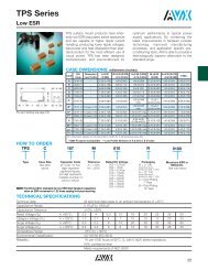
TPS – Low ESR Surface Mount Capacitor<br />
QV2000
Introduction<br />
Foreword<br />
<strong>AVX</strong> offers a broad line of solid tantalum<br />
capacitors in a wide range of sizes, styles, and<br />
ratings to meet any design needs. This catalog<br />
combines into one source <strong>AVX</strong>’s leaded tantalum<br />
capacitor information from its worldwide tantalum<br />
operations.<br />
The TAP is rated for use from -55°C to +85°C at<br />
rated voltage and up to +125°C with voltage derating.There<br />
are three preferred wireforms to choose<br />
from which are available on tape and reel, and in<br />
bulk for hand insertion.<br />
Four sizes of molded axials, the TAR series, are<br />
also available.The TAR is fully marked and available<br />
on tape and reel for high speed insertion. The TAA<br />
is a hermetically sealed series also with four case<br />
sizes available.<br />
Two series of MINITAN ® leaded capacitors are<br />
also available in both axial and radial configurations.<br />
The TMH series is designed with small batterypowered<br />
applications, such as hearing aids, in<br />
mind. The “X” case size in the TMH line is the smallest<br />
leaded tantalum capacitor available in the<br />
world. The flagship of the MINITAN ® line is the TMM<br />
series, available in five case sizes and also qualified<br />
to MIL-C-49137/6 as styles CX06 and CX16.<br />
<strong>AVX</strong> has a complete tantalum applications service<br />
available for use by all our customers. With the<br />
capability to prototype and mass produce solid<br />
tantalum capacitors in special configurations,<br />
almost any design need can be fulfilled. And if the<br />
customer requirements are outside our standard<br />
testing, <strong>AVX</strong> will work with you to define and<br />
implement a test or screening plan.<br />
<strong>AVX</strong> is determined to become the world leader in<br />
tantalum capacitor technology and has made, and<br />
is continuing to make, significant investments in<br />
equipment and research to reach that end. We<br />
believe that the investment has paid off with the<br />
devices shown on the following pages.<br />
Contents<br />
Introduction Foreword . . . . . . . . . . . . . . . . . . . . . . . . . . . . . . . . . . . . . . 1<br />
Dipped Radial <strong>Capacitors</strong> Introduction . . . . . . . . . . . . . . . . . . . . . . . . . . . . . . . . . . . . 2<br />
TAP Series . . . . . . . . . . . . . . . . . . . . . . . . . . . . . . . . . . . . . 3-6<br />
Tape and Reel Packaging . . . . . . . . . . . . . . . . . . . . . . . . . . 7-8<br />
Axial <strong>Capacitors</strong> TAR Series . . . . . . . . . . . . . . . . . . . . . . . . . . . . . . . . . . . . . 9-11<br />
TAA Series . . . . . . . . . . . . . . . . . . . . . . . . . . . . . . . . . . . . . 12-14<br />
Tape and Reel Packaging . . . . . . . . . . . . . . . . . . . . . . . . . . 15<br />
MINITAN ® <strong>Capacitors</strong> TMH Series. . . . . . . . . . . . . . . . . . . . . . . . . . . . . . . . . . . . . 16-19<br />
TMM Series . . . . . . . . . . . . . . . . . . . . . . . . . . . . . . . . . . . . 20-24<br />
Technical Summary and Application Guidelines. . . . . . . . . . . . . . . . . . . . . . . . . . . . . . . . . . . . . . 25-38<br />
Page<br />
NOTICE: Specifications are subject to change without notice. Contact your nearest <strong>AVX</strong> Sales Office for the latest specifications. All statements,<br />
information and data given herein are believed to be accurate and reliable, but are presented without guarantee, warranty, or responsibility of<br />
any kind, expressed or implied. Statements or suggestions concerning possible use of our products are made without representation or<br />
warranty that any such use is free of patent infringement and are not recommendations to infringe any patent. The user should not assume that<br />
all safety measures are indicated or that other measures may not be required. Specifications are typical and may not apply to all applications.<br />
1
Dipped Radial <strong>Capacitors</strong><br />
Introduction<br />
Solid <strong>Tantalum</strong> Resin Dipped<br />
Series TAP<br />
The TAP resin dipped series of miniature tantalum capacitors<br />
is available for individual needs in both commercial and<br />
professional applications. From computers to automotive to<br />
industrial, <strong>AVX</strong> has a dipped radial for almost any application.<br />
<strong>Tantalum</strong><br />
Graphite<br />
Resin encapsulation<br />
<strong>Tantalum</strong> Wire<br />
Terminal Wire<br />
Silver<br />
Solder<br />
Manganese<br />
dioxide<br />
<strong>Tantalum</strong><br />
pentoxide<br />
2
Dipped Radial <strong>Capacitors</strong><br />
Wire Form Outline<br />
Solid <strong>Tantalum</strong> Resin Dipped TAP<br />
Preferred Wire Forms<br />
D<br />
D<br />
Figure 1 Figure 2 Figure 3<br />
D<br />
+<br />
H<br />
H 1 + 4 (0.16)<br />
max<br />
2.0(0.08)<br />
max<br />
+<br />
H 1<br />
L<br />
S<br />
L<br />
S<br />
S<br />
d <br />
d<br />
2 (0.079)<br />
d<br />
Wire Form C<br />
min<br />
Wire Form B Wire Form S<br />
Non-Preferred Wire Forms (Not recommended for new designs)<br />
Figure 4<br />
D<br />
Figure 5<br />
Wire Form F<br />
1.10 +0.25<br />
-0.10<br />
(0.4 +0.010<br />
-0.004 <br />
Dimensions: millimeters (inches)<br />
Preferred Wire Forms<br />
D<br />
H + 3.8 (0.15)<br />
max<br />
L<br />
) S<br />
S<br />
d<br />
Wire Form G<br />
H<br />
L<br />
L<br />
<br />
2 (0.079)<br />
min<br />
Packaging<br />
Wire Form Figure Case Size L (see note 1) S d Suffixes Available*<br />
C Figure 1 A - R*<br />
B Figure 2 A - H<br />
S Figure 3 A - H*<br />
CCS Bulk<br />
16±4 5.0±1.0 0.5±0.05<br />
(0.630±0.160) (0.200±0.040) (0.020±0.002)<br />
CRW Tape/Reel<br />
CRS Tape/Ammo<br />
16±4 5.0±1.0 0.5±0.05 BRW Tape/Reel<br />
(0.630±0.160) (0.200±0.040) (0.020±0.002) BRS Tape/Ammo<br />
SCS Bulk<br />
16±4 2.5±0.5 0.5±0.05<br />
SRW Tape/Reel<br />
(0.630±0.160) (0.100±0.020) (0.020±0.002)<br />
SRS Tape/Ammo<br />
Non-Preferred Wire Forms (Not recommended for new designs)<br />
F Figure 4 A - R<br />
3.9±0.75 5.0±0.5 0.5±0.05<br />
(0.155±0.030) (0.200±0.020) (0.020±0.002)<br />
G Figure 5 A - H<br />
16±4 3.18±0.5 0.5±0.05<br />
(0.630±0.160) (0.125±0.020) (0.020±0.002)<br />
H<br />
Similar to 16±4 6.35±1.0 0.5±0.05<br />
A - R<br />
Figure 1<br />
(0.630±0.160) (0.250±0.040) (0.020±0.002)<br />
Notes: (1) Lead lengths can be supplied to tolerances other than those above and should be specified in the ordering information.<br />
(2) For D, H, and H 1 dimensions, refer to individual product on following pages.<br />
(3) Wire Form B supplied in tape format only.<br />
* For case size availability in tape and reel, please refer to page 7-8.<br />
FCS<br />
GSB<br />
HSB<br />
Bulk<br />
Bulk<br />
Bulk<br />
3
Dipped Radial <strong>Capacitors</strong><br />
TAP Series<br />
Solid <strong>Tantalum</strong> Resin Dipped <strong>Capacitors</strong><br />
TAP is a professional grade device manufactured with a flame<br />
retardant coating and featuring low leakage current and<br />
impedance, very small physical sizes and exceptional<br />
temperature stability. It is designed and conditioned to<br />
operate to +125°C (see page 27 for voltage derating<br />
above 85°C) and is available loose or taped and reeled for<br />
auto insertion. The 15 case sizes with wide capacitance and<br />
working voltage ranges means the TAP can accommodate<br />
almost any application.<br />
Case Dimensions: millimeters (inches)<br />
H<br />
+<br />
D<br />
Case H *H 1 D<br />
A 8.5 (0.33) 7.0 (0.28) 4.5 (0.18)<br />
B 9.0 (0.35) 7.5 (0.30) 4.5 (0.18)<br />
C 10.0 (0.39) 8.5 (0.33) 5.0 (0.20)<br />
D 10.5 (0.41) 9.0 (0.35) 5.0 (0.20)<br />
E 10.5 (0.41) 9.0 (0.35) 5.5 (0.22)<br />
F 11.5 (0.45) 10.0 (0.39) 6.0 (0.24)<br />
G 11.5 (0.45) 10.0 (0.39) 6.5 (0.26)<br />
H 12.0 (0.47) 10.5 (0.41) 7.0 (0.28)<br />
J 13.0 (0.51) 8.0 (0.31)<br />
K 14.0 (0.55) 8.5 (0.33)<br />
L 14.0 (0.55) 9.0 (0.35)<br />
M 14.5 (0.57) 9.0 (0.35)<br />
N 16.0 (0.63) 9.0 (0.35)<br />
P 17.0 (0.67) 10.0 (0.39)<br />
R 18.5 (0.73) 10.0 (0.39)<br />
*H 1 refers to H dimension on S wire form.<br />
How to Order:<br />
Type<br />
Capacitance Code<br />
pF code: 1st two digits represent significant figures, 3rd<br />
digit represents multiplier (number of zeros to follow)<br />
Capacitance Tolerance<br />
(K=±10%, M=±20%, For J=±5% tolerance, please consult factory)<br />
Rated DC Voltage<br />
Suffix indicating wireform and packaging<br />
(see page 3)<br />
TAP 475 M 035 SCS<br />
4
Dipped Radial <strong>Capacitors</strong><br />
TAP Series<br />
Technical Data:<br />
All technical data relate to an ambient temperature of +25°C<br />
Capacitance Range: 0.1µF to 330µF<br />
Capacitance Tolerance:<br />
±20%; ±10% (±5% consult your <strong>AVX</strong> representative for details)<br />
Rated Voltage DC (V R ) +85°C: 6.3 10 16 20 25 35 50<br />
Category Voltage (V C ) +125°C: 4 6.3 10 13 16 23 33<br />
Surge Voltage (V S ) +85°C: 8 13 20 26 33 46 65<br />
+125°C: 5 9 12 16 21 28 40<br />
Temperature Range:<br />
-55°C to +125°C<br />
Environmental Classification: 55/125/56 (IEC 68-2)<br />
Dissipation Factor:<br />
0.04 for C R 0.1-1.5µF<br />
0.06 for C R 2.2-6.8µF<br />
0.08 for C R 10-68µF<br />
0.10 for C R 100-330µF<br />
Reliability:<br />
1% per 1000 hrs. at 85°C with 0.1Ω/V series impedance, 60% confidence level.<br />
Capacitance Range (letter denotes case code)<br />
Capacitance Rated voltage DC (V R )<br />
µF Code 6.3V 10V 16V 20V 25V 35V 50V<br />
0.1 104 A A<br />
0.15 154 A A<br />
0.22 224 A A<br />
0.33 334 A A<br />
0.47 474 A A<br />
0.68 684 A B<br />
1.0 105 A A A C<br />
1.5 155 A A A A D<br />
2.2 225 A A A A B E<br />
3.3 335 A A A B B C F<br />
4.7 475 A A B C C E G<br />
6.8 685 A B C D D F H<br />
10 106 B C D E E F J<br />
15 156 C D E F F H K<br />
22 226 D E F H H K L<br />
33 336 E F F J J M<br />
47 476 F G J K M N<br />
68 686 G H L N N<br />
100 107 H K N N<br />
150 157 K N N<br />
220 227 M P R<br />
330 337 P R<br />
Values outside this standard range may be available on request.<br />
<strong>AVX</strong> reserves the right to supply capacitors to a higher voltage rating, in the same case size, than that ordered.<br />
Marking<br />
Capacitance, rated DC voltage, polarity and an "A" are laser marked on the<br />
capacitor body which is made of flame retardant gold epoxy resin with a limiting<br />
oxygen index in excess of 30 (ASTM-D-2863).<br />
• Polarity<br />
• Capacitance<br />
• Voltage<br />
• <strong>AVX</strong> logo<br />
• ±10% tolerance coded with "K" on reverse side of unit.<br />
+ A<br />
10<br />
16V<br />
5
Dipped Radial <strong>Capacitors</strong><br />
TAP Series<br />
Ratings and Part Number Reference<br />
<strong>AVX</strong> Case Capacitance DCL DF ESR<br />
Part No. Size µF (µA) % max. ()<br />
Max. Max. @ 100 kHz<br />
6.3 volt @ 85°C (4 volt @ 125°C)<br />
TAP 335( * )006 A 3.3 0.5 6 13.0<br />
TAP 475( * )006 A 4.7 0.5 6 10.0<br />
TAP 685( * )006 A 6.8 0.5 6 8.0<br />
TAP 106( * )006 B 10 0.5 8 6.0<br />
TAP 156( * )006 C 15 0.8 8 5.0<br />
TAP 226( * )006 D 22 1.1 8 3.7<br />
TAP 336( * )006 E 33 1.7 8 3.0<br />
TAP 476( * )006 F 47 2.4 8 2.0<br />
TAP 686( * )006 G 68 3.4 8 1.8<br />
TAP 107( * )006 H 100 5.0 10 1.6<br />
TAP 157( * )006 K 150 7.6 10 0.9<br />
TAP 227( * )006 M 220 11.0 10 0.9<br />
TAP 337( * )006 P 330 16.6 10 0.7<br />
10 volt @ 85°C (6.3 volt @ 125°C)<br />
TAP 225( * )010 A 2.2 0.5 6 13.0<br />
TAP 335( * )010 A 3.3 0.5 6 10.0<br />
TAP 475( * )010 A 4.7 0.5 6 8.0<br />
TAP 685( * )010 B 6.8 0.5 6 6.0<br />
TAP 106( * )010 C 10 0.8 8 5.0<br />
TAP 156( * )010 D 15 1.2 8 3.7<br />
TAP 226( * )010 E 22 1.7 8 2.7<br />
TAP 336( * )010 F 33 2.6 8 2.1<br />
TAP 476( * )010 G 47 3.7 8 1.7<br />
TAP 686( * )010 H 68 5.4 8 1.3<br />
TAP 107( * )010 K 100 8.0 10 1.0<br />
TAP 157( * )010 N 150 12.0 10 0.8<br />
TAP 227( * )010 P 220 17.6 10 0.6<br />
TAP 337( * )010 R 330 20.0 10 0.5<br />
16 volt @ 85°C (10 volt @ 125°C)<br />
TAP 155( * )016 A 1.5 0.5 4 10.0<br />
TAP 225( * )016 A 2.2 0.5 6 8.0<br />
TAP 335( * )016 A 3.3 0.5 6 6.0<br />
TAP 475( * )016 B 4.7 0.6 6 5.0<br />
TAP 685( * )016 C 6.8 0.8 6 4.0<br />
TAP 106( * )016 D 10 1.2 8 3.2<br />
TAP 156( * )016 E 15 1.9 8 2.5<br />
TAP 226( * )016 F 22 2.8 8 2.0<br />
TAP 336( * )016 F 33 4.2 8 1.6<br />
TAP 476( * )016 J 47 6.0 8 1.3<br />
TAP 686( * )016 L 68 8.7 8 1.0<br />
TAP 107( * )016 N 100 12.8 10 0.8<br />
TAP 157( * )016 N 150 19.2 10 0.6<br />
TAP 227( * )016 R 220 20.0 10 0.5<br />
20 volt @ 85°C (13 volt @ 125°C)<br />
TAP 105( * )020 A 1.0 0.5 4 10.0<br />
TAP 155( * )020 A 1.5 0.5 4 9.0<br />
TAP 225( * )020 A 2.2 0.5 6 7.0<br />
TAP 335( * )020 B 3.3 0.5 6 5.5<br />
TAP 475( * )020 C 4.7 0.7 6 4.5<br />
TAP 685( * )020 D 6.8 1.0 6 3.6<br />
TAP 106( * )020 E 10 1.6 8 2.9<br />
TAP 156( * )020 F 15 2.4 8 2.3<br />
TAP 226( * )020 H 22 3.5 8 1.8<br />
<strong>AVX</strong> Case Capacitance DCL DF ESR<br />
Part No. Size µF (µA) % max. ()<br />
Max. Max. @ 100 kHz<br />
20 volt @ 85°C (13 volt @ 125°C) continued<br />
TAP 336( * )020 J 33 5.2 8 1.4<br />
TAP 476( * )020 K 47 7.5 8 1.2<br />
TAP 686( * )020 N 68 10.8 8 0.9<br />
TAP 107( * )020 N 100 16.0 10 0.6<br />
25 volt @ 85°C (16 volt @ 125°C)<br />
TAP 105( * )025 A 1.0 0.5 4 10.0<br />
TAP 155( * )025 A 1.5 0.5 4 8.0<br />
TAP 225( * )025 A 2.2 0.5 6 6.0<br />
TAP 335( * )025 B 3.3 0.6 6 5.0<br />
TAP 475( * )025 C 4.7 0.9 6 4.0<br />
TAP 685( * )025 D 6.8 1.3 6 3.1<br />
TAP 106( * )025 E 10 2.0 8 2.5<br />
TAP 156( * )025 F 15 3.0 8 2.0<br />
TAP 226( * )025 H 22 4.4 8 1.5<br />
TAP 336( * )025 J 33 6.6 8 1.2<br />
TAP 476( * )025 M 47 9.4 8 1.0<br />
TAP 686( * )025 N 68 13.6 8 0.8<br />
35 volt @ 85°C (23 volt @ 125°C)<br />
TAP 104( * )035 A 0.1 0.5 4 26.0<br />
TAP 154( * )035 A 0.15 0.5 4 21.0<br />
TAP 224( * )035 A 0.22 0.5 4 17.0<br />
TAP 334( * )035 A 0.33 0.5 4 15.0<br />
TAP 474( * )035 A 0.47 0.5 4 13.0<br />
TAP 684( * )035 A 0.68 0.5 4 10.0<br />
TAP 105( * )035 A 1.0 0.5 4 8.0<br />
TAP 155( * )035 A 1.5 0.5 4 6.0<br />
TAP 225( * )035 B 2.2 0.6 6 5.0<br />
TAP 335( * )035 C 3.3 0.9 6 4.0<br />
TAP 475( * )035 E 4.7 1.3 6 3.0<br />
TAP 685( * )035 F 6.8 1.9 6 2.5<br />
TAP 106( * )035 F 10 2.8 8 2.0<br />
TAP 156( * )035 H 15 4.2 8 1.6<br />
TAP 226( * )035 K 22 6.1 8 1.3<br />
TAP 336( * )035 M 33 9.2 8 1.0<br />
TAP 476( * )035 N 47 10.0 8 0.8<br />
50 volt @ 85°C (33 volt @ 125°C)<br />
TAP 104( * )050 A 0.1 0.5 4 26.0<br />
TAP 154( * )050 A 0.15 0.5 4 21.0<br />
TAP 224( * )050 A 0.22 0.5 4 17.0<br />
TAP 334( * )050 A 0.33 0.5 4 15.0<br />
TAP 474( * )050 A 0.47 0.5 4 13.0<br />
TAP 684( * )050 B 0.68 0.5 4 10.0<br />
TAP 105( * )050 C 1.0 0.5 4 8.0<br />
TAP 155( * )050 D 1.5 0.6 4 6.0<br />
TAP 225( * )050 E 2.2 0.8 6 3.5<br />
TAP 335( * )050 F 3.3 1.3 6 3.0<br />
TAP 475( * )050 G 4.7 1.8 6 2.5<br />
TAP 685( * )050 H 6.8 2.7 6 2.0<br />
TAP 106( * )050 J 10 4.0 8 1.6<br />
TAP 156( * )050 K 15 6.0 8 1.2<br />
TAP 226( * )050 L 22 8.8 8 1.0<br />
(*) Insert J for ±5% capacitance tolerance; K for ±10% and M for ±20%<br />
NOTE: Voltage ratings are minimum values. <strong>AVX</strong> reserves the right to supply<br />
higher voltage ratings in the same case size.<br />
6
Dipped Radial <strong>Capacitors</strong><br />
Tape and Reel Packaging<br />
Solid <strong>Tantalum</strong> Resin Dipped<br />
TAP<br />
Tape and Reel Packaging for Automatic Component Insertion<br />
TAP types are all offered on radial tape, in reel or ‘ammo’ pack<br />
format for use on high speed radial automatic insertion<br />
equipment, or preforming machines.<br />
The tape format is compatible with EIA 468A standard for<br />
component taping set out by major manufacturers of radial<br />
automatic insertion equipment.<br />
TAP – available in three formats.<br />
P2<br />
P<br />
h<br />
H3<br />
‘B’ wires for normal automatic insertion on 5mm<br />
pitch.<br />
H<br />
L<br />
d<br />
H1<br />
S<br />
D<br />
W2<br />
W<br />
W1<br />
BRW suffix for reel<br />
BRS suffix for ‘ammo’ pack<br />
Available in case sizes A - H<br />
P1<br />
P<br />
T<br />
P2<br />
P<br />
h<br />
H3<br />
H<br />
L<br />
d<br />
H1<br />
S<br />
D<br />
W2<br />
W1<br />
W<br />
‘C’ wires for preforming.<br />
CRW suffix for reel<br />
CRS suffix for ‘ammo’ pack<br />
Available in case sizes A - M<br />
P1<br />
P<br />
T<br />
P2<br />
P<br />
h<br />
H3<br />
H2<br />
L<br />
H1<br />
d<br />
P1<br />
S<br />
P<br />
D<br />
W2<br />
W1<br />
W<br />
T<br />
S wire<br />
‘S’ wire for special applications, automatic<br />
insertion on 2.5mm pitch.<br />
SRW suffix for reel<br />
SRS suffix for ‘ammo’ pack<br />
Available in case sizes A - H<br />
Note: Lead forms may vary slightly from those shown.<br />
7
Dipped Radial <strong>Capacitors</strong><br />
Tape and Reel Packaging<br />
Solid <strong>Tantalum</strong> Resin Dipped<br />
TAP<br />
Dimensions: millimeters (inches)<br />
Description Code Dimension<br />
Feed hole pitch P 12.7 ± 0.3 (0.5 ± 0.01)<br />
Hole center to lead P 1 3.85 ± 0.7 (0.15 ± 0.03)<br />
to be measured at bottom<br />
of clench<br />
5.05 ± 1.0 (0.2 ± 0.04)<br />
for S wire<br />
Hole center to component center P 2 6.35 ± 0.4 (0.25 ± 0.02)<br />
Change in pitch p ± 1.0 (± 0.04)<br />
Lead diameter d 0.5 ± 0.05 (0.02 ± 0.003)<br />
Lead spacing S See wireform table<br />
Component alignment h 0 ± 2.0 (0 ± 0.08)<br />
Feed hole diameter D 4.0 ± 0.2 (0.15 ± 0.008)<br />
Tape width W 18.0 + 1.0 (0.7 + 0.04)<br />
- 0.5 - 0.02)<br />
Hold down tape width W 1 6.0 (0.24) min.<br />
Hold down tape position W 2 1.0 (0.04) max.<br />
Lead wire clench height H 16 ± 0.5 (0.63 ± 0.02)<br />
19 ± 1.0 (0.75 ± 0.04)<br />
on request<br />
Hole position H 1 9.0 ± 0.5 (0.35 ± 0.02)<br />
Base of component height H 2 18 (0.7) min. (S wire only)<br />
Component height H 3 32.25 (1.3) max.<br />
Length of snipped lead L 11.0 (0.43) max.<br />
Total tape thickness T 0.7 ± 0.2 (0.03 ± 0.001)<br />
Carrying card<br />
0.5 ± 0.1 (0.02 ± 0.005)<br />
Reel Configuration and<br />
Dimensions: millimeters<br />
(inches)<br />
Diameter 30<br />
(1.18) max.<br />
45 (1.77) max.<br />
40 (1.57) min.<br />
80<br />
(3.15)<br />
360 (14.17) max.<br />
Manufactured from<br />
cardboard with plastic hub.<br />
rdboard with plastic hub.<br />
olding tape outside.<br />
Holding tape outside.<br />
Positive terminal leading (negative<br />
terminal by by special request).<br />
53 (2.09) max.<br />
Packaging Quantities<br />
For Reels<br />
Style Case code No. of pieces<br />
A 1500<br />
B, C, D 1250<br />
TAP E, F 1000<br />
G, H, J 750<br />
K, L, M, N, P, R 500<br />
For ‘Ammo’ pack<br />
Style Case code No. of pieces<br />
A, B, C, D 3000<br />
TAP E, F, G 2500<br />
H 2000<br />
K, L, M, N, P, R 1000<br />
For bulk products<br />
Style Case code No. of pieces<br />
A to H 1000<br />
TAP J to L 500<br />
M to R 100<br />
Ammo Pack Dimensions<br />
millimeters (inches) max.<br />
Height 360 (14.17), width 360 (14.17),<br />
thickness 60 (2.36)<br />
General Notes<br />
Resin dipped tantalum capacitors are only<br />
available taped in the range of case codes<br />
and in the modular quantities by case<br />
code as indicated.<br />
Case sizes N, P, and R available bulk only.<br />
Packaging quantities on tape may vary by<br />
±1%.<br />
8
Molded Axial <strong>Capacitors</strong><br />
TAR Series<br />
Solid <strong>Tantalum</strong> Molded Axial<br />
<strong>Leaded</strong> <strong>Capacitors</strong><br />
TAR: Designed for use in miniature and subminiature<br />
circuit applications.<br />
1. Precision molded and taped and reeled for use in high speed<br />
automatic insertion applications.<br />
2. Suitable for decoupling, blocking, by-passing and filtering<br />
in computers, data processing, communications and<br />
other equipment.<br />
3. Available in four case sizes.<br />
4. Tapered nose identifies positive polarity.<br />
5. Capacitance, tolerance, rated voltage and polarity are marked<br />
onto the capacitor body.<br />
6. See page 15 for packaging quantities.<br />
Case Dimensions: millimeters (inches)<br />
D 1<br />
1<br />
(25) <br />
min<br />
Polarity mark<br />
L<br />
d<br />
Case L D 1 d Typical<br />
Size ±0.25 (0.01) ±0.25 (0.01) ±0.05 (0.02) Weight g<br />
Q 6.35 (0.25) 2.16 (0.085) 0.5 (0.02) 0.20<br />
R 7.4 (0.29) 2.5 (0.10) 0.5 (0.02) 0.25<br />
S 8.6 (0.34) 4.3 (0.17) 0.5 (0.02) 0.52<br />
W 10.4 (0.41) 4.3 (0.17) 0.5 (0.02) 0.53<br />
How to Order:<br />
Type<br />
Case Code<br />
Capacitance Code<br />
pF code: 1st two digits represent significant figures, 3rd<br />
digit represents multiplier (number of zeros to follow)<br />
Capacitance Tolerance<br />
(J=±5%, K=±10%, M=±20%)<br />
Rated DC Voltage<br />
TAR R 335 M 015<br />
9
Molded Axial <strong>Capacitors</strong><br />
TAR Series<br />
Technical Data:<br />
All technical data relate to an ambient temperature of +25°C<br />
Capacitance Range: 0.1µF to 68µF<br />
Capacitance Tolerance: ±20%; ±10%; ±5%<br />
Rated Voltage DC (V R<br />
) +85°C: 4 6.3 10 15 20 25 35 50<br />
Category Voltage (V C<br />
) +125°C: 2.7 4 6.3 10 13 17 23 33<br />
Surge Voltage (V S<br />
) +85°C: 5.2 8 13 20 26 33 46 65<br />
+125°C: 3.5 5 9 12 16 21 28 40<br />
Temperature Range:<br />
-55°C to +125°C<br />
Environmental Classification: 55/125/56 (IEC 68-2)<br />
Dissipation Factor:<br />
See part number table<br />
Capacitance Range (letter denotes case code)<br />
Capacitance Rated voltage DC (V R )<br />
µF 4V 6.3V 10V 15V 20V 25V 35V 50V<br />
0.1 Q Q<br />
0.15 Q Q<br />
0.22 Q Q<br />
0.33 Q R<br />
0.47 Q Q R<br />
0.68 Q R R<br />
1.0 Q Q R R<br />
1.5 Q Q R R S<br />
2.2 Q Q R R S S<br />
3.3 Q Q R R R S W<br />
4.7 Q Q R R R S S W<br />
6.8 Q R R R S S W<br />
10 R R R S S S W<br />
15 R R S S W W<br />
22 R S S W W<br />
33 S S W W<br />
47 S W W<br />
68 W W<br />
Values outside this standard range may be available on request without<br />
appropriate release or qualification.<br />
<strong>AVX</strong> reserves the right to supply capacitors to a tighter specification than that<br />
ordered.<br />
Marking • Polarity • Capacitance • Date code<br />
• Tolerance • Voltage<br />
10
Molded Axial <strong>Capacitors</strong><br />
TAR Series<br />
Ratings and Part Number Reference<br />
<strong>AVX</strong> Case Capacitance DCL DF ESR<br />
Part No. Size µF (µA) % max. ()<br />
Max. Max. @ 100 kHz<br />
4 volt @ 85°C (2.7 volt @ 125°C)<br />
TARQ475( * )004 Q 4.7 0.5 8 12<br />
TARQ685( * )004 Q 6.8 0.5 8 10<br />
TARR106( * )004 R 10 0.5 8 10<br />
TARR156( * )004 R 15 0.5 8 8.0<br />
TARR226( * )004 R 22 0.7 8 6.0<br />
TARS336( * )004 S 33 1.1 8 5.0<br />
TARS476( * )004 S 47 1.5 8 3.5<br />
TARW686( * )004 W 68 2.2 8 2.5<br />
6.3 volt @ 85°C (4 volt @ 125°C)<br />
TARQ335( * )006 Q 3.3 0.5 4 14<br />
TARQ475( * )006 Q 4.7 0.5 4 10<br />
TARR685( * )006 R 6.8 0.5 6 8.0<br />
TARR106( * )006 R 10 0.5 6 6.0<br />
TARR156( * )006 R 15 0.7 6 5.0<br />
TARS226( * )006 S 22 1.1 6 3.7<br />
TARS336( * )006 S 33 1.5 6 3.0<br />
TARW476( * )006 W 47 2.3 6 2.0<br />
TARW686( * )006 W 68 3.3 6 1.8<br />
10 volt @ 85°C (7 volt @ 125°C)<br />
TARQ225( * )010 Q 2.2 0.5 4 14<br />
TARQ335( * )010 Q 3.3 0.5 4 10<br />
TARR475( * )010 R 4.7 0.5 4 8.0<br />
TARR685( * )010 R 6.8 0.5 6 6.0<br />
TARR106( * )010 R 10 0.8 6 5.0<br />
TARS156(*)010 S 15 1.2 6 3.7<br />
TARS226( * )010 S 22 1.5 6 2.7<br />
TARW336( * )010 W 33 2.6 6 2.1<br />
TARW476( * )010 W 47 3.8 6 1.7<br />
15 volt @ 85°C (10 volt @ 125°C)<br />
TARQ155( * )015 Q 1.5 0.5 4 14<br />
TARQ225( * )015 Q 2.2 0.5 4 8.0<br />
TARR335( * )015 R 3.3 0.5 4 6.0<br />
TARR475( * )015 R 4.7 0.6 4 5.0<br />
TARR685( * )015 R 6.8 0.8 6 4.0<br />
TARS106( * )015 S 10 1.2 6 3.2<br />
TARS156( * )015 S 15 1.5 6 2.5<br />
TARW226( * )015 W 22 2.6 6 2.0<br />
TARW336( * )015 W 33 4.0 6 1.6<br />
20 volt @ 85°C (13 volt @ 125°C)<br />
TARQ105( * )020 Q 1.0 0.5 4 18<br />
TARQ155( * )020 Q 1.5 0.5 4 12<br />
TARR225( * )020 R 2.2 0.5 4 7.0<br />
TARR335( * )020 R 3.3 0.5 4 5.5<br />
TARR475( * )020 R 4.7 0.8 4 4.5<br />
TARS685( * )020 S 6.8 1.1 6 3.7<br />
TARS106( * )020 S 10 1.6 6 2.8<br />
TARW156( * )020 W 15 2.4 6 2.3<br />
TARW226( * )020 W 22 3.5 6 1.9<br />
<strong>AVX</strong> Case Capacitance DCL DF ESR<br />
Part No. Size µF (µA) % max. ()<br />
Max. Max. @ 100 kHz<br />
25 volt @ 85°C (17 volt @ 125°C)<br />
TARQ474( * )025 Q 0.47 0.5 3 20<br />
TARQ684( * )025 Q 0.68 0.5 3 16<br />
TARQ105( * )025 Q 1.0 0.5 3 12<br />
TARR155( * )025 R 1.5 0.5 3 8.0<br />
TARR225( * )025 R 2.2 0.5 3 6.0<br />
TARR335( * )025 R 3.3 0.7 3 5.0<br />
TARS475( * )025 S 4.7 0.9 4 4.0<br />
TARS685( * )025 S 6.8 1.4 4 3.1<br />
TARS106( * )025 S 10 1.5 4 2.5<br />
TARW156( * )025 W 15 3.0 4 2.0<br />
35 volt @ 85°C (23 volt @ 125°C)<br />
TARQ104( * )035 Q 0.1 0.5 3 26<br />
TARQ154( * )035 Q 0.15 0.5 3 21<br />
TARQ224( * )035 Q 0.22 0.5 3 17<br />
TARQ334( * )035 Q 0.33 0.5 3 15<br />
TARQ474( * )035 Q 0.47 0.5 3 13<br />
TARR684( * )035 R 0.68 0.5 3 10<br />
TARR105( * )035 R 1.0 0.5 3 8.0<br />
TARR155( * )035 R 1.5 0.5 3 6.0<br />
TARS225( * )035 S 2.2 0.6 3 5.0<br />
TARS335( * )035 S 3.3 0.9 4 4.0<br />
TARS475( * )035 S 4.7 1.3 4 3.0<br />
TARW685( * )035 W 6.8 1.9 4 2.5<br />
TARW106( * )035 W 10 2.8 4 2.0<br />
50 volt @ 85°C (33 volt @ 125°C)<br />
TARQ104( * )050 Q 0.1 0.5 3 26<br />
TARQ154( * )050 Q 0.15 0.5 3 21<br />
TARQ224( * )050 Q 0.22 0.5 3 17<br />
TARR334( * )050 R 0.33 0.5 3 15<br />
TARR474( * )050 R 0.47 0.5 3 13<br />
TARR684( * )050 R 0.68 0.5 3 10<br />
TARR105( * )050 R 1.0 0.5 3 8.0<br />
TARS155( * )050 S 1.5 0.6 4 5.0<br />
TARS225( * )050 S 2.2 0.9 4 3.5<br />
TARW335( * )050 W 3.3 1.3 4 3.0<br />
TARW475( * )050 W 4.7 1.9 4 2.5<br />
(*) Insert J for ±5% capacitance tolerance; K for ±10% and M for ±20%<br />
NOTE: Voltage ratings are minimum values. We reserve the right to supply<br />
higher voltage ratings in the same case size.<br />
11
Hermetic Axial <strong>Capacitors</strong><br />
TAA Series<br />
Solid <strong>Tantalum</strong> Hermetically Sealed<br />
Axial <strong>Leaded</strong> <strong>Capacitors</strong><br />
TAA: Fully hermetically sealed, of rugged construction and high<br />
reliability for use in military and professional equipment.<br />
1. Extremely low leakage current.<br />
2. Excellent capacitance to size ratio.<br />
3. Available taped and reeled for automatic insertion.<br />
4. Marked with suppliers’ logo, capacitor type, capacitance,<br />
capacitance tolerance, rated voltage, polarity indication and<br />
date of manufacture.<br />
5. Approved to BS CECC 30 201-001 and IECQ QC300 201<br />
GB0002 supplied conforming to the limits of MIL-C-39003<br />
style CSR, CTS 13 and CTS 32.<br />
Case Dimensions: millimeters (inches)<br />
L 2<br />
L 1<br />
<br />
+<br />
Polarity Mark<br />
d<br />
D<br />
Case L 1 L 2 D Lead Length d Weight<br />
Size max. max. max. min. nom. max. g<br />
A 7.2 (0.28) 10.7 (0.42) 3.6 (0.14) 28 (1.1) 0.5 0.7<br />
B 12.0 (0.47) 15.5 (0.61) 4.9 (0.19) 28 (1.1) 0.5 1.3<br />
C 17.3 (0.68) 20.9 (0.82) 7.5 (0.29) 23 (0.9) 0.6 4.7<br />
D 19.9 (0.78) 23.4 (0.92) 9.0 (0.35) 22 (0.8) 0.6 7.4<br />
Note: The tabulated dimensions are for non-insulated capacitors. Insulated capacitors are standard,<br />
dimension L 1 will increase by 0.8mm maximum, and dimension D by 0.2mm maximum.<br />
How to Order:<br />
Type<br />
Case Code<br />
Capacitance Code<br />
pF code: 1st two digits represent significant figures, 3rd<br />
digit represents multiplier (number of zeros to follow)<br />
Capacitance Tolerance<br />
(J=±5%, K=±10%, M=±20%)<br />
Rated DC Voltage<br />
TAA Packaging Suffixes (see page 15)<br />
TAA A 105 M 035 G<br />
12
Hermetic Axial <strong>Capacitors</strong><br />
TAA Series<br />
Construction:<br />
Hermetically sealed; axial terminations<br />
Capacitance Range: 0.1µF to 330µF<br />
Capacitance Tolerance: ±20%; ±10%; ±5%<br />
Measuring Conditions: 120 Hz, 20°C<br />
Rated Voltage VDC +85°C: 6.3 10 16 20 25 35 40 50<br />
Category Voltage VDC +125°C: 4 6.3 10 13 17 23 25 33<br />
Surge Voltage VDC +85°C: 8 13 20 26 33 46 52 65<br />
+125°C: 5 9 12 16 21 28 33 40<br />
Temperature Range:<br />
-55°C to +125°C<br />
Environmental Classification: 55/125/56 (IEC 68-2)<br />
Dissipation Factor: (tan ) 0.04 for C=0.1 to 4.7µF<br />
0.06 for C= 6.8 to 100µF<br />
0.08 for C= 150 to 330µF<br />
Approvals: BS CECC 30 201-001<br />
IECQ QC 300 201 GB0002<br />
CECC 30 201-005 CTS 13<br />
CECC 30 201-019 CTS 32<br />
Capacitance Range (letter denotes case code)<br />
Capacitance Cap Rated voltage DC<br />
µF Code 6.3V 10V 16V 20V 25V 35V 40V 50V<br />
0.1 104 A A A<br />
0.15 154 A A A<br />
0.22 224 A A A<br />
0.33 334 A A A<br />
0.47 474 A A A<br />
0.68 684 A A A<br />
1.0 105 A A A<br />
1.5 155 A A B B B<br />
2.2 225 A B B B<br />
3.3 335 A B B B<br />
4.7 475 A B B B B<br />
6.8 685 A B B B C<br />
10 106 B B B C C C<br />
15 156 B B C C C<br />
22 226 B C C C D<br />
33 336 B C C C D D<br />
47 476 B C C D D<br />
68 686 C C D D<br />
100 107 C D D<br />
150 157 C D D<br />
220 227 D D<br />
330 337 D<br />
Maximum Leakage Current (µA)<br />
Maximum Impedance (Ω) @ 100 kHz<br />
Capacitance Rated voltage DC<br />
µF 6.3V 10V 16V 20V 25V 35V 40V 50V<br />
0.1 0.5 0.5 0.5<br />
0.15 0.5 0.5 0.5<br />
0.22 0.5 0.5 0.5<br />
0.33 0.5 0.5 0.5<br />
0.47 0.5 0.5 0.5<br />
0.68 0.5 0.5 0.5<br />
1.0 0.5 0.5 0.5<br />
1.5 0.5 0.5 0.5 1.0 1.0<br />
2.2 0.5 1.0 1.0 1.0<br />
3.3 0.5 1.0 1.0 1.5<br />
4.7 0.5 0.8 1.5 2.0 2.5<br />
6.8 0.5 3.5 4.5 4.5<br />
10 1.0 2.0 2.5 3.5 4.0 5.0<br />
15 1.0 3.0 5.0 6.0 7.5<br />
22 3.5 4.5 7.5 9.0 10.0<br />
33 3.5 5.0 7.0 8.5 10.0 13.0<br />
47 3.0 4.5 9.5 10.0 15.0<br />
68 4.5 10.0 13.5 15.0<br />
100 10.0 15.0 20.0<br />
150 9.4 15.0 20.0<br />
220 14.0 20.0<br />
330 20.0<br />
13<br />
Capacitance Rated voltage DC<br />
µF 6.3V 10V 16V 20V 25V 35V 40V 50V<br />
0.1 26.0 26.0 26.0<br />
0.15 21.0 21.0 21.0<br />
0.22 17.0 17.0 17.0<br />
0.33 17.0 17.0 17.0<br />
0.47 13.0 13.0 13.0<br />
0.68 10.0 10.0 10.0<br />
1.0 8.0 8.0 8.0<br />
1.5 9.0 8.0 5.0 5.0 5.0<br />
2.2 8.0 3.5 3.0 3.0<br />
3.3 6.0 4.0 4.0 3.0<br />
4.7 7.5 3.0 3.0 3.0 2.5<br />
6.8 6.0 2.5 2.5 2.5 2.0<br />
10 2.6 2.6 2.5 2.0 2.0 1.6<br />
15 2.3 2.3 1.6 1.6 1.2<br />
22 2.0 1.3 1.3 1.3 1.0<br />
33 1.7 1.2 1.2 1.2 1.0 1.0<br />
47 1.5 1.1 1.1 0.8 0.8<br />
68 1.0 1.0 0.8 0.8<br />
100 1.0 0.7 0.7<br />
150 0.8 0.6 0.6<br />
220 0.55 0.55<br />
330 0.5
Hermetic Axial <strong>Capacitors</strong><br />
TAA Series<br />
Ratings and Part Number Reference<br />
<strong>AVX</strong> Case Capacitance DCL DF ESR<br />
Part No. Size µF (µA) % max. ()<br />
Max. Max. @ 100 kHz<br />
6.3 volt @ 85°C (4 volt @ 125°C)<br />
TAAA685( * )006 A 6.8 0.5 6 5.0<br />
TAAB476( * )006 B 47 3.0 6 1.6<br />
TAAC157( * )006 C 150 9.5 8 0.8<br />
TAAD337( * )006 D 330 20 8 0.5<br />
10 volt @ 85°C (6.3 volt @ 125°C)<br />
TAAA475( * )010 A 4.7 0.5 6 5.0<br />
TAAB336( * )010 B 33 3.5 6 1.6<br />
TAAD157( * )010 D 150 15 8 0.8<br />
TAAD227( * )010 D 220 20 8 0.5<br />
16 volt @ 85°C (10 volt @ 125°C)<br />
TAAA335( * )016 A 3.3 0.5 6 6<br />
TAAB656( * )016 B 15 2.4 6 2<br />
TAAB226( * )016 B 22 3.5 6 1.6<br />
TAAC686( * )016 C 68 10 6 0.8<br />
TAAD157( * )016 D 150 20 8 0.5<br />
20 volt @ 85°C (13 volt @ 125°C)<br />
TAAA225( * )020 A 2.2 0.5 6 6.5<br />
TAAB156( * )020 B 15 3.0 6 1.8<br />
TAAC476( * )020 C 47 9.5 6 0.9<br />
TAAD107( * )020 D 100 20 6 0.5<br />
25 volt @ 85°C (17 volt @ 125°C)<br />
TAAA155( * )025 A 1.5 0.5 4 7.5<br />
TAAB106( * )025 B 10 2.5 6 2.0<br />
TAAC336( * )025 C 33 8.5 6 1<br />
TAAD686( * )025 D 68 15.0 6 0.6<br />
35 volt @ 85°C (23 volt @ 125°C)<br />
TAAA104( * )035 A 0.1 0.5 4 N/A<br />
TAAA154( * )035 A 0.15 0.5 4 N/A<br />
TAAA224( * )035 A 0.22 0.5 4 N/A<br />
TAAA334( * )035 A 0.33 0.5 4 N/A<br />
TAAA474( * )035 A 0.47 0.5 4 N/A<br />
TAAA684( * )035 A 0.68 0.5 4 10<br />
TAAA105( * )035 A 1.0 0.5 4 8<br />
TAAB155( * )035 B 1.5 0.5 4 6<br />
TAAB225( * )035 B 2.2 1 4 6<br />
TAAB335( * )035 B 3.3 1 4 3.5<br />
TAAB475( * )035 B 4.7 1.5 4 2.5<br />
TAAB685( * )035 B 6.8 2.5 6 2<br />
TAAC106( * )035 C 10 3.5 6 1.6<br />
TAAC156( * )035 C 15 5 6 1.2<br />
TAAC226( * )035 C 22 7.5 6 1.0<br />
TAAD336( * )035 D 33 10 6 0.8<br />
TAAD476( * )035 D 47 10 6 0.6<br />
<strong>AVX</strong> Case Capacitance DCL DF ESR<br />
Part No. Size µF (µA) % max. ()<br />
Max. Max. @ 100 kHz<br />
40 volt @ 85°C (25 volt @ 125°C)<br />
TAAA104( * )040 A 0.10 0.5 4 N/A<br />
TAAA154( * )040 A 0.15 0.5 4 N/A<br />
TAAA224( * )040 A 0.22 0.5 4 N/A<br />
TAAA334( * )040 A 0.33 0.5 4 N/A<br />
TAAA474( * )040 A 0.47 0.5 4 N/A<br />
TAAA684( * )040 A 0.68 0.5 4 10.0<br />
TAAA105( * )040 A 1.00 0.5 4 8.0<br />
TAAB155( * )040 B 1.50 0.6 4 6.0<br />
TAAB255( * )040 B 2.20 0.9 6 6.0<br />
TAAB335( * )040 B 3.30 1.3 6 3.5<br />
TAAB475( * )040 B 4.70 1.9 6 2.5<br />
TAAB685( * )040 B 6.80 2.7 6 2.0<br />
TAAC106( * )040 C 10.0 4.0 6 1.6<br />
TAAC156( * )040 C 15.0 6.0 6 1.2<br />
TAAC226( * )040 C 22.0 8.8 6 1.0<br />
TAAC336( * )040 D 33.0 13 6 0.8<br />
TAAC476( * )040 D 47.0 19 6 0.6<br />
50 volt @ 85°C (33 volt @ 125°C)<br />
TAAA104( * )050 A 0.10 0.5 4 N/A<br />
TAAA154( * )050 A 0.15 0.5 4 N/A<br />
TAAA224( * )050 A 0.22 0.5 4 N/A<br />
TAAA334( * )050 A 0.33 0.5 4 N/A<br />
TAAA474( * )050 A 0.47 0.5 4 N/A<br />
TAAA684( * )050 A 0.68 0.5 4 10.0<br />
TAAA105( * )050 A 1.00 0.5 4 8.0<br />
TAAB155( * )050 B 1.50 0.8 4 6.0<br />
TAAB225( * )050 B 2.20 1.1 6 6.0<br />
TAAB335( * )050 B 3.30 1.7 6 3.5<br />
TAAB475( * )050 B 4.70 2.4 6 2.5<br />
TAAC685( * )050 C 6.80 3.4 6 2.0<br />
TAAC106( * )050 C 10.0 5.0 6 1.6<br />
TAAC156( * )050 C 15.0 7.5 6 1.2<br />
TAAD226( * )050 D 22.0 11 6 1.0<br />
(*) Insert J for ±5% capacitance tolerance; K for ±10% and M for ±20%<br />
NOTE: Voltage ratings are minimum values. <strong>AVX</strong> reserves the right to supply<br />
higher voltage ratings in the same case size.<br />
14
Axial <strong>Capacitors</strong><br />
Tape and Reel Packaging<br />
Solid <strong>Tantalum</strong> Axial TAR and TAA<br />
Tape and reel packaging for automatic component insertion<br />
TAR and TAA series are supplied as standard on axial bandolier,<br />
in reel format or ‘ammo’ pack for use on high speed axial automatic<br />
insertion equipment, or preforming machines.<br />
The tape format is compatible with standards for component<br />
taping set out by major manufacturers of axial automatic<br />
insertion equipment.<br />
Tape Specification<br />
Reel Configuration<br />
Taper this<br />
end<br />
Colored<br />
tape - + White tape<br />
G<br />
30 max.<br />
P<br />
400 max.<br />
K<br />
E<br />
n<br />
Shape: Circular or Octagonal<br />
7.00 max.<br />
L<br />
Packaging Quantities, TAR<br />
For reels<br />
Case Code<br />
Packaging Quantities, TAA<br />
For reels, Standard Suffix G<br />
Number of Pieces<br />
Q 3000<br />
R 3000<br />
S 2000<br />
W 2000<br />
Case Code<br />
Number of Pieces<br />
A 3500<br />
B 2500<br />
C 500<br />
D 400<br />
For ammo pack, Standard Suffix W<br />
Case Code<br />
Number of Pieces<br />
A 1500<br />
B 1000<br />
C 250<br />
D 250<br />
Dimensions millimeters (inches)<br />
E max 1.6 (0.063)<br />
G max 1.2 (0.047)<br />
K Component body shall be located centrally<br />
within a window, width K, where K is 1.4 (0.06)<br />
greater than the primary body length<br />
L 52.4 ± 1.5 (2.06 ± 0.06)<br />
P 5.0 ± 0.5 (0.2 ± 0.02)<br />
leader max 400 (15.75)<br />
trailer max 30 (1.2)<br />
n Will allow for unhindered reeling and unreeling<br />
of the taped components<br />
Preferred Dimensions: millimeters (inches)<br />
G - Taped, Reeled<br />
W - Taped, Ammo Pack<br />
73.0 (2.87) Spacing<br />
73.0 (2.87) Spacing<br />
15
MINITAN ® <strong>Capacitors</strong><br />
TMH Series<br />
The TMH series is now available in eight case sizes. These precision<br />
microminiature polarized capacitors are especially suitable<br />
for general filtering, decoupling, bypassing and RC timing applications.<br />
The TMH series is rated to +85°C without derating and<br />
up to +125°C with derating. The favorable capacitance to volume<br />
ratio has made this series of MINITAN capacitors the leader<br />
in high density applications such as hearing aids.<br />
Figure 1<br />
Figure 2 (OBSOLETE)<br />
C<br />
B<br />
D<br />
A<br />
A<br />
Radial<br />
E<br />
Case Sizes<br />
W, U, X<br />
Axial<br />
E<br />
Radial<br />
Axial<br />
Case Sizes<br />
P, K, B, A, G (OBSOLETE)<br />
Leads – Leads are solder coated pure nickel wire suitable for soldering or welding. Tested in accordance with MIL-STD-202, Method 211,<br />
.010 diameter leads withstand a 1-lb. pull and .007 diameter leads an 8 oz. pull. All lead diameters withstand 5 rotations twist.<br />
Case Dimensions — millimeters (inches)<br />
Case Applicable A B C E<br />
Size Drawing Max Max Max<br />
X Figure 1 1.9 (.075) 1.3 (.050) 1.1 (.040) 0.8±0.4 (.030±.015)<br />
W Figure 1 2.5 (.100) 1.3 (.050) 1.1 (.040) 0.8±0.4 (.030±.015)<br />
U Figure 1 3.2 (.125) 1.8 (.070) 1.1 (.040) 1.3±0.4 (.050±.015)<br />
Case Applicable A D E<br />
Size Drawing Max Max<br />
P<br />
K<br />
B<br />
A<br />
G<br />
OBSOLETE<br />
OBSOLETE<br />
OBSOLETE<br />
OBSOLETE<br />
OBSOLETE<br />
Lead length: all case sizes: Pos. 41.3±3.2 (1.625±.125) Lead Diameter: W, X = .178±.025 (.007±.001); U=.254±.025 (.010±.001).<br />
Neg. 34.9±3.2 (1.375±.125)<br />
16
MINITAN ® <strong>Capacitors</strong><br />
TMH Series<br />
How to Order:<br />
Type<br />
Case Code<br />
(See table on page 17)<br />
TMH W 472 M 020 R B SZ0000<br />
Capacitance Code<br />
pF code: 1st two digits represent significant figures, 3rd<br />
digit represents multiplier (number of zeros to follow)<br />
Tolerance<br />
(M=±20%, K=±10%, J=±5%)<br />
Rated DC Voltage<br />
Lead Configuration<br />
R=Radial, A=Axial<br />
Packaging<br />
B=Bulk<br />
Other Product Information<br />
SZ=Standard Product<br />
0000=Standard Product<br />
*Note: Other digits may be supplied by factory to identify specific customer<br />
requirements. Contact factory for details.<br />
Technical Data:<br />
All technical data relate to an ambient temperature of +25°C<br />
Capacitance Range: 0.15µF to 10µF<br />
Capacitance Tolerance: ±20%; ±10%; ±5%<br />
Rated Voltage DC (V R ) +85°C: 2 3 4 6 10 15 20 35<br />
Category Voltage (V C ) +125°C: 1.3 2 2.6 4 6.7 10 13 23<br />
Surge Voltage (V S ) +85°C: 2.6 4 5.2 8 13 19 26 46<br />
+125°C: 1.7 2.6 3.4 5.2 8.7 13 16 28<br />
Temperature Range:<br />
-55°C to +125°C<br />
Dissipation Factor:<br />
see part number table<br />
Life Test:<br />
After 2000 hrs. at 85°C with V R applied.<br />
CAP = ±15% max.<br />
DF, DCL = initial limit.<br />
Marking<br />
Capacitance value shall be typographically marked on all case sizes.<br />
Tolerance for all case sizes will be indicated by a silver dot for the<br />
±10% and a gold dot for the ±5%.<br />
• Capacitance<br />
•Tolerance<br />
•Polarity<br />
17
MINITAN ® <strong>Capacitors</strong><br />
TMH Series<br />
Ratings and Part Number Reference<br />
<strong>AVX</strong> Capacitance DCL DF<br />
Part No. µF (µA) %<br />
Max. Max.<br />
2 volt @ 85°C (1.3 volt @ 125°C)<br />
TMH-X-474ø002* 0.47 0.5 15<br />
TMH-W-474ø002* 0.47 0.5 15<br />
TMH-X-684ø002* 0.68 0.5 15<br />
TMH-W-684ø002* 0.68 0.5 15<br />
TMH-X-105ø002* 1.0 0.5 15<br />
TMH-W-105ø002* 1.0 0.5 15<br />
TMH-X-155ø002* 1.5 0.5 15<br />
TMH-X-225ø002* 2.2 0.5 15<br />
TMH-W-225ø002* 2.2 0.5 15<br />
TMH-U-225ø002* 2.2 0.5 15<br />
TMH-U-335ø002* 3.3 0.5 15<br />
TMH-P-OBSOLETE<br />
TMH-U-475ø002* 4.7 0.5 15<br />
TMH-K-OBSOLETE<br />
TMH-U-685ø002* 6.8 0.5 15<br />
TMH-K-OBSOLETE<br />
TMH-B-OBSOLETE<br />
TMH-U-106ø002* 10.0 0.5 15<br />
TMH-B-OBSOLETE<br />
TMH-A-OBSOLETE<br />
TMH-A-OBSOLETE<br />
TMH-A-OBSOLETE<br />
3 volt @ 85°C (2 volt @ 125°C)<br />
TMH-U-155ø003* 1.5 0.5 10<br />
TMH-P-OBSOLETE<br />
TMH-K-OBSOLETE<br />
TMH-U-475ø003* 4.7 0.5 10<br />
TMH-B-OBSOLETE<br />
TMH-A-OBSOLETE<br />
TMH-G-OBSOLETE<br />
4 volt @ 85°C (2.6 volt @ 125°C)<br />
TMH-X-334ø004* 0.33 0.5 10<br />
TMH-W-334ø004* 0.33 0.5 10<br />
TMH-U-105ø004* 1.0 0.5 10<br />
TMH-P-OBSOLETE<br />
TMH-K-OBSOLETE<br />
TMH-B-OBSOLETE<br />
TMH-A-OBSOLETE<br />
TMH-G-OBSOLETE<br />
*R = Radial, A = Axial<br />
ø Capacitance Tolerance:M=±20%; K=±10%; J=±5%<br />
<strong>AVX</strong> Capacitance DCL DF<br />
Part No. µF (µA) %<br />
Max. Max.<br />
6 volt @ 85°C (4 volt @ 125°C)<br />
TMH-X-224ø006* 0.22 0.5 10<br />
TMH-W-224ø006* 0.22 0.5 10<br />
TMH-U-684ø006* 0.68 0.5 10<br />
TMH-P-OBSOLETE<br />
TMH-K-OBSOLETE<br />
TMH-B-OBSOLETE<br />
TMH-A-OBSOLETE<br />
TMH-G-OBSOLETE<br />
10 volt @ 85°C (6.7 volt @ 125°C)<br />
TMH-X-154ø010* 0.15 0.5 10<br />
TMH-W-154ø010* 0.15 0.5 10<br />
TMH-U-474ø010* 0.47 0.5 10<br />
TMH-P-OBSOLETE<br />
TMH-K-OBSOLETE<br />
TMH-B-OBSOLETE<br />
TMH-A-OBSOLETE<br />
TMH-G-OBSOLETE<br />
15 volt @ 85°C (10 volt @ 125°C)<br />
TMH-X-104ø015* 0.1 0.5 10<br />
TMH-W-104ø015* 0.1 0.5 10<br />
TMH-U-334ø015* 0.33 0.5 10<br />
TMH-P-OBSOLETE<br />
TMH-K-OBSOLETE<br />
TMH-B-OBSOLETE<br />
TMH-A-OBSOLETE<br />
TMH-G-OBSOLETE<br />
18
MINITAN ® <strong>Capacitors</strong><br />
TMH Series<br />
Ratings and Part Number Reference<br />
<strong>AVX</strong> Capacitance DCL DF<br />
Part No. µF (µA) %<br />
Max. Max.<br />
20 volt @ 85°C (13 volt @ 125°C)<br />
TMH-U-102ø020* 0.001 0.5 10<br />
TMH-U-152ø020* 0.0015 0.5 10<br />
TMH-X-222ø020* 0.0022 0.5 10<br />
TMH-W-222ø020* 0.0022 0.5 10<br />
TMH-U-222ø020* 0.0022 0.5 10<br />
TMH-X-332ø020* 0.0033 0.5 10<br />
TMH-W-332ø020* 0.0033 0.5 10<br />
TMH-U-332ø020* 0.0033 0.5 10<br />
TMH-X-472ø020* 0.0047 0.5 10<br />
TMH-W-472ø020* 0.0047 0.5 10<br />
TMH-U-472ø020* 0.0047 0.5 10<br />
TMH-X-682ø020* 0.0068 0.5 10<br />
TMH-W-682ø020* 0.0068 0.5 10<br />
TMH-U-682ø020* 0.0068 0.5 10<br />
TMH-X-103ø020* 0.010 0.5 10<br />
TMH-W-103ø020* 0.010 0.5 10<br />
TMH-U-103ø020* 0.010 0.5 10<br />
TMH-U-153ø020* 0.015 0.5 10<br />
TMH-X-153ø020* 0.015 0.5 10<br />
TMH-W-153ø020* 0.015 0.5 10<br />
TMH-X-223ø020* 0.022 0.5 10<br />
TMH-W-223ø020* 0.022 0.5 10<br />
TMH-U-223ø020* 0.022 0.5 10<br />
TMH-X-333ø020* 0.033 0.5 10<br />
TMH-W-333ø020* 0.033 0.5 10<br />
TMH-U-333ø020* 0.033 0.5 10<br />
TMH-X-473ø020* 0.047 0.5 10<br />
TMH-W-473ø020* 0.047 0.5 10<br />
TMH-U-473ø020* 0.047 0.5 10<br />
TMH-X-683ø020* 0.068 0.5 10<br />
TMH-W-683ø020* 0.068 0.5 10<br />
TMH-U-683ø020* 0.068 0.5 10<br />
*R = Radial, A = Axial<br />
ø Capacitance Tolerance: M=±20%; K=±10%; J=±5%<br />
<strong>AVX</strong> Capacitance DCL DF<br />
Part No. µF (µA) %<br />
Max. Max.<br />
20 volt @ 85°C (13 volt @ 125°C) Continued<br />
TMH-U-104ø020** 0.1 0.5 10<br />
TMH-U-154ø020* 0.15 0.5 10<br />
TMH-U-224ø020* 0.22 0.5 10<br />
TMH-P-OBSOLETE<br />
TMH-K-OBSOLETE<br />
TMH-B-OBSOLETE<br />
TMH-B-OBSOLETE<br />
TMH-A-OBSOLETE<br />
TMH-G-OBSOLETE<br />
TMH-G-OBSOLETE<br />
TMH-G-OBSOLETE<br />
35 volt @ 85°C (23 volt @ 125°C)<br />
TMH-P-OBSOLETE<br />
TMH-P-OBSOLETE<br />
TMH-P-OBSOLETE<br />
TMH-P-OBSOLETE<br />
TMH-P-OBSOLETE<br />
TMH-P-OBSOLETE<br />
TMH-P-OBSOLETE<br />
TMH-B-OBSOLETE<br />
TMH-B-OBSOLETE<br />
TMH-B-OBSOLETE<br />
TMH-A-OBSOLETE<br />
TMH-A-OBSOLETE<br />
TMH-G-OBSOLETE<br />
TMH-G-OBSOLETE<br />
19
Technical Summary and Application Guidelines<br />
Contents/Introduction<br />
Section 1: Electrical Characteristics and Explanation of<br />
Terms.<br />
Section 2: A.C. Operation and Ripple Voltage.<br />
Section 3: Reliability and Calculation of Failure Rate.<br />
Section 4: Application Guidelines for <strong>Tantalum</strong> <strong>Capacitors</strong>.<br />
Section 5: Mechanical and Thermal Properties of<br />
<strong>Leaded</strong> <strong>Capacitors</strong>.<br />
Section 6: Qualification approval status.<br />
Introduction<br />
<strong>Tantalum</strong> capacitors are manufactured from a powder of<br />
pure tantalum metal. The typical particle size is between 2<br />
and 10 µm.<br />
where o is the dielectric constant of free space<br />
(8.855 x 10- 12 Farads/m)<br />
r is the relative dielectric constant for <strong>Tantalum</strong><br />
Pentoxide (27)<br />
dis the dielectric thickness in meters (for a typical<br />
25V part)<br />
Cis the capacitance in Farads<br />
and Ais the surface area in meters<br />
Rearranging this equation gives<br />
A= Cd<br />
o<br />
r<br />
thus for a 22µF/25V capacitor the surface area is 150 square<br />
centimeters, or nearly 1 ⁄2the size of this page.<br />
4000µFV 10000µFV 20000µFV<br />
The powder is compressed under high pressure around a<br />
<strong>Tantalum</strong> wire to form a ‘pellet’. The riser wire is the anode<br />
connection to the capacitor.<br />
This is subsequently vacuum sintered at high temperature<br />
(typically 1500 - 2000°C). This helps to drive off any impurities<br />
within the powder by migration to the surface.<br />
During sintering the powder becomes a sponge like<br />
structure with all the particles interconnected in a huge<br />
lattice. This structure is of high mechanical strength and density,<br />
but is also highly porous giving a large internal<br />
surface area.<br />
The larger the surface area the larger the capacitance. Thus<br />
high CV (capacitance/voltage product) powders, which have<br />
a low average particle size, are used for low voltage, high<br />
capacitance parts. The figure below shows typical<br />
powders. Note the very great difference in particle size<br />
between the powder CVs.<br />
By choosing which powder is used to produce each<br />
capacitance/voltage rating the surface area can be<br />
controlled.<br />
The following example uses a 22µF 25V capacitor to<br />
illustrate the point.<br />
C= o r A<br />
d<br />
The dielectric is then formed over all the tantalum surfaces<br />
by the electrochemical process of anodization. The ‘pellet’ is<br />
dipped into a very weak solution of phosphoric acid.<br />
The dielectric thickness is controlled by the voltage applied<br />
during the forming process. Initially the power supply is kept<br />
in a constant current mode until the correct thickness of<br />
dielectric has been reached (that is the voltage reaches the<br />
‘forming voltage’), it then switches to constant voltage mode<br />
and the current decays to close to zero.<br />
The chemical equations describing the process are as<br />
follows:<br />
Anode: 2 Ta → 2 Ta 5+ + 10 e<br />
2 Ta 5 + 10 OH-→ Ta 2 O 5 + 5 H 2 O<br />
Cathode: 10 H 2 O – 10 e → 5H 2 ↑+ 10 OH -<br />
The oxide forms on the surface of the <strong>Tantalum</strong> but it also<br />
grows into the metal. For each unit of oxide two thirds grows<br />
out and one third grows in. It is for this reason that there is a<br />
limit on the maximum voltage rating of <strong>Tantalum</strong> capacitors<br />
with present technology powders.<br />
The dielectric operates under high electrical stress. Consider<br />
a 22µF 25V part:<br />
Formation voltage = Formation Ratio x Working Voltage<br />
= 4 x 25<br />
= 100 Volts<br />
20
Technical Summary and Application Guidelines<br />
Introduction (cont.)<br />
The pentoxide (Ta 2 O 5 ) dielectric grows at a rate of<br />
1.7 x 10 -9 m/V<br />
Dielectric thickness (d)= 100 x 1.7 x 10 -9<br />
= 0.17 µm<br />
Electric Field strength = Working Voltage / d<br />
= 147 KV/mm<br />
<strong>Tantalum</strong><br />
Dielectric <br />
Oxide Film<br />
The next stage is the production of the cathode plate.<br />
This is achieved by pyrolysis of Manganese Nitrate into<br />
Manganese Dioxide.<br />
The ‘pellet’ is dipped into an aqueous solution of Nitrate<br />
and then baked in an oven at approximately 250°C to produce<br />
to Dioxide coat. The chemical equation is<br />
Mn (NO 3 ) 2 → Mn O 2 + 2NO 2 ↑<br />
Manganese<br />
Dioxide<br />
<strong>Tantalum</strong><br />
Dielectric<br />
Oxide Film<br />
This process is repeated several times through varying<br />
specific densities of Nitrate to build up a thick coat over all<br />
internal and external surfaces of the ‘pellet’, as shown in the<br />
figure.<br />
The ‘pellet’ is then dipped into graphite and silver to<br />
provide a good connection to the Manganese Dioxide<br />
cathode plate. Electrical contact is established by deposition<br />
of carbon onto the surface of the cathode. The carbon<br />
is then coated with a conductive material to facilitate connection<br />
to the cathode termination. Packaging is carried out<br />
to meet individual specifications and customer requirements.<br />
This manufacturing technique is adhered to for the<br />
whole range of <strong>AVX</strong> tantalum capacitors, which can be subdivided<br />
into four basic groups:<br />
Chip / Resin dipped / Rectangular boxed / Axial<br />
For further info on production of <strong>Tantalum</strong> <strong>Capacitors</strong> see<br />
the technical paper "Basic <strong>Tantalum</strong> Technology", by John<br />
Gill, available from your local <strong>AVX</strong> representative.<br />
Anode Manganese Graphite Outer Silver Leadframe<br />
Dioxide Silver Layer Epoxy<br />
21
Technical Summary and Application Guidelines<br />
Section 1:<br />
Electrical Characteristics and Explanation of Terms<br />
1.1 Capacitance<br />
1.1.1 Rated Capacitance (C R )<br />
This is the nominal rated capacitance. For tantalum capacitors<br />
it is measured as the capacitance of the equivalent<br />
series circuit at 20°C in a measuring bridge supplied by a<br />
120 Hz source free of harmonics with 2.2V DC bias max.<br />
1.1.2 Temperature dependence on the capacitance<br />
The capacitance of a tantalum capacitor varies with temperature.<br />
This variation itself is dependent to a small extent<br />
on the rated voltage and capacitor size. See graph below<br />
for typical capacitance changes with temperature.<br />
1.1.3 Capacitance tolerance<br />
This is the permissible variation of the actual value of the<br />
capacitance from the rated value.<br />
1.1.4 Frequency dependence of the capacitance<br />
The effective capacitance decreases as frequency increases.<br />
Beyond 100 kHz the capacitance continues to drop until<br />
resonance is reached (typically between 0.5-5 MHz depending<br />
on the rating). Beyond this the device becomes inductive.<br />
TYPICAL CAPACITANCE vs. TEMPERATURE<br />
1.4<br />
1.2<br />
15<br />
10<br />
CAP (F)<br />
1.0<br />
0.8<br />
1.0F 35V<br />
% Capacitance<br />
5<br />
0<br />
-5<br />
0.6<br />
0.4<br />
100Hz 1kHz 10kHz 100kHz<br />
FREQUENCY<br />
-10<br />
-15<br />
-55 -25 0 25 50 75 100 125<br />
Temperature (°C)<br />
Typical Curve Capacitance vs. Frequency<br />
1.2 Voltage<br />
normal course of operation, the capacitor is periodically<br />
charged and discharged.<br />
1.2.1 Rated DC voltage (V R )<br />
This is the rated DC voltage for continuous operation up to<br />
100<br />
+85°C.<br />
1.2.2 Category voltage (V C )<br />
This is the maximum voltage that may be applied continuously<br />
to a capacitor. It is equal to the rated voltage up to<br />
+85°C, beyond which it is subject to a linear derating, to 2/3<br />
V R at 125°C.<br />
1.2.3 Surge voltage (V S )<br />
This is the highest voltage that may be applied to a capacitor<br />
for short periods of time. The surge voltage may<br />
be applied up to 10 times in an hour for periods of up to<br />
30 seconds at a time. The surge voltage must not be used<br />
as a parameter in the design of circuits in which, in the<br />
22<br />
Percent of 85°C RVDC1 (VR)<br />
90<br />
80<br />
70<br />
60<br />
50<br />
75 85 95 105 115 125<br />
Temperature — °C
Technical Summary and Application Guidelines<br />
85°C 125°C<br />
Rated Surge Category Surge<br />
Voltage Voltage Voltage Voltage<br />
(V DC) (V DC) (V DC) (V DC)<br />
2 2.6 1.3 1.7<br />
3 4 2 2.6<br />
4 5.2 2.6 3.4<br />
6.3 8 4 5<br />
10 13 6.3 9<br />
16 20 10 12<br />
20 26 13 16<br />
25 33 16 21<br />
35 46 23 28<br />
50 65 33 40<br />
1.2.4 Effect of surges<br />
The solid <strong>Tantalum</strong> capacitor has a limited ability to withstand<br />
surges (15% to 30% of rated voltage). This is in<br />
common with all other electrolytic capacitors and is due to<br />
the fact that they operate under very high electrical stress<br />
within the oxide layer. In the case of ‘solid’ electrolytic<br />
capacitors this is further complicated by the limited self<br />
healing ability of the manganese dioxide semiconductor.<br />
It is important to ensure that the voltage across the terminals<br />
of the capacitor does not exceed the surge voltage rating<br />
at any time. This is particularly so in low impedance circuits<br />
where the capacitor is likely to be subjected to the full<br />
impact of surges, especially in low inductance applications.<br />
Even an extremely short duration spike is likely to cause<br />
damage. In such situations it will be necessary to use a<br />
higher voltage rating.<br />
1.2.5 Reverse voltage and Non-Polar operation<br />
The reverse voltage ratings are designed to cover exceptional<br />
conditions of small level excursions into incorrect<br />
polarity. The values quoted are not intended to cover continuous<br />
reverse operation.<br />
The peak reverse voltage applied to the capacitor must not<br />
exceed:<br />
10% of rated DC working voltage to a maximum of<br />
1V at 25°C<br />
3% of rated DC working voltage to a maximum of<br />
0.5V at 85°C<br />
1% of category DC working voltage to a maximum of<br />
0.1V at 125°C<br />
1.2.6 Non-polar operation<br />
If the higher reverse voltages are essential, then two capacitors,<br />
each of twice the required capacitance and of equal<br />
tolerance and rated voltage, should be connected in a<br />
back-to-back configuration, i.e., both anodes or both<br />
cathodes joined together. This is necessary in order to avoid<br />
a reduction in life expectancy.<br />
1.2.7 Superimposed AC voltage (V rms ) - Ripple Voltage<br />
This is the maximum RMS alternating voltage, superimposed<br />
on a DC voltage, that may be applied to a capacitor.<br />
The sum of the DC voltage and the surge value of the<br />
superimposed AC voltage must not exceed the category<br />
voltage, V c . Full details are given in Section 2.<br />
1.2.8 Voltage derating<br />
Refer to section 3.2 (page 33) for the effect of voltage<br />
derating on reliability.<br />
1.3 Dissipation Factor and Tangent of Loss Angle (Tan )<br />
1.3.1 Dissipation factor (DF)<br />
Dissipation factor is the measurement of the tangent of the<br />
loss angle (Tan ) expressed as a percentage.<br />
The measurement of DF is carried out at +25°C and 120 Hz<br />
with 2.2V DC bias max. with an AC voltage free of harmonics.<br />
The value of DF is temperature and frequency dependent.<br />
1.3.2 Tangent of loss angle (Tan )<br />
This is a measure of the energy loss in the capacitor. It is<br />
expressed as Tan and is the power loss of the capacitor<br />
divided by its reactive power at a sinusoidal voltage of<br />
specified frequency. (Terms also used are power factor, loss<br />
factor and dielectric loss, Cos (90 - ) is the true power factor.)<br />
The measurement of Tan is carried out at +20°C and<br />
120 Hz with 2.2V DC bias max. with an AC voltage free of<br />
harmonics.<br />
1.3.3 Frequency dependence of dissipation factor<br />
Dissipation Factor increases with frequency as shown in the<br />
typical curves below.<br />
Typical Curve-Dissipation Factor vs. Frequency<br />
100<br />
DF%<br />
50<br />
20<br />
10<br />
5<br />
2<br />
10F 10V<br />
3.3F 25V<br />
1.0F 35V<br />
1<br />
100Hz 1kHz 10kHz 100kHz<br />
FREQUENCY<br />
23
Technical Summary and Application Guidelines<br />
1.3.4 Temperature dependence of dissipation factor<br />
Dissipation factor varies with temperature as the typical<br />
curves show to the right. For maximum limits please refer to<br />
ratings tables.<br />
Typical Curves-Dissipation Factor vs. Temperature<br />
10<br />
100F/6V<br />
DF %<br />
5<br />
1F/35V<br />
0<br />
-55 -40 -20 0 20 40 60 80 100 125<br />
Temperature °C<br />
1.4 Impedance, (Z) and Equivalent Series Resistance (ESR)<br />
1.4.1 Impedance, Z<br />
This is the ratio of voltage to current at a specified frequency.<br />
Three factors contribute to the impedance of a tantalum<br />
capacitor; the resistance of the semiconducting layer,<br />
the capacitance, and the inductance of the electrodes and<br />
leads.<br />
At high frequencies the inductance of the leads becomes a<br />
limiting factor. The temperature and frequency behavior of<br />
these three factors of impedance determine the behavior of<br />
the impedance Z. The impedance is measured at 25°C and<br />
100 kHz.<br />
1.4.2 Equivalent series resistance, ESR<br />
Resistance losses occur in all practical forms of capacitors.<br />
These are made up from several different mechanisms,<br />
including resistance in components and contacts, viscous<br />
forces within the dielectric, and defects producing bypass<br />
current paths. To express the effect of these losses they are<br />
considered as the ESR of the capacitor. The ESR is frequency<br />
dependent. The ESR can be found by using the<br />
relationship:<br />
ESR = Tan <br />
2πfC<br />
where f is the frequency in Hz, and C is the capacitance in<br />
farads. The ESR is measured at 25°C and 100kHz.<br />
ESR is one of the contributing factors to impedance, and at<br />
high frequencies (100 kHz and above) is the dominant factor,<br />
so that ESR and impedance become almost identical,<br />
impedance being marginally higher.<br />
1.4.3 Frequency dependence of impedance and ESR<br />
ESR and impedance both increase with decreasing frequency.<br />
At lower frequencies the values diverge as the extra<br />
contributions to impedance (resistance of the semiconducting<br />
layer, etc.) become more significant. Beyond 1 mHz (and<br />
beyond the resonant point of the capacitor) impedance<br />
again increases due to induction.<br />
ESR ()<br />
Frequency Dependence of Impedance and ESR<br />
1k<br />
100<br />
10<br />
1<br />
0.1 µF<br />
0.33 µF<br />
1 µF<br />
10 µF<br />
0.1<br />
33 µF<br />
100 µF<br />
0.01<br />
330 µF<br />
100 1k 10k 100k 1M<br />
Frequency f (Hz)<br />
Impedance (Z)<br />
ESR<br />
24
Technical Summary and Application Guidelines<br />
1.4.4 Temperature dependence of the impedance<br />
and ESR<br />
At 100kHz, impedance and ESR behave identically and<br />
decrease with increasing temperature as the typical curves<br />
show. For maximum limits at high and low temperatures,<br />
please refer to graph opposite.<br />
100<br />
Temperature Dependence of the<br />
Impedance and ESR<br />
ESR/Impedance Z ()<br />
10<br />
1<br />
1/35<br />
10/35<br />
47/35<br />
1.5 DC Leakage Current (DCL)<br />
1.5.1 Leakage current (DCL)<br />
The leakage current is dependent on the voltage applied,<br />
the time, and the capacitor temperature. It is measured at<br />
+25°C with the rated voltage applied. A protective resistance<br />
of 1000 is connected in series with the capacitor in<br />
the measuring circuit.<br />
Three minutes after application of the rated voltage the leakage<br />
current must not exceed the maximum values indicated<br />
in the ratings table. Reforming is unnecessary even after<br />
prolonged periods without the application of voltage.<br />
1.5.2 Temperature dependence of the leakage current<br />
The leakage current increases with higher temperatures,<br />
typical values are shown in the graph.<br />
For operation between 85°C and 125°C, the maximum<br />
working voltage must be derated and can be found from the<br />
following formula.<br />
V max =<br />
1- (T-85) x V volts<br />
R<br />
120<br />
where T is the required operating temperature. Maximum<br />
limits are given in rating tables.<br />
1.5.3 Voltage dependence of the leakage current<br />
The leakage current drops rapidly below the value corresponding<br />
to the rated voltage V R when reduced voltages are<br />
applied. The effect of voltage derating on the leakage<br />
current is shown in the graph.<br />
This will also give a significant increase in reliability for any<br />
application. See Section 3 for details.<br />
1.5.4 Ripple current<br />
The maximum ripple current allowance can be calculated from<br />
the power dissipation limits for a given temperature rise above<br />
ambient. Please refer to Section 2 for details.<br />
0.1<br />
-55 -40 -20 0 +20 +40 +60 +80 +100 +125<br />
Temperature T (°C)<br />
Temperature Dependence of the<br />
Leakage Current for a Typical Component<br />
LEAKAGE CURRENT DCLT/DCL 25°C<br />
10<br />
1<br />
0.1<br />
-55 -40 -20 0 20 40 60 80 100 125<br />
TEMPERATURE °C<br />
Effect of Voltage Derating on Leakage Current<br />
LEAKAGE CURRENT RATIO DCL/DCL @ VR<br />
1<br />
0.1<br />
TYPICAL RANGE<br />
0.01<br />
0 20 40 60 80 100<br />
%OF RATED VOLTAGE (V R)<br />
25
Technical Summary and Application Guidelines<br />
Section 2:<br />
AC Operation — Ripple Voltage and Ripple Current<br />
2.1 Ripple ratings (AC)<br />
In an AC application heat is generated within the capacitor<br />
by both the AC component of the signal (which will depend<br />
upon signal form, amplitude and frequency), and by the DC<br />
leakage. For practical purposes the second factor is<br />
insignificant. The actual power dissipated in the capacitor is<br />
calculated using the formula:<br />
P = I 2 R = E 2 R<br />
Z 2<br />
I = rms ripple current, amperes<br />
R = equivalent series resistance, ohms<br />
E = rms ripple voltage, volts<br />
P = power dissipated, watts<br />
Z = impedance, ohms, at frequency under<br />
consideration<br />
Using this formula it is possible to calculate the maximum<br />
AC ripple current and voltage permissible for a particular<br />
application.<br />
2.2 Maximum AC ripple voltage (E max )<br />
From the previous equation:<br />
E (max)<br />
= Z P max<br />
R<br />
where P max is the maximum permissible ripple voltage as<br />
listed for the product under consideration (see table).<br />
However, care must be taken to ensure that:<br />
1. The DC working voltage of the capacitor must not be<br />
exceeded by the sum of the positive peak of the<br />
applied AC voltage and the DC bias voltage.<br />
2. The sum of the applied DC bias voltage and the negative<br />
peak of the AC voltage must not allow a voltage<br />
reversal in excess of that defined in the sector, ‘Reverse<br />
Voltage’.<br />
2.3 Maximum permissible power dissipation<br />
(Watts) @ 25°C<br />
The maximum power dissipation at 25°C has been calculatedfor<br />
the various series and are shown below, together with<br />
temperature derating factors up to 125°C.<br />
For leaded components the values are calculated for parts<br />
supported in air by their leads (free space dissipation).<br />
The ripple ratings are set by defining the maximum temperature<br />
rise to be allowed under worst case conditions, i.e.,<br />
with resistive losses at their maximum limit. This differential<br />
is normally 10°C at room temperature dropping to 2°C at<br />
125°C. In application circuit layout, thermal management,<br />
available ventilation, and signal waveform may significantly<br />
affect the values quoted below. It is recommended that<br />
temperature measurements are made on devices during<br />
operating conditions to ensure that the temperature differential<br />
between the device and the ambient temperature is<br />
less than 10°C up to 85°C and less than 2°C between 85°C<br />
and 125°C. Derating factors for temperatures above 25°C<br />
are also shown below. The maximum permissible proven<br />
dissipation should be multiplied by the appropriate derating<br />
factor.<br />
For certain applications, e.g., power supply filtering, it may<br />
be desirable to obtain a screened level of ESR to enable<br />
higher ripple currents to be handled. Please contact our<br />
applications desk for information.<br />
2.4 Power dissipation ratings (in free air)<br />
TAR – Molded Axial<br />
Case Max. power<br />
size dissipation (W)<br />
Q 0.065<br />
R 0.075<br />
S 0.09<br />
W 0.105<br />
TAA – Hermetically Sealed Axial<br />
Case Max. power<br />
size dissipation (W)<br />
A 0.09<br />
B 0.10<br />
C 0.125<br />
D 0.18<br />
TAP – Resin Dipped Radial<br />
Case<br />
size<br />
Max. power<br />
dissipation (W)<br />
A 0.045<br />
B 0.05<br />
C 0.055<br />
D 0.06<br />
E 0.065<br />
F 0.075<br />
G 0.08<br />
H 0.085<br />
J 0.09<br />
K 0.1<br />
L 0.11<br />
M/N 0.12<br />
P 0.13<br />
R 0.14<br />
Temperature<br />
derating factors<br />
Temp. °C Factor<br />
+25 1.0<br />
+85 0.6<br />
+125 0.4<br />
Temperature<br />
derating factors<br />
Temp. °C Factor<br />
+20 1.0<br />
+85 0.9<br />
+125 0.4<br />
Temperature<br />
derating factors<br />
Temp. °C Factor<br />
+25 1.0<br />
+85 0.4<br />
+125 0.09<br />
26
Technical Summary and Application Guidelines<br />
Section 3:<br />
Reliability and Calculation of Failure Rate<br />
3.1 Steady-State<br />
<strong>Tantalum</strong> Dielectric has essentially no wear out mechanism<br />
and in certain circumstances is capable of limited self<br />
healing, random failures can occur in operation. The failure<br />
rate of <strong>Tantalum</strong> capacitors will decrease with time and not<br />
increase as with other electrolytic capacitors and other<br />
electronic components.<br />
Figure 1: <strong>Tantalum</strong> reliability curve.<br />
(the ratio between applied and rated voltage) and the failure<br />
rate. The graph gives the correction factor FU for any<br />
operating voltage.<br />
Figure 2: Correction factor to failure rate F for voltage<br />
derating of a typical component (60% con. level).<br />
1.0000<br />
Voltage Correction Factor<br />
Infant<br />
Mortalities<br />
Correction Factor<br />
0.1000<br />
0.0100<br />
0.0010<br />
Infinite Useful Life<br />
Useful life reliability can be altered by voltage<br />
derating, temperature or series resistance<br />
The useful life reliability of the <strong>Tantalum</strong> capacitor is affected<br />
by three factors. The equation from which the failure rate<br />
can be calculated is:<br />
F = FU x FT x FR x FB<br />
where FU is a correction factor due to operating voltage/<br />
voltage derating<br />
FT is a correction factor due to operating<br />
temperature<br />
FR is a correction factor due to circuit series<br />
resistance<br />
FB is the basic failure rate level. For standard<br />
<strong>Tantalum</strong> product this is 1%/1000hours<br />
Operating voltage/voltage derating<br />
If a capacitor with a higher voltage rating than the maximum<br />
line voltage is used, then the operating reliability will be<br />
improved. This is known as voltage derating. The graph,<br />
figure 2, shows the relationship between voltage derating<br />
0.0001<br />
0 0.1 0.2 0.3 0.4 0.5 0.6 0.7 0.8 0.9 1 <br />
Applied Voltage / Rated Voltage<br />
Operating Temperature<br />
If the operating temperature is below the rated temperature<br />
for the capacitor then the operating reliability will be<br />
improved as shown in figure 3. This graph gives a correction<br />
factor FT for any temperature of operation.<br />
Figure 3: Correction factor to failure rate F for ambient temperature<br />
T for typical component (60% con. level).<br />
Correction Factor<br />
100.0<br />
10.0<br />
1.0<br />
0.10<br />
Temperature Correction Factor<br />
0.01<br />
20 30 40 50 60 70 80 90 100 110 120<br />
Temperature<br />
27
Technical Summary and Application Guidelines<br />
Circuit Impedance<br />
All solid tantalum capacitors require current limiting<br />
resistance to protect the dielectric from surges. A series<br />
resistor is recommended for this purpose. A lower circuit<br />
impedance may cause an increase in failure rate, especially<br />
at temperatures higher than 20°C. An inductive low impedance<br />
circuit may apply voltage surges to the capacitor and<br />
similarly a non-inductive circuit may apply current surges to<br />
the capacitor, causing localized over-heating and failure.<br />
The recommended impedance is 1 per volt. Where this is<br />
not feasible, equivalent voltage derating should be used<br />
(See MIL HANDBOOK 217E). Table I shows the correction<br />
factor, FR, for increasing series resistance.<br />
Table I: Circuit Impedance<br />
Correction factor to failure rate F for series resistance R<br />
on basic failure rate F B<br />
for a typical component (60%<br />
con. level).<br />
Circuit Resistance ohms/volt<br />
FR<br />
3.0 0.07<br />
2.0 0.1<br />
1.0 0.2<br />
0.8 0.3<br />
0.6 0.4<br />
0.4 0.6<br />
0.2 0.8<br />
0.1 1.0<br />
Example calculation<br />
Consider a 12 volt power line. The designer needs about<br />
10µF of capacitance to act as a decoupling capacitor near<br />
a video bandwidth amplifier. Thus the circuit impedance will<br />
be limited only by the output impedance of the boards<br />
power unit and the track resistance. Let us assume it to be<br />
about 2 Ohms minimum, i.e., 0.167 Ohms/Volt. The operating<br />
temperature range is -25°C to +85°C. If a 10µF 16 Volt<br />
capacitor was designed-in, the operating failure rate would<br />
be as follows:<br />
a) FT = 0.8 @ 85°C<br />
b) FR = 0.7 @ 0.167 Ohms/Volt<br />
c) FU = 0.17 @ applied voltage/rated voltage = 75%<br />
Thus FB = 0.8 x 0.7 x 0.17 x 1 = 0.0952%/1000 Hours<br />
If the capacitor was changed for a 20 volt capacitor, the<br />
operating failure rate will change as shown.<br />
FU = 0.05 @ applied voltage/rated voltage = 60%<br />
FB = 0.8 x 0.7 x 0.05 x 1 = 0.028%/1000 Hours<br />
3.2 Dynamic<br />
As stated in section 1.2.4, the solid <strong>Tantalum</strong> capacitor has<br />
a limited ability to withstand voltage and current surges.<br />
Such current surges can cause a capacitor to fail. The<br />
expected failure rate cannot be calculated by a simple formula<br />
as in the case of steady-state reliability. The two parameters<br />
under the control of the circuit design engineer<br />
known to reduce the incidence of failures are derating and<br />
series resistance.The table below summarizes the results of<br />
trials carried out at <strong>AVX</strong> with a piece of equipment which<br />
has very low series resistance and applied no derating. So<br />
that the capacitor was tested at its rated voltage.<br />
Results of production scale derating experiment<br />
Capacitance and Number of units 50% derating No derating<br />
Voltage tested applied applied<br />
47µF 16V 1,547,587 0.03% 1.1%<br />
100µF 10V 632,876 0.01% 0.5%<br />
22µF 25V 2,256,258 0.05% 0.3%<br />
As can clearly be seen from the results of this experiment,<br />
the more derating applied by the user, the less likely the<br />
probability of a surge failure occurring.<br />
It must be remembered that these results were derived from<br />
a highly accelerated surge test machine, and failure rates in<br />
the low ppm are more likely with the end customer.<br />
28
Technical Summary and Application Guidelines<br />
A commonly held misconception is that the leakage current<br />
of a <strong>Tantalum</strong> capacitor can predict the number of failures<br />
which will be seen on a surge screen. This can be disproved<br />
by the results of an experiment carried out at <strong>AVX</strong> on 47µF<br />
10V surface mount capacitors with different leakage<br />
currents. The results are summarized in the table below.<br />
Leakage Current vs Number of Surge Failures<br />
Number tested Number failed surge<br />
Standard leakage range 10,000 25<br />
0.1 µA to 1µA<br />
Over Catalog limit 10,000 26<br />
5µA to 50µA<br />
Classified Short Circuit 10,000 25<br />
50µA to 500µA<br />
Again, it must be remembered that these results were<br />
derived from a highly accelerated surge test machine,<br />
and failure rates in the low ppm are more likely with the end<br />
customer.<br />
<strong>AVX</strong> recommended derating table<br />
For further details on surge in <strong>Tantalum</strong> capacitors refer to<br />
Voltage Rail<br />
Working Cap Voltage<br />
3.3 6.3<br />
5 10<br />
10 20<br />
12 25<br />
15 35<br />
≥24 Series Combinations (11)<br />
J.A.Gill’s paper “Surge in solid <strong>Tantalum</strong> capacitors”, available<br />
from <strong>AVX</strong> offices worldwide.<br />
An added bonus of increasing the derating applied in a<br />
circuit, to improve the ability of the capacitor to withstand<br />
surge conditions, is that the steady-state reliability is<br />
improved by up to an order. Consider the example of a<br />
6.3 volt capacitor being used on a 5 volt rail. The steady<br />
state reliability of a <strong>Tantalum</strong> capacitor is affected by three<br />
parameters; temperature, series resistance and voltage derating.<br />
Assuming 40°C operation and 0.1Ω/volt of series<br />
resistance, the scaling factors for temperature and series<br />
resistance will both be 0.05 [see section 3.1]. The derating<br />
factor will be 0.15. The capacitors reliability will therefore be<br />
Failure rate = F U x F T x F R x 1%/1000 hours<br />
= 0.15 x 0.05 x 1 x 1%/1000 hours<br />
= 7.5% x 10 -3 /hours<br />
If a 10 volt capacitor was used instead, the new scaling<br />
factor would be 0.017, thus the steady-state reliability<br />
would be<br />
Failure rate = F U x F T x F R x 1%/1000 hours<br />
= 0.017 x 0.05 x 1 x 1%/1000 hours<br />
= 8.5% x 10 -4 / 1000 hours<br />
So there is an order improvement in the capacitors steadystate<br />
reliability.<br />
3.3 Reliability Testing<br />
<strong>AVX</strong> performs extensive life testing on tantalum capacitors.<br />
■2,000 hour tests as part of our regular Quality Assurance<br />
Program.<br />
Test conditions:<br />
■85°C/rated voltage/circuit impedance of 3Ω max.<br />
■125°C/0.67 x rated voltage/circuit impedance of 3Ω max.<br />
3.4 Mode of failure<br />
This is normally an increase in leakage current which ultimately<br />
becomes a short circuit.<br />
29
Technical Summary and Application Guidelines<br />
Section 4:<br />
Application Guidelines for <strong>Tantalum</strong> <strong>Capacitors</strong>.<br />
4.1 Soldering Conditions and Board<br />
Attachment<br />
The soldering temperature and time should be the minimum<br />
for a good connection.<br />
A suitable combination for wavesoldering is 230 - 250°C<br />
for 3 - 5 seconds.<br />
Small parametric shifts may be noted immediately after<br />
wave solder, components should be allowed to stabilize at<br />
room temperature prior to electrical testing.<br />
4.2 Recommended Soldering Profiles<br />
Recommended wave soldering profile for mounting of tantalum<br />
capacitors except MINITANs* is shown at right.<br />
After soldering the assembly should preferably be allowed<br />
to cool naturally. In the event that assisted cooling is used,<br />
the rate of change in temperature should not exceed that<br />
used in reflow.<br />
*Note: TMH and TMM Series are not recommended for wave soldering.<br />
<strong>AVX</strong> leaded tantalum capacitors are designed for wave<br />
soldering operations.<br />
Allowable range of peak temp./time combination for wave soldering<br />
270<br />
Temperature<br />
( o C)<br />
260<br />
250<br />
240<br />
230<br />
220<br />
210<br />
200<br />
Allowable Range <br />
with Preheat<br />
Dangerous Range<br />
Allowable Range<br />
with Care<br />
0 2 4 6 8 10 12<br />
Soldering Time (secs.)<br />
*See appropriate product specification<br />
Section 5:<br />
Mechanical and Thermal Properties, <strong>Leaded</strong> <strong>Capacitors</strong><br />
5.1 Acceleration<br />
10 g (981 m/s)<br />
5.2 Vibration severity<br />
10 to 2000 Hz, 0.75 mm or 98 m/s 2<br />
5.3 Shock<br />
Trapezoidal Pulse 10 g (981 m/s) for 6 ms.<br />
5.4 Tensile strength of connection<br />
10 N for type TAR, 5 N for type TAP. (See MINITAN Section<br />
for limits.)<br />
5.5 Bending strength of connections<br />
2 bends at 90°C with 50% of the tensile strength test loading.<br />
(See Minitan Section for limits.)<br />
5.6 Soldering conditions<br />
Dip soldering permissible provided solder bath temperature<br />
270°C; solder time
Technical Summary and Application Guidelines<br />
Questions and Answers<br />
Some commonly asked questions regarding <strong>Tantalum</strong><br />
<strong>Capacitors</strong>:<br />
Question: If I use several tantalum capacitors in<br />
serial/parallel combinations, how can I ensure equal current<br />
and voltage sharing?<br />
Answer:<br />
Connecting two or more capacitors in series and<br />
parallel combinations allows almost any value and<br />
rating to be constructed for use in an application. For<br />
example, a capacitance of more than 60µF is required in a<br />
circuit for stable operation. The working voltage rail is 24<br />
Volts dc with a superimposed ripple of 1.5 Volts at 120 Hz.<br />
The maximum voltage seen by the capacitor is V dc +<br />
V ac =25.5V<br />
Applying the 50% derate rule tells us that a 50V<br />
capacitor is required.<br />
Connecting two 25V rated capacitors in series will<br />
give the required capacitance voltage rating, but the<br />
effective capacitance will be halved,<br />
33µF<br />
25V<br />
<br />
33µF<br />
25V<br />
so for greater than 60µF, four such series combinations are<br />
required, as shown.<br />
33µF<br />
25V<br />
➡<br />
➡<br />
16.5µF<br />
50V<br />
In order to ensure reliable operation, the capacitors should<br />
be connected as shown below to allow current sharing of<br />
the ac noise and ripple signals. This prevents any one<br />
capacitor heating more than its neighbors and thus being<br />
the weak link in the chain.<br />
+<br />
• •<br />
100K<br />
• • •<br />
100K<br />
• • •<br />
100K<br />
66µF<br />
50V<br />
The two resistors are used to ensure that the leakage currents<br />
of the capacitors does not affect the circuit<br />
reliability, by ensuring that all the capacitors have half the<br />
working voltage across them.<br />
Question: What are the advantages of tantalum over other<br />
capacitor technologies?<br />
Answer:<br />
1. <strong>Tantalum</strong>s have high volumetric efficiency.<br />
2. Electrical performance over temperature is very stable.<br />
3. They have a wide operating temperature range - 55<br />
degrees C to +125 degrees C.<br />
4. They have better frequency characteristics than aluminum<br />
electrolytics.<br />
5. No wear out mechanism. Because of their construction,<br />
solid tantalum capacitors do not degrade in performance<br />
or reliability over time.<br />
Question: If the part is rated as a 25 volt part and you have<br />
current surged it, why can’t I use it at 25 volts in a low<br />
impedance circuit?<br />
Answer: The high volumetric efficiency obtained using tantalum<br />
technology is accomplished by using an extremely<br />
thin film of tantalum pentoxide as the dielectric. Even an<br />
application of the relatively low voltage of 25 volts will produce<br />
a large field strength as seen by the dielectric. As a<br />
result of this, derating has a significant impact on reliability<br />
as described under the reliability section. The following<br />
example uses a 22 microfarad capacitor rated at 25 volts to<br />
illustrate the point. The equation for determining the amount<br />
of surface area for a capacitor is as follows:<br />
C = ( (E) (E ) (A) ) / d °<br />
A = ( (C) (d) ) /( (E )(E) ) °<br />
A = ( (22 x 10 -6 ) (170 x 10 -9 ) ) / ( (8.85 x 10 -12 ) (27) )<br />
A = 0.015 square meters (150 square centimeters)<br />
Where C = Capacitance in farads<br />
A = Dielectric (Electrode) Surface Area (m 2 )<br />
d = Dielectric thickness (Space between dielectric) (m)<br />
E = Dielectric constant (27 for tantalum)<br />
E = Dielectric Constant relative to a vacuum (8.855 x<br />
° 10 -12 Farads x m -1 )<br />
To compute the field voltage potential felt by the dielectric<br />
we use the following logic.<br />
Dielectric formation potential = Formation Ratio x<br />
Working Voltage<br />
= 4 x 25<br />
Formation Potential = 100 volts<br />
31
Technical Summary and Application Guidelines<br />
Questions and Answers<br />
Dielectric (Ta 2 O 5 ) Thickness (d) is 1.7 x 10 -9 Meters Per<br />
Volt<br />
d = 0.17 µ meters<br />
Electric Field Strength = Working Voltage / d<br />
= (25 / 0.17 µ meters)<br />
= 147 Kilovolts per<br />
millimeter<br />
= 147 Megavolts<br />
per meter<br />
No matter how pure the raw tantalum powder or the precision<br />
of processing, there will always be impurity sites in the<br />
dielectric. We attempt to stress these sites in the factory with<br />
overvoltage surges, and elevated temperature burn in so that<br />
components will fail in the factory and not in your product.<br />
Unfortunately, within this large area of tantalum pentoxide,<br />
impurity sites will exist in all capacitors. To minimize the possibility<br />
of providing enough activation energy for these impurity<br />
sites to turn from an amorphous state to a crystalline<br />
state that will conduct energy, series resistance and derating<br />
is recommended. By reducing the electric field within the<br />
anode at these sites, the tantalum capacitor has increased<br />
reliability. <strong>Tantalum</strong>s differ from other electrolytics in that<br />
charge transients are carried by electronic conduction rather<br />
than absorption of ions.<br />
Question: What negative transients can Solid <strong>Tantalum</strong><br />
<strong>Capacitors</strong> operate under?<br />
Answer: The reverse voltage ratings are designed to cover<br />
exceptional conditions of small level excursions into incorrect<br />
polarity. The values quoted are not intended to cover<br />
continuous reverse operation. The peak reverse voltage<br />
applied to the capacitor must not exceed:<br />
3% of rated DC working voltage to a maximum of 0.5<br />
volt at 85 degrees C.<br />
1% of category DC working voltage to a maximum of 0.1<br />
volt at 125 C.<br />
Question: I have read that manufacturers recommend a<br />
series resistance of 0.1 ohm per working volt. You suggest<br />
we use 1 ohm per volt in a low impedance circuit. Why?<br />
Answer: We are talking about two very different sets of circuit<br />
conditions for those recommendations. The 0.1 ohm<br />
per volt recommendation is for steady state conditions. This<br />
level of resistance is used as a basis for the series resistance<br />
variable in a 1% / 1000 hours 60% confidence level<br />
reference. This is what steady state life tests are based on.<br />
The 1 ohm per volt is recommended for dynamic conditions<br />
which include current in-rush applications such as inputs to<br />
power supply circuits. In many power supply topologies<br />
where the di / dt through the capacitor(s) is limited, (such as<br />
most implementations of buck (current mode), forward converter,<br />
and flyback), the requirement for series resistance is<br />
decreased.<br />
Question: How long is the shelf life for a tantalum capacitor?<br />
Answer: Solid tantalum capacitors have no limitation on<br />
shelf life. The dielectric is stable and no reformation is<br />
required. The only factors that affect future performance of<br />
the capacitors would be high humidity conditions and<br />
extreme storage temperatures. Solderability of solder coated<br />
surfaces may be affected by storage in excess of one<br />
year under temperatures greater than 40 degrees C or<br />
humidities greater than 80% relative humidity. Terminations<br />
should be checked for solderability in the event an oxidation<br />
develops on the solder plating.<br />
10% of rated DC working voltage to a maximum of<br />
1 volt at 25 degrees C.<br />
Recommended Technical Publications<br />
1. John Gill, “Glossary of Terms used in the <strong>Tantalum</strong> Industry.”<br />
2. R.W. Franklin, “Over-Heating in Failed <strong>Tantalum</strong> <strong>Capacitors</strong>,”<br />
<strong>AVX</strong> Ltd.<br />
3. R.W. Franklin, “Upgraded Surge Performance of <strong>Tantalum</strong><br />
<strong>Capacitors</strong>,” Electronic Engineering 1985<br />
4. R.W. Franklin, “Screening beats surge threat,” <strong>Electronics</strong><br />
Manufacture & Test, June 1985<br />
5. <strong>AVX</strong> Surface Mounting Guide<br />
6. JohnGill, “Investigation into the Effects of Connecting <strong>Tantalum</strong><br />
<strong>Capacitors</strong> in Series,” <strong>AVX</strong><br />
7. Ian Salisbury, “Analysis of Fusing Technology<br />
for <strong>Tantalum</strong> <strong>Capacitors</strong>,” <strong>AVX</strong>-Kyocera Group Company<br />
8. R.W. Franklin, “Analysis of Solid <strong>Tantalum</strong> Capacitor Leakage<br />
Current,” <strong>AVX</strong> Ltd.<br />
9. R.W. Franklin, “An Exploration of Leakage Current,” <strong>AVX</strong>, Ltd.<br />
10. John Maxwell, “Assembly Induced Defects,” <strong>AVX</strong> Corporation<br />
11. R.W. Franklin, “Capacitance Tolerances for Solid <strong>Tantalum</strong><br />
<strong>Capacitors</strong>,” <strong>AVX</strong> Ltd.<br />
12. Arch G. Martin,“Decoupling Basics,” <strong>AVX</strong> Corporation<br />
13. R.W. Franklin, “Equivalent Series Resistance of <strong>Tantalum</strong><br />
<strong>Capacitors</strong>,” <strong>AVX</strong> Ltd.<br />
14. Chris Reynolds, “Reliability Management of <strong>Tantalum</strong><br />
<strong>Capacitors</strong>,” <strong>AVX</strong><strong>Tantalum</strong> Corp.<br />
15. R.W. Franklin, “Surge Current Testing of Resin Dipped <strong>Tantalum</strong><br />
<strong>Capacitors</strong>,” <strong>AVX</strong> Ltd.<br />
16. John Gill, “Surge In Solid <strong>Tantalum</strong> <strong>Capacitors</strong>,” <strong>AVX</strong> Ltd.<br />
17. John Gill, “Basic <strong>Tantalum</strong> Technology,” <strong>AVX</strong> Ltd.<br />
32
Myrtle Beach, SC / Tel: 803-448-9411 / FAX: 803-448-1943<br />
Vancouver, WA / Tel: 206-696-2840 / FAX: 206-695-5836<br />
Olean, NY / Tel: 716-372-6611 / FAX: 716-372-6316<br />
Raleigh, NC / Tel: 919-878-6200 / FAX: 919-878-6462<br />
Biddeford, ME / Tel: 207-282-5111 / FAX: 207-283-1941<br />
<strong>AVX</strong> Limited, Fleet, Hants, England / Tel: (01252) 770000 / FAX: (01252) 770001<br />
<strong>AVX</strong> S.A., France / Tel: (1) 6918 4600 / FAX: (1) 6928 7387<br />
<strong>AVX</strong>GmbH, Germany / Tel: 08131 9004-0 / FAX: 08131 9004-44<br />
<strong>AVX</strong> s.r.l., Milano, Italy / Tel: 02-665 00116 / FAX: 02-614 2576<br />
<strong>AVX</strong>/Kyocera (HK) Ltd. / Tel: 852-363-3303 / FAX: 852-765-8185<br />
<strong>AVX</strong>/Kyocera (Singapore) Pte. Ltd. / Tel: (65) 258-2833 / FAX: (65) 258-8221<br />
<strong>AVX</strong> Israel Ltd. / Tel: 972-957-3873 / FAX: 972-957-3853<br />
<strong>AVX</strong>/Kyocera Corp. / Tel: 75-593-4518 / FAX: 75-501-4936<br />
http://www.avxcorp.com<br />
S-TLG-20M1296-C