Addonics
Addonics
Addonics

Create successful ePaper yourself
Turn your PDF publications into a flip-book with our unique Google optimized e-Paper software.
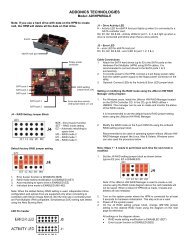
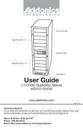
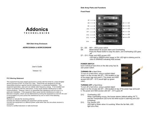
Disk Array Parts and Functions<br />
Front Panel<br />
HD1<br />
D7<br />
<strong>Addonics</strong><br />
T E C H N O L O G I E S<br />
D8<br />
D9<br />
D10<br />
D11<br />
D12<br />
D13<br />
HD2<br />
HD3<br />
HD4<br />
D1<br />
D2<br />
D3<br />
D4<br />
D5<br />
D6<br />
5SA Disk Array Enclosure<br />
D14<br />
HD5<br />
FCC Warning Statement<br />
AE5RCS35NSA & AE5RCS35NSAW<br />
User’s Guide<br />
Version 1.0<br />
This equipment has been tested and found to comply with the limits for a class B digital<br />
device pursuant to Part 15 of the FCC rules. These limits are designed to provide<br />
reasonable protection against harmful interference in a residential installation. This<br />
equipment generates, uses and can radiate radio frequency energy. If not installed and<br />
used in accordance with the instructions, it may cause harmful interference to radio<br />
communications. However, there is no guarantee that interference will not occur in a<br />
particular installation. If the equipment does cause harmful interference to radio or<br />
television reception, which can be determined by turning the equipment on and off, the user<br />
is encouraged to try and correct the interference by one or more of the following<br />
suggestions.<br />
Reorient or relocate the receiving antenna<br />
Increase the distance between the equipment and the receiver<br />
Connect the equipment to a different power outlet other than the one where receiver is<br />
connected<br />
Consult a certified television or radio technician<br />
D1 – D5: HD1 – HD5 power switch<br />
D6: Reset Switch for buzzer alarm and Overheating<br />
Press the Reset Switch to stop the alarm, and Overheating LED goes<br />
off.<br />
D7 – D11: Power and HDD access LED<br />
LED light is GREEN when power is ON. LED light is blinking and its<br />
color is ORANGE indicating HDD access.<br />
POWER SWITCH<br />
Each individual hard drive on the disk array has its<br />
own power switch.<br />
TURNING ON a Hard Drive<br />
HD5<br />
To turn on a hard drive, using a pointed object<br />
insert it on the circular slot (D1 – D5) located on top<br />
of the power logo and push it. The power and HDD<br />
access LED (D7 – D11) would light up (green<br />
color).<br />
TURNING OFF a Hard Drive<br />
To turn off a hard drive, using a pointed object<br />
insert it on the circular slot (D1 – D5) located on top of the power logo and push<br />
it. The power and HDD access LED (D7 – D11) goes off.<br />
D12: Overheating LED<br />
When overheating occurs, the buzzer alarms (default setting: 60 0 C<br />
and the Temperature LED turns red while buzzer is alarming and LED<br />
is blinking).<br />
D13: Fan Sensor LED<br />
LED light is Green when it is working. When the fan fails, LED<br />
light turns Red.
D14: Safety Lock<br />
The safety lock safeguards the hard<br />
disk in the correct position and<br />
prevents it from being ejected out<br />
while HDD is working.<br />
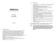
Rear View<br />
Power 2<br />
HD1<br />
FLG:<br />
Fan failure detection (green)<br />
RST:<br />
Reset Switch for buzzer alarm and Overheating LED<br />
TLR:<br />
Temperature detection (red)<br />
5V+:<br />
5V Power<br />
TLG:<br />
Temperature detection (green)<br />
GND: Grounded<br />
PL1- • PL5-: Ext Power LED detection (-)<br />
HL1- • HL5-: Ext HDD LED detection (-)<br />
VCC1- • VCC5-: Ext 5V Power (+)<br />
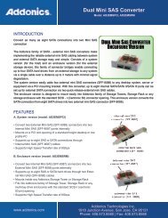
Securing the hard drive on the drive bay<br />
HD2<br />
Using the screws provided, secure the<br />
hard drive to the drive drawer.<br />
Screws<br />
HD3<br />
Power 1<br />
HD4<br />
J5<br />
HD5<br />
Technical Support<br />
Screws<br />
POWER1: 4-pin Molex Power connector<br />
Note: One 4-pin Molex power connector powers 2 drives. In order to power all<br />
5 drives all three 4-pin connectors must be connected<br />
POWER2: 15-pin Serial ATA Data Power connector<br />
Note: The top 15-pin Serial ATA Data Power connector powers 2 drives. The<br />
second 15-pin Serial ATA Data Power connector powers the three<br />
bottom drives.<br />
HD1—HD5: 7-pin Serial ATA Signal connector<br />
If your power is not from SATA 15pin connector then use the 4pin power<br />
connector. The 4pin power will automatically be convert to SATA power.<br />
J5: FAN RPM HIGH (3600 rpm) & LOW (2800 rpm) Options<br />
lJP1:<br />
Temperature setting jumper<br />
lJP2 & J4: Extension function jumper<br />
FLR:<br />
Fan failure detection (red)<br />
FL+: Fan failure detection (+)<br />
If you need assistance to get your unit functioning properly, please call <strong>Addonics</strong><br />
Technical Support. Our technical staff will be happy to assist you, but they will<br />
need your help to do so. Calling the technical support staff without all the proper<br />
information can be both time consuming and frustrating. Here are some tips to<br />
help you out:<br />
MODEL NUMBER – Please have this number on hand.<br />
SYSTEM INFORMATION – Type of computer, peripherals, etc.<br />
OPERATING SYSTEM – What version of Windows<br />
WHAT’S THE TROUBLE? – Give enough information<br />
about your problem so that we can recreate and diagnose it.<br />
FREE Software Drivers for all <strong>Addonics</strong> Technologies<br />
Products are available 24 hours per day at the<br />
World Wide Web Site: www.addonics.com.<br />
Contact Information<br />
Phone: 408-433-3899<br />
Fax: 408-433-3898<br />
Email: http://www.addonics.com/sales/query/<br />
Internet: http://www.addonics.com<br />
TECHNICAL SUPPORT<br />
Phone: 408-433-3855<br />
Hours: 8:30 am - 6:00 pm PST<br />
Email: http://www.addonics.com/support/query/