CONTACT US User Guide Storage Rack - Addonics
CONTACT US User Guide Storage Rack - Addonics
CONTACT US User Guide Storage Rack - Addonics

Create successful ePaper yourself
Turn your PDF publications into a flip-book with our unique Google optimized e-Paper software.
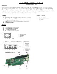
<strong>Storage</strong> <strong>Rack</strong> DA with Port Multiplier Using Multilane<br />
Connection<br />
Note: The Port Multiplier will only work with Port Multiplier aware multilane host<br />
controllers. It is compatible with multilane host controllers using the Silicon Image<br />
Chip SiI3124 & SiI3132.<br />
T E C H N O L O G I E S<br />
When the port multiplier (PM) is connected to the multilane host controller with<br />
SiI3124 or SiI3132 chip, in the RAID BIOS of the host controller, you will only see<br />
one drive and that is the drive connected to SATA port 1 on the Port Multiplier.<br />
All SATA drives connected to the PM will show in the SATARAID5 Array Manager.<br />
Refer to the SATARAID5 Management Utility <strong>User</strong> <strong>Guide</strong> V1.6 for RAID<br />
implementation<br />
http://www.addonics.com/support/user_guides/host_controller/SATARAID5-<strong>User</strong>Guid<br />
e_v1.60.pdf<br />
Connecting the Power Cable and RAID <strong>Rack</strong> to the<br />
Computer<br />
a. Connect the power cord provided from the wall outlet to the back of the rack.<br />
b. Make sure the power is off (power LED light should be off).<br />
c. Connect the infiniband cable from the back of the rack to the multilane<br />
connector on the computer.<br />
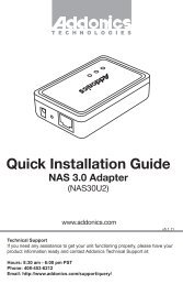
<strong>User</strong> <strong>Guide</strong><br />
<strong>Storage</strong> <strong>Rack</strong><br />
(SRDAP46SL / SRDAP46RSL)<br />
<strong>CONTACT</strong> <strong>US</strong><br />
www.addonics.com<br />
Phone: 408-573-8580<br />
Fax: 408-573-8588<br />
Email: http://www.addonics.com/sales/query/<br />
www.addonics.com<br />
Technical Support<br />
If you need any assistance to get your unit functioning properly, please have your<br />
product information ready and contact <strong>Addonics</strong> Technical Support at:<br />
Hours: 8:30 am - 6:00 pm PST<br />
Phone: 408-453-6212<br />
Email: http://www.addonics.com/support/query/<br />
v5.1.11
I<br />
Power Supply<br />
I<br />
O<br />
POWER<br />
Power Switch<br />
I<br />
I<br />
I<br />
O<br />
I<br />
O<br />
Front<br />
System Reset<br />
ATX Power Supply<br />
This power supply provides 430W of<br />
power. Before turning on the main<br />
switch located on the front panel of<br />
the storage rack, turn on the power<br />
switch of the power supply.<br />
OPower Switch<br />
RESET<br />
Fan<br />
Back<br />
O<br />
Punch out for <strong>US</strong>IB connectors<br />
O<br />
Fans<br />
Buzzer<br />
POWER<br />
TEMP<br />
FAN<br />
Buzzer Reset<br />
LED Display<br />
Redundant Power Supply<br />
This power supply includes two<br />
modules within it, each of which is<br />
capable of powering the entire<br />
system by itself. If for some reason<br />
there is a failure in one of the<br />
modules, the other one will<br />
seamlessly take over to prevent the<br />
loss of power to the PC. You can<br />
replace the damaged unit without<br />
powering the machine down. This is<br />
called hot swapping.<br />
Power<br />
Switch<br />
Handle<br />
Buzzer<br />
Reset<br />
Button<br />
Module<br />
Power<br />
LED<br />
Fans<br />
Power LED for<br />
Power Supply<br />
Punch out for <strong>US</strong>IB connectors<br />
Power Supply Punch out for eSATA<br />
HDD<br />
Power LED for Power Supply:<br />
Punch out for port multipliers/bridges<br />
Power Switch: This is the switch to power on devices connected to the power<br />
supply. The power LED will light up to indicate power is supplied.<br />
Note: The main power switch located at the back of the enclosure must be turned<br />
on first.<br />
Reset Button: Not operational.<br />
Buzzer Reset: Pressing the button stops the buzzer from making a sound. The<br />
buzzer will make a sound when temperature inside the storage rack exceeds the<br />
temperature setting on the Thermal Management card.<br />
Power LED: Lights up when the power switch is turned on.<br />
Temp LED: Lights up when temperature setting inside the storage rack exceeds<br />
the setting on the thermal card.<br />
Fan LED: Normally on when fan is operational. If an abnormal condition is<br />
detected, the LED flashes.<br />
HDD LED: Not operational.<br />
Green Light: When the main power switch located on the front of the storage rack is<br />
turned on, the power LED will light up.<br />
Red Light: When one of the module power switch is off or the module failed, the<br />
LED emits a red light and the buzzer will sound.<br />
Module Power Switch: Each module has its own switch.<br />
Module Power LED: By default, it emits a green light when the module power<br />
switch is on. If the module power switch is turned off, the power LED for the power<br />
supply emits a red light.<br />
Buzzer Reset Button: If one of the power modules fail or if the module power<br />
switch is turned off, the buzzer will sound. To reset the buzzer, click on the buzzer<br />
reset button.<br />
Replacing a failed power module:<br />
1. Loosen the screw that secures the module to the power unit.<br />
2. Firmly hold the handle of the module and pull it away from the power supply.<br />
1 10<br />
www.addonics.com Technical Support (M-F 8:30am - 6:00pm PST) Phone: 408-453-6212 Email: www.addonics.com/support/query/
Installing Bridge Boards on Mounting Poles Inside<br />
the <strong>Storage</strong> <strong>Rack</strong><br />
Top Cover Screws<br />
Separate PM or HPM from bracket by unscrewing 4 screws on the PCB. Install<br />
the PM or HPM onto the desired mounting pole.<br />
How to Remove the Top Cover:<br />
1. Locate the 2 screws at the back of the<br />
storage rack<br />
2. Turn screws counterclockwise to<br />
loosen.<br />
3. Lift the top cover and pull towards the<br />
rear end of the rack.<br />
Installing Bridge Boards onto Back Panel<br />
To Mount Back the Top Cover:<br />
Remove punch outs from the rear panel of the <strong>Storage</strong> <strong>Rack</strong>. Using the included<br />
screws, attach bridge board onto the desired back panel mounting location.<br />
1. Align the top cover with the edges of<br />
the rack.<br />
2. Lay it flat on the rack and slide it<br />
towards the front of the rack.<br />
3. Turn screws clockwise to tighten.<br />
How to Remove the 5 ¼” Drive<br />
Cage:<br />
O<br />
O<br />
O<br />
O<br />
I<br />
O<br />
I<br />
O<br />
I<br />
I<br />
I<br />
O<br />
I<br />
O<br />
I<br />
O<br />
I<br />
O<br />
I<br />
I<br />
Connect storage devices onto the internally mounted PM or HPM, then connect<br />
the host connection onto the rear mounted bridge board.<br />
1. Locate the 4 screws on the drive cage.<br />
2. Turn screws counterclockwise to<br />
loosen.<br />
3. Lift the chassis up.<br />
SATA Device<br />
PM/HPM<br />
Bridge Board<br />
9 2<br />
www.addonics.com Technical Support (M-F 8:30am - 6:00pm PST) Phone: 408-453-6212 Email: www.addonics.com/support/query/
I<br />
How to Remove the 5 ¼”<br />
Drive Bay Front Panels:<br />
At the bottom of the drive cage, locate the metal base corresponding to the storage<br />
device inserted in the previous step and secure it onto the drive cage.<br />
I<br />
O<br />
1. Locate the 3 screws for each<br />
front panel.<br />
2. Turn screws<br />
counterclockwise to loosen.<br />
3. Pull the front panel forward,<br />
away from the drive cage. 3 screws for each panel<br />
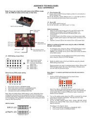
Thermal Management Card on the RAID <strong>Rack</strong><br />
Fan Connectors<br />
Overheat Buzzer<br />
When you finished, install the drive cage now populated with the devices back<br />
into the <strong>Storage</strong> <strong>Rack</strong>.<br />
Floppy Power Connector<br />
Ambient Detect Terminal<br />
Fan, Temperature and Power LED Connectors<br />
Temp. Setting<br />
(40°C, 50°C, 60°C)<br />
Fan Detect Selection<br />
O<br />
Features:<br />
Fan1 to Fan8 could be set either “ENABLE” or “DISABLE”. When all the fans are set<br />
on “DISABLE”, the Fan LED will have no light on.<br />
When Ambient temperature (or temperature inside the storage rack) is over the set<br />
temperature, the LED will flash and the buzzer will sound.<br />
3 8<br />
www.addonics.com Technical Support (M-F 8:30am - 6:00pm PST) Phone: 408-453-6212 Email: www.addonics.com/support/query/
I<br />
C. 3.5” Mobile <strong>Rack</strong><br />
1. Separate the ventilation front panel<br />
and the metal base by removing the two<br />
flat-head screws.<br />
I<br />
SRNPS - <strong>Storage</strong> <strong>Rack</strong> with No Power Supply<br />
Connections:<br />
1. Connect the 20-pin ATX connector of the power supply to the 20-pin<br />
connector on the storage rack. This connection is for the power switch on<br />
the storage rack.<br />
2. Connect one of the 4-pin floppy power connector of the power supply to<br />
the floppy power connector on the Thermal Management card.<br />
Note: The storage rack will not turn on if power is not provided to the Thermal<br />
Management card.<br />
2. Attach the 3.5” drive cradle onto<br />
the 3.5” to 5.25” drive bay mounting<br />
bracket at the six aligned screw hole<br />
locations.<br />
Installing the 4th Disk Array on the <strong>Storage</strong> <strong>Rack</strong><br />
a. Remove the back panel of the storage rack by loosening the 4 screws<br />
indicated below.<br />
3. Attach the metal base onto the<br />
optical drive or other 5.25” storage device<br />
using the flat head screws from the<br />
ventilation front panel.<br />
Screws<br />
O<br />
O<br />
With the storage device connected, slide<br />
the metal base back into the drive cage.<br />
Secure the storage device onto the top of<br />
the drive cage using the included screws.<br />
b. Secure the bottom bracket of the<br />
storage rack to the disk array using<br />
screws.<br />
c. Secure the top bracket of the<br />
storage rack to the disk array using<br />
screws.<br />
R<br />
7 4<br />
www.addonics.com Technical Support (M-F 8:30am - 6:00pm PST) Phone: 408-453-6212 Email: www.addonics.com/support/query/
I<br />
O<br />
I<br />
O<br />
R<br />
d. Slide the disk array<br />
into the storage rack.<br />
Screws<br />
B. 5.25” <strong>Storage</strong> devices<br />
1. Separate the ventilation front<br />
panel and the metal base by<br />
removing the two flat-head<br />
screws.<br />
e. Secure the Disk array<br />
by screwing the top<br />
and bottom brackets<br />
to the frame of the<br />
storage rack.<br />
Screws<br />
2. Attach the metal base onto the optical drive or other 5.25” storage device using<br />
the flat head screws from the ventilation front panel.<br />
Installing <strong>Storage</strong> Devices on the <strong>Storage</strong> <strong>Rack</strong><br />
A. 3.5” hard drive<br />
Optical Drive<br />
1. Attach the 3.5” to 5.25”<br />
mounting brackets onto both<br />
sides of the 3.5” SATA or IDE hard<br />
drive using the included screws.<br />
<strong>Addonics</strong> Drive Cradle<br />
2. Attach the ventilation front<br />
panel and base onto one side of<br />
the mounting bracket using the<br />
black screws included with the<br />
<strong>Storage</strong> <strong>Rack</strong>.<br />
5 6<br />
www.addonics.com Technical Support (M-F 8:30am - 6:00pm PST) Phone: 408-453-6212 Email: www.addonics.com/support/query/