User Guide - Addonics
User Guide - Addonics
User Guide - Addonics

You also want an ePaper? Increase the reach of your titles
YUMPU automatically turns print PDFs into web optimized ePapers that Google loves.
T E C H N O L O G I E S<br />
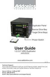
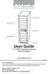
<strong>User</strong> <strong>Guide</strong><br />
RAID Tower V<br />
(RT55SN25HX)<br />
www.addonics.com<br />
v3.1.11<br />
Technical Support<br />
If you need any assistance to get your unit functioning properly, please have your<br />
product information ready and contact <strong>Addonics</strong> Technical Support at:<br />
Hours: 8:30 am - 6:00 pm PST<br />
Phone: 408-453-6212<br />
Email: http://www.addonics.com/support/query/
Unpacking and Overview<br />
1<br />
3<br />
5<br />
2<br />
4<br />
1<br />
3<br />
5<br />
2<br />
4<br />
Array 1<br />
Array 3<br />
Array 2<br />
Array 4<br />
2<br />
4<br />
1<br />
3<br />
5<br />
2<br />
4<br />
1<br />
3<br />
5<br />
Array 1<br />
Error LED<br />
Array 2<br />
Error LED<br />
Array 3<br />
Error LED<br />
Power Button<br />
Power LED<br />
Array 4<br />
Error LED<br />
WARNING: Please remember to<br />
set the power supply to your local<br />
outlet voltage prior to plugging in<br />
the power cord. Failure to do so<br />
may damage the power supply.<br />
Array 1<br />
Array 3<br />
Array 2<br />
Array 4<br />
Power<br />
Connector<br />
AC Voltage<br />
Switch<br />
Four eSATA Cables<br />
4 pairs of Disk Array keys<br />
Power Cord (US Version Shown)<br />
Software CD<br />
www.addonics.com Technical Support (M-F 8:30am - 6:00pm PST) Phone: 408-453-6212 Email: www.addonics.com/support/query/
Basic Instructions<br />
Installing drives into<br />
the RAID Tower<br />
1. Be sure the lock on each drive<br />
door is in the unlocked position. If not,<br />
use Disk Array key to unlock the drive door.<br />
Pull on the door lever to swing open<br />
the drive door all the way.<br />
2. Slide a 2.5” SATA hard drive into<br />
the drive slot with the drive connector<br />
side facing in. The drive should slide<br />
all the way into the slot with very little<br />
resistance. Forcing the drive into the<br />
slot will cause drive damage or<br />
permanent damage to the Disk Array.<br />
3. Once the drive is all the way into the<br />
drive slot, close the door all the way till<br />
the drive door latches securely. This will<br />
engage power and data connection with<br />
the hard drive. The LED lit for the drive<br />
slot should lit if the Disk Array already<br />
powered on. You may lock the drive<br />
door with the key if desired.<br />
4. To remove the hard drive from<br />
the Disk Array, simply follow the<br />
same steps - opening the drive door<br />
will push the drive out.<br />
Port Multiplier<br />
Array 3 Array 2<br />
Dip Switch<br />
Array 4<br />
Array 1<br />
Set Button<br />
www.addonics.com Technical Support (M-F 8:30am - 6:00pm PST) Phone: 408-453-6212 Email: www.addonics.com/support/query/
Port Multiplier Compatibility<br />
When configured as a set of individual drives and connected to a SATA or<br />
an eSATA host adapter, the Port Multiplier will only work with a Port Multiplier<br />
aware host. This includes setting up the unit with more than one array. Identify<br />
your host controller and check with its hardware manufacturer if you are unsure.<br />
<strong>Addonics</strong> offers several Port Multiplier aware host adapters.<br />
Using identical drives for all settings other than JBOD or LARGE is<br />
strongly recommended. Creating a LARGE array using drives that have different<br />
properties will use all space on all members, and performance will match that of<br />
the member in use during any particular I/O operation. Creating a RAID using<br />
drives that are not all the same size will result in all members using only as much<br />
space as the smallest member. Creating a RAID using drives that have different<br />
performance will degrade the overall performance of the array.<br />
Port Multiplier Modes:<br />
The Port Multiplier supports individual drives (JBOD Mode), several types of RAID<br />
and some non-RAID drive sets. Each configuration has different properties and<br />
requirements, as follows:<br />
JBOD Mode (Individual Drives)<br />
Number of drives: at least 1<br />
Unit capacity: N/A (100% of each individual drive)<br />
Spares: no<br />
Fault tolerance: none<br />
JBOD mode offers all connected units to the host adapter, no RAID is defined at<br />
all.<br />
NOTE: JBOD mode requires a SATA controller featuring Port Multiplier support for<br />
eSATA connections.<br />
NOTE: Optical drives can only be configured as JBOD using an eSATA connection.<br />
RAID 0 (Stripe set)<br />
Number of drives: at least 2<br />
Unit capacity: size of each member times number of members.<br />
Spares: no<br />
Fault tolerance: none - if any member is lost all data is lost.<br />
RAID 0 “stripes” the file system across the array by placing “chunks” of data<br />
sequentially between drives in a specific order.<br />
RAID 1 or 10 (Mirror set, Stripe of mirror sets)<br />
Number of drives: 2 (RAID 1) or 4 (RAID 10).<br />
Unit capacity: size of one member (RAID 1) or size of two members (RAID 10).<br />
Spares: yes – if EZ mode is not disabled and 3 (RAID 1) or 5 (RAID 10) drives are<br />
present, the array will be initialized with a spare.<br />
Fault tolerance: RAID 1 can withstand the loss of one drive without losing data.<br />
RAID 10 can withstand the loss of one drive from each mirror set without losing<br />
data.<br />
RAID 1 works by duplicating the exact same data on two drives.<br />
RAID 10 works by using two RAID 1 sets configured as members of a RAID 0.<br />
Disks 1 and 2 are mirrored, disks 3 and 4 are mirrored, and the two mirror sets<br />
are striped together.<br />
www.addonics.com Technical Support (M-F 8:30am - 6:00pm PST) Phone: 408-453-6212 Email: www.addonics.com/support/query/
RAID 3 (Stripe set with dedicated parity)<br />
Number of drives: at least 3<br />
Unit capacity: size of one member times number of members minus one.<br />
Spares: yes<br />
Fault tolerance: can withstand the loss of one drive without losing data.<br />
RAID 3 works by striping data for individual I/O blocks across all members<br />
except one, which contains parity data for the stripe set computed internally by<br />
the Port Multiplier. In the event of failure, the missing information can be<br />
calculated using the parity information.<br />
RAID 5 (Stripe set with striped parity)<br />
Number of drives: at least 3<br />
Unit capacity: size of one member times number of members minus one.<br />
Spares: yes<br />
Fault tolerance: can withstand the loss of one drive without losing data.<br />
RAID 5 works by striping entire I/O blocks across all members of the set, with<br />
each member taking turns carrying parity data computed by the Port Multiplier.<br />
In the event of failure, the missing information can be calculated using the<br />
parity information.<br />
CLONE (Mirror set)<br />
Number of drives: at least 2<br />
Unit capacity: size of one member.<br />
Spares: yes<br />
Fault tolerance: can withstand the loss of any number of drives without losing<br />
data as long as at least one complete member remains online. CLONE mode<br />
works the same way as RAID 1, by maintaining a complete copy of the entire<br />
set of data on each drive.<br />
LARGE (Spanned set)<br />
Number of drives: at least 2<br />
Unit capacity: 100% of all drives together regardless of differences in size<br />
Spares: no<br />
Fault tolerance: cannot withstand the loss of any drives without losing data.<br />
However, some data may be recovered as long as the drive(s) carrying the file<br />
system data (boot record, directory, etc.) remain online. LARGE mode is<br />
neither a RAID nor is it a JBOD. It works by declaring the sum of all available<br />
space of the member drives as a single unit, without striping the data. As each<br />
member is filled, new data is stored on the next.<br />
Notes about Spare Drives<br />
If EZ mode is disabled (SW1:2 ON), all individual drives not configured as array<br />
members will be offered to the host adapter as separate units.<br />
To create an array with one or more spares, set or modify the RAID mode while<br />
the spares are disconnected from the Port Multiplier. When EZ mode is<br />
enabled (SW1:2 OFF), individual drives connected when an array is present<br />
are considered spare. Spare drives must be equal to or larger in size than the<br />
smallest member. When any type of array is defined, individual units will be<br />
considered spare.<br />
www.addonics.com Technical Support (M-F 8:30am - 6:00pm PST) Phone: 408-453-6212 Email: www.addonics.com/support/query/
Configuring the Port Multiplier Using Dipswitches<br />
Resetting the RAID<br />
NOTE: This procedure destroys all RAID data. It should not harm individual drives<br />
or their contents; however, creating backups of all data is strongly recommended<br />
before proceeding.<br />
Be sure the port multiplier is connected to an active host before proceeding. The<br />
port multiplier will not complete the process if it has no host connection.<br />
1. Power down the unit and set the dip switch to the desired RAID Mode.<br />
2. While holding the SET button, turn the unit on. A long beep will sound from the<br />
Port Multiplier. The SET button may be released once the long beep starts.<br />
Shortly after releasing the SET button, the port multiplier should “chirp” to indicate<br />
the process is complete. If instead of a chirp the Port Multiplier sounds a series of<br />
short beeps, an error has occurred during the process.<br />
Setting or Modifying the RAID Mode<br />
NOTE: Setting or modifying the RAID mode destroys all data.<br />
Be sure the port multiplier is connected to an active host before proceeding. The<br />
port multiplier will not complete the process if it has no host connection.<br />
1. Follow the procedure for resetting the RAID Mode.<br />
2. Power down the unit and set the dip switch to the desired RAID Mode.<br />
3. While holding the SET button with a ballpoint pen, turn the unit on. A long beep<br />
will sound from the Port Multiplier. The SET button may be released once the long<br />
beep starts.<br />
Shortly afterward, the port multiplier should “chirp” to indicate the process is<br />
complete. If instead of a chirp the Port Multiplier sounds a series of short beeps, an<br />
error has occurred during configuration of the array.<br />
BZS Switch (SW1:1):<br />
The BZS switch is used to silence the audible alarm buzzer. The OFF position<br />
permits the audible alarm, and the ON position silences the audible alarm. The<br />
BZS switch has immediate effect.<br />
EZ Switch (SW1:2):<br />
The EZ (spare) switch inhibits spares when ON. When in the OFF position, all<br />
individual drives (not defined as members of an array) are considered spare and<br />
are not offered to the operating system. Should a RAID become degraded, when<br />
the EZ switch is in the OFF position a spare drive will be used automatically to<br />
rebuild the RAID, if present. EZ mode is determined when the unit is powered up.<br />
Changing the switch will have no effect until the unit has been re-powered.<br />
Warning: turning off the EZ switch to rebuild an array will consider any drives not<br />
declared array members to be eligible for rebuild as a spare. Rebuilding will<br />
destroy all existing data on that drive and the drive chosen is not predictable.<br />
Disconnect any individual drives with valuable data on them before enabling EZ<br />
Mode.<br />
www.addonics.com Technical Support (M-F 8:30am - 6:00pm PST) Phone: 408-453-6212 Email: www.addonics.com/support/query/
RAID Mode Switches M2, M1, M0 (SW1:3 – SW1-5)<br />
The RAID Mode switches define what type of RAID will be initialized when the<br />
unit is powered up while the RAID Mode button is held down, as follows:<br />
Dipswitch Position 1 (BZS) 1 2 (EZ) 3 (M2) 4 (M1) 5 (M0)<br />
JBOD (Individual<br />
Drives)<br />
* FACTORY<br />
OFF OFF 2 OFF OFF OFF<br />
DEFAULT SETTING<br />
RAID 0 OFF ON 3 ON ON ON<br />
RAID 1 OR 10 OFF OFF ON ON OFF<br />
RAID 3 OFF OFF ON OFF OFF<br />
RAID 5 OFF OFF OFF ON OFF<br />
CLONE OFF OFF OFF ON ON<br />
LARGE OFF ON ON OFF ON<br />
NOTES:<br />
1. Audible Alarm is recommended at all times.<br />
2. EZ mode has no effect when no array is defined.<br />
3. Disabling EZ for RAID 0 and LARGE is strongly recommended.<br />
Configuring the Port Multiplier Using the JMicron RAID Manager<br />
Windows users may install the JMicron HW RAID Manager application located<br />
on the SATA Controller CD, or download it from<br />
http://addonics.com/drivers/driver_list.php. In the CD, browse to Configuration<br />
Utilities → JMB393.<br />
Mac and Linux users may download those versions of the same utility from<br />
http://addonics.com/drivers/driver_list.php under “Port Multiplier & Hub.” The<br />
JMicron RAID Manager can be used to create, modify, and monitor the health<br />
status of the RAID drives, and provide status alerts with dialog boxes and even<br />
email. When configuring the RAID mode using the RAID Manager application, it<br />
is strongly recommended to leave the dip switch in the factory default setting.<br />
Setting or Modifying the RAID Mode<br />
This procedure briefly describes the steps for using the Jmicron RAID Manager's<br />
Basic Mode to create an array. The example shown is a LARGE set.<br />
There are other options available in the Advanced Modes, including building<br />
arrays using specified drives, setting up email notifications, and updating the<br />
firmware – which are not discussed in this user guide.<br />
After starting the Jmicron RAID Manager, the first screen will show the status of<br />
any Port Multipliers detected and any drives connected. Shown below is a Port<br />
Multiplier with a variety of five drives connected:<br />
On the left pane is “Controller 1” which is the first port multiplier detected by the<br />
software. Shown in a tree view are the five drives, listed as P0-P4. These are<br />
currently individual drives. On the right pane is a listing of the drives and below<br />
that is a graphical view of each drive. “Disk 1” through “Disk 4” indicate which<br />
physical port the drive is connected to. For the AD5HPMSXA, AD5HPMRXA-E,<br />
and AD5HPMREU this refers to ports P0-P4. On the CPR5SA unit, this refers to<br />
HD0-HD4. On the AD5EHPMEU3 this refers to D1-D5. On RAID Tower products<br />
this relates to the drives mounted left to right or top to bottom, except in cases<br />
where a drive map is included showing otherwise.<br />
www.addonics.com Technical Support (M-F 8:30am - 6:00pm PST) Phone: 408-453-6212 Email: www.addonics.com/support/query/
Next, click the Basic RAID Configuration tab and select the type of RAID desired.<br />
Note that RAID 1 is currently disabled as an option since more than two<br />
individual drives are available, and DELETE ALL RAID is disabled since there are<br />
currently no arrays to delete. Shown below is the same set of drives being<br />
selected as a LARGE array.<br />
Finally, click Apply. The Jmicron RAID Manager will confirm the operation with a<br />
reminder that existing data on the drives will be lost, then perform the RAID<br />
configuration and report with a dialog box when it is complete.<br />
www.addonics.com Technical Support (M-F 8:30am - 6:00pm PST) Phone: 408-453-6212 Email: www.addonics.com/support/query/
The RAID and Disk Information screen (shown when the program was<br />
launched) will now show the Port Multiplier with an Array. The drives are now<br />
listed as M0-M4, indicating they are members of the array. If spares are<br />
present (individual drives added later, and the EZ switch is in the OFF<br />
position), they would be listed as S0, S1, etc. On the right pane, the RAID<br />
Level, status, capacity and members that are online are listed. Status will show<br />
“Normal” (all members on line), “Degraded” (a fault-tolerant array with a drive<br />
failure needing service), “Rebuilding” (a fault-tolerant array in the process of<br />
reconstructing lost data onto a spare) or “Broken” (an array that has lost all<br />
data).<br />
In the event of a drive failure, the Jmicron RAID Manager will present a dialog<br />
box such as the one shown below, even if it is currently minimized to the system<br />
tray:<br />
www.addonics.com Technical Support (M-F 8:30am - 6:00pm PST) Phone: 408-453-6212 Email: www.addonics.com/support/query/
CONTACT US<br />
www.addonics.com<br />
Phone: 408-573-8580<br />
Fax: 408-573-8588<br />
Email: http://www.addonics.com/sales/query/