Traffic Signal Design - Section 11 Detectors - RTA
Traffic Signal Design - Section 11 Detectors - RTA
Traffic Signal Design - Section 11 Detectors - RTA

Create successful ePaper yourself
Turn your PDF publications into a flip-book with our unique Google optimized e-Paper software.
<strong>Traffic</strong> <strong>Signal</strong> <strong>Design</strong> – <strong>Section</strong> <strong>11</strong> <strong>Detectors</strong><br />
<strong>11</strong>.5 LABELLING OF DETECTORS<br />
<strong>Detectors</strong> are labelled to indicate which phases they call or extend. For example, a detector<br />
that calls A phase and extends A and B phases is called an A-B detector.<br />
Where necessary to distinguish the approach or where detector functions differ within the<br />
same approach, a numerical suffix is added to the phase symbol (e.g. A-B1 and A-B2, C1 and<br />
C2). This should be shown without any intervening spaces and should not be superscripted or<br />
subscripted. The order of allocation of the numerical suffixes is in a clockwise direction from<br />
the V1 primary lantern.<br />
When advance detectors and stop-line detectors are provided on the same approach, the<br />
numerical suffix is added to the advance detectors before the stop-line detectors.<br />
A group of adjacent detectors on the same approach may have the same call and extend<br />
functions and hence have the same label. When this occurs, an identifying lane label is added<br />
to distinguish the detectors. The lane label is based on the position of the detector in relation<br />
to the others when facing in the direction of travel. The label is selected from L, CL, C, CR<br />
and R (for left, centre left, centre, centre right and right respectively) as follows:<br />
• 2 lanes are L and R<br />
• 3 lanes are L, C and R<br />
• 4 lanes are L, CL, CR and R<br />
• 5 lanes are L, CL, C, CR and R<br />
Lane labelling is completely independent of the location of the kerb. Thus, a left detector is<br />
the left-most detector in a particular group, and not necessarily the one in the kerbside lane.<br />
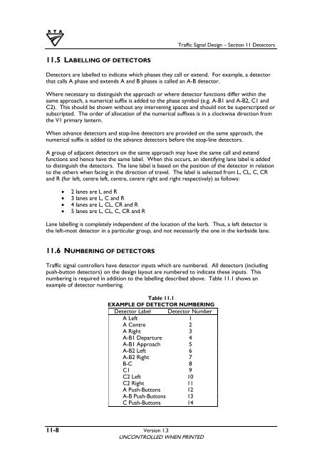
<strong>11</strong>.6 NUMBERING OF DETECTORS<br />
<strong>Traffic</strong> signal controllers have detector inputs which are numbered. All detectors (including<br />
push-button detectors) on the design layout are numbered to indicate these inputs. This<br />
numbering is required in addition to the labelling described above. Table <strong>11</strong>.1 shows an<br />
example of detector numbering.<br />
Table <strong>11</strong>.1<br />
EXAMPLE OF DETECTOR NUMBERING<br />
Detector Label Detector Number<br />
A Left 1<br />
A Centre 2<br />
A Right 3<br />
A-B1 Departure 4<br />
A-B1 Approach 5<br />
A-B2 Left 6<br />
A-B2 Right 7<br />
B-C 8<br />
C1 9<br />
C2 Left 10<br />
C2 Right <strong>11</strong><br />
A Push-Buttons 12<br />
A-B Push-Buttons 13<br />
C Push-Buttons 14<br />
<strong>11</strong>-8 Version 1.3<br />
UNCONTROLLED WHEN PRINTED