Appendix D Location and dimensions of components - RTA
Appendix D Location and dimensions of components - RTA
Appendix D Location and dimensions of components - RTA

You also want an ePaper? Increase the reach of your titles
YUMPU automatically turns print PDFs into web optimized ePapers that Google loves.
Traffic Signal Design – <strong>Appendix</strong> D <strong>Location</strong> & Dimensions <strong>of</strong> Components<br />
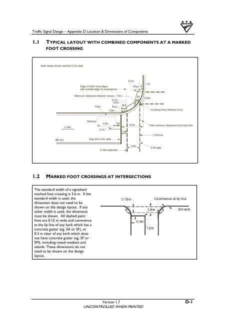
1.1 TYPICAL LAYOUT WITH COMBINED COMPONENTS AT A MARKED<br />
FOOT CROSSING<br />
1.2 MARKED FOOT CROSSINGS AT INTERSECTIONS<br />
The st<strong>and</strong>ard width <strong>of</strong> a signalised<br />
marked foot crossing is 3.6 m. If the<br />
st<strong>and</strong>ard width is used, the<br />
dimension does not need to be<br />
shown on the design layout. If any<br />
other width is used, the dimension<br />
must be shown. All dashed paint<br />
lines are 0.15 m wide <strong>and</strong> commence<br />
at the lip line <strong>of</strong> any kerb which has a<br />
concrete gutter (eg. SA or SF), or<br />
0.3 m clear <strong>of</strong> any kerb which does<br />
not have concrete gutter (eg. SF or<br />
SM), including raised medians <strong>and</strong><br />
isl<strong>and</strong>s. These <strong>dimensions</strong> do not<br />
need to be shown on the design<br />
layout.<br />
Version 1.7 D-1<br />
UNCONTROLLED WHEN PRINTED