Cisco CCNA Study Guide - Router Alley
Cisco CCNA Study Guide - Router Alley
Cisco CCNA Study Guide - Router Alley

You also want an ePaper? Increase the reach of your titles
YUMPU automatically turns print PDFs into web optimized ePapers that Google loves.
<strong>CCNA</strong> <strong>Study</strong> <strong>Guide</strong> v2.62 – Aaron Balchunas<br />
1<br />
___________________________________________<br />
<strong>Cisco</strong> <strong>CCNA</strong> <strong>Study</strong> <strong>Guide</strong><br />
v2.62 © 2012<br />
________________________________________________<br />
Aaron Balchunas<br />
aaron@routeralley.com<br />
http://www.routeralley.com<br />
________________________________________________<br />
Foreword:<br />
This study guide is intended to provide those pursuing the <strong>CCNA</strong><br />
certification with a framework of what concepts need to be studied. This is<br />
not a comprehensive document containing all the secrets of the <strong>CCNA</strong>, nor<br />
is it a “braindump” of questions and answers.<br />
This document is freely given, and can be freely distributed. However, the<br />
contents of this document cannot be altered, without my written consent.<br />
Nor can this document be sold or published without my expressed consent.<br />
I sincerely hope that this document provides some assistance and clarity in<br />
your studies.<br />
________________________________________________<br />
* * *<br />
All original material copyright © 2013 by Aaron Balchunas (aaron@routeralley.com),<br />
unless otherwise noted. All other material copyright © of their respective owners.<br />
This material may be copied and used freely, but may not be altered or sold without the expressed written<br />
consent of the owner of the above copyright. Updated material may be found at http://www.routeralley.com.
<strong>CCNA</strong> <strong>Study</strong> <strong>Guide</strong> v2.62 – Aaron Balchunas<br />
2<br />
Table of Contents<br />
Part I – General Networking Concepts<br />
Section 1<br />
Section 2<br />
Section 3<br />
Section 4<br />
Section 5<br />
Section 6<br />
Section 7<br />
Section 8<br />
Section 9<br />
Part II – The <strong>Cisco</strong> IOS<br />
Section 10<br />
Section 11<br />
Section 12<br />
Part III - Routing<br />
Section 13<br />
Section 14<br />
Section 15<br />
Section 16<br />
Section 17<br />
Section 18<br />
Section 19<br />
Section 20<br />
Part IV – VLANs, Access-Lists, and Services<br />
Section 21<br />
Section 22<br />
Section 23<br />
Part V - WANs<br />
Section 24<br />
Section 25<br />
Section 26<br />
Section 27<br />
Introduction to Networking<br />
OSI Reference Model<br />
Ethernet Technologies<br />
Hubs vs. Switches vs. <strong>Router</strong>s<br />
STP<br />
IPv4 Addressing and Subnetting<br />
TCP and UDP<br />
IPv6 Addressing<br />
Introduction to 802.11 Wireless<br />
<strong>Router</strong> Components<br />
Introduction to the <strong>Cisco</strong> IOS<br />
Advanced IOS Functions<br />
The Routing Table<br />
Static vs. Dynamic Routing<br />
Classful vs. Classless Routing<br />
Configuring Static Routes<br />
RIPv1 & RIPv2<br />
IGRP<br />
EIGRP<br />
OSPF<br />
VLANs and VTP<br />
Access-Lists<br />
DNS and DHCP<br />
Basic WAN Concepts<br />
PPP<br />
Frame-Relay<br />
NAT<br />
* * *<br />
All original material copyright © 2013 by Aaron Balchunas (aaron@routeralley.com),<br />
unless otherwise noted. All other material copyright © of their respective owners.<br />
This material may be copied and used freely, but may not be altered or sold without the expressed written<br />
consent of the owner of the above copyright. Updated material may be found at http://www.routeralley.com.
<strong>CCNA</strong> <strong>Study</strong> <strong>Guide</strong> v2.62 – Aaron Balchunas<br />
3<br />
________________________________________________<br />
Part I<br />
General Networking Concepts<br />
________________________________________________<br />
* * *<br />
All original material copyright © 2013 by Aaron Balchunas (aaron@routeralley.com),<br />
unless otherwise noted. All other material copyright © of their respective owners.<br />
This material may be copied and used freely, but may not be altered or sold without the expressed written<br />
consent of the owner of the above copyright. Updated material may be found at http://www.routeralley.com.
<strong>CCNA</strong> <strong>Study</strong> <strong>Guide</strong> v2.62 – Aaron Balchunas<br />
4<br />
Section 1<br />
- Introduction to Networks -<br />
What is a Network?<br />
Α network is simply defined as something that connects things together for<br />
a specific purpose. The term network is used in a variety of contexts,<br />
including telephone, television, computer, or even people networks.<br />
A computer network connects two or more devices together to share a<br />
nearly limitless range of information and services, including:<br />
• Documents<br />
• Email and messaging<br />
• Websites<br />
• Databases<br />
• Music<br />
• Printers and faxes<br />
• Telephony and videoconferencing<br />
Protocols are rules that govern how devices communicate and share<br />
information across a network. Examples of protocols include:<br />
• IP – Internet Protocol<br />
• HTTP - Hyper Text Transfer Protocol<br />
• SMTP – Simple Mail Transfer Protocol<br />
Multiple protocols often work together to facilitate end-to-end network<br />
communication, forming protocol suites or stacks. Protocols are covered in<br />
great detail in other guides.<br />
Network reference models were developed to allow products from different<br />
manufacturers to interoperate on a network. A network reference model<br />
serves as a blueprint, detailing standards for how protocol communication<br />
should occur.<br />
The Open Systems Interconnect (OSI) and Department of Defense (DoD)<br />
models are the most widely recognized reference models. Both are covered<br />
in great detail in another guide.<br />
* * *<br />
All original material copyright © 2013 by Aaron Balchunas (aaron@routeralley.com),<br />
unless otherwise noted. All other material copyright © of their respective owners.<br />
This material may be copied and used freely, but may not be altered or sold without the expressed written<br />
consent of the owner of the above copyright. Updated material may be found at http://www.routeralley.com.
<strong>CCNA</strong> <strong>Study</strong> <strong>Guide</strong> v2.62 – Aaron Balchunas<br />
5<br />
Basic Network Types<br />
Network types are often defined by function or size. The two most common<br />
categories of networks are:<br />
• LANs (Local Area Networks)<br />
• WANs (Wide Area Networks)<br />
A LAN is generally a high-speed network that covers a small geographic<br />
area, usually contained within a single building or campus. A LAN is<br />
usually under the administrative control of a single organization. Ethernet is<br />
the most common LAN technology.<br />
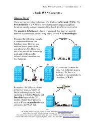
A WAN can be defined one of two ways. The book definition of a WAN is a<br />
network that spans large geographical locations, usually to connect multiple<br />
LANs. This is a general definition, and not always accurate.<br />
A more practical definition of a WAN is a network that traverses a public or<br />
commercial carrier, using one of several WAN technologies. A WAN is often<br />
under the administrative control of several organizations (or providers), and<br />
does not necessarily need to span large geographical distances.<br />
A MAN (Metropolitan Area Network) is another category of network,<br />
though the term is not prevalently used. A MAN is defined as a network that<br />
connects LAN’s across a city-wide geographic area.<br />
An internetwork is a general term describing multiple networks connected<br />
together. The Internet is the largest and most well-known internetwork.<br />
Some networks are categorized by their function, as opposed to their size. A<br />
SAN (Storage Area Network) provides systems with high-speed, lossless<br />
access to high-capacity storage devices.<br />
A VPN (Virtual Private Network) allows for information to be securely<br />
sent across a public or unsecure network, such as the Internet. Common uses<br />
of a VPN are to connect branch offices or remote users to a main office.<br />
* * *<br />
All original material copyright © 2013 by Aaron Balchunas (aaron@routeralley.com),<br />
unless otherwise noted. All other material copyright © of their respective owners.<br />
This material may be copied and used freely, but may not be altered or sold without the expressed written<br />
consent of the owner of the above copyright. Updated material may be found at http://www.routeralley.com.
<strong>CCNA</strong> <strong>Study</strong> <strong>Guide</strong> v2.62 – Aaron Balchunas<br />
6<br />
Network Architectures<br />
A host refers to any device that is connected to a network. A host can also<br />
be defined as any device assigned a network address.<br />
A host can serve one or more functions:<br />
• A host can request data, often referred to as a client.<br />
• A host can provide data, often referred to as a server.<br />
• A host can both request and provide data, often referred to as a peer.<br />
Because of these varying functions, multiple network architectures have<br />
been developed, including:<br />
• Peer-to-Peer<br />
• Client/Server<br />
• Mainframe/Terminal<br />
In a basic peer-to-peer architecture, all hosts on the network can both<br />
request and provide data and services. For example, two Windows XP<br />
workstations configured to share files would be considered a peer-to-peer<br />
network.<br />
Peer-to-peer networks are very simple to configure, yet this architecture<br />
presents several challenges. Data is difficult to manage and back-up, as it is<br />
spread across multiple devices. Security is equally problematic, as user<br />
accounts and permissions much be configured individually on each host.<br />
In a client/server architecture, hosts are assigned specific roles. Clients<br />
request data and services stored on servers. An example of a client/server<br />
network would be Windows XP workstations accessing files off of a<br />
Windows 2003 server.<br />
There are several advantages to the client/server architecture. Data and<br />
services are now centrally located on one or more servers, consolidating the<br />
management and security of that data. As a result, client/server networks can<br />
scale far larger than peer-to-peer networks.<br />
One key disadvantage of the client/server architecture is that the server can<br />
present a single point of failure. This can be mitigated by adding<br />
redundancy at the server layer.<br />
* * *<br />
All original material copyright © 2013 by Aaron Balchunas (aaron@routeralley.com),<br />
unless otherwise noted. All other material copyright © of their respective owners.<br />
This material may be copied and used freely, but may not be altered or sold without the expressed written<br />
consent of the owner of the above copyright. Updated material may be found at http://www.routeralley.com.
<strong>CCNA</strong> <strong>Study</strong> <strong>Guide</strong> v2.62 – Aaron Balchunas<br />
7<br />
Network Architectures (continued)<br />
In a mainframe/terminal architecture, a single device (the mainframe)<br />
stores all data and services for the network. This provides the same<br />
advantages as a client/server architecture – centralized management and<br />
security of data.<br />
Additionally, the mainframe performs all processing functions for the dumb<br />
terminals that connect to the mainframe. The dumb terminals perform no<br />
processing whatsoever, but serve only as input and output devices into the<br />
mainframe.<br />
In simpler terms, the mainframe handles all thinking for the dumb terminals.<br />
A dumb terminal typically consists of only a keyboard/mouse, a display, and<br />
an interface card into the network.<br />
The traditional mainframe architecture is less prevalent now than in the early<br />
history of networking. However, the similar thin-client architecture has<br />
gained rapid popularity. A thin-client can be implemented as either a<br />
hardware device, or software running on top of another operating system<br />
(such as Windows or Linux).<br />
Like dumb terminals, thin-clients require a centralized system to perform all<br />
(or most) processing functions. User sessions are spawned and managed<br />
completely within the server system.<br />
Hardware thin-clients are generally inexpensive, with a small footprint and<br />
low power consumption. For environments with a large number of client<br />
devices, the thin-client architecture provides high scalability, with a lower<br />
total cost of ownership.<br />
The two most common thin-client protocols are:<br />
• RDP (Remote Desktop Protocol) – developed by Microsoft<br />
• ICA (Independent Computer Architecture) – developed by Citrix<br />
* * *<br />
All original material copyright © 2013 by Aaron Balchunas (aaron@routeralley.com),<br />
unless otherwise noted. All other material copyright © of their respective owners.<br />
This material may be copied and used freely, but may not be altered or sold without the expressed written<br />
consent of the owner of the above copyright. Updated material may be found at http://www.routeralley.com.
<strong>CCNA</strong> <strong>Study</strong> <strong>Guide</strong> v2.62 – Aaron Balchunas<br />
8<br />
Network Reference Models<br />
Section 2<br />
- OSI Reference Model -<br />
A computer network connects two or more devices together to share<br />
information and services. Multiple networks connected together form an<br />
internetwork.<br />
Internetworking present challenges - interoperating between products from<br />
different manufacturers requires consistent standards. Network reference<br />
models were developed to address these challenges. A network reference<br />
model serves as a blueprint, detailing how communication between network<br />
devices should occur.<br />
The two most recognized network reference models are:<br />
• The Open Systems Interconnection (OSI) model<br />
• The Department of Defense (DoD) model<br />
Without the framework that network models provide, all network hardware<br />
and software would have been proprietary. Organizations would have been<br />
locked into a single vendor’s equipment, and global networks like the<br />
Internet would have been impractical, if not impossible.<br />
Network models are organized into layers, with each layer representing a<br />
specific networking function. These functions are controlled by protocols,<br />
which are rules that govern end-to-end communication between devices.<br />
Protocols on one layer will interact with protocols on the layer above and<br />
below it, forming a protocol suite or stack. The TCP/IP suite is the most<br />
prevalent protocol suite, and is the foundation of the Internet.<br />
A network model is not a physical entity – there is no OSI device.<br />
Manufacturers do not always strictly adhere to a reference model’s blueprint,<br />
and thus not every protocol fits perfectly within a single layer. Some<br />
protocols can function across multiple layers.<br />
* * *<br />
All original material copyright © 2013 by Aaron Balchunas (aaron@routeralley.com),<br />
unless otherwise noted. All other material copyright © of their respective owners.<br />
This material may be copied and used freely, but may not be altered or sold without the expressed written<br />
consent of the owner of the above copyright. Updated material may be found at http://www.routeralley.com.
<strong>CCNA</strong> <strong>Study</strong> <strong>Guide</strong> v2.62 – Aaron Balchunas<br />
9<br />
OSI Reference Model<br />
The Open Systems Interconnection (OSI) model was developed by the<br />
International Organization for Standardization (ISO), and formalized in<br />
1984. It provided the first framework governing how information should be<br />
sent across a network.<br />
The OSI model consists of seven layers, each corresponding to a specific<br />
network function:<br />
7 Application<br />
6 Presentation<br />
5 Session<br />
4 Transport<br />
3 Network<br />
2 Data-link<br />
1 Physical<br />
Note that the bottom layer is Layer 1. Various mnemonics make it easier to<br />
remember the order of the OSI model’s layers:<br />
7 Application All Away<br />
6 Presentation People Pizza<br />
5 Session Seem Sausage<br />
4 Transport To Throw<br />
3 Network Need Not<br />
2 Data-link Data Do<br />
1 Physical Processing Please<br />
ISO further developed an entire protocol suite based on the OSI model;<br />
however, the OSI protocol suite was never widely implemented.<br />
The OSI model itself is now somewhat deprecated – modern protocol suites,<br />
such as the TCP/IP suite, are difficult to fit cleanly within the OSI model’s<br />
seven layers. This is especially true of the upper three layers.<br />
The bottom (or lower) four layers are more clearly defined, and<br />
terminology from those layers is still prevalently used. Many protocols and<br />
devices are described by which lower layer they operate at.<br />
* * *<br />
All original material copyright © 2013 by Aaron Balchunas (aaron@routeralley.com),<br />
unless otherwise noted. All other material copyright © of their respective owners.<br />
This material may be copied and used freely, but may not be altered or sold without the expressed written<br />
consent of the owner of the above copyright. Updated material may be found at http://www.routeralley.com.
<strong>CCNA</strong> <strong>Study</strong> <strong>Guide</strong> v2.62 – Aaron Balchunas<br />
10<br />
OSI Model - The Upper Layers<br />
The top three layers of the OSI model are often referred to as the upper<br />
layers:<br />
• Layer-7 - Application layer<br />
• Layer-6 - Presentation layer<br />
• Layer-5 - Session layer<br />
Protocols that operate at these layers manage application-level functions,<br />
and are generally implemented in software.<br />
The function of the upper layers of the OSI model can be difficult to<br />
visualize. Upper layer protocols do not always fit perfectly within a layer,<br />
and often function across multiple layers.<br />
OSI Model - The Application Layer<br />
The Application layer (Layer-7) provides the interface between the user<br />
application and the network. A web browser and an email client are<br />
examples of user applications.<br />
The user application itself does not reside at the Application layer - the<br />
protocol does. The user interacts with the application, which in turn interacts<br />
with the application protocol.<br />
Examples of Application layer protocols include:<br />
• FTP, via an FTP client<br />
• HTTP, via a web browser<br />
• POP3 and SMTP, via an email client<br />
• Telnet<br />
The Application layer provides a variety of functions:<br />
• Identifies communication partners<br />
• Determines resource availability<br />
• Synchronizes communication<br />
The Application layer interacts with the Presentation layer below it. As it is<br />
the top-most layer, it does not interact with any layers above it.<br />
(Reference: http://docwiki.cisco.com/wiki/Internetworking_Basics)<br />
* * *<br />
All original material copyright © 2013 by Aaron Balchunas (aaron@routeralley.com),<br />
unless otherwise noted. All other material copyright © of their respective owners.<br />
This material may be copied and used freely, but may not be altered or sold without the expressed written<br />
consent of the owner of the above copyright. Updated material may be found at http://www.routeralley.com.
<strong>CCNA</strong> <strong>Study</strong> <strong>Guide</strong> v2.62 – Aaron Balchunas<br />
11<br />
OSI Model - The Presentation Layer<br />
The Presentation layer (Layer-6) controls the formatting and syntax of user<br />
data for the application layer. This ensures that data from the sending<br />
application can be understood by the receiving application.<br />
Standards have been developed for the formatting of data types, such as text,<br />
images, audio, and video. Examples of Presentation layer formats include:<br />
• Text - RTF, ASCII, EBCDIC<br />
• Images - GIF, JPG, TIF<br />
• Audio - MIDI, MP3, WAV<br />
• Movies - MPEG, AVI, MOV<br />
If two devices do not support the same format or syntax, the Presentation<br />
layer can provide conversion or translation services to facilitate<br />
communication.<br />
Additionally, the Presentation layer can perform encryption and<br />
compression of data, as required. However, these functions can also be<br />
performed at lower layers as well. For example, the Network layer can<br />
perform encryption, using IPSec.<br />
OSI Model - The Session Layer<br />
The Session layer (Layer-5) is responsible for establishing, maintaining,<br />
and ultimately terminating sessions between devices. If a session is broken,<br />
this layer can attempt to recover the session.<br />
Sessions communication falls under one of three categories:<br />
• Full-Duplex – simultaneous two-way communication<br />
• Half-Duplex – two-way communication, but not simultaneous<br />
• Simplex – one-way communication<br />
Many modern protocol suites, such as TCP/IP, do not implement Session<br />
layer protocols. Connection management is often controlled by lower layers,<br />
such as the Transport layer.<br />
The lack of true Session layer protocols can present challenges for highavailability<br />
and failover. Reliance on lower-layer protocols for session<br />
management offers less flexibility than a strict adherence to the OSI model.<br />
* * *<br />
All original material copyright © 2013 by Aaron Balchunas (aaron@routeralley.com),<br />
unless otherwise noted. All other material copyright © of their respective owners.<br />
This material may be copied and used freely, but may not be altered or sold without the expressed written<br />
consent of the owner of the above copyright. Updated material may be found at http://www.routeralley.com.
<strong>CCNA</strong> <strong>Study</strong> <strong>Guide</strong> v2.62 – Aaron Balchunas<br />
12<br />
OSI Model - The Lower Layers<br />
The bottom four layers of the OSI model are often referred to as the lower<br />
layers:<br />
• Layer-4 – Transport layer<br />
• Layer-3 – Network layer<br />
• Layer-2 – Data-Link layer<br />
• Layer-1 – Physical layer<br />
Protocols that operate at these layers control the end-to-end transport of data<br />
between devices, and are implemented in both software and hardware.<br />
OSI Model - The Transport Layer<br />
The Transport layer (Layer-4) does not actually send data, despite its<br />
name. Instead, this layer is responsible for the reliable transfer of data, by<br />
ensuring that data arrives at its destination error-free and in order.<br />
Transport layer communication falls under two categories:<br />
• Connection-oriented – requires that a connection with specific<br />
agreed-upon parameters be established before data is sent.<br />
• Connectionless – requires no connection before data is sent.<br />
Connection-oriented protocols provide several important services:<br />
• Segmentation and sequencing – data is segmented into smaller<br />
pieces for transport. Each segment is assigned a sequence number, so<br />
that the receiving device can reassemble the data on arrival.<br />
• Connection establishment – connections are established, maintained,<br />
and ultimately terminated between devices.<br />
• Acknowledgments – receipt of data is confirmed through the use of<br />
acknowledgments. Otherwise, data is retransmitted, guaranteeing<br />
delivery.<br />
• Flow control (or windowing) – data transfer rate is negotiated to<br />
prevent congestion.<br />
The TCP/IP protocol suite incorporates two Transport layer protocols:<br />
• Transmission Control Protocol (TCP) – connection-oriented<br />
• User Datagram Protocol (UDP) - connectionless<br />
(Reference: http://www.tcpipguide.com/free/t_TransportLayerLayer4-2.htm)<br />
* * *<br />
All original material copyright © 2013 by Aaron Balchunas (aaron@routeralley.com),<br />
unless otherwise noted. All other material copyright © of their respective owners.<br />
This material may be copied and used freely, but may not be altered or sold without the expressed written<br />
consent of the owner of the above copyright. Updated material may be found at http://www.routeralley.com.
<strong>CCNA</strong> <strong>Study</strong> <strong>Guide</strong> v2.62 – Aaron Balchunas<br />
13<br />
OSI Model - The Network Layer<br />
The Network layer (Layer-3) controls internetwork communication, and<br />
has two key responsibilities:<br />
• Logical addressing – provides a unique address that identifies both<br />
the host, and the network that host exists on.<br />
• Routing – determines the best path to a particular destination<br />
network, and then routes data accordingly.<br />
Two of the most common Network layer protocols are:<br />
• Internet Protocol (IP)<br />
• Novell’s Internetwork Packet Exchange (IPX).<br />
IPX is almost entirely deprecated. IP version 4 (IPv4) and IP version 6<br />
(IPv6) are covered in nauseating detail in other guides.<br />
OSI Model - The Data-Link Layer<br />
While the Network layer is concerned with transporting data between<br />
networks, the Data-Link layer (Layer-2) is responsible for transporting<br />
data within a network.<br />
The Data-Link layer consists of two sublayers:<br />
• Logical Link Control (LLC) sublayer<br />
• Media Access Control (MAC) sublayer<br />
The LLC sublayer serves as the intermediary between the physical link and<br />
all higher layer protocols. It ensures that protocols like IP can function<br />
regardless of what type of physical technology is being used.<br />
Additionally, the LLC sublayer can perform flow-control and errorchecking,<br />
though such functions are often provided by Transport layer<br />
protocols, such as TCP.<br />
The MAC sublayer controls access to the physical medium, serving as<br />
mediator if multiple devices are competing for the same physical link. Datalink<br />
layer technologies have various methods of accomplishing this -<br />
Ethernet uses Carrier Sense Multiple Access with Collision Detection<br />
(CSMA/CD), and Token Ring utilizes a token.<br />
Ethernet is covered in great detail in another guide.<br />
* * *<br />
All original material copyright © 2013 by Aaron Balchunas (aaron@routeralley.com),<br />
unless otherwise noted. All other material copyright © of their respective owners.<br />
This material may be copied and used freely, but may not be altered or sold without the expressed written<br />
consent of the owner of the above copyright. Updated material may be found at http://www.routeralley.com.
<strong>CCNA</strong> <strong>Study</strong> <strong>Guide</strong> v2.62 – Aaron Balchunas<br />
14<br />
OSI Model - The Data-Link Layer (continued)<br />
The Data-link layer packages the higher-layer data into frames, so that the<br />
data can be put onto the physical wire. This packaging process is referred to<br />
as framing or encapsulation.<br />
The encapsulation type will vary depending on the underlying technology.<br />
Common Data-link layer technologies include following:<br />
• Ethernet – the most common LAN data-link technology<br />
• Token Ring – almost entirely deprecated<br />
• FDDI (Fiber Distributed Data Interface)<br />
• 802.11 Wireless<br />
• Frame-Relay<br />
• ATM (Asynchronous Transfer Mode)<br />
The data-link frame contains the source and destination hardware (or<br />
physical) address. Hardware addresses uniquely identify a host within a<br />
network, and are often hardcoded onto physical network interfaces.<br />
However, hardware addresses contain no mechanism for differentiating one<br />
network from another, and can only identify a host within a network.<br />
The most common hardware address is the Ethernet MAC address.<br />
OSI Model - The Physical Layer<br />
The Physical layer (Layer-1) controls the signaling and transferring of raw<br />
bits onto the physical medium. The Physical layer is closely related to the<br />
Data-link layer, as many technologies (such as Ethernet) contain both datalink<br />
and physical functions.<br />
The Physical layer provides specifications for a variety of hardware:<br />
• Cabling<br />
• Connectors and transceivers<br />
• Network interface cards (NICs)<br />
• Wireless radios<br />
• Hubs<br />
Physical-layer devices and topologies are covered extensively in other<br />
guides.<br />
* * *<br />
All original material copyright © 2013 by Aaron Balchunas (aaron@routeralley.com),<br />
unless otherwise noted. All other material copyright © of their respective owners.<br />
This material may be copied and used freely, but may not be altered or sold without the expressed written<br />
consent of the owner of the above copyright. Updated material may be found at http://www.routeralley.com.
<strong>CCNA</strong> <strong>Study</strong> <strong>Guide</strong> v2.62 – Aaron Balchunas<br />
15<br />
Encapsulation and Layered Communication<br />
As data is passed from the user application down the virtual layers of the<br />
OSI model, each layer adds a header (and sometimes a trailer) containing<br />
protocol information specific to that layer. These headers are called Protocol<br />
Data Units (PDUs), and the process of adding these headers is called<br />
encapsulation. Note that in the TCP/IP protocol suite only the lower layers<br />
perform encapsulation, generally.<br />
For example, a Transport layer protocol such as TCP will add a header<br />
containing flow control, port numbers, and sequencing. The Network layer<br />
header contains logical addressing information, and the Data-link header<br />
contains physical addressing and other hardware specific information.<br />
The PDU of each layer is identified with a different term:<br />
Layer<br />
PDU Name<br />
Application -<br />
Presentation -<br />
Session -<br />
Transport<br />
Segments<br />
Network<br />
Packets<br />
Data-Link<br />
Frames<br />
Physical<br />
Bits<br />
Each layer communicates with the corresponding layer on the receiving<br />
device. For example, on the sending device, source and destination hardware<br />
addressing is placed in a Data-link header. On the receiving device, that<br />
Data-link header is processed and stripped away (decapsulated) before<br />
being sent up to the Network and other upper layers.<br />
Network devices are commonly identified by the OSI layer they operate at;<br />
or, more specifically, what header or PDU the device processes.<br />
For example, switches are generally identified as Layer-2 devices, as<br />
switches process information stored in the Data-Link header of a frame,<br />
such as Ethernet MAC addresses. Similarly, routers are identified as Layer-<br />
3 devices, as routers process logical addressing information in the Network<br />
header of a packet, such as IP addresses.<br />
* * *<br />
All original material copyright © 2013 by Aaron Balchunas (aaron@routeralley.com),<br />
unless otherwise noted. All other material copyright © of their respective owners.<br />
This material may be copied and used freely, but may not be altered or sold without the expressed written<br />
consent of the owner of the above copyright. Updated material may be found at http://www.routeralley.com.
<strong>CCNA</strong> <strong>Study</strong> <strong>Guide</strong> v2.62 – Aaron Balchunas<br />
16<br />
Encapsulation Illustrated<br />
The following illustrates how basic encapsulation occurs with the TCP/IP<br />
stack, which typically performs encapsulation only at the lower layers:<br />
During encapsulation on the sending host:<br />
• Data from the user application is handed off to the Transport layer.<br />
• The Transport layer adds a header containing protocol-specific<br />
information, and then hands the segment to the Network layer.<br />
• The Network layer adds a header containing source and destination<br />
logical addressing, and then hands the packet to the Data-Link layer.<br />
• The Data-Link layer adds a header containing source and destination<br />
physical addressing and other hardware-specific information.<br />
• The Data-Link frame is then handed off to the Physical layer to be<br />
transmitted on the network medium as bits.<br />
During decapsulation on the receiving host, the reverse occurs:<br />
• The frame is received from the physical medium.<br />
• The Data-Link layer processes its header, strips it off, and then hands<br />
it off to the Network layer.<br />
• The Network layer processes its header, strips it off, and then hands it<br />
off to the Transport layer.<br />
• The Transport layer processes its header, strips it off, and then hands<br />
the data to the user application.<br />
* * *<br />
All original material copyright © 2013 by Aaron Balchunas (aaron@routeralley.com),<br />
unless otherwise noted. All other material copyright © of their respective owners.<br />
This material may be copied and used freely, but may not be altered or sold without the expressed written<br />
consent of the owner of the above copyright. Updated material may be found at http://www.routeralley.com.
<strong>CCNA</strong> <strong>Study</strong> <strong>Guide</strong> v2.62 – Aaron Balchunas<br />
17<br />
OSI Reference Model Example<br />
A web browser serves as a good practical illustration of the OSI model and<br />
the TCP/IP protocol suite:<br />
• Τhe web browser serves as the user interface for accessing a website. The<br />
browser itself does not function at the Application layer. Instead, the<br />
web browser invokes the Hyper Text Transfer Protocol (HTTP) to<br />
interface with the remote web server, which is why http:// precedes every<br />
web address.<br />
• The Internet can provide data in a wide variety of formats, a function of<br />
the Presentation layer. Common formats on the Internet include HTML,<br />
XML, PHP, GIF, and JPEG. Any encryption or compression mechanisms<br />
used on a website are also considered a Presentation layer function.<br />
• The Session layer is responsible for establishing, maintaining, and<br />
terminating the session between devices, and determining whether the<br />
communication is half-duplex or full-duplex. However, the TCP/IP stack<br />
generally does not include session-layer protocols, and is reliant on<br />
lower-layer protocols to perform these functions.<br />
• HTTP utilizes the TCP Transport layer protocol to ensure the reliable<br />
delivery of data. TCP establishes and maintains a connection from the<br />
client to the web server, and packages the higher-layer data into<br />
segments. A sequence number is assigned to each segment so that data<br />
can be reassembled upon arrival.<br />
• The best path to route the data between the client and the web server is<br />
determined by IP, a Network layer protocol. IP is also responsible for<br />
the assigned logical addresses on the client and server, and for<br />
encapsulating segments into packets.<br />
• Data cannot be sent directly to a logical address. As packets travel from<br />
network to network, IP addresses are translated to hardware addresses,<br />
which are a function of the Data-Link layer. The packets are<br />
encapsulated into frames to be placed onto the physical medium.<br />
• The data is finally transferred onto the network medium at the Physical<br />
layer, in the form of raw bits. Signaling and encoding mechanisms are<br />
defined at this layer, as is the hardware that forms the physical<br />
connection between the client and the web server.<br />
* * *<br />
All original material copyright © 2013 by Aaron Balchunas (aaron@routeralley.com),<br />
unless otherwise noted. All other material copyright © of their respective owners.<br />
This material may be copied and used freely, but may not be altered or sold without the expressed written<br />
consent of the owner of the above copyright. Updated material may be found at http://www.routeralley.com.
<strong>CCNA</strong> <strong>Study</strong> <strong>Guide</strong> v2.62 – Aaron Balchunas<br />
18<br />
IP and the DoD Model<br />
The Internet Protocol (IP) was originally developed by the Department of<br />
Defense (DoD), and was a cornerstone for a group of protocols that became<br />
known as the TCP/IP protocol suite.<br />
The DoD developed their own networking model, which became known as<br />
the DoD or TCP/IP Model. It consists of four layers:<br />
OSI Model<br />
7 Application<br />
6 Presentation<br />
5 Session<br />
DoD Model<br />
4 Application<br />
4 Transport 3 Host-to-Host<br />
3 Network 2 Internet<br />
2 Data-link<br />
1 Physical<br />
1 Network Access<br />
The consolidated DoD model is generally regarded as more practical than<br />
the OSI model. Upper layer protocols often provide services that span the<br />
top three layers. A converged Data-link and Physical layer is also sensible,<br />
as many technologies provide specifications for both layers, such as<br />
Ethernet.<br />
The following chart illustrates where common protocols fit into the DoD<br />
model:<br />
Layer<br />
Application<br />
Host-to-Host<br />
Internet<br />
Network Access<br />
Example Protocols<br />
FTP, HTTP, SMTP<br />
TCP, UDP<br />
IP<br />
Ethernet<br />
Despite the practicality of the DoD model, the OSI model is still the basis<br />
for most network terminology.<br />
So, Please Do Not Throw Sausage Pizza Away. ☺<br />
* * *<br />
All original material copyright © 2013 by Aaron Balchunas (aaron@routeralley.com),<br />
unless otherwise noted. All other material copyright © of their respective owners.<br />
This material may be copied and used freely, but may not be altered or sold without the expressed written<br />
consent of the owner of the above copyright. Updated material may be found at http://www.routeralley.com.
<strong>CCNA</strong> <strong>Study</strong> <strong>Guide</strong> v2.62 – Aaron Balchunas<br />
19<br />
What is Ethernet?<br />
Section 3<br />
- Ethernet Technologies -<br />
Ethernet is a family of technologies that provides data-link and physical<br />
specifications for controlling access to a shared network medium. It has<br />
emerged as the dominant technology used in LAN networking.<br />
Ethernet was originally developed by Xerox in the 1970s, and operated at<br />
2.94Mbps. The technology was standardized as Ethernet Version 1 by a<br />
consortium of three companies - DEC, Intel, and Xerox, collectively referred<br />
to as DIX - and further refined as Ethernet II in 1982.<br />
In the mid 1980s, the Institute of Electrical and Electronic Engineers<br />
(IEEE) published a formal standard for Ethernet, defined as the IEEE 802.3<br />
standard. The original 802.3 Ethernet operated at 10Mbps, and successfully<br />
supplanted competing LAN technologies, such as Token Ring.<br />
Ethernet has several benefits over other LAN technologies:<br />
• Simple to install and manage<br />
• Inexpensive<br />
• Flexible and scalable<br />
• Easy to interoperate between vendors<br />
(References: http://docwiki.cisco.com/wiki/Ethernet_Technologies; http://www.techfest.com/networking/lan/ethernet1.htm)<br />
Ethernet Cabling Types<br />
Ethernet can be deployed over three types of cabling:<br />
• Coaxial cabling – almost entirely deprecated in Ethernet networking<br />
• Twisted-pair cabling<br />
• Fiber optic cabling<br />
Coaxial cable, often abbreviated as coax, consists of a single wire<br />
surrounded by insulation, a metallic shield, and a plastic sheath. The shield<br />
helps protect against electromagnetic interference (EMI), which can cause<br />
attenuation, a reduction of the strength and quality of a signal. EMI can be<br />
generated by a variety of sources, such as florescent light ballasts,<br />
microwaves, cell phones, and radio transmitters.<br />
Coax is commonly used to deploy cable television to homes and businesses.<br />
* * *<br />
All original material copyright © 2013 by Aaron Balchunas (aaron@routeralley.com),<br />
unless otherwise noted. All other material copyright © of their respective owners.<br />
This material may be copied and used freely, but may not be altered or sold without the expressed written<br />
consent of the owner of the above copyright. Updated material may be found at http://www.routeralley.com.
<strong>CCNA</strong> <strong>Study</strong> <strong>Guide</strong> v2.62 – Aaron Balchunas<br />
20<br />
Ethernet Cabling Types (continued)<br />
Two types of coax were used historically in Ethernet networks:<br />
• Thinnet<br />
• Thicknet<br />
Thicknet has a wider diameter and more shielding, which supports greater<br />
distances. However, it is less flexible than the smaller thinnet, and thus more<br />
difficult to work with. A vampire tap is used to physically connect devices<br />
to thicknet, while a BNC connector is used for thinnet.<br />
Twisted-pair cable consists of two or four pairs of copper wires in a plastic<br />
sheath. Wires in a pair twist around each other to reduce crosstalk, a form of<br />
EMI that occurs when the signal from one wire bleeds or interferes with a<br />
signal on another wire. Twisted-pair is the most common Ethernet cable.<br />
Twisted-pair cabling can be either shielded or unshielded. Shielded twistedpair<br />
is more resistant to external EMI; however, all forms of twisted-pair<br />
suffer from greater signal attenuation than coax cable.<br />
There are several categories of twisted-pair cable, identified by the number<br />
of twists per inch of the copper pairs:<br />
• Category 3 or Cat3 - three twists per inch.<br />
• Cat5 - five twists per inch.<br />
• Cat5e - five twists per inch; pairs are also twisted around each other.<br />
• Cat6 – six twists per inch, with improved insulation.<br />
An RJ45 connector is used to connect a device to a twisted-pair cable. The<br />
layout of the wires in the connector dictates the function of the cable.<br />
While coax and twisted-pair cabling carry electronic signals, fiber optics<br />
uses light to transmit a signal. Ethernet supports two fiber specifications:<br />
• Singlemode fiber – consists of a very small glass core, allowing only<br />
a single ray or mode of light to travel across it. This greatly reduces<br />
the attenuation and dispersion of the light signal, supporting high<br />
bandwidth over very long distances, often measured in kilometers.<br />
• Multimode fiber – consists of a larger core, allowing multiple modes<br />
of light to traverse it. Multimode suffers from greater dispersion than<br />
singlemode, resulting in shorter supported distances.<br />
Singlemode fiber requires more precise electronics than multimode, and thus<br />
is significantly more expensive. Multimode fiber is often used for high-speed<br />
connectivity within a datacenter.<br />
* * *<br />
All original material copyright © 2013 by Aaron Balchunas (aaron@routeralley.com),<br />
unless otherwise noted. All other material copyright © of their respective owners.<br />
This material may be copied and used freely, but may not be altered or sold without the expressed written<br />
consent of the owner of the above copyright. Updated material may be found at http://www.routeralley.com.
<strong>CCNA</strong> <strong>Study</strong> <strong>Guide</strong> v2.62 – Aaron Balchunas<br />
21<br />
Network Topologies<br />
A topology defines both the physical and logical structure of a network.<br />
Topologies come in a variety of configurations, including:<br />
• Bus<br />
• Star<br />
• Ring<br />
• Full or partial mesh<br />
Ethernet supports two topology types – bus and star.<br />
Ethernet Bus Topology<br />
In a bus topology, all hosts share a single physical segment (the bus or the<br />
backbone) to communicate:<br />
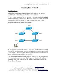
A frame sent by one host is received by all other hosts on the bus. However,<br />
a host will only process a frame if it matches the destination hardware<br />
address in the data-link header.<br />
Bus topologies are inexpensive to implement, but are almost entirely<br />
deprecated in Ethernet. There are several disadvantages to the bus topology:<br />
• Both ends of the bus must be terminated, otherwise a signal will<br />
reflect back and cause interference, severely degrading performance.<br />
• Adding or removing hosts to the bus can be difficult.<br />
• The bus represents a single point of failure - a break in the bus will<br />
affect all hosts on the segment. Such faults are often very difficult to<br />
troubleshoot.<br />
A bus topology is implemented using either thinnet or thicknet coax cable.<br />
* * *<br />
All original material copyright © 2013 by Aaron Balchunas (aaron@routeralley.com),<br />
unless otherwise noted. All other material copyright © of their respective owners.<br />
This material may be copied and used freely, but may not be altered or sold without the expressed written<br />
consent of the owner of the above copyright. Updated material may be found at http://www.routeralley.com.
<strong>CCNA</strong> <strong>Study</strong> <strong>Guide</strong> v2.62 – Aaron Balchunas<br />
22<br />
Ethernet Star Topology<br />
In a star topology, each host has an individual point-to-point connection to a<br />
centralized hub or switch:<br />
A hub provides no intelligent forwarding whatsoever, and will always<br />
forward every frame out every port, excluding the port originating the frame.<br />
As with a bus topology, a host will only process a frame if it matches the<br />
destination hardware address in the data-link header. Otherwise, it will<br />
discard the frame.<br />
A switch builds a hardware address table, allowing it to make intelligent<br />
forwarding decisions based on frame (data-link) headers. A frame can then<br />
be forwarded out only the appropriate destination port, instead of all ports.<br />
Hubs and switches are covered in great detail in another guide.<br />
Adding or removing hosts is very simple in a star topology. Also, a break in<br />
a cable will affect only that one host, and not the entire network.<br />
There are two disadvantages to the star topology:<br />
• The hub or switch represents a single point of failure.<br />
• Equipment and cabling costs are generally higher than in a bus<br />
topology.<br />
However, the star is still the dominant topology in modern Ethernet<br />
networks, due to its flexibility and scalability. Both twisted-pair and fiber<br />
cabling can be used in a star topology.<br />
* * *<br />
All original material copyright © 2013 by Aaron Balchunas (aaron@routeralley.com),<br />
unless otherwise noted. All other material copyright © of their respective owners.<br />
This material may be copied and used freely, but may not be altered or sold without the expressed written<br />
consent of the owner of the above copyright. Updated material may be found at http://www.routeralley.com.
<strong>CCNA</strong> <strong>Study</strong> <strong>Guide</strong> v2.62 – Aaron Balchunas<br />
23<br />
The Ethernet Frame<br />
An Ethernet frame contains the following fields:<br />
Field Length Description<br />
Preamble 7 bytes Synchronizes communication<br />
Start of Frame 1 byte Signals the start of a valid frame<br />
MAC Destination 6 bytes Destination MAC address<br />
MAC Source 6 bytes Source MAC address<br />
802.1Q tag 4 bytes Optional VLAN tag<br />
Ethertype or length 2 bytes Payload type or frame size<br />
Payload 42-1500 bytes Data payload<br />
CRC 4 bytes Frame error check<br />
Interframe Gap 12 bytes Required idle period between frames<br />
The preamble is 56 bits of alternating 1s and 0s that synchronizes<br />
communication on an Ethernet network. It is followed by an 8-bit start of<br />
frame delimiter (10101011) that indicates a valid frame is about to begin.<br />
The preamble and the start of frame are not considered part of the actual<br />
frame, or calculated as part of the total frame size.<br />
Ethernet uses the 48-bit MAC address for hardware addressing. The first<br />
24-bits of a MAC address determine the manufacturer of the network<br />
interface, and the last 24-bits uniquely identify the host.<br />
The destination MAC address identifies who is to receive the frame - this<br />
can be a single host (a unicast), a group of hosts (a multicast), or all hosts (a<br />
broadcast). The source MAC address indentifies the host originating the<br />
frame.<br />
The 802.1Q tag is an optional field used to identify which VLAN the frame<br />
belongs to. VLANs are covered in great detail in another guide.<br />
The 16-bit Ethertype/Length field provides a different function depending<br />
on the standard - Ethernet II or 802.3. With Ethernet II, the field identifies<br />
the type of payload in the frame (the Ethertype). However, Ethernet II is<br />
almost entirely deprecated.<br />
With 802.3, the field identifies the length of the payload. The length of a<br />
frame is important – there is both a minimum and maximum frame size.<br />
(Reference: http://www.techfest.com/networking/lan/ethernet2.htm; http://www.dcs.gla.ac.uk/~lewis/networkpages/m04s03EthernetFrame.htm)<br />
* * *<br />
All original material copyright © 2013 by Aaron Balchunas (aaron@routeralley.com),<br />
unless otherwise noted. All other material copyright © of their respective owners.<br />
This material may be copied and used freely, but may not be altered or sold without the expressed written<br />
consent of the owner of the above copyright. Updated material may be found at http://www.routeralley.com.
<strong>CCNA</strong> <strong>Study</strong> <strong>Guide</strong> v2.62 – Aaron Balchunas<br />
24<br />
The Ethernet Frame (continued)<br />
Field Length Description<br />
Preamble 7 bytes Synchronizes communication<br />
Start of Frame 1 byte Signals the start of a valid frame<br />
MAC Destination 6 bytes Destination MAC address<br />
MAC Source 6 bytes Source MAC address<br />
802.1Q tag 4 bytes Optional VLAN tag<br />
Ethertype or length 2 bytes Payload type or frame size<br />
Payload 42-1500 bytes Data payload<br />
CRC 4 bytes Frame error check<br />
Interframe Gap 12 bytes Required idle period between frames<br />
The absolute minimum frame size for Ethernet is 64 bytes (or 512 bits)<br />
including headers. A frame that is smaller than 64 bytes will be discarded as<br />
a runt. The required fields in an Ethernet header add up to 18 bytes – thus,<br />
the frame payload must be a minimum of 46 bytes, to equal the minimum<br />
64-byte frame size. If the payload does not meet this minimum, the payload<br />
is padded with 0 bits until the minimum is met.<br />
Note: If the optional 4-byte 802.1Q tag is used, the Ethernet header size will<br />
total 22 bytes, requiring a minimum payload of 42 bytes.<br />
By default, the maximum frame size for Ethernet is 1518 bytes – 18 bytes<br />
of header fields, and 1500 bytes of payload - or 1522 bytes with the 802.1Q<br />
tag. A frame that is larger than the maximum will be discarded as a giant.<br />
With both runts and giants, the receiving host will not notify the sender that<br />
the frame was dropped. Ethernet relies on higher-layer protocols, such as<br />
TCP, to provide retransmission of discarded frames.<br />
Some Ethernet devices support jumbo frames of 9216 bytes, which provide<br />
less overhead due to fewer frames. Jumbo frames must be explicitly enabled<br />
on all devices in the traffic path to prevent the frames from being dropped.<br />
The 32-bit Cycle Redundancy Check (CRC) field is used for errordetection.<br />
A frame with an invalid CRC will be discarded by the receiving<br />
device. This field is a trailer, and not a header, as it follows the payload.<br />
The 96-bit Interframe Gap is a required idle period between frame<br />
transmissions, allowing hosts time to prepare for the next frame.<br />
(Reference: http://www.infocellar.com/networks/ethernet/frame.htm)<br />
* * *<br />
All original material copyright © 2013 by Aaron Balchunas (aaron@routeralley.com),<br />
unless otherwise noted. All other material copyright © of their respective owners.<br />
This material may be copied and used freely, but may not be altered or sold without the expressed written<br />
consent of the owner of the above copyright. Updated material may be found at http://www.routeralley.com.
<strong>CCNA</strong> <strong>Study</strong> <strong>Guide</strong> v2.62 – Aaron Balchunas<br />
25<br />
CSMA/CD and Half-Duplex Communication<br />
Ethernet was originally developed to support a shared media environment.<br />
This allowed two or more hosts to use the same physical network medium.<br />
There are two methods of communication on a shared physical medium:<br />
• Half-Duplex – hosts can transmit or receive, but not simultaneously<br />
• Full-Duplex – hosts can both transmit and receive simultaneously<br />
On a half-duplex connection, Ethernet utilizes Carrier Sense Multiple<br />
Access with Collision Detect (CSMA/CD) to control media access. Carrier<br />
sense specifies that a host will monitor the physical link, to determine<br />
whether a carrier (or signal) is currently being transmitted. The host will<br />
only transmit a frame if the link is idle, and the Interframe Gap has expired.<br />
If two hosts transmit a frame simultaneously, a collision will occur. This<br />
renders the collided frames unreadable. Once a collision is detected, both<br />
hosts will send a 32-bit jam sequence to ensure all transmitting hosts are<br />
aware of the collision. The collided frames are also discarded.<br />
Both devices will then wait a random amount of time before resending their<br />
respective frames, to reduce the likelihood of another collision. This is<br />
controlled by a backoff timer process.<br />
Hosts must detect a collision before a frame is finished transmitting,<br />
otherwise CSMA/CD cannot function reliably. This is accomplished using a<br />
consistent slot time, the time required to send a specific amount of data from<br />
one end of the network and then back, measured in bits.<br />
A host must continue to transmit a frame for a minimum of the slot time. In a<br />
properly configured environment, a collision should always occur within this<br />
slot time, as enough time has elapsed for the frame to have reached the far<br />
end of the network and back, and thus all devices should be aware of the<br />
transmission. The slot time effectively limits the physical length of the<br />
network – if a network segment is too long, a host may not detect a collision<br />
within the slot time period. A collision that occurs after the slot time is<br />
referred to as a late collision.<br />
For 10 and 100Mbps Ethernet, the slot time was defined as 512 bits, or 64<br />
bytes. Note that this is the equivalent of the minimum Ethernet frame size of<br />
64 bytes. The slot time actually defines this minimum. For Gigabit Ethernet,<br />
the slot time was defined as 4096 bits.<br />
(Reference: http://www.techfest.com/networking/lan/ethernet3.htm)<br />
* * *<br />
All original material copyright © 2013 by Aaron Balchunas (aaron@routeralley.com),<br />
unless otherwise noted. All other material copyright © of their respective owners.<br />
This material may be copied and used freely, but may not be altered or sold without the expressed written<br />
consent of the owner of the above copyright. Updated material may be found at http://www.routeralley.com.
<strong>CCNA</strong> <strong>Study</strong> <strong>Guide</strong> v2.62 – Aaron Balchunas<br />
26<br />
Full-Duplex Communication<br />
Unlike half-duplex, full-duplex Ethernet supports simultaneously<br />
communication by providing separate transmit and receive paths. This<br />
effectively doubles the throughput of a network interface.<br />
Full-duplex Ethernet was formalized in IEEE 802.3x, and does not use<br />
CSMA/CD or slot times. Collisions should never occur on a functional fullduplex<br />
link. Greater distances are supported when using full-duplex over<br />
half-duplex.<br />
Full-duplex is only supported on a point-to-point connection between two<br />
devices. Thus, a bus topology using coax cable does not support full-duplex.<br />
Only a connection between two hosts or between a host and a switch<br />
supports full-duplex. A host connected to a hub is limited to half-duplex.<br />
Both hubs and half-duplex communication are mostly deprecated in modern<br />
networks.<br />
Categories of Ethernet<br />
The original 802.3 Ethernet standard has evolved over time, supporting<br />
faster transmission rates, longer distances, and newer hardware technologies.<br />
These revisions or amendments are identified by the letter appended to the<br />
standard, such as 802.3u or 802.3z.<br />
Major categories of Ethernet have also been organized by their speed:<br />
• Ethernet (10Mbps)<br />
• Fast Ethernet (100Mbps)<br />
• Gigabit Ethernet<br />
• 10 Gigabit Ethernet<br />
The physical standards for Ethernet are often labeled by their transmission<br />
rate, signaling type, and media type. For example, 100baseT represents the<br />
following:<br />
• The first part (100) represents the transmission rate, in Mbps.<br />
• The second part (base) indicates that it is a baseband transmission.<br />
• The last part (T) represents the physical media type (twisted-pair).<br />
Ethernet communication is baseband, which dedicates the entire capacity of<br />
the medium to one signal or channel. In broadband, multiple signals or<br />
channels can share the same link, through the use of modulation (usually<br />
frequency modulation).<br />
* * *<br />
All original material copyright © 2013 by Aaron Balchunas (aaron@routeralley.com),<br />
unless otherwise noted. All other material copyright © of their respective owners.<br />
This material may be copied and used freely, but may not be altered or sold without the expressed written<br />
consent of the owner of the above copyright. Updated material may be found at http://www.routeralley.com.
<strong>CCNA</strong> <strong>Study</strong> <strong>Guide</strong> v2.62 – Aaron Balchunas<br />
27<br />
Ethernet (10 Mbps)<br />
Ethernet is now a somewhat generic term, describing the entire family of<br />
technologies. However, Ethernet traditionally referred to the original 802.3<br />
standard, which operated at 10 Mbps. Ethernet supports coax, twisted-pair,<br />
and fiber cabling. Ethernet over twisted-pair uses two of the four pairs.<br />
Common Ethernet physical standards include:<br />
IEEE<br />
Standard<br />
Physical<br />
Standard<br />
Cable Type<br />
Maximum<br />
Speed<br />
Maximum<br />
Cable Length<br />
802.3a 10base2 Coaxial (thinnet) 10 Mbps 185 meters<br />
802.3 10base5 Coaxial (thicknet) 10 Mbps 500 meters<br />
802.3i 10baseT Twisted-pair 10 Mbps 100 meters<br />
802.3j 10baseF Fiber 10 Mbps 2000 meters<br />
Both 10baseT and 10baseF support full-duplex operation, effectively<br />
doubling the bandwidth to 20 Mbps. Remember, only a connection between<br />
two hosts or between a host and a switch support full-duplex. The<br />
maximum distance of an Ethernet segment can be extended through the use<br />
of a repeater. A hub or a switch can also serve as a repeater.<br />
Fast Ethernet (100 Mbps)<br />
In 1995, the IEEE formalized 802.3u, a 100 Mbps revision of Ethernet that<br />
became known as Fast Ethernet. Fast Ethernet supports both twisted-pair<br />
copper and fiber cabling, and supports both half-duplex and full-duplex.<br />
Common Fast Ethernet physical standards include:<br />
IEEE<br />
Standard<br />
Physical<br />
Standard<br />
Cable Type<br />
Maximum<br />
Speed<br />
Maximum Cable<br />
Length<br />
802.3u 100baseTX Twisted-pair 100 Mbps 100 meters<br />
802.3u 100baseT4 Twisted-pair 100 Mbps 100 meters<br />
802.3u 100baseFX Multimode fiber 100 Mbps 400-2000 meters<br />
802.3u 100baseSX Multimode fiber 100 Mbps 500 meters<br />
100baseT4 was never widely implemented, and only supported half-duplex<br />
operation. 100baseTX is the dominant Fast Ethernet physical standard.<br />
100baseTX uses two of the four pairs in a twisted-pair cable, and requires<br />
Category 5 cable for reliable performance.<br />
* * *<br />
All original material copyright © 2013 by Aaron Balchunas (aaron@routeralley.com),<br />
unless otherwise noted. All other material copyright © of their respective owners.<br />
This material may be copied and used freely, but may not be altered or sold without the expressed written<br />
consent of the owner of the above copyright. Updated material may be found at http://www.routeralley.com.
<strong>CCNA</strong> <strong>Study</strong> <strong>Guide</strong> v2.62 – Aaron Balchunas<br />
28<br />
Speed and Duplex Autonegotiation<br />
Fast Ethernet is backwards-compatible with the original Ethernet standard.<br />
A device that supports both Ethernet and Fast Ethernet is often referred to as<br />
a 10/100 device.<br />
Fast Ethernet also introduced the ability to autonegotiate both the speed and<br />
duplex of an interface. Autonegotiation will attempt to use the fastest speed<br />
available, and will attempt to use full-duplex if both devices support it.<br />
Speed and duplex can also be hardcoded, preventing negotiation.<br />
The configuration must be consistent on both sides of the connection. Either<br />
both sides must be configured to autonegotiate, or both sides must be<br />
hardcoded with identical settings. Otherwise a duplex mismatch error can<br />
occur.<br />
For example, if a workstation’s NIC is configured to autonegotiate, and the<br />
switch interface is hardcoded for 100Mbps and full-duplex, then a duplex<br />
mismatch will occur. The workstation’s NIC will sense the correct speed of<br />
100Mbps, but will not detect the correct duplex and will default to halfduplex.<br />
If the duplex is mismatched, collisions will occur. Because the full-duplex<br />
side of the connection does not utilize CSMA/CD, performance is severely<br />
degraded. These issues can be difficult to troubleshoot, as the network<br />
connection will still function, but will be excruciatingly slow.<br />
When autonegotiation was first developed, manufacturers did not always<br />
adhere to the same standard. This resulted in frequent mismatch issues, and a<br />
sentiment of distrust towards autonegotiation.<br />
Though modern network hardware has alleviated most of the<br />
incompatibility, many administrators are still skeptical of autonegotiation<br />
and choose to hardcode all connections. Another common practice is to<br />
hardcode server and datacenter connections, but to allow user devices to<br />
autonegotiate.<br />
Gigabit Ethernet, covered in the next section, provided several<br />
enhancements to autonegotiation, such as hardware flow control. Most<br />
manufacturers recommend autonegotiation on Gigabit Ethernet interfaces<br />
as a best practice.<br />
* * *<br />
All original material copyright © 2013 by Aaron Balchunas (aaron@routeralley.com),<br />
unless otherwise noted. All other material copyright © of their respective owners.<br />
This material may be copied and used freely, but may not be altered or sold without the expressed written<br />
consent of the owner of the above copyright. Updated material may be found at http://www.routeralley.com.
<strong>CCNA</strong> <strong>Study</strong> <strong>Guide</strong> v2.62 – Aaron Balchunas<br />
29<br />
Gigabit Ethernet<br />
Gigabit Ethernet operates at 1000 Mbps, and supports both twisted-pair<br />
(802.3ab) and fiber cabling (802.3z). Gigabit over twisted-pair uses all four<br />
pairs, and requires Category 5e cable for reliable performance.<br />
Gigabit Ethernet is backwards-compatible with the original Ethernet and<br />
Fast Ethernet. A device that supports all three is often referred to as a<br />
10/100/1000 device. Gigabit Ethernet supports both half-duplex or fullduplex<br />
operation. Full-duplex Gigabit Ethernet effectively provides 2000<br />
Mbps of throughput.<br />
Common Gigabit Ethernet physical standards include:<br />
IEEE<br />
Standard<br />
Physical<br />
Standard<br />
Cable Type Speed Maximum Cable<br />
Length<br />
802.3ab 1000baseT Twisted-pair 1 Gbps 100 meters<br />
802.3z 1000baseSX Multimode fiber 1 Gbps 500 meters<br />
802.3z 1000baseLX Multimode fiber 1 Gbps 500 meters<br />
802.3z 1000baseLX Singlemode fiber 1 Gbps Several kilometers<br />
In modern network equipment, Gigabit Ethernet has replaced both Ethernet<br />
and Fast Ethernet.<br />
10 Gigabit Ethernet<br />
10 Gigabit Ethernet operates at 10000 Mbps, and supports both twisted-pair<br />
(802.3an) and fiber cabling (802.3ae). 10 Gigabit over twisted-pair uses all<br />
four pairs, and requires Category 6 cable for reliable performance.<br />
Common Gigabit Ethernet physical standards include:<br />
IEEE<br />
Standard<br />
Physical<br />
Standard<br />
Cable Type Speed Maximum Cable<br />
Length<br />
802.3an 10Gbase-T Twisted-pair 10 Gbps 100 meters<br />
802.3ae 10Gbase-SR Multimode fiber 10 Gbps 300 meters<br />
802.3ae 10Gbase-LR Singlemode fiber 10 Gbps Several kilometers<br />
10 Gigabit Ethernet is usually used for high-speed connectivity within a<br />
datacenter, and is predominantly deployed over fiber.<br />
* * *<br />
All original material copyright © 2013 by Aaron Balchunas (aaron@routeralley.com),<br />
unless otherwise noted. All other material copyright © of their respective owners.<br />
This material may be copied and used freely, but may not be altered or sold without the expressed written<br />
consent of the owner of the above copyright. Updated material may be found at http://www.routeralley.com.
<strong>CCNA</strong> <strong>Study</strong> <strong>Guide</strong> v2.62 – Aaron Balchunas<br />
30<br />
Twisted-Pair Cabling Overview<br />
A typical twisted-pair cable consists of four pairs of copper wires, for a<br />
total of eight wires. Each side of the cable is terminated using an RJ45<br />
connector, which has eight pins. When the connector is crimped onto the<br />
cable, these pins make contact with each wire.<br />
The wires themselves are assigned a color to distinguish them. The color is<br />
dictated by the cabling standard - TIA/EIA-568B is the current standard:<br />
Color<br />
White Orange<br />
Orange<br />
White Green<br />
Blue<br />
White Blue<br />
Green<br />
White Brown<br />
Brown<br />
Pin#<br />
Each wire is assigned a specific purpose. For example, both Ethernet and<br />
Fast Ethernet use two wires to transmit, and two wires to receive data, while<br />
the other four pins remain unused.<br />
For communication to occur, transmit pins must connect to the receive pins<br />
of the remote host. This does not occur in a straight-through configuration:<br />
1<br />
2<br />
3<br />
4<br />
5<br />
6<br />
7<br />
8<br />
The pins must be crossed-over for communication to be successful:<br />
The crossover can be controlled either by the cable, or an intermediary<br />
device, such as a hub or switch.<br />
* * *<br />
All original material copyright © 2013 by Aaron Balchunas (aaron@routeralley.com),<br />
unless otherwise noted. All other material copyright © of their respective owners.<br />
This material may be copied and used freely, but may not be altered or sold without the expressed written<br />
consent of the owner of the above copyright. Updated material may be found at http://www.routeralley.com.
<strong>CCNA</strong> <strong>Study</strong> <strong>Guide</strong> v2.62 – Aaron Balchunas<br />
31<br />
Twisted-Pair Cabling – Cable and Interface Types<br />
The layout or pinout of the wires in the RJ45 connector dictates the function<br />
of the cable. There are three common types of twisted-pair cable:<br />
• Straight-through cable<br />
• Crossover cable<br />
• Rollover cable<br />
The network interface type determines when to use each cable:<br />
• Medium Dependent Interface (MDI)<br />
• Medium Dependent Interface with Crossover (MDIX)<br />
Host interfaces are generally MDI, while hub or switch interfaces are<br />
typically MDIX.<br />
Twisted-Pair Cabling – Straight-Through Cable<br />
A straight-through cable is used in the following circumstances:<br />
• From a host to a hub – MDI to MDIX<br />
• From a host to a switch - MDI to MDIX<br />
• From a router to a hub - MDI to MDIX<br />
• From a router to a switch - MDI to MDIX<br />
Essentially, a straight-through cable is used to connect any device to a hub or<br />
switch, except for another hub or switch. The hub or switch provides the<br />
crossover (or MDIX) function to connect transmit pins to receive pins.<br />
The pinout on each end of a straight-through cable must be identical. The<br />
TIA/EIA-568B standard for a straight-through cable is as follows:<br />
Pin# Connector 1 Connector 2 Pin#<br />
1<br />
2<br />
3<br />
4<br />
5<br />
6<br />
7<br />
8<br />
White Orange<br />
Orange<br />
White Green<br />
Blue<br />
White Blue<br />
Green<br />
White Brown<br />
Brown<br />
------------------------<br />
------------------------<br />
------------------------<br />
------------------------<br />
------------------------<br />
------------------------<br />
------------------------<br />
------------------------<br />
White Orange<br />
Orange<br />
White Green<br />
Blue<br />
White Blue<br />
Green<br />
White Brown<br />
Brown<br />
A straight-through cable is often referred to as a patch cable.<br />
* * *<br />
All original material copyright © 2013 by Aaron Balchunas (aaron@routeralley.com),<br />
unless otherwise noted. All other material copyright © of their respective owners.<br />
This material may be copied and used freely, but may not be altered or sold without the expressed written<br />
consent of the owner of the above copyright. Updated material may be found at http://www.routeralley.com.<br />
1<br />
2<br />
3<br />
4<br />
5<br />
6<br />
7<br />
8
<strong>CCNA</strong> <strong>Study</strong> <strong>Guide</strong> v2.62 – Aaron Balchunas<br />
32<br />
Twisted-Pair Cabling – Crossover Cable<br />
A crossover cable is used in the following circumstances:<br />
• From a host to a host – MDI to MDI<br />
• From a hub to a hub - MDIX to MDIX<br />
• From a switch to a switch - MDIX to MDIX<br />
• From a hub to a switch - MDIX to MDIX<br />
• From a router to a router - MDI to MDI<br />
Remember that a hub or a switch will provide the crossover function.<br />
However, when connecting a host directly to another host (MDI to MDI),<br />
the crossover function must be provided by a crossover cable.<br />
A crossover cable is often required to uplink a hub to another hub, or to<br />
uplink a switch to another switch. This is because the crossover is performed<br />
twice, once on each hub or switch (MDIX to MDIX), negating the crossover.<br />
Modern devices can now automatically detect whether the crossover<br />
function is required, negating the need for a crossover cable. This<br />
functionality is referred to as Auto-MDIX, and is now standard with Gigabit<br />
Ethernet, which uses all eight wires to both transmit and receive. Auto-<br />
MDIX requires that autonegotiation be enabled.<br />
To create a crossover cable, the transmit pins must be swapped with the<br />
receive pins on one end of the cable:<br />
• Pins 1 and 3<br />
• Pins 2 and 6<br />
Pin# Connector 1 Connector 2 Pin#<br />
1<br />
2<br />
3<br />
4<br />
5<br />
6<br />
7<br />
8<br />
White Orange<br />
Orange<br />
White Green<br />
Blue<br />
White Blue<br />
Green<br />
White Brown<br />
Brown<br />
------------------------<br />
------------------------<br />
------------------------<br />
------------------------<br />
------------------------<br />
------------------------<br />
------------------------<br />
------------------------<br />
White Green<br />
Green<br />
White Orange<br />
Blue<br />
White Blue<br />
Orange<br />
White Brown<br />
Brown<br />
3<br />
6<br />
1<br />
4<br />
5<br />
2<br />
7<br />
8<br />
Note that the Orange and Green pins have been swapped on Connector 2.<br />
The first connector is using the TIA/EIA-568B standard, while the second<br />
connector is using the TIA/EIA-568A standard.<br />
* * *<br />
All original material copyright © 2013 by Aaron Balchunas (aaron@routeralley.com),<br />
unless otherwise noted. All other material copyright © of their respective owners.<br />
This material may be copied and used freely, but may not be altered or sold without the expressed written<br />
consent of the owner of the above copyright. Updated material may be found at http://www.routeralley.com.
<strong>CCNA</strong> <strong>Study</strong> <strong>Guide</strong> v2.62 – Aaron Balchunas<br />
33<br />
Twisted-Pair – Rollover Cable<br />
A rollover cable is used to connect a workstation or laptop into a <strong>Cisco</strong><br />
device’s console or auxiliary port, for management purposes. A rollover<br />
cable is often referred to as a console cable, and its sheathing is usually flat<br />
and light-blue in color.<br />
To create a rollover cable, the pins are completely reversed on one end of the<br />
cable:<br />
Pin# Connector 1 Connector 2 Pin#<br />
1<br />
2<br />
3<br />
4<br />
5<br />
6<br />
7<br />
8<br />
White Orange<br />
Orange<br />
White Green<br />
Blue<br />
White Blue<br />
Green<br />
White Brown<br />
Brown<br />
------------------------<br />
------------------------<br />
------------------------<br />
------------------------<br />
------------------------<br />
------------------------<br />
------------------------<br />
------------------------<br />
Brown<br />
White Brown<br />
Green<br />
White Blue<br />
Blue<br />
White Green<br />
Orange<br />
White Orange<br />
Rollover cables can be used to configure <strong>Cisco</strong> routers, switches, and<br />
firewalls.<br />
8<br />
7<br />
6<br />
5<br />
4<br />
3<br />
2<br />
1<br />
* * *<br />
All original material copyright © 2013 by Aaron Balchunas (aaron@routeralley.com),<br />
unless otherwise noted. All other material copyright © of their respective owners.<br />
This material may be copied and used freely, but may not be altered or sold without the expressed written<br />
consent of the owner of the above copyright. Updated material may be found at http://www.routeralley.com.
<strong>CCNA</strong> <strong>Study</strong> <strong>Guide</strong> v2.62 – Aaron Balchunas<br />
34<br />
Power over Ethernet (PoE)<br />
Power over Ethernet (PoE) allows both data and power to be sent across<br />
the same twisted-pair cable, eliminating the need to provide separate power<br />
connections. This is especially useful in areas where installing separate<br />
power might be expensive or difficult.<br />
PoE can be used to power many devices, including:<br />
• Voice over IP (VoIP) phones<br />
• Security cameras<br />
• Wireless access points<br />
• Thin clients<br />
PoE was originally formalized as 802.3af, which can provide roughly 13W<br />
of power to a device. 802.3at further enhanced PoE, supporting 25W or<br />
more power to a device.<br />
Ethernet, Fast Ethernet, and Gigabit Ethernet all support PoE. Power can be<br />
sent across either the unused pairs in a cable, or the data transmission pairs,<br />
which is referred to as phantom power. Gigabit Ethernet requires the<br />
phantom power method, as it uses all eight wires in a twisted-pair cable.<br />
The device that provides power is referred to as the Power Source<br />
Equipment (PSE). PoE can be supplied using an external power injector,<br />
though each powered device requires a separate power injector.<br />
More commonly, an 802.3af-compliant network switch is used to provide<br />
power to many devices simultaneously. The power supplies in the switch<br />
must be large enough to support both the switch itself, and the devices it is<br />
powering.<br />
(Reference: http://www.belden.com/docs/upload/PoE_Basics_WP.pdf)<br />
* * *<br />
All original material copyright © 2013 by Aaron Balchunas (aaron@routeralley.com),<br />
unless otherwise noted. All other material copyright © of their respective owners.<br />
This material may be copied and used freely, but may not be altered or sold without the expressed written<br />
consent of the owner of the above copyright. Updated material may be found at http://www.routeralley.com.
<strong>CCNA</strong> <strong>Study</strong> <strong>Guide</strong> v2.62 – Aaron Balchunas<br />
35<br />
Layered Communication<br />
Section 4<br />
- Hubs vs. Switches vs. <strong>Router</strong>s -<br />
Network communication models are generally organized into layers. The<br />
OSI model specifically consists of seven layers, with each layer<br />
representing a specific networking function. These functions are controlled<br />
by protocols, which govern end-to-end communication between devices.<br />
As data is passed from the user application down the virtual layers of the<br />
OSI model, each of the lower layers adds a header (and sometimes a<br />
trailer) containing protocol information specific to that layer. These headers<br />
are called Protocol Data Units (PDUs), and the process of adding these<br />
headers is referred to as encapsulation.<br />
The PDU of each lower layer is identified with a unique term:<br />
# Layer PDU Name<br />
7 Application -<br />
6 Presentation -<br />
5 Session -<br />
4 Transport Segments<br />
3 Network Packets<br />
2 Data-link Frames<br />
1 Physical Bits<br />
Commonly, network devices are identified by the OSI layer they operate at<br />
(or, more specifically, what header or PDU the device processes).<br />
For example, switches are generally identified as Layer-2 devices, as<br />
switches process information stored in the Data-Link header of a frame<br />
(such as MAC addresses in Ethernet). Similarly, routers are identified as<br />
Layer-3 devices, as routers process logical addressing information in the<br />
Network header of a packet (such as IP addresses).<br />
However, the strict definitions of the terms switch and router have blurred<br />
over time, which can result in confusion. For example, the term switch can<br />
now refer to devices that operate at layers higher than Layer-2. This will be<br />
explained in greater detail in this guide.<br />
* * *<br />
All original material copyright © 2013 by Aaron Balchunas (aaron@routeralley.com),<br />
unless otherwise noted. All other material copyright © of their respective owners.<br />
This material may be copied and used freely, but may not be altered or sold without the expressed written<br />
consent of the owner of the above copyright. Updated material may be found at http://www.routeralley.com.
<strong>CCNA</strong> <strong>Study</strong> <strong>Guide</strong> v2.62 – Aaron Balchunas<br />
36<br />
Icons for Network Devices<br />
The following icons will be used to represent network devices for all guides<br />
on routeralley.com:<br />
Hub____<br />
Switch___<br />
Multilayer Switch<br />
<strong>Router</strong><br />
* * *<br />
All original material copyright © 2013 by Aaron Balchunas (aaron@routeralley.com),<br />
unless otherwise noted. All other material copyright © of their respective owners.<br />
This material may be copied and used freely, but may not be altered or sold without the expressed written<br />
consent of the owner of the above copyright. Updated material may be found at http://www.routeralley.com.
<strong>CCNA</strong> <strong>Study</strong> <strong>Guide</strong> v2.62 – Aaron Balchunas<br />
37<br />
Layer-1 Hubs<br />
Hubs are Layer-1 devices that physically connect network devices together<br />
for communication. Hubs can also be referred to as repeaters.<br />
Hubs provide no intelligent forwarding whatsoever. Hubs are incapable of<br />
processing either Layer-2 or Layer-3 information, and thus cannot make<br />
decisions based on hardware or logical addressing.<br />
Thus, hubs will always forward every frame out every port, excluding the<br />
port originating the frame. Hubs do not differentiate between frame types,<br />
and thus will always forward unicasts, multicasts, and broadcasts out every<br />
port but the originating port.<br />
Ethernet hubs operate at half-duplex, which allows a device to either<br />
transmit or receive data, but not simultaneously. Ethernet utilizes Carrier<br />
Sense Multiple Access with Collision Detect (CSMA/CD) to control<br />
media access. Host devices monitor the physical link, and will only transmit<br />
a frame if the link is idle.<br />
However, if two devices transmit a frame simultaneously, a collision will<br />
occur. If a collision is detected, the hub will discard the frames and signal<br />
the host devices. Both devices will wait a random amount of time before<br />
resending their respective frames.<br />
Remember, if any two devices connected to a hub send a frame<br />
simultaneously, a collision will occur. Thus, all ports on a hub belong to the<br />
same collision domain. A collision domain is simply defined as any<br />
physical segment where a collision can occur.<br />
Multiple hubs that are uplinked together still all belong to one collision<br />
domain. Increasing the number of host devices in a single collision domain<br />
will increase the number of collisions, which can significantly degrade<br />
performance.<br />
Hubs also belong to only one broadcast domain – a hub will forward both<br />
broadcasts and multicasts out every port but the originating port. A broadcast<br />
domain is a logical segmentation of a network, dictating how far a broadcast<br />
(or multicast) frame can propagate.<br />
Only a Layer-3 device, such as a router, can separate broadcast domains.<br />
* * *<br />
All original material copyright © 2013 by Aaron Balchunas (aaron@routeralley.com),<br />
unless otherwise noted. All other material copyright © of their respective owners.<br />
This material may be copied and used freely, but may not be altered or sold without the expressed written<br />
consent of the owner of the above copyright. Updated material may be found at http://www.routeralley.com.
<strong>CCNA</strong> <strong>Study</strong> <strong>Guide</strong> v2.62 – Aaron Balchunas<br />
38<br />
Layer-2 Switching<br />
Layer-2 devices build hardware address tables, which will contain the<br />
following at a minimum:<br />
• Hardware addresses for host devices<br />
• The port each hardware address is associated with<br />
Using this information, Layer-2 devices will make intelligent forwarding<br />
decisions based on frame (Data-Link) headers. A frame can then be<br />
forwarded out only the appropriate destination port, instead of all ports.<br />
Layer-2 forwarding was originally referred to as bridging. Bridging is a<br />
largely deprecated term (mostly for marketing purposes), and Layer-2<br />
forwarding is now commonly referred to as switching.<br />
There are some subtle technological differences between bridging and<br />
switching. Switches usually have a higher port-density, and can perform<br />
forwarding decisions at wire speed, due to specialized hardware circuits<br />
called ASICs (Application-Specific Integrated Circuits). Otherwise,<br />
bridges and switches are nearly identical in function.<br />
Ethernet switches build MAC-address tables through a dynamic learning<br />
process. A switch behaves much like a hub when first powered on. The<br />
switch will flood every frame, including unicasts, out every port but the<br />
originating port.<br />
The switch will then build the MAC-address table by examining the source<br />
MAC address of each frame. Consider the following diagram:<br />
Switch<br />
Fa0/10<br />
Computer A<br />
Fa0/11<br />
Computer B<br />
When ComputerA sends a frame to<br />
ComputerB, the switch will add ComputerA’s<br />
MAC address to its table, associating it with<br />
port fa0/10. However, the switch will not<br />
learn ComputerB’s MAC address until<br />
ComputerB sends a frame to ComputerA, or<br />
to another device connected to the switch.<br />
Switches always learn from the source<br />
MAC address.<br />
A switch is in a perpetual state of learning. However, as the MAC-address<br />
table becomes populated, the flooding of frames will decrease, allowing the<br />
switch to perform more efficient forwarding decisions.<br />
* * *<br />
All original material copyright © 2013 by Aaron Balchunas (aaron@routeralley.com),<br />
unless otherwise noted. All other material copyright © of their respective owners.<br />
This material may be copied and used freely, but may not be altered or sold without the expressed written<br />
consent of the owner of the above copyright. Updated material may be found at http://www.routeralley.com.
<strong>CCNA</strong> <strong>Study</strong> <strong>Guide</strong> v2.62 – Aaron Balchunas<br />
39<br />
Layer-2 Switching (continued)<br />
While hubs were limited to half-duplex communication, switches can<br />
operate in full duplex. Each individual port on a switch belongs to its own<br />
collision domain. Thus, switches create more collision domains, which<br />
results in fewer collisions.<br />
Like hubs though, switches belong to only one broadcast domain. A Layer-<br />
2 switch will forward both broadcasts and multicasts out every port but the<br />
originating port. Only Layer-3 devices separate broadcast domains.<br />
Because of this, Layer-2 switches are poorly suited for large, scalable<br />
networks. The Layer-2 header provides no mechanism to differentiate one<br />
network from another, only one host from another.<br />
This poses significant difficulties. If only hardware addressing existed, all<br />
devices would technically be on the same network. Modern internetworks<br />
like the Internet could not exist, as it would be impossible to separate my<br />
network from your network.<br />
Imagine if the entire Internet existed purely as a Layer-2 switched<br />
environment. Switches, as a rule, will forward a broadcast out every port.<br />
Even with a conservative estimate of a billion devices on the Internet, the<br />
resulting broadcast storms would be devastating. The Internet would simply<br />
collapse.<br />
Both hubs and switches are susceptible to switching loops, which result in<br />
destructive broadcast storms. Switches utilize the Spanning Tree Protocol<br />
(STP) to maintain a loop-free environment. STP is covered in great detail in<br />
another guide.<br />
Remember, there are three things that switches do that hubs do not:<br />
• Hardware address learning<br />
• Intelligent forwarding of frames<br />
• Loop avoidance<br />
Hubs are almost entirely deprecated – there is no advantage to using a hub<br />
over a switch. At one time, switches were more expensive and introduced<br />
more latency (due to processing overhead) than hubs, but this is no longer<br />
the case.<br />
* * *<br />
All original material copyright © 2013 by Aaron Balchunas (aaron@routeralley.com),<br />
unless otherwise noted. All other material copyright © of their respective owners.<br />
This material may be copied and used freely, but may not be altered or sold without the expressed written<br />
consent of the owner of the above copyright. Updated material may be found at http://www.routeralley.com.
<strong>CCNA</strong> <strong>Study</strong> <strong>Guide</strong> v2.62 – Aaron Balchunas<br />
40<br />
Layer-2 Forwarding Methods<br />
Switches support three methods of forwarding frames. Each method copies<br />
all or part of the frame into memory, providing different levels of latency<br />
and reliability. Latency is delay - less latency results in quicker forwarding.<br />
The Store-and-Forward method copies the entire frame into memory, and<br />
performs a Cycle Redundancy Check (CRC) to completely ensure the<br />
integrity of the frame. However, this level of error-checking introduces the<br />
highest latency of any of the switching methods.<br />
The Cut-Through (Real Time) method copies only enough of a frame’s<br />
header to determine its destination address. This is generally the first 6 bytes<br />
following the preamble. This method allows frames to be transferred at wire<br />
speed, and has the least latency of any of the three methods. No error<br />
checking is attempted when using the cut-through method.<br />
The Fragment-Free (Modified Cut-Through) method copies only the first<br />
64 bytes of a frame for error-checking purposes. Most collisions or<br />
corruption occur in the first 64 bytes of a frame. Fragment-Free represents a<br />
compromise between reliability (store-and-forward) and speed (cut-through).<br />
* * *<br />
All original material copyright © 2013 by Aaron Balchunas (aaron@routeralley.com),<br />
unless otherwise noted. All other material copyright © of their respective owners.<br />
This material may be copied and used freely, but may not be altered or sold without the expressed written<br />
consent of the owner of the above copyright. Updated material may be found at http://www.routeralley.com.
<strong>CCNA</strong> <strong>Study</strong> <strong>Guide</strong> v2.62 – Aaron Balchunas<br />
41<br />
Layer-3 Routing<br />
Layer-3 routing is the process of forwarding a packet from one network to<br />
another network, based on the Network-layer header. <strong>Router</strong>s build routing<br />
tables to perform forwarding decisions, which contain the following:<br />
• The destination network and subnet mask<br />
• The next hop router to get to the destination network<br />
• Routing metrics and Administrative Distance<br />
Note that Layer-3 forwarding is based on the destination network, and not<br />
the destination host. It is possible to have host routes, but this is less<br />
common.<br />
The routing table is concerned with two types of Layer-3 protocols:<br />
• Routed protocols - assigns logical addressing to devices, and routes<br />
packets between networks. Examples include IP and IPX.<br />
• Routing protocols - dynamically builds the information in routing<br />
tables. Examples include RIP, EIGRP, and OSPF.<br />
Each individual interface on a router belongs to its own collision domain.<br />
Thus, like switches, routers create more collision domains, which results in<br />
fewer collisions.<br />
Unlike Layer-2 switches, Layer-3 routers also separate broadcast domains.<br />
As a rule, a router will never forward broadcasts from one network to<br />
another network (unless, of course, you explicitly configure it to). ☺<br />
<strong>Router</strong>s will not forward multicasts either, unless configured to participate in<br />
a multicast tree. Multicast is covered in great detail in another guide.<br />
Traditionally, a router was required to copy each individual packet to its<br />
buffers, and perform a route-table lookup. Each packet consumed CPU<br />
cycles as it was forwarded by the router, resulting in latency. Thus, routing<br />
was generally considered slower than switching.<br />
It is now possible for routers to cache network-layer flows in hardware,<br />
greatly reducing latency. This has blurred the line between routing and<br />
switching, from both a technological and marketing standpoint. Caching<br />
network flows is covered in greater detail shortly.<br />
* * *<br />
All original material copyright © 2013 by Aaron Balchunas (aaron@routeralley.com),<br />
unless otherwise noted. All other material copyright © of their respective owners.<br />
This material may be copied and used freely, but may not be altered or sold without the expressed written<br />
consent of the owner of the above copyright. Updated material may be found at http://www.routeralley.com.
<strong>CCNA</strong> <strong>Study</strong> <strong>Guide</strong> v2.62 – Aaron Balchunas<br />
42<br />
Collision vs. Broadcast Domain Example<br />
Consider the above diagram. Remember that:<br />
• <strong>Router</strong>s separate broadcast and collision domains.<br />
• Switches separate collision domains.<br />
• Hubs belong to only one collision domain.<br />
• Switches and hubs both only belong to one broadcast domain.<br />
In the above example, there are THREE broadcast domains, and EIGHT<br />
collision domains:<br />
* * *<br />
All original material copyright © 2013 by Aaron Balchunas (aaron@routeralley.com),<br />
unless otherwise noted. All other material copyright © of their respective owners.<br />
This material may be copied and used freely, but may not be altered or sold without the expressed written<br />
consent of the owner of the above copyright. Updated material may be found at http://www.routeralley.com.
<strong>CCNA</strong> <strong>Study</strong> <strong>Guide</strong> v2.62 – Aaron Balchunas<br />
43<br />
VLANs – A Layer-2 or Layer-3 Function?<br />
By default, a switch will forward both broadcasts and multicasts out every<br />
port but the originating port.<br />
However, a switch can be logically segmented into multiple broadcast<br />
domains, using Virtual LANs (or VLANs). VLANs are covered in<br />
extensive detail in another guide.<br />
Each VLAN represents a unique broadcast domain:<br />
• Traffic between devices within the same VLAN is switched<br />
(forwarded at Layer-2).<br />
• Traffic between devices in different VLANs requires a Layer-3<br />
device to communicate.<br />
Broadcasts from one VLAN will not be forwarded to another VLAN. This<br />
separation provided by VLANs is not a Layer-3 function. VLAN tags are<br />
inserted into the Layer-2 header.<br />
Thus, a switch that supports VLANs is not necessarily a Layer-3 switch.<br />
However, a purely Layer-2 switch cannot route between VLANs.<br />
Remember, though VLANs provide separation for Layer-3 broadcast<br />
domains, and are often associated with IP subnets, they are still a Layer-2<br />
function.<br />
* * *<br />
All original material copyright © 2013 by Aaron Balchunas (aaron@routeralley.com),<br />
unless otherwise noted. All other material copyright © of their respective owners.<br />
This material may be copied and used freely, but may not be altered or sold without the expressed written<br />
consent of the owner of the above copyright. Updated material may be found at http://www.routeralley.com.
<strong>CCNA</strong> <strong>Study</strong> <strong>Guide</strong> v2.62 – Aaron Balchunas<br />
44<br />
Layer-3 Switching<br />
In addition to performing Layer-2 switching functions, a Layer-3 switch<br />
must also meet the following criteria:<br />
• The switch must be capable of making Layer-3 forwarding decisions<br />
(traditionally referred to as routing).<br />
• The switch must cache network traffic flows, so that Layer-3<br />
forwarding can occur in hardware.<br />
Many older modular switches support Layer-3 route processors – this alone<br />
does not qualify as Layer-3 switching. Layer-2 and Layer-3 processors can<br />
act independently within a single switch chassis, with each packet requiring<br />
a route-table lookup on the route processor.<br />
Layer-3 switches leverage ASICs to perform Layer-3 forwarding in<br />
hardware. For the first packet of a particular traffic flow, the Layer-3 switch<br />
will perform a standard route-table lookup. This flow is then cached in<br />
hardware – which preserves required routing information, such as the<br />
destination network and the MAC address of the corresponding next-hop.<br />
Subsequent packets of that flow will bypass the route-table lookup, and will<br />
be forwarded based on the cached information, reducing latency. This<br />
concept is known as route once, switch many.<br />
Layer-3 switches are predominantly used to route between VLANs:<br />
Traffic between devices within the same VLAN, such as ComputerA and<br />
ComputerB, is switched at Layer-2 as normal. The first packet between<br />
devices in different VLANs, such as ComputerA and ComputerD, is routed.<br />
The switch will then cache that IP traffic flow, and subsequent packets in<br />
that flow will be switched in hardware.<br />
* * *<br />
All original material copyright © 2013 by Aaron Balchunas (aaron@routeralley.com),<br />
unless otherwise noted. All other material copyright © of their respective owners.<br />
This material may be copied and used freely, but may not be altered or sold without the expressed written<br />
consent of the owner of the above copyright. Updated material may be found at http://www.routeralley.com.
<strong>CCNA</strong> <strong>Study</strong> <strong>Guide</strong> v2.62 – Aaron Balchunas<br />
45<br />
Layer-3 Switching vs. Routing – End the Confusion!<br />
The evolution of network technologies has led to considerable confusion<br />
over the terms switch and router. Remember the following:<br />
• The traditional definition of a switch is a device that performs Layer-2<br />
forwarding decisions.<br />
• The traditional definition of a router is a device that performs Layer-3<br />
forwarding decisions.<br />
Remember also that, switching functions were typically performed in<br />
hardware, and routing functions were typically performed in software. This<br />
resulted in a widespread perception that switching was fast, and routing was<br />
slow (and expensive).<br />
Once Layer-3 forwarding became available in hardware, marketing gurus<br />
muddied the waters by distancing themselves from the term router. Though<br />
Layer-3 forwarding in hardware is still routing in every technical sense, such<br />
devices were rebranded as Layer-3 switches.<br />
Ignore the marketing noise. A Layer-3 switch is still a router.<br />
Compounding matters further, most devices still currently referred to as<br />
routers can perform Layer-3 forwarding in hardware as well. Thus, both<br />
Layer-3 switches and Layer-3 routers perform nearly identical functions at<br />
the same performance.<br />
There are some differences in implementation between Layer-3 switches and<br />
routers, including (but not limited to):<br />
• Layer-3 switches are optimized for Ethernet, and are predominantly<br />
used for inter-VLAN routing. Layer-3 switches can also provide<br />
Layer-2 functionality for intra-VLAN traffic.<br />
• Switches generally have higher port densities than routers, and are<br />
considerably cheaper per port than routers (for Ethernet, at least).<br />
• <strong>Router</strong>s support a large number of WAN technologies, while Layer-3<br />
switches generally do not.<br />
• <strong>Router</strong>s generally support more advanced feature sets.<br />
Layer-3 switches are often deployed as the backbone of LAN or campus<br />
networks. <strong>Router</strong>s are predominantly used on network perimeters,<br />
connecting to WAN environments.<br />
(Fantastic Reference: http://blog.ioshints.info/2011/02/how-did-we-ever-get-into-this-switching.html)<br />
* * *<br />
All original material copyright © 2013 by Aaron Balchunas (aaron@routeralley.com),<br />
unless otherwise noted. All other material copyright © of their respective owners.<br />
This material may be copied and used freely, but may not be altered or sold without the expressed written<br />
consent of the owner of the above copyright. Updated material may be found at http://www.routeralley.com.
<strong>CCNA</strong> <strong>Study</strong> <strong>Guide</strong> v2.62 – Aaron Balchunas<br />
46<br />
Multilayer Switching<br />
Multilayer switching is a generic term, referring to any switch that<br />
forwards traffic at layers higher than Layer-2. Thus, a Layer-3 switch is<br />
considered a multilayer switch, as it forwards frames at Layer-2 and packets<br />
at Layer-3.<br />
A Layer-4 switch provides the same functionality as a Layer-3 switch, but<br />
will additionally examine and cache Transport-layer application flow<br />
information, such as the TCP or UDP port.<br />
By caching application flows, QoS (Quality of Service) functions can be<br />
applied to preferred applications.<br />
Consider the following example:<br />
Network and application traffic flows from ComputerA to the Webserver<br />
and Fileserver will be cached. If the traffic to the Webserver is preferred,<br />
then a higher QoS priority can be assigned to that application flow.<br />
Some advanced multilayer switches can provide load balancing, content<br />
management, and other application-level services. These switches are<br />
sometimes referred to as Layer-7 switches.<br />
* * *<br />
All original material copyright © 2013 by Aaron Balchunas (aaron@routeralley.com),<br />
unless otherwise noted. All other material copyright © of their respective owners.<br />
This material may be copied and used freely, but may not be altered or sold without the expressed written<br />
consent of the owner of the above copyright. Updated material may be found at http://www.routeralley.com.
<strong>CCNA</strong> <strong>Study</strong> <strong>Guide</strong> v2.62 – Aaron Balchunas<br />
47<br />
Switching Loops<br />
Section 5<br />
- Spanning Tree Protocol -<br />
By default, a switch will forward a broadcast or multicast out all ports,<br />
excluding the port the broadcast/multicast was sent from.<br />
When a loop is introduced into the network, a highly destructive broadcast<br />
storm can develop within seconds. Broadcast storms occur when broadcasts<br />
are endlessly switched through the loop, choking off all other traffic.<br />
Consider the following looped environment:<br />
Switch 1<br />
Switch 2 Switch 3<br />
Switch 4 Switch 5<br />
If the computer connected to Switch 4 sends out a broadcast, the switch will<br />
forward the broadcast out all ports, including the ports connecting to Switch<br />
2 and Switch 5. Those switches, likewise, will forward that broadcast out all<br />
ports, including to their neighboring switches.<br />
The broadcast will loop around the switches infinitely. In fact, there will be<br />
two separate broadcast storms cycling in opposite directions through the<br />
switching loop. Only powering off the switch or physically removing the<br />
loop will stop the storm.<br />
* * *<br />
All original material copyright © 2013 by Aaron Balchunas (aaron@routeralley.com),<br />
unless otherwise noted. All other material copyright © of their respective owners.<br />
This material may be copied and used freely, but may not be altered or sold without the expressed written<br />
consent of the owner of the above copyright. Updated material may be found at http://www.routeralley.com.
<strong>CCNA</strong> <strong>Study</strong> <strong>Guide</strong> v2.62 – Aaron Balchunas<br />
48<br />
Spanning Tree Protocol (STP)<br />
Switches (and bridges) needed a mechanism to prevent loops from forming,<br />
and thus Spanning Tree Protocol (STP, or IEEE 802.1D) was developed.<br />
STP is enabled by default on all VLANs on Catalyst switches.<br />
STP-enabled switches communicate to form a topology of the entire<br />
switching network, and then shutting down (or blocking) a port if a loop<br />
exists. The blocked port can be reactivated if another link on the switching<br />
network goes down, thus preserving fault-tolerance. Once all switches agree<br />
on the topology database, the switches are considered converged.<br />
STP switches send BPDU’s (Bridge Protocol Data Units) to each other to<br />
form their topology databases. BPDU’s are sent out all ports every two<br />
seconds, are forwarded to a specific MAC multicast address:<br />
0180.c200.0000.<br />
STP Types<br />
Various flavors of 802.1D STP exist, including:<br />
• Common Spanning Tree (CST) – A single STP process is used for<br />
all VLANs.<br />
• Per-VLAN Spanning Tree (PVST) – <strong>Cisco</strong> proprietary version of<br />
STP, which employs a separate STP process for each VLAN.<br />
• Per-VLAN Spanning Tree Plus (PVST+) – Enhanced version of<br />
PVST that allows CST-enabled switches and PVST-enabled switches<br />
to interoperate. This is default on newer Catalyst switches.<br />
The STP Process<br />
To maintain a loop-free environment, STP performs the following functions:<br />
• A Root Bridge is elected<br />
• Root Ports are identified<br />
• Designated Ports are identified<br />
• If a loop exists, a port is placed in Blocking state. If the loop is<br />
removed the blocked port is activated again.<br />
If multiple loops exist in the switching environment, multiple ports will be<br />
placed in a blocking state.<br />
* * *<br />
All original material copyright © 2013 by Aaron Balchunas (aaron@routeralley.com),<br />
unless otherwise noted. All other material copyright © of their respective owners.<br />
This material may be copied and used freely, but may not be altered or sold without the expressed written<br />
consent of the owner of the above copyright. Updated material may be found at http://www.routeralley.com.
<strong>CCNA</strong> <strong>Study</strong> <strong>Guide</strong> v2.62 – Aaron Balchunas<br />
49<br />
Electing an STP Root Bridge<br />
The first step in the STP process is electing a Root Bridge, which serves as<br />
the centralized point of the STP topology. Good design practice dictates that<br />
the Root Bridge be placed closest to the center of the STP topology.<br />
The Root Bridge is determined by a switch’s priority. The default priority is<br />
32,768, and the lowest priority wins. In case of a tie in priority, the switch<br />
with the lowest MAC address will be elected root bridge. The combination<br />
of a switch’s priority and MAC address make up that switch’s Bridge ID.<br />
Consider the following example:<br />
Remember that the lowest priority determines the Root Bridge. Switches 2,<br />
3, and 5 have the default priority set. Switches 1 and 4 each have a priority<br />
of 100 configured. However, Switch 1 will become the root bridge, as it has<br />
the lowest MAC address.<br />
Switches exchange BPDU’s to perform the election process. By default, all<br />
switches “believe” they are the Root Bridge, until a switch with a lower<br />
Bridge ID is discovered.<br />
Root Bridge elections are a continuous process. If a new switch with a lower<br />
Bridge ID is added to the topology, it will be elected as the new Root<br />
Bridge.<br />
* * *<br />
All original material copyright © 2013 by Aaron Balchunas (aaron@routeralley.com),<br />
unless otherwise noted. All other material copyright © of their respective owners.<br />
This material may be copied and used freely, but may not be altered or sold without the expressed written<br />
consent of the owner of the above copyright. Updated material may be found at http://www.routeralley.com.
<strong>CCNA</strong> <strong>Study</strong> <strong>Guide</strong> v2.62 – Aaron Balchunas<br />
50<br />
Identifying Root Ports<br />
The second step in the STP process is identifying Root Ports, or the port on<br />
each switch that has the lowest path cost to get to the Root Bridge. Each<br />
switch has only one Root Port, and the Root Bridge cannot have a Root Port.<br />
Path Cost is a cumulative cost based on the bandwidth of the links. The<br />
higher the bandwidth, the lower the Path Cost:<br />
Consider the following example:<br />
Bandwidth Cost<br />
4 Mbps 250<br />
10 Mbps 100<br />
16 Mbps 62<br />
100 Mbps 19<br />
1 Gbps 4<br />
Assume the links between all switches are 10Mbps Ethernet, with a Path<br />
Cost of 100. Each switch will identify the port with the least cumulative Path<br />
Cost to get to the Root Bridge.<br />
For Switch 4, the port leading up to Switch 2 has a Path Cost of 200, and<br />
becomes the Root Port. The port to Switch 5 has a higher Path Cost of 300.<br />
The Root Port is said to have received the most superior BPDU to the Root<br />
Bridge. Likewise, non-Root Ports are said to have received inferior BPDU’s<br />
to the Root Bridge.<br />
* * *<br />
All original material copyright © 2013 by Aaron Balchunas (aaron@routeralley.com),<br />
unless otherwise noted. All other material copyright © of their respective owners.<br />
This material may be copied and used freely, but may not be altered or sold without the expressed written<br />
consent of the owner of the above copyright. Updated material may be found at http://www.routeralley.com.
<strong>CCNA</strong> <strong>Study</strong> <strong>Guide</strong> v2.62 – Aaron Balchunas<br />
51<br />
Identifying Designated Ports<br />
The third and final step in the STP process is to identify Designated Ports.<br />
Each network segment requires a single Designated Port, which has the<br />
lowest path cost leading to the Root Bridge. This port will not be placed in a<br />
blocking state. A port cannot be both a Designated Port and a Root Port.<br />
Consider the following example:<br />
Ports on the Root Bridge are never placed in a blocking state, and thus<br />
become Designated Ports for directly attached segments.<br />
The network segments between Switches 2 and 4, and between Switches 3<br />
and 5, both require a Designated Port. The ports on Switch 2 and Switch 3<br />
have the lowest Path Cost to the Root Bridge for the two respective<br />
segments, and thus both become Designated Ports.<br />
The segment between Switch 4 and Switch 5 does not contain a Root Port.<br />
One of the ports must be elected the Designated Port for that segment, and<br />
the other must be placed in a blocking state.<br />
Normally, Path Cost is used to determine which port is blocked. However,<br />
the ports connecting Switches 4 and 5 have the same Path Cost to reach the<br />
Root Bridge (200). Whichever switch has the lowest Bridge ID is awarded<br />
the Designated Port. Whichever switch has the highest Bridge ID has its<br />
port placed in a blocking state. In this example, Switch 4 has the lowest<br />
priority, and thus Switch 5’s port goes into a blocking state.<br />
* * *<br />
All original material copyright © 2013 by Aaron Balchunas (aaron@routeralley.com),<br />
unless otherwise noted. All other material copyright © of their respective owners.<br />
This material may be copied and used freely, but may not be altered or sold without the expressed written<br />
consent of the owner of the above copyright. Updated material may be found at http://www.routeralley.com.
<strong>CCNA</strong> <strong>Study</strong> <strong>Guide</strong> v2.62 – Aaron Balchunas<br />
52<br />
Port ID<br />
In certain circumstances, a tie will occur in both Path Cost and Bridge ID.<br />
Consider the following example:<br />
Switch 1<br />
Root Bridge<br />
Fa0/10<br />
Fa0/11<br />
Switch 2<br />
If the bandwidth of both links are equal, then both of Switch 2’s interfaces<br />
have an equal path cost to the Root Bridge. Which interface will become the<br />
Root Port? The tiebreaker should be the lowest Bridge ID, but that cannot be<br />
used in this circumstance (unless Switch 2 has become schizophrenic).<br />
In this circumstance, Port ID will be used as the tiebreaker. An interface’s<br />
Port ID consists of two parts - a 6-bit port priority value, and the MAC<br />
address for that port. Whichever interface has the lowest Port ID will<br />
become the Root Port.<br />
By default, the port priority of an interface is 128. Lowering this value will<br />
ensure a specific interface becomes the Root Port:<br />
Switch(config)# int fa0/10<br />
Switch(config-if)# spanning-tree port-priority 50<br />
Remember, that port priority is the last tiebreaker STP will consider. STP<br />
decides Root and Designated Ports based on the following criteria, and in<br />
this order:<br />
• Lowest Path Cost to the Root Bridge<br />
• Lowest Bridge ID<br />
• Lowest Port ID<br />
* * *<br />
All original material copyright © 2013 by Aaron Balchunas (aaron@routeralley.com),<br />
unless otherwise noted. All other material copyright © of their respective owners.<br />
This material may be copied and used freely, but may not be altered or sold without the expressed written<br />
consent of the owner of the above copyright. Updated material may be found at http://www.routeralley.com.
<strong>CCNA</strong> <strong>Study</strong> <strong>Guide</strong> v2.62 – Aaron Balchunas<br />
53<br />
Extended System IDs<br />
Normally, a switch’s Bridge ID is a 64-bit value that consists of a 16-bit<br />
Bridge Priority value, and a 48-bit MAC address.<br />
However, it is possible to include a VLAN ID, called an extended System<br />
ID, into a Bridge ID. Instead of adding bits to the existing Bridge ID, 12 bits<br />
of the Bridge Priority value are used for this System ID, which identifies the<br />
VLAN this STP process represents.<br />
Because 12 bits have been stolen from the Bridge Priority field, the range of<br />
priorities has been reduced. Normally, the Bridge Priority can range from 0<br />
(or off) to 65,535, with a default value of 32,768. With extended System ID<br />
enabled, the Priority range would be 0 – 61,440, and only in multiples of<br />
4,096.<br />
To enable the extended System ID:<br />
Switch(config)# spanning-tree extend system-id<br />
Enabling extended System ID accomplishes two things:<br />
• Increases the amount of supported VLANs on the switch from 1005 to<br />
4094.<br />
• Includes the VLAN ID as part of the Bridge ID.<br />
Thus, when this command is enabled, the 64-bit Bridge ID will consist of the<br />
following:<br />
• 4-bit Priority Value<br />
• 12-bit System ID value (VLAN ID)<br />
• 48-bit MAC address<br />
* * *<br />
All original material copyright © 2013 by Aaron Balchunas (aaron@routeralley.com),<br />
unless otherwise noted. All other material copyright © of their respective owners.<br />
This material may be copied and used freely, but may not be altered or sold without the expressed written<br />
consent of the owner of the above copyright. Updated material may be found at http://www.routeralley.com.
<strong>CCNA</strong> <strong>Study</strong> <strong>Guide</strong> v2.62 – Aaron Balchunas<br />
54<br />
Per-VLAN Spanning Tree (PVST) Example<br />
Remember that PVST+ is the default implementation of STP on Catalyst<br />
switches. Thus, each VLAN on the switch is allotted its own STP process.<br />
Consider the following example:<br />
With Common Spanning Tree (CST), all VLANS would belong to the same<br />
STP process. Thus, if one Switch 4’s ports entered a blocking state to<br />
eliminate the loop, all VLANs would be blocked out that port. For efficiency<br />
purposes, this may not be ideal.<br />
In the above examples, the benefit of PVST becomes apparent. STP runs a<br />
separate process for each VLAN, allowing a port to enter a blocking state<br />
only for that specific VLAN. Thus, it is possible to load balance VLANs,<br />
allowing traffic to flow more efficiently.<br />
* * *<br />
All original material copyright © 2013 by Aaron Balchunas (aaron@routeralley.com),<br />
unless otherwise noted. All other material copyright © of their respective owners.<br />
This material may be copied and used freely, but may not be altered or sold without the expressed written<br />
consent of the owner of the above copyright. Updated material may be found at http://www.routeralley.com.
<strong>CCNA</strong> <strong>Study</strong> <strong>Guide</strong> v2.62 – Aaron Balchunas<br />
55<br />
STP Port States<br />
Switch ports participating in STP progress through five port states:<br />
Blocking – The default state of an STP port when a switch is powered on,<br />
and when a port is shut down to eliminate a loop. Ports in a blocking state do<br />
not forward frames or learn MAC addresses. It will still listen for BPDUs<br />
from other switches, to learn about changes to the switching topology.<br />
Listening – A port will progress from a Blocking to a Listening state only if<br />
the switch believes that the port will not be shut down to eliminate a loop.<br />
The port will listen for BPDU’s to participate in the election of a Root<br />
Bridge, Root Ports, and Designated Ports. Ports in a listening state will not<br />
forward frames or learn MAC addresses.<br />
Learning – After a brief period of time, called a Forward Delay, a port in a<br />
listening state will be elected either a Root Port or Designated Port, and<br />
placed in a learning state. Ports in a learning state listen for BPDUs, and also<br />
begin to learn MAC addresses. However, ports in a learning state will still<br />
not forward frames.<br />
(Note: If a port in a listening state is not kept as a Root or a Designated Port,<br />
it will be placed into a blocking state and not a learning state.)<br />
Forwarding – After another Forward Delay, a port in learning mode will be<br />
placed in forwarding mode. Ports in a forwarding state can send and receive<br />
all data frames, and continue to build the MAC address table. All designated,<br />
root, and non-uplink ports will eventually be placed in a forwarding state.<br />
Disabled – A port in disabled state has been administratively shut down, and<br />
does not participate in STP or forward frames at all.<br />
On average, a port in a blocking state will take 30 to 50 seconds to reach a<br />
forwarding state.<br />
To view the current state of a port (such fa0/10):<br />
Switch# show spanning-tree interface fa0/10<br />
Interface Fa0/10 in Spanning tree 1 is Forwarding<br />
Port path cost 100, Port priority 128<br />
<br />
(Reference: http://www.cisco.com/en/US/docs/switches/lan/catalyst4500/12.1/8aew/configuration/guide/spantree.html#wp1020487)<br />
* * *<br />
All original material copyright © 2013 by Aaron Balchunas (aaron@routeralley.com),<br />
unless otherwise noted. All other material copyright © of their respective owners.<br />
This material may be copied and used freely, but may not be altered or sold without the expressed written<br />
consent of the owner of the above copyright. Updated material may be found at http://www.routeralley.com.
<strong>CCNA</strong> <strong>Study</strong> <strong>Guide</strong> v2.62 – Aaron Balchunas<br />
56<br />
STP Timers<br />
STP utilizes three timers to ensure all switches remain synchronized, and to<br />
allow enough time for the Spanning Tree process to ensure a loop-free<br />
environment.<br />
• Hello Timer – Default is 2 seconds. Indicates how often BPDU’s are<br />
sent by switches.<br />
• Forward Delay – Default is 15 seconds. Indicates a delay period in<br />
both the listening and learning states of a port, for a total of 30<br />
seconds. This delay ensures STP has ample time to detect and<br />
eliminate loops.<br />
• Max Age – Default is 20 seconds. Indicates how long a switch will<br />
keep BPDU information from a neighboring switch before discarding<br />
it. In other words, if a switch fails to receive BPDU’s from a<br />
neighboring switch for the Max Age period, it will remove that<br />
switch’s information from the STP topology database.<br />
All timer values can be adjusted, and should only be adjusted on the Root<br />
Bridge. The Root Bridge will propagate the changed timers to all other<br />
switches participating in STP. Non-Root switches will ignore their locally<br />
configured timers.<br />
To adjust the three STP timers for VLAN 10:<br />
Switch(config)# spanning-tree vlan 10 hello-time 10<br />
Switch(config)# spanning-tree vlan 10 forward-time 20<br />
Switch(config)# spanning-tree vlan 10 max-age 40<br />
The timers are measured in seconds. The above examples represent the<br />
maximum value each timer can be configured to.<br />
Remember that STP is configured on a VLAN by VLAN basis on Catalyst<br />
Switches.<br />
* * *<br />
All original material copyright © 2013 by Aaron Balchunas (aaron@routeralley.com),<br />
unless otherwise noted. All other material copyright © of their respective owners.<br />
This material may be copied and used freely, but may not be altered or sold without the expressed written<br />
consent of the owner of the above copyright. Updated material may be found at http://www.routeralley.com.
<strong>CCNA</strong> <strong>Study</strong> <strong>Guide</strong> v2.62 – Aaron Balchunas<br />
57<br />
STP Topology Changes<br />
Switch 1<br />
Root Bridge<br />
Root Port<br />
Root Port<br />
Switch 2 Switch 3<br />
Root Port<br />
Root Port<br />
Switch 4 Switch 5<br />
An STP topology change will occur under two circumstances:<br />
• When an interface is placed into a Forwarding state.<br />
• When an interface already in a Forwarding or Learning state is placed<br />
into a Blocking state.<br />
The switch recognizing this topology change will send out a TCN<br />
(Topology Change Notification) BPDU, destined for the Root Bridge. The<br />
TCN BPDU does not contain any data about the actual change – it only<br />
indicates that a change occurred.<br />
For example, if the interface on Switch 4 connecting to Switch 5 went down,<br />
Switch 4 would send a TCN out its Root Port to Switch 2. Switch 2 will<br />
acknowledge this TCN by sending a BPDU back to Switch 4 with the<br />
Topology Change Acknowledgement (TCA) bit set. Switch 2 would then<br />
forward the TCN out its Root Port to Switch 1 (the Root Bridge).<br />
Once the Root Bridge receives the TCN, it will send out a BPDU with the<br />
Topology Change (TC) bit set to all switches. When a switch receives this<br />
Root BPDU, it will temporarily lower its MAC-address Aging Timer from<br />
300 seconds to 15 seconds, so that any erroneous MAC addresses can be<br />
quickly flushed out of the CAM table.<br />
The MAC-Address Aging Timer will stay lowered to 15 seconds for a<br />
period of 35 seconds by default, or one Max Age (20 seconds) plus one<br />
Forward Delay (15 seconds) timer.<br />
(Reference: http://www.cisco.com/en/US/tech/tk389/tk621/technologies_tech_note09186a0080094797.shtml)<br />
* * *<br />
All original material copyright © 2013 by Aaron Balchunas (aaron@routeralley.com),<br />
unless otherwise noted. All other material copyright © of their respective owners.<br />
This material may be copied and used freely, but may not be altered or sold without the expressed written<br />
consent of the owner of the above copyright. Updated material may be found at http://www.routeralley.com.
<strong>CCNA</strong> <strong>Study</strong> <strong>Guide</strong> v2.62 – Aaron Balchunas<br />
58<br />
Basic STP Configuration<br />
To disable STP for a specific VLAN:<br />
Switch(config)# no spanning-tree vlan 10<br />
To adjust the Bridge Priority of a switch from its default of 32,768, to<br />
increase its chances of being elected Root Bridge of a VLAN:<br />
Switch(config)# spanning-tree vlan 10 priority 150<br />
To change an interface’s Path Cost from its defaults:<br />
Switch(config)# int fa0/24<br />
Switch(config-if)# spanning-tree cost 42<br />
To force a switch to become the Root Bridge:<br />
Switch(config)# spanning-tree vlan 10 root primary<br />
The root primary parameter in the above command automatically lowers the<br />
switch’s priority to 24,576. If another switch on the network has a lower<br />
priority than 24,576, the above command will lower the priority by 4096 less<br />
than the priority of the other switch.<br />
It is possible to assign a Secondary Root Bridge for redundancy. To force a<br />
switch to become a Secondary Root Bridge:<br />
Switch(config)# spanning-tree vlan 10 root secondary<br />
The root secondary parameter in the above command automatically lowers<br />
the switch’s priority to 28,672.<br />
To specify the diameter of the switching topology:<br />
Switch(config)# spanning-tree vlan 10 root primary diameter 7<br />
The diameter parameter in the preceding command indicates the length of<br />
the STP topology (number of switches). The maximum (and default) value<br />
for the diameter is 7. Note that the switching topology can contain more than<br />
seven switches; however, each branch of the switching tree can only extend<br />
seven switches deep, from the Root Bridge.<br />
The diameter command will also adjust the Hello, Forward Delay, and Max<br />
Age timers. This is the recommended way to adjust timers, as the hello<br />
timers are tuned specifically to the diameter of the switching network.<br />
* * *<br />
All original material copyright © 2013 by Aaron Balchunas (aaron@routeralley.com),<br />
unless otherwise noted. All other material copyright © of their respective owners.<br />
This material may be copied and used freely, but may not be altered or sold without the expressed written<br />
consent of the owner of the above copyright. Updated material may be found at http://www.routeralley.com.
<strong>CCNA</strong> <strong>Study</strong> <strong>Guide</strong> v2.62 – Aaron Balchunas<br />
59<br />
STP PortFast<br />
PortFast allows switch ports that connect a host device (such as a printer or<br />
a workstation), to bypass the usual progression of STP states. Theoretically,<br />
a port connecting to a host device can never create a switching loop. Thus,<br />
Port Fast allows the interface to move from a blocking state to a forwarding<br />
state immediately, eliminating the normal 30 second STP delay.<br />
To configure PortFast on an interface:<br />
Switch(config)# int fa0/10<br />
Switch(config-if)# spanning-tree portfast<br />
To enable PortFast globally on all interfaces:<br />
Switch(config)# spanning-tree portfast default<br />
PortFast should not be enabled on switch ports connecting to another<br />
hub/switch, as this may result in a loop. Note that PortFast does not disable<br />
STP on an interface - it merely speeds up the convergence.<br />
PortFast additionally reduces unnecessary BPDU traffic, as TCN BPDU’s<br />
will not be sent out for state changes on a PortFast-enabled interface.<br />
STP UplinkFast<br />
Switches can have multiple uplinks to other upstream switches. If the<br />
multiple links are not placed in an EtherChannel, then at least one of the<br />
ports is placed into a blocking state to eliminate the loop.<br />
If a directly-connected interface goes down, STP needs to perform a<br />
recalculation to bring the other interface out of a blocking state. As stated<br />
earlier, this calculation can take from 30 to 50 seconds.<br />
UplinkFast allows the port in a blocking state to be held in standby-mode,<br />
and activated immediately if the forwarding interface fails. If multiple ports<br />
are in a blocking state, whichever port has the lowest Root Path Cost will<br />
become unblocked. The Root Bridge cannot have UplinkFast enabled.<br />
UplinkFast is configured globally for all VLANs on the switch:<br />
Switch(config)# spanning-tree uplinkfast<br />
(Reference: http://www.cisco.com/en/US/docs/switches/lan/catalyst3750/software/release/12.2_35_se/configuration/guide/swstpopt.html)<br />
* * *<br />
All original material copyright © 2013 by Aaron Balchunas (aaron@routeralley.com),<br />
unless otherwise noted. All other material copyright © of their respective owners.<br />
This material may be copied and used freely, but may not be altered or sold without the expressed written<br />
consent of the owner of the above copyright. Updated material may be found at http://www.routeralley.com.
<strong>CCNA</strong> <strong>Study</strong> <strong>Guide</strong> v2.62 – Aaron Balchunas<br />
60<br />
STP BackboneFast<br />
While UplinkFast allows faster convergence if a directly-connected interface<br />
fails, BackboneFast provides the same benefit is an indirectly-connected<br />
interface fails.<br />
For example, if the Root Bridge fails, another switch will be elected the<br />
Root. A switch learning about the new Root Bridge must wait its Max Age<br />
timer to flush out the old information, before it will accept the updated info.<br />
By default, the Max Age timer is 20 seconds.<br />
BackboneFast allows a switch to bypass the Max Age timer if it detects an<br />
indirect failure on the network. It will update itself with the new Root info<br />
immediately.<br />
BackboneFast is configured globally, and should be implemented on all<br />
switches in the network when used:<br />
Switch(config)# spanning-tree backbonefast<br />
Protecting STP<br />
STP is vulnerable to attack for two reasons:<br />
• STP builds its topology information by accepting a neighboring<br />
switch’s BPDU’s.<br />
• The Root Bridge is always determined by the lowest Bridge ID.<br />
Switches with a low priority can be maliciously placed on the network, and<br />
elected the Root Bridge. This may result in a suboptimal or unstable STP<br />
topology.<br />
<strong>Cisco</strong> implemented three mechanisms to protect the STP topology:<br />
• Root Guard<br />
• BPDU Guard<br />
• BPDU Filtering<br />
All three mechanisms are configured on an individual interface basis, and<br />
are disabled by default. When enabled, these mechanisms apply to all<br />
VLANs for that particular interface.<br />
(Reference: http://www.cisco.com/en/US/docs/switches/lan/catalyst3750/software/release/12.2_35_se/configuration/guide/swstpopt.html)<br />
* * *<br />
All original material copyright © 2013 by Aaron Balchunas (aaron@routeralley.com),<br />
unless otherwise noted. All other material copyright © of their respective owners.<br />
This material may be copied and used freely, but may not be altered or sold without the expressed written<br />
consent of the owner of the above copyright. Updated material may be found at http://www.routeralley.com.
<strong>CCNA</strong> <strong>Study</strong> <strong>Guide</strong> v2.62 – Aaron Balchunas<br />
61<br />
Root Guard<br />
Root Guard prevents an unauthorized switch from advertising itself as a<br />
Root Bridge.<br />
Switch(config)# interface fa0/10<br />
Switch(config-if)# spanning-tree guard root<br />
The above command will prevents the switch from accepting a new Root<br />
Bridge off of the fa0/10 interface. If a Root Bridge advertises itself to this<br />
port, the port will enter a root-inconsistent state (a pseudo-blocking state):<br />
Switch# show spanning-tree inconsistentports<br />
Name Interface Inconsistency<br />
-------------------- -------------------- ------------------<br />
VLAN100 FastEthernet0/10 Root Inconsistent<br />
BPDU Guard and BPDU Filtering<br />
BPDU Guard is employed on interfaces that are PortFast-enabled. Under<br />
normal circumstances, a PortFast-enabled interface connects to a host<br />
device, and thus the interface should never receive a BPDU.<br />
If another switch is accidentally or maliciously connected into a PortFast<br />
interface, BPDU Guard will place the interface into an errdisable state.<br />
More accurately, if an interface configured for BPDU Guard receives a<br />
BPDU, then the errdisable state will occur. To enable BPDU Guard:<br />
Switch(config)# interface fa0/10<br />
Switch(config-if)# spanning-tree bpduguard enable<br />
To take an interface out of an errdisable state, simply disable and re-enable<br />
the interface:<br />
Switch(config)# interface fa0/10<br />
Switch(config-if)# shutdown<br />
Switch(config-if)# no shutdown<br />
BPDU Filtering essentially disables STP on a particular interface, by<br />
preventing it from sending or receiving BPDU’s:<br />
Switch(config)# interface fa0/10<br />
Switch(config-if)# spanning-tree bpdufilter enable<br />
* * *<br />
All original material copyright © 2013 by Aaron Balchunas (aaron@routeralley.com),<br />
unless otherwise noted. All other material copyright © of their respective owners.<br />
This material may be copied and used freely, but may not be altered or sold without the expressed written<br />
consent of the owner of the above copyright. Updated material may be found at http://www.routeralley.com.
<strong>CCNA</strong> <strong>Study</strong> <strong>Guide</strong> v2.62 – Aaron Balchunas<br />
62<br />
Unidirectional Link Detection (UDLD)<br />
Most communication in a switching network is bi-directional. STP requires<br />
that switches send BPDU’s bi-directionally to build the topology database. If<br />
a malfunctioning switch port only allows traffic one way, and the switch still<br />
sees that port as up, a loop can form without the switch realizing it.<br />
Unidirectional Link Detection (UDLD) periodically tests ports to ensure<br />
bi-directional communication is maintained. UDLD sends out ID frames on<br />
a port, and waits for the remote switch to respond with its own ID frame. If<br />
the remote switch does not respond, UDLD assumes the interface has<br />
malfunctioned and become unidirectional.<br />
By default, UDLD sends out ID frames every 15 seconds, and must be<br />
enabled on both sides of a link. UDLD can run in two modes:<br />
• Normal Mode – If a unidirectional link is detected, the port is not<br />
shut down, but merely flagged as being in an undetermined state<br />
• Aggressive Mode – If a unidirectional link is detected, the port is<br />
placed in an errdisable state<br />
UDLD can be enabled globally (but only for Fiber ports on the switch):<br />
Switch(config)# udld enable message time 20<br />
Switch(config)# udld aggressive message time 20<br />
The enable parameter sets UDLD into normal mode, and the aggressive<br />
parameter is for aggressive mode (obviously). The message time parameter<br />
modifies how often ID frames are sent out.<br />
UDLD can be configured on individual interfaces:<br />
Switch(config-if)# udld enable<br />
Switch(config-if)# udld aggressive<br />
Switch(config-if)# udld disable<br />
To view UDLD status on ports, or re-enable UDLD errdisabled ports:<br />
Switch# show udld<br />
Switch# udld reset<br />
* * *<br />
All original material copyright © 2013 by Aaron Balchunas (aaron@routeralley.com),<br />
unless otherwise noted. All other material copyright © of their respective owners.<br />
This material may be copied and used freely, but may not be altered or sold without the expressed written<br />
consent of the owner of the above copyright. Updated material may be found at http://www.routeralley.com.
<strong>CCNA</strong> <strong>Study</strong> <strong>Guide</strong> v2.62 – Aaron Balchunas<br />
63<br />
STP Troubleshooting Commands<br />
To view STP information for a specific VLAN:<br />
Switch# show spanning-tree vlan 100<br />
VLAN0100<br />
Spanning tree enabled protocol ieee<br />
Root ID Priority 24576<br />
Address 00a.5678.90ab<br />
Cost 19<br />
Port 24 (FastEthernet0/24)<br />
Hello Time 2 sec Max Age 20 sec Forward Delay 15 sec<br />
Bridge ID Priority 32768 (priority 32768 sys-id-ext 1)<br />
Address 000c.1234.abcd<br />
Hello Time 2 sec Max Age 20 sec Forward Delay 15 sec<br />
Aging Time 300<br />
Interface Role Sts Cost Prio.Nbr<br />
----------------- --- ----- ----------- ----------------<br />
Fa0/24 Root FWD 19 128.24<br />
Fa0/23 Altn BLK 19 128.23<br />
To view STP information for all VLANS:<br />
Switch# show spanning-tree<br />
To view detailed STP interface information:<br />
Switch# show spanning-tree detail<br />
VLAN100 is executing the ieee compatible Spanning Tree protocol<br />
Bridge Identifier has priority 32768, address 000c.1234.abcd<br />
Configured hello time 2, max age 20, forward delay 15<br />
<br />
Port 23 (FastEthernet0/23) of VLAN100 is forwarding<br />
Port path cost 19, Port priority 128, Port Identifier 128.23.<br />
Designated root has priority 24576, address 00a.5678.90ab<br />
Designated bridge has priority 24576, address 00a.5678.90ab<br />
Designated port id is 128.23, designated path cost 0<br />
<br />
(Reference: http://www.cisco.com/en/US/docs/switches/lan/catalyst6500/ios/12.1E/native/command/reference/show4.html#wp1026768)<br />
* * *<br />
All original material copyright © 2013 by Aaron Balchunas (aaron@routeralley.com),<br />
unless otherwise noted. All other material copyright © of their respective owners.<br />
This material may be copied and used freely, but may not be altered or sold without the expressed written<br />
consent of the owner of the above copyright. Updated material may be found at http://www.routeralley.com.
<strong>CCNA</strong> <strong>Study</strong> <strong>Guide</strong> v2.62 – Aaron Balchunas<br />
64<br />
Rapid Spanning Tree Protocol (RSTP)<br />
To further alleviate the 30 to 50 second convergence delays with STP,<br />
enhancements were made to the original IEEE 802.1D standard. The result<br />
was 802.1w, or Rapid Spanning Tree Protocol (RSTP).<br />
RSTP is similar in many respects to STP. BPDU’s are forwarded between<br />
switches, and a Root Bridge is elected, based on the lowest Bridge ID. Root<br />
Ports and Designated Ports are also elected. RSTP defines five port types:<br />
• Root Port – Switch port on each switch that has the best Path Cost to<br />
the Root Bridge (same as STP).<br />
• Alternate Port – A backup Root Port, that has a less desirable Path<br />
Cost. An Alternate Port is placed in a discarding state.<br />
• Designated Port – Non-Root port that represents the best Path Cost<br />
for each network segment to the Root Bridge (same as STP).<br />
Designated ports are also referred to as Point-to-Point ports.<br />
• Backup Port – A backup Designated Port, that has a less desirable<br />
Path Cost. A Backup Port is placed in a discarding state.<br />
• Edge Port – A port connecting a host device, which is moved to a<br />
Forwarding state immediately. If an Edge Port receives a BPDU, it<br />
will lose its Edge Port status and participate in RSTP calculations. On<br />
<strong>Cisco</strong> Catalyst switches, any port configured with PortFast becomes<br />
an Edge Port.<br />
The key benefit of RSTP is speedier convergence. Switches no longer<br />
require artificial Forwarding Delay timers to ensure a loop-free environment.<br />
Switches instead perform a handshake synchronization to ensure a<br />
consistent topology table. During initial convergence, the Root Bridge and<br />
its directly-connected switches will place their interfaces in a discarding<br />
state. The Root Bridge and those switches will exchange BPDU’s,<br />
synchronize their topology tables, and then place their interfaces in a<br />
forwarding state.<br />
Each switch will then perform the same handshaking process with their<br />
downstream neighbors. The result is convergence that completes in a few<br />
seconds, as opposed to 30 to 50 seconds.<br />
(Reference: http://www.cisco.com/en/US/tech/tk389/tk621/technologies_white_paper09186a0080094cfa.shtml)<br />
* * *<br />
All original material copyright © 2013 by Aaron Balchunas (aaron@routeralley.com),<br />
unless otherwise noted. All other material copyright © of their respective owners.<br />
This material may be copied and used freely, but may not be altered or sold without the expressed written<br />
consent of the owner of the above copyright. Updated material may be found at http://www.routeralley.com.
<strong>CCNA</strong> <strong>Study</strong> <strong>Guide</strong> v2.62 – Aaron Balchunas<br />
65<br />
Rapid Spanning Tree Protocol (RSTP) (continued)<br />
Changes to the RSTP topology are also handled more efficiently than<br />
802.1D STP.<br />
Recall in that in 802.1D STP, a switch recognizing a topology change will<br />
send out a TCN (Topology Change Notification) BPDU, destined for the<br />
Root Bridge. Once the Root Bridge receives the TCN, it will send out a<br />
BPDU with the Topology Change (TC) bit set to all switches. When a<br />
switch receives this Root BPDU, it will temporarily lower its MAC-address<br />
Aging Timer from 300 seconds to 15 seconds, so that any erroneous MAC<br />
addresses can be quickly flushed out of the CAM table.<br />
In RSTP, a switch recognizing a topology change does not have to inform<br />
the Root Bridge first. Any switch can generate and forward a TC BPDU. A<br />
switch receiving a TC BPDU will flush all MAC addresses learned on all<br />
ports, except for the port that received the TC BPDU.<br />
RSTP incorporates the features of UplinkFast by allowing Alternate and<br />
Backup ports to immediately enter a Forwarding state, if the primary Root or<br />
Designated port fails. RSTP also inherently employs the principles of<br />
BackboneFast, by not requiring an arbitrary Max Age timer for accepting<br />
inferior BPDU’s if there is an indirect network failure.<br />
802.1w RSTP is backwards-compatible with 802.1D STP. However, when<br />
RSTP switches interact with STP switches, RSTP loses its inherent<br />
advantages, as will perform according to 802.1D specifications.<br />
Two separate standards of RSTP have been developed:<br />
• Rapid Per-VLAN Spanning Tree Protocol (RPVST+) – <strong>Cisco</strong>’s<br />
proprietary implementation of RSTP.<br />
• Multiple Spanning Tree (MST) – The IEEE 802.1s standard or<br />
RSTP.<br />
(Reference: http://www.cisco.com/en/US/tech/tk389/tk621/technologies_white_paper09186a0080094cfa.shtml)<br />
* * *<br />
All original material copyright © 2013 by Aaron Balchunas (aaron@routeralley.com),<br />
unless otherwise noted. All other material copyright © of their respective owners.<br />
This material may be copied and used freely, but may not be altered or sold without the expressed written<br />
consent of the owner of the above copyright. Updated material may be found at http://www.routeralley.com.
<strong>CCNA</strong> <strong>Study</strong> <strong>Guide</strong> v2.62 – Aaron Balchunas<br />
66<br />
Multiple Spanning Tree (MST)<br />
Earlier in this guide, two types of STP were defined:<br />
• Common Spanning Tree (CST) – All VLANs utilize one STP<br />
process<br />
• Per-VLAN Spanning Tree (PVST) – Each VLAN is allotted its own<br />
STP process<br />
PVST allows for more efficient traffic flow throughout the switching<br />
network. However, each VLAN must run its own separate STP process,<br />
often placing an extreme burden on the switch’s processor.<br />
Multiple Spanning Tree (MST) allows groups of VLANs to be allotted<br />
their own STP process. Each STP process is called an instance. MST<br />
separates the STP topology into regions that must contain identical<br />
parameters, including:<br />
• Configuration Name - a 32-bit value similar to a VTP domain<br />
• Revision Number – a 16-bit value that identifies the current MST<br />
configuration’s revision.<br />
• VLAN-to-Instance Mappings<br />
Each region runs its own Internal Spanning Tree (IST) to eliminate loops<br />
within that region. IST is essentially an enhanced form of RSTP that<br />
supports MST-specific parameters.<br />
MST is fully compatible with all other implementations of STP.<br />
(Reference: http://www.cisco.com/en/US/docs/switches/lan/catalyst4500/12.2/31sg/configuration/guide/spantree.pdf)<br />
* * *<br />
All original material copyright © 2013 by Aaron Balchunas (aaron@routeralley.com),<br />
unless otherwise noted. All other material copyright © of their respective owners.<br />
This material may be copied and used freely, but may not be altered or sold without the expressed written<br />
consent of the owner of the above copyright. Updated material may be found at http://www.routeralley.com.
<strong>CCNA</strong> <strong>Study</strong> <strong>Guide</strong> v2.62 – Aaron Balchunas<br />
67<br />
MST Configuration<br />
MST must first be enabled globally on a switch:<br />
Switch(config)# spanning-tree mode mst<br />
Most other MST configuration is completed in “MST Configuration” mode:<br />
Switch(config)# spanning-tree mst configuration<br />
To configure the switch’s MST Configuration Name:<br />
Switch(config-mst)# name MYMSTNAME<br />
To configure the switch’s Revision Number:<br />
Switch(config-mst)# revision 10<br />
To map VLANs to a specific MST instance:<br />
Switch(config-mst)# instance 2 vlan 1-100<br />
A maximum of 16 instances are allowed (0 – 15). By default, all VLANs<br />
belong to instance 0. Recall that the above three parameters (configuration<br />
name, revision number, and mappings) must be identical on all MST<br />
switches in a region.<br />
To view the changes to the configuration:<br />
Switch(config-mst)# show pending<br />
Pending MST configuration<br />
Name [MYMSTNAME]<br />
Revision 10<br />
Instance Vlans mapped<br />
-------- -------------------------------------------------<br />
0 101-4094<br />
2 1-100<br />
All other configuration of MST is identical to standard STP, with two<br />
exceptions. The parameter “mst” must be used, and all settings are applied<br />
to instances instead of VLANs.<br />
Switch(config)# spanning-tree mst 2 root primary<br />
Switch(config)# spanning-tree mst 2 priority 32000<br />
The above two configurations are applied to MST Instance 2.<br />
* * *<br />
All original material copyright © 2013 by Aaron Balchunas (aaron@routeralley.com),<br />
unless otherwise noted. All other material copyright © of their respective owners.<br />
This material may be copied and used freely, but may not be altered or sold without the expressed written<br />
consent of the owner of the above copyright. Updated material may be found at http://www.routeralley.com.
<strong>CCNA</strong> <strong>Study</strong> <strong>Guide</strong> v2.62 – Aaron Balchunas<br />
68<br />
Hardware Addressing<br />
Section 6<br />
- IPv4 Addressing and Subnetting -<br />
A hardware address is used to uniquely identify a host within a local<br />
network. Hardware addressing is a function of the Data-Link layer of the<br />
OSI model (Layer-2).<br />
Ethernet utilizes the 48-bit MAC address as its hardware address. The<br />
MAC address is often hardcoded on physical network interfaces, though<br />
some interfaces support changing the MAC address using special utilities. In<br />
virtualization environments, dynamically assigning MAC addresses is very<br />
common.<br />
A MAC address is most often represented in hexadecimal, using one of two<br />
accepted formats:<br />
00:43:AB:F2:32:13<br />
0043.ABF2.3213<br />
The first six hexadecimal digits of a MAC address identify the manufacturer<br />
of the physical network interface. This is referred to as the OUI<br />
(Organizational Unique Identifier). The last six digits uniquely identify<br />
the host itself, and are referred to as the host ID.<br />
The MAC address has one shortcoming – it contains no hierarchy. MAC<br />
addresses provide no mechanism to create boundaries between networks.<br />
There is no method to distinguish one network from another.<br />
This lack of hierarchy poses significant difficulties to network scalability. If<br />
only Layer-2 hardware addressing existed, all hosts would technically exist<br />
on the same network. Internetworks like the Internet could not exist, as it<br />
would be impossible to separate my network from your network.<br />
Imagine if the entire Internet existed purely as a single Layer-2 switched<br />
network. Switches, as a rule, will forward a broadcast out every port. With<br />
billions of hosts on the Internet, the resulting broadcast storms would be<br />
devastating. The Internet would simply collapse.<br />
The scalability limitations of Layer-2 hardware addresses are mitigated<br />
using logical addresses, covered in great detail in this guide.<br />
* * *<br />
All original material copyright © 2013 by Aaron Balchunas (aaron@routeralley.com),<br />
unless otherwise noted. All other material copyright © of their respective owners.<br />
This material may be copied and used freely, but may not be altered or sold without the expressed written<br />
consent of the owner of the above copyright. Updated material may be found at http://www.routeralley.com.
<strong>CCNA</strong> <strong>Study</strong> <strong>Guide</strong> v2.62 – Aaron Balchunas<br />
69<br />
Logical Addressing<br />
Logical addressing is a function of the Network layer of the OSI Model<br />
(Layer-3), and provides a hierarchical structure to separate networks.<br />
Logical addresses are never hardcoded on physical network interfaces, and<br />
can be dynamically assigned and changed freely.<br />
A logical address contains two components:<br />
• Network ID – identifies which network a host belongs to.<br />
• Host ID – uniquely identifies the host on that network.<br />
Examples of logical addressing protocols include Internetwork Packet<br />
Exchange (IPX) and Internet Protocol (IP). IPX was predominantly used<br />
on Novell networks, but is now almost entirely deprecated. IP is the most<br />
widely-used logical address, and is the backbone protocol of the Internet.<br />
Internet Protocol (IP)<br />
In the 1970’s, the Department of Defense developed the Transmission<br />
Control Protocol (TCP), to provide both Network and Transport layer<br />
functions. When this proved to be an inflexible solution, those functions<br />
were separated - with the Internet Protocol (IP) providing Network layer<br />
services, and TCP providing Transport layer services.<br />
Together, TCP and IP provide the core functionality for the TCP/IP or<br />
Internet protocol suite.<br />
IP provides two fundamental Network layer services:<br />
• Logical addressing – provides a unique address that identifies both<br />
the host, and the network that host exists on.<br />
• Routing – determines the best path to a particular destination<br />
network, and then routes data accordingly.<br />
IP was originally defined in RFC 760, and has been revised several times.<br />
IP Version 4 (IPv4) was the first version to experience widespread<br />
deployment, and is defined in RFC 791. IPv4 will be the focus of this guide.<br />
IPv4 employs a 32-bit address, which limits the number of possible<br />
addresses to 4,294,967,296. IPv4 will eventually be replaced by IP Version 6<br />
(IPv6), due to a shortage of available IPv4 addresses. IPv6 is covered in<br />
great detail in another guide.<br />
* * *<br />
All original material copyright © 2013 by Aaron Balchunas (aaron@routeralley.com),<br />
unless otherwise noted. All other material copyright © of their respective owners.<br />
This material may be copied and used freely, but may not be altered or sold without the expressed written<br />
consent of the owner of the above copyright. Updated material may be found at http://www.routeralley.com.
<strong>CCNA</strong> <strong>Study</strong> <strong>Guide</strong> v2.62 – Aaron Balchunas<br />
70<br />
IPv4 Addressing<br />
A core function of IP is to provide logical addressing for hosts. An IP<br />
address provides a hierarchical structure to both uniquely identify a host,<br />
and what network that host exists on.<br />
An IP address is most often represented in decimal, in the following format:<br />
158.80.164.3<br />
An IP address is comprised of four octets, separated by periods:<br />
First Octet Second Octet Third Octet Fourth Octet<br />
158 80 164 3<br />
Each octet is an 8-bit number, resulting in a 32-bit IP address. The smallest<br />
possible value of an octet is 0, or 00000000 in binary. The largest possible<br />
value of an octet is 255, or 11111111 in binary.<br />
The above IP address represented in binary would look as follows:<br />
First Octet Second Octet Third Octet Fourth Octet<br />
10011110 01010000 10100100 00000011<br />
Decimal to Binary Conversion<br />
The simplest method of converting between decimal and binary is to<br />
remember the following table:<br />
128 64 32 16 8 4 2 1<br />
To convert a decimal number of 172 to binary, start with the leftmost<br />
column. Since 172 is greater than 128, that binary bit will be set to 1. Next,<br />
add the value of the next column (128 + 64 = 192). Since 172 is less than<br />
192, that binary bit will be set to 0.<br />
Again, add the value of the next column (128 + 32 = 160). Since 172 is<br />
greater than 160, that binary bit will be set to 1. Continue this process until<br />
the columns with binary bits set to 1 add up to 172:<br />
Decimal 128 64 32 16 8 4 2 1<br />
Binary 1 0 1 0 1 1 0 0<br />
* * *<br />
All original material copyright © 2013 by Aaron Balchunas (aaron@routeralley.com),<br />
unless otherwise noted. All other material copyright © of their respective owners.<br />
This material may be copied and used freely, but may not be altered or sold without the expressed written<br />
consent of the owner of the above copyright. Updated material may be found at http://www.routeralley.com.
<strong>CCNA</strong> <strong>Study</strong> <strong>Guide</strong> v2.62 – Aaron Balchunas<br />
71<br />
Binary to Decimal Conversion<br />
Converting from binary back to decimal is even simpler. Apply the binary<br />
number to the conversion table, and then add up any columns with binary<br />
bits set to 1.<br />
For example, consider the binary number of 11110001:<br />
Decimal 128 64 32 16 8 4 2 1<br />
Binary 1 1 1 1 0 0 0 1<br />
By adding 128 + 64 + 32 + 16+ 1, it can be determined that 11110001<br />
equals 241.<br />
The Subnet Mask<br />
Part of an IP address identifies the network. The other part of the address<br />
identifies the host. A subnet mask is required to provide this distinction:<br />
158.80.164.3 255.255.0.0<br />
The above IP address has a subnet mask of 255.255.0.0. The subnet mask<br />
follows two rules:<br />
• If a binary bit is set to a 1 (or on) in a subnet mask, the corresponding<br />
bit in the address identifies the network.<br />
• If a binary bit is set to a 0 (or off) in a subnet mask, the corresponding<br />
bit in the address identifies the host.<br />
Looking at the above address and subnet mask in binary:<br />
IP Address: 10011110.01010000.10100100.00000011<br />
Subnet Mask: 11111111.11111111.00000000.00000000<br />
The first 16 bits of the subnet mask are set to 1. Thus, the first 16 bits of the<br />
address (158.80) identify the network. The last 16 bits of the subnet mask are<br />
set to 0. Thus, the last 16 bits of the address (164.3) identify the unique host<br />
on that network.<br />
The network portion of the subnet mask must be contiguous. For example, a<br />
subnet mask of 255.0.0.255 is not valid.<br />
* * *<br />
All original material copyright © 2013 by Aaron Balchunas (aaron@routeralley.com),<br />
unless otherwise noted. All other material copyright © of their respective owners.<br />
This material may be copied and used freely, but may not be altered or sold without the expressed written<br />
consent of the owner of the above copyright. Updated material may be found at http://www.routeralley.com.
<strong>CCNA</strong> <strong>Study</strong> <strong>Guide</strong> v2.62 – Aaron Balchunas<br />
72<br />
The Subnet Mask (continued)<br />
Hosts on the same logical network will have identical network addresses,<br />
and can communicate freely. For example, the following two hosts are on<br />
the same network:<br />
Host A: 158.80.164.100 255.255.0.0<br />
Host B: 158.80.164.101 255.255.0.0<br />
Both share the same network address (158.80), which is determined by the<br />
255.255.0.0 subnet mask. Hosts that are on different networks cannot<br />
communicate without an intermediating device. For example:<br />
Host A: 158.80.164.100 255.255.0.0<br />
Host B: 158.85.164.101 255.255.0.0<br />
The subnet mask has remained the same, but the network addresses are now<br />
different (158.80 and 158.85 respectively). Thus, the two hosts are not on<br />
the same network, and cannot communicate without a router between them.<br />
Routing is the process of forwarding packets from one network to another.<br />
Consider the following, trickier example:<br />
Host A: 158.80.1.1 255.248.0.0<br />
Host B: 158.79.1.1 255.248.0.0<br />
The specified subnet mask is now 255.248.0.0, which doesn’t fall cleanly on<br />
an octet boundary. To determine if these hosts are on separate networks, first<br />
convert everything to binary:<br />
Host A Address: 10011110.01010000.00000001.00000001<br />
Host B Address: 10011110.01001111.00000001.00000001<br />
Subnet Mask: 11111111.11111000.00000000.00000000<br />
Remember, the 1 (or on) bits in the subnet mask identify the network portion<br />
of the address. In this example, the first 13 bits (the 8 bits of the first octet,<br />
and the first 5 bits of the second octet) identify the network. Looking at only<br />
the first 13 bits of each address:<br />
Host A Address: 10011110.01010<br />
Host B Address: 10011110.01001<br />
Clearly, the network addresses are not identical. Thus, these two hosts are on<br />
separate networks, and require a router to communicate.<br />
* * *<br />
All original material copyright © 2013 by Aaron Balchunas (aaron@routeralley.com),<br />
unless otherwise noted. All other material copyright © of their respective owners.<br />
This material may be copied and used freely, but may not be altered or sold without the expressed written<br />
consent of the owner of the above copyright. Updated material may be found at http://www.routeralley.com.
<strong>CCNA</strong> <strong>Study</strong> <strong>Guide</strong> v2.62 – Aaron Balchunas<br />
73<br />
IP Address Classes<br />
The IPv4 address space has been structured into several classes. The value<br />
of the first octet of an address determines the class of the network:<br />
Class First Octet Range Default Subnet Mask<br />
Class A 1 - 127 255.0.0.0<br />
Class B 128 - 191 255.255.0.0<br />
Class C 192 - 223 255.255.255.0<br />
Class D 224 - 239 -<br />
Class A networks range from 1 to 127. The default subnet mask is 255.0.0.0.<br />
Thus, by default, the first octet defines the network, and the last three octets<br />
define the host. This results in a maximum of 127 Class A networks, with<br />
16,777,214 hosts per network!<br />
Example of a Class A address:<br />
Address: 64.32.254.100<br />
Subnet Mask: 255.0.0.0<br />
Class B networks range from 128 to 191. The default subnet mask is<br />
255.255.0.0. Thus, by default, the first two octets define the network, and the<br />
last two octets define the host. This results in a maximum of 16,384 Class B<br />
networks, with 65,534 hosts per network.<br />
Example of a Class B address:<br />
Address: 152.41.12.195<br />
Subnet Mask: 255.255.0.0<br />
Class C networks range from 192 to 223. The default subnet mask is<br />
255.255.255.0. Thus, by default, the first three octets define the network,<br />
and the last octet defines the host. This results in a maximum of 2,097,152<br />
Class C networks, with 254 hosts per network.<br />
Example of a Class C address:<br />
Address: 207.79.233.6<br />
Subnet Mask: 255.255.255.0<br />
Class D networks are reserved for multicast traffic. Class D addresses do<br />
not use a subnet mask.<br />
* * *<br />
All original material copyright © 2013 by Aaron Balchunas (aaron@routeralley.com),<br />
unless otherwise noted. All other material copyright © of their respective owners.<br />
This material may be copied and used freely, but may not be altered or sold without the expressed written<br />
consent of the owner of the above copyright. Updated material may be found at http://www.routeralley.com.
<strong>CCNA</strong> <strong>Study</strong> <strong>Guide</strong> v2.62 – Aaron Balchunas<br />
74<br />
CIDR (Classless Inter-Domain Routing)<br />
Classless Inter-Domain Routing (CIDR) is a simplified method of<br />
representing a subnet mask. CIDR identifies the number of binary bits set to<br />
a 1 (or on) in a subnet mask, preceded by a slash.<br />
For example, a subnet mask of 255.255.255.240 would be represented as<br />
follows in binary:<br />
11111111.11111111.11111111.11110000<br />
The first 28 bits of the above subnet mask are set to 1. The CIDR notation<br />
for this subnet mask would thus be /28.<br />
The CIDR mask is often appended to the IP address. For example, an IP<br />
address of 192.168.1.1 and a subnet mask of 255.255.255.0 would be<br />
represented as follows using CIDR notation:<br />
192.168.1.1 /24<br />
Address Classes vs. Subnet Mask<br />
Remember the following three rules:<br />
• The first octet on an address dictates the class of that address.<br />
• The subnet mask determines what part of an address identifies the<br />
network, and what part identifies the host.<br />
• Each class has a default subnet mask. A network using its default<br />
subnet mask is referred to as a classful network.<br />
For example, 10.1.1.1 is a Class A address, and its default subnet mask is<br />
255.0.0.0 (/8 in CIDR).<br />
It is entirely possible to use subnet masks other than the default. For<br />
example, a Class B subnet mask can be applied to a Class A address:<br />
10.1.1.1 /16<br />
However, this does not change the class of the above address. It remains a<br />
Class A address, which has been subnetted using a Class B mask.<br />
Remember, the only thing that determines the class of an IP address is the<br />
first octet of that address. Likewise, the subnet mask is the only thing that<br />
determines what part of an address identifies the network, and what part<br />
identifies the host.<br />
* * *<br />
All original material copyright © 2013 by Aaron Balchunas (aaron@routeralley.com),<br />
unless otherwise noted. All other material copyright © of their respective owners.<br />
This material may be copied and used freely, but may not be altered or sold without the expressed written<br />
consent of the owner of the above copyright. Updated material may be found at http://www.routeralley.com.
<strong>CCNA</strong> <strong>Study</strong> <strong>Guide</strong> v2.62 – Aaron Balchunas<br />
75<br />
Subnet and Broadcast Addresses<br />
On each IP network, two host addresses are reserved for special use:<br />
• The subnet (or network) address<br />
• The broadcast address<br />
Neither of these addresses can be assigned to an actual host.<br />
The subnet address is used to identify the network itself. A routing table<br />
contains a list of known networks, and each network is identified by its<br />
subnet address. Subnet addresses contain all 0 bits in the host portion of<br />
the address.<br />
For example, 192.168.1.0/24 is a subnet address. This can be determined by<br />
looking at the address and subnet mask in binary:<br />
IP Address: 11000000.10101000.00000001.00000000<br />
Subnet Mask: 11111111.11111111.11111111.00000000<br />
Note that all host bits in the address are set to 0.<br />
The broadcast address identifies all hosts on a particular network. A packet<br />
sent to the broadcast address will be received and processed by every host on<br />
that network. Broadcast addresses contain all 1 bits in the host portion of<br />
the address.<br />
For example, 192.168.1.255/24 is a broadcast address. Note that all host bits<br />
are set to 1:<br />
IP Address: 11000000.10101000.00000001.11111111<br />
Subnet Mask: 11111111.11111111.11111111.00000000<br />
Broadcasts are one of three types of IP packets:<br />
• Unicasts are packets sent from one host to one other host<br />
• Multicasts are packets sent from one host to a group of hosts<br />
• Broadcasts are packets sent from one host to all other hosts on the<br />
local network<br />
A router, by default, will never forward a multicast or broadcast packet<br />
from one interface to another.<br />
A switch, by default, will forward a multicast or broadcast packet out every<br />
port, except for the port that originated the multicast or broadcast.<br />
* * *<br />
All original material copyright © 2013 by Aaron Balchunas (aaron@routeralley.com),<br />
unless otherwise noted. All other material copyright © of their respective owners.<br />
This material may be copied and used freely, but may not be altered or sold without the expressed written<br />
consent of the owner of the above copyright. Updated material may be found at http://www.routeralley.com.
<strong>CCNA</strong> <strong>Study</strong> <strong>Guide</strong> v2.62 – Aaron Balchunas<br />
77<br />
Subnetting (continued)<br />
In the previous example, a Class C network was subnetted to create 16 new<br />
networks, using a subnet mask of 255.255.255.240 (or /28 in CIDR). Four<br />
bits were stolen in the subnet mask, leaving only four bits for hosts.<br />
To determine the number of hosts this results in, for each of the new 16<br />
networks, a slightly modified formula is required:<br />
2 n – 2<br />
Consider the result if four bits are available for hosts:<br />
2 n – 2 = 2 4 – 2 = 16 – 2 = 14 usable hosts per network<br />
Thus, subnetting a Class C network with a /28 mask creates 16 new<br />
networks, with 14 usable hosts per network.<br />
Why is the formula for calculating usable hosts 2 n – 2? Because it is never<br />
possible to assign a host an address with all 0 or all 1 bits in the host portion<br />
of the address. These are reserved for the subnet and broadcast addresses,<br />
respectively. Thus, every time a network is subnetted, useable host addresses<br />
are lost.<br />
The 2 n -2 Rule and Subnetted Networks<br />
To avoid confusion, it was historically unacceptable to use the first and last<br />
new networks created when subnetting, as it is possible for a classful<br />
network to have the same subnet and broadcast address as its subnetted<br />
networks. This required the 2 n – 2 formula to also be used when calculating<br />
the number of new networks created while subnetting.<br />
However, this is no longer a restriction for modern equipment and routing<br />
protocols. Specifically, on <strong>Cisco</strong> IOS devices, the following command is<br />
now enabled by default:<br />
<strong>Router</strong>(config)# ip subnet-zero<br />
The ip subnet-zero commands allows for the use of networks with all 0 or all<br />
1 bits in the stolen network portion of the address. Thus, the formula for<br />
calculating the number of new networks created is simply 2 n .<br />
Remember though, the formula for calculating usable hosts is always 2 n – 2.<br />
(Reference: http://www.cisco.com/en/US/tech/tk648/tk361/technologies_tech_note09186a0080093f18.shtml)<br />
* * *<br />
All original material copyright © 2013 by Aaron Balchunas (aaron@routeralley.com),<br />
unless otherwise noted. All other material copyright © of their respective owners.<br />
This material may be copied and used freely, but may not be altered or sold without the expressed written<br />
consent of the owner of the above copyright. Updated material may be found at http://www.routeralley.com.
<strong>CCNA</strong> <strong>Study</strong> <strong>Guide</strong> v2.62 – Aaron Balchunas<br />
78<br />
Determining the Range of Subnetted Networks<br />
Determining the range of the newly created networks can be accomplished<br />
using several methods. The long method involves some binary magic.<br />
Consider the example 192.168.254.0 network again, which was subnetted<br />
using a 255.255.255.240 mask:<br />
192.168.254.0: 11000000.10101000.11111110.00000000<br />
255.255.255.240: 11111111.11111111.11111111.11110000<br />
Subnetting stole four bits in the fourth octet, creating a total of 16 new<br />
networks. Looking at only the fourth octet, the first newly created network is<br />
0000. The second new network is 0001. Calculating all possible<br />
permutations of the four stolen bits:<br />
Binary Decimal Binary Decimal Binary Decimal<br />
.0000 xxxx .0 .0110 xxxx .96 .1100 xxxx .192<br />
.0001 xxxx .16 .0111 xxxx .112 .1101 xxxx .208<br />
.0010 xxxx .32 .1000 xxxx .128 .1110 xxxx .224<br />
.0011 xxxx .48 .1001 xxxx .144 .1111 xxxx .240<br />
.0100 xxxx .64 .1010 xxxx .160<br />
.0101 xxxx .80 .1011 xxxx .176<br />
Note that this equates to exactly 16 new networks. The decimal value<br />
represents the first (or the subnet) address of each newly created network. To<br />
determine the range for the hosts of the first new network:<br />
Binary Decimal Binary Decimal Binary Decimal<br />
.0000 0000 .0 .0000 0110 .6 .0000 1100 .12<br />
.0000 0001 .1 .0000 0111 .7 .0000 1101 .13<br />
.0000 0010 .2 .0000 1000 .8 .0000 1110 .14<br />
.0000 0011 .3 .0000 1001 .9 .0000 1111 .15<br />
.0000 0100 .4 .0000 1010 .10<br />
.0000 0101 .5 .0000 1011 .11<br />
The binary value has been split to emphasize the separation of the stolen<br />
network bits from the host bits. The first address has all 0 bits in the host<br />
portion (0000), and is the subnet address for this network. The last address<br />
has all 1 bits in the host portion, and thus is the broadcast address for this<br />
network. Note that there are exactly 14 usable addresses to assign to hosts.<br />
* * *<br />
All original material copyright © 2013 by Aaron Balchunas (aaron@routeralley.com),<br />
unless otherwise noted. All other material copyright © of their respective owners.<br />
This material may be copied and used freely, but may not be altered or sold without the expressed written<br />
consent of the owner of the above copyright. Updated material may be found at http://www.routeralley.com.
<strong>CCNA</strong> <strong>Study</strong> <strong>Guide</strong> v2.62 – Aaron Balchunas<br />
79<br />
Determining the Range of Subnetted Networks (continued)<br />
Calculating the ranges of subnetted networks can quickly become tedious<br />
when using the long binary method. The shortcut method involves taking the<br />
subnet mask (255.255.255.240 from the previous example), and subtracting<br />
the subnetted octet (240) from 256.<br />
256 – 240 = 16<br />
Assuming ip subnet-zero is enabled, the first network will begin at 0. Then,<br />
simply continue adding 16 to identify the first address of each new network:<br />
0 16 32 48 64 80 96 112 128 144 160 176 192 208 224 240<br />
Knowing the first address of each new network makes it simple to determine<br />
the last address of each network:<br />
First address of network 0 16 32 48 64 80 96 112 128 144<br />
Last address of network 15 31 47 63 79 95 111 127 143 159<br />
Only the first 10 networks were calculated, for brevity. The first address of<br />
each network becomes the subnet address for that network. The last address<br />
of each network becomes the broadcast address for that network.<br />
Once the first and last address of each network is known, determining the<br />
usable range for hosts is straightforward:<br />
Subnet address 0 16 32 48 64 80 96 112 128 144<br />
Usable Range<br />
1<br />
14<br />
17<br />
30<br />
33<br />
46<br />
Broadcast address 15 31 47 63 79 95 111 127 143 159<br />
Hosts on the same network (such as 192.168.254.2 and 192.168.254.14) can<br />
communicate freely.<br />
49<br />
62<br />
65<br />
78<br />
81<br />
94<br />
97<br />
110<br />
113<br />
126<br />
Hosts on different networks (such as 192.168.254.61 and 192.168.254.66)<br />
require a router to communicate.<br />
129<br />
142<br />
145<br />
158<br />
* * *<br />
All original material copyright © 2013 by Aaron Balchunas (aaron@routeralley.com),<br />
unless otherwise noted. All other material copyright © of their respective owners.<br />
This material may be copied and used freely, but may not be altered or sold without the expressed written<br />
consent of the owner of the above copyright. Updated material may be found at http://www.routeralley.com.
<strong>CCNA</strong> <strong>Study</strong> <strong>Guide</strong> v2.62 – Aaron Balchunas<br />
80<br />
Class A Subnetting Example<br />
Consider the following subnetted Class A network: 10.0.0.0 255.255.248.0<br />
Now consider the following questions:<br />
• How many new networks were created?<br />
• How many usable hosts are there per network?<br />
• What is the full range of the first three networks?<br />
By default, the 10.0.0.0 network has a subnet mask of 255.0.0.0. To<br />
determine the number of bits stolen:<br />
255.0.0.0: 11111111.00000000.00000000.00000000<br />
255.255.248.0: 11111111.11111111.11111000.00000000<br />
Clearly, 13 bits have been stolen to create the new subnet mask. To calculate<br />
the total number of new networks:<br />
2 n = 2 13 = 8192 new networks created<br />
There are clearly 11 bits remaining in the host portion of the mask:<br />
2 n – 2 = 2 11 – 2 = 2048 – 2 = 2046 usable hosts per network<br />
Calculating the ranges is a bit tricky. Using the shortcut method, subtract the<br />
third octet (248) of the subnet mask (255.255.248.0) from 256.<br />
256 – 248 = 8<br />
The first network will begin at 0, again. However, the ranges are spread<br />
across multiple octets. The ranges of the first three networks look as follows:<br />
Subnet address 10.0.0.0 10.0.8.0 10.0.16.0<br />
Usable Range<br />
10.0.0.1<br />
10.0.7.254<br />
10.0.8.1<br />
10.0.15.254<br />
10.0.16.1<br />
10.0.23.254<br />
Broadcast address 10.0.7.255 10.0.15.255 10.0.23.255<br />
* * *<br />
All original material copyright © 2013 by Aaron Balchunas (aaron@routeralley.com),<br />
unless otherwise noted. All other material copyright © of their respective owners.<br />
This material may be copied and used freely, but may not be altered or sold without the expressed written<br />
consent of the owner of the above copyright. Updated material may be found at http://www.routeralley.com.
<strong>CCNA</strong> <strong>Study</strong> <strong>Guide</strong> v2.62 – Aaron Balchunas<br />
81<br />
Private vs. Public IPv4 Addresses<br />
The rapid growth of the Internet resulted in a shortage of available IPv4<br />
addresses. In response, a specific subset of the IPv4 address space was<br />
designated as private, to temporarily alleviate this problem.<br />
A public address can be routed on the Internet. Thus, hosts that must be<br />
Internet-accessible must be configured with (or reachable by) public<br />
addresses. Allocation of public addresses is governed by the Internet<br />
Assigned Numbers Authority (IANA).<br />
A private address is intended for internal use within a home or<br />
organization, and can be freely used by anyone. However, private addresses<br />
can never be routed on the Internet. In fact, Internet routers are configured to<br />
immediately drop traffic with private addresses.<br />
Three private address ranges were defined in RFC 1918, one for each IPv4<br />
class:<br />
• Class A - 10.x.x.x /8<br />
• Class B - 172.16.x.x /12<br />
• Class C - 192.168.x.x /24<br />
It is possible to translate between private and public addresses, using<br />
Network Address Translation (NAT). NAT allows a host configured with<br />
a private address to be stamped with a public address, thus allowing that host<br />
to communicate across the Internet. It is also possible to translate multiple<br />
privately-addressed hosts to a single public address, which conserves the<br />
public address space.<br />
NAT provides an additional benefit – hiding the specific addresses and<br />
addressing structure of the internal (or private) network.<br />
Note: NAT is not restricted to private-to-public address translation, though<br />
that is the most common application. NAT can also perform public-to-public<br />
address translation, as well as private-to-private address translation.<br />
NAT is only a temporarily solution to the address shortage problem. IPv4<br />
will eventually be replaced with IPv6, which supports a vast address space.<br />
Both NAT and IPv6 are covered extensively in other guides.<br />
* * *<br />
All original material copyright © 2013 by Aaron Balchunas (aaron@routeralley.com),<br />
unless otherwise noted. All other material copyright © of their respective owners.<br />
This material may be copied and used freely, but may not be altered or sold without the expressed written<br />
consent of the owner of the above copyright. Updated material may be found at http://www.routeralley.com.
<strong>CCNA</strong> <strong>Study</strong> <strong>Guide</strong> v2.62 – Aaron Balchunas<br />
82<br />
Reserved IPv4 Addresses<br />
In addition to the three private IPv4 ranges, several other addresses and<br />
ranges are reserved for specific purposes:<br />
• The 0.0.0.0 /0 network is used to identify all networks, and is referred<br />
to as the default route. If a default route exists in a routing table, it<br />
will be used only if there is not a more specific route to a particular<br />
destination. Routing and default routes are covered extensively in<br />
another guide.<br />
• The 0.0.0.0 /8 range is used to identify hosts on the local network.<br />
Addresses in this range can only be used as a source address. The<br />
most commonly used address in this range is 0.0.0.0 /32, which a host<br />
will use when dynamically attempting to learn its IP address via<br />
Dynamic Host Configuration Protocol (DHCP). DHCP is covered<br />
extensively in another guide.<br />
• The entire 127.x.x.x /8 range is reserved for diagnostic purposes. The<br />
most commonly used address in this range is 127.0.0.1, which<br />
identifies the local host, and is referred to as the loopback or<br />
localhost address.<br />
• The 169.254.x.x /16 range is reserved for Automatic Private IP<br />
Addressing (APIPA). A host assigns itself an address in this range, if<br />
it cannot dynamically obtain an address from a DHCP server.<br />
• The 224.x.x.x – 239.x.x.x ranges are reserved for multicast, and are<br />
referred to as Class D addresses.<br />
• The 240.x.x.x – 255.x.x.x ranges are reserved for future and<br />
experimental use, and were formerly referred to as Class E addresses.<br />
• The 255.255.255.255 address can be used as a broadcast address for<br />
the local network.<br />
* * *<br />
All original material copyright © 2013 by Aaron Balchunas (aaron@routeralley.com),<br />
unless otherwise noted. All other material copyright © of their respective owners.<br />
This material may be copied and used freely, but may not be altered or sold without the expressed written<br />
consent of the owner of the above copyright. Updated material may be found at http://www.routeralley.com.
<strong>CCNA</strong> <strong>Study</strong> <strong>Guide</strong> v2.62 – Aaron Balchunas<br />
83<br />
The IPv4 Header<br />
The IPv4 header is comprised of 12 required fields and 1 optional field.<br />
The minimum length of the header is 160 bits (20 bytes).<br />
Field Length Description<br />
Version 4 bits Version of IP (in this case, IPv4)<br />
Internet Header Length 4 bits Specifies the length of the IP header (minimum 160 bits)<br />
DSCP 8 bits Classifies traffic for QoS<br />
Total Length 16 bits Specifies the length of both the header and data payload<br />
Identification 16 bits Uniquely identifies fragments of a packet<br />
Flags 3 bits Flags for fragmentation<br />
Fragment Offset 13 bits Identifies the fragment relative to the start of the packet<br />
Time to Live 8 bits Decremented by each router traversed<br />
Protocol 8 bits Specifies the next upper layer protocol<br />
Header Checksum 16 bits Checksum for error checking<br />
Source Address 32 bits Source IPv4 address<br />
Destination Address 32 bits Destination IPv4 address<br />
Options Variable Optional field for various parameters<br />
The 4-bit Version field is set to a value of 4 for IPv4.<br />
The 4-bit Internet Header Length field identifies the length of the IPv4<br />
header, measured in 32-bit words. The minimum of length of an IPv4 header<br />
is 160 bits, or 5 words (32 x 5 = 160).<br />
The 8-bit Differentiated Service Code Point (DSCP) field is used to<br />
classify traffic for Quality of Service (QoS) purposes. QoS is covered in<br />
great detail in other guides. This field was previously referred to as the Type<br />
of Service (ToS) field.<br />
The 16-bit Total Length field identifies the total packet size, measured in<br />
bytes, including both the IPv4 header and the data payload. The minimum<br />
size of an IPv4 packet is 20 bytes – essentially a header with no payload.<br />
The maximum packet size is 65,535 bytes.<br />
* * *<br />
All original material copyright © 2013 by Aaron Balchunas (aaron@routeralley.com),<br />
unless otherwise noted. All other material copyright © of their respective owners.<br />
This material may be copied and used freely, but may not be altered or sold without the expressed written<br />
consent of the owner of the above copyright. Updated material may be found at http://www.routeralley.com.
<strong>CCNA</strong> <strong>Study</strong> <strong>Guide</strong> v2.62 – Aaron Balchunas<br />
84<br />
The IPv4 Header (continued)<br />
Field Length Description<br />
Version 4 bits Version of IP (in this case, IPv4)<br />
Internet Header Length 4 bits Specifies the length of the IP header (minimum 160 bits)<br />
DSCP 8 bits Classifies traffic for QoS<br />
Total Length 16 bits Specifies the length of both the header and data payload<br />
Identification 16 bits Uniquely identifies fragments of a packet<br />
Flags 3 bits Flags for fragmentation<br />
Fragment Offset 13 bits Identifies the fragment relative to the start of the packet<br />
Time to Live 8 bits Limits the lifetime of a packet<br />
Protocol 8 bits Specifies the next upper layer protocol<br />
Header Checksum 16 bits Checksum for error checking<br />
Source Address 32 bits Source IPv4 address<br />
Destination Address 32 bits Destination IPv4 address<br />
Options Variable Optional field for various parameters<br />
An IPv4 packet that is larger than the Maximum Transmission Unit<br />
(MTU) size of a link must be fragmented. By default, the MTU for<br />
Ethernet is 1500 bytes.<br />
Three fields are used when a packet must be fragmented - the 16-bit<br />
Identification field, the 3-bit Flags field, and the 13-bit Fragment Offset<br />
field. Each fragment of the packet is marked with the same Identification<br />
number. The Fragment Offset allows the destination host to reassemble the<br />
fragments in the proper order.<br />
The Flags field dictates two conditions:<br />
• Don’t Fragment (DF) – indicates the packet cannot be fragmented. If<br />
a packet exceeds a link’s MTU size and this flag is set, then the packet<br />
is dropped. An ICMP error message will then be sent back to the<br />
source host.<br />
• More Fragments (MF) – all fragments have this bit set to one, except<br />
for the last fragment, where the bit is set to zero. This allows the<br />
destination host to know when it has received all fragments.<br />
* * *<br />
All original material copyright © 2013 by Aaron Balchunas (aaron@routeralley.com),<br />
unless otherwise noted. All other material copyright © of their respective owners.<br />
This material may be copied and used freely, but may not be altered or sold without the expressed written<br />
consent of the owner of the above copyright. Updated material may be found at http://www.routeralley.com.
<strong>CCNA</strong> <strong>Study</strong> <strong>Guide</strong> v2.62 – Aaron Balchunas<br />
85<br />
The IPv4 Header (continued)<br />
Field Length Description<br />
Version 4 bits Version of IP (in this case, IPv4)<br />
Internet Header Length 4 bits Specifies the length of the IP header (minimum 160 bits)<br />
DSCP 8 bits Classifies traffic for QoS<br />
Total Length 16 bits Specifies the length of both the header and data payload<br />
Identification 16 bits Uniquely identifies fragments of a packet<br />
Flags 3 bits Flags for fragmentation<br />
Fragment Offset 13 bits Identifies the fragment relative to the start of the packet<br />
Time to Live 8 bits Limits the lifetime of a packet<br />
Protocol 8 bits Specifies the next upper layer protocol<br />
Header Checksum 16 bits Checksum for error checking<br />
Source Address 32 bits Source IPv4 address<br />
Destination Address 32 bits Destination IPv4 address<br />
Options Variable Optional field for various parameters<br />
The 8-bit Time to Live (TTL) field limits the lifetime of the packet,<br />
preventing it from being endlessly forwarded. When a router forwards a<br />
packet, it will decrement the TTL value by one. Once the TTL value reaches<br />
zero, the packet is dropped.<br />
The 8-bit Protocol field identifies the next upper-layer header, and is<br />
covered in the next section.<br />
The 16-bit Header Checksum field is used to error-check the IPv4 header.<br />
The receiving host will discard the packet if it fails the checksum<br />
calculation.<br />
The 32-bit Source Address field identifies the sending host. The 32-bit<br />
Destination Address field identifies the receiving host. The value of both of<br />
these fields can be changed as the packet is forwarded, using NAT.<br />
The variable-length Options field provides additional optional IPv4<br />
parameters, outside the scope of this guide.<br />
* * *<br />
All original material copyright © 2013 by Aaron Balchunas (aaron@routeralley.com),<br />
unless otherwise noted. All other material copyright © of their respective owners.<br />
This material may be copied and used freely, but may not be altered or sold without the expressed written<br />
consent of the owner of the above copyright. Updated material may be found at http://www.routeralley.com.
<strong>CCNA</strong> <strong>Study</strong> <strong>Guide</strong> v2.62 – Aaron Balchunas<br />
86<br />
IPv4 Protocol Numbers<br />
The 8-bit Protocol field specifies the next upper-layer header within the data<br />
payload of the packet. These upper-layer protocols are identified using IP<br />
Protocol Numbers.<br />
The following is a list of common IP Protocol Numbers, as assigned by the<br />
IANA:<br />
Protocol<br />
Number<br />
Upper-Layer Protocol<br />
1 ICMP<br />
2 IGMP<br />
6 TCP<br />
9 IGRP<br />
17 UDP<br />
46 RSVP<br />
47 GRE<br />
50 IPSEC ESP<br />
51 IPSEC AH<br />
88 EIGRP<br />
89 OSPF<br />
In IPv6, this field is referred to as the Next Header field.<br />
(Reference: http://www.iana.org/assignments/protocol-numbers)<br />
* * *<br />
All original material copyright © 2013 by Aaron Balchunas (aaron@routeralley.com),<br />
unless otherwise noted. All other material copyright © of their respective owners.<br />
This material may be copied and used freely, but may not be altered or sold without the expressed written<br />
consent of the owner of the above copyright. Updated material may be found at http://www.routeralley.com.
<strong>CCNA</strong> <strong>Study</strong> <strong>Guide</strong> v2.62 – Aaron Balchunas<br />
87<br />
Resolving Logical Addresses to Hardware Addresses<br />
A host cannot directly send data to another host’s logical address. A<br />
destination logical address must be mapped to a hardware address, so that<br />
the Data-Link layer can package a frame to transmit on the physical<br />
medium.<br />
The Address Resolution Protocol (ARP) provides this mechanism for IPv4<br />
on Ethernet networks. ARP allows a host to determine the MAC address for<br />
a particular destination IP address.<br />
Consider the above diagram. The following demonstrates the steps required<br />
for HostA to communicate with HostB:<br />
• First, HostA will determine if the destination IP address of 10.1.1.6 is<br />
itself. If that address is configured on a local interface, the packet<br />
never leaves HostA. In this example, 10.1.1.6 is not locally<br />
configured on HostA.<br />
• Next, HostA will determine if the 10.1.1.6 address is on the same<br />
network or subnet as itself. HostA consults its local routing table to<br />
make this determination. In this example, the subnet mask is /16.<br />
Thus, HostA’s IP address of 10.1.1.5 and the destination address of<br />
10.1.1.6 are on the same network (10.1).<br />
• Because HostA and HostB are on the same network, HostA will then<br />
broadcast an ARP request, asking for the MAC address of the<br />
10.1.1.6 address.<br />
• HostB responds to the ARP request with an ARP reply, containing its<br />
MAC address (AAAA.BBBB.CCCC).<br />
• HostA can now construct a Layer-2 frame, with a destination of<br />
HostB’s MAC address. HostA forwards this frame to the switch,<br />
which then forwards the frame to HostB.<br />
* * *<br />
All original material copyright © 2013 by Aaron Balchunas (aaron@routeralley.com),<br />
unless otherwise noted. All other material copyright © of their respective owners.<br />
This material may be copied and used freely, but may not be altered or sold without the expressed written<br />
consent of the owner of the above copyright. Updated material may be found at http://www.routeralley.com.
<strong>CCNA</strong> <strong>Study</strong> <strong>Guide</strong> v2.62 – Aaron Balchunas<br />
88<br />
Resolving Logical Addresses to Hardware Addresses (continued)<br />
Now consider a slightly modified scenario between HostA and HostB:<br />
• Again, HostA will determine if the destination IP address of 10.2.1.5<br />
is itself. In this example, 10.2.1.5 is not locally configured on HostA.<br />
• Next, HostA will determine if the 10.2.1.5 address is on the same<br />
network or subnet as itself. In this example, the subnet mask is /16.<br />
Thus, HostA’s IP address of 10.1.1.5 and the destination address of<br />
10.2.1.5 are not on the same network.<br />
• Because HostA and HostB are not on the same network, HostA will<br />
parse its local routing table for a route to this destination network of<br />
10.2.x.x/16. Hosts are commonly configured with a default gateway<br />
to reach all other destination networks.<br />
• HostA determines that the 10.1.1.1 address on <strong>Router</strong>A is its default<br />
gateway. HostA will then broadcast an ARP request, asking for the<br />
MAC address of the 10.1.1.1 address.<br />
• <strong>Router</strong>A responds to the ARP request with an ARP reply containing<br />
its MAC address (4444.5555.6666). HostA can now construct a<br />
Layer-2 frame, with a destination of <strong>Router</strong>A’s MAC address.<br />
• Once <strong>Router</strong>A receives the frame, it will parse its own routing table<br />
for a route to the destination network of 10.2.x.x/16. It determines that<br />
this network is directly attached off of its Ethernet2 interface.<br />
<strong>Router</strong>A then broadcasts an ARP request for the 10.2.1.5 address.<br />
• HostB responds to the ARP request with an ARP reply containing its<br />
MAC address (AAAA.BBBB.CCCC). <strong>Router</strong>A can now construct a<br />
Layer-2 frame, with a destination of HostB’s MAC address.<br />
* * *<br />
All original material copyright © 2013 by Aaron Balchunas (aaron@routeralley.com),<br />
unless otherwise noted. All other material copyright © of their respective owners.<br />
This material may be copied and used freely, but may not be altered or sold without the expressed written<br />
consent of the owner of the above copyright. Updated material may be found at http://www.routeralley.com.
<strong>CCNA</strong> <strong>Study</strong> <strong>Guide</strong> v2.62 – Aaron Balchunas<br />
89<br />
Resolving Logical Addresses to Hardware Addresses (continued)<br />
Consider the following example again:<br />
Note that as a packet is routed, the source and destination IP address remain<br />
unchanged. However, both the source and destination MAC address did<br />
change.<br />
This is because a MAC address contains no network hierarchy, and thus is<br />
only significant on the local network. In the above scenario, HostA and<br />
HostB could not communicate directly using Layer-2 addressing. At every<br />
routed hop, the source and destination MAC address are adjusted to reflect<br />
the source and destination hosts on the local network.<br />
The source and destination IP address will only be changed if NAT is used.<br />
The ARP Table<br />
A host can build an ARP table that contains a list of IP to MAC address<br />
translations. The ARP table is only locally significant to that host. There are<br />
two methods to populate an ARP table:<br />
• Statically<br />
• Dynamically<br />
A static ARP entry is created manually on a host, and will remain<br />
permanently until purposely removed. More commonly, ARP tables are built<br />
dynamically by caching ARP replies. Cached entries will eventually be<br />
aged out of the ARP table. The aging time will vary depending on the<br />
operating system, and can range from several seconds to several hours.<br />
* * *<br />
All original material copyright © 2013 by Aaron Balchunas (aaron@routeralley.com),<br />
unless otherwise noted. All other material copyright © of their respective owners.<br />
This material may be copied and used freely, but may not be altered or sold without the expressed written<br />
consent of the owner of the above copyright. Updated material may be found at http://www.routeralley.com.
<strong>CCNA</strong> <strong>Study</strong> <strong>Guide</strong> v2.62 – Aaron Balchunas<br />
90<br />
Troubleshooting IP using ICMP<br />
The Internet Control Message Protocol (ICMP) is used for a multitude of<br />
informational and error messaging purposes.<br />
The following is a list of common ICMP types and codes:<br />
Type Code Description<br />
0 0 Echo Reply<br />
3<br />
- Destination Unreachable<br />
0 Network Unreachable<br />
1 Host Unreachable<br />
2 Protocol Unreachable<br />
3 Port Unreachable<br />
4 Fragmentation Needed – Don’t Fragment Flag Set<br />
6 Destination Network Unknown<br />
7 Destination Host Unknown<br />
9 Destination Network Administratively Prohibited<br />
10 Destination Host Administratively Prohibited<br />
5 Redirect<br />
8 Echo<br />
11 TTL Exceeded<br />
The two most common troubleshooting tools that utilize ICMP are:<br />
• Packet Internet Groper (ping)<br />
• Traceroute<br />
Ping is a core connectivity troubleshooting tool, which utilizes the Echo<br />
Request and Echo Reply ICMP messages to determine if an IP address is<br />
reachable and responding. Ping will additionally provide the round-trip<br />
time between the source and destination, usually measured in milliseconds.<br />
Traceroute determines the routing path a packet takes to reach its<br />
destination. Traceroute will not only identify each router the packet has been<br />
forwarded through, but will also measure the delay experienced at each<br />
router hop.<br />
* * *<br />
All original material copyright © 2013 by Aaron Balchunas (aaron@routeralley.com),<br />
unless otherwise noted. All other material copyright © of their respective owners.<br />
This material may be copied and used freely, but may not be altered or sold without the expressed written<br />
consent of the owner of the above copyright. Updated material may be found at http://www.routeralley.com.
<strong>CCNA</strong> <strong>Study</strong> <strong>Guide</strong> v2.62 – Aaron Balchunas<br />
91<br />
Transport Layer Protocols<br />
Section 7<br />
- TCP and UDP -<br />
The Transport layer (OSI Layer-4) does not actually transport data,<br />
despite its name. Instead, this layer is responsible for the reliable transfer of<br />
data, by ensuring that data arrives at its destination error-free and in order.<br />
The Transport layer is referred to as the Host-to-Host layer in the<br />
Department of Defense (DoD) reference model.<br />
Transport layer communication falls under two categories:<br />
• Connection-oriented – requires that a connection with specific<br />
agreed-upon parameters be established before data is sent.<br />
• Connectionless – requires no connection before data is sent.<br />
Connection-oriented protocols provide several important services:<br />
• Connection establishment – connections are established, maintained,<br />
and ultimately terminated between devices.<br />
• Segmentation and sequencing – data is segmented into smaller<br />
pieces for transport. Each segment is assigned a sequence number, so<br />
that the receiving device can reassemble the data on arrival.<br />
• Acknowledgments – receipt of data is confirmed through the use of<br />
acknowledgments. If a segment is lost, data can be retransmitted to<br />
guarantee delivery.<br />
• Flow control (or windowing) – data transfer rate is negotiated to<br />
prevent congestion.<br />
The TCP/IP protocol suite incorporates two Transport layer protocols:<br />
• Transmission Control Protocol (TCP) – connection-oriented<br />
• User Datagram Protocol (UDP) - connectionless<br />
Both TCP and UDP provide a mechanism to differentiate applications<br />
running on the same host, through the use of port numbers. When a host<br />
receives a packet, the port number tells the transport layer which higherlayer<br />
application to hand the packet off to.<br />
Both TCP and UDP will be covered in detail in this guide. Please note that<br />
the best resource on the Internet for TCP/UDP information is the exemplary<br />
TCP/IP <strong>Guide</strong>, found here: http://www.tcpipguide.com/free/index.htm<br />
* * *<br />
All original material copyright © 2013 by Aaron Balchunas (aaron@routeralley.com),<br />
unless otherwise noted. All other material copyright © of their respective owners.<br />
This material may be copied and used freely, but may not be altered or sold without the expressed written<br />
consent of the owner of the above copyright. Updated material may be found at http://www.routeralley.com.
<strong>CCNA</strong> <strong>Study</strong> <strong>Guide</strong> v2.62 – Aaron Balchunas<br />
92<br />
Port Numbers and Sockets<br />
Both TCP and UDP provide a mechanism to differentiate applications (or<br />
services) running on the same host, through the use of port numbers. When<br />
a host receives a segment, the port number tells the transport layer which<br />
higher-layer application to hand the packet off to. This allows multiple<br />
network services to operate simultaneously on the same logical address, such<br />
as a web and an email server.<br />
The range for port numbers is 0 – 65535, for both TCP and UDP.<br />
The combination of the IP address and port number (identifying both the<br />
host and service) is referred to as a socket, and is written out as follows:<br />
192.168.60.125:443<br />
Note the colon separating the IP address (192.168.60.125) from the port<br />
number (443).<br />
The first 1024 ports (0-1023) have been reserved for widely-used services,<br />
and are recognized as well-known ports. Below is a table of several<br />
common TCP/UDP ports:<br />
Port Number Transport Protocol Application<br />
20, 21 TCP FTP<br />
22 TCP SSH<br />
23 TCP Telnet<br />
25 TCP SMTP<br />
53 UDP or TCP DNS<br />
80 TCP HTTP<br />
110 TCP POP3<br />
443 TCP SSL<br />
666 TCP Doom<br />
Ports ranging from 1024 – 49151 are referred to as registered ports, and are<br />
allocated by the IANA upon request. Ports ranging from 49152 – 65535<br />
cannot be registered, and are considered dynamic. A client initiating a<br />
connection will randomly choose a port in this range as its source port (for<br />
some operating systems, the dynamic range starts at 1024 and higher).<br />
For a complete list of assigned port numbers, refer to the IANA website:<br />
http://www.iana.org/assignments/service-names-port-numbers/service-names-port-numbers.xml<br />
* * *<br />
All original material copyright © 2013 by Aaron Balchunas (aaron@routeralley.com),<br />
unless otherwise noted. All other material copyright © of their respective owners.<br />
This material may be copied and used freely, but may not be altered or sold without the expressed written<br />
consent of the owner of the above copyright. Updated material may be found at http://www.routeralley.com.
<strong>CCNA</strong> <strong>Study</strong> <strong>Guide</strong> v2.62 – Aaron Balchunas<br />
93<br />
Transmission Control Protocol (TCP)<br />
The Transmission Control Protocol (TCP) is a connection-oriented<br />
transport protocol, providing reliable delivery over an Internet Protocol (IP)<br />
network. Together, TCP and IP provide the core functionality for the<br />
TCP/IP or Internet protocol suite.<br />
TCP was originally defined in RFC 675, and initially designed to perform<br />
both Network and Transport layer functions. When this proved to be an<br />
inflexible solution, those functions were separated - with IP providing<br />
Network layer services, and TCP providing Transport layer services. This<br />
separation was formalized in version 4 of TCP, defined in RFC 793.<br />
Because TCP is connection-oriented, parameters must be agreed upon by<br />
both the sending and receiving devices before a connection is established.<br />
Establishing a TCP Connection<br />
TCP employs a three-way handshake to form a connection. Control<br />
messages are passed between the two hosts as the connection is set up:<br />
• HostA sends a SYN (short for synchronize) message to HostB to<br />
initiate a connection.<br />
• HostB responds with an ACK (short for acknowledgement) to<br />
HostA’s SYN message, and sends its own SYN message. The two<br />
messages are combined to form a single SYN+ACK message.<br />
• HostA completes the three-way handshake by sending an ACK to<br />
HostB’s SYN.<br />
The TCP header contains six different flags, including a SYN flag and an<br />
ACK flag. Thus, when a particular type of message needs to be sent, the<br />
appropriate flag is marked as on, or changed from a 0 to a 1. A SYN+ACK<br />
message has both flags set to on (1).<br />
* * *<br />
All original material copyright © 2013 by Aaron Balchunas (aaron@routeralley.com),<br />
unless otherwise noted. All other material copyright © of their respective owners.<br />
This material may be copied and used freely, but may not be altered or sold without the expressed written<br />
consent of the owner of the above copyright. Updated material may be found at http://www.routeralley.com.
<strong>CCNA</strong> <strong>Study</strong> <strong>Guide</strong> v2.62 – Aaron Balchunas<br />
94<br />
Establishing a TCP Connection (continued)<br />
As the three-way handshake occurs, the sending and receiving hosts will<br />
pass through several states:<br />
A closed state indicates a complete absence of a TCP connection.<br />
Before a host can accept a request for a TCP connection, the host must enter<br />
a listen state, also known as a passive open. For example, a web server will<br />
passively listen on the HTTP port, waiting for incoming connection requests.<br />
A host must listen on each port it wishes to accept connections on.<br />
A host will enter a SYN-sent state once it sends a SYN message to initiate a<br />
connection, also known as an active open. The sending host will remain in<br />
this state as it waits for the remote host’s ACK message.<br />
The receiving host will respond to the SYN message with a SYN+ACK<br />
message, and enter a SYN-received state.<br />
The sending host will respond to the SYN+ACK message with its own ACK<br />
message and enter an Established state. The receiving host will enter an<br />
Established state once it receives this final ACK.<br />
An Established state indicates that data transfer can occur. The<br />
communication becomes bidirectional, regardless of which host initiated<br />
the connection.<br />
TCP can support many simultaneous connections, and must track and<br />
maintain each connection individually. Connections are identified by the<br />
sockets of both the source and destination host, and data specific to each<br />
connection is maintained in a Transmission Control Block (TCB).<br />
(Reference: http://www.tcpipguide.com/free/t_TCPConnectionEstablishmentProcessTheThreeWayHandsh-3.htm)<br />
* * *<br />
All original material copyright © 2013 by Aaron Balchunas (aaron@routeralley.com),<br />
unless otherwise noted. All other material copyright © of their respective owners.<br />
This material may be copied and used freely, but may not be altered or sold without the expressed written<br />
consent of the owner of the above copyright. Updated material may be found at http://www.routeralley.com.
<strong>CCNA</strong> <strong>Study</strong> <strong>Guide</strong> v2.62 – Aaron Balchunas<br />
95<br />
TCP Segmentation and Sequencing<br />
TCP is a stream-oriented transport protocol. This allows the application<br />
layer to send a continuous stream of unstructured data and rely on TCP to<br />
package the data as segments, regardless of the amount of data.<br />
TCP will not only segment data into smaller pieces for transport, but will<br />
also assign a sequence number to each segment. Note though that this<br />
sequence number identifies the data (bytes) within the segment rather than<br />
the segment itself.<br />
Sequencing serves two critical purposes:<br />
• It allows the receiving host to reassemble the data from multiple<br />
segments in the correct order, upon arrival.<br />
• It allows receipt of data within a segment to be acknowledged, thus<br />
providing a mechanism for dropped segments to be detected and<br />
resent.<br />
When establishing a connection, a host will choose a 32-bit initial sequence<br />
number (ISN). The ISN is chosen from a randomizing timer, to prevent<br />
accidental overlap or predictability.<br />
The receiving host responds to this sequence number with an<br />
acknowledgment number, set to the sequence number + 1. In the above<br />
example, HostB’s acknowledgment number would thus be 1001.<br />
HostB includes an initial sequence number with its SYN message as well –<br />
4500 in the above example. HostA would respond to this sequence number<br />
with an acknowledgement number of 4501.<br />
The TCP header contains both a 32-bit Sequence Number and 32-bit<br />
Acknowledgement Number field.<br />
* * *<br />
All original material copyright © 2013 by Aaron Balchunas (aaron@routeralley.com),<br />
unless otherwise noted. All other material copyright © of their respective owners.<br />
This material may be copied and used freely, but may not be altered or sold without the expressed written<br />
consent of the owner of the above copyright. Updated material may be found at http://www.routeralley.com.
<strong>CCNA</strong> <strong>Study</strong> <strong>Guide</strong> v2.62 – Aaron Balchunas<br />
96<br />
TCP Sliding Window<br />
Once the TCP connection is established, the sequence numbers are used to<br />
identify the data within the segment. Using the above example again,<br />
HostA’s first byte of data will be assigned a sequence number 1001. Note<br />
that this is HostB’s acknowledgment number, which essentially identifies<br />
which byte the receiving host is expecting next. HostB’s first byte of data<br />
will be assigned a sequence number of 4501.<br />
Note that each individual byte of data is not assigned a sequence number<br />
and acknowledged independently, as this would introduce massive overhead.<br />
Instead, data is sequenced and acknowledged in groups, dictated by the TCP<br />
window size. The window size can never exceed the maximum segment<br />
size (MSS), which is 536 bytes by default.<br />
The TCP window size is dictating by the receiving host, and informs the<br />
sender how many bytes it is permitted to send, before waiting for an<br />
acknowledgement. This window size can be dynamically changed to provide<br />
a measure of flow control, preventing buffer congestion on the receiving<br />
host.<br />
A window size of 0 would instruct the sender to send no further data, usually<br />
indicating significant congestion on the receiving host.<br />
TCP employs a sliding window mechanism. Bytes in a sliding window fall<br />
into one of four categories:<br />
• Bytes that have already been sent and acknowledged.<br />
• Bytes that have been sent, but not acknowledged.<br />
• Bytes that have not yet been sent, but the receiving host is ready for.<br />
• Bytes that have not yet been sent, and the receiving host is not ready<br />
for.<br />
(Reference: http://www.tcpipguide.com/free/t_TCPSlidingWindowAcknowledgmentSystemForDataTranspo-5.htm;<br />
http://docwiki.cisco.com/wiki/Internet_Protocols#Transmission_Control_Protocol_.28TCP.29)<br />
* * *<br />
All original material copyright © 2013 by Aaron Balchunas (aaron@routeralley.com),<br />
unless otherwise noted. All other material copyright © of their respective owners.<br />
This material may be copied and used freely, but may not be altered or sold without the expressed written<br />
consent of the owner of the above copyright. Updated material may be found at http://www.routeralley.com.
<strong>CCNA</strong> <strong>Study</strong> <strong>Guide</strong> v2.62 – Aaron Balchunas<br />
97<br />
TCP Sliding Window (continued)<br />
Consider the following conceptual example:<br />
Byte #<br />
Category<br />
1-50 Bytes sent and acknowledged<br />
TCP 51-75 Bytes sent and not yet acknowledged<br />
Window 76-100 Bytes not sent, receiving host is ready<br />
101-200 Bytes not sent, receiving host is not ready<br />
Several determinations can be made:<br />
• The TCP stream is 200 bytes total.<br />
• The TCP window size is 50 bytes total.<br />
• The sending host can immediately send another 25 bytes of data<br />
(bytes 76-100)<br />
Once bytes 51-75 are acknowledged, and bytes 76-100 are sent, the window<br />
will slide down:<br />
Byte #<br />
Category<br />
1-75 Bytes sent and acknowledged<br />
TCP 76-100 Bytes sent and not yet acknowledged<br />
Window 101-125 Bytes not sent, receiving host is ready<br />
126-200 Bytes not sent, receiving host is not ready<br />
This assumes that that TCP window stays at 50 bytes. Remember that the<br />
window size is dictated by the receiving host (in a 16-bit Window field in<br />
the TCP header), and can be dynamically adjusted.<br />
For efficiency, TCP will generally wait to send a segment until the agreedupon<br />
TCP window size is full. This may not be acceptable for certain types<br />
of applications, which may not tolerate this latency.<br />
The TCP header provides a PSH (Push) flag to accommodate this, allowing<br />
data to be sent immediately, regardless if the TCP window has been filled.<br />
The PSH flag can be used in conjunction with the URG (Urgent) flag,<br />
which allows specified data to be prioritized over other data. The URG flag<br />
must be used with the Urgent Pointer field, which identifies the last byte of<br />
urgent data, to identify where non-urgent data begins in a segment.<br />
* * *<br />
All original material copyright © 2013 by Aaron Balchunas (aaron@routeralley.com),<br />
unless otherwise noted. All other material copyright © of their respective owners.<br />
This material may be copied and used freely, but may not be altered or sold without the expressed written<br />
consent of the owner of the above copyright. Updated material may be found at http://www.routeralley.com.
<strong>CCNA</strong> <strong>Study</strong> <strong>Guide</strong> v2.62 – Aaron Balchunas<br />
98<br />
TCP Sliding Window (continued)<br />
How do sequence and acknowledgement numbers fit within the sliding<br />
window concept? Consider the following very basic example, and assume<br />
the TCP connection is already established:<br />
Recall that during the setup of a TCP connection, the acknowledgement<br />
number was set to the sequence number + 1. However, during data transfer,<br />
the acknowledgement number is used to acknowledge receipt of a group of<br />
data bytes.<br />
In the above example, the initial TCP window size is set to 50 bytes, and the<br />
first byte in the stream is assigned a sequence number of 1001. HostB<br />
acknowledges receipt of these 50 data bytes with an acknowledgement<br />
number of 1051 (for the mathematically disinclined, this is 1001 + 50). ☺<br />
Once acknowledged, HostA then sends another 50 bytes of data, identifying<br />
the first byte with a sequence number of 1051. HostB acknowledges receipt<br />
again, with an ACK number of 1101. However, HostB also adjusts the TCP<br />
window size to 25 bytes, perhaps due to congestion.<br />
HostA’s next segment will thus only contain 25 bytes of data, with a<br />
sequence number of 1101. HostB acknowledges these 25 bytes with an ACK<br />
number of 1126.<br />
Every time a segment is sent, the sending host starts a retransmission<br />
timer, dynamically determined (and adjusted) based on the round-trip time<br />
between the two hosts. If an acknowledgement is not received before the<br />
retransmission timer expires, the segment is resent. This allows TCP to<br />
guarantee delivery, even when segments are lost.<br />
* * *<br />
All original material copyright © 2013 by Aaron Balchunas (aaron@routeralley.com),<br />
unless otherwise noted. All other material copyright © of their respective owners.<br />
This material may be copied and used freely, but may not be altered or sold without the expressed written<br />
consent of the owner of the above copyright. Updated material may be found at http://www.routeralley.com.
<strong>CCNA</strong> <strong>Study</strong> <strong>Guide</strong> v2.62 – Aaron Balchunas<br />
99<br />
Gracefully Terminating a TCP Connection<br />
A TCP connection will remain established until it is purposely terminated<br />
by either host. The most common reason for connection termination is that<br />
both hosts have finished sending data. The termination process is handled<br />
separately by each host, allowing both hosts to fully complete data transfer<br />
before the connection is terminated.<br />
Hosts can terminate an established TCP connection by sending a message<br />
with the FIN (Finish) flag set:<br />
Once HostA sends the FIN message, it will enter a FIN-Wait-1 state,<br />
waiting for the FIN to be acknowledged.<br />
HostB responds to the FIN with an ACK message, and enters a Close-Wait<br />
state, allowing the local application to finish its processes. HostA receives<br />
the ACK and enters a FIN-Wait-2 state, waiting for HostB to send a FIN<br />
message of its own, indicating it is safe to close the connection.<br />
HostB sends a FIN message to HostA once the application process is<br />
complete, and enters a Last-ACK state.<br />
HostA receives the FIN message and responds with an ACK message.<br />
HostA then enters a Time-Wait state, allowing time for the ACK to be<br />
received by HostB.<br />
HostB receives the ACK message and enters a Closed state.<br />
HostA’s Time-Wait timer expires, and it also enters a Closed state. The<br />
connection is now gracefully terminated.<br />
(Reference: http://www.tcpipguide.com/free/t_TCPConnectionTermination-2.htm)<br />
* * *<br />
All original material copyright © 2013 by Aaron Balchunas (aaron@routeralley.com),<br />
unless otherwise noted. All other material copyright © of their respective owners.<br />
This material may be copied and used freely, but may not be altered or sold without the expressed written<br />
consent of the owner of the above copyright. Updated material may be found at http://www.routeralley.com.
<strong>CCNA</strong> <strong>Study</strong> <strong>Guide</strong> v2.62 – Aaron Balchunas<br />
100<br />
Less than Graceful TCP Connection Termination<br />
A TCP connection can become half-open, indicating that one host is an<br />
established state while the other is not. Half-open connections can result<br />
from interruption by an intermediary device (such as a firewall), or from a<br />
software or hardware issue.<br />
TCP utilizes the Reset message, using the RST flag, to address half-open<br />
connections. Sending a RST message will force the remote host to reset the<br />
TCP connection and return to a closed state, or return to a passive listen state<br />
if the remote host is a server listening on that port.<br />
There are a few scenarios in which a RST might be sent:<br />
• A host receives a TCP segment from a host that it does not have a<br />
connection with.<br />
• A host receives a segment with an incorrect sequence or<br />
acknowledgement number.<br />
• A host receives a SYN request on a port it is not listening on.<br />
Note on half-open connections: A SYN flood is a common denial-ofservice<br />
attack that sends a large number of TCP SYN messages to a host,<br />
while spoofing the source address. The host will respond with an equal<br />
number of SYN+ACK messages, and will wait for the final ACK message<br />
that never comes. This spawns a large amount of half-open connections,<br />
which can prevent the host from responding to legitimate requests.<br />
Modern firewalls can detect SYN flood attacks and minimize the number of<br />
accepted half-open connections.<br />
(Reference: http://www.tcpipguide.com/free/t_TCPConnectionManagementandProblemHandlingtheConnec.htm)<br />
* * *<br />
All original material copyright © 2013 by Aaron Balchunas (aaron@routeralley.com),<br />
unless otherwise noted. All other material copyright © of their respective owners.<br />
This material may be copied and used freely, but may not be altered or sold without the expressed written<br />
consent of the owner of the above copyright. Updated material may be found at http://www.routeralley.com.
<strong>CCNA</strong> <strong>Study</strong> <strong>Guide</strong> v2.62 – Aaron Balchunas<br />
101<br />
The TCP Header<br />
The TCP header is comprised of 12 fields, and has a minimum size of 160<br />
bits (20 bytes):<br />
Field Length Description<br />
Source Port 16 bits Source TCP Port<br />
Destination Port 16 bits Destination TCP Port<br />
Sequence Number 32 bits Sequence Number<br />
Ack Number 32 bits Acknowledgement Number<br />
Data Offset 4 bits Indicates where the data begins in a TCP segment<br />
Reserved 6 bits Always set to 0<br />
Control Bits 6 bits URG, ACK, PSH, RST, SYN, and FIN flags<br />
Window 16 bits Used for Flow Control<br />
Checksum 16 bits Used for Error-Checking<br />
Urgent Pointer 16 bits Identifies last byte of Urgent traffic<br />
Options Variable<br />
Padding Variable To ensure the TCP header ends at a 32-bit boundary<br />
The 16-bit Source Port field identifies the application service on the<br />
sending host. The 16-bit Destination Port field identifies the application<br />
service on the remote host.<br />
The 32-bit Sequence Number field is used both during connection<br />
establishment, and during data transfer. During connection establishment<br />
(SYN message), an initial sequence number is randomly chosen.<br />
Subsequently, sequence numbers are used to identify data bytes in a stream.<br />
The 32-bit Acknowledgement Number field, as its name suggests, is used<br />
to acknowledge a sequence number. During connection setup, this is set to<br />
the sending host’s initial sequence number + 1. During data transfer, this<br />
value is used to acknowledge receipt of a group of data bytes.<br />
The 4-bit Data Offset field indicates where data begins in a TCP segment,<br />
by identifying the number of 32-bit multiples in the TCP header. A TCP<br />
header must end on a 32-bit boundary.<br />
Following the data offset field is the 6-bit Reserved (for future use) field,<br />
which is always set to zeroes.<br />
* * *<br />
All original material copyright © 2013 by Aaron Balchunas (aaron@routeralley.com),<br />
unless otherwise noted. All other material copyright © of their respective owners.<br />
This material may be copied and used freely, but may not be altered or sold without the expressed written<br />
consent of the owner of the above copyright. Updated material may be found at http://www.routeralley.com.
<strong>CCNA</strong> <strong>Study</strong> <strong>Guide</strong> v2.62 – Aaron Balchunas<br />
102<br />
The TCP Header (continued)<br />
Field Length Description<br />
Source Port 16 bits Source TCP Port<br />
Destination Port 16 bits Destination TCP Port<br />
Sequence Number 32 bits Sequence Number<br />
Ack Number 32 bits Acknowledgement Number<br />
Data Offset 4 bits Indicates where the data begins in a TCP segment<br />
Reserved 6 bits Always set to 0<br />
Control Bits 6 bits URG, ACK, PSH, RST, SYN, and FIN flags<br />
Window 16 bits Used for Flow Control<br />
Checksum 16 bits Used for Error-Checking<br />
Urgent Pointer 16 bits Identifies last byte of Urgent traffic<br />
Options Variable<br />
Padding Variable To ensure the TCP header ends at a 32-bit boundary<br />
The 6-bit Control Bits field contains six 1-bit flags, in the following order:<br />
• URG (Urgent) – prioritizes specified traffic.<br />
• ACK (Acknowledgment) – acknowledges a SYN or receipt of data.<br />
• PSH (Push) – forces an immediate send even if window is not full.<br />
• RST (Reset) – forcefully terminates an improper connection.<br />
• SYN (Synchronize) – initiates a connection.<br />
• FIN (Finish) – gracefully terminates a connection when there is<br />
further data to send.<br />
The 16-bit Window field identifies the number of data octets that the<br />
receiver is able to accept.<br />
The 16-bit Checksum field is used for error-checking, and is computed<br />
using both the TCP segment and select fields from the IP header. The<br />
receiving host will discard the segment if it fails the checksum calculation.<br />
The 16-bit Urgent Pointer field is used to identify the last byte of<br />
prioritized traffic in a segment, when the URG flag is set.<br />
The variable-length Options field provides additional optional TCP<br />
parameters, outside the scope of this guide.<br />
The variable-length Padding field ensures the TCP header ends on a 32-bit<br />
boundary, and is always set to zeroes.<br />
* * *<br />
All original material copyright © 2013 by Aaron Balchunas (aaron@routeralley.com),<br />
unless otherwise noted. All other material copyright © of their respective owners.<br />
This material may be copied and used freely, but may not be altered or sold without the expressed written<br />
consent of the owner of the above copyright. Updated material may be found at http://www.routeralley.com.
<strong>CCNA</strong> <strong>Study</strong> <strong>Guide</strong> v2.62 – Aaron Balchunas<br />
103<br />
User Datagram Protocol (UDP)<br />
The User Datagram Protocol (UDP) is a connectionless transport protocol,<br />
and is defined in RFC 768.<br />
UDP, above all, is simple. It provides no three-way handshake, no flowcontrol,<br />
no sequencing, and no acknowledgment of data receipt. UDP<br />
essentially forwards the segment and takes no further interest.<br />
Thus, UDP is inherently unreliable, especially compared to a connectionoriented<br />
protocol like TCP. However, UDP experiences less latency than<br />
TCP, due to the reduced overhead. This makes UDP ideal for applications<br />
that require speed over reliability. For example, DNS primarily uses UDP as<br />
its transport protocol, though it supports TCP as well.<br />
Like TCP, UDP does provide basic error-checking using a checksum, and<br />
uses port numbers to differentiate applications running on the same host.<br />
The UDP header has only 4 fields:<br />
Field Length Description<br />
Source Port 16 bits Source UDP Port<br />
Destination Port 16 bits Destination UDP Port<br />
Length 16 bits Length of the header and the data<br />
Checksum 16 bits Used for Error-Checking<br />
The following provides a quick comparison of TCP and UDP:<br />
TCP<br />
Connection-oriented<br />
Guarantees delivery<br />
Sends acknowledgments<br />
Reliable, but slower than UDP<br />
Segments and sequences data<br />
Resends dropped segments<br />
Provides flow control<br />
Performs CRC on data<br />
Uses port numbers<br />
UDP<br />
Connectionless<br />
Does not guarantee delivery<br />
Does not send acknowledgments<br />
Unreliable, but faster than TCP<br />
Does not provide sequencing<br />
Does not resend dropped segments<br />
Does not provide flow control<br />
Also performs CRC on data<br />
Also uses port numbers<br />
* * *<br />
All original material copyright © 2013 by Aaron Balchunas (aaron@routeralley.com),<br />
unless otherwise noted. All other material copyright © of their respective owners.<br />
This material may be copied and used freely, but may not be altered or sold without the expressed written<br />
consent of the owner of the above copyright. Updated material may be found at http://www.routeralley.com.
<strong>CCNA</strong> <strong>Study</strong> <strong>Guide</strong> v2.62 – Aaron Balchunas<br />
104<br />
IPv6 Basics<br />
Section 8<br />
- IPv6 Addressing -<br />
The most widespread implementation of IP currently is IPv4, which utilizes<br />
a 32-bit address. Mathematically, a 32-bit address can provide roughly 4<br />
billion unique IP addresses (2 32 = 4,294,967,296). Practically, the number of<br />
usable IPv4 addresses is much lower, as many addresses are reserved for<br />
diagnostic, experimental, or multicast purposes.<br />
The explosive growth of the Internet and corporate networks quickly led to<br />
an IPv4 address shortage. Various solutions were developed to alleviate this<br />
shortage, including CIDR, NAT, and Private Addressing. However, these<br />
solutions could only serve as temporary fixes.<br />
In response to the address shortage, IPv6 was developed. IPv6 increases the<br />
address size to 128 bits, providing a nearly unlimited supply of addresses<br />
(340,282,366,920,938,463,463,374,607,431,768,211,456 to be exact). This<br />
provides roughly 50 octillion addresses per person alive on Earth today, or<br />
roughly 3.7 x 10 21 addresses per square inch of the Earth’s surface.<br />
(References: http://cc.uoregon.edu/cnews/spring2001/whatsipv6.html; http://en.wikipedia.org/wiki/IPv6)<br />
IPv6 offers the following features:<br />
• Increased Address Space and Scalability – providing the absurd<br />
number of possible addresses stated previously.<br />
• Simplified Configuration – allows hosts to auto-configure their IPv6<br />
addresses, based on network prefixes advertised by routers.<br />
• Integrated Security – provides built-in authentication and encryption<br />
into the IPv6 network header<br />
• Compatibility with IPv4 – simplifies address migration, as IPv6 is<br />
backward-compatible with IPv4<br />
* * *<br />
All original material copyright © 2013 by Aaron Balchunas (aaron@routeralley.com),<br />
unless otherwise noted. All other material copyright © of their respective owners.<br />
This material may be copied and used freely, but may not be altered or sold without the expressed written<br />
consent of the owner of the above copyright. Updated material may be found at http://www.routeralley.com.
<strong>CCNA</strong> <strong>Study</strong> <strong>Guide</strong> v2.62 – Aaron Balchunas<br />
105<br />
The IPv6 Address<br />
The IPv6 address is 128 bits, as opposed to the 32-bit IPv4 address. Also<br />
unlike IPv4, the IPv6 address is represented in hexadecimal notation,<br />
separate by colons.<br />
An example of an IPv6 address would be:<br />
1254:1532:26B1:CC14:0123:1111:2222:3333<br />
Each “grouping” (from here on called fields) of hexadecimal digits is 16<br />
bits, with a total of eight fields. The hexadecimal values of an IPv6 address<br />
are not case-sensitive.<br />
We can drop any leading zeros in each field of an IPv6 address. For<br />
example, consider the following address:<br />
1423:0021:0C13:CC1E:3142:0001:2222:3333<br />
We can condense that address to: 1423:21:C13:CC1E:3142:1:2222:3333<br />
Only leading zeros can be condensed. If we have an entire field comprised of<br />
zeros, we can further compact the following address:<br />
F12F:0000:0000:CC1E:2412:1111:2222:3333<br />
The condensed address would be: F12F::CC1E:2412:1111:2222:3333<br />
Notice the double colons (::). We can only condense one set of contiguous<br />
zero fields. Thus, if we had the following address:<br />
F12F:0000:0000:CC1E:2412:0000:0000:3333<br />
We could not condense that to: F12F::CC1E:2412::3333<br />
The address would now be ambiguous, as we wouldn’t know how many “0”<br />
fields were compacted in each spot. Remember that we can only use one set<br />
of double colons in an IPv6 address!<br />
* * *<br />
All original material copyright © 2013 by Aaron Balchunas (aaron@routeralley.com),<br />
unless otherwise noted. All other material copyright © of their respective owners.<br />
This material may be copied and used freely, but may not be altered or sold without the expressed written<br />
consent of the owner of the above copyright. Updated material may be found at http://www.routeralley.com.
<strong>CCNA</strong> <strong>Study</strong> <strong>Guide</strong> v2.62 – Aaron Balchunas<br />
106<br />
The IPv6 Prefix<br />
IPv4 utilizes a subnet mask to define the network “prefix” and “host”<br />
portions of an address. This subnet mask can also be represented in Classless<br />
Inter-Domain Routing (CIDR) format.<br />
IPv6 always use CIDR notation to determine what bits notate the prefix of<br />
an address:<br />
Full Address: 1254:1532:26B1:CC14:123:1111:2222:3333/64<br />
Prefix ID: 1254:1532:26B1:CC14:<br />
Host ID: 123:1111:2222:3333<br />
The /64 indicates that the first 64 bits of this address identify the prefix.<br />
The IPv6 Interface ID and EUI-64 Format<br />
The host portion of an IPv4 address is not based on the hardware address of<br />
an interface. IPv4 relies on Address Resolution Protocol (ARP) to map<br />
between the logical IP address and the 48-bit hardware MAC address.<br />
IPv6 unicasts generally allocate the first 64 bits of the address to identify the<br />
network (prefix), and the last 64 bits to identify the host (referred to as the<br />
interface ID). The interface ID is based on the interface’s hardware address.<br />
This interface ID adheres to the IEEE 64-bit Extended Unique Identifier<br />
(EUI-64) format. Since most interfaces still use the 48-bit MAC address, the<br />
MAC must be converted into the EUI-64 format.<br />
Consider the following MAC address: 1111.2222.3333. The first 24 bits, the<br />
Organizationally Unique Identifier (OUI), identify the manufacturer. The<br />
last 24 bits uniquely identify the host. To convert this to EUI-64 format:<br />
1. The first 24 bits of the MAC (the OUI), become the first 24 bits of<br />
the EUI-64 formatted interface ID.<br />
2. The seventh bit of the OUI is changed from a “0” to a “1”.<br />
3. The next 16 bits of the interface ID are FFFE.<br />
4. The last 24 bits of the MAC (the host ID), become the last 24 bits of<br />
the interface ID.<br />
Thus, the MAC address 1111.2222.3333 in EUI-64 format would become<br />
1311:22FF:FE22:3333, which becomes the interface ID.<br />
* * *<br />
All original material copyright © 2013 by Aaron Balchunas (aaron@routeralley.com),<br />
unless otherwise noted. All other material copyright © of their respective owners.<br />
This material may be copied and used freely, but may not be altered or sold without the expressed written<br />
consent of the owner of the above copyright. Updated material may be found at http://www.routeralley.com.
<strong>CCNA</strong> <strong>Study</strong> <strong>Guide</strong> v2.62 – Aaron Balchunas<br />
107<br />
The IPv6 Address Hierarchy<br />
IPv4 separated its address space into specific classes. The class of an IPv4<br />
address was identified by the high-order bits of the first octet:<br />
• Class A - (00000001 – 01111111, or 1 - 127)<br />
• Class B - (10000000 – 10111111, or 128 - 191)<br />
• Class C - (11000000 – 11011111, or 192 - 223)<br />
• Class D - (11100000 – 11101111, or 224 - 239)<br />
IPv6’s addressing structure is far more scalable. Less than 20% of the IPv6<br />
address space has been designated for use, currently. The potential for<br />
growth is enormous.<br />
The address space that has been allocated is organized into several types,<br />
determined by the high-order bits of the first field:<br />
• Special Addresses – addresses begin 00xx:<br />
• Link Local – addresses begin FE8x:<br />
• Site Local – addresses begin FECx:<br />
• Aggregate Global – addresses begin 2xxx: or 3xxx:<br />
• Multicasts – addresses begin FFxx:<br />
• Anycasts<br />
(Note: an “x” indicates the value can be any hexadecimal number)<br />
There are no broadcast addresses in IPv6. Thus, any IPv6 address that is<br />
not a multicast is a unicast address.<br />
Anycast addresses identify a group of interfaces on multiple hosts. Thus,<br />
multiple hosts are configured with an identical address. Packets sent to an<br />
anycast address are sent to the nearest (i.e., least amount of hops) host.<br />
Anycasts are indistinguishable from any other IPv6 unicast address.<br />
Practical applications of anycast addressing are a bit murky. One possible<br />
application would be a server farm providing an identical service or<br />
function, in which case anycast addressing would allow clients to connect to<br />
the nearest server.<br />
* * *<br />
All original material copyright © 2013 by Aaron Balchunas (aaron@routeralley.com),<br />
unless otherwise noted. All other material copyright © of their respective owners.<br />
This material may be copied and used freely, but may not be altered or sold without the expressed written<br />
consent of the owner of the above copyright. Updated material may be found at http://www.routeralley.com.
<strong>CCNA</strong> <strong>Study</strong> <strong>Guide</strong> v2.62 – Aaron Balchunas<br />
108<br />
Special (Reserved) IPv6 Addresses<br />
The first field of a reserved or special IPv6 address will always begin 00xx.<br />
Reserved addresses represent 1/256 th of the available IPv6 address space.<br />
Various reserved addresses exist, including:<br />
• 0:0:0:0:0:0:0:0 (or ::) – is an unspecified or unknown address. It is<br />
the equivalent of the IPv4 0.0.0.0 address, which indicates the absence<br />
of a configured or assigned address. In routing tables, the unspecified<br />
address is used to identify all or any possible hosts or networks.<br />
• 0:0:0:0:0:0:0:1 (or ::1) – is the loopback or localhost address. It is<br />
the equivalent of the IPv4 127.0.0.1 address.<br />
Reserved Addresses - IPv4 and IPv6 Compatibility<br />
To alleviate the difficulties of immediately migrating from IPv4 to IPv6,<br />
specific reserved addresses can be used to embed an IPv4 address into an<br />
IPv6 address.<br />
Two types of addresses can be used for IPv4 embedding, IPv4-compatible<br />
IPv6 addresses, and IPv4-mapped IPv6 addresses.<br />
• 0:0:0:0:0:0:a.b.c.d (or ::a.b.c.d) – is an IPv4-compatible IPv6<br />
address. This address is used on devices that support both IPv4 and<br />
IPv6. A prefix of /96 is used for IPv4-compatible IPv6 addresses:<br />
::192.168.1.1/96<br />
• 0:0:0:0:0:FFFF:a.b.c.d (or ::FFFF:a.b.c.d) – is an IPv4-mapped<br />
IPv6 address. This address is used by IPv6 routers and devices to<br />
identify non-IPv6 capable devices. Again, a prefix of /96 is used for<br />
IPv4-mapped IPv6 addresses:<br />
::FFFF:192.168.1.1/96<br />
* * *<br />
All original material copyright © 2013 by Aaron Balchunas (aaron@routeralley.com),<br />
unless otherwise noted. All other material copyright © of their respective owners.<br />
This material may be copied and used freely, but may not be altered or sold without the expressed written<br />
consent of the owner of the above copyright. Updated material may be found at http://www.routeralley.com.
<strong>CCNA</strong> <strong>Study</strong> <strong>Guide</strong> v2.62 – Aaron Balchunas<br />
109<br />
Link-Local IPv6 Addresses<br />
Link-local IPv6 addresses are used only on a single link (subnet). Any<br />
packet that contains a link-local source or destination address is never routed<br />
to another link. Every IPv6-enabled interface on a host (or router) is<br />
assigned a link-local address. This address can be manually assigned, or<br />
auto-configured.<br />
The first field of a link-local IPv6 address will always begin FE8x (1111<br />
1110 10). Link-local addresses are unicasts, and represent 1/1024 th of the<br />
available IPv6 address space. A prefix of /10 is used for link-local addresses.<br />
FE80::1311:22FF:FE22:3333/10<br />
There is no hierarchy to a link-local address:<br />
• The first 10 bits are fixed (FE8), known as the Format Prefix (FP).<br />
• The next 54 bits are set to 0.<br />
• The final 64 bits are used as the interface ID.<br />
Site Local IPv6 Addresses<br />
Site-local IPv6 addresses are the equivalent of “private” IPv4 addresses.<br />
Site-local addresses can be routed within a site or organization, but cannot<br />
be globally routed on the Internet. Multiple private subnets within a “site”<br />
are allowed.<br />
The first field of a site-local IPv6 address will always begin FECx (1111<br />
1110 11). Site-local addresses are unicasts, and represent 1/1024 th of the<br />
available IPv6 address space.<br />
FEC0::2731:E2FF:FE96:C283/64<br />
Site-local addresses do adhere to a hierarchy:<br />
• The first 10 bits are the fixed FP (FEC).<br />
• The next 38 bits are set to 0.<br />
• The next 16 bits are used to identify the private subnet ID.<br />
• The final 64 bits are used as the interface ID.<br />
To identify two separate subnets (1111 and 2222):<br />
FEC0::1111:2731:E2FF:FE96:C283/64<br />
FEC0::2222:97A4:E2FF:FE1C:E2D1/64<br />
* * *<br />
All original material copyright © 2013 by Aaron Balchunas (aaron@routeralley.com),<br />
unless otherwise noted. All other material copyright © of their respective owners.<br />
This material may be copied and used freely, but may not be altered or sold without the expressed written<br />
consent of the owner of the above copyright. Updated material may be found at http://www.routeralley.com.
<strong>CCNA</strong> <strong>Study</strong> <strong>Guide</strong> v2.62 – Aaron Balchunas<br />
110<br />
Aggregate Global IPv6 Addresses<br />
Aggregate Global IPv6 addresses are the equivalent of “public” IPv4<br />
addresses. Aggregate global addresses can be routed publicly on the Internet.<br />
Any device or site that wishes to traverse the Internet must be uniquely<br />
identified with an aggregate global address.<br />
Currently, the first field of an aggregate global IPv6 address will always<br />
begin 2xxx (001). Aggregate global addresses are unicasts, and represent<br />
1/8 th of the available IPv6 address space.<br />
2000::2731:E2FF:FE96:C283/64<br />
Aggregate global addresses adhere to a very strict hierarchy:<br />
• The first 3 bits are the fixed FP.<br />
• The next 13 bits are the top-level aggregation identifier (TLA ID).<br />
• The next 8 bits are reserved for future use.<br />
• The next 24 bits are the next-level aggregation identifier (NLA ID).<br />
• The next 16 bits are the site-level aggregation identifier (SLA ID).<br />
• The final 64 bits are used as the interface ID.<br />
By have multiple levels, a consistent, organized, and scalable hierarchy is<br />
maintained. High level registries are assigned ranges of TLA IDs. These can<br />
then be subdivided in the NLA ID field, and passed on to lower-tiered ISPs.<br />
Such ISPs allocate these prefixes to their customers, which can further<br />
subdivide the prefix using the SLA ID field, to create whatever local<br />
hierarchy they wish. The 16-bit SLA field provides up to 65535 networks for<br />
an organization.<br />
Note: Do not confuse the SLA ID field of a global address field, with a sitelocal<br />
address. Site-local addresses cannot be routed publicly, where as SLA<br />
ID’s are just a subset of the publicly routable aggregate global address.<br />
* * *<br />
All original material copyright © 2013 by Aaron Balchunas (aaron@routeralley.com),<br />
unless otherwise noted. All other material copyright © of their respective owners.<br />
This material may be copied and used freely, but may not be altered or sold without the expressed written<br />
consent of the owner of the above copyright. Updated material may be found at http://www.routeralley.com.
<strong>CCNA</strong> <strong>Study</strong> <strong>Guide</strong> v2.62 – Aaron Balchunas<br />
111<br />
Multicast IPv6 Addresses<br />
Multicast IPv6 addresses are the equivalent of IPv4 multicast addresses.<br />
Interfaces can belong to one or more multicast groups. Interfaces will accept<br />
a multicast packet only if they belong to that group. Multicasting provides a<br />
much more efficient mechanism than broadcasting, which requires that<br />
every host on a link accept and process each broadcast packet.<br />
The first field of a multicast IPv6 address will always begin FFxx (1111<br />
1111). The full multicast range is FF00 through FFFF. Multicasts represent<br />
1/256 th of the available IPv6 address space.<br />
FF01:0:0:0:0:0:0:1<br />
Multicast addresses follow a specific format:<br />
• The first 8 bits identify the address as a multicast (1111 1111)<br />
• The next 4 bits are a flag value. If the flag is set to all zeroes (0000),<br />
the multicast address is considered well-known.<br />
• The next 4 bits are a scope value:<br />
o 0000 (0) = Reserved<br />
o 0001 (1) = Node Local Scope<br />
o 0010 (2) = Link Local Scope<br />
o 0101 (5) = Site Local Scope<br />
o 1000 (8) = Organization Local Scope<br />
o 1110 (e) = Global Scope<br />
o 1111 (f) = Reserved<br />
• The final 112 bits identify the actual multicast group.<br />
IPv4 multicast addresses had no mechanism to support multiple “scopes.”<br />
IPv6 scopes allow for a multicast hierarchy, a way to contain multicast<br />
traffic.<br />
* * *<br />
All original material copyright © 2013 by Aaron Balchunas (aaron@routeralley.com),<br />
unless otherwise noted. All other material copyright © of their respective owners.<br />
This material may be copied and used freely, but may not be altered or sold without the expressed written<br />
consent of the owner of the above copyright. Updated material may be found at http://www.routeralley.com.
<strong>CCNA</strong> <strong>Study</strong> <strong>Guide</strong> v2.62 – Aaron Balchunas<br />
112<br />
Common IPv6 Multicast Addresses<br />
The following is a list of common, well-known IPv6 multicast addresses:<br />
Node-Local Scope Multicast Addresses<br />
• FF01::1 – All-nodes address<br />
• FF01::2 – All-routers address<br />
Link-Local Scope Multicast Addresses<br />
• FF02::1 – All-nodes address<br />
• FF02::2 – All-routers address<br />
• FF02::5 – OSPFv3 (OSPF IPv6) All SPF <strong>Router</strong>s<br />
• FF02::6 – OSPFv3 Designated <strong>Router</strong>s<br />
• FF02::9 – RIPng <strong>Router</strong>s<br />
• FF02::13 – PIM <strong>Router</strong>s<br />
Site-Local Scope Multicast Addresses<br />
• FF05::2 – All-routers address<br />
All hosts must join the all-nodes multicast group, for both the node-local<br />
and link-local scopes. All routers must join the all-routers multicast group,<br />
for the node-local, link-local, and site-local scopes.<br />
Every site-local and aggregate global address is assigned a solicited-node<br />
multicast address. This solicited-node address is created by appending the<br />
last 24 bits of the interface ID to the following prefix: FF02::1:FF/103.<br />
Thus, if you have a site-local address of:<br />
FEC0::1111:2731:E2FF:FE96:C283<br />
The corresponding solicited-node multicast address would be:<br />
FF02::1:FF96:C283<br />
Solicited-node multicast addresses are most often used for neighbor<br />
discovery (covered in an upcoming section in this guide).<br />
* * *<br />
All original material copyright © 2013 by Aaron Balchunas (aaron@routeralley.com),<br />
unless otherwise noted. All other material copyright © of their respective owners.<br />
This material may be copied and used freely, but may not be altered or sold without the expressed written<br />
consent of the owner of the above copyright. Updated material may be found at http://www.routeralley.com.
<strong>CCNA</strong> <strong>Study</strong> <strong>Guide</strong> v2.62 – Aaron Balchunas<br />
113<br />
Required IPv6 Addresses<br />
At a minimum, each IPv6 interface on a host must recognize the following<br />
IPv6 addresses:<br />
• The loopback address<br />
• A link-local address<br />
• Any configured site-local or aggregate global addresses<br />
• Any configured multicast groups<br />
• The all-nodes multicast address (both node-local and link-local<br />
scopes)<br />
• The solicited-node multicast address for any configured unicast<br />
addresses<br />
In addition to the above addresses, each IPv6 interface on a router must<br />
recognize the following IPv6 addresses:<br />
• The subnet-router anycast address<br />
• Any configured multicast groups<br />
• The all-routers multicast address (node-local, link-local, and site-local<br />
scopes)<br />
IPv6 Addresses and URLs<br />
IPv6 addresses can also be referenced in URLs (Uniform Resource Locator).<br />
URL’s, however, use the colon to represent a specific TCP “port”. This is<br />
not an issue with IPv4 addresses, which can easily be referenced using a<br />
URL:<br />
http://192.168.1.1/index.html<br />
Because IPv6 fields are separated by colons, the IPv6 address must be<br />
placed in brackets, to conform to the URL standard:<br />
http://[FEC0::CC1E:2412:1111:2222:3333]/index.html<br />
* * *<br />
All original material copyright © 2013 by Aaron Balchunas (aaron@routeralley.com),<br />
unless otherwise noted. All other material copyright © of their respective owners.<br />
This material may be copied and used freely, but may not be altered or sold without the expressed written<br />
consent of the owner of the above copyright. Updated material may be found at http://www.routeralley.com.
<strong>CCNA</strong> <strong>Study</strong> <strong>Guide</strong> v2.62 – Aaron Balchunas<br />
114<br />
The IPv6 Header<br />
The IPv6 header has 8 fields and is 320 bits long. It has been considerably<br />
streamlined compared to its IPv4 counterpart, which has 12 fields and is 160<br />
bits long.<br />
Field Length Description<br />
Version 4 bits Version of IP (in this case, IPv6)<br />
Traffic Class 8 bits Classifies traffic for QoS<br />
Flow Label 20 bits Identifies a flow between a source and destination<br />
Payload Length 16 bits Length of data in packet<br />
Next Header 8 bits Specifies the next upper-layer or extension header<br />
Hop Limit 8 bits Decremented by each router traversed<br />
Source Address 128 bits Source IPv6 address<br />
Destination Address 128 bits Destination IPv6 address<br />
The Next Header field is of some importance. This field can identify either<br />
the next upper-layer header (for example, UDP, TCP or ICMP), or it can<br />
identify a special Extension Header, which placed in between the IPv6 and<br />
upper layer header.<br />
Several such extension headers exist, and are usually processed in the<br />
following order:<br />
• Hop-by-Hop Options – specifies options that should be processed by<br />
every router in the path. Directly follows the IPv6 header.<br />
• Destination Options – specifies options that should be processed by<br />
the destination device.<br />
• Routing Header – specifies each router the packet must traverse to<br />
reach the destination (source routing)<br />
• Fragment Header – used when a packet is larger than the MTU for<br />
the path<br />
• Authentication Header – used to integrate IPSEC Authentication<br />
Header (AH) into the IPv6 packet<br />
• ESP Header – used to integrate IPSEC Encapsulating Security<br />
Payload (ESP) into the IPv6 packet<br />
(Reference: http://www.cisco.com/univercd/cc/td/doc/product/software/ios122/122newft/122t/122t2/ipv6/ftipv6o.htm#1004285)<br />
* * *<br />
All original material copyright © 2013 by Aaron Balchunas (aaron@routeralley.com),<br />
unless otherwise noted. All other material copyright © of their respective owners.<br />
This material may be copied and used freely, but may not be altered or sold without the expressed written<br />
consent of the owner of the above copyright. Updated material may be found at http://www.routeralley.com.
<strong>CCNA</strong> <strong>Study</strong> <strong>Guide</strong> v2.62 – Aaron Balchunas<br />
115<br />
ICMPv6<br />
ICMP Version 6 (ICMPv6) is a core component of IPv6. All devices<br />
employing IPv6 must also integrate ICMPv6.<br />
ICMPv6 provides many services, including (but not limited to):<br />
• Error Messages<br />
• Informational messages (such as echo replies for IPv6 ping)<br />
• MTU Path Discovery<br />
• Neighbor Discovery<br />
There are four key ICMPv6 error messages:<br />
• Destination Unreachable (ICMP packet type 1) – indicates that the<br />
packet cannot be forwarded to its destination. The node sending this<br />
message includes an explanatory code:<br />
o 0 - No route to destination<br />
o 1 - Access is administratively prohibited<br />
o 3 - Address unreachable<br />
o 4 - Port unreachable<br />
• Packet Too Big (ICMP packet type 2) – indicates the packet is larger<br />
than the MTU of the link. IPv6 routers do not fragment packets.<br />
Instead, the Packet Too Big message is sent to the source (sending)<br />
device, which then reduces (or fragments) the size of the packet to the<br />
reported MTU. This message is used for Path MTU Discovery<br />
(PMTUD).<br />
• Time Exceeded (ICMP packet type 3) – indicates that the hop count<br />
limit has been reached, usually indicating a routing loop<br />
• Parameter Problem (ICMP packet type 4) – indicates an error in the<br />
IPv6 header, or an IPv6 extension header. The node sending this<br />
message includes an explanatory code:<br />
o 0 - Erroneous header field<br />
o 1 - Unrecognized next-header type<br />
o 2 - Unrecognized IPv6 option<br />
(Reference: http://www.cisco.com/en/US/tech/tk365/technologies_tech_note09186a0080113b1c.shtml)<br />
* * *<br />
All original material copyright © 2013 by Aaron Balchunas (aaron@routeralley.com),<br />
unless otherwise noted. All other material copyright © of their respective owners.<br />
This material may be copied and used freely, but may not be altered or sold without the expressed written<br />
consent of the owner of the above copyright. Updated material may be found at http://www.routeralley.com.
<strong>CCNA</strong> <strong>Study</strong> <strong>Guide</strong> v2.62 – Aaron Balchunas<br />
116<br />
Neighbor Discovery Protocol (NDP) and ICMPv6<br />
The neighbor discovery protocol (NDP) provides a multitude of services<br />
for IPv6 enabled devices, including:<br />
• Automatic address configuration, and prefix discovery<br />
• Duplicate address detection<br />
• MTU discovery<br />
• <strong>Router</strong> discovery<br />
• Address resolution<br />
NDP replaces many IPv4 specific protocols, such as DHCP and ARP. NDP<br />
utilizes ICMPv6 to provide the above services.<br />
Periodically, IPv6 routers send out <strong>Router</strong> Advertisements (RA’s) to both<br />
announce their presence on a link, and to provide auto-configuration<br />
information for hosts. This RA (ICMP packet type 134) is sourced from the<br />
link-local address of the sending router, and sent to the link-scope all-nodes<br />
multicast group. The sending router sets a hop limit of 255 on a RA;<br />
however, the RA packet must not be forwarded outside the local link.<br />
Hosts use RA’s to configure themselves, and add the router to its local<br />
default router list. A host can request an RA by sending out a <strong>Router</strong><br />
Solicitation (RS, ICMP packet type 133) to the link-local all-routers<br />
multicast address. A RS is usually sent when a host is not currently<br />
configured with an IP address.<br />
The RA messages contain the following information for hosts:<br />
• The router’s link-layer address (to be added to the host’s default<br />
router list)<br />
• One or more network prefixes<br />
• A lifetime (measured in seconds) for the prefix(es)<br />
• The link MTU<br />
<strong>Router</strong>s send Redirect messages to hosts, indicating a better route to a<br />
destination. Hosts can have multiple routers in its default router list, but one<br />
is chosen as the true default router. If this default router deems that another<br />
router has a better route to the destination, it forwards the Redirect message<br />
to the sending host.<br />
* * *<br />
All original material copyright © 2013 by Aaron Balchunas (aaron@routeralley.com),<br />
unless otherwise noted. All other material copyright © of their respective owners.<br />
This material may be copied and used freely, but may not be altered or sold without the expressed written<br />
consent of the owner of the above copyright. Updated material may be found at http://www.routeralley.com.
<strong>CCNA</strong> <strong>Study</strong> <strong>Guide</strong> v2.62 – Aaron Balchunas<br />
117<br />
Neighbor Discovery Protocol (NDP) and ICMPv6 (continued)<br />
Neighbor Solicitations (NS’s, ICMP packet type 135) are sent by hosts to<br />
identify the link-layer address of a neighbor, and ensure its reachability. A<br />
NS message’s source address is the link-local address of the sending host,<br />
and the destination is the solicited-node multicast address of the destination<br />
host.<br />
A neighbor will reply to a NS with a Neighbor Advertisement (NA, ICMP<br />
packet type 136). This process replaces the Address Resolution Protocol<br />
(ARP) used by IPv4, and provides a far more efficient means to learn<br />
neighbor address information.<br />
Hosts additionally use the NS messages to detect duplicate addresses.<br />
Before a host assigns itself an IPv6 address, it sends out a NS to ensure no<br />
other host is configured with that address.<br />
Autoconfiguration of Hosts<br />
Hosts can be assigned IPv6 addresses one of two ways: manually, or using<br />
autoconfiguration. Hosts learn how to autoconfigure themselves from<br />
<strong>Router</strong> Advertisements (RA’s).<br />
Two types of autoconfiguration exist, stateless and stateful.<br />
When using Stateless Autoconfiguration, a host first assigns itself a linklocal<br />
IPv6 address. It accomplishes this by combining the link-local prefix<br />
(FE8) with its interface ID (MAC address in EUI-64 format).<br />
The host then sends a <strong>Router</strong> Solicitation multicast to the all-routers<br />
multicast address, which provides one or more network prefixes. The host<br />
combines these prefixes with its interface ID to create its site-local (or<br />
aggregate global) IPv6 addresses.<br />
Stateful Autoconfiguration is used in conjunction with stateless<br />
autoconfiguration. Stateful Autoconfiguration utilizes DHCPv6 to provide<br />
additional information to the host, such as DNS servers. DHCPv6 can also<br />
be used in the event that there is no router on the link, to provide stateless<br />
autoconfiguration.<br />
* * *<br />
All original material copyright © 2013 by Aaron Balchunas (aaron@routeralley.com),<br />
unless otherwise noted. All other material copyright © of their respective owners.<br />
This material may be copied and used freely, but may not be altered or sold without the expressed written<br />
consent of the owner of the above copyright. Updated material may be found at http://www.routeralley.com.
<strong>CCNA</strong> <strong>Study</strong> <strong>Guide</strong> v2.62 – Aaron Balchunas<br />
118<br />
802.11 Overview<br />
Section 9<br />
- Introduction to 802.11 Wireless -<br />
In the mid 1990’s, the IEEE LAN/MAN committee began developing a<br />
series of Wireless Local Area Network (WLAN) standards. Collectively,<br />
these wireless standards are identified as the 802.11 standard.<br />
Note: The 802.11 standard is occasionally referred to as Wi-Fi, though the<br />
term ‘Wi-Fi’ has been applied to other wireless standards as well.<br />
Various amendments have been made to the 802.11 standard. These are<br />
identified by the letter appended to the standard, such as 802.11a or 802.11g.<br />
The 802.11 amendments will be covered in greater detail later in this guide.<br />
Wireless devices communicate across a specific range of RF frequencies<br />
known as a channel, using an antenna off of a radio card. 802.11 antennas<br />
come in several forms:<br />
• Omnidirectional<br />
• Semi-directional<br />
• Highly-directional<br />
A group of communicating 802.11 wireless devices is known as a service<br />
set. A wireless client can connect point-to-point with another wireless client<br />
– this is referred to as an ad-hoc connection, or an Independent Basic<br />
Service Set (IBSS).<br />
More commonly, wireless client are centrally connected via a wireless<br />
access point (WAP). This is referred to as an infrastructure connection, or<br />
a Basic Service Set (BSS). Wireless clients must associate with a WAP<br />
before data can be forwarded. WAPs often serve as a gateway between the<br />
wired and wireless networks.<br />
In environments where a single WAP does not provide sufficient coverage,<br />
multiple WAPs can be linked as part of an Extended Service Set (ESS).<br />
* * *<br />
All original material copyright © 2013 by Aaron Balchunas (aaron@routeralley.com),<br />
unless otherwise noted. All other material copyright © of their respective owners.<br />
This material may be copied and used freely, but may not be altered or sold without the expressed written<br />
consent of the owner of the above copyright. Updated material may be found at http://www.routeralley.com.
<strong>CCNA</strong> <strong>Study</strong> <strong>Guide</strong> v2.62 – Aaron Balchunas<br />
119<br />
Radio Frequency Overview<br />
Wireless communication is accomplished using Radio Frequency (RF)<br />
waves. Frequency is a measurement of the number of cycles completed per<br />
a given time period for an electromagnetic wave. The standard frequency<br />
measurement unit is the hertz (Hz), or one cycle per second.<br />
Note: Ranges of frequencies are often identified by their specific use; these<br />
ranges are often referred to as bands.<br />
Transmitting devices tune the signal to a specific frequency; receiving<br />
devices must tune to this frequency to receive the transmission. A signal at a<br />
specific frequency is referred to as the carrier signal. However, a carrier<br />
signal alone cannot contain data.<br />
Modulation is the method of altering a signal to convey a message or data<br />
stream, usually by varying its amplitude, frequency, or phase.<br />
802.11 devices employ multiple advanced modulation techniques, depending<br />
on the 802.11 amendment. This modulation requires that 802.11 devices<br />
communicate on a small subset of frequencies (referred to as a channel)<br />
varying around the carrier signal.<br />
Each 802.11 amendment operates in either the 2.4-GHz or 5-GHz band:<br />
• The 2.4-GHz band provides the greatest range, but is unregulated and<br />
shared with appliances like microwaves and cordless phones. This can<br />
result in interference and degraded performance. The 2.4-GHz band is<br />
a subset of the industrial, scientific, and medical (ISM) band.<br />
• The 5-GHz band is regulated and thus generally free of interference.<br />
However, signals at this frequency suffer from poor range and are<br />
easily obstructed by intermediary objects. The 5-GHz band is referred<br />
to as the Unlicensed National Information Infrastructure (UNII) band.<br />
* * *<br />
All original material copyright © 2013 by Aaron Balchunas (aaron@routeralley.com),<br />
unless otherwise noted. All other material copyright © of their respective owners.<br />
This material may be copied and used freely, but may not be altered or sold without the expressed written<br />
consent of the owner of the above copyright. Updated material may be found at http://www.routeralley.com.
<strong>CCNA</strong> <strong>Study</strong> <strong>Guide</strong> v2.62 – Aaron Balchunas<br />
120<br />
RF Signal Strength<br />
RF signals will attenuate in the open air. The power output of the RF<br />
antenna dictates the signal strength, and the usable distance of the signal.<br />
RF power output is not usually measured in absolute terms (such as Watts).<br />
Instead, it is measured in decibels (dB), as a ratio of power to a reference<br />
point. The reference point is usually one Watt (W) or one milliWatt (mW).<br />
The resulting power measurements are Decibel Watts (dBw) and Decibel<br />
milliWatts (dBm). One milliWatt of power output is represented as 0 dBm.<br />
Decibel measurements are logarithmic in nature. The formula for calculating<br />
power output in decibel form is as follows:<br />
dB = 10log 10 (P signal / P reference )<br />
The abbreviation P is short for power. Using the above formula, a signal<br />
transmitting at an absolute power of 20 mW would be represented as having<br />
a relative output power of 13 dBm.<br />
Because decibels measure a ratio of power, it is possible to have a negative<br />
value. A negative value indicates that the amount of power is less than the<br />
reference point. For example, .25 mW of absolute power would be<br />
represented as -6 dBm. Conversely, a positive value indicates that the<br />
amount of power is more than the reference point.<br />
(Reference: CCNP BCMSN Official Exam Certification <strong>Guide</strong> 4 th Edition. David Hucaby. Pages 452-457;<br />
http://en.wikipedia.org/wiki/Decibel)<br />
* * *<br />
All original material copyright © 2013 by Aaron Balchunas (aaron@routeralley.com),<br />
unless otherwise noted. All other material copyright © of their respective owners.<br />
This material may be copied and used freely, but may not be altered or sold without the expressed written<br />
consent of the owner of the above copyright. Updated material may be found at http://www.routeralley.com.
<strong>CCNA</strong> <strong>Study</strong> <strong>Guide</strong> v2.62 – Aaron Balchunas<br />
121<br />
RF Interference and Obstruction<br />
In addition to open-air attenuation, RF signals are susceptible to<br />
interference, degrading the performance and integrity of the<br />
communication. As stated previously, other devices operating in the same<br />
frequency range can interfere with a signal.<br />
Physical objects can also obstruct or alter the trajectory of a RF signal:<br />
• Reflection – occurs when a signal bounces off of a reflective material,<br />
altering its intended trajectory (and sometimes back towards the<br />
sender). Metal objects and water often cause reflection. If the signal is<br />
reflected in multiple directions, it is referred to as scattering.<br />
• Refraction – occurs when the trajectory of a signal is bent as it passes<br />
through an object, such as a wall.<br />
• Absorption – occurs when the energy of a signal is absorbed as it<br />
passes through an object, such as a wall or a tree. This loss of energy<br />
degrades the strength of the signal.<br />
• Diffraction – occurs when a signal bends around a signal-absorbing<br />
object. For example, a sufficiently-strong signal can bend around an<br />
obstructing building, or around a corner within a building. However,<br />
this weakens and negatively affects the trajectory of a point-to-point<br />
signal.<br />
Because of diffraction, it is particularly important to maintain line-of-sight<br />
when employing a point-to-point wireless signal over a long distance.<br />
Buildings, trees, and even the curvature of the earth can obstruct the line-ofsight<br />
of the transmitting/receiving antennas.<br />
(Reference: CCNP BCMSN Official Exam Certification <strong>Guide</strong> 4 th Edition. David Hucaby. Pages 447-450,<br />
http://www.cisco.com/warp/public/102/wwan/quick-ref.pdf)<br />
* * *<br />
All original material copyright © 2013 by Aaron Balchunas (aaron@routeralley.com),<br />
unless otherwise noted. All other material copyright © of their respective owners.<br />
This material may be copied and used freely, but may not be altered or sold without the expressed written<br />
consent of the owner of the above copyright. Updated material may be found at http://www.routeralley.com.
<strong>CCNA</strong> <strong>Study</strong> <strong>Guide</strong> v2.62 – Aaron Balchunas<br />
122<br />
RF Fresnel Zones<br />
Specifically, line-of-sight must be maintained within a signal’s ellipticalshaped<br />
Fresnel zone.<br />
If more than 40% of the lower radius of the Fresnel zone is obstructed, the<br />
signal will be negatively impacted from diffraction. Thus, it is imperative to<br />
maintain a minimum of 60% clearance in this radius.<br />
Calculating the radius of a Fresnel zone requires a complex formula, which<br />
is beyond the scope of this guide. Various factors must be accounted for,<br />
such as atmospheric refraction, the curvature of the earth, frequency, and the<br />
relative heights of the two antennas.<br />
A free Fresnel zone calculator is available online at:<br />
http://www.afar.net/fresnel-zone-calculator/<br />
(Reference: CCNP BCMSN Official Exam Certification <strong>Guide</strong> 4 th Edition. David Hucaby. Pages 450-452)<br />
* * *<br />
All original material copyright © 2013 by Aaron Balchunas (aaron@routeralley.com),<br />
unless otherwise noted. All other material copyright © of their respective owners.<br />
This material may be copied and used freely, but may not be altered or sold without the expressed written<br />
consent of the owner of the above copyright. Updated material may be found at http://www.routeralley.com.
<strong>CCNA</strong> <strong>Study</strong> <strong>Guide</strong> v2.62 – Aaron Balchunas<br />
123<br />
802.11 Channels<br />
Recall that all amendments to the 802.11 standard operate in one of two<br />
frequency bands:<br />
• 2.4-GHz band (specifically, 2.4000 to 2.4835GHz)<br />
• 5.0-GHz band (specifically, 5.150 to 5.825GHz)<br />
The 2.4 GHz band supports a total of 14 channels, though the FCC limits<br />
this to 11 channels in the United States. The center frequency of each<br />
channel is separated by only 5 MHz.<br />
Channel # Center Frequency Channel # Center Frequency<br />
1 2.412 MHz 8 2.447 MHz<br />
2 2.417 MHz 9 2.452 MHz<br />
3 2.422 MHz 10 2.457 MHz<br />
4 2.427 MHz 11 2.462 MHz<br />
5 2.432 MHz 12* 2.467 MHz<br />
6 2.437 MHz 13* 2.472 MHz<br />
7 2.442 MHz 14* 2.484 MHz<br />
* Restricted in US<br />
The 802.11 amendments that use the 2.4-GHz band (specifically, 802.11b<br />
and 802.11g) require a 22 MHz range to modulate the signal. Thus, with<br />
each channel’s center frequency separated by only 5 MHz, channel overlap<br />
will occur.<br />
In fact, the 2.4-GHz band supports only three non-overlapping channels.<br />
Specifically, these are channels 1, 6, and 11. Devices competing on the same<br />
or adjacent channels will interfere with each other, degrading performance<br />
and reliability.<br />
The less-often used 5-GHz band supports up to 12 non-overlapping<br />
channels (in the U.S.), and is further separated into three sub-bands (with<br />
four channels each). The lower and middle bands are dedicated for indoor<br />
use, and the higher band is dedicated for outdoor use.<br />
Remember that the 2.4-GHz band is unregulated, and the 5.0-GHz band is<br />
regulated.<br />
(Reference: http://en.wikipedia.org/wiki/List_of_WLAN_channels;<br />
http://www.cisco.com/en/US/docs/wireless/access_point/1200/vxworks/configuration/guide/bkscgaxa.html)<br />
* * *<br />
All original material copyright © 2013 by Aaron Balchunas (aaron@routeralley.com),<br />
unless otherwise noted. All other material copyright © of their respective owners.<br />
This material may be copied and used freely, but may not be altered or sold without the expressed written<br />
consent of the owner of the above copyright. Updated material may be found at http://www.routeralley.com.
<strong>CCNA</strong> <strong>Study</strong> <strong>Guide</strong> v2.62 – Aaron Balchunas<br />
124<br />
Preventing Channel Overlap<br />
In large environments, a single WAP is often insufficient for full wireless<br />
coverage. Multiple WAPs can be linked together as part of an Extended<br />
Service Set (ESS).<br />
However, special considerations must be made when installing WAPs in<br />
close proximity to each other. Recall that only a limited number of nonoverlapping<br />
channels are available in both the 2.4-GHz and 5.0-GHz bands.<br />
Adjacent WAPs should never be configured on the same channel; the<br />
overlapping wireless fields will interfere with each other and severely<br />
degrade performance.<br />
Channel 6<br />
Channel 1<br />
Channel 1<br />
Channel 11<br />
Providing full wireless coverage while preventing channel overlap can be<br />
challenging, especially if the environment has multiple floors. Performing a<br />
comprehensive wireless site survey is helpful in mapping out an accurate<br />
solution.<br />
* * *<br />
All original material copyright © 2013 by Aaron Balchunas (aaron@routeralley.com),<br />
unless otherwise noted. All other material copyright © of their respective owners.<br />
This material may be copied and used freely, but may not be altered or sold without the expressed written<br />
consent of the owner of the above copyright. Updated material may be found at http://www.routeralley.com.
<strong>CCNA</strong> <strong>Study</strong> <strong>Guide</strong> v2.62 – Aaron Balchunas<br />
125<br />
802.11 and Collisions<br />
If two devices on a half-duplex Ethernet (802.3) network send a packet<br />
simultaneously, a collision will occur. Similarly, if two 802.11 wireless<br />
devices transmit simultaneously, their signals will mix resulting in unusable<br />
noise (essentially a wireless collision).<br />
Half-duplex 802.3 Ethernet uses Carrier Sense Multiple Access with<br />
Collision Detect (CSMA/CD) to control media access. Devices monitor the<br />
physical link, and will only transmit a frame if the link is idle. When a<br />
collision is detected, both devices will wait a random amount of time before<br />
resending their respective packets.<br />
All 802.11 connections are half-duplex. The only way to achieve full duplex<br />
is to send over one channel, and receive over another. The 802.11 standard<br />
currently has no such implementation.<br />
802.11 devices have no method of detecting a collision, beyond the failure<br />
of the receiving device to send an acknowledgement. Instead, 802.11<br />
devices attempt to avoid collisions using Carrier Sense Multiple Access<br />
with Collision Avoidance (CSMA/CA). Devices will listen before<br />
attempting to transmit, and will only transmit if no other device is currently<br />
transmitting.<br />
If another device is transmitting, other devices must wait until that<br />
transmission is finished, using a process called Distributed Coordination<br />
Function (DCF). The currently transmitting device includes a duration<br />
value within the 802.11 header, informing other devices of the estimated<br />
time-length of its transmission.<br />
Other 802.11 devices will not only wait out this duration value, but will wait<br />
an additional random amount of time (referred to as the DCF interframe<br />
space (DIFS)), before beginning their own transmissions. The random DIFS<br />
was implemented to prevent devices from transmitting simultaneously after<br />
waiting out another device’s transmission duration. DIFS is often referred to<br />
as a random back-off timer.<br />
(Reference: CCNP BCMSN Official Exam Certification <strong>Guide</strong> 4 th Edition. David Hucaby. Pages 436-438,<br />
http://www.cisco.com/en/US/docs/voice_ip_comm/cuipph/7920/5_0/english/design/guide/wrlqos.html#wp1041341)<br />
* * *<br />
All original material copyright © 2013 by Aaron Balchunas (aaron@routeralley.com),<br />
unless otherwise noted. All other material copyright © of their respective owners.<br />
This material may be copied and used freely, but may not be altered or sold without the expressed written<br />
consent of the owner of the above copyright. Updated material may be found at http://www.routeralley.com.
<strong>CCNA</strong> <strong>Study</strong> <strong>Guide</strong> v2.62 – Aaron Balchunas<br />
126<br />
The 802.11 Amendments<br />
The original 802.11 standard was release in 1997, and utilized directsequence<br />
spread spectrum (DSSS) to modulate data onto an RF signal. The<br />
standard operated in the 2.4 GHz frequency range, and had a maximum<br />
throughput of 2 Mbps.<br />
The original 802.11 standard never saw widespread adoption, and was<br />
quickly supplanted by the 802.11a and 802.11b amendments, which were<br />
developed concurrently and released in 1999.<br />
802.11 wireless amendments that are currently in deployment include:<br />
• 802.11a<br />
• 802.11b<br />
• 802.11g<br />
• 802.11n<br />
(Reference: http://en.wikipedia.org/wiki/IEEE_802.11_(legacy_mode))<br />
802.11a<br />
The 802.11a amendment was released in 1999, and utilizes orthogonal<br />
frequency-division multiplexing (OFDM) for modulation. 802.11a<br />
operates in the 5.0-GHz frequency band, and has a maximum throughput of<br />
54 Mbps. Specifically, 802.11a supports data rates of 6, 9, 12, 18, 24, 36, 48<br />
and 54 Mbps, though the higher throughput is only available in close<br />
proximity to the wireless access point (WAP)/transmitter.<br />
Because 802.11a operates in the regulated 5.0-GHz band, it is generally free<br />
of interference from other RF devices. However, the higher frequency<br />
reduces the effective distance of the signal, and is more susceptible to being<br />
absorbed by obstructing objects or walls.<br />
802.11a is generally not compatible with other 802.11 amendments, as most<br />
of the other amendments operate in the 2.4-GHz band.<br />
In the U.S., 802.11a supports a total of 12 non-overlapping channels, 4 of<br />
which can be used outdoors. Despite offering a large number of channels<br />
and good throughput, 802.11a did not see the same level of widespread<br />
deployment as the less expensive 802.11b and 802.11g amendments.<br />
(Reference: http://en.wikipedia.org/wiki/IEEE_802.11a-1999)<br />
* * *<br />
All original material copyright © 2013 by Aaron Balchunas (aaron@routeralley.com),<br />
unless otherwise noted. All other material copyright © of their respective owners.<br />
This material may be copied and used freely, but may not be altered or sold without the expressed written<br />
consent of the owner of the above copyright. Updated material may be found at http://www.routeralley.com.
<strong>CCNA</strong> <strong>Study</strong> <strong>Guide</strong> v2.62 – Aaron Balchunas<br />
127<br />
802.11b<br />
The 802.11b amendment was also released in 1999, and utilizes<br />
complementary code keying (CCK) for modulation. 802.11b operates in<br />
the 2.4-GHz frequency band, and has a maximum throughput of 11 Mbps.<br />
Specifically, 802.11b supports data rates of 1, 2, 5.5, and 11 Mbps.<br />
Because 802.11b operates in the unregulated 2.4-GHz band, it is susceptible<br />
to interference from other household RF devices.<br />
In the U.S., 802.11b supports a total of 3 non-overlapping channels,<br />
specifically channels 1, 6, and 11.<br />
(Reference: http://en.wikipedia.org/wiki/IEEE_802.11b-1999)<br />
802.11g<br />
The 802.11g amendment was released in 2003, and utilizes orthogonal<br />
frequency-division multiplexing (OFDM) for modulation. 802.11g<br />
operates in the 2.4-GHz frequency band, and has a maximum throughput of<br />
54 Mbps. Specifically, 802.11g supports data rates of 6, 9, 12, 18, 24, 36,<br />
48, and 54 Mbps.<br />
As with 802.11b, 802.11g operates in the unregulated 2.4-GHz band, and is<br />
susceptible to interference from other household RF devices.<br />
In the U.S., 802.11g supports a total of 3 non-overlapping channels,<br />
specifically channels 1, 6, and 11.<br />
802.11g is backward-compatible with 802.11b, as they both operate in the<br />
2.4-GHz band. However, if an 802.11b device is present in an 802.11g<br />
environment, 802.11g will revert to CCK modulation, and will only support<br />
throughputs of 1, 2, 5.5, and 11 Mbps.<br />
Neither 802.11b nor 802.11g are backward-compatible with 802.11a.<br />
(Reference: http://en.wikipedia.org/wiki/IEEE_802.11g-2003)<br />
* * *<br />
All original material copyright © 2013 by Aaron Balchunas (aaron@routeralley.com),<br />
unless otherwise noted. All other material copyright © of their respective owners.<br />
This material may be copied and used freely, but may not be altered or sold without the expressed written<br />
consent of the owner of the above copyright. Updated material may be found at http://www.routeralley.com.
<strong>CCNA</strong> <strong>Study</strong> <strong>Guide</strong> v2.62 – Aaron Balchunas<br />
128<br />
802.11n<br />
The 802.11n amendment was officially released in 2009, though pre-release<br />
(or draft) equipment has been available since 2007. 802.11n supports<br />
significantly higher data rates than previous 802.11 amendments, through<br />
the use of wider channels (40MHz channels instead of 20MHz) and<br />
Multiple-Input Multiple-Output (MIMO).<br />
MIMO employs multiple antennas on both the transmitter and receiver. The<br />
resulting multiple data streams are then combined using Spatial Division<br />
Multiplexing (SDM). This, coupled with 40MHz channels, allows 802.11n<br />
to support throughput up to 600 Mbps.<br />
802.11n devices are identified by the number of transmit and receive<br />
antennas they support, with a format of Antenna transmit x Antenna receive . For<br />
example, a WAP with four transmit and three receive antennas would be<br />
identified as a 4 x 3 MIMO WAP.<br />
802.11n can operate in either the 2.4-GHz or the 5.0-GHz frequency bands,<br />
or both simultaneously. Thus, 802.11n is backwards compatible with<br />
802.11a, 802.11b, and 802.11g. A pure 802.11n environment should operate<br />
in the 5.0-GHz band to maximize throughput and to limit interference.<br />
Note also that the wider 40-MHz channel reduces the number of available<br />
non-overlapping channels in each band, which provides more incentive to<br />
use the 5.0-GHz band. 802.11n does support 20-MHz channels, though this<br />
will greatly reduce the maximum throughput.<br />
(Reference: http://en.wikipedia.org/wiki/IEEE_802.11n-2009; http://www.airmagnet.com/assets/whitepaper/WP-802.11nPrimer.pdf;<br />
http://www.ciscosystems.sc/en/US/prod/collateral/wireless/ps5678/ps6973/ps8382/prod_white_paper0900aecd806b8ce7_ns767_Netw<br />
orking_Solutions_White_Paper.html)<br />
The 802.11 Amendments – Quick Reference<br />
802.11 802.11a 802.11b 802.11g 802.11n<br />
Max Throughput 2 Mbps 54Mbps 11Mbps 54Mbps 600Mbps<br />
Modulation DSSS OFDM CCK OFDM OFDM<br />
Frequency Band 2.4GHz 5.0GHz 2.4GHz 2.4GHz 2.4/5.0GHz<br />
Non-Overlapping Channels - 12 3 3 Varies*<br />
Released 1997 1999 1999 2003 2009<br />
* Varies depending on the Frequency Band, and whether 20MHz or 40MHz channels are being utilized.<br />
* * *<br />
All original material copyright © 2013 by Aaron Balchunas (aaron@routeralley.com),<br />
unless otherwise noted. All other material copyright © of their respective owners.<br />
This material may be copied and used freely, but may not be altered or sold without the expressed written<br />
consent of the owner of the above copyright. Updated material may be found at http://www.routeralley.com.
<strong>CCNA</strong> <strong>Study</strong> <strong>Guide</strong> v2.62 – Aaron Balchunas<br />
129<br />
Associating with a Wireless Access Point (WAP)<br />
Recall that a group of communicating 802.11 wireless devices is known as a<br />
service set, and that there are two modes of 802.11 communication:<br />
• Ad-hoc or Independent Basic Service Set (IBSS) – where wireless<br />
clients communicate point-to-point with each other.<br />
• Infrastructure or Basic Service Set (BSS) – where wireless clients<br />
communicate via a Wireless Access Point (WAP).<br />
Wireless clients must associate with a WAP before data can be forwarded.<br />
Various parameters must match between the client and the WAP:<br />
• Service Set Identifier (SSID)<br />
• Data Rate<br />
• Authentication<br />
• Encryption/Data Integrity<br />
The SSID is used to identify the wireless connection between a WAP (or<br />
WAPs) and clients. A wireless client must be configured with the WAP’s<br />
SSID to associate with it. Otherwise, a client can also request (via a probe)<br />
the SSID if the WAP is configured to broadcast the SSID (via a beacon).<br />
As a best practice, broadcasting is usually disabled in secure environments.<br />
The SSID is often mistaken as a security feature; however, the SSID does<br />
not authenticate users or encrypt data – it merely serves as an identifier for a<br />
wireless connection. The SSID also provides separation between multiple<br />
wireless LANs that might exist in an environment.<br />
Wireless clients are often required to authenticate to a WAP. The original<br />
802.11 standard provides for two methods of authentication:<br />
• Open Authentication - authenticates any wireless client request.<br />
• Shared-Key Authentication – requires a matching key to be<br />
configured on both the wireless client and WAP.<br />
Open authentication (essentially, no authentication) is used for devices that<br />
cannot support a complex authentication process. Shared-key authentication<br />
employs Wireless Equivalence Protocol (WEP) keys for authenticating<br />
clients. WEP is covered in detail in the next section.<br />
MAC-address filtering is an additional form of authentication, though not<br />
defined in the 802.11 standard. A list of allowed MAC addresses must be<br />
maintained on the WAP itself.<br />
* * *<br />
All original material copyright © 2013 by Aaron Balchunas (aaron@routeralley.com),<br />
unless otherwise noted. All other material copyright © of their respective owners.<br />
This material may be copied and used freely, but may not be altered or sold without the expressed written<br />
consent of the owner of the above copyright. Updated material may be found at http://www.routeralley.com.
<strong>CCNA</strong> <strong>Study</strong> <strong>Guide</strong> v2.62 – Aaron Balchunas<br />
130<br />
Wireless Equivalence Protocol (WEP)<br />
The emergence of 802.11 technologies has introduced new security<br />
concerns, due to the open-air nature of wireless transmissions. Such<br />
transmissions are easily intercepted, which necessitates mechanisms to not<br />
only authenticate wireless clients, but also to secure data transfer (using<br />
encryption) and to ensure data integrity (using a 32-bit CRC).<br />
Wireless Equivalence Protocol (WEP) was developed as part of the original<br />
802.11 standard. WEP utilizes the RC4 stream cipher for encryption, which<br />
combines a key with a randomly-generated initialization vector (IV) to<br />
provide confidentiality.<br />
WEP comes in two common forms:<br />
• 64-bit WEP – employs a 40-bit key with a 24-bit IV.<br />
• 128-bit WEP – employs a 104-bit key with a 24-bit IV.<br />
The 128-bit WEP key is represented as a 26-digit hexadecimal string.<br />
WEP can be used with both Open and Shared-Key authentication. With<br />
Open authentication, the WEP key is used only for encrypting data. With<br />
Shared-Key authentication, the WEP key used for both authenticating the<br />
wireless client and encrypting data. Regardless of the authentication method,<br />
the WEP key(s) must be identical on both the wireless client and the WAP.<br />
WEP Shared-Key authentication employs a four-way handshake:<br />
1. The client makes an authentication request to the WAP.<br />
2. The WAP responds with a clear-text challenge.<br />
3. The client encrypts the challenge with its WEP key.<br />
4. The WAP decrypts the encrypted challenge and compares it to the<br />
original clear-text challenge.<br />
The authentication process will only be successful if the WEP key is<br />
identical on both the WAP and the client. Surprisingly, Shared-Key<br />
authentication is less secure than Open authentication. A malicious attacker<br />
can intercept both the clear-text and encrypted challenges, and thus<br />
somewhat easily derive the encryption key.<br />
WEP is no longer considered a viable security mechanism, as it is easily<br />
compromised. Additionally, WEP provides only one-way authentication;<br />
there is no mechanism within WEP for a client to authenticate the WAP.<br />
(Reference: http://en.wikipedia.org/wiki/Wired_Equivalent_Privacy; http://www.wi-fiplanet.com/tutorials/article.php/1368661)<br />
* * *<br />
All original material copyright © 2013 by Aaron Balchunas (aaron@routeralley.com),<br />
unless otherwise noted. All other material copyright © of their respective owners.<br />
This material may be copied and used freely, but may not be altered or sold without the expressed written<br />
consent of the owner of the above copyright. Updated material may be found at http://www.routeralley.com.
<strong>CCNA</strong> <strong>Study</strong> <strong>Guide</strong> v2.62 – Aaron Balchunas<br />
131<br />
Wi-Fi Protected Access (WPA)<br />
Wi-Fi Protected Access (WPA) was developed by the Wi-Fi Alliance to<br />
address the shortcomings of WEP. WPA incorporates some of the<br />
techniques and protocols that were eventually standardized as part of the<br />
802.11i amendment.<br />
Temporal Key Integrity Protocol (TKIP) is the core component of WPA.<br />
Though TKIP employs a RC4 stream cipher like WEP, it offers several<br />
improvements, including:<br />
• Per-Packet Key Hashing<br />
• 64-bit Message Integrity Check (MIC)<br />
• Broadcast Key Rotation<br />
• Sequence Counting<br />
Note: <strong>Cisco</strong> developed a proprietary implementation of TKIP that is not<br />
compatible with WPA TKIP. However, <strong>Cisco</strong> devices will often support<br />
both the standardized and propriety forms of TKIP.<br />
WPA2, also developed by the Wi-Fi Alliance, incorporates all portions of<br />
the 802.11i amendment. It added support for Advanced Encryption<br />
Standard (AES) encryption with Cipher Block Chaining Message<br />
Authentication Code Protocol (CCMP). AES-CCMP is considered<br />
significantly more secure than the RC4 stream cipher used by WEP/TKIP.<br />
WPA2 also added native support for Intrusion Detection Systems (IDS).<br />
Both WPA and WPA2 support two modes, Personal and Enterprise.<br />
WPA Personal employs pre-shared key (or passphrase) for authentication,<br />
and is often referred to as WPA-PSK (Pre-Shared Key). The WPA key can<br />
be represented as a 64-digit hexadecimal string, or an 8 to 63 character<br />
ASCII string. As with WEP, this key-string must be identical on both the<br />
client and the WAP.<br />
WPA Enterprise employs an 802.1X/EAP server (such as a RADIUS<br />
server) for centralized authentication. An authentication server eliminates<br />
the need for static encryption/authentication keys to be configured on both<br />
the client and the WAP.<br />
802.1X/EAP authentication is covered in detail in the next sections.<br />
(Reference: http://en.wikipedia.org/wiki/Wi-Fi_Protected_Access;<br />
http://www.cisco.com/en/US/prod/collateral/wireless/ps5678/ps430/ps4076/prod_brochure09186a00801f7d0b.html)<br />
* * *<br />
All original material copyright © 2013 by Aaron Balchunas (aaron@routeralley.com),<br />
unless otherwise noted. All other material copyright © of their respective owners.<br />
This material may be copied and used freely, but may not be altered or sold without the expressed written<br />
consent of the owner of the above copyright. Updated material may be found at http://www.routeralley.com.
<strong>CCNA</strong> <strong>Study</strong> <strong>Guide</strong> v2.62 – Aaron Balchunas<br />
132<br />
802.1X and Extensible Authentication Protocol (EAP)<br />
The 802.1X standard was developed by the IEEE to authenticate devices on<br />
a Layer-2 port basis. It was originally developed for Ethernet (802.3) bridges<br />
and switches, but was expanded to support the authentication of 802.11<br />
wireless devices as well.<br />
802.1X defines three roles in the authentication process:<br />
• Supplicant – the device being authenticated. In an 802.11<br />
environment, the supplicant would be the wireless client software.<br />
• Authenticator – the device that is requiring the authentication. In an<br />
802.11 environment, this is often the WAP.<br />
• Authentication Server – the device that stores the user database, for<br />
validating authentication credentials. This is often an external<br />
RADIUS server, though some WAPs support a local user database.<br />
802.1X provides the encapsulation of Extensible Authentication Protocol<br />
(EAP) traffic, which serves as the framework for authenticating clients. EAP<br />
is not an authentication mechanism in itself. Instead, EAP transports the<br />
authentication data between supplicants, authenticators, and authentication<br />
servers (all three of which must support 802.1X/EAP).<br />
As a general framework, EAP supports a large number of methods for<br />
authentication, including (but not limited to):<br />
• Lightweight EAP (LEAP)<br />
• EAP - Flexible Authentication via Secure Tunneling (EAP-FAST)<br />
• EAP - Transport Layer Security (EAP-TLS)<br />
• Protected EAP (PEAP)<br />
With any form of EAP, wireless clients must authenticate with a RADIUS<br />
server before any data traffic will be forwarded. Only EAP traffic is allowed<br />
between the client and WAP before authentication occurs.<br />
Authenticating clients using 802.1X/EAP offers several advantages over<br />
Static-WEP and WPA-PSK, including:<br />
• Centralized management of credentials<br />
• Support for multiple encryption types<br />
• Dynamic encryption keys<br />
(Reference: http://en.wikipedia.org/wiki/IEEE_802.1X; http://en.wikipedia.org/wiki/Extensible_Authentication_Protocol;<br />
http://www.ieee802.org/1/files/public/docs2000/P8021XOverview.PDF)<br />
* * *<br />
All original material copyright © 2013 by Aaron Balchunas (aaron@routeralley.com),<br />
unless otherwise noted. All other material copyright © of their respective owners.<br />
This material may be copied and used freely, but may not be altered or sold without the expressed written<br />
consent of the owner of the above copyright. Updated material may be found at http://www.routeralley.com.
<strong>CCNA</strong> <strong>Study</strong> <strong>Guide</strong> v2.62 – Aaron Balchunas<br />
133<br />
Lightweight Extensible Authentication Protocol (LEAP)<br />
Lightweight Extensible Authentication Protocol (LEAP) was developed<br />
by <strong>Cisco</strong>, and is supported by WPA/WPA2 as an 802.1X authentication<br />
method. LEAP employs a username/password for authentication via a<br />
RADIUS server, and does not require the use of certificates.<br />
LEAP is supported by most operating system, including Mac OS, Linux,<br />
DOS, and most versions of Windows. LEAP additionally supports single<br />
sign-on in Windows environments, allowing clients to perform Active<br />
Directory (or NT Domain) and 802.1X authentication simultaneously.<br />
LEAP authentication is a multi-step process:<br />
1. The supplicant initiates the connection with a Start message.<br />
2. The authenticator responds with a Request/Identity message.<br />
3. The supplicant responds with an Identity message containing a<br />
username.<br />
4. The authenticator then forwards the username to the authentication<br />
server with an Access Request message.<br />
5. The supplicant and authentication server then authenticate each other<br />
using a challenge/response method. The authentication server sends a<br />
randomly-generated challenge to the supplicant. The supplicant then<br />
generates a hash value from the challenge and its password, using<br />
MD5. This hash value serves as the response back to the<br />
authentication server, and eliminates the need for the actual password<br />
to be transmitted between the two devices.<br />
6. A Success message is generated if the supplicant and authentication<br />
server have successfully authenticated each other, which informs the<br />
authenticator that the supplicant can now pass data traffic.<br />
Once authentication is completed, the supplicant and authentication server<br />
then generate a pairwise master key (PMK). The PMK is used to create the<br />
actual encryption keys for data transfer, via a four-way handshake.<br />
LEAP was built on a variation of MS-CHAP, and is thus vulnerable to<br />
dictionary attacks. A strong password policy is extremely important when<br />
employing LEAP in a business environment. If strong passwords are not<br />
possible, <strong>Cisco</strong> recommends utilizing EAP-FAST instead of LEAP.<br />
(Reference: http://www.ciscosistemi.com/en/US/prod/collateral/wireless/ps5678/ps430/prod_qas0900aecd801764f1.html;<br />
http://www.cisco.com/application/pdf/en/us/guest/netsol/ns386/c649/ccmigration_09186a0080871da5.pdf; CCNP ONT Exam<br />
Certification <strong>Guide</strong>, Amir Ranjbar. Pages 262-264)<br />
* * *<br />
All original material copyright © 2013 by Aaron Balchunas (aaron@routeralley.com),<br />
unless otherwise noted. All other material copyright © of their respective owners.<br />
This material may be copied and used freely, but may not be altered or sold without the expressed written<br />
consent of the owner of the above copyright. Updated material may be found at http://www.routeralley.com.
<strong>CCNA</strong> <strong>Study</strong> <strong>Guide</strong> v2.62 – Aaron Balchunas<br />
134<br />
EAP with Flexible Authentication via Secure Tunneling (EAP-FAST)<br />
EAP-FAST was also developed by <strong>Cisco</strong> as an alternative to LEAP, and<br />
was standardized by the IETF. Like LEAP, it utilizes a username/password<br />
for authentication via a RADIUS server, and does not require the use of<br />
certificates. Unlike LEAP, EAP-FAST is not vulnerable to dictionary<br />
attacks, as it establishes a secure tunnel between the supplicant and<br />
authentication server.<br />
EAP-FAST is supported by most versions of Windows, and supports<br />
Windows single sign-on in Active Directory/Domain environments.<br />
EAP-FAST authentication is a three-phase process:<br />
• Phase 0 (optional) – the supplicant is assigned a Protected Access<br />
Credential (PAC), on a per-user basis. This phase is optional because<br />
the PAC can be manually configured on the supplicant.<br />
• Phase 1 – the supplicant and authentication server establish a secure<br />
tunnel using the PAC.<br />
• Phase 2 – the supplicant sends its username/password credentials to<br />
the authentication server, via the secure tunnel.<br />
(Reference: http://www.cisco.com/en/US/prod/collateral/wireless/ps5679/ps5861/prod_qas09186a00802030dc_ps430_Products_Q_and_A_Item.html;<br />
CCNP ONT Exam Certification <strong>Guide</strong>, Amir Ranjbar. Pages 264-266)<br />
EAP with Transport Layer Security (EAP-TLS)<br />
EAP with Transport Layer Security (EAP-TLS) is an IETF standard<br />
protocol, and was the first EAP authentication method used with 802.11<br />
wireless networks.<br />
EAP-TLS utilizes Public Key Infrastructure (PKI) to authenticate<br />
supplicants using certificates. Both the supplicant and the authentication<br />
server must be assigned a certificate from a Certificate Authority (CA)<br />
server. Because of this, EAP-TLS is considered extremely secure, though the<br />
complexity of client-side certificates makes it somewhat unpopular.<br />
EAP-TLS is natively supported on most versions of Windows (2000 and<br />
newer).<br />
(Reference: http://www.cisco.com/en/US/tech/tk722/tk809/technologies_white_paper09186a008009256b.shtml; CCNP ONT Exam<br />
Certification <strong>Guide</strong>, Amir Ranjbar. Pages 266-267)<br />
* * *<br />
All original material copyright © 2013 by Aaron Balchunas (aaron@routeralley.com),<br />
unless otherwise noted. All other material copyright © of their respective owners.<br />
This material may be copied and used freely, but may not be altered or sold without the expressed written<br />
consent of the owner of the above copyright. Updated material may be found at http://www.routeralley.com.
<strong>CCNA</strong> <strong>Study</strong> <strong>Guide</strong> v2.62 – Aaron Balchunas<br />
135<br />
Protected EAP (PEAP)<br />
Protected EAP (PEAP) was developed jointly by <strong>Cisco</strong>, Microsoft, and<br />
RSA Security, and was submitted to the IETF for standardization.<br />
PEAP utilizes TLS to create a secure tunnel between the supplicant and<br />
authentication server. The key difference between PEAP and EAP-TLS is<br />
that only the authentication server requires a PKI certificate – no certificate<br />
is required on the supplicant.<br />
PEAP authentication is a two-phase process:<br />
1. The supplicant authenticates the authentication server by verifying the<br />
server-side PKI certificate. If successful, the supplicant and<br />
authentication server form the TLS tunnel.<br />
2. The supplicant sends its username/password credentials to the<br />
authentication server, via the secure tunnel. This is accomplished<br />
using either EAP-MSCHAPv2 (for Windows-based authentication<br />
servers) or EAP-GTC (Generic Token Card, for LDAP-based<br />
authentication servers).<br />
As with the other EAP-methods, a Success message is generated if the<br />
supplicant and authentication server have successfully authenticated each<br />
other, which informs the authenticator that the supplicant can pass traffic.<br />
(Reference: http://www.cisco.com/en/US/products/ps6366/products_configuration_example09186a0080921f67.shtml; CCNP ONT<br />
Exam Certification <strong>Guide</strong>, Amir Ranjbar. Pages 267-269)<br />
* * *<br />
All original material copyright © 2013 by Aaron Balchunas (aaron@routeralley.com),<br />
unless otherwise noted. All other material copyright © of their respective owners.<br />
This material may be copied and used freely, but may not be altered or sold without the expressed written<br />
consent of the owner of the above copyright. Updated material may be found at http://www.routeralley.com.
<strong>CCNA</strong> <strong>Study</strong> <strong>Guide</strong> v2.62 – Aaron Balchunas<br />
136<br />
________________________________________________<br />
Part II<br />
The <strong>Cisco</strong> IOS<br />
________________________________________________<br />
* * *<br />
All original material copyright © 2013 by Aaron Balchunas (aaron@routeralley.com),<br />
unless otherwise noted. All other material copyright © of their respective owners.<br />
This material may be copied and used freely, but may not be altered or sold without the expressed written<br />
consent of the owner of the above copyright. Updated material may be found at http://www.routeralley.com.
<strong>CCNA</strong> <strong>Study</strong> <strong>Guide</strong> v2.62 – Aaron Balchunas<br />
137<br />
<strong>Router</strong> Memory Components<br />
Section 10<br />
- <strong>Router</strong> Components -<br />
<strong>Cisco</strong> routers (and switches) generally contain four types of memory:<br />
• ROM (Read-Only Memory)<br />
• Flash<br />
• NVRAM (Non-Volatile RAM)<br />
• RAM (Random-Access Memory)<br />
ROM contains a bootstrap program called ROM Monitor (or ROMmon).<br />
When a router is powered on, the bootstrap runs a hardware diagnostic<br />
called POST (Power-On Self Test).<br />
If POST completes successfully, the bootstrap then attempts to locate and<br />
load the <strong>Cisco</strong> IOS (Internetwork Operating System) stored in Flash<br />
memory. Flash memory can be erased or overwritten, thus making the <strong>Cisco</strong><br />
IOS upgradeable. The <strong>Cisco</strong> IOS is covered in great detail in other guides.<br />
If the bootstrap cannot find the IOS in Flash, a stripped-down version of the<br />
IOS that will be loaded from ROM instead. The contents of ROM cannot be<br />
altered or erased; the entire ROM chip must be replaced if an upgrade/repair<br />
is necessary.<br />
If the bootstrap does find the IOS in Flash, it is loaded into RAM and<br />
attempts to find a Startup Configuration (startup-config) file in NVRAM.<br />
NVRAM is non-volatile, thus its contents will survive a power-cycle.<br />
If the IOS cannot find a startup-config file in NVRAM, it will attempt to<br />
load a configuration file from a TFTP server (this request is broadcasted to<br />
255.255.255.255). If no TFTP server responds, the IOS will enter Initial<br />
Configuration Mode, a series of interactive questions intended for quick<br />
configuration of the router.<br />
If the IOS does find a startup-config file in NVRAM, this file is loaded into<br />
RAM, and becomes the Running Configuration (running-config). RAM is<br />
a volatile memory, and thus its contents will be lost if the router is powercycled.<br />
* * *<br />
All original material copyright © 2013 by Aaron Balchunas (aaron@routeralley.com),<br />
unless otherwise noted. All other material copyright © of their respective owners.<br />
This material may be copied and used freely, but may not be altered or sold without the expressed written<br />
consent of the owner of the above copyright. Updated material may be found at http://www.routeralley.com.
<strong>CCNA</strong> <strong>Study</strong> <strong>Guide</strong> v2.62 – Aaron Balchunas<br />
138<br />
<strong>Router</strong> Memory, Quick Reference<br />
The following table details each of the basic types of router memory:<br />
Memory Writable? Volatile? Function<br />
ROM No No Stores bootstrap<br />
Flash Yes No Stores IOS<br />
NVRAM Yes No Stores startup-config<br />
RAM Yes Yes Stores running-config<br />
The <strong>Router</strong> Boot-Process, Quick Reference<br />
The following details the router boot process:<br />
1. The router is powered on.<br />
2. The bootstrap program (ROMmon) is loaded from ROM.<br />
3. The bootstrap runs POST.<br />
4. The bootstrap attempts to load the IOS from Flash.<br />
a. If the IOS is not found in Flash, the bootstrap loads into RAM<br />
the basic IOS stored in ROM.<br />
b. If the IOS is found in Flash, it is loaded into RAM.<br />
5. The IOS attempts to load the startup-config file from NVRAM<br />
a. If the startup-config is not found in NVRAM, the IOS attempts<br />
to load a configuration file from TFTP.<br />
b. If no TFTP server responds, the router enters Initial<br />
Configuration Mode.<br />
c. If the startup-config is found in NVRAM, it is loaded into<br />
RAM.<br />
6. The startup-config becomes the running-config in RAM.<br />
* * *<br />
All original material copyright © 2013 by Aaron Balchunas (aaron@routeralley.com),<br />
unless otherwise noted. All other material copyright © of their respective owners.<br />
This material may be copied and used freely, but may not be altered or sold without the expressed written<br />
consent of the owner of the above copyright. Updated material may be found at http://www.routeralley.com.
<strong>CCNA</strong> <strong>Study</strong> <strong>Guide</strong> v2.62 – Aaron Balchunas<br />
139<br />
Interfaces vs Lines<br />
<strong>Cisco</strong> devices contain two distinctly different types of ports, interfaces and<br />
lines.<br />
Interfaces connect routers and switches to each other. In other words, traffic<br />
is actually routed or switched across interfaces. Examples of interfaces<br />
include (but are not limited to):<br />
• Serial interfaces<br />
• Ethernet interfaces<br />
• Fast Ethernet interfaces<br />
• Token Ring interfaces<br />
• ATM interfaces<br />
Interfaces are identified by both the type of interface, and the interface<br />
number (which always begins at “0”). Thus, the first Ethernet interface on a<br />
router would be identified as Ethernet0.<br />
Certain router families (such as the 3600 series) are modular, and have<br />
multiple “slots” for interfaces. Thus, interfaces on these routers are<br />
identified by both the module number and the interface number, formatted<br />
as: module/interface. Thus, the third Fast Ethernet interface on the first<br />
modular slot would be identified as FastEthernet0/2.<br />
Lines identify ports that allow us to connect into, and then configure, <strong>Cisco</strong><br />
devices. The most common examples of lines include:<br />
• Console ports<br />
• Auxiliary ports<br />
• VTY (telnet) ports<br />
Just like interfaces, lines are identified by both the type of line, and the line<br />
number (again, always begins at “0”). Thus, the first console port on a router<br />
would be identified as Console0.<br />
* * *<br />
All original material copyright © 2013 by Aaron Balchunas (aaron@routeralley.com),<br />
unless otherwise noted. All other material copyright © of their respective owners.<br />
This material may be copied and used freely, but may not be altered or sold without the expressed written<br />
consent of the owner of the above copyright. Updated material may be found at http://www.routeralley.com.
<strong>CCNA</strong> <strong>Study</strong> <strong>Guide</strong> v2.62 – Aaron Balchunas<br />
140<br />
Using Lines to Configure the IOS<br />
As mentioned previously, three methods (or lines) exist to configure <strong>Cisco</strong><br />
IOS devices:<br />
• Console ports<br />
• Auxiliary ports<br />
• VTY (telnet) ports<br />
Nearly every modern <strong>Cisco</strong> router or switch includes a console port,<br />
sometimes labeled on the device simply as con. The console port is generally<br />
a RJ-45 connector, and requires a rollover cable to connect to. The opposite<br />
side of the rollover cable connects to a PC’s serial port using a serial<br />
terminal adapter.<br />
From the PC, software such as HyperTerminal is required to make a<br />
connection from the local serial port to the router console port. The<br />
following settings are necessary for a successful connection:<br />
• Bits per second - 9600 baud<br />
• Data bits - 8<br />
• Parity - None<br />
• Stop bits - 1<br />
• Flow Control - Hardware<br />
Some <strong>Cisco</strong> devices include an auxiliary port, in addition to the console<br />
port. The auxiliary port can function similarly to a console port, and can be<br />
accessed using a rollover cable. Additionally, auxiliary ports support modem<br />
commands, thus providing dial-in access to <strong>Cisco</strong> devices.<br />
Telnet, and now SSH, are the most common methods of remote access to<br />
routers and switches. The standard edition of the IOS supports up to 5<br />
simultaneous VTY connections. Enterprise editions of the IOS support up<br />
to 255 VTY connections.<br />
There are two requirements before a router/switch will accept a VTY<br />
connection:<br />
• An IP address must be configured on an interface<br />
• At least one VTY port must be configured with a password<br />
* * *<br />
All original material copyright © 2013 by Aaron Balchunas (aaron@routeralley.com),<br />
unless otherwise noted. All other material copyright © of their respective owners.<br />
This material may be copied and used freely, but may not be altered or sold without the expressed written<br />
consent of the owner of the above copyright. Updated material may be found at http://www.routeralley.com.
<strong>CCNA</strong> <strong>Study</strong> <strong>Guide</strong> v2.62 – Aaron Balchunas<br />
141<br />
<strong>Cisco</strong> IOS<br />
Section 11<br />
- Introduction to the <strong>Cisco</strong> IOS -<br />
The <strong>Cisco</strong> IOS (Internetwork Operating System) is a command-line<br />
interface used by nearly all current <strong>Cisco</strong> routers and Catalyst switches. The<br />
IOS provides the mechanism to configure all Layer 2 and Layer 3 functions<br />
on <strong>Cisco</strong> devices.<br />
The IOS is structured into several modes, which contain sets of commands<br />
specific to the function of that mode. Access to a specific mode (and specific<br />
commands) is governed by privilege levels. (Both modes and privilege<br />
levels are covered in great detail in this guide).<br />
The following is a representation of the IOS command-line interface, with<br />
an example command:<br />
<strong>Router</strong># show startup-config<br />
All commands throughout all guides on this site will be represented like the<br />
above. The following is an explanation of each component of the above<br />
command:<br />
<strong>Router</strong> # show startup-config<br />
Hostname Mode Command Argument<br />
Hitting the “enter” key after a command will usually yield output specific to<br />
your command:<br />
<strong>Router</strong># show startup-config<br />
!<br />
version 12.2<br />
service timestamps log uptime<br />
service password-encryption<br />
!<br />
hostname <strong>Router</strong><br />
!<br />
<br />
(Note: The above output was truncated to save space.)<br />
* * *<br />
All original material copyright © 2013 by Aaron Balchunas (aaron@routeralley.com),<br />
unless otherwise noted. All other material copyright © of their respective owners.<br />
This material may be copied and used freely, but may not be altered or sold without the expressed written<br />
consent of the owner of the above copyright. Updated material may be found at http://www.routeralley.com.
<strong>CCNA</strong> <strong>Study</strong> <strong>Guide</strong> v2.62 – Aaron Balchunas<br />
142<br />
IOS Version Numbers<br />
IOS version numbers are formatted as follows:<br />
x.y(z)t<br />
• The "x" designates a major revision number.<br />
• The "y" designates a minor revision number.<br />
• The "z" designates an individual release number<br />
• The “t” designates a train identifier.<br />
Thus, the third release of IOS version 12.4 would be identified as 12.4(3).<br />
The major and minor revision numbers combined is often called the<br />
Maintenance Release number (for example, “12.4”).<br />
Trains identify IOS releases to specific markets, and are represented by a<br />
single letter:<br />
• The “T” or Technology train is continuously updated with new<br />
features and security fixes.<br />
• The “E” or Enterprise train contains features and commands for<br />
enterprise-level equipment.<br />
• The “S” or Service Provider train contains features and a<br />
command-set for specific ISP equipment<br />
The absence of a train identifier denotes a Mainline release. Security<br />
updates are released for the mainline train, but new functionality is never<br />
added to the feature set.<br />
The latest version of the IOS (as of this writing) is 12.4(11)T. To view the<br />
IOS version of your <strong>Cisco</strong> device:<br />
<strong>Router</strong># show version<br />
The <strong>Cisco</strong> IOS is stored in Flash on <strong>Cisco</strong> routers and Catalyst switches, in<br />
a .BIN file format. It can be upgraded using one of several methods:<br />
• Replacing the existing Flash stick<br />
• Via a TFTP server<br />
• Via Xmodem<br />
• Via a PCMCIA slot (not supported by all <strong>Cisco</strong> devices)<br />
(Reference: http://en.wikipedia.org/wiki/<strong>Cisco</strong>_IOS)<br />
* * *<br />
All original material copyright © 2013 by Aaron Balchunas (aaron@routeralley.com),<br />
unless otherwise noted. All other material copyright © of their respective owners.<br />
This material may be copied and used freely, but may not be altered or sold without the expressed written<br />
consent of the owner of the above copyright. Updated material may be found at http://www.routeralley.com.
<strong>CCNA</strong> <strong>Study</strong> <strong>Guide</strong> v2.62 – Aaron Balchunas<br />
143<br />
IOS Version Numbers (continued)<br />
The IOS .bin file stored in flash follows a specific naming convention.<br />
Observe the following IOS image:<br />
c2600-ik9s-mz.121-3.T.bin<br />
The following is an explanation of each component of the above file name:<br />
C2600 ik9s m z 121 3 T<br />
<strong>Cisco</strong><br />
Hardware<br />
Feature<br />
Set<br />
Memory<br />
Location<br />
Compression<br />
Format<br />
Maintenance<br />
Release #<br />
Individual<br />
Release #<br />
Train<br />
Identifier<br />
(Reference: http://www.cisco.com/en/US/products/sw/iosswrel/ps1828/products_white_paper09186a008018305e.shtml)<br />
The IOS supports a wide variety of feature sets. The following is a list of<br />
common feature sets (and is by no means comprehensive):<br />
• is<br />
• ipbase<br />
• ipvoice<br />
• advsecurityk9<br />
• advipservicesk9<br />
• ik9s<br />
• jk9s<br />
• io3<br />
• bin<br />
(Reference: http://www.cisco.com/en/US/products/hw/routers/ps259/prod_bulletin09186a0080161082.html)<br />
* * *<br />
All original material copyright © 2013 by Aaron Balchunas (aaron@routeralley.com),<br />
unless otherwise noted. All other material copyright © of their respective owners.<br />
This material may be copied and used freely, but may not be altered or sold without the expressed written<br />
consent of the owner of the above copyright. Updated material may be found at http://www.routeralley.com.
<strong>CCNA</strong> <strong>Study</strong> <strong>Guide</strong> v2.62 – Aaron Balchunas<br />
144<br />
IOS Modes on <strong>Cisco</strong> Devices<br />
As stated earlier in this guide, the <strong>Cisco</strong> IOS is comprised of several modes,<br />
each of which contains a set of commands specific to the function of that<br />
mode.<br />
By default, the first mode you enter when logging into a <strong>Cisco</strong> device is<br />
User EXEC mode. User mode appends a “>” after the device hostname:<br />
<strong>Router</strong>><br />
No configuration can be changed or viewed from User mode. Only basic<br />
status information can be viewed from this mode.<br />
Privileged EXEC mode allows all configuration files, settings, and status<br />
information to be viewed. Privileged mode appends a “#” after the device<br />
hostname:<br />
<strong>Router</strong>#<br />
To enter Privileged mode, type enable from User mode:<br />
<strong>Router</strong>> enable<br />
<strong>Router</strong>#<br />
To return back to User mode from Privileged mode, type disable:<br />
<strong>Router</strong># disable<br />
<strong>Router</strong>><br />
Very little configuration can be changed directly from Privileged mode.<br />
Instead, to actually configure the <strong>Cisco</strong> device, one must enter Global<br />
Configuration mode:<br />
<strong>Router</strong>(config)#<br />
To enter Global Configuration mode, type configure terminal from<br />
Privileged Mode:<br />
<strong>Router</strong># configure terminal<br />
<strong>Router</strong>(config)#<br />
To return back to Privileged mode, type exit:<br />
<strong>Router</strong>(config)# exit<br />
<strong>Router</strong>#<br />
* * *<br />
All original material copyright © 2013 by Aaron Balchunas (aaron@routeralley.com),<br />
unless otherwise noted. All other material copyright © of their respective owners.<br />
This material may be copied and used freely, but may not be altered or sold without the expressed written<br />
consent of the owner of the above copyright. Updated material may be found at http://www.routeralley.com.
<strong>CCNA</strong> <strong>Study</strong> <strong>Guide</strong> v2.62 – Aaron Balchunas<br />
145<br />
IOS Modes on <strong>Cisco</strong> Devices (continued)<br />
As its name implies, Global Configuration mode allows parameters that<br />
globally affect the device to be changed. Additionally, Global Configuration<br />
mode is sectioned into several sub-modes dedicated for specific functions.<br />
Among the most common sub-modes are the following:<br />
• Interface Configuration mode - <strong>Router</strong>(config-if)#<br />
• Line Configuration mode -<br />
• <strong>Router</strong> Configuration mode -<br />
<strong>Router</strong>(config-line)#<br />
<strong>Router</strong>(config-router)#<br />
Recall the difference between interfaces and lines. Interfaces connect<br />
routers and switches to each other. In other words, traffic is actually routed<br />
or switched across interfaces. Examples of interfaces include Serial, ATM,<br />
Ethernet, Fast Ethernet, and Token Ring.<br />
To configure an interface, one must specify both the type of interface, and<br />
the interface number (which always begins at “0”). Thus, to configure the<br />
first Ethernet interface on a router:<br />
<strong>Router</strong>(config)# interface ethernet 0<br />
<strong>Router</strong>(config-if)#<br />
Lines identify ports that allow us to connect into, and then configure, <strong>Cisco</strong><br />
devices. Examples would include console ports, auxiliary ports, and VTY<br />
(or telnet) ports.<br />
Just like interfaces, to configure a line, one must specify both the type of<br />
line, and the line number (again, always begins at “0”). Thus, to configure<br />
the first console line on a router:<br />
<strong>Router</strong>(config)# line console 0<br />
<strong>Router</strong>(config-line)#<br />
Multiple telnet lines can be configured simultaneously. To configure the first<br />
five telnet (or VTY) lines on a router:<br />
<strong>Router</strong>(config)# line vty 0 4<br />
<strong>Router</strong>(config-line)#<br />
Remember that the numbering for both interfaces and lines begins with “0.”<br />
<strong>Router</strong> Configuration mode is used to configure dynamic routing<br />
protocols, such as RIP. This mode is covered in great detail in other guides.<br />
* * *<br />
All original material copyright © 2013 by Aaron Balchunas (aaron@routeralley.com),<br />
unless otherwise noted. All other material copyright © of their respective owners.<br />
This material may be copied and used freely, but may not be altered or sold without the expressed written<br />
consent of the owner of the above copyright. Updated material may be found at http://www.routeralley.com.
<strong>CCNA</strong> <strong>Study</strong> <strong>Guide</strong> v2.62 – Aaron Balchunas<br />
146<br />
IOS Command Shortcuts<br />
Shortcuts are allowed on the IOS command-line, as long as the truncated<br />
command is not ambiguous. For example, observe the following commands:<br />
<strong>Router</strong># clear<br />
<strong>Router</strong># clock<br />
<strong>Router</strong># configure<br />
<strong>Router</strong># connect<br />
<strong>Router</strong># copy<br />
<strong>Router</strong># debug<br />
We could use de as a shortcut for the debug command, as no other command<br />
here begins with de. We could not, however, use co as a shortcut, as three<br />
commands begin with those letters. The following error would be displayed:<br />
<strong>Router</strong># co<br />
% Ambiguous command: “co”<br />
If you type a command incorrectly, the IOS will point out your error:<br />
<strong>Router</strong># clcok<br />
^<br />
% Invalid input detected at “^” marker<br />
Keyboard Shortcuts<br />
Several hotkeys exist to simplify using the IOS interface:<br />
Keyboard Shortcut<br />
Result<br />
CTRL-B (or Left-Arrow)<br />
CTRL-F (or Right-Arrow)<br />
CTRL-A<br />
CTRL-E<br />
ESC-B<br />
ESC-F<br />
CTRL-P (or Up-Arrow)<br />
CTRL-N (or Down-Arrow)<br />
CTRL-Z<br />
TAB<br />
Moves cursor back one character<br />
Moves cursor forward one character<br />
Moves cursor to beginning of a line<br />
Moves cursor to end of a line<br />
Moves cursor back one word<br />
Moves cursor forward one word<br />
Returns previous command(s) from history buffer<br />
Returns next command from history buffer<br />
Exits out of the current mode<br />
Finishes an incomplete command (assuming it is<br />
not ambiguous)<br />
(Reference: http://www.cisco.com/en/US/products/hw/switches/ps708/products_configuration_guide_chapter09186a008007e6d5.html#wp1028871)<br />
* * *<br />
All original material copyright © 2013 by Aaron Balchunas (aaron@routeralley.com),<br />
unless otherwise noted. All other material copyright © of their respective owners.<br />
This material may be copied and used freely, but may not be altered or sold without the expressed written<br />
consent of the owner of the above copyright. Updated material may be found at http://www.routeralley.com.
<strong>CCNA</strong> <strong>Study</strong> <strong>Guide</strong> v2.62 – Aaron Balchunas<br />
147<br />
Terminal History Buffer<br />
As implied in the previous section, the <strong>Cisco</strong> IOS keeps a history of<br />
previously entered commands. By default, this history buffer stores the<br />
previous 10 commands entered. To view the terminal history buffer:<br />
<strong>Router</strong>A# show history<br />
enable<br />
config t<br />
hostname <strong>Router</strong>A<br />
exit<br />
show history<br />
The Up-Arrow key (or CTRL-P) allows you to scroll through previously<br />
entered commands. To scroll back down the list, use the Down-Arrow key<br />
(or CTRL-N).<br />
To adjust the number of commands the history buffer stores (range 0-256):<br />
<strong>Router</strong>A# terminal history size 30<br />
* * *<br />
All original material copyright © 2013 by Aaron Balchunas (aaron@routeralley.com),<br />
unless otherwise noted. All other material copyright © of their respective owners.<br />
This material may be copied and used freely, but may not be altered or sold without the expressed written<br />
consent of the owner of the above copyright. Updated material may be found at http://www.routeralley.com.
<strong>CCNA</strong> <strong>Study</strong> <strong>Guide</strong> v2.62 – Aaron Balchunas<br />
148<br />
IOS Context-Sensitive Help<br />
The question mark (?) is one of the most powerful tools in the <strong>Cisco</strong> IOS,<br />
as it provides context-sensitive help for each IOS mode.<br />
Typing ? at the command prompt displays a list of all commands available at<br />
that mode, with explanations:<br />
<strong>Router</strong># ?<br />
access-enable Create a temporary Access-List entry<br />
access-profile Apply user-profile to interface<br />
access-template Create a temporary Access-List entry<br />
alps ALPS exec commands<br />
archive manage archive files<br />
audio-prompt load ivr prompt<br />
bfe For manual emergency modes setting<br />
call Load IVR call application<br />
cd Change current directory<br />
clear Reset functions<br />
clock Manage the system clock<br />
configure Enter configuration mode<br />
connect Open a terminal connection<br />
copy Copy from one file to another<br />
debug Debugging functions (see also 'undebug')<br />
<br />
Typing in part of a command with a ? displays a list of all commands that<br />
begin with those characters:<br />
<strong>Router</strong># co?<br />
configure connect<br />
copy<br />
Typing in a full command followed by a ? displays the available options and<br />
arguments for that command:<br />
<strong>Router</strong># clock ?<br />
set<br />
Set the time and date<br />
Notice the space between the command clock and the ?.<br />
* * *<br />
All original material copyright © 2013 by Aaron Balchunas (aaron@routeralley.com),<br />
unless otherwise noted. All other material copyright © of their respective owners.<br />
This material may be copied and used freely, but may not be altered or sold without the expressed written<br />
consent of the owner of the above copyright. Updated material may be found at http://www.routeralley.com.
<strong>CCNA</strong> <strong>Study</strong> <strong>Guide</strong> v2.62 – Aaron Balchunas<br />
149<br />
The “Show” Command<br />
The show command provides the ability to view a wide variety of<br />
configuration and status information on your router. The command is<br />
executed from Privileged mode, and the syntax is simple:<br />
<strong>Router</strong># show [argument]<br />
There are literally dozens of arguments for the show command, and each<br />
provides information on a specific aspect of the router. Numerous show<br />
commands will be described throughout this and most other guides.<br />
One common show command displays the IOS version, configurationregister<br />
settings, router uptime, and basic router hardware information:<br />
<strong>Router</strong># show version<br />
<strong>Cisco</strong> Internetwork Operating System Software<br />
IOS (tm) 2500 Software (C2500-IS-L), Version 12.3(1a), RELEASE SOFTWARE (fc1)<br />
Copyright (c) 1986-2003 by cisco Systems, Inc.<br />
Compiled Fri 09-Jan-03 11:23 by xxxxx<br />
Image text-base: 0x0307F6E8, data-base: 0x00001000<br />
ROM: System Bootstrap, Version 11.0(10c)XB2, PLATFORM SPECIFIC RELEASE SOFTWARE<br />
(fc1)<br />
BOOTLDR: 3000 Bootstrap Software (IGS-BOOT-R), Version 11.0(10c)XB2, PLATFORM<br />
SPECIFIC RELEASE SOFTWARE (fc1)<br />
<strong>Router</strong> uptime is 2 minutes<br />
System returned to ROM by reload<br />
System image file is "flash:c2500-is-l.123-1a.bin"<br />
cisco 2500 (68030) processor (revision L) with 14336K/2048K bytes of memory.<br />
Processor board ID 13587050, with hardware revision 00000000<br />
Bridging software.<br />
X.25 software, Version 3.0.0.<br />
2 Ethernet/IEEE 802.3 interface(s)<br />
2 Serial network interface(s)<br />
32K bytes of non-volatile configuration memory.<br />
16384K bytes of processor board System flash (Read ONLY)<br />
Configuration register is 0x2102<br />
(Example show version output from: http://www.cisco.com/en/US/products/hw/routers/ps233/products_tech_note09186a008009464c.shtml)<br />
The following command provides output similar to show version:<br />
<strong>Router</strong># show hardware<br />
Other common show commands will be described shortly.<br />
* * *<br />
All original material copyright © 2013 by Aaron Balchunas (aaron@routeralley.com),<br />
unless otherwise noted. All other material copyright © of their respective owners.<br />
This material may be copied and used freely, but may not be altered or sold without the expressed written<br />
consent of the owner of the above copyright. Updated material may be found at http://www.routeralley.com.
<strong>CCNA</strong> <strong>Study</strong> <strong>Guide</strong> v2.62 – Aaron Balchunas<br />
150<br />
Enable Passwords<br />
The enable password protects a router’s Privileged mode. This password can<br />
be set or changed from Global Configuration mode:<br />
<strong>Router</strong>(config)# enable password MYPASSWORD<br />
<strong>Router</strong>(config)# enable secret MYPASSWORD2<br />
The enable password command sets an unencrypted password intended for<br />
legacy systems that do not support encryption. It is no longer widely used.<br />
The enable secret command sets an MD5-hashed password, and thus is far<br />
more secure. The enable password and enable secret passwords cannot be<br />
identical. The router will not accept identical passwords for these two<br />
commands.<br />
Line Passwords and Configuration<br />
Passwords can additionally be configured on router lines, such as telnet<br />
(vty), console, and auxiliary ports. To change the password for a console<br />
port and all telnet ports:<br />
<strong>Router</strong>(config)# line console 0<br />
<strong>Router</strong>(config-line)# login<br />
<strong>Router</strong>(config-line)# password cisco1234<br />
<strong>Router</strong>(config)# line vty 0 4<br />
<strong>Router</strong>(config-line)# login<br />
<strong>Router</strong>(config-line)# password cisco1234<br />
<strong>Router</strong>(config-line)# exec-timeout 0 0<br />
<strong>Router</strong>(config-line)# logging synchronous<br />
<strong>Router</strong>(config-line)# exec-timeout 0 0<br />
<strong>Router</strong>(config-line)# logging synchronous<br />
The exec-timeout 0 0 command is optional, and disables the automatic<br />
timeout of your connection. The two zeroes represent the timeout value in<br />
minutes and seconds, respectively. Thus, to set a timeout for 2 minutes and<br />
30 seconds:<br />
<strong>Router</strong>(config-line)# exec-timeout 2 30<br />
The logging synchronous command is also optional, and prevents system<br />
messages from interrupting your command prompt.<br />
By default, line passwords are stored in clear-text in configuration files. To<br />
ensure these passwords are encrypted in all configuration files:<br />
<strong>Router</strong>(config)# service password–encryption<br />
* * *<br />
All original material copyright © 2013 by Aaron Balchunas (aaron@routeralley.com),<br />
unless otherwise noted. All other material copyright © of their respective owners.<br />
This material may be copied and used freely, but may not be altered or sold without the expressed written<br />
consent of the owner of the above copyright. Updated material may be found at http://www.routeralley.com.
<strong>CCNA</strong> <strong>Study</strong> <strong>Guide</strong> v2.62 – Aaron Balchunas<br />
151<br />
<strong>Router</strong> Interfaces<br />
Recall that, to configure an interface, one must specify both the type of<br />
interface, and the interface number (which always begins at “0”). Thus, to<br />
configure the first Ethernet interface on a router:<br />
<strong>Router</strong>(config)# interface ethernet 0<br />
<strong>Router</strong>(config-if)#<br />
Certain router families (such as the 3600 series) are modular, and have<br />
multiple “slots” for interfaces. All commands must reflect both the module<br />
number and the interface number, formatted as: module/interface<br />
Thus, to configure the third Fast Ethernet interface off of the first module:<br />
<strong>Router</strong>(config)# interface fastethernet 0/2<br />
<strong>Router</strong>(config-if)#<br />
By default, all router interfaces are administratively shutdown. To take an<br />
interface out of an administratively shutdown state:<br />
<strong>Router</strong>(config)# interface fa 0/0<br />
<strong>Router</strong>(config-if)# no shutdown<br />
Notice the use of fa as a shortcut for fastethernet in the above example. To<br />
manually force an interface into a shutdown state:<br />
<strong>Router</strong>(config-if)# shutdown<br />
To assign an IP address to an interface:<br />
<strong>Router</strong>(config-if)# ip address 192.168.1.1 255.255.255.0<br />
An additional secondary IP Address can be assigned to an interface:<br />
<strong>Router</strong>(config-if)# ip address 192.168.1.1 255.255.255.0<br />
<strong>Router</strong>(config-if)# ip address 192.168.1.2 255.255.255.0 secondary<br />
Serial interfaces require special consideration. The DCE (Data<br />
Communication Equipment) side of a serial connection must set the speed,<br />
or clock rate, for the DTE (Data Terminal Equipment) side. Clock rate is<br />
measured in BPS (bits-per-second).<br />
To set the clock rate, if you are the DCE side of a serial connection:<br />
<strong>Router</strong>(config)# interface serial 0<br />
<strong>Router</strong>(config-if)# clock rate 64000<br />
* * *<br />
All original material copyright © 2013 by Aaron Balchunas (aaron@routeralley.com),<br />
unless otherwise noted. All other material copyright © of their respective owners.<br />
This material may be copied and used freely, but may not be altered or sold without the expressed written<br />
consent of the owner of the above copyright. Updated material may be found at http://www.routeralley.com.
<strong>CCNA</strong> <strong>Study</strong> <strong>Guide</strong> v2.62 – Aaron Balchunas<br />
152<br />
Status of <strong>Router</strong> Interfaces<br />
To view the current status and configuration of all interfaces:<br />
<strong>Router</strong># show interfaces<br />
Ethernet 0 is up, line protocol is up<br />
Hardware is Ethernet, address is 5520.abcd.1111<br />
Internet address is 192.168.1.1, subnet mask is 255.255.255.0<br />
MTU 1500 bytes, BW 10000 Kbit, DLY 100000 usec, rely 255/255, load 1/255<br />
Encapsulation ARPA, loopback not set, keepalive set (10 sec)<br />
ARP type: ARPA, ARP Timeout 4:00:00<br />
Last input 0:00:00, output 0:00:00, output hang never<br />
Last clearing of “show interface” counters 0:00:00<br />
Output queue 0/40, 0 drops; input queue 0/75, 0 drops<br />
Five minute input rate 0 bits/sec, 0 packets/sec<br />
Five minute output rate 2000 bits/sec, 4 packets/sec<br />
53352 packets input, 351251 bytes, 0 no buffer<br />
Received 4125 broadcasts, 0 runts, 0 giants, 0 throttles<br />
0 input errors, 0 CRC, 0 frame, 0 overrun, 0 ignored, 0 abort<br />
12142 packets output, 16039 bytes, 0 underruns<br />
0 output errors, 0 collisions, 0 interface resets, 0 restarts<br />
Ethernet 1 is up, line protocol is up<br />
Hardware is Ethernet, address is 5520.abcd.1112<br />
<br />
The show interfaces command displays a plethora of information, including:<br />
• Current interface status (ethernet 0 is up, line protocol is up)<br />
• MAC address (5520.abcd.1111)<br />
• IP address (192.168.1.1)<br />
• MTU (1500 bytes)<br />
• Bandwidth (10 Mbps)<br />
• Output and input queue status<br />
• Traffic statistics (packets input, packets output, collisions, etc.)<br />
To view the current status of a specific interface:<br />
<strong>Router</strong># show interfaces ethernet 0<br />
To view only IP information for all interfaces:<br />
<strong>Router</strong># show ip interface brief<br />
Interface IP Address OK? Method Status Protocol<br />
Ethernet0 192.168.1.1 YES NVRAM up up<br />
Ethernet1 192.168.2.1 YES NVRAM up up<br />
Serial0 unassigned YES unset administratively down down<br />
* * *<br />
All original material copyright © 2013 by Aaron Balchunas (aaron@routeralley.com),<br />
unless otherwise noted. All other material copyright © of their respective owners.<br />
This material may be copied and used freely, but may not be altered or sold without the expressed written<br />
consent of the owner of the above copyright. Updated material may be found at http://www.routeralley.com.
<strong>CCNA</strong> <strong>Study</strong> <strong>Guide</strong> v2.62 – Aaron Balchunas<br />
153<br />
Status of <strong>Router</strong> Interfaces (continued)<br />
Traffic can only be routed across an interface if its status is as follows:<br />
Serial 0 is up, line protocol is up<br />
The first part of this status (Serial0 is up) refers to the physical layer status<br />
of the interface. The second part (line protocol is up) refers to the data-link<br />
layer status of the interface. A status of up/up indicates that the physical<br />
interface is active, and both sending and receiving keepalives.<br />
An interface that is physically down will display the following status:<br />
Serial 0 is down, line protocol is down<br />
The mostly likely cause of the above status is a defective (or unplugged)<br />
cable or interface.<br />
There are several potential causes of the following status:<br />
Serial 0 is up, line protocol is down<br />
Recall that line protocol refers to data-link layer functions. Potential causes<br />
of the above status could include:<br />
• Absence of keepalives being sent or received<br />
• Clock rate not set on the DCE side of a serial connection<br />
• Different encapsulation types set on either side of the link<br />
An interface that has been administratively shutdown will display the<br />
following status:<br />
Serial 0 is administratively down, line protocol is down<br />
* * *<br />
All original material copyright © 2013 by Aaron Balchunas (aaron@routeralley.com),<br />
unless otherwise noted. All other material copyright © of their respective owners.<br />
This material may be copied and used freely, but may not be altered or sold without the expressed written<br />
consent of the owner of the above copyright. Updated material may be found at http://www.routeralley.com.
<strong>CCNA</strong> <strong>Study</strong> <strong>Guide</strong> v2.62 – Aaron Balchunas<br />
154<br />
Managing Configuration Files<br />
<strong>Cisco</strong> IOS devices employ two distinct configuration files<br />
• running-config – stored in RAM, contains the active configuration<br />
• startup-config – stored in NVRAM (or flash), contains the saved<br />
configuration<br />
Any configuration change made to an IOS device is made to the runningconfig.<br />
Because the running-config file is stored in RAM, the contents of<br />
this file will be lost during a power-cycle. Thus, we must save the contents<br />
of the running-config to the startup-config file. We accomplish this by using<br />
the copy command from Privileged mode:<br />
<strong>Router</strong># copy running-config startup-config<br />
The copy command follows a very specific logic: copy [from] [to]. Thus, if<br />
we wanted to copy the contents of the startup-config file to running-config:<br />
<strong>Router</strong># copy startup-config running-config<br />
We can use shortcuts to simplify the above commands:<br />
<strong>Router</strong># copy run start<br />
<strong>Router</strong># copy start run<br />
To view the contents of the running-config and startup-config files:<br />
<strong>Router</strong># show run<br />
<strong>Router</strong># show start<br />
To delete the contents of the startup-config file:<br />
<strong>Router</strong># erase start<br />
If the router is power-cycled after erasing the startup-config file, the router<br />
will enter Initial Configuration Mode (sometimes called Setup Mode).<br />
This mode is a series of interactive questions intended for quick<br />
reconfiguration of the router.<br />
Initial Configuration Mode can be exited by typing CTRL-C.<br />
* * *<br />
All original material copyright © 2013 by Aaron Balchunas (aaron@routeralley.com),<br />
unless otherwise noted. All other material copyright © of their respective owners.<br />
This material may be copied and used freely, but may not be altered or sold without the expressed written<br />
consent of the owner of the above copyright. Updated material may be found at http://www.routeralley.com.
<strong>CCNA</strong> <strong>Study</strong> <strong>Guide</strong> v2.62 – Aaron Balchunas<br />
155<br />
“Piping” Commands<br />
In newer versions of the <strong>Cisco</strong> IOS, the output of show commands can be<br />
filtered to remove irrelevant lines, through the use of the pipe “ | ” character.<br />
The following command will display the contents of the startup-config,<br />
beginning with the first line containing the text ethernet:<br />
<strong>Router</strong># show startup | begin ethernet<br />
The following command will exclude all lines containing the text ethernet:<br />
<strong>Router</strong># show startup | exclude ethernet<br />
The following command will include all lines containing the text ethernet:<br />
<strong>Router</strong># show startup | include ethernet<br />
Miscellaneous Commands<br />
To change the hostname of your router:<br />
<strong>Router</strong>(config)# hostname My<strong>Router</strong><br />
My<strong>Router</strong>(config)# hostname My<strong>Router</strong><br />
To assign a description to an interface for documentation purposes:<br />
<strong>Router</strong>(config)# interface serial 0<br />
<strong>Router</strong>(config-if)# description SBC T1 connection to Chicago<br />
<strong>Router</strong># show interfaces<br />
Serial 0 is up, line protocol is up<br />
Hardware is Serial<br />
Internet address is 70.22.3.1, subnet mask is 255.255.255.0<br />
Description: SBC T1 connection to Chicago<br />
To create a banner message which users will see when logging into an IOS<br />
device:<br />
<strong>Router</strong>(config)# banner motd #<br />
Logging into this router without authorization is illegal<br />
and will be prosecuted!<br />
#<br />
The # symbol is used as a delimiter to indicate the beginning and end of the<br />
banner. Any character can be used as a delimiter.<br />
* * *<br />
All original material copyright © 2013 by Aaron Balchunas (aaron@routeralley.com),<br />
unless otherwise noted. All other material copyright © of their respective owners.<br />
This material may be copied and used freely, but may not be altered or sold without the expressed written<br />
consent of the owner of the above copyright. Updated material may be found at http://www.routeralley.com.
<strong>CCNA</strong> <strong>Study</strong> <strong>Guide</strong> v2.62 – Aaron Balchunas<br />
156<br />
IOS Troubleshooting Commands<br />
The show tech-support command prints to screen every configuration file,<br />
and the output of several important show commands. This can be redirected<br />
to a file and either viewed or sent to <strong>Cisco</strong> for troubleshooting purposes:<br />
<strong>Router</strong># show tech-support<br />
The debug command is a powerful tool to view real-time information and<br />
events occurring on an IOS device. As with the show command, there are a<br />
multitude of arguments for the debug command. An example debug<br />
command is as follows:<br />
<strong>Router</strong># debug ip rip events<br />
To disable a specific debugging command, simply preprend the word no in<br />
front of the command:<br />
<strong>Router</strong># no debug ip rip events<br />
To enable all possible debugging options on an IOS device:<br />
<strong>Router</strong># debug all<br />
Using the debug all command is not recommended, as it will critically<br />
impair router performance.<br />
To disable all possible debugging options on an IOS device:<br />
<strong>Router</strong># no debug all<br />
* * *<br />
All original material copyright © 2013 by Aaron Balchunas (aaron@routeralley.com),<br />
unless otherwise noted. All other material copyright © of their respective owners.<br />
This material may be copied and used freely, but may not be altered or sold without the expressed written<br />
consent of the owner of the above copyright. Updated material may be found at http://www.routeralley.com.
<strong>CCNA</strong> <strong>Study</strong> <strong>Guide</strong> v2.62 – Aaron Balchunas<br />
157<br />
The Configuration Register<br />
Section 12<br />
- Advanced IOS Functions -<br />
The configuration register (config-register) is a hexadecimal value that<br />
controls various aspects of how a router boots, including:<br />
• Baud Rate<br />
• Boot Messages (enable/disable)<br />
• Break (disable/ignore)<br />
• Flash (read-only, read-write)<br />
• NVRAM (use startup-config/bypass startup-config)<br />
The default config-register is 0x2102. To view your router’s current configregister<br />
setting:<br />
<strong>Router</strong># show version<br />
<br />
32K bytes of non-volatile configuration memory.<br />
16384K bytes of processor board System flash (Read ONLY)<br />
Configuration register is 0x2102<br />
Common config-register settings include:<br />
Value Baud Rate Boots Into? Flash Startup-Config<br />
0x2101 9600 IOS from ROM Read/Write Uses<br />
0x2102 9600 IOS from Flash Read/Only Uses<br />
0x2142 9600 IOS from Flash Read/Only Bypass<br />
Remember, 0x2102 is the default config-register value on <strong>Cisco</strong> routers. In<br />
order to upgrade the <strong>Cisco</strong> IOS, the config-register must be changed to<br />
0x2101, so that the Flash memory becomes writeable.<br />
To change the config-register from the IOS:<br />
<strong>Router</strong>(config)# config-register 0x2142<br />
This configuration change does not take affect until the next reboot.<br />
(Reference: http://www.cisco.com/en/US/products/hw/routers/ps133/products_tech_note09186a008022493f.shtml)<br />
* * *<br />
All original material copyright © 2013 by Aaron Balchunas (aaron@routeralley.com),<br />
unless otherwise noted. All other material copyright © of their respective owners.<br />
This material may be copied and used freely, but may not be altered or sold without the expressed written<br />
consent of the owner of the above copyright. Updated material may be found at http://www.routeralley.com.
<strong>CCNA</strong> <strong>Study</strong> <strong>Guide</strong> v2.62 – Aaron Balchunas<br />
158<br />
Backing up and Restoring the <strong>Cisco</strong> IOS<br />
The <strong>Cisco</strong> IOS is stored in flash. Multiple IOS files can be loaded into flash,<br />
assuming there is enough free space. You can view available free space, and<br />
the name of any file(s) in flash, by typing:<br />
<strong>Router</strong># show flash<br />
System flash directory:<br />
File Length Name/status<br />
1 4467254 c2500-ik9s-mz.122-4<br />
[4467254 bytes used, 12309962 available, 16777216 total]<br />
16384K bytes of processor board System flash (Read/Write)<br />
To backup the IOS, a TFTP server is required. The TFTP server must have<br />
IP connectivity to the router.<br />
To backup the IOS file from the router’s flash to the TFTP server:<br />
<strong>Router</strong># copy flash tftp<br />
You will be prompted for the following information:<br />
• Address of remote host (the TFTP server)<br />
• Source file name (the name of the file in flash)<br />
• Destination file name<br />
To load an IOS file from a TFTP server to the router’s flash:<br />
<strong>Router</strong># copy tftp flash<br />
The process is nearly identical to copy a startup-configuration file to or from<br />
a router’s NVRAM:<br />
<strong>Router</strong># copy startup tftp<br />
<strong>Router</strong># copy tftp startup<br />
* * *<br />
All original material copyright © 2013 by Aaron Balchunas (aaron@routeralley.com),<br />
unless otherwise noted. All other material copyright © of their respective owners.<br />
This material may be copied and used freely, but may not be altered or sold without the expressed written<br />
consent of the owner of the above copyright. Updated material may be found at http://www.routeralley.com.
<strong>CCNA</strong> <strong>Study</strong> <strong>Guide</strong> v2.62 – Aaron Balchunas<br />
159<br />
CDP (<strong>Cisco</strong> Discovery Protocol)<br />
CDP is a <strong>Cisco</strong> propriety protocol used to collect information about locally<br />
attached <strong>Cisco</strong> switches and routers. CDP is enabled by default on all IOS<br />
enabled routers and switches, and sends out updates every 60 seconds.<br />
CDP will provide the following information about directly connected<br />
neighbors:<br />
• Device ID – hostname of remote router/switch<br />
• Local Interface – interface that remote router/switch is directly<br />
connected to<br />
• Holdtime – amount of time before remote device information is<br />
purged from CDP table<br />
• Capability – Type of remote device (router, switch, host)<br />
• Platform – Model of remote device<br />
To view CDP timers and hold-down information:<br />
<strong>Router</strong># show cdp<br />
To display neighbor information:<br />
<strong>Router</strong># show cdp neighbors<br />
To display traffic statistics:<br />
<strong>Router</strong># sh cdp traffic<br />
To display port and interface information:<br />
<strong>Router</strong># sh cdp interface<br />
To disable CDP on an interface:<br />
To globally disable CDP:<br />
<strong>Router</strong>(config-if)# no cdp enable<br />
<strong>Router</strong>(config)# no cdp run<br />
* * *<br />
All original material copyright © 2013 by Aaron Balchunas (aaron@routeralley.com),<br />
unless otherwise noted. All other material copyright © of their respective owners.<br />
This material may be copied and used freely, but may not be altered or sold without the expressed written<br />
consent of the owner of the above copyright. Updated material may be found at http://www.routeralley.com.
<strong>CCNA</strong> <strong>Study</strong> <strong>Guide</strong> v2.62 – Aaron Balchunas<br />
160<br />
Telnet<br />
It is possible to telnet from a router into a remote device, using either the<br />
hostname or IP address of the remote device:<br />
To exit a telnet session:<br />
<strong>Router</strong># telnet <strong>Router</strong>2<br />
<strong>Router</strong># telnet 172.17.1.2<br />
<strong>Router</strong>2# exit<br />
To return to the router you telnetted from, without exiting the session:<br />
• Hold CTRL+SHIFT+6 and then release<br />
• Type the character x<br />
To view all open telnet sessions:<br />
<strong>Router</strong># show sessions<br />
Privilege Levels<br />
IOS devices have a total of 16 privilege levels, numbered 0 through 15.<br />
User Exec mode is privilege level 1. Privileged Exec mode is privilege<br />
level 15.<br />
We can create a custom Privilege level, including the commands users are<br />
allowed to input at that mode:<br />
<strong>Router</strong>(config)# privilege exec all level 3 show interface<br />
<strong>Router</strong>(config)# privilege exec all level 3 show ip route<br />
<strong>Router</strong>(config)# privilege exec all level 3 show reload<br />
To then enter that privilege level from User Mode:<br />
<strong>Router</strong>> enable 3<br />
Observing Performance Statistics on <strong>Cisco</strong> <strong>Router</strong>s<br />
To view the processor load on a <strong>Cisco</strong> <strong>Router</strong>:<br />
<strong>Router</strong># show processes cpu<br />
* * *<br />
All original material copyright © 2013 by Aaron Balchunas (aaron@routeralley.com),<br />
unless otherwise noted. All other material copyright © of their respective owners.<br />
This material may be copied and used freely, but may not be altered or sold without the expressed written<br />
consent of the owner of the above copyright. Updated material may be found at http://www.routeralley.com.
<strong>CCNA</strong> <strong>Study</strong> <strong>Guide</strong> v2.62 – Aaron Balchunas<br />
161<br />
________________________________________________<br />
Part III<br />
Routing<br />
________________________________________________<br />
* * *<br />
All original material copyright © 2013 by Aaron Balchunas (aaron@routeralley.com),<br />
unless otherwise noted. All other material copyright © of their respective owners.<br />
This material may be copied and used freely, but may not be altered or sold without the expressed written<br />
consent of the owner of the above copyright. Updated material may be found at http://www.routeralley.com.
<strong>CCNA</strong> <strong>Study</strong> <strong>Guide</strong> v2.62 – Aaron Balchunas<br />
162<br />
Routing Table Basics<br />
Section 13<br />
- The Routing Table -<br />
Routing is the process of sending a packet of information from one network<br />
to another network. Thus, routes are usually based on the destination<br />
network, and not the destination host (host routes can exist, but are used<br />
only in rare circumstances).<br />
To route, routers build Routing Tables that contain the following:<br />
• The destination network and subnet mask<br />
• The “next hop” router to get to the destination network<br />
• Routing metrics and Administrative Distance<br />
The routing table is concerned with two types of protocols:<br />
• A routed protocol is a layer 3 protocol that applies logical addresses<br />
to devices and routes data between networks. Examples would be IP<br />
and IPX.<br />
• A routing protocol dynamically builds the network, topology, and<br />
next hop information in routing tables. Examples would be RIP,<br />
IGRP, OSPF, etc.<br />
To determine the best route to a destination, a router considers three<br />
elements (in this order):<br />
• Prefix-Length<br />
• Metric (within a routing protocol)<br />
• Administrative Distance (between separate routing protocols)<br />
Prefix-length is the number of bits used to identify the network, and is used<br />
to determine the most specific route. A longer prefix-length indicates a more<br />
specific route. For example, assume we are trying to reach a host address of<br />
10.1.5.2/24. If we had routes to the following networks in the routing table:<br />
10.1.5.0/24<br />
10.0.0.0/8<br />
The router will do a bit-by-bit comparison to find the most specific route<br />
(i.e., longest matching prefix). Since the 10.1.5.0/24 network is more<br />
specific, that route will be used, regardless of metric or Administrative<br />
Distance.<br />
* * *<br />
All original material copyright © 2013 by Aaron Balchunas (aaron@routeralley.com),<br />
unless otherwise noted. All other material copyright © of their respective owners.<br />
This material may be copied and used freely, but may not be altered or sold without the expressed written<br />
consent of the owner of the above copyright. Updated material may be found at http://www.routeralley.com.
<strong>CCNA</strong> <strong>Study</strong> <strong>Guide</strong> v2.62 – Aaron Balchunas<br />
163<br />
Administrative Distance vs. Metric<br />
A “metric” allows a router to choose the best path within a routing protocol.<br />
Distance vector routing protocols use “distance” (usually hop-count) as their<br />
metric. Link state protocols utilize some sort of “cost” as their metric.<br />
Only routes with the best metric are added to the routing table. Thus, even<br />
if a particular routing protocol (for example, RIP) has four routes to the<br />
same network, only the route with the best metric (hop-count in this<br />
example) would make it to the routing table. If multiple equal-metric routes<br />
exist to a particular network, most routing protocols will load-balance.<br />
If your router is running multiple routing protocols, Administrative<br />
Distance is used to determine which routing protocol to trust the most.<br />
Lowest administrative distance wins.<br />
Again: if a router receives two RIP routes to the same network, it will use<br />
the routes’ metric to determine which path to use. If the metric is identical<br />
for both routes, the router will load balance between both paths.<br />
If a router receives a RIP and an OSPF route to the same network, it will use<br />
Administrative Distance to determine which routing path to choose.<br />
The Administrative Distance of common routing protocols (remember,<br />
lowest wins):<br />
Connected 0<br />
Static 1<br />
EIGRP Summary 5<br />
External BGP 20<br />
Internal EIGRP 90<br />
IGRP 100<br />
OSPF 110<br />
IS-IS 115<br />
RIP 120<br />
External EIGRP 170<br />
Internal BGP 200<br />
Unknown 255<br />
A route with an “unknown” Administrative Distance will never be inserted<br />
into the routing table.<br />
* * *<br />
All original material copyright © 2013 by Aaron Balchunas (aaron@routeralley.com),<br />
unless otherwise noted. All other material copyright © of their respective owners.<br />
This material may be copied and used freely, but may not be altered or sold without the expressed written<br />
consent of the owner of the above copyright. Updated material may be found at http://www.routeralley.com.
<strong>CCNA</strong> <strong>Study</strong> <strong>Guide</strong> v2.62 – Aaron Balchunas<br />
164<br />
Viewing the routing table<br />
The following command will allow you to view the routing table:<br />
<strong>Router</strong># show ip route<br />
Gateway of last resort is 192.168.1.1 to network 0.0.0.0<br />
C 192.168.1.0/24 is directly connected, Ethernet0<br />
150.50.0.0/24 is subnetted, 1 subnets<br />
C 150.50.200.0 is directly connected, Loopback1<br />
C 192.168.123.0 is directly connected, Serial0<br />
C 192.168.111.0 is directly connected, Serial1<br />
R 10.0.0.0 [120/1] via 192.168.123.1, 00:00:00, Serial0<br />
[120/1] via 192.168.111.2, 00:00:00, Serial1<br />
S* 0.0.0.0/0 [1/0] via 192.168.1.1<br />
Routes are labeled based on what protocol placed them in the table:<br />
o C – Directly connected<br />
o S – Static<br />
o S* - Default route<br />
o D - EIGRP<br />
o R – RIP<br />
o I – IGRP<br />
o i – IS-IS<br />
o O - OSPF<br />
Notice the RIP routes contain the following field: [120/1]. This indicates<br />
both the administrative distance and the metric (the 120 is the AD, and the 1<br />
is the hop-count metric).<br />
To clear all routes from the routing table, and thus forcing any routing<br />
protocol to repopulate the table:<br />
<strong>Router</strong># clear ip route *<br />
* * *<br />
All original material copyright © 2013 by Aaron Balchunas (aaron@routeralley.com),<br />
unless otherwise noted. All other material copyright © of their respective owners.<br />
This material may be copied and used freely, but may not be altered or sold without the expressed written<br />
consent of the owner of the above copyright. Updated material may be found at http://www.routeralley.com.
<strong>CCNA</strong> <strong>Study</strong> <strong>Guide</strong> v2.62 – Aaron Balchunas<br />
165<br />
Choosing the Best Route (Example)<br />
Assume the following routes existed to the following host: 192.168.111.5/24<br />
O 192.168.111.0/24 [110/58] via 192.168.131.1, 00:00:00, Serial3<br />
R 192.168.111.0/24 [120/1] via 192.168.123.1, 00:00:00, Serial0<br />
R 192.168.111.0/24 [120/5] via 192.168.5.2, 00:00:00, Serial1<br />
S 192.168.0.0/16 [1/0] via 10.1.1.1<br />
We have two RIP routes, an OSPF route, and a Static route to that<br />
destination. Which route will be chosen by the router?<br />
Remember the three criteria the router considers:<br />
• Prefix-Length<br />
• Metric<br />
• Administrative Distance<br />
The static route has the lowest administrative distance (1) of any of the<br />
routes; however, its prefix-length is less specific. 192.168.111.0/24 is a<br />
more specific route than 192.168.0.0/16. Remember, prefix-length is always<br />
considered first.<br />
The second RIP route will not be inserted into the routing table, because it<br />
has a higher metric (5) than the first RIP route (1). Thus, our routing table<br />
will actually look as follows:<br />
O 192.168.111.0/24 [110/58] via 192.168.131.1, 00:00:00, Serial3<br />
R 192.168.111.0/24 [120/1] via 192.168.123.1, 00:00:00, Serial0<br />
S 192.168.0.0/16 [1/0] via 10.1.1.1<br />
Thus, the true choice is between the OSPF route and the first RIP route.<br />
OSPF has the lowest administrative distance, and thus that route will be<br />
preferred.<br />
PLEASE NOTE: Calculating the lowest metric route within a routing<br />
protocol occurs before administrative distance chooses the route it “trusts”<br />
the most. This is why the order of the above “criteria” is prefix-length,<br />
metric, and then administrative distance.<br />
However, the route with the lowest administrative distance is always<br />
preferred, regardless of metric (assuming the prefix-length is equal). Thus,<br />
the metric is calculated first, but not preferred first over AD.<br />
* * *<br />
All original material copyright © 2013 by Aaron Balchunas (aaron@routeralley.com),<br />
unless otherwise noted. All other material copyright © of their respective owners.<br />
This material may be copied and used freely, but may not be altered or sold without the expressed written<br />
consent of the owner of the above copyright. Updated material may be found at http://www.routeralley.com.
<strong>CCNA</strong> <strong>Study</strong> <strong>Guide</strong> v2.62 – Aaron Balchunas<br />
166<br />
Static vs. Dynamic Routing<br />
Section 14<br />
- Static vs. Dynamic Routing -<br />
There are two basic methods of building a routing table: Statically or<br />
Dynamically.<br />
A static routing table is created, maintained, and updated by a network<br />
administrator, manually. A static route to every network must be configured<br />
on every router for full connectivity. This provides a granular level of<br />
control over routing, but quickly becomes impractical on large networks.<br />
<strong>Router</strong>s will not share static routes with each other, thus reducing<br />
CPU/RAM overhead and saving bandwidth. However, static routing is not<br />
fault-tolerant, as any change to the routing infrastructure (such as a link<br />
going down, or a new network added) requires manual intervention. <strong>Router</strong>s<br />
operating in a purely static environment cannot seamlessly choose a better<br />
route if a link becomes unavailable.<br />
Static routes have an Administrative Distance (AD) of 1, and thus are always<br />
preferred over dynamic routes, unless the default AD is changed. A static<br />
route with an adjusted AD is called a floating static route, and is covered in<br />
greater detail in another guide.<br />
A dynamic routing table is created, maintained, and updated by a routing<br />
protocol running on the router. Examples of routing protocols include RIP<br />
(Routing Information Protocol), EIGRP (Enhanced Interior Gateway<br />
Routing Protocol), and OSPF (Open Shortest Path First). Specific dynamic<br />
routing protocols are covered in great detail in other guides.<br />
<strong>Router</strong>s do share dynamic routing information with each other, which<br />
increases CPU, RAM, and bandwidth usage. However, routing protocols are<br />
capable of dynamically choosing a different (or better) path when there is a<br />
change to the routing infrastructure.<br />
Do not confuse routing protocols with routed protocols:<br />
• A routed protocol is a Layer 3 protocol that applies logical<br />
addresses to devices and routes data between networks (such as IP)<br />
• A routing protocol dynamically builds the network, topology, and<br />
next hop information in routing tables (such as RIP, EIGRP, etc.)<br />
* * *<br />
All original material copyright © 2013 by Aaron Balchunas (aaron@routeralley.com),<br />
unless otherwise noted. All other material copyright © of their respective owners.<br />
This material may be copied and used freely, but may not be altered or sold without the expressed written<br />
consent of the owner of the above copyright. Updated material may be found at http://www.routeralley.com.
<strong>CCNA</strong> <strong>Study</strong> <strong>Guide</strong> v2.62 – Aaron Balchunas<br />
167<br />
Static vs. Dynamic Routing (continued)<br />
The following briefly outlines the advantages and disadvantages of static<br />
routing:<br />
Advantages of<br />
Static Routing<br />
Disadvantages of<br />
Static Routing<br />
• Minimal CPU/Memory overhead<br />
• No bandwidth overhead (updates are not shared<br />
between routers)<br />
• Granular control on how traffic is routed<br />
• Infrastructure changes must be manually adjusted<br />
• No “dynamic” fault tolerance if a link goes down<br />
• Impractical on large network<br />
The following briefly outlines the advantages and disadvantages of dynamic<br />
routing:<br />
Advantages of<br />
Dynamic Routing<br />
Disadvantages of<br />
Dynamic Routing<br />
• Simpler to configure on larger networks<br />
• Will dynamically choose a different (or better)<br />
route if a link goes down<br />
• Ability to load balance between multiple links<br />
• Updates are shared between routers, thus<br />
consuming bandwidth<br />
• Routing protocols put additional load on router<br />
CPU/RAM<br />
• The choice of the “best route” is in the hands of<br />
the routing protocol, and not the network<br />
administrator<br />
* * *<br />
All original material copyright © 2013 by Aaron Balchunas (aaron@routeralley.com),<br />
unless otherwise noted. All other material copyright © of their respective owners.<br />
This material may be copied and used freely, but may not be altered or sold without the expressed written<br />
consent of the owner of the above copyright. Updated material may be found at http://www.routeralley.com.
<strong>CCNA</strong> <strong>Study</strong> <strong>Guide</strong> v2.62 – Aaron Balchunas<br />
168<br />
Dynamic Routing Categories<br />
There are two distinct categories of dynamic routing protocols:<br />
• Distance-vector protocols<br />
• Link-state protocols<br />
Examples of distance-vector protocols include RIP and IGRP. Examples of<br />
link-state protocols include OSPF and IS-IS.<br />
EIGRP exhibits both distance-vector and link-state characteristics, and is<br />
considered a hybrid protocol.<br />
Distance-vector Routing Protocols<br />
All distance-vector routing protocols share several key characteristics:<br />
• Periodic updates of the full routing table are sent to routing<br />
neighbors.<br />
• Distance-vector protocols suffer from slow convergence, and are<br />
highly susceptible to loops.<br />
• Some form of distance is used to calculate a route’s metric.<br />
• The Bellman-Ford algorithm is used to determine the shortest path.<br />
A distance-vector routing protocol begins by advertising directly-connected<br />
networks to its neighbors. These updates are sent regularly (RIP – every 30<br />
seconds; IGRP – every 90 seconds).<br />
Neighbors will add the routes from these updates to their own routing tables.<br />
Each neighbor trusts this information completely, and will forward their full<br />
routing table (connected and learned routes) to every other neighbor. Thus,<br />
routers fully (and blindly) rely on neighbors for route information, a concept<br />
known as routing by rumor.<br />
There are several disadvantages to this behavior. Because routing<br />
information is propagated from neighbor to neighbor via periodic updates,<br />
distance-vector protocols suffer from slow convergence. This, in addition to<br />
blind faith of neighbor updates, results in distance-vector protocols being<br />
highly susceptible to routing loops.<br />
Distance-vector protocols utilize some form of distance to calculate a<br />
route’s metric. RIP uses hopcount as its distance metric, and IGRP uses a<br />
composite of bandwidth and delay.<br />
* * *<br />
All original material copyright © 2013 by Aaron Balchunas (aaron@routeralley.com),<br />
unless otherwise noted. All other material copyright © of their respective owners.<br />
This material may be copied and used freely, but may not be altered or sold without the expressed written<br />
consent of the owner of the above copyright. Updated material may be found at http://www.routeralley.com.
<strong>CCNA</strong> <strong>Study</strong> <strong>Guide</strong> v2.62 – Aaron Balchunas<br />
169<br />
Link-State Routing Protocols<br />
Link-state routing protocols were developed to alleviate the convergence<br />
and loop issues of distance-vector protocols. Link-state protocols maintain<br />
three separate tables:<br />
• Neighbor table – contains a list of all neighbors, and the interface<br />
each neighbor is connected off of. Neighbors are formed by sending<br />
Hello packets.<br />
• Topology table – otherwise known as the “link-state” table, contains<br />
a map of all links within an area, including each link’s status.<br />
• Shortest-Path table – contains the best routes to each particular<br />
destination (otherwise known as the “routing” table”)<br />
Link-state protocols do not “route by rumor.” Instead, routers send updates<br />
advertising the state of their links (a link is a directly-connected network).<br />
All routers know the state of all existing links within their area, and store<br />
this information in a topology table. All routers within an area have identical<br />
topology tables.<br />
The best route to each link (network) is stored in the routing (or shortestpath)<br />
table. If the state of a link changes, such as a router interface failing,<br />
an advertisement containing only this link-state change will be sent to all<br />
routers within that area. Each router will adjust its topology table<br />
accordingly, and will calculate a new best route if required.<br />
By maintaining a consistent topology table among all routers within an area,<br />
link-state protocols can converge very quickly and are immune to routing<br />
loops.<br />
Additionally, because updates are sent only during a link-state change, and<br />
contain only the change (and not the full table), link-state protocols are less<br />
bandwidth intensive than distance-vector protocols. However, the three<br />
link-state tables utilize more RAM and CPU on the router itself.<br />
Link-state protocols utilize some form of cost, usually based on bandwidth,<br />
to calculate a route’s metric. The Dijkstra formula is used to determine the<br />
shortest path.<br />
* * *<br />
All original material copyright © 2013 by Aaron Balchunas (aaron@routeralley.com),<br />
unless otherwise noted. All other material copyright © of their respective owners.<br />
This material may be copied and used freely, but may not be altered or sold without the expressed written<br />
consent of the owner of the above copyright. Updated material may be found at http://www.routeralley.com.
<strong>CCNA</strong> <strong>Study</strong> <strong>Guide</strong> v2.62 – Aaron Balchunas<br />
170<br />
Section 15<br />
- Classful vs. Classless Routing -<br />
Classful vs Classless routing protocols<br />
Classful routing protocols do not send subnet mask information with their<br />
routing updates. A router running a classful routing protocol will react in one<br />
of two ways when receiving a route:<br />
• If the router has a directly connected interface belonging to the same<br />
major network, it will apply the same subnet mask as that interface.<br />
• If the router does not have any interfaces belonging to the same major<br />
network, it will apply the classful subnet mask to the route.<br />
Belonging to same “major network” simply indicates that they belong to the<br />
same “classful” network. For example:<br />
• 10.3.1.0 and 10.5.5.0 belong to the same major network (10.0.0.0)<br />
• 10.1.4.5 and 11.1.4.4 do not belong to the same major network<br />
• 192.168.1.1 and 192.168.1.254 belong to the same major network<br />
(192.168.1.0)<br />
• 192.168.1.5 and 192.167.2.5 do not belong to the same major network.<br />
Take the following example (assume the routing protocol is classful):<br />
If <strong>Router</strong> B sends a routing update to <strong>Router</strong> A, it will not include the subnet<br />
mask for the 10.2.0.0 network. Thus, <strong>Router</strong> A must make a decision.<br />
If <strong>Router</strong> A has a directly connected interface that belongs to the same major<br />
network (10.0.0.0), it will use the subnet mask of that interface for the route.<br />
For example, if <strong>Router</strong> A has an interface on the 10.4.0.0/16 network, it will<br />
apply a subnet mask of /16 to the 10.2.0.0 network.<br />
If <strong>Router</strong> A does not have a directly connected interfacing belonging to the<br />
same major network, it will apply the classful subnet mask of /8. This can<br />
obviously cause routing difficulties.<br />
When using classful routing protocols, the subnet mask must remain<br />
consistent throughout your entire network.<br />
* * *<br />
All original material copyright © 2013 by Aaron Balchunas (aaron@routeralley.com),<br />
unless otherwise noted. All other material copyright © of their respective owners.<br />
This material may be copied and used freely, but may not be altered or sold without the expressed written<br />
consent of the owner of the above copyright. Updated material may be found at http://www.routeralley.com.
<strong>CCNA</strong> <strong>Study</strong> <strong>Guide</strong> v2.62 – Aaron Balchunas<br />
171<br />
Classful vs Classless routing protocols (continued)<br />
Classless routing protocols do send the subnet mask with their updates.<br />
Thus, Variable Length Subnet Masks (VLSMs) are allowed when using<br />
classless routing protocols.<br />
Examples of classful routing protocols include RIPv1 and IGRP.<br />
Examples of classless routing protocols include RIPv2, EIGRP, OSPF, and<br />
IS-IS.<br />
The IP Classless Command<br />
The preceding section described how classful and classless protocols differ<br />
when sending routing updates. Additionally, the router itself can operate<br />
either “classfully” or “classlessly” when actually routing data.<br />
When a “classful” router has an interface connected to a major network, it<br />
believes it knows all routes connected to that major network.<br />
For example, a router may have an interface attached to the 10.1.5.0/24<br />
network. It may also have routes from a routing protocol, also for the<br />
10.x.x.x network.<br />
However, if the classful router receives a packet destined for a 10.x.x.x<br />
subnet that is not in the routing table, it will drop that packet, even if there is<br />
a default route.<br />
Again, a classful router believes it knows all possible destinations in a major<br />
network.<br />
To configure your router in “classful” mode:<br />
<strong>Router</strong>(config)# no ip classless<br />
To configure your router in “classless” mode (this is default in IOS 12.0 and<br />
greater):<br />
<strong>Router</strong>(config)# ip classless<br />
(Reference: http://www.cisco.com/en/US/tech/tk365/technologies_tech_note09186a0080094823.shtml)<br />
* * *<br />
All original material copyright © 2013 by Aaron Balchunas (aaron@routeralley.com),<br />
unless otherwise noted. All other material copyright © of their respective owners.<br />
This material may be copied and used freely, but may not be altered or sold without the expressed written<br />
consent of the owner of the above copyright. Updated material may be found at http://www.routeralley.com.
<strong>CCNA</strong> <strong>Study</strong> <strong>Guide</strong> v2.62 – Aaron Balchunas<br />
172<br />
Limitations of Classful Routing Example<br />
The following section will illustrate the limitations of classful routing, using<br />
RIPv1 as an example. Consider the following diagram:<br />
This particular scenario will work when using RIPv1, despite the fact that<br />
we’ve subnetted the major 10.0.0.0 network. Notice that the subnets are<br />
contiguous (that is, they belong to the same major network), and use the<br />
same subnet mask.<br />
When <strong>Router</strong> A sends a RIPv1 update to <strong>Router</strong> B via Serial0, it will not<br />
include the subnet mask for the 10.1.0.0 network. However, because the<br />
10.3.0.0 network is in the same major network as the 10.1.0.0 network, it<br />
will not summarize the address. The route entry in the update will simply<br />
state “10.1.0.0”.<br />
<strong>Router</strong> B will accept this routing update, and realize that the interface<br />
receiving the update (Serial0) belongs to the same major network as the<br />
route entry of 10.1.0.0. It will then apply the subnet mask of its Serial0<br />
interface to this route entry.<br />
<strong>Router</strong> C will similarly send an entry for the 10.2.0.0 network to <strong>Router</strong> B.<br />
<strong>Router</strong> B’s routing table will thus look like:<br />
<strong>Router</strong>B# show ip route<br />
Gateway of last resort is not set<br />
C<br />
C<br />
R<br />
R<br />
10.0.0.0/16 is subnetted, 4 subnets<br />
10.3.0.0 is directly connected, Serial0<br />
10.4.0.0 is directly connected, Serial1<br />
10.1.0.0 [120/1] via 10.3.5.1, 00:00:00, Serial0<br />
10.2.0.0 [120/1] via 10.4.5.1, 00:00:00, Serial1<br />
* * *<br />
All original material copyright © 2013 by Aaron Balchunas (aaron@routeralley.com),<br />
unless otherwise noted. All other material copyright © of their respective owners.<br />
This material may be copied and used freely, but may not be altered or sold without the expressed written<br />
consent of the owner of the above copyright. Updated material may be found at http://www.routeralley.com.
<strong>CCNA</strong> <strong>Study</strong> <strong>Guide</strong> v2.62 – Aaron Balchunas<br />
173<br />
Limitations of Classful Routing Example<br />
Consider the following, slightly altered, example:<br />
We’ll assume that RIPv1 is configured correctly on all routers. Notice that<br />
our networks are no longer contiguous. Both <strong>Router</strong> A and <strong>Router</strong> C contain<br />
subnets of the 10.0.0.0 major network (10.1.0.0 and 10.2.0.0 respectively).<br />
Separating these networks now are two Class C subnets (192.168.123.0 and<br />
192.168.111.0).<br />
Why is this a problem? Again, when <strong>Router</strong> A sends a RIPv1 update to<br />
<strong>Router</strong> B via Serial, it will not include the subnet mask for the 10.1.0.0<br />
network. Instead, <strong>Router</strong> A will consider itself a border router, as the<br />
10.1.0.0 and 192.168.123.0 networks do not belong to the same major<br />
network. <strong>Router</strong> A will summarize the 10.1.0.0/16 network to its classful<br />
boundary of 10.0.0.0/8.<br />
<strong>Router</strong> B will accept this routing update, and realize that it does not have a<br />
directly connected interface in the 10.x.x.x scheme. Thus, it has no subnet<br />
mask to apply to this route. Because of this, <strong>Router</strong> B will install the<br />
summarized 10.0.0.0 route into its routing table.<br />
<strong>Router</strong> C, similarly, will consider itself a border router between networks<br />
10.2.0.0 and 192.168.111.0. Thus, <strong>Router</strong> C will also send a summarized<br />
10.0.0.0 route to <strong>Router</strong> B.<br />
* * *<br />
All original material copyright © 2013 by Aaron Balchunas (aaron@routeralley.com),<br />
unless otherwise noted. All other material copyright © of their respective owners.<br />
This material may be copied and used freely, but may not be altered or sold without the expressed written<br />
consent of the owner of the above copyright. Updated material may be found at http://www.routeralley.com.
<strong>CCNA</strong> <strong>Study</strong> <strong>Guide</strong> v2.62 – Aaron Balchunas<br />
174<br />
Limitations of Classful Routing Example<br />
<strong>Router</strong> B’s routing table will then look like:<br />
<strong>Router</strong>B# show ip route<br />
Gateway of last resort is not set<br />
C<br />
C<br />
R<br />
192.168.123.0 is directly connected, Serial0<br />
192.168.111.0 is directly connected, Serial1<br />
10.0.0.0 [120/1] via 192.168.123.1, 00:00:00, Serial0<br />
[120/1] via 192.168.111.2, 00:00:00, Serial1<br />
That’s right, <strong>Router</strong> B now has two equal metric routes to get to the<br />
summarized 10.0.0.0 network, one through <strong>Router</strong> A and the other through<br />
<strong>Router</strong> C. <strong>Router</strong> B will now load balance all traffic to any 10.x.x.x network<br />
between routers A and C. Suffice to say, this is not a good thing. ☺<br />
It gets better. <strong>Router</strong> B then tries to send routing updates to <strong>Router</strong> A and<br />
<strong>Router</strong> C, including the summary route of 10.0.0.0/8. <strong>Router</strong> A’s routing<br />
table looks like:<br />
<strong>Router</strong>A# show ip route<br />
Gateway of last resort is not set<br />
C<br />
C<br />
192.168.123.0 is directly connected, Serial0<br />
10.0.0.0/16 is subnetted, 1 subnet<br />
10.1.0.0 is directly connected, Ethernet0<br />
<strong>Router</strong> A will receive the summarized 10.0.0.0/8 route from <strong>Router</strong> B, and<br />
will reject it. This is because it already has the summary network of 10.0.0.0<br />
in its routing table, and it’s directly connected. <strong>Router</strong> C will respond<br />
exactly the same, and the 10.1.0.0/16 and 10.2.0.0/16 networks will never be<br />
able to communicate.<br />
* * *<br />
All original material copyright © 2013 by Aaron Balchunas (aaron@routeralley.com),<br />
unless otherwise noted. All other material copyright © of their respective owners.<br />
This material may be copied and used freely, but may not be altered or sold without the expressed written<br />
consent of the owner of the above copyright. Updated material may be found at http://www.routeralley.com.
<strong>CCNA</strong> <strong>Study</strong> <strong>Guide</strong> v2.62 – Aaron Balchunas<br />
175<br />
Configuring Static Routes<br />
Section 16<br />
- Configuring Static Routes -<br />
The basic syntax for a static route is as follows:<br />
<strong>Router</strong>(config)# ip route [destination_network] [subnet_mask] [next-hop]<br />
Consider the following example:<br />
<strong>Router</strong>A will have the 172.16.0.0/16 and 172.17.0.0/16 networks in its<br />
routing table as directly-connected routes. To add a static route on <strong>Router</strong>A,<br />
pointing to the 172.18.0.0/16 network off of <strong>Router</strong>B:<br />
<strong>Router</strong>A(config)# ip route 172.18.0.0 255.255.0.0 172.17.1.2<br />
Notice that we point to the IP address on <strong>Router</strong>B’s fa0/0 interface as the<br />
next-hop address. Likewise, to add a static route on <strong>Router</strong>B, pointing to the<br />
172.16.0.0/16 network off of <strong>Router</strong>A:<br />
<strong>Router</strong>B(config)# ip route 172.16.0.0 255.255.0.0 172.17.1.1<br />
To remove a static route, simply type no in front of it:<br />
<strong>Router</strong>A(config)# no ip route 172.18.0.0 255.255.0.0 172.17.1.2<br />
On point-to-point links, an exit-interface can be specified instead of a nexthop<br />
address. Still using the previous diagram as an example:<br />
<strong>Router</strong>A(config)# ip route 172.18.0.0 255.255.0.0 fa0/1<br />
<strong>Router</strong>B(config)# ip route 172.16.0.0 255.255.0.0 fa0/0<br />
A static route using an exit-interface has an Administrative Distance of 0, as<br />
opposed to the default AD of 1 for static routes. An exit-interface is only<br />
functional on a point-to-point link, as there is only one possible next-hop<br />
device.<br />
* * *<br />
All original material copyright © 2013 by Aaron Balchunas (aaron@routeralley.com),<br />
unless otherwise noted. All other material copyright © of their respective owners.<br />
This material may be copied and used freely, but may not be altered or sold without the expressed written<br />
consent of the owner of the above copyright. Updated material may be found at http://www.routeralley.com.
<strong>CCNA</strong> <strong>Study</strong> <strong>Guide</strong> v2.62 – Aaron Balchunas<br />
176<br />
Advanced Static Routes Parameters<br />
The Administrative Distance of a static route can be changed to form a<br />
floating static route, which will only be used if there are no other routes<br />
with a lesser AD in the routing table. A floating static route is often used as a<br />
backup route to a dynamic routing protocol.<br />
To change the Administrative Distance of a static route to 250:<br />
<strong>Router</strong>A(config)# ip route 172.18.0.0 255.255.0.0 172.17.1.2 250<br />
Static routes will only remain in the routing table as long as the interface<br />
connecting to the next-hop router is up. To ensure a static route remains<br />
permantly in the routing table, even if the next-hop interface is down:<br />
<strong>Router</strong>A(config)# ip route 172.18.0.0 255.255.0.0 172.17.1.2 permanent<br />
Static routes can additionally be used to discard traffic to specific networks,<br />
by directing that traffic to a virtual null interface:<br />
<strong>Router</strong>A(config)# ip route 10.0.0.0 255.0.0.0 null0<br />
Default Routes<br />
Normally, if a specific route to a particular network does not exist, a router<br />
will drop all traffic destined to that network.<br />
A default route, or gateway of last resort, allows traffic to be forwarded,<br />
even without a specific route to a particular network.<br />
The default route is identified by all zeros in both the network and subnet<br />
mask (0.0.0.0 0.0.0.0). It is the least specific route possible, and thus will<br />
only be used if a more specific route does not exist (hence “gateway of last<br />
resort”).<br />
To configure a default route:<br />
<strong>Router</strong>A(config)# ip route 0.0.0.0 0.0.0.0 172.17.1.2<br />
Advanced default routing is covered in great detail in another guide.<br />
* * *<br />
All original material copyright © 2013 by Aaron Balchunas (aaron@routeralley.com),<br />
unless otherwise noted. All other material copyright © of their respective owners.<br />
This material may be copied and used freely, but may not be altered or sold without the expressed written<br />
consent of the owner of the above copyright. Updated material may be found at http://www.routeralley.com.
<strong>CCNA</strong> <strong>Study</strong> <strong>Guide</strong> v2.62 – Aaron Balchunas<br />
177<br />
Section 17<br />
- Routing Information Protocol -<br />
RIP (Routing Information Protocol)<br />
RIP is a standardized Distance Vector protocol, designed for use on smaller<br />
networks. RIP was one of the first true Distance Vector routing protocols,<br />
and is supported on a wide variety of systems.<br />
RIP adheres to the following Distance Vector characteristics:<br />
• RIP sends out periodic routing updates (every 30 seconds)<br />
• RIP sends out the full routing table every periodic update<br />
• RIP uses a form of distance as its metric (in this case, hopcount)<br />
• RIP uses the Bellman-Ford Distance Vector algorithm to determine<br />
the best “path” to a particular destination<br />
Other characteristics of RIP include:<br />
• RIP supports IP and IPX routing.<br />
• RIP utilizes UDP port 520<br />
• RIP routes have an administrative distance of 120.<br />
• RIP has a maximum hopcount of 15 hops.<br />
Any network that is 16 hops away or more is considered unreachable to RIP,<br />
thus the maximum diameter of the network is 15 hops. A metric of 16 hops<br />
in RIP is considered a poison route or infinity metric.<br />
If multiple paths exist to a particular destination, RIP will load balance<br />
between those paths (by default, up to 4) only if the metric (hopcount) is<br />
equal. RIP uses a round-robin system of load-balancing between equal<br />
metric routes, which can lead to pinhole congestion.<br />
For example, two paths might exist to a particular destination, one going<br />
through a 9600 baud link, the other via a T1. If the metric (hopcount) is<br />
equal, RIP will load-balance, sending an equal amount of traffic down the<br />
9600 baud link and the T1. This will (obviously) cause the slower link to<br />
become congested.<br />
* * *<br />
All original material copyright © 2013 by Aaron Balchunas (aaron@routeralley.com),<br />
unless otherwise noted. All other material copyright © of their respective owners.<br />
This material may be copied and used freely, but may not be altered or sold without the expressed written<br />
consent of the owner of the above copyright. Updated material may be found at http://www.routeralley.com.
<strong>CCNA</strong> <strong>Study</strong> <strong>Guide</strong> v2.62 – Aaron Balchunas<br />
178<br />
RIP Versions<br />
RIP has two versions, Version 1 (RIPv1) and Version 2 (RIPv2).<br />
RIPv1 (RFC 1058) is classful, and thus does not include the subnet mask<br />
with its routing table updates. Because of this, RIPv1 does not support<br />
Variable Length Subnet Masks (VLSMs). When using RIPv1, networks<br />
must be contiguous, and subnets of a major network must be configured with<br />
identical subnet masks. Otherwise, route table inconsistencies (or worse)<br />
will occur.<br />
RIPv1 sends updates as broadcasts to address 255.255.255.255.<br />
RIPv2 (RFC 2543) is classless, and thus does include the subnet mask with<br />
its routing table updates. RIPv2 fully supports VLSMs, allowing<br />
discontiguous networks and varying subnet masks to exist.<br />
Other enhancements offered by RIPv2 include:<br />
• Routing updates are sent via multicast, using address 224.0.0.9<br />
• Encrypted authentication can be configured between RIPv2 routers<br />
• Route tagging is supported (explained in a later section)<br />
RIPv2 can interoperate with RIPv1. By default:<br />
• RIPv1 routers will sent only Version 1 packets<br />
• RIPv1 routers will receive both Version 1 and 2 updates<br />
• RIPv2 routers will both send and receive only Version 2 updates<br />
We can control the version of RIP a particular interface will “send” or<br />
“receive.”<br />
Unless RIPv2 is manually specified, a <strong>Cisco</strong> will default to RIPv1 when<br />
configuring RIP.<br />
* * *<br />
All original material copyright © 2013 by Aaron Balchunas (aaron@routeralley.com),<br />
unless otherwise noted. All other material copyright © of their respective owners.<br />
This material may be copied and used freely, but may not be altered or sold without the expressed written<br />
consent of the owner of the above copyright. Updated material may be found at http://www.routeralley.com.
<strong>CCNA</strong> <strong>Study</strong> <strong>Guide</strong> v2.62 – Aaron Balchunas<br />
179<br />
RIPv1 Basic Configuration<br />
Routing protocol configuration occurs in Global Configuration mode. On<br />
<strong>Router</strong> A, to configure RIP, we would type:<br />
<strong>Router</strong>(config)# router rip<br />
<strong>Router</strong>(config-router)# network 172.16.0.0<br />
<strong>Router</strong>(config-router)# network 172.17.0.0<br />
The first command, router rip, enables the RIP process.<br />
The network statements tell RIP which networks you wish to advertise to<br />
other RIP routers. We simply list the networks that are directly connected to<br />
our router. Notice that we specify the networks at their classful boundaries,<br />
and we do not specify a subnet mask.<br />
To configure <strong>Router</strong> B:<br />
<strong>Router</strong>(config)# router rip<br />
<strong>Router</strong>(config-router)# network 172.17.0.0<br />
<strong>Router</strong>(config-router)# network 172.18.0.0<br />
The routing table on <strong>Router</strong> A will look like:<br />
<strong>Router</strong>A# show ip route<br />
<br />
Gateway of last resort is not set<br />
C<br />
C<br />
R<br />
172.16.0.0 is directly connected, Ethernet0<br />
172.17.0.0 is directly connected, Serial0<br />
172.18.0.0 [120/1] via 172.17.1.2, 00:00:00, Serial0<br />
The routing table on <strong>Router</strong> B will look like:<br />
<strong>Router</strong>B# show ip route<br />
<br />
Gateway of last resort is not set<br />
C<br />
C<br />
R<br />
172.17.0.0 is directly connected, Serial0<br />
172.18.0.0 is directly connected, Ethernet0<br />
172.16.0.0 [120/1] via 172.17.1.1, 00:00:00, Serial0<br />
* * *<br />
All original material copyright © 2013 by Aaron Balchunas (aaron@routeralley.com),<br />
unless otherwise noted. All other material copyright © of their respective owners.<br />
This material may be copied and used freely, but may not be altered or sold without the expressed written<br />
consent of the owner of the above copyright. Updated material may be found at http://www.routeralley.com.
<strong>CCNA</strong> <strong>Study</strong> <strong>Guide</strong> v2.62 – Aaron Balchunas<br />
180<br />
Limitations of RIPv1<br />
The example on the previous page works fine with RIPv1, because the<br />
networks are contiguous and the subnet masks are consistent. Consider the<br />
following example:<br />
This particular scenario will still work when using RIPv1, despite the fact<br />
that we’ve subnetted the major 10.0.0.0 network. Notice that the subnets are<br />
contiguous (that is, they belong to the same major network), and use the<br />
same subnet mask.<br />
When <strong>Router</strong> A sends a RIPv1 update to <strong>Router</strong> B via Serial0, it will not<br />
include the subnet mask for the 10.1.0.0 network. However, because the<br />
10.3.0.0 network is in the same major network as the 10.1.0.0 network, it<br />
will not summarize the address. The route entry in the update will simply<br />
state “10.1.0.0”.<br />
<strong>Router</strong> B will accept this routing update, and realize that the interface<br />
receiving the update (Serial0) belongs to the same major network as the<br />
route entry of 10.1.0.0. It will then apply the subnet mask of its Serial0<br />
interface to this route entry.<br />
<strong>Router</strong> C will similarly send an entry for the 10.2.0.0 network to <strong>Router</strong> B.<br />
<strong>Router</strong> B’s routing table will thus look like:<br />
<strong>Router</strong>B# show ip route<br />
Gateway of last resort is not set<br />
C<br />
C<br />
R<br />
R<br />
10.0.0.0/16 is subnetted, 4 subnets<br />
10.3.0.0 is directly connected, Serial0<br />
10.4.0.0 is directly connected, Serial1<br />
10.1.0.0 [120/1] via 10.3.5.1, 00:00:00, Serial0<br />
10.2.0.0 [120/1] via 10.4.5.1, 00:00:00, Serial1<br />
* * *<br />
All original material copyright © 2013 by Aaron Balchunas (aaron@routeralley.com),<br />
unless otherwise noted. All other material copyright © of their respective owners.<br />
This material may be copied and used freely, but may not be altered or sold without the expressed written<br />
consent of the owner of the above copyright. Updated material may be found at http://www.routeralley.com.
<strong>CCNA</strong> <strong>Study</strong> <strong>Guide</strong> v2.62 – Aaron Balchunas<br />
181<br />
Limitations of RIPv1 (continued)<br />
Consider the following, slightly altered, example:<br />
We’ll assume that RIPv1 is configured correctly on all routers. Notice that<br />
our networks are no longer contiguous. Both <strong>Router</strong> A and <strong>Router</strong> C contain<br />
subnets of the 10.0.0.0 major network (10.1.0.0 and 10.2.0.0 respectively).<br />
Separating these networks now are two Class C subnets (192.168.123.0 and<br />
192.168.111.0).<br />
Why is this a problem? Again, when <strong>Router</strong> A sends a RIPv1 update to<br />
<strong>Router</strong> B via Serial, it will not include the subnet mask for the 10.1.0.0<br />
network. Instead, <strong>Router</strong> A will consider itself a border router, as the<br />
10.1.0.0 and 192.168.123.0 networks do not belong to the same major<br />
network. <strong>Router</strong> A will summarize the 10.1.0.0/16 network to its classful<br />
boundary of 10.0.0.0/8.<br />
<strong>Router</strong> B will accept this routing update, and realize that it does not have a<br />
directly connected interface in the 10.x.x.x scheme. Thus, it has no subnet<br />
mask to apply to this route. Because of this, <strong>Router</strong> B will install the<br />
summarized 10.0.0.0 route into its routing table.<br />
<strong>Router</strong> C, similarly, will consider itself a border router between networks<br />
10.2.0.0 and 192.168.111.0. Thus, <strong>Router</strong> C will also send a summarized<br />
10.0.0.0 route to <strong>Router</strong> B.<br />
* * *<br />
All original material copyright © 2013 by Aaron Balchunas (aaron@routeralley.com),<br />
unless otherwise noted. All other material copyright © of their respective owners.<br />
This material may be copied and used freely, but may not be altered or sold without the expressed written<br />
consent of the owner of the above copyright. Updated material may be found at http://www.routeralley.com.
<strong>CCNA</strong> <strong>Study</strong> <strong>Guide</strong> v2.62 – Aaron Balchunas<br />
182<br />
Limitations of RIPv1 (continued)<br />
<strong>Router</strong> B’s routing table will then look like:<br />
<strong>Router</strong>B# show ip route<br />
Gateway of last resort is not set<br />
C<br />
C<br />
R<br />
192.168.123.0 is directly connected, Serial0<br />
192.168.111.0 is directly connected, Serial1<br />
10.0.0.0 [120/1] via 192.168.123.1, 00:00:00, Serial0<br />
[120/1] via 192.168.111.2, 00:00:00, Serial1<br />
That’s right, <strong>Router</strong> B now has two equal metric routes to get to the<br />
summarized 10.0.0.0 network, one through <strong>Router</strong> A and the other through<br />
<strong>Router</strong> C. <strong>Router</strong> B will now load balance all traffic to any 10.x.x.x network<br />
between routers A and C. Suffice to say, this is not a good thing. ☺<br />
It gets better. <strong>Router</strong> B then tries to send routing updates to <strong>Router</strong> A and<br />
<strong>Router</strong> C, including the summary route of 10.0.0.0/8. <strong>Router</strong> A’s routing<br />
table looks like:<br />
<strong>Router</strong>A# show ip route<br />
Gateway of last resort is not set<br />
C<br />
C<br />
192.168.123.0 is directly connected, Serial0<br />
10.0.0.0/16 is subnetted, 1 subnet<br />
10.1.0.0 is directly connected, Ethernet0<br />
<strong>Router</strong> A will receive the summarized 10.0.0.0/8 route from <strong>Router</strong> B, and<br />
will reject it. This is because it already has the summary network of 10.0.0.0<br />
in its routing table, and it’s directly connected. <strong>Router</strong> C will respond<br />
exactly the same, and the 10.1.0.0/16 and 10.2.0.0/16 networks will never be<br />
able to communicate.<br />
* * *<br />
All original material copyright © 2013 by Aaron Balchunas (aaron@routeralley.com),<br />
unless otherwise noted. All other material copyright © of their respective owners.<br />
This material may be copied and used freely, but may not be altered or sold without the expressed written<br />
consent of the owner of the above copyright. Updated material may be found at http://www.routeralley.com.
<strong>CCNA</strong> <strong>Study</strong> <strong>Guide</strong> v2.62 – Aaron Balchunas<br />
183<br />
RIPv2 Configuration<br />
RIPv2 overcomes the limitations of RIPv1 by including the subnet mask in<br />
its routing updates. By default, <strong>Cisco</strong> routers will use RIPv1. To change to<br />
Version 2, you must type:<br />
<strong>Router</strong>(config)# router rip<br />
<strong>Router</strong>(config-router)# version 2<br />
Thus, the configuration of <strong>Router</strong> A would be:<br />
<strong>Router</strong>A(config)# router rip<br />
<strong>Router</strong>A(config-router)# version 2<br />
<strong>Router</strong>A(config-router)# network 10.0.0.0<br />
<strong>Router</strong>A(config-router)# network 192.168.123.0<br />
Despite the fact that RIPv2 is a classless routing protocol, we still specify<br />
networks at their classful boundaries, without a subnet mask.<br />
However, when <strong>Router</strong> A sends a RIPv2 update to <strong>Router</strong> B via Serial0, by<br />
default it will still summarize the 10.1.0.0/16 network to 10.0.0.0/8. Again,<br />
this is because the 10.1.0.0 and 192.168.123.0 networks do not belong to the<br />
same major network. Thus, RIPv2 acts like RIPv1 in this circumstance…<br />
…unless you disable auto summarization:<br />
<strong>Router</strong>A(config)# router rip<br />
<strong>Router</strong>A(config-router)# version 2<br />
<strong>Router</strong>A(config-router)# no auto-summary<br />
The no auto-summary command will prevent <strong>Router</strong> A from summarizing<br />
the 10.1.0.0 network. Instead, <strong>Router</strong> A will send an update that includes<br />
both the subnetted network (10.1.0.0) and its subnet mask (255.255.0.0).<br />
* * *<br />
All original material copyright © 2013 by Aaron Balchunas (aaron@routeralley.com),<br />
unless otherwise noted. All other material copyright © of their respective owners.<br />
This material may be copied and used freely, but may not be altered or sold without the expressed written<br />
consent of the owner of the above copyright. Updated material may be found at http://www.routeralley.com.
<strong>CCNA</strong> <strong>Study</strong> <strong>Guide</strong> v2.62 – Aaron Balchunas<br />
184<br />
RIP Timers<br />
RIP has four basic timers:<br />
Update Timer (default 30 seconds) – indicates how often the router will<br />
send out a routing table update.<br />
Invalid Timer (default 180 seconds) – indicates how long a route will<br />
remain in a routing table before being marked as invalid, if no new updates<br />
are heard about this route. The invalid timer will be reset if an update is<br />
received for that particular route before the timer expires.<br />
A route marked as invalid is not immediately removed from the routing<br />
table. Instead, the route is marked (and advertised) with a metric of 16,<br />
indicating it is unreachable, and placed in a hold-down state.<br />
Hold-down Timer (default 180 seconds) – indicates how long RIP will<br />
“suppress” a route that it has placed in a hold-down state. RIP will not<br />
accept any new updates for routes in a hold-down state, until the hold-down<br />
timer expires.<br />
A route will enter a hold-down state for one of three reasons:<br />
• The invalid timer has expired.<br />
• An update has been received from another router, marking that route<br />
with a metric of 16 (or unreachable).<br />
• An update has been received from another router, marking that route<br />
with a higher metric than what is currently in the routing table. This is<br />
to prevent loops.<br />
Flush Timer (default 240 seconds) – indicates how long a route can remain<br />
in a routing table before being flushed, if no new updates are heard about<br />
this route. The flush timer runs concurrently with the invalid timer, and<br />
thus will flush out a route 60 seconds after it has been marked invalid.<br />
RIP timers must be identical on all routers on the RIP network, otherwise<br />
massive instability will occur.<br />
* * *<br />
All original material copyright © 2013 by Aaron Balchunas (aaron@routeralley.com),<br />
unless otherwise noted. All other material copyright © of their respective owners.<br />
This material may be copied and used freely, but may not be altered or sold without the expressed written<br />
consent of the owner of the above copyright. Updated material may be found at http://www.routeralley.com.
<strong>CCNA</strong> <strong>Study</strong> <strong>Guide</strong> v2.62 – Aaron Balchunas<br />
185<br />
RIP Timers Configuration and Example<br />
Consider the above example. <strong>Router</strong> A receives a RIP update from <strong>Router</strong> B<br />
that includes network 172.18.0.0. <strong>Router</strong> A adds this network to its routing<br />
table:<br />
<strong>Router</strong>A# show ip route<br />
Gateway of last resort is not set<br />
C<br />
C<br />
R<br />
172.16.0.0 is directly connected, Ethernet0<br />
172.17.0.0 is directly connected, Serial0<br />
172.18.0.0 [120/1] via 172.17.1.2, 00:00:00, Serial0<br />
Immediately, <strong>Router</strong> A sets an invalid timer of 180 seconds and flush timer<br />
of 240 seconds to this route, which run concurrently. If no update for this<br />
route is heard for 180 seconds, several things will occur:<br />
• The route is marked as invalid in the routing table.<br />
• The route enters a hold-down state (triggering the hold-down timer).<br />
• The route is advertised to all other routers as unreachable.<br />
The hold-down timer runs for 180 seconds after the route is marked as<br />
invalid. The router will not accept any new updates for this route until this<br />
hold-down period expires.<br />
If no update is heard at all, the route will be removed from the routing table<br />
once the flush timer expires, which is 60 seconds after the route is marked as<br />
invalid. Remember that the invalid and flush timers run concurrently.<br />
To configure the RIP timers:<br />
<strong>Router</strong>(config)# router rip<br />
<strong>Router</strong>(config-router)# timers basic 20 120 120 160<br />
The timers basic command allows us to change the update (20), invalid<br />
(120), hold-down (120), and flush (240) timers. To return the timers back to<br />
their defaults:<br />
<strong>Router</strong>(config-router)# no timers basic<br />
* * *<br />
All original material copyright © 2013 by Aaron Balchunas (aaron@routeralley.com),<br />
unless otherwise noted. All other material copyright © of their respective owners.<br />
This material may be copied and used freely, but may not be altered or sold without the expressed written<br />
consent of the owner of the above copyright. Updated material may be found at http://www.routeralley.com.
<strong>CCNA</strong> <strong>Study</strong> <strong>Guide</strong> v2.62 – Aaron Balchunas<br />
186<br />
RIP Loop Avoidance Mechanisms<br />
RIP, as a Distance Vector routing protocol, is susceptible to loops.<br />
Let’s assume no loop avoidance mechanisms are configured on either router.<br />
If the 172.18.0.0 network fails, <strong>Router</strong> B will send out an update to <strong>Router</strong> A<br />
within 30 seconds (whenever its update timer expires) stating that route is<br />
unreachable (metric = 16).<br />
But what if an update from <strong>Router</strong> A reaches <strong>Router</strong> B before this can<br />
happen? <strong>Router</strong> A believes it can reach the 172.18.0.0 network in one hop<br />
(through <strong>Router</strong> B). This will cause <strong>Router</strong> B to believe it can reach the<br />
failed 172.18.0.0 network in two hops, through <strong>Router</strong> A. Both routers will<br />
continue to increment the metric for the network until they reach a hop count<br />
of 16, which is unreachable. This behavior is known as counting to infinity.<br />
How can we prevent this from happening? There are several loop avoidance<br />
mechanisms:<br />
Split-Horizon – Prevents a routing update from being sent out the interface<br />
it was received on. In our above example, this would prevent <strong>Router</strong> A from<br />
sending an update for the 172.18.0.0 network back to <strong>Router</strong> B, as it<br />
originally learned the route from <strong>Router</strong> B. Split-horizon is enabled by<br />
default on <strong>Cisco</strong> <strong>Router</strong>s.<br />
Route-Poisoning – Works in conjunction with split-horizon, by triggering<br />
an automatic update for the failed network, without waiting for the update<br />
timer to expire. This update is sent out all interfaces with an infinity metric<br />
for that network.<br />
Hold-Down Timers – Prevents RIP from accepting any new updates for<br />
routes in a hold-down state, until the hold-down timer expires. If <strong>Router</strong> A<br />
sends an update to <strong>Router</strong> B with a higher metric than what is currently in<br />
<strong>Router</strong> B’s routing table, that route will be placed in a hold-down state.<br />
(<strong>Router</strong> A’s metric for the 172.18.0.0 network is 1; while <strong>Router</strong> B’s metric<br />
is 0).<br />
* * *<br />
All original material copyright © 2013 by Aaron Balchunas (aaron@routeralley.com),<br />
unless otherwise noted. All other material copyright © of their respective owners.<br />
This material may be copied and used freely, but may not be altered or sold without the expressed written<br />
consent of the owner of the above copyright. Updated material may be found at http://www.routeralley.com.
<strong>CCNA</strong> <strong>Study</strong> <strong>Guide</strong> v2.62 – Aaron Balchunas<br />
187<br />
RIP Passive Interfaces<br />
It is possible to control which router interfaces will participate in the RIP<br />
process.<br />
Consider the following scenario. <strong>Router</strong> C does not want to participate in the<br />
RIP domain. However, it still wants to listen to updates being sent from<br />
<strong>Router</strong> B, just not send any updates back to <strong>Router</strong> B:<br />
<strong>Router</strong>C(config)# router rip<br />
<strong>Router</strong>C(config-router)# network 10.4.0.0<br />
<strong>Router</strong>C(config-router)# network 10.2.0.0<br />
<strong>Router</strong>C(config-router)# passive-interface s0<br />
The passive-interface command will prevent updates from being sent out of<br />
the Serial0 interface, but <strong>Router</strong> C will still receive updates on this interface.<br />
We can configure all interfaces to be passive using the passive-interface<br />
default command, and then individually use the no passive-interface<br />
command on the interfaces we do want updates to be sent out:<br />
<strong>Router</strong>C(config)# router rip<br />
<strong>Router</strong>C(config-router)# network 10.4.0.0<br />
<strong>Router</strong>C(config-router)# network 10.2.0.0<br />
<strong>Router</strong>C(config-router)# passive-interface default<br />
<strong>Router</strong>C(config-router)# no passive-interface e0<br />
* * *<br />
All original material copyright © 2013 by Aaron Balchunas (aaron@routeralley.com),<br />
unless otherwise noted. All other material copyright © of their respective owners.<br />
This material may be copied and used freely, but may not be altered or sold without the expressed written<br />
consent of the owner of the above copyright. Updated material may be found at http://www.routeralley.com.
<strong>CCNA</strong> <strong>Study</strong> <strong>Guide</strong> v2.62 – Aaron Balchunas<br />
188<br />
RIP Neighbors<br />
Recall that RIPv1 sends out its updates as broadcasts, whereas RIPv2 sends<br />
out its updates as multicasts to the 224.0.0.9 address. We can configure<br />
specific RIP neighbor commands, which will allow us to unicast routing<br />
updates to those neighbors.<br />
On <strong>Router</strong> B:<br />
<strong>Router</strong>B(config)# router rip<br />
<strong>Router</strong>B(config-router)# network 10.3.0.0<br />
<strong>Router</strong>B(config-router)# network 10.4.0.0<br />
<strong>Router</strong>B(config-router)# neighbor 10.3.5.1<br />
<strong>Router</strong>B(config-router)# neighbor 10.4.5.1<br />
<strong>Router</strong> B will now unicast RIP updates to <strong>Router</strong> A and <strong>Router</strong> C.<br />
However, <strong>Router</strong> B will still broadcast (if RIPv1) or multicast (if RIPv2) its<br />
updates, in addition to sending unicast updates to its neighbors. In order to<br />
prevent broadcast/multicast updates, we must also use passive interfaces:<br />
<strong>Router</strong>B(config)# router rip<br />
<strong>Router</strong>B(config-router)# passive-interface s0<br />
<strong>Router</strong>B(config-router)# passive-interface s1<br />
<strong>Router</strong>B(config-router)# neighbor 10.3.5.1<br />
<strong>Router</strong>B(config-router)# neighbor 10.4.5.1<br />
The passive-interface commands prevent the updates from being<br />
broadcasted or multicasted. The neighbor commands still allow unicast<br />
updates to those specific neighbors.<br />
* * *<br />
All original material copyright © 2013 by Aaron Balchunas (aaron@routeralley.com),<br />
unless otherwise noted. All other material copyright © of their respective owners.<br />
This material may be copied and used freely, but may not be altered or sold without the expressed written<br />
consent of the owner of the above copyright. Updated material may be found at http://www.routeralley.com.
<strong>CCNA</strong> <strong>Study</strong> <strong>Guide</strong> v2.62 – Aaron Balchunas<br />
189<br />
Interoperating between RIPv1 and RIPv2<br />
Recall that, with some configuration, RIPv1 and RIPv2 can interoperate. By<br />
default:<br />
• RIPv1 routers will sent only Version 1 packets<br />
• RIPv1 routers will receive both Version 1 and 2 updates<br />
• RIPv2 routers will both send and receive only Version 2 updates<br />
If <strong>Router</strong> A is running RIP v1, and <strong>Router</strong> B is running RIP v2, some<br />
additional configuration is necessary.<br />
Either we must configure <strong>Router</strong> A to send Version 2 updates:<br />
<strong>Router</strong>A(config)# interface s0<br />
<strong>Router</strong>A(config-if)# ip rip send version 2<br />
Or configure <strong>Router</strong> B to accept Version 1 updates.<br />
<strong>Router</strong>B(config)# interface s0<br />
<strong>Router</strong>B(config-if)# ip rip receive version 1<br />
Notice that this is configured on an interface. Essentially, we’re configuring<br />
the version of RIP on a per-interface basis.<br />
We can also have an interface send or receive both versions simultaneously:<br />
<strong>Router</strong>B(config)# interface s0<br />
<strong>Router</strong>B(config-if)# ip rip receive version 1 2<br />
We can further for RIPv2 to send broadcast updates, instead of multicasts:<br />
<strong>Router</strong>B(config)# interface s0<br />
<strong>Router</strong>B(config)# ip rip v2-broadcast<br />
* * *<br />
All original material copyright © 2013 by Aaron Balchunas (aaron@routeralley.com),<br />
unless otherwise noted. All other material copyright © of their respective owners.<br />
This material may be copied and used freely, but may not be altered or sold without the expressed written<br />
consent of the owner of the above copyright. Updated material may be found at http://www.routeralley.com.
<strong>CCNA</strong> <strong>Study</strong> <strong>Guide</strong> v2.62 – Aaron Balchunas<br />
190<br />
Triggering RIP Updates<br />
On point-to-point interfaces, we can actually force RIP to only send routing<br />
updates if there is a change:<br />
<strong>Router</strong>B(config)# interface s0.150 point-to-point<br />
<strong>Router</strong>B(config-if)# ip rip triggered<br />
Again, this is only applicable to point-to-point links. We cannot configure<br />
RIP triggered updates on an Ethernet network.<br />
Troubleshooting RIP<br />
Various troubleshooting commands exist for RIP.<br />
To view the IP routing table:<br />
<strong>Router</strong># show ip route<br />
<br />
Gateway of last resort is not set<br />
C<br />
C<br />
R<br />
R<br />
172.16.0.0 is directly connected, Ethernet0<br />
172.17.0.0 is directly connected, Serial0<br />
172.18.0.0 [120/1] via 172.17.1.2, 00:00:15, Serial0<br />
192.168.123.0 [120/1] via 172.16.1.1, 00:00:00, Ethernet0<br />
To view a specific route within the IP routing table:<br />
<strong>Router</strong># show ip route 172.18.0.0<br />
Routing entry for 172.18.0.0/16<br />
Known via “rip”, distance 120, metric 1<br />
Last update from 172.17.1.2 on Serial 0, 00:00:15 ago<br />
To debug RIP in real time:<br />
<strong>Router</strong># debug ip rip<br />
* * *<br />
All original material copyright © 2013 by Aaron Balchunas (aaron@routeralley.com),<br />
unless otherwise noted. All other material copyright © of their respective owners.<br />
This material may be copied and used freely, but may not be altered or sold without the expressed written<br />
consent of the owner of the above copyright. Updated material may be found at http://www.routeralley.com.
<strong>CCNA</strong> <strong>Study</strong> <strong>Guide</strong> v2.62 – Aaron Balchunas<br />
191<br />
Troubleshooting RIP (continued)<br />
To view information specific to the RIP protocol:<br />
<strong>Router</strong># show ip protocols<br />
Routing Protocol is "rip"<br />
Sending updates every 30 seconds, next due in 20 seconds<br />
Invalid after 180 seconds, hold down 180, flushed after 240<br />
Outgoing update filter list for all interfaces is not set<br />
Incoming update filter list for all interfaces is not set<br />
Incoming routes will have 4 added to metric if on list 1<br />
Redistributing: connected, static, rip<br />
Default version control: send version 1, receive any version<br />
Interface Send Recv Triggered RIP Key-chain<br />
Ethernet0 1 1 2<br />
Serial0 1 2 1 2<br />
Automatic network summarization is in effect<br />
Maximum path: 4<br />
Routing for Networks:<br />
172.16.0.0<br />
172.17.0.0<br />
Routing Information Sources:<br />
Gateway Distance Last Update<br />
172.17.1.2 120 00:00:17<br />
Distance: (default is 120)<br />
This command provides us with information on RIP timers, on the RIP<br />
versions configured on each interface, and the specific networks RIP is<br />
advertising.<br />
To view all routes in the RIP database, and not just the entries added to the<br />
routing table:<br />
<strong>Router</strong># show ip rip database<br />
7.0.0.0/8 auto-summary<br />
7.0.0.0/8<br />
[5] via 172.16.1.1, 00:00:06, Ethernet0<br />
172.16.0.0/16 directly connected, Ethernet0<br />
172.17.0.0/16 directly connected, Serial0<br />
* * *<br />
All original material copyright © 2013 by Aaron Balchunas (aaron@routeralley.com),<br />
unless otherwise noted. All other material copyright © of their respective owners.<br />
This material may be copied and used freely, but may not be altered or sold without the expressed written<br />
consent of the owner of the above copyright. Updated material may be found at http://www.routeralley.com.
<strong>CCNA</strong> <strong>Study</strong> <strong>Guide</strong> v2.62 – Aaron Balchunas<br />
192<br />
Section 18<br />
- Interior Gateway Routing Protocol -<br />
IGRP (Interior Gateway Routing Protocol)<br />
IGRP is a <strong>Cisco</strong>-proprietary Distance-Vector protocol, designed to be more<br />
scalable than RIP, its standardized counterpart.<br />
IGRP adheres to the following Distance-Vector characteristics:<br />
• IGRP sends out periodic routing updates (every 90 seconds).<br />
• IGRP sends out the full routing table every periodic update.<br />
• IGRP uses a form of distance as its metric (in this case, a composite of<br />
bandwidth and delay).<br />
• IGRP uses the Bellman-Ford Distance Vector algorithm to determine<br />
the best “path” to a particular destination.<br />
Other characteristics of IGRP include:<br />
• IGRP supports only IP routing.<br />
• IGRP utilizes IP protocol 9.<br />
• IGRP routes have an administrative distance of 100.<br />
• IGRP, by default, supports a maximum of 100 hops. This value can<br />
be adjusted to a maximum of 255 hops.<br />
• IGRP is a classful routing protocol.<br />
IGRP uses Bandwidth and Delay of the Line, by default, to calculate its<br />
distance metric. Reliability, Load, and MTU are optional attributes that can<br />
be used to calculate the distance metric.<br />
IGRP requires that you include an Autonomous System (AS) number in its<br />
configuration. Only routers in the same Autonomous system will send<br />
updates between each other.<br />
* * *<br />
All original material copyright © 2013 by Aaron Balchunas (aaron@routeralley.com),<br />
unless otherwise noted. All other material copyright © of their respective owners.<br />
This material may be copied and used freely, but may not be altered or sold without the expressed written<br />
consent of the owner of the above copyright. Updated material may be found at http://www.routeralley.com.
<strong>CCNA</strong> <strong>Study</strong> <strong>Guide</strong> v2.62 – Aaron Balchunas<br />
193<br />
Configuring IGRP<br />
Routing protocol configuration occurs in Global Configuration mode. On<br />
<strong>Router</strong> A, to configure IGRP, we would type:<br />
<strong>Router</strong>(config)# router igrp 10<br />
<strong>Router</strong>(config-router)# network 172.16.0.0<br />
<strong>Router</strong>(config-router)# network 172.17.0.0<br />
The first command, router igrp 10, enables the IGRP process. The “10”<br />
indicates the Autonomous System number that we are using. Only other<br />
IGRP routers in Autonomous System 10 will share updates with this router.<br />
The network statements tell IGRP which networks you wish to advertise to<br />
other RIP routers. We simply list the networks that are directly connected to<br />
our router. Notice that we specify the networks at their classful boundaries,<br />
and we do not specify a subnet mask.<br />
To configure <strong>Router</strong> B:<br />
<strong>Router</strong>(config)# router igrp 10<br />
<strong>Router</strong>(config-router)# network 172.17.0.0<br />
<strong>Router</strong>(config-router)# network 172.18.0.0<br />
The routing table on <strong>Router</strong> A will look like:<br />
<strong>Router</strong>A# show ip route<br />
Gateway of last resort is not set<br />
C<br />
C<br />
I<br />
172.16.0.0 is directly connected, Ethernet0<br />
172.17.0.0 is directly connected, Serial0<br />
172.18.0.0 [120/1] via 172.17.1.2, 00:00:00, Serial0<br />
The routing table on <strong>Router</strong> B will look like:<br />
<strong>Router</strong>B# show ip route<br />
Gateway of last resort is not set<br />
C<br />
C<br />
I<br />
172.17.0.0 is directly connected, Serial0<br />
172.18.0.0 is directly connected, Ethernet0<br />
172.16.0.0 [120/1] via 172.17.1.1, 00:00:00, Serial0<br />
* * *<br />
All original material copyright © 2013 by Aaron Balchunas (aaron@routeralley.com),<br />
unless otherwise noted. All other material copyright © of their respective owners.<br />
This material may be copied and used freely, but may not be altered or sold without the expressed written<br />
consent of the owner of the above copyright. Updated material may be found at http://www.routeralley.com.
<strong>CCNA</strong> <strong>Study</strong> <strong>Guide</strong> v2.62 – Aaron Balchunas<br />
194<br />
Limitations of IGRP<br />
The example on the previous page works fine with IGRP, because the<br />
networks are contiguous and the subnet masks are consistent. Consider the<br />
following example:<br />
This particular scenario will still work when using IGRP, despite the fact<br />
that we’ve subnetted the major 10.0.0.0 network. Notice that the subnets are<br />
contiguous (that is, they belong to the same major network), and use the<br />
same subnet mask.<br />
When <strong>Router</strong> A sends an IGRP update to <strong>Router</strong> B via Serial0, it will not<br />
include the subnet mask for the 10.1.0.0 network. However, because the<br />
10.3.0.0 network is in the same major network as the 10.1.0.0 network, it<br />
will not summarize the address. The route entry in the update will simply<br />
state “10.1.0.0”.<br />
<strong>Router</strong> B will accept this routing update, and realize that the interface<br />
receiving the update (Serial0) belongs to the same major network as the<br />
route entry of 10.1.0.0. It will then apply the subnet mask of its Serial0<br />
interface to this route entry.<br />
<strong>Router</strong> C will similarly send an entry for the 10.2.0.0 network to <strong>Router</strong> B.<br />
<strong>Router</strong> B’s routing table will thus look like:<br />
<strong>Router</strong>B# show ip route<br />
Gateway of last resort is not set<br />
C<br />
C<br />
I<br />
I<br />
10.0.0.0/16 is subnetted, 4 subnets<br />
10.3.0.0 is directly connected, Serial0<br />
10.4.0.0 is directly connected, Serial1<br />
10.1.0.0 [120/1] via 10.3.5.1, 00:00:00, Serial0<br />
10.2.0.0 [120/1] via 10.4.5.1, 00:00:00, Serial1<br />
* * *<br />
All original material copyright © 2013 by Aaron Balchunas (aaron@routeralley.com),<br />
unless otherwise noted. All other material copyright © of their respective owners.<br />
This material may be copied and used freely, but may not be altered or sold without the expressed written<br />
consent of the owner of the above copyright. Updated material may be found at http://www.routeralley.com.
<strong>CCNA</strong> <strong>Study</strong> <strong>Guide</strong> v2.62 – Aaron Balchunas<br />
195<br />
Limitations of IGRP (continued)<br />
Consider the following, slightly altered, example:<br />
We’ll assume that IGRP is configured correctly on all routers. Notice that<br />
our networks are no longer contiguous. Both <strong>Router</strong> A and <strong>Router</strong> C contain<br />
subnets of the 10.0.0.0 major network (10.1.0.0 and 10.2.0.0 respectively).<br />
Separating these networks now are two Class C subnets (192.168.123.0 and<br />
192.168.111.0).<br />
Why is this a problem? Again, when <strong>Router</strong> A sends an IGRP update to<br />
<strong>Router</strong> B via Serial, it will not include the subnet mask for the 10.1.0.0<br />
network. Instead, <strong>Router</strong> A will consider itself a border router, as the<br />
10.1.0.0 and 192.168.123.0 networks do not belong to the same major<br />
network. <strong>Router</strong> A will summarize the 10.1.0.0/16 network to its classful<br />
boundary of 10.0.0.0/8.<br />
<strong>Router</strong> B will accept this routing update, and realize that it does not have a<br />
directly connected interface in the 10.x.x.x scheme. Thus, it has no subnet<br />
mask to apply to this route. Because of this, <strong>Router</strong> B will install the<br />
summarized 10.0.0.0 route into its routing table.<br />
<strong>Router</strong> C, similarly, will consider itself a border router between networks<br />
10.2.0.0 and 192.168.111.0. Thus, <strong>Router</strong> C will also send a summarized<br />
10.0.0.0 route to <strong>Router</strong> B.<br />
* * *<br />
All original material copyright © 2013 by Aaron Balchunas (aaron@routeralley.com),<br />
unless otherwise noted. All other material copyright © of their respective owners.<br />
This material may be copied and used freely, but may not be altered or sold without the expressed written<br />
consent of the owner of the above copyright. Updated material may be found at http://www.routeralley.com.
<strong>CCNA</strong> <strong>Study</strong> <strong>Guide</strong> v2.62 – Aaron Balchunas<br />
196<br />
Limitations of IGRP (continued)<br />
<strong>Router</strong> B’s routing table will then look like:<br />
<strong>Router</strong>B# show ip route<br />
Gateway of last resort is not set<br />
C<br />
C<br />
I<br />
192.168.123.0 is directly connected, Serial0<br />
192.168.111.0 is directly connected, Serial1<br />
10.0.0.0 [120/1] via 192.168.123.1, 00:00:00, Serial0<br />
[120/1] via 192.168.111.2, 00:00:00, Serial1<br />
That’s right, <strong>Router</strong> B now has two equal metric routes to get to the<br />
summarized 10.0.0.0 network, one through <strong>Router</strong> A and the other through<br />
<strong>Router</strong> C. <strong>Router</strong> B will now load balance all traffic to any 10.x.x.x network<br />
between routers A and C. Suffice to say, this is not a good thing. ☺<br />
It gets better. <strong>Router</strong> B then tries to send routing updates to <strong>Router</strong> A and<br />
<strong>Router</strong> C, including the summary route of 10.0.0.0/8. <strong>Router</strong> A’s routing<br />
table looks like:<br />
<strong>Router</strong>A# show ip route<br />
Gateway of last resort is not set<br />
C<br />
C<br />
192.168.123.0 is directly connected, Serial0<br />
10.0.0.0/16 is subnetted, 1 subnet<br />
10.1.0.0 is directly connected, Ethernet0<br />
<strong>Router</strong> A will receive the summarized 10.0.0.0/8 route from <strong>Router</strong> B, and<br />
will reject it. This is because it already has the summary network of 10.0.0.0<br />
in its routing table, and it’s directly connected. <strong>Router</strong> C will respond<br />
exactly the same, and the 10.1.0.0/16 and 10.2.0.0/16 networks will never be<br />
able to communicate.<br />
* * *<br />
All original material copyright © 2013 by Aaron Balchunas (aaron@routeralley.com),<br />
unless otherwise noted. All other material copyright © of their respective owners.<br />
This material may be copied and used freely, but may not be altered or sold without the expressed written<br />
consent of the owner of the above copyright. Updated material may be found at http://www.routeralley.com.
<strong>CCNA</strong> <strong>Study</strong> <strong>Guide</strong> v2.62 – Aaron Balchunas<br />
197<br />
IGRP Timers<br />
IGRP has four basic timers:<br />
Update Timer (default 90 seconds) – indicates how often the router will<br />
send out a routing table update.<br />
Invalid Timer (default 270 seconds) – indicates how long a route will<br />
remain in a routing table before being marked as invalid, if no new updates<br />
are heard about this route. The invalid timer will be reset if an update is<br />
received for that particular route before the timer expires.<br />
A route marked as invalid is not immediately removed from the routing<br />
table. Instead, the route is marked (and advertised) with a metric of 101<br />
(remember, 100 maximum hops is default), indicating it is unreachable, and<br />
placed in a hold-down state.<br />
Hold-down Timer (default 280 seconds) – indicates how long IGRP will<br />
“suppress” a route that it has placed in a hold-down state. IGRP will not<br />
accept any new updates for routes in a hold-down state, until the hold-down<br />
timer expires.<br />
A route will enter a hold-down state for one of three reasons:<br />
• The invalid timer has expired.<br />
• An update has been received from another router, marking that route<br />
with a metric of 101 (unreachable).<br />
• An update has been received from another router, marking that route<br />
with a higher metric than what is currently in the routing table (this is<br />
to prevent loops).<br />
Flush Timer (default 630 seconds) – indicates how long a route can remain<br />
in a routing table before being flushed, if no new updates are heard about<br />
this route. The flush timer runs concurrently with the invalid timer, and<br />
thus will flush out a route 360 seconds after it has been marked invalid.<br />
IGRP timers must be identical on all routers on the IGRP network, otherwise<br />
massive instability will occur.<br />
* * *<br />
All original material copyright © 2013 by Aaron Balchunas (aaron@routeralley.com),<br />
unless otherwise noted. All other material copyright © of their respective owners.<br />
This material may be copied and used freely, but may not be altered or sold without the expressed written<br />
consent of the owner of the above copyright. Updated material may be found at http://www.routeralley.com.
<strong>CCNA</strong> <strong>Study</strong> <strong>Guide</strong> v2.62 – Aaron Balchunas<br />
198<br />
IGRP Loop Avoidance Mechanisms<br />
IGRP, as a Distance Vector routing protocol, is susceptible to loops.<br />
Let’s assume no loop avoidance mechanisms are configured on either router.<br />
If the 172.18.0.0 network fails, <strong>Router</strong> B will send out an update to <strong>Router</strong> A<br />
within 30 seconds (whenever its update timer expires) stating that route is<br />
unreachable.<br />
But what if an update from <strong>Router</strong> A reaches <strong>Router</strong> B before this can<br />
happen? <strong>Router</strong> A believes it can reach the 172.18.0.0 network in one hop<br />
(through <strong>Router</strong> B). This will cause <strong>Router</strong> B to believe it can reach the<br />
failed 172.18.0.0 network in two hops, through <strong>Router</strong> A. Both routers will<br />
continue to increment the metric for the network until they reach an infinity<br />
hop count (by default, 101). This behavior is known as counting to infinity.<br />
How can we prevent this from happening? There are several loop avoidance<br />
mechanisms:<br />
Split-Horizon – Prevents a routing update from being sent out the interface<br />
it was received on. In our above example, this would prevent <strong>Router</strong> A from<br />
sending an update for the 172.18.0.0 network back to <strong>Router</strong> B, as it<br />
originally learned the route from <strong>Router</strong> B. Split-horizon is enabled by<br />
default on <strong>Cisco</strong> <strong>Router</strong>s.<br />
Route-Poisoning – Works in conjunction with split-horizon, by triggering<br />
an automatic update for the failed network, without waiting for the update<br />
timer to expire. This update is sent out all interfaces with an infinity metric<br />
for that network.<br />
Hold-Down Timers – Prevents IGRP from accepting any new updates for<br />
routes in a hold-down state, until the hold-down timer expires. If <strong>Router</strong> A<br />
sends an update to <strong>Router</strong> B with a higher metric than what is currently in<br />
<strong>Router</strong> B’s routing table, that route will be placed in a hold-down state.<br />
* * *<br />
All original material copyright © 2013 by Aaron Balchunas (aaron@routeralley.com),<br />
unless otherwise noted. All other material copyright © of their respective owners.<br />
This material may be copied and used freely, but may not be altered or sold without the expressed written<br />
consent of the owner of the above copyright. Updated material may be found at http://www.routeralley.com.
<strong>CCNA</strong> <strong>Study</strong> <strong>Guide</strong> v2.62 – Aaron Balchunas<br />
199<br />
IGRP Passive Interfaces<br />
It is possible to control which router interfaces will participate in the IGRP<br />
process.<br />
Consider the following scenario. <strong>Router</strong> C does not want to participate in the<br />
IGRP domain. However, it still wants to listen to updates being sent from<br />
<strong>Router</strong> B, just not send any updates back to <strong>Router</strong> B:<br />
<strong>Router</strong>C(config)# router igrp 10<br />
<strong>Router</strong>C(config-router)# network 10.4.0.0<br />
<strong>Router</strong>C(config-router)# network 10.2.0.0<br />
<strong>Router</strong>C(config-router)# passive-interface s0<br />
The passive-interface command will prevent updates from being sent out of<br />
the Serial0 interface, but <strong>Router</strong> C will still receive updates on this interface.<br />
We can configure all interfaces to be passive using the passive-interface<br />
default command, and then individually use the no passive-interface<br />
command on the interfaces we do want updates to be sent out:<br />
<strong>Router</strong>C(config)# router igrp 10<br />
<strong>Router</strong>C(config-router)# network 10.4.0.0<br />
<strong>Router</strong>C(config-router)# network 10.2.0.0<br />
<strong>Router</strong>C(config-router)# passive-interface default<br />
<strong>Router</strong>C(config-router)# no passive-interface e0<br />
* * *<br />
All original material copyright © 2013 by Aaron Balchunas (aaron@routeralley.com),<br />
unless otherwise noted. All other material copyright © of their respective owners.<br />
This material may be copied and used freely, but may not be altered or sold without the expressed written<br />
consent of the owner of the above copyright. Updated material may be found at http://www.routeralley.com.
<strong>CCNA</strong> <strong>Study</strong> <strong>Guide</strong> v2.62 – Aaron Balchunas<br />
200<br />
Advanced IGRP Configuration<br />
To change the maximum hop-count to 255 for IGRP:<br />
<strong>Router</strong>(config)# router igrp 10<br />
<strong>Router</strong>(config-router)# metric maximum-hops 255<br />
* * *<br />
All original material copyright © 2013 by Aaron Balchunas (aaron@routeralley.com),<br />
unless otherwise noted. All other material copyright © of their respective owners.<br />
This material may be copied and used freely, but may not be altered or sold without the expressed written<br />
consent of the owner of the above copyright. Updated material may be found at http://www.routeralley.com.
<strong>CCNA</strong> <strong>Study</strong> <strong>Guide</strong> v2.62 – Aaron Balchunas<br />
201<br />
Section 19<br />
- Enhanced Interior Gateway Routing Protocol -<br />
EIGRP (Enhanced Interior Gateway Routing Protocol)<br />
EIGRP is a <strong>Cisco</strong>-proprietary Hybrid routing protocol, incorporating<br />
features of both Distance-Vector and Link-State routing protocols.<br />
EIGRP adheres to the following Hybrid characteristics:<br />
• EIGRP uses Diffusing Update Algorithm (DUAL) to determine the<br />
best path among all “feasible” paths. DUAL also helps ensure a loopfree<br />
routing environment.<br />
• EIGRP will form neighbor relationships with adjacent routers in the<br />
same Autonomous System (AS).<br />
• EIGRP traffic is either sent as unicasts, or as multicasts on address<br />
224.0.0.10, depending on the EIGRP packet type.<br />
• Reliable Transport Protocol (RTP) is used to ensure delivery of most<br />
EIGRP packets.<br />
• EIGRP routers do not send periodic, full-table routing updates.<br />
Updates are sent when a change occurs, and include only the change.<br />
• EIGRP is a classless protocol, and thus supports VLSMs.<br />
Other characteristics of EIGRP include:<br />
• EIGRP supports IP, IPX, and Appletalk routing.<br />
• EIGRP applies an Administrative Distance of 90 for routes originating<br />
within the local Autonomous System.<br />
• EIGRP applies an Administrative Distance of 170 for external routes<br />
coming from outside the local Autonomous System<br />
• EIGRP uses Bandwidth and Delay of the Line, by default, to<br />
calculate its distance metric. It also supports three other parameters to<br />
calculate its metric: Reliability, Load, and MTU.<br />
• EIGRP has a maximum hop-count of 224, though the default<br />
maximum hop-count is set to 100.<br />
EIGRP, much like OSPF, builds three separate tables:<br />
• Neighbor table – list of all neighboring routers. Neighbors must<br />
belong to the same Autonomous System<br />
• Topology table – list of all routes in the Autonomous System<br />
• Routing table – contains the best route for each known network<br />
* * *<br />
All original material copyright © 2013 by Aaron Balchunas (aaron@routeralley.com),<br />
unless otherwise noted. All other material copyright © of their respective owners.<br />
This material may be copied and used freely, but may not be altered or sold without the expressed written<br />
consent of the owner of the above copyright. Updated material may be found at http://www.routeralley.com.
<strong>CCNA</strong> <strong>Study</strong> <strong>Guide</strong> v2.62 – Aaron Balchunas<br />
202<br />
EIGRP Neighbors<br />
EIGRP forms neighbor relationships, called adjacencies, with other routers<br />
in the same AS by exchanging Hello packets. Only after an adjacency is<br />
formed can routers share routing information. Hello packets are sent as<br />
multicasts to address 224.0.0.10.<br />
By default, on LAN and high-speed WAN interfaces, EIGRP Hellos are sent<br />
every 5 seconds. On slower WAN links (T1 speed or slower), EIGRP Hellos<br />
are sent every 60 seconds by default.<br />
The EIGRP Hello timer can be adjusted on a per interface basis:<br />
<strong>Router</strong>(config-if)# ip hello-interval eigrp 10 7<br />
The above command allows us to change the hello timer to 7 seconds for<br />
Autonomous System 10.<br />
In addition to the Hello timer, EIGRP neighbors are stamped with a Hold<br />
timer. The Hold timer indicates how long a router should wait before<br />
marking a neighbor inactive, if it stops receiving hello packets from that<br />
neighbor.<br />
By default, the Hold timer is three times the Hello timer. Thus, on highspeed<br />
links the timer is set to 15 seconds, and on slower WAN links the<br />
timer is set to 180 seconds.<br />
The Hold timer can also be adjusted on a per interface basis:<br />
<strong>Router</strong>(config-if)# ip hold-interval eigrp 10 21<br />
The above command allows us to change the hold timer to 21 seconds for<br />
Autonomous System 10.<br />
Changing the Hello timer does not automatically change the Hold timer.<br />
Additionally, Hello and Hold timers do not need to match between routers<br />
for an EIGRP neighbor relationship to form.<br />
(Reference: http://www.cisco.com/en/US/tech/tk365/technologies_tech_note09186a0080093f07.shtml#eigrp_work)<br />
* * *<br />
All original material copyright © 2013 by Aaron Balchunas (aaron@routeralley.com),<br />
unless otherwise noted. All other material copyright © of their respective owners.<br />
This material may be copied and used freely, but may not be altered or sold without the expressed written<br />
consent of the owner of the above copyright. Updated material may be found at http://www.routeralley.com.
<strong>CCNA</strong> <strong>Study</strong> <strong>Guide</strong> v2.62 – Aaron Balchunas<br />
203<br />
EIGRP Neighbors (continued)<br />
A neighbor table is constructed from the EIGRP Hello packets, which<br />
includes the following information:<br />
• The IP address of the neighboring router.<br />
• The local interface that received the neighbor’s Hello packet.<br />
• The Hold timer.<br />
• A sequence number indicating the order neighbors were learned.<br />
Adjacencies will not form unless the primary IP addresses on connecting<br />
interfaces are on the same subnet. Neighbors cannot be formed on secondary<br />
addresses.<br />
If connecting interfaces are on different subnets, an EIGRP router will log<br />
the following error to console when a multicast Hello is received:<br />
00:11:22: IP-EIGRP: Neighbor 172.16.1.1 not on common<br />
subnet for Serial0<br />
Always ensure that primary IP addresses belong to the same subnet between<br />
EIGRP neighbors.<br />
To log all neighbor messages and errors to console, use the following two<br />
commands:<br />
<strong>Router</strong>(config)# router eigrp 10<br />
<strong>Router</strong>(config-router)# eigrp log-neighbor-changes<br />
<strong>Router</strong>(config-router)# eigrp log-neighbor-warnings<br />
(Reference: http://www.cisco.com/en/US/tech/tk365/technologies_configuration_example09186a0080093f09.shtml)<br />
* * *<br />
All original material copyright © 2013 by Aaron Balchunas (aaron@routeralley.com),<br />
unless otherwise noted. All other material copyright © of their respective owners.<br />
This material may be copied and used freely, but may not be altered or sold without the expressed written<br />
consent of the owner of the above copyright. Updated material may be found at http://www.routeralley.com.
<strong>CCNA</strong> <strong>Study</strong> <strong>Guide</strong> v2.62 – Aaron Balchunas<br />
204<br />
The EIGRP Topology Table<br />
Once EIGRP neighbors form adjacencies, they will begin to share routing<br />
information. Each router’s update contains a list of all routes known by that<br />
router, and the respective metrics for those routes.<br />
All such routes are added to an EIGRP router’s topology table. The route<br />
with the lowest metric to each network will become the Feasible Distance<br />
(FD). The Feasible Distance for each network will be installed into the<br />
routing table.<br />
The Feasible Distance is derived from the Advertised Distance of the router<br />
sending the update, and the local router’s metric to the advertising router.<br />
Confused? Consider the following example:<br />
<strong>Router</strong> A has three separate paths to the Destination Network, either through<br />
<strong>Router</strong> B, C, or D. If we add up the metrics to form a “distance” (the metrics<br />
are greatly simplified in this example), we can determine the following:<br />
• <strong>Router</strong> B’s Feasible Distance to the Destination Network is 8.<br />
• <strong>Router</strong> C’s Feasible Distance to the Destination Network is 23.<br />
• <strong>Router</strong> D’s Feasible Distance to the Destination Network is 9.<br />
<strong>Router</strong> B sends an update to <strong>Router</strong> A, it will provide an Advertised<br />
Distance of 8 to the Destination Network. <strong>Router</strong> C will provide an AD of<br />
23, and D will provide an AD of 9.<br />
<strong>Router</strong> A calculates the total distance to the Destination network by adding<br />
the AD of the advertising router, with its own distance to reach that<br />
advertising router. For example, <strong>Router</strong> A’s metric to <strong>Router</strong> B is 8; thus, the<br />
total distance will be 16 to reach the Destination Network through <strong>Router</strong> B.<br />
* * *<br />
All original material copyright © 2013 by Aaron Balchunas (aaron@routeralley.com),<br />
unless otherwise noted. All other material copyright © of their respective owners.<br />
This material may be copied and used freely, but may not be altered or sold without the expressed written<br />
consent of the owner of the above copyright. Updated material may be found at http://www.routeralley.com.
<strong>CCNA</strong> <strong>Study</strong> <strong>Guide</strong> v2.62 – Aaron Balchunas<br />
205<br />
The EIGRP Topology Table (continued)<br />
Remember, however, that <strong>Router</strong> A’s Feasible Distance must be the route<br />
with the lowest metric. If we add the Advertised Distance with the local<br />
metric between each router, we would see that:<br />
• The route through <strong>Router</strong> B has a distance of 16 to the destination<br />
• The route through <strong>Router</strong> C has a distance of 27 to the destination<br />
• The route through <strong>Router</strong> D has a distance of 11 to the destination<br />
Thus, the route through <strong>Router</strong> D (metric of 11) would become the Feasible<br />
Distance for <strong>Router</strong> A, and is added to the routing table as the best route.<br />
This route is identified as the Successor.<br />
To allow convergence to occur quickly if a link fails, EIGRP includes<br />
backup routes in the topology table called Feasible Successors (FS). A<br />
route will only become a Successor if its Advertised Distance is less than the<br />
current Feasible Distance. This is known as a Feasible Condition (FC).<br />
For example, we determined that <strong>Router</strong> A’s Feasible Distance to the<br />
destination is 11, through <strong>Router</strong> D. <strong>Router</strong> C’s Advertised Distance is 23,<br />
and thus would not become a Feasible Successor, as it has a higher metric<br />
than <strong>Router</strong> A’s current Feasible Distance. Routes that are not Feasible<br />
Successors become route Possibilities.<br />
<strong>Router</strong> B’s Advertised Distance is 8, which is less than <strong>Router</strong> A’s current<br />
Feasible Distance. Thus, the route through <strong>Router</strong> B to the Destination<br />
Network would become a Feasible Successor.<br />
Feasible Successors provide EIGRP with redundancy, without forcing<br />
routers to re-converge (thus stopping the flow of traffic) when a topology<br />
change occurs. If no Feasible Successor exists and a link fails, a route will<br />
enter an Active (converging) state until an alternate route is found.<br />
* * *<br />
All original material copyright © 2013 by Aaron Balchunas (aaron@routeralley.com),<br />
unless otherwise noted. All other material copyright © of their respective owners.<br />
This material may be copied and used freely, but may not be altered or sold without the expressed written<br />
consent of the owner of the above copyright. Updated material may be found at http://www.routeralley.com.
<strong>CCNA</strong> <strong>Study</strong> <strong>Guide</strong> v2.62 – Aaron Balchunas<br />
206<br />
EIGRP Packet Types<br />
EIGRP employs five packet types:<br />
• Hello packets - multicast<br />
• Update packets – unicast or multicast<br />
• Query packets – multicast<br />
• Reply packets – unicast<br />
• Acknowledgement packets - unicast<br />
Hello packets are used to form neighbor relationships, and were explained<br />
in detail previously. Hello packets are always multicast to address<br />
224.0.0.10.<br />
Update packets are sent between neighbors to build the topology and<br />
routing tables. Updates sent to new neighbors are sent as unicasts. However,<br />
if a route’s metric is changed, the update is sent out as a multicast to address<br />
224.0.0.10.<br />
Query packets are sent by a router when a Successor route fails, and there<br />
are no Feasible Successors in the topology table. The router places the route<br />
in an Active state, and queries its neighbors for an alternative route. Query<br />
packets are sent as a multicast to address 224.0.0.10.<br />
Reply packets are sent in response to Query packets, assuming the<br />
responding router has an alternative route (feasible successor). Reply<br />
packets are sent as a unicast to the querying router.<br />
Recall that EIGRP utilizes the Reliable Transport Protocol (RTP) to<br />
ensure reliable delivery of most EIGRP packets. Delivery is guaranteed by<br />
having packets acknowledged using…..Acknowledgment packets!<br />
Acknowledgment packets (also known as ACK’s) are simply Hello packets<br />
with no data, other than an acknowledgment number. ACK’s are always sent<br />
as unicasts. The following packet types employ RTP to ensure reliable<br />
delivery via ACK’s:<br />
• Update Packets<br />
• Query Packets<br />
• Reply Packets<br />
Hello and Acknowledgments (ha!) packets do not utilize RTP, and thus do<br />
not require acknowledgement.<br />
* * *<br />
All original material copyright © 2013 by Aaron Balchunas (aaron@routeralley.com),<br />
unless otherwise noted. All other material copyright © of their respective owners.<br />
This material may be copied and used freely, but may not be altered or sold without the expressed written<br />
consent of the owner of the above copyright. Updated material may be found at http://www.routeralley.com.
<strong>CCNA</strong> <strong>Study</strong> <strong>Guide</strong> v2.62 – Aaron Balchunas<br />
207<br />
EIGRP Route States<br />
An EIGRP route can exist in one of two states, in the topology table:<br />
• Active state<br />
• Passive State<br />
A Passive state indicates that a route is reachable, and that EIGRP is fully<br />
converged. A stable EIGRP network will have all routes in a Passive state.<br />
A route is placed in an Active state when the Successor and any Feasible<br />
Successors fail, forcing the EIGRP to send out Query packets and reconverge.<br />
Multiple routes in an Active state indicate an unstable EIGRP<br />
network. If a Feasible Successor exists, a route should never enter an Active<br />
state.<br />
Routes will become Stuck-in-Active (SIA) when a router sends out a Query<br />
packet, but does not receive a Reply packet within three minutes. In other<br />
words, a route will become SIA if EIGRP fails to re-converge.<br />
To view the current state of routes in the EIGRP topology table:<br />
<strong>Router</strong># show ip eigrp topology<br />
IP-EIGRP Topology Table for AS(10)/ID(172.19.1.1)<br />
Codes: P - Passive, A - Active, U - Update, Q - Query, R - Reply,<br />
r - reply Status, s - sia Status<br />
P 10.3.0.0/16, 1 successors, FD is 2297856<br />
via 172.16.1.2 (2297856/128256), Serial0<br />
P 172.19.0.0/16, 1 successors, FD is 281600<br />
via Connected, Serial 1<br />
To view only active routes in the topology table:<br />
<strong>Router</strong># show ip eigrp topology active<br />
IP-EIGRP Topology Table for AS(10)/ID(172.19.1.1)<br />
Codes: P - Passive, A - Active, U - Update, Q - Query, R - Reply,<br />
r - Reply status<br />
A 172.19.0.0/16, 1 successors, FD is 23456056 1 replies,<br />
active 0:00:38, query-origin: Multiple Origins<br />
(Reference: http://www.cisco.com/en/US/tech/tk365/technologies_tech_note09186a008010f016.shtml)<br />
* * *<br />
All original material copyright © 2013 by Aaron Balchunas (aaron@routeralley.com),<br />
unless otherwise noted. All other material copyright © of their respective owners.<br />
This material may be copied and used freely, but may not be altered or sold without the expressed written<br />
consent of the owner of the above copyright. Updated material may be found at http://www.routeralley.com.
<strong>CCNA</strong> <strong>Study</strong> <strong>Guide</strong> v2.62 – Aaron Balchunas<br />
208<br />
EIGRP Metrics<br />
EIGRP can utilize 5 separate metrics to determine the best route to a<br />
destination:<br />
• Bandwidth (K1) – Slowest link in the route path, measured in kilobits<br />
• Load (K2) – Cumulative load of all outgoing interfaces in the path,<br />
given as a fraction of 255<br />
• Delay of the Line (K3) – Cumulative delay of all outgoing interfaces<br />
in the path in tens of microseconds<br />
• Reliability (K4) – Average reliability of all outgoing interfaces in the<br />
path, given as a fraction of 255<br />
• MTU (K5) – The smallest Maximum Transmission Unit in the path.<br />
The MTU value is actually never used to calculate the metric<br />
By default, only Bandwidth and Delay of the Line are used. This is<br />
identical to IGRP, except that EIGRP provides a more granular metric by<br />
multiplying the bandwidth and delay by 256. Bandwidth and delay are<br />
determined by the interfaces that lead towards the destination network.<br />
By default, the full formula for determining the EIGRP metric is:<br />
[10000000/bandwidth + delay] * 256<br />
The bandwidth value represents the link with the lowest bandwidth in the<br />
path, in kilobits. The delay is the total delay of all outgoing interfaces in the<br />
path.<br />
As indicated above, each metric is symbolized with a “K” and then a<br />
number. When configuring EIGRP metrics, we actually identify which<br />
metrics we want EIGRP to consider. Again, by default, only Bandwidth and<br />
Delay are considered. Thus, using on/off logic:<br />
K1 = 1, K2 = 0, K3 = 1, K4 = 0, K5 = 0<br />
If all metrics were set to “on,” the full formula for determining the EIGRP<br />
metric would be:<br />
[K1 * bandwidth * 256 + (K2 * bandwidth) / (256 - load)<br />
+ K3 * delay * 256] * [K5 / (reliability + K4)]<br />
Remember, the “K” value is either set to on (“1”) or off (“0”).<br />
* * *<br />
All original material copyright © 2013 by Aaron Balchunas (aaron@routeralley.com),<br />
unless otherwise noted. All other material copyright © of their respective owners.<br />
This material may be copied and used freely, but may not be altered or sold without the expressed written<br />
consent of the owner of the above copyright. Updated material may be found at http://www.routeralley.com.
<strong>CCNA</strong> <strong>Study</strong> <strong>Guide</strong> v2.62 – Aaron Balchunas<br />
209<br />
Configuring EIGRP Metrics<br />
EIGRP allows us to identify which metrics the protocol should consider,<br />
using the following commands:<br />
<strong>Router</strong>(config)# router eigrp 10<br />
<strong>Router</strong>(config-router)# metric weights 0 1 1 1 0 0<br />
The first command enables the EIGRP process for Autonomous System 10.<br />
The second actually identifies which EIGRP metrics to use. The first number<br />
(0) is for Type of Service, and should always be zero. The next numbers, in<br />
order, are K1 (1), K2 (1), K3 (1), K4 (0), and K5 (0). Thus, we are<br />
instructing EIGRP to use bandwidth, load, and delay to calculate the total<br />
metric, but not reliability or MTU.<br />
Our formula would thus be:<br />
[K1 * bandwidth * 256 + (K2 * bandwidth) / (256 - load)<br />
+ K3 * delay * 256]<br />
The actual values of our metrics (such as bandwidth, delay, etc.) must be<br />
configured indirectly. We can adjust the bandwidth of an interface:<br />
<strong>Router</strong>(config)# int s0/0<br />
<strong>Router</strong>(config-if)# bandwidth 64000<br />
<strong>Router</strong>(config-if)# ip bandwidth-percent eigrp 10 30<br />
However, this command does not actually dictate the physical speed of the<br />
interface. It merely controls how EIGRP considers this interface. Best<br />
practice is to set the bandwidth to the actual physical speed of the interface.<br />
The ip bandwidth-percent eigrp command limits the percentage of<br />
bandwidth EIGRP can use on an interface. The percentage is based on the<br />
configured bandwidth value. By default, EIGRP will use up to 50% of the<br />
bandwidth of an interface. The above command adjusts this to 30% for<br />
Autonomous System 10.<br />
If adjustments to the EIGRP metric need to be made, the delay metric (in<br />
tens of microseconds) on an interface should be used:<br />
<strong>Router</strong>(config)# int s0/0<br />
<strong>Router</strong>(config-if)# delay 10000<br />
Metric settings must be identical on the connecting interfaces of two<br />
routers; otherwise they will not form a neighbor relationship.<br />
* * *<br />
All original material copyright © 2013 by Aaron Balchunas (aaron@routeralley.com),<br />
unless otherwise noted. All other material copyright © of their respective owners.<br />
This material may be copied and used freely, but may not be altered or sold without the expressed written<br />
consent of the owner of the above copyright. Updated material may be found at http://www.routeralley.com.
<strong>CCNA</strong> <strong>Study</strong> <strong>Guide</strong> v2.62 – Aaron Balchunas<br />
210<br />
Configuring Basic EIGRP<br />
Routing protocol configuration occurs in Global Configuration mode. On<br />
<strong>Router</strong> A, to configure EIGRP, we would type:<br />
<strong>Router</strong>A(config)# router eigrp 10<br />
<strong>Router</strong>A(config-router)# network 172.16.0.0<br />
<strong>Router</strong>A(config-router)# network 10.0.0.0<br />
The first command, router eigrp 10, enables the EIGRP process. The “10”<br />
indicates the Autonomous System number that we are using. The<br />
Autonomous System number can range from 1 to 65535.<br />
Only other EIGRP routers in Autonomous System 10 will form neighbor<br />
adjacencies and share updates with this router.<br />
The network statements serve two purposes in EIGRP:<br />
• First, they identify which networks you wish to advertise to other<br />
EIGRP routers (similar to RIP).<br />
• Second, they identify which interfaces on the local router to attempt to<br />
form neighbor relationships out of (similar to OSPF).<br />
Prior to IOS version 12.0(4), the network statements were classful, despite<br />
the fact that EIGRP is a classless routing protocol. For example, the above<br />
network 10.0.0.0 command would advertise the networks of directlyconnected<br />
interfaces belonging to the 10.0.0.0/8 network and its subnets. It<br />
would further attempt to form neighbor relationships out of these interfaces.<br />
IOS version 12.0(4) and later provided us with more granular control of our<br />
network statements. It introduced a wildcard mask parameter, which allows<br />
us to choose the networks to advertise in a classless fashion:<br />
<strong>Router</strong>A(config)# router eigrp 10<br />
<strong>Router</strong>A(config-router)# network 172.16.0.0 0.0.255.255<br />
<strong>Router</strong>A(config-router)# network 10.1.4.0 0.0.0.255<br />
* * *<br />
All original material copyright © 2013 by Aaron Balchunas (aaron@routeralley.com),<br />
unless otherwise noted. All other material copyright © of their respective owners.<br />
This material may be copied and used freely, but may not be altered or sold without the expressed written<br />
consent of the owner of the above copyright. Updated material may be found at http://www.routeralley.com.
<strong>CCNA</strong> <strong>Study</strong> <strong>Guide</strong> v2.62 – Aaron Balchunas<br />
211<br />
EIGRP Passive Interfaces<br />
It is possible to control which router interfaces will participate in the EIGRP<br />
process. Just as with RIP, we can use the passive-interface command.<br />
However, please note that the passive-interface command works differently<br />
with EIGRP than with RIP or IGRP. EIGRP will no longer form neighbor<br />
relationships out of a “passive” interface, thus this command prevents<br />
updates from being sent or received out of this interface:<br />
<strong>Router</strong>C(config)# router eigrp 10<br />
<strong>Router</strong>C(config-router)# network 10.4.0.0<br />
<strong>Router</strong>C(config-router)# network 10.2.0.0<br />
<strong>Router</strong>C(config-router)# passive-interface s0<br />
<strong>Router</strong> C will not form a neighbor adjacency with <strong>Router</strong> B.<br />
We can configure all interfaces to be passive using the passive-interface<br />
default command, and then individually use the no passive-interface<br />
command on the interfaces we do want neighbors to be formed on:<br />
<strong>Router</strong>C(config)# router eigrp 10<br />
<strong>Router</strong>C(config-router)# network 10.4.0.0<br />
<strong>Router</strong>C(config-router)# network 10.2.0.0<br />
<strong>Router</strong>C(config-router)# passive-interface default<br />
<strong>Router</strong>C(config-router)# no passive-interface e0<br />
Always remember, that the passive-interface command will prevent EIGRP<br />
(and OSPF) from forming neighbor relationships out of that interface. No<br />
routing updates are passed in either direction.<br />
* * *<br />
All original material copyright © 2013 by Aaron Balchunas (aaron@routeralley.com),<br />
unless otherwise noted. All other material copyright © of their respective owners.<br />
This material may be copied and used freely, but may not be altered or sold without the expressed written<br />
consent of the owner of the above copyright. Updated material may be found at http://www.routeralley.com.
<strong>CCNA</strong> <strong>Study</strong> <strong>Guide</strong> v2.62 – Aaron Balchunas<br />
212<br />
EIGRP Auto-Summarization<br />
EIGRP is a classless routing protocol that supports Variable Length Subnet<br />
Masks (VLSMs). The above example would pose no problem for EIGRP.<br />
However, EIGRP will still automatically summarize when crossing major<br />
network boundaries.<br />
For example, when <strong>Router</strong> A sends an EIGRP update to <strong>Router</strong> B via<br />
Serial0, by default it will still summarize the 10.1.0.0/16 network to<br />
10.0.0.0/8. This is because the 10.1.0.0/16 and 192.168.123.0/24 networks<br />
do not belong to the same major network. Likewise, the 66.115.33.0/24<br />
network will be summarized to 66.0.0.0/8.<br />
An auto-summary route will be advertised as a normal internal EIGRP<br />
route. The best metric from among the summarized routes will be applied to<br />
this summary route.<br />
The router that performed the auto-summarization will also add the<br />
summary route to its routing table, with a next hop of the Null0 interface.<br />
This is to prevent routing loops.<br />
This auto-summarization can be disabled:<br />
<strong>Router</strong>A(config)# router eigrp 10<br />
<strong>Router</strong>A(config-router)# no auto-summary<br />
The no auto-summary command will prevent <strong>Router</strong> A from summarizing<br />
the 10.1.0.0/16 and 66.115.33.0/24 networks.<br />
(Reference: http://www.cisco.com/en/US/tech/tk365/technologies_white_paper09186a0080094cb7.shtml#summarization)<br />
* * *<br />
All original material copyright © 2013 by Aaron Balchunas (aaron@routeralley.com),<br />
unless otherwise noted. All other material copyright © of their respective owners.<br />
This material may be copied and used freely, but may not be altered or sold without the expressed written<br />
consent of the owner of the above copyright. Updated material may be found at http://www.routeralley.com.
<strong>CCNA</strong> <strong>Study</strong> <strong>Guide</strong> v2.62 – Aaron Balchunas<br />
213<br />
EIGRP Load-Balancing<br />
By default, EIGRP will automatically load-balance across equal-metric<br />
routes (four by default, six maximum). EIGRP also supports load-balancing<br />
across routes with an unequal metric.<br />
Consider the following example:<br />
Earlier in this section, we established that <strong>Router</strong> A would choose the route<br />
through <strong>Router</strong> D as its Feasible Distance to the destination network. The<br />
route through <strong>Router</strong> B became a Feasible Successor.<br />
By default, EIGRP will not load-balance between these two routes, as their<br />
metrics are different (11 through <strong>Router</strong> D, 16 through <strong>Router</strong> B). We must<br />
use the variance command to tell EIGRP to load-balance across these<br />
unequal-metric links:<br />
<strong>Router</strong>A(config)# router eigrp 10<br />
<strong>Router</strong>A(config-router)# variance 2<br />
<strong>Router</strong>A(config-router)# maximum-paths 6<br />
The variance command assigns a “multiplier,” in this instance of 2. We<br />
multiply this variance value by the metric of our Feasible Distance (2 x 11<br />
= 22). Thus, any Feasible Successors with a metric within twice that of our<br />
Feasible Distance (i.e. 12 through 22) will now be used for load balancing<br />
by EIGRP.<br />
Remember, only Feasible Successors can be used for load balancing, not<br />
Possibilities (such as the route through <strong>Router</strong> C).<br />
The maximum-paths command adjusts the number of links EIGRP can loadbalance<br />
across.<br />
* * *<br />
All original material copyright © 2013 by Aaron Balchunas (aaron@routeralley.com),<br />
unless otherwise noted. All other material copyright © of their respective owners.<br />
This material may be copied and used freely, but may not be altered or sold without the expressed written<br />
consent of the owner of the above copyright. Updated material may be found at http://www.routeralley.com.
<strong>CCNA</strong> <strong>Study</strong> <strong>Guide</strong> v2.62 – Aaron Balchunas<br />
214<br />
Troubleshooting EIGRP<br />
To view the EIGRP Neighbor Table:<br />
<strong>Router</strong># show ip eigrp neighbor<br />
IP-EIGRP neighbors for process 10<br />
H Address Interface Hold Uptime SRTT RTO Q Seq Type<br />
(sec) (ms) Cnt Num<br />
0 172.16.1.2 S0 13 00:00:53 32 200 0 2<br />
0 172.18.1.2 S2 11 00:00:59 32 200 0 3<br />
To view the EIGRP Topology Table, containing all EIGRP route<br />
information:<br />
<strong>Router</strong># show ip eigrp topology<br />
IP-EIGRP Topology Table for AS(10)/ID(172.19.1.1)<br />
Codes: P - Passive, A - Active, U - Update, Q - Query, R - Reply,<br />
r - reply Status, s - sia Status<br />
P 10.3.0.0/16, 1 successors, FD is 2297856<br />
via 172.16.1.2 (2297856/128256), Serial0<br />
P 172.19.0.0/16, 1 successors, FD is 281600<br />
via Connected, Serial 1<br />
P 172.18.0.0/16, 1 successors, FD is 128256<br />
via Connected, Serial 2<br />
P 172.16.0.0/16, 1 successors, FD is 2169856<br />
via Connected, Serial0<br />
To view information on EIGRP traffic sent and received on a router:<br />
<strong>Router</strong># show ip eigrp traffic<br />
IP-EIGRP Traffic Statistics for process 10<br />
Hellos sent/received: 685/429<br />
Updates sent/received: 4/3<br />
Queries sent/received: 0/0<br />
Replies sent/received: 0/0<br />
Acks sent/received: 1/2<br />
Input queue high water mark 1, 0 drops<br />
SIA-Queries sent/received: 0/0<br />
SIA-Replies sent/received: 0/0<br />
* * *<br />
All original material copyright © 2013 by Aaron Balchunas (aaron@routeralley.com),<br />
unless otherwise noted. All other material copyright © of their respective owners.<br />
This material may be copied and used freely, but may not be altered or sold without the expressed written<br />
consent of the owner of the above copyright. Updated material may be found at http://www.routeralley.com.
<strong>CCNA</strong> <strong>Study</strong> <strong>Guide</strong> v2.62 – Aaron Balchunas<br />
215<br />
Troubleshooting EIGRP (continued)<br />
To view the bandwidth, delay, load, reliability and MTU values of an<br />
interface:<br />
<strong>Router</strong># show interface s0<br />
Serial0 is up, line protocol is up<br />
Hardware is HD64570<br />
Internet address is 172.16.1.1/16<br />
MTU 1500 bytes, BW 1544 Kbit, DLY 20000 usec,<br />
reliability 255/255, txload 1/255, rxload 1/255<br />
<br />
To view information specific to the EIGRP protocol:<br />
<strong>Router</strong># show ip protocols<br />
Routing Protocol is "eigrp 10"<br />
Outgoing update filter list for all interfaces is not set<br />
Incoming update filter list for all interfaces is not set<br />
Default networks flagged in outgoing updates<br />
Default networks accepted from incoming updates<br />
EIGRP metric weight K1=1, K2=0, K3=1, K4=0, K5=0<br />
EIGRP maximum hopcount 100<br />
EIGRP maximum metric variance 1<br />
Redistributing: eigrp 10<br />
Automatic network summarization is not in effect<br />
Maximum path: 4<br />
Routing for Networks:<br />
172.16.0.0<br />
172.18.0.0<br />
172.19.0.0<br />
Routing Information Sources:<br />
Gateway Distance Last Update<br />
(this router) 90 00:26:11<br />
172.16.1.2 90 00:23:49<br />
Distance: internal 90 external 170<br />
This command provides us with information on EIGRP timers, EIGRP<br />
metrics, summarization, and the specific networks RIP is advertising.<br />
* * *<br />
All original material copyright © 2013 by Aaron Balchunas (aaron@routeralley.com),<br />
unless otherwise noted. All other material copyright © of their respective owners.<br />
This material may be copied and used freely, but may not be altered or sold without the expressed written<br />
consent of the owner of the above copyright. Updated material may be found at http://www.routeralley.com.
<strong>CCNA</strong> <strong>Study</strong> <strong>Guide</strong> v2.62 – Aaron Balchunas<br />
216<br />
Troubleshooting EIGRP (continued)<br />
To view the IP routing table:<br />
<strong>Router</strong># show ip route<br />
Gateway of last resort is not set<br />
C<br />
C<br />
D<br />
172.16.0.0 is directly connected, Serial0<br />
172.19.0.0 is directly connected, Serial1<br />
10.3.0.0 [90/2297856] via 172.16.1.2, 00:00:15, Serial0<br />
To view a specific route within the IP routing table:<br />
<strong>Router</strong># show ip route 10.3.0.0<br />
Routing entry for 10.3.0.0/16<br />
Known via “eigrp 10”, distance 90, metric 2297856 type internal<br />
Last update from 172.16.1.2 on Serial 0, 00:00:15 ago<br />
To debug EIGRP in realtime:<br />
<strong>Router</strong># debug eigrp neighbors<br />
<strong>Router</strong># debug eigrp packet<br />
<strong>Router</strong># debug eigrp route<br />
<strong>Router</strong># debug eigrp summary<br />
* * *<br />
All original material copyright © 2013 by Aaron Balchunas (aaron@routeralley.com),<br />
unless otherwise noted. All other material copyright © of their respective owners.<br />
This material may be copied and used freely, but may not be altered or sold without the expressed written<br />
consent of the owner of the above copyright. Updated material may be found at http://www.routeralley.com.
<strong>CCNA</strong> <strong>Study</strong> <strong>Guide</strong> v2.62 – Aaron Balchunas<br />
217<br />
OSPF (Open Shortest Path First)<br />
Section 20<br />
- Open Shortest Path First -<br />
OSPF is a standardized Link-State routing protocol, designed to scale<br />
efficiently to support larger networks.<br />
OSPF adheres to the following Link State characteristics:<br />
• OSPF employs a hierarchical network design using Areas.<br />
• OSPF will form neighbor relationships with adjacent routers in the<br />
same Area.<br />
• Instead of advertising the distance to connected networks, OSPF<br />
advertises the status of directly connected links using Link-State<br />
Advertisements (LSAs).<br />
• OSPF sends updates (LSAs) when there is a change to one of its links,<br />
and will only send the change in the update. LSAs are additionally<br />
refreshed every 30 minutes.<br />
• OSPF traffic is multicast either to address 224.0.0.5 (all OSPF<br />
routers) or 224.0.0.6 (all Designated <strong>Router</strong>s).<br />
• OSPF uses the Dijkstra Shortest Path First algorithm to determine<br />
the shortest path.<br />
• OSPF is a classless protocol, and thus supports VLSMs.<br />
Other characteristics of OSPF include:<br />
• OSPF supports only IP routing.<br />
• OSPF routes have an administrative distance is 110.<br />
• OSPF uses cost as its metric, which is computed based on the<br />
bandwidth of the link. OSPF has no hop-count limit.<br />
The OSPF process builds and maintains three separate tables:<br />
• A neighbor table – contains a list of all neighboring routers.<br />
• A topology table – contains a list of all possible routes to all known<br />
networks within an area.<br />
• A routing table – contains the best route for each known network.<br />
* * *<br />
All original material copyright © 2013 by Aaron Balchunas (aaron@routeralley.com),<br />
unless otherwise noted. All other material copyright © of their respective owners.<br />
This material may be copied and used freely, but may not be altered or sold without the expressed written<br />
consent of the owner of the above copyright. Updated material may be found at http://www.routeralley.com.
<strong>CCNA</strong> <strong>Study</strong> <strong>Guide</strong> v2.62 – Aaron Balchunas<br />
218<br />
OSPF Neighbors<br />
OSPF forms neighbor relationships, called adjacencies, with other routers in<br />
the same Area by exchanging Hello packets to multicast address 224.0.0.5.<br />
Only after an adjacency is formed can routers share routing information.<br />
Each OSPF router is identified by a unique <strong>Router</strong> ID. The <strong>Router</strong> ID can<br />
be determined in one of three ways:<br />
• The <strong>Router</strong> ID can be manually specified.<br />
• If not manually specified, the highest IP address configured on any<br />
Loopback interface on the router will become the <strong>Router</strong> ID.<br />
• If no loopback interface exists, the highest IP address configured on<br />
any Physical interface will become the <strong>Router</strong> ID.<br />
By default, Hello packets are sent out OSPF-enabled interfaces every 10<br />
seconds for broadcast and point-to-point interfaces, and 30 seconds for nonbroadcast<br />
and point-to-multipoint interfaces.<br />
OSPF also has a Dead Interval, which indicates how long a router will wait<br />
without hearing any hellos before announcing a neighbor as “down.” Default<br />
for the Dead Interval is 40 seconds for broadcast and point-to-point<br />
interfaces, and 120 seconds for non-broadcast and point-to-multipoint<br />
interfaces. Notice that, by default, the dead interval timer is four times the<br />
Hello interval.<br />
These timers can be adjusted on a per interface basis:<br />
<strong>Router</strong>(config-if)# ip ospf hello-interval 15<br />
<strong>Router</strong>(config-if)# ip ospf dead-interval 60<br />
* * *<br />
All original material copyright © 2013 by Aaron Balchunas (aaron@routeralley.com),<br />
unless otherwise noted. All other material copyright © of their respective owners.<br />
This material may be copied and used freely, but may not be altered or sold without the expressed written<br />
consent of the owner of the above copyright. Updated material may be found at http://www.routeralley.com.
<strong>CCNA</strong> <strong>Study</strong> <strong>Guide</strong> v2.62 – Aaron Balchunas<br />
219<br />
OSPF Neighbors (continued)<br />
OSPF routers will only become neighbors if the following parameters within<br />
a Hello packet are identical on each router:<br />
• Area ID<br />
• Area Type (stub, NSSA, etc.)<br />
• Prefix<br />
• Subnet Mask<br />
• Hello Interval<br />
• Dead Interval<br />
• Network Type (broadcast, point-to-point, etc.)<br />
• Authentication<br />
The Hello packets also serve as keepalives to allow routers to quickly<br />
discover if a neighbor is down. Hello packets also contain a neighbor field<br />
that lists the <strong>Router</strong> IDs of all neighbors the router is connected to.<br />
A neighbor table is constructed from the OSPF Hello packets, which<br />
includes the following information:<br />
• The <strong>Router</strong> ID of each neighboring router<br />
• The current “state” of each neighboring router<br />
• The interface directly connecting to each neighbor<br />
• The IP address of the remote interface of each neighbor<br />
(Reference: http://www.cisco.com/warp/public/104/29.html)<br />
* * *<br />
All original material copyright © 2013 by Aaron Balchunas (aaron@routeralley.com),<br />
unless otherwise noted. All other material copyright © of their respective owners.<br />
This material may be copied and used freely, but may not be altered or sold without the expressed written<br />
consent of the owner of the above copyright. Updated material may be found at http://www.routeralley.com.
<strong>CCNA</strong> <strong>Study</strong> <strong>Guide</strong> v2.62 – Aaron Balchunas<br />
220<br />
OSPF Designated <strong>Router</strong>s<br />
In multi-access networks such as<br />
Ethernet, there is the possibility of<br />
many neighbor relationships on the<br />
same physical segment. In the above<br />
example, four routers are connected<br />
into the same multi-access segment.<br />
Using the following formula (where<br />
“n” is the number of routers):<br />
n(n-1)/2<br />
…..it is apparent that 6 separate adjacencies are needed for a fully meshed<br />
network. Increase the number of routers to five, and 10 separate adjacencies<br />
would be required. This leads to a considerable amount of unnecessary Link<br />
State Advertisement (LSA) traffic.<br />
If a link off of <strong>Router</strong> A were to fail, it would flood this information to all<br />
neighbors. Each neighbor, in turn, would then flood that same information to<br />
all other neighbors. This is a waste of bandwidth and processor load.<br />
To prevent this, OSPF will elect a Designated <strong>Router</strong> (DR) for each multiaccess<br />
networks, accessed via multicast address 224.0.0.6. For redundancy<br />
purposes, a Backup Designated <strong>Router</strong> (BDR) is also elected.<br />
OSPF routers will form adjacencies with the DR and BDR. If a change<br />
occurs to a link, the update is forwarded only to the DR, which then<br />
forwards it to all other routers. This greatly reduces the flooding of LSAs.<br />
DR and BDR elections are determined by a router’s OSPF priority, which<br />
is configured on a per-interface basis (a router can have interfaces in<br />
multiple multi-access networks). The router with the highest priority<br />
becomes the DR; second highest becomes the BDR. If there is a tie in<br />
priority, whichever router has the highest <strong>Router</strong> ID will become the DR.<br />
To change the priority on an interface:<br />
<strong>Router</strong>(config-if)# ip ospf priority 125<br />
Default priority on <strong>Cisco</strong> routers is 1. A priority of 0 will prevent the router<br />
from being elected DR or BDR. Note: The DR election process is not<br />
preemptive. Thus, if a router with a higher priority is added to the network, it<br />
will not automatically supplant an existing DR. Thus, a router that should<br />
never become the DR should always have its priority set to 0.<br />
* * *<br />
All original material copyright © 2013 by Aaron Balchunas (aaron@routeralley.com),<br />
unless otherwise noted. All other material copyright © of their respective owners.<br />
This material may be copied and used freely, but may not be altered or sold without the expressed written<br />
consent of the owner of the above copyright. Updated material may be found at http://www.routeralley.com.
<strong>CCNA</strong> <strong>Study</strong> <strong>Guide</strong> v2.62 – Aaron Balchunas<br />
221<br />
OSPF Neighbor States<br />
Neighbor adjacencies will progress through several states, including:<br />
Down – indicates that no Hellos have been heard from the neighboring<br />
router.<br />
Init – indicates a Hello packet has been heard from the neighbor, but twoway<br />
communication has not yet been initialized.<br />
2-Way – indicates that bidirectional communication has been established.<br />
Recall that Hello packets contain a neighbor field. Thus, communication is<br />
considered 2-Way once a router sees its own <strong>Router</strong> ID in its neighbor’s<br />
Hello Packet. Designated and Backup Designated <strong>Router</strong>s are elected at<br />
this stage.<br />
ExStart – indicates that the routers are preparing to share link state<br />
information. Master/slave relationships are formed between routers to<br />
determine who will begin the exchange.<br />
Exchange – indicates that the routers are exchanging Database Descriptors<br />
(DBDs). DBDs contain a description of the router’s Topology Database. A<br />
router will examine a neighbor’s DBD to determine if it has information to<br />
share.<br />
Loading – indicates the routers are finally exchanging Link State<br />
Advertisements, containing information about all links connected to each<br />
router. Essentially, routers are sharing their topology tables with each other.<br />
Full – indicates that the routers are fully synchronized. The topology table of<br />
all routers in the area should now be identical. Depending on the “role” of<br />
the neighbor, the state may appear as:<br />
• Full/DR – indicating that the neighbor is a Designated <strong>Router</strong> (DR)<br />
• Full/BDR – indicating that the neighbor is a Backup Designated<br />
<strong>Router</strong> (BDR)<br />
• Full/DROther – indicating that the neighbor is neither the DR or<br />
BDR<br />
On a multi-access network, OSPF routers will only form Full adjacencies<br />
with DRs and BDRs. Non-DRs and non-BDRs will still form adjacencies,<br />
but will remain in a 2-Way State. This is normal OSPF behavior.<br />
* * *<br />
All original material copyright © 2013 by Aaron Balchunas (aaron@routeralley.com),<br />
unless otherwise noted. All other material copyright © of their respective owners.<br />
This material may be copied and used freely, but may not be altered or sold without the expressed written<br />
consent of the owner of the above copyright. Updated material may be found at http://www.routeralley.com.
<strong>CCNA</strong> <strong>Study</strong> <strong>Guide</strong> v2.62 – Aaron Balchunas<br />
222<br />
OSPF Network Types<br />
OSPF’s functionality is different across several different network topology<br />
types. OSPF’s interaction with Frame Relay will be explained in another<br />
section<br />
Broadcast Multi-Access – indicates a topology where broadcast occurs.<br />
• Examples include Ethernet, Token Ring, and ATM.<br />
• OSPF will elect DRs and BDRs.<br />
• Traffic to DRs and BDRs is multicast to 224.0.0.6. Traffic from<br />
DRs and BDRs to other routers is multicast to 224.0.0.5.<br />
• Neighbors do not need to be manually specified.<br />
Point-to-Point – indicates a topology where two routers are directly<br />
connected.<br />
• An example would be a point-to-point T1.<br />
• OSPF will not elect DRs and BDRs.<br />
• All OSPF traffic is multicast to 224.0.0.5.<br />
• Neighbors do not need to be manually specified.<br />
Point-to-Multipoint – indicates a topology where one interface can connect<br />
to multiple destinations. Each connection between a source and destination<br />
is treated as a point-to-point link.<br />
• An example would be Point-to-Multipoint Frame Relay.<br />
• OSPF will not elect DRs and BDRs.<br />
• All OSPF traffic is multicast to 224.0.0.5.<br />
• Neighbors do not need to be manually specified.<br />
Non-broadcast Multi-access Network (NBMA) – indicates a topology<br />
where one interface can connect to multiple destinations; however,<br />
broadcasts cannot be sent across a NBMA network.<br />
• An example would be Frame Relay.<br />
• OSPF will elect DRs and BDRs.<br />
• OSPF neighbors must be manually defined, thus All OSPF traffic<br />
is unicast instead of multicast.<br />
Remember: on non-broadcast networks, neighbors must be manually<br />
specified, as multicast Hello’s are not allowed.<br />
* * *<br />
All original material copyright © 2013 by Aaron Balchunas (aaron@routeralley.com),<br />
unless otherwise noted. All other material copyright © of their respective owners.<br />
This material may be copied and used freely, but may not be altered or sold without the expressed written<br />
consent of the owner of the above copyright. Updated material may be found at http://www.routeralley.com.
<strong>CCNA</strong> <strong>Study</strong> <strong>Guide</strong> v2.62 – Aaron Balchunas<br />
223<br />
Configuring OSPF Network Types<br />
The default OSPF network type for basic Frame Relay is Non-broadcast<br />
Multi-access Network (NBMA). To configure manually:<br />
<strong>Router</strong>(config)# interface s0<br />
<strong>Router</strong>(config-if)# encapsulation frame-relay<br />
<strong>Router</strong>(config-if)# frame-relay map ip 10.1.1.1 101<br />
<strong>Router</strong>(config-if)# ip ospf network non-broadcast<br />
<strong>Router</strong>(config)# router ospf 1<br />
<strong>Router</strong>(config-router)# neighbor 10.1.1.1<br />
Notice that the neighbor was manually specified, as multicasting is not<br />
allowed on an NBMA. However, the Frame-Relay network can be tricked<br />
into allowing broadcasts, eliminating the need to manually specify<br />
neighbors:<br />
<strong>Router</strong>(config)# interface s0<br />
<strong>Router</strong>(config-if)# encapsulation frame-relay<br />
<strong>Router</strong>(config-if)# frame-relay map ip 10.1.1.1 101 broadcast<br />
<strong>Router</strong>(config-if)# ip ospf network broadcast<br />
Notice that the ospf network type has been changed to broadcast, and the<br />
broadcast parameter was added to the frame-relay map command. The<br />
neighbor no longer needs to be specified, as multicasts will be allowed out<br />
this map.<br />
The default OSPF network type for Ethernet and Token Ring is Broadcast<br />
Multi-Access. To configure manually:<br />
<strong>Router</strong>(config)# interface e0<br />
<strong>Router</strong>(config-if)# ip ospf network broadcast<br />
The default OSPF network type for T1’s (HDLC or PPP) and Point-to-Point<br />
Frame Relay is Point-to-Point. To configure manually:<br />
<strong>Router</strong>(config)# interface s0<br />
<strong>Router</strong>(config-if)# encapsulation frame-relay<br />
<strong>Router</strong>(config)# interface s0.1 point-to-point<br />
<strong>Router</strong>(config-if)# frame-relay map ip 10.1.1.1 101 broadcast<br />
<strong>Router</strong>(config-if)# ip ospf network point-to-point<br />
* * *<br />
All original material copyright © 2013 by Aaron Balchunas (aaron@routeralley.com),<br />
unless otherwise noted. All other material copyright © of their respective owners.<br />
This material may be copied and used freely, but may not be altered or sold without the expressed written<br />
consent of the owner of the above copyright. Updated material may be found at http://www.routeralley.com.
<strong>CCNA</strong> <strong>Study</strong> <strong>Guide</strong> v2.62 – Aaron Balchunas<br />
224<br />
Configuring OSPF Network Types (continued)<br />
The default OSPF network type for Point-to-Multipoint Frame Relay is still<br />
Non-broadcast Multi-access Network (NBMA). However, OSPF supports<br />
an additional network type called Point-to-Multipoint, which will allow<br />
neighbor discovery to occur automatically. To configure:<br />
<strong>Router</strong>(config)# interface s0<br />
<strong>Router</strong>(config-if)# encapsulation frame-relay<br />
<strong>Router</strong>(config)# interface s0.2 multipoint<br />
<strong>Router</strong>(config-if)# frame-relay map ip 10.1.1.1 101 broadcast<br />
<strong>Router</strong>(config-if)# ip ospf network point-to-multipoint<br />
Additionally, a non-broadcast parameter can be added to the ip ospf network<br />
command when specifying point-to-multipoint.<br />
<strong>Router</strong>(config)# interface s0<br />
<strong>Router</strong>(config-if)# encapsulation frame-relay<br />
<strong>Router</strong>(config)# interface s0.2 multipoint<br />
<strong>Router</strong>(config-if)# frame-relay map ip 10.1.1.1 101<br />
<strong>Router</strong>(config-if)# ip ospf network point-to-multipoint non-broadcast<br />
<strong>Router</strong>(config)# router ospf 1<br />
<strong>Router</strong>(config-router)# neighbor 10.1.1.1<br />
Notice the different in configuration. The frame-relay map command no<br />
longer has the broadcast parameter, as broadcasts and multicasts are not<br />
allowed on a non-broadcast network.<br />
Thus, in the OSPF router configuration, neighbors must again be manually<br />
specified. Traffic to those neighbors will be unicast instead of multicast.<br />
OSPF network types must be set identically on two “neighboring” routers,<br />
otherwise they will never form an adjacency.<br />
* * *<br />
All original material copyright © 2013 by Aaron Balchunas (aaron@routeralley.com),<br />
unless otherwise noted. All other material copyright © of their respective owners.<br />
This material may be copied and used freely, but may not be altered or sold without the expressed written<br />
consent of the owner of the above copyright. Updated material may be found at http://www.routeralley.com.
<strong>CCNA</strong> <strong>Study</strong> <strong>Guide</strong> v2.62 – Aaron Balchunas<br />
225<br />
The OSPF Hierarchy<br />
OSPF is a hierarchical system that separates an Autonomous System into<br />
individual areas. OSPF traffic can either be intra-area (within one area),<br />
inter-area (between separate areas), or external (from another AS).<br />
OSPF routers build a Topology Database of all links within their area, and<br />
all routers within an area will have an identical topology database. Routing<br />
updates between these routers will only contain information about links local<br />
to their area. Limiting the topology database to include only the local area<br />
conserves bandwidth and reduces CPU loads.<br />
Area 0 is required for OSPF to function, and is considered the “Backbone”<br />
area. As a rule, all other areas must have a connection into Area 0, though<br />
this rule can be bypassed using virtual links (explained shortly). Area 0 is<br />
often referred to as the transit area to connect all other areas.<br />
OSPF routers can belong to multiple areas, and will thus contain separate<br />
Topology databases for each area. These routers are known as Area Border<br />
<strong>Router</strong>s (ABRs).<br />
Consider the above example. Three areas exist: Area 0, Area 1, and Area 2.<br />
Area 0, again, is the backbone area for this Autonomous System. Both Area<br />
1 and Area 2 must directly connect to Area 0.<br />
<strong>Router</strong>s A and B belong fully to Area 1, while <strong>Router</strong>s E and F belong fully<br />
to Area 2. These are known as Internal <strong>Router</strong>s.<br />
<strong>Router</strong> C belongs to both Area 0 and Area 1. Thus, it is an ABR. Because it<br />
has an interface in Area 0, it can also be considered a Backbone <strong>Router</strong>.<br />
The same can be said for <strong>Router</strong> D, as it belongs to both Area 0 and Area 2.<br />
* * *<br />
All original material copyright © 2013 by Aaron Balchunas (aaron@routeralley.com),<br />
unless otherwise noted. All other material copyright © of their respective owners.<br />
This material may be copied and used freely, but may not be altered or sold without the expressed written<br />
consent of the owner of the above copyright. Updated material may be found at http://www.routeralley.com.
<strong>CCNA</strong> <strong>Study</strong> <strong>Guide</strong> v2.62 – Aaron Balchunas<br />
226<br />
The OSPF Hierarchy (continued)<br />
Now consider the above example. <strong>Router</strong> G has been added, which belongs<br />
to Area 0. However, <strong>Router</strong> G also has a connection to the Internet, which is<br />
outside this Autonomous System.<br />
This makes <strong>Router</strong> G an Autonomous System Border <strong>Router</strong> (ASBR). A<br />
router can become an ASBR in one of two ways:<br />
• By connecting to a separate Autonomous System, such as the Internet<br />
• By redistributing another routing protocol into the OSPF process.<br />
ASBRs provide access to external networks. OSPF defines two “types” of<br />
external routes:<br />
• Type 2 (E2) – Includes only the external cost to the destination<br />
network. External cost is the metric being advertised from outside the<br />
OSPF domain. This is the default type assigned to external routes.<br />
• Type 1 (E1) – Includes both the external cost, and the internal cost to<br />
reach the ASBR, to determine the total metric to reach the destination<br />
network. Type 1 routes are always preferred over Type 2 routes to the<br />
same destination.<br />
Thus, the four separate OSPF router types are as follows:<br />
• Internal <strong>Router</strong>s – all router interfaces belong to only one Area.<br />
• Area Border <strong>Router</strong>s (ABRs) – contains interfaces in at least two<br />
separate areas<br />
• Backbone <strong>Router</strong>s – contain at least one interface in Area 0<br />
• Autonomous System Border <strong>Router</strong>s (ASBRs) – contain a<br />
connection to a separate Autonomous System<br />
* * *<br />
All original material copyright © 2013 by Aaron Balchunas (aaron@routeralley.com),<br />
unless otherwise noted. All other material copyright © of their respective owners.<br />
This material may be copied and used freely, but may not be altered or sold without the expressed written<br />
consent of the owner of the above copyright. Updated material may be found at http://www.routeralley.com.
<strong>CCNA</strong> <strong>Study</strong> <strong>Guide</strong> v2.62 – Aaron Balchunas<br />
227<br />
LSAs and the OSPF Topology Database<br />
OSPF, as a link-state routing protocol, does not rely on routing-by-rumor as<br />
RIP and IGRP do.<br />
Instead, OSPF routers keep track of the status of links within their respective<br />
areas. A link is simply a router interface. From these lists of links and their<br />
respective statuses, the topology database is created. OSPF routers forward<br />
link-state advertisements (LSAs) to ensure the topology database is<br />
consistent on each router within an area.<br />
Several LSA types exist:<br />
• <strong>Router</strong> LSA (Type 1) – Contains a list of all links local to the router, and<br />
the status and “cost” of those links. Type 1 LSAs are generated by all<br />
routers in OSPF, and are flooded to all other routers within the local area.<br />
• Network LSA (Type 2) – Generated by all Designated <strong>Router</strong>s in OSPF,<br />
and contains a list of all routers attached to the Designated <strong>Router</strong>.<br />
• Network Summary LSA (Type 3) – Generated by all ABRs in OSPF,<br />
and contains a list of all destination networks within an area. Type 3<br />
LSAs are sent between areas to allow inter-area communication to occur.<br />
• ASBR Summary LSA (Type 4) – Generated by ABRs in OSPF, and<br />
contains a route to any ASBRs in the OSPF system. Type 4 LSAs are<br />
sent from an ABR into its local area, so that Internal routers know how to<br />
exit the Autonomous System.<br />
• External LSA (Type 5) – Generated by ASBRs in OSPF, and contain<br />
routes to destination networks outside the local Autonomous System.<br />
Type 5 LSAs can also take the form of a default route to all networks<br />
outside the local AS. Type 5 LSAs are flooded to all areas in the OSPF<br />
system.<br />
Multicast OSPF (MOSPF) utilizes a Type 6 LSA, but that goes beyond the<br />
scope of this guide.<br />
Later in this section, Type 7 NSSA External LSAs will be described in<br />
detail.<br />
* * *<br />
All original material copyright © 2013 by Aaron Balchunas (aaron@routeralley.com),<br />
unless otherwise noted. All other material copyright © of their respective owners.<br />
This material may be copied and used freely, but may not be altered or sold without the expressed written<br />
consent of the owner of the above copyright. Updated material may be found at http://www.routeralley.com.
<strong>CCNA</strong> <strong>Study</strong> <strong>Guide</strong> v2.62 – Aaron Balchunas<br />
228<br />
LSAs and the OSPF Topology Database (continued)<br />
From the above example, the following can be determined:<br />
• <strong>Router</strong>s A, B, E, and F are Internal <strong>Router</strong>s.<br />
• <strong>Router</strong>s C and D are ABRs.<br />
• <strong>Router</strong> G is an ASBR.<br />
All routers will generate <strong>Router</strong> (Type 1) LSAs. For example, <strong>Router</strong> A<br />
will generate a Type 1 LSA that contains the status of links FastEthernet 0/0<br />
and FastEthernet 0/1. This LSA will be flooded to all other routers in Area 1.<br />
Designated <strong>Router</strong>s will generate Network (Type 2) LSAs. For example, if<br />
<strong>Router</strong> C was elected the DR for the multi-access network in Area 1, it<br />
would generate a Type 2 LSA containing a list of all routers attached to it.<br />
Area Border <strong>Router</strong>s (ABRs) will generate Network Summary (Type 3)<br />
LSAs. For example, <strong>Router</strong> C is an ABR between Area 0 and Area 1. It will<br />
thus send Type 3 LSAs into both areas. Type 3 LSAs sent into Area 0 will<br />
contain a list of networks within Area 1, including costs to reach those<br />
networks. Type 3 LSAs sent into Area 1 will contain a list of networks<br />
within Area 0, and all other areas connected to Area 0. This allows Area 1 to<br />
reach any other area, and all other areas to reach Area 1.<br />
* * *<br />
All original material copyright © 2013 by Aaron Balchunas (aaron@routeralley.com),<br />
unless otherwise noted. All other material copyright © of their respective owners.<br />
This material may be copied and used freely, but may not be altered or sold without the expressed written<br />
consent of the owner of the above copyright. Updated material may be found at http://www.routeralley.com.
<strong>CCNA</strong> <strong>Study</strong> <strong>Guide</strong> v2.62 – Aaron Balchunas<br />
229<br />
LSAs and the OSPF Topology Database (continued)<br />
ABRs will also generate ASBR Summary (Type 4) LSAs. For example,<br />
<strong>Router</strong> C will send Type 4 LSAs into Area 1 containing a route to the<br />
ASBR, thus providing routers in Area 1 with the path out of the<br />
Autonomous System.<br />
ASBRs will generate External (Type 5) LSAs. For example, <strong>Router</strong> G will<br />
generate Type 5 LSAs that contain routes to network outside the AS. These<br />
Type 5 LSAs will be flooded to routers of all areas.<br />
Each type of LSA is propagated under three circumstances:<br />
• When a new adjacency is formed.<br />
• When a change occurs to the topology table.<br />
• When an LSA reaches its maximum age (every 30 minutes, by<br />
default).<br />
Thus, though OSPF is typically recognized to only send updates when a<br />
change occurs, LSA’s are still periodically refreshed every 30 minutes.<br />
* * *<br />
All original material copyright © 2013 by Aaron Balchunas (aaron@routeralley.com),<br />
unless otherwise noted. All other material copyright © of their respective owners.<br />
This material may be copied and used freely, but may not be altered or sold without the expressed written<br />
consent of the owner of the above copyright. Updated material may be found at http://www.routeralley.com.
<strong>CCNA</strong> <strong>Study</strong> <strong>Guide</strong> v2.62 – Aaron Balchunas<br />
230<br />
The OSPF Metric<br />
OSPF determines the best (or shortest) path to a destination network using a<br />
cost metric, which is based on the bandwidth of interfaces. The total cost of<br />
a route is the sum of all outgoing interface costs. Lowest cost is preferred.<br />
<strong>Cisco</strong> applies default costs to specific interface types:<br />
Type<br />
Cost<br />
Serial (56K) 1785<br />
Serial (64K) 1562<br />
T1 (1.544Mbps) 64<br />
Token Ring (4Mbps) 25<br />
Ethernet (10 Mbps) 10<br />
Token Ring (16 Mbps) 6<br />
Fast Ethernet 1<br />
On Serial interfaces, OSPF will use the configured bandwidth (measured in<br />
Kbps) to determine the cost:<br />
<strong>Router</strong>(config)# interface s0<br />
<strong>Router</strong>(config-if)# bandwidth 64<br />
The default cost of an interface can be superseded:<br />
<strong>Router</strong>(config)# interface e0<br />
<strong>Router</strong>(config-if)# ip ospf cost 5<br />
Changing the cost of an interface can alter which path OSPF deems the<br />
“shortest,” and thus should be used with great care.<br />
To alter how OSPF calculates its default metrics for interfaces:<br />
<strong>Router</strong>(config)# router ospf 1<br />
<strong>Router</strong>(config-router)# ospf auto-cost reference-bandwidth 100<br />
The above ospf auto-cost command has a value of 100 configured, which is<br />
actually the default. This indicates that a 100Mbps link will have a cost of 1<br />
(because 100/100 is 1). All other costs are based off of this. For example, the<br />
cost of 4 Mbps Token Ring is 25 because 100/4 = 25.<br />
* * *<br />
All original material copyright © 2013 by Aaron Balchunas (aaron@routeralley.com),<br />
unless otherwise noted. All other material copyright © of their respective owners.<br />
This material may be copied and used freely, but may not be altered or sold without the expressed written<br />
consent of the owner of the above copyright. Updated material may be found at http://www.routeralley.com.
<strong>CCNA</strong> <strong>Study</strong> <strong>Guide</strong> v2.62 – Aaron Balchunas<br />
231<br />
Configuring Basic OSPF<br />
Routing protocol configuration occurs in Global Configuration mode. On<br />
<strong>Router</strong> A, to configure OSPF:<br />
<strong>Router</strong>A(config)# router ospf 1<br />
<strong>Router</strong>A(config-router)# router-id 1.1.1.1<br />
<strong>Router</strong>A(config-router)# network 172.16.0.0 0.0.255.255 area 1<br />
<strong>Router</strong>A(config-router)# network 172.17.0.0 0.0.255.255 area 0<br />
The first command, router ospf 1, enables the OSPF process. The “1”<br />
indicates the OSPF process ID, and can be unique on each router. The<br />
process ID allows multiple OSPF processes to run on the same router. The<br />
router-id command assigns a unique OSPF ID of 1.1.1.1 for this router.<br />
Note the use of a wildcard mask instead of a subnet mask in the network<br />
statement. With OSPF, we’re not telling the router what networks to<br />
advertise; we’re telling the router to place certain interfaces into specific<br />
areas, so those routers can form neighbor relationships. The wildcard mask<br />
0.0.255.255 tells us that the last two octets can match any number.<br />
The first network statement places interface E0 on <strong>Router</strong> A into Area 1.<br />
Likewise, the second network statement places interface S0 on <strong>Router</strong> A into<br />
Area 0. The network statement could have been written more specifically:<br />
<strong>Router</strong>A(config)# router ospf 1<br />
<strong>Router</strong>A(config-router)# network 172.16.1.2 0.0.0.0 area 1<br />
<strong>Router</strong>A(config-router)# network 172.17.1.1 0.0.0.0 area 0<br />
In order for <strong>Router</strong> B to form a neighbor relationship with <strong>Router</strong> A, its<br />
connecting interface must be put in the same Area as <strong>Router</strong> A:<br />
<strong>Router</strong>B(config)# router ospf 1<br />
<strong>Router</strong>A(config-router)# router-id 2.2.2.2<br />
<strong>Router</strong>B(config-router)# network 172.17.1.2 0.0.0.0 area 0<br />
<strong>Router</strong>B(config-router)# network 172.18.1.1 0.0.0.0 area 2<br />
If <strong>Router</strong> B’s S0 interface was placed in a different area than <strong>Router</strong> A’s S0<br />
interface, the two routers would never form a neighbor relationship, and<br />
never share routing updates.<br />
* * *<br />
All original material copyright © 2013 by Aaron Balchunas (aaron@routeralley.com),<br />
unless otherwise noted. All other material copyright © of their respective owners.<br />
This material may be copied and used freely, but may not be altered or sold without the expressed written<br />
consent of the owner of the above copyright. Updated material may be found at http://www.routeralley.com.
<strong>CCNA</strong> <strong>Study</strong> <strong>Guide</strong> v2.62 – Aaron Balchunas<br />
232<br />
OSPF Passive-Interfaces<br />
It is possible to control which router interfaces will participate in the OSPF<br />
process. Just as with EIGRP and RIP, we can use the passive-interface<br />
command.<br />
However, please note that the passive-interface command works differently<br />
with OSPF than with RIP or IGRP. OSPF will no longer form neighbor<br />
relationships out of a “passive” interface, thus this command prevents<br />
updates from being sent or received out of this interface:<br />
<strong>Router</strong>C(config)# router ospf 1<br />
<strong>Router</strong>C(config-router)# network 10.4.0.0 0.0.255.255 area 0<br />
<strong>Router</strong>C(config-router)# network 10.2.0.0 0.0.255.255 area 0<br />
<strong>Router</strong>C(config-router)# passive-interface s0<br />
<strong>Router</strong> C will not form a neighbor adjacency with <strong>Router</strong> B.<br />
It is possible to configure all interfaces to be passive using the passiveinterface<br />
default command, and then individually use the no passiveinterface<br />
command on the interfaces that neighbors should be formed on:<br />
<strong>Router</strong>C(config)# router ospf 1<br />
<strong>Router</strong>C(config-router)# network 10.4.0.0 0.0.255.255 area 0<br />
<strong>Router</strong>C(config-router)# network 10.2.0.0 0.0.255.255 area 0<br />
<strong>Router</strong>C(config-router)# passive-interface default<br />
<strong>Router</strong>C(config-router)# no passive-interface e0<br />
Always remember, that the passive-interface command will prevent OSPF<br />
(and EIGRP) from forming neighbor relationships out of that interface. No<br />
routing updates are passed in either direction.<br />
* * *<br />
All original material copyright © 2013 by Aaron Balchunas (aaron@routeralley.com),<br />
unless otherwise noted. All other material copyright © of their respective owners.<br />
This material may be copied and used freely, but may not be altered or sold without the expressed written<br />
consent of the owner of the above copyright. Updated material may be found at http://www.routeralley.com.
<strong>CCNA</strong> <strong>Study</strong> <strong>Guide</strong> v2.62 – Aaron Balchunas<br />
233<br />
OSPF Virtual Links<br />
Earlier in this guide, it was stated that all areas must directly connect into<br />
Area 0, as a rule. In the above example, Area 2 has no direct connection to<br />
Area 0, but must transit through Area 1 to reach the backbone area. In<br />
normal OSPF operation, this shouldn’t be possible.<br />
There may be certain circumstances that may prevent an area from directly<br />
connecting into Area 0. Virtual links can be used as a workaround, to<br />
logically connect separated areas to Area 0. In the above example, a virtual<br />
link would essentially create a tunnel from Area 2 to Area 0, using Area 1 a<br />
transit area. One end of the Virtual Link must be connected to Area 0.<br />
Configuration occurs on the Area Border <strong>Router</strong>s (ABRs) connecting Area<br />
1 to Area 2 (<strong>Router</strong> B), and Area 1 to Area 0 (<strong>Router</strong> C). Configuration on<br />
<strong>Router</strong> B would be as follows:<br />
<strong>Router</strong>B(config)# router ospf 1<br />
<strong>Router</strong>B(config-router)# router-id 2.2.2.2<br />
<strong>Router</strong>B(config-router)# area 1 virtual-link 3.3.3.3<br />
The first command enables the ospf process. The second command manually<br />
sets the router-id for <strong>Router</strong> B to 2.2.2.2.<br />
The third command actually creates the virtual-link. Notice that it specifies<br />
area 1, which is the transit area. Finally, the command points to the remote<br />
ABR’s <strong>Router</strong> ID of 3.3.3.3.<br />
Configuration on <strong>Router</strong> C would be as follows:<br />
<strong>Router</strong>C(config)# router ospf 1<br />
<strong>Router</strong>C(config-router)# router-id 3.3.3.3<br />
<strong>Router</strong>C(config-router)# area 1 virtual-link 2.2.2.2<br />
* * *<br />
All original material copyright © 2013 by Aaron Balchunas (aaron@routeralley.com),<br />
unless otherwise noted. All other material copyright © of their respective owners.<br />
This material may be copied and used freely, but may not be altered or sold without the expressed written<br />
consent of the owner of the above copyright. Updated material may be found at http://www.routeralley.com.
<strong>CCNA</strong> <strong>Study</strong> <strong>Guide</strong> v2.62 – Aaron Balchunas<br />
234<br />
OSPF Virtual Links (continued)<br />
It is also possible to have two separated (or discontiguous) Area 0’s. In order<br />
for OSPF to function properly, the two Area 0’s must be connected using a<br />
virtual link.<br />
Again, configuration occurs on the transit area’s ABRs:<br />
<strong>Router</strong>B(config)# router ospf 1<br />
<strong>Router</strong>B(config-router)# router-id 2.2.2.2<br />
<strong>Router</strong>B(config-router)# area 1 virtual-link 3.3.3.3<br />
<strong>Router</strong>C(config)# router ospf 1<br />
<strong>Router</strong>C(config-router)# router-id 3.3.3.3<br />
<strong>Router</strong>C(config-router)# area 1 virtual-link 2.2.2.2<br />
Always remember: the area specified in the virtual-link command is the<br />
transit area. Additionally, the transit area cannot be a stub area.<br />
As stated earlier, if authentication is enabled for Area 0, the same<br />
authentication must be configured on Virtual Links, as they are “extensions”<br />
of Area 0:<br />
<strong>Router</strong>B(config)# router ospf 1<br />
<strong>Router</strong>B(config-router)# area 1 virtual-link 3.3.3.3 message-digest-key 1 md5 MYKEY<br />
<strong>Router</strong>C(config)# router ospf 1<br />
<strong>Router</strong>C(config-router)# area 1 virtual-link 2.2.2.2 message-digest-key 1 md5 MYKEY<br />
* * *<br />
All original material copyright © 2013 by Aaron Balchunas (aaron@routeralley.com),<br />
unless otherwise noted. All other material copyright © of their respective owners.<br />
This material may be copied and used freely, but may not be altered or sold without the expressed written<br />
consent of the owner of the above copyright. Updated material may be found at http://www.routeralley.com.
<strong>CCNA</strong> <strong>Study</strong> <strong>Guide</strong> v2.62 – Aaron Balchunas<br />
235<br />
Troubleshooting OSPF<br />
To view the OSPF Neighbor Table:<br />
<strong>Router</strong># show ip ospf neighbor<br />
Neighbor ID Pri State Dead Time Address Interface<br />
7.7.7.7 1 FULL/ - 00:00:36 150.50.17.2 Serial0<br />
6.6.6.6 1 FULL/DR 00:00:11 150.50.18.1 Ethernet0<br />
The Neighbor Table provides the following information about each<br />
neighbor:<br />
• The <strong>Router</strong> ID of the remote neighbor.<br />
• The OSPF priority of the remote neighbor (used for DR/BDR<br />
elections).<br />
• The current neighbor state.<br />
• The dead interval timer.<br />
• The connecting IP address of the remote neighbor.<br />
• The local interface connecting to the remote neighbor.<br />
To view the OSPF topology table:<br />
<strong>Router</strong># show ip ospf database<br />
OSPF <strong>Router</strong> with ID (9.9.9.9) (Process ID 10)<br />
<strong>Router</strong> Link States (Area 0)<br />
Link ID ADV <strong>Router</strong> Age Seq# Checksum Link count<br />
7.7.7.7 7.7.7.7 329 0x80000007 0x42A0 2<br />
8.8.8.8 8.8.8.8 291 0x80000007 0x9FFC 1<br />
Summary Net Link States (Area 0)<br />
Link ID ADV <strong>Router</strong> Age Seq# Checksum<br />
192.168.12.0 7.7.7.7 103 0x80000005 0x13E4<br />
192.168.34.0 7.7.7.7 105 0x80000003 0x345A<br />
The Topology Table provides the following information:<br />
• The actual link (or route).<br />
• The advertising <strong>Router</strong> ID.<br />
• The link-state age timer.<br />
• The sequence number and checksum for each entry.<br />
(Reference: http://www.cisco.com/en/US/products/sw/iosswrel/ps5187/products_command_reference_chapter09186a008017d02e.html)<br />
* * *<br />
All original material copyright © 2013 by Aaron Balchunas (aaron@routeralley.com),<br />
unless otherwise noted. All other material copyright © of their respective owners.<br />
This material may be copied and used freely, but may not be altered or sold without the expressed written<br />
consent of the owner of the above copyright. Updated material may be found at http://www.routeralley.com.
<strong>CCNA</strong> <strong>Study</strong> <strong>Guide</strong> v2.62 – Aaron Balchunas<br />
236<br />
Troubleshooting OSPF (continued)<br />
To view the specific information about an OSPF process:<br />
<strong>Router</strong># show ip ospf 1<br />
Routing Process "ospf 1" with ID 9.9.9.9<br />
Supports only single TOS(TOS0) routes<br />
Supports opaque LSA<br />
SPF schedule delay 5 secs, Hold time between two SPFs 10 secs<br />
Minimum LSA interval 5 secs. Minimum LSA arrival 1 secs<br />
Number of external LSA 0. Checksum Sum 0x0<br />
Number of opaque AS LSA 0. Checksum Sum 0x0<br />
Number of DCbitless external and opaque AS LSA 0<br />
Number of DoNotAge external and opaque AS LSA 0<br />
Number of areas in this router is 1. 1 normal 0 stub 0 nssa<br />
External flood list length 0<br />
Area BACKBONE(0)<br />
Number of interfaces in this area is 1<br />
Area has no authentication<br />
SPF algorithm executed 3 times<br />
Area ranges are<br />
Number of LSA 2. Checksum Sum 0xDDEC<br />
Number of opaque link LSA 0. Checksum Sum 0x0<br />
Number of DCbitless LSA 0<br />
Number of indication LSA 0<br />
Number of DoNotAge LSA 0<br />
Flood list length 0<br />
The show ip ospf command provides the following information:<br />
• The local <strong>Router</strong> ID.<br />
• SPF Scheduling information, and various SPF timers.<br />
• The number of interfaces in specific areas, including the type of area.<br />
• The link-state age timer.<br />
• The sequence number and checksum for each entry.<br />
* * *<br />
All original material copyright © 2013 by Aaron Balchunas (aaron@routeralley.com),<br />
unless otherwise noted. All other material copyright © of their respective owners.<br />
This material may be copied and used freely, but may not be altered or sold without the expressed written<br />
consent of the owner of the above copyright. Updated material may be found at http://www.routeralley.com.
<strong>CCNA</strong> <strong>Study</strong> <strong>Guide</strong> v2.62 – Aaron Balchunas<br />
237<br />
Troubleshooting OSPF (continued)<br />
To view OSPF-specific information on an interface:<br />
<strong>Router</strong># show ip ospf interface s0<br />
Serial0 is up, line protocol is up<br />
Internet Address 192.168.79.2/24, Area 0<br />
Process ID 10, <strong>Router</strong> ID 9.9.9.9, Network Type POINT_TO_POINT, Cost: 64<br />
Transmit Delay is 1 sec, State POINT_TO_POINT,<br />
Timer intervals configured, Hello 10, Dead 40, Wait 40, Retransmit 5<br />
Hello due in 00:00:04<br />
Index 1/1, flood queue length 0<br />
Next 0x0(0)/0x0(0)<br />
Last flood scan length is 1, maximum is 1<br />
Last flood scan time is 0 msec, maximum is 0 msec<br />
Neighbor Count is 1, Adjacent neighbor count is 1<br />
Adjacent with neighbor 7.7.7.7<br />
Suppress hello for 0 neighbor(s)<br />
The show ip ospf interface command provides the following information:<br />
• The local <strong>Router</strong> ID.<br />
• The interface network type.<br />
• The OSPF cost for the interface.<br />
• The interface Hello and Dead timers.<br />
• A list of neighbor adjacencies.<br />
To view routing protocol specific information for OSPF:<br />
<strong>Router</strong># show ip protocols<br />
Routing Protocol is “ospf 10"<br />
Invalid after 0 seconds, hold down 0, flushed after 0<br />
Outgoing update filter list for all interfaces is<br />
Incoming update filter list for all interfaces is<br />
Routing for Networks:<br />
192.168.79.0 0.0.0.255 area 0<br />
192.168.109.0 0.0.0.255 area 0<br />
Routing Information Sources:<br />
Gateway Distance Last Update<br />
7.7.7.7 110 00:01:05<br />
Distance: (default is 110)<br />
The show ip protocols command provides the following information:<br />
• Locally originated networks that are being advertised.<br />
• Neighboring sources for routing information<br />
• The administrative distance of neighboring sources.<br />
* * *<br />
All original material copyright © 2013 by Aaron Balchunas (aaron@routeralley.com),<br />
unless otherwise noted. All other material copyright © of their respective owners.<br />
This material may be copied and used freely, but may not be altered or sold without the expressed written<br />
consent of the owner of the above copyright. Updated material may be found at http://www.routeralley.com.
<strong>CCNA</strong> <strong>Study</strong> <strong>Guide</strong> v2.62 – Aaron Balchunas<br />
238<br />
Troubleshooting OSPF (continued)<br />
To reset an OSPF process, including neighbor adjacencies:<br />
<strong>Router</strong># clear ip ospf process<br />
To display information about OSPF virtual-links:<br />
<strong>Router</strong># show ip ospf virtual-links<br />
To display routes to both ABRs and ASBRs:<br />
<strong>Router</strong># show ip ospf border-routers<br />
To debug OSPF in realtime:<br />
<strong>Router</strong># debug ip ospf adj<br />
<strong>Router</strong># debug ip ospf events<br />
<strong>Router</strong># debug ip ospf hello<br />
* * *<br />
All original material copyright © 2013 by Aaron Balchunas (aaron@routeralley.com),<br />
unless otherwise noted. All other material copyright © of their respective owners.<br />
This material may be copied and used freely, but may not be altered or sold without the expressed written<br />
consent of the owner of the above copyright. Updated material may be found at http://www.routeralley.com.
<strong>CCNA</strong> <strong>Study</strong> <strong>Guide</strong> v2.62 – Aaron Balchunas<br />
239<br />
________________________________________________<br />
Part IV<br />
VLANs, Access-Lists, and Services<br />
________________________________________________<br />
* * *<br />
All original material copyright © 2013 by Aaron Balchunas (aaron@routeralley.com),<br />
unless otherwise noted. All other material copyright © of their respective owners.<br />
This material may be copied and used freely, but may not be altered or sold without the expressed written<br />
consent of the owner of the above copyright. Updated material may be found at http://www.routeralley.com.
<strong>CCNA</strong> <strong>Study</strong> <strong>Guide</strong> v2.62 – Aaron Balchunas<br />
240<br />
Section 21<br />
- VLANs and VTP -<br />
Review of Collision vs. Broadcast Domains<br />
In a previous guide, it was explained that a “collision domain” is a segment<br />
where a collision can occur, and that a Layer-2 switch running in Full<br />
Duplex breaks up collision domains. Thus, Layer-2 switches create more<br />
collision domains, which results in fewer collisions.<br />
However, Layer-2 switches do not break up broadcast domains, and thus<br />
belong to only one broadcast domain. Layer-2 switches will forward a<br />
broadcast or multicast out every port, excluding the port the broadcast or<br />
multicast originated from.<br />
Only Layer-3 devices can break apart broadcast domains. Because of this,<br />
Layer-2 switches are not well suited for large, scalable networks. Layer-2<br />
switches make forwarding decisions solely based on Data-Link layer MAC<br />
addresses, and thus have no way of differentiating between one network and<br />
another.<br />
Virtual LANs (VLANs)<br />
Virtual LANs (or VLANs) separate a Layer-2 switch into multiple<br />
broadcast domains. Each VLAN is its own individual broadcast domain<br />
(i.e. IP subnet).<br />
Individual ports or groups of ports can be assigned to a specific VLAN.<br />
Only ports belonging to the same VLAN can freely communicate; ports<br />
assigned to separate VLANs require a router to communicate. Broadcasts<br />
from one VLAN will never be sent out ports belonging to another VLAN.<br />
Please note: a Layer-2 switch that supports VLANs is not necessarily a<br />
Layer-3 switch. A Layer-3 switch, in addition to supporting VLANs, must<br />
also be capable of routing, and caching IP traffic flows. Layer-3 switches<br />
allow IP packets to be switched as opposed to routed, which reduces<br />
latency.<br />
* * *<br />
All original material copyright © 2013 by Aaron Balchunas (aaron@routeralley.com),<br />
unless otherwise noted. All other material copyright © of their respective owners.<br />
This material may be copied and used freely, but may not be altered or sold without the expressed written<br />
consent of the owner of the above copyright. Updated material may be found at http://www.routeralley.com.
<strong>CCNA</strong> <strong>Study</strong> <strong>Guide</strong> v2.62 – Aaron Balchunas<br />
241<br />
VLAN Example<br />
Consider the following example:<br />
Four computers are connected to a Layer-2 switch that supports VLANs.<br />
Computers A and B belong to VLAN 1, and Computers C and D belong to<br />
VLAN 2.<br />
Because Computers A and B belong to the same VLAN, they belong to the<br />
same IP subnet and broadcast domain. They will be able to communicate<br />
without the need of a router.<br />
Computers C and D likewise belong to the same VLAN and IP subnet. They<br />
also can communicate without a router.<br />
However, Computers A and B will not be able to communicate with<br />
Computers C and D, as they belong to separate VLANs, and thus separate IP<br />
subnets. Broadcasts from VLAN 1 will never go out ports configured for<br />
VLAN 2. A router will be necessary for both VLANs to communicate.<br />
Most Catalyst multi-layer switches have integrated or modular routing<br />
processors. Otherwise, an external router is required for inter-VLAN<br />
communication.<br />
By default on <strong>Cisco</strong> Catalyst switches, all interfaces belong to VLAN 1.<br />
VLAN 1 is considered the Management VLAN (by default).<br />
* * *<br />
All original material copyright © 2013 by Aaron Balchunas (aaron@routeralley.com),<br />
unless otherwise noted. All other material copyright © of their respective owners.<br />
This material may be copied and used freely, but may not be altered or sold without the expressed written<br />
consent of the owner of the above copyright. Updated material may be found at http://www.routeralley.com.
<strong>CCNA</strong> <strong>Study</strong> <strong>Guide</strong> v2.62 – Aaron Balchunas<br />
242<br />
Advantages of VLANs<br />
VLANs provide the following advantages:<br />
Broadcast Control – In a pure Layer-2 environment, broadcasts are<br />
received by every host on the switched network. In contrast, each VLAN<br />
belongs to its own broadcast domain (or IP subnet); thus broadcast traffic<br />
from one VLAN will never reach another VLAN.<br />
Security – VLANs allow administrators to “logically” separate users and<br />
departments.<br />
Flexibility and Scalability – VLANs remove the physical boundaries of a<br />
network. Users and devices can be added or moved anywhere on the<br />
physical network, and yet remain assigned to the same VLAN. Thus, access<br />
to resources will never be interrupted.<br />
VLAN Membership<br />
VLAN membership can be configured one of two ways:<br />
• Statically – Individual (or groups of) switch-ports must be manually<br />
assigned to a VLAN. Any device connecting to that switch-port(s)<br />
becomes a member of that VLAN. This is a transparent process – the<br />
client device is unaware that it belongs to a specific VLAN.<br />
• Dynamically – Devices are automatically assigned into a VLAN<br />
based on its MAC address. This allows a client device to remain in the<br />
same VLAN, regardless of which switch port the device is attached to.<br />
<strong>Cisco</strong> developed a dynamic VLAN product called the VLAN Membership<br />
Policy Server (VMPS). In more sophisticated systems, a user’s network<br />
account can be used to determine VLAN membership, instead of a device’s<br />
MAC address.<br />
Catalyst switches that participate in a VTP domain (explained shortly)<br />
support up to 1005 VLANs. Catalyst switches configured in VTP<br />
transparent mode support up to 4094 VLANs.<br />
* * *<br />
All original material copyright © 2013 by Aaron Balchunas (aaron@routeralley.com),<br />
unless otherwise noted. All other material copyright © of their respective owners.<br />
This material may be copied and used freely, but may not be altered or sold without the expressed written<br />
consent of the owner of the above copyright. Updated material may be found at http://www.routeralley.com.
<strong>CCNA</strong> <strong>Study</strong> <strong>Guide</strong> v2.62 – Aaron Balchunas<br />
243<br />
Static VLAN Configuration<br />
The first step in configuring VLANs is to create the VLAN:<br />
Switch(config)# vlan 100<br />
Switch(config-vlan)# name MY_VLAN<br />
The first command creates VLAN 100, and enters VLAN configuration<br />
mode. The second command assigns the name MY_VLAN to this VLAN.<br />
Naming a VLAN is not required.<br />
The list of VLANs is stored in Flash in a database file named vlan.dat.<br />
However, information concerning which local interfaces are assigned to a<br />
specific VLAN is not stored in this file; this information is instead stored in<br />
the startup-config file of each switch.<br />
Next, an interface (or range of interfaces) must be assigned to this VLAN.<br />
The following commands will assign interface fa0/10 into the newly created<br />
MY_VLAN.<br />
Switch(config)# interface fa0/10<br />
Switch(config-if)# switchport mode access<br />
Switch(config-if)# switchport access vlan 100<br />
The first command enters interface configuration mode. The second<br />
command indicates that this is an access port, as opposed to a trunk port<br />
(explained in detail shortly). The third command assigns this access port to<br />
VLAN 100. Note that the VLAN number is specified, and not the VLAN<br />
name.<br />
To view the list of VLANs, including which ports are assigned to each<br />
VLAN:<br />
Switch# show vlan<br />
VLAN Name<br />
Status Ports<br />
---- -------------------------- --------- -----------<br />
1 default active fa0/1-9,11-24<br />
100 MY_VLAN active fa0/10<br />
1002 fddi-default suspended<br />
1003 token-ring-default suspended<br />
1004 fddinet-default suspended<br />
1005 trnet-default suspended<br />
* * *<br />
All original material copyright © 2013 by Aaron Balchunas (aaron@routeralley.com),<br />
unless otherwise noted. All other material copyright © of their respective owners.<br />
This material may be copied and used freely, but may not be altered or sold without the expressed written<br />
consent of the owner of the above copyright. Updated material may be found at http://www.routeralley.com.
<strong>CCNA</strong> <strong>Study</strong> <strong>Guide</strong> v2.62 – Aaron Balchunas<br />
244<br />
VLAN Port “Types”<br />
There are two types of ports supported on a VLAN-enabled switch, access<br />
ports and trunk ports.<br />
An access port belongs to only one VLAN. Host devices, such as computers<br />
and printers, plug into access ports. A host automatically becomes a member<br />
of its access port’s VLAN. This is done transparently, and the host is usually<br />
unaware of the VLAN infrastructure. By default, all switch ports are access<br />
ports.<br />
VLANs can span multiple switches. There are two methods of connecting<br />
these VLANs together. The first requires creating “uplink” access ports<br />
between all switches, for each VLAN. Obviously, in large switching and<br />
VLAN environments, this quickly becomes unfeasible.<br />
A better alternative is to use trunk ports. Trunk ports do not belong to a<br />
single VLAN. Any or all VLANs can traverse trunk links to reach other<br />
switches. Only Fast or Gigabit Ethernet ports can be used as trunk links.<br />
The following diagram illustrates the advantage of using trunk ports, as<br />
opposed to uplinking access ports:<br />
VLAN A, B, C VLAN A, B, C<br />
VLAN C<br />
VLAN C<br />
VLAN B<br />
VLAN B<br />
VLAN A<br />
VLAN A<br />
* * *<br />
All original material copyright © 2013 by Aaron Balchunas (aaron@routeralley.com),<br />
unless otherwise noted. All other material copyright © of their respective owners.<br />
This material may be copied and used freely, but may not be altered or sold without the expressed written<br />
consent of the owner of the above copyright. Updated material may be found at http://www.routeralley.com.
<strong>CCNA</strong> <strong>Study</strong> <strong>Guide</strong> v2.62 – Aaron Balchunas<br />
245<br />
VLAN Frame-Tagging<br />
When utilizing trunk links, switches need a mechanism to identify which<br />
VLAN a particular frame belongs to. Frame tagging places a VLAN ID in<br />
each frame, identifying which VLAN the frame belongs to.<br />
Tagging occurs only when a frame is sent out a trunk port. Consider the<br />
following example:<br />
If Computer 1 sends a frame to Computer 2, no frame tagging will occur.<br />
The frame never leaves the Switch 1, stays within its own VLAN, and will<br />
simply be switched to Computer 2.<br />
If Computer 1 sends a frame to Computer 3, which is in a separate VLAN,<br />
frame tagging will still not occur. Again, the frame never leaves the switch,<br />
but because Computer 3 is in a different VLAN, the frame must be routed.<br />
If Computer 1 sends a frame to Computer 5, the frame must be tagged<br />
before it is sent out the trunk port. It is stamped with its VLAN ID (in this<br />
case, VLAN A), and when Switch 2 receives the frame, it will only forward<br />
it out ports belonging to VLAN A (fa0/0, and fa0/1). If Switch 2 has<br />
Computer 5’s MAC address in its CAM table, it will only send it out the<br />
appropriate port (fa0/0).<br />
<strong>Cisco</strong> switches support two frame-tagging protocols, Inter-Switch Link<br />
(ISL) and IEEE 802.1Q.<br />
* * *<br />
All original material copyright © 2013 by Aaron Balchunas (aaron@routeralley.com),<br />
unless otherwise noted. All other material copyright © of their respective owners.<br />
This material may be copied and used freely, but may not be altered or sold without the expressed written<br />
consent of the owner of the above copyright. Updated material may be found at http://www.routeralley.com.
<strong>CCNA</strong> <strong>Study</strong> <strong>Guide</strong> v2.62 – Aaron Balchunas<br />
246<br />
Inter-Switch Link (ISL)<br />
ISL is <strong>Cisco</strong>’s proprietary frame-tagging protocol, and supports Ethernet,<br />
Token Ring, FDDI, and ATM frames.<br />
ISL encapsulates a frame with an additional header (26 bytes) and trailer (4<br />
bytes), increasing the size of an Ethernet frame up to 30 bytes. The header<br />
contains the 10 byte VLAN ID. The trailer contains an additional 4-byte<br />
CRC for data-integrity purposes.<br />
Because ISL increases the size of a frame, non-ISL devices (i.e. non-<strong>Cisco</strong><br />
devices) will actually drop ISL-tagged frames. Many devices are configured<br />
with a maximum acceptable size for Ethernet frames (usually 1514 or 1518<br />
bytes). ISL frames can be as large as 1544 bytes; thus, non-ISL devices will<br />
see these packets as giants (or corrupted packets).<br />
ISL has deprecated in use over time. Newer Catalyst models may not<br />
support ISL tagging.<br />
IEEE 802.1Q<br />
IEEE 802.1Q, otherwise known as DOT1Q, is the standardized frametagging<br />
protocol supported by most switch manufacturers, including <strong>Cisco</strong>.<br />
Thus, switches from multiple vendors can be trunked together.<br />
Instead of adding an additional header and trailer, 802.1Q actually embeds a<br />
4-byte VLAN ID into the Layer-2 frame header. This still increases the<br />
size of a frame from its usual 1514 bytes to 1518 bytes (or from 1518 bytes<br />
to 1522 bytes). However, most modern switches support 802.1Q tagging and<br />
the slight increase in frame size.<br />
Neither ISL nor 802.1Q tagging alter the source or destination address in the<br />
Layer-2 header.<br />
Manual vs. Dynamic Trunking<br />
ISL or 802.1Q tagging can be manually configured on Catalyst trunk ports.<br />
Catalyst switches can also dynamically negotiate this using <strong>Cisco</strong>’s<br />
proprietary Dynamic Trunking Protocol (DTP).<br />
* * *<br />
All original material copyright © 2013 by Aaron Balchunas (aaron@routeralley.com),<br />
unless otherwise noted. All other material copyright © of their respective owners.<br />
This material may be copied and used freely, but may not be altered or sold without the expressed written<br />
consent of the owner of the above copyright. Updated material may be found at http://www.routeralley.com.
<strong>CCNA</strong> <strong>Study</strong> <strong>Guide</strong> v2.62 – Aaron Balchunas<br />
247<br />
Configuring Trunk Links<br />
To manually configure a trunk port, for either ISL or 802.1Q tagging:<br />
Switch(config)# interface fa0/24<br />
Switch(config-if)# switchport trunk encapsulation isl<br />
Switch(config-if)# switchport mode trunk<br />
Switch(config)# interface fa0/24<br />
Switch(config-if)# switchport trunk encapsulation dot1q<br />
Switch(config-if)# switchport mode trunk<br />
The first line in each set of commands enters interface configuration mode.<br />
The second line manually sets the tagging (or encapsulation) protocol the<br />
trunk link will use. Always remember, both sides of the trunk line must be<br />
configured with the same tagging protocol. The third line manually sets the<br />
switchport mode to a trunk port.<br />
The Catalyst switch can negotiate the tagging protocol:<br />
Switch(config)# interface fa0/24<br />
Switch(config-if)# switchport trunk encapsulation negotiate<br />
Whichever tagging protocol is supported on both switches will be used. If<br />
the switches support both ISL and 802.1Q, ISL will be selected.<br />
By default, trunk ports allow all VLANs to traverse the trunk link. However,<br />
a list of allowed VLANs can be configured on each trunk port:<br />
Switch(config)# interface fa0/24<br />
Switch(config-if)# switchport trunk allowed vlan remove 50-100<br />
Switch(config-if)# switchport trunk allowed vlan add 60-65<br />
The first switchport command will prevent the trunk port from passing<br />
traffic from VLANs 50-100. The second switchport command will re-allow<br />
the trunk port to pass traffic from VLANs 60-65. In both cases, the<br />
switchport trunk allowed commands are adding/subtracting from the current<br />
list of allowed VLANs, and not replacing that list.<br />
Switch(config)# interface fa0/24<br />
Switch(config-if)# switchport trunk allowed vlan all<br />
Switch(config-if)# switchport trunk allowed vlan except 2-99<br />
Certain VLANs are reserved and cannot be removed from a trunk link,<br />
including VLAN 1 and system VLANs 1002-1005.<br />
* * *<br />
All original material copyright © 2013 by Aaron Balchunas (aaron@routeralley.com),<br />
unless otherwise noted. All other material copyright © of their respective owners.<br />
This material may be copied and used freely, but may not be altered or sold without the expressed written<br />
consent of the owner of the above copyright. Updated material may be found at http://www.routeralley.com.
<strong>CCNA</strong> <strong>Study</strong> <strong>Guide</strong> v2.62 – Aaron Balchunas<br />
248<br />
Native VLANs<br />
A native VLAN can also be configured on trunk ports:<br />
Switch(config)# interface fa0/24<br />
Switch(config-if)# switchport mode trunk<br />
Switch(config-if)# switchport trunk native vlan 42<br />
Frames from the native VLAN are not tagged when sent out trunk ports. A<br />
trunking interface can only be assigned one native VLAN. Only 802.1Q<br />
supports native VLANs, whereas ISL does not. (More accurately, ISL will<br />
tag frames from all VLANs, even if a VLAN is configured as native). The<br />
native VLAN should be configured identically on both sides of the 802.1Q<br />
trunk).<br />
Native VLANs are often configured when plugging <strong>Cisco</strong> VoIP phones into<br />
a Catalyst Switch (beyond the scope of this section). Native VLANs are also<br />
useful if a trunk port fails. For example, if an end user connects a computer<br />
into a trunk port, the trunking status will fail and the interface will<br />
essentially become an access port. The user’s computer will then be<br />
transparently joined to the Native VLAN.<br />
Native VLANs provide another benefit. A trunk port will accept untagged<br />
frames and place them in the Native VLAN. Consider the following<br />
example:<br />
Assume that both 802.1Q switches have trunk links configured to the non-<br />
802.1Q switch, and that the trunk ports are configured in Native VLAN 42.<br />
Not only will the 802.1Q switches be able to communicate with each other,<br />
the non-802.1Q switch will be placed in Native VLAN 42, and be able to<br />
communicate with any device in VLAN 42 on any switch.<br />
(Please note, that the author of this study guide finds the “benefit” of the<br />
above example of Native VLANs to be……dubious at best, and confusing<br />
as hell at worst).<br />
By default on all trunking interfaces, the Native VLAN is VLAN 1.<br />
* * *<br />
All original material copyright © 2013 by Aaron Balchunas (aaron@routeralley.com),<br />
unless otherwise noted. All other material copyright © of their respective owners.<br />
This material may be copied and used freely, but may not be altered or sold without the expressed written<br />
consent of the owner of the above copyright. Updated material may be found at http://www.routeralley.com.
<strong>CCNA</strong> <strong>Study</strong> <strong>Guide</strong> v2.62 – Aaron Balchunas<br />
249<br />
Dynamic Trunking Protocol (DTP) Configuration<br />
Not only can the frame tagging protocol of a trunk port be auto-negotiated,<br />
but whether a port actually becomes a trunk can be negotiated dynamically<br />
as well using the Dynamic Trunking Protocol (DTP).<br />
To manually set a port to be a trunk:<br />
Switch(config)# interface fa0/24<br />
Switch(config-if)# switchport mode trunk<br />
To allow a port to dynamically decide whether to become a trunk, there are<br />
two options:<br />
Switch(config)# interface fa0/24<br />
Switch(config-if)# switchport mode dynamic desirable<br />
Switch(config)# interface fa0/24<br />
Switch(config-if)# switchport mode dynamic auto<br />
If a switchport is set to dynamic desirable (the default dynamic setting), the<br />
interface will actively attempt to form a trunk with the remote switch. If a<br />
switchport is set to dynamic auto, the interface will passively wait for the<br />
remote switch to initiate the trunk.<br />
This results in the following:<br />
• If both ports are manually set to trunk - a trunk will form.<br />
• If one port is set to dynamic desirable, and the other is set to manual<br />
trunk, dynamic desirable, or dynamic auto - a trunk will form.<br />
• If one port is set to dynamic auto, and the other port is set to manual<br />
trunk or dynamic desirable - a trunk will form.<br />
• If both ports are set to dynamic auto, the link will never become a<br />
trunk, as both ports are waiting for the other to initialize the trunk.<br />
Trunk ports send out DTP frames every 30 seconds to indicate their<br />
configured mode.<br />
In general, it is best to manually specific the trunk link, and disable DTP<br />
using the switchport nonegotiate command:<br />
Switch(config)# interface fa0/24<br />
Switch(config-if)# switchport mode trunk<br />
Switch(config-if)# switchport nonegotiate<br />
* * *<br />
All original material copyright © 2013 by Aaron Balchunas (aaron@routeralley.com),<br />
unless otherwise noted. All other material copyright © of their respective owners.<br />
This material may be copied and used freely, but may not be altered or sold without the expressed written<br />
consent of the owner of the above copyright. Updated material may be found at http://www.routeralley.com.
<strong>CCNA</strong> <strong>Study</strong> <strong>Guide</strong> v2.62 – Aaron Balchunas<br />
250<br />
Troubleshooting Trunks<br />
When troubleshooting a misbehaving trunk link, ensure that the following is<br />
configured identically on both sides of the trunk:<br />
• Mode - both sides must be set to trunk or dynamically negotiated<br />
• Frame-tagging protocol - ISL, 802.1Q, or dynamically negotiated<br />
• Native VLAN<br />
• VTP Domain<br />
• Allowed VLANs<br />
If the above parameters are not set identically on both sides, the trunk link<br />
will never become active.<br />
To view whether a port is an access or trunk port (such as fa0/5):<br />
Switch# show interface fa0/24 switchport<br />
Name: Fa0/24<br />
Switchport: Enabled<br />
Administrative Mode: trunk<br />
Operational Mode: trunk<br />
Administrative Trunking Encapsulation: dot1q<br />
Operational Trunking Encapsulation: dot1q<br />
Negotiation of Trunking: On<br />
Access Mode VLAN: 1 (default)<br />
Trunking Native Mode VLAN: 42<br />
<br />
To view the status of all trunk links:<br />
Switch# show interface trunk<br />
Port Mode Encapsulation Status Native VLAN<br />
Fa0/24 on 802.1q trunking 42<br />
Port Vlans allowed on trunk<br />
Fa0/24 1,100-4094<br />
Port Vlans allowed and active in management domain<br />
Fa0/24 1,100<br />
Port Vlans in spanning tree forwarding state and not pruned<br />
Fa0/24 1,100<br />
If no interfaces are in a trunking state, the show interface trunk command<br />
will return no output.<br />
* * *<br />
All original material copyright © 2013 by Aaron Balchunas (aaron@routeralley.com),<br />
unless otherwise noted. All other material copyright © of their respective owners.<br />
This material may be copied and used freely, but may not be altered or sold without the expressed written<br />
consent of the owner of the above copyright. Updated material may be found at http://www.routeralley.com.
<strong>CCNA</strong> <strong>Study</strong> <strong>Guide</strong> v2.62 – Aaron Balchunas<br />
251<br />
VLAN Trunking Protocol (VTP)<br />
In large switching environments, it can become difficult to maintain a<br />
consistent VLAN database across all switches on the network. The <strong>Cisco</strong>proprietary<br />
VLAN Trunking Protocol (VTP) allows the VLAN database to<br />
be easily managed throughout the network.<br />
Switches configured with VTP are joined to a VTP domain. Only switches<br />
belonging to the same domain will share VLAN information, and a switch<br />
can only belong to a single domain. When an update is made to the VLAN<br />
database, this information is propagated to all switches via VTP<br />
advertisements.<br />
By default, VTP updates are sent out every 300 seconds, or anytime a<br />
change to the database occurs. VTP updates are sent across VLAN 1, and<br />
are only sent out trunk ports.<br />
There are three versions of VTP. The key additions provided by VTP<br />
Version 2 are support for Token Ring and Consistency Checks.<br />
VTP Version 1 is default on Catalyst switches, and is not compatible with<br />
VTP Version 2.<br />
<strong>Cisco</strong> describes VTP Version 3 as such: “VTP version 3 differs from earlier<br />
VTP versions in that it does not directly handle VLANs. VTP version 3 is a<br />
protocol that is only responsible for distributing a list of opaque databases<br />
over an administrative domain.”<br />
(If you are confused, don’t be alarmed. The author of this guide is not<br />
certain what that means either).<br />
<strong>Cisco</strong> further defines the enhancements that VTP version 3 provides:<br />
• Support for extended VLANs<br />
• Support for the creation and advertising of private VLANs<br />
• Support for VLAN instances and MST mapping propagation instances<br />
• Improved server authentication<br />
• Protection from the “wrong” database accidently being inserted into a<br />
VTP domain.<br />
• Interaction with VTP version 1 and VTP version 2<br />
• Ability to be configured on a per-port basis.<br />
(Reference: http://www.cisco.com/en/US/tech/tk389/tk689/technologies_tech_note09186a0080094c52.shtml,<br />
http://www.cisco.com/en/US/docs/switches/lan/catalyst6500/catos/8.x/configuration/guide/vtp.html#wp1017196)<br />
* * *<br />
All original material copyright © 2013 by Aaron Balchunas (aaron@routeralley.com),<br />
unless otherwise noted. All other material copyright © of their respective owners.<br />
This material may be copied and used freely, but may not be altered or sold without the expressed written<br />
consent of the owner of the above copyright. Updated material may be found at http://www.routeralley.com.
<strong>CCNA</strong> <strong>Study</strong> <strong>Guide</strong> v2.62 – Aaron Balchunas<br />
252<br />
VTP Modes<br />
VTP-enabled switches can operate in one of three modes:<br />
• Server<br />
• Client<br />
• Transparent<br />
Only VTP Servers can create, modify or delete entries in the shared VLAN<br />
database. Servers advertise their VLAN database to all other switches on the<br />
network, including other VTP servers. This is the default mode for <strong>Cisco</strong><br />
Catalyst switches. VTP servers can only advertise VLANs 1 - 1005.<br />
VTP Clients cannot make modifications to the VLAN database, and will<br />
receive all of their VLAN information from VTP servers. A client will also<br />
forward an update from a server to other clients out its trunk port(s).<br />
Remember, VTP switches must be in the same VTP Domain to<br />
share/accept updates to the VLAN database.<br />
A VTP Transparent switch maintains its own separate VLAN database,<br />
and will neither advertise nor accept any VLAN database information from<br />
other switches, even a server. However, transparent switches will forward<br />
VTP updates from servers to clients, thus acting as a pass-through.<br />
Transparent switches handle this pass-through differently depending on the<br />
VTP version:<br />
• VTP Version 1 – the transparent switch will only pass updates from<br />
the same VTP domain.<br />
• VTP Version 2 – the transparent switch will pass updates from any<br />
VTP domain.<br />
As a best practice, a new switch should be configured as a VTP client in the<br />
VTP domain, and have its configuration revision number (described in the<br />
next section) set back to zero before being installed into a production<br />
network.<br />
There is a specific reason for this: if by some circumstance a new switch’s<br />
configuration revision number is higher than that of the existing production<br />
switches, a new VTP switch could conceivably advertise a blank or<br />
incorrect VLAN database to all other switches. This could result in a<br />
significant network outage.<br />
* * *<br />
All original material copyright © 2013 by Aaron Balchunas (aaron@routeralley.com),<br />
unless otherwise noted. All other material copyright © of their respective owners.<br />
This material may be copied and used freely, but may not be altered or sold without the expressed written<br />
consent of the owner of the above copyright. Updated material may be found at http://www.routeralley.com.
<strong>CCNA</strong> <strong>Study</strong> <strong>Guide</strong> v2.62 – Aaron Balchunas<br />
253<br />
VTP Updates<br />
VTP updates contain a 32-bit configuration revision number, to ensure<br />
that all devices have the most current VLAN database. Every change to the<br />
VLAN database increments the configuration revision number by 1.<br />
A VTP switch will only accept or synchronize an update if the revision<br />
number is higher (and thus more recent) than that of the currently installed<br />
VLAN database. This is true even if the advertising switch is a VTP Client.<br />
Updates with a lower revision number are ignored.<br />
REMEMBER: a VTP client can update other clients and VTP servers in the<br />
VTP domain, if its revision number is higher.<br />
The simplest way to reset the configuration revision on a VTP switch is to<br />
change the VTP domain name, and then change it back to the original name.<br />
VTP utilizes three message types:<br />
• Summary Advertisement – sent out every 300 seconds, informing all<br />
VTP switches of the current configuration revision number.<br />
• Subset Advertisement – sent out when there is a change to the<br />
VLAN database. The subset advertisement actually contains the<br />
updated VLAN database.<br />
• Advertisement Request – sent out when a switch requires the most<br />
current copy of the VLAN database. A switch that is newly joined to<br />
the VTP domain will send out an Advertisement Request.<br />
A switch will also send out an Advertisement Request if it receives a<br />
Summary Advertisement with a configuration revision number higher than<br />
its current VLAN database. A Subset Advertisement will then be sent to that<br />
switch, so that it can synchronize the latest VLAN database.<br />
A Subset Advertisement will contain the following fields:<br />
• VTP Version<br />
• VTP Domain<br />
• VTP Configuration Revision<br />
• VLAN IDs for each VLAN in the database<br />
• VLAN-specific information, such as the VLAN name and MTU<br />
(Reference: http://www.cisco.com/en/US/tech/tk389/tk689/technologies_tech_note09186a0080094c52.shtml)<br />
* * *<br />
All original material copyright © 2013 by Aaron Balchunas (aaron@routeralley.com),<br />
unless otherwise noted. All other material copyright © of their respective owners.<br />
This material may be copied and used freely, but may not be altered or sold without the expressed written<br />
consent of the owner of the above copyright. Updated material may be found at http://www.routeralley.com.
<strong>CCNA</strong> <strong>Study</strong> <strong>Guide</strong> v2.62 – Aaron Balchunas<br />
254<br />
Configuring VTP<br />
To configure the VTP domain (the domain name is case sensitive):<br />
Switch(config)# vtp domain MYDOMAIN<br />
To configure the VTP mode:<br />
Switch(config)# vtp mode server<br />
Switch(config)# vtp mode client<br />
Switch(config)# vtp mode transparent<br />
The VTP domain can be further secured using a password:<br />
Switch(config)# vtp password PASSWORD<br />
All switches participating in the VTP domain must be configured with the<br />
same password. The password will be hashed into a 16-byte MD5 value.<br />
By default, a Catalyst switch uses VTP version 1. VTP Version 1 and 2 are<br />
not compatible. If applied on a VTP server, the following command will<br />
enable VTP version 2 globally on all switches:<br />
Switch(config)# vtp version 2<br />
To view status information about VTP:<br />
Switch# show vtp status<br />
VTP Version : 2<br />
Configuration Revision : 42<br />
Maximum VLANs supported locally : 1005<br />
Number of existing VLANs : 7<br />
VTP Operating Mode : Server<br />
VTP Domain Name : MYDOMAIN<br />
VTP Pruning Mode : Disabled<br />
VTP V2 Mode<br />
: Enabled<br />
VTP Traps Generation : Disabled<br />
MD5 digest<br />
Configuration last modified by 0.0.0.0 at 3-12-09 4:07:52<br />
: 0x42 0x51 0x69 0xBA 0xBE 0xFA 0xCE 0x34<br />
To view VTP statistical information and error counters:<br />
Switch# show vtp counters<br />
* * *<br />
All original material copyright © 2013 by Aaron Balchunas (aaron@routeralley.com),<br />
unless otherwise noted. All other material copyright © of their respective owners.<br />
This material may be copied and used freely, but may not be altered or sold without the expressed written<br />
consent of the owner of the above copyright. Updated material may be found at http://www.routeralley.com.
<strong>CCNA</strong> <strong>Study</strong> <strong>Guide</strong> v2.62 – Aaron Balchunas<br />
255<br />
VTP Pruning<br />
VTP pruning is a process of preventing unnecessary VLAN broadcast or<br />
multicast traffic throughout the switching infrastructure.<br />
In the following example, VTP pruning would prevent VLAN C broadcasts<br />
from being sent to Switch 2. Pruning would further prevent VLAN A and B<br />
broadcast traffic from being sent to Switch 3.<br />
With VTP pruning, traffic is only sent out the necessary VLAN trunk ports<br />
where those VLANs exist.<br />
VTP pruning is disabled by default on Catalyst IOS switches. If applied on<br />
a VTP server, the following command will enable VTP pruning globally on<br />
all switches:<br />
Switch(config)# vtp pruning<br />
On trunk ports, it is possible to specify which VLANs are pruning eligible:<br />
Switch(config)# interface fa0/24<br />
Switch(config-if)# switchport trunk pruning vlan add 2-50<br />
Switch(config-if)# switchport trunk pruning vlan remove 50-100<br />
Switch(config)# interface fa0/24<br />
Switch(config-if)# switchport trunk pruning vlan all<br />
Switch(config-if)# switchport trunk pruning vlan except 2-100<br />
VLAN 1 is never eligible for pruning. The system VLANs 1002-1005 are<br />
also pruning-ineligible.<br />
* * *<br />
All original material copyright © 2013 by Aaron Balchunas (aaron@routeralley.com),<br />
unless otherwise noted. All other material copyright © of their respective owners.<br />
This material may be copied and used freely, but may not be altered or sold without the expressed written<br />
consent of the owner of the above copyright. Updated material may be found at http://www.routeralley.com.
<strong>CCNA</strong> <strong>Study</strong> <strong>Guide</strong> v2.62 – Aaron Balchunas<br />
256<br />
Access Control Lists (ACLs)<br />
Section 22<br />
- Access Control Lists -<br />
Access control lists (ACLs) can be used for two purposes on <strong>Cisco</strong> devices:<br />
to filter traffic, and to identify traffic.<br />
Access lists are a set of rules, organized in a rule table. Each rule or line in<br />
an access-list provides a condition, either permit or deny:<br />
• When using an access-list to filter traffic, a permit statement is used to<br />
“allow” traffic, while a deny statement is used to “block” traffic.<br />
• Similarly, when using an access list to identify traffic, a permit<br />
statement is used to “include” traffic, while a deny statement states<br />
that the traffic should “not” be included. It is thus interpreted as a<br />
true/false statement.<br />
Filtering traffic is the primary use of access lists. However, there are several<br />
instances when it is necessary to identify traffic using ACLs, including:<br />
• Identifying interesting traffic to bring up an ISDN link or VPN tunnel<br />
• Identifying routes to filter or allow in routing updates<br />
• Identifying traffic for QoS purposes<br />
When filtering traffic, access lists are applied on interfaces. As a packet<br />
passes through a router, the top line of the rule list is checked first, and the<br />
router continues to go down the list until a match is made. Once a match is<br />
made, the packet is either permitted or denied.<br />
There is an implicit ‘deny all’ at the end of all access lists. You don’t create<br />
it, and you can’t delete it. Thus, access lists that contain only deny<br />
statements will prevent all traffic.<br />
Access lists are applied either inbound (packets received on an interface,<br />
before routing), or outbound (packets leaving an interface, after routing).<br />
Only one access list per interface, per protocol, per direction is allowed.<br />
More specific and frequently used rules should be at the top of your access<br />
list, to optimize CPU usage. New entries to an access list are added to the<br />
bottom. You cannot remove individual lines from a numbered access list.<br />
You must delete and recreate the access to truly make changes. Best practice<br />
is to use a text editor to manage your access-lists.<br />
* * *<br />
All original material copyright © 2013 by Aaron Balchunas (aaron@routeralley.com),<br />
unless otherwise noted. All other material copyright © of their respective owners.<br />
This material may be copied and used freely, but may not be altered or sold without the expressed written<br />
consent of the owner of the above copyright. Updated material may be found at http://www.routeralley.com.
<strong>CCNA</strong> <strong>Study</strong> <strong>Guide</strong> v2.62 – Aaron Balchunas<br />
257<br />
Types of Access Lists<br />
There are two categories of access lists: numbered and named.<br />
Numbered access lists are broken down into several ranges, each dedicated<br />
to a specific protocol:<br />
1–99 IP standard access list<br />
100-199 IP extended access list<br />
200-299 Protocol type-code access list<br />
300-399 DECnet access list<br />
400-499 XNS standard access list<br />
500-599 XNS extended access list<br />
600-699 Appletalk access list<br />
700-799 48-bit MAC address access list<br />
800-899 IPX standard access list<br />
900-999 IPX extended access list<br />
1000-1099 IPX SAP access list<br />
1100-1199 Extended 48-bit MAC address access list<br />
1200-1299 IPX summary address access list<br />
1300-1999 IP standard access list (expanded range)<br />
2000-2699 IP extended access list (expanded range<br />
Remember, individual lines cannot be removed from a numbered access list.<br />
The entire access list must be deleted and recreated. All new entries to a<br />
numbered access list are added to the bottom.<br />
Named access lists provide a bit more flexibility. Descriptive names can be<br />
used to identify your access-lists. Additionally, individual lines can be<br />
removed from a named access-list. However, like numbered lists, all new<br />
entries are still added to the bottom of the access list.<br />
There are two common types of named access lists:<br />
• IP standard named access lists<br />
• IP extended named access lists<br />
Configuration of both numbered and named access-lists is covered later in<br />
this section.<br />
* * *<br />
All original material copyright © 2013 by Aaron Balchunas (aaron@routeralley.com),<br />
unless otherwise noted. All other material copyright © of their respective owners.<br />
This material may be copied and used freely, but may not be altered or sold without the expressed written<br />
consent of the owner of the above copyright. Updated material may be found at http://www.routeralley.com.
<strong>CCNA</strong> <strong>Study</strong> <strong>Guide</strong> v2.62 – Aaron Balchunas<br />
258<br />
Wild Card Masks<br />
IP access-lists use wildcard masks to determine two things:<br />
1. Which part of an address must match exactly<br />
2. Which part of an address can match any number<br />
This is as opposed to a subnet mask, which tells us what part of an address<br />
is the network (subnet), and what part of an address is the host. Wildcard<br />
masks look like inversed subnet masks.<br />
Consider the following address and wildcard mask:<br />
Address: 172.16.0.0<br />
Wild Card Mask: 0.0.255.255<br />
The above would match any address that begins “172.16.” The last two<br />
octets could be anything. How do I know this?<br />
Two Golden Rules of Access Lists:<br />
1. If a bit is set to 0 in a wild-card mask, the corresponding bit in the<br />
address must be matched exactly.<br />
2. If a bit is set to 1 in a wild-card mask, the corresponding bit in the<br />
address can match any number. In other words, we “don’t care”<br />
what number it matches.<br />
To see this more clearly, we’ll convert both the address and the wildcard<br />
mask into binary:<br />
Address: 10101100.00010000.00000000.00000000<br />
Wild Card Mask: 00000000.00000000.11111111.11111111<br />
Any 0 bits in the wildcard mask, indicates that the corresponding bits in the<br />
address must be matched exactly. Thus, looking at the above example, we<br />
must exactly match the following in the first two octets:<br />
10101100.00010000 = 172.16<br />
Any 1 bits in the wildcard mask indicates that the corresponding bits can be<br />
anything. Thus, the last two octets can be any number, and it will still match<br />
this access-list entry.<br />
* * *<br />
All original material copyright © 2013 by Aaron Balchunas (aaron@routeralley.com),<br />
unless otherwise noted. All other material copyright © of their respective owners.<br />
This material may be copied and used freely, but may not be altered or sold without the expressed written<br />
consent of the owner of the above copyright. Updated material may be found at http://www.routeralley.com.
<strong>CCNA</strong> <strong>Study</strong> <strong>Guide</strong> v2.62 – Aaron Balchunas<br />
259<br />
Wild Card Masks (continued)<br />
If wanted to match a specific address with a wildcard mask (we’ll use an<br />
example of 172.16.1.1), how would we do it?<br />
Address: 172.16.1.1<br />
Wild Card Mask: 0.0.0.0<br />
Written out in binary, that looks like:<br />
Address: 10101100.00010000.00000001.00000001<br />
Wild Card Mask: 00000000.00000000.00000000.00000000<br />
Remember what a wildcard mask is doing. A 0 indicates it must match<br />
exactly, a 1 indicates it can match anything. The above wildcard mask has<br />
all bits set to 0, which means we must match all four octets exactly.<br />
There are actually two ways we can match a host:<br />
• Using a wildcard mask with all bits set to 0 – 172.16.1.1 0.0.0.0<br />
• Using the keyword “host” – host 172.16.1.1<br />
How would we match all addresses with a wildcard mask?<br />
Address: 0.0.0.0<br />
Wild Card Mask: 255.255.255.255<br />
Written out in binary, that looks like:<br />
Address: 00000000.00000000.00000000.00000000<br />
Wild Card Mask: 11111111.11111111.11111111.11111111<br />
Notice that the above wildcard mask has all bits set to 1. Thus, each bit can<br />
match anything – resulting in the above address and wildcard mask matching<br />
all possible addresses.<br />
There are actually two ways we can match all addresses:<br />
• Using a wildcard mask with all bits set to 1 – 0.0.0.0 255.255.255.255<br />
• Using the keyword “any” – any<br />
* * *<br />
All original material copyright © 2013 by Aaron Balchunas (aaron@routeralley.com),<br />
unless otherwise noted. All other material copyright © of their respective owners.<br />
This material may be copied and used freely, but may not be altered or sold without the expressed written<br />
consent of the owner of the above copyright. Updated material may be found at http://www.routeralley.com.
<strong>CCNA</strong> <strong>Study</strong> <strong>Guide</strong> v2.62 – Aaron Balchunas<br />
260<br />
Standard IP Access List<br />
access-list [1-99] [permit | deny] [source address] [wildcard mask] [log]<br />
Standard IP access-lists are based upon the source host or network IP<br />
address, and should be placed closest to the destination network.<br />
Consider the following example:<br />
In order to block network 172.18.0.0 from accessing the 172.16.0.0 network,<br />
we would create the following access-list on <strong>Router</strong> A:<br />
<strong>Router</strong>(config)# access-list 10 deny 172.18.0.0 0.0.255.255<br />
<strong>Router</strong>(config)# access-list 10 permit any<br />
Notice the wildcard mask of 0.0.255.255 on the first line. This will match<br />
(deny) all hosts on the 172.18.x.x network.<br />
The second line uses a keyword of any, which will match (permit) any other<br />
address. Remember that you must have at least one permit statement in your<br />
access list.<br />
To apply this access list, we would configure the following on <strong>Router</strong> A:<br />
<strong>Router</strong>(config)# int s0<br />
<strong>Router</strong>(config-if)# ip access-group 10 in<br />
To view all IP access lists configured on the router:<br />
<strong>Router</strong># show ip access-list<br />
To view what interface an access-list is configured on:<br />
<strong>Router</strong># show ip interface<br />
<strong>Router</strong># show running-config<br />
* * *<br />
All original material copyright © 2013 by Aaron Balchunas (aaron@routeralley.com),<br />
unless otherwise noted. All other material copyright © of their respective owners.<br />
This material may be copied and used freely, but may not be altered or sold without the expressed written<br />
consent of the owner of the above copyright. Updated material may be found at http://www.routeralley.com.
<strong>CCNA</strong> <strong>Study</strong> <strong>Guide</strong> v2.62 – Aaron Balchunas<br />
261<br />
Extended IP Access List<br />
access-list [100-199] [permit | deny] [protocol] [source address] [wildcard<br />
mask] [destination address] [wildcard mask] [operator [port]] [log]<br />
Extended IP access-lists block based upon the source IP address, destination<br />
IP address, and TCP or UDP port number. Extended access-lists should be<br />
placed closest to the source network.<br />
Consider the following example:<br />
Assume there is a webserver on the 172.16.x.x network with an IP address<br />
of 172.16.10.10. In order to block network 172.18.0.0 from accessing<br />
anything on the 172.16.0.0 network, EXCEPT for the HTTP port on the web<br />
server, we would create the following access-list on <strong>Router</strong> B:<br />
<strong>Router</strong>(config)# access-list 101 permit tcp 172.18.0.0 0.0.255.255 host 172.16.10.10 eq 80<br />
<strong>Router</strong>(config)# access-list 101 deny ip 172.18.0.0 0.0.255.255 172.16.0.0 0.0.255.255<br />
<strong>Router</strong>(config)# access-list 101 permit ip any any<br />
The first line allows the 172.18.x.x network access only to port 80 on the<br />
web server. The second line blocks 172.18.x.x from accessing anything else<br />
on the 172.16.x.x network. The third line allows 172.18.x.x access to<br />
anything else.<br />
We could have identified the web server in one of two ways:<br />
<strong>Router</strong>(config)# access-list 101 permit tcp 172.18.0.0 0.0.255.255 host 172.16.10.10 eq 80<br />
<strong>Router</strong>(config)# access-list 101 permit tcp 172.18.0.0 0.0.255.255 172.16.10.10 0.0.0.0 eq 80<br />
To apply this access list, we would configure the following on <strong>Router</strong> B:<br />
<strong>Router</strong>(config)# int e0<br />
<strong>Router</strong>(config-if)# ip access-group 101 in<br />
* * *<br />
All original material copyright © 2013 by Aaron Balchunas (aaron@routeralley.com),<br />
unless otherwise noted. All other material copyright © of their respective owners.<br />
This material may be copied and used freely, but may not be altered or sold without the expressed written<br />
consent of the owner of the above copyright. Updated material may be found at http://www.routeralley.com.
<strong>CCNA</strong> <strong>Study</strong> <strong>Guide</strong> v2.62 – Aaron Balchunas<br />
262<br />
Extended IP Access List Port Operators<br />
In the preceding example, we identified TCP port 80 on a specific host use<br />
the following syntax:<br />
<strong>Router</strong>(config)# access-list 101 permit tcp 172.18.0.0 0.0.255.255 host 172.16.10.10 eq 80<br />
We accomplished this using an operator of eq, which is short for equals.<br />
Thus, we are identifying host 172.16.10.10 with a port that equals 80.<br />
We can use several other operators for port numbers:<br />
eq<br />
gt<br />
lt<br />
neq<br />
range<br />
Matches a specific port<br />
Matches all ports greater than the port specified<br />
Matches all ports less than the port specified<br />
Matches all ports except for the port specified<br />
Match a specific inclusive range of ports<br />
The following will match all ports greater than 100:<br />
<strong>Router</strong>(config)# access-list 101 permit tcp any host 172.16.10.10 gt 100<br />
The following will match all ports less than 1024:<br />
<strong>Router</strong>(config)# access-list 101 permit tcp any host 172.16.10.10 lt 1024<br />
The following will match all ports that do not equal 443:<br />
<strong>Router</strong>(config)# access-list 101 permit tcp any host 172.16.10.10 neq 443<br />
The following will match all ports between 80 and 88:<br />
<strong>Router</strong>(config)# access-list 101 permit tcp any host 172.16.10.10 range 80 88<br />
* * *<br />
All original material copyright © 2013 by Aaron Balchunas (aaron@routeralley.com),<br />
unless otherwise noted. All other material copyright © of their respective owners.<br />
This material may be copied and used freely, but may not be altered or sold without the expressed written<br />
consent of the owner of the above copyright. Updated material may be found at http://www.routeralley.com.
<strong>CCNA</strong> <strong>Study</strong> <strong>Guide</strong> v2.62 – Aaron Balchunas<br />
263<br />
Access List Logging<br />
Consider again the following example:<br />
Assume there is a webserver on the 172.16.x.x network with an IP address<br />
of 172.16.10.10.<br />
We wish to keep track of the number of packets permitted or denied by each<br />
line of an access-list. Access-lists have a built-in logging mechanism for<br />
such a purpose:<br />
<strong>Router</strong>(config)# access-list 101 permit tcp 172.18.0.0 0.0.255.255 host 172.16.10.10 eq 80 log<br />
<strong>Router</strong>(config)# access-list 101 deny ip 172.18.0.0 0.0.255.255 172.16.0.0 0.0.255.255 log<br />
<strong>Router</strong>(config)# access-list 101 permit ip any any log<br />
Notice we added an additional keyword log to each line of the access-list.<br />
When viewing an access-list using the following command:<br />
<strong>Router</strong># show access-list 101<br />
We will now have a counter on each line of the access-list, indicating the<br />
number of packets that were permitted or denied by that line. This<br />
information can be sent to a syslog server:<br />
<strong>Router</strong>(config)# logging on<br />
<strong>Router</strong>(config)# logging 172.18.1.50<br />
The logging on command enables logging. The second logging command<br />
points to a syslog host at 172.18.1.50.<br />
We can include more detailed logging information, including the source<br />
MAC address of the packet, and what interface that packet was received on.<br />
To accomplish this, use the log-input argument:<br />
<strong>Router</strong>(config)# access-list 101 permit ip any any log-input<br />
* * *<br />
All original material copyright © 2013 by Aaron Balchunas (aaron@routeralley.com),<br />
unless otherwise noted. All other material copyright © of their respective owners.<br />
This material may be copied and used freely, but may not be altered or sold without the expressed written<br />
consent of the owner of the above copyright. Updated material may be found at http://www.routeralley.com.
<strong>CCNA</strong> <strong>Study</strong> <strong>Guide</strong> v2.62 – Aaron Balchunas<br />
264<br />
ICMP Access List<br />
Consider this scenario. You’ve been asked to block anyone from the<br />
172.18.x.x network from “pinging” anyone on the 172.16.x.x network. You<br />
want to allow everything else, including all other ICMP packets.<br />
The specific ICMP port that a “ping” uses is echo. To block specific ICMP<br />
parameters, use an extended IP access list. On <strong>Router</strong> B, we would<br />
configure:<br />
<strong>Router</strong>(config)# access-list 102 deny icmp 172.18.0.0 0.0.255.255 172.16.0.0 0.0.255.255 echo<br />
<strong>Router</strong>(config)# access-list 102 permit icmp 172.18.0.0 0.0.255.255 172.16.0.0 0.0.255.255<br />
<strong>Router</strong>(config)# access-list 102 permit ip any any<br />
The first line blocks only ICMP echo requests (pings). The second line<br />
allows all other ICMP traffic. The third line allows all other IP traffic.<br />
Don’t forget to apply it to an interface on <strong>Router</strong> B:<br />
<strong>Router</strong>(config)# int e0<br />
<strong>Router</strong>(config-if)# ip access-group 102 in<br />
Untrusted networks (such as the Internet) should usually be blocked from<br />
pinging an outside router or any internal hosts:<br />
<strong>Router</strong>(config)# access-list 102 deny icmp any any<br />
<strong>Router</strong>(config)# access-list 102 permit ip any any<br />
<strong>Router</strong>(config)# interface s0<br />
<strong>Router</strong>(config-if)# ip access-group 102 in<br />
The above access-list completed disables ICMP on the serial interface.<br />
However, this would effectively disable ICMP traffic in both directions on<br />
the router. Any replies to pings initiated by the Internal LAN would be<br />
blocked on the way back in.<br />
* * *<br />
All original material copyright © 2013 by Aaron Balchunas (aaron@routeralley.com),<br />
unless otherwise noted. All other material copyright © of their respective owners.<br />
This material may be copied and used freely, but may not be altered or sold without the expressed written<br />
consent of the owner of the above copyright. Updated material may be found at http://www.routeralley.com.
<strong>CCNA</strong> <strong>Study</strong> <strong>Guide</strong> v2.62 – Aaron Balchunas<br />
265<br />
Telnet Access List<br />
We can create access lists to restrict telnet access to our router. For this<br />
example, we’ll create an access list that prevents anyone from the evil<br />
172.18.x.x network from telneting into <strong>Router</strong> A, but allow all other<br />
networks telnet access.<br />
First, we create the access-list on <strong>Router</strong> A:<br />
<strong>Router</strong>(config)# access-list 50 deny 172.18.0.0 0.0.255.255<br />
<strong>Router</strong>(config)# access-list 50 permit any<br />
The first line blocks the 172.18.x.x network. The second line allows all other<br />
networks.<br />
To apply it to <strong>Router</strong> A’s telnet ports:<br />
<strong>Router</strong>(config)# line vty 0 4<br />
<strong>Router</strong>(config-line)# access-class 50 in<br />
* * *<br />
All original material copyright © 2013 by Aaron Balchunas (aaron@routeralley.com),<br />
unless otherwise noted. All other material copyright © of their respective owners.<br />
This material may be copied and used freely, but may not be altered or sold without the expressed written<br />
consent of the owner of the above copyright. Updated material may be found at http://www.routeralley.com.
<strong>CCNA</strong> <strong>Study</strong> <strong>Guide</strong> v2.62 – Aaron Balchunas<br />
266<br />
Named Access Lists<br />
Named access lists provide us with two advantages over numbered access<br />
lists. First, we can apply an identifiable name to an access list, for<br />
documentation purposes. Second, we can remove individual lines in a named<br />
access-list, which is not possible with numbered access lists.<br />
Please note, though we can remove individual lines in a named access list,<br />
we cannot insert individual lines into that named access list. New entries are<br />
always placed at the bottom of a named access list.<br />
To create a standard named access list, the syntax would be as follows:<br />
<strong>Router</strong>(config)# ip access-list standard NAME<br />
<strong>Router</strong>(config-std-nacl)# deny 172.18.0.0 0.0.255.255<br />
<strong>Router</strong>(config-std-nacl)# permit any<br />
To create an extended named access list, the syntax would be as follows:<br />
<strong>Router</strong>(config)# ip access-list extended NAME<br />
<strong>Router</strong>(config-ext-nacl)# permit tcp 172.18.0.0 0.0.255.255 host 172.16.10.10 eq 80<br />
<strong>Router</strong>(config-ext-nacl)# deny ip 172.18.0.0 0.0.255.255 172.16.0.0 0.0.255.255<br />
<strong>Router</strong>(config-ext-nacl)# permit ip any any<br />
Notice that the actual configuration of the named access-list is performed in<br />
a separate router “mode”:<br />
<strong>Router</strong>(config-std-nacl)#<br />
<strong>Router</strong>(config-ext-nacl)#<br />
* * *<br />
All original material copyright © 2013 by Aaron Balchunas (aaron@routeralley.com),<br />
unless otherwise noted. All other material copyright © of their respective owners.<br />
This material may be copied and used freely, but may not be altered or sold without the expressed written<br />
consent of the owner of the above copyright. Updated material may be found at http://www.routeralley.com.
<strong>CCNA</strong> <strong>Study</strong> <strong>Guide</strong> v2.62 – Aaron Balchunas<br />
267<br />
Time-Based Access-Lists<br />
Beginning with IOS version 12.0, access-lists can be based on the time and<br />
the day of the week.<br />
The first step to creating a time-based access-list, is to create a time-range:<br />
<strong>Router</strong>(config)# time-range BLOCKHTTP<br />
The above command creates a time-range named BLOCKHTTP. Next, we<br />
must either specify an absolute time, or a periodic time:<br />
<strong>Router</strong>(config)# time-range BLOCKHTTP<br />
<strong>Router</strong>(config-time-range)# absolute start 08:00 23 May 2006 end 20:00 26 May 2006<br />
<strong>Router</strong>(config)# time-range BLOCKHTTP<br />
<strong>Router</strong>(config-time-range)# periodic weekdays 18:00 to 23:00<br />
Notice the use of military time. The first time-range sets an absolute time<br />
that will start from May 23, 2006 at 8:00 a.m., and will end on May 26,<br />
2006 at 8:00 p.m.<br />
The second time-range sets a periodic time that is always in effect on<br />
weekdays from 6:00 p.m. to 11:00 p.m.<br />
Only one absolute time statement is allowed per time-range, but multiple<br />
periodic time statements are allowed.<br />
After we establish our time-range, we must reference it in an access-list:<br />
<strong>Router</strong>(config)# access-list 102 deny any any eq 80 time-range BLOCKHTTP<br />
<strong>Router</strong>(config)# access-list 102 permit ip any any<br />
Notice the time-range argument at the end of the access-list line. This will<br />
result in HTTP traffic being blocked, but only during the time specified in<br />
the time-range.<br />
Source:<br />
(http://www.cisco.com/univercd/cc/td/doc/product/software/ios120/120newft/120t/120t1/timerang.htm)<br />
* * *<br />
All original material copyright © 2013 by Aaron Balchunas (aaron@routeralley.com),<br />
unless otherwise noted. All other material copyright © of their respective owners.<br />
This material may be copied and used freely, but may not be altered or sold without the expressed written<br />
consent of the owner of the above copyright. Updated material may be found at http://www.routeralley.com.
<strong>CCNA</strong> <strong>Study</strong> <strong>Guide</strong> v2.62 – Aaron Balchunas<br />
268<br />
Advanced Wildcard Masks<br />
Earlier in this section, we discussed the basics of wildcard masks. The<br />
examples given previously matched one of three things:<br />
• A specific host<br />
• A specific octet(s)<br />
• All possible hosts<br />
It is also possible to match groups or ranges of hosts with wildcard masks.<br />
For example, assume we wanted a standard access-list that denied the<br />
following hosts:<br />
172.16.1.4<br />
172.16.1.5<br />
172.16.1.6<br />
172.16.1.7<br />
We could create an access-list with four separate lines:<br />
<strong>Router</strong>(config)# access-list 10 deny 172.16.1.4 0.0.0.0<br />
<strong>Router</strong>(config)# access-list 10 deny 172.16.1.5 0.0.0.0<br />
<strong>Router</strong>(config)# access-list 10 deny 172.16.1.6 0.0.0.0<br />
<strong>Router</strong>(config)# access-list 10 deny 172.16.1.7 0.0.0.0<br />
However, it is also possible to match all four addresses in one line:<br />
<strong>Router</strong>(config)# access-list 10 deny 172.16.1.4 0.0.0.3<br />
How do I know this is correct? Let’s write out the above four addresses, and<br />
my wildcard mask in binary:<br />
172.16.1.4: 10101100.00010000.00000001.00000100<br />
172.16.1.5: 10101100.00010000.00000001.00000101<br />
172.16.1.6: 10101100.00010000.00000001.00000110<br />
172.16.1.7: 10101100.00010000.00000001.00000111<br />
Wild Card Mask: 00000000.00000000.00000000.00000011<br />
Notice that the first 30 bits of each of the four addresses are identical. Each<br />
begin “10101100.00010000.00000001.000001”. Since those bits must match<br />
exactly, the first 30 bits of our wildcard mask are set to 0.<br />
* * *<br />
All original material copyright © 2013 by Aaron Balchunas (aaron@routeralley.com),<br />
unless otherwise noted. All other material copyright © of their respective owners.<br />
This material may be copied and used freely, but may not be altered or sold without the expressed written<br />
consent of the owner of the above copyright. Updated material may be found at http://www.routeralley.com.
<strong>CCNA</strong> <strong>Study</strong> <strong>Guide</strong> v2.62 – Aaron Balchunas<br />
269<br />
Advanced Wildcard Masks (continued)<br />
Notice now that the only bits that are different between the four addresses<br />
are the last two bits. Not only that, but we use every computation of those<br />
last two bits: 00, 01, 10, 11.<br />
Thus, since those last two bits can be anything, the last two bits of our<br />
wildcard mask are set to 1.<br />
The resulting access-list line:<br />
<strong>Router</strong>(config)# access-list 10 deny 172.16.1.4 0.0.0.3<br />
We also could have determined the appropriate address and wildcard mask<br />
by using AND/XOR logic.<br />
To determine the address, we perform a logical AND operation:<br />
1. If all bits in a column are set to 0, the corresponding address bit is 0<br />
2. If all bits in a column are set to 1, the corresponding address bit is 1<br />
3. If the bits in a column are a mix of 0’s and 1’s, the corresponding<br />
address bit is a 0.<br />
Observe:<br />
172.16.1.4: 10101100.00010000.00000001.00000100<br />
172.16.1.5: 10101100.00010000.00000001.00000101<br />
172.16.1.6: 10101100.00010000.00000001.00000110<br />
172.16.1.7: 10101100.00010000.00000001.00000111<br />
Result: 10101100.00010000.00000001.00000100<br />
Our resulting address is 172.16.1.4. This gets us half of what we need.<br />
* * *<br />
All original material copyright © 2013 by Aaron Balchunas (aaron@routeralley.com),<br />
unless otherwise noted. All other material copyright © of their respective owners.<br />
This material may be copied and used freely, but may not be altered or sold without the expressed written<br />
consent of the owner of the above copyright. Updated material may be found at http://www.routeralley.com.
<strong>CCNA</strong> <strong>Study</strong> <strong>Guide</strong> v2.62 – Aaron Balchunas<br />
270<br />
Advanced Wildcard Masks (continued)<br />
To determine the wildcard mask, we perform a logical XOR (exclusive OR)<br />
operation:<br />
1. If all bits in a column are set to 0, the corresponding wildcard bit is 0<br />
2. If all bits in a column are set to 1, the corresponding wildcard bit is 0<br />
3. If the bits in a column are a mix of 0’s and 1’s, the corresponding<br />
wildcard bit is a 1.<br />
Observe:<br />
172.16.1.4: 10101100.00010000.00000001.00000100<br />
172.16.1.5: 10101100.00010000.00000001.00000101<br />
172.16.1.6: 10101100.00010000.00000001.00000110<br />
172.16.1.7: 10101100.00010000.00000001.00000111<br />
Result: 00000000.00000000.00000000.00000011<br />
Our resulting wildcard mask is 0.0.0.3. Put together, we have:<br />
<strong>Router</strong>(config)# access-list 10 deny 172.16.1.4 0.0.0.3<br />
Please Note: We can determine the number of addresses a wildcard mask<br />
will match by using a simple formula:<br />
Where “n” is the number of bits set to 1 in the wildcard mask. In the above<br />
example, we have two bits set to 1, which matches exactly four addresses<br />
(2 2 = 4).<br />
2 n<br />
There will be occasions when we cannot match a range of addresses in one<br />
line. For example, if we wanted to deny 172.16.1.4-6, instead of 172.16.1.4-<br />
7, we would need two lines:<br />
<strong>Router</strong>(config)# access-list 10 permit 172.16.1.7 0.0.0.0<br />
<strong>Router</strong>(config)# access-list 10 deny 172.16.1.4 0.0.0.3<br />
If we didn’t include the first line, the second line would have denied the<br />
172.16.1.7 address. Always remember to use the above formula (2 n ) to<br />
ensure your wildcard mask doesn’t match more addresses than you intended<br />
(often called overlap).<br />
* * *<br />
All original material copyright © 2013 by Aaron Balchunas (aaron@routeralley.com),<br />
unless otherwise noted. All other material copyright © of their respective owners.<br />
This material may be copied and used freely, but may not be altered or sold without the expressed written<br />
consent of the owner of the above copyright. Updated material may be found at http://www.routeralley.com.
<strong>CCNA</strong> <strong>Study</strong> <strong>Guide</strong> v2.62 – Aaron Balchunas<br />
271<br />
Advanced Wildcard Masks (continued)<br />
Two more examples. How would we deny all odd addresses on the<br />
10.1.1.x/24 subnet in one access-list line?<br />
<strong>Router</strong>(config)# access-list 10 deny 10.1.1.1 0.0.0.254<br />
Written in binary:<br />
10.1.1.1: 00001010.00000001.00000001.00000001<br />
Wild Card Mask: 00000000.00000000.00000000.11111110<br />
What would the result of the above wildcard mask be?<br />
1. The first three octets must match exactly.<br />
2. The last bit in the fourth octet must match exactly. Because we set this<br />
bit to 1 in our address, every number this matches will be odd.<br />
3. All other bits in the fourth octet can match any number.<br />
Simple, right? How would we deny all even addresses on the 10.1.1.x/24<br />
subnet in one access-list line?<br />
<strong>Router</strong>(config)# access-list 10 deny 10.1.1.0 0.0.0.254<br />
Written in binary:<br />
10.1.1.0: 00001010.00000001.00000001.00000000<br />
Wild Card Mask: 00000000.00000000.00000000.11111110<br />
What would the result of the above wildcard mask be?<br />
4. The first three octets must match exactly.<br />
5. The last bit in the fourth octet must match exactly. Because we set this<br />
bit to 0 in our address, every number this matches will be even.<br />
6. All other bits in the fourth octet can match any number.<br />
* * *<br />
All original material copyright © 2013 by Aaron Balchunas (aaron@routeralley.com),<br />
unless otherwise noted. All other material copyright © of their respective owners.<br />
This material may be copied and used freely, but may not be altered or sold without the expressed written<br />
consent of the owner of the above copyright. Updated material may be found at http://www.routeralley.com.
<strong>CCNA</strong> <strong>Study</strong> <strong>Guide</strong> v2.62 – Aaron Balchunas<br />
272<br />
Name Resolution<br />
Section 23<br />
- DNS and DHCP -<br />
Name resolution systems provide the translation between alphanumeric<br />
names and numerical addresses, alleviating the need for users and<br />
administrators to memorize long strings of numbers.<br />
There are two common methods for implementing name resolution:<br />
• A static file on each host on the network, containing all the name-toaddress<br />
translations (examples include the HOSTS/LMHOSTS files).<br />
• A centralized server that all hosts on the network connect to for<br />
name resolution.<br />
The two most common name resolution systems are Domain Name System<br />
(DNS) and Windows Internet Name Service (WINS). WINS was used in<br />
Microsoft networks to translate IP addresses to NetBIOS names, and is<br />
mostly deprecated.<br />
DNS is heavily utilized on the Internet and on systems such as Active<br />
Directory.<br />
Domain Name System (DNS)<br />
Domain Name System (DNS) translates between domain names and IP<br />
addresses, and is supported by nearly every operating system. All Internetbased<br />
name resolution utilizes DNS.<br />
DNS is organized as a hierarchy. Consider the following translation:<br />
www.google.com = 209.85.225.104<br />
The above domain name represents a Fully Qualified Domain Name<br />
(FQDN):<br />
• .com represents a top level domain.<br />
• .google represents a secondary level domain<br />
• www represents a host computer in the .google.com domain.<br />
Other top level domains include .org, .net, and .gov. Top level domains can<br />
also include country codes, such as .ca, .nl, and .de<br />
* * *<br />
All original material copyright © 2013 by Aaron Balchunas (aaron@routeralley.com),<br />
unless otherwise noted. All other material copyright © of their respective owners.<br />
This material may be copied and used freely, but may not be altered or sold without the expressed written<br />
consent of the owner of the above copyright. Updated material may be found at http://www.routeralley.com.
<strong>CCNA</strong> <strong>Study</strong> <strong>Guide</strong> v2.62 – Aaron Balchunas<br />
273<br />
Methods of configuring DNS<br />
Recall that DNS name resolution can be implemented in the form of local<br />
HOSTS files, or a centralized name server(s). When employing HOSTS<br />
files, each translation must be statically configured on each device. In<br />
Windows 2000/XP operating systems, this file is located:<br />
c:\windows\system32\drivers\etc\hosts<br />
In UNIX/Linux operating systems, this file is generally located: /etc/hosts<br />
There are many disadvantages to using HOSTS files. The HOSTS file must<br />
be configured on every device. If a change occurs, every device’s HOSTS<br />
file must be updated.<br />
Using one or more DNS servers provides several advantages over HOSTS<br />
files. All devices point to this centralized DNS server for name resolution,<br />
ensuring that changes only need to occur in one place.<br />
If a particular DNS server does not contain the required DNS information,<br />
the request will can be forwarded to servers up the DNS hierarchy.<br />
BIND (Berkeley Internet Name Domain) is the standard implementation<br />
of DNS. Microsoft, UNIX/Linux, and Novell all employ some version of<br />
BIND.<br />
DNS servers assume one of three roles:<br />
• Primary (or master) DNS Server - maintains the SOA (Start of<br />
Authority), and contains the master zone file containing the DNS<br />
records for the domain. This server is often referred to as the<br />
Authoritative Name Server for a specific domain.<br />
• Secondary (or slave) DNS Server - maintains a current copy of the<br />
master zone file, obtained from the primary server. The secondary<br />
server cannot make changes to the zone file, but instead forwards<br />
changes to the primary server.<br />
• Caching DNS Server - does not maintain a zone file, and is not<br />
authoritative for any domain. This server will merely cache the results<br />
of DNS queries.<br />
Both hosts and DNS servers will cache the result of DNS queries for a<br />
period of time.<br />
* * *<br />
All original material copyright © 2013 by Aaron Balchunas (aaron@routeralley.com),<br />
unless otherwise noted. All other material copyright © of their respective owners.<br />
This material may be copied and used freely, but may not be altered or sold without the expressed written<br />
consent of the owner of the above copyright. Updated material may be found at http://www.routeralley.com.
<strong>CCNA</strong> <strong>Study</strong> <strong>Guide</strong> v2.62 – Aaron Balchunas<br />
274<br />
DNS Zone File Example<br />
There are two types of zones in DNS:<br />
• Forward Lookup Zones - translates a host name to an IP address.<br />
• Reverse Lookup Zones - translates an IP address to a hostname<br />
(otherwise known as the IN-ADDR.ARPA zone).<br />
The following is an example zone file for the fictional example.com domain:<br />
$ORIGIN example.com<br />
$TTL 86400<br />
@ IN SOA dns1.example.com.<br />
hostmaster.example.com. (<br />
2001062501 ; serial<br />
21600 ; refresh after 6 hours<br />
3600 ; retry after 1 hour<br />
604800 ; expire after 1 week<br />
86400 ) ; minimum TTL of 1 day<br />
IN NS dns1.example.com.<br />
IN NS dns2.example.com.<br />
IN MX 10 mail.example.com.<br />
IN MX 20 mail2.example.com.<br />
IN A 10.0.1.5<br />
server1 IN A 10.0.1.5<br />
server2 IN A 10.0.1.7<br />
dns1 IN A 10.0.1.2<br />
mail IN CNAME server1<br />
mail2 IN CNAME server2<br />
www IN CNAME server2<br />
Entries within a zone file are referred to as DNS records. There are a variety<br />
of DNS record types, including:<br />
• NS (Name Server) – identifies a DNS server for the domain.<br />
• SOA (Start of Authority) – identifies the primary (authoritative)<br />
DNS server for the domain.<br />
• A (Address) – identifies an individual host in the domain.<br />
• CNAME (Canonical Name) – assigns an alias for another host name.<br />
• MX (Mail Exchanger) - identifies a mail server in the domain.<br />
• PTR (Pointer) - used for reverse DNS lookups.<br />
The number defined in the MX record is a priority. A lower priority is more<br />
preferred.<br />
* * *<br />
All original material copyright © 2013 by Aaron Balchunas (aaron@routeralley.com),<br />
unless otherwise noted. All other material copyright © of their respective owners.<br />
This material may be copied and used freely, but may not be altered or sold without the expressed written<br />
consent of the owner of the above copyright. Updated material may be found at http://www.routeralley.com.
<strong>CCNA</strong> <strong>Study</strong> <strong>Guide</strong> v2.62 – Aaron Balchunas<br />
275<br />
DNS Process<br />
DNS follows a strict process when performing a query. The process is as<br />
follows:<br />
1. The local DNS cache on the host is queried first.<br />
2. If there is no entry in the local cache, the local HOSTS file is<br />
queried next.<br />
3. If there is no entry in the local HOSTS, the query is forwarded to<br />
any configured DNS servers on the host. If no DNS servers are<br />
configured, the query will fail.<br />
4. If the configured DNS server is not authoritative for that domain,<br />
and does not have that DNS entry locally cached, the query will be<br />
forwarded up the DNS hierarchy. DNS servers can be configured<br />
with one or more forwarders. Organizations often point to their<br />
ISP’s DNS servers for DNS forwarding purposes.<br />
5. If no forwarders are available, the query is forwarded to the Root<br />
DNS server(s), which will likely have the entry cached.<br />
6. In the rare circumstance that the Root servers do not have a cached<br />
entry, the query will be forwarded back down the hierarchy to the<br />
authoritative DNS server for that domain.<br />
Dynamic DNS allows DNS to be integrated with Dynamic Host<br />
Configuration Protocol (DHCP). When DHCP hands out an IP address lease,<br />
it will automatically update the DNS entry for that host on the DNS server.<br />
* * *<br />
All original material copyright © 2013 by Aaron Balchunas (aaron@routeralley.com),<br />
unless otherwise noted. All other material copyright © of their respective owners.<br />
This material may be copied and used freely, but may not be altered or sold without the expressed written<br />
consent of the owner of the above copyright. Updated material may be found at http://www.routeralley.com.
<strong>CCNA</strong> <strong>Study</strong> <strong>Guide</strong> v2.62 – Aaron Balchunas<br />
276<br />
Resolving Hostnames on <strong>Cisco</strong> IOS Devices<br />
There are two methods of name resolution on <strong>Cisco</strong> IOS devices:<br />
• A static host table on each device (similar to a HOSTS file).<br />
• A centralized DNS server(s) configured on each device.<br />
To manually build a local host table on an IOS device:<br />
<strong>Router</strong>(config)# ip host <strong>Router</strong>1 172.16.1.1<br />
<strong>Router</strong>(config)# ip host <strong>Router</strong>2 172.17.1.2<br />
To view the local host table:<br />
<strong>Router</strong># show hosts<br />
To point an IOS device to a centralized DNS server:<br />
<strong>Router</strong>(config)# ip name-server 10.0.1.2<br />
To disable DNS lookups on an IOS device:<br />
<strong>Router</strong>(config)# no ip domain-lookup<br />
To configure the local domain on an IOS device:<br />
<strong>Router</strong>(config)# ip domain-name CISCO.COM<br />
* * *<br />
All original material copyright © 2013 by Aaron Balchunas (aaron@routeralley.com),<br />
unless otherwise noted. All other material copyright © of their respective owners.<br />
This material may be copied and used freely, but may not be altered or sold without the expressed written<br />
consent of the owner of the above copyright. Updated material may be found at http://www.routeralley.com.
<strong>CCNA</strong> <strong>Study</strong> <strong>Guide</strong> v2.62 – Aaron Balchunas<br />
277<br />
DHCP (Dynamic Host Control Protocol)<br />
In networks with a large number of hosts, statically assigning IP addresses<br />
and other IP information quickly becomes impractical.<br />
Dynamic Host Control Protocol (DHCP) provides administrators with a<br />
mechanism to dynamically allocate IP addresses, rather than manually<br />
setting the address on each device.<br />
DHCP servers lease out IP addresses to DHCP clients, for a specific period<br />
of time. There are four steps to this DHCP process:<br />
• When a DHCP client first boots up, it broadcasts a DHCPDiscover<br />
message, searching for a DHCP server.<br />
• If a DHCP server exists on the local segment, it will respond with a<br />
DHCPOffer, containing the “offered” IP address, subnet mask, etc.<br />
• Once the client receives the offer, it will respond with a<br />
DHCPRequest, indicating that it will accept the offered protocol<br />
information.<br />
• Finally, the server responds with a DHCPACK, acknowledging the<br />
clients acceptance of offered protocol information.<br />
By default, DHCP leases an address for 8 days. Once 50% of the lease<br />
expires, the client will try to renew the lease with the same DHCP server. If<br />
successful, the client receives a new 8 day lease.<br />
If the renewal is not successful, the client will continue “attempting” to<br />
renew, until 87.5% of the lease has expired. Once this threshold has been<br />
reached, the client will attempt to find another DHCP server to bind to.<br />
In addition to IP address and subnet mask information, DHCP can provide<br />
the following protocol parameters:<br />
• Default Gateway<br />
• Domain Name and DNS servers<br />
• Time Servers<br />
• WINS servers<br />
These are just a few examples of the many DHCP “options” that exist.<br />
* * *<br />
All original material copyright © 2013 by Aaron Balchunas (aaron@routeralley.com),<br />
unless otherwise noted. All other material copyright © of their respective owners.<br />
This material may be copied and used freely, but may not be altered or sold without the expressed written<br />
consent of the owner of the above copyright. Updated material may be found at http://www.routeralley.com.
<strong>CCNA</strong> <strong>Study</strong> <strong>Guide</strong> v2.62 – Aaron Balchunas<br />
278<br />
Configuring a <strong>Cisco</strong> <strong>Router</strong> as a DHCP Server<br />
<strong>Cisco</strong> routers can be configured to function as DHCP servers. The first step<br />
is to create a DHCP pool:<br />
<strong>Router</strong>(config)# ip dhcp pool MYPOOL<br />
<strong>Router</strong>(dhcp-config)# network 192.168.1.0 255.255.255.0<br />
The first command creates a dhcp pool named MYPOOL. The second<br />
command creates our DHCP scope, indicating the range of addresses to be<br />
leased. The above command indicates any address between 192.168.1.1 –<br />
192.168.1.255 can be leased.<br />
Specific addresses can be excluded from being leased:<br />
<strong>Router</strong>(config)# ip dhcp excluded-address 192.168.1.1<br />
<strong>Router</strong>(config)# ip dhcp excluded-address 192.168.1.5 192.168.1.10<br />
The first command excludes only address 192.168.1.1. The second<br />
command excludes address 192.168.1.5 through 192.168.1.10.<br />
To specify DHCP options to be leased with the address:<br />
<strong>Router</strong>(config)# ip dhcp pool MYPOOL<br />
<strong>Router</strong>(dhcp-config)# default-router 192.168.1.1<br />
<strong>Router</strong>(dhcp-config)# dns-server 192.168.1.5<br />
<strong>Router</strong>(dhcp-config)# domain-name MYDOMAIN<br />
To specify the duration of the DHCP lease:<br />
<strong>Router</strong>(config)# ip dhcp pool MYPOOL<br />
<strong>Router</strong>(dhcp-config)# lease 1 12<br />
The above changes the default lease from 8 days to 1 day, 12 hours. To view<br />
current DHCP leases:<br />
<strong>Router</strong># show ip dhcp binding<br />
* * *<br />
All original material copyright © 2013 by Aaron Balchunas (aaron@routeralley.com),<br />
unless otherwise noted. All other material copyright © of their respective owners.<br />
This material may be copied and used freely, but may not be altered or sold without the expressed written<br />
consent of the owner of the above copyright. Updated material may be found at http://www.routeralley.com.
<strong>CCNA</strong> <strong>Study</strong> <strong>Guide</strong> v2.62 – Aaron Balchunas<br />
279<br />
IP Helper Address<br />
Recall that DHCP clients broadcast their DHCPDiscover packets, when<br />
searching for a DHCP server.<br />
What would happen if the DHCP server is on a different network, separated<br />
from the clients by a router? <strong>Router</strong>s, by default, will never forward a<br />
broadcast.<br />
Thus, in the above example, the client would never be able to reach the<br />
DHCP server to acquire its IP address. That is, unless the ip helper-address<br />
command is used:<br />
<strong>Router</strong>(config)# interface fa0<br />
<strong>Router</strong>(config-if)# ip helper-address 10.1.1.5<br />
Notice that the ip helper-address command is configured on the interface<br />
connecting to the DHCP client, pointing to the IP address of the DHCP<br />
server. When the client broadcasts its DHCPDiscover packet, the router will<br />
direct that broadcast to the DHCP server. And there was much rejoicing.<br />
By default, the ip helper-address command will forward the following UDP<br />
traffic:<br />
• TFTP (port 69)<br />
• DNS (port 53)<br />
• Time (port 37)<br />
• NetBIOS (ports 137-138)<br />
• ND (Network Disks – used by Sun workstations)<br />
• TACACS (port 49)<br />
• BOOTP/DHCP (ports 67-68)<br />
Customized UDP traffic can be specified using the following command:<br />
<strong>Router</strong>(config)# ip forward-protocol udp 107<br />
<strong>Router</strong>(config)# no ip forward-protocol udp 69<br />
(Reference: http://www.cisco.com/en/US/products/sw/iosswrel/ps5207/products_command_reference_chapter09186a0080238b72.html#wp1182972)<br />
* * *<br />
All original material copyright © 2013 by Aaron Balchunas (aaron@routeralley.com),<br />
unless otherwise noted. All other material copyright © of their respective owners.<br />
This material may be copied and used freely, but may not be altered or sold without the expressed written<br />
consent of the owner of the above copyright. Updated material may be found at http://www.routeralley.com.
<strong>CCNA</strong> <strong>Study</strong> <strong>Guide</strong> v2.62 – Aaron Balchunas<br />
280<br />
________________________________________________<br />
Part V<br />
WANs<br />
________________________________________________<br />
* * *<br />
All original material copyright © 2013 by Aaron Balchunas (aaron@routeralley.com),<br />
unless otherwise noted. All other material copyright © of their respective owners.<br />
This material may be copied and used freely, but may not be altered or sold without the expressed written<br />
consent of the owner of the above copyright. Updated material may be found at http://www.routeralley.com.
<strong>CCNA</strong> <strong>Study</strong> <strong>Guide</strong> v2.62 – Aaron Balchunas<br />
281<br />
What is a WAN?<br />
Section 24<br />
- Basic WAN Concepts -<br />
There are two prevailing definitions of a Wide Area Network (WAN). The<br />
book definition of a WAN is a network that spans large geographical<br />
locations, usually to interconnect multiple Local Area Networks (LANs).<br />
The practical definition of a WAN is a network that traverses a public<br />
network or commercial carrier, using one of several WAN technologies.<br />
Consider the following example.<br />
A connection between two<br />
buildings using Ethernet as a<br />
medium would generally be<br />
considered a LAN. However, this<br />
is because of the technology<br />
used, and not the zombie-infested<br />
distance between the two<br />
buildings.<br />
A connection between the<br />
same two buildings, using a<br />
dedicated T1 line as a<br />
medium, would generally be<br />
considered a WAN.<br />
Remember, the difference is the<br />
technology used. A variety of<br />
WAN technologies exist, each<br />
operating at both the Physical and<br />
Data-link layers of the OSI<br />
models. Higher-layer protocols<br />
such as IP are encapsulated when<br />
sent across the WAN link.<br />
* * *<br />
All original material copyright © 2013 by Aaron Balchunas (aaron@routeralley.com),<br />
unless otherwise noted. All other material copyright © of their respective owners.<br />
This material may be copied and used freely, but may not be altered or sold without the expressed written<br />
consent of the owner of the above copyright. Updated material may be found at http://www.routeralley.com.
<strong>CCNA</strong> <strong>Study</strong> <strong>Guide</strong> v2.62 – Aaron Balchunas<br />
282<br />
WAN Connection Types<br />
WANs are generally grouped into three separate connection types:<br />
• Point-to-Point technologies<br />
• Circuit-switched technologies<br />
• Packet-switched technologies<br />
Point-to-Point technologies (often called dedicated or leased lines) are<br />
usually the most expensive form of WAN technology. Point-to-Point<br />
technologies are leased from a service provider, and provide guaranteed<br />
bandwidth from location to another (hence point-to-point). Cost is<br />
determined by the distance of the connection, and the amount of bandwidth<br />
allocated.<br />
Generally, point-to-point links require no call-setup, and the connection is<br />
usually always on. Examples of point-to-point technologies include:<br />
• T1 lines<br />
• T3 lines<br />
Circuit-Switched technologies require call-setup to occur before<br />
information can be transferred. The session is usually torn down once data<br />
transfer is complete (this is identified as an On-Demand Circuit). Circuitswitched<br />
lines are generally low-speed compared to point-to-point lines.<br />
Examples of circuit-switched technologies include:<br />
• Dial-up<br />
• ISDN<br />
Packet-Switched technologies share a common infrastructure between all<br />
the provider’s subscribers. Thus, bandwidth is not guaranteed, but is instead<br />
allocated on a best effort basis. Packet-switched technologies are ill-suited<br />
for applications that require consistent bandwidth, but are considerably less<br />
expensive than dedicated point-to-point lines.<br />
Examples of packet-switched technologies include:<br />
• Frame-Relay<br />
• X25<br />
(Reference: http://www.cisco.com/univercd/cc/td/doc/cisintwk/ito_doc/introwan.htm<br />
http://www.ciscopress.com/content/images/chap01_1587051486/elementLinks/1587051486content.pdf)<br />
* * *<br />
All original material copyright © 2013 by Aaron Balchunas (aaron@routeralley.com),<br />
unless otherwise noted. All other material copyright © of their respective owners.<br />
This material may be copied and used freely, but may not be altered or sold without the expressed written<br />
consent of the owner of the above copyright. Updated material may be found at http://www.routeralley.com.
<strong>CCNA</strong> <strong>Study</strong> <strong>Guide</strong> v2.62 – Aaron Balchunas<br />
283<br />
Common WAN Terms<br />
A wide variety of hardware is used with WANs. Equipment that is housed at<br />
the subscriber is referred to as Customer Premise Equipment (CPE).<br />
The above example demonstrates the basic equipment required for a T1 line.<br />
A CSU/DSU (Channelized Service Unit/Data Service Unit) provides the<br />
clocking and channelization for T1 or T3 technology. The CSU/DSU<br />
converts the signal for use on an Ethernet (or other LAN technology)<br />
network. If a WAN technology other than a T1 line is used, a different<br />
device will be required. Examples include (but are no limited to):<br />
• ISDN – a terminal adapter<br />
• Dialup – a modem<br />
The Demarc (short for demarcation) refers to the point of last responsibility<br />
for the service provider. All equipment on the Customer Premises side of the<br />
Demarc is the customer’s responsibility to maintain. The Demarc is not<br />
always physically labeled or identifiable. Occasionally, a two-port or fourport<br />
patch-panel will be used as a physical Demarc.<br />
The Smart Jack physically terminates the T1 line. If there is a connectivity<br />
issue, the provider will perform a ping test to the smart jack. If<br />
communication to the smart jack is successful, the provider will assume the<br />
issue resides on the customer’s side of responsibility. The smart jack is often<br />
locked in a glass enclosure, and labeled with the T1’s circuit number.<br />
The Local Loop (or Last Mile) refers to the physical line connecting from<br />
the Customer Premises to the provider’s nearest Central Office (CO).<br />
* * *<br />
All original material copyright © 2013 by Aaron Balchunas (aaron@routeralley.com),<br />
unless otherwise noted. All other material copyright © of their respective owners.<br />
This material may be copied and used freely, but may not be altered or sold without the expressed written<br />
consent of the owner of the above copyright. Updated material may be found at http://www.routeralley.com.
<strong>CCNA</strong> <strong>Study</strong> <strong>Guide</strong> v2.62 – Aaron Balchunas<br />
284<br />
WAN Encapsulation<br />
Recall that WAN technologies operate at both Physical and Data-link<br />
layers of the OSI models, and that higher-layer protocols such as IP are<br />
encapsulated when sent across the WAN link.<br />
A WAN is usually terminated on a <strong>Cisco</strong> device’s serial interface. Serial<br />
interfaces support a wide variety of WAN encapsulation types, which must<br />
be manually specified.<br />
By default, a serial interface will utilize HDLC for encapsulation. Other<br />
supported encapsulation types include:<br />
• SDLC<br />
• PPP<br />
• LAPB<br />
• Frame-Relay<br />
• X.25<br />
• ATM<br />
Regardless of the WAN encapsulation used, it must identical on both sides<br />
of a point-to-point link.<br />
Each encapsulation type is described in detail in separate guides.<br />
* * *<br />
All original material copyright © 2013 by Aaron Balchunas (aaron@routeralley.com),<br />
unless otherwise noted. All other material copyright © of their respective owners.<br />
This material may be copied and used freely, but may not be altered or sold without the expressed written<br />
consent of the owner of the above copyright. Updated material may be found at http://www.routeralley.com.
<strong>CCNA</strong> <strong>Study</strong> <strong>Guide</strong> v2.62 – Aaron Balchunas<br />
285<br />
WAN Encapsulation<br />
Section 25<br />
- PPP -<br />
Recall that WAN technologies operate at both Physical and Data-link<br />
layers of the OSI models, and that higher-layer protocols such as IP are<br />
encapsulated when sent across the WAN link.<br />
A WAN is usually terminated on a <strong>Cisco</strong> device’s serial interface. Serial<br />
interfaces support a wide variety of WAN encapsulation types, which must<br />
be manually specified.<br />
By default, a serial interface will utilize HDLC for encapsulation. Other<br />
supported encapsulation types include:<br />
• SDLC<br />
• PPP<br />
• LAPB<br />
• Frame-Relay<br />
• X.25<br />
• ATM<br />
Regardless of the WAN encapsulation used, it must identical on both sides<br />
of a point-to-point link.<br />
HDLC Encapsulation<br />
High-Level Data-link Control (HDLC) is a WAN encapsulation protocol<br />
used on dedicated point-to-point serial lines.<br />
Though HDLC is technically an ISO standard protocol, <strong>Cisco</strong>’s<br />
implementation of HDLC is proprietary, and will not work with other<br />
routers.<br />
HDLC is also <strong>Cisco</strong>’s default encapsulation type for serial point-to-point<br />
links. HDLC provides no authentication mechanism.<br />
* * *<br />
All original material copyright © 2013 by Aaron Balchunas (aaron@routeralley.com),<br />
unless otherwise noted. All other material copyright © of their respective owners.<br />
This material may be copied and used freely, but may not be altered or sold without the expressed written<br />
consent of the owner of the above copyright. Updated material may be found at http://www.routeralley.com.
<strong>CCNA</strong> <strong>Study</strong> <strong>Guide</strong> v2.62 – Aaron Balchunas<br />
286<br />
PPP Encapsulation<br />
Point-to-Point Protocol (PPP) is a standardized WAN encapsulation protocol<br />
that can be used on a wide variety of WAN technologies, including:<br />
• Serial dedicated point-to-point lines<br />
• Asynchronous dial-up (essentially dialup)<br />
• ISDN<br />
PPP has four components:<br />
• EIA/TIA-232-C – standard for physical serial communication<br />
• HDLC – for encapsulating packets into frames over serial lines<br />
• LCP – for establishing, setting-up, and terminating point-to-point<br />
links<br />
• NCP – allows multiple Layer-3 protocols (such as IP and IPX) to be<br />
encapsulated into frames<br />
PPP supports several features that HDLC does not:<br />
• Authentication<br />
• Compression<br />
• Multi-link<br />
• Error Control<br />
* * *<br />
All original material copyright © 2013 by Aaron Balchunas (aaron@routeralley.com),<br />
unless otherwise noted. All other material copyright © of their respective owners.<br />
This material may be copied and used freely, but may not be altered or sold without the expressed written<br />
consent of the owner of the above copyright. Updated material may be found at http://www.routeralley.com.
<strong>CCNA</strong> <strong>Study</strong> <strong>Guide</strong> v2.62 – Aaron Balchunas<br />
287<br />
Configuring PPP<br />
To configure a serial interface for PPP encapsulation:<br />
<strong>Router</strong>(config)# int s0/0<br />
<strong>Router</strong>(config-if)# encapsulation ppp<br />
PPP supports two methods of authentication, PAP and CHAP. PAP<br />
(Password Authentication Protocol) sends passwords in clear text, and<br />
thus does not provide much security. CHAP (Challenge Handshake<br />
Authentication Protocol) uses MD5 to apply an irreversible hash.<br />
To configure PPP authentication:<br />
<strong>Router</strong>(config)# hostname <strong>Router</strong>1<br />
<strong>Router</strong>(config)# username <strong>Router</strong>2 password PASSWORD<br />
<strong>Router</strong>(config)# int s0/0<br />
<strong>Router</strong>(config-if)# ppp authentication chap<br />
The first line sets the hostname of the router. The second line sets the<br />
username and password used for PPP authentication. The username must be<br />
the hostname of the remote router, and the password must be the same on<br />
both routers.<br />
The above configuration sets the authentication to chap. To instead<br />
configure pap authentication:<br />
<strong>Router</strong>(config)# int s0/0<br />
<strong>Router</strong>(config-if)# ppp authentication pap<br />
To view the encapsulation configured on the interface:<br />
<strong>Router</strong># show interface s0/0<br />
To troubleshoot PPP authentication between two routers:<br />
<strong>Router</strong># debug ppp authentication<br />
* * *<br />
All original material copyright © 2013 by Aaron Balchunas (aaron@routeralley.com),<br />
unless otherwise noted. All other material copyright © of their respective owners.<br />
This material may be copied and used freely, but may not be altered or sold without the expressed written<br />
consent of the owner of the above copyright. Updated material may be found at http://www.routeralley.com.
<strong>CCNA</strong> <strong>Study</strong> <strong>Guide</strong> v2.62 – Aaron Balchunas<br />
288<br />
Frame-Relay<br />
Section 26<br />
- Frame-Relay -<br />
Frame-Relay is a packet-switched technology, which shares bandwidth between<br />
users on the switched network. Frame-relay service providers assume that all<br />
clients will not need the full capacity of their bandwidth at all times. Thus, in<br />
general, frame-relay is less expensive than dedicated WAN lines, but customers<br />
are not guaranteed bandwidth.<br />
All locations plug into the frame relay “cloud,” which is a conglomeration of<br />
dozens or hundreds of Frame-Relay switches and routers. The cloud is the Frame<br />
provider’s network, and the customer has no control (or even knowledge) of what<br />
occurs inside that infrastructure.<br />
For communication to occur between locations, virtual circuits (VC) must be<br />
created. A VC is a one-way path through the Frame-Relay cloud.<br />
In the above example, in order to establish full communication between Detroit<br />
and Houston, we would need to create two virtual circuits:<br />
• A virtual circuit between Detroit and Houston<br />
• A separate virtual circuit between Houston and Detroit<br />
Frame-relay circuits can either be permanent (PVC), or switched (SVC). A<br />
permanent virtual circuit is always kept active, and is the most common virtual<br />
circuit. A switched virtual circuit is created only when traffic needs to be sent, and<br />
is torn down when communication is complete.<br />
Virtual circuits are identified with Data Link Connection Identifiers (DLCIs).<br />
Frame-Relay switches make decisions based on DLCIs, whereas Ethernet switches<br />
make decisions based on MAC addresses.<br />
* * *<br />
All original material copyright © 2013 by Aaron Balchunas (aaron@routeralley.com),<br />
unless otherwise noted. All other material copyright © of their respective owners.<br />
This material may be copied and used freely, but may not be altered or sold without the expressed written<br />
consent of the owner of the above copyright. Updated material may be found at http://www.routeralley.com.
<strong>CCNA</strong> <strong>Study</strong> <strong>Guide</strong> v2.62 – Aaron Balchunas<br />
289<br />
Frame-Relay Global vs Local DLCI<br />
The difference between a globally or locally significant DLCI is all based on<br />
perspective. Remember that a DLCI identifies a one-way virtual circuit. For<br />
example, the connection between Detroit and Chicago would be considered<br />
one virtual circuit, and Chicago to Detroit would be a separate virtual circuit.<br />
To get this to work, we need to map a DLCI to an IP address. For example,<br />
on router Detroit, we’re going to create a virtual circuit to router Chicago.<br />
We’ll assign it a DLCI of “102,” and point it to Chicago’s IP address.<br />
We call this locally significant, because it only affects the interface on the<br />
Detroit router. We could, on the Chicago router, set a DLCI of “102” and<br />
point it to the IP address of the Detroit router. Because the DLCI is set on a<br />
different router (and interface), there will be no conflict.<br />
When we set a globally significant DLCI, it is really only an administrative<br />
feature. It means that an administrator has consciously decided that all<br />
virtual circuits going to Chicago will be set to DLCI 102 (or whatever DLCI<br />
number you choose), whether it is from Detroit or Houston.<br />
In essence, you are symbolically assigning the DLCI of 102 to the Chicago<br />
location. Keep in mind that you are still technically assigning the DLCI to<br />
the virtual circuits connecting to Chicago.<br />
Virtual circuits pointing to other locations will be configured with different<br />
DLCIs (Detroit could be 101; Houston could be 103, etc.). The advantage to<br />
this is that it is now easy to determine the destination of a packet, based on<br />
its DLCI.<br />
* * *<br />
All original material copyright © 2013 by Aaron Balchunas (aaron@routeralley.com),<br />
unless otherwise noted. All other material copyright © of their respective owners.<br />
This material may be copied and used freely, but may not be altered or sold without the expressed written<br />
consent of the owner of the above copyright. Updated material may be found at http://www.routeralley.com.
<strong>CCNA</strong> <strong>Study</strong> <strong>Guide</strong> v2.62 – Aaron Balchunas<br />
290<br />
Frame-Relay CIR<br />
Bandwidth is provided on a best effort basis in Frame-Relay.<br />
The Frame provider and customer agree on a Committed Information Rate<br />
(CIR), which is not always a guarantee of bandwidth. The provider will give<br />
a best effort to meet the CIR, which is measured in bits per second:<br />
• 256000 bps<br />
• 512000 bps<br />
• 1544000 bps<br />
The above are examples of possible CIR settings, though technically the CIR<br />
can be set to anything. At times, bandwidth speeds can burst (Be) above the<br />
CIR. However, speeds above the CIR are certainly not guaranteed, and if the<br />
Frame Network becomes congested, any data exceeding the CIR becomes<br />
Discard Eligible, and is at risk of being dropped.<br />
Frame-Relay Encapsulation Types<br />
On <strong>Cisco</strong> routers, two possible Frame encapsulations can be configured on<br />
the router’s serial ports.<br />
• <strong>Cisco</strong> – the default, and proprietary, Frame-Relay encapsulation<br />
• IETF – the standardized Frame-Relay encapsulation.<br />
Frame-Relay Local Management Interface (LMI)<br />
LMI is the type of signaling used between your router and your provider’s<br />
Frame-Relay switch. LMI provides status updates of Virtual Circuits<br />
between the Frame switch and the router.<br />
There are three LMI-types:<br />
• <strong>Cisco</strong> – default and proprietary (naturally)<br />
• ANSI<br />
• Q.933a<br />
LMI type is auto-sensed on <strong>Cisco</strong> routers, but can be manually set if desired.<br />
* * *<br />
All original material copyright © 2013 by Aaron Balchunas (aaron@routeralley.com),<br />
unless otherwise noted. All other material copyright © of their respective owners.<br />
This material may be copied and used freely, but may not be altered or sold without the expressed written<br />
consent of the owner of the above copyright. Updated material may be found at http://www.routeralley.com.
<strong>CCNA</strong> <strong>Study</strong> <strong>Guide</strong> v2.62 – Aaron Balchunas<br />
291<br />
Frame-Relay Point-to-Point Configuration Example<br />
Point-to-Point is the simplest form of Frame-Relay configuration.<br />
Remember that PVCs are only one-way circuits, and thus we need to create<br />
two PVCs in order for full communication to occur.<br />
Configuration on the Detroit and Chicago routers would be as follows:<br />
Detroit <strong>Router</strong>:<br />
Chicago <strong>Router</strong>:<br />
<strong>Router</strong>(config)# int s0/0<br />
<strong>Router</strong>(config-if)# ip address 172.16.1.1 255.255.0.0<br />
<strong>Router</strong>(config-if)# encapsulation frame-relay<br />
<strong>Router</strong>(config-if)# frame-relay lmi-type q933a<br />
<strong>Router</strong>(config-if)# frame-relay interface-dlci 102<br />
<strong>Router</strong>(config-if)# no shut<br />
<strong>Router</strong>(config)# int s0/0<br />
<strong>Router</strong>(config-if)# ip address 172.16.1.2 255.255.0.0<br />
<strong>Router</strong>(config-if)# encapsulation frame-relay<br />
<strong>Router</strong>(config-if)# frame-relay lmi-type q933a<br />
<strong>Router</strong>(config-if)# frame-relay interface-dlci 201<br />
<strong>Router</strong>(config-if)# no shut<br />
Notice that both routers are in the same IP subnet.<br />
The encapsulation frame-relay command sets the frame encapsulation type<br />
to the default of cisco. The encapsulation must be the same on both routers.<br />
To change the default encapsulation type, simply append the ietf keyword to<br />
the encapsulation frame-relay command:<br />
<strong>Router</strong>(config)# int s0/0<br />
<strong>Router</strong>(config-if)# ip address 172.16.1.1 255.255.0.0<br />
<strong>Router</strong>(config-if)# encapsulation frame-relay ietf<br />
The frame-relay lmi-type command sets the signaling type. The Frame-<br />
Relay provider dictates which LMI-type to use. Remember that cisco is the<br />
default LMI-type, and that LMI is usually auto-sensed.<br />
* * *<br />
All original material copyright © 2013 by Aaron Balchunas (aaron@routeralley.com),<br />
unless otherwise noted. All other material copyright © of their respective owners.<br />
This material may be copied and used freely, but may not be altered or sold without the expressed written<br />
consent of the owner of the above copyright. Updated material may be found at http://www.routeralley.com.
<strong>CCNA</strong> <strong>Study</strong> <strong>Guide</strong> v2.62 – Aaron Balchunas<br />
292<br />
Frame-Relay Point-to-Point Configuration Example (continued)<br />
Detroit <strong>Router</strong>:<br />
<strong>Router</strong>(config)# int s0/0<br />
<strong>Router</strong>(config-if)# ip address 172.16.1.1 255.255.0.0<br />
<strong>Router</strong>(config-if)# encapsulation frame-relay<br />
<strong>Router</strong>(config-if)# frame-relay lmi-type q933a<br />
<strong>Router</strong>(config-if)# frame-relay interface-dlci 102<br />
<strong>Router</strong>(config-if)# no shut<br />
Chicago <strong>Router</strong>:<br />
<strong>Router</strong>(config)# int s0/0<br />
<strong>Router</strong>(config-if)# ip address 172.16.1.2 255.255.0.0<br />
<strong>Router</strong>(config-if)# encapsulation frame-relay<br />
<strong>Router</strong>(config-if)# frame-relay lmi-type q933a<br />
<strong>Router</strong>(config-if)# frame-relay interface-dlci 201<br />
<strong>Router</strong>(config-if)# no shut<br />
The frame-relay interface-dlci command identifies the one-way PVC. The<br />
connection between Detroit and Chicago has been assigned DLCI 102. The<br />
connection between Chicago and Detroit has been assigned DLCI 201.<br />
The Frame-Relay provider usually dictates which DLCI numbers to use, as<br />
the provider’s Frame switch is configured with the appropriate DLCI<br />
information.<br />
The router can actually receive all PVC and DLCI information directly from<br />
the Frame-Relay switch via LMI, using Inverse-ARP. Inverse-ARP is<br />
enabled by default on <strong>Cisco</strong> routers.<br />
Thus, if the Frame-Relay switch is configured correctly, the frame-relay<br />
interface-dlci command could theoretically be removed, and the frame-relay<br />
connection will still work.<br />
There are circumstances when DLCIs should be manually assigned. Inverse-<br />
ARP can be disabled on an interface with the following command:<br />
<strong>Router</strong>(config)# int s0/0<br />
<strong>Router</strong>(config-if)# no frame-relay inverse-arp<br />
* * *<br />
All original material copyright © 2013 by Aaron Balchunas (aaron@routeralley.com),<br />
unless otherwise noted. All other material copyright © of their respective owners.<br />
This material may be copied and used freely, but may not be altered or sold without the expressed written<br />
consent of the owner of the above copyright. Updated material may be found at http://www.routeralley.com.
<strong>CCNA</strong> <strong>Study</strong> <strong>Guide</strong> v2.62 – Aaron Balchunas<br />
293<br />
Frame-Relay Full Mesh Configuration Example<br />
Consider the above example, a full mesh between three locations. All routers<br />
can still belong to the same IP subnet; however, DLCI’s must now be<br />
mapped to IP addresses, as multiple PVCs are necessary on each interface.<br />
This can be dynamically configured via Inverse-Arp, which is enabled by<br />
default (as stated earlier). Otherwise, the DLCI-to-IP mapping can be<br />
performed manually. Looking at the Detroit and Chicago router’s<br />
configuration:<br />
Detroit <strong>Router</strong>:<br />
<strong>Router</strong>(config)# int s0/0<br />
<strong>Router</strong>(config-if)# ip address 172.16.1.1 255.255.0.0<br />
<strong>Router</strong>(config-if)# encapsulation frame-relay ietf<br />
<strong>Router</strong>(config-if)# no frame-relay inverse-arp<br />
<strong>Router</strong>(config-if)# frame-relay lmi-type ansi<br />
<strong>Router</strong>(config-if)# frame-relay map ip 172.16.1.2 102 broadcast<br />
<strong>Router</strong>(config-if)# frame-relay map ip 172.16.1.3 103 broadcast<br />
<strong>Router</strong>(config-if)# no shut<br />
Chicago <strong>Router</strong>:<br />
<strong>Router</strong>(config)# int s0/0<br />
<strong>Router</strong>(config-if)# ip address 172.16.1.2 255.255.0.0<br />
<strong>Router</strong>(config-if)# encapsulation frame-relay ietf<br />
<strong>Router</strong>(config-if)# no frame-relay inverse-arp<br />
<strong>Router</strong>(config-if)# frame-relay lmi-type ansi<br />
<strong>Router</strong>(config-if)# frame-relay map ip 172.16.1.1 201 broadcast<br />
<strong>Router</strong>(config-if)# frame-relay map ip 172.16.1.3 203 broadcast<br />
<strong>Router</strong>(config-if)# no shut<br />
Inverse-ARP was disabled using the no frame-relay inverse-arp command.<br />
The frame-relay map command maps the remote router’s IP address to a<br />
DLCI. On the Detroit router, a map was created to Chicago’s IP<br />
(172.16.1.2), and that PVC was assigned a DLCI of 102. The broadcast<br />
option allows broadcasts and multicasts to be forwarded to that address, so<br />
that routing protocols such as OSPF can form neighbor relationships.<br />
* * *<br />
All original material copyright © 2013 by Aaron Balchunas (aaron@routeralley.com),<br />
unless otherwise noted. All other material copyright © of their respective owners.<br />
This material may be copied and used freely, but may not be altered or sold without the expressed written<br />
consent of the owner of the above copyright. Updated material may be found at http://www.routeralley.com.
<strong>CCNA</strong> <strong>Study</strong> <strong>Guide</strong> v2.62 – Aaron Balchunas<br />
294<br />
Frame-Relay Partial Mesh Configuration Example<br />
Full-mesh Frame-Relay environments can get quite expensive. Partial-mesh<br />
environments are often more cost-effective. A partial-mesh is essentially a<br />
hub-and-spoke design, with one central or hub location that all other<br />
locations must connect through.<br />
In the above example, the Detroit router serves as the hub router. In a<br />
partial-mesh environment, each spoke must be on a different IP subnet,<br />
which presents a special problem.<br />
If both spokes terminate on the Detroit router’s physical serial interface,<br />
split-horizon will prevent Chicago’s routing updates from ever reaching<br />
Houston, and vice versa. Recall that split-horizon dictates that updates<br />
received on an interface cannot be sent back out the same interface.<br />
Thus, on router Detroit, sub-interfaces must be created off of the serial<br />
interface. Sub-interfaces are virtual interfaces that the router treats as<br />
separate physical interfaces, providing a workaround for the split-horizon<br />
problem.<br />
The network type must be specified when creating a sub-interface. A pointto-point<br />
sub-interface has only a single Virtual Circuit to another router. A<br />
multipoint sub-interface can have multiple Virtual Circuits to multiple<br />
locations.<br />
* * *<br />
All original material copyright © 2013 by Aaron Balchunas (aaron@routeralley.com),<br />
unless otherwise noted. All other material copyright © of their respective owners.<br />
This material may be copied and used freely, but may not be altered or sold without the expressed written<br />
consent of the owner of the above copyright. Updated material may be found at http://www.routeralley.com.
<strong>CCNA</strong> <strong>Study</strong> <strong>Guide</strong> v2.62 – Aaron Balchunas<br />
295<br />
Frame-Relay Partial Mesh Configuration Example (continued)<br />
Configuration of the Detroit and Chicago routers would be as follows:<br />
Detroit <strong>Router</strong>:<br />
Chicago <strong>Router</strong>:<br />
<strong>Router</strong>(config)# int s0/0<br />
<strong>Router</strong>(config-if)# encapsulation frame-relay<br />
<strong>Router</strong>(config-if)# frame-relay lmi-type ansi<br />
<strong>Router</strong>(config)# int s0/0.102 point-to-point<br />
<strong>Router</strong>(config-subif)# no frame-relay inverse-arp<br />
<strong>Router</strong>(config-subif)# ip address 172.16.1.1 255.255.0.0<br />
<strong>Router</strong>(config-subif)# frame-relay interface-dlci 102<br />
<strong>Router</strong>(config-subif)# no shut<br />
<strong>Router</strong>(config)# int s0/0.103 point-to-point<br />
<strong>Router</strong>(config-subif)# no frame-relay inverse-arp<br />
<strong>Router</strong>(config-subif)# ip address 172.17.1.1 255.255.0.0<br />
<strong>Router</strong>(config-subif)# frame-relay interface-dlci 103<br />
<strong>Router</strong>(config-subif)# no shut<br />
<strong>Router</strong>(config)# int s0/0<br />
<strong>Router</strong>(config-if)# encapsulation frame-relay<br />
<strong>Router</strong>(config-if)# frame-relay lmi-type ansi<br />
<strong>Router</strong>(config)# int s0/0.201 point-to-point<br />
<strong>Router</strong>(config-subif)# no frame-relay inverse-arp<br />
<strong>Router</strong>(config-subif)# ip address 172.16.1.2 255.255.0.0<br />
<strong>Router</strong>(config-subif)# frame-relay interface-dlci 201<br />
<strong>Router</strong>(config-subif)# no shut<br />
Notice first that the Detroit router, serving as the hub, has two sub-interfaces<br />
configured pointing to Chicago and Houston. The Chicago router only has<br />
one sub-interface pointing to Detroit.<br />
On the Detroit router, the int s0/0.102 command creates a sub-interface<br />
numbered 102 on the Serial0/0 interface. Using the DLCI number for the<br />
sub-interface number is an arbitrary choice, useful for documentation<br />
purposes. On the Detroit router, each sub-interface contains only one virtual<br />
circuit, thus the interface’s network type was set to point-to-point.<br />
Notice also that encapsulation and LMI-type information is set on the<br />
physical interface, but IP address and DLCI information is set on the subinterface.<br />
* * *<br />
All original material copyright © 2013 by Aaron Balchunas (aaron@routeralley.com),<br />
unless otherwise noted. All other material copyright © of their respective owners.<br />
This material may be copied and used freely, but may not be altered or sold without the expressed written<br />
consent of the owner of the above copyright. Updated material may be found at http://www.routeralley.com.
<strong>CCNA</strong> <strong>Study</strong> <strong>Guide</strong> v2.62 – Aaron Balchunas<br />
296<br />
Frame-Relay Traffic Shaping (FRTS)<br />
Frame-Relay’s method of QoS is called traffic-shaping, which controls the<br />
amount of traffic sent out an interface, and dictates congestion control<br />
mechanisms.<br />
Frame-Relay Traffic-Shaping (FRTS) is used for two purposes:<br />
• Adhering to the Frame provider’s traffic rates.<br />
• Preventing an oversubscription of the line between hub and spoke<br />
routers.<br />
Several terms must be understood before configuring traffic-shaping:<br />
• Committed Information Rate (CIR) – the “average” traffic rate<br />
provided on a best-effort basis. By default, the CIR on a serial<br />
interface configured for traffic shaping is 56000 bits per second.<br />
• Available Rate (AR) – the maximum traffic rate, dictated either by<br />
the speed of the physical interface (using the clock rate command), or<br />
the restrictions of the Frame Provider.<br />
• Minimum CIR (MinCIR) – the minimum traffic rate the router will<br />
“throttle” down to if congestion occurs on the Frame-Relay network<br />
(i.e., a BECN is received). This is usually the provider’s guaranteed<br />
traffic rate. By default, the MinCIR is half that of the CIR.<br />
• Discard Eligible (DE) – a bit that is set for all traffic sent above the<br />
MinCIR. Essentially, traffic that is sent above the Frame Provider’s<br />
guaranteed rate can or will be dropped when congestion occurs.<br />
• Committed Burst (Bc) – the amount of bits sent during a specific<br />
interval, measured as Time Committed (Tc). Tc is measured in<br />
milliseconds (default is 125ms, or 8 intervals a second), and<br />
determines the number of intervals per second. The CIR is derived<br />
from the Bc and Tc using the following formula:<br />
CIR = Bc X 1000/Tc<br />
• Excess Burst (Be) – the amount of bits that can be sent exceeding the<br />
Bc (or CIR). Any bits sent at this rate will be marked as DE.<br />
* * *<br />
All original material copyright © 2013 by Aaron Balchunas (aaron@routeralley.com),<br />
unless otherwise noted. All other material copyright © of their respective owners.<br />
This material may be copied and used freely, but may not be altered or sold without the expressed written<br />
consent of the owner of the above copyright. Updated material may be found at http://www.routeralley.com.
<strong>CCNA</strong> <strong>Study</strong> <strong>Guide</strong> v2.62 – Aaron Balchunas<br />
297<br />
Configuring Frame-Relay (FRTS)<br />
To configure FRTS, a map-class must be created:<br />
<strong>Router</strong>(config)# map-class frame-relay MYCLASS<br />
<strong>Router</strong>(config-map-class)# frame-relay cir 64000<br />
<strong>Router</strong>(config-map-class)# frame-relay bc 8000<br />
<strong>Router</strong>(config-map-class)# frame-relay be 0<br />
<strong>Router</strong>(config-map-class)# frame-relay mincir 32000<br />
<strong>Router</strong>(config-map-class)# frame-relay adaptive-shaping becn<br />
A map-class was created for frame-relay called MYCLASS. The first three<br />
commands configure the CIR, Bc, and Be respectively.<br />
The final commands must be used in conjunction with each other. The<br />
adaptive-shaping feature has been specified, indicating that the router will<br />
throttle back to the mincir if a becn is received. The router does not throttle<br />
down to the mincir immediately, but rather will lower the rate by 25% until<br />
either the congestion stops, or the mincir is reached.<br />
A map-class applied to an interface affects all PVCs on that interface.<br />
Additionally, map classes can be applied to a specific PVC, providing more<br />
granular control of FRTS.<br />
To apply a map class to an interface:<br />
<strong>Router</strong>(config)# interface s0/0<br />
<strong>Router</strong>(config-if)# encapsulation frame-relay<br />
<strong>Router</strong>(config-if)# frame-relay traffic-shaping<br />
<strong>Router</strong>(config-if)# frame-relay class MYCLASS<br />
To apply a map class to a specific PVC:<br />
<strong>Router</strong>(config)# interface s0/0<br />
<strong>Router</strong>(config-if)# encapsulation frame-relay<br />
<strong>Router</strong>(config-if)# frame-relay traffic-shaping<br />
<strong>Router</strong>(config-if)# frame-relay interface-dlci 101 class MYCLASS<br />
Do not forget the frame-relay traffic-shaping command. Once this command<br />
is configured, all PVCs are configured with the default CIR of 56,000 bps.<br />
* * *<br />
All original material copyright © 2013 by Aaron Balchunas (aaron@routeralley.com),<br />
unless otherwise noted. All other material copyright © of their respective owners.<br />
This material may be copied and used freely, but may not be altered or sold without the expressed written<br />
consent of the owner of the above copyright. Updated material may be found at http://www.routeralley.com.
<strong>CCNA</strong> <strong>Study</strong> <strong>Guide</strong> v2.62 – Aaron Balchunas<br />
298<br />
EIGRP and Frame-Relay<br />
Chicago<br />
Frame-Relay Cloud<br />
Detroit<br />
Houston<br />
Observe the above Frame-Relay network. Two possible configuration<br />
options exist for the Detroit router:<br />
• Configure frame-relay map statements on the physical interface<br />
• Create separate sub-interfaces for each link, treating them as separate<br />
point-to-points.<br />
If choosing the latter, EIGRP will treat each sub-interface as a separate link,<br />
and routing will occur with no issue.<br />
If choosing the former, EIGRP will be faced with a split-horizon issue.<br />
Updates from Houston will not be forwarded to Chicago, and visa versa, as<br />
split horizon prevents an update from being sent out the link it was received<br />
on.<br />
It is possible to disable split horizon for EIGRP:<br />
Detroit(config)# interface s0/0<br />
Detroit(config-router)# no ip split-horizon eigrp 10<br />
Using sub-interfaces is <strong>Cisco</strong>’s preferred method of circumventing the splithorizon<br />
issue, however.<br />
* * *<br />
All original material copyright © 2013 by Aaron Balchunas (aaron@routeralley.com),<br />
unless otherwise noted. All other material copyright © of their respective owners.<br />
This material may be copied and used freely, but may not be altered or sold without the expressed written<br />
consent of the owner of the above copyright. Updated material may be found at http://www.routeralley.com.
<strong>CCNA</strong> <strong>Study</strong> <strong>Guide</strong> v2.62 – Aaron Balchunas<br />
299<br />
Troubleshooting Frame-Relay<br />
To view information concerning each PVC:<br />
<strong>Router</strong># show frame-relay pvc<br />
The above command includes the following information:<br />
• DLCI numbers<br />
• Status of PVCs (active, inactive, deleted)<br />
• Congestion information<br />
• Traffic counters<br />
To list Frame-Relay DLCI-mappings, whether manually created using the<br />
frame-relay map command, or created dynamically using Inverse ARP:<br />
<strong>Router</strong># show frame-relay map<br />
To display the LMI-type configured on each interface, and LMI traffic<br />
statistics:<br />
<strong>Router</strong># show frame-relay lmi<br />
To troubleshoot communication problems between the router and Frame-<br />
Relay switch:<br />
<strong>Router</strong># debug frame-relay lmi<br />
To display information on packets received on a Frame-Relay interface:<br />
<strong>Router</strong># debug frame-relay<br />
To display information on packets sent on a Frame-Relay interface:<br />
<strong>Router</strong># debug frame-relay packet<br />
* * *<br />
All original material copyright © 2013 by Aaron Balchunas (aaron@routeralley.com),<br />
unless otherwise noted. All other material copyright © of their respective owners.<br />
This material may be copied and used freely, but may not be altered or sold without the expressed written<br />
consent of the owner of the above copyright. Updated material may be found at http://www.routeralley.com.
<strong>CCNA</strong> <strong>Study</strong> <strong>Guide</strong> v2.62 – Aaron Balchunas<br />
300<br />
Section 27<br />
- Network Address Translation -<br />
NAT (Network Address Translation)<br />
The rapid growth of the Internet resulted in a shortage of available IPv4<br />
addresses. In response, a specific subset of the IPv4 address space was<br />
designated as private, to temporarily alleviate this problem.<br />
A public address can be routed on the Internet. Thus, devices that must be<br />
Internet-accessible must be configured with (or reachable by) public<br />
addresses. Allocation of public addresses is governed by the Internet<br />
Assigned Numbers Authority (IANA).<br />
A private address is intended for internal use within a home or<br />
organization, and can be freely used by anyone. However, private addresses<br />
can never be routed on the Internet. In fact, Internet routers are configured to<br />
immediately drop traffic with private addresses.<br />
Three private address ranges were defined in RFC 1918, one for each IPv4<br />
class:<br />
• Class A - 10.x.x.x /8<br />
• Class B - 172.16.x.x /12<br />
• Class C - 192.168.x.x /24<br />
It is possible to translate between private and public addresses, using<br />
Network Address Translation (NAT). NAT allows a host configured with<br />
a private address to be stamped with a public address, thus allowing that host<br />
to communicate across the Internet. It is also possible to translate multiple<br />
privately-addressed hosts to a single public address, which conserves the<br />
public address space.<br />
NAT provides an additional benefit – hiding the specific addresses and<br />
addressing structure of the internal (or private) network.<br />
Note: NAT is not restricted to private-to-public address translation, though<br />
that is the most common application. NAT can also perform public-to-public<br />
address translation, as well as private-to-private address translation.<br />
NAT is only a temporarily solution to the address shortage problem. IPv4<br />
will eventually be replaced with IPv6, which supports a vast address space.<br />
Both <strong>Cisco</strong> IOS devices and PIX/ASA firewalls support NAT.<br />
* * *<br />
All original material copyright © 2013 by Aaron Balchunas (aaron@routeralley.com),<br />
unless otherwise noted. All other material copyright © of their respective owners.<br />
This material may be copied and used freely, but may not be altered or sold without the expressed written<br />
consent of the owner of the above copyright. Updated material may be found at http://www.routeralley.com.
<strong>CCNA</strong> <strong>Study</strong> <strong>Guide</strong> v2.62 – Aaron Balchunas<br />
301<br />
Types of NAT<br />
NAT can be implemented using one of three methods:<br />
Static NAT – performs a static one-to-one translation between two<br />
addresses, or between a port on one address to a port on another address.<br />
Static NAT is most often used to assign a public address to a device behind a<br />
NAT-enabled firewall/router.<br />
Dynamic NAT – utilizes a pool of global addresses to dynamically translate<br />
the outbound traffic of clients behind a NAT-enabled device.<br />
NAT Overload or Port Address Translation (PAT) – translates the<br />
outbound traffic of clients to unique port numbers off of a single global<br />
address. PAT is necessary when the number of internal clients exceeds the<br />
available global addresses.<br />
NAT Terminology<br />
Specific terms are used to identify the various NAT addresses:<br />
• Inside Local – the specific IP address assigned to an inside host<br />
behind a NAT-enabled device (usually a private address).<br />
• Inside Global – the address that identifies an inside host to the<br />
outside world (usually a public address). Essentially, this is the<br />
dynamically or statically-assigned public address assigned to a private<br />
host.<br />
• Outside Global – the address assigned to an outside host (usually a<br />
public address).<br />
• Outside Local – the address that identifies an outside host to the<br />
inside network. Often, this is the same address as the Outside Global.<br />
However, it is occasionally necessary to translate an outside (usually<br />
public) address to an inside (usually private) address.<br />
For simplicity sake, it is generally acceptable to associate global addresses<br />
with public addresses, and local addresses with private addresses.<br />
However, remember that public-to-public and private-to-private translation<br />
is still possible. Inside hosts are within the local network, while outside<br />
hosts are external to the local network.<br />
* * *<br />
All original material copyright © 2013 by Aaron Balchunas (aaron@routeralley.com),<br />
unless otherwise noted. All other material copyright © of their respective owners.<br />
This material may be copied and used freely, but may not be altered or sold without the expressed written<br />
consent of the owner of the above copyright. Updated material may be found at http://www.routeralley.com.
<strong>CCNA</strong> <strong>Study</strong> <strong>Guide</strong> v2.62 – Aaron Balchunas<br />
302<br />
NAT Terminology Example<br />
Consider the above example. For a connection from HostA to HostB, the<br />
NAT addresses are identified as follows:<br />
• Inside Local Address - 10.1.1.10<br />
• Inside Global Address - 55.1.1.1<br />
• Outside Global Address – 99.1.1.2<br />
• Outside Local Address – 99.1.1.2<br />
HostA’s configured address is 10.1.1.10, and is identified as its Inside Local<br />
address. When HostA communicates with the Internet, it is stamped with<br />
<strong>Router</strong>A’s public address, using PAT. Thus, HostA’s Inside Global address<br />
will become 55.1.1.1.<br />
When HostA communicates with HostB, it will access HostB’s Outside<br />
Global address of 99.1.1.2. In this instance, the Outside Local address is also<br />
99.1.1.2. HostA is never aware of HostB’s configured address.<br />
It is possible to map an address from the local network (such as 10.1.1.5) to<br />
the global address of the remote device (in this case, 99.1.1.2). This may be<br />
required if a legacy device exists that will only communicate with the local<br />
subnet. In this instance, the Outside Local address would be 10.1.1.5.<br />
Static NAT Translation<br />
99.1.1.2 = 192.168.1.5<br />
10.1.1.1 55.1.1.1<br />
Internet<br />
99.1.1.1 192.168.1.1<br />
HostA<br />
10.1.1.10<br />
<strong>Router</strong>A<br />
NAT-Enabled<br />
<strong>Router</strong>A<br />
NAT-Enabled<br />
HostB<br />
192.168.1.5<br />
SRC Address = 10.1.1.10<br />
DST Address = 99.1.1.2<br />
SRC Address = 55.1.1.1:31092<br />
DST Address = 99.1.1.2<br />
SRC Address = 55.1.1.1:31092<br />
DST Address = 192.168.1.5<br />
The above example demonstrates how the source (SRC) and destination<br />
(DST) IP addresses within the Network-Layer header are translated by NAT.<br />
(Reference: http://www.cisco.com/warp/public/556/8.html)<br />
* * *<br />
All original material copyright © 2013 by Aaron Balchunas (aaron@routeralley.com),<br />
unless otherwise noted. All other material copyright © of their respective owners.<br />
This material may be copied and used freely, but may not be altered or sold without the expressed written<br />
consent of the owner of the above copyright. Updated material may be found at http://www.routeralley.com.
<strong>CCNA</strong> <strong>Study</strong> <strong>Guide</strong> v2.62 – Aaron Balchunas<br />
303<br />
Configuring Static NAT<br />
The first step to configure Static NAT is to identify the inside (usually<br />
private) and outside (usually public) interfaces:<br />
<strong>Router</strong>(config)# int e0/0<br />
<strong>Router</strong>(config-if)# ip nat inside<br />
<strong>Router</strong>(config)# int s0/0<br />
<strong>Router</strong>(config-if)# ip nat outside<br />
To statically map a public address to a private address, the syntax is as<br />
follows:<br />
<strong>Router</strong>(config)# ip nat inside source static 172.16.1.1 158.80.1.40<br />
This command performs a static translation of the source address 172.16.1.1<br />
(located on the inside of the network), to the outside address of 158.80.1.40.<br />
Configuring Dynamic NAT<br />
When configuring Dynamic NAT, the inside and outside interfaces must<br />
first be identified:<br />
<strong>Router</strong>(config)# int e0/0<br />
<strong>Router</strong>(config-if)# ip nat inside<br />
<strong>Router</strong>(config)# int s0/0<br />
<strong>Router</strong>(config-if)# ip nat outside<br />
Next, a pool of global addresses must be specified. Inside hosts will<br />
dynamically choose the next available address in this pool, when<br />
communicating outside the local network:<br />
<strong>Router</strong>(config)# ip nat pool POOLNAME 158.80.1.1 158.80.1.50 netmask<br />
255.255.255.0<br />
The above command specifies that the pool named POOLNAME contains a<br />
range of public addresses from 158.80.1.1 through 158.80.1.50.<br />
Finally, a list of private addresses that are allowed to be dynamically<br />
translated must be specified:<br />
<strong>Router</strong>(config)# ip nat inside source list 10 pool POOLNAME<br />
<strong>Router</strong>(config)# access-list 10 permit 172.16.1.0 0.0.0.255<br />
The first command states that any inside host with a source that matches<br />
access-list 10 can be translated to any address in the pool named<br />
POOLNAME.<br />
The access-list specifies any host on the 172.16.1.0 network.<br />
* * *<br />
All original material copyright © 2013 by Aaron Balchunas (aaron@routeralley.com),<br />
unless otherwise noted. All other material copyright © of their respective owners.<br />
This material may be copied and used freely, but may not be altered or sold without the expressed written<br />
consent of the owner of the above copyright. Updated material may be found at http://www.routeralley.com.
<strong>CCNA</strong> <strong>Study</strong> <strong>Guide</strong> v2.62 – Aaron Balchunas<br />
304<br />
Configuring NAT Overload (or PAT)<br />
Recall that NAT Overload (or PAT) is necessary when the number of<br />
internal clients exceeds the available global addresses. Each internal host is<br />
translated to a unique port number off of a single global address.<br />
Configuring NAT overload is relatively simple:<br />
<strong>Router</strong>(config)# int e0/0<br />
<strong>Router</strong>(config-if)# ip nat inside<br />
<strong>Router</strong>(config)# int s0/0<br />
<strong>Router</strong>(config-if)# ip nat outside<br />
<strong>Router</strong>(config)# ip nat inside source list 10 interface Serial0/0 overload<br />
<strong>Router</strong>(config)# access-list 10 permit 172.16.1.0 0.0.0.255<br />
Any inside host with a source that matches access-list 10 will be translated<br />
with overload to the IP address configured on the Serial0/0 interface.<br />
Troubleshooting NAT<br />
To view all current static and dynamic translations:<br />
<strong>Router</strong># show ip nat translations<br />
To view whether an interface is configure as an inside or outside NAT<br />
interface, and to display statistical information regarding active NAT<br />
translations:<br />
<strong>Router</strong># show ip nat statistics<br />
To view NAT translations in real-time:<br />
<strong>Router</strong># debug ip nat<br />
To clear all dynamic NAT entries from the translation table:<br />
<strong>Router</strong># clear ip nat translation<br />
* * *<br />
All original material copyright © 2013 by Aaron Balchunas (aaron@routeralley.com),<br />
unless otherwise noted. All other material copyright © of their respective owners.<br />
This material may be copied and used freely, but may not be altered or sold without the expressed written<br />
consent of the owner of the above copyright. Updated material may be found at http://www.routeralley.com.